

Page 1
INSTALLATION MANUAL
CENTRAL CONTROL SC-SL3N-AE, SC-SL3N-BE
(CENTER CONSOLE)
INSTALLATION MANUAL
CENTRAL CONTROL SC-SL3N-AE, SC-SL3N-BE
ENGLISH
MANUEL D’INSTALLATION DU
COMMANDE CENTRALISEE SC-SL3N-AE, SC-SL3N-BE
INSTALLATIONS-HANDBUCH
ZENTRALSTEUERUNG SC-SL3N-AE, SC-SL3N-BE
DEUTSCH
INSTALLAZIONE MANUALE
CONTROLLO CENTRALE SC-SL3N-AE, SC-SL3N-BE
ITALIANO
MANUAL DE INSTALACIÓN
CONTROL CENTRAL SC-SL3N-AE, SC-SL3N-BE
ESPAÑOL
INSTALLATIEHANDLEIDING
CENTRALE BEDIENING SC-SL3N-AE, SC-SL3N-BE
NEDERLANDS
KURULUM KILAVUZU
ESPAN˜OL
MANUAL DE INSTALAÇÃO
CONTROLO CENTRAL SC-SL3N-AE, SC-SL3N-BE
PORTUGUÊS
РУССКИЙ
TÜRKÇE
FRANÇAIS
SC-SL3N-AE, SC-SL3N-BE
PJZ012D066
This center console complies with EMC Directive 89/336/EEC,
91/263/EEC, 92/31/EEC, 93/68/EEC, 2004/108/EC, LV Directive
2006/95/EC.
Cette console centrale est conforme à la Directive EMC: 89/
336/EEC, 91/263/EEC, 92/31/EEC, 93/68/EEC, 2004/108/EC,
LV Directive 2006/95/EC.
Esta consola central cumple con la directiva EMC: 89/336/EEC,
91/263/EEC, 92/31/EEC, 93/68/EEC, 2004/108/EC, LV Directiva
2006/95/EC.
Deze centrale console voldoet aan EMC Directive 89/336/EEC,
91/263/EEC, 92/31/EEC, 93/68/EEC, 2004/108/EC, LV Directive
2006/95/EC.
Dieses Hauptsteuerpult erfüllt die EMC Direktiven 89/336/
EEC, 91/263/EEC, 92/31/EEC, 93/68/EEC, 2004/108/EC, LV
Direktiven 2006/95/EC.
Questa console centrale è conforme alla Direttiva EMC: 89/
336/EEC, 91/263/EEC, 92/31/EEC, 93/68/EEC, 2004/108/EC,
LV Direttiva 2006/95/EC.
Esta consola central está em conformidade com a Directiva
EMC 89/336/EEC 91/263/EEC, 92/31/EEC, 93/68/EEC, 2004/
108/EC, e a Directiva LV 2006/95/EC.
SC-SL3N-AE, SC-SL3N-BE
ΕΛΛΗΝΙΚΑ
SC-SL3N-AE, SC-SL3N-BE
Αυτή η κεντρική κονσόλα πληροί τις προδιαγραφές της
Οδηγίας EMC 89/336/EEC, 91/263/EEC, 92/31/EEC, 93/68/
EEC, 2004/108/EC και της Οδηγίας LV 2006/95/ της EC.
SC-SL3N-AE
SC-SL3N-BE
SC-SL3N-AE, SC-SL3N-BE
Page 2

–1–
Thank you very much for employing the Central Control of Mitsubishi
Heavy Industries, Ltd.
Before using, read through this instruction manual for proper operation. After
reading through it, carefully store it for future reference. If any trouble should
occur during operation, it will be helpful. Also, read through the instruction
manual which is attached to the air conditioner.
Table of contents
■ Safety Precautions .............................................................................................. 2
■ Introduction
Overview .............................................................................................................. 4
Names and Functions of Parts ............................................................................ 4
Blocks, Groups .................................................................................................... 4
Startup Screen..................................................................................................... 5
Quick Reference Chart for Operations ................................................................ 6
Main Menu ........................................................................................................... 7
System Configuration Screen.............................................................................. 8
All Blocks Display ................................................................................................ 9
Icons .................................................................................................................. 10
Changeover Confirmation Screen ..................................................................... 10
■ Operation
Time & Date Setting .......................................................................................... 11
Group Definition................................................................................................. 11
Block Definition .................................................................................................. 13
Group Operation Settings.................................................................................. 15
Multiple Groups Operation Settings .................................................................. 18
Group Batch Operation ..................................................................................... 19
Schedule Settings ............................................................................................. 20
Viewing Detailed Unit Information ..................................................................... 24
Calculating Settings (SC-SL3N-BE only) .......................................................... 25
■ Convenient Functions
Entering Numbers and Characters .................................................................... 26
Function Settings ............................................................................................... 27
Corrections for Power Outages ......................................................................... 28
Using USB Memory (SC-SL3N-BE only) .......................................................... 28
Viewing Alarm History ....................................................................................... 30
System Information ........................................................................................... 30
Help ................................................................................................................... 30
■ Maintenance ...................................................................................................... 31
■ Shut Down ......................................................................................................... 31
■ Troubleshooting ................................................................................................. 32
■ Installation ......................................................................................................... 34
■ After Sales Service ............................................................................................ 34
ENGLISH
Page 3
–2–
Safety Precautions
Do not handle with wet hands. Do not pull the connecting wire.
Observe instructions with
great care.
Strictly prohibited.
CAUTION
This may cause an electric shock
or failure.
If the core wire is disconnected,
it could cause a short-circuit.
Provide positive earthing.
❚ INSTALLATION PRECAUTIONS
DANGER
The central control must be installed by your dealer or a qualified professional.
It is not advisable to install the central control yourself, as faulty handling may cause electric shock or fire.
Make sure to perform grounding work. Depending on the place of installation, a leakage
breaker may be necessary.
CAUTION
If a leakage breaker is not installed, electric shock
may happen.
Consult your dealer.
Do not connect the ground wire to any gas pipes,
water pipes, lightning conductors or a ground wire
connected to telephones. Incomplete grounding may
cause electric shock.
If the central control is damaged with water due to a
natural disaster such as a flood or a typhoon, consult
your dealer.
❚ OPERATION PRECAUTIONS
DANGER
If the central control is under abnormal conditions, stop
the operation, turn the power supply switch off and consult
your dealer.
Operating the central control under such conditions
may lead to failure, electric shock and/or fire.
Continuing operating the central control under abnormal
conditions may lead to failure, electric shock and/or fire.
Do not wash the central control with
water.
It may cause electric shock or
failure.
A static electric discharge to the unit could cause a break-down.
Before performing operations, touch a grounded metal object and discharge any static electricity.
Before starting to use the central control, read these “Safety precaution” carefully to ensure proper operation of the central control.
The safety precautions are classified as “ DANGER” and “ CAUTION”. Precautions as shown in the column “ DAN-
GER” indicate that improper handling could have serious consequences like death, serious injury, etc.
“ CAUTION” might pose a serious problem, depending on the circumstances. Please observe these precautions with great
care, since they are essential to your safety.
Symbols which appear frequently in the text have the following meaning:
When you have read the instruction manual, please keep it near at hand for consultation. If someone else takes over as
operator, make sure that the manual is also passed on to the new operator.
Page 4
–3–
The energy consumption calculated by this unit does not conform to OIML, and there are no guarantees
concerning the results of the calculations.
This unit calculates only energy consumption distribution (gas, electric power). You need to calculate
the air- conditioning rates.
Warning
This is a class A product. In a domestic environment this product may cause radio interference in which case the user may be
required to take adequate measures. This unit is not a domestic use.
Never modify or disassembling the central control. If it
requires service, consult your dealer.
If it is required to relocate the central control, consult
your dealer.
❚ PRECAUTIONS FOR RELOCATION OR REPAIR
DANGER
If servicing is inadequate, electric shock and/or
fire may occur.
Improper installation of the central control may cause
electric shock and/or fire.
Page 5
–4–
Central
control
Group 1
Group Q +1
Block 1
Block 2
Group QGroup 2
Air conditioning
unit 5
Air conditioning
unit P
Group T
Air conditioning
unit P+5
Air conditioning
unit S
Air conditioning
unit 1
Air conditioning
unit 2
Air conditioning
unit 3
Air conditioning
unit 4
Air conditioning
unit P+1
Air conditioning
unit P+2
Air conditioning
unit P+3
Air conditioning
unit P+4
R
R
R
R
R
R
Introduction
Overview
Central controls are made to collectively control air conditioning indoor units. All the controls such as unit monitoring,
operation, settings and scheduling can be done on the touch panel.
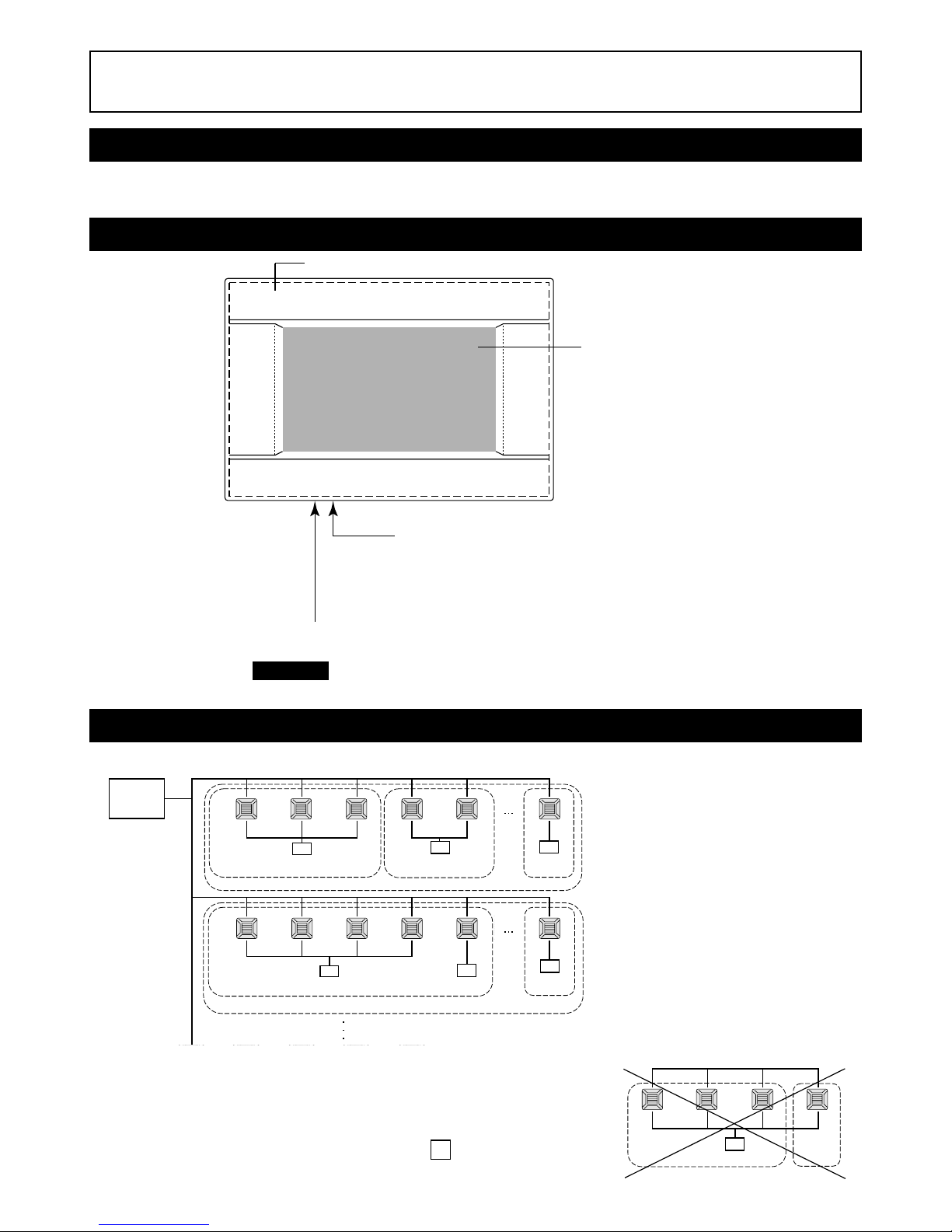
Names and Functions of Parts
Blocks, Groups
[Example of Connections]
•A maximum of 16 air conditioning units can be set up in one group.
• Do not use one remote controller for different groups of air conditioning units.
•A maximum of 9 groups can be set up in one block.
•A maximum of 16 blocks can be set up.
R : Remote controller
Color LCD Display
The screens are displayed here. Operations
are performed by touching it with a finger.
USB Memory Slot
Insert the USB memory from the bottom.
Warning!
Do not insert any USB device other than bundled USB memory.
Front Cover
Group 1 Group 2
Air conditioning
unit 1
Air conditioning
unit 2
Air conditioning
unit 3
Air conditioning
unit 4
R
Reset switch
Press the switch that is placed innermost of small hole at the lower side of this
cover, using a straight clip or similar tool.
The screen may be locked depending on the static charge or external noise,
etc, but there is not trouble. In this case, the screen can be returned to normal
display by pressing a reset switch.
Page 6
–5–
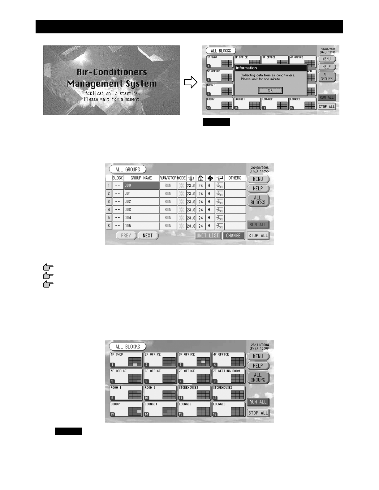
Startup Screen
[Startup Screen] [Information Screen]
This screen is displayed at startup. Note
After a brief time, the following screen is displayed. It is not possible to do any setting when information
screen is displayed.
• ALL GROUPS Display
This display appears the first time the unit starts up or when block have not been registered. Make the initial
settings in the following order.
Time & Date Setting page 11
Group Definition page 11
Block Definition page 13
* Once blocks are registered, it is very convenient because the status of all groups can be viewed on a single
screen.
• ALL BLOCKS Display
When blocks have been registered, this display appears.
Note
It may take time for the settings to be read into the unit. Do not perform any operations until all the groups
that have been set are displayed. (This should take only a few minutes.)
Page 7
–6–
Group operation
Multiple groups operation
Batch operation
Setting and checking schedules
Making calculating settings (SC-SL3N-BE only)
Entering numbers and characters
Using convenient functions
Date & time
Groups
Blocks
All blocks
All groups
Each group
Each unit
Viewing status
Page 11 (Time & Date Setting)
Page 11 (Group Definition)
Page 13 (Block Definition)
Page 9 (All Blocks Display)
Page 17 (ALL GROUPS screen)
Pages 15 & 17 (Group Operation Settings : GROUP(PANEL) & GROUP(LIST) screen)
Page 24 (Viewing Detailed Unit Information)
Page 15 (Group Operation Settings)
Page 18 (Multiple Groups Operation Settings)
Page 19 (Group Batch Operation)
Page 20 (Schedule Settings)
Page 25 (Calculating Settings)
Page 26 (Entering Numbers and Characters)
Page 27 (Function Settings)
Page 28 (Corrections for Power Outages)
Page 28 (Using USB Memory)
Page 30 (System Information)
Page 30 (Viewing Alarm History)
Page 30 (Help)
Alarm history
Further Information
Quick Reference Chart for Operations
Initial settings
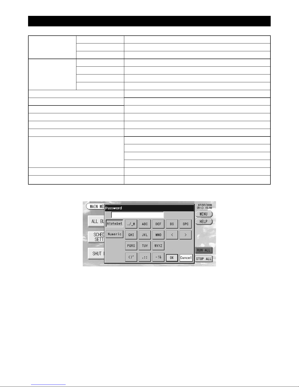
[Password Input Screen]
(∗) Password
• The password of SC-SL3N-AE is SLNA.
• The password of SC-SL3N-BE is SLNB.
It is not possible to change the password.
Page 8
–7–
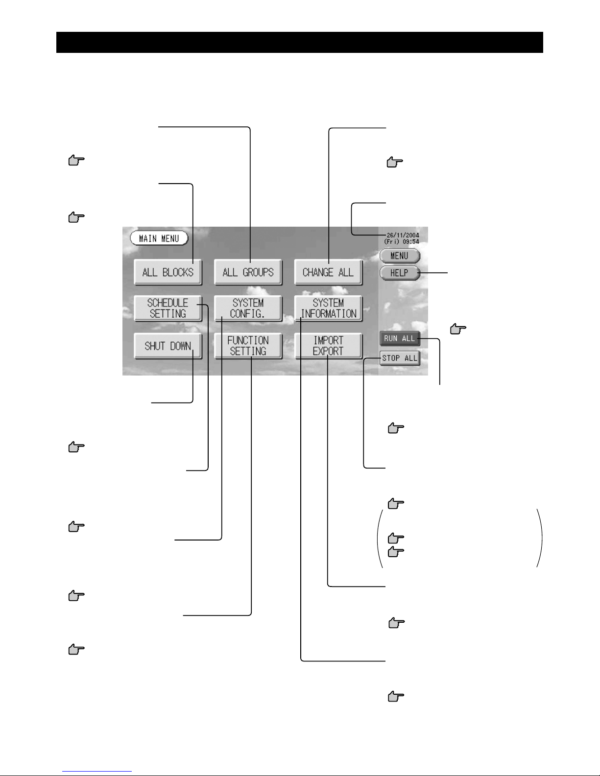
Main Menu
When the MENU button is pressed, the screen switches to the one shown below.
Please enter your password (∗) after you press the SCHEDULE SETTING, SYSTEM CONFIG., SHUT DOWN,
FUNCTION SETTING or IMPORT EXPORT button.
(∗) Refer to page 6.
STOP ALL button
Stops running for groups set up for batch
operation.
page 19
Settings can also be made for groups
not set up for batch operation.
page 11 1
page 12 56
CHANGE ALL button
Switches the screen for changing group
batch operation settings.
page 19
ALL GROUPS button
Displays all group names and status in a
list.
page 17
ALL BLOCKS button
Displays a list of the names and
status of all blocks in a panel.
page 9
SHUT DOWN button
When it is known that there will be a
power outage, this button saves the
settings.
page 31
SCHEDULE SETTING button
Switches the screen for setting air conditioning operation schedules.
(If you have not set a group, this
button is invalid.)
page 20
SYSTEM CONFIG. button
Switches the screen for making group and block
settings, date and time settings and accounting
settings (SC-SL3N-BE only) as well as viewing
the alarm history.
page 8
FUNCTION SETTING button
Switches the screen for making backlight settings and function settings.
page 27
Date and Time display
HELP button
Opens the screen for
viewing detailed information on the display
content and operations.
page 30
RUN ALL button
Starts running for groups set up for batch
operation.
page 19
SYSTEM INFORMATION button
Displays the central control version
number and number of units registered.
page 30
IMPORT EXPORT button
Switches the screen for saving settings
and outputting monthly data.
page 28
Page 9
–8–
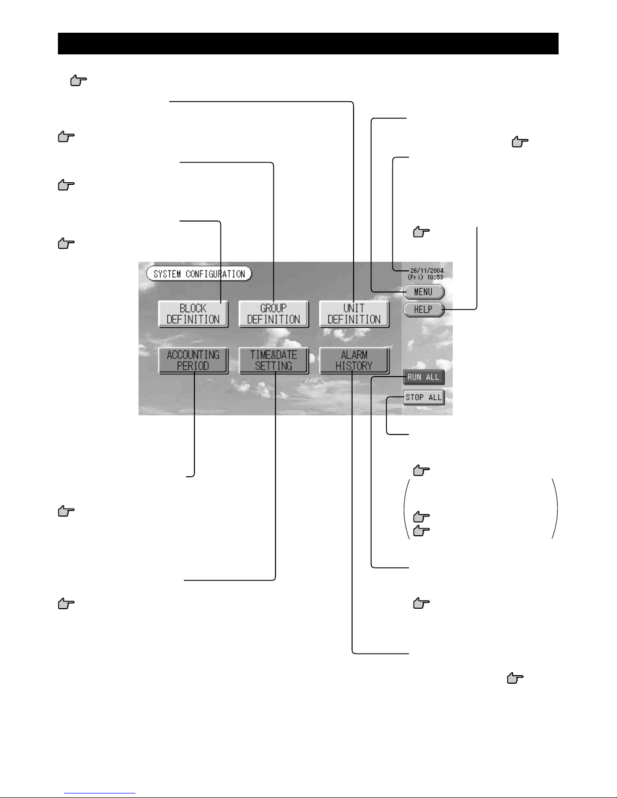
TIME&DATE SETTING button
Switches the TIME & DATE SETTING screen.
page 11
UNIT DEFINITION button
Switches the UNIT DEFINITION screen.
(SC-SL3N-BE only)
page 25
Date and Time display
HELP button
Opens the screen for viewing detailed
information on the display content and
operations.
page 30
MENU button
Returns to the MAIN MENU.
page 7
ALARM HISTORY button
Displays the Alarm History of the units.
page 30
GROUP DEFINITION button
Switches the GROUP DEFINITION screen.
page 11
BLOCK DEFINITION button
Switches the BLOCK DEFINITION screen.
page 13
STOP ALL button
Stops running for groups set up for
batch operation.
page 19
Settings can also be made for
groups not set up for batch operation.
page 11 1
page 12 56
RUN ALL button
Starts running for groups set up for
batch operation.
page 19
ACCOUNTING PERIOD button
Switches the ACCOUNTING PERIOD TIME screen.
(SC-SL3N-BE only)
page 25
System Configuration Screen
This is displayed when the SYSTEM CONFIG. button is pressed on the Main Menu.
page 7
Page 10
–9–
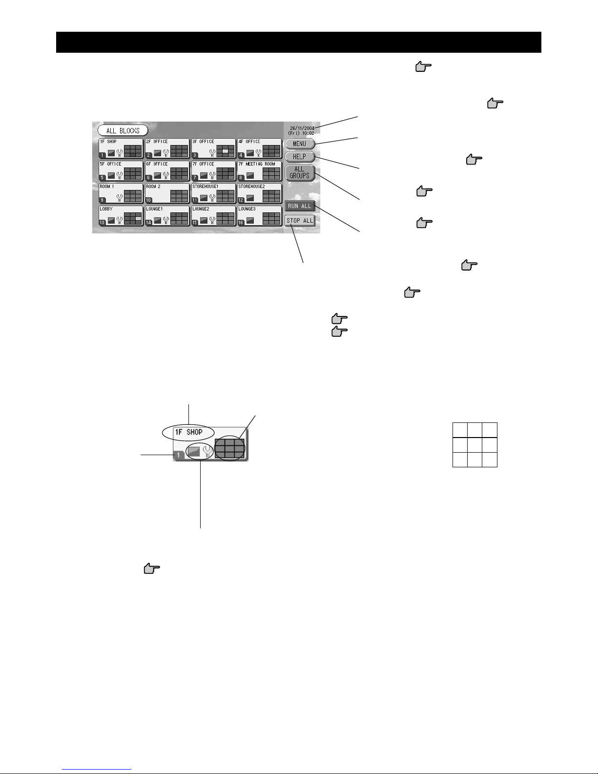
All Blocks Display
This is displayed when the ALL BLOCKS button is pressed on the MAIN MENU. page 7
The names and the status of all blocks are displayed in the panels. Unestablished blocks or blocks without any
groups are not displayed. If a block button is pressed, the GROUP (PANEL) screen is displayed.
page 15
Each group status display
The colors 1 – 9 show the status of the groups.
As shown in the right figure, it is arranged from
small group number. The colors have the following significance.
(Red) Running
(Green) Stopped
(Yellow) Malfunction
(Blue) Communication error
(Gray) No groups
Time and Date display
MENU button
Returns to the MAIN MENU.
page 7
HELP button
Opens the Help.
page 30
ALL GROUPS button
Displays all groups.
page 17
RUN ALL button
Starts running for groups set up for batch
operation.
page 19
* Settings can also be made for groups not set up for batch operation.
page 11 1
page 12 56
• Individual Block Displays
Block name
Block number
Filter Sign and Maintenance Indicator
Dispayed when at least one group needs the cleaning of the
filters or maintenance.
page 10
123
456
789
STOP ALL button
Stops running for groups set up for batch operation.
page 19
Page 11
–10–
Swinging
(AUTO)
Position 1
(STOP 1)
Position 2
(STOP 2)
Position 3
(STOP 3)
Position 4
(STOP 4)
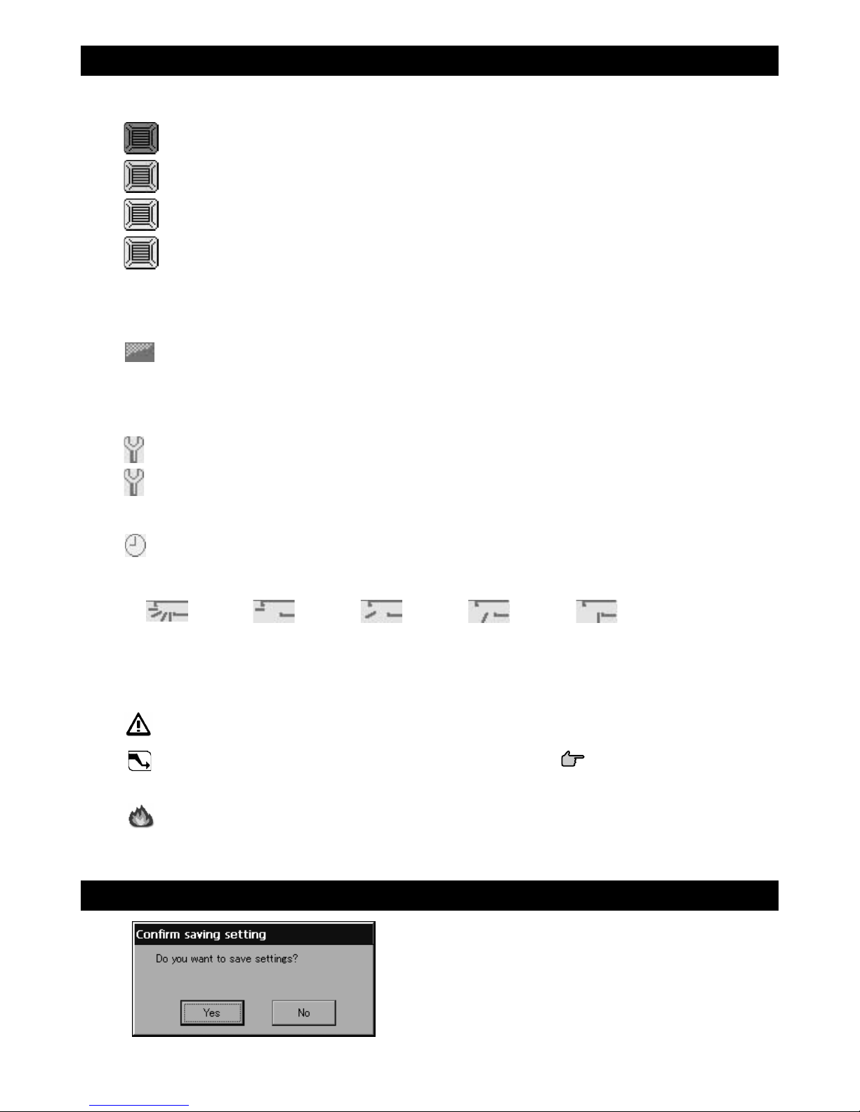
Icons
(1) Unit icon
The unit status is shown by colors.
(Red) Running (when at least one unit is running)
(Green) Stopped (when all units are stopped)
(Yellow) Malfunction of one or more units
(Blue) Communication error with one or more units
(2) Filter sign
If at least one air conditioning unit in a block or group needs filter maintenance, this indicator lights up. When
this happens, clean the filters.
(3) Maintenance Indicator
When the maintenance indicator is lit for at least one air conditioning unit in a block or group, the maintenance indicator is displayed. If the maintenance indicators are off on all units, the maintenance indicator
turns off. Contact the shop where the units were purchased if this indicator is on.
(Gray) Inspection, Inspection 1, Inspection 2
(Yellow) Backup operation (Inspection 3)
(4) Scheduling
This shows the groups that are the targets of the current day’s schedule.
(5) Air direction
This shows the status of louver operation.
(6) Unit states
The unit status is shown by figures.
Error stop (One or more units have been stopped because of malfunction.)
Please contact the shop where the unit was purchased.
Demand (The external signal is input to the demand terminal.
page 12)
The target unit will switch to fan mode and remote controller operations are prohibited. When the
external signal is cancelled, the setting will return.
Emergency stop (The external signal is input to the emergency stop terminal.)
All connected units stop and operations are prohibited. When the emergency stop signal is cancelled,
the remote controller lock/unlock setting will return but the units remain stopped.
Changeover Confirmation Screen
This is a screen for confirming the changes to various settings. The text displayed varies according to the screen
called up, but the operation is as follows.
Press the Yes button to save the settings and to exit. Press
the No button to exit without saving your settings.
Page 12

–11–
Operation
Attention
A static electric discharge to the unit could cause a break-down.
Before performing operations, touch a grounded metal object and discharge any static electricity.
Time & Date Setting
1. Press the MENU button and then press the SYSTEM CONFIG. button.
page 7
2. Press the TIME&DATE SETTING button on the SYSTEM CONFIGURATION screen.
page 8
3. Press the Year, Month, Day and Time buttons.
Input the current time and date.
page 26
4. Press the SET button, and press the Yes button on the confirmation screen.
The specified date and time are set at the 00 seconds. When you do not want to make the setting, press the
No button.
Note
• If the BACK button is pressed, it will return you to the SYSTEM CONFIGURATION screen.
• It is unnecessary to reset the time and date for power outages lasting less than 48 hours.
Group Definition
1 Selecting the groups to register and display the registered units
1. Press the SYSTEM CONFIG. button on the MAIN MENU.
page 7
2. Press the GROUP DEFINITION button on the SYSTEM
CONFIGURATION screen.
page 8
The GROUP DEFINITION screen is displayed.
3. Select a group name.
When adding a group, press an empty group name area. When changing the settings for a registered
group, press that group name. The selected group is reverse highlighted. To change the page, press the
PREV or NEXT button.
3
4
[TIME & DATE SETTING screen]
3
4
[Initial GROUP DEFINITION screen]
Initial GROUP DEFINITION screen may vary
according to the transmission method.
(Example for previous setting)
1-00
SuperLink No. Unit address
(Example for new setting) 005
Unit address
One indoor unit is registered with one group
on the initial screen previously.
When registering the indoor unit to other
groups, register it with other group after
deleting it from the group, and moving it in
the list of ALL UNITS.
Page 13

–12–
5
11
12
8 10
7
9
14
6
13
2 Registering and changing the Group Name being set
5. Press the CHANGE button.
Enter the name for the group.
page 26
3 Adding and deleting units making up the group
<When adding units>
6.
or directly press a unit name to select the unit from the list of ALL UNITS.
To change the page, press the PREV button or the NEXT button.
7. Press the ADD button.
The selected unit is added to the list of UNIT ENTRY and deleted from the list of ALL UNITS.
<When deleting units>
8.
or directly press a unit name to select the unit from the list of UNIT ENTRY.
9. Press the DEL button.
The selected unit is deleted from the list of UNIT ENTRY and moved to the list of ALL UNITS.
4 Setting the representative unit and demand
10.
or directly press a unit name to select the unit from the list of UNIT ENTRY.
11. Press the REP. button.
That unit is set as the representative unit, and an asterisk is placed to the left of its name in the display.
· Representative unit: unit for which the status is shown when the group is displayed
12. Press the DEMAND button.
That unit is set as the for demand operation, and a “D” is placed to the right of its name in the display.
· Demand: a unit that switches to fan mode and then cannot be operated from the remote controller
when there is an external demand input.
Note
By the demand input, it is possible to save on power costs in summer by reducing the power consumption.
Operation of the unit when demand input is released, is conformed to nearest schedule before release time
of the day.
In case of that schedule of the day is not set, the unit is for the operation mode and remote controller
permission prohibited setting which is just before the demand input.
5 Setting and unsetting batch operation for the group
13. Press the VALID or INVALID button.
·VALID: group set up for batch operation
· INVALID: group not set up for batch operation
6 Saving the settings
14. Press the SET button. Press the Yes button on the confirmation screen.
The group settings are saved. When you do not want to save the settings, press the No button.
Note
• If the BACK button is pressed, it returns to the previous screen.
•1 to 16 units can be registered in a group.
• When you will delete all group definition, please press the DELETE ALL DEF. button and enter your
password (∗). Press the Yes button on the confirmation screen.
Caution The all schedule settings are deleted too.
(∗) Refer to page 6.
4. Press the DETAIL button.
The GROUP DEFINITION DETAILS screen is displayed.
Page 14

–13–
7
9
8
6
10
5
3
4
Block Definition
Note
Register the group beforehand.
page 11
1 Selecting the blocks to define and displaying the registered groups
1. Press the SYSTEM CONFIG. button on the MAIN MENU.
page 7
2. Press the BLOCK DEFINITION button on the SYSTEM CONFIGURATION screen.
page 8
The BLOCK DEFINITION screen is displayed.
3. Select a block name.
When adding a block, select an empty block name area. When changing the settings for a registered block,
press that block name. The selected block is reverse highlighted. To change the page, press the PREV or
NEXT button.
4. Press the DETAIL button.
The BLOCK DEFINITION DETAILS screen is displayed.
2 Registering and changing the Block Name being set
5. Press the CHANGE button.
Enter the name for the block.
page 26
[Initial BLOCK DEFINITION screen]
When defining a new block, the block
names and registered groups are empty.
[
Initial BLOCK DEFINITION DETAILS screen
]
When defining a new block, the block
names and group entry area are empty.
Page 15

–14–
3 Adding and deleting groups registered in a block
<When adding groups>
6.
or directly press the group name to select the group from the list of ALL GROUPS.
When changing the page, press the PREV or NEXT buttons.
7. Press the ADD button.
The selected group is added to the group entry list and deleted from the list of ALL GROUPS.
<When deleting groups>
8.
or directly press the group name to select the group from the list of GROUP ENTRY.
9. Press the DEL button.
The selected group is deleted from the list of GROUP ENTRY and moved to the list of ALL GROUPS.
4 Saving the registrations and changes
10. Press the SET button. Press the Yes button on the confirmation screen.
The block settings are saved. When you do not want to save the settings, press the No button.
Note
• If the BACK button is pressed, it returns to the previous screen.
•1 to 9 groups can be registered in a block. In addition, the maximum number of blocks is 16.
Page 16

–15–
Group Operation Settings (Monitor Group Status)
1. Press the ALL BLOCKS button on the MAIN MENU.
Page 7
2. Press the block you wish to set or monitor.
The GROUP (PANEL) screen is displayed.
The group name, status, filter sign, maintenance, scheduling, temperature settings and room temperature can
be observed.
Note
• See Icons for the significance of the icon displays.
Page 10
• The running status, operating mode, temperature settings and room temperature are shown for the representative unit. When all units are stopped, stopped status is shown.
• Groups that have the current day's schedule settings show
.
•
being displayed means that these are lit for one or more units.
• If the GROUP LIST button is pressed, the GROUP (LIST) is displayed.
Page 17
•To display the units in a group, press the UNIT LIST button.
Page 24
<When running and stopping each group>
3. Press the panel of the group for which settings are to be made.
The panel frame turns blue.
4. To run units Press the RUN button, and press the Yes button on the confirmation screen.
The selected group starts running.
To stop units Press the STOP button, and press the Yes button on the confirmation screen.
The selected group stops running.
When you do not want to set, press the No button.
<When making settings and changes on each group>
3. Press the panel of the group for which settings or changes are to be made.
The panel frame turns blue.
4. Press the CHANGE button.
The screen for basic group settings is displayed. When the screen changes, no items are selected (the
temperature setting is blank). Set only the items that are to be set or changed.
[GROUP (PANEL) screen]
3
4
4
Page 17

–16–
5
6
6
5
5. Press the button for the item to set or change.
· Run/Stop: Press the RUN or STOP button.
With the RUN button is selected, the operation starts, and with the STOP button is selected,
the operation stops.
·Temperature setting: press ▲ or ▼.
Set a temperature between 18°C and 30°C.
· Mode: select
Auto, Cool, Dry, Fan or Heat by pressing the button.
* Auto Mode can be enabled in the Function Settings.
Page 27
· Fan speed: select Hi, Me or Lo, and press the button.
· Air direction: select Auto, stop 1, stop 2, stop 3 or stop 4 and press the button.
6. Press the SET button. Press the Yes button on the confirmation screen.
When you do not want to make the setting or change, press the No button.
■ Settings/changes on the detailed group settings screen.
Prohibiting operations by remote controller settings and filter resets can be carried out on this screen.
Press the DETAIL SET button on the BASIC GROUP SETTINGS screen.
Above
The DETAILS GROUP SETTINGS screen is displayed.
[BASIC GROUP SETTINGS screen]
[DETAILS GROUP SETTINGS screen]
5. Press the button for the item to set or change.
· Run/stop, temperature setting and mode are the same as the BASIC GROUP SETTINGS screen.
· LOCK: Press
or .
If
is pressed, remote controller operations are permitted, and if is pressed, they are
prohibited.
· FILTER: if the reset button is pressed, the filter sign turns off.
6. Press the SET button. Press the Yes button on the confirmation screen.
When you do not want to set or change, press the No button.
Note
• If the BACK button is pressed, it returns to the previous screen.
• If individual lock/unlock is enabled in the Function Setting, it is possible to set the remote controller operations to permit or prohibit each item such as run/stop, mode and temperature setting.
• When individual lock/unlock are enabled in the Function Setting, remote controller operations are prohibited if run/stop, mode and temperature setting are all
. (Some functions, such as reset of the filter sign
have been permitted.)
[Individual lock / unlock settings
enabled in Function Setting]
This function can be applied to the indoor units,
which are the model KXE4 or later, and to the
remote controller, which is the model RC-E1 or
later.
[Auto button enabled in Function
Setting]
This function can be applied to the outdoor units,
which are the cooling / heating free multi KXR,
GHP-R series or later and PAC.
Page 18

–17–
2
3
■ The following method can also be used to set and change operations on each group.
When making settings or changes in the GROUP (LIST) screen
1. Press the GROUP LIST button in the GROUP (PANEL) screen.
Page 15
The GROUP (LIST) screen is displayed.
[GROUP (LIST) screen]
2. Press the name of the group for which settings or changes are to be made.
The group name is reverse highlighted. To change the page, press the PREV or NEXT button.
3. Press the CHANGE button.
The screen for basic group settings is displayed. Make the settings or changes.
Page 16
Note
• If the BACK button is pressed, it returns to the previous screen.
• Run is indicated when at least one unit is running. Malfunctions are indicated when at least one unit is not
in good condition. Stop is indicated when all the units have stopped.
icon is displayed when at least one unit needs to clean.
icon is displayed when at least one unit needs the maintanance.
Operating mode, temperature setting, room temperature, fan speed and air direction show the state of the
representative unit.
• Ones which are surrounded by orange frames are the items which operations from the remote controller
are prohibited in the group settings.
•
If the GROUP PANEL button is pressed, the GROUP (PANEL) screen is displayed.
Page 15
When making settings or changes in the ALL GROUPS screen
1. Press the ALL GROUPS button on the MAIN MENU.
Page 7
2. Press the name for the group to set or change.
The group name is reverse highlighted.
When the screen switches, the previously selected group name is selected. To change the page, press the
PREV or NEXT button.
[ALL GROUPS screen]
2
3
Page 19

–18–
3
4
4
Multiple Groups Operation Settings
This section shows how to operate multiple groups in a same block.
1. Press the ALL BLOCKS button on the MAIN MENU.
Page 7
2. Press the block you wish to set.
The GROUP (PANEL) screen is displayed.
<When running and stopping multiple groups>
3. Press the panels of the groups for which settings are to be made (multiple groups can be selected).
The panel frame turns blue.
When you want to cancel, please press the panel of the group again.
4. To run units Press the RUN button, and press the Yes button on the confirmation screen.
The selected group starts running.
To stop units Press the STOP button, and press the Yes button on the confirmation screen.
The selected group stops running.
When you do not want to set, press the No button.
<When making settings and changes on multiple groups>
3. Press the panels of the groups for which settings or changes are to be made (multiple groups can
be selected).
The panel frame turns blue.
When you want to cancel, please press the panel of the group again.
4. Press the CHANGE button.
The screen to change groups is displayed. When the screen changes, no items are selected (the temperature setting is blank). Set only the items that are to be set or changed.
[GROUP (PANEL) screen]
5
6
[Individual lock/unlock settings enabled in Function
Setting]
This function can be applied to the indoor units,
which are the model KXE4 or later, and to the
remote controller, which is the model RC-E1 or
later.
3. Press the CHANGE button.
The screen for basic group settings is displayed. Make the settings or changes.
Page 16
Note
•To display the units in a group, press the UNIT LIST button.
Page 24
•To show all blocks, press the ALL BLOCKS button.
Page 9
• Ones which are surrounded by orange frames are the items which operations from the remote controller
are prohibited in the group settings.
• If the MENU button is pressed, the MAIN MENU is displayed.
Page 7
Page 20

–19–
5. Press the button for the item to set or change.
· Run/Stop: Press the RUN or STOP button.
With the RUN button, running starts, and with the STOP button, running stops.
·Temperature setting: Press ▲ or ▼.
Set a temperature between 18 and 30°C.
· Mode: Select
Auto, Cool, Dry, Fan or Heat by pressing the button.
* Auto mode can be enabled in the Function Settings.
Page 27
· LOCK: Press
or .
If
is pressed, remote controller operations are permitted, and if is pressed, they are
prohibited.
· Fan speed: select Hi, Me or Lo, and press the button.
· Air direction: select Auto, stop 1, stop 2, stop 3 or stop 4 and press the button.
· FILTER: if the reset button is pressed, the filter sign turns off.
6. Press the SET button. Press the Yes button on the confirmation screen.
When you do not want to set, press the No button.
Note
• If the BACK button is pressed, it returns to the previous screen.
• If individual lock/unlock is enabled in the Function Setting, it is possible to set the remote controller opera-
tions to permit or prohibit each item such as run/stop, mode and temperature setting.
• When individual lock/unlock are enabled in the Function Setting, remote controller operations are prohib-
ited if run/stop, mode and temperature setting are all
. (Some functions, such as reset of the filter sign
have been permitted.)
2
3
[Individual lock/unlock settings enabled in Function
Setting]
This function can be applied to the indoor units,
which are the model KXE4 or later, and to the
remote controller, which is the model RC-E1 or
later.
Group Batch Operation
This section shows how to set or change the detailed setting of Batch Operation.
Set the groups for batch operation in advance.
Page 111, 1256
1. Press the CHANGE ALL button on the MAIN MENU.
Page 7
The CHANGE ALL screen is displayed.
Note
When the screen changes, no items are selected (the temperature setting is blank). Set only the items that
are to be set or changed.
Page 21

–20–
Schedule Settings
Operating schedules can be set in group units. Sixteen schedules per day can be registered for operating time (in
minutes), run/stop, mode, prohibiting remote controller operations and temperature setting.
Set the detailed daily schedule (weekday, holiday, special 1, special 2) in advance.
Page 21
1. Press the SCHEDULE SETTING button on the MAIN MENU.
Page 7
The SCHEDULE SETTING screen is displayed.
■ Setting the current day’s schedule
The operating schedule for the current day is set on each group.
2. Press the TODAY’S SCHEDULE button on the SCHEDULE SETTING screen.
2
3
4
4
5
2. Press the button for item to set or change.
· Run/Stop: Press the RUN or STOP button.
With the RUN button, running starts, and with the STOP button, running stops.
·Temperature setting: Press ▲ or ▼.
Set a temperature between 18 and 30°C.
· Mode: Select
Auto, Cool, Dry, Fan or Heat by pressing the button.
* Auto mode can be enabled in the Function Settings.
Page 27
· LOCK: Press
or .
If
is pressed, remote controller operations are permitted, and if is pressed, they are
prohibited.
· Fan speed: select Hi, Me or Lo, and press the button.
· Air direction: select Auto, stop 1, stop 2, stop 3 or stop 4 and press the button.
· FILTER: if the reset button is pressed, the filter sign turns off.
3. Press the SET button. Press the Yes button on the confirmation screen.
When you do not want to set, press the No button.
Note
• If the BACK button is pressed, it returns to the previous screen.
• If individual lock/unlock is enabled in the Function Setting, it is possible to set the remote controller opera-
tions to permit or prohibit each item such as run/stop, mode and temperature setting.
• When individual lock/unlock are enabled in the Function Setting, remote controller operations are prohib-
ited if run/stop, mode and temperature setting are all
. (Some functions, such as reset of the filter sign
have been permitted.)
Page 22

–21–
3. Press the group name.
Select the group on the Select Group screen.
Page 22
<When setting a schedule for the current day>
4. Press the item to be changed on the list.
When "Time", "Lock" or "Temperature setting" buttons are pressed, a detailed setting screen for each item
is indicated.
Page 22, 23
Change the "RUN/STOP" or "MODE" settings by pressing the appropriate item.
To change the page, press the PREV or NEXT button.
<When rewriting the schedule displayed for the current day to detailed daily schedule>
4. Select the detailed daily schedule such as WEEKDAY, HOLIDAY, SPECIAL 1 or SPECIAL 2 button
and press it.
Note
Set the operating schedule for the detailed daily schedule in advance.
Noted below (Setting a detailed daily schedule)
5. Press the SET button. Press the Yes button on the confirmation screen.
When the CLEAR button is pressed, the selections are cleared.
Note
• If the BACK button is pressed, it returns to the SCHEDULE SETTING screen.
• Press the COPY button when copying the schedule between groups.
Page 23
■ Setting a yearly schedule
A yearly operating schedule is set on each group.
2. Press the YEARLY SCHEDULE button on the SCHEDULE SETTING screen.
3
4
5
6
3. Press the group name.
Select the group on the Select Group screen.
Page 22
4. Select the detailed daily schedule such as WEEKDAY, HOLIDAY, SPECIAL 1, SPECIAL 2 or NO
OPERATION button and press it.
Note
Set the detailed daily schedule in advance.
Noted below (Setting a detailed daily schedule)
5. Press the date (multiple dates can be selected).
The detailed daily schedule which you choose is applied to that day. However, the current day and the
dates which have elapsed can not be selected. Press the PREV or NEXT button to change the month.
Note
If the DEFAULT button is pressed, Saturday and Sunday are set as holidays and the others are set as
weekdays.
6. Press the SET button. Press the Yes button on the confirmation screen.
When you do not want to set, press the No button.
• If the BACK button is pressed, it returns to the SCHEDULE SETTINGS screen.
• Pressing the COPY button brings up the Copy Schedule screen when copying between groups.
Page 23
■ Setting a detailed daily schedule
The detailed daily schedule is set for each group.
The schedule indicates weekday, holiday, special 1 and special 2, and the operation can be set for
each group.
Page 23

–22–
1
2
1
2
[Select Group screen]
[Schedule Time Setting screen]
1. Press the group name to be selected.
The selected group name is reverse highlighted.
To change the page, press the PREV or NEXT button.
2. Press the OK button.
The selected group can be set.
When you do not want to set, press the CANCEL button. It returns to the previous screen.
1. Pressing ▲▼ changes the hour and minutes (24 hour clock display).
2. Press the OK button.
The time is changed and the screen closes. Press the CANCEL button to cancel the change.
Pressing the CLEAR button clears the currently entered values and makes the entry empty.
2. Press the DETAILED DAILY SCHEDULE button on the SCHEDULE SETTING screen.
3. Press the group name.
Select the group on the Group Select screen.
Noted below (Various screens)
4. Select the detailed daily schedule such as WEEKDAY, HOLIDAY, SPECIAL 1 or SPECIAL 2 button and
press it.
5. Press the item to be changed on the list.
When "Time", "Lock" or "Temperature setting" buttons are pressed, a detailed setting screen for each item is
indicated.
Page 22, 23
Change the "Run/Stop" or "MODE" setting by pressing the appropriate item.
To change the page, press the PREV or NEXT button.
6. Press the SET button. Press the Yes button on the confirmation screen.
When the CLEAR button is pressed, the selections are cleared.
Note
• If the BACK button is pressed, it returns to the SCHEDULE SETTING screen.
• Press the COPY button when copying the schedule between groups.
Page 23
■ Various screens
3
4
5
6
Page 24

–23–
1
2
1. Press the button of the items which are to be barred from the remote controller operation
(multiple items can be selected).
2. Press the OK button.
The prohibited item changes and the screen closes.
Press the CANCEL button to cancel the change.
If the CLEAR button is pressed, the selected item is deselected.
[Schedule Temperature Setting screen]
[Copy Schedule screen]
Select the groups that apply the chosen schedule.
1. Pressing ▲▼ changes the temperature. (18 – 30°C)
2. Press the OK button.
The temperature changes and the screen closes.
Press the CANCEL button to cancel the change.
Pressing the CLEAR button clears the currently entered values and makes the entry empty.
1. Press the group name to be selected (multiple groups can be selected).
To change the page, press the PREV button, the NEXT button or ▲▼.
To select all groups, please press the ALL GROUPS button. If you will cancel the selecting all groups, press
the ALL GROUPS button again.
2. Press the COPY button. Press the Yes button on the confirmation screen.
The schedule of the group chosen on the screen is pasted to the groups checked in the list. When you do not
want to make the setting, press the No button.
Note
• This is cancelled if the selected group is pressed two times.
• If the CANCEL button is pressed, it returns to the previous screen.
1
2
[Remote Controller Lock/Unlock screen]
This is used to allow or prohibit remote
controller operations.
[Individual lock/unlock settings enabled in
Function Setting]
1
2
1
2
Page 25

–24–
Viewing Detailed Unit Information
The unit numbers and status of each group can be observed.
1. Press the UNIT LIST button in the ALL GROUPS screen (
Page 17) or if the UNIT LIST button is
pressed in the GROUP (PANEL) or GROUP (LIST) screen (
Page 15, 17).
The units in the group are displayed.
To change the page, press the PREV or NEXT button.
[UNIT INFORMATION screen]
2. To view further information, press the unit number. After it is reverse highlighted, press the UNIT
INFO button.
The information for the specified unit is displayed.
Note
• The detail of the maintenance display content can be checked only on this screen. On other screens,
there is only a color classification of Inspection 1, 2 and backup operation.
• If the BACK button is pressed, it returns to the previous screen.
• UNIT No. display system may differ from the figuration. (Same as every other screen)
Display system is changed according to the communication method (Page 27 Function Setting, SL Mode).
Prev. SL) [3-04] New SL) [005]
SuperLink No. unit address unit address
2
2
Page 26

–25–
3
2
Calculating Settings (SC-SL3N-BE only)
1 Unit Definition
1. Press the UNIT DEFINITION button on the SYSTEM CONFIGURATION screen.
Page 8
The UNIT DEFINITION screen is displayed.
2. Press the item to be set or changed on the list.
Each time the “TYPE” item is pressed, the unit type changes.
MULTI1 : calculating according to the amount of refrigerant flow. Used for KX Series and GHP.
MULTI2 : thermo ON/OFF calculating. Used for KX Series and GHP.
RUN/STOP : calculating according to the unit operating time. Used for KX series, PAC and GHP.
If the “CAPACITY” item is pressed, it can be changed. (0 – 200 [kW])
Page 26
To change the page, press the PREV or NEXT button.
Note
• Please select same item for same system of wattmeter or gas meter.
• When you select MULTI1 or MULTI2, fan mode units are out of calculation. To calculate the fan mode
units, please select RUN/STOP.
• Standby energy used during night etc. is not included in the calculation, and does not equal the value of
wattmeter or gas meter. Please correct the calculation by spreadsheet.
3. Press the SET button. Press the Yes button on the confirmation screen.
When you do not want to make the setting, press the No button.
If the BACK button is pressed, it returns to the SYSTEM CONFIGURATION screen.
2 Setting the period for calculation
You can divide a day into two period for calculation.
If it is not necessary to devide the period into two parts, you can set the period time for 0:00 - 24:00.
1. Press the ACCOUNTING PERIOD button on the SYSTEM CONFIGURATION screen.
Page 8
2. Press the hour or minute buttons for the start time or the end time.
Input the time.
Page 26
3. Press the SET button. Press the Yes button on the confirmation screen.
When you do not want to set, press the No button.
If the BACK button is pressed, it returns to the SYSTEM CONFIGURATION screen.
Caution
The energy consumption calculated by this unit does not conform to OIML, and there are no guarantees concerning the results of the calculations.
This unit calculates only energy consumption distribution (gas, electric power). You need to calculate the air-conditioning rates.
The calculating data for twelve months are saved.
See page 28 (Using USB Memory) for the method for extracting calculating data.
2
3
Page 27

–26–
Convenient Functions
Entering Numbers and Characters
■ Entering numbers
1. Press the button of the numerical value to input.
BS button : backspaces. (Deletes one number.)
CLEAR button : clears the input. (Deletes all numbers.)
2. Press the OK button.
The number is changed and the screen closes. Press the Cancel button to cancel the change.
■ Entering characters
1. Select Alphabet or Numeric and press the button.
2. Input the group name.
When Alphabet is selected, several letters are assigned to
each button, and each time the button is pressed the character changes. (See the table to the right.)
Alphabet button : letters are input.
Numeric button : numbers are input.
BS button : backspaces. (Deletes one character.)
SPC button : inputs a space.
< > buttons : moves the cursor to the left or right.
3. Press the OK button.
The name is changed and the screen closes. Press the Cancel button to cancel the change.
* The block or the group names can be input up to 16 characters.
[Alphabet]
./ @
ABC DEF
./ _@ ABCabc DEFdef
GH I JKL M NO
GHIghi JK Ljkl MNOmno
PQ RS TU V WXYZ
PQ RSp qrs TU Vt uv WXYZw xyz
()"
,:; -!&
()" ,:; -!&
1
2
1
2
3
Page 28

–27–
2
9
4
6
10
7
8
5
11
3
Function Settings
The timeout for turning OFF the backlight, validating or invalidating of the auto mode button and locking or
unlocking the individual functions of the remote controller are set.
When changing the Function Settings, follow the following steps.
1. Press the FUNCTION SETTING button on the MAIN MENU.
Page 7
[Function Setting screen]
2. Select the Backlight Timeout time using the ▲▼ buttons. (Factory default : 10)
Time from the last operation on the touch panel until the monitor backlight turns OFF can be selected.
3. Select the Brightness using the ▲▼ buttons. (Factory default : 7)
Brightness for the monitor backlight can be selected.
4. Press the "Valid" or "Invalid" button for the Auto Mode. (Factory default : Invalid)
This enables or disables the AUTO button on the GROUP SETTINGS screen and CHANGE All screen.
If you set Auto Mode to INVALID,
Auto button is not shown on the screen.
This function can be applied to the outdoor units, which are the cooling / heating free multi KXR, GHP-R
series or later and PAC.
For other than the outdoor units above, please do not use Auto Mode.
Please contact the shop where the unit was purchased.
5. Select the "Closed" or "Open" for the Malfunction Output (Normal). (Factory default : Closed)
You can choose "Closed" or "Open" status for malfunction output during normal operation of air conditioning unit.
Contact your service representative or installer for further information.
6. Press the "Valid" or "Invalid" button for the Individual Lock/Unlock. (Factory default : Invalid)
This enables or disables permitting and prohibiting the individual operation such as run/stop, mode and
temperature settings of the remote controller.
Note
This function can be applied to the indoor units, which are the model KXE4 or later, and to the remote
controller, which is the model RC-E1 or later.
7. Press the "Unlock" or "Lock" button for the Remote Controller's Timer. (Factory default : Unlock)
This permits or prohibits remote controller's timer operation for all the air conditioners defined in a group.
8. Press the Change button.
You can specify the folder to transfer the calculated data to USB memory. (SC-SL3N-BE only)
9. Use it when set the communication system (Factory default : New). Usually, this is not necessary to
change it.
If setting is incorrect, this may cause no communication with a part or all of air conditioners.
Please contact the shop where the unit was purchased.
10. In case that managing one air conditioner with plural center consoles, different setting is performed
to the same air conditioner, and this may cause that remote controller does not be operated according
to the intention. In such case, make this setting to "Invalid" other than the primary central control.
(Factory default :Valid)
In addition, make this setting to "valid" when the external input wiring such as emergency stop input are
connected to this central control.
Please contact the shop where the unit was purchased
11. Press the SET button.
Press the Cancel button to cancel the change.
Note
Set the timeout of the backlight as short as possible in order to make the lifetime of LCD longer.
Page 29

–28–
Corrections for Power Outages
In case the blackout continues more than 48 hours, the clock inside will stop and the operation of each group
cannot follow any schedule settings. Please reset the clock.
In case the blackout continues less than 48 hours, you do not have to reset the clock, and each group will run/
stop according to the following rule.
When the power returns, the operation of each group will follow the closest schedule setting before the power returns.
In case there are no settings in the closest schedule setting, it will follow the second closest schedule setting.
In case there are no schedule settings on that day, this center console will not send any operation signal to each group.
Using USB Memory (SC-SL3N-BE only)
Attention
• Be sure to use bundled USB memory.
• Be sure to perform these operations after inserting the USB memory into the unit.
Page 4
• The calculating data for twelve months are saved. Please save it to a PC through the USB memory
within twelve months.
• Please do not operate while the display light of the USB memory is blinking fast.
You may perform your operations or remove the USB memory only when the display light is blinking
slowly.
If the USB memory you use does not have a red blinking light, please wait for a moment after each operation.
Remove the USB memory only after all operations have been completed.
<Transferring Monthly Data>
It is convenient if folders are created in the USB memory in advance.
1. Press IMPORT EXPORT button on the MAIN MENU.
Page 7
2. Press the “Export monthly data files to USB” button.
Select the folder on the Folder Selection screen.
[Import/Export screen]
[Folder Selection screen]
2
4
3
3. Press the folder to be selected.
To change the page, press the PREV or NEXT button.
Page 30

–29–
4. Press the OK button.
A confirmation screen (Calculating data file export confirmation screen / Definition file backup confirmation
screen) is displayed. Press the “OK” button on either of the screens.
Note
• If the CANCEL button is pressed, it returns to the previous screen.
• The “Import a configuration file from USB” button is not needed.
• See the bundled CD-ROM for calculating on a PC.
Important!!
Calculating Data
(1) Follow the above procedure to transfer the calculating data to USB memory.
(2) Remove the USB memory from the central control and connect it to a PC.
(3) Insert the CD-ROM that was bundled with this unit into the PC and start the software.
(4) Operate the software according to the CD-ROM menu.
* There is no need to have the USB memory connected to this unit at all times.
* After installing the calculating data software, steps (3) and (4) are unnecessary. Operate
the software with reference to the manual on the CD-ROM.
<Transferring Definition Data>
1. Press IMPORT EXPORT button on the MAIN MENU.
Page 7
2. Press the “Export a configuration file to USB” button.
Select the folder on the Folder Selection screen.
Page 28
Note
• If the BACK button is pressed, it returns to the previous screen.
• The “Import a configuration file from USB button” is not needed.
By backing up the Definition data, the following data can be easily backed up;
· Block and group definitions
· Schedule settings
[Import/Export screen]
2
Page 31

–30–
System Information
The version of the Air-Conditioner Management System being used can be confirmed.
In case of SC-SL3N-BE, you can confirm the current day's pulse input count from gas meter or wattmeter.
1. Press the SYSTEM INFORMATION button on the MAIN MENU.
Page 7
2. After checking the content, press the OK button.
System Information display closes.
Help
1. Press the HELP button.
Details about the screen being displayed are shown.
Check the content by pressing ▲▼.
2. Press the BACK button.
It returns to the previous screen.
2
Viewing Alarm History
<Viewing the Alarm History>
1. Press the ALARM HISTORY button on the SYSTEM CONFIGURATION screen.
Page 8
Check the content on the ALARM HISTORY screen.
<Deleting One Alarm history Item>
2. Press the date to be deleted.
The date is reverse highlighted. Change the date selection using
.
3. Press the DELETE button.
The selected Alarm history item is deleted.
<Deleting All Alarm history Items>
2. Press the DELETE ALL button.
All Alarm history items are deleted.
• If the BACK button is pressed, it returns to the SYSTEM CONFIGURATION screen.
Page 8
2
2
3
Page 32

–31–
Maintenance
Wipe with a soft, dry cloth to clean. When it is very dirty, excluding the touch panel, use a neutral cleanser
dissolved in warm water to wipe it off and afterwards wipe that off with clean water.
Caution
Do not use paint thinner, organic solvents or strong acids.
The color may change and the paint may be removed.
Shut Down
The confirmation screen is displayed after the SHUT DOWN button is pressed on the Main Menu and enter your
password (∗).
(∗) Refer to page 6.
When you press the Yes button, the screen switches to the one shown below (a).
Please wait until you get the message that says “Please switch off the power supply.”
When you do not turn the power off, press the No button.
When the screen switches to the one shown below (b), you can turn the power off.
(a) (b)
Page 33

–32–
Troubleshooting
A yellow unit icon is
displayed.
A blue unit icon is displayed.
The filter sign is lit.
Maintenance display is lit.
The screen does not change
when touched.
No screen is displayed (dark).
The remote controller’s
display and the unit’s screen
display do not agree.
Air conditioning unit operates
on its own.
The unit feels warm to the
touch.
The calculating results are
not accurate.
(SC-SL3N-BE only)
“Importing a configuration
file from USB memory has
failed. Check the configuration file in the USB memory.”
message appears.
“Exporting a configuration
file to USB memory has
failed.” or “Exporting monthly
data files to USB memory has
failed” message appears.
“USB memory was not
found.” message appears.
“SL-0X-self address duplication error was detected.”“ SL0X- self transmission data read
error was detected.”“ SL-0Xdata transmission error was
detected.” message appears.
Error messages other than
the above are displayed.
The room temperature display
does not change from “--”.
A malfunction has occurred with the unit. The malfunctioning unit is stopped.
Contact the shop where the unit was purchased. The shop will need the following information: “unit icon
color”, “malfunction situation”, “model name of the malfunctioning unit”, “Error No. (E00)” etc.
A communication problem has occurred.
Contact the shop where the unit was purchased. The shop will need the following information: “unit icon
color”, “malfunction situation”, “model name of the malfunctioning unit” etc.
Clean the air filter.
(See the manual attached to the air conditioning unit for the cleaning method.)
Press the filter reset button after cleaning.
Regular inspection is necessary.
Contact the shop where the unit was purchased. The shop will need the following information: “maintenance display color”, “unit model name” etc.
* The unit number and maintenance display content can be checked on the UNIT INFORMATION screen.
Page 24
It is possible that there is malfunction due to electrostatic discharge. Turn the power off, then turn it on
again (power supply reset).
When it does not operate normally with the procedure above, it can be assumed that the unit was
damaged, so contact the shop where the unit was purchased with the “malfunction situation”.
• The backlight (illumination) is turned OFF after a fixed period of time to preserve the screen. Touch the
screen. (It may take a little time for the display to reappear.)
• It is possible that there is malfunction due to electrostatic discharge. Turn the power off, then turn it on
again (power supply reset).
When it does not operate normally with the procedure above, it can be assumed that the unit is
damaged, so contact the shop where the unit was purchased with the “malfunction situation”.
When multiple units are registered in a group, the settings for the representative unit for the group are
displayed. Check the status display for each of the units.
Page 24
Run/Stop displays “Run” if one or more units in the group are running, and it displays “Stop” if all units
are stopped.
Check the schedule settings. The group settings that have been scheduled can be changed.
Page 20
The unit may get warm, but this is not a problem.
When the room is hot, it gets warm more readily. Use in an environment where the temperature around it
is 40°C or lower.
If the total operating time in a day is less than 30 minutes, there has been no operation for calculating
purposes. Therefore the calculating results may be a little low.
(In such cases, other units are a little high.)
It is possible that either the definition file has not been saved to the USB memory or there is an error in
specifying the folder to be read. Check again and then perform the operation again.
If this message appears again, contact the shop where the unit was purchased.
There is a possibility that the USB memory has damaged or the files in the USB memory have damaged.
Delete all the files in the USB memory and create them again.
If this message appears again, contact the shop where the unit was purchased.
The USB memory may not have been fully inserted. Remove the USB memory, and reinsert it. If this
message appears again, it is possible that the USB memory is damaged or the USB memory is not the
attachment. Replace it with the bundled USB memory and try the operation again. If this message
appears again, contact the shop where the unit was purchased.
Contact the shop where the unit was purchased. (Re-check the communications line connections of the
units.)
Perform operations according to the messages on the screen or turn the power off and then on (power
supply reset).
If the message appears again, contact the shop where the unit was purchased.
When the intake-air temperature is 0°C or less, “--” is displayed.
When it differs from the display of remote controller, contact the shop where the unit was purchased.
Page 34

–33–
When you select “Valid” for
the Individual Lock/Unlock on
the Function Setting screen,
the function of permitting and
prohibiting the individual
operation of the remote
controller do not work.
In case that operating
condition of a part or all of air
conditioners which are set to
a group, does not display.
The screen of this central
control is not returned to
normal display even if you
press the reset switch.
This function can be applied to the indoor units, which are the model KXE4 or later, and to the remote
controller, which is the model RC-E1 or later.
Make sure to select “Invalid” for the Individual Lock/Unlock on the Function setting screen.
There may be inadequacy for communication line or the setting of this center console.
Please contact the shop where the unit was purchased.
This may possible that the central control or power system has malfunction.
Please contact the shop where the unit was purchased.
Caution that performing of the monthly calculation (SC-SL3N-BE only)
• We will consult about the compensation when the monthly calculation was not possible by the trouble of this
central control within the limits of this central control purchased amount. Please understand that we do not
compensate for the expense more than the purchased amount.
• Because the monthly calculation by this data does not conform to OIML, we cannot apply to public business.
• Please prepare the PC, spreadsheet such as EXCEL, a printer, a voltmeter, the gas flow meter that are
required for calculation.
Page 35

–34–
Installation
Do not install the central control
in any area where noise easily
generates.
If it is installed near the computer,
automatic door, elevator or equipment which generates noise, it will
cause to improper operation.
Do not install the central control
in any area where it is very humid or the vibration is large.
If it is installed in an area exposed
to humidity, splashing water or high
vibration, it will cause malfunctions.
Avoid any place which is exposed
to direct sunlight or is near a heat
source.
If it is installed under direct sunlight
or near a heat source, it will cause
malfunctions.
After Sales Service
●
Have the following information available when
requesting repairs.
●
Model name
●
Installation date
●
Problem status, as detailed as possible
●
Address, name, telephone number
●
Relocation
Since expert techniques are required, always contact your dealer.
In such cases, there will be a fee for relocation.
●
Repairs after the free service warranty period.
Consult your dealer.
Warranty period is one year from installation. It will
be charged when repair is required after the period.
Please consult your dealer.
●
Questions
For after sales service, consult your dealer.
Page 36

AIR-CONDITIONING & REFRIGERATION SYSTEMS HEADQUARTERS
3-1, Asahi, Nishibiwajima-cho, Kiyosu, Aichi, 452-8561, Japan
MITSUBISHI HEAVY INDUSTRIES EUROPE, LTD.
AIR-CONDITIONER DIVISION
3rd Floor Thavies Inn House 3-4 Holborn Circus London EC1N 2HA, ENGLAND
Phone: 44(0)20 7842 8171
Fax: 44(0)20 7842 8104
MITSUBISHI HEAVY INDUSTRIES AUSTRALIA, PTY.LTD.
81 Railway Street, Rockdale, NSW 2216, Australia
Phone: 61(0)2 9597 7977
Fax: 61(0)2 9597 7304
 Loading...