

Mitsubishi SKM25ZD-S, SCM80ZD-S, SKM28ZD-S, SKM35ZD-S, SKM50ZD-S Technical Manual & Parts List
...Page 1

TECHNICAL MANUAL
& PARTS LIST
INVERTER MULTI-SPLIT SYSTEM
ROOM AIR-CONDITIONER
(Air to air heat pump type)
(Outdoor unit)
DRAFT
SCM45ZD-S
SCM60ZD-S
SCM80ZD-S
(Indoor unit)
SKM22ZD-S
SKM25ZD-S
SKM28ZD-S
SKM35ZD-S
SKM50ZD-S
STM25ZE-S
STM35ZE-S
STM50ZE-S
STM60ZE-S
SRRM25ZE-S
SRRM35ZE-S
SRRM50ZE-S
SRRM60ZE-S
Page 2
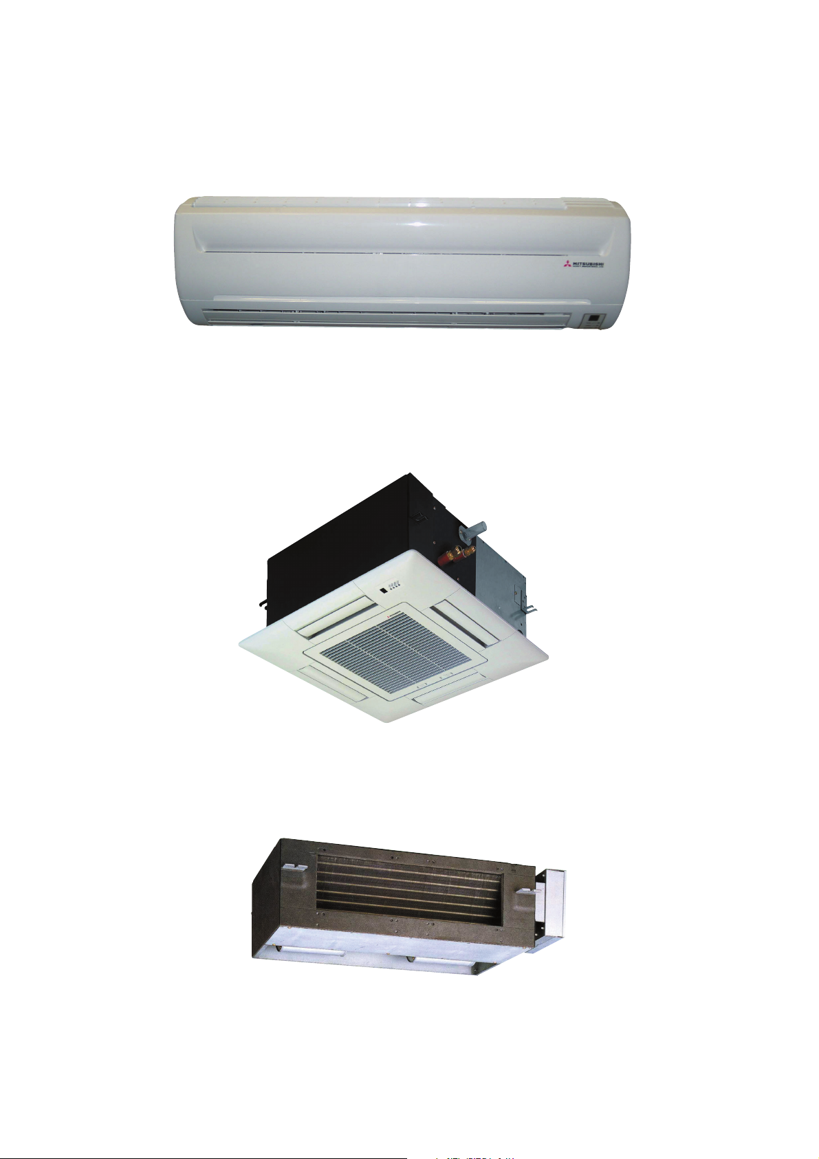
INDOOR UNIT
Models SKM22ZD-S, SKM25ZD-S, SKM28ZD-S, SKM35ZD-S,
Models SKM50ZD-S
Models STM25ZE-S, STM35ZE-S, STM50ZE-S, STM60ZE-S
Models SRRM25ZE-S, SRRM35ZE-S, SRRM50ZE-S, SRRM60ZE-S
Page 3
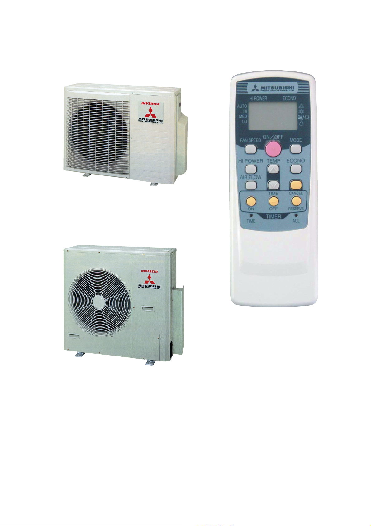
OUTDOOR UNIT
Models SCM45ZD-S, SCM60ZD-S
Model SCM80ZD-S
REMOTE CONTROLLER
Page 4

1 GENERAL INFORMATION
1.1 Specific features
(1) The long piping makes the location of the inside and units flexible.
¡ No need for additional charge of refrigerant : 45 type · 20m, 60 type · 30m, 80 type · 40m
¡ Maximum piping length : 45 type · 30m, 60 type · 40m, 80 type · 60m
(2) Connectable indoor capacity
Number of connectable units : 45 type · 2 units, 60 type · 3 units, 80 type · 4 units
Total of indoor units (class kW) : 45 type · 7.0kw, 60 type · 10.6kw, 80 type · 13.4kw
(3) Indoor units are available with 5 capacities.
5 capacities................ 22, 25, 28, 35, 50, 60
Types ......................... Wall mounted type (SKM).
4-way ceiling cassette type (STM).
Ducted type (SRRM).
(4) Inverter (Frequency converter) for multi-steps power control
¡ Heating / Cooling
The rotational speed of a compressor is changed in step in relation to varying load, to interlock with the indoor and outdoor unit
fans controlled to changes in frequency, thus controlling the power.
¡ Allowing quick heating/cooling operation during start-up period. Constant room temperature by fine-tuned control after the
unit has stabilized.
(5) Fuzzy control
Fuzzy control calculates the amount of variation in the difference between the suction air temperature and the setting temperature
in compliance with the fuzzy rules in order to control the air capacity and the inverter frequency.
(6) Self diagnosis function
We are constantly trying to do better service to our customers by installing such judges that show abnormality of operation as
follows.
1.2 How to read the model name
Example : ST M 25 Z D - S
R410A models
Series No.
Inverter and Heat pump type
Product capacity
Multiple system
Model name
-
1
SK : Wall mounted type
ST : 4 way ceiling cassette type
SRR : Ducted type
SC : Outdoor unit
-
Page 5
2 SELECTION DATA
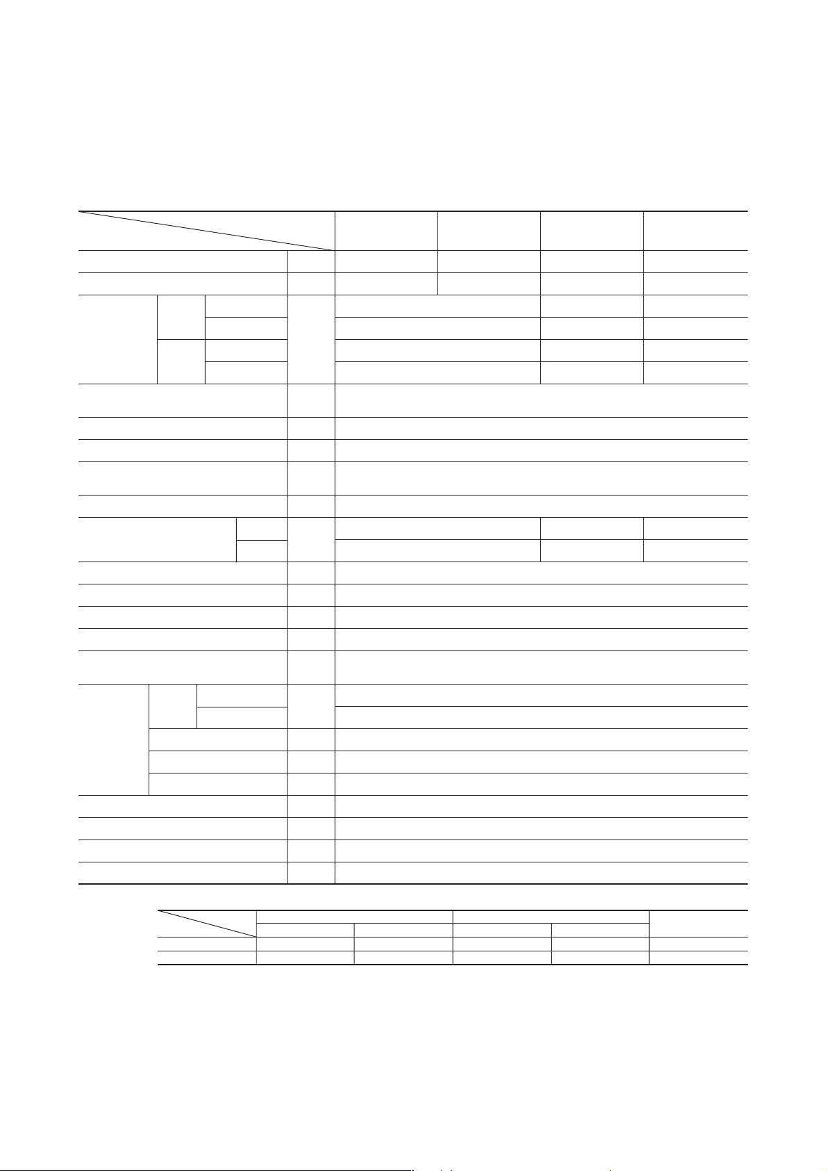
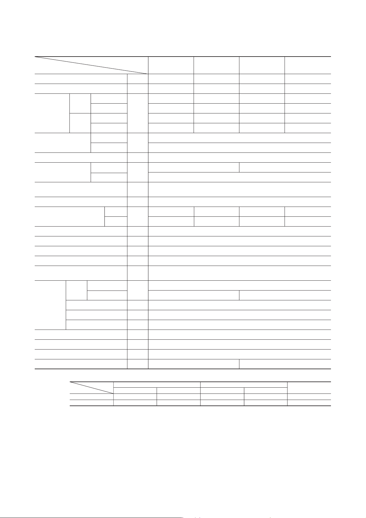
2.1 Specifications
(1) Indoor unit
Models SKM22ZD-S, 25ZD-S, 28ZD-S, 35ZD-S
Models
Item
Cooling capacity W 2200 2500 2800 3500
Heating capacity W 3200 3400 4000 4500
Cooling
Noise level
Exterior dimensions
Height × Width × Depth
Color Cool white
Net weight kg 9.0
Air handling equipment
Fan type & Q’ty
Motor W 16
Air flow (at high)
Air filter, Q’ty
Operation switch Wireless-Remote controller
Room temperature control M.C thermostat
Pilot lamp RUN (Green), TIMER (Yellow), HI POWER (Green), ECONO (Orange)
Safety equipment
Refrigerant
piping
Drain hose Connectable
Accessories (including)
Optional parts —
Outdoor units to be combined SCM45ZD-S, SCM60ZD-S, SCM80ZD-S
Heating
O.D mm (in)
Connecting method Flare connecting
Attached length of piping Liquid line : 0.4m Gas line : 0.33m
Insulation Necessary (Both Liquid & Gas lines)
Sound level
Power level
Sound level
Power level
Cooling 8.0 8.2 8.4
Heating
Liquid line
Gas line
dB
mm 250 × 815 × 249
CMM
SKM22ZD-S SKM25ZD-S SKM28ZD-S SKM35ZD-S
Hi : 37 Me : 30 Lo : 23
Hi : 53 Hi : 54 Hi : 55
Hi : 39 Me : 33 Lo : 27
Hi : 55 Hi : 56 Hi : 57
8.7 9.0 9.2
Polypropylene net × 2 (Washable)
Frost protection, Serial error protection
Fan motor error protection
Mounting kit, Clean filter (Natural enzyme filter × 1, Photocatalytic washable deodorizing filter × 1)
Hi : 38 Me : 31 Lo : 24 Hi : 39 Me : 32 Lo : 25
Hi : 40 Me : 34 Lo : 28 Hi : 41 Me : 35 Lo : 29
Tangential fan × 1
φ 6.35 (1/4″)
φ 9.52 (3/8″)
Notes (1) The data are measured at the following conditions.
Operation DB WB DB WB
Cooling 27ºC 19ºC 35ºC 24ºC ISO-T1, JIS C9612
Heating 20ºC – 7ºC 6ºC ISO-T1, JIS C9612
(2) Capacity indicated is the rated capacity with one unit operating under ISO-T1 standards conditions.
Item Indoor air temperature Outdoor air temperature
-
-
2
Standards
Page 6
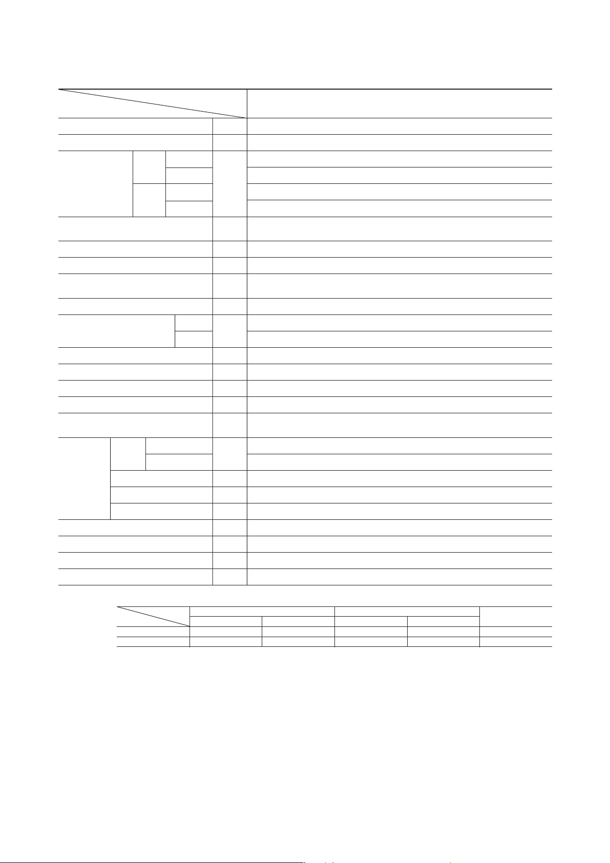
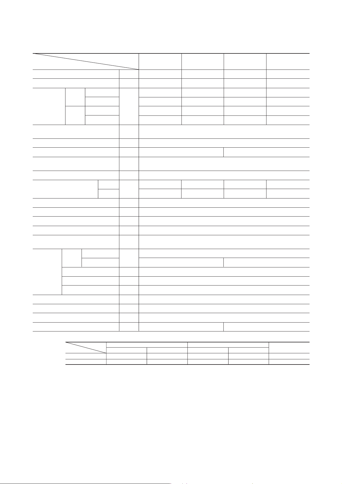
Model SKM50ZD-S
Models
Item
Cooling capacity W 5000
Heating capacity W 5800
Noise level
Noise level
Exterior dimensions
Height × Width × Depth
Color Cool white
Net weight kg 9.5
Air handling equipment
Fan type & Q’ty
Motor W 29
Air flow (at high)
Air filter, Q’ty Polypropylene net × 2 (Washable)
Operation switch Wireless-Remote controller
Room temperature control M.C thermostat
Pilot lamp RUN (Green), TIMER (Yellow), HI POWER (Green), ECONO (Orange)
Safety equipment
Refrigerant
piping
Drain hose Connectable
Accessories (including)
Optional parts —
Outdoor units to be combined SCM60ZD-S, SCM80ZD-S
Power level Hi : 62
Power level Hi : 63
O.D mm (in)
Connecting method Flare connecting
Attached length of piping Liquid line : 0.4m Gas line : 0.33m
Insulation Necessary (Both Liquid & Gas lines)
Sound level
Cooling
Sound level Hi : 48 Me : 37 Lo : 27
Heating
Cooling 11
Heating
Liquid line
Gas line
dB
mm 250 × 815 × 249
CMM
Frost protection, Serial error protection
Fan moter error protection
Mounting kit, Clean filter (Natural enzyme filter × 1, Photocatalytic washable deodorizing filter × 1)
SKM50ZD-S
Hi : 47 Me : 36 Lo : 23
Tangential fan × 1
13.9
φ 6.35 (1/4″)
φ 12.7 (1/2″)
Notes (1) The data are measured at the following conditions.
Operation DB WB DB WB
Cooling 27ºC 19ºC 35ºC 24ºC ISO-T1, JIS C9612
Heating 20ºC – 7ºC 6ºC ISO-T1, JIS C9612
(2) Capacity indicated is the rated capacity with one unit operating under ISO-T1 standards conditions.
Item Indoor air temperature Outdoor air temperature
-
-
3
Standards
Page 7
Models STM25ZE-S, 35ZE-S, 50ZE-S, 60ZE-S
Models
Item
Cooling capacity W 2500 3500 5000 6000
Heating capacity W 3400 4500 5800 6800
Cooling
Noise level
Exterior dimensions
Height × Width × Depth
Color
Net weight
Air handling equipment
Fan type & Q’ty
Motor W
Air flow (at high)
Air filter, Q’ty
Operation switch Wireless-Remote controller
Room temperature control M.C thermostat
Pilot lamp RUN (Green), TIMER (Yellow), HI POWER (Green), ECONO (Orange)
Safety equipment
Refrigerant
piping
Drain hose Connectable
Accessories (including) Mounting kit
Optional parts Wired remote controller
Outdoor units to be combined SCM45ZD-S, SCM60ZD-S, SCM80ZD-S SCM60ZD-S, SCM80ZD-S
Heating
O.D mm (in)
Connecting method Flare connecting
Attached length of piping —
Insulation Necessary (Both Liquid & Gas lines)
Sound level
Power level
Sound level
Power level
Main unit 248 × 570 × 570
Panel
Main unit
Panel 3.5
Cooling 7.7 8.5 9.4 13.0
Heating
Liquid line
Gas line
dB
mm
kg
CMM
STM25ZE-S STM35ZE-S STM50ZE-S STM60ZE-S
35 38 40 47
35 38 40 47
35 × 700 × 700
–
14 14.5
Turbo fan × 1
9.5 10.0 11.0 14.0
Long life filter
Frost protection, Serial error protection
Fan motor error protection, Drain error protection
φ 9.52 (3/8″) φ 12.7 (1/2″)
× 1
(Washable)
φ 6.35 (1/4″)
Notes (1) The data are measured at the following conditions.
Operation DB WB DB WB
Cooling 27ºC 19ºC 35ºC 24ºC ISO-T1, JIS C9612
Heating 20ºC – 7ºC 6ºC ISO-T1, JIS C9612
(2) Capacity indicated is the rated capacity with one unit operating under ISO-T1 standards conditions.
Item Indoor air temperature Outdoor air temperature
-
-
4
Standards
Page 8
Models SRRM25ZE-S, 35ZE-S, 50ZE-S, 60ZE-S
Models
Item
Cooling capacity W 2500 3500 5000 6000
Heating capacity W 3400 4500 5800 6800
Cooling
Noise level
Exterior dimensions
Height × Width × Depth
Color —
Net weight kg 22.0 23.0
Air handling equipment
Fan type & Q’ty
Motor W
Air flow (at high)
Air filter, Q’ty
Operation switch Wireless-Remote controller
Room temperature control M.C thermostat
Pilot lamp RUN (Green), TIMER (Yellow), HI POWER (Green), ECONO (Orange)
Safety equipment
Refrigerant
piping
Drain hose Connectable
Accessories (including) Mounting kit
Optional parts Wired remote controller
Outdoor units to be combined SCM45ZD-S, SCM60ZD-S, SCM80ZD-S SCM60ZD-S, SCM80ZD-S
Heating
O.D mm (in)
Connecting method Flare connecting
Attached length of piping
Insulation Necessary (Both Liquid & Gas lines)
Sound level
Power level
Sound level
Power level
Cooling 7.6 7.8 9.6 11.4
Heating
Liquid line
Gas line
dB
mm 230 × 740 × 455
CMM
SRRM25ZE-S SRRM35ZE-S SRRM50ZE-S SRRM60ZE-S
38 40 46 49
39 41 46 49
Centrifugal fan × 2
9.9 10.7 13.2 15.2
PVC net
×
1
Frost protection, Serial error protection
Fan motor error protection, Drain error protection
φ 6.35 (1/4″)
φ 9.52 (3/8″) φ 12.7 (1/2″)
–
Notes (1) The data are measured at the following conditions.
Operation DB WB DB WB
Cooling 27ºC 19ºC 35ºC 24ºC ISO-T1, JIS C9612
Heating 20ºC – 7ºC 6ºC ISO-T1, JIS C9612
(2) Capacity indicated is the rated capacity with one unit operating under ISO-T1 standards conditions.
Item Indoor air temperature Outdoor air temperature
-
-
5
Standards
Page 9
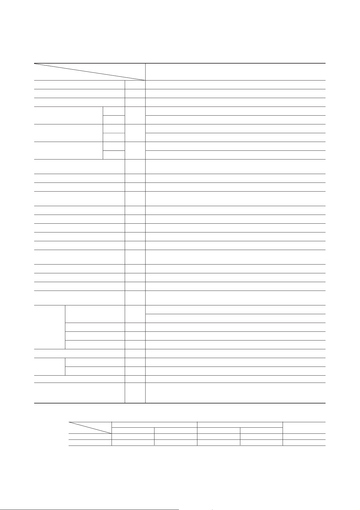
(2) Outdoor unit
Model SCM45ZD-S
Model
Item
Cooling capacity W 4500 (700 ~ 5600)
Heating capacity W 5600 (700 ~ 6800)
Power source 1 Phase 220/230/240V 50Hz
Power consumption
Running current
Noise level
Exterior dimensions
Height × Width × Depth
Color Stucco white
Net weight kg 44
Refrigerant equipment
Compressor type & Q’ty
Motor kW 0.7
Starting method Direct start
Refrigerant control Capillary tubes + Electric expansion valve
Refrigerant kg R410A 1.6 (Pre-charged up to the piping length of 20m)
Refrigerant oil R 0.48 (RB68A)
Air handling equipment
Fan type & Q’ty
Motor W 35
Air flow (at high) CMM 40
Shock & vibration absorber Rubber (for compressor)
Safety equipment
Size × Core × Number mm (in)
Refrigerant
piping
Power source supply Terminal block (Screw fixing type)
Connection wiring
Accessories (included) Installation sheet, Manual instruction
Indoor units to be combined STM25, 35 type,
Connecting method Flare connecting
Attached length piping —
Insulation Necessary (Both Liquid & Gas lines)
Size × Core number 1.5 mm2 × 4 cores (Including earth cable) × 2
Connecting method Terminal block (Screw fixing type)
Cooling
Heating 1540 (200 ~ 2340)
Cooling 6.4/6.1/5.9
Heating
Sound level
Power level
W
A
dB
mm 640 × 850 × 290
Cooling : 45/45/47 Heating : 47/47/49
Cooling : 60/60/62 Heating : 62/62/64
Compressor overheat protection, Overcurrent protection
Serial signal error protection
SCM45ZD-S
1390 (200 ~ 2160)
7.1/6.8/6.5
5CS102XFD [Scroll] × 1
Propeller fan × 1
Liquid line: φ 6.35 (1/4″) × 2
Gas line: φ 9.52 (3/8″) × 2
SKM22, 25, 28, 35 type,
SRRM25, 35 type
Notes (1) The data are measured at the following conditions.
Operation DB WB DB WB
Cooling 27ºC 19ºC 35ºC 24ºC ISO-T1, JIS C9612
Heating 20ºC – 7ºC 6ºC ISO-T1, JIS C9612
(2) The values for capacity and power consumption shown in a range ( ) indicate the minimum and maximum of the range.
(3) If the piping length exceeds 20 m, additional charging is required. (20g/m)
Item Indoor air temperature Outdoor air temperature
-
-
6
Standards
Page 10
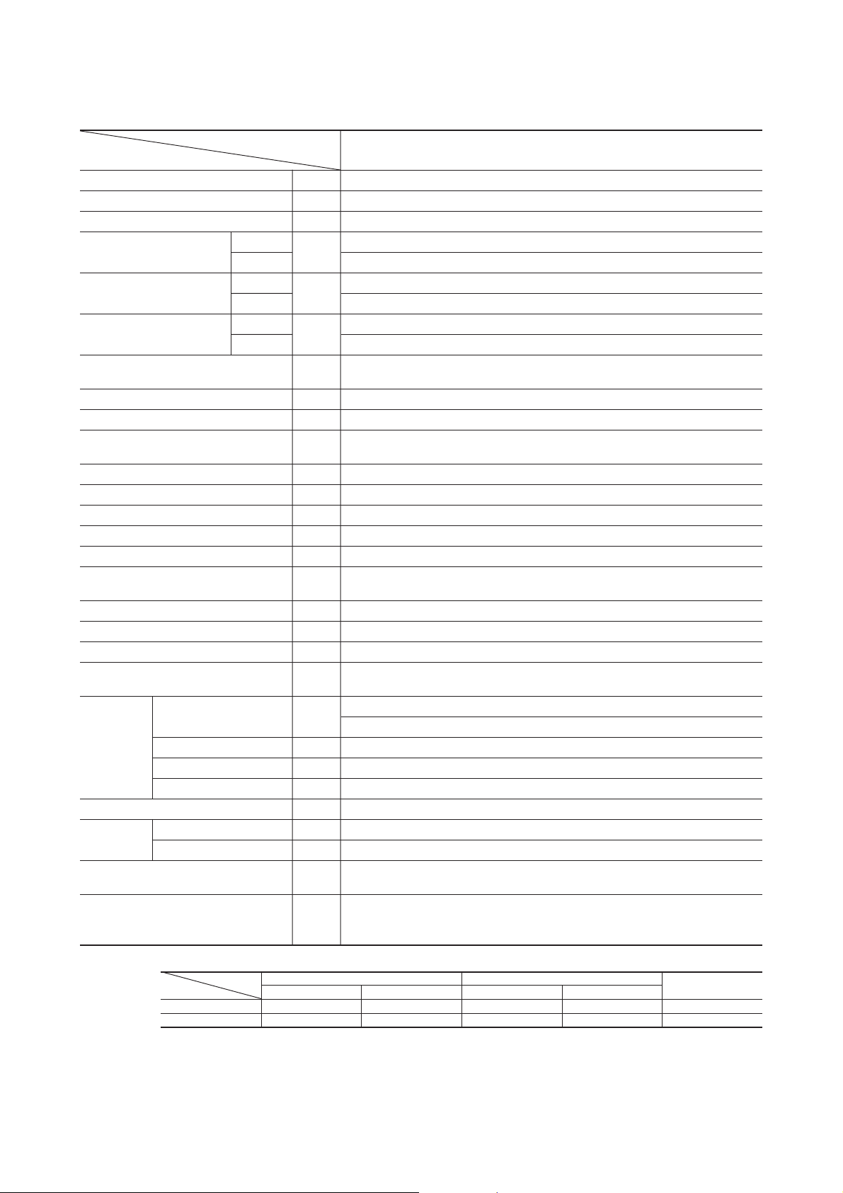
Model SCM60ZD-S
Model
Item
Cooling capacity W 6000 (1400~6900)
Heating capacity W 7000 (750~7200)
Power source 1 Phase 220/230/240V 50Hz
Power consumption
Running current
Noise level
Exterior dimensions
Height × Width × Depth
Color Stucco white
Net weight kg 51
Refrigerant equipment
Compressor type & Q’ty
Motor kW 1.3
Starting method Direct start
Refrigerant control Capillary tubes + Electronic expansion valve
Refrigerant kg R410A 2.2 (Pre-charged up to the piping length of 30m)
Refrigerant oil R 0.67 (MEL56)
Air handling equipment
Fan type & Q’ty
Motor W 45
Air flow (at high) CMM 42
Shock & vibration absorber Rubber (for compressor)
Safety equipment
Refrigerant
piping
Power source supply Terminal block (Screw fixing type)
Connection
wiring
Accessories (included)
Indoor units to be combined STM25, 35, 50, 60 type
Cooling
Heating 1740 (320~2700)
Cooling 8.5/8.2/7.8
Heating
Sound level Cooling : 48/48/50 Heating : 50/50/52
Power level
Size × Core × Number mm (in)
Connecting method Flare connecting
Attached length piping —
Insulation Necessary (Both Liquid & Gas lines)
Size × Core number 1.5 mm2 × 4 cores (Including earth cable) × 3
Connecting method Terminal block (Screw fixing type)
W
A
dB
mm
Cooling : 63/63/65 Heating : 65/65/67
TNB220FLBM1 [Twin rotary type] × 1
Compressor overheat protection, Overcurrent protection
Serial signal error protection
Installation sheet, Manual instruction
SCM60ZD-S
1860 (400~3000)
8.0/7.6/7.3
640 × 850 × 290
Propeller fan × 1
Liquid line: φ 6.35 (1/4″) × 3
Gas line: φ 9.52 (3/8″) × 3
Union : (φ 9.52 / φ 12.7) × 2
SKM22, 25, 28, 35, 50 type
SRRM25, 35, 50, 60 type
Notes (1) The data are measured at the following conditions.
Operation DB WB DB WB
Cooling 27ºC 19ºC 35ºC 24ºC ISO-T1, JIS C9612
Heating 20ºC – 7ºC 6ºC ISO-T1, JIS C9612
(2) The values for capacity and power consumption shown in a range ( ) indicate the minimum and maximum of the range.
(3) If the piping length exceeds 30 m, additional charging is required. (20g/m)
Item Indoor air temperature Outdoor air temperature
-
-
7
Standards
Page 11
Model SCM80ZD-S
Model
Item
Cooling capacity W 8000 (1000~9300)
Heating capacity W 9500 (850~9700)
Power source 1 Phase 220/230/240V 50Hz
Power consumption
Running current
Noise level
Exterior dimensions
Height × Width × Depth
Color Polar white
Net weight kg 66
Refrigerant equipment
Compressor type & Q’ty
Motor kW 1.3
Starting method Direct start
Refrigerant control Capillary tubes + Electronic expansion valve
Refrigerant kg R410A 3.05 (Pre-charged up to the piping length of 40m)
Refrigerant oil R 0.67 (MEL56)
Air handling equipment
Fan type & Q’ty
Motor W 55
Air flow (at high) CMM 56
Shock & vibration absorber Rubber (for compressor)
Safety equipment
Size × Core × Number mm (in)
Refrigerant
piping
Power source supply Terminal block (Screw fixing type)
Connection
wiring
Accessories (included)
Indoor units to be combined STM25, 35, 50, 60 type
Connecting method Flare connecting
Attached length piping —
Insulation Necessary (Both Liquid & Gas lines)
Size × Core number 1.5 mm2 × 4 cores (Including earth cable) × 4
Connecting method Terminal block (Screw fixing type)
Cooling
Heating 2440 (300~3200)
Cooling 12.2/11.6/11.2
Heating
Sound level
Power level
W
A
dB
mm
Cooling : 51/51/52 Heating : 52/52/53
Cooling : 65/65/66 Heating : 66/66/67
TNB220FLBM1 [Twin rotary type] × 1
Compressor overheat protection, Overcurrent protection
Serial signal error protection
Installation sheet, Manual instruction
SCM80ZD-S
2650 (350~3200)
11.2/10.7/10.3
845 × 880 × 340
Propeller fan × 1
Liquid line: φ 6.35 (1/4″) × 4
Gas line: φ 9.52 (3/8″) × 4
Union : (φ 9.52 / φ 12.7) × 2
SKM22, 25, 28, 35, 50 type
SRRM25, 35, 50, 60 type
Notes (1) The data are measured at the following conditions.
Operation DB WB DB WB
Cooling 27ºC 19ºC 35ºC 24ºC ISO-T1, JIS C9612
Heating 20ºC – 7ºC 6ºC ISO-T1, JIS C9612
(2) The values for capacity and power consumption shown in a range ( ) indicate the minimum and maximum of the range.
(3) If the piping length exceeds 40 m, additional charging is required. (20g/m)
Item Indoor air temperature Outdoor air temperature
-
-
8
Standards
Page 12
(3) Operation data
¡ The combinations of the indoor units is indicated by numbers. They are read as follows.
(Example) SKM22ZD-S / 22 SKM35ZD-S / 35
¡ The capacity of the indoor units is shown by rooms. If this exceeds the maximum capacity of the outdoor unit, the demand
capacity will be proportionally distributed.
¡ If units are to be combined, use the table below to make the proper selection.
Model SCM45ZD-S
(a) Heating
(220/230/240V)
Indoor unit
combination
1
room
2
room
22
25
28
35
22+22
22+25
22+28
22+35
25+25
25+28
25+35
Heating capacity (kW) Power consumption (W)
Room heating capacity (kW) Total capacity (kW)
A room
3.2
3.4
4.0
4.5
2.65
2.5
2.4
2.2
2.75
2.6
2.4
B room Min.
2.65
2.9
3.1
3.4
2.75
2.9
3.3
0.7
0.7
0.7
0.7
1.5
1.5
1.5
1.5
1.5
1.5
1.5
Standard
3.2
3.4
4.0
4.5
5.3
5.4
5.5
5.6
5.5
5.5
5.7
Max.
3.9
4.1
4.3
4.7
7.4
7.4
7.4
7.4
7.4
7.4
7.4
Min.
200
200
200
200
450
450
450
450
450
450
450
Standard
1120
1190
1400
1590
1430
1460
1490
1540
1490
1490
1570
1380
1450
1520
1660
2540
2540
2540
2540
2540
2540
2540
Running
current (A)
StandardMax.
5.1/4.9/4.7
5.5/5.2/5.0
6.4/6.1/5.9
7.3/7.0/6.7
6.6/6.3/6.0
6.7/6.4/6.1
6.8/6.5/6.3
7.1/6.8/6.5
6.8/6.5/6.3
6.8/6.5/6.3
7.2/6.9/6.6
28+28
28+35
35+35
2.8
2.6
2.95
2.8
3.2
2.95
1.5
1.5
1.5
5.6
5.8
5.9
-
-
9
7.4
7.4
7.4
450
450
450
1540
1600
1630
2540
2540
2540
7.1/6.8/6.5
7.3/7.0/6.7
7.5/7.2/6.9
Page 13

(b) Cooling
(220/230/240V)
Indoor unit
combination
1
room
2
room
22
25
28
35
22+22
22+25
22+28
22+35
25+25
25+28
25+35
Cooling capacity (kW) Power consumption (W)
Room cooling capacity (kW) Total capacity (kW)
A room
2.2
2.5
2.8
3.5
2.15
2.0
1.9
1.7
2.2
2.1
1.9
B room Min.
0.7
0.7
0.7
0.7
2.15
2.3
2.6
2.8
2.2
2.3
2.6
1.4
1.4
1.4
1.4
1.4
1.4
1.4
Standard
2.2
2.5
2.8
3.5
4.3
4.3
4.4
4.5
4.4
4.4
4.5
Max.
2.6
2.7
3.0
3.6
5.0
5.1
5.2
5.6
5.2
5.3
5.6
Min.
200
200
200
200
420
420
420
420
420
420
420
Standard
680
760
880
1200
1330
1330
1360
1390
1360
1360
1390
810
840
950
1250
1780
1800
1820
2160
1820
1850
2160
Running
current (A)
StandardMax.
3.1/3.0/2.9
3.5/3.3/3.2
4.0/3.9/3.7
5.5/5.3/5.1
6.1/5.8/5.6
6.1/5.8/5.6
6.2/6.0/5.7
6.4/6.1/5.9
6.2/6.0/5.7
6.2/6.0/5.7
6.4/6.1/5.9
28+28
28+35
35+35
2.25
2.0
2.3
2.25
2.6
2.3
1.4
1.4
1.4
4.5
4.6
4.6
5.5
5.6
5.6
420
420
420
1390
1430
1430
2120
2160
2160
6.4/6.1/5.9
6.6/6.3/6.0
6.6/6.3/6.0
-
10
-
Page 14

Model SCM60ZD-S
(a) Heating
1
room
2
room
3
room
Indoor unit
combination
22
25
28
35
50
60
22+22
22+25
22+28
22+35
22+50
22+60
25+25
25+28
25+35
25+50
25+60
28+28
28+35
28+50
28+60
35+35
35+50
35+60
50+50
22+22+22
22+22+25
22+22+28
22+22+35
22+22+50
22+22+60
22+25+25
22+25+28
22+25+35
22+25+50
22+28+28
22+28+35
22+28+50
22+35+35
25+25+25
25+25+28
25+25+35
25+25+50
25+28+28
25+28+35
25+28+50
25+35+35
28+28+28
28+28+35
28+28+50
28+35+35
35+35+35
Heating capacity (kW) Power consumption (W)
Room heating capacity (kW) Total capacity (kW)
0.75
0.75
0.75
0.75
0.75
1.1
1.1
1.1
1.1
1.2
1.1
1.1
1.1
1.2
1.1
1.1
1.2
1.1
1.2
1.5
1.7
1.7
1.7
1.7
1.9
1.7
1.7
1.7
1.9
1.7
1.7
1.9
1.7
1.7
1.7
1.7
1.9
1.7
1.7
1.9
1.7
1.7
1.7
1.9
1.7
1.7
Standard
3.2
3.4
4.0
4.5
5.8
6.8
5.1
5.3
5.8
6.1
6.6
5.5
5.9
6.3
6.7
6.4
6.7
6.7
6.7
6.7
6.7
6.7
6.9
7.0
7.0
7.0
7.0
7.0
7.0
7.1
7.0
7.1
7.1
7.1
7.0
7.0
7.0
7.1
7.1
7.1
7.1
7.1
7.1
7.1
7.1
7.1
7.1
A room B room C room Min.
3.2
3.4
4.0
4.5
5.8
6.8
2.55
2.48
2.55
2.35
2.02
2.75
2.78
2.63
2.23
3.20
2.98
2.41
3.35
2.76
3.35
2.23
2.20
2.14
1.95
1.64
2.14
2.05
1.88
1.61
1.97
1.84
1.56
1.70
2.33
2.24
2.06
1.78
2.19
2.02
1.72
1.87
2.37
2.18
1.88
2.03
2.37
-
-
-
-
-
-
2.55
2.82
3.25
3.75
4.58
2.75
3.12
3.68
4.47
3.20
3.72
4.29
3.35
3.94
3.35
2.23
2.20
2.14
1.95
1.64
2.43
2.33
2.13
1.83
2.51
2.34
1.99
2.70
2.33
2.24
2.06
1.78
2.45
2.26
1.93
2.62
2.37
2.18
1.88
2.54
2.37
-
-
-
-
-
-
-
-
-
-
-
-
-
-
-
-
-
-
-
-
-
2.23
2.50
2.72
3.10
3.72
2.43
2.61
2.99
3.66
2.51
2.92
3.55
2.70
2.33
2.51
2.88
3.55
2.45
2.82
3.45
2.62
2.37
2.73
3.35
2.54
2.37
Max.
3.4
3.6
4.2
4.6
6.2
6.5
6.5
6.5
6.6
6.8
6.5
6.5
6.6
6.8
6.6
6.7
6.8
6.7
6.8
6.8
7.2
7.2
7.2
7.2
7.2
7.2
7.2
7.2
7.2
7.2
7.2
7.2
7.2
7.2
7.2
7.2
7.2
7.2
7.2
7.2
7.2
7.2
7.2
7.2
7.2
7.2
Min.
320
320
320
320
320
330
330
330
330
360
330
330
330
360
330
330
360
330
360
420
440
440
440
440
500
440
440
440
500
440
440
500
440
440
440
440
500
440
440
500
440
440
440
500
440
440
Standard
1100
1200
1450
1750
2100
1450
1500
1700
1900
2150
1600
1800
2000
2250
2050
2200
2400
2350
2550
2600
1650
1750
1800
1850
1740
1750
1850
1950
2100
1950
2050
2200
2150
1800
1900
2000
2150
2000
2100
2250
2200
2150
2200
2350
2300
2400
Standard current (A)
Max. 220V 230V 240V
1200
1300
1550
1800
2400
2350
2350
2400
2500
2700
2350
2400
2500
2700
2450
2550
2700
2600
2700
2700
2700
2700
2700
2700
2700
2700
2700
2700
2700
2700
2700
2700
2700
2700
2700
2700
2700
2700
2700
2700
2700
2700
2700
2700
2700
2700
5.1
5.5
6.7
8.0
9.6
6.7
6.9
7.8
8.7
9.9
7.3
8.3
9.2
10.3
9.4
10.1
11.0
10.8
11.7
11.9
7.6
8.0
8.3
8.5
8.0
8.0
8.5
9.0
9.6
9.0
9.4
10.1
9.9
8.3
8.7
9.2
9.9
9.2
9.6
10.3
10.1
9.9
10.1
10.8
10.6
11.0
4.8
5.3
6.4
7.7
9.2
6.4
6.6
7.5
8.3
9.4
7.0
7.9
8.8
9.9
9.0
9.7
10.5
10.3
11.2
11.4
7.2
7.7
7.9
8.1
7.6
7.7
8.1
8.6
9.2
8.6
9.0
9.7
9.4
7.9
8.3
8.8
9.4
8.8
9.2
9.9
9.7
9.4
9.7
10.3
10.1
10.5
4.6
5.1
6.1
7.4
8.8
6.1
6.3
7.2
8.0
9.0
6.7
7.6
8.4
9.5
8.6
9.3
10.1
9.9
10.7
10.9
6.9
7.4
7.6
7.8
7.3
7.4
7.8
8.2
8.8
8.2
8.6
9.3
9.0
7.6
8.0
8.4
9.0
8.4
8.8
9.5
9.3
9.0
9.3
9.9
9.7
10.1
-
11
-
Page 15

(b) Cooling
1
room
2
room
3
room
Indoor unit
combination
22
25
28
35
50
60
22+22
22+25
22+28
22+35
22+50
22+60
25+25
25+28
25+35
25+50
25+60
28+28
28+35
28+50
28+60
35+35
35+50
35+60
50+50
22+22+22
22+22+25
22+22+28
22+22+35
22+22+50
22+22+60
22+25+25
22+25+28
22+25+35
22+25+50
22+28+28
22+28+35
22+28+50
22+35+35
25+25+25
25+25+28
25+25+35
25+25+50
25+28+28
25+28+35
25+28+50
25+35+35
28+28+28
28+28+35
28+28+50
28+35+35
35+35+35
Cooling capacity (kW) Power consumption (W)
Room cooling capacity (kW) Total capacity (kW)
1.4
1.4
1.4
1.4
1.4
1.5
1.5
1.5
1.5
1.6
1.5
1.5
1.5
1.6
1.5
1.5
1.6
1.5
1.6
1.9
1.9
1.9
1.9
1.9
2.1
1.9
1.9
1.9
2.1
1.9
1.9
2.1
1.9
1.9
1.9
1.9
2.1
1.9
1.9
2.1
1.9
1.9
1.9
2.1
1.9
1.9
Standard
2.2
2.5
2.8
3.5
5.0
6.0
4.4
4.7
5.0
5.3
6.1
5.0
5.3
5.8
6.3
5.6
6.1
6.6
6.6
6.6
6.6
5.1
5.2
5.2
5.4
6.0
5.2
5.3
5.5
5.9
5.4
5.6
6.0
5.8
5.3
5.4
5.6
6.0
5.5
5.7
6.1
5.9
5.6
5.8
6.2
5.9
6.2
A room B room C room Min.
2.2
2.5
2.8
3.5
5.0
6.0
2.20
2.20
2.20
2.05
1.86
2.50
2.50
2.42
2.10
2.80
2.71
2.37
3.30
2.72
3.30
1.70
1.66
1.59
1.50
1.40
1.59
1.55
1.48
1.34
1.52
1.45
1.32
1.39
1.77
1.73
1.65
1.50
1.70
1.62
1.48
1.55
1.87
1.78
1.64
1.69
2.07
-
-
-
-
-
-
2.20
2.50
2.80
3.25
4.24
2.50
2.80
3.38
4.20
2.80
3.39
4.23
3.30
3.88
3.30
1.70
1.66
1.59
1.50
1.40
1.81
1.77
1.68
1.52
1.94
1.84
1.68
2.21
1.77
1.73
1.65
1.50
1.90
1.81
1.66
2.17
1.87
1.78
1.64
2.11
2.07
-
-
-
-
-
-
-
-
-
-
-
-
-
-
-
-
-
-
-
-
-
1.70
1.88
2.02
2.39
3.19
1.81
1.98
2.35
3.04
1.94
2.31
3.00
2.21
1.77
1.94
2.31
3.00
1.90
2.27
2.96
2.17
1.87
2.23
2.92
2.11
2.07
Max.
2.3
2.6
3.0
3.6
5.1
4.6
4.9
5.2
5.4
6.4
5.2
5.4
5.9
6.5
5.7
6.2
6.6
6.6
6.6
6.6
6.8
6.8
6.9
6.9
6.9
6.9
6.9
6.9
6.9
6.9
6.9
6.9
6.9
6.9
6.9
6.9
6.9
6.9
6.9
6.9
6.9
6.9
6.9
6.9
6.9
6.9
Min.
400
400
400
400
400
410
410
410
410
440
410
410
410
440
410
410
440
410
440
500
620
620
620
620
680
620
620
620
680
620
620
680
620
620
620
620
680
620
620
680
620
620
620
680
620
620
Standard
720
800
950
1300
2200
1450
1600
1720
2100
2550
1720
1850
2200
2720
2000
2420
2880
2880
2880
2880
1470
1500
1500
1600
1860
1500
1550
1620
1800
1600
1650
1860
1750
1550
1600
1650
1860
1620
1700
2000
1800
1650
1750
2100
1800
2100
Standard current (A)
Max. 220V 230V 240V
750
830
1050
1350
2250
1650
1750
1900
2150
2750
1900
1950
2300
2850
2100
2500
2880
2880
2880
2880
2950
2950
3000
3000
3000
3000
3000
3000
3000
3000
3000
3000
3000
3000
3000
3000
3000
3000
3000
3000
3000
3000
3000
3000
3000
3000
3.3
3.7
4.4
6.0
10.1
6.7
7.3
7.9
9.6
11.7
7.9
8.5
10.1
12.5
9.2
11.1
13.2
13.2
13.2
13.2
6.7
6.9
6.9
7.3
8.5
6.9
7.1
7.4
8.3
7.3
7.6
8.5
8.0
7.1
7.3
7.6
8.5
7.4
7.8
9.2
8.3
7.6
8.0
9.6
8.3
9.6
3.2
3.5
4.2
5.7
9.7
6.4
7.0
7.6
9.2
11.2
7.6
8.1
9.7
11.9
8.8
10.6
12.6
12.6
12.6
12.6
6.5
6.6
6.6
7.0
8.2
6.6
6.8
7.1
7.9
7.0
7.2
8.2
7.7
6.8
7.0
7.2
8.2
7.1
7.5
8.8
7.9
7.2
7.7
9.2
7.9
9.2
3.0
3.4
4.0
5.5
9.3
6.1
6.7
7.2
8.8
10.7
7.2
7.8
9.3
11.4
8.4
10.2
12.1
12.1
12.1
12.1
6.2
6.3
6.3
6.7
7.8
6.3
6.5
6.8
7.6
6.7
6.9
7.8
7.4
6.5
6.7
6.9
7.8
6.8
7.2
8.4
7.6
6.9
7.4
8.8
7.6
8.8
-
12
-
Page 16

Model SCM80ZD-S
(a) Heating
1
room
2
room
3
room
Indoor unit
combination
22
25
28
35
50
60
22+22
22+25
22+28
22+35
22+50
22+60
25+25
25+28
25+35
25+50
25+60
28+28
28+35
28+50
28+60
35+35
35+50
35+60
50+50
50+60
22+22+22
22+22+25
22+22+28
22+22+35
22+22+50
22+22+60
22+25+25
22+25+28
22+25+35
22+25+50
22+25+60
22+28+28
22+28+35
22+28+50
22+28+60
22+35+35
22+35+50
22+35+60
22+50+50
22+50+60
25+25+25
25+25+28
25+25+35
25+25+50
25+25+60
25+28+28
25+28+35
25+28+50
25+28+60
25+35+35
Heating capacity (kW) Power consumption (W)
Room heating capacity (kW) Total capacity (kW)
A room
3.2
3.4
4.0
4.5
5.8
6.8
2.90
2.81
2.86
2.66
2.35
3.10
3.16
2.96
2.63
3.60
3.38
2.87
4.00
3.29
4.00
2.70
2.61
2.66
2.45
2.06
2.54
2.58
2.36
2.00
2.48
2.28
1.94
2.10
1.81
1.59
2.80
2.82
2.59
2.20
2.72
2.50
2.14
2.32
B room C room D room Min.
-
-
-
-
-
-
2.90
3.19
3.64
4.24
5.35
3.10
3.54
4.14
5.27
3.60
4.22
5.13
4.00
4.71
4.00
2.70
2.61
2.66
2.45
2.06
2.88
2.93
2.68
2.27
3.16
2.90
2.46
3.35
2.88
3.61
2.80
2.82
2.59
2.20
3.04
2.80
2.39
3.24
-
-
-
-
-
-
-
-
-
-
-
-
-
-
-
-
-
-
-
-
-
-
-
-
-
-
2.70
2.97
3.38
3.90
4.68
2.88
3.29
3.76
4.54
3.16
3.62
4.40
3.35
4.11
3.61
2.80
3.16
3.62
4.40
3.04
3.50
4.27
3.24
-
-
-
-
-
-
-
-
-
-
-
-
-
-
-
-
-
-
-
-
-
-
-
-
-
-
-
-
-
-
-
-
-
-
-
-
-
-
-
-
-
-
-
-
-
-
-
-
-
-
-
-
-
-
-
-
0.85
0.85
0.85
0.85
0.85
1.4
1.4
1.4
1.4
1.6
1.4
1.4
1.4
1.6
1.4
1.4
1.6
1.4
1.6
1.9
2.4
2.4
2.4
2.4
2.6
2.4
2.4
2.4
2.6
2.4
2.4
2.6
2.4
2.6
2.8
2.4
2.4
2.4
2.6
2.4
2.4
2.6
2.4
Standard
3.2
3.4
4.0
4.5
5.8
6.8
5.8
6.0
6.5
6.9
7.7
6.2
6.7
7.1
7.9
7.2
7.6
8.0
8.0
8.0
8.0
8.1
8.2
8.7
8.8
8.8
8.3
8.8
8.8
8.8
8.8
8.8
8.8
8.8
8.8
8.8
8.4
8.8
8.8
8.8
8.8
8.8
8.8
8.8
Max.
3.9
4.1
4.3
4.8
7.3
8.0
8.0
8.0
8.0
8.0
8.0
8.0
8.0
8.0
8.0
8.0
8.0
8.0
8.0
8.0
8.8
8.8
8.8
8.8
8.8
8.8
8.8
8.8
8.8
8.8
8.8
8.8
8.8
8.8
8.8
8.8
8.8
8.8
8.8
8.8
8.8
8.8
8.8
Min.
300
300
300
300
300
420
420
420
420
450
420
420
420
450
420
420
450
420
450
520
600
600
600
600
650
600
600
600
650
600
600
650
600
650
700
600
600
600
650
600
600
650
600
Standard
1180
1280
1550
1850
2200
1750
1850
2100
2300
2650
1950
2200
2350
2750
2400
2600
2950
2800
3100
3150
2250
2300
2500
3200
3200
2350
2550
2700
2950
2700
2850
3100
3000
3200
3200
2400
2600
2750
3000
2750
2900
3150
3050
Standard current (A)
Max. 220V 230V 240V
1550
1650
1750
1950
3100
3150
3150
3150
3150
3150
3150
3150
3150
3150
3150
3150
3150
3150
3150
3150
3200
3200
3200
3200
3200
3200
3200
3200
3200
3200
3200
3200
3200
3200
3200
3200
3200
3200
3200
3200
3200
3200
3200
5.4
5.9
7.1
8.5
10.1
8.0
8.5
9.6
10.6
12.2
9.0
10.1
10.8
12.6
11.0
11.9
13.5
12.9
14.2
14.5
10.3
10.6
11.5
14.7
14.7
10.8
11.7
12.4
13.5
12.4
13.1
14.2
13.8
14.7
14.7
11.0
11.9
12.6
13.8
12.6
13.3
14.5
14.0
5.2
5.6
6.8
8.1
9.7
7.7
8.1
9.2
10.1
11.6
8.6
9.7
10.3
12.1
10.5
11.4
13.0
12.3
13.6
13.8
9.9
10.1
11.0
14.1
14.1
10.3
11.2
11.9
13.0
11.9
12.5
13.6
13.2
14.1
14.1
10.5
11.4
12.1
13.2
12.1
12.7
13.8
13.4
5.0
5.4
6.5
7.8
9.3
7.4
7.8
8.8
9.7
11.2
8.2
9.3
9.9
11.6
10.1
10.9
12.4
11.8
13.0
13.3
9.5
9.7
10.5
13.5
13.5
9.9
10.7
11.4
12.4
11.4
12.0
13.0
12.6
13.5
13.5
10.1
10.9
11.6
12.6
11.6
12.2
13.3
12.8
-
13
-
Page 17

3
room
4
room
Indoor unit
combination
25+35+50
25+35+60
25+50+50
28+28+28
28+28+35
28+28+50
28+28+60
28+35+35
28+35+50
28+35+60
28+50+50
35+35+35
35+35+50
35+35+60
22+22+22+22
22+22+22+25
22+22+22+28
22+22+22+35
22+22+22+50
22+22+22+60
22+22+25+25
22+22+25+28
22+22+25+35
22+22+25+50
22+22+25+60
22+22+28+28
22+22+28+35
22+22+28+50
22+22+28+60
22+22+35+35
22+22+35+50
22+25+25+25
22+25+25+28
22+25+25+35
22+25+25+50
22+25+25+60
22+25+28+28
22+25+28+35
22+25+28+50
22+25+35+35
22+25+35+50
22+28+28+28
22+28+28+35
22+28+28+50
22+28+35+35
22+35+35+35
25+25+25+25
25+25+25+28
25+25+25+35
25+25+25+50
25+25+28+28
25+25+28+35
25+25+28+50
25+25+35+35
28+28+28+28
28+28+28+35
28+28+28+50
28+28+35+35
28+35+35+35
Heating capacity (kW) Power consumption (W)
Room heating capacity (kW) Total capacity (kW)
2.6
2.8
2.4
2.4
2.6
2.4
2.6
2.8
2.4
2.6
3.4
3.4
3.4
3.4
3.6
3.4
3.4
3.4
3.6
3.4
3.4
3.6
3.4
3.6
3.4
3.4
3.4
3.6
3.4
3.4
3.6
3.4
3.6
3.4
3.4
3.6
3.4
3.4
3.4
3.4
3.4
3.6
3.4
3.4
3.6
3.4
3.4
3.4
3.6
3.4
3.4
Standard
8.8
8.8
8.8
8.8
8.8
8.8
8.8
8.8
8.8
8.8
9.1
9.3
9.3
9.3
9.4
9.3
9.3
9.3
9.4
9.3
9.4
9.4
9.4
9.4
9.3
9.3
9.4
9.4
9.4
9.4
9.4
9.4
9.4
9.4
9.4
9.4
9.4
9.4
9.3
9.3
9.4
9.4
9.4
9.4
9.4
9.4
9.4
9.4
9.5
9.4
9.5
A room
2.00
1.76
2.93
2.71
2.32
2.51
2.18
1.93
2.93
2.57
2.28
2.25
2.18
2.03
1.78
2.18
2.11
1.97
1.74
2.05
1.93
1.70
1.81
1.60
2.11
2.05
1.93
1.70
2.01
1.88
1.65
1.77
1.57
1.95
1.83
1.62
1.72
1.63
2.33
2.26
2.14
1.88
2.22
2.08
1.84
1.96
2.35
2.21
1.99
2.09
2.00
B room C room D room Min.
2.80
3.52
2.93
2.71
2.32
3.14
2.73
3.44
2.93
2.57
2.28
2.25
2.18
2.03
1.78
2.18
2.11
1.97
1.74
2.05
1.93
1.70
1.81
1.60
2.40
2.33
2.20
1.93
2.28
2.14
1.88
2.01
1.78
2.48
2.33
2.06
2.19
2.59
2.33
2.26
2.14
1.88
2.22
2.08
1.84
1.96
2.35
2.21
1.99
2.09
2.50
4.00
3.52
2.93
3.38
4.15
3.14
3.89
3.44
2.93
3.67
2.28
2.25
2.18
2.03
1.78
2.47
2.40
2.24
1.97
2.60
2.46
2.16
2.89
2.55
2.40
2.33
2.20
1.93
2.56
2.39
2.11
2.81
2.49
2.48
2.33
2.06
2.74
2.59
2.33
2.26
2.14
1.88
2.48
2.33
2.06
2.74
2.35
2.21
1.99
2.61
2.50
-
-
-
-
-
-
-
-
-
-
-
-
-
-
2.28
2.55
2.77
3.22
4.05
2.47
2.68
3.13
3.95
2.60
3.07
3.85
2.89
3.64
2.40
2.60
3.07
3.85
2.56
2.99
3.76
2.81
3.56
2.48
2.91
3.67
2.74
2.59
2.33
2.53
2.99
3.76
2.48
2.91
3.67
2.74
2.35
2.76
3.54
2.61
2.50
Max.
8.8
8.8
8.8
8.8
8.8
8.8
8.8
8.8
8.8
8.8
9.7
9.7
9.7
9.7
9.7
9.7
9.7
9.7
9.7
9.7
9.7
9.7
9.7
9.7
9.7
9.7
9.7
9.7
9.7
9.7
9.7
9.7
9.7
9.7
9.7
9.7
9.7
9.7
9.7
9.7
9.7
9.7
9.7
9.7
9.7
9.7
9.7
9.7
9.7
9.7
9.7
Min.
650
700
600
600
650
600
650
700
600
650
850
850
850
850
920
850
850
850
920
850
850
920
850
920
850
850
850
920
850
850
920
850
920
850
850
920
850
850
850
850
850
920
850
850
920
850
850
850
920
850
850
Standard
3200
3200
2050
2100
3200
3200
3200
3200
3200
3200
2300
2300
2300
2350
2350
2300
2300
2350
2400
2350
2350
2400
2400
2400
2300
2300
2350
2400
2350
2350
2400
2400
2400
2350
2400
2400
2400
2400
2300
2350
2350
2400
2350
2400
2400
2400
2400
2400
2440
2400
2450
Standard current (A)
Max. 220V 230V 240V
3200
3200
3200
3200
3200
3200
3200
3200
3200
3200
2950
2950
2950
2950
2950
2950
2950
2950
2950
2950
2950
2950
2950
2950
2950
2950
2950
2950
2950
2950
2950
2950
2950
2950
2950
2950
2950
2950
2950
2950
2950
2950
2950
2950
2950
2950
2950
2950
2950
2950
2950
14.7
14.7
9.4
9.6
14.7
14.7
14.7
14.7
14.7
14.7
10.6
10.6
10.6
10.8
10.8
10.6
10.6
10.8
11.0
10.8
10.8
11.0
11.0
11.0
10.6
10.6
10.8
11.0
10.8
10.8
11.0
11.0
11.0
10.8
11.0
11.0
11.0
11.0
10.6
10.8
10.8
11.0
10.8
11.0
11.0
11.0
11.0
11.0
11.2
11.0
11.2
14.1
14.1
9.0
9.2
14.1
14.1
14.1
14.1
14.1
14.1
10.1
10.1
10.1
10.3
10.3
10.1
10.1
10.3
10.5
10.3
10.3
10.5
10.5
10.5
10.1
10.1
10.3
10.5
10.3
10.3
10.5
10.5
10.5
10.3
10.5
10.5
10.5
10.5
10.1
10.3
10.3
10.5
10.3
10.5
10.5
10.5
10.5
10.5
10.7
10.5
10.8
13.5
13.5
8.6
8.8
13.5
13.5
13.5
13.5
13.5
13.5
9.7
9.7
9.7
9.9
9.9
9.7
9.7
9.9
10.1
9.9
9.9
10.1
10.1
10.1
9.7
9.7
9.9
10.1
9.9
9.9
10.1
10.1
10.1
9.9
10.1
10.1
10.1
10.1
9.7
9.9
9.9
10.1
9.9
10.1
10.1
10.1
10.1
10.1
10.3
10.1
10.3
-
14
-
Page 18

(b) Cooling
1
room
2
room
3
room
Indoor unit
combination
22
25
28
35
50
60
22+22
22+25
22+28
22+35
22+50
22+60
25+25
25+28
25+35
25+50
25+60
28+28
28+35
28+50
28+60
35+35
35+50
35+60
50+50
50+60
22+22+22
22+22+25
22+22+28
22+22+35
22+22+50
22+22+60
22+25+25
22+25+28
22+25+35
22+25+50
22+25+60
22+28+28
22+28+35
22+28+50
22+28+60
22+35+35
22+35+50
22+35+60
22+50+50
22+50+60
25+25+25
25+25+28
25+25+35
25+25+50
25+25+60
25+28+28
25+28+35
25+28+50
25+28+60
25+35+35
25+35+50
Cooling capacity (kW) Power consumption (W)
Room cooling capacity (kW) Total capacity (kW)
A room
2.2
2.5
2.8
3.5
5.0
6.0
2.20
2.20
2.20
2.20
2.20
2.50
2.50
2.50
2.50
2.80
2.80
2.76
3.50
3.17
3.85
2.20
2.20
2.17
2.12
1.83
2.17
2.11
2.07
1.77
2.09
2.02
1.72
1.87
1.60
1.41
2.40
2.37
2.29
1.95
2.31
2.22
1.89
2.05
1.77
B room C room D room Min.
-
-
-
-
-
-
2.20
2.50
2.80
3.50
5.00
2.50
2.80
3.50
5.00
2.80
3.50
4.94
3.50
4.53
3.85
2.20
2.20
2.17
2.12
1.83
2.47
2.40
2.35
2.01
2.66
2.57
2.18
2.97
2.55
3.20
2.40
2.37
2.29
1.95
2.59
2.48
2.12
2.87
2.48
-
-
-
-
-
-
-
-
-
-
-
-
-
-
-
-
-
-
-
-
-
-
-
-
-
-
2.20
2.50
2.76
3.37
4.15
2.47
2.69
3.29
4.02
2.66
3.21
3.90
2.97
3.64
3.20
2.40
2.66
3.21
3.90
2.59
3.10
3.79
2.87
3.55
-
-
-
-
-
-
-
-
-
-
-
-
-
-
-
-
-
-
-
-
-
-
-
-
-
-
-
-
-
-
-
-
-
-
-
-
-
-
-
-
-
-
-
-
-
-
-
-
-
-
-
-
-
-
-
-
-
1.0
1.0
1.0
1.0
1.0
1.4
1.4
1.4
1.4
1.6
1.4
1.4
1.4
1.6
1.4
1.4
1.6
1.4
1.6
1.8
2.4
2.4
2.4
2.4
2.6
2.4
2.4
2.4
2.6
2.4
2.4
2.6
2.4
2.6
2.8
2.4
2.4
2.4
2.6
2.4
2.4
2.6
2.4
2.6
Standard
2.2
2.5
2.8
3.5
5.0
6.0
4.4
4.7
5.0
5.7
7.2
5.0
5.3
6.0
7.5
5.6
6.3
7.7
7.0
7.7
7.7
6.6
6.9
7.1
7.6
7.8
7.1
7.2
7.7
7.8
7.4
7.8
7.8
7.8
7.8
7.8
7.2
7.4
7.8
7.8
7.5
7.8
7.8
7.8
7.8
Max.
2.6
2.8
3.2
3.8
5.3
5.5
5.7
6.1
6.8
7.9
5.8
6.2
6.9
7.9
6.7
7.4
7.9
7.9
7.9
7.9
8.4
8.4
8.4
8.4
8.4
8.4
8.4
8.4
8.4
8.4
8.4
8.4
8.4
8.4
8.4
8.4
8.4
8.4
8.4
8.4
8.4
8.4
8.4
8.4
Min.
350
350
350
350
350
550
550
550
550
600
550
550
550
600
550
550
600
550
600
700
850
850
850
850
950
850
850
850
950
850
850
950
850
950
1020
850
850
850
950
850
850
950
850
950
Standard
700
830
950
1200
1950
1700
1800
1920
2200
2750
1920
2050
2300
2850
2150
2450
2950
2700
2950
2950
2400
2500
2550
2750
2850
2550
2650
2800
2850
2700
2850
2850
2850
2850
2850
2650
2700
2850
2850
2730
2850
2850
2850
2850
Standard current (A)
Max. 220V 230V 240V
850
950
1100
1350
2100
2100
2200
2350
2650
3080
2210
2400
2700
3080
2600
2900
3080
3080
3080
3080
3100
3100
3100
3100
3100
3100
3100
3100
3100
3100
3100
3100
3100
3100
3100
3100
3100
3100
3100
3100
3100
3100
3100
3100
3.2
3.8
4.4
5.5
9.0
7.8
8.3
8.8
10.1
12.6
8.8
9.4
10.6
13.1
9.9
11.2
13.5
12.4
13.5
13.5
11.0
11.5
11.7
12.6
13.1
11.7
12.2
12.9
13.1
12.4
13.1
13.1
13.1
13.1
13.1
12.2
12.4
13.1
13.1
12.5
13.1
13.1
13.1
13.1
3.1
3.6
4.2
5.3
8.6
7.5
7.9
8.4
9.7
12.1
8.4
9.0
10.1
12.5
9.4
10.8
13.0
11.9
13.0
13.0
10.5
11.0
11.2
12.1
12.5
11.2
11.6
12.3
12.5
11.9
12.5
12.5
12.5
12.5
12.5
11.6
11.9
12.5
12.5
12.0
12.5
12.5
12.5
12.5
2.9
3.5
4.0
5.1
8.2
7.2
7.6
8.1
9.3
11.6
8.1
8.6
9.7
12.0
9.0
10.3
12.4
11.4
12.4
12.4
10.1
10.5
10.7
11.6
12.0
10.7
11.2
11.8
12.0
11.4
12.0
12.0
12.0
12.0
12.0
11.2
11.4
12.0
12.0
11.5
12.0
12.0
12.0
12.0
-
15
-
Page 19

3
room
4
room
Indoor unit
combination
25+35+60
25+50+50
28+28+28
28+28+35
28+28+50
28+28+60
28+35+35
28+35+50
28+35+60
28+50+50
35+35+35
35+35+50
35+35+60
22+22+22+22
22+22+22+25
22+22+22+28
22+22+22+35
22+22+22+50
22+22+22+60
22+22+25+25
22+22+25+28
22+22+25+35
22+22+25+50
22+22+25+60
22+22+28+28
22+22+28+35
22+22+28+50
22+22+28+60
22+22+35+35
22+22+35+50
22+22+35+60
22+25+25+25
22+25+25+28
22+25+25+35
22+25+25+50
22+25+25+60
22+25+28+28
22+25+28+35
22+25+28+50
22+25+35+35
22+25+35+50
22+28+28+28
22+28+28+35
22+28+28+50
22+28+35+35
22+35+35+35
25+25+25+25
25+25+25+28
25+25+25+35
25+25+25+50
25+25+28+28
25+25+28+35
25+25+28+50
25+25+35+35
28+28+28+28
28+28+28+35
28+28+28+50
28+28+35+35
28+35+35+35
Cooling capacity (kW) Power consumption (W)
Room cooling capacity (kW) Total capacity (kW)
A room
1.56
2.53
2.40
2.06
2.23
1.93
1.71
2.60
2.28
1.93
1.86
1.80
1.70
1.50
1.80
1.75
1.65
1.46
1.69
1.60
1.42
1.51
1.35
1.75
1.69
1.60
1.42
1.67
1.56
1.39
1.49
1.32
1.62
1.52
1.36
1.45
1.37
1.93
1.89
1.77
1.58
1.84
1.73
1.54
1.65
1.95
1.86
1.67
1.76
1.66
B room C room D room Min.
-
3.12
2.53
2.40
2.06
2.79
2.42
3.05
2.60
2.28
1.93
1.86
1.80
1.70
1.50
1.80
1.75
1.65
1.46
1.69
1.60
1.42
1.51
1.35
1.98
1.93
1.82
1.62
1.89
1.77
1.58
1.69
1.50
2.06
1.93
1.73
1.84
2.18
1.93
1.89
1.77
1.58
1.84
1.73
1.54
1.65
1.95
1.86
1.67
1.76
2.08
3.12
2.53
3.00
3.68
2.79
3.45
3.05
2.60
3.25
1.93
1.86
1.80
1.70
1.50
2.05
1.98
1.88
1.66
2.16
2.04
1.81
2.39
2.14
1.98
1.93
1.82
1.62
2.12
1.99
1.77
2.36
2.09
2.06
1.93
1.73
2.30
2.18
1.93
1.89
1.77
1.58
2.06
1.93
1.73
2.30
1.95
1.86
1.67
2.19
2.08
-
-
-
-
-
-
-
-
-
-
-
-
1.93
2.12
2.29
2.70
3.41
2.05
2.22
2.63
3.32
2.16
2.55
3.24
2.39
3.06
1.98
2.16
2.55
3.24
2.12
2.48
3.16
2.36
2.99
2.06
2.42
3.09
2.30
2.18
1.93
2.12
2.48
3.16
2.06
2.42
3.09
2.30
1.95
2.32
2.99
2.19
2.08
2.8
2.4
2.4
2.6
2.4
2.6
2.8
2.4
2.6
3.4
3.4
3.4
3.4
3.6
3.4
3.4
3.4
3.6
3.4
3.4
3.6
3.4
3.6
3.4
3.4
3.4
3.6
3.4
3.4
3.6
3.4
3.6
3.4
3.4
3.6
3.4
3.4
3.4
3.4
3.4
3.6
3.4
3.4
3.6
3.4
3.4
3.4
3.6
3.4
3.4
Standard
7.8
7.6
7.8
7.8
7.8
7.8
7.8
7.8
7.8
7.7
7.7
7.7
7.8
7.9
7.7
7.7
7.8
7.9
7.7
7.8
7.9
7.8
7.9
7.7
7.7
7.8
7.9
7.8
7.8
7.9
7.9
7.9
7.8
7.8
7.9
7.9
7.9
7.7
7.8
7.8
7.9
7.8
7.8
7.9
7.9
7.8
7.9
8.0
7.9
7.9
Max.
8.4
8.4
8.4
8.4
8.4
8.4
8.4
8.4
8.4
9.3
9.3
9.3
9.3
9.3
9.3
9.3
9.3
9.3
9.3
9.3
9.3
9.3
9.3
9.3
9.3
9.3
9.3
9.3
9.3
9.3
9.3
9.3
9.3
9.3
9.3
9.3
9.3
9.3
9.3
9.3
9.3
9.3
9.3
9.3
9.3
9.3
9.3
9.3
9.3
9.3
Min.
1020
850
850
950
850
950
1020
850
950
1080
1080
1080
1080
1150
1080
1080
1080
1150
1080
1080
1150
1080
1150
1080
1080
1080
1150
1080
1080
1150
1080
1150
1080
1080
1150
1080
1080
1080
1080
1080
1150
1080
1080
1150
1080
1080
1080
1150
1080
1080
Standard
2850
2750
2850
2850
2850
2850
2850
2850
2850
2500
2500
2500
2550
2600
2500
2500
2550
2600
2500
2550
2600
2550
2600
2500
2500
2550
2600
2550
2550
2600
2600
2600
2550
2550
2600
2600
2600
2500
2550
2550
2600
2550
2550
2600
2600
2550
2600
2650
2600
2600
Standard current (A)
Max. 220V 230V 240V
3100
3100
3100
3100
3100
3100
3100
3100
3100
3200
3200
3200
3200
3200
3200
3200
3200
3200
3200
3200
3200
3200
3200
3200
3200
3200
3200
3200
3200
3200
3200
3200
3200
3200
3200
3200
3200
3200
3200
3200
3200
3200
3200
3200
3200
3200
3200
3200
3200
3200
13.1
12.6
13.1
13.1
13.1
13.1
13.1
13.1
13.1
11.5
11.5
11.5
11.7
11.9
11.5
11.5
11.7
11.9
11.5
11.7
11.9
11.7
11.9
11.5
11.5
11.7
11.9
11.7
11.7
11.9
11.9
11.9
11.7
11.7
11.9
11.9
11.9
11.5
11.7
11.7
11.9
11.7
11.7
11.9
11.9
11.7
11.9
12.2
11.9
11.9
12.5
12.1
12.5
12.5
12.5
12.5
12.5
12.5
12.5
11.0
11.0
11.0
11.2
11.4
11.0
11.0
11.2
11.4
11.0
11.2
11.4
11.2
11.4
11.0
11.0
11.2
11.4
11.2
11.2
11.4
11.4
11.4
11.2
11.2
11.4
11.4
11.4
11.0
11.2
11.2
11.4
11.2
11.2
11.4
11.4
11.2
11.4
11.6
11.4
11.4
12.0
11.6
12.0
12.0
12.0
12.0
12.0
12.0
12.0
10.5
10.5
10.5
10.7
10.9
10.5
10.5
10.7
10.9
10.5
10.7
10.9
10.7
10.9
10.5
10.5
10.7
10.9
10.7
10.7
10.9
10.9
10.9
10.7
10.7
10.9
10.9
10.9
10.5
10.7
10.7
10.9
10.7
10.7
10.9
10.9
10.7
10.9
11.2
10.9
10.9
-
16
-
Page 20

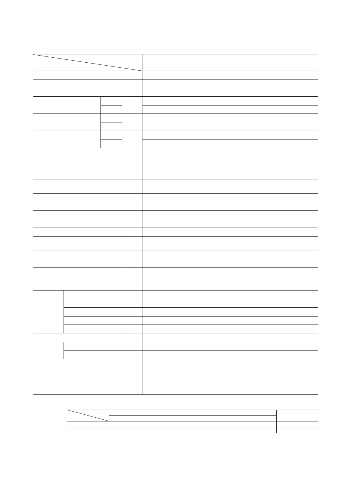
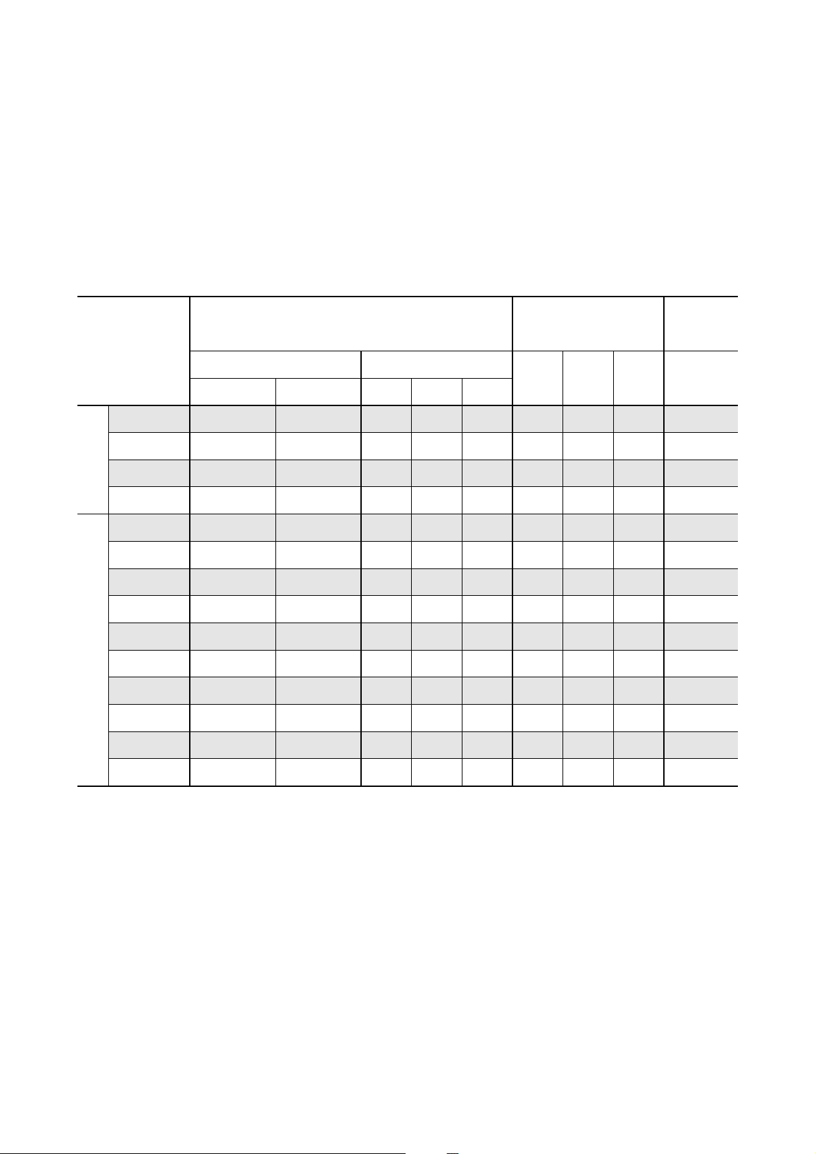
2.2 Range of usage & limitations
Model
Item
Indoor intake air temperature
(Upper, lower limits)
Outdoor air temperature
(Upper, lower limits)
Indoor units
that can be
used in
combination
Total length for all rooms
Length for one indoor unit
Difference in
height between
indoor and outdoor
units
Difference in height between indoor units (C)
Compressor
stop/start
frequency
Power source
voltage
Number of connected units
Total of indoor Units (class kW)
When above outdoor unit (B)
When below outdoor unit (A)
1 cycle time
Stop time
Voltage fluctuation
Voltage drop during start
Interval unbalance
SCM45ZD-S SCM80ZD-S
1 to 2 units
7.0kW
Max. 30m
Max. 10m Max. 15m
6 min or more (from stop to stop or from start to start)
SCM60ZD-S
Refer to the selection chart.
2 to 3 units
10.6kW
Max. 40m
Max. 25m
Max. 15m
Max. 25m
3 min or more
Within ±10% of rated voltage
Within ±15% of rated voltage
Within ±3% of rated voltage
3 to 4 units
13.4kW
Max. 70m
A
C
B
-
17
-
Page 21

2.3 Exterior dimensions
(1) Indoor unit
Models SKM22ZD-S, 25ZD-S, 28ZD-S, 35ZD-S, 50ZD-S
A
815
250
249
Unit : mm
3
Piping hole right(left)
60
42.7
175
47.2
44.5
117.5
216.5216.5
148.5
53.5
Piping hole (ø65)
580 117.5
450
450
Piping for Gas
22,25,28,35: ø9.52
( )
50: ø12.7
Piping for Liquid 465.1 (ø6.35)
Drain hose 540 (ø16)
148.5
216.5216.5
67.5
397.1
Piping hole (ø65)
Models STM25ZE-S, 35ZE-S, 50ZE-S, 60ZE-S
Celling opening 660 (For conventional celling)
Hanging bolt pitch 530
44.5
Terminal block
8.2
236.1
5.7
45
56
Remote controller
60
5
45
PANEL
9
150
18
788
60
14.5
45
VIEW A
319
Hanging bolt pitch 530
350
Control box
D
B
A
197
137
45 or
more
570
243
104
Hanging fixture
541
68
Drain hose (accessory)
To be installed at site
E
C
250
196
93
35
-
18
Air outlet
43202
Mark Description
Gas pipe connecting port ø 9.52(Flare) ø 12.7(Flare)
A
Liquid pipe connecting port ø 6.35(Flare)
B
Drain line tube connecting port VP25*
C
D
E
*Please arrange VP25 connector sockets on the installer's part.
413
700
Model 25,35ZE-S 50,60ZE-S
Power intake
Hanging bolt (M10 or M8)
-
Air intake
Page 22

Models SRRM25ZE-S, 35ZE-S, 50ZE-S, 60ZE-S
325
Controller
105
1917044
3014855
100 540 100
220 90 220 105
ø 4 × 8(Holes for tapping screws)
Air outlet
35 670 (Suspension bolts pitch)
455
Hanging bolt
106740
30 230 11 255
(M8 × 4)
Mark
Gas pipe connecting port ø9.52(Flare) ø12.7(Flare)
A
Liquid pipe connecting port
B
Terminal block
150
(Connection opening diameter ø16)
Drain hose
740
Model 25,35ZE-S 50,60ZE-S
Description
ø6.35(Flare)
Air inlet
236
38
78135
35
455 3030
515 (Suspension bolts pitch)
B
A
(2) Outdoor unit
Models SCM45ZD-S, 60ZD-S
286.4
43.5
290
49.6
203.1 510 136.9
640
15
Drain hole
476
850
50
12
12
314
14
Elogated hole
(2-12X16)
42.7
42.7
67.9
42.7
67.9
100.3
328
Liquid line service
valve C Unit (ø6.35)
(60 type only)
Ground
terminal
20º
20º
124
34.6
Unit : mm
Terminal block
Gas line service
valve C Unit (ø9.52)
(60 type only)
Liquid line service
valve B Unit (ø6.35)
Gas line service
valve B Unit (ø9.52)
Liquid line service
valve A Unit (ø6.35)
Gas line service
valve A Unit (ø9.52)
-
19
-
Page 23

Model SCM80ZD-S
Unit : mm
340
20
Terminal block
845
10
Holes for anchor bolt
(M10 x 4pcs.)
150 580 150
40
880
Service valve
(Liquid ø6.35)
Service valve
(Liquid ø6.35)
Service valve
(Liquid ø6.35)
Service valve
(Liquid ø6.35)
138.9 120.1120.1 120.1
145.2
26
Service valve
(Gas ø9.52)
Service valve
(Gas ø9.52)
Service valve
(Gas ø9.52)
Service valve
(Gas ø9.52)
120.1120.1120.193.9
Opening for
electric wiring
A
380
20
340
40
40
55
47
310222
Holes for drain
(ø9.52 x 3pcs.)
VIEW A
-
20
-
Page 24

2.4 Piping system
Outdoor unit
Indoor unit
Thermistor
(Th
I-R1
)
Thermistor
(Th
I-R2
)
Thermistor
(Th
I
-A)
Thermistor
(Th
O
-C)
Muffler
Check joint
Check joint
Check joint
Thermistor
(Th
O
-D)
Thermistor
(Th
O
-A)
Receiver
Thermistor
(ThO-R)
Heat exchanger
Heat exchanger
Liquid line
Gas line
(ø6.35)
(ø6.35)
(ø9.52)
(ø9.52)
Strainer
Suction
Capillary tube
Compressor
Discharge
Muffler
4 way valve
Service valve
(Liquid)
Capillary tube
Electric
expansion valve
EEVA
EEVB
Cooling cycle
Heating cycle
Service valve
(Gas)
Model SCM45ZD-S
-
-
21
21
-
-
Page 25

Gas line
Liquid line
(ø9.52 or ø12.7)
(ø9.52 or ø12.7)
(ø6.35)
(ø6.35)
(ø6.35)
EEVA
Strainer
EEVB
EEVC
(ø9.52 or ø12.7)
Service valve (Gas)
Outdoor Unit
Indoor Unit
Thermistor
(Th
I-R2
)
Heat exchanger
Thermistor
(Th
I-A
)
Thermistor
(Th
I-R1
)
Thermistor
(Th
O-D
)
Thermistor
(Th
O-A
)
Accumlator
Accumlator
Muffler
Thermistor
(Th
o-C
)
Service valve
(Liquid)
Electronic
expansion valve
Gas line 22, 25, 28, 35 type: ø9.52
50, 60 type : ø12.7
Capillary
tube
Compressor
Check joint
4way valve
Heating
Cooling
Discharge
Suction
Receiver
Thermistor
(ThO-R)
Heat exchanger
Model SCM60ZD-S
-
22
-
Page 26

Model SCM80ZD-S
Gas line
Liquid line
(ø9.52 or ø12.7)
(ø9.52 or ø12.7)
(ø6.35)
(ø6.35)
(ø6.35)
(ø6.35)
(ø9.52 or ø12.7)
(ø9.52 or ø12.7)
Service valve (Gas)
Outdoor Unit
Indoor Unit
Heat
exchanger
Heating
Cooling
Thermistor
(Th
I-R1
)
Thermistor
(Th
I-A
)
Thermistor
(Th
I-R2
)
EEVA
EEVD
EEVC
EEVB
Strainer
Discharge
Suction
Thermistor
(Th
O-D
)
Receiver
Capillary
tube
Thermistor
(Th
O-C
)
Service valve
(Liquid)
Electronic
expansion valve
Compressor
Check joint
Oil
separator
4way valve
Thermistor
(Th
O-A
)
Thermistor
(Th
O-R
)
Capillary tube
Heat exchanger
Accumlator
Accumlator
Gas line 22, 25, 28, 35 type: ø9.52
50, 60 type : ø12.7
23
-
-
Page 27

2.5 Selection chart
Correct the cooling and heating capacity in accordance with the conditions as follows. The net cooling and heating capacity can be
obtained in the following way.
Net capacity = Capacity shown on specification × Correction factors as follows.
(1) Coefficient of cooling and heating capacity in relation to temperatures
1.3
1.2
1.1
Cooling
1.0
0.9
Coefficient of cooling &
Heating capacity in
relation to temperature
0.8
0.7
0.6
43
40
35
30
°C D.B.
25
temperature
20
Outdoor air D.B.
Cooling operation
Heating operation
15
27
25
20
°C D.B.
15
temperature
Indoor air D.B.
10
Heating
Applicable range
14 16 18 20 22
ISO-T1 Standard ConditionIndoor air W.B. temperature °C W.B.
010-10 -5 5
ISO-T1 Standard ConditionOutdoor air W.B. temperature °C W.B.
24
20
15
(2) Correction of cooling and heating capacity in relation to one way length of refrigerant piping
It is necessary to correct the cooling and heating capacity in relation to the one way piping length between the indoor and outdoor
units.
Piping length [m]
Cooling
Heating
1.0
1.0
7
10
0.99
1.0
15
0.975
1.0
20
0.965
1.0
25
0.95
1.0
(3) Correction relative to frosting on outdoor heat exchanger during heating
In additions to the foregoing corrections (1), (2) the heating capacity needs to be adjusted also with respect to the frosting on the
outdoor heat exchanger.
Air inlet temperature of
outdoor unit in ºCWB
Adjustment coefficient
-10
0.95-90.94-70.93-50.91-30.88-10.8610.8730.9251.00
-
-
24
Page 28

3 ELECTRICAL DATA
Meaning of marks
• Outdoor Unit
Symbol
CM
FM
CFO
L
DS1
Q11
O
Compressor motor
Fan motor
Capacitor (for FM
Reactor
Diode stack
Power transistor
• Indoor Unit
Symbol
FMI
CFI
SM
Tr
ZNR
F
Fan motor
Capacitor (for FM
Flap motor
Transformer
Varistor
Fuse
3.1 Electrical wiring
(1) Indoor unit
Models SKM22ZD-S, 25ZD-S, 28ZD-S, 35ZD-S
Parts name
O)
Parts name
I)
Symbol
EEVA ~ D
20S
Tho-A
Tho-R
Tho-D
Tho-C
Symbol
DM
FS
I-A
Th
I-R1
Th
ThI-R2
Parts name
Electronic expansion valve
4 way valve (coil)
Thermistor (outdoor air temp.)
Thermistor (outdoor H.X temp.)
Thermistor (discharge pipe temp.)
Thermistor (suction pipe temp.)
Parts name
Drain motor
Float switch
Thermistor (room temp.)
Thermistor (indoor H.X temp.)
Thremistor (indoor H.X temp.)
HEAT
EXCHANGER
I
FM
SM
BR
WH
RD
CNU
1
5
3
CNW
CNM
CNC
Tr
CF
I
CNB
IC8
CNE
Display
Wireless
R-Amp
WH
BK
N
52C-4
ZNR
ThI-A ThI-R
F
(250V 3.15A)
Printed circuit
board
CNG CNF
ThI-R
1
RD
J
2
Y/GN
Y/GN
G
Back up
switch
RD
WH
BK
3
2/N
1
TB
Power line
(Outdoor unit)
Color symbol
Black
BK
Brown
BR
Red
RD
White
WH
Yellow/Green
Y/GN
-
25
-
Page 29

Model SKM50ZD-S
HEAT
EXCHANGER
Y/GN
RD
WH
BK
3
2/N
1
TB
Power line
(Outdoor unit)
FM
SM
WH
BK
N
CNU
BL
6
Y
5
WH
I
BK
RD
4
3
1
~~
CNM
CNE
Display
Wireless
R-Amp
52C-4
F
(250V 3.15A)
ZNR
CNG CNF
ThI-A ThI-R
ThI-R
Printed circuit
board
1
RD
J
Y/GN
G
Back up
switch
2
Color symbol
Black
BK
Blue
BL
Brown
BR
Red
RD
White
WH
Yellow
Y
Yellow/Green
Y/GN
-
26
-
Page 30

Models STM25ZE-S, 35ZE-S, 50ZE-S, 60ZE-S
Display
Wireless
Y
R-amp
DM
Color symbol
Black
BK
BL
Blue
RD Red
Y Yellow
WH White
Y/G
Yellow/Green
CNQ
CNE
SM
CNM
Printed circuit
board
CNP
FS
RD
FM
I
Y
BKRDWH
13 546
CNU
ZNR
F
(250V 3.15A)
CNG
BK
BK
BK
ThI-A ThI-R1ThI-R
BL
2
CNB
S/N
R/L
Control
box
WH
BK
RD
J
Y/G
G
RD
WH
BK
WH
BK
RD
Y/G
2/N
13
Power line
(Outdoor unit)
T1
Wired remote controller
YXZXYZ
T2
(Optional parts)
Models SRRM25ZE-S, 35ZE-S, 50ZE-S, 60ZE-S
RD
DM
WH
FS
Color symbol
Black
BK
BL
Blue
OR
Orange
RD Red
Y Yellow
WH White
Y/G
Yellow/Green
CNQ
CNP
SM
CNM
Printed circuit
board
CNE
Display
Wireless
R-amp
FM
I
BL
Y
BKRDWH
13 546
CNU
ZNR
F
(250V 3.15A)
CNG
BK
BK
ThI-A ThI-R1ThI-R
OR
2
CNB
S/N
R/L
CNC
Control
box
J
G
RD
WH
BK
WH
BK
RD
Y/G
WH
BK
RD
Y/G
Tr
1
2/N
3
Power line
(Outdoor unit)
T1
Wired remote controller
YXZXYZ
(Optional parts)
T2
-
27
-
Page 31

SWITCHING
POWER CIRCUIT
P
L-1
N-1
BL
GR
BL
GR
L-OUT2
L
N
1
2
3
RD
20S
G2
Y/G
+
-
~
~
DS1
CNI
RAM DATA
U
WH
RD
BKW
CM
V
PWB ASSY(POWER) PWB2
F1
250V 20A
F1
200V 2A
EEV_B
EEV_A
Tho-D
Tho-A
Tho-R
Tho-C
1
2
3
4
5
6
7
8
HEATER
F
Power source
1 Phase
220/230/240V
250V 15A
Y/G Y/G
EARTH
1
2
3
BR
BK
BK
WH
WH
WH
1
1
2
2
CNO
CNP
CNB CNC
CND
CNJ CNK
CNG
CNI
RD
BK
P_1N_1
P_1N_3
123456 123456
12
CNN CNH
1234567891011121312345
12345 12345678910111213
FMo
CNS
CFO
1
3
7
5
CAP1
CAP2
Me
Lo
COM WH
RD
BL
BK
OR
Y
G3
AC.L
AC.N
N-OUT2
BK RD
PWB ASSY(CAPACITOR) PWB3
PWB ASSY(CPU) PWB1
NW
V
U
DC-P
DC-N
N1
L
N2
P2
BK BK
C1 C2 C3
2
1
IC12 Q11
RD
WH
BK
CNG CNH
T1
T2
T3
Unit
A
Unit
B
AF-L2 AF-L1
OR OR
L
OR OR
Black
Red
White
Yellow/Green
BK
RD
WH
Blue
Yellow
BL
Brown
BR
Gray
GR
Orange
OR
YL
Y/GN
Color symbol
NF
LED 5
ERROR
NF
NF
LED 4
Unit A
(Green)
(Red)
LED 3
Unit B
-
28
-
(2) Outdoor unit
Model SCM45ZD-S
Page 32

SWITCHING
POWER CIRCUIT
EEV-C
P
L-1
N-1
L
N
BK
WH
1
2
3
RD
20S
G2
~
~
+
-
CNI
RAM DATA
URD
W
CM
V
PWB ASSY(POWER) PWB2
F1
250V 20A
F1
200V 2A
EEV-BEEV-A
Tho-D
Tho-A
Tho-R
Tho-C
1
2
3
4
5
6
7
8
HEATER
F
250V 20A
EARTH
1
2
3
BR
1
2
3
BL
BK
BK
BK
WH
WH
WH
1122
CNO
CNP
CNQ
CNB CNC
CND
CNJ CNK CNL
CNG
RD
BK
P_1N_1
P_1
123456 123456 123456
12
CNN CNH
1234567891011121312345
12345 12345678910111213
PWB ASSY(CAPACITOR) PWB3
PWB ASSY(CPU) PWB1
NW
V
U
DC-P
DC-N
N1
L
N2
P2
BK
C1 C2 C3 C4
2
1
IC12 Q11
RD
BK RD
BL
GR
BL
GR
L-OUT2
AC.L
AC.N
N-OUT2
CNG
CNH
T1
T2
DS1
AF-L2
N_3
G3
AF-L1
OR OR
L
OR OR
Y/G
Y/G Y/G
WH
BK
WH
BK
Power source
1 Phase
220/230/240V
Unit
A
Unit
B
Unit
C
Black
Red
White
Yellow/Green
BK
RD
WH
Blue
Yellow
BL
Brown
BR
Gray
GR
Orange
OR
Y
Y/GN
Color symbol
NF
NF
NF
LED4
Unit A
LED5
ERROR
LED2
Unit C
LED3
Unit B
FMo
CNS
1
3
7
5
CAP1
CAP2
Me
Lo
COM
CFO
OR
Y
BK
BL
RD
WH
-
29
-
Model SCM60ZD-S
Page 33

SWITCHING
POWER CIRCUIT
EEV-C
P
L-1
N-1
L
N
BK
WH
1
2
3
RD
20S
G2
+
-
~
~
CNI
RAM DATA
URD
W
CM
V
PWB ASSY(POWER) PWB2
F1
250V 20A
F1
200V 2A
EEV-D
EEV-BEEV-A
Tho-D
Tho-A
Tho-R
Tho-C
1
2
3
4
5
6
7
8
HEATER
F
250V 20A
T1
EARTH
T2
1
2
3
BR
T3
1
2
3
BL
1
2
3
Y
T5
T4
BK
BK
BK
BK
WH
WH
WH
WH
1122
CNO
CNP
CNQ
CNR
CNB CNC
CND
CNJ CNK CNL
CNG
CNI
RD
BK
P_1N_1
P_1
123456 123456 123456 123456 12
CNN CNH
1234567891011121312345
12345 12345678910111213
PWB ASSY(CAPACITOR) PWB3
PWB ASSY(CPU) PWB1
NW
V
U
DC-P
DC-N
N1
L
N2
P2
BK
CNM
C1 C2 C3 C4
2
1
IC12 Q11
RD
BK RD
BL
GR
BL
GR
L-OUT2
AC.L
AC.N
N-OUT2
CNG CNH
DS1
AF-L2
N_3
G3
AF-L1
OR OR
L
OR OR
Y/G
Y/G Y/G
WH
BK
WH
BK
WH
Y/G
Black
Red
White
Yellow/Green
BK
RD
WH
Blue
Yellow
BL
Brown
BR
Gray
GR
Orange
OR
Y
Y/GN
Color symbol
Power source
1 Phase
220/230/240V
Unit
A
Unit
B
Unit
C
Unit
D
NF
NF
NF
LED4
Unit A
LED5
ERROR
LED2
Unit C
LED1
Unit D
LED3
Unit B
NF
FMo
CNS
1
3
7
5
CAP1
CAP2
Me
Hi
Lo
COM
CFO
OR
Y
BK
BL
RD
WH
-
30
-
Model SCM80ZD-S
Page 34

4 OUTLINE OF OPERATION CONTROL BY MICROCOMPUTER
4.1 Operation control function by remote control switch
Remote controller
Models All models
S Operation section
FAN SPEED button
Each time the button is pushed, the indicator is switched over in turn.
HI POWER button
This button changes the HI POWER mode.
AIR FLOW button
This button changes the flap mode. When
pressed, this button changes the mode in the
following order:
(Air scroll) (SWING)
This button is not used for SRRM-ZE series.
(Air flow direction adjustment can not be
performed.)
ON TIMER button
This button selects ON TIMER operation.
Clock switch
This switch for setting the clock.
OFF TIMER button
This button selects OFF TIMER operation.
HI POWER
AUTO
HI
MID
LO
FAN SPEED
HI POWER
AIR FLOW
ON OFF
TIME
• The above illustration shows all controls, but in practice
only the relevant parts are shown.
ON OFF
ON
TEMP
TIME
TIMER
ECONO
AM PM
OFF
MODE
ECONO
CANCEL
RESERVE
ACL
OPERATION MODE select button
Each time the button is pushed, the indicator is switched over in turn.
ON/OFF button
Press for starting operation, press again for
stopping.
ECONOMY button
This button changes the ECONOMY mode.
TEMPERATURE button
This button sets the room temperature.
(This button changes the present time and
TIMER time.)
CANCEL button
This button cancels the ON timer and OFF
timer.
RESERVE button
This button sets the present time and
TIMER time.
RESET switch
Switch for resetting microcomputer.
S Indication section
HI POWER MODE indicator
Indicates during Hi power mode operation.
TEMPERATURE Indicator
Indicates set temperature.
(Does not indicate temperature when operation
mode is on AUTO)
FAN SPEED Indicator
Indicates set air flow rate with lamp.
AIR FLOW Indicator
Shows selected flap mode.
ON TIMER Indicator
Indicates during ON TIMER operation.
AUTO
HI
MID
LO
HI POWER
-
ECONO
AM PM
ON OFF
-
31
ECONOMY MODE indicator
Indicates during economy mode operation.
OPERATION MODE Indicator
Indicates selected operation with lamp.
[
(Auto) • (Cool) • (Heat) • (Dry)]
Clock Indicator
Indicates present time or timer setting time.
OFF TIMER Indicator
Indicates during OFF TIMER operation.
Page 35

Unit indication section
Models SKM22ZD-S, 25ZD-S, 28ZD-S, 35ZD-S, 50ZD-S
Models STM25ZE-S, 35ZE-S, 50ZE-S, 60ZE-S
RUN (HOT KEEP) light (green)
• Illuminates during operation.
• Blinks at air flow stop due to the ‘HOT KEEP’.
TIMER light (yellow)
Illuminates during TIMER operation.
HI POWER light (green)
Illuminates during HI POWER operation.
ECONOMY light (orange)
Illuminates during ECONOMY operation.
RUN (HOT KEEP) light (green)
• Illuminates during operation.
• Blinks at air flow stop due to the ‘HOT KEEP’.
TIMER light (yellow)
Illuminates during TIMER operation.
Models SRRM25ZE-S, 35ZE-S, 50ZE-S, 60ZE-S
RUN (HOT KEEP) light (green)
• Illuminates during operation.
• Blinks at air flow stop due to the ‘HOT KEEP’.
Illuminates during TIMER operation.
Illuminates during HI POWER operation.
Illuminates during ECONOMY operation.
ECONOMY light (orange)
Illuminates during ECONOMY operation.
HI POWER light (green)
Illuminates during HI POWER operation.
TIMER light (yellow)
HI POWER light (green)
ECONOMY light (orange)
-
32
-
Page 36

5INSTALLATION
R410A refrigerant is used for this air-conditioner. Execute the installation work while taking care of the following points in addition
tothe general caution items.
5.1 Installation tools
Prepare the following special tools for R410A in addition to the general-purpose tools.
● Flare tool
● Gauge manifold
● Vacuum pump adaptor
● Leak detector
● Charge hose
5.2 Refrigerant piping
● Use the copper pipe that has less than 40 mg/10 m of oil adhesion and 0.8 mm of wall thickness. Never use the thin walled pipe
thethickness of which is less than 0.8 mm.
● Use the flare nut attached to the air-conditioner.
5.3 Pipe connection
(1) Pipe working
Copper pipe dia.
Liquid side ø6.35
Gas side
(2) Tightening torque
● The tightening torque is shown below.
Copper pipe dia.
Liquid side
Gas side
Across flats of flare nut
ø6.35
ø9.52
ø12.7
ø9.52
ø12.7
(mm)
17
22
24
Dimension "A" (mm)
9.1
13.2
16.6
Tightening torque
N·m (kgf·m)
14 ~ 18 (1.4 ~ 1.8)
33 ~ 42 (3.3 ~ 4.2)
50 ~ 62 (5.0 ~ 6.2)
Flare tool bar
Dimension "B"
Copper pipe
Copper pipe dia.
ø6.35
ø9.52
ø12.7
Dimension "B" (mm)
Clutch type flare tool for R410A
0.0 ~ 0.5
0.0 ~ 0.5
0.0 ~ 0.5
(3) Vacuuming
● The charge hose for R22 cannot be connected because the service port diameter is different from the conventional one. Usethe
special charge hose for R410A.
● Use the vacuum pump adapter for reverse flow prevention to check the reverse flow of vacuum pump oil. If oil flows back tothe
air-conditioner, it causes failure of refrigerant cycle.
Compound
pressure gauge
-101kPa
(-76cmHg)
Handle Lo
Charge Hose
(Special for R410A)
Vacuum pump adaptor
(For reverse flow prevention)
(Special for R410A)
-
33
-
Pressure
gauge
Gauge manifold
(Special for R410A)
Handle Hi
Charge hose
(Special for R410A)
Vacuum Pump
Page 37

PARTS LIST (Main parts)
(1) Indoor unit
No.
1
PANEL ASSY, FRONT
2
PANEL, FRONT
3
PANEL ASSY, AIR INLET
4
GRILLE ASSY, AIR OUTLET
5
MOTOR, AC
6
IMPELLER
7
HEAT EXCH ASSY (AIR)
8
PWB ASSY
9
CONTROL ASSY, REMOTE
No.
1
PANEL ASSY,FRONT
Parts Name
Parts Name
SKM22ZD-S
RKV505A500C
SKM35ZD-S
RKV102A600A
Parts No.
RKV102A600A
RKV122A001B
RKV435A100B
RKV435A101B
SSA511J218
SSA431G042C
RKV301A500D
RKV505A500D
RMA502A001
Parts No.
SKM28ZD-SSKM25ZD-S
RKV505A500F
SKM50ZD-S
RKV102A600C
2
PANEL,FRONT
3
PANEL ASSY,AIR INLET
4
GRILLE ASSY,AIR OUTLET
5
MOTOR,AC
6
MOTOR,DC
7
IMPELLER
8
HEAT EXCH ASSY(AIR)
9
PWB ASSY
10
CONTROL ASSY,REMOTE
RKV122A001B
SSA511J218
-
RKV301A500D
RKV505A500G
RKV122A001H
RKV435A100B
RKV435A101B
-
SSA512T064
SSA431G042C
RKV301A102B
RKV505A001N
RMA502A001
-
34
-
Page 38

No.
Parts Name
Parts No.
STM25ZE-S STM35ZE-S STM50ZE-S STM60ZE-S
1
CABINET ASSY
2
FAN, TURBO
3
MOTOR, DC
4
PUMP ASSY, DRAIN
5
SWITCH ASSY, FLOAT
6
HEAT EXCH ASSY(AIR)
7
PWB ASSY
8
CONTROL ASSY, REMOTE
9
PANEL, FRONT
10
LOUVER ASSY, BLOW
11
MOTOR, STEPPING
12
GRILLE, AIR INLET
No.
Parts Name
RJA100A760A
SSA431J018
SSA512T074
PJA451A505P
PJA536A700B
RJH301A001RJH301A002
RKW505A200T RKW505A200W RKW505A200Y RKW505A200Z
RMA502A001
PJA122A752
PJA436A750
SSA512T045
PJA435A751
Parts No.
SRRM25ZE-S SRRM35ZE-S SRRM50ZE-S SRRM60ZE-S
1
CABINET ASSY
2
PANEL ASSY, REAR
3
MOTOR, DC
4
IMPELLER
5
SCROLL ASSY
6
HEAT EXCH ASSY(AIR)
7
PWB ASSY
8
SWITCH, FLOAT
9
CONTROL ASSY, REMOTE
RJD121A001B
RJD125A001
SSA512T069B
SSA431D088
RJD433B001
RJD301A102RJD301A101
RKW505A200M RKW505A200P RKW505A200R RKW505A200S
SSA536A017Y
RMA502A001
-
35
-
Page 39

PARTS LIST (Main parts)
(2) Outdoor unit
No.
1
PANEL,FRONT
2
PANEL,SIDE(R)
3
PANEL,SIDE(L)
4
PANEL,TOP
5
GRILLE,AIR OUTLET
6
GUARD,FAN
7
GUARD,FIN
8
BRACKET,MOTOR
9
BASE,MOTOR
10
MOTOR,AC
11
PROPELLER
12
BASE ASSY
13
HEAT EXCH(AIR)
Parts Name
SCM45ZD-S
RWC122A003
RWC123A003B
RWC123A002
RWC124A003B
RWC435A002
RWC131A004
RWC116A041A
SSA511B816
SSA431B233
RWC111A003B
RPC311A851
Parts No.
RWC123A003A
-
-
SSA511B817
RWC111A003F
SCM80ZD-SSCM60ZD-S
PCA122A027AH
-
-
PCA124A007
-
PCA131A021
PCA131A017
-
PCA116A092N
SSA511T163C
SSA431B209
RPC111A850
RPC311A853
14
VALVE,S(4WAY)
15
COIL,SOLENOID
16
COMPRESSOR ASSY
17
PWB ASSY(MAIN)
18
PWB ASSY(POWER)
19
PWB ASSY(CAPACITOR)
20
VALVE,BODY(EXP)
21
COIL,SOLENOID
22
COIL,SOLENOID
23
COIL,SOLENOID
24
COIL,SOLENOID
RSA201A001A
RPC505A850
RPC505A851
RPC505A852
SSA382F210C
SSA382F210D
-
SSA382C078
SSA382F027B
RPC505A850A
SSA387F031
SSA382F210F
-
PCA201A048A
RPC505A850B
RPC505A851A
RPC505A852A
SSA382F210F
SSA382F210K
SSA382F210L
SSA382F210M
-
36
-
Page 40

INVERTER MULTI-SPLIT SYSTEM
ROOM AIR-CONDITIONER
Air-Conditioning & Refrigeration Systems Headquarters
16-5, 2-chome, Kounan, Minato-ku, Tokyo, 108-8215, Japan
Fax: (03) 6716-5926
 Loading...