

Page 1
Printed in Japan
Pub. No.
Pub. No.
SERVICE MANUAL
SERVICE MANUAL
Pub. No.
August 2008
August 2008
99616-25000
99616-25000
99616-25000
for HYUNDAI HEAVY INDUSTRIES CO.,LTD.
for HYUNDAI HEAVY INDUSTRIES CO.,LTD.
Page 2

Page 3

Pub.No. 99616-25000
INTRODUCTION
This service manual describes the specifications, maintenance and service procedures
for Mitsubishi diesel engines.
To maintain the performance of the engine for many years and to ensure safe operation,
it is important to use the engine correctly and conduct regular inspection and maintenance,
and also to take necessary measures which involves the disassembly, inspection, repair and
reassembly of the engine and engine parts.
Read this manual carefully and understand the work procedures fully before
disassembling, inspecting, repairing or reassembling the engine.
The contents of the manual are based on the engine models that are being produced at
the time of publication. Due to improvements made thereafter, the actual engine that you
work on may differ partially from the one described in this manual.
Page 4

Page 5
INTRODUCTION
I
How to use this manual
This service manual consists of several Groups, which are arranged so as to allow you to make reference quickly to
specifications, maintenance standards, adjustment procedures and service procedures including methods for disassembly,
inspection, repair and reassembly of the Mitsubishi Diesel Engine (standard model for land use).
A short summary describing the content of each Group is given in the General Contents page, and there is also a detailed table
of contents at the beginning of each Group.
Regarding the procedures for operation and periodical maintenance of the engine, refer to the Operation and Maintenance
Manual. For information on the engine components and ordering of service parts, refer to the Parts Catalogue. Structure and
function of the engine are described in the relevant training manuals.
Methods of presentation
(1) Index numbers allotted to parts in exploded views are not only a call-out of part names listed in the text but also an indi-
cation of the sequence of disassembly.
(2) Inspections to be conducted during disassembly process are indicated in boxes in the relevant exploded views.
(3) Maintenance standards required for inspection and repair works are indicated in the appropriate positions in the text.
They are also collectively indicated in Group 2, the General Contents group.
(4) Fasteners to be tightened in “wet” condition, or with engine oil applied, are identified by [Wet] placed after tightening
torque values. If no such indication is suffixed, the fastener should be tightened in “dry” condition, or without lubricating
with engine oil.
(5) In this manual, important safety or other cautionary instructions are emphasized with the following marks headed.
Indicates an immediately hazardous situation which, if not avoided, will result in death or serious injury.
Indicates a potentially hazardous situation which, if not avoided, could result in death or serious injury.
Indicates an immediately hazardous situation which, if not avoided, may result in minor or moderate injury.
Indicates a potentially hazardous situation which, if not avoided, can result in property damage.
Emphasizes important matter, or indicates information useful for operation or maintenance of the engine.
DANGER
WARNING
CAUTION
CAUTION
Note:
Page 6

INTRODUCTION
II
Terms used in this manual
Nominal
means the rated (design) size or magnitude of a part to be measured.
Standard
means the quantitative requirement for dimension of a part, clearance between parts and performance. This is given in a form of
tolerance. Therefore, the values shown are not in agreement with the design values.
Limit
means that, if this value is reached, the part must be repaired or replaced with a new part.
Abbreviations
• BTDC: Before Top Dead Center
• ATDC: After Top Dead Center
• BBDC: Before Bottom Dead Center
• ABDC: After Bottom Dead Center
• TIR: Total Indicated Runout
• API: American Petroleum Institute
• ASTM: American Society for Testing and Materials
• JIS: Japanese Industrial Standards
• LLC: Long Life Coolant
• MIL: Military Specifications and Standards (U.S.A.)
• MSDS: Material Safety Data Sheet
• SAE: Society of Automotive Engineers (U.S.A.)
Units of measurement
Measurements are based on the International System of Units (SI), and their converted metric values are indicated in
parentheses {}. For metric conversion, the following rates are used.
• Pressure: 1 MPa = 10.197 kgf/cm²
• Torque: 1 N·m = 0.10197 kgf·m
• Force: 1 N = 0.10197 kgf
• Horsepower: 1 kW = 1.341 HP = 1.3596 PS
• Meter of mercury: 1 kPa = 0.7 cmHg
• Meter of water: 1 kPa = 10.197 cmH
2O (cmAq)
• Rotational speed: 1min
-1
= 1 rpm
Page 7
INTRODUCTION
III
Safety Cautions
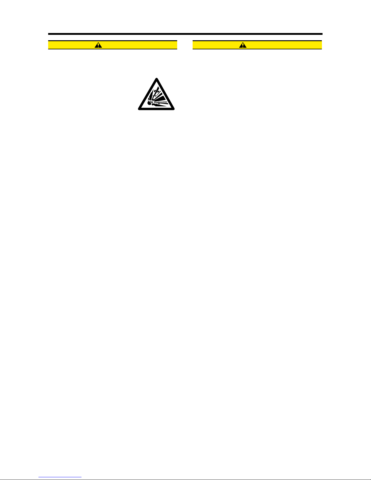
Fire and explosion
Keep flames away
Store fuel and engine oil in a well
ventilated designated area.
Make sure that the caps of fuel and
engine oil containers are tightly
closed.
Do not use flames, do not smoke,
and do not work near a heater or other fire hazard
where fuel or oil is handled or when cleaning solvent is
being used for washing parts.
Wipe off spilled fuel, oil and LLC immediately and thoroughly. Spilled fuel, oil and LLC may ignite and cause
a fire.
Keep surrounding area tidy and clean
Do not leave combustible or explosive materials, such
as fuel, engine oil and LLC, near the engine. Such substances can cause fire or explosion.
Remove dust, dirt and other foreign materials accumulated on the engine and surrounding parts thoroughly.
Such materials can cause fire or the engine to overheat. In particular, clean the top surface of the battery
thoroughly. Dust can cause a short-circuit.
Always operate the engine at a position at least 1 m
[3.28 ft.] away from buildings and other equipment to
prevent possible fire caused by engine heat.
Avoid accessing crankcase until engine
cools
Do not attempt to open the side cover of the crankcase
before the engine cools down. Wait at least 10 minutes
after stopping the engine.
Opening the cover when the engine is hot allows fresh
air to flow into the crankcase, which can cause oil mist
to ignite and explode.
Care about fuel, oil and exhaust gas leakage
If any fuel, oil or exhaust gas leakage is found, immediately take corrective measures to stop it.
Such leakages, if left uncorrected, can cause fuel or
engine oil to reach hot engine surfaces or hot exhaust
gas to contact flammable materials, possibly leading to
personal injury and/or damage to equipment.
Use explosion-proof lighting apparatus
When inspecting fuel, engine oil, coolant, battery electrolyte, etc., use a flameproof light. An ordinary light, if
accidentally broken, may ignite and cause an explosion.
Prevent electrical wires from short-circuiting
Avoid inspecting or servicing the electrical system with
the ground cable connected to the battery. Otherwise,
a fire could result from short-circuiting. Be sure to disconnect the battery cable from the negative (-) terminal
before beginning with the work procedure.
Short-circuits, possibly resulting in fire, may be caused
by a loose terminal or damaged cable/wire. Inspect the
terminals, cables and wires, and repair or replace the
faulty parts before beginning with the service procedure.
Keep fire extinguishers and first-aid kit
handy
Keep fire extinguishers handy, and
become familiar with their usage.
Keep a first-aid kit at the designated
place where it is easily accessible
by anyone at any time.
Establish response procedures to
follow in the event of fire or accident. Provide an emergency evacuation route, contact points, and means of
communication in case of emergency.
WARNING
Page 8
INTRODUCTION
IV
Stay clear of all rotating and moving parts
Install protective covers on rotating parts
Make sure the protective covers for
engine rotating parts are properly
installed as intended. Repair loose
or damaged protective covers as
necessary.
Never remove the covers guarding
personnel from rotating parts, when the engine is operating.
When combining the engine with the engine-driven machine or radiator, always provide a cover on every exposed moving part such as driving belt and coupling.
Never remove protective covers.
Ensure safety of neighboring people before
starting engine
Before starting the engine, ensure that there is nobody
in the neighborhood and that no tools are left on or near
the engine. Verbally notify people around the engine or
in the work area when starting the engine.
When the starter device is posted with a sign that prohibits startup operation, do not operate the engine.
Stay clear of moving parts during engine
running
Do not approach rotating or sliding
parts of the engine when the engine
is in operation.
Keep objects likely to be caught by
rotating parts away from such parts.
If any part of the clothing or outfitting is caught by a rotating part, serious bodily injuries could result.
Lockout and tagout
Be sure to lockout and tagout before starting inspection
and maintenance.
Lockout and tagout are effective methods of cutting off
machines and equipment from energy sources.
To accomplish the lockout/tagout, remove the starter
switch key, set the battery switch to OFF and attach a
"Do Not Run" or similar caution tag to the starter switch.
The starter switch key must be kept by the person who
performs inspection and maintenance during the work.
In the case of pneumatic starting type, close the main
valve of the air tank and post a tag saying "Do Not
Open the Valve" or the like.
Keep engine stopped during servicing
Be sure to stop the engine before proceeding to inspection and service procedure. Never attempt to make adjustments on the engine parts while the engine is
running. Rotating parts such as belt can entangle your
body and cause serious injuries.
Always restore engine turning tools after
use
Do not forget to remove the tools which have been
used for turning the engine during inspection or servicing, after the procedure is finished. Remember also
that the turning gear must be returned to the operating
condition before starting the engine.
Starting the engine with the turning tools inserted or
with the turning gear in engagement can lead to not
only engine damage but also personal injuries.
WARNING
Page 9
INTRODUCTION
V
Be careful of burns
Do not touch the engine during or immediately after operation
Do not touch the engine during or
immediately after operation to
avoid risk of burns.
To conduct maintenance and inspection work, wait until the engine
has cooled sufficiently, checking
the temperature gauge.
Slowly and carefully open radiator cap
Never attempt to open the radiator cap while the engine
is running or immediately after the engine stops. Give a
sufficient cooling time to the engine coolant before
opening the cap.
When opening the radiator cap, slowly turn the cap to
release internal pressure. To prevent scalds with steam
gushing out, wear thick rubber gloves or cover the cap
with a cloth.
Close the radiator cap tightly without fail.
The coolant is very hot and under pressure during engine running or just after the engine stops. If the radiator cap is not closed tightly, steam and hot coolant may
gush out and can cause scalds.
Add coolant only after the coolant temperature dropped
Do not add coolant immediately after the engine stops.
Wait until the coolant temperature lowers sufficiently to
avoid a risk of burns.
Never remove heat shields
The exhaust system, which becomes extremely hot
while the engine is operating, is provided with various
heat shields. Do not remove these heat shields. If any
of these heat shields have been removed owing to unavoidable circumstances during the work, be sure to restore them after the work is completed.
Be careful of exhaust fume poisoning
Operate engine in well-ventilated area
If the engine is installed in an enclosed area and the exhaust gas is
ducted outside, ensure that there is
no exhaust gas leak from duct
joints.
Take care that the exhaust gas is
not discharged toward plants or animals.
Exhaust gas from the engine contains carbon monoxide and other harmful substances. Operating the engine in an ill-ventilated area can produce gas
poisoning.
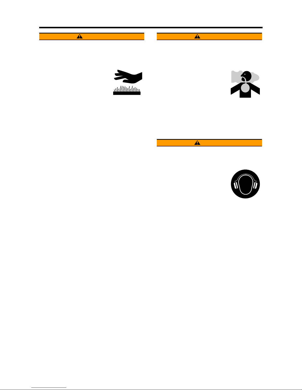
Protect ears from noises
Wear ear plugs
Always wear ear plugs when entering the machine room (engine
room). Combustion sound and mechanical noise generated by the engine can cause hearing problems.
WARNING WARNING
WARNING
Page 10
INTRODUCTION
VI
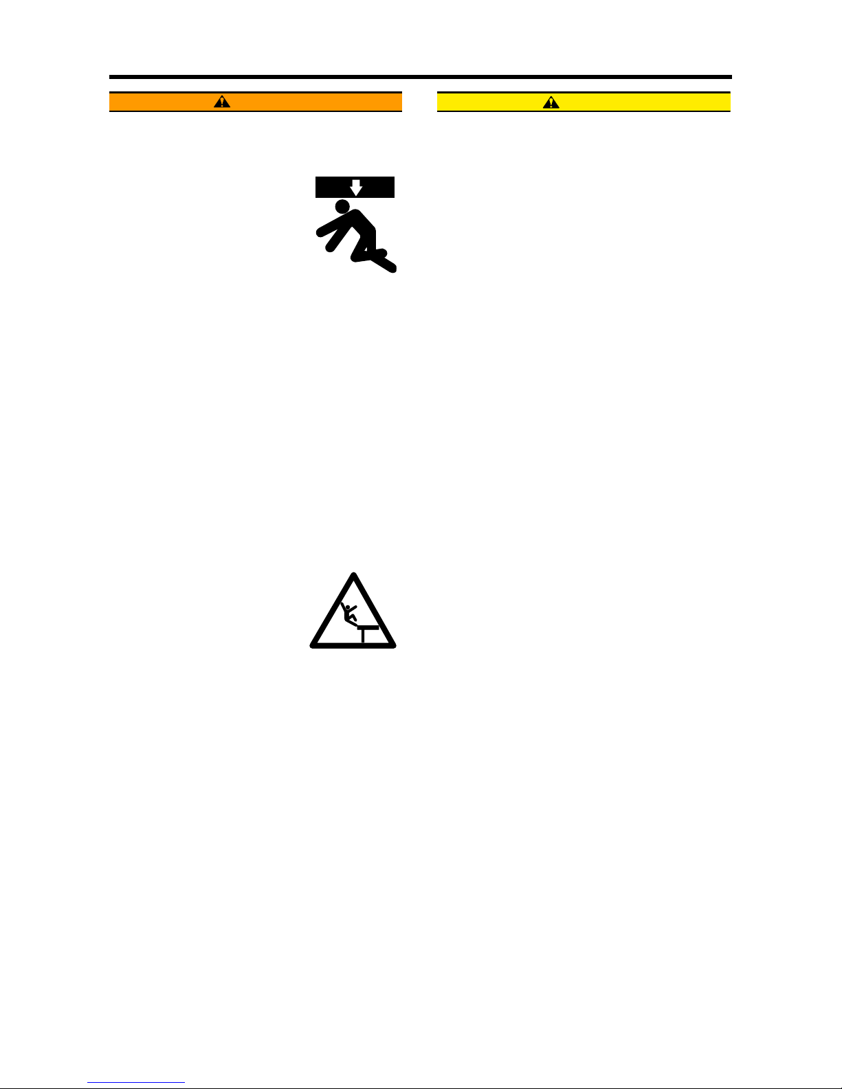
Be careful of falling down
Lift engine correctly
To lift the engine, always use a correct wire rope capable of withstanding the engine weight.
Attach the wire rope to the lifting
hangers provided on the engine using a correct sling.
During lifting process, keep the engine in a well-balanced position by taking the center of
gravity of the engine into consideration.
If the wire rope contacts the engine directly, place a
cloth or other soft padding to avoid damage to the engine and wire rope.
Do not climb onto the engine
Do not climb onto the engine, nor step on any engine
parts located on the lateral sides.
To work on parts located on the upper section of engine, use a ladder, stool, etc., that is firmly secured.
Climbing on the engine may not only damage engine
parts but also cause parts to fall off and result in personal injuries.
Establish firm scaffold during work
When working on the upper part of
the engine and other hard-toreach places, use a stable work
platform.
Standing on a decrepit stool or
parts box may result in personal
injury. Do not place any unnecessary objects on a work
platform.
Be careful of handling fuel, engine
oil and LLC
Use only specified fuel, engine oil and longlife coolant (LLC)
Use only the fuel, oil and LLC specified in the applicable operation manual, and handle them carefully.
Use of any other fuel, oil or LLC, or improper handling
may cause various engine problems and malfunctions.
Obtain the Material Safety Data Sheets (MSDS) issued
by the fuel, oil and LLC suppliers, and follow the directions in the MSDSs for proper handling.
Handle LLC (long life coolant) carefully
When handling LLC, always wear rubber gloves and
protective face mask. If LLC or cooling water containing
LLC comes into contact with your skin or eyes, or if it is
swallowed, you would suffer from inflammation, irritation or poisoning.
Should LLC be accidentally swallowed, induce vomiting immediately and seek medical attention. Should
LLC enter your eyes, flush them immediately with plenty of water and seek medical attention. If LLC splashes
onto your skin or clothing, wash it away immediately
with plenty of water.
Keep flames away from LLC. The LLC can catch
flames, causing a fire.
Coolant containing LLC is a hazardous material. Do not
dispose of it in unauthorized manner. Abide by the applicable law and regulations when discarding drained
coolant.
Proper disposal of waste oil and coolant
(LLC)
Do not discharge waste engine oil or coolant into sewerage, river, lake or other similar places. Such a way of
disposal is strictly prohibited by laws and regulations.
Dispose of waste oil, coolant and other environmentally
hazardous waste in accordance with the applicable law
and regulations, or consult a Mitsubishi dealer.
WARNING
CAUTION
Page 11
INTRODUCTION
VII
Service battery
Handle the battery correctly
• Never use flames or allow sparks
to generate near the battery. The
battery releases flammable
hydrogen gas and oxygen gas.
Any flames or sparks in the vicinity could cause an explosion.
• Do not use the battery the fluid level of which is lowered below the lower limit line. Sustained use of the
battery could result in an explosion.
• Do not short the battery terminals with a tool or other
metal object.
• When disconnecting battery cables, always remove
the cable from the negative (-) terminal first. When
reconnecting the cables, attach the cable to the positive (+) terminal first.
• Charge the battery in a well-ventilated area, with all
filling hole plugs removed.
• Make sure the cable clamps are securely installed on
the battery terminals. A loose cable clamp can cause
sparks that may result in an explosion.
• Before servicing electrical components or conducting
electric welding, set the battery switch to the [Open/
OFF] position or disconnect the cable from the negative (-) battery terminal to cut off the electrical current.
• Electrolyte (battery fluid) contains dilute sulfuric acid.
Careless handling of the battery can lead to the loss
of sight and/or skin burns. Also, keep the battery fluid
off the mouth.
• Wear protective goggles and rubber gloves when
working with the battery (when adding water, charging, etc.).
• If electrolyte is spilled onto the skin or clothing,
immediately wash it away with lots of water. Use
soap to thoroughly clean.
• The battery fluid can cause blindness if splashing
into eyes. If it gets into eyes, immediately flush it
away with plenty of clean fresh water, and seek
immediate medical attention.
• If the battery fluid is accidentally swallowed, gargle
with plenty of water, then drink lots of water, and
seek immediate medical attention.
When abnormality occurs
Stop overheated engine after cooling run
Even if the engine comes to overheat, do not stop the
engine immediately. Abrupt stopping of an overheated
engine can cause the coolant temperature to rise, resulting in seized engine parts. If the engine comes to
overheat, run the engine at low idling speed (cooling
operation), and stop the engine after the coolant temperature lowers sufficiently.
Do not add coolant immediately after stopping the engine. Adding coolant to a hot engine can cause the cylinder heads to crack due to sudden change in
temperature. Add coolant little by little after the engine
cools down to room temperature.
Avoid immediate restart after abnormal stop
If the engine stops abnormally, do not restart the engine immediately. If the engine stops with an alarm,
check and remedy the cause of the problem before restarting. Sustained use of the engine without any remedy could result in serious engine problems.
Avoid continuous engine operation with too
low oil pressure
If an abnormal engine oil pressure drop is indicated,
stop the engine immediately, and inspect the lubrication system to locate the cause. Continuous engine operation with low oil pressure may cause bearings and
other parts to seize.
Stop the engine immediately if the fan belt
breaks
If the fan belt breaks, stop the engine immediately.
Continuous engine operation with the broken fan belt
could cause the engine to overheat and thereby the
coolant to boil into steam, which may gush out from the
reserve tank or radiator, and cause personal injuries.
CAUTION CAUTION
Page 12

INTRODUCTION
VIII
Other cautions
Modification of engine prohibited
Unauthorized modification of the engine will void the
manufacturer’s warranty.
Modification of the engine may not only cause engine
damage but also produce personal injuries.
Never break the seals
To ensure proper engine operation, the fuel control link
is provided with seals that protect the fuel injection volume and rotation speed settings against tampering. If
these seals are broken and the settings are changed,
proper operation of the engine will no longer be guaranteed, and the following problems will be expected to
occur.
• Rapid wear of moving and rotating parts
• Engine troubles such as damage and seizure of
engine parts
• Increased consumption of fuel and lubricating oil
• Deterioration of engine performance due to poorly
balanced fuel injection volume and governor operation
Pre-operational check and periodic inspection/maintenance
Be sure to perform the pre-operational checks and periodic inspection/maintenance as described in this
manual.
Neglecting the pre-operational check or periodic inspection/maintenance can arouse various engine troubles such as damage to parts, eventually leading to
serious accidents.
Break-in operation
A new engine needs to be broken in for the first 50
hours of operation. During this period, do not subject
the engine to heavy loads.
Operating a new engine under high loads or severe
conditions during the break-in period can shorten the
service life of the engine.
Warming-up operation
After starting the engine, run the engine at low idling
speeds for 5 to 10 minutes for warming-up. Start the
work after this operation is completed.
Warm-up operation circulates the lubricant through the
engine. Therefore, individual engine parts are well lubricated before they are subjected to heavy loads. This
is very important for longer service life, high-performance and economical operation.
Do not conduct warm-up operation for a longer time
than necessary. Prolonged warm-up operation causes
carbon build-up in the cylinders that leads to incomplete combustion.
Avoid engine operations in a overload condition
If the engine is considered to be in an overloaded condition which is identified by too much black smoke, etc.,
immediately reduce the load on the engine such that
the correct output and load conditions may be
achieved.
Overloading the engine causes not only high fuel consumption but also excessive carbon deposits inside the
engine. Excessive carbon deposits can cause various
engine problems and shorten the service life of the engine remarkably.
Cooling operation before stopping engine
Always conduct the cooling operation (low speed
idling) for 5 to 6 minutes before stopping the engine.
Abruptly stopping the engine immediately after highload operation can cause partial overheating and shorten the service life of the engine.
During cooling operation, check the engine for abnormalities.
Protection of engine against water entry
Do not allow rainwater, etc. to enter the engine through
the air inlet or exhaust openings.
Do not wash the engine while it is operating. Cleaning
fluid (water) can be sucked into the engine.
Starting the engine with water inside the combustion
chambers can cause the water hammer action which
may result in internal engine damage and serious accidents.
CAUTION
Page 13

INTRODUCTION
IX
Maintenance of air cleaner or pre-cleaner
The major cause of abnormal wear on engine parts is
dust entering with intake air. Worn parts produce many
problems such as an increase of oil consumption, decrease of output, and starting difficulties. For effective
removal of dust from intake air, conduct maintenance
of the air cleaner according to the following instructions.
• Do not conduct maintenance of the air cleaner/precleaner while the engine is operating. Engine operation without the air cleaner/precleaner in place allows
foreign matters to enter the turbocharger, causing it
to damage seriously.
• Remove the air cleaner/pre-cleaner slowly to prevent
dust accumulated on the element from falling off.
After removing the air cleaner or pre-cleaner, immediately cover the opening (inlet port in case of air
cleaner; port in body in case of pre-cleaner) with
plastic sheet or similar means to prevent dust from
entering the engine.
• Air cleaners equipped with a dust indicator will issue
an alarm if the element gets clogged. Service the
cleaner as soon as possible if an alarm is issued.
Observe safety rules at work site
Observe the safety rules established at your workplace
when operating and maintaining the engine.
Do not operate the engine if you are feeling ill.
Operation of the engine with reduced awareness may
cause improper operation that could result in accidents.
In such a case, inform your supervisor of your condition.
When working in a team of two or more people, use
specified hand signals to communicate among workers.
Work clothing and protective gear
Wear a hardhat, face shield, safety shoes, dust mask,
gloves and other protective gear as needed.
When handling compressed air, wear safety goggles,
hardhat, gloves and other necessary protective gear.
Works without wearing proper protective gear could result in serious injuries.
Use of tools optimum for each work
Always keep in mind to select most appropriate tools
for the work to be performed and use them correctly. If
tools are damaged, replace with new tools.
Avoidance of prolonged time of starter operation
Do not operate the starter for more than 10 seconds at
a time even if the engine does not start. Wait for at least
30 seconds before next engine cranking.
Continuous operation of the starter will drain the battery
power and cause the starter to seize.
Do not turn off battery switch during operation
If the battery switch is turned OFF when the engine is
running, not only various meters will stop working but
also the alternator may have its diode and transistor
deteriorated.
Cautionary instructions for transporting engine
When transporting the engine on a truck, consider the
engine weight, width and height to ensure safety. Abide
by road traffic law, road vehicles act, vehicle restriction
ordinance and other pertinent laws.
Avoid continuous engine operation in a low
load condition
Do not operate the engine continuously for more than
10 minutes at a load of less than 30%. Engine operation in a low load condition increases the emission of
unburned fuel. Therefore, a prolonged time of engine
operation in a low load condition increases the quantity
of unburned fuel adhering to engine parts, provoking
the possibility of engine malfunctioning and shortening
the service life of the engine.
Ventilation of engine room
Always keep the engine room well ventilated. Insufficient amount of intake air causes the operating temperature to rise, resulting in poor output and lowered
performance.
It is highly recommended to calculate the required
amount of air supply to the engine and install an adequate ventilation system before installing the engine.
Avoid contact with high-pressured fuel
Should fuel leak from a fuel injection pipe, do not touch
the spouting fuel directly.
Fuel in the fuel injection pipes is under high pressure. If
high-pressured fuel contacts you skin, it penetrates
through the skin and may result in gangrene.
Page 14
INTRODUCTION
X
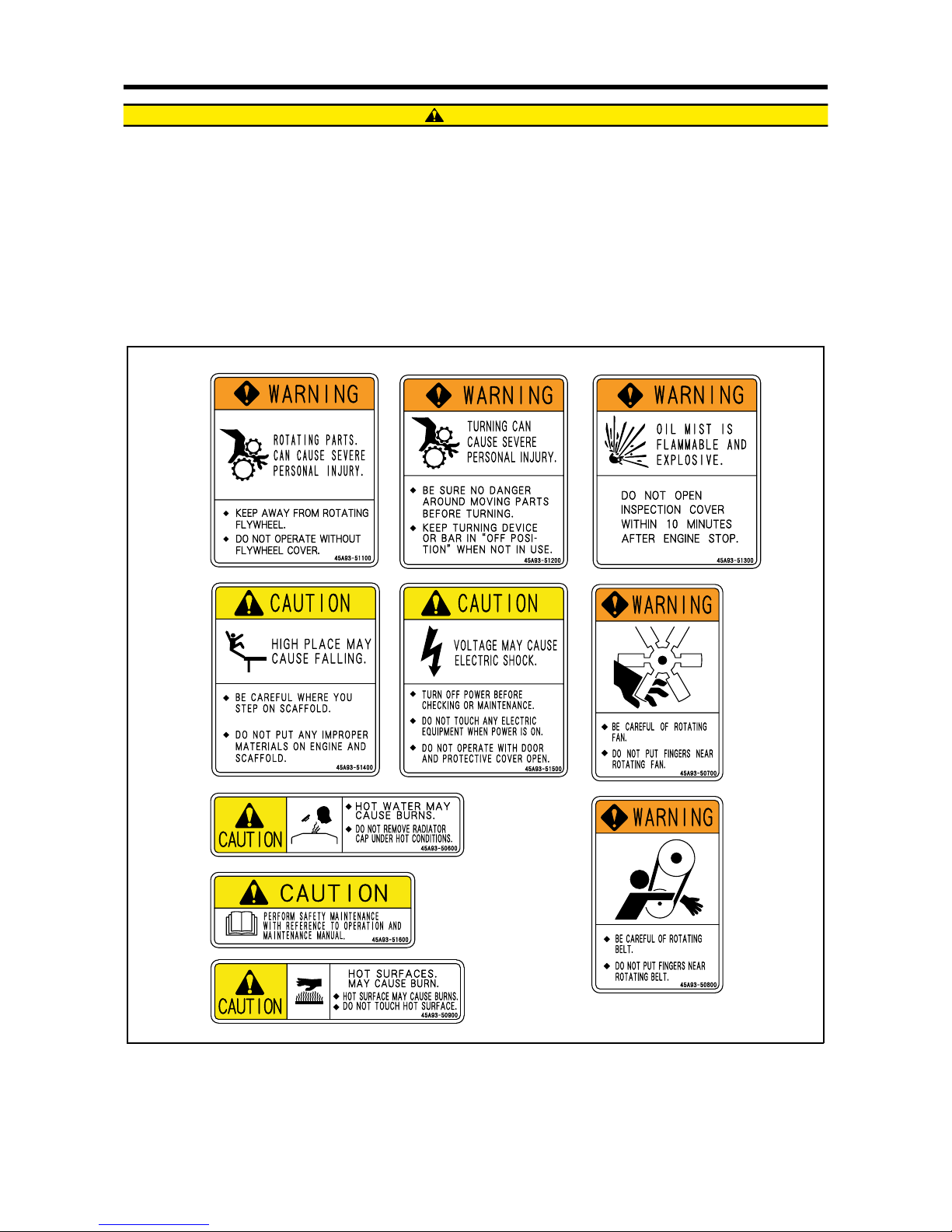
About warning labels
Maintenance of warning labels
Make sure all warning/caution labels are legible.
Clean or replace the warning/caution labels when the description and/or illustration are not clear to read.
For cleaning the warning/caution labels, use a cloth, water and soap. Do not use cleaning solvents, gasoline or other
chemicals to prevent the letters from getting blurred or the adhesion from being weakened.
Replace damaged or fractured labels with new ones.
If any engine part on which a warning label is attached is replaced with a new one, attach a new identical warning
label to the new part.
Warning labels
CAUTION
Page 15

GENERAL CONTENTS
Group Name Contents Group No.
General
External view
System flow diagrams
Engine serial number location
Main specifications
Tips on disassembling and reassembling
1
Service data
Maintenance service data
Tightening torque table
Regarding submission of parts for EPA exhaust gas regulation
2
Service tools Special tool 3
Determination of overhaul
Determining overhaul timing
Testing compression pressure
4
Disassembly of basic engine
Disassembling and inspecting cylinder head and valve mechanism
Disassembling and inspecting flywheel
Disassembling and inspecting damper, gear case, timing gear and camshaft
Disassembling and inspecting piston, connecting rod, crankshaft and crankcase
5
Inspection and repair of basic
engine
Inspecting and repairing cylinder head and valve mechanism
Inspecting and repairing flywheel
Inspecting and repairing timing gear and camshaft
Inspecting and repairing piston, connecting rod, crankshaft and crankcase
6
Reassembly of basic engine
Reassembling piston, connecting rod, crankshaft and crankcase
Reassembling timing gear and camshaft
Reassembling flywheel
Reassembling cylinder head and valve mechanism
7
Fuel system
Removing fuel system
Disassembling, inspecting and reassembling fuel system
Installing fuel system
8
Lubrication system
Removing lubrication system
Disassembling, inspecting and reassembling lubrication system
Installing lubrication system
9
Cooling system
Removing cooling system
Disassembling, inspecting and reassembling cooling system
Installing cooling system
10
Inlet and exhaust systems
Removing turbocharger, inlet and exhaust systems
Disassembling, inspecting and reassembling inlet and exhaust systems
Installing turbocharger, inlet and exhaust systems
11
Electrical system
Removing electrical system
Disassembling, inspecting and reassembling electrical system
Installing electrical system
12
Adjustment and operation
Adjusting engine
Break-in operation
Performance test (JIS standard)
13
Page 16

Page 17

1-1
GENERAL
1. External view...................................1-2
2. System flow diagrams.....................1-4
2.1 Fuel system - flow diagram...................... 1-4
2.2 Lubrication system - flow diagram .... ... ... . 1-4
2.3 Cooling system - flow diagram................. 1 -5
2.4 Inlet and exhaust system - flow diagram.. 1-5
3. Engine serial number location.........1-6
4. Main specifications..........................1-7
5. Tips on disassembling and
reassembling.................................1-10
5.1 Disassembling........................................ 1-10
5.2 Reassembling........................................ 1-10
Page 18
GENERAL
1-2
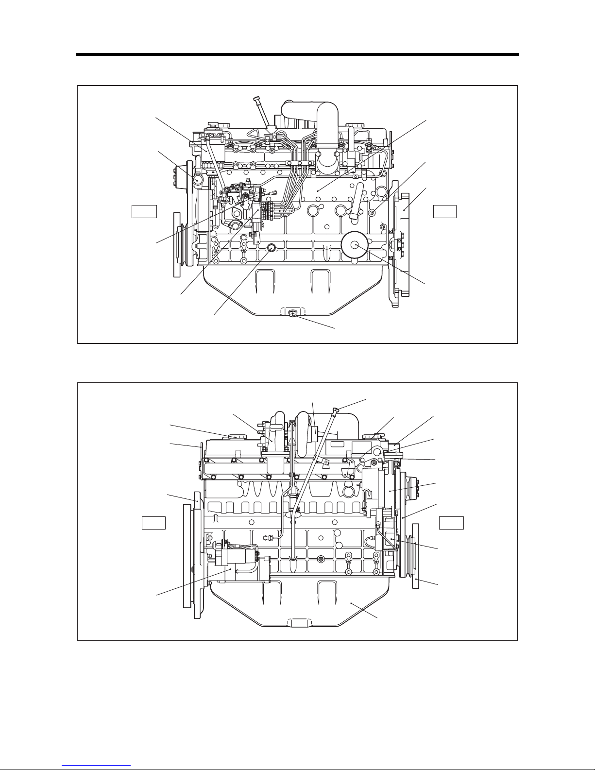
1. External view
Engine left view
Engine right view
Front
Rear
Fuei injection pump
Oil filter
Flywheel
Fuel filter
Oil drain plug
Relief valve
Magnet valve
(Stop solenoid)
Coolant drain plug
Water pump
(Coolant inlet)
Oil cooler
S6S-Y3T61HF
Front
Rear
Hanger
Oil pan
V-belt
Alternator
Thermostat case
Coolant outlet
Hanger
Oil filler
Turbocharger
(Exhaust outlet)
Starter
Oil filler
Air inlet
Damper
Rear plate
Oil level gauge
S6S-Y3T61HF
Side PTO
(Drive gear)
Page 19
GENERAL
1-3
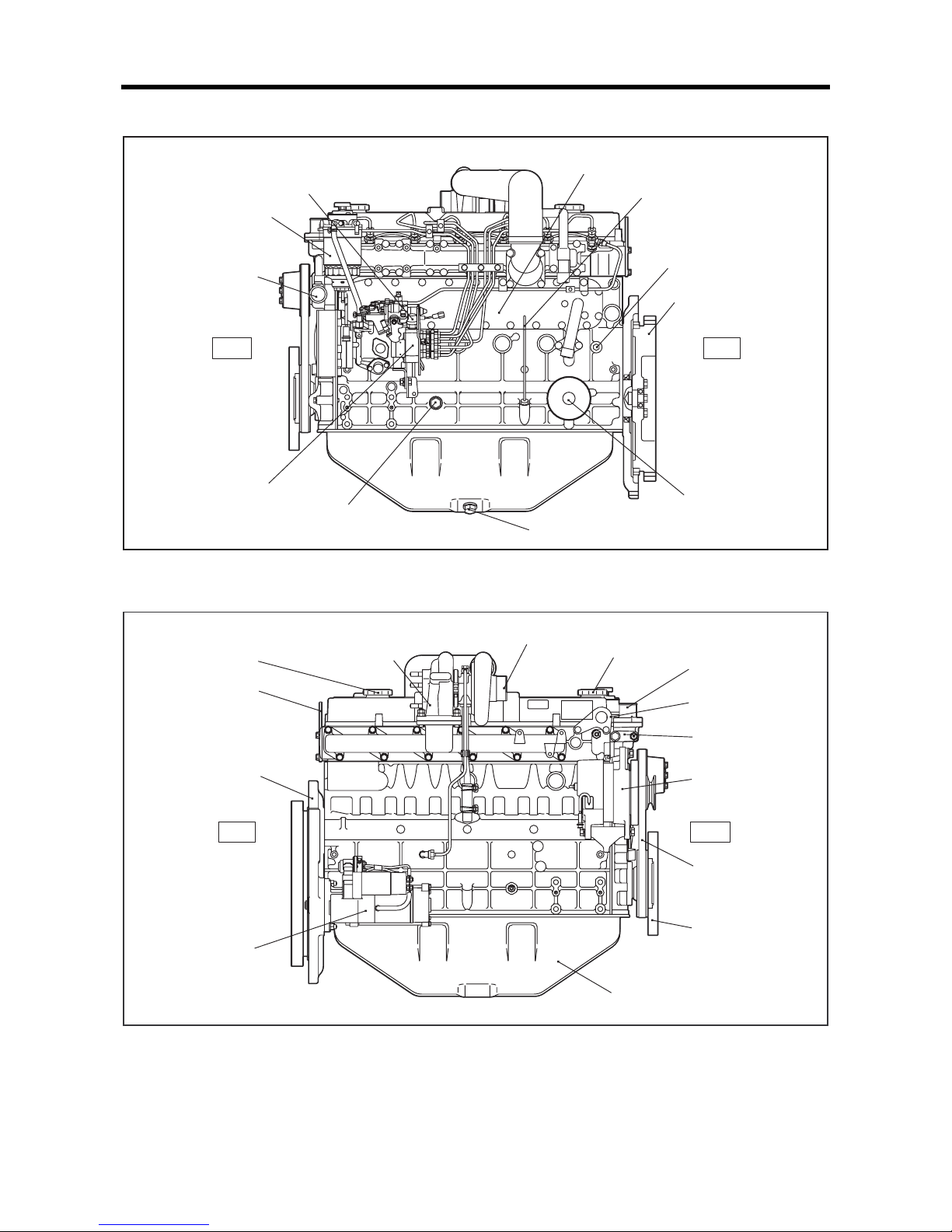
Engine left view
Engine right view
Front
Rear
Fuei injection pump
Oil filter
Flywheel
Oil drain plug
Oil level gauge
Relief valve
Magnet valve
(Stop solenoid)
Coolant drain plug
Water pump
(Coolant inlet)
Fuel filter
Oil cooler
S6S-Y3T62HF
FrontRear
Hanger
Oil pan
V-belt
Alternator
Thermostat case
Coolant outlet
Hanger
Oil filler
Turbocharger
(Exhaust outlet)
Starter
Oil filler
Air inlet
Damper
Rear plate
S6S-Y3T62HF
Page 20
GENERAL
1-4
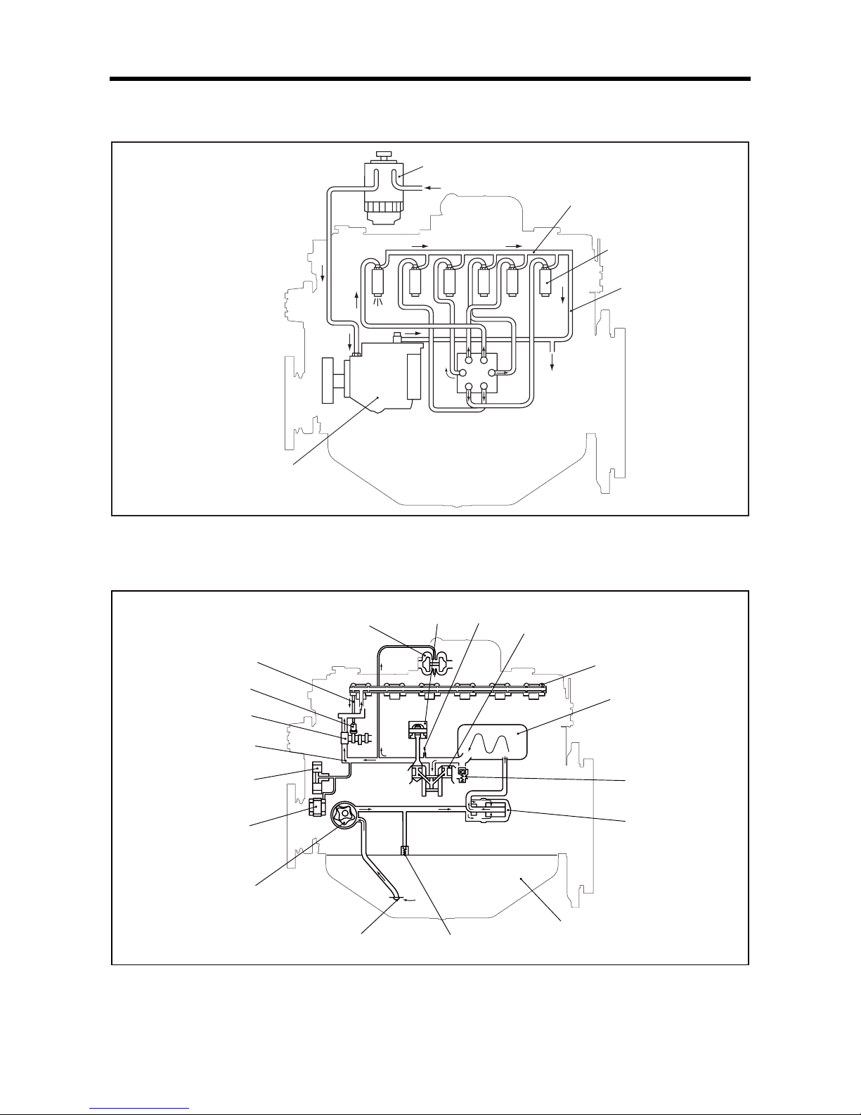
2. System flow diagrams
2.1 Fuel system - flow diagram
Fuel system - flow diagram
2.2 Lubrication system - flow diagram
Lubrication system - flow diagram
Fuel filter
Fuel inlet
Fuel leak-off pipe
Fuel injection nozzle
Fuel injection pump
Fuel return pipe
Fuel outlet
Oil jet
Pushrod
Tappet
Camshaft
Idler gear
Oil pump
Piston
Valve mechanism
Relief valve
Oil filter
Oil strainer
Oil pan
Main gallery
Crankshaft
Turbocharger
Oil cooler
Safety valve
Side PTO
(Drive gear)
[S6S-Y3T61HF]
Page 21
GENERAL
1-5
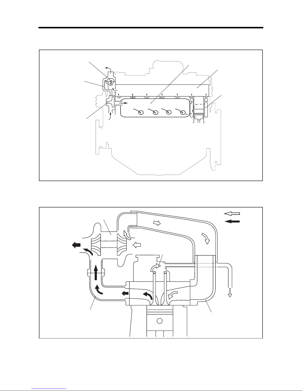
2.3 Cooling system - flow diagram
Cooling system - flow diagram
2.4 Inlet and exhaust system - flow diagram
Inlet and exhaust system - flow diagram
Thermostat
Water pump
Water jacket
Cylinder head
Bypass hose
Cooling inlet
Cooling outlet
Oil cooler
Inlet
Inlet
Exhaust
Exhaust
Turbocharger
Exhaust manifold
Inlet manifold
Blow-by gas
Discharge
Page 22
GENERAL
1-6
3. Engine serial number location
The engine serial number is stamped on the right side of
cylinder block.
Engine serial number location
Engine
serial number
Page 23
GENERAL
1-7
4. Main specifications
Table 1-1 Main specifications (1 / 3)
Engine model S6S-Y3T61HF S6S-Y3T62HF
Main
specification
Type Water cooled, 4 cycle diesel engine, turbocharged
No. of cylinders - arrangement 6 cylinder in-line
Combustion system Swirl chamber type
Valve mechanism Overhead
Cylinder bore × stroke 94 × 120 mm [3.70 × 4.72 in.]
Displacement 4.996 L [305 cu. in.]
Compression ratio 22.0 : 1
Fuel
ASTM diesel fuel oil No.2-D
(JIS K2204 gas oil specification No.2 or 3)
Firing order 1 - 5 - 3 - 6 - 2 - 4
Direction of rotation Counterclockwise when viewed from flywheel side
Dimensions
(varies depending on
the specifications)
Length 999 mm [39.33 in.] 908 mm [35.75 in.]
Width 617 mm [24.29 in.] 622 mm [24.49 in.]
Height 854 mm [33.62 in.] 839 mm [33.03 in.]
Dry weight 350 kg [771.6 lb]
Basic engine
Cylinder Type Dry (integral with cylinder block)
Piston ring Number of rings
Compression rings: 2
Oil ring (w/expander): 1
Valve timing
(when warm)
Inlet valve
Open BTDC 18°
Close ABDC 54°
Exhaust valve
Open BBDC 66°
Close ATDC 22°
Starting system Electric
Starting aid system Glow plug
Side PTO
Allowable torque 98 N·m {10 kgf·m} [72 lbf·ft] Gear ratio 1 : 1 -
Fuel system
Fuel injection pump
Type Distribution (Bosch VE type)
Plunger diameter ø 11 mm [0.43 in.]
Cam lift 1.741 mm [0.0685 in.]
Governor Bosch, all speed type
Fuel injection nozzle
Nozzle type Denso, throttle type
Number of spray holes 1
Spray hole diameter ø 1.0 mm [0.039 in.]
Spray angle 0°
Valve opening pressure 11.77 MPa {120 kgf/cm²} [1706.80 psi]
Fuel filter Type Cartridge type paper element
Page 24
GENERAL
1-8
Lubrication
system
Lubricating method
Forced circulation type
(pressure feed by oil pump)
Engine oil
Standard Class CF-4 oil SAE No.30 (API service classification)
Engine oil capacity
Engine total: approx. 16.5 L [4.36 U.S. gal.]
(approx. 15.5 L [4.10 U.S. gal.] in oil pan)
Oil pump
Type Trochoid
Speed ratio to crankshaft 0.74
Discharge capacity
38.7 L [10.22 U.S. gal.]/min
(at pump rotation of 2230 min
-1
,
0.3 MPa {3 kgf/cm²} [42.67 psi])
Relief valve
Type Piston valve type
Valve opening pressure
0.35 ± 0.05 MPa {3.5 ± 0.5 kgf/cm²}
[49.78 ± 7.11 psi]
Safety valve Opening pressure 1.1 MPa {11 kgf/cm²} [157 psi]
Oil cooler Type Plate type
Oil filter Type Cartridge type paper element
Cooling system
Cooling method Water-cooled, forced circulation
Coolant capacity (engine) 8 L [2.11 U.S. gal.]
Water pu mp
Type Volute type centrifugal pump
Speed ratio to crankshaft 1.05
Discharge capacity
160 L [42.27 U.S. gal.]/min
(at pump rotation of 3600 min
-1
,
0.075 MPa {0.75 kgf/cm²} [10.67 psi])
Cooling fan
Type Pressure type
Diameter ø 500 mm [19.69 in.]
Thermostat
Type Wax type
Valve opening temperature 76.5 ± 2°C [169.7 ± 3.6°F] (90°C [194.0°F] when fully opened)
Inlet and exhaust
system
Turbocharger
Model number TD06H
Qty 1
Table 1-1 Main specifications (2 / 3)
Engine model S6S-Y3T61HF S6S-Y3T62HF
Page 25

GENERAL
1-9
Electrical
system
Voltage - polarity 24V - negative (-) ground
Starter
Model number M008T60373
Pinion meshing type Pinion shift
Output 24 V - 5 kW
Qty 1
Ring gear and pinion ratio 10/122
Alternator
Type 3-phase alternating current, with rectifier
Output 24 V - 35 A
Speed in use
to 8000 min
-1
Rated generating speed
5000 min
-1
Permissible speed
10000 min
-1
Speed ratio to crankshaft 1.85
Glow plug
Type Electric
Rated voltage - current 22 V - 4.4 A (15-second duration)
Magnetic valve
(Stop solenoid)
Rated voltage 24 V
Power consumption 14 W
Starting voltage 13 V or below
Return voltage 5 V or more
Coil resistance
37 Ω
Table 1-1 Main specifications (3 / 3)
Engine model S6S-Y3T61HF S6S-Y3T62HF
Page 26

GENERAL
1-10
5. Tips on disassembling and reassembling
This service manual specifies the recommended procedures
to be followed when servicing Mitsubishi engines. The
manual also specifies the special tools that are required for
the work, and the basic safety precautions to follow when
working.
Note that this manual does not exhaustively cover potential
hazards that could occur during maintenance, inspection and
service work of engine.
When working on an engine, follow the relevant directions
given in this manual and observe the following instructions:
5.1 Disassembling
(1)
Use correct tools and instruments. Serious injury or
damage to the engine will result from using the wrong
tools and instruments.
(2) Use a n overhaul stand or work bench if necessary, and
follow the disassembling procedures described in this
manual.
(3) Ke ep the engine parts in order of removal to prevent
losing them.
(4) Pay atte ntion to assembling marks. Put your marks on
the parts, if necessary, to ensure correct reassembling.
(5) Carefully check each part for defects during
disassembling or cleaning. Do not miss symptoms
which can not be detected after disassembling or
cleaning.
(6) Wh en lifting or carrying heavy parts, exercise utmost
caution to ensure safety. Pay attention to balance of
heavy parts when handling. (Get help, and use jacks,
chain blocks and guide bolts as necessary.)
5.2 Reassembling
(1)
Wash all engine parts, except such parts as oil seals, Orings and rubber sheets, in cleaning oil and dry them
with compressed air.
(2) Use correct tools and instruments.
(3) Use only high-quality lubricating oils and greases of
appropriate types. Be sure to apply oil, grease or
adhesive to the part wherever specified.
(4) Use a torque wrench to tighten parts correctly when
their tightening torques are specified.
Refer to "Tightening torque table."
(5) Replace all gaskets and packings with new ones unless
specified otherwise. Apply adhesive if necessary. Use
only the proper amount of adhesive.
Page 27

2-1
SERVICE DATA
1. Maintenance service data ...............2-2
1.1 General.................................................... 2-2
1.2 Basic engine ............................................ 2-3
1.3 Fuel system.............................................. 2-6
1.4 Lubrication system............ ... ... ... .... .......... 2-6
1.5 Cooling system . ... ... ... ... ........................... 2-7
1.6 Inlet and exhaust system......................... 2-7
1.7 Electrical system...................................... 2-8
2. Tightening torque table ...................2-9
2.1 Major bolt tightening torque ..................... 2-9
2.1.1 Basic engine...............................................2-9
2.1.2 Fuel system................................................2-9
2.1.3 Lubrication system ...................................2-10
2.1.4 Cooling system.........................................2-10
2.1.5 Inlet and exhaust systems........................2-10
2.1.6 Electrical system ......................................2-10
2.2 Standard bolt and nut tightening torque. 2-11
2.2.1 Metric automobile screw thread ...............2-11
2.2.2 Metric course screw thread......................2-11
2.3 Standard stud tightening torque . .... ... ... .. 2-11
3. Regarding submission of parts for
EPA exhaust gas regulation..........2-12
Page 28
SERVICE DATA
2-2
1. Maintenance service data
1.1 General
Table 2-1 Maintenance service data table - General Unit: mm [in.]
Inspection point Nominal Standard Limit Remark
Maximum rotation speed (No-load)
2570 ± 50 min
-1
Minimum rotation speed (No-load)
820 ± 25 min
-1
Compression pressure (at 300 min-1)
3.2 MPa
{33 kgf/cm²}
[469 psi] or more
2.8 MPa
{29 kgf/cm²}
[412 psi] or less
When oil and water
temperatures
at 20 to 30°C
[68 to 86°F]
Lubricating
oil pressure
Rotated speed
at 1500 min
-1
0.3 to 0.5 MPa
{3 to 5 kgf/cm²}
[43 to 71 psi]
0.15 MPa
{1.5 kgf/cm²}
[21 psi] or less
Oil temperature
at 60 to 70°C
[140 to 158°F]
Idling speed
0.10 MPa
{1.0 kgf/cm²}
[14 psi] or more
0.05 MPa
{0.5 kgf/cm²}
[7 psi] or less
Valve timing
Inlet open BTDC 18°
Values are only for
checking valve timing
and are different from
the actual ones.
Inlet closes ABDC 54°
Exhaust open BBDC 66°
Exhaust closes ATDC 22°
Valve clearance
Inlet 0.25 [0.0098]
When engine is cold
Exhaust 0.25 [0.0098]
Fuel injection timing (before TDC) 5°
Page 29
SERVICE DATA
2-3
1.2 Basic engine
Table 2-2 Maintenance service data table - Basic engine (1 / 4) Unit: mm [in.]
Inspection point Nominal Standard Limit Remark
Rocker
Rocker bushing inside diameter
ø 19
[0.75]
19.010 to 19.030
[0.7484 to 0.7492]
Rocker shaft outside diameter
ø 19
[0.75]
18.980 to 19.000
[0.7472 to 0.7480]
Clearance between rocker bushing and
shaft
0.010 to 0.050
[0.0004 to 0.0020]
0.070
[0.0028]
Valve and
valve guide
Valve s te m
outside diameter
Inlet
ø 8
[0.31]
7.940 to 7.955
[0.3126 to 0.3132]
7.900
[0.3110]
Exhaust
ø 8
[0.31]
7.920 to 7.940
[0.3118 to 0.3126]
7.850
[0.3091]
Clearance between
valve stem and
guide
Inlet
0.065 to 0.095
[0.0026 to 0.0037]
0.150
[0.0059]
Exhaust
0.080 to 0.115
[0.0031 to 0.0045]
0.200
[0.0079]
Valve guide mounting dimension
14
[0.55]
13.9 to 14.1
[0.547 to 0.555]
Valve seat
Valve seat angle 30°
Valve sinkage
Inlet
0.4
[0.016]
0.3 to 0.5
[0.012 to 0.020]
1.0
[0.039]
Exhaust
0.5
[0.020]
0.4 to 0.6
[0.016 to 0.024]
1.0
[0.039]
Seat width
1.4
[0.055]
1.26 to 1.54
[0.0496 to 0.0606]
1.8
[0.071]
Valve margin
2.13
[0.0839]
Refacing
permissible up to
1.83 [0.0720]
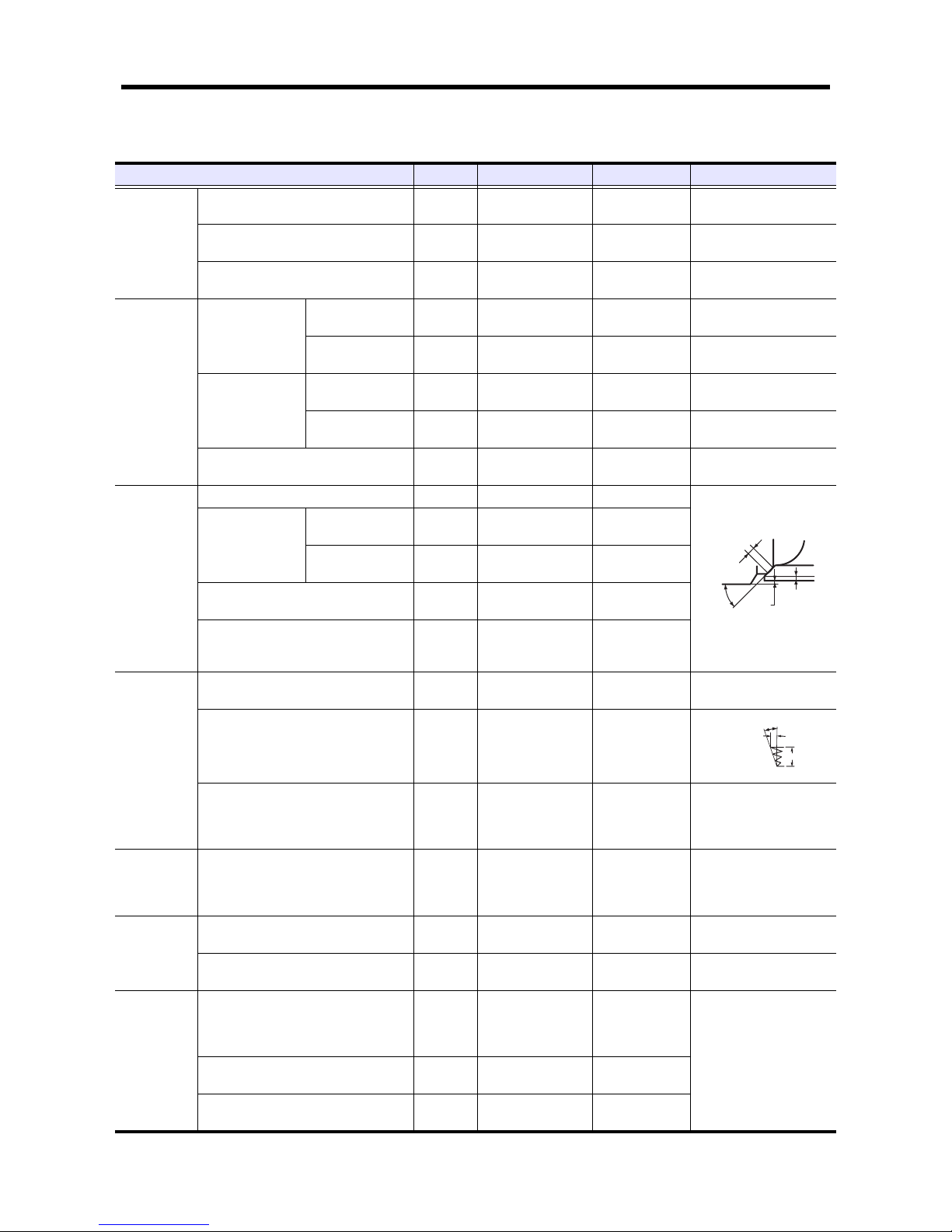
Valve
spring
Free length
48.85
[1.9232]
47.60
[1.8740]
Perpendicularity
A = 1.5°or less
B = 1.3 [0.051]
or less
Lf = 48.85 [1.9232]
B = 1.5 [0.059]
at the end
Set length/set load
43 mm [1.69 in.]/
176 to 196 N
{18 to 20 kgf}
[39 to 44 lbf]
43 mm [1.69 in.]/
147 N
{15 kgf}
[33 lbf]
Pushrod Runout
0.6
[0.024] or less
0.6
[0.024]
Runout (dial gaule reading)
when push rod is supported
along center line of spherical surface at either end.
Cylinder head
Distortion of bottom face
0.05
[0.0020] or less
0.20
[0.0079]
Reface minimum thickness.
Compressed thickness of gasket
1.2
[0.047]
1.20 ± 0.05
[0.0472 ± 0.0020]
Cylinder
Inside diameter
ø 94
[3.70]
94.000 to 94.035
[3.7008 to 3.7022]
Repair limit:
94.200 [3.7087]
Replace limit:
94.700 [3.7283]
Refinish cylinder to 0.25
[0.0098] or 0.50 [0.0197]
oversize of nominal valve
by honing.
Use oversize piston and piston ring.
Circularity
0.01
[0.0004] or less
Cylindricality
0.015
[0.0006] or less
Valve
margin
Val ve
sinkage
Val ve
seat angle
Seat width
A
B
Lf
Page 30
SERVICE DATA
2-4
Piston
Outside diameter
(at piston skirt)
STD
ø 94
[3.70]
93.955 to 93.985
[3.6990 to 3.7002]
93.770
[3.6917]
0.25 [0.0098]/OS
94.205 to 94.235
[3.7089 to 3.7100]
94.020
[3.7016]
0.50 [0.0197]/OS
94.455 to 94.485
[3.7187 to 3.7199]
94.270
[3.7114]
Protrusion from crankcase
-0.25 to 0.15
[-0.0098 to 0.0059]
Bearing clearance check.
Weight difference in one engine
5 g
[0.2 oz.] or less
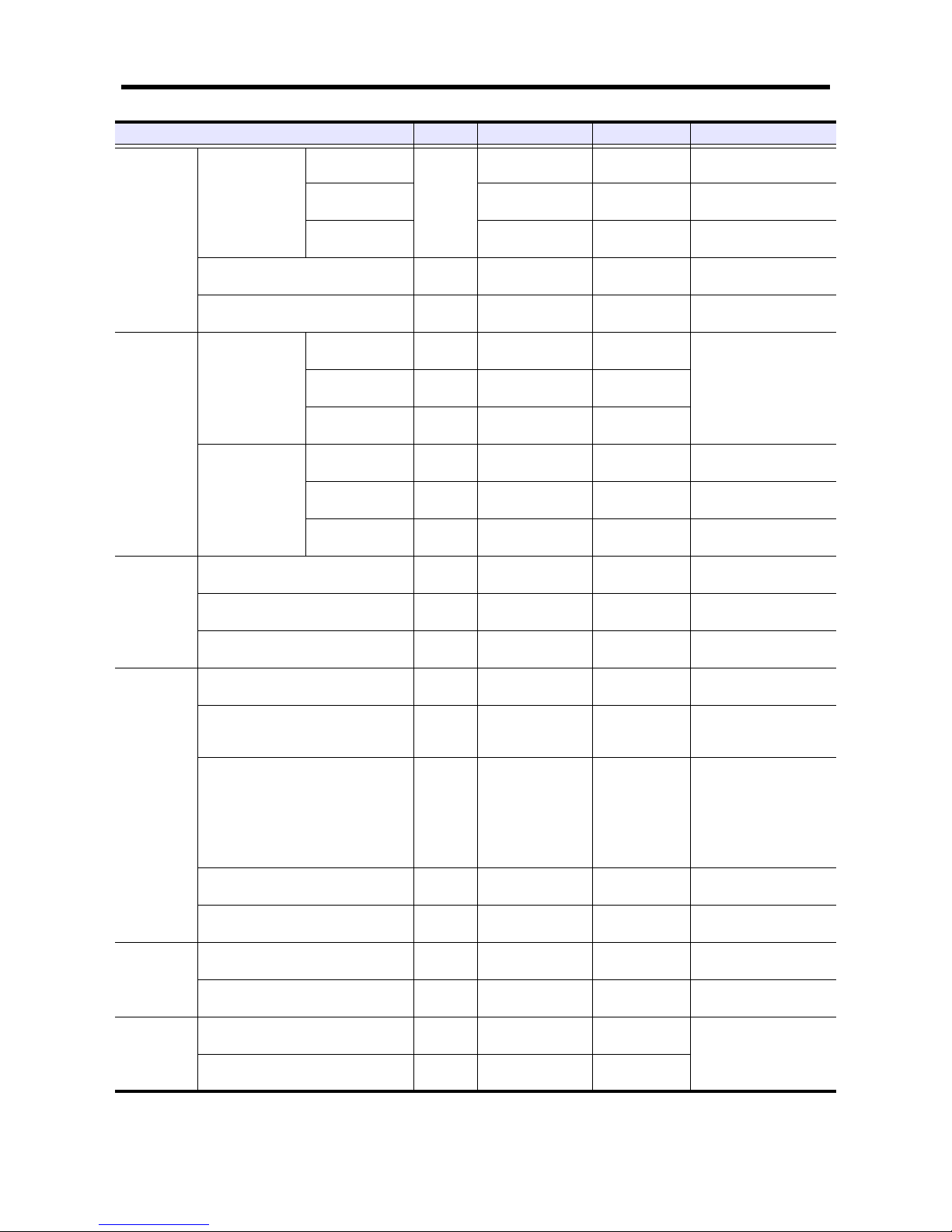
Piston ring
Clearance between
piston ring groove
No.1
compression ring
2.5 [0.098]
0.07 to 0.11
[0.0028 to 0.0043]
0.200
[0.0079]
Use the piston with replacing
the piston rings until reaching
the limits.
when reaching the limits,
replace the piston.
No.2
compression ring
2.0 [0.079]
0.045 to 0.085
[0.0018 to 0.0033]
0.150
[0.0059]
Oil ring 4.0 [0.157]
0.020 to 0.060
[0.0008 to 0.0024]
0.150
[0.0059]
Closed gap of ring
No.1
compression ring
0.30 to 0.50
[0.0118 to 0.0197]
1.50
[0.0591]
No.2
compression ring
0.50 to 0.70
[0.0197 to 0.0276]
1.50
[0.0591]
Oil ring
0.30 to 0.50
[0.0118 to 0.0197]
1.50
[0.0591]
Piston pin
Outside diameter
ø 30
[1.18]
29.994 to 30.000
[1.1809 to 1.1811]
Clearance between piston pin
0.000 to 0.016
[0.0000 to 0.0006]
0.050
[0.0020]
Clearance between connecting rod bushing
0.020 to 0.091
[0.0008 to 0.0036]
0.120
[0.0047]
Connecting
rod
Bushing inside diameter
ø 30
[1.18]
30.020 to 30.045
[1.1819 to 1.1829]
Bend and twist
0.05/100
[0.0020/3.94]
or less
0.15
[0.0059]
Clearance between crankpin and connecting rod bearing (oil clearance)
0.030 to 0.090
[0.0012 to 0.0035]
0.200
[0.0079]
Use connecting rod with
replacing bearing until
reaching the limit.
when exceeding the limit,
re-gring the crankpin and
replace the bearing with
under size.
End play 33 [1.30]
0.15 to 0.35
[0.0059 to 0.0138]
0.50
[0.0197]
Replace connecting rod.
Weight dif ference of connecting rod assembly in one engine
10 g
[0.35 oz.] or less
Flywheel
Flatness
0.15
[0.0059] or less
0.50
[0.0197]
Runout
0.15
[0.0059] or less
0.50
[0.0197]
Damper
Perpendicularity runout
0.5
[0.020] or less
1.5
[0.059]
Replace with a new one
after operating 8000 hours.
Periphery runout
0.5
[0.020] or less
1.5
[0.059]
Table 2-2 Maintenance service data table - Basic engine (2 / 4) Unit: mm [in.]
Inspection point Nominal Standard Limit Remark
Page 31

SERVICE DATA
2-5
Camshaft
Runout
0.04
[0.0016] or less
0.10
[0.0039]
TIR
Cam lift
Inlet
6.682
[0.2631]
6.382 to 6.782
[0.2513 to 0.2670]
6.182
[0.2434]
Exhaust
6.722
[0.2646]
6.422 to 6.822
[0.2528 to 0.2686]
6.222
[0.2450]
Journal outside
diameter
No. 1, 2, 3
ø 54
[2.13]
53.94 to 53.96
[2.1236 to 2.1244]
53.90
[2.1220]
No.4
ø 53
[2.09]
52.94 to 52.96
[2.0842 to 2.0850]
52.90
[2.0827]
Clearance between camshaft journal and
camshaft bushing
0.07 to 0.11
[0.0028 to 0.0043]
0.15
[0.0059]
Replace bushing if limit is
exceeded.
Reaming if necessary.
End play
5
[0.20]
0.10 to 0.25
[0.0039 to 0.0098]
0.30
[0.0118]
Replace thrust plate.
Idler
Clearance between bushing and shaft
0.009 to 0.050
[0.0004 to 0.0020]
0.100
[0.0039]
Idler gear end play
30
[1.18]
0.05 to 0.20
[0.0020 to 0.0079]
0.35
[0.0138]
Replace thrust plate.
Interference between shaft and crankcase
hole
ø 35
[1.38]
0.035T to 0.076T
[0.0014 to 0.0030]
Timing gear backlash
0.05 to 0.15
[0.0020 to 0.0059]
0.25
[0.0098]
Replace gear.
Crankshaft
Crank journal outside diameter
ø 78
[3.07]
77.955 to 77.970
[3.0691 to 3.0697]
77.850 [3.0650]
(Repair)
77.100 [3.0354]
(Replace)
Crankpin outside diameter
ø 58
[2.28]
57.955 to 57.970
[2.2817 to 2.2823]
57.800
[2.2756]
Distance between centers of journal and
crankpin
60
[2.36]
59.96 to 60.04
[2.3606 to 2.3638]
Parallelism between journal and crankpin
Pin maximum
defection:
0.01
[0.0004] or less
Roundness of journals and crankpins
0.01
[0.0004] or less
0.03
[0.0012]
Cylindericity of journals and crankpins
0.01
[0.0004] or less
0.03
[0.0012]
Fillet radius of pin and journal
R3
[0.12]
2.8 to 3.2
[0.110 to 0.126]
Runout (TIR)
0.04
[0.0016] or less
0.10
[0.0039]
TIR
End play
31
[1.22]
0.100 to 0.264
[0.0039 to 0.0104]
0.300
[0.0118]
Replace thrust plates before
limit is reached. If limit is
exceeded, use one of following oversize thrust plates;
+0.25 [+0.0098], +0.50
[+0.0197], +0.75 [+0.0295]
Table 2-2 Maintenance service data table - Basic engine (3 / 4) Unit: mm [in.]
Inspection point Nominal Standard Limit Remark
D1
D2
Page 32

SERVICE DATA
2-6
1.3 Fuel system
1.4 Lubrication system
Main bearing
Clearance between main bearing and crankshaft journal
0.050 to 0.110
[0.0020 to 0.0043]
0.200
[0.0079]
crank journal
outside diameter
(ø 78 [3.0709])
-0.9 [-0.0354]
Replace bearings before
limit is reached. Regrind
crank journal and use next
undersize bearings if limit is
exceeded;
-0.25 [-0.0098], -0.50
[-0.0197], -0.75 [-0.0295]
Crankcase
Flatness of top surface
0.05
[0.0020] or less
0.20
[0.0079]
Reface minimum thickness.
Tappet guide hole inside diameter
14.000 to 14.018
[0.5512 to 0.5519]
14.100
[0.5551]
Clearance between tappet and tappet guide
hole
0.016 to 0.052
[0.0006 to 0.0020]
0.08
[0.0031]
If the diameter is the limit or
more, replace tappet.
Table 2-2 Maintenance service data table - Basic engine (4 / 4) Unit: mm [in.]
Inspection point Nominal Standard Limit Remark
Table 2-3 Maintenance service data table - Fuel system Unit: mm [in.]
Inspection point Nominal Standard Limit Remark
Fuel
injection
nozzle
Valve opening pressure
11.77 MPa
{120 kgf/cm²}
[1707 psi]
11.77 to 12.75 MPa
{120 to 130 kgf/cm²}
[1707 to 1849 psi]
Make shim adjustment.
Pressure varies by 1 MPa {10 kgf/cm²} [142
psi] per 0.1 [0.004] thickness of shim.
Spray cone angle 0°
Check nozzle with a hand tester (at fuel oil
temperature 20°C [68°F]). Replace the nozzle tip if the spray pattern is still bad after
washing in clean fuel oil.
Nozzle valve seat oil
sealing
Seat shall hold a test pressure lower than
valve opening pressure by 2 MPa
{20 kgf/cm²} [285 psi] for 10 seconds.
Wash in clean fuel oil or replace nozzle tip.
Table 2-4 Maintenance service data table - Lubrication system Unit: mm [in.]
Inspection point Nominal Standard Limit Remark
Oil pump
Clearance between outer rotor and case
0.20 to 0.30
[0.0079 to 0.0118]
0.50
[0.0197]
Replace pump assembly.
Main shaft outside diameter
(between case)
ø 16
[0.63]
15.985 to 16.000
[0.6293 to 0.6299]
Main shaft outside diameter
(between oil pump bushing)
ø 14
[0.55]
13.957 to 13.975
[0.5495 to 0.5502]
Clearance between main shaft and pump
case
0.032 to 0.074
[0.0013 to 0.0029]
0.150
[0.0059]
Replace pump case or
replace pump assembly.
Clearance between main shaft and oil
pump bushing
0.025 to 0.111
[0.0010 to 0.0044]
0.200
[0.0079]
Replace oil pump bushing or replace pump
assembly.
Clearance between inner rotor and outer
rotor
0.13 to 0.15
[0.0051 to 0.0059]
0.20
[0.0079]
Replace outer rotor and
shaft assembly.
Rotor and case end play
0.04 to 0.09
[0.0016 to 0.0035]
0.15
[0.0059]
Replace pump assembly.
Relief valve Valve opening pressure
0.35 MPa
{3.6 kgf/cm²}
[51.20 psi]
0.35 ± 0.05 MPa
{3.5 ± 0.5 kgf/cm²}
[49.78 ± 7.11 psi]
Safety valve Valve opening pressure
1.1 MPa
{11 kgf/cm²}
[157 psi]
Page 33

SERVICE DATA
2-7
1.5 Cooling system
1.6 Inlet and exhaust system
Table 2-5 Maintenance service data table - Cooling system Unit: mm [in.]
Inspection point Nominal Standard Limit Remark
Thermostat
Temperature at which valve starts
opening
76.5 ± 1.5°C
[170 ± 3.5°F]
Temperature at which valve lift is
9 [0.35], minimum
90 ± 1.5°C
[194 ± 2.7°F]
Table 2-6 Maintenance service data table - Inlet and exhaust system Unit: mm [in.]
Inspection point Nominal Standard Limit Remark
Distortion of exhaust manifold
0.2
[0.008] or less
Repair by grinding or replace.
Axial clearance of cartridge assembly
0.057 to 0.103
[0.0022 to 0.0041]
Page 34

SERVICE DATA
2-8
1.7 Electrical system
Table 2-7 Maintenance service data table - Electrical system Unit: mm [in.]
Inspection point Nominal Standard Limit Remark
Starter
Commutator
Outside diameter
ø 32
[1.26]
31.4
[1.236]
Runout
0.05
[0.0020] or less
0.10
[0.0039]
Undercut depth
0.4 to 0.6
[0.016 to 0.024]
0.2
[0.008]
Brush length
18
[0.71]
11
[0.43]
Tension of brush springs
34 N
{3.5 kgf}
[7.7 lbf]
29.4 to 39.4 N
{3.0 to 4.0 kgf}
[6.6 to 8.8 lbf]
13.7 N
{1.4 kgf}
[3.1 lbf]
No-load characteristics
Voltage 23 V
Armature current 85 A or less
Rotational speed
3300 min
-1
or more
Load characteristics
Voltage 9 V
Armature current 1400 A or less
Torque
88.26 N·m
{9.0 kgf·m}
{65 lbf·ft} or more
Alternator
Regulator adjusting voltage
(alternator 5000 min
-1
, load at 5 A or lower)
28.5 × 0.5 V
Resistance between slip rings
9.0 to 10.4 Ω
at 20°C [68°F]
Brush spring tension
5.8 to 7.0 N
{590 to 710 gf}
[1.3 to 1.6 lbf]
3.2 N
{330 gf}
[0.7 lbf]
Brush length 21.5 [0.85] 8 [0.31]
Glow plug
Rated voltage DC22 V
(When applying the rated
voltage for 15 seconds.)
Armature current
4.4
-0.7
+0.3
A
Magnetic
valve
Resistance value
37 to 41 Ω
Ambient temperature:
23 ± 5°C
[73.4 ± 9°F])
V-belt Deflection
8
[0.31]
When center of belt pressed
at approx.
98 N {10 kgf} [22 lbf]
Page 35

SERVICE DATA
2-9
2. Tightening torque table
2.1 Major bolt tightening torque
2.1.1 Basic engine
Note: When [Wet] is indicated, apply engine oil to the threads and bearing surfaces of the bolts and nuts.
2.1.2 Fuel system
Table 2-8 Tightening torque table - Basic engine
Description
Threads
Dia × Pitch
(mm)
Torque
Remark
N·m kgf·m lbf·ft
Cylinder head 12 × 1.75 118 ± 5 12 ± 0.5 87 ± 3.6
Cylinder head plug 16 × 1.5 44.1 ± 5 4.5 ± 0.5 32.5 ± 3.6
Rocker cover 8 × 1.25 11.3 ± 1.5 1.15 ± 0.15 8.5 ± 1.1
Rocker shaft bracket (long) 8 × 1.25 17.5 ± 2.5 1.75 ± 0.25 12.7 ± 1.8
Main bearing cap 14 × 2.0 103 ± 5 10.5 ± 0.5 76 ± 3.6 [Wet]
Connecting rod cap 10 × 1.25 54 ± 5 5.5 ± 0.5 40 ± 3.6
Flywheel 12 × 1.25 83.4 ± 4.9 8.5 ± 0.5 61.5 ± 3.6
Camshaft thrust plate 8 × 1.25 11.5 ± 1.5 1.15 ± 0.15 8.3 ± 1.1
Front plate 8 × 1.25 11. 3 ± 1.5 1.15 ± 0.15 8.3 ± 1.1
Timing gear case cover 8 × 1.25 18.5 ± 1.5 1.85 ± 0.15 13.4 ± 1.1
Crankshaft pulley 30 × 1.5 490 ± 10 50 ± 1 362 ± 7.2
Idler thrust plate 10 × 1.25 34 ± 5 3.5 ± 0.5 25 ± 3.6
Rear plate 10 × 1.25 56 ± 5.9 5.7 ± 0.6 41.2 ± 4.3
Rocker adjusting nut 8 × 1.25 20 ± 2 2 ± 0.2 14.5 ± 1.4
Table 2-9 Tightening torque table - Fuel system
Description
Threads
Dia × Pitch
(mm)
Torque
Remark
N·m kgf·m lbf·ft
Fuel injection nozzle
(engine)
20 × 1.5 58.8 ± 5.9 6 ± 0.6 43.4 ± 4.3
Fuel injection nozzle retaining nut 16 × 0.75 36.8 ± 2.5 3.75 ± 0.25 27.1 ± 1.8
Fuel injection pump gear 12 × 1.75 63.7 ± 5 6.5 ± 0.5 47 ± 3.6
Fuel injection pump over flow valve - 17.5 ± 2.5 1.75 ± 0.25 12.7 ± 1.8
Fuel injection pipe nut 12 × 1.5 29.4 ± 2.9 3 ± 0.3 21.7 ± 2.2
Fuel return pipe nut 10 × 1.25 19.6 ± 1.9 2 ± 0.2 14.5 ± 1.4
Fuel filter drain plug 14 × 1.0 2 ± 0.5 0.2 ± 0.05 1.4 ± 0.4
Fuel filter cartridge 20 × 1.5 15 ± 3 1.5 ± 0.3 10.8 ± 2.2
Fuel filter water level sensor 36 × 1.5 5 ± 1 0.5 ± 0.1 3.6 ± 0.7
Fuel leak off pipe mounting nut 12 × 1.5 2 2.6 ± 1.9 2.3 ± 0.2 16.6 ± 1.4
Page 36

SERVICE DATA
2-10
2.1.3 Lubrication system
2.1.4 Cooling system
2.1.5 Inlet and exhaust systems
2.1.6 Electrical system
Table 2-10 Tightening torque table - Lubrication system
Description
Threads
Dia × Pitch
(mm)
Torque
Remark
N·m kgf·m lbf·ft
Oil pan 8 × 1.25 11. 3 ± 1.5 1.15 ± 0.15 8.3 ± 1.1
Oil pan drain plug 20 × 1.5 78 ± 5 8 ± 0.5 57.9 ± 3.6
Oil pump gear 10 × 1.25 33 ± 5 3.4 ± 0.5 24.6 ± 3.6
Oil pressure relief valve 22 × 1.5 49 ± 4.9 5 ± 0.5 36.2 ± 3.6
Safety valve 18 × 2.0 69 ± 5 7 ± 0.5 50.6 ± 3.6
Table 2-11 Tightening torque table - Cooling system
Description
Threads
Dia × Pitch
(mm)
Torque
Remark
N·m kgf·m lbf·ft
Thermostat case 8 × 1.25 18.1 ± 1.5 1.85 ± 0.15 13.4 ± 1.1
Water drain plug 1/4-18NPTF 39.2 ± 3.9 4 ± 0.4 28.9 ± 2.9
Water pump mounting bolt
8 × 1.25 9.8 ± 1 1 ± 0.1 7.2 ± 0.7
8 × 1.25 18.1 ± 3.4 1.85 ± 0.35 13.4 ± 2.5
Water pump plug R3/8 32.4 ± 2 3.3 ± 0.2 23.9 ± 1.4
Table 2-12 Tightening torque table - Inlet and exhaust systems
Description
Threads
Dia × Pitch
(mm)
Torque
Remark
N·m kgf·m lbf·ft
Exhaust manifold 8 × 1.25 18.1 ± 3.4 1.85 ± 0.35 13.4 ± 2.5
Turbo oil feed eye bolt 10 × 1.25 16.2 ± 2.5 1.65 ± 0.25 11.9 ± 1.8
Clamp - 4 ± 0.5 0.41 ± 0.05 3.0 ± 0.37
Coupling assembly 6 × 1.0 8.3 ± 0.5 0.85 ± 0.05 6.1 ± 0.4
Table 2-13 Tightening torque table - Electrical system
Description
Threads
Dia × Pitch
(mm)
Torque
Remark
N·m kgf·m lbf·ft
Starter terminal B 8 × 1.25 10.8 ± 1 1.1 ± 0.1 8 ± 0.7
Alternator pulley 20 × 1.5 147 ± 15 15 ± 1.5 108.4 ± 11.1
Glow plug (Engine body) 10 × 1.25 17.5 ± 2.5 1.75 ± 0.25 12.7 ± 1.81
Glow plug (terminal) 4 × 0.7 1.25 ± 0.25 0.13 ± 0.03 0.94 ± 0.2
Magnetic valve assembly 24 × 1 20 ± 5 2 ± 0.5 15 ± 3.6
Page 37

SERVICE DATA
2-11
2.2 Standard bolt and nut tightening torque
2.2.1 Metric automobile screw thread
2.2.2 Metric course screw thread
Note: (a) This table lists the tightening torque for standard bolts and nuts.
(b) The numerical values in the table are for fasteners with spring washers.
(c) The table shows the standard values with a maximum tolerance value of ±10%.
(d) Use the tightening torque in this table unless otherwise specified.
(e) Do not apply oil to threaded portions. (Dry)
2.3 Standard stud tightening torque
Table 2-14 Metric automobile screw thread
Threads
Dia × Pitch
(mm)
Width
across flats
(mm) [in.]
Strength classification
4T 7T 10.9
N·m kgf·m lbf·ft N·m kgf·m lbf·ft N·m kgf·m lbf·ft
M6 × 1.0 10 [0.39] 3.9 0.4 2.9 8.8 0.9 6.5 12.7 1.3 9.4
M8 × 1.25 12 [0.47] 11.8 1.2 8.7 18 1.9 13 30 3.1 22
M10 × 1.25 14 [0.55] 21.1 2.15 16 35 3.6 26 60 6.1 44
M12 × 1.25 17 [0.67] 35.3 3.6 26 64 6.5 47 108 11.0 80
4 7
10
Table 2-15 Metric course screw thread
Threads
Dia × Pitch
(mm)
Width
across flats
(mm) [in.]
Strength classification
7T 10.9
N·m kgf·m lbf·ft N·m kgf·m lbf·ft
M10 × 1.5 14 [0.55] 32 3.3 24 58 5.9 43
M12 × 1.75 17 [0.67] 57 5.8 42 102 10.4 75
Table 2-16 Standard stud tightening torque
Threads
Dia × Pitch
(mm)
For driving in aluminum materials For driving in ferrous materials
N·m kgf·m lbf·ft N·m kgf·m lbf·ft
M8 × 1.25 5.4 ± 0.5 0.55 ± 0.05 4.0 ± 0.4 13.7 ± 1.0 1.4 ± 0.1 10.1 ± 0.7
M10 × 1.25 12.7 ± 1.0 1.3 ± 0.1 9.4 ± 0.7 23.5 ± 2.0 2.4 ± 0.2 17.4 ± 1.4
Page 38

SERVICE DATA
2-12
3. Regarding submission of parts for
EPA exhaust gas regulation
CAUTION
When replacing parts, be sure to use OEM designated
parts.
If OEM parts are not used, the exhaust emission's warranty be voided.
New parts may be updated due to improvement.
Fuel and exhaust system repairs should only be conducted by an authorized Mitsubishi forklift truck dealer.
Tampering or adjusting the fuel system components
will void the warranty and could be in violation of the
EPA regulations.
The fuel injection pump is an emission control device.
Components inside the pump are specifically calibrated to meet the engine emissions requirements and
should never be disassembled or rebuilt.
If the pump fails to operate, replace the assembly with
an OEM replace part.
The following parts have been submitted in accordance with
EPA emission regulation.
(1) Fuel injection assembly
(2) Fuel injection nozzle
(3) Turbocharger assembly
(4) Other related parts (including designated fuel and
lubricant)
Page 39

3-1
SERVICE TOOLS
1. Special tool......................................3-2
Page 40

SERVICE TOOLS
3-2
1. Special tool
Table 3-1 Special tool list (1 / 3)
Tool name Part No. Shape Use
Compression gauge 33391-02100
Engine compression pressure
measuring
0 to 7 MPa {0 to 71.4 kgf/cm²}
[0 to 1015.54 psi]
Gauge adapter 30691-21100
Engine compression pressure
measuring
Socket 58309-73100 Engine turning
Valve spring pusher 30691-04500
Valve spr ing
removal/installation
Valve guide remover 32A91-00300 Valve guide removal
Valve sheet insert
caulking tool
Inlet: 36791-00200
Exhaust:
34491-03020
Valve seat installation
Stem seal installer 32A91-10200 Stem seal installation
Page 41

SERVICE TOOLS
3-3
Socket 34491-00300
Camshaft, thrust plate and
rocker bracket installation
Valve guide installer 32A91-00100 Valve guide installation
Camshaft bushing installer set 30691-00010
Camshaft bushing
removal/installation
Idler bushing installer 30091-07300
Idler bushing
removal/installation
Idler shaft puller MH061077 Idler shaft removal
Piston ring pliers 31391-12900 Piston ring removal/installation
Connecting rod bushing puller 32A91-00500
Connecting rod bushing
removal/installation
Table 3-1 Special tool list (2 / 3)
Tool name Part No. Shape Use
Page 42

SERVICE TOOLS
3-4
Oil seal sleeve installer
guide set
30691-13010
Oil seal sleeve installation of
crankshaft rear side
Piston installer 34491-00200 Piston installation
Oil pump bushing installer 32A91-00400 Oil pump bushing installation
Ring pliers 49160-90101 Snap ring removal/installation
Table 3-1 Special tool list (3 / 3)
Tool name Part No. Shape Use
Page 43

4-1
DETERMINATION OF OVERHAUL
1. Determining overhaul timing ...........4-2
2. Testing compression pressure........4-3
Page 44

DETERMINATION OF OVERHAUL
4-2
1. Determining overhaul timing
In most cases, the engine should be overhauled when the compression pressure of the engine becomes low. An increase in
engine oil consumption and blow-by gas are also considered to evaluate the engine condition. Besides, such symptoms as a
decrease in output, increase in fuel consumption, decrease in oil pressure, difficulty of engine starting and increase in noise are
also considered for judging the overhaul timing, although those symptoms are often affected by other causes, and are not
always effective to judge the overhaul timing. Decreased compression pressure shows a variety of symptoms and engine
conditions, thus making it difficult to accurately determine when the engine needs an overhaul. The following shows typical
problems caused by reduced compression pressure.
(1) Decreased output power
(2) Increased fuel consumption
(3) Increased engine oil consumption
(4) Increased blow-by gas through the breather due to worn cylinder liners and piston rings (Visually check the blow-by
amount)
(5) Increased gas leakage due to poor seating of inlet and exhaust valves
(6) Difficulty in starting
(7) Increased noise from engine parts
(8) Abnormal exhaust color after warm-up operation
The engine can exhibit these conditions in various combinations. Some of these problems are directly caused by worn engine
parts, while others are not. Phenomena described in items (2) and (6) will result from improper fuel injection volume, fuel
injection timing, worn plunger, faulty nozzles and also faulty conditions of electrical devices such as battery and starter. The
most valid reason to overhaul an engine is a decrease in compression pressure due to worn cylinder liners and pistons, as
described in item (4). In addition to this item, it is reasonable to take other problems into consideration for making the tota l
judgement.
Page 45

DETERMINATION OF OVERHAUL
4-3
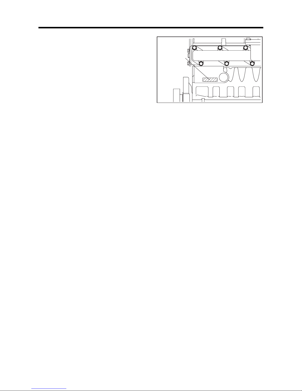
2. Testing compression pressure
CAUTION
(a) Be sure to measure the compression pressure for
all the cylinders. It is not a good practice to measure the compression pressure for only one cylinder, and presume the compression for the
remaining cylinders.
(b) Also be sure to check engine speed when measur-
ing the compression pressure, as compression
pressure varies with engine speed.
(c) Measuring the compression pressure at regular in-
tervals is important to obtain correct data.
(d) The compression pressure will be slightly higher in
a new or overhauled engine due to new piston
rings, valve seats, etc. Pressure will drop gradually
by the wear of these parts.
(e) Turn off the solenoid valve to stop fuel injection.
(1) Remove the glow plug from the cylinder head where
the compression pressure is to be measured.
(2) Atta ch the compre ssion gauge adapter to the glow plug
mount and connect compression gauge.
(3) Crank the engine with the starter, then read the
compression gauge indication while the engine is
running at the specified speed.
(4) If the compression pressure is lower than the limit,
overhaul the engine.
Testing compression pressure
Item Standard Limit
Compression pressure
3.2 MPa
{33 kgf/cm²}
[469 psi]
or more
2.8 MPa
{29 kgf/cm²}
[412 psi]
or less
Engine speed
300 min
-1
-
Oil and water temperatures
20 to 30°C
[68 to 86°F]
-
Gauge adapter
P/N:30691-21100
Compression
gauge
P/N:33391-02100
Page 46

Page 47

5-1
DISASSEMBLY OF BASIC ENGINE
1. Disassembling and inspecting cylinder
head and valve mechanism ............5-2
1.1 Removing rocker shaft assembly............. 5-3
1.2 Disassembling rocker shaft assembly...... 5-3
1.3 Removing cylinder head bolt.................... 5-3
1.4 Removing cylinder head assembly.......... 5-4
1.5 Removing valve and valve spring............5-4
1.6 Removing valve stem seal....................... 5-4
2. Disassembling and inspecting
flywheel...........................................5-5
2.1 Removing flywheel................................... 5-6
2.2 Removing rear plate................................ . 5-6
3. Disassembling and inspecting damper,
gear case, timing gear and
camshaft..........................................5-7
3.1 Removing crankshaft pulley and damper.5-9
3.2 Removing cover............ .... ... ... ... .... ... ... ... . 5-9
3.3 Removing timing gear case ................... 5-10
3.4 Measuring timing gear backlash............ 5-10
3.5 Measuring idler gear and camshaft gear
end play ........ .... ... ... ... ... .... ... ... ... ............ 5-11
3.6 Removing fuel injection pump.... .... ... ... .. 5-11
3.7 Removing oil pan................................... 5-11
3.8 Removing oil strainer............................. 5-11
3.9 Removing oil pump gear......... ... .... ... ... .. 5-12
3.10 Removing idler gear.......... ... ... ... .... ... ..... 5-12
3.11 Removing PTO drive gear ..................... 5-12
3.12 Removing camshaft............................... 5-12
3.13 Separating camshaft gear....... ... .... ... ... .. 5-13
3.14 Installing camshaft gear and thrust plate5-13
3.15 Removing front plate.............................. 5-13
3.16 Removing oil pump................................ 5-13
4. Disassembling and inspecting piston,
connecting rod, crankshaft and
crankcase......................................5-14
4.1 Removing connecting rod cap ....... ... ... .. 5-15
4.2 Removing carbon deposits from the upper part
of cylinder liner....................................... 5-15
4.3 Pulling out piston.................................... 5-15
4.4 Removing piston ring............................. 5-16
4.5 Removing piston pin and piston............. 5-16
4.6 Removing main bearing cap.................. 5-16
4.7 Removing crankshaft............................. 5-17
4.8 Removing tappet.. ... ... ... .... ... ... ... .... ... ... .. 5-17
Page 48

DISASSEMBLY OF BASIC ENGINE
5-2
1. Disassembling and inspecting cylinder head and valve mechanism
Disassembling and inspecting cylinder head and valve mechanism
Disassembling sequence
1 Rocker cover 8 Rocker arm (EX) 15 Valve cotter
2 Adjusting screw 9 Rocker shaft spring 16 Valve retainer
3 Bolt (short) 10 Rocker shaft 17 Valve spring
4 Bolt (long) 11 Valve cap 18 Valve (IN)
5 Rocker shaft bracket 12 Push rod 19 Valve (EX)
6 Snap ring 13 Cylinder head bolt 20 Valve stem seal
7 Rocker arm (IN) 14 Cylinder head 21 Cylinder he ad gasket
1
2
3
4
5
6
7
8
9
10
11
12
13
14
15
16
17
18
19
20
21
Replace
Replace
Replace
Fatigue, damage
Damaged threads,
worn rod contact surface
Wear
Wear
Worn valve cap contact
surface, clogged oil holes
Uneven wear on stems and faces,
damage, fatigue
Wear, clogged oil holes
Wear at both ends,
deflection
Crack, damage, carbon deposits,
water scale adhesion
Uneven wear
Page 49

DISASSEMBLY OF BASIC ENGINE
5-3
1.1 Removing rocker shaft assembly
CAUTION
Always loosen shorter bolts first. Failing to do so may
cause the damage to the rocker shaft bracket.
(1) Loosen the rocker arm adjusting screws by rotating
about one turn.
(2) Loosen the shorter rocker bracket bolts first.
(3) Then, loosen the longer rocker bracket bolts.
(4) Remove the rocker bracket bolts, and remove the
rocker shaft assembly from the cylinder head.
(5) Remove push rods.
Removing rocker shaft assembly
1.2 Disassembling rocker shaft assembly
Remove the snap ring, disassemble the rocker shaft
assembly into the rocker arms, brackets, rocker shaft springs
and rocker shaft.
Note: (a) Be sure to arrange the parts of rocker shaft
assembly in the order of disassembly.
Reassemble the rocker shaft assembly in the
reverse order of disassembly by making sure of
the original combination of rocker arm and shaft
assembly so that the same clearance between the
rocker shaft and arms is restored when
reassembling.
(b) Do not remove the rocker bushing if it is not
faulty, and its inside diameter does not exceed the
limit.
Disassembling rocker shaft assembly
1.3 Removing cylinder head bolt
Loosen cylinder head bolts in the numerical order as shown
in the illustration.
Removing cylinder head bolt
Rocker arm
Adjusting screw
Rocker bracket bolt
Rocker shaft
Rocker shaft spring
Bracket
Rocker arm
Snap ring
1
5
9
13
17
21
25
22
18
14
10
6
2
3711151923 24 20
16 12 8
4
Number of bolt (25)
Front
Page 50

DISASSEMBLY OF BASIC ENGINE
5-4
1.4 Removing cylinder head assembly
CAUTION
When removing the cylinder head gasket, be careful
not to damage the cylinder head or crankcase surface
with tools such as a screwdriver.
(1) Remove the cylinder head bolt.
(2) Remove the cylinder head assembly by lifting it up.
Note: If the cylinder head assembly cannot be removed due
to crimping of the cylinder head gasket, tap the thick
area on the side of the cylinder head using a plastic
hammer to give a shock.
Do not lift up the cylinder head by one person.
Use crane or lift up by two persons.
(3) Remove the gasket from the cylinder head.
Note: If there is a cylinder head problem, check the bolts for
tightness with a torque wrench before removing the
cylinder head bolts.
Removing cylinder head assembly
1.5 Removing valve and valve spring
Using a valve spring pusher, compress the valve spring
evenly and remove the valve cotters.
Note: If valves are reusable, mark each valve seat and the
mating valve for identifying their original positions.
Do not mix valve seats with other valve.
Removing valve and valve spring
1.6 Removing valve stem seal
Grab the valve stem seal with pliers and remove.
Note: Be sure to replace the valve stem seal with a new one
when reassembling the valve and valve spring.
Removing valve stem seal
Cylinder head
Valve spring pusher
P/N:30691-04500
Valve stem seal
Page 51

DISASSEMBLY OF BASIC ENGINE
5-5
2. Disassembling and inspecting flywheel
Disassembling and inspecting flywheel
Disassembling sequence
1 Flywheel 2 Rear plate 3 Oil seal 4 Gasket
1
2
3
4
Replace
Crack,
abnormality of knock hole
Damaged threads
Lip wear, damage or aging
Crack, knock hole defect,
gear damage
Page 52

DISASSEMBLY OF BASIC ENGINE
5-6
2.1 Removing flywheel
CAUTION
(a) Be careful not to cut yourself with the ring gear
when pulling out the flywheel.
Be careful not to drop or hit the flywheel when
removing.
(b) The person who holds the pulley must be very
careful to assure safety by communicating with the
person who is removing the flywheel.
(1) One personnel must firmly hold the pulley with a
wrench to prevent the flywheel from turning.
(2) Remove one bolt from the flywheel.
(3) Screw a guide bolt into the threaded hole of the bolt that
has been removed.
(4) Remove remaining bolts from the flywheel.
(5) Hold the flywheel firmly with both hands, and while
moving it back and forth, pull it out straight.
Note: The ring gear is shrink fitted to the flywheel. Do not
remove the ring gear unless it is defective.
Locking the flywheel
Removing flywheel
2.2 Removing rear plate
CAUTION
Be very careful not to damage the oil seal.
Remove the rear plate mounting bolts, and remove the rear
plate using a guide bolt.
Removing rear plate
Prevent the flywheel from rotating using a wrench.
Guide bolt
Oil seal
Page 53

DISASSEMBLY OF BASIC ENGINE
5-7
3. Disassembling and inspecting damper, gear case, timing gear and camshaft
Disassembling and inspecting damper, gear case, timing gear and camshaft
Disassembling sequence
S6S-Y3T61HF
15
14
13
12
11
7
6
5
10
9
8
4
3
2
1
16
17
18
19
20
Replace
Replace
Replace
Replace
Replace
Wear
Clogging of oil
hole, wear
Wear, damage
Wear, damage
Lip wear,
damage or aging
Clogged
oil hole
Crack, abnormality of
knock hole
Crack, abnormality of
knock hole
Worn belt groove
Flaking,
uneven contact,
damage,
key groove
defect,
abnormal wear
bushings
Flaking,
uneven contact,
damage,
key groove defect,
abnormal wear
bushings
Replace
1 Damper 8 Oil pan 15 PTO drive gear, bearing
2 Crankshaft pulley 9 Oil strainer 16 Camshaft
3 Bearing case 10 Oil pump gear 17 Camshaft gear
4 Bearing case 11 Thrust plate 18 Thrust plate
5 Cover 12 Idler gear 19 Front plate
6 Timing gear case 13 PTO bearing case 20 Oil pump
7 Fuel injection pump 14 Oil pipe
Page 54

DISASSEMBLY OF BASIC ENGINE
5-8
Disassembling and inspecting damper, gear case, timing gear and camshaft
Disassembling sequence
15
14
13
12
11
7
6
5
10
9
8
4
3
2
1
Replace
Replace
Replace
Replace
Replace
Wear
Clogging of oil
hole, wear
Wear, damage
Wear, damage
Lip wear,
damage or aging
Clogged
oil hole
Crack, abnormality of
knock hole
Crack, abnormality of
knock hole
Worn belt groove
Flaking,
uneven contact,
damage,
key groove
defect,
abnormal wear
bushings
Flaking,
uneven contact,
damage,
key groove defect,
abnormal wear
bushings
S6S-Y3T62HF
1 Damper 6 Oil pan 11 Camshaft
2 Crankshaft pulley 7 Oil strainer 12 Camshaft gear
3 Cover 8 Oil pump gear 13 Thrust plate
4 Timing gear case 9 Thrust plate 14 Front plate
5 Fuel injection pump 10 Idler gear 15 Oil pump
Page 55

DISASSEMBLY OF BASIC ENGINE
5-9
3.1 Removing crankshaft pulley and dampe r
CAUTION
The bar that stops the crankshaft from turning may
come off. Pay special attention to safety.
(1) Screw two guide bolts into the threaded holes at the rear
end of the crankshaft. Stick a bar across the guide bolts
to prevent the crankshaft from turning.
(2) Remove the crankshaft pulley and damper.
Removing damper
Removing crankshaft pulley
3.2 Removing cover
Unscrew the cover mounting bolts, and remove the cover.
Removing cover
Removing cover
回り止めをする
(Front)
(Rear)
Guide bolt
(M12×1.25mm)
Prevent crankshaft
from rotating
Crankshaft pulley
Cover
S6S-Y3T62HF
Cover
Bearing case
S6S-Y3T61HF
Page 56

DISASSEMBLY OF BASIC ENGINE
5-10
3.3 Removing timing gear case
CAUTION
The front plate is bolted to the crankcase from inside
the gear case. Do not attempt to remove the front plate
together with the gear case by tapping.
(1) Remove bolts from the timing gear case.
(2) Remove the timing gear case.
Note: Bolts have different lengths. Pay attention to the
positions of bolts to ensure correct reassembling.
Removing timing gear case
Removing timing gear case
3.4 Measuring timing gear backlash
Measure the backlash of the timing gears by using one of
the following two methods; measure the gear play with the
dial gauge plunger applied to a tooth flank on the pitch
circle at a right angle to the tooth axis, or measure the
clearance between gears by inserting a feeler gauge between
the gears at the tooth-to-tooth contacting area. Replace the
faulty gear pair if the limit is exceeded.
Note: With the injection pump gear attached to the pump,
install the injection pump gear to the front plate.
Measuring backlash timing gear
Gasket
Timing gear case
S6S-Y3T62HF
Gasket
Timing gear case
S6S-Y3T61HF
Item Standard Limit
Timing gear backlash
0.05 to 0.15 mm
[0.0020 to 0.0059 in.]
0.25 mm
[0.0098 in.]
Page 57

DISASSEMBLY OF BASIC ENGINE
5-11
3.5 Measuring idler gear and camshaft gear
end play
Using a feeler gauge or dial gauge, measure the end play of
idler gear and camshaft gear.
If the measured value exceeds the limit, replace the thrust
plate with a new one.
Measuring idler gear and camshaft gear end play
3.6 Removing fuel injection pump
(1)
Remove the pump bracket mounting bolts.
(2) Unscrew the mounting bolts of fuel injection pump, and
remove the fuel injection pump.
Removing fuel injection pump
3.7 Removing oil pan
CAUTION
Do not insert a chisel or screwdriver between the oil
pan and crankcase to remove the oil pan, as it could
deform the oil pan flange.
(1) Turn the engine upside down.
(2) Remove bolts from the oil pan.
(3) To remove oil pan, tap flange corners of the oil pan
with a plastic hammer.
Removing oil pan
3.8 Removing oil strainer
(1)
Remove the oil strainer mounting bolts.
(2) Remove the oil strainer from the crankcase.
Removing oil strainer
Item Standard Limit
End play
Idler gear
0.05 to 0.20 mm
[0.0020 to 0.0079 in.]
0.35 mm
[0.0138 in.]
Camshaft
0.10 to 0.25 mm
[0.0039 to 0.0098 in.]
0.30 mm
[0.0118 in.]
Fuel injection pump
O-ring
Oil pan
Bolt
Oil strainer
Page 58

DISASSEMBLY OF BASIC ENGINE
5-12
3.9 Removing oil pump gear
(1)
Remove the oil pump gear tightening nut.
(2) Remove the oil pump gear.
Removing oil pump gear
3.10 Removing idler gear
(1)
Remove the thrust plate bolt.
(2) Remove the idler gear while turning the gear.
Removing idler gear
3.11 Removing PTO drive gear
Remove the PTO drive gear tapping lightly with plastic
hammer.
Removing PTO drive gear
3.12 Removing camshaft
CAUTION
Be careful not to damage the cams of camshaft and
the bushings.
(1) Reverse the crankcase.
(2) Remove the thrust plate bolt.
(3) Remove the camshaft from the crankcase.
(4) Remove the tappet.
Removing camshaft
Oil pump gear
Idler gear
S6S-Y3T61HF
Camshaft gear
Page 59

DISASSEMBLY OF BASIC ENGINE
5-13
3.13 Separating camshaft gear
Using hydraulic press, remove the camshaft gear and thrust
plate from the camshaft.
Note: Do not remove the camshaft gear from the camshaft
unless the camshaft gear or the thrust plate is
defective.
Separating gear from camshaft
3.14 Installing camshaft gear and thrust plate
(1)
Install the woodruff key and the thrust plate on the
camshaft.
Note: Be sure to install the thrust plate before installing the
camshaft gear.
(2) Heat the camshaft gear with a gear heater to a
temperature of about 150°C [302°F].
(3) Press fit the camshaft gear with press.
Installing camshaft gear and thrust plate
3.15 Removing front plate
(1)
Remove the front plate bolts.
(2) Remove the front plate from the crankcase.
Note: If it is difficult to remove the front plate, lightly tap it
with a plastic hammer.
Removing front plate
3.16 Removing oil pump
(1)
Remove the oil pump mounting bolts.
(2) Remove the oil pump.
Removing oil pump
Punch out with hydraulic press
Camshaft gear
Camshaft
Thrust plate
Press fit with
hydraulic press
Thrust plate
Camshaft gear
Camshaft
Front plate
Gasket
Oil pump
O-ring
Page 60

DISASSEMBLY OF BASIC ENGINE
5-14
4. Disassembling and inspecting piston, connecting rod, crankshaft and crankcase
Disassembling and inspecting piston, connecting rod, crankshaft and crankcase
Disassembling sequence
1 Nut 8 Piston pin 15 Main bearin g (lower)
2 Connecting rod cap 9 Piston 16 Crankshaft
3 Connecting rod bearing 10 Connecting rod 17 Main bearing (upper)
4 No. 1 compression ring 11 Bearing cap bolt 18 Piston cooling nozzle
5 No. 2 compression ring 12 Main bearing cap 19 Tappet
6 Oil ring 13 Side seal 20 Crankcase
7 Snap ring 14 Thrust plate 21 Crank gear
20
19
18
21
17
16
15
14
14
14
13
12
11
10
9
8
7
6
5
4
3
2
1
Scratches on inside
and outside surfaces,
seizing, flaking
Damaged threads
Damaged threads
Cracks
Flaking, uneven contact
Scratches, cracks, dent,
clogged oil holes, wear
Wear
Wear
Wear, damage
Fatigue
Wear,
clogged oil holes
Cracks,
clogged oil holes
Serration for cracks, wear
Surface scratches, cracks,
damage, wear, carbon deposits
Adhesion of water scale, corrosion, flaking
Scratches on inside and
outside surfaces, seizing,
flaking, wear
Clogged oil hole
Note: When replacing the crankcase,
remove the parts installed in
the crankcase (relief valve,etc.)
carefully for reuse.
Page 61

DISASSEMBLY OF BASIC ENGINE
5-15
4.1 Removing connecting rod cap
(1)
Lay the engine on its side.
(2) Mark the c ylinder number on the connecting rod and
connecting rod cap so that their combination is not
changed when reassembling.
(3) Remove the connecting rod caps.
Note: Mark the cylinder No. and upper/lower on connecting
rod bearings to ensure correct reassembling.
Removing connecting rod cap
4.2 Removing carbon deposits from the upper
part of cylinder liner
CAUTION
Be sure to remove carbon deposits from the upper part
of the cylinder liner before removing the piston, as it
could cause damage to the piston and piston ring.
Remove carbon deposits from the upper part of cylinder
liner using a carbon remover.
Note: Be careful not to damage the inner surface of the
cylinder liner.
Removing carbon deposits from the upper part of
cylinder liner
4.3 Pulling out piston
(1)
Turn the crankshaft to bring the piston to top dead
center.
(2) Using a piece of wood such a hammer hand le, push the
mating surface of the connecting rod cap, and pull the
piston and connecting rod upward from the cylinder.
Removing piston
Page 62

DISASSEMBLY OF BASIC ENGINE
5-16
4.4 Removing piston ring
Remove the piston rings using piston ring pliers.
Removing piston ring
4.5 Removing piston pin and piston
(1)
Using ring pliers, remove the snap ring.
(2) Using a wooden bloc k and mallet, remove the piston
pin, and separate the piston from the connecting rod.
Note: (a) Do not tap the piston pin directly with a mallet.
(b) If the piston is stubborn, heat the piston with a
piston heater or in hot water.
Removing piston pin
4.6 Removing main bearing cap
(1)
Unscrew the main bearing cap bolts.
(2) Remove the main bearing cap.
Note: (a) Be careful not to damage the main bearings.
(b) Mark the bearings with their cylinder numbers.
Removing main bearing cap
Piston ring pliers
P/N:31391-12900
Snap ring pliers
Page 63

DISASSEMBLY OF BASIC ENGINE
5-17
4.7 Removing crankshaft
CAUTION
Be careful not to damage bearings when removing the
crankshaft.
(1) Slowly lift the crankshaft straight up.
(2) Arrange the bearings in the order of disassembly so that
their original positions are restored when reassembling.
Note: (a) When raising the crankshaft, do not allow wire or
chain to come into contact with the crankshaft.
To avoid damage to the crankshaft when raising,
use a cloth belt or pad.
(b) Mark the bearings with their cylinder numbers.
4.8 Removing tappet
Remove the tappets using a magnet.
Note: Be sure to arrange the removed tappets for
reassembling to the same tappet hole.
Removing crankshaft
Page 64

Page 65

6-1
INSPECTION AND REPAIR OF BASIC ENGINE
1. Inspecting and repairing cylinder head
and valve mechanism .....................6-2
1.1 Measuring clearance between rocker
bushing and rocker shaft.......................... 6-2
1.2 Measuring valve stem outside diameter and
valve guide inside diameter ..................... 6-2
1.3 Replacing valve guide ... .... ... ... ... .... ... ... ... . 6-3
1.4 Inspecting valve face ............................... 6-4
1.5 Refacing valve face.................................. 6-4
1.6 Refacing valve seat.................................. 6-5
1.7 Replacing valve seat................................ 6-6
1.8 Lapping valve and valve seat................... 6-7
1.9 Measuring perpendicularity and free leng th of
valve spring............................................. . 6-7
1.10 Measuring distortion of the bottom surface of
the cylinder head...................................... 6-8
1.11 Measuring push rod runout...................... 6-8
1.12 Removing combustion jet......................... 6-9
2. Inspecting and repairing flywheel..6-10
2.1 Measuring flatness of flywheel............... 6-10
2.2 Measuring flywheel face and radial
runouts................................................... 6-10
2.3 Inspecting ring gear ............................... 6-10
2.4 Replacing ring gear . ... ... .... ... ... ... .... ... ... .. 6-10
2.4.1 Removing ring gear..................................6-10
2.4.2 Installing ring gear....................................6-10
3. Inspecting and repairing timing gear and
camshaft........................................6-11
3.1 Measuring timing gear backlash............ 6-11
3.2 Measuring idler gear and camshaft gear
end play ........ .... ... ... ... ... .... ... ... ... ............ 6-11
3.3 Measuring cam lift.................................. 6-11
3.4 Measuring camshaft runout ........... ... ... .. 6-12
3.5 Measuring camshaft journal
outside diameter .................................... 6-12
3.6 Measuring camshaft bushing
inside diameter....................................... 6-12
3.7 Replacing camshaft bushing.................. 6-13
3.7.1 Removing camshaft bushing....................6-13
3.7.2 Installing camshaft bushing......................6-13
3.8 Measuring idler bushing inside diameter and
idler shaft outside diameter.................... 6-13
3.9 Replacing idler shaft ..... .... ... ... ... .... ... ... .. 6-14
3.10 Measuring clearance between tappet and
tappet guide hole ................................... 6-14
3.11 Inspecting tappet.................................... 6-14
3.11.1Contact surface of camshaft.................... 6-14
3.11.2Contact surface of push rod .................... 6-14
3.12 Inspecting V-belt groove wear................ 6-15
3.13 Inspecting damper.................................. 6-15
4. Inspecting and repairing piston,
connecting rod, crankshaft and
crankcase .....................................6-16
4.1 Measuring crankcase top surface
distortion.................................................6-16
4.2 Measuring cylinder inside diameter........6-17
4.3 Measuring piston outside diameter........6-18
4.4 Measuring piston ring end gap...............6-18
4.5 Measuring clearance between piston ring
groove and piston ring............................ 6-19
4.6 Measuring piston pin bore diameter and piston
pin outside diameter............................... 6-19
4.7 Measuring piston protrusion...................6-20
4.8 Measuring clearance between connecting rod
bearing and crankpin.............................. 6-21
4.9 Measuring clearance between connecting rod
bushing and piston pin........................... 6-21
4.10 Replacing connecting rod bushing......... 6-22
4.11 Inspecting connecting rod bend and twist6-22
4.12 Inspecting connecting rod bearing.........6-23
4.13 Measuring connecting rod end play.......6-23
4.14 Weight difference of connecting rod assembly
in one engine...................................... .... 6-23
4.15 Measuring crankshaft journal
outside diameter..................................... 6-24
4.16 Measuring crankshaft crankpin
outside diameter..................................... 6-24
4.17 Grinding crankshaft................... ... ... ... .... 6-25
4.18 Measuring crankshaft end play..............6-26
4.19 Measuring crankshaft runout..................6-26
4.20 Replacing crankshaft gear .....................6-27
4.20.1Removing crankshaft gear....................... 6-27
4.20.2Installing crankshaft gear......................... 6-27
4.21 Inspecting oil seal contact surface.........6-27
4.22 Installing oil seal sleeve .........................6-28
4.23 Removing oil seal sleeve .......................6-28
4.24 Inspecting main bearing surface............6-29
4.25 Measuring clearance between main bearing
and crankshaft journal............................6-29
Page 66

INSPECTION AND REPAIR OF BASIC ENGINE
6-2
1. Inspecting and repairing cylinder head and valve mechanism
1.1 Measuring clearance between rocker
bushing and rocker shaft
Measure the rocker assembly inside diameter and the rocker
shaft diameter. If the clearance exceeds the limit, replace
either rocker assembly or rocker shaft with a new one.
Measuring clearance between rocker bushing and
rocker shaft
1.2 Measuring valve stem out side diameter and
valve guide inside diameter
Measure the diameter at the top and bottom ends at right
angles to the outer and inner surfaces, since valve stems and
valve guides are more likely to wear at both ends. If the
outside diameter is less than the limit, or the clearance
exceeds the limit, replace either the valve or the valve guide
with a new one.
Measuring valve stem outside diameter
Measuring valve guide inside diameter
Item Nominal Standard Limit
Rocker bushing
inside diameter
ø 19 mm
[0.75 in.]
19.010 to 19.030 mm
[0.7484 to 0.7492 in.]
-
Rocker shaft
outside diameter
ø 19 mm
[0.75 in.]
18.980 to 19.000 mm
[0.7472 to 0.7480 in.]
-
Clearance
between rocker
bushing and shaft
-
0.010 to 0.050 mm
[0.0004 to 0.0020 in.]
0.070 mm
[0.0028 in.]
Measuring
direction
Measuring
direction
Item Nominal Standard Limit
Valve
stem
outside
diameter
Inlet
ø 8 mm
[0.31 in.]
7.940 to 7.955 mm
[0.3126 to 0.3132 in.]
7.900 mm
[0.3110 in.]
Exhaust
ø 8 mm
[0.31 in.]
7.920 to 7.940 mm
[0.3118 to 0.3126 in.]
7.850 mm
[0.3091 in.]
Clearance
between
valve stem
and valve
guide
Inlet -
0.065 to 0.095 mm
[0.0026 to 0.0037 in.]
0.150 mm
[0.0059 in.]
Exhaust -
0.080 to 0.115 mm
[0.0031 to 0.0045 in.]
0.200 mm
[0.0079 in.]
Valve guide
mounting dimension
14 mm
[0.55 in.]
13.9 to 14.1 mm
[0.547 to 0.555 in.]
-
Measuring
directions
Measuring
points
Inside
micrometer
Measuring
directions
Measuring
points
Page 67

INSPECTION AND REPAIR OF BASIC ENGINE
6-3
1.3 Replacing valve guide
CAUTION
Because valve guides must be inserted to the specified amount, be sure to use a valve guide installer.
(1) To remove valve guides, use a valve guide remover.
(2) To press-fit valve guides, use a valve guide installer.
(3) Check contacts between valves and valve seats after
replacing valve guides.
Pulling out valve guide
Press fitting valve guide
Valve guide remover
P/N:32A91-00300
Valve guide installer
P/N:32A91-00100
13.9 to 14.1 mm
[0.547 to 0.555 in.]
Press
Page 68

INSPECTION AND REPAIR OF BASIC ENGINE
6-4
1.4 Inspecting valve face
Apply a thin coat of lead-free coloring paste on the valve
face, and strike the valve face against the valve seat using a
valve lapper to check for contact condition.
If the contact is not even, or any defects are found, or if the
limit is exceeded, reface or replace the valve.
Note: (a) Inspect the valve face after the valve guide is
repaired or replaced.
(b) Do not rotate the valve when pressing th e valve
face coated with lead-free coloring paste against
the valve seat.
(c) Always lap the valve and valve seat after the
valve has been refaced or replaced.
Checking valve face
Valve-to-valve seat contact
Measuring positions of valve seat and valve
1.5 Refacing valve face
If the valve face is significantly worn out, reface the valve
face using a valve refacer.
Note: (a) Grind the valve face using the valve refacer at the
specified angle.
(b) Secure the valve margin width equal to or greater
than the limit. If the dimensions after refacing
does not meet the specified values, replace the
valve with a new one.
Refacing valve face
Item Nominal Standard Limit
Valve seat
Valve seat
angle
30° - -
Valve
sinkage
Inlet
0.4 mm
[0.016 in.]
0.3 to 0.5 mm
[0.012 to 0.020 in.]
1.0 mm
[0.039 in.]
Exhaust
0.5 mm
[0.020 in.]
0.4 to 0.6 mm
[0.016 to 0.024 in.]
1.0 mm
[0.039 in.]
Seat width
1.4 mm
[0.055 in.]
1.26 to 1.54 mm
[0.0496 to 0.0606 in.]
1.8 mm
[0.071 in.]
Valve margin -
2.13 mm
[0.0839 in.]
Refacing
permissible
up to
1.83 mm
[0.0720 in.]
Valve lapper
Lead-free
coloring paste
Good Bad
Valve margin
Valve sinkage
Valve seat
angle
Seat width
Set the valve face
angle at the specified
angle.
Valve refacer
Page 69

INSPECTION AND REPAIR OF BASIC ENGINE
6-5
1.6 Refacing valve seat
(1)
Use the valve seat cutter or valve seat grinder to refac e
the valve seat. After refacing, sand the valve seat lightly
using 400 grit sandpaper, inserting it between the cutter
and valve seat.
(2) Lap the valve in the valve seat.
Note: (a) Valve seat refacing should be kept to an absolute
minimum.
(b) If the valve seat width exceeds the limit due to
wear or refacing, replace the valve seat with a
new one.
(c) If the valve sinkage exceeds the limit after
refacing, replace the valve seat with a new one.
Refacing valve seat
Valve seat cutter
Page 70

INSPECTION AND REPAIR OF BASIC ENGINE
6-6
1.7 Replacing valve seat
(1)
To remove the valve seat, weld a stud to the valve seat
as illustrated. Then, insert a rod into the valve guide
hole from the top of the cylinder head, and press out the
valve seat with the rod.
Note: Be careful not to allow spatters to adhere to the
machined surface of the cylinder head during
welding.
(2) Before inserting a new valve seat, measure valve seat
fitting bore diameter and valve seat outside diameter to
make sure the interference meets the specified value.
(3) Cool the valve seat at least for four minutes in liquid
nitrogen before fitting it into the cylinder head that is
kept at room temperature.
(4) Fit the cold valve seat into the cylinder head using a
insert caulking tool.
Replacing valve seat
Valve seat fitting bore
Driving in valve seat
Valve seat
Weld
Stud
Shaft
8 ± 0.1
[0.31 ± 0.004]
8 ± 0.1
[0.31 ± 0.004]
2 ± 0.1
[0.08 ± 0.004]
2 ± 0.1
[0.08 ± 0.004]
45°
45°
ø46
+0.025
0
[1.81
+0.0010
0.00
]
ø37
+0.025
0
[1.46
+0.0010
0.00
]
Inlet Exhaust
Unit: mm [in.]
Insert caulking tool
(Inlet) P/N:36791-00200, (Exhaust) P/N:34491-03020
Page 71

INSPECTION AND REPAIR OF BASIC ENGINE
6-7
1.8 Lapping valve and valve seat
Always lap the valve against the valve seat after refacing the
valve seat or after replacing the valve.
(1) App ly a thin coat of lapping compound evenly to the
valve face.
Note: (a) Do not allow the compound to adhere on the
valve stem.
(b) Compound spreads more evenly if it is mixed
with a small amount of engine oil.
(c) Use medium-grain compound (120 to 150 mesh)
for initial lapping, then use fine-grain compound
(200 mesh or finer) for finishing.
(2) Use a valve lapper for lapping. Strike the valve against
the valve seat while rotating the valve little by little.
(3) Wash off the compound using diesel fuel.
(4) Coat the contact surfac e of the valve with engine oil,
then lap the valve again.
(5) Check valve-to-seat contact.
Coating valve with lapping
Lapping valve and valve seat
1.9 Measuring perpendicularity and free length
of valve spring
Measure the perpendicularity and free length of the valve
spring. If the measured free length and/or perpendicularity
exceed the limit, replace the valve spring with a new one. If
the measured set length and/or set load deviate from the
standard, replace the valve spring with a new one.
Squareness and free length of spring
Compound
Valve lapper
Item Standard Limit
Free length
48.85 mm
[1.9232 in.]
47.60 mm
[1.8740 in.]
Perpendicularity
A = 1.5° or less
B = 1.3 mm
[0.051 in.]
or less
Lf = 48.85 mm
[1.9232 in.]
B = 1.5 mm [0.059
in.]
at the end
Set length/set
load
43 mm [1.69 in.]/
176 to 196 N
{18 to 20 kgf}
[39 to 44 lbf]
43 mm [1.69 in.]/
147 N
{15 kgf}
[33 lbf]
A
B
Lf
Free length
Spring perpendicularity (gap)
Page 72

INSPECTION AND REPAIR OF BASIC ENGINE
6-8
1.10 Measuring distortion of the bottom surface
of the cylinder head
CAUTION
Refacing of cylinder head should be kept to an absolute minimum.
Excessive grinding of the cylinder head may result in
defects such as defective combustion and stamping
(contact between piston and valve).
With a straight edge placed on the bottom face of the
cylinder head, measure the bottom face distortion using a
feeler gauge. If the measurement exceeds the limit, grind the
bottom face using a surface grinder.
Note: Do not grind the surfaces more than 0.2 mm [0.008
in.] in total (cylinder head bottom surface plus
crankcase top surface).
Measuring distortion of the bottom surface of the
cylinder head
1.11 Measuring push rod runout
Measure the runout of each push rod. Replace if the limit is
exceeded.
Measuring push rod runout
Item Standard Limit
Distortion of bottom face
0.05 mm
[0.0020 in.] or less
0.20 mm
[0.0079 in.]
Item Standard Limit Remark
Push rod
runout
0.6 mm
[0.024 in.] or less
0.6 mm
[0.024 in.]
Total indicated reading
(TIR)
1/21/2
Push rod
Page 73

INSPECTION AND REPAIR OF BASIC ENGINE
6-9
1.12 Removing combustion jet
Replace the combustion jet only when it has a defect or
crack.
(1) Inse rt a round bar (approx; ø6 mm [0.24 in.]) into glow
plug hole, and tap the combustion jet inner face
perimeter lightly to pull out the combustion jet.
(2) When installing the combustion jet, align the
positioning hole and jet nozzle with the center of
cylinder, press fit by tapping with plastic hammer.
Removing combustion jet
Press-fitting combustion jet
Round rod
Combustion jet
Combustion jet
Jet nozzle
Page 74

INSPECTION AND REPAIR OF BASIC ENGINE
6-10
2. Inspecting and repairing flywheel
2.1 Measuring flatness of flywheel
Place the flywheel on a surface plate and move a dial gauge
on the friction surface of the flywheel to measure the
flatness.
Grind the friction surface of the flywheel if the limit is
exceeded.
Measuring flatness of flywheel
2.2 Measuring flywheel face and radial runouts
Measure the runouts of the flywheel in the installed
condition. If the measured value exceeds the standard,
check the bolt for looseness as well as the accumulation of
foreign matter on the mounting face.
Measuring flywheel face and radial runout
2.3 Inspecting ring gear
Inspect the ring gear for a missing tooth or worn teeth, and
if defects are found, replace the ring gear.
2.4 Replacing ring gear
2.4.1 Removing ring gear
(1) He at the ring gear evenly using an acetylene torch or
other appropriate heat source.
(2) With a rod placed on the periphery of ring gear, tap the
rod with a hammer evenly around the ring gear, and
remove the ring gear.
2.4.2 Installing ring gear
(1) He at the ring gear evenly up to approx. 150°C [176°F]
with an appropriate heater.
(2) Insta ll the ring gear onto the flywheel with the no -ge ar-
chamfering side faced to the flywheel.
Note: Do not heat the ring gear excessively.
Removing ring gear
Item Standard Limit
Flywheel flatness
0.15 mm
[0.0059 in.] or less
0.50 mm
[0.0197 in.]
Item Standard Limit
Flywheel face runout
and radial runout
0.15 mm
[0.0059 in.] or less
0.50 mm
[0.0197 in.]
Face runout
measuring point
Radial runout
measuring point
Ring gear
Flywheel
Page 75

INSPECTION AND REPAIR OF BASIC ENGINE
6-11
3. Inspecting and repairing timing gear and camshaft
3.1 Measuring timing gear backlash
Measure the backlash of the timing gears by using one of
the following two methods; measure the gear play with the
dial gauge plunger applied to a tooth flank on the pitch
circle at a right angle to the tooth axis, or measure the
clearance between gears by inserting a feeler gauge between
the gears at the tooth-to-tooth contacting area. Replace the
faulty gear pair if the limit is exceeded.
Note: With the injection pump gear attached to the pump,
install the injection pump gear to the front plate.
Measuring timing gear backlash
3.2 Measuring idler gear and camshaft gear
end play
Using a feeler gauge or dial gauge, measure the end play of
idler gear and camshaft gear.
If the measured value exceeds the limit, replace the thrust
plate with a new one.
Measuring idler gear and camshaft gear end play
3.3 Measuring cam lift
Measure the minor and major axes of cam to determine cam
lobe lift. If the lift is less than the limit, replace the camshaft
with a new one.
Measuring cam lift
Item Standard Limit
Timing gear backlash
0.05 to 0.15 mm
[0.0020 to 0.0059 in.]
0.25 mm
[0.0098 in.]
Item Standard Limit
End play
Idler gear
0.05 to 0.20 mm
[0.0020 to 0.0079 in.]
0.35 mm
[0.0138 in.]
Camshaft
0.10 to 0.25 mm
[0.0039 to 0.0098 in.]
0.30 mm
[0.0118 in.]
Item Nominal Standard Limit
Cam
lift
Inlet
6.682 mm
[0.2631 in.]
6.382 to 6.782 mm
[0.2513 to 0.2670 in.]
6.182 mm
[0.2434 in.]
Exhaust
6.722 mm
[0.2646 in.]
6.422 to 6.822 mm
[0.2528 to 0.2686 in.]
6.222 mm
[0.2450 in.]
D
1
D
2
Measuring
locations
Measuring
directions
Page 76

INSPECTION AND REPAIR OF BASIC ENGINE
6-12
3.4 Measuring camshaft runout
Measure the camshaft runout using a dial gauge. If the limit
is exceeded, correct the camshaft using a press, or replace
the camshaft with a new one.
Note: With a dial gauge set on the camshaft, rotate the
camshaft one turn and read the gauge indication.
Measuring camshaft runout
3.5 Measuring camshaft journal outside diameter
Measure the diameter of each camshaft journal in two
direction at right angles to each other. If the limit is
exceeded, replace the camshaft with a new one.
Measuring camshaft journal outside diameter
3.6 Measuring camshaft bushing inside diameter
With the camshaft bushings installed in the crankcase,
measure the inside diameters using a cylinder gauge. If the
limit is exceeded, replace the bushing with a new one.
Measuring camshaft bushing inside diameter
Item Standard Limit Remark
Camshaft runout
0.04 mm
[0.0016 in.] or less
0.10 mm
[0.0039 in.]
TIR
Item Standard Limit
Camshaft journal
outside diameter
No. 1, 2, 3
53.94 to 53.96 mm
[2.1236 to 2.1244 in.]
53.90 mm
[2.1220 in.]
No. 4
52.94 to 52.96 mm
[2.0842 to 2.0850 in.]
52.90 mm
[2.0827 in.]
Measuring
locations
Measuring
directions
Item Standard Limit
Clearance between camshaft
journal and camshaft bushing
0.07 to 0.11 mm
[0.0028 to 0.0043 in.]
0.15 mm
[0.0059 in.]
Measuring
directions
Page 77

INSPECTION AND REPAIR OF BASIC ENGINE
6-13
3.7 Replacing camshaft bushing
3.7.1 Removing camshaft bushing
(1) Insta ll a camshaft bushing installer set to the camshaft
bushing.
(2) Remove the camshaft bushing by tapping the end of the
rod of camshaft bushing installer set.
Removing camshaft bushing
3.7.2 Installing camshaft bushing
(1) Install the camshaft bushing to a camshaft bushing
installer set.
(2) When driving in a bushing, tap the end of camshaft
bushing installer rod so that the oil hole in the bushing
aligns with the oil hole of the oil gallery.
Installing camshaft bushing
3.8 Measuring idler bushing inside diameter
and idler shaft outside diameter
Measure the idler bushing inside diameter and idler shaft
outside diameter, and calculate the clearance between them.
If the measured value exceeds the limit, locate the defective
part and replace it.
Measuring idler bushing inside diameter and idler shaft
outside diameter
Rod
Camshaft bushing
installer set
P/N:30691-00010
Bushing
Adapter
Rod
Oil hole
Piece
Bushing
Adapter
Camshaft bushing
installer set
P/N:30691-00010
Item Standard Limit
Clearance between
idler bushing and idler shaft
0.009 to 0.050 mm
[0.0004 to 0.0020 in.]
0.100 mm
[0.0039 in.]
Measuring
direction
Measuring
position
Page 78

INSPECTION AND REPAIR OF BASIC ENGINE
6-14
3.9 Replacing idler shaft
To remove the idler shaft, use the idler shaft puller.
Note: When installing the idler shaft into the crankcase,
orient the idler shaft so that its oil hole faces the upper
crankcase.
Replacing idler shaft
3.10 Measuring clearance between tappet and
tappet guide hole
Measure clearance between the tappet and tappet hole.
Replace the tappet with a new one if the limit is exceeded.
Measuring clearance between tappet and tappet guide
hole
3.11 Inspecting tappet
3.11.1 Contact surface of camshaft
Inspect the cam contact surface of the tappets. Fit new
tappets if the surface is excessively worn or damaged.
Contact surface of camshaft
3.11.2 Contact surface of push rod
(1) App ly a lead-free coloring paste on the push rods, and
check the contact surface.
(2) Check that the push rod contacts the tappet
concentrically. If it does, replace the tappet and push
rod with new one.
Contact surface of push rod
Item Nominal Standard
Interference between shaft and
crankcase hole
ø 35 mm
[1.38 in.]
0.035T to 0.076T mm
[0.0014 to 0.0030 in.]
Idler shaft puller
P/N:MH061077
Item Standard Limit
Tappet guide hole
inside diameter
14.000 to 14.018 mm
[0.5512 to 0.5519 in.]
14.100 mm
[0.5551 in.]
Clearance between tappet
and tappet guide hole
0.016 to 0.052 mm
[0.0006 to 0.0020 in.]
0.08 mm
[0.0031 in.]
Measuring
points
Measuring
directions
Good
Bad
Bad
A
A
Good Bad
Push rod should not contact tappet concentrically.
It should be round.
Dents should not
exist.
Section A-A
Page 79

INSPECTION AND REPAIR OF BASIC ENGINE
6-15
3.12 Inspecting V-belt groove wear
Check the V-belt groove of the pulley for wear. Attach a
new V-belt around the pulley, apply high tension and
measure the sinkage of V-belt.
If the wear appears excessively, and the belt top surface
sinks 1.6 mm [0.06 in.] or more down from the top edge of
groove, replace the pulley with a new one.
If the pulley has two or more grooves for belt, and the
difference of the wear amount between grooves is
significant, replace the pulley with a new one.
Inspecting V-belt groove wear
3.13 Inspecting damper
(1)
Check the damper for cracks around the outer
periphery, swelling and/or cracks in the end plate,
silicone oil leakage and discoloration and separation of
coating due to thermal effect.
If any defect is found, replace the damper with a new
one.
(2) With the damper installed on the engine, measure the
face and radial runouts of the damper in the following
manner: Attach the dial gauge plunger on the outer
circumference of the damper to measure the radial
runout, or on the end face near the perimeter to measure
the face runout, and slowly turn the crankshaft. If the
limit is exceeded, replace the damper with a new one.
Measuring face and radial runout of damper
1.6 mm [0.06 in.]
or less
Item Nominal Standard Limit
Perpendicularity
runout
0.5 mm
[0.020 in.] or less
1.5 mm
[0.059 in.]
Replace with a
new one after
operating 8000
hours.
Periphery
runout
0.5 mm
[0.020 in.] or less
1.5 mm
[0.059 in.]
Face runout
Radial runout
Page 80

INSPECTION AND REPAIR OF BASIC ENGINE
6-16
4. Inspecting and repairing piston, connecting rod, crankshaft and crankcase
4.1 Measuring crankcase top surface distortion
CAUTION
Refacing of cylinder head should be kept to an absolute minimum.
Excessive grinding of the cylinder head may result in
defects such as defective combustion and stamping
(contact between piston and valve).
Apply a straight edge to the top surface of the crankcase and
measure its distortion using a feeler gauge. If the distortion
exceeds the limit, grind the crankcase using a surface
grinder.
Note: Do not overgrind the cylinder head, as the piston
protrusion deviates from the standard value.
Note: Do not grind the surfaces more than 0.2 mm
[0.0079 in.] in total (cylinder head bottom surface
plus crankcase top surface).
Measuring crankcase top surface distortion
Item Standard Limit
Flatness of top surface
0.05 mm
[0.0020 in.] or less
0.20 mm
[0.0079 in.]
Page 81

INSPECTION AND REPAIR OF BASIC ENGINE
6-17
4.2 Measuring cylinder inside diameter
(1)
Measure the inside diameter of the cylinder at three
levels, i.e., upper (with much stepped wear), middle,
and lower levels, in both directions parallel to and
perpendicular to the crankshaft direction.
(2) If the measurement is between the repair limit and
replacement limit, re-bore the cylinder to +0.25 mm
[0.0098 in.] or +0.5 mm [0.0197 in.] oversize. Hone the
re-bored cylinder to the accuracy of the standard.
(3) Use an oversize piston and piston rings to fit the re-
bored cylinder.
(4) If the cylinder is worn unevenly, select an oversize
diameter that ensures complete roundness when the
cylinder is re-bored to the maximum. All cylinders
must be re-bored to the same oversize diameter if one
cylinder is re-bored.
(5) If the cylinder has a slight wear and is reused after
replacing only the piston rings, remove the steps in
worn portion in the upper part of the cylinder using a
ridge reamer. Hone it as necessary.
Measuring cylinder sleeve inside diameter
Refacing using a ridge reamer
Item Standard Limit
Cylinder
inside diameter
94.000 to 94.035 mm
[3.7008 to 3.7022 in.]
Repair limit:
94.200 mm [3.7087 in.]
Replace limit:
94.700 mm [3.7283 in.]
Circularity
0.01 mm
[0.0004 in.] or less
-
Cylindricity
0.015 mm
[0.0006 in.] or less
-
11 [0.43]
80 [3.15]
150 [5.91]
Measuring
directions
Measuring
points
Unit: mm [in.]
Page 82

INSPECTION AND REPAIR OF BASIC ENGINE
6-18
4.3 Measuring piston outside diameter
(1)
Measure the piston outside diameter of the piston skirt
at right angles to the piston pin. If it exceeds the limit,
replace the piston with a new piston. When replacing
piston, be sure to select a piston so that the piston
weight difference in one engine is kept within the
permissible range.
(2) The piston weight is stamped on the top of piston head.
The piston weight is stamped on the top of piston head.
Measuring piston outside diameter
Piston weight stamp location
4.4 Measuring piston ring end gap
Place the piston ring in a gauge or a new sleeve to measure
the ring end gap. If the limit is exceeded, replace all the
rings as a set.
Note: Use a piston to push the piston ring squarely into the
gauge or the sleeve.
Measuring piston ring end gap
Item Nominal Standard Limit
Piston
outside
diameter
(at piston
skirt)
STD
ø 94 mm
[3.70 in.]
93.955 to 93.985 mm
[3.6990 to 3.7002 in.]
93.770 mm
[3.6917 in.]
0.25 mm
[0.0098 in.]
/OS
94.205 to 94.235 mm
[3.7089 to 3.7100 in.]
94.020 mm
[3.7016 in.]
0.50 mm
[0.0197 in.]
/OS
94.455 to 94.485 mm
[3.7187 to 3.7199 in.]
94.270 mm
[3.7114 in.]
Weight difference in one engine
5 g
[0.2 oz.] or less
-
Measuring point
Direction at right
angles to piston pin
Identification
mark
Front mark
Weight stamp
Number stamp
Item Standard Limit
Closed
gap
of ring
No. 1
compression ring
0.30 to 0.50 mm
[0.0118 to 0.0197 in.]
1.50 mm
[0.0591 in.]
No. 2
compression ring
0.50 to 0.70 mm
[0.0197 to 0.0276 in.]
Oil ring
0.30 to 0.50 mm
[0.0118 to 0.0197 in.]
End gap
Thickness gauge
Page 83

INSPECTION AND REPAIR OF BASIC ENGINE
6-19
4.5 Measuring clearance between piston ring
groove and piston ring
CAUTION
Remove carbon deposits from pistons and check the
entire circumference of the piston.
(1) Remove deposits such as carbon from each ring groove.
(2) Check each ring groove for wear or damage. If it is
worn or damaged, replace the piston with a new one.
(3) Insert the piston ring into the piston ring groove. Apply
a straight edge and insert thickness gauges to measure
the clearance between ring and ring groove.
If the limit is exceeded, replace the piston ring with a
new one.
(4) Wh en the piston ring has been replaced, measure the
clearance again, and if the limit is exceeded, then
replace the piston with a new one.
Measuring clearance between piston ring groove and
piston ring
4.6 Measuring piston pin bore diameter and
piston pin outside diameter
Measure the piston pin bore diameter and piston pin outside
diameter. Replace if the limit is exceeded.
Measuring piston pin bore diameter and piston pin
outside diameter
Item Standard Limit
Clearance
between
piston
ring
groove
No. 1
compression ring
0.07 to 0.11 mm
[0.0028 to 0.0043 in.]
0.200 mm
[0.0079 in.]
No. 2
compression ring
0.045 to 0.085 mm
[0.0018 to 0.0033 in.]
0.150 mm
[0.0059 in.]
Oil ring
0.020 to 0.060 mm
[0.0008 to 0.0024 in.]
0.150 mm
[0.0059 in.]
Item Nominal Standard Limit
Piston pin
outside diameter
ø 30 mm
[1.18 in.]
29.994 to 30.000 mm
[1.1809 to 1.1811 in.]
-
Clearance between
piston pin
-
0.000 to 0.016 mm
[0.0000 to 0.0006 in.]
0.050 mm
[0.0020 in.]
Measuring
points
Measuring
directions
Page 84

INSPECTION AND REPAIR OF BASIC ENGINE
6-20
4.7 Measuring piston protrusion
CAUTION
Piston protrusion must always meet the standard, as
the amount of protrusion not only influences on the
engine performance, but also it is important to prevent
valve interference.
Measure the protrusion of each piston following the
instructions below. If the measured value does not meet the
standard, inspect the clearances between various parts
involved.
(1) Bring the piston to top dead center.
(2) App ly the dial gauge plunger to the top surface of the
crankcase, and zero the dial gauge.
(3) Measure the protrusion at four points on the piston
head, and calculate the mean value.
Note: Subtract the mean value from the thickness of the
gasket compressed by tightening the cylinder head,
and the clearance between the piston top and cylinder
head will be determined.
Measuring piston protrusion
Item Standard
Piston protrusion
-0.25 to 0.15 mm
[-0.0098 to 0.0059 in.]
Compressed thickness of
cylinder head gasket
1.15 to 1.25 mm
[0.0453 to 0.0492 in.]
Page 85

INSPECTION AND REPAIR OF BASIC ENGINE
6-21
4.8 Measuring clearance between connecting
rod bearing and crankpin
CAUTION
When grinding crankpins, be sure to grind all the pins
to the same size.
Finish the fillet radius to the specified dimension.
(1) Reassemble the bearing into the big end of the
connecting rod.
(2) Tighten the connecting rod cap bolts to the specified
torque.
(3) Measure the inside diameter of the connecting rod
bearing.
(4) Measure the outside diameter of the crankpin.
(5) Calculate the clearance from the difference between the
inside diameter of the connecting rod bearing and
outside diameter of the crankpin.
(6) Replace the connecting rod bearing if the clearance
exceeds the limit.
(7) Measure the clearance between the connecting rod
bearing and the crankpin again. Use the undersize
bearing if the limit is exceeded.
(8) If an unde rsize bearing is used, grind the crankpin to
the specified undersize.
Measuring connecting rod bearing inside diameter
Measuring crankpin diameter
4.9 Measuring clearance between connecting
rod bushing and piston pin
Measure the inside diameter of the connecting rod bushing
and the outside diameter of the piston pin. Replace if the
limit is exceeded.
Measuring connecting rod bushing inside diameter
Item Nominal Standard Limit
Crankpin
outside diameter
ø 58 mm
[2.28 in.]
57.955 to 57.970 mm
[2.2817 to 2.2823 in.]
57.800 mm
[2.2756 in.]
Clearance between
crankpin and
connecting rod bearing
(oil clearance)
-
0.030 to 0.090 mm
[0.0012 to 0.0035 in.]
0.200 mm
[0.0079 in.]
Measuring
directions
Measuring
points
54 ± 5 N·m
{5.5 ± 0.5 kgf·m}
[40 ± 3.6 lbf·ft]
Measuring
directions
Measuring
points
Item Nominal Standard Limit
Bushing
inside diameter
ø 30 mm
[1.18 in.]
30.020 to 30.045 mm
[1.1819 to 1.1829 in.]
-
Clearance between
connecting rod
bushing
-
0.020 to 0.091 mm
[0.0008 to 0.0036 in.]
0.120 mm
[0.0047 in.]
Measuring
directions
Measuring
points
Page 86

INSPECTION AND REPAIR OF BASIC ENGINE
6-22
4.10 Replacing connecting rod bushing
Use a connecting rod bushing installer to replace the
connecting rod bushing.
(1) With the bushing joints oriented as shown in the
illustration, align the oil hole of bushing with the oil
hole of connecting rod, and press-fit the connecting rod
bushing into the connecting rod.
(2) After press-fitting, insert the piston pin, and check for
smooth movement of the connecting rod and piston
without looseness.
Replacing connecting rod bushing
4.11 Inspecting connecting rod bend and twist
(1)
Measure the dimensions of C and L in the illustration to
check bend and twist of the connecting rod. Straighten
the connecting rod with a press to meet the standard.
If the standard is exceeded after correction, replace the
connecting rod with a new one.
(2) In general, a connecting rod aligner is used to check
bend and twist.
Note: Before checking bend, tighten the conne cting rod cap
to the specified torque.
(3) To inspect the connecting rod with the piston installed,
turn the piston upside down and place it on a surface
plate. Insert a round bar having the same diameter as
the crankpin into the big-end bore, and measure the
height of the bar using a dial gauge.
Inspecting connecting rod bend and twist
Using a connecting rod aligner to measure rod bend
and twist
Measuring with a dial gauge
Connecting rod bushing installer
P/N:32A91-00500
Match marks side
Oil hole
Bushing joint
Item Standard Limit
Connecting rod
bend and twist
0.05/100 mm
[0.0020/3.94 in.] or less
0.15 mm
[0.0059 in.]
C
C
L
L
54 ± 5 N·m {5.5 ± 0.5 kgf·m}
[40 ± 3.6 lbf·ft]
Piston pin
Connecting rod bend
Connecting rod twist
Unit: mm [in.]
3.94
[ ]
0.05
100
C
L
0.0020
3.94
[ ]
0.05
100
C
L
0.0020
C
A
B
D
Unit: mm [in.]
D
C
100
0.05
3.94
0.0020
[ ]
Page 87

INSPECTION AND REPAIR OF BASIC ENGINE
6-23
4.12 Inspecting connecting rod bearing
Inspect the connecting rod bearings. If any defect is found,
replace it with a new one.
Inspecting connecting rod bearing
4.13 Measuring connecting rod end play
(1)
Install the connecting rods onto the respective
crankpins and tighten the connecting rod cap bolts to
the specified torque.
(2) Measure the clearance of the crank arm (end play) at
two positions (above and below the crankpin).
(3) If the limit is exceeded, replace the connecting rod with
a new one.
Measuring connecting rod end play
4.14 Weight difference of connecting rod
assembly in one engine
When replacing a connecting rod, be sure to check the
weight rank of the connecting rod. All the connecting rods
must be of the same weight rank in an engine.
Weight difference in connecting rod assembly
Flaking
Scratches
Fusion
Item Standard Limit
Connecting rod end play
0.15 to 0.35 mm
[0.0059 to 0.0138 in.]
0.50 mm
[0.0197 in.]
54 ± 5 N·m
{5.5 ± 0.5 kgf·m}
[40 ± 3.6 lbf·ft]
Feeler gauge
Item Tolerance on weight
Weight difference of
connecting rod assembly
10 g
[0.35 oz.] or less
A
Weight rank mark
Mating mark
for assembly
Page 88

INSPECTION AND REPAIR OF BASIC ENGINE
6-24
4.15 Measuring crankshaft journal outside diameter
Measure the crankshaft journal diameter using a
micrometer. Check the crankshaft journal for circularity,
cylindricity and clearance between the bearing and journal.
If the measurement value is below the repair limit, grind the
journal to fit the undersize bearing. If the measurement
value is below the service limit, replace the crankshaft with
a new one.
Measuring crankshaft journal outside diameter
4.16 Measuring crankshaft crankpin outside
diameter
Measure the crankpin outside diameter using a micrometer.
Check the crankpin for roundness, cylindricality, and the
clearance with the bearing. If the measurement value is
below the limit, grind the journal to fit the undersize
bearing. If the measurement value is below the service limit,
replace the crankshaft with a new one.
Measuring crankpin diameter
Item Nominal Standard Limit
Outside diameter
ø 78 mm
[3.07 in.]
77.955 to 77.970 mm
[3.0691 to 3.0697 in.]
77.850 mm
[3.0650 in.]
(Repair)
77.100 mm
[3.0354 in.]
(Replace)
Roundness -
0.01 mm
[0.0004 in.] or less
0.03 mm
[0.0012 in.]
Cylindricity -
0.01 mm
[0.0004 in.] or less
0.03 mm
[0.0012 in.]
Parallelism -
Pin maximum
defection:
0.01 mm
[0.0004 in.] or less
-
Measuring
direction
Measuring
position
Item Nominal Standard Limit
Outside diameter
ø 58 mm
[2.28 in.]
57.955 to 57.970 mm
[2.2817 to 2.2823 in.]
57.800 mm
[2.2756 in.]
Roundness -
0.01 mm
[0.0004 in.] or less
0.03 mm
[0.0012 in.]
Cylindricity -
0.01 mm
[0.0004 in.] or less
0.03 mm
[0.0012 in.]
Parallelism -
Pin maximum
defection:
0.01 mm
[0.0004 in.] or less
-
Measuring
directions
Measuring
points
Page 89

INSPECTION AND REPAIR OF BASIC ENGINE
6-25
4.17 Grinding crankshaft
CAUTION
(a) When grinding crank journals, be sure to grind all
the journals to the same size.
(b) Finish the fillet radius to the specified dimension.
Grind the crankshaft journal (or pin) to the diameter that fits
the inside diameter of the next undersize main (or
connecting) bearing. By doing so, the fitness check with an
actual bearing can be omitted.
When grinding, be careful not to change the fillet radius and
width. If the surface hardness is considered to have been
reduced considerably, re-harden the crankshaft and check
for flaws by means of magnetic particle inspection.
Ensure that the surface finish accuracy of the crankpins and
journals is kept within the standard even after the correction
by grinding.
Finished dimension of fillet R
Item Undersize Finished size
Crank
journal
0.25 mm
[0.0098 in.]
77.705 to 77.720 mm
[3.0592 to 3.0598 in.]
0.50 mm
[0.0197 in.]
77.455 to 77.470 mm
[3.0494 to 3.0500 in.]
0.75 mm
[0.0295 in.]
77.205 to 77.220 mm
[3.0396 to 3.0402 in.]
Crankpin
0.25 mm
[0.0098 in.]
57.705 to 57.720 mm
[2.2718 to 2.2724 in.]
0.50 mm
[0.0197 in.]
57.455 to 57.470 mm
[2.2620 to 2.2626 in.]
0.75 mm
[0.0295 in.]
57.205 to 57.220 mm
[2.2522 to 2.2528 in.]
R3 mm
[0.12 in.]
R3 mm
[0.12 in.]
R3 mm
[0.12 in.]
Page 90

INSPECTION AND REPAIR OF BASIC ENGINE
6-26
4.18 Measuring crankshaft end play
(1)
Measure the crankshaft end play (clearance between the
crank arm at the thrust force receiving journal and the
bearing cap with thrust plate attached). If the limit is
exceeded, replace the thrust plate with a new one.
(2) If the limit is still exceeded after a new thrust plate has
been installed, use an oversize thrust plate.
Note: In general, the rear thrust bearing wears faster than
the front thrust bearing. Therefore, in most cases, the
correction is achieved by replacing the rear thrust
plate with the next oversize one.
Width of crankshaft thrust journal
Measuring crankshaft end play
4.19 Measuring crankshaft runout
Support the crankshaft at the front and rear journals with Vblocks, and measure the crankshaft runout at the center
journal using a dial gauge. If the runout deviates from the
standard only slightly, grind the crankshaft to repair. If the
runout exceeds the standard considerably, straighten the
crankshaft using a press.
If the limit is exceeded, replace the crankshaft.
If the crankshaft has been repaired by grinding or pressing,
inspect the crankshaft for cracks and other harmful damage
using a magnetic particle method.
Measuring crankshaft runout
Item Standard Limit
Crankshaft end play
0.100 to 0.264 mm
[0.0039 to 0.0104 in.]
0.300 mm
[0.0118 in.]
Crankshaft thrust size after grinding
Item
OS, used
on one side
OS, used
on both sides
Tolerance
+0.15 mm
[+0.0059 in.] OS
31.15 mm
[1.2264 in.]
31.30 mm
[1.2323 in.]
0
+0.039
mm
[
0.00
+0.0015
in.]+0.30 mm
[+0.0118 in.] OS
31.30 mm
[1.2323 in.]
31.45 mm
[1.2382 in.]
31
+0.039
0
mm
[1.22
+0.015
0.00
in.]
Item Standard Limit Remark
Crankshaft
runout
0.04 mm
[0.0016 in.] or less
0.10 mm
[0.0039 in.]
TIR
Page 91

INSPECTION AND REPAIR OF BASIC ENGINE
6-27
4.20 Replacing crankshaft gear
4.20.1 Removing crankshaft gear
Using a gear puller, remove the gear from the crankshaft.
Note: Do not strike the gear with a hammer.
Removing crankshaft gear
4.20.2 Installing crankshaft gear
(1) Install the key on the crankshaft.
(2) Press-fit the gear fully in alignment with the key.
Installing crankshaft gear
4.21 Inspecting oil seal contact surface
Inspect the oil seal contact surface located on the crankshaft
rear part. If the crankshaft wears due to the oil seal, replace
the oil seal and the oil seal sleeve with new spare parts.
Inspecting oil seal contact surface (1)
Crankshaft gear
Puller
P/N:MH061326
Aligning position
Key
Crankshaft gear
Oil seal
Oil seal
contact surface
Oil seal sleeve
Page 92

INSPECTION AND REPAIR OF BASIC ENGINE
6-28
4.22 Installing oil seal sleeve
CAUTION
Be careful not to dent or damage the oil seal sleeve
circumference.
When installing the oil seal sleeve, apply the oil to the
inside of the oil seal sleeve, and drive it into the crankshaft
by using oil seal sleeve installer set.
When the engine is operated again and the oil seal sleeve
wears, remove the oil seal sleeve by using following method
and replace the oil seal assembly (oil seal and oil seal
sleeve) with the new spare parts.
Installing oil seal sleeve
Inspecting oil seal contact surface (2)
4.23 Removing oil seal sleeve
CAUTION
When making a cut in the sleeve, be very careful not to
damage the crankshaft with the chisel.
Make a cut at three locations on the periphery of the oil seal
sleeve to reduce its tension. To do so, hold a chisel against
the sleeve periphery in the radial direction and strike it with
a hammer. When the sleeve is loosened, remove the sleeve.
If the sleeve can not be removed by the above procedure,
hold the chisel against the sleeve in the axial direction and
tap on it lightly to make the sleeve expand. Once the
interference between the crankshaft and sleeve is
eliminated, the sleeve can be removed easily.
Removing oil seal sleeve
Guide
P/N:30691-13100
Installer
P/N:30691-13200
Oil seal sleeve
installer set
P/N:30691-13010
Oil seal
Oil seal sleeve
Page 93

INSPECTION AND REPAIR OF BASIC ENGINE
6-29
4.24 Inspecting main bearing surface
Check the inside surface of each main bearing shell for
abnormal contact, scratches, corrosion and peeling from
foreign material. Also check the outside surface of each
bearing shell which comes into contact with the crankcase
or main bearing cap for abnormal seating.
Inspecting main bearing surface
4.25 Measuring clearance between main bearing and crankshaft journal
(1)
Reassemble main bearings.
(2) Tighten the main bearing caps to the specified torque.
(3) Measure the inside diameter of the main bearings.
(4) Measure the outside diameter of the crank journal.
(5) Calculate the clearance between the inside diameter of
the main bearing and outside diameter of the crank
journal.
(6) Replace the main bearing if the clearance exceeds the
limit.
(7) Measure the clearance between the main bearing cap
and the crank journal again. Use the undersize bearing
if the limit is exceeded.
(8) If a n undersize bearing is used, grind the crank journal
to the specified undersize.
Measuring inside diameter of lower hole of main
bearing
Measuring crank journal outside diameter
Scratch on the inner
and outer circumference,
corrosion, and detachment
Item Standard Limit
Clearance between
main bearing and
crankshaft journal
0.050 to 0.110 mm
[0.0020 to 0.0043 in.]
0.200 mm
[0.0079 in.]
103 ± 5 N·m {10.5 ± 0.5 kgf·m}
[76 ± 3.6 lbf·ft]
Measuring
directions
Measuring
points
Measuring
direction
Measuring
position
Page 94

Page 95

7-1
REASSEMBLY OF BASIC ENGINE
1. Reassembling piston, connecting rod,
crankshaft and crankcase ...............7-2
1.1 Installing main bearing............................. 7-2
1.2 Installing thrust plate................................ 7-2
1.3 Installing tappet........................................ 7-2
1.4 Installing crankshaft.................................7-2
1.5 Installing main bearing caps .................... 7-3
1.6 Inserting side seal............. ... ... ... .............. 7-3
1.7 Installing main bearing cap bolt ............... 7-3
1.8 Measuring crankshaft end play................ 7-4
1.9 Reassembling piston and connecting rod 7-4
1.10 Installing piston ring................................. 7-5
1.11 Preparation for installing pistons.............. 7-5
1.12 Installing connecting rod bolt and connecting
rod bearing.... ........................................... 7-6
1.13 Installing pistons ...................................... 7-6
1.14 Installing connecting rod cap ................... 7-7
2. Reassembling timing gear and
camshaft..........................................7-8
2.1 Installing oil pump.................................... 7-8
2.2 Installing front plate.................................. 7-8
2.3 Installing camshaft gear and thrust plate.7-9
2.4 Installing camshaft................................... 7-9
2.5 Installing PTO drive gear ......................... 7-9
2.6 Installing idler gear................................. 7-10
2.7 Installing oil pump gear.......................... 7-11
2.8 Installing fuel injection pump.................. 7-11
2.9 Inspecting and adjusting timing gear after
installation.............................................. 7-11
2.9.1 Inspecting backlash and end play............7-11
2.10 Installing front oil seal ............................ 7-12
2.11 Installing timing gear case ..................... 7-12
2.12 Installing oil strainer............................... 7-12
2.13 Installing oil pan..................................... 7-13
2.14 Installing cover....................................... 7-14
2.15 Installing crankshaft pulley and damper. 7-14
3. Reassembling flywheel .................7-15
3.1 Installing oil seal..................................... 7-15
3.2 Installing rear plate................................. 7-15
3.3 Installing flywheel................................... 7-15
4. Reassembling cylinder head and valve
mechanism ...................................7-16
4.1 Cleaning cylinder head bottom surface..7-16
4.2 Installing valve stem seal....................... 7-16
4.3 Installing valve and valve spring ..... ... .... 7-16
4.4 Installing cylinder head gasket...............7-17
4.5 Installing cylinder head assembly ..........7-17
4.6 Tightening cylinder head bolts ............... 7-17
4.7 Inserting push rod ..................................7-18
4.8 Reassembling rocker shaft assembly .... 7-18
4.9 Installing rocker shaft assembly............. 7-18
4.10 Determining top dead center of No. 1 cylinder
compression stroke................................7-19
4.10.1When reusing the damper....................... 7-19
4.10.2When replacing the damper with a new
one........................................................... 7-19
4.11 Adjusting valve clearance ......................7-19
4.12 Installing rocker cover............................ 7-19
Page 96

REASSEMBLY OF BASIC ENGINE
7-2
1. Reassembling piston, connecting rod, crankshaft and crankcase
1.1 Installing main bearing
CAUTION
Do not apply oil to the bearing outer surface, as the oil
may cause bearing seizure.
(1) Press the upper main bearing into position by aligning
its lug to the lug groove on the crankcase.
Note: The oil hole of the main bearing is aligned with the
oil hole of the crankcase by installing the upper main
bearing in alignment with the lug groove.
(2) Apply a small amount of engine oil to each bearing.
Installing main bearing upper
1.2 Installing thrust plate
Install the thrust plates to the crankcase outside face of
rearmost bearing and to the main bearing cap with their
grooves facing outward.
1.3 Installing tappet
Apply engine oil onto the periphery of tappets, insert them
into the tappet holes.
Installing thrust plate
1.4 Installing crankshaft
(1)
Install the wood ruff key on the crankshaft.
(2) Make sure that the main bearing upper shells that are
installed in the crankcase bores have their inner
periphery (the surface comes into contact with the
journal) lubricated with an even coat of fresh engine
oil.
(3) Wash the crankshaft thoroughly with cleaning oil and
dry it completely by blowing compressed air. Then,
apply an even coat of fresh engine oil to the crankshaft
journals.
Note: When cleaning the crankshaft, pay special attention to
the oil holes in the crank journals and crankpins, and
make sure that they are free from any foreign matter.
(4) Sling up the crankshaft horizontally, then move it above
the crankcase and lower it slowly into position.
Note: When lifting the crankshaft with a chain block, do not
attach a metal hook or similar fitting directly onto the
crankshaft. Such metal fittings can damage the
crankshaft easily. Always lift the crankshaft using
cloth belts or pads on the supporting points.
Installing crankshaft
Main bearing
upper
Align with lug groove.
Oil groove
Thrust plate, upper
Thrust plate, lower
Thrust plate, lower
Page 97

REASSEMBLY OF BASIC ENGINE
7-3
1.5 Installing main bearing caps
CAUTION
The foremost and rearmost caps should be installed
so that they are flush with the crankcase surface.
Install the main bearing caps from the front side in the order
of the numbers marked on them.
(1) Apply engine oil to lower main bearings and install
them to the main bearing caps.
(2) Apply ThreeBond 1212 to the mating surface of the
foremost and rearmost caps and the crankcase mating
faces before installing the main bearing caps.
Note: Do not apply ThreeBond 1212 to any other surface
other than the mating surfaces of the foremost and
rearmost caps and the crankcase mating faces.
(3) Install the main bearing caps and temporarily tighten
bolts.
Installing main bearing cap
1.6 Inserting side seal
(1)
Apply a sealant to the outer periphery of new side seals.
(2) With the round section of the side seals facing outward,
press them partway into the front and rear caps using
hands.
(3) Wh en the side seals are installed p artway into caps, use
a tool with a flat surface to install completely, taking
care not to bend the seal.
Note: Make sure that the rear bearing cap rear face is flush
with the engine rear face.
Inserting side seal
1.7 Installing main bearing cap bolt
(1)
Tighten the main bearing cap bolts alternately and
progressively to the specified torque.
(2) Make sure that the crankshaft rotates smoothly.
Installing main bearing cap bolt
Apply ThreeBond 1212 to corner of cap
Apply ThreeBond 1211 to side seal
Sealant ThreeBond 1211
Side seal
Bearing cap
Crankcase
R section
103 ± 5 N·m
{10.5 ± 0.5 kgf·m}
[76 ± 3.6 lbf·ft]
[Wet]
Page 98

REASSEMBLY OF BASIC ENGINE
7-4
1.8 Measuring crankshaft end play
Attach a dial gauge to the end of the crankshaft to measure
the end play.
If the end play deviates from the standard value, loosen the
main bearing cap bolts and retighten.
Make sure that the crankshaft turns freely.
Measuring crankshaft end play
1.9 Reassembling piston and connecting rod
(1)
Apply engine oil to the piston pin, and reassemble the
piston and the connecting rod by inserting the piston
pin, observing the orientation of piston and connecting
rod shown in the illustration.
Note: The pistons and piston pins are assembled to each
other in clearance fit. However, the piston pins are
more easily inserted into the pistons if the pistons are
warmed up with a heater or in hot water.
(2) Using ring pliers, install the snap ring. Check the snap
ring for its tension, and make sure the ring fits snugly in
the groove.
Note: Install all the snap rings so that their end gap faces
toward the bottom of the piston.
Reassembling piston and connecting rod
Installing snap ring
Item Standard Limit
Crankshaft end play
0.100 to 0.264 mm
[0.0039 to 0.0104 in.]
0.300 mm
[0.0118 in.]
View A
Front mark
Weight stamp
Matching
mark with
connecting
rod cap
A
Snap ring pliers
Page 99

REASSEMBLY OF BASIC ENGINE
7-5
1.10 Installing piston ring
CAUTION
A marking is stamped near the end gap to indicate the
top face of piston ring. Install all piston rings with this
mark facing upward.
If the rings are installed upside down, it could cause
malfunctions such as excessive oil consumption or an
engine seizing.
(1) Install the piston rings to the piston with a ring
expander.
(2) Insta ll the oil ring with its end gap 180° awa y from the
joint of the coil spring, as shown in the illustration.
Piston/piston ring orientation
Reassembling oil ring
1.11 Preparation for installing pistons
(1)
Lay the engine on its side.
(2) Clean the cylinder inner surface and the crank pin with
a cloth, and apply engine oil.
Cleaning cylinder inner surface and applying engine oil
Top mark
Oil ring
No.1
compression
ring
No.2
compression
ring
Piston ring plier
P/N:31391-12900
Oil ring abutment
Coil spring butted ends
180°
Page 100

REASSEMBLY OF BASIC ENGINE
7-6
1.12 Installing connecting rod bolt and connecting rod bearing
(1)
Press fit the connecting rod bolts into the connecting
rod.
Note: When press fitting the bolt, make sure that the bolt
fully contacts its seating position without any
interference with the shoulder of mounting surface.
(2) Install the upper connecting rod bearing with its lug
fitted in the lug groove of connecting rod.
(3) Insta ll the connecting rod bearing with its lug fitted in
the lug groove of connecting rod cap.
(4) Apply engine oil to the inner surface of bearing.
Installing connecting rod bolt and bearing upper
Installing connecting rod bearing
1.13 Installing pistons
CAUTION
Do not forcefully insert the piston, as it may cause
damage to the piston rings and crank pin.
(1) App ly engine oil to the circumference of the piston and
piston rings.
(2) Orient the ring e nd gaps diagonally o pposite eac h other
avoiding the piston pin direction and its right angle
direction.
(3) Turn the crankshaft to bring the crank pin of the
cylinder to bottom dead center.
(4) Orient the front mark on the top of piston toward engine
front.
(5) Using a piston installer, insert the piston from the top
face of crankcase into the cylinder.
Orientation of piston ring end gaps
Installing piston
Lug groove
Apply engine oil.
Lug groove
Apply engine oil.
180°
60°
60°
Oil ring end gap
Thrust position
Camshaft side
Opposite-to-thrust
position
No.2
Compression
ring end gap
No.1
Compression
ring end gap
Combustion chamber side
Front mark
Piston installer
P/N:34491-00200
 Loading...