

Page 1
SERVICE
MANUAL
MITSUBISHI
DIESEL
ENGINES
S4S
ses
March
2002
J..
!!!!I'D'!S~~!~!.
Page 2

Page 3
Foreword
This service manual is written to familiarize you with the maintenance of your S4S and S6S Diesel Engine. If
the engine is carefully maintained it will deliver a long productive life and efficient performance marked by
power and economy.
Before you attempt to inspect, disassemble, or repair the engine, read this manual carefully to leam more about
the engine and how to care for it properly. AHdescriptions, illustrations, specifications and serial numbers in
this manual are effective as of the date printing of this manual.
The information contained in this manual applies to the engine model produced at the time of publication.
It should be noted that specifications and design may change due to improvements made thereafter.
For
items other than those in this publication, refer to the operation
manual
for a unit on which the
engine is mounted,
How to Use This Manual
1. Parts in illustrations are numbered to correspond with references to these numbers in text.
2. Items or conditions to be inspected during disassembly are enclosed in a box in the disassembIed views:
I Clogged oil hole I
3. Maintenance standards for inspeetion and repair are described in text wherethey are relevant. For a quick
summary of maintenance standards refer to group 2 of this manual.
4. The sequence in which parts are to be reassembled is summarized below eaeh assembIed view.
Sueh as:
@
.....~.....
@
.....
@
.....
CD
5. Tightening torqueunder wet conditions is indieated as "(wet)" in text, drawings, andtables.When so indieated
as (wet), apply engine oil to the threaded portion of the fastener. Unless indieated as such, the tightening
torque is to be assumed in the dry condition.
6. Pay attention to the special notes, cautions and wamings.
Pub. No. 99616-10170
Page 4
Notes, Cautions, Warnings, Dangers
Notes, cautions, wamings, dangers are used in this manual to emphasize important or critical instructions or
advice.
(&OANGER)
&WARNING
(&CAUTION)
(NOTE)
'Ierms Used in This
Manual
Indicates the most serious specific potential hazard
resulting in serious bodily injury or death.
Indicates a specific potential hazard resulting in
bodily injury.
Indicates operating procedure, practice,etc., resulting
in personal injury or damage to or destruction
of
engine.
An operating procedure, condition, etc. that will help
you work more efficiently.
Beforeyou read this manual, note that the following special terms are used indimensional and otherspecifications.
Assembly Standard Indicates the dimension of a part, the dimension to be attained at the
time of reassembly or the standard performance. The value is rounded
to the nearest whole number needed for inspeetion and is different from
the design value.
Nominal Value Indicates the standard dimension of a part.
Repair Limit.. A part which has reached this limit must be repaired.
Service Limit A part which has reached this limit must be replaced.
Standard Clearance Indicates the clearanceto be obtained betweenmating parts atreassembly.
Page 5
SummaryofManual
Contents
Group
1.
General
2.
Maintenance
Standards
3.
Special
Tools
4.
Overhaul
Instructions
5. Adjustments,
Bench
Test,
Performance
Tests
6.
Engine
Auxiliaries
Removal
and
Installation
7.
Engine
Main Parts
8. Inlet
and
Exhaust
System
9. Lubrication
System
lO.Cooling
System
11.Fuel
System
12.Electrical
System
13.Workshop Tips
Contents
External
view,
engine
serial
number
location,
engine
model
and
application codes, specifications, tips on disassembly and reassembly.
Maintenance standards, tightening torques, sealants and lubricants.
A list
of
special tools required.
Determining when to overhaul the engine, testing compression pressure
Adjustment of valve clearance, fuel system bleeding, fuel injection
timing, no-load
minimum
and maximum speed setting, V-belt, bench
testing, performance tests.
Removal and installation of turbocharger, fuel injection pump, alternator,
water
pump,
starter, etc.
Disassembly, inspeetion and reassembly of the main parts, to include
cylinderhead and valve mechanism, flywheel, damper, timing gears and
camshaft, pistons, connecting rods, crankshaft, crankcase and tappets.
Disassembly, inspeetion and reassembly of inlet and exhaust system
(exhaust manifold).
Disassembly, inspeetion and reassembly oflubrication system, to inlcude
oil
pump,
oil filter, oil cooler, oil pressure relief valve and safety valve.
Disassembly, inspeetion and reassembly of cooling system, to include
water
pump
and thermostat.
Disassembly, inspeetion and reassembly
offuel
systern, to include fuel
filter
and
injection nozzles.
Disassembly, inspeetion and reassembly of electrical system, to include
starter, alternator, glow plugs and stop solenoid (option).
Basic
recommended
assembly procedures: oil seals, O-rings, bearings,
split pins and spring pins.
Page 6

Page 7
GENERAL
1. Outline 1- 2
1.1 External View 1- 2
1.2 Engine Serial NumberLocation 1- 6
1.3 Engine Model andApplication Codes 1- 6
2. Specifications 1- 7
3. Tips on Disassembly and Reassemb1y 1-13
3.1 Disassembly 1-13
3.2 Reassembly 1-13
Di
Page 8
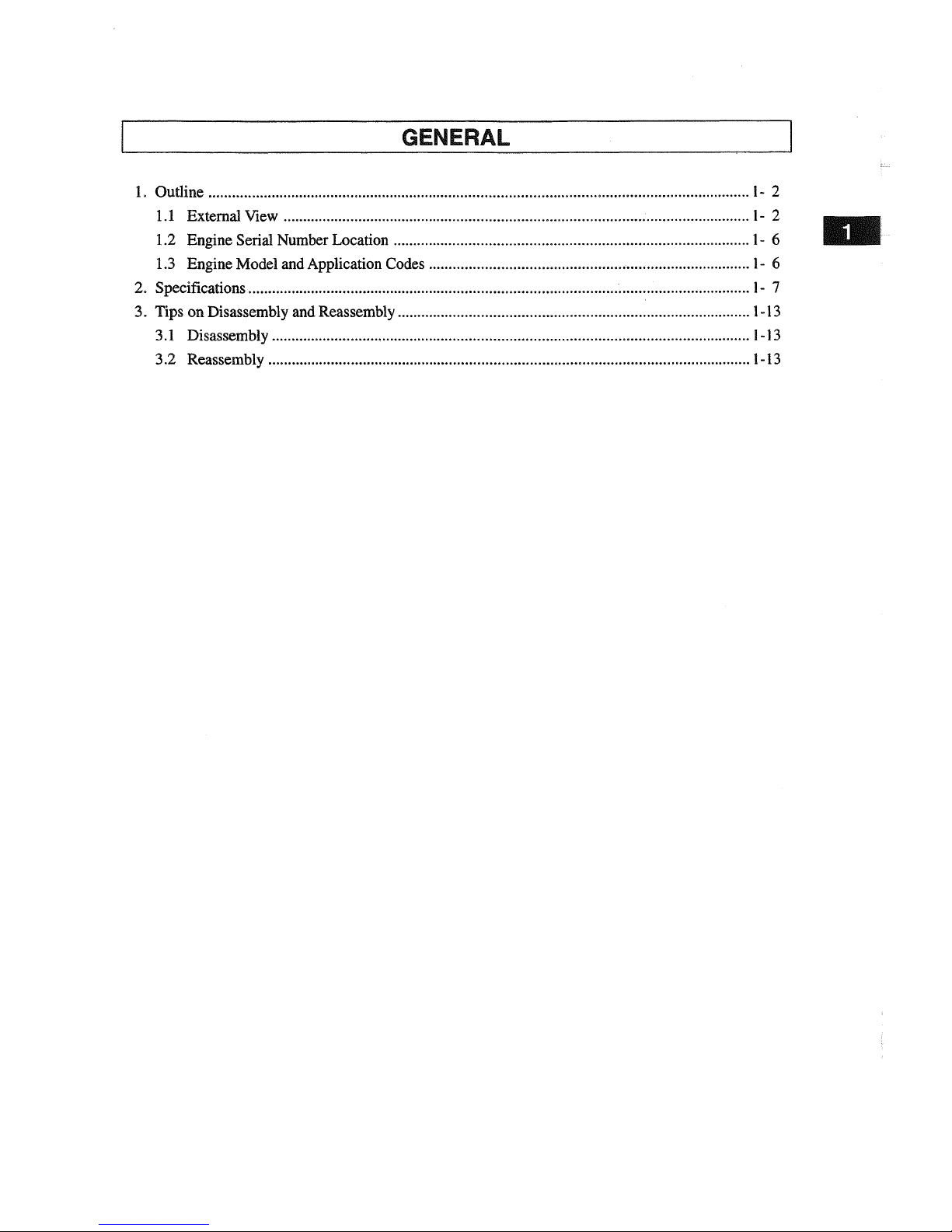
GENERAL
1. Outline
1.1 External View
[848 -
Standard]
Fuel filter Fuel injection pump
Fan
IFront I
Fuel feed pump
C'-I)
n
Inlet manifold
Fuel injection nozzle
ETR
stop solenoid
Governor
Coolant drain plug
Dipstick
IRear I
<>-tt-++--Flywheel
Oil drain plug
ILeft view
Oil filler
onfilter
Exhaust manifold
IRear I
Starter
n
I-I:)
Thermostat
Alternator
IFront I
V-belt
üil
pan
I
Right
viewl
Remark: Direction of rotation of this engine is counterclockwise as seen from flywheel side.
1-2
Page 9
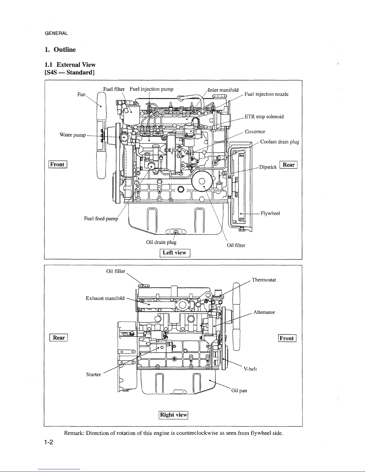
GENERAL
[S4S-DT - Standard]
IRear I
::n
"
.'
(I~I\
Fuel injection pump n
Fuel filter \
<,
I/In,
let manifold
h--.rT,----1JI
Fuel injection nozzle
Fan
~
rr-.
~
tJUI fT"i"T"i:
~
r~~
~?n'\~
I
hl
vETRstopsolenoid
Water
pump~
F -\.lIJ
11
(( --r
~Governor
I
~
;:,
Ip,~
-~
!
:;::
p
"/
/ Coolant drain plug
):
[l.l.AF::J"1"-
~
~
:::"
f'\f
r~
'Q
,
~
_
~!::L-
~.\
K"
Q.r-
~
~
I
",-
'"
Tb.
y
~
V Dipstick
13
--1.
~
~
___
0:/
ra
11
:
~
"\
V
~
(0
,0
/1, 0
ol--
~0,,~
,-'-
h>'
• F
;:;
:
I1
\
'--'-ol
Fuel feed pump -:
rUi;!=~~o?J;»-~~'-.-i~0Ë=Q:~~:
jl~~,
\~~r-~-dn
1111
~f--Ij'---H--FI
ywheel
IFront I
ondrain
PIL
I
Left
view I
on
filter
IFront I
Altemator
Thermostat
V-belt
Oil pan
Turbocharger
(1-1\
n
onfiller
Starter
Exhaust manifold
------.11ll-
~~~~~~
I
Rear
I
IRignt viewl
Remark: Direction of rotation
of
this engine is counterclockwise as seen from flywheel side.
1-3
Page 10
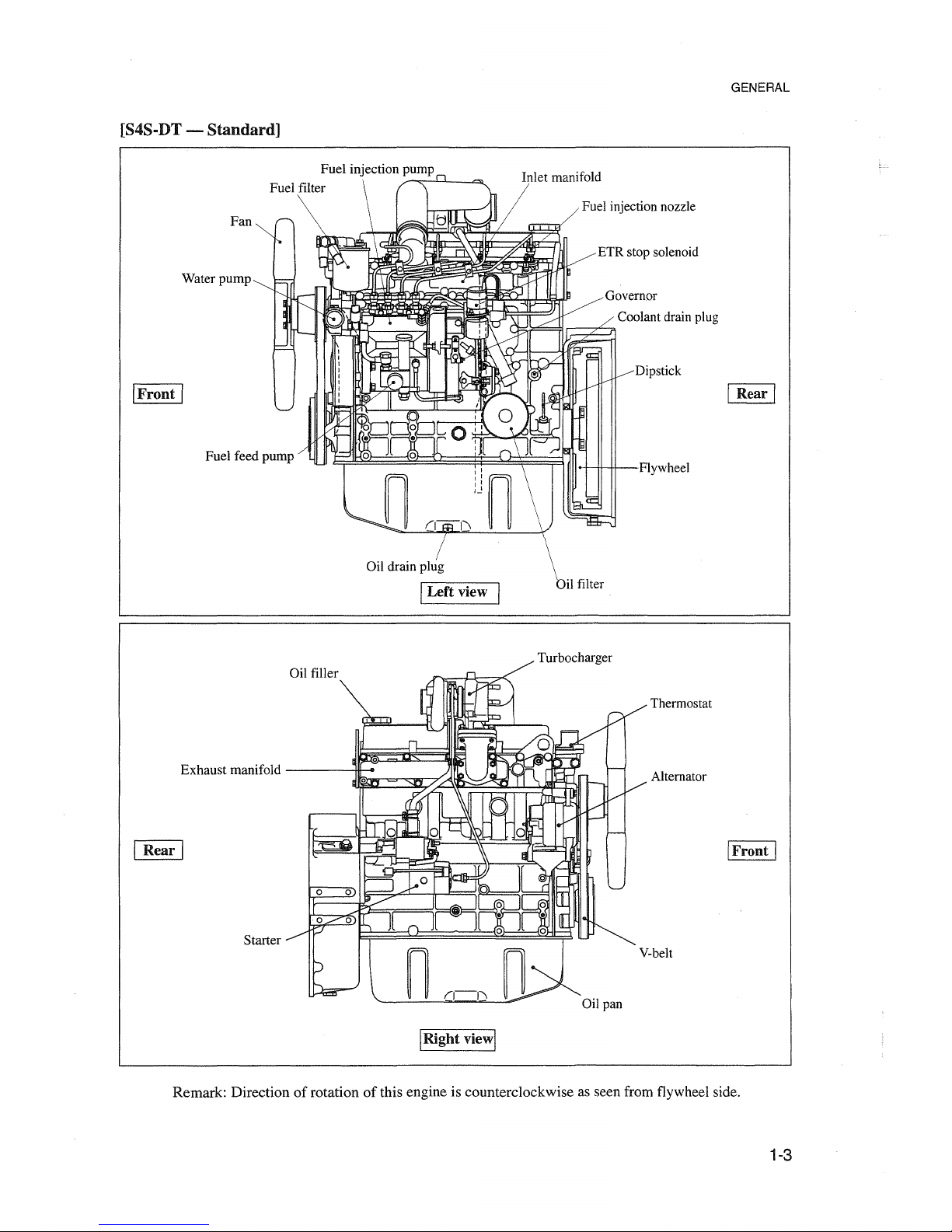
GENERAL
[868 - Standard]
uel filter Fuel injection pump lnlet manifold
I
Rear
I
Flywheel
Oil filter
Dipstick
Governor
t:~~~ah~~::~~r
Coolant drain plug
Oil drain plug
%~-1----le:::::~I-~e:::::~~--:v:
Fuel injection nozzle
1NI"bb!l;a
ETR stop solenoid
Fan
Water pump
I
Front
I
I
Left
view
Oil filler
Exhaust manifold
IRear I
Starter
Oilpan
Thermostat
Alternator
I
Front
I
V-belt
I
Right
viewl
Remark: Directionofrotation of this engine is counterclockwise as seen from flywheel side.
1-4
Page 11
GENERAL
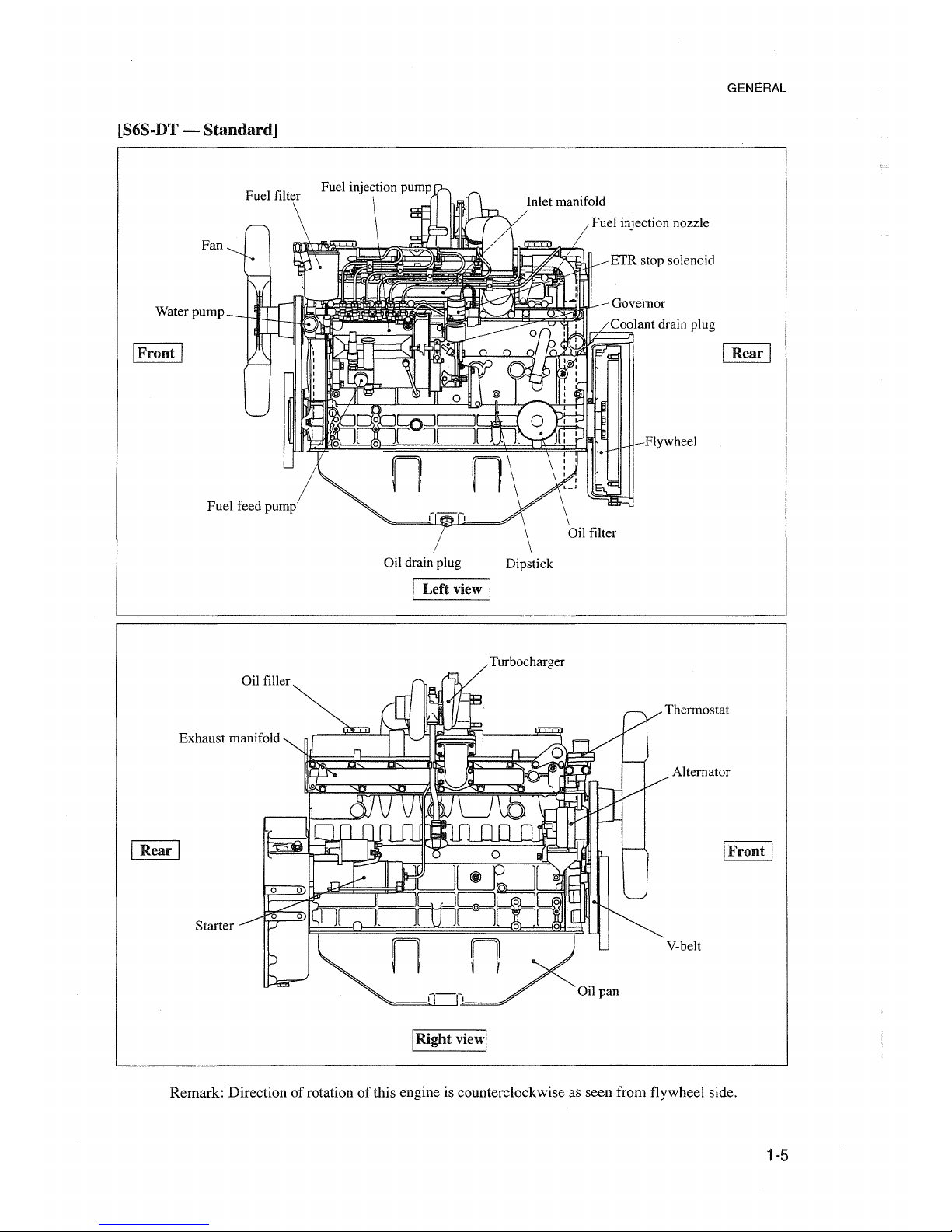
[S6S-DT-
Standard]
Fan
Water pump
IFront I
Gil filler
Exhaust manifold
IRea.. I
Starter
Fuel injection nozzle
ETR stop solenoid
).F~~~~~~
Governor
IRear I
Flywheel
Gil drain plug Dipstick
ILef! view I
Turbocharger
Thermostat
Alternator
IFront I
V-belt
Gil pan
IRight viewl
Remark:
Direction of rotation of this engine is counterclockwise as
seen
from flywheel side.
1-5
Page 12
GENERAL
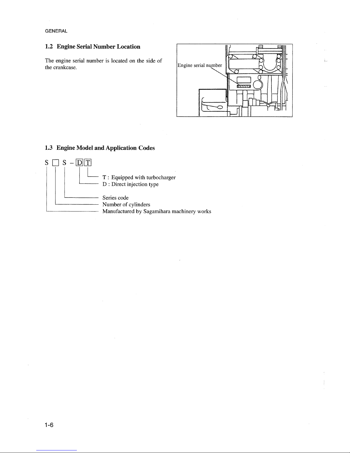
1.2 Engine Serlal Number Location
The engine serial number is located on the side of
the crankcase.
1.3 Engine Model
and
Application Codes
s D s -
[Q][ïJ
~
1-6
T : Equipped with turbocharger
D : Direct injection type
Series code
Number of cylinders
Manufactured by Sagamihara machinery works
Page 13
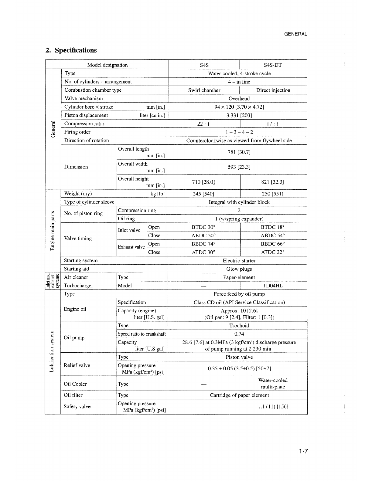
2. Specifieations
GENERAL
Model designation
S4S
S4S-DT
Type
Water-cooled, 4-stroke cycle
No. of cylinders
- arrangement
4-
in line
Combustion chamber type
Swirl chamber
Direct injection
Valve mechanism
Overhead
Cylinder bore
x stroke
mm[in.] 94
x 120 [3.70 x 4.72]
Piston displacement liter [cu in.]
3.331 [203]
";J
Compression ratio
22:
1
17:
1
...
<Ll
I:
Firing order
1-3-4-2
<Ll
0
Direction of rotation
Counterclockwise as viewed from flywheel side
Overall1ength
781 [30.7]
mm[in.]
Dimension
Overall width
593 [23.3]
mm[in.]
Overall height
710 [28.0]
821 [32.3]
mm[in.]
Weight (dry)
kg [Ib]
245 [540] 250[551]
Type of cylinder sleeve
Integral with cylinder block
Ol:>
No. of piston ring
Compression ring
2
~
0..
Oilring
1 (w/spring expander)
I:
Open BTDC 30° BTDC 18°
.e;
InIet valve
a
<Ll
Valve timing
Close
ABDC 50°
ABDC 54°
I:
·So
Open BBDC 74°
BBDC 66°
I:
Exhaust
valve
p:l
Close ATDC 30°
ATDC 22°
Starting system
Electric-starter
Starting aid
G10wplugs
"0_",
Air cleaner Type
Paper-element
§~e
"t).2
*
Turbocharger
Model TD04HL
-><>-.
-
~lUtI'.:l
Type
Force feed by oil pump
Specification
Class CD oil (API Service Classification)
Engine oil
Capacity (engine) Approx. 10 [2.6]
liter [U.S. gal] (Oil pan: 9 [2.4], Filter: 1 [0.3])
Type
Trochoid
a
Speedratioto
crankshaft
0.74
~
Oil pump
Ol:>
Capacity
28.6 [7.6] at 0.3MPa (3 kgf/cm") discharge pressure
;>,
Ol:>
I:
liter [U.S gal] of pump running at 2 230 min:'
0
.~
Type
Piston valve
u
·C
Re1iefva1ve
Opening pressure
..0
::l
0.35 ± 0.05 (3.5±0.5) [50±7]
....:l
MPa (kgf/cm") [psi]
Oil Cooler
I
Water-cooled
Type
-
multi-plate
Oil filter
Type Cartridge of paper element
Safety valve
Opening pressure
-
I
1.1
(11)
[156]
MPa (kgf/cm") [psi]
1-7
Page 14
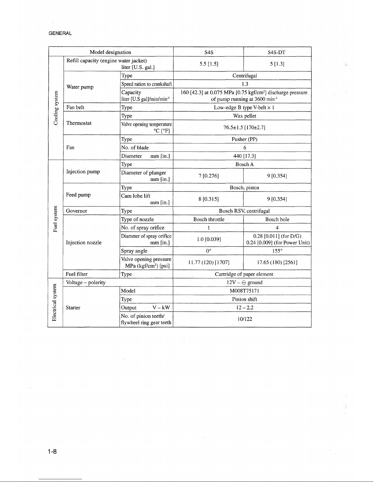
GENERAL
Model designation
S4S S4S-DT
Refill capacity (engine water jacket)
5.5 [1.5] 5 [1.3]
liter [U.S. gal.]
Type Centrifugal
Water
pump
Speedrationto
crankshaft
1.3
Ei
Capacity 160 [42.3] at 0.075 MPa [0.75 kgf/cm'] discharge pressure
2
liter [U.Sgalj/min/mirr'
of
pump running at 3600
min'
'Jl
;>,
'Jl
Fan belt
Type Low-edge B type V-belt x 1
eo
.S
Type Wax pellet
0
0
Thermostat
U
Valve
opening
temperature
°C
[OF]
76.5±1.5 [170±2.7]
Type Pusher (PP)
Fan
No.ofblade
6
Diameter
mm [in.]
440 [17.3]
Type Bosch A
Injection
pump
Diameter of plunger
7 [0.276] 9 [0.354]
mm [in.]
Type Bosch, piston
Feedpump
Cam
lobe lift
8 [0.315] 9 [0.354]
mm [in.]
Ei
Governor
Type Bosch RSV, centrifugal
2
co
;>,
Typeofnozz1e
Bosch throttle Bosch hole
'Jl
Q)
No.ofspray orifice
1 4
::l
~
Diameterof sprayorifice
1.0 [0.039]
0.28 [0.011] (for D/G)
Injection nozz1e
mm [in.]
0.24 [0.009] (for Power Unit)
Sprayangle
0° 155°
Valve opening pressure
11.77
(I20)
[1707] \7.65 (I 80) [2561]
MPa
(kgf/cm") [psi]
Fuel filter Type Cartridge of paper element
Ei
Voltage - polarity 12V - e ground
2
Model M008T75171
'Jl
;>,
'Jl
Type
Pinion shift
ë<i
Cl
Starter Output
V-kW
12 - 2.2
'5
Cl
Cl)
No.ofpinion teeth/
ü3
flywheel ring gear teeth
lO/l22
1-8
Page 15
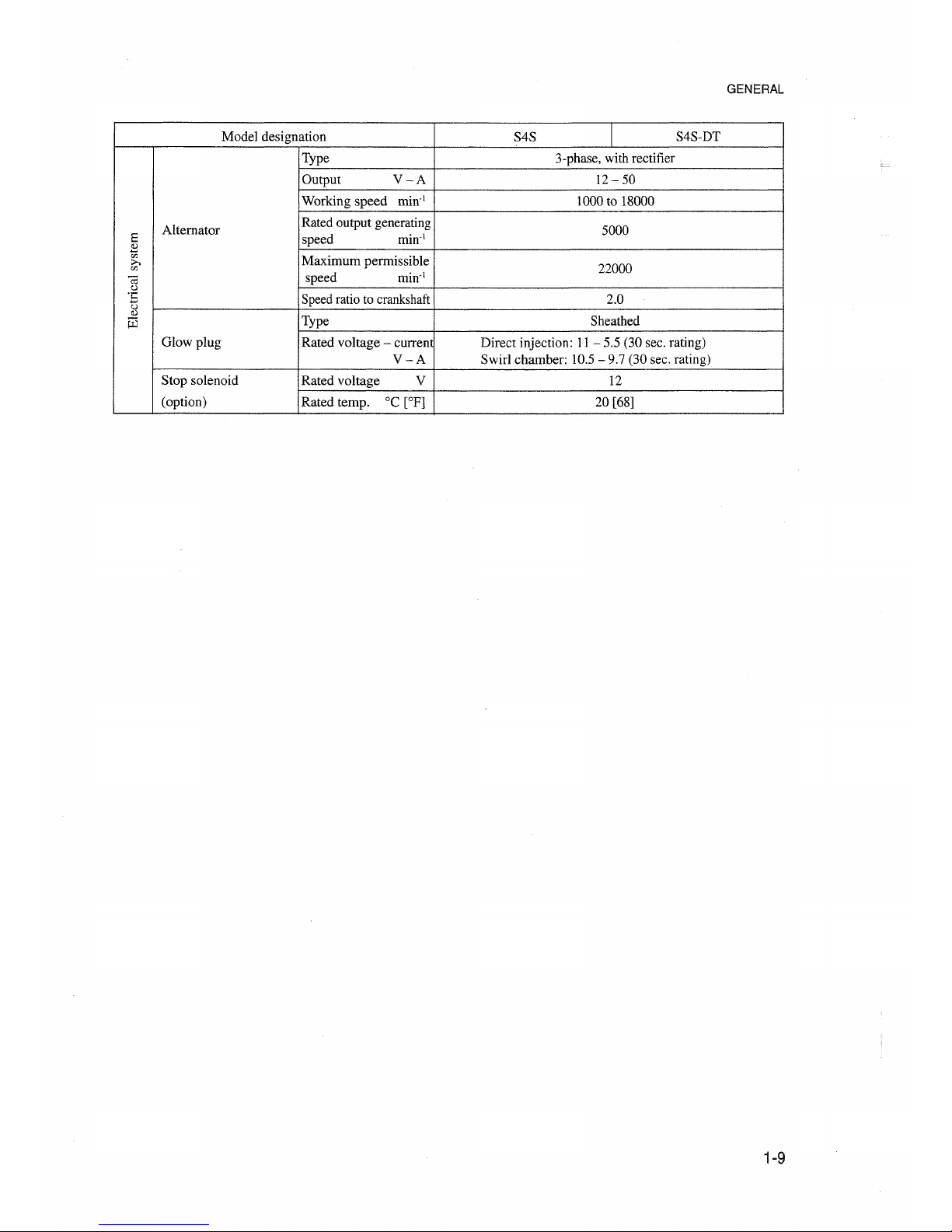
GENERAL
Model designation
S4S
I
S4S-DT
Type 3-phase, with rectifier
Output
V-A
12-50
Working
speed
min:'
1000 to 18000
Altemator
Rated output generating
5000
Ei
speed
min:'
s
<IJ
Maximum
perrnissib1e>-.
22000
co
C;;
speed
min:'
o
oE
Speed ratio to crankshaft 2.0
o
Il.l
iii
Type
Sheathed
G10w plug
Rated voltage - current Direct injection: 11
- 5.5 (30 sec. rating)
V-A
Swir1 chamber: 10.5 - 9.7 (30 sec. rating)
Stop solenoid
Rated voltage V 12
(option)
Rated temp.
oe
[OP]
20 [68]
1-9
Page 16

GENERAL
Model designation
S6S
S6S-DT
Type
Water-cooled, 4-stroke cycle
No. of cylinders
- arrangement
6-in
line
Combustion chamber type
Swirl chamber Direct injection
Valve mechanism
Overhead
Cylinder bore x stroke mm [in.]
94 x 120 [3.70 x 4.72]
Piston displacement liter [cu in.]
4.996 [305]
~
Compression ratio
22:
1
17:
1
...
Q)
:::
Firing order
I - 5
- 3 - 6 -2-4
Q)
Cl
Direction of rotation
Counterclockwise as viewed from flywheel side
Overall length
1033 [40.7] SG type, 1029 [40.5] SP type
mm[in.]
Dimension
Overall width
593 [23.3] 626 [24.6]
rum [in.]
Overall height
748 [29.4] 896 [35.3]
mm[in.]
Weight (dry) kg [Ib]
340 [750] 350 [772]
Type of cylinder sleeve
Integral with cylinder block
I!J
No. of piston ring
Compression ring
2
...
0::1
Oil ring I (w/spring expander)
0..
:::
Open
BTDC 30° BTDC 18°
.;:;
Inlet valve
8
Q)
Valve timing
Close
ABDC 50° ABDC 54°
:::
·öo
Open BBDC 74°
BBDC 66°
:::
Exhaust
valve
"'-l
Close
ATDC 30° ATDC 22°
Starting system Electric-starter
Starting aid
Glow plugs
"0_",
Air cleaner Type
Paper-element
a~E
~~*
Turbocharger Model
TE06H
-><>,
-
,.5CUoZl
Type
Force feed by oil pump
API
Service
Classification
CD
Engine oil
Refill capacity
Whole system: Approx. 12 liters [3.2 U.S. gal];
liter [U.S. gal.] Oil pan: II liters [2.9 U.S. gal]; Filter: I liters [0.3 U.S. gal]
Type
Trochoid
8
Speedratioto crankshaft
0.74
2
Oil pump
<J)
Capacity 38.7 [10.2] at 0.3 MPa (3 kgf/cm') discharge pressure
>.
<J)
e
liter [U.S gal]/min
of pump running at 2230
min'
0
.~
Type
Piston valve
o
Oil pressure
.e:
Opening pressure
.D
relief valve
::l
0.35±0.05 (3.5±0.5) [50±7]
....:l
MPa (kgf/cm") [psi]
Oil Cooler Type
Water-cooled
-
multi-plate
Oil filter Type Cartridge of paper element
Safety valve
Opening pressure
-
1.1(11)[156]
MPa (kgf/cm') [psi]
1-10
Page 17
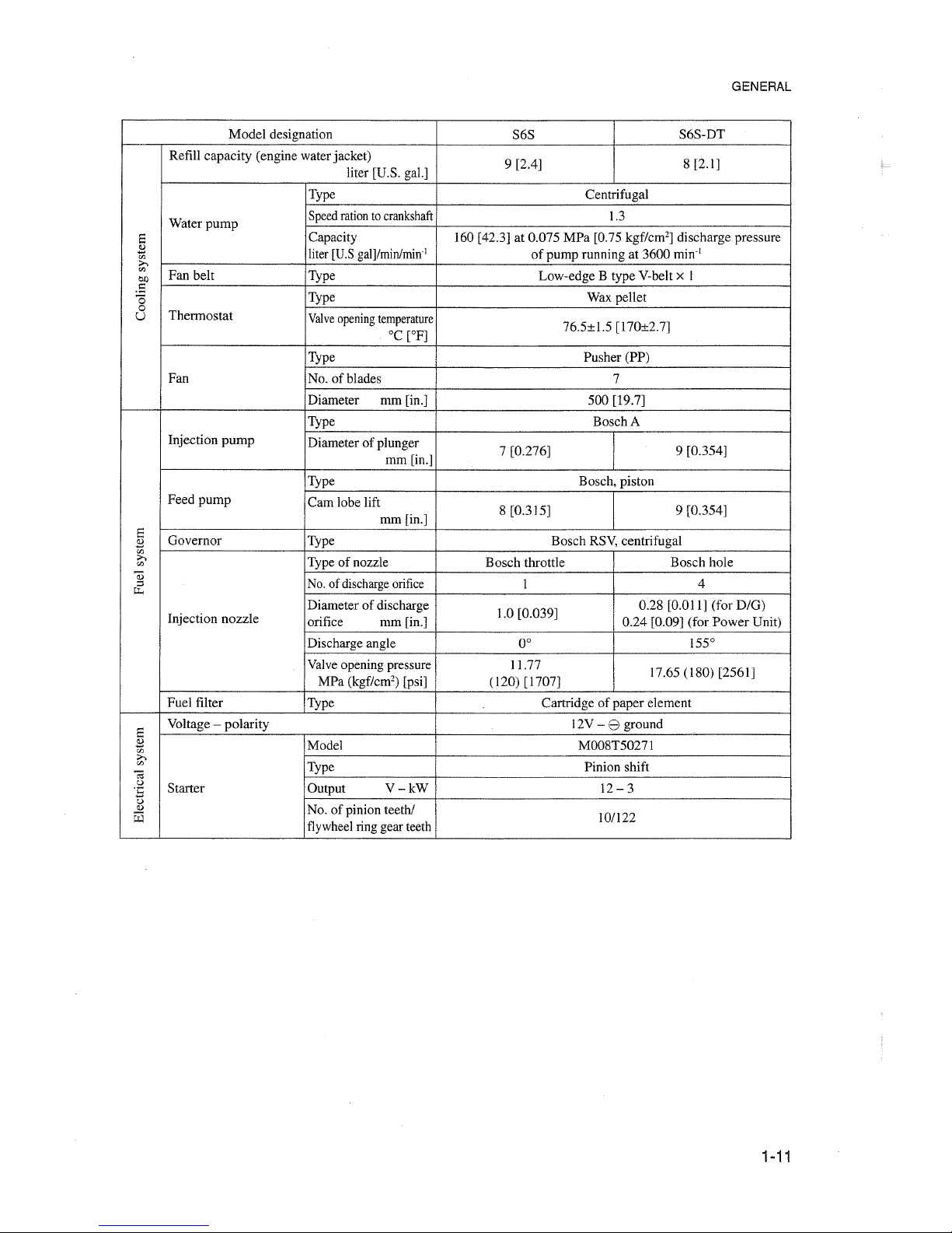
GENERAL
Model
designation
S6S
S6S-DT
Refill
capacity
(engine water jacket)
9 [2.4]
8 [2.1]
liter [U.S. gal.]
Type Centrifugal
Water
pump
Speedrationto
crankshaft
1.3
Ei
Capacity 160 [42.3] at 0.075
MPa
[0.75 kgf/cm"] discharge pressure
B
liter [U.S
gall/rnin/mirr'
of
pump
running at 3600 min'!
CI:l
;>,
CI:l
Fan belt Type
Low-edge B typeV-belt x I
en
.5
Type Wax pellet
Ö
0
Thermostat
U
Valve
opening
temperature
°C
[OF]
76.5±1.5 [170±2.7]
Type Pusher (PP)
Fan
No.
of
blades
7
Diameter mm [in.]
500
[19.7]
Type
Bosch A
Injection
pump
Diameterofplunger
7 [0.276] 9 [0.354]
mm[in.]
Type Bosch, piston
Feed
pump
Cam lobe lift
8 [0.315]
9 [0.354]
mm [in.]
Ei
Governor
Type Bosch RSV, centrifugal
B
CI:l
;>,
Typeofnozzle Bosch throttle Bosch hole
CI:l
03
No.of dischargeorifice
I
4
;:l
"'"
Diameterofdischarge
1.0 [0.039]
0.28 [0.011] (for
D/G)
Injection
nozzle
orifice
mm [in.]
0.24
[0.09] (for
Power
Unit)
Discharge angle 0°
155°
Valve opening pressure
11.77
17.65 (180) [2561]
MPa
(kgf/cm') [psi]
(120) [1707]
Fuel filter
Type Cartridge
of
paper element
Ei
Voltage -
polarity
12V - 8 ground
B
Model
M008T5027I
CI:l
;>,
CI:l
Type Pinion shift
ca
o
Starter Output
V-kW
12 - 3
"5
o
<I)
No.ofpinion teeth/
W
flywheel ring gear teeth
10/122
1-11
Page 18
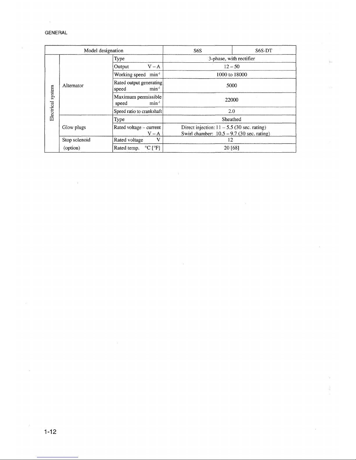
GENERAL
Model designation
S6S
I
S6S-DT
Type 3-phase, with rectifier
Output
V-A
12
-50
Working speed
min-I
1000 to 18000
a
Altemator
Rated output generating
5000
B
speed
min-I
'"
>.
Maximum permissible
'"
22000
'<'J
speed
min-I
.~
::
Speedratio tocrankshaft 2.0
o
<l.l
m
Type Sheathed
Glow plugs Rated voltage- current Direct injection:
11- 5.5 (30 sec. rating)
V-A
Swirl chamber: 10.5
-9.7
(30 sec. rating)
Stop solenoid Rated voltage V
12
(option) Rated temp.
°C
[OF]
20 [68]
1-12
Page 19
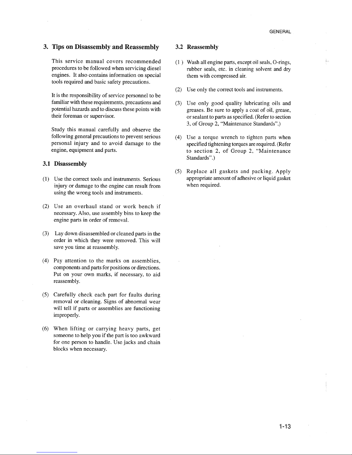
3. Tips on Disassembly
and
Reassembly
This
service
manual
covers
recommended
procedures to be followed when servicing diesel
engines. It also contains information on special
tools required and basic safety precautions.
It is the responsibility
of
service personnel to be
familiar with these requirements, precautions and
potential hazards and to discuss these points with
their foreman or supervisor.
Study this manual carefully and observe the
following general precautions to prevent serious
personal injury and to avoid
damagetothe
engine, equipment and parts.
3.1 Disassembly
(1) Use the correct tools and instruments. Serious
injury or damage to the engine can result from
using the wrong tools and instruments.
(2) Use an
overhaul
standorwork
bench
if
necessary. Also, use assembly bins to keep the
engine parts in order of removal.
(3) Lay down disassembiedorc1eanedparts in the
order in which they were removed. This will
save you time at reassembly.
(4) Pay attention to the marks on
assemblies,
components and parts for positionsordirections.
Put on your own marks, if necessary, to aid
reassembly.
(5) Carefully
check
each part for faults during
removal or cleaning. Signs of abnormal wear
will tell if parts or assemblies are functioning
improperly.
(6) When
liftingorcarrying
heavy
parts,
get
someone to help you if the part is too awkward
for one person to handle. Use jacks and chain
blocks when necessary.
GENERAL
3.2 Reassembly
(1)
Wash all engine parts, except oilseals,O-rings,
rubber seals, etc. in c1eaning solvent and dry
them with compressed air.
(2) Use only the correct tools and instruments.
(3) Use only
good
quality lubricating oils and
greases. Be sure to apply a coat of oil, grease,
or sealanttoparts as specified.(Referto section
3, of Group 2, "Maintenance Standards".)
(4) Use a torque wrench to tighten parts when
specified tightening torquesare required.(Refer
to
section2,of
Group2,"Maintenance
Standards".)
(5)
Replace
all
gaskets
and
packing.
Apply
appropriate amountof adhesiveor liquid gasket
when required.
1-13
Page 20

Page 21
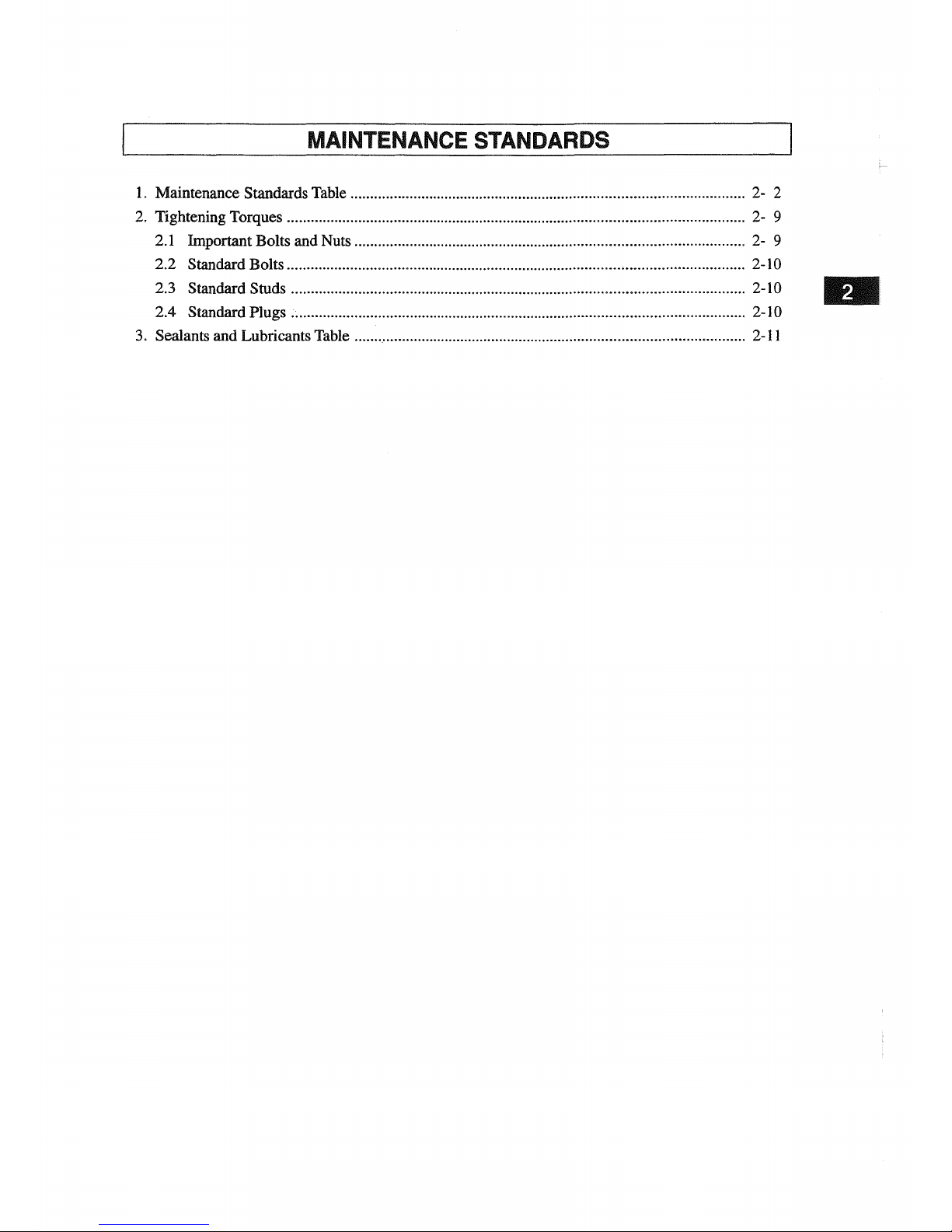
MAINTENANCE STANDARDS
1. Maintenance Standards Table 2- 2
2. Tightening Torques , 2- 9
2.1 Important Bolts and Nuts 2- 9
2.2 Standard Bolts 2-10
2.3 Standard Studs 2-10
2.4 Standard Plugs .. 2-10
3. Sealants and Lubricants Table
2-11
Page 22
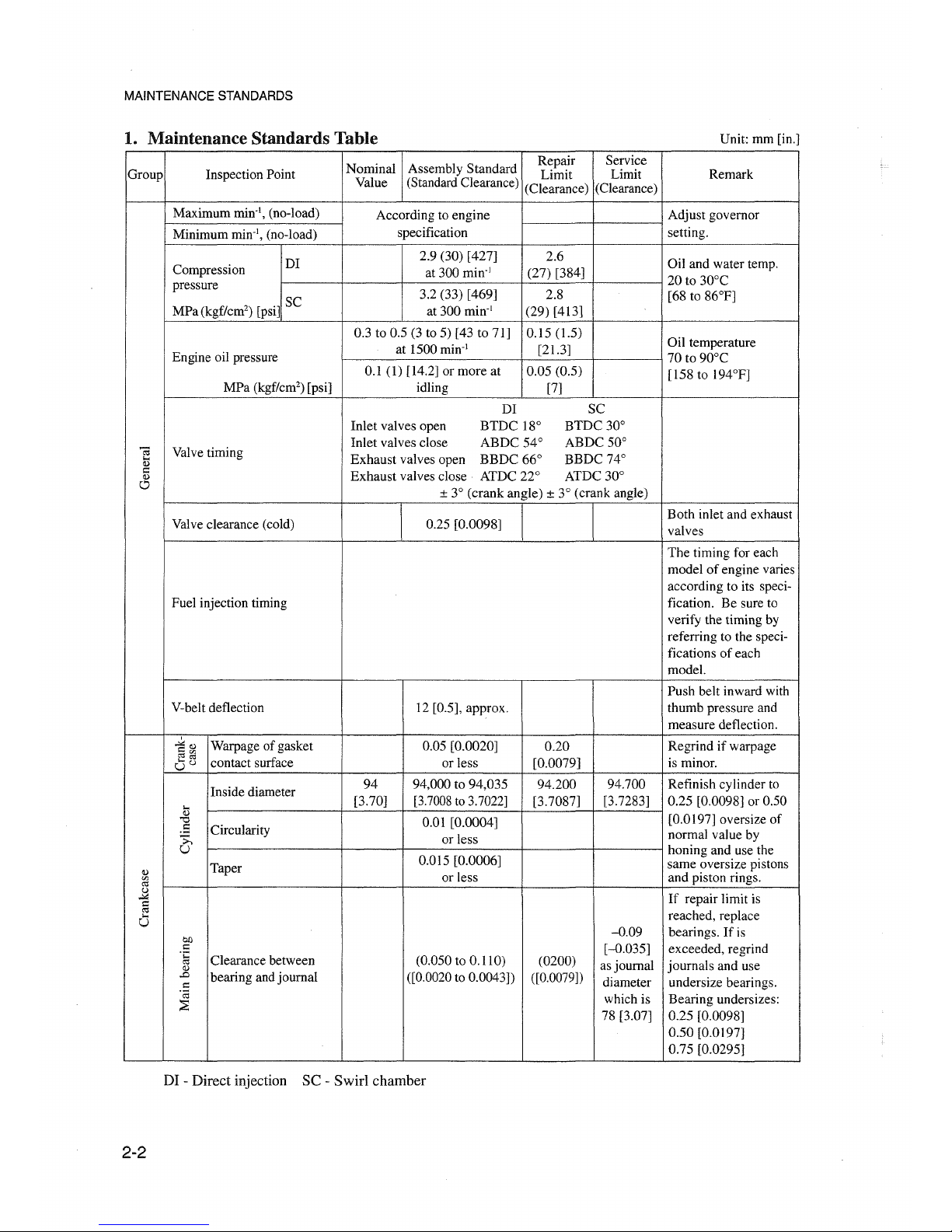
MAINTENANCE STANDARDS
1. Maintenance Standards Table
Unit: mm [in.]
Nominal
Assembly
Standard
Repair
Service
Group Inspeetion Point
Limit
Limit Remark
Value (Standard Clearance)
(Clearance)
(Clearance)
Maximum min-I, (no-load)
According to engine
Adjust governor
Minimum min", (no-lead)
specification setting.
DI
2.9 (30) [427]
2.6
Oil and water temp.
Compression
at 300 min:'
(27) [384]
20 to
30°C
pressure
3.2 (33) [469]
2.8
[68 to 86°F]
Ml'atkgf/cm') [psi]
SC
at 300 min-I
(29)
[413]
0.3 to 0.5 (3 to 5) [43 to 71] 0.15 (1.5)
üil
temperature
Engine oil pressure
at 1500 min:'
[21.3]
70 to 90°C
0.1
(1) [14.2] or
more
at
0.05
(0.5)
[158 to 194°F]
MPa (kgf/cm") [psi] idling [7]
DI SC
Inlet
valves open
BTDC
18°
BTDC
30°
C;
Valve timing
Inlet
valves close
ABDC
54°
ABDC
50°
....
Exhaust
valves open
BBDC
66°
BBDC
74°
(1)
c
Exhaust
valves close
ATDC
22°
ATDC 30°
(1)
c
± 3°
(crank
angle) ± 3° (crank angle)
Valve clearance (cold)
Both
in1et and exhaust
0.25 [0.0098]
valves
The
timing for each
model
of
engine varies
according to its speci-
Fuel injection timing fication. Be sure to
verify the timing by
referring to the speci-
fications
of
each
model.
Push beIt inward with
V-belt deflection 12 [0.5], approx.
thumb
pressure and
measure
deflection.
,
"""'(1)
Warpage of gasket 0.05 [0.0020]
0.20
Regrindifwarpage
<=:",
~~
contact surface
or 1ess [0.0079]
is minor.
Uu
Inside diameter
94
94,000 to 94,035
94.200 94.700 Refinish cylinder to
...
[3.70] [3.7008to 3.7022]
[3.7087]
[3.7283] 0.25 [0.0098] or 0.50
(1)
[0.0197] oversize of
"0
0.01 [0.0004]
.5
Circularity
>..
or less
normal value by
U
honing and use the
Taper
0.015 [0.0006]
same
oversize pistons
(1)
or less
and piston rings.
'"
<:Il
u
~
If repair limit is
<=:
<:Il
reached, replace
...
U
-0.09
bearings.Ifis
01)
<=:
[-0.035] exceeded, regrind
.t:
Clearance between
(0.050 to 0.110)
~
(0200)
asjoumal
journals
and
use(1)
.D
bearing and journal ([0.0020 to 0.0043]) ([0.0079])
diameter undersize bearings.
<=:
'ca
which is Bearing undersizes:
::E
78 [3.07]
0.25 [0.0098]
0.50
[0.0197]
0.75 [0.0295]
DI - Direct injection SC - Swirl chamber
2-2
Page 23
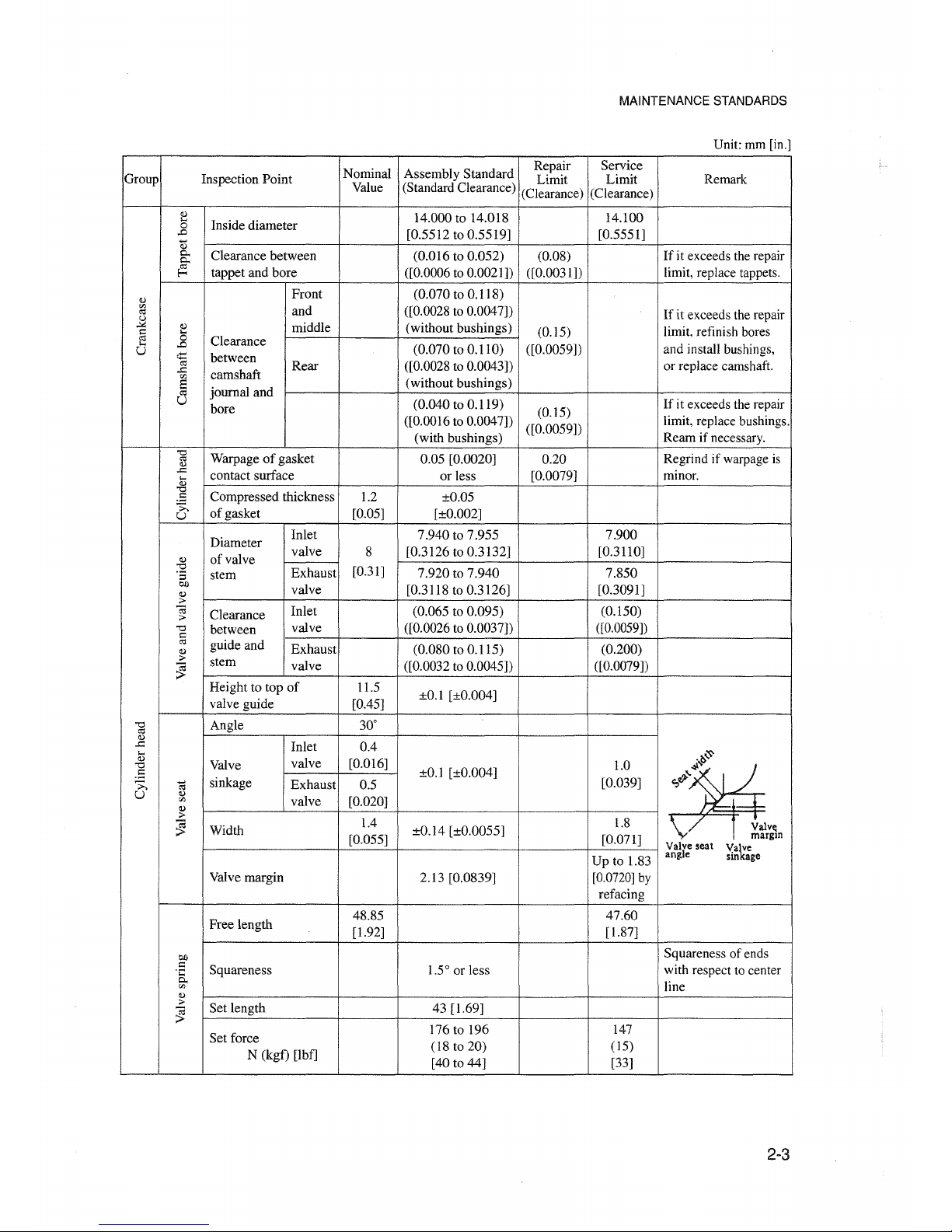
MAINTENANCE STANDARDS
Unit: mm [in.]
Nominal Assembly Standard
Repair
Service
Group Inspeetion Point
Limit Limit
Remark
Value (Standard Clearance)
(Clearance) (Clearance)
~
14.000 to 14.018 14.100
...
Inside diameter
0
..0
[0.5512 to 0.5519]
[0.5551]
Q)
0..
Clearance between
(0.016 to 0.052) (0.08)
If
it exceeds the repair
0..
~
tappet and bore
([0.0006 to 0.0021)) ([0.0031))
limit, replace tappets.
~
Front (0.070 to 0.118)
'"
and
([0.0028 to 0.0047))
<Il
If it exceeds the repair
~
~
midd1e
(without bushings)
(0.15) limit, refinish bores
§
5
...
..0
Clearance
(0.070 to 0.110) ([0.0059)) and install bushings,
U
~
between
<Il
Rear ([0.0028 to 0.0043)) or replace camshaft.
..0
camshaft
co
(without bushings)
a
journa1 and
<Il
U
(0.040 to 0.119)
If
it exceeds the repair
bore
(0.15)
([0.0016 to 0.0047))
([0.0059))
limit, rep1acebushings.
(with bushings)
Ream if necessary.
'0
Warpageofgasket 0.05 [0.0020]
0.20
Regrind if warpage is
<Il
<)
..c
contact surface
or less
[0.0079]
minor.
...
<)
'0
Compressed thickness
1.2
±0.05
.5
>-,
of gasket [0.05]
[±0.002]
U
Diameter
Inlet
7.940 to 7.955 7.900
va1ve
8 [0.3126 to 0.3132]
[0.3110]
~
ofva1ve
'0
Exhaust
[0.31]
7.920 to 7.940 7.850
'5 stern
co
va1ve
[0.3118 to 0.3126] [0.3091]
~
;>
(;J
Clearance
Inlet (0.065 to 0.095) (0.150)
;>
'0
between
valve
([0.0026 to 0.0037))
([0.0059])
=
<Il
guide and
Exhaust
(0.080 to 0.115)
(0.200)
~
;>
stern
va1ve
~
([0.0032 to 0.0045))
([0.0079))
Height to top
of
11.5
±0.1 [±0.004]
va1veguide
[0.45]
'0
Ang1e
30°
<Il
~
..0
Inlet 0.4
...
~
~
Valve
va1ve [0.016]
1.0
'0
±0.1 [±0.004]
.:::
sinkage [0.039]
è
;;,
ê<I
Exhaust
0.5
':l
U
~
va1ve'"[0.020]
~
;>
1.8
~
Width
IA
±0.14 [±0.0055]
Valve
[0.055] [0.071]
margin
Valve seat
Va~e
Up to 1.83
angle
sin age
Valve margin
2.13 [0.0839]
[o.onO] by
refacing
Free length
48.85 47.60
[1.92] [1.87]
eo
Squareness of ends
=
Squareness 1.50or less with respect to center
.t::
0..
line
'"
~
;>
Set length 43 [1.69]
~
Set force
176 to 196
147
N (kgf) [lbf]
(18 to 20)
(15)
[40 to 44]
[33]
2-3
Page 24
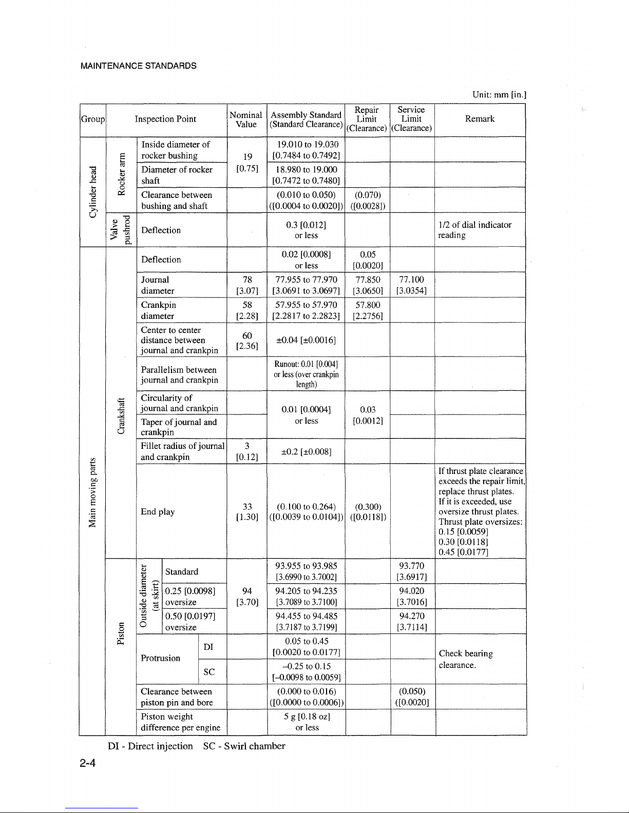
MAINTENANCE 8TANDARD8
Unit: mm [in.]
Nominal
Assembly Standard
Repair
Service
Group Inspeetion Point Limit
Limit Remark
Value
(Standard Clearance)
(Clearance)
(Clearance)
Inside diameter
of
19.010 to 19.030
S
rocker bushing
19
[0.7484 to 0.7492]
"0
a
Diameter of rocker
[0.75]
18.980 to 19.000
....
0::1
Q.}
Q.}
~
shaft [0.7472 to 0.7480]
.!:
u
à:3
0
"0
0:::
Clearance between
(0.010 to 0.050)
(0.070)
.S
;;.,
bushing and shaft
([0.0004 to 0.0020)) ([0.0028))
U
"0
Q.}
0
0.3 [0.012]
1/2
of
dial indicator
;;.-
....
Deflection
~
.!:
'"
or less
reading
:::s
0..
Deflection
0.02 [0.0008]
0.05
or less [0.0020]
Journal
78
77.955 to 77.970
77.850
77.100
diameter [3.07]
[3.0691 to 3.0697]
[3.0650]
[3.0354]
Crankpin
58
57.955 to 57.970
57.800
diameter [2.28] [2.2817 to 2.2823] [2.2756]
Center to center
60
distance between ±0.04 [±0.0016]
journal and crankpin
[2.36]
Parallelism between
Runout:
0.01
[0.004]
journal and crankpin
or
less
(over
crankpin
length)
<:i=:
Circularity of
""
journal and crankpin
.c
0.01 [0.0004]
0.03
'"
~
Taperofjournal and
or less [0.0012]
""
....
U
crankpin
Fillet radius
of
journal
3
±0.2 [±0.008]
.'!i
and crankpin [0.12]
....
0::1
If thrust plate clearance
0..
eo
exceeds the repair limit,
I:
.;;
replace thrust plates.
0
S
33
(0.100 to 0.264)
(0.300)
If it is exceeded, use
:::
End
play oversize thrust plates.
'ca
[1.30]
([0.0039 to 0.0104))
([0.0118))
::E
Thrust plate oversizes:
0.15 [0.0059]
0.30 [0.0118]
0.45 [0.0177]
....
93.955 to 93.985 93.770
Q.}
Standard
d)
[3.6990to
3.7002]
[3.6917]
S
~
0::1
....
0.25 [0.0098] 94 94.205 to 94.235 94.020
:a~
Q.}
'"
oversize [3.70] [3.7089to
3.7100]
[3.7016]
:9
:g
'"
"El
0.50 [0.0197] 94.455 to 94.485
94.270
I:
0
oversize
[3.7187to3.7199]
[3.7114]
.8
'"
p::;
DI
0.05 to 0.45
Protrusion
[0.0020 to 0.0177]
Check bearing
-0.25
to 0.15
clearance.
SC
[-0.0098 to 0.0059]
Clearance between
(0.000 to 0.016)
(0.050)
piston pin and bore ([0.0000 to 0.0006))
([0.0020]
Piston weight
5g[0.180z]
difference per engine
orless
DI - Direct injection SC - Swirl chamber
2-4
Page 25
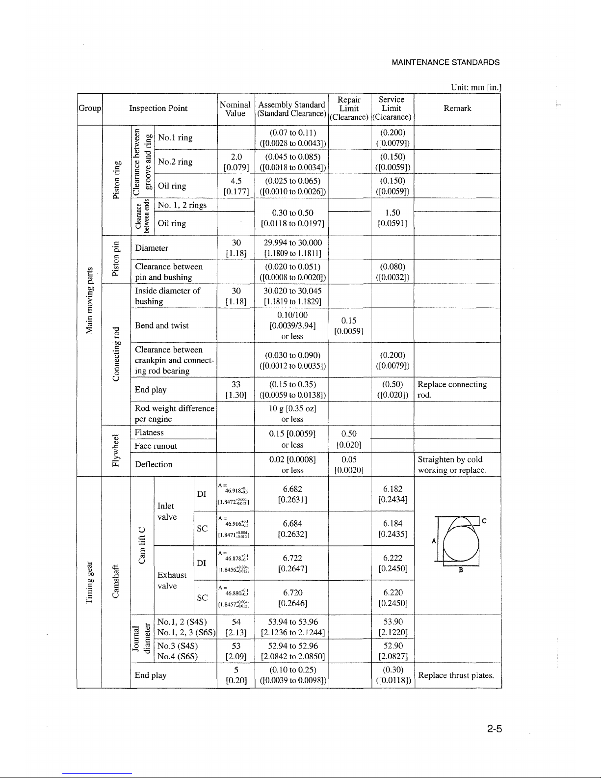
MAINTENANCE STANDARDS
Unit: mm [in.]
Graup
Inspeetion Point
Repair Service
Nominal Assembly Standard Limit Limit
Value (Standard Clearance) (Clearance) (Clearance)
Remark
1.50
[0.0591]
(0.200)
([0.0079])
(0.150)
([0.0059])
(0.150)
([0.0059])
0.30 to 0.50
[0.0118 to 0.0197]
(0.07 to 0.11)
([0.0028to 0.0043])
(0.045 to 0.085)
([0.0018to 0.0034])
(0.025 to 0.065)
([0.0010to 0.0026])
2.0
[0.079]
4.5
[0.177]
No.1 ring
No.2 ring
Gil ring
~
g]
No.
1,2
rings
~
~
-
~
Gil
ring
U]
I::
Q) Cl)
~
.S
v~f-----~---+':':--------::+-----j-':'::------=':+----------j
..0
I::
Q) o:l
U Q)
§>t-------j-"--..........::.-+--------..........::.+----+-----+-----------i
~
g
~
5i:J
U
"0
o
...
Cl)
.S
~
I::
I::
o
U
Diameter
Clearance between
pin and bushing
Inside diameter
of
bushing
Bend
and twist
Clearance between
crankpin
and
conneet-
ing rad bearing
Endplay
30
[U8]
30
[U8]
33
[1.30]
29.994 to 30.000
[l.l809 to
l.l8
II]
(0.020 to 0.051)
([0.0008to 0.0020])
30.020 to 30.045
[l.l819 to l.l829]
0.10/100
[0.0039/3.94]
or less
(0.030 to 0.090)
([0.0012to 0.0035])
(0.15 to 0.35)
([0.0059to 0.0138])
0.15
[0.0059]
(0.080)
([0.0032])
(0.200)
([0.0079])
(0.50)
([0.020])
Replace connecting
rad.
Rad
weight difference
per
engine
JO
g [0.35 oz]
orless
Flatness
Face runout
Deflection
0.15 [0.0059]
or less
0.02 [0.0008]
or less
0.50
[0.020]
0.05
[0.0020]
Straighten by cold
working or replace.
DI
U
E
o:l
U
Inlet
valve
SC
DI
Exhaust
valve
SC
A
=46.918:'2)
[1.847:ti~1
A=
46.916:'2)
[1.8471:'2~1
A=
46.878::;N
11.8456:'2~1
A=
46.880:'2)
[1.8457:'2~1
6.682
[0.2631]
6.684
[0.2632]
6.722
[0.2647]
6.720
[0.2646]
6.182
[0.2434]
6.184
[0.2435]
6.222
[0.2450]
6.220
[0.2450]
Tcr
B
No.l,
2 (S4S)
No.l,
2,3
(S6S)
No.3 (S4S)
No.4
(S6S)
54
[2.13]
53
[2.09]
53.94 to 53.96
[2.1236 to 2.1244]
52.94 to 52.96
[2.0842 to 2.0850]
53.90
[2.1220]
52.90
[2.0827]
End
play
5
[0.20]
(0.JOto 0.25)
([0.0039 to 0.0098])
(0.30)
([0.0118])
Replace thrust plates.
2-5
Page 26
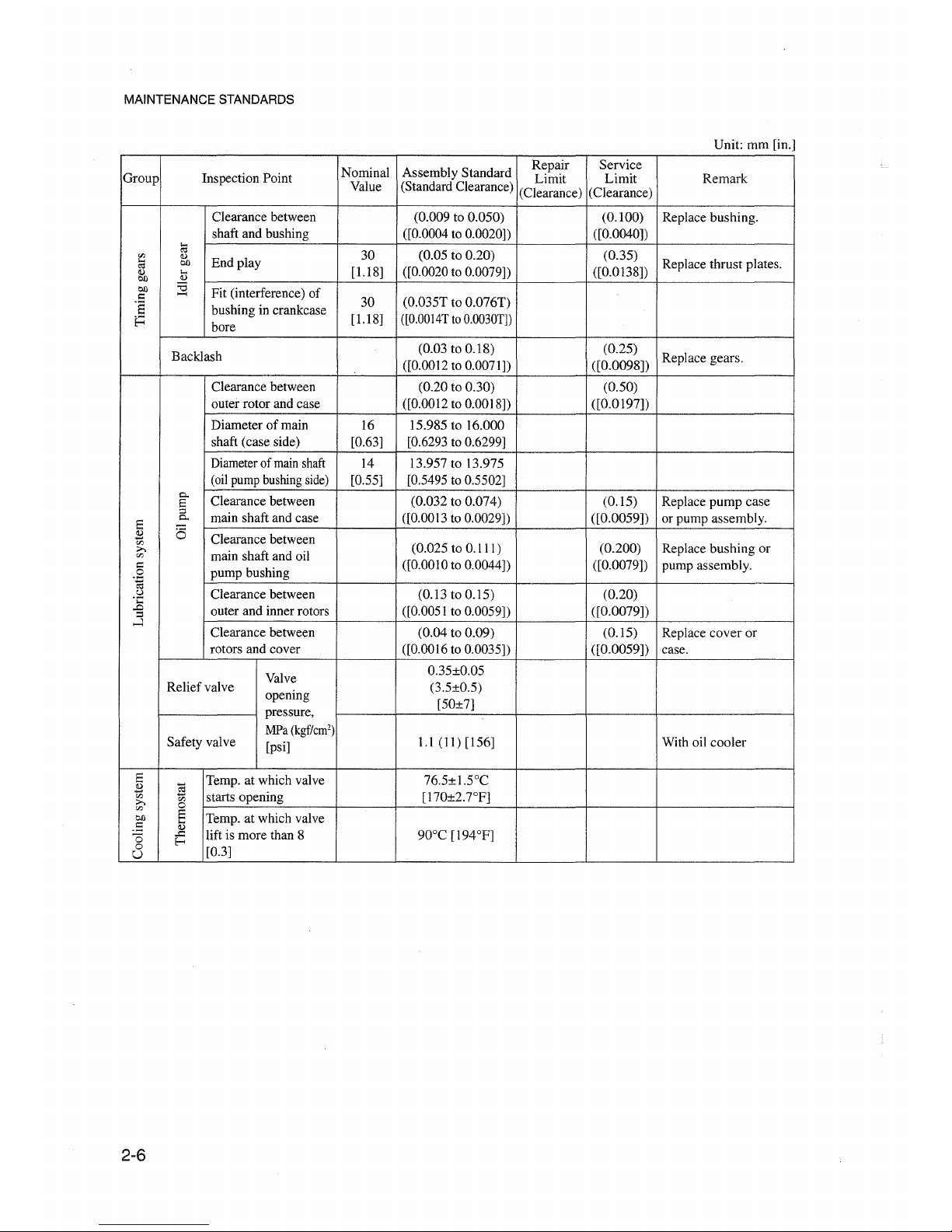
MAINTENANCE STANDARDS
Unit:mm
[in.]
Nominal Assembly Standard
Repair
Service
Group
Inspeetion Point
Limit
Limit
Remark
Value (Standard Clearance)
(Clearance) (Clearance)
Clearance between
(0.009 to 0.050) (0.100) Replace bushing.
shaft and bushing ([0.0004 to 0.0020]) ([0.0040])
~
30
(0.05 to 0.20) (0.35)
til
<l.l
End play
...
co
Replace thrust plates.
t'l
[1.18]
([0.0020 to 0.0079])
([0.0138])
<l.l
...
co
<l.l
co
::a
Fit (interference) of
l:
......
ï§
bushing in crankcase
30
(0.035T to 0.076T)
~
bore
[1.18]
([0.0014Tto0.0030T])
Backlash
(0.03 to 0.18) (0.25)
Replace gears.
([0.0012 to 0.0071]) ([0.0098])
Clearance between (0.20 to 0.30) (0.50)
outer rotor and case ([0.0012 to 0.0018]) ([0.0197])
Diameter of main
16 15.985 to 16.000
shaft (case side) [0.63]
[0.6293 to 0.6299]
Diameterof mainshaft
14 13.957 to 13.975
(oilpump bushingside) [0.55]
[0.5495 to 0.5502]
0..
Clearance between (0.032 to 0.074) (0.15)
Replace
pump
case
E
::>
main shaft and case ([0.0013 to 0.0029]) ([0.0059])
or pump assembly.
E
0..
.2
(5
Clearance between
til
(0.025 to 0.111) (0.200)
Replace bushing or
;..,
main shaft and oil
til
l:
pump bushing
([0.0010 to 0.0044]) ([0.0079])
pump assembly.
0
.~
.::l Clearance between
(0.13 to 0.15) (0.20)
...
..0
outer and inner rotors ([0.0051 to 0.0059]) ([0.0079])
::I
....l
Clearance between
(0.04 to 0.09)
(0.15)
Replace
cover
or
rotors and cover ([0.0016 to 0.0035]) ([0.0059])
case.
Valve
0.35±0.05
Reliefvalve
opening
(3.5±0.5)
[50±7]
pressure,
Safety valve
MPa
(kgfïcm')
1.1 (11) [156]
With oil
cooler
[psi]
E
g
Temp. at which valve
76.5±I.soC
.2
til
starts opening [170±2.7°F]
;..,
til
til
0
co
E
Temp. at which valve
.=
...
<l.l
lift is more than 8 90°C [194°F]
0
.J::
E-<
0
[0.3]
U
2-6
Page 27
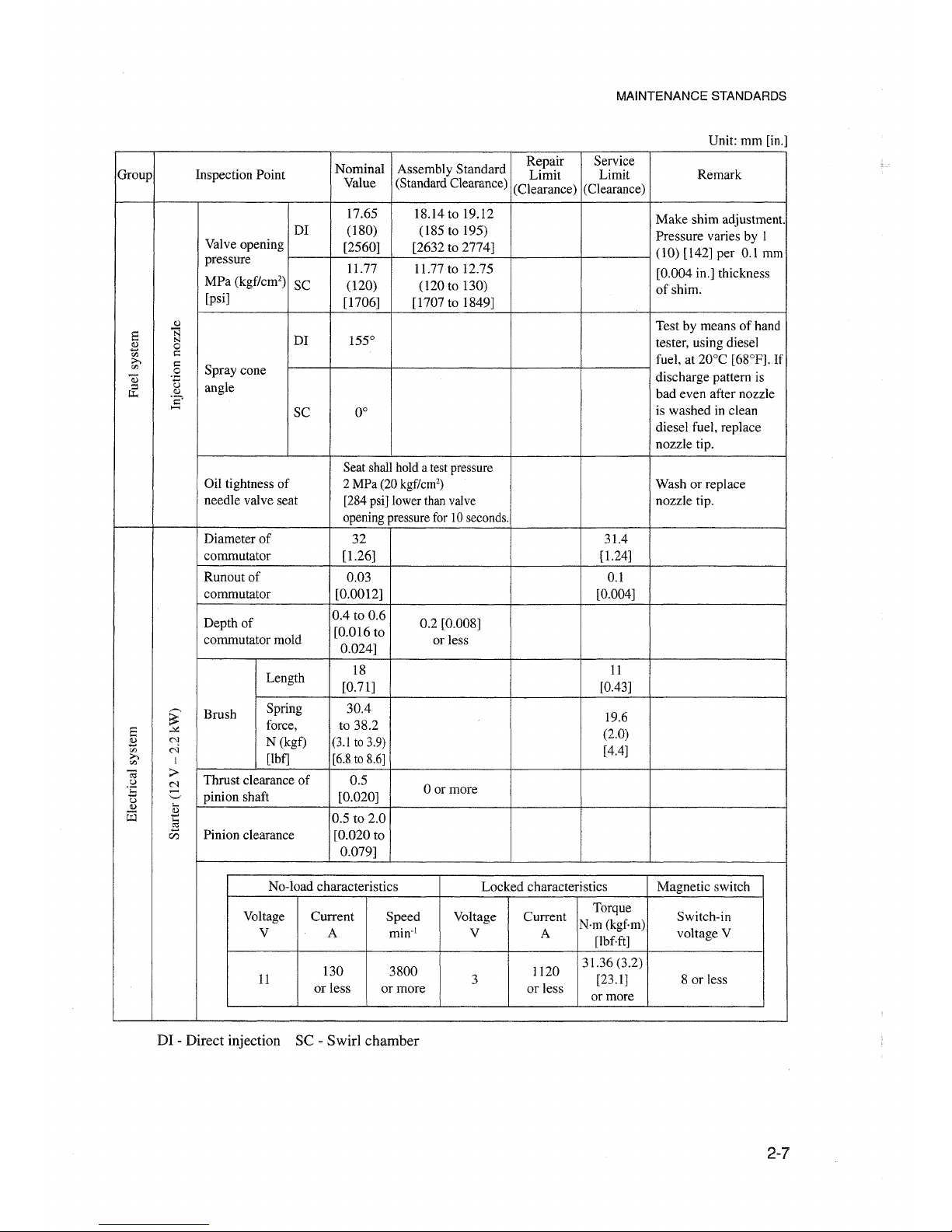
MAINTENANCE STANDARDS
Unit: mrn [in.]
Nominal
Assembly Standard
Repair Service
Group Inspeetion Point
Limit
Limit Remark
Value (Standard Clearance)
(Clearance)
(Clearance)
17.65
18.14 to 19.12
Make
shirn adjustrnent.
DI
(180)
(l85
to 195)
Pressure varies by I
Valve opening
[2560]
[2632 to 2774]
(l0)
[142] per 0.1 mrn
pressure
11.77
II.77to
12.75
[0.004 in.] thickness
MPa
(kgf/cm')
SC
(120)
(l20
to 130)
ofshim.
[psi]
[1706]
[1707 to 1849]
Cl)
Test by meansofhand
a
N
N
DI
155°
tester, using diesel
s
0
'fJ
I:::
fuel, at 20°C [68°P]. If
>-.
I:::
o:
.S
Spray cone
Q)
Ü
angle
discharge pattern is
&;
Cl)
bad even after nozzle
ï?
.....
SC
0°
is washed in clean
diesel fuel, replace
nozzle tip.
Seat shallhold a testpressure
üil
tightness of
2 MPa (20
kgf/cm")
Wash or replace
needie valve seat
[284psi] lower thanvalve nozzle tip.
opening pressurefor 10seconds.
Diameter of
32
31.4
commutator [1.26] [1.24]
Runout of
0.03
0.\
commutator [0.0012]
[0.004]
Depth of
0.4
to 0.6
0.2 [0.008]
[0.016 to
commutator mold
0.024]
or less
Length
18
11
[0.71] [0.43]
~
Brush
Spring 30.4
19.6
a
""
force,
to 38.2
(2.0)
2:l
N
N (kgf) (3.1to 3.9)
'fJ
M
[4.4]
>-.
[Ibf]
[6.8to8.6]
'fJ
I
C;; :>
Thrust clearance of 0.5
u
N
oor more
OE
-
pinion shaft [0.020]
u
'-'
<1)
...
G:l
~
0.5 to 2.0
en
Pinion clearance
[0.020 to
0.079]
No-load characteristics
Locked
characteristics Magnetic switch
Voltage
Current
Speed Voltage Current
Torque
Switch-in
Nrn (kgf-m)
V A
min:'
V
A
[lbfft]
voltage V
130
3800
1120
31.36 (3.2)
11
3
[23.1]
8 or Iess
or less or
more
or less
or more
DI - Direct injection SC - Swirl chamber
2-7
Page 28
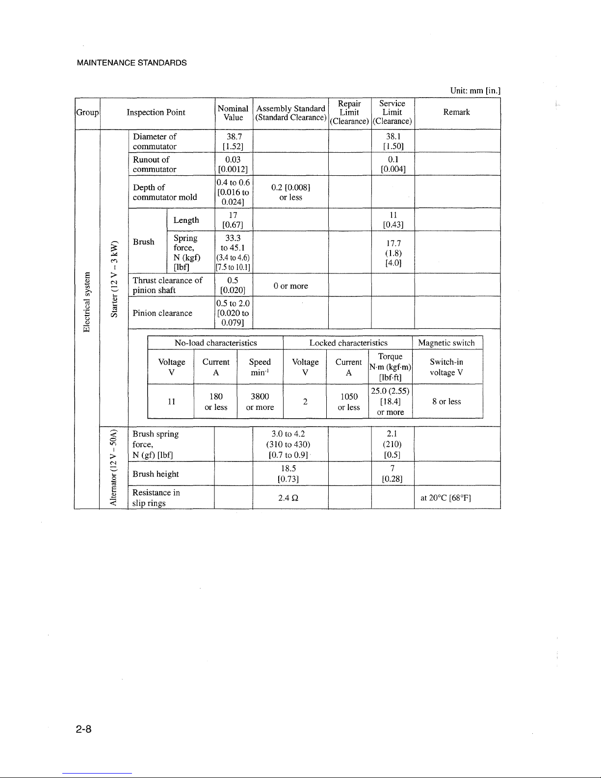
MAINTENANCE 8TANDARD8
Unit: mm [in.]
Nominal
Assembly Standard
Repair
Service
Group
Inspeetion Point
Limit
Limit
Remark
Value (Standard Clearance)
(Clearance)
(Clearance)
Diameter
of
38.7
38.1
commutator
[1.S2]
[I.SO]
Runout
of
0.03
0.1
commutator
[0.0012]
[0.004]
Depth
of
004
to 0.6
0.2 [0.008]
[0.016 to
commutator
mold
0.024]
or Iess
Length
17
11
[0.67]
[0.43]
,-..
Brush
Spring
33.3
17.7
~
force,
to
4S.1
..;.:
N (kgf) (3.4to 4.6)
(1.8)
c<)
[4.0]
I [Ibf] [7.5to
10.1]
Ei
>
Thrust clearance
of
O.S
~
C'1
oor more
on
-
pinion shaft
[0.020]
>-.
'-"'
on
....
-a
~
O.S
to 2.0
o
l§
oE
CZJ
Pinion clearance [0.020 to
()
0.079]
Il.l
~
No-laad
characteristics Locked characteristics Magnetic switch
Voltage
Current
Speed
Voltage
Current
Torque
Switch-in
Nrn
(kgf.m)
V
A
min:'
V
A
[lbf.ft]
voltage V
180
3800
lOS0
2S.0(2.S5)
11 2
[1804]
8 or less
or less or more
or less
or more
~
Brush spring 3.0 to 4.2
2.1
0
force, (310 to 430)
(210)
lr)
I
>
N (gf) [Ibf] [0.7 to 0.9]
[0.5]
N
'-"'
Brush height
18.S 7
....
[0.73]
[0.28]
~
E
Resistance in
B
2AQ
at 20°C [68°F]
~
slip rings
2-8
Page 29
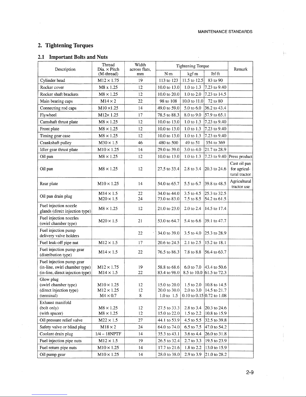
2. Tightening Torques
2.1 Important Bolts and Nuts
MAINTENANCE 8TANDARD8
Thread Width
Tightening Torque
Description
Dia. x Pitch
across flats,
Remark
(M-thread) mm
N·m
kgf-rn
IbHt
Cylinder head
M12 x 1.75
19 113 to 123
11.5 ta 12.5
83 ta 90
Rocker cover M8 x 1.25
12
10.0 to 13.0 1.0 ta 1.3
7.23 to 9.40
Rocker shaft brackets M8 x 1.25
12
10.0 ro 20.0 1.0 to 2.0 7.23 ta 14.5
Main bearing caps
M14x2
22
98 to 108
10.0 to 11.0 72 ta 80
Connecting rod caps
MlO
x 1.25
14
49.0 ta 59.0 5.0 to 6.0 36.2 ta
43.4
Flywheel
M12x
1.25
17 78.5 ta 88.3
8.0 ta 9.0 57.9 to 65.1
Camshaft thrust plate
M8 x 1.25
12 10.0 to 13.0 1.0 ta 1.3 7.23 ta
9.40
Front plate
M8 x 1.25
12 10.0 ta 13.0
1.0 to 1.3 7.23 to
9.40
Timing gear case M8 x 1.25
12 10.0 ta 13.0
1.0 to 1.3 7.23 to 9.40
Crankshaft pulley
M30
x 1.5
46 480 to 500
49 ro 51 354 to 369
Idler gear thrust plate
MlO x 1.25
14 29.0 to 39.0
3.0 to 4.0 21.7 ta 28.9
Oil pan
M8 x 1.25
12 10.0 to 13.0 1.0 ta 1.3 7.23 ro
9.40
Press product
Cast oil pan
Oil pan
M8 x 1.25
12 27.5 ta 33.4 2.8 to 3.4 20.3 to 24.6 for agricul-
tural tractor
Rear plate
MlO
x 1.25 14 54.0 ta 65.7 5.5 ta 6.7 39.8 to 48.5
Agricultural
tractor use
Oil pan drain plug
M14
x 1.5
22 34.0 ta 44.0
3.5 to 4.5
25.3 to 32.5
M20x
1.5
24 73.0 to 83.0 7.5 to 8.5
54.2 to 61.5
Fuel injection nozzle
M8 x 1.25
12 21.0 ta 23.0
2.0 ta 2.4 14.5 to 17.4
glands (direct injection type)
Fuel injection nozzles
M20x
1.5
21 53.0 to 64.7
5.4 ta 6.6 39.1 ta 47.7
(swirl chamber type)
Fuel injection pump
22 34.0 to 39.0
3.5 to 4.0 25.3 ta 28.9
delivery valve holders
Fuel leak-off pipe nut
M12
x 1.5
17 20.6 to 24.5
2.1 ta 2.5 15.2 ta 18.1
Fuel injection pump gear
M14
x 1.5
22 76.5 to 86.3
7.8 ta 8.8
56.4 to 63.7
(distribution type)
Fuel injection pump gear
(in-line, swirl chamber type)
M12
x 1.75 19 58.8 ta 68.6 6.0 ta 7.0 43.4 ta 50.6
(in-line, direct injection type)
M14
x 1.5
22 83.4 to 98.0 8.5 to 10.0 61.5 ta 72.3
Glow plug
(swirl chamber type)
MlO
x 1.25
12
15.0 to 20.0 1.5 to 2.0 10.8 ta 14.5
(direct injection type) M12 x 1.25 12 20.0 to 30.0 2.0 ta 3.0 14.5 to 21.7
(terminal)
M4xO.7
8
1.0 ta 1.5 0.10 ta 0.15 0.72 ta 1.08
Exhaust manifold
(balt only) M8 x 1.25
12 27.5 to 33.3
2.8 ta 3.4 20.3 to 24.6
(with spacer) M8 x 1.25
12 15.0 to 22.0
1.5 ta 2.2
10.8 to 15.9
Oil pressure reliefvalve
M22
x 1.5
27
44.1 ta 53.9 4.5 to 5.5
32.5
to 39.8
Safety valvearblind plug M18
x2
24 64.0 to 74.0 6.5 to 7.5 47.0 to
54.2
Coolant drain plug 1/4 - 18NPTF 14 35.3 to 43.1
3.6 to 4.4
26.0 ta 31.8
Fuel injection pipe nuts
M12
x 1.5
19 26.5 to 32.4 2.7 to 3.3 19.5 ta 23.9
Fuel return pipe nuts
MlO
x 1.25
14 17.7 ta 21.6
1.8 to 2.2 13.0 ta 15.9
Oil pump gear
MlO
x 1.25 14 28.0 ta 38.0 2.9 ta 3.9 21.0 to 28.2
2-9
Page 30
MAINTENANCE STANDAROS
Thread Width
Tightening Torque
Description Dia. x Pitch across flats,
Remark
(M-thread)
mm
N·m
kgf-m lbf-ft
Overheat warning unit
M16 x 1.5 19 20.6 to 24.5
2.1 to 2.5 15.2 to 18.1
(thermostat)
Starter terminal B M8 x 1.25 12 9.81 to 11.8 1.0 to 1.2
7.23 to 8.68
Plug
M16 x 1.5 24 39.2 to 49.0
4.0 to 5.0 28.9 to 36.2 Cylinder head
Balancer
M8 x 1.25
12
27.5 to 33.4
2.8
to 3.4 20.3 to 24.6
Fuel injection
pump
M12 x 1.0
17
16.0 to 23.0 1.6 to 2.3
11.6
to 16.6
feed pipe (flare)
Fuel injection
pump
eye bolt
M14x
1.5 22 15.0 to 20.0
1.5 to 2.0 10.8 to 14.5
Fuel injection
pump
17
15.0 to 20.0
1.5 to 2.0 10.8 to 14.5
overflow valve
Oil level sensor
1-1/16-12
24 49.0 to 58.8
5.0 to 6.0 36.2 to 43.4
2.2
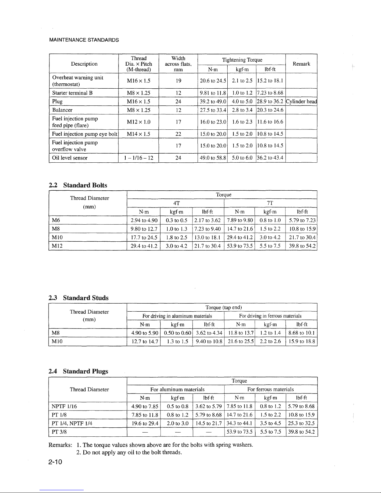
Standard
BoUs
Thread
Diameter
Torque
(mm)
4T
7T
N·m
kgf-rn lbf-ft N·m
kgf-rn
Ibf-ft
M6
2.94 to 4.90 0.3 to 0.5
2.17t03.62
7.89 to 9.80 0.8 to 1.0
5.79 to 7.23
M8
9.80 to 12.7 1.0 to 1.3 7.23 to 9.40
14.7 to 21.6 1.5 to 2.2
10.8 to 15.9
MlO
17.7t024.5
1.8 to 2.5
13.0 to 18.1 29.4 to 41.2
3.0 to 4.2
21.7 to 30.4
M12
29.4 to 41.2 3.0 to 4.2
21.7 to 30.4 53.9 to 73.5 5.5 to 7.5 39.8 to 54.2
2.3
Standard
Studs
Thread
Diameter
Torque (tap end)
(mm)
Fordriving in aluminummaterials
Fordrivinginferrousmaterials
N-m
kgf-m
lbf-ft
N·m
kgf-rn lbf-ft
M8 4.90 to 5.90 0.50 to 0.60 3.62 to 4.34
11.8to 13.7 1.2 to 1.4 8.68 to 10.1
MlO
12.7 to 14.7 1.3 to 1.5
9.40 to 10.8 21.6 to 25.5 2.2 to 2.6 15.9 to 18.8
2.4
Standard
Plugs
Torque
Thread
Diameter
For aluminum materials
For ferrous materials
N·m
kgfm
lbf-ft N·m
kgf-rn lbf-ft
NPTF
1/l6
4.90 to 7.85
0.5 to 0.8 3.62 to 5.79
7.85 to 11.8 0.8 to 1.2 5.79
to 8.68
PT 1/8 7.85 to 11.8 0.8 to 1.2 5.79 to 8.68
14.7 to 21.6 1.5 to 2.2 10.8 to 15.9
PT 1/4,
NPTF
1/4 19.6 to 29.4 2.0 to 3.0
14.5 to 21.7 34.3 to 44.1 3.5 to 4.5 25.3 to 32.5
PT3/8
-
-
- 53.9 to 73.5
5.5 to 7.5 39.8 to 54.2
Remarks: 1.
The
torque values shown above are for the balts with spring washers.
2. Do not apply any oil to the bolt threads.
2-10
Page 31

3. Sealants
and
Lubricants Table
MAINTENANCE STANDARDS
Apply to Mating part Sealant or Lubricant How to Use
üil
pan Crankcase Three Bond
12Ü?C
Apply to seal.
Rear bearing cap
Rear bearing cap Three Bond 1212
Apply to corners befare
seat on crankcase installing cap.
Side seals
Crankcase rear bearing cap
Three Bond 1212 Apply to side seals.
Cylinder head
Cylinder head Three Bond 1386D Apply to plug hole.
coolant hole plug
Crankcase coolant
Crankcase Three Bond l386D Apply to plug hole.
hole plug
Crankcase oil hole
Crankcase
Three Bond 1386D Apply to plug hole.
plug
Return oil hole
blind plug or pipe Crankcase Three Bond 1344 Apply to blind plug or pipe.
of crankcase
Crankshaft threads Crankshaft pulley nut Three Bond 1212
Apply to crankshaft thread before
tightening nut.
2-11
Page 32

Page 33

SPECIAL
rOOlS
Special
TooI
List 3-2
Page 34

SPECIAL TOOLS
Special
Tooi List
Taal name
Valve spring pusher
Valve guide remave
Valve guide installer
Stem seal installer
Valve seat insert
caulking
taal
Piston ring pliers
Part No.
30691--04500
32A91--o0300
3
2A91--o0
100
32A91-10200
Inlet valve:
36791--00200
Exhaust valve:
34491-03020
31391-12900
Shape
Use
Valve spring removal/
installation
Valve guide removal
Valve guide installation
Valve stem installation
Valve seat installation
Piston ring removal/
installation
Piston installer
34491--00200
®
Piston installation
Idler shaft puller
MH061077 Idler gear shaft removal
3-2
Page 35

SPECIALTOOLS
Tooi name Part No.
Shape
Use
Oil seal sleeve installer
30691-13010
set
Crankshaft rear oil seal sleeve
installation
Engine tuming
Compression pressure
measurement
Compression pressure
measurement
Compression pressure
measurement
58309-73100
Gage
adaptor 32A91-01100
(direct injection)
~
Gage adaptor
30691-21100
(swirl chamber)
~
Compression gage
33391-02100
Turning socket
Socket
34491-00300
Camshaft thrust plate and rocker
bracket installation
Connecting
rad
bushing puller
Camshaft bushing
instal1er set
MH061236
30691-00010
< ,
~
r
/-<~
j. / .,-'
Connecting rad bushing
rernoval/installation
Camshaft bushing removal!
installation
Oil
pump
bushing
instal1er
32A9]-00400
Oil pump bushing installation
3-3
Page 36

Page 37

OVERHAUL INSTRUCTIONS
1.
DeterminationofOverhaul
Timing
4-2
2.
Testing
the
Compression
Pressure
4-3
Page 38

OVERHAUL INSTRUCTIONS
1. Determlnation of OverhaulTiming
In most cases the engine should be overhauled when
the engine's compression pressure is low. Other
factors that indicatethe necessity of engineoverhaul
are as follows:
(a) Decreased power
(b) Increased fuel consumption
(c) Increased engine oil consumption
(d)
Increased
blow-by
gas volume
through
the
breather due to abrasion at the cylinder liner and
the piston ring
(e) Gas leakage due to poor seating of the inlet and
the exhaust valves
(f)
Starting problems
(g) Increased noise from engine parts
(h) Abnormal color of exhaustgas from engine after
warm-up
Any one or a combination of these symptoms may
indicate thatengine overhaul is required. Of the items
listed above some are not directly related to the
necessity of engine overhaul. Items (b) and
(f)
are
more likely to be affected substantially by
• Injection volume of the fuel injection pump
• Fuel injection timing
• Wearofinjection-pump plunger
• Fitting of the injection nozzle
• Condition of electrical equipment: battery,
starter, or altemator
Item
(d)
above,
however,
requires
special
consideration becausedecreased pressure due to wear
at the cylinder liner and the piston ring is one
ofthe
most
obvious
signs
that
the
engine
requires
overhauling.
The most effective way to make a decision is by
testing the compression pressure; other factors are
to be considered secondarily.
4-2
Page 39

2. Testlag the Compression Pressure
(1) Remove the injection nozzle from the cylinder
head where the compression pressure is to be
measured.
(2) On the direction injection type engine, attached
gage adaptor (32A9l-01100)tothecylinder, and
conneet thecompression gage (33391-02100) to
the adaptor.
On the swirlchambertype engine, attachthe gage
adaptor
(30691-21100) to the cylinder, and
conneetthecompression gage (33391-02100) to
the adaptor.
(3) Crank the engine by means of the starter, with
the governor stop lever pulled (the fuel supply
shut
off),
and
read
the
compression
gage
indication
when the
engine
running at the
specified speed.
(4)
If
the compression pressure is lower than the
repair limit, overhaul the engine.
r------
&CAUTION
1------
(a) Measure the compression pressure on all
cylinders.Itis
notagood
practice to
measure the compression pressure on only
few cylinders, andpresurnethe compression
on the remaining cylinders.
(b) Compression pressure varies with engine
speed. Check engine speed when measuring
the compression pressure.
Unit:
MPa
(kgf/cm") [psi]
Item
Assembly Repair
Standard Limit
Direct
2.9 2.6
injection
(30) (27)
Compression
[427] [384]
pressure
3.2 2.8
Swirl
(33) (29)
chamber
[469] [413]
.--------4
l
NOTE
Jr--------,
Measure the compression pressure with the
engine running at 300 min-I.
OVERHAUL INSTRUCTIONS
Measuring compression pressure (direct injection type)
Measuring compression pressure (swirl chamber type)
4-3
Page 40

OVERHAUL INSTRUCTIONS
......-------i[&CAUTION
JI-------.
(a) Measure the compression pressure atregular
intervals to obtain correct data.
(b) The compression pressure will be slightly
higher
ina new or overhauled engine due to
new piston rings, valve seats, etc. Pressure
will drop gradually by the wear of parts.
4-4
Page 41

ADJUSTMENTS, BENCH TEST, PERFORMANCE TESTS
1. Adjustments 5- 2
1.1 Valve Clearance 5- 2
1.2 Fuel System Bleeding 5- 3
1.3 Fuel Injection Timing 5- 4
1.4 No-load Minimum (Idling) Speed and Maximum Speed Setting 5- 5
1.5 V-belt Inspeetion and Adjustment 5-10
2. BenchTesting .. 5-11
2.1 Starting Up 5-11
2.2 Inspeetion After Starting Up 5-11
2.3 Bench Testing (Dynamometer) Conditions 5-11
2.4 Inspeetion and Adjustment After Bench Testing 5-11
3. Performance Tests 5-12
3.1 Engine Equipment Condition 5-12
3.2 Tests and Their Purposes 5-12
3.3 Other Inspections 5-12
3.4 Adjustment Engine Output 5-12
Page 42

ADJUSTMENTS, BENCH TEST, PERFORMANCE TESTS
1. Adjustments
1.1 ValveClearance
Valve clearance should be inspected and adjusted
when the engine is cold.
Unit: mm [in.]
Item Assembly Standard
Valveclearance
InIet
0.25 [0.0098]
(cold setting)
Exhaust
(l)
Inspeetion
(a) Inspeet the valve clearance in the injection
sequence.Tocheck, turn thecrankshaft by the
specified crank angle in the normal direction
to bring the piston to the top dead center of
the compression stroke.
Injection sequence
Crank angle
S4S
1-3-4-2
180
0
S6S
1-5-3-6-2-4
120
0
(b) Put socket (58309-73100) and ratchet handle
on the crankshaft pulley nut and turn the
crankshaft in the normal direction (clockwise
as seen from the front end).
Unit: mm [in]
Width across flats of
crankshaft pulley nut
46
[1.81]
(c) The top dead center on compression stroke
ofNo.1piston is identified by the timing mark
"0" (on the crankshaft pulley) being aligned
with the pointer on the gear case. With the
pistonsopositioned, boththe inlet and exhaust
valverocker anns are not being pushed up by
their pushrods.
(d) Insert afeeIer gage in between the rocker arm
and valve cap, and check the clearance.
5-2
ol
I!
I I I I
1401
Checking va1veclearance (turning)
Page 43

(2) Adjusting
(a) Loosen the loek nut of the adjusting screw.
Adjust the clearance by tuming the screw in
either direction to the extent that the gage is
slightly gripped between the rocker arm and
valve cap.
(b) After adjusting the clearance, tighten the loek
nut.Inspeet the clearance again and make sure
that it is correct.
1.2 Fuel System Bleeding
(l)
Fuel filter
(a) Loosen air vent plug on the fuel filter by
tuming it about 1.5 rotations.
(b) Unlock bleeding pump plunger by tuming it
counterclockwise, and operate the pump.
(c) Tighten the air vent plug when the fuel flows
without bubbles.
(2) Fuel injection pump
(a) Loosen air vent plug on the injection pump
by tuming it 1.5 rotations
(b) Unlock bleeding pump plunger by tuming
counterclockwise, and operate the pump.
(c) Tighten the air vent plug when the fuel flows
without bubbles.
,---------i(
&DANGER
11--
---,
When fuel overflows from the air vent plug, wipe
thoroughly with a cloth. Spilled fuel is a fire
hazard.
,----------1
NOTE
f----------,
If the vent plug is tightened before the bleeding
pump plunger is locked, fuel pressure acts on the
feed pump, making it difficult to restore the
plunger.
ADJUSTMENTS, BENCH TEST, PERFORMANCE TESTS
Adjusting valve clearance
Air vent plug
5-3
Page 44

ADJUSTMENTS, BENCH TEST, PERFORMANCE TESTS
1.3 Fuel Injection Timing
The injection timing varies according to the output,
speed and specifications of the engine. Be sure to
verify the timing by referring to the specifications.
(1) Bringing the No.l cylinder piston to thetop dead
center on compression stroke
(a) Put socket (58309-73100) on the crankshaft
pulley nut and turn the crankshaft in the
normal direction (clockwise as seenfrom the
front end).
(b) Stop turning the crankshaft when the timing
the mark
"0"
on the crankshaft pulley is
aligned with the pointer.
(c) Push down on the inlet and exhaust valve
rockerarms fortheNo.l cylinder tomake sure
they are not being pushed up by the pushrods
(the inlet and exhaust valves have some
clearance).
(2) Checking injection timing
(a) Remove delivery valve holder from the No.l
plungerofthe
injection
pump. Remove
delivery valve and spring from the holder.
Restore the holder to the pump.
(b) Conneet a spare injection pipe to the No.1
plunger, with its free end held downward so
that you can observe the fuel flow from that
end.
(c) Turn the crankshaft to bring the No.1 piston
to 60° position before top dead center on
compression stroke.
(d) While operating the priming pump to allow
the fuelto flowfrom theinjectionpipe, slowly
turn the crankshaft in the normal direction.
Stop turningthe crankshaft when thefuelflow
stops.
(e) Make sure the timing mark on the crankshaft
pulley is aligned with the pointer.
5-4
Ol
I I I I I
14Ql
Finding top dead center on compression stroke
Delivery valve
hOlde'--t
"""'
Spring
Delivery valve
_.=
,,,-,
Checking injection timing - I
(Removing delivery valve)
Checking injection timing
- 2
Page 45

(3) Adjusting injecting timing
(a) If the injection timing is retarded, move the
injection pump toward the crankcase. If the
timing is advanced, move the pump away
from the crankcase.
(b) One graduation of the scale on the injection
pump coupling changes the timing by 6° in
terms of crank angle.
1.4 No-lead
Minimum
(Idling) Speed
and
Maximum
Speed Setting
.-----------I(
&CAUTION
)f---------.
a)
The
no-Ioad minimum (idle) speed and
maximum speed are set for each engine on
the test bench at the factory. The set bolts
are sealed. These settingsareto be inspected
and adjusted at our authorized service shop
only.
b) After adjusting the govemorby breaking the
seals, be sure to re-seal all visible stoppers,
making them appear as if they were sealed
at the factory.
c)
When
inspecting
and
adjusting
these
settings, be on standby to operate the engine
stop lever manually in the event of engine
overrun.
For inspeetion and adjustment, warm up the engine
thoroughly until the coolant and oil temperature are
above 70°C [l58°F].
ADJUSTMENTS, BENCH TEST, PERFORMANCE TESTS
......
To retard
injection
timing
--~,.,.
Adjusting injection timing - I
Adjusting injection timing - 2
5-5
Page 46

ADJUSTMENTS, BENCH TEST, PERFORMANCE TESTS
(1) Starting engine
(a) Pull speedcontrollevertothe high speed side.
Operatethe starterswitch to crank the engine.
(b)
The
engine
will
fire up at 150
min-lof
cranking speed. When the engine fires, hold
the engine speed between 800 and 1000
min-I.
(c) When the engine runs with a steady speed,
move the speedcontrollever back to the idle
speed position.
(2) Setting no-Ioad minimum (idle) speed
Govemor
setbolt
-
Speed control lever
Low idle speed
set screw
Idlesub-spring
adjustingscrew
(a) Hold the speed control lever at the position
for no-Ioad minimum (idle) speed and setlow
idle speed set screw.
...----------JLt,CAUTION
1-----
__
If
a critical speed (the speed at which the engine
excessively vibrates due to torsional resonance)
might exist, shift the setting to a lower or higher
idle speed level.
(b) The engine speed will increase when the low
idle speed set screw is turned clockwise.
(c) Ifthe engine speedtends to fluctuate, turn idle
sub-spring adjusting screwclockwise to bring
this spring into slight contact with the tension
lever for eliminating fluctuation.
...----------JLt,CAUTION
1-----
__
Tightening the idle sub-spring adjusting screw
is likely to cause the engine to overspeed when
the load is removed during operation. Be sure to
tighten
this
adjusting
screw
just
enough
to
eliminate the unstable condition.
5-6
Low idle speed
set screw
Setting no-Ioad minimum (idle) speed
Idle sub-spring
adjusting screw
Setting idle sub-spring adjusting screw
Page 47

(3) Setting rack (maximum output)
(a) Hold the speed controllever at the position
for the indicated output and speed.
(b) Under this condition, check to be sure that
the engine is running in a steady state.
(c) With the engine running in a steady state,
adjust the ful1-load stopper bolt. Tighten or
loosen this bolt to find out the position where
the engine delivers the rated output.
(d)
Af
ter adjusting the stopper bolt, back it off
slowly
while
observing
the speed. Stop
backing off the stopper bolt just when the
engine speed begins todecreasefromthe rated
level and secure itin thatposition with itsloek
nut.
(e) At this time, the speed control lever should
be in the maximum speed position.
(f)
Tuming the fuIl-load stopper bolt clockwise
will increase the injection quantity (engine
output), and vice versa.
ADJUSTMENTS, BENCH TEST, PERFORMANCE TESTS
Settingrack
(maximum
output)
(4) Setting govemor (maximum speed)
(a) Apply fuIl load to the engine and hold the
speed control lever at the position for the
indicated maximum speed.
(b) Set govemor set bolt (maximum speed set
bolt) at the position for the indicated speed.
Governor
set bolt
Settinggovernor
(maximum
speed)
5-7
Page 48

ADJUSTMENTS, BENCH TEST, PERFORMANCE TESTS
(5) Deterrnining speed regulation (speed droop)
[I] Speed regulation upon removing load
(a) Run the engine with the speed control lever
set atthe position for the rated load and speed.
(b) Vnder this condition, remove the load to bring
the engine into no-load condition. Do not
move the speed contral lever.
(c)
The
engine
speed
will
increase
once
and
decrease and settle at a new steady state level
as
shown.
Read
the
highest
speed
(N2)
occurring in this transition and the speed
(N3)
af
ter
settling,
and
the
time
(tr)
from
the
momentofremoving the load at the initial
speedtbli) to the settling at the new level
(N3).
[2] Speed regulation upon applying load
With the engine runningunderno-loadcondition
subsequentto the condition mentionedin (b), [1],
above, and with the speed control lever held in
the same position as above, apply the prescribed
load instantaneously to the engine: the engine
speed will decrease once and increase, as shown,
and settle at a new steady state level. Read the
lowest speed (Ns) occurring in this transition and
the speed
(N6)
after settling, and the time (ts) from
N4toN6.
[3] Calculate the speed regulation
From the values obtained in [1]
and
[2], above,
compute
the
speed
regulation
for
each
load
change. A totaloffour percent values of speed
regulation are to be determined by using the
indicated forrnulas.
If the computer values are at varianee with the
prescribed values, "governor notch adjustment"
should be made to eliminate the varianee.
5-8
Speed regulation upon removing load
N,
Instantaneous speed Steady-state speed
regulation
(%)
regulation (%)
Nz-
NI
N3-NI
NI
X 100
NI
X 100
NI =initial speed, min-I, before load is
removed
N, = highest speed, min-I,during transitional
period
N3
=speed, min-I,at which the engine settles
after load is removed
ti =stabilization time
Speed
regUlatiO~n
upqn,applying load
N.
N,
Instantaneous speed Steady-state speed
regulation
(%)
regulation
(%)
N4-
Ns
N4-N6
N4
X 100
N4
X 100
N4
= initial speed, min-I, before load is
applied
Ns = lowest speed, min-I, during transitional
period
N6
=speed, min-I,at which the engine settles
after load is applied
tz = stabilization time
Page 49

(6) Setting no-load maximum speed (make governor
notch adjustment)
(a) This adjustment is to be made by turning the
adjustingscrew for theswivellevertoincrease
ordecrease the preload ofthe govemor spring.
(b) Togainaccess to the adjusting screw, remove
the plug at the top of the governor housing.
Turn the speed control lever all the way to
the low idle position: this will turn up the
swivellever, pointing the head oftheadjusting
screw toward the plug hole. Insert a flat-tip
screwdriver through the hole to catch the
screw head.
(c) Tightening the adjusting screw will increase
the preload of the governor spring to narrow
the
speed
regulation;
loosening
it will
decrease the preload to widen the regulation.
One notch corresponds to 1/4 turn
of
the
adjusting screw and to 3 to 5 speed change of
the engine speed.
(d) Changing the setting of this adjusting screw
changes the governorsetting (for limiting the
maximum speed). After making a governor
notch adjustment, be sure to readjust the
governor setting, as explained in (4), above.
(e) Tightening the adjusting screw, mentioned
above, will increase the maximumspeed, and
vice versa.
,---------i!h
CAUTION
1---------,
Never loosen the adjusting screw by more than
20 notches (5 turns) frorn the fully tightened
position, or the control action of the governor
will become hazardous.
(7) Seal the set bolts.
ADJUSTMENTS, BENCH TEST, PERFORMANCE TESTS
Adjusting speed reguJation
5-9
Page 50

ADJUSTMENTS, BENCH TEST, PERFORMANCE TESTS
1.5 V-belt Inspeetion
and
Adjustment
Push the belt inward with thumb pressure exerted
midway between the pulleys, as shown, to check the
belt tension (deflection).
If
the tension is incorrect,
loosen the adjusting bracket bolt and mounting bolt,
and move the altemator in or out.
Item
V-belt deflection
5-10
Unit: mm [in.]
Assembly Standard
12 [0.5]
Checking V-belt
Page 51

2. Bench Testing
An
overhauled
engine
should
be
tested
for
performance on a dynamometer. This test is also for
breaking in the major running parts of the engine.
To test the engine, follow the procedures described
below:
2.1
Starting
Up
(l)
Inspeetthe levels in the radiator, oil pan, and fuel
tank. Prime the fuel and cooling systems to bleed
air out.
(2) Crank the engine with the starter for 15 seconds
to permit lubricating oil to circulate through the
engine. Por this cranking, do not supply fuel to
the engine, placingthe stop lever in stop position.
(3)
Move
the
speed
control lever slightly in the
direction of increasing fuel injection, and turn
the starter switch to START to start the engine.
Do not move the control lever to the "full fuel
injection" position.
(4)After the engine starts, let it idle under no load
by operating the speed control lever.
2.2 Inspeetion
After
Starting
Up
Af
ter starting up
the
engine, check the foIlowing
points.
Ifyou
find anythingwrong, immediately stop
the engine, then investigate the cause.
(1) Lubricatingoil pressureshould be 0.3 to0.5 MPa
(3 to 5 kgf/cm") [43 to 71 psi] at rated speed or
0.1
MPa(lkgf/cm") [14.2 psi] at idling speed.
(2) Coolant temperature should be 75 to 85°C [167
to 185°P].
(3)
Lube
oil temperature should be 60°C to 95°C
[l40oP
to 203"F], (Varies according to engine
specifications.)
(4) Checkfor leakage of oil, coolant, fuel, especiaIly
oil
leakage
from
oil
pipe
connections
for
turbocharger lubrication.
(5) Knocking shoulddie away as coolant temperature
rises. No other defective noise should be heard.
(6)
Check
for exhaust color and abnormal odors.
ADJUSTMENTS, BENCH TEST,
PERFORMANCE
TESTS
2.3 Bench Testlng (Dynamometer)
Conditions
Step
Speed (min-I)
Load (PS) Time (min.)
1
1000
No-load
30
2 1500
25%
30
3
25%
10
-
(According to
4
engine specifi-
50%
10
-
5
cation)
75% 30
-
6
100%
20
2.4 Inspeetion
and
Adjustments Af
ter
Bench Testing
(a) Adjusting valve clearance
(b) Adjusting injection timing
(c) Re-tightening external bolts and nuts
5-11
Page 52

ADJUSTMENTS, BENCH TEST, PERFORMANCE TESTS
3. Performance Tests
There are various performance test procedures, and here the procedures for "Earth moving machinery
Engines, Part 1 : Test code
of
net power (JIS D 0006-1)" and "Earth moving machinery Engines, Part 2 :
standard format of specifications and tests methods of diesel engines (JIS D 0006-2)" are described. Other
test items may be required on application. Engine performance isjudged with integrated test results.
3.1 Engine Equipment Condition
Engine must be equipped with such standard auxiliaries as cooling fan, air cleaner and altemator.
3.2 Tests
and
TheirPurposes
(1) Operation load test
Conduct this test to evaluate engine output, torque, fuel consumption rate and governor performance under
various load conditions.
(2) Continuous load test
Operate the engine continuously for 10 hours at 90% load (continuous load application) of nominal net
brake power while engine speed is maintained at revolutions corresponding to the nominal brake power. In
this test, evaluate fuel consumption rate and operating condition and confinn continuous engine operation.
(3) No-load minimum idle speed test
Conduct this test to confinn that the engine can operate stably at the specified no-load minimum idle
speeds.
3.3 Other Inspeetiens
During performance testing, inspeet for leakage of gases, coolant, lubricating oil, or fuel, and for noise or
hunting. Make adjustment, as needed.
3.4 Adjustment Engine
Output
Diesel engine output is affected by atmospheric pressure, temperature, and humidity. Therefore, the engine
output should be set for standard atmospheric conditions.
(1) Standard atmospheric conditions
Base temperature
298 K (25°C)
[nOp]
Atmospheric pressure
WO
kPa [750 mmHg]
Atmospheric vapor pressure
99 kPa [743 mmHg]
5-12
Page 53

ADJUSTMENTS, BENCH TEST, PERFORMANCE TESTS
(2) Calculation of corrected power
Multiply the measured brake power or torque by the calculated diesel engine correction factor (see below)
to obtained a corrected value.
Corrected output
=Correction factor
(ac)
x Measured brake power
•Atmospheric conditions for test
Temperature (T): 283
K (l0°C)
[SOap]
~T~
313 K (40°C) [104°P]
Dry atmospheric pressure (Pd): 80 kPa (600 mmHg)
~Pd~
110 kPa (825 mmHg)
(3) Calculation of correction factor
(oe)
cc=(fa)fm
fa: Atmospheric factor fm: Engine factor
(a) Calculation of atmospheric factor (fa)
CD
Natural aspiration engine and engine with mechanically driven air charger
fa
=(
~)
•(
l)
0.7
Pd 298
@ Turbocharged engine without air cooler (after cooler) or with air-to-air cooler
99
T
fa = (
_)
0.7 • (
_)
1.2
Pd 298
@ Turbocharged engine with air-to-liquid cooler
99 T
fa =
(_)0.7.
(_)07
Pd 298
(b) Calculation of engine factor (fm)
fm
= 0.036 qc - 1.14
q
CD
qc (Corrected fuel supply volume) =-
r
(z) x (Fuel flow rate gIs)
q =(Stroke volume
f)
x (Engine idle speed min-I)
z
= 120000 (4-cycle engine)
r: Ratio of pressure at turbocharger or air cooler to atmospheric pressure
(r
=1 for natural aspiration engine)
@ Applicable range of engine factor (fm)
37.2
~qc~
65 mg/(f-cycle)
• qc
~
37.2 mg/(f-cycle) : fm =0.2 (Constant)
• 65
mgl(f-cycle)
~
qc : fm =1.2 (Constant)
(c) Range of correction equation use
The range of correction factor
(oe)
use is as follows: 0.9~ac
~
l.I.
If this range is exceeded, indicate the corrected value and record the test conditions on the test record sheet.
5-13
Page 54

Page 55

ENGINE
AUXlllARIES
REMOVAl
AND
INSTAllATION
1. Preparation 6- 2
2. EngineAuxiliaries Removal 6- 2
3. Engine Auxiliaries Installation 6- 7
Page 56

ENGINEAUXILIARIE8 REMOVAL AND IN8TALLATION
This section explains the procedures and tips for
removal and installation of the auxiliaries - the
pre1iminary process to go through for overhauling
the engine.
1. Preparation
(a) Shut off the
fue1
supply, and disconneet the
starting system from the engine.
(b) Loosen the drain plugs on the left-rear side
of crankcase, and drain coolant.
(c) Loosenthe oilpan drain pluganddrain engine
oil.
Hot engine oil can cause personal injury if it
contacts the skin. Use caution when draining the
oil.
.-------....,(
NOTE
)1--------,
Check the drained oil for contamination.
2. Engine Auxiliaries Removal
(1) Turbocharger (engines with turbocharger)
(a) Disconneet pipe from the turbocharger and
inlet manifold.
(b) Disconneet oil pipe and drain pipe from the
turbocharger.
(c) Remove
turbocharger
from
the
exhaust
manifold.
6-2
üil
pipe
Turbocharger
Removing turbocharger
Page 57

Return
pipe
(2) Exhaust manifold
Remove the bolts that hold exhaust manifold to
the cylinder head. Remove the manifold and
gasket from the head.
(3) Fuel filter
(a) Disconneet fuel pipes and from the fuel filter.
(b) Remove fuel filter complete with bracket
from the inlet manifold.
(4) Fuel injection pipes
(a) Remove pipe clamps and disconneet injection
pipes from the injection pump and nozzle
holders.
(b) Disconneet leak-off pipe.
(c) Disconneet return pipe.
,-------llLtCAUTION
)f--------.
Be sure to put rubber caps over the openings of
the injection pump and nozzle holders to prevent
dust from getting inside the fuel system.
(5) Inlet manifold
Remove the bolts that hold inlet manifold to the
cylinder head. Remove the manifold and gasket
from the cylinder head.
ENGINE AUXILlARIES REMOVAL AND INSTALLATION
Exhaust
manifold
Removing exhaust manifold
Removing fuel filter
Removing fuel injection pipes
Removing inlet manifold
6-3
Page 58

ENGINE AUXILIARIE8 REMOVALAND IN8TALLATION
(6) Fuel injection nozzles (direct injection type)
Remove gland, then remove nozzle and gasket
from the cylinder head.
(7) Fuel injection nozzles (swirl chamber type)
Remove nozzle and gasket.
(8) Glow plugs (direct injection type)
Remove nuts, then remove conneetion plate and
glow plug.
(9) Glow plugs (swirl chamber type)
Loosen nuts, then remove conneetion plate and
glow plug.
6-4
Removing fuel injection nozzles (direct injection type)
~
./~
Nozzle
Gasket
Removing fuel injection nozzles (swir! ehamber type)
Removing glow plug (direct injection type)
1liIIP---Nut
;"--Conneetion
plate
---Glow
plug
Removing glow plug (swirl ehamber type)
Page 59

(10) Fuel injection pump
(a) Remove oil pipe.
(b) Remove bolts that hold the gear case cover.
(c) Remove bolts that hold the flange plate.
Remove pump with gear and flange from the
front plate. (Some engines are not equipped
with pump bracket.)
(11) Oil cooler (engines with oil cooler)
Remove bolts that hold oil cooler cover to the
crankcase. Remove the cooler, complete with
the cover, from the crankcase. Remove gasket
and O-ring.
(12) Oil filter
(a) Remove oil filter with a filter wrench.
C13)Altemator
Ca)
Disconneet hamess from alternator. Remove
adjusting bolt.
(b) Remove bolts to remove the altemator.
Cc)
Remove V-belt.
ENGINE AUXILIARIE8 REMOVAL AND IN8TALLATION
Fuel injection pump
Removing fuel injection pump
Removing oil cooler
üil
filter
Removing oil filter
Removing alternator
6-5
Page 60

ENGINEAUXILIARIE8 REMOVALAND IN8TALLATION
(14) Water pump
(a) Remove the bolts that holdfan andpulley and
remove them.
(b) Remove the bolts that hold water pump and
remove the pump and gaskets.
(15) Starter
Disconneet harness from starter. Remove nuts
to remove the starter.
(16) Thermostat
(a) Remove water by-pass hose.
(b) Remove the bolts that hold thermostat case
to remove the termostat case.
(17)
ûil
pan
Remove bolts to remove oil pan.
6-6
Removing water pump
<;
<>
\~rter~
Removing starter
Removing thermostat
L
~
~Bolt
onpan
Removing oil pan
Page 61

3. Engine Auxiliaries Installation
To install the engine auxiliaries, follow the
removal procedures in reverse. After installation,
service them as follows:
(a) Refill the engine with the recommended oil
up to the specified level.
(b) Refill the cooling system with coolant.
(c) Check each pipe conneetion for oil or coolant
leaks.
(d) Prime the fuel system.
(e) To installation of the fuel injection pump is
described below. After installing the fuel
injection pumps, be sureto inspeet and adjust
the injection timing. (Refer to Section 1.3 of
Group 5, "Adjustment, Bench Testing, and
Performance Tests."
ENGINE AUXILlARIES REMOVALAND INSTALLATION
6-7
Page 62

Page 63

ENGINE MAIN PARTS
1. Cylinder Heads and ValveMechanism
00.0000.00000000.0000000000.000000.00.0000.0000000000.0000.0000.00'.000000.00"000000.
7- 2
1.1 Disassembly
.00
00
••••••••••••••••••••••••••••••••
00••00
•••
00 00
•••••••00•••••
0000.0000
00
••••••
0000
•••
0000.00.
7- 2
1.2 Inspeetion
00.00••00.00
••••
00000000
•••••
00.
0000
•••••••00••••
00'"
••••••••••••••
00
•••••••••••••
00
••••••00•••••••••
00
00...
••••••
7- 4
1.3 Reassembly
i.,
•.
00
••••••••••••
00••0000
••••••••••••
00
•••••••••••••••••••••••••
00
•••0000"'"
00.00••00
••••••••
00'00'"
0000
•••0000....
7-10
2. Flywheel .....
0000
•••••••••••••••••••••••••••••••••••••••••
00
••••00•••••••••
00
••••••••••••••••••
00••00••00
•••••••00•••••••••
00
•••••••••
00
••••
7-13
2.1 Disassembly
00.00
•••••••••••••
00
•••••••••••••••••••••••
00
•••••••••••••••••••••••••
00.00
•••••••••••••••••••••••••••••
0000
••••••
7-13
2.2 Inspeetion
00
••••••••••••••••••••
00
••••••••00•••••••••
00
•••••••••••••••••••••••••••••••••••••••••••••••
00
••••••
00
00.
7-14
2.3 Reassembly
00
••••••••••••••
00
•••••00••••00••••••00••00••••••••••
00
•••00•••00•••••••••••••••••••••••••••••••••••••
00
••••
7-16
3. Damper,Timing Gears and Camshaft.;
oooo
••••••
oo.oo••oo
•••••••••••
oo
•••••••••••••••
00
00
••
7-17
3.1 Disassembly ..
00.00
•••
00.00
••••••••••••••••••••••••••••••••••••••••••••••••••••
00
••••
00
7-17
3.2
Inspeetion
oo
•••••••••••••
00
••••••••••••••••
00
0000
00
••••••••••••••••••••••••••••
7-21
3.3 Reassembly
00.00
••••••••••••
00
•••••••••••••
00
••••••00•••••••••••
00.00••0000.00••00
0000.0000'0000.
0000
"0000"'00
00.00.
7-25
4. Pistons, Connecting Rods, Crankshaft, Crankcase and Tappets
0000.0000
0000000000.0000.00
......00......
7-30
4.1 Disassembly ........
0000000000
0000.
000000.0000.
0000
00'0000'00'"
00000000
000000••••
0000
.000000
00
00.0000
0000
...
000000••00.000000..
7-30
4.2 Inspeetion
00.0000
•••••
0000000000
••••
00.
00
00.
00
00.
0000.00..00••••00•••00....
000000"
00"
00.
0000'0000'
00
'0000'
0000 00
00"'0000
7-33
4.3 Reassembly
0000..00.000000000000.00
00
00
00.
00
00.
0000••00
.....
0000••000000.
00000000"00'000000
000000
00'
"00'
0000••00
•••
00..
7-48
Page 64

ENGINE MAIN PARTS
1. Cylinder
Head
and
Valve Mechanism
1.1 Disassembly
Check valve cap contact face
for wear.
Check
oil hole for
clogging.
Check for cracks.
or'carbon
or scale deposits,
Check
face for pitringorridging
(exhaust valve),
Check
stem
for
serarches or
scuff
marks.
Check for uneven
WeM.
IDisassembly sequence I
CD
Rocker cover
® Adjusting screw
® Bolt (short)
@ Bolt (long)
Remove @ through(@as an
assembly.
@ Rocker shaft bracket
@ Snap ring
(j) Inlet valve rocker arm
7-2
@ Exhaust valve rocker arm
® Rocker shaft spring
(@
Rocker shaft
(jJ)
Valve cap
© Valve pushrod
(j])
Cylinder
head
bolt
Remove ® through @ as an
assembly.
® Cylinder head
@ Valve cotter
@ Valve retainer
® Valve spring
@ Valve
® Valve stem seal
®>
Cylinder head gasket
Page 65

(1) Removing rocker shaft assembly
(a) Loosen the adjusting screw one rotation.
(b) Loosen the bolts, short and long, that holdthe
rocker shaft bracketto the cylinder head. Be
sure to loosen the short bolt first. Remove the
rocker shaftassembly from the cylinder head.
,-------l,&CAUTION
1--------,
If the long bolt is loosened first, the rocker shaft
bracket might suffer damage.
(2) Disassembling rocker shaft assembly
Put a mark on the rocker arm and shaft so that
the arm can be installedon the same shaft position
from which it was removed.
(3) Removing cylinder head
(a) Remove the cylinder head bolts.
(b) Lift the
head
off
the crankcase.
,--------1
NOTE
}--------,
(a)
Whenremoving
the
gasket
from
the
crankcase,
be careful not to
damage
the
gasket contact surface of the crankcase
(b)Ifany cylinder head parts are faulty, check
the
cylinder
head
bolts for torque with a
torque wrench before removing them.
ENGINE MAIN PARTS
Removing rocker shaft assembly
Disassembling rocker shaft assembly
7-3
Page 66

ENGINE MAIN PARTS
(4) Remove valve and valve spring
(a)
Use
valve spring pusher (30691-04500) to
compress the valve spring, then remove the
valve cotters.
(b) Remove the valves and valve springs.
,.....-------I[
NOTE
ÎI-
-,
If the original valves are to be reused, mark them
for their locations to ensure the originallocation
and combinations of the valve, valve seat and
valve guide.
1.2 Inspeetion
Rocker arms, rocker bushings
and
rocker shafts
(1) Measuring rocker arm bushing and rocker shaft
Measurethe inside diameterof the rockerbushing
and the diameter of the rocker shaft as shown in
the illustration. Determine the clearance between
the
bushing
and
shaft
on
the
basisofthe
measurements.
If
the clearance does not exceed
the
repair limit, replace the rocker arm. If it
exceeds the repair limit, replace the shaft and
rocker arm.
Unit: mm [in.]
Item
Nominal
Assembly
Service
Value Standard
Limit
Inside diameter
19.010
of rocker
to 19.030
bushings
[0.7484
19
to 0.7492]
[0.75]
18.980
Diameter of to 19.000
rocker shaft
[0.7472
to 0.7480]
Clearance 0.010
between rocker to 0.050
0.070
bushing and [0.0004 [0.0028]
shaft to 0.0020]
7-4
Removing valve and valve spring
Measuring rocker arm bushing and rocker shaft
Page 67

Valves, valve guldes
and
valve seats
(1)
Measuring
valve
stem
Measure
the
diameterofthe valve stem as
shown
in
the
illustration.Ifthe stem is
wom
beyond
the
service
limitorunevenly
wom
excessively,
replace
the valve.
Unit: mm [in.]
Item
Nominal Assembly
Service
Value
Standard Limit
lniet
7.940 to 7.955
7.900
[0.3126
Diameter
valve
8
to 0.3132]
[0.3110]
ofvalve
I----
Exhaust
[0.31]
7.920 to 7.940
stem
valve
[0.3118
7.850
to 0.3126]
[0.3091]
(2)
Checking
clearance
between
valve
stem
and
valve guide
The
valve guide wears more rapidly at its
both
ends
than at any
other
parts. Measure the
inside
diameterofthe
guide
at its ends as shown in
the
illustration to
determine
the clearance
between
the
guide
and
stem.Ifclearance
exceeds
the
service
limit,
replace
the
valve
or
guide
whichever
is excessively wom. Unit: mm [in.]
Item
Nominal Assembly
Service
Value Standard
Limit
InIet
0.065 to 0.095
0.150
Clearance
valve
-
[0.0026
[0.0059]
between
to 0.0037]
valve
stem
Exhaust
0.080 to 0.115
and
guide
valve
-
[0.0032
0.200
to 0.0045]
[0.0079]
Height to top of
11.5
±O.I
valve guide [0.45]
[±0.004]
ENGINE MAIN PARTS
Measuring diagram
+
Measuring valve stem
Measuring
diagram
e
~
Measuring valve guide
(3) Replacing valve guide
(a)
Use
the valve guide remover(32A91-OO300),
to
remove
the
valve guide for replacement.
Valve
guide
remover
-~.
Removing valve guide
7-5
Page 68

ENGINE MAIN PARTS
(b) To install areplacement guide, use valveguide
installer (32A91-o0100).
Press
Valve guide instalIer
.....--------iLLCAUTION
1-------,
The installation depth for the valve guide is
specified; be sure to usethe valve guide instalIer
to insure the correct depth.
Installing valve guide
Valve margin
Valve sinkage
Bad
Inspecting valve face
Valve contact pattern
Good
Coatthe valve face lightly with red lead. Use the
Valve lapper to inspeet the valve contacts with
its seat. If the contact is not uniform, or if the
valve isdefectiveoriftherepair limit is exceeded,
repair or replace the valve and valve seat.
Unit: mm [in.]
a) Inspeetthe valve faceafter the inspeetion or
replacement of the valve guide.
b) Do not rotate the valve when checking its
contact.
c)
Af
ter refacing or replacing the valve or the
valve seat, be sure to lap the valve in the
seat. (See (8) Valvelapping.)
(4) Inspecting valve face
Item
Assembly
Repair
Standard
Limit
Angle 30° -
Inlet
0.4±0.1
ce
Valve
[0.016 ± 0.004]
Q)
Valve
(inlet)
1.0
'"
Q)
sinkage
0.5±0.1
[0.039]
;>
Exhaust
~
Valve
[0.020±0.004]
(exhaust)
1.4±O.14
1.8
Width
[0.O55±0.OO55]
[0.071]
2.13
Up to 1.83
Valve margin
[0.0839]
[o.onO]
by refacing
,..---------1
NOTE
1--------,
7-6
Page 69

(5) Refacing valve face
If
the valve face is badly wom, reface it with a
valve refacer.
NOTE
1---------,
a) Set a valve refacerto an angle of 30°
b)
The
valve has a stellate facing. This facing
will be gone
if
the valve margin exceeds the
service limit.
If
the margin seems to be less
than the service limit when ground, replace
the valve.
(6) Refacing valve seat
Use
the Valve seat cutter or valve seat grinder to
reface the valve seat.
Af
ter refacing, grind the
seat lightly using #400 grade sandpaper inserted
between the cutter and valve seat.
NOTE
1---------,
a) Cut or grind the valve seat only as needed
for refacing.
b) Replace the valve seat
if
the seat width is
more than the repair limit as a result of wear
or cutting.
(7) Replacing valve seat
(a) Weld a stud to the valve seat. Insert a shaft
into the valve guide holder from the upper
side of the cylinder head. Drive the seat off
from the cylinder head as shown .
.--------I(
NOTE
11--
---,
When
you weld the stud, do not to permit splatter
to come in contact with the machined surfaces
of cylinder head.
ENGINE MAIN PARTS
Refacing valve face
Refacing valve seat
Stud
Removing valve seat
7-7
Page 70

ENGINE MAIN PARTS
(b) Before installing replacement valve seats in
the cylinder head, measure the bores in the
cylinder head for the valve seats.
(c) Chill the valve seat in liquid nitrogen of -
l70DC[-274
DF]
for more than4 minutes with
the cylinder head kept at normaltemperature,
or heat the cylinder head up to 80
DC
to 100
DC
[176DFto 212
DF]
with the valve seat chilled
in ether or alcohol containing dry ice.
(d) Using insertcaulkingtaal, drive the seat into
position.
Tools needed
Insert caulking tooI
36791-00200
(for inlet valve seat)
Insert caulking tooI
34491-03020
(for exhaust valve seat)
(8) Lapping valve in va1veseat
Be sure to lap the valve inthe valve seat after the
valve or the seat have been replaced.
(a) Coat the valve face lightly with a lapping
compound.
,---------j(
NOTE
If--
--,
(a) Do not permit the compound to come in
contact with the valve stem.
(b) Use a compound of 120 to 150 mesh for
initiallapping and the compound finer than
200 mesh for finish lapping.
(c) Mixing the compound with a small amount
of
engine oil will facilitate coating.
7-8
46~~·OO25
[1.8II
-;;"'~']
Inlet valve Exhaust valve
seat bore seat bore
Valve seat dimensions
Installing valve seat
Coating valve with lapping compound
Page 71

(b) Using lapping tool, hold the valve against the
seat and rotate it only a part of a turn, then
raisethe valve off the seat, rotating it to anew
position. Then press the valve against the seat
for another part of aturn. Repeatthis operation
untilthe compound wears and loses itcutting
particle.
(c) Wash off the compound with diesel fuel.
(d) Apply the valve face to the engine oil, and
again lap the valve.
(e) Check the valve face for contact.
(9) Measuring valve spring perpendicularity andfree
length
Measure the free length and perpendicularity of
each
valve
spring.Ifthe
free
length
or
perpendicularity
exceeds
the
service
limit,
replace the spring.
Unit: mm [in.]
Item
Assembly Service
Standard Limit
Free length 48.85 [1.92] 47.60 [1.87]
Perpendicularity
1.5°or less
-
Set
length 43 [1.69] -
Set force
176to 196 147
N (kgf) [lbf]
(18 to 20) (15)
[40 to 44] [33]
ENGiNE MAiN PARTS
Valve lapping
tooI
Lapping valve in valve set
Perpendicularity
Measuring valve spring perpendicularity and free length
7-9
Page 72

ENGINE MAIN PARTS
(10) Measuring cylinder head warpage
Using a heavy accurate straight edge and feeler
gages, check
the
gasket
contact
surface for
warpage in
two
positions
lengthwise,
two
crosswise and two widthwise as shown in the
illustration.
If
the warpage exceeds the repair
limit, reface the head with a surface grinder.
Unit: mm [in.]
Item
Assembly Repair
Standard Limit
Warpage of gasket
0.05 [0.0020] 0.20
contact surface or less [0.0079]
Measuring cylinder head warpage
(11) Measuring valve pushrod deflection
Measure the pushrod deflection with a V-block
and a dial indicator as shown in the illustration.
Ifthedial indicatorreading exceeds the assembly
standard, replace the pushrod.
Item
Deflection (dial indicator
reading) of valve pushrod
Unit: mm [in.]
Assembly Standard
0.3 [0.012] or less
Measuring valve pushrod deflection
Installing valve stem seal
1.3 Reassembly
(1) Installing valve stem seal
After installing the valve in position, install the
seal to the valve guide with stem seal installer
(32A91-10200).
..-------l(
LÏ:,CAUTION11---------,
a) Do not put any oil or sealant on the face of
the stem seal that comes in contact with the
valve guide. When installing the seal, put
engine oil on the seal contact surface of the
stemto ensure initiallubrication ofthe stem
seallip.
b) Do not remove the valve after the seal has
beeninstalledin position to prevent damage
to the seallip.
7-10
Stem seal instalIer
Valve
Valve
stem seal
Valve
guide
Page 73

(2) Installing valve and valve spring
(a) Put the valve spring and retaineron the valve
guide. Using valve spring pusher
(30691-
04500), compressthe valve spring and install
the valve cotters.
(b) Tap
the
valve stem top with a soft-faeed
hammer
several times to make sure the valve
spring and cotters are properly installed.
(3) Installing cylinderhead
(a) Put the gasket on the top of the crankcase,
making sure the two dowel pins enter their
holes in the gasket.
(b)
Put
the
cylinder
headonthe
crankcase,
making sure the two dowel pins enter their
holes in the head. Tighten the head bolts.
...------I&CAUTION
1------
Do not use any sealant. Make sure the gasket
contact surface
ofthe
crankcase is free from any
defects.
ENGINE MAIN PARTS
Installing valve cotters
Installing cylinder head
(c)
Tighten
the
cylinder
head
boltstothe
specifiedtorque in the sequence shown in the
illustration.
Tightening torque for
cylinder head bolts
113
to 123Nrn
(11.5to12.5
kgf-m)
[83 to90 lbHt]
~
/'
0
0
0
0
Front
12
0
4
Ol
5
13
0
0
0
<?
16
8
9
1:"-
-
14
0
0
0 0 0 0
0
0
15
11
7
3
2
6
10
No. of bolts: 17
Cylinder head bolt tightening sequence (S4S)
7-11
Page 74

ENGINE
MAIN PARTS
No.ofbolts: 25
Cylinder head bolt tightening sequence (565)
(4) Reassembling rocker shafts
Af
ter reassembling the rocker shafts, make sure
the
rocker arms
move
smoothly.
Reassembling rocker shafts
(a) Install the valve caps in position.
(5) Installing rocker shaft assembly
(b) Put the roeket shaft assembly on the cylinder
head and tighten the bolts to the specified
torque.
Long bolt
10.0 to 20.0 N·m
(1.0 to 2.0 kgf.m)
[7.23
to
14.5
IbHt]
Tightening torque for
rocker shaft bolts
r---------j
NOTE
1---------,
Installing rocker shaft assembly
Be sure to tighten
the
long bolt first.
(6) Adjusting valve clearance
Refer
to 1.1, Group 5.
Adjusting valve clearance
7-12
Page 75

2. Flywheel
2.1 Disassembly
Replace gasket.
Checks for cracks or
defective dowel hole.
I
Disassembly
sequence
I
CD
Flywheel
Check for wom or
defective lip.
Check for cracks or defective
dowel hole. Check ring gear
for wom or detective teeth.
Remove ® and
CID
as an assembly.
® Flywheel housing
CID
Oil seal
3
ENGINE MAIN PARTS
@ Rear gasket
7-13
Page 76

ENGINEMAIN
PARTS
(1) Removing flywheel
(a) Removeone
ofthe
bolts that hold theflywheel
to the crankshaft.
(b) Run safety bar (M12 x 1.25) in the holefrom
which the bolt was
removed
in Step (a).
Remove the remaining flywheel bolts.
(c) Remove the flywheel from the crankshaft by
puIling
it straight.
.---------J&CAUTION
f------,
When removing the flywheel, wear heavy gloves
to avoid injury.
(2) Removing flywheel housing
Remove the bolts that hold the flywheel housing
to the crankcase. Remove the housing.
...-------l[&CAUTION
JI-------.
Do not cause damage to the oil seal.
2.2 Inspeetion
Flywheel
and
ring
gear
(1) Flatness (difference between lower and higher
measurements) of flywheel
Put the flywheel on the surface plate. Set a dial
indicator at one side
of
the friction surface and
move it over to the opposite side of that surface
asshown inthe illustration.
If
the surface flatness
is over the repair limit, regrind it.
Unit: mm [in.]
Item
Assembly Repair
Standard
Limit
Flatnessof flywheel 0.15 [0.0059] 0.50
friction surface or less
[0.020]
7-14
Removing flywheel
Removing flywheel housing
Measuring flywheel flatness
Page 77

(2)
Face
runout
and
circular
runout
(radial
eccentricity)offlywheel
Set
adia! indicatorat the friction(vertical) surface
and
turn the flywheel one full revolution to check
the
face
run
out.
Set
a dial
indicatoratthe
horizontal surface of the pilot bearing bore and
turn the flywheel one full revolution to check the
circularrunout. Excessive runout of theflywheel
in either position will probably be causedby dirt
in the mounting face or improper tightening of
the
bolts. Unit:mm
[in.]
Item
Assernbly Repair
Standard
Limit
Face and bore
0.15 [0.0059]
0.50
runouts of flywheel or less [0.020]
(3)
Ring
gear replacement
Check
the
ring
gear
teeth and,ifthey
are
defective, replace the gear as outlined below.
(Removal)
(a) Heat the ring gear evenly with an burner.
(b) Hit the ring gear all the way around with a
bar
and a hammer to remove it.
(Installation)
Heat a replacement ring gear up to 100°C [212°F]
with a heater,
and
install the gear to the flywheel
placing
the
unchamfered side of the teeth to the
flywheel.
.---------l(
Lh
CAUTION
)1-------,
Do
not
heat the ring gear excessively.
ENGINE MAIN PARTS
Measuring flywheel runouts
Removingring gear
7-15
Page 78

ENGINE MAIN PARTS
2.3 Reassembly
(1)
Installing
oil
seal
(According
to
engine
specification)
Apply a thin coat of grease to the oil seal and
install the oil seal to the flywheel housing with
an installer.
..-------1
NOTE
1---------,
If the oil seal contact surface of the crankshaft is
excessively worn, use an oil seal with sleeve.
Apply grease,
Engine side
<;::::J
F1ywheel
housing
F1ywheel
side
c:::)
I ""H--_Oil seal
Installing oi! sea!
(2) Installing flywheel housing
(a) Put the new rear gasket in position.
(b) Apply engine oil to the oil seallip.
(c) Installtheflywheel housing, making sure the
dowelsenter their holes, andtighten the bolts.
,-----,..-------I(
NOTE
If--
---,
Install the starter to the housing to facilitate
installation work.
(3) Installing flywheel
(a) Install safety bar (M12 x 1.25) in the rear end
of the crankshaft.
(b) Install the flywheel to the crankshaft, making
sure the safety bar enters the hole in the
flywheel.
(c) Tighten the bolts (five) finger tight only.
(d) Remove the safety bar and install the last one
bolt.
(e) Have someone hold the crankshaft pulley nut
with a wrench.
(f)
Tighten the bolts that hold the flywheel to the
specified torque.
Tightening torque for
78.5 to 88.3 N·m
flywheel bolts
(8.0 to 9.0 kgf-m)
[57.9
to65.1lbHt]
(illCAUTION
During installation, signal to each otherto avoid
personal injury.
7-16
Installing flywhee! housing
Safety bar
Installing flywhee1
Page 79

3. Damper, Timing Gears
and
Camshaft
3.1 Disassembly
ENGINE MAIN PARTS
Replace
gasket
Check for wear
or damage.
Check teeth for wear,
nicks, burrs or chips.
Check keyway
apçl
bushing for damage
or wear.
Check for
we:n"
Check for stripped
threads.
IDisassembly sequence I
CD
Damper (S6S)
® Crankshaft pulley
@ Cover
@ Fuel injection pump
®
Oilpan
Check for wom heil
grooves.
Check for cracks or
defective dowel holes.
@ Timing gear case
(J) Oil pump gear
@ Thrust plate
® Idler gear
Remove
(j])through © as an
assembly.
(j]) Camshaft
® Camshaft gear
© Thrust plate
Cl])
Front plate
7-17
Page 80

ENGINE MAIN PARTS
(I)
Removing damper
(S6SIDT)
(a) Install two safety bars
(MI2
x 1.25)in therear
end of the crankshaft to hold the crankshaft.
(b) Remove the damper.
llliWARNING
Be to install the safety bars securely.
(2) Removing crankshaft pulley
Removethepulley from the crankshaftas shown.
(3) Removing oil pan
Remove the bolts and remove the oil pan.
(4) Removing timing gear case assembly
Removethetiming gear case assembly as shown.
.--------1illCAUTION
1-------,
Do not cause damage to the oil seal.
(5) Measuring backlash and end play
Make
a recordofthe backlash and end play
measurements to be referred to for reassembly.
(Refer to 3.2)
7-18
Removing damper
Removing crankshaft pulley
Removing timing gear case assembly
Measuring backlash and end play
Page 81

(6) Removing oil pump gear
Loosen the nut and remove the gear.
(7) Removing idler gear
Remove the thrust plate and remove the gear as
shown.
(8) Removing camshaft
(a) Turn the crankcase upside down.
(b)
Position
the
camshaft
gearsothat
its
lightening holes come to top and bottom.
Remove the bolts that hold the thrust plate.
Remove the camshaft from the crankcase.
~-------I&CAUTION
)1-----------,
Do not cause damage to the Iobe faces of the
camshaft and the bushings.
ENGINE MAIN PARTS
Removing oil pump gear
Removing idler gear
Removing camshaft
7-19
Page 82

ENGINEMAIN
PARTS
(9) Removing camshaft gear
Removethe gear from the camshaft with a puller.
Now the thrust plate can be removed.
r-------1(
NOTE
11-
---,
Do not remove the camshaftgear and thrust plate
unless they are damagedto the extent of requiring
replacement.
(10) Removing front plate
Remove the bolts that hold the front plate to the
crankcase. Remove the front plate.
7-20
Removing camshaft gear
Removing front plate
Page 83

3.2 Inspeetion
Camshaft
and
camshaft bushlngs
(1) Measuring camshaft end play
Measure the camshaft end play as shown in the
illustration. If the end play exceeds the service
limit, replace the thrust plate.
Unit: mm [in.]
Item
Assembly
Service
Standard Limit
End play of 0.10 to 0.25 0.30
camshaft [0.0039 to 0.0098] [0.0118]
(2) Measuring cam lift
To find the cam lift, use the procedure that
follows:
(a) Measure lobe height (A).
(b) Measure base circle (B).
(c) Subtract base circle (B) from the lobe height
(A). The difference is lobe lift
(C).
Ifthecam liftis lessthan the servicelimit,replace
the camshaft.
ENGINE MAIN PARTS
Measuring camshaft end play
Measuring diagram
-9-~
Measuring cam lift
Unit: mm [in.]
Item
Nominal Assembly Service
Value Standard
Limit
A=
6.62 6.182
DI
46.918tii:~1
[0.2631] [0.2434]
Inlet
[1.8472tii:8?i]
valve
A=
SC
46.916tii:~1
6.684 6.184
Cam
[1.8471tii:~]
[0.2632]
[0.2435]
liftC
A=
DI
46.878tiiS
l
6.722 6.222
Exhaust
[1.8456tii:~]
[0.2647] [0.2450]
valve
A=
SC
46.88
otiiS
1
6.720
6.220
[1.8457tii:8?i]
[0.2646] [0.2450]
DI - Direct injection SC - Swirl chamber
A
7-21
Page 84

ENGINE MAIN PARTS
(3) Measuring camshaft deflection
Support
the
camshafton its front and rear journals
in
V-blocks. With the dia! indicator set at 0.00
mm [0.0000 in.] at the
center
joumal,
turn the
camshaft
full
one
revolution
and
read
the
indicator, as shown in the illustration. 1/2ofthe
reading on
the
indicator is
the
deflectionofthe
camshaft.
If
deflection exceeds
the
repair limit,
straighten
the
camshaftbycold
working, or
replace it.
Unit: mm
[in.]
Item
Assembly
Repair
Standard Limit
Camshaft 0.02[0.0008] 0.20
detlection
or less
[0.0020]
(4)
Clearance
between
camshaft
journals
and
bushings
Measure
the
diameterofthe
camshaft
journals
and the inside diameter
of
the
bushings in the
crankcase to
check
the
clearance
between the
joumal
and
bushing.
Ifthe
clearanceexceeds the
service limit, replace the bushings.
Unit: mm [in.]
Item
Nominal Assembly Service
Value
Standard Limit
No.l,2
53.94
(S4S)
54
to 53.96
53.90
Diameters
No.l,
2,3
[2.13]
[2.1236
[2.1220]
of cam-
(S6S)
to 2.1244]
shaft
52.94
journals
No.3
(S4S)
53
to 52.96 52.90
NoA
(S6S)
[2.09] [2.0842 [2.0827]
to 2.0850]
0.070
to 0.118
Front and [0.0028
middle to 0.0047]
(without
bushings)
Clearance
0.070
between
to 0.110
0.15
camshaft
Rear
[0.0028
[0.0059]
journals to 0.0043] (Repair
and bore
(without
limit)
bushings)
0.040
to 0.119
[0.0016
to 0.0047]
(with bush-
ings)
7-22
Measuring camshaft detlection
Measuring diagram
-Q-W
Measuring camshaftjournals
Measuring camshaft bushings
Page 85

(5) Replacing camshaft bushings
(a)
Ifthe
clearancebetween the camshaftjoumal
and bore in the crankcase exceeds the service
limit,
refinish
the
boreto57H6
("'8019)
3.125 Ra. and install bushings.
(c) To replace or install bushings, use camshaft
bushings installer set (30691-00010).
(d) Install bushings with their oil holes aligned
with the holes leading to the oil gallery.
Timing
gears
Backlash
Put a dial indicatoron the gear along its pitch circle
as shown. Hold it tightly in place. Move one of the
mating gears back and forth to check the backlash.
If the backlash exceeds the service limit, replace the
wom gears.
Unit: mm [in.]
Item
Assembly Service
Standard Limit
Backlash
0.03 to 0.18 0.25
[0.0012 to 0.0071]
[0.0098]
NOTE
f-----------,
Install the injection pump drive gear to the front
plate in the state
of
being installed onthe injection
pump.
Idler
gear,
bushing
and
shaft
(l)
Measuring idler gear end play
Measurethe idler gear end play with feeIergages
or a dial indicator as shown in the illustration.
If
the end play exceeds the service limit, replace
the thrust plate.
Unit: mm [in.]
Item
Assembly
Service
Standard Limit
End play
of
idler
0.05 to 0.20 0.35
gear
[0.0020 to 0.0079]
[0.0138]
ENGINE MAIN PARTS
Removal
Replacing camshaft bushings
Measuring timing gear backlash
Measuring idler gear end play
7-23
Page 86

ENGINEMAIN
PARTS
(2) Measuring clearancebetween idler
gear
bushing
and shaft
Measure the inside diameter
of
the
bushing and
the
diameterofthe
shafttodetermine
the
clearance
between
the two.Ifthe
clearance
exceeds the service limit, replace the idler
gear
or shaft.
Unit:
rnrn [in.]
Item
Assembly Service
Standard Limit
Clearancebetween
0.009 to 0.050
0.100
idler gearbushing [0.0004
[0.0039]
and shaft to 0.0020]
(3) Removing idler gear shaft
To remove the idler gear shaft for replacement,
use idler shaft puller (MH061077).
Crankshaft
pulley
Check
the V-belt groove for wear.
Wrapanew
belt
around the pulley, pressing it in the
groove
as far as
it goes, and see if the top surface
of
the
belt is above
the top of the pulley.
If
the top surfaceofthe new belt is uniformly above
the top of the pulley all the way around, it is not
necessary to replace the pulley.
If
the top surface of the new belt sinks intothe groove
more than 1.6 mm [0.06 in.], replace
the
pulley.
7-24
Measuring
diagram
-$-
-sr
Measuringclearancebetween idlergear bushingand shaft
Removing idler gear shaft
1.6 mm [0.06 in.]
InspectingV-beltgroove
Page 87

ENGINE MAIN PARTS
(1) Installing front plate
3.3 Reassembly
(b) Tighten the bolts that hold the front plate to
the crankcase to the specified torque.
Installing front plate
10.0 to 13.0 N·m
(1.0 to 1.3 kgf-m)
[7.23
to9.40
lbf-ft]
Tightening torque for
front plate bolts
(a) Put the gasket on the crankcase, making sure
the dowels enter the holes in the gasket.
(c) Cut off the excess of the gasket with a cutter.
(2) Installing camshaft gear and thrust plate
(a) Heat the camshaft gearfor installation.
(b) Have the thrust plate installed in advance.
Installing camshaft gear and thrust plate
(3) Installing camshaft
(a) Apply engine oil to the lobes
andjoumals
of
the camshaft.
(b) Carefully put the camshaft in the bore in the
crankcase.
Installing camshaft
10.0 to 13.0 N·m
(1.0 to 1.3 kgf-m)
[7.23
to 9.40IbHt]
Tightening torque for
front plate bolts
(c) Tighten the bolts that hold the thrust plate to
the specified torque.
r-------1&,CAUTION
1-------.,
Do not cause damage to the lobes and bushings.
7-25
Page 88

ENGINE MAIN PARTS
(4) Installing idler gear
(b) Tighten the thrust plate mounting bolts to the
specified torque.
(a) Install the idler gear by aligning its matching
mark with
those
on the crankshaft gear,
injection pump gear and camshaft gear and
install the thrust plate.
Installing idler gear
29.0 to 39.0 N·m
(3.0 to 4.0 kgf.m)
[21.7 to 28.9IbHt]
Tightening torque for
thrust plate bolts
(c) The marks on the gears will be aligned as
shown when the No.1 piston is at top dead
center of compression stroke.
Injection pump
Marks on timing gears
(a) Install the gear to the oil pump shaft.
(b) Tighten the jam nut to the specified torque.
(5) Installing oil pump gear
28.0 to 38.0 N·m
(2.9
to 3.9 kgf-m)
[21.0 to 28.2 lbf-ft]
Tightening torque for
jam
nut
Installing oil pump gear
(6) Inspecting and adjusting after reassembly
Timing gear backlash and end play
After installing the timing gears,
check
the
backlash and end play and, if necessary, adjust
them. (Refer to 3.2.)
Inspecting backlash and end play
7-26
Page 89

(7) Inspecting valve timing
It is not necessary to inspeet the valve timing,
provided that all matchmarks on thetiminggears
are aligned. Inspeet thetiming for verification as
explained below:
(a) Using a 3 mm [0.12 in.] thick smooth steel
plate, add 3 mm [0.12 in.] clearance to the
inlet and exhaust valves of the No.l cylinder.
ENGINE MAIN PARTS
Exhaust valve
t
Rotatien
Bottom
dead
center
Valve timing diagram (direct injection type)
Valve timing diagram with 3 mm [0.12 in.] clearance
added (direct injetion type)
(b)
Puta0.05
mm [0.0020 in.] feeler gage
between the top of the valve cap and the
rocker.
(c) Slowly turn the crankshaft to find a position
where the feeler gage is firmly gripped (the
valve starts opening) and aposition where the
gage is
just
ungripped
(the
valve starts
closing).
(d) Checktomake surethesepositions agreewith
the angular positions shown in the valve
timingdiagram with3mm [0.12 in.]clearance
added to the valves.
Exhaust valve
t
Rotatien
Bottom
dead
center
Inlet valve
Rotatien
Exhaust valve
500
74°
Bottom
dead
center
Valve timing diagram (swirl chamber type)
Rotation
Inlet valve
Bottom
dead
center
Valve timing diagram with 3 mm [0.12 in.] clearance
added (swirl chamber type)
7-27
Page 90

ENGINE MAIN PARTS
(8) Installing oil seal (if necessary)
Apply a small amount of grease to the oil seal
and install it to the timing gear case with an
installer.
Installingoil seal
(b) Apply oil to the lip of the oil seal.
(9) Installing timing gear case
(c) Tighten the boltsthat hold thetiming gear case
to the specified torque.
Installingtiminggear case
10.0 to 13.0 N·m
(1.0 to 1.3 kgf.m)
[7.23
to9.40
lbf-ft]
Tightening torque for
timing gear case bolts
(a) Put the gasket on the front plate, making sure
the dowels enter their holes in the gasket.
(10) Installing oil pan
(a) Clean the mounting surfaces
ofthe
crankcase,
timing gear case and oil pan.
(b) Squeeze out
a4
mm [0.2 in.] thickness of
Three Bond 1207C (32A91-05100) from the
tube and put it on the oil pan flange.
./
Put Three Bond 1207C along heavy line.
-:
'~
,J
(c) Install the oil pan to the crankcase within 5
minutes after putting Three Bond 1207C.
Oil panflange
to becoated
with
ThreeBond 12Ü7C
(d) Tighten the bolts to the specified torque.
Tightening torque for
oil pan bolts
10.0 to 13.0 N·m
(1.0 to 1.3 kgf-m)
[7.23
to9.40 IbHt]
7-28
Page 91

.---------1
NOrf
'1--
---,
To squeeze outa4mm [0.2 in.] thickness
ofThree
Bond, cut the first node of the nozzie.
ENGINE MAIN PARTS
Nozzle for Three Bond 12Ü7Ctube
(11) Installing crankshaftpulley
Install two safety bars
(MI2 x 1.25) to the rear
end
of
the crankshaft.
Put
a bar between the safety bars
to hold the crankshaft. Under this condition, install
the
crankshaft
pulley
and tighten
the
nuttothe
specified torque.
Tightening torque for
crankshaft pulley nut
Î!\WARNING
480to500
Nrn
(49 to 51 kgf-m)
[354 to 369 lbf-ft]
Installing crankshaft pulley
Be on standby to act when the safety
bar
comes
off
inadvertently.
(12) Installing
damper
(S6S/-DT)
Hold the crankshaft with safety bars and install
the damper.
Installing damper
7-29
Page 92

ENGINE MAIN PARTS .
4. Pistons, Connecting Rods, Crankshaft, Crankcase and Tappets
4.1 Disassembly
Check
for scratching, pitting,
flaking. chipping or lossofoverlay.
NOTE: When replacing the crankcase, carefully
rernove the components (such as an
oil
pressure reliefvalve, etc.) to reuse them,
Check
for c10gged oil hole.
Check
for stripped
thread,
@ Main bearing (lower halt)
@ Crankshaft
@ Main bearing (upper halt)
(j]) Check valve
(direct injection with turbocharger)
(j]) Tappet
® Crankcase
Check for wear, scoring, cracking, damaged or
widened ring grooves, clogged oil drain holes or
carbon deposits,
Check
for fatigue.
Check
for
wear
or darnage.
rJ)
Snap ring
@ Piston pin
CID
Piston
®l
Connecting rod
® Bearing cap bolt
® Main bearing cap
® Side seal
CID
Thrust plate
Check
for
scale
deposits,
corrosionorother
defects.
Check
for pitting,
flaking, chipping.
eracking,
105s
of
overlay
or
signs
ofoverheating.
Check
for cracking, scoring, wear
or clogged oil hole.
Check
for nicking,
chipping
or
abnormal
tooth
contact
Check for
wear or
clogged oil
hole.
IDisassembly sequence I
CD
Nut
® Connecting
rad
cap
@ Connecting
rad
bearing
Remove
@ through
®l
as an
assembly.
@ Top compression ring
@ Second compression ring
@ ou ring
7-30
Page 93

(l)
Removing connecting rod cap
(a) Remove the nuts that hold the cap to the
connecting rod. Tap the bolts squarely and
evenly with a hammer and, after the cap
comes off the reamer bolts, remove the cap.
(b) Mark the bearings for cylinder number and
location.
(2) Preparation before removing pistons
(a) Lay the crankcase on its side.
(b) Use a cloth or oil paper to remove all carbon
deposits from the upper areas of the cylinder
liner. If any carbon deposits are present, this
will make it difficult to pull a piston upward.
(3) Removing piston
(a) Turn the crankshaft to bring the piston (from
which the
connecting
rod
cap
has been
removed) to top dead center.
(b) Put the handle of a hammer on the big-end of
the
connecting
rod
and
push
the
piston
assembly off the cylinder.
(4) Removing piston rings
Use piston ring pliers (31391-12900) to remove
the piston rings.
ENGINE MAIN PARTS
Removing connecting rad cap
Removing carbon from cylinders
Removing piston
Removing piston rings
7-31
Page 94

ENGINE MAIN PARTS
(5) Removing piston pin
Using snap ring pliers, remove the snap rings
from the piston.
Removethepiston pin to separate thepiston from
the connecting rad.
If it is difficult to pull out the pin, heat the piston
with a piston heater or in hot water to expand the
pin bore.
(6) Removing main bearing caps
Remove the
bolts
that
hold the cap to the
crankcase. Remove the cap with lower main
bearing. To remove the rearmost bearing cap,
use a puller as shown in the illustration.
.-----------l(
NOTE
11--------,
When removing the caps, do not cause damage
to the bearings. After removing the caps and
bearings, mark each combination of the cap and
bearing for its location so that it can be restored
to the original position at reassembly.
(7) Removing crankshaft
Fasten a hoist to the crankshaft. Remove the
crankshaft by lifting it in horizontal position.
(8) Removing tappets
Remove the tappets.
NOTE
1-------,
Put a mark on
each
tappet so that it can be
installed in the same position.
7-32
Removing piston pin
Removing main bearing caps
Removing crankshaft
Page 95

4.2 Inspeetion
Crankcase
(1) Gasket contact surface
Measure flatness of the gasket contact (top)
surface with a heavy accurate straight edge and
feeler gages, in three positions lengthwise, two
crosswise and two widthwise, as shown in the
illustration. If flatness exceeds the repair limit,
grind the crankcase.
Unit: mm [in.]
Item
Assembly Repair
Standard
Limit
Flatness of gasket 0.05 [0.0020] 0.20
contact surface or less [0.0079]
ENGINE MAIN PARTS
Checking crankcase f1atness
(2) Inside diameter of cylinders
(a) Measure the inside diameter of the cylinder
atthe top (ridged portion),middle and bottom,
each in two directions parallel and transverse
to the crankshaft, as shownin the illustration.
Unit: mm [in.]
Item
Assembly
Repair Service
Standard Limit Limit
Inside
94.000
diameter of
to 94.035 94.200 94.700
cylinder
[3.7008 [3.7087] [3.7283]
to 3.7022]
0.01
Circularity [0.0004]
or less
0.015
Taper
[0.0006]
or less
(b)Ifthe cylinder has reached the repair limit,
with the wear far less than the service limit,
bore it to 0.25 mm [0.0098 in.] or 0.5 mm
[0.0197
in.]
oversize.
(c) Hone the cylinder withinan accuracy of 0.035
mm [0.00138 in.], and use the piston and
piston rings
of
the same oversize.
Measuring diagram
E9
~
~
«)
lr)
7-
sti
-0
- oe
~]
Measuring cylinder
Unit: mm [in.]
7-33
Page 96

ENGINE MAIN PARTS
(d) If any cylinder is unevenly worn, determine
the oversizeonthebasis ofthe maximumwear
noted to ensure perfect roundness in the
oversized bore.
..----------J[
NOrE
JI----------..,
(a) Refinish all cylinders to the same oversize.
(b) If the cylinder is found in good condition,
with the wear far less than the repair limit,
replace the piston ring and ream off "ridge"
at the top of the cylinder. Hone
the
bore if
necessary.
-------
Ridge-reaming cylinder
Pistons
and
piston rings
(l)
Measuring piston diameter
(a) Measure the diameter
ofthe
piston at skirt in
the direction transverse to the piston pin with
a micrometer, as shown in the illustration. If
the piston is wom beyond the service limit,
replace it.
Measuring diagram
~
Measuring piston diameter
Service
Limit
Unit: mm [in.]
Assembly
Standard
Item
FRONT mark
94.270
[3.7114]
93.770
[3.6917]
94.020
[3.7016]
5
g [0.18 oz]
or less
94.455 to 94.485
[3.7187 to 3.7199]
93,955 to 93.985
[3.6990
to 3.7002]
94.205
to 94.235
[3.7089 to 3.7100]
Standard
0.25
[0.0098]
oversize
0.50
[0.0197]
oversize
Piston weight
difference per :
engine
<IJ
2
Ë
o:l
:a
~
:9
~
1----+---------+-----1
<IJ
.-
'Sc
o 0
(b) When installing the piston, make sure the
weight difference of the piston per engine is
in the assembly standard.
FRONT mark and WEIGHT mark on piston
(direct injection type)
7-34
Page 97

ENGINE MAIN PARTS
WEIGHTmark
FRONTmark
(2) Measuring cut clearancebetween endsofpiston
ring
Put
the piston ring in the gage or a new cylinder
sleeve and measurethe cut clearance with feeler
gages as shown in the illustration.
Ifthe
clearance
exceeds the service limit, replace all pistonrings.
Inside diameter of gage:
94"'2.
035
[3.7011.
001
38]
NOTE
1---------,
Use the piston to
put
the ring in the gage or the
cylinder sleeve squarely.
Unit: mm [in.]
Item
Assembly Service
Standard Limit
No.l
Cut and No.2 0.30 to 0.50 1.50
clearance rings [0.0118 to 0.0197] [0.0591]
Oi! ring
Forward
FRONT
mark and WEIGHT mark on piston
(swirl chamber type)
Measuring cut clearance between ends of piston ring
7-35
Page 98

ENGINE MAIN PARTS
(3) Measuring clearance between groove and piston
ring
Put
a new piston ring in the groove. Measure the
clearance between the groove and piston ring
with a straight edge andfeeler gages as shown in
the illustration.
If
the clearance exceeds the
service limit; replace the piston.
Unit: mm [in.]
Item
Assembly
Repair
Standard Limit
No.1 0.07 to 0.11 0.200
Clearance
ring [0.0028 to 0.0043]
[0.0079]
between
No. 2 0.045 to 0.085 0.150
groove and ring [0.0018to 0.0034] [0.0059]
piston ring
üil
0.025 to 0.065 0.150
ring
[0.001
0 to0.0026] [0.0059]
(4) Measuringclearancebetween piston pin and bare
Measuretheinside diameterof the pistonpin bare
and the diameter of the pin as shown in the
illustration to check the clearance between the
piston and pin.
If
the clearance exceeds the
service limit, replace the pin or piston whichever
is excessively wom.
Unit: mm [in.]
Item
Nomina1 Assembly Service
Value
Standard
Limit
29.994 to
Diameter of
30
30.000
piston pin [1.18] [1.1809 to
1.18ll]
Clearance 0.000 to
between
0.016 0.050
piston pin [0.0000 to [0.0020]
and bare
0.0006]
7-36
Measuring clearance between groove and piston ring
Measuring clearance between piston pin and bore
Page 99

(5) Measuring piston protrusion
If the piston protrusion is not correct, check the
various parts for clearance. Measure the piston
protrusion as outlined below.
(a) Measure the top dead center of the pistons
with a dial gage.
(b) Install the dial indicator on the top of the
crankcase. Set the indicator to read 0.0
mm
[0.000 in.].
(c) Measure the piston protrusion at least three
locations on the top
ofthe
piston and average
the
three
measurements
to
check
the
protrusion. Subtract the projection from the
compressed thickness of the cylinder head
gasket to check the clearance between the
piston top and the cylinder head.
Unit: mm [in.]
Item
Assembly Standard
Direct
0.05 to 0.45
Piston
injection [0.0020 to 0.0177]
protrusion
Swirl
-0.25
to 0.15
chamber [-0.0098 to 0.0059]
Compressed thickness
1.2±0.05
of cylinder head gasket [0.05±0.002]
.--------4
l
& CAUTION
f-------,
Incorrect
piston
protrusion
affects
engine
performance and causes valve interference with
the piston.
ENGINE MAIN PARTS
Measuring piston protrusion
7-37
Page 100

Measuring connecting rad bearing
ENGINE MAIN PARTS
Connecting rods, conneetion
rod
hearings and
piston
pin
bushings
(1) Clearance between connecting rod bearing and
crankpin
Measure the diameter of the crankpin and the
inside diameter
of
the connecting rod bearing as
shown in the illustration to check the clearance
between the two.
If
the clearance exceeds the
service limit, replace the bearing. Ifthecrankpin
is badly or unevenly wom, grind the crankpin
and use an undersize bearing.
0.25 mm [0.0098 in.], 0.50mm [0.0197 in.] and
0.75 mm [0.0295 in.] undersize connecting rod
bearings are available for service.
.--
---!r
NOrE
11--
......,
To measurethe inside diameter ofthe connecting
rod bearing, install the upper and lower halves
in the connecting rod and tighten the cap bolts to
the specified torque.
Unit: mm [in.]
Item
Nominal Assembly
Service
Value Standard Limit
57.955
57.800
Diameter of
58
to 57.970 [2.2756]
crankpin
[2.28] [2.2817 (Repair
to 2.2823]
limit)
Clearance
0.030
between
to 0.090 0.200
connecting
[0.0012 [0.0079]
rad
bearing and
to 0.0035]
crankpin
Measuring diagram
EBttE
49.0to 59.0
Nrn
(5.0to
6.0
kgf-m)
[36.2to43.4
Ibf-ft]
(2) Clearance between connecting rod bushing and
piston pin
Measure the inside diameter of the connecting
rod bushing and the diameter of the piston pin as
shown in the illustration
tocheck
the clearance
between the two. If the clearance exceeds the
service
limit,
replace
the
pinorbus
hing
whichever is badly wom.
7-38
Measuring diagram
Measuring connecting rad bushing
 Loading...