

Page 1

Mitsubishi Industrial Robot
RV-4/7/13/20FM-SE Series
INSTRUCTION MANUAL
ROBOT ARM SETUP & MAINTENANCE
BFP-A3324-C
Page 2

Page 3
All teaching work must be carried out by an operator who has received special
Always read the following precautions and the separate "Safety
Manual" before starting use of the robot to learn the required
measures to be taken.
Safety Precautions
CAUTION
CAUTION
WARNING
CAUTION
DANGER
CAUTION
CAUTION
CAUTION
training. (This also applies to maintenance work with the power source turned
ON.)
Enforcement of safety training
For teaching work, prepare a work plan related to the methods and procedures
of operating the robot, and to the measures to be taken when an error occurs
or when restarting. Carry out work following this plan. (This also applies to
maintenance work with the power source turned ON.)
Preparation of work plan
Prepare a device that allows operation to be stopped immediately during
teaching work. (This also applies to maintenance work with the power source
turned ON.)
Setting of emergency stop switch
During teaching work, place a sign indicating that teaching work is in progress
on the start switch, etc. (This also applies to maintenance work with the power
source turned ON.)
Indication of teaching work in progress
Provide a fence or enclosure during operation to prevent contact of the
operator and robot.
Installation of safety fence
Establish a set signaling method to the related operators for starting work, and
follow this method.
Signaling of operation start
As a principle turn the power OFF during maintenance work. Place a sign
indicating that maintenance work is in progress on the start switch, etc.
Indication of maintenance work in progress
Before starting work, inspect the robot, emergency stop switch and other
related devices, etc., and confirm that there are no errors.
Inspection before starting work
Page 4
The points of the precautions given in the separate "Safety Manual" are given below.
DANGER
CAUTION
CAUTION
CAUTION
CAUTION
CAUTION
CAUTION
WARNING
WARNING
CAUTION
WARNING
CAUTION
CAUTION
CAUTION
CAUTION
Refer to the actual "Safety Manual" for details.
When automatic operation of the robot is performed using multiple control
devices (GOT, programmable controller, push-button switch), the interlocking of
operation rights of the devices, etc. must be designed by the customer.
Use the robot within the environment given in the specifications. Failure to do
so could lead to a drop or reliability or faults. (Temperature, humidity,
atmosphere, noise environment, etc.)
Transport the robot with the designated transportation posture. Transporting
the robot in a non-designated posture could lead to personal injuries or faults
from dropping.
Always use the robot installed on a secure table. Use in an instable posture
could lead to positional deviation and vibration.
Wire the cable as far away from noise sources as possible. If placed near a noise
source, positional deviation or malfunction could occur.
Do not apply excessive force on the connector or excessively bend the cable.
Failure to observe this could lead to contact defects or wire breakage.
Make sure that the workpiece weight, including the hand, does not exceed the
rated load or tolerable torque. Exceeding these values could lead to alarms or
faults.
Securely install the hand and tool, and securely grasp the workpiece. Failure to
observe this could lead to personal injuries or damage if the object comes off or
flies off during operation.
Securely ground the robot and controller. Failure to observe this could lead to
malfunctioning by noise or to electric shock accidents.
Indicate the operation state during robot operation. Failure to indicate the state
could lead to operators approaching the robot or to incorrect operation.
When carrying out teaching work in the robot's movement range, always secure
the priority right for the robot control. Failure to observe this could lead to
personal injuries or damage if the robot is started with external commands.
Keep the jog speed as low as possible, and always watch the robot. Failure to do
so could lead to interference with the workpiece or peripheral devices.
After editing the program, always confirm the operation with step operation
before starting automatic operation. Failure to do so could lead to interference
with peripheral devices because of programming mistakes, etc.
Make sure that if the safety fence entrance door is opened during automatic
operation, the door is locked or that the robot will automatically stop. Failure to
do so could lead to personal injuries.
Never carry out modifications based on personal judgments, or use nondesignated maintenance parts.
Failure to observe this could lead to faults or failures.
Page 5
When the robot arm has to be moved by hand from an external area, do not
WARNING
CAUTION
CAUTION
DANGER
DANGER
DANGER
CAUTION
CAUTION
place hands or fingers in the openings. Failure to observe this could lead to
hands or fingers catching depending on the posture.
Do not stop the robot or apply emergency stop by turning the robot controller's
main power OFF. If the robot controller main power is turned OFF during
automatic operation, the robot accuracy could be adversely affected. Moreover,
it may interfere with the peripheral device by drop or move by inertia of the arm.
Do not turn off the main power to the robot controller while rewriting the
internal information of the robot controller such as the program or parameters.
If the main power to the robot controller is turned off while in automatic
operation or rewriting the program or parameters, the internal information of the
robot controller may be damaged.
Do not connect the Handy GOT when using the GOT direct connection function
of this product. Failure to observe this may result in property damage or bodily
injury because the Handy GOT can automatically operate the robot regardless
of whether the operation rights are enabled or not.
Do not remove the SSCNET III cable while power is supplied to the controller.
Do not look directly at light emitted from the tip of SSCNET III connectors or
SSCNET III cables. Eye discomfort may be felt if exposed to the light.
(Reference: SSCNET III employs a Class 1 or equivalent light source as
specified in JIS C 6802 and IEC60825-1 (domestic standards in Japan).)
Attach the cap to the SSCNET III connector after disconnecting the SSCNET
III cable. If the cap is not attached, dirt or dust may adhere to the connector
pins, resulting in deterioration connector properties, and leading to malfunction.
Make sure there are no mistakes in the wiring. Connecting differently to the way
specified in the manual can result in errors, such as the emergency stop not
being released. In order to prevent errors occurring, please be sure to check
that all functions (such as the teaching box emergency stop, customer emer
gency stop, and door switch) are working properly after the wiring setup is com
pleted.
Use the network equipments (personal computer, USB hub, LAN hub, etc)
confirmed by manufacturer. The thing unsuitable for the FA environment
(related with conformity, temperature or noise) exists in the equipments
connected to USB. When using network equipment, measures against the noise,
such as measures against EMI and the addition of the ferrite core, may be
necessary. Please fully confirm the operation by customer. Guarantee and
maintenance of the equipment on the market (usual office automa
equipment) cannot be performed.
tion
-
-
Page 6
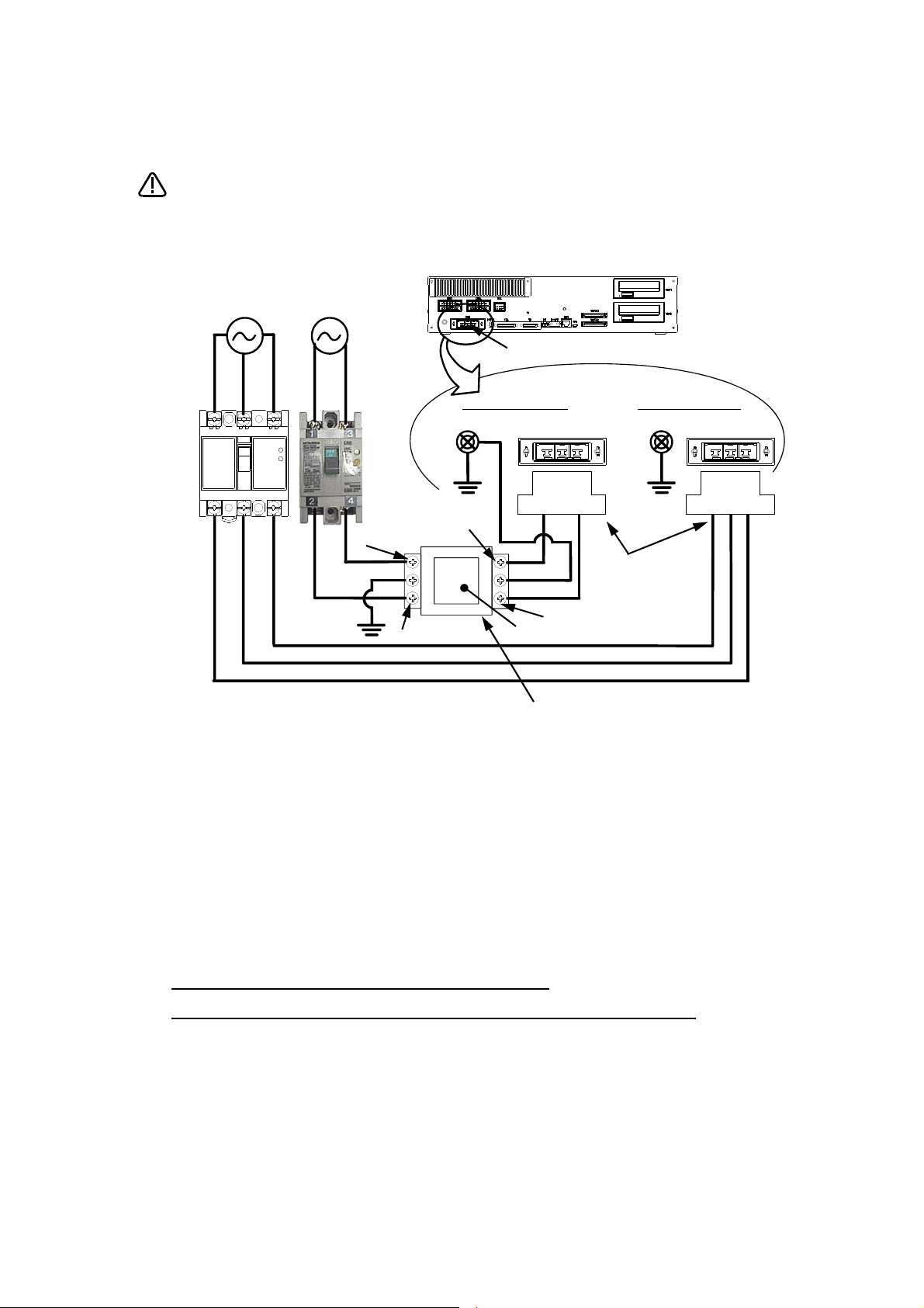
*CR751-D or CR751-Q controller
CAUTION
PE terminal
Grounding screw
Controller
ACIN connector
AC200V AC200V
Primary
Secondary
PE terminal
Grounding screw
123 123
ACIN connector
ACIN connector
Note 2)
Note 1) Crimping swage is recommended for connecting the attachment ACIN connector (soldering is also possible)
Recommendation compression tools: 234171-1(Tyco Electronics)
Note 2) The earth leakage breaker is the customer preparation. Always use the cover below.
Recommendation: For single primary power supply .........NV30FAU-2P-10A-AC100-240V-30mA, (Cover: TCS-05FA2)
For three primary power supply .......... NV30FAU-3P-10A-AC100-240V-30mA, (Cover: TCS-05FA3)
Note 3) If necessary, as shown in the figure, connects the noise filter between ACIN terminal blocks and primary power supply.
(Recommended noise filter: SUP-EL20-ER6 *OKAYA ELECTRIC INDUSTRIES)
Controller
<4> LINE/LOAD
<3> LINE/LOAD
<1> LINE/LOAD
<2> LINE/LOAD
Noise filter
Label
ACIN connector or
power cable
(Attachment)
Note 1)
For three phaseFor single phase
Three phase Single phase
Earth leak
-
age breaker
(NV)
Note 3)
* The controller is an
example.
Notes of the basic component are shown.
Please install the earth leakage breaker in the primary side supply power supply
of the controller of CR751-D or CR751-Q because of leakage protection.
1) Please prepare the following: Leakage current breaker (with the terminal cover), cable for connecting the
primary power supply (AWG #14 (2mm
2
or above).
(3.5mm
The secondary power cable (with the ACIN connector) for single phase or three phase power is supplied with
the product to match the specifications. When you build a cable suitable for your environment using the ACIN
connector and the ACIN terminal supplied, prepare a secondary power cable (AWG #14 (2mm
2) Confirm that the primary power matches the specifications.
3) Confirm that the primary power is OFF and that the earth leakage breaker power switch is OFF.
4) Connect the secondary power cable.
a) When using the supplied power cable with the ACIN connector
Refer to the figure above and connect the cable from the secondary side of the earth leakage breaker.
b) When building a power cable using the ACIN connector and the ACIN terminals supplied
Connect the ACIN terminals with the secondary power cable (prepared by customers), and insert the ACIN
terminals to the ACIN connector pins with the following numbers. Crimping caulking is recommended to
connect the ACIN terminals.
For single phase: 1 and 3
For three phase: 1, 2, and 3
Refer to the figure above and connect the cable from the secondary side of the earth leakage breaker.
5) Connect this ACIN connector to the ACIN connector on the front of the controller.
6) Connect the grounding cable to the PE terminal. (M4 screw)
7) Connect the primary power cable to the primary side terminal of the earth leakage breaker.
2
or above), cables to ground the primary power supply (AWG #12
2
) or above).
Page 7

Revision history
Date of Point Instruction Manual No. Revision Details
2014-08-20 BFP-A3324 ・ First print
2014-12-23 BFP-A3324-B ・ ”(1) Replacing the battery (robot arm)” was changed.
2015-02-09 BFP-A3324-C ・ The special hexagon flange bolts are also used for SE1502 model.
・ Packing replacement procedure was added.
・ The explanation of the origin setting method were added. The description of the setting
range of ABS origin method was added.
・ The caution in lubrication was added.
・ The corporate logo mark of illustrations in this manual was changed.
・ In recommended grease gun, CH-400 was deleted and KH-120 was added.
・ Belt type of J3 and J4 axis timing belt of RV-4F series was corrected.
(error: J3 axis 381-3GT-6、 J4 axis 240-3GT-4)
Page 8

*Introduction
・ No part of this manual may be reproduced by any means or in any form, without prior consent from
Mitsubishi.
・ The details of this manual are subject to change without notice.
・ The information contained in this document has been written to be accurate as much as possible.
Please interpret that items not described in this document "cannot be performed." or "alarm may
occur".
Please contact your nearest dealer if you find any doubtful, wrong or skipped point.
・ This specifications is original.
・ Company names and production names in this document are the trademarks or registered trademarks
of their respective owners.
Copyright(C) 2014-2015 MITSUBISHI ELECTRIC CORPORATION
Thank you for purchasing the Mitsubishi industrial robot.
This instruction manual explains the method of unpacking, installation and maintenance and inspection of
the robot arm.
Always read through this manual before starting use to ensure correct usage of the robot.
The information contained in this document has been written to be accurate as much as possible. Please
interpret that items not described in this document "cannot be performed."
This document explains for the following robot type.
Robot type ・ RV-4F/4FL series....................... Note) Indicates it as RV-4F series.
・ RV-7F/7FL series....................... Note) Indicates it as RV-7F series.
・ RV-7FLL
・ RV-13F/13FL series
・ RV-20F series
*1)
*1)
*1)
*1) Indicates it as "RV-13F series" for a general name of these robots.
Page 9

CONTENTS
Page
1 Before starting use .......................................................................................................................... 1-1
1.1 Using the instruction manuals ................................................................................................... 1-1
1.1.1 The details of each instruction manuals ............................................................................... 1-1
1.1.2 Symbols used in instruction manual .................................................................................... 1-2
1.2 Safety Precautions .................................................................................................................... 1-3
1.2.1 Precautions given in the separate Safety Manual ................................................................ 1-4
2 Unpacking to Installation .............................................................................................................................................................. 2-6
2.1 Confirming the product ......................................................................................................................................................... 2-6
2.2 Installation .................................................................................................................................................................................. 2-8
2.2.1 Unpacking ............................................................................................................................................................................ 2-8
2.2.2 Transportation procedures (Transporting with a crane) ................................................................................. 2-9
2.2.3 Installation procedures ................................................................................................................................................ 2-11
2.2.4 Grounding procedures .................................................................................................................................................. 2-13
(1) Grounding methods ................................................................................................................................................... 2-13
(2) Grounding procedures ............................................................................................................................................. 2-13
2.2.5 Connecting with the controller ................................................................................................................................ 2-14
(1) CR750 controller ....................................................................................................................................................... 2-14
(2) CR751 controller ....................................................................................................................................................... 2-16
2.3 Setting the origin ................................................................................................................................................................... 2-18
2.3.1 Installing the teaching pendant (T/B) ................................................................................................................... 2-18
(1) CR750 controller ....................................................................................................................................................... 2-18
(2) CR751 controller ....................................................................................................................................................... 2-19
2.3.2 Setting the origin with the origin data input method ...................................................................................... 2-20
(1) Confirming the origin data ..................................................................................................................................... 2-20
(2) Turning ON the control power ............................................................................................................................. 2-20
(3) Preparing the T/B ..................................................................................................................................................... 2-21
(4) Selecting the origin setting method ................................................................................................................... 2-22
(5) Inputting the origin data ......................................................................................................................................... 2-23
(6) Installing the CONBOX cover. ............................................................................................................................. 2-24
2.4 Confirming the operation .................................................................................................................................................... 2-25
(1) JOINT jog operation ................................................................................................................................................. 2-29
(2) XYZ jog operation ...................................................................................................................................................... 2-31
(3) TOOL jog operation .................................................................................................................................................. 2-33
(4) 3-axis XYZ jog operation ....................................................................................................................................... 2-35
(5) CYLNDER jog operation ......................................................................................................................................... 2-37
(6) Work jog operation ......................................................................................................... 2-39
3 Installing the option devices ..................................................................................................................................................... 3-47
3.1 Installing the J1 axis operating range change ........................................................................................................... 3-47
3.1.1 RV-4F/7F series ............................................................................................................................................................ 3-47
(1) Configuration ............................................................................................................................................................... 3-47
(2) Changeable angle ....................................................................................................................................................... 3-48
(3) Installation procedure .............................................................................................................................................. 3-50
(4) Setting the parameter ............................................................................................................................................. 3-51
(5) Check the operating range .................................................................................................................................... 3-51
3.1.2 RV-13F series ................................................................................................................................................................. 3-52
(1) Configuration ............................................................................................................................................................... 3-52
(2) Changeable ................................................................................................................................................................... 3-53
(3) Installation procedure .............................................................................................................................................. 3-54
(4) Setting the parameter ............................................................................................................................................. 3-56
(5) Check the operating range .................................................................................................................................... 3-56
3.2 Installing the solenoid valve set ...................................................................................................................................... 3-57
(1) RV-4F/7F series, RV-7FLL ................................................................................................................................. 3-58
(2) RV-13F/13FL series, RV-20F ............................................................................................................................. 3-64
3.3 Installing the hand input cable ......................................................................................................................................... 3-67
i
Page 10

CONTENTS
Page
3.4 Installing the hand output cable ...................................................................................................................................... 3-69
3.5 Installing the Forearm external wiring set/ Base external wiring set ............................................................. 3-72
(1) Installing the Forearm external wiring set ....................................................................................................... 3-72
(2) Installing the Base external wiring set ............................................................................................................. 3-73
4 Basic operations ............................................................................................................................................................................ 4-75
5 Maintenance and Inspection ..................................................................................................................................................... 5-76
5.1 Maintenance and inspection interval ............................................................................................................................. 5-76
5.2 Inspection items ..................................................................................................................................................................... 5-77
5.2.1 Daily inspection items .................................................................................................................................................. 5-77
5.2.2 Periodic inspection ........................................................................................................................................................ 5-78
5.3 Maintenance and inspection procedures ..................................................................................................................... 5-79
5.3.1 Robot arm structure ..................................................................................................................................................... 5-79
5.3.2 Installing/removing the cover ................................................................................................................................... 5-82
5.3.3 Inspection, maintenance and replacement of timing belt .............................................................................. 5-85
(1) Timing belt replacement period ......................................................................................................................... 5-85
(2) Inspection, maintenance and replacement of J1-axis timing belt (RV-4F/7F series only) ...... 5-86
(3) Inspection, maintenance and replacement of J3-axis timing belt (RV-4F/7F series only) ...... 5-87
(4) Inspection, maintenance and replacement of J4-axis timing belt ........................................................ 5-88
(5) Inspection, maintenance and replacement of J4-axis timing belt (For RV-13F series) ............. 5-89
(6) Inspection, maintenance and replacement of J5 axis timing belt ......................................................... 5-90
(7) Inspection, maintenance and replacement of J6-axis timing belt ........................................................ 5-92
(8) Timing belt tension ................................................................................................................................................... 5-94
5.3.4 Lubrication ........................................................................................................................................................................ 5-95
(1) Lubrication position and specifications ............................................................................................................ 5-95
(2) Lubrication method ................................................................................................................................................... 5-97
5.3.5 Replacing the backup battery ................................................................................................................................... 5-99
(1) Replacing the battery (robot arm) .........................
5.4 About Overhaul ................................................................................................................................................................... 5-101
5.5 Maintenance parts .............................................................................................................................................................. 5-102
5.6 Resetting the origin ........................................................................................................................................................... 5-104
5.6.1 Jig method ..................................................................................................................................................................... 5-105
(1) J1 axis origin setting ............................................................................................................................................. 5-106
(2) J2 axis origin setting ............................................................................................................................................. 5-108
(3) J3 axis origin setting ............................................................................................................................................. 5-111
(4) J4 axis origin setting ............................................................................................................................................. 5-114
(5) Origin setting of J5 axis and J6 axis (jig) ..................................................................................................... 5-116
5.6.2 ABS origin method ..................................................................................................................................................... 5-119
(1) Select the T/B ........................................................................................................................................................ 5-121
5.6.3 User origin method ..................................................................................................................................................... 5-123
5.6.4 Recording the origin data ........................................................................................................................................ 5-125
(1) Confirming the origin data label ........................................................................................................................ 5-125
(2) Confirming the origin data .................................................................................................................................. 5-125
(3) Recording the origin data .................................................................................................................................... 5-125
(4) Installing the cover ................................................................................................................................................ 5-125
6Appendix ............................................................................................................................................................................ Appendix-126
Appendix 1 : Configuration flag .......................................................................................................................... Appendix-126
.......................................................................................... 5-100
ii
Page 11
1Before starting use
Safety Manual
Standard
Specifications
Robot Arm
Setup &
Maintenance
Controller
Setup, Basic
Operation and
Maintenance
Detailed
Explanation of
Functions and
Operations
Troubleshooting
Additional
axis function
Tracking Func
-
tion Manual
Extended
Function
Instruction
Manual
1 Before starting use
This chapter explains the details and usage methods of the instruction manuals, the basic terminology and
the safety precautions. Moreover, handling and operation of a teaching pendant (T/B) are described based
on R32TB (R33TB) in instruction manuals. If using other T/B, such as R56TB (R57TB), refer to a supplied
instruction manual of the T/B.
1.1 Using the instruction manuals
1.1.1 The details of each instruction manuals
The contents and purposes of the documents enclosed with this product are shown below. Use these documents according to the application.
For special specifications, a separate instruction manual describing the special section may be enclosed.
Explains the common precautions and safety measures to be taken for robot handling, sys
tem design and manufacture to ensure safety of the operators involved with the robot.
Explains the product's standard specifications, factory-set special specifications, option
configuration and maintenance parts, etc. Precautions for safety and technology, when
incorporating the robot, are also explained.
Explains the procedures required to operate the robot arm (unpacking, transportation,
installation, confirmation of operation), and the maintenance and inspection procedures.
Explains the procedures required to operate the controller (unpacking, transportation,
installation, confirmation of operation), basic operation from creating the program to auto
-
matic operation, and the maintenance and inspection procedures.
Explains details on the functions and operations such as each function and operation, com
mands used in the program, connection with the external input/output device, and parame
ters, etc.
Explains the causes and remedies to be taken when an error occurs. Explanations are given
for each error No.
-
-
-
Explains the specifications, functions and operations of the additional axis control.
Explains the control function and specifications of conveyor tracking
Explains the detailed description of data configuration of shared memory, monitoring, and
operating procedures, about the PLC(CR750-Q/CR751-Q controller) and the GOT(CR750D/CR751-D controller).
Using the instruction manuals 1-1
Page 12
1Before starting use
DANGER
WARNING
CAUTION
1.1.2 Symbols used in instruction manual
The symbols and expressions shown in Table 1-1 are used throughout this instruction manual. Learn the
meaning of these symbols before reading this instruction manual.
Table 1-1:Symbols in instruction manual
Terminology Item/Symbol Meaning
iQ Platform
Controller
The robot CPU unit or robot CPU
Item
The robot CPU system
Drive unit
Stand-alone type
Item
Symbol Precaution indicating cases where there is a risk of operator fatality or
Controller
Indicates the controller which controls the robot arm.
It consists of the robot CPU system and the drive unit.
Indicates the CPU unit for the robots which installed to the sequencer
base unit (Q3 □ DB) of MELSEC-Q series. It is connected with the
drive unit by the dedicated cable.
Multi-CPU system.
It consists of MELSEC units, such as the sequencer base unit, the
sequencer CPU unit, and the robot CPU unit, etc.
Indicates the box which mounts the servo amplifier for robot, and the
safety circuit, etc.
Indicates the box which arranged control parts, such as robot CPU,
servo amplifier, and the safety circuit.
serious injury if handling is mistaken. Always observe these precautions to safely use the robot.
Precaution indicating cases where the operator could be subject to
fatalities or serious injuries if handling is mistaken. Always observe
these precautions to safely use the robot.
Precaution indicating cases where operator could be subject to injury
or physical damage could occur if handling is mistaken. Always
observe these precautions to safely use the robot.
[JOG]
[RESET] + [EXE]
(A) (B)
T/B This indicates the teaching pendant.
O/P Indicates the operating panel on the front of controller or drive unit for
CR751 (Thin type)
CR751 (Heavy type)
If a word is enclosed in brackets or a box in the text, this refers to a
key on the teaching pendant.
This indicates to press the (B) key while holding down the (A) key.
In this example, the [RESET] key is pressed while holding down the
[EXE] key.
the controller which installed the operating panel
There are two kinds of CR751 controller; one is "Thin type" (the
height is 98mm) and the other is "Heavy type" (the height is 174mm),
each of which are different in height.
Thin type: CR751-03HD/Q, CR751-06HD/Q, CR751-12HD/Q,
CR751-20HD/Q, CR751-03HRD/Q, CR751-02VD/Q,
CR751-04VD/Q, CR751-04VJD/Q, CR751-07VD/Q.
Heavy type: CR751-13VD/Q, CR751-20VD/Q, CR751-07VLD/Q.
* Refer to separate Standard Specifications Manual for the outside
dimension of CR751 controller.
1-2 Using the instruction manuals
Page 13
1Before starting use
CAUTION
CAUTION
WARNING
CAUTION
DANGER
CAUTION
CAUTION
CAUTION
1.2 Safety Precautions
Always read the following precautions and the separate "Safety Manual" before starting use of the robot to
learn the required measures to be taken.
All teaching work must be carried out by an operator who has received special
training. (This also applies to maintenance work with the power source turned ON.)
Enforcement of safety training
For teaching work, prepare a work plan related to the methods and procedures of
operating the robot, and to the measures to be taken when an error occurs or when
restarting. Carry out work following this plan. (This also applies to maintenance
work with the power source turned ON.)
Preparation of work plan
Prepare a device that allows operation to be stopped immediately during teaching
work. (This also applies to maintenance work with the power source turned ON.)
Setting of emergency stop switch
During teaching work, place a sign indicating that teaching work is in progress on
the start switch, etc. (This also applies to maintenance work with the power source
turned ON.)
Indication of teaching work in progress
Provide a fence or enclosure during operation to prevent contact of the operator
and robot.
Installation of safety fence
Establish a set signaling method to the related operators for starting work, and follow this method.
Signaling of operation start
As a principle turn the power OFF during maintenance work. Place a sign indicating that maintenance work is in progress on the start switch, etc.
Indication of maintenance work in progress
Before starting work, inspect the robot, emergency stop switch and other related
devices, etc., and confirm that there are no errors.
Inspection before starting work
Safety Precautions 1-3
Page 14
1Before starting use
DANGER
CAUTION
CAUTION
CAUTION
CAUTION
CAUTION
CAUTION
WARNING
WARNING
CAUTION
WARNING
CAUTION
CAUTION
CAUTION
CAUTION
WARNING
1.2.1 Precautions given in the separate Safety Manual
The points of the precautions given in the separate "Safety Manual" are given below.
Refer to the actual "Safety Manual" for details.
When automatic operation of the robot is performed using multiple control devices
(GOT, programmable controller, push-button switch), the interlocking of operation
rights of the devices, etc. must be designed by the customer.
Use the robot within the environment given in the specifications. Failure to do so
could lead to a drop or reliability or faults. (Temperature, humidity, atmosphere,
noise environment, etc.)
Transport the robot with the designated transportation posture. Transporting the
robot in a non-designated posture could lead to personal injuries or faults from
dropping.
Always use the robot installed on a secure table. Use in an instable posture could
lead to positional deviation and vibration.
Wire the cable as far away from noise sources as possible. If placed near a noise
source, positional deviation or malfunction could occur.
Do not apply excessive force on the connector or excessively bend the cable.
Failure to observe this could lead to contact defects or wire breakage.
Make sure that the workpiece weight, including the hand, does not exceed the
rated load or tolerable torque. Exceeding these values could lead to alarms or
faults.
Securely install the hand and tool, and securely grasp the workpiece. Failure to
observe this could lead to personal injuries or damage if the object comes off or
flies off during operation.
Securely ground the robot and controller. Failure to observe this could lead to
malfunctioning by noise or to electric shock accidents.
Indicate the operation state during robot operation. Failure to indicate the state
could lead to operators approaching the robot or to incorrect operation.
When carrying out teaching work in the robot's movement range, always secure
the priority right for the robot control. Failure to observe this could lead to personal
injuries or damage if the robot is started with external commands.
Keep the jog speed as low as possible, and always watch the robot. Failure to do
so could lead to interference with the workpiece or peripheral devices.
After editing the program, always confirm the operation with step operation before
starting automatic operation. Failure to do so could lead to interference with
peripheral devices because of programming mistakes, etc.
1-4 Safety Precautions
Make sure that if the safety fence entrance door is opened during automatic operation, the door is locked or that the robot will automatically stop. Failure to do so
could lead to personal injuries.
Never carry out modifications based on personal judgments, or use non-designated maintenance parts.
Failure to observe this could lead to faults or failures.
When the robot arm has to be moved by hand from an external area, do not place
hands or fingers in the openings. Failure to observe this could lead to hands or fingers catching depending on the posture.
Page 15
1Before starting use
CAUTION
CAUTION
CAUTION
DANGER
DANGER
DANGER
DANGER
CAUTION
CAUTION
Do not stop the robot or apply emergency stop by turning the robot controller's
main power OFF.
If the robot controller main power is turned OFF during automatic operation, the
robot accuracy could be adversely affected.
Do not turn off the main power to the robot controller while rewriting the internal
information of the robot controller such as the program or parameters. If the main
power to the robot controller is turned off while in automatic operation or rewriting
the program or parameters, the internal information of the robot controller may be
damaged.
Do not connect the Handy GOT when using the GOT direct connection function of
this product. Failure to observe this may result in property damage or bodily injury
because the Handy GOT can automatically operate the robot regardless of
whether the operation rights are enabled or not.
Do not connect the Handy GOT to a programmable controller when using an iQ
Platform compatible product with the CR750-Q/CR751-Q controller. Failure to
observe this may result in property damage or bodily injury because the Handy
GOT can automatically operate the robot regardless of whether the operation rights
are enabled or not.
Do not remove the SSCNET III cable while power is supplied to the multiple CPU
system or the servo amplifier. Do not look directly at light emitted from the tip of
SSCNET III connectors or SSCNET III cables of the Motion CPU or the servo
amplifier. Eye discomfort may be felt if exposed to the light. (Reference: SSCNET
III employs a Class 1 or equivalent light source as specified in JIS C 6802 and
IEC60825-1 (domestic standards in Japan).)
Do not remove the SSCNET III cable while power is supplied to the controller. Do
not look directly at light emitted from the tip of SSCNET III connectors or SSCNET
III cables. Eye discomfort may be felt if exposed to the light. (Reference: SSCNET
III employs a Class 1 or equivalent light source as specified in JIS C 6802 and
IEC60825-1 (domestic standards in Japan).)
Attach the cap to the SSCNET III connector after disconnecting the SSCNET III
cable. If the cap is not attached, dirt or dust may adhere to the connector pins,
resulting in deterioration connector properties, and leading to malfunction.
Make sure there are no mistakes in the wiring. Connecting differently to the way
specified in the manual can result in failures, such as the emergency stop not
being released. In order to prevent from occurring, please be sure to check that all
functions (such as the teaching box emergency stop, customer emergency stop,
and door switch) are working properly after the wiring setup is completed
Use the network equipments (personal computer, USB hub, LAN hub, etc) confirmed by manufacturer. The thing unsuitable for the FA environment (related with
conformity, temperature or noise) exists in the equipments connected to USB.
When using network equipment, measures against the noise, such as measures
against EMI and the addition of the ferrite core, may be necessary. Please fully
confirm the operation by customer. Guarantee and maintenance of the equipment
on the market (usual office automation equipment) cannot be performed.
Safety Precautions 1-5
Page 16
2Unpacking to Installation
2 Unpacking to Installation
2.1 Confirming the product
The standard configuration of the robot arm, part of the purchased product, is shown in Table 2-1.
Confirm the parts.
Users who have purchased optional products should refer to the separate "Standard Specifications".
Table 2-1 : Standard configuration
No. Part name Type Qty. Remarks
RV-4F series
1 Robot arm RV-4FM-SExxxx
RV-4FLM-SExxxx
2 Guarantee card 1 copy
3 Installation bolts M8 x 40 4 pcs. For robot arm installation
4 Spring washer for installation bolts For M8 4 pcs.
5 Plain washer for installation bolts For M8 4 pcs.
6 Grease nipple WA-610 6 pc. For SExx01
7 Suspension fitting 2 sets
8 Suspension fitting installation bolt M6 x 20 6 pcs.
9 Plain washer for suspension fitting installa
tion bolt
10 Eye bolt M10 4 pcs.
11 Nut for eye bolt For M10 4 pcs.
12 Fixing plate 1 set
13 Fixing plate installation bolt M15 x 12 4 pcs.
14 Plain washer for fixing plate For M5 4 pcs.
RV-7F series
1 Robot arm RV-7FM-SExxxx
2 Guarantee card 1 copy
3 Installation bolts M8 x 40 4 pcs. For robot arm installation
4 Spring washer for installation bolts For M8 4 pcs.
5 Plain washer for installation bolts For M8 4 pcs.
6 Grease nipple WA-610 5 pcs. For SExx01
7 Suspension fitting 2 sets
8 Suspension fitting installation bolt M8 x 25 4 pcs.
9 Plain washer for suspension fitting installa
tion bolt
10 Eye bolt M10 4 pcs.
11 Nut for eye bolt For M10 4 pcs.
12 Fixing plate 1 set
13 Fixing plate installation bolt M15 x 12 4 pcs.
14 Plain washer for fixing plate For M5 4 pcs.
-
For M6 6 pcs.
RV-7FLM-SExxxx
-
For M8 4 pcs.
Each 1 unit SExxxx means the following.
SExx01: Chemical-resistant specifica
tions
SExx02: Food machinery grade H1
grease specifications
5 pc. For SExx02
Each 1 unit SExxxx means the following.
SExx01: Chemical-resistant specifica
tions
SExx02: Food machinery grade H1
grease specifications
4 pcs. For SExx02
-
-
2-6
Confirming the product
Page 17
2Unpacking to Installation
No. Part name Type Qty. Remarks
RV-13F series
1 Robot arm RV-7FLLM-SExxxx
RV-13FM-SExxxx
RV-13FLM-SExxxx
RV-20FM-SExxxx
2 Guarantee card 1 copy
3 Installation bolts M12 x 55 4 pcs. For robot arm installation
4 Spring washer for installation bolts For M12 4 pcs.
5 Plain washer for installation bolts For M12 4 pcs.
6 Grease nipple WA-110 3 pcs.
WA-610 4 pcs.
7 Suspension fitting 2 sets
8 Suspension fitting installation bolt M10 x 45 4 pcs.
9 Plain washer for suspension fitting installa
tion bolt
10 Eye bolt M12 4 pcs.
11 Nut for eye bolt For M12 4 pcs.
12 Fixing plate 1 set
13 Fixing plate installation bolt M6 x 14 4 pcs.
14 Plain washer for fixing plate For M6 4 pcs.
-
For M10 4 pcs.
Each 1 unit SExxxx means the following.
SExx01: Chemical-resistant specifica
tions
SExx02: Food machinery grade H1
grease specifications
Note1) The numbers 3 to 6 are contained in the plastic bag of attachment in the robot arm.
The numbers 7 to 14 are mounted on the robot arm.
-
Confirming the product
2-7
Page 18
2Unpacking to Installation
②上ブタ
(a)
(b)
(c)
引き抜く
①テープ
フォークリフトの爪
挿入口
ロボット本体
!
CAUTION
!
Always unpack the
robot at a flat place.
The robot could tilt
over if unpacked at an
unstable place.
Pull off
<2> Upper lid
<1> Tape
The fork insertion
slots for a forklift truck
Robot arm
CAUTION
2.2 Installation
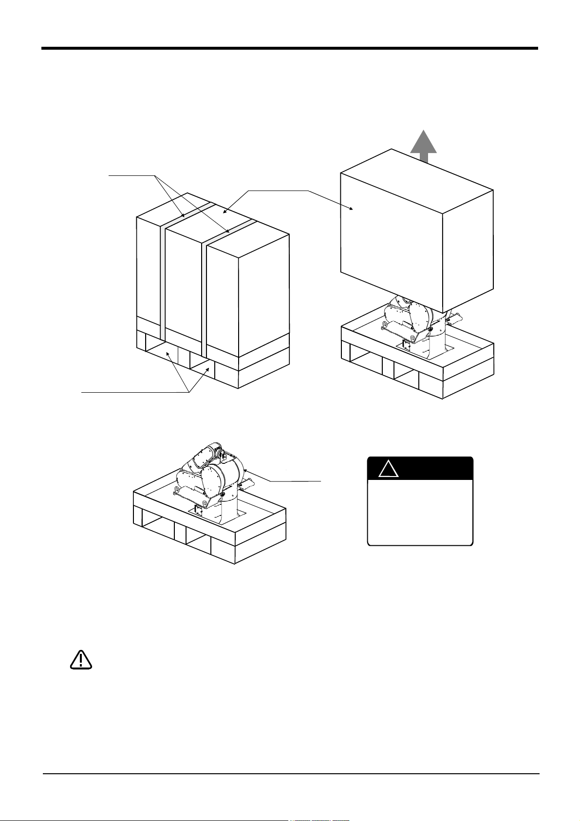
2.2.1 Unpacking
The robot is shipped from the factory in cardboard and plywood packing. Always refer to Fig. 2-1 and unpack the
robot.
Handle the robot arm according to "2.2.2Transportation procedures (Transporting with a crane)".
Fig.2-1 : Unpacking the robot arm
Always unpack the robot at a flat place. The robot could tilt over if unpacked at an
unstable place.
The unpacking process is shown below.
1) Using a knife, etc., slit the tape <1> fixing the upper lid <2> of the cardboard box. (Fig. 2-1 (a))
2) Pull the upper lid <2> of the cardboard box off with both hands. (Fig. 2-1 (b))
3) Remove the hexagon socket bolts <3> (four positions) connecting the sleeper and the base unit. (Fig. 2-1
2-8
Installation
(c))
4) This completes the unpacking.
Page 19
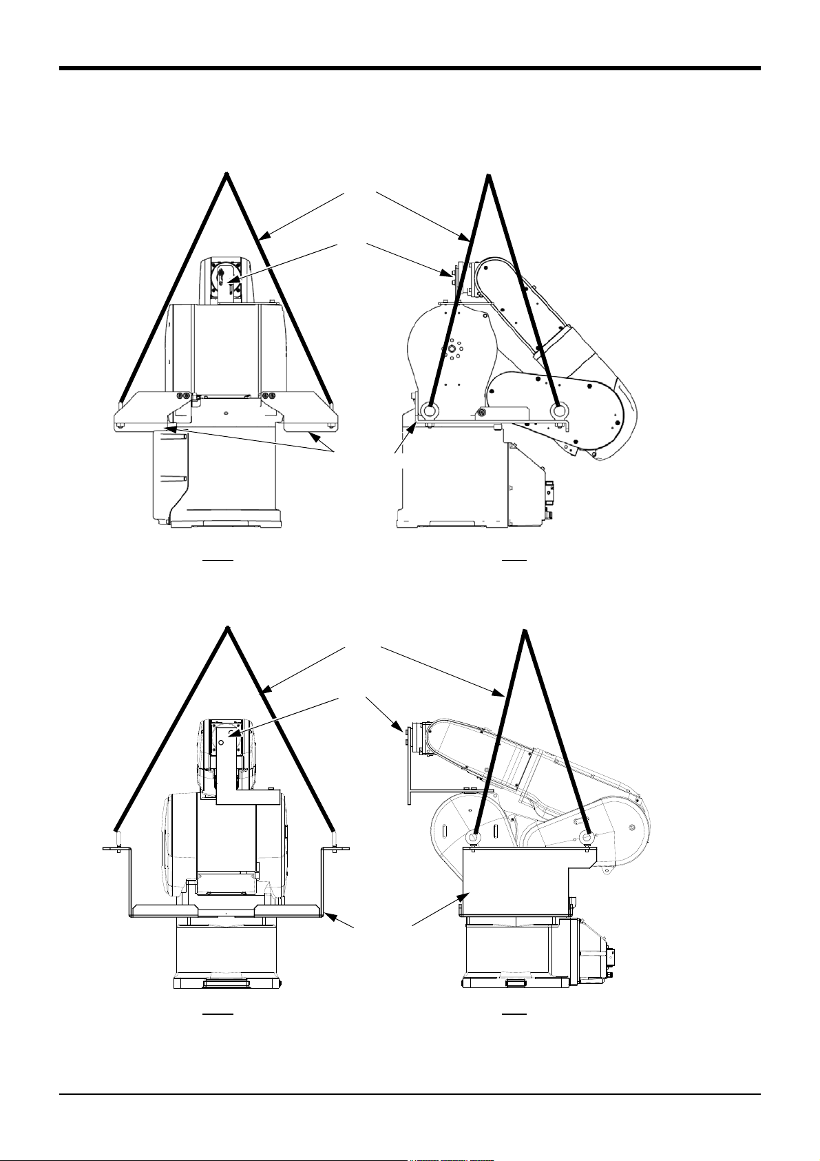
Front Side
Wire
Fixing plate
Suspension fitting
Mass
RV-4F: Approx. 39kg
RV-4FL: Approx. 41kg
RV-7F: Approx. 65kg
RV-7FL: Approx. 67kg
Note) The figure is the RV-4 F
series. The shape and
installation screw of the
suspension fitting of RV7F series differ.
RV-4F/RV-7F series
Front Side
Wire
Fixing plate
Suspension fitting
Mass
RV-13F series: Approx. 137kg
RV-13FL series: Approx. 145kg
RV-13F series
2Unpacking to Installation
2.2.2 Transportation procedures (Transporting with a crane)
The transportation procedure is shown in Fig. 2-2 for (RV-4F/7F series) and Fig. 2-3 (RV-13F series).
Fig.2-2 : Transportation procedure (transporting with a crane: RV-4F/7F series)
Fig.2-3 : Transportation procedure (transporting with a crane: RV-13F series)
Installation
2-9
Page 20

2Unpacking to Installation
1) Attach the suspension fittings to the left and right sides of the shoulder section, and securely fix with
screws and plain washers. (RV-4F series: M6x20, each three screws for the right and left. RV-7F series:
M8x25, each two screws for the right and left. RV-13F series: M10x45, each two screws for the right and
left.)
(The suspension fittings are mounted on robot arm at factory shipping)
2) Catch wires in the eye bolts installed on the suspension fittings, and quietly suspend the arm.
Note) At this time, make sure that the wires, etc., do not interfere with the robot arm or covers. Always
place cloth, etc., at interfering places.
3) When transferring to the installation place, take care not to apply vibration or impact.
4) After installing at the installation place, remove the above suspension fittings.
5) Always follow the above procedures and methods to transport the robot for secondary transportation, such
as when changing the installation position.
If the arm is directly suspended without using the specified suspension fittings, or if it is suspended in the
work posture, the configuration devices could be damaged, and the transportation workers will be subject to
risk due to an inadequate center of gravity position.
2-10
Installation
Page 21
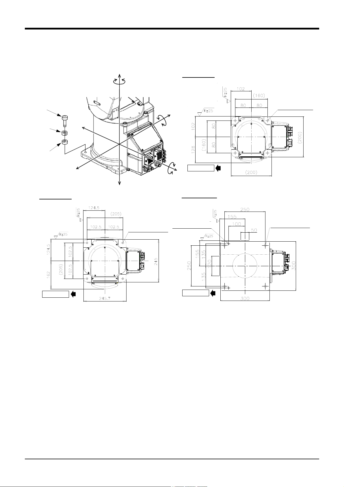
2.2.3 Installation procedures
ロボット前方
(Installation)
(Installation)
4-φ14 installation hole
Robot’s front
2-φ8H7 reamer bore
F
H
F
H
M
L
F
H
F
H
M
L
F
V
F
V
M
T
ロボット前方
RV-4F series
<Bottom view>
RV-
13F series
Plain washer
Spring
washer
RV-4F series, RV-7F series:
4-M8x40
RV-13F series:
4-M12x55
(Installation)
(Installation)
4-φ9 installation
hole
Robot’s front
ロボット前方
RV-7F series
(Installation)
(Installation)
4-φ9 installation hole
Robot’s front
The installation procedure of the robot arm is shown below.
2Unpacking to Installation
Fig.2-4 : Installation dimensions
1) The robot installation surface has been machine finished. Use the installation holes (RV-4F series and RV-
7F series: 4-φ9 holes, RV-13F series: 4-φ14 holes) opened at the four corners of the base, and securely
fix the robot with the enclosed installation bolts (RV-4F series and RV-7F series: M8 hexagon socket head
cap screws, RV-13F series: M12 hexagon socket head cap screws).
2) Installation of the robot arm is a very important step for ensuring the optimum functions of the robot.
Observe the following points when designing. Install the robot on a level surface.
3) It is recommended that the surface roughness of the table onto which the robot is to be installed by 6.3a or
more. If the installation surface is rough, the contact with the table will be poor, and positional deviation
could occur when the robot moves.
4) When installing, use a common table to prevent the position of the devices and jigs subject to robot work
from deviating.
5) The installation surface must have sufficient strength to withstand the arm reaction during operation, and
resistance against deformation and vibration caused by the static (dynamic) load of the robot arm and
peripheral devices, etc.
6) Remove the fixing plates after installing the robot. The fixing plate is needed in re-transportation. Please
keep it carefully.
7) When the robot is installed by hanging from the ceiling or on the wall, the MEGDIR parameter must be
changed. For more information about parameters and how to change the parameters, refer to the separate
"Instruction Manual/Detailed Explanation of Functions and Operations".
Installation
2-11
Page 22
2Unpacking to Installation
CAUTION
8) The installation surface must have sufficient strength to withstand the arm reaction during moving the robot
at high speed.
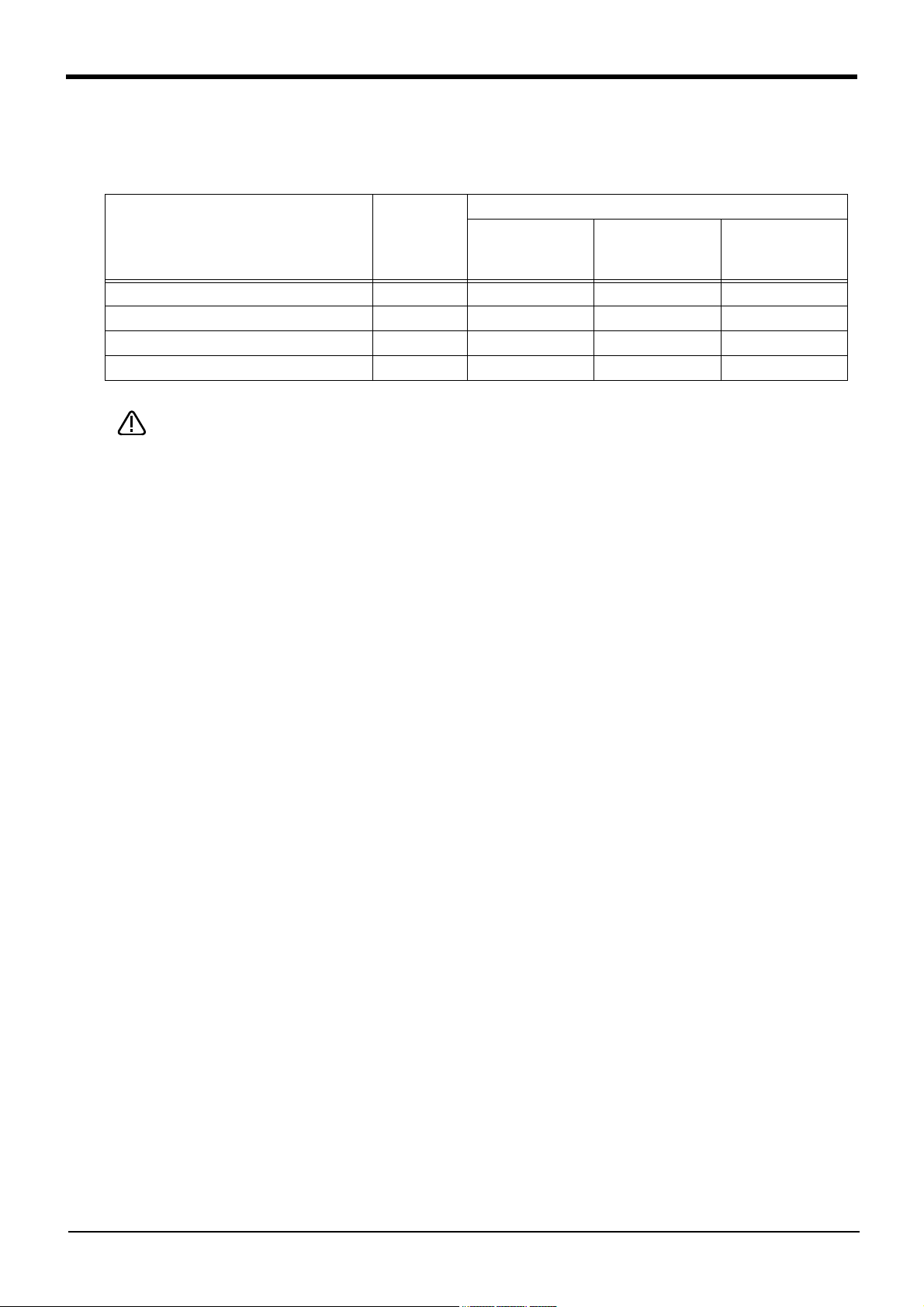
Table 2-2 : Strength of the installation side (reference)
Item Unit
Falling moment : M
Twist moment : M
Horizontal translation power : F
Vertical translation power : F
L
T
H
V
Please secure the maintenance space required for connection of the machine cable and
exchange the backup battery in the rear side, and also space for J1 axis belt in the right
side. And don't install the robot arm in the position where direct rays or the heat of
lighting hits. The skin temperature of the robot arm may rise, and the error may occur.
Value
RV-7FLL
RV-4F series RV-7F series
RV-13F series
RV-20F
N m 410 900 2,060
N m 400 900 2,060
N 700 1,000 1,750
N 1,200 1,700 2,900
2-12
Installation
Page 23
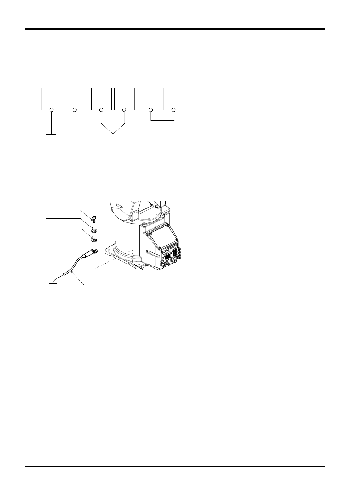
2.2.4 Grounding procedures
Robot arm
Controller
and
personal
computer
(a) Dedicated grounding
(Optimum)
(b) Common grounding
(Good)
(c) Common grounding
(Normal)
Robot arm
Controller
and
personal
computer
Robot arm
Controller
and
personal
computer
A
本体接地用ケーブル (AWG #11(4.2mm2)以上)
(お客様にてご手配ください)
Plain washer
Spring washer
M4x10
Robot grounding cable (AWG#11 (4.2mm2) or more)
(Prepared by customer)
Note) Although the figure is the example of RV-4F other types are
the same also.
(1) Grounding methods
Fig.2-5 : Grounding methods
(2) Grounding procedures
2Unpacking to Installation
1) There are three grounding methods as shown in
Fig. 2-5, but the dedicated grounding (Fig. 2-5 (a))
should be used for the robot arm and controller
when possible. (Refer to the separate " Controller
Setup, Basic Operation and Maintenance" for
details on the controller grounding.)
2) Use Class D grounding (grounding resistance
100Ω or less).
Dedicated grounding separated from the other
devices should be used.
2
3) Use a AWG#11(4.2mm
) or more stranded wire for
the grounding wire. The grounding point should be
as close to the robot arm and controller as possi
ble, and the length of the grounding wire should
be short.
-
Fig.2-6 : Connecting the grounding cable
1) Prepare the grounding cable (AWG#11(4.2mm2) or
more) and robot side installation screw and washer.
2) If there is rust or paint on the grounding screw
section (A), remove it with a file, etc.
3) Connect the grounding cable to the grounding
screw section.
Installation
2-13
Page 24
2Unpacking to Installation
CN1
CN2
ロボット本体
(ベース部背面)
ラッチ
ラッチ
モータ信号ケーブル
モータパワーケーブル
モータパワー
(CN1)
モータ信号
(CN2)
ラッチ
ラッチ
CN1
CN2
Motor power
(CN1)
Motor signal
(CN2)
Latch
Latch
Motor signal cable
Motor power cable
Latch
Latch
Robot arm
(Rear of the base.)
Note) Although the figure is the
example of RV-4F other types
are the same also.
固定フック
機器間ケーブル側コネクタ
ロボット本体
ロボット本体側コネクタ
突起部
Robot arm
Connector on the
robot arm side
Hook
Projection
Connector on the
machine cable side
固定フック
突起部
Hook
Projection
CAUTION
Be careful not to get your hand
pinched.
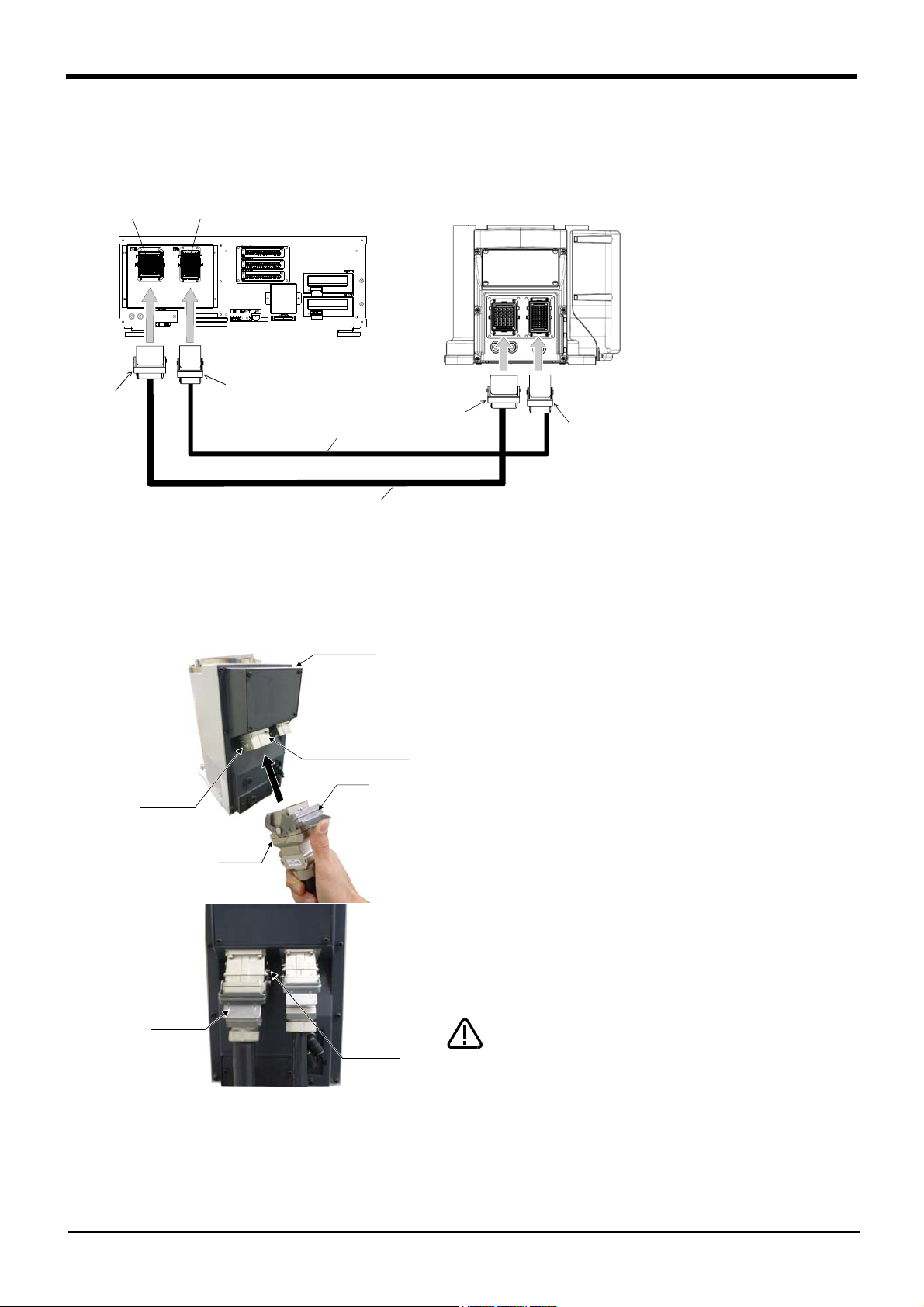
2.2.5 Connecting with the controller (1) CR750 controller
Fig.2-7 : Connecting the machine cables (CR750)
Carry out the following procedure after installing the controller referring to the separate "Controller Setup, Basic
Operation and Maintenance" manual. The procedure of connecting the machine cable is shown below.
1) Make sure that the power switch on the front of the
controller is turned OFF.
Note) Although the figure is RH-6FH, also in other robots
with same connector type, the connection method is
the same.
2) Connect the machine cable to its corresponding connector
on the robot arm side.
Note) Although the figure is RH-6FH, also in other robots
with same connector type, the connection method is
the same.
3) After connecting the connector, insert the hook attached
to the connector on the machine cable side to the rear of
the projection of the robot arm connector to fix securely in
place.
2-14
Installation
This complete the connection of machine cable.
Page 25
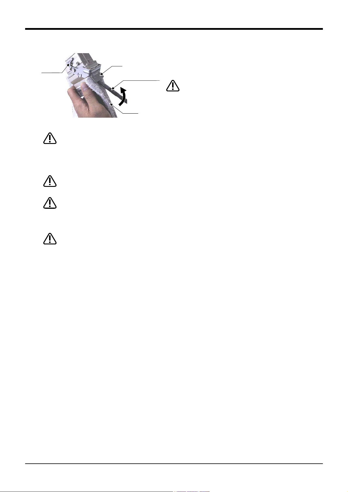
Hook
Minus screwdriver
Padding
Projection
CAUTION
When installing or removing the connector, to the connector
of the other party in parallel, install or remove. If load strong
against one side is applied, the connector pin may be
damaged and it may not be connected securely.
CAUTION
CAUTION
CAUTION
CAUTION
2Unpacking to Installation
To remove the cable, insert a minus screwdriver into the hook
while padding with a cloth, and remove the cable by lifting the
hook.
The machine cable connectors are dedicated for the controller side and robot arm
side, so take special care when connecting.
If connected incorrectly, the connector pins could bend or break. Thus, even if
connected correctly, the robot will not operate correctly, creating a dangerous
situation.
Take special care to the leading of the connection cable. If the cable is pulled with
force or bent excessively, wires could break or the connector could be damaged.
Connect the machine cable at the place without the effect of the dust or oil mist.
Please keep the dust and oil mist from being applied to of the robot-arm connector
section, in the condition that the machine cable is removed. Since it becomes the
cause of failure.
Please be careful not to catch the hand at installation and removal.
Installation
2-15
Page 26
2Unpacking to Installation
Fixing screws (2 places)
モータ信号ケーブル
モータ電源ケーブル
モータ信号(CN2)
CN2
固定ネジ
(2箇所)
モータ電源(CN1)
AMP1 AMP2 BRK
CN1
コントローラ前面
ロボット本体
(背面)
CONBOXカバー
固定ネジ
(2箇所)
Motor power cable
Motor signal cable
CONBOX cover
Robot arm
Opposite side of figure
Motor signal (CN2)
Motor power (CN1)
Controller
Two fixing screws
Note1) Although the figure is RV-4F/
7F series controller, and RV13F series is also the same.
Note2) The robot arm photo is for
illustrative purposes only.
Refer to Table 2-3 for packing
pose of actual products.
Pass into
the opening
AMP1
AMP2 CN2
Machine cables
Controller side
Battery fixing plate
Note1)
Note2)
CON cover
(Eight fixing screws)
Robot arm side
Cable clamp fixing
plate
(Two plate with
four screws each)
Two fixing screws
Connection condition
Table 2-3 : The packing pose for each type (reference) (Unit: degree)
Axis RV-4F RV-4FL RV-7F RV-7FL
RV-7FLL, RV-13F/FL
RV-20F
J1 90 90 90 90 0
J2 -122 -121 -116 -115 -93
J3 162 165 158 164 160
J40000 0
J5 45 41 48 41 23
J60000 0
*1) Do not disconnect the battery cable connector. The origin data will be lost.
*2)
The size of the cable clamp fixed plate fixed screw (four screws each) is
M4x16.
*2)
Battery
cable
*1)
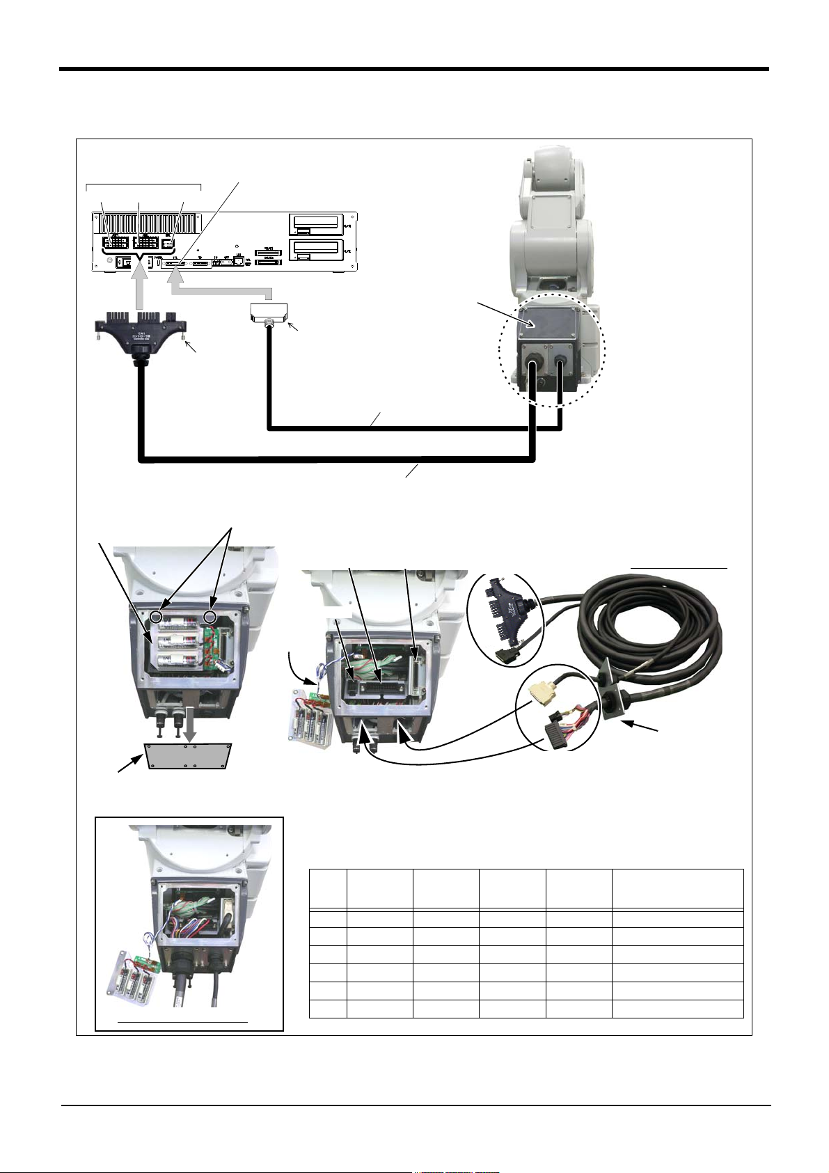
(2) CR751 controller
Fig.2-8 : Connecting the machine cables (CR751)
2-16
Installation
Page 27
CAUTION
CAUTION
CAUTION
CAUTION
CAUTION
Carry out the following procedure after installing the controller and the robot arm referring to the separate
"Controller Setup, Basic Operation and Maintenance" and Page 11, "2.2.3 Installation procedures".
And attach a cable fixation plate to the controller referring to the separate "Controller Setup, Basic Operation and
Maintenance" manual.
The connection outline is shown in Fig. 2-8.
1) Make sure that the power switch on the front of the controller is turned OFF.
Note) Although the figure is RV-4F series, also in other robots with same connector type, the connection
method is the same.
2) Connect the machine cable connectors to its corresponding connectors on the robot arm side.
a) Remove the four screws holding the CONBOX cover, and remove the cover. (Refer to Page 82, "5.3.2
Installing/removing the cover" for details.)
And, the CON cover is installed to the robot. Removes the eight fixing screws and removes the CON
cover. The opening which passes the connector is seen.
b) The battery fixing plate is inside the CONBOX cover. Remove the two fixing screws and remove the
battery fixing plate.
Note) Do not disconnect the battery cable connector. The origin data will be lost.
c) Feed the connectors of robot side to the opening on the back of the robot base and connect with the cor
responding connector. Connect the connector (AMP1, AMP2, CN2) securely.
d) Fix the cable clamp fixed plate of the machine cable with the attached fixing screw. Fix both cables
securely with the four screws, respectively.
e) Install the battery fixing plate securely as before. Be careful not to insert the cable.
f) Install the CONBOX cover securely as before. Be careful not to insert the cable.
3) Connect the machine cable to the corresponding connector of the controller. Connects the connector
(CN1(AMP1, AMP2, BRK), CN2) surely. Fix the two fixing screws securely, respectively. Tighten the fixing
screw of CN2 by 0.06-0.07 Nm.
2Unpacking to Installation
-
This complete the connection of machine cable.
The machine cable connectors are dedicated for the controller side and robot arm
side, so take special care when connecting.
If connected incorrectly, the connector pins could bend or break. Thus, even if
connected correctly, the robot will not operate correctly, creating a dangerous
situation.
Take special care to the leading of the connection cable. If the cable is pulled with
force or bent excessively, wires could break or the connector could be damaged. In
order to prevent a breaking of cables and a damage of connectors, always use the
controller after installing the attachment cable fixation plate.
Connect the machine cable at the place without the effect of the dust or oil mist.
Please keep the dust and oil mist from being applied to of the robot-arm connector
section, in the condition that the machine cable is removed. Since it becomes the
cause of failure.
Please be careful not to catch the hand at installation and removal.
Please do not disconnect the battery cable connector. If the connector is discon
nected, the robot origin data will be lost.
It is necessary to set the origin data again by ABS origin method. Refer to Page 119,
"5.6.2 ABS origin method" for details.
-
Installation
2-17
Page 28
2Unpacking to Installation
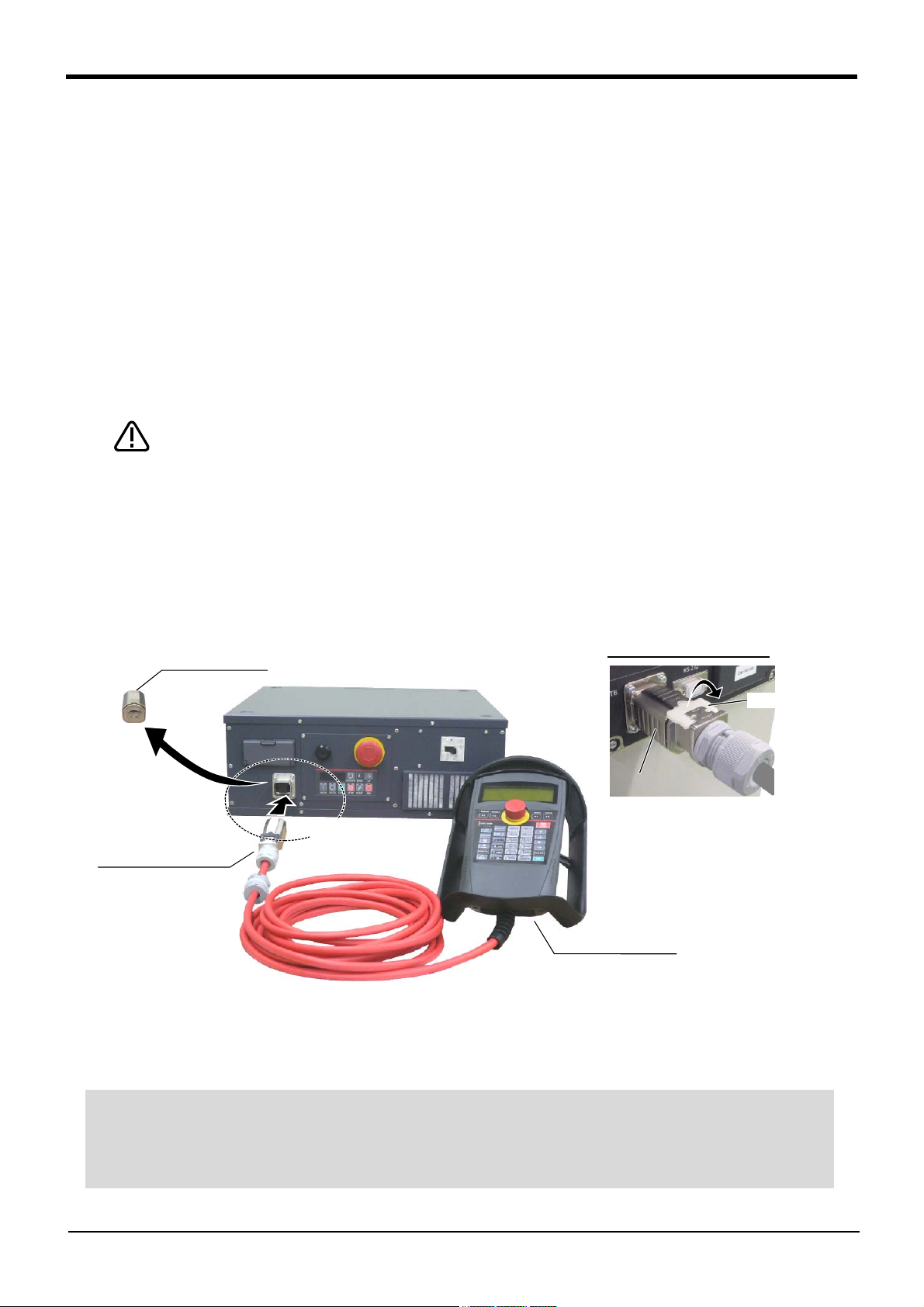
CAUTION
ティーチングボックス
(T/B)
ダミーコネクタ
A
T/B接続用コネクタ
A部詳細
T/B接続用コネクタを取り外す時は、
ロック解除(ロックレバーを上側に起
こした状態)にし、B部のケースを手前
にスライドさせてラッチを外し引き抜き
ます。
ロックレバー
B
Dummy connector
T/B connector
Teaching pendant
(T/B)
Details of the A section
When removing the connector for
T/B connection, use lock release
(state which raised the lock lever to
the up side), make the case of the
B section slide to the front, and
remove and pull up out the latch.
Lock lever
Controller
◇◆◇ If error C0150 occurs ◇◆◇
At the time of the first power supply injection, error:C0150 (the serial number of the robot arm has not been
set up) occur the robot after purchase.
Parameter: Please input the serial number of the robot body into RBSERIAL. Refer to "instructions manual /
controller setup, and basic operation & maintenance" for the operation method.
2.3 Setting the origin
The origin is set so that the robot can be used with a high accuracy. After purchasing the robot, always carry out
this step before starting work. This step must also be carried out if the combination of robot and controller being
used is changed.
There are several methods for setting the origin, but the origin data input method will be explained here. Refer to
Page 104, "5.6 Resetting the origin" for the other methods.
The teaching pendant is required for this operation.
[Caution] If the origin data at shipment is erased due to out of battery, it is necessary to set the origin again.
Refer to Page 104, "5.6 Resetting the origin" and reset the origin using the jig method or ABS method.
2.3.1 Installing the teaching pendant (T/B)
When installing and removing the T/B, turn off the controller power supply. If T/B is installed or removed in the
state of power supply ON, emergency stop alarm will occur.
If you use the robot wherein T/B is removed, please install the attached dummy connector. With the connector,
put the dummy connector or draw it out.
Please do not pull the cable of T/B strongly or do not bend it too much.
It becomes the breaking of a wire of the cable and the cause of breakage of the
connector. Please installing and removing so that stress does not start the cable
with the connector itself.
(1) CR750 controller
Explain the installation method of T/B below.
1) Check that the POWER (power supply) switch of the robot controller is OFF.
2) Connects T/B connector to the robot controller. Use as the upper surface the lock lever shown in Fig. 2-9,
and push in until there is sound.
Fig.2-9 : Installing and removing the T/B (CR750 controller)
The installation of T/B is finished.
2-18
Setting the origin
Page 29
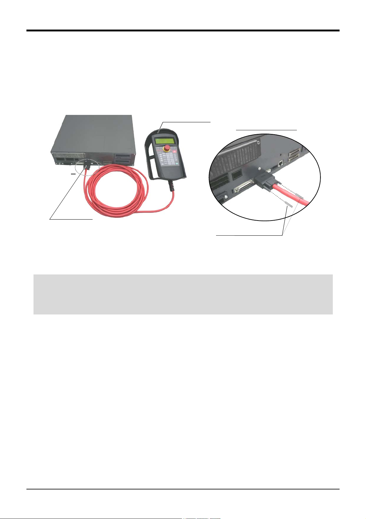
A部
ティーチングボックス
(T/B)
T/B接続用コネクタ
A部詳細
手回しロック(2箇所)
Controller
T/B connector
Teaching pendant
Details of the A section
A
Hand lock (Two places)
T/B connector
Note) Although the figure is RV-4F/7F series controller,
and RV-13F series is also the same.
◇◆◇ If error C0150 occurs ◇◆◇
At the time of the first power supply injection, error:C0150 (the serial number of the robot arm has not been
set up) occur the robot after purchase.
Parameter: Please input the serial number of the robot body into RBSERIAL. Refer to "instructions manual /
controller setup, and basic operation & maintenance" for the operation method.
2Unpacking to Installation
(2) CR751 controller
Explain the installation method of T/B below.
1) Check that the POWER (power supply) switch of the robot controller is OFF.
2) Connect the T/B connector to the controller’s T/B connector. Make sure to fix it securely by fastening the
hand locks (in 2 places), as shown in Fig. 2-10.
Fig. 2-10 : Installing and removing the T/B (CR751controller)
The installation of T/B is finished.
Setting the origin
2-19
Page 30
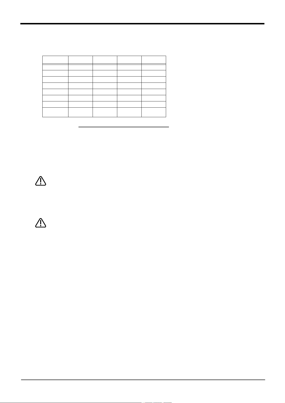
2Unpacking to Installation
● Origin data history table (Origin Data History) Serial No.ES804008
(O: O(Alphabet), 0: Zero)
Note) Meanings of symbols in method column
E: Jig method
N: Not used
SP: Not used
Date Default . . . . . . . . .
DV!#S29
J 1 06DTYY
J2 2?HL9X
J 3 1CP55V
J4 T6!M$Y
J5 Z2IJ%Z
J 6 A12%Z0
Method E E・N・SP E・N・SPE・N・SP
WARNING
CAUTION
2.3.2 Setting the origin with the origin data input method (1) Confirming the origin data
Fig.2-11 : Origin data label (an example)
The origin data to be input is noted in the
origin data sheet enclosed with the arm,
or on the origin data history table
attached to the back side of the CON
-
BOX cover. (Refer to Fig. 2-11).
Referring to Page 82, "5.3.2 Installing/
removing the cover", remove the CON
-
BOX cover and confirm the value.
The value given in the default setting
column is the origin settings set with the
calibration jig before shipment.
Always install/remove the cover with the controller control power turned OFF.
Failure to do so could lead to physical damage or personal injury should the robot
start moving due to incorrect operations.
(2) Turning ON the control power
Confirm that there are no operators near the robot before turning the power ON.
1) Turn the controller [POWER] switch ON.
The CR750 controller turns ON the front power switch.
The CR751 controller turns ON the switch of the earth leakage breaker of installation outside.
2-20
Setting the origin
Page 31

(3) Preparing the T/B
下:
ENABLE
*ランプ点灯
上:DISABLE
T/B背面
Up: Disable
Down: Enable
(Lighting)
MODE
MANUAL AUTOMATIC
◇◆◇ Operating from the T/B ◇◆◇
Always set the mode of the controller to "MAMNUAL", and then set the T/B [ENABLE] switch to "ENABLE".
When the T/B is valid, only operations from the T/B are possible. Operations from the controller or external
signals will not be accepted.
2Unpacking to Installation
Next, prepare to use the T/B
1) Set the mode of the controller to "MANUAL".
(The figure is example for CR750 controller)
2) Set the T/B [ENABLE] switch to "ENABLE". The menu selection
screen will appear.
The following operations are carried out with the T/B.
Setting the origin
2-21
Page 32

2Unpacking to Installation
<MENU>
1.FILE/EDIT 2.RUN
3.PARAM. 4.ORIGIN/BRK
5.SET/INIT. 6.ENHANCED
CLOSE
123
<ORIGIN/BRAKE>
1.ORIGIN 2.BRAKE
CLOSE
123
<ORIGIN>
1.DATA 2.MECH
3.TOOL 4.ABS
5.USER
CLOSE
123
<ORIGIN> DATA
D:(■ )
J1( ) J2( ) J3( )
J4( ) J5( ) J6( )
J7( ) J8( )
CLOSE
123
◇◆◇ Selecting a menu ◇◆◇
The menu can be selected with one of the following methods.
A: Press the numeral key for the No. of the item to be selected.
B: Using the [ ↓ ] and [ ↑ ] keys, etc., move the cursor to the item to be selected, and then press the [INP] key.
◇◆◇ The input method of numeral ◇◆◇
The number can be inputted if the key displayed on the lower left of each key is pressed. Press the
[CHARACTER] key, and in the condition that "123" is displayed on the screen lower side, press the number key.
(4) Selecting the origin setting method
1) Press the [4] key on the menu screen, and display the
ORIGIN/BRAKE screen.
2) Press the [1] key on the ORIGIN/BRAKE screen, and
display the origin setting method selection screen.
3) Press the [1] key on the origin setting method selection
screen, and select the data input method.
4) Display the origin data input screen
2-22
Setting the origin
Page 33

<ORIGIN> DATA
D:(■ )
J1( ) J2( ) J3( )
J4( ) J5( ) J6( )
J7( ) J8( )
CLOSE
123
Origin data label
(D,J1,J2,J3,J4,J5,J6,J7,J8)
T/B screen
,
,
<ORIGIN> DATA
D:(
V )
J1( ) J2( ) J3( )
J4( ) J5( ) J6( )
J7( ) J8( )
CLOSE
123
<ORIGIN> DATA
D:(
V! )
J1( ) J2( ) J3( )
J4( ) J5( ) J6( )
J7( ) J8( )
CLOSE
123
<ORIGIN> DATA
D:(V!%S29)
J1( ) J2( ) J3( )
J4( ) J5( ) J6( )
J7( ) J8( )
CLOSE
123
<ORIGIN> DATA
D:(V!%S29)
J1( ) J2( ) J3( )
J4( ) J5( ) J6( )
J7( ) J8( )
CLOSE
123
:
:
:
<ORIGIN> DATA
D:(■ )
J1( ) J2( ) J3( )
J4( ) J5( ) J6( )
J7( ) J8( )
CLOSE
123
ABC
ABC
2Unpacking to Installation
(5) Inputting the origin data
Input the value confirmed in section Page 20, "(1)
Confirming the origin data".
The correspondence of the origin data label value and axis to
be input is shown in Fig. 2-12.
Fig.2-12 : Correspondence of origin data label and axis
The method for inputting the origin data is explained below. The value shown in Fig. 2-11 will be input as an
example.
1) Confirm that the cursor is at the "D" position on the T/B
display screen.
2) Input the D value "V!%S29".
Inputting "V"
Press the [CHARACTER] key and set to the character input
mode. (Condition that "ABC" was displayed under the
screen)
Press the [TUV] key three times. "V" will be set.
Inputting "!"
Press the [ , % ] key five times. "!" will be set.
Press the [ → ] key once and advance the cursor.
Press the [ , % ] key twice (input "%"), and press the [PQRS]
key four times (input "S").
Press the [CHARACTER] key and set to the numeral input
mode. (Condition that "123" was displayed under the
screen)
Press the [2] key (input "2"), and press the [9] key (input
"9").
"V!%S29" will appear at the "D" data on the teaching
pendant screen.
3) Press the [ ↓ ] key, and move the cursor to the J1 input
position.
4) Input the J1 value in the same manner as above.
5) Input the J2, J3, J4, J5 and J6 values in the same manner.
Setting the origin
2-23
Page 34

2Unpacking to Installation
<ORIGIN> DATA
D:( V!%S29)
J1( 06DTYY) J2( 2?HL9X) J3( 1CP55V)
J4( T6!MSY) J5( Z21J%Z) J6( A12%Z0)
J7( ) J8( )
CLOSE
ABC
<ORIGIN> DATA
CHANGE TO ORIGIN. OK?
No
123
Yes
◇◆◇ Moving the cursor ◇◆◇
Press the [ ↑ ], [ ↓ ], [ ← ] and [ → ] keys.
◇◆◇ Inputting characters ◇◆◇
Press the [CHARACTER] key and set to the character input mode. (Condition that "ABC" was
displayed under the screen). The displayed character is scrolled each time at pressing the key.
The symbol is allocated to ['()], [@=], and [,%] key. Please repress each key until the symbol to wish is displayed.
a) ['()] key .......................... ' ( ) " ^ : ; \ ?
b) [@=] key......................... @ = + - * / < >
c) [,%] key........................... , % # $ ! & _ .
After returning one character by pressing the [CLEAR] key, input the character again.
WARNING
◇◆◇ If the origin input data is incorrect ◇◆◇
If the origin input data is incorrect, the alarm No. 1760 (origin setting data illegal) will occur when origin data input.
In this case, reconfirm the value input for the origin data.
6) After inputting all of the values, press the [EXE] key. The
origin setting confirmation screen will appear.
7) Press [F1] (Yes) to end the origin setting
(6) Installing the CONBOX cover.
Return the CONBOX cover removed in section Page 20, "(1) Confirming the origin data" to its original position.
This completes the setting of the origin with the origin data input method.
Removing and installing the cover by always turning off the controller power.
Failure to do so could lead to the robot moving because of incorrect operations, or
to physical damage or personal injury.
2-24
Setting the origin
Page 35

CAUTION
CAUTION
CAUTION
WARNING
◇◆◇ How to choose the jog mode ◇◆◇
Press the [JOG] key, the jog screen will be
displayed, and display the jog mode which can be
chosen at the bottom of the screen. Because
these correspond to the function key of [F1] - [F4],
press the function key corresponding to the jog
mode to wish. And, if the [FUNCTION] key is
pressed, selection in jog modes other than the
present display is possible. The override (100%),
the mechanism number (M1), and the tool number
(T1), and the base coordinate number (B1) are
displayed on the upside of the screen following the
present jog mode (JOINT).
<CURRENT> JOINT 100% M1 T0
J1: +0.00 J5: +0.00
J2: +0.00 J6: +0.00
J3: +90.00 :
J4: +0.00 :
CYLNDR
JOG
TOOL
XYZ
3-XYZ
⇒
Choose the jog mode
~
JOINT 100% M1 TO B1
2 Unpacking to Installation
2.4 Confirming the operation
In this section, the robot will be moved manually using the T/B to confirm that the operation is correct.
Moving the robot manually is called "jog operation". This operation includes the JOINT jog that moves each axis,
the XYZ jog that moves along the base coordinate system, the TOOL jog that moves along the tool coordinate
system, and the CYLNDER jog that moves along the circular arc.
This operation is carried out while pressing the deadman switch on the back of the T/B.
Note) The figure of the robot which indicated to the explanation page in each jog mode is an example.
The robot will move during this operation. Make sure that there are no operators
near the robot, and that there are no obstacles, such as tools, in the robot operation
range.
To immediately stop the robot, release the deadman switch on the back of the T/B.
The servo power will turn OFF, and the robot will stop.
The robot will also stop if the [EMG.STOP] switch (emergency stop switch) on the
front of the T/B or the [EMG.STOP] switch (emergency stop) on the front of the
controller is pressed.
To check whether the origin of the robot deviates, move the robot arm to the posi
tion where the ABS marks align each other, and check the displayed joint coordi
-
nates of the position.
For the details of the ABS mark position and the joint coordinates, refer to Page
104, "5.6 Resetting the origin", and Page 119, "5.6.2 ABS origin method".
Confirm that the origin has been set. If the origin has not been set, "****" will
appear at the current position display on the teaching pendant, the JOINT jog oper
ation will take place in any jog mode selected.
Refer to Page 18, "2.3 Setting the origin" for details on setting the origin.
-
-
Confirming the operation
2-25
Page 36

2 Unpacking to Installation
J5軸
J6軸
J3軸
J4軸
+
-
+
-
+
-
J2軸
-
+
-
+
+
-
J1軸
J1 axis
J2 axis
J3 axis
J4 axis
J5 axis
J6 axis
* Each axis moves independently.
+X
+Y
+Z
-Z
-Y
-X
ツ
ー
ル
長
+
+X
+Y
+Z
-
+
-
-
+
制御点
* While maintaining the flange surface posture, the axis moves straight along the base coordinate system.
The robot maintains the flange surface posture.
Also, while maintaining the flange surface position, the flange surface posture changes.
Control point
T
o
o
l
l
e
n
g
t
h
Fig.2-13 : JOINT jog operation
Fig.2-14 : XYZ jog operation
2-26
Confirming the operation
Page 37

-
+
-
+
-
+
+X
+Z
制御点
ツ
ー
ル
長
-Z
-X
-Y
+Y
* While maintaining the flange surface posture, the axis moves straight along the tool coordinate system.
Also, while maintaining the flange surface position, the flange surface posture changes.
Control point
T
o
o
l
l
en
g
t
h
+X
+Y
+Z
-Z
-Y
-X
J4軸
+
-
J5軸
J6軸
+
-
-
+
ツ
ー
ル
長
制御点
Control point
T
o
o
l
l
e
n
g
th
* The axis moves straight along the base coordinate system. At this time, the flange surface posture is
not maintained. Also, the flange surface posture changes. The flange surface position does not
change at this time. It is effective to change the posture of the wrist, with the position maintained.
J6 axis
J5 axis
J4 axis
2 Unpacking to Installation
Fig.2-15 : TOOL jog operation
Fig.2-16 : 3-axis XYZ jog operation
Confirming the operation
2-27
Page 38

2 Unpacking to Installation
+X
+Y
+Z
-Z
-Y
-X
ツ
ー
ル
長
制御点
半径
上下
円弧
* The current position is set as the arc centering on the Z axis, and the axis moves along that arc, expands
and contracts in the radius direction, and moves vertically. At this time, the flange surface posture is
maintained. Also, while maintaining the flange surface position, the flange surface posture changes.
Control point
T
o
o
l
l
e
n
g
t
h
Vertical
Radius
Arc
* While maintaining the flange surface posture, the axis moves straight along the work coordinate system.
Also, while maintaining the flange surface position, the flange surface posture changes.
* When the controller software version is R5 (F-Q series)/S5 (F-D series) or later, jog operation around
the work coordinates system is available (EX-T jog). In this jog operation, when the jog operation is
performed for the posture elements, the posture rotates on the Xw axis, Yw axis, or Zw axis of the work
coordinates system while the control point is changed.
+X
+Y
+Z
-Z
-Y
-X
ツ
ー
ル
長
+Xw
+Yw
+Zw
-Zw
-Xw
-Yw
+Yw'
+
-
+
-
+Xw'
+Zw'
-
+
-Yw'
-Zw'
-Xw'
WORK coordinate system
Control point
T
o
o
l
l
e
n
g
t
h
Fig.2-17 : CYLINDER jog operation
2-28
Fig.2-18 : WORK jog operation
Confirming the operation
Page 39

(1) JOINT jog operation
Select joint jog mode
Set jog speed
Setting the speed
Joint jog mode
<CURRENT> JOINT 100% M1 T0
J1: +0.00 J5: +0.00
J2: +0.00 J6: +0.00
J3: +90.00 :
J4: +0.00 :
CYLNDR
JOG
TOOL
XYZ
3-XYZ
⇒
<CURRENT> JOINT 100% M1 T0
J1: +0.00 J5: +0.00
J2: +0.00 J6: +0.00
J3: +90.00 :
J4: +0.00 :
CYLNDR
JOG
TOOL
XYZ
3-XYZ
⇒
+
J1軸回転
-
J1 axis jog operation
J1 axis
J2 axis jog operation
2 Unpacking to Installation
[JOG] Press the key and display the jog screen.
("JOG" is displayed on the screen bottom)
Check that the "joint" in jog mode is displayed on
the screen.
If other jog modes are displayed, please press the
function key corresponding to the "joint." (If the
jog mode which he wishes under the screen is not
displayed, it is displayed that the [FUNCTION]
key is pressed)
If it finishes jog operation, press the [JOG] key
again, or function key which correspond to
"close."
Whenever it presses the key of [OVRD ↑ ], the
override goes up. Conversely, if the [OVRD ↓ ]
key is pressed, it will go down.
The current setting speed is displayed on screen
upper right, and "STATUS NUMBER" of the
controller.
Set the override to 10% here for confirmation
work.
・ When the [+X (J1)] keys are pressed, the J1 axis will rotate in the plus direction.
When the [-X (J1)] keys are pressed, rotate in the minus direction.
・ When the [+Y (J2)] keys are pressed, the J2 axis will rotate in the plus direction.
When the [-Y (J2)] keys are pressed, rotate in the minus direction.
Confirming the operation
2-29
Page 40

2 Unpacking to Installation
The axes may be outside the movement area. Move these axes toward the inner side of the movement area.
+
-
J3軸回転
J3 axis jog operation
J3 axis
J4軸
+
-
J5軸
-
+
J6軸
+
-
SPACE
,
J4, J5 and J6 axis jog operation
J6 axis
J5 axis
J4 axis
◇◆◇If the buzzer of T/B sounds and the robot does not move ◇◆◇
If it is going to move the robot across the operation range, the buzzer of T/B sounds and the robot does not
move. In this case, please move to the counter direction.
・ When the [+Z (J3)] keys are pressed, the J3 axis will rotate in the plus direction.
When the [-Z (J3)] keys are pressed, rotate in the minus direction.
・ When the [+A (J4)] keys are pressed, the J4 axis will rotate in the plus direction.
When the [-A (J4)] keys are pressed, rotate in the minus direction.
・ When the [+B (J5)] keys are pressed, the J5 axis will rotate in the plus direction
When the [-B (J5)] keys are pressed, rotate in the minus direction.
・ When the [+C (J6)] keys are pressed, the J6 axis will rotate in the plus direction
When the [-C (J6)] keys are pressed, rotate in the minus direction.
2-30
Confirming the operation
Page 41

(2) XYZ jog operation
Select XYZ jog mode
Set jog speed
Setting the speed
XYZ jog mode
<CURRENT> JOINT 100% M1 T0
J1: +0.00 J5: +0.00
J2: +0.00 J6: +0.00
J3: +90.00 :
J4: +0.00 :
CYLNDR
JOG
TOOL
XYZ
3-XYZ
⇒
<CURRENT> JOINT 100% M1 T0
J1: +0.00 J5: +0.00
J2: +0.00 J6: +0.00
J3: +90.00 :
J4: +0.00 :
CYLNDR
JOG
TOOL
XYZ
3-XYZ
⇒
+X
+Y
+Z
-Z
-Y
-X
+X
+Z
ツ
ー
ル
長
+Y
* the direction of the flange will not
change
Moving along the base coordinate system
T
o
o
l
l
e
n
g
t
h
There are directions from which linear movement is not possible from the transportation posture. In this case, the
robot will not move. Refer to section Page 29, "(1) JOINT jog operation"", and move the robot to a position where
linear movement is possible, and then carry out XYZ jog.
2 Unpacking to Installation
[JOG] Press the key and display the jog screen.
("JOG" is displayed on the screen bottom)
Check that the "XYZ" in jog mode is displayed on
the screen.
If other jog modes are displayed, please press the
function key corresponding to the "XYZ." (If the
jog mode which he wishes under the screen is not
displayed, it is displayed that the [FUNCTION]
key is pressed)
If it finishes jog operation, press the [JOG] key
again, or function key which correspond to
"close."
Whenever it presses the key of [OVRD ↑ ], the
override goes up. Conversely, if the [OVRD ↓ ]
key is pressed, it will go down.
The current setting speed is displayed on screen
upper right, and "STATUS NUMBER" of the
controller.
Set the override to 10% here for confirmation
work.
・ When the [+X (J1)] keys are pressed, the robot will move along the X axis plus direction.
When the [-X (J1)] keys are pressed, move along the minus direction.
・ When the [+Y (J2)] keys are pressed, the robot will move along the Y axis plus direction.
When the [-Y (J2)] keys are pressed, move along the minus direction.
・ When the [+Z (J3)] keys are pressed, the robot will move along the Z axis plus direction.
When the [-Z (J3)] keys are pressed, move along the minus direction.
Confirming the operation
2-31
Page 42

2 Unpacking to Installation
◇◆◇If the buzzer of T/B sounds and the robot does not move ◇◆◇
If it is going to move the robot across the operation range, the buzzer of T/B sounds and the robot does not
move. In this case, please move to the counter direction.
* The control point does not change.
Changing the flange surface posture
+X
+Y
+Z
-Z
-Y
-X
ツ
ー
ル
長
+
+X
+Y
+Z
-
+
-
-
+
制御点
SPACE
,
T
o
o
l
l
e
n
g
t
h
Control
point
◇◆◇ When alarm No. 5150 occurs ◇◆◇
If alarm No. 5150 (ORIGIN NOT SET) occurs, the origin has not been set correctly. Reconfirm the value input for
the origin data.
◇◆◇ Tool length ◇◆◇
The default tool length is 0mm, and the control point is the center of the end axis.
After installing the hand, set the correct tool length in the parameters. Refer to the separate manual "Detailed
Explanation of Functions and Operations" for details.
・ When the [+A (J4)] keys are pressed, the X axis will rotate in the plus direction.
When the [-A (J4)] keys are pressed, rotate in the minus direction.
・ When the [+B (J5)] keys are pressed, the Y axis will rotate in the plus direction.
When the [-B (J5)] keys are pressed, rotate in the minus direction.
・ When the [+C (J6)] keys are pressed, the Z axis will rotate in the plus direction.
When the [-C (J6)] keys are pressed, rotate in the minus direction.
2-32
Confirming the operation
Page 43

(3) TOOL jog operation
Select TOOL jog mode
Set jog speed
Setting the speed
TOOL jog mode
<CURRENT> JOINT 100% M1 T0
J1: +0.00 J5: +0.00
J2: +0.00 J6: +0.00
J3: +90.00 :
J4: +0.00 :
CYLNDR
JOG
TOOL
XYZ
3-XYZ
⇒
<CURRENT> JOINT 100% M1 T0
J1: +0.00 J5: +0.00
J2: +0.00 J6: +0.00
J3: +90.00 :
J4: +0.00 :
CYLNDR
JOG
TOOL
XYZ
3-XYZ
⇒
~
+X
+Z
制御点
ツ
ー
ル
長
+Y
Moving along the tool coordinate system
* The direction of the flange will not change
Control
point
T
o
o
l
l
e
n
g
t
h
There are directions from which linear movement is not possible from the transportation posture. In this case, the
robot will not move. Refer to section Page 29, "(1) JOINT jog operation"", and move the robot to a position where
linear movement is possible, and then carry out XYZ jog.
2 Unpacking to Installation
[JOG] Press the key and display the jog screen.
("JOG" is displayed on the screen bottom)
Check that the "TOOL" in jog mode is displayed
on the screen.
If other jog modes are displayed, please press the
function key corresponding to the "TOOL." (If
the jog mode which he wishes under the screen is
not displayed, it is displayed that the [FUNC
-
TION] key is pressed)
If it finishes jog operation, press the [JOG] key
again, or function key which correspond to
"close."
Whenever it presses the key of [OVRD ↑ ], the
override goes up. Conversely, if the [OVRD ↓ ]
key is pressed, it will go down.
The current setting speed is displayed on screen
upper right, and "STATUS NUMBER" of the
controller.
Set the override to 10% here for confirmation
work.
・When the [+X (J1)] keys are pressed, the robot will move along the X axis plus direction of the tool coordinate
system.
When the [-X (J1)] keys are pressed, move along the minus direction.
・When the [+Y (J2)] keys are pressed, the robot will move along the Y axis plus direction of the tool coordinate
system.
When the [-Y (J2)] keys are pressed, move along the minus direction.
・When the [+Z (J3)] keys are pressed, the robot will move along the Z axis plus direction of the tool coordinate
system.
When the [-Z (J3)] keys are pressed, move along the minus direction.
Confirming the operation
2-33
Page 44

2 Unpacking to Installation
◇◆◇If the buzzer of T/B sounds and the robot does not move ◇◆◇
If it is going to move the robot across the operation range, the buzzer of T/B sounds and the robot does not
move. In this case, please move to the counter direction.
-
+
-
+
-
+
+X
+Z
ツ
ー
ル
長
+Y
SPACE
,
Changing the flange surface posture
* The control point does not change.
T
o
o
l
l
e
n
g
t
h
If alarm No. 5150 (ORIGIN NOT SET) occurs, the origin has not been set correctly. Reconfirm the value input for
the origin data.
The default tool length is 0mm, and the control point is the center of the end axis.
After installing the hand, set the correct tool length in the parameters. Refer to the separate manual "Detailed
Explanation of Functions and Operations" for details.
・ When the[+A (J4)] keys are pressed, the X axis will rotate in the plus direction of the tool coordinate system.
When the[-A (J4)] keys are pressed, rotate in the minus direction.
・ When the[+B (J5)] keys are pressed, the Y axis will rotate in the plus direction of the tool coordinate system.
When the[-B (J5)] keys are pressed, rotate in the minus direction.
・ When the[+C (J6)] keys are pressed, the Z axis will rotate in the plus direction of the tool coordinate system.
When the[-C (J6)] keys are pressed, rotate in the minus direction.
2-34
Confirming the operation
Page 45

(4) 3-axis XYZ jog operation
Select XYZ456 jog mode
Set jog speed
Setting the speed
XYZ456 jog mode
<CURRENT> JOINT 100% M1 T0
J1: +0.00 J5: +0.00
J2: +0.00 J6: +0.00
J3: +90.00 :
J4: +0.00 :
CYLNDR
JOG
TOOL
XYZ
3-XYZ
⇒
<CURRENT> JOINT 100% M1 T0
J1: +0.00 J5: +0.00
J2: +0.00 J6: +0.00
J3: +90.00 :
J4: +0.00 :
CYLNDR
JOG
TOOL
XYZ
3-XYZ
⇒
~
+X
+Y
+Z
-Z
-Y
-X
+X
+Z
ツ
ー
ル
長
+Y
Moving along the base coordinate system
* The direction of the flange will change
T
o
o
l
l
e
n
g
t
h
2 Unpacking to Installation
[JOG] Press the key and display the jog screen.
("JOG" is displayed on the screen bottom)
Check that the "XYZ456" in jog mode is
displayed on the screen.
If other jog modes are displayed, please press the
function key corresponding to the "XYZ456." (If
the jog mode which he wishes under the screen is
not displayed, it is displayed that the [FUNC
-
TION] key is pressed)
If it finishes jog operation, press the [JOG] key
again, or function key which correspond to
"close."
Whenever it presses the key of [OVRD ↑ ], the
override goes up. Conversely, if the [OVRD ↓ ]
key is pressed, it will go down.
The current setting speed is displayed on screen
upper right, and "STATUS NUMBER" of the
controller.
Set the override to 10% here for confirmation
work.
・ When the[+X (J1)] keys are pressed, the robot will move along the X axis plus direction.
When the[-X (J1)] keys are pressed, move along the minus direction.
・ When the[+Y (J2)] keys are pressed, the robot will move along the Y axis plus direction.
When the[-Y (J2)] keys are pressed, move along the minus direction.
・ When the[+Z (J3)] keys are pressed, the robot will move along the Z axis plus direction.
When the[-Z (J3)] keys are pressed, move along the minus direction.
Confirming the operation
2-35
Page 46

2 Unpacking to Installation
◇◆◇ The flange surface end axis posture cannot be maintained with 3-axis XYZ jog. ◇◆◇
With 3-axis XYZ jog, the flange surface end axis posture (orientation) is not maintained when moving linearly in
the X, Y or Z axis direction.
Use XYZ jog to maintain the posture.
J4軸
+
-
J5軸
-
+
J6軸
+
-
SPACE
,
Changing the flange surface posture
* The wrist pose can be changed maintaining the flange's position.
J6 axis
J5 axis
J4 axis
・ When the[+A (J4)] keys are pressed, the J4-axis will rotate in the plus direction.
At this time, to maintain the flange's position, other axes move simultaneously except J5 and J6.
When the[-A (J4)] keys are pressed, rotate in the minus direction.
・ When the[+B (J5)] keys are pressed, the J5-axis will rotate in the plus direction.
At this time, to maintain the flange's position, other axes move simultaneously except J4 and J6.
When the[-B (J5)] keys are pressed, rotate in the minus direction.
・ When the[+C (J6)] keys are pressed, the J6-axis will rotate in the plus direction.
When the[-C (J6)] keys are pressed, rotate in the minus direction.
2-36
Confirming the operation
Page 47

(5) CYLNDER jog operation
Select cylindrical jog mode
Set jog speed
Setting the speed
CYLNDER jog mode
<CURRENT> JOINT 100% M1 T0
J1: +0.00 J5: +0.00
J2: +0.00 J6: +0.00
J3: +90.00 :
J4: +0.00 :
CYLNDR
JOG
TOOL
XYZ
3-XYZ
⇒
<CURRENT> JOINT 100% M1 T0
J1: +0.00 J5: +0.00
J2: +0.00 J6: +0.00
J3: +90.00 :
J4: +0.00 :
CYLNDR
JOG
TOOL
XYZ
3-XYZ
⇒
~
+X
+Y
+Z
-Z
-Y
-X
ツ
ー
ル
長
制御点
半径
上下
円弧
+
-
Moving along an arc centering on the Z axis
* The direction of the frange will not change.
Vertical
Radius
Arc
Control point
T
o
o
l
l
e
n
g
t
h
2 Unpacking to Installation
[JOG] Press the key and display the jog screen.
("JOG" is displayed on the screen bottom)
Check that the "CYLNDER" in jog mode is
displayed on the screen.
If other jog modes are displayed, please press the
function key corresponding to the "CYLNDER."
(If the jog mode which he wishes under the
screen is not displayed, it is displayed that the
[FUNCTION] key is pressed)
If it finishes jog operation, press the [JOG] key
again, or function key which correspond to
"close."
Whenever it presses the key of [OVRD ↑ ], the
override goes up. Conversely, if the [OVRD ↓ ]
key is pressed, it will go down.
The current setting speed is displayed on screen
upper right, and "STATUS NUMBER" of the
controller.
Set the override to 10% here for confirmation
work.
Assuming that the current position is on an arc centering on the Z axis, the robot moves along that arc.
・ When the[+X (J1)] keys are pressed, the robot will expand in the radial direction.
When the[-X (J1)] keys are pressed, contract in the radial direction.
・ When the[+Y (J2)] keys are pressed, the robot will move along the arc in the plus direction.
When the[-Y (J2)] keys are pressed, move in the minus direction.
・ When the[+Z (J3)] keys are pressed, the robot will move along the Z axis plus direction.
When the[-Z (J3)] keys are pressed, move along the minus direction.
Confirming the operation
2-37
Page 48

2 Unpacking to Installation
Changing the flange surface posture
+X
+Y
+Z
-Z
-Y
-X
ツ
ー
ル
長
+
+X
+Y
+Z
-
+
-
-
+
SPACE
,
制御点
Control
point
T
o
o
l
l
e
n
g
t
h
* The flange position does not
change.
This is the same as the A, B
and C axis XYZ jog operation.
・ When the [+A (J4)] keys are pressed, the X axis will rotate in the plus direction.
When the [-A (J4)] keys are pressed, rotate in the minus direction.
・ When the [+B (J5)] keys are pressed, the Y axis will rotate in the plus direction.
When the [-B (J5)] keys are pressed, rotate in the minus direction.
・ When the [+C (J6)] keys are pressed, the Z axis will rotate in the plus direction.
When the [-C (J6)] keys are pressed, rotates in the minus direction.
Confirming the operation
2-38
Page 49

+Zw
+Xw
+Yw
+Z
+Y
+X
Robot coordinates
system
Work
WY
WO
WX
work coordinates
Notes) The figure is the example of
RV-6SD, but other types are
the same
The jogging movement
based on this work is
possible.
< Teaching point>
WO: Work coordinates system origin
WX: Position on the "+X" axis of work coordinates system.
WY: Position at the side of "+Y" axis on the X-Y plane of work coordinates system.
[Supplement] : The coordinate values which use all three teaching points for setting of the
work coordinates system are each only X, Y, and the Z-axis. Although the coordinate value of A, B, and C axis is not used, positioning will get easy if the XYZ
jog or TOOL jog movement is effected with the same value. (The direction of the
hand is the same)
<MENU>
1.FILE/EDIT 2.RUN
3.PARAM. 4.ORIGIN/BRK
5.SET/INIT. 6.ENHANCED
CLOSE
123
<EMHANCED>
1.SQ DIRECT 2.WORK COORD.
CLOSE
123
2 Unpacking to Installation
(6) Work jog operation
Setting of the work coordinates system is necessary.
By this jog operation, robot can be move along with the direction of work (or working table etc.), so teaching
operations get easier.
When jog operation, select by which work coordinates the robot moves
The setting method of the work coordinates system using T/B (R32TB) is shown in the following.
(Parameter: Setting the coordinate value to WKnCORD ("n" is meaning the number (1-8) of work
coordinates) can also set up the work coordinates system. Refer to the separate manual "Detailed
Explanation of Functions and Operations" for details of parameter.)
The work coordinates system teaches and sets up the three points (WO, WX, WY).
Fig.2-19 : Setting of the work coordinates system (teaching point)
The setting (definition) method of the work coordinates system is shown in the following.
1) Select "6.ENHANCED" screen on the <MENU> screen.
Confirming the operation
2-39
Page 50

2 Unpacking to Installation
The screen shows the coordinate value of the origin
(WO) of the work coordinates number 1.
<EMHANCED>
1.SQ DIRECT 2.WORK COORD.
CLOSE
123
<WORK COORD> WORK NUMBER (1)
TEACHING POINT (WO)
X: 0.00
Y: 0.00
Z: 0.00
123
TEACH
WX
WY
DEFINE
<WORK COORD> WORK NUMBER (1)
TEACHING POINT (WO)
X: 0.00
Y: 0.00
Z: 0.00
123
W.JUMP W.GRID
CLOSE
<WORK JUMP>
CHOOSE ONE OF THE WORK NUMBER
1-8.
123
CLOSE
The screen is the example which specified
the work coordinates number 2. ("2" at the
upper right of the screen)
Operation will be canceled if the
[CLOSE] key is pressed.
<WORK JUMP>
CHOOSE ONE OF THE WORK NUMBER
1-8.
123
CLOSE
<WORK COORD> WORK NUMBER (2)
TEACHING POINT (WO)
X: 0.00
Y: 0.00
Z: 0.00
123
W.JUMP W.GRID
CLOSE
<WORK COORD> WORK NUMBER (2)
TEACHING POINT (WO)
X: 0.00
Y: 0.00
Z: 0.00
123
TEACH
WX
WY
DEFINE
Specify the teaching point [WO],[WX],[WY]
teaching the position [TEACH]
<WORK COORD> WORK NUMBER (2)
TEACHING POINT (WO)
RECORD CURRENT POSITION.
OK?
123
Yes
No
2) Press the [2] keys in the menu screen and select "2. WORK COORD."
3) Selection of the work coordinates number
Press the [FUNCTION] keys, and display "W: JUMP" function. Press the function key corresponding to
"W: JUMP"
Press numeral key [1] - [8] and specify the work coordinates number. The coordinate value of the specified
work coordinates system is displayed.
4) The teaching of the work coordinates system
Teach the three points shown in Fig. 2-19. Confirm the name currently displayed on the "TEACHING
POINT" at the upper right of the screen. If it differs, press the function key corresponding to each
point(WO, WX, WY) to teach. Move the robot's arm by jog operation (other jogging movement), and press
the function key corresponding to "TEACH."([F1]) The confirmation screen is displayed.
2-40
Confirming the operation
Page 51

<WORK COORD> WORK NUMBER (2)
TEACHING POINT (WO)
RECORD CURRENT POSITION.
OK?
123
Yes
No
<WORK COORD> WORK NUMBER (2)
TEACHING POINT (WO)
X: 214.12
Y: -61.23
Z: 553.30
123
W.JUMP W.GRID
CLOSE
<WORK COORD> WORK NUMBER (2)
TEACHING POINT (WO)
X: 214.12
Y: -61.23
Z: 553.30
123
TEACH
WX
WY
DEFINE
<WORK COORD> WORK NUMBER (2)
WORK COORDINATES DATA
(3.53, -220.00, 5.14, 0.00, 0.
00, 0.00)
123
CLOSE
<WORK COORD> WORK NUMBER (2)
WORK COORDINATES DATA
(3.53, -220.00, 5.14, 0.00, 0.
00, 0.00)
123
CLOSE
<WORK COORD> WORK NUMBER (2)
TEACHING POINT (WO)
X: 214.12
Y: -61.23
Z: 553.30
123
TEACH
WX
WY
DEFINE
<WORK COORD> WORK NUMBER (2)
TEACHING POINT (WO)
X: 214.12
Y: -61.23
Z: 553.30
123
W.JUMP W.GRID
CLOSE
<EMHANCED>
1.SQ DIRECT 2.WORK COORD.
CLOSE
123
2 Unpacking to Installation
Presses the function key corresponding to"Yes", the robot's current position is registered, and the
registered coordinates value is displaye. Operation will be canceled if the [CLOSE] key is pressed.
Teach the three points, WO, WX, and WY, by the same operation.
The position data taught here is each registered into the following parameters. ("n" means the work coordinates numbers 1-8)
WO= parameter: WKnWO
WX= parameter: WKnWX
WY= parameter: WKnWY
5) Setting of work coordinates (definition)
If the function key corresponding to "DEFINE" ([F1]) is pressed, the work coordinates system will be
calculated using the three points, and the result will be displayed.
The alarm occurs if the work coordinates system is incalculable. (There are the three points on the straight
line, or the two points have overlapped) In this case, reset alarm and re-teach the three points.
This work coordinate data is registered into parameter: WKnCORD. ("n" means the work coordinates
numbers 1-8)
If the function key corresponding to "CLOSE" is pressed, it will return to the previous screen.
6) Finishing of setting the work coordinates
Press the [FUNCTION] keys, and display "CLOSE" function. Press the function key corresponding to
"CLOSE". Returns to the <MENU> screen.
Confirming the operation
2-41
Page 52

2 Unpacking to Installation
Return to the previous screen by pressing
the [CLOSE] ([F4]) key.
<WORK COORD> WORK NUMBER (2)
TEACHING POINT (WO)
X: 214.12
Y: -61.23
Z: 553.30
123
W.JUMP W.GRID
CLOSE
<WORK COORD> WORK NUMBER (2)
WORK COORDINATES DATA
(3.53, -220.00, 5.14, 0.00, 0.
00, 0.00)
123
CLOSE
Select WORK jog mode
WORK jog mode
<CURRENT> WORK 100% M1 T0 W1
J1: +0.00 J5: +0.00
J2: +0.00 J6: +0.00
J3: +90.00 :
J4: +0.00 :
CYLNDR
JOG
TOOL
XYZ
3-XYZ
⇒
Confirmation and selection of the
work coordinates system
Select the work coordinates system
<CURRENT> WORK 100% M1 T0 W1
J1: +0.00 J5: +0.00
J2: +0.00 J6: +0.00
J3: +90.00 :
J4: +0.00 :
CYLNDR
JOG
TOOL
XYZ
3-XYZ
⇒
Target work
coordinates system
~
CAUTION
Set jog speed
Setting the speed
<CURRENT> JOINT 100% M1 T0
J1: +0.00 J5: +0.00
J2: +0.00 J6: +0.00
J3: +90.00 :
J4: +0.00 :
CYLNDR
JOG
TOOL
XYZ
3-XYZ
⇒
Although setting of work coordinates is finishing above, confirmation of work coordinates can be done by press
ing the function key corresponding to "W GRID."([F2])
Then, the operation method of the work jog is shown.
Change to the work jog after nearing the work.
[JOG] Press the key and display the jog
screen. ("JOG" is displayed on the screen
bottom)
Check that the "WORK" in jog mode is
displayed on the screen.
If other jog modes are displayed, please press
the function key corresponding to the "WORK."
(If the jog mode which he wishes under the
screen is not displayed, it is displayed that the
[FUNCTION] key is pressed)
If it finishes jog operation, press the [JOG] key
again, or function key which correspond to
"close."
-
Confirm the target work coordinates system.
The current target number is displayed on the
screen upper right. (W1 - W8)
The number of work coordinates can be
changed by the arrow key [Upper arrow],
[Lower arrow]
Push the key [Upper arrow], the number will
increase. (W1, W2, ..... W8) Conversely, push
the key [Lower arrow], the number will
decrease
Always confirm that the number of the target work coordinates system is displayed
correctly (Display of W1-W8 at the upper right of the screen)
If mistaken, the robot will move in the direction which is not meant and will cause the
damage and the personal injuries.
Whenever it presses the key of [OVRD(Upper
arrow)], the override goes up. Conversely, if
the [OVRD(Lower arrow)] key is pressed, it will
go down.
The current setting speed is displayed on
screen upper right, and "STATUS NUMBER" of
the controller.
Set the override to 10% here for confirmation
work
2-42
Confirming the operation
Page 53

+X
+Y
+Z
-Z
-Y
-X
ツ
ー
ル
長
+Xw
+Yw
+Zw
The jog movement based on work coordinates system
* The direction of the flange will not
change.
Move the control point with a
straight line in accordance with the
work coordinates system
Work coordinates system
T
o
o
l
l
en
g
t
h
Controll point
2 Unpacking to Installation
When the software version is R5 (F-Q series)/S5 (F-D series) or later, the additional WORK jog operation,
Ex-T jog, is available. The conventional WORK jog operation and the Ex-T jog operation can be switched by
setting the parameters WK1JOGMD to WK8JOGMD of each work coordinates system.
The respective operations are as follows.
WORK jog operation mode Conventional WORK jog Ex-T jog
Parameters WKnJOGMD (n is 1 to8) setting
XYZ key operation Moves along each axis of the work coordi-
ABC key operation With the control point position maintained,
0 (initial value) 1
nates system
the direction changes along the work coordinates system.
Same as the conventional WORK jog
While the control point position is
changed, the direction changes on each
axis of the work coordinates system.
・ When the [+X (J1)] keys are pressed, the robot will move along the X axis (Xw) plus direction on the work
coordinates system.
When the [-X (J1)] keys are pressed, Move along the minus direction.
・ When the [+Y (J2)] keys are pressed, the robot will move along the Y axis (Yw) plus direction on the work
coordinates system.
When the [-Y (J2)] keys are pressed, Move along the minus direction.
・ When the [+Z (J3)] keys are pressed, the robot will move along the Z axis (Zw) plus direction on the work
coordinates system.
When the [-Z (J3)] keys are pressed, Move along the minus direction.
When the X, Y, or Z keys are used, the operation is the same in the WORK jog and the Ex-T jog modes.
Confirming the operation
2-43
Page 54

2 Unpacking to Installation
+X
+Y
+Z
-Z
-Y
-X
ツ
ール
長
+Xw
+Yw
+Zw
-Zw
-Xw
-Yw
+Yw'
+
-
+
-
+Xw'
+Zw'
-
+
Changing the flange surface posture
<1> Work jog mode
* The position of the control point does not change.
Change the direction of the flange in accordance with the work coordinates system.
Work coordinates system
Control point
T
o
o
l
l
e
n
g
t
h
・When the [+A (J4)] keys are pressed, the X axis will rotate in the plus direction of the work coordinate system.
When the [-A (J4)] keys are pressed, rotate in the minus direction.
・When the[+B (J5)] keys are pressed, the Y axis will rotate in the plus direction of the work coordinate system.
When the [-B (J5)] keys are pressed, rotate in the minus direction.
・When the [+C (J6)] keys are pressed, the Z axis will rotate in the plus direction of the work coordinate system.
When the [-C (J6)] keys are pressed, rotate in the minus direction.
Confirming the operation
2-44
Page 55

+X
+Y
+Z
-Z
-Y
-X
+Xw
+Yw
+Zw
-Zw
-Xw
-Yw
+
-
+
-
-
+
+X
+Y
+Z
-Z
-Y
-X
+Xw
+Yw
+Zw
-Zw
-Xw
-Yw
+
-
+
-
-
+
<2> Ex-T jog mode
* The control point rotates around each axes of work coordinates system (Ex-T coordinates system).
When the [+A (J4)] or the [-A (J4)] key is pressed, the control point rotates around the Xw axis. When the
[+B (J5)] or the [-B (J5)] key is pressed, the control point rotates around the Yw axis. When the [+C (J6)]
or the [-C (J6)] key is pressed, the control point rotates around the Zw axis.
Work coordinates system
(Ex-T coordinates system)
Control point
Work coordinates system
(Ex-T coordinates system)
Control point
+X
+Y
+Z
-Z
-Y
-X
+Xw
+Yw
+Zw
-Zw
-Xw
-Yw
+
-
+
-
-
+
SPACE
,
Work coordinates system
(Ex-T coordinates system)
Control point
There are directions from which linear movement is not possible from the transportation posture. In this case, the
robot will not move. Refer to section Page 29, "(1) JOINT jog operation"", and move the robot to a position where
linear movement is possible, and then carry out XYZ jog.
◇◆◇If the buzzer of T/B sounds and the robot does not move ◇◆◇
If it is going to move the robot across the operation range, the buzzer of T/B sounds and the robot does not
move. In this case, please move to the counter direction.
2 Unpacking to Installation
・When the [+A (J4)] keys are pressed, the control point will rotate in the plus direction around the X axis (Xw)
of work coordinates system (Ex-T coordinates system).
When the [-A (J4)] keys are pressed, the control point will rotate in the minus direction.
・ When the [+B (J5)] keys are pressed, the control point will rotate in the plus direction around the Y axis (Yw)
of work coordinates system. (Ex-T coordinates system).
When the [-B (J5)] keys are pressed, the control point will rotate in the minus direction.
・ When the [+C (J6)] keys are pressed, the control point will rotate in the plus direction around the Z axis (Zw)
of work coordinates system. (Ex-T coordinates system).
When the [-C (J6)] keys are pressed, the control point will rotate in the minus direction.
Confirming the operation
2-45
Page 56

2 Unpacking to Installation
◇◆◇ Tool length ◇◆◇
The default tool length is 0mm, and the control point is the center of the end axis.
After installing the hand, set the correct tool length in the parameters. Refer to the separate manual "Detailed
Explanation of Functions and Operations" for details.
2-46
Confirming the operation
Page 57

<1>
<5>
<4>
<3>
<2>
+ (plus) side
- (minus) side
<1> Stopper plate <2> Fixing block A <3> Fixing block B <4> Fixing block C
<5> Variable stopper block
3Installing the option devices
3 Installing the option devices
3.1 Installing the J1 axis operating range change
The configuration, changeable angle and installation outline of J1 axis operating range change are shown below.
3.1.1 RV-4F/7F series (1) Configuration
The configuration parts of this option are shown in Table 3-1. Please confirm.
The option for RV-4F series are 1F-DH-06 (For SExx01) and 1F-DH-03 (For SExx02).
The option for RV-7F series are 1F-DH-07 (For SExx01) and 1F-DH-04 (For SExx02).
Table 3-1 : Configuration devices
No. Part name Qty. Mass (kg) Remarks
RV-4F series
<1> Stopper plate 2
<2> Fixing block A 2 One piece each for + side/- side
<3> Fixing block B 1 + side
<4> Fixing block C 1 - side
<5> Variable stopper block 2 One piece each for + side/- side
<6> Screw (M10x20) 2 Use for mechanical stopper screw A and B
<7> Screw (M6x25) 2 For fixing
<8> Screw (M6x20) 16 For fixing
RV-7F series
<1> Stopper plate 2
<2> Fixing block A 2 One piece each for + side/- side
<3> Fixing block B 1 + side
<4> Fixing block C 1 - side
<5> Variable stopper block 2 One piece each for + side/- side
<6> Screw (M12x25) 2 Use for mechanical stopper screw A and B
<7> Screw (M8x25) 14 For fixing
<8> Screw (M8x20) 4 For fixing
1.1
1.1
One piece each for + side/- side
One piece each for + side/- side
Installing the J1 axis operating range change
3-47
Page 58

3Installing the option devices
(2) Changeable angle
The changeable angle of RV-4F series is shown in Table 3-2, and of RV-7F series is shown in Table 3-3. Use as
reference for the installation position of Variable stopper block to the wished angle and use/disuse of the
Mechanical stopper screw A/B and the parameter setup value.
Table 3-2 : Changeable angle (RV-4F series)
Item Standard Changeable angle (combination of + side/- side) (Unit: Degree)
+ (plus) side +240 +30 +73 +103 +146
Variable stopper block angle - +33 +76 +106 +149
Variable stopper block position
Mechanical stopper screw A
Parameter (MEJAR) setting value +240 +30 +73 +103 +146
+ (minus) side -240 -30 -73 -103 -146
Variable stopper block angle - -33 -76 -106 -149
Variable stopper block position
Mechanical stopper screw B
Parameter (MEJAR) setting value -240 -30 -73 -103 -146
Note1)
Note2)
Note1)
Note2)
- (a) (b) (a) (b)
-Use
- (d) (c) (d) (c)
-Use
Disuse
Disuse
Note3)
Note3)
Note1)Symbol: “(a)” - “(d)” in Table 3-2 is related with the symbol of "Fig. 3-1: Installation image of J1axis operating
range change option".
Note2)In the table, it means that “Disuse” does not install the screw, and “Use” does install the screw.
Note3)Mechanical stopper screw which is either one of the two is always necessary. For this reason, the combination enclosed
by the thick line of the square in the table (both of + (plus) side and - (minus) side are 103 or 146) cannot be used.
Example) Setting + 146 degree and -103 degree simultaneously cannot be used. The other combination can be set up.
Table 3-3 : Changeable angle (RV-7F series)
Item Standard Changeable angle (combination of + side/- side) (Unit: Degree)
+ (plus) side +240 +35 +77 +99 +141
Variable stopper block angle - +38 +80 +102 +144
Variable stopper block position
Mechanical stopper screw A
Parameter (MEJAR) setting value +240 +35 +77 +99 +141
+ (minus) side -240 -35 -77 -99 -141
Variable stopper block angle - -38 -80 -102 -144
Variable stopper block position
Mechanical stopper screw B
Parameter (MEJAR) setting value -240 -35 -77 -99 -141
Note1)
Note2)
Note1)
Note2)
Note1)Symbol: “(a)” - “(d)” in Table 3-3 is related with the symbol of "Fig. 3-1: Installation image of J1axis operating
range change option".
Note2)In the table, it means that “Disuse” does not install the screw, and “Use” does install the screw.
Note3)Mechanical stopper screw which is either one of the two is always necessary. For this reason, the combination enclosed
by the thick line of the square in the table (both of + (plus) side and - (minus) side are 99 or 141) cannot be used.
Example) Setting + 141 degree and -99 degree simultaneously cannot be used. The other combination can be set up.
- (a) (b) (a) (b)
-Use
- (d) (c) (d) (c)
-Use
Disuse
Disuse
Note3)
Note3)
3-48
Installing the J1 axis operating range change
Page 59

Installation image
(Top-view of J1 axis)
The installation position of Variable stopper block
(a) - (d)
(d)
(c)
(a)
(b)
Mechanical stopper screw A
Mechanical stopper screw B
3Installing the option devices
The installation procedure of the J1 axis operating range change is shown below.
When installing this option to the minus side, should move the J1 axis to the +70 degrees using jog operation
previously, and do this work.
[Note] When installing this option for safety, you should cut off the power supply of the controller.
Surely fix the screw of M6 by 15.7Nm, and the screw of M10 by 26.5Nm. Please confirm having surely
fixed by correct torque before moving the robot. Although the following shows the procedure installed to
+(plus) side, -(minus) side is the same also.
Fig.3-1 : Installation image of J1axis operating range change option
[Example] In the RV-7F series, when limiting the +side to +35 degree, and the -side to -141 degree, install as
following.
Variable stopper block: Installs in the position of (a), and the position of (c).
Mechanical stopper screw A: Install.
Mechanical stopper screw B: Do not install.
Installing the J1 axis operating range change
3-49
Page 60

3Installing the option devices
CAUTION
<2> Fixing block A
<3> Fixing block B
<2> Fixing block A
<3> Fixing block B
<1> Stopper plate
(3) Installation procedure
The installation procedure of the J1 axis operating range change is shown below.
When installing this option to the minus side, should move the J1 axis to the +70 degrees using jog operation
previously, and do this work.
1) Fix the Fixing block A <2> and the Fixing block B <3> to the robot arm as temporary.
Fix the Fixing block A <2> by using the two screws <8>, and fix the Fixing block B <3> by using a screw <7>.
When installing this option for safety, you should cut off the power supply of the
controller.
Surely fix the screw of M6 by 15.7Nm, and the screw of M10 by 26.5Nm. Please
confirm having surely fixed by correct torque before moving the robot.
Although the following shows the procedure installed to +(plus) side, -(minus) side is
the same also.
2) Install the Stopper plate <1>. Install by using each two screws (RV-4F: screw <8>, RV-7F: screw <7>),
adjusting the combination position of the Fixing block A <2> and the Fixing block B <3>. Finally fix
<1>,<2>,<3> securely.
3-50
Installing the J1 axis operating range change
Page 61

<5> Variable stopper block
Mechanical stopper screw A
Mechanical stopper screw B
3Installing the option devices
3) Install the Variable stopper block <5> by using two screws (RV-4F: screw <8>, RV-7F: screw <7>). There
are two installation positions in the +/- side respectively. Install to the position of the angle which limits the
operating range with referring to Table 3-2 and Table 3-3.
Install the minus side in the same way. Move the J1 axis to the +70 degrees using jog operation previously,
and install. (Turn on the power supply and move the J1 axis by jog operation) After installation, turn on the
power supply and move the J1 axis to the 0 degree by jog operation.
4) Install the Mechanical stopper screw A or B. Install the necessary screw with referring to Table 3-2 and
Table 3-3.
(4) Setting the parameter
Specify the operating range to parameters MEJAR with appropriate values (variable angles given in Table 3-2 or
Table 3-3) by the following steps.
1) Turn on the power supply.
2) Set up the operating range changed into parameter MEJAR.
MEJAR: (J1 minus (-) side, J1 plus (+) side, ***, ***, ***, ...).
Note) Refer to the separate "Instruction manual/Detailed Explanation of Functions and Operations" for the
details of the setting method.
(5) Check the operating range
After changing the parameter, turn off the controller power and turn on again. And, move the axis changed by
joint jog operation to the limit of the operating range. Confirm that the robot stops by limit over at the changed
angle.
This completes the procedure to change the operating range.
Installing the J1 axis operating range change
3-51
Page 62

3Installing the option devices
<1>Stopper Block J1 <2>Resin Stopper B
3.1.2 RV-13F series (1) Configuration
The configuration parts of this option are shown in Table 3-1. Please confirm.
The option for SExx01 is 1F-DH-08, and for SExx02 is 1F-DH-05J1.
Table 3-4 : Configuration devices
No. Part name Qty. Mass (kg) Remarks
<1> Stopper Block J1 1
<2> Resin Stopper B 2 One piece each for + side/- side
<3> Screw (M12×25) 2 Mechanical Stopper screw (For SExx01)
Screw (M12×20) 2 Mechanical Stopper screw (For SExx02)
<4> Screw (M10×40) 2 For Stopper Block J1 fixing
<5> Screw (M4×12) 4 For Resin Stopper B fixing
0.3
3-52
Installing the J1 axis operating range change
Page 63

The installation position of Stopper
Block J1
(Back side)
Mechanical Stopper screw A
Mechanical Stopper
screw B
Mechanical Stopper screw D
Installation image
(Top-view of J1 axis)
Mechanical Stopper screw C
3Installing the option devices
(2) Changeable
The changeable angle of RV-13F series is shown in Table 3-5. Use as reference for the installation position of
Mechanical Stopper screw and the parameter setup value.
Table 3-5 : Changeable angle (RV-13F series)
Item Standard Changeable angle
+ (plus) side +190 +30 +120
Mechanical Stopper screw position
Mechanical Stopper position +193 +32.5 +122.5
Parameter (MEJAR) setting value +190 +30 +120
+ (minus) side -190 -30 -120
Mechanical Stopper screw position
Mechanical Stopper position -193 -32.5 -122.5
Parameter (MEJAR) setting value -190 -30 -120
Note1)Symbol: “(A)” - “(D)” in the Table 3-5 is related with the symbol of "Fig. 3-2: Installation image of
J1axis operating range change option (RV-13F series)".
Note1)
Note1)
The installation procedure of the J1 axis operating range change is shown below.
[Note] When installing this option for safety, you should cut off the power supply of the controller.
Surely fix the screw of M4 by 15.7Nm, and the screw of M10 by 26.5Nm, and the screw of M12 by
26.5Nm. Please confirm having surely fixed by correct torque before moving the robot.
-(A) (B)
-(D) (C)
Fig.3-2 : Installation image of J1axis operating range change option (RV-13F series)
[Example] In the RV-13F series, when limiting + side to +32.5 degree and - side to -122.5 degree, install the
Mechanical Stopper screw in the position of (A) and (C).
Installing the J1 axis operating range change
3-53
Page 64

3Installing the option devices
CAUTION
<1> Stopper Block J1
<2> Resin Stopper B
<5> Two screws
<5> Two screws
<1>Stopper Block J1
+
<2>
Resin Stopper B
J1 axis of robot arm
(3) Installation procedure
The installation procedure of the J1 axis operating range change is shown below.
[Note] Previously, move the J1 axis to the position of the +90 degrees or the -90 degrees by jog operation.
When installing this option for safety, you should cut off the power supply of the con
troller.
Surely fix the screw of M4 by 15.7Nm, and the screw of M10 by 26.5Nm, and the
screw of M12 by 26.5Nm. Please confirm having surely fixed by correct torque before
moving the robot.
Although the following shows the procedure installed to +(plus) side, -(minus) side is
the same also.
1) Install <2> Resin Stopper B (two pieces) to the both sides of <1> Stopper Block J1 in with the two attached
<5> screws, and fix securely.
-
2) Install <1> Stopper Block J1 which combined with <2> Resin Stopper B to behind the J1 axis of robot arm
by <4> two attached screws.
3-54
Installing the J1 axis operating range change
Page 65

<1>Stopper Block J1
+
<2>
Resin Stopper B
Mechanical Stopper screw B
Mechanical Stopper screw A
<1>Stopper Block J1
+
<2>
Resin Stopper B
Mechanical Stopper screw D
Mechanical Stopper screw C
(Back side)
3Installing the option devices
3) Because to install the Mechanical Stopper screw, once move the J1 axis to the position of 0 degree. Turn
on the power supply and move the J1 axis by jog operation.
4) Install the <3> Mechanical Stopper screw. Install the <3> attached Mechanical Stopper screw to the needed
point with referring to Table 3-5 and Fig. 3-2.
Installing the J1 axis operating range change
3-55
Page 66

3Installing the option devices
(4) Setting the parameter
Specify the operating range to parameters MEJAR with appropriate values (variable angles given in Table 3-5) by
the following steps.
1) Turn on the power supply.
2) Set up the operating range changed into parameter MEJAR.
MEJAR: (J1 minus (-) side, J1 plus (+) side, ***, ***, ***, ...).
Note) Refer to the separate "Instruction manual/Detailed Explanation of Functions and Operations"" for the
details of the setting method.
(5) Check the operating range
After changing the parameter, turn off the controller power and turn on again. And, move the axis changed by
joint jog operation to the limit of the operating range. Confirm that the robot stops by limit over at the changed
angle.
This completes the procedure to change the operating range.
3-56
Installing the J1 axis operating range change
Page 67

Solenoid valve set
Forearm
* The figure is an example installed
1F-VD02-02.
3Installing the option devices
3.2 Installing the solenoid valve set
As shown in Fig. 3-3, install the solenoid valve set on the forearm.
Fig.3-3 : The installation image of the optional solenoid valve set (RV-4F series)
The installation procedure of solenoid valve set depends on robot series and specifications. Refer to below and
install the solenoid valve set properly.
Installation method differ depending on a robot's type. Please refer to the explanation section corresponding to
the robot which uses.
<Explanation section for each type of robot >
・ RV-4F/7F series and RV-7FLL robots: Refer to Page 58, "(1) RV-4F/7F series, RV-7FLL".
・ RV-13F/13FL and RV-20F robots: Refer to Page 64, "(2) RV-13F/13FL series, RV-20F".
Installing the solenoid valve set
3-57
Page 68

3Installing the option devices
* Three elbow couplings are attached.
Solenoid-valve set attachments
<Type name of elbow coupling>
Maker: SMC Corporation
Name: Plug-in elbow
Model: KQ2L06-99A
No.2 arm cover U
(M4 x 12, (four screws)
Thermal conductive sheet
After the cover is removed, take
care not to damage the thermal
conductive sheet or timing belt.
CAUTION
Timing belt
Forearm top
AIR IN (φ6, white)
Connector (GR1, GR2)
RETURN (φ6, black)
Take sufficient care to prevent for
-
eign matters (cut chips of air hoses,
etc.) from entering the robot.
CAUTION
No.2 arm cover L
(M4 x 12, five screws)
The thermal conductive sheet is
adhered closely to the No.2 arm
cover L. To prevent the thermal
conductive sheet from coming off,
detach the cover slowly and firmly.
When the sheet comes off, reattach
it to the original position.
CAUTION
(1) RV-4F/7F series, RV-7FLL
This paragraph explains how to install the solenoid valve set (1F-VD0*-02/1F-VD0*E-02) to RV-4F/7F series
and RV-7FLL robots.
Turn the controller’s power OFF before this installing operation.
Moreover, please prepare the following furnished accessory.
1) Loosen the fixing screws (M4x12) and detach the No.2 arm cover U (forearm upside) and the No.2 arm cover
L (forearm side face).
The connectors (GR1, GR2), φ4 secondary piping air hoses (4), and the AIR IN (φ6, white) and RETURN
(φ6, black) primary piping air hoses are set inside the forearm.
3-58
Installing the solenoid valve set
Page 69

<Cutting dimension guide >
Rubber
sheet
Union band
AIR IN (white) : A mm
φ6 primary piping air hose
RETURN (black) : B mm
Cutting dimension guide A, B (Unit: mm)
Robot
Dimension A
(AIR IN)
Dimension B
(RETURN)
RV-4F 60 35
RV-4FL/7F/7FL/7FLL series 70 45
Take sufficient care to prevent for
-
eign matters (cut chips of air hoses,
etc.) from entering the robot.
CAUTION
Attach the elbow couplings to the AIR IN
(white) and RETURN (black) air hoses.
Two elbow couplings are made to connect
with the air hose of RETURN (black) to a
series.
RETURN (black) :
45-50mm
AIR IN (white) :
60-65mm
*1) To facilitate connection to the sole
-
noid valve, attach the elbow couplings
to face upward.
*2) Before measuring the dimensions,
press the elbow couplings against the
No.2 arm cover L side end face. Also,
check that the air hoses are not bent
in the area specified in the figure.
No.2 arm cover L side
Elbow couplings
*1), *2)
machined surface which install
the solenoid valve
3Installing the option devices
2) Cut the φ6 primary piping air hoses.
To facilitate connection to the solenoid valve, measure the length of φ6 primary piping air hoses (AIR IN
and RETURN) from the end of rubber sheet at the base of the air hoses before cutting
3) Attach the elbow coupling and check the positions for connection.
a) Attach the elbow couplings which attached the solenoid valve set to the φ6 primary piping air hoses (one
for AIR IN, two for RETURN).
b) Check the position for connecting the couplings.
Measure the dimensions from the end of machined surface which install the solenoid valve to the end of
elbow coupling.
If the Length of an air hose is unsuitable, please cut again and adjust.
Installing the solenoid valve set
3-59
Page 70

3Installing the option devices
Solenoid-valve set
Wiring position
Connect with the same names.
GR1 connector
At the center of the solenoid
valve
GR2 connector
4) Connect the connector.
a) To prevent the lead wire from being put, checks that the lead wire which has come out of the solenoid
valve is stored inside a solenoid-valve set as shown in a figure. If that is not right, store as shown in a
figure.
b) Connects the hand output cable inside the forearm (GR1 and GR2) to the connectors of the solenoid-
valve set.
Note) In the solenoid-valve set of one set or two sets, connects only connector GR1.
c) Store the connected connectors in the positions shown in the figure below.
3-60
Installing the solenoid valve set
Page 71

"P" port
"R" port
Elbow couplings connected
to AIR IN (white)
Elbow couplings connected
to RETURN (black)
As shown in the above figure, push in the elbow
couplings from the No.2 arm cover L side to improve
workability.
As shown in the above figure, adjust the direction of
elbow couplings connected to AIR IN (white) and
RETURN (black) as cross the solenoid valve to
improve workability.
Push-in
<Connection and adjustment of the elbow couplings>
When connecting the RETURN air
hose, be sure to remove the dust cap
attached at the RETURN coupling on
the robot base section. If the cap is not removed, exhaust air
pressure will increase and the solenoid valve may not operate
properly. By connecting the exhaust air hose (φ6: customer
preparation) to this RETURN air coupling, exhaust air from the
solenoid valve is able to escape to the designated point.
CAUTION
RETURN
coupling
Note) The lead wire should be wired
inside elbow couplings to prevent
inserting the cable as shown in a
figure
When removing the solenoid valve set, remove it slowly with care.
Strong pulling may cause damage of the joint or the piping air hose connected to the
solenoid valve.
CAUTION
3Installing the option devices
5) Connect the elbow couplings to the solenoid valve set.
First, connect the elbow couplings for AIR IN (white) to the "P" port, and then connect the elbow couplings
for RETURN (black) to the "R" port.
Installing the solenoid valve set
3-61
Page 72

3Installing the option devices
The solenoid valve is installed to the shaded area.
To prevent cables from being pinched, push the cables
into the forearm and avoid placing any cable on the
shaded area.
Forearm top
Visually check that the cables and air hoses are not
pinched, and the air hoses are not bent.
<Confirmation method of cable storage condition>
Check that the solenoid-valve set is pressed down by hand and there is no gap in the installation surface.
If there is a gap the cable may not be correctly stored, please check again.
Check that there is no gap.。
CAUTION
6) Install the solenoid valve set to the forearm.
Install the solenoid valve set to the forearm and match their positions. Take care not to put air hoses or
cables between them.
When you install the solenoid valve set, be careful to not put the cable and air hose
between the cover and arm and do not break the air hose.
If the cable is inserted, it will become the cause that the cable or solenoid valve cover
be broken. And, if the air hose is put or it breaks, it becomes the cause that the
solenoid valve operation is abnormal.
3-62
Installing the solenoid valve set
Page 73

Solenoid valve set
Forearm
No.2 arm cover L
Solenoid valve set
A
Enlarged view of section A
Plugs
Table 3-6 : Solenoid valve ports and hand number
Hand Hand condition Port number
The solenoid
valve set in use
Hand 1
OPEN 1
One set
CLOSE 2
Hand 2
OPEN 3
Two sets
CLOSE 4
Hand 3
OPEN 5
Three sets
CLOSE 6
Hand 4
OPEN 7
Four sets
CLOSE 8
Port number
B port 2468
A port 1357
3Installing the option devices
7) Installs the solenoid valve set on the forearm upside.
Firmly fix the solenoid valve set using the original fixing screws of the No.2 arm cover U. (Tightening torque:
1.39-1.89N ・ m).
Then, from the No.2 arm cover L side, check that the air hoses in the forearm are not bent.
8) Install the No.2 arm cover L to the forearm.
Install attached plugs to the port A/B couplings that are not used for the solenoid valve set.
9) Connect the tool prepared by the customer with solenoid valve port A and B.
When you use the standard specification robot, please prepare the air hoses for connection.
Table 3-6 shows the relation between hand condition and port number.
This completes the procedure to install the solenoid valve set.
Installing the solenoid valve set
3-63
Page 74

3Installing the option devices
No.2 arm cover U
Air hose:
AIR IN (white hose)
Air hose:
RETURN (black hose)
Connectors:
GR1, GR2
CAUTION
CAUTION
Connector: GR1
Connector: GR2
"P" port coupling
"R" port coupling
* The figure is an example of 1F-VD04-03.
(2) RV-13F/13FL series, RV-20F
This paragraph explains how to install the solenoid valve set (1F-VD0*-03/1F-VD0*E-03) to RV-13F/13FL
series and RV-20F robots.
Turn the controller’s power OFF before this installing operation.
1) Loosen the four fixing screws of No.2 arm cover U (forearm upside) and remove the cover.
(Mounts the solenoid-valve set instead of the removed cover) The connectors (GR1, GR2) and air hoses (AIR
IN, RETURN) connected to the solenoid-valve set inside the cover.
2) Connects the air hoses and the connectors.
a) Connects the hand output cable inside the forearm (GR1 and GR2) to the connectors of the solenoid-valve
set. Connect with the same names.
Note) In the solenoid-valve set of one set or two sets, connects only connector GR1.
b) The two air hoses equipped inside the forearm, connects AIR IN (white) to "P" port coupling of the sole
noid-valve set, and connects RETURN (black) to "R" port coupling of the solenoid-valve set. The AIR IN
(white) air hose is connected with the AIR IN coupling of the robot arm base rear, and the RETURN (black)
air hose is connected with the RETURN coupling.
Because the long length air hoses are equipped, please cut and connect it to the
suitable length. If that is not right, the air hose breaks within the arm and it
becomes the cause that the solenoid valve operation is abnormal.
When connecting the RETURN air hose, be sure to remove the dust cap attached
at the RETURN coupling on the robot base section. If the cap is not removed,
exhaust air pressure will increase and the solenoid valve may not operate prop
erly. By connecting the exhaust air hose (φ6: customer preparation) to this
RETURN air coupling, exhaust air from the solenoid valve is able to escape to the
designated point.
-
-
3-64
Installing the solenoid valve set
Page 75

CAUTION
Connector storage position
View A
Solenoid valve set
A
Forearm
No.2 arm cover L
* The figure is an example
installed 1F-VD04-03.
No.2 arm cover fixing screws
M4 x 12 (five screws.)
3Installing the option devices
3) Installs the solenoid valve set on the forearm upside.
Installs the solenoid valve set instead of the No.2 arm cover U removed above.
When you install the solenoid valve set, be careful to not put the cable and air hose
between the cover and arm and do not break the air hose.
If the cable is inserted, it will become the cause that the cable be broken. And, if the
air hose is put or it breaks, it becomes the cause that the solenoid valve operation is
abnormal.
Confirms having inserted neither the cable nor the air hose and that the air hose has not broken, and fix the
No.2 arm cover U securely by the original fixing screws (Tightening torque: 1.39-1.89N ・ m). Confirms that the air
hose has not broken by removing the No.2 arm cover L.
Installing the solenoid valve set
3-65
Page 76

3Installing the option devices
Table 3-7 : Solenoid valve ports and hand number
Hand Hand condition Port number
The solenoid
valve set in use
Hand 1
OPEN 1
One set
CLOSE 2
Hand 2
OPEN 3
Two sets
CLOSE 4
Hand 3
OPEN 5
Three sets
CLOSE 6
Hand 4
OPEN 7
Four sets
CLOSE 8
Port number
B port 2468
A port 1357
4) Connect the tool prepared by the customer with solenoid valve port A and B.
Please prepare the air hoses to connect by customer. Install attached plugs to the port A/B couplings that
are not used for the solenoid valve set.
Table 3-7 shows the relation between hand condition and port number.
This completes the procedure to install the solenoid valve set.
3-66
Installing the solenoid valve set
Page 77

Cable clamp box
(under forearm)
Fixing screws (Three places)
* The figure is the example to which the J4 axis was
moved to upside down position by jog operation.
Cable clamp box
Customer wiring side
Cable clamp
threaded cap (tip), with the plug
Hand input cable
Connector: OP1, OP3
Connector: OP1, OP3
* The figure is the example to which the J4 axis was
moved to upside down position by jog operation.
3Installing the option devices
3.3 Installing the hand input cable
The installation procedure of the hand input cable is shown below. Turn the controller’s power OFF before this
installing operation.
Note) Although the robot's figure described to each page is RV-4F series, the method is the same on other
robot series.
1) Loosen the fixing screws (three M4x16 screws) of cable clamp box (under forearm) and remove the cover.
Move the J4 axis in advance to the upside down position by jog operation to facilitate installation of the cable.
2) Feed and fix the optional hand input cable through the inside of cable clamp mounted on the cable clamp box.
Uses either one in the cable clamp of both ends.
a) Loosens the threaded cap of the cable clamp and removes the plug. Use either one place of both ends.
b) Pass the customer wiring side of cable from inner side. Pass the cable with little by little, and fix the cable
securely by tightening the threaded cap as shown in the following figure.
3) Connects the connector inside the forearm (OP1 and OP3) to the connector of the hand input cable. Connect
with the same names.
Installing the hand input cable
3-67
Page 78

3Installing the option devices
* The figure is the example to which the J4 axis was
moved to upside down position by jog operation.
When you install the cable clamp
box, be careful to not put the
cable between the cable clamp
box and arm. If the cable is inserted, it will become the cause
that the cable be broken.
CAUTION
Fixing screws
(Three places)
When this cable is connected to
the robot the power supply is
applied to the end of this cable. The end of the cable is free at
factory shipping. so, if the tool side is not connected it may be
cause of the trouble such as broken the fuse by short circuit.
Before connecting to the robot, customer should check
whether or not the cable tip has been properly treated.
CAUTION
4) Fixes the cable clamp box securely by the fixing screws as before. Installs carefully so that the cable may not
be inserted.
This completes installing the cable clamp box. Pin assign of the hand input cable is shown in Table 3-8.
Table 3-8 : Pin assign of hand input cable
OP1
Note1)
Pin number: names Color
A1: HC1 Yellow
Connector
Color
Purple
Brown A2: HC2 Green A2: +24G (RG)
Blue A3: HC3 - Reserved
Black A4: HC4 - Reserved
Red B1: HC5
White B2: HC6
Gray B3: HC7
Pink B4: HC8
Note1)The connector shows the connector name connected to the robot-arm side.
Connector
OP3
Note1)
Pin number: names
A1: +24V
3-68
Installing the hand input cable
Page 79

Hand output cable
Forearm
* The figure is the example to which the J4 axis was
moved to upside down position by jog operation.
Cable clamp box
(under forearm)
Four fixing screws
No.2 arm cover U
Cable clamp box
(under forearm)
Three fixing screws
* The figure is the example to which the J4 axis was
moved to upside down position by jog operation.
3Installing the option devices
3.4 Installing the hand output cable
As shown in Fig. 3-4, connects with connector GR1 and GR2 inside the forearm, and pulls out the hand output
cable from the cable clamp box at the forearm lower part.
Note) ・ When installing the hand output cable for the safety, turn OFF the power supply of the controller.
The cable clamp box in Fig. 3-4 shows the example of four-clamps type.
・ Although the robot's figure described to each page is RV-4F series, the method is the same on other
robot series.
Fig.3-4 : Image which pulled out hand output cable
The installation procedure of the hand output cable is shown below. Turn the controller’s power OFF before
this installing operation.
1) Loosen the fixing screws (four M4x12 screws) of No.2 arm cover U and remove the cover.
2) Loosen the fixing screws (three M4x16 screws) of cable clamp box (under forearm) and remove it.
Move the J4 axis in advance to the upside down position by jog operation to facilitate installation of the cable.
Installing the hand output cable
3-69
Page 80

3Installing the option devices
Hand output cable
Feeds through between the motors.
Motor
Hand output cable
Connector: GR1, GR2
Cable clamp box
Threaded cap of the cable clamp (Tip)
With the plug
・ Tightening torque
Threaded cap Lock nut (Reference)
0.2N ・ m 0.5N ・ m
Hand output cable
3) Feed the hand output cable through to the cable clamp box side from No.2 arm cover U side inside the arm.
When the cable inside the No.2 arm cover U is pulled out, it will become easy. Feed the hand output cable
through between the motors. (ellipse position of following figure)
4) Connects the connector inside the forearm (GR1 and GR2) to the connector of the hand output cable.
Connect with the same names.
5) Feed the hand output cable through the cable clamp box.
Loosens the threaded cap of the cable clamp and removes the plug of the cable clamp box. (Tip) Pass the
cable with little by little, and pulls out the needed length, and fix the cable securely by tightening the threaded
cap.
3-70
Installing the hand output cable
Page 81

When you install the
cable clamp box, be
careful to not put the
cable between the cable
clamp box and arm. If the
cable is inserted, it will
become the cause that
the cable be broken.
CAUTION
Fixing screws
(Three places)
* The figure is the example to which the J4 axis was
moved to upside down position by jog operation.
Four fixing screws
No.2 arm cover U
The condition of storing the cable inside the No.2 arm cover U
When you install the No.2 arm cover
U, be careful to not put the cable
between the cable clamp box and
arm. If the cable is inserted, it will
become the cause that the cable be
broken.
CAUTION
3Installing the option devices
6) Fixes the cable clamp box securely by the fixing screws as before. Installs carefully so that the cable may not
be inserted.
7) Fixes the No.2 arm cover U securely by the fixing screws as before. Installs carefully so that the cable may
not be inserted.
This completes installing the cable clamp box. Pin assign of the hand output cable is shown in Table 3-9.
Table 3-9 : Pin assign of hand output cable
Color Connector Pin number: names Color Connector Pin number: names
Yellow
- A2: Reserved - A2: Reserved
Purple A3: GR1 (Hand output 1) Red A3: GR5 (Hand output 5)
Brown A4: GR2 (Hand output 2) White A4: GR6 (Hand output 6)
Blue B1: GR3 (Hand output 3) Gray B1: GR7 (Hand output 7)
Black B2: GR4 (Hand output 4) Pink B2: GR8 (Hand output 8)
- B3: Reserved - B3: Reserved
- B4: Reserved - B4: Reserved
GR1
A1: +24V Green
A1: +24V
GR2
Installing the hand output cable
3-71
Page 82

3Installing the option devices
Connector of robot side
(Connect inside of No.2 arm)
Cable clamp box
Three fixing screws
Connecting connector with the robot
(Refer to Table 3-10)
Customer wiring side
Cable outlet
(Refer to Table 3-10)
①
②
③
④
~
Forearm external
wiring set
3.5 Installing the Forearm external wiring set/ Base external wiring set
The installation procedure of Forearm external wiring set/ Base external wiring set is shown below. To pull out the
cable of the same purpose as the forearm side and the base side, you should use this option in pair. Turn the
controller’s power OFF before this installing operation. Refer to Page 82, "5.3.2 Installing/removing the cover" for
removing/ installing the cover.
Note) Although the robot's figure described to each page is RV-4F series, the method is the same on other robot
series.
(1) Installing the Forearm external wiring set
The installation summary of the Forearm external wiring set is shown in Fig. 3-5. Mounts this option instead of the
removed cable clamp box. For the 6-axis type robot, move the J4 axis in advance to the upside down position by
jog operation to facilitate installation of the cable.
1) Loosen the fixing screws (three M4x16 screws) of cable clamp box (under forearm) and remove the box.
2) Connects the connector of robot arm side inside the forearm to the connector of Forearm external wiring set.
Connect with the same names, and keep it into the forearm. The connector to connect is shown in Table 3-
10.
Fig.3-5 : Installing the Forearm external wiring set
Table 3-10 : Cable to pull out and robot side connection connector
Forearm external wiring set
1F-HB01S-02 (For SExx01)
1F-HB01S-01 (For SExx02)
1F-HB02S-02 (For SExx01)
1F-HB02S-01 (For SExx02)
Outlet Name Purpose of use
①HC
②LAN
③
④E・F1
①
② LAN Vision sensor controller LAN
③ E ・ F1 Reserved OP1, OP3
④E・F2
Note1) Although the connector is attached to the customer wiring side of the hand input cable, it can use by cutting. Pin
assign of the hand input cable is shown in Table 3-11.
3-72
Installing the Forearm external wiring set/ Base external wiring set
Cable to pull out
Hand input cable
Vision sensor controller
Force sensor
Force sensor
Note1)
Robot side connection connector
OP1, OP3
LAN
Reserved
OP4, OP2
Reserved
OP4, OP2
Page 83

CONBOX cover R
Connecting connector (two connectors)
(Inside the CONBOX cover R)
<1>
<2>
<3>
<4>
~
Customer wiring side
Cable outlet
(Refer to Table 3-12.)
Base external wiring set
LAN
CNOP1
Connectors details
CNOP1
LAN
3Installing the option devices
3) Install Forearm external wiring set on the position where cable clamp box was being installed, by using original
three fixing screws. Installs carefully so that the cable etc may not be inserted.
4) Connects the cable pulled out to the tool or sensor etc which customer will use. The Outlet and cable names
of each cables are shown in Table 3-10. You can fix the cable by using the screw holes on the robot arm.
(refer to separate "Standard Specifications Manual")
Note) Although the connector is attached to the customer wiring side of the hand input cable, it can use by
cutting. Pin assign of the hand input cable is shown in Table 3-11.
Table 3-11 : Pin assign of hand input cable
Color Signal name
Purple HC1 A1 Red HC5 B1
Brown HC2 A2 White HC6 B2
Blue HC3 A3 Gray HC7 B3
Black HC4 A4 Pink HC8 B4
Yellow +24V A6 Green +24G(RG) B6
Note1) Shows the pin number of the connector previously attached to the customer wiring side.
Connector type: 1-1827864-6, Pin type: 1827570-2, Maker: Tyco Electronics Japan G.K.
Connector (HC)
Note1)
Color Signal name
Connector (HC)
Note1)
5) Confirms after the connection that the cable interferes with neither the robot arm nor the peripheral device
and the not having receive stress. And, confirms that the tool, the sensor, etc. operate correctly.
This completes installing the Forearm external wiring set.
(2) Installing the Base external wiring set
The installation summary of the Base external wiring set is shown in Fig. 3-6. Mounts this option instead of the
CONBOX cover R.
1) Loosen the fixing screws (three M4x16 screws) of CONBOX cover R and remove the box.
2) The connector: LAN, CNOP1 is in CONBOX cover R. The connector is previously attached to the connector
LAN. Removes this connector.
3) Connects the connector of Base external wiring set to the connector of robot arm side. Connect with the
same name.
Fig.3-6 : Installing the Base external wiring set
Installing the Forearm external wiring set/ Base external wiring set
3-73
Page 84

3Installing the option devices
Base external wiring set
(1F-HA01S-01, 1F-HA02S-01,
1F-HA01S-02, 1F-HA02S-02)
Grounding
Connector
*1)
*1) Grounding process
Skins the sheath and grounds the metal braid section to the grounding terminal of customer preparation.
Note) Don't damage the shield line
Metal braid section
Sheath Sheath
20 ~ 30mm
Communication cable
Grounding cable clamp
(customer preparation)
Recommendation
Type: AL3
Maker: K.C.C. SHOKAI
LIMITED
<Base external wiring set. Process of the communication cable>
Grounding
*1)
4) Install Base external wiring set on the position where CONBOX cover R was being installed, by using original
three fixing screws. Installs carefully so that the cable etc may not be inserted.
5) Connects the cable of Base external wiring set to the force sensor interface etc which customer will use. The
Outlet and cable names of each cables are shown in Table 3-12.
Table 3-12 : Cable to pull out and outlet
Base external wiring set
1F-HA01S-02
(For SExx01)
1F-HA01S-01
(For SExx02)
1F-HA02S-02
(For SExx01)
1F-HA02S-01
(For SExx02)
6) The cable which connects the force sensor interface needs grounding.
The method is shown below.
Cable to pull out
Outlet Name Purpose of use
<1> E ・ F1
<2>
<3> LAN
<4> RIO
<1> E ・ F2
<2> E ・ F1
<3> LAN
<4> RIO
Force sensor interface CNOP1 Require
Vision sensor controller
Reserved
Force sensor interface CNOP1 Not require
Reserved
Vision sensor controller
Reserved
Robot side connection
connector
Reserved
LAN Not require
CNOP1 Require
CNOP1 Require
LAN
CNOP1 Require
Grounding process
Not require
This completes installing the Base external wiring set.
3-74
Installing the Forearm external wiring set/ Base external wiring set
Page 85

4 Basic operations
The basic operations from creating the program to automatic operation are explained in section "4. Basic
operations" in the "From Controller Setup to Maintenance" manual. Refer that manual as necessary.
4Basic operations
4-75
Page 86

5Maintenance and Inspection
<Guideline for inspection period>
For one shift.......... 10 Hr/day ×20 days/month × 3 months = approx. 600 Hr
For two shifts........ 15 Hr/day ×20 days/month ×3 months = approx. 1,000 Hr
[Caution] When using two lines, the 3-month inspection, 6-month inspection and yearly
inspection must be carried out when half the time has passed.
0 Hr
Monthly inspection
Monthly inspection
1,000 Hr Monthly inspection 3-month inspection
Monthly inspection
Monthly inspection
2,000 Hr Monthly inspection 3-month inspection 6-month inspection
Monthly inspection
Monthly inspection
3,000 Hr Monthly inspection 3-month inspection
Monthly inspection
Monthly inspection
4,000 Hr Monthly inspection 3-month inspection 6-month inspection Yearly inspection
8,000 Hr Monthly inspection 3-month inspection 6-month inspection Yearly inspection 2-year inspection
12,000 Hr Monthly inspection 3-month inspection 6-month inspection Yearly inspection 2-year inspection 3-year inspection
Operating
time
Daily inspection
5 Maintenance and Inspection
The maintenance and inspection procedures to be carried out to use the robot for a long time without trouble are
described in this chapter. The types and replacement methods of consumable parts are also explained.
5.1 Maintenance and inspection interval
Maintenance and inspection are divided into the inspections carried out daily, and the periodic inspections carry
out at set intervals. Always carry these out to prevent unforeseen trouble, to maintain the product for a long time,
and to secure safety.
(1) Inspection schedule
In addition to the monthly inspection, add the following inspection items every three months (estimated at 1,000
Hr operation hours).
Fig.5-1 : Inspection schedule
5-76
Maintenance and inspection interval
Page 87

5Maintenance and Inspection
5.2 Inspection items
The inspection items for the robot arm are shown below.
Also refer to section "5. Maintenance and inspection" in the "Controller setup, basic operation, and maintenance"
manual, and inspect the controller.
5.2.1 Daily inspection items
Carry out the daily inspections with the procedures given in Table 5-1.
Table 5-1 : Daily inspection items (details)
Procedure Inspection item (details) Remedies
Before turning power ON (Check the following items before turning the power ON.)
1 Are any of the robot installation bolts loose?
(Visual)
2 Are any of the cover tightening screws loose?
(Visual)
3 Are any of the hand installation bolts loose?
(Visual)
4 Is the power supply cable securely connected?
(Visual)
5 Is the machine cable between the robot and controller securely
connected?
(Visual)
6 Are there any cracks, foreign contamination or obstacles on the robot
and controller cover?
7 Is there any abnormality in the pneumatic system? Are there any air
leaks, drain clogging or hose damage? Is the air source normal?
(Visual)
8 Check the exterior for any scratches, rusts, or separated seals.
(Visual)
After turning the power ON (Turn the power ON while monitoring the robot.)
1 Is there any abnormal motion or abnormal noise when the power is
turned ON?
During operation (try running with an original program)
1 Check whether the movement points are deviated?
Check the following points if there is any deviation.
1. Are any installation bolts loose?
2. Are any hand installation section bolts loose.
3. Are the positions of the jigs other than the robot deviated?
4. If the positional deviation cannot be corrected, refer to
"Troubleshooting", check and remedy.
2 Is there any abnormal motion or abnormal noise?
(Visual)
Securely tighten the bolts.
Securely tighten the screws.
Securely tighten the bolts
Securely connect.
Securely connect.
Replace with a new part, or take remedial measures.
Drain the drainage, and remedy the air leaks (replace
the part).
Contact the Mitsubishi Service Department.
Follow the troubleshooting section.
Follow the troubleshooting section.
Follow the troubleshooting section.
Inspection items
5-77
Page 88

5Maintenance and Inspection
5.2.2 Periodic inspection
Carry out periodic inspection with the procedures given in Table 5-2.
Table 5-2 : Periodic inspection items (details)
Procedure Inspection item (details) Remedies
Monthly ( 3-month, 6-month) inspection items
1 Are any of the bolts or screws on the robot arm loose? Securely tighten the bolts.
2 Are any of the connector fixing screws or terminal block terminal
screws loose?
Yearly inspection items
1 Replace the backup battery in the robot arm. Exchange it referring to Page 99, "5.3.5 Replacing the
2-year inspection items
1 Is the friction at the timing belt teeth severe? If the teeth are missing or severe friction is found,
2 Is the timing belt tension abnormal? If the timing belt is loose or too tense, adjust it.
Securely tighten the screws.
backup battery".
replace the timing belt.
Note) Supply the grease to each axis with referring to Page 95, "5.3.4 Lubrication".
5-78
Inspection items
Page 89

CAUTION
5Maintenance and Inspection
5.3 Maintenance and inspection procedures
The procedures for carrying out the periodic maintenance and inspection are described in this section. Thoroughly
read the contents, and follow the instructions. This work can be commissioned to the Mitsubishi Service Depart
ment for a fee. (Never disassemble, etc., the parts not described in this manual.)
The maintenance parts, etc., required for the customer to carry out maintenance and inspection are described in
Page 102, "5.5 Maintenance parts" of this manual. Always contact your dealer when parts are needed.
The origin of the machine system could deviate when this work is carried out.
"Review of the position data" and "re-teaching" will be required.
5.3.1 Robot arm structure
An outline structure drawing is shown in Fig. 5-2 (RV-4F/7F series) and Fig. 5-3 (RV-13F series). Each part is as
shown below. Non-excitation magnetic brakes are mounted in all axis motor.
(1) RV-4F/7F series
1) The rotation of the J1 axis motor <1> arranged in the base is conveyed to the reduction gears <3> via the
timing belt <2> to rotate the J1 axis.
2) The J2 axis rotation is driven by the J2 axis motor <4> and reduction gears <5>.
-
3) The rotation of the J3 axis motor <7> arranged in the No.1 arm is conveyed to the reduction gears <9> via
the timing belt <8> to rotate the J3 axis.
4) The rotation of the J4 axis motor <10> arranged in the elbow is conveyed to the reduction gears <12> via
the timing belt <11> to rotate the J4 axis.
5) The rotation of the J5 axis motor <13> arranged in the No.2 arm is conveyed to the reduction gears <16> via
the timing belt <14> to rotate the J5 axis.
6) The rotation of the J6 axis motor <18> arranged in the No.2 arm is conveyed to the reduction gears <21> via
the timing belt <19> and gear <20> to rotate the J6 axis.
(2) RV-13F series
1) The J1 axis rotation is driven by the J1 axis motor <1> and reduction gears <2>.
2) The J2 axis rotation is driven by the J2 axis motor <3> and reduction gears <4>.
3) The J3 axis rotation is driven by the J3 axis motor <5> and reduction gears <6>.
4) The rotation of the J4 axis motor <7> arranged in the elbow is conveyed to the reduction gears <9> via the
timing belt <8> to rotate the J4 axis.
5) The rotation of the J5 axis motor <10> arranged in the No.2 arm is conveyed to the reduction gears <12> via
the timing belt <11> to rotate the J5 axis.
6) The rotation of the J6 axis motor <13> arranged in the No.2 arm is conveyed to the reduction gears <16> via
the timing belt <14> and gear <15> to rotate the J6 axis.
Maintenance and inspection procedures
5-79
Page 90

5Maintenance and Inspection
<5> Reduction gears
<11> Reduction gears
<8> Reduction gears
<7> Timing belt
<4> J2 axis motor
<6> J3 axis motor
<9> J4 axis motor
<17> Gear
<12> J5 axis motor
<13> Timing belt
<14> Reduction gears
<15> J6 axis motor
<3> Reduction gears
<21> Reduction gears
<2> Timing belt
<10> Timing belt
Base
No.1 arm
Elbow
No.2 arm
<16>Timing belt
Shoulder
<1> J1 axis motor
RV-4F/7F series
Fig 5-2 : Outline structure of robot arm (RV-4F/7F series)
5-80
Maintenance and inspection procedures
Page 91

RV-13F series
<4> Reduction gears
<9> Reduction gears
<6> Reduction gears
<8> Timing belt
<3> J2 axis motor
<5> J3 axis motor
<7> J4 axis motor
<15> Gear
<10> J5 axis motor
<14> Timing belt
<12> Reduction gears
<13> J6 axis motor
<2> Reduction gears
<16> Reduction gears
Base
No.1 arm
Elbow
No.2 arm
<11>Timing belt
Shoulder
<1> J1 axis motor
5Maintenance and Inspection
Fig 5-3 : Outline structure of robot arm (RV-13F series)
Maintenance and inspection procedures
5-81
Page 92

5Maintenance and Inspection
(g)
(h)
(i)
(j)
(k)
<1> No.2 arm cover U
<2> No.2 arm cover L
<3> No.2 arm cover R
<4> Elbow cover
<5> Cable clamp box
<6> No.1 arm cover L
<7> No.1 arm cover R
<8> No.1 arm cover U
<9> Wrist cover
<10> J1 motor cover
<11> CONBOX cover
<12> CONBOX cover R
<13> Bottom plate
RV-4F/7F series
(g)
(f)
(a)
(c)
(b)
(d)
(e)
(h)
RV-13F series
<1> No.2 arm cover U
<2> No.2 arm cover
<3> No.2 arm cover
<4> Elbow cover
<5> Cable clamp box
<7> Wrist cover
<6> Shoulder cover
<8> CONBOX
cover
<9> CONBOX cover R
5.3.2 Installing/removing the cover
Fig.5-4 : Installing/removing the cover (RV-4F/7F series)
5-82
Fig.5-5 : Installing/removing the cover (RV-13F series)
Maintenance and inspection procedures
Page 93

Table 5-3 : Cover fixing screw list
Symbols
RV-4F/7F series
For SE1101/1501/1502
(a) Hexagon flange bolt, M4 x 12 4
(b) Hexagon flange bolt, M4 x 12 5/one side Fix five screws on one side.
(c) Hexagon flange bolt, M4 x 12 4
(d) Hexagon flange bolt, M4 x 20 3 With attachment seal washer M4
(e) Hexagon flange bolt, M4 x 12 5/one side For RV-4F/7F series. Fix five screws on one side.
(f) Hexagon flange bolt, M4 x 8 4 For RV-4F/7F series
(g) Low head cap screw, M3 x 8 4
(h) Hexagon flange bolt, M4 x 12 6
(i) Hexagon flange bolt, M4 x 8 4
(j) Hexagon flange bolt, M4 x 20 3 With attachment seal washer M4
(k) Flat head screw, M4 x 8 5
For SE1102
(a) Hexagon flange bolt, M4 x 12 4
(b) Hexagon flange bolt, M4 x 12 5/one side Fix five screws on one side.
(c) Hexagon socket head cap screw, M4 x 12 4
(d) Hexagon flange bolt, M4 x 20 3 With attachment seal washer M4
(e) Hexagon socket head cap screw, M4 x 12 5/one side For RV-4F/7F series. Fix five screws on one side.
(f) Hexagon socket head cap screw, M4 x 8 4 For RV-4F/7F series
(g) Low head cap screw, M3 x 8 4
(h) Hexagon socket head cap screw, M4 x 12 6
(i) Hexagon socket head cap screw, M4 x 8 4
(j) Hexagon socket head cap screw, M4 x 20 3 With attachment seal washer M4
(k) Flat head screw, M4 x 8 5
RV-13F series
For SE1101/1501/1502
(a) Hexagon flange bolt, M4 x 12 4
(b) Hexagon flange bolt, M4 x 12 5/one side Fix five screws on one side.
(c) Hexagon flange bolt, M4 x 12 7
(d) Hexagon flange bolt, M4 x 16 3 With attachment seal washer M4
(e) Hexagon flange bolt, M4 x 12 6
(f) Low head cap screw, M3 x 8 4 For RV-7FLL
(g) Hexagon flange bolt, M4 x 8 4
(h) Hexagon flange bolt, M4 x 20 4 With attachment seal washer M4
For SE1102
(a) Hexagon flange bolt, M4 x 12 4
(b) Hexagon flange bolt, M4 x 12 5/one side Fix five screws on one side.
(c) Hexagon socket head cap screw, M4 x 12 7
(d) Hexagon flange bolt, M4 x 16 3 With attachment seal washer M4
(e) Hexagon socket head cap screw, M4 x 12 6
(f) Low head cap screw, M3 x 8 4 For RV-7FLL
(g) Hexagon socket head cap screw, M4 x 8 4
(h) Hexagon socket head cap screw, M4 x 20 4 With attachment seal washer M4
Installation screws
Hexagon socket head cap screw, M3 x 8 4 For RV-13F/13FL-20F
Hexagon socket head cap screw, M3 x 8 4 For RV-13F/13FL-20F
Note1)Note2)
Qty
6/one side For RV-4FL/7FL series. Fix six screws on one side.
6 For RV-4FL/7FL series
6/one side For RV-4FL/7FL series. Fix six screws on one side.
6 For RV-4FL/7FL series
5Maintenance and Inspection
Remarks
Maintenance and inspection procedures
5-83
Page 94

5Maintenance and Inspection
For removing and tightening, use a nut driver with width across flats 5.
M4
5
Note1)Hexagon flange bolt.
Note2) The tightening torque of each screws are shown below.
M3 screw: 0.608 - 0.824 N·m
M4 screw: 1.39 - 1.89 N·m
(1) Refer to Fig. 5-4 (RV-4F/7F series) or Fig. 5-5 (RV-13F series), and remove the cover.
(2) The names of the covers are given in Fig. 5-4 (RV-4F/7F series) or Fig. 5-5 (RV-13F series), and a list of the
cover fixing screws is given in Table 5-3.
(3) There are some covers that may be difficult to remove due to the robot posture. In this case, change the robot
posture with jog operation, and then remove the cover.
(4) When removing the wrist cover, move the J5 axis to the position of +90 degrees by jog operation.
(5) When attaching the cover after maintenance and inspection, use the detaching procedure in reverse.
The part Nos. and symbols in Table 5-3 correspond to Fig. 5-4 (RV-4F/7F series) or Fig. 5-5 (RV-13F series).
5-84
Maintenance and inspection procedures
Page 95

CAUTION
CAUTION
5 Maintenance and Inspection
5.3.3 Inspection, maintenance and replacement of timing belt
This robot uses a timing belt for the drive conveyance system of the J5 axis. Compared to gears and chains, the
timing belt does not require lubrication and has a low noise. However, if the belt usage method and tension adjust
ment are inadequate, the life could drop and noise could be generated. Sufficient aging to remove the initial elon
gation of the belt, and adjustment of the belt tension have been carried out before shipment from the factory.
However, depending on the robot working conditions, elongation will occur gradually over a long time. The tension
must be confirmed during the periodic inspection.
The replacement is necessary if the timing belt is in the condition which showed in "(1)Timing belt replacement
period". The inspection and adjustment and replacement method of the timing belt of each axis is shown below.
Please check, and adjust and replace if necessary.
-
-
Prepare the sound wave type belt tension gauge in inspection and adjustment of the timing belt. The recommen
dation gauge is shown below. Please prepare by customer. Refer to the Page 94, "(8) Timing belt tension" for the
tension adjustment value of the timing belt.
Maker:Gates Unitta Asia Company,
Type:U-505
(1) Timing belt replacement period
The timing belt life is greatly affected by the robot working conditions, so a set time cannot be given. However, if
the following symptoms occur, replace the belt.
1) When cracks from at the base or back of the belt teeth.
2) When the belt expands due to adherence of oil, etc.
3) When the belt teeth wear (to approx. half of the tooth width).
4) When the belt teeth jump due to belt teeth wear.
5) When the belt snaps.
Due to the manufacturing of the timing belt, initial wear will occur. Wear chips may
accumulate in the cover after approx. 300 Hr of operating the robot, but this is not a
fault. If the wear chips appear soon after wiping them off, replace the belt.
When the belt is replaced, the machine system origin may deviate. In this case, the
position data must be reviewed.
-
Maintenance and inspection procedures
5-85
Page 96

5 Maintenance and Inspection
Inside of J1 motor cover
<2>Timing belt
<4>Timing pulley (near side)
<5>Timing pulley (back)
<3> Tension adjustment screw
With the fixing nut
<1>Motor plate fixing screw
<6>Motor plate hook
Pulls and fixing
(2) Inspection, maintenance and replacement of J1-axis timing belt (RV-4F/7F series only)
The reference figure at inspection, adjustment, and replacement of the timing belt is shown in Fig. 5-6.
Fig.5-6 : Inspection, maintenance and replacement of J1 axis timing belt
■ Inspecting the J1 axis timing belt
1) Confirm that the robot controller power is OFF.
2) Refer to Page 82, "5.3.2 Installing/removing the cover", and remove the J1 motor cover.
3) Visually confirm that the symptoms indicated in "(1)Timing belt replacement period" have not occurred with
the timing belt.
4) Adjust the belt with reference to following " ■ Adjusting the J1 axis timing belt".
■ Adjusting the J1 axis timing belt
1) Carry out steps "1)" and "2)" indicated in " ■ Inspecting the J1 axis timing belt" above.
2) Lightly loosen the motor plate fixing screw <1>.(two pc.) (Do not loosen too much.)
3) Loosen the nut fixing tension adjustment screw <3>. And lightly loosen tension adjustment screw <3>.
4) In the condition that hook <6> of the motor plate is pulled by the force shown below, fix the motor plate fixing
screws <1> tight. (two pc.)
Force which pulls the hook <6>:
RV-4F series...................used belt: 53-65N, new belt: 80-98N
RV-7F series...................used belt: 82-100N, new belt: 123-151N
The tension of J1 axis timing belt is adjusted with this method. Certainly fix two motor plate fixing screws <1>.
Improper tightening can cause the belt to loosen with vibration.
If the belt is loosened too much when adjusting the tension causing it to come off the timing pulleys <4> and
<5>, or if the belt and pulley teeth engagement is deviated, the machine system's origin will deviate.
5) After adjustment, fixes the fixing nut and certainly fix tension adjustment screw <3>.
■ Replacing the J1 axis timing belt
Note) Make sure that the pulleys do not move while replacing the belt. If the pulley <4> and <5> position relation
deviates, the position could deviate.
1) Loosen the nut of the tension adjustment screw <3>, and loosen the tension adjustment screw <3>.
2) Remove the motor plate fixing screw <1>, and remove the timing belt <2> from the timing pulley (this side) <4>.
3) Remove the J1 axis motor, and remove the timing belt <2>.
4) Install the new timing belt to the timing pulley (back) <5> and timing pulley (this side) <4>, and install the J1
axis motor to the original position by motor plate fixing screw <1>.
5) Refer to " ■ Adjusting the J1 axis timing belt" and "(8)Timing belt tension" to adjust the tension.
6) The position could deviate after the belt is replaced. Confirm that the position has not deviated. If deviated,
refer to Page 104, "5.6 Resetting the origin", and reset the origin position.
5-86
Maintenance and inspection procedures
Page 97

<3>Tension adjustment screw
With the fixing nut
<5> Timing pulley
(joint side)
<4> Timing pulley
(motor side)
Mark
<1> Motor plate installation screws
<2> Timing belt
CAUTION
5 Maintenance and Inspection
(3) Inspection, maintenance and replacement of J3-axis timing belt (RV-4F/7F series only)
The reference figure at inspection, adjustment, and replacement of the timing belt is shown in Fig. 5-7.
Fig.5-7 : Inspection, maintenance and replacement of J3 axis timing belt
■ Inspecting the J3 axis timing belt
1) Confirm that the robot controller power is OFF.
2) Refer to Page 82, "5.3.2 Installing/removing the cover", and remove the No. 1 arm cover L.
3) Visually confirm that the symptoms indicated in "(1)Timing belt replacement period" have not occurred with
the timing belt <2>.
4) Confirm that the belt tension is adjusted to slacken as shown in "Fig.5-14 : Belt tension".
■ Adjusting the J3 axis timing belt
1) Carry out steps 1) and 2) indicated in " ■ Inspecting the J3 axis timing belt" above.
2) Lightly loosen the two motor plate installation screws <1>. (Do not loosen too much.)
3) The nut which is fixing tension adjustment screw <3> is loosened, turn tension adjustment screw <3>, and
adjust the tension of timing belt <2>.
When the screw is turned to the right, the belt will be stretched, and when turned to the left, will loosen.
Adjust the belt tension slack to within the range as shown in "Fig.5-14 : Belt tension".
If the belt is loosened too much when adjusting the tension causing it to come off the timing pulleys <4> and
<5>, or if the belt and pulley teeth engagement is deviated, the machine system's origin will deviate.
4) After adjustment fastens the fixing nut of tension adjustment screw <3>, and certainly fixes tension
adjustment screw <3>. Moreover, also fasten motor plate installation screws <1> certainly. (two pc.) Improper
tightening can cause the belt to loosen with vibration.
■ Replacing the J3 axis timing belt
If the timing belt of the J3 axis is removed, the forearm will drop by the self-weight.
And, if the positional relation between the timing pulley (4) and (5) deviated, it will
become the cause of the position deviation. For the safety before replacing the timing
belts, hit the J3 axis against mechanical stopper with releasing brake.
1) Carry out steps "1)" and "2)" indicated in " ■ Inspecting the J3 axis timing belt" above.
2) Make sure that the pulleys do not move while replacing the belt. If the timing pulley <4> and <5> position
relation deviates, the position could deviate.
Maintenance and inspection procedures
5-87
Page 98

5 Maintenance and Inspection
<1>Motor plate fixing screw
<3>Tension adjustment screw
With the fixing nut
<5> Timing pulley
(joint side)
<4> Timing pulley
(motor side)
<1>Motor plate fixing screw
<2> Timing belt
Mark
Mark
J4 axis motor
3) Make marks on the timing belt <2> and timing pulleys <4> and <5> with a felt-tip pen as shown in Fig. 5-7 so
that the engagement of the timing belt <2> and timing pulleys <4> and <5> does not deviate.
4) Lightly loosen the two motor plate installation screws <1>. (Do not loosen too much.)
5) Loosen the nut fixing tension adjustment screw <3>. Loosen the tension adjustment screw <3>, and remove
the old belt.
6) Copy the marks onto the new timing belt. Make sure that both belts are tense when making the marks.
7) Align the new timing belt with the marks on the timing pulleys <4> and <5>, and install.
8) Refer to " ■ Adjusting the J3 axis timing belt" and "(8)Timing belt tension" to adjust the tension.
9) The position could deviate after the belt is replaced. Confirm that the position has not deviated. If deviated,
refer to Page 104, "5.6 Resetting the origin", and reset the origin position.
(4) Inspection, maintenance and replacement of J4-axis timing belt
The reference figure at inspection, adjustment, and replacement of the timing belt is shown in Fig. 5-8.
Fig.5-8 : Inspection, maintenance and replacement of J4 axis timing belt (RV-4F/7F series)
■ Inspecting the J4 axis timing belt
1) Confirm that the robot controller power is OFF.
2) Refer to Page 82, "5.3.2 Installing/removing the cover", and remove the elbow cover.
3) Visually confirm that the symptoms indicated in "(1)Timing belt replacement period" have not occurred with
the timing belt.
4) Confirm that the belt tension is adjusted to slacken as shown in "Fig.5-14 : Belt tension".
■ Adjusting the J4 axis timing belt
1) Carry out steps 1) and 2) indicated in " ■ Inspecting the J4 axis timing belt" above.
2) Lightly loosen the two
3) The nut which is fixing tension adjustment screw <3> is loosened, turn the tension adjustment screw <3>, and
adjust the tension of timing belt <2>.
When the screw is turned to the right, the belt will be stretched, and when turned to the left, will loosen.
Adjust the belt tension slack to within the range as shown in "Fig.5-14 : Belt tension".
If the belt is loosened too much when adjusting the tension causing it to come off the timing pulleys <4> and
<5>, or if the belt and pulley teeth engagement is deviated, the machine system's origin will deviate.
4) After adjustment fastens the fixing nut of tension adjustment screw <3>, and certainly fixes tension
adjustment screw <3>. Moreover, also fasten
can cause the belt to loosen with vibration.
■ Replacing the J4 axis timing belt
Carries out the replacement of the timing belt of the J4 axis by our service provider. Please contact our service
provider after confirming the robot arm and the serial number of the controller.
5-88
Maintenance and inspection procedures
motor plate fixing screws <1>. (Do not loosen too much.)
motor plate fixing screw <1> certainly. (two pc.) Improper tightening
Page 99

<3>Tension adjustment screw
With the fixing nut
No.2 arm side
Elbow side
<5> Timing pulley
(joint side)
<4> Timing pulley
(motor side)
<1>Motor plate fixing block fixing screw
<2> Timing belt
J4 axis motor (Back side)
Motor plate fixing block
(Two places in the right and left)
The screw holes for jack up
(Two places in the right and left)
5 Maintenance and Inspection
(5) Inspection, maintenance and replacement of J4-axis timing belt (For RV-13F series)
The reference figure at inspection, adjustment, and replacement of the timing belt is shown in Fig. 5-9.
Fig.5-9 : Inspection, maintenance and replacement of J4 axis timing belt (RV-13F series)
■ Inspecting the J4 axis timing belt
1) Confirm that the robot controller power is OFF.
2) Refer to Page 82, "5.3.2 Installing/removing the cover", and remove the elbow cover.
3) Visually confirm that the symptoms indicated in "(1)Timing belt replacement period" have not occurred with
the timing belt.
4) Confirm that the belt tension is adjusted to slacken as shown in "Fig.5-14 : Belt tension".
■ Adjusting the J4 axis timing belt
1) Carry out steps 1) and 2) indicated in " ■ Inspecting the J4 axis timing belt" above.
2) Lightly loosen the two tension adjustment screws <3>.
3) Loosens the motor plate fixing block. (Two right and left)
Remove fixing-screw <1> of the motor plate fixing block, tighten it to the screw hole for the jack ups, and
loosen the motor plate fixing block. Loosen both the right and left in the same way.
4) Turn the tension adjustment screw <3>, and adjust the tension of timing belt <2>.
When the screw is turned to the right, the belt will be stretched, and when turned to the left, will loosen.
Adjust the belt tension slack to within the range as shown in "Fig.5-14 : Belt tension".
If the belt is loosened too much when adjusting the tension causing it to come off the timing pulleys <4> and
<5>, or if the belt and pulley teeth engagement is deviated, the machine system's origin will deviate.
5) After adjustment fastens the fixing nut of tension adjustment screw <3>, and certainly fixes tension
adjustment screw <3>. Moreover, also fasten motor plate fixing block fixing screw <1> certainly. (two pc.)
Improper tightening can cause the belt to loosen with vibration.
■ Replacing the J4 axis timing belt
Carries out the replacement of the timing belt of the J4 axis by our service provider. Please contact our service
provider after confirming the robot arm and the serial number of the controller.
Maintenance and inspection procedures
5-89
Page 100

5 Maintenance and Inspection
<1>Motor plate fixing screw
<5> Timing pulley
(joint side)
<4> Timing pulley
(motor side)
Mark
<3>Tension adjustment screw
With the fixing nut
Mark
<2> Timing belt
RV-4F/7F series
RV-7FLL
<1>Motor plate fixing screw
<5> Timing pulley
(joint side)
<4> Timing pulley
(motor side)
<3>Tension adjustment screw
With the fixing nut
<2> Timing belt
RV-13F/20F
<1>Motor plate fixing screw
Mark
Mark
(6) Inspection, maintenance and replacement of J5 axis timing belt
The reference figure at inspection, adjustment, and replacement of the timing belt is shown in Fig. 5-10 (RV-
4F/7F series, RV-7FLL) or Fig. 5-11 (RV-13F/20F).
Fig.5-10 : Inspection, maintenance and replacement of J5 axis timing belt (RV-4F/7F series, RV-7FLL)
Fig.5-11 : Inspection, maintenance and replacement of J5 axis timing belt (RV-13F/20F)
■ Inspecting the J5 axis timing belt
1) Confirm that the robot controller power is OFF.
2) Refer to Page 82, "5.3.2 Installing/removing the cover", and remove the No. 2 arm cover L.
3) Visually confirm that the symptoms indicated in "(1)Timing belt replacement period" have not occurred with
4) Confirm that the belt tension is adjusted to slacken as shown in "Fig.5-14 : Belt tension".
■ Adjusting the J5 axis timing belt
1) Carry out steps 1) and 2) indicated in " ■ Inspecting the J5 axis timing belt" above.
2) Lightly loosen the two (R-4F/7F series, RV-7FLL) or three (RV-13F/RV-20F)
3) The nut which is fixing tension adjustment screw <3> is loosened, turn tension adjustment screw <3>, and
4) After adjustment fastens the fixing nut of tension adjustment screw <3>, and certainly fixes tension
5-90
Maintenance and inspection procedures
the timing belt.
motor plate fixing screws <1>.
(Do not loosen too much.)
adjust the tension of timing belt <2>.
When the screw is turned to the right, the belt will be stretched, and when turned to the left, will loosen.
Adjust the belt tension slack to within the range as shown in "Fig.5-14 : Belt tension".
If the belt is loosened too much when adjusting the tension causing it to come off the timing pulleys <4> and
<5>, or if the belt and pulley teeth engagement is deviated, the machine system's origin will deviate.
adjustment screw <3>. Moreover, also fasten
motor plate fixing screw <1> certainly. (RV-4F/7F series and RV-
7FLL: two pc. RV-13F/20F: three pc.) Improper tightening can cause the belt to loosen with vibration.
 Loading...