

Page 1

Mitsubishi Industrial Robot
RV-12SD Series
Standard Specifications Manual
(CR3D-701M/CR3D-701 Controller)
BFP-A8656
Page 2

Page 3
All teaching work must be carried out by an operator who has received special training.
(This also applies to maintenance work with the power source turned ON.)
Enforcement of safety training
For teaching work, prepare a work plan related to the methods and procedures of
operating the robot, and to the measures to be taken when an error occurs or when
restarting. Carry out work following this plan. (This also applies to maintenance work
with the power source turned ON.)
Preparation of work plan
Prepare a device that allows operation to be stopped immediately during teaching work.
(This also applies to maintenance work with the power source turned ON.)
Setting of emergency stop switch
During teaching work, place a sign indicating that teaching work is in progress on the
start switch, etc. (This also applies to maintenance work with the power source turned
ON.)
Indication of teaching work in progress
Provide a fence or enclosure during operation to prevent contact of the operator and
robot.
Installation of safety fence
Establish a set signaling method to the related operators for starting work, and follow
this method.
Signaling of operation start
As a principle turn the power OFF during maintenance work. Place a sign indicating that
maintenance work is in progress on the start switch, etc.
Indication of maintenance work in progress
Before starting work, inspect the robot, emergency stop switch and other related
devices, etc., and confirm that there are no errors.
Inspection before starting work
CAUTION
CAUTION
WARNING
CAUTION
WARNING
CAUTION
CAUTION
CAUTION
Always read the following precautions and the separate "Safety
Manual" before starting use of the robot to learn the required
measures to be taken.
Safety Precautions
Page 4

The points of the precautions given in the separate "Safety Manual" are given below.
Refer to the actual "Safety Manual" for details.
Use the robot within the environment given in the specifications. Failure to do so could
lead to a drop or reliability or faults. (Temperature, humidity, atmosphere, noise
environment, etc.)
Transport the robot with the designated transportation posture. Transporting the robot
in a non-designated posture could lead to personal injuries or faults from dropping.
Always use the robot installed on a secure table. Use in an instable posture could lead
to positional deviation and vibration.
Wire the cable as far away from noise sources as possible. If placed near a noise source,
positional deviation or malfunction could occur.
Do not apply excessive force on the connector or excessively bend the cable. Failure to
observe this could lead to contact defects or wire breakage.
Make sure that the workpiece weight, including the hand, does not exceed the rated load
or tolerable torque. Exceeding these values could lead to alarms or faults.
Securely install the hand and tool, and securely grasp the workpiece. Failure to observe
this could lead to personal injuries or damage if the object comes off or flies off during
operation.
Securely ground the robot and controller. Failure to observe this could lead to
malfunctioning by noise or to electric shock accidents.
Indicate the operation state during robot operation. Failure to indicate the state could
lead to operators approaching the robot or to incorrect operation.
When carrying out teaching work in the robot's movement range, always secure the
priority right for the robot control. Failure to observe this could lead to personal injuries
or damage if the robot is started with external commands.
Keep the jog speed as low as possible, and always watch the robot. Failure to do so
could lead to interference with the workpiece or peripheral devices.
After editing the program, always confirm the operation with step operation before
starting automatic operation. Failure to do so could lead to interference with peripheral
devices because of programming mistakes, etc.
Make sure that if the safety fence entrance door is opened during automatic operation,
the door is locked or that the robot will automatically stop. Failure to do so could lead to
personal injuries.
Never carry out modifications based on personal judgments, or use non-designated
maintenance parts.
Failure to observe this could lead to faults or failures.
When the robot arm has to be moved by hand from an external area, do not place hands
or fingers in the openings. Failure to observe this could lead to hands or fingers catching
depending on the posture.
CAUTION
CAUTION
CAUTION
CAUTION
CAUTION
CAUTION
WARNING
WARNING
CAUTION
WARNING
CAUTION
CAUTION
CAUTION
CAUTION
WARNING
Page 5

Do not stop the robot or apply emergency stop by turning the robot controller's
main power OFF. If the robot controller main power is turned OFF during
automatic operation, the robot accuracy could be adversely affected.Moreover,
it may interfere with the peripheral device by drop or move by inertia of the arm.
Do not turn off the main power to the robot controller while rewriting the
internal information of the robot controller such as the program or parameters.
If the main power to the robot controller is turned off while in automatic
operation or rewriting the program or parameters, the internal information of the
robot controller may be damaged.
CAUTION
CAUTION
Page 6

■ Revision history
Date of print Specifications No. Details of revisions
2008-05-9 BFP-A8656 First print.
Page 7

■ Introduction
This series is a full-scale industrial vertical multi-joint type robot that is designed for use in machining processes
and assembling. This series supports the oil mist environment as standard, offering a variety of specifications
including clean specification and long-arm specification.
However, to comply with the target application, a work system having a well-balanced robot arm, peripheral
devices or robot and hand section must be structured.
When creating these standard specifications, we have edited them so that the Mitsubishi robot's characteristics
and specifications can be easily understood by users considering the implementation of robots. However, if there
are any unclear points, please contact your nearest Mitsubishi branch or dealer.
Mitsubishi hopes that you will consider these standard specifications and use our robots.
Note that in this specification document the specifications related to the robot arm is described "2 Robot arm" on
page 3 , the specifications related to the controller"3 Controller" on page 30 , and software functions and a com-
mand list "4 Software" on page 79 separately.
・ No part of this manual may be reproduced by any means or in any form, without prior consent
from Mitsubishi.
・ The contents of this manual are subject to change without notice.
・ The specifications values are based on Mitsubishi standard testing methods.
・ The information contained in this document has been written to be accurate as much as possible.
Please interpret that items not described in this document "cannot be performed.".
Please contact your nearest dealer if you find any doubtful, wrong or skipped point.
・ Microsoft, Windows, Microsoft Windows NT are either registered trademarks or trademarks of
Microsoft Corporation in the United States and/or other countries.
Copyright(C) 2008 MITSUBISHI ELECTRIC CORPORATION
Page 8

Contents
i
Page
1 General configuration .................................................................................................................................................................... 1-1
1.1 Structural equipment ............................................................................................................................................................. 1-1
1.1.1 Standard structural equipment .................................................................................................................................. 1-1
1.1.2 Shipping special specifications ................................................................................................................................... 1-1
1.1.3 Options ................................................................................................................................................................................. 1-1
1.1.4 Maintenance parts ........................................................................................................................................................... 1-1
1.2 Model type combination of robot ...................................................................................................................................... 1-2
1.2.1 Combinations of robot arms and controllers ........................................................................................................ 1-2
1.2.2 How to identify the robot model ................................................................................................................................ 1-2
1.3 CE marking specifications .................................................................................................................................................... 1-3
1.4 Indirect export .......................................................................................................................................................................... 1-3
1.5 Instruction manuals ................................................................................................................................................................ 1-3
1.6 Contents of the structural equipment ............................................................................................................................ 1-4
1.6.1 Robot arm ........................................................................................................................................................................... 1-4
1.6.2 Controller ............................................................................................................................................................................ 1-5
1.6.3 CR1B-571 controller ...................................................................................................................................................... 1-5
1.6.4 CR2B-574 controller ...................................................................................................................................................... 1-6
1.7 Contents of the Option equipment and special specification .............................................................................. 1-7
2 Robot arm ........................................................................................................................................................................................... 2-9
2.1 Standard specifications ........................................................................................................................................................ 2-9
2.2 Definition of specifications ................................................................................................................................................ 2-10
2.2.1 Pose repeatability .......................................................................................................................................................... 2-10
2.2.2 Rated load (mass capacity) ....................................................................................................................................... 2-11
2.2.3 Relationships Among Mass Capacity, Speed, and Acceleration/Deceleration Speed ...................... 2-12
(1) Setting Load Capacity and Size (Hand Conditions) .................................................................................... 2-12
2.2.4 Vibrations at the Tip of the Arm during Low-Speed Operation of the Robot ..................................... 2-12
2.2.5 Protection specifications and working environment ....................................................................................... 2-13
(1) Types of protection specifications .................................................................................................................... 2-13
(2) About the use with the bad environment ........................................................................................................ 2-14
2.2.6 Clean specifications ...................................................................................................................................................... 2-15
(1) Types of clean specifications ............................................................................................................................... 2-15
2.3 Names of each part of the robot .................................................................................................................................... 2-16
2.4 Outside dimensions ・ Operating range diagram ........................................................................................................ 2-17
(1) RV-3SB/3SBC (6-axis type) ............................................................................................................................... 2-17
(2) RV-3SJB/3SJBC (5-axis type) .......................................................................................................................... 2-19
2.5 Tooling ........................................................................................................................................................................................ 2-21
2.5.1 Wiring and piping for hand .......................................................................................................................................... 2-21
2.5.2 Internal air piping ............................................................................................................................................................ 2-22
(1) General-purpose envi-ronment/Oil mist specifications ........................................................................... 2-22
(2) Clean type .................................................................................................................................................................... 2-22
2.5.3 Internal wiring for the pneumatic hand output cable ...................................................................................... 2-22
2.5.4 Internal wiring for the hand check input cable .................................................................................................. 2-22
2.5.5 Spare Wiring ..................................................................................................................................................................... 2-22
2.5.6 Wiring and piping system diagram for hand ......................................................................................................... 2-23
2.5.7 Electrical specifications of hand input/output .................................................................................................. 2-25
2.5.8 Air supply circuit example .......................................................................................................................................... 2-26
2.6 Shipping special specifications, options, and maintenance parts ...................................................................... 2-27
2.6.1 Shipping special specifications ................................................................................................................................. 2-27
(1) Machine cable ............................................................................................................................................................. 2-28
2.7 Options ....................................................................................................................................................................................... 2-29
(1) Machine cable extension ........................................................................................................................................ 2-30
(2) Changing the operating range .............................................................................................................................. 2-33
(3) Solenoid valve set ..................................................................................................................................................... 2-34
(4) Hand input cable ........................................................................................................................................................ 2-36
(5) Hand output cable ..................................................................................................................................................... 2-37
(6) Hand curl tube ............................................................................................................................................................ 2-38
2.8 Maintenance parts ................................................................................................................................................................. 2-39
Page 9

ii
Page
3 Controller ......................................................................................................................................................................................... 3-40
3.1 Standard specifications ...................................................................................................................................................... 3-40
3.1.1 Standard specifications .............................................................................................................................................. 3-40
3.1.2 Protection specifications and operating supply ............................................................................................... 3-42
3.2 Names of each part ............................................................................................................................................................. 3-43
3.3 Outside dimensions/Installation dimensions ............................................................................................................. 3-46
3.3.1 Outside dimensions ...................................................................................................................................................... 3-46
3.3.2 Installation dimensions ................................................................................................................................................ 3-48
3.4 External input/output ......................................................................................................................................................... 3-49
3.4.1 Types .................................................................................................................................................................................. 3-49
3.4.2 Explanation ....................................................................................................................................................................... 3-49
3.5 Dedicated input/output ...................................................................................................................................................... 3-50
3.6 Emergency stop input/output ......................................................................................................................................... 3-52
3.6.1 Connection of the external emergency stop ..................................................................................................... 3-52
3.6.2 Door switch function ................................................................................................................................................... 3-54
3.7 Parallel input/output unit .................................................................................................................................................. 3-55
3.8 Options ...................................................................................................................................................................................... 3-60
(1) Teaching pendant (T/B) ........................................................................................................................................ 3-61
(2) Pneumatic hand interface ..................................................................................................................................... 3-64
(3) Controller protection box ...................................................................................................................................... 3-67
(4) Expansion option box .............................................................................................................................................. 3-70
(5) Parallel I/O unit ......................................................................................................................................................... 3-72
(6) External I/O cable .................................................................................................................................................... 3-82
(7) Personal computer cable ....................................................................................................................................... 3-84
(8) Extended serial interface ....................................................................................................................................... 3-86
(9) CC-Link interface ..................................................................................................................................................... 3-88
(10) Ethernet interface .................................................................................................................................................. 3-90
(11) Additional axis interface ...................................................................................................................................... 3-92
(12) Extension memory cassette .............................................................................................................................. 3-94
(13) Personal computer support software/Personal computer support software mini ..................... 3-96
(14) Instruction Manual(bound edition) ................................................................................................................... 3-98
3.9 Maintenance parts ................................................................................................................................................................ 3-99
4 Software ......................................................................................................................................................................................... 4-100
4.1 List of commands ............................................................................................................................................................... 4-100
(1) The procedure of robot language selection ................................................................................................. 4-100
(2) MELFA-BASIC Ⅳ commands ........................................................................................................................... 4-101
4.2 List of parameters .............................................................................................................................................................. 4-103
(1) List of parameters .................................................................................................................................................. 4-103
(2) Change the display language / 表示言語の切り 替え ............................................................................ 4-105
5 Instruction Manual ...................................................................................................................................................................... 5-106
5.1 The details of each instruction manuals ................................................................................................................... 5-106
6 Safety .............................................................................................................................................................................................. 6-108
6.1 Safety ...................................................................................................................................................................................... 6-108
6.1.1 Self-diagnosis stop functions ................................................................................................................................ 6-108
6.1.2 External input/output signals that can be used for safety protection measures ........................... 6-108
6.1.3 Precautions for using robot .................................................................................................................................... 6-109
6.1.4 Safety measures for automatic operation ........................................................................................................ 6-109
6.1.5 Safety measures for teaching ................................................................................................................................ 6-109
6.1.6 Safety measures for maintenance and inspections, etc. ........................................................................... 6-109
6.1.7 Examples of safety measures ................................................................................................................................ 6-110
6.2 Working environment ......................................................................................................................................................... 6-112
6.3 Precautions for handling .................................................................................................................................................. 6-113
7Appendix ...........................................................................................................................................................................Appendix-114
Appendix 1 : Specifications discussion material ......................................................................................... Appendix-114
Page 10

1General configuration
Structural equipment
1-1
1 General configuration
1.1 Structural equipment
Structural equipment consists of the following types.
1.1.1 Standard structural equipment
The following items are enclosed as a standard.
(1) Robot arm
(2) Controller
(3) Machine cable
(4) Robot arm installation bolts
(5) Arm fixing bolts
(6) Safety manual, Instruction manual, CD-ROM (Instruction manual)
(7) Guarantee card
1.1.2 Shipping special specifications
Part of the standard structural equipment is changed at the time of factory shipment. Consequently, kindly confirm the delivery date.
To make changes to the specifications after shipment, service work must be performed at the work site or the
robot must be returned for service.
1.1.3 Options
Installation is possible after shipment. Customer needs to perform the installation work.
1.1.4 Maintenance parts
Consumable parts and spare parts for maintenance use.
For items not listed, contact the dealer where you made your purchase.
Page 11

1-2
Model type combination of robot
1General configuration
1.2 Model type combination of robot
The robot has decided the type corresponding to load, arm length, and environment specification. Please select
the robot matched with the use.
1.2.1 How to identify the robot model
RV-12SD L C -Sxx
( a ) ( b ) ( c ) ( d )
(a). RV-12SD.................................Indicates the RV-12SD series.
(b). L..................................................Indicates long arm type.
Examples)
Blank: Standard type.
L: Long arm type.
(c). C .................................................Indicates environment specification.
Examples)
Blank: Standard Specifications
C: Clean Specifications
(d). -SXX .........................................[1] Indicates a special model number.
[2] -SM
** ................ Indicates a specification with protection specifi-
cation controller.
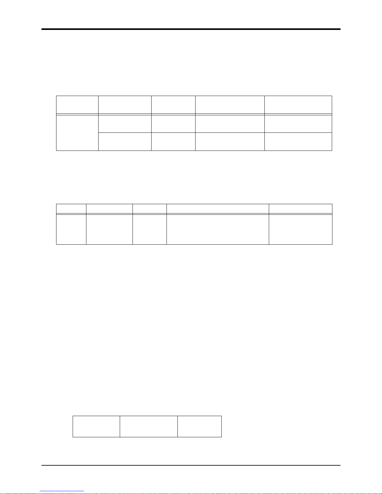
1.2.2 Combination of the robot arm and the controller
Table 1-1 : Combination of the robot arm and the controller
1.3 Combination of the robot arm and the controllerIndirect export
If you intend to export robots bought from us, be sure to choose robots whose language setting parameter (LNG)
is set to English (ENG).
1.4 Instruction manuals
The instruction manuals supplied with the shipment are provided in electronic form in a CD-ROM, except for the
Safety Manual. This CD-ROM (electronic manual) includes instruction manuals in both Japanese and English versions. Please note that the instruction manuals are the same for both language settings (parameter LNG).
Protection specification
Robot arm
Arm length Controller
Stardard specification
RV-12SD standard arm
CR3D-701M
Note1)
Note1)protection specification. (IP54)
RV-12SDL Long arm
Clean specification
RV-12SDC standard arm
CR3D-701
RV-12SDLC Long arm
Page 12
1General configuration
Contents of the structural equipment
1-3
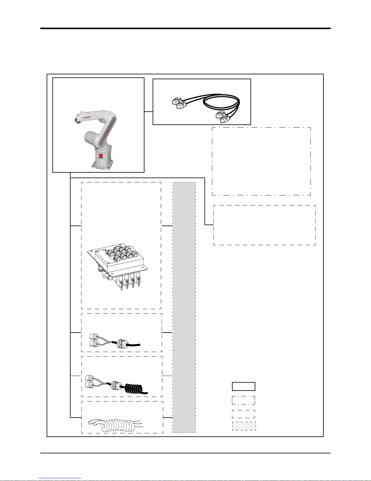
1.5 Contents of the structural equipment
1.5.1 Robot arm
The list of structural equipment is shown in Fig. 1-1.
Fig.1-1 : Structural equipment (Robot arm)
Vertical six-axis
multiple-jointed type
(RV-12SD/12SDL/12SDC/12SDLC)
Hand output cable
・ 1S-GR35S-01 (4sets)
Hand input cable
・ 1S-HC25C-01
Solenoid valve set
(Hand output cable is attached)
<Sink type>
・ 1 set: 1S-VD01-01
・ 2 set: 1S-VD02-01
・ 3 set: 1S-VD03-01
・ 4 set: 1S-VD04-01
Hand curl tube
・ 4 set, 8pc.: 1N-ST0608C
Stopper for changing the operating range
of the J1 axis
・ Stopper part: 1S-DH-01
*This must be installed by the customer.
[Caution]
Standard configuration
Special shipping
Option
equipment
specifications
Prepared by customer
Pneumatic hand customer-manufactured parts
Note1) □□ refer the length.
Refer to Table 1-1 for datails.
Note2) Connect the extension cables to
the arm side of the standard 7 m
(for fixing) cable to extend.
Machine cable extension
(attached to the standard 7 m cable)
・ Fixed type: 1S- □□ CBL-02
・ Flexed type: 1D- □□ LCBL-02
Machine cable
(Standard product: 7m attachment)
Page 13
1-1
1 General configuration
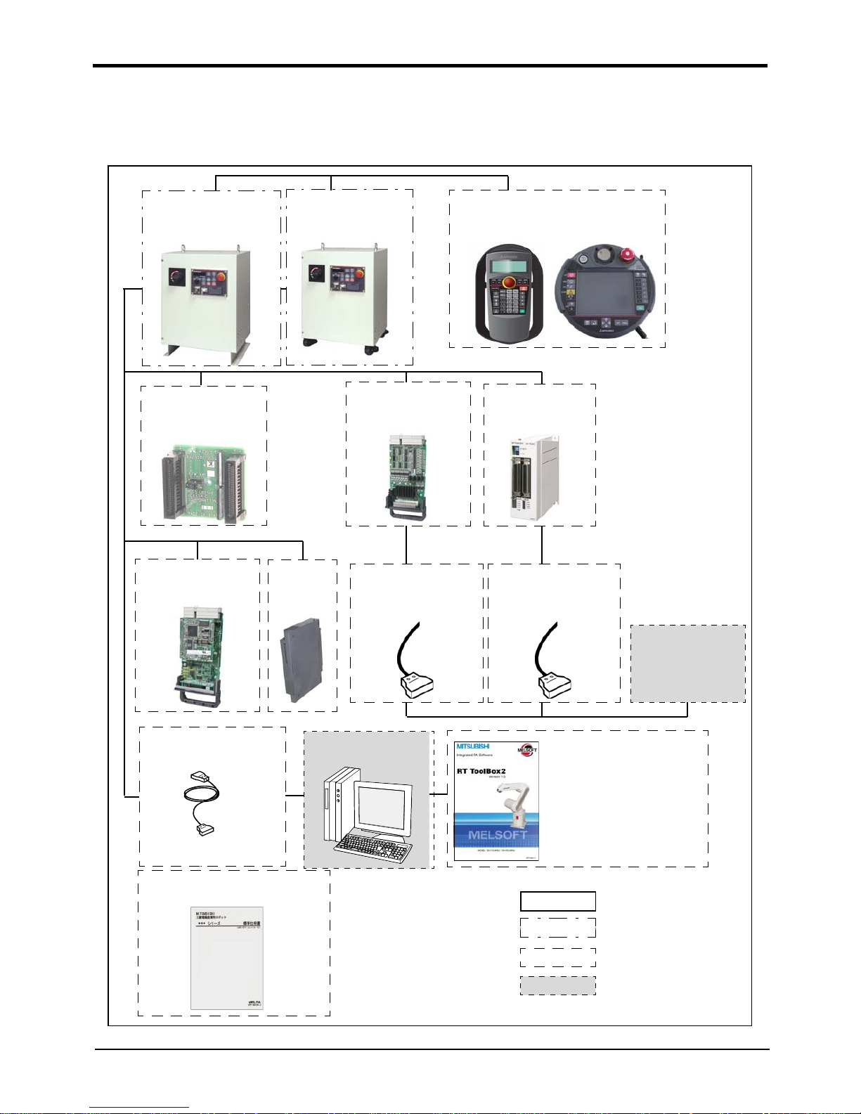
1.3.1 Controller
The devices shown below can be installed on the controller.
The controllers that can be connected differ depending on the model of the robot arm.
Fig.1-1 : Structural equipment
Pneumatic hand
interface
2A-RZ365
Teaching pendant (T/B)
R32TB
R56TB
Personal computer
Prepared by customer
RT Tool Box2
・ 3D-11C-WINJ(CD-ROM)
(MS-Windows2000/XP/Vista)
RT Tool Box2 mini
・ 3D-12C-WINJ(CD-ROM)
(MS-Windows2000/XP/Vista)
Instruction Manual(bound edition)
・ 5S-DC00-PE01
Controller
・ CR3D-701M(IP54 仕様)
ま たは
・ CR3D-701
Caster type
controller
CC-Link interface
2D-TZ576
Extension
memory
cassette
2D-TZ454
Parallel I/O interface
2D-TZ368
Parallel I/O unit
2A-RZ361/2A-RZ371
External I/O cable
・ 2D-CBL05 (5m)
・ 2D-CBL15 (15m)
PLC(Programmable
Logic Controller)
External device
Prepared by
customer
External I/O cable
・ 2A-CBL05 (5m)
・ 2A-CBL15 (15m)
Personal computer cable
2D-232CBL03M
(RS-232)
*)Refer to table 1-3 for
USB cable.
Standard configuration
Special shipping
Options
Prepared by customer
[Caution]
equipment
specifications
The photograph is the image figure.
Page 14

Contents of the Option equipment and special specification
1-1
1.4 Contents of the Option equipment and special specification
A list of all Optional equipments and special specifications are shown below.
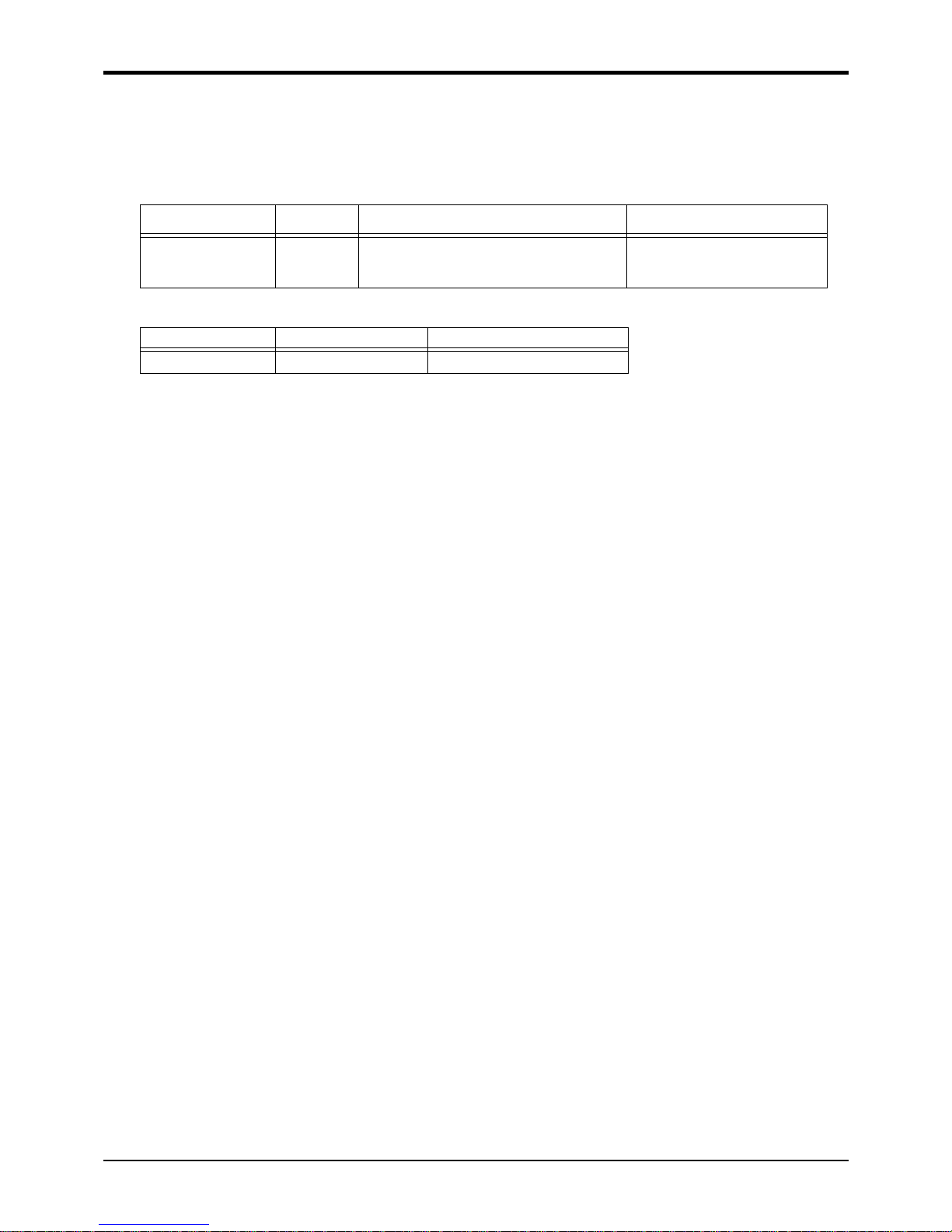
Table 1-1 : The list of Option equipment and special specification
[Reference]:The recommendation products of the USB cable are shown below.
Table 1-2 : Recommendation article of the USB cable
Item Type Specifications
Classificati
on
Note1)
Note1)In the classification column, ○ refers to an option,and □ to a Shipping special specifications.
Descripsion
Stopper for changing the
operating range of the J1
axis
1S-DH-01
Stopper part
+ side: +135, +90, or +45 deg.
- side: -135, -90, or -45 deg.
One each of the following can be
selected: ± 170 deg. are used for
the standard specification.
○
This must be installed by the customer.
Extended machine cable 1S- □□ CBL-02 For fixing (Three sets for power,
signal and ground cable)
○ 5, 10, 15m
1S- □□ LCBL-02 For bending (Three sets for power,
signal and ground cable)
○ 5, 10, 15m
Solenoid valve set 1S-VD01-01 1 set (Sink type) ○
A solenoid valve set for the pneumatic hand
1S-VD02-01 2 set (Sink type) ○
1S-VD03-01 3 set (Sink type) ○
1S-VD04-01 4 set (Sink type) ○
Hand output cable
1S-GR35S-01
Robot side connector. One terminal
is not treated.
○
The cable is connected to the hand output connector by the customer.
Hand input cable
1S-HC25C-01 Robot side connector. One terminal
is not treated.
○
The cable is connected to the sensor by the customer.
Hand curl tube 1N-ST0602C For solenoid valve 1set.:Φ6x2 ○
Curl type air tube
1N-ST0604C For solenoid valve 2set.:Φ6x4 ○
1N-ST0606C For solenoid valve 3set.:Φ6x6 ○
1N-ST0608C For solenoid valve 4set.:Φ6x8 ○
Teaching pendant R32TB Cable length 7m ○
With 3-position deadman switch
R32TB-15 Cable length 15m ○
R56TB Cable length 7m ○
R56TB-15 Cable length 15m ○
Pneumatic hand interface
2A-RZ365 DO: 8 point (Sink type) ○
It is necessary when the hand output signal of the
robot arm is used.
Parallel I/O Interface
(Sink type)
2D-TZ368 (Sink type)
DO: 32 point (Sink type)/
DI : 32 point (Sink type)
Insulated type output signal (100mA/
point)
○
The card type external input-and-output.
Interface.Install to the slot of controller.
External I/O cable
(For Parallel I/O Interface)
2D-CBL05 5m ○
Use to connect the external peripheral device to
the parallel input/output interface.
2D-CBL15 15m ○
Parallel I/O Unit
2A-RZ361
DO: 32 point (Sink type)/
DI : 32 point (Sink type)
○
The unit for expansion the external input/output.
Electrical isolated Type
(100mA/Point)
2A-RZ371
DO: 32 point (Source type)/
DI : 32 point (Source type)
○
External I/O cable
(For Parallel I/O Unit)
2A-CBL05 5m ○
Use to connect the external peripheral device to
the parallel input/output unit
2A-CBL15 15m ○
Personal computer
cable
Note2)
Note2)The recommendation products of the USB cable are shown in Table 1-1.
2D-232CBL03M
RS-232C cable 3m for PC-AT compatible model
○
RT ToolBox2
(
Personal computer Sup-
port software)
3D-11C-WINE CD-ROM ○
MS-Windows2000/XP
/Vista
(With the simulation function)
RT ToolBox2 mini
(Personal computer Sup-
port software mini)
3D-12C-WINE CD-ROM ○ MS-Windows2000/XP/Vista
CC-Link interface
2D-TZ576
Local station (The local station alone
is supported.)
○ for MELSEC PLC with CC-Link connection.
Extended memory cassette
2D-TZ454
Teaching point number: 50,800
Steps number: 50,800
Program number: 512
○
The battery backup function is provided.
The value combined with the standard
Caster specifications
controller
CR3D-701/701M Specifications with casters □
The controller height
will be h =
615
Instruction Manual 5S-DC00-PE01 RV-12SD/12SDL series ○ A set of the instructions manual bookbinding editions
Page 15
1-2
Contents of the Option equipment and special specification
Be careful to the USB cable to apply neither the static electricity nor the noise.
Failure to observe this could lead to malfunc-tioning .
製 品 名 形 名 メ ー カ名
USB cable
(USB A type-USB B type)
USB2-30 ELECOM CO., LTD.
AU230 BUFFALO KOKUYO SUPPLY INC.
USB cable
(USB A type-USB mini B type)
KU-AMB530 SANWA SUPPLY INC.
USB-M53 ELECOM CO., LTD.
GT09-C20USB-SP MITSUBISHI ELECTRIC SYSTEM & SERVICE CO., LTD.
MR-J3USBCBL3M MITSUBISHI ELECTRIC CO., LTD.
USB adapter
(USB B type-USB mini B type)
AD-USBBFTM5M ELECOM CO., LTD.
Caution
Page 16
2Robot arm
Standard specifications
2-3
2 Robot arm
2.1 Standard specifications
2.1.1 Standard specifications
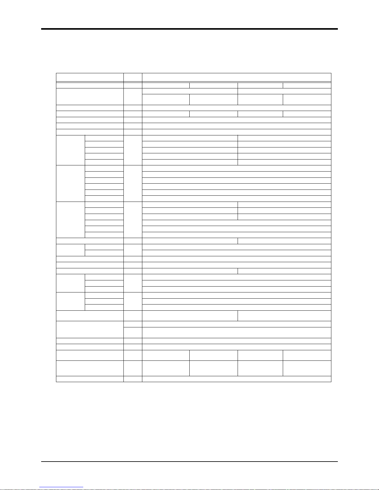
Table 2-1 : Tab Standard specifications of robot
Item Unit Specifications
Type RV-12SD RV-12SDC RV-12SDL RV-12SDLC
Type of robot
6-axis standard arm 6-axis long arm
Standard
Clean
(Special Specifications)
Standard
Clean
(Special Specifications)
Degree of freedom
6
Installation posture On floor, hanging On floor On floor, hangingOn floor
Structure Vertical, multiple-joint type
Drive system AC servo motor (brake provided on all axes)
Position detection method Absolute encoder
Arm length
Shoulder shift
mm
150 150
Upper arm 400 560
Fore arm 530 670
Elbow shift 80 80
Wrist length 97 97
Operating
range
Waist (J1)
Degree
340(-170 to +170)
Shoulder (J2) 230(-100 to +130)
Elbow (J3) 290(-130 to +160)
Wrist twist (J4) 320(-160 to +160)
Wrist pitch (J5) 240(-120 to +120)
Wrist roll (J6) 720(-360 to +360)
Speed of
motion
Waist (J1)
Degree/
s
276 230
Shoulder (J2) 230 172
Elbow (J3) 267 200
Wrist twist (J4) 352
Wrist pitch (J5) 375
Wrist roll (J6) 660
Maximum resultant velocity
Note1)
Note1) This is the value on the hand flange surface when all axes are combined.
mm/sec Approx. 9,600 Approx. 9,500
Load Maximum
Note2)
Note2) The maximum load capacity is the mass with the flange posture facing downword at the ± 10°limit.
kg
12
Rating 10
Pose repeatability
Note3)
Note3) The pose repeatability details are given in Page 6, "2.2.1 Pose repeatability"
mm ± 0.05
Ambient temperature ℃ 0 to 40
mass kg Approx. 93 Approx. 98
Allowable
moment load
Wrist twist (J4)
N・m
19.3
Wrist pitch (J5) 19.3
Wrist roll (J6) 11
Allowable
inertia
Wrist twist (J4)
kg ・ m
2
0.4
Wrist pitch (J5) 0.4
Wrist roll (J6) 0.14
Note4)
Note4) Up to 0.28kg・m2 can be supported by performing variable acceleration/deceleration control and also by setting the load
inertia.
Arm reachable radius froot p-axis
center point
mm 1,086 1,385
Tool wiring
Note5)
Note5) The air hand interface (option) is required when the tool (hand) output is used. Also, if the solenoid set (option) is
used, eight points of hand outputs are used for other options. 。
Hand input 8 point / hand output 8 point
Eight spare wires : AWG#27(0.1mm
2
)
(shielded)
Tool pneumatic pipes Primary side: Φ6 × 2 , Secondary side: Φ6 × 8
Supply pressure MPa 0.49 ± 10%
Protection specification
Note6)
Note6) The protection specification details are given in Page 7, "2.2.5 Protection specifications and working environment".
J1 to J3 axis : IP54
J4 to J6 axis : IP65
-
J1 to J3 axis : IP54
J4 to J6 axis : IP65
-
Degree of cleanliness
Note7)
Note7) The clean specification details are given in Page 9, "2.2.6 Clean specifications" .A down flow(0.3m/s or more) in the
clean room is the necessary conditions for the cleanliness.
-
10(0.3μm)
Internal suction
requirement
-
10(0.3μm)
Internal suction
requirement
Painting color Light gray (Equivalent to Munsell: 0.08GY7.64/0.81)
Page 17

2-4
Definition of specifications
2 Robot arm
2.2 Definition of specifications
The accuracy of pose repeatability mentioned in catalogs and in the specification manual is defined as follows.
2.2.1 Pose repeatability
For this robot, the pose repeatability is given in accordance with JIS 8432 (Pose repeatability). Note that the value
is based on 100 measurements (although 30 measurements are required according to JIS).
[Caution] The specified "pose repeatability" is not guaranteed to be satisfied under the following conditions.
[1] Operation pattern factors
1) When an operation that approaches from different directions and orientations are included in rela-
tion to the teaching position during repeated operations
2) When the speed at teaching and the speed at execution are different
[2] Load fluctuation factor
1) When work is present/absent in repeated operations
[3] Disturbance factor during operation
1) Even if approaching from the same direction and orientation to the teaching position, when the
power is turned OFF or a stop operation is performed halfway
[4] Temperature factors
1) When the operating environment temperature changes
2) When accuracy is required before and after a warm-up operation
[5] Factors due to differences in accuracy definition
1) When accuracy is required between a position set by a numeric value in the robot's internal coordinate system and a position within the actual space
2) When accuracy is required between a position generated by the pallet function
Note1)
and a posi-
tion within the actual space
Note1)
The pallet function is a function that teaches only the position of the work used as reference (3 to 4 points) and
obtains the remaining positions by calculations, for an operation that arranges works orderly or for an operation
that unloads orderly arranged works. By using this function, for example, in the case of an operation that arranges
works on grid points of 100 x 100, by teaching only three points of four corners, the remaining grid points are
automatically generated; thus, it is not necessary to teach all 10,000 points. For more information about the pallet
function, refer to the separate volume, "Instruction Manual/Detailed Explanation of Functions and Operations."
Page 18

2 Robot arm
Definition of specifications
2-5
2.2.2 Rated load (mass capacity)
The robot's mass capacity is expressed solely in terms of mass, but even for tools and works of similar mass,
eccentric loads will have some restrictions. When designing the tooling or when selecting a robot, consider the following issues.
(1) The tooling should have the value less or equal than the smaller of the tolerable inertia and the tolerable
moment found in Page 3, "Table 2-1 : Tab Standard specifications of robot"
(2) Fig. 2-1 shows the distribution dimensions for the center of gravity in the case where the volume of the
load is relatively small. Use this figure as a reference when designing the tooling.
(3) When the load is not mass, but force, you should design the tooling so that it does not exceed the value for
allowable moment described in Page 3, "Table 2-1 : Tab Standard specifications of robot"
[Caution] The mass capacity is greatly influenced by the operating speed of the robot and the motion posture.
Even if you are within the allowable range mentioned previously, an overload or generate an overcurrnt
alarm could occur. In such cases, it will be necessary to change the time setting for acceleration/deceleration, the operating speed, and the motion posture.
[Caution] The overhang amount of the load for the specified moment and inertia in this section is the dynamic limit
value determined by the motor driving each axis and by the capacity of the reduction gears. Consequently, accuracy cannot be guaranteed for the entire tooling area. Since accuracy is based on the center point of the mechanical interface surface, position accuracy can diminish as you go away from the
flange surface, or vibration can result, with tooling that is not rigid or that is long.
[Caution] Even within the allowable range previously mentioned, an overload alarm may be generated if an ascend-
ing operation continues at a micro-low speed. In such a case, it is necessary to increase the ascending
speed.
Fig.2-1:Position of center of gravity for loads (for loads with comparatively small volume): RV-12SD/12SDLSeries
80
80
112
112
200
200
197
277
0
Unit : mm
Rotation center for J6 axis
Rotation center for J5 axis
200
300 100
5.0kg
10.0kg
97
100
100
Page 19

2-6
Definition of specifications
2 Robot arm
2.2.3 Relationships Among Mass Capacity, Speed, and Acceleration/Deceleration Speed
This robot automatically sets the optimum acceleration and deceleration speeds and maximum speed, according
to the load capacity and size that have been set, and operates using these automatically set speeds.
To achieve that, it is necessary to correctly set the actual load data (mass and size of hand and work) to be used.
However, vibration, overheating and errors such as excessive margin of error and overload may occur,depending
on the robot operation pattern or ambient temperature. In such a case, change the setting value to the +20%
range. If a setting is performed in such a way that it falls below the mounted load, the life span of the mechanism
elements used in the robot may be shortened. In the case of a work requiring a high degree of accuracy, set up the
load correctly and use the robot by lowering the ratios of the acceleration and deceleration speeds.
(1) Setting Load Capacity and Size (Hand Conditions)
Set up the capacity and size of the hand with the "HNDDAT*" parameter (optimum acceleration/deceleration
setting parameter), and set up the capacity and size of the work with the "WRKDAT*" parameter. Numbers 0 to 8
can be used for the asterisk (*) part. Designate the "HNDDAT*" and "WRKDAT*" parameters to be used using
the "LOADSET" command in a program.
For more details, refer to the separate "Instruction Manual/Detailed Explanation of Functions and Operations."
It is the same meaning as "LOADSET 0.0" if not using the "LOADSET".
2.2.4 Vibrations at the Tip of the Arm during Low-Speed Operation of the Robot
Vibrations at the tip of the arm may increase substantially during the low-speed operation of the robot, depending
on the combination of robot operation, hand mass and hand inertia. This problem occurs when the vibration count
specific to the robot arm and the vibration count of the arm driving force are coming close to each other. These
vibrations at the tip of the arm can be reduced by taking the following measures:
1) Lower the robot's operating speed by approximately 5% from high speed using the OVRD instruction.
2) Change and move the teaching points of the robot.
3) Change the hand mass and hand inertia.
Page 20
2 Robot arm
Definition of specifications
2-7
2.2.5 Protection specifications and working environment
(1) Types of protection specifications
The robot arm has protection specifications that comply with the IEC Standards. The protection specifications
and applicable fields are shown in Table 2-2.
Even oil mist environment can be used in addition to the general environment.
Table 2-2 : Protection specifications and applicable fields
The IEC IP symbols define the degree of protection against solids and fluids, and do not indicate a protective
structure against the entry of oil or water.
The evaluation regarding oil mist specifications has been confirmed with Mitsubishi's standard testing methods
using the cutting oils shown in Table 2-3
Table 2-3 : Tested cutting oil for oil mist specifications
【Information】
・ The IEC IP54
The IEC IP54 standard refers to protection structure designed to prevent any harmful effects by fresh water
scattering vertically onto the testing equipment in a radius of 180 degrees from a distance of 300 to 500 mm,
with 10 ± 0.5 liters of water every minute, at a water pressure of 80 to 100kPa , covering the entire area of
the robot with the exception of the installation section at 1 ㎡ per minute, for a total of 5 minutes or more.
・ The IEC IP65
Protection against water infiltration as specified in IP65 indicates a protective structure that is not harmfully
affected when 12.5± 5% liters of water is supplied from a test device at a position approx. 3m away in various
directions and a water pressure of 30kPa at the nozzle section. The water is filled one minute per 1m
2
of test
device surface area for a total of three minutes.
(2) About the use with the bad environment
This robot has protection methods that conform to IEC'sIP54 (for J1 to J3 axis) and IP65 (for J4 to J6 axis) standards (splashproof type). Recommended usage conditions.
1) The robot is designed for use in combination with machining device.
2) Please examine cutting oil referring to Table 2-3 used by a standard examination of our company.
3) Take measures so that the robot will not be exposed to water, oil and/or chips for a long period of time.
4) Protection performance can be improved by pressurizing the inside of the robot arm. Since the joint (AIR
PURGE) of phi 8 is prepared at the rear of the base section, please supply the dry air for pressurization from
The specification of the dry air for pressurization is shown in Table 2-4.
Table 2-4 :
Specification of the dry air for pressurization
The warranty is invalid for any faults that occur when the robot is used under the following conditions.
Type
Protection
specifications
(IEC Standards value)
Classification Applicable field Remarks
RV-12SD
RV-12SDL
IP54
(J1 to J3 axis)
General-purpose
environment specifications
General assembly
Slightly dusty environment
IP65
(J4 to J6 axis)
Oil mist specifications
Machine tool (cutting)
Machine shop with heavy oil mist
Dusty work shop
Note that if the cutting machine
contains abrasive materials, the
machine line will be shortened.
Name Maker Relevant JIS Main characteristics Application
Emulcut
FA-800
Kyodo Yushi Co., Ltd Class A1 No. 2 Water soluble cutting oil
・ Base oil........................................................50-60%
・ Surfactant and rust inhibitor ..............30-40%
・ Additives......................................................5% or less
・ Water ...........................................................The rest
Water soluble cutting oil
Emulcut
Specification The atmospheric pressure
dew point is -20 degree or
less.
0 to 0.01MPa
Page 21

2-8
Definition of specifications
2 Robot arm
Also, if the cover and/or other parts are damaged by interferences caused by the peripheral devices and the
robot, the protection specification (seal performance, etc.) may be degraded. Therefore, please pay extra attention
when handling the robot.
Refer to Page 91, "6.2 Working environment".
1) In surroundings that generate inflammable gases or corrosive gasses.
2) Atmosphere used excluding cutting oil shown in Table 2-3
3) Environment where the robot is exposed to water, oil and/or chips for a long period of time.
4) In surroundings where chips fall directly on the robot.In surroundings where the minimum diameter of chips
is less than 0.5mm.
5) Mist atmosphere exceeding the specification.
6) Pressurization by the dry air exceeding the specification of Table 2-4
Page 22
2 Robot arm
Definition of specifications
2-9
2.2.6 Clean specifications
(1) Types of clean specifications
The robot arm with clean specification is made by order. Please check the delivery schedule.
Table 2-5 : Clean specifications
Table 2-6 : Specifications of vacuum generation valve
■ Precautions for use
1) When using a device that moves or rotates the robot arm, the down flow may not be secured because of the
air flow. In this case, the degree of cleanliness cannot be ensured.
2) A Φ8 coupling is provided in the base section of the robot arm for suction inside the robot arm. When using
the robot, connect this coupling with the vacuum generating valve and vacuum pump (furnished by the customer).
* Install the vacuum generating valve downstream of the downflow or install a filter in the exhaust air sec-
tion so that the exhaust air from the vacuum generating valve does not affect cleanness.
Recommended filter: Exhaust filter EF300-02, Koganei Corporation
* If any vacuum pump is prepared by the customer, assure on the vacuum side flow rate 30 liters/min.(ANR)
or more .
3) When using the Mitsubishi standard option solenoid valve set, use the spare piping (Φ6 pneumatic hose) of
the primary piping to exhaust the air.
If the exhaust leaks into the robot arm, the degree of cleanliness could be affected.
Clean specifications Type Degree of cleanliness Internal suction
RV-12SDC-SA
RV-12SDLC-SA
10(0.3μm) Concentrated suction with vaccum generating valve. The use of a vacuum generating valve
is recommended.
Type Maker Air pressure
MEDT 14 KONEGAI CORPORATION 0.2 to 0.6 MPa
Page 23
2-10
Names of each part of the robot
2 Robot arm
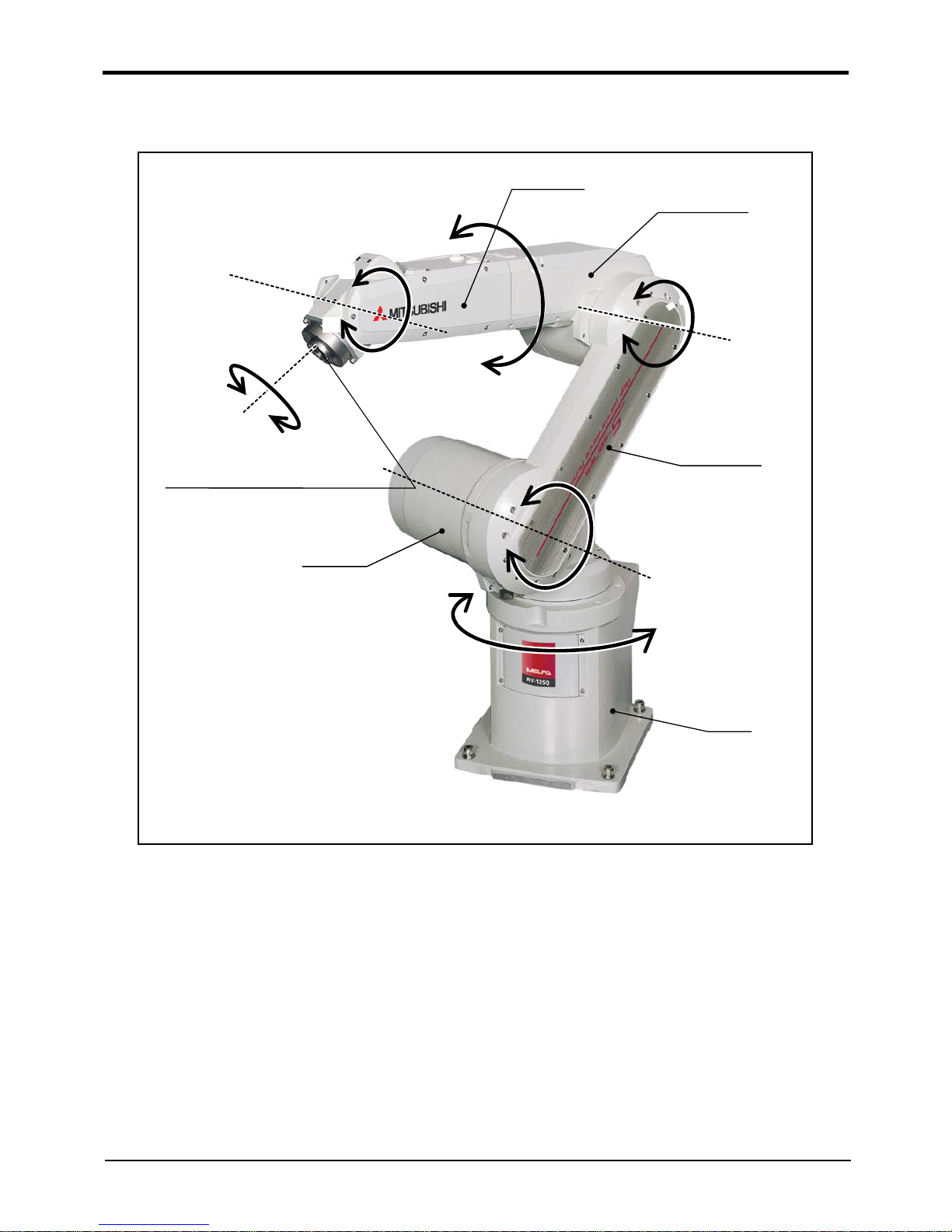
2.3 Names of each part of the robot
Fig.2-2 : Names of each part of the robot
J5 axis
J6 axis
Fore arm
Mechanical interface
(Hand installation flange surface)
Upper arm
J1 axis
J2 axis
J3 axis
J4 axis
Base
Elbow block
Shoulder
+
-
+
-
+
-
+
-
+
-
+
-
Page 24
2 Robot arm
Outside dimensions ・ Operating range diagram
2-11
2.4 Outside dimensions ・ Operating range diagram
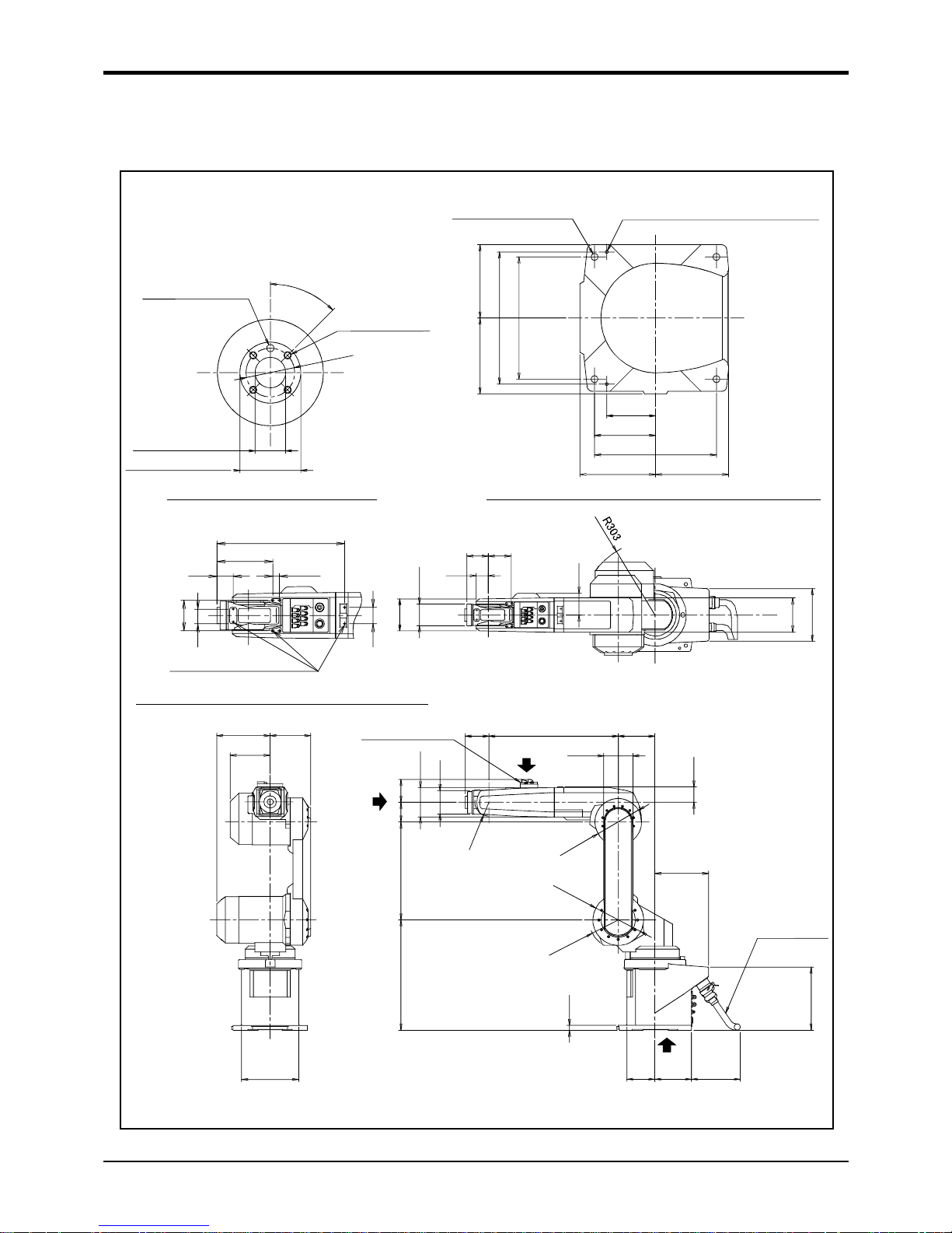
(1) RV-12SD/12SDC
Fig.2-3 : Outside dimensions : RV-12SD/12SDC
φ
40
4
5
°
φ25H7
+0.021
0
depth 9.5
φ50h8
-0.039
0
depth 8
4-M6 screw, depth 9
φ6H7
+0.012
0
depth 9
View A: Detail of mechanical interface
150
155
270
250
250
150155
100
125
4-φ14 installation hole
2-φ6 holes
(prepared holes for φ8 positioning pins)
View D bottom view drawing : Detail of installation dimension
(Installation)
6.3a
(Installation)
6.3a
530
97
120
150
63
97
120
106
80
400
220
450
20
115
150 200
258
R
5
7
φ
1
9
1
φ
2
0
8
R
1
1
9
A
B
C
Solenoid valve set
(option)
(Maintenance space)
Machine cable
50
130
φ88
89 93
89
140
214
230
215
161
164
393
172
50
50
44
93
20
(for customer use)
View C: Detail of screw holes for fixing wiring hookup
Screw holes for fixing
wiring hookup (M4)
Page 25
2-12
Outside dimensions ・ Operating range diagram
2 Robot arm
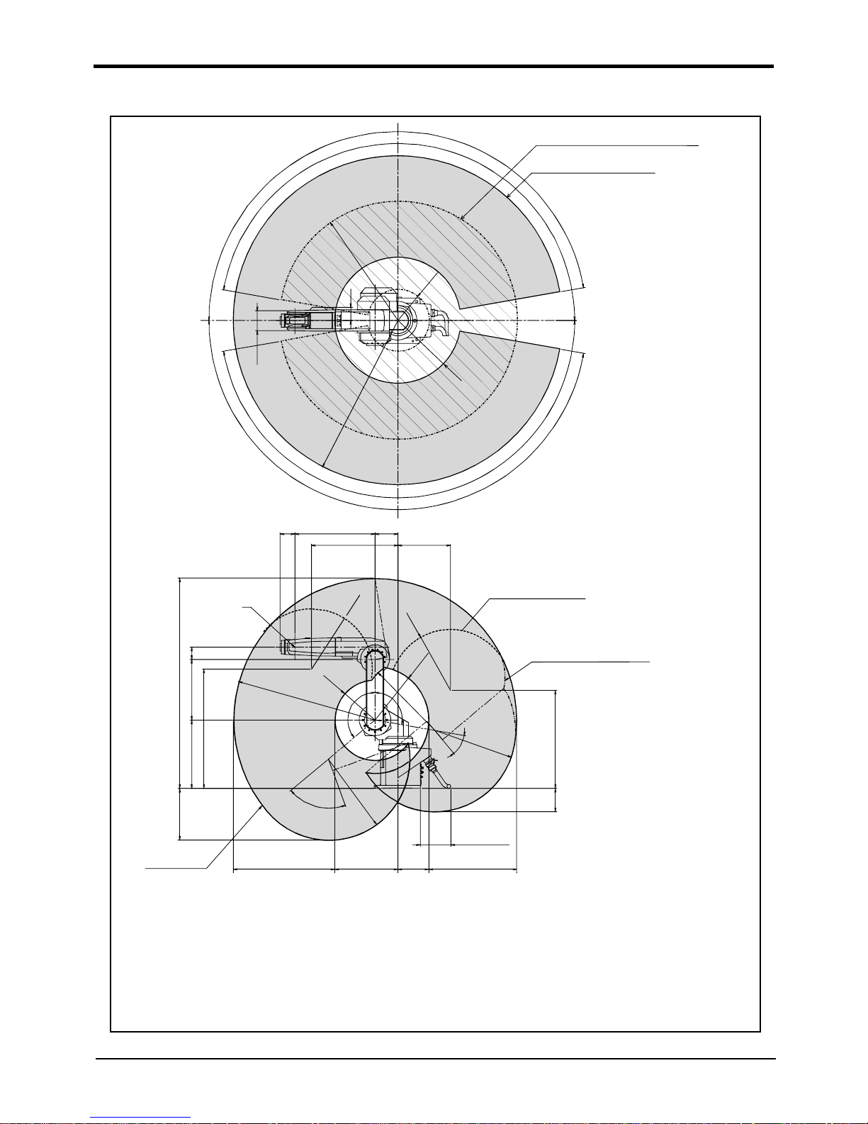
Fig.2-4 : Operating range diagram : RV-12SD/12SDC
1
7
0
°
1
7
0
°
1
7
0
°
1
7
0
°
P-point path: Reverse range
(alternate long and short dash line)
P-point path: Entire range
(solid line)
R
4
1
6
R
7
8
6
R
2
0
5
R
1
0
8
6
8
9
1
3
0
80
1386
400
450
784
R
9
3
6
R
2
6
6
R
4
0
0
R
4
0
0
R
3
5
5
R
5
36
R
5
3
6
R
5
3
6
7
0
°
1
0
0
°
1
3
0
°
646
4
0
°
581
205
416
670
97
530 150
569
349
P
Flange downward
limit line(dotted line)
343
156
P-point path
Rear surface area wide angle, narrow angle limit
*If the angle of axis J1 is -75deg <= J1 <= 75deg and the angle of axis J2 is -25deg <= J2 < 2deg,
then operating range is limited to J2 + J3 * 2 >= -258deg.
*If the angle of axis J1 is -75deg <= J1 <= 75 deg and the angle of axis J2 is -80deg <= J2 < -25deg,
then operating range is limited to J2 + J3 >= -141.5deg.
*If the angle of axis J1 is -75deg <= J1 <= 75 deg and the angle of axis J2 is J2 < -80deg,
then operating range is limited to 6.4 * J2 + J3 >= 573.5deg.
*If the angle of axis J1 is J1 <= -75 degree or J1 > 75 degree and the angle of axis J2 is -80deg <= J2 < 2 degree,
then operating range is limited to J2 + J3 * 2 >= -258 degree.
*If the angle of axis J1 is J1 <= -75deg or J1 > 75deg and the angle of axis J2 is J2 < -80deg ,
then o
p
erating range is limited to 2.4 * J2 + J3 >= -281 degree.
200 or more
Restriction on wide angle
in the rear section
Page 26
2 Robot arm
Outside dimensions ・ Operating range diagram
2-13
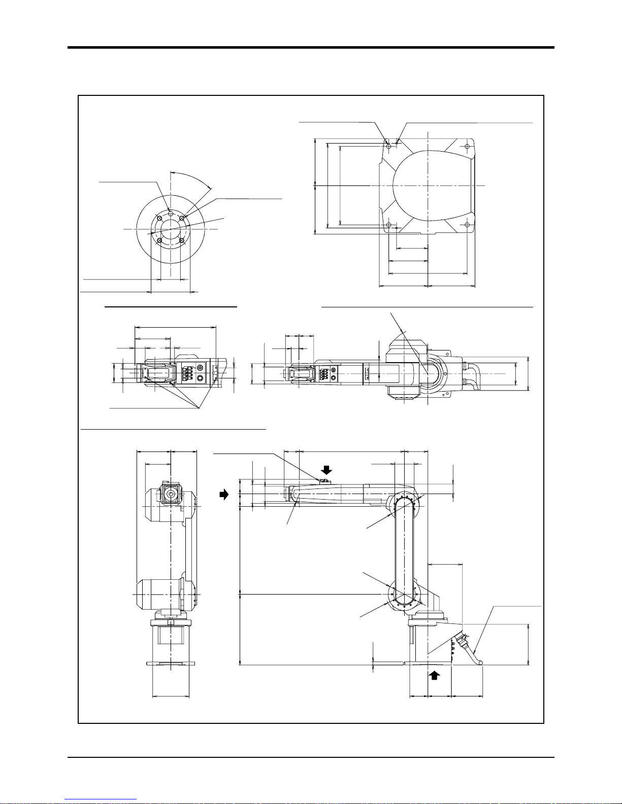
(2) RV-12SDL/12SDLC
Fig.2-5 : Outside dimensions : RV-12SDL/12SDLC
φ25H7
+0.021
0
depth 9.5
φ50h8
-0.039
0
depth 8
4-M6 screw, depth 9
φ6H7
+0.012
0
depth 9
φ
4
0
4
5
°
View A: Detail of mechanical interface
4-φ14 installation hole
150
155
270
250
250
150155
100
125
2-φ6 holes
(prepared holes for φ8 positioning pins)
View D bottom view drawing : Detail of installation dimension
(Installation)6.3a
(Installation)
6.3a
215
161
164
230
50
130
φ88
89 93
89
R
3
0
3
140
214
670
Solenoid valve set
(option)
97
124
150
63
97
120
106
80
560
220
450
20
115
150 200
258
R
5
7
φ
1
9
4
φ
2
0
8
R
1
1
9
(Maintenance space)
A
B
C
Machine cable
393
172
50
50
44
93
20
(for customer use)
View C: Detail of screw holes for fixing wiring hookup
Screw holes for fixing
wiring hookup (M4)
Page 27
2-14
Outside dimensions ・ Operating range diagram
2 Robot arm
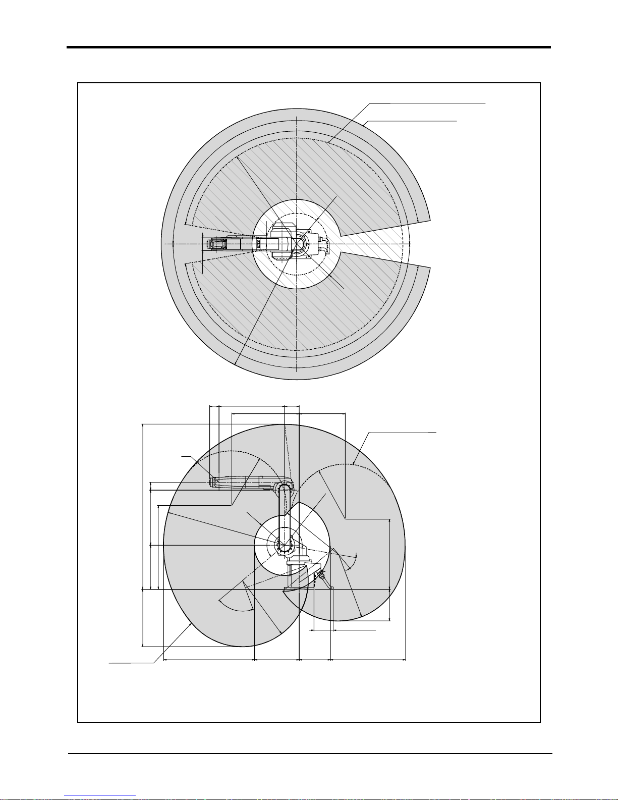
Operating range diagram : RV-12SDL/12SDLC
1
7
0
°
1
7
0
°
R
1
0
8
5
R
3
1
7
R
1
3
8
5
R
4
5
7
1
7
0
°
1
7
0
°
1
3
0
8
9
P-point path: Reverse range
(alternate long and short dash line)
P-point path: Entire range
(solid line)
768
317
928
457
80
1685
560
450
854
585
97
670
150
690 470
P
716
322
1
0
0
°
R
6
7
5
4
0
°
R
3
07
7
0
°
1
3
0
°
R
4
6
7
R
5
6
0
R
1
2
3
5
R
5
6
0
R
6
7
5
200 or more
R
6
7
3
Flange downward
limit line(dotted line)
P-point path
Rear surface area wide angle, narrow angle limit
*If the angle of axis J1 is -75deg <= J1 <= 75deg and the angle of axis J2 is J2 < -25deg ,
then operating range is limited to J2 + J3 >= -155 degree.
*If the angle of axis J1 is J1 <= -75deg or J1 > 75deg and the angle of axis J2 is J2 < -30deg ,
then operating range is limited to 0.54 * J2 + J3 >= -146.2 degree.
Page 28
2 Robot arm
Tooling
2-15
2.5 Tooling
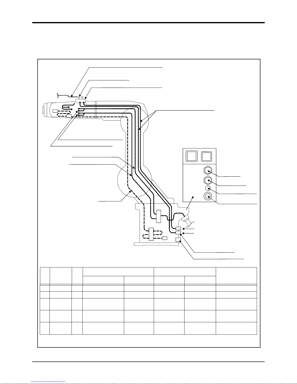
2.5.1 Wiring and piping for hand
Shows the wiring and piping configuration for a standard-equipped hand.
Fig.2-6 : Wiring and piping for hand
Solenoid valve set (option)
* Use by connecting it with the hand
output signal connector.
(1)φ6 quick coupling
(3)Hand input signal connector
(4)Hand output signal connector
(2)φ6 quick coupling
(5)φ8 quick coupling
Note1)
Spare wiring
AIRIN
RETURN
CN2
CN1
AIRIN(φ6)
RETURN(φ6)
VACUUM(φ8)
AIR PARGE(φ8)
SPEAR WIRE INLET
Primary piping pneumatic hose
Hand input signal cable
Hand output signal cable
Secondary piping pneumatic hose (φ6)
(customer-prepared)
Connector and pneumatic coupling
No Name Qty.
Robot side (Robot arm side) Counter side (customer-prepared)
Manufacturer
Connectors, couplings Connector pins Connector Connector pins
(1) Coupling 8 KJL06-01S - - - SMC Corporation
(2) Coupling 2 UKBL6 - - - Koganei Corporation
(3) Connector 2 1-1717834-3 1318108-1 1-1318115-3 1318112-1 Tyco Electronics
AMP
(4) Connector 2 1-1717834-4 1318108-1 1-1318115-4 1318112-1 Tyco Electronics
AMP
(5) Coupling
Note1)
Note1) For dust suction in the clean specification
1 UKBL8 - - - Koganei Corporation
Page 29

2-16
Tooling
2 Robot arm
2.5.2 Internal air piping
(1) Standard type
1) The robot has two φ6 x 4 urethane hoses from the pneumatic entrance on the base section to the shoulder
cover.
2) One hose is the primary piping for the pneumatic equipment.The remaining pipe is used for air exhaust.
3) The optional solenoid is provided with a maximum of eight couplings for the φ6 air hose.
4) The pneumatic inlet in the base section has a φ6 pneumatic coupling bridge.
5) Refer to Page 24, "(3) Solenoid valve set" for details on the electronic valve set (optional).
6) Protection performance can be improved by pressurizing the inside of the robot arm. Since the joint (AIR
PURGE) of phi 8 is prepared at the rear of the base section, please supply the dry air for pressurization
from this joint. Refer to Page 7, "2.2.5 Protection specifications and working environment" for the details
of dry air.
(2) Clean type
1) The clean type basically includes the same piping as the standard type.
2) With the clean specification, a φ8 coupling is provided in the base section for suction inside the machine.
For use, connect it to the suction port of the vacuum pump or the coupling on the "VACUUM" side of the
vacuum generating valve. Moreover, to clean the exhaust from the vacuum pump or vacuum generator, use
the exhaust filter (prepared by the customer). Table 2-7 shows the specifications of the vacuum generating valve.
3) To use the vacuum pump, assure a flow rate of 30 liters/min. or more.
4) Use clean air as the air supplied to the vacuum generator.
Table 2-7 : Vacuum generating valve specifications
2.5.3 Internal wiring for the pneumatic hand output cable(Standard type/Clean type)
1) When the controller uses the optional pneumatic hand interface (2A-RZ365/RZ375), the hand output signal
works as the pneumatic hand cable.
2) The hand output primary cable extends from the connector PCB of the base section to the inside of the
forearm. (AWG#24(0.2mm
2
)x 2 : 8 cables) The cable terminals have connector bridges for eight hand out-
puts. The connector names are GR1 and GR2.
To extend the wiring to the outside of the arm, a separate cable (optional "hand output cable 1S-GR35S01" IP65 is recommended) is required.
2.5.4 Internal wiring for the hand check input cable(Standard type/Clean type)
1) The hand output primary cable extends from the connector PCB of the base section to the inside of the
forearm. (AWG#24(0.2mm
2
)x 2 : 8 cables) The cable terminals have connector bridges for eight hand inputs.
The connector names are HC1 and HC2. The terminal section is connected to the connector in the forearm section.
2) The hand check signal of the pneumatic hand is input by connecting this connector.
To extend the wiring to the outside of the arm, a separate cable (optional "hand input cable 1S-HC25C01" IP65 is recommended) is required.
2.5.5 Spare Wiring
(1) Standard type
As spare wiring, four pairs of cab tire cables (total of eight cores) are preinstalled between the base section and
the forearm side section. The connector is attached to both ends. Customer can be use. Refer to the separate
"Instruction Manual/ROBOT ARM SETUP & MAINTENANCE" for details.
Both ends of the wire terminals are unprocessed. Use them under the following circumstances:
● For folding as the hand output cable when installing the solenoid valve in outside the robot.
● For when installing six or more hand I/O points for the sensor in the hand section
(Connects to the parallel I/O general purpose input.)
Type Maker Air pressure
MEDT14 KONEGAI CORPORATION 0.2 to 0.6 MPa
Page 30
2 Robot arm
Tooling
2-17
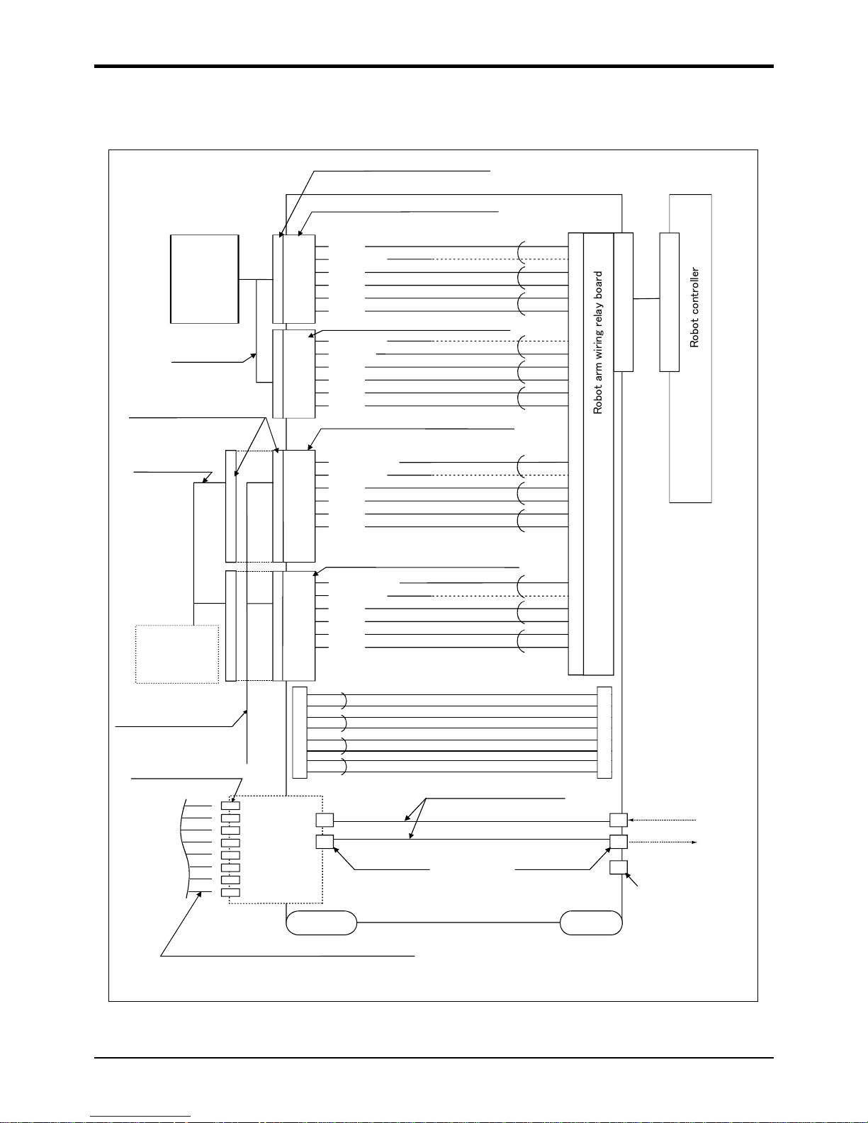
2.5.6 Wiring and piping system diagram for hand
Shows the wiring and piping configuration for a standard-equipped hand.
Fig.2-7 : Wiring and piping system diagram for hand and example the solenoid valve installation(Sink type)
<Reserved>
<24GND>
<HC 5>
<HC 6>
<HC 7>
<HC 8>
White
Black
Hand signal input connector (HC1 connector)
White
Black
White
Black
White
Black
White
Black
White
Black
White
Black
1-1717834-3
(Tyco Electronics AMP)
White
Black
White
Black
White
Black
White
Black
White
Black
1-1318115-3
(Tyco Electronics AMP)
Hand output cable
(option)
1-1717834-4
(Tyco Electronics AMP)
Hand signal output
connection connector
1-1318115-4
(Tyco Electronics AMP)
Secondary pneumatic hose piping (customer-prepared)
φ6 hose
Hand output cable
attached to the solenoid set
Hand input cable
(option)
φ6 quick coupling (1 to 8)
Hand signal input connection connector
Hand signal output connector (GR1 connector)
AIR IN
RETURN
A1
A2
A3
B1
B2
B3
<+24V>
<Reserved>
<HC 1>
<HC 2>
<HC 3>
<HC 4>
A1
A2
A3
A4
B1
B2
B3
B4
<+24V(COM)>
<Reserved>
<GR 1>
<GR 2>
<GR 3>
<GR 4>
<+24V(COM)>
<Reserved>
<GR 5>
<GR 6>
<GR 7>
<GR 8>
1
2
3
4
5
6
7
8
A1
A2
A3
B1
B2
B3
A1
A2
A3
A4
B1
B2
B3
B4
Solenoid set
(option)
valve mounting
section
φ6 quick coupling
φ6 quick coupling
φ6 hose
φ6 hose
Primary piping pneumatic hoses
Yellow
White
Red
Blue
Orange
Driving devices,
such as solenoid
and hand, provided
by the customer
Hand
prepared
by customer
R
o
b
o
t
a
r
m
w
i
r
i
n
g
r
e
l
a
y
b
o
a
r
d
R
o
b
o
t
c
o
n
t
r
o
l
l
e
r
Base
Forearm
Hand signal input connector (HC2 connector)
Hand signal output connector (GR2 connector)
Spare wiring AWG#28(0.1mm2)×6 (cab tire cables with the shield)
Green
Black
Brown
VACCUM
AIR PARGE
φ8
*Refer to Fig. 2-10 for Air
supply circuit example.
Page 31

2-18
Tooling
2 Robot arm
2.5.7 Electrical specifications of hand input/output
Table 2-8 : Electrical specifications of input circuit
Table 2-9 : Electrical specifications of output circuit
Note) An optional air hand interface (2A-RZ365/RZ375) is required to use hand output.
Item Specifications Internal circuit
Type DC input
<Sink type>
* HCn=HC1~HC8
No. of input points 8
Insulation method Photo-coupler insulation
Rated input voltage 12VDC/24VDC
Rated input current Approx. 3mA/approx. 7mA
Working voltage range DC10.2 to 26.4V(ripple rate within 5%)
ON voltage/ON current 8VDC or more/2mA or more
OFF voltage/OFF current 4VDC or less/1mA or less
Input resistance Approx. 3.3kΩ
Response time
OFF-ON 10ms or less(DC24V)
ON-OFF 10ms or less(DC24V)
Item Specification Internal circuit
Type Transistor output
<Sink type>
* GRn = GR1 ~ GR8
No. of output points 8
Insulation method Photo coupler insulation
Rated load voltage DC24V
Rated load voltage range DC21.6 to 26.4VDC
Max. current load 0.1A/ 1 point (100%)
Current leak with power OFF 0.1mA or less
Maximum voltage drop with power ON DC0.9V(TYP.)
Response time OFF-ON 2ms or less (hardware response time)
ON-OFF 2 ms or less (resistance load) (hardware response time)
Fuse rating 1.6A (each one common) Cannot be exchanged
3.3K
24V
0V(COM)
820
HCn
*
24V
24V
(Internal power supply)
*
GRn
Fuse
1.6A
0V
Page 32

2 Robot arm
2-19
2.5.8 Air supply circuit examplefor the hand
Fig. 2-8 shows an example of pneumatic supply circuitry for the hand.
(1) Place diodes parallel to the solenoid coil.
(2) When the factory pneumatic pressure drops, as a result of the hand clamp strength weakening, there can be
damage to the work. To prevent it, install a pressure switch to the source of the air as shown in Fig. 2-8 and
use the circuit described so that the robot stops when pressure drops. Use a hand with a spring-pressure
clamp, or a mechanical lock-type hand, that can be used in cases where the pressure switch becomes damaged.
(3) The optional hand and solenoid valve are of an oilless type. If they are used, don't use any lubricator.
Fig.2-8 : Air supply circuit example for the hand
Pressure switch
To the robot's air intake
(0.5MPa ±10%)
Pneumatic source
0.7MPa less
Filter
Regurater
Page 33

2-20
Options
2 Robot arm
2.6 Options
■ What are options?
There are a variety of options for the robot designed to make the setting up process easier for customer needs.
customer installation is required for the options. Options come in two types: "set options" and "single options".
1. Set options .......................................A combination of single options and parts that together, from a set for serving
some purpose.
2. Single options ..................................That are configured from the fewest number of required units of a part.
Please choose customer's purpose additionally.
Page 34

2 Robot arm
Options
2-21
(1) Machine cable extension
■ Order type : ● Fixed type 1S- □□ CBL-02
● Flexed type 1S- □□ LCBL-02 Note) The numbers in the boxes □□ refer the length.
■ Outline
This cable is exchanged for the machine cable (5 m) that was supplied as standard to
extend the distance between the controller and the robot arm.
A fixed type and flexible type are available.
Exchanges after shipment will be charged (for packaging, shipping costs).
The fixing and flexible types are both configured of the motor signal cable,motor
power cable and ground cable.
■ Configuration
Table 2-10 : Configuration equipments and types
■ Specifications
The specifications for the fixed type cables are the same as those for standard cables.
Shows usage conditions for flexed type cables in Table 2-11.
Table 2-11 : Conditions for the flexed type cables
[Caution] The guidance of life count may greatly differ according to the usage state (items related to Table 2-11
and to the amount of silicon grease applied in the cable conduit.
[Caution] This option can be installed on clean-type, but its cleanliness is not under warranty.
Part name Type
Qty.
Remarks
Fixed Flexed
Fixed Set of signal and power cables 1S- □□ CBL-02 1 set -
5m, 10m, or 15m each
Note1)
Note1)The numbers in the boxes □□ refer the length.
Motor signal cable 1S- □□ CBL(S)-01 (1 cable) -
Motor power cable 1S- □□ CBL(P)-01 (1 cable) -
Ground cable BU284D339G △△ (1 cable) -
12m, 17m or 22m each
Note2)
Note2)The numbers in the boxes △△ refer the length.
△ = Length of standard 7 m + extension (5m, 10m, or 15m each)
Flexed Set of signal and power cables 1S- □□ LCBL-02 - 1 set
5m, 10m, or 15m each
Note1)
Motor signal cable 1S- □□ LCBL(S)-01 - (1 cable)
Motor power cable 1S- □□ LCBL(P)-01 - (1 cable)
Ground cable B U284D663 G △△ - (1 cable)
12m, 17m or 22m each
Note2)
Nylon clamp NK-14N - 2 pcs. for motor signal cable
Nylon clamp NK-18N -
2 pcs.
for motor power cable and
ground cable
Silicon rubber - 4 pcs.
Item Specifications
Minimum flexed radius 100R or more
Cable bare, etc., occupation rate 50% or less
Maximum movement speed 2000mm/s or less
Guidance of life count 7.5 million times
Environmental proof Oil-proof specification sheath
(for silicon grease, cable sliding lubricant type)
Cable configuration Motor signal cable φ7 x 6and φ1.7 x 1
Motor power cable φ8.9 x 3 and φ6.5 x 6
Ground cable φ7.5 × 1
Page 35

2-22
Options
2 Robot arm
■ Cable configuration
The configuration of the flexible cable is shown in Table 2-12. Refer to this table when selecting the cable bare.
Table 2-12 : Cable configuration
Note) The square in the cable name indicates the cable length.
■ Fixing the flexible cable
(1) Connect the connector to the robot arm .
(2) Wind the silicon rubber around the cable at a position 300 to 400 mm from the side of robot arm and exten
-
sion section as shown in Fig. 2-9, and fix with the nylon clamp to protect the cable from external stress.
Fig.2-9 : Fixing the flexible cable
Item
Motor signal cable
1S- □□ LCBL(S)-01
Motor power cable
1S- □□ LCBL(P)-01
Ground cable
BU284D663G △△
No. of cores AWG#24
(0.2mm
2
)-4P
AWG#24
(0.2mm2)-7P
AWG#18
(0.75mm2)
AWG#16
(1.25mm2)-4C
AWG#18
(0.75mm2)-3C
AWG#18
(0.75mm
2
)-6C
Finish dimensions Approx. φ6mm Approx. φ8.5mm Approx. φ1.7mm Approx. φ8.9mm Approx. φ6.5mm Approx. φ7.5mm
No.of cables used 5 cables 1 cable 1 cable 2 cable 8 cable 1 cable
No. in total 7 cables 10 cables 1 cable
Silicon rubber
Nylon clamp
1S-□□LCBL(S)-01
1D-□□LCBL(P)-01
300~400mm
NK-18N
NK-14N
Controller
300~400mm
NK-14N
NK-18N
Nylon clamp
Robot arm
The fixed cable 7m
(standard attachment)
Extended flexible cable
(option)
Extension section
Motor signal cable
Motor power cable
Nylon clamp
Nylon clamp
Nylon clamp
Page 36

2 Robot arm
Options
2-23
(2) Changing the operating range
■ Order type: 1S-DH -01
■ Outline
The J1 axis operating range is limited by the robot arm's mechanical stopper and the
controller parameters.
If the axis could interfere with the peripheral devices, etc., and the operating range
need to be limited, use this.
■Configuration
Table 2-13 : Configuration devices
■ Specifications
Table 2-14 : Specifications
(1) The changeable angle shown in Table 2-14indicates the operation range by the software.
The limit by the mechanical stopper is positioned 1degrees outward from that angle, so take care when
designing the layout.
(2) The changeable angle can be set independently on the + side and - side.
(3) The operating range is changed with robot arm settings and parameter settings. Refer to the separate
"Instruction Manual/ROBOT ARM SETUP & MAINTENANCE" or "Instruction Manual/Detailed Explanation
of Functions and Operations" for details.
Part name Type Qty. Remarks
Stopper for changing the operating range 1S-DH-01 2 pcs. Hexagon socket bolt: M12 x 20 plating (strength classification 10.9)
Axis Standard Changeable angle
J1
+ side +170 degree One point from +135°, +90°, +45°
- side -170 degree One point from -135°, -90°, -45°
Page 37

2-24
Options
2 Robot arm
(3) Solenoid valve set
■ Order type: One set: 1S-VD01-01(Sink type)/1S-VD01E-01(Source type)
Two sets: 1S-VD02-01(Sink type)/1S-VD02E-01(Source type)
Three sets: 1S-VD03-01(Sink type)/1S-VD03E-01(Source type)
Four sets: 1S-VD04-01(Sink type)/1S-VD04E-01(Source type)
■ Outline
The solenoid valve set is an option that is used for controlling toolings when various
toolings, such as the hand, are installed at the end of the arm. All have double sole
-
noid specification, and either one or two or three sets can be selected. This solenoid
valve set has a hand output cable attached to the solenoid valve. Also, for easy
installation of this electromaagnetic set onto the robot, it comes equipped with a
manifold, couplings, silencers, among other things.
When using the robot arm's hand output signal, the pneumatic hand interface option
-
must be installed on the separate controller.
■ Configuration
Table 2-15 : Configuration equipment
■ Specifications
Table 2-16 : Valve specifications
Note2) The air to be provided must be clean, i.e., filtered with a mist separator or air
filter. Failing to do so may lead to malfunctions.
Table 2-17 : Solenoid specifications
Part name Type
Q'ty
Remark
One set Two sets Three sets Four sets
Solenoid valve set (1 set) 1S-VD01-01/
1S-VD01E-01
1 pc. - - -
M4x8 four screws (installation screws).
1S-VD01-01/VD02-01/VD03-01/VD04-01 are
the sink type.
1S-VD01E-01/VD02E-01/VD03E-01/VD04E-01
are the source type.
Solenoid valve set (2 sets) 1S-VD02-01/
1S-VD02E-01
-1 pc. - -
Solenoid valve set (3 sets) 1S-VD02-01/
1S-VD02E-01
--1 pc.-
Solenoid valve set (4 sets) 1S-VD02-01/
1S-VD02E-01
-- -1 pc.
Item Specifications
Number of positions 2
Port 5
Note1) )
Note1) Couplings of unused solenoid valves must be blocked with plugs. If they are not blocked, supplied
air will blow out from the couplings, lowering the air pressure of the solenoid valves being used
and making them nonfunctional
(recommended plugs: KQ2P-04 plugs made by SMC).
Valve function Double solenoid
Operating fluid Clean air
Note2)
Operating method Internal pilot method
Effective sectional area (CV value) 0.64mm
Oiling Unnecessary
Operating pressure range 0.1 to 0.7MPa
Guaranteed proof of pressure 1.0MPa or more
Response time 22msec or less (at 0.5 MPa)
Max. operating frequency 5c/s
Ambient temperature -5 to 50 ℃ (However, there must be no condensation.)
Item Specifications
Coil rated voltage DC24V ± 10%
Power consumption 0.55W
Voltage protection circuit with power surge
protection
Diode
CAUTION
Page 38

2 Robot arm
Options
2-25
Fig.2-10 : Outline dimensional drawing
102
93 4.5
<3>
131
138.5
3.5
80 11
50.137.8
87.9
<9>
φ
4
.
5
<4>
<5>
<6>
<2>
<1>
φ
2
1
GR1
GR2
<7><8>
φ
4
.
5
Part no. Part name 1 sets 2 sets 3 sets 4 sets Specifications
<1>Solenoid valve 1234
<2>Manifold block 1111
<3>Quick coupling 2468φ6
<4>Block plate 1111
<5>Quick coupling 1111φ6
<6>Quick coupling 1111φ6
<7>Connector 11221-1318115-4
<8> Contact 6 6 12 12 1318112-1
<9>Installation screw 4444M4×8
SOL1A
SOL1B
SOL2A
SOL2B
White
A3
<GR1>
A4
A1
A2
B3
B4
B1
B2
GR1
GR2
+24V (COM)
Reserve
Reserve
Reserve
GR3
GR4
Black
Red
Black
Red
Black
Red
Black
Red
SOL3A
SOL3B
SOL4A
SOL4B
White
A3
<GR2>
A4
A1
A2
B3
B4
B1
B2
GR5
GR6
+24V (COM)
Reserve
GR7
GR8
Black
Red
Black
Red
Black
Red
Black
Red
Reserve
Reserve
<Source type><Sink type>
Connector name
SOL1
A
SOL1B
SOL2A
SOL2B
A3
<GR1>
A4
A1
A2
B3
B4
B1
B2
GR1
GR2
24V (RG)
Reserve
GR3
GR4
Reserve
Reserve
White
Black
Red
Black
Red
Black
Red
Black
Red
SOL3
A
SOL3B
SOL4A
SOL4B
A3
<GR2>
A4
A1
A2
B3
B4
B1
B2
GR5
GR6
24V (RG)
Reserve
GR7
GR8
Reserve
Reserve
White
Black
Red
Black
Red
Black
Red
Black
Red
Connector name
Page 39

2-26
Options
2 Robot arm
(4) Hand input cable
■ Order type: 1S-HC25C-01
■ Outline
The hand input cable is used for customer-designed pneumatic hands.
It is necessary to use this to receive the hand's open/close confirmation signals and
grasping confirmation signals, at the controller.
One end of the cable connects to the connector for hand input signals, which is in
the wrist section of the hand. The other end of the cable connects to the sensor
inside the hand customer designed.
■ Configuration
Table 2-18 : Configuration equipment
■ Specifications
Table 2-19 : Specifications
Fig.2-11 : Outside dimensional drawing and pin assignment
[Caution] This option can be installed on clean-type, but its cleanliness is not under warranty.
Part name Type Qty. Remarks
Hand input cable 1S-HC25C-01 1 cable
Item Specifications Remarks
Size x cable core
AWG#24 (0.2mm
2
)×12
One-sided connector, one-sided cable bridging
Total length 800mm (Including the curl section, which is 300mmlong)
15
200 300 200±10
100
φ25
HC1
HC2
HC3
HC4
+24V
Reserve
24G(RG)
HC5
HC6
A1
(Yellow)
(Purple)
(Brown)
(Blue)
(Black)
(Green)
(Red)
(White)
A2
A3
B1
B2
B3
A1
A2
A3
B1
B2
B3
Reserve
HC7
HC8
(Gray)
(Pink)
<HC1>
<HC2>
1-1318115-3
(Tyco Electronics AMP)
HC
HC1
HC2
Page 40

2 Robot arm
Options
2-27
(5) Hand output cable
■ Order type: Four sets:1S-GR35S-01
■ Outline
The hand output cable (solenoid valve connection cable) is an option that is used
when an solenoid valve other than one of the solenoid valve set options, is used.
One end of the cable has a connector that connects to the input terminal inside the
robot. The other end of the cable is connected.
■Configuration
Table 2-20 : Configuration equipment
■ Specifications
Table 2-21 : Specifications
Fig.2-12 : Outline dimensional drawing and pin assignment
Part name Type Qty. Remarks
Hand output cable 1S-GR35S-01 1 cable For four sets
Item Specifications Remarks
Size x Cable core
AWG#24(0.2mm
2
) x 12 cores
One side connector and one side cable connection
Total length 400mm
15
300
100
GR1
GR3
GR4
Reserve
+24V (COM)
Reserve
+24V(COM)
GR5
GR7
A1
A2
A3
B1
B2
B3
A1
A2
A3
B1
B2
B3
Reserve
GR8
Reserve
<GR1>
<GR2>
1-1318115-4
(Tyco Electronics AMP)
GR1
GR2
GR
Reserve
B4
GR2
A4
GR6
A4
B4
Reserve
(Yellow)
(Purple)
(Brown)
(Blue)
(Black)
(Green)
(Red)
(White)
(Gray)
(Pink)
GR1
GR3
GR4
Reserve
24G (RG)
Reserve
24V(RG)
GR5
GR7
Reserve
GR8
Reserve
Reserve
GR2
GR6
Reserve
Source
type
Sink
type
Page 41

2-28
Options
2 Robot arm
(6) Hand curl tube
■ Order type: Four set: :1N-ST0608C
■ Outline
The hand curl tube is a curl tube for the pneumatic hand.
■Configuration
Table 2-22 : Configuration equipment
■ Specifications
This option can be installed on clean-type, but its cleanliness is not under warranty.
Table 2-23 : Specifications
Fig.2-13 : Outline dimensional drawing
[Caution] This option can be installed on clean-type, but its cleanliness is not under warranty.
Part name Type Qty. Remarks
Hand curl tube (Four set: 8 pcs.) 1N-ST0608C 1 pc. φ6 tube, 8pcs.
Item Specifications
Material Urethane
Size Outside diameter: φ6 x Inside diameter: φ4
6
0
0
(Tooling side)
2
5
0
3
0
0
(Robot side)
Page 42

2 Robot arm
Maintenance parts
2-29
2.7 Maintenance parts
The consumable parts used in the robot arm are shown in Table 2-24. Purchase these parts from the designated
maker or dealer when required. Some Mitsubishi-designated parts differ from the maker's standard parts. Thus,
confirm the part name, robot arm and controller serial No. and purchase the parts from the dealer.
Table 2-24 : Consumable part list
No.
Part name
Type
Note1)
Note1)Confirm the robot arm serial No., and contact the dealer or service branch of Mitsubishi Electric Co., for
the type.
Usage place Qty. Supplier
1 Grrase SK-1A Reduction gears of each axis As needed
Mitsubishi Electric System &
Service;Co.,Ltd.
2 Lithium battery A6BAT In the battery cover 5 pcs.
Page 43

3-30
Standard specifications
3Controller
3 Controller
3.1 Standard specifications
3.1.1 Standard specifications
Table 3-1 : Standard specifications of controller
Item Unit Specification Remarks
Type CR3D-701/701M CR3D-701:RV-12SDC series
CR3D-701M:RV-12SD series
Number of control axis Simultaneously 6(Maximum)
Memory
capacity
Programmed positions and No.
of steps
point
step
13,000
26,000
Number of programs 256
Robot language MELFA-BASIC Ⅴ
or
MELFA-BASIC Ⅳ
Note1)
Note1)The program of MELFA-BASICIV can be used by MELFA-BASICV, if program is converted by RT ToolBox2
(option).
Teaching method Pose teaching method ,MDI method
External
input and
output
input and output point 0/0 Max. 256/256 by option
Dedicated input/output point Assigned with general-purpose input/output
Special stop input point 1
Hand open/close input/output
point Input 8 point/Output 0 point
Up to 8 output points can be added
as an option
Note2)
Note2) It is when an pneumatic hand interface (2A-RZ365) is installed.
Emergency stop input point 1 Dual emergency line
Door switch input point 1 Dual door switch line
Enabling device input point 1 Dual enabling switch line
Emergency stop output point 1
Mode output point 1
Robot error output point 1
Addition axis synchronization point 1
Interface RS-232C port
1
For expansion such as the personal
cpmputer, Vision sensor
Ethernet port 1: For T/B, 1: For customers 10BASE-T/100BASE-Tx
USB 1 Ver. 2.0 Only device function
Hand dedicated slot slot 1
Dedicated for pneumatic hand
interface
Option slot slot 3
Additional axis interface Channel 1 SSCNET Ⅲ
Power
source
Input voltage range V 3-phase, AC180 to 253
Note3)
Note3) Please use the controller with an input power supply voltage fluctuation rate of 10% or less.
Power capacity KVA
3.0
Does not include rush current
Note4) Note5)
Note4) The power capacity is the rating value for normal operation. The power capacity does not include the rush
current when the power is turned ON. The power capacity is a guideline and the actual operation is
affected by the input power voltage. The power consumption in the specific operation pattern with the
RV-12SD/12SDL series is approx. 4.5kW.
Note5)If the earth leakage breaker is installed in the primary side power supply circuit of the controller, please
select the earth leakage breaker of the specification of the amperage rating 20A and 10mA of sensed cur
-
rent. (The leak current of the controller is set to about 7.5mA)
The short circuit breaker should use the following.
*Operate by the current leakage under the commercial frequency domain (50-60Hz).
If sensitive to the high frequency ingredient, it will become the cause in which below the maximum leak cur
-
rent value carries out the trip.
Outline dimensions mm CR3D-701: 450(W) x 380(D) x 625( H )
CR3D-701M: 450(W) x 440(D) x 625(H )
Excluding protrusions
Note6)
Note6)Becomes 615(H) at the caster specification.
Mass kg Approx. 60
Construction Self-contained floor type, Closed type (IP54)
Operating temperature range deg. 0 to 40
Ambient humidity %RH 45 to 85 Without dew drops
Grounding Ω 100 or less
D class grounding earth
Note7)
Note7) The robot must be grounded by the customer.
Paint color Light gray Munsell 0.08GY7.64/0.81
Page 44

3Controller
Standard specifications
3-31
3.1.2 Protection specifications and operating supply
A protection method complying with the IEC Standard IP54(Closed type) is adopted for the controller.
The IEC IP symbols refer only to the degree of protection between the solid and the fluids, and don't indicated
that any special protection has been constructed for the prevention against oil and water.
Refer to the section Page 91, "6.2 Working environment" for details on the working environment.
Page 45

3-32
Names of each part
3 Controller
3.2 Names of each part
Fig.3-1 : Names of controller parts
①
POWER switch....................................... This turns the control power ON/OFF. (With earth leakage breaker function)
② START button................................... This executes the program and operates the robot. The program is run continuously.
③ STOP button...................................... This stops the robot immediately. The servo does not turn OFF.
④ RESET button.................................... This resets the error. This also resets the program's halted state and resets the program.
⑤ Emergency stop switch ................. This stops the robot in an emergency state. The servo turns OFF.
⑥ CHNGDISP button........................... This changes the details displayed on the display panel in the order of "Override" → "Pro-
gram No." → "Line No.".
⑦ END button......................................... This stops the program being executed at the last line or END statement.
⑧ SVO.ON button................................. This turns ON the servo power. (The servo turns ON.)
⑨ SVO.OFF button............................... This turns OFF the servo power. (The servo turns OFF.)
⑩ STATUS NUMBER
(display panel) .................................... The alarm No., program No., override value (%), etc., are displayed.
⑪ T/B connection connector ......... This is a dedicated connector for connecting the T/B. When not using T/B, connect the
attached dummy connector.
< CR3D-700 >
< Operating panel >
⑯
①
<Operating panel
②
④
⑤
⑥
⑧
⑬
⑫
⑩
⑨
⑭
⑦
③
⑪
⑮
Page 46

3 Controller
Names of each part
3-33
⑫ MODE key switch............................. This changes the robot's operation mode.
AUTOMATIC................................operations from the controller or external equipment are valid. Operations for
which the operation mode must be at the external device or T/B are not possible. It
is necessary to set the parameter for the rights of operation to connection
between the operation panel and external equipment. For details, please refer to
"INSTRUCTION MANUAL/Detailed explanations of functions and operations" of
the separate volume.
MANUAL........................................When the T/B is valid, only operations from the T/B are valid. Operations for which
the operation mode must be at the external device or controller are not possible.
⑬
UP/DOWN button............................ This scrolls up or down the details displayed on the "STATUS. NUMBER" display panel.
⑭ Interface cover ...........................USB interface and battery are mounted.
⑮ RS-232 connector
...................... This is an RS-232C specification connector for connecting the personal computer.
⑯ Power cable clamp .......................... Fix the primary power cable.
1) Machine cable (for motor power)................................. Connects to the robot arm base. (CN1 connector)
2) Machine cable (for motor signal).................................. Connects to the robot arm base. (CN2 connector)
Fig.3-2 : Names of each part (Rear side CR3D-700 series)
CN2
CN1
①
②
< CR3D-700 series >
① Machine cable connector (motor power)(CN1)........... Connects to the robot arm base. (CN1 connector)
② Machine cable connector (motor signal)(CN2)............ Connects to the robot arm base. (CN2 connector)
Page 47

3-34
Names of each part
3 Controller
図 3-3 : Names of each part (interior CR3D-700 series)
①
②
④
③
⑤SLOT1
⑥SLOT2
⑦SLOT3
R700CPUユニット
OPT1
(予約済)
⑩OPT2
⑪MEMORY CASSETTE
⑫LAN1
⑬CNENC
⑨BAT
⑧RIO
① Emergency stop input(EMGIN)........................................... Connect the emergency stop switch to the robot.
② Emergency stop output(EMGOUT).................................. The robot's error condition is outputted.
③ Special stop input(SKIP)....................................................... stops the robot immediately.
④ Hand slot(HND)......................................................................... Install the pneumatic hand interface optional.
⑤⑥⑦ Option slot(SLOT1, SLOT2, SLOT3)..................... Install the interface optional.
⑧ Extension parallel input/output unit connection connector(RIO)
Connect the extension parallel input/output unit.
⑨ Battery connection connector(BAT)...............................Connect the battery
⑩ Addition axis connection connector(OPT).................... Connect the cable for addition axis control.
⑪ Expansion memory cassette(
MEMORY CASSETTE).... Install the memory cassette optional.
⑫ Ethernet interface(LAN1).....................................................Connect the Ethernet cable.
⑬ Tracking interface(CNENC).................................................Connect the encoder cable, if it uses the tracking
function.
CR3D-700 series
Page 48

3 Controller
Outside dimensions/Installation dimensions
3-35
3.3 Outside dimensions/Installation dimensions
3.3.1 Outside dimensions
図 3-4 : Outside dimensions of controller(CR3D-700)
550
(65)
615
(45)
(35)
420(15) (15)
380
3.2
(75)
550
625
450
(35)
(40.5) (79.5)320
440
(134)
55 340
(55)
380 60
95
288
SVO OFF
STOP
END
SVO ON
MODE
START RESET
DOWN
UP
STATUS NUMBER
EMG.STOP
CHANG DISP
TB
RS-232
85
Eye bolt
2-M10
2×2-φ15 hole
←(When caster specification)
<CR3D-700>
Page 49

3-36
Outside dimensions/Installation dimensions
3 Controller
Fig.3-5 : Outside dimensions of controller (CR3D-700M Supplement)
図 3-6 : Outside dimensions of controller (CR3D-700 Supplement)
(Right side drawing)
(Back drawing)
Exhaust
Suction
Exhaust
(380)
60
140
(75)
(625)
CN2 CN1
122
123
70
FANFAN
(7,000)
<CR3D-700M>
(Right side drawing)
(Back drawing)
Exhaust
Suction
Exhaust
(380)
60
140
(75)
(625)
CN2 CN1
122
123
70
FANFAN
(7,000)
<CR3D-700>
Page 50

3 Controller
Outside dimensions/Installation dimensions
3-37
3.3.2 Installation dimensions
Fig.3-7 : Installation of controller (CR3D-700/700M)
450
1
1
0
450
380
450
1
1
0
440
450
(
Anchor bolt installation: 4 places)
300
Approx.
Side
Side
Approx.
200
Controller
(upside)
Approx.
Back
500
Note1)
Front
500
Approx.
(
View from upside
)
Maintenance area
(
View from upside
)
Maintenance area
Approx.
Back
500
Note1)
Front
500
Approx.
300
Approx.
Side
Side
Approx.
200
Controller
(upside)
Note1) The controller sucks in the outside air and discharges the inside air after cooling. The space
required for cooling is 100 mm minimum. Reserve approximately 500 mm of space behind the unit
as the maintenance work area.
<CR3D-700/700M>
<CR3D-700M> <CR3D-700>
Page 51

3-38
Outside dimensions/Installation dimensions
3 Controller
図 3-8 : Cable lead-in and dimension of the controller (CR3D-700/700M)
Capcon installing panel
Left side drawing
Front drawing
Right side drawing
Cable lead in port
(1) Left surface input power supply
lead-in port
(2) Bottom surface input/output signal
lead-in port (with sponge)
(3) Left surface cable outlet
(4) Right surface input/output signal
lead-in port
(no sponge, with cabl fixing plate)
・Use (1) to lead in the input
power cable.
・Use (2) or (4) to lead in the
input/output signal cable.
SVO OFF STOP
END
SVO ONMODE
TEACH
AUTO
(Ext.)
AUTO
(Op.)
START
RESET
DOWN
UP
STATUS NUMBER
REMOVE T/B
EMG.STOP
CHANG DISP
40(45)
(39) 90
5
5
□40×90
67
φ34
φ28
45
199
□40×81
36
273
Enlarged view of A section
(4)
(1)
(3)
(2)
Bottom view
<figure is CR3D-711M>
<CR3D-700/700M>
Page 52

3 Controller
External input/output
3-39
3.4 External input/output
3.4.1 Types
(1) Dedicated input/output...............................These inputs and outputs carry out the robot remote operation and
status display.
(2) General-purpose input/output.................These are inputs and outputs that the customer can program for
peripheral device control.
(3) Hand input/output.........................................These are inputs and outputs related to the hand that the customer can
program.
Table 3-2 : Emergency stop/Door switch input
The wiring for the safe security of the emergency stop etc. is shown after
The hand output is an option. Refer to Page 57, "(2) Pneumatic hand interface" for details
Name
No. of input/output points
Connection
format
Input Output
Emergency stop 1 1 Connector
Special stop input 1 -
Door switch 1 -
Enabling device input 1 -
Dedicated input/output Assigned with HLS input/output
Page 53

3-40
Dedicated input/output
3 Controller
3.5 Dedicated input/output
Show the main function of dedicated input/output in the Table 3-3. Refer to attached instruction manual
"Detailed explanations of functions and operations" in the product for the other functions. Each parameter indi
-
cated with the parameter name is used by designated the signal No., assigned in the order of input signal No. and
output signal No. If the number of dedicated inputs and general-purpose input points used exceeds the standard
No. of input/output points, install the parallel input /output unit (1st to 7th station: option).
Table 3-3 : Dedicated input/output list
Parameter
name
Input
Note1)
Output
Name Function Level Name Function
TEACHMD None Teaching mode out-
put signal
Outputs that the teaching mode is
entered.
ATTOPMD None Automatic mode out
-
put signal
Outputs that the automatic mode is
entered.
ATEXTMD None Remote mode output
signal
Outputs that the remote mode is
entered.
RCREADY None Controller power ON
complete signal
Outputs that external input signals can
be received.
AUTOENA Automatic opera
-
tion enabled input
signal
Allows automatic operation.
L
Automatic operation
enabled output signal
Outputs the automatic operation
enabled state.
START Start input signal Starts all slots.
E
Operating output sig
-
nal
Outputs that the slot is operating.
STOP Stop input signal Stops all slots.
The input signal No. is fixed to 0.
Note) Use the emergency stop
input for stop inputs related
to safety.
L
Wait output signal Outputs that the slot is temporarily
stopped.
STOP2 Stop input signal The program during operation is
stopped.
Unlike the STOP parameter,
change of the signal number is
possible.
Notes) specification is the same as
the STOP parameter.
L
Wait output signal Outputs that the slot is temporarily
stopped.
SLOTINIT Program reset input
signal
Resets the wait state.
E
Program selection
enabled output signal
Outputs that the slot is in the program
selection enabled state.
ERRRESET Error reset input
signal
Resets the error state.
E
Error occurring out
-
put signal
Outputs that an error has occurred.
CYCLE Cycle stop input
signal
Carries out cycle stop.
E
In cycle stop opera
-
tion output signal
Outputs that the cycle stop is operat
-
ing.
SRVOFF Servo ON enabled
input signal
Turns the servo OFF for all mech
-
anisms.
L
Servo ON enabled
output signal
Outputs servo-on disable status.
(Echo back)
SRVON Servo ON input
signal
Turns the servo ON for all mecha
-
nisms.
E
In servo ON output
signal
Outputs the servo ON state.
IOENA Operation rights
input signal
Requests the operation rights for
the external signal control.
L
Operation rights out
-
put signal
Outputs the operation rights valid state
for the external signal control.
MELOCK Machine lock input
signal
Sets/resets the machine lock
state for all mechanisms.
E
In machine lock out
-
put signal
Outputs the machine lock state.
SAFEPOS Evasion point
return input signal
Requests the evasion point return
operation.
E
In evasion point
return output signal
Outputs that the evasion point return
is taking place.
OUTRESET General-purpose
output signal reset
Resets the general-purpose output
signal.
ENone
EMGERR
None
Emergency stop out
-
put signal
Outputs that an emergency stop has
occurred.
S1START
:
S32START
Start input Starts each slot. E In operation output
Outputs the operating state for each
slot.
S1STOP
:
S32STOP
Stop input Stops each slot. L In wait output
Outputs that each slot is temporarily
stopped.
Page 54

3 Controller
Dedicated input/output
3-41
PRGSEL Program selection
input signal
Designates the setting value for
the program No. with numeric value
input signals.
ENone
OVRDSEL Override selection
input signal
Designates the setting value for
the override with the numeric value
input signals.
ENone
IODATA
Note2)
Numeric value input
(start No., end No.)
Used to designate the program
name, override value., mechanism
value.
L
Numeric value output
(start No., end No.)
Used to output the program name,
override value., mechanism No.
PRGOUT Program No. out
-
put request
Requests output of the program
name. E
Program No. output
signal
Outputs that the program name is
being output to the numeric value out
-
put signal.
LINEOUT Line No. output
request
Requests output of the line No.
E Line No. output signal
Outputs that the line No. is being out
-
put to the numeric value output signal.
OVRDOUT Override value out
-
put request
Requests the override output.
E
Override value out
-
put signal
Outputs that the override value is being
output to the numeric value output signal.
ERROUT Error No. output
request
Requests the error No. output.
E
Error No. output sig
-
nal
Outputs that the error No. is being out
-
put to the numeric value output signal.
JOGENA Jog valid input sig
-
nal
Validates jog operation with the
external signals
E
Jog valid output sig
-
nal
Outputs that the jog operation with
external signals is valid.
JOGM Jog mode input 2-
bit
Designates the jog mode.
L
Jog mode output 2bit
Outputs the current jog mode.
JOG+ Jog feed + side for
8-axes
Requests the + side jog operation. L None
JOG- Jog feed - side for
8-axes
Requests the - side jog operation. L None
HNDCNTL1
:
HNDCNTL3
None
Mechanism 1 hand
output signal status
:
Mechanism 3 hand
output signal status
Mechanism 1: Outputs the status of
general-purpose outputs
900 to 907.
Mechanism 2: Outputs the status of
general-purpose outputs
910 to 917.
Mechanism 3: Outputs the status of
general-purpose outputs
920 to 927.
HNDSTS1
:
HNDSTS3
None
Mechanism 1 hand
input signal status
:
Mechanism 3 hand
input signal status
Mechanism 1: Outputs the status of
hand inputs 900 to 907.
Mechanism 2: Outputs the status of
hand inputs 910 to 917.
Mechanism 3: Outputs the status of
hand inputs 920 to 927.
HNDERR1
:
HNDERR3
Mechanism 1 hand
error input signal
:
Mechanism 3 hand
error input signal
Requests the hand error occur
-
rence.
L
Mechanism 1 hand
error output signal
:
Mechanism 3 hand
error output signal
Outputs that a hand error is occurring.
AIRERR1
:
AIRERR3
Pneumatic pressure
error 1 input signal
:
Pneumatic pressure
error 3 input signal
Request the pneumatic pressure
error occurrence.
L
Pneumatic pressure
error 1 output signal.
:
Pneumatic pressure
error 3 output signal.
Outputs that a pneumatic pressure
error is occurring.
M1PTEXC
:
M3PTEXC
None L
Maintenance parts
replacement time
warning signal
Outputs that the maintenance parts
have reached the replacement time.
USER
-
AREA
Note3)
None
User-designated area
8-points
Outputs that the robot is in the userdesignated area.
Parameter
name
Input
Note1)
Output
Name Function Level Name Function
Page 55

3-42
Emergency stop input and output etc.
3 Controller
3.6 Emergency stop input and output etc.
Do wiring of the external emergency stop, the special stop input, the door switch, and the enabling device from
the "special input/output" terminal connector.
Table 3-4 : Special input/output terminal
Pin number assignment of each terminal and the circuit diagram are shown in Fig. 3-10.
3.6.1 Connection of the external emergency stop
The external emergency stop input and door switch input and enabling device input are opened at shipment as
shown in Fig. 3-10.
Connect the external emergency stop switch and door switch with the following procedure.
1) Prepare the "emergency stop switch", "enabling device" and "door switch".
2) Securely connect the external emergency stop's contacts across 3A-4A, 3B-4B, and the door switch's con
-
tacts across 8A-9A, 8B-9B, and the enabling device switch's contacts across 10A-11A, 10B-11B, on the
terminal block.
[Caution] When wiring the emergency stop switch (double emergency line type), wire both contacts to the two
terminal blocks on the controller. If both contacts are wired to only one of the terminal blocks, errors
cannot be cancelled using the door switch. The cable uses the shielded cable and installs the ferrite
core. Install the ferrite core in less than 30cm from the contact button.
Note1) The level indicates the signal level.
L: Level signal → The designated function is validated when the signal is ON, and is invalidated when the sig
-
nal is OFF.
E: Edge signal → The designated function is validated when the signal changes from the OFF to ON state, and
the function maintains the original state even when the signal then turns OFF.
Note2) Four elements are set in the order of input signal start No., end No., output signal start No. and end No.
Note3) Up to eight points can be set successively in order of start output signal No. and end output signal No.
区分 名称 内容
Input Emergency stop Applies the emergency stop. Dual emergency line
Input Special stop input Applies the stop. (Refer to Page 45, "3.6.2 Special stop input(SKIP)")
Input door switch Servo-off
Input enabling device Servo-off
Output Emergency stop It outputs that the emergency stop is inputting.
Page 56

3 Controller
Emergency stop input and output etc.
3-43
Fig.3-9 : Emergency stop cable connection( CR3D-700)
安全ユニット(R700SFT)
EMGINコネクタ
フェライトコア
非常停止配線ケーブル
EMGOUTコネクタ
30cm以内
<CR3D-700/700M>
Pin allotment of EMGIN and the EMGOUT connector is shown in Page 44, "Fig.3-10 : External emergency stop
connection".
ferrite core
EMGOUT
EMGIN
Safty unit
Cable
Page 57

3-44
Emergency stop input and output etc.
3 Controller
Fig.3-10 : External emergency stop connection
EMGOUT1
EMGOUT2
Internal circuit structure
(Customer)
(
Controller)
Warning
Please do not do the withstand voltage examination.
Moreover, it becomes the cause of failure if it connects incorrectly.
11A
10A
9A
8A
7A
6A
5A
4A
3A
2A
1A
EMGIN1
+24V
Relay
+24V
24GND
24GND
24GND
RA
+24V
Relay
RA
Relay
RA
External emergency input
(prepare by customer)
Door switch input
(prepare by customer)
Enabling device input
(prepare by customer)
TB
EMG. stop
OP
EMG. stop
11B
10B
9B
8B
7B
6B
5B
4B
3B
2B
1B
EMGIN2
+24V
Relay
+24V
24GND
24GND
24GND
RA
+24V
Relay
RA
Relay
RA
6A
5A
4A
3A
2A
1A
6B
5B
4B
3B
2B
1B
Robot error output
Mode output
Add. axis contacts
control output
(AXMC1)
EMGIN pin arrangement
AWG#24~#18
(0.2~0.75mm
2
)
Type :2-1871940-1
EMGIN2
EMGIN1
11A
10A
9A
8A
7A
6A
5A
4A
3A
2A
1A
11B
10B
9B
8B
7B
6B
5B
4B
3B
2B
1B
EMGOUT pin arrangement
EMGOUT2
EMGOUT1
6A
5A
4A
3A
2A
1A
6B
5B
4B
3B
2B
1B
Type :1-1871940-6
Minus driver plug
AWG#24~#18(0.2~0.75mm
2
)
Electric wire plug
<The connector connection method>
The electric wire skins covering 7mm.
In the condition that the minus driver is inserted,
insert the electric wire , and remove the minus driver.
The electric wire is locked by the connector.
(Customer)
Of the customer, please do suitable wiring and use it.
Short
Short
Short
Short
External emergency input
(prepare by customer)
Door switch input
(prepare by customer)
Enabling device input
(prepare by customer)
Robot error output
Mode output
Add. axis contacts
control output
(AXMC2)
Minus driver plug
Electric wire plug
7mm
Skin covering of the electric wire and insert directly.
Use it after twisting the electric wire.
Please insert the electric wire to the back, pushing the back
spring with the small minus driver etc.
* Recommendation driver sizes are 1.4mm - 2.4mm.
(The driver plug area of the connector is 2.5mm)
Page 58

3 Controller
Emergency stop input and output etc.
3-45
Please install the emergency stop switch to the place which is easy to operate it, and
when the robots are the abnormalities, stop the robot immediately.
Be careful of the short circuit with the next terminal at the time of connection of the
electric wire to the EMGIN connector.
Moreover, since solder plating to the electric wire section may wake up loose
connection, please do not carry out.
3.6.2 Special stop input(SKIP)
The skip is the input signal to stop the robot. Wire 1A-1B of the special stop connector (SKIP) shown in Page
46, "Fig.3-11 : Connection of the special-stop-input".
Table 3-5 : Special stop input electric specification
Item Specifications Internal circuit
Type D C input
No. of input point 1
Insulation method Phto-coupler insulation
Rated inpit voltage D C 2 4 V
Rated input current approx. 1 1 m A
Working voltage range D C 2 1 . 6~ 2 6. 4 V
(Ripple rate within 5%)
ON voltage/ON current D C 8 V or more / 2 m A or more
OFF voltage/OFF current D C 4 V or less / 1 m A or less
Input resistance approx. 2 . 2 k Ω
Response
time
OFF → ON 1 m s or less
ON → OFF 1 m s or less
Common method 1 point per common
External wire connection method Connector
CAUTION
CAUTION
330
2.2k
入力
+24V(COM)
1A
1B
Input
Page 59

3-46
Emergency stop input and output etc.
3 Controller
Fig.3-11 : Connection of the special-stop-input
安全ユニット(R700SFT)
SKIP
CR3D-700
1A
2A
3A
4A
1B
2B
3B
4B
専用停止入力コネクタ(SKIP)
電線差込口(AWG#24-18)
マイナスドライバ差込口
Special stop connector
Minus driver plug area
Electric wire plug area(AWG#24-18)
<The connector connection method>
The electric wire skins covering 7mm.
In the condition that the minus driver is inserted, insert the electric wire, and remove the
minus driver.
The electric wire is locked by the connector.
Safty unit
Page 60

3 Controller
Emergency stop input and output etc.
3-47
3.6.3 Door switch function
This function retrieves the status of the switch installed on the door of the safety fence, etc., and stops the robot
when the door is opened. This differs from an emergency stop in that the servo turns OFF when the door is
opened and an error does not occur. Follow the wiring example shown in Fig. 3-10, and wire so that the contact
closes when the door is closed. Details of this function according to the robot status are shown below.
・ During automatic operation ............. When the door is opened, the servo turns OFF and the robot stops. An error
occurs.
The process of the restoration : Close the door, reset the alarm, turn on the
servo, and restart
・ During teaching...................................... Even when the door is opened, the servo can be turned ON and the robot
moved using the teaching pendant.
Fig.3-12 : Door switch function
Safeguard
Turns OFF the servo
STOP!!
Open
TEACH
AUTO
(Ext.)
A
UTO
(Op.)
Open
TEACH
AUTO
(Ext.)
A
UTO
(Op.)
The servo can be turned ON/Off
by turning the enable switch ON/OFF.
Safeguard
Teaching
pendant
Robot arm
(Example)
Robot arm
(Example)
① Auto executing
②Teaching
Page 61

3-48
Additional Axis Function
3 Controller
3.7 Additional Axis Function
This controller is equipped with an additional axis interface for controlling an additional axis when a traveling axis
or rotary table is added to the robot. A maximum of eight axes of servo motors can be controlled at the same time
by connecting a general-purpose servo amplifier (MR-J3-B series) that supports Mitsubishi's SSC Net Ⅲ .
Refer to the separate "Additional axis interface Instruction Manual" for details on the additional axis function.
3.7.1 Wiring of the Additional Axis Interface
Table 3-6 shows the connectors for additional axes inside the controller and Fig. 3-13 shows a connection exam-
ple (configuration example). The magnet contactor control connector for additional axes, AXMC1, is designed to
accommodate circuit connection with improved safety in Mitsubishi's industrial robot systems connecting addi
-
tional axes. Please implement the appropriate circuit connection by refere to Page 50, "3.8 Magnet contactor
control connector output (AXMC) for addition axes".
Table 3-6 : Dedicated Connectors inside the Controller
Name Connector name Details
Connector for additional axes OPT2 This connector is used to connect between general-purpose servo
amplifiers and the controller.
Magnet contactor control connector
for additional axes
EMGOUT This contact output is used to turn ON/OFF the motor power by
connecting to general-purpose servo amplifiers.
Page 62

3 Controller
Additional Axis Function
3-49
Fig.3-13 : Example of addition axis connection (CR3-700/700M)
EMGOUT
OPT2
R700CPU
SSCNETⅢcable
SSCNETⅢcable
Servo amplifier Servo amplifier
OPT connector
CN1A connector
CN1B connector
CN1A connector
Cap
CN1B connecto
r
*It cannot communicate, if connection of CN1A and CN1B is mistaken.
Magnetic contact
<CR3D-700/700M>
Page 63

3-50
Magnet contactor control connector output (AXMC) for addition axes
3 Controller
3.8 Magnet contactor control connector output (AXMC) for addition axes
When an additional axis is used, the servo ON/OFF status of the additional axis can be synchronized with the
servo ON/OFF status of the robot itself by using the output contact (AXMC) provided on the rear or inside of the
controller and configuring a circuit so that the power to the servo amplifier for the additional axis can be turned
off when this output is open.
Fig. 3-14 shows an example of its circuit, and Fig. 3-15 show the layout drawings of the output contact (AXMC1).
When you are using an additional axis, please perform appropriate circuit connections by referring to these draw
-
ings.
Refer to the separate "Additional axis interface Instruction Manual" for details on the additional axis function.
Note1) you use the addition axis function as a user mechanism who became independent of the robot arm, please
do not connect this output signal. Servo-on of the user mechanism may be unable.
Fig.3-14 : Example of circuit for addition axes of Magnet contactor control output
MC2
NV
MC MC1
NV
5B
6B
AXMC2
AXMC1
5A
6A
88
EMGOUT
Amplifier
1) Get the power supply for the controller from the secondary erminal
of short circuit breaker (NV) built in the addition axis amplifier box.
2) Get the power supply for the MC synchronization from the secondary
terminal of short circuit breaker (NV) built in the controller.
To the internal circuit
AXMC is outputted
from the contact
for internal servo
power supplies.
<Robot controller>
<Electric specification>
Note) This output is opened, if the robot turns off the servo
by occurrence of alarm etc.
AC15 class(AC200V) 5A
AC13 class(DC48V)3A
Note)
Note)
<Addition axis amplifier box>
Page 64

3 Controller
Magnet contactor control connector output (AXMC) for addition axes
3-51
図 3-15 : EMGOUT connector (CR3D-700/700M)
EMGOUT
Safty unit(R700SFT)
EMGOUT connector
EMGOUT2
EMGOUT1
6A
5A
4A
3A
2A
1A
6B
5B
4B
3B
2B
1B
Type :1-1871940-6
Minus driver plug area
AWG#24~#18
(0.2~0.75mm
2
)
Electric wire plug area
Internal circuit
EMGOUT1
EMGOUT2
(Custmer)
(Controller)
6A
5A
6B
5B
Contactor control output
for addition axes
(AXMC1)
Contactor control output
for addition axes
(AXMC1)
<CR3D-700/700M>
Page 65

3-52
Magnet contactor control connector output (AXMC) for addition axes
3 Controller
Page 66

3 Controller
3-53
3.9 Options
■ What are options?
There are a variety of options for the robot designed to make the setting up process easier for user needs.
User installation is required for the options.
Options come in two types: "set options" and "single options".
1. Set options......................................A combination of single options and parts that together, form a set for serving
some purpose.
2. Single options.................................That are configured from the fewest number of required units of a part.
Please choose user's purpose additionally.
Page 67

3-54
Teaching pendant (T/B)
3 Controller
(1) Teaching pendant (T/B)
■ Order type: R32TB :Cable length 7m
R32TB-15 :Cable length 15m
■ Outline
This is used to create, edit and control the program, teach the operation position and
for jog feed, etc.
For safety proposes, a 3-position enable switch is mounted.
Note1)
■Configuration
Table 3-7 : Configuration device
■Specifications
Table 3-8 : Specifications
Note1) <3-position enable switch>
In ISO/10218 (1992) and JIS-B8433 (1993), this is defined as an "enable device". These standards specify that the
robot operation using the teaching pendant is enabled only when the "enable device" is at a specified position.
With the Mitsubishi Electric industrial robot, the above "enable device" is configured of an "Enable/Disable switch"
and "Deadman switch".
The 3-position deadman switch has three statuses. The following modes are entered according to the switch state.
"Not pressed" ............................... The robot does not operate.
*)
"Pressed lightly".......................... The robot can be operated and teaching is possible.
"Pressed with force" ................. The robot does not operate.
*)
*) Operations, such as program editing and status display, other than robot operation are possible.
Safety is secured as the servo power is turned OFF simultaneously with the input of the emergency stop.
Part name Type Qty. Remarks
Teaching pendant R32TB Either one pc. Cable length is 7m. Hand strap is attached.
R32TB-15 Cable length is 15m. Hand strap is attached.
Items Specifications Remarks
Outline dimensions 195(W) x 292(H) x 106(D) (refer to outline drawing)
Body color Dark gray
Mass Approx. 0.9kg (only arm, excluding cable)
Connection method Connection with controller and square connector (24-pin)
Interface RS-422
Display method LCD method: 24 characters x 8 lines, LCD illumination: with backlight
Operation section 36 keys
Page 68

3 Controller
Teaching pendant (T/B)
3-55
Fig.3-16 : Outside dimensions of teaching pendant
■ Installation method
The teaching pendant is connected to the T/B connector on the front of the controller.
Enable/Disable switch
Emergency stop
Enable switch
Operetion key
Body
Cable (with connector)
<Back>
<Bottom>
63.5
<Front>
LCD
291.9
195.2
133
<side>
105.5
Page 69

3-56
Teaching pendant (T/B)
3 Controller
■ Key layout and main functions
Fig.3-17 : Teaching pendant key layout and main functions
⑪
⑭
⑬
⑫
⑨
⑤
⑥
⑦
⑮
⑯
⑳
⑤
⑥
⑧
⑱
⑲
⑩
⑰
①
④
③
②
1) : [Emergency stop] switch............... The robot servo turns OFF and the operation stops immediately.
2) : [Enable/Disable] switch................. This switch changes the T/B key operation between enable and dis
-
able.
3) : [Enable] switch.................................. When the [Enable/Disable] switch "2)" is enabled, and this key is
released or pressed with force, the servo will turn OFF, and the oper
-
ating robot will stop immediately.
4) : LCD display panel............................. The robot status and various menus are displayed.
5) : Status display lamp.......................... Display the state of the robot or T/B.
6) : [F1], [F2], [F3], [F4]........................ Execute the function corresponding to each function currently dis
-
played on LCD.
7) : [FUNCTION]....................................... Change the function display of LCD.
8) : [STOP] key .........................................This stops the program and decelerates the robot to a stop.
9) : [OVRD ↑ ][OVRD ↓ ] key.......... Change moving speed. Speed goes up by [OVRD ↑ ] key. Speed goes
down by [OVRD ↓ ] key
10) : JOG operation key ........................Move the robot according to jog mode. And, input the numerical value.
11) : [SERVO] key.................................... Press this key with holding AA key lightly, then servo power will turn
on.
12) : [MONITOR] key .............................. It becomes monitor mode and display the monitor menu.
13) : [JOG] key.......................................... It becomes jog mode and display the jog operation.
14) : [HAND] key.......................................It becomes hand mode and display the hand operation.
15) : [CHAR] key.......................................This changes the edit screen, and changes between numbers and
alphabetic characters.
16) : [RESET] key..................................... This resets the error. The program reset will execute, if this key and
the EXE key are pressed.
17) : [ ↑ ][ ↓ ][ ← ][ → ] key............Moves the cursor each direction .
18) : [CLEAR] key ....................................Erase the one character on the cursor position .
19) : [EXE] key...........................................Input operation is fixed. And, while pressing this key, the robot moves
when direct mode.
20) : Number/Character key................ Erase the one character on the cursor position . And, inputs the num
-
ber or character
Page 70

3 Controller
Pneumatic hand interface
3-57
(2) Pneumatic hand interface
■ Order type: 2A-RZ365(Sink type)
■ Outline
This interface is required to use the robot arm's hand output signals. This interface is
pre-installed on the controller.
・ Up to eight hand output points can be used with this interface.
・ The eight hand input points can be used without this interface.
・ The previous pneumatic hand interface can be used. .
■ Configuration
Table 3-9 : Configuration device
■ Specifications
Table 3-10 : Specifications
Part name Type Qty. Remarks
Pneumatic hand interface 2A-RZ365 1pc. Output 8 points expansion.
Item Specification Internal circuit
Type Transistor output
<Sink type>
* GRn=GR1~GR8
No. of output points 8
Insulation method Photo coupler insulation
Rated load voltage DC24V
Rated load voltage range DC21.6 to 26.4VDC
Max. current load 0.1A/ 1 point (100%)
Current leak with power OFF 0.1mA or less
Maximum voltage drop with power ON DC0.9V(TYP.)
Response time OFF-ON 2ms or less (hardware response time)
ON-OFF 2 ms or less (resistance load) (hardware response time)
Fuse rating Fuses 1.6A (each one common)
Common method 8 points, 1 common
24V
(Internal power supply)
*
GRn
Fuse
1.6A
0V
Page 71

3-58
Pneumatic hand interface
3 Controller
■ Installation method
This is mounted in the controller.
Attach the pneumatic hand interface (2A-RZ365) to the CNHNDOUT/CNHND connector of the hand interface
relay card (2D-TZ315) securely. Refer to separate "Instruction Manual/ Controller setup, basic operation, and
maintenance" for details on the installing method.
Fig.3-18 : Installation of the pneumatic hand interface (CR3D-700/700M)
Safty unit(R700SFT)
(2A-RZ365)
(2D-TZ315)
A
pneumatic hand interface
hand interface relay card
M4x2
View A
CNHNDOUT
CNHND
CNHND
CNHNDOUT
pneumatic hand interface
hand interface relay card
<CR3D-700/700M>
Page 72

3 Controller
Parallel I/O interface
3-59
(3) Parallel I/O interface
■ Order type : ● 2D-TZ368 (Sink type)
■ Outline
This is used to expand the external inputs and outputs
・ The connecting cable with external equipment is not attached. Since we are preparing
the external input-and-output cable (2D-CBL05 or 2D-CBL15) as the option, please use.
Notes)Although the combined use with the parallel input-and-output unit (2A-RZ361/2A-
RZ371) of another option is also possible, please use the setup of the station
number by the different number separately. The station number is automatically
determined by the position of the option slot which installed this interface. (station
number 0 to 2)
■ Configuration
Table 3-11 : Configuration device
■仕様
1) The CR3D-700 series controller can connect this three interfaces.
Table 3-12 : Electrical specifications of input circuits
Part name Type
Qty.
Remarks
Parallel I/O interface 2D-TZ368 1 pc.
Input/output 32 points/32 points
Item
Specification Internal circuit
Type DC input
<Sink type>
Number of input points 32
Insulation method Photo coupler insulation
Rated input voltage DC12V/DC24V
Rated input current Approx. 3mA/7mA
Working voltage range DC10.2 ~ 26.4V
(Ripple factor should be less than 5%)
ON voltage/ON current DC4V or more/1mA or more
OFF voltage/ OFF current DC0.1V or less/0.02mA or less
Input resistance Approx. 2.7kΩ
Response time OFF-ON 10ms or less(DC24V)
ON-OFF 10ms or less(DC24V)
Common method 8points per common
External cable connection
method
Connector
入力
+24V/+12V
(COM)
2.7K
820
Page 73

3-60
Parallel I/O interface
3 Controller
Table 3-13 : Electrical specifications for the output circuits
The protection fuse of the output circuit prevents the failure at the time of the load short
circuit and incorrect connection. The load connected of the customer should be careful
not to exceed maximum rating current. The internal transistor may be damaged if
maximum rating current is exceeded.
■ Installation method
The expansion parallel input/output interface is installed in the controller. Refer to separate "Instruction Manual/
Controller setup, basic operation, and maintenance" for details on the installing method.
If it installs in the option SLOT of the controller, the station number will be assigned automatically.
SLOT1: station number 0(0 to 31)
SLOT2: station number 1(32 to 63)
SLOT3: station number 2(64 to 95)
If it uses together with parallel input-and-output unit 2 A-RZ361/2 A-RZ371, please do
not overlap with the station number of the parallel input-and-output interface.
Item
Specification Internal circuit
Type Transistor output
<Sink type>
No. of output points 32
Insulation method Photo-coupler insulation
Rated load voltage DC12V/DC24V
Rated load voltage
range
DC10.2 ~ 30V(peak voltage DC30V)
Max. load current 0.1A/point (100%)
Leakage current at
OFF
0.1mA or less
Max. voltage drop at
ON
DC0.9V(TYP.)
Respo
nse
time
OFF-ON 10ms or less (hardware response time)
ON-OFF
10ms or less(Resistance load) (hardware response time)
Fuse rating Fuse 1.6A(one per common)
Replacement possible (max. 3)
Common method 8per common(common terminal : 4 points)
External wire connec
-
tion method
Connector
Exter
-
nal
power
supply
Voltage DC12/24V(DC10.2 ~ 30V)
Current
60mA(TYP.DC24V per common)(base drive current)
+24V/+12V
出力
0V
ヒューズ
Caution
Caution
Page 74

3 Controller
Parallel I/O interface
3-61
Fig.3-19 : Parallel I/O interface installation position (CR3D-700/700M)
SLOT1
SLOT2
SLOT3
R700CPUユニット
<CR3D-700/700M>
unit
Page 75

3-62
Parallel I/O interface
3 Controller
■ Pin layout of connector
Fig.3-20 : Pin layout of connector
■ Connector pin No. and signal assignment
The station number is fixed by the slot to install and the allocation range of the general-purpose input-and-
output signal is fixed.
Table 3-14 : The slot number and the station number
The connector pin number of the parallel input-and-output interface installed in SLOT1 and signal number
allocation are shown in Table 3-15 and Table 3-16. If it installs in other slots, please interpret and utilize.
Slot number
Station
number
Range of the general-purpose input-and-output signal
Connector <1> Connector <2>
SLOT1 0 Input : 0 to 15
Output : 0 to 15
Input : 16 to 31
Output : 16 to 31
SLOT2 1 Input : 32 to 47
Output : 32 to 47
Input : 48 to 63
Output : 48 to 63
SLOT3 2 Input : 64 to 79
Output : 64 to 79
Input : 80 to 95
Output : 80 to 95
1B
1A
20A
20B
1D
1C
20C
20D
Connector<2>
Output 16 to 31
Input 16 to 31
(when station number 0)
Connector<1>
Output 0 to 15
Input 0 to 15
(when station number 0)
Page 76

3 Controller
Parallel I/O interface
3-63
Table 3-15 : Connector<1> pin assignment list and external I/O cable (2D-CBL**) color(SLOT1)
Pin
No.
Line color
Function name
Pin
No.
Line color
Function name
General-purpose power supply, common General-purpose power supply, common
1C Orange/Red a 0V : For pins 5D-20D 1D Orange/Black a 12V/24V : For pins 5D-20D
2C
Gray/Red a 12V/24V : For pins 5C-20C 2D Gray/Black a
Reserved
3C White/Red a
Reserved
3D White/Black a
Reserved
4C Yellow/Red a
Reserved
4D Yellow/Black a
Reserved
5C Pink/Red a
General-purpose
input
15
5D
Pink/Black a
General-purpose
output
15
6C
Orange/Red b
General-purpose
input
14
6D
Orange/Black b
General-purpose
output
14
7C
Gray/Red b
General-purpose
input
13
7D
Gray/Black b
General-purpose
output
13
8C
White/Red b
General-purpose
input
12
8D
White/Black b
General-purpose
output
12
9C
Yellow/Red b
General-purpose
input
11
9D
Yellow/Black b
General-purpose
output
11
10C
Pink/Red b
General-purpose
input
10
10D
Pink/Black b
General-purpose
output
10
11C
Orange/Red c
General-purpose
input
9
11D
Orange/Black c
General-purpose
output
9
12C
Gray/Red c
General-purpose
input
8
12D
Gray/Black c
General-purpose
output
8
13C
White/Red c
General-purpose
input
7
13D
White/Black c
General-purpose
output
7
14C
Yellow/Red c
General-purpose
input
6
14D
Yellow/Black c
General-purpose
output
6
15C
Pink/Red c
General-purpose
input
5
15D
Pink/Black c
General-purpose
output
5
16C
Orange/Red d
General-purpose
input
4
16D
Orange/Black d
General-purpose
output
4
17C
Gray/Red d
General-purpose
input
3
17D
Gray/Black d
General-purpose
output
3
18C
White/Red d
General-purpose
input
2
18D
White/Black d
General-purpose
output
2
19C
Yellow/Red d
General-purpose
input
1
19D
Yellow/Blackc d
General-purpose
output
1
20C
Pink/Red d
General-purpose
input
0
20D
Pink/Black d
General-purpose
output
0
Page 77

3-64
Parallel I/O interface
3 Controller
Table 3-16 : Connector<2> pin assignment list and external I/O cable (2D-CBL**) color(SLOT1)
Pin
No.
Line color
Function name
Pin
No.
Line color
Function name
General-purpose power supply, common General-purpose power supply, common
1A Orange/Red a 0V : For pins 5B-20B 1B Orange/Black a 12V/24V : For pins 5B-20B
2A
Gray/Red a 12V/24V : For pins 5A-20A 2B Gray/Black a
Reserved
3A White/Red a
Reserved
3B White/Black a
Reserved
4A Yellow/Red a
Reserved
4B Yellow/Black a
Reserved
5A Pink/Red a
General-purpose
input
31
5B
Pink/Black a
General-purpose
output
31
6A
Orange/Red b
General-purpose
input
30
6B
Orange/Black b
General-purpose
output
30
7A
Gray/Red b
General-purpose
input
29
7B
Gray/Black b
General-purpose
output
29
8A
White/Red b
General-purpose
input
28
8B
White/Black b
General-purpose
output
28
9A
Yellow/Red b
General-purpose
input
27
9B
Yellow/Black b
General-purpose
output
27
10A
Pink/Red b
General-purpose
input
26
10B
Pink/Black b
General-purpose
output
26
11A
Orange/Red c
General-purpose
input
25
11B
Orange/Black c
General-purpose
output
25
12A
Gray/Red c
General-purpose
input
24
12B
Gray/Black c
General-purpose
output
24
13A
White/Red c
General-purpose
input
23
13B
White/Black c
General-purpose
output
23
14A
Yellow/Red c
General-purpose
input
22
14B
Yellow/Black c
General-purpose
output
22
15A
Pink/Red c
General-purpose
input
21
15B
Pink/Black c
General-purpose
output
21
16A
Orange/Red d
General-purpose
input
20
16B
Orange/Black d
General-purpose
output
20
17A
Gray/Red d
General-purpose
input
29
17B
Gray/Black d
General-purpose
output
19
18A
White/Red d
General-purpose
input
18
18B
White/Black d
General-purpose
output
18
19A
Yellow/Red d
General-purpose
input
17
19B
Yellow/Blackc d
General-purpose
output
17
20A
Pink/Red d
General-purpose
input
16
20B
Pink/Black d
General-purpose
output
16
Page 78

3 Controller
Parallel I/O interface
3-65
<Reference> The example of connection with our PLC
Table 3-17 : Connection with a Mitsubishi PLC (Example of sink type)
*The input/output circuit external power supply (24 VDC) must be prepared by the customer.
60mA
(24/12V)
Output
Fuse
(0V)
(COM)
AX41C
(Mitsubishi programmable
controller)
AY51C
(Mitsubishi programmable
controller)
+24V
24V
COM
X
Y
24V
…
…
Input
Parallel I/O interface
(Output)
(Input)
3.3K
CTL+
Output
Input
External
power supply
CTLG
24G
COM
External
power supply
24G
24V
…
…
<Sink>
Page 79

3-66
External I/O cable
3 Controller
(4) External I/O cable
■ Order type : ● 2D-CBL □□ Note) The numbers in the boxes □□ refer to the length. (05: 5m、 15: 15m)
■Outline
This is the dedicated cable used to connect an external peripheral device to the con
-
nector on the parallel I/O interface. For parallel I/O unit is another option 2A-CBL.**.
One end matches the connector on the parallel input/output unit, and the other end is
free. Connect the peripheral device's input/output signal using the free end.
One cable correspond to the input 16 points and output 16 points.
Two cables are needed to connection of (input 32 points and output 32 points) with
built-in standard.
■ Configuration
Table 3-18 : Configuration device
■ Specifications
Table 3-19 : Specifications
■ Connector pin numbers and cable colors
Table 3-20 : Connector pin numbers and cable colors
Notes) Pin number of connector<1> are 1C, 2C, ....20C, 1D, 2D, ....20D, connector<2> are 1A, 2A, ....20A, 1B, 2B,
....20B.
Part name Type Qty. Remarks
External I/O cable 2D-CBL □□ 1 pc. 5m or 15m
Items Specifications
Number of cables x cable size AWG #28 x 20P (40 pairs)
Total length 5m、 15m
Pin no. Cable colors Pin no. Cable colors Pin no. Cable colors Pin no. Cable colors
1A/C Orange/Red a 11A/C Orange/Red c 1B/D Orange/Black a 11B/D Orange/Black c
2A/C Gray/Red a 12A/C Gray/Red c 2B/D Gray/Black a 12B/D Gray/Black c
3A/C White/Red a 13A/C White/Red c 3B/D White/Black a 13B/D White/Black c
4A/C Yellow/Red a 14A/C Yellow/Red c 4B/D Yellow/Black a 14B/D Yellow/Black c
5A/C Pink/Red a 15A/C Pink/Red c 5B/D Pink/Black a 15B/D Pink/Black c
6A/C Orange/Red b 16A/C Orange/Red d 6B/D Orange/Black b 16B/D Orange/Black d
7A/C Gray/Red b 17A/C Gray/Red d 7B/D Gray/Black b 17B/D Gray/Black d
8A/C White/Red b 18A/C White/Red d 8B/D White/Black b 18B/D White/Black d
9A/C Yellow/Red b 19A/C Yellow/Red d 9B/D Yellow/Black b 19B/D Yellow/Black d
10A/C Pink/Red b 20A/C Pink/Red d 10B/D Pink/Blackb 20B/D Pink/Blackd
Page 80

3 Controller
External I/O cable
3-67
■ Connections and outside dimensions
The sheath of each signal cable (40 lines) is color indicated and marked with dots. Refer to the cable color speci
-
fications in "Table 3-29: Connector pin numbers and cable colors" when making the connections.
Fig.3-21 : Connections and outside dimensions
(Eg.) Pin number: color indication
1 : Orange / Red / A
Type of dot mark (see figure below)
Color of dot mark
Color of sheath
Line color
type
a type
Pattern of the print mark
One dot
Two dots
Three dots
Four dots
b type
c type
d type
1A/C 1B/D
20A/C
20B/D
or
Plug (Fujitsu Ltd) Connector : FCN-361J040-AU
Cover : FCN-360C040-B
Page 81

3-68
Parallel I/O unit
3 Controller
(5) Parallel I/O unit
■ Order type: 2A-RZ361(Sink type)
2A-RZ371(Source type)
■ Outline
This is used to expand the external inputs and outputs. One one equal with this unit
is built into the control unit among controllers the standard.
・ The connection cable is not included. .Prepare the optional external input/output
cable (2A-CBL05 or 2A-CBL15).
・ Use 2A-RZ361 if the external input/output signal logic is of the sink type and 2A-
RZ371 for source type signal logic.
Notes) Although the combined use with the parallel I/O interface (2D-TZ368) of another option is also possible,
please use the setup of the station number by the different number separately. The station number is automati
-
cally fixed by the position of the option slot which installed the parallel I/O interface in 0-2.
■ Configuration
Table 3-21 : Configuration device
■Specifications
1) The parallel I/O interface (2D-TZ368) of another option, and the a maximum of eight pieces in all. (One sta
-
tion occupies one unit.)
2) The power supply (24V) must be prepared by the customer and connected with the power connection cable
(DCcable-2)
A separate 24V power supply is required for the input/output circuit wiring.
Part name Type Qty. Remarks
Parallel I/O unit
2A-RZ361/
2A-RZ371
1 pc.
Input/output 32 points/32 points
2A-RZ361 is the sink type.
2A-RZ371 is the source type.
Robot I/O link connection connector
NETcable-1 2 sets
Connector with pins.
The cable must be prepared and wired by the customer.
Power connection connector
DCcable-2 1 set
Connector with pins.
The cable must be prepared and wired by the customer.
Terminator R-TM 1 pc. 100Ω(1/4W)
Page 82

3 Controller
Parallel I/O unit
3-69
Table 3-22 : Electrical specifications of input circuits
Table 3-23 : Electrical specifications for the output circuits
The output circuit protective fuses prevent failure in case of load short-circuit and
improper connections. Please do not connect loads that cause the current to exceed
the maximum rated current. If the maximum rated current is exceeded, the internal
transistors may be damaged.
Item Specification Internal circuit
Type DC input
<Sink type>
<Source type>
Number of input points 32
Insulation method Photo coupler insulation
Rated input voltage 12VDC/24VDC
Rated input current Approx 3mA/7mA
Working voltage range 10.2 to 26.4VDC(Ripple factor should be less than 5%.)
ON voltage/ON current 8VDC or more/ 2mA or more
OFF voltage/ OFF current 4VDC or less/ 1mA or less
Input resistance Approx. 3.3kΩ
Response time OFF-ON 10ms or less (24VDC)
ON-OFF 10ms or less (24VDC)
Common method 8 points per common
External cable connection method Connector
Item Specification Internal circuit
Type Transistor output
<Sink type>
<Source type>
No. of output points 32
Insulation method Photo-coupler insulation
Rated load voltage 12VDC/24VDC
Rated load voltage range 10.2 to 30VDC(peak voltage 30VDC)
Max. load current 0.1A/point (100%)
Leakage current at OFF 0.1mA or less
Max. voltage drop at ON 0.9VDC(TYP.)
Response time
OFF-ON
2ms or less
(hardware response time)
ON-OFF
2ms or less
(Resistance load) (hardware response time)
Fuse rating Fuse 3.2A (one per common) Replacement not possible
Common method 8 points per common (common terminal: 8 points)
External wire connection
method
Connector
External power
supply
Voltage 12VDC/24VDC(10.2 to 30VDC)
Current 60mA (TYP. 24VDC per common) (base drive current)
3.3K
Input
820
24V/12V
(COM)
3.3K
Input
820
0V(COM)
(24/12V)
Outline
(0V)
Fuse
Fuse
(24/12V)
Outline
(0V)
CAUTION
Page 83

3-70
Parallel I/O unit
3 Controller
Fig.3-22 : Spacifications for the connection cable
NETcable-1 (Network cable)
Pin No. RIO1/2 RIO1/2 Pin No.
1TXRXH TXRXH1
2 TXRXL TXRXL 2
3 SG(GND) SG(GND) 3
FG
DCcable-2 (Power cable)
Pin No. DCIN
1 24V +
24V Power
224G(RG) -
3FG(PE)
Connected the frame ground or protect ground
R-TM (Terminator)
Pin No. RIO1/2 100Ω
1TXRXH
2 TXRXL
3 SG(GND)
List of parts and manufacturer
Type Connector type Contact type Resistant Manufacturer
NETcable-1 1-178288-3 (2) 175218-3 (6) - AMP
DCcable-2 2-178288-3 (1) 175218-3 (3) - AMP
R-TM 1-178288-3 (1) 175218-3 (2) 100Ω(1/4W) (1) Equivalent to KOA.
Note 2)
Note 1)
Note 1) The 24V power supply is prepared by customer (The power consumption is approx. 0.3A.)
Note 2) The cable for general purpose can be used to the network cable. However, use the twisted shield cable of
AWG#22(0.3mm
2
) or more.
Page 84

3 Controller
Parallel I/O unit
3-71
■ Installation method
Fig.3-23 : Installing the parallel I/O unit (CR3D-700/700M)
<CR3D-700/700M>
①
②
④
③
R700CPUユニット
RIO
60
54 6
Radiation/wiring space
150
6
156
2-M5 screw
6
168
Heat radiation space
128
(175)
100
Wiring
space
(40)
<2A-RZ361>
Installation dimensions of 2A-RZ361
6
downside
upside
Control panel installation dimensions
(The controller outside installation.)
R700CPU
Page 85

3-72
Parallel I/O unit
3 Controller
Fig.3-24 : Connection method of expansion parallel I/O unit (CR3D-700/700M)
RIO1
R700CPU unit
<CN100>
<CN300>
<CN100>
<CN300>
DCIN
connector
DCcable-2
cable
RIO1 connector
NETcable-1
cable
DCcable-2
cable
RIO2 connector
RIO1 connector
DCIN connector
Front
FG
FG
Note)
Parallel I/O unit 1 . . . 6 Parallel I/O unit 7
Station No. setting
1 . . . 6
NETcable-1
cable
Note)
RIO2 connector
RIO2 connecto
r
RIO1 connector
R-TM
terminator
Station No. setting
7
I/O unit the bottom
Connecta la
y
out
DCIN
connector
Connect the NET cable-1 to the RIO connector on the back of the controller. Each unit is connected to from a
daisy chain.
Always install a terminator (R-TM) to the last unit.
Note) Use a shield cable for NET cable-1 as a measure against noise.
Always connect the shield to FG.
The unit could malfunction because of noise if the shield cable is not used.
<CR3D-700/700M>
Page 86

3 Controller
Parallel I/O unit
3-73
■ Pin arrangement of the connector
Fig.3-25 : Pin arrangement of the parallel I/O unit
■ Assignment of pin number and signal
The assignment range of the general-purpose input-and-output signal is fixed by the setup of the station number.
Table 3-24 : Assignment of pin number and signal
The connector pin number of the parallel I/O unit of the station number 0 and signal number assignment are
shown in Table 3-25 and Table 3-26. If it is set as other station number, please interpret and utilize.
Unit Number
Station
number
CN100 CN300
1st set 0 Input : 0 to 15
Output : 0 to 15
Input : 16 to 31
Output : 16 to 31
2nd set 1 Input : 32 to 47
Output : 32 to 47
Input : 48 to 63
Output : 48 to 63
3rd set 2 Input : 64 to 79
Output : 64 to 79
Input : 80 to 95
Output : 80 to 95
4th set 3 Input : 96 to 111
Output : 96 to 111
Input : 112 to 127
Output : 112 to 127
5th set 4 Input : 128 to 143
Output : 128 to 143
Input : 144 to 159
Output : 144 to 159
6th set 5 Input : 160 to 175
Output : 160 to 175
Input : 176 to 191
Output : 176 to 191
7th set 6 Input : 192 to 207
Output : 192 to 207
Input : 208 to 223
Output : 208 to 223
8th set 7 Input : 224 to 239
Output : 224 to 239
Input : 240 to 255
Output : 240 to 255
*2A-RZ361/2 A-RZ371 are 32/32 input-and-output units. (One-station occupancy)
50
26
25
1
Channel No. setting
TXD
LED display
Input 0 to 15
Output 0 to 15
<CN100>
<CN300>
Input 16 to 31
Output 16 to 31
Page 87

3-74
Parallel I/O unit
3 Controller
■ Parallel I/O interface (First expansion unit)
Table 3-25 : Connector CN100pin No. and signal assignment list (2A-CBL
□□ )
Table 3-26 : Connector CN300pin No. and signal assignment list (2A-CBL
□□ )
Pin
No.
Line color
Function name
Pin
No.
Line color
Function name
General-purpose
Dedicated/power supply,
common
General-purpose
Dedicated/power supply,
common
1 Orange/Red A FG 26 Orange/Blue A FG
2 Gray/Red A 0V:For pins 4-7, 10-13 27 Gray/Blue A 0V:For pins 29-32, 35-38
3 White/Red A 12V/24V:For pins 4-7 28 White/Blue A 12V/24V:For pins 29-32
4 Yellow/Red A General-purpose output 0 29 Yellow/Blue A General-purpose output 4
5 Pink/Red A General-purpose output 1 30 Pink/Blue A General-purpose output 5
6 Orange/Red B General-purpose output 2 31 Orange/Blue B General-purpose output 6
7 Gray/Red B General-purpose output 3 32 Gray/Blue B General-purpose output 7
8 White/Red B 0V:For pins 4-7, 10-13 33 White/Blue B 0V:For pins 29-32, 35-38
9 Yellow/Red B 12V/24V:For pins 10-13 34 Yellow/Blue B 12V/24V:For pins 35-38
10 Pink/Red B General-purpose output 8 35 Pink/Blue B General-purpose output 12
11 Orange/Red C General-purpose output 9 36 Orange/Blue C General-purpose output 13
12 Gray/Red C General-purpose output 10 37 Gray/Blue C General-purpose output 14
13 White/Red C General-purpose output 11 38 White/Blue C General-purpose output 15
14 Yellow/Red C COM0:For pins 15-22 39 Yellow/Blue C COM1:For pins 40-47
Note1)
15 Pink/Red C General-purpose input 0 40 Pink/Blue C General-purpose input 8
16 Orange/Red D General-purpose input 1 41 Orange/Blue D General-purpose input 9
17 Gray/Red D General-purpose input 2 42 Gray/Blue D General-purpose input 10
18 White/Red D General-purpose input 3 43 White/Blue D General-purpose input 11
19 Yellow/Red D General-purpose input 4 44 Yellow/Blue D General-purpose input 12
20 Pink/Red D General-purpose input 5 45 Pink/Blue D General-purpose input 13
21 Orange/Red E General-purpose input 6 46 Orange/Blue E General-purpose input 14
22 Gray/Red E General-purpose input 7 47 Gray/Blue E General-purpose input 15
23 White/Red E Reserved 48 White/Blue E Reserved
24 Yellow/Red E Reserved 49 Yellow/Blue E Reserved
25 Pink/Red E Reserved 50 Pink/Blue E Reserved
Pin
No.
Line color
Function name
Pin
No.
Line color
Function name
General-purpose
Dedicated/power supply,
common
General-purpose
Dedicated/power supply,
common
1 Orange/Red A FG 26 Orange/Blue A FG
2 Gray/Red A 0V:For pins 4-7, 10-13 27 Gray/Blue A 0V:For pins 29-32, 35-38
3 White/Red A 12V/24V:For pins 4-7 28 White/Blue A 12V/24V:For pins 29-32
4 Yellow/Red A General-purpose output 16 29 Yellow/Blue A General-purpose output 20
5 Pink/Red A General-purpose output 17 30 Pink/Blue A General-purpose output 21
6 Orange/Red B General-purpose output 18 31 Orange/Blue B General-purpose output 22
7 Gray/Red B General-purpose output 19 32 Gray/Blue B General-purpose output 23
8 White/Red B 0V:For pins 4-7, 10-13 33 White/Blue B 0V:For pins 29-32, 35-38
9 Yellow/Red B 12V/24V:For pins 10-13 34 Yellow/Blue B 12V/24V:For pins 35-38
10 Pink/Red B General-purpose output 24 35 Pink/Blue B General-purpose output 28
11 Orange/Red C General-purpose output 25 36 Orange/Blue C General-purpose output 29
12 Gray/Red C General-purpose output 26 37 Gray/Blue C General-purpose output 30
13 White/Red C General-purpose output 27 38 White/Blue C General-purpose output 31
14 Yellow/Red C COM0:(12V/24V(COM))
For pins 15-22
39 Yellow/Blue C COM1:(12V/24V(COM))
For pins 40-47
15 Pink/Red C General-purpose input 16 40 Pink/Blue C General-purpose input 24
16 Orange/Red D General-purpose input 17 41 Orange/Blue D General-purpose input 25
17 Gray/Red D General-purpose input 18 42 Gray/Blue D General-purpose input 26
18 White/Red D General-purpose input 19 43 White/Blue D General-purpose input 27
19 Yellow/Red D General-purpose input 20 44 Yellow/Blue D General-pu rpose input 28
20 Pink/Red D General-purpose input 21 45 Pink/Blue D General-purpose input 29
21 Orange/Red E General-purpose input 22 46 Orange/Blue E General-purpose input 30
22 Gray/Red E General-purpose input 23 47 Gray/Blue E General-purpose input 31
23 White/Red E Reserved 48 White/Blue E Reserved
24 Yellow/Red E Reserved 49 Yellow/Blue E Reserved
25 Pink/Red E Reserved 50 Pink/Blue E Reserved
Page 88

3 Controller
External I/O cable
3-75
(6) External I/O cable
■ Order type: 2A-CBL □□ Note) The numbers in the boxes □□ refer to the length. (05: 5m、 15: 15m)
■ Outline
This is the dedicated cable used to connect an external peripheral device to the con
-
nector on the parallel input/output unit.
One end matches the connector on the parallel input/output unit, and the other end
is free. Connect the peripheral device's input/output signal using the free end.
One cable correspond to the input 16 points and output 16 points.
Two cables are needed to connection of (input 32 points and output 32 points) with
built-in standard.
■ Configuration
Table 3-27 : Configuration device
■ Specifications
Table 3-28 : Specifications
■ Connector pin numbers and cable colors
Table 3-29 : Connector pin numbers and cable colors
Part name Type Qty. Remarks
External I/O cable 2A-CBL □□ 1pc. 5m or 15m
Items Specifications
Number of cables x cable size 50 pairs x AWG #28
Total length 5m or 15m
Pin
no.
Cable colors
Pin
no.
Cable colors
Pin
no.
Cable colors
Pin
no.
Cable colors
Pin
no.
Cable colors
1 Orange/Red A 11 Orange/Red C 21 Orange/Red E 31 Orange/Blue B 41 Orange/Blue D
2 Gray/Red A 12 Gray/Red C 22 Gray/Red E 32 Gray/Blue B 42 Gray/Blue D
3 White/Red A 13 White/Red C 23 White/Red E 33 White/Blue B 43 White/Blue D
4 Yellow/Red A 14 Yellow/Red C 24 Yellow/Red E 34 Yellow/Blue B 44 Yellow/Blue D
5 Pink/Red A 15 Pink/Red C 25 Pink/Red E 35 Pink/Blue B 45 Pink/Blue D
6 Orange/Red B 16 Orange/Red D 26 Orange/Blue A 36 Orange/Blue C 46 Orange/Blue E
7 Gray/Red B 17 Gray/Red D 27 Gray/Blue A 37 Gray/Blue C 47 Gray/Blue E
8 White/Red B 18 White/Red D 28 White/Blue A 38 White/Blue C 48 White/Blue E
9 Yellow/Red B 19 Yellow/Red D 29 Yellow/Blue A 39 Yellow/Blue C 49 Yellow/Blue E
10 Pink/Red B 20 Pink/Red D 30 Pink/Blue A 40 Pink/Blue C 50 Pink/Blue E
Page 89

3-76
External I/O cable
3 Controller
■ Connections and outside dimensions
The sheath of each signal cable (50 lines) is color indicated and marked with dots. Refer to the cable color speci
-
fications in "Table 3-29: Connector pin numbers and cable colors" when making the connections.
Fig.3-26 : Connections and outside dimensions
(Eg.) Pin number: color indication
1 : Orange / Red / A
Type of dot mark (see figure below)
Color of dot mark
Color of sheath
T
ype of dot mark
A type
B type
C type
D type
E type
F type
G type
H type
I type
J type
Dot pattern
Receptacle type (PCB side):57AE-40500-21D(D8)
Plug type (cable side):57YE-30500-2(D8)
……DDK
Maker
……DDK
26
5000
6
6
50
25
1
18.5
1
18.5
18.5
Continuous
18.5
1.5
1.5
1.5
1.5
18.5
3
3
3
18.5
18.5
18.5
7.5
7.5
Continuous
35.7
13.54
16.2
9.27
7
6
.
7
4
6
4
.
5
3
5
1
.
8
1
6
2
.
1
5
9
Type of dot mark
Dot pattern
Note1) The type of the plug shows the specification of this cable.
The following connector is recommended when user make the cable.
・Plug type (cable side) : 57E series (Soldering type).....................................................DDK
57FE series (Flat cable
p
ressure connection type)......DDK
Note1)
Page 90

3 Controller
Personal computer cable
3-77
(7) Personal computer cable
■ Order type: ● For PC/AT : 2D-232CBL03M
■ Outline
This is the RS-232 interface cable used for connecting the controller with a personal com
-
puter. The personal computer on hand may be usable with the above interface cable. Confirm the connection specifications when placing an order.
Personal computer cables for the PC/AT compatible model is available.
■ Configuration
Table 3-30 : Configuration device
■ Specifications
Fig.3-27 : Personal computer cabe connection
Part name Type Qty. Remarks
Personal computer cable (for PC/AT)
2D-232CBL03M
1pc.
3m, D-SUB 9 pin
Robot controller side
(signal, pin number)
Personal computer side
(Not use) DCD 1
R×D 2
T×D 3
DTR 4
DSR 6
RTS 7
CTS 8
GND 5
1 DCD
2 R×D
3 T×D
4 DTR
6 DSR
7 RTS
8 CTS
5 GND
2D-232CBL03M
(Not use) RI 9
9 RI (Not use)
(signal, pin number)
1
6
9
5
1
6
9
5
Robot controller side
Personal computer side
Page 91

3-78
CC-Link interface
3 Controller
(8) CC-Link interface
■ Order type: ● 2D-TZ576
■Outline
The CC-Link interface is the optioninterface to not only add bit data to the robot
controller. but also to add CC-Link field network function that allows cyclic
transmission of word data.
■ Configuration
Table 3-31 : Configuration deviceon
Table 3-32 : Procured by the customer
Fig.3-28 : Example of CC-Link Product Configuration
■ Specifications
Part name Type Qty. Remarks
CC-Link interface 2D-TZ576 1
Ferrite core E04SR301334 2 Be sure to install this for noise countermeasure.
Part name Type Qty. Remarks
Master station
QJ61BT11(Q series)
1 FX series products are not supported.
AJ61QBT11(QnA series)
A1SJ61QBT11(QnAS series)
AJ61BT11(A series)
A1SJ61BT11(AnS series)
A80BD-J61BT11(personal computer
board)
Communication cable - 1
Shielded 3-core twisted cable
This cable may be manufactured by the customer.
Terminal resistor - 1 110Ω or 130Ω is recommended.
Cc-Link interface
(this option)
Partner manufacturers' devices
I/O unit
Display
Sequencer
Robot arm
Controller
Personal computer
Inverter
Page 92

3 Controller
CC-Link interface
3-79
Table 3-33 : Specifications
Item Specifications Remarks
Communication function Bit data and word data can be transmitted. Word data are used by the registers.
Station type
Intelligent device station
Note1)
Note1)The CC-Link interface supports neither the transient transmission function nor the FX series.
Support station Local station No master station function
The version corresponding to CC-Link Ver.2 The extended cyclic setup is possible.
Mountable option slot Slot 1, 2, 3
Number of mountable CC-Link interface cards 1 Multiple CC-Link interface cards cannot be
inserted.
Number of stations 1 to 64 stations When four stations are occupied, continuous
station numbers are used. The station
numbers are set by a DIP switch.
Transmission speed 10M/5M/2.5M/625K/156K bps This is set by the rotary SW.
Station number 1 to 64 When four stations are occupied, continuous
station numbers are used.
Number of occupied stations One or four occupied stations can be set.
Extended cyclic setup 1/2/4/8
Maximum link point Remote I/O
(RX, RY).
Each 896 points The two last cannot be used.
Remote register
(RWr, RWw)
Each 128 register 16 bits/register
Extended cyclic setup - 1 fold
setup
2 fold
setup
3 fold
setup
4 fold
setup
Link point
per set
When one
station is
occupied
Remote I/O
(RX, RY).
32 point 32 point 64 point 128 point
Remote register
( RWw)
4 word 8 word 16 word 32 word
Remote register
(RWr)
4 word 8 word 16 word 32 word
When two
stations is
occupied
Remote I/O
(RX, RY).
64 point 96 point 192 point 384 point
Remote register
( RWw)
8 word 16 word 32 word 64 word
Remote register
(RWr)
8 word 16 word 32 word 64 word
When three
stations is
occupied
Remote I/O
(RX, RY).
96 point 160 point 320 point 640 point
Remote register
( RWw)
12 word 24 word 48 word 96 word
Remote register
(RWr)
12 word 24 word 48 word 96 word
When four
stations is
occupied
Remote I/O
(RX, RY).
128 point 224 point 448 point 896 point
Remote register
( RWw)
16 word 32 word 64 word 128 word
Remote register
(RWr)
16 word 32 word 64 word 128 word
Number of the maximum occupancy station 4 stations
The I/O first number of the robot controller. No. 6000 -.
The number corresponding to the station
number by the setup of the parameter
"CCFIX."
Page 93

3-80
CC-Link interface
3 Controller
■ Functions
(1) Communication function
・ The number of usable points is 126 points maximum for bit control and 16 points maximum for word control.
・ Up to 2,048 points of input bit data can be monitored by a unit being connected. (Input only, output is disabled.)
・ Up to 256 points of input word data can be monitored by a unit being connected. (Input only, output is disabled.)
(2) Easy setup
・ The CC-Link interface card can be set by a rotary switch or DIP switch.
・No separate space is required to mount the CC-Link interface card as it is embedded in the robot controller (can
only be mounted into slot 2).
・ Easy wiring since only four terminals need to be connected.
・ Dedicated commands have been added to MELFA-BASIC IV (robot programming language); thus, no complex
interface programming is required.
(3) High-speed response
・The link scan time when connecting 64 stations is approximately 7.2 ms, achieving superior high-speed response
performance.
・ A transmission speed can be selected from 10M, 5M, 2.5M, 625K and 156K bps according to the transmission
distance.
Page 94

3 Controller
Extension memory cassette
3-81
(9) Extension memory cassette
■Order type:●2D-TZ454
■ Outline
Used to increase the total number of teaching points in the robot program.
■ Configuration
Table 3-34 : Configuration device
■ Specifications
Table 3-35 : Specifications
[CAUTION]
・ Inserting and removing the memory cassette
A memory cassette cannot be inserted or removed while the control power is on. Please turn off the control
power before handling the memory cassette to avoid destroying the memory information in the cassette.
Part name Type Qty. Remarks
Extension memory cassette 2D-TZ454 1
Items Specifications Remarks
External dimensions Approx. 94(W)X65(D)X15(H) mm Excluding the connection connector
Mass Approx. 0.2 kg
Connection method Connection using a special connector
Memory size
Note1)
Note1) As for the standard points, after adding an expansion memory cassette, the information in all backup
memory areas in the controller is copied into the expansion memory cassette. Therefore, please note that
if the expansion memory cassette is removed after it has been added, there will be no program left in the
controller.
Teaching point number: 37,800
Steps number: 75,600
Program number: 256
The sum total value combined with the standard are
Teaching point number: 50,800
Steps number: 101,600
Program number: 512
Backup Backup using the controller's internal battery
Page 95

3-82
RT ToolBox2/RT ToolBox2 mini
3 Controller
(10) RT ToolBox2/RT ToolBox2 mini
■ Order type : ● RT ToolBox2
*For windows CD-ROM : 3D-11C-WINE
●
RT ToolBox2 mini
*For windows CD-ROM : 3D-12C-WINE
■Outline
This is handy software that fully uses the personal computer functions. It can be used in
various stages from the robot specifications study (tact study, etc.) to the design support
(creation and editing of programs), start up support (execution, control and debugging of
program), and maintenance (remote maintenance.)
The "personal computer support software" which supports these function fully, and the
"personal computer support software mini" which does not have the simulation function are
available.
■ Configuration
Table 3-36 : Product configuration
■Features
(1) Simple operation with guidance method and menu method
The Windows standard is used for windows operation, so the controller initialization and startup operations can
be carried out easily by following the instructions given on the screen. Even a beginner can easily carry out the
series of operations from program creation to execution.
(2) Increased work efficiency with ample support functions
The work efficiency is greatly improved with the multi-window method that carries out multiple steps and dis
-
plays in parallel. The renumbering function, and copy, search, syntax check and step execution are especially
sufficient, and are extremely useful when editing or debugging the program.
With the simulation function support, the program can be debugged and the tact checked before starting the
machine at the site. This allows the on-site startup work efficiently to be greatly improved.
(3) Increased maintenance efficiency with remote maintenance function
With remote operations over a telephone line, the robot's operation status can be monitored without going to
the site. Losses incurred while moving to the site can be reduced, and the time required to investigate the trou
-
ble and determine measures to be taken can be shortened.
(4) The maintenance forecast function increases the efficiency of maintenance work. Analyze the load condition
while the robot is actually operating. Based on this analysis, calculate the time for maintenance, such as lubri
-
cation and belt replacement. By utilizing this information, the line stop time as well as the maintenance costs
can be reduced.
(5) The position recovery support function increases the recovery efficiency in the event of origin position dis
-
placement. This function compensates the origin settings and position data by just reproducing several previous
teaching points when hand and/or arm displacement occurs, when replacing the motor and the belts, or when
reloading the robot. This function can reduce the time required for recovery.
Part name Type Medium Remarks
RT ToolBox2 3D-11C-WINE CD-ROM
RT ToolBox2 mini 3D-12C-WINE CD-ROM
Page 96

3 Controller
RT ToolBox2/RT ToolBox2 mini
3-83
■ Functions
Table 3-37 : Functions
Function
Functional existence
Note1)
Note1)The functions included with the RT ToolBox2 and the RT ToolBox2 mini are shown below.
○ : Function provided × : Function not provided
Details
Compatible model ○ ○ Personal computer running Microsoft Windows2000/XP/Vista.
Program editing
functions
Editing functions
○○
・ MELFA BASIC Ⅴ language compatible
・ Multiple editing screen simultaneously display
・ Command input, comment writing
・ Position data editing
・ File operation (writing to controller, floppy disk, personal computer)
・ Search and replace function (using characters, line Nos., labels)
・ Copy, cut, paste, insert (per character, line), undo (per command
statement, position conversion)
・ Line No. automatic generation, renumbering
・ Batch syntax check
・ Command template
・ Position conversion batch editing
・ Position variable template
・ Print, print preview
Control func
-
tions
○○
・ Program file control (list, copy, movement, delete, content compari
-
son, name change, protect)
Debugging func
-
tions
○○
・ Direct editing of program in controller
・ Confirmation of robot program operation (step execution, direct execution)
・ Tact time measurement
Note2)
Note2)When using the RT ToolBox2 mini, connect with the controller and measure.
Simulation function ○ ×
・ Off-line simulation of robot program operation using CG (computer
graphics)
・ Tact time calculation
Monitor func
-
tions
○○
・ Robot operation monitor (robot operation state, stop signal, error
monitor, program monitor (execution program, variables), general-purpose input/output signals (forced output possible), dedicated input/
output signals, operation confirmation (operation range, current posi
-
tion, hand, etc.)
・ Operation monitor (working time statistics, production information,
robot version)
・ Servo monitor (position, speed, current, load, power)
Maintenance
function
○○
・ Parameter setting
・ Batch, divided backup
Remote mainte
-
nance function ○ ○
・ Monitoring and maintenance of robot state at remote site using tele
-
phone line.
(A separate modem is required for this function.)
RT ToolBox2 mini
(3D-12C-WINE)
RT ToolBox2
(3D-11C-WINE)
Page 97

3-84
Instruction Manual(bound edition)
3 Controller
(11) Instruction Manual(bound edition)
■ Order type : ● 5S-DC00-PE01 : RV-12SD/12SDL series
■Outline
This is a printed version of the CD-ROM (instruction manual) supplied with this
product.
■ Configuration
表 3-38 : Product configuration(RV-12SD-SM/12SDL-SM series)
Name Type
Specifications
Instruction Manual 5S-DC00-PE01
Safety Manual BFP-A5948 Items relating to safety in handling the robot
Standard Specifications BFP-A8599 Specification of the robot arm and controller
Robot Arm Setup & Maintenance BFP-A8600
Installation method of the robot arm, jog operation, and maintenance
and inspection procedures
Controller Setup, Basic Operation and Maintenance BFP-A8601
Installation method of the controller, basic operation, and maintenance
and inspection procedures
Detailed Explanation of Functions and Operations BFP-A8586
Functions of the controller and T/B, operation method, and
explanation of MELFA-BASIC Ⅴ
Troubleshooting BFP-A8588 Causes of errors occurred and their countermeasures
Page 98

3 Controller
Maintenance parts
3-85
3.10 Maintenance parts
The consumable parts used in the controller are shown in Table 3-39. Purchase these parts from your dealer
when required. Some Mitsubishi-designated parts differ from the maker's standard parts. Thus, confirm the part
name, robot arm and controller serial No. and purchase the parts from your dealer.
Table 3-39 : Contloller consumable parts list
No.
Part name
Type
Note1)
Note1)Confirm the robot arm serial No., and contact the dealer or service branch of Mitsubishi Electric Co., for
the type.
Usage
place
Qty. Supplier
CR3D-700 controller
1 Lithium battery Q6BAT 1 Front operation panel
Mitsubishi Electric Sys
-
tem Service;Co.,Ltd
2 Fan (40 square) 5 Amplifier unit
Converter unit
3 Fan (90 square) 1 Control unit
4 Filter 1 Controller rear
Page 99

4-86
List of commands
4Software
4 Software
4.1 List of commands
The available new functions in MELFA-BASIC Ⅴ are given in Table 4-1.
Table 4-1 : List of MELFA-BASIC Ⅴ commands
Type Class Function Input format (example)
Position and operation control
Joint interpolation Moves to the designated position with joint interpolation. Mov P1
Linear interpolation Moves to the designated position with linear interpolation. Mvs P1
Circular interpolation Moves along a designated arc (start point →passing point→start point
(end point)) with 3-dimensional circular interpolation (360 degrees).
Mvc P1,P2,P1
Moves along a designated arc (start point → passing point → end point) with
3-dimensional circular interpolation.
Mvr P1,P2,P3
Moves along the arc on the opposite side of a designated arc (start point →
reference point → end point) with 3-dimensional circular interpolation.
Mvr2 P1,P9,P3
Moves along a set arc (start point → end point) with 3-dimensional circular
interpolation.
Mvr3 P1,P9,P3
Speed designation Designates the speed for various interpolation operations with a percentage
(0.1% unit).
Ovrd 100
Designate the speed for joint interpolation operation with a percentage
(0.1% unit).
JOvrd 100
Designates the speed for linear and circular interpolation with a numerical
value (mm/s unit).
Spd 123.5
Designates the acceleration/deceleration time as a percentage in respect to
the predetermined maximum acceleration/deceleration. (1% unit)
Accel 50,80
Operation Adds a process unconditionally to the operation. Wth
Adds a process conditionally to the operation. Wthif
Designates smooth operation. Cnt 1,100,200
Designates the positioning completion conditions with a No. of pulses. Fine 200
Turns the servo power ON/OFF for all axes. Servo OFF
Limits the operation of each axis so that the designated torque is not
exceeded.
Torq 4,10
Position control Designates the base conversion data. Base P1
Designates the tool conversion data. Tool P1
Pallet Defines the pallet. Def Plt 1,P1,P2,P3,P4,5,3,1
Operates the pallet grid point position. Plt 1,M1
Program control
Branching Branches unconditionally to the designated place. GoTo 120
Branches according to the designated conditions. If M1=1 Then GoTo 100
Else GoTo 20
End If
Repeats until the designated end conditions are satisfied. For M1=1 TO 10
Next M1
Repeats while the designated conditions are satisfied. While M1<10
Wend
Branches corresponding to the designated expression value. On M1 GOTO 100,200,300
Executes program block corresponding to the designated expression value.. Select
Case 1
Break
Case 2
Break
End Select
Moves the program process to the next line. Skip
Impact detection Set to enable/disable the impact detection. ColChk ON/OFF
Set the detection level of the impact detection. ColLvl 100,80,,,,,,
Page 100

4Software
List of commands
4-87
Program control
Subroutine Executes the designated subroutine. (Within program) GoSub 200
Returns from the subroutine. Return
Executes the designated program. CallP "P10",M1,P1
Defines the program argument executed with the CALLP command. FPrm M10,P10
Executes the subroutine corresponding to the designated expression value. On M1 GOSUB 100,200,300
Interrupt Defines the interrupt conditions and process. Def Act 1, M1=1 GOTO 100
Enables/disables the interrupt. Act 1=1
Defines the start line of the program to be executed when an interrupt is
generated from the communication line.
On Com(1) GOSUB 100
Enables the interrupt from the communication line. Com(1) ON
Disables the interrupt from the communication line. Com(1) OFF
Stops the interrupt from the communication line. Com(1) STOP
Wait Designates the wait time, and the output signal pulse output time. (0.01s
unit)
Dly 0.5
Waits until the variable becomes the designated value. Wait M_IN(1)=1
Stop Stops the program execution. Hlt
Generates an error. During program execution, continue, stop or servo OFF
can be designated.
Error 9000
End Ends the program execution. End
Hand
Hand open Opens the designated hand. HOpen 1
Hand close Closes the designated hand.
HClose 1
Input/output
Assignment Defines the input/output variables. Def IO PORT1=BIT,0
Input Retrieves the general-purpose input signal. M1=M_IN (1)
Output Calls out the general-purpose output signal.
M_Out(1) =0
Parallel execution
Mechanism designation
Acquires the mechanism with the designated mechanism No. GetM 1
Releases the mechanism with the designated mechanism No. RelM 1
Selection Selects the designated program for the designated slot. XLoad 2,"P102"
Start/stop Carries out parallel execution of the designated program. XRun 3,"100",0
Stops parallel execution of the designated program. XStp 3
Returns the designated program's execution line to the head and enters the
program selection enabled state.
XRst 3
Others
Definition Defines the integer type or real number type variable. Def Inte KAISUU
Defines the character string variable. Def Char MESSAGE
efines the layout variable. (Up to 3-dimensional possible) Dim PDATA(2,3)
Defines the joint variable. Def Jnt TAIHI
Defines the position variable. Def Pos TORU
Defines the function. Def FN TASU(A,B)=A+B
Clear Clears the general-purpose output signal, variables in program, variables
between programs, etc.
Clr 1
File Opens a file. Open "COM1:" AS #1
Closes a file. Close #1
Inputs data from a file. Input# 1,M1
Outputs data to a file. Print# 1,M1
Comment Describes a comment. Rem "ABC"
Label Indicates the branching destination. *SUB1
Type Class Function Input format (example)
 Loading...