

Page 1

Mitsubishi Electric Automation, Inc.
UPS Group
REMOTE STATUS ALARM PANEL
RSAP
INSTALLATION/INSTRUCTION MANUAL
W3-002-SLSUPS-002A
Page 2

Table of Contents
Physical Characteristics..................................................................... 2
Installation instructions...................................................................... 2
Operating instructions........................................................................ 3
Remote Monitor Closed (Figure 1.0)…............................................. 4
Remote Monitor Closed Hardwired (Figure 1.1)............................... 5
Terminal Block Description (Figure 2.0)........................................... 6
Terminal Block Description Hardwired (Figure 2.1)......................... 7
Remote Monitor Open (Figure 3.0)…................................................ 8
Remote Monitor Open Hardwired (Figure 3.1).................................. 9
Remote Monitor Conduit Access (Figure 4)….................................. 10
Figure 2033A (Analog) UPS ............................................................. 11
Figure 2033A (DDC) UPS …............................................................ 12
Figure 2033C UPS …………............................................................. 13
Figure 2033D/9800AD UPS ..................………................................ 14
Figure 9700 Series ............................................................................. 15
Figure 9800A UPS ............................................................................. 16
10/13/04 1 93120-MAN07
Page 3

Physical Characteristics
Weight: 10lbs (4.5 kgs.)
Height: 81/4 inches (210 mm)
Width: 8 5/16 inches (211 mm)
Depth: 4 5/16 inches (110 mm)
Installation
1. Locate the area where the Remote Status Alarm Panel (RSAP) will be installed. The
monitor should be within 300 feet (91 meters) of the UPS.
2. Mount the monitor to the wall using the four pre-drilled holes in the back. Use
appropriate hardware for the installation.
3. Wiring requirements are: 7 twisted pair 16 AWG cable run in metal conduit. Use Belden
Catalog No. 1485B (8 twisted pair) or equivalent. All electrical and mechanical
connections to be made per local and/or national electric codes.
4. Connect the conduit to the RSAP by punching the appropriately sized hole in a
convenient location.. Caution! Care should be taken not to damage any internal
components when drilling hole for conduit.
5. Refering to Figure 2.0, 3.0, and the corresponding UPS wiring diagram, connect the
seven (7) pairs of twisted wire from the RSAP to the customer accessible alarm contact
terminal bar in the UPS module. (Refer to the UPS’ owner’s manual for location)
6. Refering to Figure 3.0, install (6) AA batteries (included). Batteries will provide about 8
hours of run time in the event of an AC power failure. Replace these batteries yearly for
optimum performance.
7. Refering to Figure 1.0, connect the power supply adapter into the corresponding jack
located on the bottom left-hand side of the RSAP enclosure. Plug the power supply into a
convenient 120V/60Hz wall receptacle. Failure to connect to a suitable wall outlet will
drain the RSAP’s internal batteries and/or result in damage to the monitor. (If supplied
with the hardwire version, please refer to Figure 3.1 for AC input terminal block layout.
Connect L1, Neutral, and Ground with minimum of 18awg wire.)
Caution!
The monitor must be installed by a qualified electrician. Installation to be inspected
by an Authorized UPS Service Engineer at the time of UPS startup.
10/13/04 2 93120-MAN07
Page 4

Operating Instructions
ALARM SILENCE pushbutton is used to silence the alarm.
MONITOR RESET pushbutton is used to reset the RSAP’s UPS FAULT alarm. The monitor will alarm
again if the alarm condition is still present following the RESET.
Monitor TEST pushbutton is used to check the operation of all LED's and the audible alarm. All LED’s
that are illuminated will go off and all lights that are off will illuminate. Horn will also sound.
INTERNAL MONITOR BATTERY TEST button is used to test the condition of the monitor's battery
pack. If the yellow LED does not illuminate, replace the batteries.
Reset the RSAP as follows:
1. On the UPS, note the alarm and it’s fault code. If applicable, contact 24 hour UPS field service at
(800) 887-7830.
2. If no alarm code is present, press the monitor reset button.
3. If the monitor's audible alarm sounds again repeat steps 1and 2.
4. Contact Mitsubishi service if the alarm cannot be reset after a few attempts.
Refer to Figure 1.0 for the location of the LED's and pushbuttons described below:
1. Rectifier / Charger LED.
operating.
2. Battery LED.
This yellow LED is illuminated as long as the UPS is in the battery backup mode.
The audible alarm will beep intermittently.
3. Inverter On LED
4. Output LED
. The green LED is illuminated as long as the UPS’ inverter is operating.
. This green LED is illuminated as long as there is power to the critical load. (either
by the Inverter or Bypass)
5. Load On Bypass LED
by the Bypass.
6. AC Input LED.
This green LED is illuminated as long as there is AC power supplied to the
system.
7. UPS Fault.
This Red LED is illuminated and the audible alarm sounds when a UPS fault has
occurred. The RSAP must be reset after the alarm is cleared.
8. Overload LED.
This red LED is illuminated when a UPS overload has occurred. The audible
alarm will also sound.
9. Input Failure LED
present. The audible alarm will also sound.
10. Battery Low Voltage
cutoff voltage. The audible alarm will also sound.
11. Alarm Silence LED
been pressed and alarm condition is still present. If alarm condition clears, the ALARM
SILENCE LED will automatically reset.
12. Internal Monitor Battery OK LED.
push button is pressed and the batteries are OK. If this light is dim or does not light, replace all
internal batteries.
This green LED is illuminated as long as the UPS’ inverter is
. This yellow LED is illuminated as long as the critical load is powered
. This red LED is illuminated when an input power failure condition is
. This red LED is illuminated as soon as the DC bus voltage approaches its
. This LED will illuminate when the ALARM SILENCE pushbutton has
This yellow LED will illuminate when it's corresponding
10/13/04 3 93120-MAN07
Page 5
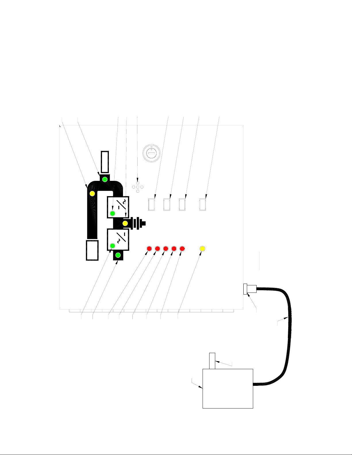
4. OUTPUT TO CRITICAL LOAD (GREEN LED)
5. LOAD ON BYPASS (YELLOW LED)
3. INVERTER ON (GREEN LED)
AUDIBLE ALARM
2. BATTERIES ON (YELLOW LED)
MONITOR RESET PUSHBUTTON
MONITOR TEST PUSHBUTTON
ALARM SILENCE PUSHBUTTON
INTERNAL MONITOR BATTERY TEST PUSHBUTTON
OUTPUT
MONITOR RESET
ALARM SILENCE
MONITOR TEST
INTERNAL MONITOR
BATTERY TEST
FIGURE 1.0
VOLTAGE
INPUT FAILURE
BATTERY LOW
12. INTERNAL MONITOR BATTERY
ALARM SILENCE
OK (YELLOW LED)
INPUT TRANSFORMER
INTERNAL MONITOR
BATTERY OK
INPUT CONFIGURATION
OPTIONS: VARIOUS INPUT CONFIGURATIONS ARE AVAILABLE FOR THE
UPS REMOTE MONITOR. PLEASE CONSULT THE FACTORY ABOUT YOUR
PARTICULAR APPKICATION.
6' CORD
FEMALE MIC PLUG
(SEE OPTIONS)
OVERLOAD
UPS FAULT
INPUT
BYPASS
7. UPS FAULT (RED LED)
8. OVERLOAD (RED LED)
6. AC INPUT ON (GREEN LED)
1. RECTIFIER ON (GREEN LED)
9. INPUT FAILURE (RED LED)
11. ALARM SILENCE (RED LED)
10. BATTERY LOW VOLTAGE (RED LED)
10/13/04 4 93120-MAN07
Page 6
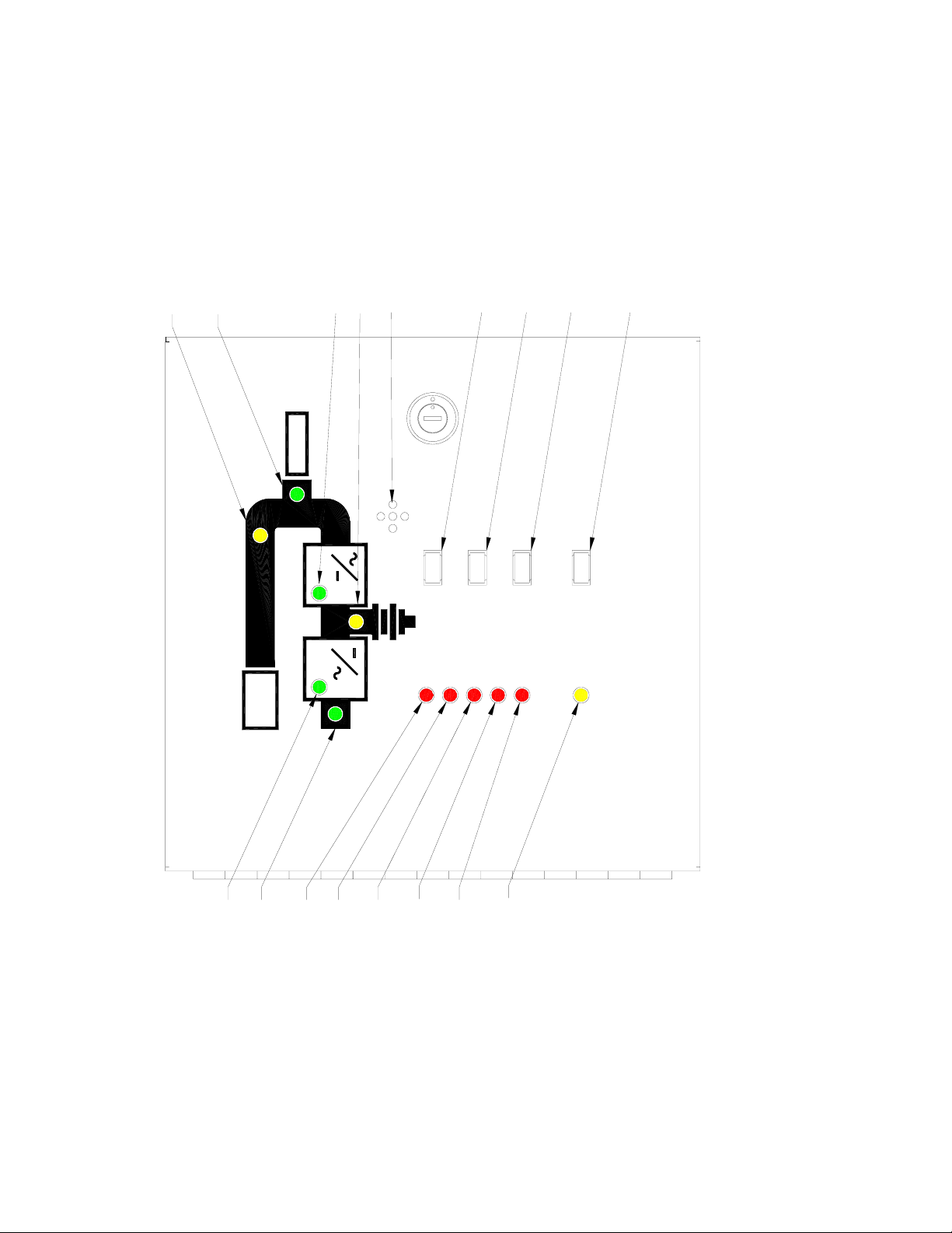
4. OUTPUT TO CRITICAL LOAD (GREEN LED)
5. LOAD ON BYPASS (YELLOW LED)
3. INVERTER ON (GREEN LED)
AUDIBLE ALARM
2. BATTERIES ON (YELLOW LED)
MONITOR RESET PUSHBUTTON
MONITOR TEST PUSHBUTTON
ALARM SILENCE PUSHBUTTON
INTERNAL MONITOR BATTERY TEST PUSHBUTTON
OUTPUT
INPUT
BYPASS
MONITOR RESET
UPS FAULT
OVERLOAD
MONITOR TEST
INPUT FAILURE
ALARM SILENCE
INTERNAL MO NITOR
BATTERY TEST
FIGURE 1.1
VOLTAGE
ALARM SILENCE
BATTERY LOW
INTERNAL MONITOR
BATTERY OK
(INTERNAL POWER SUPPLY / HARDWIRE OPTION)
OK (YELLOW LED)
7. UPS FAULT (RED LED)
8. OVERLOAD (RED LED)
6. AC INPUT ON (GREEN LED)
1. RECTIFIER ON (GREEN LED)
9. INPUT FAILURE (RED LED)
11. ALARM SILENCE (RED LED)
12. INTERNAL MONITOR BATTERY
10. BATTERY LOW VOLTAGE (RED LED)
10/13/04 5 93120-MAN07
Page 7

TB1
1
2
3
4
5
6
7
8
9
10
-AC INPUT L1 (OPTION)
-AC INPUT L1 (OPTION)
-BYPASS (CLOSES WHEN ON BYPASS)
-BYPASS COMMON
-INVERTER (CLOSES WHEN INVERTER IS RUNNING)
-INVERTER COMMON
-ON BATTERIES (CLOSES WHEN ON BATTERIES)
-BATTERY COMMON
-RECTIFIER (CLOSES WHEN RECTIFIER IS RUNNING)
-RECTIFIER COMMON
11
12
13
14
15
16
-UPS FAILURE (CLOSES ON UPS FAILURE)
-UPS COMMON
-LOW BATTERY (CLOSES WHEN BATTERIES ARE LOW)
-LOW BATTERY COMMON
-OVERLOAD (CLOSES WHEN IN OVERLOAD)
-OVERLOAD COMMON
TERMINAL BLOCK DESCRIPTION
(LOCATED INSIDE BOX)
FIGURE 2.0
10/13/04 6 93120-MAN07
Page 8

1
-AC LINE INPUT L1
2
3
5
6
7
8
9
10
11
-AC NEUTRAL INPUT
-GROUND
-NOT USED4
-BYPASS
-BYPASS COMMON
-INVERTER (CLOSES WHEN INVERTER IS RUNNING)
-INVERTER COMMON
-ON BATTERIES (CLOSES WHEN ON BATTERIES)
-BATTERY COMMON
-RECTIFIER (CLOSES WHEN RECTIFIER IS RUNNING)
12
13
14
15
16
17
18
-RECTIFIER COMMON
-UPS FAILURE (CLOSES ON UPS FAILURE)
-UPS COMMON
-LOW BATTERY (CLOSES WHEN BATTERIES ARE LOW)
-LOW BATTERY COMMON
-OVERLOAD (CLOSES WHEN IN OVERLOAD)
-OVERLOAD COMMON
TERMINAL BLOCK DESCRIPTION
(LOCATED INSIDE BOX)
FIGURE 2.1
(INTERNAL POWER SUPPLY / HARDWIRE OPTION)
10/13/04 7 93120-MAN07
Page 9

6"
6"
1 AC INPUT L1 (OPTION)
TERMINAL BLOCK
2 AC INPUT L1 (OPTION)
4 BYPASS COMMON
3 BYPASS
6 INVERTER COMMON
5 INVERTER
8 BATTERY COMMON
7 ON BATTERIES
9 RECTIFIER
10 RECTIFIER COMMON
11 UPS FAILURE
12 UPS COMMON
13 LOW BATTERY
14 LOW BATTERY COMMON
15 OVERLOAD
16 OVERLOAD COMMON
.312"Ø MOUNT HOLES
LABELS
FIGURE 3.0
INPUT PLUG
BATTERY
CIRCUIT BOARD
BATTERY HOLDER
ARRANGEMENT
(12 VOLT DC OUTPUT)
INPUT TRANSFORMER
10/13/04 8 93120-MAN07
Page 10

6"
1 AC LINE INPUT L1
2 AC NEUTRAL INPUT
4 NOT USED
3 GROUND
6 BYPASS COMMON
5 BYPASS
7 INVERTER
8 INVERTER COMMON
6"
9 ON BATTERIES
10 BATTERY COMMON
11 RECTIFIER
13 UPS FAILURE
12 RECTIFIER COMMON
15 LOW BATTERY
14 UPS COMMON
16 LOW BATTERY COMMON
17 OVERLOAD
18 OVERLOAD COMMON
.312"Ø MOUNT HOLES
LABELS
FIGURE 3.1
BATTERY
CIRCUIT BOARD
10/13/04 9 93120-MAN07
BATTERY HOLDER
ARRANGEMENT
(INTERNAL POWER SUPPLY / HARDWIRE OPTION)
TERMINAL BLOCKS
Page 11

6.00"
1.00"
6.00"
Ø 0.312 MOUNT HOLES
REAR VIEWFRONT VIEW
KNOCKOUT FOR 1/2" EMT CONDUIT
1.00"
4.00"
TYP. TOP AND BOTTOM.
KNOCKOUT FOR 1/2" EMT CONDUIT
1.50"
1.50"
OUTPUT
1.50"
FIGURE 4
ALARM SILENCE
INTERNAL MONITOR
MONI TOR RESET
MONITOR TEST
BATTERY TEST
TOP VIEW
VOLTAGE
OVERLOAD
UPS FAULT
INPUT
BYPASS
10/13/04 10 93120-MAN07
ALARM SILENCE
BATTERY LO W
INPUT FAILURE
INTERNAL MONITOR
BATTERY OK
Page 12

1
2
3
456
78
Dwg No.
9
U-23026
External Terminal
A
Output Overload
Selectable Item 5
Common
Battery Low
Selectable Item 6
B
C
UPS Failure
Common
Converter Operation
Selectable Item 3
Battery Operat ion
Selectable Item 4
Load on Inverter
Selectable Item 2
Load on Bypass
Selectable Item 1
Strip in UPS
21
16
22
To be programmed by start-up personnel
14
13
19
To be programmed by start-up personnel
20
18
17
Terminal Strip TB1 in
Remote Status Alarm Panel
Output Overload
15
Common
14
Low Battery
13
Common
12
UPS Failure
11
Common
10
Rectifier On
9
Common
8
On Batteries
7
Load on Inverter
5
Common
4
Load on Bypass
3
16 awg twisted pair recommended
Note: TB1 terminals 6 and 16 not shown for clarity. Terminals are
connected internally.
Mitsubishi Electric
D
10/13/04 0 93120-MAN07
Automation, Inc.
Date
Drawn by
Dwg No.
02-15-00
Tom Kobayashi
U-23026
Remote Status Alarm Panel
(RSAP) Interconnect Diagram
2033 A (Analog)
Page
1/1
Page 13

1
2
3
456
78
Dwg No.
9
U-23028
External Terminal
A
Output Overload Output Overload
Battery Low Low Battery
B
C
UPS Failure
Converter Operation Rectifier On
Battery Operat ion On Batteries
Load on Inverter Load on Inverter
Load on Bypass Load on Bypass
Strip in UPS
35
Common Common
34
33
Common Common
30
29
Common Common
28
27
Common Common
26
25
24
Common
22
21
Terminal Strip TB1 in
Remote Status Alarm Panel
15
14
13
12
UPS Failure
11
10
9
8
7
5
Common
4
3
14 awg shielded wire recommended
Note: TB1 terminals 6 and 16 not shown for clarity. Terminals are
connected internally.
D
10/13/04 0 93120-MAN07
Mitsubishi Electric
Automation, Inc.
Date
Drawn by
Dwg No.
03-10-98
Mario Recine
U-23028
Remote Status Alarm Panel
(RSAP) Interconnect Diagram
2033 A DDC
Page
1/1
Page 14

1
2
3
456
78
Dwg No.
9
U-23C012
External Terminal
A
Output Overload
Common
Output Overload
Battery Low
Common
Battery Low Low Battery
B
C
UPS Failure
Common
UPS Failure UPS Failure
Converter Operation
Common
Converter Operation Rectifier On
Battery Operat ion
Common
Battery Operat ion On Batteries
Load on Inverter
Common
Load on Inverter
Strip in UPS
18
17
16
15
6
5
14
13
12
11
8
7
Terminal Strip TB1 in
Remote Status Alarm Panel
Output Overload
16
Common
Output Overload
15
Low Battery
14
Common
13
UPS Failure
12
Common
11
Rectifier On
10
Common
9
On Batteries
8
Common
7
Load on Inverter
6
Common
Load on Inverter
5
Load on Bypass
Common
Load on Bypass Load on Bypass
10
9
16 awg twisted pair recommended
Mitsubishi Electric
D
10/13/04 0 93120-MAN07
Automation, Inc.
Date
Drawn by
Dwg No.
02-15-00
Tom Kobayashi
U-23C012
Load on Bypass
4
Common
3
Remote Status Alarm Panel
(RSAP) Interconnect Diagram
2033 C
Page
1/1
Page 15

1
2
3
456
78
DWG No.
9
U-23D019
External Terminal Strip
A
B
C
TN1(Output) in UPS
Overload Common
Overload
Battery Low
Voltage Common
Battery Low
Voltage
Total Alarm
Common
Total Alarm
Converter (Rectifier)
Operation Common
Converter (Rectifier)
Operation
Battery Operat ion
Common
Battery Operat ion
Load on Inverter
Common
Load on Inverter
26
25
22
21
38
37
18
17
14
13
10
9
Terminal Strip TB1 in
Remote Status Alarm Panel
Overload Common
16
Overload
15
Low Battery Common
14
Low Battery
13
UPS (Failure) Common
12
UPS Failure
11
Rectifier Common
10
Rectifier
9
On Batteries Common
8
On Batteries
7
Inverter Common
6
Inverter
5
Load on Bypass
Common
Load on Bypass
6
5
14 AWG shielded wire recommended
D
Date
Drawn by
DWG No.
10/13/04 0 93120-MAN07
Mitsubishi Electric
Automation, Inc.
Carl E. Luecht
8/29/03
U-23D019
Bypass Common
4
Bypass
3
Remote Status Alarm Panel
(RSAP) Interconnect Diagram
2033D/9800AD
Rev A
Page
1/1
Page 16

1
2
3
456
78
Dwg No.
9
U-97017
External Terminal
A
Output Overload Output Overload
Battery Low Low Battery
B
C
UPS Failure
Converter Operation Rectifier On
Battery Operat ion On Batteries
Load on Inverter Load on Inverter
Load on Bypass Load on Bypass
Strip in UPS
35
Common Common
34
33
Common Common
30
29
Common Common
28
27
Common Common
26
25
24
Common
22
21
Terminal Strip TB1 in
Remote Status Alarm Panel
15
14
13
12
UPS Failure
11
10
9
8
7
5
Common
4
3
14 awg shielded wire recommended
Note: TB1 terminals 6 and 16 not shown for clarity. Terminals are
connected internally.
D
10/13/04 1 93120-MAN07
Mitsubishi Electric
Automation, Inc.
Date
Drawn by
Dwg No.
10-21-97
Mario Recine
U-97017
Remote Status Alarm Panel
(RSAP) Interconnect Diagram
9700
Page
1/1
Page 17

1
2
3
456
78
Dwg No.
9
U-98015
External Terminal
A
Strip in UPS
Terminal Strip TB1 in
Remote Status Alarm Panel
Output Overload
Common
Output Overload
Battery Low
Common
Battery low
B
C
UPS Failure
Common
UPS Failure
Rectifier Operation
Common
Rectifier
Operation
Battery Operat ion
Common
Battery Operat ion
Load on Inverter
Common
Load on Inverter
Load on Bypass
Common
Load on Bypass
28
27
26
25
16
15
24
23
22
21
20
19
18
17
Output Overload Common
16
Output Overload
15
Low Battery Common
14
Low Battery
13
UPS Failure Common
12
UPS Failure
11
Rectifier On Common
10
Rectifier On
9
On Batteries Common
8
On Batteries
7
Load on Inverter Common
6
Load on Inverter
5
Load on Bypass Common
4
Load on Bypass
3
14 awg shielded wire recommended
D
10/13/04 2 93120-MAN07
Mitsubishi Electric
Automation, Inc.
Date
Drawn by
Dwg No.
07-09-99
Mario Recine
U-98015
Remote Status Alarm Panel
(RSAP) Interconnect Diagram
9800A
Page
1/1
 Loading...