

Page 1

MELSEC FX Series
Programmable Logic Controllers
User's Manual
Communications Modules
RS-232C, RS-485, RS-422
INDUSTRIAL AUTOMATION
MITSUBISHI ELECTRI
C
MIT
SUBIS
HI ELECTRI
C
Art. no.: 070143
15 04 2003
JY992D69901
Version E
Page 2

Foreword
• This manual contains text, diagrams and explanations which will guide the reader in the
correct installation and o peration of the communication facilities of FX seri es. It should be
read and understood before attempting to install or use the unit.
• Further information can be found in the re specti ve manual of each programmab l e control ler.
• If in doubt at any stage of the installation of the communication faciliti es of FX series always
consult a professional electrical engineer wh o is qualified and trained to the local and
national standards that applies to the installation site.
• If in doubt about the operation or use of the communication facilities of FX series please
consult the nearest Mitsubishi Elec tric dis tributor.
• This manual is subject to change without notice.
FX communication
Page 3

i
FX COMMUNICATION
(RS-232C, RS-485, RS-422)
USER’S MANUAL
Brand and product names described by/in this manual are trademarks or registered
trademarks of the irrespective owners.
Manual number : JY992D69901
Manual revision : E
Date : April 2003
FX communication
Page 4

FX communication
ii
Page 5

FAX BACK
Mitsubishi has a world wide reputation f or its eff orts in continually de veloping and pushing back
the frontiers of industrial automation. What is sometimes overlooked by the user is the care
and attention to detail that is taken with the documentation. However, to continue this process
of improvement, the comments of th e Mitsubish i users ar e always welcomed. This pag e has
been designed for you, the reader, to fill in your comments and fax them back to us. We look
forward to hearing from you.
Fax numbers: Your name:...................................................
Mitsubishi Electric.... .....................................................................
America (01) 847-478-2253 Your company:.............................................
Australia (02) 638-7072 .....................................................................
Germany (0 21 02) 4 86-1 12 Your location:................................................
Spain (34) 93-589-1579 .....................................................................
United Kingdom (01707) 278-695
Please tick the box of your choice
What condition did the manual arrive in?
!
Good
!
Minor damage
!
Unusable
Will you be using a f older to store the manual?
!
Yes
!
No
What do you think to the manual presentation?
!
Tidy
!
Unfriendly
Are the explanations understandable?
!
Yes
!
Not too bad
!
Unusable
Which explanation was most difficult to understand:..................................................................
....................................................................................................................................................
Are there any diagrams which are not clear?
!
Yes
!
No
If so,which:..................................................................................................................................
What do you think to the manual layout?
!
Good
!
Not too bad
!
Unhelpful
If there one thing you would li ke to see improved, what is it?.................... .. ............................ ...
....................................................................................................................................................
....................................................................................................................................................
Could you find the information you required easily using the index and/or the conten ts, if
possible please identify your experience: ...................................................................................
....................................................................................................................................................
....................................................................................................................................................
....................................................................................................................................................
....................................................................................................................................................
Do you have any comments in general about the Mitsubishi manuals? ............. ........................
....................................................................................................................................................
....................................................................................................................................................
....................................................................................................................................................
....................................................................................................................................................
Thank you for taking the time to fill out this questionnai re. We hope you found both the product
and this manual easy to use.
FX communication
iii
Page 6

FX communication
iv
Page 7

FX communication
v
Guidelines for the Safety of the User and Protection of the programmable
controllers
This manual provides information for the use of the FX series communication unit. The manual
has been written to be used by trained and competent personnel. The definition of such a
person or persons is as follows;
a) Any engineer who is responsible for the planning, design and construction of automatic
equipment using the product associated w ith this manual should be of a competen t
nature, trained and qualified to the loc al and national sta ndards required to fulfill that
role. These engineers should be fully aware of all aspects of safety with regards to
automated equipment.
b) Any commissioning or service engineer must be of a competent nature, trained and
qualified to the local and national standards require d to fulfill that job. These engineers
should also be trained in the use and maintenance of the completed product. This
includes being completely f amili ar with all ass ociated doc umentation for the said product.
All maintenance should be carried out in accordance with established safety pra ctices.
c) All operators of the completed equipment (see Note) should be trained to use this
product in a safe manner in compliance to established safety practices. The operators
should also be familiar with documentation which is associated with the operation of the
completed equipment.
Note :
Note: the term ‘completed equipment’ refers to a third party constructed device which
contains or uses the product associated with this manual.
Notes on the Symbols Used in this Manual
At various times throughout this manual cer tain symbols will be used t o highlight points of
information which are intended to ensure the users personal safety and protect the integrity of
equipment. Whenever any of the following symbols are encountered its associated note must
be read and understood. Each of the symbols used will no w be listed wi th a brief description of
its meaning.
Hardware Warnings
1) Indicates that the identified danger
WILL
cause physical and prop erty damage.
2) Indicates that the identified danger could
POSSIBLY
cause physical and proper ty
damage.
3) Indicates a point of further interest or further explanation.
Software Warnings
4) Indicates special care must be taken when using this element of software.
5) Indicates a special point which the user of the associate software element should
be aware of.
6) Indicates a point of interest or further explanation.
Page 8

FX communication
vi
• Under no circumstances will Mitsubishi Electric be liable responsible for any consequential
damage that may arise as a result of the installation or use of this equipment.
• All examples and diagrams shown in this manual are intended only as an aid to
understanding the text, not to guarantee operation. Mitsubishi Electric will accept no
responsibility for actual use of the product based on these illustrative examples.
• Please contact a Mitsubishi Electric distributor for more information concerning applications
in life critical situations or high reliability.
Page 9

FX communication
vii
Further Information Manual List
Table 1: Further Information Manual List
Manual name Manual No. Description
FX
1S
Hardware Manual JY992D83901
This manual contains written hardware explanation of
wiring, installation and specification, etc. regarding
the FX
1S
Series programmable controller.
FX
0
/ FX0N Hardware Manual JY992D47501
This manual contains written hardware explanation of
wiring, installation and specification, etc. regarding
the FX
0
and FX0N Series programmable controllers.
FX Hardware Manual JY992D47401
This manual contains written hardware explanation of
wiring, installation and specification, etc. regarding
the FX Series programmable controller.
FX
2C
Supplementary Manual JY992D50201
This manual contains supplementary data regarding
the FX Series programmable controller Hardware
Manual
FX
1N
Hardware Manual JY992D88201
This manual contains written hardware explanation of
wiring, installation and specification, etc. regarding
the FX
1N
Series programmable controller.
FX
2N
Hardware Manual JY992D66301
This manual contains written hardware explanation of
wiring, installation and specification, etc. regarding
the FX
2N
Series programmable controller.
FX
2NC
Hardware Manual JY992D76401
This manual contains written hardware explanation of
wiring, installation and specification, etc. regarding
the FX
2NC
Series programmable controller.
FX Programming Manual JY992D48301
This manual contains written instructions regarding
the FX
0
, FX0S, FX0N, FX, FX2C, FX2N and FX
2NC
Series
programmable controllers.
FX Programming Manual
ΙΙΙΙΙΙΙΙ
JY992D88101
This manual contains written instructions regarding
the FX
1
S
, FX1N, FX2N and FX
2NC
Series
programmable controllers.
FX / FX
0N
-485ADP User’s
Guide
JY992D53201
This manual contains written hardware explanation of
installation and specification regarding the
FX-485ADP and FX
0N
-485ADP.
FX
2NC
-485ADP Installation
Manual
JY997D01201
This manual contains written hardware explanation of
installation and specification regarding the
FX
2NC
-485ADP.
FX-232ADP User’s Guide JY992D48801
This manual contains written hardware explanation of
installation and specification regarding the
FX-232ADP.
FX
0N
-232ADP User’s Guide JY992D51301
This manual contains written hardware explanation of
installation and specification regarding the
FX
0N
-232ADP.
FX
2NC
-232ADP Installation
Manual
JY997D01101
This manual contains written hardware explanation of
installation and specification regarding the
FX
2NC
-232ADP.
FX
2N
-232-BD User’s Guide JY992D66001
This manual contains written hardware explanation of
installation and specification regarding the
FX
2N
-232-BD.
Page 10
FX communication
viii
FX2N-485-BD Hardware
Manual
JY992D73401
This manual contains written hardware explanation of
installation and specification regarding the
FX
2N
-485-BD.
FX
2N
-422-BD User’s Guide JY992D66101
This manual contains written hardware explanation of
installation and specification regarding the
FX
2N
-422-BD.
FX
1N
-232-BD Hardware
Manual
JY992D84501
This manual contains written hardware explanation of
installation and specification regarding the
FX
1N
-232-BD.
FX
1N
-485-BD Hardware
Manual
JY992D84301
This manual contains written hardware explanation of
installation and specification regarding the FX
1N
-485-
BD.
FX
1N
-422-BD User’s Guide JY992D84101
This manual contains written hardware explanation of
installation and specification regarding the
FX
1N
-422-BD.
FX-485-IF Hardware Manual JY992D81801
This manual contains written hardware explanation of
installation and specification regarding the FX-485-IF.
Table 1: Further Information Manual List
Manual name Manual No. Description
Page 11

ix
Table of Contents
Further Informa t ion M a nu a l Li st ...................... ................... .................... ......vii
1. Introduction .............................................................................................1-1
1.1 Abbreviations, Generic Names and Terms Used in This Manual..........................1-1
1.2 Communication Types...........................................................................................1-2
1.3 System Configuration ............................................................................................1-3
1.3.1 N:N Network .................. ....... ...... ....... ...... ....... ...... ....... ...... ...... ....... ...... ....... ...... .......................1-3
1.3.2 Parallel Link ....................................... ...... ....... ...... ....... ...... ...... ....... ...... ....... .............................1-3
1.3.3 Computer Link.......... ...... ....... ...... .................................................... ..........................................1-5
1.3.4 No Protocol Communication ............. ...... ....... ...... ....... ...... .......................................................1-6
1.4 Supported Functions and Applicable Versions .....................................................1-6
2. Specifications..........................................................................................2-1
2.1 Communication Specification................................................................................2-1
2.2 Communication Time.............................................................................................2-2
2.2.1 N:N network ............................................................................ ....... ..........................................2-2
2.2.2 Parallel link .............. ...... ....... ...... ....... .......................................................................................2-2
2.2.3 Computer link........................ ...... ....... ...... ....... ...... .................................................... ................2-3
3. Wiring......................................................................................................3-1
3.1 Caution on cable selection................................. .... ..... .......................................... .3-2
3.1.1 FX1N-485-BD, FX2N-485-BD, FX
2NC
-485ADP..........................................................................3-2
3.1.2 FX
0N
-485ADP .......................................................................................................................... 3-2
3.1.3 FX
2
-40AW.................................................................................................................................3-2
3.2 Using RS-232C Interface.......................................................................................3-3
3.2.1 Using RS Instruction or Computer Link.....................................................................................3-3
3.2.2 Using FX
2N
-232IF.....................................................................................................................3-4
3.3 Using RS-485 Interface.........................................................................................3-6
3.3.1 Wiring Selection.............................................. ...... ....... ...... ...... .................................................3-6
3.3.2 Terminal Resistor........................ ....... ...... .................................................... ...... ....... ................3-6
3.3.3 One-pair Wiring ................................. ...... ....... ...... ....... .............................................................3-7
3.3.4 Two-pair Wiring ................................. ...... ....... ...... ....... ...... ...... ....... ...... ....... ...... ....... . ...............3-8
3.4 Parallel Link...........................................................................................................3-9
3.4.1 FX
2N(1N)
-485-BD and FX0N-485ADP........................................................................................3-9
3.4.2 FX
0N
-485ADP and FX0N-485ADP ..........................................................................................3-10
3.4.3 FX
2N(1N)
-485-BD and FX
2N(1N)
-485-BD .................................................................................3-11
3.4.4 FX
2NC
-485ADP and FX0N-485ADP........................................................................................3-12
3.4.5 FX
2N(1N)
-485-BD and FX
2NC
-485ADP....................................................................................3-13
3.4.6 FX
2NC
-485ADP and FX
2NC
-485ADP......................................................................................3-14
3.4.7 FX
2
-40AW and FX2-40AW ............................. ............. ............ ............. ............. ............. ........ 3-15
3.4.8 FX
2
-40AP and FX2-40AP ............................... ................... ................... .................... ..............3-15
4. N:N Network............................................................................................4-1
4.1 Related Flags and Data Registers.........................................................................4-1
4.1.1 Auxiliary Relays .......................................................................................... .............................4-1
4.1.2 Data Registers ..................... ...... ....... ...... ....... ...... ....... ...... ...... ....... ...... ....... ...... ....... ................4-2
FX communication
Page 12

FX communication
x
4.2 Setting....................................................................................................................4-3
4.2.1 Setting the Station No. (D8176)................................................................................................4-3
4.2.2 Setting the Total Number of Slave Stations (D8177) ...............................................................4-3
4.2.3 Setting the Refresh Range (D8178)..........................................................................................4-4
4.2.4 Setting Retry Count (D8179).....................................................................................................4-5
4.2.5 Setting Comms Time-out (D8180) ............................................................................................4-5
4.2.6 Program Used for Setting ........................................................................................................4-6
4.3 Example Program..................................................................................................4-7
4.3.1 System Configuration .... ....... ...... ....... ...... ....... ...... ....... ...... ...... ....... ...... ....... ...... .......................4-7
4.3.2 Operations ............................ ...... ....... ...... ....... ...... ....... ...... ...... ....... ...... ....... .............................4-7
4.3.3 Example of Setting Program.....................................................................................................4-8
4.3.4 Example of Error Program .......................................................................................................4-8
4.3.5 Example of Operation Program ................................................................................................4-9
5. Parallel link..............................................................................................5-1
5.1 Related Flags and Data Registers ........................................................................5-1
5.2 Mode and Link Device...........................................................................................5-2
5.2.1 Normal Mode (Special auxiliary relay M8162: OFF) ................................................................5-2
5.2.2 High Speed Mode (Special auxiliary relay M8162: ON) ...........................................................5-3
5.3 Example Program..................................................................................................5-4
5.3.1 Normal Mode ..................................... ................................................... ....................................5-4
5.3.2 High Speed Mode .....................................................................................................................5-4
6. Communication format (D8120)....................................... .......................6-1
6.1 What Is Communication Format? ..........................................................................6-1
6.2 Related Flags and Data Registers.........................................................................6-1
6.2.1 Special Auxiliary Relays ........................................................................................................... 6-1
6.2.2 Special Data Registers ............................................................................................................6-1
6.3 Communication Format (D8120) ..........................................................................6-2
6.4 Example of setting program...................................................................................6-3
7. Computer Link.........................................................................................7-1
7.1 Data Flow by Link..................................................................................................7-1
7.2 Information Needed Before Programming.............................................................7-3
7.2.1 Programmable Controller Operation.........................................................................................7-3
7.2.2 Computer Notes................................. ................................................... ....................................7-3
7.3 How to Read a Control Protocol Diagram..............................................................7-4
7.4 Basic Formats of Dedicated Protocol ....................................................................7-5
7.4.1 Control Protocol Format 1 ........................................................................................................7-6
7.4.2 Control Protocol Format 4.........................................................................................................7-7
7.4.3 Control Protocol Parts Explained..............................................................................................7-8
7.4.4 Time-out Check Time..............................................................................................................7-11
7.5 Communication Timing Chart..............................................................................7-12
7.5.1 Reading Data from Programmable controller .........................................................................7-12
7.5.2 Writing Data to Programmable Controller............................................................................... 7-12
7.5.3 Communication Time...................................... ................................................... .....................7-13
7.6 Character Area Data Transmission.....................................................................7-14
7.6.1 Bit Device Memory..................................................................................................................7-14
7.6.2 Word Device Memory .............................................................................................................7-15
7.7 Commands and Device Ranges..........................................................................7-16
7.7.1 Commands........ ....... ...... ....... ...... ....... ...... .................................................... ...... .....................7-16
7.7.2 Device specification ranges....................................................................................................7-17
7.8 Example Computer Program for Loopback Test .................................................7-18
Page 13

FX communication
xi
8. Commands.............. ........................................................................ ........8-1
8.1 Batch Read of Bit Device (BR command)..............................................................8-2
8.2 Batch Read of Word Device (WR command)........................................................8-3
8.3 Batch Write of Bit Device (BW command).............................................................8-5
8.4 Batch Write of Word Device (WW command)........................................................8-6
8.5 Test of Bit Device (BT command)..........................................................................8-8
8.6 Test of Word Device (WT command) ....................................................................8-9
8.7 Remote RUN/STOP (RR, RS commands) ..........................................................8-10
8.7.1 Operation of Remote RUN/STOP...........................................................................................8-10
8.7.2 Conditions for Valid Execution of Remote RUN/STOP...........................................................8-10
8.7.3 Control Specification and Examples of Remote RUN/STOP..................................................8-11
8.8 Reading The Programmable Controller Type (PC command).............................8-12
8.8.1 Type Codes .......................... ...... ....... ...... ....... ...... ....... ...... ...... ....... ...... ....... ...... ....... ..............8-12
8.8.2 Control Specification and Example.........................................................................................8-13
8.9 Global Function (GW command).........................................................................8-14
8.9.1 Control Specification and Example of Global Function...........................................................8-14
8.10 On-demand Function.........................................................................................8-15
8.10.1 Special Devices Used in On-demand Function ....................................................................8-15
8.10.2 On-demand Control Protocol................................................................................................8-16
8.10.3 Specification and Example of On-demand............................................................................ 8-18
8.11 Loopback Test...................................................................................................8-21
9. RS instruction..........................................................................................9-1
9.1 Function and Operation.........................................................................................9-1
9.1.1 Send and Receive Program......................................................................................................9-1
9.1.2 Operation of RS Instruction.......................................................................................................9-3
9.1.3 Related Flags and Data Registers............................................................................................9-4
9.2 Hardware Hand Shake Operation..........................................................................9-6
9.2.1 FX, FX2C, FX
0N,
FX1S, FX1N and FX
2N
(earlier than V 2.00)....................................................9-6
9.2.2 FX
2N
, FX
2NC
(V 2.00 or later) .................................................................................................9-10
9.3 Number of Communication Data.........................................................................9-13
9.3.1 Deal with 16 bits Data............................................................................................................. 9-13
9.3.2 Deal with 8 bits Data............................................................................................................... 9-14
9.4 Example Program................................................................................................9-15
9.4.1 Personal Computer......................................... ...... ....... ...... ...... ....... ........................................9-15
9.4.2 Printer ......................................... ....... ...... ....... ...... ..................................................................9-17
10. FX2N-232IF..........................................................................................10-1
10.1 Introduction........................................................................................................10-1
10.1.1 Outline of Product.................................................................................................................10-1
10.2 Allocation of Buffer Memories (BFM’s) ..............................................................10-2
10.2.1 BFM List ................................... ....... ...... ....... ...... ....... ...... ...... ....... ...... ....... ...... .....................10-2
10.2.2 Communication Format <BFM#0> .......................................................................................10-4
10.2.3 Command
〈
BFM #1
〉 .................................................................................................. 10−8
10.2.4 Receive Upper Limit Byte Count 〈BFM #2
〉 ................................................................... 10−9
10.2.5 Receive Time-out Time <BFM #3>.......................................................................................10-9
10.2.6 Send Header <BFM #5 (upper), BFM #4 (lower)>................................................................10-9
10.2.7 Send Terminator <BFM #7 (upper), BFM #6 (lower)> ..........................................................10-9
10.2.8 Receive Header <BFM #9 (upper), BFM #8 (lower)>.........................................................10-10
10.2.9 Receive Terminator <BFM #11 (upper), BFM #10 (lower)>................................................10-10
10.2.10 Receive Suspension Waiting Time <BFM #12> ...............................................................10-10
10.2.11 Number of Remaining Send Data <BFM #13> .................................................................10-11
10.2.12 Number of Receive Buffers <BFM #14>........................ ...... ....... ...... ....... ...... ....... ...... ...... 10-11
Page 14

FX communication
xii
10.2.13 Send Sum Result <BFM #15>..........................................................................................10-11
10.2.14 Receive Sum Result <BFM #16>......................................................................................10-11
10.2.15 Time from CS ON to Send Start <BFM #20>....................................................................10-12
10.2.16 Time from Completion of Actual Send to RS OFF (completion flag ON) <BFM #21> ......10-12
10.2.17 Status <BFM #28> ...........................................................................................................10-13
10.2.18 Error Code <BFM #29>.....................................................................................................10-14
10.2.19 Model Code <BFM #30>...................................................................................................10-14
10.2.20 Send Byte Count <BFM #1000>....................................................................................... 10-14
10.2.21 Send Buffers <BFMs #1001 to #1256>.............................................................................10-14
10.2.22 Receive Byte Count <BFM #2000> ..................................................................................10-15
10.2.23 Receive Buffers <BFM #2001 to #2256>................................................. ...... ....... ...... ...... 10-15
10.2.24 Spare Receive Buffers for Interlink Connection Mode <BFM #2257 to #2271> ...............10-15
10.3 Hardware Hand Shake Operation....................................................................10-16
10.3.1 No Hardware Hand Shake..................................................................................................10-16
10.3.2 Standard RS-232C Mode....................................................................................................10-17
10.3.3 Interlink Mode .................................. ...... ....... ...... ....... .............................................. ...........10-18
10.4 Example Program............................................................................................10-19
10.4.1 Example of 16 Bits Data Communication ...........................................................................10-19
10.4.2 Example of 8 Bits Data Communication .......................... ...... ....... ...... ................................10-23
11. Optional Pr o g r amming Port..... ............................................................11-1
11.1 FX2N-422-BD, FX1N-422-BD............................................................................11-1
11.2 FX2N-232-BD FX1N-232-BD FX0N-232ADP and FX2NC-232ADP .................11-2
11.2.1 Connection cables ........................... ...... ....... ...... ....... ...... .....................................................11-2
11.3 Cautions on Use................................................................................................11-3
11.3.1 Cautions on Setting...............................................................................................................11-3
11.3.2 Cautions on use ................................................................................................................... 11-3
12. Diagnostics.................. .. .................... ................... ................... .. ..........12-1
12.1 Common Items..................................................................................................12-1
12.2 N:N Network ......................................................................................................12-2
12.2.1 Error Code ............................................. ....... ...... ....... ...... ...... ....... ...... ..................................12-2
12.2.2 Diagnostics ............................................................................ ....... ........................................12-2
12.3 Parallel Link.......................................................................................................12-3
12.3.1 Diagnostics ............................................................................ ....... ........................................12-3
12.4 Computer Link ...................................................................................................12-4
12.4.1 NAK Error Code....................................................................................................................12-4
12.4.2 Programmable Controller Error Code ...................................................................................12-4
12.4.3 Diagnostics ............................................................................ ....... ........................................12-5
12.5 RS Instruction....................................................................................................12-6
12.5.1 Diagnostics ............................................................................ ....... ........................................12-6
12.6 FX2N-232IF ........................................................................................................12-7
12.6.1 Error code.................... ....... ...... ....... ...... ....... ...... ....... ...... ...... ....... ........................................12-7
12.6.2 Diagnostics ............................................................................ ....... ........................................12-7
12.7 Using Optional Programming Port.....................................................................12-8
12.7.1 FX1S, FX1N and FX
2N(C)
earlier V2.00.......... ...... ....... ...... ...... ....... ...... ....... ...........................12-8
12.7.2 FX
2N
, FX
2NC
whose version is V 2.00 or later......................................................................12-8
Appendix A:
ASCII code Lists................................................................................................... A-1
Page 15

FX communication
Introduction 1
1-1
1
1. Introduction
1.1 Abbreviations, Generi c Names and Terms Used in This
Manual
Abbreviation List
This manual describes the following product in the new name.
Abbreviation/generic name/term Description
CPU
FX
1S
Series Generic name of FX1S Series main units
FX
0N
Series Generic name of FX0N Series main units
FX
1N
Series Generic name of FX1N Series main units
FX Series Generic name of FX Series main units
FX
2
Series Generic name of FX2 Series main units
FX
2N
Series Generic name of FX2N Series main units
FX
2C
Series Generic name of FX2C Series main units
FX
2NC
Series Generic name of FX
2NC
Series main units
FXCPU
Generic name of FX
0
/FX0S/FX1S/FX0N/FX1N/FX1/FX/FX2/FX2N/FX2C/
FX
2NC
Series main units
Others
FX/WIN Abbreviation of programming software FX-PCS/WIN-E for FX Series PLC
Windows95 Abbreviation of Microsoft Windows95
Windows98 Abbreviation of Microsoft Windows98
Windows NT4.0 Abbreviation of Microsoft Windows NT Workstation 4.0
Windows 2000 Abbreviation of Microsoft Windows 2000 Professional
Windows
Generic name of Windows95, Windows98, Windows NT4.0 and
Windows2000
Personal computer (PC)
Personal computer compatible with Windows to which GX Developer or FXPCS/WIN-E is installed
Conventional name New name Remarks
GPPW GX Developer Abbreviation of software package SW"D5C-GPPW-E
Page 16

FX communication
Introduction 1
1-2
1.2 Communication Types
The FX Series supports the following 5 types of communication.
1 ) N:N network
Data transfer with FX
2N
, FX
2NC
, FX1N, FX1S, FX0N programmable controllers can be
performed on a N:N basis. They can link data of a small-scale system if using this network.
For the system configuration please refer to subsection 1.2.1, specifications refer to chapter
3, wiring refer to chapter 2, settings and the number of transferred data and example
program refer to chapter 4,diagnostics refer to chapter 12.
2 ) Parallel link
Data transfer with FX
2N
, FX
2NC
, FX1N, FX and FX2C programmable controllers can be
performed on a 1:1 bas is for 100 auxiliar y relays and 10 data reg isters. With the FX
1S
and
FX
0N
data transfer is performed for 50 auxiliary relays and 10 data registers.
For the system configuration please refer to subsection 1.2.2, specifications refer to chapter
3, wiring refer to chapter 2, setting and example program refer to chapter 5, diagnostics refer
to chapter 12.
3 ) Computer link (Data transfer using dedicated protocol)
Data transfer with RS-485 (RS-422) units can be performed on a 1:n (16) basis using
dedicated protocol.
For the system configuration please refer to subsection 1.2.3, specifications refer to chapter
3, wiring refer to chapter 2, setting of communication format refer to chapter 6, dedicated
protocol refer to chapter 7 & 8, diagnostics refer to chapter 12.
4 ) No protocol communication (Data transfer using RS instruction)
Data communication with a diversified RS-232C unit including personal computers, bar code
readers and printers can be performed using no protocol communications.
This communication uses RS instruction’s or an FX
2N
-232IF special function block.
For the system configuration please refer to subsection 1.2.3, specifications refer to chapter
3, wiring refer to chapter 2, setting of communication format, RS ins truction and example
program refer to chapter 6 and 9, diagnostics refer to chapter 12.
When using the RS ins tructio n, for setting the communicatio n format refer to chapter 6, for
the RS instruction and example program please refer to chapter 9. Or when using an FX
2N
-
232IF, for setting and example progr am please refer to chapter 10.
5 ) Optional programming port
The port can support programming protocol, if connected to an FX
2N
-232-BD, FX0N-232ADP,
FX
2NC
-232ADP, FX1N-232-BD, FX2N-422-BD and FX1N-422-BD for the FX2N, FX
2NC
, FX1N,
FX
1S
Series programmable controller.
For notes on use, refer to chapter 11, diagnostics refer to chapter 12.
Page 17
FX communication
Introduction 1
1-3
1
1.3 System Configuration
For programming protocol refer to chapter 11.
1.3.1 N:N Network
1.3.2 Parallel Link
1 ) FX
2N
, FX
2NC
(Shielded twisted-pair cable)
Note:
*1 When including an FX
2N
-485-BD in the system confi gur at ion, thai s , total extension distance
has a max of 50m (164' 0").
FX Series PLC Interface
FX
0N
, FX
2NC
FX0N-485ADP
FX
2NC
-485ADP
FX
1S
, FX
1N
FX1N-CNV-BD + FX0N-485ADP
FX
1N
-CNV-BD + FX
2NC
-485ADP
FX
1N
-485-BD
FX
2N
FX2N-CNV-BD + FX0N-485ADP
FX
2N
-CNV-BD + FX
2NC
-485ADP
FX
2N
-485-BD
####, $$$$
Using interface Extension distance
FX
2N
FX2N-485-BD Max. 50m (164' 0")
FX
2N
-CNV-BD + FX0N-485ADP
Max. 500m (1640' 5")
*1
FX2N-CNV-BD + FX
2NC
-485ADP
FX
2NC
FX0N-485ADP
FX
2NC
-485ADP
RS-485
communication
equipment
RS-485
communication
equipment
RS-485
communication
equipment
RS-485
communication
equipment
RS-485
communication
equipment
FX PLC FX PLC FX PLC FX PLC FX PLC
Up to eight FX series programmable controllers can be connected.
The total extension distance is 500m(1640' 5") when only the FX
0N
-485ADP and FX
2NC
-485ADP
are used in the configuration, and 50m(164' 0") when the FX1N-485-BD and FX2N-485-BD are used.
① ②
Page 18
FX communication
Introduction 1
1-4
2 ) FX1N (Shielded twisted-pair cabl e)
*2 When including an FX
1N
-485-BD in the system configuration, thais, total extension distanc e
has a max of 50m
(164' 0")
.
3 ) FX
1S
(Shielded twisted-pair cable)
*3 When including an FX
1N
-485-BD in the system configuration, thais, total extension distanc e
has a max of 50m
(164' 0")
.
4 ) FX
0N
(Shielded twisted-pair cabl e)
5 ) FX, FX
2C
(Shielded twisted-pair cable and glassfiber cable)
Note;
Parallel link is only possible between the same series of PLC’s, or between other
series in th e same group. However, parallel link between each group cannot be
achieved.
Group’s are separated as follows.
####, $$$$
Using interface Extension distance
FX
1N
FX1N-485-BD Max. 50m (164' 0")
FX
1N
-CNV-BD + FX0N-485ADP
Max. 500m (1640' 5")
*2
FX1N-CNV-BD + FX
2NC
-485ADP
####, $$$$
Using interface Extension distance
FX
1S
FX1N-485-BD Max. 50m (164' 0")
FX
1N
-CNV-BD + FX0N-485ADP
Max. 500m (1640' 5")
*3
FX1N-CNV-BD + FX
2NC
-485ADP
####, $$$$
Using interface Extension distance
FX
0N
FX0N-485ADP
Max. 500m (1640' 5")
FX
2NC
-485ADP
####, $$$$
Using interface Extension distance
FX
2
, FX
2C
FX2-40AW (Shielded twisted-pair cable) Max. 10m (32' 9")
FX
2
-40AP (Glassfiber cable) Max. 50m (164' 0")
Group No. Series
Group 1 FX
2N
, FX
2NC
Group 2 FX
1N
Group 3 FX
1S
Group 4 FX
0N
Group 5 FX, FX
2C
Page 19
FX communication
Introduction 1
1-5
1
1.3.3 Computer Link
1 ) In the case of 1:N connection using RS-485 (RS-422)
2 ) In the case of 1:1 connection using RS-232C
Up to sixteen FX series programmable controllers can be connected.
The total extension distance is 500m(1640' 5") when only the FX0N-485ADP and FX
2NC
-485ADP are used
in the configuration, and 50m(164' 0") when the FX1N-485-BD and FX2N-485-BD are used.
FX0N,FX
2NC
FX2N + FX2N-CNV-BD,
FX
1S
+ FX1N-CNV-BD,
FX
1N
+ FX1N-CNV-BD
FX
2NC
-485ADP,
FX0N-485ADP
FX2,
FX
2C
FX-485ADP
A series PLC +
A
(1S)
J71UC24
FX
2N
+ FX2N-485-BD,
FX
1S
+ FX1N-485-BD,
FX
1N
+ FX1N-485-BD
Computer
RS-232C
FX-485PC-IF
RS-485(RS-422)
Total extension distance is 15m(49' 2").
Computer
FX
2N
FX
2NC
,FX
0N
FX1N,FX
1S
FX2,FX
2C
:FX2N-232-BD
FX2N-CNV-BD+FX0N-232ADP
FX2N-CNV-BD+FX
2NC
-232ADP
:FX
0N
-232ADP
FX
2NC
-232ADP
:FX1N-232-BD,
FX1N-CNV-BD+FX0N-232ADP
FX1N-CNV-BD+FX
2NC
-232ADP
:FX-232ADP
%
%
%
%
Page 20
FX communication
Introduction 1
1-6
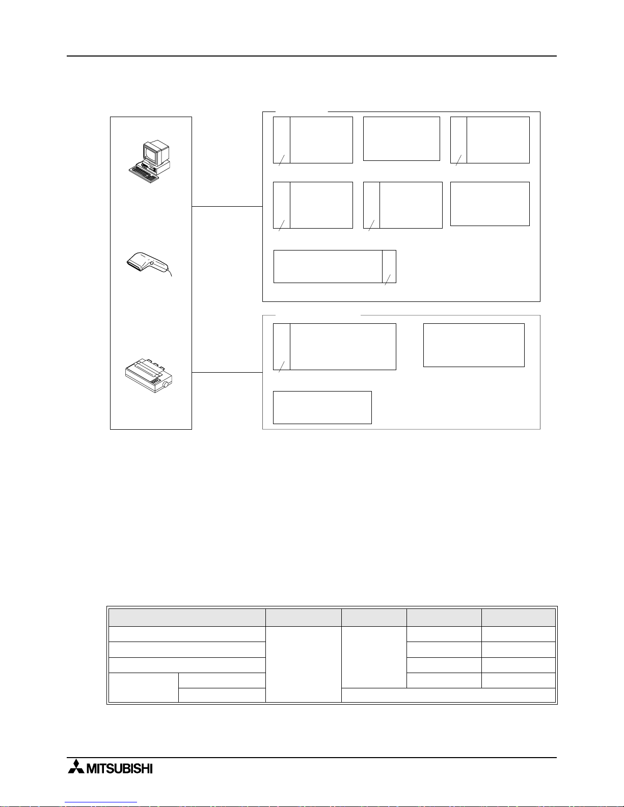
1.3.4 No Protocol Communication
*1 The RS-485/RS-232C signal co nvertor is necessary in the case of an R S-485 interface for a
computer connection.
*2 When using an FX
1N
-485-BD a FX2N-485-BD in a s ystem the total extension distance has a
max of 50m(164' 0").
But, RS-485/RS-232C signal convertor is necessary in the case of an RS-232C interface for a
computer connection.
*3 This system configuration can achieve full-duplex or half-duplex communication.
*4 This system configuration can only achieve half-duplex communication.
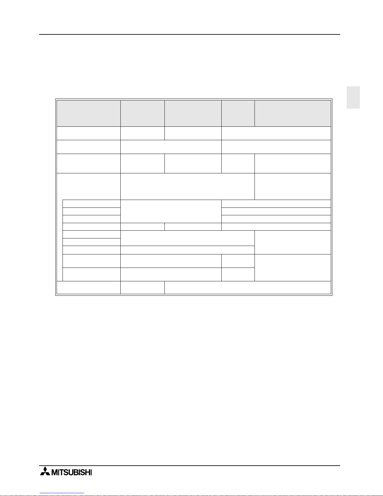
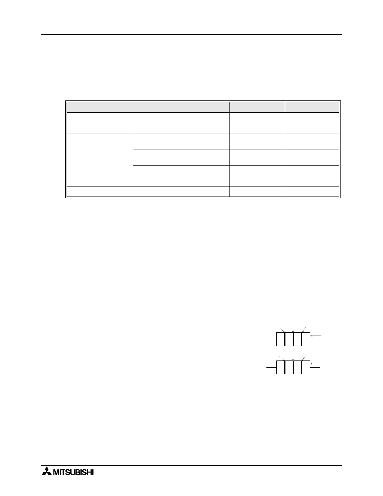
1.4 Supported Functio n s and Applicable Versions
Items
FX
2N
,
FX
2NC
FX1N, FX
1S
FX
0N
FX, FX
2C
N:N network
All versions
All versions
V2.00 or more No support
Parallel link All versions All versions
Computer link V1.20 or more V3.30 or more
No protocol
communication
Use RS instruction All versions V3.00 or more
Use FX
2N
-232IF Not supported.
FX
2N
+
FX2N-CNV-BD
FX, FX
2C
FX
2N
+
FX2N-232-BD
FX0N-232ADP,FX
2NC
-232ADP
RS-232C
FX2N + FX2N-CNV-BD
FX1N + FX1N-CNV-BD
FX1S + FX1N-CNV-BD
FX0N, FX
2NC
FX2N + FX2N-485-BD
FX-232ADP
FX0N-485ADP,FX
2NC
-485ADP
Max
15m(49' 2") *1
Max 500m
(1640' 5") *2
*3
*4
*3
FX
0N
FX1N +
FX1N-CNV-BD
FX1S +
FX1N-CNV-BD
FX0N-232ADP,FX
2NC
-232ADP
*4
*4 *3
Personal computer
Bar code reader
Printer
FX
2NC
FX0N-232ADP,FX
2NC
-232ADP
*3
FX1N + FX1N-485-BD
FX1S + FX1N-485-BD
*4
%
%
%
FX
1N
+
FX1N-232-BD
FX1S +
FX1N-232-BD
*4
%
%
%
%
%
%
%
%
FX2N,
FX
2NC
+ FX
2NC
-CNV-IF
FX2N-232IF
RS-485(RS-422)
Page 21
FX communication
Specifications 2
2-1
2
2. Specifications
2.1 Communication Specification
*1 FX2N, FX
2NC
, FX1N, FX1S and FX0N PLCs are supported.
*2 When using an FX
0N
-485ADP or FX
2NC
-485ADP, this system is only half-duplex.
N:N network Parallel lin k
Computer
link
(dedicated
protocol)
No protocol commu nica tion
Transmission standard
Conforming to
RS-485
Conforming to RS-485
and RS-422
Conforming to RS-485 and RS-422 or
RS-232C
Transmission distance Max. 500m
RS-485(RS-422): Max. 500m(1640' 5")
RS-232C: Max. 15m (49' 2")
Number of stations Max. 8 stations 1:1
1:N
(N is Max. 16
stations
RS-232C:1:1
RS-485:1:N
*1
Communication method Half-duplex comm un ic ati on
FX, FX2C, FX0N, FX1N, FX1S:
half-duplex communication
FX2N, FX
2NC
*2
: full-duplex
communication
Data length
Fixed
7 bit / 8 bit
Parity None / Odd / Even
Stop bit 1 bit / 2bit
Baud rate (bps) 38,400 19,200 300/600/1,200/2,400/4,800/9,600/19,200
Header character
Fixed
None / effective
Terminator character
Control line
Protocol
Format 1 /
Format 4
None
Sum check Fixed
None /
effective
Supported programmab le
controller
FX
2N
, FX
2NC
,
FX
1N
, FX1S, FX
0N
FX2N, FX
2NC
, FX1N, FX1S, FX0N, FX, FX
2C
Page 22
FX communication
Specification 2
2-2
2.2 Communicatio n Ti m e
2.2.1 N:N network
Note;
If a N:N network is used, the scan time of each station programmable controller
becomes about 10 percent longer regar dless of the number of link s tations or the
communication device pattern used.
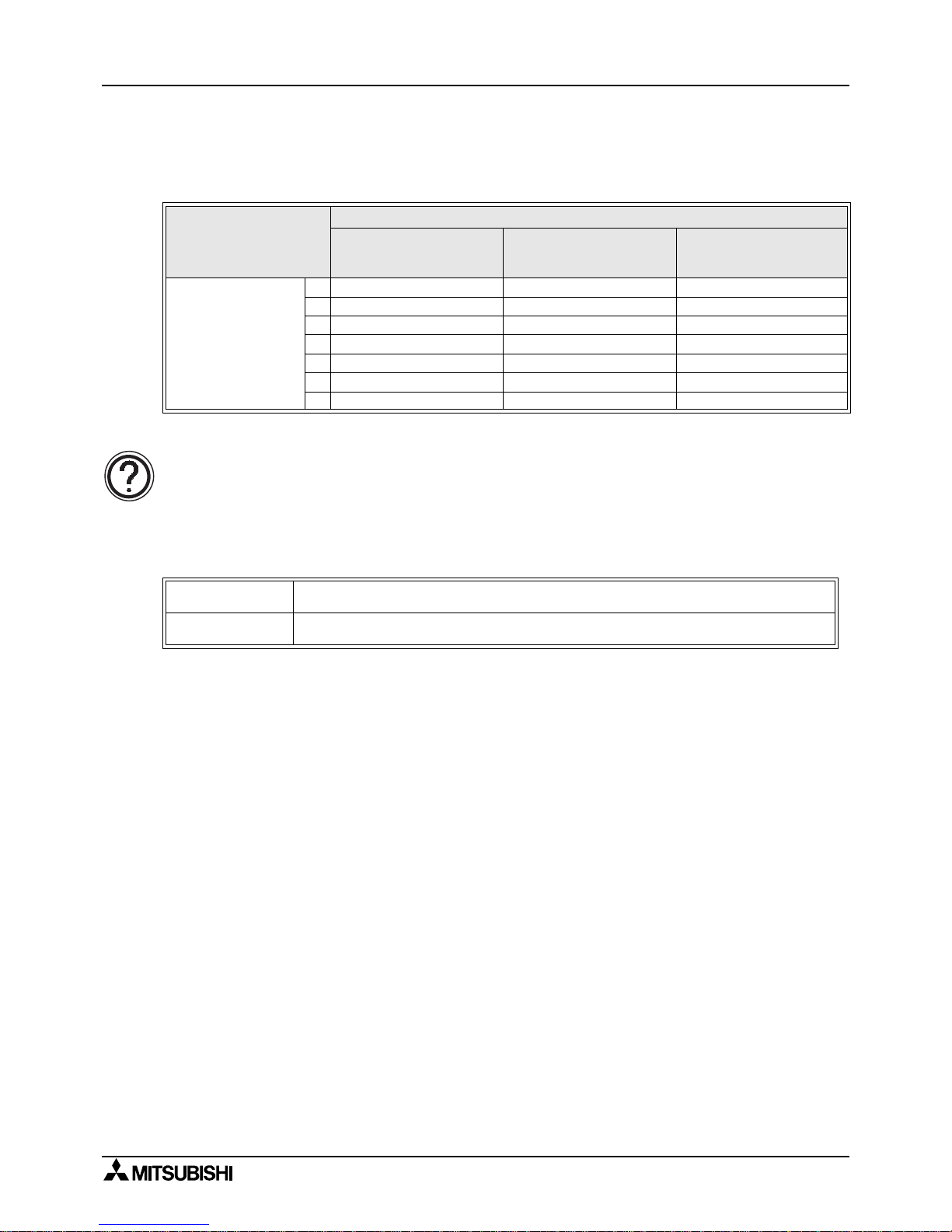
2.2.2 Parallel link
Communication de vice
Pattern 0
Bit device: 0 point
Word device: 4 points
Pattern 1
Bit device: 32 points
Word device: 4 points
Pattern 2
Bit device: 64 points
Word device: 8 points
Total station number
2 18 22 34
3 26 32 50
4 33 42 66
5 41 52 83
6 49 62 99
7 57 72 115
8 65 82 131
Normal Mode
70ms for reciprocation + Operation cycle of master station
+ Operation cycle of slave station (ms)
High speed mode
20ms for reciprocation + Operation cycle of master station
+ Operation cycle of slave station (ms)
Page 23
FX communication
Specifications 2
2-3
2
2.2.3 Computer link
Calculations to determine the approximate time until communication is complete.
1 ) Programmable controller
→
Computer
Communication time = Total number of characters based on dedicated protocol
*1
×
Time to send or receive one character (ms)*2
+ Programmable controller’s maximum scan time (ms)
×
3
+ Message wait (ms)
2 ) Computer
→
Programmable controller
Communication time = Number of total characters based on dedicated protocol
*1
×
Time to send or receive one character (ms)*2
+ Programmable controller’s maximum scan time (ms)
+ Message wait (ms)
Note:
*1 Please count the number of characters with ref erence section 7.4.1 and 7.4.2 and chapter 8.
*2 Please refer to the following expression for time calculati on.
Time to send or receive one character = 1/baud rate
×
number of bits in character
(start bit(1) + Data length(7 or 8) + Parity bit(0 or 1) + Stop bit(1 or 2))
Example
When 1 character = 10 bits (Data length = 7, Parity bit = 1, stop bit = 1 start bit = 1),
the time is as follows.
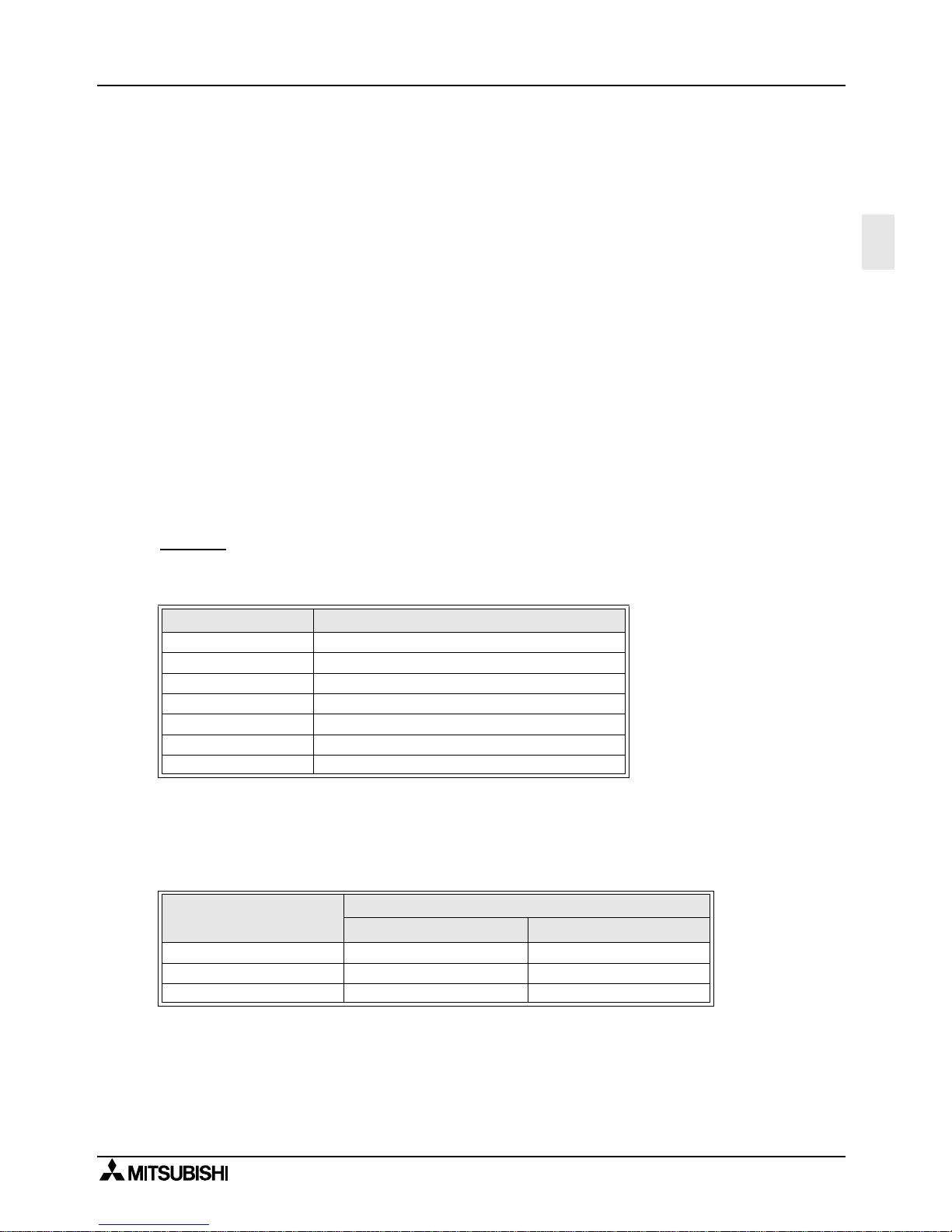
Note;
Please refer to following table fo r the relation between read ing word points and com munication
time.
“Message time = 0ms, Maximum scan time = 20ms, Dedicated protocol format = format 1,
Command = WR, Baud rate = 9,600 or 19,200 bps”
Baud rate (bps) Time to send or receive one character (ms)
300 33.34
600 16.67
1200 8.34
2400 4.17
4800 2.08
9600 1.04
19200 0.52
Reading word points
Baud rate (bps)
9,600 19,200
10 0.3 s 0.2 s
32 0.4 s 0.3 s
64 0.5 s 0.4 s
Page 24

FX communication
Specification 2
2-4
MEMO
Page 25

FX communication
Wiring 3
3-1
3
3. Wiring
Terminal layout when using a communication unit, please refer to the individual units manual.
Common
1 ) This system is designed to read and write data (forced on/off) while the programmable
controller is running.
If abnormal data is written to the programmable controller, due to effects of noise, the
programmable controller may malfunction and cause machine trouble or a n accident.
Therefore, observe the following cautions.
• Do not lay signal cables near high voltage power cables or put them in the same trunking
duct.
Otherwise effect s of noise or surge induction are likely to take place. Keep a safe distance
of more than 100 mm (3.94") from these wires.
• Ground the shield wire or shield of a shielded cable at one poi nt on the programmable
controller. Do not, however, ground at the same point as high voltage lines.
2 ) Cut off phases of power source externally, before installation or wiring work in order to avoid
electric shock or serious damage to the product.
3 ) Replace the provided terminal cover before supplying power and operating the unit after
installation or wiring work in order to avoid electric shock.
Page 26
FX communication
Wiring 3
3-2
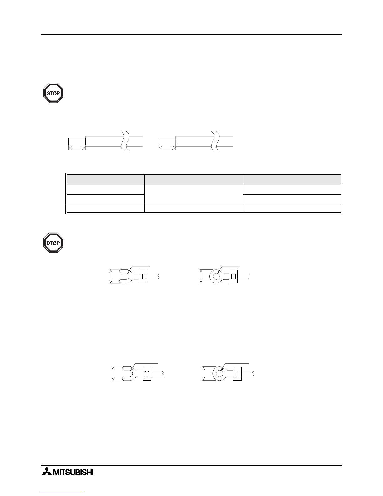
3.1 Caution on cable selection
3.1.1 FX1N-485-BD, FX2N-485-BD, FX
2NC
-485ADP
Number of cables connected to terminal and their specification
3.1.2 FX
0N
-485ADP
3.1.3 FX
2
-40AW
1 ) The terminal screws for the terminal bl oc k of the FX
2
-40A W are M3.5 s crews, theref ore crimp
style terminal (see drawing) suitable for use with these screws should be fitted to th e cable
for wiring.
2 ) The ter minal tightening torque is 0.5 to 0.8 N⋅m (5 to 8 kgf⋅cm), tighten securely to avoid
malfunction.
FX1N-485-BD, FX2N-485-BD FX
2NC
-485ADP
When connecting 1 cable
AWG26-16
AWG26-16
When connecting 2 cables AWG26-20
Tightening torque 0.6N%m 0.4 to 0.5N%m
6mm(0.23")
FX
1N
-485-BD,FX2N-485-BD
8mm(0.32")
FX
2NC
-485ADP
To connect the RS-485(RS-422) unit, use a shielded twist-pair cable. The cable model must be
A WG 26 to 16, and the maximum tightening tor que must be 0.6 N%m (6 kgf%cm). If a cable other
than the AWG 26 to 16 is used, normal communication cannot be assured as the terminal may
be imperfectly contacted. It is recommended to insert a cable integrated by a crimping tool into
the terminal.
For M3
6.2mm
(0.24 inches)
or less
6.2mm
(0.24 inches)
or less
For M3
1 ) The terminal screws of the FX
(0N)
-485ADP are M3 screws, therefore, crimp style terminal
(see drawing) suitable for use with these screws should be fitted to the cable for wiring.
2 ) The terminal tightening torque is 0.5 to 0.8 N⋅m (5 to 8 kgf⋅cm), tighte n securely to avoid
malfunction.
For M3.5
6.8mm
(0.27 inches)
or less
6.8mm
(0.27 inches)
or less
For M3.5
Page 27
FX communication
Wiring 3
3-3
3
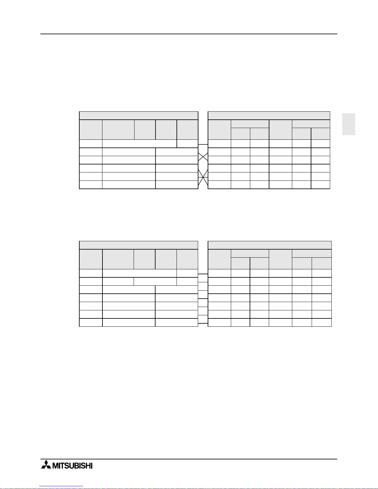
3.2 Using RS-232C Interface
Below is a typical wiring example. Please wire similar to the following pin name, when a pin
number on the side of a counterpart machine differs.
3.2.1 Using RS Instruction or Computer Link
1 ) Terminal specification device
Note;
When using ER and DR signals, please also chec k if RS and CS signals are needed according to
the RS-232C device specifications.
2 ) Modem specification device
Note;
The FX
0N
-232ADP and FX
2NC
-232ADP does not monitor the CD pin (pin8).
3 ) Computer link
Please refer to 2.2.1 1) for wiring.
RS-232C Device Side
Signal
name
FG
RD(RXD)
SD(TXD)
RSRTS)
SG(GND)
CS(CTS)
Uses CS, RS
2
3
7
5
8
9-pin
D-SUB
25-pin
D-SUB
1
3
2
4
7
5
Uses DR, ER
9-pin D-
SUB
25-pin
D-SUB
2
3
4
5
6
1
3
2
20
7
6
Signal
name
FG
RD(RXD)
SD(TXD)
ER(DTR)
SG(GND)
DR(DSR)
Programmable Controller Side
Signal
name
FX0N-
232ADP
FX-
232ADP
- 1
RD(RXD)
SD(TXD)
FG
ER(DTR)
SG(GND)
DR(DSR)
FX2N-232-BD
FX
1N
-232-BD
2
3
4
5
6
3
2
20
7
6
FX
2NC
-
232ADP
Programmable Controller Side
FX
2NC
-
232ADP
FX-
232ADP
- 1
RS-232C Device Side
Uses CS, RS Uses DR, ER
- 8
Signal
name
FG
RD(RXD)
SD(TXD)
ER(DTR)
SG(GND)
DR(DSR)
CD(DCD)
FX2N-232-BD
FX
1N
-232-BD
1
FX0N-
232ADP
3
2
20
7
6
Signal
name
FG
RD(RXD)
SD(TXD)
RS(RTS)
SG(GND)
CS(CTS)
CD(DCD)
-
2
3
7
5
8
9-pin
D-SUB
1
25-pin
D-SUB
1
3
2
4
7
5
8
Signal
name
FG
RD(RXD)
SD(TXD)
ER(DTR)
SG(GND)
DR(DSR)
FG
9-pin
D-SUB
-
2
3
4
5
6
1
25-pin
D-SUB
1
3
2
20
7
6
8
2
3
4
5
6
Page 28
FX communication
Wiring 3
3-4
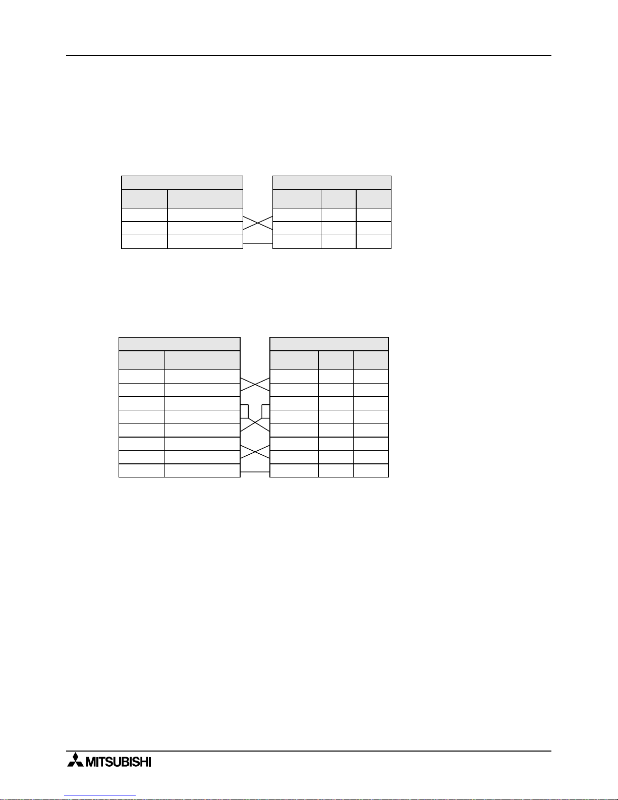
3.2.2 Using FX2N-232IF
The signal wiring o f the RS-232C equipmen t varies depending on the RS-232C connection
specifications. Check the specifications of the RS-232C equipment used, then connect the
signals correctly. Representative wiring examples are shown below.
1 ) Terminal specification device (No control line)
Setting communication format (BFM #0); b9=0, b8=0
Communication is performed in
accordance with the condition
determined by the software in
the FX
2N
-232IF and the
counterpart equipment.
2 ) Terminal specification device (Use control line)
a ) Standard RS-232C mode (Use cross cable)
Setting communication format (BFM #0); b9=0, b8=1
As the carrier to send (CS)
signal pin of the FX
2N
-232IF
itself receives the request to
send (RS) signal, signal tr ansfer
is performed as if the
counterpart equipment is
functioning.
Note:
*1 When the CD signal is not monitored, the CD signal pin is not required to be connected.
With regard to the CD signal, the FX
2N
-232IF only indicates the status.
*2 The FX
2N
-232IF only indicates the status.
Programm able Controller Side
Signal
name
RD (RXD)
SD (TXD)
SG (GND)
FX2N-232IF
2
3
5
RS-232C D evice Side
Signal
name
RD (RXD)
SD (TXD)
SG (GND)
2
3
5
9-pin
D-SUB
25-pin
D-SUB
3
2
7
Programm able Controller Side
Signal
name
RD (RXD)
SD (TXD)
RS (RTS)
FX2N-232IF
2
3
7
RS-232C D evice Side
Signal
name
2
3
7
9-pin
D-SUB
25-pin
D-SUB
3
2
4
CD (DCD)
CS (CTS)
ER (DTR)
1
8
4
1
8
4
8
5
20
6
5
6
7
DR (DTR)
SG (GND)
6
5
RD (RXD)
SD (TXD)
RS (RTS)
CD (DCD)
CS (CTS)
ER (DTR)
DR (DTR)
SG (GND)
*1 *1
*2 *2
Page 29

FX communication
Wiring 3
3-5
3
b ) Interlink connection mode (Use interlink serial cross cable)
Setting connection format (BFM #0); b9=1, b8=1
In the interlink connection
mode, data exceeding 512
bytes (upper limit of the receive
buff er in the FX
2N
-232IF) can be
received.
Note:
*1 The FX
2N
-232IF only indicates the status.
*2 In this mode, the request to send (RS) signal func tions as the signal to enable receive in
the FX
2N
-232IF.
When receiving data exceeding 512 bytes, the FX
2N
-232IF sets the request to send (RS)
signal to “OFF” and requests the counterpart equipment to suspend the send operation.
When the data saved in the receive buffers is read by the sequence program, the
remaining data can be receiv ed.
3 ) Modem specification device
Standard RS-232C mode (Using straight cable)
Setting communication format (BFM #0); b9=0, b8=1
Note:
*1 The FX
2N
-232IF indicates the status exclusively.
*2 When the CD signal is not monitored, the CD signal pin is not required to be connected.
With regard to the CD signal, the FX
2N
-232IF indicates the status exclusively.
*3 When the CI signal is not required, the CI signal pi n is not required to the connected. With
regard to the CI signal, the FX
2N
-232IF indicates the status exclusively.
Programm able Controller Side
Signal
name
RD (RXD)
SD (TXD)
RS (RTS)
FX2N-232IF
2
3
7
RS-232C D evice Side
Signal
name
2
3
7
9-pin
D-SUB
25-pin
D-SUB
3
2
4
CS (CTS)
ER (DTR)
8
4
8
4
5
20
6
5
6
7
DR (DTR)
SG (GND)
6
5
RD (RXD)
SD (TXD)
RS (RTS)
CS (CTS)
ER (DTR)
DR (DTR)
SG (GND)
*1 *1
*2 *2
Programm able Controller Side
Signal
name
RD (RXD)
SD (TXD)
RS (RTS)
FX2N-232IF
2
3
7
RS-232C D evice Side
Signal
name
2
3
7
9-pin
D-SUB
25-pin
D-SUB
3
2
4
CD (DCD)
CS (CTS)
ER (DTR)
1
8
4
1
8
4
8
5
20
6
5
6
7
DR (DTR)
SG (GND)
6
5
RD (RXD)
SD (TXD)
RS (RTS)
CD (DCD)
CS (CTS)
ER (DTR)
DR (DTR)
SG (GND)
*1 *1
*2 *2
9 22C I (R I) 9 CI (RI)
*3 *3
Page 30
FX communication
Wiring 3
3-6
3.3 Using RS-485 Interface
3.3.1 Wiring Selection
The wiring of RS-485 can either be one-pair or two-pair. The wiring method is decided according
to application usage. Please select the wiring method from the table below.
&
…
Recommendation,
'
…
OK, ×…Cannot use
Note:
*1 When this product is added to the system, please match the wir ing to the existing method of
the system.
*2 When using an FX
2N
-485-BD with this wiring method, remember to take account of/or ignore
the “echo” of the commands sent from the FX
2N
programmable contr oller.
*3 Please use the FX
2N
programmable cont roller and FX2N-485-BD together.
Full-duplex combination cannot be achieved with other configurations.
*4 For wiring parallel link, see section 2.4.
3.3.2 T erminal Resistor
A terminal resistor must be used at both ends of the communication line as described in section
2.3.3 and 2.3.4.
Usage One-pair wiring Two-pair wiring
No protocol
(Use RS instruction) *1
Half-duplex communication
&
*2
'
Full-duplex communication *3
×
'
Dedicated protocol
(Use computer link)*1
It is necessary to set the message
wait time to 70 ms or less.
×
'
It is not necessary to set the
massage wait time to 70 ms or less.
&
*2
'
Use the on-demand function
×
'
Parallel link *4
&
'
N:N network
'
×
Orange Orange Brown
Brown Brown Brown
330
Ω
1/4 W
110
Ω
1/2 W
1 )In the case of two-pair wiring, connect the terminal resistor
(330
Ω
, 1/4W) between terminals SDA and SDB and between
terminals RDA and RDB. Use the resistors offered as
accessories with the product.
2 )In the case of one-pair wiring, connect the terminal resistor
(110
Ω
, 1/2W) between terminals RDA and RDB. Use the
resistors offered as accessories with the product.
Page 31

FX communication
Wiring 3
3-7
3
3.3.3 One-pair Wiring
Note:
*1 R is a terminating resistor (110Ω)
*2 Make sure to connect the shield of the appropriate cable with the FX
2N
-485-BD, FX1N-485-BD
or FX
2NC
-485ADP to ground that has a resistance of 100Ω or less (Class D grounding).
*3 Make sure to connect the terminal FG to the ground terminal of a programmable
controller grounded with resistance of 100Ω or less (Class D grounding).
However, for a computer link unit of the A series programmable controller, see the manual of
the computer link unit.
*4 When using an RS-232C/485 converter, use the FX-485PC-IF.
Have in mind that "echo" occurs on the RS-232C side if one-pair wiring is performed using the
FX-485PC-IF.
*5 In the case of FX
2NC
-485ADP
Class D grounding
R*1
SDA
SDB
RDA
RDB
SDA
SDB
RDA
RDB
SDA
SDB
RDA
RDB
LINK
SG
*3
FG
SDA
SDB
RDA
RDB
SG
*3
FG
R*1
RS-485 unit *4
SG
*2
SG
(NC)*5
FX
2NC
-485ADP
FX
1N
-485-BD,FX2N-485-BD
FX
A series programmable
(0N)
-485ADP
controller's computer link unit
Station
No. 0
Station
No. 1
Station
No. 15
Page 32

FX communication
Wiring 3
3-8
3.3.4 Two-pair Wiring
Note:
*1 R is a terminating resistor (330Ω)
*2 Make sure to connect the shield of the appropriate cable with the FX
2N
-485-BD, FX1N-485-BD
or FX
2NC
-485ADP to ground that has a resistance of 100Ω or less (Class D grounding).
*3 Make sure to connect the terminal FG to the ground terminal of a programmable
controller grounded with resistance of 100Ω or less (Class D grounding).
However, for a computer link unit of the A series programmable controller, see the manual of
the computer link unit.
*4 When using an RS-232C/485 converter, use the FX-485PC-IF.
*5 In the case of FX
2NC
-485ADP
Class D grounding
R*1
R*1
SDA
SG
SG
*3
FG
Station
No. 1
Station
No. 0
SG
*3
FG
Station
No. 15
R*1
R*1
RS-422/RS-485 unit *4
SG
*2
(NC)*5
FX
2NC
-485ADP
FX
1N
-485-BD,FX2N-485-BD
FX
A series programmable
(0N)
-485ADP
controller's computer link unit
SDB
RDA
RDB
SDA
SDB
RDA
RDB
SDA
SDB
RDA
RDB
LINK
SDA
SDB
RDA
RDB
Page 33

FX communication
Wiring 3
3-9
3
3.4 Parallel Link
3.4.1 FX
2N(1N)
-485-BD and FX0N-485ADP
1 ) One-pair Wiring
Note:
*1 Connect the terminal FG to the ground terminal of a programmable controller grounded
with a resistance of 100Ω or less (Class D grounding). If the programmable controller is
not equipped with a ground terminal, con nect the terminal FG dir ectly to a gr ound with the
resistance of 100Ω or less (Class D grounding).
2 ) Two-pair Wiring
Note:
*1 Connect the terminal FG to the ground terminal of a programmable controller grounded
with a resistance of 100Ω or less (Class D grounding). If the programmable controller is
not equipped with a ground terminal, con nect the terminal FG dir ectly to a gr ound with the
resistance of 100Ω or less (Class D grounding).
RDB
RDA
SDA
SDB
SDA
FX
2N
-485-BD
FX
1N
-485-BD
Terminating
resistor
110
Ω
FX0N-485ADP
Terminating
registor
110
Ω
RDA
RDB
SG
SDB
LINK
SG
FG *1
RDB
RDA
SDA
SDB
SDA
FX
2N
-485-BD
FX
1N
-485-BD
Terminating
resistor
330
Ω
FX0N-485ADP
Terminating
resistor
330
Ω
RDA
RDB
SG
SDB
LINK
SG
FG *1
Terminating
resistor
330
Ω
Terminating
resistor
330
Ω
Page 34

FX communication
Wiring 3
3-10
3.4.2 FX0N-485ADP and FX0N-485ADP
1 ) One-pair Wiring
Note:
*1 Connect the terminal FG to the ground terminal of a programmable controller grounded
with a resistance of 100Ω or less (Class D grounding). If the programmable controller is
not equipped with a ground terminal, con nect the terminal FG dir ectly to a gr ound with the
resistance of 100Ω or less (Class D grounding).
2 ) Two-pair Wiring
Note:
*1 Connect the terminal FG to the ground terminal of a programmable controller grounded
with a resistance of 100Ω or less (Class D grounding). If the programmable controller is
not equipped with a ground terminal, con nect the terminal FG dir ectly to a gr ound with the
resistance of 100Ω or less (Class D grounding).
RDB
RDA
SDA
SDB
SDA
Terminating
resistor
110
Ω
FX0N-485ADP
Terminating
resistor
110
Ω
RDA
RDB
LINK
SG
SDB
LINK
SG
FG *1FG
FX
0N
-485ADP
RDB
RDA
SDA
SDB
SDA
FX
0N
-485ADP
Terminating
resistor
330
Ω
FX0N-485ADP
Terminating
resistor
330
Ω
RDA
RDB
LINK
SG
SDB
LINK
SG
FG *1FG
Terminating
resistor
330
Ω
Terminating
resistor
330
Ω
Page 35

FX communication
Wiring 3
3-11
3
3.4.3 FX
2N(1N)
-485-BD and FX
2N(1N)
-485-BD
1 ) One-pair Wiring
2 ) Two-pair Wiring
RDB
RDA
SDA
SDB
SDA
Terminating
resistor
110
Ω
Terminating
resistor
110
Ω
RDA
RDB
SG
SDB
SG
FX2N-485-BD,
FX
1N
-485-BD
Class D grounding
FX
2N
-485-BD,
FX
1N
-485-BD
RDB
RDA
SDA
SDB
SDA
Terminating
resistor
330
Ω
Terminating
resistor
330
Ω
RDA
RDB
SG
SDB
SG
Terminating
resistor
330
Ω
Terminating
resistor
330
Ω
Class D grounding
FX
2N
-485-BD,
FX
1N
-485-BD
FX
2N
-485-BD,
FX
1N
-485-BD
Page 36

FX communication
Wiring 3
3-12
3.4.4 FX
2NC
-485ADP and FX0N-485ADP
1 ) One-pair Wiring
Note:
*1 Connect the terminal FG to the ground terminal of a programmable controller grounded
with a resistance of 100Ω or less (Class D grounding). If the programmable controller is
not equipped with a ground terminal, con nect the terminal FG dir ectly to a gr ound with the
resistance of 100Ω or less (Class D grounding).
2 ) Two-pair Wiring
Note:
*1 Connect the terminal FG to the ground terminal of a programmable controller grounded
with a resistance of 100Ω or less (Class D grounding). If the programmable controller is
not equipped with a ground terminal, con nect the terminal FG dir ectly to a gr ound with the
resistance of 100Ω or less (Class D grounding).
SDB
SDA
RDA
SDA
SDB
RDA
RDB RDB
LINK
SG
FG
*1
FX0N-485ADP
FX
2NC
-485ADP
SG
Terminating
resistor
110
Ω
Terminating
resistor
110
Ω
SDB
SDA
RDA
SDA
SDB
RDA
RDB
SG
RDB
LINK
SG
FG
*1
FX0N-485ADP
FX
2NC
-485ADP
Terminating
resistor
330
Ω
Terminating
resistor
330
Ω
Terminating
resistor
330
Ω
Terminating
resistor
330
Ω
Page 37

FX communication
Wiring 3
3-13
3
3.4.5 FX
2N(1N)
-485-BD and FX
2NC
-485ADP
1 ) One-pair Wiring
2 ) Two-pair Wiring
SDB
SDA
RDA
SDA
SDB
RDA
RDB
SG
RDB
SG
FX2N-485-BD,
FX
1N
-485-BD
Class D grounding
FX
2NC
-485ADP
Terminating
resistor
110
Ω
Terminating
resistor
110
Ω
SDB
SDA
RDA
SDA
SDB
RDA
RDB
SG
RDB
SG
FX
2N
-485-BD,
FX
1N
-485-BD
Class D grounding
FX
2NC
-485ADP
Terminating
resistor
330
Ω
Terminating
resistor
330
Ω
Terminating
resistor
330
Ω
Terminating
resistor
330
Ω
Page 38

FX communication
Wiring 3
3-14
3.4.6 FX
2NC
-485ADP and FX
2NC
-485ADP
1 ) One-pair Wiring
2 ) Two-pair Wiring
SDB
SDA
RDA
SDA
SDB
RDA
RDB
SG
RDB
SG
Class D grounding
FX
2NC
-485ADPFX
2NC
-485ADP
Terminating
resistor
110
Ω
Terminating
resistor
110
Ω
SDB
SDA
RDA
SDA
SDB
RDA
RDB
SG
RDB
SG
FX
2NC
-485ADP
Class D grounding
FX
2NC
-485ADP
Terminating
resistor
330
Ω
Terminating
resistor
330
Ω
Terminating
resistor
330
Ω
Terminating
resistor
330
Ω
Page 39

FX communication
Wiring 3
3-15
3
3.4.7 FX2-40AW and FX2-40AW
3.4.8 FX
2
-40AP and FX2-40AP
SB
SASA
SB
SG
*1
SG
*1
FX2-40AW FX2-40AW
Note:
*1 Connect the terminal SG to the terminal SG of
the basic unit.
Two SG terminals are connected to each other
internally.
R
TT
R
FX
2
-40AP FX2-40AP
Note:
• " " indicates an optical connector. Keep optical connectors away from cabling
carrying high loads.
Output terminals (Y000 to Y003) located near optical connectors must have light
loads connector.
Page 40

FX communication
Wiring 3
3-16
MEMO
Page 41

FX communication
N:N network 4
4-1
4
4. N:N Network
For diagnostics, please refer to chapter 12 .
4.1 Related Flags and Data Registers
4.1.1 Auxiliary Relays
R : Read only W : Write only M : Master station L : Slave station
Note:
*1 The number of communication errors that have occurred in each station cannot be counted in
the CPU error status, the program error status or the stop status.
*2 Number in accordance with the slave station No.
Example: FX
0N
, FX
1S
……………
Slave station No.1 is M505, Slave station No.2 is M506,
~ Slav e station No.7 is M511.
FX
2N
, FX2N, FX
1N
……
Slave station No.1 is M8184, Slave station No.2 is M8185,
~ Slave station No.7 is M8190.
Attribute
Auxiliary relays
Name Description
Response
type
FX0N,
FX
1S
FX1N, FX2N,
FX
2NC
R M8038
N:N network
parameter setting
Used to set N:N network
parameters
M, L
R M504 M8183
Communication error of
master station
ON when communication error
occurs in the master station.
*1
L
R
M505 to
M511
*2
M8184 to
M8190
*2
Communication error of
slave station
ON when communication error
occurs in the slave station.
*1
M, L
R M503 M8191 Data communication
ON when communicating to
another station.
M, L
Note:
• Devices M503 to M511 in the FX
0N
and FX1S cannot be used in the program.
These devices are used by the N:N network.
Page 42

FX communication
N:N network 4
4-2
4.1.2 Data Registers
R : Read only W : Write only M : Master station L : Slave station
*1 The number of communication errors oc curred in its own station cannot be counte d in the
CPU error status, the program error status or the stop status.
*2 Number (Same meaning but looks better.) in accordance with the sla ve station No.
Slave station No.1 is D204, D212, slave station No.2 is D205, D213,
…
slave station No.7 is D210, D218.
*3 Number (Same meaning but looks better.) in accordance with the sla ve station No.
Slave station No.1 is D8204, D8212, slave station No.2 is D8205, D8213,
…
slave station No.7 is D8210, D8218.
Attribute
Data Registers
Name Description
Response
type
FX0N,
FX
1S
FX1N, FX2N,
FX
2NC
R D8173 Station No. Saves its own station No. M, L
R D8174
Total number of slave
stations
Saves total number of
slav e stations
M, L
R D8175 Refresh range Saves refresh range M, L
W D8176 Station number setting Sets its own station No. M, L
W D8177
Total slave station number
setting
Sets total number of
slav e stations
M
W D8178 Refresh range setting Sets refresh range M
W/R D8179 Retry count setting Sets retry count M
W/R D8180 Comms time-out setting Sets comms time-out M
R D201 D8201 Current network scan time
Saves current network
scan time
M, L
R D202 D8202
Maximum network scan
time
Saves maximum network
scan time
M, L
R D203 D8203
Number of communication
error at master station
Number of
communication error at
master station *1
L
R
D204 to
D210 *2
D8204 to
D8210 *3
Number of communication
error at slave station
Number of
communication error at
slav e station *1
M, L
R D211 D8211
Code of communication
error at master station
Code of communication
error at master station *1
L
R
D212 to
D218 *2
D8212 to
D8218 *3
Code of communication
error at slave station
Code of communication
error at slave station *1
M, L
D219 to
D255
Not used For internal processing
Note;
• Devices M503-M511 and D201-D255 in the FX
0N
and FX1S cannot be used in the
program. These devices are used by the N:N network.
Page 43

FX communication
N:N network 4
4-3
4
4.2 Setting
N:N settings beco me valid when the program is r un or when the power of the programmable
controller is turned ON.
4.2.1 Setting the Station No. (D8176)
Set a value 0 to 7 to the special data register D8176.
4.2.2 Setting the Total Number of Slave Stations (D8177)
Set value Description
0 Master station
1 to 7
Slave station No.
Example: 1 is slave station No.1, 2 is slave station No.2
Set a value 1 to 7 to the special data register D8177. (Default = 7)
This setting is not required for the slave station.
Set value Description
1
1 slave station
2
2 slave stations
:
:
7
7 slave stations
Page 44

FX communication
N:N network 4
4-4
4.2.3 Setting the Refresh Range (D8178)
Set a value 0 to 2 to the special data register D8178. (Default = 0)
This setting is not required for the slave station.
The devices used in each pattern are occupied b y all the stations for the N:N network.
1 ) In the case of pattern 0 (FX
0N
, FX1S, FX1N, FX2N, FX
2NC
)
Communication
device
Refresh range
Pattern 0
(FX
0N
, FX1S, FX1N,
FX
2N
, FX
2NC
)
Pattern 1
(FX
1N
, FX2N, FX
2NC
)
Pattern 2
(FX
1N
, FX2N, FX
2NC
)
Bit device (M) 0 point 32 points 64 points
Word device (D) 4 points 4 points 8 points
Station No.
Device No.
Bit device (M) Word device (D)
0 point 4 points
No.0
D0 to D3
No.1
D10 to D13
No.2
D20 to D23
No.3
D30 to D33
No.4
D40 to D43
No.5
D50 to D53
No,6
D60 to D63
No.7
D70 to D73
Note;
• Please set the refresh range to patt ern 0. When setting it other t han pat tern 0, all FX
0N
and FX1S series units in the system experience a communications error.
In this case, please note that link time becomes as long as the FX
0N
and FX
1S
communication error is occurring.
Page 45

FX communication
N:N network 4
4-5
4
2 ) In the case of pattern 1 (FX1N, FX2N, FX
2NC
)
3 ) In the case of pattern 2 (FX
1N
, FX2N, FX
2NC
)
4.2.4 Setting Retry Count (D8179)
Set a value 0 to 10 to the special data register D8178. (Default = 3)
This setting is not required for the slave station.
If a master station tries to communicate with the slave station at this retry count (or over),
communication error occur in the station.
4.2.5 Setting Comms Time-out (D8180)
Set value 5 to 255 to the special dat a register D8179. (Default = 5)
This value multiplied by 10(ms) is duration of the comms time-out.
Comms time-out is the communication dwell time between the master station and slave station.
Station No.
Device No.
Bit device (M) Word device (D)
32 points 4 points
No.0 M1000 to M1031 D0 to D3
No.1 M1064 to M1095 D10 to D13
No.2 M1128 to M1159 D20 to D23
No.3 M1192 to M1223 D30 to D33
No.4 M1256 to M1287 D40 to D43
No.5 M1320 to M1351 D50 to D53
No.6 M1384 to M1415 D60 to D63
No.7 M1448 to M1479 D70 to D73
Station No.
Device No.
Bit device (M) Word device (D)
64 points 8 points
No.0 M1000 to M1063 D0 to D7
No.1 M1064 to M1127 D10 to D17
No.2 M1128 to M1191 D20 to D27
No.3 M1192 to M1255 D30 to D37
No.4 M1256 to M1319 D40 to D47
No.5 M1320 to M1383 D50 to D57
No,6 M1384 to M1447 D60 to D67
No.7 M1448 to M1511 D70 to D77
Page 46

FX communication
N:N network 4
4-6
4.2.6 Program Used for Setting
Make sure to write the program above step 0 as the N:N network parameter setting program.
This program does not require to be executed, because it becomes effective automatically when it
is programmed in this position.
M8038
FNC 12
MOV
K 0 D8176
Station No. setting:
Required for master
station (Set range: 0 to 7)
FNC 12
MOV
K 2 D8177
Total number of slave
stations: 2
(Setting range: 1 to 7)
FNC 12
MOV
K 1 D8178
Refresh range setting:
Pattern 1
(Set range: 1 to 2)
FNC 12
MOV
K 3 D8179
Retry count setting:
3 (3times)
FNC 12
MOV
K 6 D8180
Comms time-out setting:
6 (60ms)
Not required for
slave station
0
Note:
• Setting of the parameters for the N:N network is started at step 0 (LD M8038), and
finished when any instruction or device other than the program above is processed.
Page 47

FX communication
N:N network 4
4-7
4
4.3 Example Program
4.3.1 System Configuration
• Refresh range: 32 bit devices and 4 word devices (Pattern 1)
• Retry count: 3 times
• Comms time-out: 5 (50 ms)
4.3.2 Operations
The following operations are performed in the system configuration above.
1 ) The input points X000 to X003 (M1000 to M1003) in the master station are output to the
output points Y010 to Y013 in the stations Nos.1 and 2.
2 ) The input points X000 to X003 (M1064 to M1067) in the station No.1 are output to the output
points Y014 to Y017 in the master station and the station No.2.
3 ) The input points X000 to X003 (M1128 to M1131) in the station No.2 are output to the output
points Y020 to Y023 in the master station and the station No.1.
4 ) The data register D1 in the master station is specified as the set value of the counter C1 in
the station No.1.
The contact (M1070) status of the counter C1 is reflected on the output point Y005 in the
master station.
5 ) The data register D2 in the master station is specified as the set value of the counter C2 in
the station No.2.
The contact (M1140) status of the counter C2 is reflected on the output point Y006 in the
master station.
6 ) The value of the data register D10 in the station No.1 and the value of the data register D20
in the station No.2 are added in the master station, and saved to the data register D3.
7 ) The value of the data register D10 in the master station and the value of the data register
D20 in the station No.2 are added in the station No.1, and saved to the data register D11.
8 ) The value of the data register D10 in the master station and the value of the data register
D10 in the station No.1 are added in the station No.2, and saved to the data register D21.
FX
2N
FX
2N
FX2N-485-BD FX2N-485-BD FX2N-485-BD
Master station (No.0) Slave station (No.1) Slave station (No.2)
Page 48

FX communication
N:N network 4
4-8
4.3.3 Example of Setting Program
For the setting program of the master station and the stations Nos.1 and 2, refer to the program
below.
4.3.4 Example of Error Program
* A station cannot recognize its own error. An error program for each station is not necessary.
Master station Slave station No.1 Slave station No.2 Remarks
D8176
K0 K1 K2 Station No.
D8177
K2
Total slave station : 2 stations
D8178
K1
Refresh range : Pattern 1
D8179
K3
Retry count : 3 times (default)
D8180
K5
Comms time-out : 50 ms (default)
Not required for
slave station
M8038
FNC 12
MOV
K 0 D8176
Station No. setting:
Required for master
station (Set range: 0 to 7)
FNC 12
MOV
K 2 D8177
Total number of slave
stations: 2
(Setting range: 1 to 7)
FNC 12
MOV
K 1 D8178
Refresh range setting:
Pattern 1
(Set range: 1 to 2)
FNC 12
MOV
K 3 D8179
Retry count setting:
3 (3times)
FNC 12
MOV
K 5 D8180
Comms time-out setting:
5 (50ms)
0
M8183
Master communication error
Y000
M8184
Slave 1 communication error
Y001
M8185
Slave 2 communication error
Y002
M8191
Data communication
Y003
Continued to a), b) or c) in "4.3.5 Program".
*
*
*
Page 49

FX communication
N:N network 4
4-9
4
4.3.5 Example of Operation Program
a ) Program of master station
Slave 1
communication
error
M8184
Slave 2
communication error
M8185
Contact of slave 2 C2
device
M1140
Y006
Operation 6)
Operation 7), 8)
Operation 5)
Slave 2
communication
error
M8185
END
RUN monitor
M8000
Slave 1
communication error
M8184
Slave 2
communication error
M8185
Slave 1
communication error
M8184
Contact of slave 1 C1
device
M1070
Y005
Operation 1)
Operation 2)
Operation 3)
Operation 4)
D 0
D 2
D 3
K1M1000
K1Y014
K1Y020
D 1
K 10
K 10
K 10
K1X000
K1M1064
K1M1128
K 10
FNC 12
MOV
FNC 12
MOV
FNC 12
MOV
FNC 12
MOV
FNC 12
MOV
FNC 12
MOV
FNC 12
MOV
Page 50

FX communication
N:N network 4
4-10
b ) Program of slave station No.1
Master
communication
error
M8183
K1M1000 K1Y010
Counter reset
Counter input
X000
C 1
RST C 1
K1X000
K1M1064
K1M1128 K1Y020
Slave 2
communication
error
M8185
D 1
C 1
Y005
M1070
Operation 4)
X001
Slave 2
communication
error
Slave 2
communication
error
M8185
K 10
D 10
Contact of
slave 2 C2
device
M1140
Y006
END
D 20 D 11D 0
M8185
Operation 6), 8)
Operation 7)
Operation 1)
Operation 2)
Operation 3)
Operation 5)
FNC 12
MOV
FNC 12
MOV
FNC 12
MOV
FNC 12
MOV
FNC 20
ADD
Page 51

FX communication
N:N network 4
4-11
4
c ) Program of slave station No.2
Master
communication
error
M8183
Counter reset
RST C 2
FNC 12
MOV
FNC 12
MOV
Slave 1
communication
error
M8184
Y005
Contact of
slave 1 C1
device
Slave 1
communication
error
M8184
M1070
FNC 12
MOV
K 10 D 20
Counter input
X000
C 2
END
FNC 20
ADD
D 10 D 21D 0
C 2
Y006
Operation 5)
D 2
M1140
M8184
Slave 1
communication
error
Operation 6), 7)
Operation 4)
Operation 1)
Operation 2)
Operation 3)
X001
K1Y014
K1M1128
FNC 12
MOV
K1Y010
K1M1064
K1X000
K1M1000
Page 52

FX communication
N:N network 4
4-12
MEMO
Page 53

FX communication
Parallel link 5
5-1
5
5. Parallel link
Data transfe r wi th FX2N, FX
2NC
, FX1N, FX, FX2C programmable cont roll ers can be per formed on a
1:1 basis for 100 auxiliary relays and 10 data registers. Data transfer with FX
1S
, FX
0N
programmable controller can be performed on a 1:1 basis for 50 auxiliar y relays and 10 data
registers.
For system configuration, refer to subsectio n 1.2.2.
5.1 Related Flags and Data Registers
Device Operation
M8070 Driven when the programmable controller is a master station in a parallel link.
M8071 Driven when the programmable controller is a slave station in a parallel link.
M8072 ON while the programmable controller is operating in a parallel link.
M8073 ON when M8070/M8071 are incorrectly set during parallel link operations.
M8162 High speed mode for parallel link, 2 data words read/write only.
M8070 Parallel link watchdog time (Default: 500 ms).
Page 54

FX communication
Parallel link 5
5-2
5.2 Mode and Link Device
5.2.1 Normal Mode (Special auxiliary relay M8162: OFF)
Note;
Parallel link is possible between PLC’ s in the same series, or in other series as long as
they are in the group. However, parallel link between each different group cannot be
achieved.
Groups are sepa ra ted as follows.
FX2N, FX
2NC
, FX1N, FX, FX
2C
FX1S, FX
0N
Communication
devices
Master
→→→→ Slave
M800 to M899 (100 points),
D490 to D499 (10 points)
M400 to M449 (50 points),
D230 to D239 (10 points)
Slave
→
→ →
→ Master
M900 to M999 (100 points),
D500 to D509 (10 points)
M450 to M499 (50 points),
D240 to D249 (10 points)
Communication time
70 (ms) + Scan time of master (ms) + Scan time of slave (ms)
Group No. Series
Group 1 FX
2N
, FX
2NC
Group 2 FX
1N
Group 3 FX
1S
Group 4 FX
0N
Group 5 FX, FX
2C
M8000
M8071
D -D
D -D
M -M
M -M
D -D
D -D
M -M
M -M
M8000
Master
Automatic
communication
Slave
M8070
✰✰ ✰✰
Page 55

FX communication
Parallel link 5
5-3
5
5.2.2 High Speed Mode (Special auxiliary relay M8162: ON)
Note;
Parallel link is possible between PLC’ s in the same series, or in other series as long as
they are in the group. However, parallel link between each different group cannot be
achieved.
Groups are sepa ra ted as follows.
FX2N, FX
2NC
, FX1N, FX, FX
2C
FX1S, FX
0N
Communication
devices
Master
→→→→ Slave
D490, D491 (2 points) D230, D231 (2 points)
Slave
→
→ →
→ Master
D500, D501 (2 points) D240, D241 (2 points)
Communication time
20 (ms) + Scan time of master (ms) + Scan time of slave (ms)
Group No. Series
Group 1 FX
2N
, FX
2NC
Group 2 FX
1N
Group 3 FX
1S
Group 4 FX
0N
Group 5 FX, FX
2C
M8162
D ,D
D ,D
M8000
M8070
M8162
M8000
M8071
Master
Automatic
communication
Slave
Page 56

FX communication
Parallel link 5
5-4
5.3 Example Program
5.3.1 Normal Mode
The ON/OFF status of the inputs X000 to X007 in the master station is output to Y000 to Y007 in
the slave station (#). When the calculation result (D0+D2) in the master station is 100 or less,
Y010 in the slave station is turned on ($). The ON/OFF status of M0 to M7 in the slave station is
output to Y000 to Y007 in the master station ((). The value of D10 in the slave station is set to
the timer (T0) in the master station ()).
5.3.2 High Speed Mode
When the calculation resul t (D0+ D2) i n the maste r stat ion i s 1 00 or l ess , Y010 in the sl a ve station
is turned on (#). The value of D10 in the slave station is set t o the t ime r (T0) in the master stat io n
($).
Master station
M8000
M8070
M8000
M8000
X010
T0
D500
END
①
②
③
④
Slave station
M8000
M8071
M8000
M8000
X010
END
M10
Y010
①
②
③
④
FNC 20
ADD
FNC 12
MOV
FNC 12
MOV
FNC 12
MOV
K2M800K2X000
D490D2D0
K2Y000K2M900
K2Y000K2M800
M10D490 K100
K2M900K2M0
D500D10
FNC 12
MOV
FNC 12
MOV
FNC 10
CMP
M8000
M8070
M8000
X010
T0
D500
END
M8162
①
②
Master station
Slave station
M8000
M8071
M8000
END
M8162
M10
Y010
X010
①
②
D2D0 D490
D490 K100 M10
D10 D500
FNC 20
ADD
FNC 10
CMP
FNC 12
MOV
Note;
In the normal mode, “FNC 81 PRUN” instruction can be used for #.
However, this instruction is only supported for FX
1S
, FX1N, FX, FX2C, FX2N, FX
2NC
programmable controller.
Page 57

FX communication
Communication format 6
6-1
6
6. Communication format (D8120)
This chapter explains setting the communication between no protocol communication (RS
instruction) and computer link. For the RS instruction, refer to Section 9. For computer link, refer
to Sections 7 and 8.
6.1 What Is Communication Format?
The communication f ormat decides the communicat ion setting (dat a length, parity, and baud rate,
etc.) between computer link and no protocol communication (RS instruction).
The communication format can be set using the special data register D8120* in a programmable
controller. Set D8120 in accordance with external equipment used.
After modifying the setting of the D 8120, make sure to tur n off the power of the programma ble
controller, then turn it on again.
* In the FX
2N
, FX
2NC
series, this setting can be performed using parameters.
6.2 Related Flags and Data Registers
6.2.1 Special Auxiliary Relays
( ) indicates the applicable application.
6.2.2 Special Data Registers
( ) indicates the applicable application.
Special auxiliary relays Description
M8121 Data transmission delayed (RS instruction)
M8122 Data transmission flag (RS instruction)
M8123 Finished receiving flag (RS instruction)
M8124 Carrier detection flag (RS instruction)
M8126 Global flag (computer link)
M8127 On-demand handshake flag (computer link)
M8128 On-demand error flag (computer link)
M8129
On-demand word/byte changeover (computer link)
Time out evaluation flag (RS instruction)
M8161 8 bits/16 bits changeover flag (RS instruction)
Special data registers Description
D8120 Communication format (RS instruction, computer link)
D8121 Station No. setting (computer link)
D8122 Number of remaining data to be transmitted (RS instruction)
D8123 Number of receive data (RS instruction)
D8124 Data header <Initial value: STX> (RS instruction)
D8125 Data terminator <Initial value: ETX> (RS instruction)
D8127 On-demand head device register (computer link)
D8128 On-demand data length register (computer link)
D8129 Data network Time-out timer value (RS instruction, computer link)
Page 58

FX communication
Communication format 6
6-2
6.3 Communication Format (D8120)
*1 Make sure to set to “0” when computer link used.
*2 Make sure to set to “0” when no protocol commun ication used.
*3 When using RS-485 (RS-422) inte rface, make sett i ng control li ne the same as th is . But control
line of communication is the same as when not using control line operation.
This connection (RS-485) is supported in the FX
0N
, FX1S, FX1N, FX2N, FX
2NC
series.
Bit
No.
Name
Description
0 (bit = OFF) 1 (bit = ON)
b0 Data length 7 bit 8 bit
b1
b2
Parity
(b2, b1)
( 0, 0) : None
( 0, 1) : Odd
( 1, 1) : Even
b3 Stop bit 1 bit 2 bit
b4
b5
b6
b7
Baud
rate(bps)
(b7, b6, b5, b4) (b7, b6, b5, b4)
( 0, 0, 1, 1) : 300 ( 0, 1, 1, 1) : 4,800
( 0, 1, 0, 0) : 600 ( 1, 0, 0, 0) : 9,600
( 0, 1, 0, 1) : 1,200 ( 1, 0, 0, 1) : 19,200
( 0, 1, 1, 0) : 2,400
b8
*1
Header None Effective (D8124) Default : STX (02H)
b9
*1
Terminator None Effective (D8125) Default : ETX (03H)
b10
b11
b12
Control
line
No
protocol
(b12, b11, b10)
( 0, 0, 0) : No use <RS-232C interface>
( 0, 0, 1) : Terminal mode <RS-232C interface>
( 0, 1, 0) : Interlink mode <RS-232C interface > (FX
2N
V2.00 or
more)
( 0, 1, 1) : Normal mode 1 <RS-232C interface>,
<RS-485 (RS-422) interface>*3
( 1, 0, 1) : Normal mode 2 <RS-232C interface> (FX, FX
2C
only)
Computer
link
(b12, b11, b10)
( 0, 0, 0) : RS-485 (RS-422) interface
( 0, 1, 0) : RS-232C interface
b13
*2
Sum check Sum check code is not added Sum check code is added automatically
b14
*2
Protocol No protocol Dedicated protocol
b15
*2
Transmission
control
protocol
Protocol format 1 Protocol format 4
Page 59

FX communication
Communication format 6
6-3
6
6.4 Example of setting program
When setting the contents shown on the left, perform programming as follows.
M8002
0000 1100 1000 1110
b15 b0
0 C 8 E
D8120 =
FNC 12
MOV
H0C8E D8120
Data length 7 bits
Parity Even
Stop bit 2 bits
Baud rate 9600 bps
Protocol No protocol
Header No used
Terminator No used
Control line Normal mode 1
Page 60

FX communication
Communication format 6
6-4
MEMO
Page 61

FX communication
Computer link 7
7-1
7
7. Computer Link
This chapter explains the details and methods of specifying dedicated protocol used f or linking of
the FX programmable controller and computer. The dedicated protocol is available in two types,
format 1and f ormat 4 (the format names conform to the dedicated protoc ols used in t he comp uter
link unit of the A series programmab le controller).
In this chapter FX
2N
-232-BD, FX1N-232-BD, FX0N-232ADP and FX-232ADP refer to 232ADP,
FX
2N
-485-BD, FX1N-485-BD, FX0N-485ADP and FX-485ADP refer to 485ADP, FX-485PC-IF refer
to 485PC-IF.
When interface of programmable controller using RS-232C, please after read 232ADP instead of
485ADP.
7.1 Data Fl ow by Link
Shown below are drawings of data flow for reading, writing, and status control of the
programmable controller.
1 ) The computer reads data from programmable cont roller.
2 ) The computer sends data to programmable controller.
*OS (operating system) is the software for operating (or using) effectively the resources such as
the CPU, memory, terminal, file and network.
OS*
RS-232C
(2)Command
(9)Various data
(12)Response
Device memory
information (Read)
Programmable
controller CPU
information (Read)
(1)
(10)
(11)
Computer
Request
Data
Comn.
Prog.
485ADP
(4)
(7)
(14)
ProgramOS*
Device
memory,etc.
Programmable controller
Data(6) (5)Read
RS-485
(13)
485PC-IF
Signal
converting
interface
(3)
(8)
%
%
(3)
(4)
(7)
(6)
485PC-IF
RS-485
485ADP
OS*
(1)
Computer
Request
Data
Comn.
Prog.
Program
OS*
Device
memory,etc.
Programmable controller
(5)
Write
(2)
Command,
data,etc.
(8)
Response
RS-232C
Device memory
information (Write)
Programmable
controller CPU
information (Write)
%
%
Page 62

FX communication
Computer link 7
7-2
3 ) Programmable controller sends data to the comput er.
*OS (operating system) is the software for operating (or using) effectively the resources such as
the CPU, memory, terminal, file and network.
(6)
Data
(5)
(4)
Data
RS-232C
485PC-IF
RS-485
485ADP
On-demand data
(2)
Read
Data
(3)
(1)
Send
request+
data write
Program
OS*
Device
memory,etc.
Programmable controller
(7)
Write
OS*
Computer
Data
Comn.
Prog.
Page 63

FX communication
Computer link 7
7-3
7
7.2 Information Needed Before Programming
7.2.1 Programmable Controller Operation
The operation and the scan time of programmable controller using computer link is as follows.
While the programmable controller is running, access requests to the programmable controller
from the computer are processed on every END processing. The processing of Send or Receive
data is performed using interrupts.
Therefore, during the processing of Send or Receive, the scan time is extended; typically by
about 10%. The scan time can be monitored using the special data registers D8010 to D8012 of
the programmable controller.
Note:
- These are in units of 0.1 ms
7.2.2 Computer Notes
1 ) Conditions under which the transmission sequence is initialized.
The transmission sequence of the programmable controller is initialized during the following
conditions.
- When the power is turned on
- When data communication is completed normally
- When control code EOT or CL is received
- When a NAK control code is received
- After the time-out check time has elapsed (see section 7.4.4)
2 ) Occurrence of a framing error at the computer side
When a commercial RS-485 interface is used at the computer, if nothing is transmitted from
the programmable controller to the computer at the interface, a framing error may occur at
the computer.
Accordingly, read and skip the data at the computer until any one of STX, ACK, and NAK is
transmitted from the programmable controller.
3 ) NAK response from programmable controll er
NAK response from the programmable controller to the computer is done when an error is
detected.
4 ) Command transmission from computer
When sending a command from the computer to the programmable controller using
dedicated protocol, on ly send the comma nd after a gap of app roximately two PLC scans
from the time the data communications required by the previous command was elapsed.
Caution:
When using RS-485 wiri ng (one pair, see section 2.3.3) remember to take account of/or
ignore the “echo” of the commands sent from the computer.
Page 64

FX communication
Computer link 7
7-4
7.3 How to Read a Control Protocol Diagram
1 ) When the computer reads data from the programmable controller
(computer
←
programmabl e controller)
a ) Areas A and C indicate transmission from the computer to the programmable controller.
b ) Area B denotes transmission from the programmab le controller to the computer.
c ) The computer program is created so that the data is transmitted in the order read from left
to right, and the protocol determines that the data is sent in the sequence A, B, C.
(Example: In area A, ENQ is transmitted followed by all other data, starting to the r ight, after
the ENQ.)
2 ) When writing data from the computer into the programmable controller
(computer
→
programmable controller)
a ) Areas A indicates transmission from the computer to the programmable controller.
b ) Area B denotes transmission from the programmab le controller to the computer.
c ) The computer program is created so that the data is transmitted in the order read from left
to right, and the protocol determines that the data is sent in the sequence A, B.
(Example: In area A, ENQ is transmitted followed by all other data, starting to the r ight, after
the ENQ.)
Computer
Programmable
controller
Data
Data
S
T
X
Data
A
C
K
B
E
N
Q
A
C
Data
Data
Computer
Programmable
controller
A
C
K
E
N
Q
A
B
Page 65

FX communication
Computer link 7
7-5
7
7.4 Basic Formats of Dedicated Protocol
There are two formats for the dedicated protocol; which may be selected by setting special data
register D8120(see chapter 6).
The difference between these two formats is whether CR
+
LF is added to each block or not.
The protocols are format 1 and f ormat 4. (The f ormat names conform to the computer link unit for
the A series programmable controller.)
Note:
*1 Whether or not to add sum check code can be selected using the communication format
special data register D8120.
*2 Whether or not to add terminating CR
+
LF codes is determined by the protocol selected.
(
)
Control code
Station No.
PLC No.
Command
Message wait
Character
Sum check code *1
Control code CR/LF *2
)
(
Basic format of transmitted data.
Page 66

FX communication
Computer link 7
7-6
7.4.1 Control Protocol Format 1
Description Control protocol
To read data
from the PLC
to the
computer
To write data
from the
computer to
the
PLC
Remarks
1 ) Sum check code is used when the sum c heck flag i s set “Yes” (“b13=1” in s pecial data r egist er
D8120), and not used when set to “No” (“b13=0”).
2 ) When the sum check flag is set to “Yes”, the sum check is made on the characters in the
asterisked area.
3 ) In the diagram, the contents of character area A, character area B, and character area C
depend on the individual system, but do not differ depending on the format of control protocol.
For details of each character area, see the link contents.
Computer
Programmable
controller
E N Q
Station
No.
PLC No.
Command
Message
wait time
Character
area A
Sum
check
code
Station
No.
S T X
PLC No.
Character
area B
E T X
Sum
check
code
Station
No.
A C K
PLC No.
Station
No.
N A K
PLC No.
or
N A K
Station
No.
PLC No.
Error
code
or
*
*
Transmission sequence
Computer
Programmable
controller
E N Q
Station
No.
PLC No.
Command
Message
wait time
Character
area C
Sum check
code
Station
No.
A C K
PLC No.
N A K
Station
No.
PLC No.
Error code
or
*
Transmission sequence
Page 67

FX communication
Computer link 7
7-7
7
7.4.2 Control Protocol Format 4
Description Control protocol
To read data
from the
PLC
to the
computer
To write data
from the
computer to
the PLC
Remarks
1 ) Sum check code is used when the sum check flag is set “Yes” (“b13=1” in special data register
D8120), and not used when set to “No” (“b13=0”).
2 ) When the sum check flag is set to “Yes”, the sum check is made on the characters in the
asterisked area.
3 ) In the diagram, the contents of character area A, character area B, and character area C
depend on the individual system, but do not differ depending on the format of control protocol.
For details of each character area, see the link contents.
Computer
Programmable
controller
E N Q
Station
No.
PLC No.
Command
Message
wait time
Character
area A
Sum check
code
Station
No.
S T X
PLC No.
Character
area B
E T X
Sum check
code
Station
No.
A C K
PLC No.
Station
No.
N A K
PLC No.
or
N A K
Station
No.
PLC No.
Error code
or
*
*
Transmission sequence
L F
C R
L F
C R
L F
C R
L F
C R
L F
C R
Computer
Programmable
controller
E N Q
Station
No.
PLC No.
Command
Message
wait time
Character
area C
Sum check
code
Station
No.
A C K
PLC No.
N A K
Station
No.
PLC No.
Error
code
or
*
Transmission sequence
L F
C R
L F
C R
L F
C R
Page 68

FX communication
Computer link 7
7-8
7.4.3 Control Protocol Parts Explained
This is to explain the content of data set in each control procedure.
1 ) Control codes
The control codes are listed below.
a ) The programmable controller initializes the transmission sequence when receiving any
one of ENQ, ACK, NAK, and starts.
b ) When EOT, or CL code is received as follows, the programmable controller initializes the
transmission sequence. At this time, no response is made fro m the programmable
controller.
Signal
Code
(Hexadecimal)
Description Signal
Code
(Hexadecimal)
Description
STX 02H Start of Text LF 0AH Line Feed
ETX 03H End of Text CL 0CH Clear
EOT 04H End of Transmission CR 0DH Carriage Return
ENQ 05H Enquiry NAK 15H Not Acknowledge
ACK 06H Acknowledge
Format 1 Format 4
C
L
Computer
Programmable
controller
or
E
O
T
C
L
Computer
Programmable
controller
or
E
O
T
C
R
C
R
L
F
L
F
Page 69

FX communication
Computer link 7
7-9
7
2 ) Station number
The station number is the number provided at the programmable controller in order to
determine which programmable controller the computer accesses. In the FX series
programmab le controll er, the station number is set by the special data register D8121( special
D8121 hereinafter). The setting range is 00H to 0FH. In the case of FX
0N
series turn on
M8120 when using the special D8121. For the setting method of an A series programmable
controller, see the A series manual.
The following ins tructions can be used to set the stat ion number of sta tion 0 in the abo ve system.
↑
485ADP
Station No.15
Computer
FX
series
FX
series
FX
series
FX
series
485PC-IF
↑
485ADP
Station No.0
↑
485ADP
Station No.1
↑
485ADP
Station No.2
M8002
FNC 12
MOV
H0
D8121
Notes
1 )When setting station numbers, don't set the same number at more than 1 station.
Otherwise, transmission data may become confused and communication irregular.
2 ) Station numbers need not be set in numerical order, but are free to be set within the
specified range(00H to 0FH). For example, setting in a random order or skipping numbers
is acceptable.
3 )PLC number
The PLC number is the number identifyin g the programmable controller C PU on the A
series MELSECNET(II) or MELSECN E T /B.
Accordingly, the PLC number for an FX series programmable controller is FF
H
, and is
represented as two ASCII characters; i.e. ”FF”. When using the on-deman d function the
PLC number is automatically converted to FF
H
by the programmable controller.
For the PLC number of programmable controller CPU on the MELSECNET(II),
MELSECNET/B see the computer link manual for A series programmable controllers.
4 )Command
Used to specify the operation r equired, e.g. read, write, etc. Commands are de fined using
two ASCII characters.
For a description of the available commands, see section 7.7.1.
Page 70

FX communication
Computer link 7
7-10
5 ) Message wait
This is a delay time required by some computers to switch between send and receive states.
The message wait time determ ines the minimum de lay before the programmable controller
sends data after receiving a message from the computer. Set the wait time according to the
computer specifications.
The message wait time may be set between 0 to 150 ms in 10 ms increments. The value is
set using a single ASCII character (“0 to “F”) representing 0
H
to FH (0 to 15).
When using the 485PC-IF in a 1:n system always set the message to be 70 ms or longer (7
or more). If scan time of progr ammable controller is 70 ms or more on the network, message
wait time needs to be set at maximum scan time o r more.
Example: Setting the message wait time
6 ) Sum check code
The sum check code i s us ed to verify that the data in a mes sage has not been corrupted. I t i s
calculated by adding (summing) the hexadecimal values of the ASCII character codes in the
sum check area of a m essage. The lower two digits (in hexadecimal) of the su mmed resu lt
(the sum check code) are then represented as two ASCII characters at the end of the
message. (Note: The sum of the decimal ASCII character codes, converted to hexadecimal,
will give the same result).
Special data register D8120 (comm unic ati on format) b13, sets whether or not to add the sum
check code to the message.
• When “b13=1”, the sum check code is automatically added to messages when
transmitting, and a new sum check value is calculated from the Receive data
and compared with the received sum check value, thereby checking the
Receive message.
• When “b13=0”, the sum check code is not added, and the Receive data is not
checked.
An example showing how to calculate the sum check code is given below .
Example: When transmitting s tation numbe r 0, PL C number F F, comman d BR (device memor y
batch read), message wait time 30 ms, and data ABCD in format 1, the sum che ck code is
calculated as foll ows.
Computer
Programmable
controller
Transmission starts more than 100 ms later.
Wait time must be longer than two-scan time.
"A"
Message wait (100 ms)
05H
30H
E
N
Q
30ms
(Message wait time)
30H+30H+46H+46H+42H+52H+33H+41H+42H
+43H+44H=2BDH
···
Computer
Programmable controller
Station
No.
0 0
PLC
No.
F F
Sum
check
code
B D
30H46H46H 42H 52H 33H 41H42H43H44H42H44H
Message
wait time
3
Character area
A B C D
02H30H
E
N
Q
Station
No.
0 0
PLC
No.
F F
30H46H46H
Command
B R
Page 71

FX communication
Computer link 7
7-11
7
7.4.4 Time-out Check Time
The time out check time refers to the duration after termination of receive (final character
received) of a failed transmission from the computer to the programmable controller, until the
send sequence is initialized.
This check time is speci fied as follows depending on the model and version of the prog rammable
controller.
To set the time-out check time as 60 ms:
It must be noted that the time-out check time is not updated until the next character is received,
and hence must be set to at least more than the time necessary to receive one character at the
baud rate (transmission speed) in use. When 1 character = 12 bits, the minimum setting of timeout check time is as follows.
PC series Setting range
FX
0N
, FX1S, FX
1N
1 to 255 (10 to 2,550 ms) ; however, a setting of “0” gives 100 ms.
FX, FX
2C
, FX2N, FX
2NC
1 to 3,276 (10 to 32,760 ms) ; however, setting of “0” gives 100 ms.
Baud rate (bps) Time to receive one character (ms) Time-out check time (set value)
300 40 50ms (5)
600 20 30ms (3)
1200 10 20ms (2)
2400 5 10ms (1)
4800 2.5 10ms (1)
9600 1.25 10ms (1 )
19200 0.625 10ms (1)
M8002
FNC 12
MOV
K6
D8129
Other function information:
• In the case of FX
0N
series, turn on M8120 when using the special D8129.
Page 72

FX communication
Computer link 7
7-12
7.5 Communication Timing Chart
7.5.1 Reading Data from Programmable controller
7.5.2 Writing Data to Programmable Controller
E N Q
Computer
Interface
Programmable
controller
A C K
S T X
Wait(TW) T3 T4 T5
More than two-scan
delay is needed.
Read process
This time becomes 0 when the message wait time is not set or
when the wait time is less than the processing time needed by
the programmable controller.
T0 T1 T2
Programmable
controller program
END Step 0 END Step 0 END Step 0 END
If the wait time has expired the response is sent at completion of the
END process, otherwise the wait time is checked again during the next
END process.
Writing data
E N Q
Computer
Interface
Programmable
controller
Wait(TW) T3
Write process
This time becomes 0 when the message wait time is not set or
when the wait time is less than the processing time needed by
the programmable controller.
T0 T1 T2
Programmable
controller program
END Step 0 END Step 0 END Step 0 END
If the wait time has expired the response is sent at completion of the
END process, otherwise the wait time is checked again during the next
END process.
Page 73

FX communication
Computer link 7
7-13
7
7.5.3 Communication Time
This is to explain the method of calculating the approximate time until all communication is over.
For the locations of T0 to T4, see the previous page.
1 ) When reading data from the programmable controlle r to the computer
Communication time = T0 + (T1 + T2 or TW, whichever is longer) + T3 + T4 + T5
2 ) When writing data from the computer to the programmable controller
Communication time = T0 + (T1 + T2 or TW, whichever is longer) + T3
T0, T3, T5 =1/baud rate × number of bits in 1 character (1 + 7(8) + 0(1) + 1(2))
×
number of characters
T1 =max. 1 scan time (during RUN, message processing is done at END processing, a
maximum delay of 1 scan could occur depending on message timing; during STOP,
T1 is 1 ms)
T2 =END process time of programmab le controller during data communication
T4 =A delay of at least 2 scans is required. However, using one-pair wiring on the 1:N
system configuration, this time need to set “Time-out timer value (D8129) + 1 scan
time” or more.
TW = set time when message wait is set.
Stop bit (1 or 2)
Data length (7 or 8)
Parity bit (0 or 1)
Start bit
T0, T3 =1/baud rate × number of bits in 1 character (1 + 7(8) + 0(1) + 1(2))
×
number of characters
T1 =max. 1 scan time (during RUN, message processing is done at END processing, a
maximum delay of 1 scan could occur depending on message timing; during STOP,
T1 is 1 ms)
T2 =END process time of programmab le controller during data communication
TW = set time when message wait is set.
Stop bit (1 or 2)
Data length (7 or 8)
Parity bit (0 or 1)
Start bit
Page 74

FX communication
Computer link 7
7-14
7.6 Character Area Data Transmission
The data shown in the f oll owing examples are samples of the data used in character area B when
reading or character area C when writing data. (see section 7.4.1 and 7.4. 2)
7.6.1 Bit Device Memory
Bit device memory is handled in 1 bit units (1 point) or in word unit (16 points).
1 ) Bit units (units of 1 point)
When handling bit device memor y in bit units, the specified number of devices, in an
increasing order from the s pecified head device, are represented sequen tially from the left,
as “1”(31H) when ON, and as “0”(30H) when OFF.
Example: When transmitting the on/off status of five points from M10
2 ) Word units (units of 16 points)
When handling bit device memory in word units, each word (16 bits, highest bit being first) is
expressed as 4 hexadecimal digits (each of 4 bits) starting with the higher digit. Each digit
being represented by the appropriate ASCII character.
Example: When transmitting the on/off status of 32 points from M16
4DH 30H31H30H30H 35H30H
Head device
M 0 0 1 0
No.of
device
points
0 5
Data
1 0 1 0 1
31H 31H30H31H30H
Indicating M14 is ON
Indicating M12 is ON
Indicating M13 is OFF
Indicating M10 is ON
Indicating M11 is OFF
41H 32H31H42H 33H 44H43H34H
The number of devices is "02" because word units are used.
1010000000000 1111111111111 00000 0
B15 B11B12B13B14 B9B10 B8 B5B6B7 B4 B1B2B3 B15 B11B12B13B14 B9B10 B8 B5B6B7 B4 B1B2B3B0 B0
M
31
M17M18M19M20M21M22M23M24M25M26M27M28M29M
30
M35M
36
M38M
37
M39M40M41M42M43M44M45M46M47M
16
M33M34M
32
AB DC4321
1:Represents ON
0:Represents OFF
4DH 36H31H30H30H 32H30H
Head device
M 0 0 16
No.of
device
points
0 2
Data
A B 1 2
Data
3 4 C D
Lowest bit
of 2nd word
Head device:
Lowest bit of 1st word
Page 75

FX communication
Computer link 7
7-15
7
7.6.2 Word Device Memory
When handling word device memory, each word is expressed as 4 hexadecimal digits (each of 4
bits) starting w ith the higher digit. Each digit being repres ented by the appropriate ASC II
character.
Example 1) When showing the contents of data registers D350, D351
Example 2) When showing the contents of C200* (32-bit counter)
* The device code of C200 is CN200.
10 10000000000 111111111111 0000
56 F071BA
11 1
Contents of D350 is 56ABH
(22187 in decimal).
Contents of D351 is 170FH
(5903 in decimal).
B15 B11B12B13B14 B9B10 B8 B5B6B7 B4 B1B2B3 B15 B11B12B13B14 B9B10 B8 B5B6B7 B4 B1B2B3B0 B0
35H 42H41H36H 31H 46H30H37H
44H 30H35H33H30H 32H30H
Head device
D 0 3 5 0
No.of
device
points
0 2
Data
5 6 A B
Data
1 7 0 F
12 876543
The content of the C200 shows 12345678H (305419896 in decimal notation).
31H 34H33H32H 35H 38H37H36H
44H 30H30H32H4EH 31H30H
Head device
C N 2 0 0
No.of
device
points
0 1
Data
1 2 3 4
Data
5 6 7 8
B15 B11B12B13B14 B9B10 B8 B5B6B7 B4 B1B2B3 B15 B11B12B13B14 B9B10 B8 B5B6B7 B4 B1B2B3B0 B0
0
0
0
1
00
101
0
11001
1
1
1
0
0
0
0
0
0
1
0
1
10001
Page 76

FX communication
Computer link 7
7-16
7.7 Commands and Devi ce Ranges
7.7.1 Commands
* Computer except high speed (32-bit) counters C200 to C255.
Command
Description
Maximum No. of units
per communication
Symbol
ASCII
code
FX0N,
FX
1S
FX, FX2C,
FX
1N
, FX2N,
FX
2NC
Device memory
Batch
read
Bit
unit
BR 42H, 52H
Reads a group of bit devices (X, Y, M,
S, T, C), result is in units of 1 device.
54 points 256 points
Word
unit
WR 57H, 52H
Reads a group of bit devices (X, Y, M,
S), result is in units of 16 devices.
13 words,
208 points
32 words,
512 points
Reads a group of word devices (D, T,
C), result is in units of 1 device.
13 points 64 points
Batch
write
Bit
unit
BW 42H, 57H
Writes a group of bit devices (X , Y, M,
S, T, C), data is in units of 1 device.
46 points 160 points
Word
unit
WW 57H, 57H
Writes a group of bit devices (X , Y, M,
S), data is in units of 16 devices.
10 words,
160 points
10 words
160 points
Writes a group of word devices (D, T,
C), data is in units of 1 device.
11 points 64 points
Test
(select
write)
Bit
unit
BT 42H, 54H
Set/reset individual bit devices (X, Y,
M, S, T, C) selectively in units of 1
device.
10 points 20 points
Word
unit
WT 57H, 54H
Set/reset bit devices (X, Y, M, S)
selectively in units of 16 devices.
6 words,
96 points
10 words,
160 points
Write word devices (D, T, C*)
selective ly in units of 1 device.
6 points 10 points
PC
Remote run RR 52H, 52H
Remote run/stop request to
programmable controller.
Remote stop RS 52H, 53H
PC type read PC 50H, 43H PC type name(code) is read.
Global GW 47H, 57H
Set/reset the global flag (M8126 for
FX series) to all connected
programmable controllers.
1 point 1 point
On-demand
Send request from programmable
controller. Possible, however, only in
1:1 system configuration.
Maximum
13 words
Maximum
64 words
Loopback test TT 54H, 54H
Characters received from the
computer are directly sent back to the
computer.
25
characters
254
characters
Page 77

FX communication
Computer link 7
7-17
7
7.7.2 Device specification ranges
The following is the device and device number range that can be used in the access of device
memory.
Each device is composed of five characters.
Device (1 character, 2 characters with timer and counter) + device number (4 characters, 2
characters with timer and counter) = 5 characters.
1 ) Bit devices
In FX series, the timer coil (TC) and counter coil (CC) are not supported.
2 ) Word devices
* Only CN000 to CN199 can be used.
(C200 to C255 of 32 bit counter or high speed counter cannot be used.)
Device
Device specification characters
Decimal/octal
expression
Usable
command
FX
0N
FX
1S
FX, FX
2C
FX
1N
FX
2N
,
FX
2NC
BR,
BW,
BT
WR,
WW,
WT
Inputs (X)
X0000
∼
X0177
X0000
∼
X0017
X0000
∼
X0337
X0000
∼
X0177
X0000
∼
X0267
Octal
'
'
Outputs (Y)
Y0000
∼
Y0177
Y0000
∼
Y0015
Y0000
∼
Y0337
Y0000
∼
Y0177
Y0000
∼
Y0267
Auxiliary relays (M)
M0000
∼
M0511 M0000∼M1535
M0000
∼
M3071
Decimal
States (S)
S0000∼S0127 S0000∼S0999
Special auxiliary relays (M)
M8000
∼
M8254 M8000∼M8255
Timer contacts (T)
TS000
∼
TS063 TS000∼TS255
×
Counter contacts (C)
CS000
∼
CS031
CS235
∼
CS254
CS000
∼
CS255
Device
Device specif ication characters
Decimal/
octal
expression
Usable
command
FX
0N
FX
1S
FX, FX
2C
FX1N, FX
2N
,
FX
2NC
BR,
BW,
BT
WR,
WW
WT
Timer current value (T)
TN000
∼
TN063 TN000∼TN255
Decimal
×
'
'
Counter current value(C)
CN000
∼
CN031
CN235
∼
CN254
CN000
∼
CN255
'
*
Data registers (D)
D0000
∼
D0255 D0000∼D0999 D0000∼D7999
'
File registers (D)
D1000∼D2499
D1000∼D2999
RAM file registers (D)
D6000∼D7999
Special data registers(D)
D8000∼D8255 D8000∼D8255
Notes
1 ) When using bit devices specified in word units (WR, WW, WT), the number of the
head device must be a multiple of 8 (or if an octal device end in 0) e.g. X30, M24.
2 ) The special auxiliary relays (M8000 to M8255) and special data registers (D8000
to D8255) can be read only, write only, and received for system use.
If an attempt is made to write outside the write enable range, an error may occur in
the programmable controller. Accordingly, for details of special auxiliary relays and
special data registers, see the programmable controller manual.
Page 78

FX communication
Computer link 7
7-18
7.8 Example Computer Program for Loopback Test
This is an example of a BASIC program for communication of the computer link using a
computer, programmable controller 485PC-IF, and 485ADP. (not used outside Japan.)
Pleas see loopback test command see section 8.11.
1 ) Setting of transmission specification
2 ) Program example
Personal
computer
485
PC-IF
FX series
programmable
controller
4
8
5
A
D
P
Item Description
Communication
method
Half-duplex communication
method
Synchronizing
method
Start-stop synchronization
method
Baud rate 9600 bps
Data format
Start bit 1 bi t
Data length 7 bit
Parity bit None
Stop bit 1 bit
Sum check Sum check is used
Station No. Station No.0
Exclusive protocol
format
Format 1
According to the above transmission specification, the transmission specification and
transmission procedure of the programmable controller are set as follows.
D8120 = H6080
D8121 = H0000
D8129 = K0
For setting and details, see chapter 6, and section 7.4.
10 T0 = 3000 : ′ Reception wait counter (adjusted depending on computer speed)
20 STCNT = 14 : ′ Normal data length
30 NACNT = 7 : ′ Data length of error code (NAK statement)
40 ERFLG = 0
50 ENQ$ = CHR$(5)
60 STX$ = CHR$(2)
70 ETX$ = CHR$(3)
80 NAK$ = CHR$(&H15)
90 *DATASEND : ′ Data transmission
100 CLOSE #1
110 OPEN″COM1″:″AS#1
″
120 SENDDATA$ = ″00FFTT204ABCD34
″
: ′ Transmission data
130 PRINT #1, ENQ$; SENDDATA$;
140 *REC0: ′ Reception of first character
150 RVCNT = 1
160 GOSUB *RECWAIT
170 IF ERFLG = 99 THEN GOT O ERRORFIN1
180 BUF$ = RCV$
0 0 F F T T 2 A B C D 3 4
Station No.
PLC No.
Command
Data wait
Character
0 4
Number of characters
Sum check code
Transmission data
Page 79

FX communication
Computer link 7
7-19
7
190 HED$ = LEFT$(BUF$.1)
200 IF HED$ = STX$ OR HED$ = NAK$ THEN GOTO *REC1 ELSE GOTO *REC0
210 *REC1 : ′ Reception of remaining data
220 IF HED$ = STX$ THEN RVCNT = STCNT-1
230 IF HED$ = NAK$ THEN RVCNT = NACNT-1
240 GOSUB *RECWAIT
250 IF ERFLG = 99 THEN GOTO *ERRORFIN1
260 BUF$ = BUF$ + R C V$
270 *PRINTRDATA : ′ Display of received data
280 PRINT ″Received data
″
290 PRINT ″HEX ASCII
″
300 FOR I=1 TO LEN(BUF$)
310 PRT1$ = MID$(BUF$,I,1)
320 PRT1$ = HEX$(ASC(PRT1$))
330 IF PRT2$ = ″2″ THEN PRINT ″ ″;″02″;″STX″ :GOTO 370
340 IF PRT2$ = ″3″ THEN PRINT ″ ″;″03″;″ETX″ :GOTO 370
350 IF PRT2$ = ″15″ THEN PRINT ″ ″;″15″;″NAK″ :GOTO 370
360 PRINT ″ ″;PRT2$;″ ″CHR$(&H22);PRT1$;CHR$(&H22)
370 NEXT I
380 IF HED$ = NAK$ THEN GOTO *ERROROFIN2
390 *DATACHECK : ′ Check of receiv ed da ta
400 DDATA$ = STX$ + ″00FF04ABCD″ + ETX$ + ″5D″ : ′ Normal data
410 FOR J=1 TO LEN(BUF$)
420 RDATA$ = MID$(BUF$,J,1)
430 ODATA$ = MID$(DDTA$,J,1)
440 IF RDATA$ <> ODATA$ THEN GOTO *ERRORFIN3
450 NEXT J
460 PRINT ″Received data is normal
″
470 PRINT ″Loopback test complete ″:GOTO *FIN
480 *ERRORFIN1
490 PRINT ″Data is not received at all or data content is insufficient.
″
500 GOTO *FIN
510 *ERRORFIN2
520 ERRORCODE$ = MID$(BUF$,6,2)
530 PRINT ″Error code″ ;ERRORCODE$; ″H is received.
″
540 GOTO *FIN
550 *ERRORFIN3
560 PRINT ″Received data is abnormal.(″;J;″-th character)
″
570 *FIN
580 CLOSE #1
590 END
600 *RECWAIT : ′ Wait for receive
610 FOR I=1 TO T0
620 RCV$ =
″″
630 IF LOC(1) => RVCNT THEN GOTO *BUFIN
640 NEXT
650 IF RCV$ = ″″ THEN ERFLG=99
660 RETURN
670 *BUFIN : ′ Reading of received data
680 RCV$ = INPUT$(RVCNT,#1)
690 RETURN
Page 80

FX communication
Computer link 7
7-20
3 ) Operation
a ) Start the computer program.
b ) Send four characters “ABCD” from the computer to the FX programmable controller.
c ) The FX programmable controller returns the four characters “ABCD” back to the
computer.
d ) The computer compares the data received from the programmable controller and the
original sent data, and displays a result message.
4 ) List of result messages
Message Remedy
Received data is normal. Data sending and receiving is normal.
Data is not received at all or data content is
insufficient.
Check again the writing, station No., transmission
specification, and transmission protocol.
Error code 00H is received. Refer to error code list in chapter 12.
Received character is abnormal.
(0-th character)
Check for faulty writing, observing writing cautions.
Page 81

FX communication
Commands 8
8-1
8
8. Commands
This chapter describes the str ucture and gives examples for each command of the dedicated
protocol.
See also Chapter 7 “Communication using Dedicated Protocols” .
The reference pages for command are given below.
Command Description Section
BR Bit devices read in units of 1 point. 8.1
WR Bit devices read in units of 16 points, or word devices read in units of 1 point. 8.2
BW Bit devices written in units of 1 point. 8.3
WW Bit devices written in units of 16 points, or word devices written in units of 1 point. 8.4
BT Bit devices specified in units of 1 point, and set/reset (forced on/off). 8.5
WT
Bit devices specified in units of 16 p oints, and set/reset ( forced on/off), or word
devices specified in units of 1 point, and data written.
8.6
RR Programmable controller is started (RUN) by remote control. 8.7
RS Programmable controller is stopped (STOP) by remote control. 8.7
PC Programmable controller type name code is read. 8.8
GW Global signal is turned on/off on all linked programmable controllers. 8.9
On-demand function (Send request is issued from the Programmable controller.
There is no command).
8.10
TT Characters received from the computer are directly returned to the computer. 8.11
Page 82

FX communication
Commands 8
8-2
8.1 Batch Read of Bit Device (BR command)
1 ) Command specification
Protocol format 1 is shown.
2 ) Command example
To read five points of data from X040 to X044 at station No.5 (with message wait time set to
100 ms).
(Assuming that X040 and X043 are OFF and X41, X42 and X44 are ON)
Computer
Programmable
controller
E N Q
Station
No.
PLC No.
B R
Message
wait time
Sum check
code
Station
No.
S T X
PLC No.
Data of
the
specified
devices
E T X
Sum check
code
Station
No.
A C K
PLC No.
Character area B
Batch read command (bits)
Head device
(5 characters)
Number of
devices
(2 characters,
hexadecimal)
Specifies the range of
devices to be read.
"0" (30H) indicates OFF.
"1" (31H) indicates ON.
Character area A
Notes
• Specify the range and number of devices so as to satisfy the foll owing conditions.
-1
≤
number of device s ≤ 256(54 for FX0N)(256 points are specified by 00H)
- Head device No. + number of devices -1
≤
max. device No.
• The station number, PC (PLC) number, number of devices, and sum check code are
expressed in hexadecimal.
Computer
Programmable
controller
E
N
Q
The sum check is calculated
over this range
The sum check is calculated
over this range
35H30H
0 5
46H46H
F F
52H42H
B R
41HA58H 30H34H30H30H 35H30H
X 0 0 4 0
0 5
37H34H
4 7
05H
S
T
X
35H30H
0 5
46H46H
F F
02H
0 1 1 0 1
30H 31H30H31H31H
E
T
X
35H30H
0 5
03H
A
C
K
35H30H
0 5
46H46H
F F
06H
Indicating X044 is ON
Indicating X042 is ON
Indicating X043 is OFF
Indicating X040 is OFF
Indicating X041 is ON
Notes
• Message wait time can be specified from 0 to 150 ms in 10 ms increments, expressed
by 0H to FH (in hexadecima l) .
Therefore, 100 ms is expressed as “A”.
Page 83

FX communication
Commands 8
8-3
8
8.2 Batch Read of Word Device (WR command)
1 ) Command specification
Protocol format 1 is shown.
2 ) Command examples
a ) Exa m p le 1
To read 32 points of data from X040 to X077 at station No . 5 (with message w ait time set to
100 ms).
Computer
Programmable
controller
E N Q
Station
No.
PLC No.
W R
Message
wait time
Sum check
code
Station
No.
S T X
PLC No.
Data of
the
specified
devices
E T X
Sum check
code
Station
No.
A C K
PLC No.
Character area B
Batch read command (words)
Head device
(5 characters)
Number of
devices
(2 characters,
hexadecimal)
Specifies the range of
devices to be read.
One word device requires
four hexadecimal digits.
Therefore,one word is
expressed using four
characters.
Character area A
Notes
• Specify the range and number of devices (16 bit words) so as to satisfy the following
conditions.
-1
≤
number of devi ces ≤ 64 (32 words in the case of bit devices) (13 words for FX0N)
- Head device No. + number of devices (number of devices
×
16 in the case of bit
devices) -1
≤
max. device No.
- When reading 32-bit devices (C200 to C255), the returned data is a double word.
Hence, the maximum number of devices is 32.
• The station number, PC (PLC) number, number of devices, and sum check code are
expressed in hexadecimal.
Computer
Programmable
controller
E
N
Q
The sum check is calculated
over this range
The sum check is calculated
over this range
35H30H
0 5
46H46H
F F
52H57H
W R
30H058H 30H34H30H30H 32H30H
X 0 0 4 0 0 2
38H34H
4 8
05H
S
T
X
35H30H
0 5
46H46H
F F
02H
E
T
X
38H30H
0 8
03H
A
C
K
35H30H
0 5
46H46H
F F
06H
31H 34H33H32H 41H 44H43H42H
0000101010001 1111100101010 00111 0
X
0
6
0
12 DCBA43
1 2 3 4 A B C D
X
0
6
1
X
0
6
2
X
0
6
3
X
0
6
7
X
0
7
0
X
0
7
1
X
0
7
2
X
0
7
7
X
0
4
0
X
0
4
1
X
0
4
2
X
0
4
3
X
0
4
7
X
0
5
0
X
0
5
1
X
0
5
2
X
0
5
7
Notes
• Command WR uses word units. When reading 32 points, the number of devices is
specified by “02” (16 points (bits) per one word unit).
Page 84

FX communication
Commands 8
8-4
b ) Exa m p le 2
To read the present value of two points , T123 and T124, at station No.5.
Computer
Programmable
controller
E
N
Q
The sum check is calculated
over this range
The sum check is calculated over
this range
35H30H
0 5
46H46H
F F
52H57H
W R
30H054H 33H32H31H4EH 32H30H
T N 1 2 3 0 2
34H36H
6 4
05H
S
T
X
35H30H
0 5
46H46H
F F
02H
E
T
X
33H42H
B 3
03H
A
C
K
35H30H
0 5
46H46H
F F
06H
37H 39H43H42H 31H 34H33H32H
7 B C 9 1 2 3 4
Present value of T123: 7BC9H(hexadecimal): indicates 31689 in decimal.
Present value of T124: 1234H(hexadecimal): indicates 4660 in decimal.
Page 85

FX communication
Commands 8
8-5
8
8.3 Batch Write of Bit Device (BW command)
1 ) Command specification
Protocol format 1 is shown
2 ) Command example
To write data into five points from M903 to M907 at station No.0 (with message wait time set
to 0 ms).
E N Q
Station
No.
PLC No.
B W
Message
wait time
Sum check
code
Station
No.
A C K
PLC No.
Data of
the
specified
devices
Head device
(5 characters)
Number of
devices
(2 characters,
hexadecimal)
Batch write command (bits)
Character area A
Computer
Programmable
controller
Specifies the range of devices to be written.
"0" (30H) indicates OFF.
"1" (31H) indicates ON.
Notes
• Specify the range and number of devices so as to satisfy the foll owing conditions.
-1
≤
number of device s ≤ 160
- Head device No. + number of devices -1
≤
max. device No.
• The station number, PC (PLC) number, number of devices, and sum check code are
expressed in hexadecimal.
Computer
Programmable
contoroller
E
N
Q
The sum check is calculated over this range
30H30H
0 0
46H46H
F F
57H42H
B W
30H04DH 33H30H39H30H 35H30H
M 0 9 0 3 0 5
36H
32H
2 6
05H
A
C
K
30H30H
0 0
46H46H
F F
06H
0 1 1 0 1
30H 31H30H31H31H
Specifies to turn OFF M903
Specifies to turn ON M905
Specifies to turn ON M904
Specifies to turn ON M907
Specifies to turn OFF M906
Page 86

FX communication
Commands 8
8-6
8.4 Batch Write of Word Device (WW command)
1 ) Command specification
Protocol format 1 is shown
2 ) Specification examples
a ) Exa m p le 1
To write to 32 points from M640 to M671 at station No.0 (with message wait time set to
0 ms).
Computer
Programmable
controller
E N Q
Station
No.
PLC No.
B R
Message
wait time
Sum check
code
Station
No.
A C K
PLC No.
Data of
the
specified
devices
Batch write Command (words)
Head device
(5 characters)
Number of
devices
(2 characters,
hexadecimal)
Specifies the range of devices to be read.
Character area C
One word device requires four hexadecimal digits.
Therefore,one word is expressed using four
characters.
Notes
• Specify the range and number of devices (16 bit words) so as to satisfy the following
conditions.
-1
≤
number of device s ≤ 64 (10 words in the case of bit devices)
- Head device No. + number of devices (number of devices
×
16 in the case of bit
device) -1
≤
max. device No.
• The station number, PC (PLC) number, number of devices, and sum check code are
expressed in hexadecimal.
Computer
Programmable
controller
E
N
Q
The sum check is calculated
over this range
30H30H
0 0
46H46H
F F
57H57H
W W
30H04DH 30H34H36H30H 32H30H
M 0 6 4 0 0 2
05H
A
C
K
30H30H
0 5
46H46H
F F
06H
0010111001000 0100100110110 01111 1
M
6
5
6
12 69BA73
M
6
5
7
M
6
5
8
M
6
5
9
M
6
6
9
M
6
7
0
M
6
7
1
M
6
4
0
M
6
4
1
M
6
4
2
M
6
4
3
M
6
5
3
M
6
5
4
M
6
5
5
32H 37H34H33H 41H 36H39H42H
2 3 4 7 A B 9 6
35H30H
0 5
Notes
• Command WW uses word units. When writing 32 points, the number of devices is
specified by “02” (1 6 points (bits) per one word unit).
Page 87

FX communication
Commands 8
8-7
8
b ) Exa m p le 2
To write to data to two points, D0 and D1, at station No.0 (with message wait time set to
0 ms).
Computer
Programmable
controller
E
N
Q
The sum check is calculated over this range
30H30H
0 0
46H46H
F F
57H57H
W W
30H044H 30H30H30H30H 32H30H
D 0 0 0 0 0 2
05H
A
C
K
30H30H
0 5
46H46H
F F
06H
31H 34H33H32H 41H 37H44H43H
1 2 3 4 A C D 7
39H46H
F 9
1234H(hexadecimal) to D0: indicates to write 4660 in decimal.
ACD7H(hexadecimal) to D1: indicates to write -21289 in decimal.
Page 88

FX communication
Commands 8
8-8
8.5 Test of Bit Device (BT command)
1 ) Command specification
Protocol format 1 is shown
2 ) Specification example
To set ON M50, OFF S100, and ON Y001 at station No.5 (with message wait time set to 0
ms).
Computer
Programmable
controller
E N Q
Station
No.
PLC No.
B T
Message
wait time
Sum check
code
Station
No.
A C K
PLC No.
Test command
(selective write,bits)
Device
(5 characters)
Number of
devices
(2 characters,
hexadecimal)
1 character
Character area C
Set/reset
Device
(5 characters)
Set/reset
"0" (30H) indicates reset (OFF)
"1" (31H) indicates set (ON)
Notes
• Specify the range and number of devices so as to satisfy the foll owing condition.
-1
≤
number of devices ≤ 20(10 for FX0N)
• The station number, PC (PLC) number, number of devices, and sum check code are
expressed in hexadecimal.
Computer
Programmable
controller
E
N
Q
Set (ON)
35H30H
0 5
46H46H
F F
54H42H
B T
30H033H30H
0 3
05H
A
C
K
35H30H
0 5
46H46H
F F
06H
4DH 35H30H30H 30H 31H
M 0 0 5 0 1
43H45H
E C
53H 30H31H30H 30H 30H
S 0 1 0 0 0
59H 30H30H30H 31H 31H
Y 0 0 0 1 1
Set (ON)Reset (OFF)
The sum check is calculated over this range
Page 89

FX communication
Commands 8
8-9
8
8.6 Test of Word Device (WT command)
1 ) Command specification
Protocol format 1 is shown.
2 ) Specification example
To changing the present value of D500 to 1234H, bits Y100 to Y117 to BCA9H, and the
present value of C100 to 100 at station No.5 (with message wait time set to 0 ms).
Computer
Programmable
controller
E N Q
Station
No.
PLC No.
W T
Message
wait time
Sum check
code
Station
No.
A C K
PLC No.
Test command
(selective write,word)
Device
(5 characters)
Number of
devices
(2 characters,
hexadecimal)
Character area C
When specifying bit
devices,speci fy the He ad
device.
Device
(4 characters)
Device
(5 characters)
Device
(4 characters)
One word device requires four hexadecimal
digits.
Therefore,one word is expressed using four
characters.
Notes
• Specify the range and number of devices (16 bit words) so as to satisfy the following
conditions.
-1
≤
number of devices ≤ 10 (6 for FX0N)(one unit is 16 points for bit devices)
• The station number, PC (PLC) number, number of devices, and sum check code are
expressed in hexadecimal.
• C200 to C255 (CN200 to CN255) which are 32-bit devices cannot be handled in this
command.
Computer
Programmable
controller
E
N
Q
35H30H
0 5
46H46H
F F
54H57H
W T
30H033H30H
0 3
05H
A
C
K
30H30H
0 5
46H46H
F F
06H
44H 30H35H30H
30H 31H
D 0 5 0 0
37H30H
0 7
32H 34H33H
1 2 3 4
The sum check is calculated over this range
59H 30H31H30H 30H 42H
Y 0 1 0 0
43H 39H41H
B C A 9
43H 30H31H4EH 30H 30H
C N 1 0 0
30H 34H36H
0 0 6 4
Indicates to change the
contents of D500 to
1234H or 4660 in
decimal.
10110110111 00001
BC 9A
Y
1
0
6
Y
1
0
7
Y
1
1
0
Y
1
1
1
Y
1
1
2
Y
1
1
3
Y
1
1
4
Y
1
1
5
Y
1
1
6
Y
1
1
7
Indicates to change the
present value of C100 to
64H or 100 in decimal.
Y
1
0
0
Y
1
0
1
Y
1
0
2
Y
1
0
3
Y
1
0
4
Y
1
0
5
Each bit 0/1 indicates reset (OFF) or set (ON) respectivly.
Page 90

FX communication
Commands 8
8-10
8.7 Remote RUN/STOP (RR, RS commands)
8.7.1 Operation of Remote RUN/STOP
When remote RUN/STOP is requested fr om the c omput er, the programmable contro ller forced
run mode, and the special auxiliary relays M8035, M8036, M8037 are controlled as follows.
• Remote RUN
When remote RUN (RR command) is requested, M8035 and M8036 are set ON at the
programmable controller, and forced RUN mode becomes active; the programmable
controller switching to RUN.
However, when remote run is executed while the programmable controller is running (forced
or otherwise), the state is not changed , and the remote error code (18 H) is retur ned to the
computer.
• Remote STOP
When remote STOP (RS command) is req uested, M8037 is set ON at the programmable
controller. This in turn resets M8035, M8036 and M8037 to OFF and forced RUN mode is
disabled; the programmable controller switching to STOP.
However, when remote STOP is executes while the programmable controller is not in forced
RUN mode, the state is not changed, and the remote error code (18H) is returned to the
computer.
8.7.2 Conditions for Valid Execution of Remote RUN/STOP
The RUN terminal of the programmable controller is OFF, any built-in RUN/STOP switch is at
STOP.
• Remote RUN
The programmable controller should be stopped.
• Remote STOP
The programmable controller should be in forced run mode.
Remote stop
Forced run mode
Special auxiliary relay
M8037 is ON
Special auxiliary relays
M8035, M8036, M8037
are OFF
Programmable
controller is stopped.
Remote error code (18H) is returned to
computer, and the state of programmable
controller is not changed.
NO
YES
Notes
• Forced RUN mode is not restored after a power failure. When the programmable
controller is in forced RUN mode, if the power source is turned off and on, the special
auxiliary relays M8035, M8036, M80 37 are all reset to OFF, and the programmable
controller remains in STOP.
Page 91

FX communication
Commands 8
8-11
8
8.7.3 Control Specification and Examples of Remote RUN/STOP
1 ) Control specification
Protocol format 1 is shown.
2 ) Operation examples
a ) Exa m p le 1
To execute remote RUN at station No.5 (with a message wait time set to 0 ms).
b ) Exa m p le 2
To execute remote STOP at station No.0 (with message wait time set to 0 ms).
Computer
Programmable
controller
E N Q
Station
No.
PLC No.
RR
or
RS
Message
wait time
Sum check
code
Station
No.
A C K
PLC No.
Programmable controller remote run command: "RR"
Programmable controller remote stop command: "RS"
Notes
• The station number, PC (PLC) number, number of devices, and sum check code are
expressed in hexadecimal.
Computer
Programmable
controller
E
N
Q
35H30H
0 5
46H46H
F F
52H52H
R R
30H035H43H
C 5
05H
A
C
K
35H30H
0 5
46H46H
F F
06H
The sum check is
calculated over
this range
Computer
Programmable
controller
E
N
Q
30H30H
0 0
46H46H
F F
53H52H
R S
30H031H43H
C 1
05H
A
C
K
30H30H
0 0
46H46H
F F
06H
The sum check is
calculated over
this range
Page 92

FX communication
Commands 8
8-12
8.8 Reading The Programmable Controller Type
(PC command)
8.8.1 T ype Codes
Programmable controller type
Type code
(hex.)
Programmable controller type
Type code
(hex.)
FX
1S
F2H A2USCPU 82H
FX
0N
8EH A2CPU-A1, A2USCPU-S1 83H
FX, FX2C 8DH A3CPU, A3NCPU A3H
FX
1N
9EH A3ACPU 94H
FX2N, FX
2NC
9DH A3HCPU, A3MCPU A4H
A0J2HCPU 98H A3UCPU 84H
A1CPU, A1NCPU A1H A4UCPU 85H
A1SCPU, A1SJCPU 98H A52GCPU 9AH
A2CPU(-S1), A2NCPU(-S1), A2SCPU A2H A73CPU A3H
A2ACPU 92H A7LMS-F A3H
A2ACPU-S1 93H AJ72P25/R25 ABH
A2CCPU 9AH AJ72LP25/BR15 8BH
Page 93

FX communication
Commands 8
8-13
8
8.8.2 Control Specification and Example
1 ) Control specification
Protocol format 1 is shown.
2 ) Specification example
To read the type name from station No.15 (with message wait time set to 0 ms)
Computer
Programmable
controller
E N Q
Station
No.
PLC No.
P C
Message
wait time
Sum check
code
Station
No.
S T X
PLC No.
PC type
name
(2 characters)
E T X
Sum check
code
Station
No.
A C K
PLC No.
Character area B
Programmable controller type name
read command
Notes
• The station number, PC (PLC) number, number of devices, and sum check code are
expressed in hexadecimal.
Computer
Programmable
controller
E
N
Q
The sum check is
calculated over this
range
The sum check is
calculated over this
range
46H30H
0 F
46H46H
F F
43H50H
P L C
30H035H43H
C 5
05H
S
T
X
46H
30H
0 F
46H
46H
F F
02H
E
T
X
31H38H
8 1
03H
A
C
K
46H30H
0 F
46H46H
F F
06H
Indicates station No. 15
("0F" in hexadecimal).
Indicates the type name of the Programmable controller is FX, FX2C series.
44H38H
8 D
Page 94

FX communication
Commands 8
8-14
8.9 Global Fu nc ti on (G W co m m a nd )
This function is to turn on and off the global operation flag at all stations in the multidrop link.
For an FX series programmable controller this is special auxiliary M8126, and for an A series
programmable controller, it is Xn2 of the computer link unit.
This function can be used for initialization, resetting or simultaneous start/stop of all
programmable controller stations.
8.9.1 Control Specification and Example of Global Function
The global function is to turn on or off the special auxiliary relay M8126 (global operation flag) at
all stations in the multidrop link.
• The station number specified in the control protocol must indicate all stations, and is hence
specified as FFH (“FF”). If other than FFH is specified as the station number, the special
auxiliary relay M8126 of the specified station is turned on/off.
• No reply is given by the programmable controll er to this command.
• If the programmable controller power is t urned off , the comm unicat ion format changed, or the
programmab le control ler is sto pped, the spe cial aux iliary rela y M8126 of that station i s turned
off, and the global funct ion operation is cleared.
1 ) Control specification
Protocol format 1 is shown.
2 ) Specification example
To turn on the global operation flag at all programmable controller stations in the computer link;
auxiliary relay M8126 in an FX series PLC station, and Xn2 in an A series programmable
controller station.
Computer
Programmable
controller
E N Q
Station
No.
PLC No.
G W
Message
wait time
Sum check
code
Control flag
(1 characters)
Character area AGlobal function command
When data value is "1" (31H), global operation flag is tumed on.
When data value is "0" (30H), global operation flag is tumed off.
Notes
• The station number, PC (PLC) number, number of devices, and sum check code are
expressed in hexadecimal.
Computer
Prpgrammable
controller
E
N
Q
The sum check is
calculated over
this range
46H
46H
F F
46H
46H
F F
57H
47H
G W
30H
0
37H31H
1 7
05H
"FF" is specified to indicate all stations.
For a specific station, specify the station number between "00" to "0F"
("00" to "1F" for A series).
Indicates that the global operation flag is turned ON.
1
31H
Page 95

FX communication
Commands 8
8-15
8
8.10 On-demand Function
Data transmission between the computer and programmable controller is usually initiated by the
computer only. The on-demand function is used if there is a n eed to transmit data from the
programmable controller to the computer. The range of data registers containing the data to be
sent is specified in special data registers.
8.10.1 Special Devices Used in On-demand Function
The special data registers and auxiliar y relays used in the on-demand function are explained in
the following table.
Device Name Description
M8127
On-demand handshake
signal
On during execution of on-demand
ON: on-demand data being transmitted
OFF: on-demand data transmission complete
M8128 On-demand error flag
On if there is error in specified value for data transmission in on demand
ON: error
OFF: no error
M8129
Flag for specifying word
or byte data format
Word/byte data format for on-demand data.
ON: byte units (8-bits per data register)
OFF: word units (16-bits per data register)
D8127
On-demand head
device number register
The head device number of the data area in which the data to be
transmitted is stored. Set by programmable controller’s program.
D8128
On-demand data length
register
The data length to be transmitted by on-demand. Set by
programmable controller’s program.
Program
Programmable controller
Computer
D8127
D8128
D(n)
D(n+m-1)
Head address
Data length
Notes
• This function can only be used when the configuration of the computer and
programmable controller is 1:1.
Notes
• The on-demand handshake signal is turned on when data transmission to the
computer is started from the programmable controller, and is turned off when
transmission of the specified data i s comple te.
This is used as an interlock so that multiple on-demand requests can not be issued
simultaneously.
Page 96

FX communication
Commands 8
8-16
8.10.2 On-demand Control Protocol
1 ) Control protocol programmable controller
2 ) Control protocol at computer
Transmission error check
On-demand data transmission
Set the word/byte data format
Set the on-demand data
Reset the on-demand error flag
Start on-demand
Transmission Complete
Set on/off special M8129.
ON: byte units(8bits), OFF: word units(16bits)
Write the data to be transmitted into data
registers.
Turn off on-demand error flag special M8128.
(If special M8128 is ON, on-demand can not
be started.)
On-demand is started by writing the head
device number where the data is stored into
special M8127, and writing the data length
into special D8128.
When the request is received, special M8127
is turned on, and when transmission is
completed, M8127 is turned off.
If the on-demand error flag special M8128 is
ON, the data was not transmitted due to a
transmission error.
Error
No error
……
……
……
……
……
On-demand Receive
Check that the received data is
on-demand data.
Data processing
Completion of Receive
On-demand data has a PLC numbe r of “FE”
automatically attached. This can b e used to
identify on-demand data.
……
Page 97

FX communication
Commands 8
8-17
8
3 ) On-demand request time chart.
• When the computer is transmitting data
a ) When on-demand is requested, the on-demand execution signal (special M8127) is
immediately turned on.
b ) Transmission of on-demand data is forced to wait until completion of reception of
command data (ENQ-) from the computer.
c ) Transmission of response data (STX-) to command data (ENQ-) is forced to wait until
completion of transmission of on-demand data.
• When the computer is receiving data
a ) When on-demand is requested, the on-demand execution signal (special M8127) is
immediately turned on.
b ) Transmission of on-demand data is forced to wait until completion of transmission of
response data (STX-) to the command data (ENQ-) from the computer.
c ) Transmission of response data (ACK-) from the computer to the transmission of response
data (STX-) from the programmable controller should be done after completion of
reception of on-demand data.
Computer
Programmable
controller
E
N
Q
S
T
X
A
C
K
On-demand
execution
flag M8127
Start on-demand,
writing of the on-
demand data length
b) On-demand data
a)
c)
Programmable
controller
Computer
Programmable
controller
E
N
Q
S
T
X
A
C
K
On-demand
execution
flag M8127
Start on-demand,
writing of the ondemand data length
On-demand data
a)
c)
b)
Programmable
controller
Page 98

FX communication
Commands 8
8-18
8.10.3 Specification and Example of On-demand
1 ) Command specification
Protocol format 1 is shown.
Programmable
controller
Special auxiliary
relay M8127
Write processing
ON
Computer
Programmable
controller
S T X
Station
No.
PLC No.
Sum check
code
Transmission
data
Added by
programmable
controller
E T X
OFF
On-demand data is set, the head address is
written to D8127 and the data length is
written to D8128.
Notes
• Specify the data length so as to satisfy the following condition.
Data length
≤
40H (64 points)(13 points for FX0N)
• The PLC number, “FE” is added by the programmab le controller.
• The station number, PLC number, number of devices, and sum check code are
expressed in hexadecimal.
Important
• Don't use the on-demand function unless the system configuration is 1:1.
• If the on-demand function is used in a multidrop system in which the computer and the
programmable controller are connected in 1:n configuration, no rmal co mmunication
data in control protocol formats 1 to 4, and on-de mand data become con fused, and
normal data transmission is not possible.
Page 99

FX communication
Commands 8
8-19
8
2 ) Specification Example 1
To transmit the data stored in data registers D100 and D101 from the programmable
controller (when the station number is 0, and data is specified in word units)
Program example
Programmable
controller
M8127
Write processing
Computer
Programmable
controller
Set ON if a transmission
error occurs
S
T
X
30H30H
0 0
45H46H
F E
32H31H
1 2 3 4
33H 35H34H
02H
E
T
X
32H39H
9 2
03H
The PLC number "FE" is automatically added by the programmable controller.
36H37H38H
5 6 7 8
The 4 hexadecimal digits of
each word are transmitted
in ASCII, starting with the
most significant digit.
D8127
D8128
100
2
On-demand
command
➀
➁
M8128
M8129
ON/OFF
OFF
D100
D101
1234H
5678H
X000
M8129
M8000
M8002
PLS M0
M0 M8127
H1234 D100
FNC 12
MOV
H5678 D101
RST M8128
RST Y000
RST Y001
K100 D8127
FNC 12
MOV
K2 D8128
FNC 12
MOV
SET Y000
SET Y001
END
Data transmission set to word units.
Start command signals a pulse.
Transmission data is set.
On-demand error flag is reset
(cannot start if M8128 is ON)
On-demand is started by specifying transmission data
area head address and data length.
Confirming on-demand error, normal/abnormal external
output is set.
M8127 M8128
M8128
0
33
7
3
40
· · · · · · · · ·
· · · · · · · · ·
· · · · · · ·
· · · · · · · · ·
· · · · · · ·
· · · · · · ·
M8128 OFF : Normally transmitted.
ON : Data is not transmitted due to error.
FNC 12
MOV
Page 100

FX communication
Commands 8
8-20
3 ) Specification Example 2
To transmit the data stored in data registers D100 and D101 from the programmable
controller (when the station number is 0, and data is specified in byte units)
Program example
Programmable
controller
M8127
Write processing
Computer
Programmable
controller
Set ON if a transmission
error occurs
S
T
X
30H30H
0 0
45H46H
F E
32H31H
3 4 1 2
33H 37H34H
02H
E
T
X
32H39H
9 2
03H
The PC number "FE" is automatically added by the
programmable controller
38H 35H 36H
7 8 5 6
The 2 hexadecimal digits of
each byte are transmitted in
ASCII, starting with the most
significant digit.The lower byte
of each word is transmitted first.
D8127
D8128
100
4
On-demand
command
➀
➁
M8128
M8129
ON/OFF
ON
D100
D101
1234H
5678H
X000
M8129
M8000
M8002
PLS M0
M0 M8127
H1234 D100
FNC 12
MOV
H5678 D101
FNC 12
MOV
RST M8128
RST Y000
RST Y001
K100 D8127
FNC 12
MOV
K4 D8128
FNC 12
MOV
SET Y000
SET Y001
END
Data transmission set to byte units.
Start command signals a pulse.
Transmission data is set.
On-demand error flag is reset
(cannot start if M8128 is ON)
Confirming on-demand error, normal/
abnormal external output is set.
Confirming on-demand error, normal/
abnormal external output is set.
M8127 M8128
M8128
0
33
7
3
40
· · · · · · · · ·
· · · · · · · · ·
· · · · · · ·
· · · · · · · · ·
· · · · · · ·
· · · · · · ·
M8128 OFF : Normally transmitted.
ON : Data is not transmitted due to error.
 Loading...