

Page 1

MELSEC iQ-R PROFIBUS-DP Module
User's Manual (Startup)
-RJ71PB91V
Page 2

Page 3
SAFETY PRECAUTIONS
WARNING
Indicates that incorrect handling may cause hazardous conditions, resulting in
death or severe injury.
CAUTION
Indicates that incorrect handling may cause hazardous conditions, resulting in
minor or moderate injury or property damage.
(Read these precautions before using this product.)
Before using this product, please read this manual and the relevant manuals carefully and pay full attention to safety to handle
the product correctly.
The precautions given in this manual are concerned with this product only. For the safety precautions of the programmable
controller system, refer to the MELSEC iQ-R Module Configuration Manual.
In this manual, the safety precautions are classified into two levels: " WARNING" and " CAUTION".
Under some circumstances, failure to observe the precautions given under " CAUTION" may lead to serious
consequences.
Observe the precautions of both levels because they are important for personal and system safety.
Make sure that the end users read this manual and then keep the manual in a safe place for future reference.
[Design Precautions]
WARNING
● Configure safety circuits external to the programmable controller to ensure that the entire system
operates safely even when a fault occurs in the external power supply or the programmable controller.
Failure to do so may result in an accident due to an incorrect output or malfunction.
(1) Emergency stop circuits, protection circuits, and protective interlock circuits for conflicting
operations (such as forward/reverse rotations or upper/lower limit positioning) must be configured
external to the programmable controller.
(2) When the programmable controller detects an abnormal condition, it stops the operation and all
outputs are:
• Turned off if the overcurrent or overvoltage protection of the power supply module is activated.
• Held or turned off according to the parameter setting if the self-diagnostic function of the CPU
module detects an error such as a watchdog timer error.
(3) All outputs may be turned on if an error occurs in a part, such as an I/O control part, where the
CPU module cannot detect any error. To ensure safety operation in such a case, provide a safety
mechanism or a fail-safe circuit external to the programmable controller. For a fail-safe circuit
example, refer to "General Safety Requirements" in the MELSEC iQ-R Module Configuration
Manual.
(4) Outputs may remain on or off due to a failure of a component such as a relay and transistor in an
output circuit. Configure an external circuit for monitoring output signals that could cause a
serious accident.
● In an output circuit, when a load current exceeding the rated current or an overcurrent caused by a
load short-circuit flows for a long time, it may cause smoke and fire. To prevent this, configure an
external safety circuit, such as a fuse.
● Configure a circuit so that the programmable controller is turned on first and then the external power
supply. If the external power supply is turned on first, an accident may occur due to an incorrect output
or malfunction.
● For the operating status of each station after a communication failure, refer to manuals relevant to the
network. Incorrect output or malfunction due to a communication failure may result in an accident.
1
Page 4

[Design Precautions]
WARNING
● When connecting an external device with a CPU module or intelligent function module to modify data
of a running programmable controller, configure an interlock circuit in the program to ensure that the
entire system will always operate safely. For other forms of control (such as program modification,
parameter change, forced output, or operating status change) of a running programmable controller,
read the relevant manuals carefully and ensure that the operation is safe before proceeding. Improper
operation may damage machines or cause accidents.
● Especially, when a remote programmable controller is controlled by an external device, immediate
action cannot be taken if a problem occurs in the programmable controller due to a communication
failure. To prevent this, configure an interlock circuit in the program, and determine corrective actions
to be taken between the external device and CPU module in case of a communication failure.
● Do not write any data to the "system area" and "write-protect area" of the buffer memory in the
module. Also, do not use any "use prohibited" signals as an output signal from the CPU module to
each module. Doing so may cause malfunction of the programmable controller system. For the
"system area", "write-protect area", and the "use prohibited" signals, refer to the user's manual for the
module used.
● If a communication cable is disconnected, the network may be unstable, resulting in a communication
failure of multiple stations. Configure an interlock circuit in the program to ensure that the entire
system will always operate safely even if communications fail. Failure to do so may result in an
accident due to an incorrect output or malfunction.
● To maintain the safety of the programmable controller system against unauthorized access from
external devices via the network, take appropriate measures. To maintain the safety against
unauthorized access via the Internet, take measures such as installing a firewall.
● When a communication error occurs on the PROFIBUS-DP network, the operating status of each
station is as shown below ((1), (2), or (3)). Check the communication status information ('Diagnostic
information detection signal' (X1), 'Diagnostic information area (for mode 3)' (Un\G23072 to
Un\G23321), and 'Extended diagnostic information area (for mode 3)' (Un\G23328 to Un\G23454))
and configure an interlock circuit in the program to ensure that the entire system will operate safely.
Failure to do so may result in an accident due to an incorrect output or malfunction.
(1) The DP-Master holds the input data before a communication error occurs.
(2) When the DP-Master has gone down, the output status of each DP-Slave is dependent on the
parameter setting.
(3) When a DP-Slave has gone down, the output status of other DP-Slaves is dependent on the
parameter setting of the DP-Master.
● When a stop error has occurred in the CPU module, the status of the RJ71PB91V is as shown below.
(1) When "Output Mode upon CPU Error" is set to "Clear".
• Data exchanges with DP-Slaves are interrupted.
• Output data in the buffer memory of the RJ71PB91V are cleared and are not transmitted.
• Input data received from DP-Slaves when a stop error has occurred in the CPU module are
held in the buffer memory of the RJ71PB91V.
(2) When "Output Mode upon CPU Error" is set to "Hold".
• Data exchanges with DP-Slaves are continued.
• Output data in the buffer memory of the RJ71PB91V are held the value when a stop error has
occurred in the CPU module and are transmitted to DP-Slaves.
• The buffer memory of the RJ71PB91V is updated by input data received from DP-Slaves.
2
Page 5

[Design Precautions]
CAUTION
● Do not install the control lines or communication cables together with the main circuit lines or power
cables. Keep a distance of 100mm or more between them. Failure to do so may result in malfunction
due to noise.
● During control of an inductive load such as a lamp, heater, or solenoid valve, a large current
(approximately ten times greater than normal) may flow when the output is turned from off to on.
Therefore, use a module that has a sufficient current rating.
● After the CPU module is powered on or is reset, the time taken to enter the RUN status varies
depending on the system configuration, parameter settings, and/or program size. Design circuits so
that the entire system will always operate safely, regardless of the time.
● Do not power off the programmable controller or reset the CPU module while the settings are being
written. Doing so will make the data in the flash ROM and SD memory card undefined. The values
need to be set in the buffer memory and written to the flash ROM and SD memory card again. Doing
so also may cause malfunction or failure of the module.
● When changing the operating status of the CPU module from external devices (such as the remote
RUN/STOP functions), select "Do Not OPEN in Program" for "Open Method Setting" of "Module
Parameter". If "OPEN in Program" is selected, an execution of the remote STOP function causes the
communication line to close. Consequently, the CPU module cannot reopen the line, and external
devices cannot execute the remote RUN function.
3
Page 6

[Installation Precautions]
WARNING
● Shut off the external power supply (all phases) used in the system before mounting or removing the
module. Failure to do so may result in electric shock or cause the module to fail or malfunction.
[Installation Precautions]
CAUTION
● Use the programmable controller in an environment that meets the general specifications in the Safety
Guidelines included with the base unit. Failure to do so may result in electric shock, fire, malfunction,
or damage to or deterioration of the product.
● To mount a module, place the concave part(s) located at the bottom onto the guide(s) of the base unit,
and push in the module until the hook(s) located at the top snaps into place. Incorrect interconnection
may cause malfunction, failure, or drop of the module.
● To mount a module with no module fixing hook, place the concave part(s) located at the bottom onto
the guide(s) of the base unit, push in the module, and fix it with screw(s). Incorrect interconnection
may cause malfunction, failure, or drop of the module.
● When using the programmable controller in an environment of frequent vibrations, fix the module with
a screw.
● Tighten the screws within the specified torque range. Undertightening can cause drop of the screw,
short circuit, or malfunction. Overtightening can damage the screw and/or module, resulting in drop,
short circuit, or malfunction.
● When using an extension cable, connect it to the extension cable connector of the base unit securely.
Check the connection for looseness. Poor contact may cause malfunction.
● When using an SD memory card, fully insert it into the SD memory card slot. Check that it is inserted
completely. Poor contact may cause malfunction.
● Securely insert an extended SRAM cassette into the cassette connector of the CPU module. After
insertion, close the cassette cover and check that the cassette is inserted completely. Poor contact
may cause malfunction.
● Do not directly touch any conductive parts and electronic components of the module, SD memory
card, extended SRAM cassette, or connector. Doing so can cause malfunction or failure of the
module.
4
Page 7
[Wiring Precautions]
WARNING
● Shut off the external power supply (all phases) used in the system before installation and wiring.
Failure to do so may result in electric shock or cause the module to fail or malfunction.
● After installation and wiring, attach a blank cover module (RG60) to each empty slot and an included
extension connector protective cover to the unused extension cable connector before powering on the
system for operation. Failure to do so may result in electric shock.
[Wiring Precautions]
CAUTION
● Individually ground the FG and LG terminals of the programmable controller with a ground resistance
of 100 ohms or less. Failure to do so may result in electric shock or malfunction.
● Use a solderless terminal with an insulation sleeve for terminal block wiring. Note that up to two
solderless terminals can be connected per terminal block.
● Use applicable solderless terminals and tighten them within the specified torque range. If any spade
solderless terminal is used, it may be disconnected when the terminal screw comes loose, resulting in
failure.
● Check the rated voltage and signal layout before wiring to the module, and connect the cables
correctly. Connecting a power supply with a different voltage rating or incorrect wiring may cause fire
or failure.
● Connectors for external devices must be crimped or pressed with the tool specified by the
manufacturer, or must be correctly soldered. Incomplete connections may cause short circuit, fire, or
malfunction.
● Securely connect the connector to the module. Poor contact may cause malfunction.
● Do not install the control lines or communication cables together with the main circuit lines or power
cables. Keep a distance of 100mm or more between them. Failure to do so may result in malfunction
due to noise.
● When an overcurrent caused by an error of an external device or a failure of a module flows for a long
time, it may cause smoke and fire. To prevent this, configure an external safety circuit, such as a fuse.
● Place the cables in a duct or clamp them. If not, dangling cable may swing or inadvertently be pulled,
resulting in damage to the module or cables or malfunction due to poor contact. Do not clamp the
extension cables with the jacket stripped. Doing so may change the characteristics of the cables,
resulting in malfunction.
● When disconnecting the communication cable or power cable from the module, do not pull the cable
by the cable part. For the cable connected to the terminal block, loosen the terminal screws. Pulling
the cable connected to the module may result in malfunction or damage to the module or cable.
● Check the interface type and correctly connect the cable. Incorrect wiring (connecting the cable to an
incorrect interface) may cause failure of the module and external device.
5
Page 8

[Wiring Precautions]
CAUTION
● Tighten the terminal screws or connector screws within the specified torque range. Undertightening
can cause drop of the screw, short circuit, fire, or malfunction. Overtightening can damage the screw
and/or module, resulting in drop, short circuit, fire, or malfunction.
● Tighten the terminal block mounting screws, terminal screws, and module fixing screws within each
specified torque range. Undertightening of the terminal block mounting screws and terminal screws
can cause short circuit, fire, or malfunction. Overtightening of them can damage the screw and/or
module, resulting in drop, short circuit, or malfunction. Undertightening of the module fixing screws
can cause drop of the screw. Overtightening of them can damage the screw and/or module, resulting
in drop.
● Prevent foreign matter such as dust or wire chips from entering the module. Such foreign matter can
cause a fire, failure, or malfunction.
● A protective film is attached to the top of the module to prevent foreign matter, such as wire chips,
from entering the module during wiring. Do not remove the film during wiring. Remove it for heat
dissipation before system operation.
● Programmable controllers must be installed in control panels. Connect the main power supply to the
power supply module in the control panel through a relay terminal block. Wiring and replacement of a
power supply module must be performed by qualified maintenance personnel with knowledge of
protection against electric shock. For wiring, refer to the MELSEC iQ-R Module Configuration Manual.
● For Ethernet cables to be used in the system, select the ones that meet the specifications in the user's
manual for the module used. If not, normal data transmission is not guaranteed.
6
Page 9
[Startup and Maintenance Precautions]
WARNING
● Do not touch any terminal while power is on. Doing so will cause electric shock or malfunction.
● Correctly connect the battery connector. Do not charge, disassemble, heat, short-circuit, solder, or
throw the battery into the fire. Also, do not expose it to liquid or strong shock. Doing so will cause the
battery to produce heat, explode, ignite, or leak, resulting in injury and fire.
● Shut off the external power supply (all phases) used in the system before cleaning the module or
retightening the terminal screws, connector screws, or module fixing screws. Failure to do so may
result in electric shock.
[Startup and Maintenance Precautions]
CAUTION
● When connecting an external device with a CPU module or intelligent function module to modify data
of a running programmable controller, configure an interlock circuit in the program to ensure that the
entire system will always operate safely. For other forms of control (such as program modification,
parameter change, forced output, or operating status change) of a running programmable controller,
read the relevant manuals carefully and ensure that the operation is safe before proceeding. Improper
operation may damage machines or cause accidents.
● Especially, when a remote programmable controller is controlled by an external device, immediate
action cannot be taken if a problem occurs in the programmable controller due to a communication
failure. To prevent this, configure an interlock circuit in the program, and determine corrective actions
to be taken between the external device and CPU module in case of a communication failure.
● Do not disassemble or modify the modules. Doing so may cause failure, malfunction, injury, or a fire.
● Use any radio communication device such as a cellular phone or PHS (Personal Handy-phone
System) more than 25cm away in all directions from the programmable controller. Failure to do so
may cause malfunction.
● Shut off the external power supply (all phases) used in the system before mounting or removing the
module. Failure to do so may cause the module to fail or malfunction.
● Tighten the screws within the specified torque range. Undertightening can cause drop of the
component or wire, short circuit, or malfunction. Overtightening can damage the screw and/or module,
resulting in drop, short circuit, or malfunction.
● After the first use of the product, do not mount/remove the module to/from the base unit, and the
terminal block to/from the module, and do not insert/remove the extended SRAM cassette to/from the
CPU module more than 50 times (IEC 61131-2 compliant) respectively. Exceeding the limit may cause
malfunction.
● After the first use of the product, do not insert/remove the SD memory card to/from the CPU module
more than 500 times. Exceeding the limit may cause malfunction.
● Do not touch the metal terminals on the back side of the SD memory card. Doing so may cause
malfunction or failure of the module.
● Do not touch the integrated circuits on the circuit board of an extended SRAM cassette. Doing so may
cause malfunction or failure of the module.
● Do not drop or apply shock to the battery to be installed in the module. Doing so may damage the
battery, causing the battery fluid to leak inside the battery. If the battery is dropped or any shock is
applied to it, dispose of it without using.
7
Page 10
[Startup and Maintenance Precautions]
CAUTION
● Startup and maintenance of a control panel must be performed by qualified maintenance personnel
with knowledge of protection against electric shock. Lock the control panel so that only qualified
maintenance personnel can operate it.
● Before handling the module, touch a conducting object such as a grounded metal to discharge the
static electricity from the human body. Failure to do so may cause the module to fail or malfunction.
[Operating Precautions]
CAUTION
● When changing data and operating status, and modifying program of the running programmable
controller from an external device such as a personal computer connected to an intelligent function
module, read relevant manuals carefully and ensure the safety before operation. Incorrect change or
modification may cause system malfunction, damage to the machines, or accidents.
● Do not power off the programmable controller or reset the CPU module while the setting values in the
buffer memory are being written to the flash ROM in the module. Doing so will make the data in the
flash ROM and SD memory card undefined. The values need to be set in the buffer memory and
written to the flash ROM and SD memory card again. Doing so can cause malfunction or failure of the
module.
[Disposal Precautions]
CAUTION
● When disposing of this product, treat it as industrial waste.
● When disposing of batteries, separate them from other wastes according to the local regulations. For
details on battery regulations in EU member states, refer to the MELSEC iQ-R Module Configuration
Manual.
[Transportation Precautions]
CAUTION
● When transporting lithium batteries, follow the transportation regulations. For details on the regulated
models, refer to the MELSEC iQ-R Module Configuration Manual.
● The halogens (such as fluorine, chlorine, bromine, and iodine), which are contained in a fumigant
used for disinfection and pest control of wood packaging materials, may cause failure of the product.
Prevent the entry of fumigant residues into the product or consider other methods (such as heat
treatment) instead of fumigation. The disinfection and pest control measures must be applied to
unprocessed raw wood.
8
Page 11

CONDITIONS OF USE FOR THE PRODUCT
(1) Mitsubishi programmable controller ("the PRODUCT") shall be used in conditions;
i) where any problem, fault or failure occurring in the PRODUCT, if any, shall not lead to any major or serious accident;
and
ii) where the backup and fail-safe function are systematically or automatically provided outside of the PRODUCT for the
case of any problem, fault or failure occurring in the PRODUCT.
(2) The PRODUCT has been designed and manufactured for the purpose of being used in general industries.
MITSUBISHI SHALL HAVE NO RESPONSIBILITY OR LIABILITY (INCLUDING, BUT NOT LIMITED TO ANY AND ALL
RESPONSIBILITY OR LIABILITY BASED ON CONTRACT, WARRANTY, TORT, PRODUCT LIABILITY) FOR ANY
INJURY OR DEATH TO PERSONS OR LOSS OR DAMAGE TO PROPERTY CAUSED BY the PRODUCT THAT ARE
OPERATED OR USED IN APPLICATION NOT INTENDED OR EXCLUDED BY INSTRUCTIONS, PRECAUTIONS, OR
WARNING CONTAINED IN MITSUBISHI'S USER, INSTRUCTION AND/OR SAFETY MANUALS, TECHNICAL
BULLETINS AND GUIDELINES FOR the PRODUCT.
("Prohibited Application")
Prohibited Applications include, but not limited to, the use of the PRODUCT in;
• Nuclear Power Plants and any other power plants operated by Power companies, and/or any other cases in which the
public could be affected if any problem or fault occurs in the PRODUCT.
• Railway companies or Public service purposes, and/or any other cases in which establishment of a special quality
assurance system is required by the Purchaser or End User.
• Aircraft or Aerospace, Medical applications, Train equipment, transport equipment such as Elevator and Escalator,
Incineration and Fuel devices, Vehicles, Manned transportation, Equipment for Recreation and Amusement, and
Safety devices, handling of Nuclear or Hazardous Materials or Chemicals, Mining and Drilling, and/or other
applications where there is a significant risk of injury to the public or property.
Notwithstanding the above restrictions, Mitsubishi may in its sole discretion, authorize use of the PRODUCT in one or
more of the Prohibited Applications, provided that the usage of the PRODUCT is limited only for the specific
applications agreed to by Mitsubishi and provided further that no special quality assurance or fail-safe, redundant or
other safety features which exceed the general specifications of the PRODUCTs are required. For details, please
contact the Mitsubishi representative in your region.
9
Page 12

INTRODUCTION
Thank you for purchasing the Mitsubishi Electric MELSEC iQ-R series programmable controllers.
This manual describes the procedures, system configuration, and wiring of the relevant product listed below.
Before using this product, please read this manual and the relevant manuals carefully and develop familiarity with the
functions and performance of the MELSEC iQ-R series programmable controller to handle the product correctly.
When applying the program examples provided in this manual to an actual system, ensure the applicability and confirm that it
will not cause system control problems.
Please make sure that the end users read this manual.
Relevant product
RJ71PB91V
COMPLIANCE WITH EMC AND LOW VOLTAGE DIRECTIVES
Method of ensuring compliance
To ensure that Mitsubishi Electric programmable controllers maintain EMC and Low Voltage Directives when incorporated into
other machinery or equipment, certain measures may be necessary. Please refer to one of the following manuals.
• MELSEC iQ-R Module Configuration Manual
• Safety Guidelines (This manual is included with the base unit.)
The CE mark on the side of the programmable controller indicates compliance with EMC and Low Voltage Directives.
Additional measures
No additional measures are necessary for the compliance of this product with EMC and Low Voltage Directives.
10
Page 13

CONTENTS
SAFETY PRECAUTIONS . . . . . . . . . . . . . . . . . . . . . . . . . . . . . . . . . . . . . . . . . . . . . . . . . . . . . . . . . . . . . . . . . . . .1
CONDITIONS OF USE FOR THE PRODUCT . . . . . . . . . . . . . . . . . . . . . . . . . . . . . . . . . . . . . . . . . . . . . . . . . . . . 9
INTRODUCTION. . . . . . . . . . . . . . . . . . . . . . . . . . . . . . . . . . . . . . . . . . . . . . . . . . . . . . . . . . . . . . . . . . . . . . . . . .10
COMPLIANCE WITH EMC AND LOW VOLTAGE DIRECTIVES . . . . . . . . . . . . . . . . . . . . . . . . . . . . . . . . . . . . . 10
RELEVANT MANUALS . . . . . . . . . . . . . . . . . . . . . . . . . . . . . . . . . . . . . . . . . . . . . . . . . . . . . . . . . . . . . . . . . . . . .12
TERMS . . . . . . . . . . . . . . . . . . . . . . . . . . . . . . . . . . . . . . . . . . . . . . . . . . . . . . . . . . . . . . . . . . . . . . . . . . . . . . . . .13
CHAPTER 1 PART NAMES 14
CHAPTER 2 SPECIFICATIONS 16
2.1 Performance Specifications . . . . . . . . . . . . . . . . . . . . . . . . . . . . . . . . . . . . . . . . . . . . . . . . . . . . . . . . . . . . . . . 16
CHAPTER 3 FUNCTION LIST 18
CHAPTER 4 PROCEDURES BEFORE OPERATION 20
CHAPTER 5 SYSTEM CONFIGURATION 22
5.1 Configuration of PROFIBUS-DP network . . . . . . . . . . . . . . . . . . . . . . . . . . . . . . . . . . . . . . . . . . . . . . . . . . . . 22
5.2 Applicable CPU Modules . . . . . . . . . . . . . . . . . . . . . . . . . . . . . . . . . . . . . . . . . . . . . . . . . . . . . . . . . . . . . . . . . 26
5.3 Available Software Packages . . . . . . . . . . . . . . . . . . . . . . . . . . . . . . . . . . . . . . . . . . . . . . . . . . . . . . . . . . . . . . 27
CHAPTER 6 WIRING 28
6.1 Connectors. . . . . . . . . . . . . . . . . . . . . . . . . . . . . . . . . . . . . . . . . . . . . . . . . . . . . . . . . . . . . . . . . . . . . . . . . . . . . 28
6.2 Wiring Products. . . . . . . . . . . . . . . . . . . . . . . . . . . . . . . . . . . . . . . . . . . . . . . . . . . . . . . . . . . . . . . . . . . . . . . . . 30
CHAPTER 7 COMMUNICATION EXAMPLE 31
7.1 Communication example of data exchange . . . . . . . . . . . . . . . . . . . . . . . . . . . . . . . . . . . . . . . . . . . . . . . . . .31
System configuration example . . . . . . . . . . . . . . . . . . . . . . . . . . . . . . . . . . . . . . . . . . . . . . . . . . . . . . . . . . . . . . 31
Settings for DP-Master . . . . . . . . . . . . . . . . . . . . . . . . . . . . . . . . . . . . . . . . . . . . . . . . . . . . . . . . . . . . . . . . . . . .32
Settings for DP-Slaves . . . . . . . . . . . . . . . . . . . . . . . . . . . . . . . . . . . . . . . . . . . . . . . . . . . . . . . . . . . . . . . . . . . . 38
Checking the network status . . . . . . . . . . . . . . . . . . . . . . . . . . . . . . . . . . . . . . . . . . . . . . . . . . . . . . . . . . . . . . . . 38
Program example . . . . . . . . . . . . . . . . . . . . . . . . . . . . . . . . . . . . . . . . . . . . . . . . . . . . . . . . . . . . . . . . . . . . . . . . 39
CONTENTS
APPENDIX 42
Appendix 1 External Dimensions . . . . . . . . . . . . . . . . . . . . . . . . . . . . . . . . . . . . . . . . . . . . . . . . . . . . . . . . . . . . . . . .42
INDEX 44
REVISIONS. . . . . . . . . . . . . . . . . . . . . . . . . . . . . . . . . . . . . . . . . . . . . . . . . . . . . . . . . . . . . . . . . . . . . . . . . . . . . .46
WARRANTY . . . . . . . . . . . . . . . . . . . . . . . . . . . . . . . . . . . . . . . . . . . . . . . . . . . . . . . . . . . . . . . . . . . . . . . . . . . . .47
TRADEMARKS . . . . . . . . . . . . . . . . . . . . . . . . . . . . . . . . . . . . . . . . . . . . . . . . . . . . . . . . . . . . . . . . . . . . . . . . . . .48
11
Page 14

RELEVANT MANUALS
e-Manual is stored in the zip file where the installer for PROFIBUS Configuration Tool is stored.
Manual name [manual number] Description Available
form
MELSEC iQ-R PROFIBUS-DP Module User's Manual
(Startup)
[SH-081855ENG] (this manual)
MELSEC iQ-R PROFIBUS-DP Module User's Manual
(Application)
[SH-081857ENG]
This manual does not include detailed information on the following:
• General specifications
• Installation
For details, refer to the following.
MELSEC iQ-R Module Configuration Manual
This manual does not include information on the module function blocks.
For details, refer to the Function Block Reference for the module used.
e-Manual refers to the Mitsubishi Electric FA electronic book manuals that can be browsed using a dedicated
tool.
e-Manual has the following features:
• Required information can be cross-searched in multiple manuals.
• Other manuals can be accessed from the links in the manual.
• The hardware specifications of each part can be found from the product figures.
• Pages that users often browse can be bookmarked.
• Sample programs can be copied to an engineering tool.
Specifications, procedures before operation, system configuration, wiring, and
communication examples of the PROFIBUS-DP module
Functions, parameter settings, PROFIBUS Configuration Tool, programming,
troubleshooting, I/O signals, and buffer memory of the PROFIBUS-DP module
Print book
e-Manual
PDF
Print book
e-Manual
PDF
12
Page 15

TERMS
Unless otherwise specified, this manual uses the following terms.
Ter m Description
Buffer memory Memory in an intelligent function module for storing data such as setting values and monitored values.
CPU module A generic term for the MELSEC iQ-R series CPU modules
Device A device (X, Y, M, D, or others) in a CPU module
DP-Master A generic term for DP-Master (Class 1) and DP-Master (Class 2).
DP-Master (Class 1) A device that exchanges I/O data with DP-Slaves. (Such as QJ71PB92D)
DP-Master (Class 2) A device that communicates with DP-Slaves to check the FDL address setting and the operating status.
DP-Slave A device that exchanges I/O data with DP-Master.
Engineering tool Another name for the software package for the MELSEC programmable controllers This manual indicates GX Works3.
Global label A label that is valid for all the program data when multiple program data are created in the project.
Intelligent function module A module that has functions other than input and output, such as an A/D converter module and D/A converter module
Label A label that represents a device in a given character string
Module label A label that represents one of memory areas (I/O signals and buffer memory areas) specific to each module in a given
PROFIBUS-DPV0 Basic version of PROFIBUS-DP that is configured by the following basic functions.
PROFIBUS-DPV1 Version of PROFIBUS-DP that contains the following functions in addition to the basic functions of PROFIBUS-DPV0.
PROFIBUS-DPV2 Version of PROFIBUS-DP that contains the following functions in addition to the functions of PROFIBUS-DPV1.
Repeater A device that connects segments of the PROFIBUS-DP network.
When integrated into the CPU module, this memory refers to a memory for storing data such as setting values and
monitored values of the Ethernet function, and data used for data communication of the multiple CPU system function.
This device can perform start-up, maintenance, and diagnosis of the network as the DP-Master for the network control.
The global label has two types; a label that is automatically created by GX Works3 and a label that can be arbitrarily created
for a specified device.
character string.
For the module used, GX Works3 automatically generates this label, which can be used as a global label.
• Data exchange function
• Diagnostic information notification function
• Acyclic communication function
• Alarm function
• Time stamping
13
Page 16
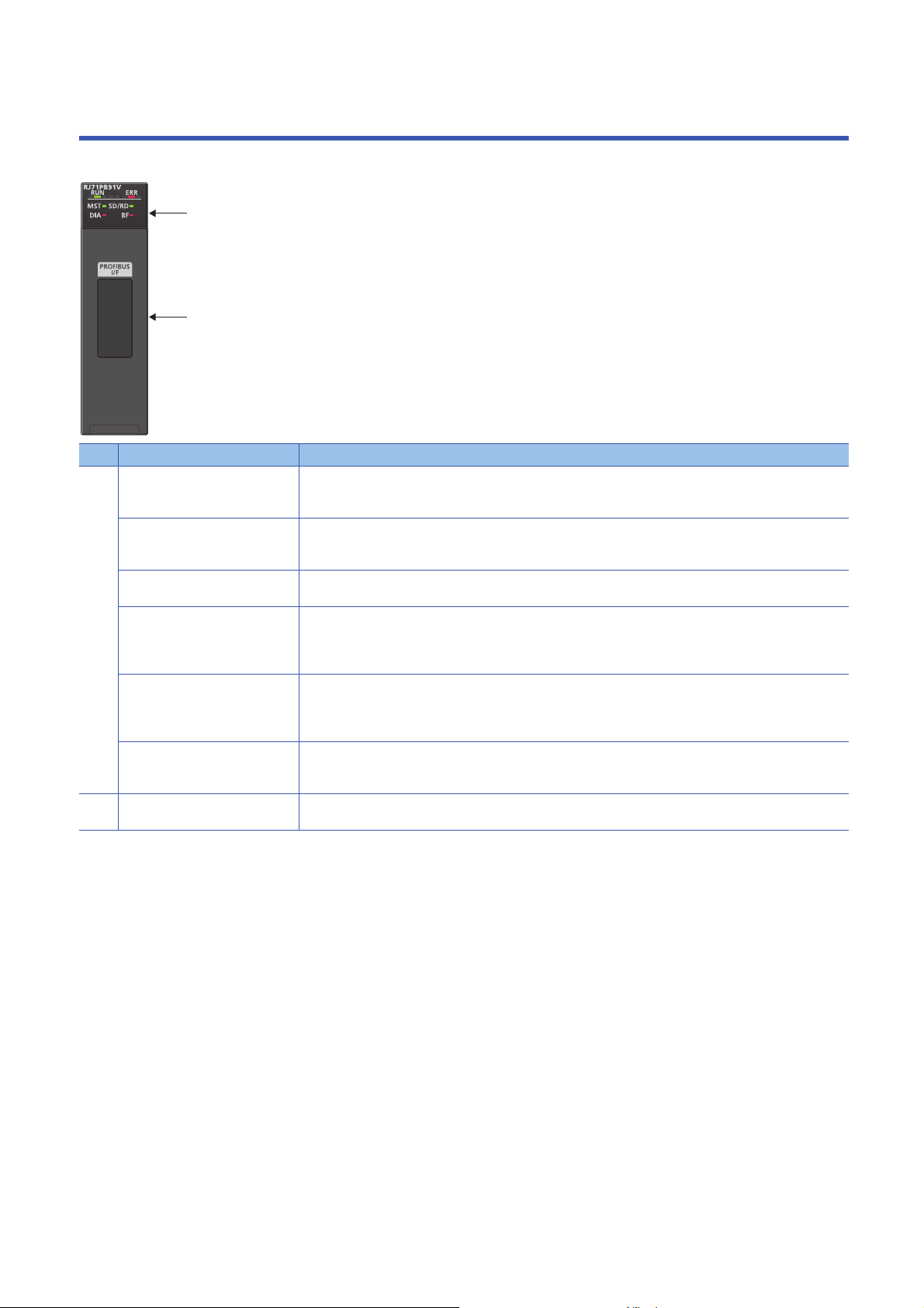
1 PART NAMES
(1)
(2)
This section describes the names of each part of the RJ71PB91V.
No. Name Description
(1) RUN LED Indicates the operating status of the module.
ERR LED Indicates the error status of the module.
MST LED Indicates the operating status.
SD/RD LED Indicates the communication status with DP-Slaves.
DIA LED Indicates the diagnostic information and the alarm detected.
BF LED Indicates the occurrence of a communication error.
(2) PROFIBUS-DP interface
connector
*1 Flashes when the module requests or responds to the Acyclic communication.
On: Normal operation
Off: Error ( MELSEC iQ-R PROFIBUS-DP Module User's Manual (Application))
On or flashing: Error ( MELSEC iQ-R PROFIBUS-DP Module User's Manual (Application))
Off: Normal operation
On: Operating as the DP-Master
On or flashing: During data exchange ('Data exchange start completed signal' (X0) is on), or Acyclic
communication.
Off: During data exchange stop ('Data exchange start completed signal' (X0) is off)
On: Diagnostic information or alarm is detected. ( MELSEC iQ-R PROFIBUS-DP Module User's Manual
(Application))
Off: No diagnostic information
On: Communication error ( MELSEC iQ-R PROFIBUS-DP Module User's Manual (Application))
Off: No communication error has occurred.
Connector to connect the PROFIBUS cable ( Page 28 WIRING)
*1
14
1 PART NAMES
Page 17

MEMO
1
1 PART NAMES
15
Page 18

2 SPECIFICATIONS
2.1 Performance Specifications
The following table lists the performance specifications of the RJ71PB91V.
Item Description
PROFIBUS-DP station type DP-Master (Class 1)
Transmis
sion
specifica
tions
Number of occupied I/O points 32
Internal current consumption (5VDC) 0.42A
External
dimensio
ns
Weight 0.16kg
Electrical standard and characteristics Compliant with EIA-RS485
Medium Shielded twisted pair cable (Page 28 Wiring for PROFIBUS cable)
Network configuration Bus topology (or tree topology when repeaters are used)
Data link method • Between DP-Masters: Token passing
Encoding method NRZ
Transmission speed
Transmission distance Varies depending on the transmission speed. ( Page 16 Transmission distance)
Maximum number of repeaters (per
network)
Number of connectable modules (per
segment)
Number of connectable modules (per
network)
Maximum number of DP-Slaves 125 (Page 22 Configuration of PROFIBUS-DP network)
Number of connectable nodes (number of
repeaters)
Transmittable data Input data Maximum of 8192 bytes (maximum of 244 bytes per DP-Slave)
Height 106mm (base unit mounting side: 98mm)
Width 27.8mm
Depth 110mm
*1
Output data Maximum of 8192 bytes (maximum of 244 bytes per DP-Slave)
• Between DP-Master and DP-Slave: Polling
9.6kbps to 12Mbps ( Page 16 Transmission distance)
3
32 per segment (including repeaters)
126 per network (including DP-Master and DP-Slaves (Page 22 Configuration of PROFIBUSDP network))
32, 62(1), 92(2), 126(3)
*1 Transmission speed accuracy is within 0.2% (compliant with IEC61158-2).
Transmission distance
Transmission speed Transmission distance Maximum transmission distance when
repeaters are used
9.6kbps 1200m/segment 4800m/network
19.2kbps
45.45kbps
93.75kbps
187.5kbps 1000m/segment 4000m/network
500kbps 400m/segment 1600m/network
1.5Mbps 200m/segment 800m/network
3Mbps 100m/segment 400m/network
6Mbps
12Mbps
*1 The maximum transmission distance shown in the above table indicates the distance when three repeaters are used.
To calculate the maximum transmission distance when repeaters are used and the transmission distance is extended, use the following
formula.
Maximum transmission distance [m/network] = (Number of repeaters + 1) Transmission distance[m/segment]
*1
16
2 SPECIFICATIONS
2.1 Performance Specifications
Page 19

MEMO
2
2 SPECIFICATIONS
2.1 Performance Specifications
17
Page 20

3 FUNCTION LIST
The following table lists the functions of the RJ71PB91V. For details on the functions, refer to the following.
MELSEC iQ-R PROFIBUS-DP Module User's Manual (Application)
Function Description
PROFIBUSDPV0
PROFIBUSDPV1
PROFIBUSDPV2
Data swap function Swaps upper and lower bytes in units of words when I/O data is sent/received.
Data consistency function Maintains consistency of I/O data of DP-Slaves when it is read/written from/to the buffer memory.
Output status setting function for CPU stop error Sets whether to stop or continue the data exchange with DP-Slaves when a CPU stop error occurs in the
Temporarily reserved station specification
function
Mode changing function Changes the operation mode using PROFIBUS Configuration Tool or a program.
Data exchange function Performs data exchange of up to 8192 bytes by connecting up to 125 DP-Slaves to one RJ71PB91V.
Acquisition of diagnostic
information and extended
diagnostic information
Global control function Sends service (SYNC, UNSYNC, FREEZE, UNFREEZE) to each DP-Slave in a group, and synchronously
Acyclic communication
function
Alarm acquisition function Acquires up to eight items of the alarm or status information occurring in a DP-Slave.
Time control over DP-Slaves Sets the time of each DP-Slave by operating RJ71PB91V as a time master.
Acquires the diagnostic information and the extended diagnostic error information occurring in DP-Slaves
during data exchange using buffer memory and I/O signals, facilitates.
controls I/O data of DP-Slaves.
Reads/writes data from/to DP-Slaves at a different timing from the data exchange.
CPU module to which the RJ71PB91V is mounted.
Temporarily changes a DP-Slave to a reserved station without changing slave parameters of PROFIBUS
Configuration Tool.
18
3 FUNCTION LIST
Page 21

MEMO
3
3 FUNCTION LIST
19
Page 22

4 PROCEDURES BEFORE OPERATION
This chapter describes the procedures before operation.
1. Self-diagnostics test
Turn on the power and perform the self-diagnostics test on the RJ71PB91V alone. ( MELSEC iQ-R PROFIBUS-DP
Module User's Manual (Application))
When no errors are detected, the LEDs and the relevant buffer memory areas behave as follows.
• ERR LED: Off
• Test results are stored in 'Offline test status area' (Un\G2258).
2. Network construction
Configure the system and set the parameters which are required for start-up.
• Wiring ( Page 28 WIRING)
• Parameter setting ( MELSEC iQ-R PROFIBUS-DP Module User's Manual (Application))
3. Start of data exchange
Start the data exchange of the PROFIBUS-DP network using either of the following procedures.
• Turn on 'Data exchange start request signal' (Y0).
• Click "Start/Stop PROFIBUS" of PROFIBUS Configuration Tool. ( MELSEC iQ-R PROFIBUS-DP Module User's Manual
(Application))
4. Network diagnostics
Check that communications are performed normally. When communications are performed normally, the LEDs and the bits
corresponding to the relevant buffer memory areas behave as follows.
• RUN LED: On
• ERR LED: Off
•BF LED: Off
• Bit corresponding to 'Slave status area (Normal communication detection)' (Un\G23040 to Un\G23047): ON
• Bit corresponding to 'Slave status area (Diagnostic information detection)' (Un\G23056 to Un\G23064): OFF
5. Programming
Create a program. ( Page 31 COMMUNICATION EXAMPLE)
20
4 PROCEDURES BEFORE OPERATION
Page 23

MEMO
4
4 PROCEDURES BEFORE OPERATION
21
Page 24

5 SYSTEM CONFIGURATION
RJ71PB91V
No.32
(1)
(2)(2)
No.1
·
No.31
5.1 Configuration of PROFIBUS-DP network
This section describes the basic configuration of the PROFIBUS-DP network using the RJ71PB91V as DP-Master (Class 1).
To configure the PROFIBUS-DP network, following conditions should be met.
Configuration condition Description
Number of connectable modules in the entire
network (when repeaters are used)
Number of connectable modules per segment DP-Master
Number of repeaters Maximum of 3 repeaters between the RJ71PB91V and a DP-Slave
Number of connectable DP-Slaves per RJ71PB91V 125
*1 Includes the RJ71PB91V.
*2 Repeaters are counted as modules for both segments.
In the multi-master system configuration, the DP-Master whose communication chips use ASPC2 STEP C or
equivalent cannot be connected to the PROFIBUS-DP network to which the RJ71PB91V is connected. To use
the DP-Master having such communication chips, configure another network.
For communication chips used, contact the manufacturer.
DP-Master*1 + DP-Slave 126
*1
+ DP-Slave + Repeater *2 32
Maximum configuration when repeaters are not connected
Up to 32 modules can be connected in one segment.
DP-Master (RJ71PB91V): 1
DP-Slave: 31
No.: FDL address (1 to 31 are for DP-Slaves, and 32 is for DP-Master)
(1) Segment
(2) Bus resistor
*1 Any FDL address can be assigned to the DP-Master.
*1
22
5 SYSTEM CONFIGURATION
5.1 Configuration of PROFIBUS-DP network
Page 25

Maximum configuration when one repeater is connected
RJ71PB91V
No.31
(2)(2)
No.1
·
No.30
(2)
(3)
(1)
(2)
No.32
·
No.62
Up to 32 modules can be connected in one segment.
DP-Master (RJ71PB91V): 1
DP-Slave: 61
Repeater: 1
5
No.: FDL address (1 to 30 and 32 to 62 are for DP-Slaves, and 31 is for DP-Master)
(1) Segment
(2) Bus resistor
(3) Repeater
*1 Any FDL address can be assigned to the DP-Master.
*1
5 SYSTEM CONFIGURATION
5.1 Configuration of PROFIBUS-DP network
23
Page 26

When 125 DP-Slaves are connected
RJ71PB91V
No.30
No.0
·
No.29
No.31
·
No.60
No.61
·
No.89
No.90
·
No.120 No.121
·
No.125
DP-Master (RJ71PB91V): 1
DP-Slave: 125
Repeater: 4
No.: FDL address (0 to 29 and 31 to 125 are for DP-Slaves, and 30 is for DP-Master)
*1 Any FDL address can be assigned to the DP-Master.
*1
24
5 SYSTEM CONFIGURATION
5.1 Configuration of PROFIBUS-DP network
Page 27

When multiple DP-Masters are connected (multi-master system)
RJ71PB91V
No.2
RJ71PB91V
No.3
RJ71PB91V
No.1
(1) No.0 (2) No.4
(3) No.5
·
(3) No.34
(2) No.35
·
(2) No.63
(1) No.64
·
(1) No.94 (3) No.95
·
(3) No.125
Multiple DP-Masters having different FDL addresses can be connected in one network.
Up to 123 DP-Slaves can be connected using three RJ71PB91V modules as follows.
DP-Master (RJ71PB91V): 3
DP-Slave: 123
Repeater: 4
5
No.: FDL address (0, 4, and 5 to 125 are for DP-Slaves, and 1 to 3 are for DP-Master)
(1) DP-Slave controlled by DP-Master (Class 1) (FDL address 1)
(2) DP-Slave controlled by DP-Master (Class 1) (FDL address 2)
(3) DP-Slave controlled by DP-Master (Class 1) (FDL address 3)
*1 Any FDL address can be assigned to the DP-Master.
*1
5 SYSTEM CONFIGURATION
5.1 Configuration of PROFIBUS-DP network
25
Page 28

5.2 Applicable CPU Modules
The following table shows whether the RJ71PB91V can be used with CPU modules and remote head modules.
The CPU modules and remote head modules are indicated by symbols as follows.
• Rn: RnCPU
• RnEN: RnENCPU
• RnP(P): Process CPU (process mode)
• RnP(R): Process CPU (redundant mode)
•RnMT: Motion CPU
: Can be used, : Cannot be used
Model Rn RnEN RnP
(P)
RJ71PB91V
*1 To use the data consistency function by the refresh settings, use the firmware version 28 or later. When using the firmware version 27 or
earlier, disable the automatic refresh and the data consistency function.
*2 To use the data consistency function by the refresh settings, use the firmware version 12 or later. When using the firmware version 11 or
earlier, disable the automatic refresh and the data consistency function.
*1
*1
*2
The number of mountable RJ71PB91V modules depends on the specifications of the CPU module used.
(There are no restrictions specific to the RJ71PB91V.)
For the number of mountable RJ71PB91V modules, refer to the following.
MELSEC iQ-R Module Configuration Manual
• RnNC: NCCPU
• RnC: C Controller module
• RnSF: Safety CPU
• Rem: Remote head module
• Rem(R): Remote head module (redundant system)
RnP
(R)
RnMT RnNC RnC RnSF Rem Rem
(R)
Multiple CPU system
The RJ71PB91V supports the multiple CPU system. ( MELSEC iQ-R Module Configuration Manual)
26
5 SYSTEM CONFIGURATION
5.2 Applicable CPU Modules
Page 29

5.3 Available Software Packages
GX Works3 and PROFIBUS Configuration Tool are required to configure the RJ71PB91V.
Software Supported version
GX Works3 Version 1.042U or later
PROFIBUS Configuration Tool 1.00A
Profile of the RJ71PB91V
Profile is data that contains information of connected devices (such as model names).
Profile of the RJ71PB91V is automatically registered to GX Works3 during the installation of PROFIBUS Configuration Tool.
If GX Works3 is installed or upgraded in the system having PROFIBUS Configuration Tool, the parameters of
the RJ71PB91V may not be configured properly.
In such a case, uninstall PROFIBUS Configuration Tool install or upgrade GX Works3 install PROFIBUS
Configuration Tool again.
5
5 SYSTEM CONFIGURATION
5.3 Available Software Packages
27
Page 30

6 WIRING
(9)
(8)
(7)
(6)
(5)
(4)
(3)
(2)
(1)
6.1 Connectors
Wiring for PROFIBUS cable
This section describes the pin assignment of the PROFIBUS-DP interface connector of the RJ71PB91V, wiring specifications
of the PROFIBUS cable, and the bus terminator.
■Pin assignment of the PROFIBUS-DP interface connector
The following table shows the pin assignment of the PROFIBUS-DP interface connector (D-sub 9-pin female connector).
Pin assignment No. Signal code Name Application Cable color
(1) SHIELD
(2) M24V
(3) B/B' RxD/TxD-P Receive/send data-P Red
(4) CNTR-P
(5) C/C' DGND
(6) VP
(7) P24V
(8) A/A' RxD/TxD-N Receive/send data-N Green
(9) CNTR-N
*1
*1
*1
*2
*2
*1
*1
Empty
Empty
Empty
Data ground
Voltage+
Empty
Empty
*1 Optional signal
*2 Signal used for connecting a bus terminator
28
6 WIRING
6.1 Connectors
Page 31

Precautions
(1)
(5)
(4)
(2)
(3)
RJ71PB91V
To make full use of the functions of the RJ71PB91V and to configure a highly reliable system, the external wiring should be
resistant to noise.
The following are precautions for the external wiring of the RJ71PB91V.
• Do not route the communication cable of the RJ71PB91V near the main circuit, power cable, or load cable other than that
of the programmable controller. In addition, do not bundle those cables together. Otherwise the RJ71PB91V may be
affected by noise or surge induction.
• Place the PROFIBUS cable as far away from the I/O module cable as possible.
6
(1) Power supply module
(2) Input module wiring
(3) Output module wiring
(4) Shield jacket
(5) PROFIBUS cable
• As a rule, to use the RJ71PB91V, ground the FG and LG terminals of the power supply module of the programmable
controller.
• Place the communication cables and power cables connected to the module in a duct or clamp them. If not, dangling cable
can swing or inadvertently be pulled, resulting in damage to the module or the cable or malfunction due to poor contact.
• Do not touch the core of the cable-side or module-side connector, and protect it from dirt or dust. If oil from your hand, dirt,
or dust is attached to the core, transmission loss can increase, causing communication failures.
• Securely connect the connector to the module.
• Tighten the screws within the specified torque range. Undertightening can cause drop of the screw, short circuit, or
malfunction. Overtightening can damage the screw and/or module, resulting in drop, short circuit, or malfunction.
• When disconnecting the cable from the module, do not pull the cable by the cable part. For the cable with connector, hold
the connector part of the cable. Pulling the cable connected to the module may result in malfunction or damage to the
module or cable.
6 WIRING
6.1 Connectors
29
Page 32

6.2 Wiring Products
RJ71PB91V
RxD/TxD-P
RxD/TxD-N
VP
RxD/TxD-N
DGND
RxD/TxD-P
Ru = 390Ω ± 2%, min1/4W
R
tA
= 220Ω ± 2%, min1/4W
R
d
= 390Ω ± 2%, min1/4W
PROFIBUS devices such as PROFIBUS cables and connectors should be prepared by users. For details on PROFIBUS
devices, refer to the following.
• PI: www.profibus.com
PROFIBUS cable
The following are the specifications and wiring specifications of PROFIBUS cables.
•PROFIBUS cable
Use PROFIBUS cables that satisfy the following specifications (compliant with TypeA (IEC 61158-2)).
Item Specifications
Applicable cable Shielded twisted pair cable
Impedance 135 to 165 (f = 3 to 20MHz)
Capacity Less than 30pF/m
Conductor resistance Less than 110/km
Cross-sectional area 0.34 or larger
Wire diameter 22 AWG
Type Stranded wire
Material Copper wire
Temperature rating 60 or larger
• Wiring specifications
RxD/TxD-P: Red
RxD/TxD-N: Green
Connectors
Use D-sub 9-pin male connectors for PROFIBUS cables.
Use #4-40 UNC screws for the connector. Tighten the screws within the range of 0.20 to 0.28Nm.
Wiring specifications of terminating resistor
When the RJ71PB91V is the terminal station, use the connector with built-in bus terminator that satisfies the following wiring
specifications.
30
6 WIRING
6.2 Wiring Products
Page 33

7 COMMUNICATION EXAMPLE
RJ71PB91V No.0 No.1 No.2
7.1 Communication example of data exchange
This section describes a communication example between the RJ71PB91V and DP-Slaves (with the refresh settings
enabled).
System configuration example
The following system configuration is used to explain data exchange between the RJ71PB91V and DP-Slaves.
System configuration
Number and station type Module
No.0: DP-Master (FDL address 0) • Power supply module: R61P
• CPU module: R04CPU
• RJ71PB91V (start I/O number: 0000H to 001FH)
No.1: DP-Slave (FDL address 1) ET200S (HighFeature(Cu)) manufactured by Siemens
No.2: DP-Slave (FDL address 2) • Power supply module: Q61P-A1
• CPU module: Q06UDH
• QJ71PB93D (start I/O number: 0000H to 001FH)
7
7 COMMUNICATION EXAMPLE
7.1 Communication example of data exchange
31
Page 34

Settings for DP-Master
Connect the engineering tool to the CPU module of the DP-Master, and set the parameters.
Creating a new project
1. Set the CPU module as follows.
[Project] [New]
2. Click the [OK] button to add the module labels of the CPU module.
3. Set the RJ71PB91V as follows.
[Navigation window] [Parameter] [Module Information] Right-click [Add New Module]
4. To enable the data consistency function, set the items under "Basic Setting" as follows.
[Navigation window] [Parameter] [Module Information] [RJ71PB91V] [Module Parameter] [Basic Setting]
32
7 COMMUNICATION EXAMPLE
7.1 Communication example of data exchange
Page 35

PROFIBUS module setting
1. Start PROFIBUS Configuration Tool from the engineering tool.
[Navigation window] [Parameter] [Module Information] [RJ71PB91V] [PROFIBUS Module Setting]
2. Add the DP-Slave to the project.
[Navigation window] [Parameter] [Module Information] [RJ71PB91V] [PROFIBUS Module Setting] [Global
GSD Database] tab Target DP-Slave Right-click [Add Slave to Project]
3. Set the items in the "Slave Settings" window as follows.
[Navigation window] [Parameter] [Module Information] [RJ71PB91V] [PROFIBUS Module Setting] Tar g e t
DP-Slave Right-click [Slave Settings]
• DP-Slave (FDL address 1)
7
7 COMMUNICATION EXAMPLE
7.1 Communication example of data exchange
33
Page 36

• DP-Slave (FDL address 2)
34
7 COMMUNICATION EXAMPLE
7.1 Communication example of data exchange
Page 37

4. Set the items in "Master Settings" as follows.
[Navigation window] [Parameter] [Module Information] [RJ71PB91V] [PROFIBUS Module Setting] [I/O
no.:0x0000/FDL:0 'RJ71PB91V'] Right-click [Master Settings]
7
7 COMMUNICATION EXAMPLE
7.1 Communication example of data exchange
35
Page 38

5. Click the [Next] button in the "Master Settings" window, and set the items in "CPU Device Access" as follows.
6. Click the [Finish] button to exit the "Master Settings" window.
36
7 COMMUNICATION EXAMPLE
7.1 Communication example of data exchange
Page 39

Update of PROFIBUS labels
This function creates and updates the structures used for global labels and module function blocks by enabling the refresh
settings.
1. Click "Update PROFIBUS Label".
[Navigation window] [Parameter] [Module Information] [RJ71PB91V] [PROFIBUS Module Setting]
[PROFIBUS Configurator Tasks]
2. Convert some program codes or all program codes.
[Convert] [Convert] or [Rebuild All]
3. Write the set parameters to the CPU module or an SD memory card in the CPU module. Then reset the CPU module or
power on the system.
[Online] [Write to PLC]
In this example, default values are used for parameters that are not shown above. For the parameters, refer to
the following.
MELSEC iQ-R PROFIBUS-DP Module User's Manual (Application)
7
7 COMMUNICATION EXAMPLE
7.1 Communication example of data exchange
37
Page 40

Settings for DP-Slaves
Set for DP-Slaves that configure the PROFIBUS-DP network. ( Manual for each DP-Slave)
Checking the network status
Communications are performed normally if the status of LEDs and bits corresponding to the relevant buffer memory areas are
as follows after the program execution.
• LED on the RJ71PB91V
LED Status
RUN On
ERR Off
BF Off
• Bit corresponding to buffer memory area
Name Status
'Slave status area (Normal communication detection)' (Un\G23040.0 to
Un\G23040.1)
'Slave status area (Diagnostic information detection)' (Un\G23057.0 to
Un\G23057.1)
ON
OFF
38
7 COMMUNICATION EXAMPLE
7.1 Communication example of data exchange
Page 41

Program example
Classification Label name Description Device
Module label RCPU.stSM.bAfter_RUN1_Scan_ON ON only for 1 scan after RUN SM402
Global label that
was updated in
the RJ71PB91V
Label to be
defined
glRJ71PB91V_1.stMgmtInputs_D.bDataExchStartCompleted Data exchange start completed
signal
glRJ71PB91V_1.stMgmtInputs_D.bCommunicationReady Communication READY signal X1B
glRJ71PB91V_1.stMgmtInputs_D.bModuleReady Module ready signal X1D
glRJ71PB91V_1.stMgmtInputs_D.bWatchdogTimerError Watchdog timer error signal X1F
glRJ71PB91V_1.stMgmtOutputs_D.bDataExchStartRequest Data exchange start request signal Y0
glRJ71PB91V_1.stMgmtOutputs_D.uSet_DiagnosticInfoInvalid_D Diagnostic information invalid setting
area
glRJ71PB91V_1.stMgmtOutputs_D.uSet_DiagnosticInfoNon_notificationTime_D Diagnostic information non-
notification time setting area
glRJ71PB91V_1.stMgmtInputs_D.b128CommunicationStatus_D[0] Slave status area (Normal
communication detection) on the first
device
glRJ71PB91V_1.stMgmtOutputs_D.bnReqTemporarySlaveReservation_D[1] Temporarily reserved station
specification request area on the
second device
glRJ71PB91V_1.vSLV001MOD001.outputs Output area on the first device D1002.0
glRJ71PB91V_1.vSLV001MOD002inputs Input area on the first device D1000.0
Define global labels as shown below:
X0
U0\G2080
U0\G2084
U0\G23040.0
U0\G23608.1
7
7 COMMUNICATION EXAMPLE
7.1 Communication example of data exchange
39
Page 42

40
7 COMMUNICATION EXAMPLE
7.1 Communication example of data exchange
Page 43

(9) Set the 'Diagnostic information invalid setting area' (Un\G2080), 'Diagnostic information non-notification time setting area' (Un\G2084), and 'Temporarily
reserved station specification request area' (Un\G23608 to Un\G23615).
(84) Write the output data or turn on "Data exchange start request signal" (Y0).
(129) Turn on M0 (refresh start request).
(134) Process the input data (first word (bit 0)).
(182) Process the output data setting. (Set the data according to the output setting of the DP-Slave.)
7
7 COMMUNICATION EXAMPLE
7.1 Communication example of data exchange
41
Page 44

APPENDIX
98 4
27.8110
111
106
Appendix 1 External Dimensions
This section describes the external dimensions of the RJ71PB91V.
(Unit: mm)
42
APPX
Appendix 1 External Dimensions
Page 45

MEMO
A
APPX
Appendix 1 External Dimensions
43
Page 46

INDEX
A
Acquisition of diagnostic information and extended
diagnostic information
Acyclic communication function . . . . . . . . . . . . . 18
Alarm acquisition function . . . . . . . . . . . . . . . . . 18
D
Data consistency function . . . . . . . . . . . . . . . . . 18
Data exchange function . . . . . . . . . . . . . . . . . . . 18
Data swap function . . . . . . . . . . . . . . . . . . . . . . 18
E
External dimensions . . . . . . . . . . . . . . . . . . . . . 16
G
Global control function. . . . . . . . . . . . . . . . . . . . 18
L
. . . . . . . . . . . . . . . . . . . . 18
LED. . . . . . . . . . . . . . . . . . . . . . . . . . . . . . . . . 14
M
Mode changing function. . . . . . . . . . . . . . . . . . . 18
O
Output status setting function for CPU stop error . 18
P
PROFIBUS Configuration Tool . . . . . . . . . . . . . . 27
Profile . . . . . . . . . . . . . . . . . . . . . . . . . . . . . . . 27
T
Temporarily reserved station specification function
. . . . . . . . . . . . . . . . . . . . . . . . . . . . . . . . . . . . 18
Time control over DP-Slaves . . . . . . . . . . . . . . . 18
44
Page 47

MEMO
I
45
Page 48

REVISIONS
*The manual number is given on the bottom left of the back cover.
Revision date *Manual number Description
December 2017 SH(NA)-081855ENG-A First edition
Japanese manual number: SH-081854-A
This manual confers no industrial property rights of any other kind, nor does it confer any patent licenses. Mitsubishi Electric Corporation cannot be held
responsible for any problems involving industrial property rights which may occur as a result of using the contents noted in this manual.
2017 MITSUBISHI ELECTRIC CORPORATION
46
Page 49

WARRANTY
Please confirm the following product warranty details before using this product.
1. Gratis Warranty Term and Gratis Warranty Range
If any faults or defects (hereinafter "Failure") found to be the responsibility of Mitsubishi occurs during use of the product
within the gratis warranty term, the product shall be repaired at no cost via the sales representative or Mitsubishi Service
Company.
However, if repairs are required onsite at domestic or overseas location, expenses to send an engineer will be solely at
the customer's discretion. Mitsubishi shall not be held responsible for any re-commissioning, maintenance, or testing
on-site that involves replacement of the failed module.
[Gratis Warranty Term]
The gratis warranty term of the product shall be for one year after the date of purchase or delivery to a designated place.
Note that after manufacture and shipment from Mitsubishi, the maximum distribution period shall be six (6) months, and
the longest gratis warranty term after manufacturing shall be eighteen (18) months. The gratis warranty term of repair
parts shall not exceed the gratis warranty term before repairs.
[Gratis Warranty Range]
(1) The range shall be limited to normal use within the usage state, usage methods and usage environment, etc., which
follow the conditions and precautions, etc., given in the instruction manual, user's manual and caution labels on the
product.
(2) Even within the gratis warranty term, repairs shall be charged for in the following cases.
1. Failure occurring from inappropriate storage or handling, carelessness or negligence by the user. Failure caused
by the user's hardware or software design.
2. Failure caused by unapproved modifications, etc., to the product by the user.
3. When the Mitsubishi product is assembled into a user's device, Failure that could have been avoided if functions
or structures, judged as necessary in the legal safety measures the user's device is subject to or as necessary by
industry standards, had been provided.
4. Failure that could have been avoided if consumable parts (battery, backlight, fuse, etc.) designated in the
instruction manual had been correctly serviced or replaced.
5. Failure caused by external irresistible forces such as fires or abnormal voltages, and Failure caused by force
majeure such as earthquakes, lightning, wind and water damage.
6. Failure caused by reasons unpredictable by scientific technology standards at time of shipment from Mitsubishi.
7. Any other failure found not to be the responsibility of Mitsubishi or that admitted not to be so by the user.
2. Onerous repair term after discontinuation of production
(1) Mitsubishi shall accept onerous product repairs for seven (7) years after production of the product is discontinued.
Discontinuation of production shall be notified with Mitsubishi Technical Bulletins, etc.
(2) Product supply (including repair parts) is not available after production is discontinued.
3. Overseas service
Overseas, repairs shall be accepted by Mitsubishi's local overseas FA Center. Note that the repair conditions at each FA
Center may differ.
4. Exclusion of loss in opportunity and secondary loss from warranty liability
Regardless of the gratis warranty term, Mitsubishi shall not be liable for compensation to:
(1) Damages caused by any cause found not to be the responsibility of Mitsubishi.
(2) Loss in opportunity, lost profits incurred to the user by Failures of Mitsubishi products.
(3) Special damages and secondary damages whether foreseeable or not, compensation for accidents, and
compensation for damages to products other than Mitsubishi products.
(4) Replacement by the user, maintenance of on-site equipment, start-up test run and other tasks.
5. Changes in product specifications
The specifications given in the catalogs, manuals or technical documents are subject to change without prior notice.
47
Page 50

TRADEMARKS
SH(NA)-081855ENG-A
Ethernet is a registered trademark of Fuji Xerox Co., Ltd. in Japan.
PROFIBUS is a trademark of PROFIBUS Nutzerorganisation e.V.
The company names, system names and product names mentioned in this manual are either registered trademarks or
trademarks of their respective companies.
In some cases, trademark symbols such as '
' or '' are not specified in this manual.
48
Page 51

Page 52

SH(NA)-081855ENG-A(1712)MEE
Specifications subject to change without notice.
When exported from Japan, this manual does not require application to the
Ministry of Economy, Trade and Industry for service transaction permission.
HEAD OFFICE : TOKYO BUILDING, 2-7-3 MARUNOUCHI, CHIYODA-KU, TOKYO 100-8310, JAPAN
NAGOYA WORKS : 1-14 , YADA-MINAMI 5-CHOME , HIGASHI-KU, NAGOYA , JAPAN
MODEL: RJ71PB91V-U-IN-E
MODEL CODE: 13JX79
 Loading...