

Mitsubishi RH-3FRH Series, RH-6FRH Series, RH-3FRHR3515, RH-3FRHR3512C, RH-3FRHR3512W Instruction Manual
...
Mitsubishi Electric Industrial Robot
RH-FRH Series INSTRUCTION MANUAL
ROBOT ARM SETUP & MAINTENANCE
RH-3FRH series
RH-6FRH series
RH-12FRH series
RH-20FRH series
RH-3FRHR series
BFP-A3472-C

All teaching work must be carried out by an operator who has received special
Always read the following precautions and the separate "Safety
Manual" before starting use of the robot to learn the required
measures to be taken.
Safety Precautions
CAUTION
CAUTION
WARNING
CAUTION
DANGER
CAUTION
CAUTION
CAUTION
training. (This also applies to maintenance work with the power source turned
ON.)
Enforcement of safety training
For teaching work, prepare a work plan related to the methods and procedures
of operating the robot, and to the measures to be taken when an error occurs
or when restarting. Carry out work following this plan. (This also applies to
maintenance work with the power source turned ON.)
Preparation of work plan
Prepare a device that allows operation to be stopped immediately during
teaching work. (This also applies to maintenance work with the power source
turned ON.)
Setting of emergency stop switch
During teaching work, place a sign indicating that teaching work is in progress
on the start switch, etc. (This also applies to maintenance work with the power
source turned ON.)
Indication of teaching work in progress
Provide a fence or enclosure during operation to prevent contact of the
operator and robot.
Installation of safety fence
Establish a set signaling method to the related operators for starting work, and
follow this method.
Signaling of operation start
As a principle turn the power OFF during maintenance work. Place a sign
indicating that maintenance work is in progress on the start switch, etc.
Indication of maintenance work in progress
Before starting work, inspect the robot, emergency stop switch and other
related devices, etc., and confirm that there are no errors.
Inspection before starting work
The points of the precautions given in the separate "Safety Manual" are given below.
DANGER
CAUTION
CAUTION
CAUTION
CAUTION
CAUTION
CAUTION
WARNING
WARNING
CAUTION
WARNING
CAUTION
CAUTION
CAUTION
CAUTION
Refer to the actual "Safety Manual" for details.
When automatic operation of the robot is performed using multiple control
devices (GOT, programmable controller, push-button switch), the interlocking of
operation rights of the devices, etc. must be designed by the customer.
Use the robot within the environment given in the specifications. Failure to do
so could lead to a drop or reliability or faults. (Temperature, humidity,
atmosphere, noise environment, etc.)
Transport the robot with the designated transportation posture. Transporting
the robot in a non-designated posture could lead to personal injuries or faults
from dropping.
Always use the robot installed on a secure table. Use in an instable posture
could lead to positional deviation and vibration.
Wire the cable as far away from noise sources as possible. If placed near a noise
source, positional deviation or malfunction could occur.
Do not apply excessive force on the connector or excessively bend the cable.
Failure to observe this could lead to contact defects or wire breakage.
Make sure that the workpiece weight, including the hand, does not exceed the
rated load or tolerable torque. Exceeding these values could lead to alarms or
faults.
Securely install the hand and tool, and securely grasp the workpiece. Failure to
observe this could lead to personal injuries or damage if the object comes off or
flies off during operation.
Securely ground the robot and controller. Failure to observe this could lead to
malfunctioning by noise or to electric shock accidents.
Indicate the operation state during robot operation. Failure to indicate the state
could lead to operators approaching the robot or to incorrect operation.
When carrying out teaching work in the robot's movement range, always secure
the priority right for the robot control. Failure to observe this could lead to
personal injuries or damage if the robot is started with external commands.
Keep the jog speed as low as possible, and always watch the robot. Failure to do
so could lead to interference with the workpiece or peripheral devices.
After editing the program, always confirm the operation with step operation
before starting automatic operation. Failure to do so could lead to interference
with peripheral devices because of programming mistakes, etc.
Make sure that if the safety fence entrance door is opened during automatic
operation, the door is locked or that the robot will automatically stop. Failure to
do so could lead to personal injuries.
Never carry out modifications based on personal judgments, or use nondesignated maintenance parts.
Failure to observe this could lead to faults or failures.
When the robot arm has to be moved by hand from an external area, do not
WARNING
CAUTION
CAUTION
DANGER
DANGER
DANGER
DANGER
DANGER
CAUTION
place hands or fingers in the openings. Failure to observe this could lead to
hands or fingers catching depending on the posture.
Do not stop the robot or apply emergency stop by turning the robot controller's
main power OFF. If the robot controller main power is turned OFF during
automatic operation, the robot accuracy could be adversely affected. Moreover,
it may interfere with the peripheral device by drop or move by inertia of the arm.
Do not turn off the main power to the robot controller while rewriting the
internal information of the robot controller such as the program or parameters.
If the main power to the robot controller is turned off while in automatic
operation or rewriting the program or parameters, the internal information of the
robot controller may be damaged.
Do not connect the Handy GOT when using the GOT direct connection function
of this product. Failure to observe this may result in property damage or bodily
injury because the Handy GOT can automatically operate the robot regardless
of whether the operation rights are enabled or not.
Do not connect the Handy GOT to a programmable controller when using an iQ
Platform compatible product with the CR800-R/CR800-Q controller. Failure to
observe this may result in property damage or bodily injury because the Handy
GOT can automatically operate the robot regardless of whether the operation
rights are enabled or not.
Do not remove the SSCNET III cable while power is supplied to the multiple
CPU system or the servo amplifier. Do not look directly at light emitted from
the tip of SSCNET III connectors or SSCNET III cables of the Motion CPU or
the servo amplifier. Eye discomfort may be felt if exposed to the light.
(Reference: SSCNET III employs a Class 1 or equivalent light source as
specified in JIS C 6802 and IEC60825-1 (domestic standards in Japan).)
Do not remove the SSCNET III cable while power is supplied to the controller.
Do not look directly at light emitted from the tip of SSCNET III connectors or
SSCNET III cables. Eye discomfort may be felt if exposed to the light.
(Reference: SSCNET III employs a Class 1 or equivalent light source as
specified in JIS C 6802 and IEC60825-1 (domestic standards in Japan).)
Attach the cap to the SSCNET III connector after disconnecting the SSCNET
III cable. If the cap is not attached, dirt or dust may adhere to the connector
pins, resulting in deterioration connector properties, and leading to malfunction.
Make sure there are no mistakes in the wiring. Connecting differently to the way
specified in the manual can result in errors, such as the emergency stop not
being released. In order to prevent errors occurring, please be
that all functions (such as the teaching box emergency stop, customer emer
gency stop, and door switch) are working properly after the wiring setup is com
pleted.
sure to check
-
-

Use the network equipments (personal computer, USB hub, LAN hub, etc)
CAUTION
CAUTION
confirmed by manufacturer. The thing unsuitable for the FA environment
(related with conformity, temperature or noise) exists in the equipments
connected to USB. When using network equipment, measures against the noise,
such as measures against EMI and the addition of the ferrite core, may be
necessary. Please fully confirm the operation by customer. Guarantee and
maintenance of the equipment on the market (usual office automation
equipment) cannot be performed.
To maintain the safety of the robot system against unauthorized access from
external devices via the network, take appropriate measures.
To maintain the safety against unauthorized access via the Internet, take mea
sures such as installing a firewall.
-
*CR800 controller
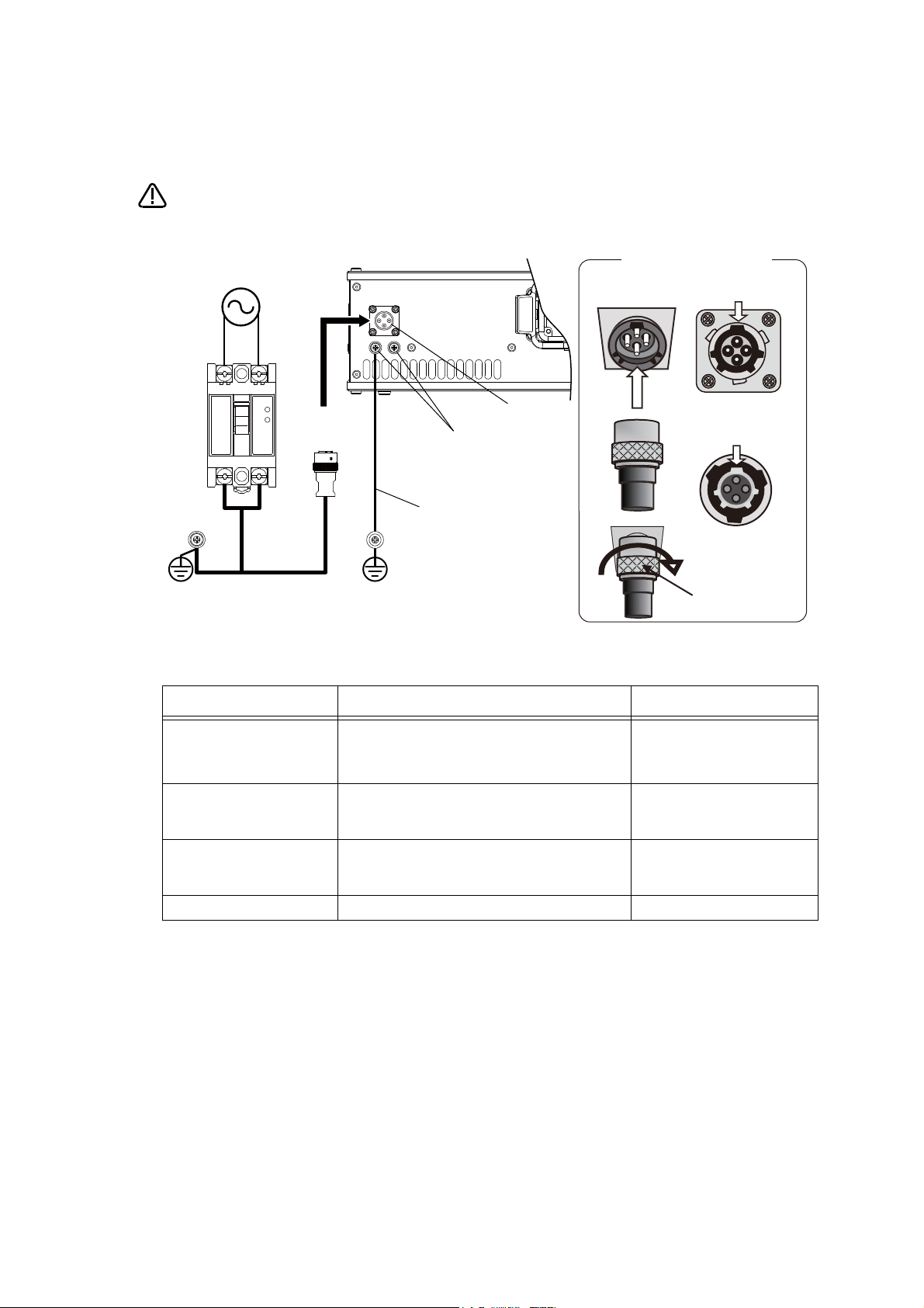
CAUTION
LN
Controller rear
ACIN cable
(attachment)
PE terminal
PE terminal
Primary side
Secondry side
Single phase
AC200V
ACIN connector
PE (protective earth) terminal
M4 screw
Grounding cable
Note 1)
Earth leakage
breaker (NV)
<3>
<1> <2>
ACIN cable connection
ACIN cable
(male)
ACIN socket
(female)
Main key (wide)
Groove for main
key (wide)
Top
Top
Coupling
Note 1) Always use the terminal cover for the earth leakage breaker.
Notes of the basic component are shown.
Please install the earth leakage breaker in the primary side power supply of the
controller because of leakage protection.
1) Prepare the following items.
Part name Specifications Remarks
Earth leakage breaker The following is recommended product. Prepared by customer.
Single phase: NV30FAU-2P-10A-AC100-240V-30mA
(Terminal cover: TCS-05FA2)
Cable for primary power supply
Grounding cable
ACIN cable Terminal: M5, cable length: 3m Supplied with the product.
AWG14 (2mm
AWG14 (2mm
2
) or above
2
) or above
Prepared by customer.
Tightening torque for terminal
fixing screw is 2 ~ 3Nm.
Prepared by customer.
Tightening torque for terminal
fixing screw is 2 ~ 3Nm.
2) Confirm that the primary power matches the specifications.
3) Confirm that the primary power is OFF and that the earth leakage breaker power switch is OFF.
4) Connect the ACIN cable to the breaker.
Connect the power terminals of the ACIN cable to the secondary side terminals of the earth leakage breaker.
Also, ground the FG terminal of the cable.
5) Connect the ACIN cable to the ACIN connector on the rear of the controller.
<1> Face the main key on the ACIN cable plug upwards. (Refer to the "ACIN cable connection" illustration.)
<2> Align the main key of the ACIN cable plug with the grooves on the ACIN connector. Push the plug into the
connector as far as it will go.
The plug may be damaged if it is not correctly aligned with the connector.
<3> Tighten the coupling on the ACIN cable, turning it to the right until it locks.
6) Connect one end of the grounding cable to the PE (protective earth) terminal on the controller and ground the
other end (2-point grounding) in order to comply with the requirements of EN 61800-5-1 for the touch cur
rent of 3.5 mA AC or more.
7) Connect the primary power cable to the primary side terminal of the earth leakage breaker.
-
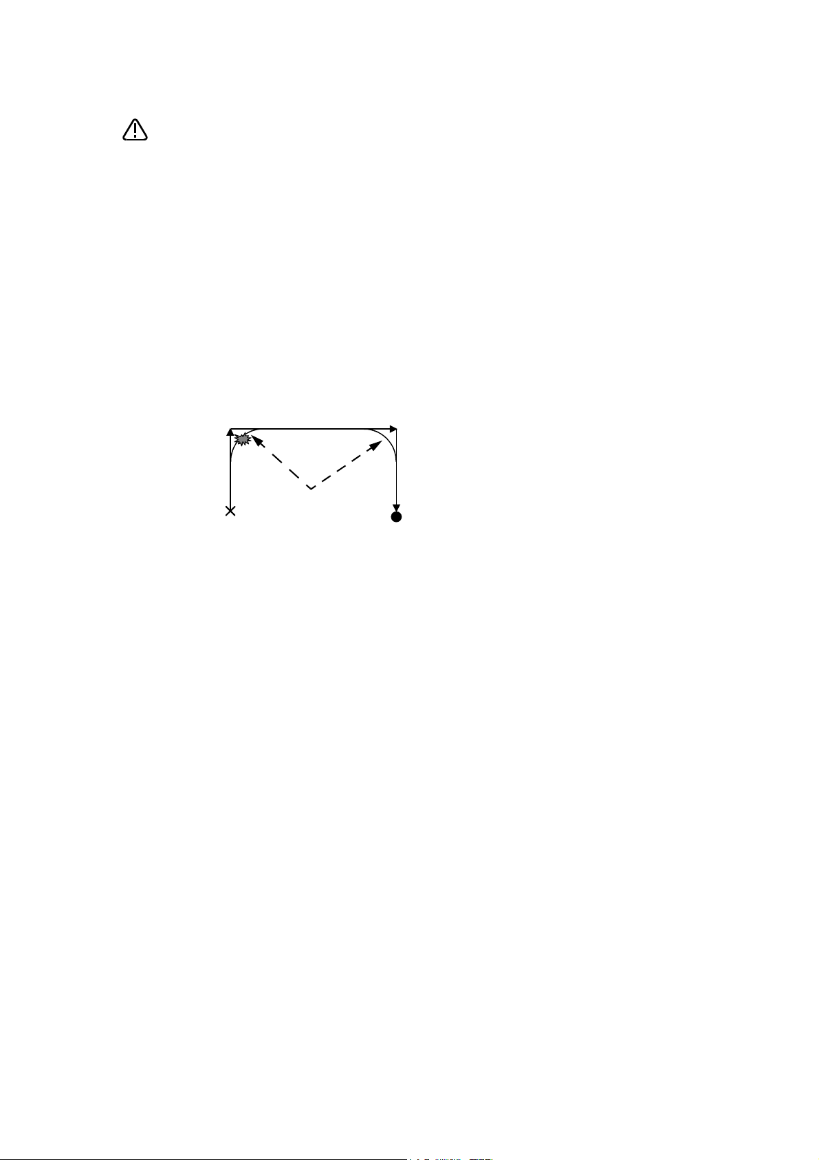
Be careful of interference with peripheral equipment.
CAUTION
Short cut
Arch movement (example)
Especially don't give a shock to the shaft (J3 axis). When you install the
hand, be careful not to knock at the shaft end by the hammer etc. The shaft
may be damaged.
Collision detection function is valid condition for both of automatic and jog operation at shipping in
RH-3FRHR series. However, damage to the ball screw shaft cannot be prevented completely.
Refer to the separate instruction manual "Detailed explanations of functions and operations" for
collision detection function.
Take care also of the following items.
(1)The robot's locus of movement may change with specified speed.
Especially as for the corner section, short cut distance may change. Therefore, when beginning automatic operation, moves at low speed at first, and you should gather speed slowly with
being careful of interference with peripheral equipment.
(2)It can be confirmed whether the specified position exist in the defined area by using the instruc-
tion command "Zone". It can utilize as one of the methods for collision evasion. Refer to the
"detailed description of the instructions manual/function, and operation" of the separate volume
for the details of the instruction command.

Revision history
Date of Point Instruction Manual No. Revision Details
2017-04-27 BFP-A3472 ・ First print
2018-03-01 BFP-A3472-A ・ Descriptions of CR800-Q controller were added.
2018-12-25 BFP-A3472-B ・ ”5.6.3 ABS origin method” was corrected.
2019-04-19 BFP-A3472-C ・ Installation dimensions in Fig. 2-6 was corrected.
・ Mechanical stopper position in Fig 3-16 were corrected.
・ Added further explanation of the ACIN cable.
・ Timing belt tension of RH-3FRHR series in Table 5-8 was corrected.

*Introduction
・ No part of this manual may be reproduced by any means or in any form, without prior consent from
Mitsubishi.
・ The details of this manual are subject to change without notice.
・ The information contained in this document has been written to be accurate as much as possible.
Please interpret that items not described in this document "cannot be performed." or "alarm may
occur".
Please contact your nearest dealer if you find any doubtful, wrong or skipped point.
・ This specifications is original.
・ Company names and production names in this document are the trademarks or registered trademarks
of their respective owners.
Copyright(C) 2017-2019 MITSUBISHI ELECTRIC CORPORATION
Thank you for purchasing the Mitsubishi industrial robot.
This instruction manual explains the method of unpacking, installation and maintenance and inspection of
the robot arm.
Always read through this manual before starting use to ensure correct usage of the robot.
The information contained in this document has been written to be accurate as much as possible. Please
interpret that items not described in this document "cannot be performed."
And, when maintenance and inspection of the robot, to access the arm and the base section is necessary.
Please prepare the environment which can access the robot with the stepladder etc. in RH-3FRHR.
This document explains for the following robot type.
Robot type
On floor type...........*RH-3FRH series
*RH-6FRH series
*RH-12FRH series
*RH-20FRH series
Hanging type ...........*RH-3FRHR series

CONTENTS
Page
1 Before starting use .......................................................................................................................... 1-1
1.1 Using the instruction manuals ................................................................................................... 1-1
1.1.1 The details of each instruction manuals ............................................................................... 1-1
1.1.2 Symbols used in instruction manual .................................................................................... 1-2
1.2 Safety Precautions .................................................................................................................... 1-3
1.2.1 Precautions given in the separate Safety Manual ................................................................ 1-4
2 Unpacking to Installation .............................................................................................................................................................. 2-6
2.1 Confirming the product ......................................................................................................................................................... 2-6
2.2 Installation .................................................................................................................................................................................. 2-7
2.2.1 Unpacking ............................................................................................................................................................................ 2-7
(1) RH-3FRH/6FRH/12FRH/20FRH series ............................................................................................................ 2-7
(2) RH-3FRHR series ....................................................................................................................................................... 2-8
2.2.2 Transportation procedures .......................................................................................................................................... 2-9
(1) RH-3FRH/6FRH series ............................................................................................................................................. 2-9
(2) RH-12FRH/20FRH series ...................................................................................................................................... 2-11
(3) RH-3FRHR series ..................................................................................................................................................... 2-13
2.2.3 Installation procedures ................................................................................................................................................ 2-15
(1) RH-3FRH/6FRH/12FRH/20FRH series .......................................................................................................... 2-15
(2) RH-3FRHR series ..................................................................................................................................................... 2-17
2.2.4 Grounding procedures .................................................................................................................................................. 2-19
(1) Grounding methods ................................................................................................................................................... 2-19
(2) Grounding procedures ............................................................................................................................................. 2-19
2.2.5 Connecting with the controller ................................................................................................................................ 2-20
(1) Connection of robot arm and machine cable ................................................................................................. 2-20
(2) Connection of controller and machine cable ................................................................................................. 2-22
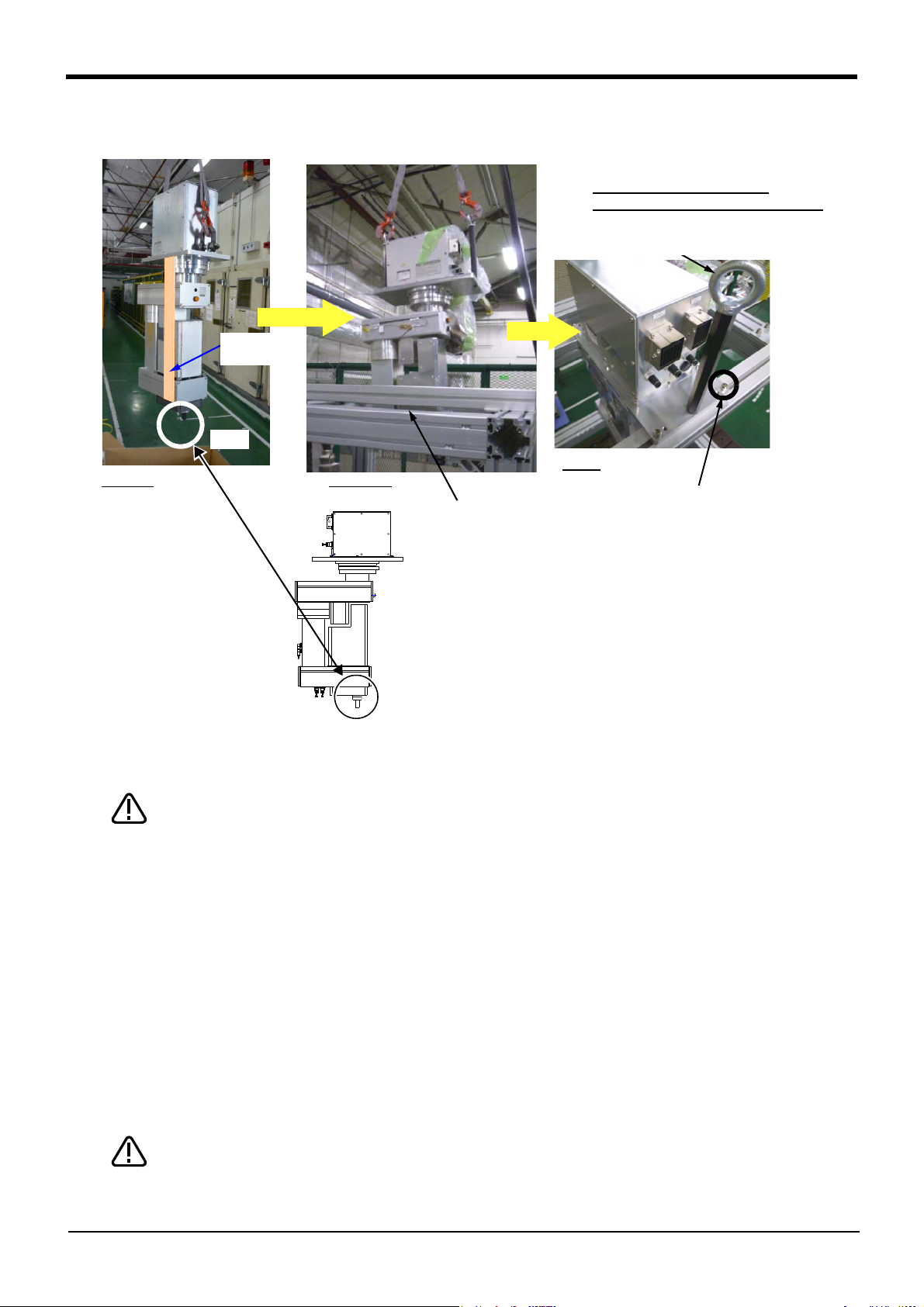
2.2.6 Ethernet Cables (RH-3FRH/6FRH/12FRH/20FRH series) ......................................................................... 2-23
(1) No.2 arm ........................................................................................................................................................................ 2-23
(2) Base area ...................................................................................................................................................................... 2-24
2.2.7 Ethernet Cables (RH-3FRHR series) .................................................................................................................... 2-26
(1) No.2 arm section ........................................................................................................................................................ 2-26
(2) Base area ................................................................................................................
2.2.8 Passing air hoses and cables through the shaft (RH-3FRH/6FRH/12FRH/20FRH series) .......... 2-29
(1) Specifications of internal air hoses and cables ............................................................................................ 2-29
(2) Customer prepared products ............................................................................................................................... 2-29
(3) Installation procedure .............................................................................................................................................. 2-30
(4) RH-3FRH series ........................................................................................................................................................ 2-31
(5) RH-6FRH series ........................................................................................................................................................ 2-32
(6) RH-12FRH/20FRH series ...................................................................................................................................... 2-33
2.2.9 About oil mist specification ....................................................................................................................................... 2-34
(1) Piping for pressurization inside robot arm ...................................................................................................... 2-34
2.2.10 About clean specification ......................................................................................................................................... 2-34
(1) Piping for suction inside robot arm .................................................................................................................... 2-34
(2) Arrangement of the ventilation duct ................................................................................................................. 2-35
2.3 Confirming the operation .................................................................................................................................................... 2-36
2.3.1 Installing the teaching pendant (T/B) ................................................................................................................... 2-37
(1) Turning ON the control power ............................................................................................................................. 2-37
(2) Preparing the T/B ..................................................................................................................................................... 2-38
(3) JOINT jog operation ................................................................................................................................................. 2-42
(4) XYZ jog operation ...................................................................................................................................................... 2-44
(5) TOOL jog operation .................................................................................................................................................. 2-46
(6) 3-axis XYZ jog operation ....................................................................................................................................... 2-48
(7) CYLNDER jog operation ......................................................................................................................................... 2-50
(8) Work jog operation ......................................................................................................... 2-52
2.3.2 Setting the hand parameters .................................................................................................................................... 2-58
...................................................... 2-27
3 Installing the option devices ..................................................................................................................................................... 3-59
i

CONTENTS
Page
3.1 Installing the solenoid valve set (RH-3FRH/6FRH/12FRH/20FRH series) ................................................. 3-59
(1) RH-3FRH/6FRH series ........................................................................................................................................... 3-59
(2) RH-12FRH/20FRH series ...................................................................................................................................... 3-61
(3) Hand number and solenoid valve ports (common to floor installation type robot) ....................... 3-62
3.2 Installing the solenoid valve set (RH-3FRHR series) ............................................................................................. 3-63
3.3 Installation of hand tube (RH-3FRHR series) ........................................................................................................... 3-68
3.4 Installing the hand input cable ......................................................................................................................................... 3-72
(1) RH-3FRH/6FRH/12FRH/20FRH series .......................................................................................................... 3-72
(2) RH-3FRHR series ..................................................................................................................................................... 3-73
3.5 Installing the hand output cable ...................................................................................................................................... 3-75
(1) RH-3FRH/6FRH/12FRH/20FRH series .......................................................................................................... 3-75
(2) RH-3FRHR series ..................................................................................................................................................... 3-76
3.6 Changing the operating range .......................................................................................................................................... 3-78
(1) RH-3FRH/6FRH/12FRH/20FRH series .......................................................................................................... 3-78
(2) Operating range changeable angle ..................................................................................................................... 3-78
(3) The change method of the operating range ................................................................................................... 3-79
(4) RH-3FRHR series ..................................................................................................................................................... 3-80
3.6.1 Operating range change of J1 axis ......................................................................................................................... 3-80
3.6.2 Operating range change of J2 axis ......................................................................................................................... 3-82
3.7 Hand internal wiring and piping set (RH-3FRH/6FRH/12FRH/20FRH series) ........................................... 3-84
(1) Installation procedure .............................................................................................................................................. 3-84
(2) RH-3FRH series ........................................................................................................................................................ 3-86
(3) RH-6FRH series ........................................................................................................................................................ 3-87
(4) RH-12FRH/20FRH series ...................................................................................................................................... 3-88
3.8 External Wiring and Piping Box (RH-3FRH/6FRH/12FRH/20FRH series) ................................................... 3-89
3.9 Connector protection when the option devices are installed ............................................................................. 3-91
4 Basic operations ............................................................................................................................................................................ 3-93
5 Maintenance and Inspection ..................................................................................................................................................... 4-94
5.1 Type of inspection and maintenance works ............................................................................................................... 4-94
5.2 Inspection items ..........................................
5.2.1 Daily inspection items .................................................................................................................................................. 4-95
5.2.2 Periodic inspection ........................................................................................................................................................ 4-96
(1) Inspection item ........................................................................................................................................................... 4-96
(2) Schedule ........................................................................................................................................................................ 4-97
5.3 Maintenance and inspection procedures ..................................................................................................................... 4-98
5.3.1 Robot arm structure ..................................................................................................................................................... 4-98
(1) RH-3FRH series ........................................................................................................................................................ 4-98
(2) RH-6FRH/12FRH/20FRH series ........................................................................................................................ 4-99
(3) RH-3FRHR series .................................................................................................................................................. 4-100
5.3.2 Installing/removing the cover ................................................................................................................................ 4-101
(1) RH-3FRH/6FRH/12FRH/20FRH series ....................................................................................................... 4-101
(2) RH-3FRHR series .................................................................................................................................................. 4-103
5.3.3 Packing Replacement Procedure ......................................................................................................................... 4-105
(1) Packing Replacement Instructions .................................................................................................................. 4-105
5.3.4 Inspection replacement of timing belt ................................................................................................................ 4-109
(1) Timing belt replacement period ...................................................................................................................... 4-110
(2) Timing belt tension measurement ................................................................................................................... 4-111
(3) RH-3FRH series: Inspecting the J3 axis timing belt ............................................................................... 4-112
(4) RH-3FRH series: Replacing the J3 axis timing belt ................................................................................ 4-113
(5) RH-6FRH/12FRH/20FRH series: Inspecting the J3 axis timing belt .............................................. 4-116
(6) RH-6FRH/12FRH/20FRH series: Replacing the J3 axis timing belt ................................................ 4-117
(7) RH-3FRH/6FRH/12FRH/20FRH series: Inspecting the J4 axis timing belt ................................. 4-119
(8) RH-3FRHR series: Inspection of J1 axis timing belt .............................................................................. 4-120
(9) RH-3FRHR series: Inspection of J2 axis timing belt .............................................................................. 4-121
........................................................................................................................... 4-95
ii

CONTENTS
Page
(10) RH-3FRHR series: Inspection of J3 axis timing belt ............................................................................ 4-122
(11) RH-3FRHR series: Inspection of J4 axis timing belt ............................................................................ 4-123
(12) Timing belt tension .............................................................................................................................................. 4-125
(13) Amount of movement of each axis during the timing belt tension measurement .................... 4-126
5.3.5 Replacing the bellows ................................................................................................................................................ 4-127
(1) RH-3FRH/6FRH/12FRH/20FRH series ....................................................................................................... 4-127
(2) RH-3FRHR series .................................................................................................................................................. 4-129
5.3.6 Lubrication ..................................................................................................................................................................... 4-130
(1) RH-3FRH/6FRH/12FRH/20FRH series ....................................................................................................... 4-130
(2) RH-3FRHR series .................................................................................................................................................. 4-134
5.3.7 Replacing the backup battery ................................................................................................................................ 4-136
(1) Replacing the battery of the robot arm ........................................................................................................ 4-137
5.4 About Overhaul ................................................................................................................................................................... 4-139
5.5 Maintenance parts .............................................................................................................................................................. 4-140
5.6 Resetting the origin ........................................................................................................................................................... 5-142
5.6.1 Setting the origin with the origin data input method ................................................................................... 5-143
(1) Confirming the origin data .................................................................................................................................. 5-143
(2) Selecting the origin setting method ................................................................................................................ 5-144
(3) Inputting the origin data ...................................................................................................................................... 5-145
(4) Installing the cover ................................................................................................................................................ 5-146
5.6.2 Jig method ..................................................................................................................................................................... 4-147
(1) J1 axis origin setting ............................................................................................................................................. 4-148
(2) J2 axis origin setting ............................................................................................................................................. 4-150
(3) J3 and J4 axis origin setting ............................................................................................................................. 4-152
5.6.3 ABS origin method ..................................................................................................................................................... 5-156
(1) RH-3FRH/6FRH/12FRH/20FRH series ....................................................................................................... 5-157
(2) RH-3FRHR series .................................................................................................................................................. 5-158
(3) Origin setting procedure ...................................................................................................................................... 5-159
5.6.4 User origin method ..................................................................................................................................................... 5-160
5.6.5 Recording the origin data ..............................................................................................
(1) Confirming the origin data label ........................................................................................................................ 5-162
(2) Confirming the origin data .................................................................................................................................. 5-162
(3) Recording the origin data .................................................................................................................................... 5-162
(4) Installing the cover ................................................................................................................................................ 5-162
5.7 How to release the brake in an emergency ............................................................................................................. 5-163
6Appendix ............................................................................................................................................................................ Appendix-165
Appendix 1 : Configuration flag .......................................................................................................................... Appendix-165
.......................................... 5-162
iii

1Before starting use
1 Before starting use
This chapter explains the details and usage methods of the instruction manuals, the basic terminology and
the safety precautions. Moreover, handling and operation of a teaching pendant (T/B) are described based
on R32TB in instruction manuals. If using other T/B, such as R56TB, refer to a supplied instruction manual
of the T/B.
1.1 Using the instruction manuals
1.1.1 The details of each instruction manuals
The contents and purposes of the documents enclosed with this product are shown below. Use these documents according to the application.
For special specifications, a separate instruction manual describing the special section may be enclosed.
Manual name Description
Safety Manual Explains the common precautions and safety measures to be taken for robot handling, system design
Standard Specifications Explains the product's standard specifications, factory-set special specifications, option configuration
Robot Arm Setup & Maintenance Explains the procedures required to operate the robot arm (unpacking, transportation, installation,
Controller setup, basic operation,
and maintenance
Detailed explanations of functions
and operations
Troubleshooting Explains the causes and remedies to be taken when an error occurs. Explanations are given for each
Additional axis function Explains the specifications, functions and operations of the additional axis control.
Tracking Function Explains the control function and specifications of conveyor tracking.
GOT Direct Connection Extended
Function
iQ Platform Supporting Extended
Function
Ethernet Function Explains the measures to perform communication with personal computers on Ethernet with the
and manufacture to ensure safety of the operators involved with the robot.
and maintenance parts, etc.
Precautions for safety and technology, when incorporating the robot, are also explained.
confirmation of operation), and the maintenance and inspection procedures.
Explains the procedures required to operate the controller (unpacking, transportation, installation,
confirmation of operation), basic operation from creating the program to automatic operation, and the
maintenance and inspection procedures.
Explains details on the functions and operations such as each function and operation, commands used
in the program, connection with the external input/output device, and parameters, etc.
error No.
Explains the detailed description of data configuration of shared memory, monitoring, and operating
procedures about the GOT (standalone type robot).
Explains the detailed description of data configuration of shared memory, monitoring, and operating
procedures about the PLC (iQ Platform compatible type robot).
TCP/IP protocol.
1-1 Using the instruction manuals
1Before starting use
DANGER
WARNING
CAUTION
1.1.2 Symbols used in instruction manual
The symbols and expressions shown in Table 1-1 are used throughout this instruction manual. Learn the
meaning of these symbols before reading this instruction manual.
Table 1-1:Symbols in instruction manual
Terminology Item/Symbol Meaning
iQ Platform compatible type
Controller Indicates the controller which controls the robot arm.
Indicates the CPU unit for the robots which installed to the sequencer
The robot CPU unit or robot CPU
Item
The robot CPU system
Standalone type
Controller Indicates the controller which controls the robot arm.
base unit of MELSEC iQ-R/MELSEC-Q series. It is connected with
the controller by the dedicated cable.
Multi-CPU system.
It consists of MELSEC units, such as the sequencer base unit, the
sequencer CPU unit, and the robot CPU unit, etc.
Precaution indicating cases where there is a risk of operator fatality or
serious injury if handling is mistaken. Always observe these precautions to safely use the robot.
Symbol
Precaution indicating cases where the operator could be subject to
fatalities or serious injuries if handling is mistaken. Always observe
these precautions to safely use the robot.
Precaution indicating cases where operator could be subject to injury
or physical damage could occur if handling is mistaken. Always
observe these precautions to safely use the robot.
[JOG]
[RESET] + [EXE]
(A) (B)
T/B This indicates the teaching pendant.
If a word is enclosed in brackets or a box in the text, this refers to a
key on the teaching pendant.
This indicates to press the (B) key while holding down the (A) key.
In this example, the [RESET] key is pressed while holding down the
[EXE] key.
Descriptions in this manual are based on R32TB.
Using the instruction manuals 1-2
1Before starting use
CAUTION
CAUTION
WARNING
CAUTION
DANGER
CAUTION
CAUTION
CAUTION
1.2 Safety Precautions
Always read the following precautions and the separate "Safety Manual" before starting use of the robot to
learn the required measures to be taken.
All teaching work must be carried out by an operator who has received special
training. (This also applies to maintenance work with the power source turned ON.)
Enforcement of safety training
For teaching work, prepare a work plan related to the methods and procedures of
operating the robot, and to the measures to be taken when an error occurs or when
restarting. Carry out work following this plan. (This also applies to maintenance
work with the power source turned ON.)
Preparation of work plan
Prepare a device that allows operation to be stopped immediately during teaching
work. (This also applies to maintenance work with the power source turned ON.)
Setting of emergency stop switch
During teaching work, place a sign indicating that teaching work is in progress on
the start switch, etc. (This also applies to maintenance work with the power source
turned ON.)
Indication of teaching work in progress
Provide a fence or enclosure during operation to prevent contact of the operator
and robot.
Installation of safety fence
Establish a set signaling method to the related operators for starting work, and follow this method.
Signaling of operation start
As a principle turn the power OFF during maintenance work. Place a sign indicating
that maintenance work is in progress on the start switch, etc.
Indication of maintenance work in progress
Before starting work, inspect the robot, emergency stop switch and other related
devices, etc., and confirm that there are no errors.
Inspection before starting work
1-3 Safety Precautions
1Before starting use
DANGER
CAUTION
CAUTION
CAUTION
CAUTION
CAUTION
CAUTION
WARNING
WARNING
CAUTION
WARNING
CAUTION
CAUTION
CAUTION
CAUTION
WARNING
1.2.1 Precautions given in the separate Safety Manual
The points of the precautions given in the separate "Safety Manual" are given below.
Refer to the actual "Safety Manual" for details.
When automatic operation of the robot is performed using multiple control devices
(GOT, programmable controller, push-button switch), the interlocking of operation
rights of the devices, etc. must be designed by the customer.
Use the robot within the environment given in the specifications. Failure to do so
could lead to a drop or reliability or faults. (Temperature, humidity, atmosphere,
noise environment, etc.)
Transport the robot with the designated transportation posture. Transporting the
robot in a non-designated posture could lead to personal injuries or faults from
dropping.
Always use the robot installed on a secure table. Use in an instable posture could
lead to positional deviation and vibration.
Wire the cable as far away from noise sources as possible. If placed near a noise
source, positional deviation or malfunction could occur.
Do not apply excessive force on the connector or excessively bend the cable.
Failure to observe this could lead to contact defects or wire breakage.
Make sure that the workpiece weight, including the hand, does not exceed the
rated load or tolerable torque. Exceeding these values could lead to alarms or
faults.
Securely install the hand and tool, and securely grasp the workpiece. Failure to
observe this could lead to personal injuries or damage if the object comes off or
flies off during operation.
Securely ground the robot and controller. Failure to observe this could lead to
malfunctioning by noise or to electric shock accidents.
Indicate the operation state during robot operation. Failure to indicate the state
could lead to operators approaching the robot or to incorrect operation.
When carrying out teaching work in the robot's movement range, always secure
the priority right for the robot control. Failure to observe this could lead to personal
injuries or damage if the robot is started with external commands.
Keep the jog speed as low as possible, and always watch the robot. Failure to do
so could lead to interference with the workpiece or peripheral devices.
After editing the program, always confirm the operation with step operation before
starting automatic operation. Failure to do so could lead to interference with
peripheral devices because of programming mistakes, etc.
Make sure that if the safety fence entrance door is opened during automatic operation, the door is locked or that the robot will automatically stop. Failure to do so
could lead to personal injuries.
Never carry out modifications based on personal judgments, or use non-designated maintenance parts.
Failure to observe this could lead to faults or failures.
When the robot arm has to be moved by hand from an external area, do not place
hands or fingers in the openings. Failure to observe this could lead to hands or fingers catching depending on the posture.
Safety Precautions 1-4
1Before starting use
CAUTION
CAUTION
CAUTION
DANGER
DANGER
DANGER
DANGER
CAUTION
CAUTION
CAUTION
Do not stop the robot or apply emergency stop by turning the robot controller's
main power OFF.
If the robot controller main power is turned OFF during automatic operation, the
robot accuracy could be adversely affected.
Do not turn off the main power to the robot controller while rewriting the internal
information of the robot controller such as the program or parameters. If the main
power to the robot controller is turned off while in automatic operation or rewriting
the program or parameters, the internal information of the robot controller may be
damaged.
Do not connect the Handy GOT when using the GOT direct connection function of
this product. Failure to observe this may result in property damage or bodily injury
because the Handy GOT can automatically operate the robot regardless of
whether the operation rights are enabled or not.
Do not connect the Handy GOT to a programmable controller when using an iQ
Platform compatible product with the CR800-R/CR800-Q controller. Failure to
observe this may result in property damage or bodily injury because the Handy
GOT can automatically operate the robot regardless of whether the operation rights
are enabled or not.
Do not remove the SSCNET III cable while power is supplied to the multiple CPU
system or the servo amplifier. Do not look directly at light emitted from the tip of
SSCNET III connectors or SSCNET III cables of the Motion CPU or the servo
amplifier. Eye discomfort may be felt if exposed to the light. (Reference: SSCNET
III employs a Class 1 or equivalent light source as specified in JIS C 6802 and
IEC60825-1 (domestic standards in Japan).)
Do not remove the SSCNET III cable while power is supplied to the controller. Do
not look directly at light emitted from the tip of SSCNET III connectors or SSCNET
III cables. Eye discomfort may be felt if exposed to the light. (Reference: SSCNET
III employs a Class 1 or equivalent light source as specified in JIS C 6802 and
IEC60825-1 (domestic standards in Japan).)
Attach the cap to the SSCNET III connector after disconnecting the SSCNET III
cable. If the cap is not attached, dirt or dust may adhere to the connector pins,
resulting in deterioration connector properties, and leading to malfunction.
Make sure there are no mistakes in the wiring. Connecting differently to the way
specified in the manual can result in failures, such as the emergency stop not
being released. In order to prevent from occurring, please be sure to check that all
functions (such as the teaching box emergency stop, customer emergency stop,
and door switch) are working properly after the wiring setup is completed
Use the network equipments (personal computer, USB hub, LAN hub, etc) confirmed by manufacturer. The thing unsuitable for the FA environment (related with
conformity, temperature or noise) exists in the equipments connected to USB.
When using network equipment, measures against the noise, such as measures
against EMI and the addition of the ferrite core, may be necessary. Please fully
confirm the operation by customer. Guarantee and maintenance of the equipment
on the market (usual office automation equipment) cannot be performed.
1-5 Safety Precautions
To maintain the safety of the robot system against unauthorized access from
external devices via the network, take appropriate measures.
To maintain the safety against unauthorized access via the Internet, take measures such as installing a firewall.

2Unpacking to Installation
2 Unpacking to Installation
2.1 Confirming the product
The standard configuration of the robot arm, part of the purchased product, is shown in Table 2-1.
Confirm the parts.
Users who have purchased optional products should refer to the separate "Standard Specifications".
Table 2-1 : Standard configuration
No. Part name Type Qty. Remarks
RH-3FRH series
1 Robot arm 1 unit
2 Installation bolts M8 x 40 4 pcs. For robot arm installation
3 Spring washer for installation bolts For M8 4 pcs.
4 Plain washer for installation bolts For M8 4 pcs.
5 Fixing plates 1 set For robot arm transportation
6 Fixing plates installation bolt 1 set
7 Installation bolt for machine-cable M4 x12 4 pcs. To fix to the back of robot arm base
RH-6FRH series
1 Robot arm 1 unit
2 Installation bolts M8 x 40 4 pcs. For robot arm installation
3 Spring washer for installation bolts For M8 4 pcs.
4 Plain washer for installation bolts For M8 4 pcs.
5 Grease nipple WA-610 1 pc.
6 Fixing plates 1 set For robot arm transportation
7 Fixing plates installation bolt 1 set
RH-12FRH/20FRH series
1 Robot arm 1 unit
2 Installation bolts M12×45 4 pcs For robot arm installation
3 Spring washer for installation bolts For M12 4 pcs
4 Plain washer for installation bolts For M12 4 pcs
5 Fixing plates 1 set For robot arm transportation
6 Fixing plates installation bolt 1 set
7 Transporting jig 1 set
8 Transporting jig fixing bolt 1 set
RH-3FRHR series
1 Robot arm 1 unit
2 Installation bolts M8 × 90 4 pcs. For robot arm installation
3 Installation bolts (Spare) M8 × 40 4 pcs.
4 Installation nut M8 4 pcs.
5 Spring washer for installation bolts For M8 8 pcs.
6 Plain washer for installation bolts For M8 8 pcs.
7 Hanging tools (Eye bolt) 1 set To hang the robot arm with the crane.
8 Fixing plate
9 Nats for T slot M5 4 pcs. For fixing the tool wiring etc.
10 T slot cover 1.5m 1 pc. For clean/waterproof specification
1 set
Note1) RH-3FRH/12FRH/20FRH series: Items No. 2 to 4 are contained in the plastic bag of attachment in the robot arm.
RH-6FRH series: Items No. 2 to 5 are contained in the plastic bag of attachment in the robot arm.
RH-3FRHR series: Item No.2 to 6 are contained in the plastic bag of attachment in the robot arm.
No. 7 and 8 are mounted on the robot.
No. 10 is a dustproof cover for T slots in the sides of No.1 arm and No.2 arm of the robot. Please cut and use the T slot
cover to a suitable length.
Fixing plates installation bolt: 5 pcs.
Nuts: 4 pcs.
Confirming the product
2-6
2Unpacking to Installation
DANGER
②上ブタ
(a)
(b)
(c)
引き抜く
①テープ
固定台
③六角穴付ボルト
(4箇所)
ロボット本体
固定具A
固定具B
!
CAUTION
!
Always unpack the
robot at a flat place.
The robot could tilt
over if unpacked at an
unstable place.
<2> Upper lid
Pull out
<1> Tape
Fixing
board
<3> Hexagon socket
bolts
(Four positions)
Robot arm
Fixing plate B
Fixing plate A
*The grease for preventing rust is applied at the tip of the shaft (J3 axis)
in general-purpose environment robot.
CAUTION
CAUTION
2.2 Installation
Install the robot with a safety fence or enclosure around it. Otherwise, operators may be
injured due to unintended access to the robot.
2.2.1 Unpacking (1) RH-3FRH/6FRH/12FRH/20FRH series
Fig.2-1 : Unpacking the robot arm (RH-3FRH/6FRH/12FRH/20FRH series)
The robot is shipped from the factory in cardboard and plywood frame packing. Always refer to Fig. 2-1 and
unpack the robot. Handle the robot arm according to "2.2.2Transportation procedures".
Always unpack the robot at a flat place. The robot could tilt over if unpacked at an
unstable place.
The unpacking process is shown below.
1) Using a knife, etc., slit the tape <1> fixing the upper lid <2> of the cardboard box. (Fig. 2-1 (a))
2) Pull the upper lid <2> of the cardboard box off with both hands. (Fig. 2-1 (b))
3) Remove the hexagon socket bolts <3> (four positions) which fix the robot. (Fig. 2-1 (c))
The unpacking is completed.
Note) The robot must be transported without removing the fixing plate A and B. Remove after installing.
2-7
Installation
When repackaging the robot in the wooden frame, always use the fixing plate.
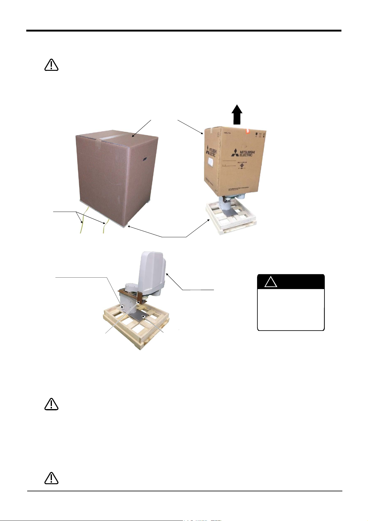
(2) RH-3FRHR series
Unpacking the robot with hoisting.
(Utilize the hanging tools (two places) <4> of the robot arm).
Please unpack near the installation place.
<5> Packing
material
Cut the tape
Hang the hook of the crane.
Completion
Robot-arm
base section
<2> Upper cover
Remove the upper cover. Remove the packing material.
Open the vinyl.
Hoist with crane and remove
the packing material.
<4>hanging tools
(Two places)
<1> Tape
(two)
Packing box
Always unpack the robot at a flat place. The robot
could tilt over if unpacked at an unstable place.
Don't remove fixing plate <7> till installation is
completed. When you pack the robot again, be
sure to install the fixing plate <7>.
CAUTION
CAUTION
<7> Fixing
plate
<3> Packing
material
(Cardboard)
<6> Tape
(two)
*The grease for preventing rust is applied at the tip of the shaft (J3 axis) in general-
purpose environment robot.
2Unpacking to Installation
Fig.2-2 : Unpacking the robot arm (RH-3FRHR series)
The unpacking procedure is shown below.
Unpacking is completd.
1) Cut with scissors etc. the tape <1> of fixing cardboard.
2) Raise and remove upper cover <2>. Remove packing material (cardboard) <3> in the inside.
3) Open the vinyl and confirm the hanging tools (two places) <4>. Hang the hook of the crane here. (Two
places)
4) Hoist with the crane and separate the robot arm together with packing material from the packing box.
5) Cut with scissors etc. tape <6> which fixed packing material <5>, and remove packing material <4>.
Installation
2-8
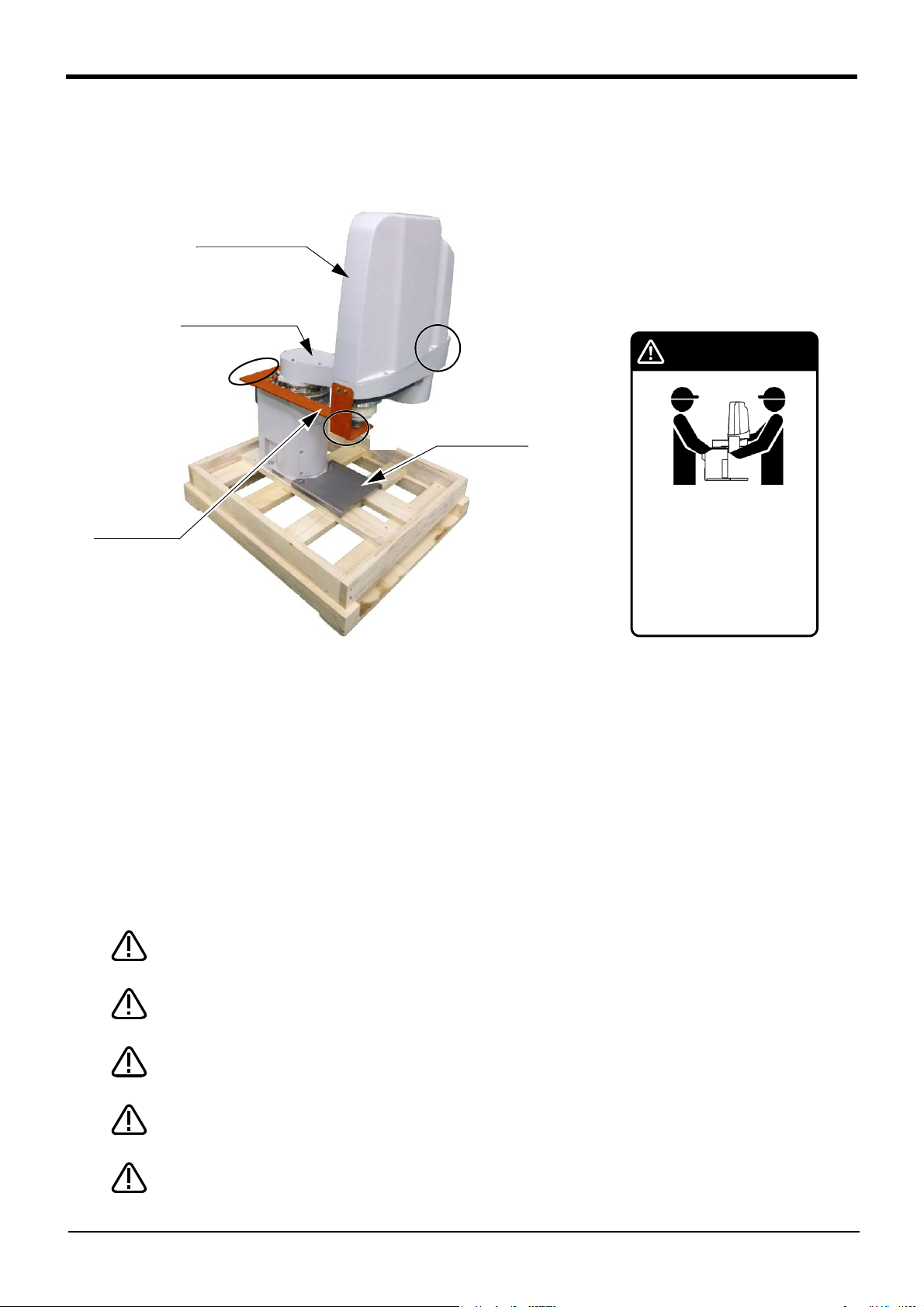
2Unpacking to Installation
注意 CAUTION
VORSICHT
ロボットの運搬は、図の姿勢のように
2人でおこなってください。
The robot must always be
transported by two workers.
Bei einem Transport sollte
der Roboter von 2
Personen an den in der
Abbildung gezeigten Stellen
angehoben werden.
Fixing plate B
No.1 arm
No.2 arm
<1>
<3>
Mass
RH-3FRH35** series: Approx. 31kg
RH-3FRH45** series: Approx. 32kg
RH-3FRH55** series: Approx. 33kg
RH-6FRH35** series: Approx. 39kg
RH-6FRH45** series: Approx. 40kg
RH-6FRH55** series: Approx. 41kg
Fixing plate A
<2>
*The grease for preventing rust is applied
at the tip of the shaft (J3 axis) in gen
-
eral-purpose environment robot.
CAUTION
CAUTION
CAUTION
CAUTION
CAUTION
2.2.2 Transportation procedures (1) RH-3FRH/6FRH series
1) The robot must be transported by two workers with putting the fixing plate A and B. Place the robot on a
cart, etc., and move it to near the installation place. Transporting the robot with the following should be lim
ited to placing the robot on the frame or cart, and to positioning.
2) When transporting the robot arm, one person should hold the fixing plate A of No.2 arm <1> and No.2 arm
<2> and another person should hold the fixing plate A of base <3>. When transporting the robot, do not apply
force to the cover, or apply a strong shock on the robot.
3) Remove the fixtures after installing the robot.
4) Always attach the fixing plate, and follow the above procedures and methods to transport the robot for
secondary transportation, such as when changing the installation position.
If the arm is directly holded without using the specified fixing plate, or if it is holded in the work posture, the
configuration devices could be damaged, and the transportation workers will be subject to risk due to an
inadequate center of gravity position.
Fig.2-3 : Transportation of robot arm (RH-3FRH/6FRH series)
To prevent accidents, do not hold the robot from the left/right sides, or hold covers that
have no grips.
Be careful not to apply force to the shaft section (J3 axis). The shaft may be damaged
and the overload error may occur at the time of movement.
When installing the fixing tool again, place the robot in the posture where each axis
shows the values listed in Table 2-2.
The robot should keep vertical. (not be horizontal)
It becomes the cause of the grease leakage or the trouble.
-
2-9
Installation
The ventilation duct is attached to the clean specification robot’s base section rear.
Please handle with care when transporting or installing the robot arm.
CAUTION
2Unpacking to Installation
If it is difficult to follow the transportation procedure shown in this section, take
countermeasures not to allow the joints of the robot arm freely move by fixing the robot
arm in such a way as to take advantage of the screw holes for fixing plates or the like.
Otherwise, applying an excessive power on the joints by external forces may cause a
malfunction.
Do not apply an excessive load to the robot arm while fixing it. Otherwise, the robot arm
may be damaged.
Table 2-2 : Transportation posture (RH-3FRH/6FRH series)
Axis RH-3FRH35** RH-3FRH45** RH-3FRH55** RH-6FRH35** RH-6FRH45** RH-6FRH55**
J 1 49.5 deg. 25 deg. 17 deg. 57.5 deg. 28 deg. 19 deg.
J 2 -139.5 deg. -115 deg. -107 deg. -147.5 deg. -118 deg. -109 deg.
J 3 290.4mm 290.4mm
J4 Not fixed Not fixed
Installation
2-10
2Unpacking to Installation
Mass
RH-12FRH55** series: Approx. 65kg
RH-12FRH70** series: Approx. 67kg
RH-12FRH85** series: Approx. 69kg
RH-20FRH85** series: Approx. 75kg
RH-20FRH100** series: Approx. 77kg
Self-supporting plate
Base
Transport
-
ing jig
Fixing plate
Eye bolt
No.1 arm
Wire hook
Wire
Note 1)
No.2 arm
*The grease for preventing rust is applied at the
tip of the shaft (J3 axis) in general-purpose
environment robot.
Note 1) Use wires that are 1300 mm or more.
CAUTION
CAUTION
CAUTION
CAUTION
CAUTION
(2) RH-12FRH/20FRH series
Fig.2-4 : Transportation of robot arm (RH-12FRH/20FRH series)
1) Hook the wires to each of the four eyebolts attached to the transporting jig. (Make sure the bolts are
securely hooked.)
2) Lift with a crane to transport the robot to the designated location.
3) At this time, make sure that the wires, etc., do not interfere with the robot arm or the covers. Always place
the cloth, etc., at interfering places.
4) Be careful not to subject the robot to physical shock during transport.
5) After installing the robot (refer to Page 15, "2.2.3 Installation procedures"), remove the wires, the wire
hooks (the robot will stand by itself as shown in Fig. 2-4), the self-supporting plate, transporting jig and fix
ing plate.
6) Always attach the self-supporting plate, fixing plate, and transporting jig, and follow the above procedures
and methods to transport the robot for secondary transportation, such as when changing the installation
position.
If the arm is directly suspended without using the specified transporting jig, or if it is suspended in the work
posture, the configuration devices could be damaged, and the transportation workers will be subject to risk
due to an inadequate center of gravity position.
When transporting a robot, always attach four wires.
To reattach the fixing plate again, set the axes of the robot to the positions according to
Table 2-3.
The robot should keep vertical. (not be horizontal)
It becomes the cause of the grease leakage or the trouble.
-
2-11
Installation
The ventilation duct is attached to the clean specification robot’s base section rear.
Please handle with care when transporting or installing the robot arm.
When the robot is not installed, the self-supporting plate must be attached to the robot.
The robot could tilt over, if the self-supporting plate is not attached to the robot.
CAUTION
2Unpacking to Installation
If it is difficult to follow the transportation procedure shown in this section, take
countermeasures not to allow the joints of the robot arm freely move by fixing the robot
arm in such a way as to take advantage of the screw holes for fixing plates or the like.
Otherwise, applying an excessive power on the joints by external forces may cause a
malfunction.
Do not apply an excessive load to the robot arm while fixing it. Otherwise, the robot arm
may be damaged.
Table 2-3 : Transportation posture (RH-12FRH/20FRH series)
Axis
J1 -37.5° -21.4° -15.1° -21.0°
J2 127.5° 111.4° 105.1° 111.0°
Note1)
J3
J4 Not fixed
RH-12FRH55** RH-12FRH70** RH-12FRH85** RH-20FRH85** RH-20FRH100**
340mm
Note1) The bottom surface of the shaft will interfere with the floor if the J3 axis is lowered down to the upper
mechanical stopper. Position the axes as indicated when transporting the robot.
Installation
2-12
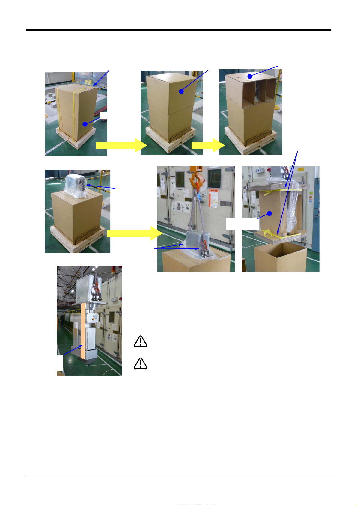
2Unpacking to Installation
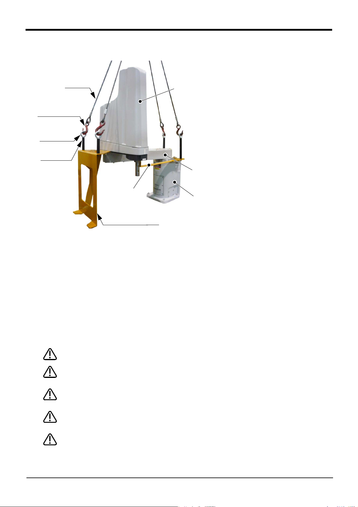
Mass
RH-3FRHR3515: Approx. 24kg
RH-3FRHR3512C/3512W: Approx. 28kg
Note)
Note) Be cautious of interference
at the end of the shaft.
Hoisting
Transport
<8> Installation stage
Install
<4> Transporting jig (two places)
<9> Installation bolt, Nut
(four places)
<7> Fixing
plate
*The grease for preventing rust is applied at the tip
of the shaft (J3 axis) in general-purpose environ
-
ment robot.
CAUTION
CAUTION
(3) RH-3FRHR series
Fig.2-5 : Transportation of robot arm (RH-3FRHR series)
The transportation procedure is shown below. Transport the robot with careful of safety, referring to Fig. 2-5.
Transport by using the crane with fixing plate <7> still being installed is necessary.
Transport carefully so that the robot may not tilt by using two wires. Take care suffi
ciently not to give the interference and the shock with the installation stage etc.,
1) Transport the robot by the crane from the condition which unpacking completed to the fixing position of
installation stage <8>.
2) Fixing the robot by four installation bolts <9> (attached) certainly to installation stage <8>.
3) Remove transporting jigs (two places) <4> after installation. Loosen the screw (M5 x 4, M4x1) fixing the fix
ing plate <7>, and remove the fixing plate <7>. Also remove the nut for T slots. Fixing plate <7>, and fixing
screws and transporting jigs <4> are needed at secondary transportation. Please keep them with care.
4) Always attach the fixing plate and transporting jig, and follow the above procedures and methods to
transport the robot for secondary transportation, such as when changing the installation position.
If the arm is directly suspended without using the specified transporting jig, or if it is suspended in the work
posture, the configuration devices could be damaged, and the transportation workers will be subject to risk
due to an inadequate center of gravity position.
Transportation is complete above.
To reattach the fixing plate again, set the axes of the robot to the positions according to
Table 2-4.
-
-
2-13
Installation
CAUTION
If it is difficult to follow the transportation procedure shown in this section, take
countermeasures not to allow the joints of the robot arm freely move by fixing the robot
arm in such a way as to take advantage of the screw holes for fixing plates or the like.
Otherwise, applying an excessive power on the joints by external forces may cause a
malfunction.
Do not apply an excessive load to the robot arm while fixing it. Otherwise, the robot arm
may be damaged.
Table 2-4 : Transportation posture (RH-3FRHR series)
Axis
J1 0 deg.
J2 0 deg.
Note1)
J3
J4 Not fixed
RH-3FRHR3515 RH-3FRHR3512C/3512W
-569.5mm (Upper end) -599.5mm (Upper end)
Note1) Because if the J3 axis is lowered the shaft juts danger, be sure to specified
posture at transport.
2Unpacking to Installation
Installation
2-14
2Unpacking to Installation
(4箇所)
バネ座金
平座金
20
4-M8×40
F
H
F
V
F
H
F
H
F
H
M
L
M
L
F
V
M
T
(Four positions)
Spring washer
Plain washer
<Detail of installation dimension>
(Base section of a robot arm)
RH-3FRH/6FRH series
RH-12FRH/20FRH series
4-M8x40 (RH-3FRH/6FRH series)
4-M12x45 (RH-12FRH/20FRH series)
2.2.3 Installation procedures
The installation procedure of the robot arm is shown below.
(1) RH-3FRH/6FRH/12FRH/20FRH series
㻔㼒㼛㼞㻌䃥㻤㻌㼜㼛㼟㼕㼠㼕㼛㼚㼕㼚㼓㻌㼜㼕㼚㼟㻕
㻞㻙䃥㻢㻌㼔㼛㼘㼑㼟
㻠㻙䃥㻥㻌㼕㼚㼟㼠㼍㼘㼘㼍㼠㼕㼛㼚㻌㼔㼛㼘㼑㼟
㻔㻵㼚㼟㼠㼍㼘㼘㼍㼠㼕㼛㼚㻌
㼞㼑㼒㼑㼞㼑㼚㼏㼑㻌㼟㼡㼞㼒㼍㼏㼑㻕
㻾㼦㻞㻡
㻥㻞
㻝㻤㻞
Fig.2-6 : Installation dimensions (RH-3FRH/6FRH/12FRH/20FRH series)
1) The robot installation surface has been machine finished. Use the installation holes (RH-3FRH/6FRH: 4-φ9
holes, RH-12FRH/20FRH: 4-φ16 holes) opened at the four corners of the base, and securely fix the robot
with the enclosed installation bolts (hexagon socket bolts).
2) Install the robot on a level surface.
3) It is recommended that the surface roughness of the table onto which the robot is to be installed by Rz25 or
more. If the installation surface is rough, the contact with the table will be poor, and positional deviation
could occur when the robot moves.
4) When installing, use a common table to prevent the position of the devices and jigs subject to robot work
from deviating.
5) The installation surface must have sufficient strength to withstand the arm reaction during operation, and
resistance against deformation and vibration caused by the static (dynamic) load of the robot arm and
peripheral devices, etc.
6) After installing the robot, remove the self-supporting plate, hanging jig, and fixing plate.
㻝㻤㻜
㻔㻵㼚㼟㼠㼍㼘㼘㼍㼠㼕㼛㼚㻌
㼞㼑㼒㼑㼞㼑㼚㼏㼑㻌㼟㼡㼞㼒㼍㼏㼑㻕
㻾㼦㻞㻡
㻝㻡㻜
㻝㻢㻜
㻞㻝㻞
㻥㻞
㻝㻞㻜㻥㻜
㻝㻡㻜
㻢㻜
㻔㼒㼛㼞㻌䃥㻤㻌㼜㼛㼟㼕㼠㼕㼛㼚㼕㼚㼓㻌㼜㼕㼚㼟㻕
㻠㻙䃥㻝㻢㻌㼕㼚㼟㼠㼍㼘㼘㼍㼠㼕㼛㼚㻌㼔㼛㼘㼑㼟
㻔㻵㼚㼟㼠㼍㼘㼘㼍㼠㼕㼛㼚㻌
㼞㼑㼒㼑㼞㼑㼚㼏㼑㻌㼟㼡㼞㼒㼍㼏㼑㻕
㻝㻣㻠
㻞㻙䃥㻢㻌㼔㼛㼘㼑㼟
㻝㻞㻞
㻞㻠㻞
㻾㼦㻞㻡
㻞㻠㻜
㻔㻵㼚㼟㼠㼍㼘㼘㼍㼠㼕㼛㼚㻌
㼞㼑㼒㼑㼞㼑㼚㼏㼑㻌㼟㼡㼞㼒㼍㼏㼑㻕
㻾㼦㻞㻡
㻞㻜㻜
㻞㻞㻜
㻝㻞㻞
㻝㻞㻜
㻞㻤㻜
㻔㻝㻡㻤㻕
㻞㻜㻜
㻤㻜
㻝㻤㻜
2-15
Installation
CAUTION
2Unpacking to Installation
7) If you operate the robot at a high speed, reaction forces are applied to the installation stand by the robot's
operation. Make sure that the installation stand on which the robot is placed has sufficient strength and
rigidity. Table 2-5 shows the maximum reaction force (design values) that may be applied to an installation
stand. Please use these values as reference when designing the installation stand.
Table 2-5 : Magnitude of each reaction force
Item
RH-3FRH series
Tilt moment : M
Torsional moment : M
L
T
Horizontal direction translation force : F
Vertical direction translation force : F
RH-6FRH series
Tilt moment : M
Torsional moment : M
L
T
V
Horizontal direction translation force : F
Vertical direction translation force : F
RH-12FRH/20FRH series
Tilt moment : M
Torsional moment : M
L
T
V
Horizontal direction translation force : F
Vertical direction translation force : F
V
H
H
H
Unit Value
N ・ m 240
N ・ m 255
N 810
N 380
N ・ m 1,640
N ・ m 710
N 1,653
N 2,318
N ・ m 3,190
N ・ m 1,840
N 2,240
N 2,500
When installing the robot, secure enough space for connection of the machine cable and
replacement of the backup battery in front of or behind the robot base. And don't install
the robot arm in the position where direct rays or the heat of lighting hits. The skin tem
perature of the robot arm may rise, and the error may occur.
-
Installation
2-16

2Unpacking to Installation
㻾㼦㻞㻡
㻾㼦㻞㻡
㻟㻢㻜
㻟㻠㻜
㻝㻤㻜㻛㻞㻜㻜
㻝㻢㻜
㻔㻵㼚㼟㼠㼍㼘㼘㼍㼠㼕㼛㼚㻌㼞㼑㼒㼑㼞㼑㼚㼏㼑㻕
㻔㻵㼚㼟㼠㼍㼘㼘㼍㼠㼕㼛㼚㻌
㼞㼑㼒㼑㼞㼑㼚㼏㼑㻕
㻠㻙䃥㻥
㼕㼚㼟㼠㼍㼘㼘㼍㼠㼕㼛㼚㻌㼔㼛㼘㼑
㻹㼍㼕㼚㼠㼑㼚㼍㼚㼏㼑㻌㼟㼜㼍㼏㼑
㻞㻙㻹㻝㻞㻌㼔㼛㼘㼑㻌㼒㼛㼞㻌㼔㼍㼚㼓㼕㼚㼓㻌㼠㼛㼛㼘㼟
㻠㻙㻹㻤㻌㼔㼛㼘㼑㻌㼒㼛㼞㻌㼖㼍㼏㼗㻙㼡㼜
㻵㼚㼟㼠㼍㼘㼘㼍㼠㼕㼛㼚㻌㼟㼠㼍㼓㼑
㻔㼑㼤㼍㼙㼜㼘㼑㻕
㻺㼛㼠㼑㻌㻝㻕
㻺㼛㼠㼑㻌㻞㻕
㻔㻤㻜㻕
㻟㻟㻢
㻟㻝㻜
㻞㻟㻜
㻟㻜㻜㻡㻜㻜
㻤㻞
㻹㼍㼕㼚㼠㼑㼚㼍㼚㼏㼑㻌㼟㼜㼍㼏㼑
FV
MT
FH
ML
FH
ML
FH
FH
FV
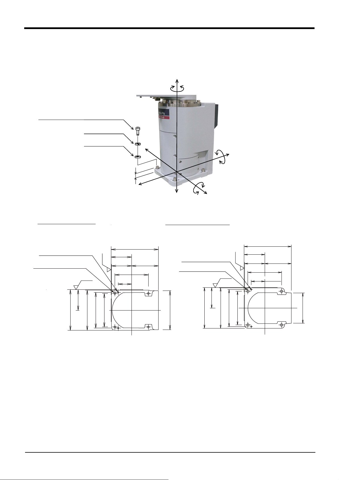
Note1) General environment type:
180mm
Clean/waterproof specification:
200mm
Note2) The interference of installation bolt
and No.1 arm may occur depending on
the size of installation stage. Take care
against interference of installation bolt,
such as inserting the installation bolt
from the bottom.
(2) RH-3FRHR series
2-17
Fig.2-7 : Installation dimensions (RH-3FRHR series)
1) The robot installation surface has been machine finished. Use the installation holes (4-φ9) opened at the
four corners of the base, and securely fix the robot with the enclosed installation bolts (hexagon socket
bolts).
2) Install the robot on a level surface.
3) It is recommended that the surface roughness of the table onto which the robot is to be installed by Rz25 or
more. If the installation surface is rough, the contact with the table will be poor, and positional deviation
could occur when the robot moves.
4) When installing, use a common table to prevent the position of the devices and jigs subject to robot work
from deviating.
5) The installation surface must have sufficient strength to withstand the arm reaction during operation, and
resistance against deformation and vibration caused by the static (dynamic) load of the robot arm and
peripheral devices, etc.
6) If you operate the robot at a high speed, reaction forces are applied to the installation stand by the robot's
operation. Make sure that the installation stand on which the robot is placed has sufficient strength and
rigidity. Table 2-5 shows the maximum reaction force (design values) that may be applied to an installation
stand. Please use these values as reference when designing the installation stand.
Installation
 Loading...