

Page 1

QSCPU User's Manual
(Hardware Design, Maintenance and Inspection)
-QS001CPU
Page 2

Page 3
SAFETY PRECAUTIONS
(Read these precautions before using this product.)
Before using this product, please read this manual and the relevant manuals carefully and pay full attention
to safety to handle the product correctly.
In this manual, the safety precautions are classified into two levels: " WARNING" and " CAUTION".
WARNING
CAUTION
Under some circumstances, failure to observe the precautions given under " CAUTION" may lead to
serious consequences.
Observe the precautions of both levels because they are important for personal and system safety.
Make sure that the end users read this manual and then keep the manual in a safe place for future
reference.
Indicates that incorrect handling may cause hazardous conditions,
resulting in death or severe injury.
Indicates that incorrect handling may cause hazardous conditions,
resulting in minor or moderate injury or property damage.
[Design Precautions]
WARNING
When a safety programmable controller detects an error in an external power supply or a failure in
programmable controller, it turns off all the outputs.
Create an external circuit to securely stop the power of hazard by turning off the outputs. Incorrect
configuration may result in an accident.
Create short current protection for a safety relay, and a protection circuit such as a fuse, and
breaker, outside a safety programmable controller.
When data/program change, or status control is performed from a personal computer to a running
safety programmable controller, create an interlock circuit outside the sequence program and safety
programmable controller to ensure that the whole system always operates safely.
For the operations to a safety programmable controller, pay full attention to safety by reading the
relevant manuals carefully, and establishing the operating procedure.
Furthermore, for the online operations performed from a personal computer to a safety CPU module,
the corrective actions against a communication error due to a cable connection fault, etc. should be
predetermined as a system.
A - 1
Page 4
[Design Precautions]
WARNING
All output signals from a safety CPU module to the CC-Link Safety system master module are
prohibited to use.
These signals can be found in the CC-Link Safety System Master Module User's Manual.
Do not turn ON or OFF these signals by sequence program, since turning ON/OFF these output
signals of the programmable controller system may cause malfunctions and safety operation cannot
be guaranteed.
All output signals from a safety CPU module to the CC-Link IE Field Safety Network master/local
module (with safety functions) are prohibited to use.
These signals can be found in the MELSEC-QS CC-Link IE Field Safety Network Master/Local
User's Manual.
Do not turn ON or OFF these signals by sequence program, since turning ON/OFF these output
signals of the programmable controller system may cause malfunctions and safety operation cannot
be guaranteed.
When a safety remote I/O module has detected a CC-Link Safety error, it turns off all the outputs.
Note that the outputs in a sequence program are not automatically turned off.
If a CC-Link Safety or CC-Link IE Field Network error has been detected, create a sequence
program that turns off the outputs in the program.
If the CC-Link Safety or CC-Link IE Field Network is restored with the outputs on, it may suddenly
operate and result in an accident.
To inhibit restart without manual operation after safety functions was performed and outputs were
turned OFF, create an interlock program which uses a reset button for restart.
To prevent an illegal operation and malfunction, do not connect a safety programmable controller to
the Internet or to a wireless LAN.
[Design Precautions]
CAUTION
Do not install the wires of external devices or communication cables together with the main circuit
lines or power cables. Keep a distance of 100mm (3.94 inch) or more between them.
Failure to do so may result in malfunction due to noise.
After the CPU module is powered on or is reset, the time taken to enter the RUN status varies
depending on the system configuration, parameter settings, and/or program size.
Design circuits so that the entire system will always operate safely, regardless of the time.
A - 2
Page 5
[Installation Precautions]
CAUTION
Use the safety programmable controller in an environment that meets the general specifications in
this manual. Failure to do so may result in electric shock, fire, malfunction, or damage to or
deterioration of the product.
To mount the module, while pressing the module mounting lever located in the lower part of the
module, fully insert the module fixing projection(s) into the hole(s) in the base unit and press the
module until it snaps into place.
Incorrect interconnection may cause malfunction, failure, or drop of the module.
Secure the module to the base unit with screws.
Tighten the screws within the specified torque range.
Undertightening can cause drop of the screw, short circuit, or malfunction.
Overtightening can damage the screw and/or module, resulting in drop, short circuit, or malfunction.
Shut off the external power supply (all phases) used in the system before mounting or removing the
module.
Failure to do so may result in damage to the product.
Do not directly touch any conductive part of the module.
Doing so can cause malfunction or failure of the module.
[Wiring Precautions]
WARNING
Shut off the external power supply (all phases) used in the system before wiring.
Failure to do so may result in electric shock or damage to the product.
After wiring, attach the included terminal cover to the module before turning it on for operation.
Failure to do so may result in electric shock.
A - 3
Page 6
[Wiring Precautions]
CAUTION
Individually ground the FG and LG terminals of the programmable controller with a ground
resistance of 100 or less.
Failure to do so may result in electric shock or malfunction.
Use a solderless terminal with insulation sleeve for wiring of a terminal block.
Use up to two solderless terminals for a single terminal.
Use applicable solderless terminals and tighten them within the specified torque range.
If any spade solderless terminal is used, it may be disconnected when a terminal block screw comes
loose, resulting in failure.
Check the rated voltage and terminal layout before wiring to the module, and connect the cables
correctly.
Connecting a power supply with a different voltage rating or incorrect wiring may cause a fire or
failure.
Tighten the terminal block mounting screws, terminal screws, and module fixing screws within the
specified torque range.
Undertightening of the terminal block mounting screws or terminal screws can cause short circuit,
fire, or malfunction.
Overtightening can damage the screw and/or module, resulting in drop, short circuit, or malfunction.
Undertightening of the module fixing screws can cause drop of the module.
Overtightening can damage the screw and/or module, resulting in drop.
Prevent foreign matter such as dust or wire chips from entering the module.
Such foreign matter can cause a fire, failure, or malfunction.
A protective film is attached to the top of the module to prevent foreign matter, such as wire chips,
from entering the module during wiring.
Do not remove the film during wiring.
Remove it for heat dissipation before system operation.
A - 4
Page 7
[Wiring Precautions]
CAUTION
Mitsubishi programmable controllers must be installed in control panels.
Connect the main power supply to the power supply module in the control panel through a relay
terminal block.
Wiring and replacement of a power supply module must be performed by qualified maintenance
personnel with knowledge of protection against electric shock.
(For the wiring methods, refer to Section 10.3.)
[Startup and Maintenance Precautions]
WARNING
Do not touch any terminal while power is on.
Doing so will cause electric shock.
Correctly connect the battery connector.
Do not charge, disassemble, heat, short-circuit, or solder the battery, or throw it into the fire.
Doing so will cause the battery to produce heat, explode, or ignite, resulting in injury and fire.
Shut off the external power supply (all phases) used in the system before cleaning the module or
retightening the terminal block mounting screws, terminal screws, or module fixing screws.
Failure to do so may result in electric shock.
Tighten these screws within the specified torque range.
Undertightening of the terminal block mounting screws or terminal screws can cause short circuit,
fire, or malfunction.
Overtightening can damage the screw and/or module, resulting in drop, short circuit, or malfunction.
Undertightening of the module fixing screws can cause drop of the module.
Overtightening can damage the screw and/or module, resulting in drop.
A - 5
Page 8
[Startup and Maintenance Precautions]
CAUTION
The online operations performed from a personal computer to a running safety programmable
controller (Program change when a safety CPU module is RUN, device test, and operating status
change such as RUN-STOP switching) have to be executed after the manual has been carefully
read and the safety has been ensured.
Following the operating procedure predetermined at designing, the operation has to be performed by
an instructed person.
When changing a program while a safety CPU module is RUN (Write during RUN), it may cause a
program breakdown in some operating conditions.
Fully understand the precautions described in the GX Developer's manual before use.
Do not disassemble or modify the modules.
Doing so may cause failure, malfunction, injury, or a fire.
If the product is repaired or remodeled by other than the specified FA centers or us, the warranty is
not covered.
Use any radio communication device such as a cellular phone or PHS (Personal Handy-phone
System) more than 25cm (9.85 inches) away in all directions from the programmable controller.
Failure to do so may cause malfunction.
Shut off the external power supply (all phases) used in the system before wiring.
Failure to do so may cause the module to fail or malfunction.
After the first use of the product, do not mount/remove the module to/from the base unit, and the
terminal block to/from the module more than 50 times (IEC 61131-2 compliant) respectively.
Exceeding the limit may cause malfunction.
Do not drop or apply shock to the battery to be installed in the module.
Doing so may damage the battery, causing the battery fluid to leak inside the battery.
If the battery is dropped or any shock is applied to it, dispose of it without using.
Before handling the module, touch a conducting object such as a grounded metal to discharge the
static electricity from the human body.
Failure to do so may cause the module to fail or malfunction.
A - 6
Page 9

[Disposal Precautions]
CAUTION
When disposing of this product, treat it as industrial waste.
When disposing of batteries, separate them from other wastes according to the local regulations.
(For details of battery regulations in EU member states, refer to Appendix 4.)
[Transportation Precautions]
CAUTION
When transporting lithium batteries, follow the transportation regulations.
(For details of the regulated models, refer to Appendix 3.)
A - 7
Page 10

CONDITIONS OF USE FOR THE PRODUCT
(1) Although MELCO has obtained the certification for Product's compliance to the international safety
standards IEC61508, EN954-1/ISO13849-1 from TUV Rheinland, this fact does not guarantee that
Product will be free from any malfunction or failure. The user of this Product shall comply with any
and all applicable safety standard, regulation or law and take appropriate safety measures for the
system in which the Product is installed or used and shall take the second or third safety measures
other than the Product. MELCO is not liable for damages that could have been prevented by
compliance with any applicable safety standard, regulation or law.
(2) MELCO prohibits the use of Products with or in any application involving, and MELCO shall not be
liable for a default, a liability for defect warranty, a quality assurance, negligence or other tort and a
product liability in these applications.
(a) power plants,
(b) trains, railway systems, airplanes, airline operations, other transportation systems,
(c) hospitals, medical care, dialysis and life support facilities or equipment,
(d) amusement equipments,
(e) incineration and fuel devices,
(f) handling of nuclear or hazardous materials or chemicals,
(g) mining and drilling,
(h) and other applications where the level of risk to human life, health or property are elevated.
A - 8
Page 11
REVISIONS
Correction
Addition
Correction
Addition
Correction
Addition
Change of a term
Correction
Correction
Addition
Correction
Addition
Correction
Correction
The manual number is given on the bottom left of the back cover.
Print Date Manual Number Revision
Sep., 2006 SH(NA)-080626ENG-A First edition
May, 2007 SH(NA)-080626ENG-B
Section 2.2, 4.1, 5.1, 6.1, 9.1.1, 9.1.3, 10.1, 10.3.1, 10.3.2, 12.2.1, 12.2.10
Section 12.2.12
Apr., 2008 SH(NA)-080626ENG-C
ABOUT MANUALS, GENERIC TERMS AND ABBREVIATIONS, Section 1.1,
2.1, 4.2, 4.3, 4.4, 5.1, 5.3, 6.2, 8.1, 9.1.3, 9.1.4, 9.2.1, 10.2.1, 10.2.3, 10.3.1,
10.3.2, 11.1, 11.2, 12.2.1, 12.2.3, 12.2.4, 12.2.5, 12.2.7, 12.2.8, 12.2.9, 12.2.12,
12.3.1, 12.3.3, 12.3.4, 12.3.5, 12.3.6, 12.3.7, 12.3.8, 12.6, 12.7
Section 2.1.1, Appendix 2
Sep., 2008 SH(NA)-080626ENG-D
Section 10.2.1
SAFETY PRECAUTIONS, Section 7.1, Appendix 4
Apr., 2009 SH(NA)-080626ENG-E
"PLC" was changed to "programmable controller".
Feb., 2010 SH(NA)-080626ENG-F
Jul., 2010 SH(NA)-080626ENG-
May, 2011 SH(NA)-080626ENG-H
May, 2012 SH(NA)-080626ENG-I
ABOUT MANUALS GENERIC TERMS AND ABBREVIATIONS Chapter 1,
Section 2.1.1, Chapter 3, Chapter 9, Section 11.3.1, Section 11.3.2,
Section 12.3.3, Section 12.3.6
SAFETY PRECAUTIONS, Section 2.1, 4.1, 7.1.1, 7.1.2, Chapter 11, Section
11.3.1, 12.3.3, Appendix 1.1, Appendix 1.3
CONDITIONS OF USE FOR THE PRODUCT
G
SAFETY PRECAUTIONS, Section 1.1, 2.1, 2.1.1, 4.1, Chapter 9
Section 9.3
SAFETY PRECAUTIONS, ABOUT MANUALS, GENERIC TERMS AND
ABBREVIATIONS Section 1.1, 2.1, 2.1.1, 8.1, 9.1.3, 9.2.2, Chapter 10, Section
12.2.7, 12.3.1, 12.3.4, 12.3.5, 12.6, 12.7, Appendix 2
SAFETY PRECAUTIONS, Section 2.3, Chapter 3, Section 5.2, 5.3, 9.1.1, 9.2.1,
10.3.1, 12.6, Appendix 2
A - 9
Page 12
The manual number is given on the bottom left of the back cover.
Correction
Deletion
Correction
Print Date Manual Number Revision
Jun., 2013 SH(NA)-080626ENG-J
Section 2.1.1, 5.3, 9.1.5
Section 9.2.5
Feb., 2015 SH(NA)-080626ENG-K
Section 7.1.1
Japanese Manual Version SH-080607-K
This manual confers no industrial property rights or any rights of any other kind, nor does it confer any patent licenses.
Mitsubishi Electric Corporation cannot be held responsible for any problems involving industrial property rights which may
occur as a result of using the contents noted in this manual.
C
2006 MITSUBISHI ELECTRIC CORPORATION
A - 10
Page 13

INTRODUCTION
Thank you for choosing the Mitsubishi MELSEC-QS Series of Safety Programmable Controllers.
Before using the equipment, please read this manual carefully to develop full familiarity with the functions
and performance of the QS series programmable controller you have purchased, so as to ensure correct
use.
CONTENTS
SAFETY PRECAUTIONS .................................................................................................................................A - 1
CONDITIONS OF USE FOR THE PRODUCT..................................................................................................A - 8
REVISIONS....................................................................................................................................................... A - 9
INTRODUCTION.............................................................................................................................................A - 11
CONTENTS ....................................................................................................................................................A - 11
ABOUT MANUALS .........................................................................................................................................A - 19
HOW THIS MANUAL IS ORGANIZED ...........................................................................................................A - 21
HOW TO USE THIS MANUAL........................................................................................................................ A - 22
GENERIC TERMS AND ABBREVIATIONS.................................................................................................... A - 23
PRECAUTIONS FOR USE .............................................................................................................................A - 24
CHAPTER1 OVERVIEW 1 - 1 to 1 - 7
1.1 Features........................................................................................................................................... 1 - 3
CHAPTER2 SYSTEM CONFIGURATION 2 - 1 to 2 - 7
2.1 System Configuration ...................................................................................................................... 2 - 1
2.1.1 Precautions for system configuration .......................................................................................2 - 4
2.2 Configuration of Peripheral Devices ................................................................................................ 2 - 5
2.3 Checking Serial Number and Function Version ............................................................................... 2 - 6
CHAPTER3 GENERAL SPECIFICATIONS 3 - 1 to 3 - 2
CHAPTER4 CPU MODULE 4 - 1 to 4 - 7
4.1 Performance Specifications ............................................................................................................. 4 - 1
4.2 Part Names...................................................................................................................................... 4 - 3
4.3 Switch Operation after Writing a Program ....................................................................................... 4 - 5
4.4 Reset Operation............................................................................................................................... 4 - 6
A - 11
Page 14

CHAPTER5 POWER SUPPLY MODULE 5 - 1 to 5 - 5
5.1 Specifications................................................................................................................................... 5 - 1
5.2 Precaution when connecting the uninterruptible power supply........................................................ 5 - 3
5.3 Names of Parts and Settings ........................................................................................................... 5 - 4
CHAPTER6 BASE UNIT 6 - 1 to 6 - 2
6.1 Specification .................................................................................................................................... 6 - 1
6.2 Part Names...................................................................................................................................... 6 - 2
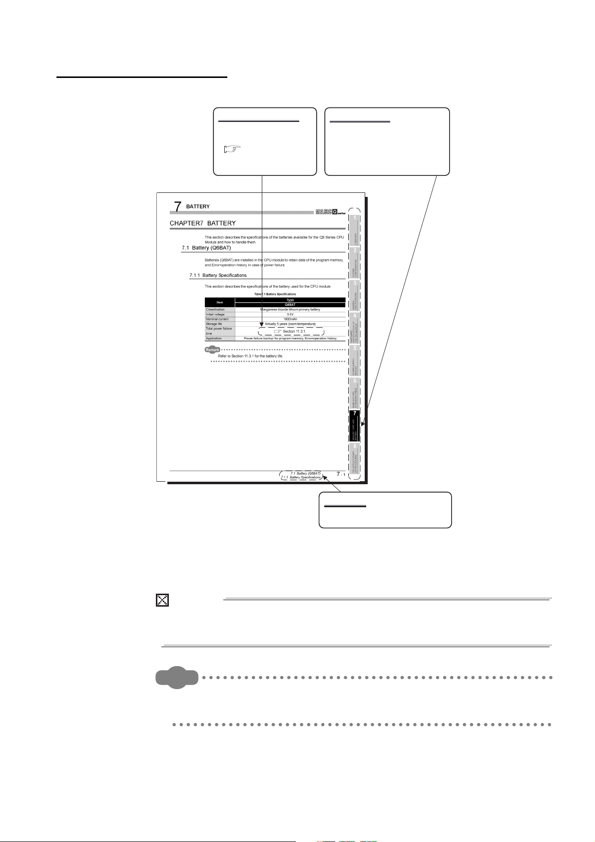
CHAPTER7 BATTERY 7 - 1 to 7 - 2
7.1 Battery (Q6BAT) .............................................................................................................................. 7 - 1
7.1.1 Battery Specifications ............................................................................................................... 7 - 1
7.1.2 Installation of Battery ................................................................................................................ 7 - 2
CHAPTER8 CPU MODULE START-UP PROCEDURES 8 - 1 to 8 - 3
8.1 Procedure before Operating in SAFETY MODE.............................................................................. 8 - 1
CHAPTER9 EMC, LOW VOLTAGE, AND MACHINERY DIRECTIVES 9 - 1 to 9 - 13
9.1 Requirements for Conformance to EMC Directive........................................................................... 9 - 1
9.1.1 Standards relevant to the EMC Directive.................................................................................. 9 - 2
9.1.2 Installation in a control panel .................................................................................................... 9 - 3
9.1.3 Cables....................................................................................................................................... 9 - 4
9.1.4 Power Supply Module............................................................................................................... 9 - 7
9.1.5 Others....................................................................................................................................... 9 - 7
9.2 Requirement to Conform to the Low Voltage Directive.................................................................... 9 - 9
9.2.1 Standard applied for MELSEC-QS series programmable controller......................................... 9 - 9
9.2.2 MELSEC-QS series programmable controller selection........................................................... 9 - 9
9.2.3 Power supply .......................................................................................................................... 9 - 10
9.2.4 Control panel .......................................................................................................................... 9 - 10
9.2.5 External wiring ........................................................................................................................ 9 - 12
9.3 Requirements for compliance with the Machinery Directive .......................................................... 9 - 13
CHAPTER10 LOADING AND INSTALLATION 10 - 1 to 10 - 22
10.1 Calculating Heat Generation of programmable controller.............................................................. 10 - 3
10.2 Module Installation ......................................................................................................................... 10 - 5
10.2.1 Installation precautions ........................................................................................................... 10 - 5
10.2.2 Instructions for mounting the base unit................................................................................. 10 - 12
10.2.3 Installation and removal of module ....................................................................................... 10 - 15
10.3 Wiring........................................................................................................................................... 10 - 18
10.3.1 Wiring precautions................................................................................................................ 10 - 18
10.3.2 Connecting to the power supply module............................................................................... 10 - 22
A - 12
Page 15

CHAPTER11 MAINTENANCE AND INSPECTION 11 - 1 to 11 - 11
11.1 Daily Inspection ............................................................................................................................. 11 - 3
11.2 Periodic Inspection ........................................................................................................................ 11 - 4
11.3 Battery Life and Replacement Procedure......................................................................................11 - 5
11.3.1 Battery lives of CPU modules................................................................................................. 11 - 6
11.3.2 Replacement Procedure of the CPU Module Battery ............................................................. 11 - 8
11.4 When programmable controller Has been Stored without a Battery............................................ 11 - 10
11.5 When Battery Has Gone Flat during Storage of a programmable controller ............................... 11 - 11
CHAPTER12 TROUBLESHOOTING 12 - 1 to 12 - 101
12.1 Troubleshooting Basics ................................................................................................................. 12 - 1
12.2 Troubleshooting Flowchart ............................................................................................................ 12 - 2
12.2.1 Troubleshooting category flow................................................................................................ 12 - 2
12.2.2 Flowchart for when the ERR terminal (negative logic) is off (opened) ................................... 12 - 3
12.2.3 Flowchart for when the "POWER" LED turns off .................................................................... 12 - 5
12.2.4 When the "ALIVE" LED does not turn on or turns off ............................................................. 12 - 7
12.2.5 Flowchart for when the "RUN" LED turns off .......................................................................... 12 - 9
12.2.6 When the "RUN" LED flashes .............................................................................................. 12 - 10
12.2.7 Flowchart for when the "ERR." LED turns on or flashes ...................................................... 12 - 11
12.2.8 When the "USER" LED turns on........................................................................................... 12 - 14
12.2.9 When the "BAT." LED turns on............................................................................................. 12 - 15
12.2.10 Flowchart for when a program cannot be read ..................................................................... 12 - 16
12.2.11 Flowchart for when a program cannot be written ................................................................. 12 - 17
12.2.12 Flowchart for when the CPU cannot communicate with the GX Developer ......................... 12 - 18
12.3 Error Code List............................................................................................................................. 12 - 20
12.3.1 Error codes........................................................................................................................... 12 - 21
12.3.2 Reading an error code.......................................................................................................... 12 - 22
12.3.3 Error code list (1000 to 1999) ............................................................................................... 12 - 23
12.3.4 Error code list (2000 to 2999) ............................................................................................... 12 - 29
12.3.5 Error code list (3000 to 3999) ............................................................................................... 12 - 35
12.3.6 Error code list (4000 to 4999) ............................................................................................... 12 - 45
12.3.7 Error code list (5000 to 5999) ............................................................................................... 12 - 49
12.3.8 Error code list (8000 to 9000) ............................................................................................... 12 - 51
12.4 Clearing an error.......................................................................................................................... 12 - 65
12.5 Error codes returned to request source during communication with CPU module ...................... 12 - 68
12.6 Special Relay List ........................................................................................................................ 12 - 77
12.7 Special Register List .................................................................................................................... 12 - 83
APPENDICES App- 1 to App - 9
Appendix 1 External Dimensions..........................................................................................................App- 1
Appendix 1.1 CPU module ..............................................................................................................App- 1
Appendix 1.2 Power supply module ................................................................................................App- 2
Appendix 1.3 Main base unit ...........................................................................................................App- 3
Appendix 2 Safety CPU Module Upgrade ............................................................................................ App- 4
Appendix 3 Precautions for Battery Transportation.............................................................................. App- 6
A - 13
Page 16

Appendix 4 Handling of Batteries and Devices with Built-in Batteries in EU Member States............... App- 7
Appendix 4.1 Disposal precautions ................................................................................................. App- 7
Appendix 4.2 Exportation precautions .............................................................................................App- 8
INDEX Index- 1 to Index- 2
A - 14
Page 17

(Related manual).................QSCPU User's Manual (Function Explanation, Program Fundamentals)
CONTENTS
CHAPTER1 OVERVIEW
1.1 Features
1.2 Program Storage and Operation
1.3 Devices and Instructions Convenient for Programming
1.4 How to Check the Serial No. and Function Version
CHAPTER2 PERFORMANCE SPECIFICATION
CHAPTER3 SEQUENCE PROGRAM EXECUTION
3.1 Sequence Program
3.1.1 Sequence program description method
3.1.2 Sequsence program operation
3.2 Concept of Scan Time
3.3 Operation Processing
3.3.1 Initial processing
3.3.2 I/O refresh
3.3.3 END processing
3.4 RUN, STOP Operation Processing
3.5 Operation Processing during Momentary Power Failure
3.6 Data Clear Processing
3.7 Numeric Values which can be Used in Sequence Programs
3.7.1 BIN (Binary Code)
3.7.2 HEX (Hexadecimal)
3.7.3 BCD (Binary Coded Decimal)
CHAPTER4 I/O NUMBER ASSIGNMENT
4.1 Definition of I/O Number
4.2 Concept of I/O Number Assignment
4.2.1 I/O numbers of base unit
4.2.2 I/O numbers of remote station
4.3 I/O Assignment by GX Developer
4.3.1 Purpose of I/O assignment by GX Developer
4.3.2 Concept of I/O assignment using GX Developer
4.3.3 Examples of I/O Number Assignment
4.4 Checking the I/O Numbers
CHAPTER5 MEMORIES AND FILES HANDLED BY CPU MODULE
5.1 Memories by CPU Module
A - 15
Page 18

5.1.1 Memory configuration and storable data
5.1.2 Program memory
5.1.3 Standard ROM
5.1.4 Standard ROM program execution (boot run) and writing
5.2 Program File Structure
5.3 File Operation by GX Developer and Handling Precautions
5.3.1 File operation
5.3.2 Precautions for handling files
5.3.3 Memory capacities of files
5.3.4 File size units
CHAPTER6 FUNCTIONS
6.1 Function List
6.2 Safety CPU Operation Mode
6.2.1 Safety CPU operation mode
6.2.2 Checking safety CPU operation mode
6.2.3 Safety CPU operation mode switching
6.2.4 Operation of each function in each safety CPU operation mode and CPU operation status
6.2.5 Online operations that can be executed on the CPU module from GX Developer
6.3 CPU access password
6.4 PLC memory initialization
6.5 Setting to prevent continuous RUN in TEST MODE
6.6 Checking the ROM write count
6.7 Self-diagnostics Function
6.7.1 LED display for error
6.7.2 Cancel the error
6.8 Recording the operation contents and self-diagnostics error occurrence contents (operation/error history function)
6.9 Constant scan
6.10 Setting of Output (Y) Status when Changing between STOP and RUN
6.11 Clock Function
6.12 Remote Operation
6.12.1 Remote RUN/STOP
6.12.2 Remote RESET
6.12.3 Relationship of remote operation and CPU's RUN/STOP status
6.13 Monitor Function
6.14 Writing in Program during CPU Module RUN
6.14.1 Online change in ladder mode
6.15 Watchdog Timer(WDT)
6.16 Remote password
6.17 CPU Module System Display by GX Developer
6.18 LED Display
6.18.1 Method to turn off the LED
A - 16
Page 19

CHAPTER7 COMMUNICATION WITH INTELLIGENT FUNCTION MODULE
7.1 Communication with CC-Link Safety master module
7.2 Communication with CC-Link IE Field Network Master/Local Module (With Safety Functions)
7.3 Communication with CC-Link IE Controller Network Module or MELSECNET/H Module
7.4 Communication with Ethernet Module
7.5 Communication using intelligent function module dedicated instructions
CHAPTER8 PARAMETERS
8.1 PLC Parameters
8.2 Network Parameters
8.3 Remote Password
CHAPTER9 DEVICE EXPLANATION
9.1 Device List
9.2 Internal User Devices
9.2.1 Input (X)
9.2.2 Output (Y)
9.2.3 Internal relay (M)
9.2.4 Annunciator (F)
9.2.5 Edge relay (V)
9.2.6 Link relay (B)
9.2.7 Link special relay (SB)
9.2.8 Timer (T)
9.2.9 Counter (C)
9.2.10 Data register (D)
9.2.11 Link register (W)
9.2.12 Link special register (SW)
9.3 Internal System Devices
9.3.1 Special relay (SM)
9.3.2 Special register (SD)
9.4 Nesting (N)
9.5 Constants
9.5.1 Decimal constant (K)
9.5.2 Hexadecimal constant (H)
CHAPTER10 CPU MODULE PROCESSING TIME
10.1 Scan Time
10.1.1 Structure and calculation of scan time
10.1.2 Time required for each processing included in scan time
10.1.3 Factors that increase the scan time
10.2 Other Processing Times
CHAPTER11 PROCEDURE FOR WRITING PROGRAM TO CPU MODULE
A - 17
Page 20

11.1 Items to be examined for program creation
11.2 Procedure for writing program
11.3 Boot run procedure
APPENDICES
Appendix 1 Special Relay List
Appendix 2 Special Register List
Appendix 3 List of Parameter No
Appendix 4 Restrictions on Using CC-Link IE Controller Network Module with Safety CPU Module
Appendix 5 Restrictions on Using MELSECNET/H Module with Safety CPU Module
Appendix 6 Restrictions on Using Ethernet Module with Safety CPU Module
Appendix 7 Dedicated Instructions which can be used in Safety CPU Module
Appendix7.1 List of dedicated instructions
Appendix7.2 Programming using dedicated instructions
Appendix 8 Safety CPU Module Upgrade
Appendix 9 Access Range for Safety CPU Module
INDEX
A - 18
Page 21

ABOUT MANUALS
Introduction Manual
Read the following manual before designing and constructing a safety system.
Manual Name
Safety Application Guide
Explains the overview, construction method, laying and wiring examples, and application programs of the
safety-related system.
Related Manuals
The manual related to this product is shown below.
Please place an order as needed.
Manual No.
(Model Code)
SH-080613ENG
(13JR90)
(Sold separately)
Manual Name
QSCPU User's Manual (Function Explanation, Program Fundamentals)
Explains the functions, programming methods, devices and others that are necessary to create programs with the
QSCPU.
(Sold separately)
QSCPU Programming Manual (Common Instructions)
Explains how to use the sequence instructions, basic instructions, application instructions, and QSCPU dedicated
instructions.
(Sold separately)
CC-Link Safety System Master Module User's Manual
Explains the specifications, procedures and settings before operation, parameter settings, and troubleshooting of
the QS0J61BT12 CC-Link Safety system master module.
(Sold separately)
CC-Link Safety System Remote I/O Module User's Manual
Explains the specifications, procedures and settings before operation, parameter settings, and troubleshooting of
the CC-Link Safety system remote I/O modules.
(Sold separately)
MELSEC-QS CC-Link IE Field Network Master/Local Module User's Manual
Explains the specifications, procedures and settings before operation, parameter settings, and troubleshooting of
a CC-Link IE Field Network master/local module (with safety functions).
(Sold separately)
CC-Link IE Controller Network Reference Manual
Explains the system configuration, performance specifications, functions, handling, wiring, and troubleshooting of
CC-Link IE Controller Network.
(Sold separately)
Q Corresponding MELSECNET/H Network System Reference Manual (PLC to PLC network)
Explains the specifications, procedures and settings before operation, parameter settings, programming, and
troubleshooting of a MELSECNET/H network system for PLC to PLC network.
(Sold separately)
Q Corresponding Ethernet Interface Module User's Manual (Basic)
Explains the specifications, procedures for data communication with external devices, line connection (open/
close), fixed buffer communication, random access buffer communication, and troubleshooting of the Ethernet
module.
(Sold separately)
Manual No.
(Model Code)
SH-080627ENG
(13JR93)
SH-080628ENG
(13JW01)
SH-080600ENG
(13JR88)
SH-080612ENG
(13JR89)
SH-080969ENG
(13JZ53)
SH-080668ENG
(13JV16)
SH-080049
(13JF92)
SH-080009
(13JL88)
A - 19
Page 22

Remark
Manual Name
Q Corresponding Ethernet Interface Module User's Manual (Application)
Explains the e-mail function, programmable controller CPU status monitoring function, communication function via
CC-Link IE Controller Network, MELSECNET/H or MELSECNET/10, communication function using the data link
instructions, file transfer function (FTP server) of the Ethernet module.
(Sold separately)
MELSEC-Q/L MELSEC Communication Protocol Reference Manual
Explains the communication methods and control procedures using the MC protocol, which is used by external
devices to read and write data of the programmable controller CPU via the serial communication module or
Ethernet module.
(Sold separately)
Printed materials are separately available for single item purchase. Order the
manual by quoting the manual number on the table above (Model code).
Manual No.
(Model Code)
SH-080010
(13JL89)
SH-080008
(13JF89)
A - 20
Page 23
HOW THIS MANUAL IS ORGANIZED
POINT
Remark
Chapter heading
The index on the right side of the page
shows the chapter of the open page at a
glance.
Section title
The section of the open page is shown at a
glance.
Reference destination
A reference destination or
reference manual is marked
.
In addition, this manual provides the following explanations.
Explains the matters to be especially noted, the functions and others related to the
description on that page.
Provides the reference destination related to the description on that page and the
convenient information.
A - 21
Page 24

HOW TO USE THIS MANUAL
Remark
This manual is prepared for users to understand the hardware specifications of those
modules such as the CPU modules, power supply modules, and base units, maintenance
and inspections of the system, and troubleshooting required when you use QS series
programmable controllers.
The manual is classified roughly into three sections as shown below.
1) Chapters 1 and 2 Describe the outline of the CPU module and the system
2) Chapters 3 to 7 Describe the general specifications indicating the operating
3) Chapters 8 to 12 Describe the overall maintenance such as the installation of the
configuration.
The basics of the system configuration of CPU module are
described.
environments of the CPU module, power supply module, and base
units, and the performance specifications of these modules.
CPU module, daily inspections, and troubleshooting.
This manual does not explain the functions of the CPU module.
For these functions, refer to the manual shown below.
QSCPU User's Manual (Function Explanation, Program Fundamentals)
A - 22
Page 25

GENERIC TERMS AND ABBREVIATIONS
Unless otherwise specified, this manual uses the following generic terms and
abbreviations to explain the QS series CPU modules.
Generic Term/Abbreviation Description
Generic term for safety CPU module, safety power supply module, safety main base
Safety programmable controller
Standard programmable controller
QS series Abbreviation for Mitsubishi safety programmable controller MELSEC-QS series
QS001CPU Abbreviation for the QS001CPU type safety CPU module
CPU module Other name for the QS001CPU
GX Developer
QS034B Abbreviation for the QS034B type safety main base unit
Base unit Other name for the QS034B
QS061P Abbreviation for the QS061P-A1 and QS061P-A2 type safety power supply modules
Power supply module Other name for the QS061P
QS0J61BT12 Abbreviation for the QS0J61BT12 type CC-Link Safety system master module
CC-Link Safety Abbreviation for the CC-Link Safety system
CC-Link Safety master module Other name for the QS061BT12
QS0J65BTS2-8D Abbreviation for the QS0J65BTS2-8D CC-Link Safety system remote I/O module
QS0J65BTS2-4T Abbreviation for the QS0J65BTS2-4T CC-Link Safety system remote I/O module
QS0J65BTB2-12DT Abbreviation for the QS0J65BTB2-12DT CC-Link Safety system remote I/O module
CC-Link Safety remote I/O
module
CC-Link IE Field Network master/
local module (with safety
functions)
CC-Link IE Controller Network
module
MELSECNET/H Abbreviation for the MELSECNET/H network system
MELSECNET/H module
Ethernet Abbreviation for the Ethernet network system
Ethernet module
Intelligent function module
Network module
Battery Abbreviation for the Q6BAT type battery
Blank cover Abbreviation for the QG60 type blank cover
GOT
unit, CC-Link safety master module, CC-Link safety remote I/O moduls, and CC-Link IE
Field Network master/local module (with safety functions).
Generic term of each module for MELSEC-Q series, MELSEC-L series, MELSEC-QnA
series, MELSEC-A series and MELSEC-FX series. (Used for distinction from safety
programmable controller.)
General product name for the models SW8D5C-GPPW-E, SW8D5C-GPPW-EA,
SW8D5C-GPPW-EV and SW8D5C-GPPW-EVA
Generic term for the QS0J65BTS2-8D, QS0J65BTS2-4T, and QS0J65BTB2-12DT
Abbreviation for the MELSEC-QS series CC-Link IE Field Network master/local module
Abbreviation for the QJ71GP21-SX and QJ71GP21S-SX CC-Link IE Controller Network
module
Abbreviation for the QJ71LP21-25, QJ71LP21S-25, QJ71LP21G, QJ71BR11
MELSECNET/H network module
Abbreviation for the QJ71E71-100, QJ71E71-B5, QJ71E71-B2 Ethernet interface
module
Generic term for the CC-Link Safety master module, CC-Link IE Field Network master/
local module (with safety functions), CC-Link IE Controller Network module,
MELSECNET/H module, and Ethernet module
Generic term for the CC-Link IE Field Network master/local module (with safety
functions), CC-Link IE Controller Network module, MELSECNET/H module, and
Ethernet module
Generic term for the Mitsubishi Graphic Operation Terminal GOT-A*** series, GOT-F***
series and GOT1000 series
A - 23
Page 26

PRECAUTIONS FOR USE
Precautions for the first use of the QS series CPU module
Precautions on battery
(1) When running the CPU module that has been stored without battery
(2) When running the CPU module that has been stored with battery longer than
When using a CPU module for the first time, the PLC memory needs to be initialized
using GX Developer.
For details of PLC memory initialization, refer to the following manual.
GX Developer Operating Manual (Safety Programmable Controller)
When, in the TEST MODE, running the CPU module that has been stored with the
battery removed, the memory needs to be formatted using GX Developer.
( Section 11.4)
the battery life
When, in the TEST MODE, running the CPU module that has been stored with the
battery exceeding its life, the memory needs to be formatted using GX Developer.
( Section 11.5)
A - 24
Page 27

1
OVERVIEW
CHAPTER1 OVERVIEW
This manual describes the hardware specifications and handling methods of the QS series
CPU module, QS001CPU. The manual also describes the specifications of the power
supply module, base, unit, and battery.
For the functions, programs, and devices of the QS series CPU module, refer to the
following.
QSCPU User's Manual (Function Explanation, Program Fundamentals)
1
2
3
OVERVIEW
SYSTEM
CONFIGURATION
GENERAL
SPECIFICATIONS
4
5
6
7
CPU MODULE
POWER SUPPLY
MODULE
BASE UNIT
BATTERY
8
CPU MODULE START-
1 - 1
UP PROCEDURES
Page 28
1
Program
Fundamentals
Outline
Details
Details
Details
OVERVIEW
(1) List of QS Series CPU Module manuals
The QS series CPU module manuals are as shown below.
For details such as manual numbers, refer to "About Manuals" in this manual.
Table1.1 List of manuals of QS Series CPU module
Purpose
Confirmation of part names and
specifications of the CPU module
Confirmation of connection methods
for the power supply module and base
unit
Construction of the CPU system
(confirmation of start-up procedure
and I/O number assignment)
Confirmation of the sequence program
configuration and memory
Confirmation of the functions,
parameters, and devices of the CPU
module
Maintenance
and Inspection
QSCPU User's Manual
(Hardware Design,
Maintenance and
inspection)
Details
Details
Details
QSCPU User's Manual
(Function Explanation,
Program Fundamentals)
Common
Instructions
QSCPU Programming
Manual (Common
Instruction)
1 - 2
Confirmation of the troubleshooting
and error codes
Confirmation of usage of sequence
instructions, basic instructions,
application instructions, etc.
Details
Page 29
1
CC-Link Safety
GX Developer
(Version 8.40S or later)*1
CC-Link Safety remote I/O station
Standard remote I/O
station
Standard remote
device station
CC-Link Safety
remote I/O station
CC-Link Safety
remote I/O station
Light curtain
Emergency stop
switch
Safety relay
Emergency stop
switch
CC-Link Safety remote I/O station
Light curtain
Emergency stop
switch
CC-Link Safety
CC-Link IE field network
Power supply/CPU/CC-Link Safety master module/
CC-Link IE Field Network master/local module
(with safety functions)*2
Power supply/CPU/CC-Link Safety master module/
CC-Link IE Field Network master/local module
(with safety functions)*2
OVERVIEW
1.1 Features
The QS series CPU module has the following new features:
(1) Safety programmable controller system can be constructed
The QS series CPU module has acquired certification of the highest safety level (SIL3
of IEC 61508, Category 4 of EN 654-1, and Category 4 performance level "e" of EN
ISO 13849-1) applicable to programmable controllers.
1
2
3
OVERVIEW
SYSTEM
CONFIGURATION
GENERAL
SPECIFICATIONS
* 1 : The available functions vary depending on the versions. For details, refer to Appendix 2.
* 2 : For details of the CC-Link IE Field Network master/local module (with safety functions), refer to the
Figure 1.1 Safety programmable controller system
following manual.
MELSEC-QS CC-Link IE Field Network Master/Local Module User's Manual
4
5
6
7
CPU MODULE
POWER SUPPLY
MODULE
BASE UNIT
1.1 Features
BATTERY
8
CPU MODULE START-
1 - 3
UP PROCEDURES
Page 30
1
OVERVIEW
(2) The safety CPU operation mode is equipped for safe system operation
The CPU module is equipped with two safety CPU operation modes. "SAFETY
MODE" for safe system operation and "TEST MODE" for system construction and
maintenance.
These two modes prevent the user's erroneous operations for safe system operation.
(a) SAFETY MODE
SAFETY MODE is a mode for safe system operation. This mode prohibits the
write operation from a programming tool and the device test operation during the
system operation.
(b) TEST MODE
TEST MODE is a mode for maintenance. This mode enables the write operation
from a programming tool and the device test operation to debug or maintain the
sequence program.
For the details of operations available in the SAFETY MODE and TEST MODE, refer
to the following manual.
QSCPU User's Manual (Function Explanation, Program Fundamentals)
(3) Enriched operation history and error history
The CPU module can record up to 3000 logs of user operations performed on the
CPU module, and errors occurred in the CPU module, CC-Link Safety, or CC-Link IE
Field Network.
User operations and errors will be recorded as operation/error history data in
chronological order.
Checking the operation/error history data helps users perform troubleshooting easier.
The contents recorded in the operation/error history are shown in Table1.2.
Table1.2 Recorded contents of operation/error history
Information Contents History Information per Entry
• Operation code
• Operation message
• Operation execution date
• Result code
• Operation attached information
• Error code
• Error message
• Occurrence date
• Error information category (common
information/individual information)
• Error information (common
information/individual information)
Operation
history
information
Error history
information
User's operations for the CPU module are
stored as a history.
(Operations which change the CPU module
status are recorded.)
The following errors are stored as a history.
• Error/failure detected by self-diagnostics
• Hardware error
• Error detected in CC-Link Safety
• Error detected in the CC-Link IE Field
Network
1 - 4
1.1 Features
Page 31

1
OVERVIEW
(4) Enhanced RAS
(a) Enhanced memory diagnostics
The memory diagnostics equipped with the CPU module are enhanced.
(b) Redundant CPU
The CPU module has two CPUs (CPU A and CPU B). The operation results of
CPU A/CPU B are compared, and output only when the results are matched so
that incorrect outputs can be prevented. (When the compared results are
mismatched, the system stops.)
CPU module
1
2
3
OVERVIEW
SYSTEM
CONFIGURATION
CPU
A
Operation
result
Figure 1.2 Redundant CPU
(c) Enhanced hardware diagnostics by hardware circuit
The diagnostic functions of the Table1.3 prevents incorrect outputs when a
hardware error which cannot be detected by the OS occurs.
Table1.3 Hardware diagnostics function added to the QS series CPU module
Diagnostics Diagnosis Contents
Overvoltage/
undervoltage detection
Clock stop detection The input clock stop to the CPU module internal circuit is detected.
Overvoltage or undervoltage is detected for the power supply voltage
provided from the power supply module to the CPU module.
Compare
CPU
B
Operation
result
Output when matched
4
5
6
GENERAL
SPECIFICATIONS
CPU MODULE
POWER SUPPLY
MODULE
1.1 Features
BASE UNIT
7
BATTERY
8
CPU MODULE START-
1 - 5
UP PROCEDURES
Page 32

1
Personal computer
USB
Personal computer
OVERVIEW
(5) USB interface is equipped
(6) Connectable with personal computers and standard programmable
The CPU module is equipped with the USB interface to communicate with a
programming tool.
Figure 1.3 Connection to a personal computer using USB
controllers
The CPU module can read data from the MELSOFT products installed in the personal
computer and also can communicate data between safety programmable controller
and standard programmable controller using dedicated instructions via CC-Link IE
Controller Network, MELSECNET/H, and/or Ethernet
Besides, the data of ladder monitor, device monitor, and operation/error history in the
safety programmable controller can be read using GOT.
*1
*2
.
1 - 6
1.1 Features
Figure 1.4 Connection with personal computer and standard programmable controller
* 1 : For an access range from GX Developer and a GOT to a safety CPU module, refer to the following
manual.
QSCPU User's Manual (Function Explanation, Program Fundamentals)
* 2 : An access to the CPU module can be restricted by using the remote password function.
Page 33

1
OVERVIEW
(7) Safety communication in the CC-Link IE Field Network
A CC-Link IE Field Network master/local module (with safety functions) enables
safety communication between safety CPU modules. In addition, safety and standard
communications can be used on the same network. These factors allow a safety
programmable controller to be simply added to the existing CC-Link IE Field Network.
CC-Link IE Field Network
master/local module
CC-Link IE Field Network master/local
Standard
communication
Personal computer
module (with safety functions)
1
2
3
OVERVIEW
SYSTEM
CONFIGURATION
GENERAL
SPECIFICATIONS
Safety communication
: Standard communication
: Safety communication
Figure 1.5 Safety communication using the CC-Link IE Field Network
master/local module (with safety functions)
(8) Safety Standards
Use the product according to the following safety standards.
Table1.4 Safety Standards
Region Safety Standards
IEC61508 Parts 1-7:1998-2000, ISO13849-1:2006,
International
Europe
North America UL508, NFPA79-2007
IEC61131-2:2007, IEC61000-6-2:2005, IEC61000-6-4:2006,
IEC61784-3:2010, IEC60204-1:2006
EN954-1:1996, EN ISO13849-1:2008, EN61131-2:2007,
EN61000-6-2:2005, EN61000-6-4:2007
4
CPU MODULE
5
POWER SUPPLY
MODULE
6
BASE UNIT
7
BATTERY
1.1 Features
8
CPU MODULE START-
1 - 7
UP PROCEDURES
Page 34

2
QS034B base unit
QS001CPU CPU module
Battery for a CPU
(Q6BAT)
Power supply/intelligent function module
*1
SYSTEM CONFIGURATION
CHAPTER2 SYSTEM CONFIGURATION
This section describes the system configuration of the QS series CPU module cautions on
use of the system, and configured equipment.
2.1 System Configuration
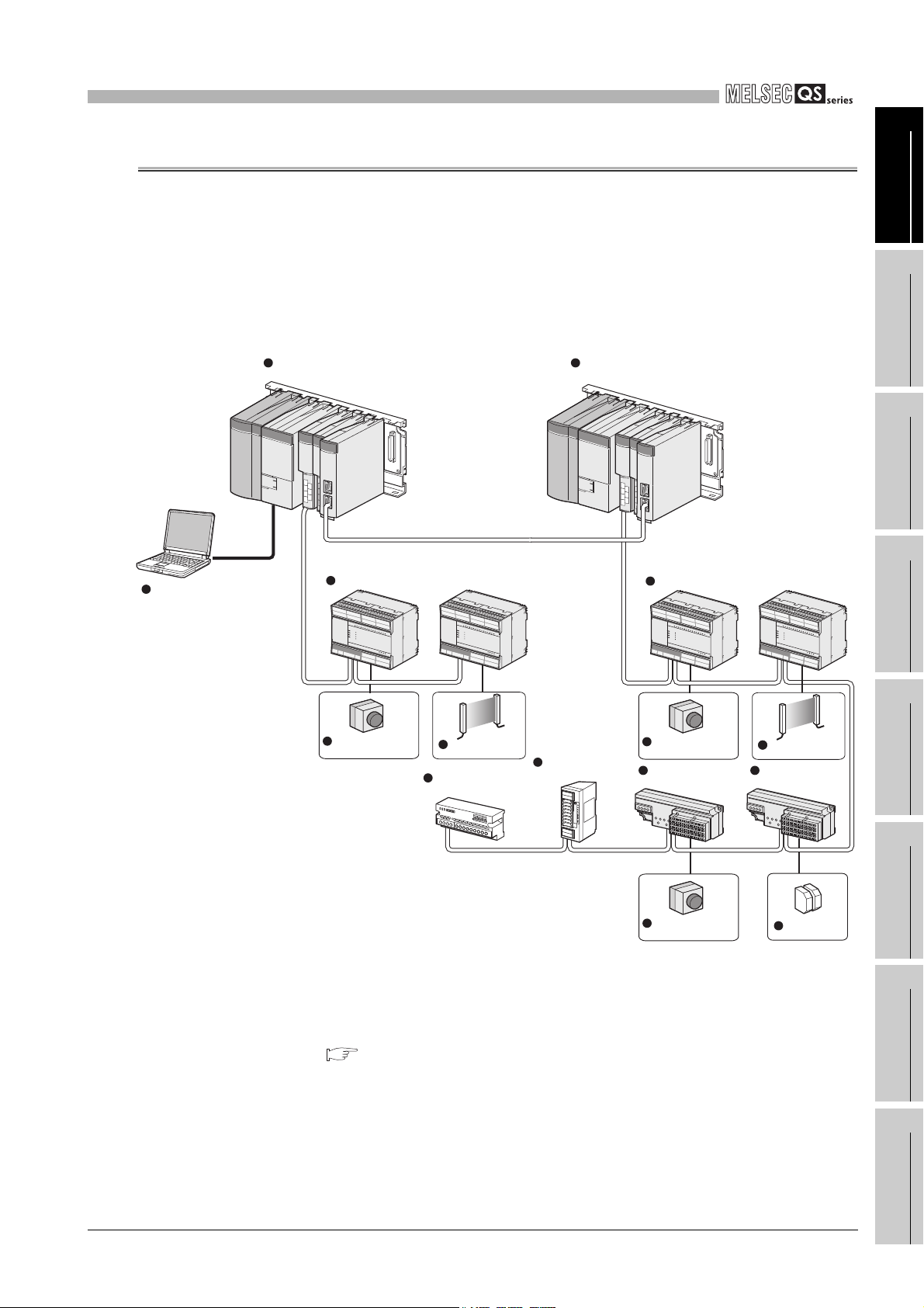
The following figure shows the system configuration of the safety programmable controller
system when the QS series CPU module is used.
(1) System configuration when the CPU(QS001CPU) is used
2 - 1
* 1 : For mountable modules, refer to Section 2.1.1 "Precautions for system configuration".
2.1 System Configuration
Figure 2.1 System configuration
Page 35

2
r
SYSTEM CONFIGURATION
(2) System configuration overview
Base unit (QS034B)
CPU 0 1 2 3
1
Slot numbe
OVERVIEW
00 to 0F
10 to 1F
20 to 2F
CPU modulePower supply module
Figure 2.2 System configuration
Table2.1 Base unit and power supply module applicable to system configuration
Base unit model name QS034B
Maximum number of
mountable modules
Power supply module model
name
4 modules
QS061P-A1, QS061P-A2
Precautions
• The extension base unit cannot be connected.
• The multiple CPU system cannot be configured.
• The modules which can be mounted on the I/O slot are the intelligent function
module and blank cover only.
If a module other than the ones mentioned above is mounted, "MODULE
LAYOUT ERROR" (error code: 2125) is detected.
Note, however, that a "MODULE LAYOUT ERROR" is not detected for the
slot where "Empty" has been set in the I/O assignment setting of PLC
parameter.
• Bus connection for the GOT is not available. For the GOT connection, refer to
the following.
GOT1000 Series Connection Manual (Mitsubishi Products)
30 to 3F
I/O number
2
3
4
5
6
SYSTEM
CONFIGURATION
GENERAL
SPECIFICATIONS
CPU MODULE
POWER SUPPLY
MODULE
BASE UNIT
7
BATTERY
8
CPU MODULE START-
2.1 System Configuration
2 - 2
UP PROCEDURES
Page 36

2
SYSTEM CONFIGURATION
Table2.2 Safety programmable controller products
Product Name Model Description
Safety main base unit
Safety power supply
module
Safety CPU module
CC-Link Safety master
module
CC-Link IE Field
Network master/local
module (with safety
functions)
* 1 : S-mark is a safety certification issued by Korea Occupational Safety and Health Agency (KOSHA).
QS034B
QS034B-K
QS061P-A1
QS061P-A2
QS061P-A1-K
QS061P-A2-K
QS001CPU
QS001CPU-K
QS0J61BT12
QS0J61BT12-K
QS0J71GF11-T2
A unit where a safety CPU module, safety power supply module,
and CC-Link Safety system master module are mounted
An S-mark
A module which is mounted on a safety main base unit and
supplies 100VAC to the system
A module which is mounted on a safety main base unit and
supplies 200VAC to the system
An S-mark
An S-mark
A module which is mounted on a safety main base unit and
performs logic operations for safety control
An S-mark
A module which is mounted on a safety main base unit and
establishes connection to CC-Link Safety
An S-mark
A module which is mounted on a safety main base unit and
establishes connection to CC-Link IE Field Network
*1
certified safety main base unit
*1
certified safety power supply module (100VAC)
*1
certified safety power supply module (200VAC)
*1
certified safety CPU module
*1
certified CC-Link Safety master module
2 - 3
2.1 System Configuration
Page 37

2
SYSTEM CONFIGURATION
2.1.1 Precautions for system configuration
(1) Modules mountable on the main base unit
Table2.3 lists the modules that can be mounted on the main base unit.
The number of mounted modules and functions are restricted depending on the
module type.
Table2.3 Modules mountable on the main base unit
Module Model
CPU module • QS001CPU Only one ---
Power supply module
CC-Link Safety master
module
CC-Link IE Field Network
master/local module (with
safety functions)
CC-Link IE Controller Network
module
MELSECNET/H module
Ethernet module
Blank cover • QG60 Up to four ---
• QS061P-A1
• QS061P-A2
• QS0J61BT12 Up to two ---
• QS0J71GF11-T2 Only one ---
• QJ71GP21-SX
• QJ71GP21S-SX
• QJ71LP21-25
• QJ71LP21S-25
• QJ71LP21G
• QJ71LP21GE
• QJ71BR11
• QJ71E71-B2
• QJ71E71-B5
• QJ71E71-100
Number of modules
mounted in one system
Only one (only one of the module
models)
Only one (only one of the models
among CC-Link IE Controller
Network modules and MELSECNET/
H modules)
Only one (only one of the module
models)
Remarks
• Serial number (first five digits):
“10041” or later
• Function version: D or later
• Serial number (first five digits):
“08102” or later
• Function version: D or later
---
---
1
2
3
4
5
OVERVIEW
SYSTEM
CONFIGURATION
GENERAL
SPECIFICATIONS
CPU MODULE
(2) Module/Unit Replacement
Replace the module or unit according to the following replacement cycle.
Table2.4 Module/Unit Replacement
Module/Unit Replacement Cycle
Safety power supply module 5 years
Safety CPU module 10 years
Safety main base unit 10 years
CC-Link Safety master module 10 years
CC-Link IE Field Network master/local module (with
safety functions)
10 years
6
7
8
POWER SUPPLY
MODULE
BASE UNIT
BATTERY
2.1 System Configuration
2.1.1 Precautions for system configuration
2 - 4
CPU MODULE START-
UP PROCEDURES
Page 38

2
Personal computer
(GX Developer Version 8.40S or later)
USB cable*1
QS001CPU
SYSTEM CONFIGURATION
2.2 Configuration of Peripheral Devices
This section describes the configuration of the peripheral devices usable in the safety
programmable controller system.
* 1: For details of the USB cable, refer to "About the USB cable (QCPU (Q mode) compatible)" of the
following manual.
GX Developer Operating Manual
Figure 2.3 Configuration of peripheral devices
2 - 5
2.2 Configuration of Peripheral Devices
2.1.1 Precautions for system configuration
Page 39

2
SYSTEM CONFIGURATION
2.3 Checking Serial Number and Function Version
The serial number and function version of the CPU module can be checked on the rating
plate or the System monitor window in GX Developer.
1
OVERVIEW
(1) Checking on the rating plate
The rating plate is located on the side of the CPU module.
PASSED
MODEL
Serial No. (first 5 digits)
function version
SERIAL
080910000000000-A
Standard symbol for
conformance is described.
MADE IN JAPAN
Figure 2.4 Rating plate
(2) Checking on the front of the module
The serial number on the rating plate is printed on the front (at the bottom) of the
module.
2
3
4
5
SYSTEM
CONFIGURATION
GENERAL
SPECIFICATIONS
CPU MODULE
Q S 0 0 1 C P U
A L I V E
R U N
E R R.
PULL
U S B
T E S T
U S E R
B A T.
090911090910001-B
Serial No.
Figure 2.5 Display on the front of the module
6
7
8
POWER SUPPLY
MODULE
BASE UNIT
BATTERY
2.3 Checking Serial Number and Function Version
CPU MODULE START-
2 - 6
UP PROCEDURES
Page 40

2
POINT
Serial number function version
SYSTEM CONFIGURATION
(3) Checking on the System monitor window (Product Information List window)
To display the window for checking the serial number and function version, select
[Diagnostics] [System monitor] and click the Product Information List button in GX
Developer.
On the window, the serial number and function version of intelligent function modules
can also be checked.
Figure 2.6 System monitor
The serial number displayed on the Product information list window of GX
Developer may differ from that on the rating plate and on the front of the module.
• The serial number on the rating plate indicates the management
information of the product.
• The serial number displayed on the Product Information List window
indicates the functional information of the product.
The functional information of the product is updated when a new function
is added.
2 - 7
2.3 Checking Serial Number and Function Version
Page 41

3
GENERAL SPECIFICATIONS
CHAPTER3 GENERAL SPECIFICATIONS
The performance specifications of QS series programmable controllers are shown in Table3.1.
Table3.1 General specifications
Item Specifications
Operating ambient temperature
Storage ambient temperature
Operating ambient humidity
Storage ambient humidity
Compliant
Vibration resistance
Shock resistance
Operating atmosphere No corrosive gases
Operating altitude
Installation location Inside a control panel
Overvoltage category
Pollution degree
Equipment class Class I
*3
*1
*2
with JIS B
3502 and
IEC 61131-2
Conforming to JIS B 3502 and IEC 61131-2 (147 m/s2, duration of action 11ms, 3 times
Under
intermittent
vibration
Under
continuous
vibration
each in 3 directions X, Y, Z by sine half-wave pulse)
5 to 95%RH, non-condensing
Frequency
5 to 8.4Hz ---- 3.5mm 10 times
8.4 to 150Hz
5 to 8.4Hz ---- 1.75mm
8.4 to 150Hz
0 to 55
-40 to 75
Constant
acceleration
0 to 2000m
II or less
2 or less
9.8m/s
4.9m/s
2
2
Half
amplitude
----
----
Sweep count
each in X, Y,
Z directions
----
1
2
3
4
5
OVERVIEW
SYSTEM
CONFIGURATION
GENERAL
SPECIFICATIONS
CPU MODULE
*1 : This indicates the section of the power supply to which the equipment is assumed to be connected between the public
electrical power distribution network and the machinery within premises. Category II applies to equipment for which
electrical power is supplied from fixed facilities. The surge voltage withstand level for equipment with the rated voltage
of up to 300V is 2500V.
*2 : This index indicates the degree to which conductive material is generated in terms of the environment in which the
equipment is used. Pollution level 2 is when only non-conductive pollution occurs. A temporary conductivity caused by
condensing may be expected occasionally.
*3 : Do not use or store the programmable controller under pressure higher than the atmospheric pressure of altitude 0m.
Doing so may cause malfunction. When using the programmable controller under pressure, please consult your local
Mitsubishi Electric representative.
6
7
8
POWER SUPPLY
MODULE
BASE UNIT
BATTERY
CPU MODULE START-
3 - 1
UP PROCEDURES
Page 42

3
Memo
GENERAL SPECIFICATIONS
3 - 2
Page 43

4
CPU MODULE
CHAPTER4 CPU MODULE
1
4.1 Performance Specifications
Table4.1 shows the performance specifications of the CPU module.
Item QS001CPU Remarks
Control method Repetitive operation of stored program ----
I/O control mode Refresh mode ---Program
language
Processing speed
(sequence
instruction)
Constant scan
(Function for keeping regular scan
time)
Program capacity
Memory
*1
capacity
Max. number of
files stored
Sequence control
language
LD X0
MOV D0 D1
*1
Program memory
(drive 0)
Standard ROM
(drive 4)
Program memory
Standard ROM
Table4.1 Performance Specifications
Relay symbol language, function block. ----
0.10 s
0.35 s
1 to 2000ms
(in increments of 1ms)
14K steps
(56K bytes)
128K bytes ----
128K bytes ----
*2
3
*2
3
----
----
Setting by parameters.
----
----
----
2
3
4
OVERVIEW
SYSTEM
CONFIGURATION
GENERAL
SPECIFICATIONS
CPU MODULE
No. of times of writing data into the
standard ROM
No. of I/O device points 6144 points(X/Y0 to 17FF)
No. of I/O points 1024 points(X/Y0 to 3FF)
*1 : The maximum number of executable sequence steps is as shown below.(Program capacity) - (File header size (default: 34 steps))
For the details, refer to the manual below.
QSCPU User's Manual (Function Explanation, Program Fundamentals)
*2 : Each of parameter, sequence program, SFC program, and device comment files can be stored.
Max.100000 times ----
No. of points
usable on
program
No. of points
accessible to the
actual I/O module
5
6
7
8
POWER SUPPLY
MODULE
BASE UNIT
BATTERY
4.1 Performance Specifications
CPU MODULE START-
4 - 1
UP PROCEDURES
Page 44

4
Remark
CPU MODULE
Table4.1 Performance Specifications (Continue)
Item QS001CPU Remarks
Internal relay [M] 6144 points by default (M0-6143) (changeable)
Link relay [B] 2048 points by default (B0 to 7FF) (changeable)
512 points by default (T0 to 511) (changeable)
(Sharing of low- and high-speed timers)
The low- and high-speed timers are specified by the instructions.
Timer [ T]
Retentive timer [ST]
No. of device points
Counter [C] Normal counter: 512 points by default (C0 to 511) (changeable)
Data register [D] 6144 points by default (D0 to 6143) (changeable)
Link register [W] 2048 points by default (W0 to 7FF) (changeable)
Annunciator [F] 1024 points by default (F0 to 1023) (changeable)
Edge relay [V] 1024 points by default (V0 to 1023) (changeable)
Link special relay [SB] 1536 points (SB0 to 5FF)
Link special register [SW] 1536 points (SW0 to 5FF)
Special relay [SM] 5120 points (SM0 to 5119)
Special register [SD] 5120 points (SD0 to 5119)
RUN/PAUSE contact
Timer function
Allowable instantaneous power failure
period
5VDC internal current consumption
H 98mm (3.86 inch) ----
External dimensions
Weight 0.29kg ----
Protection of degree IP2X ----
*3 : The value for the CPU module whose serial number (first four digits) is "1207" or earlier is 0.43A.
5VDC internal current consumption: 0.43A
W 55.2mm (2.17 inch) ----
D 114mm (4.49 inch) ----
The measurement unit of the low- and high-speed timers is set up by
parameters.
(Low-speed timer: 1 to 1000ms, 1ms unit, 100ms by default)
(High-speed timer: 0.1 to 100ms, 0.1ms unit, 10ms by default)
0 point by default
(sharing of the low- and high-speed retentive timers) (changeable)
The low- and high-speed retentive timers are specified
by the instructions.
The measurement unit of the low- and high-speed retentive timers
is set up by parameters.
(Low-speed retentive timer: 1 to 1000ms, 1ms unit, 100ms by default)
(High-speed retentive timer: 0.1 to 100ms, 0.1ms unit, 10ms by default)
One contact can be set up in X0 to 17FF for each of RUN. No PAUSE
contact.
Year, month, date, hour, minute, second and day-of-week
(leap year automatically identified)
Accuracy: -3.18 to +5.25s (TYP.+2.14s)/d at 0
Accuracy: -3.18 to +2.59s (TYP.+2.07s)/d at 25
Accuracy: -12.97 to +3.63s (TYP.-3.16s)/d at 55
Varies depending on the power supply module. ----
*3
0.58A
The number of points
can be changed within
the setting range.
( QSCPU User's
Manual
(Function
Explanation,
Program
Fundamentals)
The number of device
points is fixed.
Setting by parameters.
----
----
4 - 2
For the general specifications, refer to CHAPTER 3.
4.1 Performance Specifications
Page 45

4
STOP
RESET RUN
PULL
BAT.
USB
PULL
QS001CPU
TEST
USER
BAT.
ALIVE
RUN
ERR.
TEST
USER
BAT.
ALIVE
RUN
ERR.
3)
6)
7)
2)
1)
4)
5)
15)
1)
13)
14)
10)
9)
When opening the cover, put
your finger here.
CPU MODULE
4.2 Part Names
1
2
3
OVERVIEW
SYSTEM
CONFIGURATION
GENERAL
SPECIFICATIONS
4
CPU MODULE
Figure 4.1 Front face Figure 4.2 With front cover open
11)
5
6
POWER SUPPLY
MODULE
BASE UNIT
7
12)
8)
Figure 4.3 Side Face
BATTERY
8
4.2 Part Names
CPU MODULE START-
4 - 3
UP PROCEDURES
Page 46

4
On :
Normal
*1
Off : When the hardware watchdog timer error is detected
("ERR." LED is On.)
On :
TEST MODE
*1
Flash : When TEST MODE is switched to SAFETY MODE
The "TEST" LED turns off after reset.
(Flash interval: On 200ms/Off 200ms)
Off : SAFETY MODE
On :
During operation in "RUN"
*1
Off : During stop in "STOP" or when the error which stops the operation is detected
Flash : When parameters/program is written during STOP and the RUN/STOP/RESET
switch is moved from "STOP" to "RUN"
(Flash interval: On 200ms/Off 200ms)
On :
When the self-diagnostics error that will not stop operation, other than a battery
error, is detected
*1
Off : Normal
Flash : When the self-diagnostics error that will stop operation is detected
(Flash interval: On 200ms/Off 200ms)
When the reset operation is performed
(Flash interval: On 60ms/Off 60ms)
On :
When the annunciator (F) turns ON
*1
Off : Normal
On :
When a battery error has occurred due to the CPU battery voltage drop
*1
Off : Normal
RUN : Executes sequence program operation.
STOP : Stops sequence program operation.
RESET :
Performs hardware reset and operation initialization when an operation
error occurs. ( Section 4.4)
CPU MODULE
No. Name Application
1) Module fixing hook Hook used to fix the module to the base unit.
"ALIVE" LED
2)
(Green)
Indicates the operating mode of the CPU module.
"TEST" LED
3)
(Yellow)
Indicates the operating status of the CPU module.
"RUN" LED
4)
(Green)
"ERR." LED
5)
(Red)
Table4.2 Part Names
"USER" LED
6)
(Red)
"BAT." LED
7)
(Yellow)
8) Module loading lever Used to load the module to the safety base unit.
Connector used to connect to the USB compatible peripheral devices.
9)
USB connector
10)
RUN/STOP/RESET switch
11) Module fixing screw Screw used to fix a module to the base unit. (M3 screw)
12) Module fixing latch Latch used to fix a module to the base unit.
13) Battery Backup battery for the power failure compensation function of program memory.
14) Battery connector pin
15) Serial number display Displays the serial number on the rating plate.
*1 : Turns On during the initial processing (self-diagnostics, etc.) right after the power-on or reset cancel.
*2 : When a cable is to be connected to the USB connector at all times, clamp the cable to prevent a loose connection,
shifting, or disconnection by pulling due to carelessness.
*3 : Operate the RUN/STOP/RESET switch with your fingertips.
Do not use any tool such as a screwdriver because the switch part might be damaged.
4 - 4
*2
4.2 Part Names
(Connector type B)
Can be connected by the USB dedicated cable.
*3
For connection of the battery lead wires (When shipped from the factory, the lead wires
are disconnected from the connector to prevent the battery from discharging.)
Page 47

4
POINT
CPU MODULE
4.3 Switch Operation after Writing a Program
Programs can be written to the CPU module in either the STOP or RUN status.
(1) When writing a program with the CPU module set to "STOP"
(a) Set the RUN/STOP/RESET switch to STOP.
The "RUN" LED turns Off, and the module is placed in the STOP status.
Write a program from GX Developer to the CPU module in the STOP status.
(b) Reset with the RUN/STOP/RESET switch.
The CPU module is reset. ( Section 4.4)
1
2
OVERVIEW
SYSTEM
CONFIGURATION
(c) Set the RUN/STOP/RESET switch to RUN.
The "RUN" LED turns on, and the CPU module is placed in the RUN status.
(2) When writing a program during RUN
When writing a program during RUN, the operation for the RUN/STOP/RESET switch
is not required.
1. The program modified online during boot operation is written to the program
memory.
After making online program change, also write the program to the standard
ROM of the boot source memory. If the program is not written in the standard
ROM, the old program will be executed at the next boot operation.
For details of the boot operation, refer to the manual below.
QSCPU User's Manual (Function Explanation, Program Fundamentals)
2. To stop the CPU module, the remote operation of GX Developer can also be
used.
In this case, the operation for the RUN/STOP/RESET switch is not required.
For details on the remote operation of GX Developer, refer to the following
manual.
GX Developer Version 8 Operating Manual
3
4
5
6
GENERAL
SPECIFICATIONS
CPU MODULE
POWER SUPPLY
MODULE
4.3 Switch Operation after Writing a Program
BASE UNIT
7
BATTERY
8
CPU MODULE START-
4 - 5
UP PROCEDURES
Page 48

4
POINT
Start
Termination , completed , end
Hold the RUN/STOP/RESET switch
in the "RESET" position (for one
second or longer).
Reset operation is started using
the RUN/STOP/RESET switch.
.......................
Reset is accepted and reset
processing is performed.
.......................
Reset is completed.
Reset is canceled.
.......................
Releasing your hand from the
RUN/STOP/RESET switch returns it
to the STOP position.
RUN/STOP/RESET
switch
flashing
Off.
The ERR. LED flashes several times
(3 to 4 times) rapidly.
The "ERR. LED" turns off .
Return the RUN/STOP/RESET
switch to the "STOP" position.
RUN/STOP/RESET
switch
:
RUN
TEST
USER
BAT.
ALIVE
ERR.
RESET
RUN
STOP
RESET
RUN
STOP
RUN
TEST
USER
BAT.
ALIVE
ERR.
CPU MODULE
4.4 Reset Operation
For the CPU module, the RUN/STOP/RESET switch of the CPU module is used to switch
between the "RUN status" and "STOP status" and to perform "RESET operation".
When using the RUN/STOP/RESET switch to reset the CPU module, moving the RUN/
STOP/RESET switch to the reset position will not reset it immediately.
Perform reset operation with the RUN/STOP/RESET switch as shown in Figure 4.4.
Hold the RUN/STOP/RESET switch in the RESET position until reset processing
is complete (the flashing ERR. LED turns off).
If you release your hand from the RUN/STOP/RESET switch during reset
processing (during rapid flashing of ERR. LED), the switch will return to the STOP
position and reset processing cannot be completed.
4 - 6
4.4 Reset Operation
Figure 4.4 Reset Operation
Page 49

4
POINT
CPU MODULE
Operate the RUN/STOP/RESET switch with your fingertips.
Do not use any tool such as a screwdriver because the switch part might be
damaged.
1
2
3
OVERVIEW
SYSTEM
CONFIGURATION
GENERAL
SPECIFICATIONS
4
5
6
7
CPU MODULE
POWER SUPPLY
MODULE
BASE UNIT
4.4 Reset Operation
BATTERY
8
CPU MODULE START-
4 - 7
UP PROCEDURES
Page 50

5
+10%
-15%
+10%
-15%
POWER SUPPLY MODULE
CHAPTER5 POWER SUPPLY MODULE
This section describes the specifications of the power supply modules applicable for the
programmable controller system and how to select the most suitable module.
5.1 Specifications
Table5.1 shows the specifications of the power supply modules.
Table5.1 Power supply module specifications
Item
Base loading position QS series power supply module loading slot
Applicable base unit QS034B
Input power supply
Input frequency
Input voltage distortion ratio
Max. input apparent power 125VA
Inrush current
Rated output
current
Overcurrent
protection
Overvoltage
protection
Efficiency 70% or more
Allowable momentary power
failure period
Withstand voltage
Insulation resistance
Noise immunity
Operation indication LED indication (Normal: On (green), Error: Off)
Fuse Built-in (Unchangeable by user)
*1
*2
*3
5VDC 6A
5VDC 6.6A or more
5VDC 5.5 to 6.5V
1780VAC rms/3 cycles between all inputs
and LG and all outputs and FG (2000 m
10M or higher (500VDC insulation resistance tester) between:
• all inputs and LG and all outputs and FG
• all inputs and LG
• all outputs and FG
• Noise voltage 1500Vp-p, noise width 1 s, noise frequency 25 to 60Hz (noise
simulator condition)
• Noise voltage IEC61000-4-4: 2kV
QS061P-A1 QS061P-A2
100 to 120VAC
(85 to 132VAC)
(6562 ft.) above sea level)
Performance Specifications
200 to 240VAC
50/60Hz 5%
Within 5% ( Section 5.2)
20A, 8ms or less
Within 20ms
*4
2830VAC rms/3 cycles between all inputs
and LG and all outputs and FG
(2000 m (6562 ft.) above sea level)
(170 to 264VAC)
5 - 1
5.1 Specifications
Page 51

5
POINT
POWER SUPPLY MODULE
Table5.1 Power supply module specifications (Continue)
Item
Application
Rated switching
voltage/current
Min. switching load 5VDC, 1mA
Response time
Life
Contact output part
Surge suppressor No
Fuse No
Terminal screw size M3.5
Applicable wire size
Applicable solderless terminal RAV1.25 to 3.5, RAV2 to 3.5 (0.8mm or less thick)
Applicable tightening torque 0.66 to 0.89N•m
External
dimensions
Weight 0.40kg
H 98mm (3.86 inch)
W 55.2mm (2.17 inch)
D 115mm (4.53 inch)
Electrical : Rated switching voltage/current load: 100 thousand times or more
QS061P-A1 QS061P-A2
OFF ON: 10ms or less, ON OFF: 12ms or less
Performance Specifications
ERR. contact ( Section 5.3)
24VDC, 0.5A
Mechanical : 20 million times or more
0.75 to 2mm
2
1
2
3
4
OVERVIEW
SYSTEM
CONFIGURATION
GENERAL
SPECIFICATIONS
*1: Overcurrent protection
The overcurrent protection function shuts off the 5 VDC circuit and stops the system if
the current flowing in the circuit exceeds the specified value.
The LED of the power supply module is turned off or lights up in dim green when
voltage is lowered. If this device is activated, switch the input power supply OFF and
eliminate the cause such as insufficient current capacity or short. Then, a few minutes
later, switch it ON to restart the system.
The initial start for the system takes place when the current value becomes normal.
*2: Overvoltage protection
The overvoltage protection function shuts off the 5 VDC circuit and stops the system if
a voltage of 5.5 VDC or above is applied to the circuit.
When this device is activated, the power supply module LED is turned OFF.
For restart of the system, turn OFF the input power supply, and then turn ON in a few
minutes. This allows the system to start up with initial start. If the system doesn't start
up and a LED indication remains off, replacement of a power supply module is
required.
*3: Allowable momentary power failure period
• An instantaneous power failure lasting less than 20ms will cause AC down to be
detected, but operation will continue.
• An instantaneous power failure lasting in excess of 20ms may cause the
operation to continue or initial start to take place depending on the power supply
load.
*4: Inrush current
When power is switched on again immediately (within 5 seconds) after power-off, an
inrush current of more than the specified value (2ms or less) may flow. Reapply power
5 or more seconds after power-off. When selecting a fuse and breaker in the external
circuit, take account of the blowout, detection characteristics and above matters.
5
6
7
8
CPU MODULE
POWER SUPPLY
MODULE
BASE UNIT
BATTERY
5.1 Specifications
CPU MODULE START-
5 - 2
UP PROCEDURES
Page 52

5
POWER SUPPLY MODULE
5.2 Precaution when connecting the uninterruptible power supply
Be sure of the following terms when connecting the QS Series CPU Module system to the
uninterruptible power supply (abbreviated as UPS hereafter):
Use an online UPS (uninterruptible power supply) with power distortion factor of 5% or
less or line-interactive UPS. For a standby system UPS, use Mitsubishi small-capacity
UPS "FREQUPS FW-F series" (hereafter abbreviated as FW-F series).
(Example: FWF10-0.3K/0.5K)
Do not use any standby system UPS other than the FW-F series.
* 1: Use a FW-F series UPS with the serial number starts with P or later or ends with HE.
Starts with "P" or later
Ends with "HE"
*1
5 - 3
5.2 Precaution when connecting the uninterruptible power supply
Page 53

5
1)7)
8)
4)
3)
2)
6)
5)
9),10)
<QS061P-A1>
QS061P-A2 (200 to 240VAC input, 5VDC 6A output)
QS061P-A1 (100 to 120VAC input, 5VDC 6A output)
POWER SUPPLY MODULE
5.3 Names of Parts and Settings
The names of the parts of each power supply module are described below.
1
2
3
OVERVIEW
SYSTEM
CONFIGURATION
GENERAL
SPECIFICATIONS
Figure 5.1 Power supply module
4
5
6
7
CPU MODULE
POWER SUPPLY
MODULE
BASE UNIT
BATTERY
8
5.3 Names of Parts and Settings
5 - 4
CPU MODULE START-
UP PROCEDURES
Page 54

5
POINT
POWER SUPPLY MODULE
Table5.2 Part names
No. Name Application
On (green) : Normal (5VDC output, instantaneous power failure within 20ms)
Off : • AC power supply is ON, however, the power supply module is out of
order.
1) "POWER" LED
• Turned ON when the whole system operates normally.
2) ERR. terminal
3) FG terminal Ground terminal connected to the shielding pattern of the printed-circuit board.
4) LG terminal
5) Terminal screw M3.5 screw
6) Terminal cover Protective cover of the terminal block
7) Module fixing screw
8) Module loading lever Used to load the module to the base unit.
9) Power input terminal Power input terminal for the QS061P-A1 and connected to a 100VAC power supply.
10) Power input terminal Power input terminal for the QS061P-A2 and connected to a 200VAC power supply.
• Turns OFF (opens) when the AC power is not input, a stop error (including a reset)
occurs in the CPU module, or the fuse is blown.
Grounding for the power filter. The potential of the QS061P-A1 and QS061P-A2 ter-
minals are one-half of the input voltage.
Used to fix the module to the base unit.
M3 screw (Tightening torque range : 0.36 to 0.48N•m)
(5VDC error, overload, internal circuit failure, fuse blown)
• AC power supply is not ON.
• Power failure (including an instantaneous power failure of 20ms or
more)
1. The QS061P-A1 is dedicated for inputting a voltage of 100 VAC.
Do not input a voltage of 200 VAC into it or trouble may occur on the
QS061P-A1.
Table5.3 Precaution
Power module
type
QS061P-A1 Operates normally.
Power supply module does not
QS061P-A2
2. Individually ground the LG and FG terminals with a ground resistance of 100
or less.
3. ERR.
terminal cannot be used as a safety output.
Connect the cable for ERR.
cause trouble.
CPU module cannot be
operated.
100VAC 200VAC
contact of 30m or less in length in a control panel.
Supply power voltage
Power supply module causes
trouble.
Operates normally.
5 - 5
5.3 Names of Parts and Settings
Page 55

6
BASE UNIT
CHAPTER6 BASE UNIT
This section describes the specifications of the base units used in the programmable
controller system.
6.1 Specification
The base unit is a unit to which the CPU module, power supply module and/or intelligent
function module are installed.
Table6.1 Base unit specifications
Item
Number of I/O modules installed 4
Possibility of extension Disable
Applicable module QS series modules
5 VDC internal current consumption 0.10A
Mounting hole size
H 98mm (3.86 inch)
External dimensions
Weight 0.28kg
Attachment
DIN rail mounting Adapter type Q6DIN2
W 245mm (9.65 inch)
D 44.1mm (1.74 inch)
Mounting screw M4 14 4 pieces (DIN rail mounting adapter to be sold separately)
M4 screw hole or 4.5 hole (for M4 screw)
Typ e
QS034B
1
2
3
4
OVERVIEW
SYSTEM
CONFIGURATION
GENERAL
SPECIFICATIONS
CPU MODULE
5
6
7
8
POWER SUPPLY
MODULE
BASE UNIT
BATTERY
6.1 Specification
CPU MODULE START-
6 - 1
UP PROCEDURES
Page 56
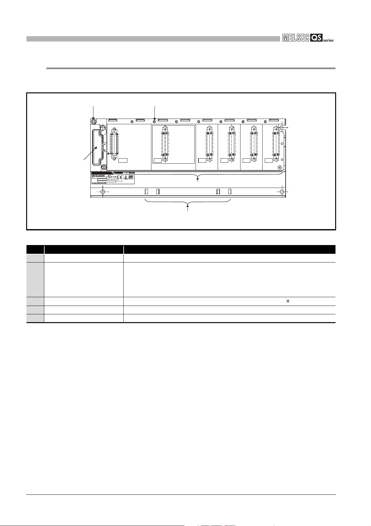
6
OUT
I/O3I/O2I/O1I/O0CPU
POWER
b1
a1
BD992C202H01
SERIAL
MODEL
MADE IN JAPAN
PASSED
1)
4) 3)
2)
5)
BASE UNIT
6.2 Part Names
The names of the parts of the base unit are described below.
Figure 6.1 Base unit (QS034B)
Table6.2 Part Names
No. Name Application
1) Base cover Cover for protecting the printed-circuit board of the base unit
Connector for installing the QS series power supply module, CPU module and
2) Module connector
intelligent function module.
For the reserved connector where no module is mounted, attach a supplied
connector cover or a blank cover (QG60) to prevent entry of dust.
3) Module fixing screw hole
Screw hole for fixing the module to the base unit. Screw size: M3 12
4) Base mounting hole Hole for mounting this base unit onto the panel of the control panel (for M4 screw)
5) DIN rail adapter mounting hole Hole for mounting DIN rail adapter
6 - 2
6.2 Part Names
Page 57

7
Remark
BATTERY
CHAPTER7 BATTERY
This section describes the specifications of the batteries available for the QS series CPU
module and how to handle them.
7.1 Battery (Q6BAT)
Batteries (Q6BAT) are installed in the CPU module to retain data of the program memory
and operation/error history in case of power failure.
1
2
OVERVIEW
SYSTEM
CONFIGURATION
7.1.1 Battery Specifications
This section describes the specifications of the battery used for the CPU module.
Item
Classification Manganese dioxide lithium primary battery
Initial voltage 3.0V
Nominal current 1800mAh
Battery life when
stored
Battery life when
used
Lithium content
Application Power failure backup for program memory, operation/error history
1. Refer to Section 11.3.1 for the battery life.
2. For the battery directive in EU member states, refer to Appendix 4.
Table7.1 Battery Specifications
Type
Q6BAT
Actually 5 years (room temperature)
Section 11.3.1.
0.52g
3
4
5
6
GENERAL
SPECIFICATIONS
CPU MODULE
POWER SUPPLY
MODULE
7.1 Battery (Q6BAT)
7.1.1 Battery Specifications
7 - 1
7
8
BASE UNIT
BATTERY
CPU MODULE START-
UP PROCEDURES
Page 58

7
POINT
BAT.
BATTERY
7.1.2 Installation of Battery
The battery for the CPU module is shipped with its connector disconnected. Connect
the connector as follows.
Refer to Section 11.3 for the service life of the battery and how to replace the battery.
Open the CPU module front cover.
Confirm that the battery is loaded
correctly.
Insert the battery connector into the
connector pin on the case. Be sure that
the insertion direction is correct.
Completed
Figure 7.1 Q6BAT battery setting procedure
Firmly push the connector all the way.
Connector
CPU module
BAT.
PULL
STOP
RUN
RESET
7 - 2
7.1 Battery (Q6BAT)
7.1.2 Installation of Battery
Page 59

8
Installing a base unit
Install a base unit to a panel.
Installing modules
Install modules required for the system configuration to the base unit.
Fixing modules by screws
Fix the modules to the base unit with screws to prevent the displacement by vibrations or
other causes.
Wiring
1) Wire the power supply to the power supply module.
2) Install wiring between the CC-Link Safety master module and the CC-Link Safety remote
I/O module.
3) Wire external device(s) to the CC-Link Safety remote I/O module.
4) Install wiring between network modules.
(To the next page)
Start
1) Set the RUN/STOP/RESET switch of the CPU module to the STOP position.
(Set the CPU module to stop status.)
2) Make switch settings for the MELSECNET/H module.
Making initial settings of modules
• • • CHAPTER 10
• • • CHAPTER 2,
CHAPTER 10
• • • CHAPTER 10
• • • CHAPTER 4
MELSECNET/H
Network System
Reference Manual
(PLC to PLC network)
• • • CHAPTER 10
CPU MODULE START-UP PROCEDURES
CHAPTER8 CPU MODULE START-UP PROCEDURES
This chapter describes the procedure for starting up the CPU module.
It is assumed that programs and parameters have been created separately.
8.1 Procedure before Operating in SAFETY MODE
This section describes the procedure before operating the CPU module in SAFETY
MODE.
The default operation mode of the CPU module is TEST MODE. Switch the mode to
SAFETY MODE to operate the CPU module.
1
2
3
OVERVIEW
SYSTEM
CONFIGURATION
GENERAL
SPECIFICATIONS
4
5
6
7
CPU MODULE
POWER SUPPLY
MODULE
BASE UNIT
8.1 Procedure before Operating in SAFETY MODE
BATTERY
8
CPU MODULE START-
8 - 1
UP PROCEDURES
Page 60

8
(To the next page)
(Continued from the previous page)
Connecting a personal computer in which GX Developer is installed
1) Start up GX Developer on the personal computer in which GX Developer is installed.
2) Connect the personal computer with GX Developer installed, to the CPU module.
Registering the CPU access password with the CPU module
Register the CPU access password with the CPU module by using GX Developer.
Setting clock data and clearing history data of the CPU module
When the safety CPU module is operated for the first time after purchase, take the following
actions for the CPU module with GX Developer.
Set the clock with "Clock setup".
Clear the error history of the CPU module with "PLC diagnostics".
Writing the parameters and programs to the CPU module
Write the parameters and user programs created by GX Developer to the CPU module.
Restarting the system
Turn off and then turn on the system power supply, or reset the CPU module.
Running the CPU module
Set the RUN/STOP/RESET switch of the CPU module to the RUN position.
Confirm that the "ALIVE" LED, "RUN" LED, and "TEST" LED of the CPU module are on.
Checking the user program operation
Check the user program operation, cables, and inputs/outputs.
When the "ERR." LED of the CPU module is on or flashing, identify the error cause by the
diagnostics*
2
of GX Developer to eliminate the error cause.
When the error is related to the parameters or programs, correct them.
Initializing the PLC memory of the CPU module
Initialize the PLC memory of the CPU module with GX Developer.
Confirming the CPU module LEDs
Confirm that the "ALIVE" LED and "TEST" LED of the CPU module are on.
(Confirm that the CPU module is in TEST MODE.)
1
Installing a battery
Install a battery to the CPU module.
Powering ON the power supply module
Confirm the following items of the safety programmable controller system, and then turn on
the power supply.
Wiring of the power supply
Power supply voltage
Operating status of the CPU module Stop status (The RUN/STOP/RESET switch is
in the STOP position.)
• • • CHAPTER 4
• • • GX Developer Version 8
Operating Manual
(Safety Programmable
Controller)
• • • GX Developer Version 8
Operating Manual
(Safety Programmable
Controller)
• • • GX Developer Version 8
Operating Manual
(Safety Programmable
Controller)
• • • GX Developer Version 8
Operating Manual
GX Developer Version 8
Operating Manual
(Safety Programmable
Controller)
• • • GX Developer Version 8
Operating Manual
• • • CHAPTER 4
• • • CHAPTER 4
• • • CHAPTER 4
• • • CHAPTER 7
• • • CHAPTER 4,
CHAPTER 5,
CHAPTER 10
CPU MODULE START-UP PROCEDURES
* 2: The following types of diagnostics are available.
• PLC diagnostics
• Ethernet diagnostics
• CC IE Control diagnostics
• CC IE Field diagnostics
• MELSECNET diagnostics
• CC-Link / CC-Link/LT diagnostics
• System monitor
8 - 2
8.1 Procedure before Operating in SAFETY MODE
Page 61

8
Turn the system power supply OFF and then ON, or perform the reset operation on the
CPU module.
(Continued from the previous page)
Restarting the system
Running the CPU module
Set the RUN/STOP/RESET switch of the CPU module to the RUN position.
Confirm that the "ALIVE" LED and "RUN" LED of the CPU module are on, and the "TEST"
LED is off.
Correct the program?
NO
YES
Stopping the CPU module
Set the RUN/STOP/RESET switch of the CPU module to the STOP position.
Switching to TEST MODE
Switch the mode from SAFETY MODE to TEST MODE by selecting the menu option,
"Switch safety CPU operation mode", in GX Developer.
Confirming the CPU module LEDs
After the operation mode has been switched from SAFETY MODE to TEST MODE using
GX Developer, confirm that both the "TEST" LED and "ALIVE" LED of the CPU module are on.
Correcting the program
Correct the program with GX Developer.
End
After the operation mode has been switched from TEST MODE to SAFETY MODE using
GX Developer, confirm that the "TEST" LED of the CPU module is flashing while the
"ALIVE" LED is on.
Confirming the CPU module LEDs
1
Stopping the CPU module
Set the RUN/STOP/RESET switch of the CPU module to the STOP position.
Switching to SAFETY MODE
Switch the mode from TEST MODE to SAFETY MODE by selecting the menu option,
"Switch safety CPU operation mode", in GX Developer.
• • • CHAPTER 4
• • •
GX Developer Version 8
Operating Manual
(Safety Programmable
Controller)
• • • CHAPTER 4
• • •
GX Developer Version 8
Operating Manual
• • • CHAPTER 4
• • • CHAPTER 4
• • • CHAPTER 4
• • • CHAPTER 4
• • • GX Developer Version 8
Operating Manual
(Safety Programmable
Controller)
CPU MODULE START-UP PROCEDURES
1
2
3
4
OVERVIEW
SYSTEM
CONFIGURATION
GENERAL
SPECIFICATIONS
5
6
7
8
CPU MODULE
POWER SUPPLY
MODULE
BASE UNIT
BATTERY
8.1 Procedure before Operating in SAFETY MODE
8 - 3
CPU MODULE START-
UP PROCEDURES
Page 62

9
TUV Rheinland
EMC, LOW VOLTAGE, AND MACHINERY DIRECTIVES
CHAPTER9 EMC, LOW VOLTAGE, AND MACHINERY
DIRECTIVES
Compliance with the Machinery Directive, which is one of the EU directives, has been
mandatory for the products sold within EU member states since 1995, as well as
compliance with the EMC Directive since 1996 and compliance with the Low Voltage
Directive since 1997.
The safety programmable controller is a CE-marked product. To prove the compliance,
Mitsubishi has issued an EC Declaration of Conformity for each EMC, Low Voltage, and
Machinery Directive, based on the safety approval obtained from the third-party
certification organization, .
(1) Authorized representative in Europe
Authorized representative in Europe is shown below.
Name : Mitsubishi Electric Europe BV
Address: Gothaer strasse 8, 40880 Ratingen, Germany
9.1 Requirements for Conformance to EMC Directive
The EMC Directive specifies that products placed on the market must "be so constructed
that they do not cause excessive electromagnetic interference (emissions) and are not
unduly affected by electromagnetic interference (immunity)".
The applicable products are requested to meet these requirements. The Section 9.1.1
through Section 9.1.5 summarize the precautions on conformance to the EMC Directive of
the machinery constructed using the MELSEC-QS series programmable controllers.
The details of these precautions has been prepared based on the control requirements
and the applicable standards control. However, we will not assure that the overall
machinery manufactured according to these details conforms to the above-mentioned
directives. The method of conformance to the EMC Directive and the judgment on whether
or not the machinery conforms to the EMC Directive must be determined finally by the
manufacturer of the machinery.
9 - 1
9.1 Requirements for Conformance to EMC Directive
Page 63
9
EMC, LOW VOLTAGE, AND MACHINERY DIRECTIVES
9
9.1.1 Standards relevant to the EMC Directive
(1) Emission related standards
Table9.1 Emission related standards
Standard Test item Test description Value specified in standard
• 30 to 230MHz, QP: 40dBµV/m (measured at 10m
distance)
• 230 to 1000MHz, QP: 47dBµV/m (measured at
10m distance)
• 0.15 to 0.5MHz, QP: 79dB,
Mean: 66dB
• 0.5 to 30MHz, QP: 73dB, Mean: 60dB
*1
*1
EN61131-2:
2007
CISPR16-2-3
Radiated emission
CISPR16-2-1,
CISPR16-1-2
Conducted emission
The electromagnetic wave which
*2
*2
* 1 : QP: Quasi-Peak value, Mean: Average value
* 2 : Programmable controller is an open type device (a device designed to be housed in other
the product emits to the external
space is measured.
The noise level which the product
emits to the power line is
measured.
equipment) and must be installed inside a conductive control panel. The tests were conducted
with the programmable controller installed in a control panel, applying the maximum applicable
input voltage to the power supply module.
(2) Immunity related standards
Table9.2 Immunity related standards
Standard Test item Test description Value specified in standard
EN61131-2:
2007
EN61000-4-2
Electrostatic discharge
immunity
EN61000-4-3
Radiated, radio-frequency,
electromagnetic field
immunity
EN61000-4-4
Fast transient burst
immunity
EN61000-4-5
Surge immunity
EN61000-4-6
Conducted RF immunity
EN61000-4-8
Power-frequency magnetic
field immunity
EN61000-4-11
Voltage dips and interruption
immunity
*1
*1
*1
*1
*1
An electrostatic discharge is
applied to the enclosure of the
equipment.
An electric field is radiated to the
product.
Burst noise is applied to power
lines and signal lines.
Lightning surge is applied to
power lines and signal lines.
High-frequency noise is applied
*1
to power lines and signal lines.
The product is immersed in the
magnetic field of an induction
coil.
Power voltage is momentarily
interrupted.
• 8kV Air discharge
• 4kV Contact discharge
80% AM modulation @1kHz
• 80 to 1000MHz: 10Vm
• 1.4 to 2.0GHz: 3Vm
• 2.0 to 2.7GHz: 1Vm
• AC/DC power, I/O power, and AC I/O (unshielded)
lines: 2kV
• DC I/O, analog, and communication lines: 1kV
• AC power, AC I/O power, and AC I/O (unshielded)
lines: 2kV CM, 1kV DM
• DC power and DC I/O power lines: 0.5kV CM,
0.5kV DM
• DC I/O, AC I/O (shielded), analog
communication lines: 1kV CM
0.15 to 80MHz, 80% AM modulation @1kHz, 10Vrms
50/60Hz, 30A/m
• 0%, 0.5 period, starting at zero-crossing
• 0%, 250/300 period (50/60Hz)
• 40%, 10/12 period (50/60Hz)
• 70%, 25/30 period (50/60Hz)
*2
, and
EMC AND LOW
VOLTAGE
10
LOADING AND
11
MAINTENANCE AND
12
DIRECTIVES
INSTALLATION
INSPECTION
TROUBLESHOOTING APPENDICES INDEX
* 1 : Programmable controller is an open type device (a device designed to be housed in other
equipment) and must be installed inside a conductive control panel. The tests were conducted
with the programmable controller installed in a control panel, applying the maximum applicable
input voltage to the power supply module.
* 2 : The accuracy of an analog-digital converter module may temporarily vary within ±10%.
9.1 Requirements for Conformance to EMC Directive
9.1.1 Standards relevant to the EMC Directive
9 - 2
Page 64

9
EMC, LOW VOLTAGE, AND MACHINERY DIRECTIVES
9.1.2 Installation in a control panel
The programmable controller is open equipment and must be installed within a control
panel for use.*
This not only ensures safety but also ensures effective shielding of programmable
controller-generated electromagnetic noise.
* : Install CC-Link Safety remote stations within a control panel as well.
(1) Control panel
• Use a conductive control panel.
• When attaching the control panel's top plate or base plate, mask painting and
weld so that good surface contact can be made between the panel and plate.
• To ensure good electrical contact with the control panel, mask the paint on the
installation bolts of the inner plate in the control panel so that contact between
surfaces can be ensured over the widest possible area.
• Earth the control panel with a thick wire so that a low impedance connection to
ground can be ensured even at high frequencies.
• Holes made in the control panel must be 10 cm (3.94 inch) diameter or less. If
the holes are 10 cm (3.94 inch) or larger, radio frequency noise may be emitted.
In addition, because radio waves leak through a clearance between the control
panel door and the main unit, reduce the clearance as much as practicable.
The leakage of radio waves can be suppressed by the direct application of an
EMI gasket on the paint surface.
Our tests have been carried out on a panel having the damping characteristics of
37 dB max. and 30 dB mean (measured by 3 m method with 30 to 300 MHz).
(2) Connection of power and earth wires
Earthing and power supply wires for the programmable controller system must be
connected as described below.
• Provide an earthing point near the power supply module. Earth the power
supply's LG and FG terminals (LG : Line Ground, FG : Frame Ground) with the
thickest and shortest wire possible. (The wire length must be 30 cm (11.81 inch)
or shorter.) The LG and FG terminals function is to pass the noise generated in
the programmable controller system to the ground, so an impedance that is as
low as possible must be ensured. As the wires are used to relieve the noise, the
wire itself carries a large noise content and thus short wiring means that the wire
is prevented from acting as an antenna.
• The earth wire led from the earthing point must be twisted with the power supply
wires. By twisting with the earthing wire, noise flowing from the power supply
wires can be relieved to the earthing. However, if a filter is installed on the power
supply wires, the wires and the earthing wire may not need to be twisted.
9 - 3
9.1 Requirements for Conformance to EMC Directive
9.1.2 Installation in a control panel
Page 65

9
Shield part
Shield cable
Wire
Solderless terminal
EMC, LOW VOLTAGE, AND MACHINERY DIRECTIVES
9.1.3 Cables
The cables pulled out from the control panel contain a high frequency noise component.
On the outside of the control panel, therefore, they serve as antennas to emit noise.
To prevent noise emission, use shielded cables when pulling out the cables which are
connected to intelligent function module and CC-Link Safety remote I/O module and using
them outside of the control panel.
The use of shielded cables also increases noise immunity.
For signal lines (including common line) of intelligent function module and CC-Link Safety
remote I/O module, the noise immunity satisfies the standard value on the condition that
the shielded cables are used for grounding.
If shielded cables are not used or not grounded correctly, the noise immunity does not
meet the specified requirements.
(1) Shield grounding processing of shielded cables
• Provide a grounding point on the shielded cable as near the module as possible
so that the wiring between the module and grounding point is not induced
electromagnetically by the other parts of wiring on the cable.
• Take appropriate measures so that the exposed shield part of the shielded cable,
where the cable jacket was partly removed, is grounded to the control panel on
the widest contact surface.
A clamp may also be used as shown in Figure 9.2.
In this case, however, a mask painting is required for the inner wall of the control
panel which comes into contact with the clamp.
9
EMC AND LOW
VOLTAGE
10
LOADING AND
11
MAINTENANCE AND
12
DIRECTIVES
INSTALLATION
INSPECTION
TROUBLESHOOTING APPENDICES INDEX
Screw
Clamp
Mask painting
Shield cable
Figure 9.1 Part to be exposed Figure 9.2 Shield grounding (Good example)
Note) If a wire is soldered onto the shield part of the shielded cable for grounding
as shown below, the high-frequency impedance rises, resulting in a loss of
shield effect.
Figure 9.3 Shield grounding (Bad example)
9.1 Requirements for Conformance to EMC Directive
9.1.3 Cables
9 - 4
Page 66

9
AUI cable
Shield
EMC, LOW VOLTAGE, AND MACHINERY DIRECTIVES
(2) MELSECNET/H module
Be sure to use double-shielded coaxial cables (MITSUBISHI CABLE INDUSTRIES,
LTD.: 5C-2V-CCY) for the coaxial cables of MELSECNET/H module. Radiated noise
in the range of 30HMz or higher can be suppressed by using double-shielded coaxial
cables. Ground the double-shielded coaxial cable by connecting its outer shield to the
ground.
Shield
Figure 9.4 Double-shielded coaxial cable grounding
Refer to (1) for the shield grounding processing.
Earth here
(3) Ethernet module
Precautions for using AUI cables, twisted pair cables, and coaxial cables are
described below.
*1
• Be sure to ground the AUI cables
the AUI cable is of the shielded type, ground the exposed shield section of the
cable, where the cable jacket was partly removed as shown in Figure 9.5, on the
widest contact surface.
Figure 9.5 AUI cable grounding
Refer to (1) for the shield grounding processing.
* 1 : Make sure to install a ferrite core for the cable.
The ZCAT2032 ferrite core manufactured by TDK is recommended.
connected to the 10BASE5 connectors. Since
9 - 5
• Use shielded twisted pair cables for the twisted pair cables connected to the
10BASE-T/100BASE-TX connectors. Ground the exposed shield section of the
shielded twisted pair cable, where the cable jacket was partly removed as shown
in Figure 9.6, on the widest contact surface.
Shielded twisted pair cable
Shield
Figure 9.6 Shielded twisted pair cable grounding
Refer to (1) for the shield grounding processing.
9.1 Requirements for Conformance to EMC Directive
9.1.3 Cables
Page 67

9
EMC, LOW VOLTAGE, AND MACHINERY DIRECTIVES
• Be sure to use double-shielded coaxial cables for the coaxial cables*2 connected
to the 10BASE2 connectors. Ground the double-shielded coaxial cable by
connecting its outer shield to the ground
Shield
Figure 9.7 Double-shielded coaxial cable grounding
Refer to (1) for the shield grounding processing.
* 1 : Make sure to install a ferrite core for the cable.
The ZCAT2032 ferrite core manufactured by TDK is recommended.
Ground here
9
EMC AND LOW
VOLTAGE
10
LOADING AND
DIRECTIVES
INSTALLATION
(4) CC-Link IE Field Network master/local module (with safety functions)
This section describes the precautions for using the CC-Link IE Field Network cable.
• Use the CC-Link IE Field Network cable (SCE5EW-S M).
• Because the CC-Link IE Field Network cable is a shielded type, strip part of the
jacket as shown in Figure 9.8 and ground the exposed shield section to the
ground as much as possible.
CC-Link IE Field Network cable
Shield
Figure 9.8 CC-Link IE Field Network cable grounding
Use shielded cables for the external wiring, and ground the shields of the external
wiring cables to the control box with the AD75CK cable clamp (Mitsubishi).
(Ground the shield section 20 to 30cm away from the module.)
QSJ71GF11-T2
Inside control box
11
MAINTENANCE AND
12
INSPECTION
TROUBLESHOOTING APPENDICES INDEX
AD75CK
20 to 30cm (7.87 to 11.81 inch)
Figure 9.9 AD75CK cable clamp mounting position
(5) I/O signal lines and other communication cables
If the I/O signal lines (including common line) and other communication cables (such
as CC-Link Safety and CC-Link IE Field Network) are pulled out from the control
panel, be sure to ground the shield sections of the cables as described in (1).
9.1 Requirements for Conformance to EMC Directive
9.1.3 Cables
9 - 6
Page 68
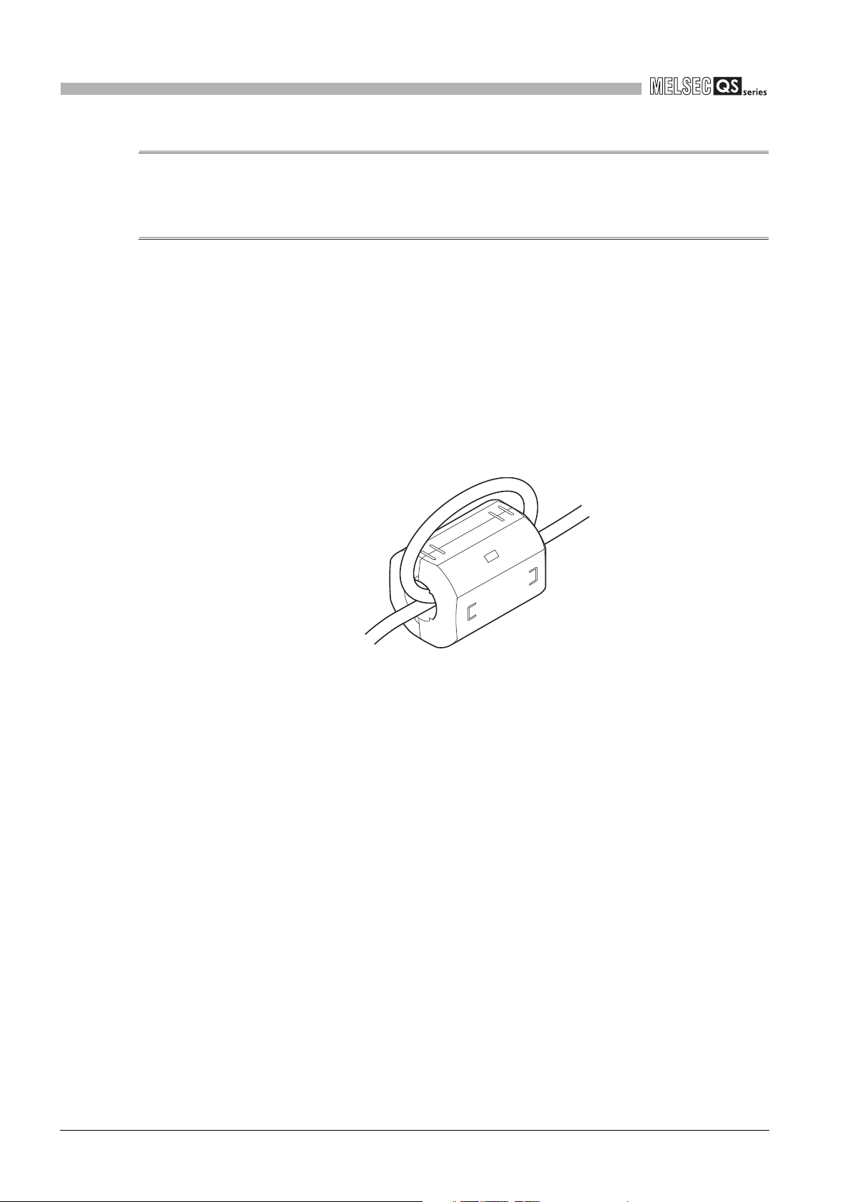
9
EMC, LOW VOLTAGE, AND MACHINERY DIRECTIVES
9.1.4 Power Supply Module
Always ground the LG and FG terminals after short-circuiting them.
9.1.5 Others
(1) Ferrite core
A ferrite core has the effect of reducing conduction noise in around 10MHz band and
radiated noise in the 30MHz to 100MHz band.
It is recommended to fit ferrite cores if shielded cables pulled out of the panel do not
provide sufficient shielding effects or if the emission of conduction noise from the
power supply line has to be suppressed.
It is also recommended to fit a ferrite core to the USB cable which connects the CPU
and the personal computer as measures against noise.
Regarding the number of winding to the ferrite core, the more the better. The two turns
or more is recommended as the number of winding.
Figure 9.10 For number of winding is two turns or more
Note that the ferrite cores should be fitted to the cables in the position immediately
before they are pulled out of the panel. If the fitting position is improper, the ferrite will
not produce any effect.
9 - 7
9.1 Requirements for Conformance to EMC Directive
9.1.4 Power Supply Module
Page 69

9
Remark
Remark
EMC, LOW VOLTAGE, AND MACHINERY DIRECTIVES
(2) Noise filter (power supply line filter)
A noise filter is a component which has an effect on conducted noise.
It is not required to fit the noise filter to the power supply line, but fitting it can further
suppress noise.
(The noise filter has the effect of reducing conducted noise of 10 MHz or less.)
The precautions required when installing a noise filter are described below.
• Do not bundle the wires on the input side and output side of the noise filter. When
bundled, the output side noise will be induced into the input side wires from which
the noise was filtered.
9
EMC AND LOW
VOLTAGE
10
LOADING AND
DIRECTIVES
INSTALLATION
Input side
(power supply side)
Induction
Filter
Output side
(device side)
The noise will be induced when the
input and output wires are bundled.
Figure 9.11 Precautions on noise filter
• Earth the noise filter earthing terminal to the control cabinet with the shortest wire
possible (approx. 10 cm (3.94 inch)).
Table9.3 Noise filer specifications
Noise Filter Model Name FN343-3/01 FN660-6/06 ZHC2203-11
Manufacturer SCHAFFNER SCHAFFNER TDK
Rated current 3A 6A 3A
Rated voltage 250V
Input side
(power supply side)
Filter
Output side
(device side)
Separate and lay the input
and output wires.
11
MAINTENANCE AND
12
INSPECTION
TROUBLESHOOTING APPENDICES INDEX
(3) DC surge protective devices
DC surge protective device (SPD) is a device designed to protect electrical devices
from lightning surges on the DC power line. Connect a DC SPD to the module power
supply terminal of a CC-Link Safety remote I/O module. Use the one having
characteristics comparable to the MDP-D24 made by M-System Co., Ltd.
• Before using a DC SPD, check the specifications and precautions in the manual.
• An MDP-D24 cannot be connected to the external power supply terminal of a
CC-Link Safety remote I/O module.
9.1 Requirements for Conformance to EMC Directive
9.1.5 Others
9 - 8
Page 70

9
EMC, LOW VOLTAGE, AND MACHINERY DIRECTIVES
9.2 Requirement to Conform to the Low Voltage Directive
The Low Voltage Directive requires each device that operates with the power supply
ranging from 50 to 1000VAC and 75 to 1500VDC to satisfy the safety requirements.
In Section 9.2.1 to Section 9.2.5, cautions on installation and wiring of the MELSEC-QS
series programmable controller to conform to the Low Voltage Directive are described.
These descriptions are based on the requirements and standards of the regulation,
however, it does not guarantee that the entire machinery manufactured based on the
descriptions conforms to the above-mentioned directive. The method and judgment for the
conformity to the low voltage directive must be left to the manufacturer's own discretion.
9.2.1 Standard applied for MELSEC-QS series programmable controller
The standard applied for MELSEC-QS series programmable controller is EN61131-2
safety of devices used in measurement rooms, control rooms, or laboratories.
The MELSEC-QS series programmable controller modules which operate at the rated
voltage of 50VAC/75VDC or above are also developed to conform to the above standard.
The modules which operate at the rated voltage of less than 50VAC/75VDC are out of the
Low Voltage Directive application range.
For CE-marked products, please consult your local Mitsubishi representative.
9.2.2 MELSEC-QS series programmable controller selection
(1) Power supply module
There are dangerous voltages (voltages higher than 42.4V peak) inside the power
supply modules of the 100/200VAC rated input voltages. Therefore, the CE marked
models are enhanced in insulation internally between the primary and secondary.
(2) CPU module, base unit
Using 5VDC circuits inside, CPU modules and base units are out of the Low Voltage
Directive application range.
(3) Intelligent function module
The intelligent function module is out of the scope of the Low Voltage Directive
because the rated voltage is 24VDC or less.
9 - 9
9.2 Requirement to Conform to the Low Voltage Directive
9.2.1 Standard applied for MELSEC-QS series programmable controller
Page 71

9
Category IV Category III Category II Category I
EMC, LOW VOLTAGE, AND MACHINERY DIRECTIVES
9.2.3 Power supply
The insulation specification of the power supply module was designed assuming
installation category II. Be sure to use the installation category II power supply to the
programmable controller.
The installation category indicates the durability level against surge voltage generated by
a thunderbolt. Category I has the lowest durability; category IV has the highest durability.
Figure 9.12 Installation category for power supply module
Category II indicates a power supply whose voltage has been reduced by two or more
levels of isolating transformers from the public power distribution.
9
EMC AND LOW
VOLTAGE
10
LOADING AND
11
MAINTENANCE AND
12
DIRECTIVES
INSTALLATION
INSPECTION
9.2.4 Control panel
Because the programmable controller is an open device (a device designed to be stored
within another module), be sure to use it after storing in the control panel.*
* : Also, each network remote station needs to be installed inside the control panel.
(1) Electrical shock prevention
The control panel must be handled as shown below to protect a person who does not
have adequate knowledge of electricity from an electric shock.
• Lock the control panel so that only those who are trained and have acquired
enough knowledge of electric facilities can open the control panel.
• The control panel must have a structure which automatically stops the power
supply when the box is opened.
• For electric shock protection, use IP20 or greater control panel.
TROUBLESHOOTING APPENDICES INDEX
9.2 Requirement to Conform to the Low Voltage Directive
9.2.3 Power supply
9 - 10
Page 72

9
EMC, LOW VOLTAGE, AND MACHINERY DIRECTIVES
(2) Dustproof and waterproof features
The control panel also has the dustproof and waterproof functions. Insufficient
dustproof and waterproof features lower the insulation withstand voltage, resulting in
insulation destruction.
The insulation in our programmable controller is designed to cope with the pollution
level 2, so use in an environment with pollution level 2 or below.
Pollution level 1 : An environment where the air is dry and conductive dust
does not exist.
Pollution level 2 : An environment where conductive dust
does not usually exist, but occasional temporary
conductivity occurs due to the accumulated dust.
Generally, this is the level for inside the control box
equivalent to IP54 in a control room or on the floor of a
typical factory.
Pollution level 3 : An environment where conductive dust exits and
conductivity may be generated due to the accumulated
dust.
An environment for a typical factory floor.
Pollution level 4 : Continuous conductivity may occur due to rain, snow, etc.
An outdoor environment.
As shown above, the programmable controller can realize the pollution level 2 when
stored in a control panel equivalent to IP54.
9 - 11
9.2 Requirement to Conform to the Low Voltage Directive
9.2.4 Control panel
Page 73

9
EMC, LOW VOLTAGE, AND MACHINERY DIRECTIVES
9.2.5 External wiring
(1) 24VDC external power supply
This power supply must include a reinforced insulation for 24VDC circuit to prevent
dangerous voltage for CC-Link Safety remote I/O module.
(2) External devices
When a device with a hazardous voltage circuit is externally connected to the
programmable controller, use the device whose interface circuit section to the
programmable controller has the reinforced insulation against the hazardous voltage
circuit.
9
EMC AND LOW
VOLTAGE
10
LOADING AND
DIRECTIVES
INSTALLATION
(3) Reinforced insulation
The reinforced insulation covers the withstand voltages shown in Table9.4.
Table9.4 Reinforced Insulation Withstand Voltage
(Installation Category II, source : IEC664)
Rated voltage of hazardous
voltage area
150VAC or below 2500V
300VAC or below 4000V
Surge withstand voltage
(1.2/50 s)
11
MAINTENANCE AND
12
INSPECTION
TROUBLESHOOTING APPENDICES INDEX
9.2 Requirement to Conform to the Low Voltage Directive
9.2.5 External wiring
9 - 12
Page 74

9
EMC, LOW VOLTAGE, AND MACHINERY DIRECTIVES
9.3 Requirements for compliance with the Machinery Directive
The Machinery Directive requires that machinery satisfy the three pillars of safety:
mechanical safety, electrical safety, and worker safety.
This product complies with the Machinery Directive (2006/42/EC).
Before using this product, please read this manual, the relevant manuals, the manuals for
standard programmable controller, and the safety standards carefully and pay full attention
to safety to handle the product correctly.
The descriptions are based on the requirements of the Machinery Directive and the
harmonized standards. However, they do not guarantee that the entire machinery
constructed according to the descriptions complies with the Machinery Directive. The
manufacture of the machinery must determine the testing method for compliance and
declare conformity to the Machinery Directive.
9 - 13
9.3 Requirements for compliance with the Machinery Directive
Page 75

10
LOADING AND INSTALLATION
CHAPTER10 LOADING AND INSTALLATION
In order to increase the reliability of the system and exploit the maximum performance of
its functions, this section describes the methods and precautions for the mounting and
installation of the system.
9
EMC AND LOW
VOLTAGE
10
DIRECTIVES
WARNING
When a safety programmable controller detects an error in an external
power supply or a failure in programmable controller, it turns off all the
outputs.
Create an external circuit to securely stop the power of hazard by turning
off the outputs. Incorrect configuration may result in an accident.
Create short current protection for a safety relay, and a protection circuit
such as a fuse, and breaker, outside a safety programmable controller.
When data/program change, or status control is performed from a per-
sonal computer to a running safety programmable controller, create an
interlock circuit outside the sequence program and safety programmable
controller to ensure that the whole system always operates safely.
For the operations to a safety programmable controller, pay full attention
to safety by reading the relevant manuals carefully, and establishing the
operating procedure.
Furthermore, for the online operations performed from a personal computer to a safety CPU module, the corrective actions of the whole system
should be predetermined in case that a communication error occurs due
to a cable connection fault, etc.
LOADING AND
11
MAINTENANCE AND
12
INSTALLATION
INSPECTION
TROUBLESHOOTING APPENDICES INDEX
All output signals from a safety CPU module to the CC-Link Safety mas-
ter module are prohibited to use.
These signals can be found in the CC-Link Safety System Master Module User's Manual.
Do not turn ON or OFF these signals by sequence program, since turning ON/OFF these output signals of the programmable controller system
may cause malfunctions and safety operation cannot be guaranteed.
All output signals from a safety CPU module to the CC-Link IE Field Net-
work master/local module (with safety functions) are prohibited to use.
These signals can be found in the MELSEC-QS CC-Link IE Field Network Master/Local User's Manual.
Do not turn ON or OFF these signals by sequence program, since turning ON/OFF these output signals of the programmable controller system
may cause malfunctions and safety operation cannot be guaranteed.
10 - 1
Page 76

10
LOADING AND INSTALLATION
WARNING
CAUTION
When a safety remote I/O module has detected a CC-Link Safety error, it
turns off all the outputs.
Note that the outputs in a sequence program are not automatically
turned off.
If a CC-Link Safety or CC-Link IE Field Network error has been detected,
create a sequence program that turns off the outputs in the program.
If the CC-Link Safety or CC-Link IE Field Network is restored with the
outputs on, it may suddenly operate and result in an accident.
To inhibit restart without manual operation after safety functions was
performed and outputs were turned OFF, create an interlock program
which uses a reset button for restart.
Do not install the wires of external devices or communication cables
together with the main circuit lines or power cables. Keep a distance of
100mm (3.94 inch) or more between them.
Failure to do so may result in malfunction due to noise.
10 - 2
Page 77

10
PW =
3
7
×(I5V×5) (W)
W
=
C
T
UA
W
10.1 Calculating Heat Generation of programmable controller
LOADING AND INSTALLATION
The ambient temperature inside the panel storing the programmable controller must be
suppressed to an ambient temperature of 55 or less, which is specified for the
programmable controller.
For the design of a heat releasing panel, it is necessary to know the average power
consumption (heating value) of the devices and instruments stored inside.
Here the method of obtaining the average power consumption of the programmable
controller system is described.
From the power consumption, calculate a rise in ambient temperature inside the panel.
9
EMC AND LOW
VOLTAGE
10
LOADING AND
DIRECTIVES
INSTALLATION
How to calculate average power consumption
The power consuming parts of the programmable controller are roughly classified into six
blocks as shown below.
(1) Power consumption of power supply module
The power conversion efficiency of the power supply module is approx. 70 %, while
30 % of the output power is consumed as heat. As a result, 3/7 of the output power is
the power consumption.
Therefore the calculation formula is as follows.
: Current consumption of logic 5 VDC circuit of each module
I
5V
(2) Total power consumption for 5VDC logic circuits of all modules
(including CPU module)
The power consumption of the 5 VDC output circuit section of the power supply
module is the power consumption of each module (including the current consumption
of the base unit).
= I5V5 (W)
W
5V
11
MAINTENANCE AND
12
INSPECTION
TROUBLESHOOTING APPENDICES INDEX
The total of the power consumption values calculated for each block becomes the power
consumption of the overall sequencer system.
W = WPW+W
From this overall power consumption (W), calculate the heating value and a rise in
ambient temperature inside the panel.
The outline of the calculation formula for a rise in ambient temperature inside the panel is
shown below.
W : Power consumption of overall sequencer system (value obtained above)
A : Surface area inside the panel
U : When the ambient temperature inside the panel is uniformed by a fan ........ 6
When air inside the panel is not circulated ................................................... 4
10.1 Calculating Heat Generation of programmable controller
5V
10 - 3
Page 78

10
POINT
LOADING AND INSTALLATION
If the temperature inside the panel has exceeded the specified range, it is
recommended to install a heat exchanger to the panel to lower the temperature.
If a normal ventilating fan is used, dust will be sucked into the programmable
controller together with the external air, and it may affect the performance of the
programmable controller.
(3) Example of calculation of average power consumption
(a) System configuration
QS061P-A1 QS001CPU
QS034
QS0J61BT12
Figure 10.1 System configuration
(b) 5 VDC current consumption of each module
QS001CPU : 0.43(A)
QS0J61BT12 : 0.46(A)
QS034B : 0.10(A)
(c) Power consumption of power supply module
PW = 3/7 (0.43 + 0.46 + 0.10) 5 = 2.12(W)
W
(d) Total power consumption for 5 VDC logic circuits of all module
W
5V = (0.43 + 0.46 + 0.10) 5 = 4.95(W)
(e) Power consumption of overall system
W = 2.12 + 4.95 = 7.07(W)
10 - 4
10.1 Calculating Heat Generation of programmable controller
Page 79

10
10.2 Module Installation
LOADING AND INSTALLATION
9
10.2.1 Installation precautions
CAUTION
Use the safety programmable controller in an environment that meets the
general specifications in this manual.
Failure to do so may result in electric shock, fire, malfunction, or damage
to or deterioration of the product.
To mount the module, while pressing the module mounting lever located
in the lower part of the module, fully insert the module fixing projection(s)
into the hole(s) in the base unit and press the module until it snaps into
place.
Incorrect interconnection may cause malfunction, failure, or drop of the
module.
Secure the module to the base unit with screws.
Tighten the screws within the specified torque range.
Undertightening can cause drop of the screw, short circuit, or malfunction.
Overtightening can damage the screw and/or module, resulting in drop,
short circuit, or malfunction.
Shut off the external power supply (all phases) used in the system before
mounting or removing the module.
Failure to do so may result in damage to the product.
EMC AND LOW
VOLTAGE
10
LOADING AND
11
MAINTENANCE AND
12
DIRECTIVES
INSTALLATION
INSPECTION
TROUBLESHOOTING APPENDICES INDEX
Do not directly touch any conductive part of the module.
Doing so can cause malfunction or failure of the module.
10.2 Module Installation
10.2.1 Installation precautions
10 - 5
Page 80

10
Panel
LOADING AND INSTALLATION
This section gives instructions for handling the CPU, and power supply modules, base unit
and so on.
• Do not drop the module case and main module or subject them to strong impact.
• Do not remove modules' printed circuit boards from the enclosure in order to
avoid failures in operation.
• Tighten the screws such as module fixing screws within the following ranges.
Location of Screw Tightening Torque Range
Module fixing screw (M3 12 screw)
Power supply module terminal screw (M3.5 screw) 0.66 to 0.89N•m
* 1 The module can be easily fixed onto the base unit using the hook at the top of the module.
However, it is recommended to secure the module with the module fixing screw if the module is
subject to significant vibration.
• Be sure to install a power supply module in the power supply installation slot of
QS034B.
Install a base unit (by screwing) in the following procedure.
Table10.1 Tightening torque range
*1
0.36 to 0.48N•m
1) Fit the two base unit top mounting screws into the panel.
Panel
Figure 10.2 Install a base unit
2) Place the right-hand side notch of the base unit onto the right-hand side screw.
Figure 10.3 Install a base unit
3) Place the left-hand side pear-shaped hole onto the left-hand side screw.
10 - 6
Panel
Figure 10.4 Install a base unit
10.2 Module Installation
10.2.1 Installation precautions
Page 81

10
Base unit rear
Place the hook of the adaptor
(small) in the lower hole.
Push the top of the adaptor
(small) far enough until it
"clicks".
Insert the adaptor (large) into the grooves of
the base unit from below.
Push the bottom of the adaptor (large) far enough
until it "clicks".
LOADING AND INSTALLATION
4) Fit the mounting screws into the holes at the bottom of the base unit, and then
retighten the 4 mounting screws.
Note1 : Install the base unit to a panel, with no module loaded in the right-end
slot.
Remove the base unit after unloading the module from the right-end
slot.
Note the following points when mounting a DIN rail.
Mounting a DIN rail needs special adaptors (optional), which are to be prepared by the
user.
(a) Applicable adaptor types
For QS034B : Q6DIN2
Table10.2 Parts included with DIN rail mounting adaptors included parts
9
EMC AND LOW
VOLTAGE
10
LOADING AND
11
DIRECTIVES
INSTALLATION
DIN rail mounting
adaptors
Q6DIN2 23222
Adaptor(Large) Adaptor(small)
Quantity of included parts
Mounting screw
(M5 10)
Square washer Stopper
(b) Adaptor installation method
The way to install the adaptors for mounting a DIN rail to the base unit is given in
Figure 10.5.
MAINTENANCE AND
12
INSPECTION
TROUBLESHOOTING APPENDICES INDEX
Figure 10.5 Adaptor installation method
10.2 Module Installation
10.2.1 Installation precautions
10 - 7
Page 82

10
35mm
(1.38 inch)
P=200mm (7.88 inch) or less
DIN rail
DIN rail mounting screw
(obtained by user)
PPP
DIN rail
Mounting screws
(M5 10)
Square washer
Side view A
DIN railMounting screws
square washer
Mounting side
(e.g. Control panel)
Side view A
LOADING AND INSTALLATION
(c) Applicable DIN rail types (IEC 60715)
TH35-7.5Fe
TH35-7.5AI
TH35-15Fe
(d) DIN rail mounting screw intervals
When using either the TH35-7.5Fe or TH35-7.5Al DIN rail, tighten rail mounting
screws with an interval of 200mm (7.88 inch) or less to ensure that the rail has
sufficient strength.
Figure 10.6 DIN rail mounting screw intervals
When installing the DIN rail in a large vibration and/or shock prone environment,
tighten the mounting screws with an interval of 200mm (7.88 inch) or less by the
following method shown below.
Screw the DIN rail in two places using the mounting screws and square washers
included with the adaptors in ‘Position A’ (bottom of base unit).
B *3
P=200mm (7.88 inch) or less
* 1
DIN rail
35mm
Stopper
Mounting screws
(included with adaptors)
Square washers necessary *1
A *2B *3
Mounting screws (obtained by user)
No square washers
Stopper
P
Figure 10.7 DIN rail mounting screw intervals
PP
10 - 8
10.2 Module Installation
10.2.1 Installation precautions
Figure 10.8 Square washer
* 2: Screw the DIN rail to a control panel using the mounting screws and square washers included
with the adaptors in ‘Position A’ (bottom of base unit).
* 3: Screw the DIN rail with mounting screws(obtained by user) in ‘Position B’ (Where the base unit is
not installed). In this method the supplied mounting screws and square washers are not used.
Page 83

10
POINT
DIN railsquare washer DIN railsquare washer
LOADING AND INSTALLATION
(1) Use only one washer for each mounting screw. Use only the square washers
supplied with the adaptors.
If two or more washers are used together for one mounting screw, the screw
may interfere with the base unit.
(2) Make sure to align the square washer sides with the DIN rail.
Figure 10.9 Precautions when mounting a square washer
(3) Use the DIN rail that is compatible with M5 size screws.
9
EMC AND LOW
VOLTAGE
10
LOADING AND
11
MAINTENANCE AND
DIRECTIVES
INSTALLATION
INSPECTION
12
TROUBLESHOOTING APPENDICES INDEX
10.2 Module Installation
10.2.1 Installation precautions
10 - 9
Page 84

10
4)
5)
Stopper
(Left side)
4)
5)
Stopper
(Right side)
2)
3)
1)
Stopper
Hook
Hook
Stopper Stopper
Hitch hook to top of
DIN rail
Hitch hook to bottom
of DIN rail
DIN rail
DIN rail
Complete
1)
2)
3)
4)
5)
Loosen the screw at the top of the
stopper. (2 stoppers)
Hitch the lower hook of the stopper
to the bottom of the DIN rail. Install
the stopper with the arrowhead side
facing up.
Hitch the upper hook of the stopper
to the top of the DIN rail.
Slide the stopper to the end of the
base unit so that they are fully in
contact.
Tighten the screw of the stopper
with a screwdriver.
(Tightening torque 1.00 to 1.35N m)
Make sure that the left and right
stoppers are fixed securely to the
DIN rail.
LOADING AND INSTALLATION
(e) Stopper mounting
When using the DIN rail in a large vibration and/or shock prone environment,
install the base unit using the stoppers supplied with the DIN rail mounting
adaptors indicated in (a).
Figure 10.10 Fixture mounting procedure
10 - 10
10.2 Module Installation
10.2.1 Installation precautions
Page 85

10
POINT
Unit: mm (inch)
49 49
Base unit
DIN rail
W+18(0.71)
Base unit width : W
DIN rail center
35(1.38)
(1.93)
98(3.86)
(1.93)
Stopper Stopper
7.5D
3
DIN rail depth (D)
Board side
DIN rail adaptor
Base unit
115 (4.53)
Power supply module
DIN rail: TH35-7.5Fe,
TH35-7.5Al,
TH35-15Fe
TH35-7.5Fe, TH35-7.5Al:7.5 (0.30)
TH35-15Fe:15 (0.59)
(0.12)
35 (1.38)
(0.30)
98 (3.86)
(49 (1.93))(49 (1.93))
5
(0.20)
Unit: mm (inch)
5
LOADING AND INSTALLATION
When stoppers are used, the dimension of stoppers need to be considered in the
unit installation dimensions. Refer to Section 6.1 for the base unit dimensions (W).
Figure 10.11 Base unit external dimensions (Front view)
(f) Dimensions when DIN rail is attached (Side view).
9
EMC AND LOW
VOLTAGE
10
LOADING AND
11
MAINTENANCE AND
12
DIRECTIVES
INSTALLATION
INSPECTION
TROUBLESHOOTING APPENDICES INDEX
Figure 10.12 External dimensions (Side view)
10.2 Module Installation
10.2.1 Installation precautions
10 - 11
Page 86

10
Indicates the panel top, wiring duct or any
part position.
30mm(1.18 inch)
or more
Panel
5mm (0.20 inch) or more
5mm (0.20 inch) or more
20mm
(0.79 inch)
or more
Door
Programmable
logic controller
30mm(1.18 inch)
or more
*1
LOADING AND INSTALLATION
10.2.2 Instructions for mounting the base unit
When mounting the programmable controller to an enclosure or similar, fully consider its
operability, maintainability and environmental resistance.
(1) Module mounting position
Keep the clearances shown in Figure 10.13 between the top/bottom faces of the
module and other structures or parts to ensure good ventilation and facilitate module
replacement.
(a) In case of base unit
* 1: For wiring duct with 50mm (1.97 inch) or less height. For other cases, 40mm (1.58 inch) or more.
Figure 10.13 Module mounting position
10 - 12
10.2 Module Installation
10.2.2 Instructions for mounting the base unit
Page 87

10
Vertical mounting Horizontal installation
Horizontal mounting
LOADING AND INSTALLATION
(2) Module mounting orientation
• Install the programmable controller in the orientation in Figure 10.14 to ensure
good ventilation for heat release.
Figure 10.14 Orientation in which modules can be mounted
• Do not mount it in either of the orientations shown in Figure 10.15.
9
EMC AND LOW
VOLTAGE
10
LOADING AND
11
MAINTENANCE AND
DIRECTIVES
INSTALLATION
INSPECTION
Figure 10.15 Orientation in which modules cannot be mounted
12
TROUBLESHOOTING APPENDICES INDEX
10.2 Module Installation
10.2.2 Instructions for mounting the base unit
10 - 13
Page 88

10
LOADING AND INSTALLATION
(3) Installation surface
Mount the base unit on a flat surface. If the mounting surface is not even, this may
strain the printed circuit boards and cause malfunctions.
(4) Installation of unit in an area where the other devices are installed
Avoid mounting base unit in proximity to vibration sources such as large magnetic
contractors and no-fuse circuit breakers; mount these on a separate panel or at a
distance.
(5) Distances from the other devices
In order to avoid the effects of radiated noise and heat, provide the clearances
indicated below between the programmable controller and devices that generate
noise or heat (contactors and relays).
• Required clearance in front of programmable controller
• Required clearance on the right and left of programmable controller
: at least 100 mm (3.94 inch)
: at least 50 mm (1.97 inch).
*
At least
100mm
(3.94 inch)
Contactor, relay, etc.
At least
50mm (1.97 inch)
At least
50mm (1.97 inch)
Figure 10.16 Distances from the other devices
10 - 14
10.2 Module Installation
10.2.2 Instructions for mounting the base unit
Page 89

10
Module fixing hole
Module
fixing latch
Base unit
Module loading
lever
Check that the module is
inserted in the base unit
securely and then fix it with the
module fixing screws.
Completed
Securely insert the module
fixing latch(*1) into the module
fixing hole so that the latch is
not misaligned.
Using the module fixing hole as
a fulcrum, push the module in
the direction of arrow to mount
it into the base unit.
Module
Unit fixing
hook (*2)
Base unit
Module fixing hole
Module loading
lever
Module fixing
latch (*1)
Base unit
Module connector
Base unit hook
Module fixing hook
Power supply module
Push
Center top
LOADING AND INSTALLATION
10.2.3 Installation and removal of module
This section explains how to install and remove a power supply, CPU, intelligent function
or another module to and from the base unit.
9
EMC AND LOW
VOLTAGE
DIRECTIVES
(1) Installation and removal of the module from the QS034B
(a) Installation of module on the QS034B
Figure 10.17 Module mounting procedure
* 1: The power supply module and CPU module has two module fixing latches. Insert the two module
fixing latches on the right and left into the module fixing holes so that they are not misaligned.
10
LOADING AND
11
MAINTENANCE AND
12
INSTALLATION
INSPECTION
TROUBLESHOOTING APPENDICES INDEX
Figure 10.18 Mounting the power supply module and CPU module
* 2: The power supply module and CPU module has two module fixing hooks on its top. Push the
center top of the power supply module and CPU module and mount the module so that the two
module fixing hooks on the right and left are securely engaged with the base unit hooks.
10.2.3 Installation and removal of module
10.2 Module Installation
10 - 15
Page 90

10
POINT
LOADING AND INSTALLATION
1. When mounting the module, always insert the module fixing latch into the
module fixing hole of the base unit.
At that time, securely insert the module fixing latch so that it does not come off
from the module fixing hole.
If the module is forcibly mounted without the latch being inserted, the module
connector and module will be damaged.
2. Do not mount/remove the module onto/from base unit more than 50 times
(IEC61131-2-compliant), after the first use of the product. Failure to do so
may cause the module to malfunction due to poor contact of connector.
10 - 16
10.2 Module Installation
10.2.3 Installation and removal of module
Page 91

10
POINT
Completed
Pull the module based on the
supporting point of module bottom
while pressing the module fixing
hook .
While lifting the module, take the
module fixing latch(*2) off the
module fixing hole.
Remove the module fixing screw.
Then support the module with both
hands
and securely press the
module fixing hook*1 with your
finger.
Module
Module
connector
Module fixing hole
Base unit
Push
Module fixing
hook *1
Lifting
Push simultaneously
Module fixing hooks
LOADING AND INSTALLATION
(b) Removal from the QS034B
Figure 10.19 Module removal procedure
* 1: The power supply module and CPU module has two module fixing hooks on its top. Push the two
module fixing hooks on the right and left of the module top simultaneously with your fingers until
they stop.
9
EMC AND LOW
VOLTAGE
DIRECTIVES
10
LOADING AND
INSTALLATION
11
MAINTENANCE AND
INSPECTION
12
Figure 10.20 Power supply module and CPU module removal procedure
* 2: The power supply module and CPU module has two module fixing latches. Remove the two
module fixing latches on the right and left of the module bottom from the module fixing holes.
When removing the module, always remove the module fixing screw(s) first, and
then remove the module fixing projection(s) from the module fixing hole(s).
Attempting to remove the module by force may damage the module fixing latch.
TROUBLESHOOTING APPENDICES INDEX
10.2 Module Installation
10.2.3 Installation and removal of module
10 - 17
Page 92

10
10.3 Wiring
LOADING AND INSTALLATION
10.3.1 Wiring precautions
WARNING
Shut off the external power supply (all phases) used in the system before
wiring.
Failure to do so may result in electric shock or damage to the product.
After wiring, attach the included terminal cover to the module before turn-
ing it on for operation.
Failure to do so may result in electric shock.
10 - 18
10.3 Wiring
10.3.1 Wiring precautions
Page 93

10
LOADING AND INSTALLATION
9
CAUTION
Individually ground the FG and LG terminals of the programmable con-
troller with a ground resistance of 100 or less. Failure to do so may
result in electric shock or malfunction.
Use a solderless terminal with insulation sleeve for wiring of a terminal
block.
Use up to two solderless terminals for a single terminal.
Use applicable solderless terminals and tighten them within the specified
torque range.
If any spade solderless terminal is used, it may be disconnected when a
terminal block screw comes loose, resulting in failure.
Check the rated voltage and terminal layout before wiring to the module,
and connect the cables correctly.
Connecting a power supply with a different voltage rating or incorrect wiring may cause a fire or failure.
Tighten the terminal block mounting screws, terminal screws, and mod-
ule fixing screws within the specified torque range.
Undertightening of the terminal block mounting screws or terminal
screws can cause short circuit, fire, or malfunction.
Overtightening can damage the screw and/or module, resulting in drop,
short circuit, or malfunction.
Undertightening of the module fixing screws can cause drop of the module.
Overtightening can damage the screw and/or module, resulting in drop.
EMC AND LOW
VOLTAGE
10
LOADING AND
11
MAINTENANCE AND
12
DIRECTIVES
INSTALLATION
INSPECTION
TROUBLESHOOTING APPENDICES INDEX
Prevent foreign matter such as dust or wire chips from entering the mod-
ule.
Such foreign matter can cause a fire, failure, or malfunction.
A protective film is attached to the top of the module to prevent foreign
matter, such as wire chips, from entering the module during wiring.
Do not remove the film during wiring.
Remove it for heat dissipation before system operation.
Mitsubishi programmable controllers must be installed in control panels.
Connect the main power supply to the power supply module in the control panel through a relay terminal block.
Wiring and replacement of a power supply module must be performed by
qualified maintenance personnel with knowledge of protection against
electric shock.
(For the wiring methods, refer to Section 10.3.)
The precautions on the connection of the power cables are described below.
10.3 Wiring
10.3.1 Wiring precautions
10 - 19
Page 94

10
200VAC
T1
Main
power supply
Programmable
controller
power supply
Insulation
Transformer
I/O power supply
I/O equipment
On a control panel
Main circuit
power supply
Main circuit equipment
Programmable
controller
Relay
terminal block
E1 E1
AC
E1
E2
Surge absorber for lightening
Programmable
controller
I/O devices
LOADING AND INSTALLATION
(1) Power supply wiring
• Separate the programmable controller power supply line from the lines for I/O
devices and power devices as shown below.
When there is much noise, connect an insulation transformer.
• Taking rated current or inrush current into consideration when wiring the power
supply, be sure to connect a breaker or an external fuse that have proper blown
and detection.
When using a single programmable controller, a 10A breaker or an external fuse
are recommended for wiring protection.
Figure 10.21 Power supply connection diagram
• 100VAC and 200VAC wires should be twisted as dense as possible.
Connect the modules with the shortest distance.
Also, to reduce the voltage drop to the minimum, use the thickest wires possible
2
(maximum 2mm
).
• Do not bundle the 100VAC and 200VAC wires with, or run them close to, the main
circuit (high voltage, large current) and I/O signal lines (including common line).
Reserve a distance of at least 100 mm from adjacent wires.
• Momentary power failure may be detected or the CPU module may be reset due
to serge caused by lightening.
As measures against serge caused by lightening, connect a surge absorber for
lightening as shown in Figure 10.22.
Using the surge absorber for lightening can reduce the influence of lightening.
10 - 20
10.3 Wiring
10.3.1 Wiring precautions
Figure 10.22 Connecting a lightning surge absorber
Page 95

10
POINT
(3) Joint grounding Not allowed
Programmable
controller
Another
equipment
Programmable
controller
Another
equipment
Programmable
controller
Another
equipment
(1) Independent grounding Best (2) Common grounding Good
Ground
resistance of
100 or less
Ground
resistance of
100 or less
LOADING AND INSTALLATION
1. Separate the ground of the surge absorber for lightening (E1) from that of the
programmable controller (E2).
2. Select a surge absorber for lightening whose power supply voltage does no
exceed the maximum allowable circuit voltage even at the time of maximum
power supply voltage elevation.
(2) Grounding
For grounding, perform the following:
• Use a dedicated grounding wire as far as possible. (Grounding resistance of
100 or less.)
• When a dedicated grounding cannot be performed, use (2) Common Grounding
shown below.
9
EMC AND LOW
VOLTAGE
10
LOADING AND
11
MAINTENANCE AND
DIRECTIVES
INSTALLATION
INSPECTION
Figure 10.23 Grounding procedures
2
• For grounding a cable, use the cable of 2 mm
or more.
Position the ground-contact point as closely to the sequencer as possible, and
reduce the length of the grounding cable as much as possible.
12
TROUBLESHOOTING APPENDICES INDEX
10.3 Wiring
10.3.1 Wiring precautions
10 - 21
Page 96

10
POINT
AC
AC
DC
100/110VAC
24VDC
QS061P-A1
FG
LG
INPUT
100-120VAC
Fuse
Connect to 24VDC
terminals of module
that requires 24VDC
internally.
Main base unit
(QS034B)
CPU module
ERR
1
Ground wire
Grounding
Terminal block
Solderless terminals
with insulation sleeves
LOADING AND INSTALLATION
10.3.2 Connecting to the power supply module
The following figure shows the wiring example of power lines, grounding lines, etc. to the
unit.
* 1: The ERR. terminal turns ON/OFF as described below.
The terminal turns OFF (opens) when the AC power is not input, a CPU module stop error
(including a reset) occurs, or the fuse of the power supply module is blown.
Figure 10.24 Wiring example
1. Use the thickest possible (max. 2 mm2 (14 AWG)) wires for the 100/200 VAC
power cables. Be sure to twist these wires starting at the connection terminals. For wiring a terminal block, be sure to use a solderless terminal. To prevent short-circuit due to loosening screws, use the solderless terminals with
insulation sleeves of 0.8 mm (0.03 inch) or less thick. The number of the solderless terminals to be connected for one terminal block are limited to 2.
2. The ERR
cable for ERR
. terminal can not be used as a safety output. In addition, set the
. contact in the control panel and its length to 30m (98.43 ft.) or
less.
10 - 22
10.3 Wiring
10.3.2 Connecting to the power supply module
Page 97

11
MAINTENANCE AND INSPECTION
CHAPTER11 MAINTENANCE AND INSPECTION
Do not touch the terminals while power is on.
WARNING
Doing so could cause shock or erroneous operation.
Correctly connect the battery.
Also, do not charge, disassemble, heat, place in fire, short circuit,
or solder the battery.
Mishandling of battery can cause overheating or cracks which
could result in injury and fires.
Turn off all phases of the external supply power used in the system
when cleaning the module or retightening the terminal block
mounting screws, terminal screws, or module fixing screws.
Not doing so could result in electric shock.
Tighten a terminal block mounting screw, terminal screw, and
module fixing screw within the specified torque range.
If the terminal block mounting screw or terminal screw is too loose,
it may cause a short circuit, fire, or malfunctions.
If too tight, it may damage the screw and/or the module, resulting
in a drop of the screw or module, a short circuit or malfunctions.
If the module fixing screw is too loose, it may cause a drop of the
screw or module.
Overtightening the screw may cause a drop due to the damage of
the screw or module.
9
EMC AND LOW
VOLTAGE
10
LOADING AND
11
MAINTENANCE AND
12
DIRECTIVES
INSTALLATION
INSPECTION
TROUBLESHOOTING APPENDICES INDEX
11 - 1
Page 98

11
MAINTENANCE AND INSPECTION
The online operations performed from a personal computer to a
CAUTION
running safety programmable controller (Program change when a
safety CPU is RUN, device test, and operating status change such
as RUN-STOP switching) have to be executed after the manual
has been carefully read and the safety has been ensured.
Following the operating procedure predetermined at designing, the
operation has to be performed by an instructed person.
When changing a program while a safety CPU is RUN (Write
during RUN), it may cause a program breakdown in some
operating conditions.
Fully understand the precautions described in the GX Developer's
manual before use.
Do not disassemble or modify the modules.
Doing so could cause a failure, erroneous operation, injury, or fire.
If the product is repaired or remodeled by other than the specified
FA centers or us, the warranty is not covered.
Use any radio communication device such as a cellular phone or a
PHS phone more than 25cm (9.85 inch) away in all directions of
the programmable controller.
Not doing so can cause a malfunction.
Completely turn off the externally supplied power used in the sys-
tem before mounting or removing the module.
Not doing so may result in a failure or malfunctions of the module.
Restrict the mounting/removal of a module, base unit, and terminal
block up to 50 times (IEC61131-2-compliant), after the first use of
the product.
Failure to do so may cause the module to malfunction due to poor
contact of connector.
Do not drop or give an impact to the battery mounted to the
module.
Doing so may damage the battery, causing the battery fluid to leak
inside the battery.
If the battery is dropped or given an impact, dispose of it without
using.
Before touching the module, always touch grounded metal, etc. to
discharge static electricity from human body, etc.
Not doing so may result in a failure or malfunctions of the module.
11 - 2
In order that you can use the programmable controller in normal and optimal condition
at all times, this section describes those items that must be maintained or inspected
daily or at regular intervals.
Page 99

11
11.1 Daily Inspection
MAINTENANCE AND INSPECTION
The items that must be inspected daily are listed in Table11.1.
Table11.1 Daily inspection
9
EMC AND LOW
VOLTAGE
DIRECTIVES
Item Inspection Item Inspection Judgment Criteria Remedy
1 Installation of base unit
Installation of power supply
2
module and CPU module
3 Connecting conditions
Power supply module
"POWER" LED
CPU module "ALIVE"
LED
CPU module "RUN"
4
LED
CPU module "ERR."
LED
Module indication LED
CPU module "TEST"
LED
CPU module "BAT."
LED
Check that fixing screws are
not loose and the cover is
not dislocated.
Check that the module is not
dislocated and the unit fixing
hook is engaged securely.
Check that the module fixing
screws are securely
tightened.
Check for loose terminal
screws.
Check for distance between
solderless terminals.
Check that the LED is On
(green).
Check that the LED is On
(green).
Check that the LED is On
(green).
Check that the LED is Off.
Check that the LED is Off.
Check that the LED is Off.
The screws and cover must
be installed securely
The module fixing hook
must be engaged and
installed securely.
The module fixing screws
must be securely tightened.
Screws should not be loose.
The proper clearance
should be provided between
Solderless terminals.
The LED must be On
(green).
(Abnormal if the LED is Off.)
The LED must be On
(green).
(Abnormal if the LED is Off.)
The LED must be On
(green).
(Abnormal if the LED is Off.)
The LED must be Off.
(Abnormal if the LED is On
or flashing.)
The LED must be Off.
(Abnormal if the LED is On.)
The LED must be Off.
(Abnormal if the LED is On.)
Retighten the screws.
Securely engaged the unit
fixing hook.
Securely tighten the
module fixing screws.
Retighten the terminal
screws.
Correct.
Since the status other
than indicated on the
left is in the status other
than normal operation
perform the
troubleshooting
referring to Section
12.2.
10
LOADING AND
INSTALLATION
11
MAINTENANCE AND
INSPECTION
12
TROUBLESHOOTING APPENDICES INDEX
*1
,
*1: Normal operation indicates the following conditions.
• Safety CPU operation mode is in the SAFETY MODE.
• The CPU operation status is in the RUN status.
11.1 Daily Inspection
11 - 3
Page 100

11
MAINTENANCE AND INSPECTION
11.2 Periodic Inspection
The items that must be inspected one or two times every 6 months to 1 year are listed
below.
When the equipment is moved or modified, or layout of the wiring is changed, also perform
this inspection.
Table11.2 Periodic Inspection
Item Inspection Item Inspection Judgment Criteria Remedy
Ambient temperature
Ambient humidity 5 to 95 %RH
1
Atmosphere Measure corrosive gas.
Ambient environment
2 Power voltage
Measure with a
thermometer and a
hygrometer.
Measure a voltage across
the terminals of 100/
200VAC.
0 to 55
Corrosive gas must not be
present.
85 to 132VAC
170 to 264VAC
When the sequencer is
used in the board, the
ambient temperature in the
board becomes the
ambient temperature.
Change the power supply.
Looseness and rattling
3
4
5 Battery
6
7Clock
of module fixing screws
Installation
Adhesion of dirt and
foreign matter
Looseness of terminal
screws
Proximity of solderless
terminals to each other
Connection
Looseness of
connectors
Number of writes to
standard ROM
Try to further tighten screws
with a screwdriver.
Check visually.
Try to further tighten screws
with a screwdriver.
Check visually.
Check visually.
Check "BAT." LED on the
front face of the CPU
module.
Check the period after the
purchase of the battery.
Check in the monitoring
mode of GX Developer that
SM51 or SM52 is turned
OFF.
Check the values of SD232
and SD233 in the monitoring
mode of GX Developer.
Check the current time at
the clock setting of GX
Developer.
The module must be
installed fixedly.
Dirt and foreign matter must
not be present.
Screws must not be loose.
Solderless terminals must
be positioned at proper
intervals.
Connectors must not be
loose.
The LED must be Off.
The period must be five
years or less.
SM51 or SM52 must be
OFF.
The number of writes to the
standard ROM must be
100,000 times or less.
There is no time lag
between the time checked
at the time setting of GX
Developer and the actual
time.
Retighten the screws.
If the CPU, or power
supply module is loose, fix
it with screws.
Remove and clean.
Retighten the terminal
screws.
Correct.
Retighten the connector
fixing screws.
If the LED is On, replace
the battery.
If the battery is used for
more than 5 years, replace
the battery.
If SM51 or SM52 is ON,
replace the battery.
If the number of writes to
the standard ROM
exceeds 100,000 times,
replace the CPU module.
Change the time at the
time setting of GX
Developer.
11 - 4
11.2 Periodic Inspection
 Loading...