

Page 1
Page 2

Page 3
• SAFETY PRECAUTIONS •
(You must read these cautions before using the product)
As for the use of the product, please carefully read this manual and the related manuals introduced later.
Also, please pay attention to safety adequately and manage the product correctly.
The safety cautions shown in this manual apply to the product only.
In this manual, the safety precautions are ranked as "DANGER" and "CAUTION".
DANGER
!
CAUTION
!
Note that the !CAUTION level may lead to a serious consequence according to the circumstances.
Always follow the instructions of both levels because they are important to personal safety.
Please store this manual in order to read whenever it is necessary. Also, always forward this manual to
the end users.
Indicates that incorrect handling may cause hazardous conditions,
resulting in death or severe injury.
Indicates that incorrect handling may cause hazardous conditions,
resulting in medium or slight personal injury or physical damage.
[Design Precautions]
!
DANGER
• Install a safety circuit external to the programmable controller that keeps the entire system safe
even when there are problems with the external power supply or the programmable controller.
Otherwise, it may cause an output error or an operating error, resulting in an accident.
(1) Configure a circuit such as an emergency stop circuit and a protective circuit on the outside
of the programmable logic controller.
(2) When the programmable controller detects the following problems, it will stop calculation
and turn off all outputs.
• An overcurrent protective device or an overvoltage protective device in a power supply
module start running.
• A watchdog timer error or others is detected with self-checking function in the
programmable controller CPU.
All outputs may be turned on, when an error occurs in the part of I/O controlling or others
that the programmable controller CPU cannot detect. Build a fail safe circuit exterior to the
programmable controller to keep the entire system safe.
As for the fail safe circuit, refer to a CPU module User’s Manual.
• Configure a circuit that turns on an external power supply when the main power of
programmable controller is turned on. If the external power supply is turned on first, it could
result in an output error or an operating error.
A - 1
Page 4

[Design Precautions]
!
DANGER
• When connecting a peripheral device to the CPU module or connecting a personal computer or
others to an intelligent function module, always configure an interlock circuit in the sequence
program to ensure that the whole system always operate safely.
Also, make sure to read this manual carefully and check all operations for safety first before
executing other control (program changes, changes of operation status (and status control)) of
the operating sequence.
Especially for the control described above on the remote sequence from an external device, an
immediate action may not be taken for a programmable controller’s trouble due to a data
communication fault.
Configure the interlock circuit in the sequence program. Simultaneously a recovery method for
system, in which a data communications fault occurs, should be determined between the
external device and the programmable controller CPU.
[Startup/Maintenance Precaution]
!
CAUTION
• Make sure to read this manual carefully and check all operations for safety first before
connecting a peripheral device to an operating CPU module online (particularly program
changes, forced outputs, and changes of operation status). Otherwise, an operating error may
cause damage or problems with the modules.
A - 2
Page 5
REVISIONS
* The manual number is given on the bottom left of the back cover.
Print Date * Manual Number Revision
Dec., 1999 SH (NA) 080040-A First edition
Jun., 2001 SH (NA) 080040-B
Partial addition
About Manuals, Chapter 1, Chapter 2, Section 2.1, 3.1, 3.2, 3.3, 3.3.1,
4.2.3, 4.3.2, 4.3.5, Chapter 5, Section 5.1, 5.2, Chapter 6, Chapter 7,
Section 8.1, 8.2
Apr., 2002 SH (NA) 080040-C
Correction
Chapter 1, Chapter 7, Section 8.1, 8.2, 8.3, 8.4, 8.5
Jan., 2003 SH (NA) 080040-D • Addition of use of Basic model QCPU
• Addition of explanation of incomplete derivative
Overall reexamination
Mar., 2003 SH (NA) 080040-E • Addition of explanation of incomplete derivative to High Performance
model QCPU
Dec., 2003 SH (NA) 080040-F
Jun., 2004 SH (NA) 080040-G
Sep., 2006 SH (NA) 080040-H
Apr.,2007 SH (NA) 080040-I
Mar.,2008 SH (NA) 080040-J
Correction
Chapter 1
Addition of Redundant CPU
Partial addition
About Manuals, Chapter 1, Chapter 2, Section 2.1, 3.1.1, 3.1.3, 3.2.1,
3.2.3, 4.3.5, 5.1, 5.2, Chapter 6, Chapter 7, Section 8.1.1 to 8.1.4,
Section 9.1.1 to 9.1.5, 9.2, Appendix 1
Partial addition
Section 4.2.5, Appendix 2
Addition of Universal model QCPU
Addition module
Q02UCPU, Q03UDCPU, Q04UDHCPU, Q06UDHCPU
Partial correction
GENERIC TERMS AND ABBREVIATIONS USED IN THIS MANUAL,
Chapter 1, Chapter 2, Section 2.1, 3.1.1, 3.1.3, 3.2.1, 3.2.3, 5.1, Chapter 6,
Chapter 7, 8.1.1 to 8.1.5, 9.1.1 to 9.1.5, Appendix 1
Addition of Universal model QCPU
Addition module
Q13UDHCPU, Q26UDHCPU
Partial correction
GENERIC TERMS AND ABBREVIATIONS USED IN THIS MANUAL,
Section 2.1, Appendix 1
A - 3
Page 6
* The manual number is given on the bottom left of the back cover.
Print Date * Manual Number Revision
May,2008 SH (NA) 080040-K
Revision due to the addition of Process CPU and Universal model QCPU
Addition module
Q03UDECPU, Q04UDEHCPU, Q06UDEHCPU, Q13UDEHCPU,
Q26UDEHCPU
Q02PHCPU, Q06PHCPU
Partial correction
GENERIC TERMS AND ABBREVIATIONS USED IN THIS MANUAL,
Section 2.1, Appendix 1
Japanese Manual Version SH-080022-K
This manual confers no industrial property rights or any rights of any other kind, nor does it confer any patent licenses.
Mitsubishi Electric Corporation cannot be held responsible for any problems involving industrial property rights which
may occur as a result of using the contents noted in this manual.
© 1999 MITSUBISHI ELECTRIC CORPORATION
A - 4
Page 7

INTRODUCTION
Thank you for choosing the Mitsubishi MELSEC-Q/QnA Series of Programmable Logic Controllers.
Please read this manual carefully so that the equipment is used to its optimum. A copy of this manual should
be forwarded to the end User.
CONTENTS
SAFETY CAUTIONS ......................................................................................................................................A- 1
REVISIONS .....................................................................................................................................................A- 3
CONTENTS.....................................................................................................................................................A- 5
About Manuals ................................................................................................................................................A- 8
Generic Terms and Abbreviations Used in This Manual ..............................................................................A-11
1. GENERAL DESCRIPTION 1 – 1 to 1 - 3
1.1 PID Processing Method ........................................................................................................................... 1 - 3
2. SYSTEM CONFIGURATION FOR PID CONTROL 2 - 1 to 2 - 2
2.1 Applicable PLC CPU ................................................................................................................................ 2 - 2
3. PID CONTROL SPECIFICATIONS 3 - 1 to 3 - 14
3.1 PID Control by Incomplete derivative ...................................................................................................... 3 - 1
3.1.1 Performance specifications............................................................................................................... 3 - 1
3.1.2 PID operation block diagram and operation expressions ................................................................ 3 - 2
3.1.3 PID control instruction list.................................................................................................................. 3 - 3
3.2 PID Control by Complete Derivative........................................................................................................ 3 - 8
3.2.1 Performance specifications............................................................................................................... 3 - 8
3.2.2 PID operation block diagram and operation expressions ................................................................ 3 - 9
3.2.3 PID control instruction list................................................................................................................ 3 - 10
4. FUNCTIONS OF PID CONTROL 4 - 1 to 4 - 14
4.1 Outline of PID Control .............................................................................................................................. 4 - 1
4.2 Functions of PID Control.......................................................................................................................... 4 - 2
4.2.1 Operation method.............................................................................................................................. 4 - 2
4.2.2 Forward operation and reverse operation ........................................................................................ 4 - 2
4.2.3 Proportionate operation (P operation) .............................................................................................. 4 - 4
4.2.4 Integrating operation (I operation) .................................................................................................... 4 - 5
4.2.5 Differentiating operation (D operation) ............................................................................................. 4 - 6
4.2.6 PID operation..................................................................................................................................... 4 - 8
4.3 Other Functions........................................................................................................................................ 4 - 9
4.3.1 Bumpless changeover function ........................................................................................................ 4 - 9
4.3.2 MV higher/lower limit control function ............................................................................................. 4 - 10
4.3.3 Monitorning PID control with the AD57(S1) (QnACPU only)......................................................... 4 - 11
4.3.4 Function for transfer to the SV storage device for the PV in manual mode .................................. 4 - 12
4.3.5 Changing the PID control data or input/output data setting range (QCPU only) ......................... 4 – 13
A - 5
Page 8

5. PID CONTROL PROCEDURE 5 - 1 to 5 - 24
5.1 PID Control Data ...................................................................................................................................... 5 - 4
5.1.1 Number of loops to be used and the number of loops to be executed in a single scan ............... 5 - 15
5.1.2 Sampling cycle ................................................................................................................................5 - 16
5.2 I/O Data .................................................................................................................................................. 5 - 18
6. PID CONTROL INSTRUCTIONS 6 - 1 to 6 - 2
7. HOW TO READ EXPLANATIONS FOR INSTRUCTIONS 7 - 1 to 7 - 2
8. INCOMPLETE DERIVATIVE PID CONTROL INSTRUCTIONS AND PROGRAM EXAMPLES
8 - 1 to 8 - 16
8.1 PID Control Instructions ........................................................................................................................... 8 - 1
8.1.1 PID control data settings S.PIDINIT,SP.PIDINIT .......................................... 8 - 2
8.1.2 PID operation S.PIDCONT,SP.PIDCONT................................... 8 - 3
8.1.3 Operation stop/start of designated loop no. S.PIDSTOP,SP.PIDSTOP,S.PIDRUN,SP.PIDRUN
.................................................................................................................................................................... 8 - 5
8.1.4 Parameter change at designated loop S.PIDPRMW,SP.PIDPRMW ................................8 - 6
8.2 PID Control Program Examples .............................................................................................................. 8 - 8
8.2.1 System configuration for program examples.................................................................................... 8 - 8
8.2.2 Program example for automatic mode PID control.......................................................................... 8 - 9
8.2.3 Program example for changing the PID control mode between automatic and manual .............. 8 - 13
9. COMPLETE DERIVATIVE PID CONTROL INSTRUCTIONS AND PROGRAM EXAMPLES 9 - 1 to 9 - 28
9.1 PID Control Instructions ........................................................................................................................... 9 - 1
9.1.1 PID control data settings PIDINIT,PIDINITP................................................. 9 - 2
9.1.2 PID control PIDCONT,PIDCONTP.......................................... 9 - 3
9.1.3 Monitoring PID control status (QnACPU only) PID57,PID57P....................................................... 9 - 5
9.1.4 Operation stop/start of designated loop no. PIDSTOP,PIDSTOPP,PIDRUN,PIDRUNP ......... 9 - 8
9.1.5 Parameter change at designated loop PIDPRMW,PIDPRMWP ....................................... 9 - 9
9.2 PID Control Program Examples (QCPU only) ...................................................................................... 9 - 11
9.2.1 System configuration for program examples.................................................................................. 9 - 11
9.2.2 Program example for automatic mode PID control........................................................................ 9 - 12
9.2.3 Program example for changing the PID control mode between automatic and manual .............. 9 - 15
9.3 PID Control Program Examples (QnACPU only).................................................................................. 9 - 19
9.3.1 System configuration for program examples.................................................................................. 9 - 19
9.3.2 Program example for automatic mode PID control........................................................................ 9 - 20
9.3.3 Program example for changing the PID control mode between automatic and manual ............. 9 – 24
A - 6
Page 9

APPENDIX APP - 1 to APP - 3
Appendix 1 Processing Time List .............................................................................................................APP - 1
Appendix 2 Anti-Reset Windup Measure .................................................................................................APP - 3
A - 7
Page 10

About Manuals
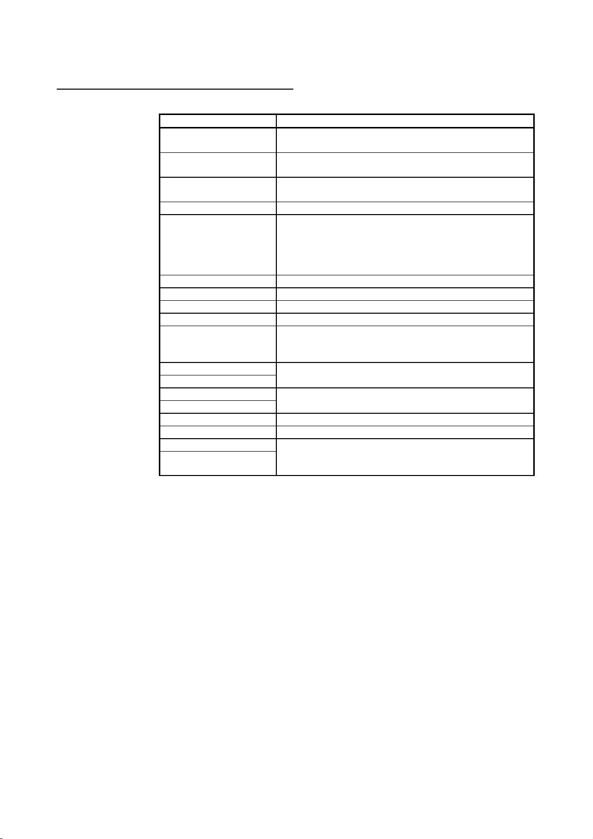
Related Manuals
The following manuals are also related to this product.
In necessary, order them by quoting the details in the tables below.
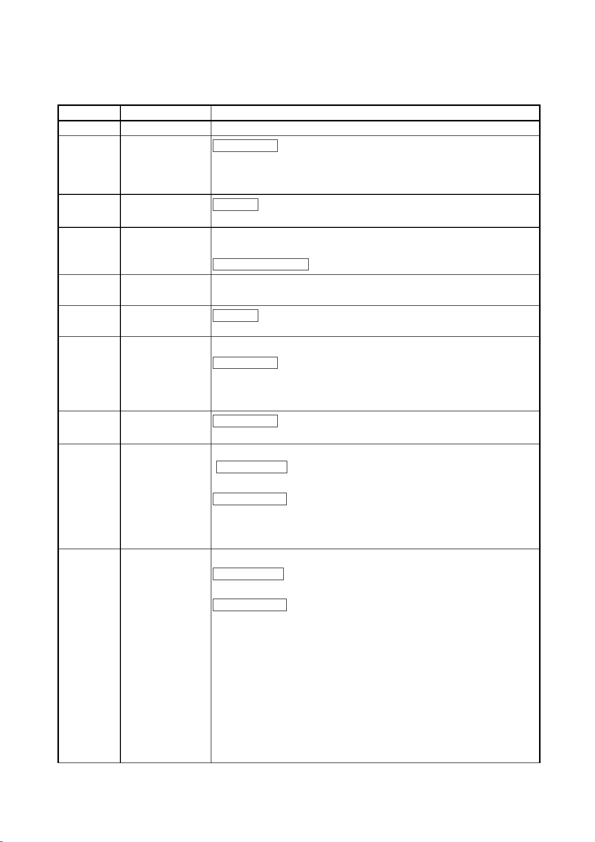
Manual Name
Manual Number
(Model Code)
QCPU User's Manual (Function Explanation, Program Fundamentals)
Describes the functions, programming procedures, devices, etc. necessary to create programs.
(Sold separately)
QnACPU Programming Manual (Fundamentals)
Describes how to create programs, the names of devices, parameters, and types of program.
(Sold separately)
QCPU (Q mode) /QnACPU Programming Manual (Common Instructions)
Describes how to use sequence instructions, basic instructions, and application instructions.
(Sold separately)
QnACPU Programming Manual (Special Function)
Describes the dedicated instructions for special function modules available when using the
Q2ACPU(S1), Q3ACPU, and Q4ACPU. (Sold separately)
QnACPU Programming Manual (AD57 Instructions)
Describes the dedicated instructions for controlling an AD57(S1) type CRT controller module available
when using the Q2ACPU(S1), Q3ACPU, or Q4ACPU. (Sold separately)
SH-080484ENG
(13JR73)
IB-66614
(13JF46)
SH-080039
(13JF58)
SH-4013
(13JF56)
IB-66617
(13JF49)
A - 8
Page 11
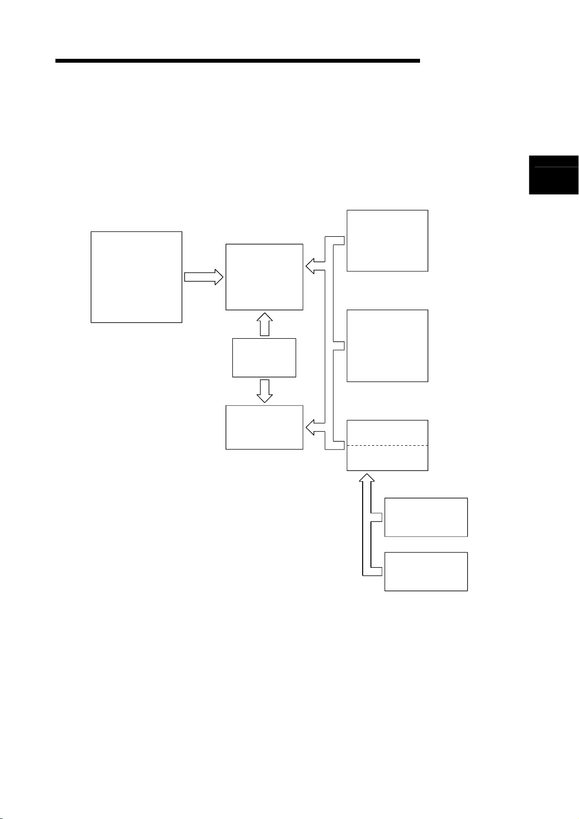
g
Before reading this manual, refer to the user's manual of the used CPU module or the
QnACPU Programming Manual (Fundamentals), and confirm which programs, I/O
processing, and devices can be used with the used CPU module.
(1) When QCPU is used
QCPU (Q mode)/
QnACPU
Programming
Manual
(Common
Instructions)
Describes the
instructions other
than those given
on the ri
ht.
This manual
QCPU (Q mode)/
QnACPU
Programming
Manual
(PID Control
Instructions)
Describes the
instructions used for
PID control.
QCPU
User's Manual
(Function Explanation,
Program Fundamentals)
QCPU (Q mode)/
QnACPU
Programming
Manual
(SFC)
Describes SFC.
Describes the functions,
executable programs,
I/O processing and device
names of the QCPU.
QCPU (Q mode)
Programming
Manual
(MELSAP-L)
Describes MELSAP-L.
QCPU (Q mode)
Programming
Manual
(Structured Text)
Describes the
structured text.
A - 9
Page 12
(2) When QnACPU is used
QCPU (Q mode)/
QnACPU
Programming
Manual
(Common
Instructions)
Describes the
instructions other
than those given
on the right.
QnACPU
Programming
Manual
(Special Function
Modules)
Describes the
instructions for the
special function
modules such as the
AJ71QC24 and
AJ71PT32-S3.
QnACPU
Programming
Manual
(Fundamentals)
QnACPU
Programming
Manual
(AD57 Commands)
Describes the AD57
commands for
controlling the
AD57/AD58.
Describes the programs, I/O processing,
device names, etc. that can be executed
by the QnACPU.
This manual
QCPU (Q mode)/
QnACPU
Programming
Manual
(PID Control
Instructions)
Describes the
instructions used
for PID control.
QCPU (Q mode)/
QnACPU
Programming
Manual
(SFC)
Describes SFC.
Q4ARCPU only
Q4ARCPU
Programming
Manual
(Application PID
Instructions)
Describes the
instructions used
for applied PID control.
A - 10
Page 13
Generic Terms and Abbreviations Used in This Manual
This manual uses the following generic terms and abbreviations unless otherwise described.
Generic term/abbreviation Description of generic term/abbreviation
CPU module
QnACPU
QnA
Q4AR Abbreviation of Q4ARCPU
QCPU
QnCPU Abbreviation of Q02CPU
QnHCPU Abbreviation of Q02HCPU, Q06HCPU, Q12HCPU, Q25HCPU
QnPHCPU Abbreviation of Q02PHCPU, Q06PHCPU, Q12PHCPU, Q25PHCPU
QnPRHCPU Abbreviation of Q12PRHCPU, Q25PRHCPU
QnUD(H)CPU
Basic model QCPU
Basic
High Performance model QCPU
High Performance
Process CPU Generic term of Q02PHCPU, Q06PHCPU, Q12PHCPU, Q25PHCPU
Redundant CPU Generic term of Q12PRHCPU, Q25PRHCPU
Universal model QCPU
Universal
Generic term of Basic model QCPU, High Performance model QCPU,
Redundant CPU, Universal model QCPU, QnACPU
Abbreviation of Q2ASCPU, Q2ASCPU-S1, Q2ASHCPU, Q2ASHCPU-S1,
Q2ACPU, Q2ACPU-S1, Q3ACPU, Q4ACPU, Q4ARCPU
Abbreviation of Q2ASCPU, Q2ASCPU-S1, Q2ASHCPU, Q2ASHCPU-S1,
Q2ACPU, Q2ACPU-S1, Q3ACPU, Q4ACPU
Abbreviation of Q00CPU, Q01CPU, Q02CPU, Q02HCPU, Q06HCPU,
Q12HCPU, Q25HCPU, Q12PRHCPU, Q25PRHCPU, Q02UCPU,
Q03UDCPU, Q04UDHCPU, Q06UDHCPU, Q13UDHCPU, Q26UDHCPU,
Q03UDECPU, Q04UDEHCPU, Q06UDEHCPU, Q13UDEHCPU,
Q26UDEHCPU
Abbreviation of Q03UDCPU, Q04UDHCPU, Q06UDHCPU,
Q13UDHCPU, Q26UDHCPU, Q03UDECPU, Q04UDEHCPU,
Q06UDEHCPU, Q13UDEHCPU, Q26UDEHCPU
Generic term of Q00JCPU, Q00CPU, Q01CPU
Generic term of Q02CPU, Q02HCPU, Q06HCPU, Q12HCPU, Q25HCPU
Generic term of Q02UCPU, Q03UDCPU, Q04UDHCPU, Q06UDHCPU,
Q13UDHCPU, Q26UDHCPU, Q03UDECPU, Q04UDEHCPU,
Q06UDEHCPU, Q13UDEHCPU, Q26UDEHCPU
A - 11
Page 14

MEMO
A - 12
Page 15
A
1. GENERAL DESCRIPTION
MELSEC-Q/Qn
1. GENERAL DESCRIPTION
This manual describes the sequence program instructions used to implement PID
control with any of the following CPU modules.
• Basic model QCPU (first five digits of serial No. are 04122 or later)
• High Performance model QCPU
• Redundant CPU
• Universal model QCPU
• QnACPU
The Basic model QCPU, High Performance model QCPU, Redundant CPU, and
Universal model QCPU have the instructions used to perform PID control by
incomplete derivative (PID control instructions) and the instructions used to perform
PID control by complete derivative (PID control instructions) as standard features.
The QnACPU has the instructions used to perform PID control by complete derivative
(PID control instructions) as standard features.
Since the incomplete derivative PID control instructions and complete derivative PID
control instructions are independent of each other, they can be executed at the same
time.
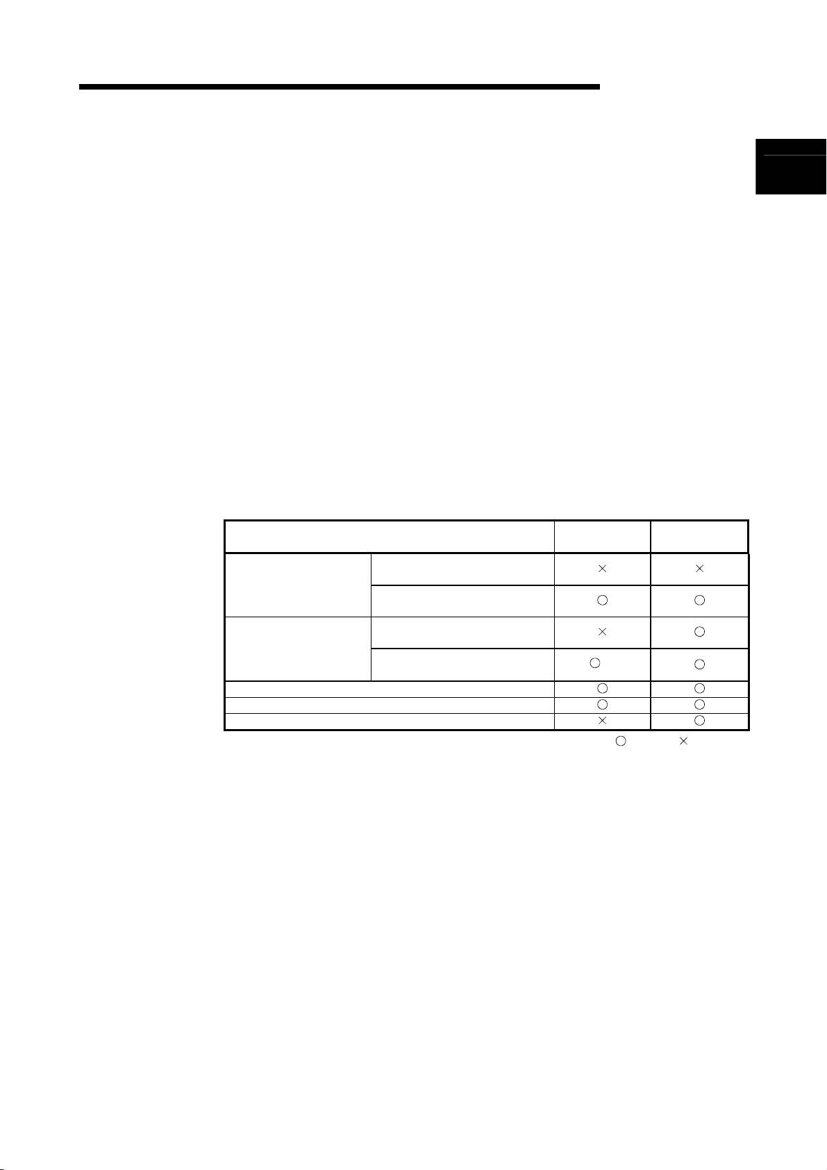
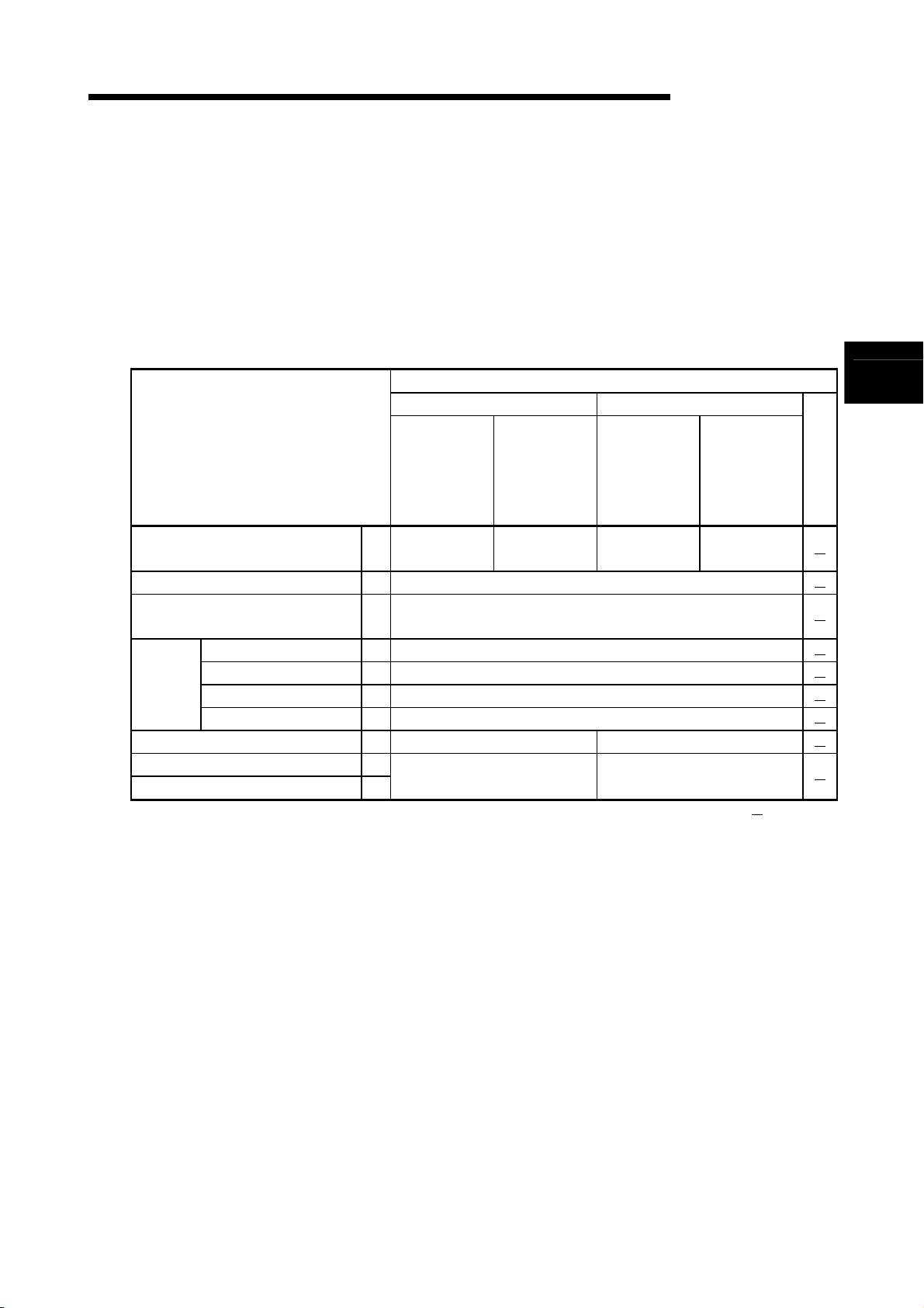
The following table indicates the CPU modules that can use the incomplete derivative
PID control instructions and complete derivative PID control instructions.
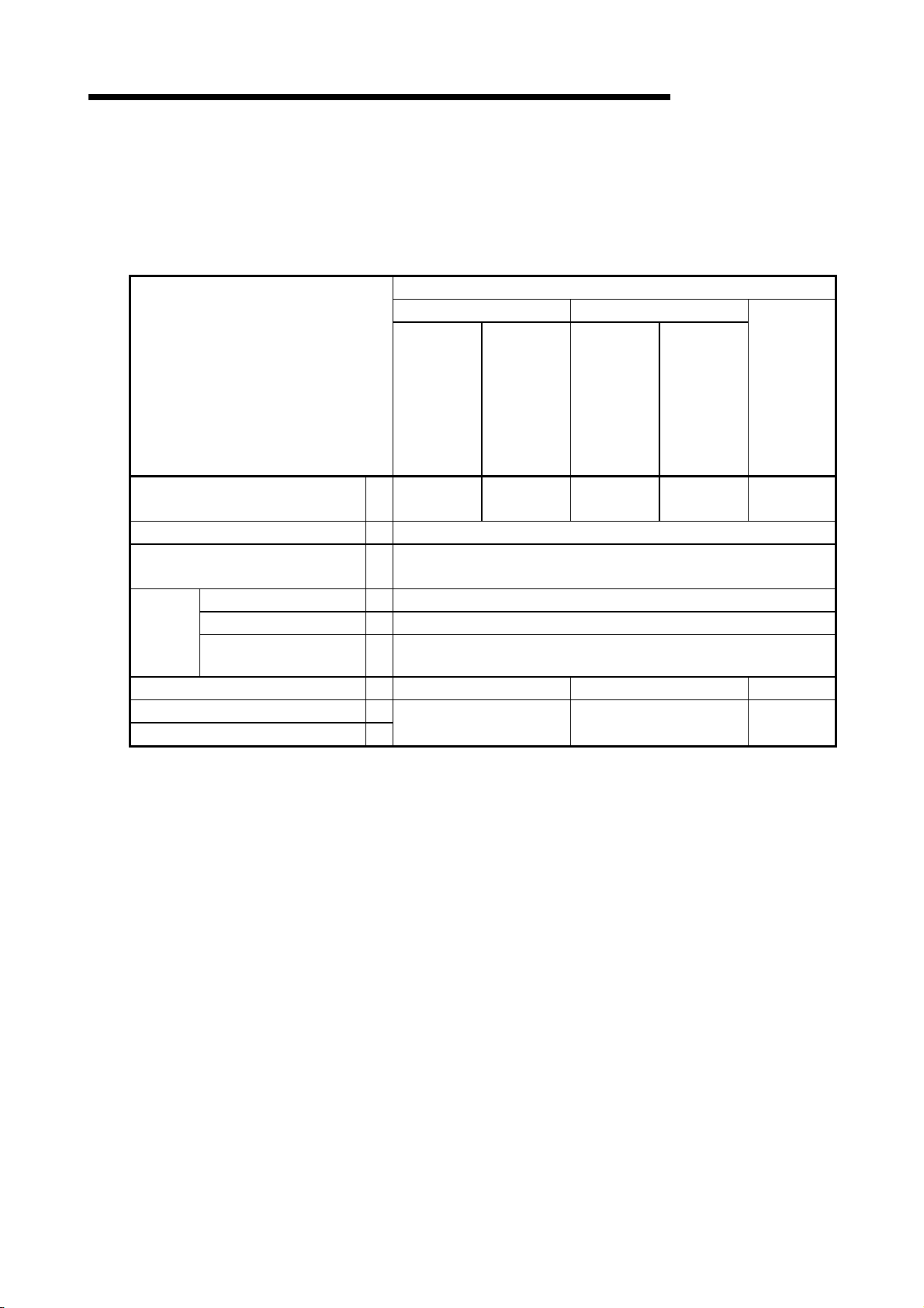
CPU Module Model Name
First five digits of serial No. are
Basic model QCPU
High Performance model
QCPU
Redundant CPU
Universal model QCPU
QnACPU
"04121" or earlier
First five digits of serial No. are
"04122" or later
First five digits of serial No. are
"05031" or earlier
First five digits of serial No. are
"05032" or later
*1: Version 7 or earlier version of GX Developer issues an “instruction code alarm” if it
loads a new CPU instruction realized with GX Developer Version 8.
Incomplete
Derivative
*1
: Usable, : Unusable
Complete
Derivative
1
1 - 1
Page 16
A
1. GENERAL DESCRIPTION
MELSEC-Q/Qn
There are the following PID control instructions.
Classification Incomplete Derivative Complete Derivative
PID control data setting
PID operation
PID control status monitor
Specified loop No. operation stop
Specified loop No. operation start
Specified loop No. parameter change
S(P).PIDINIT PIDINIT(P)
S(P).PIDCONT PIDCONT(P)
PID57(P)
S(P).PIDSTOP PIDSTOP(P)
S(P).PIDRUN PIDRUN(P)
S(P).PIDPRMW PIDPRMW(P)
PID control via PID control instructions is implemented by combining the CPU module
with the A/D converter module and D/A converter module.
In the case of the QnACPU, the PID control status can be monitored using the
AD57(S1) CRT controller module.
POINT
(1) The Process CPU is not compatible with the PID control instructions described
in this manual.
To implement PID control using the Process CPU, use the process control
instructions described in the QnPHCPU/QnPRHCPU Programming Manual
(Process Control Instructions).
(2) The Redundant CPU can use the PID control instructions and process control
instructions.
1 - 2
Page 17
A
1. GENERAL DESCRIPTION
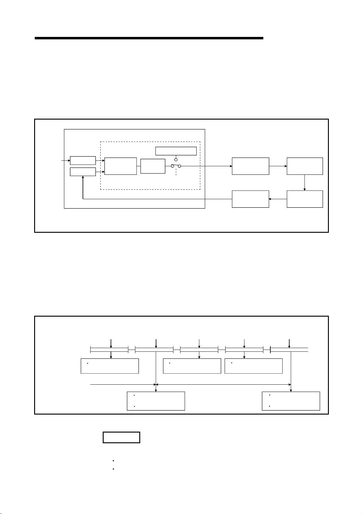
1.1 PID Processing Method
This section describes the processing method for PID control using PID control
Set value
SV
PV
instructions. (For details on PID operations, see Chapter 4.)
Execute PID control with PID control instructions by loading an A/D converter module
and a D/A converter module, as shown in Figure 1.1.
CPU module
PID control instructions
PID operation
Automatic
MV
Manual MV
Manual/automatic
changeover
MV
PV
D/A conversion
module
A/D conversion
module
MELSEC-Q/Qn
Controlled
system
Sensor
Sequence program
SV: Set Value
PV: Process Value
MV: Manipulated Value
Figure 1.1 Overview of PID Control Processing
In the PID control processing method, as shown in Figure 1.1, the PID operation is
executed using the set value (SV) and the process value (PV) read from the A/D
converter module, and the manipulated value (MV) is then calculated.
The calculated MV (manipulated value) is output to the D/A converter module.
When a PID operation instruction* is executed in a sequence program, the sampling
cycle is measured and a PID operation is performed.
PID operation in accordance with the PID operation instruction is executed in preset
sampling cycles.
PID operation
instruction
execution
Step 0
Measurement of
sampling cycle
Sampling cycle
PID operation
instruction
execution
Step 0 Step 0
END END END END
PID operation
instruction
execution
Measurement of
sampling cycle
PID operation
instruction
execution
Step 0 Step 0
Measurement of
sampling cycle
Sampling cycle
PID operation
instruction
execution
Measurement of
sampling cycle
PID operation
Measurement of
sampling cycle
PID operation
Figure 1. 2 Operation when PID Operation Instruction Executed
REMARK
*: There are the following PID operation instructions.
S.PIDCONT (incomplete derivative)
PIDCONT (complete derivative)
1 - 3
Page 18

A
1. GENERAL DESCRIPTION
MEMO
MELSEC-Q/Qn
1 - 4
Page 19
A
2. SYSTEM CONFIGURATION FOR PID CONTROL
MELSEC-Q/Qn
2. SYSTEM CONFIGURATION FOR PID CONTROL
This chapter describes the system configuration for PID control using the PID control
instructions.
For the modules that can be used to configure a system, refer to the following manual.
• Basic model QCPU, High Performance model QCPU, Universal model QCPU: MELSEC-Q DATA
BOOK
CPU module
• QnACPU: User's manual (details) of the used CPU module
Main base unit
Extension
cable
For PV (process value) input
A/D conversion
module
For MV (manipulated
value) output
D/A conversion
module
2
Extension base
unit
For PID control monitoring (Only QnACPU)
CRT control
module
AD57 or AD57-S1
only
CRT
Operation panel
2 - 1
Page 20
A
2. SYSTEM CONFIGURATION FOR PID CONTROL
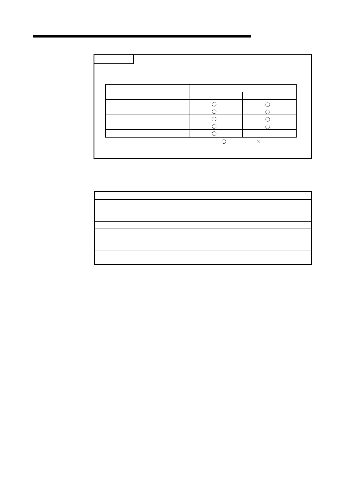
POINT
SV, PV and MV used with the PID control instructions may be set either with the
fixed values of 0 to 2000 or to any values according to the used module.
Refer to Section 4.3.5 for details.
Basic model QCPU
High Performance model QCPU
Redundant CPU
Universal model QCPU
QnACPU
*: When the resolution of the A/D converter module or D/A converter module used for
I/O of PID control is other than 0 to 2000, convert the digital values into 0 to 2000.
CPU Module Type
2.1 Applicable PLC CPU
SV, PV, MV
0 to 2000 fixed *
: Can be set, : Cannot be set
MELSEC-Q/Qn
Any setting
×
Component Module
Basic model QCPU
High Performance model QCPU Q02CPU, Q02HCPU, Q06HCPU, Q12HCPU, Q25HCPU
Redundant CPU Q12PRHCPU, Q25PRHCPU
Universal model QCPU
QnACPU
Q00JCPU, Q00CPU, Q01CPU
(First 5 digits of serial No. are 04122 or later)
Q02UCPU, Q03UDCPU, Q04UDHCPU, Q06UDHCPU,
Q13UDHCPU, Q26UDHCPU, Q03UDECPU, Q04UDEHCPU,
Q06UDEHCPU, Q13UDEHCPU, Q26UDEHCPU
Q2ASCPU, Q2ASCPU-S1, Q2ASHCPU, Q2ASHCPU-S1
Q2ACPU, Q3ACPU, Q4ACPU, Q4ARCPU
2 - 2
Page 21
A
3. PID CONTROL SPECIFICATIONS
MELSEC-Q/Qn
3. PID CONTROL SPECIFICATIONS
This section gives the specifications PID operation using PID control instructions.
3.1 PID Control by incomplete derivative
3.1.1 Performance specifications
Number of PID control loops —
Sampling cycle TS 0.01 to 60.00 s
PID operation method —
PID
constant
setting
range
SV (set value) setting range SV 0 to 2000 -32768 to 32767
PV (process value) setting range
MV (manipulated value) output range
Proportional constant KP 0.01 to 100.00
Integral constant TI 0.1 to 3000.0 s
Derivative constant TD 0.00 to 300.00 s
Derivative gain KD 0.00 to 300.00
The performance specifications for PID control are tabled below.
Specifications
With PID limits Without PID limits
High Performance
Item
PV
MV
Basic model
QCPU
8 loops
(maximum)
-50 to 2050 -32768 to 32767
model QCPU,
Redundant CPU,
Universal model
QCPU
32 loops
(maximum)
Process value differentiation incomplete derivative
(forward operation/reverse operation)
Basic model
QCPU
8 loops
(maximum)
High Performance
model QCPU,
Redundant CPU,
Universal model
QCPU
32 loops
(maximum)
: Unusable
QnA
CPU
3
3 - 1
Page 22
A
3. PID CONTROL SPECIFICATIONS
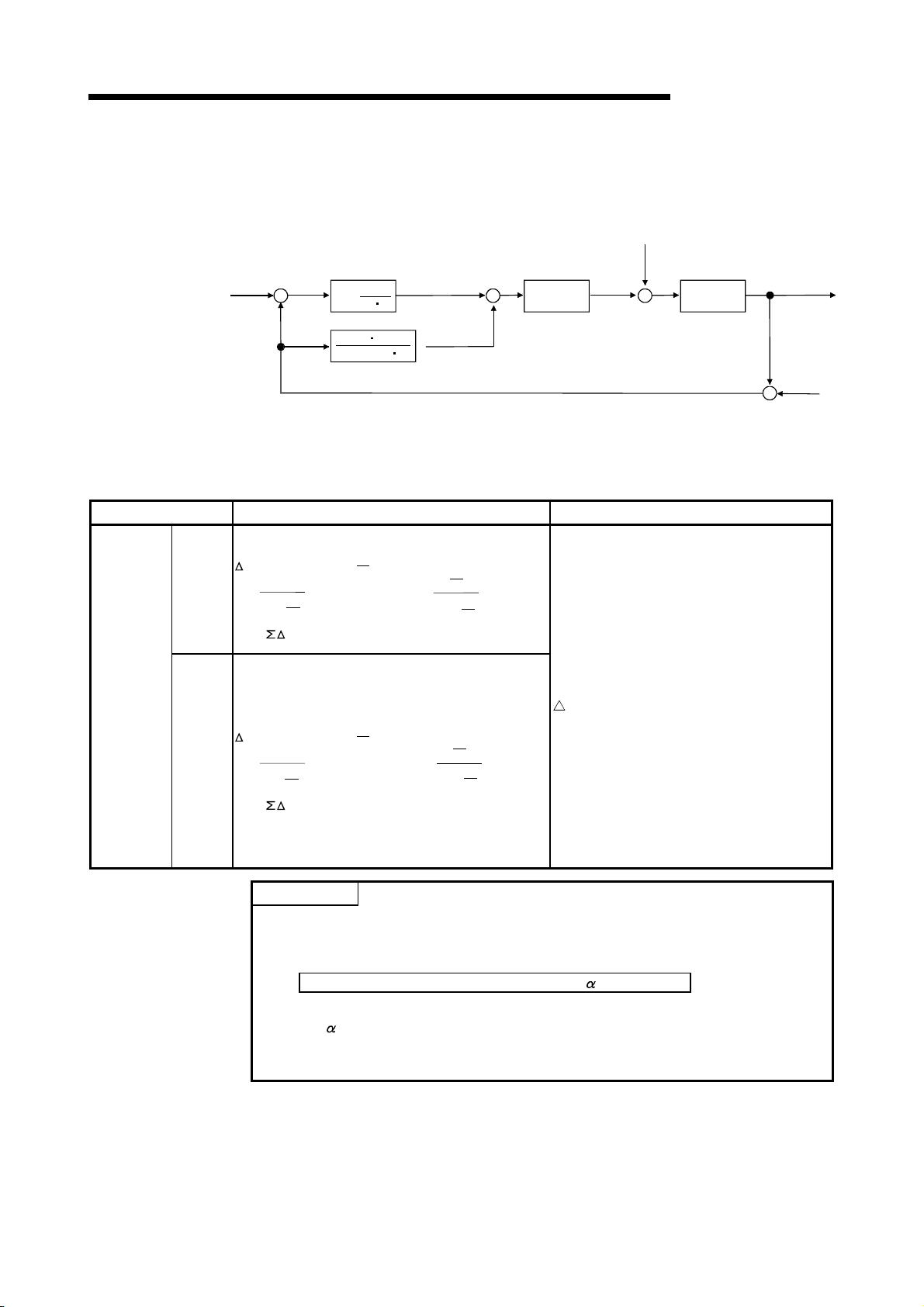
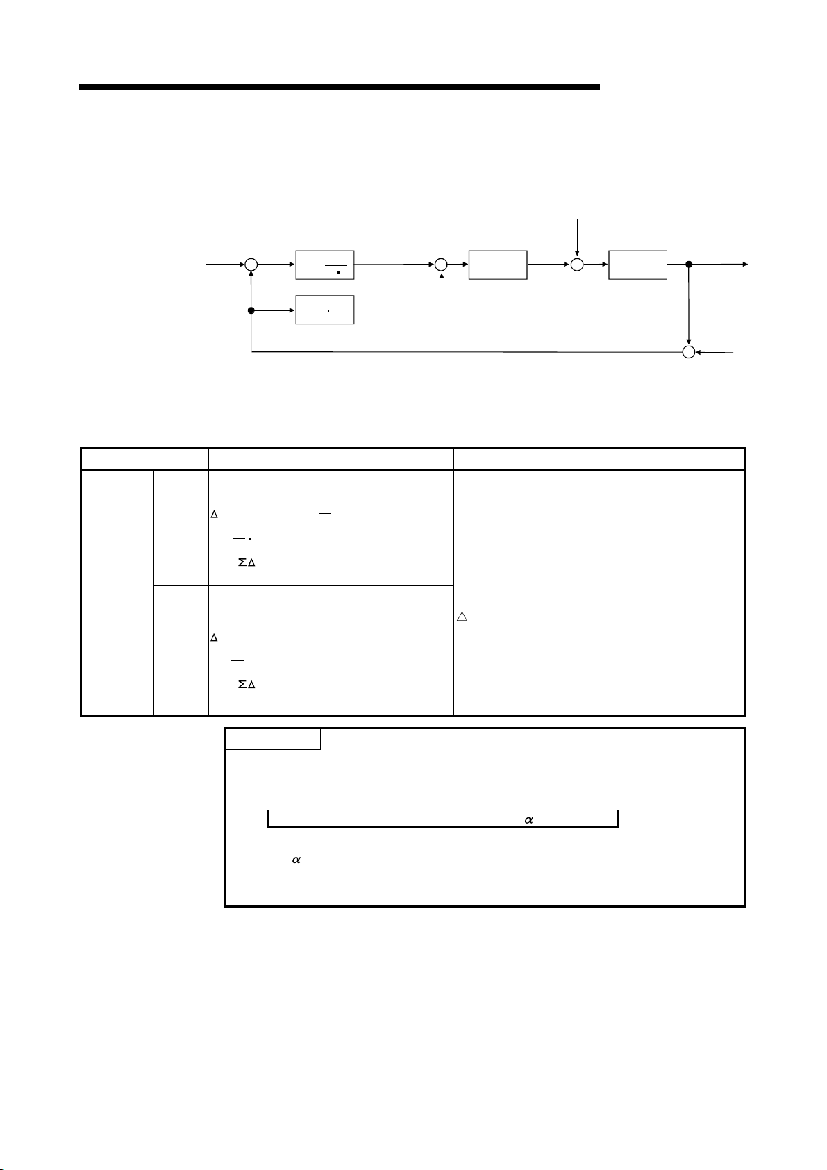
3.1.2 PID operation block diagram and operation expressions
MELSEC-Q/Qn
Name Operation Expressions Meanings of Symbols
Process
value
differentiation
Incomplete
derivative
Forward
operation
Reverse
operation
(1) The PID operation block diagram for incomplete derivative is shown below.
SV +
Set value
Disturbance
1
1
+
s
-
TI
(P)
TD S
1
+(TD/KD) s
(D)
(I)
+
-
Kp P
Gain
Manipulated
value
MV
W
+
Control
objective
(2) The operation expressions for PID control using PID control instructions are
indicated below.
EV
EV
n=PVfn*-SV
MV=Kp{(EVn-EV
T
TS+
D
T
D
K
D
Dn= (PVfn-2PV
MVn= MV
)+ EVn+Dn}
n-1
T
S
T
I
+PV
fn-1
fn-2
T
D
K
D
)+
D
n-1
T
D
+
T
S
K
D
n : Deviation in the present sampling cycle
EV
n-1 : Deviation in the preceding sampling
cycle
SV : Set value
fn : Process value of the present sampling
PV
cycle (after filtering)
fn-1 : Process value of the preceding
PV
sampling cycle (after filtering)
PVfn-2 : Process value of the sampling cycle
two cycles before (after filtering)
EV
n=SV-PVfn*
MV=Kp{(EVn-EV
T
TS+
D
T
D
K
D
Dn= (-PVfn+2PV
MVn= MV
POINT
T
)+ EVn+Dn}
n-1
T
S
I
-PV
fn-1
fn-2
T
D
K
D
)+
D
n-1
T
D
T
+
S
K
D
MV : Output change value
n : Present manipulation value
MV
n : Present derivative term
D
D
n-1 : Derivative term of the preceding
sampling cycle
P : Proportional constant
K
T
S : Sampling cycle
I : Integral constant
T
D : Derivative constant
T
K
D : Derivative gain
(1) *:PVfn is calculated using the following expression.
Therefore, it is the same as the PV (process value) of the input data as long
as the filter coefficient is not set for the input data.
Process Value after Filtering PV
fn= PVn+ (PVfn-1-PVn)
PVn : Process value of the present sampling cycle
: Filter coefficient
PV
fn-1 : Process value of the preceding sampling cycle (after filtering)
fn is stored in the I/O data area. (See Section 5.2)
(2) PV
Process
value
++
Detected
noise
PV
V
3 - 2
Page 23

A
3. PID CONTROL SPECIFICATIONS
3.1.3 PID control instruction list
MELSEC-Q/Qn
Name
S.PIDINIT Sets the reference data for PID operation. * ×
S.PIDCONT
S.PIDSTOP
S.PIDRUN
S.PIDPRMW
A list of the instructions used to execute PID control is given below.
Processing Details
Executes PID operation with the SV (set value)
and the PV (process value).
Stops or starts PID operation for the set loop No.
Changes the operation parameters for the
designated loop number to PID control data.
QCPU QnACPU
* ×
*
CPU Instruction
:
×
×
Usable, ×: Unusable
*: The Basic model QCPU, High Performance model QCPU, Redundant CPU and
Universal model QCPU allow selection of "with/without PID limits".
Refer to Sections 5.1 and 5.2 for details of the setting range when "with/without PID
limits" has been selected.
3 - 3
Page 24
A
3. PID CONTROL SPECIFICATIONS
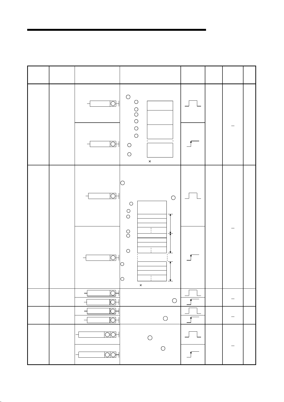
(1) PID control instruction list
The PID control instruction list has the format indicated below:
Table 3.1 How to Read the PID control Instruction List
Category
Contril
data
setting
Instruction
Symbol
S.PIDINIT 7
Ladder Format Processing Details
S.PIDINIT
SP.PIDINIT
S
S
Sets the PID control data stored in
the word device (designated by )
S
+ 0
Common data
to
to
+ 1
+ 2
+ 15
+ 16
+ 29
setting area
For loop 1
For loop 2
to
For loop n
S
S
S
S
S
S
+ (m+0)
to
S
+ (m+13)
m=(n-1) 14+2
S
Excution
Condition
MELSEC-Q/Qn
Number
of Basic
Steps
Subset
Processing
Page
8-2
(4)(3)(2)(1)
(5)
(8)(7)(6)
Explanation
(1) Classification of instructions according to their application.
(2) Instruction names written in a sequence program.
(3) Symbols used in the ladder diagram.
(4) Processing for each instruction.
16-bit data 16-bit data
S
+ 1S
+ 2S
+ 3S
Four consecutive device numbers
(beginning with the device number
designated for )
S
D
D + 1
D
+ 2
D
+ 3
Four consecutive device numbers
(beginning with the device number
designated for )
D
Fig. 3.1 Processing for Each Instruction
3 - 4
Page 25

A
3. PID CONTROL SPECIFICATIONS
(5) The execution condition for each instruction. Details are given below.
Symbol Execution Condition
(6) Number of instruction steps
For details on the number of steps, refer to the QCPU (Q mode) /QnACPU
Programming Manual (Common Instructions).
(7)
A circle
indicates that subset processing is possible.
indicates that subset processing is impossible.
For details on subset processing, refer to the QCPU (Q mode) /QnACPU
Programming Manual (Common Instructions).
(8) Indicates the page number in this manual where a detailed description for the
instruction can be found.
MELSEC-Q/Qn
Indicates an instruction that is executed for the duration that the
condition for its execution is ON.
When the condition before the instruction is OFF, the instruction is
not executed and no processing is carried out.
Indicates an instruction that is executed once only at the leading
edge (OFF to ON) of the condition for its execution; thereafter the
instruction will not be executed, and no processing will be carried
out, even if the condition is ON.
3 - 5
Page 26
A
3. PID CONTROL SPECIFICATIONS
A PID control instruction list is given in Table 3.2.
Table 3.2 PID Control Instruction List
MELSEC-Q/Qn
Category
PID
Control
data
setting
PID
operation
Instruction
Symbol
S.PIDINIT
S.PIDCONT
Ladder Format Processing Details
Sets the PID control data stored
in the word device (designated
).
by
S
S
+ 0
S.PIDINIT S
SP.PIDINIT
S
S
+ (m+0)
to
S
+ (m+13)
Common data
to
to
+ 1
+ 2
+ 15
+ 16
+ 29
setting area
For loop 1
For loop 2
For loop n
S
S
S
S
S
m=(n-1) 14+2
to
Executes PID operation with
the SV (set value) and the PV
(process value) designated by
and stores the PID
S
operation results in the MV
S.PIDCONT S
SP.PIDCONT
(manipulated value) area of the
word device designated by
S
Common data
to
S
S
to
S
S
to
S
S
S
+ (m+0)
to
S
+ (m+22)
m=(n-1) 23+10
setting area
+ 9
SV setting area
+ 10
PV setting area
MV value stor age area
+ 32
SV setting area
+ 33
PV setting area
MV value stor age area
+ 55
SV setting area
PV setting area
MV value stor age area
.
S
For
loop 1
For
loop 2
For
loop n
Execution
Condition
Number
of Basic
Steps
7
7
Subset
Processing
Page
8-2
8-3
Operation
stop
Operation
start
Parameter
change
S.PIDSTOP
S.PIDRUN
S.PIDPRMW
S.PIDSTOP
SP.PIDSTOP
S.PIDRUN
SP.PIDRUN
S.PIDPRMW
SP.PIDPRMW
n
Stops the PID operation at the
loop number designated by n.
n
n
Starts the operation at the loop
number designated by
n
n
.
7
8-5
6
8-5
Changes the operation
n
n
parameter for the loop number
S
designated by n to the PID
control data stored in the word
device designated by S
S
8
8-6
3 - 6
Page 27

A
3. PID CONTROL SPECIFICATIONS
POINT
(1) "PID operation by incomplete derivative" and "PID operation by complete
derivative" can be executed simultaneously since they are independent.
(2) When the S(P).PIDINIT instruction has been used to make initialization, use the
S(P).PIDCONT instruction to perform PID operation.
To stop and start the PID operation of the specified loop No. and to change the
PID control data, use the S(P).PIDSTOP, S(P).PIDRUN and S(P).PIDPRMW
instructions accordingly.
MELSEC-Q/Qn
3 - 7
Page 28
A
3. PID CONTROL SPECIFICATIONS
3.2 PID Control by Complete Derivative
3.2.1 Performance specifications
MELSEC-Q/Qn
Number of PID control loops —
Sampling cycle TS 0.01 to 60.00 s
PID operation method —
PID
constant
setting
range
SV (set value) setting range SV 0 to 2000 -32768 to 32767 0 to 2000
PV (process value) setting range
MV (manipulated value) output range
Proportional constant KP 0.01 to 100.00
Integral constant TI 0.1 to 3000.0 s
Derivative constant T
The performance specifications for PID control are tabled below.
Specification
With PID limits Without PID limits
High
Performance
Item
Basic model
QCPU
8 loops
(maximum)
D 0.00 to 300.00 s
PV
MV
model QCPU,
Redundant
CPU,
Universal model
QCPU
32 loops
(maximum)
Process value differentiation complete derivative
(forward operation/reverse operation)
-50 to 2050 -32768 to 32767 -50 to 2050
Basic model
QCPU
Universal model
8 loops
(maximum)
High
Performance
model QCPU,
Redundant
CPU,
QCPU
32 loops
(maximum)
QnACPU
32 loops
(maximum)
3 - 8
Page 29
A
3. PID CONTROL SPECIFICATIONS
3.2.2 PID operation block diagram and operation expressions
MELSEC-Q/Qn
Name Operation Expressions Meanings of Symbols
Process
value
differentiation
Complete
derivative
Forward
operation
Reverse
operation
(1) The PID operation block diagram for complete derivative is shown below.
SV +
Set value
Disturbance
1
1
+
T
(P)
T
(D)
I S
(I)
D S
-
+
-
Kp P
Gain
Manipulated
value
MV
W
+
+
Control
objective
(2) The operation expressions for PID operation using PID control instructions are
indicated below.
EV
EVn=PVfn*-SV
S
fn-1
T
T
I
+PV
fn-2
MV=Kp{(EVn-EVn-1)+ EVn+Dn}
T
D
Dn= (PVfn-2PV
T
S
MVn= MV
)
n : Deviation in the present sampling cycle
EV
n-1 : Deviation in the preceding sampling cycle
SV : Set value
fn : Process value of the present sampling cycle
PV
(after filtering)
PVfn-1 : Process value of the preceding sampling
cycle (after filtering)
PVfn-2 : Process value of the sampling cycle two
cycles before (after filtering)
EVn=SV-PVfn*
T
fn-1
T
-PV
S
I
fn-2
MV=Kp{(EVn-EVn-1)+ EVn+Dn}
T
D
Dn= (-PVfn+2PV
T
S
MVn= MV
POINT
)
MV : Output change value
MV
n : Present manipulation value
n : Present derivative term
D
P : Proportional constant
K
T
S : Sampling cycle
I : Integral constant
T
D : Derivative constant
T
(1) *:PVfn is calculated using the following expression.
Therefore, it is the same as the PV (process value) of the input data as long
as the filter coefficient is not set for the input data.
Process Value after Filtering PV
fn= PVn+ (PVfn-1-PVn)
PVn : Process value of the present sampling cycle
: Filter coefficient
PV
fn-1 : Process value of the preceding sampling cycle (after filtering)
(2) PV
fn is stored in the I/O data area. (See Section 5.2)
Process
value
++
Detected
noise
PV
V
3 - 9
Page 30

A
3. PID CONTROL SPECIFICATIONS
3.2.3 PID control instruction list
MELSEC-Q/Qn
Name
PIDINIT Sets the reference data for PID operation. *
PIDCONT
PID57
PIDSTOP
PIDRUN
PIDPRMW
A list of the instructions used to execute PID control is given below.
Processing Details
Executes PID operation with the SV (set value)
and the PV (process value).
Used to monitor the results of PID operation at an
AD57(S1).
Stops or starts PID operation for the set loop No.
Changes the operation parameters for the
designated loop number to PID control data.
QCPU QnACPU
*
×
*
CPU Instruction
:
Usable, ×: Unusable
*: The Basic model QCPU, High Performance model QCPU, Redundant CPU and
Universal model QCPU allow selection of "with/without PID limits".
Refer to Sections 5.1 and 5.2 for details of the setting range when "with/without PID
limits" has been selected.
3 - 10
Page 31

A
3. PID CONTROL SPECIFICATIONS
(1) The PID control instruction list
The PID control instruction list has the format indicated below:
Table 3.3 How to Read the PID control Instruction List
Category
PID
control
data
setting
Instruction
Symbol
PIDINIT 29-2
Ladder Format Processing Details
PIDINIT
PIDINITP
S
S
Sets the PID control data stored in
the word device (designated by )
S
+ 0
Common data
to
to
+ 1
+ 2
+ 11
+ 12
+ 21
setting area
For loop 1
For loop 2
to
For loop n
S
S
S
S
S
S
+ (m+0)
to
S
+ (m+9)
m=(n-1) 10+2
S
Excution
Condition
MELSEC-Q/Qn
Number
of Basic
Steps
Subset
Processing
Page
(8)(7)(6)(5)(4)(3)(2)(1)
Explanation
(1) Classification of instructions according to their application.
(2) Instruction names written in a sequence program.
(3) Symbols used in the ladder diagram.
(4) Processing for each instruction.
16-bit data 16-bit data
S
+ 1S
+ 2S
+ 3S
Four consecutive device numbers
(beginning with the device number
designated for )
S
D
D + 1
D
+ 2
D
+ 3
Four consecutive device numbers
(beginning with the device number
designated for )
D
Fig. 3.2 Processing for Each Instruction
3 - 11
Page 32

A
3. PID CONTROL SPECIFICATIONS
(5) The execution condition for each instruction. Details are given below.
Symbol Execution Condition
(6) Number of instruction steps
For details on the number of steps, refer to the QCPU (Q mode) /QnACPU
Programming Manual (Common Instructions).
(7)
A circle
indicates that subset processing is possible.
indicates that subset processing is impossible.
For details on subset processing, refer to the QCPU (Q mode) /QnACPU
Programming Manual (Common Instructions).
(8) Indicates the page number in this manual where a detailed description for the
instruction can be found.
MELSEC-Q/Qn
Indicates an instruction that is executed for the duration that the
condition for its execution is ON.
When the condition before the instruction is OFF, the instruction is
not executed and no processing is carried out.
Indicates an instruction that is executed once only at the leading
edge (OFF to ON) of the condition for its execution; thereafter the
instruction will not be executed, and no processing will be carried
out, even if the condition is ON.
3 - 12
Page 33

A
3. PID CONTROL SPECIFICATIONS
A PID control instruction list is given in Table 3.4.
Table 3.4 PID Control Instruction List
MELSEC-Q/Qn
Category
Instruction
Symbol
PID
control
data
PIDINIT
setting
PID
operation
PIDCONT
Monitoring PID57
Ladder Format Processing Details
Sets the PID control data stored
in the word device (designated
by
).
PIDINIT
PIDINITP
S
S
S
S
S
S
to
S
S
to
S
S
+ (m+0)
to
S
+ (m+9)
m=(n-1) 10+2
+ 0
+ 1
+ 2
+ 11
+ 12
+ 21
Common data
setting area
For loop 1
For loop 2
to
For loop n
Executes PID operation with
the SV (set value) and the PV
(process value) designated by
and stores the PID
S
operation results in the MV
PIDCONT
S
(manipulated value) area of the
word device designated by
S
+ 0
Common da ta
to
S
S
to
S
S
to
S
setting area
+ 9
SV setting area
+ 10
PV setting area
MV value star age area
+ 27
SV setting area
+ 28
PV setting area
MV value star age area
+ 45
PIDCONTP S
S
S
SV setting area
+ (m+0)
PV setting area
to
MV value star age area
+ (m+17)
m=(n-1) 18+10
Monitors the PID operation
results for the AD57 (S1)
PID57
S1
n
(designated by
S2
n
: First I/O number of the
n
).
AD57(S1)
S1
: Monitor screen number
1:Loop 1 to loop 8
2:Loop 9 to loop16
PID57P
S1
S2
n
3:Loop17 to loop24
4:Loop25 to loop32
S2
: Initial screen display
request
.
S
For
loop 1
For
loop 2
For
loop n
Execution
Condition
Number
of Basic
Steps
2
2
4
Subset
Processing
Page
9-2
9-3
9-5
3 - 13
Page 34

A
3. PID CONTROL SPECIFICATIONS
Table 3.4 PID Control Instruction List
MELSEC-Q/Qn
Category
Operation
stop
Operation
start
Parameter
change
Instruction
Symbol
PIDSTOP
PIDRUN
PIDPRMW
Ladder Format Processing Details
PIDSTOP
PIDSTOPP
PIDRUN
PIDRUNP
PIDPRMW
PIDPRMWP
POINT
n
Stops the PID operation at the
loop number designated by n.
n
n
Starts the operation at the loop
number designated by
n
Changes the operation
n
n
parameter for the loop number
S
designated by
control data stored in the word
device designated by
S
n
to the PID
Execution
Condition
n
.
S
Number
of Basic
Steps
Subset
Processing
2
2
3
(1) "PID operation by incomplete derivative" and "PID operation by complete
derivative" can be executed simultaneously since they are independent.
(2) When the PIDINIT(P) instruction was used to make initialization, use the
PIDCONT(P) instruction to perform PID operation.
To stop and start the PID operation of the specified loop No. and to change the
PID control data, use the PIDSTOP(P) instruction, PIDRUN(P) instruction and
PIDPRMW(P) instruction.
Page
9-8
9-8
9-9
3 - 14
Page 35

A
4. FUNCTIONS OF PID CONTROL
MELSEC-Q/Qn
4. FUNCTIONS OF PID CONTROL
This chapter describes PID control performed using the PID control instructions.
4.1 Outline of PID Control
PID control is applicable to process control in which factors such as flowrate, velocity,
air flow volume, temperature, tension, mixing ratio, etc. must be controlled. The control
Set value
for maintaining the control object at the preset value is shown in the diagram below:
CPU module
PID control instructions
Manual MV
SV
PID operation
PV
Manual/automatic
changeover
Fig. 4.1 Application of PID Control Process Control
During PID control, the value measured by the sensor (process value) is compared
with the preset value (set value). The output value (manipulated value) is then adjusted
in order to eliminate the difference between the process value and the set value.
The MV (manipulated value) is calculated by combining the proportional operation (P),
the integral operation (I), and the derivative operation (D) so that the PV is brought to
the same value as the SV quickly and precisely.
The MV is made large when the difference between the PV and the SV is large so as
to bring the PV close to the SV quickly. As the difference between the PV and the SV
gets smaller, a smaller MV is used to bring the PV to the same value as the SV
gradually and accurately.
MV
D/A conversion
module
A/D conversion
module
SV: Set Value
PV: Process Value
MV: Manipulated Value
Controlled
system
Sensor
4
4 - 1
Page 36

A
4. FUNCTIONS OF PID CONTROL
4.2 Functions of PID Control
The operation methods for PID control with the PID control instructions are the velocity
type and process value derivative type. The following describes the control executed
for both of these methods:
4.2.1 Operation method
(1) Velocity type operation
The velocity type operation calculates amounts of changes in the MVs
(manipulated values) during PID operation.The actual MV is the accumulated
amount of change of the MV calculated for each sampling cycle.
(2) Process value derivative type operation
The process value derivative type operation executes PID operations by
differentiating the PV (process value).
Because the deviation is not subject to differentiation, sudden changes in the
output due to differentiation of the changes in the deviation generated by
changing the set value can be reduced.
4.2.2 Forward operation and reverse operation
MELSEC-Q/Qn
Either forward operation or reverse operation can be selected to designate the
direction of PID control.
(1) In forward operation, the MV (manipulated value) increases as the PV (process
value) increases beyond the SV (set value).
(2) In reverse operation, the MV increases as the PV decreases below the SV.
(3) In forward operation and reverse operation, the MV becomes larger as the
difference between the SV and the PV increases.
(4) The figure below shows the relationships among forward operation and reverse
operation and the MV, the PV, and the SV.
(MV)
Reverse
operation
(SV)
(PV)
Forward
operation
4 - 2
Page 37

A
)
4. FUNCTIONS OF PID CONTROL
(5) The figure below shows examples of process control with forward operation and
reverse operation:
Process value
MELSEC-Q/Qn
Set value
Temperature
Forward operation (for cooling)
Set value
Time
Temperature
Reverse operation (for heating
Process value
Time
4 - 3
Page 38

A
4. FUNCTIONS OF PID CONTROL
4.2.3 Proportional operation (P operation)
The control method for proportional operation is described below.
(1) In proportional operation, an MV (manipulated value) proportional to the deviation
(the difference between the set value and process value) is obtained.
(2) The relationship between E (deviation) and the MV is expressed by the following
formula:
MV=Kp • E
Kp is a proportional constant and is called the "proportional gain".
Condition
When proportional gain Kp is
smaller
When proportional gain Kp is
larger
(3) The proportional operation in step response with a constant E (deviation) is
illustrated in Fig. 4.2.
MELSEC-Q/Qn
Proportional Operation
Control operation gets slower.
Control operation gets faster.
However, hunting is more likely to occur.
DeviationMV
Time
Time
Kp
E
.
E
Fig. 4.2 Proportional Operation with a Constant Deviation
(4) A certain error produced relative to a set value is called an offset.
An offset is produced in proportional operation.
Set value Offset Set value Offset
t t
4 - 4
Page 39

A
4. FUNCTIONS OF PID CONTROL
4.2.4 Integral operation (I operation)
The control method for integral operation is described below.
(1) In the integral operation, the MV (manipulated value) changes continuously to
zero deviation when it occurs.
This operation can eliminate the offset that is unavoidable in proportional
operation.
(2) The time required for the MV in integral operation to reach the MV for proportional
operation after the generation of deviation is called the integral time. Integral time
is expressed as T
Condition
When integral time TI is
shorter
When integral time TI is longer Integrating effect decreases and the time to
(3) The integral operation in step response with a constant E (deviation) is illustrated
in Fig. 4.3.
MELSEC-Q/Qn
I.
Integral Operation
Integrating effect increases and the time to
eliminate the offset becomes shorter.
However, hunting is more likely to occur.
eliminate the offset becomes longer.
Deviation
E
Time
MV in "P + I" operations
MV
T
I
Time
MV value in I operation
.
Kp
E
MV value in
P operation
Fig. 4.3 Integral Operation with a Constant Deviation
(4) Integral operation is always used in combination with proportional operation (PI
operation) or with proportional and derivative operations (PID operation).
Integral operation cannot be used independently.
4 - 5
Page 40

A
4. FUNCTIONS OF PID CONTROL
4.2.5 Derivative operation (D operation)
The control method for derivative operation is described below.
(1) In derivative operation, an MV (manipulated value) proportional to the deviation
change rate is added to the system value to zero deviation when it occurs.
This operation prevents significant fluctuation at the control objective due to
external disturbances.
(2) The time required for the MV in the derivative operation to reach the MV for the
proportional operation after the generation of deviation is called the derivative
time. Derivative time is expressed as T
Condition
When derivative time TD is
shorter
When derivative time TD is
longer
(3) The derivative operation when the deviation is a constant value stepped response
is shown in Fig. 4.4.
MELSEC-Q/Qn
D.
Derivative Operation
Differentiating effect decreases.
Differentiating effect increases.
However, hunting of short cycle is more likely
to occur.
Time
Time
DV
K DV
P
Manipulated value for proportional operation
Deviation
Manipulated
value
T
D
Fig. 4.4 Derivative operation when the deviation is a constant
(4) Derivative operation is always used in combination with proportional operation
(PD operation) or with proportional and integral operations (PID operation).
Derivative operation cannot be used independently.
4 - 6
Page 41

A
4. FUNCTIONS OF PID CONTROL
REMARK
About the differences between complete derivative and incomplete derivative
[Incomplete derivative]
Incomplete derivative is PID control that has a primary delay filter in the input of a
derivative term.
The S.PIDCONT instruction is the incomplete derivative PID control instruction.
Incomplete derivative is effective for the following cases.
• Control susceptible to high-frequency noise
• When energy effective to actuate an operation end is not given when a step
change occurs in a complete derivative system
[Complete derivative]
Complete derivative is PID control that uses the input of a derivative term as it is.
The PIDCONT instruction is the complete derivative PID control instruction.
Input
PV
Incomplate derivative
Primary
delay filter
Derivative
term
TD s
1 TD s
MELSEC-Q/Qn
PV 1/
1/ Derivative gain
Time
Time
Complete derivative
Derivative term
TD s
Larger
Time
4 - 7
Page 42

A
4. FUNCTIONS OF PID CONTROL
4.2.6 PID operation
The control method when proportional operation (P operation), integral operation (I
operation), and derivative operation (D operation) are used in combination is described
below.
(1) During PID operation, the system is controlled by the MV (manipulated value)
calculated in the (P + I + D) operation.
(2) PID operation in step response with a constant E (deviation) is illustrated in Fig.
Deviation
4.5.
Deviation
MELSEC-Q/Qn
PID
PID
MV
Time
Incomplete derivative
MV
Complete derivative
Time
Fig. 4.5 PID Operation with Constant Deviation
4 - 8
Page 43

A
4. FUNCTIONS OF PID CONTROL
4.3 Other Functions
During PID control using the PID control instructions, MV upper/lower limit control is
automatically executed by the bumpless changeover function explained below.
4.3.1 Bumpless changeover function
(1) This function controls the MV (manipulated value) continuously when the control
mode is changed between manual and automatic.
(2) When the mode is changed (between manual and automatic), data is transferred
between the "MV area for automatic mode (automatic MV)" and "MV area for
manual mode (manual MV)" as described below.
The control mode is changed in the I/O data area (see Section 5.2).
(a) Changing from the manual ...........
mode to the automatic mode
(b) Changing from the automatic .......
mode to the manual mode
POINT
(1) Manual and automatic modes of PID control:
1) Automatic mode
PID operation is executed with a PID control instruction.
The control object is controlled according to the calculated MV.
2) Manual mode
PID operation is not executed. The MV is calculated by the user and the
(2) The loop set in the manual mode stores the PV (process value) in the set value
control object is controlled according to the user-calculated MV.
area every sampling cycle.
MELSEC-Q/Qn
The MV in the manual mode is transmitted to
the MV area for the automatic mode.
The MV in the automatic mode is transmitted
to the MV area for the manual mode.
4 - 9
Page 44

A
4. FUNCTIONS OF PID CONTROL
4.3.2 MV upper/lower limit control function
(1) The MV upper/lower limit control function controls the upper or lower limit of the MV
calculated in the PID operation. This function is only effective in the automatic
mode. It cannot be executed in the manual mode.
(2) By setting the MV upper limit (MVHL) and the MV lower limit (MVLL), the MV
calculated in the PID operation can be controlled within the range between the
limits.
EV (deviation)
MVHL
(MV upper limit)
MVLL
(MV lower limit)
Fig. 4.6 Operation in Accordance with the MV Upper/Lower limit
MELSEC-Q/Qn
MV
without limit
AUTO
control
MV
AUTO
(3) When the MV upper/lower limit control is used, the MV is controlled as illustrated
above.
A MVHL (MV upper limit) and MVLL (MV lower limit) takes on a value between -50
and 2050 or a user-defined value (except the QnACPU).
The following are the default settings:
• Upper limit ..................2000 (Or user-defined value)
• Lower limit ..................0 (Or user-defined value)
The value set for the upper limit must not be smaller than the value set for the lower
limit.
An error will occur if it is.
4 - 10
Page 45

A
4. FUNCTIONS OF PID CONTROL
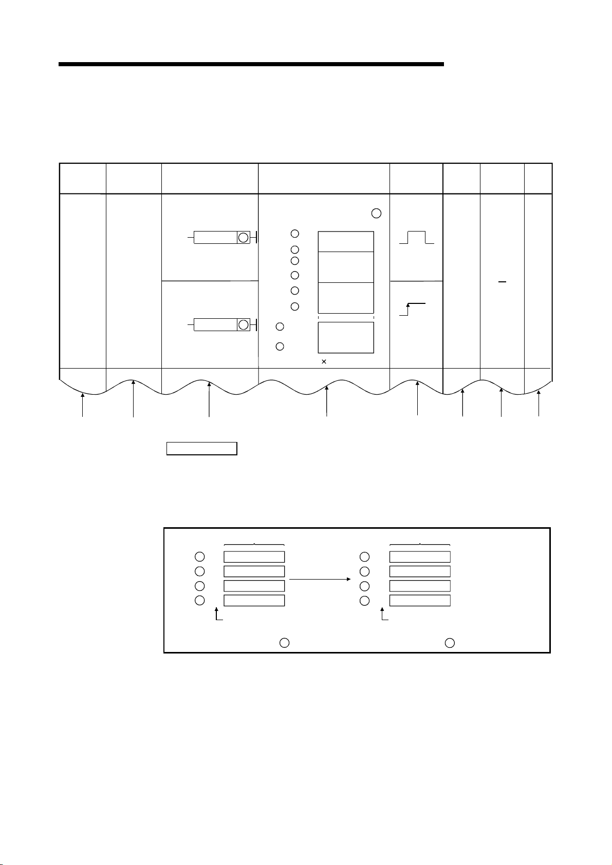
4.3.3 Monitoring PID control with the AD57(S1) (QnACPU only)
The PID control operation results can be monitored in a bar graph with an AD57(S1)
CRT controller unit.
(1) The monitor screen displays the monitored information of eight loops beginning
Bar graph display
The SV, PV, and MV of each loop
are displayed as percentages in a
bar graph.
If the MV percentage is in the
range of -2.5% MV 0%, a " "
will bedisplayed at the 0% position.
If the MV percentage is between
100% and 102.5%, a " " will be
displayed above the bar graph.
Limit operation status display
If an SV, PV, and/or MV limiter is
activated, the corresponding
character is highligted.
with the designated loop number.
Loop number display
Display the loop number (1 to 32).
LOOP 1 LOOP 2 LOOP 3 LOOP 4 LOOP 5 LOOP 6 LOOP 7 LOOP 8
M
SP
SV 50 %
PV 40 %
MV 73 %
PV MV
100
80
60
40
20
0
M
SP
SV 91 %
PV 95 %
MV 21 %
PV MV
100
80
60
40
20
0
Device display
Display the device in which the
PID data (SV and PV) are stored.
100
80
60
40
20
0
M
SP
SV 30 %
PV 60 %
MV 50 %
PV MV
100
80
60
40
20
0
M
S
P
SV 88 %
PV 10 %
MV 100 %
PV MV
100
80
60
40
20
0
SP
SV 40 %
PV 15 %
MV 83 %
PV MV
MELSEC-Q/Qn
Device number display
Display the first device number
of the devices in which the PID
value (SV and PV) are stored.
DEVICE R NO. 80
100
80
60
40
20
0
M
SPM
SV 100 %
PV 45 %
MV 100 %
PV MV
100
80
60
40
20
0
SPM
SV 61 %
PV 0 %
MV 92 %
PV MV
100
80
60
40
20
0
M
SP
SV 5 %
PV 1 %
MV 25 %
PV MV
Present value display
The SV, PV, and MV present values
for each loop are displayed as
percentages.
Alarm status display
If the PV exceeds the preset PVL
and/or the MV exceeds the preset
MVL, the corresponding character
is highlighted.
POINT
The SV, PV, and MV present value are displayed as percentages of 2000.
SV
PV
MV
100 (%)
100 (%)
100 (%)
1) SV percentage display ...............
2) PV percentage display ...............
3) MV percentage display...............
2000
2000
2000
(2) Use the PID57 instruction to execute monitoring with an AD57(S1).
See Section 9.1.3 for details on the PID57 instruction.
4 - 11
Page 46

A
4. FUNCTIONS OF PID CONTROL
MELSEC-Q/Qn
4.3.4 Function for transfer to the SV storage device for the PV in manual mode
When using the PID control instruction to perform PID control, execute the PID
PID Bumpless Processing Flag
SM794
(Incomplete derivative)
operation instruction also in the manual mode.
In the manual mode, it is possible to select whether the PV imported from the A/D
converter module is transferred to the SV storage device or not when the PID
operation instruction is executed, depending on the ON/OFF status of the PID
bumpless processing flag (SM774, SM794).
SM774
(Complete derivative)
OFF
ON
POINT
• The PV is transferred to the SV storage device when the PID operation
instruction is executed.
• When the manual mode is switched to the automatic mode, the MV
output in the manual mode is continued.
• When the SV is changed after switching to the automatic mode,
control is performed to achieve the SV, starting from the MV output in
the manual mode.
• The PV is not transferred to the SV storage device when the PID
operation instruction is executed.
• When the manual mode is switched to the automatic mode, control is
performed to achieve the SV, starting from the MV output in the
manual mode.
• Before switching to the automatic mode, store the SV into the SV
storage device.
Operation
Depending on whether SM774/SM794 is ON or OFF, there are the following
differences in control when the manual mode is switched to the automatic mode.
• When SM774/SM794 is OFF, the PV is transferred to the SV storage device.
Therefore, there is no difference between the PV and SV when the manual mode
is switched to the automatic mode.
Hence, an abrupt change does not occur in MV at the time of mode switching.
Instead, since the SV after mode switching differs from the target value in the
automatic mode, the user should change the SV to the target value step by step
in the sequence program.
• When SM774/SM794 is ON, the PV is not transferred to the SV storage device.
Therefore, there is a difference between the PV and SV when the manual mode
is switched to the automatic mode.
If the difference is large at the time of mode switching, an abrupt change may
occur in MV.
Use this method in a system where the mode is switched when the PV has fully
neared the SV.
PID control in the automatic mode can be executed immediately without the SV
being changed step by step in the sequence program.
REMARK
The SV and PV are stored into the devices specified in the I/O data area with the
PID operation instruction.
4 - 12
Page 47

A
4. FUNCTIONS OF PID CONTROL
MELSEC-Q/Qn
4.3.5 Changing the PID control data or input/output data setting range (QCPU only)
The setting ranges of the following data of the PID control data (refer to Section 5.1)
and I/O data (refer to Section 5.2) can be changed as desired by user setting.
Item Set Data
MV lower limit value
PID control data
I/O data
To make the user setting valid, turn the bit corresponding to the relevant loop of the
PID limit setting special register (SD774, SD775, SD794, SD795) to "1".
PID Limit Setting Special Register
Incomplete derivative Complete derivative
SD794 SD774
SD795 SD775
POINT
The Basic model QCPU has 8 loops.
b0 to b7 of SD774 and SD794 are valid.
b15
0/1
b15
0/1
MV upper limit value
MV change rate limit value
PV change rate limit value
SV
PV
Automatic MV
PV after filtering
Manual MV
Setting Range
b14 b13 b12 b11 b10 b9 b8 b7 b6 b5 b4 b3 b2
0/1 0/1 0/1 0/1 0/1 0/1 0/1 0/1 0/1 0/1 0/1 0/1
0/1
LOOP 15
LOOP 16
b14 b13 b12 b11 b10 b9 b8 b7 b6 b5 b4 b3 b2
0/1 0/1 0/1 0/1 0/1 0/1 0/1 0/1 0/1 0/1 0/1 0/1
0/1
LOOP 31
LOOP 32
LOOP 8
0: With PID limit (system fixed value)
1: Without PID limit (user setting)
0/1b10/1
0/1b10/1
b0
LOOP 1
LOOP 2
b0
LOOP 17
LOOP 18
4 - 13
Page 48

A
4. FUNCTIONS OF PID CONTROL
MEMO
MELSEC-Q/Qn
4 - 14
Page 49

A
5. PID CONTROL PROCEDURE
MELSEC-Q/Qn
5. PID CONTROL PROCEDURE
Changing the PID control data
Changing the SV (set value)
Automatic/manual mode change
of MV (manipulated value)
The programming procedure required to execute PID control is shown below.
Programming Procedure
Setting the PID control data
Set the PID control data in the
word devices.
Executing the PID control data
setting instruction *
Enter in the CPU module the PID
control data set in the word devices
by executing the PID control data
setting instruction.
Setting the initial processing flag
Set the initial processing flag in
the I/O data.
Setting the SV (set value)
Set the SV (set value) in the
I/O data.
See Section 5.1 for details on the
setting items and setting procedure.
See Section 8.1.1/9.1.1 for details on the
instruction.
See Section 5.2 for details on
I/O data.
See Section 5.2 for details on
I/O data.
5
Select manual mode?
NO (automatic mode)
Selecting automatic MV control
Set the manual/automatic selection
for I/O data to automatic
Reading/setting the PV
After reading the data from the A/D
converter module, set it in the PV
area of the I/O data area.
(1)
(2)
YES (manual mode)
Selecting manual MV control
Set the manual/automatic selection
for I/O data to manual.
Setting the manually controlled
MV (MV
Set the manual MV(MV
the I/O data.
MAN
See Section
5.2 for details
on I/O data.
)
) in
MAN
REMARK
*: The following instructions are available as the PID control data setting instructions.
S.PIDINIT (incomplete derivative)
PIDINIT (complete derivative)
5 - 1
Page 50

A
5. PID CONTROL PROCEDURE
MELSEC-Q/Qn
(2)(1)
Executing the PID operation
instruction
Using the PID operation instruction,
execute PID operation based on the
PID control data set in the word
devices and the I/O data.
Outputting the MV (manipulated
value)
The MV obtained from the PID
operation result is read, and written
to the D/A converter module.
Mounitoring with the AD57(S1)
(QnACPU only)
Using an AD57(S1) monitor the
controlled conditions by executing
a PID57 instruction.
1
*
See Section 8.1.2/9.1.2 for details on
the instruction.
The MV, obtained from the PID
operation result, is stored in the
I/O data area.
See Section 5.2 for details on
I/O data.
See Section 9.1.3 for details on
the instruction.
Thus step is not necessary
when monitoring with an
AD57(S1) is not required.
POINT
• Registering or changing the PID control data per sequence program scan will
present no problem.
However, execute the the PID control data setting instructions *
2
when you
registered or changed the PID control data.
If you do not execute the PID control data setting instructions instruction, the data
registered or the correction made to the PID control data will not be reflected at
the execution of the the PID operation instructions.
• You need not execute the PID control data setting instructions when using the
parameter change instruction *
3
to change the PID control data per loop.
REMARK
*1: The following instructions are available as the PID operation instructions.
S.PIDCONT (incomplete derivative)
PIDCONT (complete derivative)
*2: The following instructions are available as the PID control data setting
instructions.
S.PIDINIT (incomplete derivative)
PIDINIT (complete derivative)
*3: The following instructions are available as the parameter change instructions.
S. PIDPRMW (incomplete derivative)
PIDPRMW (complete derivative)
5 - 2
Page 51

A
5. PID CONTROL PROCEDURE
MEMO
MELSEC-Q/Qn
5 - 3
Page 52

A
5. PID CONTROL PROCEDURE
5.1 PID Control Data
MELSEC-Q/Qn
Common
setting
data
Data for
each loop
Data
No.
1
2
1
2
3
4
5
6
(1) PID control data is used to set the reference values for PID operation.
Store the PID control data into the CPU module with the PID control data setting
instruction before executing PID operation instruction
The PID control data is classified into two types, "common data for all loops" and
"data for individual loops".
(a) For Basic model QCPU
Table 5.1 PID Control Data List
Data Item Description
Number of
loops
Number of
loops in one
scan
Selection of
operational
expression
Sampling
cycle (T
Proportional
constant (K
Integral
constant (T
Derivative
constant (T
Filter
coefficient (
Sets the number of loops for
which PID operation will be
executed.
Sets the number of loops for
which single PID operation
will be executed when the
multiple loops reaches the
sampling cycle time.
Selects the PID operational
expression indicated in
Section 3.1.2/Section 3.2.2.
Sets the cycle of PID
S)
operation.
PID operation Proportional
P)
gain
This constant expresses the
magnitude of the integral
operation (I operation) effect.
Increasing the integral
I)
constant slows down the
manipulated value change.
This constant expresses the
magnitude of the derivative
operation
(D operation) effect.
Increasing the derivative
constant causes a significant
D)
change in the manipulated
value even with slight
change of the control
objective.
Sets the degree of filtering
applied to the process value.
)
The filtering effect decreases
as the value gets closer to 0.
1
*
.
Incomplete derivative
With PID limits Without PID limits
User
Setting Range
1 to 8 1 to 8 1 to 8 1 to 8
1 to 8 1 to 8 1 to 8 1 to 8
Forward
operation: 0
Reverse
operation: 1
0.01 to 60.00 s
0.01 to 100.00
0.1 to 3000.0 s 0.1 to 3000.0 s
Infinite(
If the setting
exceeds
for T
I
3000.0 s
0.00 to 300.00 s
0 to 100 % 0 to 100 0 to 100 % 0 to 100
)
Specification
Range
0 or 1
1 to 6000
(unit: 10 ms)
1 to 10000
(unit: 0.01)
1 to 32767
(unit: 100 ms)
0 to 30000
(unit: 10 ms)
Setting Range
Forward
operation: 0
Reverse
operation: 1
0.01 to 60.00 s
0.01 to 100.00
Infinite(
If the setting
for T
3000.0 s
0.00 to 300.00 s
)
exceeds
I
User
Specification
Range
0 or 1
1 to 6000
(unit: 10 ms)
1 to 10000
(unit: 0.01)
1 to 32767
(unit: 100 ms)
0 to 30000
(unit: 10 ms)
2
*
5 - 4
Page 53

A
5. PID CONTROL PROCEDURE
REMARK
*1: The following are available as the PID operation instructions.
S.PIDCONT (incomplete derivative)
PIDCONT (complete derivative)
*2: The following are available as the PID control data setting instructions.
S.PIDINIT (incomplete derivative)
PIDINIT (complete derivative)
Complete derivative
With PID limits Without PID limits
Setting
Range
1 to 8 1 to 8 1 to 8 1 to 8
1 to 8 1 to 8 1 to 8 1 to 8
Forward operation :
0
Reverse operation: 1
0.01 to 60.00s
0.01 to 100.00
0.1 to 3000.0 s 0.1 to 3000.0 s
Infinite(
If the setting
for T
3000.0 s
0.00 to 300.00 s
0 to 100% 0 to 100 0 to 100% 0 to 100
)
exceeds
I
User
Specification
Range
0 or 1
1 to 6000
(unit: 10 ms)
1 to 10000
(unit: 0.01)
1 to 32767
(unit: 100 ms)
0 to 30000
(unit: 10 ms)
Setting
Range
Forward operation : 0
Reverse operation: 1
0.01 to 60.00 s
0.01 to 100.00
Infinite(
If the setting
for T
3000.0 s
0.00 to 300.00 s
)
exceeds
I
User
Specification
Range
0 or 1
1 to 6000
(unit: 10 ms)
1 to 10000
(unit: 0.01)
1 to 32767
(unit: 100 ms)
0 to 30000
(unit: 10 ms)
MELSEC-Q/Qn
Processing when Set Data is
Outside the Allowable Setting Range
An error occurs and PID operation is
not executed for all loops.
An error occurs and PID operation
for the corresponding loop is not
executed.
An error occurs and PID operation
for the corresponding loop is not
executed.
An error occurs and PID operation
for the corresponding loop is not
executed.
5 - 5
Page 54

A
5. PID CONTROL PROCEDURE
Table 5.1 PID Control Data List
Data for
each
loop
Data
No.
Data Item Description
In the automatic mode, sets the
lower limit for the MV (manipulated
7
8
9
10
11
MV Lower
limit (MVLL)
MV Upper
limit (MVHL)
MV change
rate limit
MVL)
(
PV change
rate limit
PVL)
(
Derivative
gain (K
value) calculated in PID operation.
When the MV is less than the MV
lower limit, the MVLL is used as
the MV.
In the automatic mode, sets the
upper limit for the MV calculated in
PID operation.
When the MV is greater than the
MV upper limit, the MVHL is used
as the MV.
Sets the limit for variation between
the previous MV and present MV.
When the MV variation is greater
than the limit value, 1 is set for bit
1 (b1) of the alarm device.
Does not limit the MV variation.
(If the MV variation is greater than
the limit value, it is used
unchanged as the MV variation to
calculate the MV.)
Sets the limit for variation between
the previous PV and present PV.
When the PV variation is greater
than the limit value, 1 is set for bit
0 (b0) of the alarm device.
Does not limit the PV variation.
(If the PV variation is greater than
the limit value, it is used
unchanged as the PV variation to
perform the PID operation.)
Sets a time period (operation
delay) for derivative operation.
As the value is greater, the time
period decreases and operation
D)
becomes closer to complete
derivative.
MELSEC-Q/Qn
Incomplete derivative
With PID limits Without PID limits
User
Setting Range
-50 to 2050 -50 to 2050
-50 to 2050 -50 to 2050
0 to 2000 0 to 2000
0 to 2000 0 to 2000
0.00 to 300.00
(Ideal value is
8.00)
Infinite(
If the setting
exceeds
for K
D
300.00
)
Specification
Range
0 to 32767
(unit: 0.01)
Setting Range
-32768 to
32767
-32768 to
32767
-32768 to
32767
-32768 to
32767
0.00 to 300.00
(Ideal value is
8.00)
Infinite(
If the setting
for K
300.00
exceeds
D
)
Specification
Range
-32768 to
-32768 to
-32768 to
-32768 to
0 to 32767
(unit: 0.01)
User
32767
32767
32767
32767
5 - 6
Page 55

A
5. PID CONTROL PROCEDURE
Complete derivative
With PID limits Without PID limits
Setting
Range
-50 to 2050 -50 to 2050 -32768 to 32767 -32768 to 32767
-50 to 2050 -50 to 2050 -32768 to 32767 -32768 to 32767
0 to 2000 0 to 2000 -32768 to 32767 -32768 to 32767
0 to 2000 0 to 2000 -32768 to 32767 -32768 to 32767
User Specification
Range
Setting Range
User Specification
Range
MELSEC-Q/Qn
Processing when Set Data is
Outside the Allowable Setting Range
In the case of "with PID limits", PID
operation is performed after
conversion into the following value.
When the MVLL or MVHL value is
less than -50, "-50" is used.
When the MVLL or MVHL value is
greater than 2050, "2050" is used.
In the case of "with PID limits", PID
operation is performed after
conversion into the following value.
When the MVL value is less
than -50, it is converted into -50.
When the MVL value is greater
than 2050, it is converted into
2050.
In the case of "with PID limits", PID
operation is performed after
conversion into the following value.
When the PVL value is less
than -50, it is converted into -50.
When the PVL value is greater
than 2050, it is converted into
2050.
An error occurs and PID operation
for the corresponding loop is not
executed.
5 - 7
Page 56

A
5. PID CONTROL PROCEDURE
(b) For High Performance model QCPU, Redundant CPU,
Data
No.
Data Item Description
Universal model QCPU
Table 5.2 PID Control Data List
MELSEC-Q/Qn
Incomplete derivative
With PID limits Without PID limits
User
Setting Range
Specification
Range
Setting Range
Specification
Range
User
Common
setting
data
Data for
each loop
Number of
1
loops
Number of
2
loops in one
scan
Selection of
1
operational
expression
Sampling
2
cycle (T
Proportional
3
constant (K
Integral
4
constant (T
Derivative
5
constant (T
Filter
6
coefficient (
Sets the number of loops for which
PID operation will be executed.
Sets the number of loops for which
single PID operation will be
executed when the multiple loops
reaches the sampling cycle time.
Selects the PID operational
expression indicated in Section
3.1.2/Section 3.2.2.
Sets the cycle of PID operation. 0.01 to 60.00 s
S)
PID operation proportional gain 0.01 to 100.00
P)
This constant expresses the
magnitude of the integral operation
(I operation) effect. Increasing the
I)
integral constant slows down the
manipulated value change.
This constant expresses the
magnitude of the derivative
operation
(D operation) effect.
Increasing the derivative constant
D)
causes a significant change in the
manipulated value even with slight
change of the control objective.
Sets the degree of filtering applied
to the process value.
)
The filtering effect decreases as the
value gets closer to 0.
1 to 32 1 to 32 1 to 32 1 to 32
1 to 32 1 to 32 1 to 32 1 to 32
Forward
operation: 0
Reverse
operation: 1
0.1 to 3000.0 s 0.1 to 3000.0 s
Infinite(
If the setting
for T
3000.0 s
300.00 s
0 to 100 % 0 to 100 0 to 100 % 0 to 100
exceeds
I
0.00 to
)
0 or 1
1 to 6000
(unit: 10 ms)
1 to 10000
(unit: 0.01)
1 to 32767
(unit: 100 ms)
0 to 30000
(unit: 10 ms)
Forward
operation: 0
Reverse
operation: 1
0.01 to 60.00 s
0.01 to 100.00
Infinite(
If the setting
for T
3000.0 s
exceeds
I
0.00 to
300.00 s
)
0 or 1
1 to 6000
(unit: 10 ms)
1 to 10000
(unit: 0.01)
1 to 32767
(unit: 100 ms)
0 to 30000
(unit: 10 ms)
5 - 8
Page 57

A
5. PID CONTROL PROCEDURE
Complete derivative
With PID limits Without PID limits
Setting Range
1 to 32 1 to 32 1 to 32 1 to 32
1 to 32 1 to 32 1 to 32 1 to 32
Forward
operation : 0
Reverse
operation: 1
0.01 to 60.00 s
0.01 to 100.00
0.1 to 3000.0 s 0.1 to 3000.0 s
User Designation
Range
0 or 1
1 to 6000
(units: 10 ms)
1 to 10000
(units: 0.01)
Setting Range
Forward
operation : 0
Reverse
operation: 1
0.01 to 60.00 s
0.01 to 100.00
User Designation
Range
0 or 1
1 to 6000
(units: 10 ms)
1 to 10000
(units: 0.01)
MELSEC-Q/Qn
Processing if Set Data is Outside the
Allowable Setting Range
An error occurs and PID operation is not
executed for all loops.
An error occurs and PID operation for the
corresponding loop is not executed.
Infinite(
If the setting
for T
3000.0 s
0.00 to 300.00 s
0 to 100 % 0 to 100 0 to 100 % 0 to 100
)
exceeds
I
1 to 32767
(units: 100 ms)
0 to 30000
(units: 10 ms)
Infinite(
If the setting
for T
3000.0 s
0.00 to 300.00 s
)
exceeds
I
1 to 32767
(units: 100 ms)
0 to 30000
(units: 10 ms)
An error occurs and PID operation for the
corresponding loop is not executed.
An error occurs and PID operation for the
corresponding loop is not executed.
5 - 9
Page 58

A
5. PID CONTROL PROCEDURE
Table 5.2 PID Control Data List
Data for
each
loop
Data
No.
Data Item Description
In the automatic mode, sets the
lower limit for the MV (manipulated
7
8
9
10
11
MV Lower
limit (MVLL)
MV Upper
limit (MVHL)
MV change
rate limit
MVL)
(
PV change
rate limit
PVL)
(
Derivative
gain (K
value) calculated in PID operation.
When the MV is less than the MV
lower limit, the MVLL is used as
the MV.
In the automatic mode, sets the
upper limit for the MV calculated in
PID operation.
When the MV is greater than the
MV upper limit, the MVHL is used
as the MV.
Sets the limit for variation between
the previous MV and present MV.
When the MV variation is greater
than the limit value, 1 is set for bit
1 (b1) of the alarm device.
Does not limit the MV variation.
(If the MV variation is greater than
the limit value, it is used
unchanged as the MV variation to
calculate the MV.)
Sets the limit for variation between
the previous PV and present PV.
When the PV variation is greater
than the limit value, 1 is set for bit
0 (b0) of the alarm device.
Does not limit the PV variation.
(If the PV variation is greater than
the limit value, it is used
unchanged as the PV variation to
perform the PID operation.)
Sets a time period (operation
delay) for derivative operation.
As the value is greater, the time
period decreases and operation
D)
becomes closer to complete
derivative.
MELSEC-Q/Qn
Incomplete derivative
With PID limits Without PID limits
User
Setting Range
-50 to 2050 -50 to 2050 -32768 to 32767
-50 to 2050 -50 to 2050 -32768 to 32767
0 to 2000 0 to 2000 -32768 to 32767
0 to 2000 0 to 2000 -32768 to 32767
0.00 to 300.00
(Ideal value is
8.00)
Infinite(
If the setting
exceeds
for K
D
300.00
)
Specification
Range
0 to 32767
(unit: 0.01)
Setting Range
0.00 to 300.00
(Ideal value is
8.00)
Infinite(
If the setting
for K
300.00
exceeds
D
)
Specification
Range
-32768 to
-32768 to
-32768 to
-32768 to
0 to 32767
(unit: 0.01)
User
32767
32767
32767
32767
5 - 10
Page 59

A
5. PID CONTROL PROCEDURE
Complete derivative
With PID limits Without PID limits
Setting
Range
-50 to 2050 -50 to 2050 -32768 to 32767 -32768 to 32767
-50 to 2050 -50 to 2050 -32768 to 32767 -32768 to 32767
0 to 2000 0 to 2000 -32768 to 32767 -32768 to 32767
0 to 2000 0 to 2000 -32768 to 32767 -32768 to 32767
User Specification
Range
Setting Range
User Specification
Range
MELSEC-Q/Qn
Processing when Set Data is
Outside the Allowable Setting Range
For the High Performance model
QCPU "with PID limits" or the
QnACPU, PID operation is
performed after conversion into the
following value.
When the MVLL or MVHL value is
less than -50, it is converted into -
50.
When the MVLL or MVHL value is
greater than 2050, it is converted
into 2050.
In the case of "with PID limits", PID
operation is performed after
conversion into the following value.
When the MVL value is less
than 0, it is converted into 0.
When the MVL value is greater
than 2000, it is converted into
2000.
In the case of "with PID limits", PID
operation is performed after
conversion into the following value.
When the PVL value is less
than 0, it is converted into 0.
When the PVL value is greater
than 2000, it is converted into
2000.
An error occurs and PID operation
for the corresponding loop is not
executed.
5 - 11
Page 60

A
5. PID CONTROL PROCEDURE
(c) For QnACPU
Table 5.3 PID Control Data List
Data
Commo
n setting
data
Data for
each
loop
Data Item Description
No.
Number of
1
loops
Number of
2
loops in one
scan
Selection of
operational
1
expression
Sampling
2
cycle (T
Proportional
3
constant (K
Integral
4
constant (T
Derivative
5
constant (T
Filter
coefficient
6
(
MV Lower
7
limit (MVLL)
MV Upper
8
limit (MVHL)
MV change
9
rate limit
(
PV change
10
rate limit
(
)
MVL)
PVL)
Sets the number of loops for which PID
operation will be executed.
Sets the number of loops for which single
PID operation will be executed when the
multiple loops reaches the sampling cycle
time.
Selects the PID operational expression
indicated in Section 3.2.2.
Sets the cycle of PID operation. 0.01 to 60.00 s
S)
PID operation ratio 0.01 to 100.00
P)
This constant expresses the magnitude of
the integral operation (I operation) effect.
I)
Increasing the integral constant slows
down the manipulated value change.
This constant expresses the magnitude of the
derivative operation (D operation) effect.
Increasing the derivative constant causes a
D)
significant change in the manipulated value
even with slight change of the control objective.
Sets the degree of filtering applied to the
process value.
The filtering effect decreases as the value
gets closer to 0.
In the automatic mode, sets the lower
limit for the MV (manipulated value)
calculated in PID operation.
When the MV is less than the MV lower
limit, the MVLL is used as the MV.
In the automatic mode, sets the upper limit
for the MV calculated in PID operation.
When the MV is greater than the MV
upper limit, the MVHL is used as the MV.
Sets the limit for variation between the
previous MV and present MV.
When the MV variation is greater than
the limit value, 1 is set for bit 1 (b1) of the
alarm device.
Does not limit the MV variation.
(If the MV variation is greater than the
limit value, it is used unchanged as the
MV variation to calculate the MV.)
Sets the limit for variation between the
previous PV and present PV.
When the PV variation is greater than
the limit value, 1 is set for bit 0 (b0) of the
alarm device.
Does not limit the PV variation.
(If the PV variation is greater than the limit
value, it is used unchanged as the PV
variation to perform the PID operation.)
Setting Range
1 to 32 1 to 32
1 to 32 1 to 32
Forward
operation: 0
Reverse
operation: 1
0.1 to 3000.0 s
Infinite(
If the setting
exceeds
for T
I
3000.0 s
0.00 to 300.00 s
0 to 100 % 0 to 100
-50 to 2050 -50 to 2050
-50 to 2050 -50 to 2050
0 to 2000 0 to 2000
0 to 2000 0 to 2000
User Specifi-
cation Range
1 to 6000
(unit: 10 ms)
1 to 10000
(unit: 0.01)
)
1 to 32767
(unit: 100 ms)
0 to 30000
(unit: 10 ms)
0 or 1
MELSEC-Q/Qn
Processing when Set Data is
Outside the Allowable Setting
An error occurs and PID
operation is not executed for all
loops.
An error occurs and PID
operation for the corresponding
loop is not executed.
An error occurs and PID
operation for the corresponding
loop is not executed.
An error occurs and PID
operation for the corresponding
loop is not executed.
PID operation is performed after
conversion into the following value.
When the MVLL or MVHL
value is less than -50, it is
converted into -50.
When the MVLL or MVHL
value is greater than 2050, it
is converted into 2050.
PID operation is performed after
conversion into the following
value.
When the MVL value is less
than 0, it is converted into 0.
When the MVL value is
greater than 2000, it is
converted into 2000.
PID operation is performed after
conversion into the following
value.
When the PVL value is less
than 0, it is converted into 0.
When the PVL value is
greater than 2000, it is
converted into 2000.
Range
5 - 12
Page 61

A
5. PID CONTROL PROCEDURE
MELSEC-Q/Qn
Specified device number +0
(2) PID control data can be set in any word device number.
However, all the data used for the corresponding loops must be set in devices
with consecutive numbers.
(3) The PID control data allocations are shown below.
(a) For incomplete derivative
Number of loops
+1
Number of loops in 1 scan
+2
Selection of operational expression
+3
Sampling cycle (T
+4
Proportional constant (K
+5
Integral constant (T
+6
Derivative constant (T
+7
Filter coefficient ( )
+8
MV lower limit (MVLL)
+9
MV upper limit (MVHL)
+10
MV change rate limit ( MVL)
+11
PV change rate limit ( PVL)
0 *
+12
Derivative gain (K
+13
0 *
+14
0 *
+15
+16
Selection of operational expression
Sampling cycle (T
+17
Proportional constant (K
+18
Integral constant (T
+19
Derivative constant (T
+20
Filter coefficient (
+21
MV lower limit (MVLL)
+22
MV upper limit (MVHL)
+23
MV change rate limit ( MVL)
+24
PV change rate limit (
+25
+26
0 *
Derivative gain (K
+27
0 *
+28
0 *
+29
S)
P)
)
I
)
D
D)
)
S
)
P
)
I
)
D
)
PVL)
)
D
Conmon to all loops
For loop No.1
(14 words)
For loop No.2
(14 words)
For the total
number of
loops to be
used
to
+(m + 0)
+(m + 1)
+(m + 2)
+(m + 3)
+(m + 4)
+(m + 5)
+(m + 6)
+(m + 7)
+(m + 8)
+(m + 9)
+(m + 10)
+(m + 11)
+(m + 12)
+(m + 13)
Selection of operational expression
Sampling cycle (T
Proportional constant (K
Integral constant (T
Derivative constant (T
Filter coefficient (
MV lower limit (MVLL)
MV upper limit (MVHL)
MV change rate limit ( MVL)
PV change rate limit ( PVL)
0 *
Derivative gain (K
0 *
0 *
)
S
)
I
)
)
D
POINT
to
)
P
)
D
For loop No.n
(14 words)
m=(n-1) 14+2
Store 0 into the " * " marked area of the PID control data.
If other than 0 is stored into the " * " marked area, an error occurs and processing is
not performed. (Error code: 4100)
5 - 13
Page 62

A
5. PID CONTROL PROCEDURE
(a) Use the following formula to calculate the number of device points to be
used when setting the PID control data:
Number of device points = 2 + 14 n (n: Number of loops to be used)
(b) Set each data as a binary value.
(c) If the number of device points for the number of used loops exceeds the
last device number of the specified device, an error occurs and processing
Specified device number +0
+1
+2
+3
+4
+5
+6
+7
+8
+9
+10
+11
+12
+13
+14
+15
+16
+17
+18
+19
+20
+21
+22
+23
to
is not performed. (Error code: 4101)
(b) For complete derivative
Number of loops
Number of loops in 1 scan
Selection of operational expression
Sampling cycle (T
Proportional constant (K
Integral constant (T
Derivative constant (T
Filter coefficient ( )
MV lower limit (MVLL)
MV upper limit (MVHL)
MV change rate limit ( MVL)
PV change rate limit ( PVL)
Selection of operational expression
Sampling cycle (T
Proportional constant (K
Integral constant (T
Derivative constant (T
Filter coefficient ( )
MV lower limit (MVLL)
MV upper limit (MVHL)
MV change rate limit ( MVL)
PV change rate limit (
Selection of opperational expression
Sampling cycle (T
MELSEC-Q/Qn
Conmon to all loops
)
S
)
P
I)
D)
)
S
)
P
I)
D)
PVL)
S)
to
For loop No.1
(10 words)
For loop No.2
(10 words)
For loop No.3
(10 words)
For the total
number of
loops to be
used
+(m + 0)
+(m + 1)
+(m + 2)
+(m + 3)
+(m + 4)
+(m + 5)
+(m + 6)
+(m + 7)
+(m + 8)
+(m + 9)
Selection of opperational expression
Sampling cycle (T
Proportional constant (K
Integral constant (T
Derivative constant (T
Filter coefficient (
MV lower limit (MVLL)
MV upper limit (MVHL)
MV change rate limit ( MVL)
PV change rate limit ( PVL)
)
S
)
P
)
I
)
D
)
m=(n-1) 10+2
For loop No.n
(10 words)
(a) Use the following formula to calculate the number of device points to be
used when setting the PID control data:
Number of device points = 2 + 10 n (n: Number of loops to be used)
(b) Set each data as a binary value.
(c) If the number of device points used for the corresponding loops exceeds
the last device number of the specified device, an error occurs and
processing is not performed. (Error code: 4101)
5 - 14
Page 63

A
5. PID CONTROL PROCEDURE
MELSEC-Q/Qn
5.1.1 Number of loops to be used and the number of loops to be executed in a single scan
(1) The number of loops to be used means the number of loops for which PID
operation is executed. The sampling cycle time is measured for the set number
of loops when the PID operation instruction
executed for the loop for which the sampling cycle time reaches or exceeds the
set sampling cycle.
(2) Processing time increases in proportion to the number of loops for which PID
operation is executed when the PID operation instruction is executed.
A : Fixed time for measuring sampling time
Processing time = A + B n
B : Time required to execute PID operation for a
loop
n = Number of loops
(3) The number of loops to be executed in a single scan means the number of loops
for which PID operation is executed in one scan when there is more than one
loop for which sampling cycle time reaches or exceeds the set sampling cycle
when the PID operation instruction is executed.
If the number of loops to be executed in a single scan is set, PID operation is
only executed for the set number of loops even if there are a greater number of
loops for which the sampling cycle time reaches or exceeds the set sampling
cycle when the PID operation instruction is executed. PID operation is executed
for the rest of the loops in the next scan.
Execution of
PID operation instruction
* is executed. PID operation is
Next PID operation
instruction step
Sequence program
Execution of the PID operation
POINT
Processing time
= A + B n
END 0
Processing time
= A + B n
Scan time
END 0
If the number of loops for which sampling cycle time reaches or exceeds the set
sampling cycle is greater than the number of loops to be executed in a single scan,
the PID operation execution priority is as follows:
(1) The lowest numbered loop is given the highest priority.
(2) If there are loops in the preceding scan for which PID operation has not been
executed, they are given the highest priority.
REMARK
*: The following instructions are available as the PID operation instructions.
S.PIDCONT (incomplete derivative)
PIDCONT (complete derivative)
5 - 15
Page 64

A
5. PID CONTROL PROCEDURE
5.1.2 Sampling cycle
(1) A sampling cycle is the cycle in which PID operation is executed.
The measurement time for one scan is added to the measurement time of up to
the preceding scan each time a PID operation instruction*
When the cumulative value reaches or exceeds the set sampling cycle, the PID
operation of the corresponding loop is performed.
(2) The measured value of the sampling time used for PID operation is truncated to
units of 10 ms.
For example, if the sampling cycle setting is 50 ms and the measured value is 57
ms, PID operation is executed with a sampling time of 50 ms.If the measured
value is 64 ms, PID operation is executed with a sampling time of 60 ms.
When sampling cycle = 50 ms
Power ON
Sequence
program
Measured
value
PID operation
instruction
0
PID control
data setting
instruction
0 ms
END
PID operation
instruction
0
19 ms
19 ms
END
PID operation
instruction
0
19 ms
19+19=38 ms
END
PID operation
instruction
0
19 ms
38+19=57 ms
PID operation
instruction
0
END
19 ms 19 ms
7+19=26 ms
PID operation
instruction
0
END
19 ms 19 ms
26+19=45 ms
MELSEC-Q/Qn
1
is executed.
PID operation
instruction
0
END
END
45+19=64 ms
PID operation
instruction
0
4+19=23 ms
END
Measured value
< Set value
PID operation is executed
with set values.
Measured value
< Set value
Measured value
< Set value
Measured value is changed
to 57 - 50 = 7 ms
Measured value
> Set value
PID operation is executed
with 50 ms sampling
time.
Measured value
< Set value
Measured value
< Set value
Measured value is changed
to 64 - 60 = 4 ms
Measured value
> Set value
PID operation is executed
with 60 ms sampling
time.
Measured value
< Set value
POINT
The sampling cycle is measured when the PID operation instruction is executed.
Therefore, a value smaller than the sequence program scan time cannot be set for
the sampling cycle. If a value smaller than the scan time is set, PID operation will
be executed in accordance with the scan time.
REMARK
*1: The following instructions are available as the PID operation instructions.
S.PIDCONT (incomplete derivative)
PIDCONT (complete derivative)
*2: The following instructions are available as the PID control data setting
instructions.
S.PIDINIT (incomplete derivative)
PIDINIT (complete derivative)
5 - 16
Page 65

A
5. PID CONTROL PROCEDURE
MEMO
MELSEC-Q/Qn
5 - 17
Page 66

A
5. PID CONTROL PROCEDURE
MELSEC-Q/Qn
5.2 I/O Data
(1) The I/O data consists of input data, such as the SV (set value) and PV (process
value), which are set to execute PID operation, and output data, such as
operation results.
(2) The I/O data area is divided into the "data area where data are allocated loop-by-
loop" and "work area used by the system to perform PID operation".
Data Name Description
Set value SV PID control target value 0 to 2000 -32768 to 32767
Process value PV
Automatic
manipulated
value
Process value
after filtering
Manual
manipulated
value
Manual/
automatic
selection
Alarm ALARM
MV
PVf
MV
MAN/
AUTO
Feedback data from controlled system objective to
A/D converter module
The manipulated value calculated by PID
operation.
Output from the D/A converter module to the
controlled system.
Process value calculated using the operation
formula in POINT(1) in Section 3.1.2/ POINT(1) in
Section 3.2.2.
In the manual control mode, the data output from
MAN
the D/A converter module is stored.
Selects whether the output data to the D/A
converter module is shown as a manual
manipulated value or an automatic manipulated
value.
In manual control mode, the automatic
manipulated value remains unchanged.
Used to determine if the change rate of the MV
(manipulated value) and the PV (process value) is
within or outside the allowable range.
Once set, the alarm data is retained until the user
resets it.
If the MV is outside the limit range, "1" is set for bit 1
(b1).
If the PV is outside the limit range, "1" is set for bit 0
(b0).
Table 5.4 I/O Data List
0: Manual manipulated value
1: Automatic manipulated
value
b15tob2b0b1
Setting Range
QCPU
With PID limits Without PID limits
-50 to 2050 -32768 to 32767
-50 to 2050 -32768 to 32767
-50 to 2050 -32768 to 32767
-50 to 2050 -32768 to 32767
0: Manual manipulated value
1: Automatic manipulated
value
b15tob2b0b1
If the PV is outside
the limit range, '1'
is set for bit 0.
If the MV is outside
the limit range, '1'
is set for bit 1.
If the PV is outside
the limit range, '1'
is set for bit 0.
If the MV is outside
the limit range, '1'
is set for bit 1.
5 - 18
Page 67

A
5. PID CONTROL PROCEDURE
MELSEC-Q/Qn
0: Manual manipulated
1: Automatic manipulated
value
value
QnACPU
0 to 2000
-50 to 2050
-50 to 2050
-50 to 2050
-50 to 2050
QCPU "with PID limit", or QnACPU, PID operation is performed after
conversion into the following value.
QCPU "with PID limit", or QnACPU, PID operation is performed after
conversion into the following value.
QCPU "with PID limit", or QnACPU, PID operation is performed after
conversion into the following value.
An error occurs if the setting is neither 0 nor 1, and PID operation of the
corresponding loop will not be executed.
Processing when Set Data is Outside the Specified Range
When SV is less than 0, SV must be 0.
When SV is greater than 2000, SV must be 2000.
When PV is less than -50, PV must be -50.
When PV is greater than 2050, PV must be 2050.
When MVMAN is less than -50, MVMAN must be -50.
When MVMAN is greater than 2050, MVMAN must be 2050.
b15tob2b0b1
If the PV is outside
the limit range, '1'
is set for bit 0.
If the MV is outside
the limit range, '1'
is set for bit 1.
5 - 19
Page 68

A
5. PID CONTROL PROCEDURE
(3) For the I/O data, any word device number can be specified. However, all the data
used for the corresponding loops must be set in devices with consecutive
numbers.
(4) The I/O data allocations are shown below.
(a) For incomplete derivative
Designated device number +0
Initial processing flag
+1
Work area for PID control
to
(cannot be used)
+9
Set value (SV)
+10
Process value (PV)
+11
Automatic manipulated value (MV)
+12
Process value after filtering (PVf)
+13
Manual manipulated value (MV
+14
Manual/automatic selection (MAN/AUTO)
+15
Alarm (ALARM)
+16
+17
Work area for No. 1 loop
to
(cannot be used)
+32
Set value (SV)
+33
Process value (PV)
+34
Automatic manipulated value (MV)
+35
Process value after filtering (PVf)
+36
Manual manipulated value (MV
+37
+38
Manual/automatic selection (MAN/AUTO)
+39
Alarm (ALARM)
+40
Work area for No. 2 loop
to
(cannot be used)
+55
+56
Set value (SV)
+57
Process value (PV)
Automatic manipulated value (MV)
+58
+59
to
MELSEC-Q/Qn
Write
Read/write
disabled
Write
Read
)
MAN
)
MAN
to
Write
Read/write
Read/write
disabled
Write
Read
Write
Read/write
Read/write
disabled
Write
Read
I/O data area
for loop 1
(23 words)
I/O data area
for loop 2
(23 words)
Number
of loops
to be used
I/O data area
for loop 3
(23 words)
+ (m + 0)
+ (m + 1)
+ (m + 2)
+ (m + 3)
+ (m + 4)
+ (m + 5)
+ (m + 6)
+ (m + 7)
+ (m + 22)
Set value (SV)
Process value (PV)
Automatic manipulated value (MV)
Process value after filtering (PVf)
Manual manipulated value (MV
Manual/automatic selection (MAN/AUTO)
Alarm (ALARM)
Work area for No. n loop
to
(cannot be used)
)
MAN
m=(n-1) 23+10
Write
Read
Write
Read/write
Read/write
disabled
I/O data area
for loop n
(23 words)
1) Use the following formula to calculate the number of device points to be
used when setting the input/output data:
Number of device points = 10 + 23 n (n: Number of loops to be used)
2) Set each data as a binary value.
5 - 20
Page 69

A
5. PID CONTROL PROCEDURE
3) The initial processing flag sets the processing method at the start of PID
•) In the initial PID operation processing cycle, operation is executed
•) The initial processing flag is set in the following manner:
4) Where "write" is designated for a data area, it indicates that the data
should be written with a user sequence program.
Where "read" is designated for a data area, it indicates that the data
should be read with a user sequence program.
Never attempt to write data to a data area designated "read/write
disabled" or "read". If this is attempted, correct PID operation will not be
possible.
5) If the number of device points used for the corresponding loops exceeds
the last device number of the specified device, an error occurs and
processing is not performed. (Error code: 4101)
MELSEC-Q/Qn
operation.
assuming that the set sampling cycle is reached or exceeded.
0......................... PID operation is batch processed in a single scan for
the number of loops to be used.
Other than 0 ......PID operation is processed in several scans for the
number of loops to be used.
Sampling begins sequentially from the loop for which
the initial processing has been completed.
The number of processing loops per scan is the set
number of loops to be executed per scan.
5 - 21
Page 70

A
5. PID CONTROL PROCEDURE
(b) For complete derivative
Designated device number +0
Initial processing flag
+1
Work area for PID control
to
(cannot be used)
+9
Set value (SV)
+10
Process value (PV)
+11
Automatic manipulated value (MV)
+12
Process value after filtering (PVf)
+13
Manual manipulated value (MV
+14
Manual/automatic selection (MAN/AUTO)
+15
Alarm (ALARM)
+16
+17
Work area for No. 1 loop
to
(cannot be used)
+27
Set value (SV)
+28
Process value (PV)
+29
Automatic manipulated value (MV)
+30
Process value after filtering (PVf)
+31
Manual manipulated value (MV
+32
+33
Manual/automatic selection (MAN/AUTO)
+34
Alarm (ALARM)
+35
Work area for No. 2 loop
to
(cannot be used)
+45
+46
Set value (SV)
+47
Process value (PV)
Automatic manipulated value (MV)
+48
+49
to
MELSEC-Q/Qn
Write
Read/write
disabled
Write
Read
)
MAN
)
MAN
to
Write
Read/write
Read/write
disabled
Write
Read
Write
Read/write
Read/write
disabled
Write
Read
I/O data area
for loop 1
(18 words)
I/O data area
for loop 2
(18 words)
Number
of loops
to be used
I/O data area
for loop 3
(18 words)
+ (m + 0)
+ (m + 1)
+ (m + 2)
+ (m + 3)
+ (m + 4)
+ (m + 5)
+ (m + 6)
+ (m + 7)
+ (m + 17)
Set value (SV)
Process value (PV)
Automatic manipulated value (MV)
Process value after filtering (PVf)
Manual manipulated value (MV
Manual/automatic selection (MAN/AUTO)
Alarm (ALARM)
Work area for No. n loop
to
(cannot be used)
)
MAN
m=(n-1) 18+10
Write
Read
Write
Read/write
Read/write
disabled
I/O data area
for loop n
(18 words)
1) Use the following formula to calculate the number of device points to be
used when setting the I/O data:
Number of device points = 10 + 18 n (n: Number of loops to be used)
2) Set each data as a binary value.
5 - 22
Page 71

A
5. PID CONTROL PROCEDURE
3) The initial processing flag sets the processing method at the start of PID
operation.
•) In the initial PID operation processing cycle, operation is executed
•) The initial processing flag is set in the following manner:
4) Where "write" is designated for a data area, it indicates that the data
should be written with a user sequence program.
Where "read" is designated for a data area, it indicates that the data
should be read with a user sequence program.
Never attempt to write data to a data area designated "read/write
disabled" or "read". If this is attempted, correct PID operation will not be
possible.
Note that when control is to be started from the initial status, data must
be cleared with a sequence program.
5) If the number of device points for the number of used loops exceeds the
last device number of the specified device, an error occurs and
processing is not performed. (Error code: 4101)
MELSEC-Q/Qn
assuming that the set sampling cycle is reached or exceeded.
0......................... PID operation is batch processed in a single scan for
the number of loops to be used.
Other than 0 ......PID operation is processed in several scans for the
number of loops to be used. Sampling begins
sequentially from the loop for which the initial
processing has been completed. The number of
processing loops per scan is the set number of loops
to be executed per scan.
5 - 23
Page 72

A
5. PID CONTROL PROCEDURE
MEMO
MELSEC-Q/Qn
5 - 24
Page 73

A
6. PID CONTROL INSTRUCTIONS
MELSEC-Q/Qn
6. PID CONTROL INSTRUCTIONS
PID control instructions are defined in the same configuration as High Performance
model QCPU, Redundant CPU, Universal model QCPU and QnACPU control
instructions.
For details on the configuration of control instructions, see the QCPU (Q mode)/
QnACPU Programming Manual (Common Instructions.)
6
6 - 1
Page 74

A
6. PID CONTROL INSTRUCTIONS
MEMO
MELSEC-Q/Qn
6 - 2
Page 75

A
A
7. HOW TO READ EXPLANATIONS FOR INSTRUCTIONS
MELSEC-Q/Qn
7. HOW TO READ EXPLANATIONS FOR INSTRUCTIONS
The explanations for instructions presented in the next section take the following form.
Device
Classification
Usable
4
devices*
(1)
(2)
(3)
(4)
(5)
Internal Device
(system, user)
Bit Word
X, Y, M,
L, SM, F,
B, SB,
2
FX*
, FY*2
T*
C*
SD,SW,
8. INCOMPLETE DERIVATIVE PID CONTROL INSTRUCTIONS
AND PROGRAM EXAMPLES
QCPU
Process CPU
Universal
*1: First five digits of serial No. are 04122 or later
*2: First five digits of serial No. are 05032 or later
Special Function
Module U
\G
S.PIDCONT
SP.PIDCONT
8.1.2 PID Operation
Bit Word
Instruction
mnemonic
S.PIDCONT
SP.PIDCONT
Internal Devices
(System, User)
Set Data
S
Execution
condition
Applicable
CPU
File Register
Command
Command
Basic
PLC CPU
High Performance
*1
MELSECNET/10 (H)
*2
Usable Devices
J
\
Bit Word
[SET DATA]
[FUNCTION]
Set Data Description Data Type
S
First number of devices allocated to I/O device area 16-bi t binary
(1) When the S.PIDCONT instruction is executed, the sampling cycle is measured
and PID operation is performed.
(2) With the S.PIDCONT instruction, PID operation is carried out on the basis of the
set value (SV) and process value (PV) in the I/O data area set to the device
number specified by S or later, and the operation result is stored into the
automaticall y manipulated value (MV) area of the I/O data area.
(3) PID operation is executed in response to the execution of the S.PIDCONT
instruction appearing first after the set time for sampling cycle has elapsed (see
Section 5.1.2).
(4) During PID control, turn ON the control command to execute the S.PIDCONT
instruction in every scan.
If not, PID operation in a normal sampling cycle will not available.
It is not possible to execute the S.PIDCONT instruction more than once in one
scan.
If it is executed more than once in one scan, PID operation cannot be performed
in a normal sampling cycle.
(5) The S.PIDCONT instruction is not available for use in an interrupt program, fixed
scan execution type program or low speed execution type program.
If the S.PIDCONT instruction has been used in an interrupt program, fixed scan
execution type program or low speed execution type program, PID operation
cannot be performed in a normal sampling cycle.
8 - 3
(1) Section number and general description of the instruction
(2) "O" is appended to those devices that can be used with the instruction.
The classes of use into which the devices that can be used are divided are as follows.
5
, ST*5,
5
,D, W,
FD
File
Register
R, ZR
MELSECNET/10 (H)
J
\ *3
Bit Word
\X
J
J
\Y
\B
J
J
J
J
\SB
Special Function
Module U
\W
\SW
U
\G Z
*1 : The devices that can be set are indicated in the "Constant" and "Other" columns.
*2 : FX and FY can only be used with bit data, and FD can only be used with word data.
*3 : Can be used with MELSECNET/G,MELSECNET/H and MELSECNET/10.
*4 : For the explanation of the corresponding devices, refer to the QCPU User's Manual
(Function Explanation, Programming Fundamentals) or the QnACPU Programming
Manual (Basics).
*5 : T, ST and C can be used as the word devices only.
\G
Index
Register
Zn
Constant*1 Other*1
Decimal number
Hexadecimal number
Real number constant
Character string constant
Index Register
Zn
MELSEC-Q/Qn
Redundant
QnA Q4AR
CPU
Constant Other
S
S
U,DX, DY,
N, BL, TR,
P, I, J,
BLY\S
(6)
7
7 - 1
Page 76

A
A
7. HOW TO READ EXPLANATIONS FOR INSTRUCTIONS
8. INCOMPLETE DERIVATIVE PID CONTROL INSTRUCTIONS
AND PROGRAM EXAMPLES
(6) For S, designate the first number of the device numbers that are designated in the I/O
data area. If file registers (R) are designated for the I/O data area, do not set memory
protect ON for the file registers (R).
If memory protect is set ON, correct P ID operation will be precluded, although no error
will occur.
See Section 5.2 for details on the I/O data area.
(7) Execute the S.P IDCONT instruction in every scan even while the manual manipulated
value (MVMAN) is being output in the manual control mode.
The bumpless switching cannot be executed if the S.PIDCONT instruction has not been
executed.
See Section 4.3.1 for details on the bumpless switching.
(8) Use the READY signal to establish an interlock with respect to the individual modules,
so that the S.PIDCONT instruction is executed only when both the A/D converter
module for reading the PV (process value) and the D/A converter module for outputting
the MV (manipulated value) are normal.*
READY signal for the
A/D converter module
Control command
READY signal for the
D/A converter module
If the S.PIDCONT instruction is executed while either or both of the modules are faulty,
PID operation cannot be executed correctly because the PV (process value) cannot be
(7)
[OPERATION ERRORS]
read correctl y and/or the MV (manipulated value) cannot be output correctly.
(1) An operation error will occur, the error flag (S M0) will be turned ON, and an error code
will be stored in SD0, in the following cases.
• When the S.PIDINIT instruction is executed before executing the S.PIDCONT
instruction. (Error code: 4103)
• When the value set as the PID control data is outside the allowable range.
(Error code: 4100)
• When the device range allocated to the PID control data area, designated with
exceeds the last device number of the corresponding device.
(Error code: 4101)
REMARK
*: For details on the READY signals of the A/D converter module and D/A converter module,
refer to the manual for the relevant module.
8 - 4
(3) Indicates the expressions and instruction execution conditions in the ladder
mode.
Execution Condition Executed while ON Executed once at OFF ON
Symbol used on the
explanation page
(4) Explains the set data for each instruction and indicates the data type.
Data Type Description
16-bit binary
Indicates that binary 16-bit data or the first number of a word device can be used.
(5) Indicates the function of the instruction.
(6) This shows a CPU module to which instructions are given.
: Usable, : Usable on condition, : Unusable
(7) Indicates the conditions that will cause errors and the error numbers.
7 - 2
MELSEC-Q/Qn
MELSEC-Q/Qn
S.PIDCONT D100
S
,
Page 77

A
8. INCOMPLETE DERIVATIVE PID CONTROL INSTRUCTIONS AND PROGRAM EXAMPLES
MELSEC-Q/Qn
8. INCOMPLETE DERIVATIVE PID CONTROL
INSTRUCTIONS AND PROGRAM EXAMPLES
This section explains how to use the PID control instructions for PID control and shows
some programming examples.
8.1 PID Control Instructions
8
8 - 1
Page 78

A
8. INCOMPLETE DERIVATIVE PID CONTROL INSTRUCTIONS
AND PROGRAM EXAMPLES
MELSEC-Q/Qn
Applicable
CPU
Basic
*1
8.1.1 PID control data settings
Instruction
mnemonic
Internal Devices
(System, User)
Bit Word
Execution
condition
S.PIDINIT
SP.PIDINIT
File Register
Command
Command
Set Data Description Data Type
S
First number of devices in which data for PID control is set 16-bit binary
(1) The PID control data for the number of loops to be used, which are set to the
device number specified by
thereby making the PID control possible.
See section 5.1 for details on PID control data
(2) When the S.PIDINIT instruction is executed at more than one point within a scan,
the setting value of the S.PIDINIT instruction closest to the S.PIDCONT
instruction is effective.
(3) The S.PIDINIT instruction must be executed before the S.PIDCONT instruction.
PID control is not possible if the S.PIDINIT instruction has not been executed.
(1) An operation error will occur, the error flag (SM0) will be turned ON, and an error
code will be stored in SD0, in the following cases.
• When the value set as the PID control data is outside the allowable range.
(Error code: 4100)
• When (MV upper limit) < (MV lower limit). (Error code: 4100)
• When (Number of loops used) < (Number of loops executed in one scan).
(Error code:4100)
• When the device range allocated to the PID control data area, designated by
exceeds the last device number of the corresponding device.
(Error code: 4101)
• When the "*" area of the PID control data that is mentioned in section 5.1 (3) is
not 0. (Error code: 4100)
Set Data
S
[SET DATA]
[FUNCTIONS]
[OPERATION ERRORS]
PLC CPU
High Performance
*2
MELSECNET/10 (H)
Direct J
Bit Word
Universal
Usable Devices
\
or later, are entered in the CPU module in a batch,
S
QCPU
Process CPU
*1: First five digits of serial No. are 04122 or later
*2: First five digits of serial No. are 05032 or later
Special Function
Module U
\G
S.PIDINIT
SP.PIDINIT
Redundant
CPU
Index Register
Zn
Constant Other
S
S
QnA Q4AR
,
S
8 - 2
Page 79

A
8. INCOMPLETE DERIVATIVE PID CONTROL INSTRUCTIONS
AND PROGRAM EXAMPLES
MELSEC-Q/Qn
Applicable
CPU
8.1.2 PID operation
Instruction
mnemonic
Internal Devices
(System, User)
Bit Word
Execution
condition
S.PIDCONT
SP.PIDCONT
(1) When the S.PIDCONT instruction is executed, the sampling cycle is measured
(2) With the S.PIDCONT instruction, PID operation is carried out on the basis of the
(3) PID operation is executed in response to the execution of the S.PIDCONT
(4) During PID control, turn ON the control command to execute the S.PIDCONT
(5) The S.PIDCONT instruction is not available for use in an interrupt program, fixed
Set Data
S
[SET DATA]
[FUNCTION]
QCPU
Basic
File Register
Command
Command
*1
PLC CPU
High Performance
*2
MELSECNET/10 (H)
Direct J
Bit Word
Universal
Usable Devices
\
Process CPU
*1: First five digits of serial No. are 04122 or later
*2: First five digits of serial No. are 05032 or later
Special Function
Module U
\G
S.PIDCONT
SP.PIDCONT
Redundant
CPU
Index Register
Zn
QnA Q4AR
Constant Other
S
S
Set Data Description Data Type
S
First number of devices allocated to I/O device area
16-bit binary
and PID operation is performed.
set value (SV) and process value (PV) in the I/O data area set to the device
number specified by S or later, and the operation result is stored into the
automatically manipulated value (MV) area of the I/O data area.
instruction appearing first after the set time for sampling cycle has elapsed (see
Section 5.1.2).
instruction in every scan.
If not, PID operation in a normal sampling cycle will not available.
It is not possible to execute the S.PIDCONT instruction more than once in one
scan.
If it is executed more than once in one scan, PID operation cannot be performed
in a normal sampling cycle.
scan execution type program or low speed execution type program.
If the S.PIDCONT instruction has been used in an interrupt program, fixed scan
execution type program or low speed execution type program, PID operation
cannot be performed in a normal sampling cycle.
8 - 3
Page 80

A
8. INCOMPLETE DERIVATIVE PID CONTROL INSTRUCTIONS
AND PROGRAM EXAMPLES
S
(6) For
(7) Execute the S.PIDCONT instruction in every scan even while the manual
(8) Use the READY signal to establish an interlock with respect to the individual
, designate the first number of the device numbers that are designated in
the I/O data area. If file registers (R) are designated for the I/O data area, do not
set memory protect ON for the file registers (R).
If memory protect is set ON, correct PID operation will be precluded, although no
error will occur.
See Section 5.2 for details on the I/O data area.
manipulated value (MV
The bumpless switching cannot be executed if the S.PIDCONT instruction has
not been executed.
See Section 4.3.1 for details on the bumpless switching.
modules, so that the S.PIDCONT instruction is executed only when both the A/D
converter module for reading the PV (process value) and the D/A converter
module for outputting the MV (manipulated value) are normal.*
READY signal for the
A/D converter module
Control command
MAN) is being output in the manual control mode.
S.PIDCONT D100
MELSEC-Q/Qn
[OPERATION ERRORS]
(1) An operation error will occur, the error flag (SM0) will be turned ON, and an error
REMARK
READY signal for the
D/A converter module
If the S.PIDCONT instruction is executed while either or both of the modules are
faulty, PID operation cannot be executed correctly because the PV (process
value) cannot be read correctly and/or the MV (manipulated value) cannot be
output correctly.
code will be stored in SD0, in the following cases.
• When the S.PIDINIT instruction is executed before executing the S.PIDCONT
instruction. (Error code
: 4103)
• When the value set as the PID control data is outside the allowable range.
(Error code
: 4100)
• When the device range allocated to the PID control data area, designated with
S
, exceeds the last device number of the corresponding device.
(Error code
: 4101)
*: For details on the READY signals of the A/D converter module and D/A converter
module, refer to the manual for the relevant module.
8 - 4
Page 81

A
8. INCOMPLETE DERIVATIVE PID CONTROL INSTRUCTIONS
AND PROGRAM EXAMPLES
MELSEC-Q/Qn
Applicable
CPU
Basic
*1
PLC CPU
High Performance
*2
Universal
8.1.3 Operation stop/start of designated loop no.
Usable Devices
Set Data
n
Internal Devices
(System, User)
Bit Word
Instruction
mnemonic
S.PIDSTOP
S.PIDRUN
SP.PIDSTOP
SP.PIDRUN
Execution
condition
[SET DATA]
Set Data Description Data Type
[FUNCTION]
(1) S.PIDSTOP, SP.PIDSTOP
(2) S.PIDRUN, SP.PIDRUN
[OPERATION ERRORS]
(1) An operation error will occur and the error flag (SM0) will be turned ON in the
File Register
Command
Command
n
Loop number at which start/stop is to be executed 16-bit binary
(a) Stops the PID operation for the loop number designated by
The loop stopped by the S.PIDSTOP instruction does not resume PID
operation even if the S.PIDINIT instruction is executed.
(b) Retains the operation data during the stop.
(a) Starts the PID operation of the loop No. specified by
This instruction is designed to re-execute PID operation of the loop No. that
has stopped with the S.PIDSTOP instruction.
(b) This instruction will be ignored if the instruction is executed for the loop No.
that is currently running PID operation.
following cases.
• When the loop number designated by
• When
• When
Redundant CPU, Universal model QCPU) (Error code: 4100)
• When the S.PIDINIT and S.PIDCONT instructions have not been executed
before execution of the S.PIDSTOP instruction. (Error code: 4103)
• When the S.PIDINIT and S.PIDCONT instructions have not been executed
before execution of the S.PIDRUN instruction. (Error code: 4103)
MELSECNET/10 (H)
Direct J
Bit Word
\
Special Function
Module U
n
is outside the range 1 to 8. (Basic model QCPU) (Error code: 4100)
n
is outside the range 1 to 32. (High Performance model QCPU,
QCPU
Process CPU
*1: First five digits of serial No. are 04122 or later
*2: First five digits of serial No. are 05032 or later
\G
S.
SP.
Redundant
CPU
Index Register
Zn
indicates PIDSTOP/PIDRUN
QnA Q4AR
Constant
K, H
n
n
n
.
n
.
n
does not exist. (Error code: 4100)
Other
8 - 5
Page 82

A
8. INCOMPLETE DERIVATIVE PID CONTROL INSTRUCTIONS
AND PROGRAM EXAMPLES
MELSEC-Q/Qn
QCPU
Applicable
CPU
Basic
*1
PLC CPU
High Performance
*2
Universal
Process CPU
*1: First five digits of serial No. are 04122 or later
*2: First five digits of serial No. are 05032 or later
Redundant
CPU
8.1.4 Parameter change at designated loop
Usable Devices
Set Data
n
S
Internal Devices
(System, User)
Bit Word
File Register
Instruction
mnemonic
S.PIDPRMW
SP.PIDPRMW
Execution
condition
Command
Command
[SET DATA]
Set Data Description Data Type
n
S
Loop number for which change is to be made
First number of devices in which PID control data to be
changed is stored
[FUNCTIONS]
(1) Changes the operation parameter for the loop number designated by
PID control data stored in the devices starting with the device number designated
S
by
.
(2) The configuration of the data for PID control which starts from the device number
designated by
Selection of operational expression
S
+0
Sampling cycle (T
S
+1
Proportional constant (K
S
+2
Integral constant (T
S
+3
Derivative constant (T
S
+4
S
Filter coefficient ( )
+5
MV lower limit (MVLL)
S
+6
S
MV upper limit (MVHL)
+7
MV change rate limit ( MVL)
S
+8
S
PV change rate limit ( PVL)
+9
S
0
+10
Derivative gain (K
S
+11
0
S
+12
0
S
+13
MELSECNET/10 (H)
Direct J
Bit Word
\
Special Function
Module U
\G
S.PIDPRMW
SP.PIDPRMW
Index Register
Zn
n
n
Constant
K, H
S
S
16-bit binary
S
is shown below.For details on PID control data, see Section 5.1.
S)
P)
)
I
)
D
)
D
QnA Q4AR
Other
n
to the
8 - 6
Page 83

A
8. INCOMPLETE DERIVATIVE PID CONTROL INSTRUCTIONS
AND PROGRAM EXAMPLES
[OPERATION ERRORS]
(1) An operation error will occur and the error flag (SM0) will be turned ON, and error
code will be stored in SD0, in the following cases.
• When the loop number designated by
• When
• When
Redundant CPU, Universal model QCPU) (Error code: 4100)
• When the PID control data is outside the setting range. (Error code: 4100)
• When any of
(Error code: 4100)
• When the device range assigned to the PID control data area by
last device number of the applicable range. (Error code: 4101)
• When the S.PIDINIT instruction has not been executed before execution of the
S.PIDPRMW instruction. (Error code: 4100)
n
is outside the range 1 to 8.(Basic model QCPU) (Error code: 4100)
n
is outside the range 1 to 32.(High Performance model QCPU,
S
+10, S+12 and S+13 in the PID control data is not 0.
n
does not exist. (Error code: 4100)
MELSEC-Q/Qn
S
exceeds the
8 - 7
Page 84

A
8. INCOMPLETE DERIVATIVE PID CONTROL INSTRUCTIONS
AND PROGRAM EXAMPLES
8.2 PID Control Program Examples
This section describes examples of sequence programs that execute PID control.
8.2.1 System configuration for program examples
The following illustrates the system configuration for the program examples in Sections
8.2.2 and 8.2.3
CPU module
MELSEC-Q/Qn
PID operation
Loop 1
PID operation
Loop 2
PV
MV
MV
PV
Q62DA
CH.1
CH.2
External
device
External
device
Q64AD I/O numbers ...........X/Y80 to X/Y8F
Q62DA I/O numbers ...........X/YA0 to X/YAF
Q64AD
CH.1
CH.2
8 - 8
Page 85

A
8. INCOMPLETE DERIVATIVE PID CONTROL INSTRUCTIONS
AND PROGRAM EXAMPLES
8.2.2 Program example for automatic mode PID control
This section gives a program example in which PID operation is performed using the
digital values imported from the Q64AD as PV and the MV obtained as a result of PID
operation are output from the Q62DA to control external devices.
[PROGRAMMING CONDITIONS]
(1) Refer to Section 8.2.1 for details on the system configuration.
(2) PID operation is executed for 2 loops.
(3) The sampling cycle is 1 second.
(4) The PID control data is set in the following devices:*
Common data ..................................D500 and D501
Loop 1 data ......................................D502 to D515
Loop 2 data ......................................D516 to D529
(5) The I/O data is set in the following devices:*
Common data ..................................D600 to D609
Loop 1 data ......................................D610 to D632
Loop 2 data ......................................D633 to D655
(6) The following SV are set for loop 1 and loop 2 using a sequence program:
Loop 1 ..............................................600
Loop 2 ..............................................1000
(7) The following devices are used for PID control start/stop commands.
PID control start command ..............X0
PID control stop command ..............X1
(8) The digital values of the Q64AD and Q62DA are set within the range 0 to 2000.
2
MELSEC-Q/Qn
1
REMARK
*1: For details on PID control data, see Section 5.1.
*2: For details on I/O data, see Section 5.2.
8 - 9
Page 86

A
8. INCOMPLETE DERIVATIVE PID CONTROL INSTRUCTIONS
AND PROGRAM EXAMPLES
[PROGRAM EXAMPLE]
MELSEC-Q/Qn
Sets the number of loops to
be used to 2.
Sets the number of loops to
be executed per scan to 2.
Sets the operation expression
to forward operation.
Sets the sampling cycle to 1s.
Sets the proportional
constant to 1.
Sets the integral constant
to 3000s.
Sets the derivative constant
to 0s.
Sets the filter coefficient to
0%.
Sets the MV lower limit to 0.
Sets the MV upper limit to
2000.
Sets the MV change rate
limit to 2000.
Sets the PV change rate
limit to 2000.
Sets 0.
Setting of
common
data of PID
control data
Setting of PID
control data
for loop 1
Sets the derivative gain to 8.
Sets 0.
Sets 0.
8 - 10
Page 87

A
8. INCOMPLETE DERIVATIVE PID CONTROL INSTRUCTIONS
AND PROGRAM EXAMPLES
MELSEC-Q/Qn
Sets the operation
expression to reverse
operation.
Sets the sampling
cycle to 1s.
Sets the proportional
constant to 1.
Sets the integral
constant to 3000s.
Sets the derivative
constant t o 0s.
Sets the filter coeffic
ent to 0%.
Sets the MV lower limit
to 0.
Sets the MV upper limit
to 2000.
Sets the MV change
rate limit to 2000.
Sets the PV change
rate limit to 2000.
Setting of PID
control data
for loop 2
Sets 0.
Sets the derivative gain
to 8.
Sets 0.
Sets 0.
Sets the PID control data that are set
in D500 to D529.
Sets the Q62DA to output enable.
Sets the initial
processing flag to 0.
Sets the SV to 600.
Sets the automatic
mode.
Sets the SV to 1000.
Sets the automatic
mode.
PID opera tion start command
Setting of
common data
of I/O data
Setting of I/O
data for loop 1
Setting of I/O
data for loop 2
8 - 11
Page 88

A
8. INCOMPLETE DERIVATIVE PID CONTROL INSTRUCTIONS
AND PROGRAM EXAMPLES
MELSEC-Q/Qn
Sets the PV from the Q64AD to
the I/O data area (for loop 1).
Sets the PV from the Q64AD to
the I/O data area (for loop 2).
PID operation
Turns ON the output enable of
CH. 1 of the Q62DA.
Turns ON the output enable of
CH. 2 of the Q62DA.
Writes the MV of loop 1 to CH. 1
of the Q62DA.
Writes the MV of loop 2 to CH. 2
of the Q62DA.
PID operation stop
8 - 12
Page 89

A
8. INCOMPLETE DERIVATIVE PID CONTROL INSTRUCTIONS
AND PROGRAM EXAMPLES
MELSEC-Q/Qn
8.2.3 Program example for changing the PID control mode between automatic and manual
An example program for switching between automatic and manual modes while
executing PID operation is described below.
[PROGRAMMINGCONDITIONS]
(1) Refer to Section 8.2.1 for details on the system configuration.
(2) PID operation is executed for 1 loop.
(3) The sampling cycle is 1 second.
(4) The PID control data is set in the following devices:
Common data ............................................................ D500 and D501
Loop 1 data ................................................................ D502 to D515
(5) The I/O data is set in the following devices:
Common data ............................................................ D600 to D609
Loop 1 data ................................................................ D610 to D630
(6) The SV and MV in manual mode are set with external digital switches as follows:
SV............................................................................... X30 to X3F
MV (manual control mode) ........................................ X20 to X2F
(7) The following devices are used to start and stop PID control and the
automatic/manual changeover command:
PID control start command ........................................ X0
PID control stop command ........................................ X1
SV setting command.................................................. X3
MV setting command in manual mode ..................... X4
Automatic/manual mode changeover command ...... X6
(OFF: Automatic mode, ON: Manual mode)
(8) The digital values of the Q64AD and Q62DA are set within the range 0 to 2000.
8 - 13
Page 90

A
8. INCOMPLETE DERIVATIVE PID CONTROL INSTRUCTIONS
AND PROGRAM EXAMPLES
(9) The PID bumpless processing flag, SM794, is set to OFF. In the manual mode,
the SV is automatically rewritten to the PV when PID operation is performed.
Therefore, when the manual mode is returned to the automatic mode, the SV
must be rewritten to the one used in the automatic mode before switching to the
manual mode.
The SV is rewritten step-by-step 10 times as illustrated below:
SV value in manual mode
Manual to automatic
mode change command
SV value in automatic mode
1 s
1 s 1 s 1 s
10 s
The SV is rewritten using the operation method illustrated below:
SV value in
manual mode
SV value in
automatice mode
10
Incremental
=
value
The incremental value obtained with the formula above is added to SV every
second. The remainder is added in the first addition operation.
MELSEC-Q/Qn
Remainder
8 - 14
Page 91

A
8. INCOMPLETE DERIVATIVE PID CONTROL INSTRUCTIONS
AND PROGRAM EXAMPLES
[PROGRAM EXAMPLE]
MELSEC-Q/Qn
Sets the n umber of
loops to be used to 1.
Sets the nu mber of lo ops
to be execu ted per scan
to 1.
Sets the operation
expression to forward
operation.
Sets the sampling cycle
to 1s.
Sets the proportional
constant to 1.
Sets the integral
constant to 3000s.
Sets the derivati ve
constant to 0s.
Sets the filter coefficient
to 0%.
Sets the MV lower limit
to 0.
Sets the MV upper limit
to 2000.
Sets the MV change rate
limit to 2000.
Sets the PV change rate
limit to 2000.
Setting of
common data
of PID control
data
Setting of PID
control da ta for
loop 1
Sets 0.
Sets the derivative gain
to 8.
Sets 0.
Sets 0.
Sets the PID control data that are set in
D500 to D515.
Sets the Q62DA to output enable.
Sets the initial
processing flag to 0.
Inputs the SV externally.
Saves the SV for manual to automatic
mode change processing.
PID operation start command
Sets the PV value from the Q64AD to
the I/O data area.
I/O data setting
8 - 15
Page 92

A
8. INCOMPLETE DERIVATIVE PID CONTROL INSTRUCTIONS
AND PROGRAM EXAMPLES
MELSEC-Q/Qn
Sets the manual mode.
Resets the devices
used for manual to
automatic mode
change processing.
Sets the MV externally.
Sets the automatic mode.
Manual to automatic mode
change command
Since the manual mode is not switched
to the automatic mode until PID
operation is performed after the manual
to automatic mode change command
has turned ON, executes the manual to
automatic change command processing
(step 115 to step 151) with a delay in
switching time taken into consideration.
Processing in
manual mode
(Present
SV value)
is calculated; the quotient is stored in
D215 and the remainder in D216.
Command to execute
processing at 1 second
intervals
Counts the number of
times.
Subtracts the quotient
from the SV.
Subtracts the
remainder from the SV
only at the first time.
End of manual to automatic mode
change processing
Executes the S.PIDCONT instruction in
either the manual mode or automatic mode.
Turns ON the output enable of CH.1 of
the Q62DA.
Writes the MV value to CH.1 of the
Q62DA.
PID operation stop
(SV value in
automatic mode)
10
Processing to
return the SV
to the value
used in the
automatic
mode.
8 - 16
Page 93

A
9. COMPLETE DERIVATIVE PID CONTROL INSTRUCTIONS AND PROGRAM EXAMPLES
MELSEC-Q/Qn
9. COMPLETE DERIVATIVE PID CONTROL
INSTRUCTIONS AND PROGRAM EXAMPLES
This chapter explains the PID control instruction usage and program examples for
implementing PID control.
9.1 PID Control Instructions
9
9 - 1
Page 94

A
9. COMPLETE DERIVATIVE PID CONTROL INSTRUCTIONS AND
PROGRAM EXAMPLES
MELSEC-Q/Qn
Applicable
CPU
9.1.1 PID control data settings
Instruction
mnemonic
Internal Devices
(System, User)
Bit Word
Execution
condition
PIDINIT
PIDINITP
File Register
Set Data
S
[SET DATA]
Set Data Description Data Type
S
[FUNCTIONS]
(1) The PID control data for the number of loops to be used, which are set to the
device number specified by
thereby making the PID control possible.
Refer to Section 5.1 for details of the PID control data.
(2) When the PIDINIT instruction is executed at more than one point within a scan,
the setting value of the PIDINIT instruction closest to the PIDCONT instruction is
effective.
(3) The PIDINIT instruction must be executed before the PIDCONT instruction.
PID control is not possible if the PIDINIT instruction has not been executed.
[OPERATION ERRORS]
(1) An operation error will occur, the error flag (SM0) will be turned ON, and an error
code will be stored in SD0, in the following cases.
• When the value set as the PID control data is outside the allowable range.
• When (Number of loops used) < (Number of loops executed in one scan).
• When (MV upper limit value) < (MV lower limit value).
• When the device range allocated to the PID control data area, designated by
exceeds the last device number of the corresponding device.
QCPU
Basic
*1
Command
Command
PLC CPU
High Performance
MELSECNET/10 (H)
Direct J
Bit Word
Universal
Usable Devices
\
Process CPU
*1: First five digits of serial No. are 04122 or later
Special Function
Module U
\G
PIDINIT
PIDINITP
Redundant
CPU
Index Register
Zn
QnA Q4AR
Constant Other
S
S
First number of devices in which data for PID control is set 16-bit binary
or later, are entered in the CPU module in a batch,
S
(Error code: 4100)
(Error code: 4100)
(Error code: 4100)
(Error code: 4101)
,
S
9 - 2
Page 95

A
9. COMPLETE DERIVATIVE PID CONTROL INSTRUCTIONS AND
PROGRAM EXAMPLES
MELSEC-Q/Qn
9.1.2 PID control
Instruction
mnemonic
Internal Devices
(System, User)
Bit Word
PIDCONT
PIDCONTP
Set Data
S
[SET DATA]
[FUNCTION]
QCPU
Applicable
CPU
Execution
condition
Basic
File Register
Control command
Control command
*1
PLC CPU
High Performance
MELSECNET/10 (H)
Direct J
Bit Word
Universal
Usable Devices
\
Process CPU
*1: First five digits of serial No. are 04122 or later
Special Function
Module U
\G
PIDCONT
PIDCONTP
Redundant
CPU
Index Register
Zn
QnA Q4AR
Constant Other
S
S
Set Data Description Data Type
S
First number of devices allocated to I/O device area
16-bit binary
(1) When the PIDCONT instruction is executed, the sampling cycle is measured and
PID operation is performed.
(2) With the PIDCONT instruction, PID operation is carried out on the basis of the set
value (SV) and process value (PV) in the I/O data area set to the device number
specified by S or later, and the operation result is stored into the automatically
manipulated value (MV) area of the I/O data area.
(3) PID operation is executed in response to the execution of the PIDCONT
instruction appearing first after the set time for sampling cycle has elapsed (see
Section 5.1.2).
(4) During PID control, turn ON the control command to execute the PIDCONT
instruction in every scan.
If not, PID operation in a normal sampling cycle will not available.
It is not possible to execute the PIDCONT instruction more than once in one
scan.
If it is executed more than once in one scan, PID operation cannot be performed
in a normal sampling cycle.
(5) The PIDCONT instruction is not available for use in an interrupt program, fixed
scan execution type program or low speed execution type program.
If the PIDCONT instruction has been used in an interrupt program, fixed scan
execution type program or low speed execution type program, PID operation
cannot be performed in a normal sampling cycle.
9 - 3
Page 96

A
9. COMPLETE DERIVATIVE PID CONTROL INSTRUCTIONS AND
PROGRAM EXAMPLES
(6) For
S
, designate the first number of the device numbers that are designated as
the I/O data area. If file registers (R) are designated for the I/O data area, do not
set memory protect ON for the file registers (R).
If memory protect is set ON, correct PID operation will be precluded, although no
error will occur.
See Section 5.2 for details on the I/O data area.
(7) Execute the PIDCONT instruction in every scan even while the manual
manipulated value (MV
MAN) is being output in the manual control mode.
The bumpless function cannot be executed if the PIDCONT instruction has not
been executed.
See Section 4.3.1 for details on the bumpless function.
(8) Use the READY signal to establish an interlock with respect to the individual
modules, so that the PIDCONT instruction is executed only when both the A/D
converter module for reading the PV (process value) and the D/A converter
module for outputting the MV (manipulated value) are normal.*
READY signal for the
A/D converter module
Control command
READY signal for the
D/A converter module
PIDCONT D100
If the PIDCONT instruction is executed while either or both of the modules are
faulty, PID operation cannot be executed correctly because the PV (process
value) cannot be read correctly and/or the MV (manipulated value) cannot be
output correctly.
[OPERATION ERRORS]
(1) An operation error will occur, the error flag (SM0) will be turned ON, and an error
code will be stored in SD0, in the following cases.
• When the PIDINIT instruction is executed before executing the PIDCONT
instruction. (Error code
• When the value set as the PID control data is outside the allowable range.
• When the device range allocated to the PID control data area, designated with
S
, exceeds the last device number of the corresponding device.
(Error code
MELSEC-Q/Qn
: 4103)
(Error code
: 4100)
: 4101)
REMARK
*: For details on the READY signals of the A/D converter module and D/A converter
module, refer to the manual for the relevant module.
9 - 4
Page 97

A
9. COMPLETE DERIVATIVE PID CONTROL INSTRUCTIONS AND
PROGRAM EXAMPLES
MELSEC-Q/Qn
QCPU
CPU
Basic
PLC CPU
High Performance
Universal
Process CPU
Redundant
CPU
9.1.3 Monitoring PID control status (QnACPU only)
Usable Devices
Set Data
n
S1
S2
Internal Devices
(System, User)
Bit Word
File Register
MELSECNET/10 (H)
Direct J
Bit Word
\
Special Function
Module U
\G
Index Register
Zn
Constant
K, H
Instruction
mnemonic
PID57
PID57P
Execution
condition
Command
Command
PID57
PID57P
n
n
S1
S1 S2
S2
[SET DATA]
Set Data Description Data Type
n
S1
S2
First I/O number of the AD57(S1) used to monitor the PID
control status
Screen number corresponding to the loop number to be
monitored
Initial screen display request
[FUNCTION]
n
(1) The display unit of the AD57(S1) designated by
of the loop number designated by
S1
in a bar graph.
By executing the initial screen display request, designated by
in the still portion of the monitor screen (with the exception of bar graphs and
numerical data) are displayed in the initial state of PID control monitoring.
(2) Addresses 0 to 1599 in the VRAM area of the AD57(S1) are used for the PID
control monitor.
Therefore, these addresses cannot be used by the user if PID control status
monitoring is executed; if they are, the data stored in them will be lost.
(3) Execute the CMODE instruction (AD57 command) to monitor the PID control
status before executing the PID57 instruction.
If the CRT standard display mode, set with the CMODE instruction, has not been
set for the AD57(S1), the display unit will not be able to display anything.
displays the PID control status
S2
, the characters
QnA Q4ARApplicable
Other
16-bit binary
9 - 5
Page 98

A
9. COMPLETE DERIVATIVE PID CONTROL INSTRUCTIONS AND
PROGRAM EXAMPLES
(4) Execute the PID57 instruction only after the PIDINIT and PIDCONT instructions
have been executed.
An error will occur if the PID57 instruction is executed before the PIDINIT and
PIDCONT instructions.
(5) Designate the loop number indicated by
S1
with a screen number from "1" to "4",
as shown below:
Screen Number
Loop Numbers to be Monitored
1 Loop 1 to loop 8
2
3
4
Loop 9 to loop 16
Loop 17 to loop 24
Loop 25 to loop 32
(6) The initial screen display request, designated by
S2
, displays the characters in the
still portion of the monitor screen.
To make the initial screen display request, set "0" for
Characters besides the bar graphs and numeric data will be not displayed unless
the initial screen display request is executed.
(7) After the initial screen is displayed, the value designated by
S2
stored in
If the device designated by
and then the PID control monitor function is executed.
S2
is a file register, do not set the memory protect
function for the file register ON.
If the memory protect function is ON, the screen cannot display the monitor data
correctly.
(8) The initial screen display request should only be executed once in response to
the first PID57 instruction after the start of QnACPU operation.
If it is executed every scan, the bar graphs and numeric data will not be
displayed, although the characters in the still portion are displayed.
(9) To monitor PID control status with the AD57(S1), a character generator ROM and
canvas ROM must be loaded to the AD57(S1).
The characters shown in Figure 9.1, corresponding to character codes 000 to
00B
H, must be created in the character generator ROM.
If these characters are not created, bar graphs cannot be displayed.
Refer to the following manuals for details on creating the character generator
ROM and canvas ROM.
• SW1GP-AD57P Operating Manual
MELSEC-Q/Qn
S2
.
S1
is automatically
9 - 6
Page 99

A
9. COMPLETE DERIVATIVE PID CONTROL INSTRUCTIONS AND
PROGRAM EXAMPLES
76543210 76543210 76543210 76543210 76543210 76543210
0
1
2
3
4
5
6
7
8
9
10
11
12
13
14
15
16
17
18
19
000H
0
1
2
3
4
5
6
7
8
9
10
11
12
13
14
15
16
17
18
19
001H
0
1
2
3
4
5
6
7
8
9
10
11
12
13
14
15
16
17
18
19
002H
0
1
2
3
4
5
6
7
8
9
10
11
12
13
14
15
16
17
18
19
003H
Address where a character should be created
7654321076543210
0
1
2
3
4
5
6
7
8
9
10
11
12
13
14
15
16
17
18
19
0
1
2
3
4
5
6
7
8
9
10
11
12
13
14
15
16
17
18
19
007H006H
Address where a character should be created
76543210
0
1
2
3
4
5
6
7
8
9
10
11
12
13
14
15
16
17
18
19
008H
76543210
0
1
2
3
4
5
6
7
8
9
10
11
12
13
14
15
16
17
18
19
009H 00BH
Fig. 9.1 Characters for PID Control Status Monitor
MELSEC-Q/Qn
0
1
2
3
4
5
6
7
8
9
10
11
12
13
14
15
16
17
18
19
004H
76543210
0
1
2
3
4
5
6
7
8
9
10
11
12
13
14
15
16
17
18
19
0
1
2
3
4
5
6
7
8
9
10
11
12
13
14
15
16
17
18
19
005H
76543210
0
1
2
3
4
5
6
7
8
9
10
11
12
13
14
15
16
17
18
19
00AH
[OPERATION ERRORS]
(1) An operation error will occur and the error flag (SM0) will be turned ON, and an
error code will be stored in SD0, in the following cases.
• When the CMODE instruction has not been executed for AD57(S1).
(Error code: 2110)
• When the PIDINIT instruction has not been executed before the PID57
instruction. (Error code: 4103)
• When the PIDCONT instruction has not been executed before the PID57
instruction. (Error code: 4103)
• When the screen number designated with
S1
is outside the range of 1 to 4.
(Error code
: 4100)
9 - 7
Page 100

A
9. COMPLETE DERIVATIVE PID CONTROL INSTRUCTIONS AND
PROGRAM EXAMPLES
MELSEC-Q/Qn
Applicable
CPU
Basic
*1
PLC CPU
High Performance
9.1.4 Operation stop/start of designated loop no.
Usable Devices
Set Data
n
Internal Devices
(System, User)
Bit Word
File Register
MELSECNET/10 (H)
Direct J
Bit Word
\
Instruction
mnemonic
PIDSTOP
PIDRUN
PIDSTOPP
PIDRUNP
Execution
condition
Command
Command
[SET DATA]
Set Data Description Data Type
n
Loop number at which start/stop is to be executed 16-bit binary
[FUNCTION]
(1) PIDSTOP, PIDSTOPP
(a) Stops the PID operation for the loop number designated by
The loop stopped by the PIDSTOP instruction does not resume PID
operation even if the PIDINIT instruction is executed.
(b) Retains the operation data during the stop.
(2) PIDRUN, PIDRUNP
(a) Starts the PID operation of the loop No. specified by
This instruction is designed to re-execute PID operation of the loop No. that
has stopped with the PIDSTOP instruction.
(b) This instruction will be ignored if the instruction is executed for the loop No.
that is currently running PID operation.
[OPERATION ERRORS]
(1) An operation error will occur and the error flag (SM0) will be turned ON in the
following cases.
• When the loop number designated by
• When n is outside the range 1 to 8. (Basic model QCPU) (Error code: 4100)
• When
CPU, Universal model QCPU, QnACPU) (Error code: 4100)
n
is outside the range 1 to 32.(High Performance model QCPU, Redundant
• When the PIDINIT and PIDCONT instructions have not been executed before
execution of the PIDSTOP instruction. (Error code: 4103)
• When the PIDINIT and PIDCONT instructions have not been executed before
execution of the PIDRUN instruction. (Error code: 4103)
Universal
Special Function
Module U
QCPU
Process CPU
*1: First five digits of serial No. are 04122 or later
\G
Redundant
CPU
Index Register
Zn
indicates PIDSTOP/PIDRUN
P
QnA Q4AR
Constant
K, H
n
n
n
.
n
.
n
does not exist. (Error code: 4100)
Other
9 - 8
 Loading...