

QM400HA-H
MITSUBISHI TRANSISTOR MODULES
QM400HA-H
HIGH POWER SWITCHING USE
INSULATED TYPE
• IC Collector current ........................ 400A
• V
CEX Collector-emitter voltage ........... 600V
• h
FE DC current gain............................. 750
• Insulated Type
• UL Recognized
Yellow Card No. E80276 (N)
File No. E80271
APPLICATION
AC motor controllers, UPS, DC motor controllers, NC equipment
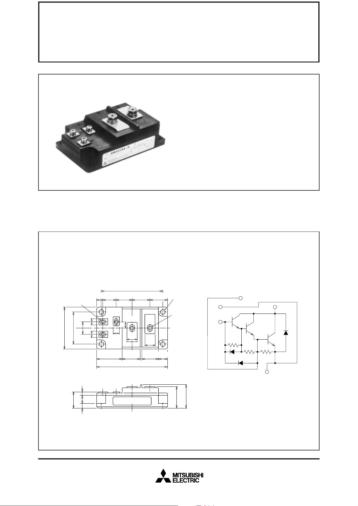
OUTLINE DRAWING & CIRCUIT DIAGRAM Dimensions in mm
93
10
62
48
M4
10
10
9
9
18.5
25
BX
8
BE
9
37.5 28
E
16
107
27
16
25
26.5
C
13.5
M6
φ6.5
BX
E
B
C
E
24.5
4.5
13
7
LABEL
32.2
35
Feb.1999
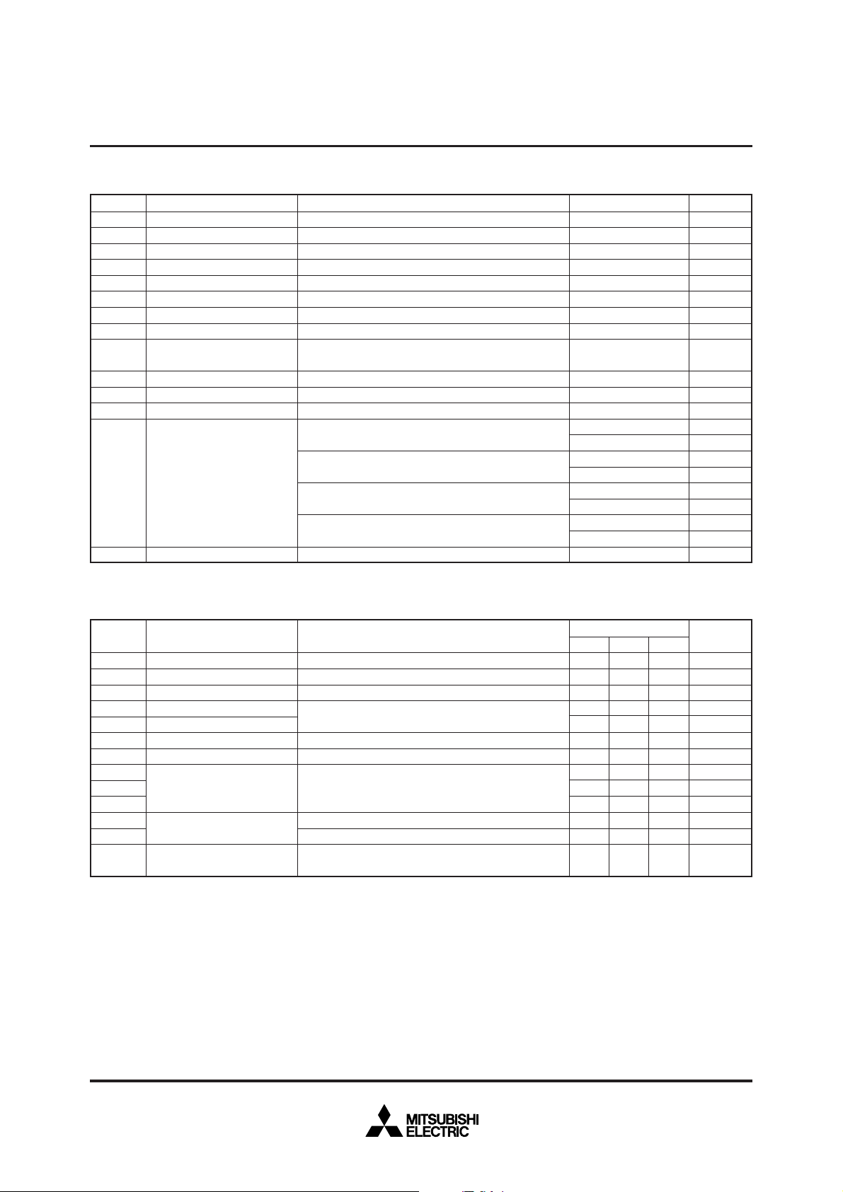
ABSOLUTE MAXIMUM RATINGS (Tj=25°C, unless otherwise noted)
Symbol
CEX (SUS)
V
VCEX
VCBO
VEBO
IC
–IC
PC
IB
–ICSM
Tj
Tstg
Viso
Collector-emitter voltage
Collector-emitter voltage
Collector-base voltage
Emitter-base voltage
Collector current
Collector reverse current
Collector dissipation
Base current
Surge collector reverse current
(forward diode current)
Junction temperature
Storage temperature
Isolation voltage
—
Mounting torque
—
Weight
Parameter
C=1A, VEB=2V
I
EB=2V
V
Emitter open
Collector open
DC
DC (forward diode current)
C=25°C
T
DC
Peak value of one cycle of 60Hz (half wave)
Charged part to case, AC for 1 minute
Main terminal screw M6
Mounting screw M6
B(E) terminal screw M4
BX terminal screw M4
Typical value
Conditions
MITSUBISHI TRANSISTOR MODULES
QM400HA-H
HIGH POWER SWITCHING USE
INSULATED TYPE
Ratings
600
600
600
7
400
400
1500
10
4000
–40~+150
–40~+125
2500
1.96~2.94
20~30
1.96~2.94
20~30
0.98~1.47
10~15
0.98~1.47
10~15
640
Unit
V
V
V
V
A
A
W
A
A
°C
°C
V
N·m
kg·cm
N·m
kg·cm
N·m
kg·cm
N·m
kg·cm
g
ELECTRICAL CHARACTERISTICS (Tj=25°C, unless otherwise noted)
Symbol
I
CEX
ICBO
IEBO
VCE (sat)
VBE (sat)
–VCEO
hFE
ton
ts
tf
Rth (j-c) Q
Rth (j-c) R
Rth (c-f)
Parameter
Collector cutoff current
Collector cutoff current
Emitter cutoff current
Collector-emitter saturation voltage
Base-emitter saturation voltage
Collector-emitter reverse voltage
DC current gain
Switching time
Thermal resistance
(junction to case)
Contact thermal resistance
(case to fin)
V
CE=600V, VEB=2V
CB=600V, Emitter open
V
EB=7V
V
I
C=400A, IB=0.53A
–I
C=400A (diode forward voltage)
C=400A, VCE=2.5V
I
CC=300V, IC=400A, IB1=0.8A, –IB2=8A
V
Transistor part
Diode part
Conductive grease applied
Test conditions
Min.
—
—
—
—
—
—
750
—
—
—
—
—
—
Limits
Typ.
—
—
—
—
—
—
—
—
—
—
—
—
—
Max.
5.0
5.0
400
2.5
3.5
1.8
—
3.0
10
35
0.083
0.25
0.04
Unit
mA
mA
mA
V
V
V
—
µs
µs
µs
°C/W
°C/W
°C/W
Feb.1999

PERFORMANCE CURVES
MITSUBISHI TRANSISTOR MODULES
QM400HA-H
HIGH POWER SWITCHING USE
INSULATED TYPE
C (A)
COLLECTOR CURRENT I
1000
800
600
400
200
COMMON EMITTER OUTPUT
CHARACTERISTICS (TYPICAL)
0
0
12345
=2A
B
I
B
I
=400mA
B
I
=200mA
B
I
Tj=25°C
=1A
10
7
5
3
FE
2
10
7
5
3
2
10
7
5
DC CURRENT GAIN h
3
2
10
DC CURRENT GAIN VS.
COLLECTOR CURRENT (TYPICAL)
5
Tj=25°C
j
=125°C
T
4
3
2
10
0
1
10
444
COLLECTOR-EMITTER VOLTAGE VCE (V) COLLECTOR CURRENT IC (A)
COMMON EMITTER INPUT
CHARACTERISTIC (TYPICAL)
1
10
VCE=2.5V
7
Tj=25°C
5
4
3
B (A)
2
0
10
7
5
4
3
BASE CURRENT I
2
–1
10
2.4 2.6 2.8 3.0 3.2 3.4
, VBE (sat) (V)SWITCHING TIME t
CE (sat)
10
SATURATION VOLTAGE V
10
10
10
7
5
3
2
7
5
3
2
7
5
3
2
–1
SATURATION VOLTAGE
CHARACTERISTICS (TYPICAL)
2
Tj=25°C
j
=125°C
T
1
V
BE(sat)
0
V
CE(sat)
10
0
1
10
444
COLLECTOR CURRENT IC (A)BASE-EMITTER VOLTAGE VBE (V)
VCE=2.5V
10
–IB=0.53A
10
VCE=5.0V
2
2
3
10
753275327532
3
10
753275327532
COLLECTOR-EMITTER SATURATION
VOLTAGE (TYPICAL)
5
IC=200A
VCE (sat) (V)
4
3
2
VOLTAGE
COLLECTOR-EMITTER SATURATION
1
Tj=25°C
j
=125°C
T
0
–2
10
444
10
–1
IC=100A
BASE CURRENT I
SWITCHING TIME VS. COLLECTOR
CURRENT (TYPICAL)
1
10
IC=400A
7
5
4
t
s
3
2
on, ts, tf (µs)
10
0
t
on
7
5
4
3
t
2
–1
10
0
10
B (A) COLLECTOR CURRENT IC (A)
1
10
753275327532
10 23457210 23457310
f
1
VCC=300V
IB1=0.8A
–IB2=8A
Tj=25°C
T
j
=125°C
Feb.1999

MITSUBISHI TRANSISTOR MODULES
QM400HA-H
HIGH POWER SWITCHING USE
INSULATED TYPE
SWITCHING TIME VS. BASE
REVERSE BIAS SAFE OPERATING AREA
CURRENT (TYPICAL)
1
10
7
VCC=300V
IB1=0.8A
5
4
10
3
2
0
IC=400A
Tj=25°C
T
j
=125°C
(µs)
s, tf
7
5
4
3
SWITCHING TIME t
2
–1
10
0
10 23457110 23457210
t
s
t
f
800
Tj=125°C
C (A)DERATING FACTOR (%)COLLECTOR REVERSE CURRENT –I
600
400
–5A
–8A
200
COLLECTOR CURRENT I
0
100 300 500 700
0 200 800
400 600
COLLECTOR-EMITTER VOLTAGE VCE (V)BASE REVERSE CURRENT –IB2 (A)
FORWARD BIAS SAFE OPERATING AREA DERATING FACTOR OF F. B. S. O. A.
3
10
7
5
3
C (A)
2
2
10
7
5
3
2
1
10
7
5
3
COLLECTOR CURRENT I
TC=25°C
2
NON REPETITIVE
0
10
0
10
444
10
1
DC
COLLECTOR-EMITTER VOLTAGE V
1m
10
10m
S
50µ
S
100µ
S
2
S
200µ
S
3
10
753275327532
CE (V) CASE TEMPERATURE TC (°C)
100
90
80
70
60
50
40
30
20
10
0
0 16020
SECOND
BREAKDOWN
AREA
COLLECTOR
DISSIPATION
40 60 80 100 120 140
–IB2=3A
0.08
0.06
(°C/ W)
0.04
Zth (j–c)
0.02
TRANSIENT THERMAL IMPEDANCE
CHARACTERISTIC (TRANSISTOR)
0
23457
10
0.1
0
–3
10
1
10
–2
10
444
10
TIME (s)
REVERSE COLLECTOR CURRENT VS.
COLLECTOR-EMITTER REVERSE
VOLTAGE (DIODE FORWARD
CHARACTERISTICS) (TYPICAL)
3
10
C (A)
T
j
7
5
4
=25°C
Tj=125°C
3
2
2
10
7
5
4
3
2
1
–1
0
10
753275327532
10
0.4 0.8 1.2 1.5 2.0
COLLECTOR-EMITTER REVERSE VOLTAGE
CEO (V)
–V
Feb.1999

RATED SURGE COLLECTOR REVERSE CURRENT
(DIODE FORWARD SURGE CURRENT)
5000
4000
3000
CSM (A)
–I
2000
1000
0
SURGE COLLECTOR REVERSE CURRENT
10
0
75432
10 75432
1
CONDUCTION TIME (CYCLES AT 60Hz)
10
MITSUBISHI TRANSISTOR MODULES
QM400HA-H
HIGH POWER SWITCHING USE
INSULATED TYPE
2
(°C/ W)
Zth (j–c)
TRANSIENT THERMAL IMPEDANCE
0.5
CHARACTERISTIC (DIODE)
0
23457
10
10
1
0.4
0.3
0.2
0.1
0
10
–3
–2
444
10
10
TIME (s)
–1
0
10
753275327532
Feb.1999
 Loading...