

Mitsubishi MELSEC-Q, QJ71FL71-T-F01, QJ71FL71-B5-F01, QJ71FL71-B2-F01, QJFL71-F01-U-HW User Manual
Page 1
FL-net(OPCN-2)
Interface Module
User’s Manual
(Hardware)
QJ71FL71-T-F01
QJ71FL71-B5-F01
QJ71FL71-B2-F01
Thank you for purchasing the Mitsubishi programmable controller
MELSEC-Q series.
Prior to use, please read this and relevant manuals thoroughly to
fully understand the product.
MODEL QJFL71-F01-U-HW
MODEL
13JP09
CODE
IB(NA)-0800239-E(0809)MEE
2002 MITSUBISHI ELECTRIC CORPORATION
Page 2
A
z SAFETY PRECAUTIONS z
(Always read these instructions before using this equipment.)
Before using this product, please read this manual and the relevant manuals
introduced in this manual carefully and pay full attention to safety to handle the
product correctly.
The instructions given in this manual are concerned with this product. For safety
instructions of the programmable controller system, please read the CPU module
user's manual.
In this manual, the safety instructions are ranked as "DANGER" and "CAUTION".
Indicates that incorrect handling may cause hazardous
DANGER
CAUTION
conditions, resulting in death or severe injury.
Indicates that incorrect handling may cause hazardous
conditions, resulting in medium or slight personal injury or
physical damage.
Note that the
the circumstances. Always follow the instructions of both levels because they are
important to personal safety.
Please save this manual to make it accessible when required and always forward
it to the end user.
CAUTION level may lead to serious consequence according to
-1
Page 3
A
[Design Precautions]
CAUTION
z Do not bunch the control wires or communication cables with the main circuit
or power wires, or install them close to each other.
They should be installed 100 mm (3.94 inch) or more from each other.
Not doing so could result in noise that would cause erroneous operation.
[Installation Precautions]
CAUTION
z Use the programmable controller in an environment that meets the general
specifications contained in this manual.
Using this programmable controller in an environment outside the range of
the general specifications could result in electric shock, fire, erroneous
operation, and damage to or deterioration of the product.
z While pressing the installation lever located at the bottom of module, insert
the module fixing tab into the fixing hole in the base unit until it stops. Then,
securely mount the module with the fixing hole as a supporting point.
Incorrect loading of the module can cause a malfunction, failure or drop.
When using the programmable controller in the environment of much
vibration, tighten the module with a screw.
z Tighten the screw in the specified torque range.
Undertightening can cause a drop, short circuit or malfunction.
Overtightening can cause a drop, short circuit or malfunction due to damage
to the screw or module.
z Before mounting or dismounting the module, make sure to shut off all phases
of the external power supply and FL-net (OPCN-2) system's power supply.
Failure to do so may damage the product.
z Do not directly touch the module's conductive parts or electronic
components.
Touching the conductive parts could cause an operation failure or give
damage to the module.
-2
Page 4

A
[Wiring Precautions]
CAUTION
z When wiring the connectors for external cable connection, crimp or clamp
the wires with a tool specified by the manufacture or solder them. An
incomplete connection could cause malfunctions.
z Do not connect AUI cables when the programmable controllers on the station
where the module is mounted and the FL-net (OPCN-2) system are powered
ON.
z Install the connector to the module securely.
z Place the communication and power cables to be connected to the module in
a duct or fasten them using a clamp. If not, dangling cables may swing or
inadvertently be pulled, resulting in damage to the module or cables or
malfunctions due to poor cable contact.
z Tighten the terminal screws with the specified torque.
If the terminal screws are loose, it could result in short circuits, fire, or
erroneous operation.
Tightening the terminal screws too far may cause damages to the screws
and/or the module, resulting in fallout, short circuits, or malfunction.
z When disconnecting a communication or power cable from the module, do
not pull the cable part by hand. When disconnecting a cable with a
connector, hold the connector connected to the module by hand and pull it
out. When disconnecting a cable connected to a terminal block, loosen the
screws on the terminal block first before removing the cable. Failure to do so
may cause a malfunction or damage to the module and/or cables.
z Be sure there are no foreign substances such as sawdust or wiring debris
inside the module.
Such debris could cause fires, damage, or erroneous operation.
z The module has an ingress prevention label on its top to prevent foreign
matter, such as wire offcuts, from entering the module during wiring.
Do not peel this label during wiring.
Before starting system operation, be sure to peel this label because of heat
dissipation.
-3
Page 5
A
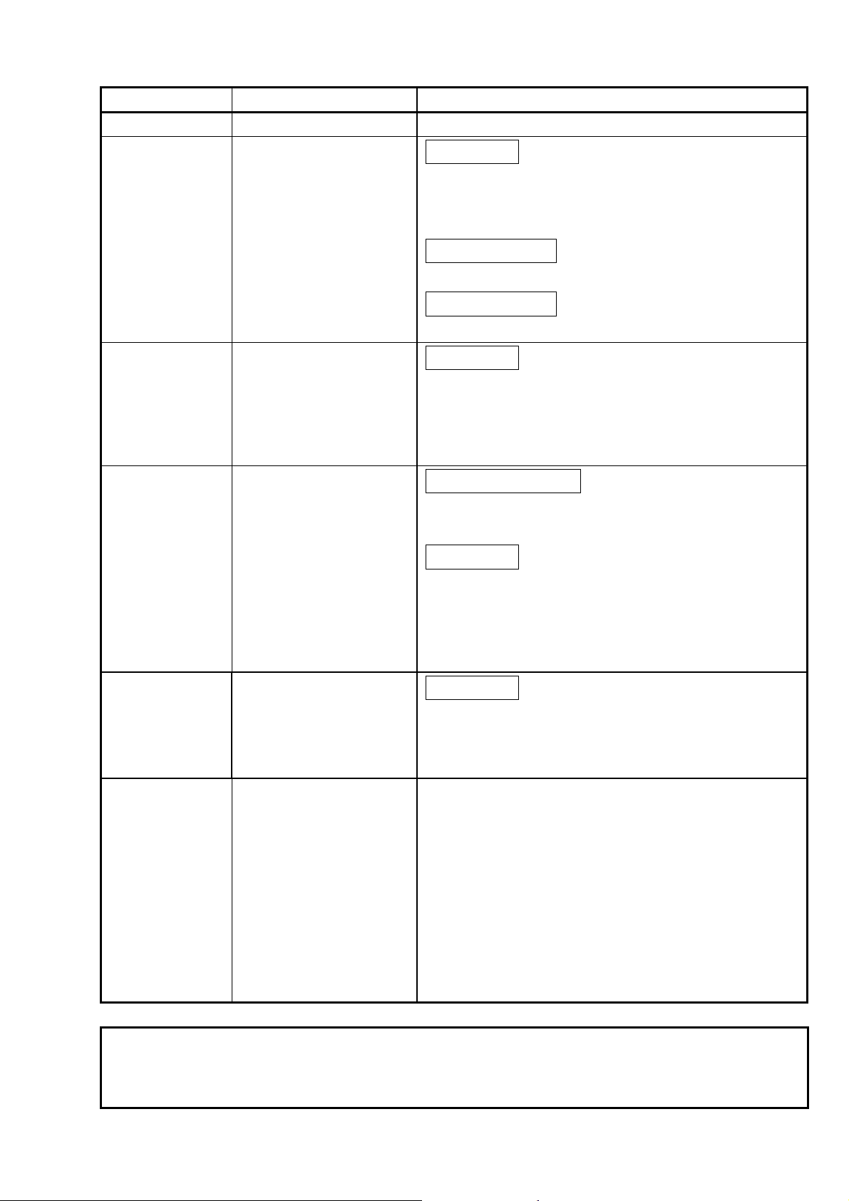
Revisions
* The manual number is given on the bottom right of the cover.
Print Date *Manual Number Revision
June, 2002 IB(NA)-0800239-A First printing
July, 2003 IB(NA)-0800239-B
Correction
About the Manuals, Chapter 1, Chapter 2,
Section 3.1, Chapter 4, Section 5.1, 5.2,
Chapter 6
Model addition
QJ71FL71-T-F01, QJ71FL71-B5-F01
Model deletion
QJ71FL71-F01
Mar., 2006 IB(NA)-0800239-C
Correction
SAFETY PRECAUTIONS, Compliance
with the EMC and Low Voltage Directive,
Chapter 2, Chapter 4, Section 5.2, 5.4,
Chapter 6
Dec., 2007 IB(NA)-0800239-D
Change of a term
Sep., 2008 IB(NA)-0800239-E
"PLC" was changed to "programmable
controller".
Correction
SAFETY PRECAUTIONS, Compliance
with the EMC and Low Voltage Directive,
Chapter 2, Section 3.1, Chapter 4,
Chapter 5, Chapter 6
Correction
Compliance with the EMC and Low
Voltage Directives, Chapter 2, Section 3.1,
Chapter 4, Section 5.2, Chapter 6
This manual confers no industrial property rights or any rights of any other kind, nor does it
confer any patent licenses. Mitsubishi electric Corporation cannot be held responsible for
any problems involving industrial property rights which may occur as a result of using the
contents noted in this manual.
2002 MITSUBISHI ELECTRIC CORPORATION
-4
Page 6
A
CONTENTS
1. Overview ······································································································· 1
2. Performance Specifications ·········································································· 1
3. Mounting and Installation ·············································································· 3
3.1 Precautions when handling ······································································ 3
3.2 Installation environment ··········································································· 3
4. Name of Parts ······························································································· 3
5. Connection to a Network················································································ 6
5.1 Connecting to 10BASE-T/100BASE-TX network ······································ 6
5.2 Connecting to 10BASE5 network ····························································· 7
5.3 Connecting to 10BASE2 network ····························································· 9
5.4 Switch settings for intelligent function module ·········································· 9
6. External Dimensions···················································································· 10
About Manual
The following manual is also related to this product.
If necessary, please place an order for it.
Related Manual
Manual name
Manual No.
(Model code)
FL-net(OPCN-2) Interface Module User’s Manual
QJ71FL71-T-F01, QJ71FL71-B5-F01,
QJ71FL71-B2-F01
Compliance with the EMC and Low Voltage Directives
(1) For programmable controller system
To configure a system meeting the requirements of the EMC and Low
Voltage Directives when incorporating the Mitsubishi programmable
controller (EMC and Low Voltage Directives compliant) into other
machinery or equipment, refer to Chapter 9 "EMC AND LOW VOLTAGE
DIRECTIVES" of the QCPU User's Manual (Hardware Design,
Maintenance and Inspection).
The CE mark, indicating compliance with the EMC and Low Voltage
Directives, is printed on the rating plate of the programmable controller.
(2) For the product
For the compliance of this product with the EMC and Low Voltage
Directives, refer to Section 9.1.3 "Cables" in Chapter 9 "EMC AND LOW
VOLTAGE DIRECTIVES" of the QCPU User's Manual (Hardware Design,
Maintenance and Inspection).
SH-080350E
(13JR61)
-5
Page 7

1. Overview
This manual explains how to handle the FL-net (OPCN-2) interface module,
model numbers QJ71FL71-T-F01, QJ71FL71-B5-F01 and QJ71FL71-B2-F01
(hereinafter referred to as the FL-net module).
(Product composition)
Model name Product name Quantity
QJ71FL71-T-F01 QJ71FL71-T-F01 FL-net (OPCN-2) interface module 1
QJ71FL71-B5-F01 QJ71FL71-B5-F01 FL-net (OPCN-2) interface module 1
QJ71FL71-B2-F01 QJ71FL71-B2-F01 FL-net (OPCN-2) interface module 1
2. Performance Specifications
The following are the performance specifications of the FL-net module.
Specifications
QJ71FL71-B5
Items
Data transmission speed
Transmission method Base band
Electric interface IEEE802.3 standard (CSMA/CD standard)
Transmission protocol UDP/IP FA link protocol
Maximum distance
between nodes
Maximum segment length 500 m 100 m 185 m
Maximum number of nodes
in system
Maximum number of nodes 100/segment
Transmission specifications
Minimum node interval 2.5 m — 0.5 m
Cyclic data volume
Message data volume Maximum 1024 bytes
-F01
10BASE5
10 Mbps
(Half duplex)
2500 m — 925 m
Maximum (8 k bits + 8 k words)/system
Maximum (8 k bits + 8 k words)/node
QJ71FL71-T
-F01
10BASE-T/
100BASE-TX
10 Mbps
(Half duplex)
100 Mbps
(Full duplex/
Half duplex)
254
For 10BASE-T,
Maximum 4
bases for
Cascade
connection
For 100BASE-TX,
Maximum 2
bases for
Cascade
connection
QJ71FL71-B2
-F01
10BASE2
10 Mbps
(Half duplex)
30/segment
1
Page 8

Specifications
QJ71FL71-B5
Items
Common memory area
Virtual address space and
physical memory
Error log memory area 512 words
Status memory area
Local node network
parameter setting area
Other node network
parameter setting area
Network parameter
acquisition area
Link data specifications
Device profile memory
area
Message area
(Transient area)
Number of input/output points 32 points (I/O assignment: intelligent)
5V DC internal current
consumption
Noise resistance
Voltage resistance
Insulation resistance
External dimensions
Weight 0.12 kg 0.11 kg 0.13 kg (*1)
According to the power supply specifications of the station
-F01
10BASE5
Area 1 (bit area): 8 k bits
Area 2 (word area): 8 k words
Maximum 1024 bytes 2 (1 for each of transmit and
0.50 A 0.50 A 0.60 A (*2)
to which the FL-net module is mounted.
98 (3.86 in.)(H) 27.4 (1.08 in.)(W)
QJ71FL71-T
-F01
10BASE-T/
100BASE-TX
—
Bit area: 2 k bits
Word area: 2 k words
128 words
2048 words
512 words
512 words
receive)
90 (3.54 in.)(D) mm
QJ71FL71-B2
-F01
10BASE2
*1: The 5V DC internal current consumption and weight of the product whose
first 5 digits of serial No. are 05079 or earlier are as follows:
• 5V DC internal current consumption : 0.70 A
• Weight : 0.14 kg
For general specifications of the FL-net module, refer to the user’s manual for the
CPU module that is to be used.
2
Page 9

3. Mounting and Installation
3.1 Precautions when handling
This section explains the precautions for the FL-net module itself.
(1) The case for the FL-net module is plastic. Do not drop it or expose it to
strong impact.
(2) Before touching the module, always touch grounded metal, etc. to
discharge static electricity from human body, etc.
Not doing so can cause the module to fail or malfunction.
(3) Tighten the screws such as module fixing screws within the following
ranges.
Screw location
Tightening torque
range
External power supply terminal screw (M2.5 screw) (*1) 0.40 N•m
Module fixing screw (Normally not required)
0.36 to 0.48 N•m
(M3 screw) (*2)
*1: External supply power input terminal to be used to supply power to the
transceiver for connection to 10BASE5.
*2: The module can be easily fixed onto the base unit using the hook at the top
of the module.
However, it is recommended to secure the module with the module fixing
screw if the module is subject to significant vibration.
3.2 Installation environment
Refer to the user’s manual for the CPU module that is to be used.
4. Name of Parts
The following introduces the functions and names of parts of the FL-net module.
1)
2)
7)
6)
*1
*1
1)
3)
5)
7)
6)
1)
4)
7)
6)
3
Page 10

Name Description
1) LED indicator Refer to (1) LED indication.
10BASE-T/100BASE-TX
connector (RJ45) (*2)
Connector for connecting FL-net module to
10BASE-T/100BASE-TX. (The FL-net module
2)
(for QJ71FL71-T-F01
only)
10BASE5 connector
3)
(for QJ71FL71-B5-F01
only)
10BASE2 connector
4)
(for QJ71FL71-B2-F01
only)
detects the 10BASE-T or 100BASE-TX
according to the hub.)
Connector for connecting FL-net module to
10BASE5. (For connecting 10BASE5 AUI
cable (transceiver cable))
Connector for connecting FL-net module to
10BASE2.
(For connecting 10BASE2 coaxial cable)
Terminal for supplying power to the
External power supply
5)
transceiver in the connection for 10BASE5.
terminal
(13.28 V to 15.75 V)
Lever for mounting
Guide for correctly mounting FL-net module to
6)
module
base unit.
7) Serial number plate Indicates the serial No. of the FL-net module.
*1: The following is printed on a product whose serial No. (the first 5 digits) is
earlier than 10011.
Although the silkscreen print is different, the LED indications and connector
functionality are the same.
Part name Print
100M LED No print
10BASE-T/100BASE-TX connector 10BASE-T
Since the high-speed cyclic transmission function (100Mbps) by
100BASE-TX connection has been certified by Japan Electrical
Manufacture’s Association (JEMA), it can be used from the first released
products. (The QJ71FL71-T-F01 only)
*2: The LED on the connector will not light up.
4
Page 11

(1) LED indications
1) LED indicators
QJ71FL71-T-F01
RUN
LNK
TX
PER
100M
RX
LED name Indication LED on LED off
RUN
Normal operation Normal Error (*1)
(Green)
LNK
Token passing
Token passing
No token passing
(Green)
indicator
status
Data send status
TX (Green)
Sending data Not sending data
indicator
Network parameter
PER (Red)
Setting error (*2) Setting normal
setting
100M
10Mbps/
Transmission speed 100Mbps
(Green)
Unconnected
Data receiving
RX (Green)
Receiving data Not receiving data
status indicator
*1: [RUN]LED turns off under the following conditions.
• Hardware error
• Watchdog timer error
*2: [PER]LED turns when:
• Setting is outside the range. (e.g. mode, node number, or allocation)
• A critical error is detected.
5
Page 12

5. Connection to a Network
This chapter explains the methods of connecting the FL-net module to a
10BASE5, 10BASE-T/100BASE-TX or 10BASE2 network.
POINT
The installation of 10BASE5, 10BASE-T/100BASE-TX or 10BASE2 network
requires strict adherence to safety precautions. Consult a specialist when
connecting cable terminals or installing trunk line cables, etc.
5.1 Connecting to 10BASE-T/100BASE-TX network
<Operating procedure>
(Step 1) Connect the twisted
pair cable to the hub.
(Step 2) Connect the twisted
pair cable to the FL-net
module.
POINT
During the high-speed communication (100 Mbps) via 100BASE-TX
connection, a communication error may occur due to the effect of high
frequency noise from devices other than programmable controllers in a given
installation environment.
The following are countermeasures on the QJ71FL71-T-F01 side to prevent
the effect of high frequency noise when constructing network systems.
(1) Wiring
• Do not bundle the twisted pair cables with the main circuit and the power
wires, and do not install them close to each other.
• Place the twisted pair cables in a duct.
(2) 10 Mbps communication
• Use a data transmission rate of 10 Mbps by changing the hub connected
to the QJ71FL71-T-F01 to a 10 Mbps hub.
6
Page 13

5.2 Connecting to 10BASE5 network
r
(1) Connecting an AUI cable
Retainer
A
B
AUI cable
<Operating procedure>
(Step 1) Slide the retainer in
direction B
(Step 2) Insert the AUI
connector all the way.
(*1)
(Step 3) Slide the retainer in
direction A
(Step 4) Check that the AUI
cable is locked.
Power supply for transceive
*1: Never connect the AUI cable when the power to the station with a module
mounted is on.
(2) Wiring to the external power supply terminal (DC power supply for
transceiver (*1))
The following explains how to connect a cable to the external power supply
terminal (DC power supply for transceiver).
1) Strip the cable jacket back 13mm. (*2)
The applicable cable size is 0.13mm
2
(AWG26) to 2.5mm2 (AWG14).
13mm
(0.51 in.)
2) Loosen the terminal screw and insert the cable into the terminal.
3) Tighten the terminal screw within the torque range shown in Section 3.1.
*1: Use a transceiver that is equipped with a function generally called as SQE
TEST or heartbeat (a signal that is used for checking normal transceiver
operation after transmission).
*2: If the wire strip length is too long, the conductive part is exposed and it may
increase the risk of electric shock or short circuit between the adjacent
terminals. If the wire strip length is too short, it may result in poor contact.
7
Page 14

POINT
(1) To prevent a communication error caused by high frequency noise in the
installation environment, installing a ferrite core is one of the preventive
measures.
(2) When 10BASE5 is used and countermeasures against noise and high
frequency waves are required for the installation environment of the
QJ71FL71-B5-F01, attaching a ferrite core (*1) to the transceiver side of the
AUI cable is often effective.
*1: Can use ZCAT 2032-0930, manufactured by TDK
QJ71FL71-B5-F01
AUI cable
DC
power supply
Ferrite core
Transceiver
Coaxial cable
for 10BASE5
8
Page 15

5.3 Connecting to 10BASE2 network
<Operating procedure>
1) As shown in figure, align the
grooves [1] and tab [2] and push in.
2) While pushing the connector in,
turn the connector to the right until
it locks.
3) Confirm that the connector has
[2]
[1]
been locked.
5.4 Switch settings for intelligent function module
Intelligent functional module switch settings are performed in "I/O allocation" of
GX Developer (SW4D5C-GPPW or later).
Contents
Switch 1
Switch 2
Switch 3
Switch 4
Switch 5
Set the first digit of the IP address.
If set to "No setting (Blank)", the default setting is used.
• Default value : 192
Set the second digit of the IP address.
If set to "No setting (Blank)", the default setting is used.
• Default value : 168
• Setting range : 0 to 255
Set the third digit of the IP address.
If set to "No setting (Blank)", the default setting is used.
• Default value : 250
• Setting range : 0 to 255
Set the fourth digit of the IP address. (This is the node
number.)
If set to "No setting (Blank)", the default setting is used.
• Default value : 1
• Setting range : 1 to 254
Enter the operating mode of the FL-net module.
0: Online (10Mbps, half duplex) (Default)
1: Offline
2: Loopback test
3: Hardware test
4: Online (Auto negotiation) (Mode to be selected when
using 100Mbps, theQJ71FL71-T-F01 only)
9
Page 16

6. External Dimensions
(1) QJ71FL71-T-F01
98(3.86)
R1
(*1)
23
(0.91)
27.4
(1.08)
(Unit :mm (in.))
*1: When connecting a twisted pair cable, the bending radius near the
connector (reference value: R1) must be four times the cable's
outside diameter or larger.
(2) QJ71FL71-B5-F01
90(3.54)
4(0.16)
98(3.86)
R2
(*1)
DC power
supply for
90(3.54)
8.5
(0.33)
4(0.16)
transceiver
23
(0.91)
27.4
(1.08)
(Unit :mm (in.))
*1: When connecting a AUI cable, the bending radius near the
connector (reference value: R2) must be four times the cable's
outside diameter or larger.
10
Page 17

(
)
(3) QJ71FL71-B2-F01
98(3.86)
29.2(1.15)
23.65
(0.93)
90(3.54)
11.5
(0.45)
4(0.16)
23
(0.91)
27.4
1.08
(Unit :mm (in.))
11
Page 18

Warranty
Mitsubishi will not be held liable for damage caused by factors found not to be the cause of
Mitsubishi; machine damage or lost profits caused by faults in the Mitsubishi products;
damage, secondary damage, accident compensation caused by special factors unpredictable
by Mitsubishi; damages to products other than Mitsubishi products; and to other duties.
For safe use
y This product has been manufactured as a general-purpose part for general industries, and
has not been designed or manufactured to be incorporated in a device or system used in
purposes related to human life.
y Before using the product for special purposes such as nuclear power, electric power,
aerospace, medicine or passenger movement vehicles, consult with Mitsubishi.
y This product has been manufactured under strict quality control. However, when installing
the product where major accidents or losses could occur if the product fails, install
appropriate backup or failsafe functions in the system.
Country/Region Sales office/Tel
U.S.A Mitsubishi Electric Automation Inc.
500 Corporate Woods Parkway Vernon
Hills, IL 60061, U.S.A.
Tel : +1-847-478-2100
Brazil MELCO-TEC Rep. Com.e Assessoria
Tecnica Ltda.
Rua Correia Dias, 184,
Edificio Paraiso Trade Center-8 andar
Paraiso, Sao Paulo, SP Brazil
Tel : +55-11-5908-8331
Germany Mitsubishi Electric Europe B.V. German
Branch
Gothaer Strasse 8 D-40880 Ratingen,
GERMANY
Tel : +49-2102-486-0
U.K Mitsubishi Electric Europe B.V. UK
Branch
Travellers Lane, Hatfield, Hertfordshire.,
AL10 8XB, U.K.
Tel : +44-1707-276100
Italy Mitsubishi Electric Europe B.V. Italian
Branch
Centro Dir. Colleoni, Pal. Perseo-Ingr.2
Via Paracelso 12, I-20041 Agrate Brianza.,
Milano, Italy
Tel : +39-039-60531
Spain Mitsubishi Electric Europe B.V. Spanish
Branch
Carretera de Rubi 76-80,
E-08190 Sant Cugat del Valles,
Barcelona, Spain
Tel : +34-93-565-3131
France Mitsubishi Electric Europe B.V. French
Branch
25, Boulevard des Bouvets, F-92741
Nanterre Cedex, France
TEL: +33-1-5568-5568
South Africa Circuit Breaker Industries Ltd.
Private Bag 2016, ZA-1600 Isando,
South Africa
Tel : +27-11-928-2000
Country/Region Sales office/Tel
Hong Kong Mitsubishi Electric Automation
(Hong Kong) Ltd.
10th Floor, Manulife Tower, 169 Electric
Road, North Point, Hong Kong
Tel : +852-2887-8870
China Mitsubishi Electric Automation
(Shanghai) Ltd.
4/F Zhi Fu Plazz, No.80 Xin Chang Road,
Shanghai 200003, China
Tel : +86-21-6120-0808
Taiwan Setsuyo Enterprise Co., Ltd.
6F No.105 Wu-Kung 3rd.Rd, Wu-Ku
Hsiang, Taipei Hsine, Taiwan
Tel : +886-2-2299-2499
Korea Mitsubishi Electric Automation Korea
Co., Ltd.
1480-6, Gayang-dong, Gangseo-ku
Seoul 157-200, Korea
Tel : +82-2-3660-9552
Singapore Mitsubishi Electric Asia Pte, Ltd.
307 Alexandra Road #05-01/02,
Mitsubishi Electric Building,
Singapore 159943
Tel : +65-6470-2460
Thailand Mitsubishi Electric Automation (Thailand)
Co., Ltd.
Bang-Chan Industrial Estate No.111
Moo 4, Serithai Rd, T.Kannayao,
A.Kannayao, Bangkok 10230 Thailand
Tel : +66-2-517-1326
Indonesia P.T. Autoteknindo Sumber Makmur
Muara Karang Selatan, Block A/Utara
No.1 Kav. No.11 Kawasan Industri
Pergudangan Jakarta - Utara 14440,
P.O.Box 5045 Jakarta, 11050 Indonesia
Tel : +62-21-6630833
India Messung Systems Pvt, Ltd.
Electronic Sadan NO:III Unit No15,
M.I.D.C Bhosari, Pune-411026, India
Tel : +91-20-2712-3130
Australia Mitsubishi Electric Australia Pty. Ltd.
348 Victoria Road, Rydalmere,
N.S.W 2116, Australia
Tel : +61-2-9684-7777
HEAD OFFICE : TOKYO BUILDING, 2-7-3 MARUNOUCHI, CHIYODA-KU, TOKYO 100-8310, JAPAN
NAGOYA WORK S : 1-14, YA DA-MINAMI 5-CHOM E, HIGASHI-KU, NAGOYA, JAPAN
When exported from Japan, this manual does not require application to the Ministry
of Economy, Trade and Industry for service transaction permission.
Specifications subject to change without notice.
Printed in Japan on recycled paper.
 Loading...