

Mitsubishi Electric QJ71LP21, QJ71BR11, QJ71LP21GE, QJ72LP25-25, QJ72LP25G Reference Manual
...
Q Corresponding MELSECNET/H
R
Network System
(Remote I/O network)
Q Corresponding MELSECNET/H Network System Reference Manual(Remote I/O network)
Mitsubishi Programmable
Logic Controller
QJ71LP21
QJ71LP21-25
QJ71LP21G
QJ71LP21GE
QJ71BR11
QJ72LP25-25
QJ72LP25G
QJ72LP25GE
QJ72BR15

A - 1 A - 1
• SAFETY PRECAUTIONS •
(Always read these instructions before using this equipment.)
Before using this product, pl ease read this manual and the relevant ma nuals introduced in this manual
carefully and pay full attent ion t o safety to handle the product correctly .
The instructions given in this manual are concerned with this produ ct. For the safety instructions of the
programmable controller system, please read the CPU module user's manual.
In this manual, the safety instructi ons are ranked as "DANGER" and "CAUTION ".
!
DANGER
CAUTION
!
Indicates that incorrect handling may cause hazardous conditions,
resulting in death or severe injury.
Indicates that incorrect handling may cause hazardous conditions,
resulting in medium or slight personal injury or physical damage.
Note that the !CAUTION level may lead t o a serious consequence accor ding to the circumstances.
Always follow the instruct ions of both levels because they are important to personal safety .
Please store this manual in a safe place and make it accessible when required. Alway s forward it to the
end user.
[Design Precautions]
!
DANGER
• When the network develops a communication error, the station with the communication error will
enter into the following status.
Use the communication status data to form an interlock circuit in the sequence program that will
operate the system on the safe side. Erroneous output or malfunctioning could cause accidents.
(1) The remote master station w ill hold the data fr om be fore the co mmunicat ion error .
(2) The remote I/O station turns off all outputs. The output module of the remote I/O station can
clear/hold the output status at the time of error by using the remote I/O module parameters.
As the parameters are set to "clear" by default, the output module turns off the outputs at the
time of error. If it is required to hold the output in order to operate the system safely, set the
parameters to "hold".
• If the coaxial cable is disconnected, the line may become unstable and the dat a link
communication error may occur in more than one stations. Make sure to create an interlock
circuit in the sequence program so that the system operates safely even when the data link
communication error occurs in more than one stations.
Failure to do so may cause the stations to mis-output or malfunction, resulting in accidents.
A - 2 A - 2
[Design Precautions]
!
DANGER
• When performing control operations to a PLC (modifying data) in operation by connecting G X
Developer to the CPU module or connect ing persona l comput ers to the intelligent funct ional
modules, configure an interlocking circuit in a sequence program so that the safety of the overall
system is maintained. Also, before performing other control operations (program modifications
and operating status modifications (status control)) on the PLC in operation, be sure to read the
manual thoroughly and confirm the safety. Especially if the abov e mentioned control operations
are performed from an external device to a remote PLC, problems arising on the PLC side may
not be dealt with immediately due to abnormal data communication. Thus, in addit ion to
configuring an interlocking circuit in a sequence program, determine how the sy stem should
handle data communication errors between the PLC CPU and external devices.
!
CAUTION
• Always reset the CPU module after changing the parameters for the CPU modul e or the remote
I/O module. If this is not done, data from before the change could cause malfunctioning.
• Do not bundle the control wires and communication cables with the main circuit or power wires,
or install them close to each other. They should be installed at least 100 mm (3.94 in.) away
from each other. Failure to do so may generate noise that may cause malfunctions.
[Installation Precautions]
!
CAUTION
• Use the PLC in the operating environment that meets the general specificat ions describe d in the
user's manual for the CPU module used. Using the PLC in any ot her operating env ironments
may cause electric shocks, fires or malfunctions, or may damage or degrade the product.
• With holding down the module installation lever on the low er part of the module, securely insert
the module fastening latch in the installation hole on the base unit to inst all the module using the
module installation hole as a supporting point. If the module is not installed properly , it may
cause the module to malfunction, fail or fall off.
Secure the module with screws especially when it is used in an environment where constant
vibrations may occur.
Be sure to tighten the screws using the specified torque. If the screws are loose, it may cause
the module to short-circuit, malfunction or fall off. If the screws are tightened excessively, it may
damage the screws and cause the module to short-circuit, malfunction or fall off.
• Before mounting or dismounting the module, make sure to shut off all phases of the external
power supply. Failure to do so may damage the product.
For remote I/O stations of function version D or later, online module change can be performed.
However, the modules which can be replaced online are limited, and replaceme nt procedures
are determined for each module. For details, refer to the section of online module replacement
in this manual.
A - 3 A - 3
[Installation Precautions]
!
CAUTION
• Do not directly touch the conducting parts and electronic parts of the module. This may cause
the module to malfunction or fail.
[Wiring Precautions]
!
DANGER
• Before starting wiring or similar work, be sure to shut off all phases of the external power supply
to the entire system. Failure to completely shut off the power supply to the system may cause
electric shocks and damage the product.
!
CAUTION
• Be sure to ground the FG terminals independently for PLC by class D (class 3) or higher.
Failure to do so may cause malfunctions.
• When connecting cables to the terminal block for external power supply, check the rated volt age
and terminal layout of the product for correct wiring.
Connecting a cable to power supply of different rating or incorrect wiring may cause a fire or
fault.
• Tighten the terminal screws with the specified torque.
Loose tightening may lead to a short circuit, fire or malfunction.
• Solder coaxial cable connectors properly. Incomplete soldering may result in ma lfunction ing.
• Be careful not to let foreign particles such as chaff and wire chips get inside the module. They
may cause a fire, mechanical breakdown or malfunction.
• The top surface of the module is covered with a protective film to prevent foreign objects such as
wire chips from entering the module during wiring work. Do not remove this film until all the
wiring work is complete. Before operating the system, be sure to remove the film to provide
adequate heat ventilation.
• Make sure to place the communication and power cables to be connected to the module in a
duct or fasten them using a clamp. If the cables are not placed in a duct or not fastened with a
clamp, their positions may become unstable and may move, or they may be pulled
inadvertently. This may damage the module and the cables or cause the module to malfunction
because of faulty cable connections.
• When disconnecting the communication and power cables from the module, do not pull the
cables by hand. When disconnecting a cable with a connector, hold the connector to the module
by hand and pull it out to remove the cable. When disconnecting a cable connected to a terminal
block, loosen the screws on the terminal block first before removing the cable. If a cable is
pulled while being connected to the module, it may cause the module to malfunct ion or damage
the module and cables.
A - 4 A - 4
[Setup and Maintenance Precautions]
!
CAUTION
• Please read this manual thoroughly and confirm the safety enough before starting online
operations (especially, program modifications, forced outputs, and operating status
modifications), which are performed by connecting GX Developer via the MELSECNET/H
network system to a CPU module running on another station. Performing incorrect online
operations may damage the machinery or result in accidents.
• Never disassemble or modify the module. This may cause breakdowns, malfunctions, injuries or fire.
• When using a cellular phone, use it at least 25 cm (9.84 in.) away from the PLC. Failing t o do so
may cause malfunctions.
• Before mounting or dismounting the module, make sure to shut off all phases of the external
power supply. Failure to do so may damage the module or result in malfunctions.
For the remote I/O network systems of function version D or later, online module change can be
performed. However, the modules which can be replaced online are limited, and replacement
procedures are determined for each module. For details, refer to the section of online module
replacement in this manual.
• Do not mount/remove the module onto/from base unit more than 50 times (IEC61131-2compliant), after the first use of the product.
Failure to do so may cause the module to malfunction due to poor contact of connector.
• Do not touch the terminals while the power is on. Th i s m a y ca use break d o wns, m a l func tion s ,
injuries or fire.
• Before cleaning the module or retightening the terminal screws and module installation screw s,
make sure to shut off all phases of the external power supply. Failure to completely shut off all
phases of the external power supply may cause module breakdowns and malfunctions. If the
screws are loose, it may cause the module to short-circuit, malfunction or fall off. If the screws
are tightened excessively, it may damage the screws and cause the module to short circuit,
malfunction or fall off.
• Before handling the module, always touch grounded metal, etc. to discharge static elect ricity
from the human body.
Failure to do so can cause the module to fail or malfunction.
[Disposal Precautions]
!
CAUTION
• When disposing of this product, treat it as industrial waste.
A - 5 A - 5
REVISIONS
The manual number is given on the bottom left of the back cover.
Print Date Manual Number Revision
Oct., 2000 SH (NA) -080124-A First printing
May., 2001 SH (NA) -080124-B
Model addition
QJ71LP21G, QJ72LP25G, QJ71LP21GE, QJ72LP25GE
Correction
Product Components, About The Generic Terms And Abbreviations,
Chapter 1, Section 1.2, 2.4, 3.1.1, 3.1.2, 3.2.1, 3.2.2, 3.3.2, 4.2.1, 4.2.2,
4.8.2, Chapter 5, Section 5.1.5, 5.2.1, 6.1.2, 6.2.1, 6.3, 6.4, 7.1.1, 7.8,
8.1, 8.1.1, 8.1.4, 8.3.1, 8.3.2, Appendix 2, 3, 4, 5, Index
Addition
Section 8.2.6
Apr., 2002 SH (NA) -080124-C
Correction
Section 1.2, 1.3, 2.3.1, 2.3.2, 2.3.3, 2.5, 3.1.1, 3.1.2, 3.2, 3.3.2, 4.2.1,
6.1.1, 6.4, Chapter 7, Section 8.4, Appendix 2, 3
Changed item numbers
Section 2.3 Section 2.4, Section 2.4 Section 2.5
Addition
Section 7.10
Nov., 2002 SH (NA) -080124-D
Model addition
QJ71LP21S-25
Correction
SAFETY PRECAUTIO NS, CONT ENTS,
Generic Terms And Abbreviations, Product Components,
Section 1.1, 1.2, 3.1.1, 3.1.2, 4.1.2, 4.8.1, 4.8.2, 7.1.1, 8.1.4,
Appendix 2, 3
Apr., 2003 SH (NA) -080124-E
Correction
SAFETY PRECAUTIONS, About Manuals, Section 1.2, 2.1.2, 2.2.2,
2.3.2, 2.5, 3.1.1, 3.1.2, 3.2.2, 3.3.1, Chapter 5, Section 5.1.3, 5.1.5, 6.2,
6.3, 6.4, 6.5, 8.1, 8.2, 8.2.1, 8.2.5, 8.3.1
A - 6 A - 6
The manual number is given on the bottom left of the back cover.
Print Date Manual Number Revision
Jun., 2004 SH (NA) -080124-F
Correction
SAFETY PRECAUTIONS, Manuals, Generic Terms And Abbreviations,
Section 1.2, 2.1.2, 2.2.2, 2.3.2, 2.4.2, 2.5, 3.1.1, 3.1.2, 3.1.3, 3.1.4, 3.2,
3.2.2, 4.2.2, 4.9.1, 4.10, 4.10.1, 4.10.2, 4.10.3, Chapter 5, Section 5.1.1,
5.2, 5.2.1, 6.4, 6.5, Chapter 7, Section 8.1, 8.1.1, 8.1.2, 8.1.3, 8.1.4,
8.2.1, 8.2.3, 8.2.5, 8.2.7, 8.3.1, 8.3.2, Appendix 2, 3
Addition
Section 1.4, 2.4, 2.7, 3.3.3, 3.3.4, 7.11, 7.12, 8.2.7, Appendix 7
Changed section No.
Section 2.4 Section 2.5, Section 2.5 Section 2.6
Japanese Manual Version SH-080123-H
This manual confers no industrial property rights or any rights of any other kind, nor does it confer any patent
licenses. Mitsubishi Electric Corporation cannot be held responsible for any problems involving industrial property
rights which may occur as a result of using the contents noted in this manual.
2000 MITSUBISHI ELECTRIC CORPORATION

A - 7 A - 7
INTRODUCTION
Thank you for purchasing the MELSEC-Q series PLC.
Before using the equipment, please read this manual carefully to develop full familiarity with the functions
and performance of the Q series PLC you have purchased, so as to ensure correct use.
Please forward a copy of this manual to the end user.
CONTENTS
SAFETY PRECAUTIONS..............................................................................................................................A- 1
REVISIONS....................................................................................................................................................A- 5
CONTENTS....................................................................................................................................................A- 7
Manuals ....................................................................................................................................................A-11
Conformation to the EMC Directive and Low Voltage Instruction ................................................................A-11
Generic Terms And Abbreviations.................................................................................................................A-12
Product Components .....................................................................................................................................A-12
1 OVERVIEW 1- 1 to 1- 9
1.1 Overview..................................................................................................................................................1- 1
1.2 Features ..................................................................................................................................................1- 2
1.3 Abbreviations Used in the Text, Tables and Diagrams of This Manual................................................ 1- 9
1.4 Functions Added/Changed with Upgrade to Function Version D..........................................................1- 9
2 SYSTEM CONFIGURATION 2- 1 to 2-17
2.1 Single Remote I/O Networks ..................................................................................................................2- 1
2.1.1 Configuration....................................................................................................................................2- 1
2.1.2 Setting items.....................................................................................................................................2- 2
2.1.3 Available device ranges ...................................................................................................................2- 3
2.2 Multiple Remote I/O Network (QnPHCPU Only)....................................................................................2- 4
2.2.1 Configuration.................................................................................................................................... 2- 4
2.2.2 Setting items.....................................................................................................................................2- 5
2.2.3 Available device ranges ...................................................................................................................2- 6
2.3 Multiplexed Remote I/O Network for Redundant System (QnPRHCPU Only).....................................2- 7
2.3.1 Configuration....................................................................................................................................2- 7
2.3.2 Setting items.....................................................................................................................................2- 8
2.3.3 Available device ranges ...................................................................................................................2- 9
2.4 Multiple Remote I/O Network..................................................................................................................2-10
2.4.1 Configuration....................................................................................................................................2-10
2.4.2 Setting items.....................................................................................................................................2-10
2.4.3 Available device ranges ...................................................................................................................2-11
2.5 Precautions when Configuring the System............................................................................................2-12
2.6 When Using a Multiple CPU System......................................................................................................2-15
2.7 Checking Function Version and Serial No. ............................................................................................2-17
3 SPECIFICATIONS 3- 1 to 3-50
3.1 Performance Specifications....................................................................................................................3- 1
3.1.1 Optical loop system performance specifications............................................................................. 3- 1

A - 8 A - 8
3.1.2 Coaxial cable system performance specifications..........................................................................3- 2
3.1.3 Optical fiber cable specifications .....................................................................................................3- 3
3.1.4 Coaxial cable specifications.............................................................................................................3- 4
3.2 Function Specifications...........................................................................................................................3- 7
3.2.1 Cyclic transmission function (Periodic communication)..................................................................3- 8
(1) Communicating with input/output module....................................................................................... 3- 8
(2) Communicating with intelligent function module.............................................................................3- 9
3.2.2 RAS functions...................................................................................................................................3-14
(1) Output reset function for communication errors..............................................................................3-14
(2) Automatic return function................................................................................................................. 3-14
(3) Loopback function (Optical loop system)........................................................................................3-15
(4) Station detach function (Coaxial bus systems)...............................................................................3-17
(5) Transient transmission enabled even at CPU module error ..........................................................3-18
(6) Checking the transient transmission abnormal direction time........................................................3-19
(7) Diagnostic functions.........................................................................................................................3-20
(8) Configuration of a redundant power supply on a remote I/O station .............................................3-21
(9) Online module change in a remote I/O station ...............................................................................3-24
3.3 Link Data Send/Receive Processing Time Specifications.....................................................................3-30
3.3.1 Link data send/receive processing ..................................................................................................3-30
3.3.2 Transmission delay time..................................................................................................................3-33
3.3.3 Switching time from the multiplexed remote master station to the multiplexed remote
sub-master station in a multiplexed remote I/O network ..............................................................3-45
3.3.4 Output holding time during system switching in the multiplexed remote I/O network for
redundant system...........................................................................................................................3-46
4 SETUP AND PROCEDURES BEFORE STARTING THE OPERATION 4- 1 to 4-27
4.1 Procedures Before Starting the Operation.............................................................................................4- 1
4.2 Network Module Names and Settings....................................................................................................4- 2
4.2.1 QJ71LP21, QJ71LP21-25, QJ71LP21G, QJ71LP21GE, QJ71BR11 (Remote master station)...4- 2
4.2.2 QJ72LP25-25, QJ72LP25G, QJ72LP25GE, QJ72BR15 ...............................................................4- 5
4.3 Installing and Uninstalling the Module....................................................................................................4- 7
4.4 Stopping the CPU (Unintentional Output Prevention) ...........................................................................4- 8
4.5 Checking the Input Power Supply Voltage.............................................................................................4- 8
4.6 Powering On............................................................................................................................................4- 8
4.6.1 Checking the on status of the POWER LED of the power supply module.....................................4- 8
4.6.2 Checking the on status of the RUN LED of the network module ...................................................4- 8
4.7 Standalone Check of the Network Module (Offline Tests) ....................................................................4- 9
4.7.1 Self-loopback test.............................................................................................................................4-10
4.7.2 Internal self-loopback test................................................................................................................4-11
4.7.3 Hardware test...................................................................................................................................4-12
4.8 Cable Connections..................................................................................................................................4-13
4.8.1 Optical loop system..........................................................................................................................4-13
4.8.2 Coaxial bus system..........................................................................................................................4-15
4.9 Offline Tests from GX Developer............................................................................................................4-20
4.9.1 Forward loop/reverse loop test (Remote master station only)........................................................ 4-20
4.10 Network Diagnostics from GX Developer (Online Tests) .................................................................... 4-23
4.10.1 Loop test (optical loop system only)..............................................................................................4-24
4.10.2 Setup confirmation test..................................................................................................................4-25

A - 9 A - 9
4.10.3 Station order check test (optical loop system only).......................................................................4-26
4.10.4 Communication test .......................................................................................................................4-27
5 PARAMETER SETTINGS 5- 1 to 5-30
5.1 Remote Master Station Parameter Setting............................................................................................5- 5
5.1.1 Setting the number of module cards (Network type) ......................................................................5- 5
5.1.2 Network settings...............................................................................................................................5- 6
(1) Starting I/O No. ................................................................................................................................5- 6
(2) Network No. .....................................................................................................................................5- 6
(3) Total (slave) stations........................................................................................................................5- 6
(4) Group No.
(Can be set for multiplexed remote master station/multiplexed remote sub-master station only)5- 7
(5) Mode.................................................................................................................................................5- 7
(6) Parameter setting example..............................................................................................................5- 8
5.1.3 Common parameter.........................................................................................................................5- 9
(1) LX/LY settings..................................................................................................................................5- 9
(2) LB/LW setting...................................................................................................................................5-11
(3) Reserved station designation..........................................................................................................5-12
(4) Remote sub-master station .............................................................................................................5-12
5.1.4 Supplemental settings......................................................................................................................5-14
5.1.5 Network refresh parameters ............................................................................................................5-16
5.1.6 Valid Module During Other Station Access.....................................................................................5-24
5.1.7 Redundant settings ..........................................................................................................................5-25
5.2 Remote I/O Station Parameter Settings.................................................................................................5-26
5.2.1 Remote I/O station possible parameter settings.............................................................................5-26
6 PROGRAMMING 6- 1 to 6-15
6.1 Programming Precautions......................................................................................................................6- 1
6.1.1 Interlock related signals ...................................................................................................................6- 1
6.1.2 Program example.............................................................................................................................6- 3
6.2 Cyclic Transmission................................................................................................................................6- 5
6.2.1 32-bit data guarantee.......................................................................................................................6- 5
6.2.2 Block guarantee of cyclic data per station.......................................................................................6- 6
6.3 Communication Between Input/Output Module and Intelligent Function Module.................................6- 7
6.4 Dedicated Link Instruction List................................................................................................................ 6-11
6.5 Using the Link Special Relays (SB)/ Link Special Registers (SW) .......................................................6-15
7 APPLICATIO N FU NC TI O NS 7- 1 to 7-45
7.1 Transient Transmission Function (Non-Periodical Communication).....................................................7- 2
7.1.1 Dedicated link instruction.................................................................................................................7- 3
(1) Reading/writing remote I/O station intelligent function module buffer memory
(REMFR/REMTO)............................................................................................................................7- 3
7.2 Remote I/O Station System Monitor.......................................................................................................7-13
7.3 Device Test for Remote I/O Station........................................................................................................7-14
7.4 Multiplex Transmission Function (Optical Loop System) ......................................................................7-16
7.5 Return Sequence Station Number Setting Function..............................................................................7-17

A - 10 A - 10
7.6 Reserved Station Function .....................................................................................................................7-17
7.7 Interrupt Settings..................................................................................................................................... 7-18
7.8 I/O Assignment Function ........................................................................................................................7-19
7.9 Stopping/Re st a rtin g the Cyclic Transmissio n and St oppi ng Lin k Re fre shi ng ( Net w ork Test ).............7-20
7.10 Multiplexed remote master function (QnPHCPU only)........................................................................7-21
7.11 Multiplexed remote master function for redundant system (QnPRHCPU only)..................................7-36
7.11.1 Backup function of master operation on system switching between control system and
standby system ..............................................................................................................................7-37
7.11.2 Master operation by the station that has started up as the control system..................................7-38
7.11.3 System switching request function of control system...................................................................7-39
7.11.4 Access function by specifying either the control system or standby system ...............................7-41
7.12 Remote password.................................................................................................................................7-42
8 TROUBLESHOOTING 8- 1 to 8-97
8.1 Network Diagnostics (Network Monitor).................................................................................................8- 2
8.1.1 Host information ...............................................................................................................................8- 4
8.1.2 Other station information..................................................................................................................8- 6
8.1.3 Network monitor details....................................................................................................................8- 8
8.1.4 Error history monitor.........................................................................................................................8-11
8.2 Troubleshooting ......................................................................................................................................8-14
8.2.1 Items to be checked first ..................................................................................................................8-19
8.2.2 When data link cannot be executed on the entire system..............................................................8-19
8.2.3 When data link is disabled because of reset or power off of each station.....................................8-20
8.2.4 When a specific-station's data link cannot be executed.................................................................8-20
8.2.5 When the transmission and reception data are abnormal..............................................................8-21
8.2.6 When the dedicated link instruction is not completed.....................................................................8-21
8.2.7 When a multiplexed remote I/O network for the redundant system does not operate normally...8-22
8.3 Error Codes.............................................................................................................................................8-23
8.3.1 MELSECNET/H error code list ........................................................................................................8-23
8.3.2 Error codes corresponding to CPU module detected on remote I/O station..................................8-34
8.4 H/W Information ......................................................................................................................................8-96
APPENDIX App- 1 to App-46
Appendix 1 Precautions when Changing Over from a MELSECNET/10 Remote I/O Network to
a MELSECNET/H Remote I/O Network................................................................................App- 1
Appendix 2 Link Special Relay (SB) List..................................................................................................App- 3
Appendix 3 Link Special Register (SW) List.............................................................................................App-11
Appendix 4 Special Relay (SM) for Remote I/O Modules List.................................................................App-27
Appendix 5 Special Register (SD) for Remote I/O Module List...............................................................App-29
Appendix 6 Discontinued Models that can be Mounted on Remote I/O Stations...................................App-40
Appendix 7 External Dimensions..............................................................................................................App-41
INEDX Index- 1 to Index- 2
A - 11 A - 11
Manuals
The following manuals are also related to this product.
In necessary, order them by quoting the details in the tables below.
Related Manuals
Manual Name
Manual Number
(Model Code)
Q Corresponding MELSECNET/H Network System Reference Manual (PLC to PLC network)
This manual describes the specifications for a MELSECNET/H network system for PLC to PLC network.
It explains the procedures and settings up to operation, setting the parameters, programming and
troubleshooting. (Sold separately)
SH-080049
(13JF92)
QCPU User's Manual (Hardware Design, Maintenance and Inspection)
This manual provides the specifications of the CPU modules, power supply modules, base units,
extension cables, memory cards and others. (Sold separately)
SH-080483ENG
(13JR73)
QCPU User's Manual (Function Explanation, Program Fundamentals)
This manual explains the functions, programming methods, devices and so necessary to create
programs with the QCPU. (Sold separately)
SH-080484ENG
(13JR74)
QCPU User's Manual (Multiple CPU System)
This manual explains the multiple CPU system overview, system configuration, I/O numbers,
communication between CPU modules, and communication with the I/O modules or intelligent function
modules. (Sold separately)
SH-080485ENG
(13JR75)
QnPRHCPU User's Manual (Redundant System)
This manual explains the redundant system configuration, functions, communication with external
devices, and troubleshooting for redundant system construction using the Redundant CPU.
(Sold separately)
SH-080486ENG
(13JR76)
GX Developer Version 8 Operating Manual
This manual describes the programming, printing, monitoring and debugging procedures, and other
online functions using GX Developer. (Sold separately)
SH-080373E
(13JU41)
Conformation to the EMC Directive and Low Voltage Instruction
When incorporating a Mitsubishi PLC compliant with the EMC Directive and Low
Voltage Instruction into your product to conform to the directives, see Chapter 3
"EMC Directive and Low Voltage Instruction" of the CPU User's Manual used
(Hardware).
The CE logo is printed on the rating plate on the main body of the PLC that conforms
to the EMC directive and low voltage instruction.
For information on compliance with the EMC directive and low voltage directive,
please refer to Section 3.1.3. "Cable" in Chapter 3 "EMC Directive and Low Voltage
Directive" of the User’s Manual (Hardware) for the CPU module.
A - 12 A - 12
Generic Terms And Abbreviations
Generic term/abbreviation Description of generic term/abbreviation
QJ71LP21
This is an abbreviation for a QJ71LP21, QJ71LP21-25, QJ71LP21S-25, QJ71LP21G, QJ71LP21GE
MELSECNET/H network module. However, especially in cases to show different models,
QJ71LP21, QJ71LP21-25, QJ71LP21S-25, QJ71LP21G and QJ71LP21GE are printed.
QJ71BR11 Abbreviation for QJ71BR11 type MELSECNET/H network module.
QJ72LP25
Abbreviation for QJ72LP25-25, QJ72LP25G, QJ72LP25GE MELSECNET/H network module.
However, especially in cases to show different models, QJ72LP25-25, QJ72LP25G and
QJ72LP25GE are printed.
QJ72BR15 Abbreviation for QJ72BR15 MELSECNET/H network module.
Master module General term for QJ71LP21 and QJ71BR11.
Remote I/O module General term for QJ72LP25 and QJ72BR15.
Network module General term for master module and remote I/O module.
Ethernet module Abbreviation for QJ71E71-100, QJ71E71-B5, and QJ71E71-B2 Ethernet interface modules.
Serial communication module
Abbreviation for QJ71C24N, QJ71C24N-R2, QJ71C24N-R4, QJ71C24, and QJ71C24-R2 serial
communication modules.
Modem interface module Abbreviation for QJ71CM0 modem interface module.
MELSECNET/H Abbreviation for Q series MELSECNET/H network system.
MELSECNET/10
Abbreviation for AnU series MELSECNET/10 network system and QnA/Q4AR series
MELSECNET/10 network system
QCPU
Abbreviation for Q02CPU, Q02HCPU, Q06HCPU, Q12HCPU, Q25HCPU, Q12PHCPU,
Q25PHCPU, Q12PRHCPU, Q25PRHCPU.
QnCPU Abbreviation for Q02CPU.
QnHCPU Abbreviation for Q02HCPU, Q06HCPU, Q12HCPU, Q25HCPU.
QnPHCPU Abbreviation for Q12PHCPU, Q25PHCPU.
QnPRHCPU Abbreviation for Q12PRHCPU and Q25PRHCPU modules.
QnACPU Generic term for MELSEC-QnA series CPU modules.
ACPU Generic term for MELSEC-A series CPU modules.
AnUCPU
Generic term for MELSEC-A series A2UCPU, A2UCPU-S1, A3UCPU, A4UCPU, A2USCPU,
A2USCPU-S1, and A2USHCPU-S1 CPU modules.
GX Developer Abbreviation for GX Developer software package.
GX Configurator Abbreviation for GX Configurator software package.
Tracking cable Abbreviation for QC10TR and QC30TR tracking cables.
Product Components
Model name Part name Quantity
QJ71LP21 QJ71LP21 MELSECNET/H Network Module (optical loop type) 1
QJ71LP21-25 QJ71LP21-25 MELSECNET/H Network Module (optical loop type) 1
QJ71LP21S-25
QJ71LP21S-25 MELSECNET/H Network Module (optical loop type, with
external power supply function)
1
QJ71LP21G QJ71LP21G MELSECNET/H Network Module (optical loop type) 1
QJ71LP21GE QJ71LP21GE MELSECNET/H Network Module (optical loop type) 1
QJ71BR11 MELSECNET/H Network Module (coaxial bus type) 1
QJ71BR11
F-type connector 1
QJ72LP25-25 QJ72LP25-25 MELSECNET/H Network Module (optical loop type) 1
QJ72LP25G QJ72LP25G MELSECNET/H Network Module (optical loop type) 1
QJ72LP25GE QJ72LP25GE MELSECNET/H Network Module (optical loop type) 1
QJ72BR15 MELSECNET/H Network Module (coaxial cable bus type) 1
QJ72BR15
F-type connector 1
REMARK
For the coaxial bus system, terminal resistors (75 Ω) are required in the network
terminal stations.
Terminal resistors are not included with the QJ71BR11, QJ72BR15; they must be
purchased separately.
For a list of the model and how to use the terminal resistors, refer to Section 4.8.2.
1 - 1 1 - 1
MELSEC-Q
1 OVERVIEW
1 OVERVIEW
The MELSECNET/H system includes the following 2 types of networks:
1) PLC to PLC network for communications between a control station and normal
stations
2) Remote I/O network for communications between a remote master station and
remote I/O stations
This is the manual to read when building a remote I/O network for MELSECNET/H
systems (hereafter called MELSECNET/H). If you are building a MELSECNET/H
network for PLC to PLC network, please refer to the Q-corresponding MELSECNET/H
network system reference manual. (PLC to PLC network) (SH-080049)
POINT
The Q00JCPU, Q00CPU and Q01CPU cannot configure a remote I/O network in a
MELSECNET/H ne tw o rk sy ste m.
REMARK
The previous network, called MELSECNET/10H is now called MELSECNET/H.
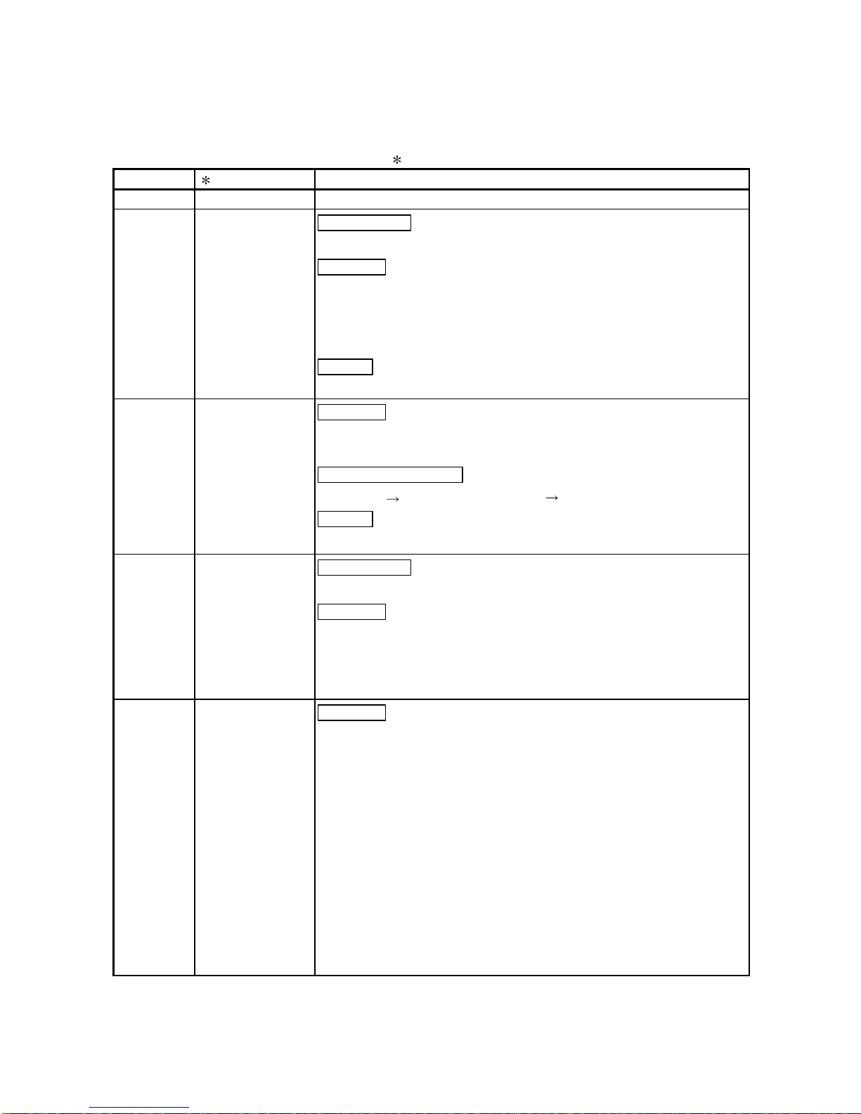
1.1 Overview
The MELSECNET/H remote I/O network system has more functionality and capacity
than the former network system, MELSECNET/10 network system (hereafter referred
to as MELSECNET/10).
As the MELSECNET/H remote I/O network adopts the same module mounting method
as the usual one (mounting I/O modules and intelligent function modules onto the main
base unit/expansion base unit), each module mounted on the remote I/O stations can
be handled in the similar way as the basic one.
In addition, the applicability to the MELSECNET/10 remote I/O network has been
further enhanced so that the FA system can be easily configured.
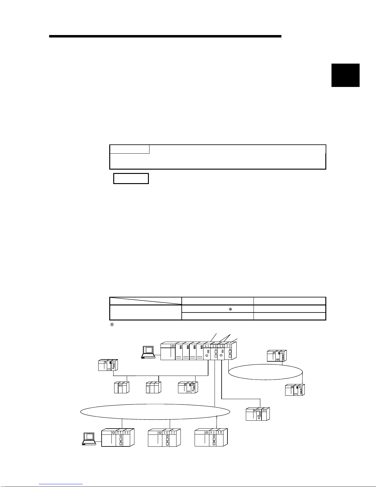
In the MELSECNET/H remote I/O network optical loop system, the communication
speed can be set to 25 Mbps or 10 Mbps.
Network system Communication speed
Optical loop 1 25 Mbps
MELSECNET/H
Optical loop, coaxial cable 10 Mbps
1: QJ71LP21-25, QJ71 LP21S - 25 , QJ72LP 25 - 25 only
Remote I/O station
QCPU
GX Developer
Control station (MELSECNET/10 mode)
Control station (MELSECNET/H mode)
GX Developer
QCPU normal station
QCPU normal station
QCPU normal station
Remote I/O station Remote I/O station Remote I/O station
MELSECNET/H (25Mbps)
PC network
Remote master stat io n
MELSECNET/H (10Mbps)
remote I/O network
MELSECNET/H (25Mbps) remote I/O network
MELSECNET/H (10Mbps)
PLC to PLC network
QnACPU
normal station
AnUCPU
normal station
QCPU
normal station
1
1 - 2 1 - 2
MELSEC-Q
1 OVERVIEW
POINT
(1) Use QCPU for MELSECNET/H remote I/O network PLC selection time.
(2) Remote I/O networks and PLC to PLC networks cannot be mixed on the same
MELSECNET/H network. Always build separate networks.
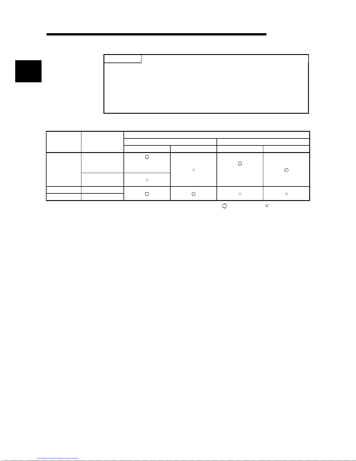
(3) Only MELSECNET/H network modules can be connected to a MELSECNET/H
remote I/O ne two r k. Th ey cannot be mixed wi th MELS E CNET/10 network
modules.
The following table shows th e types of netw orks the CPU module s can be conne cted to.
Network to be connected
MELSECNET/10 MELSECNET/HCPU module
Type of networks
that can be used
with CPU
PLC to PLC network Remote I/O network PLC to PLC network Remote I/O network
MELSECNET/H
(10 Mbps)
(MELSECNET/10
mode)
QCPU
MELSECNET/H
(25 Mbps)
(MELSECNET/H
mode)
AnUCPU MELSECNET/10
QnACPU MELSECNET/10
: Can be used : Cannot be used
1.2 Features
The MELSECNET/H remote I/O network has the following features.
(1) Achievement of a high-speed communication system
(a) High-speed data sending at a communication rate of 10 Mbps/25 Mbps is
possible.
(25Mbps is avail abl e fo r onl y the op ti cal loop type QJ71LP21- 2 5,
QJ71LP21S-25 and QJ72LP25-25.)
(2) Large-scale and flexible system configur ation
(a) The link device has a larger capacity: 16384 points for the link relay (LB)
and 16384 points for the link register (LW). (See Section 2.1.3, "Available
device range setting s." )
(b) A maximum of 4096 I/O points can be set for each remote I/O station.
The link points between a remote master station and a remote I/O station
can be set up to 1600 bytes. The link points of up to 2000 bytes can be set
between a master station and a sub-master station on a multiplexed remote
I/O network.
(c) Either of the following systems can be chosen: the optical loop system
(maximum total extension of 30 km (98430 ft.)) which has a long station-tostation distance and total distance, and is resistant to noise, or the coaxial
bus system (maximum total extension of 500 m (1640.5 ft.) which can easy
be wired.
(See Section 3.1, "Performance Specifications.")
1
1 - 3 1 - 3
MELSEC-Q
1 OVERVIEW
(d) It is not necessary to d e signat e re se rved stations which are t reate d a s
stations to be connected in future or to connect stations in the order of station
numbers. The opt i cal loo p sy ste m exe cut e s a lo opb a ck w hen a stati on i s
down. Because of these functions, connecting networks has become easier
than ever. (See Se ction 5 .1 . 3, " Designat i o n of the r eserv ed station . " )
(e) The parameters can be written to remote I/O modules using GX Developer
in the same way as to CPU modules.
The parameters of the remote I/O module can be used to change the
detailed settings (response time, error output mode) for I/O modules on a
remote I/O station, intelligent function module switch settings and I/O
allocations, and remote password settings.
(Refer to Section 5.2 "Remote I/O Station Parameter Settings".)
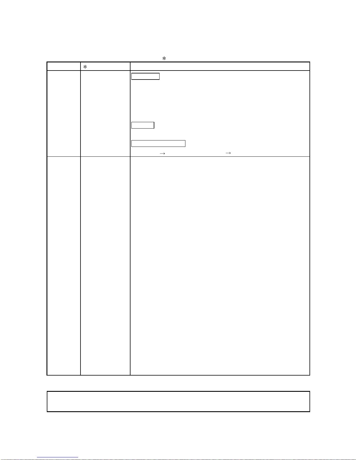
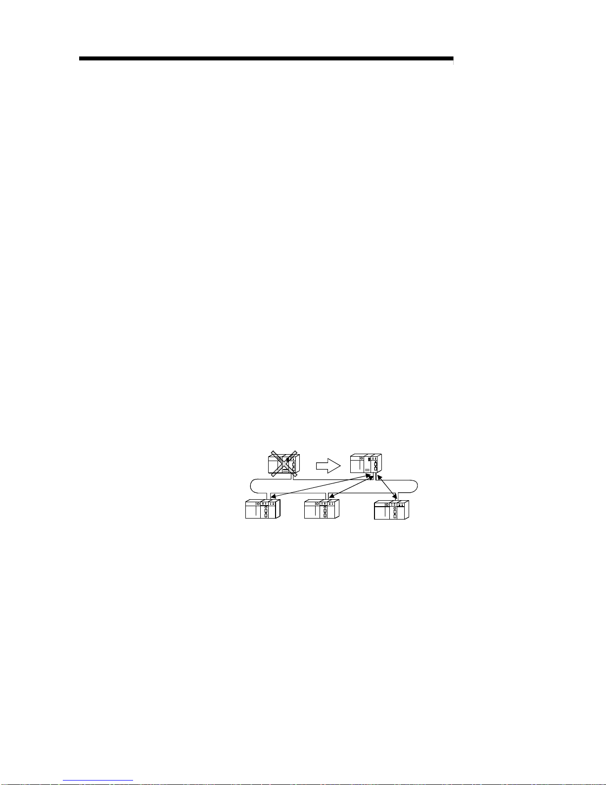
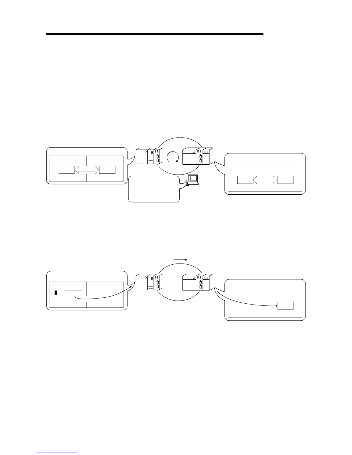
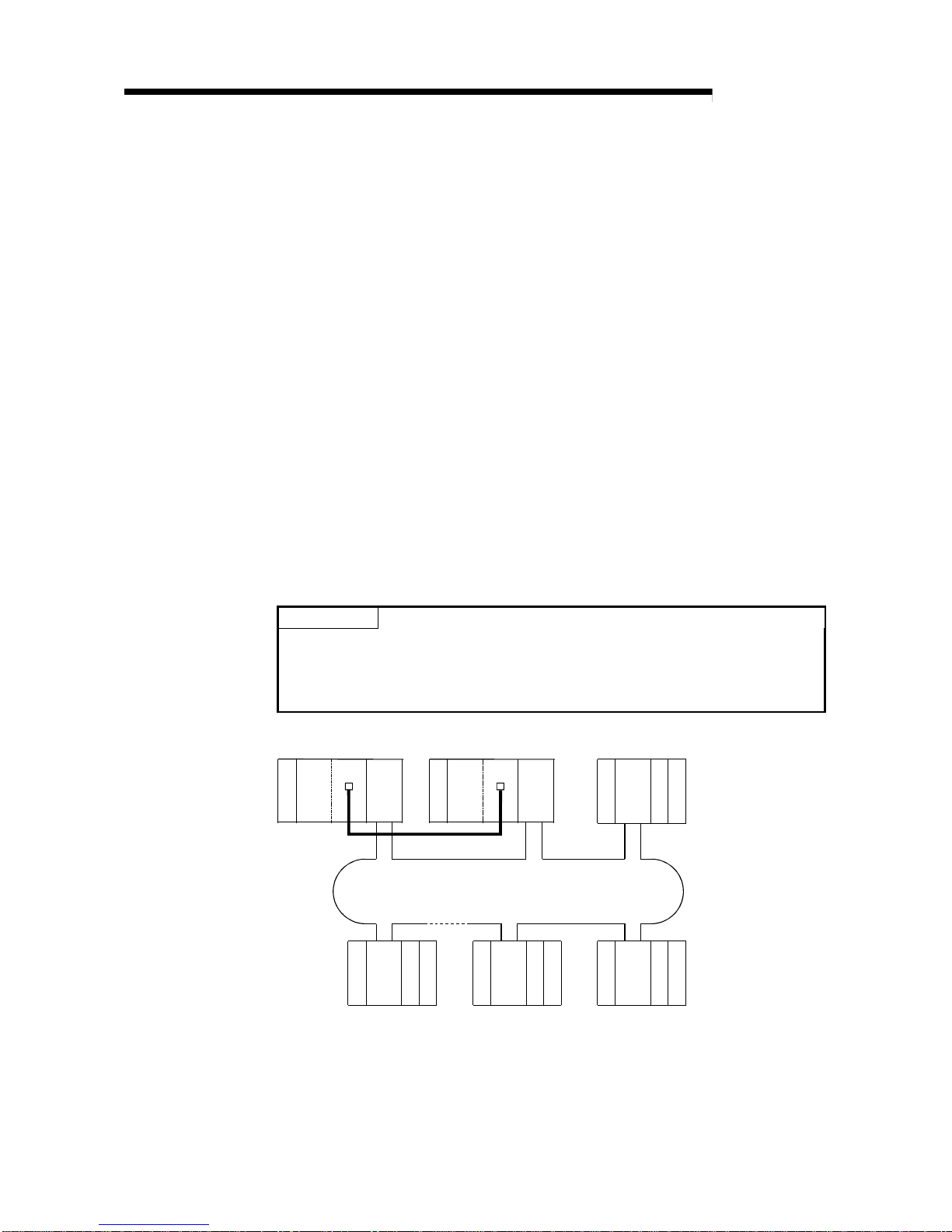
(f) Setting up a master station (DM
R
) and a sub-master station (DSMR) on the
multiplexed remote I/O network allows the sub-master station to take over
the control of remote I/O stations (R) in case of the master station's failure.
(The QnPHCPU should be used for the multiplexed remote master station
and sub-master station.)
By making a parameter setting, the multiplexed remote sub-master station
can continue the control of the remote I/O stations even if the master
station has recovered to normal and rejoined to the system. (Setting for the
recovered master station to control the remote I/O stations is also
available.)
(Refer to Section 7.10 "Multiplex Remote Master Function (QnPHCPU
Only)".)
Multiplexed rem ote
master station (DM
R
)
Multiplexed rem ote
sub-master station (DSMR)
Remote I/O station (R) Remote I/O station (R) Remote I/O station (R)
1 - 4 1 - 4
MELSEC-Q
1 OVERVIEW
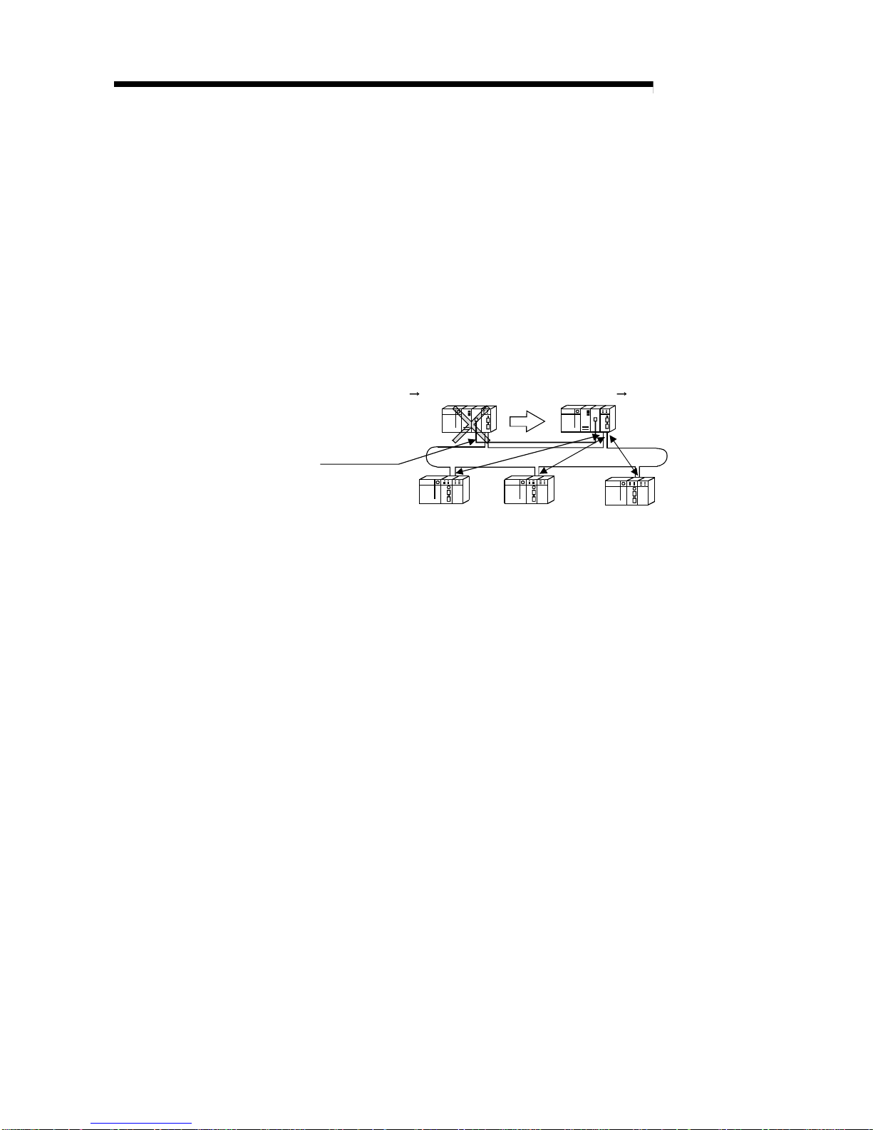
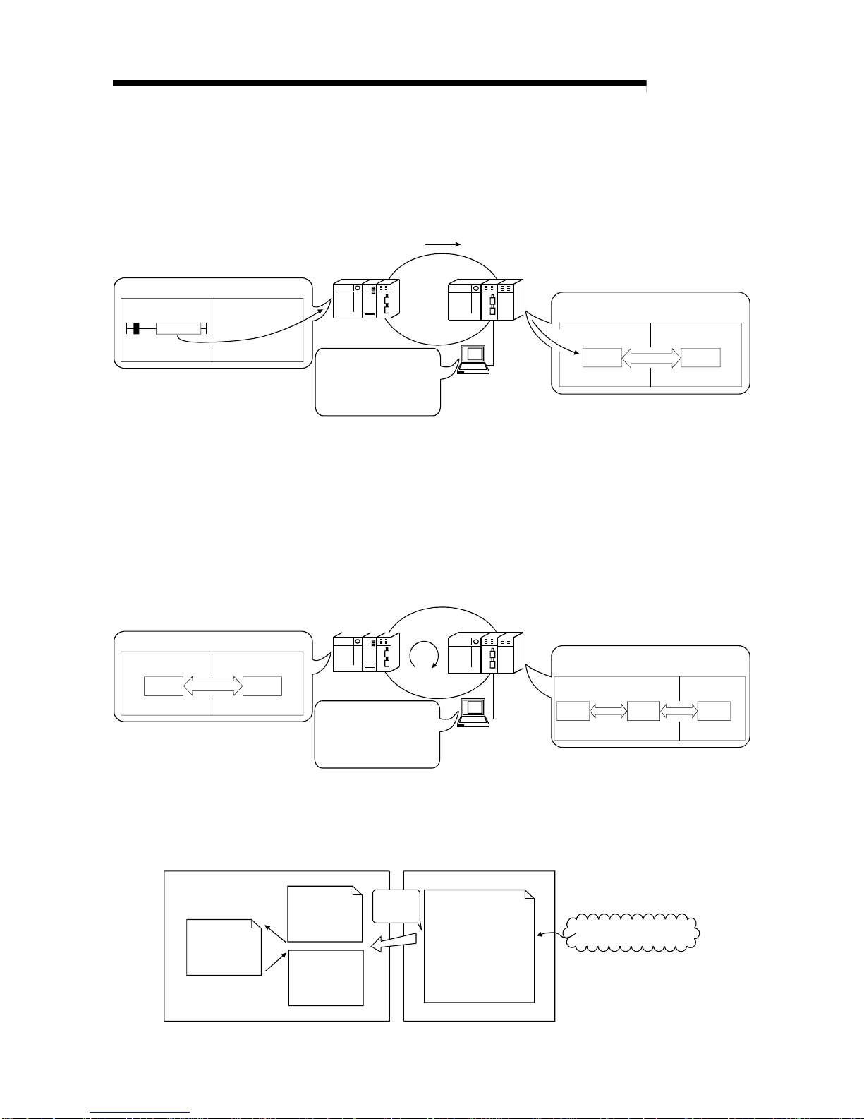
(g) The redundant system uses the multiplex remote master function to control
I/O modules and intelligent function modules. (The QnPRHCPU should be
used in the redundant system.)
If the multiplexed master station (control system) fails, the multiplex remote
master function will switch the master station from "control system" to
"standby system". At this time, the multiplexed remote sub-master station
is switched from "standby" to "control", continuing the remote I/O control.
The sub-master station (control system) that is controlling the remote I/O
stations will keep its control even if the master station (standby system) has
returned to normal status.
(Refer to Section 7.11 "Multiplex Remote Master Function for Redundant
System (QnPRHCPU Only).)
Remote I/O station (R)
Remote I/O station (R)
Remote I/O station (R)
Tracking cable
Multiplexed remote master station (DMR)
Control system Standby system
Multiplexed remote sub-master station (DSM
R
)
Standby system Control system
(h) A maximum of 7 extension base units can be connected to the remote I/O
module (eight base units including the main base unit), allowing the
installation of up to 64 modules.
The maximum overall length of extension cables is 13.2m, ensuring a
flexible layout of extension base units.
1 - 5 1 - 5
MELSEC-Q
1 OVERVIEW
(3) Providing versatile communication ser v ice
(a) Reading and writing of data for an intelligent function module that has been
mounted to a remote I/O station can be easily performed.
There are four methods available for reading and writing.
1) Use GX Configurator to make the initial settings and automatic refresh
settings in the intelligent function module parameters, and write them
into the remote I/O module in the remote I/O station.
By refreshing the intelligent function module data to the link register W
of the remote I/O module in the auto refresh settings, the remote
master station can read/write refreshed data by cyclic transmission.
QCPU
Remote master station
Remote I/O station
Intelligent function module
LW
GX
Configurator
Intelligent function
module paramete rs
• Initial settings
• Automatic refresh
settings
Remote I/O module
Intelligent
function module
Buffer m emory
QCPU Master module
Link register W
Link register LW
Refresh
Link register W
Refresh
2) Special link instructions can be used to directly read from or write to the
buffer memory of the intelligent module.
• REMFR instruction: Reads data from the buffer memory of the
remote I/O statio n inte lli ge nt fu n ctio n modu le .
• REMTO instruction: Writes data to the buffer memory of the remote
I/O station intelligent function module.
QCPU
Remote master station
Remote I/O station
Intelligent function module
REMTO
Network module
Intelligent
function module
Buffer m emory
REMTO
QCPU Network module
Z.REMTO
1 - 6 1 - 6
MELSEC-Q
1 OVERVIEW
3) By refreshing the intelligent function module data into the remote I/O
module's data register D by the automatic refresh setting of the
intelligent function module parameters, the remote master station can
read/wri te da ta fr o m/t o th e d at a r eg i st e r D wi th READ or WRITE
instruction.
QCPU
Remote master station
Remote I/O station
Intelligent function module
GX
Configurator
Intelligent function
module paramete rs
• Initial settings
• Automatic refresh
settings
Remote I/O module
Intelligent
function module
Data
register D
Buffer
memory
QCPU Master station
WRITE
JP.WRITE
WRITE
Refresh
4) The automatic refresh setting of the intelligent function parameters
enables the intelligent function module data to be refreshed into the
remote I/O module's data register D. By refreshing the data register D
to the link register W with the parameter of the remote I/O module, the
remote master station can read/write the intelligent function module
data by cyclic transmission.
This method has th e ad va ntag e t ha t the int ell ig en t fu nc ti on modul e
parameters created for QCPU can be applied to the remote I/O
module without making any modifications.
QCPU
Remote master station
Remote I/O station
Intelligent function module
LW
Remote I/O module
Intelligent
function module
QCPU Master station
Link register W Link register LW
Intelligent function
module parameters
• Initial settings
• Automatic refresh
settings
Refresh
Refresh
Link
register W
Data
register D
Buffer
memory
Refresh
GX
Configurator
(b) The interrupt sequence program of the host's CPU module can be started
up using the event issue function. This function reduces the response time
of the system and enables real-time data reception.
(See Section 7.7, "Starting Up the Interrupt Sequence Program.")
END
MAIN
I50
CPU module Network module
Cyclic transmission
MELSECNET/H
Normal
sequence
program
Condition check
Interrupt condition
parameters
• Relay information
• Register data
• Network st a tus
Conditions
matched
Interrupt
sequence
program
IRET

1 - 7 1 - 7
MELSEC-Q
1 OVERVIEW
(4) Enhanced RAS functions (Refer to Section 3.2.2 "RAS functions")
(a) When a faulty station recovers and can resume normal operation, it
automatically returns to the network to resume the data communication
using the automatic return function.
(b) By using the loop ba ck fun ct i o n (the op ti cal loop sy ste m), i t i s possible to
continue data transmission among operational stations by disconnecting
faulty areas such as a part of the network where there is a cable
disconnection, a faulty station, etc.
(c) By using the station detach function (coaxial bus system), even when some
of the connected stations are down due to power off, etc., the normal
communication can be continued among other operational stations.
(d) The network module can continue the transient transmission even if an error
that stops the CPU module while the system is operating occurs.
(e) It is possible to check the time when a transient error occurred.
(f) By mounting 2 power supply modules on a remote I/O station, either of
them can be replaced without powering off the station. (Redundant power
supply on remote I/O station)
The redundan t pow e r sup pl y base un it is r eq ui red fo r mount in g 2 pow e r
supply modules.
(g) When an input module, an output module or an intelligent function module
mounted on a remote I/O station fails, the faulty module can be replaced
without stopping the system operation. (Online module change)
Online module change is available for Q series I/O modules and function
version D or later analog-to-digital and digital-to-analog converter modules,
temperature input modules and temperature control modules.
REMARK
The following fa ul t s make t h e RAS fu n cti on s vali d.
• Break in cable
• Power-off of slave station
• Network setting error
• Fault detectable by self-diagnostics of CPU module
If the network module has become faulty, the RAS functions may not be activated
depending on the fault.
(5) Control of external connection to remote I/O stations ( refer to
Section 7.12)
Setting a remote password for a remote I/O station restricts connections from the
outside via an Ethernet interface module, serial communication module or
modem interface module. (Remote password)

1 - 8 1 - 8
MELSEC-Q
1 OVERVIEW
(6) Strengthening network functions
(a) Intelligent function modules mounted to remote I/O stations can be
diagnosed using the GX Developer system monitor.
Intelligent function modules mounted to remote I/O stations can be
diagnosed using the system monitor even if it is done via the network using
a GX Developer connected to a remote master station or even if the GX
Developer is directly connected to a remote I/O station.
QCPU
GX Developer
Remote master station
Remote I/O station
GX Developer
GX Developer
Q64AD
Select
Q64AD
Remote I/O station
system monitor
Q64AD
system monitor
Remote I/O station
When the network seems to be faulty, it can be diagnosed through GX
Developer connected to the remote master station or remote I/O station.
(b) If the GX Developer is connected to a remote I/O station, it w ill not a ffect the
system operating so user program network function testing can be done online.
It shuts out input (X) from the input module on the remote I/O station and
can turn input (X) on or off using the GX Developer test.
This allows testing of the re mote master station inpu t prog ram to b e perfor med.
In addition, it shuts of output (Y) form the remote master station and can
turn remote I/O station output (Y) on and off using the GX Developer test.
This allows testing of the wires for the output module on the remote I/O
station to be performed.
(7) Increased ease of network configuration i n combinati on with Q
corresponding GX Developer
(a) The network parameters can easily be set by visualising pull-down menus,
dialogue boxes, etc.
(b) The settings of network Nos., group numbers and operation modes have
been simplified so that these values can be designated only through
software settings.
(Network parameters)
Pull-down men u
Abbreviations
1 - 9 1 - 9
MELSEC-Q
1 OVERVIEW
1.3 Abbreviations Used in the Text, Tables and Di ag r ams of This M anual
(1) Abbreviations
Abbreviations Name
M
R
Remote master station
R Remote I/O station
DM
R
Multiplexed remote master
DSM
R
Multiplexed remote sub-master
(2) Marking format
Station number (1 to 64)
Abbreviation
Network No. (1 to 239
)
[Example]
1) Network No. 3 and remote master station· · · · · · · · · · · · · · · · · · · · 3M
R
Station number "0" is not attached to the remote master station.
2) Network No. 5, remote I/O station, station number 3 · · · · · · · · · · · · 5R3
3) Network No. 7, Multiplexed remote sub-master,
station number 4 · · · · · · · · · · · · · · · · · · · · · · · · · · · · · · · · · · · · 7DSM
R
4
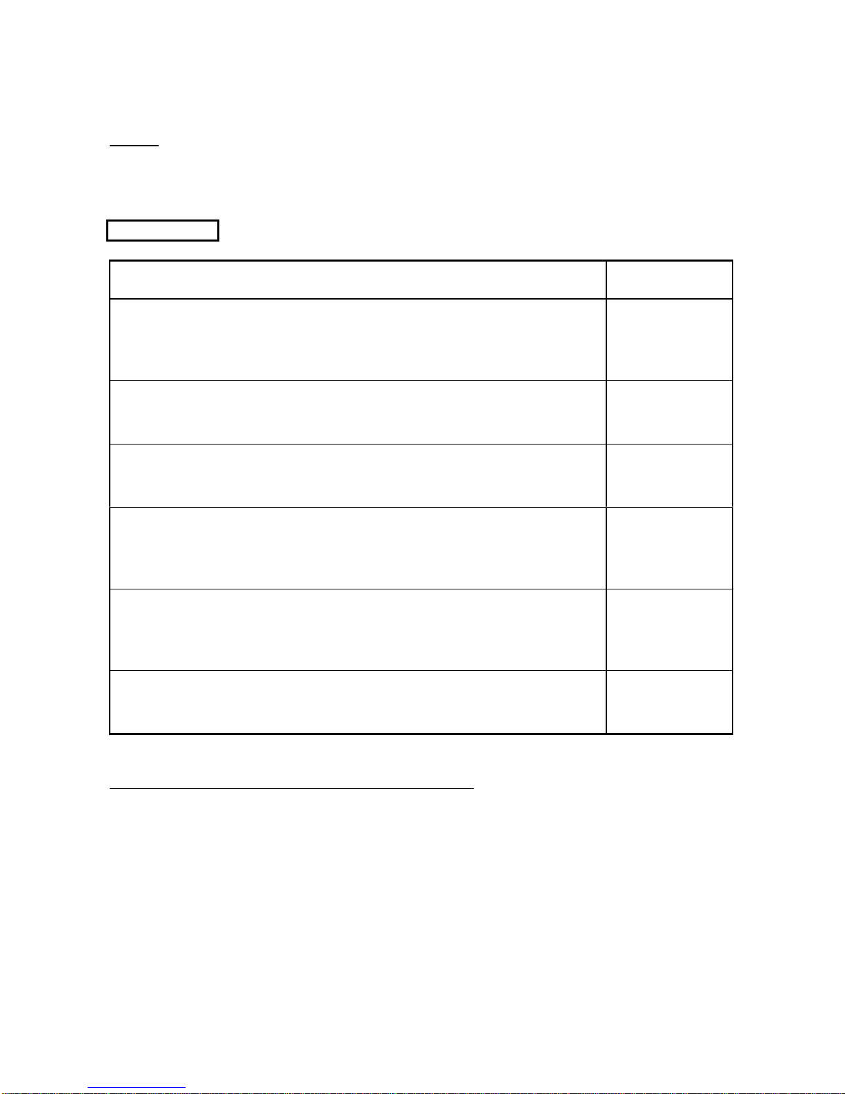
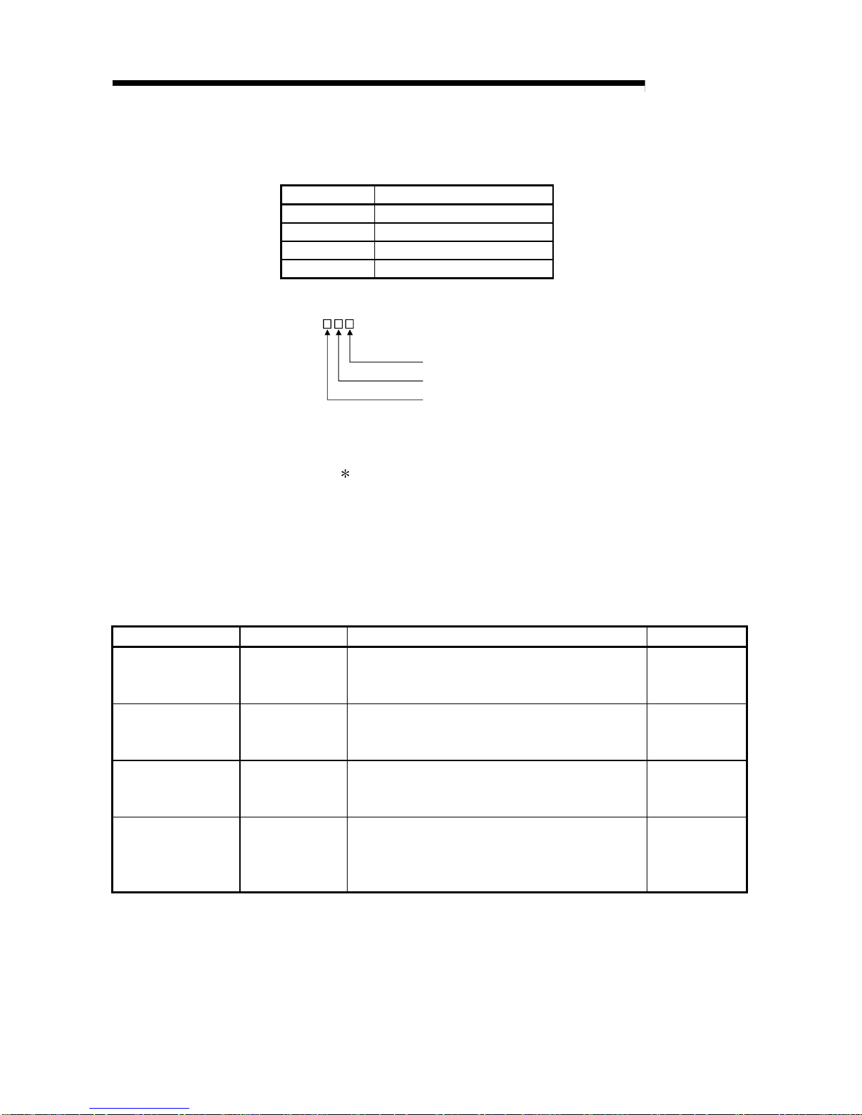
1.4 Functions Added/Changed with Upgrade to Functi on Ver si on D
The following table lists the additional/altered functions for network modules of function
version D.
Function Function version Description Reference
Multiplexed remote I/O
network for redundant
system
Function version D
Allows construction of a multiplexed remote I/O network
that includes the redundant system as the master station.
Section 7.11
Power supply
redundancy on remote
I/O station
Function version D
Allows the construction of the system that includes a
remote I/O station in which 2 power supply modules are
mounted for power supply redundancy.
Section 3.2.2 (8)
Online module change
on remote I/O station
Function version D
Allows the faulty I/O module or intelligent function module
on a remote I/O station to be replaced online while the
remote I/O station is running.
Section 3.2.2 (9)
Remote password for
remote I/O station
Function version D
Limits the connection made from GX Developer via the
Ethernet module, serial communication module or
modem interface module mounted on a remote I/O
station, by setting the password.
Section 7.12
2 - 1 2 - 1
MELSEC-Q
2 SYSTEM CONFIGURATION
2 SYSTEM CONFIGURATION
This introduces a system comprised of remote I/O networks.
2.1 Single Remote I/O Networks
2.1.1 Configuration
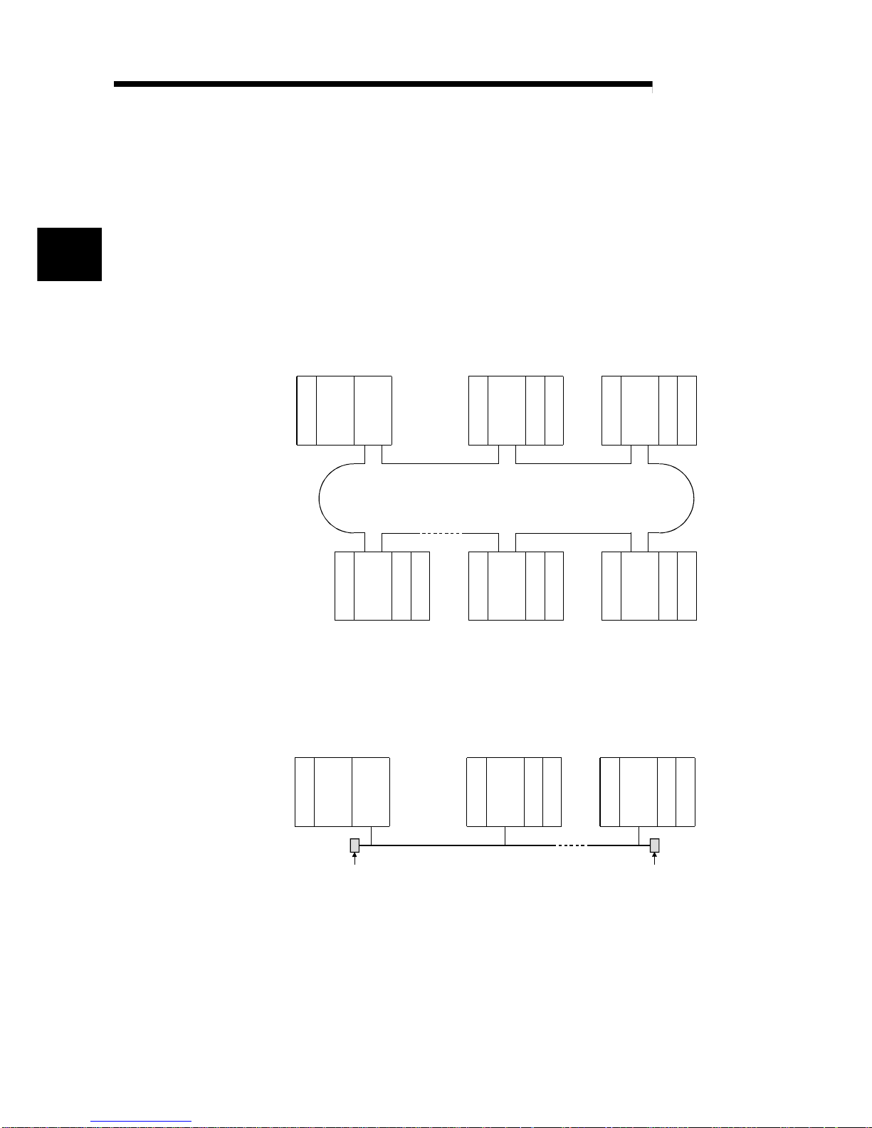
(1) Optical loop system
Up to 64 remote I/O modules can be connected to a remote master station.
Always set the station number of the remote master station to 0.
Power supply
QCPU QJ71
LP21
Station number 0
(remote master station)
Station number 1
(remote I/O station)
I/O
QJ72
LP25
I/O
Station number 2
(remote I/O station)
I/O
QJ72
LP25
I/O
Optical fiber cable
Power supply
Power supply
I/O
QJ72
LP25
I/O I/O
QJ72
LP25
I/O
Power supply
Power supply
I/O
QJ72
LP25
I/O
Power supply
Station number 4
(remote I/O station)
Station number 3
(remote I/O station)
Station number 64
(remote I/O station)
(2) Coaxial cable bus system
Up to 32 remote I/O stations can be connected to a remote master station.
Always set the station number of the remote master station to 0.
QCPU
QJ71
BR11
Terminator
(Sold separately)
Terminator
(Sold separately)
Coaxial cable
Station number 1
(remote I/O station)
I/O
QJ72
BR15
I/O
Station number 32
(remote I/O sta t ion)
I/O
QJ72
BR15
I/O
Power supply
Power supply
Power supply
Station number 0
(remote master station)
2
2 - 2 2 - 2
MELSEC-Q
2 SYSTEM CONFIGURATION
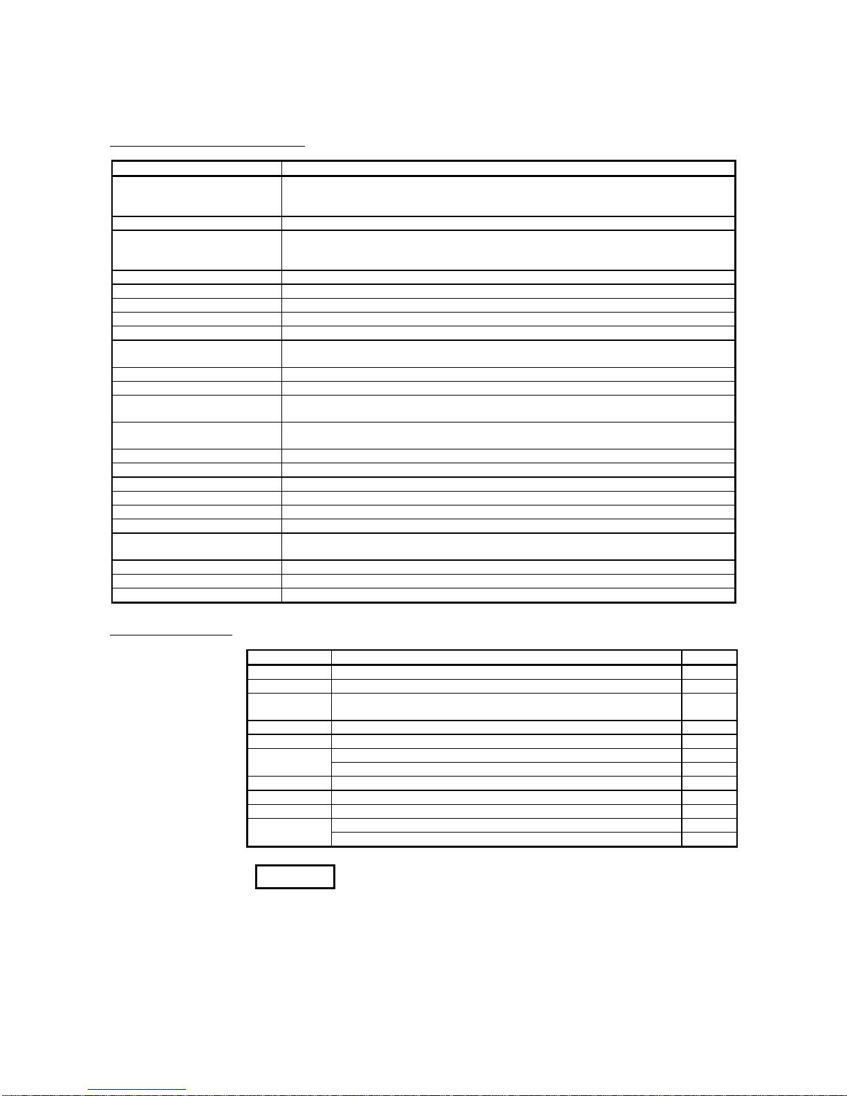
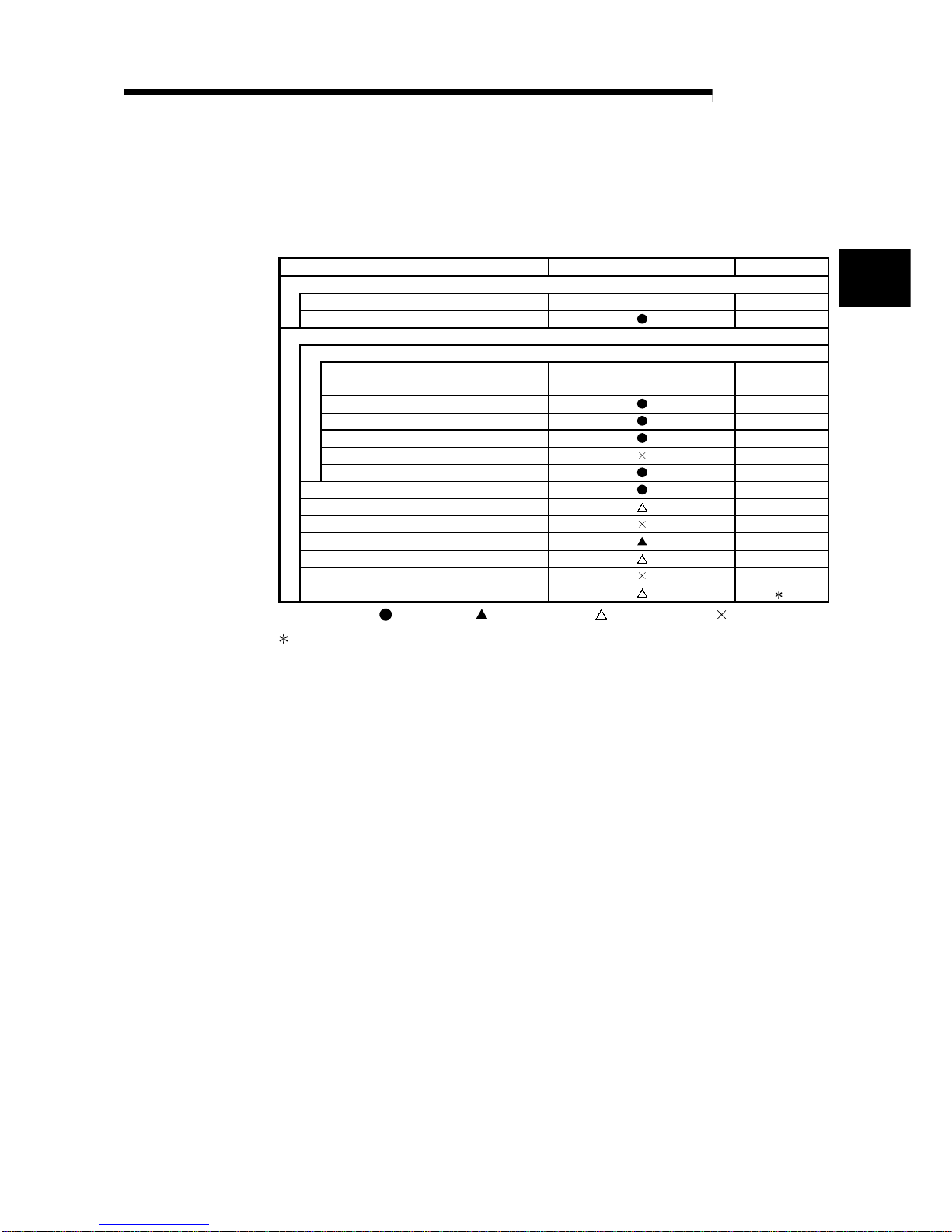
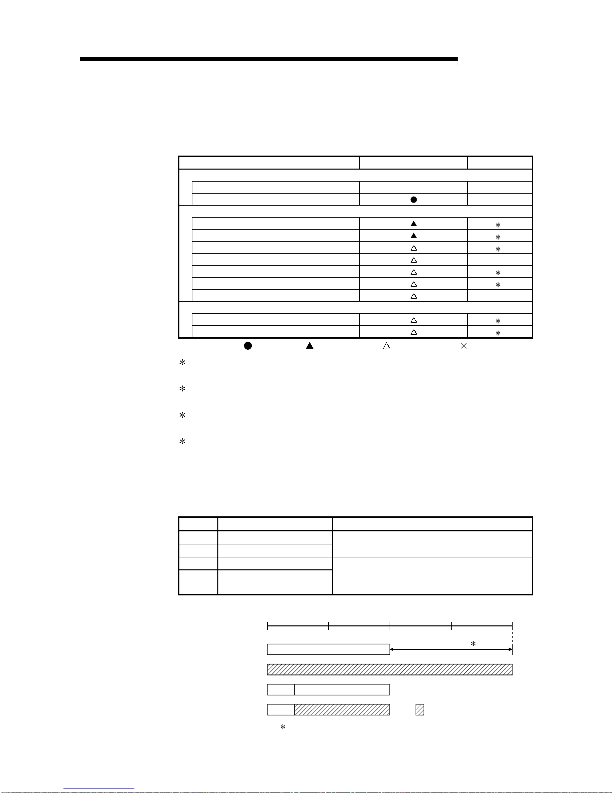
2.1.2 Setting items
(1) Table 2.1 shows the setting items on the master module of the remote master
station (MR) and the parameter setting items on GX Developer.
Table 2.1 Remote master station setting items
Setting items Remote master station (MR) Reference
Network module switch
STATION NO. 0 Section 4.2.1
MODE Section 4.2.2
Parameter setting on GX Developer
MELSECNET/H Ethernet module count setting
Network type
MELSECNET/H
(Remote master station)
Section 5.1.1
Starting I/O No. Section 5.1.2
Network No. Section 5.1.2
Total stations Section 5.1.2
Group No. —
Mode Section 5.1.2
Common parameters Section 5.1.3
Auxiliary setting Section 5.1.4
Station specific parameters —
Refresh parameters Section 5.1.5
Valid module during other station access Section 5.1.6
Interlink transmission parameters —
Routing parameters 1
: Always set,
:
Default setting, : Set as needed, : No need to set
1: Refer to the "Q Corresponding MELSECNET/H Network System Reference
Manual (PLC to PLC Network) (SH-080049)".
2
2 - 3 2 - 3
MELSEC-Q
2 SYSTEM CONFIGURATION
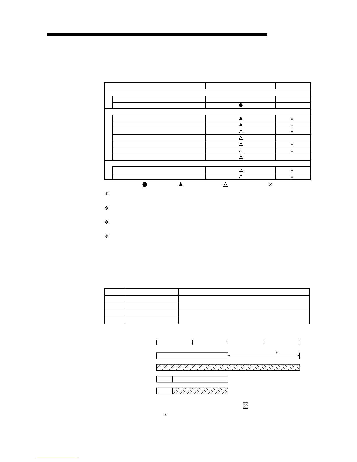
(2) Table 2.2 shows the setting items on the remote I/O module of the remote I/O
station (R) and the parameter setting items on the GX Developer.
Table 2.2 Remote I/O station setting items
Setting items Remote I/O station (R) Reference
Network module switch
STATION NO. 1 to 64 Section 4.2.2
MODE Section 4.2.2
Parameter setting on GX Developer
PLC system settin g 2
PLC RAS setting 2
I/O assignment 2
Operation setting Section 5.2.1
Ethernet setting 3
CC-Link setting 4
Remote password setting Section 7.12
GX Configurator setting
Initial setting 5
Auto refresh setting 5
: Always set,
:
Default setting, : Set as needed, : No need to set
2 : Refer to "QCPU U ser 's Manua l ( Fun ct io nal Explanation: Prog r a m Fund a men tal s)
(SH-080484ENG)".
3 : Refer to "Q Corresponding Ethernet Interface Module User's Manual (Basic) (SH-
080009)". Note that interrupt setting is not available.
4 : Refer to "CC-Link System Master/Local Module User's Manual (SH-080394E)".
Note that inte rr up t sett in g i s not av ai la ble .
5 : Refer to the user's manual of the corresponding intelligent function module.
2.1.3 Available device ranges
The remote I/O network can use the following device ranges within each network
module.
These device ranges indicate the remote master station.
Device Range setting Other
LB 0H to 3FFFH (16384 points)
LW 0H to 3FFFH (16384 points)
—
LX 0H to 1FFFH (8192 points)
LY 0H to 1FFFH (8192 points)
The device range (excluding that of I/O module mounted on the host
station) should be assigned to each network module.
: Available device range
B/W
X/Y
Actual I/O
LX/LY
CPU module
LB/LW
CPU module
Extended 1
0
3FFF
H
2000
H
3000
H
(4096)
1000
H
(8192) (12288) (16383)
Network module
Network module
Actual I/O
1: Expandable by changing from [PLC parameters] - [Device settings]
2 - 4 2 - 4
MELSEC-Q
2 SYSTEM CONFIGURATION
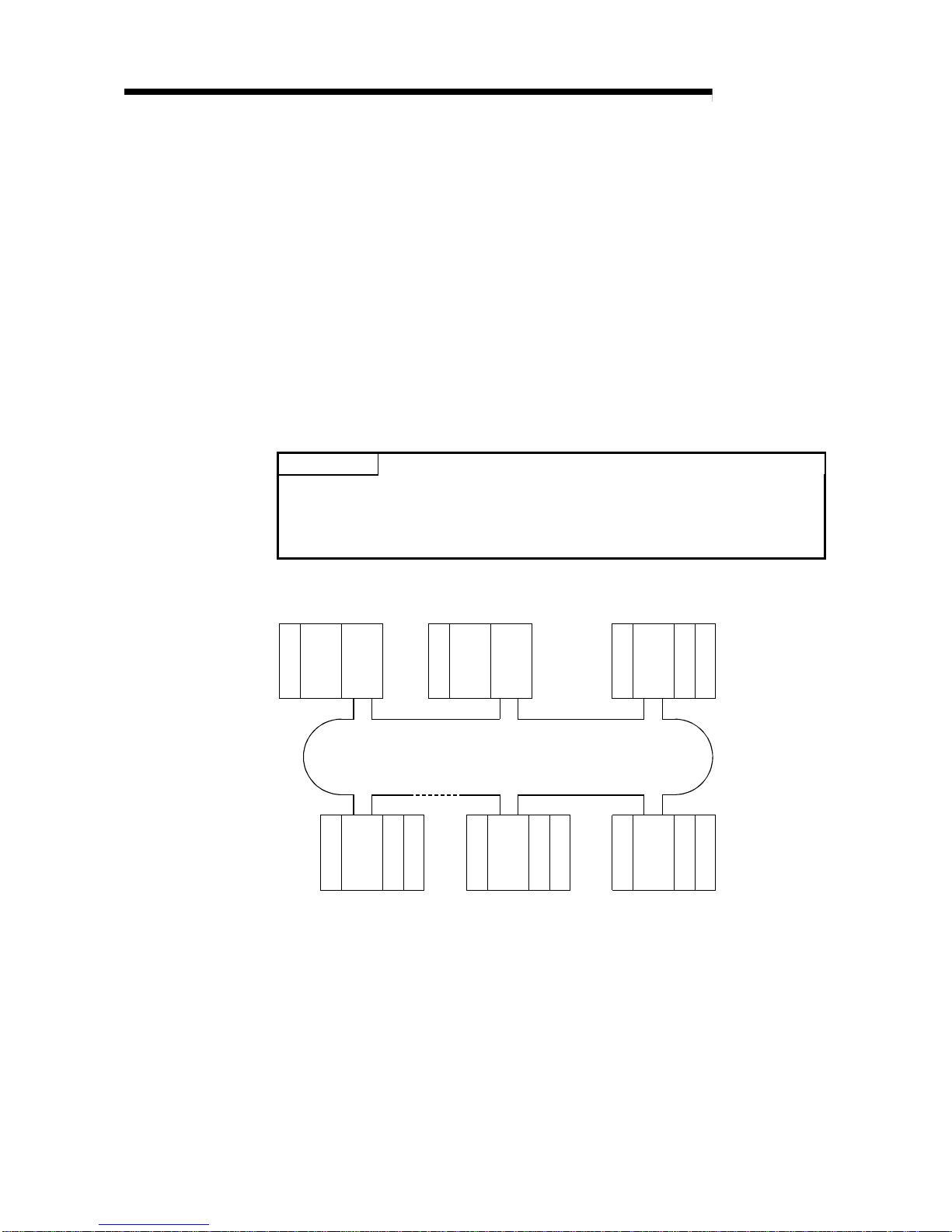
2.2 Multiple Remote I/O Network (QnPHCPU Only)
2.2.1 Configuration
A multiplexed remote I/O network system includes a multiplexed remote master station
and a multiplexed remote sub-master station. The multiplexed remote sub-master
station takes control of remote I/O stations when the multiplexed remote master station
fails.
Always assign station No. 0 to the multiplexed remote master station.
It is allowed to assign any of station number 1 to 64 to the multiplexed remote submaster station, provided that the number does not overlap with that of remote I/O
station.
63 remote I/O stations can be connected in an optical loop system, 31 stations in a
coaxial bus system.
POINT
Only the QnPHCPU is the CPU module that works as a multiplexed remote master
station and multiplexed remote sub-master station.
The Q02CPU, Q02HCPU, Q06HCPU, Q12HCPU and Q25HCPU do not work as a
multiplexed remote master station and multiplexed remote sub-master station.
QnPH
CPU
QJ71
LP21
I/OQJ72
LP25
I/O
I/OQJ72
LP25
I/O I/OQJ72
LP25
I/OI/OQJ72
LP25
I/O
QnPH
CPU
QJ71
LP21
Station No. 0
(Multiplexed remote
master station)
Power supply
Station No. 1
(Multiplexed remote
sub-master station)
Station No. 2
(Remote I/O station)
Power supply
Optical fiber cable
Station No. 64
(Remote I/O station)
Station No. 4
(Remote I/O station)
Station No. 3
(Remote I/O station)
Power supply
Power supply
Power supply
Power supply
Up to 63 remote I/O stations can be connected in an optical loop system.
Up to 31 stations can be connected in a coaxial bus system.
2 - 5 2 - 5
MELSEC-Q
2 SYSTEM CONFIGURATION
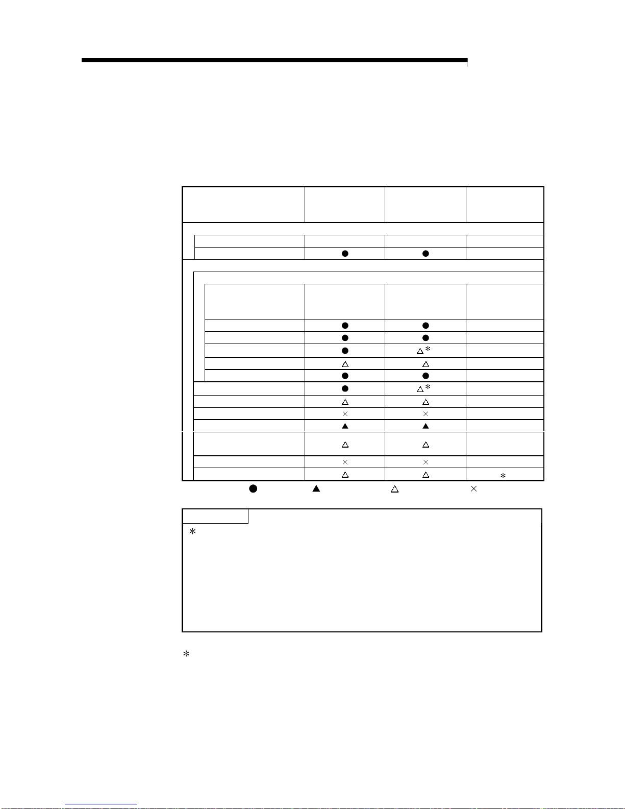
2.2.2 Setting items
(1) Table 2.3 lists the parameter setting items of the multiplexed remote master
station (DM
R
) and multiplexed remote sub-master station (DSMR).
Table 2.3 Setting Items of Multiplex ed R emote Master Stati on and
Multiplexed Remote Sub-Master Station
Setting item
Multiplexed remote
master station (DM
R
)
Multiplexed remote
sub-master station
(DSM
R
)
Reference
Network module switch
STATION NO. 0 1 to 64 Section 4.2.1
MODE Section 4.2.1
Parameter setting on GX Developer
MELSECNET/H Ethernet module count setting
Network type MELSECNET/H
(Multiplexed remote
master station)
MELSECNET/H
(Multiplexed remote
sub-master station)
Section 5.1.1
Starting I/O Section 5.1.2
Network No. Section 5.1.2
Total stations
1
Section 5.1.2
Group No. Section 5.1.2
Mode Section 5.1.2
Common parameters
1
Section 5.1.3
Auxiliary setting Section 5.1.4
Station specific parameters —
Refresh parameters Section 5.1.5
Valid module during other
station access
Section 5.1.6
Interlink transmission parameter —
Routing parameters 2
: Always set,
:
Default setting, : Set as needed, : No need to set
POINT
1: Set Total stations and common parameters of the multiplexed remote sub-
master station when using the multiplexed remote sub-master station to
resume the network. The settings must be the same as those of the
multiplexed remote master station.
For example, if the multiplexed remote master station is powered off and then
on during network control by the multiplexed remote sub-master station, the
multiplexed remote sub-master station resumes networking as a master
operating station.
2 : Refer to the "Q Corresponding MELSECNET/H Network System Reference
Manual (PLC to PLC Network) (SH-080049)".
2 - 6 2 - 6
MELSEC-Q
2 SYSTEM CONFIGURATION
(2) Table 2.4 lists the setting items can be set on a remote I/O module operating as a
remote I/O station (R) and the parameter setting items can be set from GX
Developer.
Table 2.4 Setting Items of Remote I/O Station
Setting item Remote I/O station ( R )
Reference
Network module main module switch
STATION NO. 1 to 64 Section 4.2.2
MODE Section 4.2.2
Parameter setting
PLC system settin g
3
PLC RAS setting
3
I/O assignment
3
Operation setting
Section 5.1.2
Ethernet setting
4
CC-Link setting
5
Remote password setting
Section 7.12
GX Configurator setting
Initial setting
6
Auto refresh setting
6
: Always set,
:
Default setting, : Set as needed, : No need to set
3 : Refer to "QCPU U ser 's Manua l ( Fun ct io nal Explanation: Prog r a m Fund a men tal s)
(SH-080484ENG)".
4 : Refer to "Q Corresponding Ethernet Interface Module User's Manual (Basic) (SH-
080009)". Note that interrupt setting is not available.
5 : Refer to "CC-Link System Master/Local Module User's Manual (SH-080394E)".
Note that inte rr up t sett in g i s not av ai la ble .
6 : Refer to the user's manual of the corresponding intelligent function module.
2.2.3 Available device ranges
The remote I/O network can use the following ranges of devices inside network
modules.
Device Available Range Others
LB 0H to 3FFFH (16384 points)
LW 0H to 3FFFH (16384 points)
—
LX 0H to 1FFFH (8192 points)
LY 0H to 1FFFH (8192 points)
The device range (excluding that of I/O module
mounted on the host station) should be assigned to
each network module.
B/W
: Available device range
X/Y
Actual I/O
LX/LY
CPU module
LB/LW
CPU module
0
3FFF
H
2000
H
3000
H
(4096)
1000
H
(8192) (12288) (16383)
Network module
Network module
Actual I/O
1: Expandable by changing from [PLC parameters] - [Device settings]
Extended 1
2 - 7 2 - 7
MELSEC-Q
2 SYSTEM CONFIGURATION
2.3 Multiplexed Remote I/O Network for Redundant System (QnPRHCPU Only)
2.3.1 Configuration
The redundant system including QnPRHCPU utilizes the multiplexed remote I/O
network system in order to control I/O modules and intelligent function modules.
In the multiplexed remote I/O network system for the redundant system, the network
module on the side of the control QnPRHCPU (started up as a control system) acts as
a multiplexed remote master station and controls remote I/O stations, while the
network module mounted on the side of the standby QnPRHCPU performs the submaster operation as a multiplexed remote sub-master station.
When the control system CPU or the multiplexed remote master station goes down,
the multiplexed remote sub-master station switches from "standby" to "control" and
takes over the control of the remote I/O stations.
Make sure to assign No.0 to the network module mounted on the system A, i.e., the
system to which the system A connector of tracking cable is connected within the
redundant system.
For station No. of the multiplexed remote sub-master station, set any of No. 1 to 64,
which should not be overlapped with any of remote I/O stations.
The number of remote I/O stations connectable to a multiplexed remote I/O network for
the redundant system is 63 in the optical loop system and 31 in the coaxial bus
system.
POINT
The CPU module applicable for the multiplexed remote master or sub-master
station in the redundant system is the QnPRHCPU only.
The Q02CPU, Q02HCPU, Q06HCPU, Q12HCPU, Q25HCPU, Q12PHCPU and
Q25PHCPU are not applicable.
Power supply
QnPRH
CPU
QJ71
LP21
Station No. 2
(Remote I/O station)
I/O
QJ72
LP25
I/O
Station No. 0
(Multiplexed remote master station)
I/O
QJ72
LP25
I/O
Station No. 4
(Remote I/O station)
I/O
QJ72
LP25
I/O
Station No. 3
(Remote I/O station)
Power supply
I/O
QJ72
LP25
I/O
Station No. 64
(Remote I/O station)
Optical fiber cable
Station No. 1
(Multiplexed remote sub-master station)
QnPRH
CPU
QJ71
LP21
Tracking cable
System
A
Power supply
Power supply
Power supply
Power supply
System
B
In the optical loop system, up to 63 remote I/O stations can be connected.
Connection of up to 31 stations is allowed for the coaxial bus system.
 Loading...