


PROFIBUS-DP Slave Module
User's Manual
-QJ71PB93D

SAFETY PRECAUTIONS
(Read these precautions before using this product.)
Before using this product, please read this manual and the relevant manuals carefully and pay full
attention to safety to handle the product correctly.
The precautions given in this manual are concerned with this product only. For the safety precautions of
the programmable controller system, refer to the user’s manual for the CPU module used.
In this manual, the safety instructions are classified into two levels: " WARNING" and " CAUTION".
! !
Under some circumstances, failure to observe the precautions given under " CAUTION" may lead to
serious consequences.
Observe the precautions of both levels because they are important for personal and system safety.
Make sure that the end users read this manual and then keep the manual in a safe place for future
reference.
!
[DESIGN PRECAUTIONS]
!
WARNING
When a communication error occurs on PROFIBUS-DP, the status of the faulty station is as
follows. Configure an interlock circuit in the sequence program using the communication status
information (input X1) so that the system can operate safely.
Failure to do so may result in an accident due to an incorrect output or malfunction.
(1) The input data from the master station remains unchanged from the data prior to the
communication error.
(2) When the master station becomes faulty, the output status of the QJ71PB93D will be as in
the parameter settings of the master station.
(3) When any QJ71PB93D is down, the output state of other slave stations will be in
accordance with the parameter settings of the master station.
Do not output (turn on) the "Use prohibited" signal as the output signal to an intelligent function
module from the CPU module.
Writing data into the "system area" or outputting a signal for "Use prohibited" may cause system
malfunction in the programmable controller.
A - 1 A - 1
!
CAUTION
Do not install the PROFIBUS cables together with the main circuit lines or power cables.
Keep a distance of 100mm or more between them.
Failure to do so may result in malfunction due to noise.
[INSTALLATION PRECAUTIONS]
!
CAUTION
Use the programmable controller under the environment specified in the user's manual of the
CPU module used.
Failure to do so may result in electric shock, fire, malfunction, or damage to or deterioration of
the product.
To mount the module, while pressing the module mounting lever in the lower part of the module,
fully insert the module fixing projection(s) into the hole(s) in the base unit and press the module
until it snaps into place.
Incorrect mounting may cause malfunctions, a failure, or a drop of the module.
When using the programmable controller in an environment of frequent vibrations, fix the
module with a screw.
Tighten the screws within the range of specified torque.
If the screws are loose, it may cause the module to fallout, short circuits, or malfunction.
If the screws are tightened too much, it may cause damage to the screw and/or the module,
resulting in fallout, short circuits or malfunction.
Shut off the external power supply (all phases) used in the system before mounting or removing
the module.
Failure to do so may result in damage to the product.
Do not directly touch any conductive parts and electronic components of the module.
Doing so can cause malfunction or failure of the module.
[WIRING PRECAUTIONS]
!
WARNING
Shut off the external power supply (all phases) used in the system before wiring the PROFIBUS
cables.
Failure to do so may result in failure or malfunctions of the module.
Be sure to shut off all phases of the external power supply used by the system before wiring
PROFIBUS cables.
Failure to do so may result in failure or malfunctions of the module.
A - 2 A - 2

!
CAUTION
Prevent foreign matter such as dust or wire chips from entering the module. Such foreign matter
can cause a fire, failure, or malfunction.
Place the PROFIBUS cables in a duct or clamp them.
If not, dangling cables may swing or inadvertently be pulled, resulting in damages to the module
or cables or malfunctions due to poor contact.
When disconnecting the PROFIBUS cable from the module, do not pull by holding the cable
section. To disconnect the cable, make sure to hold the connector which is coupled with the
module. Do not attempt to pull the cable to disconnect it from the module. It could damage the
module or the cable, or cause malfunction due to a poor contact of the cable.
A protective film is attached to the top of the module to prevent foreign matter, such as wire
chips, from entering the module during wiring.
Do not remove the film during wiring.
Remove it for heat dissipation before system operation.
[STARTING AND MAINTENANCE PRECAUTIONS]
!
WARNING
Shut off the external power supply (all phases) used in the system before cleaning the module
or retightening the connector screws or module fixing screws.
Failure to do so may result in electric shock or cause the module to fail or malfunction.
Undertightening can cause drop of the screw, short circuit, or malfunction.
Overtightening can damage the screw and/or module, resulting in drop, short circuit, or
malfunction.
!
CAUTION
Do not disassemble or modify the modules.
Doing so may cause failure, malfunction, injury, or a fire.
Use any radio communication device such as a cellular phone or PHS (Personal Handy-phone
System) more than 25cm (9.85 inches) away in all directions from the programmable controller.
Failure to do so may cause malfunction.
Shut off the external power supply (all phases) used in the system before mounting or removing
the module.
Failure to do so may cause the module to fail or malfunction.
After the first use of the product, do not mount/remove the module to/from the base unit more
than 50 times (IEC 61131-2 compliant).
Exceeding the limit of 50 times may cause malfunction.
Before handling the module, touch a grounded metal object to discharge the static electricity
from the human body.
Failure to do so may cause the module to fail or malfunction.
A - 3 A - 3

[DISPOSAL PRECAUTIONS]
!
CAUTION
When disposing of this product, treat it as industrial waste.
A - 4 A - 4

CONDITIONS OF USE FOR THE PRODUCT
(1) Mitsubishi programmable controller ("the PRODUCT") shall be used in conditions;
i) where any problem, fault or failure occurring in the PRODUCT, if any, shall not lead to any major or serious accident;
and
ii) where the backup and fail-safe function are systematically or automatically provided outside of the PRODUCT for the
case of any problem, fault or failure occurring in the PRODUCT.
(2) The PRODUCT has been designed and manufactured for the purpose of being used in general industries.
MITSUBISHI SHALL HAVE NO RESPONSIBILITY OR LIABILITY (INCLUDING, BUT NOT LIMITED TO ANY AND ALL
RESPONSIBILITY OR LIABILITY BASED ON CONTRACT, WARRANTY, TORT, PRODUCT LIABILITY) FOR ANY
INJURY OR DEATH TO PERSONS OR LOSS OR DAMAGE TO PROPERTY CAUSED BY the PRODUCT THAT ARE
OPERATED OR USED IN APPLICATION NOT INTENDED OR EXCLUDED BY INSTRUCTIONS, PRECAUTIONS, OR
WARNING CONTAINED IN MITSUBISHI'S USER, INSTRUCTION AND/OR SAFETY MANUALS, TECHNICAL
BULLETINS AND GUIDELINES FOR the PRODUCT.
("Prohibited Application")
Prohibited Applications include, but not limited to, the use of the PRODUCT in;
• Nuclear Power Plants and any other power plants operated by Power companies, and/or any other cases in which the
public could be affected if any problem or fault occurs in the PRODUCT.
• Railway companies or Public service purposes, and/or any other cases in which establishment of a special quality
assurance system is required by the Purchaser or End User.
• Aircraft or Aerospace, Medical applications, Train equipment, transport equipment such as Elevator and Escalator,
Incineration and Fuel devices, Vehicles, Manned transportation, Equipment for Recreation and Amusement, and
Safety devices, handling of Nuclear or Hazardous Materials or Chemicals, Mining and Drilling, and/or other
applications where there is a significant risk of injury to the public or property.
Notwithstanding the above restrictions, Mitsubishi may in its sole discretion, authorize use of the PRODUCT in one or
more of the Prohibited Applications, provided that the usage of the PRODUCT is limited only for the specific
applications agreed to by Mitsubishi and provided further that no special quality assurance or fail-safe, redundant or
other safety features which exceed the general specifications of the PRODUCTs are required. For details, please
contact the Mitsubishi representative in your region.
A - 5 A - 5
REVISIONS
* The manual number is given on the bottom left of the back cover.
Print Date * Manual Number Revision
Mar., 2002 SH(NA)-080318E-A First Edition
Apr., 2004 SH(NA)-080318E-B
Correction
Section 2.1, 2.3, 3.1, 3.3.2, 3.5, 5.2.1, 7.3.1, 7.3.2, 9.5
Addition
SAFETY PRECAUTIONS
Aug., 2004 SH(NA)-080318E-C
Correction
SAFETY PRECAUTIONS, Section 5.2.1, Chapter 7, Section 8.1, 8.2
Aug., 2006 SH(NA)-080318E-D
Correction
SAFETY PRECAUTIONS, Conformation to the EMC Directive and Low
Voltage Instruction, Section 2.3, 3.1 to 3.5, 5.1, 5.5, 5.7.2, 8.1, 8.2, 9.5,
Appendix 2
Addition
About Manuals, About the Generic Terms and Abbreviations, Meanings
and Definitions of Terms, Section 1.1, 2.1, 2.2, 4.1.1 to 4.1.4, 5.2.1 to
5.2.3, 5.6, 5.7.1, Chapter 6, Section 6.1, 6.2, 7.1 to 7.4, Chapter 8,
Appendix 1
New Addition
Section 5.3
Section number change
Section 3.5 5.2, 3.5.1 to 3.5.3 5.2.1 to 5.2.3, 3.6 3.5, 5.1.1
5.2, 5.2 to 5.5 5.4 to 5.7
Jul., 2007 SH(NA)-080318E-E
Change of a term
"PLC" was changed to "programmable controller".
Correction
About the Generic Terms and Abbreviations, Section 2.1, 2.3, 3.1,
3.4.1, 5.5, 8.2 to 8.3, Appendix 1
Addition
Section 5.3.1, 5.4.1, 7.3.1, 7.3.2, 9.4
Section number change
Chapter 8(3) Section 8.1, Section 8.1 to 8.2 8.2 to 8.3
Nov., 2007 SH(NA)-080318E-F
Correction
Section 3.3.2, 3.4.1, 7.3.1
A - 6 A - 6
* The manual number is given on the bottom left of the back cover.
Print Date * Manual Number Revision
Jun., 2015 SH(NA)-080318E-G
Correction
SAFETY PRECAUTIONS, COMPLIANCE WITH EMC AND LOW
VOLTAGE DIRECTIVES, ABOUT THE GENERIC TERMS AND
ABBREVIATIONS, MEANINGS AND DEFINITIONS OF THE TERMS,
Section 2.1, 2.4, Chapter 3, Section 4.1.2, 4.1.4, Chapter 5, Section
7.3.1, 7.3.2, 8.1, Chapter 9, Appendix 2
Addition
CONDITIONS OF USE FOR THE PRODUCT, Section 2.2
Section number change
Section 2.2 to 2.3 Section 2.3 to 2.4
Sep., 2018 SH(NA)-080318E-H
Correction
Related Manuals, Section 2.1, 2.4
Japanese Manual Version SH-080317-G
This manual confers no industrial property rights or any rights of any other kind, nor does it confer any patent
nses. Mitsubishi Electric Corporation cannot be held responsible for any problems involving industrial property
lice
rights which may occur as a result of using the contents noted in this manual.
2002 MITSUBISHI ELECTRIC CORPORATION
A - 7
A - 7

INTRODUCTION
Thank you for purchasing the Mitsubishi Electric Programmable Controller MELSEC-Q Series.
Before using the equipment, please read this manual carefully to develop full familiarity with the functions
and performance of the graphic operation terminal you have purchased, so as to ensure correct use.
Please forward a copy of this manual to the end user.
CONTENTS
SAFETY PRECAUTIONS ..............................................................................................................................A -
CONDITIONS OF USE FOR THE PRODUCT .............................................................................................A -
REVISIONS ....................................................................................................................................................A -
INTRODUCTION ............................................................................................................................................A -
CONTENTS ....................................................................................................................................................A -
MANUALS ..................................................................................................................................................... A -11
COMPLIANCE WITH EMC AND LOW VOLTAGE DIRECTIVES .............................................................. A -11
ABOUT THE GENERIC TERMS AND ABBREVIATIONS .......................................................................... A -12
MEANINGS AND DEFINITIONS OF THE TERMS ..................................................................................... A -13
PRODUCT CONFIGURATION .................................................................................................................... A -14
1 OVERVIEW 1- 1 to 1- 3
1
5
6
8
8
1.1 QJ71PB93D Features ............................................................................................................................. 1 - 2
2 SYSTEM CONFIGURATION 2- 1 to 2- 7
2.1 Applicable Systems .................................................................................................................................. 2- 1
2.2 When Used in a Redundant System ....................................................................................................... 2-
2.3 Precautions for Configuring a System ..................................................................................................... 2-
2.4 Checking Serial No. and Function Version ............................................................................................. 2-
4
4
5
3 SPECIFICATIONS 3- 1 to 3-22
3.1 Performance Specifications ..................................................................................................................... 3- 1
3.2 Network Configuration ............................................................................................................................. 3-
2
3.3 I/O Signal .................................................................................................................................................. 3- 3
3.3.1 I/O signal list ...................................................................................................................................... 3-
3.3.2 I/O signal detail description .............................................................................................................. 3-
3
4
3.4 Buffer Memory List ................................................................................................................................. 3-14
3.4.1 Buffer memory/configuration ............................................................................................................ 3-14
3.4.2 Buffer memory detail description ..................................................................................................... 3-15
3.5 Operation Mode ...................................................................................................................................... 3-22
4 FUNCTIONS 4- 1 to 4-12
4.1 Functions for Communication with Class 1 Master ................................................................................ 4- 1
4.1.1 I/O data communication function ...................................................................................................... 4-
1
4.1.2 I/O data separation prevention function ........................................................................................... 4- 4
4.1.3 Global control function ...................................................................................................................... 4-
7
4.1.4 Word data swapping function .......................................................................................................... 4-10
A - 8 A - 8

5 SETTINGS AND PROCEDURES BEFORE SYSTEM OPERATION 5- 1 to 5-25
5.1 Procedures before Operation .................................................................................................................. 5- 1
5.2 Parameter Setting to Master Station ....................................................................................................... 5-
5.2.1 Data module setting .......................................................................................................................... 5-
5.2.2 Data assignment mode setting ......................................................................................................... 5-
2
4
8
5.2.3 Swap setting ..................................................................................................................................... 5-11
5.3 Parameter Setting to Slave Station (QJ71PB93D) ................................................................................ 5-13
5.3.1 Setting FDL address and automatic refresh parameters ................................................................ 5-13
5.4 Installation ............................................................................................................................................... 5-18
5.4.1 Handling precautions ....................................................................................................................... 5-18
5.4.2 Installation environment ................................................................................................................... 5-18
5.5 Part Names ............................................................................................................................................. 5-19
5.6 Execution Method for Self-diagnosis ...................................................................................................... 5-20
5.7 Wiring....................................................................................................................................................... 5-22
5.7.1 PROFIBUS cable wiring................................................................................................................... 5-22
5.7.2 Wiring precautions ........................................................................................................................... 5-24
6 TRANSMISSION DELAY TIME 6- 1 to 6- 5
6.1 Transmission Delay Time of Output Receive (Master station QJ71PB93D) ..................................... 6- 4
6.2 Transmission Delay Time of Input Send (QJ71PB93D Master station) ............................................ 6-
5
7 PROGRAMMING 7- 1 to 7-22
7.1 Communication Sequence ..................................................................................................................... 7 - 1
7.2 Station Number Setting ........................................................................................................................... 7 -
7.3 Communication of I/O Data .................................................................................................................... 7 -
7.3.1 LUMP mode ..................................................................................................................................... 7 -
3
5
5
7.3.2 DIVIDED mode ................................................................................................................................ 7 -14
7.4 Global Control-driven Program Execution ............................................................................................ 7 -22
8 DEDICATED INSTRUCTIONS 8- 1 to 8- 4
8.1 Precautions for Execution of Dedicated Instructions ............................................................................. 8 - 1
8.2 G.BBLKRD .............................................................................................................................................. 8 -
8.3 G.BBLKWR ............................................................................................................................................. 8 -
3
4
9 TROUBLESHOOTING 9- 1 to 9- 5
9.1 LED-indicated Error Causes and Actions ............................................................................................... 9- 1
9.2 Checks and Actions for Network-related Faults ...................................................................................... 9-
9.3 Causes of Failure to Make Normal Data Communication and Actions to Be Taken ............................. 9-
9.4 Error Code List ......................................................................................................................................... 9-
9.5 Checking the QJ71PB93D Status by System Monitor of GX Works2 ................................................... 9-
1
2
3
4
A - 9 A - 9

APPENDICES APPX - 1 to APPX - 2
Appendix 1 External Dimensions .......................................................................................................... APPX - 1
INDEX INDEX - 1 to INDEX - 3
A - 10 A - 10

MANUALS
The following are manuals related to this product.
Request for the manuals as needed according to the chart below.
Related Manuals
Manual Name Manual Number
PROFIBUS-DP Master Module User's Manual
Describes the overview, system configuration, specifications, functions, procedures before system
operation, programming and dedicated instructions of the QJ71PB92V.
(Sold separately)
PROFIBUS-DP Interface Module User's Manual
Describes the overview, system configuration, specifications, functions, procedures before system
operation, programming and dedicated instructions of the QJ71PB92D.
(Sold separately)
SH-080572ENG
(13JR84)
SH-080127
(13JR22)
GX Configurator-DP Version7 Operating Manual
Explains the overview, installation method, screen operations, etc. of GX Configurator-DP Version 7.
(Sold separately)
COMPLIANCE WITH EMC AND LOW VOLTAGE DIRECTIVES
(1) Method of ensuring compliance
To ensure that Mitsubishi Electric programmable controllers maintain EMC and
Low Voltage Directives when incorporated into other machinery or equipment,
certain measures may be necessary. Please refer to one of the following
manuals.
• QCPU User's Manual (Hardware Design, Maintenance and Inspection)
• Safety Guidelines
(This manual is included with the CPU module or base unit.)
The CE mark on the side of the programmable controller indicates compliance
with EMC and Low Voltage Directives.
(2) Additional measures
No additional measures are necessary for the compliance of this product with
EMC and Low Voltage Directives.
SH-080579ENG
(13JU54)
A - 11 A - 11
ABOUT THE GENERIC TERMS AND ABBREVIATIONS
Unless otherwise specified, this manual uses the following generic terms and
abbreviations to describe the Type QJ71PB93D PROFIBUS-DP slave module.
Generic Term/Abbreviation Description of the abbreviation/general terms
QJ71PB93D Abbreviation for the model QJ71PB93D PROFIBUS-DP slave module.
QJ71PB92V Abbreviation for the model QJ71PB92V PROFIBUS-DP master module.
Generic term for the Q00JCPU, Q00CPU, Q00UJCPU, Q00UCPU, Q01CPU,
Q01UCPU, Q02CPU, Q02HCPU, Q02PHCPU, Q02UCPU, Q03UDCPU, 03UDVCPU,
Q03UDECPU, Q04UDHCPU, Q04UDVCPU, Q04UDEHCPU, Q06HCPU,
CPU module
GX Works2 The product name of the software package for the MELSEC programmable controllers
GX Configurator-DP
PROFIBUS-DP Abbreviation of PROFIBUS-DP network.
BBLKRD Abbreviation for G.BBLKRD.
BBLKWR Abbreviation for G.BBLKWR.
Q06PHCPU, Q06UDHCPU, Q06UDVCPU, Q06UDEHCPU, Q10UDHCPU,
Q10UDEHCPU, Q12HCPU, Q12PHCPU, Q13UDHCPU, Q13UDVCPU,
Q13UDEHCPU, Q20UDHCPU, Q20UDEHCPU, Q25HCPU, Q25PHCPU,
Q26UDHCPU, Q26UDVCPU, Q26UDEHCPU, Q50UDEHCPU, and Q100UDEHCPU
modules
The configurator for the QJ71PB93D
Generic term for the product name SWnD5C-PROFID-E ("n" means version 7 or
later.)
A - 12 A - 12

MEANINGS AND DEFINITIONS OF THE TERMS
The terms used in this manual have the following meanings and definitions.
Term Definition
A basic version of PROFIBUS-DP.
The following functions are executable:
PROFIBUS-DPV0
PROFIBUS-DPV1
PROFIBUS-DPV2
Class 1 master station A device exchanging I/O data with a slave stations. (QJ71PB92V, QJ71PB92D, etc.)
Class 2 master station
Slave station
Repeater A device used to connect different segments of PROFIBUS-DP.
Bus terminator
Configuration tool
GSD file
Station number
Slave parameter
I/O configuration information
(Data module)
Input data
Output data
Global control
Communication watchdog
timer
Extended diagnostic error
information
Bus cycle time
Module watchdog timer Watchdog timer in the QJ71PB93D.
I/O data exchange
Diagnostic information notification
etc.
A PROFIBUS-DP version for which the following functions have been added to the
basic functionality of PROFIBUS-DPV0.
Acyclic communication
Alarm function
etc.
A PROFIBUS-DP version for which the following functions have been added to the
PROFIBUS-DPV1 functionality.
Time stamping
etc.
A device that communicates with slave stations and checks their station number
settings and/or operation states.
The Class 2 master station is used as a master station for supervising the network,
which can start, maintain, and diagnose the system.
A device that exchanges I/O data with a Class 1 master station. (QJ71PB93D,
ST1H-PB, etc.)
A terminating resistor that is connected to either end of each segment on
PROFIBUS-DP.
Software used to set slave parameters, etc. and to write them to a master station.
(GX Configurator-DP, etc.)
An electronic file that contains parameters of a slave station.
The GSD file is used to set up the slave parameters on configuration tool.
The numbers assigned to a master station and slave stations.
The station number is set within the range from 0 to 125.
The parameter for a slave station, which is set on the master station.
The setting items are described on the GSD File.
Information on I/O configuration of a slave station.
Data sent by the QJ71PB93D and received by the master station. (data input by the
master station.)
Data sent by the master station and received by the QJ71PB93D. (data output by the
master station.)
This function enables synchronization command transmission for I/O data from a
Class 1 master station to slave stations.
Watchdog timer set in the slave parameter of the master station.
Diagnostic information specific to each slave station.
Each of slave stations notifies of it to the master station when an error is detected.
PROFIBUS-DP processing time for the master station to perform cyclic transfer with
each slave station.
A - 13 A - 13

PRODUCT CONFIGURATION
The product configuration of this product is given in the table below.
QJ71PB93D QJ71PB93D PROFIBUS-DP slave module. 1
Model Product name Quantity
A - 14 A - 14

r
1 OVERVIEW
MELSEC-Q
1 OVERVIEW
Class 1 master station
(QJ71PB92V)
Bus terminator
This is the user's manual for the QJ71PB93D PROFIBUS-DP slave module (hereafter
abbreviated as "QJ71PB93D"), which is used to connect a MELSEC-Q series
programmable controller to a PROFIBUS-DP network.
The QJ71PB93D operates as a slave station in the PROFIBUS-DP network.
Slave station (QJ71PB93D) Slave station (MELSEC-ST system) Slave station
ST1PSD
ST1H-PB
RUN
SYS
AUX
RELEASE
RESET
PROFIBU S I/ F
ST1PDD
ERR
RUN ERR
RUN ERR
RUN
ERR
RUN ERR RUN ERR
11 21
11 21
.
AUX
Bus terminato
1
1 - 1 1 - 1
1 OVERVIEW
1.1 QJ71PB93D Features
1
MELSEC-Q
(1) Conformance with EN50170 Volume 2 (Part 1, 2, 3, 4, 8)
The module conforms with EN50170 Volume 2 (Part 1, 2, 3, 4, 8) and can
communicate with the master station as a PROFIBUS-DP slave station.
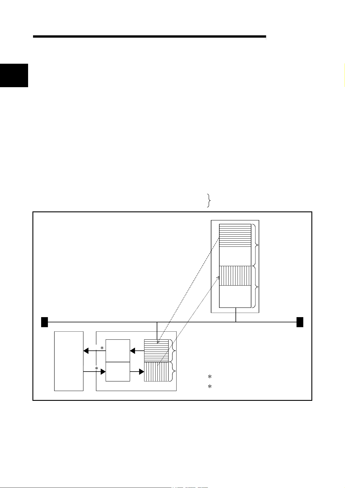
(2) I/O data communication with class 1 master station
The module can communicate I/O data with the class 1 master station (master
station that makes data communication cyclically with a slave station) of
PROFIBUS-DP.
The QJ71PB93D supports the PROFIBUS-DPV0 function.
PROFIBUS-DPV1 and PROFIBUS-DPV2, which are extended versions of
PROFIBUS-DP, are not supported.
(a) Available data size
The QJ71PB93D can handle the following size of data. (Refer to Section
4.1.1)
Input data : Max. 122 words
Output data : Max. 122 words
Max. 192 words in total
Class 1 master station
Output
image
Input
image
Bus terminator Bus terminator
PROFIBUS-DP network
Buffer memory
Read 1
Write 2
CPU module QJ71PB93D (slave station)
Output
receive
area
Input
send
area
(3) Communication can be made by merely setting the master station
Output
image
Input
image
1: Reads with BBLKRD/MOV/FROM instruction
or automatic refresh
2: Writes with BBLKWR/MOV/TO instruction or
automatic refresh
parameters
After you have set the parameters at the master station, the QJ71PB93D can
make communication by merely setting the station number. (Refer to Section 5.1)
1 - 2 1 - 2

1 OVERVIEW
MELSEC-Q
(4) Swapping of I/O data
When I/O data is sent/received from/to the master station, their upper and lower
bytes can be swapped.
Though PROFIBUS-DP handles the upper and lower bytes of I/O data differently
depending on the master station type, the I/O data need not be swapped in a
sequence program. (Refer to Section 4.1.4)
(5) Start/stop of refreshing the input send area
Refreshing of send data from the QJ71PB93D to the master station is
controllable by an output signal (Y00).
Providing an interlock disables the buffer memory data from being sent to the
master station at error occurrence. (Refer to Section 4.1.1)
(6) Extended trouble notification function
Data stored in the extended trouble information area of the buffer memory can be
sent to the master station as extended trouble information
faulty, for example.
When the host is not faulty anymore, notify the master station that there is no
fault. (Refer to Section 3.4.2(9))
: Diagnostics Information (device-related trouble information set by the user as
desired)
when the host is
(7) Compatibility with global control function
Compatibility with the global control function allows the updating of I/O data at the
QJ71PB93D to be controlled from the class 1 master station using the command
(SYNC, UNSYNC, FREEZE, UNFREEZE) sent by the class 1 master. (Refer to
Section 4.1.3)
(8) Communication with class 2 master station
The following communications can be made with the class 2 master station
(master station designed for network management to perform booting,
maintenance and diagnostics) of PROFIBUS-DP.
Read from input send area/output receive area
Read of I/O configuration information
Station number change
For the way to use each function, refer to the manual of the class 2 master
station used.
(9) I/O data separation prevention
For data transmission between the CPU module and buffer memory of
QJ71PB93D, automatic refresh or dedicated instruction are used to prevent I/O
data from being separated
: The data of specified sizes are not matched with each other.
. (Refer to Section 4.1.2)
(10) Compatibility with multiple CPU system
Even when a plurality of CPU modules are installed through the multiple CPU
system, this model can be controlled by any CPU module.
1 - 3 1 - 3

2 SYSTEM CONFIGURATION
2 SYSTEM CONFIGURATION
2.1 Applicable Systems
MELSEC-Q
2
This section describes applicable systems.
(1) Mountable modules, No. of mountable modules, and mountable
base unit
(a) When mounting with a CPU module
REMARKS
When using the module with a C Controller module, refer to the user's manual for
the C Controller module.
For the CPU modules, the number of modules, and base units mountable
to the QJ71PB93D, refer to user's manual for the CPU module used.
• User's Manual for the CPU module used (Hardware Design, Maintenance
and Inspection)
2 - 1 2 - 1

2 SYSTEM CONFIGURATION
POINT
(1) There are restrictions on the number of automatic refresh parameters that can
be set for CPU modules.
For details, refer to Section 5.3.1(5).
(2) To utilize the data consistency function and dedicated instruction, use a CPU
module whose first 5 digits of the serial No. is "02092" or later.
If this function is used in any other models, I/O data may be identified as invalid
values.
(b) When mounting to remote I/O station of MELSECNET/H
The QJ71PB93D cannot be mounted to remote I/O station of the
MELSECNET/H.
Mount it next to the CPU module on the MELSECNET/H remote master
station.
(2) Compatibility with a multiple CPU system
When using the QJ71PB93D in a multiple CPU system, refer to the User's
Manual (Multiple CPU System) for CPU module used.
(a) Compatible QJ71PB93D
The function version of the QJ71PB93D has been "B" from the first release
and it supports the multiple CPU system.
(3) Compatibility with online module change
The QJ71PB93D cannot be changed online.
(4) Applicable software packages
Please configure the system by combining QJ71PB93D and software package
as follows:
GX Works2: For setting CPU module parameters and creating sequence
programs (Required)
GX Configurator-DP : For setting the QJ71PB93D station number and automatic
refresh parameter
1 GX Configurator-DP is required when using automatic refresh.
The station number can also be set on a sequence program. (Refer to Section 5.3)
MELSEC-Q
2
1
2 - 2 2 - 2
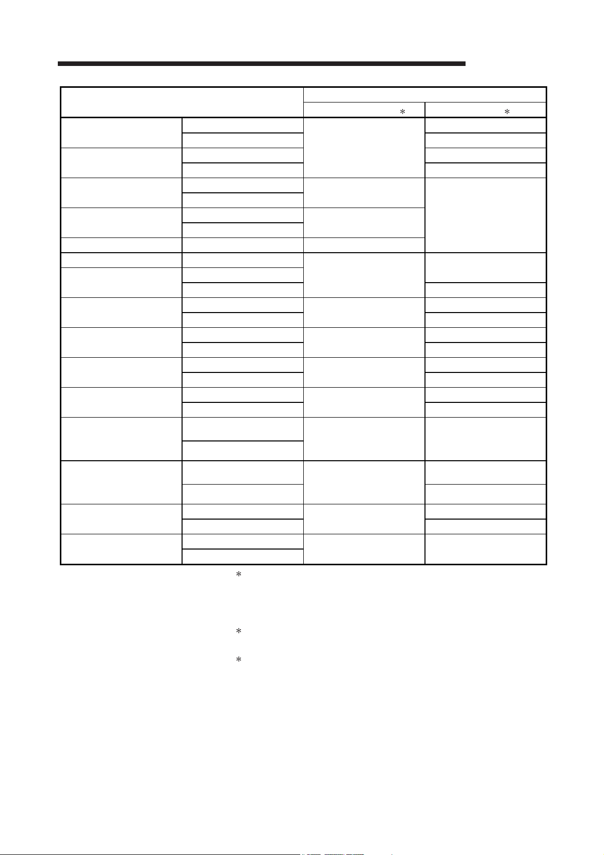
2 SYSTEM CONFIGURATION
MELSEC-Q
System
Q00J/Q00/Q01CPU
Q02/Q02H/Q06H/Q12H/
Q25HCPU
Q02PH/Q06PHCPU
Q12PH/Q25PHCPU
Q12PRH/Q25PRHCPU Redundant system Version 7.00A or later*3
Q00UJCPU Single CPU system
Q00U/Q01UCPU
Q02UCPU
Q03UD/Q04UDH/
Q06UDHCPU
Q10UDH/Q20UDHCPU
Q13UDH/Q26UDHCPU
Q03UDV/Q04UDV/
Q06UDV/Q13UDV/
Q26UDVCPU
Q03UDE/Q04UDEH/
Q06UDEH/Q13UDEH/
Q26UDEHCPU
Q10UDEH/Q20UDEHCPU
Q50UDEH/Q100UDEHCPU
Single CPU system
Multiple CPU system Version 1.14Q or later
Single CPU system Version 1.11M or later
Multiple CPU system Version 1.14Q or later
Single CPU system
Multiple CPU system
Single CPU system
Multiple CPU system
Single CPU system
Multiple CPU system Version 1.14Q or later
Single CPU system
Multiple CPU system Version 1.14Q or later
Single CPU system
Multiple CPU system Version 1.14Q or later
Single CPU system
Multiple CPU system Version 1.14Q or later
Single CPU system
Multiple CPU system Version 1.14Q or later
Single CPU system
Multiple CPU system
Single CPU system
Multiple CPU system Version 1.14Q or later
Single CPU system
Multiple CPU system Version 1.14Q or later
Single CPU system
Multiple CPU system
GX Configurator-DP1 GX Works22
Version 7.00A or later
Version 7.04E or later
Version 7.00A or later
Version 7.04E or later
Version 7.03D or later
Version 7.02C or later
Version 7.04E or later
Version 7.03D or later
Version 7.09K or later Version 1.95Z or later
Version 7.03D or later
Version 7.04E or later
Version 7.07H or later Version 1.25B or later
1 The operation mode of the QJ71PB93D cannot be changed using
GX Configurator-DP Version 7.03D or later.
Change the mode using operation mode change request area
(buffer memory address: 8CFH).
2 For how to use GX Configurator-DP and GX Works2 together,
refer to the GX Configurator-DP Operating Manual.
3 To mount the QJ71PB93D on an extension base unit, use GX
Configurator-DP Version 7.03D or later.
Software Version
Version 1.11M or later
Version 1.86Q or later
Version 1.11M or later
Version 1.11M or later
Version 1.11M or later
Version 1.11M or later
Version 1.11M or later
Version 1.11M or later
Version 1.11M or later
2 - 3 2 - 3

2 SYSTEM CONFIGURATION
2.2 When Used in a Redundant System
For the precautions on when using an extension base unit, refer to the User's Manual
(Redundant System) for the CPU module used.
2.3 Precautions for Configuring a System
(1) Precaution for station number setting
(a) If a station number different from the one of the currently operating station is
set during I/O data communication, the communication is suspended to
execute the setting.
It is restarted after completion of the station number setting.
(b) Do not change the operation mode during execution of the station number
setting.
Doing so may disable proper station number setting or mode change.
(2) Precaution for parameter writing
(a) If a parameter based on a station number setting different from the one of the
currently operating station is written to the QJ71PB93D that is exchanging I/O
data, the I/O data communication is suspended. It is restarted after
completion of parameter writing.
(b) Do not change the operation mode from the sequence program during
parameter writing.
Doing so may disable proper station number setting or mode change.
(c) Do not write parameters from multiple GX Configurator-DPs to a single
QJ71PB93D at the same time.
Doing so makes the parameter values of the QJ71PB93D incorrect.
(3) When switching the operation mode using Y11/X11 on the
sequence program
Be sure to switch the mode while the module READY signal (X1D) of the
QJ71PB93D is ON.
If data are read from or written to the buffer memory with the X1D status ignored,
the CPU module may detect an error to stop the sequence calculation.
MELSEC-Q
2 - 4 2 - 4
2 SYSTEM CONFIGURATION
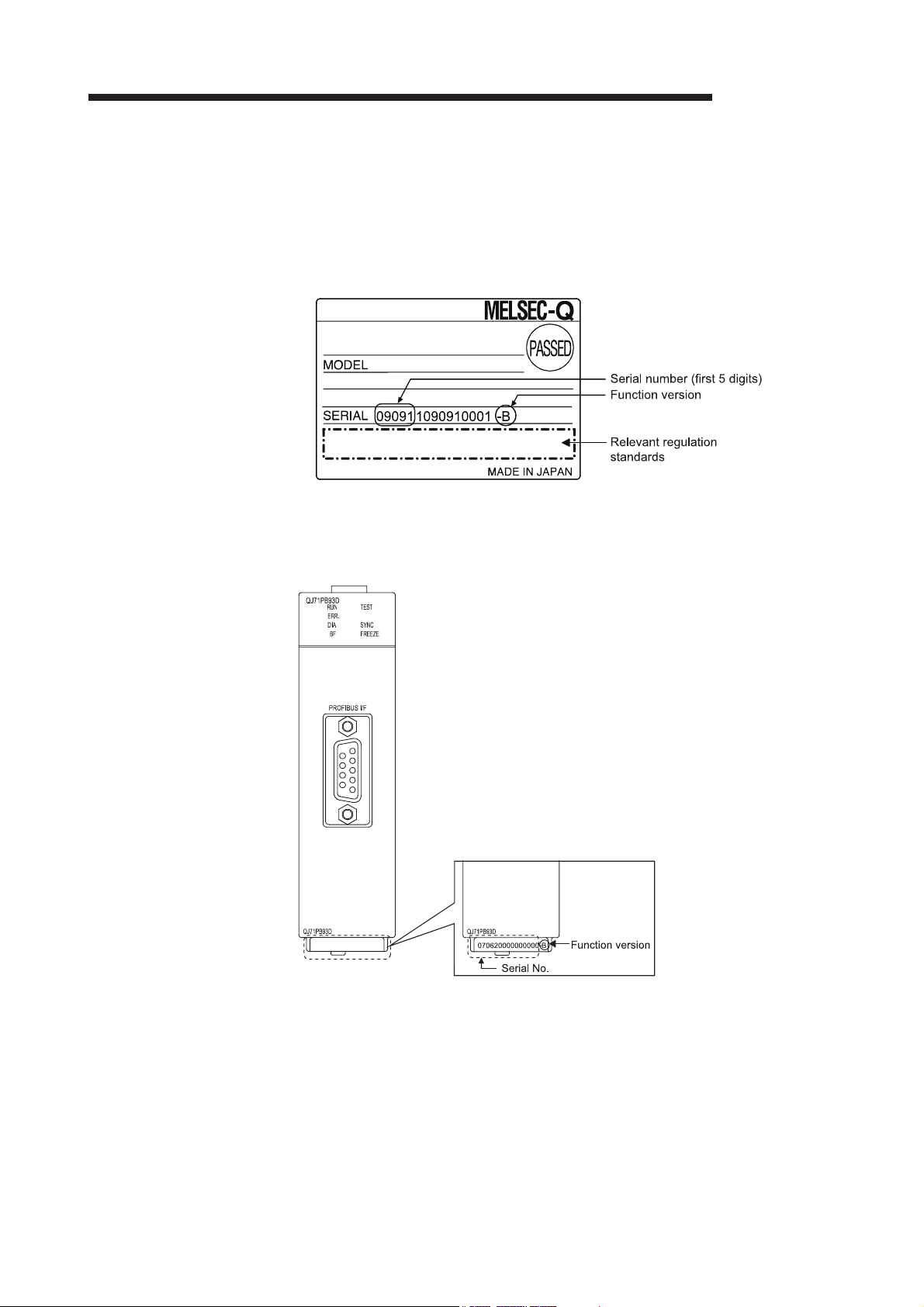
2.4 Checking Serial No. and Function Version
The serial No. and function version of the QJ71PB93D can be checked on the rating
plate, on the front of the module, and on the System monitor of GX Works2.
(1) Checking on the rating plate
The rating plate is located on the side of the QJ71PB93D.
MELSEC-Q
(2) Checking on the front of the module
The serial No. and function version on the rating plate are printed on the front (at
the bottom) of the module.
2 - 5 2 - 5
2 SYSTEM CONFIGURATION
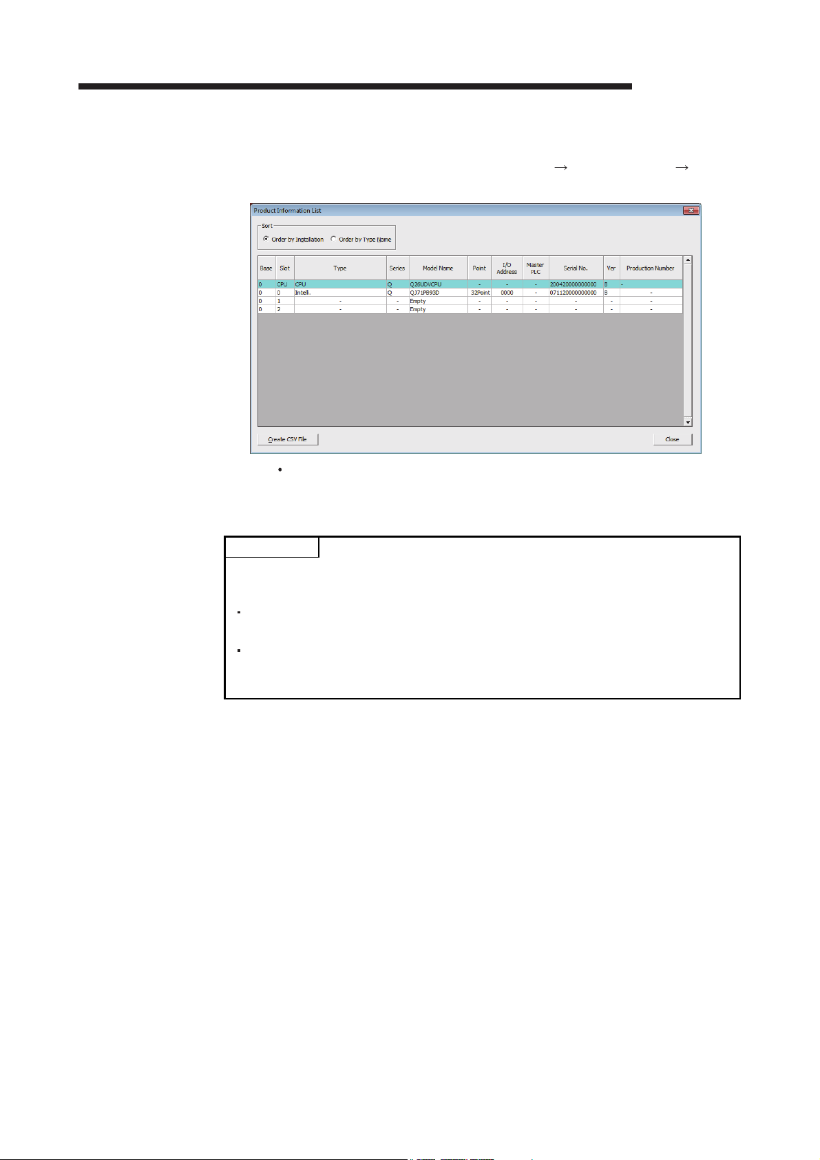
(3) Checking on the System monitor window (Product information list
window)
To display the System monitor, select [Diagnosis] [System monitor]
[Product information list] button of GX Works2.
MELSEC-Q
Product No.
"-" is displayed as QJ71PB93D does not support the product number
display.
POINT
The serial No. displayed on the Product Information List window of GX Works2 may
differ from that on the rating plate or on the front of the module.
The serial No. on the rated plate or on the front of the module indicates the
management information of the product.
The serial No. displayed on the Product Information List window of GX Works2
indicates the functional information of the product. The functional information of
the product will be updated when a function is added.
2 - 6 2 - 6

2 SYSTEM CONFIGURATION
MEMO
MELSEC-Q
2 - 7 2 - 7
3 SPECIFICATIONS
MELSEC-Q
3 SPECIFICATIONS
This chapter describes the performance specifications, network configuration, I/O
signals, buffer memory, and operation modes of the QJ71PB93D.
For the general specifications of the QJ71PB93D, refer to the User's Manual
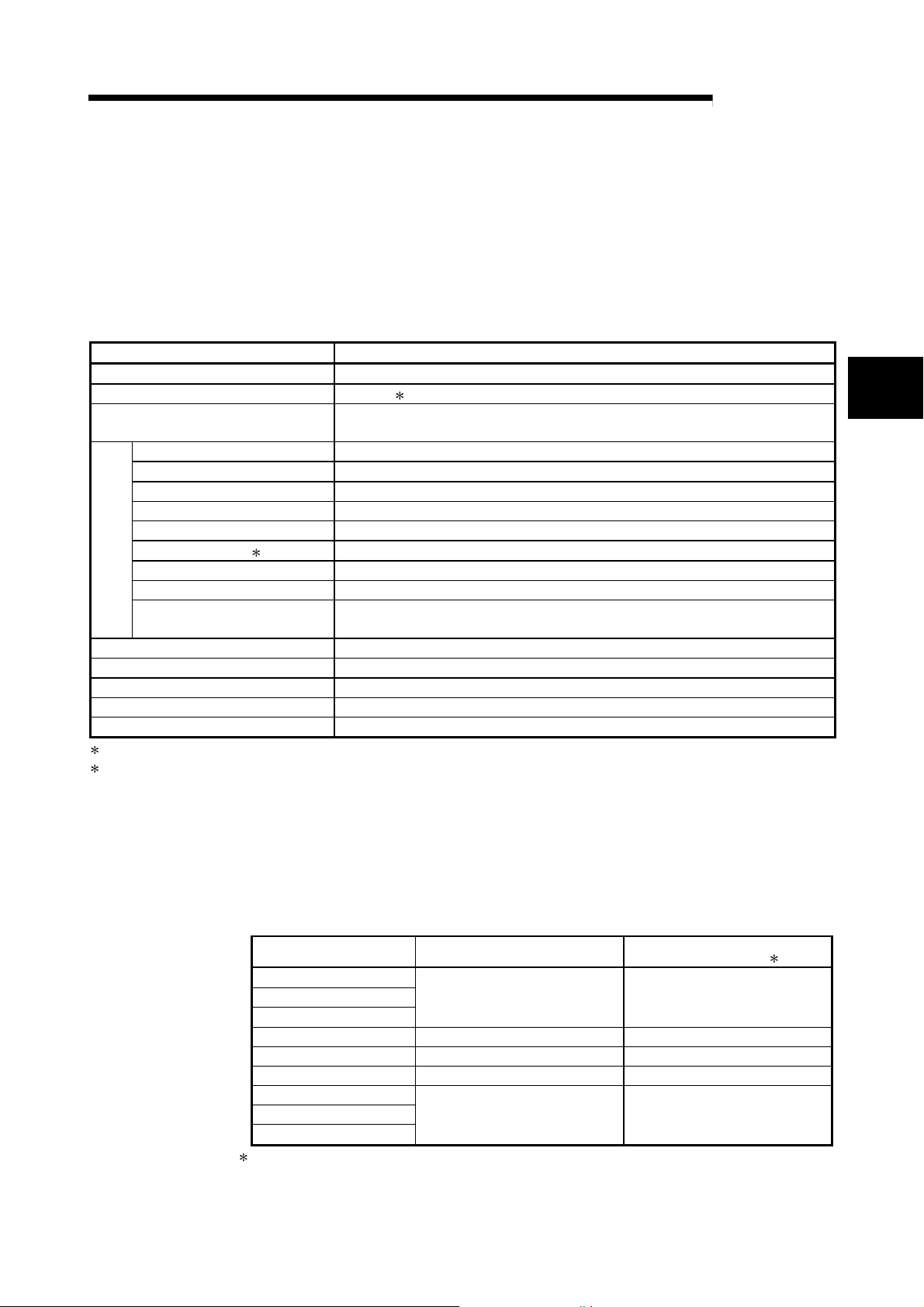
3.1 Performance Specifications
Item Specifications
PROFIBUS-DP station type Slave station (Complies with EN50170 Volume2 (Part 1, 2, 3, 4, 8))
Station numbers that may be set 0 to 125 2
Max. number of data that may be
communicated
Electrical standard/characteristics Complies with EIA-RS485
Medium Shielded twisted pair cable (Type A) (Refer to Section 5.7.1)
Network topology Bus topology (Tree topology when repeaters are used)
Data link method Polling method
Encoding method NRZ
Transmission speed 1 9.6 kbps to 12 Mbps (Refer to (1) in this section)
Transmission distance Differs depending on the transmission speed (Refer to (1) in this section)
Maximum number of repeaters
Transmission specifications
Number of connectable modules
(Per segment)
Flash ROM write count Max. 10000 times
Number of occupied I/O points 32 points (I/O assignment : 32 intelligent points)
5VDC Internal power consumption 0.44 A
External dimensions 98(3.86) (H) 27.4(1.08) (W) 90(3.55) (D) [mm(inch)]
Weight 0.11 kg
1 Transmission speed control within +/- 0.3% (EN50170 Volume 2 compliant)
2 Factory-set to "126" (EN50170 Volume 2 compliant)
Set a station number within 0 to 125 for I/O data communication.
3 - 1 3 - 1
(Hardware Design, Maintenance and Inspection) for the CPU module used.
Number of I/O data is 192 words in total. (Size of I/O data is up to 122 words.)
3 units (Refer to
32 units (including repeaters)
(1) in this section)
For the noise immunity, withstand voltage, insulation resistance, and others in the
programmable controller system using this module, refer to the power supply module
specifications given in the User's Manual (Hardware Design, Maintenance and
Inspection) for the CPU module used.
(1) Transmission distance
Transmission Speed Transmission Distance
9.6 kbps
19.2 kbps
93.75 kbps
187.5 kbps 1000 m (3281 ft.)/segment 4000 m (13123 ft.)/network
500 kbps 400 m (1312 ft.)/segment 1600 m (5249 ft.)/network
1.5 Mbps 200 m (656 ft.)/segment 800 m (2625 ft.)/network
3 Mbps
6 Mbps
12 Mbps
3 The max. transmission distance in the table above is based on the case where 3 repeaters are used.
The calculation formula for the transmission distance extended using a repeater(s) is:
Max. transmission distance [m/network] = (Number of repeaters + 1) x Transmission distance [m/segment]
1200 m (3937 ft.)/segment 4800 m (15748 ft.)/network
100 m (328 ft.)/segment 400 m (1312 ft.)/network
Max. Transmission Distance when
Repeater is Used
3
3

r
r
3 SPECIFICATIONS
3.2 Network Configuration
MELSEC-Q
3
This section explains the basic PROFIBUS-DP configuration for using the QJ71PB93D
as a slave station.
(1) System equipment
The following table shows the equipment required for the PROFIBUS-DP system.
System Equipment Description
Slave station QJ71PB93D
Class 1 master station QJ71PB92V, QJ71PB92D, etc.
Configuration tool Configurator applicable to the master station
Repeater Required when 32 or more slave stations are connected
PROFIBUS cable
Bus terminator
Refer to section 5.7.1
(2) Network configuration
In the PROFIBUS-DP system configuration, the following conditions must be
satisfied:
(a) Number of connectable modules in the whole network (when repeaters are
used)
Master station + Slave station
1: Including the QJ71PB93D
(b) Number of connectable modules per segment
Master station + Slave station
1: Including the QJ71PB93D
2: A repeater is counted for both segments.
(c) Maximum number of repeaters
Up to 3 repeaters can be used for communication between master station
and the QJ71PB93D.
(d) Number of slave stations that are connectable to master station
The maximum number of slave stations that may be connected to one
master station depends on the specifications of the master station.
Master station
Bus terminator
1 126
1 + repeaters 2 32
Class 1
Bus terminato
QJ71
CPU
module
PB93D
Slave
Station No. 1
Slave
Station No. 2
Slave
Station No. 30
Bus terminator
QJ71
CPU
PB93D
module
Slave
Station No. 31
Slave
Station No. 32
Slave
Station No. 60
3 - 2 3 - 2
Repeater
Bus terminato
3 SPECIFICATIONS
MELSEC-Q
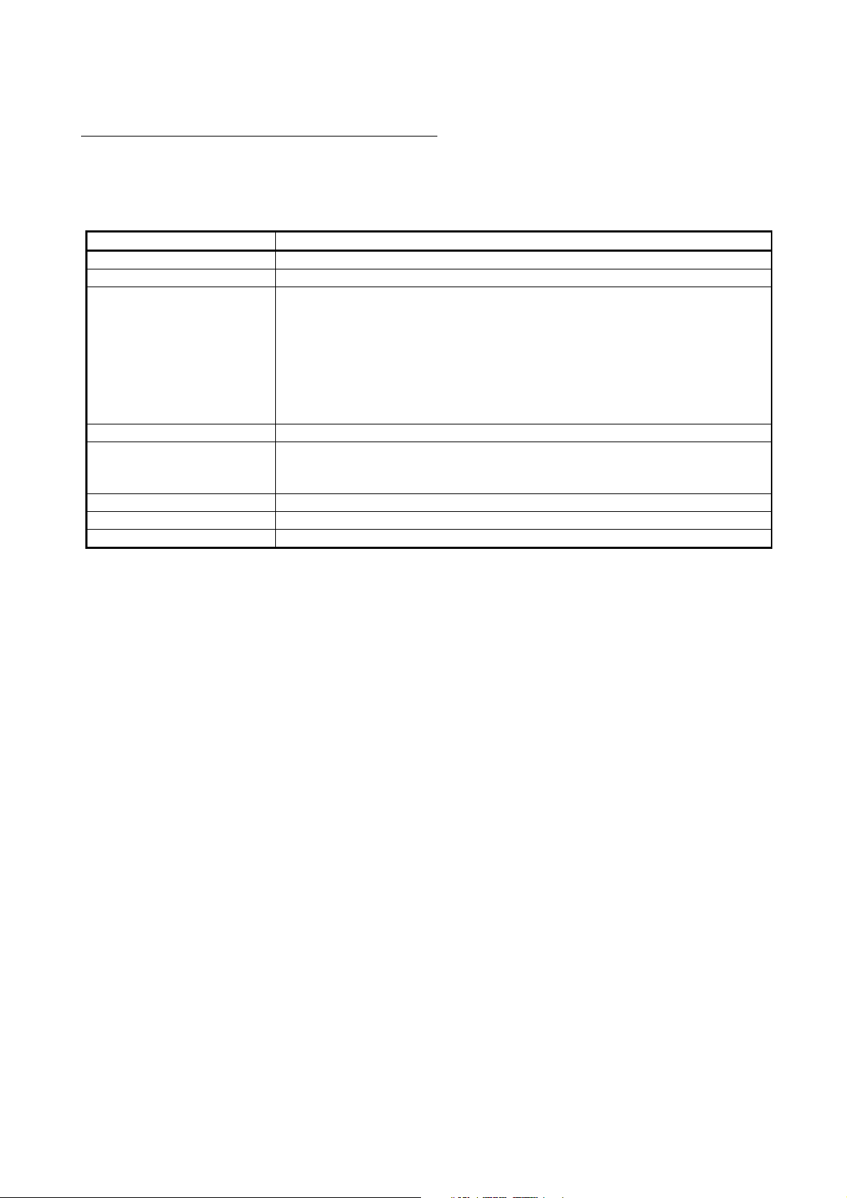
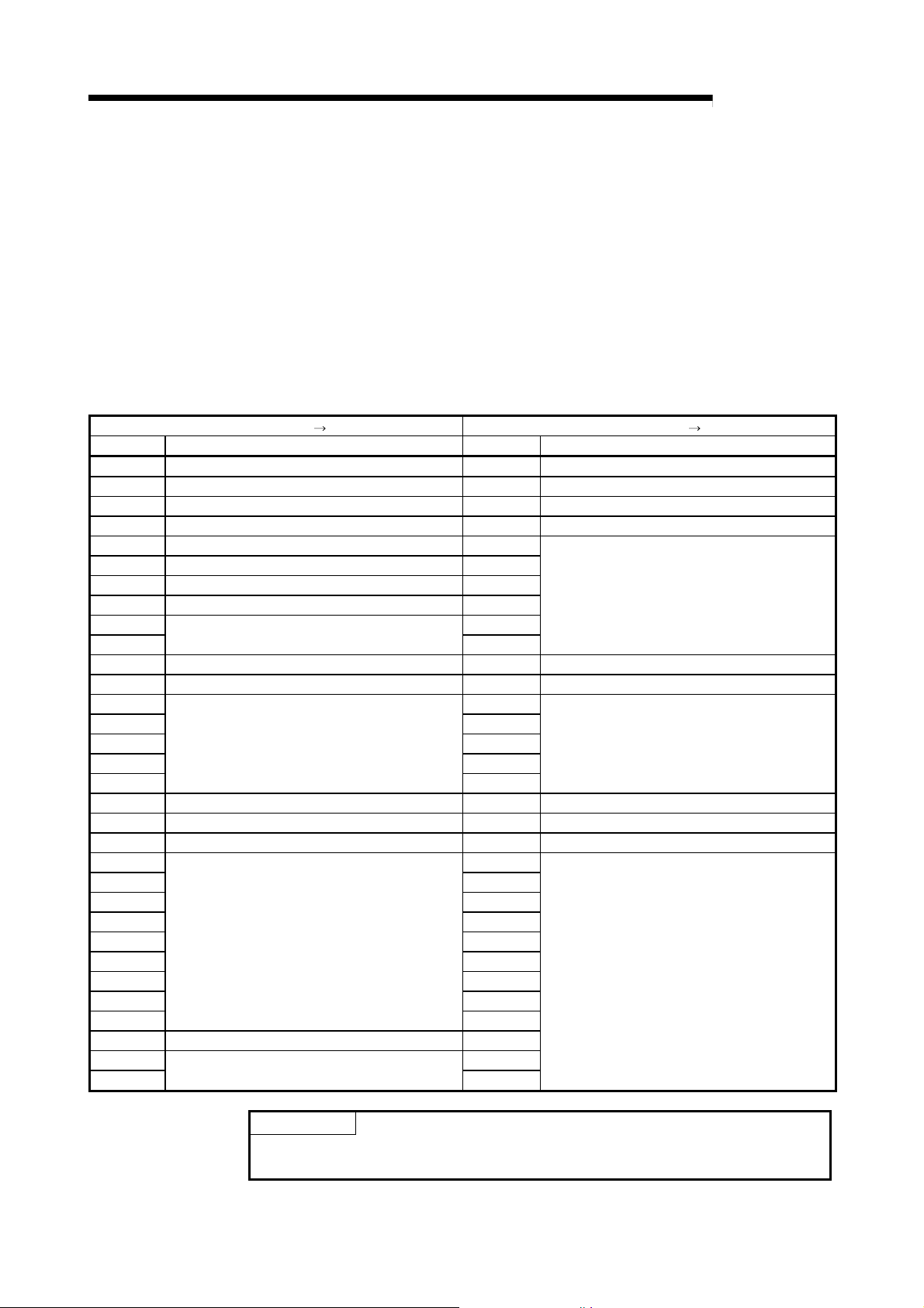
3.3 I/O Signal
3.3.1 I/O signal list
The I/O signal configuration used in the QJ71PB93D and the data communications
with the CPU module are described below.
The following I/O signal assignment is based on the case where the start I/O No. of the
QJ71PB93D is "0000" (installed to slot 0 of the main base unit).
Device X represents an input signal from the QJ71PB93D to the CPU module.
Device Y shows an output signal from the CPU module to the QJ71PB93D.
Refer to the corresponding reference sections for details.
Signal direction: QJ71PB93D CPU module Signal direction: CPU module
Device No. Description Device No. Description
X00 Watchdog timer error Y00 Input send area refresh directive signal
X01 I/O communication signal Y01 Use prohibited
X02 Extension trouble notification completion signal Y02 Extension trouble notification request signal
X03 Module error signal Y03 Module error reset request signal
X04 Use prohibited Y04
X05 SYNC mode signal Y05
X06 SYNC receive signal Y06
X07 FREEZE mode signal Y07
X08
X09 Y09
X0A BBLKRD start request acceptance completion signal Y0A BBLKRD start request signal
X0B BBLKWR start request acceptance completion signal Y0B BBLKWR start request signal
X0C
X0D Y0D
X0E Y0E
X0F Y0F
X10 Y10
X11 Operation mode change completion signal Y11 Operation mode change request signal
X12 Use prohibited Y12 Use prohibited
X13 Station number change completion signal Y13 Station number change request signal
X14
X15 Y15
X16 Y16
X17 Y17
X18 Y18
X19 Y19
X1A Y1A
X1B Y1B
X1C Y1C
X1D Module READY signal Y1D
X1E
X1F Y1F
Use prohibited
Use prohibited
Use prohibited
Use prohibited
Y08
Y0C
Y14
Y1E
Use prohibited
Use prohibited
Use prohibited
POINT
Do not output (turn on) the "Use prohibited" signals.
Doing so may cause the programmable controller system malfunction.
QJ71PB93D
3 - 3 3 - 3
3 SPECIFICATIONS
3.3.2 I/O signal detail description
(1) Watchdog timer error (X00)
(a) This signal turns on when a watchdog timer error occurs on the
QJ71PB93D.
(b) The watchdog timer error (X00) does not turn off until the following
operation is performed.
Turning the programmable controller power off to on
Resetting the CPU module
If the signal turns on again, a hardware error may be the cause.
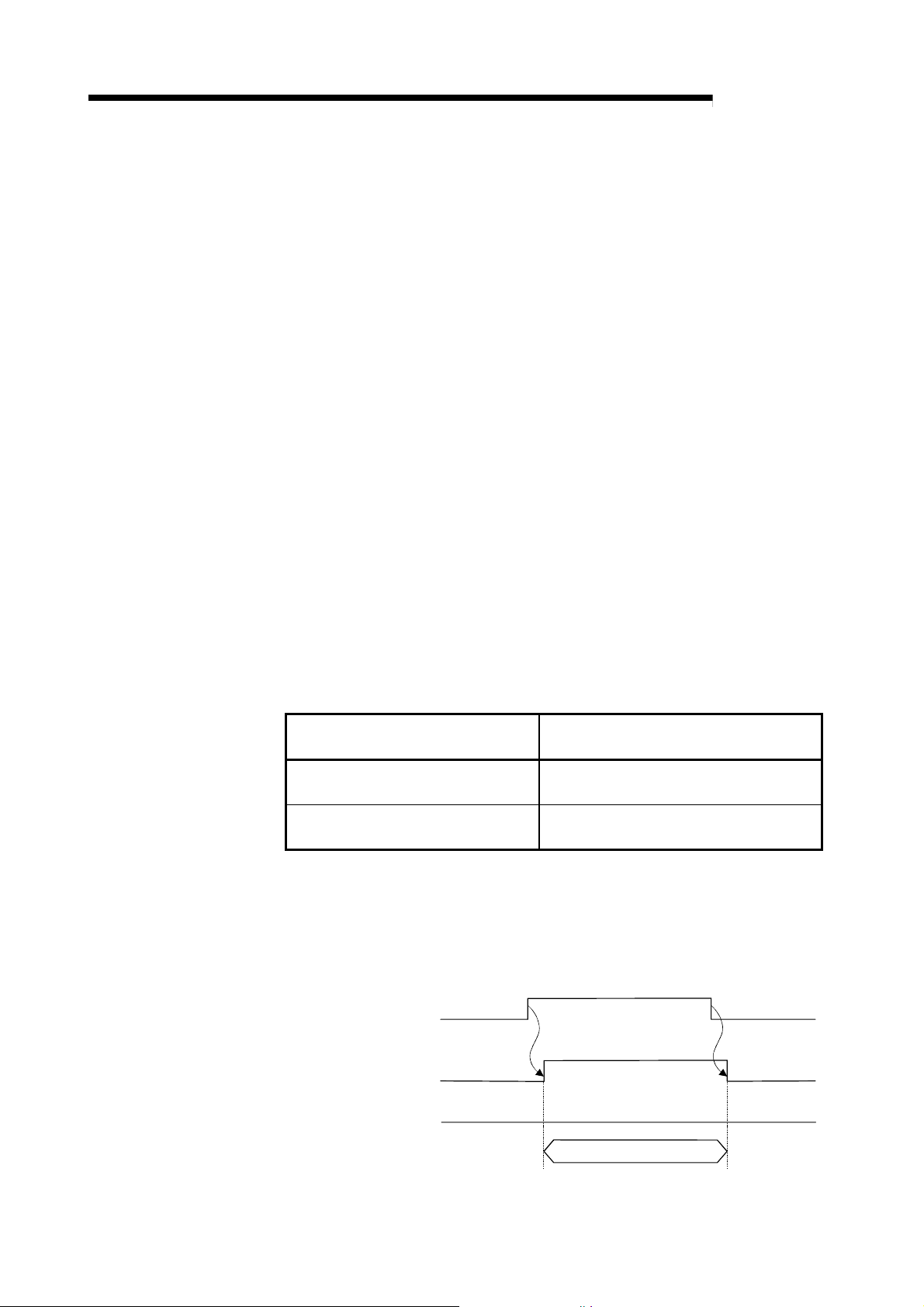
(2) I/O communication signal (X01)
(a) This signal turns on when the module is ready to communicate with the
Communication with
master station
master station properly.
(b) While the I/O communication signal (X01) is on, the output receive area is
updated to the output data sent from the master station.
(It is independent of the status of the input send area refresh directive
signal (Y00).)
(c) The I/O communication signal (X01) turns off when a communication time-
out error occurs due to a stop of communication with the master station.
However, if the communication watchdog timer setting in the master station
side parameters is "invalid", the I/O communication signal does not turn off
since a communication time-out error does not occur.
(The output data in the output receive area is held.)
Communication watchdog timer Setting
in Master Station Side Parameters
Invalid
Valid (2 to 65025)
The communication watchdog timer setting can be confirmed in the
"Current communication watchdog timer value (buffer memory address:
8D1
(d) Use this signal as a signal for interlocking output receive area read
performed with the MOV/FROM instruction.
H)" of the QJ71PB93D.
MELSEC-Q
Operation at Master Station Fault
No error
(I/O communication signal (X01) remains on)
Communication time-out error occurrence
(I/O communication signal (X01) turns off)
Communication in progressCommunication stop
Communication stop
I/O communication signal (X01) ONOFF OFF
Data update in output
receive area
Output receive area
(Buffer memory address :
to BFH)
0
H
Not updated Updated Not updated
MOV/FROM instruction
Execution of read from
output receive area
3 - 4 3 - 4

3 SPECIFICATIONS
(3) Extension trouble notification completion signal (X02)
When performing the extension trouble notification requests consecutively, provide
an interlock using the extension trouble notification completion signal (X02) in the
procedure shown above.
(4) Module error signal (X03)
Module error reset request signal (Y03)
Module error signal (X03)
MELSEC-Q
(a) The extension trouble notification completion signal (X02) turns on when
the extension trouble information is sent to the master station by turning on
the extension trouble notification request signal (Y02).
(While the I/O communication signal (X01) is off, the extension trouble
notification completion signal (X02) does not turn on since an extension
trouble notification request is ignored.)
(b) Turning off the extension trouble notification request signal (Y02) turns off
the extension trouble notification completion signal (X02).
I/O communication signal (X01)
Extension trouble notification
request signal (Y02)
Extension trouble notification
completion signal (X02)
Extension trouble information area
(Buffer memory address :
7f9
to 805H)
H
POINT
Extension trouble
notification request
Extension trouble
notification completion
MOV/TO
Instruction
Extension trouble
information write
(a) This signal turns on when an error occurs.
At this time, an error code is stored into the module error information area
(buffer memory address: 7F8
H)).
(b) This signal turns off when the error is reset by turning on the module error
reset request signal (Y03) or resetting the CPU, for example. At this time,
the ERR. LED goes off and the error code is cleared.
(c) The module error reset request signal (Y03) turns off after confirming that
the module error signal (X03) have turned off.
Error detection
Error reset
Module error information area
(Buffer memory address : 7F8H)
The error code is read from the buffer memory to the CPU module.
MOV/FROM
instruction
(5) SYNC mode signal (X05)
(a) This signal turns on when the QJ71PB93D is placed in the SYNC mode by
3 - 5 3 - 5
a SYNC request from the master station.
(b) The SYNC mode signal (X05) turns off when the SYNC mode is terminated
by an UNSYNC request from the master station, a communication stop or a
CPU reset.

3 SPECIFICATIONS
(6) SYNC receive signal (X06)
Request from master
MELSEC-Q
(c) The SYNC LED turns on/off in synchronization with the on/off of the SYNC
mode signal (X05).
(d) The SYNC mode signal (X05) turns off if a communication time-out error
occurs due to a stop of communication with the master station while the
SYNC mode signal (X05) is on.
However, if the communication watchdog timer setting in the master station
side parameters is "invalid", the SYNC mode signal (X05) does not turn off
since a communication time-out error does not occur. (The output data in
the output receive area is held.)
Communication watchdog timer
Setting in Master Station Side
Parameters
Invalid
Valid (2 to 65025)
Operation at Master Station Fault
No error
(SYNC mode signal (X05) remains on)
Communication time-out error occurrence
(SYNC mode signal (X05) turns off)
The communication watchdog timer setting can be confirmed in the
"Current communication watchdog timer value (buffer memory address:
8D1
H)" of the QJ71PB93D.
(a) The SYNC receive signal (X06) turns on receipt of a SYNC request from
the master station.
(b) While the SYNC mode signal (X05) is on, the receipt of a SYNC request
from the master station changes the on/off state of the SYNC receive signal
(X06).
At this time, the SYNC mode signal (X05) remains on.
(c) The SYNC receive signal (X06) turns off when the SYNC mode is
terminated by an UNSYNC request from the master station, a
communication stop or a CPU reset.
SYNC request
SYNC request SYNC request UNSYNC request
SYNC mode signal (X05)
SYNC receive signal (X06)
SYNC LED
Off OffOn
3 - 6 3 - 6

r
3 SPECIFICATIONS
(7) FREEZE mode signal (X07)
Request from maste
MELSEC-Q
(d) The SYNC receive signal (X06) turns off if a communication time-out error
occurs due to a stop of communication with the master station while the
SYNC receive signal (X06) is on.
However, if the communication watchdog timer setting in the master station
side parameters is "invalid", the SYNC receive signal (X06) does not turn
off since a communication time-out error does not occur. (The output data
in the output receive area is held.)
Communication watchdog timer
Setting in Master Station Side
Parameters
Invalid
Valid (2 to 65025)
Operation at Master Station Fault
No error
(SYNC receive signal (X06) remains on)
Communication time-out error occurrence
(SYNC receive signal (X06) turns off)
The communication watchdog timer setting can be confirmed in the
"Current communication watchdog timer value (buffer memory address:
8D1
H)" of the QJ71PB93D.
(a) The FREEZE mode signal (X07) turns on when the QJ71PB93D is placed
in the FREEZE mode by a FREEZE request from the master station.
(b) The FREEZE mode signal (X07) turns off when the FREEZE mode is
terminated by an UNFREEZE request from the master station, a
communication stop or a CPU reset.
(c) The FREEZE LED turns on/off in synchronization with the on/off of the
FREEZE mode signal (X07).
FREEZE request UNFREEZE request
FREEZE mode signal (X07)
FREEZE LED Off OffOn
3 - 7 3 - 7

3 SPECIFICATIONS
(8) BBLKRD start request acceptance completion signal (X0A)
MELSEC-Q
(d) The FREEZE mode signal (X07) turns off if a communication time-out error
occurs due to a stop of communication with the master station while the
FREEZE mode signal (X07) is on.
However, if the communication watchdog timer setting in the master station
side parameters is "invalid", the FREEZE mode signal (X07) does not turn
off since a communication time-out error does not occur. (The output data
in the output receive area is held.)
Communication watchdog timer
Setting in Master Station Side
Parameters
Invalid
Valid (2 to 65025)
Operation at Master Station Fault
No error
(FREEZE mode signal (X07) remains on)
Communication time-out error occurrence
(FREEZE mode signal (X07) turns off)
The communication watchdog timer setting can be confirmed in the
"Current communication watchdog timer value (buffer memory address:
8D1
H)" of the QJ71PB93D.
(a) This signal is used as an interlock condition signal to execute the dedicated
instruction BBLKRD.
(b) When the BBLKRD start request signal (Y0A) is turned on in the sequence
program, the BBLKRD start request acceptance completion signal (X0A)
turns on.
(c) When the BBLKRD start request signal (Y0A) is turned off in the sequence
program, the BBLKRD start request acceptance completion signal (X0A)
also turns off.
BBLKRD start request signal (Y0A)
BBLKRD start request acceptance
completion signal (X0A)
BBLKRD instruction
(9) BBLKWR start request acceptance completion signal (X0B)
(a) This signal is used as an interlock condition signal to execute the dedicated
3 - 8 3 - 8
instruction BBLKWR.
(b) When the BBLKWR start request signal (Y0B) is turned on in the sequence
program, the BBLKWR start request acceptance completion signal (X0B)
turns on.

3 SPECIFICATIONS
BBLKWR start request signal (Y0B)
BBLKWR start request acceptance
completion signal (X0B)
MELSEC-Q
(c) When the BBLKWR start request signal (Y0B) is turned off in the sequence
program, the BBLKWR start request acceptance completion signal (X0B)
also turns off.
BBLKWR instruction
(10) Operation mode change completion signal (X11)
(a) This signal turns on when an operation mode change is completed by
setting the required operation mode to the operation mode change request
area (buffer memory address: 8CF
change request signal (Y11).
At this time, the result is stored into the operation mode change result area
(buffer memory address: 8D0
(b) Turning off the operation mode change request signal (Y11) after
confirmation of the result turns off the operation mode change completion
signal (X11).
(c) This signal turns on at either normal or abnormal completion of an
operation mode change.
At abnormal completion, the operation mode change request is made
invalid and operation continues in the operation mode that had been used
Input send area refresh
directive signal (Y00)
Operation mode change
request signal (Y11)
before the change request was given.
H) and turning on the operation mode
H).
Operation mode change
completion signal (X11)
Operation mode change result area
(Buffer memory address: 2256(8D0
))
H
MOV/TO
instruction
Sets the operation mode
in "operation mode change
request area (Address : 8CF
)".
H
Change result of operation mode
MOV/FROM
instruction
Checks result in "operation mode
change result area (Address : 8D0
and "current operation mode
(Address : 8CE
)".
H
3 - 9 3 - 9
)"
H

3 SPECIFICATIONS
(11) Station number change completion signal (X13)
MELSEC-Q
(a) This signal turns on when the station number setting is completed by
setting the station number to the station number change request area
(buffer memory address: 203
H) and turning on the station number change
request signal (Y13).
(b) Check the setting result in the operation station number area (buffer
memory address: 201
address: 7F8
H) of the buffer memory.
H) and module error information area (buffer memory
(c) Turning off the station number change request signal (Y13) after
confirmation of the result turns off the station number change completion
signal (X13).
(d) If a station number error (error code: 1002
H) has occurred, the station
number change request is made invalid and operation continues with the
station number that had been used before the change request was given.
(e) Turning on the station number change request signal (Y13) suspends I/O
communication.
Turning on the station number change completion signal (X13) resumes I/O
communication.
Input send area refresh
directive signal (Y00)
Station number change
request signal (Y13)
Station number change
completion signal (X13)
Buffer memory
MOV/TO
instruction
Sets station number in "station
number change request area
(Address : 203
)".
H
Checks result in "operation station
number area (Address : 201
module error information area
(Address : 7F8
MOV/FROM
instruction
)".
H
),
H
(12) Module READY signal (X1D)
(a) This signal turns on when the QJ71PB93D is enabled for access from the
CPU module. (It turns on regardless of the operation mode.)
(b) This signal turns off when the QJ71PB93D is disabled for access from the
CPU module due to a module watchdog timer
error, hardware fault or like.
3 - 10 3 - 10

3 SPECIFICATIONS
(13) Input send area refresh directive signal (Y00)
I/O communication
signal (X01)
MELSEC-Q
(a) Turning on this signal during communication with the master station (I/O
communication signal (X01) = ON) starts data communication of the input
send area (buffer memory addresses: 100
H to 1BFH) in the buffer memory.
(b) Turning this signal off stops sending of the data in the input send area to
the master station. (0 data are sent.)
(c) While the I/O communication signal (X01) is off, ON of the input send area
refresh directive signal (Y00) is invalid.
(communication stop)
OFF
ON (during communication)
(communication stop)
OFF
Input send area refresh
directive signal (Y00)
Data send in input
send area
Data update in output
receive area
Not sent Sent
Not updated Updated Not updated
ONOFF
OFF
Not sent
ON
OFF
POINT
The following are the relationships between data send and receive of the
QJ71PB93D, which vary with the states of the I/O communication signal (X01) and
input send area refresh directive signal (Y00).
X01 State Y00 State Data in Output Receive Area/Input Send Area
Master station QJ71PB93D
Input
area
Not sent
Input
send area
OFF ON/OFF
Output
area
Not updated
Output
receive area
Master station QJ71PB93D
Input
area
Sent
Input
send area
ON
Output
area
Updated
Output
receive area
ON
Master station QJ71PB93D
Input
area
0 data sent
Input
send area
OFF
Output
area
Updated
Output
receive area
3 - 11 3 - 11

3 SPECIFICATIONS
(14) Extension trouble notification request signal (Y02)
To turn on/off Y02, provide an interlock using X02.
(15) Module error reset request signal (Y03)
(16) BBLKRD start request signal (Y0A)
MELSEC-Q
(a) Turning on the extension trouble notification request signal (Y02) sends the
data set in the extension trouble information area (buffer memory address:
7F9
H to 805H) to the master station as extension trouble information. (The
extension trouble notification request is ignored while the I/O
communication signal (X01) is off.)
(b) When you have checked that the extension trouble notification completion
signal (X02) is on, turn off the extension trouble notification request signal
(Y02).
(c) Refer to (3) in this section for the on/off timing.
POINT
(a) Turning on the module error reset request signal (Y03) resets the error of
(b) When you have checked that the module error signal (X03) is off, turn off
(c) Making an error reset clears the error code in the module error information
(d) Refer to (4) in this section for the on/off timing.
(a) This signal is used to start the processing of the dedicated instruction
(b) When the BBLKRD start request signal (Y0A) is turned on in the sequence
(c) When the BBLKRD start request signal (Y0A) is turned off from the
(d) Only when using the dedicated instruction BBLKRD, turn on the BBLKRD
the QJ71PB93D. (The module error signal (X03) turns off and the ERR.
LED goes off.)
the module error reset request signal (Y03).
area (buffer memory address: 7F8
BBLKRD.
When executing the dedicated instruction BBLKRD, always turn on the
BBLKRD start request signal (Y0A) to turn on the BBLKRD start request
acceptance completion signal (X0A) so that it is used as an interlock
condition.
program, the QJ71PB93D starts the processing of the dedicated instruction
BBLKRD.
sequence program, the processing of the dedicated instruction BBLKRD is
ignored.
start request signal (Y0A).
Note that, if the dedicated instruction BBLKRD is not executed after the
BBLKRD start request signal (Y0A) has been turned on, the transmission
delay time between the master and a slave stations is prolonged.
H).
3 - 12 3 - 12

3 SPECIFICATIONS
(17) BBLKWR start request signal (Y0B)
(18) Operation mode change request signal (Y11)
(19) Station number change request signal (Y13)
Station numbers can be set from the class 2 master station.
In this case, specifying "TRUE" for "No_Add_Chg" disables the station number
change on the QJ71PB93D.
The station number of the QJ71PB93D cannot be changed while the station
number change is disabled.
To change the station number again, clear the station number in the station number
change request area of the QJ71PB93D (buffer memory address: 515(203
cancel the disabled status. (Refer to Section 3.4.2 (6))
MELSEC-Q
(a) This signal is used to start the processing of the dedicated instruction
BBLKWR.
When executing the dedicated instruction BBLKRD, always turn on the
BBLKRD start request signal (Y0B) to turn on the BBLKRD start request
acceptance completion signal (X0B) so that it is used as an interlock
condition.
(b) When the BBLKWR start request signal (Y0B) is turned on in the sequence
program, the QJ71PB93D starts the processing of the dedicated instruction
BBLKWR.
(c) When the BBLKWR start request signal (Y0B) is turned off from the
sequence program, the processing of the dedicated instruction BBLKWR is
ignored.
(d) Only when using the dedicated instruction BBLKWR, turn on the BBLKWR
start request signal (Y0B).
Note that, if the dedicated instruction BBLKWR is not executed after the
BBLKWR start request signal (Y0B) has been turned on, the transmission
delay time between the master and a slave stations is prolonged.
(a) Turn on the operation mode change request signal (Y11) when changing
the operation mode to the one set in the operation mode change request
area (buffer memory address: 8CF
(b) When you have checked that the operation mode change completion signal
(X11) is on, turn off the operation mode change request signal (Y11).
(c) Refer to (10) in this section for the on/off timing.
(a) Turn on the station number change request signal (Y13) when changing the
station number to the one set in the station number change request area
(buffer memory address: 203
(b) When you have checked that the station number change completion signal
(X13) is on, turn off the station number change request signal (Y13).
(c) Refer to (11) in this section for the on/off timing.
POINT
H).
H).
H)) to
3 - 13 3 - 13

3 SPECIFICATIONS
MELSEC-Q
3.4 Buffer Memory List
3.4.1 Buffer memory/configuration
The configuration of the buffer memory used to receive and send data with the
Buffer memor y address
Hexadecimal decimal
0H
0
BFH
191
C0H
192
FFH
255
100H
256
1BFH
447
1C0H
448
1FFH
511
200H 512 Operation baud rate Stores the baud rate in current operation. Read
201H 513 Operation station number Stores the station number in current operation. Read
202H 514 Station number set on flash ROM Stores the station number saved on the flash ROM. Read
203H 515 Station number change request area
204H 516 Station number rewritabl e count to flash ROM
205H
517
7F7H
2039
7F8H 2040 Module error information Stores the error code detected by the QJ71PB93D. Read
2041
7F9H
805H
2053
2054
806H
8CDH
2253
8CEH 2254 Current operation mode Stores the operation mode in current operation. Read
8CFH 2255 Operation mode change request area
8D0H 2256 Operation mode change result
8D1H 2257 Current communication watchdog timer value Stores the communication watchdog timer value in current operation. Read
8D2H 2258 Self-diagnostic status type code display area Stores the diagnostic status type code at the time of self-diagnostics. Read
8D3H 2259 Swapping function setting status Stores the setting status of the swapping function in current operation. Read
8D4H
2260
8DFH
2271
8E0H
2272
8EBH
2283
8ECH
2284
8EFH
2287
8F0H
2288
8FBH
2299
2300
8FCH
AFFH
2815
QJ71PB93D and the CPU module is described below.
Area name Description Read/Write
Output receive area
System area (Use prohibited)
Input send area
System area (Use prohibited)
System area (Use prohibited)
Extension trouble information area
System area (Use prohibited)
System area (Use prohibited)
Output receive area used status Stores the current used status of the output receive area. Read
System area (Use prohibited)
Input send area used status Stores the current used status of the input send area. Read
System area (Use prohibited)
POINT
Stores the output data received from the master station.
(Max. usable range 122 words)
Used to set the input data to be sent to the master station.
(Max. usable range 122 words)
Used to set a new station number to be set in response to the station
number change request signal (Y13).
Stores the remaining number of times when the station number can be
saved onto the flash ROM during continuous operati on.
Used to set the extension trouble notification data to the master
station.
Used to set a new operation mode to be set in response to the
operation mode change request signal (Y11).
Stores the result of changing the operation mode in response to the
operation mode change request signal (Y11).
Do not write any data in the "system area (Use prohibited)" of the buffer memory.
If data is written to the "system area (Use prohibited)", there is a risk that the
programmable controller system may malfunction.
Read
Read/Write
Read/Write
Read
Read/Write
Read/Write
Read
3 - 14 3 - 14

3 SPECIFICATIONS
3.4.2 Buffer memory detail description
(1) Output receive area
Stores the output data received from the master station.
The structure varies with the data module setting and data assignment mode
setting in the slave parameters. (Refer to Section 5.2.1 to 5.2.3)
(2) Input send area
(buffer memory address 100H to 1BFH: Un\G256 to Un\G447)
Used to store the input data to be sent to the master station.
The structure varies with the data module setting and data assignment mode
setting in the slave parameters. (Refer to Section 5.2.1 to 5.2.3)
(3) Operation baud rate (buffer memory address 200H: Un\G512)
Stores the baud rate in current operation.
Baud rate not yet recognized 0000H
The stored value while the I/O communication signal (X01) is on is valid.
Use the master station parameter to set the baud rate of the PROFIBUS-DP.
(4) Operation station number (buffer memory address 201H: Un\G513)
Stores the station number of the QJ71PB93D in current operation.
The storage range is 0 to 126.
The stored value while the I/O communication signal (X01) is on is valid.
If the station number is not set (the station number is as set in the factory or has
been cleared), "126" is stored.
I/O data cannot be communicated if the station number is not set.
MELSEC-Q
(buffer memory address 0H to BFH: Un\G0 to Un\G191)
Baud Rate Stored Value
9.6 kbps 96E2H
19.2 kbps 19E3H
45.45 kbps 45E3H
93.75 kbps 93E3H
187.5 kbps 18E4H
500 kbps 05E5H
1.5 Mbps 15E5H
3 Mbps 03E6H
6 Mbps 06E6H
12 Mbps 12E6H
3 - 15 3 - 15

3 SPECIFICATIONS
(5) Station number set on flash ROM
(6) Station number change request area
(1) Saving the station number to the flash ROM enables the operation based on the
(2) At power-on or at CPU reset, "FFFE
(7) Station number rewritable count to flash ROM
MELSEC-Q
(buffer memory address 202H: Un\G514)
Stores the station number of the QJ71PB93D set to the flash ROM.
The storage range is 0 to 125.
If the station number is not set to the flash ROM (the station number is as set in
the factory or has been cleared), "FFFF
H" is stored.
(buffer memory address 203H: Un\G515)
Used to set any of the following values when setting a new station number of the
QJ71PB93D in response to the station number change request signal (Y13).
Set Value Description
Set a station number.
By turning on b8, the station number is saved onto the flash ROM.
Fixed to 0
0000H to 007DH or
0100
H to 017DH
FFFFH
POINT
0: Not save onto the flash ROM
1: Save onto the flash ROM
(Example 1) Set the station number to 12. (Not saved onto the flash
ROM): 000C
(Example 2) Set the station number to 12. (Saved onto the flash
ROM): 010C
Clears the station number.
After clearing, the operation station number is "126".
The station number set to the flash ROM is "FFFE
H
H
Set a station number within the
range from 0
H
to 7DH (0 to125).
H".
station number setting stored in the flash ROM even if the module is powered
off and on or the CPU module is reset.
H" is stored.
Turn on the station number change request signal (Y13) after storing a setting
value given in the above table.
Executing the station number change request with any invalid value results in a
station number error (error code: 1002
H).
(buffer memory address 204H: Un\G516)
Stores the remaining number of times when the station number setting can be
saved onto the flash ROM during operation.
The initial value is 60.
(a) Counting down the number of times
Every time the station number is changed on the flash ROM, the count is
decremented by 1.
The count is not decremented when station number setting is requested
with the same station number as the one saved on the flash ROM (buffer
memory address: 202
H).
b0b1b2b3b4b5b6b7b8b9b10b11b12b13b14b15
3 - 16 3 - 16

3 SPECIFICATIONS
(8) Module error information (buffer memory address 7F8H: Un\G2040)
(9) Extension trouble information area
MELSEC-Q
(b) Resetting the count
The count is reset to 60 by resetting the CPU, by powering on the
QJ71PB93D or by clearing the station number on the flash ROM using the
station number change request signal (Y13).
(c) If an attempt is made to rewrite the station number on the flash ROM at the
remaining count of 0
A station number rewrite count excess error (error code: 2001
H) occurs and
the station number on the flash ROM is not changed.
If the station number rewrite count excess error has occurred, switch power
on again, reset the CPU, or clear the station number on the flash ROM
using the station number change request signal (Y13). (This returns the
remaining count to 60 times.)
Stores the error code of the error that occurred in the QJ71PB93D.
Refer to Section 9.4 for the error codes.
(buffer memory address 7F9H to 805H: Un\G2041 to Un\G2053)
Used to set the extension trouble information to be sent to the master station.
The extension trouble information sent by the QJ71PB93D is the Device Related
Diagnostic specified in PROFIBUS.
The extension trouble information can be set in a sequence program.
Data length : Data length of the data to be sent as extension
trouble information (bytes units)
Extension trouble information : Any data to be set to the master station (max. 24
bytes)
7F9
H
7FA
H
805
H
The extended trouble information area is used as described below when an
extended trouble occurs and when the extended trouble is removed.
(a) When extended trouble occurs
Data length
Extension trouble
information
When the host becomes faulty, for example, the data stored in the
extended trouble information area of the buffer memory is sent to the
master station as extended trouble information.
In the following procedure, the QJ71PB93D can notify the master station of
the extended trouble of the host.
1) In the buffer memory 7FA
H to 805H, set the data to be sent to the
master station.
2) In the buffer memory 7F9
H, set the length of the data to be sent to the
master station.
3) Turn on the extension trouble notification request signal (Y02).
4) After the extension trouble notification completion signal (X02) has
turned on, turn off the extension trouble notification request signal (Y02).
3 - 17 3 - 17

3 SPECIFICATIONS
(10) Current operation mode (buffer memory address 8CEH: Un\G2254)
(11) Operation mode change request area
(12) Operation mode change result area
MELSEC-Q
(b) When extended trouble is removed
When the host is not faulty anymore, notify the master station that there is
no fault.
In the following procedure, the QJ71PB93D can notify the master station
that the extended trouble of the host has been removed.
1) In the buffer memory 7F9
H, set the data length 0.
2) Turn on the extension trouble notification request signal (Y02).
3) After the extension trouble notification completion signal (X02) has
turned on, turn off the extension trouble notification request signal (Y02).
(c) DIA LED of QJ71PB93D front panel is turned on as follows.
Y02
X02
7F9
H
Off On Off
DIA
0Except 0
Stores the current operation mode.
Refer to Section 3.5 for the operation mode.
Stored Value Mode
0000H Normal operation mode
0002H Self-diagnostic mode
At power-on or CPU reset, the module starts in the normal operation mode.
(buffer memory address 8CFH: Un\G2255)
Set any of the following values when changing the operation mode of the
QJ71PB93D with the operation mode change request signal (Y11).
Set Value Description
0000H Normal operation mode
0002H Self-diagnostic mode
At power-on or CPU reset, "FFFE
H" is stored.
If an operation mode change request is executed with any value other than the
set value, the operation cannot be guaranteed.
(buffer memory address 8D0H: Un\G2256)
Stores the result of changing the operation mode in response to the operation
mode change request signal (Y11).
0 : Normal completion
1 : Abnormal completion (A change request was made with an illegal value
set in the operation mode change request area (buffer memory address:
8CF
H))
3 - 18 3 - 18

3 SPECIFICATIONS
(13) Current communication watchdog timer value
Send data to master station 1 Retained 2 Cleared
Data update in output receive
area
I/O communication signal (X01) ON 2 OFF
(14) Self-diagnostic status type code display area (buffer memory
(15) Swapping function setting status
MELSEC-Q
(buffer memory address 8D1H: Un\G2257)
Stores the communication watchdog timer value set in the master station side
parameters.
The stored value is invalid if the I/O communication signal (X01) is off.
0 : Communication watchdog timer setting invalid
Other than 0 : Communication watchdog timer setting (in increments of 10ms)
When the master station becomes faulty, the send/receive data and I/O
communication signal (X01) statuses change depending on the communication
watchdog timer setting.
Statuses at master station fault
1: The send data to the master station indicates the data that flows on the
PROFIBUS-DP actually. It differs from the data in the input send area of the
QJ71PB93D.
2: If the communication watchdog timer setting is invalid (This area is 0), the
data is retained since the communication watchdog timer does not count up
if the master station becomes faulty during communication.
Current communication watchdog timer value (This area)
0 Other than 0
Retained
2 Cleared
address 8D2H: Un\G2258)
The diagnostic status type code at the time of self-diagnostics is stored.
The following type code can be confirmed during self-diagnostics or at abnormal
termination.
Status Type Code Description
During self-diagnostics 0001H to 0009H During self-diagnostics
At normal termination 0H Normal termination
8001
At abnormal termination
Refer to Section 5.6 for the way to run the self-diagnostics.
H to 8006H Hardware fault
8007H Swap test error
(buffer memory address 8D3H: Un\G2259)
Stores the setting status of the swapping function set in the master station side
parameter.
The stored value while the I/O communication signal (X01) is on is valid.
0 : Without swap setting
1 : With swap setting
3 - 19 3 - 19

3 SPECIFICATIONS
MELSEC-Q
(16) Output receive area used status
(buffer memory address 8E0H to 8EBH: Un\G2272 to Un\G2283)
Stores the used status of the output receive area.
The bits corresponding to the buffer memory addresses in output receive area
set by the master station parameters (Data module setting) turn on.
Buffer Memory Address Corresponding Buffer Memory Addresses (Hexadecimal) in output receive area
Hexadecimal Decimal
b15 b14 b13 b12 b11 b10 b9 b8 b7 b6 b5 b4 b3 b2 b1 b0
8E0H 2272 FH EH DH CH BH AH 9H 8H 7H 6H 5H 4H 3H 2H 1H 0H
8E1H 2273 1FH 1EH 1DH 1CH 1BH 1AH 19H 18H 17H 16H 15H 14H 13H 12H 11H 10H
8E2H 2274 2FH 2EH 2DH 2CH 2BH 2AH 29H 28H 27H 26H 25H 24H 23H 22H 21H 20H
8E3H 2275 3FH 3EH 3DH 3CH 3BH 3AH 39H 38H 37H 36H 35H 34H 33H 32H 31H 30H
8E4H 2276 4FH 4EH 4DH 4CH 4BH 4AH 49H 48H 47H 46H 45H 44H 43H 42H 41H 40H
8E5H 2277 5FH 5EH 5DH 5CH 5BH 5AH 59H 58H 57H 56H 55H 54H 53H 52H 51H 50H
8E6H 2278 6FH 6EH 6DH 6CH 6BH 6AH 69H 68H 67H 66H 65H 64H 63H 62H 61H 60H
8E7H 2279 7FH 7EH 7DH 7CH 7BH 7AH 79H 78H 77H 76H 75H 74H 73H 72H 71H 70H
8E8H 2280 8FH 8EH 8DH 8CH 8BH 8AH 89H 88H 87H 86H 85H 84H 83H 82H 81H 80H
8E9H 2281 9FH 9EH 9DH 9CH 9BH 9AH 99H 98H 97H 96H 95H 94H 93H 92H 91H 90H
8EAH 2282 AFH AEH ADH ACH ABH AAH A9H A8H A7H A6H A5H A4H A3H A2H A1H A0H
8EBH 2283 BFH BEH BDH BCH BBH BAH B9H B8H B7H B6H B5H B4H B3H B2H B1H B0H
Area name
Buffer memory
The stored value while the I/O communication signal (X01) is on is valid.
Example of output receive area used status
Address
DecimalHexadecimal
0H
1H
0
b0: ON indicates that the output receive area at address 0H is used,
1
and b14: ON that the output receive area at address E
is used.
H
Output
receive area
EH
F
10
11H
H
H
14
15
16
17
b1: ON indicates that the output receive area at address 11H is used,
and b15: ON that the output receive area at address 1FH is used.
Output
receive area
used status
1EH
1F
20H
8E0
8E1H
8E2
H
H
H
30
31
32
b11 b10 b9 b8b15b14b13b12 b7b6b5b4b3b2b1b0
2272
2273
2274
Areas where output data are being received from master station
0000000000001010
0000000000010100
00000 00 00000
00 00
0:OFF , 1:ON
3 - 20 3 - 20

3 SPECIFICATIONS
MELSEC-Q
(17) Input send area used status
(buffer memory address 8F0H to 8FBH: Un\G2288 to Un\G2299)
Stores the used status of the input send area.
The bits corresponding to the buffer memory addresses of the input send area
set in the master station parameters (Data module setting) turn on.
Buffer Memory Address Corresponding Buffer Memory Addresses of Input Send Area (Hexadecimal)
Hexadecimal Decimal
b15 b14 b13 b12 b11 b10 b9 b8 b7 b6 b5 b4 b3 b2 b1 b0
8F0H 2288 10FH 10EH 10DH 10CH 10BH 10AH 109H 108H 107H 106H 105H 104H 103H 102H 101H 100H
8F1H 2289 11FH 11EH 11DH 11CH 11BH 11AH 119H 118H 117H 116H 115H 114H 113H 112H 111H 110H
8F2H 2290 12FH 12EH 12DH 12CH 12BH 12AH 129H 128H 127H 126H 125H 124H 123H 122H 121H 120H
8F3H 2291 13FH 13EH 13DH 13CH 13BH 13AH 139H 138H 137H 136H 135H 134H 133H 132H 131H 130H
8F4H 2292 14FH 14EH 14DH 14CH 14BH 14AH 149H 148H 147H 146H 145H 144H 143H 142H 141H 140H
8F5H 2293 15FH 15EH 15DH 15CH 15BH 15AH 159H 158H 157H 156H 155H 154H 153H 152H 151H 150H
8F6H 2294 16FH 16EH 16DH 16CH 16BH 16AH 169H 168H 167H 166H 165H 164H 163H 162H 161H 160H
8F7H 2295 17FH 17EH 17DH 17CH 17BH 17AH 179H 178H 177H 176H 175H 174H 173H 172H 171H 170H
8F8H 2296 18FH 18EH 18DH 18CH 18BH 18AH 189H 188H 187H 186H 185H 184H 183H 182H 181H 180H
8F9H 2297 19FH 19EH 19DH 19CH 19BH 19AH 199H 198H 197H 196H 195H 194H 193H 192H 191H 190H
8FAH 2298 1AFH 1AEH 1ADH 1ACH 1ABH 1AAH 1A9H 1A8H 1A7H 1A6H 1A5H 1A4H 1A3H 1A2H 1A1H 1A0H
8FBH 2299 1BFH 1BEH 1BDH 1BCH 1BBH 1BAH 1B9H 1B8H 1B7H 1B6H 1B5H 1B4H 1B3H 1B2H 1B1H 1B0H
Area name
Buffer memory
The stored value while the I/O communication signal (X01) is on is valid.
Example of input send area used status
Address
DecimalHexadecimal
100H
101
256
257
H
b1: ON indicates that the output receive area at address 101H is used,
and b15: ON that the output receive area at address 10F
is used.
H
Input send
area
10E
10F
110
111
270
H
H
271
272
H
273
H
b0: ON indicates that the output receive area at address 110H is used,
and b14: ON that the output receive area at address 11EH is used.
Input send
area used
status
11E
11FH
120
8F0
8F1
8F2H
286
H
287
288
H
b11 b10 b9 b8b15 b14 b13 b12 b7 b6 b5 b4 b3 b2 b1 b0
2288
H
2289
H
2290
Areas where input data are being sent to master station
0000000000010100
0000000000001010
0000
000000 000000
0:OFF , 1:ON
3 - 21 3 - 21

3 SPECIFICATIONS
3.5 Operation Mode
The QJ71PB93D has two operation modes, normal operation mode and selfdiagnostic mode.
The modes will be described.
Normal operation mode
Self-diagnostic mode
(1) Changing the operation mode
MELSEC-Q
Operation Mode Description
In this mode, communication is made as in the slave
parameters set to the master station.
Communication can be made if the slave parameters
are within the setting ranges.
(Set only the station number in a sequence program or
GX Configurator-DP.)
After power is switched on or the programmable
controller CPU is reset, the QJ71PB93D operates in
the normal operation mode.
In this mode, the QJ71PB93D is tested alone to
diagnose a hardware fault.
No communication is made with the master station.
Reference
Section
Section 4.1.1
Section 5.6
Set the operation mode using the operation mode change request area (Buffer
memory address: 8CF
H) and the operation mode change request signal (Y11).
REMARKS
Refer to Section 5.6 for how to change the operation mode.
3 - 22 3 - 22

r
4 FUNCTIONS
MELSEC-Q
4 FUNCTIONS
4.1 Functions for Communication with Class 1 Master
This section explains the functions provided for communication between the
QJ71PB93D and class 1 master station.
4.1.1 I/O data communication function
This function allows the QJ71PB93D to operate as a PROFIBUS-DP slave station and
to communicate I/O data with the master station.
A single QJ71PB93D can handle the following size of data.
Input data : Max. 122 words
Output data : Max. 122 words
Max. 192 words in total
Class 1 master station
Output
image
4
Input
image
Bus terminator Bus terminato
PROFIBUS-DP network
Buffer memory
Read 1
Write 2
CPU module QJ71PB93D (slave station)
Output
receive
area
Input
send
area
Output
image
Input
image
1: Reads with BBLKRD/MOV/FROM instruction
or automatic refresh
2: Writes with BBLKWR/MOV/TO instruction or
automatic refresh
4 - 1 4 - 1

4 FUNCTIONS
4
MELSEC-Q
(1) Reading/writing I/O data
(a) Where to be stored
The I/O data are stored in the following buffer memory of the QJ71PB93D.
Input data: Input send area (Buffer memory address: 100
Output data: Output receive area (Buffer memory address: 0
(b) Read/write methods
Read or write I/O data (from the buffer memory) to devices in CPU module
by the following methods.
Read/Write Methods Setting Location Data Consistency Function
Automatic refresh GX Configurator-DP
Dedicated instructions (BBLKRD, BBLKWR) Sequence program
MOV or FROM/TO instructions Sequence program Not available
Available
H to 1BFH)
H to BFH)
(2) Sending/receiving I/O data
The sending and receiving process is described below.
(a) The I/O communication signal (X01) turns on when the QJ71PB93D is ready
to communicate with the master station.
(b) When the I/O communication signal (X01) turns on, data output from the
master station are stored into the output receive area (Buffer memory
address: 0
(c) When sending input data to the master station, write the initial value to the
input send area (Buffer memory address: 100
(d) Turning on the input send area refresh directive signal (Y00) starts input
data communication.
Turning off the signal stops the input data communication.
H to BFH).
H to 1BFH).
4 - 2 4 - 2

4 FUNCTIONS
[Receiving output data from the master station]
MELSEC-Q
(e) The I/O communication signal of the QJ71PB93D is turn off when
communication with the master station is stopped.
*3
Master
station side
QJ71PB93D
side
[Sending input data to the master station]
Master station
side
QJ71PB93D
side
*1
Bus cycle time (Bc)
Turned on when communication
with master station is ready.
I/O communication signal (X01)
Output receive area
(Buffer memory address:
H
0
to BFH)
*1
Bus cycle time (Bc)
Turned on when communication
with master station is ready.
I/O communication signal (X01)
Input send area
refresh directive signal (Y00)
Input send area
(Buffer memory address:
100
H to 1BFH)
Output area
Input area
Input send data
*2
refresh start
Data
1
Bc 1) Bc 2) Bc 3) Bc 4)
Previous data
Bc 1) Bc 2) Bc 3) Bc 4)
*4
Data
1
Data
Data
Input data
at Bc 1)
(Data )1
2
1
Data
2
Data
3
Data
Input data
at Bc 2)
(Data )
2
*3
Data
3
Data
4
Turned off when communication
with master station is disabled.
2
Data
Input data
at Bc 3)
(Data )
Data
4
4
4
Input send data
refresh stop
1: For the bus cycle time calculation formula, refer to the manual for the PROFIBUS-DP
module used as the master station.
2: Y00 must be turned on after X01 turns on and data are stored in the input send area.
3: Hold the data for more than 1 bus cycle time.
If the data are held for the time less than 1 bus cycle time, they may not be sent.
4: Transmission delay equal to 1 bus cycle time occurs to read the data in the output receive
area after X01 turns on.
Transmission delay equal to a maximum of 1 bus cycle time occurs to store data in the
input receive area after X01 turns on.
4 - 3 4 - 3

4 FUNCTIONS
4.1.2 I/O data separation prevention function
The I/O data separation prevention function is a function to prevent the I/O data of the
CPU module from being unmatched with the I/O data of the master station.
When not using the separation prevention function (Output data)
The following shows an example of output data separation.
CPU module
1
3
B
DC
0
2
A
Read during
data transfer
: Area where data transmission from master station is updated
: Area where data transmission from master station is not yet updated
QJ71PB93D
Buffer memory
1
3
B
DC
(1) I/O data separation prevention function
(a) The separation of I/O data occurs when the buffer memory is also read
from/written to the CPU module during the data transmission between the
When using the separation prevention function (Output data)
CPU module
1
32
54
76
0
buffer memory of QJ71PB93D and the master station.
(b) When the separation prevention function is used, the reading from the CPU
module is waited during the data transmission from the master station to the
buffer memory (output receive area) of QJ71PB93D, and executed after the
data transmission has been completed.
Also, the data transmission to the master station is waited until the writing
from the CPU module to the buffer memory (input send area) of QJ71PB93D
is completed, and executed after the writing has been completed.
QJ71PB93D
Buffer memory
1
3
5 4
7 6
Read after
completion of
data transfer
: Area where data transmission from master station is updated
: Area where data transmission from master station is not yet updated
MELSEC-Q
Master station
0
2
A
Data
transmission
1
3
5
76
0
2
4
Master station
0
2
1
3
54
76
Data transfer
completed
0
2
4 - 4 4 - 4

4 FUNCTIONS
MELSEC-Q
(2) How to prevent data inconsistency
The I/O data separation prevention function is executed by either of the following
methods.
This function is not available when the MOV or FROM/TO instruction is used for
buffer memory reading/writing.
(a) Using automatic refresh
Automatic refresh can be set in GX Configurator–DP.
To use the data separation prevention function at the time of automatic
refresh, check the “Enable Autorefresh” and “Consistency” boxes in the
“Buffer Devices” area on the parameter setting window.
REMARKS
For the automatic refresh setting method, refer to Section 5.3.1.
(b) Using dedicated instruction
Using the BBLKRD or BBLKWR instruction to read or write data prevents I/O
data separation. (Refer to Chapter 8)
REMARKS
Refer to Section 7.3.1 and 7.3.2 for program examples of the I/O data
communication using dedicated instructions.
4 - 5 4 - 5

4 FUNCTIONS
MELSEC-Q
(3) Precautions
(a) Applicable CPU module
To utilize the separation prevention function, use a CPU module whose first
five digits of the serial No. is "02092" or later. (Refer to Section 2.3)
(b) Transmission delay time caused by the separation prevention function
The delay time in transmission between the CPU module and master station
is lengthened because the QJ71PB93D have to wait for reading from or
writing to the CPU module and data transfer from/to the master station.
(Refer to Chapter 6)
The separation prevention function can be disabled in the automatic refresh
setting. (Refer to Section 5.3.1 (2))
Disable the separation prevention function when it is not necessary.
(c) When the separation prevention function is enabled in the automatic refresh
setting
Dedicated instructions are not executable. (They are not processed.)
They can be executed when the separation prevention function is disabled in
the automatic refresh setting.
4 - 6 4 - 6

r
4 FUNCTIONS
4.1.3 Global control function
The inputs/outputs of slave stations are controlled simultaneously for each specified
group by multicasting (broadcasting) from the master station. (Refer to (1) in this
section)
Set group numbers when using the global control function.
The group numbers are set to the slave parameters of the master station. (Refer to (2)
in this section.)
Class 1 master station
Sent to group 1
MELSEC-Q
Bus terminatorBus terminato
Slave
station
Slave
station
Group 1 Group 2
Slave
station
Slave
station
Slave
station
(1) Global control services available for QJ71PB93D
The following table describes the global control services available for the global
control function of the QJ71PB93D.
Service name Description
Starts the SYNC (output synchronization) mode.
SYNC
UNSYNC Ends the SYNC (output synchronization) mode.
FREEZE
UNFREEZE Ends the FREEZE (input synchronization) mode.
During the SYNC mode, the output status is refreshed every time the SYNC
service is received.
The output status is held as long as the SYNC service is not received.
Starts the FREEZE (input synchronization) mode.
During the FREEZE mode, the input status is refreshed every time the
FREEZE service is received.
The input status is held as long as the FREEZE service is not received.
4 - 7 4 - 7

4 FUNCTIONS
1) Before receiving SYNC service
Class 1 master
station
Input data Input data
Output data Output data
(a) When receiving SYNC and UNSYNC services
nput/Output
I
Image memory
QJ71PB93D
Buffer
memory
Input
send
area
Output
receive
area
MELSEC-Q
2) After
3) After receiving UNSYNC service
receiving SYNC service
Class 1 master
station
Input data Input data
Output data Output data
Class 1 master
station
Input data Input data
Output data Output data
SYNC service
UNSYNC service
nput/Output
I
Image memory
nput/Output
I
Image memory
QJ71PB93D
QJ71PB93D
Buffer
memory
Input
send
area
Output
receive
area
Buffer
memory
Input
send
area
Output
receive
area
Upon reception of the SYNC service, the SYNC
mode is started and refresh from the output data
area to the output receive area is stopped.
During the SYNC mode, the SYNC LED of the
QJ71PB93D is on.
When the SYNC service is received during the
SYNC mode, refresh to the output receive area is
performed only once.
Even during the SYNC mode, refresh from the input
send area to the input data area is executed
continuously.
Upon reception of the UNSYNC service, the SYNC
mode is terminated and refresh from the output
data area to the output receive area is restarted.
When the UNSYNC service is received and the
SYNC mode is ended, the SYNC LED of the
QJ71PB93D turns off.
4 - 8 4 - 8

4 FUNCTIONS
1) Before receiving FREEZE service
Class 1 master
station
MELSEC-Q
(b) When receiving FREEZE and UNFREEZE services
nput/Output
I
Image memory
QJ71PB93D
Buffer
memory
Input data Input data
Output data Output data
2) After receiving FREEZE service
Class 1 master
station
Input data Input data
Output data Output data
3) After receiving UNFREEZE service
Class 1 master
station
Input data Input data
Output data Output data
FREEZE service
UNFREEZE service
(2) Group selection
Input
send
area
Output
receive
area
nput/Output
I
Image memory
nput/Output
I
Image memory
QJ71PB93D
QJ71PB93D
Buffer
memory
Input
send
area
Output
receive
area
Buffer
memory
Input
send
area
Output
receive
area
Upon reception of the FREEZE service, the
FREEZE mode is started and refresh from the
input send area to the input data area is stopped.
During the FREEZE mode, the FREEZE LED of
the QJ71PB93D is on.
When the FREEZE service is received during the
FREEZE mode, refresh to the input sending area
is performed only once.
Even during the FREEZE mode, refresh from the
output data area to the output receive area is
executed continuously.
Upon reception of the UNFREEZE service, the
FREEZE mode is terminated and refresh from the
input send area to the input data area is restarted.
When the UNFREEZE service is received and the
FREEZE mode is ended, the FREEZE LED of the
QJ71PB93D turns off.
There are a total of 8 groups from 1 to 8.
The QJ71PB93D is allowed to belong to any of the 8 groups. (Specify the group
using the configuration tool of the master station.)
4 - 9 4 - 9

4 FUNCTIONS
4.1.4 Word data swapping function
The high and low bytes are swapped in word units when input or output data are sent
to or received from the master station.
Use this function when the used master station handles the high and low bytes of word
data in reverse to those of the QJ71PB93D.
Data can be swapped for communication without the need for creating a program for
swapping the high and low bytes.
(1) Operation outline for swap function
The data stored in the input sending area are sent to the master station after their
high and low bytes have been swapped.
The data received from the master station are stored into the output receiving
area after their high and low bytes have been swapped.
Input image
Output image
Master station
Data 1
(L)
Data 2
(L)
Data 3
(L)
Data 4
(L)
Data 1
(H)
Data 2
(H)
Data 3
(H)
Data 4
(H)
Input data
Data 1
(L)
Data 2
(L)
Output data
Data 3
(L)
Data 4
(L)
Data 1
(H)
Data 2
(H)
Data 3
(H)
Data 4
(H)
MELSEC-Q
QJ71PB93D
Input sending area
Data 1
(H)
Data 2
(H)
Output receiving area
Data 3
Swap processing
(H)
Data 4
(H)
Data 1
(L)
Data 2
(L)
Data 3
(L)
Data 4
(L)
PROFIBUS-DP data communication
H: High byte, L: Low byte
(2) Swap function setting
The setting required for swapping I/O data, the setting by master station type and
the operation outline are described below.
(a) Swap function setting by master station type
The swap function setting changes depending on the master station type as
described below.
Master station type Swap function setting of QJ71PB93D
When swap is not executed on
QJ71PB92V,
QJ71PB92D
master station side (Default setting)
When swap is not executed on
master station side
A1SJ71PB92D, AJ71PB92D Disable (Not swapped)
Other master station
Disable (Not swapped)
Enable (Swapped)
Set according to the specifications of
the master station
4 - 10 4 - 10

g
4 FUNCTIONS
Input image
Output image
(b) Operation outline
Master station
Data 1
(H)
Data 2
(H)
Data 3
(H)
Data 4
(H)
MELSEC-Q
When the QJ71PB92V, QJ71PB92D, A1SJ71PB92D or AJ71PB92D is used
as the master station, the operation outline is as shown below.
1) When the master station is the QJ71PB92V/QJ71PB92D/
A1SJ71PB92D/AJ71PB92D (not swapped)
QJ71PB93D
Data 1
(L)
Data 2
(L)
Data 3
(L)
Data 4
(L)
Input data
Data 1
(H)
Data 2
(H)
Output data
Data 3
(H)
Data 4
(H)
Data 1
(L)
Data 2
(L)
Data 3
(L)
Data 4
(L)
Input sending area
Data 1
Data 2
Output receiving area
Data 3
Data 4
(H)
(H)
(H)
(H)
Data 1
(L)
Data 2
(L)
Data 3
(L)
Data 4
(L)
PROFIBUS-DP data communication
h byte, L: Low byte
Master station
Data 1
(H)
Input image
Output image
Data 2
(H)
Data 3
(H)
Data 4
(H)
2) When the master station is the QJ71PB92V/QJ71PB92D (swapped)
Input data
Data 1
(L)
Data 2
(L)
Data 3
(L)
Data 4
(L)
Swap processing
PROFIBUS-DP data communication
Data 1
(L)
Data 2
(L)
Output data
Data 3
(L)
Data 4
(L)
Data 1
(H)
Data 2
(H)
Data 3
(H)
Data 4
(H)
H: Hi
QJ71PB93D
Input sending area
Data 1
(H)
Data 2
(H)
Output receiving area
Data 3
Swap processing
(H)
Data 4
(H)
H: High byte, L: Low byte
Data 1
(L)
Data 2
(L)
Data 3
(L)
Data 4
(L)
4 - 11 4 - 11

4 FUNCTIONS
Input image
Output image
Master station
Data 1
(L)
Data 2
(L)
Data 3
(L)
Data 4
(L)
MELSEC-Q
3) When high and low bytes of word data are reversed (swap) between
the master station and the QJ71PB93D
QJ71PB93D
Data 1
(H)
Data 2
(H)
Data 3
(H)
Data 4
(H)
Input data
Data 1
(L)
Data 2
(L)
Output data
Data 3
(L)
Data 4
(L)
Data 1
(H)
Data 2
(H)
Data 3
(H)
Data 4
(H)
Input sending area
Data 1
(H)
Data 2
(H)
Output receiving area
Data 3
Swap processing
(H)
Data 4
(H)
Data 1
(L)
Data 2
(L)
Data 3
(L)
Data 4
(L)
PROFIBUS-DP data communication
H: High byte, L: Low byte
(c) How to set the swap function
The swap function can be set as a slave parameter of the master station
(Word Data Swap in the user parameters setting).
Slave parameters of the master station are set from configuration tool on the
master station.
In the case of GX Configurator-DP
REMARKS
Refer to Section 5.2.3 for a setting example using GX Configurator-DP.
When using another configuration tool, refer to the relevant manual.
4 - 12 4 - 12

5 SETTINGS AND PROCEDURES BEFORE SYSTEM OPERATION
MELSEC-Q
5 SETTINGS AND PROCEDURES BEFORE SYSTEM OPERATION
5.1 Procedures before Operation
The following diagram illustrates the procedure before system operation.
Start
Load the QJ71PB93D to the base unit.
Check that the QJ71PB93D operates properly as
a single module.
(Self-diagnostics)
Set the QJ71PB93D slave parameters to the master
station using configuration tool applicable to
the master station.
Set parameters to the QJ71PB93D.
Station number 1
Automatic refresh parameters
Connect the master station and QJ71PB93D by a
PROFIBUS cable.
Connect bus terminators to the modules at both ends.
Make checks before power-on.
Check the module loading status.
Check the input power supply voltage.
Check that the CPU module STOP/RUN switch is
in the "STOP" position.
Refer to Section 5.6.
Refer to Section 5.2.
Refer to Section 5.3.
Refer to Section 5.7.
5
Power-on
Check operation with the LEDs.
Data communication normal: RUN lit, BF extinguished
Data communication abnormal: ERR./BF lit
Write a program to the CPU module.
Reset the CPU module or switch power from OFF to
ON.
System start
End
1: When setting the station number
from the class 2 master station,
connect the PROFIBUS cable to
the QJ71PB93D before the setting.
5 - 1 5 - 1

5 SETTINGS AND PROCEDURES BEFORE SYSTEM OPERATION
5.2 Parameter Setting to Master Station
In PROFIBUS-DP systems, slave parameters for the QJ71PB93D must be set to the
5
FDL Address
Min T_sdr
Group identification number
Data module setting
Data assignment mode
setting
Swap setting
master station.
For the setting method, refer to the manual of the configuration tool to be used.
Item Description Reference
Set the station number of the QJ71PB93D.
Setting range: 0 to 125
Set the minimum response time during which the response frame is
sent from the QJ71PB93D to the master station.
Usually the default value is used.
Setting range: 1 to 255
Specify groups (Grp1 to Grp8) to which the QJ71PB93D belongs.
Multiple groups (Grp1 to Grp8) can be set.
Set the I/O configuration information (set to "Cfg_Data" of the
master station).
Setting type: 96 pattern
Number of setting: 1 to 40
Set the data layout of the output receive area/input send area of the
buffer memory (set to "User_Prm_Data" of the master station).
Setting range
0 : LUMP mode (default)
1 : DIVIDED mode
Set whether the word data sent/received on the QJ71PB93D side
will be swapped or not (set to "User_Prm_Data" of the master
station).
Setting range
0 : Without swap (default)
1 : With swap
MELSEC-Q
Section
5.2.1
Section
5.2.2
Section
5.2.3
5 - 2 5 - 2

5 SETTINGS AND PROCEDURES BEFORE SYSTEM OPERATION
(1) Procedure for setting the slave parameters for QJ71PB93D to the
master station
1. Read the GSD (DDB) file of the QJ71PB93D to the configurator corresponding
to the master station used. (Refer to (2) in this section)
2. Set the QJ71PB93D slave parameters using the configurator.
3. Write the parameters to the master station.
MELSEC-Q
Configurator
GSD file for
QJ71PB93D
(DDB file)
Write
REMARKS
Refer to Section 5.2.1 to 5.2.3 for setting examples using GX Configurator-DP.
When using another configuration tool on the master station, refer to the relevant
manual.
(2) GSD (DDB) file
(a) When using GX Configurator-DP
GSD files have been incorporated into GX Configurator–DP.
GSD file installation is, therefore, unnecessary.
(b) When using another configuration tool
Please consult your local Mitsubishi representative for the GSD (DDB) file
of the QJ71PB93D.
Master station
on the master station
5 - 3 5 - 3

5 SETTINGS AND PROCEDURES BEFORE SYSTEM OPERATION
5.2.1 Data module setting
Set the I/O configuration information of the master station and QJ71PB93D.
(1) Number of data modules to be set
Set the data modules per QJ71PB93D within the following range.
• Number of data modules: Max. 40 modules
• Total data size
Input data: Max. 122 words
Output data: Max. 122 words
Total max. 192 words
(2) Data module setting pattern
For data module setting, choose the corresponding one from among 96 patterns
made available by combining I/O designation (3 types), data size (16 types) and
separation prevention setting (2 types).
Setting Item Types
I/O designation Input, output, input/output
Data size 1 to 16 words
Separation prevention setting Word unit (con word)/data module unit (con whole)
POINT
When even one data module is set to "data module unit (con whole)" in the
separation prevention setting, data inconsistency is prevented based on the
specified data size.
(3) Data module setting example
The data module setting example given here assumes the following
configuration.
• Configuration example
CPU
module
QJ71PB93D Input module
• Setting example
Data Module Setting QJ71PB93D Buffer Memory
Data module 0
(Input, 4 words, word unit)
Data module 1
(Output, 4 words, word unit)
Data module 2
(Input/output, 2 words, word unit)
Data module 0
64 points
(4 words)
X20 to X5F
Data module 0 area (4 words) is reserved in the input
send area.
Data module 1 area (4 words) is reserved in the
output receive area.
Data module 2 areas (2 words each) are reserved in
the output receive area and input send area.
Data module 1 Data module 2
Output module
64 points
(4 words)
Y60 to Y9F
I/O module
32 points
(2 words)
XA0 to XBF
YA0 to YBF
MELSEC-Q
5 - 4 5 - 4

r
5 SETTINGS AND PROCEDURES BEFORE SYSTEM OPERATION
(a) Total data size
The total data size of the data modules 0 to 2 is as follows.
• Input date size: Data module 0 (input, 4 words)
+ data module 2 (input, 2 words)
= 6 words
• Output date size: Data module 1 (output, 4 words)
+ data module 2 (output, 2 words)
= 6 words
• Total date size: Input date size (6 words)
+ output data size (6 words)
= 12 words
(b) Flows of data
The following indicates the flows of data between the modules.
Master station
Output area
MELSEC-Q
Input area
Bus terminator Bus terminato
*1
*1
Input
(X20 to X5F)
Output
(Y60 to Y9F)
(XA0 to XBF)
Input/Output
(YA0 to YBF)
CPU module
Output receive area
*3
*2
*2
*3
Data module 1
Data module 2
0(0
) to 191(BFH)
H
Input send area
Data module 0
Data module 2
256(100
) to 447(1BFH)
H
QJ71PB93D (Slave station)
1: Use the data assignment mode setting to set the layout on the buffer memory. (Refer to
Section 5.2.2)
2: Reads with BBLKRD/MOV/FROM instruction or automatic refresh.
3: Writes with BBLKWR/MOV/TO instruction or automatic refresh.
5 - 5 5 - 5

5 SETTINGS AND PROCEDURES BEFORE SYSTEM OPERATION
(4) Setting method when using GX Configurator-DP
This section describes how to make setting from GX Configurator-DP.
When using another configuration tool, refer to the relevant manual.
1) Drag the "QJ71PB93" in the "Global GSD data" window to the
"PROFIBUS Network" window.
MELSEC-Q
2) Click the [Next] button in the "Slave Settings" window.
5 - 6 5 - 6

5 SETTINGS AND PROCEDURES BEFORE SYSTEM OPERATION
3) Set the I/O configuration of the slave station in the "Slave Modules"
window.
4) Write the configured parameters to the master station.
MELSEC-Q
REMARKS
Refer to GX Configurator-DP Version7 Operating Manual for creating projects and
writing parameters to the master station by GX Configurator-DP.
5 - 7 5 - 7

5 SETTINGS AND PROCEDURES BEFORE SYSTEM OPERATION
5.2.2 Data assignment mode setting
Set how to assign each module in the output receive area or the input send area of the
buffer memory.
This section gives an example of the output receive area and the input send area in the
following data module setting.
Data
module 0
Data
module 1
Data
module 2
Data
module 3
MELSEC-Q
Data
module 4
Data
module 5
CPU
module
QJ71PB93D
Input
1 word
Output
2 words
Data Module Setting Output Data Input Data
Data module 0 1 word, input 1 word
Data module 1 2 words, output 2 words
Data module 2 1 word, input/output 1 word 1 word
Data module 3 1 word, output 1 word
Data module 4 2 words, input 2 words
Data module 5 1 word, output 1 word
I/O
1 word
Output
1 word
Input
2 words
Output
1 word
5 - 8 5 - 8

5 SETTINGS AND PROCEDURES BEFORE SYSTEM OPERATION
(1) Data assignment modes
There are the following two assignment modes.
(a) DIVIDED mode
In this mode, storage location of I/O data is assigned in the same way as
the actual input/output of data modules.
Since arrangement in the assignment is the same as that of the actual
inputs and outputs, reading from or writing to I/O modules and/or intelligent
Buffer memory
address Output receive area
function modules can be done with a single instruction.
0 100H Used by data module 0
1H
2H 102H
3H Used by data module 2 103H Used by data module 2
4H Used by data module 3 104H
5H 105H
6H 106H
7H Used by data module 5 106H
8H 107H
9H 108H
BFH 1BFH
Used by data module 1
H
101
(b) LUMP mode (Default)
In this mode, the areas for storing input and output data are assigned in
order of the data modules without allowing any empty space.
Because of this, reading from or writing to I/O modules and/or intelligent
function modules may not be executable with a single instruction.
When storing data in the output receive area and the input send area,
Buffer memory
address Output receive area
device areas can be used effectively.
0H
1H 101H Used by data module 2
2H Used by data module 2
3H Used by data module 3
4H Used by data module 5 103H
5H 104H
6H 105H
7H 106H
8H 107H
9H 108H
BFH 1BFH
Used by data module 1
H Used by data module 0
100
102
H Used by data module 4
MELSEC-Q
Input send area
Used by data module 4
Input send area
5 - 9 5 - 9

5 SETTINGS AND PROCEDURES BEFORE SYSTEM OPERATION
(2) Setting method when using GX Configurator-DP
This section describes how to make setting from GX Configurator-DP.
When using another configuration tool, refer to the relevant manual.
1) Open the "Slave Modules" window (refer to Section 5.2.1 (4)).
Click the [Next] button in the "Slave Modules" window.
MELSEC-Q
2) Set a mode for the "Data Alignment Mode" in the "Slave User
Data Alignment Mode
Parameters" window.
Item Description
LUMP mode : Assigns data as a lump. (Default)
DIVIDED mode : Assigns data individually.
3) Write the configured parameters into the master station.
REMARKS
Refer to GX Configurator-DP Version7 Operating Manual for creating projects and
writing parameters to the master station by GX Configurator-DP.
5 - 10 5 - 10

5 SETTINGS AND PROCEDURES BEFORE SYSTEM OPERATION
5.2.3 Swap setting
Set whether the word data swap function will be used or not.
Refer to Section 4.1.4 for the word data swap function.
(1) Setting method when using GX Configurator-DP
This section describes how to make setting from GX Configurator-DP.
When using another configuration tool, refer to the relevant manual.
1) Open the "Slave Modules" window (refer to Section 5.2.1 (4)).
Click the [Next] button in the "Slave Modules" window.
MELSEC-Q
5 - 11 5 - 11

5 SETTINGS AND PROCEDURES BEFORE SYSTEM OPERATION
2) Configure the setting for "Word Data Swap" in the "Slave User
Word Data Swap
Parameters" window.
Item Description
enable : Swaps the high and low bytes of data in units of
words when receiving or sending I/O data.
disable : Sends or receives I/O data as they are. (Default)
3) Write the configured parameters into the master station.
MELSEC-Q
REMARKS
Refer to the GX Configurator-DP Operating Manual for creating projects and writing
parameters to the master station by GX Configurator-DP.
5 - 12 5 - 12

5 SETTINGS AND PROCEDURES BEFORE SYSTEM OPERATION
5.3 Parameter Setting to Slave Station (QJ71PB93D)
Set the parameters displayed below to the QJ71PB93D.
Item Description
Set the station number of the QJ71PB93D.
Station number (FDL Address)
Automatic refresh parameters
(Autom. Refresh) 1
1: Set the automatic refresh parameters only when using the automatic refresh.
• Setting range
From 0 to 125
Set the parameters to automatically refresh the I/O data
between the QJ71PB93D and CPU module.
(1) Parameter setting method
(a) FDL address
The FDL address can be set by either of the following:
• GX Configurator-DP (Refer to Section 5.3.1)
• Sequence program (Refer to Section 7.2)
(b) Automatic refresh parameters
The automatic refresh parameters can be set only in GX Configurator-DP.
(Refer to Section 5.3.1)
5.3.1 Setting FDL address and automatic refresh parameters
MELSEC-Q
The following explains the procedure for setting the FDL address (station number) and
automatic refresh parameters using GX Configurator-DP.
Refer to GX Configurator-DP Version7 Operating Manual for usage of GX
Configurator-DP.
(1) Setting procedure
1) Select [Project] [New] in GX Configurator-DP.
5 - 13 5 - 13

5 SETTINGS AND PROCEDURES BEFORE SYSTEM OPERATION
2) Select "QJ71PB93D" in the "Select Module Type" window and click the
[Next] button.
MELSEC-Q
Item Description
CPU Series Qn
MELSEC Module Type QJ71PB93D
When automatic refresh of the other intelligent function module is set, set
the project file of GX Works2 to "PLC Project". (Refer to GX ConfiguratorDP Version7 Operating Manual.)
3) Set the station number as follows and click the [Next] button.
Item Description
Set the starting I/O number of the slave module with three
Starting I/O number
FDL Address
digits.
• Setting range: 000
Set the FDL address (station number).
• Setting range: 0 to 125 (default: 1)
H to FE0H (default: 000
)
H
5 - 14 5 - 14

5 SETTINGS AND PROCEDURES BEFORE SYSTEM OPERATION
MELSEC-Q
4) Set the auto refresh parameter as follows and click the [Finish] button.
Item Description
Check to enable the automatic refresh of device in the QCPU
module and buffer memory areas in the slave module (default:
Enable Autorefresh
Consistency
Input Size (In words)
Output Size(In words)
Input CPU Device
Output CPU Device
checked).
• Unchecked: automatic refresh is disabled.
• Checked: automatic refresh is enabled.
Check to enable the separation prevention at the time of
automatic refresh (default: unchecked).
For details on the separation prevention, refer to Section
4.1.2.
• Unchecked: separation prevention is disabled.
• Checked: separation prevention is enabled.
Set the number of words of the data to be transferred from the
slave module to the QCPU module (default: 0).
• Setting range: 0 to 122
Set the number of words of the data to be transferred from the
QCPU module to the slave module (default: 0).
• Setting range: 0 to 122
Set the data storage device when transferring the data in the
output receive area of the slave module to the QCPU module
(default: D1000).
The value of this item can be set when the setting value of
"Input Size" is 1 or more.
Set the data storage device when transferring the data of the
QCPU module to the input send area of the slave module
(default: D2000).
The value of this item can be set when the setting value of
"Output Size" is 1 or more.
5 - 15 5 - 15

5 SETTINGS AND PROCEDURES BEFORE SYSTEM OPERATION
(2) Writing the configured parameters
Write the configured parameters to the CPU module with the following steps.
1) Select the "Download to Module" in the "Task Panel".
2) Select the "Download PROFIBUS configuration" in the "Select Items for
Download" window.
When automatic refresh parameter is set, check also "Update
Autorefresh settings"
MELSEC-Q
3) Click [OK] to write the parameters to the CPU module.
4) When automatic refresh parameters are set, automatic refresh will be
enabled by powering off and on the programmable controller or by
resetting the CPU module.
POINT
To change the FDL address, perform the following to stop the refresh of the I/O
data between the master and slave stations.
• Turn off the Input send area refresh directive signal (Y0) of the QJ71PB93D.
• Stop I/O data communication on the master station side.
A new FDL address becomes effective right after the setting.
If the FDL address is changed during system operation, I/O data may be updated to
those for the new FDL address.
REMARKS
Automatic refresh parameters written in the CPU module can be checked in the
"Autorefresh Settings" window in GX configurator-DP.
5 - 16 5 - 16

5 SETTINGS AND PROCEDURES BEFORE SYSTEM OPERATION
(4) Number of automatic refresh parameter
There are restrictions on the number of automatic refresh parameters that can be
set for CPU modules.
Set automatic refresh parameters properly so that the number of the parameters
does not exceed the limit shown below.
(a) Number of automatic refresh parameters set for all intelligent function
modules
When multiple intelligent function modules are mounted, the number of
automatic refresh parameter must not exceed the following limit.
CPU Type Max. No. of Auto-refresh Parameter
Q00J/Q00/Q01CPU 256
Q02/Q02H/Q06H/Q12H/Q25HCPU 256
Q02PH/Q06PH/Q12PH/Q25PHCPU 256
Q12PRH/Q25PRHCPU 256
Q00UJ/Q00U/Q01UCPU 256
Q02UCPU 1024
Q03UD/Q04UDH/Q06UDH/Q10UDH/
Q13UDH/Q20UDH/Q26UDH/Q03UDV/
Q04UDV/Q06UDV/Q13UDV/Q26UDV/
Q03UDE/Q04UDEH/Q06UDEH/Q10UDEH/
Q13UDEH/Q20UDEH/Q26UDEH/Q50UDEH/
Q100UDEHCPU
MELSECNET/H remote I/O station 256
(b) Number of automatic refresh parameter settings for the QJ71PB93D
The following number of automatic refresh parameters can be set for one
QJ71PB93D.
Target Module Automatic Refresh Setting
QJ71PB93D 2 (Maximum)
Example: Counting the number of parameters for the automatic refresh
setting.
MELSEC-Q
2048
5 - 17 5 - 17

5 SETTINGS AND PROCEDURES BEFORE SYSTEM OPERATION
5.4 Installation
The following section explains the precautions when handling the QJ71PB93D, from
the time they are unpacked until they are installed.
For more details on the module installation, refer to the User's Manual (Hardware
Design, Maintenance and Inspection) for the CPU module used.
5.4.1 Handling precautions
(1) Do not drop the module case or subject it to heavy impact since it is made of
resin.
(2) Do not remove the PCB of each module from its case. This may cause a
failure in the module.
(3) Be careful not to let foreign objects such as wire burrs enter the module
during wiring. In the event any foreign object enters, remove it immediately.
(4) A protective film is attached to the top of the module to prevent foreign
matter, such as wire chips, from entering the module during wiring.
Do not remove this film until the wiring is complete. Before operating the
system, be sure to remove the film to provide adequate heat ventilation.
(5) Tighten the module fixing screws within the following torque ranges.
Screw location Tightening torque range
Module fixing screws (M3 screws) *1 0.36 to 0.48 N · m
PROFIBUS cable connector screws
(#4-40 UNC screws)
1 The module can be easily fixed onto the base unit using the hook at the top of
the module.
However, it is recommended to secure the module with the module fixing screw
if the module is subject to significant vibration or shock.
0.20 to 0.28 N · m
5.4.2 Installation environment
MELSEC-Q
Refer to the User's Manual (Hardware Design, Maintenance and Inspection) for the
CPU module used.
5 - 18 5 - 18

5 SETTINGS AND PROCEDURES BEFORE SYSTEM OPERATION
5.5 Part Names
MELSEC-Q
No. Name Description
1) LED Displays the QJ71PB93D status. (Refer to (1) in this section)
PROFIBUS
2)
interface connector
serial number
3)
display
1: For the connector type, use a male D-Sub 9 pin.
The PROFIBUS cable must be created by the user. (For information regarding the cable wiring, refer to Section 5.7.)
The size of the screw which can be used for the connector is #4-40 UNC.
This section explains the part names of the QJ71PB93D.
Connector for connecting the table for the PROFIBUS-DP network. 1
Displays the serial number on the rating plate.
(1) LED
QJ71PB93D
RUN
ERR.
DIA
BF
LED
Name
RUN Normal
ERR.
SYNC During SYNC mode
FREEZE During FREEZE mode
DIA
BF
TEST
Parameter setting error or
module error occurrence
Extended trouble information
present
Before data communication or
communication error detected
During execution of selfdiagnostics
TEST
SYNC
FREEZE
ON OFF
Description
Reference
Hardware error (module
watchdog timer error) or
power failure
Normal Section 9.1
Section 4.1.3
Section 4.1.3
Extended trouble
information absent
During data communication Section 9.1
Section 5.6
Section 9.1
Section 3.4.2
(9)
5 - 19 5 - 19

5 SETTINGS AND PROCEDURES BEFORE SYSTEM OPERATION
5.6 Execution Method for Self-diagnosis
This section describes the procedure for self-diagnosis, status during self-diagnosis,
and results after self-diagnosis.
It takes about 5 seconds to complete the self-diagnosis.
(1) Procedure for self-diagnosis
The procedure for self-diagnosis is as follows.
1) Set the CPU module to STOP.
2) Select [Online] [Monitor] [Device/Buffer Memory Batch] from the
menu of GX Works2.
3) Set 2
4) Turn on the operation mode change request signal (Y11) to start the
5) The TEST LED on the QJ71PB93D will flash during the self-diagnosis.
H (self-diagnosis mode) in the operation mode change request
area (buffer memory address: 8CF
self-diagnosis automatically.
H).
(2) Self-diagnosis results
(a) When completed normally
The "TEST LED" and "ERR. LED" go off.
(b) When completed abnormally
The "TEST LED" and "ERR. LED" will light up.
If the self-diagnostic result is an error, any of the following type codes is
stored into the self-diagnostic status type code display area (buffer memory
address: 8D2
The type code can be checked in the device/buffer memory batch monitor
of GX Works2.
Result of Self-diagnostics Type code
Normal 0H
Hardware fault 8001H to 8006H
Swap test error 8007H
H).
MELSEC-Q
5 - 20 5 - 20

5 SETTINGS AND PROCEDURES BEFORE SYSTEM OPERATION
(3) Completion of the self-diagnostics
Perform the following operation after checking normal or abnormal termination of
the self-diagnostics.
(a) When completed normally
Return the operation mode of the QJ71PB93D to the normal operation
mode.
Doing this will place the QJ71PB93D in the state of waiting for parameter
reception from the master station.
1) Select [Online] [Monitor] [Device/Buffer Memory Batch] from the
menu of GX Works2.
2) Set 0
3) Turn on the operation mode change request signal (Y11).
H (normal operation mode) in the operation mode change request
area (buffer memory address: 8CF
H).
(b) When completed abnormally
If the self-diagnostic result is an error, please consult your local Mitsubishi
representative.
(4) Cautions
During the self-diagnosis, do not monitor the QJ71PB93D buffer memory from
GX Works2.
Monitor may stop if the buffer memory is monitored during the self-diagnosis.
MELSEC-Q
5 - 21 5 - 21

5 SETTINGS AND PROCEDURES BEFORE SYSTEM OPERATION
5.7 Wiring
5.7.1 PROFIBUS cable wiring
The following describes the pin assignments of the PROFIBUS interface connector on
the QJ71PB93D, the PROFIBUS cable wiring specifications, bus terminator and other
information.
(1) Pin assignments of the PROFIBUS interface connector
The following shows the pin assignments of the PROFIBUS interface connector
5
9
4
8
3
7
2
6
1
(D-sub 9 pin female connector) on the QJ71PB93D.
Pin No. Signal Code Name Description Cable color
1
2
3 B/B' RxD/TxD-P Receive/send data-P Red
4
5 C/C' DGND 2 Data Ground
6
7
8 A/A' RxD/TxD-N Receive/send data-N Green
9
SHIELD 1 Shield, protective ground
Open
Open
VP 2 Voltage +
Open
Open
1: Optional signal.
2: Signal used to connect the bus terminator.
(2) PROFIBUS cable
The following shows the PROFIBUS cable and wiring specifications.
(a) PROFIBUS cable
Use a PROFIBUS cable that meets the following specifications (EN50170
Volume 2: Type A compliant).
Item Transmission line
Applicable cable Shielded twisted pair cable
Impedance 135 to 165 (f=3 to 20 MHz)
Capacity Less than 30 pF/m
Conductor resistance Less than 110 /km
Cross-sectional area 0.34mm2 or more
Wire diameter 22 AWG
Type Stranded
Material Copper
Temperature rating 60C or more
MELSEC-Q
5 - 22 5 - 22

5 SETTINGS AND PROCEDURES BEFORE SYSTEM OPERATION
MELSEC-Q
QJ71PB93D
SHIELD
RxD/TxD-P (red)
RxD/TxD-N (green)
1
PROFIBUS cable
3
8
(3) Connector
(b) Wiring specifications
Use a D-sub 9 pin male connector for the PROFIBUS cable.
The applicable screw size is #4-40 UNC.
(4) Wiring specifications for bus terminator
When the QJ71PB93D is a terminal station, use a connector with built-in bus
terminator that meets the following wiring specifications.
VP (6)
R 390 2 , min1/4W
u
RxD/TxD-P (3)
R
220 2 , min1/4W
tA
RxD/TxD-N (8)
R
390 2 , min1/4W
d
DGND (5)
(5) PROFIBUS equipment
The PROFIBUS cables, connectors and other PROFIBUS equipment must be
purchased or obtained at user's discretion.
For details on PROFIBUS equipment, access the following website.
• PROFIBUS International : www.profibus.com
5 - 23 5 - 23

5 SETTINGS AND PROCEDURES BEFORE SYSTEM OPERATION
5.7.2 Wiring precautions
As one of the requirements to give full play to QJ71PB93D’s functions and make up
the system with high reliability, it is necessary to have an external wiring unsusceptible
to an influence of noise. Precautions against external wiring of QJ71PB93D are
described below.
(1) Communication cable wiring
Do not install the QJ71PB93D communication cable together with the main
circuit, power lines and/or load carrying wires for other than the programmable
controller, or bring them close.
Doing so may cause the QJ71PB93D to be affected by noise and surge
induction.
(2) Wiring from I/O modules among programmable controllers
Keep the PROFIBUS cable away from I/O module cables as much as possible.
MELSEC-Q
Input module
Output module
QJ71PB93D
Wiring of input module
Wiring of output module
Shield jacket
(3) Grounding
(a) When using the QJ71PB93D, basically ground the FG and LG terminals of
the power supply module of the programmable controller.
(b) Grounding the module and other device with the same FG terminal may
apply noise through the FG terminal and result in a communication error. If
this error occurs, disconnect the FG terminal from the module.
PROFIBUS cable
5 - 24 5 - 24

5 SETTINGS AND PROCEDURES BEFORE SYSTEM OPERATION
MEMO
MELSEC-Q
5 - 25 5 - 25

6 TRANSMISSION DELAY TIME
6 TRANSMISSION DELAY TIME
MELSEC-Q
This section explains the processing time of the QJ71PB93D.
Communication processing between the master station and QJ71PB93D is shown
below.
(1) The processing of the output receive data
The following shows how the output data from the master station are read out to
a CPU module.
(a) When BBLKRD instruction is used
Class 1 master station Refer to the relevant
PROFIBUS-DP
QJ71PB93D
I/O image memory
Buffer memory
CPU module
ON
Bus cycle time
END END
END
BBLKRD
END
BBLKRD
manual for the
processing time
of the master station.
BBLKRD
6
Transmission delay time for output
(Refer to Section 6.1 (1))
(b) When MOV/FROM instruction is used
Class 1 master station Refer to the relevant
PROFIBUS-DP
QJ71PB93D
I/O image memory
Buffer memory
CPU module
END
ON
Bus cycle time
END
MOV/FROM
Transmission delay time for output
(Refer to Section 6.1 (2))
END
MOV/FROM
manual for the
processing time
of the master station.
6 - 1 6 - 1

6 TRANSMISSION DELAY TIME
MELSEC-Q
(c) When automatic refresh is used
Class 1 master station Refer to the relevant
PROFIBUS-DP
QJ71PB93D
I/O image memory
Buffer memory
CPU module
ON
Bus cycle time
manual for the
processing time
of the master station.
END ENDEND END END
Transmission delay time for output
(Refer to Section 6.1 (3))
END
6
6 - 2 6 - 2

(
)
)
6 TRANSMISSION DELAY TIME
(2) The processing of the input send data
The following shows how the CPU module data are sent to the master station.
(a) When BBLKWR/MOV/TO instruction is used
Class 1 master station Refer to the relevant
PROFIBUS-DP
QJ71PB93D
I/O image memory
Buffer memory
Bus cycle time
MELSEC-Q
manual for the
processing time
of the master station.
CPU module
END
BBLKWR/MOV/TO
Transmission delay time for input
END END
(Refer to Section 6.2 (1))
(b) When automatic refresh is used
Class 1 master station Refer to the relevant
PROFIBUS-DP
QJ71PB93D
I/O image memory
Buffer memory
CPU module
ON
Bus cycle time
ENDEND END
Transmission delay time for input
Refer to Section 6.2(3
END END
manual for the
processing time
of the master station.
6 - 3 6 - 3

6 TRANSMISSION DELAY TIME
MELSEC-Q
6.1 Transmission Delay Time of Output Receive (Master station QJ71PB93D)
The formulas for calculating the delay time for the output receive data transmission are
shown below.
The following symbols are used in the calculation formulas.
Bc: Bus cycle time
Scan: Scan time
(1) When BBLKRD instruction is used
Transmission delay time of output receive = Bc + Scan + 0.2 [ms]
(2) When MOV/FROM instruction is used
Transmission delay time of output receive = Scan + 0.2 [ms]
(3) When automatic refresh is used
(a) When the separation prevention function is not used
Item Transmission Delay Time in Output Reception
Normal value Scan 0.5 + 0.2[ms]
Max. value Scan + 0.2[ms]
(b) When the separation prevention function is used.
Item Transmission Delay Time in Output Reception
Normal value Scan 1.5 + 0.2[ms]
Max. value Scan 3 + 0.2[ms]
POINT
For the calculation formula of the bus cycle time, refer to the manual of the
PROFIBUS-DP module used on the master station.
6 - 4 6 - 4

6 TRANSMISSION DELAY TIME
6.2 Transmission Delay Time of Input Send (QJ71PB93D Master station)
The formulas for calculating the delay time for the input send data transmission are
shown below.
The following symbols are used in the calculation formulas.
Bc: Bus cycle time
Scan: Scan time
(1) When BBLKWR instruction is used
(a) When Scan < Bc
Transmission delay time in input transmission = Bc 3+0.2 [ms]
(b) When Scan > Bc
Transmission delay time of input transmission = Bc 2+Scan+0.2 [ms]
(2) When MOV/TO instruction is used
Transmission delay time of input transmission = Bc 2+0.2 [ms]
(3) When automatic refresh is used
(a) When the separation prevention function is not used.
Item Transmission Delay Time in Output Reception
Normal value Scan 0.5 + 0.2[ms]
Max. value Scan + 0.2[ms]
(b) When the separation prevention function is used.
Item Transmission Delay Time in Output Reception
Normal value Scan 1.5 + 0.2[ms]
Max. value Scan 4 + 0.2[ms]
POINT
For the calculation expression of the bus cycle time, refer to the manual of the
PROFIBUS-DP module used on the master station.
MELSEC-Q
6 - 5 6 - 5

7 PROGRAMMING
MELSEC-Q
7 PROGRAMMING
This chapter gives program examples of station number setting, I/O data
communication, and global control-driven program execution.
Before using the program examples introduced in this chapter in an actual system, fully
check that there is no problem in control on the target system.
7.1 Communication Sequence
The following is the sequence of I/O data communication with the master station.
Refresh between the programmable controller CPU and QJ71PB93D and refresh of
the QJ71PB93D buffer memory (output receive area, input send area) are executed
asynchronously.
(1) When using the automatic refresh
Make sure that the I/O
communication signal (X01) is on.
Start
Refer to Section 3.3.2 (2)
Write the initial input data value to
the device set in “Output CPU
Device” of the automatic refresh
parameter.
Turn on the input send area
refresh directive signal (Y00).
Communication
Refer to Section 5.3.1
Refer to Section 3.3.2 (13)
7
7- 1 7 - 1

7 PROGRAMMING
MELSEC-Q
Start
(2) When not using the automatic refresh
Make sure that the I/O
communication signal (X01) is on.
Write the initial values of the input
data to the input send area.
Turn on the Input send area refresh
directive signal (Y00).
Read the output data from the
output receive area using the
BBLKRD/MOV/FROM instruction.
Write the input data to the input
send area of the buffer memory
using the BBLKWR/MOV/TO
instruction.
Refer to Section 3.3.2 (2)
Refer to Section 3.4.2 (2)
Refer to Section 3.3.2 (13)
7
7- 2 7 - 2

7 PROGRAMMING
7.2 Station Number Setting
(1) System configuration example
This section gives a program example for setting a station number to the
QJ71PB93D in the following configuration.
MELSEC-Q
No.0
No. 1 Module Input signal Output signal
0 QJ71PB93D X0 to X1F Y0 to Y1F
1: The QJ71PB93D is to be mounted in slot 0 of the base unit with the head I/O number set
to "00
H".
(2) Settings
In the program example, the station number of the QJ71PB93D is set to 1.
(3) Assignment of device in program example
The program example given in this section uses the following device
assignments.
Device Description Device Description
X0 Watchdog timer error
X13 Station number change completion Y13 Station number change request
X1D Module READY
Device Description Device Description
M0 Station number setting flag D0 Operation station number storage device
(a) Devices used by the QJ71PB93D
(b) Devices used by user
7- 3 7 - 3

7 PROGRAMMING
MELSEC-Q
(4) Program example
1: When not writing the station number to the flash ROM, replace "H101" with "H1".
POINT
(1) Storing a station number in the flash ROM allows the QJ71PB93D to operate as
the station number even if the power is switched from off to on or if the CPU
module is reset.
(2) The station number can be also set from GX Configurator-DP. (Refer to Section
5.3.1)
However, if the station number is changed in this program example, do not
perform it from GX Configurator-DP.
Sets the station number to 1.
(Stores the station number in
the flash ROM)*1
Station number change
request.
Stores the operating station
number in D0.
Resets the station number
change request.
Resets the station number
setting flag.
7- 4 7 - 4

7 PROGRAMMING
7.3 Communication of I/O Data
7.3.1 LUMP mode
(1) System configuration example
A program example for I/O data communication is provided here to show the
case where the LUMP mode is used for data assignment of the following
configuration.
Refer to (2) for the outline of the program example.
MELSEC-Q
No.0 No.1 No.2 No.3 No.4
No. 1 Module Input signal Output signal
0 QJ71PB93D X0 to X1F Y0 to Y1F
1 QX41 X20 to X3F
2 QY41P Y40 to Y5F
3 Q64AD X60 to X6F Y60 to Y6F
4 Q64DA X70 to X7F Y70 to Y7F
1: Modules are to be mounted to the base unit from slot 0 as shown in the figure. Start I/O No.
data are to be set as follows:
REMARKS
Refer to Section 5.2.2 for details on the LUMP mode.
7- 5 7 - 5

7 PROGRAMMING
MELSEC-Q
(2) Settings
The following configuration and operation are set in the program example given
in this section.
(a) Data module setting of QJ71PB93D
Data module 0 Input, 2 words, word unit
Data module 1 Output, 2 words, word unit
Data module 2 Input, 4 words, word unit
Data module 3 Output, 4 words, word unit
(b) Used states of QJ71PB93D output receive area and input
send area
1) When dedicated instruction (BBLKRD/BBLKWR) is used
CPU module
QJ71PB93D
Device (D)
D100 to D101
D102 to D105
D200 to D201
D202 to D205
Data output
to QY41P
DA conversion
value output
to Q64DA
Data input
from QX41
AD conversion
value input
from Q64AD
*1
*2
1: The output receive area data are read to D100 to D105 using the BBLKRD instruction.
The data in D100 to D105 are written to the QY41P and Q64DA.
2: Data of the QX41 and Q64AD are read to the D200 to D205 beforehand.
The data in D200 to D205 are written to the input send area using the BBLKWR
instruction.
Output receive area
Data module 1
(Output, 2 words)
Data module 3
(Output, 4 words)
Empty
Input send area
Data module 0
(Input, 2 words)
Data module 2
(Input, 4 words)
Empty
)
0(0
H
1(1
H)
)
2(2
H
3(3
)
H
)
4(4
H
5(5
)
H
6(6
)
H
191(BF
256(100
257(101
258(102
259(103
260(104
261(105
262(106
447(1BF
H)
)
H
)
H
H)
)
H
)
H
)
H
)
H
)
H
7- 6 7 - 6

7 PROGRAMMING
MELSEC-Q
D102 to D105
D202 to D205
2) When MOV instruction is used
CPU module
Output (Y)
QY41P outputsY40 to Y5F
Input (X)
QX41 inputsX20 to X3F
Device (D)
DA conversion value
output to Q64DA
AD conversion value
input from Q64AD
*1
*2
*1
*3
QJ71PB93D
Output receive area
Data module 1
(Output, 2 words)
Data module 3
(Output, 4 words)
Empty
Input send area
Data module 0
(Input, 2 words)
Data module 2
(Input, 4 words)
Empty
0(0H)
1(1
H)
2(2
)
H
3(3
)
H
4(4
)
H
5(5
H)
6(6
H)
191(BF
H
256(100H)
257(101
258(102
259(103
260(104
261(105
262(106
447(1BF
)
H)
H)
)
H
)
H
H)
H)
H)
1: Data are read from Input (X) or written to Output (Y) using the BMOV instruction.
2: The output receive area data are read to D102 to D105 using the BMOV instruction.
The data in D102 to D105 are written to the Q64DA.
3: Data of the Q64AD are read to D202 to D205 beforehand.
With the BMOV instruction, the data in D202 to D205 are written to the input receive area.
REMARKS
Refer to Section 5.2.1 for the data module setting.
7- 7 7 - 7

7 PROGRAMMING
MELSEC-Q
(3) Assignment of devices in program examples
The program examples given in this section use the following device
assignments.
(a) Devices used by module
Device Description Device Description
X0 Watchdog timer error Y0 Input send area refresh directive
X1 I/O communication
X2 Extension trouble notification completion Y2 Extension trouble notification request
X3 Module error Y3 Module error reset request
X0A BBLKRD start request acceptance completion Y0A BBLKRD start request
X0B BBLKWR start request acceptance completion Y0B BBLKWR start request
X11 Operation mode change completion Y11 Operation mode change request
X1D Module READY
Device Description Device Description
X20 to X3F Inputs of QX41
Device Description Device Description
Y40 to Y5F Outputs of QY41P
Device Description Device Description
X60 Module READY
Device Description Device Description
X70 Module READY
Device Description Device Description
M10 Operation mode change flag M40 Extension trouble notification flag
M11 Operation mode change storage M41 Extension trouble notification completion flag
M20 Initial input data write M42 Extension trouble cancel flag
M30 Error handling flag M100 Self-diagnosis mode change
1) QJ71PB93D
2) QX41
3) QY41P
4) Q64AD
5) Q64DA
(b) Devices used by user
7- 8 7 - 8

7 PROGRAMMING
MELSEC-Q
Device Description Device Description
D10 Operation mode storage
D11 Operation mode change result
D20 Error code storage D300 Extension trouble information data length
D100 to
D101
D102 to
D105
QY41P (Y40 to Y5F) output data storage D301 Extension trouble information data
Digital-to-analog conversion value to be output to
Q64DA (CH.1 to 4)
(c) Devices used for automatic refresh or buffer memory reading
D200 to
D201
D202 to
D205
QX41 (X20 to X3F) input data storage
Analog-to-digital conversion value to be input
from the Q64AD (CH.1 to 4)
7- 9 7 - 9

7 PROGRAMMING
<Initial input data write>
<Input send area refresh start>
<Output data read>
(4) Program example
(a) When using dedicated instructions (BBLKRD/BBLKWR)
Initial input data write.
Input send area refresh start.
Output data read.
Outputs data to Y40 to Y5F.
MELSEC-Q
<Input data write>
<Error handling>
<Extension trouble information notification request>
Writes digital value to Q64DA.
Stores data in X20 to X3F into
D200.
Reads digital value from Q64AD.
Input data write.
Stores error code.
Resets error.
Turns on extension trouble
notification flag when error code
is other than 0.
Sets extension trouble notification
data length.
Sets extension trouble notification
data.
Stores extension trouble
notification data in buffer memory.
Extension trouble notification
request.
Resets extension trouble
notification request.
Extension trouble notification
completion flag.
Stores error code.
7- 10 7 - 10
 Loading...