


SAFETY PRECAUTIONS
(Always read these instructions before using this equipment.)
Before using this product, please read this manual and the relevant manuals introduced in this manual
carefully and pay full attention to safety to handle the product correctly.
The instructions given in this manual are concerned with this product. For the safety instructions of the
programmable controller system, please read the user's manual for the CPU module to use.
In this manual, the safety instructions are ranked as "DANGER" and "CAUTION".
DANGER
CAUTION
Note that the CAUTION level may lead to a serious consequence according to the circumstances.
Always follow the instructions of both levels because they are important to personal safety.
Please store this manual in a safe place and make it accessible when required. Always forward it to the end
user.
Indicates that incorrect handling may cause hazardous conditions,
resulting in death or severe injury.
Indicates that incorrect handling may cause hazardous conditions,
resulting in medium or slight personal injury or physical damage.
[DESIGN PRECAUTION]
DANGER
Do not write data into the "system area" of the buffer memory of intelligent function modules.
Also, do not use any "prohibited to use" signals as an output signal to an intelligent function
module from the programmable controller CPU.
Writing data into the "system area" or outputting a signal for "prohibited to use" may cause a
malfunction of the programmable controller system.
CAUTION
Do not bunch the control wires or communication cables with the main circuit or power wires, or
install them close to each other.
They should be installed 100mm(3.9inch) or more from each other.
Not doing so could result in noise that may cause malfunction.
At power ON/OFF, voltage or current may instantaneously be output from the output terminal of
this module. In such case, wait until the analog output becomes stable to start controlling the
external device.
A - 1

[INSTALLATION PRECAUTIONS]
CAUTION
Use the programmable controller in an environment that meets the general specifications
contained in the user's manual of the CPU module to use.
Using this programmable controller in an environment outside the range of the general
specifications may cause electric shock, fire, malfunction, and damage to or deterioration of the
product.
While pressing the installation lever located at the bottom of module, insert the module fixing tab
into the fixing hole in the base unit until it stops.
Improper installation may result in malfunction, breakdown or the module coming loose and
dropping.
Securely hold the module with module fixing bracket.
Tighten the screws within the range of specified torque.
If the screws are loose, it may cause the module to fallout, short circuits, or malfunction.
If the screws are tightened too much, it may cause damage to the screw and/or the module,
resulting in fallout, short circuits or malfunction.
Be sure to shut off all phases of the external power supply used by the system before mounting or
removing the module.
Not doing so may cause damage to the module.
In the system where a CPU module supporting the online module change is used and on the
MELSECNET/H remote I/O stations, modules can be replaced online (during energizing).
However, there are some restrictions on replaceable modules and the replacement procedures
are predetermined for each module.
For details, refer to the chapter of the online module change in this manual.
Do not directly touch the conductive area or electronic components of the module.
Doing so may cause malfunction or failure in the module.
A - 2

[WIRING PRECAUTIONS]
CAUTION
Always ground the FG terminal for the programmable controller.
There is a risk of electric shock or malfunction.
Tighten the terminal screws within the range of specified torque.
If the terminal screws are loose, it may result in short circuits or malfunction.
If the terminal screws are tightened too much, it may cause damage to the screw and/or the
module, resulting in short circuits or malfunction.
Be careful not to let foreign matter such as sawdust or wire chips get inside the module.
They may cause fires, failure or malfunction.
A - 3
[WIRING PRECAUTIONS]
CAUTION
The top surface of the module is covered with protective film to prevent foreign objects such as
cable offcuts from entering the module when wiring.
Do not remove this film until the wiring is complete.
Before operating the system, be sure to remove the film to provide adequate ventilation.
[STARTING AND MAINTENANCE PRECAUTIONS]
CAUTION
Do not disassemble or modify the modules.
Doing so could cause failure, malfunction injury or fire.
Be sure to shut off all phases of the external power supply used by the system before mounting or
removing the module.
Not doing so may cause failure or malfunction of the module.
In the system where a CPU module supporting the online module change is used and on the
MELSECNET/H remote I/O stations, modules can be replaced online (during energizing).
However, there are some restrictions on replaceable modules and the replacement procedures
are predetermined for each module.
For details, refer to the chapter of the online module change in this manual.
Do not install/remove the module to/from the base unit more than 50 times after the first use of the
product. (IEC 61131-2 compliant)
Failure to do so may cause malfunctions.
Do not touch the connector while the power is on. Doing so may cause malfunction.
Switch off all phases of the externally supplied power used in the system when cleaning the
module or retightening the terminal or module fixing screws.
Not doing so may cause failure or malfunction of the module.
If the screws are loose, it may cause the module to fallout, short circuits, or malfunction.
If the screws are tightened too much, it may cause damages to the screws and/or the module,
resulting in the module falling out, short circuits or malfunction.
Always make sure to touch the grounded metal to discharge the electricity charged in the body,
etc., before touching the module.
Failure to do so may cause a failure or malfunctions of the module.
[DISPOSAL PRECAUTIONS]
CAUTION
When disposing of this product, treat it as industrial waste.
A - 4
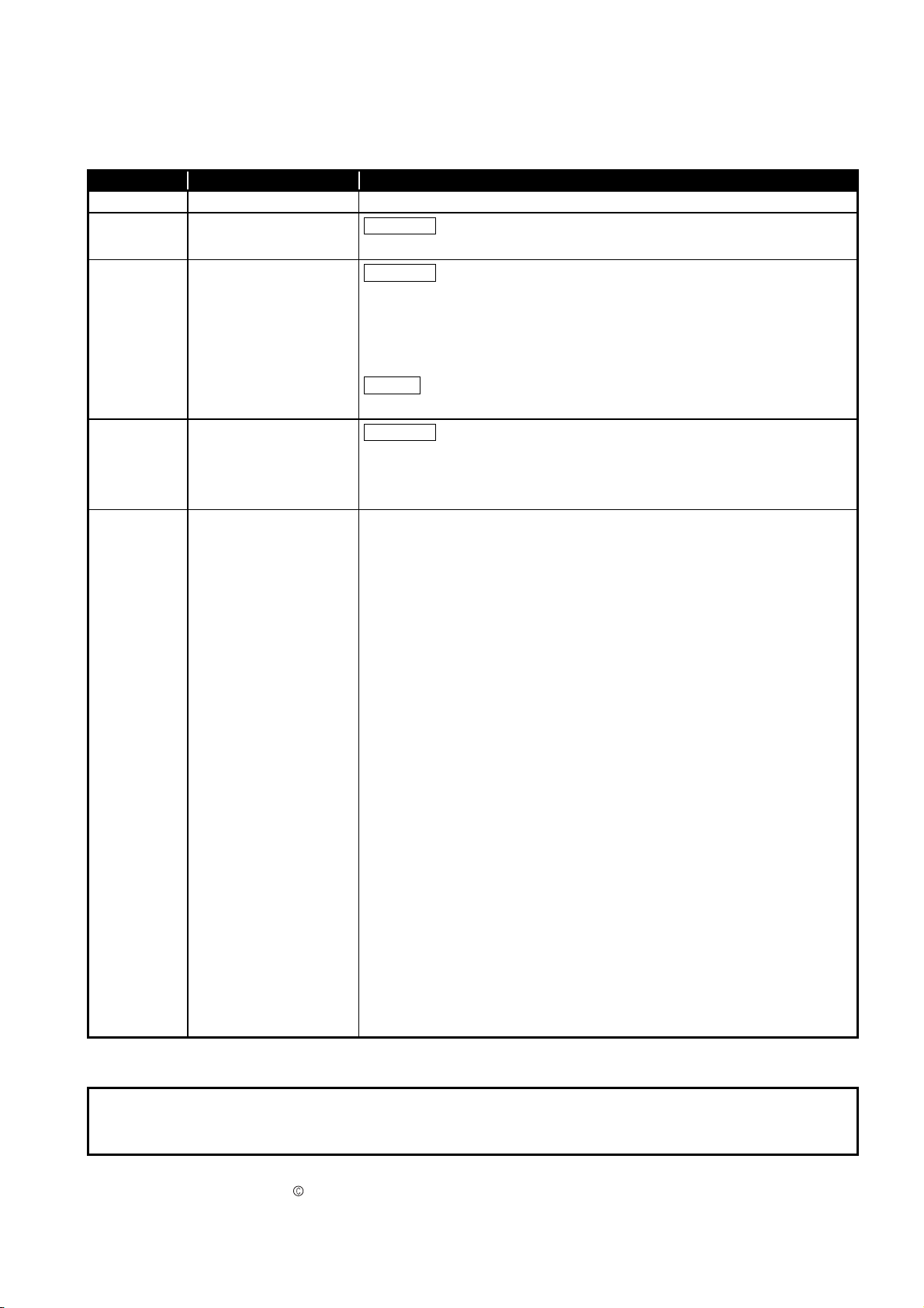
REVISIONS
* The manual number is given on the bottom left of the back cover.
Print Date *Manual Number Revision
Oct., 2006 SH (NA)-080648ENG-A First printing
Jan.,2007 SH (NA)-080648ENG-B
Jan.,2008 SH (NA)-080648ENG-C
May,2008 SH (NA)-080648ENG-D
Correction
Section3.2.1, Section4.6
Correction
SAFETY PRECAUTIONS, About the Generic Terms and Abbreviations, Section
1.1, Section 2.1, Section 2.3, Section 4.1, Section 4.6, Section 5.2.1, Section
5.2.2, Section 7.3.3, Section 7.3.5, Section 8.1, Appendix 1, Appendix 1.1,
Appendix 1.2, Appendix 1.3
Addition
Section 2.2
Correction
SAFETY PRECAUTIONS, Compliance with the EMC and Low Voltage Directives, About the Generic Terms and Abbreviations, Section 2.1, 2.3, 4.1, 4.3,
5.1, 5.2.1, 5.2.2, 5.3.1, 5.3.3, Chapter 7, Section 7.1
Japanese Manual Version SH-080646-E
This manual confers no industrial property rights or any rights of any other kind, nor does it confer any patent
licenses. Mitsubishi Electric Corporation cannot be held responsible for any problems involving industrial
property rights which may occur as a result of using the contents noted in this manual.
2006 MITSUBISHI ELECTRIC CORPORATION
A - 5

INTRODUCTION
Thank you for purchasing the MELSEC-Q series programmable controller.
Before using the equipment, please read this manual carefully to develop full familiarity with the functions
and performance of the Q series programmable controller you have purchased, so as to ensure
correct use.
Please forward a copy of this manual to the end user.
CONTENTS
SAFETY PRECAUTIONS .................................................................................................................................A - 1
REVISIONS.......................................................................................................................................................A - 5
INTRODUCTION...............................................................................................................................................A - 6
CONTENTS ......................................................................................................................................................A - 6
ABOUT MANUALS .........................................................................................................................................A - 10
RELATED MANUALS .....................................................................................................................................A - 10
Compliance with the EMC and Low Voltage Directives ..................................................................................A - 10
ABOUT THE GENERIC TERMS AND ABBREVIATIONS ..............................................................................A - 11
PRODUCT STRUCTURE ...............................................................................................................................A - 12
1 OVERVIEW 1 - 1 to 1 - 2
1.1 Features........................................................................................................................................... 1 - 1
2 SYSTEM CONFIGURATION 2 - 1 to 2 - 6
2.1 Applicable Systems ......................................................................................................................... 2 - 1
2.2 Precautions on System Configuration ............................................................................................. 2 - 4
2.3 How to Check the Function Version and Software Version ............................................................. 2 - 5
3 SPECIFICATIONS 3 - 1 to 3 - 38
3.1 Performance Specifications ............................................................................................................. 3 - 1
3.1.1 Performance specifications list ............................................................................................... 3 - 1
3.1.2 I/O conversion characteristics ................................................................................................ 3 - 2
3.1.3 Accuracy ................................................................................................................................. 3 - 9
3.1.4 Conversion speed................................................................................................................... 3 - 9
3.2 Function List .................................................................................................................................. 3 - 10
3.2.1 Analog output HOLD/CLEAR function .................................................................................. 3 - 11
3.2.2 Analog output test during programmable controller CPU STOP .......................................... 3 - 13
3.2.3 Warning output function........................................................................................................ 3 - 14
3.2.4 Rate control function............................................................................................................. 3 - 16
3.2.5 Scaling function .................................................................................................................... 3 - 18
3.3 I/O Signals for the Programmable Controller CPU ........................................................................ 3 - 21
3.3.1 List of I/O signals .................................................................................................................. 3 - 21
3.3.2 Details of I/O signals............................................................................................................. 3 - 22
3.4 Buffer Memory ............................................................................................................................... 3 - 27
A - 6

3.4.1 Buffer memory assignment...................................................................................................3 - 27
3.4.2 D/A conversion enable/disable setting (Un\G0).................................................................... 3 - 30
3.4.3 CH digital values (Un\G1 to Un\G6) ..................................................................................... 3 - 30
3.4.4 CH[ ]set value check codes (Un\G11 to Un\G16)................................................................. 3 - 31
3.4.5 Error codes (Un\G19) ........................................................................................................... 3 - 31
3.4.6 Setting range (Un\G20, Un\G21) .......................................................................................... 3 - 32
3.4.7 Offset/gain setting mode and offset/gain specification (Un\G22, Un\G23) ........................... 3 - 32
3.4.8 Offset/gain adjustment value specification (Un\G24) ........................................................... 3 - 33
3.4.9 Offset/gain range setting (Un\G25)....................................................................................... 3 - 33
3.4.10 Rate control enable/disable setting (Un\G46)....................................................................... 3 - 34
3.4.11 Warning output setting (Un\G47).......................................................................................... 3 - 34
3.4.12 Warning output flag (Un\G48)............................................................................................... 3 - 35
3.4.13 Scaling enable/disable setting (Un\G53) .............................................................................. 3 - 35
3.4.14 Scaling upper/lower limit value (Un\G54 to Un\G65)............................................................ 3 - 36
3.4.15 CH increase/decrease digital limit values (Un\G70 to Un\G81)............................................ 3 - 36
3.4.16 CH warning output upper limit value/lower limit value (Un\G86 to Un\G97) ......................... 3 - 36
3.4.17 Mode switching setting (Un\G158, Un\G159) ....................................................................... 3 - 37
3.4.18 Save data classification setting (Un\G200)........................................................................... 3 - 37
3.4.19 Factory default setting and user range settings offset/gain values
(Un\G202 to Un\G225) ......................................................................................................... 3 - 38
4 SETUP AND PROCEDURES BEFORE OPERATION 4 - 1 to 4 - 15
4.1 Handling Precautions...................................................................................................................... 4 - 1
4.2 Setup and Procedures before Operation ......................................................................................... 4 - 3
4.3 Part Names...................................................................................................................................... 4 - 4
4.4 Wiring............................................................................................................................................... 4 - 6
4.4.1 Wiring precautions.................................................................................................................. 4 - 6
4.4.2 External wiring ....................................................................................................................... 4 - 7
4.5 Intelligent Function Module Switch Setting ...................................................................................... 4 - 8
4.6 Offset/Gain Settings....................................................................................................................... 4 - 11
5 UTILITY PACKAGE (GX Configurator-DA) 5 - 1 to 5 - 34
5.1 Utility Package Functions ................................................................................................................ 5 - 1
5.2 Installing and Uninstalling the Utility Package ................................................................................. 5 - 2
5.2.1 Handling precautions.............................................................................................................. 5 - 2
5.2.2 Operating environment ........................................................................................................... 5 - 4
5.3 Utility Package Operation ................................................................................................................ 5 - 6
5.3.1 Common utility package operations ....................................................................................... 5 - 6
5.3.2 Operation overview................................................................................................................. 5 - 9
5.3.3 Starting the Intelligent function module utility ....................................................................... 5 - 11
5.4 Initial Setting .................................................................................................................................. 5 - 15
5.5 Auto Refresh Setting...................................................................................................................... 5 - 17
5.6 Monitoring/Test .............................................................................................................................. 5 - 20
5.6.1 Monitor/test screen ............................................................................................................... 5 - 20
5.6.2 Offset/gain setting operation................................................................................................. 5 - 23
5.6.3 Confirmation of Conversion Characteristic ........................................................................... 5 - 25
A - 7

5.6.4 Pass data.............................................................................................................................. 5 - 27
5.7 FB Conversion of Initial Setting/Auto Refresh Setting ................................................................... 5 - 29
5.8 Usage of FB................................................................................................................................... 5 - 31
5.8.1 Outline .................................................................................................................................. 5 - 31
5.8.2 Paste an FB to a Sequence Program ................................................................................... 5 - 33
5.8.3 Convert (Compile) a Sequence Program.............................................................................. 5 - 34
6 PROGRAMMING 6 - 1 to 6 - 18
6.1 Programming Procedure.................................................................................................................. 6 - 1
6.2 For Use in Normal System Configuration ........................................................................................ 6 - 2
6.2.1 Before creating a program...................................................................................................... 6 - 3
6.2.2 Program example using the utility package ............................................................................ 6 - 5
6.2.3 Programming example without using the utility package........................................................ 6 - 8
6.3 For Use on Remote I/O Network ................................................................................................... 6 - 10
6.3.1 Program example using the utility package .......................................................................... 6 - 12
6.3.2 Program example without using the utility package.............................................................. 6 - 15
7 ONLINE MODULE CHANGE 7 - 1 to 7 - 36
7.1 Online Module Change Conditions .................................................................................................. 7 - 2
7.2 Online Module Change Operations ................................................................................................. 7 - 3
7.3 Online Module Change Procedure .................................................................................................. 7 - 4
7.3.1 When industrial shipment setting is used and initial setting was made with
GX Configurator-DA ............................................................................................................... 7 - 4
7.3.2 When industrial shipment setting is used and initial setting was made with
sequence program.................................................................................................................. 7 - 9
7.3.3 When user range setting is used and initial setting was made with GX Configurator-DA
(other system is available) .................................................................................................... 7 - 14
7.3.4 When user range setting is used and initial setting was made with GX Configurator-DA
(other system is unavailable) ................................................................................................ 7 - 19
7.3.5 When user range setting is used and initial setting was made with sequence program
(other system is available) .................................................................................................... 7 - 25
7.3.6 When user range setting is used and initial setting was made with sequence program
(other system is unavailable) ................................................................................................ 7 - 30
7.4 Range Reference Table................................................................................................................. 7 - 35
7.5 Precautions for Online Module Change .........................................................................................7 - 36
8 TROUBLESHOOTING 8 - 1 to 8 - 7
8.1 Error Code List................................................................................................................................. 8 - 1
8.2 Troubleshooting ............................................................................................................................... 8 - 3
8.2.1 When the "RUN" LED is flashing or turned off........................................................................ 8 - 3
8.2.2 When the "ERR." LED is on or flashing .................................................................................. 8 - 3
8.2.3 When the "ALM" LED is turned on.......................................................................................... 8 - 3
8.2.4 When an analog output value is not output ............................................................................ 8 - 4
8.2.5 When the analog value is not within the reference accuracy of the theoretical value ............ 8 - 5
8.2.6 When analog output value is not “HOLD” ............................................................................... 8 - 5
A - 8

8.2.7 Checking the Q66DA-G status using GX Developer system monitor..................................... 8 - 6
APPENDIX App- 1 to App - 10
Appendix 1 Dedicated Instruction List and Available Devices.................................................................. App- 1
Appendix 1.1 G(P).OFFGAN ................................................................................................................App- 2
Appendix 1.2 G(P).OGLOAD ................................................................................................................App- 4
Appendix 1.3 G(P).OGSTOR................................................................................................................ App- 7
Appendix 2 External Dimension Diagram............................................................................................... App- 10
INDEX Index - 1 Index - 2
A - 9
ABOUT MANUALS
RELATED MANUALS
The following manuals are also related to this product.
If necessary, order them by quoting the details in the tables below.
Manual Name
GX Developer Version 8 Operating Manual
Describes the methods of using GX Developer to create a program and print out, monitor, and debug the
program. (Sold separately)
GX Developer Version 8 Operating Manual (Function Block)
Describes the methods of using GX Developer to create a function block and print out the function block.
(Sold separately)
îRRemark
If you would like to obtain a manual individually, printed matters are available separately. Order the manual by quoting the manual number on the table above
(model code).
COMPLIANCE WITH THE EMC AND LOW VOLTAGE DIRECTIVES
(1) For programmable controller system
To configure a system meeting the requirements of the EMC and Low Voltage
Directives when incorporating the Mitsubishi programmable controller (EMC and
Low Voltage Directives compliant) into other machinery or equipment, refer to
Chapter 9 "EMC AND LOW VOLTAGE DIRECTIVES" of the QCPU User's
Manual (Hardware Design, Maintenance and Inspection).
The CE mark, indicating compliance with the EMC and Low Voltage Directives, is
printed on the rating plate of the programmable controller.
Manual Number
(Model Code)
SH-080373E
(13JU41)
SH-080376E
(13JU44)
A - 10
(2) For the product
No additional measures are necessary for the compliance of this product with the
EMC and Low Voltage Directives.
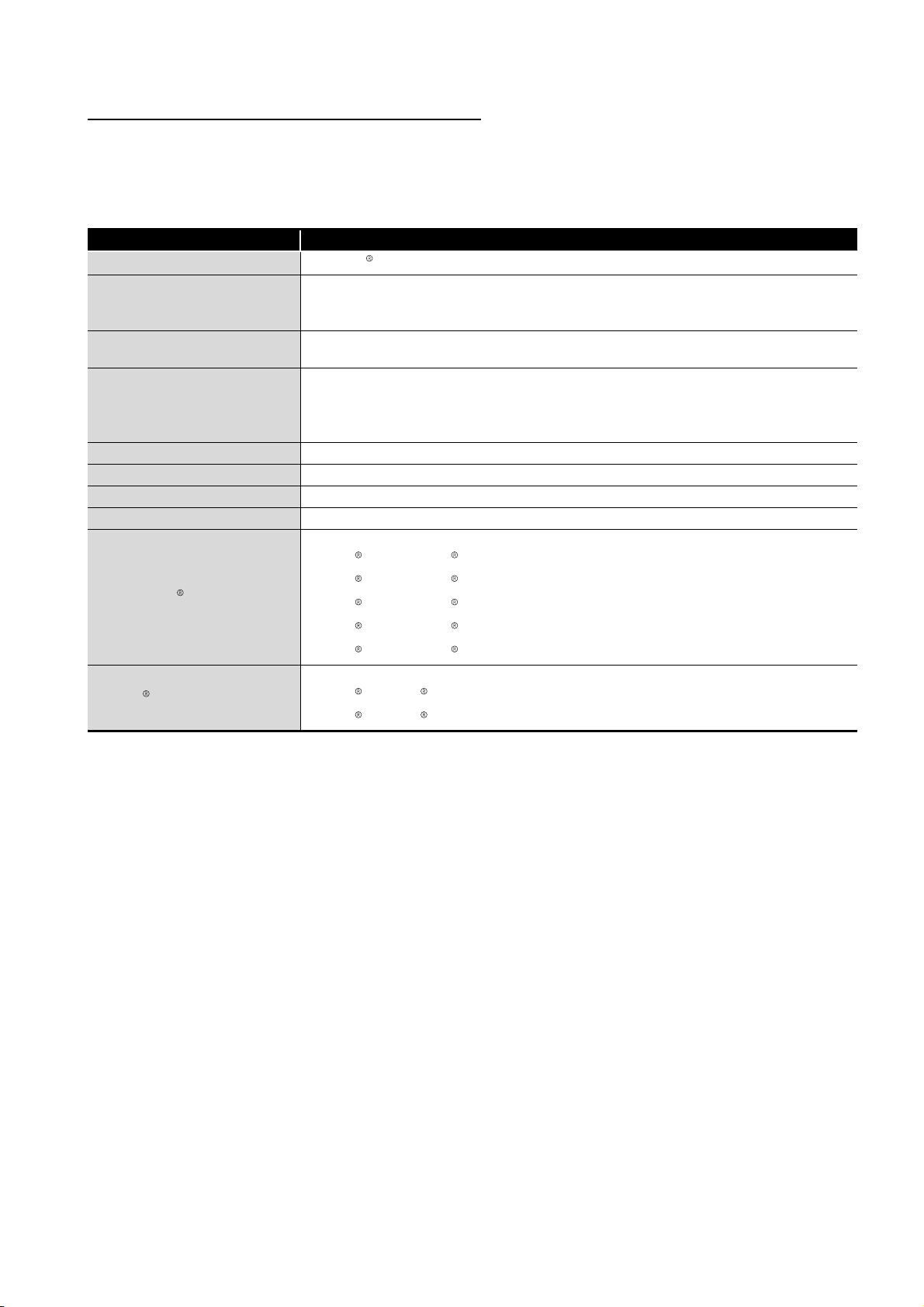
ABOUT THE GENERIC TERMS AND ABBREVIATIONS
Unless otherwise specified, this manual uses the following general terms and
abbreviations.
Abbreviation/general terms Description of the abbreviation/general terms
DOS/V personal computer
GX Developer
GX Configurator-DA
QCPU (Q mode)
Process CPU Generic term for Q02PHCPU, Q06PHCPU, Q12PHCPU and Q25PHCPU.
Personal computer Generic term for DOS/V personal computer
Industrial shipment setting Generic term for analog input ranges 0 to 5V, 1 to 5V, -10 to 10V, 0 to 20mA and 4 to 20mA.
FB Abbreviation of function block.
Windows Vista
Windows XP
IBM PC/AT or compatible computer with DOS/V.
Generic product name for the SWnD5C-GPPW-E, SWnD5C-GPPW-EA, SWnD5C-GPPW-EV and
SWnD5C-GPPW-EVA. ("n" is 4 or greater.)
"-A" and "-V" denote volume license product and upgraded product respectively.
Generic term for digital-analog conversion module setting and monitor tool GX Configurator-DA
(SW2D5C-QDAU-E).
Generic term for Q00JCPU, Q00CPU, Q01CPU, Q02CPU, Q02HCPU, Q06HCPU, Q12HCPU,
Q25HCPU, Q02PHCPU, Q06PHCPU, Q12PHCPU, Q25PHCPU, Q12PRHCPU, Q25PRHCPU,
Q02UCPU, Q03UDCPU, Q04UDHCPU, Q06UDHCPU, Q13UDHCPU, Q26UDHCPU,
Q03UDECPU, Q04UDEHCPU, Q06UDEHCPU, Q13UDEHCPU and Q26UDEHCPU.
Generic term for the following:
Microsoft Windows Vista Home Basic Operating System,
Microsoft Windows Vista Home Premium Operating System,
Microsoft Windows Vista Business Operating System,
Microsoft Windows Vista Ultimate Operating System,
Microsoft Windows Vista Enterprise Operating System
Generic term for the following:
Microsoft Windows XP Professional Operating System,
Microsoft Windows XP Home Edition Operating System
A - 11

PRODUCT STRUCTURE
The product structure of this product is given in the table below.
Model code Product name Quantity
Q66DA-G Q66DA-G Model Channel Isolated Digital-Analog Converter module 1
SW2D5C-QDAU-E
SW2D5C-QDAU-EA
GX Configurator-DA Version 2(1-license product) (CD-ROM)
GX Configurator-DA Version 2(Multiple-license product) (CD-ROM)
1
1
A - 12

1
OVERVIEW
1 OVERVIEW
This User's Manual describes the specifications, handling and programming methods for
the Q66DA-G type channel isolated digital-analog converter module (hereinafter referred
to as the Q66DA-G) which are used in conjunction with MELSEC-Q series CPU module
(hereinafter referred to as the programmable controller CPU).
1.1 Features
1
OVERVIEW
2
(1) Multi-channel analog input is available.
By using a single Q66DA-G, analog voltage or current outputs of 6 points (6 channels)
are available.
(2) Channel isolated
The module is isolated between the channels and between the external supply power
and channels.
(3) High accuracy
The reference accuracy*1 is as high as +0.1% and the temperature coefficient*2 is as
high as -80ppm/°C.
*1: Accuracy attained at the ambient temperature when offset/gain setting has been made
*2: Accuracy per temperature change of 1°C
Example) Accuracy when the ambient temperature varies from 25°C to 30°C
0.1% (reference accuracy) + 0.008%/°C (temperature coefficient) 5°C
(temperature variation difference) = 0.14%
(4) Output range switching
The output range*1 switching can be set easily from GX Developer.
*1: The output range indicates the offset/gain setting type. Besides the generally often used output
ranges available as defaults, the user can make offset/gain settings and use the values. (Refer to
Section 4.5)
SYSTEM
CONFIGURATION
3
SPECIFICATIONS
4
SETUP AND
PROCEDURES
BEFORE OPERATION
5
UTILITY PACKAGE
(GX CONFIGURATOR-
DA)
6
(4) Analog output HOLD/CLEAR function
This function is used to set whether the analog output value will be held or cleared
when the CPU module is in a STOP status or when a stop error occurs. (Refer to
Section 3.2.1)
(5) Output monitor function
The analog output value output by D/A conversion is reconverted into a digital value
within the Q66DA-G and the result is stored into the buffer memory as an output
monitor value.
(6) Changing the resolution mode
The resolution mode can be changed according to the application, and digital value
resolution settings of 1/4000, 1/12000 or 1/16000 can be selected. (Refer to Section
4.5)
1.1 Features
1 - 1
PROGRAMMING
7
ONLINE MODULE
CHANGE
8
TROUBLESHOOTING

1
OVERVIEW
(7) Warning output function
A warning is output if a digital input value falls outside the setting range. (Refer to
Section 3.2.4.)
(8) Rate control function
The increase and decrease in analog output values per 6ms *1 can be limited,
preventing rapid change of the values. (Refer to Section 3.2.4.)
*1 6ms is the conversion cycle per channel.
(9) Scaling function
The digital input value range can be changed to any given range between –32000 and
32000, and digital values within the range are converted to analog values. (Refer to
Section 3.2.5.)
(10)Online module change
The module can be changed without the system being stopped.
Further, the dedicated instruction (G(P). OGLOAD, G(P). OGSTOR), write to the
buffer memory, or turning ON the Y signal enables "inheritance of offset/gain settings
to the new Q66DA-G replacing the old one changed online" and "transfer of offset/
gain settings to the other Q66DA-G mounted on the other slot". (These apply to the
modules of the same model.) (Refer to Chapter 7.)
(11)Offset/gain setting
GX Configurator-DA, dedicated instruction (G(P). OFFGAN) or mode switching
setting allows a shift to the offset/gain setting mode easily. (Refer to Section 4.6.)
(12)Easy settings using the utility package
A utility package is sold separately (GX Configurator-DA).
The utility package is not a required item, however, it is useful for on-screen setting of
the intelligent function module parameters (initial setting/auto refresh setting). In
addition, FB
parameters that have been set up and used in a sequence program. (Refer to
Chapter 5.)
*1: FB is the function for making a circuit block used in a sequence program repeatedly a part (FB) to
*1
can be generated automatically from the intelligent function module
use it in the sequence program.
This function can improve the efficiency of program development and minimize program bugs to
improve program qualities.
For the details of FB, refer to "GX Developer Version 8 Operating Manual (Function Block)."
1 - 2
1.1 Features
2
SYSTEM CONFIGURATION
2 SYSTEM CONFIGURATION
This chapter explains the system configuration of the Q66DA-G.
2.1 Applicable Systems
This section describes the applicable systems.
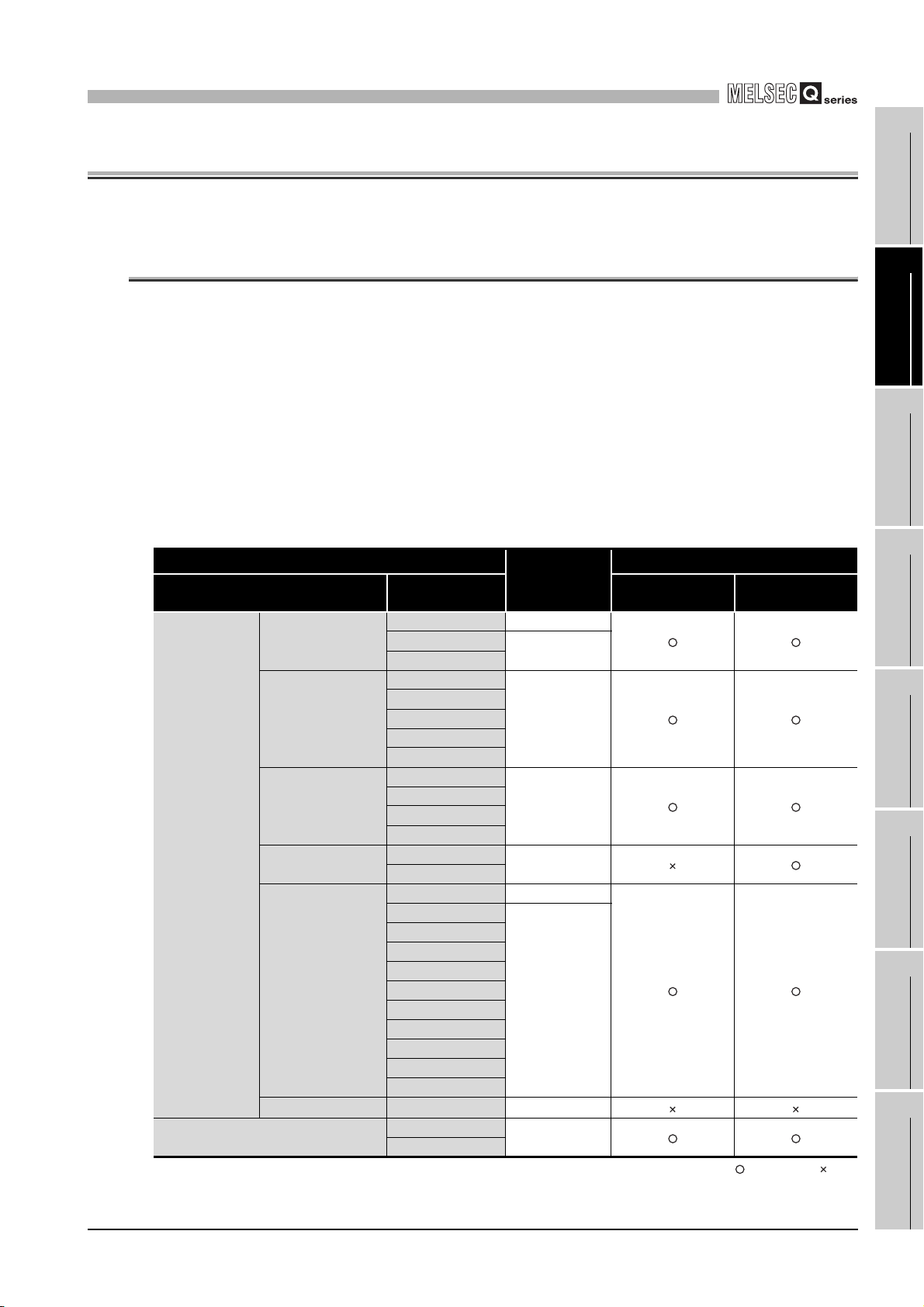
(1) Applicable modules and base units, and No. of modules
(a) When mounted with a CPU module
The table below shows the CPU modules and base units applicable to the
Q66DA-G and quantities for each CPU model.
Depending on the combination with other modules or the number of mounted
modules, power supply capacity may be insufficient.
Pay attention to the power supply capacity before mounting modules, and if the
power supply capacity is insufficient, change the combination of the modules.
Applicable CPU module
CPU type CPU model Main base unit
Q00JCPU Up to 16
Programmable
controller CPU
C Controller module
Basic model QCPU
High Performance
model QCPU
Process CPU
Redundant CPU
Universal model
QCPU
Safety CPU QS001CPU N/A
*1 Limited within the range of I/O points for the CPU module.
*2 Can be installed to any I/O slot of a base unit.
Q00CPU
Q01CPU
Q02CPU
Q02HCPU
Q06HCPU
Q12HCPU
Q25HCPU
Q02PHCPU
Q06PHCPU
Q12PHCPU
Q25PHCPU
Q12PRHCPU
Q25PRHCPU
Q02UCPU Up to 36
Q03UDCPU
Q04UDHCPU
Q06UDHCPU
Q13UDHCPU
Q26UDHCPU
Q03UDECPU
Q04UDEHCPU
Q06UDEHCPU
Q13UDEHCPU
Q26UDEHCPU
Q06CCPU-V
Q06CCPU-V-B
No. of mod-
*1
ules
Up to 24
Up to 64
Up to 64
Up to 53
Up to 64
Up to 64
Base unit
2.1 Applicable Systems
*2
Extension base
unit
: Applicable, : N/A
2 - 1
1
OVERVIEW
2
SYSTEM
CONFIGURATION
3
SPECIFICATIONS
4
SETUP AND
PROCEDURES
BEFORE OPERATION
5
UTILITY PACKAGE
(GX CONFIGURATOR-
DA)
6
PROGRAMMING
7
ONLINE MODULE
CHANGE
8
TROUBLESHOOTING
2
SYSTEM CONFIGURATION
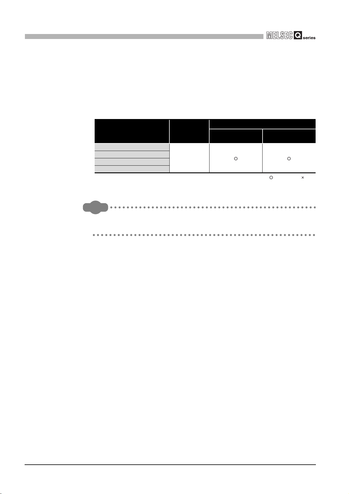
(b) Mounting to a MELSECNET/H remote I/O station
The table below shows the network modules and base units applicable to the
Q66DA-G and quantities for each network module model.
Depending on the combination with other modules or the number of mounted
modules, power supply capacity may be insufficient.
Pay attention to the power supply capacity before mounting modules, and if the
power supply capacity is insufficient, change the combination of the modules.
Applicable network module
QJ72LP25-25
QJ72LP25G
QJ72LP25GE
QJ72BR15
*1 Limited within the range of I/O points for the network module.
*2 Can be installed to any I/O slot of a base unit.
No. of mod-
*1
ules
Up to 64
Main base unit of
remote I/O station
Base unit
*2
Extension base unit of
remote I/O station
: Applicable, : N/A
Remark
The Basic model QCPU or C Controller module cannot create the MELSECNET/
H remote I/O network.
(2) Support of the multiple CPU system
When using the Q66DA-G in a multiple CPU system, refer to the following manual
first.
• QCPU User's Manual (Multiple CPU System)
(a) Intelligent function module parameters
Write intelligent function module parameters to only the control CPU of the
Q66DA-G.
2 - 2
(3) Compatibility with online module change
The Q66DA-G supports online module change (hot swapping).
For procedures of the online module change, refer to Chapter7.
2.1 Applicable Systems
2
SYSTEM CONFIGURATION
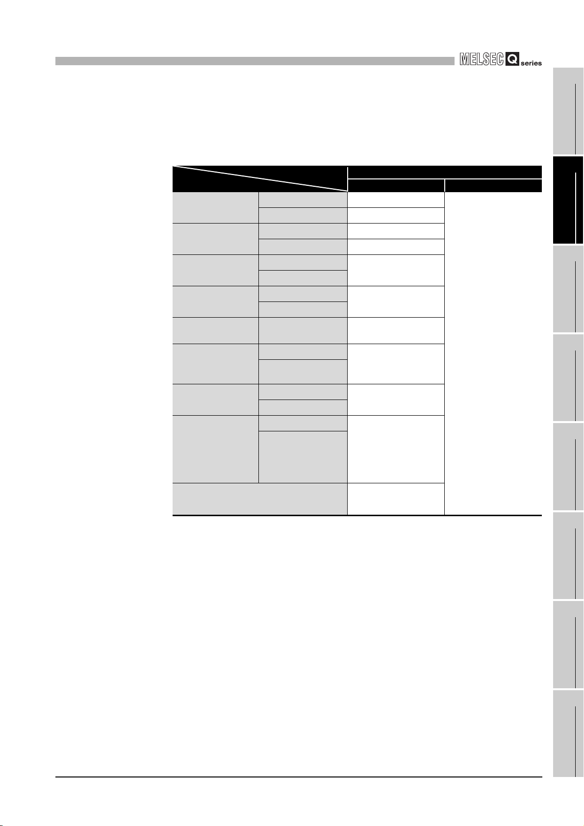
(4) Supported software packages
Relation between the system containing the Q66DA-G and software package is
shown in the following table.
GX Developer is necessary when using the Q66DA-G.
Q00J/Q00/Q01CPU
Q02/Q02H/Q06H/
Q12H/Q25HCPU
Q02PH/Q06PHCPU
Q12PH/Q25PHCPU
Q12PRH/
Q25PRHCPU
Q02U/Q03UD/
Q04UDH/
Q06UDHCPU
Q13UDH/
Q26UDHCPU
Q03UDE/
Q04UDEH/
Q06UDEH/
Q13UDEH/
Q26UDEHCPU
If installed in a MELSECNET/H remote I/O
station
Single CPU system Version 7 or later
Multiple CPU system Version 8 or later
Single CPU system Version 4 or later
Multiple CPU system Version 6 or later
Single CPU system
Multiple CPU system
Single CPU system
Multiple CPU system
Redundant CPU
system
Single CPU system
Multiple CPU system
Single CPU system
Multiple CPU system
Single CPU system
Multiple CPU system
Software Version
GX Developer GX Configurator-DA
Version 8.68W or later
Version 7.10L or later
Version 8.45X or later
Version 2.06G or later
Version 8.48A or later
Version 8.62Q or later
Version 8.68W or later
Version 6 or later
SETUP AND
UTILITY PACKAGE
1
OVERVIEW
2
SYSTEM
CONFIGURATION
3
SPECIFICATIONS
4
PROCEDURES
BEFORE OPERATION
5
(GX CONFIGURATOR-
DA)
6
2.1 Applicable Systems
2 - 3
PROGRAMMING
7
ONLINE MODULE
CHANGE
8
TROUBLESHOOTING
2
SYSTEM CONFIGURATION
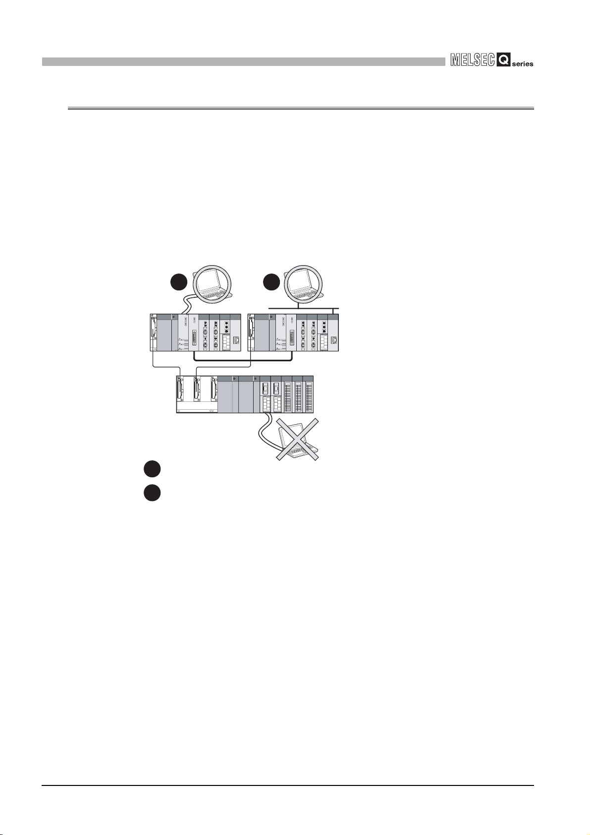
2.2 Precautions on System Configuration
(1) For Use with Q12PRH/Q25PRHCPU
(a) Dedicated instruction
The dedicated instruction cannnot be used.
(b) GX Configurator-DA connection
GX Configurator-DA cannot be used when accessing the Q12PRH/Q25PRHCPU
via an intelligent function module on an extension base unit from GX Developer.
Connect a personal computer with a communication path indicated below.
1 2
1
Direct connection to use the CPU
2
Direct connection to the CPU
Main base unit
Extension base unit
(GX Configurator-DA cannot be used.)
2 - 4
2.2 Precautions on System Configuration
2
SYSTEM CONFIGURATION
2.3 How to Check the Function Version and Software Version
This section describes how to check the function version of the Q66DA-G and the GX
Configuration-DA software version.
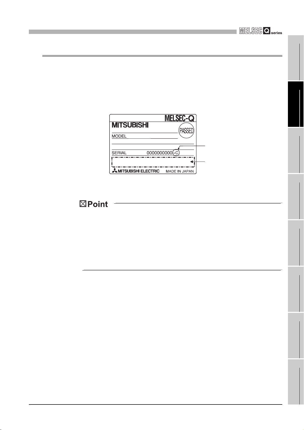
(1) Checking the function version of the Q66DA-G
(a) Checking at "the SERIAL field of the rating plate" located on the side of the mod-
ule
(b) To check the version using the GX Developer
Refer to Section 8.2.7 of this manual.
080810
Function version
Relevant regulation
standards
1
OVERVIEW
2
SYSTEM
CONFIGURATION
3
SPECIFICATIONS
4
The serial No. on the rating plate may be different from the serial No. displayed on
the product information screen of GX Developer.
• The serial No. on the rating plate indicates the management information
of the product.
• The serial No. displayed on the product information screen of GX Developer indicates the function information of the product.
The function information of the product is updated when a new function is
added.
SETUP AND
PROCEDURES
BEFORE OPERATION
5
UTILITY PACKAGE
(GX CONFIGURATOR-
DA)
6
PROGRAMMING
7
ONLINE MODULE
CHANGE
8
2.3 How to Check the Function Version and Software Version
TROUBLESHOOTING
2 - 5
2
SYSTEM CONFIGURATION
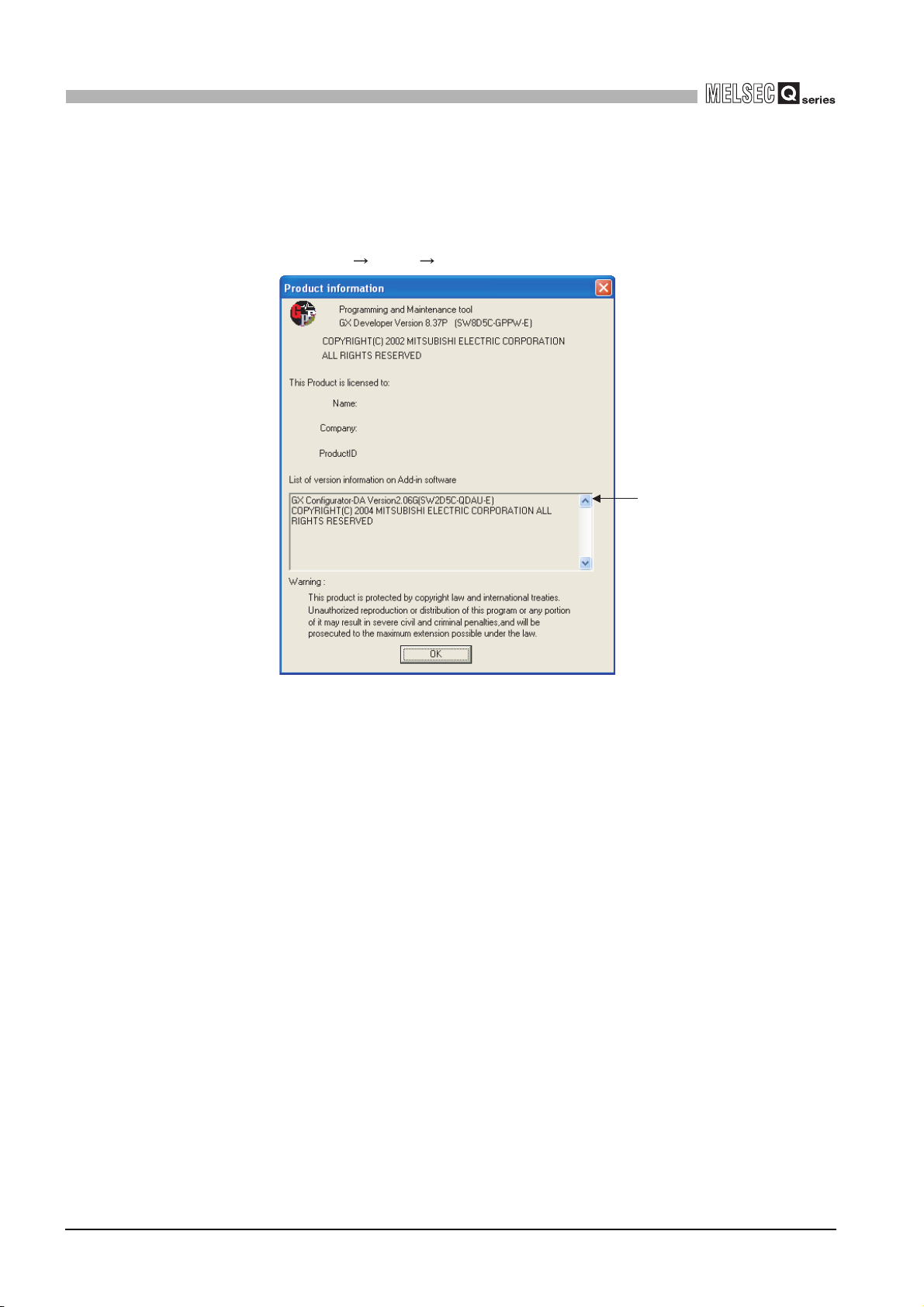
(2) Checking the software version of GX Configuration-DA
The software version of GX Configurator-DA can be checked in GX Developer's "Productinformation" screen.
[Operating procedure]
GX Developer [Help] [Product information]
Software version
(In the case of GX Developer Version 8)
2 - 6
2.3 How to Check the Function Version and Software Version
3
SPECIFICATIONS
3 SPECIFICATIONS
3.1 Performance Specifications
3.1.1 Performance specifications list
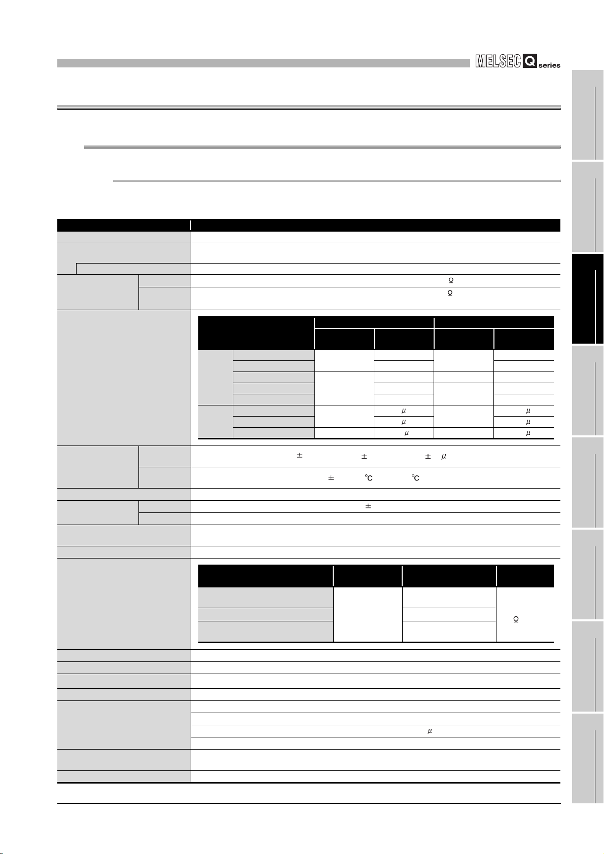
Table3.1 Performance specifications list
Item Specifications
Number of analog outputs 6 points (6 channels)
Digital input
Using scaling function 16-bit signed binary (-32768 to 32767)
Volt age
Analog output
I/O characteristics
maximum resolution
Accuracy (Accuracy
relative to maximum
analog output value)
Conversion speed
Absolute maximum
output
Maximum number of writes to flash
memory
Output short-circuit protection
Current
Analog output range
Volt age
User range setting 2 0.75mV
User range setting 3 0.375mV 0.210mV
Current
User range setting 1 -4000 to 4000 1.5 A -12000 to 12000 0.95 A
Reference
accuracy *1
Temperature
coefficient *2
Volt age
Current
16-bit signed binary (normal resolution mode:-4096 to 4095
high resolution mode: -12288 to 12287, -16384 to 16383)
-12 to 12VDC (External load resistance: 1k to 1M )
0 to 20mADC (External load resistance: 0 to 600 )
0 to 22mADC (External load resistance: Please refer to Note 3)
Normal resolution mode High resolution mode
Digital input
value
0 to 5V
1 to 5V 1.0mV 0.333mV
-10 to 10V
0 to 20mA
4 to 20mA 4 A 1.33 A
0 to 4000
-4000 to 4000
0 to 4000
0.1% (Voltage: 10mV, Current: 20 A)
80ppm/ (0.008%/ )
6ms/ channels
Up to 50,000 times
Maximum
resolution
1.25mV
2.5mV -16000 to 16000 0.625mV
13V
23mA
Available
5A
Digital input
value
0 to 12000
-12000 to 12000
0 to 12000
Maximum
resolution
0.416mV
0.400mV
1.66 A
1
OVERVIEW
2
SYSTEM CONFIGU-
RATION
3
SPECIFICATIONS
4
SETUP AND PROCE-
DURES BEFORE
OPERATION
5
UTILITY PACKAGE
(GX CONFIGURA-
TOR-DA)
6
Isolation specifications
Number of I/O occupied points
External wiring connection system
Applicable wire size
External device connection connector
External supply power
Internal current consumption
(5 VDC)
Weight
Specific isolated area Isolation method
Between the output terminal and programmable controller power supply
Between analog output channels
Between external supply power and
analog output cannel
16 points (I/O assignment: Intelligent 16 points)
Ripple, spike within 500 mV p-p
Inrush current: 4.8A, within 400 s
Dielectric withstand
oltage
500VAC rms, 1min
Transformer
isolation
40-pin connector
0.3 mm2 (AWG #22)
A6CON4 (Sold separately)
24VDC, +20%, -15%
0.22A
0.62A
0.22kg
1000VAC rms, 1min
500VAC rms, 1min
3.1 Performance Specifications
3.1.1 Performance specifications list
Insulation
resistance
500VDC
10M or more
3 - 1
PROGRAMMING
7
ONLINE MODULE
CHANGE
8
TROUBLESHOOT-
ING
3
SPECIFICATIONS
*1: Accuracy of offset/gain setting at ambient temperature
Q66DA-G needs to be powered on 30 minutes prior to operation for compliance to the specification
(accuracy).
*2: Accuracy per temperature change of 1 °C
Example: Accuracy when temperature changes from 25 to 30 °C
0.1% (Reference accuracy) + 0.008%/ °C (temperature coefficient) 5 °C (temperature
change difference) = 0.14%
*3: The following indicates the external load resistance when output current is 20mA or more.
Output
current
22mA
20mA
500
External load resistance
Remark
See the user's manual for the CPU module being used for the general specifications for the Q66DA-G.
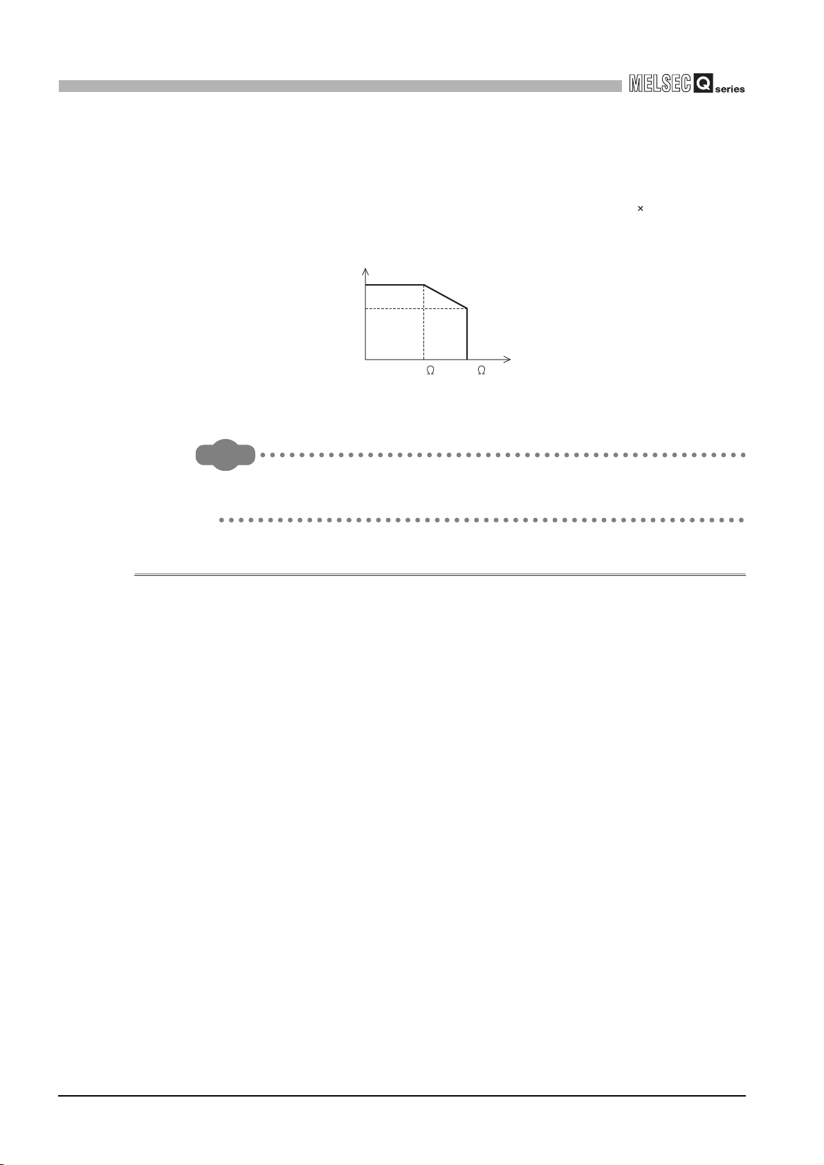
3.1.2 I/O conversion characteristics
I/O conversion characteristics are used for converting the digital value written from the programmable controller CPU to an analog output value (voltage or current output), and represented by inclined straight lines when offset and gain values are included.
Offset value
The offset value is the analog output value (voltage or current) when the digital input value
set from the programmable controller CPU is 0.
Gain value
The gain value is the analog output value (voltage or current) when the digital input value
set from the programmable controller CPU is
4000 (in normal resolution mode)
12000 (when 1 to 5V, 0 to 5V, 4 to 20 mA, 0 to 20 mA or the user range setting1 to 3 is
selected in high resolution mode),
16000 (when -10 to 10V is selected in high resolution mode).
600
3 - 2
3.1 Performance Specifications
3.1.2 I/O conversion characteristics
3
SPECIFICATIONS
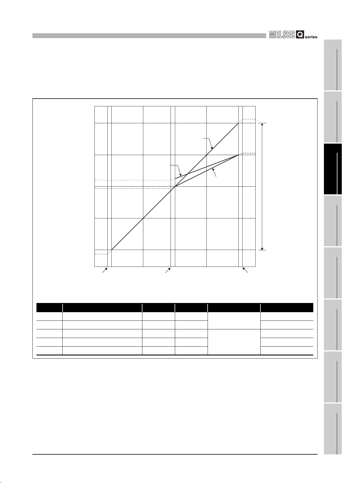
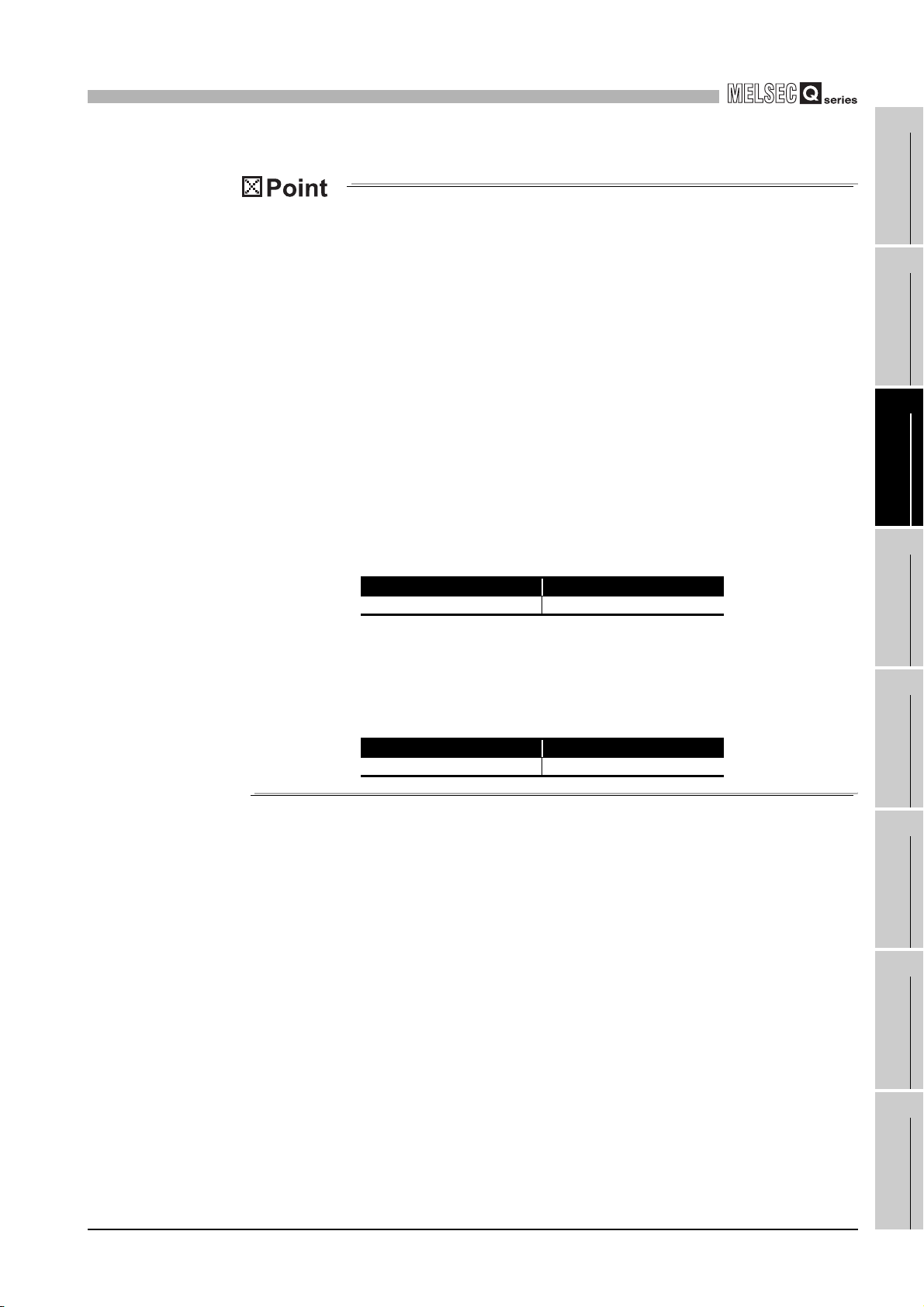
(1) Voltage output characteristic
(a) Voltage output characteristic in normal resolution mode
Fig.3.1 shows a graph of the voltage output characteristic in normal resolution
mode.
10
1
OVERVIEW
2
3)
5
1)
1
0
Analog output value(V)
-5
-10
-4000-4096
Number Output range setting Offset value Gain value Digital input value Maximum resolution
1) 1 to 5 V 1 V 5 V
2) 0 to 5 V 0 V 5 V 1.25 mV
3) -10 to 10 V 0 V 10 V
- User range setting 2 *1 *1 0.75 mV
- User range setting 3 *2 *2 0.375 mV
Fig.3.1 Voltage output characteristic in normal resolution mode
-2000
0
-96
Digital input value
2)
0 to 4000
-4000 to 4000
Practical analog output range
409540002000
1.0 mV
2.5 mV
SYSTEM CONFIGU-
RATION
3
SPECIFICATIONS
4
SETUP AND PROCE-
DURES BEFORE
OPERATION
5
UTILITY PACKAGE
(GX CONFIGURA-
TOR-DA)
6
PROGRAMMING
7
3.1 Performance Specifications
3.1.2 I/O conversion characteristics
3 - 3
ONLINE MODULE
CHANGE
8
TROUBLESHOOT-
ING
3
SPECIFICATIONS
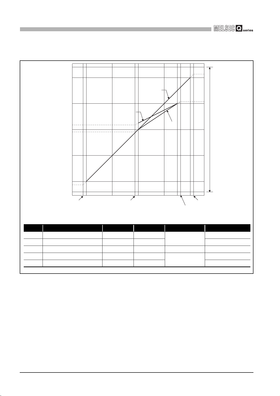
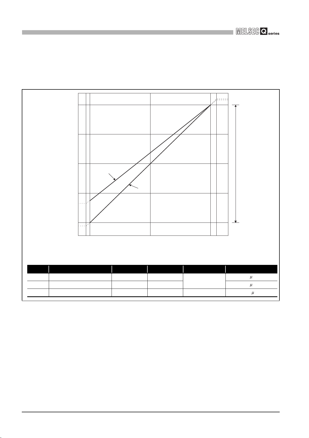
(b) Voltage output characteristic in high resolution mode
Fig.3.2 shows a graph of the voltage output characteristic in high resolution mode.
12
10
3)
5
1)
1
0
Analog output value(V)
-5
-10
-12
0
-288
Digital input value
Number Output range setting Offset value Gain value Digital input value Maximum resolution
1) 1 to 5 V 1 V 5 V
2) 0 to 5 V 0 V 5 V 0.416 mV
3) –10 to 10 V 0 V 10 V -16000 to 16000 0.625 mV
- User range setting2 *1 *1
- User range setting3 *2 *2 0.210 mV
2)
12000
12287
0 to 12000
-12000 to 12000
Practical analog output range
16383160008000-8000-16000-16384
0.333 mV
0.400 mV
3 - 4
Fig.3.2 Voltage output characteristic in high resolution mode
3.1 Performance Specifications
3.1.2 I/O conversion characteristics
3
SPECIFICATIONS
(1) Set within the digital input range and analog output range for each output
range.
If these ranges are exceeded, the maximum resolution and accuracy may not
fall within the performance specifications. (Avoid using the dotted line area
shown in Figures 3.1 and 3.2.)
(2) In user range setting 2, the maximum and minimum output values are 6V and
-6V respectively. Obtain these values as follows using the gain and offset values.
Maximum analog output value = Gain value
Minimum analog output value = (Offset value - (Gain value - Offset value))
If a maximum or minimum value exceeds the output range, use user range
setting 3.
(3) Set the offset/gain values for the user range setting 2 *1 within a range in
which the following conditions are satisfied.
(a) Setting range is from -12 to 12 V.
(b) { (Gain value) - (Offset value) } > A
<Value of A>
Normal resolution mode High resolution mode
3.0V 5.0V
1
2
SYSTEM CONFIGU-
3
4
OVERVIEW
RATION
SPECIFICATIONS
(4) Set the offset/gain values for the user range setting 3 *2 within a range in
which the following conditions are satisfied.
(a) Setting range is from -0.5 to 6 V.
(b) { (Gain value) - (Offset value) } > A
<Value of A>
Normal resolution mode High resolution mode
1.5V 2.6V
SETUP AND PROCE-
DURES BEFORE
OPERATION
5
UTILITY PACKAGE
(GX CONFIGURA-
TOR-DA)
6
PROGRAMMING
7
ONLINE MODULE
CHANGE
8
3.1 Performance Specifications
3.1.2 I/O conversion characteristics
3 - 5
TROUBLESHOOT-
ING
3
SPECIFICATIONS
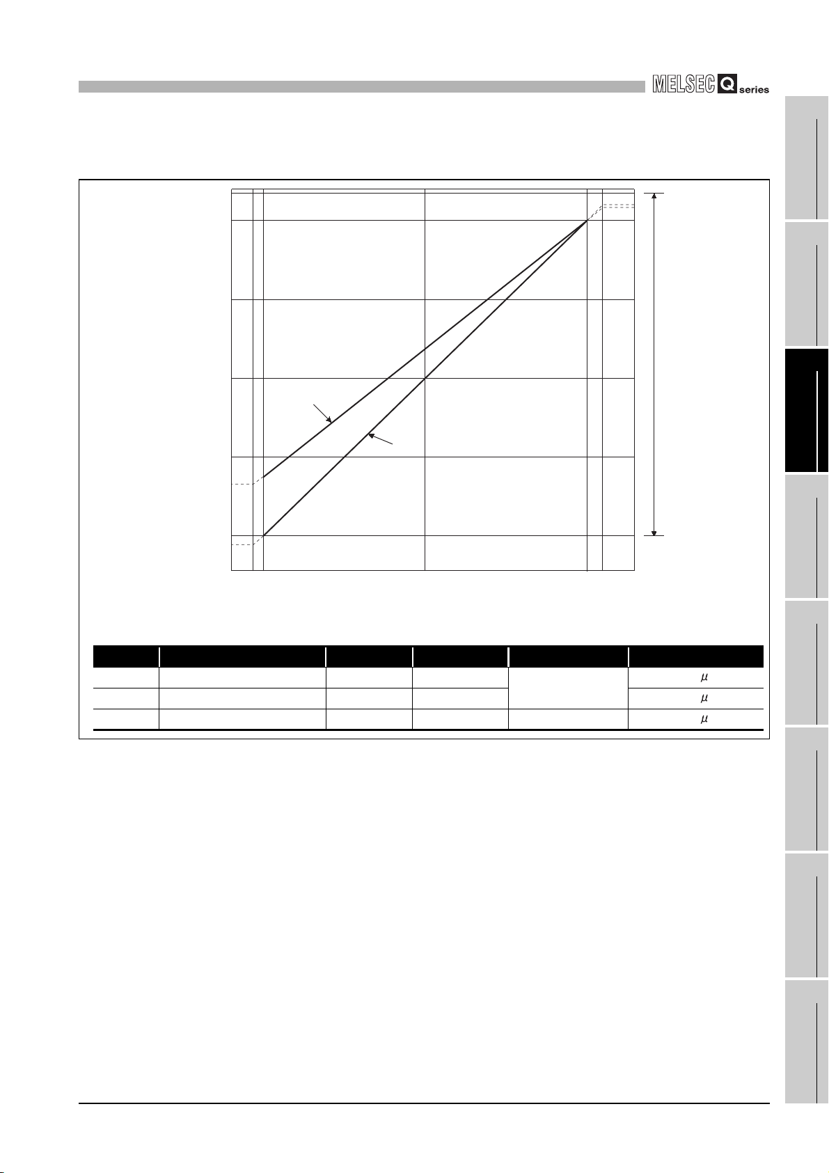
(2) Current output characteristic
(a) Current output characteristic in normal resolution mode
Fig.3.3 shows a graph of the current output characteristic in normal resolution
mode.
20
15
10
1)
Analog output value(mA)
5
4
0
0-96 2000 4095
Number Output range setting Offset value Gain value Digital input value Maximum resolution
1) 4 to 20 mA 4 mA 20 mA
2) 0 to 20 mA 0 mA 20 mA
- User range setting1 *1 *1 –4000 to 4000
Fig.3.3 Current output characteristic in normal resolution mode
2)
4000
Digital input value
0 to 4000
Practical analog output range
4A
5A
1.5 A
3 - 6
3.1 Performance Specifications
3.1.2 I/O conversion characteristics
3
SPECIFICATIONS
(b) Current output characteristic in high resolution mode
Fig.3.4 shows a graph of the current output characteristic in high resolution mode.
22
20
15
10
Analog output value(mA)
5
4
1
OVERVIEW
2
SYSTEM CONFIGU-
RATION
3
1)
2)
Practical analog output range
SPECIFICATIONS
4
0
0-288 6000 12287
Digital input value
Number Output range setting Offset value Gain value Digital input value Maximum resolution
1) 4 to 20 mA 4 mA 20 mA
2) 0 to 20 mA 0 mA 20 mA
- User range setting1 *1 *1 –12000 to 12000
Fig.3.4 Current output characteristic in high resolution mode
12000
0 to 12000
1.33 A
1.66 A
0.95 A
SETUP AND PROCE-
DURES BEFORE
OPERATION
5
UTILITY PACKAGE
(GX CONFIGURA-
TOR-DA)
6
PROGRAMMING
7
3.1 Performance Specifications
3.1.2 I/O conversion characteristics
3 - 7
ONLINE MODULE
CHANGE
8
TROUBLESHOOT-
ING

3
SPECIFICATIONS
(1) Set within the digital input range and analog output range for each output
range.
If these ranges are exceeded, the maximum resolution and accuracy may not
fall within the performance specifications. (Avoid using the dotted line area
shown in Figures 3.3 and 3.4.)
(2) Set the offset/gain values for the user range setting 1 *1 within a range in
which the following conditions are satisfied.
(a) Setting range is from 0 to 22 mA
(b) { (Gain value) - (Offset value) } > A
<Value of A>
Normal resolution mode High resolution mode
6.0mA 11.5mA
3 - 8
3.1 Performance Specifications
3.1.2 I/O conversion characteristics
 Loading...