

Page 1

MELSEC-Q Temperature Control Module
User's Manual
-Q64TCTTN
-Q64TCTTBWN
-Q64TCRTN
-Q64TCRTBWN
Page 2

Page 3
SAFETY PRECAUTIONS
(Read these precautions before using this product.)
Before using this product, please read this manual and the relevant manuals carefully and pay full attention
to safety to handle the product correctly.
The precautions given in this manual are concerned with this product only. For the safety precautions of the
programmable controller system, refer to the user's manual for the CPU module used.
In this manual, the safety precautions are classified into two levels: " CAUTION" and " WARNING".
WARNING
CAUTION
Under some circumstances, failure to observe the precautions given under " CAUTION" may lead to
serious consequences.
Observe the precautions of both levels because they are important for personal and system safety.
Make sure that the end users read this manual and then keep the manual in a safe place for future
reference.
Indicates that incorrect handling may cause hazardous conditions,
resulting in death or severe injury.
Indicates that incorrect handling may cause hazardous conditions,
resulting in minor or moderate injury or property damage.
[Design Precautions]
WARNING
● Outputs may remain on or off due to a failure of a component such as a transistor in an output circuit.
Configure an external circuit for monitoring output signals that could cause a serious accident.
● Do not write any data to the "system area" and "write-protect area" (R) of the buffer memory in the
intelligent function module. Also, do not use any "use prohibited" signal as an input or output signal
from the intelligent function module to the programmable controller CPU.
Doing so may cause malfunction of the programmable controller system.
CAUTION
● Do not install the control lines or communication cables together with the main circuit lines or power
cables. Keep a distance of 100mm or more between them.
Failure to do so may result in malfunction due to noise.
1
Page 4

[Installation Precautions]
CAUTION
● Use the programmable controller in an environment that meets the general specifications in the user's
manual for the CPU module used.
Failure to do so may result in electric shock, fire, malfunction, or damage to or deterioration of the
product.
● To mount the module, while pressing the module mounting lever located in the lower part of the
module, fully insert the module fixing projection(s) into the hole(s) in the base unit and press the
module until it snaps into place.
Incorrect mounting may cause malfunction, failure or drop of the module.
When using the programmable controller in an environment of frequent vibrations, fix the module with
a screw.
● Tighten the screw within the specified torque range.
Undertightening can cause drop of the screw, short circuit or malfunction.
Overtightening can damage the screw and/or module, resulting in drop, short circuit, or malfunction.
● Shut off the external power supply (all phases) used in the system before mounting or removing the
module.
Failure to do so may result in damage to the product.
A module can be replaced online (while power is on) on any MELSECNET/H remote I/O station or in
the system where a CPU module supporting the online module change function is used.
Note that there are restrictions on the modules that can be replaced online, and each module has its
predetermined replacement procedure.
For details, refer to the relevant chapter in this manual.
● Do not directly touch any conductive parts and electronic components of the module.
Doing so can cause malfunction or failure of the module.
2
Page 5

[Wiring Precautions]
CAUTION
● Individually ground the shielded cables of the programmable controller with a ground resistance of
100 or less.
Failure to do so may result in electric shock or malfunction.
● Use applicable solderless terminals and tighten them within the specified torque range.
If any spade solderless terminal is used, it may be disconnected when the terminal screw comes
loose, resulting in failure.
● Check the rated voltage and terminal layout before wiring to the module, and connect the cables
correctly.
Connecting a power supply with a different voltage rating or incorrect wiring may cause a fire or
failure.
● Prevent foreign matter such as dust or wire chips from entering the module.
Such foreign matter can cause a fire, failure, or malfunction.
● A protective film is attached to the top of the module to prevent foreign matter, such as wire chips,
from entering the module during wiring.
Do not remove the film during wiring.
Remove it for heat dissipation before system operation.
● Place the cables in a duct or clamp them. If not, dangling cable may swing or inadvertently be pulled,
resulting in damage to the module or cables or malfunction due to poor contact.
● When disconnecting the cable from the module, do not pull the cable by the cable part.
For the cable connected to the terminal block, loosen the terminal screw.
Pulling the cable connected to the module may result in malfunction or damage to the module or
cable.
3
Page 6

[Startup and Maintenance Precautions]
CAUTION
● Do not touch any terminal while power is on.
Doing so will cause electric shock or malfunction.
● Shut off the external power supply (all phases) used in the system before cleaning the module or
retightening the terminal screws or module fixing screws.
Failure to do so may result in electric shock or cause the module to fail or malfunction.
Undertightening can cause drop of the component or wire, short circuit, or malfunction.
Overtightening can damage the screw and/or module, resulting in drop, short circuit, or malfunction.
● Do not disassemble or modify the module.
Doing so may cause failure, malfunction, injury, or a fire.
● Shut off the external power supply (all phases) used in the system before mounting or removing the
module.
Failure to do so may cause the module to fail or malfunction.
A module can be replaced online (while power is on) on any MELSECNET/H remote I/O station or in
the system where a CPU module supporting the online module change function is used.
Note that there are restrictions on the modules that can be replaced online, and each module has its
predetermined replacement procedure.
For details, refer to the relevant chapter in this manual.
● After the first use of the product, do not mount/remove the module to/from the base unit, and the
terminal block to/from the module more than 50 times (IEC 61131-2 compliant) respectively.
Exceeding the limit of 50 times may cause malfunction.
● Before handling the module, touch a grounded metal object to discharge the static electricity from the
human body.
Failure to do so may cause the module to fail or malfunction.
[Disposal Precautions]
CAUTION
● When disposing of this product, treat it as industrial waste.
4
Page 7

CONDITIONS OF USE FOR THE PRODUCT
(1) Mitsubishi programmable controller ("the PRODUCT") shall be used in conditions; i) where any
problem, fault or failure occurring in the PRODUCT, if any, shall not lead to any major or serious
accident; and ii) where the backup and fail-safe function are systematically or automatically
provided outside of the PRODUCT for the case of any problem, fault or failure occurring in the
PRODUCT.
(2) MITSUBISHI SHALL HAVE NO RESPONSIBILITY OR LIABILITY (INCLUDING, BUT NOT
LIMITED TO ANY AND ALL RESPONSIBILITY OR LIABILITY BASED ON CONTRACT,
WARRANTY, TORT, PRODUCT LIABILITY) FOR ANY INJURY OR DEATH TO PERSONS OR
LOSS OR DAMAGE TO PROPERTY CAUSED BY the PRODUCT THAT ARE OPERATED OR
USED IN APPLICATION NOT INTENDED OR EXCLUDED BY INSTRUCTIONS, PRECAUTIONS,
OR WARNING CONTAINED IN MITSUBISHI'S USER, INSTRUCTION AND/OR SAFETY
MANUALS, TECHNICAL BULLETINS AND GUIDELINES FOR the PRODUCT. ("Prohibited
Application") Prohibited Applications include, but not limited to, the use of the PRODUCT in;
• Nuclear Power Plants and any other power plants operated by Power companies, and/or any
other cases in which the public could be affected if any problem or fault occurs in the PRODUCT.
• Railway companies or Public service purposes, and/or any other cases in which establishment of
a special quality assurance system is required by the Purchaser or End User.
• Aircraft or Aerospace, Medical applications, Train equipment, transport equipment such as
Elevator and Escalator, Incineration and Fuel devices, Vehicles, Manned transportation,
Equipment for Recreation and Amusement, and Safety devices, handling of Nuclear or
Hazardous Materials or Chemicals, Mining and Drilling, and/or other applications where there is a
significant risk of injury to the public or property.
Notwithstanding the above, restrictions Mitsubishi may in its sole discretion, authorize use of the
PRODUCT in one or more of the Prohibited Applications, provided that the usage of the PRODUCT
is limited only for the specific applications agreed to by Mitsubishi and provided further that no
special quality assurance or fail-safe, redundant or other safety features which exceed the general
specifications of the PRODUCTs are required. For details, please contact the Mitsubishi
representative in your region.
5
Page 8

INTRODUCTION
Remark
Thank you for purchasing the Mitsubishi MELSEC-Q series programmable controllers.
This manual describes the operating procedures, system configuration, parameter settings, functions, programming,
and troubleshooting of the Q series temperature control module
Q64TCTTN/Q64TCTTBWN/Q64TCRTN/Q64TCRTBWN (hereafter abbreviated as Q64TCN).
Before using this product, please read this manual and the relevant manuals carefully and develop familiarity with the
functions and performance of the MELSEC-Q series programmable controller to handle the product correctly.
When applying the program examples introduced in this manual to the actual system, ensure the applicability and
confirm that it will not cause system control problems.
Relevant modules: Q64TCTTN, Q64TCTTBWN, Q64TCRTN, Q64TCRTBWN
.
● Operating procedures are explained using GX Works2. When using GX Developer or GX Configurator-CT, refer to the
following.
Page 378, Appendix 3
● In the Temperature Control Module User's Manual (SH-080121) for the Q64TCTT, Q64TCTTBW, Q64TCRT, and
Q64TCRTBW, buffer memory addresses are written in hexadecimal. In this manual, the addresses are written in decimal
using Intelligent function module device (Un\G).
• SH-080121: Temperature process value (PV) (buffer memory address: 9
• SH-080989ENG: CH Temperature process value (PV) (Un\G9 to Un\G12)
Although differently expressed, the buffer memory areas have the same address as long as they are used for the same
functions.
to CH)
H
6
Page 9

COMPLIANCE WITH EMC AND LOW VOLTAGE
DIRECTIVES
(1) Method of ensuring compliance
To ensure that Mitsubishi programmable controllers maintain EMC and Low Voltage Directives when incorporated
into other machinery or equipment, certain measures may be necessary. Please refer to one of the following
manuals.
• QCPU User's Manual (Hardware Design, Maintenance and Inspection)
• Safety Guidelines
(This manual is included with the CPU module or base unit.)
The CE mark on the side of the programmable controller indicates compliance with EMC and Low Voltage
Directives.
(2) Additional measures
To ensure that this product maintains EMC and Low Voltage Directives, please refer to one of the manuals listed
under (1).
7
Page 10

RELEVANT MANUALS
(1) CPU module user's manual
Manual name
<manual number (model code)>
QCPU User's Manual
(Hardware Design, Maintenance and Inspection)
<SH-080483ENG, 13JR73>
QnUCPU User's Manual
(Function Explanation, Program Fundamentals)
<SH-080807ENG, 13JZ27>
Qn(H)/QnPH/QnPRHCPU User's Manual
(Function Explanation, Program Fundamentals)
<SH-080808ENG, 13JZ28>
(2) Operating manual
Manual name
<manual number (model code)>
GX Works2 Version 1 Operating Manual (Common)
<SH-080779ENG, 13JU63>
GX Developer Version 8 Operating Manual
<SH-080373E, 13JU41>
Description
Specifications of the hardware (CPU modules, power supply
modules, base units, extension cables, and memory cards), system
maintenance and inspection, troubleshooting, and error codes
Functions, methods, and devices for programming
Description
System configuration, parameter settings, and online operations
(common to Simple project and Structured project) of GX Works2
Operating methods of GX Developer, such as programming,
printing, monitoring, and debugging
8
Page 11

Memo
9
Page 12

CONTENTS
CONTENTS
SAFETY PRECAUTIONS . . . . . . . . . . . . . . . . . . . . . . . . . . . . . . . . . . . . . . . . . . . . . . . . . . . . . . . . . . . . . 1
CONDITIONS OF USE FOR THE PRODUCT . . . . . . . . . . . . . . . . . . . . . . . . . . . . . . . . . . . . . . . . . . . . . 5
INTRODUCTION . . . . . . . . . . . . . . . . . . . . . . . . . . . . . . . . . . . . . . . . . . . . . . . . . . . . . . . . . . . . . . . . . . . . 6
COMPLIANCE WITH EMC AND LOW VOLTAGE DIRECTIVES . . . . . . . . . . . . . . . . . . . . . . . . . . . . . . . 7
RELEVANT MANUALS . . . . . . . . . . . . . . . . . . . . . . . . . . . . . . . . . . . . . . . . . . . . . . . . . . . . . . . . . . . . . . . 8
MANUAL PAGE ORGANIZATION . . . . . . . . . . . . . . . . . . . . . . . . . . . . . . . . . . . . . . . . . . . . . . . . . . . . . . 14
TERMS . . . . . . . . . . . . . . . . . . . . . . . . . . . . . . . . . . . . . . . . . . . . . . . . . . . . . . . . . . . . . . . . . . . . . . . . . . 16
PACKING LIST . . . . . . . . . . . . . . . . . . . . . . . . . . . . . . . . . . . . . . . . . . . . . . . . . . . . . . . . . . . . . . . . . . . . 16
CHAPTER 1 OVERVIEW 17
1.1 Features . . . . . . . . . . . . . . . . . . . . . . . . . . . . . . . . . . . . . . . . . . . . . . . . . . . . . . . . . . . . . . . . . . 19
1.2 The PID Control System . . . . . . . . . . . . . . . . . . . . . . . . . . . . . . . . . . . . . . . . . . . . . . . . . . . . . . 21
1.3 About the PID Operation. . . . . . . . . . . . . . . . . . . . . . . . . . . . . . . . . . . . . . . . . . . . . . . . . . . . . .23
1.3.1 Operation method and formula . . . . . . . . . . . . . . . . . . . . . . . . . . . . . . . . . . . . . . . . . . . . . . . 23
1.3.2 The Q64TCN actions . . . . . . . . . . . . . . . . . . . . . . . . . . . . . . . . . . . . . . . . . . . . . . . . . . . . . . . 24
1.3.3 Proportional action (P-action). . . . . . . . . . . . . . . . . . . . . . . . . . . . . . . . . . . . . . . . . . . . . . . . . 25
1.3.4 Integral action (I-action) . . . . . . . . . . . . . . . . . . . . . . . . . . . . . . . . . . . . . . . . . . . . . . . . . . . . . 26
1.3.5 Derivative action (D-action) . . . . . . . . . . . . . . . . . . . . . . . . . . . . . . . . . . . . . . . . . . . . . . . . . . 27
1.3.6 PID action. . . . . . . . . . . . . . . . . . . . . . . . . . . . . . . . . . . . . . . . . . . . . . . . . . . . . . . . . . . . . . . . 28
CHAPTER 2 SYSTEM CONFIGURATION 29
2.1 Applicable Systems . . . . . . . . . . . . . . . . . . . . . . . . . . . . . . . . . . . . . . . . . . . . . . . . . . . . . . . . . 29
2.2 Using the Q64TCN with Redundant CPU. . . . . . . . . . . . . . . . . . . . . . . . . . . . . . . . . . . . . . . . .33
2.3 How to Check the Function Version and Serial Number. . . . . . . . . . . . . . . . . . . . . . . . . . . . . . 34
2.4 Precautions for System Configuration . . . . . . . . . . . . . . . . . . . . . . . . . . . . . . . . . . . . . . . . . . . 37
CHAPTER 3 SPECIFICATIONS 38
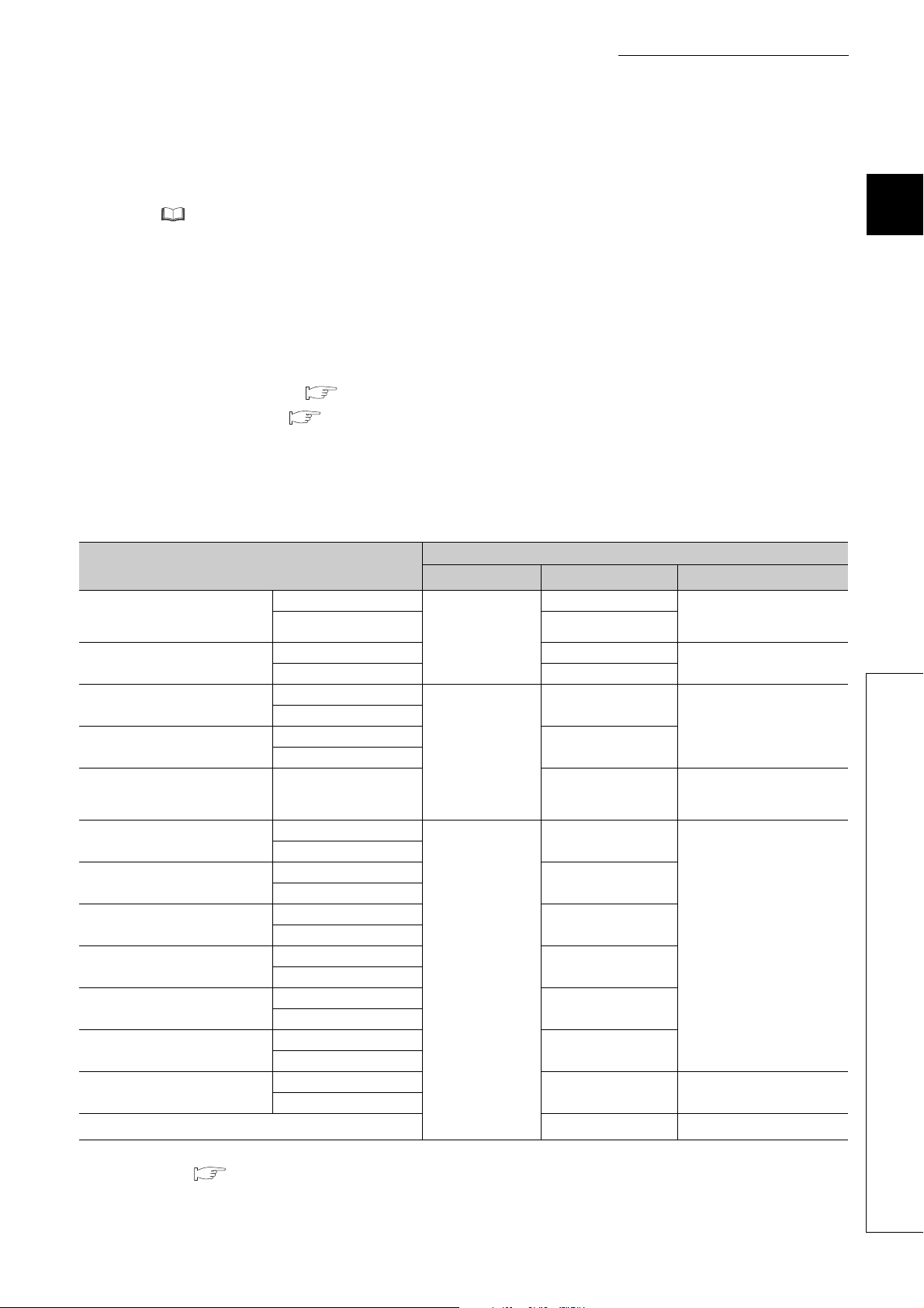
3.1 Performance Specifications . . . . . . . . . . . . . . . . . . . . . . . . . . . . . . . . . . . . . . . . . . . . . . . . . . . 38
3.1.1 Type of usable temperature sensors, temperature measurement range, resolution,
and effect from wiring resistance of 1 ohm
3.1.2 Sampling cycle and control output cycle . . . . . . . . . . . . . . . . . . . . . . . . . . . . . . . . . . . . . . . . 42
3.1.3 Number of parameters to be set . . . . . . . . . . . . . . . . . . . . . . . . . . . . . . . . . . . . . . . . . . . . . . 43
3.2 Function List . . . . . . . . . . . . . . . . . . . . . . . . . . . . . . . . . . . . . . . . . . . . . . . . . . . . . . . . . . . . . . . 45
3.3 I/O Signals Transferred to/from the CPU Module . . . . . . . . . . . . . . . . . . . . . . . . . . . . . . . . . . . 48
3.3.1 I/O signal list. . . . . . . . . . . . . . . . . . . . . . . . . . . . . . . . . . . . . . . . . . . . . . . . . . . . . . . . . . . . . . 48
3.3.2 Details of input signals . . . . . . . . . . . . . . . . . . . . . . . . . . . . . . . . . . . . . . . . . . . . . . . . . . . . . . 50
3.3.3 Details of output signals . . . . . . . . . . . . . . . . . . . . . . . . . . . . . . . . . . . . . . . . . . . . . . . . . . . . . 56
3.4 Buffer Memory Assignment . . . . . . . . . . . . . . . . . . . . . . . . . . . . . . . . . . . . . . . . . . . . . . . . . . . 59
3.4.1 Q64TCN buffer memory assignment list . . . . . . . . . . . . . . . . . . . . . . . . . . . . . . . . . . . . . . . . 59
3.4.2 Details of the buffer memory . . . . . . . . . . . . . . . . . . . . . . . . . . . . . . . . . . . . . . . . . . . . . . . . . 86
. . . . . . . . . . . . . . . . . . . . . . . . . . . . . . . . . 40
CHAPTER 4 FUNCTIONS 162
4.1 Control Mode Selection Function . . . . . . . . . . . . . . . . . . . . . . . . . . . . . . . . . . . . . . . . . . . . . .162
4.2 Control Output Setting at CPU Stop Error . . . . . . . . . . . . . . . . . . . . . . . . . . . . . . . . . . . . . . . 165
4.3 Control Method . . . . . . . . . . . . . . . . . . . . . . . . . . . . . . . . . . . . . . . . . . . . . . . . . . . . . . . . . . . . 166
10
Page 13

4.4 Manual Reset Function . . . . . . . . . . . . . . . . . . . . . . . . . . . . . . . . . . . . . . . . . . . . . . . . . . . . . .173
4.5 Manual Control . . . . . . . . . . . . . . . . . . . . . . . . . . . . . . . . . . . . . . . . . . . . . . . . . . . . . . . . . . . .175
4.6 Auto Tuning Function . . . . . . . . . . . . . . . . . . . . . . . . . . . . . . . . . . . . . . . . . . . . . . . . . . . . . . .176
4.7 Simple Two-degree-of-freedom . . . . . . . . . . . . . . . . . . . . . . . . . . . . . . . . . . . . . . . . . . . . . . .188
4.8 Derivative Action Selection Function . . . . . . . . . . . . . . . . . . . . . . . . . . . . . . . . . . . . . . . . . . .189
4.9 Setting Change Rate Limiter Setting Function . . . . . . . . . . . . . . . . . . . . . . . . . . . . . . . . . . . .190
4.10 Moving Averaging Process to a Temperature Process Value (PV). . . . . . . . . . . . . . . . . . . . . 191
4.11 Temperature Process Value (PV) Scaling Function . . . . . . . . . . . . . . . . . . . . . . . . . . . . . . . .192
4.12 Alert Function . . . . . . . . . . . . . . . . . . . . . . . . . . . . . . . . . . . . . . . . . . . . . . . . . . . . . . . . . . . . .194
4.13 RFB Limiter Function . . . . . . . . . . . . . . . . . . . . . . . . . . . . . . . . . . . . . . . . . . . . . . . . . . . . . . .208
4.14 Sensor Correction Function . . . . . . . . . . . . . . . . . . . . . . . . . . . . . . . . . . . . . . . . . . . . . . . . . .209
4.15 Auto-setting at Input Range Change . . . . . . . . . . . . . . . . . . . . . . . . . . . . . . . . . . . . . . . . . . .220
4.16 Input/output (with Another Analog Module) Function . . . . . . . . . . . . . . . . . . . . . . . . . . . . . . .221
4.17 ON Delay Output Function . . . . . . . . . . . . . . . . . . . . . . . . . . . . . . . . . . . . . . . . . . . . . . . . . . .222
4.18 Self-tuning Function . . . . . . . . . . . . . . . . . . . . . . . . . . . . . . . . . . . . . . . . . . . . . . . . . . . . . . . . 223
4.19 Peak Current Suppression Function. . . . . . . . . . . . . . . . . . . . . . . . . . . . . . . . . . . . . . . . . . . . 233
4.20 Simultaneous Temperature Rise Function . . . . . . . . . . . . . . . . . . . . . . . . . . . . . . . . . . . . . . .238
4.21 Forward/Reverse Action Selection Function. . . . . . . . . . . . . . . . . . . . . . . . . . . . . . . . . . . . . .252
4.22 Loop Disconnection Detection Function . . . . . . . . . . . . . . . . . . . . . . . . . . . . . . . . . . . . . . . . .253
4.23 During AT Loop Disconnection Detection Function . . . . . . . . . . . . . . . . . . . . . . . . . . . . . . . .255
4.24 Proportional Band Setting Function . . . . . . . . . . . . . . . . . . . . . . . . . . . . . . . . . . . . . . . . . . . .257
4.25 Cooling Method Setting Function . . . . . . . . . . . . . . . . . . . . . . . . . . . . . . . . . . . . . . . . . . . . . .258
4.26 Overlap/Dead Band Function . . . . . . . . . . . . . . . . . . . . . . . . . . . . . . . . . . . . . . . . . . . . . . . . .259
4.27 Temperature Conversion Function (Using Unused Channels) . . . . . . . . . . . . . . . . . . . . . . . .262
4.28 Heater Disconnection Detection Function . . . . . . . . . . . . . . . . . . . . . . . . . . . . . . . . . . . . . . .265
4.29 Output Off-time Current Error Detection Function . . . . . . . . . . . . . . . . . . . . . . . . . . . . . . . . .269
4.30 Buffer Memory Data Backup Function . . . . . . . . . . . . . . . . . . . . . . . . . . . . . . . . . . . . . . . . . .270
4.31 Error History Function . . . . . . . . . . . . . . . . . . . . . . . . . . . . . . . . . . . . . . . . . . . . . . . . . . . . . . .272
4.32 Module Error History Collection Function . . . . . . . . . . . . . . . . . . . . . . . . . . . . . . . . . . . . . . . . 274
4.33 Error Clear Function . . . . . . . . . . . . . . . . . . . . . . . . . . . . . . . . . . . . . . . . . . . . . . . . . . . . . . . .275
CHAPTER 5 SETTINGS AND THE PROCEDURE BEFORE OPERATION 276
5.1 Handling Precautions . . . . . . . . . . . . . . . . . . . . . . . . . . . . . . . . . . . . . . . . . . . . . . . . . . . . . . .276
5.2 Settings and the Procedure before Operation . . . . . . . . . . . . . . . . . . . . . . . . . . . . . . . . . . . . 277
5.3 Part Names. . . . . . . . . . . . . . . . . . . . . . . . . . . . . . . . . . . . . . . . . . . . . . . . . . . . . . . . . . . . . . .278
5.4 Wiring . . . . . . . . . . . . . . . . . . . . . . . . . . . . . . . . . . . . . . . . . . . . . . . . . . . . . . . . . . . . . . . . . . .287
5.4.1 Wiring precautions . . . . . . . . . . . . . . . . . . . . . . . . . . . . . . . . . . . . . . . . . . . . . . . . . . . . . . . . 287
5.4.2 External wiring . . . . . . . . . . . . . . . . . . . . . . . . . . . . . . . . . . . . . . . . . . . . . . . . . . . . . . . . . . . 288
5.4.3 Heater disconnection detection wiring and setting example for three-phase heater . . . . . . 296
5.5 Unused Channel Setting. . . . . . . . . . . . . . . . . . . . . . . . . . . . . . . . . . . . . . . . . . . . . . . . . . . . .297
CHAPTER 6 VARIOUS SETTINGS 298
6.1 Addition of Modules . . . . . . . . . . . . . . . . . . . . . . . . . . . . . . . . . . . . . . . . . . . . . . . . . . . . . . . .298
6.2 Switch Setting . . . . . . . . . . . . . . . . . . . . . . . . . . . . . . . . . . . . . . . . . . . . . . . . . . . . . . . . . . . . . 299
11
Page 14

6.3 Parameter Setting . . . . . . . . . . . . . . . . . . . . . . . . . . . . . . . . . . . . . . . . . . . . . . . . . . . . . . . . . .300
6.4 Auto Refresh. . . . . . . . . . . . . . . . . . . . . . . . . . . . . . . . . . . . . . . . . . . . . . . . . . . . . . . . . . . . . .303
6.5 Auto Tuning . . . . . . . . . . . . . . . . . . . . . . . . . . . . . . . . . . . . . . . . . . . . . . . . . . . . . . . . . . . . . . 305
6.6 Sensor Correction. . . . . . . . . . . . . . . . . . . . . . . . . . . . . . . . . . . . . . . . . . . . . . . . . . . . . . . . . .305
CHAPTER 7 PROGRAMMING 306
7.1 Programming Procedure. . . . . . . . . . . . . . . . . . . . . . . . . . . . . . . . . . . . . . . . . . . . . . . . . . . . .306
7.2 When Using the Module in a Standard System Configuration . . . . . . . . . . . . . . . . . . . . . . . .307
7.2.1 Standard control (such as auto tuning, self-tuning, and error code read) . . . . . . . . . . . . . . 307
7.2.2 Standard control (peak current suppression function, simultaneous temperature rise
function)
7.2.3 When performing the heating-cooling control . . . . . . . . . . . . . . . . . . . . . . . . . . . . . . . . . . . 334
7.3 When Using the Module on the Remote I/O Net . . . . . . . . . . . . . . . . . . . . . . . . . . . . . . . . . .344
. . . . . . . . . . . . . . . . . . . . . . . . . . . . . . . . . . . . . . . . . . . . . . . . . . . . . . 319
CHAPTER 8 TROUBLESHOOTING 359
8.1 Before Troubleshooting . . . . . . . . . . . . . . . . . . . . . . . . . . . . . . . . . . . . . . . . . . . . . . . . . . . . .359
8.2 Troubleshooting Procedure . . . . . . . . . . . . . . . . . . . . . . . . . . . . . . . . . . . . . . . . . . . . . . . . . .359
8.3 Checks Using LEDs . . . . . . . . . . . . . . . . . . . . . . . . . . . . . . . . . . . . . . . . . . . . . . . . . . . . . . . .361
8.3.1 When the RUN LED flashes or turns off . . . . . . . . . . . . . . . . . . . . . . . . . . . . . . . . . . . . . . . 361
8.3.2 When the ERR. LED turns on or flashes . . . . . . . . . . . . . . . . . . . . . . . . . . . . . . . . . . . . . . . 361
8.3.3 When the ALM LED turns on or flashes. . . . . . . . . . . . . . . . . . . . . . . . . . . . . . . . . . . . . . . . 362
8.4 Checks Using Input Signals . . . . . . . . . . . . . . . . . . . . . . . . . . . . . . . . . . . . . . . . . . . . . . . . . .363
8.4.1 When Module READY flag (Xn0) does not turn on . . . . . . . . . . . . . . . . . . . . . . . . . . . . . . . 363
8.4.2 When Write error flag (Xn2) is on. . . . . . . . . . . . . . . . . . . . . . . . . . . . . . . . . . . . . . . . . . . . . 363
8.4.3 When Hardware error flag (Xn3) is on . . . . . . . . . . . . . . . . . . . . . . . . . . . . . . . . . . . . . . . . . 363
8.4.4 When the auto tuning does not start (CH Auto tuning status (Xn4 to Xn7) does not
. . . . . . . . . . . . . . . . . . . . . . . . . . . . . . . . . . . . . . . . . . . . . . . . . . . . . . 363
turn on)
8.4.5 When the auto tuning does not complete (CH Auto tuning status (Xn4 to Xn7) stays on
and does not turn off)
8.4.6 When the self-tuning does not start (CH Auto tuning status (Xn4 to Xn7) does not
. . . . . . . . . . . . . . . . . . . . . . . . . . . . . . . . . . . . . . . . . . . . . . . . . . . . . . 364
turn on)
8.4.7 When E2PROM write failure flag (XnA) is on . . . . . . . . . . . . . . . . . . . . . . . . . . . . . . . . . . . . 364
8.4.8 When CH Alert occurrence flag (XnC to XnF) is on . . . . . . . . . . . . . . . . . . . . . . . . . . . . . 365
8.5 Troubleshooting by Symptom . . . . . . . . . . . . . . . . . . . . . . . . . . . . . . . . . . . . . . . . . . . . . . . . .366
8.5.1 When the temperature process value (PV) is abnormal . . . . . . . . . . . . . . . . . . . . . . . . . . . 366
8.6 Error Code List . . . . . . . . . . . . . . . . . . . . . . . . . . . . . . . . . . . . . . . . . . . . . . . . . . . . . . . . . . . .367
8.7 Alarm Code List . . . . . . . . . . . . . . . . . . . . . . . . . . . . . . . . . . . . . . . . . . . . . . . . . . . . . . . . . . .370
8.8 Check the Q64TCN Status . . . . . . . . . . . . . . . . . . . . . . . . . . . . . . . . . . . . . . . . . . . . . . . . . . . 372
. . . . . . . . . . . . . . . . . . . . . . . . . . . . . . . . . . . . . . . . . . . . . 364
APPENDICES 374
Appendix 1 Addition and Change of Functions . . . . . . . . . . . . . . . . . . . . . . . . . . . . . . . . . . . . . . . .374
Appendix 1.1 Additional function . . . . . . . . . . . . . . . . . . . . . . . . . . . . . . . . . . . . . . . . . . 374
Appendix 1.2 Change of functions . . . . . . . . . . . . . . . . . . . . . . . . . . . . . . . . . . . . . . . . . 374
Appendix 2 Comparison of the Q64TCN with the Q64TCTT, Q64TCTTBW, Q64TCRT, and
Q64TCRTBW . . . . . . . . . . . . . . . . . . . . . . . . . . . . . . . . . . . . . . . . . . . . . . . . . . . . . . . .
12
375
Page 15

Appendix 2.1 Compatibility between the Q64TC and Q64TCN. . . . . . . . . . . . . . . . . . . . . . . 377
Appendix 3 When Using GX Developer and GX Configurator-TC. . . . . . . . . . . . . . . . . . . . . . . . . .378
Appendix 3.1 GX Developer operation . . . . . . . . . . . . . . . . . . . . . . . . . . . . . . . . . . . . . . 378
Appendix 3.2 GX Configurator-TC operation . . . . . . . . . . . . . . . . . . . . . . . . . . . . . . . . . . 381
Appendix 4 Online Module Change Procedure (When Using GX Developer) . . . . . . . . . . . . . . . . . 386
Appendix 4.1 Precautions on online module change . . . . . . . . . . . . . . . . . . . . . . . . . . . . . 386
Appendix 4.2 Conditions for online module change . . . . . . . . . . . . . . . . . . . . . . . . . . . . . . 387
Appendix 4.3 Operations when performing an online module change . . . . . . . . . . . . . . . . . . 390
Appendix 4.4 Online module change procedures . . . . . . . . . . . . . . . . . . . . . . . . . . . . . . . 391
Appendix 4.5 When GX Configurator-TC was used for the initial setting . . . . . . . . . . . . . . . . 392
Appendix 4.6 When a sequence program was used for the initial setting . . . . . . . . . . . . . . . . 396
Appendix 5 Online Module Change Procedure (When Using GX Works2) . . . . . . . . . . . . . . . . . . .401
Appendix 5.1 Precautions on online module change . . . . . . . . . . . . . . . . . . . . . . . . . . . . . 401
Appendix 5.2 Online module change conditions . . . . . . . . . . . . . . . . . . . . . . . . . . . . . . . . 402
Appendix 5.3 Operations of when performing an online module change . . . . . . . . . . . . . . . . 403
Appendix 5.4 Online module change procedures . . . . . . . . . . . . . . . . . . . . . . . . . . . . . . . 404
Appendix 5.5 When parameters were configured using GX Works2 . . . . . . . . . . . . . . . . . . . 405
Appendix 5.6 When the initial settings were configured using a sequence program . . . . . . . . . 410
Appendix 6 External Dimensions . . . . . . . . . . . . . . . . . . . . . . . . . . . . . . . . . . . . . . . . . . . . . . . . . . .416
INDEX 418
REVISIONS . . . . . . . . . . . . . . . . . . . . . . . . . . . . . . . . . . . . . . . . . . . . . . . . . . . . . . . . . . . . . . . . . . . . . . 424
WARRANTY . . . . . . . . . . . . . . . . . . . . . . . . . . . . . . . . . . . . . . . . . . . . . . . . . . . . . . . . . . . . . . . . . . . . . 425
13
Page 16
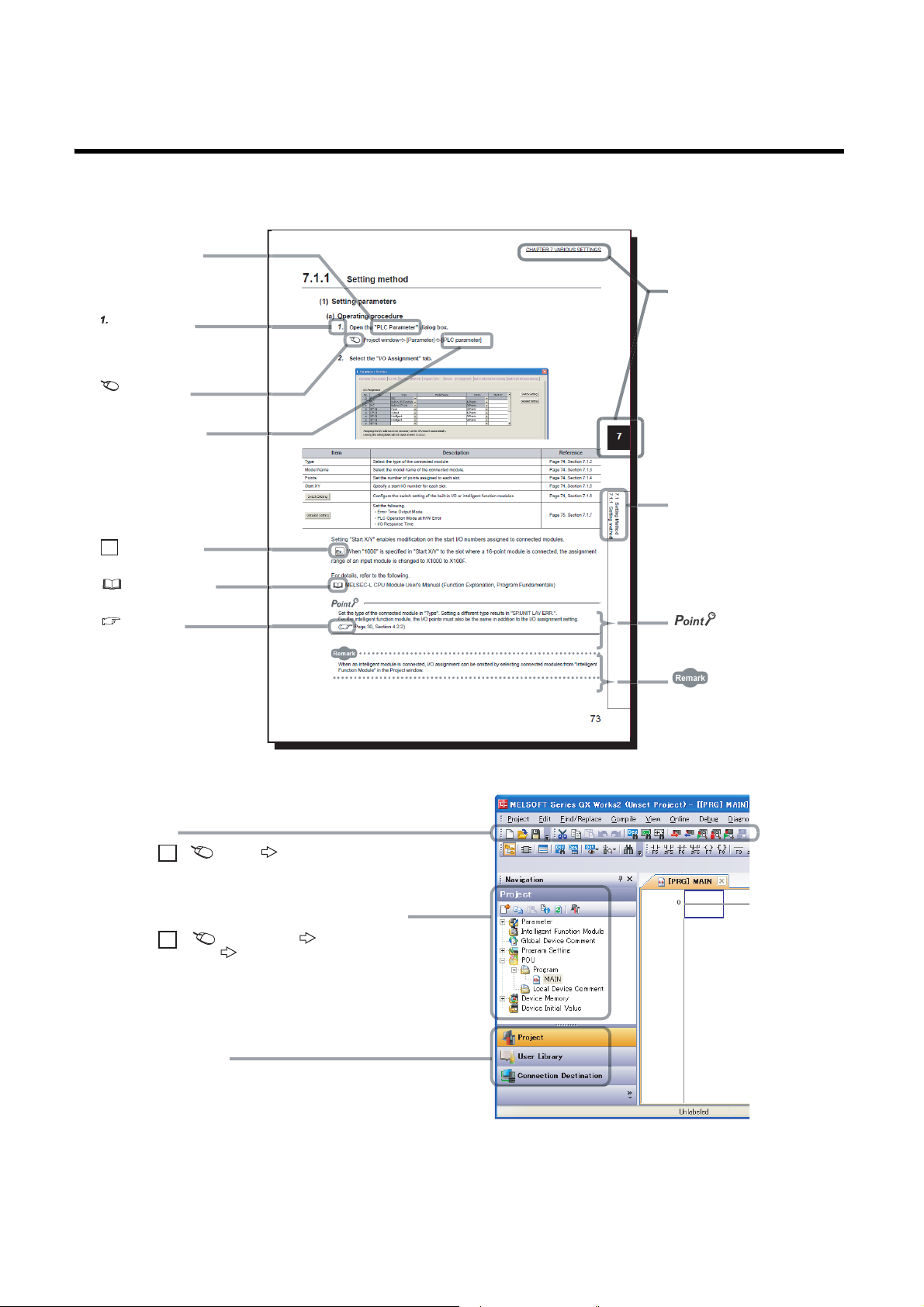
MANUAL PAGE ORGANIZATION
The section of
the current page is shown.
The chapter of
the current page is shown.
"" is used for
screen names and items.
[ ] is used for items
in the menu bar and
the project window.
shows operating
procedures.
shows reference
manuals.
shows notes that
requires attention.
shows mouse
operations.
*1
shows
reference pages.
shows setting or
operating examples.
Ex.
shows useful
information.
A window selected in the view selection area is displayed.
View selection area
[Online] [Write to PLC...]
Select [Online] on the menu bar,
and then select [Write to PLC...].
Project window
[Parameter]
[PLC Parameter]
Select [Project] from the view selection
area to open the Project window.
Menu bar
Ex.
Ex.
In the Project window, expand [Parameter] and
select [PLC Parameter].
In this manual, pages are organized and the symbols are used as shown below.
The following illustration is for explanation purpose only, and should not be referred to as an actual documentation.
*1 The mouse operation example is provided below.
14
Page 17
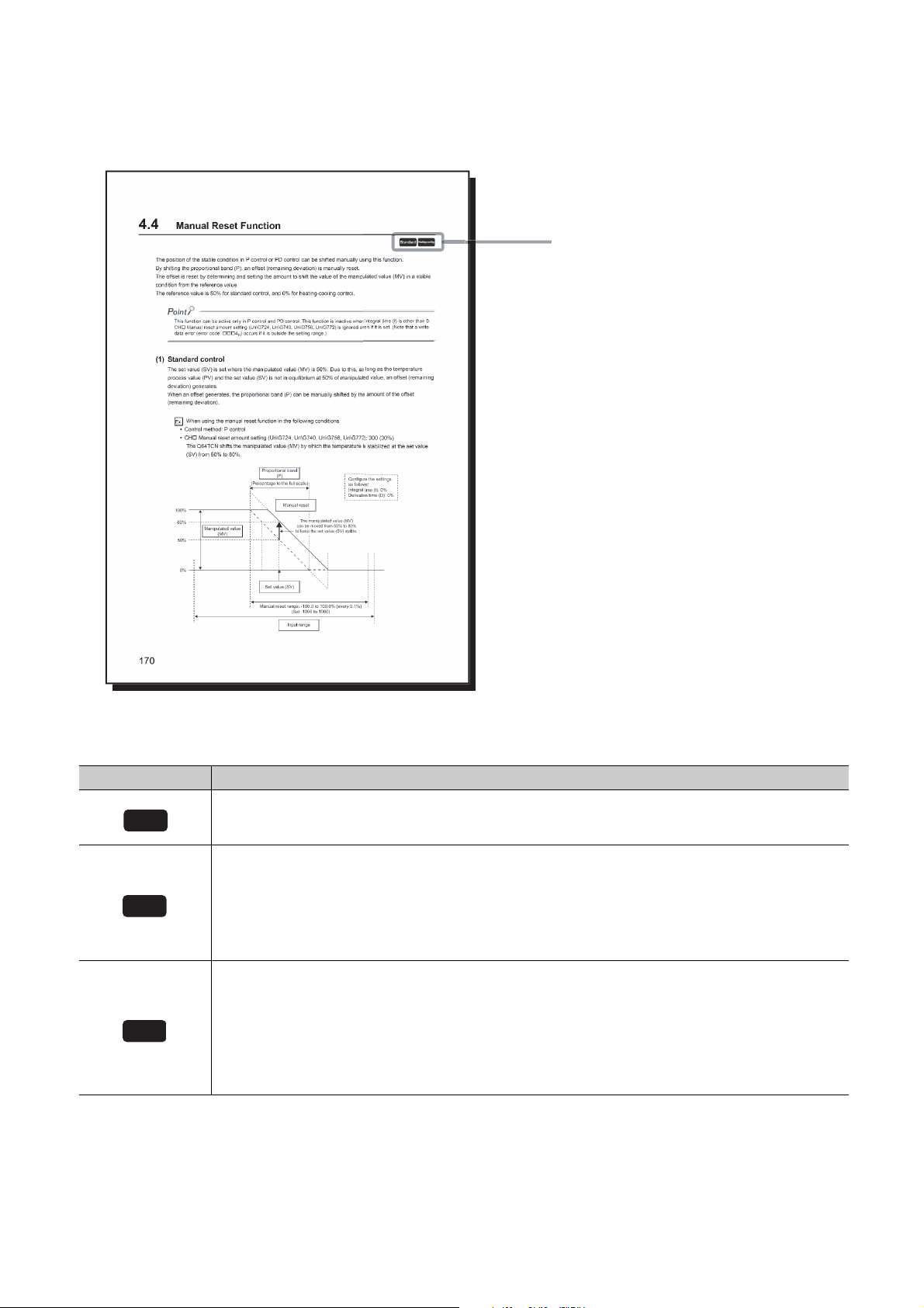
Pages describing buffer memory areas and functions are organized as shown below.
These icons indicate control modes
that can be used.
Common
Standard
Heating-cooling
The following illustration is for explanation purpose only, and should not be referred to as an actual documentation.
The following table describes the meaning of each icon.
Icon Meaning
This icon means that the buffer memory area or function can be used in all control modes.
This icon means that the buffer memory area or function for temperature control can be used in the standard
control.
The buffer memory area and function can be used in the following control modes and channels:
• CH1 to CH4 in the standard control
• CH3 and CH4 in the mix control (normal mode)
• CH3 and CH4 in the mix control (expanded mode)
This icon means that the buffer memory or function for temperature control can be used in the heating-cooling
control.
The buffer memory area and function can be used in the following control modes and channels:
• CH1 and CH2 in the heating-cooling control (normal mode)
• CH1 to CH4 in the heating-cooling control (expanded mode)
• CH1 in the mix control (normal mode)
• CH1 and CH2 in the mix control (expanded mode)
15
Page 18

TERMS
Unless otherwise specified, this manual uses the following terms.
Term Description
Q64TCTTN The abbreviation for the Q64TCTTN temperature control module
Q64TCTTBWN
Q64TCRTN The abbreviation for the Q64TCRTN temperature control module
Q64TCRTBWN
Q64TCN A generic term for the Q64TCTTN, Q64TCTTBWN, Q64TCRTN, and Q64TCRTBWN
PID constants A generic term for the proportional band (P), integral time (I), and derivative time (D)
Temperature sensor A generic term for thermocouples and platinum resistance thermometers
Control method
Control mode
Fixed value action The operating status of when the set value (SV) is fixed
Full scale
Ramp action The operating status of when the set value (SV) is constantly changed
Number of loops
QCPU Another term for the MELSEC-Q series CPU module
Redundant CPU A generic term for the Q12PRHCPU and Q25PRHCPU
External input The abbreviation for input from connectors for external devices
External output The abbreviation for output to connectors for external devices
Programming tool A generic term for GX Works2 and GX Developer
GX Works2
GX Developer
GX Configurator-TC
Buffer memory
The abbreviation for the Q64TCTTBWN temperature control module with the
disconnection detection function
The abbreviation for the Q64TCRTBWN temperature control module with the
disconnection detection function
A generic term for two-position control, P control, PI control, PD control, and PID
control
A generic term for the standard control, heating-cooling control (normal mode),
heating-cooling control (expanded mode), mix control (normal mode), and mix control
(expanded mode)
A full input range. For example, when the selected input range is
-200.0°C to 400.0°C, the full scale is 600.0.
The number of feedback control systems (closed-loop control systems) that can be
configured using one module. Under the standard control, one loop consists of one
input and one output. Under the heating-cooling control, one loop consists of one input
and two outputs.
The product name of the software package for the MELSEC programmable
controllers
A setting and monitoring tool added in GX Developer (for temperature control
modules)
The memory of an intelligent function module used to store data (such as setting
values and monitored values) for communication with a CPU module
PACKING LIST
The following items are included in the package of this product.
Model Item name Quantity
Q64TCTTN Q64TCTTN temperature control module 1
Q64TCTTBWN Q64TCTTBWN temperature control module with the disconnection detection function 1
Q64TCRTN Q64TCRTN temperature control module 1
Q64TCRTBWN Q64TCRTBWN temperature control module with the disconnection detection function 1
Q64TCTTN/RTN-U-HW Before Using the Product 1
16
Page 19
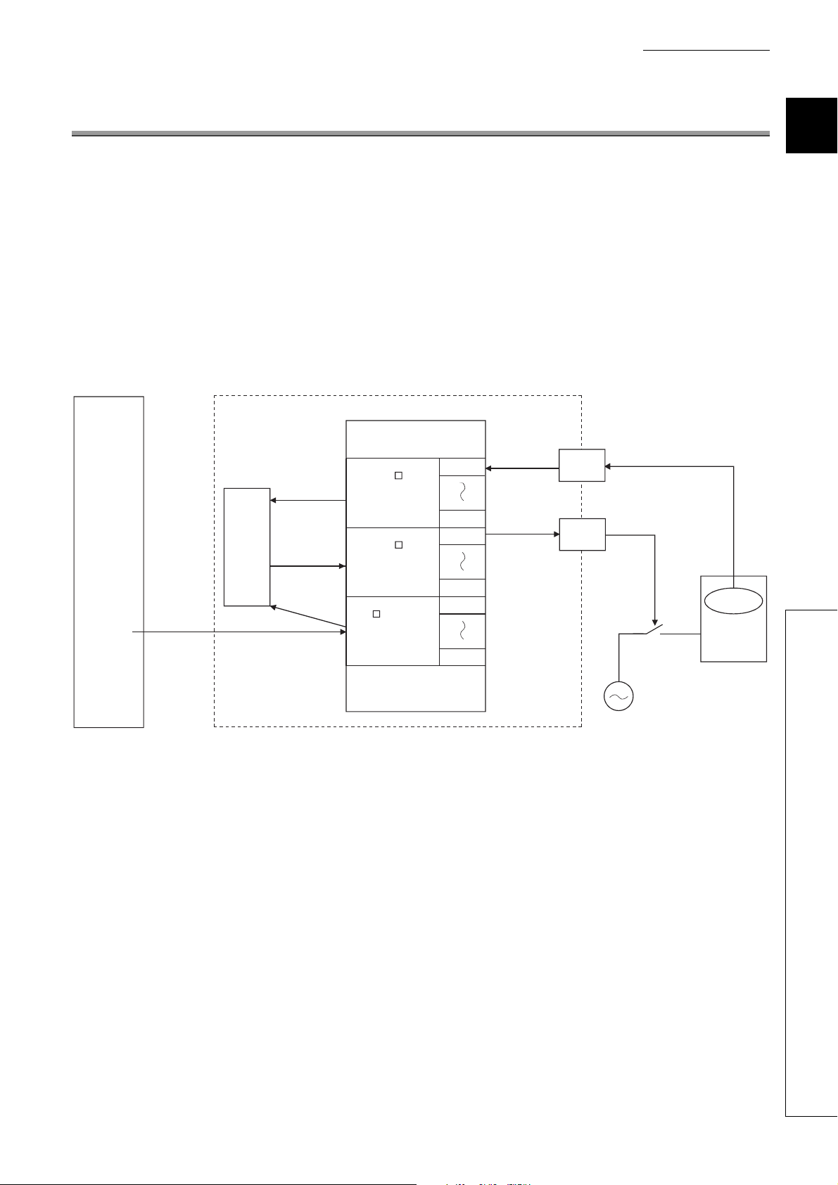
CHAPTER 1 OVERVIEW
Buffer memory
Programmable
controller CPU Q64TCTTN, Q64TCRTN
Initial
setting
(To instruction)
Set value (SV)
Set value (SV)
PID
operation
Temperature
process
value (PV)
Temperature
process
value (PV)
Manipulated
value (MV)
Manipulated
value (MV)
Temperature
Device to be
controlled
Input from temperature sensor
Transistor output
(ON/OFF pulse)
CH1
CH4
CH4
CH4
CH1
CH1
CH1
CH1
CH
Temperature
process value (PV)
(Un\G9 to Un\G12)
CH
Manipulated value
(MV)
(Un\G13 to Un\G16)
CH
Set value
(SV) setting
(Un\G34, Un\G66,
Un\G98, Un\G130)
This chapter describes the overview of the Q64TCN.
(1) The Q64TCTTN and Q64TCRTN
• The Q64TCTTN and Q64TCRTN perform PID operation to reach the target temperature based on input from
an external temperature sensor. The modules control temperature by transistor output.
• The Q64TCTTN and Q64TCRTN possess the auto tuning function by which proportional band (P), integral
time (I) and derivative time (D) for PID operation are automatically set.
• The Q64TCTTN accepts type K, J, T, B, S, E, R, N, U, L, PL II, and W5Re/W26Re thermocouples. The
Q64TCRTN accepts type Pt100 and JPt100 platinum resistance thermometers.
CHAPTER 1 OVERVIEW
1
17
Page 20
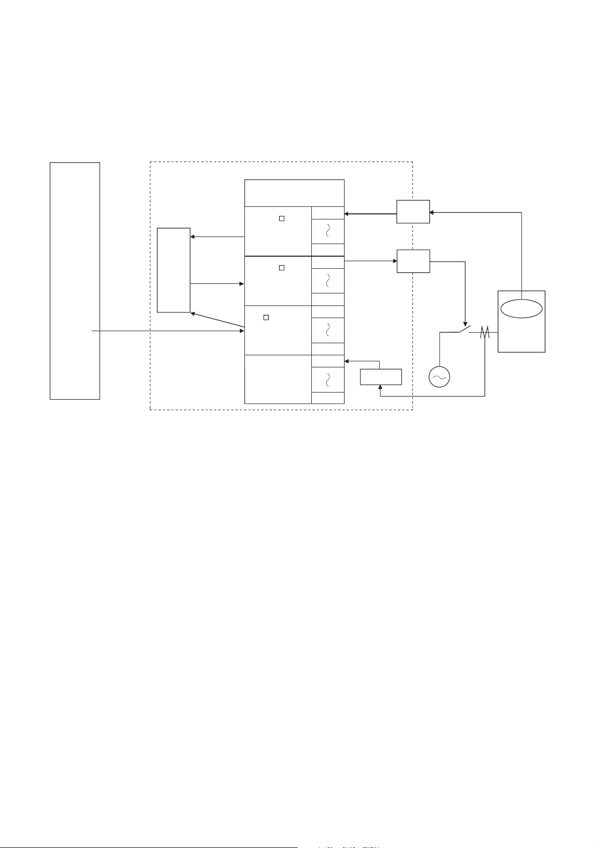
(2) The Q64TCTTBWN and Q64TCRTBWN
Buffer memory
Programmable
controller CPU
Initial
setting
(To instruction)
Set value (SV)
Set value (SV)
PID
operation
Temperature
process
value (PV)
Manipulated
value (MV)
Manipulated
value (MV)
Temperature
Device to be
controlled
Input from temperature sensor
Transistor output
(ON/OFF pulse)
CH1
CH4
CH4
CH4
CH1
CH1
CH1
CH1
Q64TCTTBWN, Q64TCRTBWN
CH4
CH1
Current
sensor
Disconnection
detection
Alarm
Temperature
process
value (PV)
CH
Temperature
process value (PV)
(Un\G9 to Un\G12)
CH
Manipulated value
(MV)
(Un\G13 to Un\G16)
CH
Set value
(SV) setting
(Un\G34, Un\G66,
Un\G98, Un\G130)
The Q64TCTTBWN and Q64TCRTBWN are Q64TCTTN and Q64TCRTN-based modules which possess an
additional function to detect heater disconnection using input from external current sensors.
18
Page 21

CHAPTER 1 OVERVIEW
1.1 Features
(1) Optimum temperature adjustment control (PID control)
• The Q64TCN performs temperature adjustment control automatically when the user simply sets PID
constants necessary for PID operation: proportional band (P), integral time (I), derivative time (D), and
temperature set value (SV). No special instruction is necessary to perform PID control.
• Using the auto tuning function or self-tuning function enables the PID constants to be set automatically.
Complicated PID operational expressions to determine PID constants are not necessary.
(2) Selection of control mode
A control mode can be selected from the standard control (heating or cooling), heating-cooling control (heating
and cooling), or mix control (combination of the standard control and heating-cooling control).
(3) Four loops on one module
The maximum of four loops of temperature adjustment control can be performed simultaneously. In addition, loop
control can be performed using analog modules on the base unit or the network; input from an A/D converter
module or output to a D/A converter module can be processed.
(4) Simultaneous temperature rise of multiple loops
Temperatures of multiple loops can be adjusted to simultaneously reach the set value of each; temperatures are
controlled evenly without any partial heat exaggeration. This function saves energy and cost.
1
(5) Suppression of peak current
Current flows into a heater can be suppressed by controlling output so that each channel's output does not turn
on at the same time as other channels.
This function saves energy and cost.
(6) RFB limiter function
The RFB (Reset feed back) limiter suppresses overshoot which is liable to occur at a startup or when a
temperature process value (PV) is increased.
(7) Correction of temperature process value (PV)
The difference between the temperature process value (PV) and actual temperature can be corrected easily
using the following functions.
• Normal sensor correction (one-point correction) function: Corrects the difference by setting the rate of
correction value to the full scale of the input range.
• Sensor two-point correction function: Corrects the difference based on the inclination of the line on the two
points set in advance.
• Primary delay digital filter setting: Smoothens transient noise, and absorbs drastic change.
(8) E2PROM for backing up set values
The set values in the buffer memory, such as the setting related to PID control, can be stored into E2PROM for
data backup. The values do not need to be reset after turning the power on from off or releasing the CPU module
from its reset status.
Using the test function of the programming tool to write data directly to the buffer memory, the minimum
sequence program required is "LD**" + "OUT Yn1".
1.1 Features
19
Page 22

(9) Detection of disconnection
Heater disconnection can be detected easily by the loop disconnection detection function.
The Q64TCTTBWN and Q64TCRTBWN can detect the disconnection of a heater accurately.
(10)Easy setting by GX Works2
Sequence program can be reduced by configuring the default setting or auto refresh setting on the screen. Also,
the setting status or operating status of the module can be checked easily.
20
Page 23
CHAPTER 1 OVERVIEW
Set value data
storage area
Temperature
process value
data storage area
PID operation
Manipulated
value data storage
area
Temperature
sensor
Control
object
Q64TCN
Set value
(SV)
Temperature
process
value (PV)
Manipulated
value (MV)
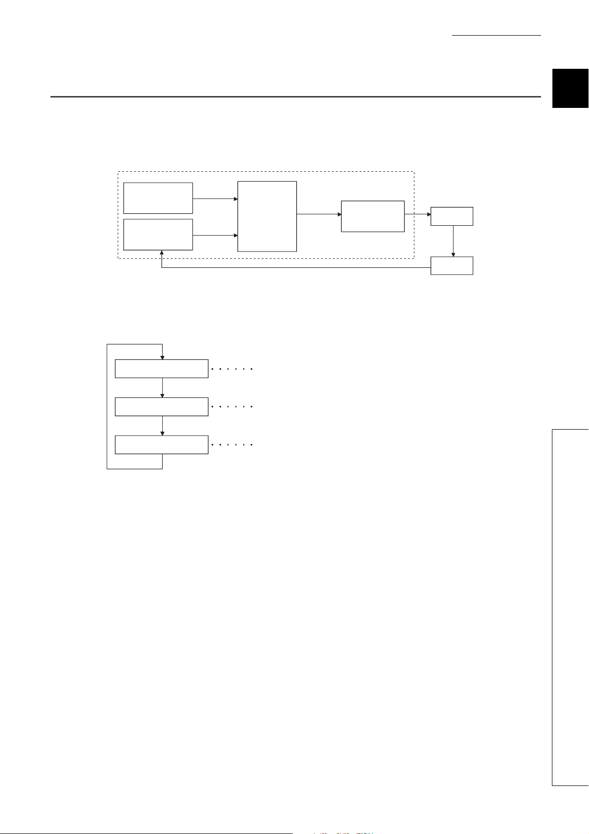
Import a signal from the temperature sensor and write it to the temperature
process value data storage area as a temperature process value (PV).
Perform PID operation using the Set value (SV)/temperature process
value (PV) values in the set value/temperature process value data
storage area.
Convert manipulated value (MV) obtained by the PID operation to
transistor-output on time and output it.
Read the temperature
process value (PV)
Perform PID operation
Output the manipulated
value (MV)
1.2 The PID Control System
(1) PID control system
The following figure shows a system of when performing the PID control.
(2) PID control procedure
The PID control is performed in the following procedure.
1
1.2 The PID Control System
21
Page 24
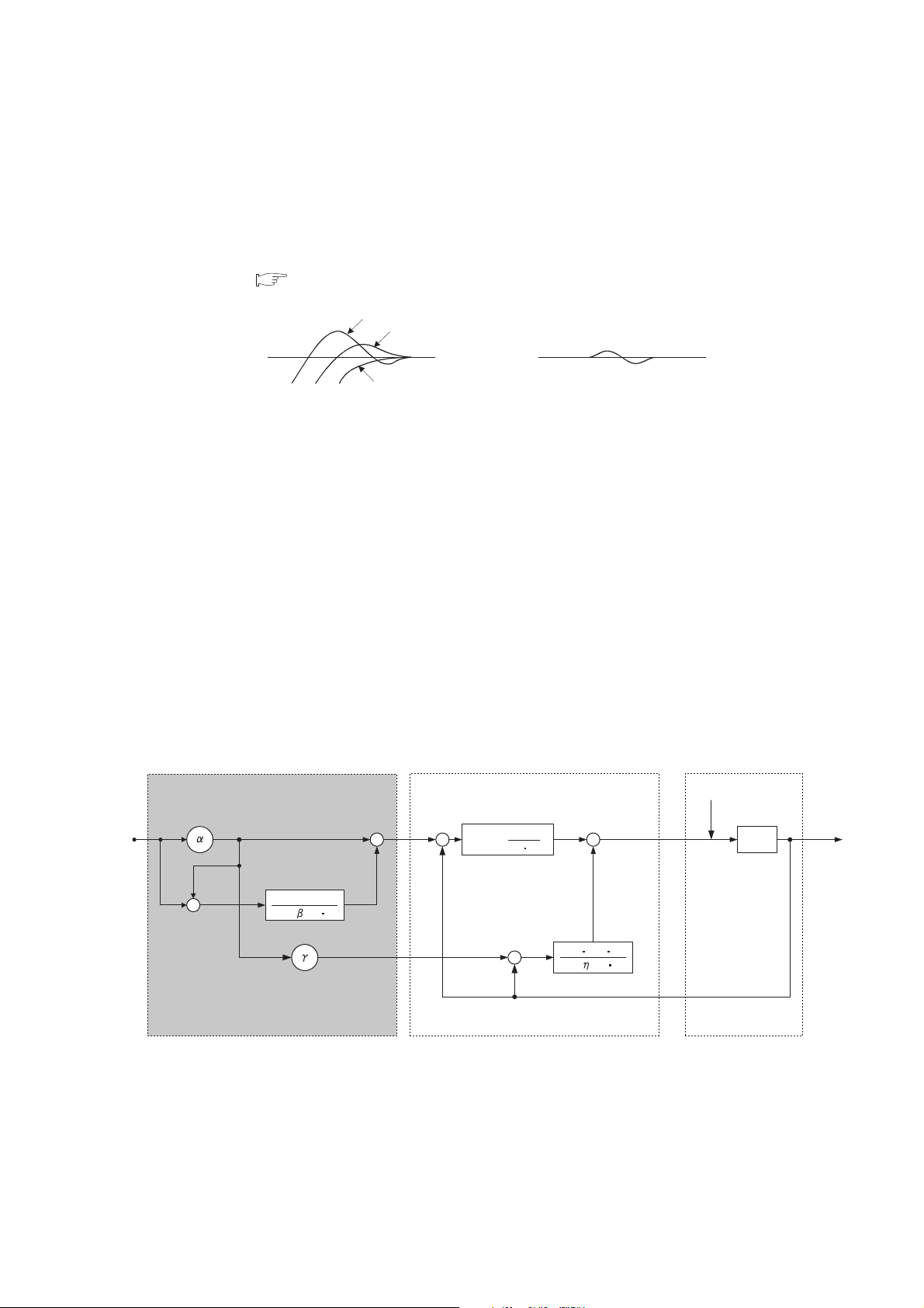
(3) PID control (simple two-degree-of-freedom)
PID control
Object to be
controlled
Disturbance D
1
1 + T
I s
1 + TD s
KP TD s
1
T
I s
KP (1 + )
Added function for two-degree-of-freedom
Manipulated
value (MV)
Set value
(SV)
G(s)
Temperature
process value (PV)
-
+
-
+
+
+
+
+
+
-
The Q64TCN operates in "simple two-degree-of-freedom". In this form of PID control, parameters are simplified
compared to the two-degree-of-freedom PID control.
In the simple two-degree-of-freedom, the module controls the target subject using not only PID constants but also
the control response parameter. The parameter can be set to "fast", "normal", or "slow". This setting enables the
form of "response to the change of the set value (SV)" to change maintaining "response to the disturbance" in a
good condition. ( Page 188, Section 4.7)
Fast
Normal
Set value
(SV)
Slow
Response to the change
of the set value (SV)
The following explains the difference between the one-degree-of-freedom PID control, two-degree-of-freedom
PID control, and simple two-degree-of-freedom PID control.
(a) One-degree-of-freedom PID control and two-degree-of-freedom PID control
• General PID control is called one-degree-of freedom PID control. In the one-degree-of freedom PID
control, when PID constants to improve "response to the change of the set value (SV)" are set, "response
to the disturbance" degrades. Conversely, when PID constants to improve "response to the disturbance"
are set, "response to the change of the set value (SV)" degrades.
• In the two-degree-of-freedom PID control, a manipulated value (MV) is determined considering the set
value (SV) or variations. In this form of PID control, "response to the change of the set value (SV)" and
"response to the disturbance" can be compatible with each other.
Set value
(SV)
Response to the disturbance
(b) Two-degree-of-freedom PID control and simple two-degree-of-freedom PID control
The following figure is a block diagram of the two-degree-of-freedom PID control.
By setting , , and above properly, optimum control can be achieved.
Note that required parameter settings increase and PID constants can hardly be auto-set by the auto tuning
function for complete two-degree-of-freedom PID control. Therefore, the Q64TCN operates in the simple two-
degree-of-freedom PID control for which parameters are simplified.
22
Page 25
CHAPTER 1 OVERVIEW
Remark
Q64TCN
Control object
Slow
Normal
Fast
1
Disturbance D
G(s)
K
P TD s
1
TD s
Temperature
process value (PV)
Laplace transform conversion
DerivativeProportional gain
Integral time
Derivative time
Set value (SV)
K
P (1 )
Control response
parameters
TI s
KP
TI
TD
s
Manipulated
value (MV)
Sampling cycle
Incomplete derivative output
Temperature process value (PV)
Derivative time
Derivative
MV
n MVn 1
TD
(PV
n 1 PVn)
T
D
MVn 1
MV
PV
T
D
TD
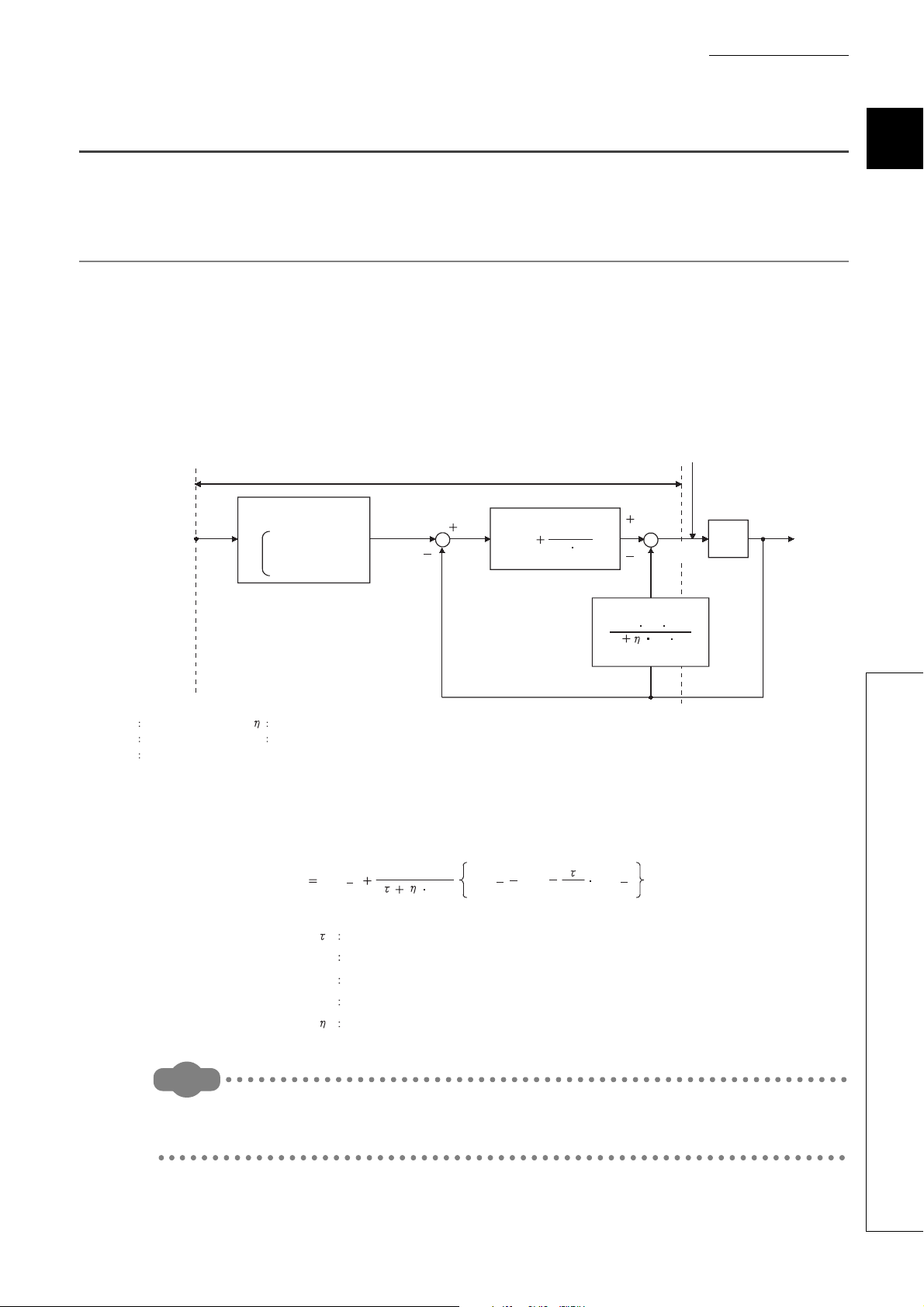
1.3 About the PID Operation
The Q64TCN can perform PID control in process-value incomplete derivation.
1.3.1 Operation method and formula
The PID control in process-value incomplete derivation is an operation method which puts a primary delay filter on
input from a derivative action and eliminate high-frequency noise component in order to perform a PID operation on
the deviation (E).
(1) Algorithm of PID control in process-value incomplete derivation
The algorithm of PID control in process-value incomplete derivation is shown below.
1
(2) Formula
The formula used for the Q64TCN is shown below.
The PID control in process-value derivation is an operation method which uses the process value (PV) for the derivation
section in order to perform a PID operation. Not using deviation for the derivation section, drastic output change due to a
derivative action is reduced when deviation varies along with the setting value change.
23
1.3 About the PID Operation
1.3.1 Operation method and formula
Page 26
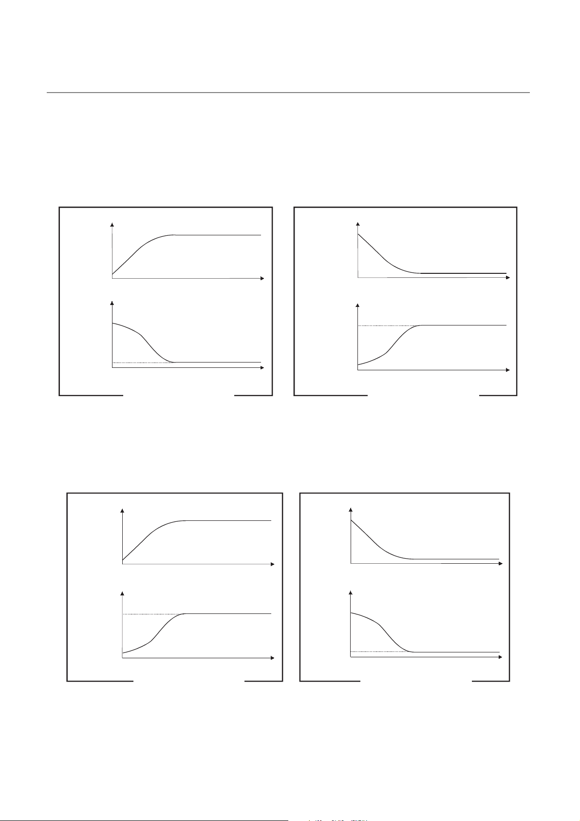
1.3.2 The Q64TCN actions
Manipulated
value
Manipulated
value
Temperature Temperature
Time
Time
Time
Time
Set value < Starting temperature Set value > Starting temperature
Set
value
Set
value
Manipulated
value
Temperature
Time
Time
Time
Time
Manipulated
value
Temperature
Set
value
Set value > Starting temperature Set value < Starting temperature
Set
value
The Q64TCN performs PID operations in forward actions and reverse actions.
(1) Forward action
In a forward action, the manipulated value (MV) is increased when the temperature process value (PV) increases
from the set value (SV).
A forward action is used for cooling control.
(2) Reverse action
In a reverse action, the manipulated value is increased when the temperature process value (PV) decreases from
the set value (SV).
A reverse action is used for heating control.
24
Page 27

CHAPTER 1 OVERVIEW
E
Time
Time
Deviation
(E)
Manipulated
value (MV)
K
P E
Set value
(SV)
Set value
(SV)
Temperature process value (PV) Temperature process value (PV)
Offset
TimeTime
Offset
1.3.3 Proportional action (P-action)
A proportional action is an action to obtain the manipulated value (MV) proportional to the deviation (difference
between the set value (SV) and the process value (PV)).
(1) Proportional gain
In a proportional action, the relationship between changes in the deviation (E) and the manipulated value can be
expressed in the following formula:
MV = K
P•E
where Kp is a proportional constant and is called proportional gain. The manipulated value (MV) varies in the
range from -5.0% to 105.0%.
The following table describes the difference of actions depending on the value of Kp, proportional gain.
Condition Proportional action
Kp is a small value The control action slows down.
Kp is a large value
The following figure shows a proportional action of step responses where the deviation (E) is a fixed value.
The control action speeds up, though the temperature process value (PV) tends to
fluctuate around the set value.
1
(2) Offset
The certain amount of difference generates between the temperature process value (PV) and the set value (SV)
is called an offset (remaining deviation).
In an proportional action, an offset (remaining deviation) generates.
1.3 About the PID Operation
1.3.3 Proportional action (P-action)
25
Page 28
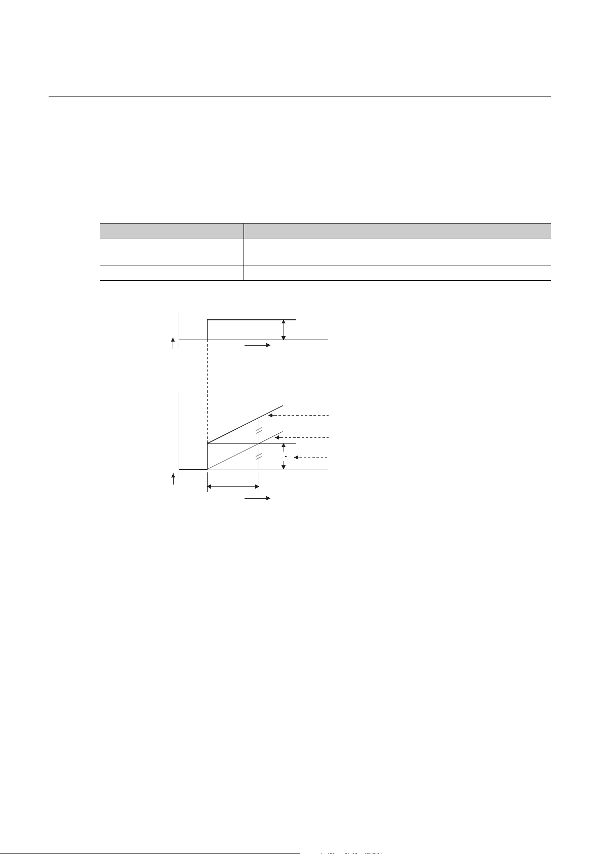
1.3.4 Integral action (I-action)
An integral action is an action which continuously changes the manipulated value (MV) to eliminate the deviation (E)
when there is any.
The offset caused by a proportional action can be eliminated.
In an integral action, the time from a deviation occurrence until when the manipulated value (MV) of the integral action
becomes equals to that of the proportional action is called integral time, and is indicated as TI.
The following table describes the difference of actions depending on the value of T
Condition Integral action
TI is a small value
I is a large value The integral effect gets small, and time to eliminate the offset gets long.
T
The integral effect gets large, and time to eliminate the offset gets short.
Though, the temperature process value (PV) tends to fluctuate around the set value.
The following figure shows an integral action of step responses where the deviation (E) is a fixed value.
I, integral time.
Deviation
(E)
Manipulated
value (MV)
T
I
Time
K
P E
Time
E
Manipulated value of the Proportional action + Integral action
Manipulated value of the Integral action
Manipulated value of the Proportional action
An integral action is used as a PI action in combination with a proportional action, or PID action in combination with a
proportional and derivative actions.
An integral action cannot be used by itself.
26
Page 29

CHAPTER 1 OVERVIEW
E
Manipulated value of the Proportional action
T
D
Time
Time
Deviation
(E)
Manipulated
value (MV)
K
P E
1.3.5 Derivative action (D-action)
A derivative action adds the manipulated value (MV) proportional to the rate of change to eliminate the deviation (E)
when it occurs.
A derivative action can prevent the control target from changing significantly due to disturbance.
In a derivative action, the time from a deviation occurrence until when the manipulated value (MV) of the derivative
action becomes equals to that of the proportional action is called derivative time, and is indicated as TD.
The following table describes the difference of actions depending on the value of T
Condition Derivative action
TD is a small value The derivative effect gets small.
The derivative effect gets large.
T
D is a large value
Though, the temperature process value (PV) tends to fluctuate around the set value
in short cycles.
The following figure shows a derivative action of step responses where the deviation (E) is a fixed value.
D, derivative time.
1
A derivative action is used as a PD action in combination with a proportional action, or PID action in combination with
a proportional and integral actions.
A derivative action cannot be used by itself.
1.3 About the PID Operation
1.3.5 Derivative action (D-action)
27
Page 30

1.3.6 PID action
PID action
I action
P action
D action
PI action
Deviation
(E)
Manipulated
value (MV)
Time
Time
A PID action performs control using the manipulated value (MV) calculated by merging the proportional action, integral
action, and derivative action.
The following figure shows a PID action of step responses where the deviation (E) is a fixed value.
28
Page 31
CHAPTER 2 SYSTEM CONFIGURATION
CHAPTER 2 SYSTEM CONFIGURATION
This chapter describes the system configuration of the Q64TCN.
2.1 Applicable Systems
This section describes applicable systems.
(1) Applicable CPU modules and base units, and number of mountable modules
The following table lists CPU modules and base units applicable to the Q64TCN and the number of mountable
Q64TCN.
Depending on the combination with other modules or the number of mounted modules, power supply capacity
may be insufficient.
Select the power supply capacity according to the module to be used. If the power supply capacity is insufficient,
change the combination of the modules.
*1
Applicable base unit
Main base
unit
CPU type CPU model
Programmable
controller CPU
Applicable CPU module
Basic model
QCPU
High Performance
model QCPU
Process CPU
Redundant CPU
Universal model
QCPU
Q00JCPU Up to 16 Up to 8
Q00CPU
Q01CPU
Q02CPU
Q02HCPU
Q06HCPU
Q12HCPU
Q25HCPU
Q02PHCPU
Q06PHCPU
Q12PHCPU
Q25PHCPU
Q12PRHCPU
Q25PRHCPU
Q00UJCPU Up to 16 Up to 8
Q00UCPU
Q01UCPU
Q02UCPU Up to 36 Up to 18
Q03UDCPU
Q04UDHCPU
Q06UDHCPU
Q10UDHCPU
Q13UDHCPU
Q20UDHCPU
Q26UDHCPU
Number of modules
Q64TCTTN/
Q64TCRTN
Up to 24 Up to 12
Up to 64 Up to 32
Up to 64 Up to 32
Up to 53 Up to 26 ×
Up to 24 Up to 12
Up to 64 Up to 32
Q64TCTTBWN/
Q64TCRTBWN
*2
Extension
base unit
2
2.1 Applicable Systems
29
Page 32
Remark
Remark
Applicable CPU module
CPU type CPU model
Programmable
controller CPU
C Controller module
Universal model
QCPU
Safety CPU QS001CPU N/A N/A ×
*1 Limited within the range of I/O points for the CPU module.
*2 Can be installed to any I/O slot of a base unit.
*3 Connection of an extension base unit is not available with any safety CPU.
Q03UDECPU
Q04UDEHCPU
Q06UDEHCPU
Q10UDEHCPU
Q13UDEHCPU
Q20UDEHCPU
Q26UDEHCPU
Q50UDEHCPU
Q100UDEHCPU
Q06CCPU-V
Q12DCCPU-V
Number of modules
Q64TCTTN/
Q64TCRTN
Up to 64 Up to 32
Up to 64 Up to 32Q06CCPU-V-B
Q64TCTTBWN/
Q64TCRTBWN
*1
Applicable base unit
Main base
Extension
unit
*2
base unit
*3
×
: Applicable, ×: N/A
To use a C controller module with the Q64TCN, refer to the C Controller Module User's Manual.
(a) When mounted on a MELSECNET/H remote I/O station
The following table lists the network modules and base units applicable to the Q64TCN and the number of
mountable Q64TCN.
Depending on the combination with other modules or the number of mounted modules, power supply capacity
may be insufficient.
Select the power supply capacity according to the module to be used. If the power supply capacity is
insufficient, change the combination of the modules.
Applicable
network module
Number of modules
Q64TCTTN/
Q64TCTTBWN/Q
Q64TCRTN
QJ72LP25-25
QJ72LP25G
QJ72LP25GE
QJ72BR15
*1 Limited within the range of I/O points for the network module.
*2 Can be installed to any I/O slot of a base unit.
Up to 64 Up to 32
*1
64TCRTBWN
Applicable base unit
Main base unit of
remote I/O station
Extension base unit
of remote I/O station
*2
: Applicable, ×: N/A
30
The Basic model QCPU or C Controller module cannot configure the MELSECNET/ H remote I/O net.
Page 33
CHAPTER 2 SYSTEM CONFIGURATION
(2) For multiple CPU system
The function version of the first released Q64TCN is C, and the Q64TCN supports multiple CPU systems.
When using the Q64TCN in a multiple CPU system, refer to the following.
QCPU User's Manual (Multiple CPU System)
(a) Intelligent function module parameters
Write intelligent function module parameters to only the control CPU of the Q64TCN.
(3) For online module change
The function version of the first released Q64TCN is C, and the Q64TCN supports online module change. For
details, refer to the following.
• For GX Developer: Page 386, Appendix 4
• For GX Works2: Page 401, Appendix 5
(4) Applicable software packages
The following table lists relation between the system including the Q64TCN and software package.
A programming tool is required to use the Q64TCN.
2
Item
Single CPU system
Q00J/Q00/Q01CPU
Q02/Q02H/Q06H/Q12H/Q25HCPU
Q02PH/Q06PHCPU
Q12PH/Q25PHCPU
Q12PRH/Q25PRHCPU Redundant system Version 8.45X or later
Q00UJ/Q00U/Q01UCPU
Q02U/Q03UD/Q04UDH/Q06UDHCP
U
Q10UDH/Q20UDHCPU
Q13UDH/Q26UDHCPU
Q03UDE/Q04UDEH/Q06UDEH/Q13
UDEH/Q26UDEHCPU
Q10UDEH/Q20UDEHCPU
Q50UDEH/Q100UDEHCPU
If installed in a MELSECNET/H remote I/O station Version 6 or later SW0D5C-QTCU 10B or later
Multiple CPU system Version 8 or later
Single CPU system Version 4 or later
Multiple CPU system Version 6 or later
Single CPU system
Multiple CPU system
Single CPU system
Multiple CPU system
Single CPU system
Multiple CPU system
Single CPU system
Multiple CPU system
Single CPU system
Multiple CPU system
Single CPU system
Multiple CPU system
Single CPU system
Multiple CPU system
Single CPU system
Multiple CPU system
Single CPU system
Multiple CPU system
GX Works2 GX Developer
Version 7 or later Version 1.10L or later
Version 1.62Q or later
Version 8.68W or later
Version 1.87R or later
Version 1.62Q or later
Version 7.10L or later
Version 8.76E or later
Version 8.48A or later
Version 8.76E or later
Version 8.62Q or later
Version 8.68W or later
Version 8.76E or later
GX Configurator-TC
(SW0D5C-QTCU 40E or earlier
versions cannot be used.)
SW0D5C-QTCU 00A or later
Version 1.13P or later
(SW0D5C-QTCU 40E or earlier
versions cannot be used.)
Version 1.14Q or later
(SW0D5C-QTCU 40E or earlier
versions cannot be used.)
Version 1.23Z or later
(SW0D5C-QTCU 40E or earlier
versions cannot be used.)
N/A N/A
*1
Software version
2.1 Applicable Systems
*1 For the function available in GX Configurator-TC, refer to the following.
Page 383, Appendix 3.2 (2)
31
Page 34

Depending on the version of GX Configurator-TC, available systems and CPU modules are different.
(5) Temperature sensor
For usable temperature sensors, refer to the following.
Page 40, Section 3.1.1
(6) Current sensor for heater disconnection detection
The following table lists current sensors for heater disconnection detection available with the Q64TCTTBWN or
Q64TCRTBWN.
Model name Remarks Manufacturer
CTL-12-S36-8 (0.0 to 100.0A)
CTL-12-S36-10 (0.0 to 100.0A)
CTL-12-S56-10 (0.0 to 100.0A)
CTL-6-P (0.00 to 20.00A)
CTL-6-P-H (0.00 to 20.00A)
*1 The CTL-12-S36-8 and CTL-6-P can be used although they have been discontinued.
For how to select current sensors for heater disconnection detection, refer to the following.
Page 140, Section 3.4.2 (55)
Page 141, Section 3.4.2 (57)
*1
-
*1
U.R.D.Co., LTD.
www.u-rd.com/english
32
Page 35
CHAPTER 2 SYSTEM CONFIGURATION
2.2 Using the Q64TCN with Redundant CPU
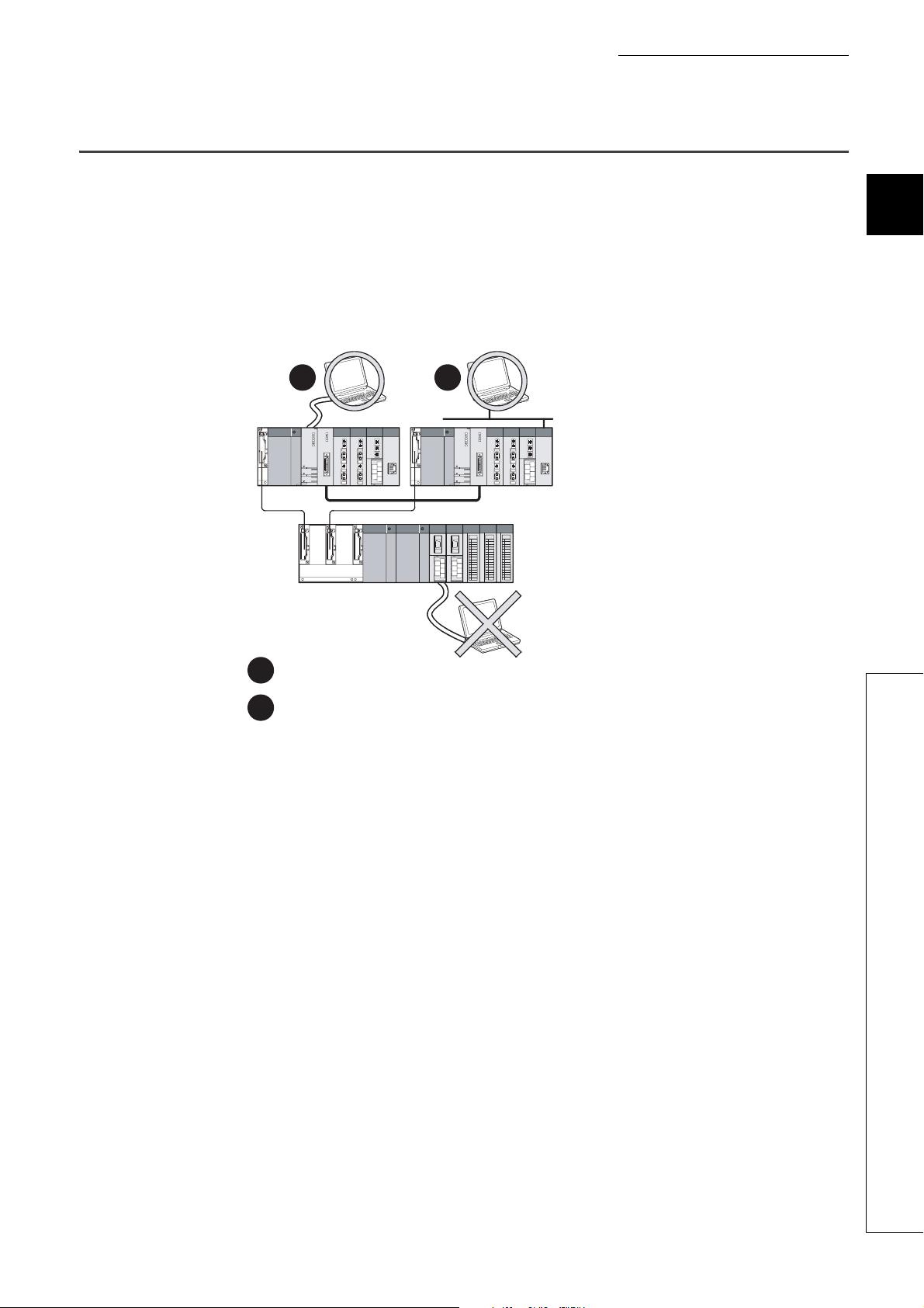
This section describes the use of the Q64TCN with the redundant CPU.
(1) GX Configurator-TC
GX Configurator-TC cannot be used when the redundant CPU accessed via an intelligent function module on an
extension base unit from GX Developer. Consider a communication path which does not go through the
intelligent function modules on the extension base unit.
Connect a personal computer with a redundant CPU using a communication path shown below.
12
Main base unit
2
Extension base unit
(GX Configurator-TI cannot be used.)
Direct connection to use the CPU
1
Connection through an intelligent function module on the main base unit
2
(Through Ethernet module, MELSECNET/H module, or CC-Link module)
2.2 Using the Q64TCN with Redundant CPU
33
Page 36

2.3 How to Check the Function Version and Serial Number
140212000000000-C
Relevant regulation standards
Function version
Serial number (first six digits)
The function version and serial number of the Q64TCN can be checked on the rating plate, front part of a module, or
system monitor of a programming tool.
(1) Checking on rating plate
The rating plate is on the side of the Q64TCN.
(a) For the Q64TCTTN and Q64TCRTN
(b) For the Q64TCTTBWN and Q64TCRTBWN
Serial number (first six digits)
Function version
Relevant regulation standards
34
Page 37

CHAPTER 2 SYSTEM CONFIGURATION
140212000000000-C
Serial No.
Function version
(2) Checking on the front part (bottom part) of module
The function version and serial number on the rating plate are also shown on the front part (bottom part) of the
module.
2
2.3 How to Check the Function Version and Serial Number
35
Page 38

(3) Checking on the system monitor
The function version and serial number can be checked on the "Product Information List" window.
[Diagnostics] [System Monitor...]
(a) Displaying production number
For the Q64TCN, "-" is displayed since the production number display is not supported.
The serial number displayed on the product information list of a programming tool may differ from that on the rating plate and
on the front part of the module.
● The serial number on the rating plate and front part of the module indicates the management information of the product.
● The serial number displayed on the product information list of a programming tool indicates the function information of the
product.
The function information of the product is updated when a new function is added.
36
Page 39

CHAPTER 2 SYSTEM CONFIGURATION
2.4 Precautions for System Configuration
The Q64TCN measures temperature based on the temperature of the terminal block. Therefore, depending on the
system configuration, temperature distribution of the terminal block can be uneven due to the effect of heat generated
from modules, and the measured temperature may differ from actual temperature (especially when two or more
Q64TCN modules are mounted next to each other or the Q64TCN is mounted next to the power supply module or
CPU module).
In this case, the difference between measured value and actual temperature can be reduced by the following methods.
(1) Using the sensor correction function
The measured temperature can be corrected to the actual temperature by this function.
For details on the sensor correction function, refer to the following.
Page 209, Section 4.14
2
2.4 Precautions for System Configuration
37
Page 40
CHAPTER 3 SPECIFICATIONS
This chapter describes the performance specifications of the Q64TCN, I/O signals transferred to/from the CPU
module, and the specifications of the buffer memory.
For the general specifications of the Q64TCN, refer to the following.
QCPU User's Manual (Hardware Design, Maintenance and Inspection)
3.1 Performance Specifications
The following table lists the performance specifications of the Q64TCN.
Item
Control output Transistor output
Number of temperature input points 4 channels/module
Type of usable temperature sensors, the temperature
measurement range, the resolution, and the effect from
wiring resistance of 1
Ambient temperature:
Indication
accuracy
Cold junction
Accuracy
Sampling cycle 500ms/4 channels (constant independently of the number of channels used)
Control output cycle 1 to 100s
Input impedance 1M
Input filter 0 to 100s (0: Input filter OFF)
Sensor correction value setting -50.00 to 50.00%
Operation at sensor input disconnection Upscale processing
Temperature control method PID ON/OFF pulse or two-position control
PID constants range
Set value (SV) setting range
Dead band setting range 0.1 to 10.0%
*1
temperature
compensation
accuracy:
(ambient
temperature:
0 to 55°C)
25±5°C
Ambient temperature: 0 to
55°C
Temperature process
value (PV): -100°C or
more
value (PV): -150 to -100°C
Temperature process
value (PV): -200 to -150°C
PID constants setting Can be set by auto tuning.
Proportional band (P) 0.0 to 1000.0% (0: Two-position control)
Integral time (I) 0 to 3600s (set 0 for P control and PD control.)
Derivative time (D) 0 to 3600s (set 0 for P control and PI control.)
Q64TCTTN Q64TCRTN Q64TCTTBWN Q64TCRTBWN
Within ±1.0°C
Within ±2.0°C Within ±2.0°C
Within ±3.0°C Within ±3.0°C
Within the temperature range set in the used thermocouple/platinum resistance
Specifications
Page 40, Section 3.1.1
Full scale × (±0.3%)
Full scale × (±0.7%)
Within ±1.0°C
thermometer to be used
Temperature process
38
Page 41
CHAPTER 3 SPECIFICATIONS
Ex.
Ex.
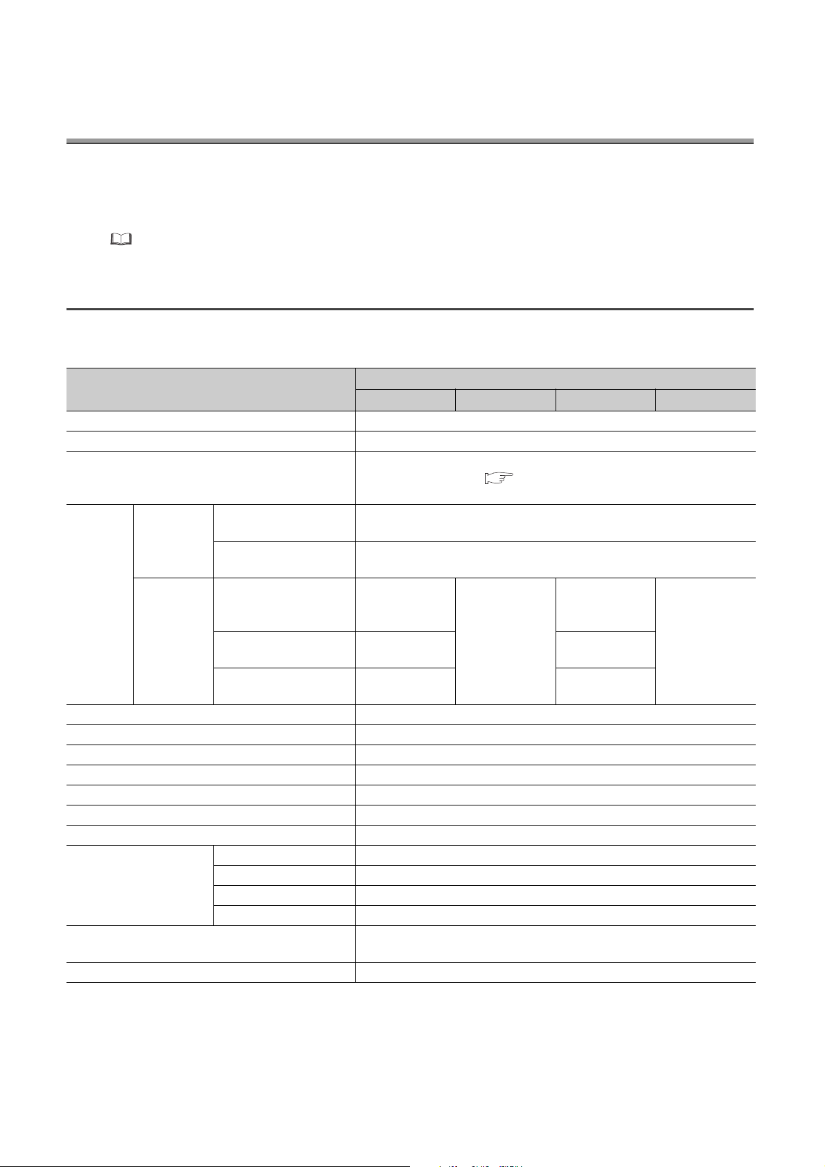
Item
Output signal ON/OFF pulse
Rated load voltage 10 to 30VDC
Max. load current 0.1A/point, 0.4A/common
Transistor output
Number of accesses to non-volatile memory
Insulation method
Dielectric withstand voltage
Insulation resistance
Heater disconnection
detection specifications
I/O occupied points
Connection terminal 18-point terminal block Two 18-point terminal blocks
Applicable wire size
Applicable solderless terminal R1.25-3 (Crimping terminal with sleeve is unavailable.)
Internal current consumption 0.29A 0.33A
Weight 0.20kg 0.30kg
Outline dimensions 27.4(W)mm × 98(H)mm × 112(D)mm 55.2(W)mm × 98(H)mm × 112(D)mm
*2
*1 Calculate the accuracy in the following method (only when it is not affected by noise).
Accuracy (°C) = full scale × indication accuracy + cold junction temperature compensation accuracy
Max. inrush current 0.4A 10ms
Leakage current at OFF 0.1mA or less
Max. voltage drop at ON 1.0VDC (TYP) at 0.1A 2.5VDC (MAX) at 0.1A
Response time OFFON: 2ms or less, ONOFF: 2ms or less
Current sensor
Input accuracy Full scale × (±1.0%)
Number of alert delay 3 to 255
Q64TCTTN Q64TCRTN Q64TCTTBWN Q64TCRTBWN
Between input terminal and programmable controller power supply: Transformer
Between input channels: Transformer insulation
Between input terminal and programmable controller power supply: 500VAC for
Between input channels: 500VAC for 1 minute
Between input terminal and programmable controller power supply: 500VDC
Between input channels: 500VDC 20M or more
16 points/slot
(I/O assignment: 16 intelligent points)
Specifications
12
Max. 10
20M or more
0.3mm
times
insulation
1 minute
2
to 0.75mm
Page 32, Section 2.1 (6)
32 points/2 slots
(I/O assignment:
Vacancy for 16 points
+ 16 intelligent points)
2
3
3.1 Performance Specifications
Accuracy at the input range of 38 (-200.0 to 400.0°C), the operating ambient temperature of 35°C, and the
temperature process value (PV) of 300°C
(Full scale) × (indication accuracy) + cold junction temperature compensation accuracy
= (400.0°C- (-200.0°C)) × (±0.007) + (±1.0°C)
= ± 5.2°C
*2 When the Q64TCTTBWN or Q64TCRTBWN is used, the device numbers of the I/O signals increase by 16 points
depending on how many free points the left-hand side slots have. Hence, as I/O signals are given as indicated below in
this manual, read them according to the module used.
When 0 is set as the start I/O number, Yn1 is assigned as follows.
When the Q64TCTTN or Q64TCRTN is used: Y1
When the Q64TCTTBWN or Q64TCRTBWN is used: Y11
For the noise immunity, dielectric withstand voltage, insulation resistance and others of the programmable controller
system which uses the Q64TCN, refer to the following.
QCPU User's Manual (Hardware Design, Maintenance and Inspection)
39
Page 42

3.1.1 Type of usable temperature sensors, temperature
measurement range, resolution, and effect from wiring
resistance of 1 ohm
This section describes types of temperature sensors that can be used with the Q64TCN, the temperature
measurement range, the resolution, and the effect from wiring resistance of 1.
Set the used temperature sensor in the following buffer memory area.
•CH Input range (Un\G32, Un\G64, Un\G96, Un\G128) ( Page 96, Section 3.4.2 (12))
(1) Q64TCTTN, Q64TCTTBWN
The following table lists the types of thermocouples that can be used with the Q64TCTTN and Q64TCTTBWN,
the temperature measurement range, the resolution, and the effect from wiring resistance of 1.
°C
Thermocouple
type
Temperature
measurement
Resolution
range
R 0 to 1700 1 0.030 0 to 3000 1 0.054
0 to 500
0 to 800
0 to 1300
K
J
T
S 0 to 1700 1 0.030 0 to 3000 1 0.054
B
E
N 0 to 1300 1 0.006 0 to 2300 1 0.011
U
L
-200.0 to 400.0
0.0 to 400.0
0.0 to 500.0
0.0 to 800.0
0 to 500
0 to 800
0 to 1200
0.0 to 400.0
0.0 to 500.0
0.0 to 800.0
-200 to 400
-200 to 200
0 to 200
0 to 400
-200.0 to 400.0
0.0 to 400.0
0 to 1800
0.0 to 700.0 0.1
-200 to 200
0.0 to 600.0 0.1
0.0 to 400.0
0.0 to 900.0
*2
0 to 400
0 to 1000
0 to 400
0 to 400
0 to 900
1
0.1 0.0 to 1000.0 0.1
1
0.1 0.0 to 1000.0 0.1
1
0.1 0.0 to 700.0 0.1
1 0.038
1
1
1
0.1
Effect from wiring
resistance of 1
*1
(°C/)
0.005
0.003
0.004
0.003
0.004
0.003
Temperature
measurement
Resolution
range
0 to 1000
0 to 2400
0 to 1000
0 to 1600
0 to 2100
0 to 700
-300 to 400
0 to 3000
-300 to 400
*2
0 to 1800 1 0.005
0 to 700
0 to 800
0 to 1600
1
1
1
1 0.068
1 0.009
1 0.006
Effect from wiring
resistance of 1
*1
(/)
0.008
0.006
0.008
40
Page 43

CHAPTER 3 SPECIFICATIONS
°C
Thermocouple
type
Temperature
measurement
Resolution
range
PLII 0 to 1200 1 0.005 0 to 2300 1 0.010
W5Re/W26Re 0 to 2300 1 0.017 0 to 3000 1 0.021
*1 Means temperature error per of wiring resistance of the thermocouple. The error varies depending on measured
temperature or ambient temperature. The temperature error can be corrected by the sensor correction function.
( Page 209, Section 4.14)
*2 While temperature can be measured within less than 400°C/800 , the accuracy cannot be guaranteed.
Effect from wiring
resistance of 1
*1
(°C/)
Temperature
measurement
range
Resolution
Effect from wiring
resistance of 1
(/)
(2) Q64TCRTN, Q64TCRTBWN
The following table lists the types of platinum resistance thermometers that can be used with the Q64TCRTN and
Q64TCRTBWN and temperature measurement range.
*1
3
Platinum resistance
thermometer type
Pt100
JPt100
Temperature
measurement range
-200.0 to 600.0
-200.0 to 200.0
-200.0 to 500.0
-200.0 to 200.0
°C
Resolution
0.1
0.1
Temperature
measurement range
-300 to 1100 1
-300.0 to 300.0 0.1
-300 to 900 1
-300.0 to 300.0 0.1
Resolution
3.1 Performance Specifications
3.1.1 Type of usable temperature sensors, temperature measurement range, resolution, and effect
from wiring resistance of 1 ohm
41
Page 44

3.1.2 Sampling cycle and control output cycle
This section describes the sampling cycle and control output cycle of the Q64TCN.
(1) Sampling cycle
The Q64TCN performs PID operations in the order of CH1, CH2, CH3, CH4, CH1, CH2 .....
The time from when PID operation is started on the current channel (CHn) until PID operation is restarted on the
current channel (CHn) is called a sampling cycle. The sampling cycle is 500ms.
The number of used channels and the settings of unused channels do not affect the sampling cycle.
CH1 PID
operation
CH2 PID
operation
500ms (sampling cycle)
CH3 PID
operation
500ms (sampling cycle)
CH4 PID
operation
CH1 PID
operation
CH2 PID
operation
(2) Control output cycle
The control output cycle is the ON/OFF cycle of transistor output.
ON ON
Transistor output
Control output cycle Control output cycle
OFF
The manipulated value (MV) represents the ON time of the control output cycle in percentage. ( Page 89,
Section 3.4.2 (5))
Set the control output cycle in the following buffer memory area in the range 1 to 100s.
•CH Control output cycle setting (Un\G47, Un\G79, Un\G111, Un\G143) ( Page 114, Section 3.4.2
(23))
In the heating-cooling control, the following buffer memory areas are used for the manipulated value (MV) and
control output cycle.
OFF
Data type
Manipulated
value (MV)
Control output
cycle
42
Buffer memory area
name
Manipulated value for
heating (MVh)
Manipulated value for
cooling (MVc)
Heating control output
cycle setting
Cooling control output
cycle setting
Buffer memory address
CH1 CH2 CH3 CH4
Un\G13 Un\G14 Un\G15 Un\G16
Un\G704 Un\G705 Un\G706 Un\G707
Un\G47 Un\G79 Un\G111 Un\G143
Un\G722 Un\G738 Un\G754 Un\G770
Reference
Page 89, Section 3.4.2 (5)
Page 114, Section 3.4.2 (23)
Page 45

CHAPTER 3 SPECIFICATIONS
3.1.3 Number of parameters to be set
The total number of the parameters of the initial setting and of the auto refresh setting of the Q64TCN must be within
the number of parameters which can be set in the CPU module including the number of other intelligent function
module parameters. For the maximum number of parameters which can be set in a CPU module (maximum number of
set parameter), refer to the following.
QCPU User's Manual (Hardware Design, Maintenance and Inspection)
(1) Number of parameters of the Q64TCN
The following table lists the number of parameters that can be set for one Q64TCN.
3
Target module Initial setting
Q64TCTTN 54
Q64TCRTN 53
Q64TCTTBWN 55
Q64TCRTBWN 54
Number of parameters of the auto refresh setting can be reduced by changing the normal mode to the setting
item reduction mode. For the setting item reduction mode, refer to the following:
Page 303, Section 6.4
Normal mode Setting item reduction mode
103 (Max.) 35 (Max.)
115 (Max.) 36 (Max.)
Auto refresh setting
3.1 Performance Specifications
3.1.3 Number of parameters to be set
43
Page 46

(2) Checking method
The current number and maximum number of the set parameters in the intelligent function module can be
checked by the following operation.
Project window [Intelligent Function Module] Right-click [Intelligent Function Module
Parameter List...]
1) 2) 3) 4)
No. Description
1) Total number of the parameters of the initial setting that is checked on the window
2) Maximum number of parameters of the initial setting
3) Total number of the parameters of the auto refresh setting that is checked on the window
4) Maximum number of parameters of the auto refresh setting
44
Page 47

3.2 Function List
This section lists the Q64TCN functions.
Item Description
The control mode can be selected from the following modes.
• Standard control
Control mode selection
function
Control output setting at
CPU stop error
Control method
Manual reset function
Manual control
Auto tuning function The Q64TCN sets the optimal PID constants automatically.
Simple two-degree-of-
freedom
Derivative action
selection function
Setting change rate
limiter setting function
Moving averaging
process to a temperature
process value (PV)
Temperature process
value (PV) scaling
function
Alert function
• Heating-cooling control (normal mode)
• Heating-cooling control (expanded mode)
• Mix control (normal mode)
• Mix control (expanded mode)
Whether to clear or hold the transistor output status when a CPU
stop error occurs or when a CPU module is turned from RUN to
STOP can be selected.
The following control methods can be used with the settings of
proportional band (P), integral time (I), and derivative time (D).
• Two-position control
•P control
•PI control
• PD control
• PID control
The stable status position in the P control or PD control can be
moved manually.
The manipulated value (MV) can be set manually by users without
automatic calculation by the PID control.
In addition to the PID control, the response speed responding to
the change of the set value (SV) can be selected from three levels.
The simple two-degree-of-freedom PID control can be realized.
Dynamic performance can be improved by selecting the suitable
derivative action for the fixed value action and the ramp action.
Change rate setting of the set value (SV) per set time unit when
this value is changed. The batch setting or individual setting can be
selected for the temperature rise and drop.
Moving averaging process can be set to a temperature process
value (PV). With this function, the fluctuation of temperature
process values (PV) can be reduced in electrically noisy
environments or in the environments where temperature process
values (PV) fluctuate greatly. The moving averaging process can
be disabled to hasten the response to the change of temperature
process values (PV).
The temperature process value (PV) can be converted to the set
width and this value can be imported into the buffer memory.
The modules goes to the alert status when the temperature
process value (PV) or deviation (E) meets the condition set in
advance.
CHAPTER 3 SPECIFICATIONS
Enable or disable
Standard
control
Heating-
cooling
control
: Enable, ×: Disable
Reference
Page 162,
Section 4.1
Page 165,
Section 4.2
Page 166,
Section 4.3
Page 173,
Section 4.4
Page 175,
Section 4.5
Page 176,
Section 4.6
Page 188,
Section 4.7
Page 189,
Section 4.8
Page 190,
Section 4.9
Page 191,
Section 4.10
Page 192,
Section 4.11
Page 194,
Section 4.12
3
3.2 Function List
45
Page 48
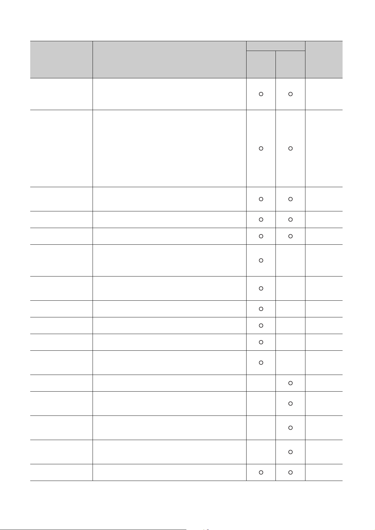
Item Description
RFB limiter function
Sensor correction
function
Auto-setting at input
range change
Input/output (with another
analog module) function
ON delay output function
Self-tuning function
Peak current suppression
function
Simultaneous
temperature rise function
Forward/reverse action
selection function
Loop disconnection
detection function
During AT loop
disconnection detection
function
Proportional band setting
function
Cooling method setting
function
Overlap/dead band
function
Temperature conversion
function (using unused
nels)
chan
Heater disconnection
detection function
Enable or disable
Standard
control
When the deviation (E) continues for a long time, the PID operation
result (manipulated value (MV)) by the integral action can be
prevented from exceeding the effective range of the manipulated
value (MV).
If a difference between a temperature process value (PV) and an
actual temperature occurs due to the measurement status, the
error can be corrected. Select a correction method from the
following two types.
• Normal sensor correction (one-point correction) function: The
percentage of the full scale of the set input range can be
corrected as an error corrected value.
• Sensor two-point correction function: An error is corrected by
setting any two points (corrected offset value and corrected gain
value).
When the input range is changed, the related buffer memory data
is changed automatically so that errors outside the setting range
does not occur.
Data can be input/output using another analog module (A/D
conversion module or D/A conversion module) on the system.
Setting with considering delay time (response/scan time delay) of
actual transistor output is possible.
The Q64TCN monitors the control status constantly. If the control
system oscillates due to a status soon after the control starts, a
change of the set value (SV), and property fluctuation of a
controlled object, PID constants are changed automatically.
Changing automatically the upper limit output limiter value of each
channel and dividing the timing of transistor output can suppress
the peak current.
This function allows several loops to reach the set value (SV) at the
same time.
Whether to perform PID operations in the forward action or reverse
action can be selected.
Errors in the control system (control loop) can be detected. ×
A loop disconnection can be detected during auto tuning. ×
The proportional band (P) can be individually set for heating or
cooling.
When the auto tuning is executed, an auto tuning formula is
automatically selected according to the selected cooling method
and the operation starts.
By changing the temperature where the cooling transistor output is
started, whether control stability is prioritized or energy saving is
prioritized can be selected.
In heating-cooling control (normal mode) and mix control (normal
mode), only temperature measurement is allowed by using unused
temperature input terminals.
The current which flows in the heater main circuit can be measured
and disconnections can be detected.
×
×
×
×
Heating-
cooling
control
×
×
×
×
Reference
Page 208,
Section 4.13
Page 209,
Section 4.14
Page 220,
Section 4.15
Page 221,
Section 4.16
Page 222,
Section 4.17
Page 223,
Section 4.18
Page 233,
Section 4.19
Page 238,
Section 4.20
Page 252,
Section 4.21
Page 253,
Section 4.22
Page 255,
Section 4.23
Page 257,
Section 4.24
Page 258,
Section 4.25
Page 259,
Section 4.26
Page 262,
Section 4.27
Page 265,
Section 4.28
46
Page 49

Item Description
Output off-time current
error detection function
Buffer memory data
backup function
Error history function
Module error history
collection function
Error clear function
An error of when the transistor output is off can be detected.
A set value in a buffer memory area can be backed up to the
2
PROM. Because the backed up value is restored at the next
E
startup of the module, an initial setting program is not required
once this function is executed.
Up to 16 errors and alarms that occur on the Q64TCN are stored in
the buffer memory as history.
Error contents can be notified to the CPU module when errors and
alarms occur on the Q64TCN. Error information is held in the
memory inside of the CPU module as module error history.
When an error occurs, the error can be cleared on the system
monitor.
CHAPTER 3 SPECIFICATIONS
Enable or disable
Standard
control
Heating-
cooling
control
Reference
Page 269,
Section 4.29
Page 270,
Section 4.30
Page 272,
Section 4.31
Page 274,
Section 4.32
Page 275,
Section 4.33
3
3.2 Function List
47
Page 50

3.3 I/O Signals Transferred to/from the CPU Module
Ex.
This section describes the I/O signals of the Q64TCN.
3.3.1 I/O signal list
This section describes the assignment and applications of the Q64TCN input signals.
When the Q64TCTTBWN or Q64TCRTBWN is used, the device numbers of the I/O signals increase by 16 points
depending on how many empty points the left-hand side slots have. Therefore, I/O signals are given as indicated
below in this manual. Read them according to the module used.
When 0 is set as the start I/O number, Yn1 is assigned as follows.
When the Q64TCTTN or Q64TCRTN is used: Y1
When the Q64TCTTBWN or Q64TCRTBWN is used: Y11
(1) Input signal list
Input signal (Signal direction: CPU module Q64TCN)
Device No. Standard control Heating-cooling control Mix control
Xn0 Module READY flag Module READY flag Module READY flag
Xn1 Setting/operation mode status Setting/operation mode status Setting/operation mode status
Xn2 Write error flag Write error flag Write error flag
Xn3 Hardware error flag Hardware error flag Hardware error flag
Xn4 CH1 Auto tuning status CH1 Auto tuning status CH1 Auto tuning status
Xn5 CH2 Auto tuning status CH2 Auto tuning status
Xn6 CH3 Auto tuning status
Xn7 CH4 Auto tuning status
Xn8
Xn9 Default value write completion flag Default value write completion flag Default value write completion flag
XnA
XnB Setting change completion flag Setting change completion flag Setting change completion flag
XnC CH1 Alert occurrence flag CH1 Alert occurrence flag CH1 Alert occurrence flag
XnD CH2 Alert occurrence flag CH2 Alert occurrence flag CH2 Alert occurrence flag
XnE CH3 Alert occurrence flag CH3 Alert occurrence flag CH3 Alert occurrence flag
XnF CH4 Alert occurrence flag CH4 Alert occurrence flag CH4 Alert occurrence flag
*1 Available only under the heating-cooling control (expanded mode). For details on the expanded mode, refer to
*2 Available only under the mix control (expanded mode). For details on the expanded mode, refer to Page 164,
2
E
PROM write completion flag E2PROM write completion flag E2PROM write completion flag
2
E
PROM write failure flag E2PROM write failure flag E2PROM write failure flag
Page 164, Section 4.1 (3).
Section 4.1 (3).
CH3 Auto tuning status
CH4 Auto tuning status
*1
*1
CH2 Auto tuning status
CH3 Auto tuning status
CH4 Auto tuning status
*2
48
Page 51

CHAPTER 3 SPECIFICATIONS
(2) Output signal list
Output signal (signal direction: CPU module Q64TCN)
Device No. Standard control Heating-cooling control Mix control
Yn0 N/A N/A N/A
Yn1 Setting/operation mode instruction Setting/operation mode instruction Setting/operation mode instruction
Yn2 Error reset instruction Error reset instruction Error reset instruction
Yn3 N/A N/A N/A
Yn4 CH1 Auto tuning instruction CH1 Auto tuning instruction CH1 Auto tuning instruction
Yn5 CH2 Auto tuning instruction CH2 Auto tuning instruction
Yn6 CH3 Auto tuning instruction
Yn7 CH4 Auto tuning instruction
Yn8
Yn9 Default setting registration instruction Default setting registration instruction Default setting registration instruction
YnA N/A N/A N/A
YnB Setting change instruction Setting change instruction Setting change instruction
YnC
YnD
YnE
YnF
*1 Available only under the heating-cooling control (expanded mode). For details on the expanded mode, refer to
*2 Available only under the mix control (expanded mode). For details on the expanded mode, refer to Page 164,
2
E
PROM backup instruction E2PROM backup instruction E2PROM backup instruction
CH1 PID control forced stop
instruction
CH2 PID control forced stop
instruction
CH3 PID control forced stop
instruction
CH4 PID control forced stop
instruction
Page 164, Section 4.1 (3).
Section 4.1 (3).
CH3 Auto tuning instruction
CH4 Auto tuning instruction
CH1 PID control forced stop
instruction
CH2 PID control forced stop
instruction
CH3 PID control forced stop
instruction
CH4 PID control forced stop
instruction
*1
*1
*1
*1
CH2 Auto tuning instruction
CH3 Auto tuning instruction
CH4 Auto tuning instruction
CH1 PID control forced stop
instruction
CH2 PID control forced stop
instruction
CH3 PID control forced stop
instruction
CH4 PID control forced stop
instruction
*2
3
*2
3.3 I/O Signals Transferred to/from the CPU Module
3.3.1 I/O signal list
The functions of the Q64TCN cannot be guaranteed if any of the unavailable areas is turned on/off in a sequence program.
49
Page 52
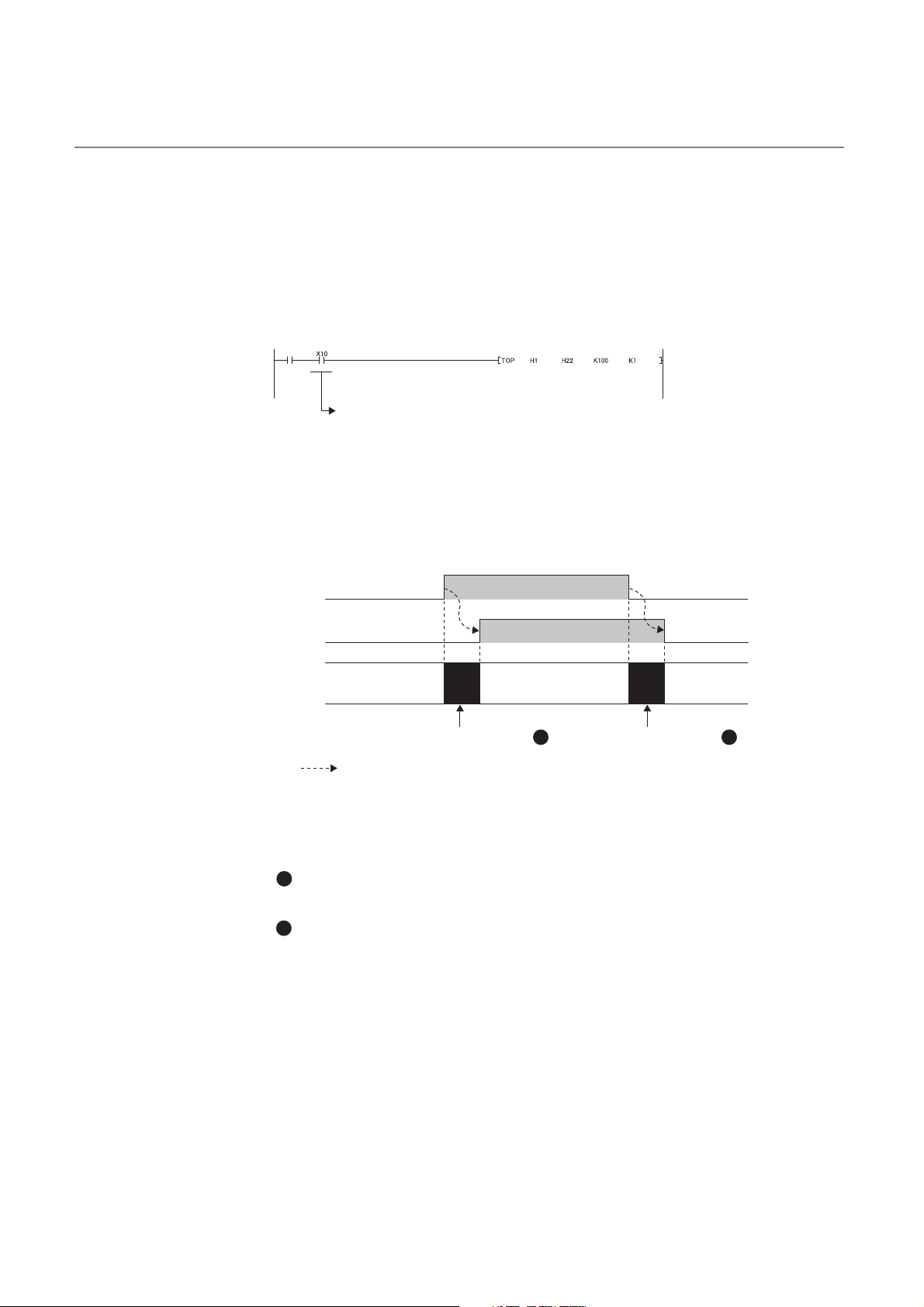
3.3.2 Details of input signals
Write
instruction
Used as buffer memory read/write interlock.
Setting/operation mode
instruction (Yn1)
Setting/operation mode
status (Xn1)
Mode transition
Setting mode at
power-ON
ON
OFF
OFF
ON
During mode shift processing During mode shift processing
Setting mode
(after operation)
Operation mode
(during operation)
Executed by the Q64TCN
1 2
(1) Module READY flag (Xn0)
This flag turns on to indicate that the preparation for the Q64TCN is completed when the module is turned on
from off or when the CPU module's reset is released.
Make sure that this flag is on when reading/writing data from/in the buffer memory of the Q64TCN from the CPU
module. The following shows an example of a program. (In the following example, the start I/O number of the
Q64TCN is set to 10.)
If the watchdog timer error is detected, this flag turns off. The Q64TCN stops controlling the temperature and the
transistor output turns off. (The RUN LED turns off and ERR. LED turns on.)
(2) Setting/operation mode status (Xn1)
This signal turns on at the operation mode, off at the setting mode.
(a) Precautions during the mode shifting
The mode shifting means the following timings.
• From Setting/operation mode instruction (Yn1) OFF ON to Setting/operation mode status (Xn1) ON
(above figure )
• From Setting/operation mode instruction (Yn1) ON OFF to Setting/operation mode status (Xn1) OFF
(above figure )
During the mode shifting, do not change the set values. If the set values are changed during the mode shifting,
the module operation cannot be guaranteed. Use Setting/operation mode status (Xn1) as an interlock condition
for Setting/operation mode instruction (Yn1) when changing the setting.
1
2
50
Page 53

CHAPTER 3 SPECIFICATIONS
The conditions whether to perform the temperature judgment, PID control, and alert judgment by the Q64TCN differ among
the following timings.
• Setting mode at power-ON
• Operation mode (in operation)
• Setting mode (after operation)
For each detail on the temperature judgment, PID control, and alert judgment, refer to the following.
• Temperature judgment: Page 87, Section 3.4.2 (3)
• PID control: Page 170, Section 4.3 (6)
• Alert judgment: Page 203, Section 4.12 (5)
(3) Write error flag (Xn2)
The write data error occurs in the Q64TCN when the data is set to the buffer memory in the area where data
cannot be written or the timing when data cannot be written.
After a write data error occurs and the error code is stored in Write data error code (Un\G0), this flag turns on.
A write data error occurs under the following conditions.
• When data is set in the buffer memory of the system area
• When the setting of the area which can be written only during the setting mode (Setting/operation mode
status (Xn1): OFF) is changed during the operation mode (Setting/operation mode status (Xn1): ON)
( Page 50, Section 3.3.2 (2))
• When the data which cannot be set is set
• When the setting of the buffer memory is changed during the default setting registration ( Page 58,
Section 3.3.3 (5))
• When the current control mode and the control mode backed up in the E
change of the control mode selection.
2
PROM are different due to the
3
3.3 I/O Signals Transferred to/from the CPU Module
3.3.2 Details of input signals
ON
Write error flag (Xn2)
Write data error code
(Un\G0)
Error reset instruction (Yn2)
OFF
H
0
OFF
Executed by the Q64TCN
(4) Hardware error flag (Xn3)
This flag turns on when hardware error occurs in the Q64TCN.
Error code
ON
0
H
51
Page 54

(5) CH Auto tuning status (Xn4 to Xn7)
During auto tuning
ON
ON
OFF
OFF
Executed in a sequence program
Executed by the Q64TCN
CH Auto tuning instruction
(Yn4 to Yn7)
CH Auto tuning status
(Xn4 to Xn7)
This signal turns on when auto tuning of each channel is set by the user or when the Q64TCN performs self-
tuning.
Auto tuning status
Channel
Standard
control
CH1 Xn4 Xn4 Xn4
CH2 Xn5 Xn5
CH3 Xn6
CH4 Xn7
*1 Available only under the heating-cooling control (expanded mode). For details on the expanded mode, refer to
Page 164, Section 4.1 (3).
*2 Available only under the mix control (expanded mode). For details on the expanded mode, refer to Page 164,
Section 4.1 (3).
(a) Performing auto tuning
To perform auto tuning, turn CH Auto tuning instruction (Yn4 to Yn7) on from off.
While auto tuning is in process, this signal is on, and turns off at the completion of the auto tuning.
Heating-
cooling
control
*1
Xn6
*1
Xn7
Mix control
*2
Xn5
Xn6
Xn7
ON/OFF status
ON: The auto tuning/self-tuning is being
performed.
OFF: The auto tuning/self-tuning is not being
performed or is completed.
(b) Self-tuning
For details on the auto tuning function, refer to the following.
Page 176, Section 4.6
This signal turns on when self-tuning starts. This signal automatically turns off at the completion of the self-
tuning.
Set a self-tuning option in CH Self-tuning setting (Un\G574, Un\G606, Un\G638, Un\G670). ( Page 146,
Section 3.4.2 (68))Self-tuning can be executed only in the standard control.
For details on the self-tuning function, refer to the following.
Page 223, Section 4.18
52
Page 55
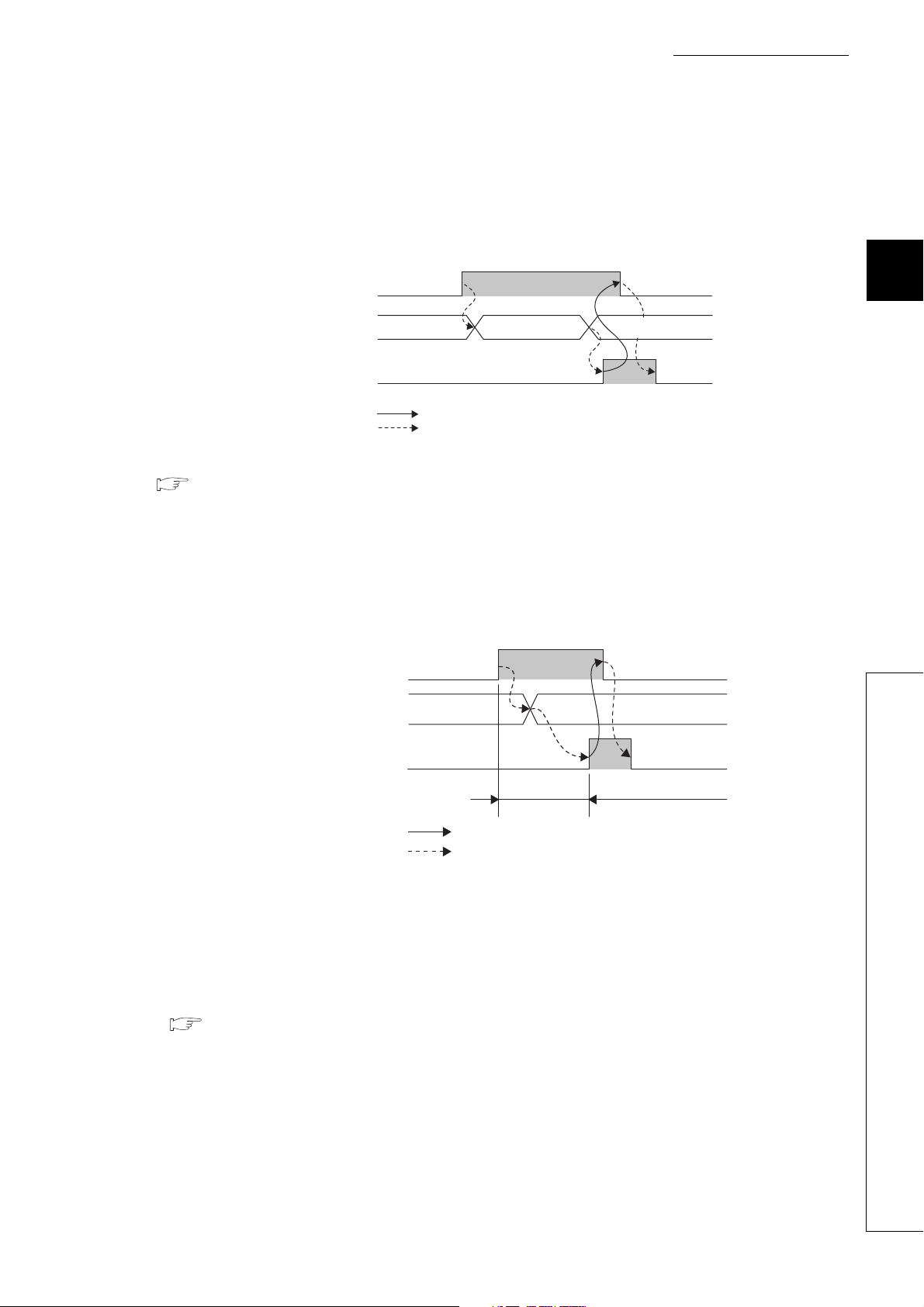
CHAPTER 3 SPECIFICATIONS
(6) E2PROM write completion flag (Xn8)
Turning E2PROM backup instruction (Yn8) on from off starts the writing of the buffer memory data to the
E2PROM. After the data writing is completed, this flag turns on. Turning E2PROM backup instruction (Yn8) off
from on also turns off this flag.
ON
E2PROM backup instruction
2
E
(Yn8)
Execution status of
2
E
PROM write
PROM write completion
flag (Xn8)
OFF
Before write to
2
E
PROM
OFF
Executed in a sequence program
Executed by the Q64TCN
During write to
2
E
PROM
Completion of write to
E2PROM
ON
For details on the data writing to the E2PROM, refer to the following.
Page 270, Section 4.30
(7) Default value write completion flag (Xn9)
Turning Default setting registration instruction (Yn9) on from off starts the writing of the default value of the
Q64TCN to the buffer memory. After the data writing is completed, this flag turns on. Turning Default setting
registration instruction (Yn9) off from on also turns off this flag.
ON
Default setting registration instruction
(Yn9)
Buffer memory
Default value write completion flag
(Xn9)
OFF
User setting
value
OFF
Default value
ON
During default setting
registration
3
3.3 I/O Signals Transferred to/from the CPU Module
3.3.2 Details of input signals
Executed in a sequence program
Executed by the Q64TCN
(a) Unused channel
For unused channels (which temperature sensors are not connected to), CH Unused channel setting
(Un\G61, Un\G93, Un\G125, Un\G157) must be set to Unused (1) after the completion of the writing of the
default value.
If not, the ALM LED blinks.
For details on the unused channel setting, refer to the following.
Page 297, Section 5.5
53
Page 56
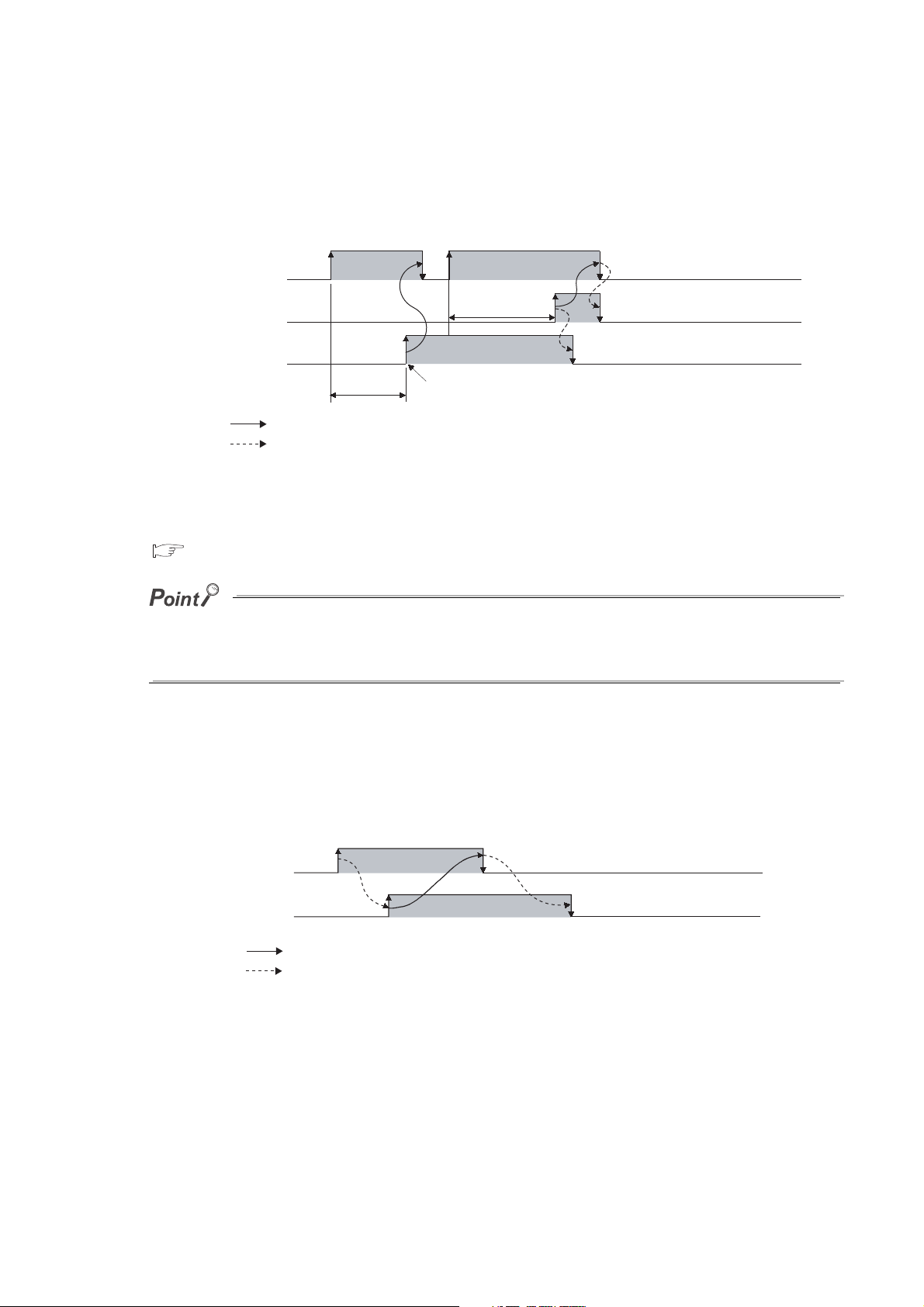
(8) E2PROM write failure flag (XnA)
E2PROM backup instruction
(Yn8)
E
2
PROM write completion flag
(Xn8)
E
2
PROM write failure flag
(XnA)
OFF
OFF
OFF
ON
ON
During write
to E
2
PROM
During write
to E
2
PROM
Error detection of write to E
2
PROM
ON
Executed in a sequence program
Executed by the Q64TCN
Setting change instruction
(YnB)
Setting change
completion flag
(XnB)
ON
OFF
OFF
ON
Executed in a sequence program
Executed by the Q64TCN
Turning E2PROM backup instruction (Yn8) on from off starts the writing of the buffer memory data to the
E2PROM. This flag turns on when the writing failed.
2
This flag turns off when E
to the E2PROM.
For details on the data writing to the E
Page 270, Section 4.30
PROM backup instruction (Yn8) is turned on from off again to complete the data writing
2
PROM, refer to the following.
When an error of the data read from E2PROM is detected at power-on, E2PROM write failure flag (XnA) turns on and the
Q64TCN operates by default. In this case, turn E
If the data writing to the E
2
PROM fails, hardware failure is a likely cause. Please consult your local Mitsubishi representative.
2
PROM backup instruction (Yn8) on from off to write data to the E2PROM.
(9) Setting change completion flag (XnB)
Turning Setting change instruction (YnB) on from off during the setting mode (Setting/operation mode status
(Xn1): OFF) reflects the set contents of each buffer memory to the control. After the data is reflected, this flag
turns on. Turning Setting change instruction (YnB) off from on also turns off this flag.
This flag can be used as an interlock condition for Setting/operation mode instruction (Yn1).
54
Page 57

CHAPTER 3 SPECIFICATIONS
Ex.
CH1 Alert occurrence flag
(XnC)
OFF
ON
CH1 Alert definition
(Un\G5)
0 Detected alert definition
Executed by the Q64TCN
(10)CH Alert occurrence flag (XnC to XnF)
When an alert occurs, the alert definition is stored in CH Alert definition (Un\G5 to Un\G8), and this flag turns
on.
For conditions where this flag turns off, refer to the following.
Page 203, Section 4.12 (6)
The following table lists the particular flag and buffer memory addresses of alert definitions for each channel.
Channel
CH1 XnC
CH2 XnD Un\G6
CH3 XnE Un\G7
CH4 XnF Un\G8
Alert occurrence
flag
ON/OFF status
OFF: Alert does not occur.
ON: Alert occurs.
Time chart for CH1
CH Alert definition (buffer memory
address) ( Page 87, Section 3.4.2 (3))
Un\G5
3
3.3 I/O Signals Transferred to/from the CPU Module
3.3.2 Details of input signals
55
Page 58
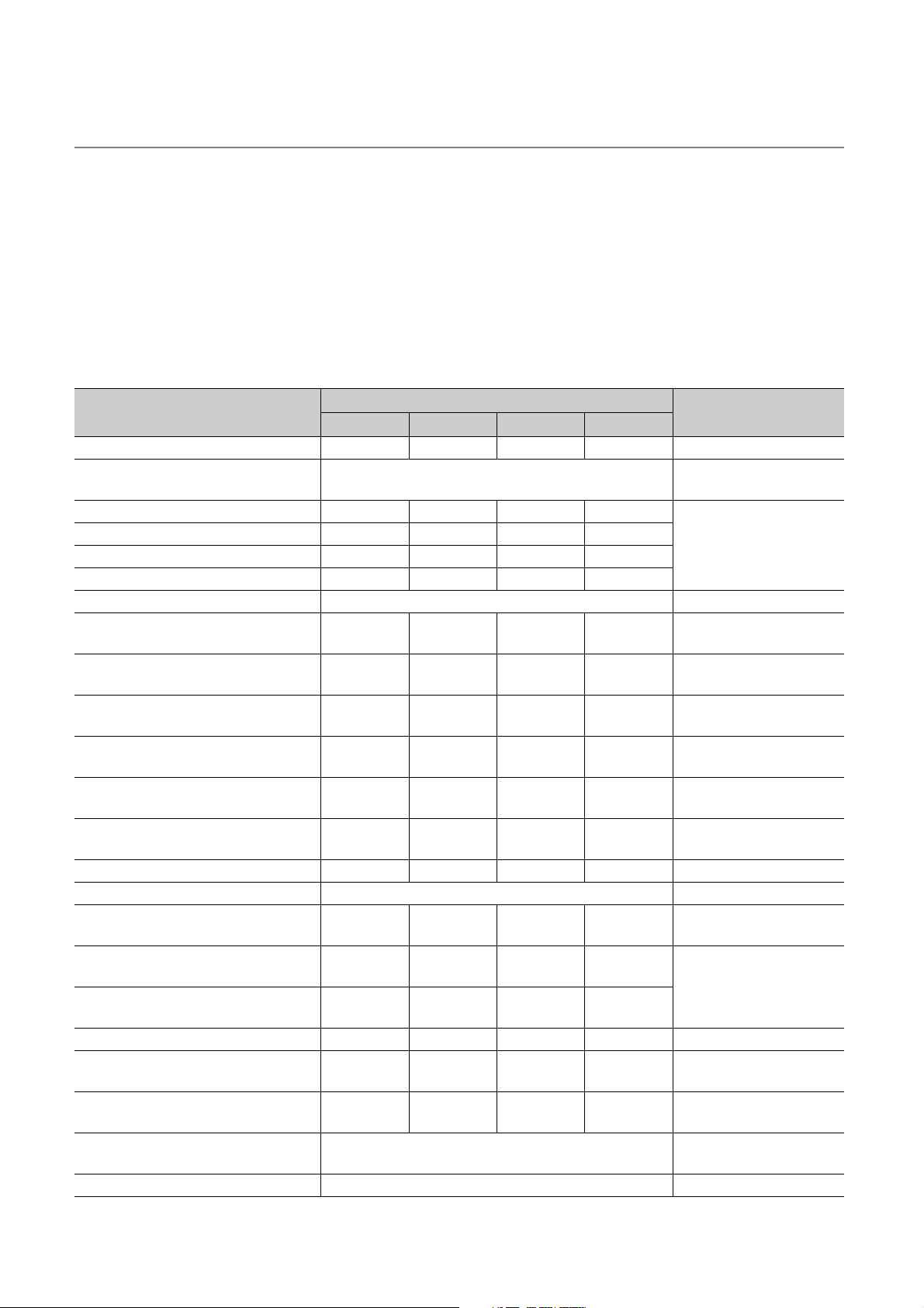
3.3.3 Details of output signals
(1) Setting/operation mode instruction (Yn1)
Use this signal to select the setting mode or the operation mode.
• OFF: Setting mode
• ON: Operation mode
Some buffer memory areas can be set only in the setting mode.
(a) Buffer memory areas that can be set only in the setting mode
The following settings can be changed only when Setting/operation mode instruction (Yn1) is off. If the settings
are changed in the operation mode, a write data error (error code: 3H) occurs.
Buffer memory area name
CH Input range Un\G32 Un\G64 Un\G96 Un\G128 Page 96, Section 3.4.2 (12)
Resolution of the manipulated value for
output with another analog module
CH Alert 1 mode setting Un\G192 Un\G208 Un\G224 Un\G240
CH Alert 2 mode setting Un\G193 Un\G209 Un\G225 Un\G241
CH Alert 3 mode setting Un\G194 Un\G210 Un\G226 Un\G242
CH Alert 4 mode setting Un\G195 Un\G211 Un\G227 Un\G243
CT CT selection Un\G272 to Un\G279 (set for each current sensor (CT)) Page 140, Section 3.4.2 (55)
CH Sensor two-point correction offset
value (measured value)
CH Sensor two-point correction offset
value (corrected value)
CH Sensor two-point correction gain
value (measured value)
CH Sensor two-point correction gain
value (corrected value)
CH Sensor two-point correction offset
latch request
CH Sensor two-point correction gain
latch request
CH Number of moving averaging Un\G698 Un\G699 Un\G700 Un\G701 Page 151, Section 3.4.2 (72)
Cooling method setting Un\G719 Page 151, Section 3.4.2 (73)
CH Process value (PV) scaling function
enable/disable setting
CH Process value (PV) scaling lower
limit value
CH Process value (PV) scaling upper
limit value
CH Derivative action selection Un\G729 Un\G745 Un\G761 Un\G777 Page 153, Section 3.4.2 (79)
CH Simultaneous temperature rise
group setting
CH Setting change rate limiter unit time
setting
Peak current suppression control group
setting
Sensor correction function selection Un\G785 Page 159, Section 3.4.2 (87)
CH1 CH2 CH3 CH4
Un\G181 Page 134, Section 3.4.2 (48)
Un\G544 Un\G576 Un\G608 Un\G640 Page 142, Section 3.4.2 (58)
Un\G545 Un\G577 Un\G609 Un\G641 Page 142, Section 3.4.2 (59)
Un\G546 Un\G578 Un\G610 Un\G642 Page 143, Section 3.4.2 (60)
Un\G547 Un\G579 Un\G611 Un\G643 Page 143, Section 3.4.2 (61)
Un\G548 Un\G580 Un\G612 Un\G644 Page 144, Section 3.4.2 (62)
Un\G550 Un\G582 Un\G614 Un\G646 Page 144, Section 3.4.2 (64)
Un\G725 Un\G741 Un\G757 Un\G773 Page 152, Section 3.4.2 (76)
Un\G726 Un\G742 Un\G758 Un\G774
Un\G727 Un\G743 Un\G759 Un\G775
Un\G730 Un\G746 Un\G762 Un\G778 Page 154, Section 3.4.2 (80)
Un\G735 Un\G751 Un\G767 Un\G783 Page 157, Section 3.4.2 (85)
Buffer memory address
Un\G784 Page 158, Section 3.4.2 (86)
Reference
Page 137, Section 3.4.2 (52)
Page 153, Section 3.4.2 (77)
56
Page 59

CHAPTER 3 SPECIFICATIONS
(2) Error reset instruction (Yn2)
Use this signal to turn off Write error flag (Xn2) and to reset Write data error code (Un\G0). For the method to
reset an error, refer to Write error flag (Xn2). ( Page 51, Section 3.3.2 (3))
(3) CH Auto tuning instruction (Yn4 to Yn7)
Use this signal to start auto tuning per channel. Turning this signal on from off starts auto tuning and turns on
CH Auto tuning status (Xn4 to Xn7). After auto tuning is completed, CH Auto tuning status (Xn4 to Xn7) turns
off.
Keep this instruction ON during auto tuning and turn it off from on at the completion of the auto tuning. If this
instruction is turned off from on during auto tuning, the auto tuning stops. If the auto tuning stops, PID constants
in the buffer memory do not change.
● If proportional band (P)/heating proportional band (Ph) is set to 0, auto tuning cannot be performed. ( Page 105,
Section 3.4.2 (15))
● If Setting/operation mode instruction (Yn1) is turned off from on and the operation status shifts to the setting mode during
auto tuning, the auto tuning stops. After that, even if Setting/operation mode instruction (Yn1) is turned on from off and
the operation status shifts back to the operation mode, the auto tuning does not resume. To resume the auto tuning, turn
Auto tuning instruction (Yn4 to Yn7) off from on, and turn it on from off again.
3
For details on the auto tuning function, refer to the following.
Page 176, Section 4.6
(4) E2PROM backup instruction (Yn8)
Use this signal to write the buffer memory data to the E2PROM. Turning this instruction on from off starts the data
writing to the E2PROM.
For the buffer memory areas whose data is to be backed up, refer to the following.
Page 59, Section 3.4.1
(a) When data writing to the E2PROM has completed normally
E2PROM write completion flag (Xn8) turns on.
(b) When data writing to the E2PROM has not completed normally
E2PROM write failure flag (XnA) turns on. When E2PROM write failure flag (XnA) turns on, turn E2PROM write
2
failure flag (XnA) on from off to write the data to the E
(c) Timings when this instruction cannot be received
In the following timings, this instruction cannot be received.
• 1: While PID constants are written after auto tuning
• 2: While PID constants are read from the E2PROM
• 3: While a setting error is occurring
• 4: While a setting is being changed by Setting change instruction (YnB)
For 1 to 3 above, turn this instruction on from off after each condition is resolved.
For 4, data writing to the non-volatile memory automatically starts if the factor is resolved.
For details on the data writing to the E
2
PROM, refer to Page 270, Section 4.30.
PROM again.
3.3 I/O Signals Transferred to/from the CPU Module
3.3.3 Details of output signals
57
Page 60

(5) Default setting registration instruction (Yn9)
Turning Default setting registration instruction (Yn9) on from off sets the data in the buffer memory areas back to
the default values according to control mode selection.
After the data writing is completed, Default value write completion flag (Xn9) turns on.
(a) When Setting/operation mode status (Xn1) is on (in operation mode)
Turning this instruction on from off does not set data back to the default value. Turn on this instruction when
Setting/operation mode status (Xn1) is off (in the setting mode).
(6) Setting change instruction (YnB)
Use this instruction to confirm the set value of the buffer memory (the buffer memory areas that can be set only in
the setting mode (Setting/operation mode status (Xn1): OFF)). ( Page 56, Section 3.3.3 (1))
(a) Reflection of set value
Even though the set values are written into the buffer memory, they cannot be reflected to the Q64TCN's
operation immediately. To confirm the set values, turn this instruction OFF ON OFF after the set values
are written into the buffer memory. Doing so lets the Q64TCN operate according to the setting in each buffer
memory area.
(7) CH PID control forced stop instruction (YnC to YnF)
Use this signal to temporarily stop PID control forcibly.
(a) Mode when PID control stops
The mode depends on the setting of CH Stop mode setting (Un\G33, Un\G65, Un\G97, Un\G129).
For details on CH Stop mode setting (Un\G33, Un\G65, Un\G97, Un\G129), refer to the following.
Page 103, Section 3.4.2 (13)
58
Page 61

3.4 Buffer Memory Assignment
This section describes the Q64TCN buffer memory assignment.
3.4.1 Q64TCN buffer memory assignment list
This section lists the Q64TCN buffer memory areas.
For details on the buffer memory, refer to Page 86, Section 3.4.2.
Do not write data in the system area or the write-protect area in a sequence program in the buffer memory. Doing so may
cause malfunction.
(1) Buffer memory address by control mode
This section describes the buffer memory assignments by control mode.
For details on the control mode, refer to Page 162, Section 4.1.
CHAPTER 3 SPECIFICATIONS
3
Depending on the control mode, some channels cannot be used for control.
The channels which cannot be used for control are the following.
• For heating-cooling control (normal mode): CH3, CH4
• For mix control (normal mode): CH2
The channels which cannot be used for control can be used only for temperature measurement. For details,
refer to Page 262, Section 4.27.
3.4 Buffer Memory Assignment
3.4.1 Q64TCN buffer memory assignment list
59
Page 62

Address
(decimal
(hexadecimal))
0(0H)
)
1(1
H
)
2(2
H
)
3(3
H
)
4(4
H
)
5(5
H
)
6(6
H
)
7(7
H
)
8(8
H
)
9(9
H
)
10(A
H
)
11( B
H
)
12(C
H
13(D
)
H
)
14(E
H
15(FH)
)
16(10
H
17(11
)
H
)
18(12
H
19(13H)
)
20(14
H
Targ et
channel
or
current
sensor
Standard
control
Setting contents
Heating-
cooling
control
Mix control
Default
value
*1
Read/
Write
*2
Automatic
setting
*3
E2PROM
availability
(CT)
All CHs Write data error code 0 R × ×
CH1 Decimal point position
CH2 Decimal point position
CH3 Decimal point position
CH4 Decimal point position
CH1 Alert definition
CH2 Alert definition
CH3 Alert definition
CH4 Alert definition
CH1 Temperature process value (PV)
CH2 Temperature process value (PV)
CH3 Temperature process value (PV)
CH4 Temperature process value (PV)
Manipulated
value for
heating (MVh)
Manipulated
value for
heating (MVh)
Manipulated
value for
heating
*6
(MVh)
Manipulated
value for
heating
*6
(MVh)
Temperature
rise judgment
flag
Temperature
rise judgment
flag
Temperature
rise judgment
*6
flag
Temperature
rise judgment
*6
flag
CH1
CH2
CH3
CH4
CH1
CH2
CH3
CH4
Manipulated
value (MV)
Manipulated
value (MV)
Manipulated
value (MV)
Manipulated
value (MV)
Temperature
rise judgment
flag
Temperature
rise judgment
flag
Temperature
rise judgment
flag
Temperature
rise judgment
flag
Manipulated
value for
heating (MVh)
Manipulated
value for
heating
*7
(MVh)
Manipulated
value (MV)
Manipulated
value (MV)
Temperature
rise judgment
flag
Temperature
rise judgment
*7
flag
Temperature
rise judgment
flag
Temperature
rise judgment
flag
0(TT)
1(RT)
*5
0R × ×
0R × ×
0R × ×
0R × ×
R× ×
: Enable, ×: Disable
write
*4
Reference
Page 86,
Section
3.4.2 (1)
Page 86,
Section
3.4.2 (2)
Page 87,
Section
3.4.2 (3)
Page 89,
Section
3.4.2 (4)
Page 89,
Section
3.4.2 (5)
Page 91,
Section
3.4.2 (6)
60
Page 63
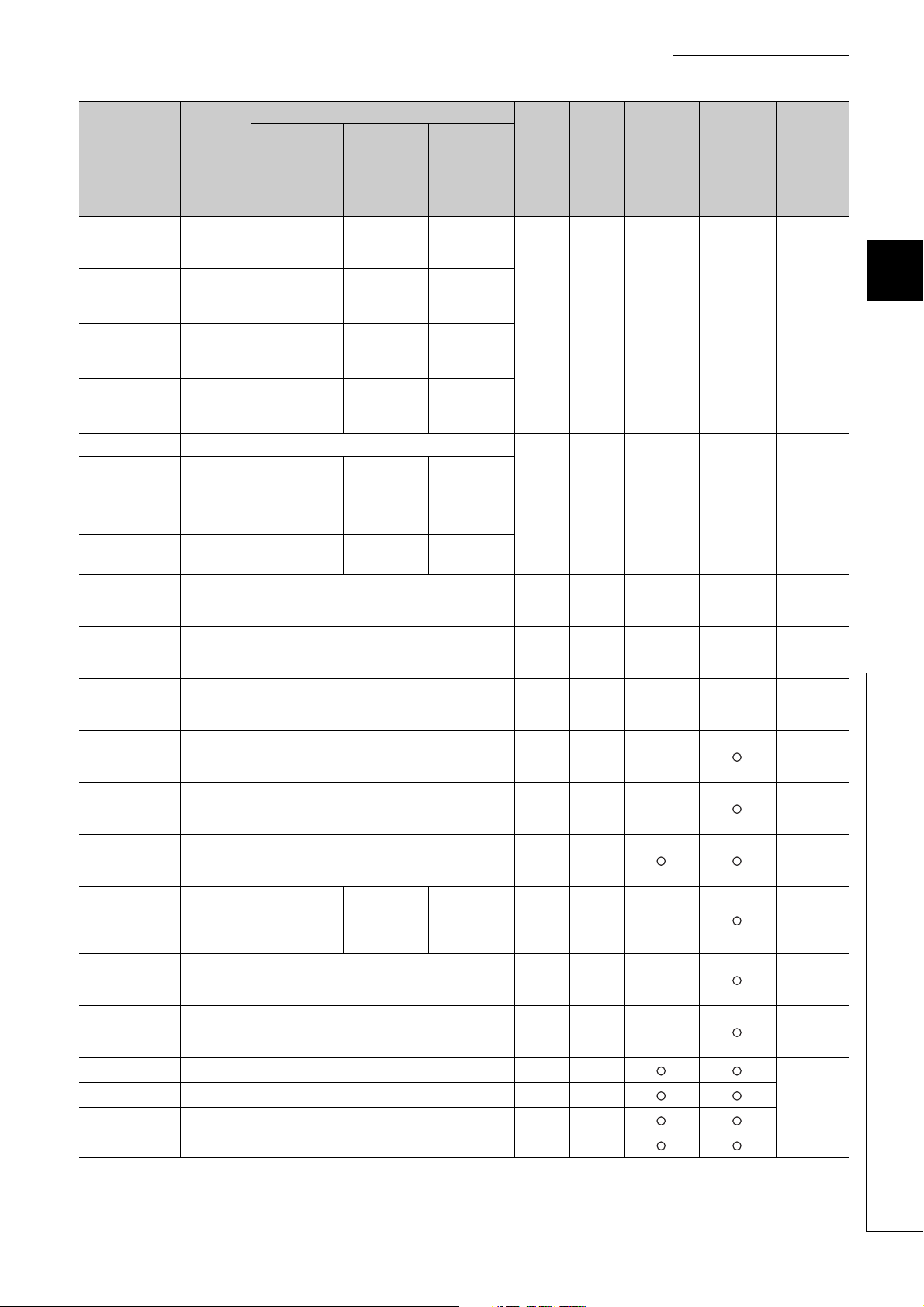
CHAPTER 3 SPECIFICATIONS
Address
(decimal
(hexadecimal))
21(15H)
)
22(16
H
23(17H)
)
24(18
H
)
25(19
H
)
26(1A
H
27(1BH)
28(1C
)
H
29(1D
)
H
)
30(1E
H
)
31(1F
H
)
32(20
H
)
33(21
H
)
34(22
H
)
35(23
H
)
36(24
H
)
37(25
H
)
38(26
H
)
39(27
H
40(28
)
H
41(29
)
H
Tar get
channel
or
current
sensor
Standard
control
Setting contents
Heating-
cooling
control
Mix control
Default
value
*1
Read/
Write
*2
Automatic
setting
*3
E2PROM
availability
(CT)
*9
Heating
transistor
output flag
Heating
transistor
output flag
Heating
transistor
output flag
Heating
transistor
output flag
Set value (SV)
monitor
Set value (SV)
*6
monitor
Set value (SV)
*6
monitor
Heating
proportional
band (Ph)
setting
CH1
CH2
CH3
CH4
CH1 Set value (SV) monitor
CH2
CH3
CH4
All CHs
All CHs MAN mode shift completion flag 0 R × ×
All CHs
CH1
CH1 Stop mode setting 1 R/W ×
CH1 Set value (SV) setting 0 R/W
CH1
CH1 Integral time (I) setting 240 R/W ×
CH1 Derivative time (D) setting 60 R/W ×
CH1 Alert set value 1 0 R/W
CH1 Alert set value 2 0 R/W
CH1 Alert set value 3 0 R/W
CH1 Alert set value 4 0 R/W
Transistor
output flag
Transistor
output flag
Transistor
output flag
Transistor
output flag
Set value (SV)
monitor
Set value (SV)
monitor
Set value (SV)
monitor
Cold junction temperature process value
2
E
PROM's PID constants read/write completion flag
Input range
Proportional
band (P) setting
*6
*6
Heating
transistor
output flag
Heating
transistor
output flag
Transistor
output flag
Transistor
output flag
Set value (SV)
monitor
Set value (SV)
monitor
Set value (SV)
monitor
Heating
proportional
band (Ph)
setting
*7
*7
*8
0R × ×
0R × ×
0R × ×
0R × ×
2(TT)
7(RT)
*5
30 R/W ×
R/W ×
write
*4
Reference
Page 92,
Section
3.4.2 (7)
Page 93,
Section
3.4.2 (8)
Page 93,
Section
3.4.2 (9)
Page 93,
Section
3.4.2 (10)
Page 94,
Section
3.4.2 (11)
Page 96,
Section
3.4.2 (12)
Page 103,
Section
3.4.2 (13)
Page 104,
Section
3.4.2 (14)
Page 105,
Section
3.4.2 (15)
Page 107,
Section
3.4.2 (16)
Page 107,
Section
3.4.2 (17)
Page 108,
Section
3.4.2 (18)
3
3.4 Buffer Memory Assignment
3.4.1 Q64TCN buffer memory assignment list
61
Page 64
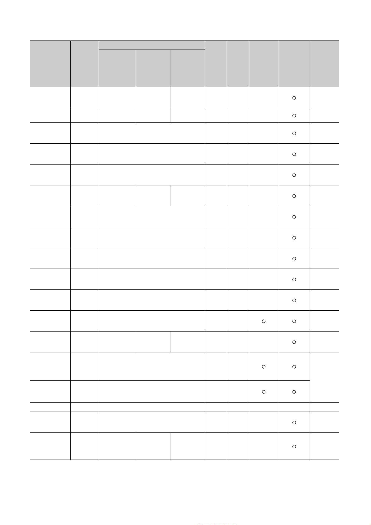
Address
(decimal
(hexadecimal))
42(2AH)
)
43(2B
H
44(2C
)
H
)
45(2D
H
)
46(2E
H
)
47(2F
H
)
48(30
H
)
49(31
H
)
50(32
H
)
51(33
H
)
52(34
H
)
53(35
H
)
54(36
H
)
55(37
H
)
56(38
H
)
57(39
H
)
58(3A
H
)
59(3B
H
Targ et
channel
or
current
sensor
Standard
control
Setting contents
Heating-
cooling
control
Mix control
Default
value
*1
Read/
Write
*2
Automatic
setting
*3
E2PROM
write
availability
*4
Reference
(CT)
CH1
CH1
CH1 Output variation limiter setting 0 R/W ×
CH1 Sensor correction value setting 0 R/W ×
CH1 Adjustment sensitivity (dead band) setting 5 R/W ×
CH1
CH1 Primary delay digital filter setting 0 R/W ×
CH1 Control response parameters 0 R/W ×
CH1 AUTO/MAN mode shift 0 R/W ×
CH1 MAN output setting 0 R/W ×
CH1
CH1 AT bias 0 R/W
CH1
CH1 Upper limit setting limiter
CH1 Lower limit setting limiter
CH1 System area
CH1
CH1
Upper limit
output limiter
Lower limit
output limiter
Control output
cycle setting
Setting change rate limiter/Setting change rate
limiter (temperature rise)
Forward/reverse
action setting
Heater disconnection alert setting
Loop
disconnection
detection
judgment time
Heating upper
limit output
limiter
System area System area 0 R/W ×
Heating control
output cycle
setting
*10
System area System area 1 R/W ×
System area System area 480 R/W ×
Heating upper
limit output
limiter
Heating control
output cycle
setting
*11
1000 R/W ×
30 R/W ×
0R/W ×
1300
(TT)
6000
(RT)
0(TT)
-2000
(RT)
0R/W ×
R/W
*5
R/W
*5
Page 110,
Section
3.4.2 (19)
Page 112,
Section
3.4.2 (20)
Page 113,
Section
3.4.2 (21)
Page 113,
Section
3.4.2 (22)
Page 114,
Section
3.4.2 (23)
Page 115,
Section
3.4.2 (24)
Page 116,
Section
3.4.2 (25)
Page 117,
Section
3.4.2 (26)
Page 118,
Section
3.4.2 (27)
Page 119,
Section
3.4.2 (28)
Page 120,
Section
3.4.2 (29)
Page 121,
Section
3.4.2 (30)
Page 122,
Section
3.4.2 (31)
Page 123,
Section
3.4.2 (32)
Page 124,
Section
3.4.2 (33)
62
Page 65

CHAPTER 3 SPECIFICATIONS
Address
(decimal
(hexadecimal))
60(3CH)
)
61(3D
H
)
62(3E
H
)
63(3F
H
)
64(40
H
)
65(41
H
)
66(42
H
)
67(43
H
)
68(44
H
)
69(45
H
70(46
)
H
)
71(47
H
)
72(48
H
)
73(49
H
74(4A
)
H
)
75(4B
H
)
76(4C
H
)
77(4D
H
)
78(4E
H
Tar get
channel
or
current
sensor
Standard
control
Setting contents
Heating-
cooling
control
Mix control
Default
value
*1
Read/
Write
*2
(CT)
Loop
CH1
CH1 Unused channel setting 0 R/W ×
CH1
CH1
CH2
CH2
CH2
CH2
CH2
CH2
CH2 Alert set value 1
CH2 Alert set value 2
CH2 Alert set value 3
CH2 Alert set value 4
CH2
CH2
CH2
CH2 Sensor correction value setting 0 R/W ×
CH2
disconnection
detection dead
System area System area 0 R/W
band
2
PROM's PID constants read instruction
E
Automatic backup setting after auto tuning of PID
constants
Input range
Stop mode
setting
Set value (SV)
setting
Proportional
band (P) setting
Integral time (I)
setting
Derivative time
(D) setting
Upper limit
output limiter
Lower limit
output limiter
Output variation
limiter setting
Adjustment
sensitivity (dead
band) setting
*9
Stop mode
setting
Set value (SV)
setting
Heating
proportional
band (Ph)
setting
Integral time (I)
setting
Derivative time
(D) setting
Alert set value
1
Alert set value
2
Alert set value
3
Alert set value
4
Heating upper
limit output
limiter
Stop mode
*7
setting
Set value (SV)
*7
setting
Heating
proportional
band (Ph)
*7
setting
Integral time (I)
*7
setting
Derivative time
(D) setting
Alert set value
*7
1
Alert set value
*7
2
Alert set value
*7
3
Alert set value
*7
4
Heating upper
limit output
*7
limiter
System area System area 0 R/W ×
Output
variation limiter
setting
Adjustment
sensitivity
(dead band)
setting
Output
variation limiter
*7
setting
Adjustment
sensitivity
(dead band)
*7
setting
0R/W × ×
0R/W × ×
2(TT)
7(RT)
*5
1R/W ×
0R/W
30 R/W ×
240 R/W ×
*7
60 R/W ×
0R/W
0R/W
0R/W
0R/W
1000 R/W ×
0R/W ×
5R/W ×
R/W ×
Automatic
setting
*3
E2PROM
write
availability
*4
Reference
Page 125,
Section
3.4.2 (34)
Page 126,
Section
3.4.2 (35)
Page 127,
Section
3.4.2 (36)
Page 128,
Section
3.4.2 (37)
Page 96,
Section
3.4.2 (12)
Page 103,
Section
3.4.2 (13)
Page 104,
Section
3.4.2 (14)
Page 105,
Section
3.4.2 (15)
Page 107,
Section
3.4.2 (16)
Page 107,
Section
3.4.2 (17)
Page 108,
Section
3.4.2 (18)
Page 110,
Section
3.4.2 (19)
Page 112,
Section
3.4.2 (20)
Page 113,
Section
3.4.2 (21)
Page 113,
Section
3.4.2 (22)
3
3.4 Buffer Memory Assignment
3.4.1 Q64TCN buffer memory assignment list
63
Page 66
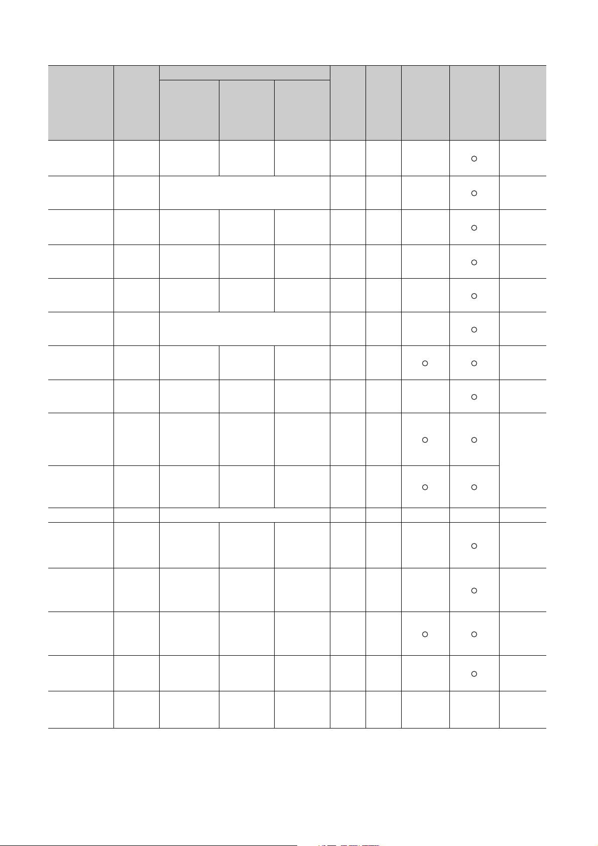
Address
(decimal
(hexadecimal))
79(4FH)
80(50
)
H
81(51
)
H
82(52
)
H
)
83(53
H
)
84(54
H
)
85(55
H
)
86(56
H
)
87(57
H
)
88(58
H
89(59
)
H
)
90(5A
H
)
91(5B
H
)
92(5C
H
)
93(5D
H
)
94(5E
H
Targ et
channel
or
current
sensor
Standard
control
Setting contents
Heating-
cooling
control
Mix control
Default
value
*1
Read/
Write
*2
Automatic
setting
*3
E2PROM
write
availability
*4
Reference
(CT)
Heating control
output cycle
*7
setting
30 R/W ×
CH2
Control output
cycle setting
Heating control
output cycle
setting
CH2 Primary delay digital filter setting 0 R/W ×
Control
response
parameters
AUTO/MAN
mode shift
*7
MAN output
*7
setting
*7
0R/W ×
0R/W ×
0R/W ×
CH2
CH2
CH2
Control
response
parameters
AUTO/MAN
mode shift
MAN output
setting
Control
response
parameters
AUTO/MAN
mode shift
MAN output
setting
Setting change rate limiter/Setting change rate
CH2
limiter (temperature rise)
*10
CH2 AT bias AT bias
CH2
Forward/reverse
action setting
System area System area 1 R/W ×
AT bias
*7
0R/W ×
0R/W
1300
CH2
Upper limit
setting limiter
Upper limit
setting limiter
Upper limit
setting limiter
(TT)
6000
*7
(RT)
*5
R/W
0(TT)
CH2
Lower limit
setting limiter
Lower limit
setting limiter
Lower limit
setting limiter
-2000
*7
(RT)
*5
R/W
CH2 System area
CH2
Heater
disconnection
alert setting
*11
Heater
disconnection
alert setting
*11
Heater
disconnection
alert
*7*11
setting
0R/W ×
Loop
CH2
disconnection
detection
System area System area 480 R/W ×
judgment time
Loop
CH2
disconnection
detection dead
System area System area 0 R/W
band
Unused
channel
*7
setting
2
PROM's PID
E
constants read
instruction
*7
0R/W ×
0R/W × ×
CH2
CH2
Unused channel
setting
2
E
PROM's PID
constants read
instruction
Unused
channel setting
E2PROM's PID
constants read
instruction
Page 114,
Section
3.4.2 (23)
Page 115,
Section
3.4.2 (24)
Page 116,
Section
3.4.2 (25)
Page 117,
Section
3.4.2 (26)
Page 118,
Section
3.4.2 (27)
Page 119,
Section
3.4.2 (28)
Page 120,
Section
3.4.2 (29)
Page 121,
Section
3.4.2 (30)
Page 122,
Section
3.4.2 (31)
Page 123,
Section
3.4.2 (32)
Page 124,
Section
3.4.2 (33)
Page 125,
Section
3.4.2 (34)
Page 126,
Section
3.4.2 (35)
Page 127,
Section
3.4.2 (36)
64
Page 67
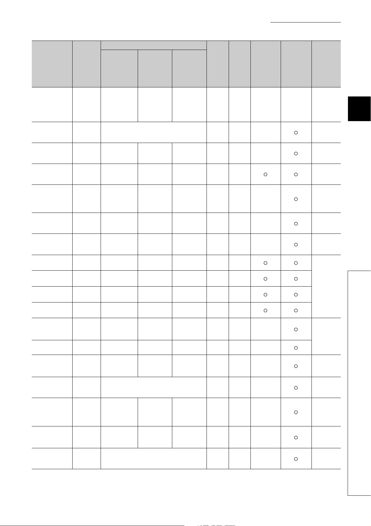
CHAPTER 3 SPECIFICATIONS
Address
(decimal
(hexadecimal))
95(5FH)
)
96(60
H
)
97(61
H
)
98(62
H
)
99(63
H
)
100(64
H
)
101(65
H
)
102(66
H
103(67
)
H
)
104(68
H
)
105(69
H
)
106(6A
H
)
107(6B
H
108(6C
)
H
109(6D
)
H
)
110(6E
H
)
111( 6F
H
112(70
)
H
Tar get
channel
or
current
sensor
Standard
control
Setting contents
Heating-
cooling
control
Mix control
Default
value
*1
Read/
Write
*2
(CT)
*6
Automatic
backup setting
after auto
tuning of PID
*7
constants
Stop mode
setting
Set value (SV)
setting
Proportional
band (P)
setting
Integral time (I)
setting
Derivative time
(D) setting
Alert set value
1
Alert set value
2
Alert set value
3
Alert set value
4
Upper limit
output limiter
Lower limit
output limiter
Output
variation limiter
setting
Adjustment
sensitivity
(dead band)
setting
Control output
cycle setting
0R/W × ×
2(TT)
7(RT)
*5
R/W ×
1R/W ×
0R/W
30 R/W ×
240 R/W ×
60 R/W ×
0R/W
0R/W
0R/W
0R/W
1000 R/W ×
0R/W ×
0R/W ×
5R/W ×
30 R/W ×
*9
Automatic
backup setting
after auto
tuning of PID
constants
Stop mode
*6
setting
Set value (SV)
*6
setting
CH2
CH3
CH3
CH3
Automatic
backup setting
after auto tuning
of PID constants
Input range
Stop mode
setting
Set value (SV)
setting
Heating
CH3
CH3
CH3
Proportional
band (P) setting
Integral time (I)
setting
Derivative time
(D) setting
CH3 Alert set value 1
CH3 Alert set value 2
CH3 Alert set value 3
CH3 Alert set value 4
CH3
CH3
CH3
Upper limit
output limiter
Lower limit
output limiter
Output variation
limiter setting
proportional
band (Ph)
*6
setting
Integral time (I)
*6
setting
Derivative time
(D) setting
Alert set value
*6
1
Alert set value
*6
2
Alert set value
*6
3
Alert set value
*6
4
Heating upper
limit output
*6
limiter
System area
Output
variation limiter
*6
setting
CH3 Sensor correction value setting 0 R/W ×
Adjustment
sensitivity
(dead band)
*6
setting
Heating control
output cycle
*6
setting
CH3
CH3
Adjustment
sensitivity (dead
band) setting
Control output
cycle setting
CH3 Primary delay digital filter setting 0 R/W ×
Automatic
setting
*3
E2PROM
write
availability
*4
Reference
Page 128,
Section
3.4.2 (37)
Page 96,
Section
3.4.2 (12)
Page 103,
Section
3.4.2 (13)
Page 104,
Section
3.4.2 (14)
Page 105,
Section
3.4.2 (15)
Page 107,
Section
3.4.2 (16)
Page 107,
Section
3.4.2 (17)
Page 108,
Section
3.4.2 (18)
Page 110,
Section
3.4.2 (19)
Page 112,
Section
3.4.2 (20)
Page 113,
Section
3.4.2 (21)
Page 113,
Section
3.4.2 (22)
Page 114,
Section
3.4.2 (23)
Page 115,
Section
3.4.2 (24)
3
3.4 Buffer Memory Assignment
3.4.1 Q64TCN buffer memory assignment list
65
Page 68
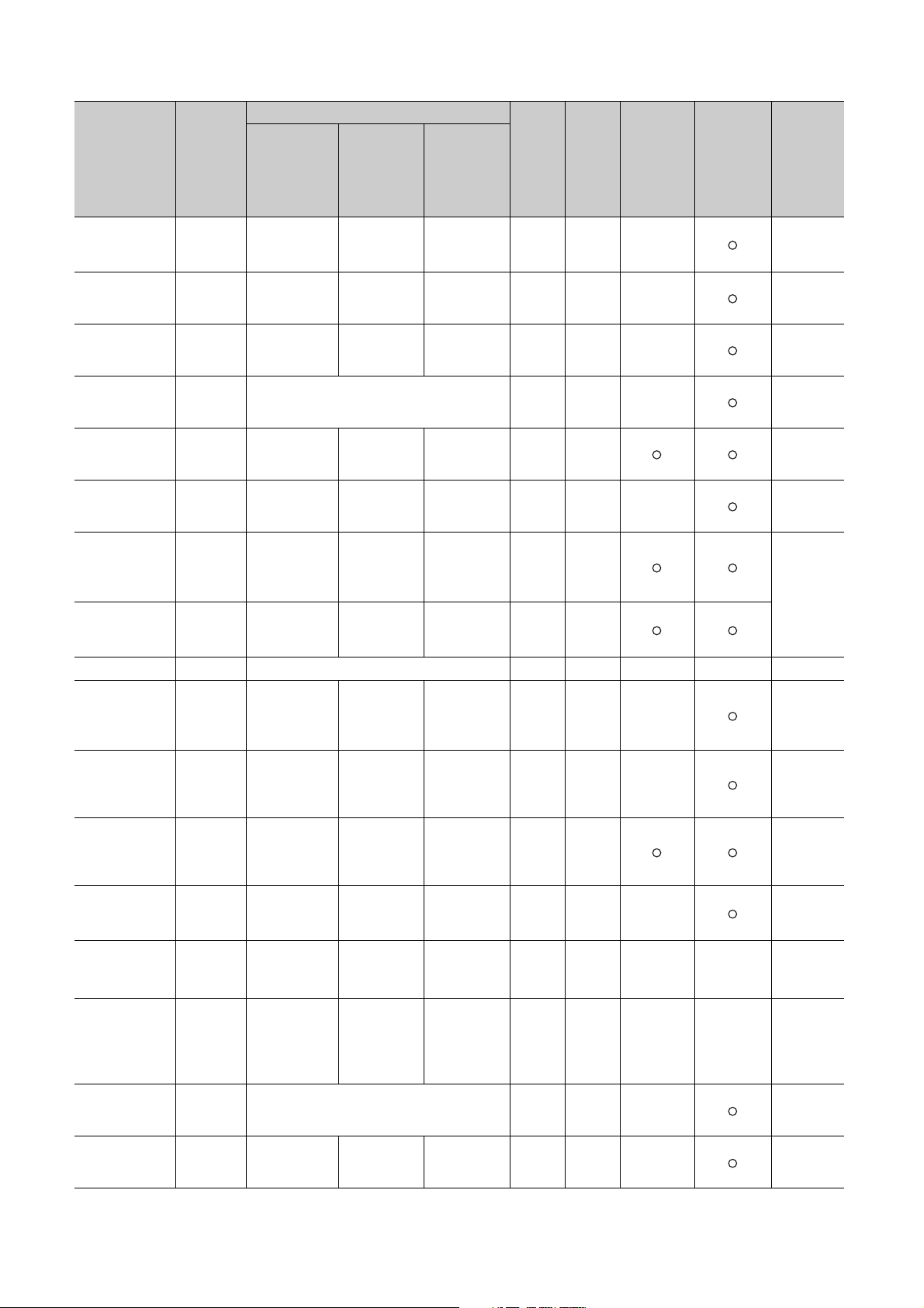
Address
(decimal
(hexadecimal))
113(71H)
114(72
)
H
)
115(73
H
)
116(74
H
)
117(75
H
)
118(76
H
119(77
)
H
)
120(78
H
)
121(79
H
122(7A
)
H
123(7B
)
H
)
124(7C
H
)
125(7D
H
126(7E
)
H
)
127(7F
H
)
128(80
H
)
129(81
H
Targ et
channel
or
current
sensor
Standard
control
Setting contents
Heating-
cooling
control
Mix control
Default
value
*1
Read/
Write
*2
Automatic
setting
*3
E2PROM
write
availability
*4
Reference
(CT)
*11
*9
Control
response
parameters
*6
AUTO/MAN
mode shift
*6
MAN output
*6
setting
*6
AT b i as
System area
Upper limit
setting limiter
Lower limit
setting limiter
Heater
disconnection
alert
*6*11
setting
System area
System area
Unused
channel
*6
setting
2
E
PROM's PID
constants read
instruction
*6
Automatic
backup setting
after auto
tuning of PID
*6
constants
Stop mode
*6
setting
Control
response
0R/W ×
parameters
AUTO/MAN
mode shift
MAN output
setting
0R/W ×
0R/W ×
0R/W ×
AT bias 0 R/W
Forward/
reverse action
1R/W ×
setting
1300
Upper limit
*6
setting limiter
Lower limit
*6
setting limiter
(TT)
6000
(RT)
0(TT)
-2000
(RT)
*5
*5
Heater
disconnection
alert setting
*11
0R/W ×
Loop
disconnection
detection
480 R/W ×
judgment time
Loop
disconnection
detection dead
0R/W
band
Unused
channel setting
0R/W ×
E2PROM's PID
constants read
0R/W × ×
instruction
Automatic
backup setting
after auto
0R/W × ×
tuning of PID
constants
2(TT)
7(RT)
*5
Stop mode
setting
1R/W ×
R/W
R/W
R/W ×
Page 116,
Section
3.4.2 (25)
Page 117,
Section
3.4.2 (26)
Page 118,
Section
3.4.2 (27)
Page 119,
Section
3.4.2 (28)
Page 120,
Section
3.4.2 (29)
Page 121,
Section
3.4.2 (30)
Page 122,
Section
3.4.2 (31)
Page 123,
Section
3.4.2 (32)
Page 124,
Section
3.4.2 (33)
Page 125,
Section
3.4.2 (34)
Page 126,
Section
3.4.2 (35)
Page 127,
Section
3.4.2 (36)
Page 128,
Section
3.4.2 (37)
Page 96,
Section
3.4.2 (12)
Page 103,
Section
3.4.2 (13)
Control
CH3
response
parameters
CH3
CH3
AUTO/MAN
mode shift
MAN output
setting
Setting change rate limiter/Setting change rate
CH3
limiter (temperature rise)
*10
CH3 AT bias
CH3
CH3
CH3
Forward/reverse
action setting
Upper limit
setting limiter
Lower limit
setting limiter
CH3 System area
Heater
CH3
disconnection
alert setting
Loop
CH3
disconnection
detection
judgment time
Loop
CH3
disconnection
detection dead
band
CH3
CH3
Unused channel
setting
2
E
PROM's PID
constants read
instruction
Automatic
CH3
backup setting
after auto tuning
of PID constants
CH4
CH4
Input range
Stop mode
setting
66
Page 69

CHAPTER 3 SPECIFICATIONS
Address
(decimal
(hexadecimal))
130(82H)
131(83
)
H
)
132(84
H
)
133(85
H
134(86
)
H
)
135(87
H
)
136(88
H
137(89
)
H
138(8A
)
H
139(8B
)
H
)
140(8C
H
)
141(8D
H
)
142(8E
H
)
143(8F
H
)
144(90
H
)
145(91
H
146(92
)
H
)
147(93
H
)
148(94
H
Tar get
channel
or
current
sensor
Standard
control
Setting contents
Heating-
cooling
control
Mix control
Default
value
*1
Read/
Write
*2
(CT)
CH4
CH4
CH4
CH4
Set value (SV)
setting
Proportional
band (P) setting
Integral time (I)
setting
Derivative time
(D) setting
CH4 Alert set value 1
CH4 Alert set value 2
CH4 Alert set value 3
CH4 Alert set value 4
CH4
CH4
CH4
Upper limit
output limiter
Lower limit
output limiter
Output variation
limiter setting
CH4 Sensor correction value setting 0 R/W ×
Adjustment
CH4
sensitivity (dead
band) setting
CH4
Control output
cycle setting
CH4 Primary delay digital filter setting 0 R/W ×
Control
CH4
response
parameters
CH4
CH4
CH4
AUTO/MAN
mode shift
MAN output
setting
Setting change rate limiter/Setting change rate
limiter (temperature rise)
Set value (SV)
*6
setting
Heating
proportional
band (Ph)
*6
setting
Integral time (I)
*6
setting
Derivative time
(D) setting
*6
Alert set value
*6
1
Alert set value
*6
2
Alert set value
*6
3
Alert set value
*6
4
Heating upper
limit output
*6
limiter
System area
Output
variation limiter
*6
setting
Adjustment
sensitivity
(dead band)
*6
setting
Heating control
output cycle
*6
setting
Control
response
parameters
*6
AUTO/MAN
mode shift
*6
MAN output
*6
setting
*10
Set value (SV)
setting
Proportional
band (P)
setting
Integral time (I)
setting
Derivative time
(D) setting
Alert set value
1
Alert set value
2
Alert set value
3
Alert set value
4
Upper limit
output limiter
Lower limit
output limiter
Output
variation limiter
setting
Adjustment
sensitivity
(dead band)
setting
Control output
cycle setting
Control
response
parameters
AUTO/MAN
mode shift
MAN output
setting
0R/W
30 R/W ×
240 R/W ×
60 R/W ×
0R/W
0R/W
0R/W
0R/W
1000 R/W ×
0R/W ×
0R/W ×
5R/W ×
30 R/W ×
0R/W ×
0R/W ×
0R/W ×
0R/W ×
Automatic
setting
*3
E2PROM
write
availability
*4
Reference
Page 104,
Section
3.4.2 (14)
Page 105,
Section
3.4.2 (15)
Page 107,
Section
3.4.2 (16)
Page 107,
Section
3.4.2 (17)
Page 108,
Section
3.4.2 (18)
Page 110,
Section
3.4.2 (19)
Page 112,
Section
3.4.2 (20)
Page 113,
Section
3.4.2 (21)
Page 113,
Section
3.4.2 (22)
Page 114,
Section
3.4.2 (23)
Page 115,
Section
3.4.2 (24)
Page 116,
Section
3.4.2 (25)
Page 117,
Section
3.4.2 (26)
Page 118,
Section
3.4.2 (27)
Page 119,
Section
3.4.2 (28)
3
3.4 Buffer Memory Assignment
3.4.1 Q64TCN buffer memory assignment list
67
Page 70

Address
(decimal
(hexadecimal))
149(95H)
)
150(96
H
)
151(97
H
)
152(98
H
153(99
)
H
)
154(9A
H
155(9B
)
H
)
156(9C
H
)
157(9D
H
)
158(9E
H
)
159(9F
H
)
160(A0
H
)
163(A3
H
164(A4
)
H
)
165(A5
H
)
166(A6
H
)
167(A7
H
)
168(A8
H
Targ et
channel
or
current
sensor
Standard
control
Setting contents
Heating-
cooling
control
Mix control
Default
value
*1
Read/
Write
*2
Automatic
setting
*3
E2PROM
write
availability
*4
Reference
(CT)
CH4 AT bias
CH4
Forward/reverse
action setting
*6
AT b i as
System area
AT bias 0 R/W
Forward/revers
e action setting
1R/W ×
1300
CH4
CH4
Upper limit
setting limiter
Lower limit
setting limiter
Upper limit
setting limiter
Lower limit
setting limiter
Upper limit
*6
setting limiter
Lower limit
*6
setting limiter
(TT)
6000
(RT)
0(TT)
-2000
(RT)
R/W
*5
R/W
*5
CH4 System area
CH4
CH4
CH4
CH4
CH4
CH4
Heater
disconnection
alert setting
Loop
disconnection
detection
judgment time
Loop
disconnection
detection dead
band
Unused channel
setting
2
E
PROM's PID
constants read
instruction
Automatic
backup setting
after auto tuning
of PID constants
*11
Heater
disconnection
alert
*6*11
setting
System area
System area
Unused
channel
*6
setting
2
PROM's PID
E
constants read
instruction
*6
Automatic
backup setting
after auto
tuning of PID
*6
constants
Heater
disconnection
alert setting
*11
Loop
disconnection
detection
judgment time
Loop
disconnection
detection dead
band
Unused
channel setting
E2PROM's PID
constants read
instruction
Automatic
backup setting
after auto
tuning of PID
constants
0R/W ×
480 R/W ×
0R/W
0R/W ×
0R/W × ×
0R/W × ×
System area to
All CHs Alert dead band setting 5 R/W ×
All CHs Number of alert delay 0 R/W ×
Heater disconnection/output off-time current error
All CHs
detection delay count
*11
3R/W ×
All CHs Temperature rise completion range setting 1 R/W ×
All CHs Temperature rise completion soak time setting 0 R/W ×
Page 120,
Section
3.4.2 (29)
Page 121,
Section
3.4.2 (30)
Page 122,
Section
3.4.2 (31)
Page 123,
Section
3.4.2 (32)
Page 124,
Section
3.4.2 (33)
Page 125,
Section
3.4.2 (34)
Page 126,
Section
3.4.2 (35)
Page 127,
Section
3.4.2 (36)
Page 128,
Section
3.4.2 (37)
Page 129,
Section
3.4.2 (38)
Page 129,
Section
3.4.2 (39)
Page 130,
Section
3.4.2 (40)
Page 130,
Section
3.4.2 (41)
Page 131,
Section
3.4.2 (42)
68
Page 71

CHAPTER 3 SPECIFICATIONS
Address
(decimal
(hexadecimal))
169(A9H)
)
170(AA
H
)
171(AB
H
)
174(AE
H
175(AF
)
H
)
176(B0
H
)
177(B1
H
)
178(B2
H
)
179(B3
H
)
180(B4
H
)
181(B5
H
182(B6
)
H
)
183(B7
H
Tar get
channel
or
current
sensor
Standard
control
Setting contents
Heating-
cooling
control
Mix control
Default
value
*1
Read/
Write
*2
Automatic
setting
*3
E2PROM
availability
(CT)
All CHs PID continuation flag 0 R/W ×
All CHs
All CHs Transistor output monitor ON delay time setting 0 R/W ×
All CHs
CH1
CH2
CH3
CH4
All CHs
All CHs
All CHs Control switching monitor 0 R × ×
Heater disconnection compensation function
*11
selection
System area to
CT monitor method switching
Manipulated
value (MV) for
output with
another analog
module
Manipulated
value (MV) for
output with
another analog
module
Manipulated
value (MV) for
output with
another analog
module
Manipulated
value (MV) for
output with
another analog
module
Resolution of the manipulated value for output with
another analog module
Cold junction temperature compensation selection
Manipulated
value of
heating (MVh)
for output with
another analog
module
Manipulated
value of
heating (MVh)
for output with
another analog
module
Manipulated
value of
heating (MVh)
for output with
another analog
module
Manipulated
value of
heating (MVh)
for output with
another analog
module
*11
*6
*6
Manipulated
value of
heating (MVh)
for output with
another analog
module
Manipulated
value of
heating (MVh)
for output with
another analog
*7
module
Manipulated
value (MV) for
output with
another analog
module
Manipulated
value (MV) for
output with
another analog
module
0R/W ×
0R/W ×
0R × ×
0R × ×
0R × ×
0R × ×
0R/W ×
*8
0R/W ×
write
*4
Reference
Page 131,
Section
3.4.2 (43)
Page 131,
Section
3.4.2 (44)
Page 132,
Section
3.4.2 (45)
Page 132,
Section
3.4.2 (46)
Page 133,
Section
3.4.2 (47)
Page 134,
Section
3.4.2 (48)
Page 135,
Section
3.4.2 (49)
Page 135,
Section
3.4.2 (50)
3
3.4 Buffer Memory Assignment
3.4.1 Q64TCN buffer memory assignment list
69
Page 72
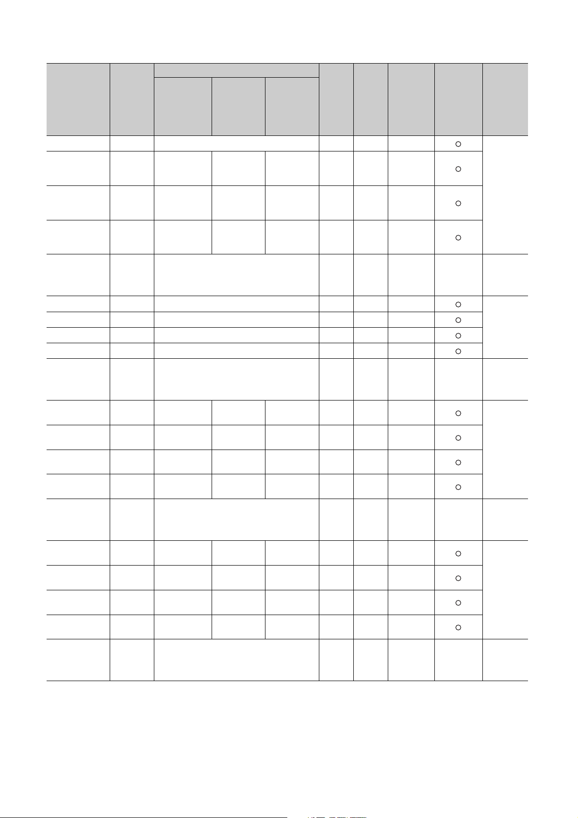
Address
(decimal
(hexadecimal))
184(B8H)
)
185(B9
H
)
186(BA
H
187(BB
)
H
)
188(BC
H
)
191(BF
H
)
192(C0
H
)
193(C1
H
)
194(C2
H
195(C3
)
H
196(C4
)
H
)
207(CF
H
)
208(D0
H
)
209(D1
H
)
210(D2
H
)
211(D3
H
212(D4
)
H
)
223(DF
H
)
224(E0
H
)
225(E1
H
)
226(E2
H
)
227(E3
H
228(E4
)
H
)
239(EF
H
Targ et
channel
or
current
sensor
Standard
control
Setting contents
Heating-
cooling
control
Mix control
Default
value
*1
Read/
Write
*2
(CT)
CH1 Auto tuning mode selection 0 R/W ×
*6
*6
Auto tuning
mode
*7
selection
Auto tuning
mode selection
Auto tuning
mode selection
Alert 1 mode
*7*9
setting
Alert 2 mode
*7*9
setting
Alert 3 mode
*7*9
setting
Alert 4 mode
*7*9
setting
Alert 1 mode
*9
setting
Alert 2 mode
*9
setting
Alert 3 mode
*9
setting
Alert 4 mode
*9
setting
0R/W ×
0R/W ×
0R/W ×
0R/W ×
0R/W ×
0R/W ×
0R/W ×
0R/W ×
0R/W ×
0R/W ×
0R/W ×
0R/W ×
0R/W ×
0R/W ×
0R/W ×
CH2
CH3
CH4
System area to
CH1
CH1
CH1
CH1
System area to
CH2
CH2
CH2
CH2
System area to
CH3
CH3
CH3
CH3
System area to
Auto tuning
mode selection
Auto tuning
mode selection
Auto tuning
mode selection
Alert 1 mode setting
Alert 2 mode setting
Alert 3 mode setting
Alert 4 mode setting
Alert 1 mode
*9
setting
Alert 2 mode
*9
setting
Alert 3 mode
*9
setting
Alert 4 mode
*9
setting
Alert 1 mode
*9
setting
Alert 2 mode
*9
setting
Alert 3 mode
*9
setting
Alert 4 mode
*9
setting
Auto tuning
mode selection
Auto tuning
mode
selection
Auto tuning
mode
selection
*9
*9
*9
*9
Alert 1 mode
*9
setting
Alert 2 mode
*9
setting
Alert 3 mode
*9
setting
Alert 4 mode
*9
setting
Alert 1 mode
*6*9
setting
Alert 2 mode
*6*9
setting
Alert 3 mode
*6*9
setting
Alert 4 mode
*6*9
setting
Automatic
setting
*3
E2PROM
write
availability
*4
Reference
Page 136,
Section
3.4.2 (51)
Page 137,
Section
3.4.2 (52)
Page 137,
Section
3.4.2 (52)
Page 137,
Section
3.4.2 (52)
70
Page 73

CHAPTER 3 SPECIFICATIONS
Address
(decimal
(hexadecimal))
240(F0H)
)
241(F1
H
)
242(F2
H
)
243(F3
H
)
244(F4
H
)
255(FF
H
)
256(100
H
)
257(101
H
258(102H)
259(103H)
260(104H)
261(105H)
262(106H)
263(107H)
264(108H)
)
265(109
H
266(10AH)
267(10BH)
268(10CH)
269(10DH)
270(10EH)
271(10FH)
272(110H)
)
273(111
H
274(112H)
275(113H)
276(114H)
277(115H)
278(116H)
279(117H)
280(118H)
)
281(119
H
282(11AH)
283(11BH)
284(11CH)
285(11DH)
286(11EH)
287(11FH)
Tar get
Setting contents
channel
or
current
sensor
Standard
control
Heating-
cooling
control
(CT)
CH4
CH4
CH4
CH4
Alert 1 mode
*9
setting
Alert 2 mode
*9
setting
Alert 3 mode
*9
setting
Alert 4 mode
*9
setting
System area to
CT1 Heater current process value*11
CT2
CT3
CT4
CT5
CT6
CT7
CT8
CT1
CT2
CT3
CT4
CT5
CT6
CT7
CT8
CT1
CT2
CT3
CT4
CT5
CT6
CT7
CT8
CT1
CT2
CT3
CT4
CT5
CT6
CT7
CT8
Heater current process value
Heater current process value
Heater current process value
Heater current process value
Heater current process value
Heater current process value
Heater current process value
CT input channel process setting
CT input channel process setting
CT input channel process setting
CT input channel process setting
CT input channel process setting
CT input channel process setting
CT input channel process setting
CT input channel process setting
CT selection
CT selection
CT selection
CT selection
CT selection
CT selection
CT selection
CT selection
Reference heater current value
Reference heater current value
Reference heater current value
Reference heater current value
Reference heater current value
Reference heater current value
Reference heater current value
Reference heater current value
Alert 1 mode
setting
Alert 2 mode
setting
Alert 3 mode
setting
Alert 4 mode
setting
*9*11
*9*11
*9*11
*9*11
*9*11
*9*11
*9*11
*9*11
*6*9
*6*9
*6*9
*6*9
*11
*11
*11
*11
*11
*11
*11
*11
*11
*11
*11
*11
*11
*11
*11
Mix control
Alert 1 mode
setting
Alert 2 mode
setting
Alert 3 mode
setting
Alert 4 mode
setting
*11
*11
*11
*11
*11
*11
*11
*11
Default
value
*9
*9
Read/
Write
*1
*2
Automatic
setting
*3
0R/W ×
0R/W ×
E2PROM
write
availability
*4
Reference
Page 137,
3
Section
*9
*9
0R/W ×
0R/W ×
3.4.2 (52)
Page 138,
0R × ×
Section
3.4.2 (53)
3.4 Buffer Memory Assignment
3.4.1 Q64TCN buffer memory assignment list
Page 139,
0R/W ×
Section
3.4.2 (54)
Page 140,
0R/W ×
Section
3.4.2 (55)
Page 141,
0R/W ×
Section
3.4.2 (56)
71
Page 74
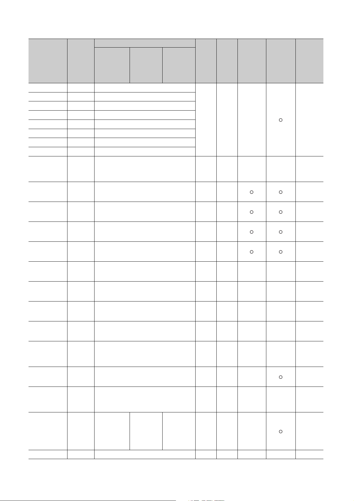
Address
(decimal
(hexadecimal))
288(120H)
)
289(121
H
290(122H)
291(123H)
292(124H)
293(125H)
294(126H)
295(127H)
296(128H)
543(21F
544(220
545(221
546(222
547(223
548(224
549(225
550(226
551(227
552(228
563(233
564(234
565(235
570(23A
571(23B
572(23C
)
H
)
H
)
H
)
H
)
H
)
H
)
H
)
H
)
H
)
H
)
H
)
H
)
H
)
H
)
H
)
H
Targ et
channel
or
current
sensor
Standard
control
Setting contents
Heating-
cooling
control
Mix control
Default
value
*1
Read/
Write
*2
Automatic
setting
*3
E2PROM
write
availability
*4
Reference
(CT)
CT1
CT2
CT3
CT4
CT5
CT6
CT7
CT8
CT ratio setting
CT ratio setting
CT ratio setting
CT ratio setting
CT ratio setting
CT ratio setting
CT ratio setting
CT ratio setting
System area to
CH1
CH1
CH1
CH1
CH1
Sensor two-point correction offset value (measured
value)
Sensor two-point correction offset value (corrected
value)
Sensor two-point correction gain value (measured
value)
Sensor two-point correction gain value (corrected
value)
Sensor two-point correction offset latch request
CH1 Sensor two-point correction offset latch completion 0 R × ×
CH1
Sensor two-point correction gain latch request
CH1 Sensor two-point correction gain latch completion 0 R × ×
System area to
CH1
Setting change rate limiter (temperature drop)
System area to
During AT loop
disconnection
All CHs
detection
function
enable/disable
setting
System area
*11
*11
*11
*11
*11
*11
*11
*11
800 R/W ×
Page 141,
Section
3.4.2 (57)
Page 142,
*9
0R/W
Section
3.4.2 (58)
Page 142,
*9
0R/W
Section
3.4.2 (59)
Page 143,
*9
0R/W
Section
3.4.2 (60)
Page 143,
*9
0R/W
Section
3.4.2 (61)
Page 144,
*9
0R/W × ×
Section
3.4.2 (62)
Page 144,
Section
3.4.2 (63)
Page 144,
*9
0R/W × ×
Section
3.4.2 (64)
Page 145,
Section
3.4.2 (65)
Page 119,
*12
0R/W ×
Section
3.4.2 (28)
During AT loop
System area
disconnection
detection
function
enable/disable
0R/W ×
Page 145,
Section
3.4.2 (66)
setting
72
Page 75
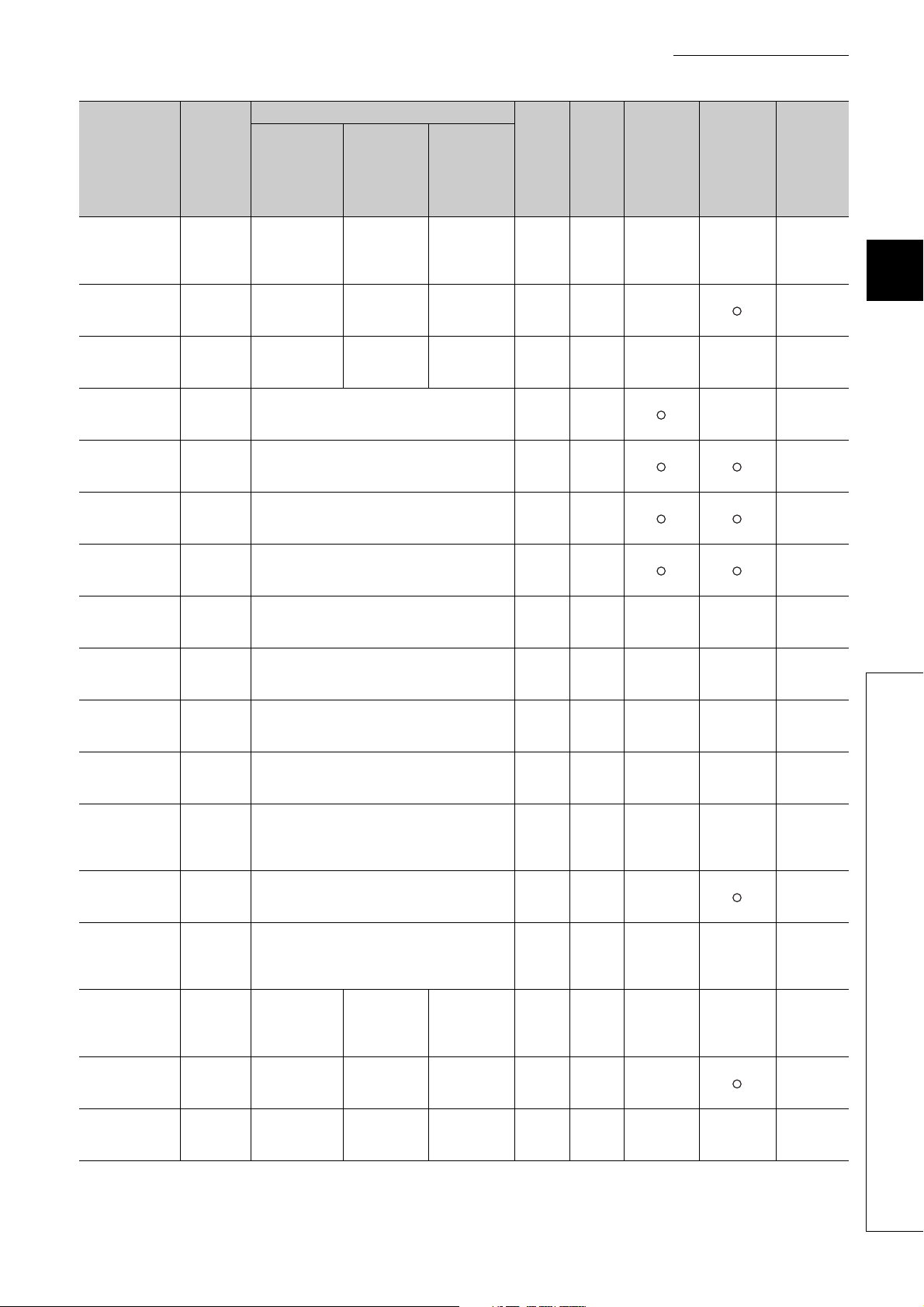
CHAPTER 3 SPECIFICATIONS
Address
(decimal
(hexadecimal))
573(23DH)
575(23F
576(240
577(241
578(242
579(243
580(244
581(245
582(246
583(247
584(248
595(253
596(254
597(255
607(25F
)
H
)
H
)
H
)
H
)
H
)
H
)
H
)
H
)
H
)
H
)
H
)
H
)
H
)
H
)
H
)
H
)
H
)
H
574(23E
604(25C
605(25D
606(25E
Tar get
channel
or
current
sensor
Standard
control
Setting contents
Heating-
cooling
control
Mix control
Default
value
*1
Read/
Write
*2
Automatic
setting
*3
(CT)
AT simultaneous
CH1
CH1
CH1 Self-tuning flag System area System area 0 R × ×
CH2
CH2
CH2
CH2
CH2
CH2 Sensor two-point correction offset latch completion 0 R × ×
CH2
CH2 Sensor two-point correction gain latch completion 0 R × ×
CH2
CH2
CH2
CH2 Self-tuning flag System area System area 0 R × ×
temperature rise
parameter
calculation flag
Self-tuning
setting
Sensor two-point correction offset value (measured
*9
value)
Sensor two-point correction offset value (corrected
*9
value)
Sensor two-point correction gain value (measured
*9
value)
Sensor two-point correction gain value (corrected
*9
value)
Sensor two-point correction offset latch request
Sensor two-point correction gain latch request
System area to
Setting change rate limiter (temperature drop)
System area to
AT simultaneous
temperature rise
parameter
calculation flag
Self-tuning
setting
System area System area 0 R × ×
System area System area 0 R/W ×
System area System area 0 R × ×
System area System area 0 R/W ×
*12
0R/W ×
0R/W
0R/W
0R/W
*9
*9
0R/W × ×
0R/W × ×
0R/W ×
E2PROM
write
availability
*4
Reference
Page 145,
Section
3.4.2 (67)
Page 146,
Section
3.4.2 (68)
Page 147,
Section
3.4.2 (69)
Page 142,
Section
3.4.2 (58)
Page 142,
Section
3.4.2 (59)
Page 143,
Section
3.4.2 (60)
Page 143,
Section
3.4.2 (61)
Page 144,
Section
3.4.2 (62)
Page 144,
Section
3.4.2 (63)
Page 144,
Section
3.4.2 (64)
Page 145,
Section
3.4.2 (65)
Page 119,
Section
3.4.2 (28)
Page 145,
Section
3.4.2 (67)
Page 146,
Section
3.4.2 (68)
Page 147,
Section
3.4.2 (69)
3
3.4 Buffer Memory Assignment
3.4.1 Q64TCN buffer memory assignment list
73
Page 76

Address
(decimal
(hexadecimal))
608(260H)
)
609(261
H
)
610(262
H
)
611(263
H
)
612(264
H
)
613(265
H
)
614(266
H
)
615(267
H
)
616(268
H
)
627(273
H
)
628(274
H
)
629(275
H
636(27C
637(27D
638(27E
639(27F
640(280
641(281
642(282
)
H
)
H
)
H
)
H
)
H
)
H
)
H
Targ et
channel
or
current
sensor
Standard
control
Setting contents
Heating-
cooling
control
Mix control
Default
value
*1
Read/
Write
*2
Automatic
setting
*3
(CT)
CH3
CH3
CH3
CH3
CH3
CH3 Sensor two-point correction offset latch completion 0 R × ×
CH3
CH3 Sensor two-point correction gain latch completion 0 R × ×
System area to
CH3
System area to
CH3
CH3
CH3 Self-tuning flag System area Self-tuning flag 0 R × ×
CH4
CH4
CH4
Sensor two-point correction offset value (measured
*9
value)
Sensor two-point correction offset value (corrected
*9
value)
Sensor two-point correction gain value (measured
*9
value)
Sensor two-point correction gain value (corrected
*9
value)
Sensor two-point correction offset latch request
Sensor two-point correction gain latch request
Setting change rate limiter (temperature drop)
AT simultaneous
temperature rise
parameter
calculation flag
Self-tuning
setting
System area
System area
AT
simultaneous
temperature
rise parameter
calculation flag
Self-tuning
setting
*9
*9
*12
Sensor two-point correction offset value (measured
*9
value)
Sensor two-point correction offset value (corrected
*9
value)
Sensor two-point correction gain value (measured
*9
value)
0R/W
0R/W
0R/W
0R/W
0R/W × ×
0R/W × ×
0R/W ×
0R × ×
0R/W ×
0R/W
0R/W
0R/W
E2PROM
write
availability
*4
Reference
Page 142,
Section
3.4.2 (58)
Page 142,
Section
3.4.2 (59)
Page 143,
Section
3.4.2 (60)
Page 143,
Section
3.4.2 (61)
Page 144,
Section
3.4.2 (62)
Page 144,
Section
3.4.2 (63)
Page 144,
Section
3.4.2 (64)
Page 145,
Section
3.4.2 (65)
Page 119,
Section
3.4.2 (28)
Page 145,
Section
3.4.2 (67)
Page 146,
Section
3.4.2 (68)
Page 147,
Section
3.4.2 (69)
Page 142,
Section
3.4.2 (58)
Page 142,
Section
3.4.2 (59)
Page 143,
Section
3.4.2 (60)
74
Page 77

CHAPTER 3 SPECIFICATIONS
Address
(decimal
(hexadecimal))
643(283H)
)
644(284
H
)
645(285
H
)
646(286
H
)
647(287
H
)
648(288
H
)
659(293
H
660(294
)
H
)
661(295
H
671(29F
)
H
)
H
)
H
)
H
)
H
)
H
668(29C
669(29D
670(29E
672(2A0
688(2B0
Tar get
channel
or
current
sensor
Standard
control
Setting contents
Heating-
cooling
control
Mix control
Default
value
*1
Read/
Write
*2
Automatic
setting
*3
(CT)
CH4
CH4
CH4 Sensor two-point correction offset latch completion 0 R × ×
CH4
CH4 Sensor two-point correction gain latch completion 0 R × ×
CH4
CH4
CH4
CH4 Self-tuning flag System area Self-tuning flag 0 R × ×
Sensor two-point correction gain value (corrected
*9
value)
Sensor two-point correction offset latch request
Sensor two-point correction gain latch request
System area to
Setting change rate limiter (temperature drop)
System area to
AT simultaneous
temperature rise
parameter
calculation flag
Self-tuning
setting
System area to
System area
System area
*9
*9
*12
AT
simultaneous
temperature
rise parameter
calculation flag
Self-tuning
setting
0R/W
0R/W × ×
0R/W × ×
0R/W ×
0R × ×
0R/W ×
E2PROM
write
availability
*4
Reference
Page 143,
Section
3.4.2 (61)
Page 144,
Section
3.4.2 (62)
Page 144,
Section
3.4.2 (63)
Page 144,
Section
3.4.2 (64)
Page 145,
Section
3.4.2 (65)
Page 119,
Section
3.4.2 (28)
Page 145,
Section
3.4.2 (67)
Page 146,
Section
3.4.2 (68)
Page 147,
Section
3.4.2 (69)
3
3.4 Buffer Memory Assignment
3.4.1 Q64TCN buffer memory assignment list
75
Page 78
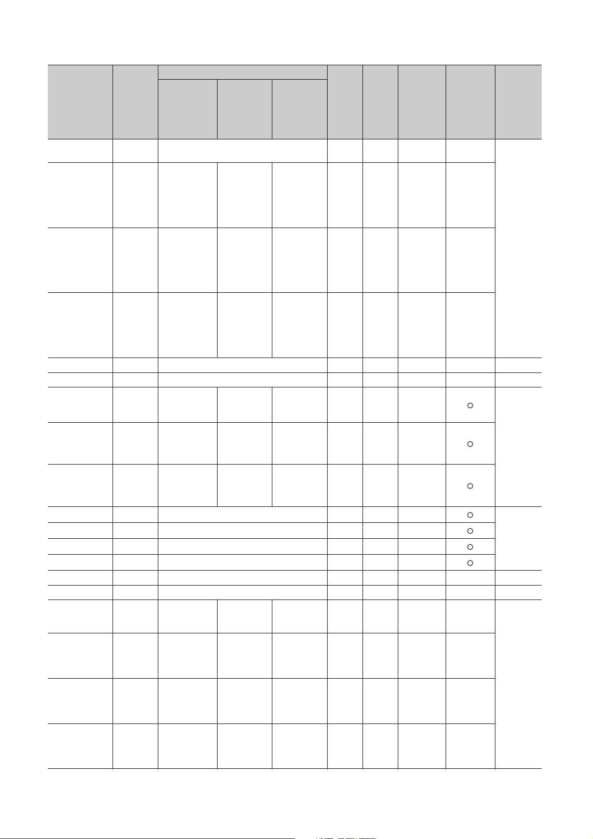
Address
(decimal
(hexadecimal))
689(2B1H)
690(2B2
691(2B3
692(2B4
693(2B5
694(2B6
695(2B7
696(2B8
697(2B9
698(2BA
699(2BB
700(2BC
701(2BD
702(2BE
703(2BF
704(2C0
705(2C1
706(2C2
707(2C3
)
H
)
H
)
H
)
H
)
H
)
H
)
H
)
H
)
H
)
H
)
H
)
H
)
H
)
H
)
H
)
H
)
H
)
H
Targ et
channel
or
current
sensor
Standard
control
Setting contents
Heating-
cooling
control
Mix control
Default
value
*1
Read/
Write
*2
Automatic
setting
*3
E2PROM
write
availability
*4
Reference
(CT)
CH1
CH2
CH3
CH4
System area
System area
CH2 System area System area
CH3 System area
CH4 System area
CH1 Number of moving averaging 2 R/W ×
CH2 Number of moving averaging 2 R/W ×
CH3 Number of moving averaging 2 R/W ×
CH4 Number of moving averaging 2 R/W ×
System area
System area
CH1 System area
CH2 System area
CH3 System area
CH4 System area
Temperature process value (PV) for input with
another analog module
Temperature
process value
(PV) for input
with another
analog module
Temperature
process value
(PV) for input
with another
analog module
Temperature
process value
(PV) for input
with another
analog module
Temperature
process value
(PV) for input
with another
analog module
Temperature
process value
(PV) for input
with another
analog
*6
module
Temperature
process value
(PV) for input
with another
analog
*6
module
Temperature
process value
(PV) for input
with another
analog
module
Temperature
process value
(PV) for input
with another
analog module
Temperature
process value
(PV) for input
with another
analog module
Temperature
conversion
*14
setting
Temperature
conversion
setting
*13
System area 0 R/W ×
Temperature
conversion
setting
*13
Manipulated
value for
cooling (MVc)
Manipulated
value for
cooling (MVc)
System area 0 R/W ×
Manipulated
value for
cooling (MVc)
Manipulated
value for
cooling
*7
(MVc)
Manipulated
value for
cooling
*6
(MVc)
System area 0 R × ×
Manipulated
value for
cooling
*6
(MVc)
System area 0 R × ×
0R/W × ×
0R/W × ×
*7
Page 150,
Section
0R/W × ×
3.4.2 (70)
0R/W × ×
0R/W ×
Page 150,
Section
3.4.2 (71)
Page 151,
3.4.2 (72)
0R × ×
0R × ×
Page 89,
Section
3.4.2 (5)
Section
76
Page 79

CHAPTER 3 SPECIFICATIONS
Address
(decimal
(hexadecimal))
708(2C4H)
711(2C7
)
H
)
H
)
H
)
H
)
H
)
H
)
H
)
H
)
H
)
H
)
H
)
H
)
H
)
H
709(2C5
710(2C6
712(2C8
713(2C9
714(2CA
715(2CB
716(2CC
718(2CE
719(2CF
720(2D0
721(2D1
722(2D2
723(2D3
Tar get
channel
or
current
sensor
Standard
control
(CT)
CH1 System area
CH2 System area
CH3 System area
CH4 System area
CH1 System area
CH2 System area
CH3 System area
CH4 System area
System area to
All CHs System area
CH1 System area
CH1 System area
CH1 System area
CH1 System area
Setting contents
Heating-
cooling
control
Manipulated
value of
cooling (MVc)
for output with
another analog
module
Manipulated
value of
cooling (MVc)
for output with
another analog
module
Manipulated
value of
cooling (MVc)
for output with
another analog
*6
module
Manipulated
value of
cooling (MVc)
for output with
another analog
*6
module
Cooling
transistor
output flag
Cooling
transistor
output flag
Cooling
transistor
output flag
Cooling
transistor
output flag
Cooling
method setting
*9
Cooling
proportional
band (Pc)
setting
Cooling upper
limit output
limiter
Cooling control
output cycle
setting
Overlap/dead
band setting
*6
*6
Default
Mix control
Manipulated
value of
cooling (MVc)
for output with
another analog
module
Manipulated
value of
cooling (MVc)
for output with
another analog
*7
module
System area 0 R × ×
System area 0 R × ×
Cooling
transistor
output flag
Cooling
transistor
output flag
System area 0 R × ×
System area 0 R × ×
Cooling
method setting
*9
Cooling
proportional
band (Pc)
setting
Cooling upper
limit output
limiter
Cooling control
output cycle
setting
Overlap/dead
band setting
value
*7
1000 R/W ×
Read/
Write
*1
0R × ×
0R × ×
0R × ×
0R × ×
0R/W ×
30 R/W ×
30 R/W ×
0R/W ×
*2
Automatic
setting
*3
E2PROM
write
availability
Reference
*4
3
Page 133,
Section
3.4.2 (47)
3.4 Buffer Memory Assignment
3.4.1 Q64TCN buffer memory assignment list
Page 92,
Section
3.4.2 (7)
Page 151,
Section
3.4.2 (73)
Page 105,
Section
3.4.2 (15)
Page 110,
Section
3.4.2 (19)
Page 114,
Section
3.4.2 (23)
Page 152,
Section
3.4.2 (74)
77
Page 80

Address
(decimal
(hexadecimal))
724(2D4H)
725(2D5
726(2D6
727(2D7
728(2D8
729(2D9
730(2DA
731(2DB
732(2DC
733(2DD
734(2DE
735(2DF
736(2E0
737(2E1
738(2E2
739(2E3
740(2E4
741(2E5
)
H
)
H
)
H
)
H
)
H
)
H
)
H
)
H
)
H
)
H
)
H
)
H
)
H
)
H
)
H
)
H
)
H
Targ et
channel
or
current
sensor
Standard
control
Setting contents
Heating-
cooling
control
Mix control
Default
value
*1
Read/
Write
*2
Automatic
setting
*3
(CT)
CH1 Manual reset amount setting 0 R/W ×
CH1
CH1
CH1
CH1 Process value (PV) scaling value 0 R × ×
CH1
CH1
CH1
CH1
CH1
CH1
CH1
CH2 System area
CH2 System area
CH2 System area
CH2 System area
CH2
CH2
Process value (PV) scaling function enable/disable
*9
setting
Process value (PV) scaling lower limit value
Process value (PV) scaling upper limit value
Derivative action selection
*9
*9
*9
Simultaneous
temperature rise
group setting
System area System area 0 R/W ×
*9
Simultaneous
temperature rise
System area System area 0 R/W
gradient data
Simultaneous
temperature rise
System area System area 0 R/W
dead time
Simultaneous
temperature rise
AT m o de
System area System area 0 R/W ×
selection
Simultaneous
temperature rise
System area System area 0 R × ×
status
Setting change rate limiter unit time setting
Cooling
proportional
band (Pc)
setting
Cooling upper
limit output
limiter
Cooling control
output cycle
setting
Overlap/dead
band setting
Manual reset
amount setting
Process value
(PV) scaling
function
enable/disable
*9
setting
Manual reset
amount setting
Process value
(PV) scaling
function
enable/disable
*9
setting
*9
Cooling
proportional
band (Pc)
*7
setting
Cooling upper
limit output
*7
limiter
Cooling control
output cycle
*7
setting
Overlap/dead
band setting
Manual reset
amount
*7
setting
Process value
(PV) scaling
function
enable/disable
*7*9
setting
0R/W ×
0R/W ×
0R/W ×
0R/W ×
0R/W ×
30 R/W ×
1000 R/W ×
30 R/W ×
0R/W ×
*7
0R/W ×
0R/W ×
E2PROM
write
availability
*4
Reference
Page 152,
Section
3.4.2 (75)
Page 152,
Section
3.4.2 (76)
Page 153,
Section
3.4.2 (77)
Page 153,
Section
3.4.2 (78)
Page 153,
Section
3.4.2 (79)
Page 154,
Section
3.4.2 (80)
Page 154,
Section
3.4.2 (81)
Page 155,
Section
3.4.2 (82)
Page 155,
Section
3.4.2 (83)
Page 156,
Section
3.4.2 (84)
Page 157,
Section
3.4.2 (85)
Page 105,
Section
3.4.2 (15)
Page 110,
Section
3.4.2 (19)
Page 114,
Section
3.4.2 (23)
Page 152,
Section
3.4.2 (74)
Page 152,
Section
3.4.2 (75)
Page 152,
Section
3.4.2 (76)
78
Page 81

CHAPTER 3 SPECIFICATIONS
Address
(decimal
(hexadecimal))
742(2E6H)
752(2F0
753(2F1
754(2F2
755(2F3
756(2F4
757(2F5
)
H
)
H
)
H
)
H
)
H
)
H
)
H
)
H
)
H
)
H
)
H
)
H
)
H
)
H
)
H
743(2E7
744(2E8
745(2E9
746(2EA
747(2EB
748(2EC
749(2ED
750(2EE
751(2EF
Tar get
channel
or
current
sensor
Standard
control
(CT)
Process value
CH2
CH2
CH2
CH2
CH2
CH2
CH2
CH2
CH2
CH2
CH3 System area
CH3 System area
CH3 System area
CH3 System area
CH3
CH3
(PV) scaling
lower limit
value
Process value
(PV) scaling
upper limit
value
Process value
(PV) scaling
value
Derivative action
selection
Simultaneous
temperature rise
group setting
Simultaneous
temperature rise
gradient data
Simultaneous
temperature rise
dead time
Simultaneous
temperature rise
AT mode
selection
Simultaneous
temperature rise
status
Setting change
rate limiter unit
time setting
Manual reset
amount setting
Process value
(PV) scaling
function
enable/disable
setting
Setting contents
Heating-
cooling
Mix control
Default
value
control
Process value
(PV) scaling
lower limit
*9
value
*9
Process value
(PV) scaling
upper limit
*9
value
*9
Process value
(PV) scaling
value
Derivative
*9
action
selection
*9
Process value
(PV) scaling
lower limit
*7*9
value
Process value
(PV) scaling
upper limit
*7*9
value
Process value
(PV) scaling
*7
value
Derivative
action
*7*9
selection
Read/
Write
*1
*2
Automatic
setting
*3
0R/W ×
0R/W ×
0R × ×
0R/W ×
System area System area 0 R/W ×
*9
System area System area 0 R/W
System area System area 0 R/W
System area System area 0 R/W ×
System area System area 0 R × ×
*9
Setting change
rate limiter unit
time setting
*9
Setting change
rate limiter unit
time setting
*7*9
0R/W ×
Cooling
proportional
band (Pc)
*6
setting
System area 30 R/W ×
Cooling upper
limit output
*6
limiter
System area 1000 R/W ×
Cooling control
output cycle
*6
setting
Overlap/dead
band setting
Manual reset
amount
*6
setting
Process value
(PV) scaling
function
enable/disable
*9
setting
*6*9
System area 30 R/W ×
System area 0 R/W ×
*6
Manual reset
amount setting
0R/W ×
Process value
(PV) scaling
function
0R/W ×
enable/disable
*9
setting
E2PROM
write
availability
*4
Reference
Page 153,
Section
3.4.2 (77)
Page 153,
Section
3.4.2 (78)
Page 153,
Section
3.4.2 (79)
Page 154,
Section
3.4.2 (80)
Page 154,
Section
3.4.2 (81)
Page 155,
Section
3.4.2 (82)
Page 155,
Section
3.4.2 (83)
Page 156,
Section
3.4.2 (84)
Page 157,
Section
3.4.2 (85)
Page 105,
Section
3.4.2 (15)
Page 110,
Section
3.4.2 (19)
Page 114,
Section
3.4.2 (23)
Page 152,
Section
3.4.2 (74)
Page 152,
Section
3.4.2 (75)
Page 152,
Section
3.4.2 (76)
3
3.4 Buffer Memory Assignment
3.4.1 Q64TCN buffer memory assignment list
79
Page 82

Address
(decimal
(hexadecimal))
758(2F6H)
759(2F7
760(2F8
761(2F9
762(2FA
763(2FB
764(2FC
765(2FD
766(2FE
767(2FF
768(300
769(301
770(302
771(303
772(304
)
H
)
H
)
H
)
H
)
H
)
H
)
H
)
H
)
H
)
H
)
H
)
H
)
H
)
H
Targ et
channel
or
current
sensor
Standard
control
(CT)
Process value
CH3
CH3
CH3
CH3
CH3
CH3
CH3
CH3
CH3
CH3
CH4 System area
CH4 System area
CH4 System area
CH4 System area
CH4
(PV) scaling
lower limit
value
Process value
(PV) scaling
upper limit
value
Process value
(PV) scaling
value
Derivative action
selection
Simultaneous
temperature rise
group setting
Simultaneous
temperature rise
gradient data
Simultaneous
temperature rise
dead time
Simultaneous
temperature rise
AT m o de
selection
Simultaneous
temperature rise
status
Setting change
rate limiter unit
time setting
Manual reset
amount setting
Setting contents
Heating-
cooling
Mix control
Default
value
control
Process value
(PV) scaling
lower limit
*9
value
*6*9
Process value
(PV) scaling
upper limit
*9
value
*6*9
Process value
(PV) scaling
value
*6
Derivative
*9
action
selection
*6*9
Process value
(PV) scaling
lower limit
*9
value
Process value
(PV) scaling
upper limit
*9
value
Process value
(PV) scaling
value
Derivative
action
*9
selection
Read/
Write
*1
*2
Automatic
setting
*3
0R/W ×
0R/W ×
0R × ×
0R/W ×
Simultaneous
System area
*9
temperature
rise group
*9
setting
0R/W ×
Simultaneous
System area
temperature
rise gradient
0R/W
data
Simultaneous
System area
temperature
0R/W
rise dead time
Simultaneous
System area
temperature
rise AT mode
0R/W ×
selection
Simultaneous
System area
temperature
0R × ×
rise status
*9
Setting change
rate limiter unit
time setting
*6*9
Setting change
rate limiter unit
time setting
*9
0R/W ×
Cooling
proportional
band (Pc)
*6
setting
System area 30 R/W ×
Cooling upper
limit output
*6
limiter
System area 1000 R/W ×
Cooling control
output cycle
*6
setting
Overlap/dead
band setting
Manual reset
amount
*6
setting
System area 30 R/W ×
System area 0 R/W ×
*6
Manual reset
amount setting
0R/W ×
E2PROM
write
availability
*4
Reference
Page 153,
Section
3.4.2 (77)
Page 153,
Section
3.4.2 (78)
Page 153,
Section
3.4.2 (79)
Page 154,
Section
3.4.2 (80)
Page 154,
Section
3.4.2 (81)
Page 155,
Section
3.4.2 (82)
Page 155,
Section
3.4.2 (83)
Page 156,
Section
3.4.2 (84)
Page 157,
Section
3.4.2 (85)
Page 105,
Section
3.4.2 (15)
Page 110,
Section
3.4.2 (19)
Page 114,
Section
3.4.2 (23)
Page 152,
Section
3.4.2 (74)
Page 152,
Section
3.4.2 (75)
80
Page 83
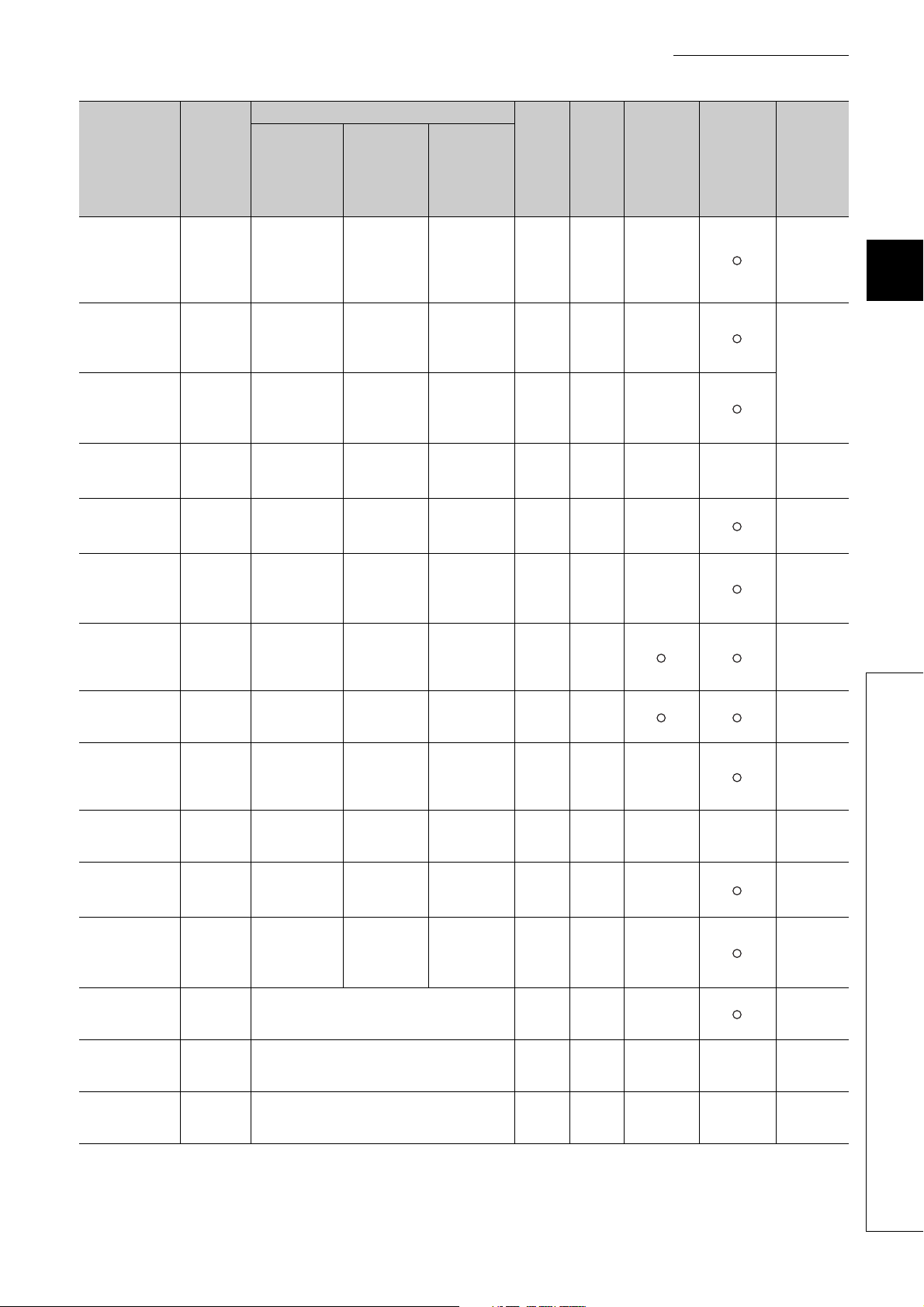
CHAPTER 3 SPECIFICATIONS
Address
(decimal
(hexadecimal))
773(305H)
)
774(306
H
)
775(307
H
)
776(308
H
)
777(309
H
783(30F
784(310
785(311
786(312
787(313
)
H
)
H
)
H
)
H
)
H
)
H
)
H
)
H
)
H
)
H
778(30A
779(30B
780(30C
781(30D
782(30E
Tar get
channel
or
current
sensor
Standard
control
Setting contents
Heating-
cooling
control
Mix control
Default
value
*1
Read/
Write
*2
Automatic
setting
*3
E2PROM
availability
(CT)
Process value
(PV) scaling
CH4
function
enable/disable
*9
setting
Process value
CH4
(PV) scaling
lower limit
*9
value
Process value
CH4
(PV) scaling
upper limit
*9
value
Process value
CH4
(PV) scaling
value
CH4
Derivative action
*9
selection
Simultaneous
CH4
temperature rise
group setting
Simultaneous
CH4
temperature rise
gradient data
Simultaneous
CH4
temperature rise
dead time
Simultaneous
CH4
temperature rise
AT mode
selection
Simultaneous
CH4
temperature rise
status
Setting change
CH4
rate limiter unit
time setting
Peak current
All CHs
All CHs
suppression
control group
*9
setting
Sensor correction function selection
All CHs Temperature conversion completion flag 0 R × ×
All CHs Function extension bit monitor 0 R × ×
Process value
(PV) scaling
function
enable/disable
*6*9
setting
Process value
(PV) scaling
lower limit
*6*9
value
Process value
(PV) scaling
upper limit
*6*9
value
Process value
(PV) scaling
*6
value
Derivative
action
selection
*6*9
Process value
(PV) scaling
function
enable/disable
*9
setting
Process value
(PV) scaling
lower limit
*9
value
Process value
(PV) scaling
upper limit
*9
value
Process value
(PV) scaling
value
Derivative
action
*9
selection
0R/W ×
0R/W ×
0R/W ×
0R × ×
0R/W ×
Simultaneous
System area
*9
temperature
rise group
*9
setting
0R/W ×
Simultaneous
System area
temperature
rise gradient
0R/W
data
Simultaneous
System area
temperature
0R/W
rise dead time
Simultaneous
System area
temperature
rise AT mode
0R/W ×
selection
Simultaneous
System area
temperature
0R × ×
rise status
*9
Setting change
rate limiter unit
time setting
*6*9
Setting change
rate limiter unit
time setting
*9
0R/W ×
System area System area 0 R/W ×
*9
0R/W ×
write
*4
Reference
Page 152,
Section
3.4.2 (76)
Page 153,
Section
3.4.2 (77)
Page 153,
Section
3.4.2 (78)
Page 153,
Section
3.4.2 (79)
Page 154,
Section
3.4.2 (80)
Page 154,
Section
3.4.2 (81)
Page 155,
Section
3.4.2 (82)
Page 155,
Section
3.4.2 (83)
Page 156,
Section
3.4.2 (84)
Page 157,
Section
3.4.2 (85)
Page 158,
Section
3.4.2 (86)
Page 159,
Section
3.4.2 (87)
Page 159,
Section
3.4.2 (88)
Page 160,
Section
3.4.2 (89)
3
3.4 Buffer Memory Assignment
3.4.1 Q64TCN buffer memory assignment list
81
Page 84

Address
(decimal
(hexadecimal))
788(314H)
1278(4FE
1279(4FF
4095(FFF
4096(1000
53247(CFFF
)
H
)
H
to
)
H
)
H
H
*1 This value is stored when Default setting registration instruction (Yn9) is turned on. The default value varies depending
*2 This column indicates whether data can be read from or written to the buffer memory area through sequence programs.
*3 This column indicates whether the setting in the buffer memory area is automatically changed when the input range is
*4 Whether writing to the E
*5 (TT) indicates the Q64TCTTN and Q64TCTTBWN. (RT) indicates the Q64TCRTN and Q64TCRTBWN.
*6 Available only when the heating-cooling control (expanded mode) is set on Switch Setting. With other models, this area
*7 Available only when the mix control (expanded mode) is set on Switch Setting. With other models, this area is handled
*8 Available only when the Q64TCTTN or Q64TCTTBWN is used. With other models, this area is handled as a system
*9 Available only in the setting mode. To enable the setting contents, turn off, on, and on Setting change instruction (YnB)
*10 By using the setting change rate limiter, whether to set temperature rise/temperature drop in a batch or individually can
*11 Available only when the Q64TCTTBWN or Q64TCRTBWN is used. With other models, this area is handled as a system
*12 By using the setting change rate limiter, whether to set temperature rise/temperature drop in a batch or individually can
*13 Available only when the heating-cooling control (normal mode) is set on Switch Setting. With other models, this area is
*14 Available only when the mix control (normal mode) is set on Switch Setting. With other models, this area is handled as a
Targ et
channel
or
current
sensor
Standard
control
Setting contents
Heating-
cooling
control
Mix control
Default
value
*1
Read/
Write
*2
Automatic
setting
*3
E2PROM
write
availability
*4
(CT)
System area to
Buffer memory for error history ( Page 83, Section 3.4.1 (2))
System area to
)
on the mode. For details on the default values, refer to the following.
Page 86, Section 3.4.2
R: Reading enabled
W: Writing enabled
changed. Enable/disable of automatic change can be set on Switch Setting. For details, refer to Page 220, Section
4.15.
2
PROM by turning off and on E2PROM backup instruction (Yn8) is enabled is indicated in this
column. For details, refer to Page 270, Section 4.30.
is handled as a system area.
as a system area.
area.
when Setting/operation mode instruction (Yn1) is off (during setting mode). Note that a write data error (error code:
3
) occurs if the setting is changed during the operation mode.
H
be selected on Switch Setting. In the batch setting, the target of setting change rate limiter is only this area. In the
individual setting, this area is the setting target for the temperature rise. For details, refer to Page 190, Section 4.9.
area.
be selected on Switch Setting. In the batch setting, this area is handled as a system area. In the individual setting, this
area is the setting target for the temperature drop. For details, refer to Page 190, Section 4.9.
handled as a system area.
system area.
Reference
82
Page 85

(2) Buffer memory address for error history
CHAPTER 3 SPECIFICATIONS
Address
(decimal
(hexadecimal))
1279(4FF
1280(500
1281(501
1282(502
1283(503
1284(504H)
1285(505
1287(507
1288(508
1292(50C
1293(50D
1295(50F
1296(510
1300(514
1301(515
1303(517
1304(518
1308(51C
1309(51D
1311(51F
1312(520
1316(524
1317(525
1319(527
1320(528
1324(52C
1325(52D
1327(52F
)
H
)
H
)
H
)
H
)
H
)
H
to
)
H
)
H
to
)
H
)
H
)
H
)
H
to
)
H
)
H
)
H
)
H
to
)
H
)
H
)
H
)
H
to
)
H
)
H
)
H
)
H
to
)
H
)
H
)
H
Tar get
channel
All CHs Latest address of error history 0 R × ×
All CHs History 1
System area
All CHs History 2
System area to
All CHs History 3
System area to
All CHs History 4
System area to
All CHs History 5
System area to
All CHs History 6
System area to
Setting contents
Error code
Upper 2
digits of year
Error
occurrence
time
Error code, error occurrence time (Data
structure is the same as that of History 1.)
Error code, error occurrence time (Data
structure is the same as that of History 1.)
Error code, error occurrence time (Data
structure is the same as that of History 1.)
Error code, error occurrence time (Data
structure is the same as that of History 1.)
Error code, error occurrence time (Data
structure is the same as that of History 1.)
Month Day
Hour Minute
Second
Lower 2
digits of year
Day of the
week
Default
value
Read/
Write
*1
0R × ×
0R × ×
0R × ×
0R × ×
0R × ×
0R × ×
*2
Automatic
setting
*3
E2PROM
write
availability
*4
Reference
Page 161,
Section
3.4.2 (90)
Page 161,
Section
3.4.2 (91)
Page 161,
Section
3.4.2 (91)
Page 161,
Section
3.4.2 (91)
Page 161,
Section
3.4.2 (91)
Page 161,
Section
3.4.2 (91)
Page 161,
Section
3.4.2 (91)
3
3.4 Buffer Memory Assignment
3.4.1 Q64TCN buffer memory assignment list
83
Page 86

Address
(decimal
(hexadecimal))
1328(530H)
to
1332(534
1333(535
1335(537
1336(538
1340(53C
1341(53D
1343(53F
1344(540
1348(544
1349(545
1351(547
1352(548
1356(54C
1357(54D
1359(54F
1360(550
1364(554
1365(555
1367(557
1368(558
1372(55C
1373(55D
1375(55F
1376(560
1380(564
1381(565
1383(567
1384(568
1388(56C
)
H
)
H
)
H
)
H
to
)
H
)
H
)
H
)
H
to
)
H
)
H
)
H
)
H
to
)
H
)
H
)
H
)
H
to
)
H
)
H
)
H
)
H
to
)
H
)
H
)
H
)
H
to
)
H
)
H
)
H
)
H
to
)
H
Tar get
channel
All CHs History 7
System area to
All CHs History 8
System area to
All CHs History 9
System area to
All CHs
All CHs
All CHs
All CHs
All CHs
History 10Error code, error occurrence time (Data
System area to
History 11Error code, error occurrence time (Data
System area to
History 12Error code, error occurrence time (Data
System area to
History 13Error code, error occurrence time (Data
System area to
History 14Error code, error occurrence time (Data
Setting contents
Error code, error occurrence time (Data
structure is the same as that of History 1.)
Error code, error occurrence time (Data
structure is the same as that of History 1.)
Error code, error occurrence time (Data
structure is the same as that of History 1.)
structure is the same as that of History 1.)
structure is the same as that of History 1.)
structure is the same as that of History 1.)
structure is the same as that of History 1.)
structure is the same as that of History 1.)
Default
value
*1
Read/
Write
*2
Automatic
setting
*3
E2PROM
write
availability
*4
0R × ×
0R × ×
0R × ×
0R × ×
0R × ×
0R × ×
0R × ×
0R × ×
Reference
Page 161,
Section
3.4.2 (91)
Page 161,
Section
3.4.2 (91)
Page 161,
Section
3.4.2 (91)
Page 161,
Section
3.4.2 (91)
Page 161,
Section
3.4.2 (91)
Page 161,
Section
3.4.2 (91)
Page 161,
Section
3.4.2 (91)
Page 161,
Section
3.4.2 (91)
84
Page 87

CHAPTER 3 SPECIFICATIONS
Address
(decimal
(hexadecimal))
1389(56DH)
1391(56F
1392(570
1396(574
1397(575
1399(577
1400(578
1404(57C
1405(57D
4095(FFF
)
H
)
H
to
)
H
)
H
)
H
)
H
to
)
H
)
H
)
H
*1 This default value is set after the module is turned off and on or after the CPU module is reset and the reset is cancelled.
*2 This column indicates whether data can be read from or written to the buffer memory area through sequence programs.
*3 This column indicates whether the setting in the buffer memory area is automatically changed when the input range is
*4 Whether writing to the E
E2PROM
write
availability
*4
Reference
Page 161,
Section
3.4.2 (91)
Page 161,
Section
3.4.2 (91)
Tar get
channel
System area to
All CHs
System area to
All CHs
System area to
Setting contents
History 15Error code, error occurrence time (Data
structure is the same as that of History 1.)
History 16Error code, error occurrence time (Data
structure is the same as that of History 1.)
Default
value
Read/
Write
*1
0R × ×
0R × ×
*2
Automatic
setting
*3
R: Reading enabled
W: Writing enabled
changed. Enable/disable of automatic change can be set on Switch Setting. For details, refer to Page 220, Section
4.15.
2
PROM by turning off and on E2PROM backup instruction (Yn8) is enabled is indicated in this
column. For details, refer to Page 270, Section 4.30
3
3.4 Buffer Memory Assignment
3.4.1 Q64TCN buffer memory assignment list
85
Page 88

3.4.2 Details of the buffer memory
Common
Common
This chapter describes details on the buffer memory of the Q64TCN.
For buffer memory areas indicated with the icon , the following terms are used, unless otherwise specified.
• Proportional band (P): includes heating proportional band (Ph) and cooling proportional band (Pc)
• Manipulated value (MV): includes manipulated value for heating (MVh) and manipulated value for cooling (MVc)
• Transistor output: includes heating transistor output and cooling transistor output
• Control output cycle: includes heating control output cycle and cooling control output cycle
(1) Write data error code (Un\G0)
An error code or alarm code is stored in this buffer memory area.
For error codes and alarm codes, refer to the following.
Page 367, Section 8.6, Page 370, Section 8.7
(2) CH Decimal point position (Un\G1 to Un\G4)
Common
According to the setting of CH Input range (Un\G32, Un\G64, Un\G96, Un\G128), the decimal point position
applicable in the following buffer memory areas is stored in this buffer memory area.
Buffer memory area name
CH Temperature process value (PV) Un\G9 Un\G10 Un\G11 Un\G12 Page 89, Section 3.4.2 (4)
CH Set value (SV) setting Un\G34 Un\G66 Un\G98 Un\G130
CH Alert set value 1 Un\G38 Un\G70 Un\G102 Un\G134
CH Alert set value 2 Un\G39 Un\G71 Un\G103 Un\G135
CH Alert set value 3 Un\G40 Un\G72 Un\G104 Un\G136
CH Alert set value 4 Un\G41 Un\G73 Un\G105 Un\G137
CH AT bias setting Un\G53 Un\G85 Un\G117 Un\G149
CH Upper limit setting limiter Un\G55 Un\G87 Un\G119 Un\G151
CH Lower limit setting limiter Un\G56 Un\G88 Un\G120 Un\G152
CH Loop disconnection detection dead
band
CH Sensor two-point correction offset
value (measured value)
CH Sensor two-point correction offset
value (corrected value)
CH Sensor two-point correction gain value
(measured value)
CH Sensor two-point correction gain value
(corrected value)
CH Simultaneous temperature rise
gradient data
CH1 CH2 CH3 CH4
Un\G60 Un\G92 Un\G124 Un\G156
Un\G544 Un\G576 Un\G608 Un\G640
Un\G545 Un\G577 Un\G609 Un\G641
Un\G546 Un\G578 Un\G610 Un\G642
Un\G547 Un\G579 Un\G611 Un\G643
Un\G731 Un\G747 Un\G763 Un\G779
Buffer memory address
Reference
Page 104, Section 3.4.2
(14)
Page 108, Section 3.4.2
(18)
Page 120, Section 3.4.2
(29)
Page 122, Section 3.4.2
(31)
Page 125, Section 3.4.2
(34)
Page 142, Section 3.4.2
(58)
Page 142, Section 3.4.2
(59)
Page 143, Section 3.4.2
(60)
Page 143, Section 3.4.2
(61)
Page 154, Section 3.4.2
(81)
86
Page 89
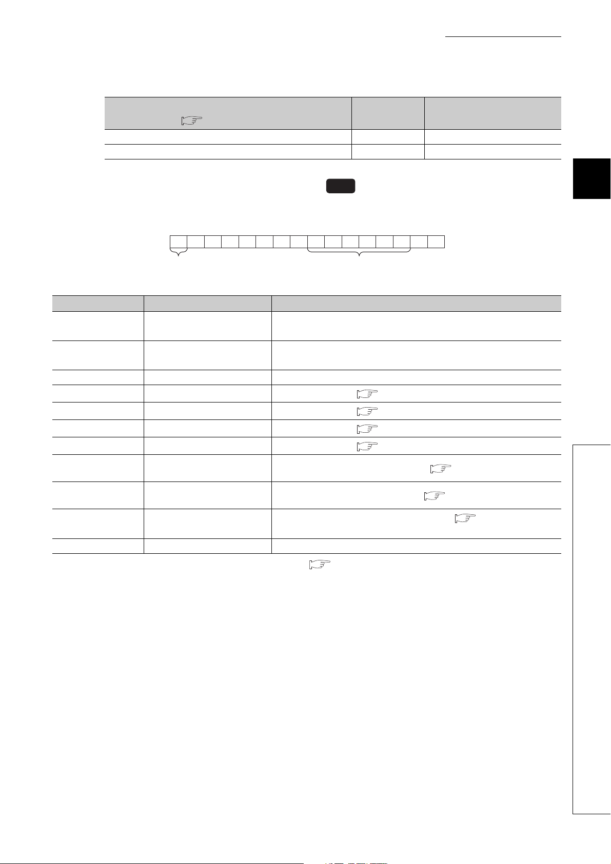
CHAPTER 3 SPECIFICATIONS
b15 b2 b1 b0
Bit data b15 are
fixed to 0.
Bit data from b7 to
b2 are fixed to 0.
b7b8b9b10b11b12b13b14
0 000000
to
Stored values differ depending on the setting in CH Input range (Un\G32, Un\G64, Un\G96, Un\G128).
Setting of CH Input range (Un\G32, Un\G64, Un\G96,
Un\G128) ( Page 96, Section 3.4.2 (12))
Resolution is 1. 0 Nothing after decimal point
Resolution is 0.1. 1 First decimal place
(3) CH Alert definition (Un\G5 to Un\G8)
Common
Stored value Setting contents
Bits corresponding to alerts detected in each channel become 1.
Target bit number Flag name Alert definition
b0 CH Input range upper limit
b1 CH Input range lower limit
b2 to b7 (fixed to 0) (Unused)
b8 CH Alert 1
b9 CH Alert 2
b10 CH Alert 3
b11 CH Alert 4
b12
b13
b14
b15 (fixed to 0) (Unused)
CH Heater disconnection
detection
CH Loop disconnection
detection
CH Output off-time current
error
Temperature process value (PV) has exceeded the temperature
measurement range
Temperature process value (PV) has fallen below the temperature
measurement range
Alert 1 has occurred. ( Page 194, Section 4.12)
Alert 2 has occurred. ( Page 194, Section 4.12)
Alert 3 has occurred. ( Page 194, Section 4.12)
Alert 4 has occurred. ( Page 194, Section 4.12)
Heater disconnection has been detected. ( Page 265, Section 4.28)
Loop disconnection has been detected. ( Page 253, Section 4.22)
Output off-time current error has been detected. ( Page 269, Section
4.29)
*1
of the set input range.
*1
of the set input range.
3
3.4 Buffer Memory Assignment
3.4.2 Details of the buffer memory
*1 For the temperature measurement range, refer to Page 88, Section 3.4.2 (3) (a).
87
Page 90
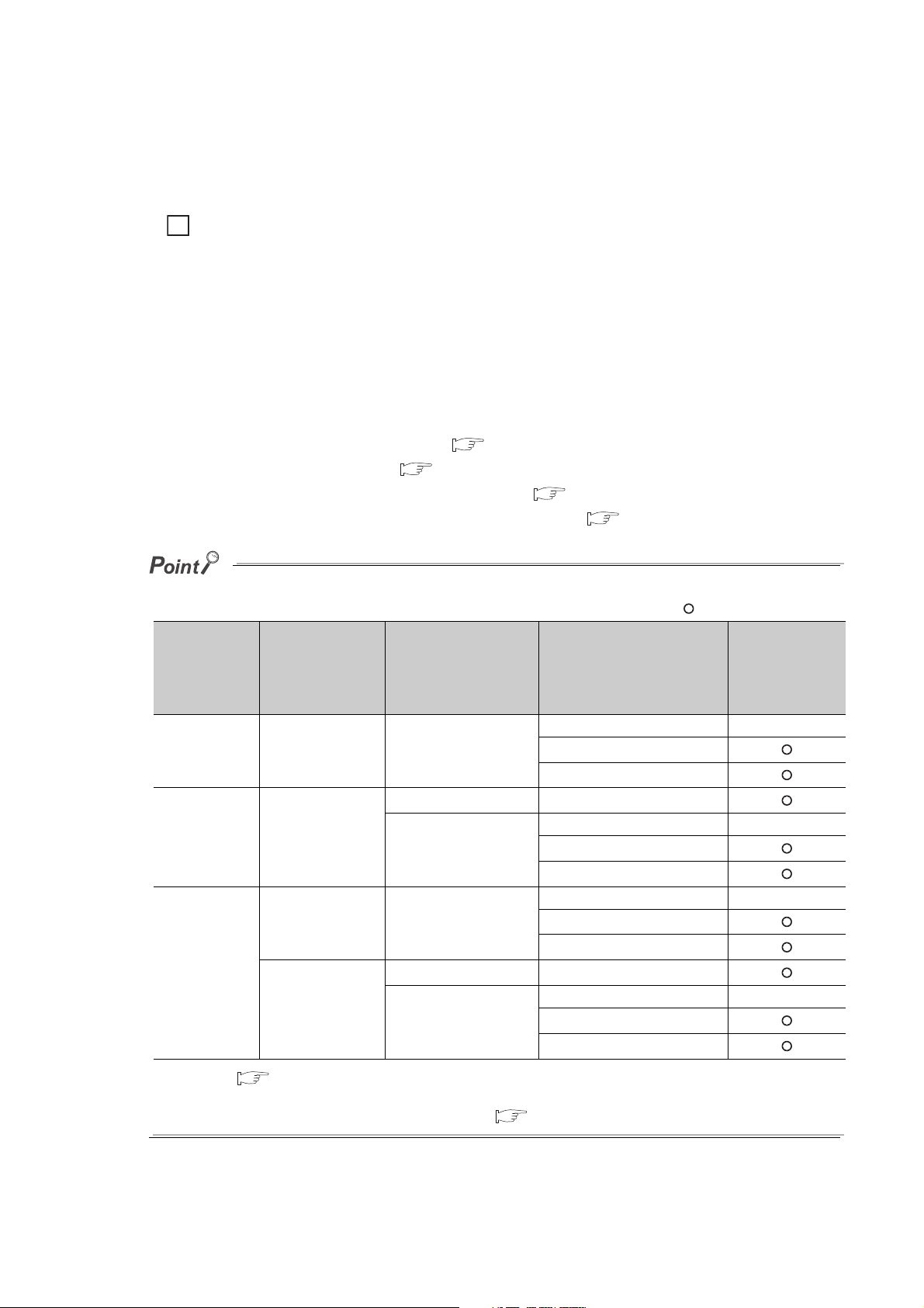
(a) Temperature measurement range
Ex.
The temperature measurement range is as follows.
• Input range lower limit - 5% of full scale to Input range upper limit + 5% of full scale
A calculation example when CH Input range (Un\G32, Un\G64, Un\G96, Un\G128): 38 (temperature
measurement range: -200.0 to 400.0°C)
• Input range lower limit - 5% of full scale = -200 - ((400.0 - (-200.0)) × 0.05) = -230.0
• Input range upper limit + 5% of full scale = 400 + ((400.0 - (-200.0)) × 0.05) = 430.0
Therefore, the temperature measurement range is -230.0 to 430.0°C.
The Q64TCN checks whether the input temperature is in temperature measurement range of the input range.
When the input temperature is out of the temperature measurement range, CH Input range upper limit (b0 of
Un\G5 to Un\G8), or CH Input range lower limit (b1 of Un\G5 to Un\G8) become 1 (ON). The conditions which
the Q64TCN uses to judge whether the measured temperature is within the temperature measurement range
differ depending on the following settings.
• Setting/operation mode instruction (Yn1) ( Page 56, Section 3.3.3 (1))
• PID continuation flag (Un\G169) ( Page 131, Section 3.4.2 (43))
•CH PID control forced stop instruction (YnC to YnF) ( Page 58, Section 3.3.3 (7))
•CH Stop mode setting (Un\G33, Un\G65, Un\G97, Un\G129) ( Page 103, Section 3.4.2 (13))
The following table lists the conditions whether to perform the temperature judgment.
Setting/opera
tion mode
instruction
*1
(Yn1)
Setting mode at
power-ON
Operation mode
(in operation)
Setting mode
(after operation)
PID continuation
flag (Un\G169)
Stop (0)/Continue
(1)
Stop (0)/Continue
(1)
Stop (0) OFF/ON
Continue (1)
CH PID control
forced stop
instruction (YnC to
YnF)
OFF/ON
OFF Stop (0)/Monitor (1)/Alert (2)
ON
OFF Stop (0)/Monitor (1)/Alert (2)
ON
CH Stop mode setting
(Un\G33, Un\G65,
Un\G97, Un\G129)
Monitor (1)
Monitor (1)
Monitor (1)
Monitor (1)
: Executed ×: Not executed
Temperature
judgment
Stop (0) ×
Alert (2)
Stop (0) ×
Alert (2)
Stop (0) ×
Alert (2)
Stop (0) ×
Alert (2)
*1 Refer to Page 50, Section 3.3.2 (2) for each timing.
If CH Unused channel setting (Un\G61, Un\G93, Un\G125, Un\G157) is set to Disable (1), temperature judgment is not
executed even though the condition above is satisfied. ( Page 126, Section 3.4.2 (35))
88
Page 91

CHAPTER 3 SPECIFICATIONS
Standard
(4) CH Temperature process value (PV) (Un\G9 to Un\G12)
Common
The detected temperature value where sensor correction is performed is stored in this buffer memory area.
The value to be stored differs depending on the stored value in CH Decimal point position (Un\G1 to Un\G4).
( Page 86, Section 3.4.2 (2))
• No decimal place (0): Stored as it is.
• One decimal place (1): Stored after a multiplication by 10.
When value measured by a temperature sensor exceeds the temperature measurement range, the following value is stored.
• When measured value exceeds temperature measurement range: Input range upper limit + 5% of full scale
• When measured value falls below temperature measurement range: Input range lower limit - 5% of full scale
(5) CH Manipulated value (MV) (Un\G13 to Un\G16)
CH Manipulated value for heating (MVh) (Un\G13 to Un\G16)
CH Manipulated value for cooling (MVc) (Un\G704 to Un\G707)
The result of PID operation based on temperature process value (PV) is stored in these buffer memory areas.
The area Un\G13 to Un\G16 are used for heating in the case of the heating-cooling control. The following table
lists the range of value to be stored.
Heating-cooling
Heating-cooling
3
Store description Store range in control Stored value when control stops
Manipulated value (MV) -50 to 1050 (-5% to 105.0%) -50 (-5.0%)
Manipulated value for heating
(MVh)
Manipulated value for cooling
(MVc)
0 to 1050 (0.0% to 105.0%) -50 (-5.0%)
However, values are output in the range of 0% to 100%. For 0% or less and 100% or more, refer to the following.
• For 0% or less: 0%
• For 100% or more: 100%
3.4 Buffer Memory Assignment
3.4.2 Details of the buffer memory
89
Page 92

(a) Manipulated value (MV) and control output cycle
Ex.
30s
ON
12s (40%)18s (60%)
OFF
Transistor output
• Manipulated value (MV) indicates ON time of CH Control output cycle setting (Un\G47, Un\G79,
Un\G111, Un\G143) in percentage. ( Page 114, Section 3.4.2 (23))
• Manipulated value for heating (MVh) indicates ON time of CH Heating control output cycle setting
(Un\G47, Un\G79, Un\G111, Un\G143) in percentage. ( Page 114, Section 3.4.2 (23))
• Manipulated value for cooling (MVc) indicates ON time of CH Cooling control output cycle setting
(Un\G722, Un\G738, Un\G754, Un\G770) in percentage. ( Page 114, Section 3.4.2 (23))
When 600 (60.0%) is stored in CH Manipulated value (MV) (Un\G13 to Un\G16) and the value of the
buffer memory is set as shown in the following.
•CH Control output cycle setting (Un\G47, Un\G79, Un\G111, Un\G143): 30s
ON time of transistor output = Control output cycle setting (s) × Manipulated value (MV) (%) = 30 × 0.6 =
18 (s)
ON time of transistor output is 18s.
Transistor output is pulse of ON for 18s, OFF for 12s.
90
Page 93

CHAPTER 3 SPECIFICATIONS
Common
Set value
(SV)
Temperature rise
completion range
Temperature
process value (PV)
Time
Temperature rise completion soak time setting
(
Un\G168
)
CH Temperature rise judgment
flag turns to Within temperature
rise completion range (1) at this point.
(6) CH Temperature rise judgment flag (Un\G17 to Un\G20)
This flag is for checking whether the temperature process value (PV) is in the temperature rise completion range
or not.
The following values are stored in this buffer memory area.
• 0: Out of temperature rise completion range
• 1: Within temperature rise completion range
When the temperature process value (PV) stays in the temperature rise completion range during the set
temperature rise completion soak time, 1 is stored in this buffer memory area, which is within temperature rise
completion range (1).
3
Set the temperature rise completion range and temperature rise completion soak time in the following buffer
memory areas.
• Temperature rise completion range setting (Un\G167) ( Page 130, Section 3.4.2 (41)
)
• Temperature rise completion soak time setting (Un\G168) ( Page 131, Section 3.4.2 (42))
3.4 Buffer Memory Assignment
3.4.2 Details of the buffer memory
91
Page 94
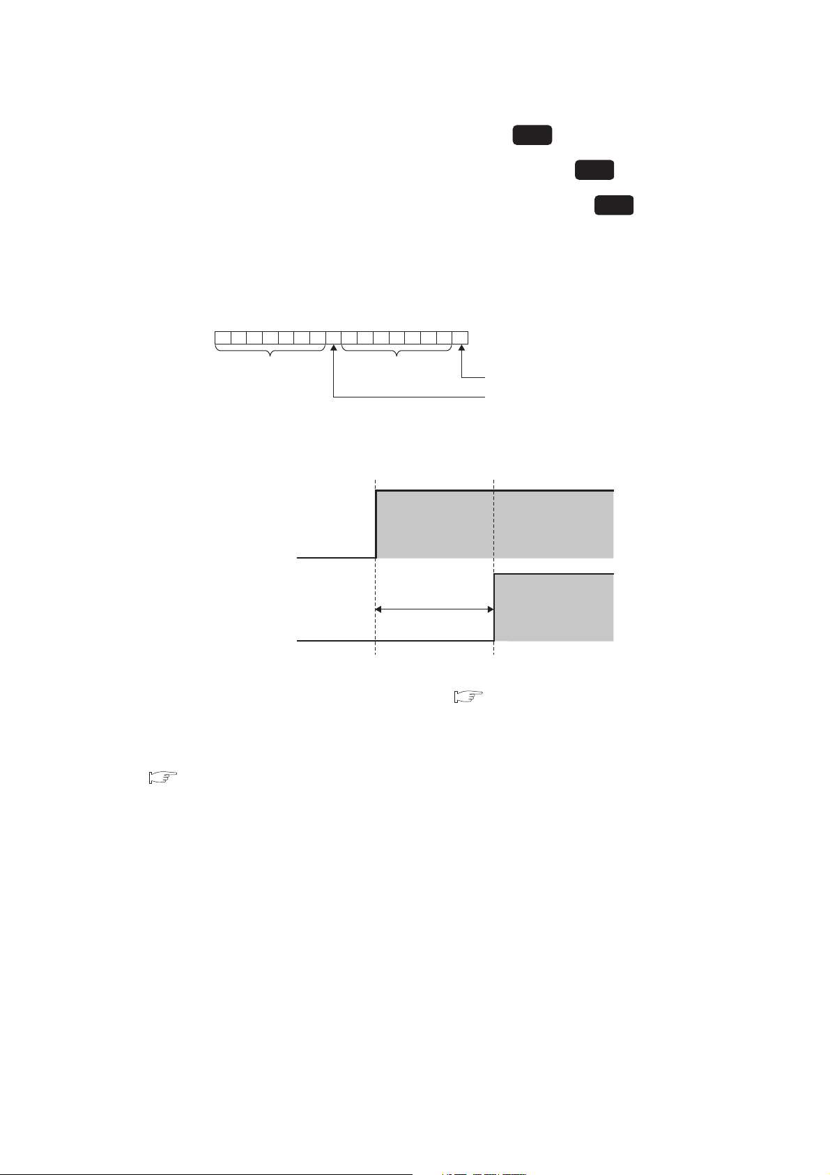
(7) CH Transistor output flag (Un\G21 to Un\G24)
Standard
Transistor output flag
ON delay output flag
b8 b0b9 b7b15
0000000 0000000
b1
Bit data from b15 to
b9 are fixed to 0.
Bit data from b7 to
b1 are fixed to 0.
to to
CH Heating transistor output flag (Un\G21 to Un\G24)
CH Cooling transistor output flag (Un\G712 to Un\G715)
Heating-cooling
Heating-cooling
ON/OFF status of transistor output and ON delay output are stored in these flags. In the heating-cooling control,
ON/OFF status of transistor output/ON delay output for heating are stored in Un\G21 to Un\G24.
• OFF: 0
•ON: 1
(a) Relationship with ON delay output flag
Relationship between Transistor output flag and ON delay output flag is shown in the following.
ON
Transistor
output flag
OFF
ON
ON delay
output flag
Transistor output monitor
ON delay time setting
(Un\G175)
OFF
Transistor output monitor ON delay time setting (Un\G175) enables setting considering delay time
(response/scan time delay) of actual transistor output. ( Page 132, Section 3.4.2 (45)
)
By monitoring the ON delay output flag and external output on the program, disconnection of external output
can be judged.
For details on the ON delay output function, refer to the following.
Page 222, Section 4.17
92
Page 95
CHAPTER 3 SPECIFICATIONS
Common
Common
Common
(8) CH Set value (SV) monitor (Un\G25 to Un\G28)
Set value (SV) of each time unit set in CH Setting change rate limiter time unit setting (Un\G735, Un\G751,
Un\G767, Un\G783) is stored in this buffer memory area. ( Page 157, Section 3.4.2 (85))
The set value (SV) can be monitored in real time.
(9) Cold junction temperature process value (Un\G29)
The measured temperature of cold junction temperature compensation resistor is stored in this buffer memory
area.
Values to be stored
Section 3.4.2 (12))
• For other than : -10 to 100
• For : 14 to 212
*1 The operation of the Q64TCN is guaranteed in the ambient temperature of 0 to 55°C.
For the general specifications of the Q64TCN, refer to the following.
*1
vary depending on the temperature unit set in CH1 Input range (Un\G32). ( Page 96,
QCPU User's Manual (Hardware Design, Maintenance and Inspection)
(a) Usable modules
• Q64TCTTN
• Q64TCTTBWN
(10)MAN mode shift completion flag (Un\G30)
This flag is for checking completion of the mode shift when shifting AUTO (auto) mode to MAN (manual) mode.
The following values are stored in this buffer memory area.
• 0: MAN mode shift uncompleted
• 1: MAN mode shift completed
3
3.4 Buffer Memory Assignment
3.4.2 Details of the buffer memory
The following figure shows bits of the buffer memory area that correspond to each channel.
b150b140b130b120b110b100b90b80b70b60b50b40b3
CH4b2CH3b1CH2b0CH1
Bit data from b15 to b4 are fixed to 0.
When shift to MAN mode is completed, bits corresponding to appropriate channel become MAN mode shift
completed (1).
(a) How to shift the mode
Shift the mode in the following buffer memory area.
•CH AUTO/MAN mode shift (Un\G50, Un\G82, Un\G114, Un\G146) ( Page 117, Section 3.4.2 (26)
(b) Setting manipulated value (MV) in MAN mode
Set the manipulated value (MV) in the following buffer memory area.
•CH MAN output setting (Un\G51, Un\G83, Un\G115, Un\G147) ( Page 118, Section 3.4.2 (27))
Set the manipulated value (MV) after confirming MAN mode shift completion flag (Un\G30) has become MAN
mode shift completed (1).
)
93
Page 96

(11)E2PROM's PID constants read/write completion flag (Un\G31)
Common
This flag indicates whether an operation to the E2PROM by the settings in the following buffer memory areas is
completed or failed.
•CH E2PROM's PID constants read instruction (Un\G62, Un\G94, Un\G126, Un\G158) ( Page 127,
Section 3.4.2 (36)
)
•CH Automatic backup setting after auto tuning of PID constants (Un\G63, Un\G95, Un\G127, Un\G159)
( Page 128, Section 3.4.2 (37))
(a) Correspondence between each bit and flag
The following table lists flags that correspond to bits of this buffer memory area.
Bit
number
b0 CH1 Read completion flag b8 CH1 Read failure flag
b1 CH2 Read completion flag b9 CH2 Read failure flag
b2 CH3 Read completion flag b10 CH3 Read failure flag
b3 CH4 Read completion flag b11 CH4 Read failure flag
b4 CH1 Write completion flag b12 CH1 Write failure flag
b5 CH2 Write completion flag b13 CH2 Write failure flag
b6 CH3 Write completion flag b14 CH3 Write failure flag
b7 CH4 Write completion flag b15 CH4 Write failure flag
Flag description
Bit
number
Flag description
(b) ON/OFF timing for CH E2PROM's PID constants read instruction (Un\G62, Un\G94,
Un\G126, Un\G158) ( Page 127, Section 3.4.2 (36))
The following figure shows the ON/OFF timing of this flag for CH E2PROM's PID constants read instruction
(Un\G62, Un\G94, Un\G126, Un\G158). (For CH1)
2
CH1 E
PROM's PID constants
read instruction
(Un\G62)
CH1 Read completion flag
(b0 of Un\G31)
CH1 Read failure flag
(b8 of Un\G31)
00 0 0
ON
OFF
OFF
Read completion
Executed by the Q64TCN
111
ON
ON
Read failure
Read completion
94
When the data reading from E
2
PROM is completed normally, CH Read completion flag (b0 to b3 of Un\G31)
of the corresponding channel turns on.
CH Read completion flag (b0 to b3 of Un\G31) turns off when CH E
2
PROM's PID constants read
instruction (Un\G62, Un\G94, Un\G126, Un\G158) is turned off from on.
When the data reading from E
2
PROM fails, CH Read failure flag (b8 to b11 of Un\G31) of the corresponding
channel turns on and the Q64TCN operates with PID constants before the data reading. (The LED status
remains.)
CH Read failure flag (b8 to b11 of Un\G31) turns off when the data reading of the corresponding channel is
completed normally.
When the data reading fails, try it again by turning CH E
2
PROM's PID constants read instruction (Un\G62,
Un\G94, Un\G126, Un\G158) ON OFF ON.
Page 97

CHAPTER 3 SPECIFICATIONS
0
0
01
1
CH1 Automatic backup setting after
auto tuning of PID constants
(Un\G63)
CH1 Write completion flag
(b4 of Un\G31)
CH1 Write failure flag
(b12 of Un\G31)
Auto tuning completion
(Write failure)
CH1 Auto tuning status (Xn4)
Auto tuning completion
(Write failure)
OFF
OFF
OFF
ON
ON
ON
Executed by the Q64TCN
Executed in a sequence program
(c) ON/OFF timing for CH Automatic backup setting after auto tuning of PID constants
(Un\G63, Un\G95, Un\G127, Un\G159) ( Page 128, Section 3.4.2 (37))
The following figure shows ON/OFF timing of this flag for CH Automatic backup setting after auto tuning of
PID constants (Un\G63, Un\G95, Un\G127, Un\G159). (For CH1)
3
When the data writing to E
2
PROM is completed normally, CH Write completion flag (b4 to b7 of Un\G31)
turns on.
CH Write completion flag (b4 to b7 of Un\G31) turns off when CH Automatic backup setting after auto
tuning of PID constants (Un\G63, Un\G95, Un\G127, Un\G159) is set to Disable (0) from Enable (1).
When the data writing to E
2
PROM fails, CH Write failure flag (b12 to b15 of Un\G31) of the corresponding
channel turns on and the Q64TCN operates with PID constants calculated in the previous auto tuning. (The
LED status remains.)
CH Write failure flag (b12 to b15 of Un\G31) turns off when the data writing of the corresponding channel is
completed normally.
When the data writing fails, perform auto tuning again by turning CH Auto tuning instruction (Yn4 to Yn7) ON
OFF ON. If the data writing fails even after executing auto tuning again, a hardware error can be the
reason. Please consult your local Mitsubishi representative.
● By referring to this flag at the completion of auto tuning, whether the automatic data backup is completed normally or not
can be checked.
● After confirming that the following flags are on, set CH Automatic backup setting after auto tuning of PID constants
(Un\G63, Un\G95, Un\G127, Un\G159) to Disable (0).
•CH Write completion flag (b4 to b7 of Un\G31) (when automatic backup is completed normally)
•CH Write failure flag (b12 to b15 of Un\G31) (when automatic backup fails)
If auto tuning is executed under Enable (1), although PID constants are stored after auto tuning is complete, CH Auto
tuning status (Xn4 to Xn7) does not turn off.
3.4 Buffer Memory Assignment
3.4.2 Details of the buffer memory
For details on the auto tuning function, refer to the following.
Page 176, Section 4.6
95
Page 98

(12)CH Input range (Un\G32, Un\G64, Un\G96, Un\G128)
Ex.
Common
Select the set value according to temperature sensor, temperature measurement range*1, output temperature
unit (Celsius (°C)/Fahrenheit ( )/digit) and resolution (1/0.1) which are used with the Q64TCN.
*1 In the case of input from other analog modules (such as an A/D converter module) also, set these values.
When the Q64TCTTN or Q64TCTTBWN is used and the following thermocouple is selected
• Thermocouple type: R
• Temperature measurement range: 0 to 1700°C
• Resolution: 1
Set 1 in CH Input range (Un\G32, Un\G64, Un\G96, Un\G128).
When using the Q64TCTTN or Q64TCTTBWN, refer to Page 97, Section 3.4.2 (12) (a).
When using the Q64TCRTN or Q64TCRTBWN, refer to Page 100, Section 3.4.2 (12) (b).
96
Page 99

CHAPTER 3 SPECIFICATIONS
(a) Setting range of the Q64TCTTN, Q64TCTTBWN
The following table lists set values of CH Input range (Un\G32, Un\G64, Un\G96, Un\G128) and the
corresponding thermocouple types. The relationship between temperature unit and setting values is as follows.
Setting of CH Input range (Un\G32,
Un\G64, Un\G96, Un\G128)
1 to 99 Thermocouple is used. (No input from
100 to 199
200 to 299
Thermocouple
type
Temperature
measurement
range
Fahrenheit
( )/digit
R
K
0 to 1700 °C 1 1 1700 0
0 to 3000 1 105 3000 0
-200.0 to 400.0 °C 0.1 38 4000 -2000
0.0 to 400.0 °C 0.1 36 4000 0
0 to 1300 °C 1
0 to 500 °C 1 11 500 0
0.0 to 500.0 °C 0.1 40 5000 0
0 to 800 °C 1 12 800 0
0.0 to 800.0 °C 0.1 41 8000 0
0 to 1000 1 100 1000 0
0.0 to 1000.0 0.1 130 10000 0
Celsius
(°C)/
other analog modules (such as an A/D
converter module)) (1 to 199)
Other analog modules (such as an A/D
converter module) are used. (200 to 299)
CH Input range
Resolution
(Un\G32,
Un\G64, Un\G96,
Un\G128)
2
(Default value)
Item
Output temperature unit is Celsius (°C).
Output temperature unit is Fahrenheit ( ).
Unit is digit.
Auto-setting at input range change
CH Upper limit
setting limiter
(Un\G55, Un\G87,
Un\G119,
Un\G151)
1300 0
CH Lower limit
setting limiter
(Un\G56, Un\G88,
Un\G120,
Un\G152)
3
*1
3.4 Buffer Memory Assignment
3.4.2 Details of the buffer memory
0 to 2400 1 101 2400 0
0.0 to 400.0 °C 0.1 37 4000 0
0 to 500 °C 1 13 500 0
0.0 to 500.0 °C 0.1 42 5000 0
0 to 800 °C 1 14 800 0
0.0 to 800.0 °C 0.1 43 8000 0
J
0 to 1200 °C 1 3 1200 0
0 to 1000 1 102 1000 0
0.0 to 1000.0 0.1 131 10000 0
0 to 1600 1 103 1600 0
0 to 2100 1 104 2100 0
97
Page 100
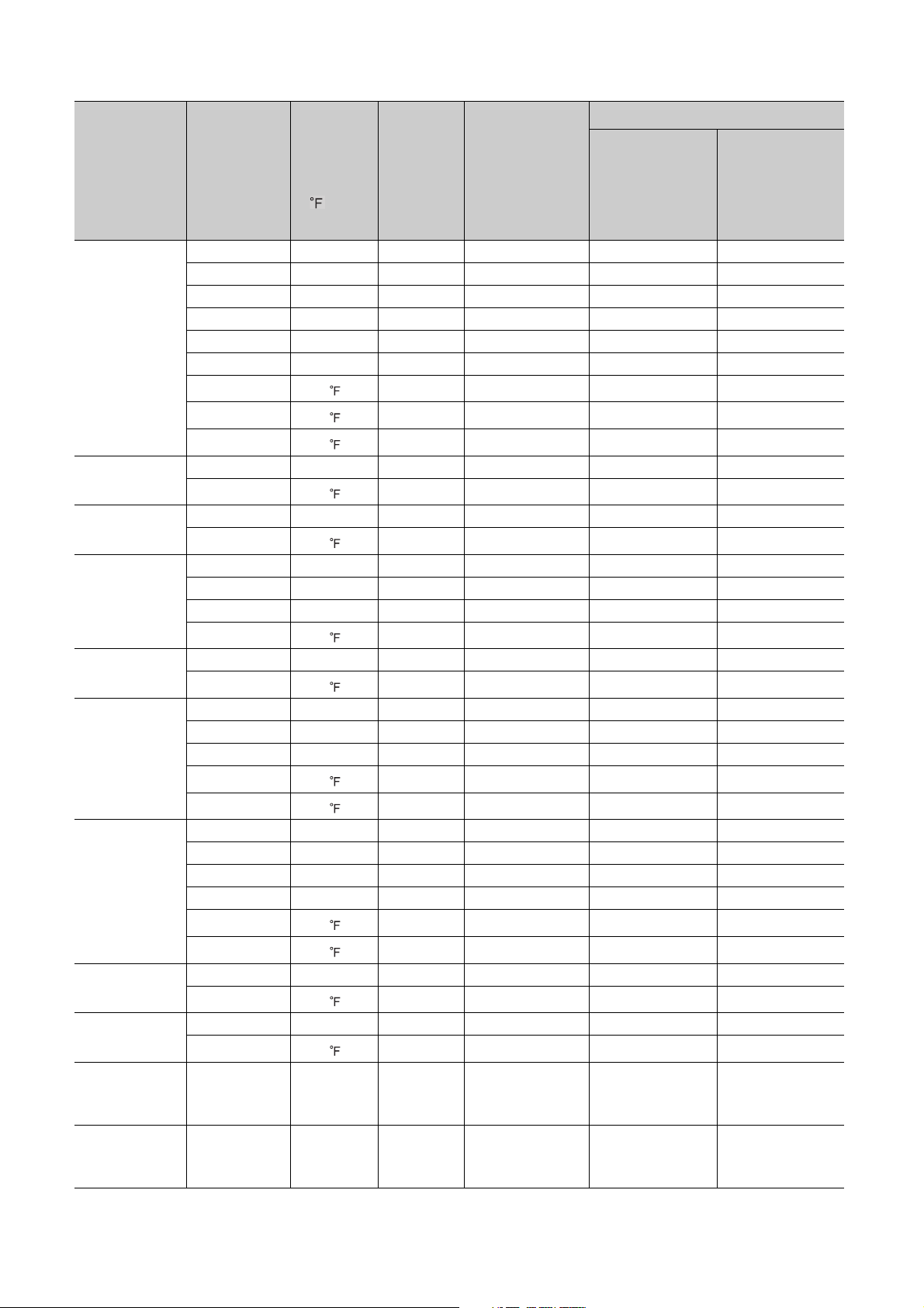
Thermocouple
type
T
S
B
E
N
U
Auto-setting at input range change
Temperature
measurement
(°C)/
Fahrenheit
Resolution
range
( )/digit
-200 to 400 °C 1 4 400 -200
-200 to 200 °C 1 21 200 -200
-200.0 to 400.0 °C 0.1 39 4000 -2000
0 to 200 °C 1 19 200 0
0 to 400 °C 1 20 400 0
0.0 to 400.0 °C 0.1 45 4000 0
-300 to 400 1 110 400 -300
0 to 700 1 109 700 0
0.0 to 700.0 0.1 132 7000 0
0 to 1700 °C 1 15 1700 0
0 to 3000 1 106 3000 0
0 to 1800 °C 1 16 1800 0
0 to 3000 1 107 3000 0
0 to 400 °C 1 17 400 0
0.0 to 700.0 °C 0.1 44 7000 0
0 to 1000 °C 1 18 1000 0
0 to 1800 1 108 1800 0
0 to 1300 °C 1 22 1300 0
0 to 2300 1 111 2300 0
-200 to 200 °C 1 26 200 -200
0 to 400 °C 1 25 400 0
0.0 to 600.0 °C 0.1 46 6000 0
-300 to 400 1 115 400 -300
Celsius
CH Input range
(Un\G32,
Un\G64, Un\G96,
Un\G128)
CH Upper limit
setting limiter
(Un\G55, Un\G87,
Un\G119,
Un\G151)
CH Lower limit
setting limiter
(Un\G56, Un\G88,
Un\G120,
Un\G152)
*1
L
PLII
W5Re/W26Re
Input from other
analog modules
(0 to 4000)
Input from other
analog modules
(0 to 12000)
*2
*2
0 to 700 1 114 700 0
0 to 400 °C 1 27 400 0
0.0 to 400.0 °C 0.1 47 4000 0
0 to 900 °C 1 28 900 0
0.0 to 900.0 °C 0.1 48 9000 0
0 to 800 1 116 800 0
0 to 1600 1 117 1600 0
0 to 1200 °C 1 23 1200 0
0 to 2300 1 112 2300 0
0 to 2300 °C 1 24 2300 0
0 to 3000 1 113 3000 0
0 to 4000 digit 1 201 4000 0
0 to 12000 digit 1 202 12000 0
98
 Loading...