

Mitsubishi Q64AD, Q66-AD-Dg, Q64AD-DGH, Q64AD-GH, Q68AD-G Installation Manual
...
MELSEC System Q
MITSUBISHI ELECTRIC
MITSUBISHI
ELECTRIC
FACTORY AUTOMATION
4~20mA
Q62AD-DGH
CHK-
CH1
I/CHK+
P
CHK-
CH2
I/CHK+
P
ALM
ERR
RUN
15
16
17
18
14
13
12
11
10
9
8
7
6
5
4
3
2
1
(FG)
IN
24VDC
I+
(FG)
C
H
4
C
H
1
C
H
2
C
H
3
AVD
0~±10V
0~±20mA
15
16
17
18
14
13
12
11
10
9
8
7
6
5
4
3
2
1
A.G.
V+
I+
V+
I+
V+
I+
V+
SLD
V-
SLD
V-
SLD
V-
SLD
V-
Q64AD
RUN
ERROR
Programmable Controllers
Installation Manual for Analog-Digital
Converter Modules
Art-no.: 212582 ENG, Version A, 11072008
Safety Information
For qualified staff only
This manual is only intended for use by properly trained and qualified elec
trical technicians who are fully acquainted with automation technology
safety standards. All work with the hardware described, including system
design, installation, setup, maintenance, service and testing, may only be
performed by trained electrical technicians with approved qualifications
who are fully acquainted with the applicable automation technology safety
standards and regulations.
Proper use of equipment
The programmable controllers (PLC) of the MELSEC System Q are only
intended for the specific applications explicitly described in this manual or
the manuals listed below. Please take care to observe all the installation
and operating parameters specified in the manual. All products are
designed, manufactured, tested and documented in agreement with the
safety regulations. Any modification of the hardware or software or
disregarding of the safety warnings given in this manual or printed on the
product cancause injury topersons or damageto equipment orother property. Only accessories and peripherals specifically approved by
MITSUBISHI ELECTRIC maybe used. Any other use or application of the
products is deemed to be improper.
Relevant safety regulations
All safety and accident prevention regulations relevant to your specific
application must be observed in the system design, installation, setup,
maintenance, servicing and testing of these products.
In this manual special warnings that are important for the proper and safe
use of the products are clearly identified as follows:
DANGER:
Personnel health and injury warnings.
Failure to observe the precautions described here
P
can result in serious health and injury hazards.
CAUTION:
Equipment and property damage warnings.
Failure to observe the precautions described here
E
can result in serious damage to the equipment or
other property.
Further Information
The following manuals contain further information about the modules:
쎲
Hardware manuals for the MELSEC System Q
쎲
Manuals for the modules described in this installation manual
These manuals are available free of charge through the internet
(www.mitsubishi-automation.com).
If you have any questions concerning the installation, configuration or
operation of the equipment described in this manual, please contact your
relevant sales office or department.
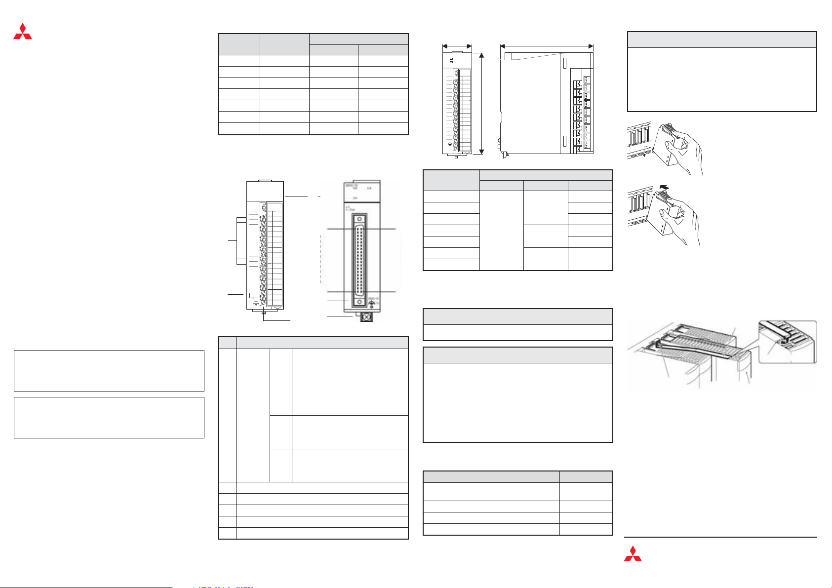
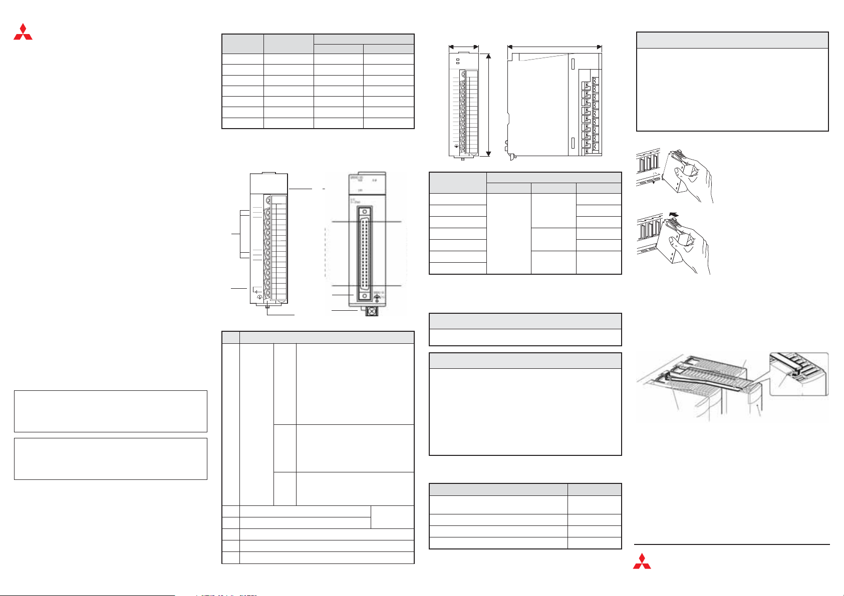
Overview
Module
No. of analog
inputs
Q62AD-DGH 2 — 4 to 20 mA DC
Q64AD 4 -10 to +10 V DC 0 to 20 mA DC
Q64AD-GH 4 -10 to +10 V DC 0 to 20 mA DC
Q66-AD-DG 6 — 0 to 20 mA DC
Q68AD-G 8 -10 to +10 V DC 0 to 20 mA DC
Q68ADV 8 -10 to +10 V DC —
Q68ADI 8 — 0 to 20 mA
Analog input ranges
Voltage Current
Names and Functions of Parts
Modules with terminal block
-
No.
Description
RUN
Status
LED
ERR.
ALM
쐇 Check terminals for analog input current (Q62AD-DGH only)
External power supply terminal (Q62AD-DGH only)
쐏 40-pin connector (female) for connection of the input signals
Terminal block for connection of the input signals
쐂 FG terminal (Q66AD-DG only)
Modules with 40-pin connector
Pin No.
A1
A20
Indicates the operating status of the
module
ON: Normal operation
Flicker: Offset/gain setting mode
OFF: – 5 V power off
– Watchdog timer error
occurrence
– module change enabled status
during online module change
Indicates the error status of the module
ON: Error (A/D conversion continues)
Flicker: Error (A/D conversion stops)
OFF: Normal operation
Indicates the alarm status
ON: An alarm has been occurred.
Flicker: Input signal error
OFF: Operating normally
Pin No.
B1
B20
Dimensions
a
b
Module
abc
Q62AD-DGH
Q64AD 90
Q64AD-GH 112
Q66AD-DG
27.4
Q68AD-G 90*
Q68ADV
Q68ADI
* The connector will increase this dimension by 47 mm.
c
Dimensions [mm]
98
102
98 90
112
130*
Installation and Wiring
P
Turn off all phases of the power supply for the PLC and other
쎲
external sources beforestarting theinstallation orwiring work.
E
Use the product in the environment within the general specifi
쎲
cations described in the Hardware Manual for the MELSEC
System Q. Never use the product in areas with dust, oily
smoke, conductive dusts, corrosive or flammable gas, vibra
tions or impacts, or expose it to high temperature, condensa
tion, or wind and rain.
When drilling screwholes or wiring,cutting chips orwire chips
쎲
should not enter ventilation slits. This may cause a short cir
cuit. Use the provided dustproof sheet to coverthe ventilation
port. Be sure to remove this sheet from the PLC's ventilation
port when the installation work is completed to prevent over
heating.
Tighen the screws of the module using torque within the following ranges.
Loose screws may cause short circuits, mechanical failures or malfunc
tion.
Screw Torque
Module mounting screw (M3, essential for
Q66AD-DG, optional for other modules)
Terminal block screws (M3) 0.42 to 0.58 Nm
Terminal block mounting screws (M3.5) 0.66 to 0.89 Nm
FG-Terminal screw (Q66AD-DG only) 0.42 to 0.58 Nm
DANGER
CAUTION
0.36 to 0.48 Nm
Mounting a module to a base unit
E
Do not drop the module or subject it to heavy inpact.
쎲
Do not open or modify a module. Doing socan cause afailure,
쎲
malfunction, injury or fire.
Always insert the module fixing latch of the module into the
쎲
module fixing hole of the base unit. Forcing the hook into the
hole will damage the module connector and module.
Do not touch the conductive or electronic parts of a module
쎲
directly. Doing so can cause a unit malfunction or failure.
햴 All modules exept the Q66AD-DG:
Secure the modulewith an additional screw (M3 x 12)to the base unit
if large vibration is expected. This screw is not supplied with the
module.
햴 Q66AD-DG only:
Mount the module fixing bracket. Make sure that the module fixing
bracket is hooked on the 3rd slit viewed from the front of the
Q66AD-DG. Tighten the module mounting screw with the specified
torque.
-
Module mounting screw
-
-
Wiring
-
Please observe the following precautions for external wiring:
쎲
Use separatecables for the AC controlunit and the external input sig
nals of the analog input modules to avoid the influence of AC side
-
surges and inductions.
쎲
Do not lay signal cables close to the main circuit, high-voltage power
lines, or load lines. Otherwise effects of noise or surge induction are
likely to take place. Keep a safe distance of more than 100 mm from
the above when wiring.
쎲
The shield of the signal cables must be grounded at one end.
CAUTION
After switching off the power supply,
햲
insert the module fixing latch into the
module fixing hole of the base unit.
Push the modulein the direction of arrow
햳
to load it into the base unit.
Module fixing bracket
Q66AD-DG
Mitsubishi Electric Europe B.V. /// FA - European Business Group ///
Germany /// Tel.: +49(0)2102-4860 /// Fax: +49(0)2102-486112 ///
www.mitsubishi-automation.com
3rd slit
-
MELSEC System Q
MITSUBISHI ELECTRIC
MITSUBISHI
ELECTRIC
FACTORY AUTOMATION
4~20mA
Q62AD-DGH
CHK-
CH1
I/CHK+
P
CHK-
CH2
I/CHK+
P
ALM
ERR
RUN
15
16
17
18
14
13
12
11
10
9
8
7
6
5
4
3
2
1
(FG)
IN
24VDC
I+
(FG)
C
H
4
C
H
1
C
H
2
C
H
3
AVD
0~±10V
0~±20mA
15
16
17
18
14
13
12
11
10
9
8
7
6
5
4
3
2
1
A.G.
V+
I+
V+
I+
V+
I+
V+
SLD
V-
SLD
V-
SLD
V-
SLD
V-
Q64AD
RUN
ERROR
Speicherprogrammierbare
Steuerungen
Installationsanleitung für AnalogEingangsmodule
Art.-Nr.: 212582 GER, Version A, 11072008
Sicherheitshinweise
Nur für qualifizierte Elektrofachkräfte
Diese Installationsanleitung richtet sich ausschließlich an anerkannt aus
gebildete Elektrofachkräfte, die mit den Sicherheitsstandards der Elektround Automatisierungstechnik vertraut sind. Projektierung, Installation,
Inbetriebnahme, Wartung und Prüfung der Geräte dürfen nur von einer
anerkannt ausgebildeten Elektrofachkraft durchgeführt werden. Eingriffe
in die Hard- und Software unserer Produkte, soweit sie nicht in dieser
Installationsanleitung oder anderen Handbüchern beschrieben sind, dür
fen nur durch unser Fachpersonal vorgenommen werden.
Bestimmungsgemäßer Gebrauch
Die speicherprogrammierbaren Steuerungen (SPS) des MELSEC Sys
tem Qsind nur für dieEinsatzbereiche vorgesehen, diein der vorliegenden
Installationsanleitung oder den unten aufgeführten Handbüchern
beschrieben sind. Achten Sie auf die Einhaltung der in den Handbüchern
angegebenen allgemeinen Betriebsbedingungen. Die Produkte wurden
unter Beachtung der Sicherheitsnormen entwickelt, gefertigt, geprüft und
dokumentiert. Unqualifizierte Eingriffe in die Hard- oder Software bzw.
Nichtbeachtung derin dieser Installationsanleitung angegebenen oder am
Produkt angebrachten Warnhinweise können zu schweren Personenoder Sachschäden führen. Es dürfen nur von MITSUBISHI ELECTRIC
empfohlene Zusatz- bzw.Erweiterungsgeräte in Verbindung mit den speicherprogrammierbaren Steuerungen des MELSEC System Q verwendet
werden. Jede andere darüber hinausgehende Verwendung oder Benutzung
gilt als nicht bestimmungsgemäß.
Sicherheitsrelevante Vorschriften
Bei der Projektierung, Installation, Inbetriebnahme, Wartung und Prüfung
der Geräte müssen die für den spezifischen Einsatzfall gültigen Sicher
heits- und Unfallverhütungsvorschriften beachtet werden.
In dieser Installationsanleitung befinden sich Hinweise, die für den sach
gerechten und sicheren Umgang mit dem Gerät wichtig sind. Die einzel
nen Hinweise haben folgende Bedeutung:
GEFAHR:
Warnung vor einer Gefährdung des Anwenders
Nichtbeachtung der angegebenen Vorsichtsmaß
P
nahmen kann zu einer Gefahrfür das Lebenoder die
Gesundheit des Anwenders führen.
ACHTUNG:
Warnung vor einer Gefährdung von Geräten
Nichtbeachtung der angegebenen Vorsichtsmaß
E
nahmen kann zu schweren Schäden am Gerät oder
anderen Sachwerten führen.
Weitere Informationen
Folgende Handbücher enthalten weitere Informationen zu den Geräten:
쎲
쎲
Diese Handbücher stehen Ihnen im Internet kostenlos zur Verfügung
(www.mitsubishi-automation.de).
Sollten sich Fragen zur Installation, Programmierung und Betrieb der
Steuerungen des MELSEC System Q ergeben, zögern Sie nicht, Ihr
zuständiges Verkaufsbüro oder einen Ihrer Vertriebspartner zu
kontaktieren.
Hardware-Beschreibung zum MELSEC System Q
Bedienungsanleitungen zu den in dieser Installationsanleitung
beschriebenen Modulen
Übersicht
Modul
Anzahl analoger
Eingänge
Q62AD-DGH 2 — 4 bis 20 mA DC
Q64AD 4 -10 bis +10 V DC 0 bis 20 mA DC
Q64AD-GH 4 -10 bis +10 V DC 0 bis 20 mA DC
Q66-AD-DG 6 — 0 bis 20 mA DC
Q68AD-G 8 -10 bis +10 V DC 0 bis 20 mA DC
Q68ADV 8 -10 bis +10 V DC —
Q68ADI 8 — 0 bis 20 mA DC
Analoge Eingangsbereiche
Spannung Strom
Bedienelemente
Module mit Anschlussklemmen
-
-
-
Nr.
Beschreibung
Anzeige des Betriebszustands des
-
-
-
-
LED-
Anzeige
Moduls
EIN: Normalbetrieb
Blinkt: Einstellung von Offset oder Ver-
RUN
AUS: – Fehlende 5-V-Spannungsver-
Fehleranzeige
EIN: Fehler (A/D-Wandlung wird fort-
ERR.
-
Blinkt: Fehler (A/D-Wandlung wird ange-
AUS: Normalbetrieb
Anzeige von Alarmen
EIN: Ein Fehler ist aufgetreten.
ALM
Blinkt: Fehlerhaftes Eingangssignal
AUS: Normalbetrieb
Prüfklemmen für analogen Eingangsstrom
Anschluss für externe Spannungsversorgung
쐏 40-polige Buchse zum Anschluss der Eingangssignale
쐄 Klemmenblock zum Anschluss der Eingangssignale
쐂 Erdungsanschluss (FG), nur bei Q66AD-DG
Module mit 40-poligem
Steckanschluss
Pin Nr.
A1
A20
stärkung
sorgung
– Watch-Dog-Timer-Fehler
– Austausch des Moduls beim
Online-Modultausch frei-
gegeben
gesetzt)
halten).
Pin Nr.
nur bei
Q62AD-DGH
Abmessungen
a
b
Modul
abc
Q62AD-DGH
Q64AD 90
B1
Q64AD-GH 112
Q66AD-DG
27,4
Q68AD-G 90*
Q68ADV
Q68ADI
B20
* Durch den Stecker vergrößert sich dieses Maß um 47 mm.
c
Abmessungen [mm]
98
102
98 90
Installation und Verdrahtung
P
Schalten Sie vor der Installationoder derVerdrahtung die Ver
쎲
sorgungsspannung der Bediengeräte aus.
E
Betreiben Sie die Geräte nur unter den Umgebungsbedingun
쎲
gen, die in der Hardware-Beschreibung zum MELSEC Sys
tem Q aufgeführt sind. Die Geräte dürfen keinem Staub, Ölne
bel, ätzenden oder entzündlichen Gasen, starken Vibrationen
oder Schlägen,hohen Temperaturen und keinerKondensation
oder Feuchtigkeit ausgesetzt werden.
Achten Sie beider Montage darauf, dasskeine Bohrspäneoder
쎲
Drahtreste durch die Lüftungsschlitze in das Modul eindrin
gen, die später einen Kurzschluss verursachen könnten. Ver
wenden Sie zum Verschließen der Lüftungsschlitze die mitge
lieferte Abdeckung. Nach dem Abschluss aller Installationsarbeiten muss diese Abdeckung wieder entfernt werden, um
eine Überhitzung der Steuerung zu vermeiden.
Ziehen Sie die Schrauben der Module mit den in der folgenden Tabelle
angegebenen Anzugsmomenten an. Lose Schrauben können Kurz
schlüsse, mechanische Fehler oder Fehlfunktionen hervorrufen.
Schraube Drehmoment
Befestigungsschraube (M3, erforderlich für
Q66AD-DG, optional für andere Module)
Schrauben der Anschlussklemmen (M3) 0,42 bis 0,58 Nm
Befestigungsschrauben des Klemmblocks (M3,5) 0,66 bis 0,89 Nm
Erdungsanschluss (FG) bei Q66AD-DG 0,42 bis 0,58 Nm
GEFAHR
ACHTUNG
112
130*
0,36 bis 0,48 Nm
Montage der Module auf dem Baugruppenträger
E
Lassen Sie das Modul nicht fallen und setzen Sie es keinen
쎲
starken Erschütterungen aus.
Öffnen Sie nicht das Gehäuse eines Moduls. Verändern Sie
쎲
nicht das Modul. Störungen, Verletzungen und/oder Feuer
können die Folge sein.
Wird ein Modul nicht korrektüber die Führungslasche auf den
쎲
Baugruppenträger gesetzt,können sich die Stifteim Modulste
cker verbiegen
Berühren Siekeine leitenden Teileoder elektronischeBauteile
쎲
der Module. Dies kann zu Störungen oder Beschädigung der
Module führen.
햴 Gilt für alle Module außer dem Q66AD-DG:
Sichern Siedas Modulzusätzlich miteiner Schraube (M3 x12), wenn
Vibrationen zu erwarten sind. Diese Schraube gehört nicht zum Lieferumfang der Module.
햴 Gilt nur für das Q66AD-DG
Montieren Sie den Haltebügel für das Modul. Vergewissern Sie sich,
-
-
-
-
-
-
-
dass der Bügel im dritten Schlitz des Q66AD-DG eingehangen ist
und ziehenSie die Befestigungsschraube desModuls mit dem ange
gebenem Drehmoment fest.
Modulbefestigungsschraube
Verdrahtung
Bitte beachten Sie bei der Verdrahtung die folgenden Vorsichtsmaßnah
men:
쎲
VerwendenSie für Wechselspannungen unddie Eingangssignale der
Analogeingangsmodule separate Leitungen, um den Einfluss von
induktiven und kapazitiven Störimpulsen zu minimieren.
쎲
Verlegen Sie Signalleitungen nicht in der Nähe von Netz- oder Hoch
spannungsleitungen oder Leitungen, die eine Lastspannung führen.
Der Mindestabstandzu diesen Leitungen beträgt 100 mm. Wenn dies
nicht beachtet wird, können durch Störungen Fehlfunktionen auftreten.
쎲
Die Abschirmung der Signalleitungen muss an einem Ende geerdet
werden.
ACHTUNG
Nachdem Sie die Netzspannung
햲
ausgeschaltet haben, setzen Sie das
Modul mit der unteren Lasche in die
Führung des Baugruppenträgers ein.
Drücken Sie das Modul anschließend
햳
auf den Baugruppenträger, bis das
Modul ganz am Baugruppenträger
anliegt.
Haltebügel
3. Schlitz
Q66AD-DG
Mitsubishi Electric Europe B.V. /// FA - European Business Group ///
Germany /// Tel.: +49(0)2102-4860 /// Fax: +49(0)2102-486112 ///
www.mitsubishi-automation.com
-
-
-
-
MELSEC System Q
MITSUBISHI ELECTRIC
MITSUBISHI
ELECTRIC
FACTORY AUTOMATION
4~20mA
Q62AD-DGH
CHK-
CH1
I/CHK+
P
CHK-
CH2
I/CHK+
P
ALM
ERR
RUN
15
16
17
18
14
13
12
11
10
9
8
7
6
5
4
3
2
1
(FG)
IN
24VDC
I+
(FG)
C
H
4
C
H
1
C
H
2
C
H
3
AVD
0~±10V
0~±20mA
15
16
17
18
14
13
12
11
10
9
8
7
6
5
4
3
2
1
A.G.
V+
I+
V+
I+
V+
I+
V+
SLD
V-
SLD
V-
SLD
V-
SLD
V-
Q64AD
RUN
ERROR
Automates programmables
Manuel d'installation pour les modules
d'entrée analogique
N° arti : 212582 FRA, Version A, 11072008
Informations de sécurité
Groupe cible
Ce manuel est destiné uniquement à des électriciens qualifiés et ayant
reçus une formation reconnue par l'état et quise sont familiarisés avec les
standards desécurité de la techniqued'automatisation. Touttravail avec le
matériel décrit, y compris la planification, l'installation, la configuration, la
maintenance, l'entretien et les tests doit être réalisé uniquement par des
électriciens formés et qui se sont familiarisés avec les standards et pres
criptions de sécurité de la technique d'automatisation applicable.
Utilisation correcte
Les automates programmables (API) de MELSEC System Q sont conçus
uniquement pour les applications spécifiques explicitement décrites dans
ce manuel ou les manuels mentionnés ci-après. Veuillez prendre soin de
respecter tousles paramètres d'installation et defonctionnement spécifiés
dans lemanuel. Tous lesproduits ont été développés, fabriqués,contrôlés
et documentés en respectant les normes de sécurité. Toute modification
du matérielou du logicielou le non-respectdes avertissements desécurité
indiqués dans ce manuel ou placés sur leproduit peut induire desdommages importantsaux personnes ouau matériel ou àd'autres biens. Seuls les
accessoires et appareils périphériques recommandés par MITSUBISHI
ELECTRIC doivent être utilisés. Tout autre emploi ou application des produits sera considéré comme non conforme.
Prescriptions de sécurité importantes
Toutes les prescriptions de sécurité et de prévention d'accident importantes pour votre application spécifique doivent être respectées lors de la pla
nification, l'installation, la configuration, la maintenance, l'entretien et les
tests de ces produits.
Dans ce manuel, les avertissements spéciaux importants pour l'utilisation
correcte et sûre des produits sont indentifiés clairement comme suit :
DANGER :
Avertissements de dommage corporel.
Le non-respect des précautions décrites ici peut
entraîner des dommagescorporels et desrisques de
P
blessure.
ATTENTION :
Avertissements d'endommagement du matériel et
des biens. Le non-respect des précautions décrites
E
ici peut entraîner de graves endommagements du
matériel ou d'autres biens.
Autres informations
Les manuelssuivants comportent d'autres informationssur les modules:
쎲
Description du matériel du MELSEC System Q
쎲
Instructions de service relatives aux modules décrits dans ce manuel
d'installation
Ces manuels sont disponibles gratuitement sur (www.mitsubishi-automa
tion.fr).
Si vous avez des questions concernant la programmation etle fonctionne
ment du matériel décrit dans ce manuel, contactez votre bureau de vente
responsable ou votre distributeur.
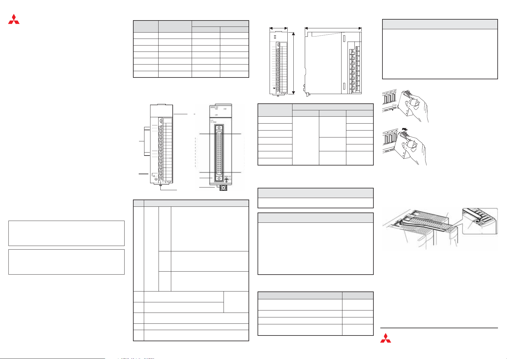
Aperçu
Module
Nombre d'entrées
analogiques
Q62AD-DGH 2 — 4 à 20 mA CC
Q64AD 4 -10 à +10 V CC 0 à 20 mA CC
Q64AD-GH 4 -10 à +10 V CC 0 à 20 mA CC
Q66-AD-DG 6 — 0 à 20 mA CC
Q68AD-G 8 -10 à +10 V CC 0 à 20 mA CC
Q68ADV 8 -10 à +10 V CC —
Q68ADI 8 — 0 à 20 mA CC
Plages de l'entrée analogique
Tension Courant
Eléments de commande
Modules avec bornes de
raccordement
-
-
N°
Description
Affichage de l'état de fonctionnement du module
ON: Fonctionnement normal
Clignote:Réglage de l'offset ou de l 'amplifica
tion
OFF: – Alimentation 5 V absente
RUN
-
Affi
chage
DEL
Affichage d'erreur
ON: Erreur (la conversion A/D est poursuivie)
ERR.
Clignote:Erreur (la conversion A/D est arrêtée)
OFF: Fonctionnement normal
Affichage d'alarmes
ON: Une erreur est survenue
ALM
Clignote:Signal d'entrée incorrect
OFF: Fonctionnement normal
Bornes de contrôle pour l’entrée analogique en
courant
Raccordement pour l'alimentation externe du
-
-
module
Prise femelle à 40 broches pour le raccordement des signaux
쐏
d'entrée
쐄 Répartiteur pour le raccordement des signaux d'entrée
Raccordement de la mise à la terre (FG), seulement pour
쐂
Q66AD-DG
Modules avec prise embrochable
de 40 broches
N° broche
A1 B1
A20
– Erreur de l'horloge du chien de
garde
– Modification du module autorisée
lors d’une modification en ligne du
module
N° broche
seulement
pour
Q62AD-DG
Dimensions
a
b
Module
abc
Q62AD-DGH
Q64AD 90
Q64AD-GH 112
Q66AD-DG
27,4
Q68AD-G 90*
Q68ADV
Q68ADI
B20
* Cette mesure augmente de 47 mm avec le connecteur.
c
Mesures [mm]
98
102
98 90
Installation et câblage
P
Veuillez mettreles phases d’alimentationde l’API horstension
쎲
avant l'installation ou le câblage.
-
E
Utiliser l'équipement seulement selon les conditions indi
쎲
quées dans la Description du matériel du MELSEC System Q.
Ne pasexposer l'équipement àla poussière, àla fumée d'huile,
aux gaz corrosifs ou inflammable, aux fortes vibrations ou
forts impacts, aux températures élevées, à lacondensation ou
à la vapeur.
Lors de l'installation de l'équipement, veiller à ce qu'aucun
쎲
copeau ou fragment de fil ne pénètre dans le module et n'en
gendre ultérieurement des courts-circuits. Utiliser le cou
vercle fourni pour boucher les ouïes de ventilation pendant
l'installation. Nepas oublier d'enlever le couvercle après avoir
installé l'unité afin d'éviter une surchauffe de l'automate pen
dant le fonctionnement.
Serrez les vis des modules avec les couples de serrage mentionnés dans
le tableau suivant. Des vis desserrées peuvent entraîner des courts-cir
cuits, des erreurs mécaniques ou des dysfonctionnements.
Vis Couple
Vis de fixation (M3, nécessaire pour Q66AD-DG,
en option pour les autres modules)
Vis des bornes de raccordement (M3) 0,42 à 0,58 Nm
Vis de fixation du répartiteur (M3,5) 0,66 à 0,89 Nm
Raccordement de la mise à la terre (FG) pour
Q66AD-DG
DANGER
ATTENTION
112
130*
0,36 à 0,48 Nm
0,42 à 0,58 Nm
Installation des modules dans l'appareil de base
E
Ne pas faire tomber le module et ne l'exposer à aucune vibra
쎲
tion forte.
Ne pas ouvrirle boîtier d'un module.Ne pasmodifier le module.
쎲
Au risque d’avoir pour conséquence des défaillances, des
blessures et/ou un incendie.
Faire attention à positionner le module correctement sur la
쎲
patte deguidage de l'appareil de base, sinon il y a un risquede
plier les broches dans le connecteur du module.
Ne jamais toucheraux parties conductrices du module ou aux
쎲
composants électroniques. Ceci peut entraîner des dysfonc
tionnements ou des dégâts des modules.
햴 Valable pour tous les modules sauf le Q66AD-DG :
Fixer le module avec une visM3x12 sil'emplacement de montage est
soumis àdes vibrations.Ces vis ne sont pasfournies avec les modules.
햴 Valable seulement pour le Q66AD-DG :
Montez l'attache de sûreté pour le module. S'assurer que l'attache
soit accrochée dans la troisième rainure du Q66AD-DG et serrer la
vis de fixation du module avec le couple de serrage indiqué.
-
Vis de fixation du
module
-
-
Câblage
Prière de tenir compte des mesures de précaution suivantes pour le
-
câblage :
쎲
Utiliser des chemins de câbles séparés pour les tensions alternatives
et les signaux d'entrée des modules d'entrée analogique afin de
réduire au strict minimum l’influence des impulsions perturbatrices
inductives et capacitives.
쎲
Ne pas poser des câbles de signaux à proximité de câbles secteur, à
haute tension ou encore parcourus par une tension endécharge.L'é
cart minimal entre ces câbles doit être de 100 mm. Des défaillances
dues à desper turbations peuvent apparaître si cetécar t n'est pasres
pecté.
쎲
Le blindage des câbles de signaux doit être connecté à la terre.
ATTENTION
Après avoir coupé l'alimentation élec
햲
trique, introduire la patte inférieure du
module dans le trou de guidage de l'ap
pareil de base.
Appuyer ensuite fermement sur le
햳
module dans l'appareil de base en s'as
surant qu'il soittotalement enfoncé dans
l'appareil de base.
Attache de sûreté
3ième rainure
Q66AD-DG
Mitsubishi Electric Europe B.V. /// FA - European Business Group ///
Germany /// Tel.: +49(0)2102-4860 /// Fax: +49(0)2102-486112 ///
www.mitsubishi-automation.com
-
-
-
-
-
-
-
Q66AD-DG Q68AD-G
I+
V
V+
–
SLD
FG
I+
V
V+
–
SLD
I+
V-/I-
V+
I
I+
–
FG
I/CHK+
P
I-/CHK-
I/CHK+
P
FG
I-/CHK-
24V
24G
V
+
-
I+
V
V+
–
SLD
FG
I+
V
V+
–
SLD
I+
V-/I-
V+
V
V+
–
FG
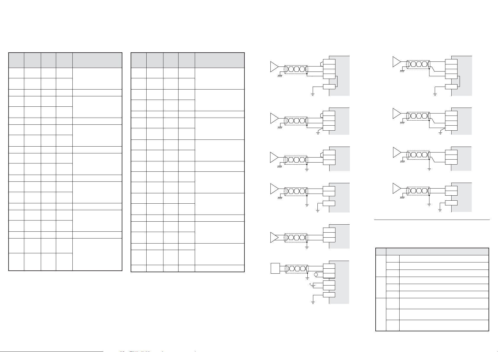
Pin assignment of the connector
m
Belegung des Steckers
D
Affectation du connecteur
F
Pin assignment of the connector
m
Belegung des Steckers
D
Affectation du connecteur
F
Current input
m
Strommessung
D
Mesure de courant
F
Voltage input
m
Spannungsmessung
D
Mesure de tension
F
Pin /
Pin /
Broche
A1
A2 — B2 I-/CHK-
A3 — B3 — —
A4
A5 — B5 I-/CHK-
A6 — B6 — —
A7
A8 — B8 I-/CHK-
A9 — B9 — —
A10
A11 — B11 I-/CHK-
A12 — B12 — —
A13
A14 — B14 I-/CHK-
A15 — B15 — —
A16
A17 — B17 I-/CHK-
A18 — B18 — —
A19 24V B19 24V
A20 24G B20 24G
Pin /
Signal
Pin /
Broche
P B1 I+/CHK+
P B4 I+/CHK+
P B7 I+/CHK+
P B10 I+/CHK+
P B13 I+/CHK+
P B16 I+/CHK+
Signal
Description /
Beschreibung /
Description
Input channel 1
m
Eingang Kanal 1
D
Entrée canal 1
F
Input channel 2
m
Eingang Kanal 2
D
Entrée canal 2
F
Input channel 3
m
Eingang Kanal 3
D
Entrée canal 3
F
Input channel 4
m
Eingang Kanal 4
D
Entrée canal 4
F
Input channel 5
m
Eingang Kanal 5
D
Entrée canal 5
F
Input channel 6
m
Eingang Kanal 6
D
Entrée canal 6
F
External power
m
supply 24 V DC
Externe Spannungs
D
versorgung 24 V DC
Tension d'alimenta
F
tion externe 24 V CC
Pin /
Pin /
Broche
A1
A2 I+ B2 —
A3
A4
A5 — B5 — —
A6
A7
A8
A9 V–/I– B9 I+
A10
A11
A12 I+ B12 —
A13
A14 V–/I– B14 I+
A15 — B15 — —
A16
A17 I+ B17 —
-
-
A18 — B18 V+
A19 V–/I– B19 I+
A20 — B20 — —
Pin /
Signal
Pin /
Signal
Broche
V+ B1 V–/I–
—B3V+
V–/I– B4 I+
V+ B6 V–/I–
I+ B7 —
—B8V+
— B10 — —
V+ B11 V–/I–
— B13 V+
V+ B16 V–/I–
Description /
Beschreibung /
Description
Input channel 1
m
Eingang Kanal 1
D
Entrée canal 1
F
Input channel 2
m
Eingang Kanal 2
D
Entrée canal 2
F
Input channel 3
m
Eingang Kanal 3
D
Entrée canal 3
F
Input channel 4
m
Eingang Kanal 4
D
Entrée canal 4
F
Input channel 5
m
Eingang Kanal 5
D
Entrée canal 5
F
Input channel 6
m
Eingang Kanal 6
D
Entrée canal 6
F
Input channel 7
m
Eingang Kanal 7
D
Entrée canal 7
F
Input channel 8
m
Eingang Kanal 8
D
Entrée canal 8
F
Q64AD
Q64AD-GH
Q68AD-G
Q68ADI
Q66AD-DG
Q62AD-DGH, Q66AD-DG
Q64AD
Q64AD-GH
Q68AD-G
Q68ADV
No.
Description / Beschreibung / Description
2-wire transmitter (4 to 20 mA)
m
쐃
2-Draht-Wandler (4 bis 20 mA)
D
Convertisseur à 2 fils (4 à 20 mA)
F
Check terminals (4 to 20 mA -> 1 to 5 V)
m
Prüfklemmen (4 bis 20 mA -> 1 bis 5 V)
D
Bornes de contrôle (4 à 20 mA -> 1 à 5 V)
F
External power supply:
m
24 V DC +20 % -15 %, 360 mA
Externe Versorgungsspannung:
D
24 V DC +20 % -15 %, 360 mA
Tension d'alimentation externe :
F
24 V CC +20 % -15 %, 360 mA
 Loading...