

Q2AS(H)CPU(S1)
Mitsubishi Programmable Controller
User's Manual
(Hardware)
Thank you for purchasing the Mitsubishi programmable logic controller
MELSEC-QnA series.
Prior to use, please read both this and relevant manual
thoroughly to fully understand the product.
MODEL
MODEL
CODE
IB(NA)-66677-H(0810)MEE
Q2ASCPU-U(H/W)-E
13J857
©1996 MITSUBISHI ELECTRIC CORPORATION

SAFETY PRECAUTIONS
(Be sure to read these instructions before use.)
Before using the product, read this and relevant manuals carefully and handle the
product correctly with full attention to safety.
In this manual, SAFETY PRECAUTIONS are classified into 2 levels:
"DANGER" and "CAUTION".
Indicates that incorrect handling may cause hazardous
DANGER
conditions, resulting in death or severe injury.
CAUTION
Under some circumstances, failure to observe the
instructions may also lead to serious results.
Be sure to observe the instructions of both levels to ensure the safety.
Please keep this manual in a safe place for future reference and also pass this
manual on to the end user.
Indicates that incorrect handling may cause hazardous
conditions, resulting in minor or moderate injury and/or
property damage.
CAUTION level
[DESIGN PRECAUTIONS]
DANGER
Create a safety circuit outside the programmable controller to ensure the
whole system will operate safely even if an external power failure or a
programmable controller failure occurs.
Otherwise, incorrect output or malfunction may cause an accident.
(1) For an emergency stop circuit, protection circuit and interlock circuit that
is designed for incompatible actions such as forward/reverse rotation or
for damage prevention such as the upper/lower limit setting in
positioning, any of them must be created outside the programmable
controller.
Install the emergency stop switch outsid the controlpanel so that workers
can operate it easily.
A-1

[DESIGN PRECAUTIONS]
DANGER
(2) When the programmable controller detects the following error
conditions, it stops the operation and turn off all the outputs.
The overcurrent protection device or overvoltage protection device of
the power supply module is activated.
The programmable controller CPU detects an error such as a
watchdog timer error by the self-diagnostics function.
In the case of an error of a part such as an I/O control part that cannot
be detected by the programmable controller CPU, all the outputs may
turn on. In order to make all machines operate safely in such a case, set
up a fail-safe circuit or a specific mechanism outside the programmable
controller.
Refer to "LOADING AND INSTALLATION" in this manual for example
fail safe circuits.
(3) Depending on the failure of the output module’s relay or transistor, the
output status may remain ON or OFF incorrectly. For output signals that
may lead to a serious accident, create an external monitoring circuit.
If load current more than the rating or overcurrent due to a short circuit
in the load has flowed in the output module for a long time, it may
cause a fire and smoke. Provide an external safety device such as a
fuse.
Design a circuit so that the external power will be supplied after
power-up of the programmable controller.
Activating the external power supply prior to the programmable
controller may result in an accident due to incorrect output or
malfunction.
For the operation status of each station at a communication error in
data link, refer to the respective data link manual.
The communication error may result in an accident due to incorrect
output or malfunction.
A-2
[DESIGN PRECAUTIONS]
DANGER
When controlling a running programmable controller (data modification) by
connecting a peripheral device to the CPU module or a PC to a special
function module, create an interlock circuit on sequence programs so that the
whole system functions safely all the time.
Also, before performing any other controls (e.g. program modification,
operating status change (status control)), read the manual carefully and
ensure the safety.
In these controls, especially the one from an external device to a
programmable controller in a remote location, some programmable controller
side problem may not be resolved immediately due to failure of data
communications.
To prevent this, create an interlock circuit on sequence programs and
establish corrective procedures for communication failure between the
external device and the programmable controller CPU.
When setting up the system, do not allow any empty slot on the base unit.
If any slot is left empty, be sure to use a blank cover (A1SG60) or a dummy
module (A1SG62) for it.
When using the extension base unit, A1S52B(S1), A1S55B(S1) or
A1S58B(S1), attach the included dustproof cover to the module in slot 0.
Otherwise, internal parts of the module may be flied in the short circuit test or
when an overcurrent or overvoltage is accidentally applied to external I/O
section.
CAUTION
Do not install the control lines or communication cables together with the
main circuit or power lines, or bring them close to each other.
Keep a distance of 100mm (3.94inch) or more between them.
Failure to do so may cause malfunctions due to noise.
If having read register R outside the allowable range with the MOV
instruction, the file register data will be FFFF
H. Using this as it is may cause
malfunctions. Pay attention not to use any out-of-range file register when
designing sequence programs. For instruction details, refer to the
programming manual.
When an output module is used to control the lamp load, heater, solenoid
valve, etc., a large current (ten times larger than the normal one) may flow at
the time that the output status changes from OFF to ON. Take some
preventive measures such as replacing the output module with the one of a
suitable current rating.
A-3

[INSTALLATION PRECAUTIONS]
CAUTION
Use the programmable controller under the environment specified in the
user’s manual.
Otherwise, it may cause electric shocks, fires, malfunctions, product
deterioration or damage.
Insert the module fixing projection into the fixing hole in the base unit and
then tighten the module mounting screw within the specified torque.
When no screw is tightened, even if the module is installed correctly, it may
cause malfunctions, a failure or a drop of the module.
Tightening the screw excessively may damage the screw and/or the module,
resulting in a drop of the module, a short circuit or malfunctions.
Connect the extension cable to the connector of the base unit or module.
Check the cable for incomplete connection after connecting it.
Poor electrical contact may cause incorrect inputs and/or outputs.
Insert the memory card and fully press it to the memory card connector.
Check for incomplete connection after installing it.
Poor electrical contact may cause malfunctions.
Be sure to shut off all phases of the external power supply used by the
system before mounting or removing the module. Failure to do so may
damage the module.
Do not directly touch the conductive part or electronic components of the
module.
Doing so may cause malfunctions or a failure of the module.
A-4
[WIRING PRECAUTIONS]
DANGER
Be sure to shut off all phases of the external power supply used by the
system before wiring.
Failure to do so may result in an electric shock or damage of the product.
Before energizing and operating the system after wiring, be sure to attach the
terminal cover supplied with the product.
Failure to do so may cause an electric shock.
CAUTION
Always ground the FG and LG terminals to the protective ground conductor.
Failure to do so may cause an electric shock or malfunctions.
Wire the module correctly after confirming the rated voltage and terminal
layout.
Connecting a power supply of a different voltage rating or incorrect wiring
may cause a fire or failure.
Do not connect multiple power supply modules to one module in parallel.
The power supply modules may be heated, resulting in a fire or failure.
Press, crimp or properly solder the connector for external connection with the
specified tool.
Incomplete connection may cause a short circuit, fire or malfunctions.
Tighten terminal screws within the specified torque range. If the screw is too
loose, it may cause a short circuit, fire or malfunctions.
If too tight, it may damage the screw and/or the module, resulting in a short
circuit or malfunctions.
Carefully prevent foreign matter such as dust or wire chips from entering the
module.
Failure to do so may cause a fire, failure or malfunctions.
Install our programmable controller in a control panel for use.
Wire the main power supply to the power supply module installed in a control
panel through a distribution terminal block.
Furthermore, the wiring and replacement of a power supply module have to
be performed by a maintenance worker who acquainted with shock
protection.
(For the wiring methods, refer to Type Q2AS(H)CPU(S1) User’s Manual.)
A-5
[STARTUP AND MAINTENANCE PRECAUTIONS]
DANGER
Do not touch any terminal during power distribution.
Doing so may cause an electric shock.
Properly connect batteries. Do not charge, disassemble, heat or throw them
into the fire and do not make them short-circuited and soldered. Incorrect
battery handling may cause personal injuries or a fire due to exothermic heat,
burst and/or ignition.
Be sure to shut off all phases of the external power supply used by the
system before cleaning or retightening the terminal screws or module
mounting screws.
Failure to do so may result in an electric shock.
If they are too loose, it may cause a short circuit or malfunctions.
If too tight, it may cause damage to the screws and/or module, resulting in an
accidental drop of the module, short circuit or malfunctions.
CAUTION
When performing online operations (especially, program modification, forced
output or operating status change) by connecting a peripheral device to the
running CPU module, read the manual carefully and ensure the safety.
Incorrect operation will cause mechanical damage or accidents.
Do not disassemble or modify each of modules.
Doing so may cause failure, malfunctions, personal injuries and/or a fire.
When using a wireless communication device such as a mobile phone, keep
a distance of 25cm (9.84inch) or more from the programmable controller in
all directions.
Failure to do so may cause malfunctions.
Be sure to shut off all phases of the external power supply used by the
system before mounting or removing the module.
Failure to do so may result in failure or malfunctions of the module.
Do not drop or apply any impact to the battery.
Doing so may damage the battery, resulting in electrolyte spillage inside the
battery.
If any impact has been applied, discard the battery and never use it.
Do not install/remove the terminal block more than 50 times after the first use
of the product. (IEC 61131-2 compliant)
Before handling modules, touch a grounded metal object to discharge the
static electricity from the human body.
Failure to do so may cause failure or malfunctions of the module.
A-6
[DISPOSAL PRECAUTIONS]
CAUTION
When disposing of the product, treat it as an industrial waste.
When disposing of batteries, separate them from other wastes according to
the local regulations.
(For details of the battery directive in EU member states, refer to the
Q2AS(H)CPU(S1) User's Manual.)
[TRANSPORTATION PRECAUTIONS]
CAUTION
When transporting lithium batteries, make sure to treat them based on the
transportation regulations. (Refer to Chapter 7 for details of the relevant
models.)
A-7
REVISIONS
*The manual number is given on the bottom right of the front cover.
Print Date *Manual Number Revision
Jan., 1996 IB(NA) 66677-A First edition
Sep., 1998 IB(NA) 66677-B
Correction
SAFETY PRECAUTIONS, Section 4.5.2
Addition
Specifications, Performance specifications,
EMC standards,
Low-Voltage instruction
Deletion
I/O module specifications and connections
Dec., 2002 IB(NA) 66677-C Equivalent to Japanese version E
Correction
SAFETY PRECAUTIONS, 1.1, Chapter 3,
Section 4.2, 4.3.1, 4.3.2, 4.5.2, Chapter 5,
Chapter 6, Section 6.2
Dec., 2003 IB(NA) 66677-D
Addition of model
A1SY42P
Jul., 2005 IB(NA) 66677-E
Addition
Chapter 7, Section 7.1, 7.2
Correction
SAFETY PRECAUTIONS, Section 5.2.1,
5.2.2, 5.3.1, 5.3.2, 6.2
Correction
SAFETY PRECAUTIONS, Section 1.1,
Chapter 3, Section 3.1, 3.1.1, 3.1.2, 3.1.3,
3.2, 3.2.4, 3.2.7, 4.1.1, 4.2, 4.3.1, 4.3.2,
4.3.3, 4.3.4, 4.4, 6.2, 6.3
Section change
Section 6.1, 6.2 are changed to Section 6.2,
6.3, respectively.
A-8
*The manual number is given on the bottom right of the front cover.
Print Date *Manual Number Revision
Oct., 2006 IB(NA) 66677-F
May, 2007 IB(NA) 66677-G
Oct., 2008 IB(NA) 66677-H
Addition of model
A1SY40P, A1SY41P
Addition
Section 6.5, 6.6, 6.7, 6.8, 6.9, 6.10
Correction
SAFETY PRECAUTIONS, Section 1.1,
3.1.3, 3.2.4, 3.2.6, 4.1.1, 4.1.3, 4.3.2, 4.3.3,
4.3.4, 5.2.1, 5.2.2, Chapter 6
Partial Correction
Section 3.1.1, 3.1.3, 3.1.4, 3.2.7, 4.3.3,
4.3.4, 5.2.1, 6.3
Partial Correction
SAFETY PRECAUTIONS, Section 1.1, 3.1,
3.1.1, 3.1.2, 3.1.3, 3.2, 3.2.1, 3.2.2, 3.2.3,
3.2.4, 3.2.5, 3.2.6, 3.2.7, 4.1.3, 4.2, 4.3.3,
4.3.4, 4.5.2, 5.1.1, 5.2.1, Chapter 6
Japanese Manual Version IB(NA)68653-J
This manual confers no industrial property rights or any rights of any other kind,
nor dose it confer any patent licenses. Mitsubishi Electric Corporation cannot be
held responsible for any problems involving industrial property rights which may
occur as a result of using the contents noted in this manual.
©1996 Mitsubishi Electric Corporation
A-9

CONTENTS
1. SPECIFICATIONS .....................................................................................................1
1.1 SPECIFICATIONS.................................................................................................1
2. PERFORMANCE SPECIFICATION..........................................................................2
2.1 QnASCPU Module Performance Specification .....................................................2
3. EMC DIRECTIVES AND LOW VOLTAGE DIRECTIVES ........................................3
3.1 Requirements for Compliance with EMC Directives .............................................3
3.1.1 EMC standard.................................................................................................4
3.1.2 Installation instructions for EMC Directive......................................................5
3.1.3 Cables.............................................................................................................6
3.1.4 Power supply module ...................................................................................11
3.1.5 Base unit .......................................................................................................11
3.1.6 Ferrite core....................................................................................................11
3.1.7 Noise filter (power supply line filter)..............................................................12
3.2 Requirements for Compliance with Low Voltage Directives................................13
3.2.1 Standard applied for MELSEC-QnA series programmable controller .........13
3.2.2 Precautions when using the MELSEC-QnA series programmable controller
...............................................................................................................................13
3.2.3 Power supply ................................................................................................14
3.2.4 Control panel.................................................................................................15
3.2.5 Module installation ........................................................................................16
3.2.6 Grounding .....................................................................................................16
3.2.7 External wiring ..............................................................................................16
4. LOADING AND INSTALLATION ............................................................................17
4.1 Installing the Module............................................................................................17
4.1.1 Notes on handling the module......................................................................17
4.1.2 Installation environment................................................................................18
4.1.3 Notes on installing the base unit...................................................................19
4.2 Fail-safe Circuit Concept .....................................................................................21
4.3 Wiring ...................................................................................................................27
4.3.1 Power supply module specifications ............................................................27
4.3.2 Part names and settings...............................................................................29
4.3.3 Wiring instructions ........................................................................................30
4.3.4 Wiring to module terminals ...........................................................................35
4.4 Precautions when Connecting the Uninterruptive Power Supply (UPS).............36
4.5 Part names and Settings .....................................................................................37
4.5.1 Part names and settings...............................................................................37
4.5.2 Relation between switch operation and the LED indication .........................39
5. SPECIFICATION AND CONNECTION OF I/O MODULES
5.1 Input modules ......................................................................................................41
5.1.1 Input module specifications ..........................................................................41
5.1.2 Input module connections.............................................................................43
5.2 Output modules....................................................................................................47
5.2.1 Output module specifications .......................................................................47
5.2.2 Output module connections..........................................................................49
5.3 Input/output combined modules ..........................................................................57
5.3.1 Input/output combined module specifications ..............................................57
5.3.2 Input/output composite module connections................................................59
.........................................41
A-10

6. ERROR CODE......................................................................................................... 61
6.1 Error Code Type ..................................................................................................62
6.2 Reading Error Code.............................................................................................62
6.3 Error Code List.....................................................................................................63
6.4 Canceling of Errors............................................................................................225
7. TRANSPORTATION PRECAUTIONS..................................................................226
7.1 Relevant Models................................................................................................226
7.2 Transportation Guidelines .................................................................................226
A-11
This manual explains safety precautions, I/O module wiring, and error codes regarding the
Q2ASCPU, Q2ASCPU-S1, Q2ASHCPU, and Q2ASHCPU-S1 (hereinafter, these are all referred
to as Q2ASCPU).
About this manual
The following tables show the manuals relevant to this product. Refer to these tables when you
order a manual, if necessary.
Detailed Manual
Manual title
type Q2AS(H)CPU(S1) User's Manual
This manual explains performance, functions, and handling of the Q2ASCPU,
Q2ASCPU-S1, Q2ASHCPU, and Q2ASHCPU-S1, power supply, memory
rd, specifications, and handling of the base unit.
ca
(sold separately)
Relavant Manuals
Manual title
QnACPU-GUIDEBOOK
This manual explains how to create a program, write the program using the
CPU module, and debug the program. This manual is designed for first-time
users of the QnACPU. It also explains some applications of the QnACPU.
(sold separately)
QnACPU PROGRAMMING MANUAL (Fundamentals)
This manual describes programming methods, device names, and
parameters required to create a program. It also describes various types of
programs.
(sold separately)
QCPU(Q mode)/QnACPU PROGRAMMING MANUAL
(Common Instructions)
This manual explains how to use sequence instructions, basic instructions,
and application instructions.
(sold separately)
QnACPU PROGRAMMING MANUAL (Special Function)
This manual describes specific instructions for a special function module for
the QnACPU.
(sold separately)
QnACPU PROGRAMMING MANUAL (AD57 Instructions)
This manual describes specific instructions for controlling the AD57(S1) type
CRT controller module from the QnACPU.
(sold separately)
Manual number
(Type code)
SH-3599
(13J858)
Manual number
(Type code)
IB-66606
(13JF10)
IB-66614
(13JF46)
SH080039
(13JF58)
SH-4013
(13JF56)
IB-66617
(13JF49)
A-12

Manual title
QCPU(Q mode)/QnACPU PROGRAMMING MANUAL
(PID Control Instructions)
This manual describes specific instructions for PID control for the QnACPU.
(sold separately)
QCPU(Q mode)/QnACPU PROGRAMMING MANUAL (SFC)
This manual describes the system configuration, performance specifications
functions, programming, debugging procedures, and the error codes of the
SW0SRX-SAP3 and SW0NX-SAP3.
(sold separately)
Ans Module type I/O User's Manual
This manual describes the specifications for the compact building block type
I/O modules.
(sold separately)
Manual number
(Type code)
SH-080040
(13JF59)
SH-080041
(13JF60)
IB-66541
(13JF81)
A-13
1. SPECIFICATIONS
1.1 SPECIFICATIONS
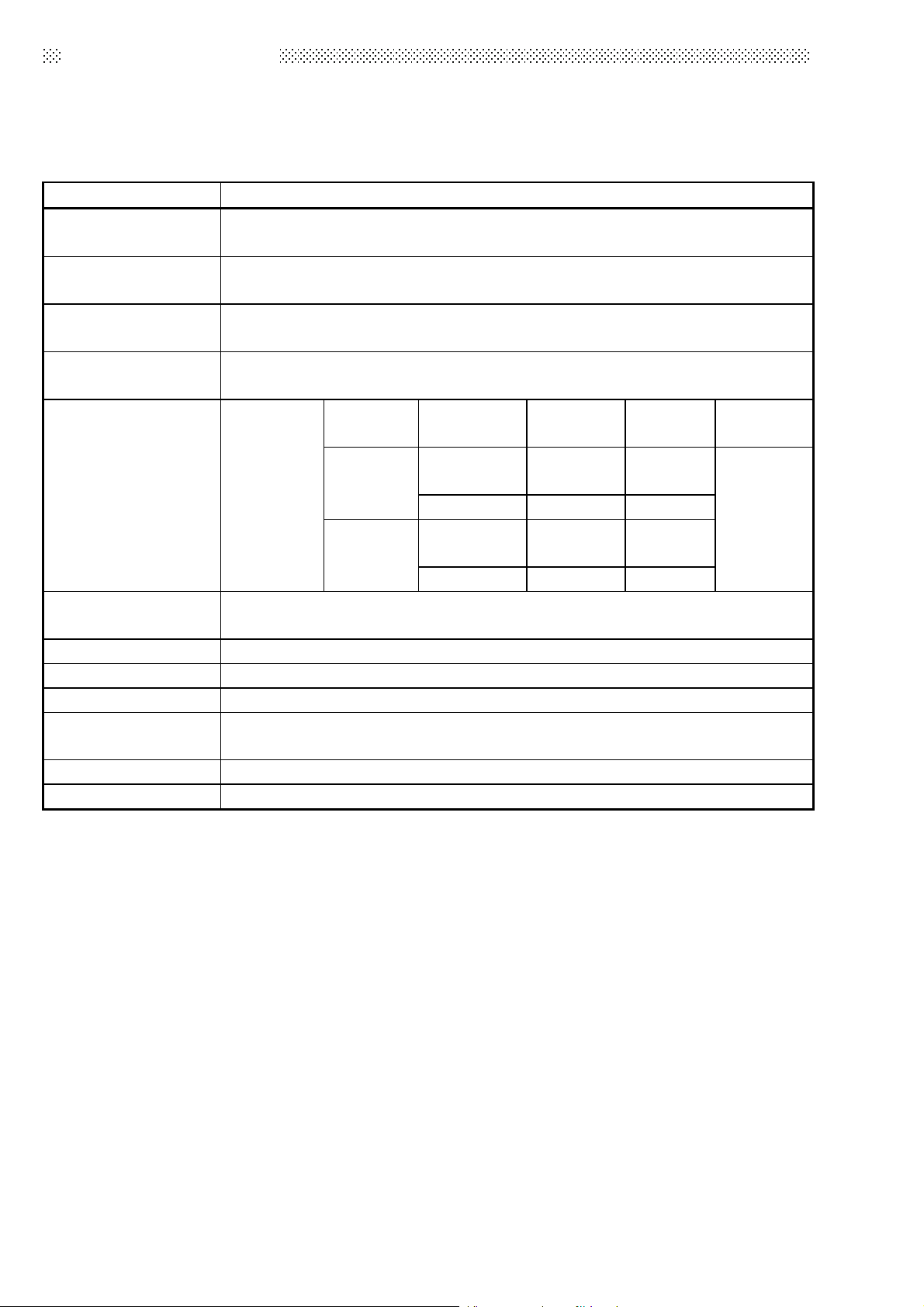
Table 1.1 General specification
Item Specifications
Ambient operating
temperature
Ambient storage
temperature
Ambient operating
humidity
Ambient storage
humidity
Frequency Acceleration Amplitude
Conforming
Vibration resistance
Shock resistance
Operating ambience No corrosive gases
Operating elevation *3 2000m (6562ft.) max.
Installation location Control panel
Over voltage category
*1
Pollution level *2 2 max.
Equipment category Class I
to JIS B
3502, IEC
61131-2
Under
intermitten
t vibration
Under
continuous
vibration
(147 m/s
10 to 90 % RH, No-condensing
10 to 90 % RH, No-condensing
10 to 57Hz ⎯⎯
57 to 150Hz 9.8m/s
10 to 57Hz ⎯⎯
57 to 150Hz 4.9m/s
Conforming to JIS B 3502, IEC 61131-2
2
, 3 times in each of 3 directions X Y Z)
0 to 55 °C
−20 to 75 °C
II max.
0.075mm
(0.003in.)
2
⎯⎯
0.035mm
(0.001in.)
2
⎯⎯
No. of
sweeps
10 times
each in
X, Y, Z
directions
(for 80min.)
*1: This indicates the section of the power supply to which the equipment is assumed to be
connected between the public electrical power distribution network and the machinery within
premises. Category II applies to equipment for which electrical power is supplied from fixed
facilities. The surge voltage withstand level for up to the rated voltage of 300 V is 2500 V.
*2: This index indicates the degree to which conductive material is generated in terms of the
environment in which the equipment is used. Pollution level 2 is when only non-conductive
pollution occurs. A temporary conductivity caused by condensing must be expected
occasionally.
*3: Do not use or store the programmable controller in the environment when the pressure is
higher than the atmospheric pressure at sea level. Otherwise, malfunction may result. To use
the programmable controller in high-pressure environment, contact your nearest Mitsubishi
representative.
1
2. PERFORMANCE SPECIFICATION
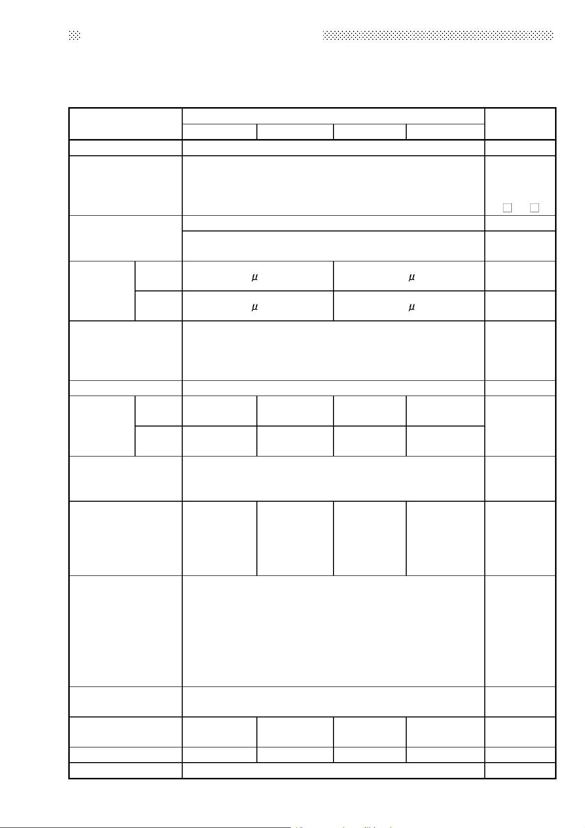
2.1 QnASCPU Module Performance Specification
Performance specification of Q2ASCPU module is as follows:
Item
Control method Repetitive operation of stored program
I/O control method Refresh mode
Programming
language
Processing
speed
(sequence
instructions)
Constant scan
(Function that makes
scan time constant)
Memory capacity Capacity of loading memory cards (2036 kbyte maximum)
Program
capacity
I/O device points 8192 points (X/Y0 to 1FFF)
I/O points
Clock function
Allowable momentary
power failure period
5 VDC Internal current
consumption
Mass 0.5 kg 0.5 kg 0.5 kg 0.5 kg
External dimension 130(H) × 54.5(W) × 110(D) (5.12 × 2.15 × 4.33) mm (inch)
LD 0.2 s/step 0.075 s/step
MOV 0.6
Number
of steps
Number
of files
Q2ASCPU Q2ASCPU-S1
Sequence control dedicated language
Relay symbol language, logic symbolic language, MELSAP3
s/step 0.225 s/step
5 to 2000 ms (configurable in multiple of 5 ms module)
28 k steps
maximum
28 files 60 files 28 files 60 files
512 points
(X/Y0 to 1FF)
Year, month, date, hour, minute, second, day of week
Accuracy : -1.7 to +4.9s (TYP. +1.7s) / d at 0 depress
centigrade
Accuracy : -1.0 to +5.2s (TYP. +2.2s) / d at 25 depress
centigrade
Accuracy : -7.3 to +2.5s (TYP. -1.9s) / d at 55 depress
centigrade
0.3 A 0.3 A 0.7 A 0.7 A
60 k steps
maximum
1024 points
(X/Y0 to 3FF)
(auto-detects leap years)
By power supply module
Model
Q2ASHCPU Q2ASHCPU-S1
(SFC)
28 k steps
maximum
512 points
(X/Y0 to 1FF)
60 k steps
maximum
1024 points
(X/Y0 to 3FF)
Remark
I/O enabled by
specifying
direct I/O
, DY )
(DX
Set
parameter
values to
specify
Number of
usable points
in program
Number of
points
accessible to
actual I/O
modules
2

3. EMC DIRECTIVES AND LOW VOLTAGE DIRECTIVES
The products sold in the European countries have been required by law to comply
with the EMC Directives and Low Voltage Directives of the EU Directives since
1996 and 1997, respectively.
The manufacturers must confirm by self-declaration that their products meet the
requirements of these directives, and put the CE mark on the products.
3.1 Requirements for Compliance with EMC Directives
The EMC Directives specifies emission and immunity criteria and requires the
products to meet both of them, i.e., not to emit excessive electromagnetic
interference (emission): to be immune to electromagnetic interference outside
(immunity).
Guidelines for complying the machinery including MELSEC-QnA series
programmable controller with the EMC Directives are provided in Section 3.1.1 to
3.1.6 below.
The guidelines are created based on the requirements of the regulations and
relevant standards, however, they do not guarantee that the machinery
constructed according to them will not comply with the Directives.
Therefore, the manufacturer of the machinery must finally determine how to make
it comply with the EMC Directives: if it is actually compliant with the EMC
Directives.
3
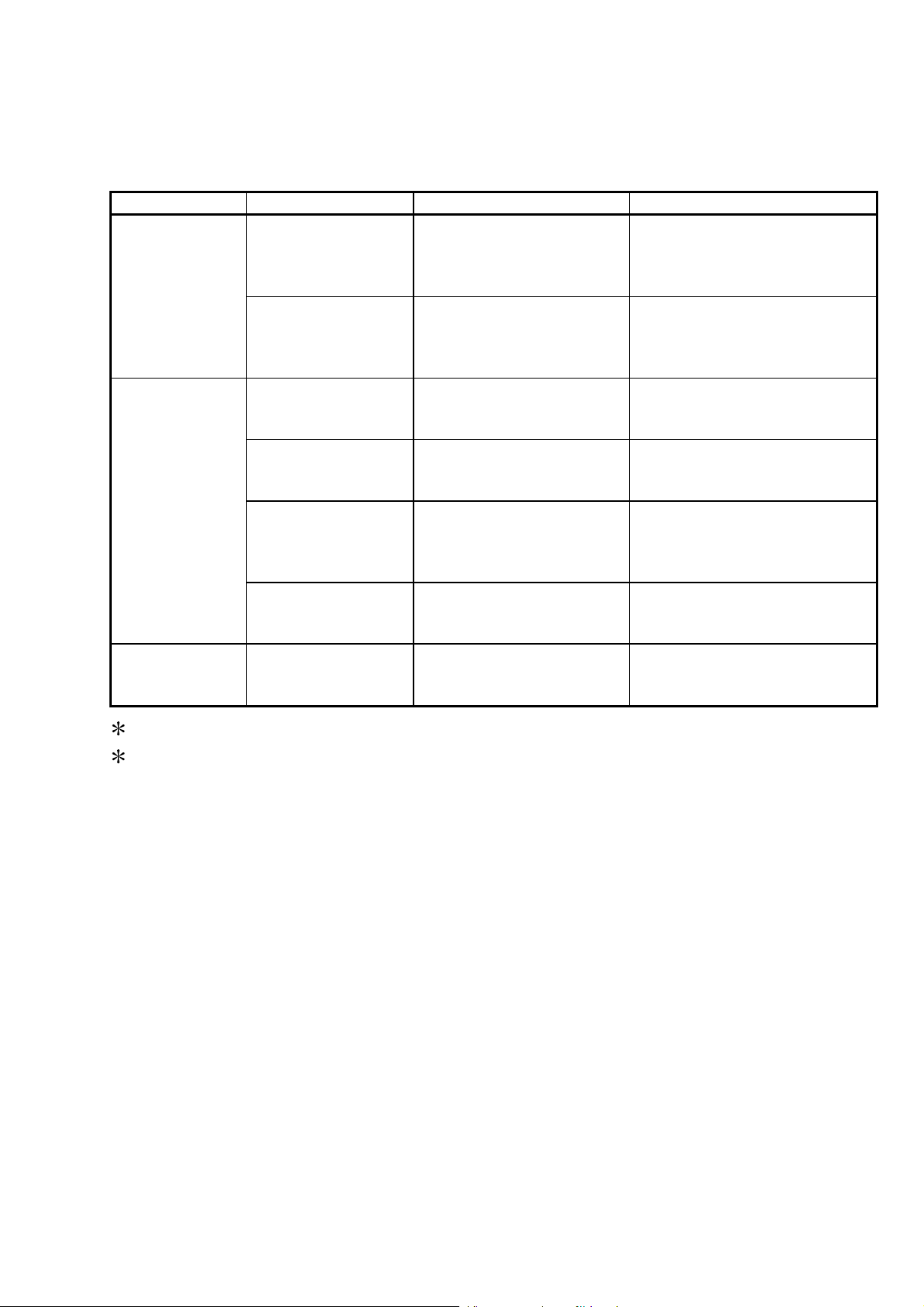
3.1.1 EMC standards
When the programmable controller is installed following the directions given in this
manual its EMC performance is compliant to the following standards and levels as
required by the EMC directive.
Specifications Test Item Test Description Standard Values
30M-230 M Hz QP: 30dBμ V/m
EN61000-6-4
(2001)
EN61131-2/A12
(2000)
EN61000-6-2
(2001)
EN55011 *2
Radiated noise
EN55011 *2
Conduction noise
EN61000-4-2 *2
Static electricity
immunity
EN61000-4-4 *2
First transient burst
noise
EN61000-4-12 *2
Damped oscillatory
wave
EN61000-4-3 *2
Radiated
electromagnetic field
EN61000-4-6 *2
Conduction noise
Measure the emission
released by the product.
Measure the emission
released by the product to
the power line.
Immunity test by applying
static electricity to the
module enclosure.
Immunity test by applying
burst noise to the power
line and signal line.
Immunity test in which a
damped oscillatory wave is
superimposed on the
power line.
Immunity test by applying a
radiated electric field to the
product.
Immunity test by inducting
an electromagnetic field in
the power line signal line.
(30m measurement) *1
230M-1000MHz QP: 37dBμ
V/m (30m measurement) *1
150k-500kHz QP:
79dB, Mean: 66dB*1
500k-30MHz QP:
73dB, Mean: 60dB *1
4kV contact discharge
8kV air discharge
2kV Power line
1kv Signal line
1kv
10V/m, 26-1000MHz
10 V/ms, 0.15-80MHZ, 80% AM
modulation@1kHz
1: QP: Quasi-peak value, Mean: Average value
2: The programmable controller is an open type device (device installed to
another device) and must be installed in a conductive control panel.
The tests for the corresponding items were performed while the
programmable controller was installed inside the control panel.
4

3.1.2 Installation instructions for EMC Directive
The programmable controller is open equipment and must be installed within a
control cabinet for use.* This not only ensures safety but also ensues effective
shielding of programmable controller-generated electromagnetic noise.
* : Also, each network remote station needs to be installed inside the control
panel.
However, the waterproof type remote station can be installed outside the
control panel.
(1) Control cabinet
(a) Use a conductive control cabinet.
(b) When attaching the control cabinet's top plate or base plate, mask
painting and weld so that good surface contact can be made between
the cabinet and plate.
(c) To ensure good electrical contact with the control cabinet, mask the paint
on the installation bolts of the inner plate in the control cabinet so that
contact between surfaces can be ensured over the widest possible area.
(d) Earth the control cabinet with a thick wire so that a low impedance
connection to ground can be ensured even at high frequencies.
(e) Holes made in the control cabinet must be 10 cm (3.94 in.) diameter or
less. If the holes are 10 cm (3.94 in.) or larger, radio frequency noise
may be emitted.
(f) Lock the control panel so that only those who are trained and have
acquiredenough knowledge of electric facilities can open the control
panel.
(2) Connection of power and earth wires
Earthing and power supply wires for the programmable controller system
must be connected as described below.
(a) Provide an earthing point near the power supply module. Earth the
power supply's LG and FG terminals (LG: Line Ground, FG: Frame
Ground) with the thickest and shortest wire possible. (The wire length
must be 30 cm (11.81 in.) or shorter.) The LG and FG terminals function
is to pass the noise generated in the programmable controller system to
the ground, so an impedance that is as low as possible must be ensured.
In addition, make sure to wire the ground cable short as the wires are
used to relieve the noise, the wire itself carries large noise content and
thus short wiring means that the wire is prevented from acting as an
antenna.
(b) The earth wire led from the earthing point must be twisted with the power
supply wires. By twisting with the earthing wire, noise flowing from the
power supply wires can be relieved to the earthing. However, if a filter is
installed on the power supply wires, the wires and the earthing wire may
not need to be twisted.
5
n
3.1.3 Cables
The cables pulled out of the control panel contain a high frequency noise
component. On the outside of the control panel, therefore, they serve as
antennas to emit noise.
Ensure to use shielded cables for the cables, which are connected to the I/O
modules, special modules and those pulled out to outside of the control panel.
Mounting ferrite core is not required except some types of CPU however, noise
emanated via the cable can be restrained using it.
The use of a shielded cable also increases noise resistance. The signal lines
(including common line) connected to the programmable controller input/output
modules and intelligent modules use shielded cables to assure noise resistance,
as a condition, standardized on EN61131-2/A12 (2000).
If a shielded cable is not used or not earthed correctly, the noise resistance will
be less than the rated value
(1) Earthing of shielded of cables
(a) Earth the shield of the shielded cable as near the unit as possible taking
care so that the earthed cables are not induced electromagnetically by
the cable to be earthed.
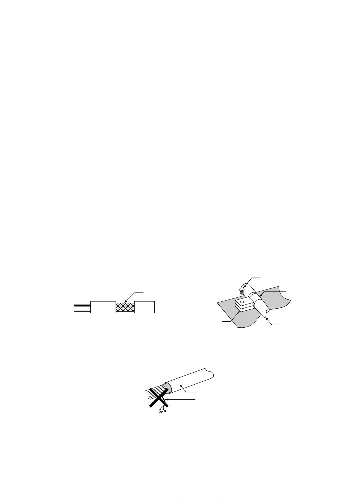
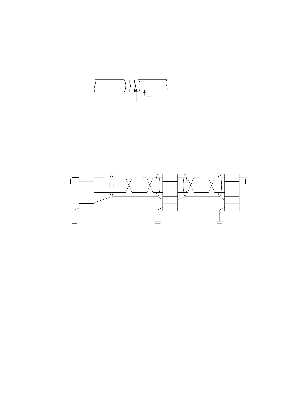
(b) Take appropriate measures so that the shield section of the shielded
cable from which the outer cover was partly removed for exposure is
earthed to the control panel on an increased contact surface. A clamp
may also be used as shown in the figure below. In this case, however,
apply a cover to the painted inner wall surface of the control panel which
comes in contact with the clamp.
Screw
Shield sectio
Clamp fitting
Paint mask
Shielded cable
Note) The method of earthing by soldering a wire onto the shield section of
the shielded cable as shown below is not recommended. The high
frequency impedance will increase and the shield will be ineffective.
Shielded cable
Wire
Crimp terminal
6
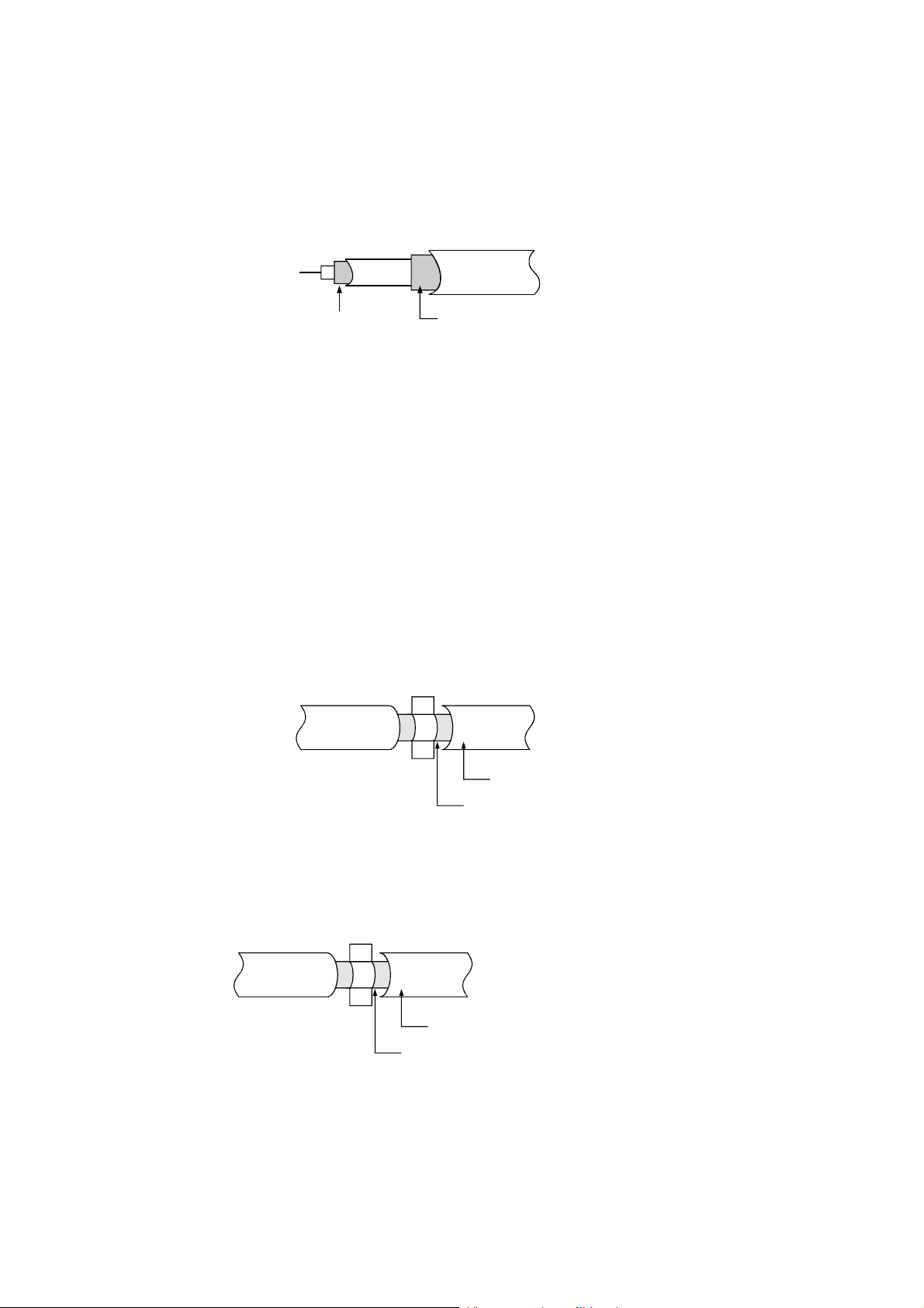
(2) MELSECNET (II) and MELSECNET/10 units
(a) Use a double-shielded coaxial cable for the MELSECNET unit which
uses coaxial cables. Noise in the range of 30 MHz or higher in radiation
noise can be suppressed by the use of double-shielded coaxial cables
(Mitsubishi Cable: 5C-2V-CCY). Earth the outer shield to the ground.
The precautions on shielding to be followed are the same as those
stated in item (1) above.
Earth this sectionShield
(b) Ensure to attach a ferrite core to the double-shielded coaxial cable
connected to the MELSECNET unit. In addition, position the ferrite core
on each cable near the outlet of the control panel. TDK-make ZCAT3035
ferrite core is recommended.
(3) Ethernet module
Precautions to be followed when AUI cables and coaxial cables are used
are described below.
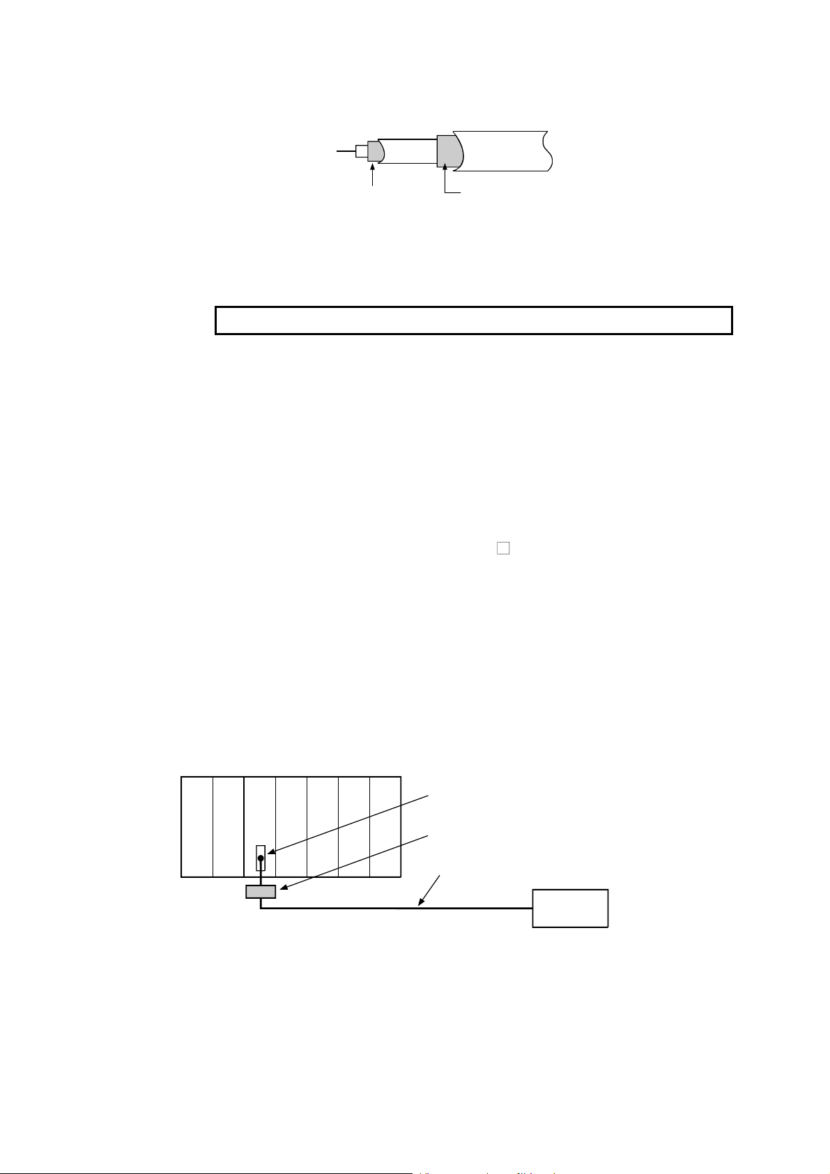
(a) Ensure to earth also the AUI cables connected to the 10BASE5
connectors of the A1SJ71QE71-B5. Because the AUI cable is of the
shielded type, as shown in the figure below, partly remove the outer
cover of it, and earth the exposed shield section to the ground on the
widest contact surface.
AUI cable
Shield
(b) Use shielded twisted pair cables as the twisted pair cables*1 connected
to the 10BASE-T connectors. For the shielded twisted pair cables, strip
part of the outer cover and earth the exposed shield section to the
ground on the widest contact surface as shown below.
Shielded twisted pair cables
Shield
Refer to (1) for the earthing of the shield.
*1: Make sure to install a ferrite core for the cable.
As a ferrite core, ZCAT2035 manufactured by TDK is recommended.
7
(c) Always use double-shielded coaxial cables as the coaxial cables*2
connected to the 10BASE2 connectors. Earth the double-shielded
coaxial cable by connecting its outer shield to the ground.
Earth hereShield
Refer to (1) for the earthing of the shield.
*2: Make sure to install a ferrite core for the cable.
As a ferrite core, ZCAT2035 manufactured by TDK is recommended.
Ethernet is the registered trademark of XEROX, Co.,LTD
(4) I/O and other communication cables
For the I/O signal lines (including common line) and other communication
cables (RS-232, RS-422, etc), if extracted to the outside of the control panel,
also ensure to earth the shield section of these lines and cables in the same
manner as in item (1) above.
(5) Positioning Modules
Precautions to be followed when the machinery conforming to the EMC
Directive is configured using the A1SD75P
-S3 are described below.
(a) When wiring with a 2 m (6.56 ft.) or less cable
• Ground the shield section of the external wiring cable with the cable
clamp.
(Ground the shield at the closest location to the A1SD75 external
wiring connector.)
• Wire the external wiring cable to the drive unit and external device with
the shortest practicable length of cable.
• Install the drive unit in the same panel.
y
l
p
e
p
l
u
u
s
d
r
o
e
m
w
o
P
e
l
5
e
u
l
7
d
u
D
o
d
S
o
m
1
m
A
U
P
C
External wiring connector
Cable clamp
External wiring cable (within 2 m (6.56 ft.))
Drive unit
8
(b) When wiring with cable that exceeds 2 m (6.56 ft.), but is 10 m (32.81 ft.)
or less
• Ground the shield section of the external wiring cable with the cable
clamp.
(Ground the shield at the closest location to the A1SD75 external
wiring connector.)
• Install a ferrite core.
• Wire the external wiring cable to the drive unit and external device with
the shortest practicable length of cable.
y
l
p
e
p
l
u
u
s
d
r
o
e
m
w
o
P
e
l
5
u
e
7
l
d
u
D
o
d
S
o
m
1
m
A
U
P
C
External wiring connector
Ferrite core
Cable clamp
External wiring cable (2 m to 10 m (6.56 ft. to 32.81 ft.))
Drive unit
(c) Ferrite core and cable clamp types and required quantities
• Cable clamp
Type: AD75CK (Mitsubishi Electric)
• Ferrite core
Type: ZCAT3035-1330 (TDK ferrite core)
• Required quantity
Cable length Prepared part
Within 2 m (6.56 ft.) AD75CK 1 1 1
2 m (6.56 ft.) to 10m (32.81 ft.)
AD75CK 1 1 1
ZCAT3035-1330 1 2 3
1 axis 2 axes 3 axes
Inside control panel
A1SD75
Required Qty
20 30cm
AD75CK
(7.87 11.81inch)
9
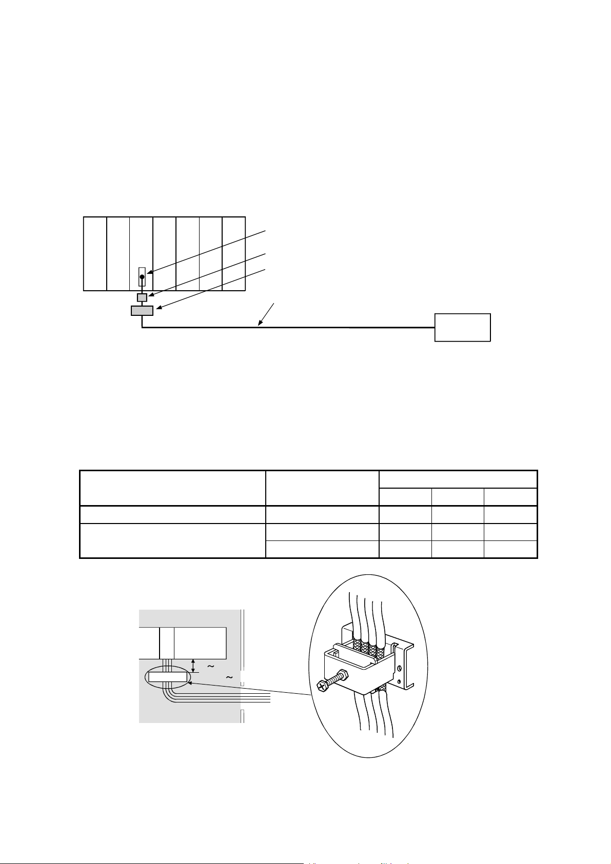
(6) CC-Link Module
(a) Be sure to ground the cable shield that is connected to the CC-Link
module close to the exit of control panel or to any of the CC-Link stations
within 30 cm (11.81 in.) from the module or stations.
The CC-Link dedicated cable is a shielded cable. As shown in the
illustration below, remove a portion of the outer covering and ground as
large a surface area of the exposed shield part as possible.
CC-Link dedicated cable
Shield
(b) Always use the specified CC-Link dedicated cable.
(c) The CC-Link module, the CC-Link stations and the FG line inside the
control panel should be connected at the FG terminal as shown in the
diagram below.
[Simplified diagram]
Local module
DA
DB
Terminal
DG
SLD
resistor
FG
Terminal
resistor
Master module
(Blue)
DA
(White)
DB
(Yellow)
DG
SLD
FG
CC-Link
dedicated
cable
Remote module
DA
DB
DG
SLD
FG
CC-Link
dedicated
cable
(d) Power line connecting to the external power supply terminal (compliant
with I/O power port of CE standard) should be 30m (98.43 ft.) or less.
Power line connecting to module power supply terminal (compliant with
main power port of CE standard) should be 10m (32.81 ft.) or less.
(e) A power line connecting to the analog input of the following modules
should be 30cm or less.
• AJ65BT-64RD3
• AJ65BT-64RD4
• AJ65BT-68TD
(7) Measures against static electricity
When using an insulation displacement connector without connector cover,
a connected cable for the connector is thin in applicable wire size and
coating. Therefore, note that the module may cause an electric discharge
failure.
As measures against the failure, using pressure-displacement type
connector whose applicable wire size is thick or soldering type connector is
recommended.
10
3.1.4 Power supply module
The precautions required for each power supply module are described below.
Always observe the items noted as precautions.
Model Precautions
A1S61PN, A1S62PN
A1S63P 1
Make sure to short and ground the LG and FG
terminals.
Use the 24VDC panel power equipment conforming to
the EU Directive.
2
1: If sufficient filter circuitry is built into the 24 VDC external power supply
module, the noise generated by A1S63P will be absorbed by that filter
circuit, so a line filter may not be required.
Filtering circuitry of version F or later of A1S63P is improved so that a
external line filter is not required.
2: To ensure the compliance with CE (EN6111-21/A11), make sure to short
the LG and FG terminals using a wire of 6 to 7cm.
3.1.5 Base unit
The following table shows models of base units that are compatible with EMC
instructions.
Type Model name Applicability
Main base unit
A1S38HBEU Applicable
A1S3
B, A1S38HB Not applicable
Extension base unit A1S5 B(S1), A1S6 B(S1) Applicable
3.1.6 Ferrite core
Use of ferrite cores is effective in reducing the conduction noise in the band of
about 10 MHz and radiated noise in 30 to 100 MHz band.
It is recommended to attach ferrite cores when the shield of the shielded cable
coming out of control panel does not work effectively, or when emission of the
conduction noise from the power line has to be suppressed.*1 The ferrite cores
used in our tests are TDK's ZCAT3035.
It should be noted that the ferrite cores should be fitted to the cables in the
position immediately before they are pulled out of the enclosure. If the fitting
position is improper, the ferrite will not produce any effect.
1:To response with CE (EN61131-2/A12), make sure to mount 2 or more
ferrite cores onto the power supply line. The mounting position should be
as near the power supply module as possible.
Ferrite core
Type: ZCAT2235-1030A (TDK ferrite core)
11
3.1.7 Noise filter (power supply line filter)
A noise filter is a component which has an effect on conducted noise. With the
exception of some models, it is not required to fit the noise filter to the power
supply line, but fitting it can further suppress noise. (The noise filter has the
effect of reducing conducted noise of 10 M Hz or less.) Use any of the following
noise filters (double
type filters) or equivalent.
Model name FN343-3/01 FN660-6/06 ZHC2203-11
Manufacturer SCHAFFNER SCHAFFNER TDK
Rated current 3 A 6 A 3 A
Rated voltage 250 V
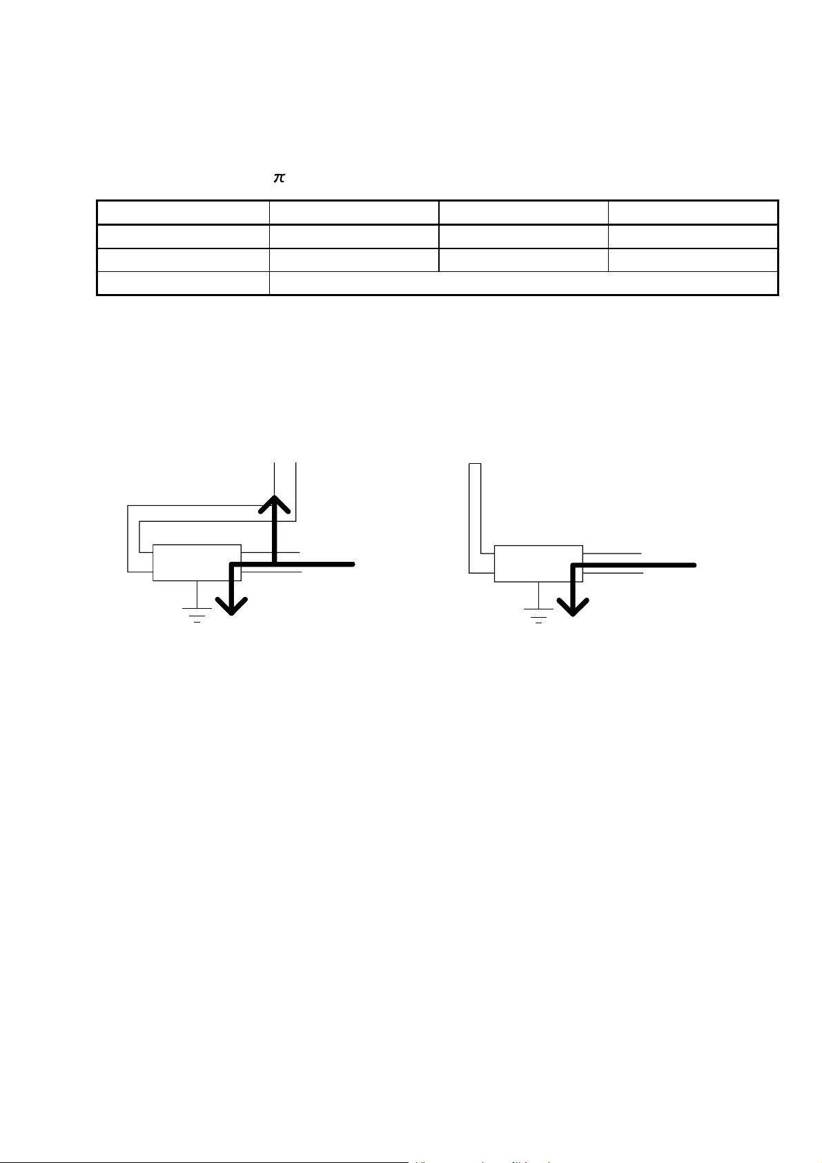
The precautions required when installing a noise filter are described below.
(1) Do not bundle the wires on the input side and output side of the noise filter.
When bundled, the output side noise will be induced into the input side
wires from which the noise was filtered.
Input side
(power supply side)
Induction
Filter
Input side
(power supply side)
Filter
Output side
(device side)
Output side
(device side)
(a) The noise will be
included when the input
(b) Separate and lay the
input and output wires.
and output wires are
bundled.
(2) Earth the noise filter earthing terminal to the control cabinet with the shortest
wire possible (approx. 10 cm (3.94 in.)).
12

3.2 Requirements for Compliance with Low Voltage Directives
The Low Voltage Directives apply to the electrical equipment operating from 50
to 1000VAC or 75 to 1500VDC; the manufacturer must ensure the adequate
safety of the equipment.
Guidelines for installation and wiring of MELSEC-QnA series programmable
controller are provided in Section 3.2.1 to 3.2.7 for the purpose of compliance
with the EMC Directives.
The guidelines are created based on the requirements of the regulations and
relevant standards, however, they do not guarantee that the machinery
constructed according to them will comply with the Directives.
Therefore, the manufacturer of the machinery must finally determine how to
make it comply with the EMC Directives: if it is actually compliant with the EMC
Directives.
3.2.1 Standard applied for MELSEC-QnA series programmable controller
The standard applied for MELSEC-QnA series programmable controller series
is EN61010-1 safety of devices used in measurement rooms, control rooms, or
laboratories.
For the modules which operate with the rated voltage of 50 VAC/75 VDC or
above, we have developed new models that conform to the above standard.
For the modules which operate with the rated voltage under 50 VAC/75 VDC,
the conventional models can be used, because they are out of the low voltage
directive application range.
3.2.2 Precautions when using the MELSEC-QnA series programmable controller
Module selection
(1) Power module
For a power module with rated input voltage of 100/200 VAC, select a model in
which the internal part between the first order and second order is intensively
insulated, because it generates hazardous voltage (voltage of 42.4 V or more at
the peak) area.
For a power module with 24 VDC rated input, a conventional model can be used.
(2) I/O module
For I/O module with rated input voltage of 100/200 VAC, select a model in
which the internal area between the first order and second order is
intensively insulated, because it has hazardous voltage area.
For I/O module with 24 VDC rated input, a conventional model can be used.
(3) CPU module, memory cassette, base unit
Conventional models can be used for these modules, because they only
have a 5 VDC circuit inside.
(4) Special function module
Conventional models can be used for the special modules including analog
module, network module, and positioning module, because the rated voltage
is 24 VDC or smaller.
(5) Display device
Use the CE-marked product.
13
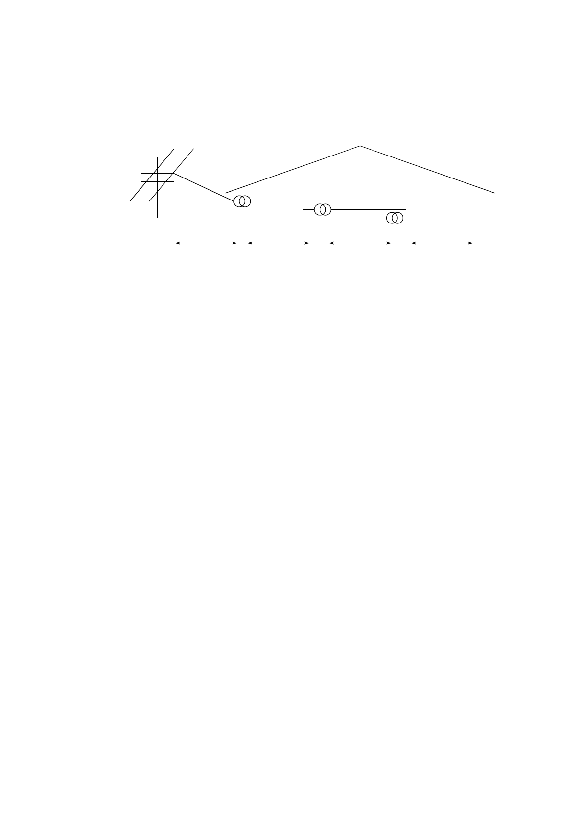
3.2.3 Power supply
The insulation specification of the power module was designed assuming
installation category II. Be sure to use the installation category II power supply to
the programmable controller.
The installation category indicates the durability level against surge voltage
generated by a thunderbolt. Category I has the lowest durability; category IV has
the highest durability.
Category III Category II Category ICategory IV
Figure 1.: Installation Category
Category II indicates a power supply whose voltage has been reduced by two or
more levels of isolating transformers from the public power distribution.
14

3.2.4 Control panel
Because the programmable controller is an open device (a device designed to be
stored within another module), be sure to use it after storing in the control panel.
(1) Electrical shock prevention
In order to prevent persons who are not familiar with the electric facility such
as the operators from electric shocks, the control panel must have the
following functions:
(a) The control panel must be equipped with a lock so that only the personnel
who has studied about the electric facility and have enough knowledge
can open it.
(b) The control panel must have a structure which automatically stops the
power supply when the box is opened.
(c) For electric shock protection, use IP20 or greater control panel.
(2) Dustproof and waterproof features
The control panel also has the dustproof and waterproof functions. Insufficient
dustproof and waterproof features lower the insulation withstand voltage,
resulting in insulation destruction. The insulation in our programmable
controller is designed to cope with the pollution level 2, so use in an
environment with pollution level 2 or below.
Pollution level 1: An environment where the air is dry and conductive dust
does not exist.
Pollution level 2: An environment where conductive dust
does not usually exist, but occasional temporary
conductivity occurs due to the accumulated dust. Generally,
this is the level for inside the control panel equivalent to
IP54 in a control room or on the floor of a typical factory.
Pollution level 3: An environment where conductive dust exits and
conductivity may be generated due to the accumulated dust.
An environment for a typical factory floor.
Pollution level 4: Continuous conductivity may occur due to rain, snow, etc.
An outdoor environment.
As shown above, the programmable controller can realize the pollution level 2
when stored in a control panel equivalent to IP54.
15

3.2.5 Module installation
(1) Installing modules contiguously
In Q2AS series programmable controllers, the left side of each I/O module is
left open. When installing an I/O module to the base, do not make any open
slots between any two modules. If there is an open slot on the left side of a
module with 100/200 VAC rating, the printed board which contains the
hazardous voltage circuit becomes bare. When it is unavoidable to make an
open slot, be sure to install the blank module (A1SG60).
3.2.6 Grounding
There are two kinds of grounding terminals as shown below. Either grounding
terminal must be used grounded.
Be sure to ground the protective grounding for the safety reasons.
Protective grounding
: Maintains the safety of the programmable
controller and improves the noise resistance.
Functional grounding
: Improves the noise resistance.
3.2.7 External wiring
(1) Module power supply and external power supply
For the remote module which requires 24VDC as module power supply, the
5/12/24/48VDC I/O module, and the intelligent function module (special
function module) which requires the external power supply, use the
5/12/24/48VDC circuit which is doubly insulated from the hazardous voltage
circuit or use the power supply whose insulation is reinforced.
(2) External devices
When a device with a hazardous voltage circuit is externally connected to the
programmable controller, use a model whose circuit section of the interface to
the programmable controller is intensively insulated from the hazardous
voltage circuit.
(3) Intensive insulation
Intensive insulation refers to the insulation with the dielectric withstand
voltage shown in Table 1.
Table 1: Intensive Insulation Withstand Voltage
(Installation Category II, source: IEC664)
Rated voltage of hazardous voltage area Surge withstand voltage (1.2/50 µs)
150 VAC or below 2500 V
300 VAC or below 4000 V
16

4. LOADING AND INSTALLATION
4.1 Installing the Module
4.1.1 Notes on handling the module
This section explains some notes on handling the CPU module, I/O module,
special function module, power supply module, and base unit.
(1) Do not drop or allow any impact to the modules case, memory card, terminal
block cover, or pin connector.
(2) Do not remove the module printed wiring board from the case. Otherwise, a
malfunction may occur.
(3) Use caution to prevent foreign matter, such as wire chips, falling into the
module during wiring. If foreign matter enters the module, remove it.
(4) Use the fallowing torque range to tighten the module fixing screws and
terminal block screws:
Screw portion Tightening torque range
Module fixing screw (M4 screw) 78 to 118 Ncm
I/O module (M3.5 screw) 59 to 88 Ncm
Power supply module terminal screws (M3.5 screw) 59 to 78 Ncm
(5) Observe the following points when you are installing the DIN rail:
(a) Applicable DIN rail type (JIS C 2812)
TH35-7.5Fe
TH35-7.5Al
TH35-15Fe
(b) DIN rail installation screw interval
When you are using the TH35-7.5Fe or TH35-7.5Al DIN rail, tighten
the DIN rail installation screw with a pitch of 200 mm (7.87 inch) or
less to maintain the strength.
DIN rail
35 mm
(1.38 inch)
DIN rail installation screw
P
P
P
P=200 mm (7.87 inch) or less
(6) When installing the base unit to DIN rail in an environment with large
vibration, use a vibration-proofing bracket (A1S-PLT-D). Mounting the
vibration-proofing bracket (A1S-PLT-D) enhances the resistance to vibration.
Depending on the environment to set up the base unit, it is also
recommended to fix the base unit to the control panel directly.
17

4.1.2 Installation environment
Avoid the following environment when you install the CPU system:
(1) A location in which the ambient temperature falls outside the range of 0 to
55 degrees Celsius.
(2) A location in which the ambient humidity falls outside the range of 10 to
90%RH.
(3) A location in which condensation may occur due to drastic changes in
temperature.
(4) A location in which corrosive gas or flammable gas exists.
(5) A location in which the system is easily exposed to conductive powder,
such as dust and iron filings, oil mist, salt, or organic solvent.
(6) A location exposed to direct sunlight.
(7) A location in which strong electrical or magnetic fields are generated.
(8) A location in which the module is exposed to direct vibration or impact.
18

4.1.3 Notes on installing the base unit
Take ease of operation, ease of maintenance, and environmental durability into
consideration when you are installing the programmable controller on the panel.
(1) Mounting dimension
Mounting dimensions of each base unit are as follows:
H
POWER
CPU 0 1 2 3 4 5 6 7
MITSUBISHI ELECTRIC CORPORATION BD626E680G52
Ws
W
MADE IN JAPAN E.S.D. A1S38B
Hs
A1S32B A1S33B A1S35B
W
Ws
220
(8.66)
200
(7.87)
255
(10.04)
235
(9.25)
325
(12.80)
305
(12.01)
A1S38B
A1S38HB
A1S38HBEU
430
(16.93)
410
(16.14)
A1S52B
(S1)
155
(6.10)
135
(5.31)
A1S55B
(S1)
260
(10.24)
240
(9.45)
A1S58B
(S1)
365
(14.37)
345
(13.58)
A1S65B
(S1)
315
(12.40)
295
(11.61)
A1S68B
(S1)
420
(16.54)
400
(15.75)
H 130 (5.12)
Hs 110 (4.33)
Dimensions: mm (inch)
19

)
(2) Module installation position
To maintain good ventilation and make it easy to replace the module, keep
the following distances between the top and bottom of the module and the
structure or other components.
A1S3B, A1S38HB, A1S38HBEU, A1S5B(S1), A1S6B(S1)
........................................................................................30 mm (1.18 inch) or over
A5B, A6B..................................................................80 mm (3.15 inch) or over
This shows the position of the panel's ceiling,
wiring duct, or components.
Duct (Height of
50mm (1.97inch)
or less)
Extension base unit
(A1S5B (S1),
A1S6B(S1))
Main base
30mm
(1.18inch)
or more
30mm (1.18inch)
or more
30mm (1.18inch)
or more
30mm (1.18inch)
or more
Duct (Height of
50mm (1.97inch)
or less)
(A5B (S1), A6B(S1))
Main base
Extension base unit
(3) Module installation direction
(a) Use the programmable controller in the following position for better
ventilation and heat dissipation:
30mm
(1.18inch
or more
30mm
(1.18inch)
or more
80mm
(3.15inch)
or more
80mm
(3.15inch)
or more
(b) Do not use the programmable controller in the following positions:
Vertical position Horizontal position
(4) Install the base unit on a level surface.
If the surface is not level, force may be applied to the printed wiring board,
causing a malfunction.
20

(5) Install the unit far from any source of vibration, such as a large magnetic
contactor and a no-fuse breaker on the same panel, or install it on a
separate panel.
(6) Keep the following distance between the programmable controller and
other devices (such as a contactor and a relay) in order to avoid the
influence of radiated noise and heat:
a device installed in front of the programmable controller
....................................................................................... 100mm (3.94 inch) or more
a device installed on the right or left of the programmable controller
....................................................................................... 50mm (1.97 inch) or more
50mm (1.97inch)
or more
50mm (1.97inch)
100mm (3.94inch)
or more
Contactor, and
relay, etc.
or more
4.2 Fail-Safe Circuit Concept
When the programmable controller is powered ON and then OFF, improper
outputs may be generated temporarily depending on the delay time and start-up
time differences between the programmable controller power supply and the
external power supply for the control target (especially, DC).
For example, if the external power supply for the control target is powered ON and
then the programmable controller is powered ON, the DC output module may
generate incorrect outputs temporarily upon the programmable controller
power-ON. Therefore, it is required to build the circuit that energizes the
programmable controller by priority.
The external power failure or programmable controller failure may lead to the
system error.
In order to eliminate the possibility of the system error and ensure fail-safe
operation, build the following circuit outside the programmable controller:
emergency circuit, protection circuit and interlock circuit, as they could cause
machine damages and accidents due to the abovementioned failures.
An example of system design, which is based on fail-safe concept, is provided on
the next page.
21

DANGER
Create a safety circuit outside the programmable controller to
ensure the whole system will operate safely even if an
external power failure or a programmable controller failure
occurs.
Install the emergency stop switch outsaid the controlpanel so
that workers can operation it easily.
Otherwise, incorrect output or malfunction may cause an
accident.
(1) For an emergency stop circuit, protection circuit and
interlock circuit that is designed for incompatible actions
such as forward/reverse rotation or for damage
prevention such as the upper/lower limit setting in
positioning, any of them must be created outside the
programmable controller.
(2) When the programmable controller detects the following
error conditions, it stops the operation and turn off all the
outputs.
The overcurrent protection device or overvoltage
protection device of the power supply module is
activated.
The programmable controller CPU detects an error
such as a watchdog timer error by the self-diagnostics
function.
In the case of an error of a part such as an I/O control
part that cannot be detected by the programmable
controller CPU, all the outputs may turn on. In order to
make all machines operate safely in such a case, set up
a fail-safe circuit or a specific mechanism outside the
programmable controller.
(3) Depending on the failure of the output module’s relay or
transistor, the output status may remain ON or OFF
incorrectly. For output signals that may lead to a serious
accident, create an external monitoring circuit.
Design a circuit so that the external power will be supplied
after power-up of the programmable controller.
Activating the external power supply prior to the
programmable controller may result in an accident due to
incorrect output or malfunction.
If load current more than the rating or overcurrent due to a
short circuit in the load has flowed in the output module for a
long time, it may cause a fire and smoke. Provide an external
safety device such as a fuse.
22

DANGER
For the operation status of each station at a communication
error in data link, refer to the respective data link manual.
The communication error may result in an accident due to
incorrect output or malfunction.
When controlling a running programmable controller (data
modification) by connecting a peripheral device to the CPU
module or a PC to a special function module, create an
interlock circuit on sequence programs so that the whole
system functions safely all the time.
Also, before performing any other controls (e.g. program
modification, operating status change (status control)), read
the manual carefully and ensure the safety.
In these controls, especially the one from an external device
to a programmable controller in a remote location, some
programmable controller side problem may not be resolved
immediately due to failure of data communications.
CAUTION
To prevent this, create an interlock circuit on sequence
programs and establish corrective procedures for
communication failure between the external device and the
programmable controller CPU.
When setting up the system, do not allow any empty slot on
the base unit.
If any slot is left empty, be sure to use a blank cover
(A1SG60) or a dummy module (A1SG62) for it.
When using the extension base unit, A1S52B(S1),
A1S55B(S1) or A1S58B(S1), attach the included dustproof
cover to the module in slot 0.
Otherwise, internal parts of the module may be flied in the
short circuit test or when an overcurrent or overvoltage is
accidentally applied to external I/O section.
Do not install the control lines or communication cables
together with the main circuit or power lines, or bring them
close to each other.
Keep a distance of 100mm (3.9inch) or more between them.
Failure to do so may cause malfunctions due to noise.
When an output module is used to control the lamp load,
heater, solenoid valve, etc., a large current (ten times larger
than the normal one) may flow at the time that the output
status changes from OFF to ON. Take some preventive
measures such as replacing the module with the one of a
suitable current rating.
23

(1) System design circuit example
AC system AC/DC system
Power supply
DC power supply
established signal
input
Start/stop circuit
Can be started
by turning ON of
RA1, which is the
programmable
controller's RUN
output.
XM
Output for warning
(lamp or buzzer)
Turned ON in RUN
status by SM403
MC
Switches the power
supply to output devices
OFF when the system
stops:
At emergency stops
At stops on reaching a
limit
Interlock circuit
Constructs external
interlock circuits for
opposing operations
such as forward and
reverse rotation, and
parts that could cause
machine damage or
accidents.
MC
Start
switch
MC
RA2
Output unit
Output unit
Transformer
Fuse
CPU module
SM52
SM403
RA1
Stop
switch
Ym
Yn
Y1
Ym
Yn
Y1
XM
SM1084
Program
MC
Input unit
RA1
MC2
MC1
MC1
MC2
RA2
L
Power supply
Start
switch
MC
Stop
switch
RA2
Output unit
Ym
Yn
Output module
Transformer
Fuse
CPU module
SM52
Ym
SM403
Yn
XM
TM
TM
MC1 N0 M10
M10N0
Program
RA1
MC
Input unit
L
RA1
MC2
MC1
MC1
MC2
XM
DC power
supply
(+)(−)
RA2
MC MC
Fuse
The setting for TM
is the time taken
to establish the
DC input signal.
Voltage relay
recommended
Output for warning
(lamp or buzzer)
Turned ON in RUN
status by SM403
Switches the power
supply to output
devices OFF when
the system stops:
At emergency stops
At stops on reaching
a limit
The procedures used to switch on the power supply are indicated below.
AC system
[1] Switch the power supply ON.
[2] Set the CPU module to RUN.
[3] Switch the start switch ON.
[4] The output devices are driven in
accordance with program when the
magnetic contactor (MC) turns ON.
[1] Switch the power supply ON.
[2] Set the CPU module to RUN.
[3] Switch RA2 ON when the DC power supply starts.
[4] Switch the timer (TM) ON when the DC power supply
reaches working voltage. (The set value for TM must
be the time it takes for 100% establishment of the DC
AC/DC system
power after RA2 is switched ON. Make this set value
0.5 seconds.)
[5] Switch the start switch ON.
[6] The output devices are driven in accordance with the
program when the magnetic contactor (MC) comes ON.
(If a voltage relay is used at RA2, no timer (TM) is
necessary in the program.)
24

(2) Fail-safe measures to cover the possibility of programmable controller
failure
Problems with a CPU module and memory can be detected by the self
diagnostics function. However, problems with I/O control area may not be
detected by the CPU module.
In such cases, all I/O points turn ON or OFF depending on the problem,
and normal operation and safety cannot be maintained.
Though Mitsubishi programmable controllers are manufactured under strict
quality control, they may fail or malfunction due to unspecified reasons. To
prevent the whole system failure, machine breakdown, and accidents, build
a fail-safe circuit outside the programmable controller.
Examples of a system and its fail-safe circuitry are described below:
<System example>
Output
16
16
points
YB0
to
YBF
Power
supply
module
CPU
module
Input
16
points
Input
16
points
Input
16
points
Input
16
points
Output
16
points
Output
16
points
Output
16
points
Output
16
points
Power
supply
module
Output
16
points
Output
16
points
Output
points
Vacant
Output module for fail-safe purpose*1
*1: The output module for fail-safe purpose should be mounted on the last
slot of the system. (YB0 to YBF in the above system.)
ON delay timer
Internal program
SM412
YB0
YB0
0.5s0.5s
CPU module Output module
YB0
YB1
to
YBF
24V
0V
*2
OFF delay timer *3
External load
L
L
T1
T2
T2T1
1s
1s
MC
+-
24VDC
MC
*2: Since YB0 turns ON and OFF alternatively at 0.5 second intervals, use a
contactless output module (a transistor is used in the above example).
*3: If an offdelay timer (especially miniature timer) is not available, construct
the failsafe circuit using an ondelay timer shown on the next page.
25

When constructing a failsafe circuit using ondelay timers only
On-delay timer
Internal program
SM412
YB0
CPU module Output module
0.5s0.5s
YB0
YB0
YB1
to
YBF
24V
0V
*1
On-delay timer
M1
M1
T2
M2
Externai load
L
to
L
M2
T1
T1
M1
T2
M2
+-
24VDC
MC
1s
1s
MC
*1: Use a solid state relay for the M1 relay.
26

4.3 Wiring
4.3.1 Power supply module specifications
(1) Table 4.1 shows the specifications of the power supply modules.
Table 4.1 Power supply module specifications
Item
Base unit position Power supply module slot
Rated input voltage
Rated input frequency 50/60 Hz ± 5 % ⎯⎯
Input voltage distortion factor Within 5 % (Refer to Section 4.4) ⎯⎯
Max. input apparent power 105 V A 41 W
Inrush current 20 A 8 ms or lower *4 81 A 1 ms or lower
5 V DC 5 A 3 A 5 A Rated output
current
protection *1
protection *2
Efficiency 65 % or higher
Allowable momentary power
failure time *3
Dielectric
withstand
voltage
Insulation resistor
Noise durability
Power indication Power LED indication (light at the time of output of 5 V DC)
Terminal screw size M3.5 × 7
Applicable wire size 0.75 to 2 mm2 (AWG 18 to 14)
Applicable solderless terminal
Applicable tightening torque 59 to 88 N⋅cm
External dimension 130 × 55 × 93.6 (5.12 × 2.17 × 3.69) mm (inch)
Weight 0.60 kg 0.50 kg
24 V DC ± 10 % ⎯⎯ 0.6 A ⎯⎯
5 V DC 5.5 A or higher 3.3 A or higher 5.5 A or higher Overcurrent
24 V DC ⎯⎯ 0.66 A or higher ⎯⎯
5 V DC 5.5 to 6.5 V Overvoltage
24 V DC ⎯⎯
Between primary
and 5 V DC
Between primary
and 24 V DC
A1S61PN A1S62PN A1S63P
100 to 240 V AC (+10 %/-15 %)
(85 to 264 V AC)
20 ms or higher 1 ms or lower
AC across input/LG and output/FG
2830 V AC rms/3 cycle
(2000 m (6562 ft.))
AC across input/LG and output/FG 10 M
measures with a 500 V DC insulation resistance tester
(1) Noise voltage 1500 Vp-p, Noise
width 1
Hz (noise simulator condition)
(2) Noise voltage IEC801-4, 2 kV
s, Noise frequency 25 to 60
Specifications
RAV 1.25 to 3.5,
RAV 2 to 3.5
24 V DC
(+30 %/-35 %)
(15.6 to 31.2 V DC)
500 V AC
⎯⎯
or higher,
Noise voltage 500 Vp-p,
Noise width 1 s, Noise
frequency 25 to 60 Hz
(noise simulator condition)
27

POINT
*1: Overcurrent protection
The overcurrent proctection device shuts off the 5VDC and/or
24VDC circuit(s) and stops the system if the current exceeding the
specified value flows in the circuit(s).
As this results in voltage drop, the power supply module LED turns
OFF or is dimly lit.
After that, eliminate the causes of overcurrent, e.g., insufficient
current capacity and short circuit, and then start the system.
When the current has reached the normal value, the initial start up
of the system will be performed.
*2: Overvoltage protection
The overvoltage protection shuts off the 5VDC circuit and stops the
system if the overvoltage of 5.5 to 6.5V is applied to the circuit.
This results in the power supply module LED turning OFF.
When restarting the system, power OFF and ON the input power
supply, and the initial start up of the system will be performed.
If the system is not booted and the LED remains off, this means
that the power supply module has to be replaced.
*3: Allowable momentary power failure period
The programmable controller CPU allowable momentary power
failure period varies with the power supply module used.
In case of the A1S63P power supply module, the allowable
momentary power failure period is defined as the time from when
the primary side of the stabilized power supply for supplying 24VDC
to the A1S63P is turned OFF until when the voltage (secondary
side) has dropped from 24VDC to the specified value (15.6VDC) or
less.
*4: Inrush current
If the power supply module is re-powered ON right after powered
OFF (within 5seconds), the inrush current exceeding the specified
value (2ms or less) may be generated. Therefore, make sure to
re-power ON the module 5seconds after power off.
When selecting a fuse or breaker for external circuit, consider the
above point as well as meltdown and detection characteristics.
28

4.3.2 Parts names
The following gives the names and description of the parts of the power supply
modules:
[9]
[3]
[4]
[6]
[7]
[9]
MELSECA1S61PN
POWER
MITSUBISHI
[1]
MELSECA1S62PN
POWER
MITSUBISHI
[8]
INPUT
100-240VAC
105VA
50 / 60Hz
OUTPUT
5VDC 5A
INPUT
100-240VAC
10 5VA
50 / 60 Hz
NC
NC
[2]
OUTPUT
5VDC 3A
24VDC 0.6A
[3]
(LG)
INPUT
100-240VAC
A1S61PN
[4]
[6]
[7]
(1) A1S61PN (2) A1S62PN
[9]
MELSECA1S63P
INPUT
DC15.6 31.2V
POWER
MITSUBISHI
OUTPUT
DC 5V 5A
[1]
[6]
+24V
24G
(FG)(FG)
(LG)
INPUT
100-240VAC
A1S62PN
[1]
[8]
NC
NC
+24V
INPUT
24G
(FG)
(LG)
[3]
[4]
[5]
[7]
(3) A1S63P
No. Name Description
[1] POWER LED The indicator LED for the 5 V DC power.
[2] 24 V and 24 G terminals
[3] FG terminal
[4] LG terminal
[5] Power supply input terminals Used to connect a 24 V DC power supply.
[6] Power supply input terminals Used to connect 100 V AC to 200 V AC power supply.
[7] Terminal screw M3.5 × 7
[8] Terminal cover The protective cover of the terminal block.
[9] Module fixing screw
Used to supply 24 V DC to inside the output module
(using external wiring).
The grounding terminal connected to the shield pattern of the
printed circuit board.
Grounding for the power supply filter. The potential of A1S61PN
or A1S62PN terminal is 1/2 of the input voltage.
Used to fix the module to the base unit.
(M4 screw, tightening torque: 78 to 118 N⋅cm)
29

POINT
(1) Do not cable to the unused terminals such as FG and LG on the terminal
block (terminals whose name is not printed on the terminal cover).
(2) Be sure to ground the terminal
LG to the protective ground conductor
with class D (class-3) grounding or above.
4.3.3 Wiring instructions
Instructions for wiring the power supply cable and I/O cable.
DANGER
Be sure to shut off all phases of the external power supply used by the
system before wiring.
Failure to do so may result in an electric shock or damage of the product.
Before energizing and operating the system after wiring, be sure to attach the
terminal cover supplied with the product.
Failure to do so may cause an electric shock.
CAUTION
Always ground the FG and LG terminals to the protective ground conductor.
Failure to do so may cause an electric shock or malfunctions.
Wire the module correctly after confirming the rated voltage and terminal
layout.
Connecting a power supply of a different voltage rating or incorrect wiring
may cause a fire or failure.
Do not connect multiple power supply modules to one module in parallel. The
power supply modules may be heated, resulting in a fire or failure.
Press, crimp or properly solder the connector for external connection with the
specified tool.
Incomplete connection may cause a short circuit, fire or malfunctions.
Tighten terminal screws within the specified torque range. If the screw is too
loose, it may cause a short circuit, fire or malfunctions.
If too tight, it may damage the screw and/or the module, resulting in a short
circuit or malfunctions.
Carefully prevent foreign matter such as dust or wire chips from entering the
module.
Failure to do so may cause a fire, failure or malfunctions.
Install our programmable controller in a control panel for use.
Wire the main power supply to the power supply module installed in a control
panel through a distribution terminal block.
Furthermore, the wiring and replacement of a power supply module have to
be performed by a maintenance worker who acquainted with shock
protection.
(For the wiring methods, refer to Type Q2AS(H)CPU(S1) User’s Manual.)
30

(1) Wiring of power supply
(a) When voltage fluctuations are larger than the specified value, connect a
constant-voltage transformer.
Constant
voltage
transformer
Programmable
controller
(b) Use a power supply which generates minimal noise between wires and
between the programmable controller and ground. If excessive noise is
generated, connect an insulating transformer.
I/O
equipment
Insulating
transformer
Programmable
controller
Insulating
transformer
(c) When a power transformer or insulating transformer is employed to
reduce the voltage from 200 VAC to 100 VAC, use one with a capacity
greater than those indicated in the following table.
Power Supply Module Transformer Capacity
A1S61PN 110VA n
A1S62PN 110VA n
n: Stands for the number of power
supply modules.
(d) Separate the programmable controller’s power supply line from the lines
for I/O devices and power devices as shown below.
When there is much noise, connect an insulation transformer.
(e) Taking rated current or inrush current into consideration when wiring the
power supply, be sure to connect a breaker or an external fuse that
have proper blown and detection.
When using a single programmable controller, a 10A breaker or an
external fuse are recommended for wiring protection.
200VAC
Main
power supply
Relay
terminal
block
On a control panel
Programmable
controller
power supply
I/O power supply
Main circuit
power supply
Insulation
Transformer
Programmable
controller
T1
I/O equipment
Main circuit equipment
31

r
(f) Note on using the 24 VDC output of the A1S62PN power supply
module.
CAUTION
Do not connect multiple power supply modules to one
module in parallel. The power supply modules may be
heated, resulting in a fire or failure.
If the 24 VDC output capacity is insufficient for one power supply
module, supply 24 VDC from the external 24 VDC power supply as
shown below:
24VDC
24VDC
unit
Power supply
unit
Power supply
I/O module
24VDC
External power supply
unit
Power supply
I/O module
(g) 100 V AC, 200 V AC and 24 V DC wires should be twisted as dense as
possible. Connect the modules with the shortest distance.
Also, to reduce the voltage drop to the minimum, use the thickest wires
possible (maximum 2mm
2
).
(h) Do not bind 100VAC and 24VDC wires together with main circuit (high
tension and large current) wires or I/O signal wires (including common
line) nor place them near each other. Provide 100mm (3.94 inch)
clearance between the wires if possible.
(i) As a countermeasure to power surge due to lightening, connect a surge
absorber for lightening as shown below.
Programmable
AC
controller
I/O
device
E1
E1
E1
E2
Lightning surge absorbe
32

POINT
(1) Separate the ground of the surge absorber for lightening (E1) from that of
the programmable controller (E2).
(2) Select a surge absorber for lightening whose power supply voltage does
no exceed the maximum allowable circuit voltage even at the time of
maximum power supply voltage elevation.
(2) Wiring to I/O device
(a) The solderless terminal with insulation sleeve is inapplicable to a
terminal block.
It is advisable to cover the wire connection part of a terminal with a mark
tube or insulation tube.
(b) Install wiring to a terminal block using the cable of core diameter 0.3 to
0.75mm
2
, and outside diameter 2.8mm or less.
(c) Run the I/O line and output line away from each other.
(d) When the main circuit line and power line cannot be separated, use a
shielding cable and ground it on the programmable controller side.
However, ground it on the opposite side in some cases.
Programmable controller
Input
Output
DC
Shielded cable
RA
Shield jacket
(e) When cables are run through pipes, securely ground the pipes.
(f) Run the 24VDC input line away from the 100VAC and 200 VAC lines.
(g) The cabling of 200m (656.2ft.) or longer distance may produce leakage
current depending on the capacity between lines and result in an
accident.
(h) As a countermeasure against the power surge due to lightning,
separate the AC wiring and DC wiring and connect a surge absorber for
lightning as shown in (i) of item (1).
Failure to do so increases the risk of I/O device failure due to lightning.
33

(3) Grounding
CAUTION
Be sure to ground the FG terminals and LG terminals to
the protective ground conductor. Not doing so could result
in electric shock or erroneous operation.
(a) Carry out the independent grounding if possible. (Grounding resistance
100
or less.)
(b) If the independent grounding is impossible, carry out the shared
grounding (2) as shown below.
Programmable
controller
Class 3
grounding
(1) Independent grounding.....Best (2) Shared grounding.....Good (3) Common grounding.....Not allowed
Other
device
Programmable
controller
Class 3
grounding
Other
device
Programmable
controller
Other
device
(c) Use the cable of 2mm2 or more for grounding.
Set the grounding point closer to the programmable controller to make
the grounding cable short as possible.
(d) If a malfunction occurs due to earthling, separate either LG or FG of the
base module, the device combination, or all the connection from the
earthling.
34

A
4.3.4 Wiring to module terminals
This section explains the wiring of power lines and grounding lines to the main
and extension bases.
100/110VAC
200/220VAC
C
Fuse
AC
DC
24VDC
Connect to the 24VDC
terminals of an I/O module
that requires 24VDC
internally.
External cable
Grounding wire
Ground
Main base unit (A1S38B)
A1S61PN
External base unit (A1S58B)
I/O I/O
FG
CPU
NC
NC
(FG)
(LG)
INPUT
100-240VAC
AC
AC
DC
Connect to the 24VDC
terminals of an I/O
module that requires
24VDC internally.
External cable
100/240VAC
Grounding wire
100/110VAC
200/220VAC
Fuse
24VDC
24VDC
Ground
Main base unit (A1S38B)
A1S62PN
External base unit (A1S68B)
A1S62PN
CPU
+24V
24G
(FG)
(LG)
INPUT
100-240VAC
I/O
+24V
24G
(FG)
(LG)
INPUT
100-240VAC
POINT
(1) Use the thickest possible (max. 2 mm2 (14 AWG)) wires for the 100/200
VAC and 24 VDC power cables. Be sure to twist these wires starting at the
connection terminals. For wiring a terminal block, be sure to use a
solderless terminal. To prevent short-circuit due to loosening screws, use
the solderless terminals with insulation sleeves of 0.8 mm (0.03 inch) or
less thick. The number of the solderless terminals to be connected for one
terminal block are limited to 2.
Solderless terminals
with insulation sleeves
Terminal block
(2) Be sure to ground the LG and FG terminals. Failure to do so may cause
the programmable controller to be susceptible to noise. Note that LG
terminals include the potential as half as that of input voltage; you might
get an electric shock when you touch them.
(3) A1S61PN and A1S62PN do not need to be switched as the are 100 to
240VAC wide-range.
35

4.4 Precautions when Connecting the Uninterruptible Power Supply (UPS)
Connect the Q2ASCPU system to the uninterruptible power supply (UPS), while
paying attention to the followings.
Use the on-line UPS or line interactive UPS (voltage distortion of 5% or less.)
Alternatively, use the off-line UPS, i.e., FREQUPS-F series with serial number P or
later (Mitsubishi).
Example: FW-F10-03.K/0.5K
Do not use the off-line UPS other than above.
36

4.5 Part names and Settings
4.5.1 Part names and settings
This section describes the name and setting of each part of the module.
Q2ASCPU, Q2ASCPU-S1, Q2ASHCPU, Q2ASHCPU-S1
Q2ASH
6)
9)
8)
12)
10)
13)
11)
CPU
STOP
RUNL.CLR
RESETRESET
Illustration of the module with the front cover open
No. Name Application
This LED indicates the CPU module operating condition.
Lit :Operating with the RUN/STOP key switch set to RUN or
STEP-RUN.
Off :Stopped with the RUN/STOP key switch set to STOP, PAUSE, or
STEP-RUN.
Or, the CPU module has detected the error that would cause the
1) RUN LED
2) ERROR LED
3) USER LED
4) BAT. ALARM LED
5) BOOT LED
Flash :The RUN/STOP key switch has been set from STOP to RUN after
Lit :A self-diagnostic error (other than a battery error) that will not stop
Off :Normal
Flash :An error that will stop the operation has been detected.
Lit :A error has been detected by the CHK instruction, or annunciator F
Off :Normal
Flash :The latch clear operation has been executed.
Lit :Battery error has occurred due to a drop in the CPU module main
Off :Normal
Lit :The boot operation has been completed.
Off :The boot operation has not been executed.
operation to stop.
the program was written in stop mode.
The CPU module is not in RUN mode. To engage the CPU module
in RUN mode, set the RUN/STOP key switch to RUN, STOP, the
RUN. Alternatively, reset the module using the RUN/STOP key
switch.
operation has been detected. (The parameter has been set to
Continue operation at error detection.)
has been turned ON.
unit/memory card battery voltage.
1)
2)
3)
4)
5)
7)
14)
37

No. Name Application
RUN/STOP :Executes/stops the operation of the sequence program.
L.CLR :Sets the entire data of the latch area specified by the
RUN/STOP key
6)
switch
7) Battery (A6BAT)
Battery connector
8)
pin
Memory card
9)
EJECT button
Memory card
10)
loading connector
Memory card
Load/eject switch
(LED equipped)
11)
ON
RESET :Executes the hardware reset operation and the reset at an
Backup battery to be used for the internal RAM and the power failure
compensation function.
Used to connect the battery lead wire. (The lead wire is removed from the
connector at shipment in order to prevent battery consumption.)
Used to eject the memory card from the CPU module.
This connector is used to load the memory card in the CPU module.
This switch setting determines whether or not you can load/eject the
memory card during energizing. The factory default setting is OFF.
ON :Loading is prohibited. (LED is lit.)
OFF :Loading is allowed. (LED is turned off.)
parameter to OFF or 0. Clears the entry of the sampling trace
and the status latch.
operation error occurrence, and initializes the operation.
System setting
switches 1
ON
5
12)
4
3
2
1
System setting
switches 2
ON
13)
2
1
14) RS-422 connector
These switches allow you to set the items for the CPU module operation.
The factory default setting of all switches is OFF.
SW5 :Boot setting. This switch allows you to select the memory for
operation.
ON :Boot operation
OFF :Boot operation is not performed
SW2 to 4 :Parameter area. These switches allow you to select the
memory into which to write the parameters.
Internal RAM
SW4 OFF ON OFF
Memory card
RAM ROM
*SW2 to 4 are valid if SW5 is OFF.
SW3 OFF OFF ON
SW2 OFF OFF OFF
SW1 :System protect. Writing to the CPU module and issuing the control
instructions are prohibited.
ON :System protect is valid.
OFF :System protect is invalid.
These switches allow you to set the items for CPU module operation. The
factory default setting of all switches is OFF.
SW2 :Unused (Fixed to OFF)
SW1 :Peripheral protocol. This switch allows you to select the type of
peripheral devices that are connected to the CPU module
peripheral interface.
(Set this switch to ON when you wish to access another stations
ACPU from the ACPU peripheral device. The setting becomes
effective as soon as you set the switch.)
ON :Peripheral device for the ACPU
OFF :Peripheral device for the Q2ASCPU
Used to connect a peripheral device.
38

4.5.2 Relation between switch operation and the LED indication
(1) Writing a program while the CPU module is stopped:
Follow the procedure below to write a program while the CPU module is
stopped:
1) RUN/STOP key switch: STOP
RUN LED: Off ......CPU module is in STOP mode.
Write a program.
2) RUN/STOP key switch: RESET
RUN LED: Off ......CPU module is in STOP mode.
3) RUN/STOP key switch: STOP
RUN
RUN LED: Lit .......CPU module is in RUN mode.
POINT
After writing a program (except for online program write), perform reset
operation, and then place the CPU module in the RUN status.
When remote STOP is switched to RUN, the CPU module is not put in
the "PROG CHECK" status but is placed in the RUN status.
(2) Latch clear operation:
Operate the RUN/STOP key switch as follows to execute the latch clear
operation:
1) Turn the RUN/STOP key switch of the CPU module from the "STOP"
position to the "L. CLR" position several times (three or four times) to
flicker the "USER LED" on the CPU module front.
Normally, the LED flickers when the switch is turned several times
(three or four times).
When the "USER LED" flickers, it indicates that latch clear is ready.
2) After the "USER LED" has flickered, turning the RUN/STOP key switch
from the "STOP" position to the "L. CLR" position again executes latch
clear and lights up the "USER LED".
If the "USER LED" comes on for two seconds and then goes off, it
indicates that latch clear is completed normally.
3) To cancel latch clear midway, turn the RUN/STOP key switch to the
"RUN" position to place the CPU module in the RUN state, or turn it to
the "RESET" position to make a reset.
POINT
You can make latch clear valid or invalid for each device via the device
setting in parameter mode.
Instead of using the RUN/STOP key switch, you can also execute the
latch clear operation remotely from the peripheral device. (Refer to the
Q2AS(H)CPU(S1) User's Manual)
39

(3) Removing the memory card while the programmable controller power is on:
Operate the memory card load/eject switch as described below the
memory card while the programmable controller power is still on:
1) Load/eject switch: ON,
Load/eject switch internal LED: Lit..........Ejecting the memory card is
prohibited.
2) Load/eject switch: OFF,
Load/eject switch internal LED: Off.........Ejecting the memory card is
allowed.
...............................................................
Remove the memory card.
POINT
The load/eject switch internal LED may not be turned off when you are
using the memory card for the CPU module system function (such as
sampling trace and status latch) or for the program.
In this case, quit the corresponding system function or program that is
using the memory card. Then, make sure that the load/eject switch
internal LED is turned off, and remove the memory card.
Do not turn on the memory card load/eject switch after you have removed
the memory card. Otherwise, on error will occur.
When there are parameter-set file registers, local devices or failure
history, the memory card cannot be the removed.
If the "memory card in/out" switch is turned OFF, the in/out switch built-in
LED does not go off.
For the file registers, the memory card can be removed when they are set
to be unused with the QDRSET(P) instruction.
(4) Loading the memory card while the programmable controller power is on:
Operate the memory card load/eject switch as described below to load the
memory card while the programmable controller power is still on:
1) Load the memory card.
2) Load/eject switch: ON,
Load/eject switch internal LED: Lit..........Ejecting the memory card is
prohibited.
POINT
Be sure to turn on the memory card load/eject switch after you have
loaded the memory card. Otherwise, you will not be able to use the card.
Since mount processing is performed again after the memory card is
inserted, note that the scan time of one scan when mount processing is
performed increases by a maximum of 10ms.
40

5. SPECIFICATION AND CONNECTION OF I/O MODULES
5.1 Input modules
5.1.1 Input module specifications
Operating Voltage
Model Type
A1SX10 100 to 120VAC 6mA
No. of
Points
Rated Input
Voltage
Input
Current
ON voltage OFF voltage
A1SX10EU 100 to 120VAC 7mA
A1SX20 200 to 240VAC 9mA
A1SX20EU
A1SX30 AC/DC input
A1SX40 12/24VDC 3/7mA 8VDC or higher 4VDC or lower
A1SX40-S1
A1SX40-S2
A1SX41 12/24VDC 3/7mA 8VDC or higher 4VDC or lower
A1SX41-S1 24VDC 7mA 17VDC or higher 3.5VDC or lower
A1SX41-S2
A1SX42 12/24VDC 2/5mA 8VDC or higher 4VDC or lower
A1SX42-S1 24VDC 5mA
A1SX42-S2
A1SX71 32 5/12/24VDC
A1SX80 12/24VDC 3/7mA 8VDC or higher 4VDC or lower
A1SX80-S1 24VDC 17VDC or higher 5VDC or lower
A1SX80-S2
A1SX81 12/24VDC 3/7mA 8VDC or higher 4VDC or lower
A1SX81-S2
AC input
DC input
(sink type)
DC input
(sink/source
type)
16
200 to 240VAC 11mA
12/24VAC
4/8.5mA
12/24VDC
24VDC 7mA DC14V or higher 6.5VDC or lower
32
24VDC 7mA 14VDC or higher 6.5VDC or lower
64
24VDC 5mA
1.2/3.3/7mA
16
7mA
24VDC
32
24VDC 7mA 13VDC or higher 6VDC or lower
80VAC or higher 30VAC or lower
7VAC/DC or
higher
18.5VDC or higher
17.5VDC or higher
3.5VDC or
higher
13VDC or higher 6VDC or lower
2.7VAC/DC or
lower
3VDC or lower
7VDC or lower
1VDC or lower
A1SX82-S1
A1S42X
DC input
(dynamic)
64 24VDC 5mA
*2
16/32
48/64
12/24VDC 4/9mA 8VDC or higher 4VDC or lower
41
18.5VDC or higher
3VDC or lower

Maximum
Simultaneous
Input Points
(Percentage
Simultaneously
ON)
Max. Response Time
OFF to ON ON to OFF
Field
Wiring
Points/
Common
Internal
Current
Consump-
tion
(5VDC)
NO. of
Occupied
Points
100%(110VAC) 20ms or lower 35ms or lower
60%(220VAC) 30ms or lower 55ms or lower
60%(220VAC) 30ms or lower 55ms or lower
75%(26.4VDC)
100%(26.4VDC)
60%(26.4VDC)
50%(24VDC)
100% 1.5ms or lower 3ms or lower
100%(110VAC)
60%(132VAC)
20ms or lower 35ms or lower
25ms or lower 20ms or lower
20ms or lower 20ms or lower
10ms or lower 10ms or lower
0.1ms or lower 0.2ms or lower
10ms or lower 10ms or lower
10ms or lower 10ms or lower 0.08A
0.3ms or lower 0.3ms or lower 0.12A
10ms or lower 10ms or lower
10ms or lower 10ms or lower 0.09A
0.3ms or lower 0.3ms or lower
Terminal 16 0.05A 16
40-pin
connector
40-pin
connector
2
40-pin
connector
32
0.08A
0.16A
0.09A
32 0.075A*3 32
32
64
10ms or lower 10ms or lower
100%(26.4VDC)
60%(26.4VDC) 10ms or lower 10ms or lower
50%(26.4VDC) 0.3ms or lower 0.3ms or lower
100%(26.4VDC) 0.4ms or lower*1 0.4ms or lower*1
For all modules, the insulation system is photocoupler insulation and the input indications are LED
indications.
*1................The dynamic scan cycle is 13.3ms.
*2................Set using the DIP switch on the module front.
*3 ..............0.08A is shown on the rating plate of the module.
0.4ms or lower 0.5ms or lower
10ms or lower 10ms or lower
Terminal 16 0.05A 16
37-pin
D-sub
connector
40-pin
connector
24-pin
connector
32 0.08A 32
32 0.16A 64
- 0.08A
16/32/48/
64
42

5.1.2 Input module connections
Model Rated Input Voltage Model Rated Input Voltage
A1SX10
(1)
A1SX10EU
A1SX20
A1SX20EU
100 to 120 VAC
200 to 240 VAC
(2)
A1SX30 12/24 VAC/DC
10
12
14
16
18
20
X00
1
2
X02
3
4
X04
5
6
X06
7
8
COM
9
X09
11
X0B
13
X0D
15
X0F
17
19
+
−
9 and 18 areconnected internally.
−
12/24VAC
12/24VDC
+
X01
X03
X05
X07
X08
X0A
X0C
X0E
COM
10
12
14
16
18
20
X00
1
2
X02
3
4
X04
5
6
X06
7
8
COM
9
X09
11
X0B
13
X0D
15
X0F
17
19
X01
X03
X05
X07
X08
X0A
X0C
X0E
COM
9 and 18 are connected internally.
Do not touch
DANGER
terminals while the
power is supplied.
Model Rated Input Voltage Model Rated Input Voltage
A1SX40 12/24 VAC A1SX80 12/24 VAC
(3)
A1SX40-S1 A1SX80-S1
24 VAC
A1SX40-S2
(4)
24 VAC
A1SX80-S2
X00
X01
X03
X05
X07
X08
X0A
X0C
X0E
−
+
COM
9 and 18 are connected internally.
2
4
6
8
10
12
14
16
18
20
11
13
15
17
19
1
3
5
7
9
X02
X04
X06
COM
X09
X0B
X0D
X0F
X00
X01
X03
X05
X07
X08
X0A
X0C
X0E
−
+
−
COM
+
9 and 18 are connected internally.
2
4
6
8
10
12
14
16
18
20
3
5
7
9
11
13
15
17
19
1
X02
X04
X06
COM
X09
X0B
X0D
X0F
43

Model Rated Input Voltage Model Rated Input Voltage
A1SX41 12/24 VDC
A1SX41-S1(S2) 24 VDC
(5)
A1SX42 12/24 VDC
A1SX42-S1(S2)
A1SX82-S1
X00
X01
X02
X03
X04
X05
X06
X07
X08
X09
X0A
X0B
X0C
X0D
X0E
X0F
*3
24 VDC
B20 A20
B19 A19
B18 A18
B17 A17
B16 A16
B15 A15
B14 A14
B13 A13
B12 A12
B11 A11
B10 A10
B9 A9
B8 A8
B7 A7
B6 A6
B5 A5
X10
X11
X12
X13
X14
X15
X16
X17
X18
X19
X1A
X1B
X1C
X1D
X1E
X1F
(6)
A1SX71 5/24 VDC
X00
X01
X02
X03
X04
X05
X06
X07
X08
X09
X0A
X0B
X0C
X0D
X0E
X0F
Vacant
Vacant
−
+
COM
COM
B20 A20
B19 A19
B18 A18
B17 A17
B16 A16
B15 A15
B14 A14
B13 A13
B12 A12
B11 A11
B10 A10
B9 A9
B8 A8
B7 A7
B6 A6
B5
B4 A4
B3 A3
B2 A2
B1 A1
A5
X10
X11
X12
X13
X14
X15
X16
X17
X18
X19
X1A
X1B
X1C
X1D
X1E
X1F
Vacant
Vacant
Vacant
Vacant
B4 A4
B3 A3
B2 A2
B1 A1
Vacant
Vacant
Vacant
Vacant
*3
Vacant
Vacant
−
+
COM
COM
+
−
*1 The figure above indicates F (the first half 32
points).
The connections for L
are the same as for F
(the latter half 32 points)
(regard X00 to X1F as
X20 to X3F.)
and B2 are connected internally.
B1
*2 The A and B pin number rows shown above are
transposed with respect to the diagram of the A
and B rows which is printed on the module.
Remember that the A row pin numbers correspond
to the B row of the module.
*3
A1SX82-S1 can use both positive common
and negative common.
*1 The figure above shows the connections for the open
collector (sink) type.
and B2 are connected internally.
B1
TTL, LS-TTL, CMOS buffer (sink) connection
−
+
Sensor (source) connection
−
+
B20
B2
B20
B2
*2 The A and B pin number rows shown above are
transposed with respect to the diagram of the A and B
rows which is printed on the module. Remember that
the A row pin numbers correspond to the B row of the
module.
44

Model Rated Input Voltage
(7)
A1SX81 12/24 VDC
A1SX81-S2 24 VDC
X01
X03
X05
X07
X09
X0B
X0D
X0F
X11
X13
X15
X17
X19
X1B
X1D
X1F
COM
Vacant
X00
1
20
21
22
23
24
25
26
27
28
29
30
31
32
33
34
35
36
37
10
11
12
13
14
15
16
17
18
19
X02
2
X04
3
X06
4
X08
5
X0A
6
X0C
7
X0E
8
X10
9
X12
X14
X16
X18
X1A
X1C
X1E
−
COM
+
COM
−
+
Vacant
17 , 18 and 36 are connected internally.
45

e
(
(8)
Model Rated Input Voltage Pin Arrangement
A1S42X 12/24 VDC
Pin No.
Input terminals
X38 X30 X28 X20 X18 X10 X08 X00
X39 X31 X29 X21 X19 X11 X09 X01
X40 X32X2A X22X1AX12X0A X02
X41 X33X2B X23X1BX13X0B X03
X42 X34X2C X24 X1CX14X0C X04
X43 X35X2D X25 X1DX15X0D X05
X44 X36X2E X26X1EX16X0E X06
X45 X37X2F X27 X1F X17 X0F X07
12/24 VDC
B12
A12
B11
A11
B10
A10
B9
A9
B8
A8
B7
A7
B6
A6
B5
A5
B3, A3
B2, A2
XD0
XD1
XD2
XD3
XD4
XD5
XD6
XD7
XSCN0
XSCN1
XSCN2
XSCN3
XSCN4
XSCN5
XSCN6
XSCN7
* If there will be cases where two or more switches
are pressed simultaneously, install a diode at each
switch
see right).
Internal
control
circuit
Internal
control
circuit
Internal
control
1/8th duty
B12
B11
B10
B9
B8
B7
B6
B5
B4
B3
B2
B1
Seen from front
face of the modul
Pin
Signal
No.
Name
Pin
No.
A12
A11
A10
A9
A8
A7
A6
A5
A4
A3
A2
A1
Signal
Name
B12 XD0 A12 XD1
B11 XD2 A11 XD3
B10 XD4 A10 XD5
B9 XD6 A9 XD7
B8 XSCN0 A8 XSCN1
B7 XSCN2 A7 XSCN3
B6 XSCN4 A6 XSCN5
B5 XSCN6 A5 XSCN7
B4 Vacant A4 Vacant
B3
12/24
VDC
A3
12/24
VDC
B2 0V A2 0V
B1 FG A1 FG
46

5.2 Output modules
5.2.1 Output module specifications
Model Type
A1SY10 16
A1SY
10EU
Relay Output
A1SY
14EU
A1SY18A 8 2A - 8A
A1SY
18AEU
A1SY22 16 0.6A 2.4A -
A1SY28A 1A -
Triac Output
No. of
Points
16
12 2A 8A -
8
8
Rated
Load
Voltage
100V to
240VAC
24VDC
AC100V
to 120V
DC24V
100V to
240VAC
24VDC
100V to
240VAC
Max. Load Current
Point Common Module OFF to ON ON to OFF
2A 8A -
2A 8A -
2A - -
8A(AC13
6V,46
8A(AC26
4V,40
4A(AC13
2V,55
2A(AC26
4V,55
)
)
)
1ms or lower
)
Max. Output
Response Time
10ms or
lower
cycles or less
12ms or
lower
1ms + 0.5
2.4A
A1SY
28EU
A1SY40 0.8A - 2ms or lower 2ms or lower
A1SY40P
A1SY41 2A - 2ms or lower 2ms or lower
A1SY41P
A1SY42 1.6A - 2ms or lower 2ms or lower
A1SY42P
A1SY50
A1SY60
A1SY60E
A1SY68A
For all modules, the insulation system is photocoupler insulation and the output indications are LED indications.
*1 .................The dynamic scan cycle is 13.3ms (FAST mode) or 106.7ms (SLOW mode).
*2 .................Set using the DIP switch on the module front.
Transistor Output
(sink type)
Transistor Output
(source type)
Transistor Output
(sink/source type)
(Set using the DIP switch on the module rear.)
16 0.1A
32 0.1A
12/24VDC
64 0.1A
16
8
24VDC 2A 4A -
5/12/
24VDC
5/1224/
48VDC
0.6A
0.5A 2A -
2A 4A -
2A - -
(46
)
1.9A
(55
)
0.8A - 1ms or lower 1ms or lower
2A - 1ms or lower 1ms or lower
2A - 1ms or lower 1ms or lower
-
2ms or lower 2ms or lower
3ms or lower
1ms + 0.5
cycles or less
10ms or
lower
47

Field Wiring
External
Points/
Common
8 0.090A 0.12A
8 0.090A 0.12A
4 0.1A 0.12A
-
8 CR absorber 5A LED 0.002A *3 0.27A
Surge
Suppression
None None None
Fuse
Rating
Error
display
Power Supply
(TYP DC24V)
Current
0.075A 0.24A
0.075A 0.24A
Internal
Current
Consumption
No. of
Occupied
Points
Terminal
40-pin connector
40-pin connector
2
Terminal
-
4 CR absorber
8
32
8
CR absorber
varistor
Zener diode
None None -
1.6A LED 0.008A 0.27A
None None 0.011A 0.79A *6
3.2A LED 0.008A 0.5A
None None 0.012A 0.141A *7
3.2A LED 0.008A 0.93A
None None 0.014A 0.17A
3.2A 0.06A 0.12A
16
0.13A
0.27A
32
64
5A 0.015A 0.12A
7A
LED
0.01A 0.2A
16
-
None None - 0.11A
*3 .................Value at TYP 200VAC.
*4 .................Value at TYP 12VDC.
*5 ................."ERR".LED turns on when fuse is blown or external supply power is off.
*6 .................0.08A is shown on the rating plate of the module.
*7 .................0.15A is shown on the rating plate of the module.
48

Model Type
Transistor Output
A1SY71
A1SY80 16 0.8A 3.2A A1SY81 0.1A 2A -
A1SY
81EP
A1SY82
A1S42Y
(for TTL/CMOS)
sink type
Transistor Output
(source type)
Transistor Output
(dynamic)
No. of
Points
32 5/12VDC 0.016A 0.256A - 1ms or lower 1ms or lower
32
64
16/32
48/64
*2
Rated
Load
Voltage
12/24VDC
Max. Load Current
Point Common Module OFF to ON ON to OFF
2ms or lower 2ms or lower
0.1A
(25
0.05A
(55
12VDC
0.1A
24VDC
0.05A
0.1A
(40
0.05A
(55
)
)
)
)
2A
(25
)
0.05A
(55
)
12VDC
1.6A
12VDC
1.6Av
- -
-
- 2ms or lower 2ms or lower
2ms or lower
Max. Output
Response Time
0.5ms or
lower
*1
1.5ms or
lower
2ms or lower
*1
For all modules, the insulation system is photocoupler insulation and the output indications are LED indications.
*1 .................The dynamic scan cycle is 13.3ms (FAST mode) or 106.7ms (SLOW mode).
(Set using the DIP switch on the module rear.)
*2 .................Set using the DIP switch on the module front.
49

External
Field Wiring
40-pin connector 32 None 1.6A 0.15A *4 0.4A 32
Terminal 8 5A 0.02A 0.12A 16
Points/
Common
Surge
Suppression
Zener diode
Fuse
Rating
3.2A
Error
display
LED
Power Supply
(TYP DC24V)
Current
0.008A 0.5A
Internal
Current
Consumption
No. of
Occupied
Points
37-pin D-sub
connector
40-pin connector
2
24-pin connector - None 1.6A LED 0.008A 0.1A
32
32 Zener diode 3.2A LED 0.080A 0.93A 64
Clamp diode None None 0.080A 0.5A
*3 .................Value at TYP 200VAC.
*4 .................Value at TYP 12VDC.
*5 ................."ERR".LED turns on when fuse is blown or external supply power is off.
*6 .................0.08A is shown on the rating plate of the module.
*7 .................0.15A is shown on the rating plate of the module.
32
16/32
48/64
50

5.2.2 Output module connections
(1)
Model Rated Load Voltage Model Rated Load Voltage
A1SY10 240 VAC, 24 VDC
Y00
10
12
14
16
18
20
1
2
Y02
3
4
Y04
5
6
Y06
7
8
COM1
9
Y09
11
Y0B
13
Y0D
15
Y0F
17
19
(For relay drive)
L
L
L
L
L
L
L
L
External load
power supply
*: The external load power supply section is as shown below.
−
+
Y01
Y03
Y05
Y07
Y08
Y0A
Y0C
Y0E
*
COM2
+
100 to 240VAC
24VDC
−
L
L
L
L
External load
+
power supply
L
L
L
L
+
24 VDC
Do not touch
DANGER
terminals while the
power is supplied.
(2)
*
−
−
A1SY10EU 120 VAC, 24 VDC
Y00
10
12
14
16
18
20
1
2
Y02
3
4
Y04
5
6
Y06
7
8
COM1
9
Y09
11
Y0B
13
Y0D
15
Y0F
17
19
L
L
L
L
L
L
L
L
External load
power supply
*: The external load power supply section is as shown below.
−
+
Y01
Y03
Y05
Y07
Y08
Y0A
Y0C
Y0E
*
COM2
+
100 to 240VAC
24VDC
−
Do not touch
DANGER
terminals while the
power is supplied.
L
L
L
L
External load
power supply
L
L
L
L
+
24 VDC
(For relay drive)
*
−
(3)
Model Rated Load Voltage Model Rated Load Voltage
A1SY14EU 240 VAC, 24 VDC
(4)
A1SY18A
240 VAC, 24 VDC
A1SY18AEU
Y00
10
12
14
16
18
20
1
2
Y02
3
4
COM1
5
6
Y05
7
8
Y07
9
Y08
11
Y0A
13
COM3
15
17
19
(For relay drive)
L
L
L
L
External load
power supply
L
L
*: The external load power supply section is as shown below.
−
+
Y01
Y03
Y04
Y06
*
COM2
Y09
Y0B
+
100 to 240VAC
24VDC
−
Do not touch
DANGER
terminals while the
power is supplied.
L
L
External load
power supply
L
L
L
L
External load
power supply
−
+
24 VDC
Y00
1
Y01
3
Y02
5
Y03
7
Y04
9
Y05
11
Y06
13
Y07
15
17
19
(For relay drive)
L
L
L
L
L
L
L
L
−
+
24 VDC
+
100 to 240VAC
24VDC
−
*
Y00
2
Y01
4
Y02
6
Y03
8
Y04
10
Y05
12
Y06
14
Y07
16
18
20
*
*
*: The external load power supply section is as shown below.
External load
power suppl y
External load
power suppl y
External load
power suppl y
External load
power suppl y
External load
power suppl y
External load
power suppl y
External load
power suppl y
External load
power suppl y
−
+
Do not touch
DANGER
terminals while the
power is supplied.
51

(5)
Model Rated Load Voltage Model Rated Load Voltage
A1SY22 100 to 200 VAC
Y00
10
12
14
16
18
20
1
2
4
6
8
11
13
15
17
19
Y02
3
Y04
5
Y06
7
COM1
9
Y08
Y0A
Y0C
Y0E
COM2
L
L
L
L
100/200 VAC
L
L
L
L
100/200 VAC
Y01
Y03
Y05
Y07
Y09
Y0B
Y0D
Y0F
(6)
L
L
L
L
L
L
L
L
A1SY28A 100 to 200 VAC
Y00
10
12
14
16
18
20
1
2
4
6
8
11
13
15
17
19
Y01
3
Y02
5
Y03
7
Y04
9
Y05
Y06
Y07
Y00
Y01
Y02
Y03
Y04
Y05
Y06
Y07
L
L
L
L
L
L
L
L
Do not touch
DANGER
Model Rated Load Voltage Model Rated Load Voltage
(7)
A1SY28EU 100 to 240 VAC
terminals while the
power is supplied.
(8)
10
12
14
16
18
20
Y00
1
2
4
6
8
11
13
15
17
19
Y02
3
Y04
5
Y06
7
COM1
9
Y08
Y0A
Y0C
L
L
L
L
L
L
L
L
Do not touch
DANGER
terminals while the
power is supplied.
A1SY40
12/24 VAC
A1SY40P
Y00
2
4
6
8
10
12
14
16
18
20
1
Y02
3
Y04
5
Y06
7
12/24 VDC
9
Y08
11
Y0A
13
Y0C
15
Y0E
17
12/24 VDC
19
L
L
L
L
+
L
L
L
L
+
Y01
Y03
Y05
Y07
−
COM
Y09
Y0B
Y0D
Y0F
−
COM
L
L
L
L
L
L
L
L
DANGER
Do not touch
terminals while the
power is supplied.
52

Model Rated Load Voltage Model Rated Load Voltage
(9)
A1SY50 12/24 VDC
A1SY60 24 VDC
(10)
A1SY60E 5/12/24 VDC
10
12
14
16
18
20
1
2
3
4
5
6
7
8
9
11
13
15
17
19
(11)
L
L
L
L
+
L
L
L
L
+
Y01
Y03
Y05
Y07
−
COM2
Y09
Y0B
Y0D
Y0F
−
COM2
Model Rated Load Voltage Model Rated Load Voltage
A1SY68A 5/12/24/48 VDC
Y00
10
12
14
16
18
20
1
2
4
6
8
7
11
13
15
17
19
Y01
3
Y02
5
Y03
Y04
9
Y05
Y06
Y07
Vacant
Vacant
−
L
L
L
L
−
−
−
Y00
Y01
Y02
Y03
Y04
Y05
Y06
Y07
Vacant
Vacant
+
+
+
+
Y00
Y02
Y04
Y06
Y08
Y0A
Y0C
Y0E
Y00
10
12
14
16
18
20
1
2
Y02
3
4
Y04
5
6
Y06
7
8
COM1
9
Y08
11
Y0A
13
Y0C
15
Y0E
17
COM2
19
L
L
L
L
L
L
L
L
L
L
L
L
L
L
L
L
+
Y01
Y03
Y05
Y07
0V
Y09
Y0B
Y0D
Y0F
−
0V
L
L
L
L
−
+
L
L
L
L
−
+
For a load
voltage of
12/24 VDC.
For a load
voltage of
5 VDC.
* When using a working load voltage of 5VDC,
a separate 12/24VDC source is required for
the external power supply.
(12)
A1SY80 12/24 VAC
Y00
10
12
14
16
18
20
1
2
4
6
8
11
13
15
17
19
Y02
3
Y04
5
Y06
7
COM1
9
Y08
Y0A
Y0C
Y0E
COM2
L
L
L
L
−
+
−
+
−
+
−
+
For sink
For source
L
L
L
L
L
L
L
L
Y01
Y03
Y05
Y07
0V
Y09
Y0B
Y0D
Y0F
0V
L
L
L
L
−
+
L
L
L
L
−
+
53

(13)
Model Rated Load Voltage Model Rated Load Voltage
A1SY41 A1SY42
12/24 VDC
A1SY41P
(14) A1SY42P
12/24 VDC
Y00
L
Y01
L
Y02
L
Y03
L
Y04
L
Y05
L
Y06
L
Y07
L
Y08
L
Y09
L
Y0A
L
Y0B
L
Y0C
L
Y0D
L
Y0E
L
Y0F
L
B20 A20
B19 A19
B18 A18
B17 A17
B16 A16
B15 A15
B14 A14
B13 A13
B12 A12
B11 A11
B10 A10
B9 A9
B8 A8
B7 A7
B6 A6
B5 A5
Y10
Y11
Y12
Y13
Y14
Y15
Y16
Y17
Y18
Y19
Y1A
Y1B
Y1C
Y1D
Y1E
Y1F
L
L
L
L
L
L
L
L
L
L
L
L
L
L
L
L
A1
Vacant
Vacant
COM
COM
−
12/24 VDC
Vacant
Vacant
12/24 VDC +
12/24 VDC
B4 A4
B3 A3
B2 A2
B1
*1 B1 and B2 , and A1 and A2 , are
connected internally.
*2 The A and B pin number rows shown above
are transposed with respect to the diagram of
the A and B rows which is printed on the
module. Remember that the A row pin
numbers correspond to the B row of the
module.
A1
Vacant
Vacant
COM
COM
−
12/24 VDC
Vacant
Vacant
12/24 VDC
12/24 VDC
B4 A4
B3 A3
B2 A2
B1
*1 The figure above indicates F (the first half
32 points).
The connections for
L (the latter half 32
points) are the same as for F (regard Y00
to Y1F as Y20 to Y3F.)
B1 and B2 , and A1 and A2 , are
connected internally.
*2 The A and B pin number rows shown above
are transposed with respect to the diagram of
the A and B rows which is printed on the
module. Remember that the A row pin
numbers correspond to the B row of the
module.
+
54

(15)
Model Rated Load Voltage Model Rated Load Voltage
A1SY71 5/12 VDC
(16)
A1SY81
12/24 VDC
A1SY81EP
Y00
L
Y01
L
Y02
L
Y03
L
Y04
L
Y05
L
Y06
L
Y07
L
Y08
L
Y09
L
Y0A
L
Y0B
L
Y0C
L
Y0D
L
Y0E
L
Y0F
L
Vacant
Vacant
5/12 VDC
5/12 VDC
B20 A20
B19 A19
B18 A18
B17 A17
B16 A16
B15 A15
B14 A14
B13 A13
B12 A12
B11 A11
B10 A10
B9 A9
B8 A8
B7 A7
B6 A6
B5 A5
B4 A4
B3 A3
B2 A2
B1
A1
Y10
Y11
Y12
Y13
Y14
Y15
Y16
Y17
Y18
Y19
Y1A
Y1B
Y1C
Y1D
Y1E
Y1F
Vacant
Vacant
COM
COM
Y00
L
L
L
L
L
L
L
L
L
L
L
L
L
L
L
L
Y01
L
Y03
L
Y05
L
Y07
L
Y09
L
Y0B
L
Y0D
L
Y0F
L
Y11
L
Y13
L
Y15
L
Y17
L
Y19
L
Y1B
L
Y1D
L
Y1F
L
COM
0V
-
+
20
21
22
23
24
25
26
27
28
29
30
31
32
33
34
35
36
37
10
11
12
13
14
15
16
17
18
19
1
Y02
2
Y04
3
Y06
4
Y08
5
Y0A
6
Y0C
7
Y0E
8
Y10
9
Y12
Y14
Y16
Y18
Y1A
Y1C
Y1E
COM
COM
0V
L
L
L
L
L
L
L
L
L
L
L
L
L
L
L
L
−
+
*1 B1 and B2 , and A1 and A2 , are
connected internally.
*2 The A and B pin number rows shown above
are transposed with respect to the diagram of
the A and B rows which is printed on the
module. Remember that the A row pin
numbers correspond to the B row of the
module.
17 and 18 and 36 , and 19 and
37 are connected internally.
55

(17)
Model Rated Load Voltage
A1SY82 12/24 VDC
Y00
L
Y01
L
Y02
L
Y03
L
Y04
L
Y05
L
Y06
L
Y07
L
Y08
L
Y09
L
Y0A
L
Y0B
L
Y0C
L
Y0D
L
Y0E
L
Y0F
L
B20 A20
B19 A19
B18 A18
B17 A17
B16 A16
B15 A15
B14 A14
B13 A13
B12 A12
B11 A11
B10 A10
B9 A9
B8 A8
B7 A7
B6 A6
B5 A5
Y10
Y11
Y12
Y13
Y14
Y15
Y16
Y17
Y18
Y19
Y1A
Y1B
Y1C
Y1D
Y1E
Y1F
L
L
L
L
L
L
L
L
L
L
L
L
L
L
L
L
Vacant
Vacant
-
+
COM
COM
B4 A4
B3 A3
B2 A2
B1
A1
Vacant
Vacant
5/12VDC
5/12VDC
*1 The figure above indicates F (the first half
32 points).
The connections for
L (the latter half 32
points) are the same as for F (regard Y00
to Y1F as Y20 to Y3F.)
B1 and B2 , and A1 and A2 , are
connected internally.
*2 The A and B pin number rows shown above
are transposed with respect to the diagram of
the A and B rows which is printed on the
module. Remember that the A row pin
numbers correspond to the B row of the
module.
56

(18)
Model Rated Load Voltage Pin Arrangement
A1S42Y 12/24 VDC
Internal
scanning at
1/8th duty
Internal
control
circuit
Internal
control
circuit
A1S42Y
Pin
No.
A12
A11
A10
A9
A8
A7
A6
A5
A4
A3
A2
Signal
Name
(F
H)
Pin No.
*3
Resistors to limit
B12
A12
B11
A11
B10
A10
B9
A9
B8
A8
B7
A7
B6
A6
B5
A5
B3A3
B2A2
LED current
12/24 VDC
YD0
R
R
R
YD1
YD2
YD3
YD4
YD5
YD6
YD7
YSCN0
YSCN1
YSCN2
YSCN3
YSCN4
YSCN5
YSCN6
YSCN7
Output terminals
Y38
Y30Y28Y20Y18Y10Y08Y00
Y39Y31Y29Y21Y19Y11Y09Y01
Y3AY32Y2AY2 2Y1AY12Y0AY02
Y3BY33Y2BY2 3Y1BY13Y0BY03
Y3CY34Y2CY24Y1CY14Y0CY04
Y3DY35Y2DY25Y1DY15Y0DY05
Y3EY36Y2EY2 6Y1EY16Y0EY06
Y3FY37Y2FY2 7Y1FY17Y0FY07
Pin
No.
B12 YD0 A12 YD1
B11 YD2 A11 YD3
B10 YD4 A10 YD5
B12
B11
B10
B9
B8
B7
B6
B5
B4
B3
B2
B1 A1
Seen from front
face of the module
Signal
Name
(F
H)
B9 YD6 A9 YD7
B8 YSCN0 A8 YSCN1
B7 YSCN2 A7 YSCN3
B6 YSCN4 A6 YSCN5
B5 YSCN6 A5 YSCN7
B4 Vacant A4 Vacant
B3
12/24
VDC
A3
12/24
VDC
B2 0V A2 0V
B1 Vacant A1 Vacant
*1 The fuse in the output module is provided to
prevent the external wiring from burning in
the event of a short circuit in the module’s
output. Consequently, it may not be able to
protect output devices.
If an output device is damaged in a failure
mode other than a short circuit, the fuse
might not be blown.
*2 The "ERR." LED will alxo come ON when
the external power supply is cut.
*3 Mount the resistors to limit
LED current externally to the
A1S42Y.
*4 The power supply voltage (12/24VDC) is
applied in the LED’s reverse direction.
If the peak inverse voltage is insufficient,
connect protective diodes in series with
each of the LEDs.
57

MEMO
58

5.3 Input/output combined modules
5.3.1 Input/output combined module specifications
Model Type
No. of
Points
Rated Input Voltage
Input
Current
Operating Voltage
ON
Voltage
OFF
Voltage
A1SH42 12/24VDC 2/5mA
32
A1SH42-S1
A1SX48Y18
A1SX48Y58
DC Input
(sink type)
8 24VDC 7mA
24VDC 5mA
8VDC or
higher
15VDC or
higher
14VDC or
higher
4VDC or
lower
3VDC or
lower
6.5VDC or
lower
Max. Output
Response Time
2ms or
lower
10ms or
lower
2ms or
lower
2ms or
lower
12ms or
lower
2ms or
lower
Model Type
A1SH42
A1SH42-S1
A1SX48Y18 Relay Output
A1SX48Y58
Transistor
Output
(sink type)
Transistor
Output
No. of
Points
32 12/24VDC 0.1A 1.6A
8
Rated
Load
Voltage
24VDC
240VAC
12/24VDC 0.5A 2A
Max. Load Current
1 Point Common OFF to ON ON to OFF
2A 8A
For all modules, the insulation system is photocoupler insulation and the operation status is
provided by LED indications.
59

60%(24VDC)
Max. Simultaneous Input Points
(Percentage Simultaneously ON)
Max. Response Time
OFF to ON ON to OFF
10ms or lower 10ms or lower 32
0.3ms or lower 0.3ms or lower 20
No. of
Occupied
Points
100%(26.4VDC) 10ms or lower 10ms or lower 8
External Power
Points/
Common
32
8 Terminal
Field
Wiring
40-pin
Connector
Surge
Suppression
Zener diode 3.2A 0.008A 0.5A 32
None None 0.045A 0.085A
Zener diode 3.2A 0.06A 0.06A
Fuse
Rating
Supply
(TYP 24VDC)
Current
External
Current
Consumption
(5VDC)
No. of
Occupied
Points
16
60

5.3.2 Input/output composite module connections
(1)
A1SH42
A1SH42-S1
Model
Vacant
Vacant
−
+
Rated Input
Voltage
Rated Load
Voltage
12/24 VDC 12/24 VDC
X00
X01
X02
X03
X04
X05
X06
X07
X08
X09
X0A
X0B
X0C
X0D
X0E
X0F
COM
COM
B20 A20
B19 A19
B18 A18
B17 A17
B16 A16
B15 A15
B14 A14
B13 A13
B12 A12
B11 A11
B10 A10
B9 A9
B8 A8
B7
B6 A6
B5 A5
B4 A4
B3 A3
B2 A2
B1 A1
X10
X11
X12
X13
X14
X15
X16
X17
X18
X19
X1A
X1B
X1C
X1D
A7
X1E
X1F
Vacant
Vacant
Vacant
Vacant
L
L
L
L
L
L
L
L
L
L
L
L
L
L
L
L
Vacant
Vacant
12/24VDC +
12/24VDC
Y00
Y01
Y02
Y03
Y04
Y05
Y06
Y07
Y08
Y09
Y0A
Y0B
Y0C
Y0D
Y0E
Y0F
B20 A20
B19 A19
B18 A18
B17 A17
B16 A16
B15 A15
B14 A14
B13 A13
B12 A12
B11 A11
B10 A10
B9 A9
B8 A8
B7 A7
B6 A6
B5 A5
B4 A4
B3 A3
B2 A2
B1
A1
Y10
Y11
Y12
Y13
Y14
Y15
Y16
Y17
Y18
Y19
Y1A
Y1B
Y1C
Y1D
Y1E
Y1F
Vacant
Vacant
COM
COM
L
L
L
L
L
L
L
L
L
L
L
L
L
L
L
L
−
X (Input side)
*1
B1 and B2 are connected internally.
Y (Output side)
*3
B1 and B2 , and A1 and A2 , are
connected internally.
*2 The A and B pin number rows shown above are transposed with respect to the diagram of the A
and B rows which is printed on the module. Remember that the A row pin numbers correspond to
the B row of the module.
61

Model
(2)
A1SX48Y18 24 VDC
Rated Input
Voltage
Rated Load
Voltage
24 VDC/
240 VAC
L
L
L
L
X01
X03
X05
X07
Y08
Y0A
Y0C
Y0E
COM2
0V
10
12
14
16
18
20
X00
1
2
4
6
8
X02
3
X04
5
X06
7
COM1
9
Y09
11
Y0B
13
Y0D
15
Y0F
17
24 VDC
19
(For relay drive)
+
L
L
L
L
+
24 VDC
−
−
(3)
DANGER
Model
Do not touch terminal while the power is supplied.
Rated Input
Voltage
A1SX48Y58 24 VDC 12/24 VDC
L
L
L
L
Rated Load
Voltage
X01
X03
X05
X07
Y08
Y0A
Y0C
Y0E
12/24 VDC
10
12
14
16
18
20
X00
1
2
4
6
8
11
13
15
17
19
X02
3
X04
5
X06
7
COM1
9
Y09
Y0B
Y0D
Y0F
COM2
−
+
L
L
L
L
−
+
62

6. ERROR CODE
If an error occurs when the programmable controller is powered ON, switched to
RUN status or running, the Q2ASCPU module executes the self diagnostics
function to display the error (LED display, message display) and store the error
information into the special relay SM and special register SD.
Also, if an error occurs when a communication request is issued from a
peripheral device, special function module or network system, the Q2ASCPU
module returns the error code (4000
H to 4FFFH) to the request source.
The following explains the Q2ASCPU errors and the corresponding corrective
actions.
REMARK
The error code of the error that occurred when a general data processing request
is made from the peripheral device, special function module or network system is
not stored into SD0 of the Q2ASCPU.
The error code is returned to the source of the general data processing request.
63

6.1 Error Code Type
Errors are detected by the self diagnostics function of CPU module or during
communication with CPU module.
The following table classifies the errors according to the detection pattern,
detection location and error code.
Error detection
pattern
Detection by the
self diagnostics
function of CPU
module
Detection at
communication with
CPU module
Error detection
location
CPU module 1000 to 10000*1 Section 6.3
CPU module 4000H to 4FFFH
Serial communication
module, etc.
CC-Link module B000H to BFFFH
Ethernet module C000H to CFFFH
MELSECNET/H
network module
Error code Reference
Q2A(S1)/Q3A/Q4ACPU User’s
Manual
7000
F000
H to 7FFFH
H to FFFFH
Serial Communication User’s
Manual, etc.
CC-Link System Master/Local
Module User’s Manual
Ethernet Interface Module User’s
Manual
For QnA/Q4AR MELSECNET/10
Network System Reference Manual
*1: CPU module error codes are classified into minor, moderate, major errors as
shown below.
Minor error: Errors that may allow the CPU module to continue the operation, e.g., battery
error.
(Error code: 1300 to 10000)
Moderate error: Errors that may cause the CPU module to stop the operation, e.g., WDT error.
(Error code: 1300 to 10000)
Major error: Errors that may cause the CPU module to stop the operation, e.g., RAM error.
(Error code: 1000 to 1299)
Determine the error level, i.e. whether the operation can be continued or stopped,
by referring to "Operating Statuses of CPU" described in Section 6.3 "Error Code
List".
6.2 Reading Error Code
When an error occurs, the corresponding error code and error message can be
read out using a peripheral device.
For details on peripheral device operation, refer to GX Developer Operating
Manual or SW
IVD-GPPQ/SW NX-GPPQ Operating Manual (Online).
64

6.3 Error Code List
The following information deals with error codes and the meanings, causes, and
corrective measures of error messages.
<Relevant CPU>
QCPU : Indicates all the Q series CPU modules.
Q00J/Q00/Q01 : Indicates the Basic model QCPU.
Qn(H) : Indicates the High Performance model QCPU.
QnPH : Indicates the Process CPU.
QnPRH : Indicates the Redundant CPU.
QnA : Indicates the QnA series and Q2ASCPU series.
Rem : Indicates the MELSECNET/H remote I/O modules.
Each CPU module model name: Indicates the relevant specific CPU module.
(Example: Q4AR, Q2AS)
: Indicates all the QnACPUs and QCPU.
Error
Code
(SD0)
1000
1010
Error
Message
MAIN CPU
DOWN
END NOT
EXECUTE
Common
Information
(SD5 to 15)
– – Off Flicker Stop Always
– – Off Flicker Stop
Individual
Information
(SD16 to 26)
LED Status CPU
RUN ERROR
Operation
Status
Diagnostic
Timing
When an END
instruction
executed
*1 CPU operation can be set in the parameters at error occurrence. (LED indication varies.)
*2 The BAT.ALM LED turns on at BATTERY ERROR.
65

Error
Code
(SD0)
Error Contents and Cause Corrective Action
Corresponding
CPU
1000
1010
Runaway or failure of CPU module or
failure of main CPU
• Malfunctioning due to noise or other
reason
• Hardware fault
Entire program was executed without
the execution of an END instruction.
• When the END instruction is
executed it is read as another
instruction code, e.g. due to noise.
• The END instruction has been
changed to another instruction code
somehow.
• Take noise reduction measures.
• Reset the CPU module and RUN it
again.If the same error is displayed
again, this suggests a CPU module
hardware fault.(Contact your local
Mitsubishi representative.)
• Take noise reduction measures.
• Reset the CPU module and RUN it
again. If the same error is displayed
again, this suggests a CPU module
hardware fault. (Contact your local
Mitsubishi representative.)
QnA
QnA
66

Error
Code
(SD0)
1101
1102
Error
Message
Common
Information
(SD5 to 15)
Individual
Information
(SD16 to 26)
LED Status CPU
RUN ERROR
Operation
Status
RAM ERROR – – Off Flicker Stop
Diagnostic
Timing
At power ON/
At reset/ When
an END
instruction
executed
At power ON/
At reset/ When
an END
instruction
executed
1103
1104
1105
RAM ERROR – – Off Flicker Stop
At power ON/
At reset
At power ON/
At reset
*1 CPU operation can be set in the parameters at error occurrence. (LED indication varies.)
*2 The BAT.ALM LED turns on at BATTERY ERROR.
67

Error
Code
(SD0)
1101
1102
1103
1104
1105
Error Contents and Cause Corrective Action
• Take noise reduction measures.
The sequence program storing built-in
RAM/program memory in the CPU
module is faulty.
The work area RAM in the CPU module
is faulty.
The device memory in the CPU module
is faulty.
The address RAM in the CPU module is
faulty.
The system RAM in the CPU module is
faulty.
• Reset the CPU module and RUN it
again. If the same error is displayed
again,this suggests a CPU module
hardware fault.(Contact your local
Mitsubishi representative.)
• Take noise reduction measures.
• Reset the CPU module and RUN it
again. If the same error is displayed
again,this suggests a CPU module
hardware fault.(Contact your local
Mitsubishi representative.)
• Take noise reduction measures.
• When indexing is performed, check
the value of index register to see if it
is within the device range.
• Reset the CPU module and RUN it
again. If the same error is displayed
again,this suggests a CPU module
hardware fault.(Contact your local
Mitsubishi representative.)
• Take noise reduction measures.
• Reset the CPU module and RUN it
again.If the same error is displayed
again, this suggests a CPU module
hardware fault. (Contact your local
Mitsubishi representative.)
Corresponding
CPU
QnA
QnA
QnA
QnA
Q4AR
68

Error
Code
(SD0)
1200
Error
Message
Common
Information
(SD5 to 15)
Individual
Information
(SD16 to 26)
LED Status CPU
RUN ERROR
Operation
Status
Diagnostic
Timing
1201
1202
1203
1204
1205
1206
OPE. CIRCUIT
ERR.
OPE. CIRCUIT
ERR.
OPE. CIRCUIT
ERR.
– – Off Flicker Stop
– – Off Flicker Stop
– – Off Flicker Stop
At power ON/
At reset
When an END
instruction
executed
When
instruction
executed
*1 CPU operation can be set in the parameters at error occurrence. (LED indication varies.)
*2 The BAT.ALM LED turns on at BATTERY ERROR.
69

Error
Code
(SD0)
1200
1201
1202
1203
1204
1205
Error Contents and Cause Corrective Action
The operation circuit for index
modification in the CPU module does
not operate normally.
The hardware (logic) in the CPU
module does not operate normally.
The operation circuit for sequence
processing in the CPU module does not
operate normally.
The operation circuit for index
modification in the CPU module does
not operate normally.
The hardware (logic) in the CPU
module does not operate normally.
The operation circuit for sequence
processing in the CPU module does not
operate normally.
This suggests a CPU module hardware
fault. (Contact your local Mitsubishi
representative.)
Corresponding
CPU
QnA
QnA
QnA
Q4AR
Q4AR
QnA
1206
The DSP operation circuit in the CPU
module does not operate normally.
Q4AR
70

Error
Code
(SD0)
1300
Error
Message
FUSE BREAK
OFF
Common
Information
(SD5 to 15)
Module No.
(Slot No.)
[For Remote I/
O network]
Network No./
Station No.
Individual
Information
(SD16 to 26)
–
LED Status CPU
RUN ERROR
Off/OnFlicker/
On
Operation
Status
Stop/
Continue
*1
Diagnostic
Timing
Always
1310
*1 CPU operation can be set in the parameters at error occurrence. (LED indication varies.)
*2 The BAT.ALM LED turns on at BATTERY ERROR.
I/O INT.
ERROR
– – Off Flicker Stop
71
During
interrupt

Error
Code
(SD0)
1300
1310
Error Contents and Cause Corrective Action
• Check ERR. LED of the output
modules and replace the fuse of the
module whose LED is lit.
• Read the common information of the
error using the peripheral device and
replace the fuse at the output module
corresponding to the numerical value
(module No.) reading.
There is an output module with a blown
fuse.
• There is an output module with a
blown fuse.
• External power supply for output load
is turned off or disconnected.
An interruption has occurred although
there is no interrupt module.
Alternatively, monitor special
registers SD1300 to SD1331 with the
peripheral device and change the
fuse of the output module whose bit
has a value of "1".
• When a GOT is bus-connected to the
main base unit or extension base
unit, check the connection status of
the extension cable and the
grounding status of the GOT.
• Check ERR. LED of the output
modules and replace the module
whose LED is lit.
• Read the common information of the
error using the peripheral device and
replace the fuse at the output module
corresponding to the numerical value
(module No.) reading.
Alternatively, monitor special
registers SD1300 to SD1331 with the
peripheral device and change the
fuse of the output module whose bit
has a value of "1".
• Check whether the external power
supply for output load is ON or OFF.
• When a GOT is bus-connected to the
main base unit or extension base
unit, check the connection status of
the extension cable and the earth
status of the GOT.
Any of the mounted modules is
experiencing a hardware fault.
Therefore, check the mounted modules
and change the faulty module. (Contact
your local Mitsubishi representative.)
Corresponding
CPU
QnA
Q4AR
Q2AS
QnA
72

Error
Code
(SD0)
Error
Message
Common
Information
(SD5 to 15)
Individual
Information
(SD16 to 26)
LED Status CPU
RUN ERROR
Operation
Status
Diagnostic
Timing
1401
1402
1411
SP. UNIT
DOWN
SP. UNIT
DOWN
CONTROLBUS. ERR.
Module No.
(Slot No.)
Module No.
(Slot No.)
Module No.
(Slot No.)
–OffFlicker
Program error
location
Off Flicker Stop
Stop
–OffFlickerStop
*2
At power ON/
At reset
During
execution of
FROM/TO
instruction set
At power ON/
At reset
During
1412
CONTROLBUS. ERR.
Module No.
(Slot No.)
Program error
location
Off Flicker Stop
execution of
FROM/TO
instruction set
1421
SYS. UNIT
DOWN
– – Off Flicker Stop Always
1500 AC/DC DOWN – – On Off Continue Always
*1 CPU operation can be set in the parameters at error occurrence. (LED indication varies.)
*2 The BAT.ALM LED turns on at BATTERY ERROR.
73

Error
Code
(SD0)
1401
1402
1411
1412
Error Contents and Cause Corrective Action
When PLC parameter I/O allocation
was being made, there was no return
signal from the special function module
during initial processing stage.(When
error is generated, the head I/O number
of the special function module that
corresponds to the common information
is stored.)
The special function module was
accessed during the execution of a
FROM/TO instruction set, but there was
no response.
(When an error is generated, the
program error location corresponding to
the individual information is stored.)
When performing a parameter I/O
allocation the intelligent function
module/special function module could
not be accessed during initial
communications.
(On error occurring, the head I/O
number of the corresponding intelligent
function module/special function
module is stored in the common
information.)
The FROM/TO instruction is not
executable, due to a control bus error
with the intelligent function module/
special function module.
(On error occurring, the program error
location is stored in the individual
information.)
The CPU module, base unit and/or the
special function module that was
accessed is experiencing a hardware
fault. (Contact your local Mitsubishi
representative.)
The CPU module, base unit and/or the
special function module that was
accessed is experiencing a hardware
fault.(Contact your local Mitsubishi
representative.)
Reset the CPU module and RUN it
again. If the same error is displayed
again, the intelligent function module/
special function module, CPU module
or base unit is faulty. (Contact your local
Mitsubishi representative.)
Corresponding
CPU
QnA
QnA
QnA
QnA
1421
1500
Hardware fault at the system
management module AS92R.
• A momentary power supply
interruption has occurred.
• The power supply went off.
This suggests a system management
module AS92R hardware fault.
(Contact your local Mitsubishi
representative.)
Check the power supply. QnA
Q4AR
74

Error
Code
(SD0)
Error
Message
Common
Information
(SD5 to 15)
Individual
Information
(SD16 to 26)
LED Status CPU
RUN ERROR
Operation
Status
Diagnostic
Timing
1510
DUAL DC
DOWN 5V
– – On On Continue Always
1520 DC DOWN 5V – – Off Flicker Stop Always
1530
DC DOWN
24V
– – On On Continue Always
1600
BATTERY
ERROR
*2
Drive Name – On
Off
Continue Always
1601
1602 On
*1 CPU operation can be set in the parameters at error occurrence. (LED indication varies.)
*2 The BAT.ALM LED turns on at BATTERY ERROR.
75

Error
Code
(SD0)
1510
1520
1530
1600
1601
1602
Error Contents and Cause Corrective Action
The power supply voltage (100 to
240VAC) of either of the two power
supply modules on the power supply
duplexing extension base unit dropped
to or below 85% of the rated voltage.
(This can be detected from the control
system of the redundant system.)
The voltage(100 to 240VAC) of the
power supply module on the extension
base unit dropped to or below 85% of
the rated voltage.
(This can be detected from the control
system of the stand-alone system or
redundant system.)
The 24 VDC power supplied to the
system management module AS92R
has dropped below 90% of the rated
voltage.
(This can be detected from the control
system or standby system of the
redundant system.)
• The battery voltage in the CPU
module has dropped below stipulated
level.
• The lead connector of the CPU
module battery is not connected.
Voltage of the battery on memory card 1
has dropped below stipulated level.
Voltage of the battery on memory card 2
has dropped below stipulated level.
Check the supply voltage of the power
supply module. If the voltage is
abnormal then replace the power supply
module.
Check the supply voltage of the power
supply module. If the voltage is
abnormal then replace the power supply
module.
Check the 24VDC power supplied to the
system management module AS92R.
• Change the battery.
• If the battery is for program memory,
standard RAM or for the back-up
power function, install a lead
connector.
Change the battery. QnA
Change the battery. QnA
Corresponding
CPU
Q4AR
Q4AR
Q4AR
QnA
76

Error
Code
(SD0)
2000
Error
Message
UNIT VERIFY
ERR.
Common
Information
(SD5 to 15)
Module No.
(Slot No.)
[For Remote I/
O network]
Network No./
Station No.
Individual
Information
(SD16 to 26)
–
LED Status CPU
RUN ERROR
Off/OnFlicker/
On
Operation
Status
Stop/
Continue
Diagnostic
Timing
When an END
instruction
*1
executed
2100
2101
2102
2103
SP. UNIT LAY
ERR.
SP. UNIT LAY
ERR.
SP. UNIT LAY
ERR.
Module No.
(Slot No.)
Module No.
(Slot No.)
Module No.
(Slot No.)
–OffFlickerStop
–OffFlickerStop
–OffFlickerStop
At power ON/
At reset
At power ON/
At reset
At power ON/
At reset
*1 CPU operation can be set in the parameters at error occurrence. (LED indication varies.)
*2 Either error stop or continue can be selected for each module by the parameters.
77

Error
Code
(SD0)
2000
2100
2101
2102
2103
Error Contents and Cause Corrective Action
• Read the common information of the
error using the peripheral device, and
check and/or change the module that
corresponds to the numerical value
(module number) there.
I/O module information power ON is
changed.
• I/O module (or special function
module) not installed properly or
installed on the base unit.
In PLC parameter I/O allocation
settings, a special function module was
allocated to a location reserved for an I/
O module. Or, the opposite has
happened.
13 or more special function modules
(not counting the A(1S)I61) capable of
sending an interrupt to the CPU module
have been installed.
Seven or more serial communication
modules (excludes A(1S)J71QC24)
have been installed.
Two or more A(1S)I61 interrupt modules
have been mounted.
• Alternatively, monitor the special
registers SD1400 to SD1431 at a
peripheral device, and change the
fuse at the output module whose bit
has a value of "1".
• When a GOT is bus-connected to the
main base unit or extension base
unit, check the connection status of
the extension cable and the
grounding status of the GOT.
Reset the PLC parameter I/O allocation
setting to conform with the actual status
of the special function modules.
Keep the number of special function
modules that can initiate an interrupt
(with the exception of the A(1S)I61
module) to 12 or fewer.
Keep the number of serial
communication modules (excludes
A(1S)J71QU24) installed to six or fewer.
Install only 1 A(1S)I61 module. QnA
Corresponding
CPU
QnA
QnA
QnA
QnA
78

Error
Code
(SD0)
2104
Error
Message
Common
Information
(SD5 to 15)
Individual
Information
(SD16 to 26)
LED Status CPU
RUN ERROR
Operation
Status
Diagnostic
Timing
2105
2106
SP. UNIT LAY
ERR.
SP. UNIT LAY
ERR.
Module No.
(Slot No.)
Module No.
(Slot No.)
–OffFlickerStop
–OffFlickerStop
At power ON/
At reset
At power ON/
At reset
*1 CPU operation can be set in the parameters at error occurrence. (LED indication varies.)
*2 Either error stop or continue can be selected for each module by the parameters.
79

Error
Code
(SD0)
2104
2105
2106
Error Contents and Cause Corrective Action
At the MELSECNET/MINI auto refresh
network parameter settings, the module
allocation that was set is different from
the actual module models at the station
numbers in the link system.
Reset the network parameter
MELSECNET/MINI auto refresh unit
module allocation setting so that it
conforms to the station number of the
module that is actually linked.
There are too many special function
modules that can use dedicated
instructions allocated (number of
modules installed).
(The total of the figures indicated below
is above 1344.)
(AD57(S1)/AD58
(AJ71C24(S3/S6/S8)
(AJ71PT32-S3/AJ71T32-S3
(AJ71QC24(R2,R4)
(AD59
(AJ71UC24
(AJ71C21(S1)
(AJ71ID1(2)-R4
+(AD75
modules installed 5)
modules installed 8)
modules installed 10)
modules installed 10)
modules installed 29)
modules installed 125)
modules installed 29)
modules installed 8)
modules installed 12)
total 1344
Reduce the number of special function
modules installed.
*: When the expansion mode is used.
• Five or more AJ71QLP21 &
AJ71QBR11 modules are installed.
• Three or more AJ71AP21/R21 &
AJ71AT21B modules are installed.
• The total number of installed
AJ71QLP21, AJ71QBR11,
AJ71AP21/R21, and AJ71AT21B
modules exceeds five.
• The same network numbers or
identical station numbers exist in the
MELSECNET/10 network system.
• Two or more master or load stations
exist simultaneously at the
• Reduce the AJ71QLP21 and
AJ71QBR11 modules to four or less.
• Reduce the AJ71AP21/R21 and
AJ71AT21B modules to two or less.
• Reduce the AJ71QLP21,
AJ71QBR11, AJ71AP21/R21 and
AJ71AT21B modules to a total of four
or less.
• Check the network Nos. and station
Nos.
• Check the station Nos.
MELSECNET(II) or MELSECNET/B
data link system.
Corresponding
CPU
QnA
QnA
80

Error
Code
(SD0)
2107
Error
Message
Common
Information
(SD5 to 15)
Individual
Information
(SD16 to 26)
LED Status CPU
RUN ERROR
Operation
Status
Stop
Diagnostic
Timing
2108
2109
2110
2111
SP. UNIT LAY
ERR.
SP. UNIT
ERROR
Module No.
(Slot No.)
Module No.
(Slot No.)
–OffFlicker
Program error
location
Off/OnFlicker/
On
Stop/
Continue
Stop/
Continue
At power ON/
At reset
*2
instruction
*1
executed
When
2112
*1 CPU operation can be set in the parameters at error occurrence. (LED indication varies.)
*2 Either error stop or continue can be selected for each module by the parameters.
SP. UNIT
ERROR
Module No.
(Slot No.)
Program error
location
81
Off/OnFlicker/
On
Stop/
Continue
*1
When
instruction
executed/
STOP
RUN

Error
Code
(SD0)
2107
2108
2109
2110
2111
2112
Error Contents and Cause Corrective Action
The start X/Y set in the PLC
parameter’s I/O assignment settings is
overlapped with the one for another
module.
A(1S)J71LP21 or A(1S)J71BR11 for
use with the AnUCPU network module
has been installed.
The control system and standby system
module configurations are different
when a redundant system is in the
backup mode.
• The location designated by the
FROM/TO instruction set is not the
special function module.
• The module that does not include
buffer memory has been specified by
the FROM/TO instruction.
• The special function module, Network
module being accessed is faulty.
• Station not loaded was specified
using the instruction whose target
was the CPU share memory.
• The location designated by a link
direct device (J \ ) is not a network
module.
• The I/O module (special function
module) was nearly removed,
completely removed, or mounted
during running.
• The module other than special
function module is specified by the
special function module dedicated
instruction.
Or, it is not the corresponding special
function module.
• The module model specified by the
special function module dedicated
instruction and that specified by the
parameter I/O assignment is different.
Make the PLC parameter’s I/O
assignment setting again so it is
consistent with the actual status of the
special function modules.
Replace the network module to
A(1S)J71QLP21 or A(1S)J71QBR11.
Check the module configuration of the
standby system.
• Read the individual information of the
error using the GX Developer, check
the FROM/TO instruction that
corresponds to that numerical value
(program error location), and correct
when necessary.
• The special function module that was
accessed is experiencing a hardware
fault. Therefore, change the faulty
module. Alternatively, contact your
local Mitsubishi representative.
• Read the individual information of the
error using a peripheral device, and
check the special function module
dedicated instruction (network
instruction) that corresponds to the
value (program error part) to make
modification.
• Set the module model by PLC
parameter I/O assignment according
to the special function module
dedicated instruction setting.
Example) Although AJ71QC24N is
used actually, AJ71QC24 is set.
Corresponding
CPU
QnA
QnA
Q4AR
QnA
QnA
QnA
82

Error
Code
(SD0)
2113
Error
Message
SP. UNIT
ERROR
Common
Information
(SD5 to 15)
FFFFH (fixed)
Individual
Information
(SD16 to 26)
Program error
location
LED Status CPU
RUN ERROR
Off/OnFlicker/
On
Operation
Status
Stop/
Continue
*2
Diagnostic
Timing
When
instruction
executed/
STOP
RUN
2210 BOOT ERROR Drive name – Off Flicker Stop
2300
ICM. OPE.
ERROR
Drive name –
Off/OnFlicker/
On
Stop/
Continue
2302
2400
FILE SET
ERROR
File name/
Drive name
Parameter
number
Off Flicker Stop
At power ON/
At reset
When memory
card is
*1
inserted or
removed2301
At power ON/
At reset/
At PLC writing
*1 CPU operation can be set in the parameters at error occurrence. (LED indication varies.)
*2 Either error stop or continue can be selected for each module by the parameters.
83

Error
Code
(SD0)
2113
2210
2300
2301
2302
2400
Error Contents and Cause Corrective Action
Read the individual information of the
error using a peripheral device, and
Data of special function module to be
simulated is not set in the simulation
data.
There is no boot file in the drive
designated by the parameter enabled
drive switch even though the Boot DIP
switch is ON.
• A memory card was removed without
switching the memory card in/out
switch OFF.
• The memory card in/out switch is
turned ON although a memory card is
not actually installed.
• The memory card has not been
formatted.
• Memory card format status is
incorrect.
A memory card that cannot be used
with the CPU module has been
installed.
The file designated at the PLC file
settings in the parameters cannot be
found.
check the special function module /
special function module dedicated
instruction (network instruction) that
corresponds to the value (program error
part) to make modification.
Check and correct the valid parameter
drive settings made by the DIP
switches.
Set the boot file to the drive specified by
the parameter drive DIP switches.
• Remove memory card after placing
the memory card in/out switch OFF.
• Turn on the card insert switch after
inserting a memory card.
• Format memory card.
• Reformat memory card.
• Format memory card.
• Reformat memory card.
• Check memory card.
• Read the individual information of the
error using peripheral device, check
to be sure that the parameter drive
name and file name correspond to
the numerical values there
(parameter number), and correct.
• Create a file created using
parameters, and load it to the CPU
module.
Corresponding
CPU
QnA
QnA
QnA
QnA
QnA
QnA
84

Error
Code
(SD0)
Error
Message
Common
Information
(SD5 to 15)
Individual
Information
(SD16 to 26)
LED Status CPU
RUN ERROR
Operation
Status
Diagnostic
Timing
2401
2402
FILE SET
ERROR
File name/
Drive name
Parameter
number
Off Flicker Stop
At power ON/
At reset/
At PLC writing
*1 CPU operation can be set in the parameters at error occurrence. (LED indication varies.)
*2 Either error stop or continue can be selected for each module by the parameters.
85
 Loading...