


SAFETY PRECAUTIONS
(Read these precautions before using this product.)
Before using this product, please read this manual and the relevant manuals carefully and pay full attention
to safety to handle the product correctly.
In this manual, the safety precautions are classified into two levels: " WARNING" and " CAUTION".
WARNING
CAUTION
Under some circumstances, failure to observe the precautions given under " CAUTION" may lead to
serious consequences.
Make sure that the end users read this manual and then keep the manual in a safe place for future
reference.
Indicates that incorrect handling may cause hazardous conditions,
resulting in death or severe injury.
Indicates that incorrect handling may cause hazardous conditions,
resulting in minor or moderate injury or property damage.
[DESIGN PRECAUTIONS]
WARNING
Create a safety circuit outside the PLC to ensure the whole system will operate safely even if an
external power failure or a PLC failure occurs. Otherwise, incorrect output or malfunction may cause
an accident.
(1) For an emergency stop circuit, protection circuit and interlock circuit that is designed for
incompatible actions such as forward/reverse rotation or for damage prevention such as the
upper/lower limit setting in positioning, any of them must be created outside the PLC.
(2) When the PLC detects the following error conditions, it stops the operation and turn off all the
outputs.
• The overcurrent protection device or overvoltage protection device of the power supply
module is activated.
• The PLC CPU detects an error such as a watchdog timer error by the self-diagnostics
function.
In the case of an error of a part such as an I/O control part that cannot be detected by the PLC
CPU, all the outputs may turn on. In order to make all machines operate safely in such a case,
set up a fail-safe circuit or a specific mechanism outside the PLC. For fail-safe circuit example,
refer to "LOADING AND INSTALLATION" of this manual.
(3) Depending on the failure of the output module's relay or transistor, the output status may remain
ON or OFF incorrectly. For output signals that may lead to a serious accident, create an external
monitoring circuit.
A - 1

[DESIGN PRECAUTIONS]
WARNING
If load current more than the rating or overcurrent due to a short circuit in the load has flowed in the
output module for a long time, it may cause a fire and smoke. Provide an external safety device such
as a fuse.
Design a circuit so that the external power will be supplied after power-up of the PLC.
Activating the external power supply prior to the PLC may result in an accident due to incorrect
output or malfunction.
For the operation status of each station at a communication error in data link, refer to the respective
data link manual.
Otherwise, incorrect output or malfunction may cause an accident.
When controlling a running PLC (data modification) by connecting a peripheral device to the CPU
module or a PC to a special function module, create an interlock circuit on sequence programs so that
the whole system functions safely all the time.
Also, before performing any other controls (e.g. program modification, operating status change (status
control)), read the manual carefully and ensure the safety.
In these controls, especially the one from an external device to a PLC in a remote location, some PLC
side problem may not be resolved immediately due to failure of data communications.
To prevent this, create an interlock circuit on sequence programs and establish corrective procedures
for communication failure between the external device and the PLC CPU.
When setting up the system, do not allow any empty slot on the base unit.
If any slot is left empty, be sure to use a blank cover (AG60) or a dummy module (AG62) for it.
When using the extension base unit, A52B, A55B or A58B, attach the included dustproof cover to
the module in slot 0.
Otherwise, internal parts of the module may be flied in the short circuit test or when an overcurrent or
overvoltage is accidentally applied to the external I/O section.
A - 2
[DESIGN PRECAUTIONS]
CAUTION
Do not install the control lines or communication cables together with the main circuit or power lines,
or bring them close to each other.
Keep a distance of 100mm (3.94inch) or more between them.
Failure to do so may cause malfunctions due to noise.
If having read register R outside the allowable range with the MOV instruction, the file register data
will be FFFF
file register when designing sequence programs. For instruction details, refer to the programming
manual.
When an output module is used to control the lamp load, heater, solenoid valve, etc., a large current
(ten times larger than the normal one) may flow at the time that the output status changes from OFF
to ON. Take some preventive measures such as replacing the module with the one of a suitable
current rating.
Time from when the CPU module is powered on or is reset to when it enters in RUN status depends
on the system configuration, parameter settings, and program size.
Design the program so that the entire system will always operate safely, regardless of the time.
H. Using this as it is may cause malfunctions. Pay attention not to use any out-of-range
[INSTALLATION PRECAUTIONS]
CAUTION
Use the PLC under the environment specified in the user's manual.
Otherwise, it may cause electric shocks, fires, malfunctions, product deterioration or damage.
Insert the module fixing projection into the fixing hole in the base unit to mount the module.
Incorrect mounting may cause malfunctions, a failure or a drop of the module.
In an environment of frequent vibrations, secure the module with the screw.
Tighten the screw within the specified torque range.
If the screw is too loose, it may cause a drop of the module, a short circuit or malfunctions.
Tightening the screw excessively may damage the screw and/or the module, resulting in a drop of
the module, a short circuit or malfunctions.
Connect the extension cable to the connector of the base unit or module.
Check for incomplete connection after installing it.
Poor electrical contact may cause incorrect inputs and/or outputs.
Insert the memory card and fully press it to the memory card connector.
Check for incomplete connection after installing it.
Poor electrical contact may cause malfunctions.
Be sure to shut off all phases of the external power supply used by the system before mounting or
removing the module.
Failure to do so may damage the module.
Do not directly touch the conductive part or electronic components of the module.
Doing so may cause malfunctions or a failure of the module.
A - 3
[WIRING PRECAUTIONS]
WARNING
Be sure to shut off all phases of the external power supply used by the system before wiring.
Failure to do so may result in an electric shock or damage of the product.
Before energizing and operating the system after wiring, be sure to attach the terminal cover
supplied with the product.
Failure to do so may cause an electric shock.
CAUTION
Ground the FG and LG terminals correctly.
Failure to do so may cause an electric shock or malfunctions.
Wire the module correctly after confirming the rated voltage and terminal layout.
Connecting a power supply of a different voltage rating or incorrect wiring may cause a fire or failure.
Do not connect multiple power supply modules to one module in parallel.
The power supply modules may be heated, resulting in a fire or failure.
Press, crimp or properly solder the connector for external connection with the specified tool.
Incomplete connection may cause a short circuit, fire or malfunctions.
Tighten terminal screws within the specified torque range.
If the screw is too loose, it may cause a short circuit, fire or malfunctions.
If too tight, it may damage the screw and/or the module, resulting in a short circuit or malfunctions.
Carefully prevent foreign matter such as dust or wire chips from entering the module.
Failure to do so may cause a fire, failure or malfunctions.
Install our PLC in a control panel for use.
Wire the main power supply to the power supply module installed in a control panel through a
distribution terminal block.
Furthermore, the wiring and replacement of a power supply module have to be performed by a
maintenance worker who acquainted with shock protection.
(For the wiring methods, refer to Section 19.7.)
A - 4

[STARTUP AND MAINTENANCE PRECAUTIONS]
WARNING
Do not touch any terminal during power distribution.
Doing so may cause an electric shock.
Correctly connect the battery connector.
Do not charge, disassemble, heat, short-circuit, solder, or throw the battery into the fire.
Incorrect battery handling may cause personal injuries or a fire due to exothermic heat, burst and/or
ignition.
Be sure to shut off all phases of the external power supply used by the system before cleaning or
retightening the terminal screws or module mounting screws.
Failure to do so may result in an electric shock.
If they are too loose, it may cause a short circuit or malfunctions.
Tightening the screw excessively may damage the screw and/or the module, resulting in a drop of
the module, a short circuit or malfunctions.
A - 5
[STARTUP AND MAINTENANCE PRECAUTIONS]
CAUTION
When performing online operations (especially, program modification, forced output or operating
status change) by connecting a peripheral device to the running CPU module, read the manual
carefully and ensure the safety.
Incorrect operation will cause mechanical damage or accidents.
Do not disassemble or modify each of modules.
Doing so may cause failure, malfunctions, personal injuries and/or a fire.
When using a wireless communication device such as a mobile phone, keep a distance of 25cm
(9.84inch) or more from the PLC in all directions.
Failure to do so may cause malfunctions.
Be sure to shut off all phases of the external power supply used by the system before mounting or
removing the module.
Failure to do so may result in failure or malfunctions of the module.
When replacing the fuse, use a fuse specified by the manufacturer.
Using the one for the high-rated current or an electric wire may cause a fire.
Do not drop or apply any impact to the battery.
Doing so may damage the battery, resulting in electrolyte spillage inside the battery.
If any impact has been applied, discard the battery and never use it.
Before handling modules, touch a grounded metal object to discharge the static electricity from the
human body.
Failure to do so may cause failure or malfunctions of the module.
[DISPOSAL PRECAUTIONS]
CAUTION
When disposing of the product, treat it as an industrial waste.
When disposing of batteries, separate them from other wastes according to the local regulations.
(For details of the battery directive in EU member states, refer to Appendix 11.)
[TRANSPORTATION PRECAUTIONS]
CAUTION
When transporting lithium batteries, make sure to treat them based on the transportation regulations.
(Refer to Appendix 10 for details of the relevant models.)
A - 6

CONDITIONS OF USE FOR THE PRODUCT
(1) Mitsubishi programmable controller ("the PRODUCT") shall be used in conditions;
i) where any problem, fault or failure occurring in the PRODUCT, if any, shall not lead to any major
or serious accident; and
ii) where the backup and fail-safe function are systematically or automatically provided outside of
the PRODUCT for the case of any problem, fault or failure occurring in the PRODUCT.
(2) The PRODUCT has been designed and manufactured for the purpose of being used in general
industries.
MITSUBISHI SHALL HAVE NO RESPONSIBILITY OR LIABILITY (INCLUDING, BUT NOT
LIMITED TO ANY AND ALL RESPONSIBILITY OR LIABILITY BASED ON CONTRACT,
WARRANTY, TORT, PRODUCT LIABILITY) FOR ANY INJURY OR DEATH TO PERSONS OR
LOSS OR DAMAGE TO PROPERTY CAUSED BY the PRODUCT THAT ARE OPERATED OR
USED IN APPLICATION NOT INTENDED OR EXCLUDED BY INSTRUCTIONS, PRECAUTIONS,
OR WARNING CONTAINED IN MITSUBISHI'S USER, INSTRUCTION AND/OR SAFETY
MANUALS, TECHNICAL BULLETINS AND GUIDELINES FOR the PRODUCT.
("Prohibited Application")
Prohibited Applications include, but not limited to, the use of the PRODUCT in;
• Nuclear Power Plants and any other power plants operated by Power companies, and/or any
other cases in which the public could be affected if any problem or fault occurs in the PRODUCT.
• Railway companies or Public service purposes, and/or any other cases in which establishment of
a special quality assurance system is required by the Purchaser or End User.
• Aircraft or Aerospace, Medical applications, Train equipment, transport equipment such as
Elevator and Escalator, Incineration and Fuel devices, Vehicles, Manned transportation,
Equipment for Recreation and Amusement, and Safety devices, handling of Nuclear or
Hazardous Materials or Chemicals, Mining and Drilling, and/or other applications where there is a
significant risk of injury to the public or property.
Notwithstanding the above, restrictions Mitsubishi may in its sole discretion, authorize use of the
PRODUCT in one or more of the Prohibited Applications, provided that the usage of the PRODUCT
is limited only for the specific applications agreed to by Mitsubishi and provided further that no
special quality assurance or fail-safe, redundant or other safety features which exceed the general
specifications of the PRODUCTs are required. For details, please contact the Mitsubishi
representative in your region.
A - 7
REVISIONS
*The manual number is given on the bottom left of the back cover.
Print Date *Manual Number Revision
Jul., 1996 IB (NA) 66608-A First edition
Dec., 2003 IB (NA) 66608-B
Oct., 2006 IB (NA) 66608-C
Partial correction
SAFETY PRECAUTIONS, CONTENTS, Related Manuals, Section 1.1, 1.2, 2.1,
3.1.1, 3.1.2, 3.2, 3.3.1, 3.3.2, 3.3.3, Chapter 4, Section 5.1, 5.2, 5.3, 5.4, 6.1, 6.2,
6.3, 7.1, 8.1, 8.2, 8.2.1, 8.3, 8.4.1, 8.4.3, 8.5, 8.6, 8.7, 8.7.1, 8.7.2, 8.7.3, 8.8, 8.9,
8.10, 8.10.1, 8.10.2, 9.1, 9.2, 9.3, 9.3.1, 9.3.3, 9.4, 9.5, 9.6, 9.7, 9.8, 9.9, 9.9.1,
9.9.2, 10.1, 10.2, 10.3, 10.4, 10.5, 10.6, 10.6.1, 10.6.2, 10.6.3, 10.6.4, 10.6.5,
10.6.6, 10.7, 10.7.1, 10.8, 11.1, 11.2, 11.3, 11.4, 11.5, 11.6, 11.7, 12.1, 12.1.1,
12.1.2, 12.1.3, 12.1.4, 12.1.5, 12.1.6, 12.1.7, 12.2, 12.3, 12.4, Chapter 13, 14,
Section 14.1, 14.2, 14.3, 15.1, 15.2, 15.3, 16.1.1, 16.1.2, 16.2, 16.3, Chapter 17,
Section 17.1, 17.1.1, 17.2, 17.4, 17.5, 18.1, 18.2, 18.3, 18.4, 18.6, 18.7, 19.1,
19.4.1, 19.5, 19.6, 19.7, 19.7.1, 19.7.2, 19.8, 21.1, 21.2, 21.3, 21.3.1, 21.3.2,
21.4, 21.4.1, 21.4.2, 22.2.1, 22.2.2, 22.2.3, 22.2.4, 22.2.5, 22.2.6, 22.2.7, 22.2.8,
22.2.9, 22.2.10, 22.3, 22.3.1, 22.3.2, 22.5, 22.5.1, 22.5.2, Appendix 1.1, 1.4, 1.6,
2.3, 4.4.1, 4.2, 4.3, 4.6, 4.10, 4.11, 4.12, 5.1, 5.2, 6.2
Partial addition
Section 2.2, 2.2.1, 7.2, 8.2.2, 19.8, Chapter 20, Section 20.1, 20.1.1, 20.1.2,
20.1.3, 20.1.4, 20.1.5, 20.1.6, 20.2, 20.2.1, 20.2.2, 20.2.3, 20.2.4, 20.2.5, 20.2.6,
20.2.7, 22.4, Appendix 7, 8, 9, 9.1, 9.2, WARRANTY
Partial correction
SAFETY PRECAUTIONS, Section 3.1.1, 3.1.2, 3.2, 3.3.1, 3.3.2, Chapter 4,
Section 5.3, 6.1, 7.1, 9.1, 9.3, 9.3.1, 9.9.2, 12.1.2, 12.1.5, 12.4, 14.1, 15.1, 15.2,
16.1.1, 16.1.3, 16.2, 16.3, 17.1, 17.1.1, 17.2, 17.5, 18.1, 18.2, 18.3, 19.1, 19.6,
19.7, Chapter 20, Section 20.1.3, 21.5, 21.6, 22.2.6, 22.2.7, 22.3.3, Appendix 2,
3, 5.2, 6.2, 9.2
Deletion
Section 14.2
Chapter change
Section 14.3 Section 14.2
May, 2007 IB(NA)66608-D
Dec., 2009 IB(NA)66608-E
Partial correction
Related Manuals, Section 19.7.1, 19.7.2, 20.1.3, 20.1.4, 20.2.7, 22.3,
APPENDIX 2, APPENDIX3
Partial correction
SAFETY PRECAUTIONS, Section 3.3.1, Chapter 13, Section 15.1, 16.1.2,
16.1.3, 18.3, Chapter 20, 21.3.1, 21.3.2, 22.3, 22.3.1, 22.3.3, 22.3.4, 22.3.5,
22.3.6, 22.3.7, 22.3.8, 22.3.9, APPENDIX 2, APPENDIX 3
Addition
CONDITIONS OF USE FOR THE PRODUCT, APPENDIX 2, 3, 11, 11.1, 11.2
Japanese Manual Version SH-3532-L
This manual confers no industrial property rights or any rights of any other kind, nor dose it confer any patent licenses.
Mitsubishi Electric Corporation cannot be held responsible for any problems involving industrial property rights which may
occur as a result of using the contents noted in this manual.
1995 MITSUBISHI ELECTRIC CORPORATION
A - 8

*The manual number is given on the bottom left of the back cover.
Print Date *Manual Number Revision
Mar., 2010 IB(NA)66608-F
Partial correction
SAFETY PRECAUTIONS, Section 3.3.1, 19.1, 19.5, 19.7.1, 21.2, 21.3.2, 22.3.7,
APPENDIX 2
A - 9

Introduction
Thank you for purchasing the Mitsubishi programmable logic controller MELSEC-QnA series.
Before using your new PLC, please read this manual thoroughly to gain an understanding of its functions so
that you can use it properly.
Please forward a copy of this manual to the end user.
Table of Contents
1 ABOUT THIS MANUAL 1 - 1 to 1 - 2
1.1 About this Manual..........................................................................................................................1 - 1
1.2 Abbreviations and Generic Terms Used in this Manual ................................................................1 - 2
2 OVERVIEW 2 - 1 to 2 - 8
2.1 Features ........................................................................................................................................2 - 1
2.2 Additional Functions of QnACPU ..................................................................................................2 - 5
2.2.1 Overview of added functions.................................................................................................2 - 7
3 SYSTEM CONFIGURATION 3 - 1 to 3 - 25
3.1 System Configuration ....................................................................................................................3 - 1
3.1.1 Equipment configuration in a stand-alone system ................................................................3 - 1
3.1.2 Configuration of peripheral devices capable of QnACPU .....................................................3 - 2
3.2 System Configuration Overview ....................................................................................................3 - 3
3.3 System Equipment ........................................................................................................................3 - 6
3.3.1 System equipment list ...........................................................................................................3 - 6
3.3.2 Precautions when configuring the system...........................................................................3 - 21
3.3.3 QnACPU memory block diagram ........................................................................................3 - 25
4 PERFORMANCE SPECIFICATIONS 4 - 1 to 4 - 3
5 I/O NUMBER ASSIGNMENT 5 - 1 to 5 - 14
5.1 I/O Numbers ..................................................................................................................................5 - 1
5.2 I/O Number Assignment Concept..................................................................................................5 - 2
5.3 I/O Assignment with GPP Function ...............................................................................................5 - 4
5.4 Example of I/O Number Assignment .............................................................................................5 - 9
6 DATA COMMUNICATIONS WITH SPECIAL FUNCTION MODULES 6 - 1 to 6 - 5
6.1 Reading/Writing Data from/to the QnACPU Using the FROM/TO Instruction ...............................6 - 2
6.2 Reading/Writing Data from/to the QnACPU Using Special Direct Devices ...................................6 - 3
6.3 Processing for Data Communication Requests from a Special Function Module .........................6 - 5
7 AUTO REFRESH FUNCTION 7 - 1 to 7 - 14
7.1 For MELSECNET/MINI-S3............................................................................................................7 - 1
7.2 Auto Refresh Setting of CC-Link ...................................................................................................7 - 8
A - 10

8 DEBUGGING FUNCTION 8 - 1 to 8 - 64
8.1 Function List ..................................................................................................................................8 - 1
8.2 Monitor Function............................................................................................................................8 - 2
8.2.1 Monitoring condition setting ..................................................................................................8 - 2
8.2.2 Monitor test of local device (function version B or later) .....................................................8 - 12
8.3 Write During RUN........................................................................................................................8 - 15
8.4 Execution Time Measurement.....................................................................................................8 - 19
8.4.1 Program monitor list ............................................................................................................8 - 19
8.4.2 Interrupt program monitor list ..............................................................................................8 - 22
8.4.3 Scan time measurement .....................................................................................................8 - 23
8.5 Sampling Trace Function ............................................................................................................8 - 25
8.6 Status Latch Function..................................................................................................................8 - 35
8.7 Step Operation ............................................................................................................................8 - 41
8.7.1 Step execution ....................................................................................................................8 - 42
8.7.2 Partial execution..................................................................................................................8 - 44
8.7.3 Skip function........................................................................................................................8 - 47
8.8 Program Trace Function..............................................................................................................8 - 48
8.9 Simulation Function .....................................................................................................................8 - 57
8.10 Debugging by Several People.....................................................................................................8 - 61
8.10.1 Simultaneous monitoring by several people .......................................................................8 - 62
8.10.2 Simultaneous execution of write during RUN by several people ........................................8 - 63
9 MAINTENANCE FUNCTION 9 - 1 to 9 - 21
9.1 Function List ..................................................................................................................................9 - 1
9.2 Watchdog Timer ............................................................................................................................9 - 2
9.3 Self-diagnostics Function ..............................................................................................................9 - 4
9.3.1 Interruption due to error detection.........................................................................................9 - 8
9.3.2 LED indication due to an error ..............................................................................................9 - 8
9.3.3 Resetting error ......................................................................................................................9 - 9
9.4 Error History ................................................................................................................................9 - 10
9.5 System Protect ............................................................................................................................9 - 11
9.6 Password Registration ................................................................................................................9 - 12
9.7 Online I/O Module Replacement .................................................................................................9 - 14
9.8 System Display............................................................................................................................9 - 16
9.9 LED Indications ...........................................................................................................................9 - 17
9.9.1 LED indication .....................................................................................................................9 - 17
9.9.2 Priority setting .....................................................................................................................9 - 19
10 OTHER FUNCTIONS 10 - 1 to 10 - 24
10.1 Function List ................................................................................................................................10 - 1
10.2 Constant Scan.............................................................................................................................10 - 2
10.3 Latch Function.............................................................................................................................10 - 5
10.4 Setting of the Output (Y) Status When Switching from STOP to RUN ........................................10 - 7
10.5 Clock Function.............................................................................................................................10 - 8
10.6 Remote Operation .....................................................................................................................10 - 13
10.6.1 Remote RUN/STOP ..........................................................................................................10 - 13
A - 11

10.6.2 Remote STEP-RUN ..........................................................................................................10 - 15
10.6.3 Remote PAUSE ................................................................................................................10 - 16
10.6.4 Remote RESET.................................................................................................................10 - 18
10.6.5 Remote latch clear ............................................................................................................10 - 19
10.6.6 Relationship between remote operation and CPU module RUN/STOP key switch ..........10 - 20
10.7 Terminal Operation....................................................................................................................10 - 21
10.7.1 Operation for message display .........................................................................................10 - 21
10.7.2 Key input operation ...........................................................................................................10 - 22
10.8 Reading Module Access Time Intervals ....................................................................................10 - 23
11 COMMENTS THAT CAN BE STORED IN QnACPU 11 - 1 to 11 - 8
11.1 Function List ................................................................................................................................11 - 1
11.2 PLC name ...................................................................................................................................11 - 2
11.3 Drive Title ....................................................................................................................................11 - 3
11.4 File Title.......................................................................................................................................11 - 4
11.5 Device Comment.........................................................................................................................11 - 5
11.6 Statements/Notes........................................................................................................................11 - 7
11.7 Initial Device Value Comment .....................................................................................................11 - 8
12 OVERVIEW OF PROCESSING PERFORMED BY THE QnACPU 12 - 1 to 12 - 28
12.1 Program Execution Types ...........................................................................................................12 - 1
12.1.1 Initial execution type programs ...........................................................................................12 - 4
12.1.2 Scan execution type program .............................................................................................12 - 7
12.1.3 Low-speed execution type program ....................................................................................12 - 9
12.1.4 Standby type program.......................................................................................................12 - 16
12.1.5 Initial processing ...............................................................................................................12 - 22
12.1.6 Refresh processing of I/O module.....................................................................................12 - 22
12.1.7 END processing ................................................................................................................12 - 23
12.2 Operation Processing of RUN, STOP, PAUSE, and STEP-RUN..............................................12 - 24
12.3 Operation Processing for Instantaneous Power Failure............................................................12 - 26
12.4 Data Clear Processing ..............................................................................................................12 - 27
13 PARAMETER LIST 13 - 1 to 13 - 10
14 SELECTING MEMORY CARD MODELS 14 - 1 to 14 - 4
14.1 Applications of Memory Cards ....................................................................................................14 - 2
14.2 Selecting Memory Card Capacity................................................................................................14 - 3
15 HARDWARE SPECIFICATIONS OF CPU MODULES 15 - 1 to 15 - 7
15.1 SPECIFICATIONS ......................................................................................................................15 - 1
15.2 Part Names .................................................................................................................................15 - 2
15.3 Relationship between Switch Operations and LEDs/LED Display ..............................................15 - 5
16 POWER SUPPLY MODULE 16 - 1 to 16 - 14
16.1 Specifications ..............................................................................................................................16 - 1
A - 12

16.1.1 Power supply module specifications ...................................................................................16 - 1
16.1.2 Power supply module selection...........................................................................................16 - 5
16.1.3 Fuse specifications..............................................................................................................16 - 7
16.2 Handling precautions...................................................................................................................16 - 8
16.3 Part Names ...............................................................................................................................16 - 10
17 BASE UNIT AND EXTENSION CABLE 17 - 1 to 17 - 11
17.1 Specifications of Base Units........................................................................................................17 - 1
17.1.1 Main base unit for high-speed access (A38HB/A38HBEU) ................................................17 - 3
17.2 Extension Cable Specifications ...................................................................................................17 - 4
17.3 Application Standards of Extension Base Units (A52B, A55B, A58B) ........................................17 - 5
17.4 Handling Precautions ..................................................................................................................17 - 7
17.5 Part Names .................................................................................................................................17 - 8
17.6 Setting of Extension Stage Numbers ........................................................................................17 - 11
18 MEMORY CARDS AND BATTERIES 18 - 1 to 18 - 9
18.1 Memory Card Specifications .......................................................................................................18 - 1
18.2 Handling Memory Cards..............................................................................................................18 - 3
18.3 Battery Specifications (CPU Module and Memory Card Batteries) .............................................18 - 4
18.4 Handling Precautions ..................................................................................................................18 - 5
18.5 Part Names of Memory Card.......................................................................................................18 - 6
18.6 Installing Batteries (CPU Module and Memory Card Batteries) ..................................................18 - 7
18.7 Installing/Removing a Memory Card ...........................................................................................18 - 8
19 LOADING AND INSTALLATION 19 - 1 to 19 - 24
19.1 Fail-Safe Circuit Concept ............................................................................................................19 - 1
19.2 Installation Environment ..............................................................................................................19 - 7
19.3 Calculation of Heat Generated by the PLC .................................................................................19 - 8
19.4 Installing the Base Units............................................................................................................19 - 10
19.4.1 Installation precautions .....................................................................................................19 - 10
19.4.2 Installation .........................................................................................................................19 - 11
19.5 Installation and Removal of Modules ........................................................................................19 - 12
19.6 Installation and Removal of the Dustproof Cover ......................................................................19 - 15
19.7 Wiring ........................................................................................................................................19 - 17
19.7.1 Wiring instructions .............................................................................................................19 - 17
19.7.2 Wiring to module terminals................................................................................................19 - 22
19.8 Precautions When Connecting Uninterruptible Power Supply Module (UPS)...........................19 - 24
20 EMC AND LOW VOLTAGE DIRECTIVES 20 - 1 to 20 - 14
20.1 Requirements for Compliance with EMC Directives....................................................................20 - 1
20.1.1 EMC standards ...................................................................................................................20 - 2
20.1.2 Installation inside the control panel .....................................................................................20 - 3
20.1.3 Cables .................................................................................................................................20 - 4
20.1.4 Power supply module..........................................................................................................20 - 9
20.1.5 Base unit .............................................................................................................................20 - 9
20.1.6 Ferrite core ........................................................................................................................20 - 10
A - 13

20.1.7 Noise filter (power supply line filter) ..................................................................................20 - 10
20.2 Requirements for Compliance with Low Voltage Directives......................................................20 - 11
20.2.1 Standard applied for MELSEC-QnA series PLC ...............................................................20 - 11
20.2.2 Precautions when using the QnA series PLC ...................................................................20 - 11
20.2.3 Power supply.....................................................................................................................20 - 12
20.2.4 Control panel .....................................................................................................................20 - 13
20.2.5 Module installation ............................................................................................................20 - 14
20.2.6 Grounding .........................................................................................................................20 - 14
20.2.7 External wiring...................................................................................................................20 - 14
21 MAINTENANCE AND INSPECTION 21 - 1 to 21 - 15
21.1 Daily Inspection ...........................................................................................................................21 - 1
21.2 Periodic Inspection ......................................................................................................................21 - 2
21.3 Battery Replacement...................................................................................................................21 - 4
21.3.1 Battery life ...........................................................................................................................21 - 6
21.3.2 Battery replacement procedure...........................................................................................21 - 8
21.4 Fuse Replacement ....................................................................................................................21 - 12
21.4.1 Replacement of the fuse for a power supply module ........................................................21 - 12
21.4.2 Replacement of the fuse for an output module .................................................................21 - 13
21.5 When Reoperating a PLC After Storing it with a Battery Unconnected.....................................21 - 14
21.6 When a PLC is Reoperated After Stored with the Battery Over the Battery Life.......................21 - 15
22 TROUBLESHOOTING 22 - 1 to 22 - 52
22.1 Fundamentals of Troubleshooting...............................................................................................22 - 1
22.2 Troubleshooting...........................................................................................................................22 - 2
22.2.1 Troubleshooting flowchart ...................................................................................................22 - 2
22.2.2 Flow for actions when the "POWER" LED is turned OFF ...................................................22 - 3
22.2.3 Flow for actions when the "RUN" LED is turned OFF .........................................................22 - 4
22.2.4 When the "RUN" LED is flashing ........................................................................................22 - 5
22.2.5 Flow for actions when the "ERROR LED" is turned ON/flashing ........................................22 - 6
22.2.6 When the "USER" LED is turned ON ..................................................................................22 - 7
22.2.7 When the "BAT.ARM" LED is turned ON ...........................................................................22 - 7
22.2.8 Flow for actions when the output module's output load does not turn ON ..........................22 - 8
22.2.9 Flow for actions when the program cannot be written.........................................................22 - 9
22.2.10 Flow for actions when booting from a memory card is not possible..................................22 - 11
22.2.11 Flow chart used when the CPU module is not started up .................................................22 - 13
22.3 Error Code List ..........................................................................................................................22 - 15
22.3.1 Error Codes.......................................................................................................................22 - 16
22.3.2 Procedure to read an error code .......................................................................................22 - 16
22.3.3 Error code list (1000 to 1999)............................................................................................22 - 17
22.3.4 Error code list (2000 to 2999)............................................................................................22 - 22
22.3.5 Error code list (3000 to 3999)............................................................................................22 - 28
22.3.6 Error code list (4000 to 4999)............................................................................................22 - 32
22.3.7 Error code list (5000 to 5999)............................................................................................22 - 41
22.3.8 Error code list (6000 to 6999)............................................................................................22 - 42
22.3.9 Error code list (7000 to 10000)..........................................................................................22 - 44
22.3.10 Canceling of Errors ...........................................................................................................22 - 45
A - 14

22.4 Resetting Errors ........................................................................................................................22 - 46
22.5 Fault Examples with I/O Modules..............................................................................................22 - 47
22.5.1 Faults with the input circuit and the corrective actions......................................................22 - 47
22.5.2 Faults in the output circuit .................................................................................................22 - 49
APPENDICES App - 1 to App - 163
APPENDIX 1 INSTRUCTION LIST................................................................................................. App - 1
Appendix 1.1 Sequence Instructions ......................................................................................... App - 1
Appendix 1.2 Basic Instructions................................................................................................. App - 5
Appendix 1.3 Application Instructions ...................................................................................... App - 17
Appendix 1.4 Data Link Instructions ........................................................................................ App - 38
Appendix 1.5 PID Control Instructions ..................................................................................... App - 41
Appendix 1.6 Special Function Module Instructions ................................................................ App - 42
APPENDIX 2 Special Relay List ................................................................................................... App - 48
APPENDIX 3 Special Register List ............................................................................................... App - 72
APPENDIX 4 PRECAUTIONS FOR UTILIZING THE EXISTING MELSEC-A SERIES PROGRAM FOR
QnACPU ............................................................................................................... App - 110
Appendix 4.1 Instructions....................................................................................................... App - 110
Appendix 4.2 Devices ............................................................................................................ App - 118
Appendix 4.3 Parameters ...................................................................................................... App - 120
Appendix 4.4 Timer and Interrupt Counter Operations .......................................................... App - 121
Appendix 4.5 Sequence Programs, Statements, Notes......................................................... App - 122
Appendix 4.6 Microcomputer programs ................................................................................. App - 124
Appendix 4.7 Comments........................................................................................................ App - 125
Appendix 4.8 Constant Scan Function, Error Check Function............................................... App - 126
Appendix 4.9 I/O control mode .............................................................................................. App - 127
Appendix 4.10 Data Link System............................................................................................. App - 128
Appendix 4.11 Index Register Processing ............................................................................... App - 129
Appendix 4.12 CHK Instruction, IX Instruction......................................................................... App - 130
Appendix 4.13 Accessing File Register R with Instructions ..................................................... App - 131
APPENDIX 5 ERROR CODES RETURNED TO THE REQUEST SOURCE IN GENERAL DATA
PROCESSING ...................................................................................................... App - 132
Appendix 5.1 Error Codes...................................................................................................... App - 132
Appendix 5.2 Error Contents of Error Codes Detected by the CPU Module (4000H to 4FFFH)
......................................................................................................................... App - 133
APPENDIX 6 EXTERNAL DIMENSIONS ................................................................................... App - 141
Appendix 6.1 CPU Module..................................................................................................... App - 141
Appendix 6.2 Power Supply Module ...................................................................................... App - 143
Appendix 6.3 Main Base Unit................................................................................................. App - 145
Appendix 6.4 Extension Base Unit......................................................................................... App - 147
APPENDIX 7 USE OF LOCAL DEVICE FOR SUBROUTINE/INTERRUPT PROGRAM STORAGE FILE
(FUNCTION VERSION B OR LATER) ................................................................. App - 149
APPENDIX 8 NETWORK RELAY FROM ETHERNET MODULE
(FUNCTION VERSION B OR LATER) ................................................................. App - 153
APPENDIX 9 QnACPU PROCESSING TIME............................................................................. App - 156
Appendix 9.1 Overview of QnACPU Scan Time .................................................................... App - 156
Appendix 9.2 Causes of Increasing Scan Time ..................................................................... App - 157
A - 15

APPENDIX 10 TRANSPORTATION PRECAUTIONS.................................................................. App - 160
Appendix 10.1 Relevant Models .............................................................................................. App - 160
Appendix 10.2 Transportation Guidelines................................................................................ App - 161
APPENDIX 11 Handling of Batteries and Devices with Built-in Batteries in EU Member States
.............................................................................................................................. App - 162
Appendix 11.1 Disposal precautions........................................................................................ App - 162
Appendix 11.2 Exportation precautions ................................................................................... App - 163
INDEX Index - 1 to Index - 6
A - 16

bout This Manual
A
Related Manuals
The following manuals are related to this product.
Please order those you require.
Manual Name
QnACPU Programming Manual (Fundamentals)
Explains the programming procedures, device names and program types required
for program creation. (Sold separately)
QCPU (Q mode)/QnACPU Programming Manual (Common Instructions)
Explains how to use the sequence instructions, basic instructions and application
instructions. (Sold separately)
QnACPU Programming Manual (Special Function Module)
Explains the dedicated instructions used with special function modules.
(Sold separately)
QnACPU Programming Manual (AD57 Instructions)
Explains the dedicated instructions for controlling an AD57 (S1) type CRT
controller module. (Sold separately)
QCPU (Q mode)/QnACPU Programming Manual (PID Control Instructions)
Explains the dedicated instructions to execute PID control. (Sold separately)
QCPU (Q mode)/QnACPU Programming module (SFC)
Explains MELSAP3 system configuration, performance specifications, functions,
programming, debugging and error codes. (Sold separately)
Building Block Type I/O Module User's Manual
Explains the specifications of building block type I/O modules.
(Sold separately)
MELSECNET/10 Network System (for QnA/Q4AR) Reference Manual
Describes the general concept, specifications, and part names and settings, for
MELSECNET/10. (Sold separately)
MELSECNET, MELSECNET/B Data Link System Reference Manual
Explains overviews, specifications, part names, and settings of MELSECNET (II)
and MELSECNET/B. (Sold separately)
GX Developer Version 8 Operating Manual
Explains the methods of programming, print out, monitoring, and debugging of
Developer. (Sold separately)
SW2IVD-GPPQ GPP Software package Operating Manual (Offline)
Explains offline functions such as the methods of programming, print out and file
maintenance of SW2IVD-GPPQ.
(Included with product)
SW2IVD-GPPQ GPP Software package Operating Manual (Online)
Explains online functions such as methods of monitoring and debugging of
SW2IVD-GPPQ. (Included with product)
Type SW2IVD-GPPQ GPP Software package Operating Manual (SFC)
Describes MELSAP-3 system components, performance specifications, functions,
system start-up procedure, SFC program editing method, monitoring method,
printout method and error messages.
(Included with product)
Manual No.
(Model Code)
IB-66614
(13JF46)
SH-080039
(13JF58)
SH-4013
(13JF56)
IB-66617
(13JF49)
SH-080040
(13JF59)
SH-080041
(13JF60)
IB-66140
(13J643)
IB-66690
(13JF78)
IB-66350
(13JF70)
SH-080373E
(13JU41)
IB-66774
(13J921)
IB-66775
(13J922)
IB-66776
(13J923)
A - 17

Manual Name
Type SW2IVD-GPPQ GPP Software package Operating Manual
(Q6TEL)
Describes Q6TEL system configuration, operating methods, etc.
(Included with product)
Manual No.
(Model Code)
IB-66777
(13J924)
A - 18

ser Precautions
U
Precautions when using QnACPU
When using a CPU module, format the memory using a peripheral device.
For details of memory format, refer to the following manuals.
• GX Developer Operating Manual
• SW IVD-GPPQ Software package Operating Manual (Online)
P
recautions for Battery
(1) The operation after removal of a battery
After removing a battery of the CPU module, format the memory using a peripheral
device to start next operation. (Refer to Section 21.5)
(2) The operation after excess of a battery life
After removing a battery of the CPU module due to its excess life, format the memory
using a peripheral device to start next operation. (Refer to Section 21.6)
A - 19

1.
ABOUT THIS MANUAL
1 ABOUT THIS MANUAL
1.1 About this Manual
This manual serves to explain the specifications and functions of the Q2ACPU(S1),
Q3ACPU, and Q4ACPU (abbreviated as QnACPU hereafter), the specifications of other
modules, and the maintenance required for smooth system operation, to users of
MELSEC-QnA series programmable controllers.
It is divided into the following three main parts:
(1) Sections 2 and 3 These sections give the general description and system
(2) Sections 4 to 15 These sections give the specifications and functions of
configuration for the QnACPU.
Read them to learn the features of QnACPU, and the modules
that can be used and points to note when configuring a system.
QnACPU.
They describe each QnACPU function to enable you to use the
QnACPU effectively.
(3) Sections 16 to 18 These sections describe the specifications and handling of units/
modules other than the CPU module (power supply module,
base units, etc.).
Read them to learn how to handle the power supply module,
base units, memory cards, etc.
(4) Sections 19 to 20 These sections describe the loading and installation, EMC and
low voltage directives.
(5) Sections 21 to 22 These sections describe all aspects of maintenance, from
installing the QnACPU to daily inspections and troubleshooting.
Read them to learn how to install the QnACPU so as to ensure
smooth operation, and how to carry out daily inspections and
corrective action in the event of trouble.
REMARK
This manual does not cover MELSECNET(II) data link systems, MELSECNET/B data
link systems, MELSECNET/10 networks, or the SFC function.
For details on each function, refer to the following manuals.
• MELSECNET(II), MELSECNET/B Data Link
MELSECNET, MELSECNET/B Data Link System Reference Manual
• MELSECNET/10 Network
MELSECNET/10 Network System Manual for QnA/Q4AR
• SFC Function
QCPU (Q Mode)/QnACPU Programming Manual (SFC)
1 - 1

1.
ABOUT THIS MANUAL
1.2 Abbreviations and Generic Terms Used in this Manual
The following abbreviations and generic terms are used in this manual.
(1) QnACPU................................... Abbreviation for Q2ACPU, Q2ACPU-S1,
(2) Network module......................... Abbreviation of AJ71QLP21(G), AJ71QLP21S,
(3) Ethernet module......................... Abbreviation of AJ71QE71N-B2 and
(4) Serial communication module.... Abbreviation of AJ71QC24 (N), AJ71QC24 (N)-
Q3ACPU, and Q4ACPU type CPU modules.
AJ71QLR21, AJ72QLP25 (G), AJ71QBR11,
AJ72QBR15 and AJ72QLR25 type
MELSECNET/10 network modules.
AJ71QE71N-B5T type Ethernet interface
modules.
R2 type serial communication module.
(5) CC-Link..................................... Abbreviation of Control & Communication Link
(6) GPP function.............................
(7) Personal computer..................... IBM's PC/AT or completely compatible
(8) Peripheral device capable .........
of GPP functions
(9) Q6PU......................................... Abbreviation for Q6PU programming unit.
(10) Peripheral device........................ Generic term for a device that is connected to a
(11) Built-in RAM............................... A RAM incorporated in the QnA CPU that stores
(12) Memory card..............................
(13) ACPU......................................... Generic term for a MELSEC-A series
Abbreviations for the SW IVD-GPPQ type
GPP function software package, GX Developer.
computers.
Generic term for a peripheral device capable of
running the GPP function software, for example
an IBM PC/AT.
QnACPU and can be used to operate it, for
example a IBM-PC/AT-compatible personal
computer or Q6PU.
sequence programs and other data.
Abbreviation for Q1MEM- type memory
card
programmable controller
1 - 2

2.
OVERVIEW
2 OVERVIEW
2.1 Features
QnACPU has the following features.
(1) Large memory capacity
(a) Q4ACPU has a program capacity of 124k steps, which means that 124k steps
can be used for a single program (Q2ACPU: 28k steps, Q2ACPU-S1: 60k steps,
Q3ACPU: 92k steps).
(b) The device memory capacity is 32k words and the user can change the number
of points as required.
For example, the default number of points for internal relays (M) is 8k points, but
this can be expanded up to 32k points.
(c) Two memory cards of a maximum of 2M bytes can be installed.
Memory cards are used to store programs, comments, statements, and file
registers.
(Programs can be stored in the CPU module itself, so a memory card is not
essential to run a CPU module.)
(2) High-speed processing
(a) Higher operation processing speeds have been achieved for basic instructions
and application instructions.
A4UCPU Q4ACPU
Basic instruction
Application instruction
(b) The access time for expansion data memory (file registers: R) has been
conformed with the internal devices of the QnACPU (data registers: D, and link
registers: W).
(c) Reading/writing of the buffer memories of special function modules dedicated to
QnA (serial communication modules) have been realised processing speed-up
by six times compared to AnUCPU.
(The processing speed of the existing special function modules for ACPU use is
about the same as that when using AnUCPU.)
(d) A high-speed access base unit (A38HB/A38HBEU) is available to speed up the
processing time for accessing special function modules such as network
modules and serial communication modules that handle large quantities of data.
Simply by mounting the special function module on the high-speed access base
unit, the access processing speed is increased when the QnACPU accesses the
special function module.
0.15 s 0.075 s
0.90 s 0.225 s
2 - 1
2. OVERVIEW
(3) Selection of program execution type that is appropriate for the control has been
realised.
There are four program execution types to be selected as follows.
(a) Initial execution type
This program type is executed once only when the QnACPU is set to RUN.
(b) Scan execution type
This program type is run continually while the QnACPU is in the RUN status.
This is equivalent to a conventional program that runs from step 0 to END
instruction. It is possible to create subroutine programs and interrupt programs
for this type of program.
(c) Low-speed execution type
This is a program type which is executed only during the surplus constant scan
time (process to preset the program execution time for constant scan time) or
during the set execution time of the low-speed execution program.
(d) Stand-by type
This type of program consists entirely of a subroutine program or interrupt
program.
(4) The SFC language MELSAP3 has been supplied.
With enhancement of step attributes and SFC control instructions, MELSAP3 makes
SFC programming even easier.
(5) A software development environment that improves program productivity has been
realized.
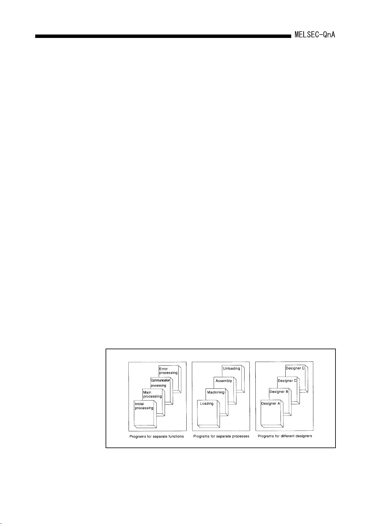
(a) In order to enable the design of structured programs, a file format has been
adopted for programs.
What would conventionally have been a single continuous program can now be
handled in a structured way as a number of files.
This allows for design work to be shared by several designers, and allows
management of programs in accordance with functions, processes, or
designers, etc.
2 - 2
2. OVERVIEW
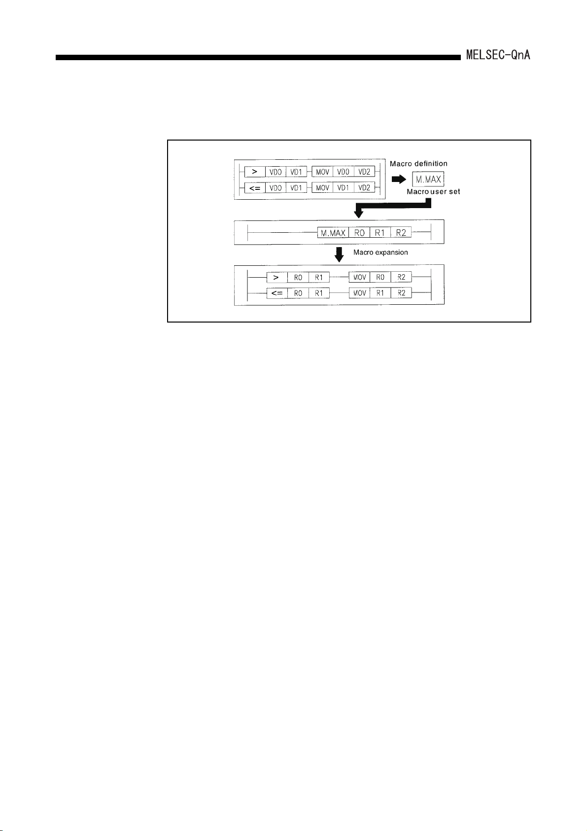
(b) The user can standardize and simplify programs by creating and using macro
instructions corresponding to functions.
(c) Devices can be used without restrictions.
1) Word device bit operations are possible.
2) Differential contacts can be used.
3) Buffer memories of special function modules can be accessed directly from a
program as devices.
4) The link data of network modules can be accessed directly from a program as
devices.
(d) Ease of operation for GPP function program editing has been improved.
1) Up to four programs, data, etc., can be edited simultaneously.
Programs and data can be cut and pasted between edited objects.
2) Ladder editing is possible while the ladder is displayed with comments.
3) Familiar operations can be performed with pull-down menus and dialog
boxes.
(e) The debugging function at start-up has been perfected.
1) Ladder modification while performing monitoring is possible.
2) Coil ON/OFF causes can be searched for.
3) The timing for monitoring can be set using a step number or device status,
allowing debugging to be conducted under the optimum conditions.
4) Devices for which index qualifications have been set can be monitored.
(f) The GPP function document creation function has been strengthened.
1) Since comments can now comprise 32 characters, they can be more detailed
than before.
2) Comments can now be set for all devices.
3) The statements and notes appended to programs can now be managed as
an integral part of the program, which makes program modifications and
utilization easier.
4) Printout data can be saved in a file.
2 - 3

2. OVERVIEW
(g) A powerful array of support software packages is available for program creation.
1) Data conversion package
Comment data, device data, etc., which is created with spreadsheet software
and text editors available on the market, can be converted to files for GPP
function use.
Conversely, files created for GPP function use can be converted to data for
spreadsheets or text editors.
2) Macro/library package
The basic programs for accessing special function modules, and standard
programs for error detection, alarm processing, etc., have been brought
together as a package of macro and library data.
3) Ladder sequence linking package
This package is used to link multiple programs to make a single program.
This has an automatic allocation function that ensures that devices from each
program without duplicating in the created program.
4) CAD interface program
This package is used to handle sequence ladders, instruction lists, comment
data and SFC diagrams as CAD data and communicate these data to CAD
systems.
2 - 4

2.
OVERVIEW
2.2 Additional Functions of QnACPU
New functions and instructions for special function module are added to the QnACPU.
[Additional functions]
Variety of local devices.................................................. Refer to Section 2.2.1 (1).
Monitor test of local device.................................. Refer to Section 8.2.2.
Use of local device at the subroutine/interrupt
program storage destination................................. Refer to Appendix 7.
Auto refresh setting of CC-Link...................................... Refer to Section 2.2.1 (2),
MELSECNET/10 relay communication from the
Ethernet module (Network relay).................................... Refer to Section 2.2.1 (3),
Addition of AJ71QC24N-compatible commands ............Section 2.2.1 (4)
Section 7.2.
Appendix 8.
[Added instructions for special function module]
The following instructions have been added for function version "B'' of the QnACPU:
AJ61QBT11 control instructions...................................... 13
AD75 control instructions................................................ 19
AJ71D -R4 control instructions.....................................
AJ71QE71 control instructions........................................ 10
Additional function/special function module instructions can be used for the QnACPU
described function version B in the date column of the rating plate.
Check that function version B is described on the QnACPU rating plate before using the
additional function/special function module instructions.
If your QnACPU does not have indication of function version B, skip this item and the
description of additional functions.
12
When using additional function/special function module instructions of the QnACPU, it is
necessary to match the GPP function model and the function version/version of the
applicable special function module. (Refer to Table 2.1.)
2 - 5
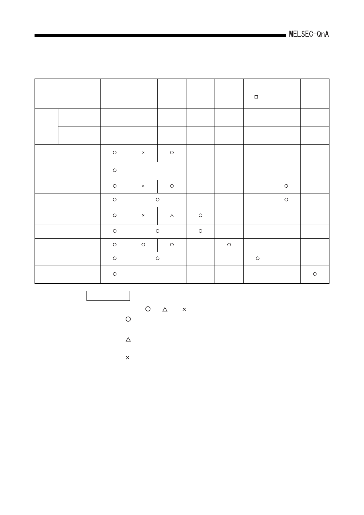
2. OVERVIEW
Table 2.1 List of combination between QnACPU and function version/version of special function module
SW0IVD-
Module/package Name QnACPU
Function version
Condition
Version –
Local device
monitor test
Local device switching of
subroutine/interrupt program
Auto refresh function of CC-Link – – – –
AJ61QBT11 control instructions – – – –
MELSECNET/10 relay
communication from Ethernet
AJ71QE71 control instructions – – – –
AD75 control instructions – – – –
ID interface module instructions – – – –
9707B and
later
GPPQ
SW1IVD-
GPPQ
––
No
restriction
SW2IVD-
GPPQ
No
restriction
– –––––
AJ71QE71
(B2), (B5)
9707B and
later
–
–––––
AD75P-S3
––
No
restriction
––––
AJ71
ID -R4
BC and later –
AJ61QBT11
9707B and
later
AJ71QC24
(N)(R2)
restriction
–
No
Compatibility with AJ71QC24N
commands
REMARK
–––––
1) Marks , –, and in Table 2.1 indicate as follows:
:
Essential for use of function and instruction
– :
Irrelevant to function and instruction
:
Required in the case of access to the QnACPU in other stations from
the peripheral device via Ethernet
:
Not available on peripheral devices.
2) GX Developer complies with functions of function version B.
2 - 6

2.
OVERVIEW
2.2.1 Overview of added functions
This section shows an overview of the added functions.
(1) Variety of local device
(a) The device set as the local device at "Device" in Parameter can be monitored
and tested with a peripheral device.
This function allows checking and debug of the local device in the program
monitored with a peripheral device.
(b) The local device of the file where the subroutine program/interrupt program is
stored has made it possible to be used during execution of the subroutine
program/interrupt program.
For this function, even if an operation using the local device of the subroutine
program is carried out, the original local device cannot be overwritten. In
addition, even if an operation using the local device of the interrupt program, the
local device which is executed before starting up the interrupt program cannot be
overwritten.
(c) The following GPP function software packages are required to perform the
monitor test of the local device:
• Personal computer
GX Developer, SW2IVD-GPPQ type GPP function software package
(2) Auto refresh setting of CC-Link
(a) When setting auto refresh of the CC-Link on the peripheral function, cyclic
communication with other stations connected to the CC-Link can be
automatically performed according to the set auto refresh data.
• Remote I/O station (Communication in ON/OFF data)
• Remote device station (Communication in ON/OFF data and Word data)
• Intelligent device station (Communication in ON/OFF data and Word data)
• Local station/master station (Communication in ON/OFF data and Word data)
The auto refresh setting of the CC-Link allows communication with other stations
using the FROM/TO instruction without communicating with the master station of
the CC-Link.
(b) Auto refresh is available for up to 8 CC-Link modules for each unit of QnACPU.
Communication for 9th CC-Link module and more can be performed with the
CC-Link module using the FROM/TO instruction.
(c) The following GPP function software packages are required to perform the auto
refresh setting of the CC-Link:
• Personal computer:
GX Developer, SW2IVD-GPPQ type GPP function software package
It is necessary to upgrade the master station local station module of CC-Link to
function version B or later.
2 - 7

2. OVERVIEW
(3) Netwotk relay from Ethernet module
(a) In the network system with mixture of Ethernet and MELSECNET/10, data can
be communicated with the QnACPU of other stations via multiple Ethernets or
MELSECNET/10 modules.
(b) For the network relay from the Ethernet module, the function version of the
Ethernet module should be upgraded to "B" or later.
(4) AJ71QC24N-compatible commands are possible.
(a) The following AJ71QC24N commands are available:
• Multiple blocks batch read: Command "0406"
• Multiple blocks batch write: Command "1406"
(b) Multiple blocks batch read/batch write is available with AJ71QC24N (-R2, R4).
Multiple blocks batch read/batch write is not available with AJ71QC24 (-R2, R4).
For commands of multiple blocks batch read/batch write, refer to the following
manual:
• Corresponding Additional Explanation for AJ71QC24N (-R2/R4)
2 - 8

3.
SYSTEM CONFIGURATION
3 SYSTEM CONFIGURATION
This section describes the system configurations that can be used for a system centered
on a QnACPU, cautions on configuring the system, and the system equipment.
3.1 System Configuration
The following shows the configuration of equipment and peripheral device when a
QnACPU is used in a stand-alone system.
3.1.1 Equipment configuration in a stand-alone system
POINT
*1 Up to two memory cards can be installed, if required.
2
SRAM and E
CPU module.
*2 When using an A5 B extension base unit, pay particular attention to the
power supply capacity of the main base unit. In the case of I/O modules and
the special function module with a high internal current consumption,
mounting on an A6 B extension base unit is recommended.
(Refer to Section 16.1 and Section 17.3 for details.)
PROM memory cards allow file read/write when mounted on the
3 - 1

3.
SYSTEM CONFIGURATION
3.1.2 Configuration of peripheral devices capable of QnACPU
(To RS-422 interface)
QnACPU
AC30R4-PUS cable
AC20R4-A8PU cable
RS-422 cable
Q6PU
programming unit
*2
RS-422 RS-232C
convertor
IBM-PC/AT-compatible
software package used:
RS-232C cable
*3
AJ71QC24 serial
communication module
(Mounted to the
base unit)
(To RS-422 interface/RS-232C)
(To option board slot)
Option board
*2
RS-232C cable
Dedicated cable
IBM-PC/AT-compatible
software package used:
IC memory card
reader/writer
*1
*1 For details on the IC memory card reader/writer setting, refer to Operating Manual for the
peripheral device capable of GPP functions.
*2 For connection to RS-422 interface, use the RS-422 RS-232C converter.
*3 When connecting the serial communication module and the peripheral devices capable of
GPP function, see User's Manual of the serial communication modules.
REMARK
1. For details on the system configuration for each peripheral device, refer to
the Operating Manual for each.
2. QnACPU can connect a peripheral device capable of ACPU only when
accessing an ACPU in another station via a MELSECNET/10 or
MELSECNET data link. (However, QnACPU cannot be accessed. ) In this
case, set SW2 of system setting switch 2 on the CPU module ON.
3 - 2

3.
SYSTEM CONFIGURATION
3.2 System Configuration Overview
(a) Q2ACPU system
System configuration
Maximum number of
extension stages
Maximum number of I/O
modules
Maximum number of I/O
points
Main base unit model
name
Extension base unit
model name
Extension cable model
name
Precautions
I/O number assignment
* An example when the 16-point module is installed to each slot is shown.
3rd extension stage
32 modules
512 points
A32B, A32B-S1, A35B, A38B, A38HB, A38HBEU
A62B, A65B, A68B, A52B, A55B, A58B
AC06B, AC12B, AC30B
(1) It is not possible to connect an extension base unit to an A32B main base unit. For an extension base, use A32B-S1.
(2) When using the extension base unit A52B, A55B, A58B, 5VDC is supplied from the power supply module of the main
base unit. Before use, refer to Section 17.3 and examine if it can be used.
(3) The overall distance of the extension cable must be 6.6m (21.65ft.) or shorter.
(4) When using the extension cable, do not tie it with the main circuit cables, which has high voltage, large current, or install
them close to each other.
(1) I/O numbers are allocated in accordance with the order of the numbers set for the extension base stages, regardless of
the order in which the extension cables are connected.
(2) Assign I/O numbers as if both main base unit and extension base unit have 8 slots each.
Consequently, allocations of 16 points per slot are made for the parts of the system configuration drawing indicated with
dotted lines.
(3) 16 points are assigned to an empty slot.
(4) Extension stage numbers do not need to be sequential, but any extension stage omitted from the system will occupy 8
(slots) 16 I/O points.
(5) With regard to items (2) to (4) above, the I/O allocations can be changed by setting I/O allocations in the
parameters.(Refer to Section 5.3)
3 - 3

3. SYSTEM CONFIGURATION
(b) Q2ACPU-S1 system
Extension
cable
1st extension
stage
2nd extension
stage
System configuration
3rd extension
stage
4th extension
stage
Main base unit (A38B)
0
23
1
CF
20
14F
1B0
1BF
230
23F
20
2F
12
C0
27
35
30
3F 4F
13
D0
DF
(21)(22)
150140
160
16F
15F
28
1C0
1D0
1DF
1CF
36
250
240
25F
24F
4
40
14
E0
EF
29
37
00
10
C
to to to to to to to to
P
U
0F
1F
Power supply
module
A58B extension base unit
8
9
11
10
B0
90
80
A0
to to to to to to to to
AF
BF
9F
8F
A55B extension base unit
19
18
16
17
130
120
100
110
to to to to to to to to
11F10F
13F
12F
A68B extension base unit
26
25
24
180
1A0
190
to to to to to to to to
1AF
18F
19F
Power supply
module
33
32
34
220
210
200
to to to to to to to to
22F
21F
20F
Power supply
module
50
5F
15
F0
FF
(23)
170
17F
30
1E0
1EF
38
260
26F
5
6
60 70
6F
31
1F0
1FF
39
270
27F
Slot No.
7
7F
* An example when the 16-point module
is installed to each slot is shown.
5th extension
stage
6th extension
stage
7th extension
stage
A65B extension base unit
2A0
2AF
320
32F
3A0
3AF
(45)(46)
44
43
42
2D0
2B0
2C0
2DF
2BF
2CF
52
51
50
330
350
340
33F
35F
34F
59
58
60
3C0
3D0
3B0
3BF
3DF
3CF
41
40
280
290
to to to to to to to to
29F
28F
Power supply
module
49
48
300
310
to to to to to to to to
31F
30F
Power supply
module
57
56
380
390
to to to to to to to to
39F
38F
Power supply
module
(
2E0
2EF
(((
53
360
36F
61
3E0
3EF
(47)
(
(
2F0
2FF
54
55
370
37F
63
62
3F0
3FF
Maximum number of
extension stages
Maximum number of I/O
modules
Maximum number of I/O
points
Main base unit model
name
Extension base unit
model name
Extension cable model
name
Precautions
I/O number assignment
7th extension stage
64 modules
1024 points
A32B, A32B-S1, A35B, A38B, A38HB, A38HBEU
A62B, A65B, A68B, A52B, A55B, A58B
AC06B, AC12B, AC30B
(1) It is not possible to connect an extension base unit to an A32B main base unit. For an extension base, use A32B-S1.
(2) When using extension base units A52B, A55B, A58B, 5VDC is supplied from the power supply module of the main base.
Before use, refer to Section 17.3 and examine if it can be used.
(3) The overall distance of the extension cable must be 6.6m (21.65ft.) or shorter.
(4) When using the extension cable, do not tie it with the main circuit cables, which has high voltage, large current, or install
them close to each other.
(1) I/O numbers are allocated in accordance with the order of the numbers set for the extension base stages, regardless of
the order in which the extension cables are connected.
(2) Assign I/O numbers as if both main base unit and extension base unit have 8 slots each.
Consequently, allocations of 16 points per slot are made for the parts of the system configuration drawing indicated with
dotted lines.
(3) 16 points are assigned to an empty slot.
(4) Extension stage numbers do not need to be sequential, but any extension stage omitted from the system will occupy 8
(slots) 16 I/O points.
(5) With regard to items (2) to (4) above, the I/O allocations can be changed by setting I/O allocations in the
parameters.(Refer to Section 5.3)
3 - 4

3. SYSTEM CONFIGURATION
(c) Q3A/Q4ACPU system
Extension
cable
1st extension
stage
2nd extension
stage
System configuration
3rd extension
stage
4th extension
stage
Main base unit (A38B)
0
23
1
00
10
C
to to to to to to to to
P
U
0F
1F
Power supply
module
A58B extension base unit
8
9
11
10
B0
90
80
A0
to to to to to to to to
AF
BF
9F
8F
A55B extension base unit
18
16
17
130
120
100
110
to to to to to to to to
11F10F
13F
12F
A68B extension base unit
25
24
180
1A0
190
to to to to to to to to
1AF
18F
19F
Power supply
module
33
32
220
210
200
to to to to to to to to
22F
21F
20F
Power supply
module
4
30
20
40
2F
3F 4F
13
12
14
D0
C0
E0
CF
DF
EF
20
19
(21)(22)
160
150140
14F
16F
15F
27
26
29
28
1B0
1C0
1D0
1BF
1DF
1CF
35
36
34
37
250
230
240
23F
25F
24F
(23)
170
17F
1E0
1EF
260
26F
5
6
50
60 70
6F
5F
15
F0
FF
31
30
1F0
1FF
38
39
270
27F
Slot No.
7
7F
* An example when the 16-point module
is installed to each slot is shown.
5th extension
stage
6th extension
stage
7th extension
stage
A65B extension base unit
2A0
2AF
320
32F
3A0
3AF
(45)(46)
44
43
42
2B0
2C0
2D0
2BF
2CF
2DF
52
51
53
50
330
350
340
33F
35F
34F
59
58
61
60
3C0
3D0
3B0
3BF
3DF
3CF
41
40
280
290
to to to to to to to to
29F
28F
Power supply
module
49
48
300
310
to to to to to to to to
31F
30F
Power supply
module
57
56
380
390
to to to to to to to to
39F
38F
Power supply
module
(
(
2E0
2EF
(((
54
360
36F
62
3E0
3EF
(47)
2F0
2FF
370
37F
3F0
3FF
(
55
63
Maximum number of
extension stages
Maximum number of I/O
modules
Maximum number of I/O
points
Main base unit model
name
Extension base unit
model name
Extension cable model
name
Precautions
I/O number assignment
7th extension stage
64 modules
Q3A 2048 points/Q4A 4096 points
A32B, A35B, A38B, A38HB, A38HBEU
A62B, A65B, A68B, A52B, A55B, A58B
AC06B, AC12B, AC30B
(1) It is not possible to connect an extension base unit to an A32B main base unit. For an extension base, use A32B-S1.
(2) When extension base unit A52B, A55B, A58B is used, 5VDC power supply is supplied from the power supply module of
the main base. Before use, refer to Section 17.3 and examine if it can be used.
(3) The overall distance of the extension cable must be 6.6m (21.65ft.) or shorter.
(4) When using the extension cable, do not tie it with the main circuit cables, which has high voltage, large current, or install
them close to each other.
(1) I/O numbers are allocated in accordance with the order of the numbers set for the extension base stages, regardless of
the order in which the extension cables are connected.
(2) Assign I/O numbers as if both main base unit and extension base unit have 8 slots each.
Consequently, allocations of 16 points per slot are made for the parts of the system configuration drawing indicated with
dotted lines.
(3) 16 points are assigned to an empty slot.
(4) Extension stage numbers do not need to be sequential, but any extension stage omitted from the system will occupy 8
(slots) 16 I/O points.
(5) With regard to items (2) to (4) above, the I/O assignment can be changed by setting I/O assignments in the
parameters.(Refer to Section 5.3)
3 - 5

3.
SYSTEM CONFIGURATION
3.3 System Equipment
3.3.1 System equipment list
The following shows the system equipment (modules and peripheral devices) that can be
used in a QnACPU system.
(1) For QnA module
Product Name Model Name Description
Number of I/O points: 512, built-in RAM: 28k
steps
Number of I/O points: 1024, built-in RAM: 60k
steps
Number of I/O points: 2048, built-in RAM: 92k
steps
Number of I/O points: 4096, built-in RAM: 124k
steps
SRAM, 32k bytes, E
2
PROM, 32k bytes
CPU module
Memory card
Q2ACPU
Q2ACPU-S1
Q3ACPU
Q4ACPU
Q1MEM-64S SRAM, 64k bytes
Q1MEM-128S SRAM, 128k bytes
Q1MEM-256S SRAM, 256k bytes
Q1MEM-512S SRAM, 512k bytes
Q1MEM-1MS SRAM, 1M bytes
Q1MEM-2MS SRAM, 2M bytes
Q1MEM-64SE
Number of Occupied
Points (points)
[I/O Allocation
Module Type]
–
–––
Current Consumption
5VDC(A) 24VDC(A)
0.4 –
0.4 –
0.4 –
0.9 –
Remark
Memory card
procured
separately.
Including
memory card
current
consumption.
For use with
QnACPU only
Q1MEM-128SE
Q1MEM-256SE
Q1MEM-512SE
Q1MEM-1MSE
SRAM, 64k bytes, E2PROM, 64k bytes
SRAM, 128k bytes, E2PROM, 128k bytes
SRAM, 256k bytes, E2PROM, 256k bytes
SRAM, 512k bytes, E2PROM, 512k bytes
3 - 6

3. SYSTEM CONFIGURATION
Product Name Model Name Description
AX10 16-input 100VAC input module 16 (16 inputs) 0.055 –
AX11 32-input 100VAC input module 32 (32 inputs) 0.11 –
AX11EU 32-input 100VAC input module CE-compliant 32 (32 inputs) 0.15 –
AX20 16-input 200VAC input module 16 (16 inputs) 0.055 –
AX21 32-input 200VAC input module 32 (32 inputs) 0.11 –
AX21EU 32-point 200VAC input module CE-compliant 32 (32 inputs) 0.15 –
AX31 32-input 12/24VAC/DC input module 32 (32 inputs) 0.11 –
AX31-S1 32-input 24VDC input module 32 (32 inputs) 0.11 –
AX40 16-input 12/24VDC input module 16 (16 inputs) 0.055 –
AX41 32-point 12/24VDC input module 32 (32 inputs) 0.11 –
AX41-S1 32-point 12/24VDC input module 32 (32 inputs) 0.11 –
AX42 64-input 12/24VDC input module 64 (64 inputs) 0.12 –
AX50 16-input 48VDC sink input module 16 (16 inputs) 0.055 –
Number of Occupied
Points (points)
[I/O Allocation
Module Type]
Current Consumption
Remark
5VDC(A) 24VDC(A)
Input module
AX50-S1 16-input 48VDC sink/source input module 16 (16 inputs) 0.055 –
AX60
AX60-S1
AX70 16-input input module for sensor 16 (16 inputs) 0.055 –
AX71 32-input input module for sensor 32 (32 inputs) 0.11 –
AX80 16-input 12/24VDC source input module 16 (16 inputs) 0.055 –
AX80E 16-input 12/24VDC source input module 16 (16 inputs) 0.055 –
AX81 32-input 12/24VDC source input module 32 (32 inputs) 0.11 –
AX81-S1 32-input 12/24VDC source input module 32 (32 inputs) 0.105 –
AX81-S2 32-input 48/60VDC source input module 32 (32 inputs) 0.11 –
AX81-S3 32-input 12/24VDC source input module 32 (32 inputs) 0.11 –
AX81B 32-input 24VDC sink/source input module 64 (64 inputs) 0.125 –
AX82 64-point 12/24VDC source input module 64 (64 inputs) 0.12 –
16-input 100/110/125VDC
sink input module
16-input 100/110/125VDC
sink/source input module
16 (16 inputs) 0.055 –
16 (16 inputs) 0.055 –
3 - 7

3. SYSTEM CONFIGURATION
Product Name Model Name Description
AY10 16-output relay contact output module (2A) 16 (16 outputs) 0.115 0.15
AY1 0A
AY11
AY11 A
AY11 AE U
AY11 E
AY11 EE U
AY13 32-point relay contact output module (2A) 32 (32 outputs) 0.23 0.29
AY13E 32-point relay contact output module 32 (32 outputs) 0.23 0.29
AY1 3E U
Output module
AY1 5E U
AY2 2
AY2 3
AY4 0
AY4 0A
AY4 1
AY4 2
16-output relay contact output module,
for independent contact output
16-output relay contact output module,
with surge suppressor
16-output relay contact output module, for
independent contact output, with surge
suppressor
16-output relay contact output module, for
independent contact output, with surge
suppressor
16-output relay contact output module
(fused)
16-output relay contact output module
(fused)
32-output relay contact output module
(fused)
24-point relay contact output module (2A)
CE-compliant
16-point triac output module
(2A, fused)
32-point triac output module
(0.6A, fused)
16-output 12/24VDC transistor output module
(0.1A)
16-point 12/24VDC transistor output module,
for independent contact output (0.3A)
32-output 12/24VDC transistor output module
(0.1A)
64-output 12/24VDC transistor output module
(0.1A)
Number of Occupied
Points (points)
[I/O Allocation
Module Type]
16 (16 outputs) 0.115 0.15
16 (16 outputs) 0.115 0.15
16 (16 outputs) 0.115 0.15
16 (16 outputs) 0.115 0.15
16 (16 outputs) 0.115 0.15
16 (16 outputs) 0.115 0.15
32 (32 outputs) 0.23 0.29
32 (32 outputs) 0.15 0.22
16 (16 outputs) 0.305 –
32 (32 outputs) 0.59 –
16 (16 outputs) 0.115 0.016
16 (16 outputs) 0.19 –
32 (32 outputs) 0.23 0.04
64 (64 outputs) 0.29 0.08
Current Consumption
5VDC(A) 24VDC(A)
Remark
The short
protection and
overheat
protection
functions of the
AY4 0 P, AY 4 1 P,
AY6 0E P,
AY8 0E P,
AY81EP, and
AY82EP are
described
below:
Short protection
function
Function that
protects the
transistors from
overcurrents
occurring, for
example, due to
short circuits in
external wiring.
Overheat
protection
function
Function that
protects the
transistors from
damage due to
external
temperature rise
attributable to
external causes.
AY4 2- S1
AY4 2- S3
AY4 2- S4
64-output 12/24VDC transistor output module
(0.1A)
64-output 12/24 VDC transistor output module
(fused)
64-output 12/24VDC transistor output module,
zener diode with built-in photocoupler
3 - 8
64 (64 outputs) 0.29 0.08
64 (64 outputs) 0.29 0.08
64 (64 outputs) 0.50 –

3. SYSTEM CONFIGURATION
Product Name Model Name Description
16-point 12/24VDC transistor output module
(0.5A, fused)
32-output 12/24VDC transistor output module
(0.5A)
32-point 12/24VDC transistor output module
(0.3A, fused)
16-output 12/24/48VDC transistor output
module (2A, fused)
16-output 12/24/48VDC
transistor output module (2A)
16-output 12/24 VDC transistor output module
*1
(2A), with short protection function and
overheat protection function
16-output, CMOS (5/12VDC) output module
(16mA)
32-output, CMOS (5/12VDC) output module
(16mA)
64-output, CMOS (5/12VDC) output module
(16mA)
16-output 12/24/48VDC transistor output
module (0.5A, fused)
32-output 12/24VDC transistor output module
(0.5A)
Output module
AY5 0
AY5 1
AY5 1- S1
AY6 0
AY6 0S
AY60EP
AY7 0
AY7 1
AY7 2
*1
AY8 0
*1
AY8 1
Number of Occupied
Points (points)
[I/O Allocation
Module Type]
16 (16 outputs) 0.115 0.13
32 (32 outputs) 0.23 0.10
32 (32 outputs) 0.31 0.02
16 (16 outputs) 0.115 0.13
16 (16 outputs) 0.075 0.006
16 (16 outputs) 0.115 0.22
16 (16 outputs) 0.10
32 (32 outputs) 0.20
64 (64 outputs) 0.30
16 (16 outputs) 0.115 0.12
32 (32 outputs) 0.23 0.10
Current Consumption
5VDC(A) 24VDC(A)
12VDC
0.11
12VDC
0.20
12VDC
0.60
Remark
*1: Indicates a
source load
module.
Other modules
are sink load
modules.
The short
protection and
overheat
protection
functions of the
AY4 0 P, AY 4 1 P,
AY6 0E P,
AY8 0E P,
AY81EP, and
AY82EP are
described
below:
Short protection
function
Function that
protects the
transistors from
overcurrents
occurring, for
example, due to
short circuits in
external wiring.
Dynamic input/
output
combination
module
Input/output
combination
module
64-output 12/24VDC transistor output module
*1
AY82EP
A42XY 64 inputs, 64 outputs, dynamic scanning mode 64 (64 outputs) 0.11 0.235
AH42
(0.1A), with short protection function and
overheat protection function
32 inputs, 32 outputs, 12/24VDC transistor
output module (0.1A)
64 (64 outputs) 0.29 0.10
64 (64 outputs) 0.245 0.04
3 - 9
Overheat
protection
function
Function that
protects the
transistors from
damage due to
external
temperature rise
attributable to
external causes.
Performs I/O
processing in 8point units
independently
of the CPU
module, while
scanning.
The first half 32
points are inputs
and the second
half 32 points
are outputs.
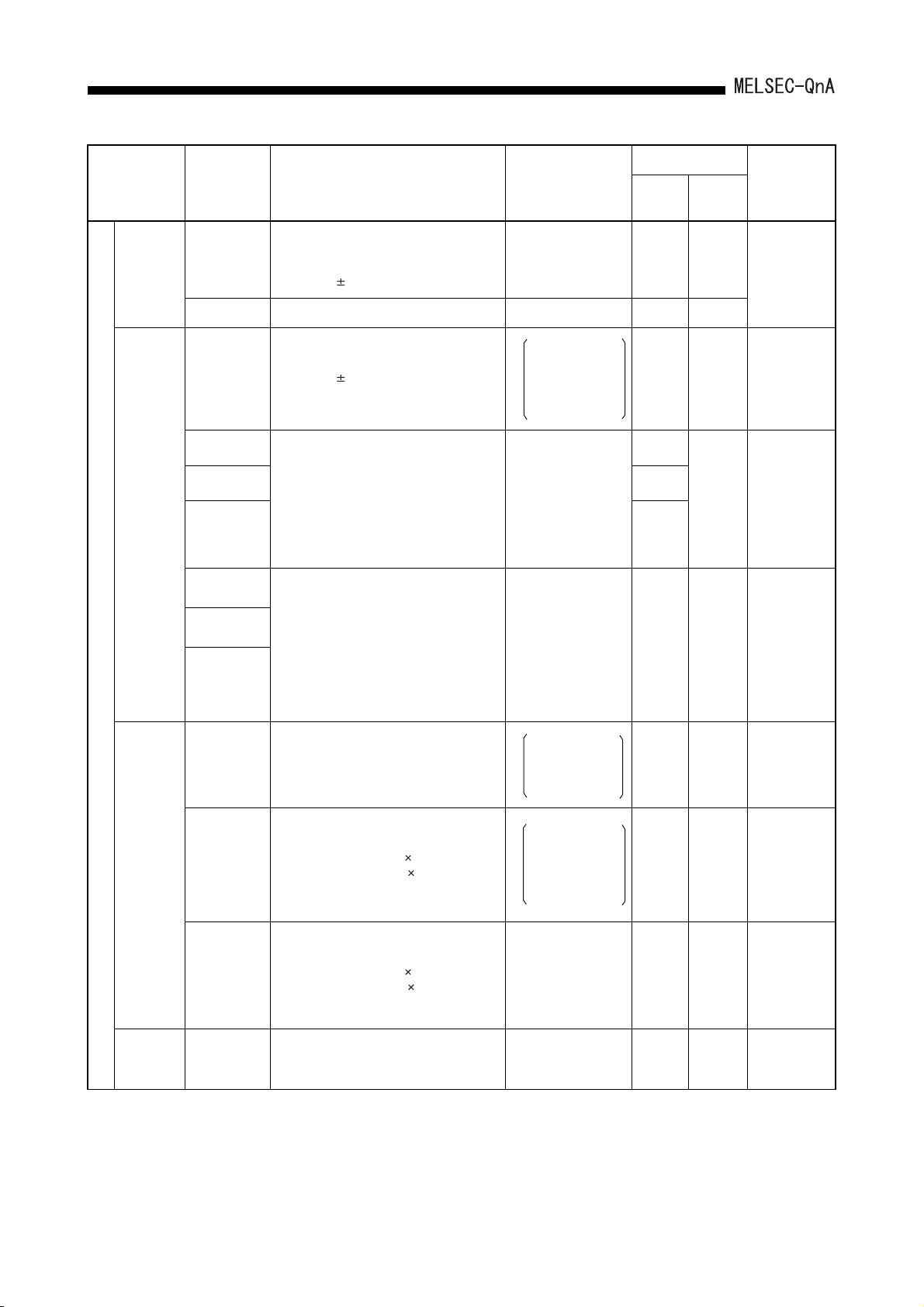
3. SYSTEM CONFIGURATION
Product Name Model Name Description
1-axis positioning control, speed control
1-axis
positioning
module
Positioning
module
Special function module
AD70
AD70D-S2 1-axis, digital output, for MR-SB(K)/SD 32 (special 32 points) 0.8 –
AD72
AD75P1-S3
AD75P2-S3 0.7
AD75P3-S3
AD75M1
AD75M2
AD75M3
and speed-positioning control,
analog voltage output for speed-positioning
control (0 to 10V)
For positioning control
analog voltage output for speed-positioning
control (0 to 10V)
2-axis (independent control, simultaneous 2axis control, linear interpolation control).
For positioning control, pulse output
P1: 1 axis
P2: 2 axes (Independent, simultaneous 2
axes, linear interpolation,
circular interpolation)
P3: 3 axes (Independent, simultaneous 3
axes, linear interpolation 2 axes,
circular interpolation 2 axes)
Digital output for positioning control, for MR-HB/MR-JB/ MR-J2-B
P1: 1 axis
P2: 2 axes (Independent, simultaneous 2
axes, linear interpolation,
circular interpolation)
P3: 3 axes (Independent, simultaneous 3
axes, linear interpolation 2 axes,
circular interpolation 2 axes)
Number of Occupied
Points (points)
[I/O Allocation
Module Type]
32 (special 32 points) 0.3 –
First half:
empty 16 points
Second half:
48
special 32
points
32 (special 32 points)
32 (special 32 points) 0.7 –
Current Consumption
5VDC(A) 24VDC(A)
0.9 –
0.7
*
0.7
–
Remark
* When
differential
driver is
connected: 0.78
Positioning
detection
module
Ultrasonic
linear scale
module
Absolute detection method.
A61LS
A62LS-S5
A63LS 32 (special 32 points) 0.9 –
A64BTL
Resolution: One resolver revolution = 4096
divisions.
Response speed: within 6ms
Absolute detection method, multiple rotation
type, linear type
Resolution: 4096 divisions 32 rotations to
409.6 divisions 320 rotations
Response speed: 2ms, 8 channels
Absolute detection method, multiple rotation
type
Resolution: 4096 divisions 32 rotations to
409.6 divisions 320 rotations
Response speed: 2ms, 8 channels
Measuring range: 0.000 to 3,550,000 mm
Resolution: 0.025mm, 4 channels
First half:
special 32 points
48
Second half:
empty 16 points
First half:
empty 16 points
Second half:
48
special 32
points
32 (special 32 points) 1.05 –
0.8 –
1.5 –
The resolution
depends on the
connected
resolver.
When setting
module is
connected:
5VDC current
consumption:
1.35A
3 - 10

3. SYSTEM CONFIGURATION
Product Name Model Name Description
24-bit binary, 1/2 phase input,
High-speed
counter
module
A/D
converter
module
Special function module
AD61
AD61S1
A68AD
A68AD-S2
A68ADN
A616AD
A60MX
A60MXR
A60MXRN
A616TD
reversible counter,
50kPPS, 2 channels
24-bit binary, 1/2 phase input,
reversible counter,
1 phase 10kPPS, 2 phases 7kPPS,
2 channels
4 to 20mA/0 to 10V,
Analog input, 8 channels
0 to 20mA/0 to 10V,
Analog input, 8 channels
4 to 20mA/0 to 10V,
Analog input, 16 channels
Expansion to maximum of 121 channels
possible by using A60MX(R)
Multiplex module (IC relay)
Analog input, 16 channels
Multiplex module (mercury relay)
Analog input, 16 channels
Multiplex module (photo MOS relay)
Analog input, 16 channels
For temperature detection by thermocouple
(when connected to A60MXT).
0 to 10V/0 to 20mA (when connected to
A60MX(R))
Number of Occupied
Points (points)
[I/O Allocation
Module Type]
32 (special 32 points) 0.3 –
32 (special 32 points) 0.3 –
32 (special 32 points) 0.9 –
32 (special 32 points) 0.4 –
32 (special 32 points) 1.0 –
16 (empty 16 points) 0.65 –
16 (empty 16 points) 0.5 –
16 (empty 16 points) 0.35 –
32 (special 32 points) 1.0 –
Current Consumption
5VDC(A) 24VDC(A)
Remark
Used in
combination
with A616AD or
A616TD.
Temperature
digital
converter
module
A60MXT
A60MXTN
A68RD3
A68RD4
Multiplex module (mercury relay)
Temperature input: 15 channels.
Temperature detection by thermocouple when
used in combination with A616TD.
Multiplex module (photo MOS relay)
Temperature input: 15 channels.
Temperature detection by thermocouple when
used in combination with A616TD.
-180 to 600 temperature input module
(For 3-wire type platinum resistor)
-180 to 600 temperature input module
(For 4-wire type platinum resistor)
First half:
empty 16 points
32
Second half:
empty 16 points
First half:
empty 16 points
32
Second half:
empty 16 points
32 (special 32 points)
0.8 –
Used in
combination
with A616TD.
0.64 –
0.94 –
0.75 –
3 - 11

3. SYSTEM CONFIGURATION
Product Name Model Name Description
A68DAV
0 to 10V, analog output, 8 channels.
A68DAI-S1 0 to 20mA, analog output, 8 channels. 32 (special 32 points) 0.15 0.4
4 to 20mA/0 to 10V
Analog output 12 bits, 2 channels
4 to 20mA/0 to 10V Analog output,
2 channels
D/A
converter
A62DA
A62DA-S1
module
4 to 20mA. Resolution: 1/4000
Analog output, 16 channels
0 to 10 V/0 to 5 V. Resolution: 1/4000
Analog output, 16 channels
32k byte-memory battery backup
Can be connected to printer conforming to
Centronics standards
Special function module
Memory
card,
Centronics
interface
module
A616DAI
A616DAV
AD59
AD59-S1
Number of Occupied
Current Consumption
Points (points)
[I/O Allocation
Module Type]
5VDC(A) 24VDC(A)
32 (special 32 points) 0.15 0.5
32 (special 32 points) 0.6 0.35
32 (special 32 points) 0.3 –
32 (special 32 points) 0.38 –
0.3
32 (special 32 points)
–
0.32
Remark
15VDC (A68P)
+0.53A
is
-0.125A
required.
15VDC (A68P)
+0.2A
is
-0.17A
required.
0.35A when
connected to
AD59MEF.
Voice output
module
Network
module
Messages can be recorded and played back on
a maximum of 60 channels.
A11VC
The following recording times can be selected
for each channel: 1 second, 2 seconds,
16 (special 16 points) 0.6 0.38
4 seconds, 8 seconds.
The total recording time is 64 seconds
AJ71QLP21
For MELSECNET/10 optical loop networks
(compatible with SI cable)
32 (special 32 points) 0.65 –
AJ71QLP21G
AJ71QLP21S
AJ71QBR11 For MELSECNET/10 coaxial bus networks
For MELSECNET/10 optical loop network
(compatible with GI cable)
For MELSECNET/10 optical loop networks.
Network backup by external power supply
32 (special 32 points) 0.65 0.2
0.8
32 (special 32 points)
AJ71QLR21 For MELSECNET/10 coaxial loop network 1.14
AJ72QLP25
For MELSECNET/10 optical loop network
remote I/O stations (compatible with SI cable)
–0.8–
AJ72QLP25G
AJ72QBR15
For MELSECNET/10 optical loop network
remote I/O station (compatible with GI cable)
For MELSECNET/10 coaxial bus network
remote I/O stations
0.9
–
AJ72QLR25
For MELSECNET/10 coaxial loop network
remote I/O station
1.3
–
–
• For Use with
QnACPU
Only
• Maximum 4
modules can
be used for
one CPU
module.
(Refer to
Section 3.3.2 )
3 - 12

3. SYSTEM CONFIGURATION
Product Name Model Name Description
*2
For MELSECNET II optical data links
For MELSECNET II optical data link
(compatible with GI cable)
*2
For MELSECNET II coaxial data links 32 (special 32 points) 0.9 –
*2
For MELSECNET/B data links 32 (special 32 points) 0.72 –
For MESLECNET optical data link remote I/O
station
For MESLECNET optical data link remote I/O
station (compatible with GI cable)
For MESLECNET coaxial data link remote I/O
station
For MELSECNET/B data link remote I/O
stations
Data link module
AJ71AP21
AJ71AP21-S3
*1
AJ71AR21
AJ71AT21B
AJ72P25
AJ72P25-S3
AJ72R25
AJ72T25B
Link module that communicates data
AJ71QC24N
with a computer.
Transmission speed: 300bps to 19.2kbps
RS-232, RS-422/485: one channel each
Number of Occupied
Current Consumption
Points (points)
[I/O Allocation
Module Type]
5VDC(A) 24VDC(A)
32 (special 32 points) 0.5 –
–0.23–
–2.6–
–0.3–
32 (special 32 points) 0.3 –
Remark
Maximum 2
modules can be
used for one
CPU module.
(Refer to
Section 3.3.2 )
Serial
communications
module
Ethernet
interface
module
Link module that communicates data
AJ71QC24
N-R2
with a computer.
Transmission speed: 300bps to 19.2kbps
RS-232C: 2 channels
Link module that communicates data
AJ71QC24
N-R4
with a computer.
Transmission speed: 300bps to 19.2kbps
RS-422: 2 channels
AJ71QE71-B2
10BASE2 specification Transmission speed:
10Mbps
AJ71QE71N-B510BASE5 specification Transmission speed:
10 Mbps
AJ71QE71N3-T10BASE-T specification Transmission speed:
10Mbps
AJ71E71N-B2
*2
AJ71E71N-B5
*2
AJ71E71N3-T
*2
10BASE2 specification, Transmission speed:
10 Mbps
10BASE5 specification, Transmission speed:
10Mbps
10BASE-T specification Transmission speed:
10Mbps
32 (special 32 points) 0.2 –
32 (special 32 points) 0.38 –
0.56
0.40
0.53
32 (special 32 points)
0.67
0.55
0.69
–
–
• For use with
QnACPU only
• For use with
QnACPU only
• Maximum 4
modules can
be used for
one CPU
module.
(Refer to
Section 3.3.2 )
3 - 13

3. SYSTEM CONFIGURATION
Product Name Model Name Description
Link module that communicates data with a
Computer link
module
Intelligent
communication
module
Host controller
high-speed link
module
Multidrop data link
module
AJ71UC24
AD51H-S3
AJ71C23-S3
AJ71C22-S1
A0J2C25
computer.
*2
Transmission speed: 300bps to 19.2kbps
RS-232C, RS-422: one channel each,
compatible with RS485
AD51H-BASIC, maximum of 8 tasks executes
data communication with a PLC or a computer,
and monitoring control status.
Data communication with a computer can be
executed by any format.
RS-232C: 2 channels, RS-422, Parallel: one
channel each
Link module that sends/receives data at high
speed to/from a computer.
*2
Transmission speed: 500kbps
RS-422: one channel each
Sends and receives bit data to maximum 8
slave stations to which it is connected in a
multidrop system.
Used for the master station of a multidrop link.
Transmission speed: 38.4kbps
RS-422: one channel each
Used for a remote I/O station of a multidrop
link.
Number of Occupied
Points (points)
[I/O Allocation
Module Type]
32 (special 32 points) 0.3 –
First half:
empty 16 points
48
Second half:
special 32
points
32 (special 32 points) 1.5 –
32 (special 32 points) 1.4 –
–––
Current Consumption
5VDC(A) 24VDC(A)
1.0 –
Remark
Maximum 6
modules can be
used for one
CPU module.
CC-Link system
master/local
module
MELSECNET/
MINI-S3 data link
module
B/NET interface
module
Interrupt module
Used for a local station in a multidrop link.
A0J2C214(S1)
AJ61QBT11
AJ71PT32-S3
AJ71T32-S3
AJ71B62-S3
AI61
AI61-S1 Product for changing time to turn ON/OFF A61
In A0J2CPU and A0J2HCPU systems,
A0J2C214 can also be used as the master
station in computer links and multidrop data links
For CC-Link system master and local stations
When used as the master station, the module
controls maximum 64 remote I/O stations.
When a local station is used, the module
occupies 1 or 4 station(s).
For MELSECNET/MINI-S3 master stations
(max. 64 stations). Performs remote I/O and
remote terminal control of a total of 512 I/O
points.
Used for B/NET transmission terminal control.
Up to 63 stations can be controlled per module.
Used to designate execution of interrupt
programs (16 interrupt inputs).
64 points 0.3 –
32 (special 32 points) 0.45 –
I/O dedicated mode
32 (special 32 points)
0.34 –
Expanded mode
48 (special 48 points)
32 (special 32 points) 0.17 –
32 (special 32 points) 0.14 –
For use with
QnACPU only
Only one
module can be
used per CPU.
3 - 14
3. SYSTEM CONFIGURATION
Product Name Model Name Description
Device Net
interface
module
PROFIBUS-DP
interface
module
PROFIBUSFMS interface
module
MODBUS serial
communication
module
PLC easier
monitoring
module
Dummy module AG62
AJ71DN91
AJ71PB92D 32 (special 32 points) 0.54 –
AJ71PB96F
AJ71UC24-R2
*2
AS91 PLC easier monitoring module 16 (16 outputs) 0.08 –
Device Net master module
Total I/O points: 4096 points
PROFIBUS-DP master module
Sendable data Regula r service: 32 byt es
Extension service: 244 bytes
PROFIBUS-FMS master/client/server module
Total I/O points: 241241 points
MODBUS serial communication module
Transmission speed: 300bps to 19200bps
Module allows selection of 16, 32, 48, or 64
points.
Number of Occupied
Points (points)
[I/O Assignment
Module Type]
32 (special 32 points) 0.24 –
32 (special 32 points) 0.54 –
32 (special 32 points) 1.4 –
Setting range
[Input
Set number of points
Current Consumption
5VDC(A) 24VDC(A)
0.07 –
]
Remark
With simulation
switch 16 points
Blank cover AG60 Dust-proof cover for unused slot 16 (empty 16 points) – – CE-compliant
*2 This module can access devices within the device range of the AnACPU (cannot access file
register).
(Refer to Section 3.3.2)
3 - 15

3. SYSTEM CONFIGURATION
Product Name Model Name Description
Large-size graphic operation terminal
A985GOT
A975GOT
A970GOT
A960GOT
A956GOT
256 colors, TFT color, 800 600 dots, high
intensity
Large-size graphic operation terminal
256 colors, TFT color, 640 480 dots, high
intensity/256 colors, TFT color, 640 480 dots,
wide viewing angle
Large-size graphic operation terminal
16 colors, TFT color, 640 480 dots, high
intensity/16 colors, TFT color, 640 480 dots,
wide viewing angle/8 colors, STN color,
640 480 dots/2 colors, STN monochrome,
640 480 dots
Large-size graphic operation terminal
2 colors, EL, 640 400 dots
Medium-size graphic operation terminal
8 colors, STN color, 320 240 dots/
STN monochrome, 320 240 dots/
256 colors, TFT color, 320 240 dots, high
intensity
Number of Occupied
Points (points)
[I/O Assignment
Module Type]
32 (special 32 points)
Current Consumption
5VDC(A) 24VDC(A)
*
0.22
*
–
Remark
*When bus
connected
Graphic
operation
terminal
A956WGOT
A953GOT
A951GOT
A950GOT
GT1565-VTBA
GT1575-VTBA
Medium-size graphic operation terminal
256 colors, TFT color, 320 240 dots, high
intensity
Medium-size graphic operation terminal
8 colors, STN color, 320 240 dots/
STN monochrome, 320 240 dots/
256 colors, TFT color, 320 240 dots, high
intensity
With handheld type
Medium-size graphic operation terminal
8 colors, STN color, 320 240 dots/
STN monochrome, 320 240 dots/
256 colors, TFT color, 320 240 dots, high
intensity
Medium-size graphic operation terminal
8 colors, STN color, 320 240 dots/
STN monochrome, 320 240 dots/
256 colors, TFT color, 320 240 dots, high
intensity
With handheld type
Large-size graphic operation terminal
8.4"
256 colors, TFT color, 640 480 dots (When
installing a multi color display board, 65536
colors can be displayed.)
Large-size graphic operation terminal
10.4"
256 colors, TFT color, 640 480 dots (When
installing a multi color display board, 65536
colors can be displayed.)
–––
32 (special 32 points)
–––
32 (special 32 points)
*
*
*
0.22
0.12 –
–
For RS-232C
connected only
*When bus
connected
Dedicated to
RS-422
connection
*When bus
connected
3 - 16

3. SYSTEM CONFIGURATION
Product Name Model Name Description
Power supply module
Power
supply
slot
mouting
position
I/O slot
mounting
position
A61P
A61PN
A61PEU CE-compliant
A62P
A62PEU CE-compliant
A63P
A66P
A68P
A38HB 8 I/O modules can be installed.
100/200VAC input
Output: 5VDC 8A
100/200VAC input
Output: 5VDC 5A, 24VDC 0.8A
24VDC input
Output: 5VDC 8A
100/200VAC input
Output: 24VDC 1.2A
100/200VAC input
Output: +15VDC 1.2A, -15VDC 0.7A
Number of Occupied
Points (points)
[I/O Assignment
Module Type]
16 (empty 16 points)
First half:
empty 16 points
32
Second half:
empty 16 points
Current Consumption
Remark
5VDC(A) 24VDC(A)
––
Power supply
for AD70,
A616DAV,
A616DAI
For high-speed
access
(dedicated to
QnACPU)
Main
base unit
Base unit
Extension
base unit
Extension cable
A38HBEU 8 I/O modules can be installed.
A38B 8 I/O modules can be installed.
A35B 5 I/O modules can be installed.
A32B 2 I/O modules can be installed.
A32B-S1 2 I/O modules can be installed.
A68B 8 I/O modules can be installed.
A65B 5 I/O modules can be installed.
A62B 2 I/O modules can be installed.
A58B 8 I/O modules can be installed.
A55B 5 I/O modules can be installed.
A52B 2 I/O modules can be installed.
AC06B
AC30B
600mm (23.62inch)
long
1200mm (47.24inch)
long
3000mm (118.11inch)
long
Cables for
connections between
base units
For high-speed
access
(dedicated to
QnACPU)
–––
–––
–––
–––AC12B
CE-compliant
No connector
for extension.
With connector
for extension.
The power
supply module
is required.
A61P, A61PN,
A62P,
A63P, andA65P
cannot be
mounted.
3 - 17

3. SYSTEM CONFIGURATION
Number of Occupied
Product Name Model Name Description
Simulation
switch
Battery A6BAT Built-in RAM memory backup – – –
For
AY11E,
AY1 3E
For AY22 HP-70K Plug type, 7A
For AY23 HP-32 Plug type, 3.2A
For
AY5 0,
AY8 0
Fuse
For AY60 MP-32 Plug type, 3.2A
For
AY6 0E
A6SW16 16-point simulation switch
A6SW32 32-point simulation switch
MF51NM8
FGMA250V 8A
MP-20 Plug type, 2A
MP-50 Plug type, 5A
Cartridge type, 8A
Points (points)
[I/O Assignment
Module Type]
–––
–––
Current Consumption
5VDC(A) 24VDC(A)
Remark
Installed in an
input module.
Mounting to
QnACPU
module
For
power
supply
For A63P
GTH 4
FGTA250V 4A
SM250V 4A
SM6.3A
FGTA250V 6A
Cartridge type, 4A
Cartridge type, 6.3A
3 - 18

3. SYSTEM CONFIGURATION
Product Name Model Name Description Applicable Model
Connector/terminal
block converter
module
Cable for connector/
terminal block
converter module
A6TBXY36
A6TBXY54
A6TBX70 For sink-type input module (3-wire type) AX42(S1), AH42
A6TBX36-E For source-type input module (standard type) AX82
A6TBY36-E For source-type output module (standard type) AY82EP
A6TBX54-E For source-type input module (2-wire type) AX82
A6TBY54-E For source-type output module (2-wire type) AY82EP
A6TBX70-E For source type input modules (3-wire type) AX82
AC05TB For 0.5m (1.64ft.) sink module
AC10TB For 1m (3.28ft.) sink module
AC20TB For 2m (6.56ft.) sink module
AC30TB For 3m (9.84ft.) sink module
AC50TB For 5m (16.40ft.) sink module
AC80TB
AC100TB
For sink-type input module and
sink-type output module (standard type)
AX42(S1), AY42(S1/S3/S4), AH42
For sink-type input module and
sink-type output module. (2-wire type)
A6TBXY36
A6TBXY54
A6TBX70
For 8m (314.96inch) sink module (Common
current: 0.5A or less)
For 10m (393.7inch) sink module (Common
current: 0.5A or less)
Relay terminal
module
Cable for connecting
relay terminal module
AC05TB-E For 0.5m (1.64ft.) source module
AC10TB-E For 1m (3.28ft.) source module
AC20TB-E For 2m (6.56ft.) source module
AC30TB-E For 3m (9.84ft.) source module
AC50TB-E For 5m (16.40ft.) source module
A6TE216SRN
AC06TE 0.6 m (1.97ft.) long
AC10TE 1m (3.28ft.) long
AC30TE 3m (9.84ft.) long
AC50TE 5m (16.40ft.) long
AC100TE 10m (32.80ft.) long
For sink-type output module
A6TBX36-E
A6TBY36-E
A6TBX54-E
A6TBY54-E
A6TBX70-E
AY42, AY42-S1, AY42-S3, AY42-S4,
AH42
A6TE2-16SRN
3 - 19

3. SYSTEM CONFIGURATION
REMARK
Toa Electric Industrial CO., LTD. provides I/O cables with connectors, which can
connect to 40-pin connector (AX42, AY42, etc.) or 37-pin D-sub connector (AX82,
AY82) of I/O modules.
Contact:
(2) Peripheral device
Product Name Model Name Remark
TOA ELECTRIC INDUSTRIAL CO., LTD.
Programming unit Q6PU
AC30R4-PUS
RS-422 cable
AC20R4-A8PU
Connected to the CPU module by an RS-422 cable (AC30R4-PUS,
AC20R4-A8PU); for program writing and reading. (5VDC 0.4A)
Cable for connection between CPU module and Q6PU
3m (9.84ft.) long
Cable for connection between CPU module and Q6PU
2m (6.56ft.) long
3 - 20

3.
SYSTEM CONFIGURATION
3.3.2 Precautions when configuring the system
The following shows the hardware and software packages which can be used for
QnACPU.
(1) Hardware
(a) The number of modules that can be mounted is restricted depending on the
module type.
Applicable Module Dedicated to QnACPU For ACPU Remark
I/O module
Special function module No restrictions No restrictions –
Intelligent special
function module
Interrupt module
Link module
Ethernet module
Total 4 for network,
Ethernet use
– No restrictions –
No restrictions Total 6 modules
– Only 1 module –
Total 2 for data link use
Including GOT-A900
Series
(Only when the bus
connection is used.),
and GOT1000 Series
(Only when the bus
connection is used.)
Total 4 for network,
Ethernet and data link
use
REMARK
The modules described above are categorized as follows.
1) I/O module............................... Standard input modules and output modules
2) Special function module.......... Special function modules that perform processing
in accordance with FROM/TO instructions from the
QnACPU (for example: A68AD, A62DA, etc.)
3) Intelligent special function......
module
Special function modules that can process not only
by executing FROM/TO instruction of QnACPU but
also by accessing QnACPU from special function
module (Example: AJ71UC24, AJ71QC24N, etc.)
4) Interrupt module...................... Modules that issue interrupts to the QnACPU
(AI61)
5) Link module............................. Special function modules for MELSECNET II, /B
data links and MELSECNET/10 networks.
(Example: AJ71AP21, AJ71QLP21, etc.)
6) Ethernet module...................... Dedicated Ethernet interface modules for
QnACPU (AJ71QE71, AJ71QE71-B5)
3 - 21

3. SYSTEM CONFIGURATION
(b) The following shows special function modules that cannot be used with
QnACPU:
• AJ71C23 (Host controller high-speed link module)
• AD57-S2 (A6MD controller module)
• AJ71C24 (Computer link module): Manufactured through February 1987.
• AD51 (Intelligent communication module): Manufactured thorugh March 1987.
• A7GT-BUS (Bus connection interface module for A77GOT and A870GOT):
Manufactured through January 1996.
Products manufactured in March 1987 or later,
and products marked "H" (corresponding to A3H)
can be used.
Products manufactured in April 1987 or later,
and products marked "H"(corresponding to A3H )
can be used.
Products manufactured in February 1996 or
later, and products marked "C" (corresponding to
A3H ) can be used.
• AJ71LP21(G), AJ71BR11, AJ71LR21 (MELSECNET/10 network modules)
(c) When using a special function module with QnACPU, the device range to be
used is depending on models of special function modules.
Access range
Device range equivalent to the
Device
AD51(S3), AJ71C24-S3,
I/O device (X/Y) X/Y0 to X/Y7FF X/Y0 to X/Y7FF
Internal relays (M, L, S)
Link relay (B) B0 to B3FF B0 to BFFF B0 to BFFF
Timer (T) T0 to T255 T0 to T2047 T0 to T2047
Counter (C) C0 to C255 C0 to C1023 C0 to C1023
*3
M0 to M2047 M0 to M8191 M0 to M8191
A3HCPU
AJ71P41
*1
AD51H(S3), AD51FD-S3,
AJ71C23-S3, AJ71C24-S6/S8,
AJ71UC24, AJ71AP21(S3)
AJ71AR21
Device range equivalent to the AnACPU
AJ71E71(S3)
*2
*2
, AJ71AT21B
AJ71ME81
,
*2
,
Q2A Q2A-S1 Q3A, Q4A
X/Y0 to
X/Y1FF
AJ71E71N-B5T/B2/B5
*1
*2
, AJ71E71N(3)-T,
X/Y0 to
X/Y3FF
X/Y0 to
X/Y7FF
Data register (D) D0 to D1023 D0 to D6143 D0 to D6143
Link register (W) W0 to W3FF W0 to WFFF W0 to WFFF
Annunciator (F) F0 to F255 F0 to F2047 F0 to F2047
*1 Reading/Writing of file registers, programs, etc. are not possible.
*2 Only I/O devices (X/Y), link relay (B), and link register (W) are available.
*3 Even when L or S is specified, the device becomes M.
(Example: Even when L10 is specified, the device becomes M10.)
3 - 22

3. SYSTEM CONFIGURATION
(d) When a QnACPU is mounted on a main base unit for A38HB/A38HBEU high-
speed access, the QnACPU can access special function modules, intelligent
special function modules and link modules to write/read at greater speeds.
QnACPU cannot input/output to the I/O module at greater speed.
(e) The following shows how to connect graphic operation terminal units to a
QnACPU.
Model Connection Method Accessible Device Range
Direct connection to CPU
Computer link connection
GOT1000 series
GOT-A900 series
CC-Link connection
MELSECNET/10 connection
Bus connection
Direct connection to CPU
Computer link connection
CC-Link connection
MELSECNET(II), /B, /10 connection
Bus connection
Access is available for all device ranges of QnACPU.
(Refer to the GT Works2/GT Designer2 Reference Manual for
details.)
Access is available for all device ranges of QnACPU.
(Refer to the GT Works2/GT Designer2 Reference Manual for
details.)
(f) The accessible range for an AJ71UC24 computer link module comprises the
CPU to which the AJ71UC24CPU is mounted (the host station) and the other
stations in the network to which the host station is connected.
It is not possible to access other stations in other networks by using the
MELSECNET/10 network system routing function.
The access range for an AJ71QC24N serial communication module is the host
station, other stations in the network connected to the host station, and other
stations in other networks accessed through up to 7 relay stations by using the
routing function.
(g) When accessing from intelligent communication module AD51H-S3 to other
station QnACPU on the network, only Format 1 control table can be used.
Format 2 control table cannot be used.
Access to other network is not allowed on Format 1 control table.
(h) In QnACPU, I/O assignment set with the parameter cannot be valid for
MELSECNET (II) and MELSECNET/B. When setting the I/O assignment for a
remote I/O station, build the remote I/O network with MELSECNET/10.
3 - 23

3. SYSTEM CONFIGURATION
(2) Software package
The following shows the system start-up software packages to create programs for
QnACPU.
Peripheral Device Capable of GPP Functions Software Package for System Start-up
Personal computer
GX Developer, SW IVD-GPPQ
Apart from the above, the following software packages can be used.
• CAD interface package
• Data conversion package
• Macro/library package
SW IVD-CADQ
SW IVD-CNVQ
SW IVD-MSDQ
SW IVD-MSPQ
• Ladder sequence linking package
SW IVD-LNKQ
REMARK
The following shows the peripheral devices and software packages that cannot be
used with QnACPU:
• A PU (Programming unit)
• A6WU (ROM writer unit)
• A6DU-B (Data access unit)
• A6TEL (Modem interface unit)
• A6GPP (Intelligent GPP)
• A6HGP (Hand-held graphic programmer)
• A6PHP (Plasma hand-held graphic programmer)
• System start-up software package for ACPU
SW -GPPA, SW -SAP2
• Utility software package for ACPU
SW -GPPATEL, SW -CADIF, SW -DRWA,
SW -FUNP, SW -TSAP2
3 - 24

3.
SYSTEM CONFIGURATION
3.3.3 QnACPU memory block diagram
The following block diagram shows the QnACPU memory configuration.
Built-in RAM : Memory that stores parameters, sequence programs, etc.
Error history storage
memory
Device memory : Memory that stores device data
Memory card
(RAM, ROM area)
PLC memory : Indicates all the memories of drives 0 through 4.
For file types stored in each memory, refer to "File Types & Storage Destinations of Files
Managed by QnACPU" in the QnACPU Programming Manual (Fundamentals).
: Memory that stores error history data
: Memory that stores the files, comments, etc., for parameters,
sequence programs, sampling traces, etc.
3 - 25

4.
PERFORMANCE SPECIFICATIONS
4 PERFORMANCE SPECIFICATIONS
This section shows the performance specifications of the QnACPU.
Max. 60k
steps
Model Name
0.15 s/
steps
0.45 s/
steps
Max. 92k
steps
0.075 s/
steps
0.225 s/
steps
Max. 124k
steps
Item
Control method Sequence program control method
I/O control mode Refresh mode
Programming language
Processing speed
(Sequence instruction)
Constant scan
(Function that makes the scan time
constant)
Memory capacity Capacity of the installed memory card (Max. 2036k bytes)
Program
capacity
Number of steps
Number of files 28 files 60 files 92 files 124 files
LD
MOV
Q2ACPU Q2ACPU-S1 Q3ACPU Q4ACPU
Language dedicated to sequence control
Relay symbol language, logic symbolic language, MELSAP-3 (SFC)
0.2 s/steps
0.6 s/steps
5ms to 2000ms (Possible to set in 5ms units) Possible to set in the parameters
Max. 28k
steps
Remark
Direct input/output is allowed by
specifying direct input/output (DX ,
DY ).
Number of I/O device points 8192 points (X/Y0 to X/Y1FFF)
Number of I/O points
512 points
(X/Y0 to
X/Y1FF)
1024 points
(X/Y0 to
X/Y3FF)
2048 points
(X/Y0 to
X/Y7FF)
4096 points
(X/Y0 to
X/YFFF)
The number of points usable in the
program
The number of accessible points to
actual I/O module
4 - 1

4. PERFORMANCE SPECIFICATIONS
Item
Internal relay [M] Default: 8192 points (M0 to M8191)
Latch relay [L] Default: 8192 points (L0 to L8191)
Link relay [B] Default: 8192 points (B0 to B1FFF)
Timer [T]
Retentive timer [ST]
Counter [C]
Data register [D] Default: 12288 points (D0 to D12287)
Q2ACPU Q2ACPU-S1 Q3ACPU Q4ACPU
Default: 2048 points (T0 to T2047)
(Low-speed timers and high-speed timers sharing)
Set low-speed timers/high-speed timers switching with instructions.
Set low-speed/high-speed measurement units by parameter.
(Low-speed timers: 10ms to 1000ms, 10ms units, Default: 100ms)
(High-speed timers: 1ms to 100ms, 1ms units, Default: 10ms)
Default: 0 point (ST0 to ST2047)
(Low-speed timers and high-speed timers sharing)
Set Low-speed timers/high-speed timers switching with instructions.
Set low-speed/high-speed measurement units by parameter.
(Low-speed timers: 10ms to 1000ms, 10ms units, Default: 100ms)
(High-speed timers: 1ms to 100 ms, 1ms units, default: 10 ms)
• Normal counters Default: 1024 points (C0 to C1023)
• Interrupt counters Max. 48 points (Default: 0 point, Can be set by the
parameter.)
Model Name
Remark
Possible to set the number of points
to be used by the parameter
Link register [W] Default: 8192 points (W0 to W1FFF)
Annunciator [F] Default: 2048 points (F0 to F2047)
Edge relay [V] Default: 2048 points (V0 to V2047)
Device points
File register [R]
Special link relay [SB] Default: 2048 points (SB0 to SB7FF)
Special link register [SW] Default: 2048 points (SW0 to SW7FF)
Step relay [S] 8192 points (S0 to S8191)
Index register [Z] 16 points (Z0 to Z15)
Pointer [P]
Interrupt pointer [I]
Special relay [SM] 2048 points (SM0 to SM2047)
Special register [SD] 2048 points (SD0 to SD2047)
Up to 1042432 points can be used by block switching.
The fixed-cycle interval for system interrupt pointers I28 to I31
is set by the parameter. (5ms to 1000ms, in 5ms units)
32768 points (R0 to R32767)
1042432 points (ZR0 to ZR1042431)
Block switching is not necessary.
4096 points (P0 to P4095),
Possible to set Ranges for pointers in files and
common pointers by the parameter.
48 points (I0 to I47)
The number of device points is fixed.
Function input [FX] 16 points (FX0 to FXF)
Function output [FY] 16 points (FY0 to FYF)
Function register [FD] 5 points (FD0 to FD4)
Link direct device
Dedicated to MELSECNET/10 Designation format: J \
Devices that access link devices directly.
4 - 2

4. PERFORMANCE SPECIFICATIONS
Item
Special function module direct device
Latch (power failure compensation)
range
Remote RUN/PAUSE contact
Clock function
Allowable momentary power failure
period
5VDC internal current consumption* 0.4A 0.4A 0.4A 0.9A
Weight 0.8kg 0.8kg 0.8kg 0.8kg
External dimensions 250mm (9.84inch) 79.5mm (3.13inch) 121mm (4.76inch)
Q2ACPU Q2ACPU-S1 Q3ACPU Q4ACPU
Devices that directly access the buffer memories
Designation format: U \G
(Latch ranges can be set for B, F, V, T, ST, C, D, W devices.)
Possible to setup one contact point for each of
Year, month, day, hour, minute, second, day of the week (automatic
Accuracy -2.3 to +4.4s (TYP. +1.8s)/d at 0
Accuracy -1.1 to +4.4s (TYP. +2.2s)/d at 25
Accuracy -9.6 to +2.7s (TYP. +2.4s)/d at 55
Depends on the power supply modules Refer to Section 16.1.
Model Name
of special function modules.
L0 to L8191 (Default)
RUN/PAUSE from X0 to X1FFF.
detection of the leap year)
Remark
Possible to set in the parameters
REMARK
* Indicates current consumption of the QnACPU with function version "B" (9707B).
The following shows the current consumption values of the QnACPU without the function
version:
• Q2ACPU, Q2ACPU-S1, Q3ACPU : 0.3A
• Q4ACPU : 0.6A
4 - 3

5.
I/O NUMBER ASSIGNMENT
5 I/O NUMBER ASSIGNMENT
This section explains the method for I/O number assignment using the QnACPU to enable
data communications with a I/O modules and a special function module.
5.1 I/O Numbers
The I/O number is used in the sequence program to input data from a input module and to
output data to an output module.
The I/O number is expressed as three-digit hexadecimal numbers.
The I/O numbers when all the I/O modules are occupied in 16 points are indicated below.
Concept of I/O numbers
REMARK
When programming with a peripheral device for GPP function, I/O numbers can be
input in 2 digits.
I/O numbers Input with a peripheral device
X010 X10
Y020 Y20
5 - 1

5.
I/O NUMBER ASSIGNMENT
5.2 I/O Number Assignment Concept
When the PLC power is ON or the CPU module is reset, the I/O assignment described
below is performed.
In the sequence program, designate the I/O numbers assigned in accordance with the
following.
(1) I/O numbers are sequentially assigned from left to right, taking slot 0 (The slot to the
right of the CPU module) of the main base unit to be "0".
(2) The I/O modules and special function modules mounted to the main base unit occupy
the I/O numbers corresponding to the number of I/O points for each module.
(3) 16 points are assigned to the empty slots where no I/O module or special function
module is mounted.
(4) If an extension base unit is connected, its assignment starts from the number
immediately after the number assigned to a main base unit.
The order of assignment for extension base units is not the order in which the
extension base units are connected, but the order of the stage numbers set for the
extension base units. It is possible to connect extension base units as follows: main
base unit 2nd extension base stage 1st extension stage.
(5) If any extension stage number is skipped, I/O points are assigned with assuming that
"all the skipped stage 8 slots" occupy 16 points.
5 - 2

5. I/O NUMBER ASSIGNMENT
(6) I/O numbers are assigned assuming that every base unit has 8 slots.
If a 5-slot type base unit is used, an I/O number obtained by adding points equivalent
to 3 slots (48 points) to the final I/O number of the 5-slot base unit is assigned to the
next extension base unit.
Extension cable
Stage number setting
2nd extension
stage
UNIT
1
1
2
2
3
3
4
4
5
5
6
6
7
7
3rd extension
stage
UNIT
1
1
2
2
3
3
4
4
5
5
6
6
7
7
Main base unit
Power supply
Extension
base unit
100
0123456
000F101F202F303F404F505F606F70
to to to to to to
module
CPU module
1) 2)
I/O No. assignment order
8 9 10 11 12 13 14 15
808F909FA0AFB0BFC0CFD0DFE0EFF0
to to to to to to to to
3) 4)
140
150
22 23
160
18 19 20 21
1716
120
110
130
170
7
to
to
7F
8 slots are occupied
FF
Equivalent of 8 slots occupied, allocated as 8 slots.
to to to to to to to to
12F
13F
14F
15F
16F
1D0
1DF
17F
Number obtained by adding equivalent of one extension stage
(128 points) is allocated here.
1E0
1F0
1EF
1FF
11F
10F
5) 6)
Extension
base unit
180
18F
26 27 28 29 30 31
2524
1A0
1B0
1AF
1BF
1C0
1CF
190
to to to to to to to to
19F
7) 8)
Number obtained by adding the points of slots 21 to 23 of the previous stage
(48 points) is allocated here.
Example above shows a case where all slots are 16-point modules.
The three slots, from 21 to 23,
are treated as empty slots.
.
I/O number assignment example without no extension base on the 1st extension stage
5 - 3

5.
I/O NUMBER ASSIGNMENT
5.3 I/O Assignment with GPP Function
When using the QnACPU, I/O modules and a special function module can be controlled
even if I/O assignment with GPP function is not performed.
I/O assignment with GPP function are valid in the following cases.
(1) The purpose of I/O assignment with GPP function
(a) When using a base unit for 5 slots, set 0 point for 3 slots for efficient use of
number of I/O points.
(b) Reserve the points when changing a module to other than a 16-point module for
future system extension.
(c) The I/O assignment prevents the I/O numbers from changing if an I/O module or
special function module that occupies other than 16 points has to be removed
due to failure.
(d) The I/O assignment reduces the I/O number modification in a program since it
enables to match with the I/O numbers of the designed program and to change
the I/O numbers assigned to each module on the base unit per slot.
(2) The concept of I/O assignment with GPP function
The following two methods are available for I/O assignment with GPP function.
1) Set the number of points for the empty slots on a main base and extension
base. (Points occupied by empty slot)
2) Set the I/O assignment per slot of main base unit or extension base unit to
each module type. (I/O assignment)
Parameter settings are used for both of these methods. If both 1) and 2) are set, the
setting of 2) takes priority.
(a) Setting points occupied by empty slot
Set the number of points for all slots that are empty on the base unit.
In the systems in which this setting is not made in the parameters, 16 points are
set for empty slots.
Make this setting in "7. # of empty slots" on the "PC system" screen in the
parameter mode.
5 - 4

5. I/O NUMBER ASSIGNMENT
The setting is made in units of 16 point within the range of 0 to 64. The default is 16 points.
Example: When the points occupied by empty slot is set to 0 points
A35B
Power supply
module
A65B 9
Power supply
module
points
Y070
Y08F
(b) I/O assignment settings
Set the I/O assignment per slot of main base unit or extension base unit to each
module type.
Make this setting in the "I/O Allocation" screen in the parameter mode.
012345 67
Input
Input
Input
Output
CPU module
32
16
points
points
X000
X020
X01F
X02F
32
points
X030
X04F
16
points
Y050
Y05F
16
points
Y060
Y06F
Output
point
0
10 11 128
Empty
Output
Output
Empty
Output
16
32
32
points
points
Y090
Y0AF
Y0BF
48
points
Y0C0
Y0EF
32
points
Y0F0Y0B0
Y10F
Three empty slots (48 points) of the A35B are
allocated as 0 point.
0
0
point
point
Allocate a number consecutive to the last I/O number of the main
base unit.
5 - 5

5. I/O NUMBER ASSIGNMENT
The setting details are as follows:
Item Setting Setting range Default value
Slot setting
Type Set the module type.
Points Set the number of points for the module.
Start XY Set the start number of XY devices of the module. 0 to 1FFF (in 16 point units)
Model name Set the model name of the module. Up to 16 characters
Base specification Set data for each base unit.
Extension cable Set the model name of the extension cable. Up to 16 characters
Set data for each slot.
(Not necessary to set all data).
Free/input/output/special
0 to 64 points
(in 16 point units)
Up to 16 characters
The items without settings are handled as follows:
Type and Points : In accordance with the loaded module.
Start XY : The number following the total points obtained by adding the
number of points of the modules already set.
If there is any duplication, an error (SP.UNIT LAY ERROR) is
detected.
No setting
No settingPower model name Set the model name of the power supply module.
POINT
The power supply module names set in the base specification is only used for the
current capacity check in the PLC diagnostics mode and not used for a CPU
module. Therefore, even if they are not set, any problem does not occur.
5 - 6

5. I/O NUMBER ASSIGNMENT
The CPU module performs the following processing when I/O assignment is set.
1) Any of the following assignment can be performed per slot of each base unit.
Assigned number of points
Empty slot Input module Output module
0–––
16 16 16 16
32 32 32 32
48 48 48 48
64 64 64 64
Special function
module
2) The slots for which I/O assignment has been performed with GPP function,
the I/O assignment setting takes priority regardless of the loaded module.
• If a number of points fewer than the that of the loaded I/O module is set, the
actual number of points of the loaded I/O module is reduced.
For example, if the loaded module is a 32-point input module but I/O
assignment is set for a 16-point input module using GPP function, the latter
16 points for the input module cannot be used.
• If a number of points is greater than the that of the loaded I/O module is
set, the number of points in excess of the actual number of points is
occupied with dummy points.
• If the slot where an I/O module is loaded is set as a empty slot, the I/O
module will be unusable.
3) The slots for which I/O assignment is not performed using GPP function are
assigned with the number of points of the loaded module.
4) The slots for which I/O assignment is not performed using GPP function are
assigned I/O numbers that are consecutive to those of modules for which I/O
assignment has been performed.
(3) Precautions
(a) If there is a disparity between the I/O assignment made in the parameter settings
and the actually loaded I/O modules, the input and output is not normally
performed.
Loaded module I/O assignment Result
Input Output No input
Output Input No output
Input/Output Special CPU module error
Special Input/Output CPU module error
5 - 7

5. I/O NUMBER ASSIGNMENT
(b) The I/O assignment of a slot to which a special function module is loaded has to
be the same setting with the module. Not doing so may cause an error.
1) A11VC........................................... Special: 16 points
2) AI61 ..............................................Special: 32 points
3) AG62.............................................Input: Set number of points
4) Modules that occupy 2 slots.......... Set "Empty, 16 points" and "Special, 32 points".
(c) When operating MELSECNET data link, perform I/O assignment as follows.
1) As for a master station, I/O assignment has to be performed for the master
station and all remote I/O stations.
I/O assignment of MELSECNET (II)/B to the remote I/O station is invalid.
2) As for a local station, perform I/O assignment only for the local station.
3) Assign the I/O for the I/O hybrid module (e.g. A42XY) as an output module.
(d) When the MELSECNET/10 network is established, assign the I/O only for the
host station (master station).
Since the I/O assignment of MELSECNET/10 to the remote I/O station is
irrelevant, the I/O assignment is not allowed.
For I/O assignment of MELSECNET/10 to the remote I/O station, use the I/O
assignment settings in the "Network parameter".
REMARK
As for the remote I/O station of MELSECNET (II)/B, I/O assignment settings in the
"Network parameter" is irrelevant, therefore, the I/O assignment is not allowed.
5 - 8

5.
I/O NUMBER ASSIGNMENT
5.4 Example of I/O Number Assignment
The following shows the example of I/O number assignment when I/O assignment is
performed using GPP function.
(1) When changing the assignment for an empty slot from 16 points to 0 or 32 points
When the A35B is used, there are three empty slots. When setting the assignment for
these to 0 points in order to increase the number of I/O points that can be used by the
CPU module.
When reserving 32 I/O points for a current empty slot to which a 32-point input
module is loaded later, in order to prevent the I/O number assignment change.
To achieve these operations, perform I/O assignment as follows.
(a) Loading status and I/O numbers
5 - 9

5. I/O NUMBER ASSIGNMENT
(b) I/O numbers when I/O assignment is performed using GPP function
1) I/O Allocation example
The example of I/O assignment with GPP function
5 - 10

5. I/O NUMBER ASSIGNMENT
2) I/O numbers after performing I/O assignment using GPP functon
*1 Since 16 points is set, the latter 16 points of inputs cannot be used.
*2 Since 32 points is set, the points from 40 to 4F is occupied with dummy points.
*3 Since "Empty (S), 16 points" is set, the points cannot be used for outputs.
*4 Since "Empty (S), 0 points" is set, the number of I/O points for the three slots are not lost.
*5 Since "input (S), 32 points" is set, there are 32 input points.
*6 Since 48 points are set, E0 to EF is occupied with dummy points.
5 - 11

5. I/O NUMBER ASSIGNMENT
(2) Replacing a 16-point input module with a 32-point input module
When replacing the 16-point input module with a 32-point input module without
changing the all I/O number assignment in a system to which a 16-point input module
is designed. To achieve this operation, perform I/O assignment as follows.
(a) Loading status and I/O numbers before the replacement
A38B
01234567
Input
Input
module
16
CPU module
Power supply
points16points
X00
X0F
Input
16
16
points
points
X10 X20 X30 Y40 Y50
X2F
X1F
X3F
Input
points
16
Y4F
Output
points
Y5F
Output
16
16
points
Y60
Y6F
Output
16
points
Y70
Y7F
Output
These I/O numbers are not to be changed.
This module is to be replaced by a 32-point module.
The I/O numbers are to be changed to X80 to X9F.
(b) I/O numbers when I/O Allocation is performed using GPP function
1) I/O Allocation example
The example of I/O assignment with GPP function
5 - 12
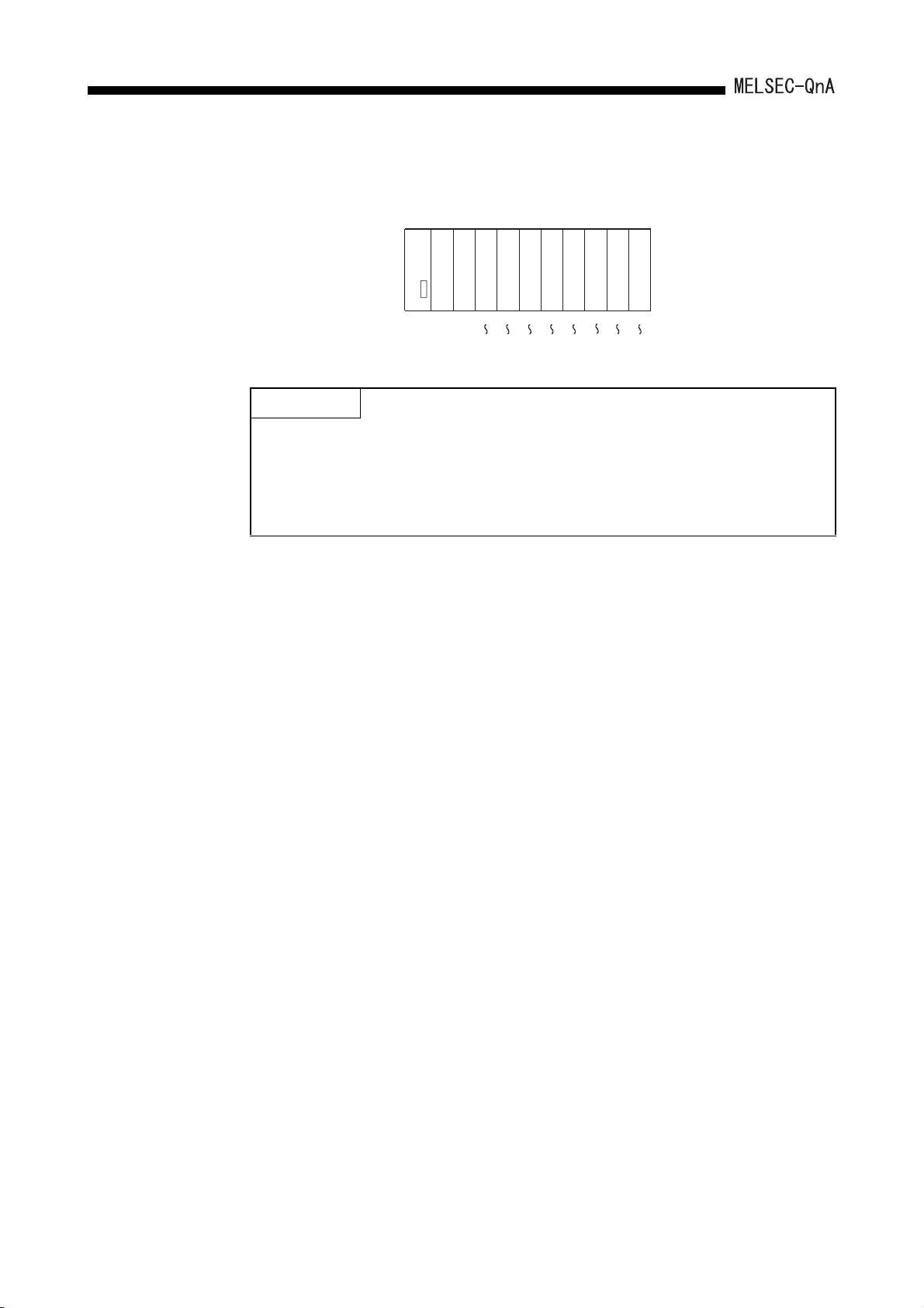
5. I/O NUMBER ASSIGNMENT
A
2) I/O numbers after performing I/O assignment using GPP function and
replacing the module
38B
01234567
Input
Input
Input
points
X2F
16
points
X3F
Input
module
16
CPU module
Power supply
points
X00
X0F
32 16
points
X80 X20 X30 Y40 Y50
X9F
16
points
Y4F
Output
Output
16
points
Y5F
16
Y60
Y6F
Output
Output
16
pointspoints
Y70
Y7F
POINT
When the I/O number set for "Start XY" in the "I/O Assign" is changed, also set the
"Start XY" for the next module to avoid changing the I/O numbers of the module
for which the change was made and the subsequent modules.
In the example above, since "20" is set for the "Start XY" for the second slot,
consecutive I/O numbers starting from X30 are set for slot 3 and later.
5 - 13

5. I/O NUMBER ASSIGNMENT
(3) When combining an input module and output module having non-consecutive I/O
numbers on a base unit
When controlling the machine (I/O numbers X0 to X3F, Y40 to Y7F) and machine
(I/O numbers X200 to X23F and Y240 to Y27F) with a single PLC, it is desired to
B
combine input modules and output modules on the base unit. To achieve this
operation, perform I/O assignment as follows.
(a) Loading status and I/O numbers to be set
A
(b) The example of I/O Allocation with GPP function
5 - 14

6.
DATA COMMUNICATIONS WITH SPECIAL FUNCTION MODULES
6 DATA COMMUNICATIONS WITH SPECIAL FUNCTION MODULES
This chapter explains the methods for reading data from a special function module, and
writing data to a special function module with the QnACPU.
The special function module is a module that allows analog quantity, high-speed pulse,
etc., which cannot be processed with I/O module alone, to be handled by the QnACPU.
For example, analog quantity is converted to a digital value by an analog/digital converter
module (which is a special function module) so that they can be used by the QnACPU.
The special function module has buffer memory in which data input from external sources
and data to be output to external destinations are stored.
The folloiwng two methods are available for reading data from a special function module,
and writing data to a special function module with the QnACPU.
1) Using the FROM/TO instruction
2) Using special direct devices
These methods are explained in the following sections.
6 - 1

6. DATA COMMUNICATIONS WITH SPECIAL FUNCTION MODULES
6.1 Reading/Writing Data from/to the QnACPU Using the FROM/TO Instruction
When the FROM/TO instruction is performed, data stored in the buffer memory of a
special function module is read, or data is written to the buffer memory of a special
function module.
Data communications with a special function module
When the FROM instruction is performed, the data read from the buffer memory is stored
in the specified device. When the TO instruction is performed, the data in the specified
device is written to the buffer memory.
REMARK
1) For details on the FROM/TO instructions, refer to the QCPU (Q mode)/
QnACPU Programming Manual (Common Instructions).
2) For details on the buffer memory of a special function module, refer to the
manual of the special function module in use.
POINT
When executing the FROM/TO instruction for the special function module
frequently in short scan time, it may cause the target special function module
operation error.
When executing the FROM/TO instruction, match the processing time and
conversion time of the special function module using timer or constant scanning.
6 - 2

6.
DATA COMMUNICATIONS WITH SPECIAL FUNCTION MODULES
6.2 Reading/Writing Data from/to the QnACPU Using Special Direct Devices
As the FROM/TO instruction, the special direct device reads data stored in the buffer
memory of a special function module or writes data to the buffer memory of a special
function module.
The special direct device represents the buffer memory in a special function module as the
QnACPU device.
Example: U10\G10: U10
G10
Indicates the head I/O No.100 of the special function
module. (Hexadecimal)
Indicates the buffer memory address 10. (Decimal)
REMARK
For details on a special direct device, refer to the QnACPU Programming Manual
(Fundamentals).
The special direct device differs from the FROM/TO instruction in that the CPU
module can handle the buffer memory of a special function module as a direct
device.
This can reduce the total number of steps in the program. However, the instruction
processing speed is the same with the FROM/TO instruction.
Example: Writing data to address 0 of the buffer memory in the special function
module loaded at X/Y0, and reading the data of address 1.
(a) Using the FROM/TO instruction (b) Using special direct device
6 - 3

6. DATA COMMUNICATIONS WITH SPECIAL FUNCTION MODULES
POINT
1. When reading data from the special function module frequently during the
programming, store the special direct device to a data register after reading in
an area of the program by using the FROM instruction rather than by using
them at each instruction.
This is because programming scan interval is added due to an access
processing to the special function module for each instruction.
2. When executing the instruction using a special direct device for the special
function module frequently in short scan time, it may cause the target special
function module operation error.
When performing the instruction using a special direct device, match the
processing time and conversion time of the special function module using
timer or constant scanning.
6 - 4

6.
DATA COMMUNICATIONS WITH SPECIAL FUNCTION MODULES
6.3 Processing for Data Communication Requests from a Special Function Module
When a data communication request is received from a special function module such as a
serial communication module, the QnACPU performs the processing for the data
communication request at the END processing.
The QnACPU can process all the data communication requests received in one scan with
one END processing, according to the parameter settings. In this case, the data lag to
each module is eliminated, but the END processing is extended by the data
communications request processing.
Data communications request batch processing is set in the "6. General Data
Processing"on the "PC system" screen in the GPP function parameter mode.
The setting range is 1 to 6 modules, and the processsing can be set per module.
6 - 5

7.
AUTO REFRESH FUNCTION
7 AUTO REFRESH FUNCTION
7.1 For MELSECNET/MINI-S3
By setting link information, I/O storage device, etc. of the MELSECNET/MINI-S3 to the
parameters, the module automatically communicates with the buffer memory area for the
batch refresh send/received data of the type AJ71PT32-S3 MELSECNET/MINI-S3 master
module (abbreviated as the MINI master module hereafter).
The settings are made on the MELSECNET/MINI setting in the parameter mode of GPP
function.
Sequence programs can be created using the I/O devices allocated to send/received by
the MELSECNET/MINI-S3 setting. (The FROM/TO instructions are not required.)
7 - 1

7. AUTO REFRESH FUNCTION
POINT
(1) Since up to 8 master modules can be set for auto refresh by the parameter,
auto refresh is possible for up to 8 modules.
When 9 or more modules are desired, use the FROM/TO instruction in the
sequence program from the 9th module.
(2) Since auto refresh is not possible with send/received data for the separate
refresh I/O modules and for the remote terminal units No.1 to No.14, use them
by the FROM/TO instructions.
However, the remote terminal units shown below are subject of auto refresh in
the limited area:
AJ35PTF-R2 RS-232C interface module
AJ35PT-OPB-M1-S3 mount-type tool box
AJ35PT-OPB-P1-S3 portable type tool box
(3) For the master modules set up for auto refresh, since the QnACPU
automatically turns ON the link communication start signal Y(n+18) or
Y(n+28), it is not necessary to turn it on from the sequence program.
(4) Auto refresh of I/O data is performed by the batch after the QnACPU performs
the END instruction.
(Auto refresh processing is performed when the CPU module is in the RUN/
PAUSE/STEP-RUN status.)
(5) The master module may perform the processing while the link communication
start signal Y(n+18) or Y(n+28) is OFF depending on the remote terminal units
connected.
For instance, if the AJ35PTF-R2 RS-232C interface unit is used without
protocol, it is necessary to write parameters to the parameter area (buffer
memory address 860 to 929) while the link communication start signal is OFF.
Since the link communication start signal becomes ON after the CPU module
enters the RUN status and one scan is performed, write the parameters
during the first 1 scan.
Link communication
start signal
Y(n+28)
SM402
ON
OFF
ON
OFF
1 scan
Set CPU module to RUN
(6) If the hardware error signal X(n+0)or X(n+20) or ROM error signal X(n+8)or
X(n+28) of a master module for which auto refresh has been set comes ON,
the QnACPU does not perform auto refresh processing.
(7) When making the settings, ensure that there is no duplication between
receive data refresh devices and send data refresh devices.
7 - 2

7. AUTO REFRESH FUNCTION
(1) Parameter setting items, setting ranges and contents of auto refresh, as well as the
buffer memory address of the master module which is used for exchanging data with
the QnACPU are shown below.
Set the parameters for the number of the master modules used.
I/O signal
from a
master
module
––
– – Start I/O No.
––
–0
–
–
Buffer memory
address of a
master module
110
to
141
10
to
41
Number of
master
modules
Model
classification
of MINI/MINIS3
Total number
of remote I/O
stations
Storage
device for
received data
*4
Send data
storage
device
Item Setting range Description Default value
0, 1 to 8 module(s)
Number of I/O points of CPU
module
• MINI or MINI-S3
0 to 64 stations
•X
• M, L, B, T, ST, C, D, W, R, ZR,
none
(Bit device: multiples of 16)
•Y
• M, L, B, T, ST, C, D, W, R, ZR,
none
(Bit device: multiples of 16)
• Sets the total number of the master modules used.
Set "0" if auto refresh is not to be used.
• Sets the head I/O number where the master module
is installed.
•MINI
In I/O mode (occupies 32 points)
• MINI-S3
In expansion mode (occupies 48 points)
• Set only when MINI is set.
• In MINI-S3, since the number of master module's
initial ROMs becomes valid, the setting is not
necessary .(When the setting is executed, ignore it).
• Sets the devices to store the received/send data for
batch refresh.
• Specify the head number of the device.
• The total number of remote I/O stations, set starting
from the first device number, is occupied as a auto
refresh area.
(8 points/station 64 stations = 512 points : Bit
*2
device)
• Use of X/Y remote I/O range is recommended for
devices.
Follow the
settings
made in the
"I/O Assign"
in the
parameter
*3
mode.
X1000 to
X11FF
Y1000 to
Y11FF
–1
Y(n+1A)
Y(n+1B)
*1
*1
–
–
Number of
retries
FROM/TO
response
specification
Data clear
specification
for
communication
faulty station
0 to 32 times
Link priority; CPU priority
Priority selection of access
to the master module
buffer memory
Retention, clear (received data)
• Sets the number of retries upon the communication
errors occurrence.
• Error is not output when the communication is
restored within the number of the retries set.
1) Link priority
• Link access by MINI-S3 has the priority.
During the link access, FROM/TO is caused to wait.
• Possible to read out the received data refreshed at
the same timing.
• The maximum wait time (0.3ms + 0.2ms number
of separate refresh stations) for the FROM/TO
instruction may be generated.
2) CPU priority
• The FROM/TO instructions from a CPU module are
given access priority. Even during the link access, it
interrupts and accesses.
• Depending on the timing, received data in the midst
of I/O refresh may be read.
• No wait time for the FROM/TO instruction.
• Retention
Retains the received data for batch and separate
refresh.
• Clear
Sets all points to OFF
5 times
CPU priority
Clear
7 - 3

7. AUTO REFRESH FUNCTION
I/O signal
from a
master
module
–
–
–4
––
Buffer memory
address of a
master module
100
to
103
195
107
196
to
203
Item Setting range Description Default value
Faulty station
detection
Error No. T, ST, C, D, W, R, ZR
Line error
check setting
(Line error)
Operation at
CPU STOP
M, L, B, T, ST, C, D, W, R, ZR,
none
(Bit device: multiples of 16)
• Test message sending (Test)
• OFF data sending (OFF)
• Immediate data transmission
before line errors
(Retention)
Stop/Continue
• Sets the head device to store the faulty stations
detected data.
• MINI occupies 4 words; MINI-S3 occupies 5 words.
• Sets the head device to store the error code at the
error occurrence.
• MINI occupies 1 word; MINI-S3 occupies (1 +
Number of remote terminal modules) words.
• Sets data sending method for verification of faulty
area when the line errors occur.
• Sets the operating status when the CPU module is
in the STOP state.
No setting
No setting
*1 "n" is determined by the installation location of the master modules.
*2 When the total number of remote I/O station is odd, add 1 to the station number to obtain the
occupied storage devices.
*3 When the master module number setting column is made blank in parameter setting, auto
refresh can be used without this setting.
However, model name registration is required in the "I/O Assign". (MINI mode: AJ71PT32,
MINI-S3 mode: AJ71PT32-S3)
*4 When the input (X) is specified in the received data storage device, use the I/O number later
than the number used for the module loaded on the main base unit and the extension base
unit. When the I/O number usage range for the module loaded on the main base and the
extension base is used for input/output of the received data storage device, the CPU module
imports both the input ON/OFF data from the input module and the ON/OFF data from auto
refresh of MELSECNET/MINI-S3. Therefore, input (X) of the CPU module is not operated as
desired.
Retention
Stop
7 - 4

7. AUTO REFRESH FUNCTION
(2) Setting of the send/received data storage devices is explained using the system
example shown below.
(Example) When the device X/Y400 and later are used as the remote I/O stations:
Sample parameter setting of the GPP function for the above system configuration is
shown below:
7 - 5

7. AUTO REFRESH FUNCTION
A
The storage devices for the send/received data for the present system example are as
follows:
(a) Storage device for received data
ddress
110
111
112
113
114
115
Master module
b15 b8 b7 b0
Station No.2
Station No.4
Station No.6
Station No.8
Station No.10
Station No.
Station No.3
Station No.5
Station No.7
Station No.9
Station No.11
Input area
1
X40F
X41F
X42F
X43F
X44F
X45F
CPU module
X408
X407
X418
X417
X427
X428
X437
X438
X447
X448
X457
X458
Used by the system
1) Set the device number (X400) for b0 of the station 1 as a received data
storage device.
2) The received data storage device occupies from X400 to X45F.
For the present system example, since the total number of stations is odd, it
is occupied for one extra station.
3) The device numbers of input modules connected are as follows:
Stations 1 to 4
Stations 5 and 6
Stations 7 and 8
AX41C
AJ35TB-16D
AX40Y50C
X400 to X41F
X420 to X42F
X430 to X43F
With respect to X440 to X45F, they are simultaneously refreshed, and set to
OFF at any time.
Do not use X440 to X45F in the sequence program.
X400
X410
X420
X430
X440
X450
7 - 6

7. AUTO REFRESH FUNCTION
(b) Send data storage device
1) Set the device number (Y400) for b0 of the station 1 as a send data storage
device.
2) The send data storage device occupies from Y400 to Y45F.
For the present system example, since the total number of stations is odd, it
is occupied for one extra station.
3) The device numbers of output modules connected are as follows:
Station 9 to 10
Station 11
With respect to Y400 to Y43F and Y458 to Y45F, they are simultaneously
refreshed, but are not output.
AX40Y50C
AJ35TJ-8R
Y440 to Y44F
Y450 to Y457
POINT
(1) If the same device type is used for the send data storage devices and
received data storage devices, make sure that there is no duplication of
device numbers.
When the received data storage device is set to B0 in the system
configuration example, it occupies B0 to B5F as the device range.
Set the send data storage device to B60 or later.
When the send data storage device is set to B60, the device range will be B60
to BBF.
(2) If a bit device is specified as the send/received data storage device, the
device number set must be a multiple of 16.
Example:
(3) Device range used is (8 points) (Number of stations).
When the number of stations is an odd number, extra 8 points are necessary.
(4) When specifying input (X) for the received data storage device, specify the
device number out of the actual input (X) range.
X0, X10, X100,
M0, M16, M256,
B0, B10, B100,
7 - 7

7.
AUTO REFRESH FUNCTION
7.2 Auto Refresh Setting of CC-Link
Auto refresh of the CC-Link designates automatic communications between the QnACPU
and the buffer memory for cyclic communication of CC-Link master stations/local stations.
Data for communication varies depending on the remote station connected.
• Remote I/O station (Communication in ON/OFF data)
• Remote device station (Communication in ON/OFF data and Word data)
• Intelligent device station (Communication in ON/OFF data and Word data)
• Master station/local station (Communication in ON/OFF data and Word data)
The auto refresh setting of the CC-Link allows communication with other stations of CCLink using the FROM/TO instruction without communicating with the master station of the
CC-Link.
7 - 8

7. AUTO REFRESH FUNCTION
(1) Settings for auto refresh
The Table 7.1 shows the setting items for auto refresh parameters of the QnACPU.
Table 7.1 List of auto refresh settings
Item Description Setting range
Number of modules The number of CC-Link modules is set. 1 to 8
Module head I/O number The head I/O number of a CC-Link module is set. 0000
• M: Master station
• L: Local station
• T: Stand-by station
X, M, L, B, T, ST, C, D,
W, R, ZR
X, M, L, B, T, ST, C, D,
W, R, ZR
M, L, B, T ,ST, C, D, W,
R, ZR
Module type
Receiving data batch refresh
bit device
(Input data)
Transmission data batch
refresh bit device
(Output data)
Receiving data batch refresh
word device
(Remote device: RWr)
The loaded CC-Link module type (Master station, local station, stand-by station)
is set.
• The device that stores the batch refresh received data from the remote station
is set.
• When the head device number is set, the points corresponding to the specified
number of stations (Total number of stations) are obtained to refresh all areas.
The output module area is also refreshed.
• The settings are made in units of 16 points.
• The device that stores the batch refresh send data to the remote station is set.
• When the head device number is set, the points corresponding to the specified
number of stations (Total number of stations) are obtained to refresh all areas.
The input module area is also refreshed.
• The settings are made in units of 16 points.
• The device that stores the batch refresh received data from the remote station
is set.
• When the head device number is set, the points corresponding to the specified
number of stations (Total number of stations) are obtained to refresh all areas.
The I/O module area is also refreshed.
• The settings are made per point.
Setting station
MLT
H to 0FE0H
*
*
*
Transmission data batch
refresh device
(Remote device: RWw)
Receiving buffer specification
for transient station
Transmission buffer
specification for transient
station
Batch refresh device for
special relay
• The device that stores the batch refresh send data to the remote station is set.
• When the head device number is set, the points corresponding to the specified
number of stations (Total number of stations) are obtained to refresh all areas.
The I/O module area is also refreshed.
• The settings are made per point.
• The receive buffer capacity for transient station is set. 80 to 4096
• The send buffer capacity for transient station is set. 80 to 4096
• The destination device for special relay is set.
M, L, B, T ,ST, C, D, W,
*
R, ZR
M, L, B, T ,ST, C, D, W,
*
R, ZR
* Only when the file register is set to "Use the designated file" with the "Parameter", R and ZR
can be used as the auto refresh devices.
When "Use same file name as program" is set, R and ZR cannot be used.
REMARK
1) In "Setting station" in the table above, M refers to the master station, L to the
local station, and T to the stand-by station.
2)
In the table above, means that the setting can be made and means that
the setting is not required.
7 - 9

7. AUTO REFRESH FUNCTION
Table 7.1 List of auto refresh settings (Continued)
Item Description Setting range
Batch refresh device for
special register
Auto update buffer
specification
Total number of slave
stations
Delay timer • The delay time of link scan is set.
Standby station specification • The use status of the stand-by master function is set.
Number of retries • The number of retries at the occurrence of a transient transmission error is set. 1 to 7
Number of automatic return
stations
Operation specification for
CPU stop
Scan mode setting • Synchronization/Non-synchronization is set to the CPU module scan.
• The destination device for special register is set.
• The buffer capacity for automatic update is set. 128 to 4096
• The last station number of the remote station connected to the master station
is set.
• The number of automatic return stations is set to one link scan. 1 to 10
• When the CPU module has stopped, continuation/stop of the data link is set.
T, ST, C, D, W, R, ZR
1 to 64
1 to 100
(0 is invalid.)
• Not used
• Used
•Stop
• Continue
• Non-synchronization
• Synchronization
Setting station
MLT
*
Station type • The model for each remote station is set.
Number of occupied stations • The number of occupied stations for each remote station is set.
Specification of reserved
station
Specification of invalid
station
• Reservation for remote station is set.
• Validity/Invalidity for error detection of the remote station is set.
* Only when the file register is set to "Use the designated file" with the "Parameter",
R and ZR can be used as the auto refresh devices. When "Use same file name as program" is
set, R and ZR cannot be used.
REMARK
1) In "Setting station" in the table above, M refers to the master station, L to the
local station, and T to the stand-by station.
2)
In the table above, means that the setting can be made and means that
the setting is not required.
• Remote I/O station
• Remote device
station
• Intelligent device
station
• 1 station
•2 stations
•3 stations
•4 stations
•Not reserved
• Reserved
•Invalid
• Valid
7 - 10

7. AUTO REFRESH FUNCTION
(2) Precautions
(a) Auto refresh of the CC-Link is available when the QnACPU and the CC-Link
module with function version "B" are used.
When either of the QnACPU or the CC-Link module does not indicate function
version "B," auto refresh of the CC-Link is not available.
(b) Auto refresh can be set to up to 8 CC-Link modules.
When 9 or more CC-Link modules are used, handle with the FROM/TO
instruction of the sequence program for the 9th module or later.
(c) When both the CC-Link module and the master station module for
MELSECNET/MINI-S3 are loaded and auto refresh is not set, the default
parameter is set to the master station module for MELSECNET/MINI-S3.
(d) The COM instruction or the G(P). ZCOM instruction allows auto refresh to the
CC-Link module while performing the sequence program.
However, auto refresh to the CC-Link module cannot be performed with the
J(P).ZCOM instruction. Error code "4102" (The network number designated with
the dedicated network instruction does not exist) appears.
(e) Refresh operation for the mixture of MELSECNET (/10, /II) and MELSECNET/
MINI-S3.
• Refresh is performed in the order of MELSECNET (/10, /II), CC-Link and
MELSECNET/MINI-S3.
Therefore, the input data specifying the same range is afterward overwritten
with the executed data.
• The output data is output to the MELSECNET (/10, /II), CC-Link, and
MELSECNET/MINI-S3.
(f) The operation of the QnACPU when the CC-Link module is in the online/offline
mode is shown in the table below:
Parameter settings
for auto refresh
Set
Not set
CC-Link module
status
Online
Offline
Online
Offline
Operation of the QnACPU
The communications with the remote station is
performed with the specified parameter for
auto refresh.
The QnACPU does not generate an error, but
does not communicate with the remote station.
The communications with the remote station is
performed by the FROM/TO instruction.
The QnACPU does not generate an error, but
does not communicate with the remote station.
(g) Auto refresh setting to the CC-Link is performed using the following peripheral
devices.
• Personal computer:
GX Developer, SW2IVD-GPPQ type GPP function software package
7 - 11

7. AUTO REFRESH FUNCTION
(3) Setting method
Auto refresh setting to the CC-Link is set with the following procedures.
(a) When the "CC-Link" is selected in the "Parameter", the "CC-Link setting" screen
appears.
(b) Set the number of the CC-Link modules loaded on the main base unit and
extension base unit for the QnACPU and selct "Execute", then the screen of CCLink setting list appears.
Pressing the key registers the set data.
Esc
7 - 12

7. AUTO REFRESH FUNCTION
(c) Move the cursor to the module number position for auto refresh setting and
I/O number setting
of the CC-Link
module for the
specified module
number
CC-Link module
type setting for
the specified unit
number
Device setting of
QnACPU used
press the key (Detail). The "CC-Link setting" screen appears.
F3
Select "4. Auxiliary setting...." and "5. Station information setting...." to set
detailed data.
Remote station
[CC-Link setting]
1. Module starting I/O No. [ ] Auxiliary setting....
2. Module type 1. (*) M. Master station 5. Station information
2. ( ) L. Local station
3 Batch refresh device
Remote input(RX) Device [ ]
Remote output(RY) Device [ ]
Remote register(RWr) Device [ ]
Remote register(RWw) Device [ ]
Special link relay(SB) Device [ ]
Special link register(SW) Device [ ]
Execute(Y)
When pressing the Execute (Y) or the key , the screen returns to the
Label name:
4.
setting....
Cancel(N)
Spase:Select Esc:Close
Esc
setting connected to
CC-Link module
(Refer to 1).)
Setting of each remote
station (Refer to 2).)
screen of CC-Link setting list.
7 - 13

7. AUTO REFRESH FUNCTION
1) When selecting the "4. Auxiliary setting....", the "Auxiliary setting" screen
appears.
Set the number of
stations specified in
2).
When pressing the key, the screen returns to the CC-Link setting
Esc
screen of (c).
2) When selecting the "5. Station information setting...", the "Station information
setting"screen appears.
When pressing the key, the screen returns to the CC-Link setting
Esc
screen of (c).
[
Station information setting
Station
Station type
No.
1
2
3
4
5
6
7
8
9
10
11
12
<
< I/O >
< I/O >
< I/O >
< I/O >
< I/O >
< I/O >
< I/O >
< I/O >
< I/O >
< I/O >
< I/O >
I/O
>
Number of
occupied
stations
< 1 >
< 1 >
< 1 >
< 1 >
< 1 >
< 1 >
< 1 >
< 1 >
< 1 >
< 1 >
< 1 >
< 1 >
]
Reserved/
invalid
station
< >
< >
< >
< >
< >
< >
< >
< >
< >
< >
< >
< >
Label name:
Intelligent buffer specification (word)
Send Receive Auto
[ ]
[ ]
[ ]
[ ]
[ ]
[ ]
[ ]
[ ]
[ ]
[ ]
[ ]
[ ]
[ ]
[ ]
[ ]
[ ]
[ ]
[ ]
[ ]
[ ]
[ ]
[ ]
[ ]
[ ]
Spase:Select Esc:Close
[ ]
[ ]
[ ]
[ ]
[ ]
[ ]
[ ]
[ ]
[ ]
[ ]
[ ]
[ ]
7 - 14

8.
DEBUGGING FUNCTION
8 DEBUGGING FUNCTION
8.1 Function List
QnACPU has a variety of convenient functions when debugging.
The following shows the debugging functions.
Item Description Reference
Monitor function
Write during RUN
Execution time measurement
Program monitor list
Interrupt program monitor list
Scan time measurement
Sampling trace function
Status latch function
Step operation
Step execution Function that runs a program step by step Section 8.7.1
*1
*1
Function that reads CPU programs, device statuses from a
peripheral device capable of GPP functions
Function that writes a program while the CPU module is
running
Functions that displays the processing time of a program
being execute
Functions that displays the processing time of a program
being executed
Function that displays the number of executions of an
interrupt program
Function that measures the execution time of section of a
program
Function that continually collects the data of devices in
accordance with a timing set at the CPU module
Function that collects the device data at the moment to
designate
Functions that runs one step or one part of a program,
runs a program with a part skipped
Section 8.2
Section 8.3
Section 8.4
Section 8.4.1
Section 8.4.2
Section 8.4.3
Section 8.5
Section 8.6
Section 8.7
Partial execution Function that executes a designated part of a program Section 8.7.2
Skip execution
Program trace function
Simulation function
Debugging by several people
Monitoring trace function
*1
*2
Function that executes a program with a designated part
skipped
Function that collects the program execution status Section 8.8
Function that simulats execution in isolation from the I/O
modules and special function modules
Function that simultaneously debuggs from several
peripheral devices capable of GPP functions
Function that collects device data at a peripheral device
capable of GPP functions in accordance with the
designated timing
Section 8.7.3
Section 8.9
Section 8.10
For details on the operation for each function, refer to the GPP function Operating
Manual.
*1 When executing this function, a memory card is required.
*2 When executing part of this function, a memory card is required.
8 - 1
–

8.
DEBUGGING FUNCTION
8.2 Monitor Function
This function reads CPU module programs and device statuses to a peripheral device
capable of GPP functions.
Application
This function is used to set monitoring conditions for monitoring the operating
statuses of the PLC in accordance with a precise timing.
There are three "Monitoring Condition" as follows.
• Executing a monitoring at END processing.
• Setting the step number to be monitored and the step conducting status.
• Setting the device status.
This function is used to retain the monitoring screen by setting "Monitor stop
condition setup" in accordance with a precise timing.
When monitoring the CPU module marked Function version B using a peripheral
device capable of GPP function, local device monitor test is executed by setting
"local device monitor".
8.2.1 Monitoring condition setting
Function Description
(1) This function allows setting of the monitoring condition.
All operations are performed using Monitor/test menu in the ladder mode.
The following shows an example of setting a monitor condition.
The following shows an explanation of the screen above:
The monitoring condition can be select either "1. ( ) Monitor Always." or "2. ( )
Condition".
(a) When "1. ( ) Monitor Always." is set
The collection timing for monitor data is every scan after END processing at the
CPU module.
8 - 2

8. DEBUGGING FUNCTION
(b) When "2. ( ) Condition" is set
"1. [ ] Device" and "2. [ ] Step #" can be set.
1) When only "2. [ ] Step #" is set
The monitor data collection timing is the moment when a QnACPU shows
designated status immediately before executing the designated step.
The following shows the possible designations to execute.
When switching from OFF to ON:
When switching from ON to OFF:
All the time only during ON :< ON >
All the time only during OFF :<OFF >
All the time in any statuses :<Always>
:< >
:< >
8 - 3

8. DEBUGGING FUNCTION
REMARK
1) When Step # [ 0] is designated, the execution condition must be set as Always.
2) When "1. [ ] Device" only is specified (when "2. [ ] Step #" is not specified), the
monitor data collection timing is every scan after END processing of the PLC CPU.
When the data is changed in the same scan, it cannot be detected. (Including the
low-speed program)
3) When only "1. [ ] Device" is set, either
"1. ( ) Word Device" or "2. ( ) Bit Device" can be designated.
When "1. ( ) Word Device" is designated
The collection timing of the monitor data is the scan END processing when the
current value of the specified word device becomes the specified value.
The following shows the method for designating the current value.
Decimal designation: [K ]
Hexadecimal designation: [H ]
Decimal number
Hexadecimal number
When "2. ( ) Bit Device" is designated
The collection timing of the monitor data is the scan END processing when the
execution status of the specified bit device becomes the specified status.
The following shows the possible designations for execution status.
At leading edge :< >
At trailing edge :< >
4)
When "2. [ ] Step #" and "1. [ ] Device" are designated
The monitor data collection timing is such that data is collected when the status
immediately before execution of the designated step or the execution status (current
value) of the designated bit device (word device) attains the designated status.
8 - 4
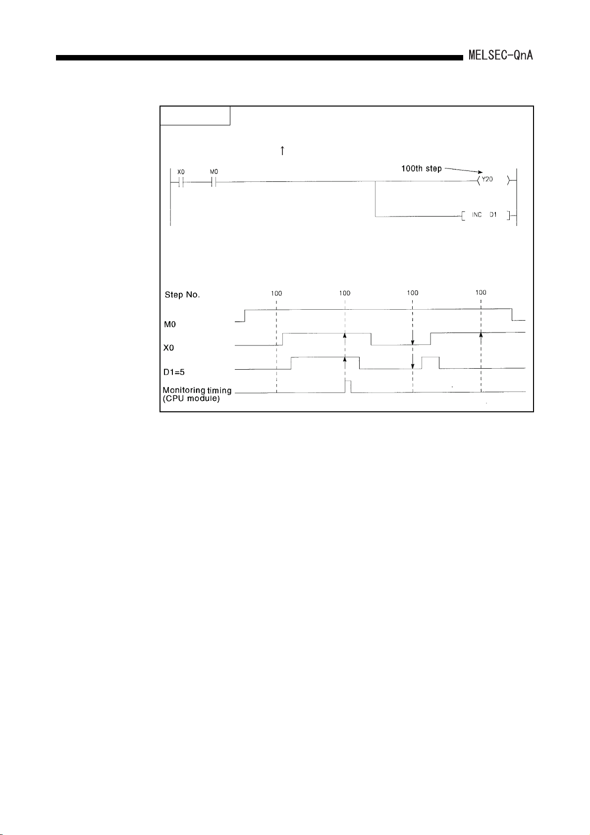
8. DEBUGGING FUNCTION
POINT
In the ladder block shown below, assuming that the detailed condition is set as
follows: "Step # [100] = < >, Word device [D1 ] = [K5 ]".
The monitor timing is shown below. However, the monitoring interval at a
peripheral device capable of GPP functions depends on the processing speed of
that peripheral device. Even if data changes occur faster than the monitor interval,
data can be collected only once during the interval.
8 - 5

8. DEBUGGING FUNCTION
POINT
(1) Assume that "Step # [ 2] = <ON>" is designated as the detailed condition in
the case of the ladders shown below; In this case the monitor execution differs
for the two ladders. For (a) it is "X0 and X1 both ON" and for (b) it is "X1 ON
(regardless of ON/OFF status of X0)".
If a step part way through an AND/OR block is designated for a monitor
condition, the monitor data collection timing is such that data is collected when
the status immediately before execution of the step designated from the LD
instruction in the block becomes the designated status.
(2) If the ladder block head other than 0 step is specified to the step number as
detailed conditions, the monitor data is collected when the instruction
execution status immediately before execution is the specified status.
When "Step # [ 2] = <ON>" is specified in the ladder below, the monitor data is
collected for OUT Y10 ON.
8 - 6

8. DEBUGGING FUNCTION
(2) A monitor stop condition can be set.
All operations are performed on the monitor/test screen window in the ladder mode.
The following shows an example of the setting for a monitor stop condition.
The following shows an explanation of the screen above:
Either "1. ( ) Without Monitor Stop" or "2. ( ) Condition" can be set for the monitor stop
condition.
(a) When "1. ( ) Without Monitor Stop" is set
Monitoring is stopped when key is pressed.
(b) When "2. ( ) Condition" is set
"1. [ ] Device" and "2. [ ] Calculation State" can be set.
1) When "2. [ ] Calculation State" is set
The monitor stop timing is such that monitoring stops when the execution
condition of the step designated for the monitor condition attains the
designated status.
The following shows the possible designations for execution status.
When switching from OFF to ON
When switching from ON to OFF
All the time only during ON
All the time only during OFF
All the time in any statuses
If "2. [ ] Calculation State" isn't set, the timing for monitor stop is such that
monitoring is stopped after CPU module END processing.
:
:
:ON
:OFF
:Always
8 - 7

8. DEBUGGING FUNCTION
2) When "1. [ ] Device" is set Either
"1. ( ) Word Device" or "2. ( ) Bit Device" can be set.
When "1. ( ) Word Device" is set
The monitor stop timing is such that monitoring stops when the present
value of the designated word device attains the designated value.
The following shows the method for designating the current value.
For decimal (word) designation
For hexadecimal (word) designation : [H ]
For decimal (double word) designation
For hexadecimal (double word)
: [K ]
Decimal number
Hexadecimal number
: [K L]
Decimal number
: [H L]
Hexadecimal number
Space
Space
designation
For real number designation : [E ]
Real number
When "2. ( ) Bit Device" is designated
The monitor stop timing is such that monitoring stops when the execution
status of the designated bit device becomes the designated status.
The following shows the possible designations for execution status.
At leading edge :
At trailing edge :
(3) In the case of devices for which index qualifications have been made, the index
qualified value is monitored.
The following shows an example of this type of monitoring.
8 - 8
 Loading...