

Page 1

QCPUQCPU
(Function Explanation,
Program Fundamentals)
Mitsubishi Programmable
Logic Controller
Q00JCPU
Q00CPU
Q01CPU
Q02CPU
Q02HCPU
Q06HCPU
Q12HCPU
Q25HCPU
Q12PHCPU
Q25PHCPU
Q12PRHCPU
Q25PRHCPU
Page 2

Page 3

SAFETY PRECAUTIONS
(Always read these instructions before using this equipment.)
Before using this product, please read this manual and the relevant manuals int roduced in this manual
carefully and pay full attention to safety to handle the product correctly.
In this manual, t h e safety instructions are ranked as "DA NGER" and "CAUTION".
DANGER
CAUTION
Note that the CAUTION level may lead to a serious consequence according to the circumstances.
Always follow the instructions of both levels because they are important to personal safety.
Please save this ma nual to make it accessible when required and alwa ys forward it to the end user.
Indicates that incorrect handling may cause hazardous conditions,
resulting in death or severe injury.
Indicates that incorrect handling may cause hazardous conditions,
resulting in medium or slight personal injury or physical damage.
A
- 1
Page 4

[Design Precautions]
DANGER
Install a safety circuit external to the PLC that keeps the entire system safe even when there are
problems with the external power suppl y or the PLC module. Otherwise, trouble could result from
erroneous output or er roneous operation.
(1) Outside the PLC, constru ct mech anica l damag e prevent ing i nterl ock circu its su ch as eme rgency
stop, protective circuits, posit ioning upper and lower limits switches and interlocking for ward/
reverse operations.
(2) When the PLC detects the following problems,
it will stop calc ulation and turn off all output in the case of (a).
In the case of (b), it will hold or turn off all output according to the parameter setting.
Note that the An S series module wi ll turn off the output in either of cases (a) and (b).
Q series module AnS series module
(a) The power supply module has
over currentprotection equipment
and over voltage protection
equipment.
(b) The CPU module self-diagnosis
functions, such as the watchdog
timer error, detect problems.
Output OFF Output OFF
Hold or turn off all
output according to
the parameter setting.
Output OFF
In addition, all output will be turned on when there are pro blems that the PLC CPU cannot
detect, such as in th e I/O control ler. Buil d a fail safe ci rcuit ex terior t o the PLC that will make sure
the equipment operates safely at such times.
Refer to " LOADING AND INSTALLATION" in QCPU User's Manual (Hardware Design,
Maintenance and Inspection) for example fail safe circuits.
(3) Output could be left on or off when t here is trouble in the outputs module rel ay or transistor. So
build an external monitoring circuit that will monitor any single outputs that could cause serious
trouble.
A
- 2
Page 5

[Design Precautions]
DANGER
When overcurrent which exceeds the rating or caused by short-circuited load flows in the output
module for a long time, it may cause smoke or fire. To prevent this, configure an external safety
circuit, such as fuse.
Build a circuit that turns on the external power supp ly when the PLC main module power is turned
on.
If the external power supply is turned on first, it could result in erroneous output or erroneous
operation.
When there are communication problems with the data link , refer to the corresponding data link
manual for the operating status of each station.
Not doing so could result in erroneous output or erroneous operation.
When connecting a peripheral device to the CPU module or connecting a personal computer or the
like to the intelligent function module / special function module to exercise control (data change) on
the running PLC, configure up an int erlock circuit in the sequence program to ensure that the whole
system will always operate safely.
Also before exercising other control (program change, operating status c hange (status control)) on
the running PLC, read the manual carefully and fully conf irm safety.
Especially for the above control on the remote PLC from an external device, an immediate action
may not be taken for PLC trouble due to a data communication fault.
In addition to configuring up the interlock circuit in the sequence program, corrective and other
actions to be taken as a system for the occurrence of a data communication fault should be
predetermined between the external device and PLC CPU.
CAUTION
Do not bunch the control wires or communication cables with the main circuit or power wires, or
install them close to each other.
They should be installed 100 mm (3.94 inch) or more from each other.
Not doing so could result in noise that would cause erroneous ope ration.
When controlling items li ke lamp l oad, heate r or sole noid val ve using a n output module, l arge curr ent
(approximately ten times greater than that present in normal circumstances) may flow when the
output is turned OFF to ON.
Take measures such as replacing the module with one having sufficient rated current.
A
- 3
Page 6

[Installation Precautions]
CAUTION
Use the PLC in an environment that meets the general specifications contained in QCPU User's
Manual (Hardware Design, Maintenance and Inspect ion).
Using this PLC in an environment outside the range of the gen eral specifications could result in
electric shock, fire, erroneous operation, and damage to or deterioration of the product.
While pressing th e inst alla tion lever l ocate d at the bott om of module , ins ert th e modul e fixi ng tab into
the fixing hole in the base unit until it stops. Then, securely mount the mo dule with the fixing hole as
a supporting poin t.
Incorrect loading of the module can cause a malfunction, failure or drop.
When using the PL C in the en vi ro nm e nt of mu c h vi bra t i o n, ti gh te n th e m od ul e wit h a sc re w.
Tighten the screw in the specified torque range.
Undertightening can cause a drop, shor t circuit or malfunction.
Overtightening can cause a drop, short circuit or malfunction due to damage to the screw or mo dule.
When installing extension cables, be sure that the base unit and the extension module connectors
are installed correctly.
After installation, check them for looseness.
Poor connections c ould cause an input or out put failure.
Securely load the memory card into the memory card loading connector.
After installation, check for lifting.
Poor connections c ould cause an operation fault.
Completely turn off the external ly supplied power used in the system before mounting or removing
the module. Not doing so could result in damage to the product.N ote that the module can be
changed online (while power is on) in the system that uses the CPU module compatible with online
module change or on the MELSECNET/H remote I/O station.
Note that there are restrictions on the modules that can be changed online(while power is on), and
each module has its predetermined changing procedure.
For details, refer to QCPU User's Manual (Hardware Design, Maintenance and Inspection) and the
online module change section in the manual of the module compatible with online module change.
Do not directly touch the module's conductive parts or elect ronic components.
Touching the conductive parts could cause an operation failure or give damage to the mo dule.
A
- 4
Page 7
[Wiring Precautions]
DANGER
Completely turn off the externally supplied pow er used in the system when installing or placing
wiring.
Not completely turning off all po wer could result in electric shock or damage to the product.
When turning on the power supply or opera ting the module after installation or wiring work, be sure
that the module's terminal covers are correctly attached.
Not attaching the terminal cover could result in electric shock.
DANGER
Be sure to ground the FG terminals and LG terminals to the prote c tive ground conductor.
Not doing so could result in electric shock or erroneous operation.
When wiring in the PLC, be sure tha t it is d one corr ectl y by che cki ng t he pr od uct' s ra te d vol tage and
the terminal layout.
Connecting a power supply that is diff erent from the rating or incorrectly wiring the product coul d
result in fire or damage.
External connections shall be crimped or pressure welded with the specified tools, or correctly
soldered.
Imperfect connections could result in short circuit, fi res, or erroneous operation.
Tighten the terminal screws with the specified torque.
If the terminal sc rews are loose, it could result in short cir c uits, fire, or erroneous operation.
Tighte ning the terminal screw s too far may cause damages to the screws and/or the module,
resulting in fallout, short circuits, or malfunction.
Be sure there are no foreign substances such as sawdust or wiring debris inside the module.
Such debris could cause fires, damage, or erroneous operation.
The module has an ing ress pr eventio n la bel o n its t op t o preve nt for eign matter, such as wire offcuts ,
from entering th e module during wir ing.
Do not peel this la be l du ri ng wi rin g .
Before starting system operation, be sure to peel this label because of hea t dissipation.
A
- 5
Page 8

[Startup and Maintenance Precautions]
DANGER
Do not touch the terminals while power is on.
Doing so could cause shock or erroneous operation.
Correctly connect the battery.
Also, do not charge, disassemble, heat, place in fire, sho rt circuit, or solder the battery.
Mishandling of bat tery can cause overheating or cracks which could result in injury and fires.
Switch off all phases of the externally supplied power used in the system when cleaning the module
or retightening the terminal or module mounting scr ews.
Not doing so could resu lt in electric shock.
Undertightening of terminal screws can cause a short ci rcuit or malfunction.
Overtightening of screws can cause damages to the screws and/or the module, resulting in fallout,
short circuits, or malfunction.
A
- 6
Page 9

[Startup and Maintenance Precautions]
CAUTION
The online operations conducted for the CPU module being operated, connecting the peripheral
device (especiall y, when changing data or operation s tatus) , shall b e conduc ted af ter th e manual has
been carefully read and a sufficien t check of safety has been conducted.
Operation mistakes could cause damage or problems with of the module.
Do not disassemble or mod ify the modules.
Doing so could cause trouble, erroneous operation, injur y, or fire.
Use any radio communication device such as a cellular phone or a PHS phone more than 25cm
(9.85 inch) away in all direction s of the PLC.
Not doing so can cause a mal function.
Completely turn off the externall y supplied power used in the system before mount ing or removing
the module. Not doing so could result in damage to the product.
Note that the module can be changed online (while power is on) in the system that uses the CPU
module compatible with online module change or on the MELSECNET/H remote I/O station.
Note that there are restrictions on the modules that can be changed online (while power is on) , and
each module has its predetermined changing procedure.
For details, refer to QCPU User's Manual (Hardware Design, Maintenance and Inspection) and the
online module change section in the manual of the module compatible with online module change.
Do not mount/remove the module onto/from base unit more than 50 t imes (IEC61131-2-compliant),
after the first use of the product.Failure to do so may cause the module to malfunction due to poor
contact of connector.
Do not drop or give an impact to the battery mounted to the module.
Doing so may damage the battery, causing the battery fluid to leak inside the battery.
If the battery is dropped or given an impact, dispose of it without using.
Before touching the module, always touch grounded metal, etc. to discharge static electricity from
human body, etc.
Not doing so can cause the module to fail or malfunction.
A
- 7
Page 10

[Disposal Precautions]
CAUTION
When disposing of this product, treat it as industrial waste.
[Transportation Precautions]
CAUTION
When transporting lithium batteries, make sure to trea t them based on the transp ort regulations.
(Refer to Appendix4 for details of the controlled models.)
A
- 8
Page 11

REVISIONS
The manual number is given on the bottom left of the back cover.
Print Date Manual Number Revision
Jun., 2004 SH(NA)-080484ENG-A First edition
Japanese Manual Version SH-080473 -A
This manual confers no industrial property rights or any rights of any other kind, nor does it confer any patent licenses.
Mitsubishi Electric Corporation cannot be held responsible for any problems involving industrial property rights which may
occur as a result of using the contents noted in this manual.
C
2004 MITSUBISHI ELECTRIC CORPORATION
A
- 9
Page 12

INTRODUCTION
Thank you for choo sing t he Mits ubis hi MELSE C-Q Se ries of Gene ral Pu rpose Prog rammabl e Contr oll ers.
Before using the equipment, please read this manual carefully to develop full familiarity with the functions
and performance of the Q series PLC you have purchased, so as to ensure correct use.
CONTENTS
SAFETY PRECAUTIONS•••••••••••••••••••••••••••••••••••••••••••••••••••••••••••••••••••••••••••••••••••••••••••••••••••••• A - 1
REVISIONS•••••••••••••••••••••••••••••••••••••••••••••••••••••••••••••••••••••••••••••••••••••••••••••••••••••••••••••••••••••••A - 9
INTRODUCTION ••••••••••••••••••••••••••••••••••••••••••••••••• ••••••• ••••••• •••••• ••••••• •••••• ••••••• ••••••• •••••• ••••••• ••A - 10
CONTENTS••••••••••••••••••••••••••••••••••••••••••••••••••••••••••••••••••••••••••••••••••••••••••••••••••••••••••••••••••••••A - 10
ABOUT MANUALS•••••••••••••••••••••••••••••••••••••••••••••••••••••••••••••••••••••••••••••••••••••••••••••••••••••••••••••A - 20
HOW TO SEE THIS MANUAL IS ORGANIZED••••••••••••••••••••••••••••••••••••••••••••••••••••••••••••••••••••••••••A - 23
HOW TO USE THIS MANUAL•••••••••••••••••••••••••••••••••••••••••••••••••••••••••••••••••••••••••••••••••••••••••••••••A - 25
GENERIC TERMS AND ABBREVIATIONS•••••••••••••••••••••••••••••••••••••••••••••••••••••••••••••••••••••••••••••••A - 26
CHAPTER1 OVERVIEW 1 - 1 to 1 - 28
1.1 Features •••••••••••••••••••••••••••••••••••••••• •••••• ••••••• ••••••• •••••• ••••••• •••••• ••••••• ••••••• ••••••••••••••• 1 - 10
1.1.1 Features of Basic model QCPU•••••••••••••••••••••••••••••••••••••••••••••••••••••••••••••••••••••••••• 1 - 10
1.1.2 Features of High Performance model QCPU •••••••••••••••••••••••••••••••••••••••••••••••••••••••••• 1 - 11
1.1.3 Features of Process CPU•••••••••••••••••••••••••••••••••••••••••••••••••••••••••••••••••••••••••••••••••• 1 - 13
1.1.4 Features of Redundant CPU•••••••••••••••••••••••••••••••••••••••••••••••••••••••••••••••••••••••••••••• 1 - 15
1.2 Program Storage and Operation••••••••••••••••••••••••••••••••••••••••••••••••••••••••••••••••••••••••••••••• 1 - 17
1.3 Devices and Instructions Convenient for Programming ••••••••••••••••••••••••••••••••••••••••••••••••••• 1 - 23
1.4 How to Check the Serial No. and Function Version•••••••••••••••••••••••••••••••••••••••••••••••••••••••• 1 - 28
CHAPTER2 PERFORMANCE SPECIFICATION 2 - 1 to 2 - 8
CHAPTER3 SEQUENCE PROGRAM CONFIGURATION AND EXECUTION CONDITIONS
3 - 1 to 3 - 83
3.1 Sequence Program•••••••••••••••••••••••••••••••••••••••••••••••••••••••••••••••••••••••••••••••••••••••••••••••••3 - 3
3.1.1 Main routine programs •••••••••••••••••••••••••••••••••••••••••••••••••••••••••••••••••••••••••••••••••••••••3 - 7
3.1.2 Subroutine programs •••••••••••••••••••••••••••••••••••••••••••••••••••••••••••••••••••••••••••••••••••••••••3 - 9
3.1.3 Interrupt programs •••••••••••••••••••••••••••••••••••••••••••••••••••••••••••••••••••••••••••••••••••••••••• 3 - 12
3.2 Settings for Execution of Only One Sequence Program •••••••••••••••••••••••••••••••••••••••••••••••••• 3 - 22
3.3 Settings for Creation and Execution of Multiple Sequence Programs •••••••••••••••••••••••••••••••••• 3 - 24
3.3.1 Initial execution type program••••••••••••••••••••••••••••••••••••••••••••••••••••••••••••••••••••••••••••• 3 - 26
3.3.2 Scan execution type program••••••••••••••••••••••••••••••••••••••••••••••••••••••••••••••••••••••••••••• 3 - 30
3.3.3 Low speed execution type program ••••••••••••••••••••••••••••••••••••••••••••••••••••••••••••••••••••• 3 - 33
3.3.4 Stand-by type program••••••••••••••••••••••••••••••••••••••••••• ••••••• •••••• ••••••• •••••••••••••••••••••• 3 - 41
3.3.5 Fixed scan execution type program ••••••••••••••••••••••••••••••••••••••••••••••••••••••••••••••••••••• 3 - 46
3.3.6 Execution type setting and example of type changing••••••••••••••••••••••••••••••••••••••••••••••• 3 - 52
3.4 Operation Processing •••••••••••••••••••••••• •••••• ••••••• ••••••• ••••••••••••••••••••••••••••••••••••••• ••••••• •• 3 - 58
A
- 10
Page 13

3.4.1 Initial processing••••••••••••••••••••••••••••••••••••••••••••••••••••••••••••••••••••••••••••••••••••••••••••• 3 - 58
3.4.2 I/O refresh (I/O module refresh processing) ••••••••••••••••••••••••••••••••••••••••••••••••••••••••••• 3 - 59
3.4.3 Automatic refresh of the intelligent functi on modu le•••• ••••••• •••••• ••••••••••••••••••••••••••••••••• 3 - 59
3.4.4 END processing ••••••••••••••••••••••••••••••••••••••••••••••••••••••••••••••••••••••••••••••••••••••••••••• 3 - 60
3.5 RUN, STOP, PAUSE Operation Processing •••••••••••••••••••••••••••••••••••••••••••••••••••••••••••••••• 3 - 61
3.6 Operation Processing during Momentary Power Failure•••••••••••••••••••••••••••••••••••••••••••••••••• 3 - 63
3.7 Data Clear Processing••••••••••••••••••••••••••••••••••••••••••••••••••••••••••••••••••••••••••••••••••••••••••• 3 - 64
3.8 I/O Processing and Response Lag•••••••••••••••••••••••••••••••••••••••••••••••••••••••••••••••••••••••••••• 3 - 66
3.8.1 Refresh mode•••••••••••••••••••••••••••••••••••••••••••••••••••••••••••••••••••••••••••••••••••••••••••••••• 3 - 67
3.8.2 Direct mode •••••••••••••••••••••••••••••••••••••••••••••••••••••••••••••••••••••••••••••••••••••••••••••••••• 3 - 70
3.9 Numeric Values which can be Used in Sequence Programs••••••••••••••••••••••••••••••••••••••••••••• 3 - 73
3.9.1 BIN (Binary Code)••••••••••••••••••••••••••••••••••••••••••••••••••••••••••••••••••••••••••••••••••••••••••• 3 - 76
3.9.2 HEX (Hexadecimal)••••••••••••••••••••••••••••••••••••••••••••••••••••••••••••••••••••••••••••••••••••••••• 3 - 77
3.9.3 BCD (Binary Coded Decimal)••••••••••••••••••••••••••••••••••••••••••••••••••••••••••••••••••••••••••••• 3 - 78
3.9.4 Real numbers (floating decimal point data) •••••••••••••••••••••••••••••••••••••••••••••••••••••••••••• 3 - 79
3.10 Character String Data•••••••••••••••••••••••••••••••••••••••••••••••••••••••••••••••••••••••••••••••••••••••••••• 3 - 83
CHAPTER4 I/O NUMBER ASSIGNMENT 4 - 1 to 4 - 34
4.1 Relationship between Number of Slots and Main Base Unit •••••••••••••••••••••••••••••••••••••••••••••••4 - 1
4.2 Relationship between No. of Extension Stages and No. of Slots••••••••••••••••••••••••••••••••••••••••••4 - 2
4.3 Installing Extension Base Units and Setting the Number of Stages ••••••••••••••••••••••••••••••••••••••4 - 4
4.4 Base Unit Assignment (Base Mode) •••••••••••••••••••••••••••••••••••••••••••••••••••••••••••••••••••••••••• 4 - 10
4.5 Definition of I/O Number••••••••••••••••••••••••••••••••••••••••••••••••••••••••••••••••••••••••••••••••••••••••• 4 - 17
4.6 Concept of I/O Number Assignment •••••••••••••••••••••••••••••••••••••••••••••••••••••••••••••••••••••••••• 4 - 18
4.6.1 I/O numbers of base unit••••••••••••••••••••••••••••••••••••••••••••••••••••••••••••••••••••••••••••••••••• 4 - 18
4.6.2 I/O numbers of remote station•••••••••••••••••••••••••••••••••••••••••••••••••••••••••••••••••••••••••••• 4 - 21
4.7 I/O Assignment by GX Developer ••••••••••••••••••••••••••••••••••••••••••••••••••••••••••••••••••••••••••••• 4 - 23
4.7.1 Purpose of I/O assignment by GX Developer ••••••••••••••••••••••••••••••••••••••••••••••••••••••••• 4 - 23
4.7.2 Concept of I/O assignment using GX Developer•••••••••••••••••••••••••••••••••••••••••••••••••••••• 4 - 25
4.8 Examples of I/O Number Assignment••••••••••••••••••••••••••••••••••••••••••••••••••••••••••••••••••••••••• 4 - 30
4.9 Checking the I/O Numbers•••••••••••••••••••••••••••••••••••••••••••••••••••••••••••••••••••••••••••••••••••••• 4 - 34
CHAPTER5 MEMORIES AND FILES HANDLED BY CPU MODULE 5 - 1 to 5 - 59
5.1 Basic Model QCPU••••••••••••••••••••••••••••• ••••••• ••••••• •••••• •••••••••••••••••••••••••••••••••••••••• •••••• ••5 - 1
5.1.1 Memory configuration and storable data••••••••••••••••••••••••••••••••••••••••••••••••••••••••••••••••••5 - 1
5.1.2 Program memory••••••••••••• ••••••• •••••• ••••••• ••••••• •••••• ••••••• •••••• ••••••• ••••••• •••••• ••••••• •••••• ••5 - 3
5.1.3 Standard ROM•••••••••••••••••••••••••••••••••••••••••••••••••••••••••••••••••••••••••••••••••••••••••••••••••5 - 7
5.1.4 Standard RAM •••••••••••••••••••••••••••••••••••••••••••••••••••••••••••••••••••••••••••••••••••••••••••••••••5 - 9
5.1.5 Standard ROM program execution (boot run) and writing••••••••••••••••••••••••••••••••••••••••••• 5 - 12
5.2 High Performance Model QCPU, Process CPU and Redundant CPU••••••••••••••••••••••••••••••••• 5 - 16
5.2.1 Memory configuration and storable data•••••••••••••••••••••••••••••••••••••••••••••••••••••••••••••••• 5 - 16
5.2.2 Program memory•••••••••••••••••••••••••••••••••••••••••••••••••••••••••••••••••••••••••••••••••••••••••••• 5 - 20
5.2.3 Standard ROM••••••••••••••••••••••••••••••••••••••••••••••••••••••••••••••••••••••••••••••••••••••••••••••• 5 - 24
5.2.4 Standard RAM ••••••••••••••••••••••••••••••••••••••••••••••••••••••••••••••••••••••••••••••••••••••••••••••• 5 - 26
A
- 11
Page 14

5.2.5 Memory card ••••••••••••••••••••••••••••••••••••••••••••••••••••••••••••••••••••••••••••••••••••••••••••••••• 5 - 29
5.2.6 Write to standard ROM and Flash card by GX Developer •••••••••••••••••••••••••••••••••••••••••• 5 - 34
5.2.7 Automatic all data write from memory card to standard ROM•••••••••••••••••••••••••••••••••••••• 5 - 39
5.2.8 Execution of standard ROM/memory card programs (boot run) ••••••••••••••••••••••••••••••••••• 5 - 43
5.2.9 Details of written files••••••••••••••••••••••••••••••••••••••••••••••••••••••••••••••••••••••••••••••••••••••• 5 - 48
5.3 Program File Structure••• ••••••• •••••• ••••••• •••••• ••••••• ••••••• •••••• ••••••• •••••• ••••••••••••••••••••••••••••• 5 - 50
5.4 File Operation by GX Developer and Handling Precautions•••••••••••••••••••••••••••••••••••••••••••••• 5 - 52
5.4.1 File operation••••••••••••••••••••••••••••••••••••••••••••••••••••••••••••••••••••••••••••••••••••••••••••••••• 5 - 52
5.4.2 Precautions for handling files ••••••••••••••••••••••••••••••••••••••••••••••••••••••••••••••••••••••••••••• 5 - 53
5.4.3 Memory capacities of files ••••••••••••••••••••••••••••••••••••••••••••••••••••••••••••••••••••••••••••••••• 5 - 54
5.4.4 File size units••••••••• ••••••• •••••• ••••••• •••••• ••••••• ••••••• •••••• •••••••••••••••••••••••••••••••••••••••• •• 5 - 56
CHAPTER6 FUNCTIONS 6 - 1 to 6 - 163
6.1 Function List •••••••••••••••••••••••••••••••••••••••••••••••••••••••••••••••••••••••••••••••••••••••••••••••••••••••••6 - 1
6.2 Constant scan •••••••••••••••••••••••••••••••••••••••••••••••••••••••••••••••••••••••••••••••••••••••••••••••••••••••6 - 5
6.3 Latch Function•••••••••••••••••••••••••••••••••••••••••••••••••••••••••••••••••••••••••••••••••••••••••••••••••••••••6 - 9
6.4 Setting of Output (Y) Status when Changing between STOP and RUN ••••••••••••••••••••••••••••••• 6 - 12
6.5 Clock Function••••••••••••••••••••••••••••••••••••••••••••••••••••••••••••••••••••••••••••••••••••••••••••••••••••• 6 - 15
6.6 Remote Operation •••••••••••••••••••••••••••••••••••••••••••••••••••••••••••••••••••••••••••••••••••••••••••••••• 6 - 20
6.6.1 Remote RUN/STOP •••••••••••••••••••••••••••••••••••••••••••••••••••••••••••••••••••••••••••••••••••••••• 6 - 20
6.6.2 Remote PAUSE ••••••••••••••••••••••••••••••••••••••••••••••••••••••••••••••••••••••••••••••••••••••••••••• 6 - 24
6.6.3 Remote RESET•••••••••••••••••••••••••••••••••••••••••••••••••••••••••••••••••••••••••••••••••••••••••••••• 6 - 27
6.6.4 Remote latch clear •••••••••••••••••••••••••••••••••••••••••••••••••••••••••••••••••••••••••••••••••••••••••• 6 - 31
6.6.5 Relationship of remote operation and CPU's RUN/STOP status •••••••••••••••••••••••••••••••••• 6 - 33
6.7 Input Response Time Selection of Q Series Modules ••••••••••••••••••••••••••••••••••••••••••••••••••••• 6 - 34
6.8 Error Time Output Mode Setting ••••••••••••••••••••••••••••••••••••••••••••••••••••••••••••••••••••••••••••••• 6 - 37
6.9 Hardware Error Time PLC Operation Settings•••••••••••••••••••••••••••••••••••••••••••••••••••••••••••••• 6 - 38
6.10 Intelligent Function Module Switch Setting••••••••••••••••••••••••••••••••••••••••••••••••••••••••••••••••••• 6 - 39
6.11 Monitor Function •••••••••••••••••••••••••••••• ••••••••••••••••••••••••••••••••••••••• ••••••• ••••••• •••••• ••••••• •• 6 - 42
6.11.1 Monitor condition setting ••••••••••••••••••••••••••••••••••••••••••••••••••••••••••••••••••••••••••••••••••• 6 - 44
6.11.2 Local device monitor/test •••••••••••••••••••••••••••••••••••••••••••••••••••••••••••••••••••••••••••••••••• 6 - 50
6.11.3 Enforced ON/OFF of external I/O •••••••••••••••••••••••••••••••••••••••••••••••••••••••••••••••••••••••• 6 - 53
6.12 Writing in Program during CPU Module RUN ••••••••••••••••••••••••••••••••••••••••••••••••••••••••••••••• 6 - 61
6.12.1 Write during RUN in ladder mode•••••••••••••••••••••••••••••••••••••••••••••••••••••••••••••••••••••••• 6 - 61
6.12.2 File-write during RUN•••••••••••• ••••••• ••••••••••••••••••••••••••••••••••••••• ••••••• ••••••• •••••• ••••••• •• 6 - 67
6.13 Execution Time Measurement•••••••••••••••••••• ••••••• ••••••• •••••• ••••••• •••••• ••••••• ••••••• •••••• ••••••••• 6 - 70
6.13.1 Program list monitor •••••••••••••••••••••••••• ••••••• ••••••• •••••• ••••••• •••••• ••••••••••••••••••••••••••••• 6 - 70
6.13.2 Interrupt program monitor list ••••••••••••••••••••••••••••••••••••••••••••••••••••••••••••••••••••••••••••• 6 - 76
6.13.3 Scan time measurement••••••••••••••• •••••• ••••••• ••••••• •••••• ••••••• •••••• ••••••• ••••••• •••••• ••••••• •• 6 - 77
6.14 Sampling Trace Function•••••••••••••••••••••••••••••••••••••••••••••••••••••••••••••••••••••••••••••••••••••••• 6 - 80
6.15 Debug Execution by Multiple Users ••••••••••••••••••••••••••••••••••••••••••••••••••••••••••••••••••••••••••• 6 - 91
6.15.1 Simultaneous monitoring execution by multiple users ••••••••••••••••••••••••••••••••••••••••••••••• 6 - 92
6.15.2 Simultaneous write during RUN by multiple users•••••••••••••••••••••••••••••••••••••••••••••••••••• 6 - 95
6.16 Watchdog Timer (WDT) ••••••••••••••••••••••••••••••••••••••••••••••••••••••••••••••••••••••••••••••••••••••••• 6 - 97
A
- 12
Page 15

6.17 Self-diagnostics Function•••••••••••••••••••••••••••••••••••••••••••••••••••••••••••••••••••••••••••••••••••••••6 - 100
6.17.1 Interrupt due to error occurrence••••••••••••••••••••••••••••••••••••••••••••••••••••••••••••••••••••••••6 - 111
6.17.2 LED display at the time of error occurrence•••••••••••••••••••••••••••••••••••••••••••••••••••••••••••6 - 113
6.17.3 Error Clear•••••••••••••••••••••••••••••••••••••••••••••••••••••••••••••••••••••••••••••••••••••••••••••••••••6 - 113
6.18 Error History ••••••••••••••••••••••••••••••••••••••••••••••••••••••••••••••••••••••••••••••••••••••••••••••••••••••6 - 115
6.18.1 Basic model QCPU ••••••••••••••••••••••••••••••••••••••••••••••••••••••••••••••••••••••••••••••••••••••••6 - 115
6.18.2 High Performance model QCPU, Process CPU, Redundant CPU •••••••••••••••••••••••••••••••6 - 116
6.19 System Protect •••••••••••••••••••••••••••••••••••••••••••••••••••••••••••••••••••••••••••••••••••••••••••••••••••6 - 117
6.19.1 Password registration •••••••••••••••••••••••••••••••••••••••••••••••••••••••••••••••••••••••••••••••••••••6 - 118
6.19.2 Remote password••••••••••••••••••••••••••••••••••••••••••••••••••••••••••••••••••••••••••••••••••••••••••6 - 121
6.20 CPU Module System Display by GX Developer •••••••••••••••••••••••••••••••••••••••••••••••••••••••••••6 - 127
6.21 LED Display•••••••••••••••••••••••••••••••••••••••••••••••••••••••••••••••••••••••••••••••••••••••••••••••••••••••6 - 131
6.21.1 Method to turn off the LED •••••••••••••••••••••••••••••••••••••••••••••••••••••••••••••••••••••••••••••••6 - 132
6.21.2 Priority setting•••••••••••••••••••••••••••••••••••••••••••••••••••••••••••••••••••••••••••••••••••••••••••••••6 - 133
6.22 High Speed Interrupt Function ••••••••••••••••••••••••••••••••••••••••••••••••••••••••••••••••••••••••••••••••6 - 136
6.22.1 High speed interrupt program execu tio n•••••••••••• •••••• ••••••• •••••• ••••••• ••••••• •••••••••••••••••• 6 - 138
6.22.2 High speed I/O refresh, high speed buffer transfer••••••••••••••••••••••••••••••••••••••••••••••••••6 - 140
6.22.3 Processing times •••••••••••••••••••••••••••••••••••••••••••••••••••••••••••••••••••••••••••••••••••••••••••6 - 143
6.22.4 Restrictions••••••••••••••••••••••••••••••••••••••••••••••••••••••••••••••••••••••••••••••••••••••••••••••••••6 - 145
6.23 Interrupt from the Intelligent Function Module••••••••••••••••••••••••••••••••••••••••••••••••••••••••••••••6 - 148
6.24 Serial Communication Function•••••••••••••••••••••••••••••••••••••••••••••••••••••••••••••••••••••••••••••••6 - 149
6.25 Reading the Module Service Interval Time •••••••••••••••••••••••••••••••••••••••••••••••••••••••••••••••••6 - 157
6.26 Device Initial Value ••••••••••••••••••••••••••••••••••••••••••••••••••••••••••••••••••••••••••••••••••••••••••••••6 - 159
CHAPTER7 COMMUNICATION WITH INTELLIGENT FUNCTION MODULE 7 - 1 to 7 - 10
7.1 Communication Between CPU Module and Intelligent Function Modules•••••••••••••••••••••••••••••••7 - 2
7.1.1 Initial setting and auto refresh setting by GX Configurator••••••••••••••••••••••••••••••••••••••••••••7 - 3
7.1.2 Initial setting by device initial value ••••••••••••••••••••••••••••••••••••••••••••••••••••••••••••••••••••••••7 - 5
7.1.3 Communication by FROM/TO instruction ••••••••••••••••••••••••••••••••••••••••••••••••••••••••••••••••7 - 5
7.1.4 Communication by intelligent function module device •••••••••••••••••••••••••••••••••••••••••••••••••7 - 6
7.1.5 Communication by instructions for Intelli. function modules ••••••••••••••••••••••••••••••••••••••••••7 - 8
7.2 Access to AnS Series Corresponding Special Function Module •••••••••••••••••••••••••••••••••••••••• 7 - 10
CHAPTER8 PARAMETERS 8 - 1 to 8 - 37
8.1 PLC Parameters ••••••••••••••••••••••••••••••••••••••••••••••••••••••••••••••••••••••••••••••••••••••••••••••••••••8 - 2
8.1.1 Basic model QCPU •••••••••••••••••••••••••••••••••••••••••••••••••••••••••••••••••••••••••••••••••••••••••••8 - 2
8.1.2 High Performance model QCPU, Process CPU, Redundant CPU •••••••••••••••••••••••••••••••• 8 - 14
8.2 Redundant Parameter ••••••••••••••••••••••••••••••••••••••••••••••••••••••••••••••••••••••••••••••••••••••••••• 8 - 30
8.3 Network Parameters ••••••••••••••••••••••••••••••••••••••••••••••••••••••••••••••••••••••••••••••••••••••••••••• 8 - 32
8.4 Remote Password •••••••••••••••••••••••••••••••••••••••••••••••••••••••••••••••••••••••••••••••••••••••••••••••• 8 - 37
CHAPTER9 DEVICE EXPLANATION 9 - 1 to 9 - 107
9.1 Device List••••••••••••••••••••••••••••••••••••••••••••••••••••••••••••••••••••••••••••••••••••••••••••••••••••••••••••9 - 1
A
- 13
Page 16

9.2 Internal User Devices ••••••••••••••••••••••••••••••••••••• ••••••• •••••• ••••••• •••••• ••••••• ••••••• •••••• •••••••••••9 - 5
9.2.1 Input (X)•••••••••••••••••••••••••••••••••••••••••••••••••••••••••••••••••••••••••••••••••••••••••••••••••••••••••9 - 8
9.2.2 Output (Y)••••••••••••••••••••••••••••••••••••••••••••••••••••••••••••••••••••••••••••••••••••••••••••••••••••• 9 - 10
9.2.3 Internal relay (M) ••••••••••••••••••••••••••••••••••••• ••••••• •••••• ••••••• •••••• ••••••• •••••••••••••••••••••• 9 - 11
9.2.4 Latch relay (L)•••••••••••••••••••••••••••••••••••••••••••••••••••••••••••••••••••••••••••••••••••••••••••••••• 9 - 12
9.2.5 Annunciator (F) ••••••••••••• •••••• ••••••• ••••••••••••••••••••••••••••••••••••••• ••••••• ••••••• •••••• ••••••• •• 9 - 14
9.2.6 Edge relay (V)•••••••••••••••••••••••••••••••••••••••••••••••••••••••••••••••••••••••••••••••••••••••••••••••• 9 - 20
9.2.7 Link relay (B)••• •••••• ••••••• •••••• ••••••• •••••• ••••••• ••••••• •••••• ••••••• •••••• ••••••• •••••••••••••••••••••• 9 - 21
9.2.8 Link special relay (SB) ••••••••••••••••••••••••••••••••••••••••••••••••••••••••••••••••••••••••••••••••••••• 9 - 23
9.2.9 Step relay (S) •••••••• ••••••• •••••• ••••••• •••••• ••••••• ••••••• •••••• ••••••• •••••• ••••••••••••••••••••••••••••• 9 - 24
9.2.10 Timer (T) •••••••••••••••••••••••••••••••••••••••••••••••••••••••••••••••••••••••••••••••••••••••••••••••••••••• 9 - 25
9.2.11 Counter (C)••••••••••••••••••••••••••••••••••••••••••••••••••••••••••••••••••••••••••••••••••••••••••••••••••• 9 - 32
9.2.12 Data register (D)••••••••••••••••••••••••••••••••••••••••••••••••••••••••••••••••••••••••••••••••••••••••••••• 9 - 38
9.2.13 Link register (W)••••••••••••••••••••••••••••••••••••••••••••••••••••••••••••••••••••••••••••••••••••••••••••• 9 - 39
9.2.14 Link special register (SW) ••••••••••••••••••••••••••••••••••••••••••••••••••••••••••••••••••••••••••••••••• 9 - 41
9.3 Internal System Devices• ••••••• •••••• ••••••• •••••• ••••••• ••••••• •••••• •••••••••••••••••••••••••••••••••••••••• •• 9 - 42
9.3.1 Function devices (FX, FY, FD) ••••••• ••••••••••••••••••••••••••••••••••••••• ••••••• ••••••• •••••• ••••••• •• 9 - 42
9.3.2 Special relay (SM)••••••••••••••••••••••••••••••••••••••••••••••••••••••••••••••••••••••••••••••••••••••••••• 9 - 45
9.3.3 Special register (SD)•••••••••••••••••••••••••••••••••••••••••••••••••••••••••••••••••••••••••••••••••••••••• 9 - 46
9.4 Link direct device •••••••••••••••••••••••••••••••••••••••••• ••••••• •••••• ••••••• ••••••••••••••••••••••••••••••••••• 9 - 48
9.5 Intelligent Function Module Device•••••••••••••••••••••••••••••••••••••••••••••••••••••••••••••••••••••••••••• 9 - 53
9.6 Index Register (Z) ••• •••••• ••••••• ••••••••••••••••••••••••••••••••••••••• ••••••• •••••• ••••••• ••••••• •••••• ••••••• •• 9 - 55
9.6.1 Switching between scan execution and low speed execution types •••••••••••••••••••••••••••••• 9 - 57
9.6.2 Switching scan/low speed exec. to Interrupt/fixed scan exec.•••••••••••••••••••••••••••••••••••••• 9 - 58
9.7 File Register (R)••••••••••••••••••••••••••••••••••••••••••••••••••••••••••••••••••••••••••••••••••••••••••••••••••• 9 - 62
9.7.1 File register data storage location•••••••••••••••••••••••••••••••••••••••••••••••••••••••••••••••••••••••• 9 - 63
9.7.2 File register capacity•••••••••••••••••••••••••••••••••••••••••••••••••••••••••••••••••••••••••••••••••••••••• 9 - 64
9.7.3 Differences in access methods by storage destination memory ••••••••••••••••••••••••••••••••••• 9 - 65
9.7.4 File register registration procedure •••••••••••••••••••••••••••••••••••••••••••••••••••••••••••••••••••••• 9 - 66
9.7.5 File register designation method ••••••••••••••••••••••••••••••••••••••••••••••••••••••••••••••••••••••••• 9 - 71
9.7.6 Precautions for using file registers••••••••••••••••••••••••••••••••••••••••••••••••••••••••••••••••••••••• 9 - 72
9.8 Nesting (N) ••••••••••••••••••••••••••••••••••••••••••••••••••••••••••••••••••••••••••••••••••••••••••••••••••••••••• 9 - 76
9.9 Pointer (P)•••••••••••••••••••••••••••••••••••••••••••••••••••••••••••••••••••••••••••••••••••••••••••••••••••••••••• 9 - 77
9.9.1 Local pointer•••••••••••••••••••••••••••••••••••••••••••••••••••••••••••••••••••••••••••••••••••••••••••••••••• 9 - 79
9.9.2 Common pointer •••••••••••••••••••••••••••••••••••••••••••••••••••••••••••••••••••••••••••••••••••••••••••• 9 - 81
9.10 Interrupt pointer (I)•••••••••••••••••••••••••••••••••••••••••••••••••••••••••••••••••••••••••••••••••••••••••••••••• 9 - 84
9.10.1 List of interrupt pointer Nos and interrupt factors ••••••••••••••••••••••••••••••••••••••••••••••••••••• 9 - 86
9.11 Other Devices ••••••••••••••••••••••••••••••••••••••••••••••••••••••••••••••••••••••••••••••••••••••••••••••••••••• 9 - 92
9.11.1 SFC block device (BL) ••••••••••••••••••••••••••••••••••••••••••••••••••••••••••••••••••••••••••••••••••••• 9 - 92
9.11.2 SFC transition device (TR) •••••••••••••••••••••••••••••••••••••••••••••••••••••••••••••••••••••••••••••••• 9 - 92
9.11.3 Network No. designation device (J)•••••••••••••••••••••••••••••••••••••••••••••••••••••••••••••••••••••• 9 - 92
9.11.4 I/O No. designation device (U)•••••••••••••••••••••••••••••••••••••••••••••••••••••••••••••••••••••••••••• 9 - 93
9.11.5 Macro instruction argument device (VD)•••••••••••••••••••••••••••••••••••••••••••••••••••••••••••••••• 9 - 94
9.12 Constants•••••••••••••••••••••••••• •••••• ••••••• •••••• •••••••••••••••••••••••••••••••••••••••• ••••••• •••••• ••••••• •• 9 - 96
9.12.1 Decimal constant (K) ••••••••••••••••••••••••••••••••••••••••••••••••••••••••••••••••••••••••••••••••••••••• 9 - 96
9.12.2 Hexadecimal constant (H) •••••••••••••••••••••••••••••••••••••••••••••••••••••••••••••••••••••••• ••••••• •• 9 - 96
9.12.3 Real number (E)••••••••••••••••••••••••••••••••••••••••••••••••••••••••••••••••••••••••••••••••••••••••••••• 9 - 97
9.12.4 Character string (" ") •••••••••••••••••••••••••••••••••••••••••••••••••••••••••••••••••••••••••••••••••••••••• 9 - 97
A
- 14
Page 17

9.13 Convenient Usage of Devices•••••••••••••••••••••••••••••••••••••••••••••••••••••••••••••••••••••••••••••••••• 9 - 98
9.13.1 Global devices and local devices •••••••••••••••••••••••••••••••••••••••••••••••••••••••••••••••••••••••• 9 - 98
CHAPTER10 CPU MODULE PROCESSING TIME 10 - 1 to 10 - 21
10.1 Scan Time•••••••••••••••••••••••••••••••••••••••••••••••••••••••••••••••••••••••••••••••••••••••••••••••••••••••••• 10 - 1
10.1.1 Scan time structure ••••••••••••••••••••••••••••••••••••••••••••••••••••••••••••••••••••••••••••••••••••••••• 10 - 1
10.1.2 Time required for each processing included in scan time ••••••••••••••••••••••••••••••••••••••••••• 10 - 4
10.1.3 Factors that increase the scan time ••••••••••••••••••••••••••••••••••••••••••••••••••••••••••••••••••••10 - 12
10.1.4 Factors that can shorten scan time by changing the settings •••••••••••••••••••••••••••••••••••••10 - 17
10.2 Other Processing Times••••••••••••••••••••••••••••••••••••••••••••••••••••••••••••••••••••••••••••••••••••••••10 - 21
CHAPTER11 PROCEDURE FOR WRITING PROGRAM TO CPU MODULE 11 - 1 to 11 - 16
11.1 Basic Model QCPU••••••••••••••••••••••• •••••• ••••••• ••••••• •••••• ••••••• •••••• ••••••• ••••••• •••••• ••••••• •••••• 11 - 1
11.1.1 Items to be examined for program creation•••••••••••••••••••••••••••••••••••••••••••••••••••••••••••• 11 - 1
11.1.2 Hardware check ••••••••••••••••••••••••••••••••••••••••••••••••••••••••••••••••••••••••••••••••••••••••••••• 11 - 2
11.1.3 Procedure for writing program •••••••••••••••••••••••••••••••••••••••••••••••••••••••••••••••••••••••••••• 11 - 4
11.1.4 Boot run procedure ••••••••••••••••••••••••••••••••••••••••••••••••••••••••••••••••••••••••••••••••••••••••• 11 - 6
11.2 High Performance Model QCPU, Process CPU, Redundant CPU•••••••••••••••••••••••••••••••••••••• 11 - 7
11.2.1 Items to be examined for program creation•••••••••••••••••••••••••••••••••••••••••••••••••••••••••••• 11 - 7
11.2.2 Hardware check ••••••••••••••••••••••••••••••••••••••••••••••••••••••••••••••••••••••••••••••••••••••••••••• 11 - 8
11.2.3 Procedure for writing one program •••••••••••••••••••••••••••••••••••••••••••••••••••••••••••••••••••••11 - 10
11.2.4 Procedure for writing multiple programs•••••••••••••••••••••••••••••••••••••••••••••••••••••••••••••••11 - 13
11.2.5 Boot run procedure ••••••••••••••••••••••••••••••••••••••••••••••••••••••••••••••••••••••••••••••••••••••••11 - 16
APPENDICES App- 1 to App - 90
Appendix 1 Special Relay List••••••••••••••••••••••••••••••••••••••••••••••••••••••••••••••••••••••••••••••••••••••• App- 1
Appendix 2 Special Register List•••••••••••••••••••••••••••••••••••••••••••••••••••••••••••••••••••••••••••••••••••App- 28
Appendix 3 Comparison ••••••••••••••••••••••••••••••••••••••••••• •••••• ••••••• •••••• ••••••• ••••••• •••••• ••••••• ••••App - 80
Appendix 3.1 Basic model QCPU Upgrade•••••••••••••••••••••••••••••••••••••••••••••••••••••••••••••••••••App- 80
Appendix 3.2 High Performance model QCPU Upgrade•••••••••••••••••••••••••••••••••••••••••••••••••••App- 84
Appendix 4 Precautions for Battery Transport••••••••••••••••••••••• •••••••••••••••••••••••••••••••••••••••• ••••App - 88
Appendix 5 Device Point Assignment Sheet•••••••••••••••••••••••••••••••• •••••••••••••••••••••••••••••••••••••App - 89
INDEX INDEX- 1 to INDEX- 4
A
- 15
Page 18

(Related manual).................QCPU User's Manual (Hardware Design, Maintenance and Inspection)
CONTENTS
CHAPTER1 OVERVIEW
1.1 Features
CHAPTER2 SYSTEM CONFIGURATION
2.1 System Configuration
2.1.1 System Configuration for Single CPU System
2.1.2 System Configuration for Bus connection of GOT
2.1.3 Configuration of peripher al devic es
2.1.4 Applicable Devices and Software
2.1.5 Precaution on system configuration
2.2 Confirming Serial No. and Function Version
CHAPTER3 GENERAL SPECIFICATIONS
CHAPTER4 HARDWARE SPECIFICATIONS OF THE CPU MODULE
4.1 Performance Specifications
4.2 Basic Model QCPU
4.2.1 Part Names
4.2.2 Switch Operation After Writing Program
4.2.3 Reset Operation
4.2.4 Latch Clear Operation
4.3 High Performance Model QCPU, Process CPU and Redundant CPU
4.3.1 Part Names
4.3.2 Switch Operation After Writing Program
4.3.3 Reset Operation
4.3.4 Latch Clear Operation
4.3.5 Automatic Writing to Standard ROM
CHAPTER5 POWER SUPPLY MODULE
5.1 Base Units and CPU Modules Used with Power Sup pl y Modu le
5.2 Specifications
5.2.1 Power supply module specifications
5.2.2 Selecting the power supply module
5.2.3 Precaution when connecting the uninterruptive power supply
5.2.4 Cautions on power supply cap ac ity
5.3 Names of Parts and Settings
CHAPTER6 BASE UNIT AND EXTENSION CABLE
6.1 Base Unit
A
- 16
Page 19

6.1.1 Specification Table
6.1.2 Part Names
6.1.3 Setting the Extension Base Unit
6.1.4 Guideline for Use of Extension Base Units
6.2 Extension Cable
6.2.1 Specification Table
CHAPTER7 MEMORY CARD AND BATTERY
7.1 Memory Card
7.1.1 List of Usable Memory Cards
7.1.2 Memory Card Specifications
7.1.3 The Part Names of the Memory Card
7.1.4 Handling the Memory Card
7.1.5 Memory Card Loading/Unloading Procedures
7.1.6 Specifications of the Battery for Memory Card
7.1.7 Battery Installation into the Memory Card
7.2 Battery (Q6BAT, Q7BAT)
7.2.1 Battery Specifications
7.2.2 Installation of Battery
CHAPTER8 CPU MODULE START-UP PROCEDURES
CHAPTER9 EMC AND LOW VOLTAGE DIRECTIVES
9.1 Requirements for Conformance to EMC Directive
9.1.1 Standards relevant to the EMC Directive
9.1.2 Installation instructions for EMC Directive
9.1.3 Cables
9.1.4 Power Supply Module and Q00JCPU's Power Supply Part
9.1.5 When Using MELSEC-A Series Modules
9.1.6 Others
9.2 Requirement to Conform to the Low Voltage Directive
9.2.1 Standard applied for MELSEC-Q series PLC
9.2.2 MELSEC-Q series PLC selection
9.2.3 Power supply
9.2.4 Control panel
9.2.5 Grounding
9.2.6 External wiring
CHAPTER10 LOADING AND INSTALLATION
10.1 General Safety Requirements
10.2 Calculating Heat Generation of PLC
10.3 Module Installation
10.3.1 Precaution on in stallation
10.3.2 Instructions for mounting the base unit
10.3.3 Installation and removal of module
10.4 How to Set Stage Numbers for the Extension Base Unit
A
- 17
Page 20

10.5 Connection and Disconnection of Extension Cable
10.6 Wiring
10.6.1 The precautions on the wiring
10.6.2 Connecting to the power supply module
CHAPTER11 MAINTENANCE AND INSPECTION
11.1 Daily Inspection
11.2 Periodic Inspection
11.3 Battery Life and Replacement Procedure
11.3.1 Battery lives of CPU modules
11.3.2 Replacement Procedure of the CPU Module Battery
11.3.3 SRAM card battery life
11.3.4 SRAM card CPU module battery replacement procedure
11.4 When PLC Has Been Stored Without Battery
11.5 When Battery Has Gone Flat During Storage of PLC
CHAPTER12 TROUBLESHOOTING
12.1 Troubleshooting Basics
12.2 Troubleshooting
12.2.1 Troubleshooting flowchart
12.2.2 Flowchart for when the ERR terminal (negative logic) is turns off (opened)
12.2.3 Flowchart for when the "MODE" LED does not turn on
12.2.4 Flowchart for when the "MODE" LED is flickering
12.2.5 Flowchart for when the "POWER" LED turns off
12.2.6 Flowchart for when the "POWER" LED turns on (red)
12.2.7 Flowchart for when the "RUN" LED turned off
12.2.8 When the "RUN" LED is flickering
12.2.9 Flowchart for when the "ERR." LED is on/flickering
12.2.10 When the "USER" LED is turned on
12.2.11 When the "BAT." LED is turned on
12.2.12 Flowchart for when the "BOOT" LED is flickering
12.2.13 Flowchart for when output module LED does not turn on
12.2.14 Flowchart for when output load of output module does not turn on
12.2.15 Flowchart for when a program cannot be read
12.2.16 Flowchart for when write a program cannot be written
12.2.17 Flowchart for when program is rewritten unintentionally
12.2.18 Flowchart for when boot operation cannot be performed from memory card
12.2.19 Flowchart for when UNIT VERIFY ERR. occurs
12.2.20 Flowchart for when CONTROL BUS ERR. occurs
12.3 Error Code List
12.3.1 Error codes
12.3.2 CPU module errors
12.3.3 Error codes returned to request source during communication with CPU module
12.4 Module Change during System Operation
12.4.1 Online module change
12.4.2 Change of redundant power supply module (Q64RP)
A
- 18
Page 21

12.5 I/O Module Troubleshooting
12.5.1 Input circuit troubleshoot ing
12.5.2 Output Circuit Troubleshooting
12.6 Special Relay List
12.7 Special Register List
APPENDICES
Appendix 1 External Dimensions
Appendix 1.1CPU module
Appendix 1.2Power supply module
Appendix 1.3Main base unit
Appendix 1.4Extension base unit
Appendix 1.5Extension cable
Appendix 1.6Tracking cable
Appendix 2 Comparison
Appendix 2.1Functions Improvement of Basic Model QCPU
Appendix 2.2Upgraded Functions of High Performance Model QCPU
Appendix 2.3Precautions for Using the High Performance Model QCPU of Older Versions
Appendix 3 Precautions for Battery Transportation
INDEX
A
- 19
Page 22

ABOUT MANUALS
Related Manuals
The following manuals are also related to this product.
In necessary, order them by quoting the details in the tables below.
(1) Common to CPU modules
The following table indicates the related manuals common to the Basic model QCPU,
High Performance model QCPU, Process CPU and Redundant CPU.
Manual Name
QCPU User's Manual (Hardware Design, Maintenance and Inspection)
This manual provides the specifications of the CPU modules, power supply modules, base units,
extension cables, memory cards and others.
(Sold separately)
QCPU (Q Mode)/QnACPU Programming Manual (Common Instructions)
This manual describes how to use the sequence instructions and application instructions.
(Sold separately)
QCPU (Q Mode)/QnACPU Programming Manual (SFC)
This manual explains the system configuration, performance specifications, functions, programming, debugging,
error codes and others of MELSAP3.
(Sold separately)
QCPU (Q Mode) Programming Manual (MELSAP-L)
This manual describes the programming methods, specifications functions, and so on that are necessary to
create the MELSAP-L type SFC program.
(Sold separately)
QCPU (Q Mode) Programming Manual (Structured Text)
This manual describes the structured text language programming methods.
(Sold separately)
Manual Number
(Model Code)
SH-080483ENG
(13JR73)
SH-080039
(13JF58)
SH-080041
(13JF60)
SH-080076
(13JF61)
SH-080366E
(13JF68)
A
- 20
Page 23

(2) Basic model QCPU
The following table indicates the related manuals of the Basic model QCPU other than
the manuals indicated in "(1) Common to CPU modules".
Manual Name
QCPU (Q Mode)/QnACPU Programming Manual (PID Control Instructions)
This manual describes the dedicated instructions used to exercise PID control.
(Sold separately)
QCPU User’s Manual (Multiple CPU System)
This manual explains the multiple CPU system overview, system configuration, I/O numbers, communication
between CPU modules, and communication with the I/O modules or intelligent function modules.
(Sold separately)
Q Corresponding MELSEC Communication Protocol Reference Manual
This manual explains the communication methods and control procedures through the MC protocol for the
external devices to read and write data from/to the CPU module using the serial communication module/
Ethernet module.
(Sold separately)
(3) High Performance model QCPU
The following table indicates the related manuals of the High Performance model
QCPU other than the manuals indicated in "(1) Common to CPU modules".
Manual Name
QCPU (Q Mode)/QnACPU Programming Manual (PID Control Instructions)
This manual describes the dedicated instructions used to exercise PID control.
(Sold separately)
QCPU User’s Manual (Multiple CPU System)
This manual explains the multiple CPU system overview, system configuration, I/O numbers, communication
between CPU modules, and communication with the I/O modules or intelligent function modules.
(Sold separately)
Manual Number
(Model Code)
SH-080040
(13JF59)
SH-080485ENG
(13JR75)
SH-080008
(13JF89)
Manual Number
(Model Code)
SH-080040
(13JF59)
SH-080485ENG
(13JR75)
A
- 21
Page 24

(4) Process CPU
The following table indicates the related manuals of the Process CPU other than the
manuals indicated in "(1) Common to CPU modules".
Manual Name
QnPHCPU/QnPRHCPU Programming Manual (Process Control Instructions)
This manual describes the programming procedures, device names, and other items necessary to implement
PID control using process control instructions.
(Sold separately)
QCPU User’s Manual (Multiple CPU System)
This manual explains the multiple CPU system overview, system configuration, I/O numbers, communication
between CPU modules, and communication with the I/O modules or intelligent function modules.
(Sold separately)
(5) Redundant CPU
The following table indicates the related manuals of the Redundant CPU other than
the manuals indicated in "(1) Common to CPU modules".
Manual Name
QnPRHCPU User's Manual (Redundant System)
This manual explains the redundant system configuration, functions, communication with external devices, and
troubleshooting for redundant system construction using the Redundant CPU.
(Sold separately)
QCPU (Q Mode)/QnACPU Programming Manual (PID Control Instructions)
This manual describes the dedicated instructions used to exercise PID control.
(Sold separately)
QnPHCPU/QnPRHCPU Programming Manual (Process Control Instructions)
This manual describes the programming procedures, device names, and other items necessary to implement
PID control using process control instructions.
(Sold separately)
Manual Number
(Model Code)
SH-080316E
(13JF67)
SH-080485ENG
(13JR75)
Manual Number
(Model Code)
SH-080486ENG
(13JR76)
SH-080040
(13JF59)
SH-080316E
(13JF67)
A
- 22
Page 25
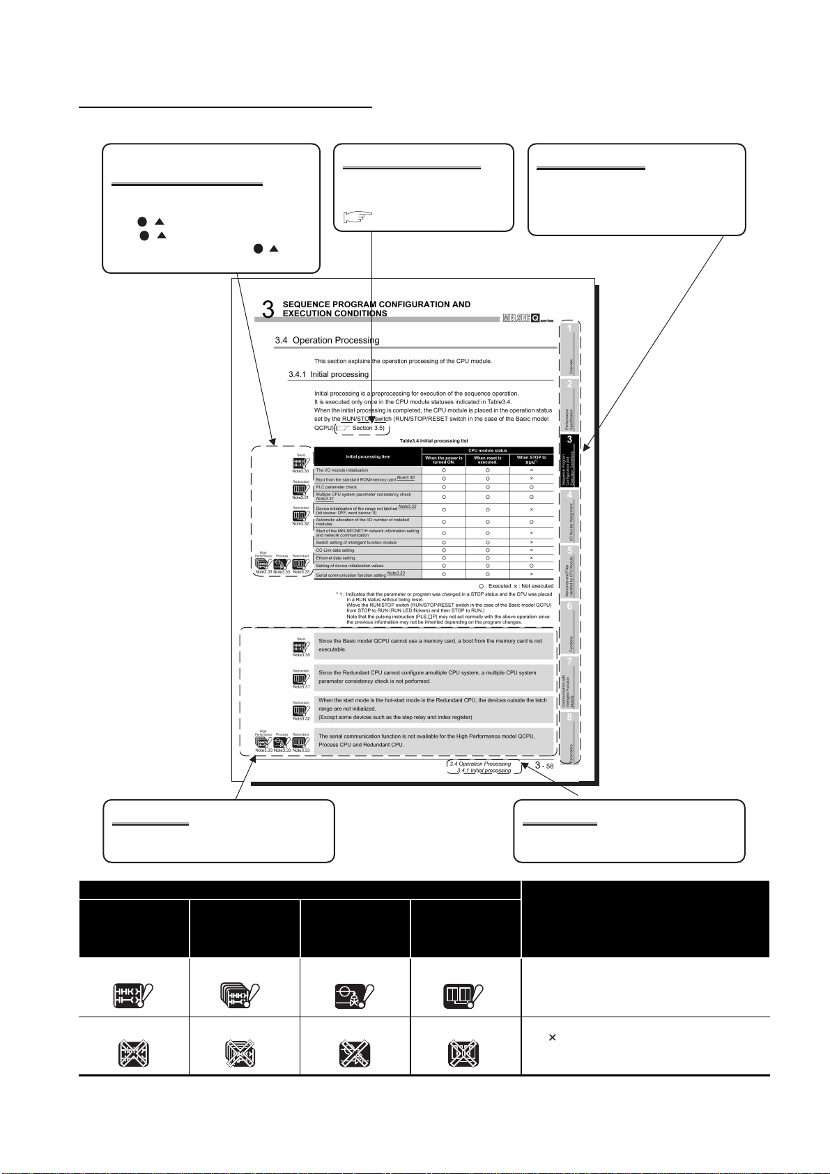
HOW TO SEE THIS MANUAL IS ORGANIZED
CPU modules requiring
precautions
The CPU modules requiring precautions
are shown as icons.
"Note . " under the icon corresponds to
"Note . " in the sentences and at the
page bottom. However, "Note . " is not
described in the section title.
Reference destination
A reference destination or
reference manual is marked
.
Chapter heading
The index on the right side of the page
shows the chapter of the open page at a
glance.
Precautions
Precautions corresponding to the icons are
provided.
Icon
High
QCPU
Basic
Basic
Performance
model QCPU
High
Performance
High
Performance
Process CPU Redundant CPU
Process Redundant
Process
Redundant
Section title
The section of the open page is shown at a
glance.
DescriptionBasic model
The ! marked icon indicates the CPU module
does not support a part of the described
functions.
The marked icon indicates the CPU module
does not support all of the described functions.
A
- 23
Page 26

In addition, this manual provides the foll owi ng exp la nati ons.
POINT
Explains the matters to be especially noted, the functions and others related to the
description.
Remark
Provides the reference destination related to the description on that page and the
convenient information.
A
- 24
Page 27

HOW TO USE THIS MANUAL
This manual is prepared for users to understand memory map, functions, programs and
devices of the CPU module when you use Q Series PLCs.
The manual is classified roughly into three sections as shown below.
1) Chapters 1 Describe the outline of the CPU module.
2) Chapters 2 to 5 Describe the perform ance spe cificat ions, executab le pr ogram, I/O
3) Chapter 6 Describes the functions of the CPU modules.
4) Chapter 7 Describes communication with intelligent function modules.
5) Chapters 8 and 9 Describe parameters and devices used in the CPU modules.
6) Chapter 10 Describes the CPU module processing time.
7) Chapter 11 Describes the procedure for writing parameters and programs
Remark
No. and memory of the CPU module.
created at the GX Developer to the CPU module.
This manual does not explain the functi ons of power sup pl y modu le s, bas e units,
extension cables, memory cards and batteries of CPU module.
For these details, refer to the manual shown below.
QCPU User's Manual (Hardware Design, Maintenance and Inspection)
Refer to the following manual for the multiple CPU system.
QCPU User's Manual (Multiple CPU Syst em)
Refer to the following manual for the redundant system.
QnPRHCPU User's Manual (Redundant System)
A
- 25
Page 28
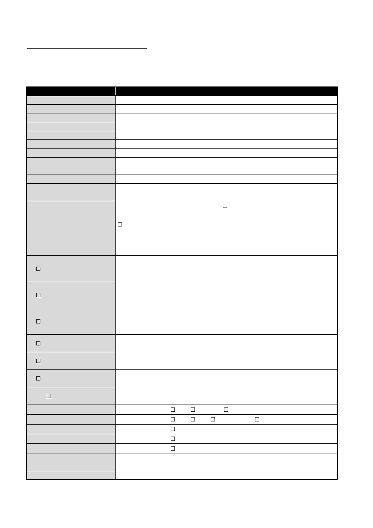
GENERIC TERMS AND ABBREVIATIONS
Unless otherwise specified, this manual uses the following generic terms and
abbreviations to explain the Q series CPU modules.
Generic Term/Abbreviation Description
Basic model QCPU General name for Q00JCPU, Q00CPU and Q01CPU modules.
High Performance model QCPU General name for Q02CPU, Q02HCPU, Q06HCPU Q12HC PU and Q25HCPU mo dules .
Process CPU General name for Q12PHCPU and Q25PHCPU
Redundant CPU General name for Q12PRHCPU and Q25PRHCPU.
QnHCPU General name for Q02HCPU, Q06HCPU Q12HCPU and Q25HCPU
QnPHCPU General name for Q12PHCPU and Q25PHCPU
QnPRHCPU General name for Q12PRHCPU and Q25PRHCPU.
CPU module
Q series Abbreviation for Mitsubishi MEL SEC-Q Series Programmable Logic Controller.
AnS series
GX Developer
Q3 B
Q3 SB
Q3 RB
Q5 B
Q6 B
Q6 RB
QA1S6 B
Main base unit
Extension base unit
Slim type main base unit
Redundant main base unit
Redundant extension base unit
Base unit
Redundant base unit General name for redundant main base unit and redundant extension base unit.
General name for Basic model QCPU, High performance model QCPU, Process CPU
and Redundant CPU.
Abbreviation for compact types of Mitsubishi MELSEC-A Series Programmable Logic
Controller.
Product name for Q series compatible SW D5C-GPPW-E type GPP function software
package.
indicates the version.
For the GX Developer versions applicable for each CPU module, refer to "System
configuration" in the QCPU User's Manual (Hardware Design, Maintenance and
Inspection).
General name for Q33B, Q35B, Q38B and Q312B main base units on which CPU
module (except Q00JCPU), Q series power supply module, I/O module and intelligent
function module can be mounte d.
General name for Q32SB, Q33SB an d Q35SB slim ty pe main base uni ts on which Basic
model QCPU (except Q00JCPU) High Performance model QCPU, slim type power
supply module, I/O module and intelligent function module can be mounted.
General name for Q38RB redundant power supply base unit on which CPU module
(except Q00JCPU), redundant power supply module, Q series I/O module and
intelligent function module can be mounted.
General name for Q52B and Q55B extension base unit on which the Q Series I/O and
intelligent function module can be mounted.
General name for Q63B, Q65B, Q68B and Q612B extension base unit on which Q
Series power supply module, I/O module, intelligent function module can be mounted.
General name for Q68R B re dun dan t power supply base unit on w h ic h red und an t po we r
supply module, Q series I/O modules and intelligent function module can be mounted.
General name for QA1S65B and QA1S68B extension base units on which with AnS
Series power supply module, I/O module, special function module can be mounted.
General name for Q3 B, Q3 SB and Q3 RB.
General name for Q5 B, Q6 B, Q6 RB and QA1S6 B.
General name for Q3 SB.
General name for Q3 RB.
General name for Q6 RB.
General name for main base unit, extension base unit, slim type main base unit,
redundant main base unit and redundant extension base unit.
A
- 26
Page 29

Generic Te rm/Abbreviation Description
Extension cable
Tracking cable General name for QC10TR and QC30TR tracking cable for Redundant CPU.
Q series power supply module General name for Q61P-A1, Q61P-A2, Q62P, Q63P and Q64P power supply modules.
Slim type power supply module General name for Q61SP slim type power supply module.
Redundant power supply module General name for Q64RP redundant power supply module.
AnS series power supply module General name for A1S61PN, A1S62PN and A1S63P power supply modules.
Power supply module
Battery
SRAM card Abbreviation for Q2MEM-1MBS and Q2MEM-2MBS type SRAM card.
Flash card General name for Q2MEM-2MBF and Q2MEM-4MBF type Flash card.
ATA card General name for Q2MEM- 8MBA, Q 2M EM -16 MBA a nd Q 2M EM -32 MBA ty pe ATA card.
Memory card General name for SRAM card, Flash card and ATA card.
PC CPU module MELSEC-Q series compatible PC CPU module of Contec makes.
Control system Abbreviation for Redundant CPU specified as control system.
Standby system Abbreviation for Redundant CPU specified as standby system.
System A Abbreviation for Redundant CPU specified as System A.
System B Abbreviation for Redundant CPU specified as System B.
General name for QC05B, QC06B, QC12B, QC30B, QC50B, QC100B extension
cables.
General name for Q series power supply modules, AnS series power supply modules,
slim type power supply module and redundant power supply module.
General name for Q6BAT and Q7BAT CPU module batteries and Q2MEM-BAT SRAM
card battery.
A
- 27
Page 30

1
OVERVIEW
CHAPTER1 OVERVIEW
This manual describes the programs, I/O number assignment method, functions and
devices of the Q Series CPU Modules ( (1) below).
For the power supply modules, base units, extension cables, memory cards and batteries,
refer to the manual below.
QCPU User's Manual (Hardware Design, Maintenance and Inspection)
(1) CPU modules corresponding to the description of this manual
The CPU modules described in this manual are as shown in Table1.1.
Table1.1 List of CPU modules corresponding to the description of this manual
CPU module Model name
Basic model QCPU Q00JCPU, Q00CPU, Q01CPU
High Performance model QCPU
Process CPU Q12PHCPU, Q25PHCPU
Redundant CPU Q 12PRHCPU, Q25PRHCPU
Q02CPU, Q02HCPU, Q06HCPU, Q12HCPU,
Q25HCPU
1
- 1
Page 31

1
OVERVIEW
1
(2) List of Q Series CPU Module manuals
The Q series CPU module manuals are as shown below.
For details such as manual numbers, refer to "About Manuals" in this manual.
Overview
(a) Basic model QCPU
2
T able1.2 List of user's manuals of basic model QCPU
Purpose
Confirmation of part names and
specifications of the CPU module
Confirmation of connection methods
for the power supply module, base
unit and I/O module
Construction of the single CPU
system (confirmation of start-up
procedure and I/O number
assignment)
Construction of the multiple CPU
system (confirmation of start-up
procedure and I/O number
assignment)
Hardware
(Packed)
QCPU (Q mode)
CPU Module User's
Manual (Hardware)
Outline
Outline
Maintenance
and
Inspection
QCPU User's
Manual (Hardware
Design,
Maintenance and
inspection)
Details
Details
Details
Program
Fundamentals
QCPU User's
Manual (Fun ction
Explanation,
Program
Fundamentals)
Outline
Multi CPU
System
QCPU User's
Manual (Multiple
CPU System)
Details
Redundant
System
QnPRHCPU User's
Manual (Redundant
System)
Sequence Program
3
4
5
Performance
Configuration and
Specification
Execution Conditions
I/O Nunber Assignment
Confirmation of the sequence program
configuration and memory
Confirmation of the functions,
parameters, and devices of the CPU
module
Confirmation of the troubleshooting
and error codes
Details
Details
Details
1
- 2
Memories and Files
Handled by CPU Module
6
Functions
7
Communication with
Intelligent Function
Module
8
Parameters
Page 32

1
OVERVIEW
Table1.3 List of progra m mi ng m a nuals of basic model QCPU
Purpose
Confirmation of usage of
sequence instructions, basic
instructions, application
instructions, etc.
Confirmation of dedicated
instructions for PID control
Confirmation of MELSAP3's
system configuration,
performance specifications,
functions, programming,
debugging, and error codes
Confirmation of the
programming method,
specifications, functions, etc.
required for SFC programming
of the MELSAP-L type
Common
Instructions
QCPU (Q mode)/
QnACPU
Programming
Manual
(Common
Instruction)
Details
PID Control
Instructions
QCPU (Q mode)/
QnACPU
Programming
Manual (PID
Control
Instruction)
Details
Process
Control
Instruction
QnPHCPU/
QnPRHCPU
Programming
Manual (Process
Control
Instruction)
SFC
QCPU (Q mode)/
QnACPU
Programming
Manual (SFC)
Details
MELSAP-L
QCPU (Q mode)
Programming
Manual
(MELSAP-L)
Details
Structured
Text
QCPU (Q mode)
Programming
Manual
(Structured Text)
Confirmation of the
programming method of the
structured text language
Details
1
- 3
Page 33

1
OVERVIEW
1
(b) High Performance Model QCPU
Table1.4 List of user's manuals of high performance model QCPU
Purpose
Confirmation of part names and
specifications of the CPU module
Confirmation of connection methods
for power supply module, base unit
and I/O module
Construction of the single CPU
system (confirmation of start-up
procedure and I/O number
assignment)
Construction of the multiple CPU
system (confirmation of start-up
procedure and I/O number
assignment)
Hardware
(Packed)
QCPU (Q mode)
CPU Module User's
Manual (Hardware)
Outline
Outline
Maintenance
and
Inspection
QCPU User's
Manual (Hardware
Design,
Maintenance and
inspection)
Details
Details
Details
Program
Fundamentals
QCPU User's
Manual (Fun ction
Explanation,
Program
Fundamentals)
Outline
Multi CPU
System
QCPU User's
Manual (Multiple
CPU System)
Details
Redundant
System
QnPRHCPU User's
Manual (Redundant
System)
Sequence Program
2
3
4
Performance
Configuration and
Overview
Specification
Execution Conditions
I/O Nunber Assignment
Confirmation of the sequence program
configuration and memory
Confirmation of the functions,
parameters, and devices of CPU
module
Confirmation of the troubleshooting
and error codes
Details
Details
Details
5
Memories and Files
Handled by CPU Module
6
Functions
7
Communication with
Intelligent Function
Module
8
1
- 4
Parameters
Page 34

1
OVERVIEW
Table1.5 List of programming manuals of high performance model QCPU
Purpose
Confirmation of usage of
sequence instructions, basic
instructions, application
instructions, etc.
Confirmation of dedicated
instructions for PID control
Confirmation of MELSAP3's
system configuration,
performance specifications,
functions, programming,
debugging, and error codes
Confirmation of the
programming method,
specifications, functions, etc.
required for SFC programming
of the MELSAP-L type
Common
Instructions
QCPU (Q mode)/
QnACPU
Programming
Manual
(Common
Instruction)
Details
PID Control
Instructions
QCPU (Q mode)/
QnACPU
Programming
Manual (PID
Control
Instruction)
Details
Process
Control
Instruction
QnPHCPU/
QnPRHCPU
Programming
Manual (Process
Control
Instruction)
SFC
QCPU (Q mode)/
QnACPU
Programming
Manual (SFC)
Details
MELSAP-L
QCPU (Q mode)
Programming
Manual
(MELSAP-L)
Details
Structured
Text
QCPU (Q mode)
Programming
Manual
(Structured Text)
Confirmation of the
programming method of the
structured text language
Details
1
- 5
Page 35

1
OVERVIEW
1
(c) Process CPU
Table1.6 List of user's manuals of process CPU
Purpose
Confirmation of part names and
specifications of the CPU module
Confirmation of connection methods
for power supply module, base unit
and I/O module
Construction of the single CPU
system (confirmation of start-up
procedure and I/O number
assignment)
Construction of the multiple CPU
system (confirmation of start-up
procedure and I/O number
assignment)
Hardware
(Packed)
QCPU (Q mode)
CPU Module User's
Manual (Hardware)
Outline
Outline
Maintenance
and
Inspection
QCPU User's
Manual (Hardware
Design,
Maintenance and
inspection)
Details
Details
Details
Program
Fundamentals
QCPU User's
Manual (Fun ction
Explanation,
Program
Fundamentals)
Outline
Multi CPU
System
QCPU User's
Manual (Multiple
CPU System)
Details
Redundant
System
QnPRHCPU User's
Manual (Redundant
System)
Sequence Program
2
3
4
Performance
Configuration and
Overview
Specification
Execution Conditions
I/O Nunber Assignment
Confirmation of sequence program
configuration and memory
Confirmation of the functions,
parameters, and devices of the CPU
module
Confirmation of the troubleshooting
and error codes
Details
Details
Details
5
Memories and Files
Handled by CPU Module
6
Functions
7
Communication with
Intelligent Function
Module
8
1
- 6
Parameters
Page 36

1
OVERVIEW
Table1.7 List of programming manuals of process CPU
Purpose
Confirmation of usage of
sequence instructions, basic
instructions, application
instructions, etc.
Confirmation of dedicated
instructions for process control
Confirmation of MELSAP3's
system configuration,
performance specifications,
functions, programming,
debugging and error codes
Confirmation of the
programming method,
specifications, functions etc.
required for SFC programming
of the MELSAP-L type
Common
Instructions
QCPU (Q mode)/
QnACPU
Programming
Manual
(Common
Instruction)
Details
PID Control
Instructions
QCPU (Q mode)/
QnACPU
Programming
Manual (PID
Control
Instruction)
Process
Control
Instruction
QnPHCPU/
QnPRHCPU
Programming
Manual (Process
Control
Instruction)
Details
SFC
QCPU (Q mode)/
QnACPU
Programming
Manual (SFC)
Details
MELSAP-L
QCPU (Q mode)
Programming
Manual
(MELSAP-L)
Details
Structured
Text
QCPU (Q mode)
Programming
Manual
(Structured Text)
Confirmation of the
programming method of the
structured text language
Details
1
- 7
Page 37

1
OVERVIEW
1
(d) Redundant CPU
Table1.8 List of user's manual of redundant CPU
Purpose
Confirmation of part names and
specifications of the CPU module
Confirmation of connection methods
for power supply module, base unit
and I/O module
Construction of redundant system
(confirmation of start-up procedure
and I/O number assignment)
Confirmation of the configuration and
memory of sequence programs
Confirmation of the functions,
parameters, devices, etc. of the CPU
module
Hardware
(Packed)
QCPU (Q mode)
CPU Module User's
Manual (Hardware)
Outline
Outline
Maintenance
and
Inspection
QCPU User's
Manual (Hardware
Design,
Maintenance and
inspection)
Details
Details
Program
Fundamentals
QCPU User's
Manual (Fun ction
Explanation,
Program
Fundamentals)
Outline
Details
Details
Multi CPU
System
QCPU User's
Manual (Multiple
CPU System)
Redundant
System
QnPRHCPU User's
Manual (Redundant
System)
Details
Sequence Program
2
3
4
5
Performance
Configuration and
Overview
Specification
Execution Conditions
I/O Nunber Assignment
Confirmation of the troubleshooting
Confirmation of the error codes
Details
Details
Memories and Files
Handled by CPU Module
6
Functions
7
Communication with
Intelligent Function
Module
8
1
- 8
Parameters
Page 38

1
OVERVIEW
Table1.9 List of programming manuals of redundant CPU
Purpose
Confirmation of usage of
sequence instructions, basic
instructions, application
instructions, etc.
Confirmation of dedicated
instructions for PID control
Confirmation of dedicated
instructions for process control
Confirmation of MELSAP3's
system configuration,
performance specifications,
functions, programming,
debugging and error codes
Confirmation of the
programming method,
specifications, functions, etc.
required for SFC programming
of the MELSAP-L type
Common
Instructions
QCPU (Q mode)/
QnACPU
Programming
Manual
(Common
Instruction)
Details
PID Control
Instructions
QCPU (Q mode)/
QnACPU
Programming
Manual (PID
Control
Instruction)
Details
Process
Control
Instruction
QnPHCPU/
QnPRHCPU
Programming
Manual (Process
Control
Instruction)
Details
SFC
QCPU (Q mode)/
QnACPU
Programming
Manual (SFC)
Details
MELSAP-L
QCPU (Q mode)
Programming
Manual
(MELSAP-L)
Details
Structured
Text
QCPU (Q mode)
Programming
Manual
(Structured Text
Edition)
Confirmation of the
programming method of the
structured text language
Details
1
- 9
Page 39

1
OVERVIEW
1.1 Features
1.1.1 Features of Basic model QCPU
Basic model QCPU
This section explains the features of the CPU modules.
The features specific to the Basic model QCPU are described below.
(1) Cost performance optimum for small-scaled system
The Basic model QCPU is a module targeted for a small-scaled system and optimum
for controlling a simple, compact system.
The Basic model QCPU realizes the cost performance optimum for a small-scaled
system.
GX Developer
Ethernet
Sequence Program
1
2
3
4
Performance
Configuration and
Overview
Specification
Execution Conditions
CC-Link remote
I/O station
MELSECNET/H PLC to PLC network
Diagram 1.1 System example using the Basic model QCPU
CC-Link remote
device station
(2) Communications with personal computer or display by serial
communication function ( Section 6.23)
The Q00CPU or Q01CPU can communicate with a personal computer/display other
devices via the RS-232 interface under the MELSEC communication protocol
(hereafter abbreviated to the MC protocol).
RS-232 cable
Personal computer,
display device
5
6
7
I/O Nunber Assignment
Memories and Files
Handled by CPU Module
Functions
Communication in MC protocol
Diagram 1.2 Communication with personal computer/display
1.1 Featu res
1.1.1 Features of Basic model QCPU
1
- 10
Communication with
Intelligent Function
Module
8
Parameters
Page 40

1
OVERVIEW
1.1.2 Features of High Performance model QCPU
The features specific to the High Performance model QCPU are described below.
(1) High performance and large capacity
The High Performance model QCPU is a module targeted for small-scaled to largescaled systems and capable of high-speed massive data processing.
The High Performance model QCPU realizes construction of the optimum and highperformance system.
GX Developer
Ethernet
High Performance model QCPU
MELSECNET remote I/O network
CC-Link remote
I/O station
MELSECNET/H PLC to PLC network
CC-Link remote
device station
1
- 11
Diagram 1.3 System example using the High Performance model QCPU
1.1 Features
1.1.2 Features of High Performance model QCPU
Page 41

1
OVERVIEW
1
(2) AnS series I/O modules and special function modules are available
The QA1S65B/QA1S68B type extension base units allow the High Performance
model QCPU to use the AnS series I/O modules and special function modules.
Overview
Remark
Refer to 3.2 for upgraded functions added to the High Performance model QCPU.
Sequence Program
2
3
4
5
Performance
Configuration and
Specification
Execution Conditions
I/O Nunber Assignment
1.1 Featu res
1.1.2 Features of High Performance model QCPU
1
- 12
Memories and Files
Handled by CPU Module
6
Functions
7
Communication with
Intelligent Function
Module
8
Parameters
Page 42

1
OVERVIEW
1.1.3 Features of Process CPU
The features specific to the Process CPU are described below.
(1) Additional 52 process control functions
Fifty-two instructions supporting high-leveled process controls have been added to
the CPU based on the High Performance model QCPU.
Refer to the following manual for details of the added instructions.
QnPHCPU/QnPRHCPU Programming Manual (Process Control Instructions)
GX Developer
PX Developer
Ethernet
Process CPU Process CPU
Valve
Flow rate
sensor
Tank Flow
rate
sensor
Solenoid
valve
Tank
Diagram 1.4 Operations of Process CPU
(2) Two-degree-of-freedom PID control system
The Two-degree-of-freedom PID control system has been adopted to enable optimum
responses to both set value changes and disturbance.
(3) Auto tuning function (PID constant initial value setting)
The auto tuning function enables automatic control parameter tuning, decreases the
tuning time and labor of operators and control engineers, and eliminates differences
between individuals in tuning results.
Refer to the following manual for details of the auto tuning function.
QnPHCPU/QnPRHCPU Programming Manual (Process Control Instructions)
1
- 13
1.1 Features
1.1.3 Features of Process CPU
Page 43

1
OVERVIEW
(4) Module can be replaced online (Online module change)
When a module becomes faulty, it can be replaced without the system being stopped.
Modules available for this are the Q series I/O modules, and the A/D converter
modules, D/A converter modules, temperature input modules, temperature control
modules and pulse input modules of function version C.
Refer to the following manuals for details of the online module change.
QCPU User's Manual (Hardware Design, Maintenance and Inspection)
Manuals of the modules compatible with the online module change
1
Overview
2
(5) Configuration of MELSECNET/H multiplexed remote I/O system
A MELSECNET/H multiplexed remote I/O system can be configured,mounting a
remote master station in the MELSECNET/H network system.
(6) Supporting software package dedicated to process control
Using the process control software package (PX Developer), PID control programs
can be created easily with function blocks.
The combination of the Process CPU and the process control software package (PX
Developer) offers an excellent engineering environment.
POINT
1. When using the Process CPU, use GX Developer Version 7.10L or later.
2. Use PX Developer together with GX Developer Version 7.12L or later.
Refer to the PX Developer manual for details.
Sequence Program
3
4
5
Performance
Configuration and
Memories and Files
Specification
Execution Conditions
I/O Nunber Assignment
Handled by CPU Module
1.1 Featu res
1.1.3 Features of Process CPU
1
- 14
6
Functions
7
Communication with
Intelligent Function
Module
8
Parameters
Page 44

1
OVERVIEW
1.1.4 Features of Redundant CPU
The features specific to the Redundant CPU are described below.
(1) Supporting redundant system in addition to the Process CPU functions
(a) Redundant system using Redundant CPU
Using the Redundant CPUs, the whole system including a base unit, a power
supply module and a CPU module (Redundant CPU) can be doubled.
Since the standby system takes over the control even if a failure occurs in the
control system, a highly reli able system can be created.
Control system
Stop!
During stop, power supply
module, faulty module or other
module can be changed!
Diagram 1.5 Operation of Redundant CPU
Standby system
Data tracking
Control system
Continuous operation
can be performed!
Continued with device
data used in control
system
1
- 15
1.1 Features
1.1.4 Features of Redundant CPU
Page 45

1
OVERVIEW
(b) Redundant power supply system
Using the redundant main base unit (Q3 RB) and redundant power supply
module (Q6 RB) on the remote I/O station side, the remote I/O station side
power supply can be made redundant.
This enables the power supply module to be changed without stopping the system
if the remote I/O station side power supply module becomes faulty.
1
Overview
2
Redundant power
supply on remote
I/O station side!
Control system
Tracking cable
Standby system
MELSECNET/H remote I/O network
Redundant power
supply on remote
I/O station side!
Sequence Program
3
4
5
Performance
Configuration and
Specification
Execution Conditions
I/O Nunber Assignment
POINT
Remark
Diagram 1.6 Redundant power supply system
1. When using the Redundant CPU, use GX Developer Version 8.18U or later.
2. Use PX Developer in combination with GX Developer Version.
When using the Redundant CPU, use PX Developer Version 1.06G or later.
Refer to the PX Developer manual for details of PX Developer.
Refer to the following manual for detailed features, functions and others of the
Redundant CPU.
QnPRHCPU User's Manual (Redundant System)
Memories and Files
Handled by CPU Module
6
Functions
7
Communication with
Intelligent Function
Module
8
1.1 Featu res
1.1.4 Features of Redundant CPU
1
- 16
Parameters
Page 46

1
OVERVIEW
1.2 Program Storage and Operation
(1) Program storage
Basic
Note1.1
(a) Storage of program created by GX Developer
The program created by GX Developer can be stored into the program memory,
standard ROM or memory card
Note1.1
of the CPU module.Note1
1) Basic model QCPU
Program memory
Parameter
Standard ROM
Parameter
Standard RAM
CPU shared memory
3
1
3
2 4
File register
Program
Device initial valueDevice comment
Program
Device initial valueDevice comment
CPU module
5
Note1
* 1 : The standard ROM is used to ROM the program memory.
* 2 : The standard RAM is a memory used for the file registers.
* 3 : The intelligent function module parameters set by GX Configurator are included.
* 4 : The Q00JCPU does not have the standard RAM.
The file registers are unavailable.
* 5 : Refer to the following manual for the CPU shared memory.
QCPU User's Manual (Multiple CPU System)
Diagram 1.7 Memory configuration and storage destinations of Basic model QCPU
Basic
The Basic model QCPU cannot use a memory card.
Note1.1
1
- 17
1.2 Program Storage and Operation
Page 47

1
OVERVIEW
1
2) High Performance model QCPU, Process CPU, Redundant CPU
Program memory
Parameter
Standard ROM
Parameter
Device comments
Standard RAM
File register
Redundant
Note1.2
Diagram 1.8 Memory configuration and storage destinations of High Performance model QCPU, Process CPU, Redundant CPU
CPU shared memory
3
1
3
2 4
* 1 : The standard ROM is used to ROM the program memory.
* 2 : The standard RAM is a memory provided for using the file registers and local devices without
installing a memory card.
The standard RAM is used to speed up access to the file registers.
* 3 : The intelligent function module parameters set by GX Configurator are included.
* 4 : Only available for the Flash card.
Note that only read is enabled.
* 5 : Refer to the following manual for the CPU shared memory.
Program
Device initial value
Program
Device initial value
CPU module Memory card
Local devices
Note1.2
5
QCPU User's Manual (Multiple CPU System)
RAM
Parameter Program
Device initial valueDevice commentsDevice comments
File register Local devices
Sampling
ROM
Parameter Program
Device initial valueDevice comments
File register
Note1.2
4
Note2
Failure history
(b) Program execution
The CPU module operates the progra m stored in the program memory.
Sequence Program
2
3
4
5
Performance
Configuration and
Overview
Specification
Execution Conditions
I/O Nunber Assignment
Note2
Redundant
Note1.2
Program memory
Parameter
Program
Device comments
Device initial value
Diagram 1.9 Execution of stored program
Execution of program
in program memory
For program comment display
by GX Developer
The Redundant CPU does not include CPU shared memory.
Memories and Files
Handled by CPU Module
6
Functions
7
Communication with
Intelligent Function
Module
8
1.2 Program Storage and Operation
1
- 18
Parameters
Page 48

1
OVERVIEW
Basic
Note1.3
(c) Execution of program stored in standard ROM/memory card
Note1.3
Programs and data can also be stored into the standard ROM/memory card.
The programs stored in the standard ROM/memory card can be booted (read) to
the program memory and executed when the PLC is powered ON or the CPU
module is reset.Note3
By storing programs and data into the standard ROM/memory card, they can be
saved without battery backup.
1) Basic model QCPU
To execute boot from the standard ROM to the program memory, it is
necessary to make boot file setting in the PLC Parameter dialog box of GX
Developer.
Execution of program booted from the
standard ROM to the program memory.
Program
memory
Boot
Standard
ROM
Parameter Program
Device
comments
Device
initial value
Diagram 1.10 Boot run of Basic model QCPU
2) High Performance model QCPU, Process CPU, Redundant CPU
To execute boot to the program memory, make boot file setting in the PLC
Parameter dialog box of GX Developer and set the parameter-valid drive with
DIP switches.
ParameterProgram
Device
comments
Diagram 1.11 Boot run of High Performance model QCPU, Process CPU, Redundant CPU
Device
initial value
Memory card
Boot
Program
memory
Standard
ROM
Execution of program booted from the standard
ROM or memory card to the program memory.
Boot
Device
comments
ParameterProgram
Device
initial value
Note3
1
- 19
Basic
Note1.3
1.2 Program Storage and Operation
Since the Basic model QCPU cannot use a memory card, it cannot store programs in the
memory card.
Page 49

1
OVERVIEW
(2) Structured programs
CPU module programs can be structured.
A program can be created according to processes and functions by structuring it.
As program structuring, structuring in the same program ( (2)(a) in this section)
and file-divided structuring ( (2)(b) in this section) are available.
(a) Structuring in the same program
Structuring in the same program is achieved by creating subroutine programs
( Section 3.1.2) or interrupt programs ( Section 3.1.3).
1
2
Overview
Performance
Specification
Main routine
program
P0
Subroutine
program 1
P8
Subroutine
program 2
P1
Subroutine
program 3
Diagram 1.12 Example of structuring in the same program
CALL P1
FEND
Y10
RET
Y11
RET
Y12
RET
END
Sequence Program
3
4
5
6
Configuration and
Memories and Files
Execution Conditions
I/O Nunber Assignment
Handled by CPU Module
1.2 Program Storage and Operation
1
- 20
Functions
7
Communication with
Intelligent Function
Module
8
Parameters
Page 50

1
OVERVIEW
Basic
Note1.4
GX Developer
(b) File-divided structuring
Programs are stored in file format.
Note1.4
*1
Changing the file name allows the CPU module to store multiple programs.Note4
* 1 : The program storage destination changes depending on the CPU module.
(i CHAPTER 5)
Multiple program writing is enabled
by using different file names.
File name: PARAM File name: ABC File name: ABC File name: DEF
Write
Device
comments
Program
CPU module
Parameter Program
Diagram 1.13 File-divided structuring
Hence, a program can be created separately by multiple designers, or can be
divided and managed/maintained individually according to the processes and
functions.
If specifications are changed, it is necessary to correct/debug only the
corresponding program.
1) When program is created separately by multiple designers
Program memory /
Standard ROM /
Memory card
Desiner A Program A
Desiner B Program B
Desiner C Program C
* 2 : The execution order and execution conditions of the program can be set by program setting
( Section 3.3.6(1)).
Diagram 1.14 Separate creation of program (by designers)
Program A to C
are executed in
sequence. 2
Note4
1
- 21
Basic
Note1.4
1.2 Program Storage and Operation
Since the Basic model QCPU cannot store multiple programs by changing the file name, it
cannot execute file-divided structuring.
Page 51

1
OVERVIEW
1
2) When program is divided according to processes
Program memory /
Standard ROM /
Memory card
Ship in
Manufacturing
Split by
process
* 1 : The processings performed according to the processes can further be managed separately
according to the functions.
* 2 : The execution order and execution conditions of the program can be set by program setting
( Section 3.3.6(1)).
Assembly
Ship out
Diagram 1.15 Separate creation of program (by processes)
Program A
Program B
Program C
Program D
*1
Program A to D
are executed in
sequence. 2
Sequence Program
2
3
4
Performance
Configuration and
Overview
Specification
Execution Conditions
3) When program is divided according to functions
Program memory /
Standard ROM /
Memory card
Initial processing
Main processing
Split by
function
* 2 : The execution order and execution conditions of the program can be set by program setting
Communication
processing
Error processing
( Section 3.3.6(1)).
Diagram 1.16 Separate creation of program (by functions)
Program A
Program B
Program C
Program D
The execution
sequence and
execution
conditions can be
set to conform to
programs A to D.
I/O Nunber Assignment
5
Memories and Files
Handled by CPU Module
2
6
Functions
7
Communication with
Intelligent Function
Module
1.2 Program Storage and Operation
1
8
Parameters
- 22
Page 52

1
OVERVIEW
1.3 Devices and In structions Conv enient for Programming
The CPU module has devices and instructions convenient for program creation.
The main devices and instructions are outlined below.
(1) Flexible device designation
The Q series CPU modules allow devices to be specified flexibly.
(a) Word device bits are handled as contacts/coils
By specifying the bit of the word device, each bit of the word device can be
handled as a contact/coil .
X0
SET D0.5
D0.5
SET Y10
Word device bit designation (Turns ON
(1) Bit 5 (b5) of D0.)
Word device bit designation (Turns ON/OFF
depending on 1/0 of Bit 5 (b5) in D0.)
Diagram 1.17 Designation of word device bit
(b) Easy direct processing in 1-point units
Using the direct access input (DX ) and direct access output (DY ), direct
processing can be easily performed in 1-point units in a program. ( Section
3.8.2)
M0 DX10
Diagram 1.18 Direct processing in 1-point units
Direct access input
DY100
Output to output
module at
instruction
execution
Read from input
module at
instruction
execution
1
- 23
1.3 Devices and Instructions Convenient for Programming
Page 53

1
OVERVIEW
1
(c) Input need not be pulsed by use of differential contact
An input need not be pulsed by use of a differential contact( / ).
X0
Y100
X1
Differential contact
Y100
Diagram 1.19 Use of differential contact
ON at leading
edge of X0
X0
M0
Y100
X1
(d) Direct access to intelligent function module buffer memory
The intelligent function module buffer memory can be handled as devices for
programming. ( Section 9.5)
X0
+P
012 45673
Q64AD
Q64AD
Input module
Input module
Input module
16
points
16
points
16
points
Diagram 1.20 Direct access to intelligent function module buffer memory
16
points
16
points
D0U4\G12
Readout of Q64AD
buffer memory's
address 12 data
Q62DA
Output module
16
16
points
points
points
I/O Nos.:X/Y40 to X/Y4f
U4\G12
Buffer memory
address designation
Intelligent function module
designation
Output module
16
(e) Direct access to link devices
The link devices (LX, LY, LB, L W, SB, SW) of t he MELSECNET/H network modu le can
be accessed directly without refresh setting.
M0PLS
Y100
Sequence Program
2
3
4
5
6
Performance
Configuration and
Memories and Files
Overview
Specification
Execution Conditions
I/O Nunber Assignment
Handled by CPU Module
X0
+P
012 45673
Q68AD
Q68AD
Input module
16
Input module
16
points
points
16
16
points
points
QJ71LP21-25
points
Diagram 1.21 Direct access to link devices
D0J5\W12
Direct readout of the No.5 network module's
"LW12" link register
Q62DA
Output module
16
16
16
points
points
Network No.5
1.3 Devices and Instructions Convenient for Programming
J5\W12
Output module
Link register
designation
Network No.
designation
1
- 24
Functions
7
Communication with
Intelligent Function
Module
8
Parameters
Page 54

1
OVERVIEW
(2) Structural description of programs
Using the index registers and edge relays, programs including pulse processing can
be structured easily. ( Section 9.2.6)
FOR n
X0 X1
M0
PLS M0
Y8
Basic
Note1.5
X0Z0 X1Z0
V0Z1
Y8Z2
NEXT
Diagram 1.22 Structuring of programs including pulse processing
n pieces of similar
programs can be
described at one time!
X10 X11
M10
X170 X171
M170
(3) Ease of data processing
(a) Real numbers and character string constants used unchanged
The real numbers (floating-point data) and character string constants can be used
Note1.5
Real number data
R0D0E1.23
D10
Note5
E1.23
Character
string data
D5
"0" "Q"
D6
NUL
"2"
D0
D1
E3.45
Character
string data
+
"CPU"
+
unchanged in programming.
X0
E+P
Real number ADD instruction
$+P
D5
"CPU"
Character string data LINK
instruction
* : NUL indic a te s "00H (end of character string)".
Diagram 1.23 Use of real numbers and character string constants
PLS M10
Y18
PLS M170
Y178
Real number dataReal number data
R0
R1
D10
D11
D12
D13
E4.68
Character
string data
"0"
"C"
"U"
NUL
"Q"
"2"
"P"
Note5
1
- 25
Basic
• When using real numbers (floating-po int da ta) on th e Basi c mod el QCPU , check the ve rsion of
the CPU module. ( Appendix 3.1 (2))
Note1.5
• On the Basic model QCPU, character strings are available for only the $MOV, STR, DSTR,
VAL, DVAL, ESTR and EVAL instructions.
1.3 Devices and Instructions Convenient for Programming
Page 55

1
OVERVIEW
1
(b) High-speed processing of massive data
The data processing instructions, such as the table processing instruction, have
been reinforced to enable high-speed processing of massive data.
Program A
M0
0
Basic
Note1.6
X0
K2R0D0FINSP
Insertion
source
Instruction for data insertion
at table
Diagram 1.24 Data processing by table processing instruction
Inserting
position
Insertion
designation
D0
15
(4) Flexible management of subroutine program
(a) Subroutine program sharing
A subroutine program can be shared to reduce the number of program steps.
Programs can also be created and managed easily.
A subroutine program can be created and called in the same program. Using a
common pointer, however, a subroutine program in the other program can be also
Note1.6
called.
P1000CALLP
Note6
P1000 call
Common pointer
Program C
Subroutine program
SM400
P1000
Always
ON
FIF0 table FIF0 table
R0
R1
R2
R3
R4
M0
M0
3
10
20
30
R0
R1
R2
R3
K4X0MOV
MOV
R0
R0K4X20
10
15
20
30R4
Overview
4
2
Performance
Specification
3
Sequence Program
Configuration and
Execution Conditions
4
I/O Nunber Assignment
5
Program B
0
Note6
M10
Basic
Note1.6
P1000 call
P1000CALLP
Diagram 1.25 Subrout ine program sharing
Since the Basic model QCPU cannot execute multiple programs, it cannot use subroutine
programs in the other programs.
1.3 Devices and Instructions Convenient for Programming
RET
1
- 26
Memories and Files
Handled by CPU Module
6
Functions
7
Communication with
Intelligent Function
Module
8
Parameters
Page 56

1
OVERVIEW
(b) Subroutine call instructions with arguments
A subroutine program called several time can be created easily by the subroutine
call instructions with arguments.
Main routine program
Argument designation
M0
K4X0W0
R0
Argument from FD2
Argument to FD1
Argument to FD0
K4X10W10
R10
Argument from FD2
Argument to FD1
Argument to FD0
FEND
100
CALLP
CALLP
P0
Sub routine program
designation
Argument designation
P0
0
M10
Subroutine program
M0
M0
source data
MOV
FD0MOV
FD2
FD2FD1
RET
END
SM400
P0
Always
ON
* : Refer to Section 9.3.1 for the input/output condition of the argument.
Diagram 1.26 Subroutine call instructions with arguments
Destination data
1
- 27
1.3 Devices and Instructions Convenient for Programming
Page 57

1
OVERVIEW
1.4 How to Check th e Serial No. and Function Version
The serial No. and function version of the CPU module can be checked on the rating plate
or in the system monitor of GX Developer.
1
Overview
(1) Checking on rating plate
The rating plate is on the side face of the CPU module.
Serial number (first 5 digits)
Function version
Applicable Standard
marking is provided.
Diagram 1.27 Rating plate
(2) Checking in system monitor (product information list)
To display the system monitor, choose [Diagnostics] [System monitor] on GX
Developer.
In the system monitor, the serial Nos. and function versions of the intelligent function
modules can also be checked.
Serial number function version
Sequence Program
2
3
4
5
Performance
Configuration and
Specification
Execution Conditions
I/O Nunber Assignment
Diagram 1.28 System monitor
1.4 How to Check the Serial No. and Function Version
1
- 28
Memories and Files
Handled by CPU Module
6
Functions
7
Communication with
Intelligent Function
Module
8
Parameters
Page 58

2
PERFORMANCE SPECIFICATION
CHAPTER2 PERFORMANCE SPECIFICATION
The table below shows the performance specifications of the CPU module.
Table2.1 Performance Specification
Item
Control method Repetitive operation of stored program
I/O control mode Refresh mode
Q00JCPU Q00CPU Q01CPU Q02CPU Q02HCPU Q06HCPU
Basic model QCPU High Performance model QCPU
Sequence control
Programming
language
Processing
speed
(Sequence
instruction)
Processing
speed
(Redundant
function)
Constant scan (ms)
(Function for setting the scan timer to fixed
settings)
Program capacity
Memory
capacity
*1
dedicated language
Process control language ----
LD X0 0.20 s 0.16 s 0.10 s 0.079 s 0.034 s
MOV D0 D1 0.70 s 0.56 s 0.35 s 0.237 s 0.102 s
Tracking exec ut ion ti me
(Increased scan time)
*1 *2
Program memory
(Drive 0)
Memory card (RAM)
(Drive 1)
Memory card (ROM)
(Drive 2)
Standard RAM
(Drive 3)
Standard ROM
(Drive 4)
Relay symbol language, logic symbolic language,MELSAP3 (SFC),
MELSAP-L, Function block, structured text (S T)
----
1 to 2000ms (configurable in increments of 1 ms) 0.5 to 2000ms (configurable in increments of 0.5 ms)
8k step
(32k byte)
58k byte 94k byte 112k byte 240k byte
---- Capacity of loading memory cards (2Mbyte max.)
----
0
58k byte 94k byte 112k byte 240k byte
128k byte
14k step
(56k byte)
*3
28k step
(112k byte)
Installed memory card capacity
(Flash card: 4 Mbyte max., ATA card: 32 Mbyte max.)
64k byte
128k byte
60k step
(240k byte)
*3
2
- 1
CPU shared memory
*3 *4
---- 1k byte 8k byte
* 1 : The size unit of the file stored in the memory area changes depending on the CPU module.
( Section 5.4.4)
* 2 : The maximum number of executable sequence steps is obtained by the following expression.
(Program size) - (File header size (default: 34 steps))
Refer to CHAPTER 5 for details of the program capacity and file.
* 3 : The capacity has been increased by the improvement of the CPU module functions.
( Appendix 3)
Page 59

2
PERFORMANCE SPECIFICATION
1
.
High Performance model QCPU Process CPU Redundant CPU
Q12HCPU Q25HCPU Q12PHCPU Q25PHCPU Q12PRHCPU Q25PRHCPU
Repetitive operation of stored program ----
Refresh mode
Relay symbol language, logic symbolic language,MELSAP3 (SFC), MELSAP-L, Function block,
structured text (ST)
---- FBD for process control
0.034 s ----
0.102 s ----
----
0.5 to 2000ms (configurable in increments of 0.5 ms) Set parameter values to specify
124k step
(496k byte)
496k byte 1008k byte 496k byte 1008k byte 496k byte 1008k byte
252k step
(1008k byte)
124k step
(496k byte)
Capacity of loading memory cards (2Mbyte max.)
252k step
(1008k byte)
Device memo ry 48k word points: 22ms
Device memory 100k word points: 40ms
124k step
(496k byte)
(1008k byte )
252k step
Remark
Direct I/O is possible by direct
I/O specification
(DX , DY )
----
Use PX Developer for
programming.
QnPRHCPU User's
Manual (Redundant
System)
Section 5.1,Section 5.2
Section 5.1.1,
Section 5.2.1
Section 5.2.4
Sequence Program
2
3
4
5
Performance
Configuration and
Overview
Specification
Execution Conditions
I/O Nunber Assignment
Installed memory card capacity(Flash card: 4 Mbyte max., ATA card: 32 Mbyte max.)
*3
256k byte
496k byte 1008k byte 496k byte 1008k byte 496k byte 1008k byte
8k byte ----
* 4 : The CPU shared memory is not latched.
QCPU User's Manual (Multiple CPU System)
The CPU shared memory is cleared when the power is turned on to the PLC or when the CPU
module is reset.
Section 5.2.4
Section 5.1.3,
Section 5.2.3
Section 5.1.2,
Section 5.2.2
QCPU User's Manual
(Multiple CPU System)
Memories and Files
Handled by CPU Module
6
Functions
7
Communication with
Intelligent Function
Module
8
2
- 2
Parameters
Page 60

2
Maximum
number of
stored files
PERFORMANCE SPECIFICATION
Table2.1 Performance Specification
Item
Program memory
Memory card (RAM) ---- 256
Memory
card
(ROM)
Standard RAM ----
Flash card ---- 288
ATA card ---- 512
Q00JCPU Q00CPU Q01CPU Q02CPU Q02HCPU Q06HCPU
Basic model QCPU High Performance model QCPU
*5
6
*6
1
28 60
2
Standard ROM
Standard ROM number of writings Max. 100000 times
Number of I/O device points 2048 points(X/Y0 to 7FF) 8192 points(X/Y0 to 1FFF)
Number of occupied I/O points
256 points
(X/Y0 to FF)
* 5 : One file of parameters, instelligent function module parameters, sequence programs, SFC
programs, device comments and device initial values can be stored.
* 6 : In the case of the Basic model QCPU, only one file of file register can be stored.
* 7 : 124 is the maximum number of programs that can be executed on CPU module. 125 or more
programs cannot be executed.
*5
6
1024 points(X/Y0 to 3FF) 4096 points (X/Y0 to FFF)
28 60
2
- 3
Page 61

2
PERFORMANCE SPECIFICATION
1
High Performance model QCPU Process CPU Redundant CPU
Q12HCPU Q25HCPU Q12PHCPU Q25PHCPU Q12PRHCPU Q25PRHCPU
124
124 252 124 252 124 252
252
*7
124
256
288
512
2
Max. 100000 times ----
8192 points(X/Y0 to 1FFF)
4096 points (X/Y0 to FFF)
252
*7
124
252
*7
Remark
Section 5.1.1,Section
5.2.1
Section 5.2.4
Section 5.2.4
Section 5.2.4
Section 5.1.3,
Section 5.2.3
Section 5.1.2,
Section 5.2.2
Number of devices usable on
program
Number of points accesible to
actual I/O modules
Sequence Program
2
3
4
Performance
Configuration and
Overview
Specification
Execution Conditions
I/O Nunber Assignment
5
Memories and Files
Handled by CPU Module
6
Functions
7
Communication with
Intelligent Function
Module
2
8
Parameters
- 4
Page 62

2
PERFORMANCE SPECIFICATION
Table2.1 Performance Specification
Item
Internal relay [M] Default 8192 points (M0 to 8191) (changeable)
Latch relay [L] Default 2048 points (L0 to 2047) (changeable) Default 8192 points (L0 to 8191) (changeable)
Link relay [B] Default 2048 points (B0 to 7FF) (changeable) Default 8192points (B0 to 1FFF) (changeable)
Tim er [ T]
Retentive timer [ST]
Counter [C]
Data register [D] Default 11136 points (D0 to 11135) (changeable) Default 12288 points (D0 to 12287) (changeable)
Link register [W] Default 2048 points (W0 to 7FF) (changeable) Default 8192 points (W0 to 1FFF) (changeable)
Annunciator [F] Default 1024 points (F0 to 1023) (changeable) Default 2048 points (F0 to 2047) (changeable)
Edge relay [V] Default 1024 points (V0 to 1023) (changeable) Default 2048 points (V0 to 2047) (changeable)
Number of device points
File register
[R] ----
[ZR] ---- 65536 points(ZR0 to 65535)
Q00JCPU Q00CPU Q01CPU Q02CPU Q02HCPU Q06HCPU
Default 512 points (T0 to 511) (changeable)
The measurement unit of the low / high speed timer is set with parameters.(Low speed timer: 1 to 1000ms, 1ms/
Use the instruction to switch between the low speed retentive timer and high speed retentive timer.
The measurement unit of the low /high speed retentive timer is set with parameters.(Low speed retentive timer : 1
to 1000ms, 1ms/unit, default 100ms)(High speed retentive timer : 0.1 to 100ms, 0.1ms/unit, default 10ms)
• Normal counter default 512 points (C0 to 511)
(changeable)
• Interrupt counter maximum 128 points(default 0 point,
set with parameters)
Basic model QCPU High Performance model QCPU
(for low / high speed timer)
Use the instruction to switch between the low speed timer and high speed timer.
unit, default 100ms)(High speed timer: 0.1 to 100ms, 0.1ms/unit, default 10ms)
Default 0 point(for low / high speed retentive timer) (changeable)
32768 points(R0 to 32767)
/block
Default 2048 points (T0 to 2047) (changeable)
(for low / high speed timer)
• Normal counter default 1024 points (C0 to 1023)
(changeable)
• Interrupt counter maximum 256 points(default 0 point,
set with parameters)
• When a standard RAM is used:
Q02CPU••••••••••••32768 points (R0 to 32767)
Q02HCPU,Q06HCPU••••••••••••The number of points
of up to 65536 points can be used by block
conversion in increments of 32768 points (R0 to
32767).
• When a SRAM (1M byte) card is used:
The number of points of up to 517120 points can be
used by block conversion in increments of 32768
points (R0 to 32767).
• When a SRAM (2M byte) card is used:
The number of points of up to 1041408 points can be
used by block conversion in increments of 32768
points (R0 to 32767).
• When a Flash (2M byte) card is used:
The number of points of up to 1041408 points can be
used by block conversion in increments of 32768
points (R0 to 32767).
• When a Flash (4M byte) card is used:
The number of points of up to 1042432 points can be
used by block conversion in increments of 32768
points (R0 to 32767).
• When a standard RAM is used:
Q02CPU•••••••••• •• •32 768 poi nts (R0 to 32767)
Q02HCPU,Q06HCPU••••65536 points (R0 to 65535),
no block conversion necessary.
• When a SRAM (1M byte) card is used:
517120 points (ZR0 to 517119), no block conversion
necessary.
• When a SRAM (2M byte) card is used:
1041408 points (ZR0 to 1041407), no block
conversion necessary.
• When a Flash (2M byte) card is used:
1041408 points (ZR0 to 1041407), no block
conversion necessary.
• When a Flash (4M byte) card is used:
1042432 points (ZR0 to 1042431), no block conversion
necessary.
2
- 5
Page 63

2
PERFORMANCE SPECIFICATION
1
High Performance model QCPU Process CPU Redundant CPU
Q12HCPU Q25HCPU Q12PHCPU Q25PHCPU Q12PRHCPU Q25PRHCPU
Default 8192 points (M0 to 8191) (changeable)
Default 8192 points (L0 to 8191) (changeable)
Default 8192points (B0 to 1FFF) (changeable)
Default 2048 points (T0 to 2047) (for low / high speed timer) (changeable)
Use the instruction to switch between the low speed timer and high speed timer.
The measurement unit of the low / high speed timer is set with parameters.(Low speed timer: 1 to 1000ms,
1ms/unit, default 100ms)(High speed timer: 0.1 to 100ms, 0.1ms/unit, default 10ms)
Default 0 point(for low / high speed retentive timer) (changeable)
Use the instruction to switch between the low speed retentive timer and high speed retentive timer.
The measurement unit of the low /high speed retentive timer is set with parameters.(Low speed retentive timer :
1 to 1000ms, 1ms/unit, default 100ms)(High speed retentive timer : 0.1 to 100ms, 0.1ms/unit, default 10ms)
• Normal counter default 1024 points (C0 to 1023) (changeable)
• Interrupt counter maximum 256 points(default 0 point, set with parameters)
Default 12288 points (D0 to 12287) (changeable)
Default 8192 points (W0 to 1FFF) (changeable)
Default 2048 points (F0 to 2047) (changeable)
Default 2048 points (V0 to 2047) (changeable)
Remark
The number of used points can
be changed w ithin the setting
range. ( Section 9.2)
Sequence Program
2
3
4
Performance
Configuration and
Overview
Specification
Execution Conditions
• When a standard RAM is used: The number of points of up to 131072 points can be used by block conversion in
increments of 32768 points (R0 to 32767)
• When a SRAM card (1Mbyte) is used:The number of points of up to 517120 points can be used by block conversion in
increments of 32768 points (R0 to 32767).
• When a SRAM card (2Mbyte) is used:The number of points of up to 1041408 points can be used by block conversion in
increments of 32768 points (R0 to 32767).
• When a Flash card (2Mbyte) is used:The number of points of up to 1041408 points can be used by block conversion in
increments of 32768 points (R0 to 32767).
• When a Flash card (4Mbyte) is used:The number of points of up to 1042432 points can be used by block conversion in
increments of 32768 points (R0 to 32767).
• When a standard RAM is used: 131072 points (ZR0 to 131071), No block conversion necessary.
• When a SRAM card (1Mbyte) is used:517120 points (ZR0 to 517119), No block conversion necessary.
• When a SRAM card (2Mbyte) is used:1041408 points (ZR0 to 1041407), No block conversion necessary.
• When a Flash card (2Mbyte) is used:1041408 points (ZR0 to 1041407), No block conversion necessary.
• When a Flash card (4Mbyte) is used:1042432 points (ZR0 to 1042431), No block conversion necessary.
• When the Basic mo del QCPU
is used:
The number of device points
is fixed.
• When High Perfo rmance
model QCPU, Process CPU
or Redundant CPU is used:
When a Flash card is used,
read only is possible.The ATA
card cannot be used.
I/O Nunber Assignment
5
Memories and Files
Handled by CPU Module
6
Functions
7
Communication with
Intelligent Function
Module
2
8
Parameters
- 6
Page 64

2
PERFORMANCE SPECIFICATION
Table2.1 Performance Specification
Item
Link special relay [SB] 1024 points(SB0 to 3FF) 2048 points(SB0 to 7FF)
Link special register [SW] 1024 points(SW0 to 3FF) 2048 points(SW0 to 7FF)
Step relay [S]
Index register [Z] 10 points(Z0 to 9) 16 points(Z0 to 15)
Pointer [P] 300 points(P0 to 299)
Interrupt pointer [ I ]
Special relay [SM] 1024 points(SM0 to 1023) 2048 points(SM0 to 2047)
Special register [SD] 1024 points(SD0 to 1023) 2048 points(SD0 to 2047)
Function input [FX] 16 points(FX0 to F)
Function output [FY] 16 points(FY0 to F)
Function register[ FD] 5 points(FD0 to 4)
Number of device points
*8
Q00JCPU Q00CPU Q01CPU Q02CPU Q02HCPU Q06HCPU
The specified intervals of the system interrupt pointers
Default I28 : 100ms I29 : 40ms I30 : 20ms I31 : 10ms
Basic model QCPU High Performance model QCPU
2048 points(S0 to 127/block) 8192 points(S0 to 8191)
4096 points (P0 to 4095), set parameter values to select
usable range of in-file pointer / shared pointers.
128 points(I0 to 127)
The specified intervals of the system interrupt pointers
I28 to 31 can be set with parameters.
(2 to 1000ms, 1ms unit)
Default I28 : 100ms I29 : 40ms I30 : 20ms I31 : 10ms
256 points(I0 to 255)
I28 to I31 can be set with parameters.
(0.5 to 1000ms, 0.5 ms/unit)
Number of device tracking words ----
Device having a direct access to link device.MELSECNET/10(H) use only.
Link direct device
Intelligent function module device
Latch (power failure compensation) range
RUN/PAUSE contact
Clock function
Allowable momentary power failure period
5VDC internal current consumption
H 98mm 98mm
External dimensions
Weight
W
D 97.5mm 89.3mm
(Latch range can be set for B, F, V, T, ST, C, D, and W.)
RUN and PAUSE contacts can be set from among X0 to
Year, month, day, hour, minute, second, day of the week
Specified form :J \X ,J \Y ,J \W ,J \B ,J \SW ,
J\SB
Device having a direct access to the buffer memory of the intelligent function module.
Specified form : U \G
L0 to 2047 (default)
7FF, respectively.
(leap year automatic distinction)
Accuracy -3.2 to +5.27s (TYP. +1.98s) /d at 0
Accuracy -2.57 to +5.27s(TYP. +2.22s)/d at 25
Accuracy -11. 68 to +3.6 5s(TYP. -2.64s)/d at 55
Within 20ms
(100VAC or
more)
*9
0.22A
*10
245mm
*10
0.66kg
0.25A 0.27A 0.60A 0.64A
0.13kg 0.13kg 0.20kg
Varies accordi ng to the type of power supply module.
L0 to 8191 (default)
(Latch range can be set for B, F, V, T, ST, C, D, and W.)
RUN and PAUSE contacts can be set from among X0 to
1FFF, respectively.
Year, month, day, hour, minute, second, day of the week
(leap year automatic distinction)
Accuracy -3.18 to +5.25s (TYP. +2.12s) /d at 0
Accuracy -3.93 to +5.25s(TYP. +1.90s)/d at 25
Accuracy -14.69 to +3.53s(TYP. -3.67s)/d at 55
27.4mm
2
- 7
* 8 : The step relays are devices for the SFC function.
* 9 : Value including those of the CPU module and base unit.
* 10 : Value including those of the CPU module, base unit and power supply module.
Page 65

2
PERFORMANCE SPECIFICATION
1
High Performance model QCPU Process CPU Redundant CPU
Q12HCPU Q25HCPU Q12PHCPU Q2 5PHCPU Q12PRHCPU Q25PRHCPU
2048 points(SB0 to 7FF)
2048 points(SW0 to 7FF)
8192 points(S0 to 8191)
16 points(Z0 to 15)
4096 points (P0 to 4095), set parameter values to select usable range of in-file pointer / shared pointers.
The specified intervals of the system interrupt pointers I28 to I31 can be set with parameters.
(0.5 to 1000ms, 0.5 ms/unit) Default I28 : 100ms I29 : 40ms I30 : 20ms I31 : 10ms
---- Max. 100k words
Device having a direct access to link device.
Specified form : J\X,J\Y,J\W,J\B,J\SW,
Device having a direct access to the buffer memory of the intelligent function module.
(Latch range can be set for B, F, V, T, ST, C, D, and W.)
RUN and PAUSE contacts can be set from among X0 to 1FFF, respectively.
Year, month, day, hour, minute, second, day of the week
(leap year automatic distinction)
Accuracy -3.18 to +5.25s (TYP. +2.12s) /d at 0
Accuracy -3.93 to +5.25s(TYP. +1.90s)/d at 25
Accuracy -14.69 to +3.53s(TYP. -3.67s)/d at 55
256 points (I0 to 255)
2048 points(SM0 to 2047)
2048 points(SD0 to 2047)
16 points(FX0 to F)
16 points(FY0 to F)
5 points(FD0 to 4)
MELSECNET/10(H) use only.
J\SB
Specified form : U \G
L0 to 8191 (default)
Year, month, day, hour, minute, second,
day of week
(Automatic leap year j udgment)
Accuracy-3.2 to +5.27s(TYP .+2.07s)/d at
0
Accuracy -2.77 to +5.27s(TYP.+2.22s)/d
at 25
Accuracy -12.14 to +3.65s(TYP.- 2.89s)/d at
55
Remark
The number of device points
is fixed.
QnPRHCPU User's
Manual (Redundant
System)
Section 9.4
Section 9.5
Set parameter values to
specify
Section 6.5
Sequence Program
2
3
4
5
6
Performance
Configuration and
Memories and Files
Overview
Specification
Execution Conditions
I/O Nunber Assignment
Handled by CPU Module
Varies according to the type of power supply module. ----
0.64A 0.89A ---98mm ----
27.4mm 55.2mm ----
89.3mm ----
0.20kg 0.30kg ----
Remark
Refer to the following manual for the general specifications.
QCPU User's Manual (Hardware Design, Maintenance and Inspection)
2
- 8
Functions
7
Communication with
Intelligent Function
Module
8
Parameters
Page 66

SEQUENCE PROGRAM CONFIGURATION AND
3
EXECUTION CONDIT IO NS
CHAPTER3 SEQUENCE PROGRAM CONFIGURATION
AND EXECUTION CONDITIONS
As programs that can be executed by the CPU module, there are a sequence program,
SFC program and ST program.
This manual does not explain the SFC program and ST program.
Refer to the following manuals for the SFC program and ST program.
QCPU (Q Mode)/QnACPU Programming Manual (SFC)
QCPU (Q Mode) Programming Manual (Structured Text)
(1)
Program execution order of Basic model QCPU
The Basic model QCPU executes a program in the following order (Diagram 3.1).
Initial processing
I/O module refresh processing
Program operation processing
END processing
Diagram 3.1 Program execution order of Basic model QCPU
3
- 1
Page 67

3
SEQUENCE PROGRAM CONFIGURATION AND
EXECUTION CONDITIONS
(2) Program execution order of High Performance model QCPU, Process
CPU or Redundant CPU
The High Performance model QCPU, Process CPU or Redundant CPU executes a
program in the following order (Diagram 3.2).
1
Overview
Sequence Program
2
3
4
Performance
Configuration and
Specification
Execution Conditions
Initial processing
I/O module refresh processing
Program operation processing
END processing
Diagram 3.2 Program execution order of High Performance model QCPU, Process CPU or Redundant CPU
).
Execution order can be changed.
Operation processing of program B
Operation processing of program C
Operation processing of program A
POINT
The High Performance model QCPU, Process CPU or Redundant CPU can store
multiple programs.
Set the program execution order by making program setting in the PLC Parameter
dialog box of GX Developer.( Section 3.3.6)
I/O Nunber Assignment
5
3
- 2
Memories and Files
Handled by CPU Module
6
Functions
7
Communication with
Intelligent Function
Module
8
Parameters
Page 68

SEQUENCE PROGRAM CONFIGURATION AND
3
EXECUTION CONDIT IO NS
3.1 Sequence Pro gram
A sequence program is created using the sequence instructions, basic instructions,
application instructions, etc.
Remark
X0
T0
X1
X41
M0
BIN K4X10 D0
FROM H5 K0 D10 K1
Diagram 3.3 Sequence program
Sequence
instruction
K100
T0
Y30
Basic instruction
Application
instruction
Refer to the following manual for the sequence instructions, basic instructions and
application instructions.
QCPU (Q Mode)/QnACPU Programming Manual (Common Instructions)
3
- 3
3.1 Sequence Program
Page 69

3
SEQUENCE PROGRAM CONFIGURATION AND
EXECUTION CONDITIONS
(1) Sequence program description method
There are two different methods for describing sequence programs: ladder mode and
list mode.
(a) Ladder mode
The ladder mode is based on the concept of a sequence circuit of relay control. It
enables programming in representation close to a sequence circuit.
In the ladder mode, programming is performed in ladder block units.
A ladder block is the minimum unit for performing sequence program operation,
which starts from the left side vertical bus bar and ends at the right side vertical
bus bar.
Left side vertical bus bar N/O contact N/C contact Coil (output)
X0
0
Step number
X1 X2
2
X3
Y20
Y21
Right side
vertical bus bar
1
2
3
Overview
Performance
Specification
X4 X5
8
Y24
X0 to 5 indicate inputs.
Y20 to 24 indicates outputs.
Diagram 3.4 Ladder mode
Y22
Y23
Y24
Ladder block
(b) List mode
In the list mode, the contacts and coils indicated by symbols in the ladder mode
are programmed using dedicated instructions.
The following instructions are used for N/O contacts (a contact), N/C contacts (b
contact) and coils.
• N/O contact • • • LD,AND,OR
• N/C contact • • • LDI,ANI,ORI
• Coil • • • • • • • • OUT
Sequence Program
4
5
6
Configuration and
Memories and Files
Execution Conditions
I/O Nunber Assignment
Handled by CPU Module
Functions
3.1 Sequence Program
3
- 4
7
Communication with
Intelligent Function
Module
8
Parameters
Page 70

3
SEQUENCE PROGRAM CONFIGURATION AND
EXECUTION CONDIT IO NS
(2) Sequence program operation
Program operation is executed sequentially from Step 0 to the END/FEND instruction.
In the ladder mode, operation is performed from the left side vertical bus bar to the
right end for each ladder block, and from the top rung to the bottom.
From top
to bottom
[Ladder mode]
From left to right
1) 2)
X0 X1 X5 X6 X7
0
3)6)4)
X2
X4
10
1) to 11) indicate operation order of
sequence program.
7) 8) 9)
X3
5)
Diagram 3.5 Comparison between ladder and list modes
10)
Y10
11)
END
[List mode]
Program is
executed from
Step 0 to END
instruction in
due order.
0 LD X0 1)
1 AND X1 2)
2 LD X2 3)
3 AND X3 4)
4 ORB 5)
5 OR X4 6)
6 AND X5 7)
7 AND X6 8)
8 AND X7 9)
9 OUT Y10 10)
10 END 11)
Step number
3
- 5
3.1 Sequence Program
Page 71

3
SEQUENCE PROGRAM CONFIGURATION AND
EXECUTION CONDITIONS
(3) Sequence program classification
• Sequence programs are classified into the following three types.
• Main routine program Section 3.1.1
• Subroutine program Section 3.1.2
• Interrupt program Section 3.1.3
1
Overview
2
Basic
Note3.1
Note3.1
Note1
File A
Main routine
program
FEND
P0
I0
Diagram 3.6 Sequence program classification
Subroutine
program
RET
Interrupt
program
IRET
END
Sequence Program
3
4
5
Performance
Configuration and
Specification
Execution Conditions
I/O Nunber Assignment
Note1
Basic
Note3.1
Since the Basic model QCPU cannot execute
multiple programs, the file name is fixed to
"MAIN".
File name is fixed to "MAIN".
MAIN
Main routine
program
FEND
P0
P8
P1
Y10
RET
Y11
RET
Y12
RET
END
3.1 Sequence Program
3
- 6
Memories and Files
Handled by CPU Module
6
Functions
7
Communication with
Intelligent Function
Module
8
Parameters
Page 72

3
SEQUENCE PROGRAM CONFIGURATION AND
EXECUTION CONDIT IO NS
3.1.1 Main routine programs
(1) Definition of main routine program
A main routine program is a program from Step 0 to the END/FEND instruction.
(2) Execution operation of main routine program
When the main routine program is executed, it operates as described below.
(a) When only one program is executed
The main routine program is executed from Step 0 to the END/FEND instruction,
where END processing is performed.
After the END processing, the program restarts operation from Step 0.
Step 0
Indicates execution of program.
Main routine
program
When only one program is
executed, program returns to
END/FEND
Diagram 3.7 Main routine program
(b) When multiple programs are executed
The main routine program operation after execution of the END/FEND instruction
varies depending on the preset execution conditions.
END/FEND
END
processing
Step 0.
3
- 7
3.1 Sequence Program
3.1.1 Main routine programs
Page 73

3
SEQUENCE PROGRAM CONFIGURATION AND
EXECUTION CONDITIONS
1
Basic
Note3.2
Redundant
Note3.3
(3) Execution types for main routine programs
Note3.2
When multiple programs are to be executed, the following five different execution
types can be set to main routine programs depending on the application.Note2
• Initial execution type program Section 3.3.1
• Scan execution type program Section 3.3.2
• Low speed execution type program Section 3.3.3
Note3.3
Note3
• Stand-by type program Section 3.3.4
• Fixed scan execution type program Section 3.3.5
POINT
When no execution type is set for execution of only one program( Section
3.3.6) , the main routine program operates as a scan execution type program.
Remark
Refer to the following manual for details of the END/FEND instruction.
QCPU (Q Mode)/QnACPU Programming Manual (Common Instructions)
Sequence Program
2
3
4
Performance
Configuration and
Overview
Specification
Execution Conditions
Note2
Note3
Basic
Note3.2
Redundant
Note3.3
The Basic model QCPU cannot execute multiple programs.
Therefore, it is not necessary to set the program execution type.
The low speed execution type program is not available for the Redundant CPU.
I/O Nunber Assignment
5
Memories and Files
Handled by CPU Module
6
Functions
7
Communication with
Intelligent Function
Module
8
3.1 Sequence Program
3.1.1 Main routine programs
3
- 8
Parameters
Page 74

3
SEQUENCE PROGRAM CONFIGURATION AND
EXECUTION CONDIT IO NS
3.1.2 Subroutine programs
(1) Definition of subroutine program
A subroutine program is a program section from a pointer (P ) to the REET
instruction.
The subroutine program is executed only when it is called by a subroutine program
call instruction (e.g. CALL(P), FCALL(P)) from the main routine program.
(2) Subroutine program applications
Using a subroutine program as described below reduces the number of program
steps.
• Changing a section, which is executed several times during one scan, to a
subroutine program reduces the number of steps in the whole program.
• Changing a section, which is executed only when a certain condition is satisfied,
to a subroutine program reduces the number of steps in a normally executed
program.
3
- 9
3.1 Sequence Program
3.1.2 Subroutine programs
Page 75

3
SEQUENCE PROGRAM CONFIGURATION AND
EXECUTION CONDITIONS
(3) Subroutine program management
Subroutine programs are created after a main routine program (after the FEND
instruction).
Subroutine programs can also be managed as a single program.
1
Overview
Basic
Note3.4
(a) Creating subroutine programs after main routine program
1) Location of creating subroutine programs
Create subroutine programs between the FEND and END instructions of the
main routine program.
Note3.4
Note4
Program A
Main routine
Subroutine
program
program
FEND
P0
P8
P1
Y10
RET
Y11
RET
Y12
RET
END
Write
File of
program A
Sequence Program
2
3
4
5
Performance
Configuration and
Specification
Execution Conditions
I/O Nunber Assignment
Note4
Basic
Note3.4
Diagram 3.8 Subroutine pr ogr a m s
Since the Basic model QCPU cannot execute
multiple programs, the file name is fixed to
"MAIN".
File name is fixed to "MAIN".
MAIN
Main routine
program
P0
P8
P1
FEND
Y10
RET
Y11
RET
Y12
RET
END
Memories and Files
Handled by CPU Module
6
Functions
7
Communication with
Intelligent Function
Module
8
3.1 Sequence Program
3.1.2 Subroutine programs
3
- 10
Parameters
Page 76

3
SEQUENCE PROGRAM CONFIGURATION AND
EXECUTION CONDIT IO NS
2) Restrictions on creation order
When creating multiple subroutine programs, it is not necessary to set the
pointer numbers in ascending order.
Basic
Note3.5
Basic
Note3.6
3) Available pointers
Local pointers and common pointers are available for subroutine
programs.
Note3.5
Note5
Note that when a local pointer is used, the subroutine program cannot be
called from another program. ( Section 9.9)
Remark
Refer to Section 9.8 for the nesting of subroutine programs.
(b) Managing subroutine program as another program
Subroutine programs can be managed as one program (Stand-by type program).
( Section 3.3.4) Note6
Note3.6
Note5
Note6
3
- 11
Basic
Note3.5
Basic
Note3.6
3.1 Sequence Program
3.1.2 Subroutine programs
Since the Basic model QCPU cannot execute multiple programs, it has no distinction between
the local and common pointers.
Since the Basic model QC PU cannot ex ecute multip le programs , subrou tine programs c annot be
managed as another program.
Page 77

3
SEQUENCE PROGRAM CONFIGURATION AND
EXECUTION CONDITIONS
3.1.3 Interrupt programs
(1) Definition of interrupt program
An interrupt program is a program section from an interrupt pointer (I ) to the IRET
instruction.
EI
Main routine
program
FEND
I0 interrupt
program
I0
IRET
Indicates end of
main routine
program.
1
2
3
Overview
Performance
Specification
I29 interrupt
program
I29
IRET
END
Interrupt pointer
Diagram 3.9 Interrupt programs
The interrupt factor varies depending on the interrupt pointer (I ) number.
( Section 9.10)
When an interrupt factor occurs, the interrupt program of the interrupt pointer number
corresponding to that factor is executed. (The interrupt program is executed only
when the interrupt factor occurs .)
Occurrence of
interrupt
corresponding to I29
Execution
Execution
IRET
Time
Main routine
program
I0 interrupt
program
I29 interrupt
program
Occurrence of
interrupt
corresponding to I0
Execution
Execution
Diagram 3.10 Interrupt program execution timing
Execution
IRET
Sequence Program
4
5
6
7
Configuration and
Memories and Files
Execution Conditions
I/O Nunber Assignment
Handled by CPU Module
Functions
3.1 Sequence Program
3.1.3 Interrupt programs
3
- 12
Communication with
Intelligent Function
Module
8
Parameters
Page 78

3
Basic
Note3.7Note3.7 Note3.7
SEQUENCE PROGRAM CONFIGURATION AND
EXECUTION CONDIT IO NS
POINT
Process Redundant
High
Performance
Note3.8
1. A pointer dedicated to the high-speed interrupt function (I49) is available as
an interrupt pointer.
Note3.7,Note3.8
Note7Note8
When using I49, do not execute the following:
• Other interrupt pointers (Interrupt pointers other than I49)
• Interrupt program
• Fixed scan execution type program
If any of the above is executed, the interrupt program of I49 cannot be
executed in the preset interrupt cycles.
2. Only one interrupt program can be created with one interrupt pointer number.
EI
FEND
I0
IRET
I29
IRET
I0 interrupt
program
I29 interrupt
program
Note7
Note8
Basic
Process Redundant
Note3.7 Note3.7Note3.7
High
Performance
Note3.8
END
Remark
Refer to Section 9.10 for details of the interrupt factors and interrupt pointers.
The pointer dedicated to the high-speed interrupt function (I49) is not available for the Basic
model QCPU, Process CPU and Redu nda nt CPU.
IIn the case of the High Performance model QCPU, the pointer dedicated to the high-speed
interrupt function (I49) is available for the QnHCPU only.
It is not available for the other CPU modules.
3
- 13
3.1 Sequence Program
3.1.3 Interrupt programs
Page 79

3
SEQUENCE PROGRAM CONFIGURATION AND
EXECUTION CONDITIONS
(2) Interrupt program management
Interrupt programs are created after the main routine program (after the FEND
instruction).
The interrupt programs can also be managed as a single program.
1
Overview
Basic
Note3.9
(a) Creating interrupt programs after main routine program
1) Location of creating interrupt programs
Create interrupt programs between the FEND and END instructions of the
main routine program.
Note3.9
Note9
Program A
Main routine
Interrupt
program
I32
I28
program
FEND
Y10I0
IRET
Y11
IRET
Y12
IRET
END
Write
File of
program A
Sequence Program
2
3
4
5
Performance
Configuration and
Specification
Execution Conditions
I/O Nunber Assignment
Note9
Basic
Note3.9
Interrupt pointer
Diagram 3.11 Interrupt programs
2) Restrictions on creation order
When creating multiple interrupt programs, it is not necessary to set the
interrupt pointer numbers in ascending order.
Since the Basic model QCPU cannot execute
multiple programs, the file name is fixed to
"MAIN".
File name is fixed to "MAIN".
MAIN
Main routine
program
I32
I28
FEND
Y10I0
IRET
Y11
IRET
Y12
IRET
END
Memories and Files
Handled by CPU Module
6
Functions
7
Communication with
Intelligent Function
Module
8
3.1 Sequence Program
3.1.3 Interrupt programs
3
- 14
Parameters
Page 80

3
SEQUENCE PROGRAM CONFIGURATION AND
EXECUTION CONDIT IO NS
Basic
Note3.10
(b) Managing interrupt programs as another program
Interrupt programs can be managed as one program (stand-by type program).
( Section 3.3.4)Note10
Note3.10
(3) Before executing interrupt programs
Before executing interrupt programs, execute the following instructions to enable the
interrupts.
(a) Basic model QCPU
Execute the EI instruction to enable the interrupts.
(b) High Performance model QCPU, Process CPU or Redundant CPU
When executing interrupt programs of interrupt pointers I32 to 47, execute the
IMASK and EI instructions to enable the interrupts.
The interrupt programs of interrupt pointers I0 to 31 or I48 to 255 can be executed
after enabling the interrupts with the EI instruction.
Remark
Refer to the following manual for details of the IMASK and EI instructions.
QCPU (Q Mode)/QnACPU Programming Manual (Common Instructions)
Note10
3
- 15
Basic
Note3.10
3.1 Sequence Program
3.1.3 Interrupt programs
Since the Basic model QCPU cannot execute multiple programs, interrupt programs
cannot be managed as another program.
Page 81

3
SEQUENCE PROGRAM CONFIGURATION AND
EXECUTION CONDITIONS
(4) When interrupt factor occurs
There are restrictions on interrupt programs depending on the interrupt factor
occurrence timing.
(a) When interrupt factor occurs before interrupts are enabled
The CPU module stores the interrupt factor that has occurred.
As soon as interrupts are enabled, the interrupt program corresponding to the
stored interrupt factor is executed.
1
Overview
2
Interrupt factor
occurrence
Main routine
program
Interrupt
program
Diagram 3.12 When interrupt factor occurs before interrupts are enabled
Not executed as
interrupt is
disabled (DI).
Interrupt enable (EI)
Execution
Executed
when interrupt
is enabled.
When the same interrupt factor occurs several times before interrupts are
enabled, the operation is performed as described below.
1) Basic model QCPU
Interrupt factors of I0 to I15, I28 to I31 and I50 to I127 are stored only once.
2) High Performance model QCPU, Process CPU or Redundant CPU
Interrupt factors of I0 to I27 and I50 to I255 are stored only once.
For those of I32 to I41 and I49, factors occurred in the interrupt-disabled status
are discarded.
For those of I28 to 31 and in the fixed scan execution type program, all
interrupt factors occurred are stored and, as soon as interrupt is enabled, all of
interrupt programs corresponding to those factors are executed.
Sequence Program
3
4
5
Performance
Configuration and
Memories and Files
Specification
Execution Conditions
I/O Nunber Assignment
Handled by CPU Module
Note that factors generated with interrupts masked by the IMASK instruction
are all discarded.
(b) When interrupt factor occurs in STOP/PAUSE status
When an interrupt factor occurs in the STOP/PAUSE status, the CPU module
execute the interrupt program corresponding to the interrupt factor as soon as an
interrupts are enabled after the CPU module status changes to RUN.
STOP/PAUSE
Interrupt factor
occurrence
Main routine
program
Interrupt
program
Diagram 3.13 When interrupt factor occurs in STOP/PAUSE status
Interrupt program
is not executed
during STOP.
to RUN
Interrupt enable (EI)
Execution
Executed when interrupt is
enabled after
STOP/PAUSE RUN.
3.1 Sequence Program
3.1.3 Interrupt programs
3
- 16
6
Functions
7
Communication with
Intelligent Function
Module
8
Parameters
Page 82

3
SEQUENCE PROGRAM CONFIGURATION AND
EXECUTION CONDIT IO NS
(c) When multiple interrupt factors occur simultaneously in interrupt enable
status
The interrupt programs are executed in the order of descending preferences of
their interrupt pointers (I ) .( Section 9.10)
The other interrupt programs have to wait until the processing of the interrupt
program being executed is completed.
Interrupt
enable (EI)
Main routine
program
I50 interrupt
program
I100 interrupt
program
I150 interrupt
Low Priority High
program
Diagram 3.14 When multiple interrupt factors occur simultaneously in interrupt enable status
Multiple interrupt factors
occur simultaneously.
I50 I100
I150
Execution
IRET
Wait to be
processed
Execution
Wait to be
processed
IRET
IRET
When the same interrupt factor with that of the interrupt program currently being
executed occurs before completion of the processing, the operation will be as
described below.
1) Basic model QCPU
Interrupt factors of I0 to I15, I28 to I31 and I50 to I127 are stored only once.
2) High Performance model QCPU, Process CPU or Redundant CPU
Interrupt factors of I0 to I27 and I50 to I255 are stored only once.
For those of I32 to I41 and I49, factors occurred in the interrupt-disabled status
are discarded.
For those of I28 to 31 and in the fixed scan execution type program, all
interrupt factors occurred are stored and, as soon as interrupt is enabled, all of
interrupt programs corresponding to those factors are executed.
3
- 17
Note that factors generated with interrupts masked by the IMASK instruction
are all discarded.
(d) When instruction is being executed
The interrupt program may be executed during execution of the main routine
program instruction with the instruction execution being suspended.
When the same device is used for the main routine program and interrupt
program, device data may become inconsistent.
In this case, take the following measures to prevent device data inconsistency.
1) Transfer device data to another device
Do not specify the device, which is to be written into the interrupt program,
directly in the main routine program, but use it in another device by
transferring it with the transfer instruction.
3.1 Sequence Program
3.1.3 Interrupt programs
Page 83

3
SEQUENCE PROGRAM CONFIGURATION AND
EXECUTION CONDITIONS
2) Disable interrupt with DI instruction
Disable the instructions that may cause inconvenience for the main routine
program with the DI instruction.
Basic
Note3.11
(e) When interrupt occurs during network refresh
During access to the device of the corresponding argument of the instruction,
however, the interrupt program will not be inserted and therefore data
inconsistency will not occur in argument units.
When an interrupt occurs during network refresh, network refresh is suspended
and an interrupt program is executed.
Even if the cyclic data block has been guaranteed for each station in the
MELSECNET/H network system, it is not available when the device set as a
refresh target is used in the interrupt progr am.
In the interrupt program, do not use the device set as the network refresh target.
10ms 10ms 10ms 10ms
Note3.11
Note11
1
2
3
Overview
Performance
Specification
Interrupt factor
Interrupt program
execution
Network refresh
execution
Diagram 3.15 When interrupt occurs during network r e fresh
Remark
Refer to the following manual for the block guarantee of cyclic data per station.
Q Corresponding MELSECNET/H Network System Reference Manual
(f) Interrupt during END processing
When an interrupt factor occurs during constant scan execution and during the
wait time in the END processing, the interrupt program corresponding to the
interrupt factor is executed.
Network refresh is suspended and
interrupt program is executed.
Sequence Program
4
5
6
7
Configuration and
Memories and Files
Execution Conditions
I/O Nunber Assignment
Handled by CPU Module
Functions
Note11s
Basic
Note3.11
When using the Basic model QCPU, data inconsistency may be occurred in argument unit.
3.1 Sequence Program
3.1.3 Interrupt programs
3
- 18
Communication with
Intelligent Function
Module
8
Parameters
Page 84

3
SEQUENCE PROGRAM CONFIGURATION AND
EXECUTION CONDIT IO NS
(5) Save and restoration of index register data and file register No.
When an interrupt program is executed by default of the CPU module, the index
Basic
Note3.12
Redundant
register data and file register block No. are saved and restored at the time of switching
between the scan execution type program/low speed execution type program
and the interrupt program.( Section 9.6.2)Note12
(6) High speed execution setting and overhead time of interrupt program
When "High speed execution" of an interrupt program is selected in the PLC system
settings of the PLC parameter dialog box, the index register data are not saved and
restored at the time of switching from the main routine program to the interrupt
program.
The overhead time of the interrupt program can be reduced.
( CHAPTER 10)
(7) Restrictions on programming
Restrictions on interrupt programming will be explained.
(a) Device turned ON/OFF by instruction such as PLS
When using an instruction such as PLS, by which an execution condition turns ON
from OFF in the next step and it turns the operation device ON, the device
remains ON until the same instruction is executed.
When using an instruction such as PLF, by which an execution condition turns
OFF from ON in the next step and it turns the operation device ON, the device
remains ON until the same instruction is executed.
Note3.12
X0
PLS M0
END 0 I0
ON
OFF
X0
OFF
M0
Diagram 3.16 Device turned ON by PLS in interrupt program
END 0 END 0 I0 IRET END 0
IRET
ON
Turned ON when PLS M0 instruction is executed on
leading edge (OFF ON) of X0.
X0
PLS M0
Turned OFF when PLS M0
instruction is executed.
(b) EI/DI instruction
During execution of an interrupt program, interrupts are disabled (DI) so that any
other interrupt processing will not be executed.
Do not execute the EI/DI instruction during interrupt program execution.
Note12
3
- 19
Basic
Note3.12
Redundant
The Basic model QCPU and Redundant CPU cannot be use low speed execution type program.
3.1 Sequence Program
3.1.3 Interrupt programs
Page 85

3
SEQUENCE PROGRAM CONFIGURATION AND
EXECUTION CONDITIONS
(c) Timers (T) and counters (C)
Timers and counters are not available for interrupt programs.
The timers (T) and counters (C) update the current values and turn ON/OFF the
contacts when the OUT T and OUT C instructions are executed, respectively.
Using a timer (T) and/or a counter (C) in an interrupt program update the current
value only during execution of the interrupt program.
Do not use them since measurement cannot be made correctly.
(d) Instructions not available for interrupt programs
For instructions not available in interrupt programs, refer to each instruction of
programming manual.
(e) When interrupt/fixed scan execution type program is executed for execution
time measurement, etc.
Basic
Note3.13
When an interrupt/fixed scan execution type program
measure the scan time or execution time using special registers, the time for the
program is added to the measured time.Note13
The values stored into the special registers and the monitor values (measured
times) of GX Developer shown below increase when the program is executed.
1) Basic model QCPU
• Special registers
SD520, SD521 : Current scan time
SD524, SD525 : Minimum scan time
SD526, SD527 : Maximum scan time
SD540, SD541 : END processing time
SD542, SD543 : Constant scan wait time
SD548, SD549 : Scan execution type program execution time
Note3.13
is executed to
Sequence Program
1
2
3
4
5
Performance
Configuration and
Overview
Specification
Execution Conditions
I/O Nunber Assignment
Note13
Basic
Note3.13
• Monitor values of GX Developer
Scan time measurement
Constant scan
The fixed scan execution type programs are not available for the Basic model QCPU.
Memories and Files
Handled by CPU Module
6
Functions
7
Communication with
Intelligent Function
Module
8
3.1 Sequence Program
3.1.3 Interrupt programs
3
- 20
Parameters
Page 86

3
SEQUENCE PROGRAM CONFIGURATION AND
EXECUTION CONDIT IO NS
2) High Performance model QCPU or Process CPU
• Special registers
SD520, SD521 : Current scan time
SD522, SD523 : Initial scan time
SD524, SD525 : Minimum scan time
SD526, SD527 : Maximum scan time
SD528, SD529 : Current scan time for low speed execution type program
SD532, SD533 : Minimum scan time for low speed execution type
program
SD534, SD535 : Maximum scan time for low speed execution type
program
SD540, SD541 : END processing time
SD542, SD543 : Constant scan wait time
SD544, SD545 : Cumulative execution time for low speed execution type
programs
SD546, SD547 : Execution time for low speed execution type programs
SD548, SD549 : Scan execution type program execution time
SD551, SD552 : Service interval time
• Monitor values of GX Developer
Execution time measurement
Scan time measurement
Constant scan
3) Redundant CPU
• Special registers
SD520, SD521 : Current scan time
SD522, SD523 : Initial scan time
SD524, SD525 : Minimum scan time
SD526, SD527 : Maximum scan time
SD540, SD541 : END processing time
SD542, SD543 : Constant scan wait time
SD548, SD549 : Scan execution type program execution time
SD551, SD552 : Service interval time
• Monitor values of GX Developer
Execution time measurement
Scan time measurement
Constant scan
3
- 21
3.1 Sequence Program
3.1.3 Interrupt programs
Page 87

SEQUENCE PROGRAM CONFIGURATION AND
3
EXECUTION CONDITIONS
3.2 Settings fo r Execution of Onl y One Sequence Pr ogram
A sequence program performs operation from Step 0 to the END/FEND instruction.
It performs an END processing when the END/FEND instruction is executed.
After the END processing, operation restarts from Step 0.
As described above, the sequence program repeats the operation from Step 0 to the END/
FEND instruction.
POINT
This section explains the case where only one sequence program is created.
For creation of multiple sequence programs, the execution type can be specified
for each program, e.g. a program started only once at startup or a program
executed at fixed intervals.( Section 3.3)
(1) Scan time
Scan time is a period from the time when the CPU module starts the sequence
program operation from Step 0 until it executes Step 0 of the same sequence program
again.
The scan time consists of the sequence program execution time and the END
processing time.
When either of the following programs is executed, the execution time of that program
is added to the scan time.
Basic
Note3.14
• Interrupt program
SD521
SD525
SD527
Note3.14
Note14
• Fixed scan execution type program
(a) Scan time storage location
The CPU module measures the current value and minimum and maximum values
of the scan time and stores them into the special registers (SD520, SD521,
SD524 to 527).
The scan time can be checked by monitoring SD520, SD521 and SD524 to 527.
Current value
Minimum value
Maximum value
SD520
SD524
SD526
Sequence Program
1
2
3
4
5
6
Performance
Configuration and
Memories and Files
Overview
Specification
Execution Conditions
I/O Nunber Assignment
Handled by CPU Module
Note14
Basic
Note3.14
Stores scan time of 1ms or less (unit s).
Stores scan time in 1ms units.
Diagram 3.17 Scan time storage location
When SD520 is 3 and SD521 is 400, the scan time is 3.4ms.
(b) Accuracy and measurement of scan time
The accuracy of each scan time stored into the special registers is 0.1ms.
Even if the watchdog timer reset instruction (WDT) is executed in the sequence
program, the measurement of each scan time is continued.
The fixed scan execution type programs are not available for the Basic model QCPU.
3.2 Settings for Execution of Only One Sequence Program
3
- 22
Functions
7
Communication with
Intelligent Function
Module
8
Parameters
Page 88

3
SEQUENCE PROGRAM CONFIGURATION AND
EXECUTION CONDIT IO NS
(c) Scan time watch
The CPU module has scan time watch timers (watchdog timers).( (2) in this
section)
(2) WDT (Watchdog timer)
The watchdog timer (hereafter abbreviated to the WDT) watches the scan time.
The default value is 200ms.
(a) WDT error
A WDT error is 10ms.
When the WDT (t) is set to 10ms, a "WDT ERROR" occurs within a scan time
range of 10ms<t<20ms.
(b) WDT Setting
The WDT setting can be changed within a range of 10ms to 2000ms in the PLC
RAS of the PLC parameter dialog box. (Setting unit: 10ms)
Diagram 3.18 PLC RAS (WDT Setting)
Remark
The execution time of the program being executed can be checked in the program
list monitor of GX Developer.( Section 6.13.1)
(3) Function that repeats program at fixed intervals
The constant scan function( Section 6.2)allows a program to be executed
repeatedly at fixed intervals.
When the constant scan is set, a program is executed at intervals of the preset
constant scan time.
3
- 23
3.2 Settings for Execution of Only One Sequence Program
Page 89

SEQUENCE PROGRAM CONFIGURATION AND
3
Basic
EXECUTION CONDITIONS
3.3 Settings for Creation and Execution of Multiple Sequence
1
Note3.15
Programs
When multiple sequence programs are created, the execution type can be specified for
each program, e.g. a program started only once at startup or a program executed at fixed
intervals.Note15
(1) Applications for multiple sequence programs creation
A program can be divided into multiple programs on the basis of each control unit and
stored into the CPU module. (They can also be stored as a single program.)
This enables programming to be shared by each designer for each processing unit.
Control as one program
Control data A
Control data B
Control divided into
multiple programs
Program A
Control data A
Program B
Control data B
Divided and
registered by
control data
Overview
2
Performance
Specification
3
Sequence Program
Configuration and
Execution Conditions
4
1
Program n
Control data n
Diagram 3.19 Control divided into multiple programs
* 1 : Refer to the following sections for the program storage location.
•Basic model QCPU : Section 5.1.1
•High Performance model QCPU, Process CPU or Redundant CPU : Section 5.2.1
Control data n
(2) Settings required for execution of multiple programs
When multiple programs are to be executed by the CPU module, the file names
(program names) and execution conditions of the programs must be preset.
Make the program settings in the PLC parameter dialog box of GX Developer.
( Section 3.3.6)
I/O Nunber Assignment
5
Memories and Files
Handled by CPU Module
6
Functions
7
Communication with
Intelligent Function
Module
Note15
Basic
Note3.15
Since the Basic model QCPU cannot execute multiple programs, the settings for creation and
execution of multiple sequence programs are not available.
3.3 Settings for Creation and Execution of Multiple Sequen ce Programs
3
8
Parameters
- 24
Page 90

3
SEQUENCE PROGRAM CONFIGURATION AND
EXECUTION CONDIT IO NS
(3) Program storage location
The programs executed by the CPU module can be stored into the following
memories.
• Program memory
• Standard ROM
• Memory card
(4) Available execution types
The following program execution types can be set on the CPU module.
• Initial execution type program Section 3.3.1
Redundant
Note3.16
• Scan execution type program Section 3.3.2
• Low speed execution type program Section 3.3.3
• Stand-by type program Section 3.3.4
• Fixed scan execution type program Section 3.3.5
Note3.16
Note16
Note16
3
- 25
Redundant
The low speed execution type programs are not available for the Redundant CPU.
Note3.16
3.3 Settings for Creation and Execution of Multiple Sequence Programs
Page 91

3
Basic
SEQUENCE PROGRAM CONFIGURATION AND
EXECUTION CONDITIONS
1
3.3.1 Initial execution type programNote17
Note3.17
(1) Definition of initial execution type program
An initial execution type program is executed only once when the PLC is powered ON
or the STOP status is changed to the RUN status.
The initial execution type program can be used for a program that need not be
executed from the next scan or later once it is executed, e.g. initial processing for the
intelligent function module.
When controlled by one program
Processing
executed only once
Processing
executed every scan
Diagram 3.20 When processing to be executed only once is separated as initial execution type
When initial execution type program is used
Program A
Initial execution
type program
Program B
Scan execution
type program
program
Divided into initial
execution type
program and
scan execution
type program.
Sequence Program
2
3
4
Performance
Configuration and
Overview
Specification
Execution Conditions
I/O Nunber Assignment
5
Memories and Files
Handled by CPU Module
6
Functions
7
Communication with
Intelligent Function
Module
Note17
Basic
Note3.17
The initial execution type programs are not available for the Basic model QCPU.
3.3 Settings for Creation and Execution of Multiple Sequen ce Programs
3.3.1 Initial execution typ e progra m
3
8
Parameters
- 26
Page 92

3
SEQUENCE PROGRAM CONFIGURATION AND
EXECUTION CONDIT IO NS
(2) Initial execution type program processing
(a) Execution sequence
When the execution of all the initial execution type program is completed, an END
processing is performed and a scan execution type program is executed at the
next scan.
Power supply OFF ON/
STOP RUN
Initial execution
type program A
Initial execution
type program B
Initial execution
type program n
1 scan
When there are multiple initial
execution type programs, they
are executed in ascending
order of program setting.
END processing
Scan execution type
program
Diagram 3.21 Execution sequence of initial execution type program
(b) Initial scan time
The initial scan time is the execution time of an initial execution type program.
When multiple initial execution type programs are executed, the initial scan time is
the time taken until the execution of all initial execution type programs is
completed.
1) Initial scan time storage location
The CPU module measures the initial scan time and stores it into the special
registers (SD522, SD523).
The initial scan time can be checked by monitoring SD522 and SD523.
SD522 SD523
Stores initial scan time of 1ms or less (unit s).
Stores initial scan time in 1ms units.
Diagram 3.22 Initial scan time storage location
Example: When SD522 is 3 and SD523 is 400, the scan time is 3.4ms.
3
- 27
2) Accuracy and measurement of initial scan time
The accuracy of the initial scan time stored into the special registers is
0.1ms.
The measurement of the initial scan time is continued even if the watchdog
timer reset instruction (WDT) is executed in a sequence program.
3.3 Settings for Creation and Execution of Multiple Sequence Programs
3.3.1 Initial execution type program
Page 93

3
SEQUENCE PROGRAM CONFIGURATION AND
EXECUTION CONDITIONS
3) When interrupt program/fixed scan execution type program is executed
When an interrupt program/fixed scan execution type program is executed
before completion of the initial execution type program execution, the interrupt
program/fixed scan execution type program execution time is added to the
initial execution type program execution time.
(c) Initial execution watch time
The initial execution watch time is measured by the timer that watches the initial
scan time.
The setting range is 10 to 2000ms (setting unit: 10ms).
No default value is preset to the initial execution watch time (There is no default
value.).
1) When initial execution watch time is exceeded
A "WDT ERROR" occurs when the initial scan time exceeds the preset initial
execution watch time.
The CPU module stops the operation.
1
2
3
Overview
Performance
Specification
Redundant
Note3.18
POINT
1. When an initial execution type program and low speed execution type
program
program( Section 3.3.3)is executed after completion of the initial
execution type program.Note18
As the initial execution watch time, set a value greater than the total execution
times of the initial execution type program and low speed execution type
program.
2. When the initial execution watch time is set, the error of the measurement
value is 10ms.
When the initial execution watch time (t) is set to 10ms, a "WDT ERROR"
occurs within a
(3) Precautions for initial execution type program creation
In initial execution type programs, instructions that require several scans until
execution completion (instructions where completion devices exist) cannot be used.
Example: SEND, RECV and similar instructions
Note3.18
are to be executed, the low speed execution type
scan time range of 10ms<t<20ms.
Sequence Program
4
5
6
Configuration and
Memories and Files
Execution Conditions
I/O Nunber Assignment
Handled by CPU Module
Functions
Note18
Redundant
Note3.18
Since the Redund ant C PU c an not us e low sp eed e xec ut ion ty pe programs, it is not ne ce ss ary to
take into account the low speed execution type program execution time when setting the initial
execution w atch time.
3.3 Settings for Creation and Execution of Multiple Sequen ce Programs
3.3.1 Initial execution typ e progra m
3
- 28
7
Communication with
Intelligent Function
Module
8
Parameters
Page 94

3
SEQUENCE PROGRAM CONFIGURATION AND
EXECUTION CONDIT IO NS
(4) Settings for initial execution type program execution
(a) Program
Set the execution type to "Initial" in the program of the PLC parameter dialog box.
When using multiple initial execution type programs, register them in the order of
execution.
Diagram 3.23 Program
(b) Initial execution monitoring time
When watching the initial execution type program execution time, set the initial
execution monitoring time within a range of 10ms to 2000ms in the PLC RAS of
the PLC parameter dialog box. (Setting unit: 10ms)
Diagram 3.24 PLC RAS (Initial execution monitoring time)
3
- 29
3.3 Settings for Creation and Execution of Multiple Sequence Programs
3.3.1 Initial execution type program
Page 95

3
Basic
SEQUENCE PROGRAM CONFIGURATION AND
EXECUTION CONDITIONS
1
3.3.2 Scan execution type programNote19
Note3.19
(1) Definition of scan execution type program
An scan execution type program is executed once for each scan, starting at the next
scan after execution of the initial execution type program.
STOP RUN
Power supply ON RUN
END processing
Initial execution type program
Scan execution type program A
Scan execution type program B
Scan execution type program C
(2) Scan execution type program processing
1st scan 2nd scan 3rd scan 4th scan
0 END
0 END
0 END
Scan time
Diagram 3.25 Execution order of scan execution type programs
0 END
0 END
0 END
0 END
Overview
2
Performance
Specification
3
0
Sequence Program
Configuration and
Execution Conditions
4
(a) Scan time
Scan time is the sum of the scan execution type program execution time and END
processing time.
1) Scan time storage places
The CPU module measures the current value and minimum and maximum
values of the scan time and stores them into the special registers (SD520,
SD521, SD524 to 527).
The scan time can be checked by monitoring SD520, SD521 and SD524 to
527.
Current value
Minimum value
Maximum value
SD520
SD524
SD526
SD521
SD525
SD527
Stores scan time of 1ms or less (unit s).
Stores scan time in 1ms units.
Diagram 3.26 Scan time storage location
Example : When SD520 is 3 and SD521 is 400, the scan time is 3.4ms.
I/O Nunber Assignment
5
Memories and Files
Handled by CPU Module
6
Functions
7
Communication with
Intelligent Function
Module
Note19
Basic
Note3.19
The Basic model QCPU canno t use multip le sc an execution type programs.
Refer to Section 3.2 for details of program execution in the Basic model QCPU.
3.3 Settings for Creation and Execution of Multiple Sequen ce Programs
3.3.2 Scan execution type program
3
8
Parameters
- 30
Page 96

3
SEQUENCE PROGRAM CONFIGURATION AND
EXECUTION CONDIT IO NS
2) Accuracy and measurement of scan time
The accuracy of each scan time stored into the special registers is 0.1ms.
Even if the watchdog timer reset instruction (WDT) is executed in a sequence
program, the measurement of each scan time is continued.
3) Execution of multiple scan execution type programs
When multiple scan execution type programs are executed, the scan
execution type program execution time is the time taken until the execution of
all scan execution type programs is completed.
When an interrupt program/fixed scan execution type program is executed,
the interrupt program/fixed scan execution type program execution time is
added to the scan time.
(b) END processing
When all scan execution type programs are executed, an END processing is
performed and the first scan execution type program is executed again.
By placing the COM instruction at the end of each scan execution type program,
the END processing (network refresh) can be performed for each program.
(c) WDT (Watchdog timer)
The watchdog timer (hereafter abbreviated to the WDT) watches the scan time.
The default value is 200ms.
1) WDT error
A WDT error is 10ms.
When the WDT (t) is set to 10ms, a "WDT ERROR" occurs within a scan time
range of 10ms<t<20ms.
2) WDT setting
The WDT setting can be changed in the PLC RAS setting of the PLC
parameter dialog box.
( (3)(b) in this section)
Remark
The execution time of the program being executed can be checked in the program
list monitor of GX Developer.( Section 6.13.1)
(d) Scan execution type program can be repeated at fixed intervals
When the constant scan function ( Section 6.2) is used, a scan execution
type program can be executed repeatedly at fixed intervals.
When the constant scan is set, a scan execution type program is executed at
intervals of the preset constant scan time.
3
- 31
3.3 Settings for Creation and Execution of Multiple Sequence Programs
3.3.2 Scan execution type program
Page 97

3
SEQUENCE PROGRAM CONFIGURATION AND
EXECUTION CONDITIONS
(3) Settings for execution of scan execution type programs
(a) Program
Set the execution type to "Scan" in the program of the PLC parameter dialog box.
When using multiple scan execution type programs, register them in the order of
execution.
Diagram 3.27 Program
(b) WDT Setting
When changing the WDT from the default value, set the WDT within a range of
10ms to 2000ms in the WDT setting of the PLC parameter dialog box. (Setting
unit: 10ms)
Sequence Program
1
2
3
4
Performance
Configuration and
Overview
Specification
Execution Conditions
Diagram 3.28 PLC RAS (WDT Setting)
I/O Nunber Assignment
5
Memories and Files
Handled by CPU Module
6
Functions
7
Communication with
Intelligent Function
Module
3.3 Settings for Creation and Execution of Multiple Sequen ce Programs
3.3.2 Scan execution type program
3
8
Parameters
- 32
Page 98

3
Basic
Note3.20
Redundant
Note3.20
SEQUENCE PROGRAM CONFIGURATION AND
EXECUTION CONDIT IO NS
3.3.3 Low speed execution type programNote20
(1) Definition of low speed execution type program
A low speed execution type program is executed only during the excess time of
constant sca n or the preset low speed program execution time.
The low speed execution type program can be used for the program that need not be
executed every scan (e.g. output to a printer).
Constant scan
Scan execution type
program
Low speed
execution type
program
Diagram 3.29 Low speed execution type program execution (When executed during excess constant scan time)
Scan time (1 scan) Scan time (1 scan)
Scan
execution A
END processing
Scan
execution B
Low speed
execution A
Low speed
execution B
Low speed END
processing
Low speed scan time Low speed scan time
Scan
execution A
END processing
Scan
execution B
Low speed
execution A
Low speed
execution B
Low speed END
processing
(2) Low speed execution type program processing
(a) Execution operation
The low speed execution type program execution varies depending on the
following settings.
Use a desired setting as necessary.
Note20
3
- 33
Basic
1) When giving priority to the control accuracy at fixed scan time
Set the constant scan.
2) When securing the execution time for the low speed execution type
program
Set the low speed program execution time.
Make the above settings in the PLC RAS setting of the PLC parameter dialog
box.( (4) in this sec tio n)
POINT
When executing a low speed execution type program, set either the constant scan
or the low speed program execution time.
Redundant
The low speed execution type program is not available for the Basic model QCPU.
Note3.20
3.3 Settings for Creation and Execution of Multiple Sequence Programs
3.3.3 Low speed execution type program
Page 99

3
SEQUENCE PROGRAM CONFIGURATION AND
EXECUTION CONDITIONS
(b) When there is excess time after completion of all low speed execution type
program execution within one scan
The processing performed after completion of low speed execution type program
operation varies depending on the ON/OFF status of the special relay SM330 and
low speed execution type program execution condition.
1) Asynchronized tracking mode (SM330 = OFF)
The low speed execution type program operation is continued within excess
time.
2) Synchronized tracking mode (SM330 = ON)
If there is excess time, operation is started at the next scan without the low
speed execution type program operation being continued.
Table3.1 Operation mode and setting
Low speed execution
type program operation
mode
Asynchronized tracking
mode
Synchronized tracking
mode
* 1 : Low speed execution type programs are executed repeatedly during the excess time of constant
scan.
Hence, the low speed execution type program exec ution time differs between scans.
( Diagram 3.30)
* 2 : Low speed execution type programs are executed repeatedly during the preset low speed
execution type program execution time.
Hence, the scan time differs between scans.( Diagram 3.32)
* 3 : The waiting time is the excess time after completion of low speed END processing.
When the preset constant scan time is reached, the scan execution type program is executed.
Hence, the scan time is invariable at each scan.( Diagram 3.31)
* 4 : The excess time after completion of low speed END processing is ignored, and the scan execution
type program operation is started.
Hence, the scan time differs between scans.( Diagram 3.33)
Set status of
SM330
OFF
ON
Low speed execution type program execution condition
When constant scan is set
Low speed execution type
programs are re-executed
Constant scan waiting time
*3
occurs
When low speed program
execution time is set
Low speed execution type
*1
programs are re-executed
Scan execution type program
operation starts
*4
1
Overview
2
Performance
Specification
3
Sequence Program
Configuration and
Execution Conditions
*2
4
I/O Nunber Assignment
5
Memories and Files
Handled by CPU Module
6
3.3 Settings for Creation and Execution of Multiple Sequen ce Programs
3.3.3 Low speed execution type program
3
- 34
Functions
7
Communication with
Intelligent Function
Module
8
Parameters
Page 100

SEQUENCE PROGRAM CONFIGURATION AND
3
When constant scan is set
EXECUTION CONDIT IO NS
The following timing charts show the operations performed when low speed execution
type programs are executed under the conditions given below.
• Constant scan time : 8ms
• Total execution time of scan execution type programs : 4 to 5ms
• Execution time of low speed execution type program A : 1ms
• Execution time of low speed execution type program B : 3ms
• END processing/low speed END processing : 0ms (assumed to be 0ms for easy
understanding)
Scan execution type
program
Low speed execution
type program A
Low speed execution
type program B
Constant scan excess
time
END processing
0816
4ms
2.5ms
0.5ms
Low speed
scan time
(13ms) (8.5ms) (8.5ms)
Diagram 3.30 Asynchronized tracking mode (SM330: OFF)
END processing
0816
END processing
4.5ms
1ms1ms
0.5ms
Low speed
scan time
Low speed END
processing
execution
END processing
END processing
4ms
1.5ms1.5ms
0.5ms
Low speed END
processing
execution
END processing
END processing
24
4ms
1ms
1ms
0.5ms
Low speed
scan time
END processing
24 32
(ms)
1ms
2ms
0.5ms
Low speed END
processing
execution
(ms)
3
- 35
Scan execution type
program
Low speed execution
type program A
Low speed execution
type program B
Constant scan excess
time
4ms
1ms
2.5ms
Low speed scan time
(13ms) (15.5ms)
Diagram 3.31 Synchronized tracking mode (SM330: ON)
4.5ms
0.5ms
4ms
1ms
0.5ms
3ms
Low speed scan time
Low speed END
processing execution
3.3 Settings for Creation and Execution of Multiple Sequence Programs
3.3.3 Low speed execution type program
2.5ms
4ms 5ms
0.5ms
0.5ms
3.5ms
Low speed END
processing execution
 Loading...