

Page 1
MOTION CONTROLLERS
SV43
Q173HCPU
Q172HCPU
Programming Manual
Page 2
SAFETY PRECAUTIONS
(Read these precautions before using.)
When using this equipment, thoroughly read this manual and the associated manuals introduced in this
manual. Also pay careful attention to safety and handle the module properly.
These precautions apply only to this equipment. Refer to the Q173HCPU/Q172HCPU Users manual for a
description of the Motion controller safety precautions.
These SAFETY PRECAUTIONS classify the safety precautions into two categories: "DANGER" and
"CAUTION".
DANGER
!
CAUTION
!
Depending on circumstances, procedures indicated by ! CAUTION may also be linked to serious
results.
In any case, it is important to follow the directions for usage.
Store this manual in a safe place so that you can take it out and read it whenever necessary. Always
forward it to the end user.
Indicates that incorrect handling may cause hazardous conditions,
resulting in death or severe injury.
Indicates that incorrect handling may cause hazardous conditions,
resulting in medium or slight personal injury or physical damage.
A - 1
Page 3
For Safe Operations
1. Prevention of electric shocks
!
DANGER
Never open the front case or terminal covers while the power is ON or the unit is running, as
this may lead to electric shocks.
Never run the unit with the front case or terminal cover removed. The high voltage terminal and
charged sections will be exposed and may lead to electric shocks.
Never open the front case or terminal cover at times other than wiring work or periodic
inspections even if the power is OFF. The insides of the Motion controller and servo amplifier
are charged and may lead to electric shocks.
When performing wiring work or inspections, turn the power OFF, wait at least ten minutes, and
then check the voltage with a tester, etc.. Failing to do so may lead to electric shocks.
Be sure to ground the Motion controller, servo amplifier and servomotor. (Ground resistance :
or less) Do not ground commonly with other devices.
100
The wiring work and inspections must be done by a qualified technician.
Wire the units after installing the Motion controller, servo amplifier and servomotor. Failing to do
so may lead to electric shocks or damage.
Never operate the switches with wet hands, as this may lead to electric shocks.
Do not damage, apply excessive stress, place heavy things on or sandwich the cables, as this
may lead to electric shocks.
Do not touch the Motion controller, servo amplifier or servomotor terminal blocks while the
power is ON, as this may lead to electric shocks.
Do not touch the built-in power supply, built-in grounding or signal wires of the Motion controller
and servo amplifier, as this may lead to electric shocks.
2. For fire prevention
!
CAUTION
Install the Motion controller, servo amplifier, servomotor and regenerative resistor on
inflammable material. Direct installation on flammable material or near flammable material may
lead to fire.
If a fault occurs in the Motion controller or servo amplifier, shut the power OFF at the servo
amplifier’s power source. If a large current continues to flow, fire may occur.
When using a regenerative resistor, shut the power OFF with an error signal. The regenerative
resistor may abnormally overheat due to a fault in the regenerative transistor, etc., and may
lead to fire.
Always take heat measures such as flame proofing for the inside of the control panel where
the servo amplifier or regenerative resistor is installed and for the wires used. Failing to do so
may lead to fire.
A - 2
Page 4
3. For injury prevention
!
CAUTION
Do not apply a voltage other than that specified in the instruction manual on any terminal.
Doing so may lead to destruction or damage.
Do not mistake the terminal connections, as this may lead to destruction or damage.
Do not mistake the polarity ( + / - ), as this may lead to destruction or damage.
Do not touch the servo amplifier's heat radiating fins, regenerative resistor and servomotor, etc.,
while the power is ON and for a short time after the power is turned OFF. In this timing, these
parts become very hot and may lead to burns.
Always turn the power OFF before touching the servomotor shaft or coupled machines, as
these parts may lead to injuries.
Do not go near the machine during test operations or during operations such as teaching.
Doing so may lead to injuries.
4. Various precautions
Strictly observe the following precautions.
Mistaken handling of the unit may lead to faults, injuries or electric shocks.
(1) System structure
!
CAUTION
Always install a leakage breaker on the Motion controller and servo amplifier power source.
If installation of an electromagnetic contactor for power shut off during an error, etc., is specified
in the instruction manual for the servo amplifier, etc., always install the electromagnetic
contactor.
Install the emergency stop circuit externally so that the operation can be stopped immediately
and the power shut off.
Use the Motion controller, servo amplifier, servomotor and regenerative resistor with the combi-
nations listed in the instruction manual. Other combinations may lead to fire or faults.
If safety standards (ex., robot safety rules, etc.,) apply to the system using the Motion controller,
servo amplifier and servomotor, make sure that the safety standards are satisfied.
Construct a safety circuit externally of the Motion controller or servo amplifier if the abnormal
operation of the Motion controller or servo amplifier differ from the safety directive operation in
the system.
In systems where coasting of the servomotor will be a problem during the forced stop,
emergency stop, servo OFF or power supply OFF, use dynamic brakes.
Make sure that the system considers the coasting amount even when using dynamic brakes.
A - 3
Page 5
!
CAUTION
In systems where perpendicular shaft dropping may be a problem during the forced stop,
emergency stop, servo OFF or power supply OFF, use both dynamic brakes and
electromagnetic brakes.
The dynamic brakes must be used only on errors that cause the forced stop, emergency stop,
or servo OFF. These brakes must not be used for normal braking.
The brakes (electromagnetic brakes) assembled into the servomotor are for holding
applications, and must not be used for normal braking.
The system must have a mechanical allowance so that the machine itself can stop even if the
stroke limits switch is passed through at the max. speed.
Use wires and cables that have a wire diameter, heat resistance and bending resistance
compatible with the system.
Use wires and cables within the length of the range described in the instruction manual.
The ratings and characteristics of the parts (other than Motion controller, servo amplifier and
servomotor) used in a system must be compatible with the Motion controller, servo amplifier
and servomotor.
Install a cover on the shaft so that the rotary parts of the servomotor are not touched during
operation.
There may be some cases where holding by the electromagnetic brakes is not possible due to
the life or mechanical structure (when the ball screw and servomotor are connected with a
timing belt, etc.). Install a stopping device to ensure safety on the machine side.
(2) Parameter settings and programming
!
CAUTION
Set the parameter values to those that are compatible with the Motion controller, servo amplifier,
servomotor and regenerative resistor model and the system application. The protective functions
may not function if the settings are incorrect.
The regenerative resistor model and capacity parameters must be set to values that conform to
the operation mode, servo amplifier and servo power supply module. The protective functions
may not function if the settings are incorrect.
Set the mechanical brake output and dynamic brake output validity parameters to values that
are compatible with the system application. The protective functions may not function if the
settings are incorrect.
Set the stroke limit input validity parameter to a value that is compatible with the system
application. The protective functions may not function if the setting is incorrect.
A - 4
Page 6
!
CAUTION
Set the servomotor encoder type (increment, absolute position type, etc.) parameter to a value
that is compatible with the system application. The protective functions may not function if the
setting is incorrect.
Set the servomotor capacity and type (standard, low-inertia, flat, etc.) parameter to values that
are compatible with the system application. The protective functions may not function if the
settings are incorrect.
Set the servo amplifier capacity and type parameters to values that are compatible with the
system application. The protective functions may not function if the settings are incorrect.
Use the program commands for the program with the conditions specified in the instruction
manual.
Set the sequence function program capacity setting, device capacity, latch validity range, I/O
assignment setting, and validity of continuous operation during error detection to values that are
compatible with the system application. The protective functions may not function if the settings
are incorrect.
Some devices used in the program have fixed applications, so use these with the conditions
specified in the instruction manual.
The input devices and data registers assigned to the link will hold the data previous to when
communication is terminated by an error, etc. Thus, an error correspondence interlock program
specified in the instruction manual must be used.
Use the interlock program specified in the special function module's instruction manual for the
program corresponding to the special function module.
(3) Transportation and installation
!
CAUTION
Transport the product with the correct method according to the mass.
Use the servomotor suspension bolts only for the transportation of the servomotor. Do not
transport the servomotor with machine installed on it.
Do not stack products past the limit.
When transporting the Motion controller or servo amplifier, never hold the connected wires or
cables.
When transporting the servomotor, never hold the cables, shaft or detector.
When transporting the Motion controller or servo amplifier, never hold the front case as it may
fall off.
When transporting, installing or removing the Motion controller or servo amplifier, never hold
the edges.
Install the unit according to the instruction manual in a place where the mass can be withstood.
A - 5
Page 7
!
CAUTION
Do not get on or place heavy objects on the product.
Always observe the installation direction.
Keep the designated clearance between the Motion controller or servo amplifier and control
panel inner surface or the Motion controller and servo amplifier, Motion controller or servo
amplifier and other devices.
Do not install or operate Motion controller, servo amplifiers or servomotors that are damaged or
that have missing parts.
Do not block the intake/outtake ports of the servomotor with cooling fan.
Do not allow conductive matter such as screw or cutting chips or combustible matter such as oil
enter the Motion controller, servo amplifier or servomotor.
The Motion controller, servo amplifier and servomotor are precision machines, so do not drop
or apply strong impacts on them.
Securely fix the Motion controller and servo amplifier to the machine according to the
instruction
manual. If the fixing is insufficient, these may come off during operation.
Always install the servomotor with reduction gears in the designated direction. Failing to do so
may lead to oil leaks.
Store and use the unit in the following environmental conditions.
Environment
Ambient
temperature
Ambient humidity
Storage
temperature
Atmosphere
Altitude
Vibration
Motion controller/Servo amplifier Servomotor
According to each instruction manual.
According to each instruction manual.
According to each instruction manual.
Indoors (where not subject to direct sunlight).
No corrosive gases, flammable gases, oil mist or dust must exist
1000m (3280.84ft.) or less above sea level
According to each instruction manual
Conditions
0°C to +40°C (With no freezing)
(32°F to +104°F)
80% RH or less
(With no dew condensation)
-20°C to +65°C
(-4°F to +149°F)
When coupling with the synchronization encoder or servomotor shaft end, do not apply impact
such as by hitting with a hammer. Doing so may lead to detector damage.
Do not apply a load larger than the tolerable load onto the servomotor shaft. Doing so may lead
to shaft breakage.
When not using the module for a long time, disconnect the power line from the Motion controller
or servo amplifier.
Place the Motion controller and servo amplifier in static electricity preventing vinyl bags and
store.
When storing for a long time, please contact with our sales representative.
A - 6
Page 8
(4) Wiring
!
CAUTION
Correctly and securely wire the wires. Reconfirm the connections for mistakes and the terminal
screws for tightness after wiring. Failing to do so may lead to run away of the
servomotor.
After wiring, install the protective covers such as the terminal covers to the original positions.
Do not install a phase advancing capacitor, surge absorber or radio noise filter (option FR-BIF)
on the output side of the servo amplifier.
Correctly connect the output side (terminals U, V, W). Incorrect connections will lead the
servomotor to operate abnormally.
Do not connect a commercial power supply to the servomotor, as this may lead to trouble.
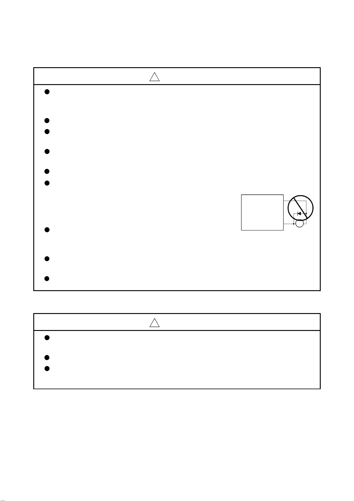
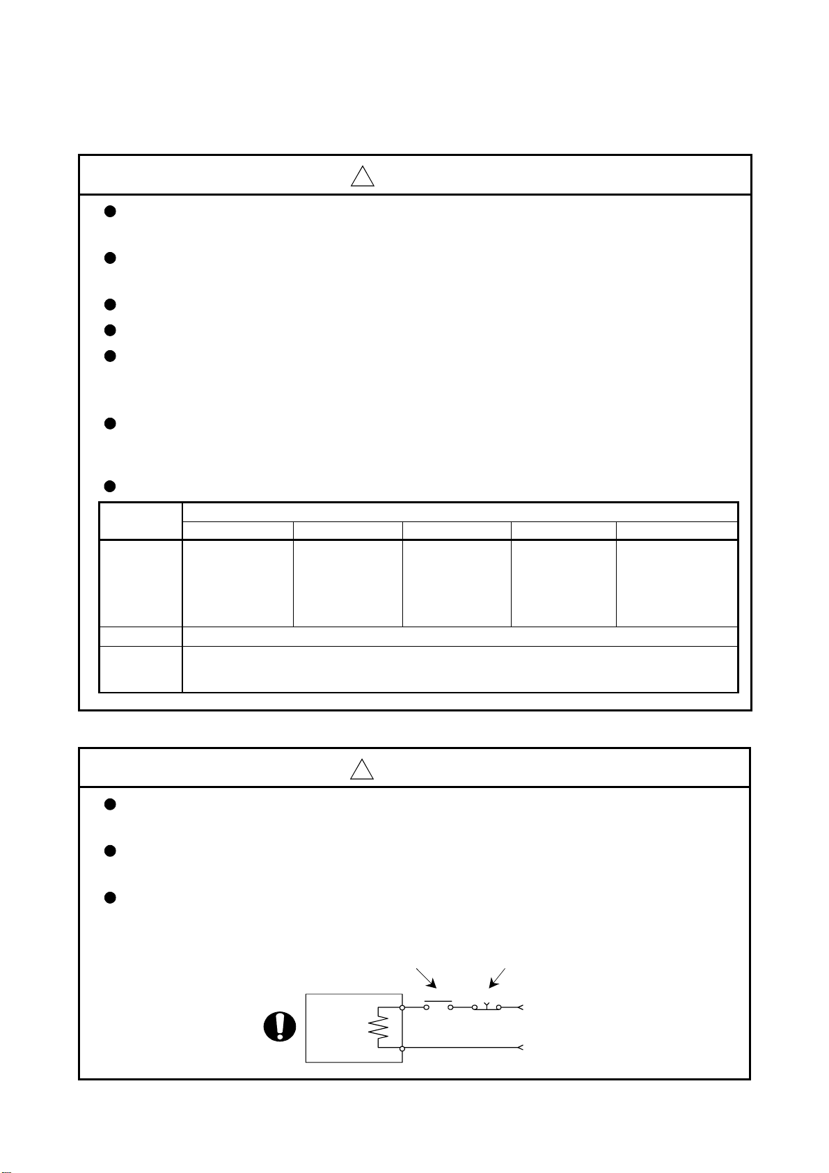
Do not mistake the direction of the surge absorbing diode
installed on the DC relay for the control signal output of
brake signals, etc. Incorrect installation may lead to signals
not being output when trouble occurs or the protective
functions not functioning.
Do not connect or disconnect the connection cables between
each unit, the encoder cable or PLC expansion cable while the
power is ON.
Servo amplifier
VIN
(24VDC)
Control output
signal
RA
Securely tighten the cable connector fixing screws and fixing mechanisms. Insufficient fixing
may lead to the cables combing off during operation.
Do not bundle the power line or cables.
(5) Trial operation and adjustment
!
CAUTION
Confirm and adjust the program and each parameter before operation. Unpredictable
movements may occur depending on the machine.
Extreme adjustments and changes may lead to unstable operation, so never make them.
When using the absolute position system function, on starting up, and when the Motion
controller or absolute value motor has been replaced, always perform a home position return.
A - 7
Page 9
(6) Usge methods
!
CAUTION
Immediately turn OFF the power if smoke, abnormal sounds or odors are emitted from the
Motion controller, servo amplifier or servomotor.
Always execute a test operation before starting actual operations after the program or
parameters have been changed or after maintenance and inspection.
The units must be disassembled and repaired by a qualified technician.
Do not make any modifications to the unit.
Keep the effect or electromagnetic obstacles to a minimum by installing a noise filter or by using
wire shields, etc. Electromagnetic obstacles may affect the electronic devices used near the
Motion controller or servo amplifier.
When using the CE Mark-compliant equipment, refer to the "EMC Installation Guidelines"
(data number IB(NA)-67339) for the Motion controllers and refer to the corresponding EMC
guideline information for the servo amplifiers, inverters and other equipment.
Use the units with the following conditions.
Item
Input power
Input frequency 50/60Hz ±5%
Tolerable
momentary
power failure
Q61P-A1 Q61P-A2 Q62P Q63P Q64P
100 to 120VAC
(85 to 132VAC) (170 to 264VAC) (85 to 264VAC) (15.6 to 31.2VDC)
+10% +10% +10% +30% +10%
200 to 240VAC
-15%
200 to 240VAC
-15%
Conditions
100 to 240VAC
20ms or less
-15%
24VDC
-35%
100 to 120VAC
(7) Corrective actions for errors
!
CAUTION
If an error occurs in the self diagnosis of the Motion controller or servo amplifier, confirm the
check details according to the instruction manual, and restore the operation.
If a dangerous state is predicted in case of a power failure or product failure, use a servomotor
with electromagnetic brakes or install a brake mechanism externally.
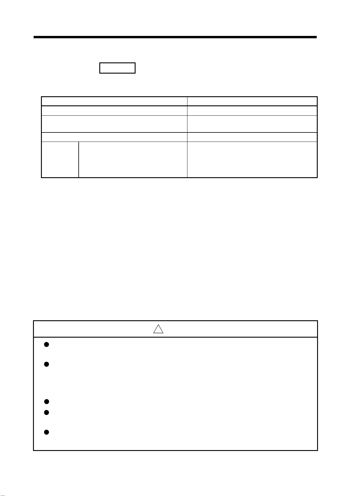
Use a double circuit construction so that the electromagnetic brake operation circuit can be
operated by emergency stop signals set externally.
Shut off with servo ON signal OFF,
alarm, magnetic brake signal.
Servomotor
RA1
Shut off with the
emergency stop
signal(EMG).
EMG
-15%
+10%
-15%
(85 to 132VAC/
170 to 264VAC)
/
`
Electromagnetic
brakes
24VDC
A - 8
Page 10
!
CAUTION
If an error occurs, remove the cause, secure the safety and then resume operation after alarm
release.
The unit may suddenly resume operation after a power failure is restored, so do not go near the
machine. (Design the machine so that personal safety can be ensured even if the machine
restarts suddenly.)
(8) Maintenance, inspection and part replacement
!
CAUTION
Perform the daily and periodic inspections according to the instruction manual.
Perform maintenance and inspection after backing up the program and parameters for the
Motion controller and servo amplifier.
Do not place fingers or hands in the clearance when opening or closing any opening.
Periodically replace consumable parts such as batteries according to the instruction manual.
Do not touch the lead sections such as ICs or the connector contacts.
Do not place the Motion controller or servo amplifier on metal that may cause a power leakage
or wood, plastic or vinyl that may cause static electricity buildup.
Do not perform a megger test (insulation resistance measurement) during inspection.
When replacing the Motion controller or servo amplifier, always set the new module settings
correctly.
When the Motion controller or absolute value motor has been replaced, carry out a home
position return operation using one of the following methods, otherwise position displacement
could occur.
1) After writing the servo data to the Motion controller using programming software, switch on
the power again, then perform a home position return operation.
2) Using the backup function of the programming software, load the data backed up before
replacement.
After maintenance and inspections are completed, confirm that the position detection of the
absolute position detector function is correct.
Do not short circuit, charge, overheat, incinerate or disassemble the batteries.
The electrolytic capacitor will generate gas during a fault, so do not place your face near the
Motion controller or servo amplifier.
The electrolytic capacitor and fan will deteriorate. Periodically replace these to prevent
secondary damage from faults. Replacements can be made by our sales representative.
A - 9
Page 11

(9) About processing of waste
When you discard Motion controller, servo amplifier, a battery (primary battery) and other option articles,
please follow the law of each country (area).
!
CAUTION
This product is not designed or manufactured to be used in equipment or systems in situations
that can affect or endanger human life.
When considering this product for operation in special applications such as machinery or
systems used in passenger transportation, medical, aerospace, atomic power, electric power, or
submarine repeating applications, please contact your nearest Mitsubishi sales representative.
Although this product was manufactured under conditions of strict quality control, you are
strongly advised to install safety devices to forestall serious accidents when it is used in facilities
where a breakdown in the product is likely to cause a serious accident.
(10) General cautions
!
CAUTION
All drawings provided in the instruction manual show the state with the covers and safety
partitions removed to explain detailed sections. When operating the product, always return the
covers and partitions to the designated positions, and operate according to the instruction
manual.
A - 10
Page 12

REVISIONS
The manual number is given on the bottom left of the back cover.
Print Date Manual Number Revision
Feb., 2006 IB(NA)-0300115-A First edition
Japanese Manual Number IB(NA)-0300095
This manual confers no industrial property rights or any rights of any other kind, nor does it confer any patent
licenses. Mitsubishi Electric Corporation cannot be held responsible for any problems involving industrial property
rights which may occur as a result of using the contents noted in this manual.
© 2006 MITSUBISHI ELECTRIC CORPORATION
A - 11
Page 13

INTRODUCTION
Thank you for choosing the Q173HCPU/Q172HCPU Motion Controller.
Please read this manual carefully so that equipment is used to its optimum.
CONTENTS
Safety Precautions .........................................................................................................................................A- 1
Revisions ........................................................................................................................................................A-11
Contents .........................................................................................................................................................A-12
About Manuals ...............................................................................................................................................A-17
1. OVERVIEW 1- 1 to 1- 6
1.1 Overview................................................................................................................................................... 1- 1
1.2 Features ................................................................................................................................................... 1- 3
1.2.1 Performance specifications............................................................................................................... 1- 3
1.2.2 Differences between Q173HCPU/Q172HCPU and Q173CPU(N)/Q172CPU(N)......................... 1- 6
2. POSITIONING CONTROL BY THE MOTION CPU 2- 1 to 2-10
2.1 Positioning Control by the Motion CPU. .................................................................................................. 2- 1
3. MOTION DEDICATED PLC INSTRUCTION 3- 1 to 3-44
3.1 Motion Dedicated PLC Instruction ........................................................................................................... 3- 1
3.1.1 Restriction item of the Motion dedicated PLC instruction ................................................................ 3- 1
3.2 Motion program (Control program) Start Request from The PLC CPU to The Motion CPU:
S(P).SFCS (PLC instruction:
S(P).SFCS
)............................................................................................ 3- 8
3.3 Motion Program (Axis designation program) Start Request from The PLC CPU to The Motion CPU:
S(P).SVST (PLC instruction:
S(P).SVST
) ............................................................................................ 3-13
3.4 Home position return instruction from The PLC CPU to The Motion CPU:
S(P).CHGA (PLC instruction:
S(P).CHGA
)........................................................................................... 3-19
3.5 Speed Change Instruction from The PLC CPU to The Motion CPU:
S(P).CHGV (PLC instruction:
S(P).CHGV
)........................................................................................... 3-24
3.6 Torque Limit Value Change Request Instruction from The PLC CPU to The Motion CPU:
S(P) .CHGT
S(P).CHGT (PLC instruction:
3.7 Write from The PLC CPU to The Motion CPU: S(P).DDWR (PLC instruction:
3.8 Read from The Devices of The Motion CPU: S(P).DDRD (PLC instruction:
).......................................................................................... 3-32
S(P).DDWR
S(P).DDRD
) ..............3-36
) ................. 3-40
4. POSITIONING SIGNALS 4- 1 to 4-88
4.1 Internal Relays ......................................................................................................................................... 4- 2
4.1.1 Axis statuses ..................................................................................................................................... 4-13
4.1.2 Axis command signals ......................................................................................................................4-26
4.1.3 Axis statuses 2 .................................................................................................................................. 4-33
4.1.4 Axis command signals 2 ................................................................................................................... 4-36
4.1.5 Common devices .............................................................................................................................. 4-45
4.2 Data Registers.......................................................................................................................................... 4-56
A - 12
Page 14

4.2.1 Axis monitor devices ......................................................................................................................... 4-64
4.2.2 Control change registers ................................................................................................................... 4-67
4.2.3 Axis monitor devices 2 ...................................................................................................................... 4-68
4.2.4 Control program monitor devices ..................................................................................................... 4-72
4.2.5 Control change registers 2................................................................................................................ 4-74
4.2.6 Tool length offset data setting registers............................................................................................ 4-75
4.2.7 Common devices .............................................................................................................................. 4-76
4.3 Motion Registers (#)................................................................................................................................. 4-79
4.4 Special Relays (SP.M) ............................................................................................................................. 4-80
4.5 Special Registers (SP.D) ......................................................................................................................... 4-83
5. PARAMETERS FOR POSITIONING CONTROL 5- 1 to 5-20
5.1 System Settings .......................................................................................................................................5- 1
5.2 Fixed Parameters..................................................................................................................................... 5- 2
5.2.1 Number of pulses/travel value per rotation....................................................................................... 5- 3
5.2.2 Backlash compensation amount....................................................................................................... 5- 5
5.2.3 Upper/lower stroke limit value........................................................................................................... 5- 5
5.2.4 Command in-position range.............................................................................................................. 5- 7
5.2.5 High-speed feed rate setting............................................................................................................. 5- 8
5.2.6 Speed control 10
5.3 Parameter Block....................................................................................................................................... 5-13
5.3.1 Relationships between the speed limit value, acceleration time, deceleration time and rapid
stop deceleration time ................................................................................................................... 5-16
5.3.2 S-curve ratio ......................................................................................................................................5-18
5.3.3 Allowable error range for circular interpolation................................................................................. 5-19
5.4 Work Coordinate Data ............................................................................................................................. 5-20
multiplier setting for degree axis ........................................................................ 5- 9
6. MOTION PROGRAMS FOR POSITIONING CONTROL 6- 1 to 6-186
6.1 Motion Program Composition .................................................................................................................. 6- 1
6.2 Type of The Motion Program ................................................................................................................... 6- 4
6.3 G-code List ............................................................................................................................................... 6- 5
6.4 M-code List ............................................................................................................................................... 6- 7
6.5 Control Instruction List ............................................................................................................................. 6- 8
6.6 Start/End Method .....................................................................................................................................6-10
6.7 Number of Maximum Nesting for Program Call and Multi Startable Program ....................................... 6-12
6.8 Motion parameter ..................................................................................................................................... 6-13
6.9 Caution at The Axis Designation Program Creation ............................................................................... 6-14
6.10 Instruction Symbols/Characters List...................................................................................................... 6-19
6.11 Setting Method for Command Data....................................................................................................... 6-23
6.11.1 Direct setting (numerical value) ...................................................................................................... 6-23
6.11.2 Indirect setting ................................................................................................................................. 6-24
6.11.3 Operational data.............................................................................................................................. 6-31
6.11.4 Setting range of instruction symbols list ......................................................................................... 6-41
6.11.5 Positioning control unit for 1 axis .................................................................................................... 6-43
6.11.6 Control units for interpolation control.............................................................................................. 6-44
6.11.7 Control in the control unit "degree"................................................................................................. 6-46
6.12 About Coordinate Systems .................................................................................................................... 6-48
A - 13
Page 15

6.13 G-code .................................................................................................................................................... 6-49
6.13.1 G00 Point-to-point positioning at the high-speed feed rate .......................................................... 6-52
6.13.2 G01 Constant-speed positioning at the speed specified in F ....................................................... 6-54
6.13.3 G02 Circular interpolation CW (Central coordinates-specified) .................................................. 6-56
6.13.4 G03 Circular interpolation CCW (Central coordinates-specified)................................................. 6-59
6.13.5 G02 Circular interpolation CW (Radius-specified) ........................................................................ 6-62
6.13.6 G03 Circular interpolation CCW (Radius-specified) ..................................................................... 6-64
6.13.7 G04 Dwell....................................................................................................................................... 6-66
6.13.8 G09 Exact stop check .................................................................................................................... 6-68
6.13.9 G12 Helical interpolation CW (Helical central coordinates-specified) .......................................... 6-70
6.13.10 G13 Helical interpolation CCW (Helical central coordinates-specified) ..................................... 6-73
6.13.11 G12 Helical interpolation CW (Helical radius-specified) ............................................................. 6-75
6.13.12 G13 Helical interpolation CCW (Helical radius-specified) .......................................................... 6-77
6.13.13 G23 Cancel, cancel start invalid .................................................................................................. 6-79
6.13.14 G24 Cancel, cancel start.............................................................................................................. 6-80
6.13.15 G25 High-speed oscillation.......................................................................................................... 6-83
6.13.16 G26 High-speed oscillation stop.................................................................................................. 6-85
6.13.17 G28 Home position return............................................................................................................ 6-86
6.13.18 G30 Second home position return............................................................................................... 6-88
6.13.19 G32 Skip....................................................................................................................................... 6-90
6.13.20 G43 Tool length offset (+) ............................................................................................................ 6-94
6.13.21 G44 Tool length offset (-) ............................................................................................................. 6-96
6.13.22 G49 Tool length offset cancel ......................................................................................................6-98
6.13.23 G53 Mechanical coordinate system selection............................................................................. 6-99
6.13.24 G54 to G59 Work coordinate system selection ........................................................................ 6-101
6.13.25 G61 Exact stop check mode...................................................................................................... 6-104
6.13.26 G64 Cutting mode ......................................................................................................................6-106
6.13.27 G90 Absolute value command .................................................................................................. 6-108
6.13.28 G91 Incremental value command ............................................................................................. 6-110
6.13.29 G92 Coordinates system setting ...............................................................................................6-112
6.13.30 G98, G99 Preread disable/enable .............................................................................................6-114
6.13.31 G100, G101 Time-fixed acceleration/deceleration, acceleration-fixed acceleration/deceleration
switching command..................................................................................................................... 6-116
6.14 M-Code................................................................................................................................................. 6-120
6.15 Special M-Code.................................................................................................................................... 6-121
6.15.1 M00 Program stop ....................................................................................................................... 6-122
6.15.2 M01 Optional program stop ........................................................................................................6-123
6.15.3 M02 Program end ........................................................................................................
6.15.4 M30 Program end ........................................................................................................................6-125
6.15.5 M98, M99 Subprogram call, subprogram end ...........................................................................6-126
6.15.6 M100 Preread disable .................................................................................................................6-128
6.16 Miscellaneous....................................................................................................................................... 6-129
6.16.1 Program control function (IF, GOTO statement) ........................................................................ 6-130
6.16.2 Program control function (IF, THEN, ELSE, END statements) .................................................6-132
6.16.3 Program control function (WHILE, DO, END statements)......................................................... 6-134
6.16.4 Four fundamental operators, assignment operator (+, -, *, /, MOD, =)..................................... 6-136
6.16.5 Trigonometric functions (SIN, COS, TAN, ASIN, ACOS, ATAN) .............................................. 6-138
6.16.6 Real number to BIN value conversion (INT)............................................................................... 6-139
6.16.7 BIN value to real number conversion (FLT)................................................................................6-140
................ 6-124
A - 14
Page 16

6.16.8 32-bit real number and 64-bit real number data conversion (DFLT, SFLT) ............................... 6-141
6.16.9 Functions (SQRT, ABS, BIN, BCD, LN, EXP, RND, FIX, FUP) ................................................ 6-142
6.16.10 Logical operators (AND, OR, XOR, NOT, <<, >>) ...................................................................6-143
6.16.11 Move block wait functions (W AITON, WAITOFF)..................................................................... 6-145
6.16.12 Block wait functions (EXEON, EXEOFF) .................................................................................. 6-147
6.16.13 Bit set and reset for word devices (BSET, BRST)..................................................................... 6-150
6.16.14 Parameter block change (PB) ................................................................................................... 6-151
6.16.15 Torque limit value change (TL) .................................................................................................. 6-153
6.16.16 Home position return (CHGA) .................................................................................................... 6-155
6.16.17 Speed change (CHGV) ...............................................................................................................6-156
6.16.18 Torque limit value change (CHGT)............................................................................................. 6-157
6.16.19 Bit device set, reset functions (SET, RST) ...............................................................................6-158
6.16.20 Bit device operation on condition (IF, THEN, SET/RST/OUT) ................................................. 6-159
6.16.21 Program start (CALL).................................................................................................................. 6-161
6.16.22 Program call 1 (GOSUB) ............................................................................................................ 6-163
6.16.23 Program call 2 (GOSUBE) .........................................................................................................6-164
6.16.24 Control program end (CLEAR) ................................................................................................... 6-167
6.16.25 Time to wait (TIME)..................................................................................................................... 6-169
6.16.26 Block transfers (BMOV : 16-bit unit) ..........................................................................................6-170
6.16.27 Block transfer (BDMOV : 32-bit unit)......................................................................................... 6-172
6.16.28 Identical data block transfers (FMOV)........................................................................................ 6-174
6.16.29 Write device data to shared CPU memory (MULTW) ...............................................................6-176
6.16.30 Read device data from shared CPU memory of the other CPU (MULTR)............................... 6-178
6.16.31 Write words data to intelligent function module/special function module (TO)......................... 6-180
6.16.32 Read words data from intelligent function module/special function module (FROM) .............. 6-182
6.16.33 Conditional branch using bit device (ON, OFF) ....................................................................... 6-184
7. AUXILIARY AND APPLIED FUNCTIONS 7- 1 to 7-80
7.1 Backlash Compensation Function........................................................................................................... 7- 1
7.2 Torque Limit Function .............................................................................................................................. 7- 3
7.3 Home Position Return .............................................................................................................................. 7- 5
7.3.1 Home position return data................................................................................................................. 7- 6
7.3.2 Home position return by the proximity dog type 1............................................................................ 7-16
7.3.3 Home position return by the proximity dog type 2............................................................................ 7-19
7.3.4 Home position return by the count type 1......................................................................................... 7-21
7.3.5 Home position return by the count type 2......................................................................................... 7-23
7.3.6 Home position return by the count type 3......................................................................................... 7-25
7.3.7 Home position return by the data set type 1 .................................................................................... 7-27
7.3.8 Home position return by the data set type 2 .................................................................................... 7-28
7.3.9 Home position return by the dog cradle type ................................................................................... 7-29
7.3.10 Home position return by the stopper type 1 ...................................................................................7-33
7.3.11 Home position return by the stopper type 2 ...................................................................................7-35
7.3.12 Home position return by the limit switch combined type................................................................ 7-37
7.3.13 Home position return retry function ................................................................................................ 7-39
7.3.14 Home position shift function............................................................................................................ 7-43
7.3.15 Condition selection of home position set........................................................................................ 7-47
7.3.16 Execution of home position return................................................................................................. 7-48
7.4 Speed Change (CHGV instruction) ......................................................................................................... 7-49
A - 15
Page 17

7.5 JOG Operation ......................................................................................................................................... 7-53
7.5.1 JOG operation data ........................................................................................................................... 7-53
7.5.2 Individual start ................................................................................................................................... 7-54
7.5.3 Simultaneous start............................................................................................................................. 7-59
7.6 Manual Pulse Generator Operation......................................................................................................... 7-62
7.7 Override Ratio Setting Function .............................................................................................................. 7-68
7.8 FIN signal wait function ............................................................................................................................ 7-70
7.9 Single Block Operation ............................................................................................................................ 7-74
7.10 Control Program Stop Function from The PLC CPU............................................................................ 7-79
8. USER FILES 8- 1 to 8- 2
8.1 Projects..................................................................................................................................................... 8- 1
8.2 User File List............................................................................................................................................. 8- 2
APPENDICES APP- 1 to APP-67
APPENDIX 1 Error Codes Stored Using The Motion CPU ....................................................................APP- 1
APPENDIX 1.1 Motion program setting errors (Stored in D9190).......................................................APP- 3
APPENDIX 1.2 Minor errors .................................................................................................................APP- 4
APPENDIX 1.3 Major errors .................................................................................................................APP-20
APPENDIX 1.4 Servo errors.................................................................................................................APP-24
APPENDIX 1.5 PC link communication errors .....................................................................................APP-41
APPENDIX 2 Motion dedicated signal.....................................................................................................APP-42
APPENDIX 2.1 Internal relay (M) .........................................................................................................APP-42
APPENDIX 2.2 Data registers (D) ........................................................................................................APP-52
APPENDIX 2.3 Motion Registers (#) ....................................................................................................APP-59
APPENDIX 2.4 Special Relays .............................................................................................................APP-60
APPENDIX 2.5 Special Registers.........................................................................................................APP-63
APPENDIX 3 Processing Times of the Motion CPU ...............................................................................APP-67
A - 16
Page 18

About Manuals
The following manuals are related to this product.
Referring to this list, please request the necessary manuals.
Related Manuals
(1) Motion controller
Q173HCPU/Q172HCPU Motion controller User's Manual
This manual explains specifications of the Motion CPU modules, Q172LX Servo external signal interface
module, Q172EX Serial absolute synchronous encoder interface module, Q173PX Manual pulse
generator interface module, Teaching units, Power supply modules, Servo amplifiers, SSCNET
synchronous encoder cables and others.
(Optional)
Q173HCPU/Q172HCPU Motion controller Programming Manual (COMMON)
This manual explains the Multiple CPU system configuration, performance specifications, common
parameters, auxiliary/applied functions and others.
(Optional)
Manual Name
cables,
Manual Number
(Model Code)
IB-0300110
(1XB910)
IB-0300111
(1XB911)
Q173HCPU/Q172HCPU Motion controller (SV13/SV22) Programming Manual (Motion SFC)
This manual explains the functions, programming, debugging, error codes and others of the Motion SFC.
(Optional)
Q173HCPU/Q172HCPU Motion controller (SV13/SV22) Programming Manual (REAL MODE)
This manual explains the servo parameters, positioning instructions, device list, error list and others.
(Optional)
Q173HCPU/Q172HCPU Motion controller (SV22) Programming Manual (VIRTUAL MODE)
This manual describes the dedicated instructions use to the synchronous control by virtual main shaft,
mechanical system program create mechanical module.
This manual explains the servo parameters, positioning instructions, device list, error list and others.
(Optional)
IB-0300112
(1XB912)
IB-0300113
(1XB913)
IB-0300114
(1XB914)
A - 17
Page 19

(2) PLC
QCPU User's Manual (Hardware Design, Maintenance and Inspection)
This manual explains the specifications of the QCPU modules, power supply modules, base modules,
extension cables, memory card battery and others.
(Optional)
QCPU User's Manual (Function Explanation, Program Fundamentals)
This manual explains the functions, programming methods and devices and others to create programs
with the QCPU.
(Optional)
QCPU User's Manual (Multiple CPU System)
This manual explains the functions, programming methods and cautions and others to construct the
Multiple CPU system with the QCPU.
(Optional)
QCPU (Q Mode)/QnACPU Programming Manual (Common Instructions)
This manual explains how to use the sequence instructions, basic instructions, application instructions and
micro computer program.
(Optional)
QCPU (Q Mode)/QnACPU Programming Manual (PID Control Instructions)
This manual explains the dedicated instructions used to exercise PID control.
(Optional)
QCPU (Q Mode)/QnACPU Programming Manual (SFC)
This manual explains the system configuration, performance specifications, functions, programming,
debugging, error codes and others of MELSAP3.
(Optional)
I/O Module Type Building Block User's Manual
This manual explains the specifications of the I/O modules, connector, connector/terminal block
conversion modules and others.
(Optional)
Manual Name
(3) Servo amplifier
MR-J3-B Servo amplifier Instruction Manual
This manual explains the I/O signals, parts names, parameters, start-up procedure and others.
(Optional)
Manual Name
Manual Number
(Model Code)
SH-080483ENG
(13JR73)
SH-080484ENG
(13JR74)
SH-080485ENG
(13JR75)
SH-080039
(13JF58)
SH-080040
(13JF59)
SH-080041
(13JF60)
SH-080042
(13JL99)
Manual Number
(Model Code)
SH-030051
(1CW202)
A - 18
Page 20
1 OVERVIEW
1. OVERVIEW
1.1 Overview
This programming manual describes the operating system software packages
Generic term/Abbreviation Description
Q173HCPU/Q172HCPU or
Motion CPU (module)
Q172LX/Q172EX/Q173PX or
Motion module
MR-J3- B Servo amplifier model MR-J3- B
AMP or Servo amplifier General name for "servo amplifier model MR-J3- B"
QCPU, PLC CPU or PLC CPU module Qn(H)CPU
Multiple CPU system or Motion system Abbreviation for "Multiple PLC system of the Q series"
CPUn
Programming software package General name for "MT Developer" and "GX Developer"
Operating system software General name for "SW RN-SV Q "
SV43 Operating system software for machine tool peripheral use: SW5RN-SV43Q
MT Developer
GX Developer
Manual pulse generator or MR-HDP01 Abbreviation for "Manual pulse generator (MR-HDP01)"
Serial absolute synchronous encoder
or Q170ENC
SSCNET
SSCNET
Absolute position system
Battery holder unit Battery holder unit (Q170HBATC)
External battery General name for "Q170HBATC" and "Q6BAT"
A 0BD-PCF A10BD-PCF/A30BD-PCF SSC I/F board
(Note-2)
(Note-2)
"SW5RN-SV43Q
In this manual, the following abbreviations are used.
" for Motion CPU module (Q173HCPU/Q172HCPU).
Q173HCPU/Q172HCPU Motion CPU module
Q172LX Servo external signals interface module/
Q172EX-S2/S3 Serial absolute synchronous encoder interface module
Q173PX(-S1) Manual pulse generator interface module
Abbreviation for "CPU No.n (n= 1 to 4) of the CPU module for the Multiple
CPU system"
Abbreviation for "MT Developer (Version 00M or later)"
(Integrated start-up support software package)
Abbreviation for "GX Developer (Version 6 or later)"
(GX Developer function software package)
Abbreviation for "Serial absolute synchronous encoder (Q170ENC)"
High speed synchronous network between Motion controller and servo
amplifier
High speed serial communication between Motion controller and servo
amplifier
General name for "system using the servomotor and servo amplifier for
absolute position"
(Note-1)
1
/
SSC I/F communication cable Abbreviation for "Cable for SSC I/F board/card"
Intelligent function module
Abbreviation for "MELSECNET/H module/Ethernet module/
CC-Link module/Serial communication module"
(Note-1) : Q172EX can be used in SV22.
(Note-2) : SSCNET: S
1 - 1
ervo System Controller NETwork
Page 21
1 OVERVIEW
REMARK
For information about the each module, design method for program and parameter,
Motion CPU module/Motion unit Q173HCPU/Q172HCPU User’s Manual
PLC CPU, peripheral devices for PLC program design, I/O
modules and intelligent function module
Operation method for MT Developer Help of each software
• Multiple CPU system configuration
• Performance specification
• Design method for common parameter
• Auxiliary and applied functions (common)
SV43
refer to the following manuals relevant to each module.
Item Reference Manual
Manual relevant to each module
Q173HCPU/Q172HCPU Motion controller
Programming Manual (COMMON)
!
CAUTION
When designing the system, provide external protective and safety circuits to ensure safety in
the event of trouble with the Motion controller.
There are electronic components which are susceptible to the effects of static electricity
mounted on the printed circuit board. When handling printed circuit boards with bare hands you
must ground your body or the work bench.
Do not touch current-carrying or electric parts of the equipment with bare hands.
Make parameter settings within the ranges stated in this manual.
Use the program instructions that are used in programs in accordance with the conditions
stipulated in this manual.
Some devices for use in programs have fixed applications: they must be used in accordance
with the conditions stipulated in this manual.
1 - 2
Page 22
1 OVERVIEW
1.2 Features
The Motion CPU has the following features.
1.2.1 Performance specifications
(1) Basic specifications of Q172HCPU/Q172HCPU
Item Q173HCPU Q172HCPU
Number of control axes Up to 32 axes Up to 8 axes
Operation cycle
(Default)
Interpolation functions Linear interpolation (Up to 4 axes), Circular interpolation (2 axes), Helical interpolation (3 axes)
Control modes PTP (Point to Point) control, Constant speed positioning, High-speed oscillation control
Method
Position
command
(a) Motion control specifications
0.88ms/ 1 to 5 axes
1.77ms/ 6 to 14 axes
3.55ms/15 to 28 axes
7.11ms/29 to 32 axes
PTP : Select of absolute or incremental data method.
Constant-speed control : Both absolute and incremental data method can be used together.
Selectable for each axis
Control
mm 10
inch 10
degree 10
unit
Command unit
-4
mm
-5
inch
-5
degree 0 to 35999999
Address setting
range
-2147483648 to
2147483647
0.88ms/ 1 to 5 axes
1.77ms/ 6 to 8 axes
Travel value setting range
0 to ±2147483647
Positioning
Control
Speed
command
(Command
unit)
Automatic
Acceleration/
deceleration
control
Compensation Backlash compensation, Electronic gear
Programming language Dedicated instruction (EIA language)
Motion program capacity 248k bytes
trapezoidal
S-curve S-curve ratio : 0 to 100[%]
mm 0.01 to 6000000.00 (mm/min)
inch 0.001 to 600000.000 (inch/min)
degree
unit
• Speed control 10 multiplier setting for degree axis is invalid
• Speed control 10
Acceleration-fixed
acceleration/deceleration method
Acceleration time : 1 to 65535 ms
Deceleration time : 1 to 65535 ms
Speed setting range
0.001 to 2147483.647 (degree/min)
multiplier setting for degree axis is valid
0.01 to 21474836.47 (degree/min)
Time-fixed acceleration/deceleration
method
Acceleration/deceleration time :
1 to 5000 ms
(Only constant speed control)
(Note-1)
1 - 3
Page 23
1 OVERVIEW
Motion control specifications (continued)
Item Q173HCPU Q172HCPU
Number of programs 1024
Number of simultaneous
start programs
Number of positioning
points
Number of I/O (X/Y) points 8192 points
Number of real I/O (PX/PY)
points
Internal relays
Number of
Devices
(internal
motion
CPU only)
Programming tool IBM PC/AT
Peripheral I/F USB/SSCNET
Teaching operation
function
Home position return
function
JOG operation function Provided
Manual pulse generator
operation function
M-code function
Limit switch output function
Skip function Provided
Override ratio setting
function
Absolute position system
Number of SSCNET
systems
Number of Motion related
modules
(M)
Latch relays
(L)
Link relays (B) 8192 points
Annunciators
(F)
(Note-2)
Axis designation program : 32
Control program : 16
Approx. 10600 points
(Positioning data can be designated indirectly)
Total 256 points
Total (M+L) : 8192 points
2048 points
None
Proximity dog type (2 types), Count type (3 types), Data set type (2 types), Dog cradle type,
Stopper type (2 types), Limit switch combined type
(Home position return re-try function provided, home position shift function provided)
Possible to connect 3 modules.
M-code output function provided
M-code completion wait function provided
Number of output points 32 points
Watch data: Motion control data/Word device
Override ratio setting : 0 to 100[%]
Made compatible by setting battery to servo amplifier.
(Possible to select the absolute data method or incremental method for each axis)
2 systems 1 system
Q172LX : 4 modules
Q173PX : 1 module
Axis designation program : 8
Control program : 16
Q172LX : 1 module
Q173PX : 1 module
1 - 4
Page 24

1 OVERVIEW
(Note-1) : Acceleration-fixed/time-fixed acceleration/deceleration method is switched as follows.
Acceleration-fixed acceleration/deceleration method Time-fixed acceleration/deceleration method
G00 (Without M-code setting.)
G28
G30
G53
in G100
All travel instructions in G101
(Note-2) : The servo amplifiers for SSCNET cannot be used.
Program capacity
Operation controls
G-codes Positioning command
M-codes Output command to data register M****
Special M-codes Program control command M00, M01, M02, M30, M98, M99, M100
Variable Device variable X, Y, B, F, D, W, #
Functions
Instructions
Number of controls
Total of program files 248k bytes
Number of programs Up to 1024 (No. 1 to 1024)
Arithmetic operation
Comparison operation Equal to, Not equal to
Logical operation
Trigonometric function SIN, COS, TAN, ASIN, ACOS, ATAN
Numerical function
Start/end CALL, CLEAR
Home position return CHGA
Speed/torque setting TL, CHGV, CHGT
Motion control WAITON, WAITOFF, EXEON, EXEOFF
Jump/repetition processing
Data operation
Number of program calls
(GOSUB/GOSUBE)
Number of program calls (M98) Up to 8
(b) Motion program performance specifications
Item Q173HCPU/Q172HCPU
G00 (With M-code setting.)
G01
G02
G03
G12
G13
G32
in G101
—
Unary operation, Additive operation, Multiplicative operation,
Remainder operation
Logical shift operation, Logical negation, Logical AND,
Logical OR, Exclusive OR
G00, G01, G02, G03, G04, G09, G12, G13, G23, G24, G25, G26,
G28, G30, G32, G43, G44, G49, G53, G54, G55, G56, G61, G64,
G90, G91, G92, G98, G99, G100, G101
ABS, SQR, BIN, LN, EXP, BCD, RND, FIX, FUP, INT, FLT,
DFLT, SFLT
CALL, GOSUB/GOSUBE, IF…GOTO, IF…THEN…ELSE…END,
WHILE…DO
BMOV, BDMOV, FMOV, BSET, BRST, SET, RST, MULTW,
MULTR, TO, FROM, ON, OFF, IF…THEN…SET/RST/OUT, PB
Up to 8
1 - 5
Page 25

1 OVERVIEW
1.2.2 Differences between Q173HCPU/Q172HCPU and Q173CPU(N)/Q172CPU(N)
Item Q173HCPU Q172HCPU Q173CPU(N) Q172CPU(N)
Number of control axes 32 axes 8 axes 32 axes 8 axes
Operation cycle
(Default)
(It can be set up by parameters.)
Peripheral devices I/F USB/SSCNET USB/RS-232/SSCNET
Servo amplifier I/F
Indirect setting of home position
return data
Expansion of speed setting range in
the unit [degree]
Fetch of external signal input Q172LX/General input of servo amplifier
0.88ms/ 1 to 5 axes
1.77ms/ 6 to 14 axes
3.55ms/15 to 28 axes
7.11ms/29 to 32 axes
SSCNET
(Optical
communication)
Indirect setting with word devices (D, W, #) of
• When the speed control 10
for degree axis is valid ;
• When the speed control 10
for degree axis is invalid ;
Motion CPU.
0.01 to 21474836.47[degree/min]
0.001 to 2147483.647[degree/min]
0.88ms/1 to 5 axes
1.77ms/6 to 8 axes
Q173HCPU : 2 systems
Q172HCPU : 1 system
multiplier setting
multiplier setting
(Note-2)
0.88ms/ 1 to 4 axes
1.77ms/ 5 to 12 axes
3.55ms/13 to 24 axes
7.11ms/25 to 32 axes
SSCNET
Only direct setting by programming software.
0.001 to 2147483.647[degree/min] fixed
Q172LX
Q173CPU(N) : 4 systems
Q172CPU(N) : 1 system
0.88ms/1 to 4 axes
1.77ms/5 to 8 axes
(Note-1)
OFF.
more.)
—
(Note-4)
Optional data monitor function 3 points/axis (Specified device D, W, #)
When the speed change is executed after
positioning automatic decerelation start or during
Minor error [303], [304]
Processing with power supply OFF
of servo amplifier
Back-up battery for internal memory
(Note-1) : Use the dividing unit (Q173DV) or dividing cable (Q173J2B CBL M/Q173HB CBL M).
(Note-2) : When selecting the each servo amplifier general input, the home position return by the count type cannot be executed. And, the
external stop input cannot be used.
(Note-3) : When adding the external battery (Q6BAT), use the Q170HBATC.
(Note-4) : When adding the external battery (A6BAT/MR-BAT), use the Q173DV (Q173CPU(N) use) or Q170BAT (Q172CPU(N) use).
decerelation by the JOG start command signal
(M3202+20n, M3203+20n) OFF, since the
speed change request is ignored, a minor error
[303], [304] will not occur.
Servo OFF is executed for all servo amplifier
connected behind servo amplifier with which the
control power supply was turned OFF.
Internal rechargeable battery
(Set the external battery (Q6BAT) if continuous
power off time is longer for 1 month or more.)
(Note-3)
When the speed change is executed after
positioning automatic decerelation start or during
decerelation by the JOG start command signal
(M3202+20n, M3203+20n) OFF, a minor error
[303], [304] will occur.
Servo OFF is executed for only servo amplifier
with which the control power supply was turned
Internal rechargeable battery
(Set the external battery (A6BAT/MR-BAT) if
continuous power off time is longer for 1 month or
1 - 6
Page 26

2 POSITIONING CONTROL BY THE MOTION CPU
2. POSITIONING CONTROL BY THE MOTION CPU
2.1 Positioning Control by the Motion CPU
The positioning control of up to 32 axes in Q173HCPU and up to 8 axes in Q172HCPU
is possible in the Motion CPU.
There are following four functions as controls toward the servo amplifier/servomotor.
(1) Servo operation by the positioning instructions.
The positioning instructions are programmed using the Motion program.
The starting method of Motion program is shown below.
(a) Motion program start request (S(P).SVST) using the PLC program of PLC
CPU or Motion program (control program) start request (S(P).SFCS)
(b) Automatic start setting of Motion program (control program)
(c) Start by CALL, GOSUB/GOSUBE instruction using other Motion program
(2) JOG operation by the axis command signal of Motion CPU.
(3) Manual pulse generator operation by the positioning dedicated device of Motion
CPU.
(4) Speed change and torque limit value change during positioning control by the
Motion dedicated PLC instruction (S(P).CHGV, S(P).CHGT instruction) or the
CHGV, CHGT, TL instruction in the Motion program.
2
2 - 1
Page 27

2 POSITIONING CONTROL BY THE MOTION CPU
[Execution of the Motion program start (S(P).SVST instruction)]
Positioning control is executed by starting the Motion program (axis designation
program) specified with S(P).SVST instruction of the PLC CPU in the Motion CPU.
An overview of the starting method using the Motion program is shown below.
Multiple CPU control system
PLC CPU
PLC program . . . . . . . . .
Create using a peripheral device
(Note-1)
<Example> SP.SVST instruction
Positioning execute command
M0 D0
.
SP
SVST H3E3
"J1"
K15
Device which stores the
complete status
Complete device
Motion program No.15
Axis 1
(Start axis No.)
Target CPU
Start request of the
Motion program
1) The Motion program No. and start axis No. are set using the
S(P).SVST instruction in the PLC program.
2) When the S(P).SVST instruction is executed, the program of the
Motion program No. specified with the Motion CPU is executed.
Point
In the above, it is explained the start of axis designation program.
There are following 2 types as the Motion program.
Control program : Only control instruction can be used, the travel instruction by G-code
can not be used.
It is started by the S(P).SFCS of PLC CPU, automatic start with parameter,
or CALL, GOSUB/GOSUBE instruction of other control program.
Axis designation program : The travel instruction by G-code and control instruction can be used.
It is started by the S(P).SVST instruction of PLC CPU or CALL,
GOSUB/GOSUBE instruction of control program.
(1) Create the Motion programs and positioning control parameters using a peripheral
device.
(2) Perform the positioning start using the PLC program (S(P).SVST instruction) of
PLC CPU.
(a) Motion program No. is specified with the S(P).SVST instruction.
1) Motion program No. can be set either directly or indirectly.
2) Start axis No. can be set only directly.
(3) Perform the specified positioning control using the specified with the Motion
program.
Start request of the
Motion program
2 - 2
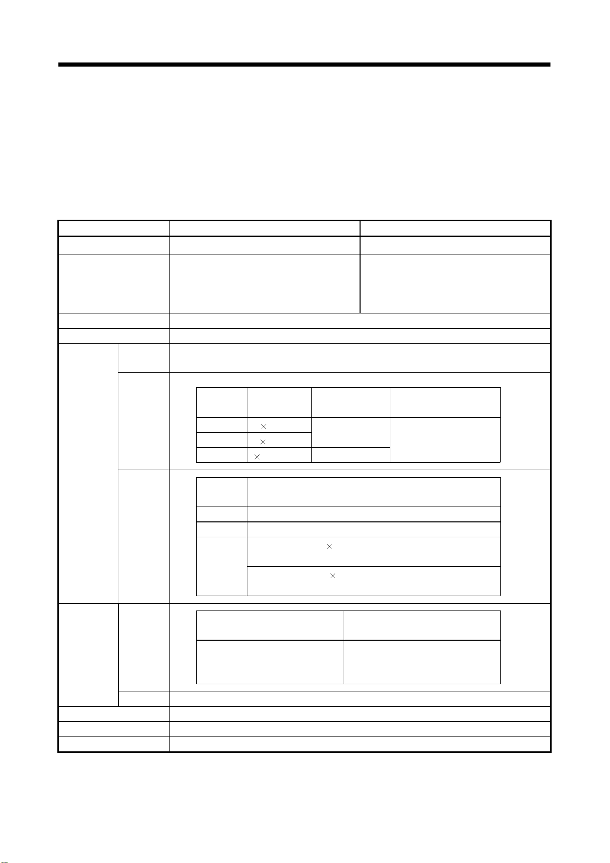
Page 28
2 POSITIONING CONTROL BY THE MOTION CPU
Motion CPU
Motion program . . . . .
O0015;
SET #M2042
N10 G00 X100. Y100.;
X200.;
Y200.;
N20 G01 X25. F500.;
.
.
.
N70 G28 X0. Y0.;
N80 M02;
%
Create and correct using a peripheral
(Note-1)
device
Motion program No.15
(Program No. specified with the S(P).SVST instruction.)
All axes servo ON command turns on.
PTP positioning instruction by high-speed feed speed
Linear positioning of the specified axis is executed from
the current position to the specified coordinate position
by all axes fixed speed.
CP positioning instruction by the speed specified with F
Linear interpolation is executed from the current
position to the specified coordinate position by the feed
speed specified with F.
Home position return instruction
Home position return of the specified axis is executed
from the current position through the specified
coordinate position.
Program end instruction
Program ends.
Positioning control parameters . . . . .
System settings
Fixed parameters
Servo parameters
Parameters block
Home position return data
JOG operation data
Limit switch output data
System data such as axis allocations
Fixed data by the mechanical system, etc.
Data by the specifications of the connected
servo amplifier
Data required for the acceleration, deceleration
of the positioning control, etc.
Data required for the home position return
Data required for the JOG operation
ON/OFF pattern data required for the limit
switch output function
Set and correct using a
peripheral device
(Note-1)
Servo amplifier
Servomotor
REMARK
(Note-1) : The following peripheral devices started by the SW6RN-GSV43P can be
used.
• The personal computer by which WindowsNT
Windows
WindowsNT
R
2000/Windows
R
, WindowsRare either registered trademarks or trademarks of
R
XP works. (IBM PC/AT compatible)
Microsoft Corporation in the United States and/or other countries.
2 - 3
R
4.0/WindowsR98/
Page 29
2 POSITIONING CONTROL BY THE MOTION CPU
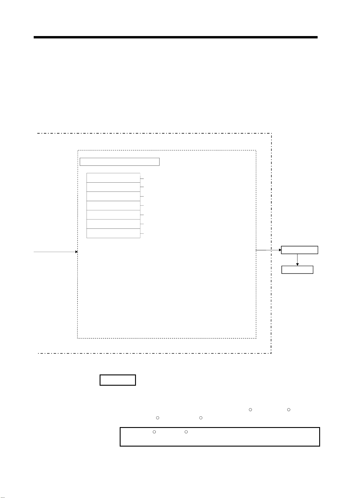
[Execution of the JOG operation]
JOG operation of specified axis is executed using the Motion program in
the Motion CPU. JOG operation can also be executed by controlling the JOG
dedicated device of specified axis.
An overview of JOG operation is shown below.
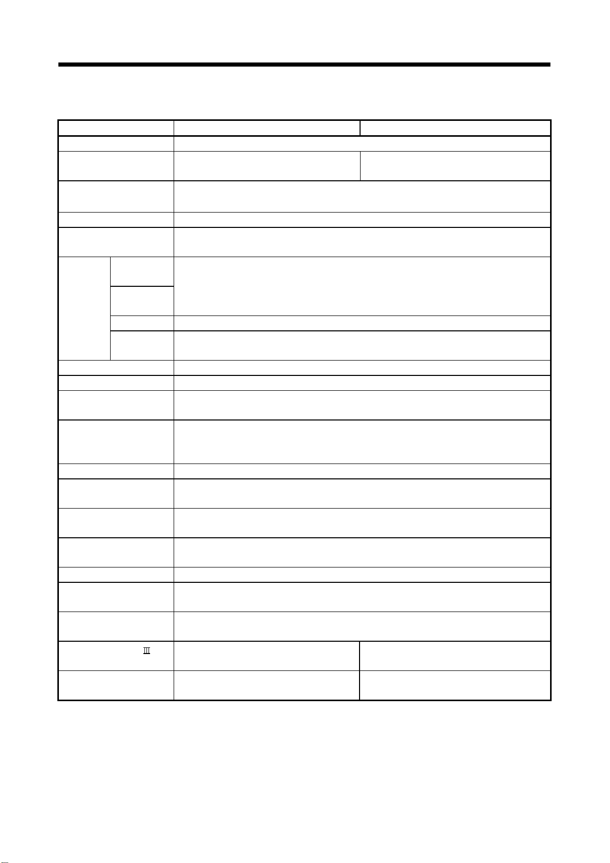
Motion CPU control system
Motion program . . . . .
O100;
SET #M2042;
N10 IF[[ON #M2 415] AND [ON #M2435]] GOTO 20;
GOTO 10;
N20 #D640 = 100000;
#D642L = 100000;
IF [[O N #X003 ] AN D [OFF #M 32 03]] TH EN 1;
SET #M3202;
ELSE 1;
RST #M 3202;
END 1;
IF [[O N #X004 ] AN D [OFF #M 32 02]] TH EN 2;
SET #M3203;
ELSE 2;
RST #M 3203;
END 2;
.
.
.
N80 M02;
%
Create and correct using a peripheral device
(Note-1)
Motion program No.100
(Program No. specified with the
S(P).SFCS instruction.)
All axes servo ON command turns on.
Transfer the JOG operation speed to
D640L and D642L.
Program control function instruction
The flow of execute program is
controlled by conditions.
1 axis forward rotation command
SET/RST
Program control function instruction
The flow of execute program is
controlled by conditions.
1 axis reverse rotation command
SET/RST
Program end instruction
Program ends.
JOG operation by
the JOG dedicated
device control
(1) Set the positioning control parameters using a peripheral device.
(2) Set the JOG speed to the JOG speed setting register for each axis using the
Motion program.
(3) Perform the JOG operation while the JOG start command signal is ON in the
Motion program.
2 - 4
Page 30
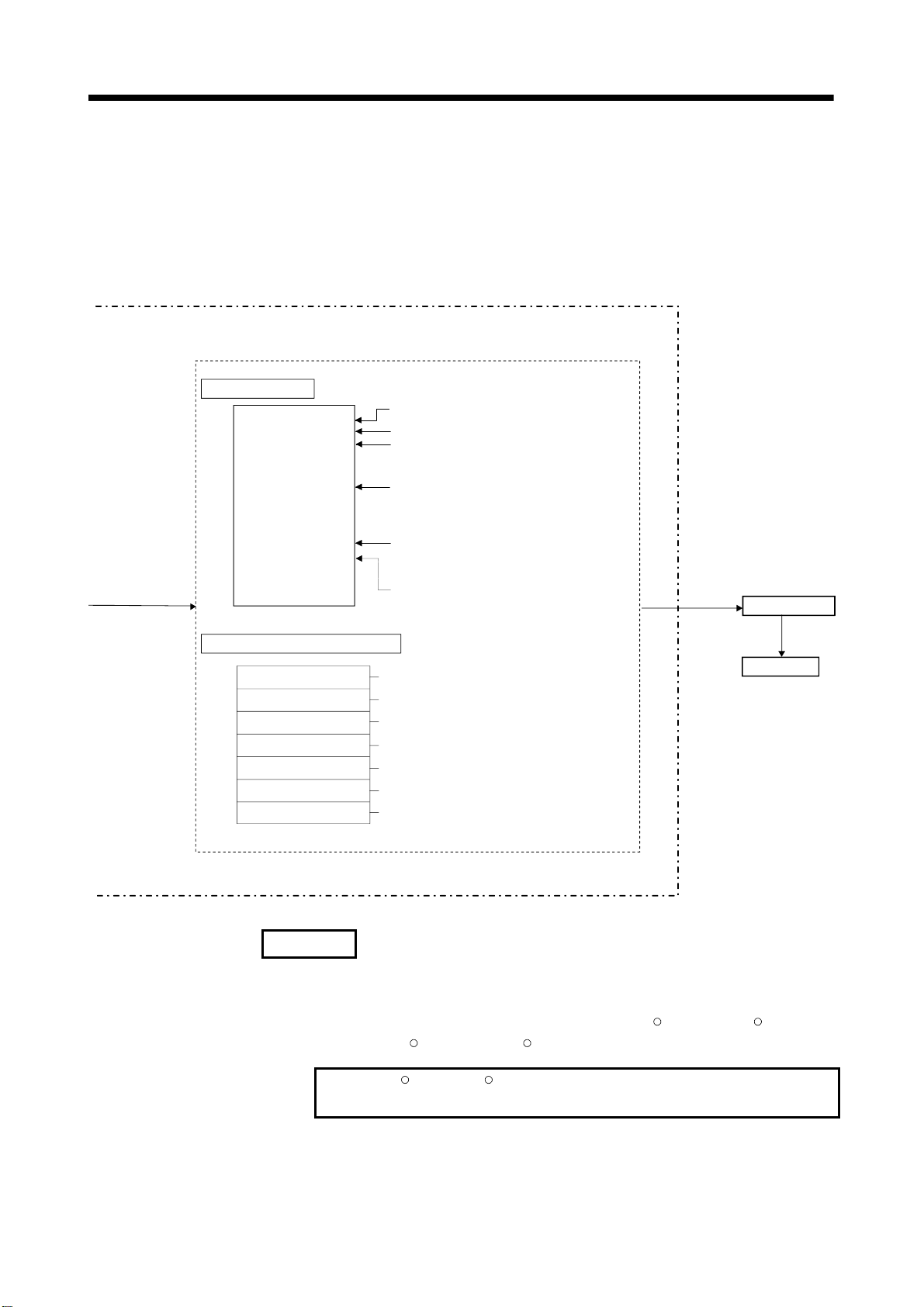
2 POSITIONING CONTROL BY THE MOTION CPU
Positioning control parameter . . . . .
System settings
Fixed parameters
Servo parameters
Parameter block
Home position return data
JOG operation data
Limit switch output data
System data such as axis allocations
Fixed data by the mechanical system, etc.
Data by the specifications of the connected
servo amplifier
Data required for the acceleration, deceleration
of the positioning control, etc.
Data required for the home position return
Data required for the JOG operation
ON/OFF pattern data required for the limit
switch output function
Set and correct using a
peripheral device
(Note-1)
Servo amplifier
Servomotor
REMARK
(Note-1) : The following peripheral devices started by the SW6RN-GSV43P can be
used.
• The personal computer by which WindowsNT
Windows
WindowsNT
R
2000/Windows
R
, WindowsRare either registered trademarks or trademarks of
R
XP works. (IBM PC/AT compatible)
Microsoft Corporation in the United States and/or other countries.
2 - 5
R
4.0/WindowsR98/
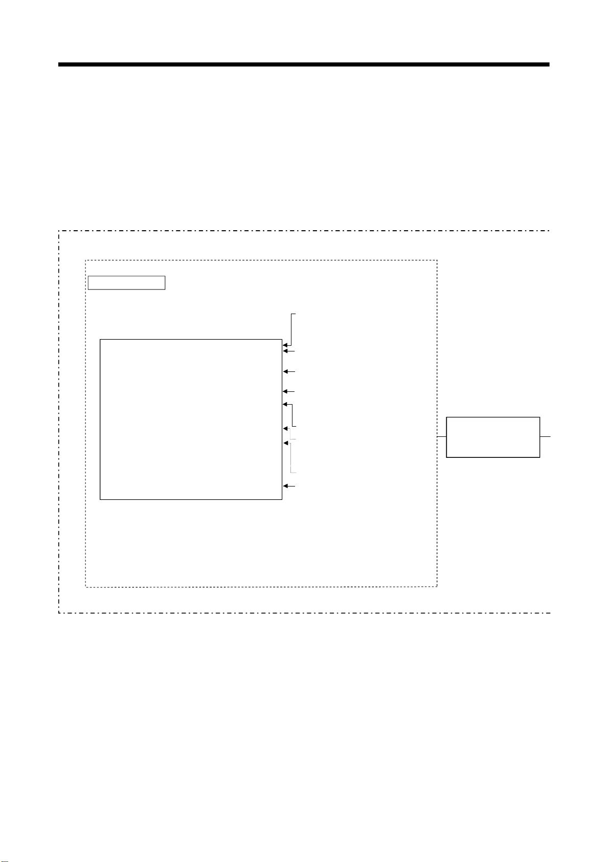
Page 31

2 POSITIONING CONTROL BY THE MOTION CPU
[Executing Manual Pulse Generator Operation]
When the positioning control is executed by the manual pulse generator connected to
the Q173PX, manual pulse generator operation must be enabled using the Motion
program.
An overview of manual pulse generator operation is shown below.
Motion program
O100;
SET #M2042;
N10 IF[[ON #M2415] AND [ON #M2435]] GOTO 20;
GOTO 10;
N20 IF[ON #X000] GOTO 30;
GOTO 20;
N30 #D720 = 100;
#D721 = 100;
#D714L = 1;
#D716L = 2;
SET #M2051;
SET #M2052;
N40 IF[OFF #X000] GOTO 50;
GOTO 40;
N50 RST #M2051;
RST #M2052;
M02;
%
Motion CPU control system
Motion program No. 100
(Program No. specified with the
S(P).SFCS instruction.)
All axes servo ON command
turns on.
Wait until axis 1 and axis 2
servo ON.
Wait until manual pulse
generator operation start.
Set "axis 1" and "axis 2" 1 pulse
input magnification.
Control axis 1 by P1.
Control axis 2 by P2.
Axis 1 and axis 2 manual pulse
generator enable flag turn on.
Wait until manual pulse
generator operation end.
Axis 1 and axis 2 manual pulse
generator enable flag turn off.
Program end instruction
Program ends.
Manual pulse generator operation
by the manual pulse generator
dedicated device
(Note) :
Turn off the axis 1 and axis 2 manual pulse generator enable flag for
safety not to continue the manual pulse generator operation at the
manual pulse generator operation end.
(1) Set the positioning control parameters using a peripheral device.
(2) Set the used manual pulse generator, operated axis No. and magnification for 1
pulse input using the Motion program.
(3) Turn the manual pulse generator enable flag ON using the Motion program
................................................ Manual pulse generator operation enabled
(4) Perform the positioning by operating the manual pulse generator.
(5) Turn the manual pulse generator enable flag OFF using the Motion program
................................................ Manual pulse generator operation completion
2 - 6
Page 32

2 POSITIONING CONTROL BY THE MOTION CPU
Positioning control parameter . . . . .
System settings
Fixed parameters
Servo parameters
Parameter block
Home position return data
JOG operation data
Limit switch output data
System data such as axis allocations
Fixed data by the mechanical system, etc.
Data by the specificat ions of the connected
servo amplifier
Data required for the acceleration, decelerat ion
of the positioning control, etc.
Data required for the home position return
Data required for the JOG op eration
ON/OFF pattern data required for the limit
switch output function
Set and correct using a
peripheral device
(Note-1)
Servo amplifier
Servomotor
Manual pulse generator
REMARK
(Note-1) : The following peripheral devices started by the SW6RN-GSV43P can be
used.
• The personal computer by which WindowsNT
Windows
WindowsNT
R
2000/Windows
R
, WindowsRare either registered trademarks or trademarks of
R
XP works. (IBM PC/AT campatible)
Microsoft Corporation in the United States and/or other countries.
2 - 7
R
4.0/WindowsR98/
Page 33

2 POSITIONING CONTROL BY THE MOTION CPU
(1) Positioning control parameters
There are following seven types as positioning control parameters.
Item Description Reference
1 System settings
2 Fixed parameters
Servo
3
parameters
Home position
4
return data
JOG operation
5
data
6 Parameter block
Limit switch
7
output data
(Note-1): Refer to Section 3.3 of the "Q173HCPU/Q172HCPU Motion controller Programming Manual
(Note-2): Refer to Section 4.1 of the "Q173HCPU/Q172HCPU Motion controller Programming Manual
Parameter data can be set and corrected interactively using a peripheral device.
Multiple system settings, Motion modules and axis No., etc. are
set.
Data by such as the mechanical system are set for every axis.
They are used for calculation of a command position at the
positioning control.
Data by such as the servo amplifier and motor type with the
connected servomotor are set for every axis.
They are set to control the servomotors at the positioning
control.
Data such as the direction, method and speed of the home
position return used at the positioning control are set for every
axis.
Data such as the JOG speed limit value and parameter block
No. used at the JOG operation are set for every axis.
Data such as the acceleration/deceleration time and speed
control value at the positioning control are set up to 16
parameter blocks.
They are set with the servo program, JOG operation data and
home position return data, and it is used to change easily the
acceleration/deceleration processing (acceleration/deceleration
time and speed limit value) at the positioning control.
Output device, watch data, ON section, output enable/disable
bit and forced output bit used for the limit output function for
every limit output are set.
(COMMON)".
(COMMON)".
(2) Motion program
The positioning control, JOG operation and manual pulse generator operation
are executed in the Motion program. The start request is performed using the
PLC program (S(P).SFCS/SVST instruction).
It comprises a Motion program No., G-code, M-code instruction and positioning
data.
Refer to Chapter 6 for details.
• Motion program No. ................
• G-code, M-code instruction .....
• Positioning data ......................
Section
5.1
Section
5.2
(Note-1)
Section
7.3.1
Section
7.5.1
Section
5.3
(Note-2)
It is specified using the PLC program
(S(P).SFCS/SVST instruction).
It indicates the type of positioning control.
It is required to execute the G-code, M-code
instructions. The required data is fixed for
every G-code, M-code instruction.
2 - 8
Page 34

2 POSITIONING CONTROL BY THE MOTION CPU
(3) PLC program
The positioning control by the Motion program can be executed using the Motion
dedicated PLC instruction of PLC program.
Refer to Chapter 3 for details.
2 - 9
Page 35

2 POSITIONING CONTROL BY THE MOTION CPU
MEMO
2 - 10
Page 36

3 MOTION DEDICATED PLC INSTRUCTION
3. MOTION DEDICATED PLC INSTRUCTION
3.1 Motion Dedicated PLC Instruction
(1) The Motion dedicated PLC instruction which can be executed toward the Motion
CPU which installed a SV43 operating system software is shown below.
Instruction Description
S(P).SFCS Start request of the specified Motion program (Control program)
S(P).SVST Start request of the specified Motion program (Axis designation program)
S(P).CHGA Home position return request of the specified axis
S(P).CHGV Speed change request of the specified axis
S(P).CHGT Torque control value change request of the specified axis
S(P).DDWR Write from the PLC CPU to the Motion CPU
S(P).DDRD Read from the devices of the Motion CPU
(Note) : As for the details of each instruction, it explains after the next section.
3.1.1 Restriction item of the Motion dedicated PLC instruction
(1) To self CPU high speed interrupt accept flag from CPUn.
Common precautions of the Motion dedicated PLC instruction as shown below.
(a) To self CPU high speed interrupt accept flag from CPUn is shown in the
following table.
To self CPU high speed interrupt accept flag from CPUn is "No operation"
even if the instruction is executed when it is cannot be accepted.
When the Motion dedicated PLC instruction is accepted in the Motion CPU,
to self CPU high speed interrupt accept flag from CPUn of the self CPU
(Motion CPU) shared CPU memory cannot be accepted and
processing toward the instruction for requirement.
When processing is completed and it becomes the condition that it has an
instruction accepted, to self CPU high speed interrupt accept flag from CPUn
can be accepted.
3
3 - 1
Page 37

3 MOTION DEDICATED PLC INSTRUCTION
Shared CPU
memory address
( ) is decimal
address
30H(48)
31H(49)
32H(50)
33H(51)
The lowest rank bit (30H(48)) toward executing instruction
from CPU No.1.
The lowest rank bit (31H(49)) toward executing instruction
from CPU No.2.
The lowest rank bit (32H(50)) toward executing instruction
from CPU No.3.
The lowest rank bit (33H(51)) toward executing instruction
from CPU No.4.
Description
(b) "To self CPU high speed interrupt accept flag from CPUn" turn ON/OFF at
the executing instruction, when the Multiple CPU dedicated instructions are
executed to the same CPU from one PLC CPU.
Therefore, when each instruction is executed only once at approval the
executing condition, it is necessary to take an interlock by internal relay
(M10) and so on besides "To self CPU high speed interrupt accept flag from
CPUn".
(2) Execution of the Motion dedicated PLC instruction
(a) Motion dedicated PLC instruction can be executed with fixed cycle execute
type PLC and interrupt PLC. However, as for a complete device, the program
turned on according to fixed cycle executed type PLC and program type
(scan or low speed) executed interrupt PLC is different.
(b) One Motion CPU can be accepted up to 32 instructions simultaneously from
multiple other CPUs. If 33 instructions or more are executed Motion CPU
returns the complete status[4C08] error.
As Motion CPU can be accepted up to 32 instructions, number of
acceptable instructions changes according to number of CPUs included
Motion CPU. Calculation expression is shown below.
Example of the reading
(When target is the CPU No.2)
U3E1/G48.0
U3E1/G49.0
U3E1/G50.0
U3E1/G51.0
(Number of maximum acceptable instructions per one Motion CPU) =
32 – ( (Number of all CPUs) – 2 ) [Number of instructions]
(c) Local devices and file registers as program are written to device by END
processing. Do not use the devices below.
Each instruction complete device
D1 of S(P).DDRD instruction (The first device of the self CPU which
stored the reading data.)
3 - 2
Page 38

3 MOTION DEDICATED PLC INSTRUCTION
(d) Use a flag in the shared CPU memory which correspond with each
instruction not to execute multiple instructions to the same shaft of the
Motion CPU of same CPU No. for the interlock condition.
(Program example 1).
(e) S(P).SFCS/S(P).SVST/S(P).CHGA/S(P).CHGVS(P).CHGT/S(P).DDWR/
S(P).DDRD instructions cannot be executed simultaneously. Therefore, it is
necessary to take an interlock by to self CPU high speed interrupt accept
flag from CPUn.
One PLC CPU can be executed max.32 Motion dedicated PLC instructions
simultaneously using to self CPU high speed interrupt accept flag from
CPUn.
If 33 instructions or more are executed, the PLC CPU returns the
OPERATION ERROR[4107].
(f) When multiple Motion dedicated PLC instructions are directly executed
because one contact-point turns on, an instruction may not be executed.
In this case, create a program with reference to program example.
(Program example 2).
<Program example 1>
Program which executes multiple instructions to the same shaft of the Motion CPU of
same CPU No..
To self CPU high
speed interrupt
accept flag from
CPU1
U3E1\G48.0
M0
Start accept
flag of the Axis 1
(CPU No.2)
U3E1\G516.0
Start accept
flag of the Axis 2
(CPU No.2)
U3E1\G516.1
K0
K0
To self CPU high
speed interrupt
accept flag from
CPU No.1
M2
U3E1\G48.0
To self CPU high
speed interrupt
accept flag from
CPU No.1
M6
U3E1\G48.0
SP.SVST K100 M10 D0H3E1 "J1J2"
Start accept
flag of the Axis 1
(CPU No.2)
U3E1\G516.0
SP.CHGA K0 M3 D2H3E1
SP.CHGT
3 - 3
H3E1
"J1"
K250 M7 D6
"J2"
RST M0
RST M2
RST M6
Page 39

3 MOTION DEDICATED PLC INSTRUCTION
<Program example 2>
Program which executes directly multiple Motion dedicated PLC instructions because
one contact-point turns on.
M1001
SET M21
SET M23
SET M25
SET M27
RST
To self CPU high
speed interrupt
accept flag from
CPU1
M21
U3E1\G48.0
To self CPU high
speed interrupt
accept flag from
CPU1
U3E1\G48.0
M23
Start accept
flag of the Axis 1
(CPU No.2)
U3E1\G516.0
SP.SVST K104 M30 D20H3E1
Start accept
flag of the Axis 2
(CPU No.2)
U3E1\G516.1
SP.SVST K105 M32 D22H3E1
"J1"
"J2"
M1001
RST M21
To self CPU high
speed interrupt
accept flag from
CPU1
U3E1\G48.0
M25
To self CPU high
speed interrupt
accept flag from
CPU1
M27
U3E1\G48.0
Start accept
flag of the Axis 4
(CPU No.2)
U3E1\G516.3
SP.SVST K106 M34 D24H3E1
Start accept
flag of the Axis 5
(CPU No.2)
U3E1\G516.4
SP.SVST K107 M36 D26H3E1
RST M23
"J4"
RST M25
"J5"
RST M27
3 - 4
Page 40

3 MOTION DEDICATED PLC INSTRUCTION
POINT
Access from the PLC CPU is processed before the communication processing of
the Motion CPU. Therefore, if the Motion dedicated PLC instruction is frequently
performed from the PLC CPU, the scan time of the PLC CPU is not only prolonged,
but delay will arise in the communication processing of the Motion CPU.
Perform execution of the Motion dedicated PLC instruction from the PLC CPU by
S(P).DDWR/S(P).DDRD/S(P).CHGV instruction etc. only at the time of necessity.
3 - 5
Page 41

3 MOTION DEDICATED PLC INSTRUCTION
(3) Complete status
The error code is stored in the complete status at abnormal completion of the
Multiple CPU dedicated instruction. The error code which is stored is shown
Complete status
(Error code)(H)
0 Normal completion
4C00 *
4C01 *
4C02 *
4C03 *
4C04 * Axis No. set by SVST instruction is injustice.
4C05 * Axis No. set by CHGA instruction is injustice.
4C06 * Axis No. set by CHGV instruction is injustice.
4C07 * Axis No. set by CHGT instruction is injustice.
4C08 *
4C09 * CPU No. of the instruction cause is injustice.
4C0A *
4C80
4C81
4C83
4C84
4C90
The specified device cannot be used in the Motion CPU. Or, it is outside
the device range.
The instruction for the Multiple CPU system which did not be correspond with
operating system software of the Motion CPU was executed.
The Motion program (Control program) No. to start is outside the following range.
The control program is set
•
1 to1024
•
Indirect setting by data register
10000 to 18191
•
Indirect setting by motion register
20000 to 28191
The Motion program (Axis designation program) No. to start is outside the following
range.
• The control program is set
1 to 1024
• Indirect setting by data register
10000 to 18191
• Indirect setting by motion register
20000 to 28191
• When using the S(P).SFCS/S(P).SVST/S(P).CHGA instruction
There are 33 or more instruction requests to the Motion CPU from the PLC CPU in
S(P).SFCS, S(P).SVST, S(P).CHGA sum table simultaneously, and the Motion
CPU cannot process them.
• When using the S(P).DDRD/S(P).DDWR instruction
There are 33 or more instruction requests to the Motion CPU from the PLC CPU in
S(P).DDRD/S(P).DDWR sum table simultaneously, and the Motion CPU cannot
process them.
Data error
(The instruction which cannot be decoded in the Motion CPU was specified.)
H/W error of the target CPU
Number over of execute instructions of the target CPU.
There are 33 or more instruction requests to the Motion CPU from the PLC CPU in
S(P).SFCS, S(P).SVST, S(P).CHGA, S(P).SHGV, S(P).CHGT, S(P).DDRD and
S(P).DDWD sum table simultaneously, and the Motion CPU cannot process them.
below. (The error code marked " * " is dedicated with the Motion CPU.)
Error factor
Corrective
action
Confirm a
program, and
correct it to a
correct PLC
program.
3 - 6
Page 42

3 MOTION DEDICATED PLC INSTRUCTION
(4) Self CPU operation data area used by Motion dedicated instruction (30H to 33H)
The complete status of the to self CPU high speed interrupt accept flag from
Shared
memory
address
30H(48)
31H(49)
32H(50)
33H(51)
CPU
To self CPU high speed interrupt
accept flag from CPU1
To self CPU high speed interrupt
accept flag from CPU2
To self CPU high speed interrupt
accept flag from CPU3
To self CPU high speed interrupt
accept flag from CPU4
CPUn is stored in the following address.
Name Description
This area is used to check whether to self CPU high speed interrupt accept
flag from CPUn can be accepted or not.
0: To self CPU high speed interrupt accept flag from CPUn accept usable.
1: To self CPU high speed interrupt accept flag from CPUn accept disable.
(5) System area used by Motion dedicated instruction (204H to 20DH)
Shared CPU
memory
address
204H(516) Start accept flag (Axis1 to 16)
205H(517) Start accept flag (Axis17 to 32)
The complete status of the each flag is stored in the following address.
Name Description
The start accept flag is stored by the 1 to 32 axis, each bit.
(As for a bit's actually being set Q173HCPU : J1 to J32/
Q172HCPU : J1 to J8.)
OFF : Start accept flag usable
ON : Start accept flag disable
204H(516) address
205H(517) address
The speed changing flag is stored by the 1 to 32 axis, each bit.
206H(518) Speed changing flag (Axis1 to 16)
207H(519) Speed changing flag (Axis17 to 32)
(As for a bit's actually being set Q173HCPU : J1 to J32/
Q172HCPU : J1 to J8.)
OFF : Start accept usable
ON : Start accept disable
206H(518) address
207H(519) address
J16
J32
J16
J32
b1 b0b15
J2
J1
J17
b1 b0b15
J2
J1
J17
3 - 7
Page 43

[
3 MOTION DEDICATED PLC INSTRUCTION
3.2 Motion program (Control program) Start Request from The PLC CPU to The Motion
CPU:S(P).SFCS (PLC instruction:
• Motion program (Control program) start request instruction from the PLC CPU to the
(Note)
Setting data
Internal devices
(System, User)
Bit Word
Motion CPU (S(P).SFCS)
File
register
Bit
digit
specified
S(P).SFCS
Usable devices
Indirectly
specified
device
)
MELSECNET/10
direct J
\
Bit Word
Special
function
module
\G
U
Index
register
Z
Constant
K, H
Other
(n1)
(n2)
(D1)
(D2)
[Setting data]
[Instruction]
SP.SFCS
S.SFCS
Condition]
Start request
Start request
: Usable : Usable partly
(Note) : Setting data (n1) to (D2) : Index qualification possible
SP.SFCS
S.SFCS
(n2) (D1) (D2)
(n1)
(n2) (D1) (D2)
(n1)
Setting data Description Data type
(First I/O No. of the target CPU)/16
(n1)
Value to specify actually is the following.
(Note-1)
CPU No.2 : 3E1H, CPU No.3 : 3E2H, CPU No.4 : 3E3H
(n2) Motion program (Control program) No. to start.
16-bit
binary
16-bit
binary
Complete devices
(D1+0) : Device which make turn on for one scan at start accept completion of
(D1)
(D1+1) : Device which make turn on for one scan at start accept abnormal
instruction.
Bit
completion of instruction.
("D1+0" also turns on at the abnormal completion.)
(D2) Device to store the complete status.
16-bit
binary
(Note-1) : Motion CPU cannot used CPU No.1 in the Multiple CPU configuration.
3 - 8
Page 44

3 MOTION DEDICATED PLC INSTRUCTION
Set the control program No. to start in (n2). Usable range is shown below.
(1) The control program No. is set
The specified control program No. is started.
In this case, control program is executed from the first block.
(n2) usable range
1 to 1024
(2) The sequence No. (N****) is set in the control program
It can be started in the middle of program.
(a) Indirect setting by data register
D((n2) – 10000 : The control program No. stored in the data register
D((n2) – 10000 + 1) : The sequence No. stored in the data register (Motion
(n2) usable range
10000 to 18191
(b) Indirect setting by motion register
#(n2) – 20000 : The control program No. stored in the motion register
#((n2) – 20000 + 1) : The sequence No. stored in the motion register
(n2) usable range
20000 to 28191
[Description]
(1) This instruction is dedicated instruction toward the Motion CPU in the Multiple
CPU system. Errors occurs when it was executed toward the CPU except the
Motion CPU.
(2) Request to start the Motion program (Control program) specified with (n2).
(3) S(P).SFCS/S(P).SVST/S(P).CHGA/S(P).CHGV/S(P).CHGT/S(P).DDRD/
S(P).DDWR cannot be executed simultaneously toward the CPU executing
S(P).SFCS instruction.
When the Motion dedicated PLC instruction is started continuously, it is necessary
to execute the next instruction after the complete device of executing instruction
turns on.
(Motion CPU side) is started.
CPU side) is started.
(Motion CPU side) is started.
(Motion CPU side) is started.
3 - 9
Page 45

3 MOTION DEDICATED PLC INSTRUCTION
[Operation of the self CPU at execution of S(P).SFCS instruction]
PLC program
S(P).SFCS instruction
To self CPU high speed interrupt
accept flag from CPUn
END
OFF
OFF
S(P).SFCS execution
ON
ON
END
END
END
t
Motion program
(Control program)
Instruction start
accept complete device
(D1+0)
State display device(D1+1)
at the instruction start
accept completion
Instruction accept
completion at the
Motion CPU side
OFF
OFF
Motion program execution
ON
ON : Abnormal completion only
1 scan
3 - 10
Page 46

3 MOTION DEDICATED PLC INSTRUCTION
[Errors]
The abnormal completion in the case shown below, and the error code is stored in the
device specified with the complete status storing device (D2).
Complete status
(Error code)(H)
4C00
4C01
4C02
4C08
4C09 CPU No. of the instruction cause is injustice.
(Note)
The specified device cannot be used ih the Motion CPU. Or,
it is outside the device range.
The instruction for the Multiple CPU system which did not be
correspond with operating system software of the Motion
CPU was executed.
The Motion program (Control program) No. to start is outside
the following range.
• The control program is set
1 to1024
Indirect setting by data register
•
10000 to 18191
Indirect setting by motion register
•
20000 to 28191
There are 33 or more instruction requests to the Motion CPU
from the PLC CPU in S(P).SFCS/S(P).SVST and
S(P).CHGA sum table simultaneously, and the Motion CPU
cannot process them.
The error flag (SM0) is turned on an operation error in the case shown below, and an
error code is stored in SD0.
Error code
(Note)
2110
2114
2117
4002 Specified instruction is wrong.
4004
4100
The CPU No. to be set by "(First I/O NO. of the target
CPU)/16" is specified.
The self CPU by "(First I/O No. of the target CPU)/16" is
specified.
The CPU except the Motion CPU by "(First I/O No. of the
target CPU)/16" is specified.
The instruction is composed of devices except usable
devices.
Since 0 to 3DFH, 3E4H is specified by "(First I/O No. of the
target CPU)/16" is specified.
Error factor
Error factor
Corrective
action
Confirm a
program, and
correct it to a
correct PLC
program.
(Note) : 0000H(Normal)
Corrective
action
Confirm a
program, and
correct it to a
correct PLC
program.
(Note) : 0000H(Normal)
3 - 11
Page 47

3 MOTION DEDICATED PLC INSTRUCTION
[Program example]
(1) This program starts the Motion program (Control program) No.10 of the Motion CPU No.4.
X0
M0
SP.SFCS
M1
M1
K10 M0 D0
H3E3
Normal complete program
Abnormal complete program
(2) This program starts the Motion program (Control program) No.30 and sequence No.200
of the Motion CPU No.4 by indirect setting.
PLC program (PLC CPU side)
X0
M0
M1
M1
Motion program (Motion CPU side)
Set the data in the data register of "No. specified with SFCS instruction - 10000".
O0010;
D1000 = 30 ; Motion program No.
D1001 = 200 ; Sequence No.
SP.SFCS
H3E3
K11000 M0
Normal complete program
Abnormal complete program
D0
3 - 12
Page 48

3 MOTION DEDICATED PLC INSTRUCTION
3.3 Motion Program (Axis designation program) Start Request from The PLC CPU to The
Motion CPU:S(P).SVST (PLC instruction:
• Motion program (Axis designation program) start request instruction from the PLC
Internal devices
(System, User)
(Note)
Setting data
(n1)
(S1)
(S2)
(D1)
(D2)
Bit Word
CPU to the Motion CPU (S(P).SVST)
File
register
[Instruction] [Condition]
SP.SVST
S.SVST
Bit
digit
specified
Start request
Start request
S(P).SVST
Usable devices
Indirectly
specified
device
MELSECNET/10
direct J \
Bit Word
(Note) : Setting data except (S1) : Index qualification possible
(n1)
)
(S2) (D1) (D2)
(S1)SP.SVST
(S2) (D1) (D2)(n1)
(S1)S.SVST
Special
function
module
\G
U
Index
register
Z
: Usable : Usable partly
Constant
K, H
Other
[Setting data]
Setting data Description Data type
(First I/O No. of the target CPU)/16
(n1)
(S1)
(S2) Motion program (Axis designation program) No. to start.
(D1)
(D2) Device to store the complete status.
(Note-1) : Motion CPU cannot used CPU No.1 in the Multiple CPU configuration.
(Note-2) : "n" shows the numerical value correspond to axis No..
Value to specify actually is the following.
CPU No.2 : 3E1H, CPU No.3 : 3E2H, CPU No.4 : 3E3H
Axis No.("Jn")
Q173HCPU : J1 to J32/Q172HCPU : J1 to J8
Complete devices
(D1+0) : Device which make turn on for one scan at start accept completion of
(D1+1) : Device which make turn on for one scan at start accept abnormal
Q173HCPU : Axis No.1 to No.32 (n=1 to 32) / Q172HCPU : Axis No.1 to No.8 (n=1 to 8)
(Note-2)
to start.
instruction.
completion of instruction.
("D1+0" also turns on at the abnormal completion.)
(Note-1)
16-bit
binary
Character
sequence
16-bit
binary
Bit
16-bit
binary
3 - 13
Page 49

3 MOTION DEDICATED PLC INSTRUCTION
[Description]
(1) This instruction is dedicated instruction toward the Motion CPU in the Multiple
CPU system. Errors occurs when it was executed toward the CPU except the
Motion CPU.
(2) Request to start the Motion program (Axis designation program) specified with
(S2).
(3) S(P).SFCS/S(P).SVST/S(P).CHGA/S(P).CHGV/S(P).CHGT/S(P).DDRD/
S(P).DDWR cannot be executed simultaneously toward the CPU executing
S(P).SFCS instruction.
When the Motion dedicated PLC instruction is started continuously, It is necessary
to take an inter-lock by the to self CPU high speed interrupt accept flag from
CPUn.
(4) It is necessary to take an inter-lock by the start accept flag of the shared CPU
memory so that multiple instructions may not be executed toward the same axis of
the same Motion CPU No..
[Operation]
1 scan
END
END
PLC program
S(P).SVST instruction
To self CPU high speed interrupt
accept flag from CPUn
Start accept flag (axis)
Motion program
(Axis designation program)
Instruction start
accept complete device
(D1+0)
State display device(D1+1)
at the instruction start
accept completion
END
OFF
OFF
OFF
OFF
OFF
Instruction accept
completion at the
Motion CPU side
S(P).SVST execution
ON
ON
ON
Motion program execution
END
ON
ON : Abnormal completion only
t
(1) The start accept status of each axis can be confirmed with the start accept flag in
the shared CPU memory of target CPU.
3 - 14
Page 50

3 MOTION DEDICATED PLC INSTRUCTION
(2) S(P).SVST instruction accepting and normal/abnormal completion can be
confirmed with the complete device(D1) or status display device(D2) at the
completion.
(a) Complete device
It is turned on by the END processing of scan which the instruction
completed, and turned off by the next END processing.
(b) Status display device at the completion
It is turned on/off according to the status of the instruction completion.
Normal completion : OFF
Abnormal completion : It is turned on by the END processing of scan
[Setting range]
(1) Setting of the starting axis
The starting axis set as (S1) sets J + Axis No. in a character sequence " ".
(S1) usable range
Q173HCPU 1 to 32
Q172HCPU 1 to 8
Up to 8 axes can be set. If multiple axes are set, it sets without dividing in a
space etc,.
The axis No. set in the system setting is used as the axis No. to start.
Refer to the "Q173HCPU/Q172HCPU Motion controller Programming Manual
(COMMON)" for system settings.
And, the axis No. to start does not need to be a order.
Example) When multiple axes (Axis1, Axis2, Axis10, Axis11)are set.
"J1J2J10J11"
(2) Setting of the Motion program (Axis designation program) No.
The usable range of axis designation program No. to set (S2) is checked in the
Motion CPU side.
(a) The control program No. is set
The specified axis designation program is started.
In this case, axis designation program is executed from the first block.
(S2) usable range
1 to 1024
which the instruction completed, and turned off by
the next END processing.
3 - 15
Page 51

3 MOTION DEDICATED PLC INSTRUCTION
(b) The sequence No. (N****) / parameter block No. in the control program is set
It can be started in the middle of program.
1) Indirect setting by data register
D((S2) – 10000) : The axis designation program No. stored in
D((S2) – 10000 + 1) : The sequence No. stored in the data register
D((S2) – 10000 + 2) : The parameter block No. stored in the data
(S2) usable range
10000 to 18191
2) Indirect setting by motion register
#((S2) – 20000) : The axis designation program No. stored in the
#((S2) – 20000 + 1) : The sequence No. stored in the motion register
#((S2) – 20000 + 2) : The parameter block No. stored in the motion
(S2) usable range
20000 to 28191
[Start accept flag (System area)]
the data register (Motion CPU side) is started.
(Motion CPU side) is started.
register (Motion CPU side) is started.
motion register (Motion CPU side) is started.
(Motion CPU side) is started.
register (Motion CPU side) is started.
The complete status of the start accept flag is stored in the address of the start accept
flag in the shared CPU memory.
Shared CPU memory
address
( ) is decimal address
The start accept flag is stored by the 1 to 32 axis, each bit.
(As for a bit's actually being set Q173HCPU : J1 to J32/
Q172HCPU : J1 to J8.)
204H(516)
205H(517)
OFF : Start accept flag usable
ON : Start accept flag disable
204H(516) address
205H(517) address
J16
J32
Description
b1 b0b15
J2
J1
J17
3 - 16
Page 52

3 MOTION DEDICATED PLC INSTRUCTION
[Errors]
The abnormal completion in the case shown below, and the error code is stored in the
device specified with the complete status storing device (D2).
Complete status
(Error code)(H)
4C00
4C01
4C03
4C04 Axis No. set by SVST instruction is injustice.
4C08
(Note)
The specified device cannot be used in the Motion
CPU. Or, it is outside the device range.
The instruction for the Multiple CPU system which did
not be correspond with operating system software of
the Motion CPU was executed.
The Motion program (Axis designation program) No. to
start is outside the following range.
• The control program is set
1 to 1024
• Indirect setting by data register
10000 to 18191
• Indirect setting by motion register
20000 to 28191
There are 33 or more instruction requests to the
Motion CPU from the PLC CPU in S(P).SFCS,
S(P).SVST and S(P).CHGA sum table simultaneously,
and the Motion CPU cannot process them.
Error factor Corrective action
Confirm a program,
and correct it to a
correct PLC
program.
4C09 CPU No. of the instruction cause is injustice.
(Note) : 0000H(Normal)
The error flag (SM0) is turned on an operation error in the case shown below, and an
error code is stored in SD0.
2110
2114
2117
4004
4100
(Note)
The CPU No. to be set by "(First I/O NO. of the target
CPU)/16" is specified.
The self CPU is by "(First I/O No. of the target
CPU)/16" is specified.
The CPU except the Motion CPU by "(First I/O No. of
the target CPU)/16" is specified.
The instruction be composed of devices except
usable devices.
Since 0 to 3DFH, 3E4H is specified by "(First I/O No.
of the target CPU)/16" is specified.
Error code
Error factor Corrective action
Confirm a program,
and correct it to a
correct PLC
program.
(Note) : 0000H(Normal)
3 - 17
Page 53

3 MOTION DEDICATED PLC INSTRUCTION
[Program example]
(1) Program which requests to start the Motion program (Axis designation program) No.10
toward axis No.1 and No.2 of the Motion CPU No.4. from the PLC CPU No.1.
To self CPU
high speed
interrupt accept
flag from CPU
U3E3
\G48.0
M100
M0
M1
M1
(2) Program which requests to start the Motion program (Axis designation program) No.20,
sequence No. 100 and parameter block No.30 toward axis No.1 and No.2 of the Motion
CPU No.4 by indirect setting from the PLC CPU No.1.
Sequence program (PLC CPU side)
To self CPU
high speed
interrupt accept
flag from CPU
U3E3
\G48.0
M100
Start accept flag
of the axis No.1
(CPU No.4)
U3E3
\G516.0
Start accept flag
of the axis No.1
(CPU No.4)
U3E3
\G516.0
Start accept flag
of the axis No.2
(CPU No.4)
U3E3
\G516.1
SP.SVST
Start accept flag
of the axis No.2
(CPU No.4)
U3E3
\G516.1
SP.SVST
H3E3
"J1J2"
K10 M0 D0
"J1J2"
Normal complete program
Abnormal complete program
K12000
RST M100
M0 D0H3E3
RST M100
M1
M0
M1
Motion program (Motion CPU side)
Set the data in the data register of "No. specified with SVST instruction - 10000".
O0015;
D2000 = 20; Motion program No.
D2001 = 100; Sequence No.
D2002 = 30; Parameter block No.
Normal complete program
Abnormal complete program
3 - 18
Page 54

3 MOTION DEDICATED PLC INSTRUCTION
3.4 Home position return instruction from The PLC CPU to The Motion CPU:
S(P).CHGA (PLC instruction:
S(P).CHGA
)
Internal devices
(System, User)
(Note)
Setting data
Bit Word
(n1)
(S1)
(S2)
(D1)
(D2)
[Setting data]
• Home position return instruction from the PLC CPU to the Motion CPU (S(P).CHGA)
Usable devices
File
register
Bit
digit
specified
Indirectly
specified
device
MELSECNET/10
direct J
Bit Word
\
[Instruction] [
SP.CHGA
S.CHGA
Condition]
Start request
Start request
S.CHGA
(Note) : Setting data except (S1) : Index qualification possible
(S1)SP.CHGA
(n1)
(n1)
(S1)
Setting data Description Data type
(n1)
(First I/O No. of the target CPU)/16
Value to specify actually is the following.
(Note-1)
CPU No.2 : 3E1H, CPU No.3 : 3E2H, CPU No.4 : 3E3H
(Note-2)
to execute the home position return.
(S1)
Axis No. ("Jn")
Q173HCPU : J1 to J32/Q172HCPU : J1 to J8
(S2) Dummy (Set the any of constant etc.)
Complete devices
(D1+0) : Device which make turn on for one scan at start accept completion of
(D1)
(D1+1) : Device which make turn on for one scan at start accept abnormal
instruction.
completion of instruction.
("D1+0" also turns on at the abnormal completion.)
(D2) Device to store the complete status.
(Note-1) : Motion CPU cannot used CPU No.1 in the Multiple CPU configuration.
(Note-2) : "n" shows the numerical value which correspond to axis No..
Q173HCPU : Axis No.1 to No.32 (n=1 to 32) / Q172HCPU : Axis No.1 to No.8 (n=1 to 8)
Special
function
module
U
\G
(S2) (D1) (D2)
(S2) (D1)
Index
register
Z
Constant
K, H
: Usable : Usable partly
(D2)
Character
sequence
Other
16-bit
binary
32-bit
binary
Bit
16-bit
binary
3 - 19
Page 55

3 MOTION DEDICATED PLC INSTRUCTION
[Description]
(1) This instruction is dedicated instruction toward the Motion CPU in the Multiple
CPU system. Errors occurs when it was executed toward the CPU except the
Motion CPU.
(2) Execute the home position return of axis (stopped axis) No. specified with (S1) .
(3) S(P).SFCS/S(P).SVST/S(P).CHGA/S(P).CHGV/S(P).CHGT/S(P).DDRD/
S(P).DDWR cannot be executed simultaneously toward the CPU executing
S(P).CHGA instruction.
When the Motion dedicated PLC instruction is started continuously, It is necessary
to take an inter-lock by the to self CPU high speed interrupt accept flag from
CPUn.
(4) It is necessary to take an inter-lock by the start accept flag of the shared CPU
memory so that multiple instructions may not be executed toward the same axis of
the same Motion CPU No..
[Operation]
PLC program
S(P).CHGA instruction
To self CPU high speed interrupt
accept flag from CPUn
Start accept flag (axis)
Home position return
Instruction start
accept complete device
(D1+0)
State display device (D1+1)
at the instruction start
accept completion
Instruction accept
completion at the
Motion CPU side
END
OFF
OFF
OFF
OFF
OFF
S(P).CHGA execution
ON
ON
ON
END
Home position return
ON
ON : Abnormal completion only
END
1 scan
END
Home position
return completion
t
(1) The start accept status of each axis can be confirmed with the start accept flag in
the shared CPU memory of target CPU.
(2) S(P).CHGA instruction accepting and normal/abnormal completion can be
confirmed with the complete device (D1) or status display device (D2) at the
completion.
(a) Complete device
It is turned on by the END processing of scan which the instruction
completed, and turned off by the next END processing.
3 - 20
Page 56

3 MOTION DEDICATED PLC INSTRUCTION
(b) Status display device at the completion
It is turned on/off according to the status of the instruction completion.
Normal completion : OFF
Abnormal completion : It is turned on by the END processing of scan
[Setting range]
(1) Setting of axis to execute the home position return.
The starting axis set as (S1) sets J + Axis No. in a character sequence " ".
(S1) usable range
Q173HCPU 1 to 32
Q172HCPU 1 to 8
The number of axes which can set are only 1 axis.
The axis No. set in the system setting is used as the axis No. to start.
Refer to the "Q173HCPU/Q172HCPU Motion controller Programming Manual
(COMMON)" for system settings.
[Start accept flag (System area)]
which the instruction completed, and turned off by
the next END processing.
The complete status of the start accept flag is stored in the address of the start accept
flag in the shared CPU memory.
Shared CPU memory
address
( ) is decimal address
The start accept flag is stored by the 1 to 32 axis, each bit.
(As for a bit's actually being set Q173HCPU : J1 to J32/
Q172HCPU : J1 to J8.)
204H(516)
205H(517)
OFF : Start accept flag usable
ON : Start accept flag disable
204H(516) address
205H(517) address
J16
J32
Description
b1 b0b15
J2
J1
J17
3 - 21
Page 57

3 MOTION DEDICATED PLC INSTRUCTION
[Errors]
The abnormal completion in the case shown below, and the error code is stored in the
device specified with the complete status storing device (D2).
Complete status
(Error code)(H)
4C00
4C01
4C05 Axis No. set by CHGA instruction is injustice.
4C08
4C09 CPU No. of the instruction cause is injustice.
(Note)
The specified device cannot be used in the Motion
CPU. Or, it is outside the device range.
The instruction for the Multiple CPU system which did
not be correspond with operating system software of
the Motion CPU was executed.
There are 33 or more instruction requests to the
Motion CPU from the PLC CPU in S(P).SFCS,
S(P).SVST and S(P).CHGA sum table simultaneously,
and the Motion CPU cannot process them.
The error flag (SM0) is turned on an operation error in the case shown below, and an
error code is stored in SD0.
Error code
(Note)
Error factor Corrective action
Confirm a program,
and correct it to a
correct PLC
program.
(Note) : 0000H(Normal)
Error factor Corrective action
2110
2114
2117
4004
4100
The CPU No. to be set by "(First I/O NO. of the target
CPU)/16" is specified.
The self CPU by "(First I/O No. of the target CPU)/16"
is specified.
The CPU except the Motion CPU by "(First I/O No. of
the target CPU)/16" is specified.
The instruction is composed of devices except usable
devices.
Since 0 to 3DFH, 3E4H by "(First I/O No. of the target
CPU)/16" is specified.
Confirm a program,
and correct it to a
correct PLC
program.
(Note) : 0000H(Normal)
3 - 22
Page 58

3 MOTION DEDICATED PLC INSTRUCTION
[Program example]
Program which execute the home position return of the axis No.1 of the Motion CPU
(CPU No.4) from PLC CPU (CPU No.1).
Start accept flag
of the axis No.1
(CPU No.4)
U3E3
\G516.0
SP.CHGA
dummy
K10 M0 D0
"J1"
H3E3
Normal complete program
Abnormal complete program
RST M100
M100
M0
To self CPU
high speed
interrupt accept
flag from CPU
U3E3
\G48.0
M1
M1
3 - 23
Page 59

3 MOTION DEDICATED PLC INSTRUCTION
3.5 Speed Change Instruction from The PLC CPU to The Motion CPU:
S(P).CHGV (PLC instruction:
S(P).CHGV
)
Internal devices
(System, User)
(Note)
Setting data
Bit Word
(n1)
(S1)
(S2)
(D1)
(D2)
[Setting data]
• Speed change instruction (S(P).CHGV)
Usable devices
MELSECNET/10
direct J \
Bit Word
File
register
Bit
digit
specified
Indirectly
specified
device
[Instruction] [Condition]
SP.CHGV
S.CHGV
Start request
Start request
S.CHGV
(Note) : Setting data except (S1) : Index qualification possible
(S1)SP.CHGV
(n1)
(n1)
(S1)
Setting data Description Data type
(n1)
(First I/O No. of the target CPU)/16
Value to specify actually is the following.
(Note-1)
CPU No.2 : 3E1H, CPU No.3 : 3E2H, CPU No.4 : 3E3H
(Note-2)
to execute the speed change.
(S1)
Axis No.("Jn")
Q173HCPU : J1 to J32/Q172HCPU : J1 to J8
(S2) Setting of the current value to change.
Complete devices
(D1+0) : Device which make turn on for one scan at start accept completion of
(D1)
(D1+1) : Device which make turn on for one scan at start accept abnormal
instruction.
completion of instruction.
("D1+0" also turns on at the abnormal completion.)
(D2) Device to store the complete status.
(Note-1) : Motion CPU cannot used CPU No.1 in the Multiple CPU configuration.
(Note-2) : "n" shows the numerical value which correspond to axis No..
Q173HCPU : Axis No.1 to No.32 (n=1 to 32) / Q172HCPU : Axis No.1 to No.8 (n=1 to 8)
Special
function
module
\G
U
(S2) (D1) (D2)
(S2) (D1)
Index
register
Z
Constant
K, H
: Usable : Usable partly
(D2)
Character
sequence
Other
16-bit
binary
32-bit
binary
Bit
16-bit
binary
3 - 24
Page 60

3 MOTION DEDICATED PLC INSTRUCTION
[Description]
(1) This instruction is dedicated instruction toward the Motion CPU in the Multiple CPU
system. Errors occurs when it was executed toward the CPU except the Motion
CPU.
(2) The speed change is executed of the axis specified with (S1) during positioning or
JOG operating.
(3) S(P).SFCS/S(P).SVST/S(P).CHGA/S(P).CHGV/S(P).CHGT/S(P).DDRD/
S(P).DDWR cannot be executed simultaneously toward the CPU executing
S(P).CHGV instruction.
When the Motion dedicated PLC instruction is started continuously, It is necessary
to take an inter-lock by the to self CPU high speed interrupt accept flag from
CPUn.
(4) It is necessary to take an inter-lock by the speed changing flag of the shared CPU
memory so that multiple instructions may not be executed toward the same axis of
the same Motion CPU No..
[Operation]
1 scan
END
END
PLC program
S(P).CHGV instruction
To self CPU high speed interrupt
accept flag from CPUn
Speed changing flag
Speed change
Instruction start
accept complete device
(D1+0)
State display device (D1+1)
at the instruction start
accept completion
END
OFF
OFF
OFF
OFF
OFF
Instruction accept
completion at the
Motion CPU side
S(P).CHGV execution
ON
ON
ON
END
Speed change processing
ON
ON : Abnormal completion only
t
3 - 25
Page 61

3 MOTION DEDICATED PLC INSTRUCTION
[Setting range]
(1) Setting of axis to execute the speed change.
The axis to execute the speed change set as (S1) sets J + axis No. in a character
sequence " ".
(S1) usable range
Q173HCPU 1 to 32
Q172HCPU 1 to 8
The number of axes which can set are only 1 axis.
The axis No. set in the system setting is used as the axis No. to start.
Refer to the "Q173HCPU/Q172HCPU Motion controller Programming Manual
(COMMON)" for system settings.
(2) Setting of the speed to change.
mm : -6000000 to 6000000
inch : -6000000 to 6000000
(Note)
degree
(Note) : When the "speed control 10 multiplier setting for degree axis" is set to "valid",
: -2147483648 to 2147483647 10
the setting range is "-2147483648 to 2147483647".
[Speed changing flag (System area)]
10
10
-2
-3
[mm/min]
[inch/min]
-3
[degree/min]
The complete status of the start accept flag is stored in the address of the start accept
flag in the shared CPU memory.
Shared CPU memory
address
( ) is decimal address
The start accept flag is stored by the 1 to 32 axis, each bit.
(As for a bit's actually being set Q173HCPU : J1 to J32/
Q172HCPU : J1 to J8.)
OFF : Start accept usable
206H(518)
207H(519)
ON : Start accept disable
206H(518) address
207H(519) address
J16
J32
Description
b1 b0b15
J2
J1
J17
3 - 26
Page 62

3 MOTION DEDICATED PLC INSTRUCTION
[Errors]
The abnormal completion in the case shown below, and the error code is stored in the
device specified with the complete status storing device (D2).
Complete status
(Error code)(H)
4C00
4C01
4C06 Axis No. set by CHGV instruction is injustice.
4C09 CPU No. of the instruction cause is injustice.
(Note)
The specified device cannot be used in the Motion
CPU. Or, it is outside the device range.
The instruction for the Multiple CPU system which did
not be correspond with operating system software of
the Motion CPU was executed.
Error factor Corrective action
Confirm a program,
and correct it to a
correct PLC
program.
(Note) : 0000H(Normal)
The error flag (SM0) is turned on an operation error in the case shown below, and an
error code is stored in SD0.
2110
2114
2117
4004
4100
(Note)
The CPU No. to be set by "(First I/O NO. of the target
CPU)/16" is specified.
The self CPU by "(First I/O No. of the target CPU)/16"
is specified.
The CPU except the Motion CPU by "(First I/O No. of
the target CPU)/16" is specified.
The instruction is composed of devices except usable
devices.
Since 0 to 3DFH, 3E4H by "(First I/O No. of the target
CPU)/16" is specified.
Error code
Error factor Corrective action
Confirm a program,
and correct it to a
correct PLC
program.
(Note) : 0000H(Normal)
In this following case, the minor error (control change error) occurs, speed change is
not execute. At this time, the error detection flag (M2047 + 20n) of Motion CPU turns
on, an error code is stored in the minor error code area of the applicable axis.
When the axis specified with (S1) is executing the home position return at the
speed change.
When the axis specified with (S1) is executing the deceleration at the speed
change.
When the speed specified with (S2) is outside the range of 0 to speed limit
value.
3 - 27
Page 63

3 MOTION DEDICATED PLC INSTRUCTION
Moving Backward during Positioning
When a speed change is made to a negative speed by the CHGV instruction, the travel
direction can be changed to the direction opposite to the intended positioning direction.
G-code Instruction Operation
G00
G28 (High-speed home position return)
G30
G53
G02
G03
G01
G32
G25 Minor error (Error code : 310)
G28 (Proximity dog, count, data set, dog
cradle, stopper and limit switch combined type
home position return)
JOG operation
Operation for each instruction is as follows.
The axis is reversed in travel direction, returns to the positioning start
point at the specified speed, and stops (stands by) there.
The axis is reversed in travel direction, returns to the preceding point at
the specified speed, and stops (waits) there.
Speed change cannot be
made.
Speed change to negative
speed is not made.
Speed is controlled at speed
limit value.
(Note) : Minor error (Error code : 301) : Speed change was made during home position return.
Minor error (Error code : 305) : Preset speed is outside the range of 0 to speed limit value.
Minor error (Error code : 310) : Speed change was made during high-speed oscillation.
Minor error (Error code : 301)
Minor error (Error code : 305)
[Description]
(Note)
(Note)
(Note)
occurs.
occurs.
occurs.
(1) When a speed change is made to negative speed, speed is controlled as listed
above according to the G-code in execution.
(2) The backing command speed is the absolute value of the new speed. If it exceeds
the speed limit value, a minor error (Error code : 305) occurs and the speed is
controlled at the speed limit value.
3 - 28
Page 64

3 MOTION DEDICATED PLC INSTRUCTION
(3) When the axis is standing by at the return position
(a) Signal states
• Start accept (M2001 + 20n)
ON
(Remains unchanged from before
execution of CHGV)
• Positioning start completion (M2400 + 20n)
• Positioning completion (M2401 + 20n)
• In-position (M2402 + 20n)
• Command in-position (M2403 + 20n)
• Speed change "0" accepting flag (M2240 + n)
ON
(Remains unchanged from before
execution of CHGV)
OFF
ON
OFF
ON
(b) When re-starting, make a speed change to positive speed.
(c) When positioning is end, turn on the stop command.
(d) When a negative speed change is executed again after negative speed
completion, CHGV instruction is ignored.
(4) When the complete round is set in G02, G03, do not execute the negative speed
change by CHGV instruction.
3 - 29
Page 65

3 MOTION DEDICATED PLC INSTRUCTION
[Operation Example under G01]
.
[ Motion program ]
O10;
G90;
N1 G01 X10000. Y0 F1000. ;
N2 Y10000. ;
N3 X10000. ;
M02;
%
Stat request SVST
Start accept M2001+n
Speed change request
CHGV
Change speed
Combined speed
Command in-position
(OFF)
Speed change "0"
accepting flag
When a speed change is made to negative speed during positioning to P2 in the N2
block as shown above, the axis returns to P1 along the track specified in the program
and stands by at P1.
(1) A speed change to negative speed is invalid (ignored), even if it is made again
(2) The start accept flag (M2001+n) remains ON during the standby in P1.Turn on the
(3) A speed change to negative speed is ignored if it is made during stop by the
Locus
Y-axis
N2
Starting point
Return operation to point P1
N1
during the standby after returning to P1.
stop command to end the positioning at this point.
waiting for FIN using the M-code FIN signal waiting function in the constant-speed
control.
P2
P1
-1000
N3
P3
Negative speed change
X-axis
1000
Waiting at P1
3 - 30
Page 66

3 MOTION DEDICATED PLC INSTRUCTION
(4) In the above example, the axis returns to P2 even if the axis passes through P2
during a speed change made to negative speed immediately before P2.
Y-axis
Start point
[Program example]
Program which changes the positioning speed of the axis No.1 of the Motion CPU
(CPU No.4) from PLC CPU (CPU No.1) to 1000.
P2
P1
P3
X-axis
Speed changing flag
of the axis No.1
(CPU No.4)
U3E3
\G518.0
SP.CHGV K1000 M0 D0H3E3
"J1"
RST M100
Normal complete program
Abnormal complete program
M100
M0
To self CPU
high speed
interrupt accept
flag from CPU
U3E3
\G48.0
M1
M1
3 - 31
Page 67

3 MOTION DEDICATED PLC INSTRUCTION
3.6 Torque Limit Value Change Request Instruction from The PLC CPU to The Motion CPU:
S(P).CHGT (PLC instruction:
• Torque limit value change request instruction from the PLC CPU to the Motion CPU
Internal devices
(System, User)
(Note)
Setting data
Bit Word
(n1)
(S1)
(S2)
(D1)
(D2)
[Setting data]
Setting data Description Data type
(n1)
(S1)
(S2) Setting of the torque limit value change to change.
(D1)
(D2) Device to store the complete status.
(Note-1) : Motion CPU cannot used CPU No.1 in the Multiple CPU configuration.
(Note-2) : "n" shows the numerical value which correspond to axis No..
(S(P).CHGT)
[Instruction] [Condition]
SP.CHGT
S.CHGT
(First I/O No. of the target CPU)/16
Value to specify actually is the following.
CPU No.2 : 3E1H, CPU No.3 : 3E2H, CPU No.4 : 3E3H
Axis No.("Jn")
Q173HCPU : J1 to J32/Q172HCPU : J1 to J8
Complete devices
(D1+0) : Device which make turn on for one scan at start accept completion of
(D1+1) : Device which make turn on for one scan at start accept abnormal
Q173HCPU : Axis No.1 to No.32 (n=1 to 32) / Q172HCPU : Axis No.1 to No.8 (n=1 to 8)
File
register
S(P) .CHGT
)
Usable devices
Bit
digit
specified
Indirectly
specified
device
MELSECNET/10
direct J \
Bit Word
Special
function
module
\G
U
Start request
Start request
(Note-2)
to execute the torque limit value change.
S.CHGT
(Note) : Setting data except (S1) : Index qualification possible
(S2) (D1) (D2)
(S1)SP.CHGT
(n1)
(S1)
(S2) (D1)
(n1)
(Note-1)
instruction.
completion of instruction.
("D1+0" also turns on at the abnormal completion.)
Index
register
Z
Constant
K, H
: Usable : Usable partly
(D2)
Character
sequence
Other
16-bit
binary
16-bit
binary
Bit
16-bit
binary
3 - 32
Page 68

3 MOTION DEDICATED PLC INSTRUCTION
[Description]
(1) This instruction is dedicated instruction toward the Motion CPU in the Multiple
CPU system. Errors occurs when it was executed toward the CPU except the
Motion CPU.
(2) The torque limit value of the axis specified with (S1) is changed to the value of
(S2) regardless of the state of during operating or stopping.
(3) S(P).SFCS/S(P).SVST/S(P).CHGA/S(P).CHGV/S(P).CHGT/S(P).DDRD/
S(P).DDWR cannot be executed simultaneously toward the CPU executing
S(P).CHGT instruction.
When the Motion dedicated PLC instruction is started continuously, It is necessary
to take an inter-lock by the to self CPU high speed interrupt accept flag from
CPUn.
[Operation]
[Setting range]
PLC program
S(P).CHGT instruction
To self CPU high speed interrupt
accept flag from CPUn
Torque limit value change
Instruction start accept
complete device (D1+0)
State display device (D1+1)
at the instruction start
accept completion
Instruction accept
completion at the
Motion CPU side
END
OFF
OFF
OFF
OFF
S(P).CHGT execution
ON
ON
Torque limit value change processing
END
ON
ON : Abnormal completion only
END
1 scan
(1) Setting of the axis to execute the torque limit value change.
The axis to execute the torque limit change set as (S1) sets J + axis No. in a
character sequence " ".
(S1) usable range
Q173HCPU 1 to 32
Q172HCPU 1 to 8
The number of axes which can set are only 1 axis.
The axis No. set in the system setting is used as the axis No. to start.
Refer to the "Q173HCPU/Q172HCPU Motion controller Programming Manual
(COMMON)" for system settings.
END
t
3 - 33
Page 69

3 MOTION DEDICATED PLC INSTRUCTION
(2) Setting of the torque limit value to change.
(S2) usable range
1 to 1000
[Errors]
The abnormal completion in the case shown below, and the error code is stored in the
device specified with the complete status storing device (D2).
Complete status
(Error code)(H)
4C00
4C01
4C07 Axis No. set by CHGT instruction is injustice.
4C09 CPU No. of the instruction cause is injustice.
(Note)
The specified device cannot be used in the Motion
CPU. Or, it is outside the device range.
The instruction for the Multiple CPU system which did
not be correspond with operating system software of
the Motion CPU was executed.
The error flag (SM0) is turned on an operation error in the case shown below, and an
error code is stored in SD0.
Error code
(Note)
Error factor Corrective action
Confirm a program,
and correct it to a
correct PLC
program.
(Note) : 0000H(Normal)
Error factor Corrective action
2110
2114
2117
4004
4100
The CPU No. to be set by "(First I/O NO. of the target
CPU)/16" is specified.
The self CPU by "(First I/O No. of the target CPU)/16"
is specified.
The CPU except the Motion CPU by "(First I/O No. of
the target CPU)/16" is specified.
The instruction is composed of devices except usable
devices.
Since 0 to 3DFH, 3E4H by "(First I/O No. of the target
CPU)/16" is specified.
Confirm a program,
and correct it to a
correct PLC
program.
(Note) : 0000H(Normal)
3 - 34
Page 70

3 MOTION DEDICATED PLC INSTRUCTION
[Program example]
Program which changes the torque limit value of the axis No.1 of the Motion CPU
(CPU No.4) from PLC CPU (CPU No.1) to 10[%].
To self CPU
high speed
interrupt accept
flag from CPU
U3E3
\G48.0
M100
SP.CHGT
M0
M1
M1
K10 M0 D0H3E3
"J1"
RST M100
Normal complete program
Abnormal complete program
3 - 35
Page 71

3 MOTION DEDICATED PLC INSTRUCTION
3.7 Write from The PLC CPU to The Motion CPU: S(P).DDWR (PLC instruction:
S(P) .DDWR
)
Internal devices
(System, User)
(Note)
Setting data
(n1)
(S1)
(S2)
(D1)
(D2)
Bit Word
[Data to be set]
[Control data]
• Write instruction from the PLC CPU to the Motion CPU (S(P).DDWR)
Usable devices
File
register
[Instruction] [Condition]
SP.DDWR
S.DDWR
Set data Description Data type
(n1)
(S1) First device of the self CPU in which control data is stored.
(S2) First device of the self CPU in which writing data is stored.
(D1) First device of the target Motion CPU which stores the writing data.
(D2) Bit device which make turn on for one scan at completion of instruction. Bit
Device Item Setting data
S1+0 Complete status
S1+1
(First I/O No. of the target CPU)/16
Value to specify actually is the following.
CPU No.1 : 3E0H, CPU No.2 : 3E1H, CPU No.3 : 3E2H, CPU No.4 : 3E3H
Number of writing
data
Bit
digit
specified
(Note-1) : Motion CPU cannot used CPU No.1 at the Multiple CPU configuration.
Indirectly
specified
device
Start request
Start request
The condition result at the completion of the
instruction is stored.
0 : No error (Normal completion)
Except 0 : Error code
Set the number of writing data 1 to 16 User
MELSECNET/10
direct J
Bit Word
(n1)
\
(Note) : Setting data (n1) to (D2) : Index qualification possible
(S1)SP.DDWR
(S1)S.DDWR
(Note-1)
Special
function
module
\G
U
(S2) (D1) (D2)
(S2) (D1) (D2)(n1)
Index
register
Z
: Usable : Usable partly
Constant
K, H
Other
16-bit
binary
16-bit
binary
Setting
range
— System
Set by
3 - 36
Page 72

3 MOTION DEDICATED PLC INSTRUCTION
[Controls]
(1) This instruction is dedicated instruction toward the Motion CPU in the Multiple
CPU system. Errors occurs when it was executed toward the CPU except the
Motion CPU.
A part for the number of writing data of the control data specified with (S1) of data
since the device specified with (S2) of the self CPU are stored to since the word
device specified with (D1) of the target CPU (n1) in the Multiple CPU system.
(2) Figure specification of the bit device is possible for (S2) and (D1). However, figure
specification is 4 figures and a start bit device number is only the multiple of 16. It
becomes INSTRCT CODE ERROR [4004] when other values are specified.
(3) If the target CPU is not instruction acceptable condition, even if the S(P).DDWR
instruction is executed, it may not be processed. In this case, it is necessary to
execute the S(P).DDWR instruction again.
(S(P).SFCS/S(P).SVST/S(P).CHGA/S(P).CHGV/S(P).CHGT/S(P).DDRD/
S(P).DDWR cannot be executed simultaneously toward the CPU executing
S(P).DDWR instruction.). It can be confirmed by data in the shared CPU memory
of the target CPU (Motion CPU) whether the instruction is acceptable or not.
When the Motion dedicated PLC instruction is started continuously, it is must be
design to execute next instruction after executing instruction complete device on.
(4) The target CPU device range check is not executed with self CPU at the
S(P).DDWR instruction execution, but it checks by the target CPU side, and it
becomes abnormal completion at the device range over.
(5) S(P).DDWR instruction accepting and normal/abnormal completion can be
confirmed with the complete device (D1) or status display device (D2) at the
completion.
(a) Complete device
It is turned on by the END processing of scan which the instruction
completed, and turned off by the next END processing.
(b) Status display device at the completion
It is turned on/off according to the status of the instruction completion.
Normal completion : OFF
Abnormal completion : It is turned on by the END processing of scan
(6) SM390 turns on when the target CPU specified with (n1) complete to accept.
SM390 turns off when the target CPU specified with (n1) cannot be write correctly
by the reset status or error factor (5000 to 5999).
which the instruction completed, and turned off by
the next END processing.
3 - 37
Page 73

(
)
(
)
3 MOTION DEDICATED PLC INSTRUCTION
[Operation of the self CPU at execution of S(P).DDWR instruction]
To self CPU high speed interrupt
accept flag from CPUn
(Instruction accept destination
buffer memory)
S(P).DDWR instruction
(First)
First S(P).DDWR instruction
complete device
State display device at the first
S(P).DDWR instruction
completion
S(P).DDWR instruction
(Second)
Second S(P).DDWR instruction
complete device
State display device at the second
S(P).DDWR instruction
completion
OFF
OFF
OFF
OFF
OFF
OFF
OFF
First S(P).DDWR
instruction accept
END
ON ON
ON
END
Second S(P).DDWR
instruction accept
ON
END
END
ON
ON : Abnormal completion
OFF : Normal completion
ON
ON : Abnormal completion
OFF : Normal completion
END
t
[Errors]
First S(P).DDWR
instruction completion
with response
Second S(P).DDWR
instruction completion
with response
The abnormal completion in the case shown below, and the error code is stored in the
control data (S1+ 0 : Complete status).
Complete status
(Error code)(H)
4C00
4C08
4C09 CPU No. of the instruction cause is injustice.
(Note)
Error factor Corrective action
The specified device cannot be used in the Motion
CPU. Or, it is outside the device range.
There are 33 or more instruction requests to the Motion
CPU from the PLC CPU in S(P).DDRD and
S(P).DDWR sum table simultaneously, and the Motion
CPU cannot process them.
Confirm a
program, and
correct it to a
correct PLC
program.
(Note) : 0000H(Normal)
3 - 38
Page 74

3 MOTION DEDICATED PLC INSTRUCTION
The error flag (SM0) is turned on an operation error in the case shown below, and an
error code is stored in SD0.
Error code
(Note)
Error factor Corrective action
2110
2114
2117
The CPU No. to be set by "(First I/O NO. of the target
CPU)/16" is specified.
The self CPU by "(First I/O No. of the target CPU)/16"
is specified.
The CPU except the Motion CPU by "(First I/O No. of
the target CPU)/16" is specified.
4002 Specified instruction is wrong.
4004
4100
The instruction is composed of devices except usable
devices.
Since 0 to 3DFH, 3E4H is specified by "(First I/O No.
of the target CPU)/16" is specified.
Number of the writing data is except 1 to 16.
4101
Number of writing data exceeds range of the storage
device of the written data.
[Program example]
<Example 1>
Program which stores 10 points worth of the data from D0 of the self
CPU (CPU No.1) since D100 of CPU No.2., when X0 is turned on.
Confirm a program,
and correct it to a
correct PLC
program.
(Note) : 0000H(Normal)
<Example 2>
Program which stores 10 points worth of the data from D0 of the
self CPU (CPU No.1) since D100 of CPU No.2. during turn on X0.
SM400
X0
M10
SP.DDWR
M11
M11
D51
K10MOV
D50
D0 D100 M10H3E1
Normal complete processing
Abnormal complete processing
3 - 39
SM400
X0
M0
M10
M10
M10
M11
M11
SP.DDWR
D51
K10MOV
D50
D0 D100 M10H3E1
M0SET
M0RST
Normal complete processing
Abnormal complete processing
Page 75

3 MOTION DEDICATED PLC INSTRUCTION
3.8 Read from The Devices of The Motion CPU: S(P).DDRD (PLC instruction:
S(P).DDRD
)
Internal devices
(System, User)
(Note)
Setting data
(n1)
(S1)
(S2)
(D1)
(D2)
Bit Word
[Setting data]
[Control data]
• Read instruction from the devices of the Motion CPU : S(P).DDRD
Usable devices
File
register
[Instruction] [Condition]
SP.DDRD
S.DDRD
Set data Description Data type
(n1)
(S1) First device of the self CPU in which control data is stored.
(S2) First device of the target CPU in which reading data is stored.
(D1) First device of the self CPU which stores the reading data.
(D2) Bit device which make turn on for one scan at completion of instruction. Bit
Device Item Setting data
S1+0 Complete status
S1+1
(First I/O No. of the target CPU)/16
Value to specify actually is the following.
CPU No.1 : 3E0H, CPU No.2 : 3E1H, CPU No.3 : 3E2H, CPU No.4 : 3E3H
Number of reading
data
Bit
digit
specified
(Note-1) : Motion CPU cannot used CPU No.1 in the Multiple CPU configuration.
Indirectly
specified
device
Start request
Start request
The condition result at the completion of the
instruction is stored.
0 : Not error (Normal completion)
Except 0 : Error code
Set the number of reading data. 1 to 16 User
MELSECNET/10
direct J
Bit Word
SP.DDRD
(n1)
\
(Note) : Setting data (n1) to (D2) : Index qualification possible
(S1)
(S1)S.DDRD
(Note-1)
Special
function
module
\G
U
(S2) (D1) (D2)
(S2) (D1) (D2)(n1)
Index
register
Z
: Usable : Usable partly
Constant
K, H
Other
16-bit
binary
Setting
range
— System
Set by
3 - 40
Page 76

3 MOTION DEDICATED PLC INSTRUCTION
[Control]
(1) This instruction is dedicated instruction toward the Motion CPU in the Multiple
CPU system. Errors occurs when it was executed toward the CPU except the
Motion CPU.
A part for the number of reading data of the control data specified with (S1) of
data since the device specified with (S2) in the target CPU (n1) is stored to since
the word device specified with (D1) of the self CPU in the Multiple CPU system.
(2) Figure specification of the bit device is possible for (S2) and (D1). However, figure
specification is 4 figures and a start bit device number is only the multiple of 16. It
becomes INSTRCT CODE ERROR [4004] when other values are specified.
(3) If the target CPU is not instruction acceptable condition, even if the S(P).DDWR
instruction is executed, it may not be processed. In this case, it is necessary to
execute the S(P).DDWR instruction again.
(S(P).SFCS/S(P).SVST/S(P).CHGA/S(P).CHGV/S(P).CHGT/S(P).DDRD/
S(P).DDWR cannot be executed simultaneously toward the CPU executing
S(P).DDWR instruction.). It can be confirmed by data in the shared CPU memory
of the target CPU (Motion CPU) whether the instruction is acceptable or not.
When the Motion dedicated PLC instruction is started continuously, it is must be
design to execute next instruction after executing instruction complete device on.
(4) The target CPU device range check is not executed with self CPU at the
S(P).DDRD instruction execution, but it checks by the target CPU side, and it
becomes abnormal completion at the device range over.
(5) S(P).DDRD instruction accepting and normal/abnormal completion can be
confirmed with the complete device (D1) or status display device (D2) at the
completion.
(a) Complete device
It is turned on by the END processing of scan which the instruction
completed, and turned off by the next END processing.
(b) Status display device at the completion
It is turned on/off according to the status of the instruction completion.
Normal completion : OFF
Abnormal completion : It is turned on by the END processing of scan
(6) SM390 turns on when the target CPU specified with (n1) complete to accept.
SM390 turns off when the target CPU specified with (n1) cannot be write correctly
by the reset status or error factor (5000 to 5999).
which the instruction completed, and turned off by
the next END processing.
3 - 41
Page 77

(
)
(
)
3 MOTION DEDICATED PLC INSTRUCTION
[Operation of the self CPU at execution of S(P).DDRD instruction]
To self CPU high speed interrupt
accept flag from CPUn
(Instruction accept destination
buffer memory)
S(P).DDRD instruction
(First)
First S(P).DDRD instruction
complete device
State display device at the first
S(P).DDRD instruction
completion
S(P).DDRD instruction
(Second)
Second S(P).DDRD instruction
complete device
State display device at the second
S(P).DDRD instruction
completion
First S(P).DDRD
instruction accept
END
ON ON
OFF
ON
OFF
OFF
OFF
OFF
OFF
OFF
Second S(P).DDRD
instruction accept
END END END
ON
ON : Abnormal completion
OFF : Normal completion
ON
END
t
ON
ON : Abnormal completion
OFF : Normal completion
[Errors]
First S(P).DDRD
instruction completion
with response
Second S(P).DDRD
instruction completion
with response
The abnormal completion in the case shown below, and the error code is stored in the
control data (S1+ 0 : Complete status).
Complete status
(Error code)(H)
4C00
4C08
4C09 CPU No. of the instruction cause is injustice.
(Note)
Error factor Corrective action
The specified device cannot be used in the Motion
CPU. Or, it is outside the device range.
There are 33 or more instruction requests to the Motion
CPU from the PLC CPU in S(P).DDRD and
S(P).DDWR sum table simultaneously, and the Motion
CPU cannot process them.
Confirm a
program, and
correct it to a
correct PLC
program.
(Note) : 0000H(Normal)
3 - 42
Page 78

3 MOTION DEDICATED PLC INSTRUCTION
The error flag (SM0) is turned on an operation error in the case shown below, and an
error code is stored in SD0.
Error code
(Note)
Error factor Corrective action
2110
2114
2117
The CPU No. to be set by "(First I/O NO. of the target
CPU)/16" is specified.
The self CPU by "(First I/O No. of the target CPU)/16"
is specified.
The CPU except the Motion CPU by "(First I/O No. of
the target CPU)/16" is specified.
4002 Specified instruction is wrong.
4004
4100
The instruction is composed of devices except usable
devices.
Since 0 to 3DFH, 3E4H is specified by "(First I/O No.
of the target CPU)/16" is specified.
Number of the writing data is except 1 to 16.
4101
Number of writing data exceeds range of the storage
device of the written data.
[Program example]
<Example 1>
Program which stores 10 points worth of the data from D0 of the CPU
since D100 of self CPU (CPU No.1), when X0 is turned on.
SM400
X0
M0
M1
M1
SP.DDRD
H3E1
Normal complete processing
Abnormal complete processing
D50
MOV
D0 D100
K10
D51
M0
Confirm a program,
and correct it to a
correct PLC
program.
(Note) : 0000H(Normal)
<Example 2>
Program stores 10 points worth of the data from D0 of the CPU No.2
since D100 of self CPU (CPU No.1) during turn on X0.
SM400
X0
M0
M10
M10
M10
M11
M11
SP.DDRD
H3E1
Normal complete processing
Abnormal complete processing
MOV
D50
K10
D51
D0 D100 M10
M0SET
M0RST
3 - 43
Page 79

3 MOTION DEDICATED PLC INSTRUCTION
MEMO
3 - 44
Page 80

4 POSITIONING SIGNALS
4. POSITIONING SIGNALS
The internal signals of the Motion CPU and the external signals to the Motion CPU
are used as positioning signals.
(1) Internal signals
The following five devices of the Motion CPU are used as the internal signals of
the Motion CPU.
• Internal relay (M) .............................. M2000 to M3839 (1840 points)
M4000 to M4719 (720 points)
• Special relay (SP.M) ........................ M9073 to M9079 (7 points)
• Data register (D) .............................. D0 to D1631 (1632 points)
D1650 to D1679 (30 points)
• Motion register (#) ........................... #8000 to #8191 (192 points)
• Special register (SP.D) .................... D9112 and D9180 to D9201 (23 points)
4
(2) External signals
The external input signals to the Motion CPU are shown below.
• Upper/lower limit switch input .......... The upper/lower limit of the positioning
range is controlled.
• Stop signal ....................................... Stop signal for speed control
• Proximity dog signal ........................ ON/OFF signal from the proximity dog
• Manual pulse generator input .......... Signal from the manual pulse generator
Configuration between modules
Motion CPU
2)
Motion control
processor
PLC control
processor
PLC CPU
Device memory
Shared CPU
memory
1)
Device memory
Shared CPU
memory
SSCNET
PLC bus
Servo amplifier
Sensor, solenoid, etc.
(DI/O)
PLC intelligent function
module (A/D, D/A, etc.)
Motion control dedicated I/F
(DOG signal, manual
pulse generator)
M
M
Note) : Device memory data : 1) = 2)
Servomotor
Fig.4.1 Flow of the internal signals/external signals
4 - 1
Page 81

4 POSITIONING SIGNALS
The positioning dedicated devices are shown below.
It indicates the device refresh cycle of the Motion CPU for status signal with the
positioning control, and the device fetch cycle of the Motion CPU for command signal
with the positioning control.
The operation cycle of the Motion CPU is shown below.
Number of control axes Up to 32 axes Up to 8 axes
Operation cycle
(Default)
4.1 Internal Relays
Item Q173HCPU Q172HCPU
0.88[ms] / 1 to 5 axes
SV43
1.77[ms] / 6 to 14 axes
3.55[ms] / 15 to 28 axes
7.11[ms] / 29 to 32 axes
0.88[ms] / 1 to 5 axes
1.77[ms] / 6 to 8 axes
(1) Internal relay list
Device No. Purpose Device No. Purpose
M0 M3840
to
M2000 M4000
to
M2320 M4320
to
M2400 M4400
to
M3040 M4720
to to
M3072
to
M3136
to
M3200
to
M3839
User device
(2000 points)
Common device (Status)
(320 points)
Special relay allocated device (Status)
(80 points)
Axis status
(20 points
Unusable
(32 points)
Common device (Command signal)
(64 points)
Special relay allocated device
(Command signal)
(64 points)
Axis command signal
(20 points
32 axes)
32 axes)
to
to
to
to
M8191
User device
(160 points)
Axis I/O signal (Axis status 2)
(10 points
Unusable
(80 points)
Axis I/O siganal
(Axis command signal 2)
(10 points
User device
(3472 points)
32 axes
32 axes)
)
It can be used as a user device.
POINT
• Total number of user device points
5632points
4 - 2
Page 82

4 POSITIONING SIGNALS
Axis No. Device No. Signal name
1 M2400 to M2419
2 M2420 to M2439
3 M2440 to M2459
4 M2460 to M2479 0 Positioning start complete
5 M2480 to M2499 1 Positioning complete
6 M2500 to M2519 2 In-position
7 M2520 to M2539 3 Command in-position
8 M2540 to M2559 4
9 M2560 to M2579 5
10 M2580 to M2599 6 Zero pass Operation cycle
11 M2600 to M2619 7 Error detection Immediate
12 M2620 to M2639 8 Servo error detection Operation cycle
13 M2640 to M2659 9 Home position return request Main cycle
14 M2660 to M2679 10 Home position return complete Operation cycle
15 M2680 to M2699 11 FLS
16 M2700 to M2719 12 RLS
17 M2720 to M2739 13 STOP
18 M2740 to M2759 14
19 M2760 to M2779 15 Servo ready
20 M2780 to M2799 16 Torque limiting
21 M2800 to M2819
22 M2820 to M2839 18
23 M2840 to M2859 19 M-code outputting signal Operation cycle Status signal
24 M2860 to M2879
25 M2880 to M2899
26 M2900 to M2919
27 M2920 to M2939
28 M2940 to M2959
29 M2960 to M2979
30 M2980 to M2999
31 M3000 to M3019
32 M3020 to M3039
(2) Axis status list
Unusable — — —
External
signals
17
Unusable — — —
Signal name Refresh cycle Fetch cycle Signal direction
Operation cycle
Main cycle
DOG/CHANGE
Operation cycle
(Note-1): The range of axis No.1 to 8 is valid in the Q172HCPU.
(Note-2): Device area of 9 axes or more is unusable in the Q172HCPU.
Status signal
Status signal
4 - 3
Page 83

4 POSITIONING SIGNALS
Axis No. Device No. Signal name
1 M3200 to M3219
2 M3220 to M3239
3 M3240 to M3259
4 M3260 to M3279 0 Stop command
5 M3280 to M3299 1 Rapid stop command
6 M3300 to M3319 2 Forward rotation JOG start command
7 M3320 to M3339 3 Reverse rotation JOG start command
8 M3340 to M3359 4 Complete signal OFF command
9 M3360 to M3379 5
10 M3380 to M3399
11 M3400 to M3419 7 Error reset command
12 M3420 to M3439 8 Servo error reset command
13 M3440 to M3459
14 M3460 to M3479
15 M3480 to M3499
16 M3500 to M3519 11
17 M3520 to M3539 12
18 M3540 to M3559 13
19 M3560 to M3579
20 M3580 to M3599 15 Servo OFF command Operation cycle
21 M3600 to M3619
22 M3620 to M3639 17
23 M3640 to M3659
24 M3660 to M3679
25 M3680 to M3699
26 M3700 to M3719
27 M3720 to M3739
28 M3740 to M3759
29 M3760 to M3779
30 M3780 to M3799
31 M3800 to M3819
32 M3820 to M3839
(3) Axis command signal list
Unusable — — —
6
External stop input disable at start
9
command
10
Unusable — — —
14
16 Gain changing command
Unusable — — —
18
19 FIN signal
Signal name Refresh cycle Fetch cycle
(Note-1): The range of axis No.1 to 8 is valid in the Q172HCPU.
(Note-2): Device area of 9 axes or more is unusable in the Q172HCPU.
(Note-3): Operation cycle 7.1[ms] or more: Every 3.5[ms]
direction
Operation cycle
(Note-3)
Command
Command
Command
Command
Main cycle
Main cycle
At start
Operation cycle
Operation cycle
Signal
signal
signal
signal
signal
4 - 4
Page 84

4 POSITIONING SIGNALS
Axis No. Device No. Signal name
1 M4000 to M4009
2 M4010 to M4019
3 M4020 to M4029
4 M4030 to M4039 0
5 M4040 to M4049 1
6 M4050 to M4059 2 Automatic start
7 M4060 to M4069 3 Temporary stop
8 M4070 to M4079 4
9 M4080 to M4089 5
10 M4090 to M4099 6
11 M4100 to M4109 7
12 M4110 to M4119 8
13 M4120 to M4129 9 Unusable
14 M4130 to M4139 M4009 : Single block processing signal
15 M4140 to M4149
16 M4150 to M4159
17 M4160 to M4169
18 M4170 to M4179
19 M4180 to M4189
20 M4190 to M4199
21 M4200 to M4209
22 M4210 to M4219
23 M4220 to M4229
24 M4230 to M4239
25 M4240 to M4249
26 M4250 to M4259
27 M4260 to M4269
28 M4270 to M4279
29 M4280 to M4289
30 M4290 to M4299
31 M4300 to M4309
32 M4310 to M4319
(4) Axis status 2 list
Unusable — — —
Unusable — — —
Signal name Refresh cycle Fetch cycle Signal direction
Operation cycle
(note-1)
— — —
(Note-1): At single block mode, only M4009 is used single block processing signal.
(Note-2): The range of axis No.1 to 8 is valid in the Q172HCPU.
(Note-3): Device area of 9 axes or more is unusable in the Q172HCPU.
Status signal
4 - 5
Page 85

4 POSITIONING SIGNALS
Axis No. Device No. Signal name
1 M4400 to M4409
2 M4410 to M4419
3 M4420 to M4429
4 M4430 to M4439 0 Temporary stop command
5 M4440 to M4449 1 Optional program stop command
6 M4450 to M4459 2 Optional block skip command
7 M4460 to M4469 3 Single block command
8 M4470 to M4479 4 Re-start command
9 M4480 to M4489 5 Override ratio valid/invalid
10 M4490 to M4499
11 M4500 to M4509 7 Axis interlock (Reverse)
12 M4510 to M4519 8
13 M4520 to M4529 9
14 M4530 to M4539 M4408 : Single block mode signal
15 M4540 to M4549
16 M4550 to M4559 M4418 : Axis interlock valid/invalid
17 M4560 to M4569
18 M4570 to M4579
19 M4580 to M4589
20 M4590 to M4599
21 M4600 to M4609
22 M4610 to M4619
23 M4620 to M4629
24 M4630 to M4639
25 M4640 to M4649
26 M4650 to M4659
27 M4660 to M4669
28 M4670 to M4679
29 M4680 to M4689
30 M4690 to M4699
31 M4700 to M4709
32 M4710 to M4719
(Note-1): M4408 (single block mode signal) and M4409 (single block start signal) are used in the single block operation.
(Note-2): The range of axis No.1 to 8 is valid in the Q172HCPU.
(Note-3): Device area of 9 axes or more is unusable in the Q172HCPU.
(5) Axis command signal 2 list
6 Axis interlock (Forward)
Unusable
M4409 : Single block start signal
M4418 (axis interlock valid/invalid) is used in the axis interlock (forward)/(reverse).
Signal name Refresh cycle Fetch cycle
(Note-1)
— — —
Operation cycle
direction
Command
Signal
signal
4 - 6
Page 86

4 POSITIONING SIGNALS
Device
No.
M2000 PLC ready flag Main cycle
M2001 Axis 1 M2056
M2002 Axis 2 M2057
M2003 Axis 3 M2058
M2004 Axis 4 M2059
M2005 Axis 5 M2060
M2006 Axis 6 M2061 Axis 1
M2007 Axis 7 M2062 Axis 2
M2008 Axis 8 M2063 Axis 3
M2009 Axis 9 M2064 Axis 4
M2010 Axis 10 M2065 Ax is 5
M2011 Axis 11 M2066 Ax is 6
M2012 Axis 12 M2067 Ax is 7
M2013 Axis 13 M2068 Ax is 8
M2014 Axis 14 M2069 Ax is 9
M2015 Axis 15 M2070 Ax is 10
M2016 Axis 16 M2071 Ax is 11
M2017 Axis 17 M2072 Ax is 12
M2018 Axis 18 M2073 Ax is 13
M2019 Axis 19 M2074 Ax is 14
M2020 Axis 20 M2075 Ax is 15
M2021 Axis 21 M2076 Ax is 16
M2022 Axis 22 M2077 Ax is 17
M2023 Axis 23 M2078 Ax is 18
M2024 Axis 24 M2079 Ax is 19
M2025 Axis 25 M2080 Ax is 20
M2026 Axis 26 M2081 Ax is 21
M2027 Axis 27 M2082 Ax is 22
M2028 Axis 28 M2083 Ax is 23
M2029 Axis 29 M2084 Ax is 24
M2030 Axis 30 M2085 Ax is 25
M2031 Axis 31 M2086 Ax is 26
M2032 Axis 32
M2033 Unusable — — — — M2088 Axis 28
M2034
M2035 M2091 Axis 31
M2036 M2092 Axis 32
M2037 M2093
M2038 M2094
M2039 M2095
M2040
M2041 System setting error flag O peration cycle
M2042 All axes servo ON comm and Operation cycle
M2043 M2102
M2044 M2103
M2045 M2104
M2046
M2047 Motion slot fault detec tion flag Operation cycl e
M2048
M2049 All axes servo ON acc ept flag M2111
M2050 Start buf fer full
M2051
M2052
M2053
Signal name Refresh cycle F etch cycle
Start accept flag Operation cycle
Personal com puter link
communicati on error flag
Unusable
(6 points)
Unusable
(4 points)
JOG operation sim ultaneous
start command
Manual pulse generator 1
enable flag
Manual pulse generator 2
enable flag
Manual pulse generator 3
enable flag
(6) Common device list
Signal
direction
Command
signal
(Note-1)
Status
signal
(Note-1),
(Note-2)
Operation cycle
— — — —
— — — —
Main cycle
Operation cycle
Main cycle
Status
signal
Status
signal
Command
Signal
(Note-1)
Status
signal
Command
signal
(Note-1)
Status
signal
Command
signal
(Note-1)
Remark
Device
(Note-4)
No.
M2054 Operation cycle ov er flag Operation cycle
M3072
M2055
Unusable
(6 points)
M2087 Axis 27
M2089 Axis 29
M2090 Axis 30
M2096
M2097
M2098
M2099
M3074
M2100
M2101
M2105
Unusable
(26 points)
M2106
M2107
M2108
M3076
M2109
M2110
M2112
M2113
M3077
M2114
M2115
M3078
M2116
M2117
M3079
M2118
Signal name Refresh cycle Fetch cycle
— — — —
Speed changing flag Operation cycle
— — — —
Signal
direction
Status
signal
Status
signal
(Note-2)
Remark
(Note-4)
4 - 7
Page 87

4 POSITIONING SIGNALS
Device
No.
M2119 M2180
M2120 M2181
M2121 M2182
M2122 M2183
M2123 M2184
M2124 M2185
M2125 M2186
M2126 M2187
M2127
M2128 Axis 1 M2189
M2129 Axis 2 M2190
M2130 Axis 3 M2191
M2131 Axis 4 M2192
M2132 Axis 5 M2193
M2133 Axis 6 M2194
M2134 Axis 7 M2195
M2135 Axis 8 M2196
M2136 Axis 9 M2197
M2137 Axis 10 M2198
M2138 Axis 11 M2199
M2139 Axis 12 M2200
M2140 Axis 13 M2201
M2141 Axis 14 M2202
M2142 Axis 15 M2203
M2143 Axis 16 M2204
M2144 Axis 17 M2205
M2145 Axis 18 M2206
M2146 Axis 19 M2207
M2147 Axis 20 M2208
M2148 Axis 21 M2209
M2149 Axis 22 M2210
M2150 Axis 23 M2211
M2151 Axis 24 M2212
M2152 Axis 25 M2213
M2153 Axis 26 M2214
M2154 Axis 27 M2215
M2155 Axis 28 M2216
M2156 Axis 29 M2217
M2157 Axis 30 M2218
M2158 Axis 31 M2219
M2159 Axis 32
M2160 M2221
M2161 M2222
M2162 M2223
M2163 M2224
M2164 M2225
M2165 M2226
M2166 M2227
M2167 M2228
M2168 M2229
M2169 M2230
M2170 M2231
M2171 M2232
M2172 M2233
M2173 M2234
M2174 M2235
M2175 M2236
M2176 M2237
M2177 M2238
M2178 M2239
M2179
Signal name Refresh cycle F etch cycle
Unusable
(9 points)
Automatic
deceleration fl ag
Unusable
(20 points)
Common device list (Continued)
Remark
Signal
direction
— — — —
Operation cycle
Status
signal
(Note-2)
— — — —
Device
(Note-4)
M2188
M2220
No.
Signal name Refresh cycle Fetch cycle
Unusable
(60 points)
— — — —
Signal
direction
Remark
(Note-4)
4 - 8
Page 88

4 POSITIONING SIGNALS
Device
No.
M2240 Axis 1 M2280
M2241 Axis 2 M2281
M2242 Axis 3 M2282
M2243 Axis 4 M2283
M2244 Axis 5 M2284
M2245 Axis 6 M2285
M2246 Axis 7 M2286
M2247 Axis 8 M2287
M2248 Axis 9 M2288
M2249 Axis 10 M2289
M2250 Axis 11 M2290
M2251 Axis 12 M2291
M2252 Axis 13 M2292
M2253 Axis 14 M2293
M2254 Axis 15 M2294
M2255 Axis 16 M2295
M2256 Axis 17 M2296
M2257 Axis 18 M2297
M2258 Axis 19 M2298
M2259 Axis 20 M2299
M2260 Axis 21 M2300
M2261 Axis 22 M2301
M2262 Axis 23 M2302
M2263 Axis 24 M2303
M2264 Axis 25 M2304
M2265 Axis 26 M2305
M2266 Axis 27 M2306
M2267 Axis 28 M2307
M2268 Axis 29 M2308
M2269 Axis 30 M2309
M2270 Axis 31 M2310
M2271 Axis 32
M2272 M2312
M2273 M2313
M2274 M2314
M2275 M2315
M2276 M2316
M2277 M2317
M2278 M2318
M2279
Signal name Refresh cycle Fetch cycl e
Speed change "0"
accepting flag
Unusable
(8 points)
Common device list (Continued)
Remark
Signal
direction
Operation cycle
Status
(Note-2)
— — — —
signal
(Note-4)
Device
M2311
M2319
No.
Signal name Refresh cycle Fetch cycle
Unusable
(40 points)
— — — —
Signal
direction
Remark
(Note-4)
4 - 9
Page 89

4 POSITIONING SIGNALS
No. Function Bit device Request register
1 PLC ready flag M2000 D704
2 All axes servo ON command M2042 D706
3 JOG operation simultaneous start command M2048 D708
4 Manual pulse generator 1 enable flag M2051 D755
5 Manual pulse generator 2 enable flag M2052 D756
Explanation of the request register
6 Manual pulse generator 3 enable flag M2053 D757
(Note-1): The range of axis No.1 to 8 is valid in the Q172HCPU.
(Note-2): Device area of 9 axes or more is unusable in the Q172HCPU.
(Note-3): Handling of D704 to D708 and D755 to D757 registers
Because cannot be turn on/off for every bit from the PLC CPU, the above bit
devices are assigned to D register, and each bit device becomes on with the
lowest rank bit 0
1
0.
1 of each register, and each bit device becomes off with
Use it when the above functions are requested from the PLC CPU using the
S(P).DDRD and S(P).DDWR instruction.
(Note-4): It can also be ordered the device of a remark column.
CAUTION
The data executed later becomes effective when the same device is executed in the Motion
program and PLC program.
4 - 10
Page 90

4 POSITIONING SIGNALS
Device No. Signal name Refresh cycle Fetch cycle Signal direction
M2320 Fuse blown detection
(7) Special relay allocated device list (Status)
Remark
M9000
(Note)
M2321 AC/DC DOWN detection
M2322 Battery low
M2323 Battery low latch
M2324 Self-diagnostic error
M2325 Diagnostic error
M2326 Always ON
M2327 Always OFF
M2328 Clock data error
M2329 PCPU WDT error flag
M2330 PCPU READY complete flag
M2331 Test mode ON flag
M2332 External forced stop input flag
M2333
Manual pulse generator axis setting
error flag
M2334 TEST mode request error flag
M2335 Motion program setting error flag
M2336 CPU No.1 reset flag
Error
occurrence
Main
operation
Error
occurrence
At request
Operation
cycle
Error
occurrence
M9005
M9006
M9007
M9008
M9010
M9036
M9037
M9026
M9073
M9074
M9075
Status signal
M9076
M9077
M9078
M9079
M9240
M2337 CPU No.2 reset flag
M2338 CPU No.3 reset flag
M2339 CPU No.4 reset flag
M2340 CPU No.1 error flag
M2341 CPU No.2 error flag
M2342 CPU No.3 error flag
M2343 CPU No.4 error flag
At status
change
M9241
M9242
M9243
M9244
M9245
M9246
M9247
M2344 Unusable — — — —
M2345 CPU No.1 MULTR complete flag
M2346 CPU No.2 MULTR complete flag
M2347 CPU No.3 MULTR complete flag
M2348 CPU No.4 MULTR complete flag
At instruction
completion
Status signal
M9216
M9217
M9218
M9219
M2349
to Unusable
— — — —
M2399
(Note) : The same status as a remark column is output.
4 - 11
Page 91

4 POSITIONING SIGNALS
Device No. Signal name Refresh cycle Fetch cycle Signal direction
M3072 PLC ready flag
M3073 Unusable — — — —
M3074 All axes servo ON command
M3076
M3077 Manual pulse generator 1 enable flag
M3078 Manual pulse generator 2 enable flag
(8) Common device list (Command signal)
JOG operation simultaneous start
command
Remark
(Note-1) , (Note-2)
Main cycle
Operation
cycle
Main cycle
Command
signal
Command
signal
M2000
M2042
M2048
M2051
M2052
M3079 Manual pulse generator 3 enable flag
M3080
to
M3135
(Note-1) : The device of a remarks column turns ON by OFF to ON of the above device, and the device of a remarks column
(Note-2) : It can also be ordered the device of a remark column.
Unusable — — — —
turns OFF by ON to OFF of the above device. The state of a device is not in agreement when the device of a remarks
column is turned on directly. In addition, when the request from a data register and the request from the above device
are performed simultaneously, the request from the above device becomes effective.
M2053
Device No. Signal name Refresh cycle Fetch cycle Signal direction
M3136 Clock data set request
M3137 Clock data read request
M3138 Error reset
M3139
to
M3199
(Note-1) : The device of a remarks column turns ON by OFF to ON of the above device, and the device of a remarks column
turns OFF by ON to OFF of the above device. The state of a device is not in agreement when the device of a remarks
column is turned on directly.
(Note-2) : It can also be ordered the device of a remark column.
(9) Special relay allocated device list (Command signal)
Remark
(Note-1), (Note-2)
M9025
Unusable — — — —
Main cycle
Command
signal
M9028
M9060
4 - 12
Page 92

4 POSITIONING SIGNALS
4.1.1 Axis statuses
(1) Positioning start complete signal (M2400+20n)
(a) This signal turns on with the start completion for the positioning control of
(b) This signal turns off at turning the complete signal OFF command
When the complete signal OFF command (M3204+20n) turns off to on.
the axis specified with the Motion program (Axis designation program).
The Motion program (Axis designation program) is started by the following
instructions.
1) SVST instruction of the PLC program
2) CALL, GOSUB/GOSUBE instruction in the Motion program (Control
program)
It does not turn on at the starting using home position return, JOG operation
or manual pulse generator operation.
(M3204+20n) off to on or positioning completion.
V
Dwell time
t
Motion program (Axis
designation program) start
OFF
(Note-1)
(Note- 1)
OFF
OFF
Start accept flag (M2001+n)
Positioning start complete
signal (M2400+20n)
Complete signal OFF command
(M3204+20n)
(Note-1)
ON
ON
ON
When the positioning is completed.
V
Motion program (Axis
designation program) start
Start accept flag
(M2001+n)
Positioning start complete
signal (M2400+20n)
(Note-1)
(Note-1)
ON
OFF
ON
OFF
Dwell time
Positioning completion
t
Fig.4.2 ON/OFF timing of the positioning start complete signal
4 - 13
Page 93

4 POSITIONING SIGNALS
REMARK
(Note-1): In the above descriptions, "n" in"M3204+20n", etc. indicates a value
corresponding to axis No. such as the following tables.
Axis No. n Axis No. n Axis No. n Axis No. n
1 0 9 8 17 16 25 24
2 1 10 9 18 17 26 25
3 2 11 10 19 18 27 26
4 3 12 11 20 19 28 27
5 4 13 12 21 20 29 28
6 5 14 13 22 21 30 29
7 6 15 14 23 22 31 30
8 7 16 15 24 23 32 31
• Calculate as follows for the device No. corresponding to
each axis.
(Example) M3200+20n (Stop command)=M3200+20 31=M3820
M3215+20n (Servo OFF) =M3215+20 31=M3835
• The range (n=0 to 7) of axis No.1 to 8 is valid in the Q172HCPU.
4 - 14
Page 94

4 POSITIONING SIGNALS
(2) Positioning complete signal (M2401+20n)
(a) This signal turns on with the completion for the positioning control of the
(b) This signal turns off at turning the complete signal OFF command
[Motion program exapmle]
axis specified with the Motion program (Axis designation program).
The Motion program (Axis designation program) is started by the following
instructions.
1) SVST instruction of the PLC program
2) CALL, GOSUB/GOSUBE instruction in the Motion program (Contorl
program)
It does not turn on at the start or stop on the way using home position
return, JOG operation, manual pulse generator operation or speed control.
It does not turn on at the stop on the way during positioning.
(M3204+20n) off to on or positioning start completion.
O0001;
G90 G00 X100. ;
X200. ;
G00 X300 G04 P500;
M02;
%
Program No.
Absolute value command PTP positioning (X100.)
PTP positioning (X200.)
PTP positioning (X300.), Dwell (500ms)
Reset
Dwell
Motion program (Axis
designation program) start
Start accept flag (M2001+n)
Automatic start signal
(M4002+10n)
Positioning complete signal
(M2401+20n)
Complete signal OFF command
(M3204+20n)
(Note-1)
(Note-1)
(Note-1)
(Note-1)
OFF
OFF
OFF
OFF
ON
ON
ON
ON
ON
Fig.4.3 ON/OFF timing of the positioning complete signal
4 - 15
Page 95

4 POSITIONING SIGNALS
(3) In-position signal (M2402+20n)
(a) This signal turns on when the number of droop pulses in the deviation
[Motion program exapmle]
counter becomes below the "in-position range" set in the servo parameters.
It turns off at the start.
O0001;
G90 G00 X100. ;
X200. ;
M02;
%
Program No.
Absolute value command PTP positioning (X100.)
PTP positioning (X200.)
Reset
In-position range
Motion program (Axis
designation program) start
Start accept flag (M2001+n)
Automatic start signal
(M4002+10n)
In-position signal (M2402+20n)
OFF
ON
(b) An in-position check is performed in the following cases.
• When the servo power supply is turned on.
• After the automatic deceleration is started during positioning control.
• After the deceleration is started with the JOG start signal OFF.
• During the manual pulse generator operation.
• After the proximity dog ON during a home position return.
• After the deceleration is started with the stop command.
• When the speed change to a speed "0" is executed.
• After the deceleration is started with the temporary stop command.
POINT
• If in-position range is longer than the deceleration distance, refer to the following
case.
In-position
(Note)
range
Motion program (Axis
designation program) start
Start accept flag(M2001+n)
In-position signal (M2402+20n)
(Note) : If in-position range is longer than the deceleration distance,
in-position signal turns on after deceleration start.
4 - 16
Page 96

(
)
4 POSITIONING SIGNALS
(4) Command in-position signal (M2403+20n)
(a) This signal turns on when the absolute value of difference between the
(b) Command in-position check is continually performed during positioning
[Motion program example]
command position and machine value becomes below the "command inposition range" set in the fixed parameters.
This signal turns off in the following cases.
• Positioning control start
• Home position return
• JOG operation
• Manual pulse generator operation
control.
O0001;
G90 G00 X100. ;
X200. ;
M02;
%
Motion program (Axis
designation program) start
Start accept flag (M2001+n)
Automatic start signal
(M4002+10n)
Command in-position signal
M2403+20n
(Note-1)
Program No.
Absolute value command PTP positioning (X100.)
PTP positioning (X200.)
Reset
Command
in-position range
ON
OFF
4 - 17
Page 97

4 POSITIONING SIGNALS
POINTS
Example 1, 2 are shown below about in-position signal and command in-position
signal of the interpolation axis.
[Example1]
PLC program
Motion program
Operation timing
Motion program (Axis
designation program) start
To self CPU
high sped
Start
command
O100;
G91;
G00 X100. Y100.;
M02;
%
interrupt accept
flag from CPU
U3E1\G48.0
Start accept flag
of the axis No.1
(CPU No.2)
U3E1\G516.0
Axis X,Y speed
(Z-axis does not travel)
Start accept flag
of the axis No.2
(CPU No.2)
U3D1\G516.1
G0 travel block
Start accept flag
of the axis No.3
(CPU No.2)
U3E1\G516.2
SP.SVST H3E1 "J1J2J3" K100 D0
Command in-position range
In-position range
Start accept flag (M2001+n)
In-position signal (M2402+20n)
X
Y
Z
Command in-position signal
(M2403+20n)
X
Y
Z
(1) The in-position signal turns ON by reaching the in-position range of servo
parameter after deceleration start.
Since the Z-axis is stopped in this case, it always turns on immediately after
deceleration start.
Even if the only 2 axes (X,Y) is commanded in the G00 command of Motion
program, when the 3 axes is started by SVST instruction in the PLC program,
the in-position signal turns ON after deceleration start in the Z-axis as X,Y-axis.
(2) The command in-position signal turns ON when the difference between the
command position of Motion program and the absolute position of machine
value is less than the command in-position range set in the fixed parameter.
Since the command of Z-axis is not described in this program, the command inposition check is not executed during travel of Z-axis and it remains OFF from
start to stop of travel.
4 - 18
Page 98

4 POSITIONING SIGNALS
POINTS
[Example2]
PLC program
Motion program
To self CPU
high sped
Start
command
O100;
G91;
G00 X100. Y100. Z0;
M02;
%
interrupt accept
flag from CPU
U3E1\G48.0
Start accept flag
Start accept flag
of the axis No.1
(CPU No.2)
U3E1\G516.0
Add the travel value
"0" of Z-axis in the
Motion program.
of the axis No.2
(CPU No.2)
U3D1\G516.1
Start accept flag
of the axis No.3
(CPU No.2)
U3E1\G516.2
SP.SVST H3E1 "J1J2J3" K100 D0
Operation timing
Axis X,Y speed
(Z-axis does not travel)
Motion program (Axis
designation program) start
Start accept flag (M2001+n)
In-position signal (M2402+20n)
X
Y
Z
Command in-position signal
(M2403+20n)
X
Y
Z
G0 travel block
Command in-position range
In-position range
(1) In-position signal is the same as the example 1.
(2) The command in-position check of Z-axis is also executed during axis travel by
addition of the travel value "0" of Z-axis in the Motion program. Therefore, the
command in-position signal of Z-axis turns OFF moment at the travel start,
however it is immediately judged as within the range, and turns ON by
processing of command-in-position check.
4 - 19
Page 99

(
)
4 POSITIONING SIGNALS
(5) Zero pass signal (M2406+20n)
This signal turns on when the zero point is passed after the power supply on of
the servo amplifier.
Once the zero point has been passed, it remains on state until the CPU has
been reset.
However, in the home position return method of proximity dog, count, dog cradle
or limit switch combined type, this signal turns off once at the home position
return start and turns on again at the next zero point passage.
(6) Error detection signal (M2407+20n)
(a) This signal turns on with detection of a minor error or major error, and it is
(b) This signal turns off when the error reset command (M3207+20n) turns on.
Error detection signal
(M2407+20n)
Error reset command
(M3207+20n)
used as judgement of the error available/not available.
The applicable error code
(Note-1)
is stored in the minor error code storage
register with detection of a minor error. (Refer to Section 4.2.1)
The applicable error code
(Note-2)
is stored in the major error code storage
register with detection of a major error. (Refer to Section 4.2.1)
Error detection
OFF
OFF
ON
ON
REMARK
(Note-1): Refer to APPENDIX 1.2 for the error codes with detection of minor errors.
(Note-2): Refer to APPENDIX 1.3 for the error codes with detection of major errors.
(7) Servo error detection signal (M2408+20n)
(a) This signal turns on when an error occurs at the servo amplifier side (except
for errors cause of alarms and emergency stops)
judgement of the servo error available/not available.
When an error is detected at the servo amplifier side, the applicable error
(Note-1)
code
is stored in the servo error code storage register (Refer to
Section 4.2.1).
(b) This signal turns off when the servo error reset command (M3208+20n)
Servo error detection signal
(M2408+20n)
Servo error reset command
M3208+20n
turns on or the servo power supply turns on again.
Servo error detection
OFF
OFF
ON
ON
(Note-1)
, and it is used as
4 - 20
Page 100

4 POSITIONING SIGNALS
REMARK
(Note-1): Refer to APPENDIX 1.4 for the error codes on errors detected at the servo
(8) Home position return request signal (M2409+20n)
This signal turns on when it is necessary to confirm the home position address.
(a) When not using an absolute position system
(b) When using an absolute position system
When home position return request
signal is OFF
When home position return request
signal is ON
amplifier side.
1) This signal turns on in the following cases:
• Motion CPU power supply on or reset
• Servo amplifier power supply on
• Home position return start
(Unless a home position return is completed normally, the home
position return request signal does not turn off.)
2) This signal turns off by the completion of home position return.
1) This signal turns on in the following cases:
• When not executing a home position return once after system start.
• Home position return start
(Unless a home position return is completed normally, the home
position return request signal does not turn off.)
• Erase of an absolute data in Motion CPU according to causes, such
as battery error
• Servo error [2025] (absolute position erase) occurrence
• Servo error [2143] (absolute position counter warning) occurrence
• Major error [1203] or [1204] occurrence
• When the
"rotation direction selection" of servo parameter is
changed.
2) This signal turns off by the completion of the home position return.
Operation in G28 of the Motion program changes by the ON/OFF of the
home position return request signal.
The axis starts from the current position, passes through the
specified mid point, and returns to the home position at high-
speed feed rate.
Proximity dog, count, data set, dog cradle, stopper or limit
switch combined type home position return is executed in
accordance with the home position returun data.
CAUTION
When using the absolute position system function, on starting up, and when the Motion
controller or absolute value motor has been replaced, always perform a home position return.
In the case of the absolute position system, use the PLC program to check the home position
return request before performing the positioning operation.
Failure to observe this could lead to an accident such as a collision.
4 - 21
 Loading...