

Page 1

Motion Controllers
MITSUBISHI ELECTRIC
MITSUBISHI ELECTRIC
Programming Manual
Common
01 01 2008
B(NA)-0300134
Version A
Q173DCPU
Q172DCPU
INDUSTRIAL AUTOMATION
Page 2
SAFETY PRECAUTIONS
(Please read these instructions before using this equipment.)
Before using this product, please read this manual and the relevant manuals introduced in this manual
carefully and pay full attention to safety to handle the product correctly.
These precautions apply only to this product. Refer to the Q173DCPU/Q172DCPU Users manual for a
description of the Motion controller safety precautions.
In this manual, the safety instructions are ranked as "DANGER" and "CAUTION".
Indicates that incorrect handling may cause hazardous
Depending on circumstances, procedures indicated by
results.
In any case, it is important to follow the directions for usage.
Please save this manual to make it accessible when required and always forward it to the end user.
DANGER
CAUTION
conditions, resulting in death or severe injury.
Indicates that incorrect handling may cause hazardous
conditions, resulting in medium or slight personal injury or
physical damage.
CAUTION may also be linked to serious
A - 1
Page 3
For Safe Operations
1. Prevention of electric shocks
DANGER
Never open the front case or terminal covers while the power is ON or the unit is running, as this
may lead to electric shocks.
Never run the unit with the front case or terminal cover removed. The high voltage terminal and
charged sections will be exposed and may lead to electric shocks.
Never open the front case or terminal cover at times other than wiring work or periodic
inspections even if the power is OFF. The insides of the Motion controller and servo amplifier are
charged and may lead to electric shocks.
Completely turn off the externally supplied power used in the system before mounting or removing the
module, performing wiring work, or inspections. Failing to do so may lead to electric shocks.
When performing wiring work or inspections, turn the power OFF, wait at least ten minutes, and
then check the voltage with a tester, etc.. Failing to do so may lead to electric shocks.
Be sure to ground the Motion controller, servo amplifier and servomotor. (Ground resistance :
or less) Do not ground commonly with other devices.
100
The wiring work and inspections must be done by a qualified technician.
Wire the units after installing the Motion controller, servo amplifier and servomotor. Failing to do
so may lead to electric shocks or damage.
Never operate the switches with wet hands, as this may lead to electric shocks.
Do not damage, apply excessive stress, place heavy things on or sandwich the cables, as this
may lead to electric shocks.
Do not touch the Motion controller, servo amplifier or servomotor terminal blocks while the power
is ON, as this may lead to electric shocks.
Do not touch the built-in power supply, built-in grounding or signal wires of the Motion controller
and servo amplifier, as this may lead to electric shocks.
2. For fire prevention
CAUTION
Install the Motion controller, servo amplifier, servomotor and regenerative resistor on
incombustible. Installing them directly or close to combustibles will lead to fire.
If a fault occurs in the Motion controller or servo amplifier, shut the power OFF at the servo
amplifier’s power source. If a large current continues to flow, fire may occur.
When using a regenerative resistor, shut the power OFF with an error signal. The regenerative
resistor may abnormally overheat due to a fault in the regenerative transistor, etc., and may lead
to fire.
Always take heat measures such as flame proofing for the inside of the control panel where the
servo amplifier or regenerative resistor is installed and for the wires used. Failing to do so may
lead to fire.
Do not damage, apply excessive stress, place heavy things on or sandwich the cables, as this may
lead to fire.
A - 2
Page 4
3. For injury prevention
CAUTION
Do not apply a voltage other than that specified in the instruction manual on any terminal.
Doing so may lead to destruction or damage.
Do not mistake the terminal connections, as this may lead to destruction or damage.
Do not mistake the polarity ( + / - ), as this may lead to destruction or damage.
Do not touch the heat radiating fins of controller or servo amplifier, regenerative resistor and
servomotor, etc., while the power is ON and for a short time after the power is turned OFF. In this
timing, these parts become very hot and may lead to burns.
Always turn the power OFF before touching the servomotor shaft or coupled machines, as these
parts may lead to injuries.
Do not go near the machine during test operations or during operations such as teaching.
Doing so may lead to injuries.
4. Various precautions
Strictly observe the following precautions.
Mistaken handling of the unit may lead to faults, injuries or electric shocks.
(1) System structure
CAUTION
Always install a leakage breaker on the Motion controller and servo amplifier power source.
If installation of an electromagnetic contactor for power shut off during an error, etc., is specified in
the instruction manual for the servo amplifier, etc., always install the electromagnetic contactor.
Install the emergency stop circuit externally so that the operation can be stopped immediately and
the power shut off.
Use the Motion controller, servo amplifier, servomotor and regenerative resistor with the correct
combinations listed in the instruction manual. Other combinations may lead to fire or faults.
Use the CPU module, base unit and motion module with the correct combinations listed in the
instruction manual. Other combinations may lead to faults.
If safety standards (ex., robot safety rules, etc.,) apply to the system using the Motion controller,
servo amplifier and servomotor, make sure that the safety standards are satisfied.
Construct a safety circuit externally of the Motion controller or servo amplifier if the abnormal
operation of the Motion controller or servo amplifier differ from the safety directive operation in the
system.
In systems where coasting of the servomotor will be a problem during the forced stop, emergency
stop, servo OFF or power supply OFF, use dynamic brakes.
Make sure that the system considers the coasting amount even when using dynamic brakes.
In systems where perpendicular shaft dropping may be a problem during the forced stop,
emergency stop, servo OFF or power supply OFF, use both dynamic brakes and electromagnetic
brakes.
A - 3
Page 5
CAUTION
The dynamic brakes must be used only on errors that cause the forced stop, emergency stop, or
servo OFF. These brakes must not be used for normal braking.
The brakes (electromagnetic brakes) assembled into the servomotor are for holding applications,
and must not be used for normal braking.
The system must have a mechanical allowance so that the machine itself can stop even if the
stroke limits switch is passed through at the max. speed.
Use wires and cables that have a wire diameter, heat resistance and bending resistance
compatible with the system.
Use wires and cables within the length of the range described in the instruction manual.
The ratings and characteristics of the parts (other than Motion controller, servo amplifier and
servomotor) used in a system must be compatible with the Motion controller, servo amplifier and
servomotor.
Install a cover on the shaft so that the rotary parts of the servomotor are not touched during
operation.
There may be some cases where holding by the electromagnetic brakes is not possible due to the
life or mechanical structure (when the ball screw and servomotor are connected with a timing belt,
etc.). Install a stopping device to ensure safety on the machine side.
(2) Parameter settings and programming
CAUTION
Set the parameter values to those that are compatible with the Motion controller, servo amplifier,
servomotor and regenerative resistor model and the system application. The protective functions
may not function if the settings are incorrect.
The regenerative resistor model and capacity parameters must be set to values that conform to
the operation mode, servo amplifier and servo power supply module. The protective functions
may not function if the settings are incorrect.
Set the mechanical brake output and dynamic brake output validity parameters to values that are
compatible with the system application. The protective functions may not function if the settings
are incorrect.
Set the stroke limit input validity parameter to a value that is compatible with the system
application. The protective functions may not function if the setting is incorrect.
Set the servomotor encoder type (increment, absolute position type, etc.) parameter to a value
that is compatible with the system application. The protective functions may not function if the
setting is incorrect.
Set the servomotor capacity and type (standard, low-inertia, flat, etc.) parameter to values that
are compatible with the system application. The protective functions may not function if the
settings are incorrect.
Set the servo amplifier capacity and type parameters to values that are compatible with the
system application. The protective functions may not function if the settings are incorrect.
A - 4
Page 6
CAUTION
Use the program commands for the program with the conditions specified in the instruction
manual.
Set the sequence function program capacity setting, device capacity, latch validity range, I/O
assignment setting, and validity of continuous operation during error detection to values that are
compatible with the system application. The protective functions may not function if the settings
are incorrect.
Some devices used in the program have fixed applications, so use these with the conditions
specified in the instruction manual.
The input devices and data registers assigned to the link will hold the data previous to when
communication is terminated by an error, etc. Thus, an error correspondence interlock program
specified in the instruction manual must be used.
Use the interlock program specified in the intelligent function module's instruction manual for the
program corresponding to the intelligent function module.
(3) Transportation and installation
CAUTION
Transport the product with the correct method according to the mass.
Use the servomotor suspension bolts only for the transportation of the servomotor. Do not
transport the servomotor with machine installed on it.
Do not stack products past the limit.
When transporting the Motion controller or servo amplifier, never hold the connected wires or
cables.
When transporting the servomotor, never hold the cables, shaft or detector.
When transporting the Motion controller or servo amplifier, never hold the front case as it may fall
off.
When transporting, installing or removing the Motion controller or servo amplifier, never hold the
edges.
Install the unit according to the instruction manual in a place where the mass can be withstood.
Do not get on or place heavy objects on the product.
Always observe the installation direction.
Keep the designated clearance between the Motion controller or servo amplifier and control panel
inner surface or the Motion controller and servo amplifier, Motion controller or servo amplifier and
other devices.
Do not install or operate Motion controller, servo amplifiers or servomotors that are damaged or
that have missing parts.
Do not block the intake/outtake ports of the Motion controller, servo amplifier and servomotor with
cooling fan.
Do not allow conductive matter such as screw or cutting chips or combustible matter such as oil
enter the Motion controller, servo amplifier or servomotor.
A - 5
Page 7
CAUTION
The Motion controller, servo amplifier and servomotor are precision machines, so do not drop or
apply strong impacts on them.
Securely fix the Motion controller, servo amplifier and servomotor to the machine according to
the instruction manual. If the fixing is insufficient, these may come off during operation.
Always install the servomotor with reduction gears in the designated direction. Failing to do so
may lead to oil leaks.
Store and use the unit in the following environmental conditions.
Environment
Ambient
temperature
Ambient humidity
Storage
temperature
Atmosphere
Altitude
Vibration
Motion controller/Servo amplifier Servomotor
According to each instruction manual.
According to each instruction manual.
According to each instruction manual.
Indoors (where not subject to direct sunlight).
No corrosive gases, flammable gases, oil mist or dust must exist
1000m (3280.84ft.) or less above sea level
According to each instruction manual
Conditions
0°C to +40°C (With no freezing)
(32°F to +104°F)
80% RH or less
(With no dew condensation)
-20°C to +65°C
(-4°F to +149°F)
When coupling with the synchronous encoder or servomotor shaft end, do not apply impact such
as by hitting with a hammer. Doing so may lead to detector damage.
Do not apply a load larger than the tolerable load onto the synchronous encoder and servomotor
shaft. Doing so may lead to shaft breakage.
When not using the module for a long time, disconnect the power line from the Motion controller
or servo amplifier.
Place the Motion controller and servo amplifier in static electricity preventing vinyl bags and store.
When storing for a long time, please contact with our sales representative.
Also, execute a trial operation.
A - 6
Page 8
(4) Wiring
CAUTION
Correctly and securely wire the wires. Reconfirm the connections for mistakes and the terminal
screws for tightness after wiring. Failing to do so may lead to run away of the servomotor.
After wiring, install the protective covers such as the terminal covers to the original positions.
Do not install a phase advancing capacitor, surge absorber or radio noise filter (option FR-BIF)
on the output side of the servo amplifier.
Correctly connect the output side (terminal U, V, W). Incorrect connections will lead the
servomotor to operate abnormally.
Do not connect a commercial power supply to the servomotor, as this may lead to trouble.
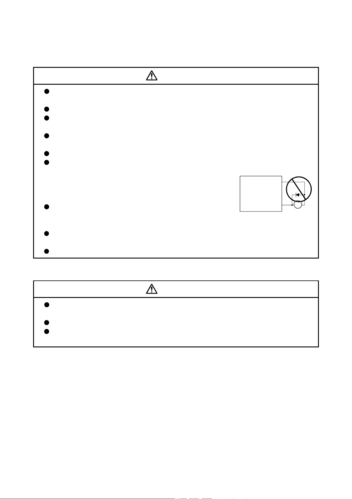
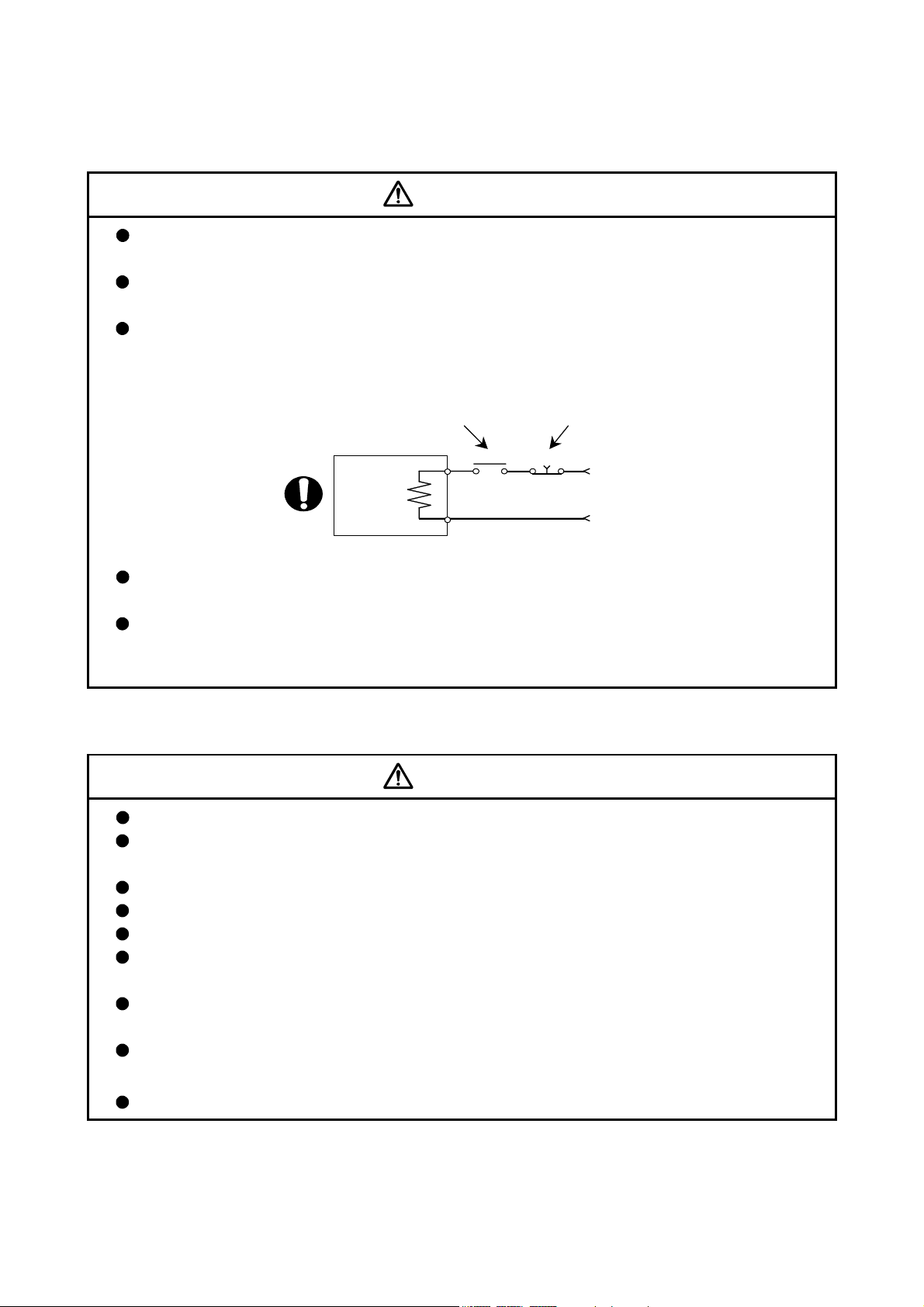
Do not mistake the direction of the surge absorbing diode
installed on the DC relay for the control signal output of brake
signals, etc. Incorrect installation may lead to signals not being
output when trouble occurs or the protective functions not
functioning.
Do not connect or disconnect the connection cables between
each unit, the encoder cable or PLC expansion cable while the
power is ON.
Securely tighten the cable connector fixing screws and fixing mechanisms. Insufficient fixing may
lead to the cables combing off during operation.
Do not bundle the power line or cables.
Servo amplifier
VIN
(24VDC)
Control output
signal
RA
(5) Trial operation and adjustment
CAUTION
Confirm and adjust the program and each parameter before operation. Unpredictable
movements may occur depending on the machine.
Extreme adjustments and changes may lead to unstable operation, so never make them.
When using the absolute position system function, on starting up, and when the Motion
controller or absolute value motor has been replaced, always perform a home position return.
A - 7
Page 9
(6) Usage methods
CAUTION
Immediately turn OFF the power if smoke, abnormal sounds or odors are emitted from the Motion
controller, servo amplifier or servomotor.
Always execute a test operation before starting actual operations after the program or
parameters have been changed or after maintenance and inspection.
Do not attempt to disassemble and repair the units excluding a qualified technician whom our
company recognized.
Do not make any modifications to the unit.
Keep the effect or electromagnetic obstacles to a minimum by installing a noise filter or by using
wire shields, etc. Electromagnetic obstacles may affect the electronic devices used near the
Motion controller or servo amplifier.
When using the CE Mark-compliant equipment, refer to the "EMC Installation Guidelines" (data
number IB(NA)-67339) for the Motion controllers and refer to the corresponding EMC guideline
information for the servo amplifiers, inverters and other equipment.
Use the units with the following conditions.
Item
Input power
Input frequency 50/60Hz ±5%
Tolerable
momentary
power failure
Q61P-A1 Q61P-A2 Q61P Q62P Q63P Q64P
100 to 120VAC
(85 to 132VAC) (170 to 264VAC) (85 to 264VAC) (15.6 to 31.2VDC)
+10% +10% +10% +30% +10%
200 to 240VAC
-15%
200 to 240VAC
-15%
Conditions
100 to 240VAC
20ms or less
-15%
24VDC
-35%
100 to 120VAC
(85 to 132VAC/
170 to 264VAC)
-15%
+10%
-15%
/
A - 8
Page 10
(7) Corrective actions for errors
CAUTION
If an error occurs in the self diagnosis of the Motion controller or servo amplifier, confirm the
check details according to the instruction manual, and restore the operation.
If a dangerous state is predicted in case of a power failure or product failure, use a servomotor
with electromagnetic brakes or install a brake mechanism externally.
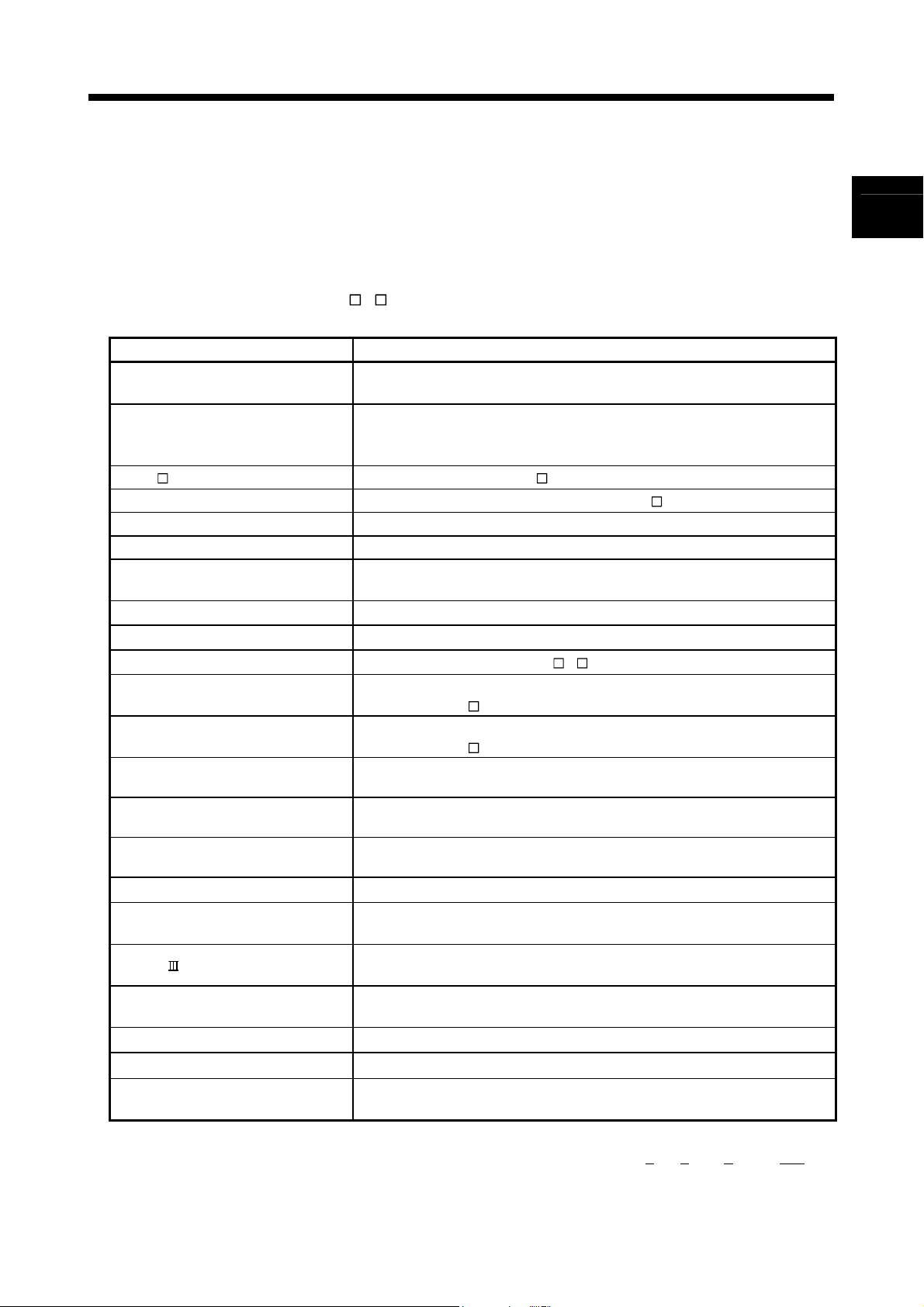
Use a double circuit construction so that the electromagnetic brake operation circuit can be
operated by emergency stop signals set externally.
Shut off with the
Shut off with servo ON signal OFF,
alarm, electromagnetic brake signal.
Servomotor
Electromagnetic
brakes
RA1
emergency stop
signal(EMG).
EMG
24VDC
If an error occurs, remove the cause, secure the safety and then resume operation after alarm
release.
The unit may suddenly resume operation after a power failure is restored, so do not go near the
machine. (Design the machine so that personal safety can be ensured even if the machine
restarts suddenly.)
(8) Maintenance, inspection and part replacement
CAUTION
Perform the daily and periodic inspections according to the instruction manual.
Perform maintenance and inspection after backing up the program and parameters for the Motion
controller and servo amplifier.
Do not place fingers or hands in the clearance when opening or closing any opening.
Periodically replace consumable parts such as batteries according to the instruction manual.
Do not touch the lead sections such as ICs or the connector contacts.
Before touching the module, always touch grounded metal, etc. to discharge static electricity from
human body. Failure to do so may cause the module to fail or malfunction.
Do not directly touch the module's conductive parts and electronic components.
Touching them could cause an operation failure or give damage to the module.
Do not place the Motion controller or servo amplifier on metal that may cause a power leakage
or wood, plastic or vinyl that may cause static electricity buildup.
Do not perform a megger test (insulation resistance measurement) during inspection.
A - 9
Page 11
CAUTION
When replacing the Motion controller or servo amplifier, always set the new module settings
correctly.
When the Motion controller or absolute value motor has been replaced, carry out a home position
return operation using one of the following methods, otherwise position displacement could occur.
1) After writing the servo data to the Motion controller using programming software, switch on the
power again, then perform a home position return operation.
2) Using the backup function of the programming software, load the data backed up before
replacement.
After maintenance and inspections are completed, confirm that the position detection of the
absolute position detector function is correct.
Do not drop or impact the battery installed to the module.
Doing so may damage the battery, causing battery liquid to leak in the battery. Do not use the
dropped or impacted battery, but dispose of it.
Do not short circuit, charge, overheat, incinerate or disassemble the batteries.
The electrolytic capacitor will generate gas during a fault, so do not place your face near the
Motion controller or servo amplifier.
The electrolytic capacitor and fan will deteriorate. Periodically replace these to prevent secondary
damage from faults. Replacements can be made by our sales representative.
(9) About processing of waste
When you discard Motion controller, servo amplifier, a battery (primary battery) and other option articles,
please follow the law of each country (area).
CAUTION
This product is not designed or manufactured to be used in equipment or systems in situations
that can affect or endanger human life.
When considering this product for operation in special applications such as machinery or systems
used in passenger transportation, medical, aerospace, atomic power, electric power, or
submarine repeating applications, please contact your nearest Mitsubishi sales representative.
Although this product was manufactured under conditions of strict quality control, you are strongly
advised to install safety devices to forestall serious accidents when it is used in facilities where a
breakdown in the product is likely to cause a serious accident.
(10) General cautions
CAUTION
All drawings provided in the instruction manual show the state with the covers and safety
partitions removed to explain detailed sections. When operating the product, always return the
covers and partitions to the designated positions, and operate according to the instruction manual.
A - 10
Page 12

REVISIONS
The manual number is given on the bottom left of the back cover.
Print Date Manual Number Revision
Jan., 2008 IB(NA)-0300134-A First edition
Japanese Manual Number IB(NA)-0300126
This manual confers no industrial property rights or any rights of any other kind, nor does it confer any patent
licenses. Mitsubishi Electric Corporation cannot be held responsible for any problems involving industrial property
rights which may occur as a result of using the contents noted in this manual.
© 2008 MITSUBISHI ELECTRIC CORPORATION
A - 11
Page 13

INTRODUCTION
Thank you for choosing the Mitsubishi Motion controller Q173DCPU/Q172DCPU.
Before using the equipment, please read this manual carefully to develop full familiarity with the functions
and performance of the Motion controller you have purchased, so as to ensure correct use.
CONTENTS
Safety Precautions .................................................................................................................................. A- 1
Revisions................................................................................................................................................. A-11
Contents.................................................................................................................................................. A-12
About Manuals ........................................................................................................................................ A-14
1. OVERVIEW 1- 1 to 1-20
1.1 Overview ........................................................................................................................................... 1- 1
1.2 Features ............................................................................................................................................ 1- 3
1.2.1 Features of Motion CPU ................................................................................................................... 1- 3
1.2.2 Basic specifications of Q173DCPU/Q172DCPU ............................................................................. 1- 5
1.3 Hardware Configuration .................................................................................................................... 1- 8
1.3.1 Motion system configuration ............................................................................................................. 1- 8
1.3.2 Q173DCPU System overall configuration ........................................................................................ 1-10
1.3.3 Q172DCPU System overall configuration ........................................................................................ 1-12
1.3.4 Software packages............................................................................................................................ 1-14
1.3.5 Restrictions on motion systems ........................................................................................................ 1-17
2. MULTIPLE CPU SYSTEM 2- 1 to 2-32
2.1 Multiple CPU System ........................................................................................................................ 2- 1
2.1.1 Overview ............................................................................................................................................ 2- 1
2.1.2 Installation position of CPU module.................................................................................................. 2- 2
2.1.3 Precautions for using I/O modules and intelligent function modules............................................... 2- 3
2.1.4 Modules subject to installation restrictions ....................................................................................... 2- 4
2.1.5 How to reset the Multiple CPU system ............................................................................................. 2- 5
2.1.6 Operation for CPU module stop error............................................................................................... 2- 6
2.2 Starting Up the Multiple CPU System............................................................................................... 2- 9
2.2.1 Startup Flow of the Multiple CPU System ........................................................................................2- 9
2.3 Communication between the PLC CPU and the Motion CPU in the Multiple CPU System ............. 2-11
2.3.1 CPU shared Memory......................................................................................................................... 2-11
2.3.2 Multiple CPU high speed transmission............................................................................................. 2-14
2.3.3 Multiple CPU high speed refresh function........................................................................................ 2-25
2.3.4 Clock synchronization between Multiple CPU ................................................................................. 2-29
2.3.5 Multiple CPU synchronous startup ...................................................................................................2-30
2.3.6 Control Instruction from PLC CPU to Motion CPU .......................................................................... 2-31
3. COMMON PARAMETERS 3- 1 to 3-22
3.1 System Settings ................................................................................................................................ 3- 1
3.1.1 System data settings ......................................................................................................................... 3- 2
3.1.2 Common system parameters ........................................................................................................... 3- 4
A - 12
Page 14

3.1.3 Individual parameters ........................................................................................................................ 3-10
3.2 I/O number assignment..................................................................................................................... 3-15
3.2.1 I/O number assignment of each module .......................................................................................... 3-15
3.2.2 I/O number of each CPU modules ................................................................................................... 3-17
3.2.3 I/O number setting............................................................................................................................. 3-18
3.3 Servo Parameters ............................................................................................................................. 3-19
4. AUXILIARY AND APPLIED FUNCTIONS 4- 1 to 4-44
4.1 Limit Switch Output Function ............................................................................................................ 4- 1
4.1.1 Operations ......................................................................................................................................... 4- 1
4.1.2 Limit output setting data .................................................................................................................... 4- 4
4.2 Absolute Position System ................................................................................................................. 4- 8
4.2.1 Current value control ......................................................................................................................... 4-10
4.3 High-Speed Reading of Specified Data ............................................................................................ 4-11
4.4 ROM Operation Function .................................................................................................................. 4-12
4.4.1 Specifications of 7-segment LED/Switches...................................................................................... 4-12
4.4.2 Outline of ROM operation ................................................................................................................. 4-14
4.4.3 Operating procedure of the ROM operation function....................................................................... 4-19
4.5 Security Function .............................................................................................................................. 4-21
4.5.1 Password registration/change .......................................................................................................... 4-21
4.5.2 Password delete................................................................................................................................ 4-23
4.5.3 Password check ................................................................................................................................ 4-24
4.5.4 Password save .................................................................................................................................. 4-25
4.6 All clear function................................................................................................................................ 4-26
4.7 Communication via Network ............................................................................................................. 4-27
4.7.1 Specifications of the communications via network........................................................................... 4-27
4.7.2 Access range of the communications via network ........................................................................... 4-28
4.8 Monitor Function of the Main Cycle .................................................................................................. 4-33
4.9 Servo Parameter Reading Function.................................................................................................. 4-34
4.10 Optional Data Monitor Function ...................................................................................................... 4-35
4.11 Connect/Disconnect Function ......................................................................................................... 4-36
4.12 Remote operation ........................................................................................................................... 4-41
4.12.1 Remote RUN/STOP ........................................................................................................................ 4-41
4.12.2 Remote latch clear .......................................................................................................................... 4-43
APPENDICES APP- 1 to APP-35
APPENDIX 1 Special relays/Special registers ................................................................................... APP- 1
APPENDIX 1.1 Special relays ..............................................................................................................APP- 1
APPENDIX 1.2 Special registers .....................................................................................................APP- 5
APPENDIX 1.3 Replacement of special relays/special registers ........................................................APP-11
APPENDIX 2 System Setting Errors.................................................................................................. APP-13
APPENDIX 3 Self-diagnosis error code............................................................................................. APP-15
APPENDIX 4 Differences Between Q173DCPU/Q172DCPU and Q173HCPU/Q172HCPU ............ APP-26
APPENDIX 4.1 Differences Between Q173DCPU/Q172DCPU and Q173HCPU/Q172HCPU .........APP-26
APPENDIX 4.2 Comparison of devices................................................................................................APP-28
APPENDIX 4.3 Differences of each mode ...........................................................................................APP-35
A - 13
Page 15

About Manuals
The following manuals are also related to this product.
In necessary, order them by quoting the details in the tables below.
Related Manuals
(1) Motion controller
Q173DCPU/Q172DCPU Motion controller User's Manual
This manual explains specifications of the Motion CPU modules, Q172DLX Servo external signal interface
module, Q172DEX Synchronous encoder interface module, Q173DPX Manual pulse generator interface
module, Power supply modules, Servo amplifiers, SSCNET
others.
(Optional)
Q173DCPU/Q172DCPU Motion controller (SV13/SV22) Programming Manual (Motion SFC)
This manual explains the functions, programming, debugging, error lists and others for Motion SFC.
(Optional)
Manual Name
cables, Synchronous encoder cables and
Manual Number
(Model Code)
IB-0300133
(1XB927)
IB-0300135
(1XB929)
Q173DCPU/Q172DCPU Motion controller (SV13/SV22) Programming Manual (REAL MODE)
This manual explains the servo parameters, positioning instructions, device lists, error lists and others.
(Optional)
Q173DCPU/Q172DCPU Motion controller (SV22) Programming Manual (VIRTUAL MODE)
This manual explains the dedicated instructions to use the synchronous control by virtual main shaft,
mechanical system program create mechanical module, servo parameters, positioning instructions, device
lists, error lists and others.
(Optional)
IB-0300136
(1XB930)
IB-0300137
(1XB931)
A - 14
Page 16

(2) PLC
QCPU User's Manual (Hardware Design, Maintenance and Inspection)
This manual explains the specifications of the QCPU modules, power supply modules, base modules,
extension cables, memory card battery and others.
(Optional)
QCPU User's Manual (Function Explanation, Program Fundamentals)
This manual explains the functions, programming methods and devices and others to create programs
with the QCPU.
(Optional)
QCPU User's Manual (Multiple CPU System)
This manual explains the functions, programming methods and cautions and others to construct the
Multiple CPU system with the QCPU.
(Optional)
QCPU (Q Mode)/QnACPU Programming Manual (Common Instructions)
This manual explains how to use the sequence instructions, basic instructions, application instructions and
micro computer program.
(Optional)
QCPU (Q Mode)/QnACPU Programming Manual (PID Control Instructions)
This manual explains the dedicated instructions used to exercise PID control.
(Optional)
QCPU (Q Mode)/QnACPU Programming Manual (SFC)
This manual explains the system configuration, performance specifications, functions, programming,
debugging, error codes and others of MELSAP3.
(Optional)
I/O Module Type Building Block User's Manual
This manual explains the specifications of the I/O modules, connector, connector/terminal block
conversion modules and others.
(Optional)
Manual Name
(3) Servo amplifier
MR-J3- B Servo amplifier Instruction Manual
This manual explains the I/O signals, parts names, parameters, start-up procedure and others for
MR-J3-
(Optional)
Fully Closed Loop Control MR-J3- B-RJ006 Servo amplifier Instruction Manual
This manual explains the I/O signals, parts names, parameters, start-up procedure and others for Fully
Closed Loop Control MR-J3-
(Optional)
B Servo amplifier.
Manual Name
B-RJ006 Servo amplifier.
Manual Number
(Model Code)
SH-080483ENG
(13JR73)
SH-080484ENG
(13JR74)
SH-080485ENG
(13JR75)
SH-080039
(13JF58)
SH-080040
(13JF59)
SH-080041
(13JF60)
SH-080042
(13JL99)
Manual Number
(Model Code)
SH-030051
(1CW202)
SH-030056
(1CW304)
A - 15
Page 17

MEMO
A - 16
Page 18
1 OVERVIEW
1. OVERVIEW
1.1 Overview
This programming manual describes the common items of each operating system
software, such as the Multiple CPU system of the operating system software packages
Generic term/Abbreviation Description
Q173DCPU/Q172DCPU or
Motion CPU (module)
Q172DLX/Q172DEX/Q173DPX or
Motion module
MR-J3- B Servo amplifier model MR-J3- B
AMP or Servo amplifier General name for "Servo amplifier model MR-J3- B"
QCPU, PLC CPU or PLC CPU module QnUD(H)CPU
Multiple CPU system or Motion system Abbreviation for "Multiple PLC system of the Q series"
CPUn
Self CPU Motion CPU being programmed by the currently open MT Developer project
Programming software package General name for MT Developer/GX Developer/MR Configurator
Operating system software General name for "SW8DNC-SV Q "
SV13
SV22
MT Developer
GX Developer
MR Configurator
Manual pulse generator or MR-HDP01 Abbreviation for "Manual pulse generator (MR-HDP01)"
Serial absolute synchronous encoder
or Q170ENC
SSCNET
Absolute position system
Battery holder unit Battery holder unit (Q170DBATC)
External battery General name for "Q170DBATC" and "Q6BAT"
Intelligent function module
(Note-2)
"SW8DNC-SV
In this manual, the following abbreviations are used.
Q " for Motion CPU module (Q173DCPU/Q172DCPU).
Q173DCPU/Q172DCPU Motion CPU module
Q172DLX Servo external signals interface module/
Q172DEX Serial Synchronous encoder interface module
Q173DPX Manual pulse generator interface module
Abbreviation for "CPU No.n (n= 1 to 4) of the CPU module for the Multiple CPU
system"
Operating system software for conveyor assembly use (Motion SFC) :
SW8DNC -SV13Q
Operating system software for automatic machinery use (Motion SFC) :
SW8DNC -SV22Q
Abbreviation for "Motion controller programming software
MT Developer2 (Version 1.00A or later)"
Abbreviation for "MELSEC PLC programming software package
GX Developer (Version 8.48A or later)"
Abbreviation for "Servo setup software package
MR Configurator (Version C0 or later)"
Abbreviation for "Serial absolute synchronous encoder (Q170ENC)"
High speed synchronous network between Motion controller and servo
amplifier
General name for "system using the servomotor and servo amplifier for
absolute position"
Abbreviation for "MELSECNET/H module/Ethernet module/CC-Link module/
Serial communication module"
(Note-1) : Q172DEX can be used in SV22.
(Note-2) : SSCNET: S
(Note-1)
/
ervo System Controller NETwork
1
1 - 1
Page 19

1 OVERVIEW
REMARK
For information about the each module, design method for program and parameter,
Motion CPU module/Motion unit Q173DCPU/Q172DCPU User’s Manual
PLC CPU, peripheral devices for PLC program design, I/O
modules and intelligent function module
Operation method for MT Developer Help of each software
• Design method for Motion SFC program
• Design method for Motion SFC parameter
• Motion dedicated PLC instruction
SV13/SV22
SV22
(Virtual mode)
• Design method for positioning control
• Design method for positioning control
• Design method for mechanical system
refer to the following manuals relevant to each module.
Item Reference Manual
Manual relevant to each module
Q173DCPU/Q172DCPU Motion controller (SV13/SV22)
Programming Manual (Motion SFC)
program in the real mode
parameter
program
Q173DCPU/Q172DCPU Motion controller (SV13/SV22)
Programming Manual (REAL MODE)
Q173DCPU/Q172DCPU Motion controller (SV22)
Programming Manual (VIRTUAL MODE)
1 - 2
Page 20

1 OVERVIEW
1.2 Features
The Motion CPU and Multiple CPU system have the following features.
1.2.1 Features of Motion CPU
(1) Q series PLC Multiple CPU system
(a) Load distribution of processing can be performed by controlling the
complicated servo control with Motion CPU and the machine control or
information control with PLC CPU. Therefore, the flexible system
configuration can be realized.
(b) The Motion CPU and PLC CPU are selected flexibly, and the Multiple CPU
system up to 4 CPU modules can be realized.
The Motion CPU module for the number of axis to be used can be selected.
Q173DCPU : Up to 32 axes
Q172DCPU : Up to 8 axes
The PLC CPU module for the program capacity to be used can be selected.
(One or more PLC CPU is necessary with the Multiple CPU system.)
Q03UDCPU : 30k steps
Q04UDHCPU : 40k steps
Q06UDHCPU : 60k steps
(c) The device data access of the Motion CPU and the Motion SFC program
start can be executed from PLC CPU by the Motion dedicated PLC
instruction.
(2) High speed operation processing
(a) The minimum operation cycle of the Motion CPU is made 0.44[ms], and it
correspond with high frequency operation.
(b) High speed PLC control is possible by the universal model QCPU.
(For LD instruction)
Q03UDCPU : 20[ns]
Q04UDHCPU : 9.5[ns]
Q06UDHCPU : 9.5[ns]
1 - 3
Page 21

1 OVERVIEW
(3) Connection between the Motion controller and servo amplifier with
high speed synchronous network by SSCNET
(a) High speed synchronous network by SSCNET connect between the
Motion controller and servo amplifier, and batch control the charge of servo
parameter, servo monitor and test operation, etc.
It is also realised reduce the number of wires.
(b) The maximum distance between the Motion CPU and servo amplifier, servo
amplifier and servo amplifier of the SSCNET
set to 50(164.04)[m(ft.)], and the flexibility improved at the Motion system
design.
cable on the same bus was
(4) The operating system software package for your application needs
By installing the operating system software for applications in the internal flash
memory of the Motion CPU, the Motion controller suitable for the machine can be
realized.
And, it also can correspond with the function improvement of the software
package.
(a) Conveyor assembly use (SV13)
Offer liner interpolation, circular interpolation, helical interpolation, constantspeed control, speed control, fixed-pitch feed and etc. by the dedicated
servo instruction. Ideal for use in conveyors and assembly machines.
(b) Automatic machinery use (SV22)
Provides synchronous control and offers electronic cam control by
mechanical support language. Ideal for use in automatic machinery.
1 - 4
Page 22
1 OVERVIEW
1.2.2 Basic specifications of Q173DCPU/Q172DCPU
(1) Module specifications
Item Q173DCPU Q172DCPU
Internal current consumption (5VDC) [A] 1.25 1.14
Mass [kg] 0.33 0.33
Exterior dimensions [mm(inch)] 98 (3.85)(H) 27.4 (1.08)(W) 119.3 (4.69)(D)
(2) SV13/SV22 Motion control specifications/performance
specifications
Item Q173DCPU Q172DCPU
Number of control axes Up to 32 axes Up to 8 axes
SV13
Operation cycle
(default)
SV22
Interpolation functions
Control modes
Acceleration/
deceleration control
Compensation Backlash compensation, Electronic gear, Phase compensation (SV22)
Programming language Motion SFC, Dedicated instruction, Mechanical support language (SV22)
Servo program capacity 14k steps
Number of positioning
points
Peripheral I/F Via PLC CPU (USB/RS-232)
Home position return
function
JOG operation function Provided
Manual pulse generator
operation function
Synchronous encoder
operation function
M-code function
Limit switch output
function
(a) Motion control specifications
0.44ms/ 1 to 6 axes
0.88ms/ 7 to 18 axes
1.77ms/19 to 32 axes
0.44ms/ 1 to 4 axes
0.88ms/ 5 to 12 axes
1.77ms/13 to 28 axes
3.55ms/29 to 32 axes
Linear interpolation (Up to 4 axes), Circular interpolation (2 axes),
Helical interpolation (3 axes)
PTP(Point to Point) control, Speed control, Speed-position control, Fixed-pitch feed,
Constant speed control, Position follow-up control, Speed control with fixed position stop,
Speed switching control, High-speed oscillation control, Synchronous control (SV22)
Automatic trapezoidal acceleration/deceleration,
S-curve acceleration/deceleration
3200 points
(Positioning data can be designated indirectly)
Proximity dog type (2 types), Count type (3 types), Data set type (2 types), Dog cradle type,
Stopper type (2 types), Limit switch combined type
(Home position return re-try function provided, home position shift function provided)
Possible to connect 3 modules
Possible to connect 12 modules Possible to connect 8 modules
M-code output function provided
M-code completion wait function provided
Number of output points 32 points
Watch data: Motion control data/Word device
1 - 5
0.44ms/ 1 to 6 axes
0.88ms/ 7 to 8 axes
0.44ms/ 1 to 4 axes
0.88ms/ 5 to 8 axes
Page 23

1 OVERVIEW
Item Q173DCPU Q172DCPU
Motion control specifications (continued)
Absolute position system
Number of SSCNET
systems
Motion related interface
module
(Note-1)
(Note-1) : The servo amplifiers for SSCNET cannot be used.
(Note-2) : When using the incremental synchronous encoder (SV22 use), you can use above number of modules.
When connecting the manual pulse generator, you can use only 1 module.
(Possible to select the absolute data method or incremental method for each axis)
Q172DLX : 4 modules usable Q172DLX : 1 module usable
Q172DEX : 6 modules usable Q172DEX : 4 modules usable
Q173DPX : 4 modules usable
Made compatible by setting battery to servo amplifier.
2 systems 1 system
(Note-2)
Q173DPX : 3 modules usable
(Note-2)
1 - 6
Page 24
1 OVERVIEW
Motion SFC program capacity
Motion SFC program
Operation control program
(F/FS)
/
Transition program
(G)
Execute specification
Number of devices
(Device In the Motion CPU
only)
(Included the positioning
dedicated device)
(b) Motion SFC Performance Specifications
Item Q173DCPU/Q172DCPU
Code total
(Motion SFC chart + Operation control
+ Transition)
Text total
(Operation control + Transition)
Number of Motion SFC programs 256 (No.0 to 255)
Motion SFC chart size/program Up to 64k bytes (Included Motion SFC chart comments)
Number of Motion SFC steps/program Up to 4094 steps
Number of selective branches/branch 255
Number of parallel branches/branch 255
Parallel branch nesting Up to 4 levels
Number of operation control programs
Number of transition programs 4096(G0 to G4095)
Code size/program Up to approx. 64k bytes (32766 steps)
Number of blocks(line)/program Up to 8192 blocks (in the case of 4 steps(min)/blocks)
Number of characters/block Up to 128 (comment included)
Number of operand/block Up to 64 (operand: constants, word device, bit devices)
( ) nesting/block Up to 32 levels
Descriptive
expression
Number of multi execute programs Up to 256
Number of multi active steps Up to 256 steps/all programs
Executed
task
Internal relays (M) 8192 points
Link relays (B) 8192 points
Annunciators (F) 2048 points
Special relays (SM) 2256 points
Data registers (D) 8192 points
Link registers (W) 8192 points
Special registers (SD) 2256 points
Motion registers (#) 8736 points
Coasting timers (FT)
Multiple CPU area devices (U
Operation control program Calculation expression/bit conditional expression
Transition program
Normal task Execute in main cycle of Motion CPU
Event task
(Execution
can be
masked.)
NMI task
Fixed cycle
External
interrupt
PLC interrupt Execute with interrupt instruction (D(P).GINT) from PLC CPU.
(Note): Usable number of points changes according to the system settings.
4096 with F(Once execution type) and FS(Scan execution type)
combined. (F/FS0 to F/FS4095)
Calculation expression/bit conditional expression/
comparison conditional expression
(0.88ms, 1.77ms, 3.55ms, 7.11ms, 14.2ms)
Execute when input ON is set among interrupt module QI60
Execute when input ON is set among interrupt module QI60
\G) Up to 14336 points usable
543k bytes
484k bytes
Execute in fixed cycle
(16 points).
(16 points).
1 point (888µs)
(Note)
1 - 7
Page 25
1 OVERVIEW
1.3 Hardware Configuration
This section describes the Q173DCPU/Q172DCPU system configuration, precautions
on use of system, and configured equipments.
1.3.1 Motion system configuration
This section describes the equipment configuration, configuration with peripheral
devices and system configuration in the Q173DCPU/Q172DCPU system.
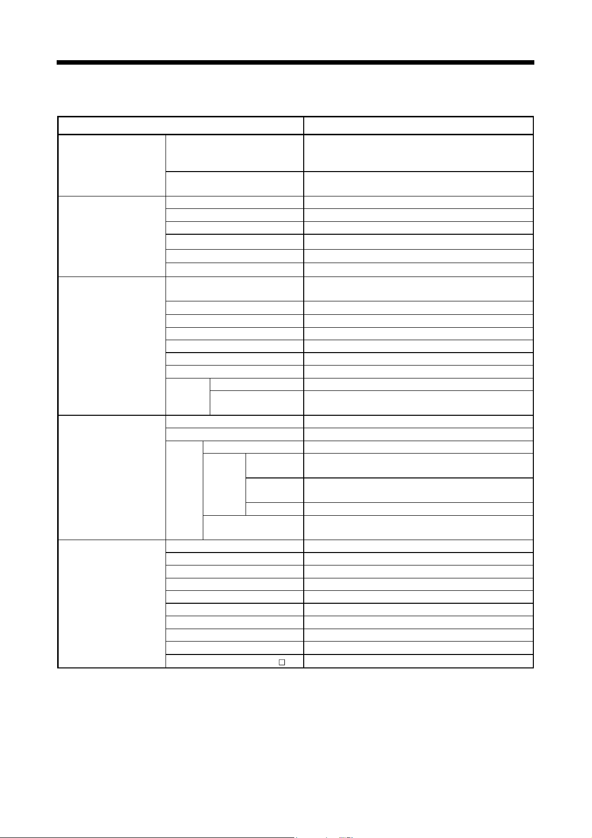
(1) Equipment configuration in Q173DCPU/Q172DCPU system
Power supply module/
QnUD(H)CPU/ I/O module/
Intelligent function module
of the Q series
Extension of the Q series module
(Note-2)
Motion module
(Q172DLX, Q173DPX)
Motion mo dule
(Q172DLX, Q172DEX, Q173DPX)
(Note-1)
Battery holder unit
(Q170DBATC)
(Note-1)
MITSUBISHI
LITHIUM BATT ERY
Battery
(Q6BAT)
Main base unit
(Q38DB, Q312DB)
Motion CPU module
(Q173DCPU/Q172DCPU)
SSCNET cable
(MR-J3BUS M(-A/-B))
Servo amplifier
(MR-J3- B)
Extension cable
(QC B)
Forced stop input cable
(Q170DEMICBL M)
Q6 B extension base unit
(Q63B, Q65B, Q68B, Q612B)
Power supply module/
I/O module/Intelligent function
module of the Q series
It is possible to select the best according to the system.
(Note-1) : Be sure to install the Battery (Q6BAT) to the Battery holder unit (Q170DBATC).
It is packed together with Q173DCPU/Q172DCPU.
(Note-2) : Q172DEX cannot be used in the extension base unit.
Mount it to the main base unit.
1 - 8
Page 26
1 OVERVIEW
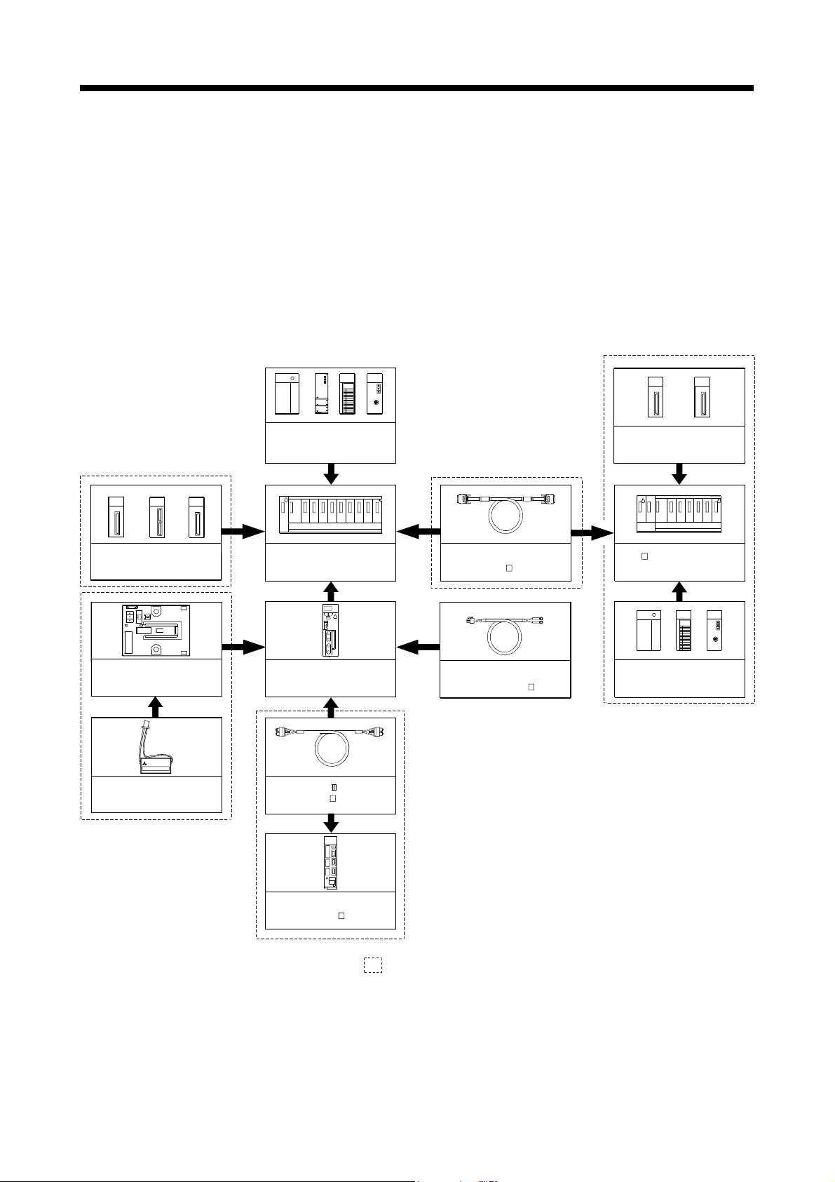
(2) Peripheral device configuration for the Q173DCPU/Q172DCPU
The following (a)(b) can be used.
(a) USB configuration
(b) RS-232 configuration
PLC CPU module
(QnUD(H)CPU)
USB cable
M
S
I
T
U
B
I
S
H
I
Personal computer
PLC CPU module
(
QnUD(H)CPU)
RS-232 communication cable
(QC30R2)
M
I
T
S
U
B
I
S
H
I
Personal computer
1 - 9
Page 27
1 OVERVIEW
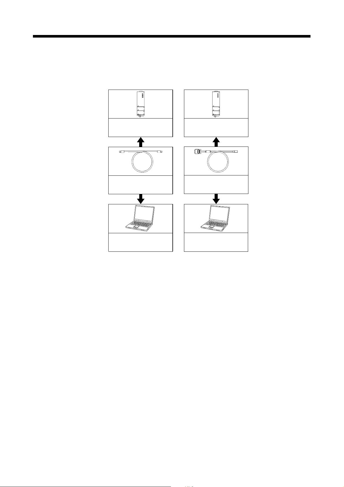
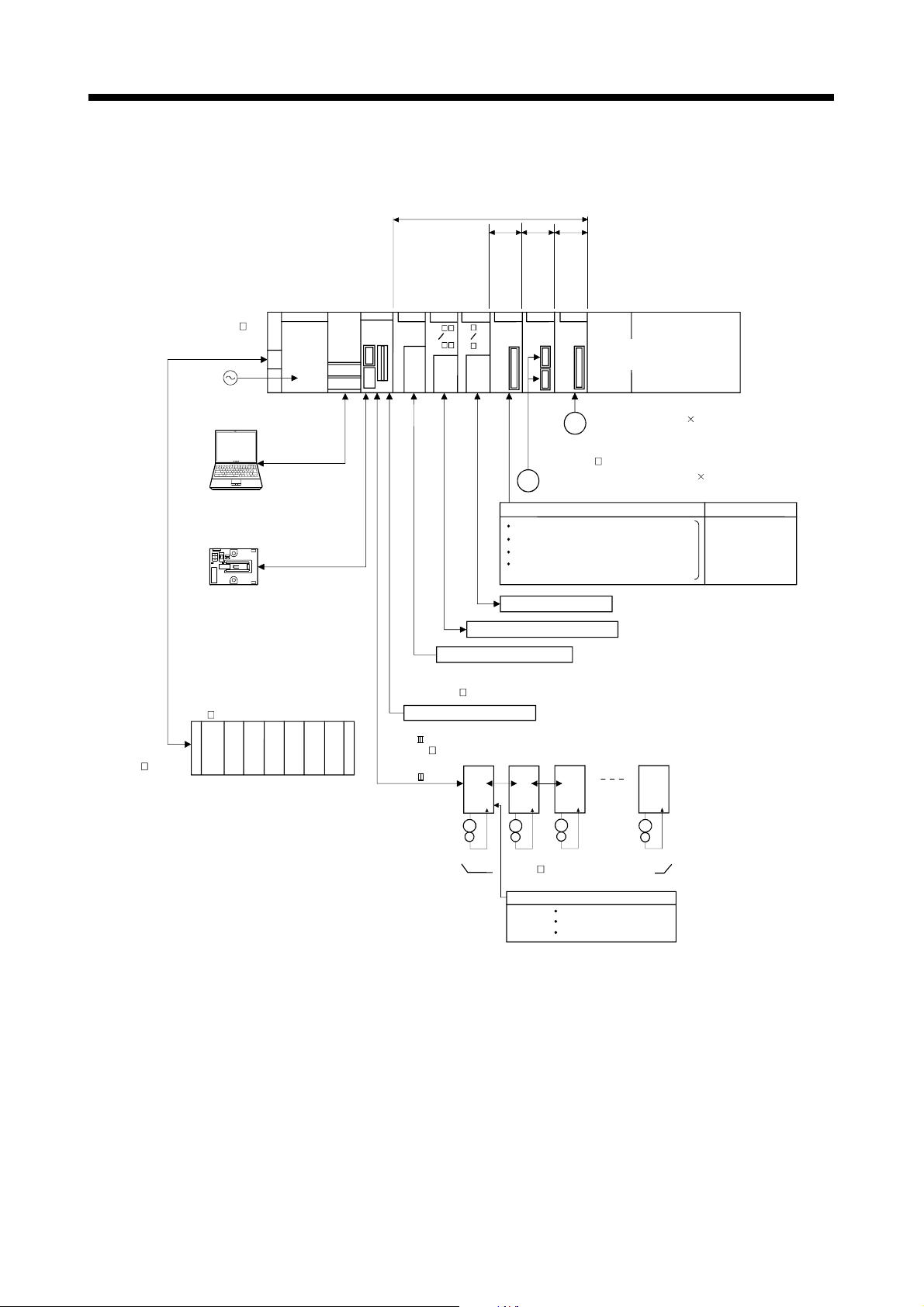
1.3.2 Q173DCPU System overall configuration
Motion CPU control module
PLC CPU/
Q61P
Motion CPU
QnUD(H)
CPU
Q173D
QI60 QX
CPU
QY
Forced stop input cab le
(Q170DEMICBL M)
EMI forced stop input (24VDC)
SSCNET cable
(MR-J3BUS M(-A/-B))
SSCNET (CN2)
Interrupt signals (16 points)
Extension cable
(QC B)
Main base un it
(Q3 DB)
100/200VAC
Personal Computer
IBM PC/AT
Battery holder unit
Q170DBATC
Extension base unit
(Q6 B)
y
l
p
p
u
s
e
r
l
e
u
d
w
o
o
P
m
UP to 7 extensions
USB/RS-232
e
e
e
l
l
l
u
a
d
s
n
o
u
r
o
e
m
t
n
x
e
o
e
r
c
s
l
h
a
o
f
a
c
r
v
n
r
n
e
t
g
y
e
i
n
S
S
s
i
Q6 AD
Q6 DA
Q172D
Q172D
EX
LX
Serial absolute synchronous encoder cable
(Q170ENCCBL M)
E
FLS
RLS
STOP
DOG/CHANGE : Proximity dog/
Speed-position switching
l
u
u
d
d
e
o
o
s
l
m
u
m
r
p
o
e
r
e
t
l
c
c
e
a
a
r
a
a
d
f
u
f
e
r
r
o
n
n
c
e
e
a
t
t
e
n
n
n
M
g
i
e
i
Q173D
PX
Manual pulse generator 3/module
P
(MR-HDP01)
Serial absolute synchronous encoder 2/module
External input s ignals
: Upper stroke limit
: Lower stroke limit
: Stop sign al
Analogue input/output
Input/output (Up to 256 points)
SSCNET (CN1)
d16
d1
I/O module/
Intelligent function module
(Up to 1 module)
(Up to 6 modules) (Q170ENC)
d1
d16
Number of Inputs
8 axes/module
(Up to 4 modules)
M
E
1 - 10
M
E
MR-J3- B model Servo amplifier,
Up to 32 axes (Up to 16 axes/system)
External input signals of servo amplifier
Proximity dog
Upper stroke limit
Lower stroke limit
M
E
M
E
Page 28

1 OVERVIEW
CAUTION
Construct a safety circuit externally of the Motion controller or servo amplifier if the abnormal
operation of the Motion controller or servo amplifier differ from the safety directive operation in
the system.
The ratings and characteristics of the parts (other than Motion controller, servo amplifier and
servomotor) used in a system must be compatible with the Motion controller, servo amplifier and
servomotor.
Set the parameter values to those that are compatible with the Motion controller, servo amplifier,
servomotor and regenerative resistor model and the system application. The protective functions
may not function if the settings are incorrect.
1 - 11
Page 29
1 OVERVIEW
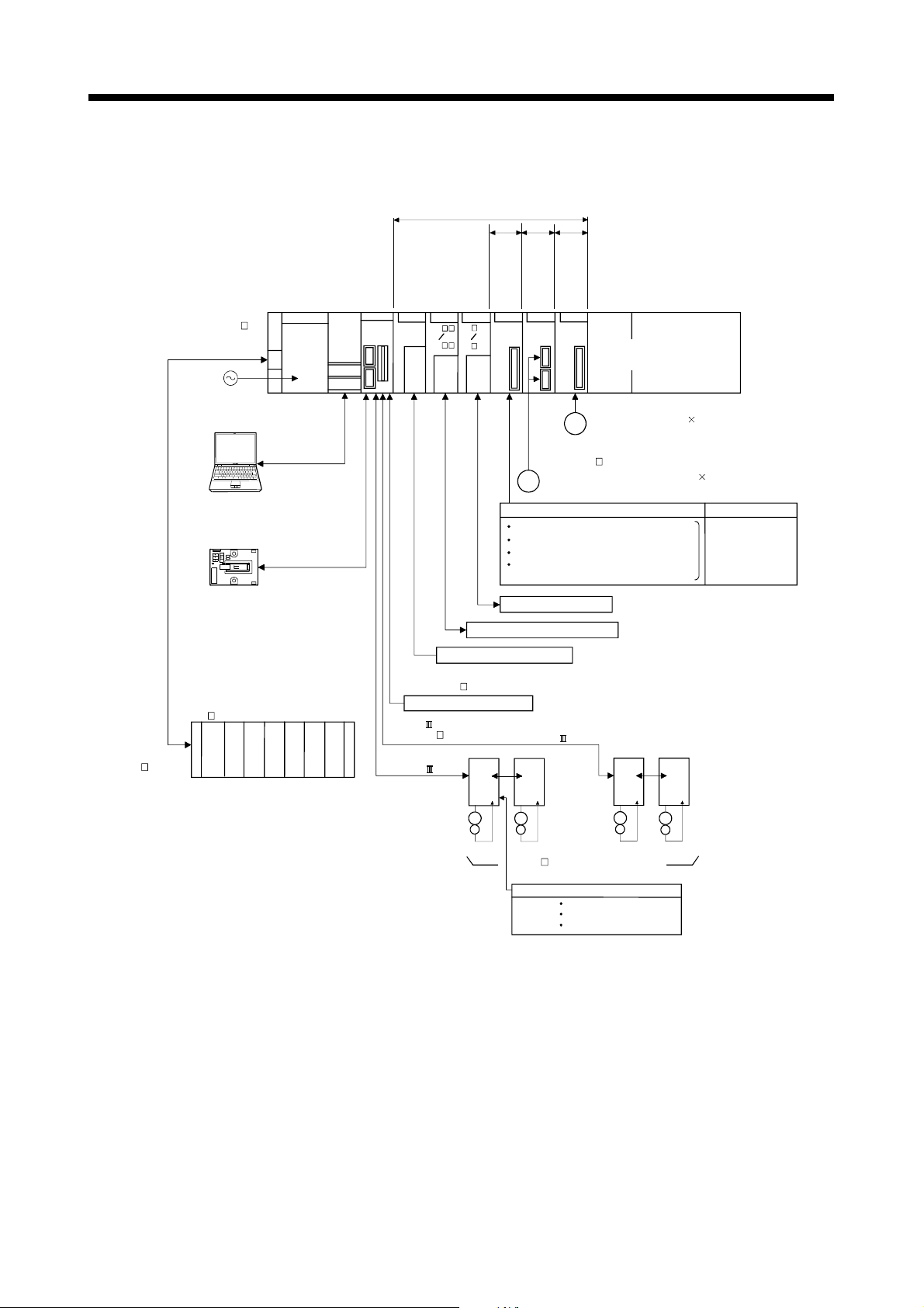
1.3.3 Q172DCPU System overall configuration
Motion CPU control module
PLC CPU/
Main base unit
(Q3 DB)
100/200VAC
Personal Computer
IBM PC/AT
Battery holder unit
Q170DBATC
USB/RS-232
Q61P
Motion CPU
QnUD(H)
CPU
Q172D
CPU
QX
QI60
QY
Interrupt signals (16 points)
e
e
l
l
Q6 AD
Q6 DA
l
a
n
r
e
t
x
e
o
v
r
e
S
Q172D
LX
u
u
d
o
m
e
c
s
l
a
f
a
r
n
e
t
g
i
n
s
i
FLS
RLS
STOP
DOG/CHANGE : Proximity dog/
Speed-position switching
d
e
s
o
s
u
l
o
m
u
r
n
p
o
r
e
t
o
l
c
r
e
a
a
r
h
a
d
f
u
c
e
o
r
n
n
n
c
e
a
t
y
n
e
n
M
g
S
e
i
Q172D
Q173D
EX
PX
P
Serial absolute synchronous encoder cable
(Q170ENCCBL M)
Serial absolute synchronous encoder 2/module
E
(Q170ENC)
External input signals
: Upper stroke limit
: Lower stroke limit
: Stop signal
Analogue input/output
Input/output (Up to 256 points)
e
l
u
d
o
m
e
c
a
f
r
e
t
n
i
I/O module /
Intelligent function module
Manual pulse generator 3/module
(MR-HDP01)
(Up to 6 modules)
(Up to 1 module)
Number of Inputs
8 axes/module
(Up to 4 mo dules)
Extension cable
(QC B)
Extension base unit
(Q6 B)
y
l
p
p
u
s
e
r
l
e
u
d
w
o
o
P
m
UP to 7 extensions
Forced stop input cable
(Q170DEMICBL M)
EMI forced stop input (24VDC)
SSCNET cable
(MR-J3BUS M(-A/-B))
SSCNET (CN1)
d2
d1
M
E
MR-J3- B model Servo amplifier,
Up to 8 axes
M
M
E
External input signals of servo amplifier
E
Proximity dog
Upper stroke limit
Lower stroke limit
d3
d8
M
E
1 - 12
Page 30

1 OVERVIEW
CAUTION
Construct a safety circuit externally of the Motion controller or servo amplifier if the abnormal
operation of the Motion controller or servo amplifier differ from the safety directive operation in
the system.
The ratings and characteristics of the parts (other than Motion controller, servo amplifier and
servomotor) used in a system must be compatible with the Motion controller, servo amplifier and
servomotor.
Set the parameter values to those that are compatible with the Motion controller, servo amplifier,
servomotor and regenerative resistor model and the system application. The protective functions
may not function if the settings are incorrect.
1 - 13
Page 31

1 OVERVIEW
1.3.4 Software packages (1) Software packages
For conveyor assembly SV13 SW8DNC-SV13QB SW8DNC-SV13QD
For automatic machinery SV22 SW8DNC-SV22QA SW8DNC-SV22QC
MT Developer2
(Note) : Operating environment to use MT Developer is WindowsR Vista/WindowsR XP/WindowsR 2000
(2) Operating environment of personal computer
OS
CPU
Memory capacity Recommended 512MB or more
Video card Card compatible with MicrosoftR DirectXR 9.0c or later
Available hard disk
capacity
Disk drive CD-ROM disk drive
Display
(Note-1) : Microsoft, Windows and DirectX are either registered trademarks or trademarks of Microsoft
(Note-2) : Intel, Celeron an d Pen tium ar e tr adem arks o f In te l Corp orat ion in th e U. S. and ot he r count rie s.
(a) Operating system software
Application
Q173DCPU Q172DCPU
Software package
(b) Motion controller programming software
Part name Model name Details
Conveyor Assembly Software
Automatic Machinery So ftw a r e
Cam Data Creation Software
SW1DNC-MTW2-E
(1 CD-ROM disk)
English version only.
Operating environment is shown below.
IBM PC/AT with which Windows
version operates normally.
Item Operating environment
R
Microsoft
Microsoft
Microsoft
Microsoft
Microsoft
Microsoft
Microsoft
Microsoft
Desktop PC: Recommended Intel
Laptop PC: Recommended Intel
Installation: HD 1GB or more
Operation: Virtual memory 5 0M B or m or e
Resolution 1024×768 pixels or higher
Corporation in the United States and/or other countries.
WindowsR Vista Home Basic
R
WindowsR Vista Home Premium
R
WindowsR Vista Business
R
WindowsR Vista Ultimate
R
WindowsR Vista Enterprise
R
WindowsR XP Professional (Service Pack 2 or later)
R
WindowsR XP Home Edition (Service Pack 2 or later)
R
WindowsR 2000 Professional (Service Pack 4 or later)
Digital Oscilloscope Software
Communication System So f tw are
Document Print So ftw ar e
Operation Manual (Help)
Installation manual (PDF)
R
Vista/WindowsR XP/WindowsR2000 English
R
CeleronR Processor 2.8GHz or more
R
PentiumR Processor M 1.7GHz or more
1 - 14
Page 32

1 OVERVIEW
(3) Operating system type/version
(a) Confirmation method in the operating system (CD)
1)
1) OS software type
2) OS software version
3) Serial number
Example) When using Q173DCPU, SV22 and version 00A.
1) SW8DNC-SV22QA
2) 00A
(b) Confirmation method in MT Debeloper
The operating system(OS) type/version of connected CPU is displayed on
the installation screen of MT Developer.
(OS software)
SV 2 2 QAVER3
A or B : Q173DCPU
C or D : Q172DCPU
(4) Relevant software packages
(a) PLC software package
Model name Software package
2)
3)
00 A
OS version
3: Motion SFC compatibility
. : Motion SFC not compatibility
GX Developer SW8D5C-GPPW-E
(b) Servo set up software package
Model name Software package
MR Configurator MRZJW3-SETUP221E
1 - 15
Page 33

1 OVERVIEW
POINTS
(1) When the operation of Windows is not unclear in the operation of this software,
refer to the manual of Windows or guide-book from the other supplier.
(2) The following functions cannot be used when the computer is running under
Windows
This product may not perform properly, when these functions are used.
< Windows
• Activating the application with Windows
R
Vista, WindowsR XP or WindowsR 2000.
R
Vista/WindowsR XP>
R
compatibility mode
• Fast user switching
• Remote desktop
• Large size
R
)
• x64 Edition (64 bit Windows
< Windows
R
2000>
• Large fonts
1 - 16
Page 34

1 OVERVIEW
1.3.5 Restrictions on motion systems
(1) Combination of Multiple CPU system
(a) Motion CPU module cannot be used as standalone module.
Be sure to install the universal model PLC CPU module (Q03UDCPU/
Q04UDHCPU/Q06UDHCPU) to CPU No.1.
For Universal model PLC CPU module, "Multiple CPU high speed
taransmission function" must be set in the Multiple CPU settings.
(b) Only Multiple CPU high speed main base unit (Q38DB/Q312DB) can be
used.
(c) The combination of Q173DCPU/Q172DCPU and Q173HCPU(-T)/
Q172HCPU(-T)/Q173CPUN(-T)/Q172CPUN(-T) cannot be used.
(d) Up to four modules of PLC CPU modules (Q03UDCPU/Q04UDHCPU/
Q06UDHCPU/Motion CPU modules can be installed from the CPU slot (the
slot on the right side of power supply module) to slot 2 of the main base unit.
CPU modules called as CPU No.1 to CPU No.4 from the left sequentially.
There is no restriction on the installation order of CPU No.2 to No.4.
For CPU module except CPU No.1, an empty slot can be reserved for
addition of CPU module. An empty slot can be set between CPU modules.
However, the mounting condition when combining with the High
performance PLC CPU module/Process CPU module/PC CPU module/C
controller module is different depending on the specification of CPU
modules, refer to the Manuals of each CPU modules.
(e) It takes about 10 seconds to startup (state that can be controlled) of Motion
CPU. Make a Multiple CPU synchronous startup setting suitable for the
system.
(f) Execute the automatic refresh of the Motion CPU modules and PLC CPU
modules (Q03UDCPU/Q04UDHCPU/Q06UDHCPU) by using the automatic
refresh of Multiple CPU high speed transmission area setting.
When the High performance PLC CPU module/Process CPU module/PC
CPU module/C controller module is mounted in the combination of Multiple
CPU system, the Motion CPU module cannot be execute the automatic
refresh with these modules.
(g) Use the Motion dedicated PLC instructions that starts by "D(P).". The Motion
dedicated PLC instructions that starts by "S(P)." cannot be used. When the
High performance PLC CPU module/Process CPU module/PC CPU
module/C controller module is mounted in the combination of Multiple CPU
system, the Motion dedicated PLC instruction from these modules cannot be
executed.
1 - 17
Page 35

1 OVERVIEW
(2) Motion modules
(a) Installation position of Q172DEX
It cannot be used on the extension base unit.
(b) Q172DLX/Q173DPX can be installed on any of the main base unit/
extension base unit.
(c) Q172DLX/Q172DEX
(Note-1)
slot 0 to 2 of the main base unit. Wrong installation might damage the main
base unit.
(d) Q172EX(-S1/-S2/-S3)/Q172LX/Q173PX(-S1) for Q173HCPU(-T)/
Q172HCPU(-T)/Q173CPUN(-T)/Q172CPUN(-T)/Q173CPU/Q172CPU
cannot be used.
(e) Be sure to use the Motion CPU as the control CPU of Motion modules
(Q172DLX, Q172DEX
(Note-1)
operate correctly if PLC CPU is set and installed as the control CPU by
mistake. Motion CPU is treated as a 32-point intelligent module by PLC
CPU of other CPU.
(Note-1)
is only the main base unit.
/Q173DPX cannot be installed in CPU slot and I/O
, Q173DPX, etc.) for Motion CPU. They will not
(Note-1) : Q172DEX can be used in SV22. It cannot be used in SV13.
1 - 18
Page 36

1 OVERVIEW
(3) Other restrictions
(a) Motion CPU module cannot be set as the control CPU of intelligent function
module (except some modules) or Graphic Operation Terminal(GOT).
(b) Be sure to use the external battery.
(c) There are following methods to execute the forced stop input.
• Use a EMI terminal of Motion CPU module
• Use a device set in the forced stop input setting of system setting
(d) Forced stop input for EMI terminal of Motion CPU module cannot be
invalidated by the parameter.
When the device set in the forced stop input setting is used without use of
EMI terminal of Motion CPU module, apply 24VDC voltage on EMI terminal
and invalidate the forced stop input of EMI terminal.
(e) Be sure to use the cable for forced stop input (sold separately). The forced
stop cannot be released without using it.
(f) When the operation cycle is 0.4[ms], set the system setting as the axis select
switch of servo amplifier "0 to 7".
If the axis select switch of servo amplifier "8 to F" is set, the servo amplifiers
are not recognized.
(g) It is impossible to mount the main base unit by DIN rail when using the
Motion CPU module.
Doing so could result in vibration that may cause erroneous operation.
(h) The module name displayed by "System monitor" - "Product information list"
of GX Developer is different depending on the function version of Motion
modules (Q172DLX, Q172DEX, Q173DPX).
(Note): Even if the function version "C" is displayed, it does not correspond
to the online module change.
Module name
Function version "B" Function version "C"
Q172DLX Q172LX Q172DLX
Q172DEX MOTION-UNIT Q172DEX
Q173DPX MOTION-UNIT Q173DPX
Model display
1 - 19
Page 37

1 OVERVIEW
MEMO
1 - 20
Page 38

2 MULTIPLE CPU SYSTEM
2. MULTIPLE CPU SYSTEM
2.1 Multiple CPU System
2.1.1 Overview
(1) What is Multiple CPU system ?
A Multiple CPU system is a system in which more than one PLC CPU module
and Motion CPU module (up to 4 modules) are mounted on several main base
unit in order to control the I/O modules and intelligent function modules.
Each Motion CPU controls the servo amplifiers connected by SSCNET
(2) System configuration based on load distribution
(a) By distributing such tasks as servo control, machine control and information
(b) You can increase the number of control axes by using a multiple Motion
(c) By distributing the high-load processing performed on a single PLC CPU
(3) Communication between CPUs in the Multiple CPU system
(a) Since device data of other CPUs can be automatically read by the automatic
(b) Motion dedicated PLC instructions can be used to access device data from
2
cable.
control among multiple processors, the flexible system configuration can be
realized.
CPU modules.
It is possible to control up to 96 axes by using the three CPU modules
(Q173DCPU).
over several CPU modules, it is possible to reduce the overall system PLC
scan time.
refresh function, the self CPU can also use them as those of self CPU.
(Note): When the High performance PLC CPU module/Process CPU
module/PC CPU module/C controller module is mounted in the
combination of Multiple CPU system, the Motion dedicated PLC
instruction from these modules cannot be executed.
the PLC CPU to Motion CPU and start Motion SFC program.
2 - 1
Page 39

r
2 MULTIPLE CPU SYSTEM
2.1.2 Installation position of CPU module
Up to four PLC CPUs and Motion CPUs can be installed from the CPU slot (the right
side slot of the power supply module) to slots 2 of the main base unit.
The Motion CPU module cannot be installed in the CPU slot.
The PLC CPU module must be installed in the CPU slot (CPU No.1) in the Multiple
CPU system.
There is no restriction on the installation order for CPU modules (CPU No.2 to 4).
(Note): Refer to the manual for each CPU module when the High performance PLC
CPU module, Process CPU module, PC CPU module and C controller module
is mounted in the combination of Multiple CPU.
Table 2.1 Example for CPU module installation
Number of
CPUs
2
3
4
(Example 1)
Power
supply
CPU 0 1 2
QnUD(H)
Power
supply
Power
supply
Power
supply
Q17 D
CPU
CPU
CPU
CPU
No.2
No.1
CPU 0 1 2
QnUD(H)
Q17 D
CPU
CPU
CPU
CPU
No.2
No.1
CPU 0 1 2
QnUD(H)
Q17 D
CPU
CPU
CPU
CPU
No.2
No.1
An empty slot can be reserved for future addition of a CPU module.
Set the number of CPU modules including empty slots in the Multiple CPU setting, and
set the type of the slots to be emptied to "PLC (Empty)" in the CPU setting.
CPU 0 1 2
QnUD(H)
CPU
CPU
empty
Q17 D
CPU
CPU
No.3
QnUD(H)
CPU
CPU
No.3
QnUD(H)
CPU
CPU
No.3
CPU
No.4
CPU
No.4
CPU
empty
CPU
No.4
(Example 2)
Power
supply
Installation position of CPU module
—— ——
CPU 0 1 2
Q17 D
CPU
CPU
No.2
Q17 D
CPU
CPU
No.2
Q17 D
CPU
Q17 D
CPU
CPU
No.3
Q17 D
CPU
CPU
No.3
CPU
empty
QnUD(H)
QnUD(H)
Power
CPU
supply
CPU
No.1
CPU 0 1 2
QnUD(H)
Power
CPU
supply
CPU
No.1
CPU 0 1 2
QnUD(H)
CPU
CPU
empty
——
CPU
No.4
CPU 0 1 2
QnUD(H)
Power
CPU
CPU
No.4
supply
CPU012: Slot numbe
(Example 3)
CPU 0 1 2
QnUD(H)
Power
CPU
supply
CPU
CPU
No.1
CPU
empty
Q17 D
CPU
CPU
No.2
CPU
empty
Q17 D
CPU
CPU
No.3
Q17 D
CPU
Q17 D
CPU
CPU
No.4
CPU
No.1
CPU
No.2
CPU
No.3
CPU
No.4
CPU
No.1
No.2
CPU
No.3
CPU
No.4
CPU
No.1
CPU
No.2
CPU
No.3
CPU
No.4
CPU
2 - 2
Page 40

2 MULTIPLE CPU SYSTEM
2.1.3 Precautions for using I/O modules and intelligent function modules
(1) Modules controllable by the Motion CPU
Modules controllable by the Motion CPU are shown below.
• Motion modules (Q172DLX, Q172DEX, Q173DPX)
• I/O modules (QX
• Analogue modules (Q6
• Interrupt module (QI60)
, QY , QH , QX Y )
AD , Q6 AD- , Q6 DA , Q6 DA- )
(2) Compatibility with the Multiple CPU system
The intelligent function modules of function version "B" or later support the
Multiple CPU system. Be sure to use the PLC CPU as a control CPU because of
the intelligent function modules cannot be controlled by the Motion CPU.
(3) Access range from non-controlled CPU
(a) The Motion CPU can access only the modules controlled by the self CPU. It
cannot access the modules controlled by other CPUs.
(b) Access range from non-controlled PLC CPU for the modules controlled by
the Motion CPU are shown below.
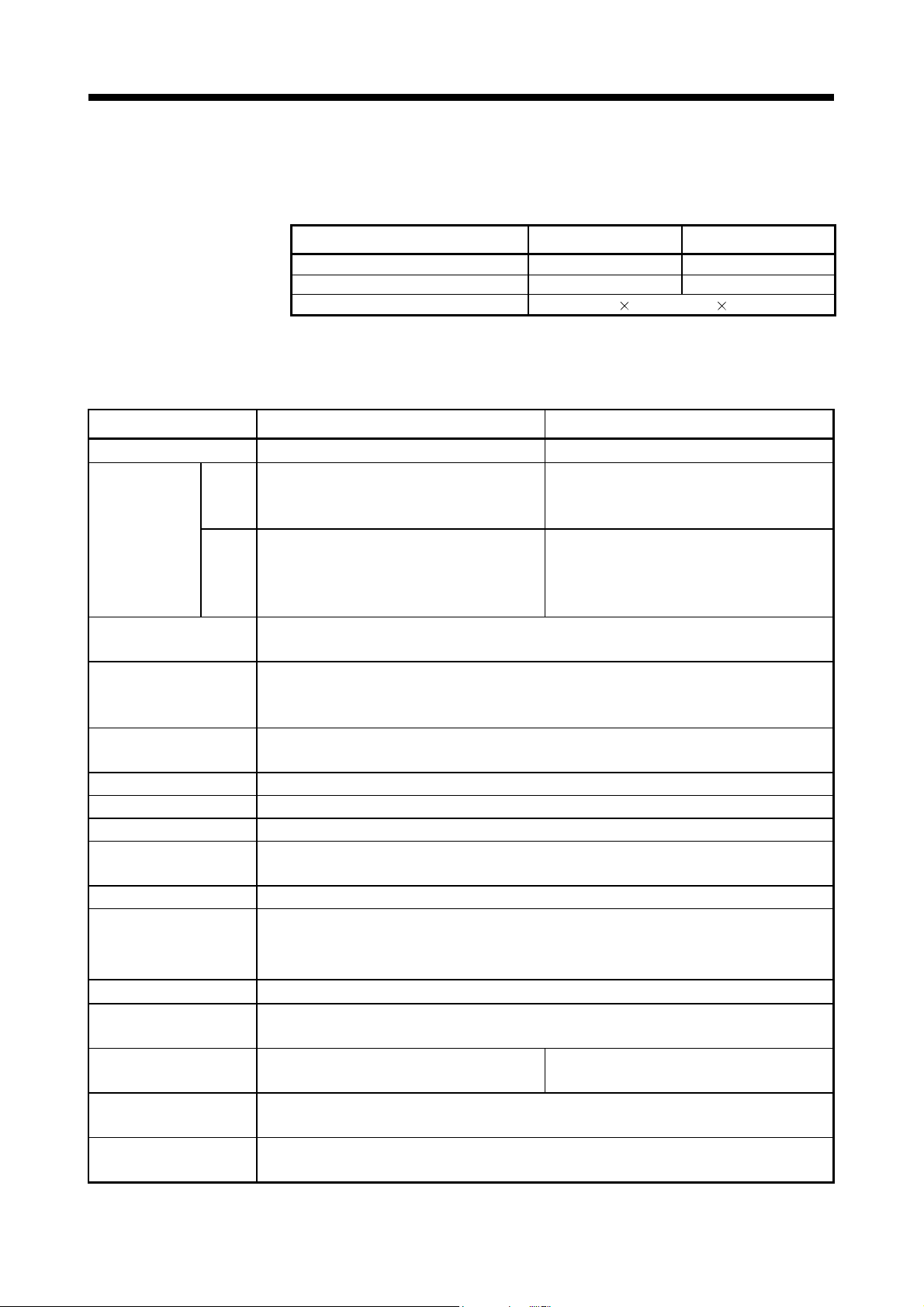
Table 2.2 Access range to non-controlled module
I/O setting outside of the group
Access target
Disabled (Not checked) Enabled (Checked)
Input (X)
Output (Y)
Buffer
memory
Read
Write
(Set by PLC CPU)
: Accessible : Inaccessible
REMARK
• The function version of an intelligent function module can be checked on the rated
plate of the intelligent function module or in the GX Developer's system monitor
product information list.
• Refer to the "Q173DCPU/Q172DCPU User's Manual" for the model name which
can be controlled by the Motion CPU.
2 - 3
Page 41

2 MULTIPLE CPU SYSTEM
2.1.4 Modules subject to installation restrictions
(1) Modules subject to install restrictions for the Motion CPU are sown below. Use
Description Model name
Servo external signals
interface module
Serial absolute synchronous
interface module
Manual pulse generator
interface module
Input module QX
Output module QY
Input/output
composite module
Analogue input module Q6 AD
Analogue output module Q6 DA
Interrupt module QI60 1 module
(Note-1) : When the Manual pulse generator and the serial encoder are used at the same time with the SV22, the
Q173DPX installed in the slot of the smallest number is used for manual pulse generator input.
(Note-2) : SV22 only.
within the restrictions listed below.
Maximum installable modules per CPU
Q173DCPU Q172DCPU
Q172DLX 4 modules 1 module
Q172DEX
(Note-2)
Q173DPX
(Note-1)
QH
QX Y
Q6 AD-
DA-
Q6
(Incremental serial encoder use)
(Manual pulse generator only use)
6 modules 4 modules
4 modules
(Note-2)
1 module
(Incremental serial encoder use)
(Manual pulse generator only use)
Total 256 points
3 modules
1 module
(2) A total of eight base units including one main base unit and seven extension base
units can be used. However, the usable slots (number of modules) are limited to
64 per system including empty slots. If a module is installed in slot 65 or
subsequent slot, an error (SP. UNIT LAY ERROR) will occur. Make sure all
modules are installed in slots 1 to 64. (Even when the total number of slots
provided by the main base unit and extension base units exceeds 65 (such as
when six 12-slot base units are used), an error does not occur as long as the
modules are installed within slots 1 to 64.)
POINT
(1) Q172DLX/Q172DEX/Q173DPX cannot be installed in CPU slot and I/O slot 0
to 2 of the main base unit. Wrong installation might damage the main base
unit.
(2) Q172DEX can be installed in the main base unit only. It cannot be used in the
extension base unit.
(Note-2)
2 - 4
Page 42

2 MULTIPLE CPU SYSTEM
2.1.5 How to reset the Multiple CPU system
The entire Multiple CPU system can be reset by resetting CPU No.1.
The CPU modules of No.2 to No.4, I/O modules and intelligent function modules will be
reset when PLC CPU No.1 is reset.
If a stop error occurs in any of the CPUs on the Multiple CPU system, either reset CPU
No.1 or restart the Multiple CPU system (power supply ON
recovery.
(Recovery is not allowed by resetting the error-stopped CPU modules other than CPU
No.1.)
POINT
(1) It is not possible to reset the CPU modules of No.2 to No.4 individually in the
Multiple CPU system.
If an attempt to reset any of those PLC CPU modules during operation of the
Multiple CPU system, a "MULTI CPU DOWN (error code: 7000)" error will
occur for the other CPUs, and the entire Multiple CPU system will be halted.
However, depending on the timing in which any of PLC CPU modules other
than No.1 has been reset, an error other than the "MULTI CPU DOWN" may
halt the other PLC CPUs/Motion CPUs.
(2) A "MULTI CPU DOWN (error code: 7000)" error will occur regardless of the
operation mode(All stop by stop error of CPU "n"/continue) set at the "Multiple
CPU setting" screen when any of PLC CPU modules of No.2 to No.4 is reset.
(Refer to Section 2.1.6.)
OFF ON) for
2 - 5
Page 43

2 MULTIPLE CPU SYSTEM
2.1.6 Operation for CPU module stop error
The entire system will behaves differently depending whether a stop error occurs in
CPU No.1 or any of CPU No.2 to No.4 in the Multiple CPU system.
(1) When a stop error occurs at CPU No.1
(a) A "MULTI CPU DOWN (error code: 7000)" error occurs at the other CPUs
and the Multiple CPU system will be halted when a stop error occurs at the
PLC CPU No.1.
(b) The following procedure to restore the system is shown below.
1) Confirm the error cause with the PLC diagnostics on GX Developer.
2) Remove the error cause.
3) Either reset the PLC CPU No.1 or restart the power to the Multiple CPU
system (power ON
All CPUs on the entire Multiple CPU system will be reset and the system will
be restored when PLC CPU No. 1 is reset or the Multiple CPU system is
reapplied.
(2) When a stop error occurs at CPU other than No.1
Whether the entire system is halted or not is determined by the Multiple CPU
setting's "Operating Mode" setting when a stop error occurs in a PLC CPU
module/Motion CPU module other than CPU No.1.
The default is set for all CPUs to be stopped with a stop error.
When you do not want to stop all CPUs at occurrence of a stop error in a PLC
CPU module/Motion CPU module, remove the check mark that corresponds to
the CPU No. so that its error will not stop all CPUs. (See arrow A.)
(Note-1)
OFF ON).
A
(a) When a stop error occurs in the CPU module for which "All station stop by
stop error of CPU 'n' " has been set, a "MULTI CPU DOWN (error code:
7000)" error occurs for the other PLC CPU module/Motion CPU modules
(Note-1)
and the Multiple CPU system will be halted.
2 - 6
Page 44

2 MULTIPLE CPU SYSTEM
(b) When a stop error occurs in the CPU module for which " All station stop by
POINT
(Note-1) : When a stop error occurs, a "MULTI CPU DOWN (error code : 7000)"
stop error of CPU 'n' " has not been set, a "MULTI EXE. ERROR (error
code: 7010)" error occurs in all other CPUs but operations will continue.
stop error will occur at the CPU on which the error was detected.
Depending on the timing of error detection, a "MULTI CPU DOWN" error
may be detected in a CPU of "MULTI CPU DOWN" status, not the first
CPU on which a stop error occurs.
Because of this, CPU No. different from the one of initial error CPU may
be stored in the error data's common information category.
To restore the system, remove the error cause on the CPU that is
stopped by an error other than "MULTI CPU DOWN".
In the screen below, the cause of the CPU No.2 error that did not cause
the "MULTI CPU DOWN" error is to be removed.
(c) Observe the following procedures to restore the system.
1) Confirm the error-detected CPU No. and error cause with the PLC
diagnostics on GX Developer.
2) If the error code occurred in Motion CPU 10000 to 10999, confirm the
error cause with Motion CPU error batch monitor of MT Developer.
3) Remove the error cause.
4) Either reset the PLC CPU No.1 or restart the power to the Multiple CPU
system (power ON
All CPUs on the entire Multiple CPU system will be reset and the system will
be restored when PLC CPU No.1 is reset or the power to the Multiple CPU
system is reapplied.
OFF ON).
2 - 7
Page 45

2 MULTIPLE CPU SYSTEM
(3) Operation at a Motion CPU error
Category Type of error Operation Remark
System setting error
WDT error Varies depending on the error.
Operation
disable errors
Operation
continuous
enable errors
Self-diagnosis error Stops at a CPU DOWN error.
Other CPU DOWN error
Self-diagnosis error
Motion SFC error
Minor error
Major error
Servo error
Servo program setting
error
Operations at a Motion CPU error are shown below.
Does not operate from the
beginning (does not run).
Operation corresponding to
STOP (M2000 OFF). Depends on
the "Operation mode upon CPU
stop error" setting.
Operation continues when the
continuous error occurred.
Processing stops for each
program or axis instead of the
Motion CPU stopping all the
processing.
• All actual output PY points turn OFF.
No effect on other CPUs.
• All actual output PY points turn OFF.
Other CPUs may also stop depending on
the parameter setting.
• All actual output PY points turn OFF.
• Only the applicable program stops (the
program may continue depending on the
type of error).
• Actual output PY retains output.
• No effect on other CPUs.
2 - 8
Page 46

2 MULTIPLE CPU SYSTEM
2.2 Starting Up the Multiple CPU System
This section describes a standard procedure to start up the Multiple CPU system.
2.2.1 Startup Flow of the Multiple CPU System
START
Definition of functions with Multiple CPU
system
Control and function executed in each
CPU module are defined.
PLC CPU
Motion CPU
PLC CPU
Application and assignment of device
When automatic refresh of the CPU
shared memory is performed, the
number of refresh points is continuously
obtained.
Selection of module
Select the module to achieve the
function with the Multiple CPU system.
Installation of module
Install the selected module on the main
base unit and extension base unit.
Start-up of GX Developer
Start-up GX Developer
(Ver. 8.48A or later).
Creation of parameters, etc.
Create the parameter such as Multiple
CPU setting and control CPU setting,
and the PLC program.
Connection of PC to the PLC CPU
module of CPU No. 1
Connect the PC that started
GX Developer to the PLC CPU module
of CPU No. 1 with the RS-232 cable/
USB cable.
Refer to Section 2.3
Refer to the "Q173DCPU/Q172DCPU User's
Manual"
Refer to the "Q173DCPU/Q172DCPU User's
Manual"
Refer to the GX Developer Manual.
Create the parameters for CPU No. 1 to 4 and
PLC programs.
Refer to the "QCPU User's Manual" (Function
Explanation/Program Fundamentals)".
PLC CPU
Multiple CPU system power ON
Turn ON the power of Multiple CPU
system in the following state of PLC
CPU module of CPU No.1.
RUN/STOP/RESET switch : STOP
Write of parameter and program
Write parameter and PLC program in
the PLC CPU of CPU No. 1.
For PLC CPU other than CPU No. 1,
select the applicable PLC CPU by
specifying the connection.
1)
2 - 9
Page 47

g sy
2 MULTIPLE CPU SYSTEM
1)
Start-up of MT Developer Refer to the help for operation of MT Developer.
Start-up MT Developer.
Motion CPU
PLC CPU
Motion CPU
PLC CPU
Creation of system settings and
program, etc.
Create the system settings, servo data
and Motion SFC program.
Write to the Motion CPU
Write the system settings, servo data
and Motion SFC program.
Switch setting for all CPUs
Set RUN/STOP/RESET switch of PLC
CPU modules and RUN/STOP switch of
Motion CPU modules in CPU No.1 to 4
to RUN.
Reset PLC CPU module of CPU No.1
Set RUN/STOP/RESET switch of PLC
CPU module in CPU No.1 to RESET
to reset the entire system.
Status check in all CPU modules
Check if all CPUs of the Multiple CPU
system are RUN status/error by
resetting the CPU module of CPU No. 1.
Refer to Section 3.1 for system settings.
Refer to the Programming Manual of each
operatin
stem software for details of program.
Check and correction of errors
An error is checked with the PC
diagnosis function of GX Developer and
PLC CPU
Motion CPU
Motion CPU error batch monitor of
MT Developer for correction.
Debug of each CPU module
Multiple CPU system is debugged for
each PLC CPU/Motion CPU.
Actual operation
Check in the automatic operation.
END
(Note) : Installation of the operating system software is required to the Motion CPU module before start of
the Multiple CPU system.
Refer to Chapter 5 of the "Q173DCPU/Q172DCPU User's Manual" for installation of the Motion
CPU operating system software.
2 - 10
Page 48

2 MULTIPLE CPU SYSTEM
2.3 Communication between the PLC CPU and the Motion CPU in the Multiple CPU System
2.3.1 CPU shared Memory
(1) Structure of CPU shared memory
The CPU shared memory is memory provided for each CPU module by which
data is written or read between CPU modules of a Multiple CPU system.
The CPU shared memory consists of four areas.
• Self CPU operation information area
• System area
• User setting area
• Multiple CPU high speed transmission area
The CPU shared memory configuration and the availability of the communication
(0H)
to
(1FFH)
(200H)
(7FFH)
(800H)
511
512
to
2047
2048
to
from the self CPU using the CPU shared memory by program are shown below.
CPU shared memory
0
to
to
to
Self CPU operation
information area
System area
User setting area
Self CPU Other CPU
Write Read Write Read
(Note-2) (Note-2)
(Note-1)
(Note-2) (Note-2)
(Note-2)
(FFFH)
(1000H)
(270FH)
(2710H)
(5F0FH)
4095
4096
to
to
9999
10000
to
24335
Multiple CPU high speed
transmission area
to
(Variable size in 0 to
up to
14k[points]: 1k words in unit)
Unusable
Multiple CPU
high speed
bus
: Communication allowed
(Note-3) (Note-3)(Note-3)
: Communication not allowed
REMARK
(Note-1) : Use the MULTW instruction to write to the user setting area of the self
CPU in the Motion CPU.
Use the S. TO instruction to write to the user setting area of the self CPU
in the PLC CPU.
(Note-2) : Use the MULTR instruction to read the shared memory of self CPU and
other CPU in the Motion CPU.
Use the FROM instruction/Multiple CPU area device (U
shared memory of the Motion CPU from the PLC CPU.
(Note-3) : Refer to Section 2.3.2(1) for the access method of Multiple CPU high
speed transmission area.
\G ) to read the
2 - 11
Page 49

2 MULTIPLE CPU SYSTEM
(a) Self CPU operation information area (0H to 1FFH)
1) The following information of self CPU is stored as the Multiple CPU
system
Table 2.3 Table of self CPU operation information areas
CPU shared
memory
address
0H Information availability
1H Diagnostic error Diagnostic error number
2H
3H
4H
5H
6H to 10H Common error information Common error information
11H to 1BH
1CH Empty —
1DH Switch status CPU switch status
1EH Empty —
1FH CPU operation status CPU operation status
Time the diagnostic error
occurred
Error information
identification code
Individual error
information
Name Detail
Information availability
flag
Time the diagnostic error
occurred
Error information
identification code
Individual error
information
2) The self CPU operation information area is refreshed every time the
applicable register has been changed in the main cycle.
3) Other PLC CPU can use FROM instruction to read data from the self
CPU operation information area.
However, because there is a delay in data updating, use the read data
for monitoring purposes only.
(b) System area
The area used by the operating systems (OS) of the PLC CPU/Motion CPU.
(c) User setting area
The area for communication between CPU modules in the Multiple CPU
system by MULTR/MULTW instruction of Motion CPU.
(PLC CPU use FROM/S.TO instruction or Multiple CPU area devices to
communicate between CPU modules.)
Refer to the Programming Manual of operating system software for
MULTR/MULTW instruction.
(Note)
Description
The area to confirm if information is stored in the self CPU's
operation information area (1H to 1FH) or not.
• 0: Information not stored in the self CPU's operation information
area.
• 1: Information stored in the self CPU's operation information
area.
An error No. identified during diagnosis is stored in BIN.
The year and month that the error number was stored in the CPU
shared memory's 1H address is stored with two digits of the BCD
code.
The date and time that the error number was stored in the CPU
shared memory's 1H address is stored with two digits of the BCD
code.
The minutes and seconds that the error number was stored in the
CPU shared memory's 1H address is stored with two digits of the
BCD code.
Stores an identification code to determine what error information
has been stored in the common error information and individual
error information.
The common information corresponding to the error number
identified during diagnosis is stored.
The individual information corresponding to the error num ber
identified during diagnostic is stored.
Cannot be used
Stores the CPU module switch status.
Cannot be used
Stores the CPU module's operation status.
(Note) : Refer to the corresponding special register for details.
Corresponding
special register
—
SD0
SD1
SD2
SD3
SD4
SD5 to SD15
SD16 to SD26
—
SD200
—
SD203
2 - 12
Page 50

y
2 MULTIPLE CPU SYSTEM
(d) Multiple CPU high speed transmission area
CPU No.1
U3E0\G10000
to
U3E0\G
U3E1\G10000
U3E1\G
U3E2\G10000
U3E2\G
U3E3\G10000
U3E3\G
(Note-1)
to
(Note-1)
to
(Note-1)
to
(Note-1)
CPU No.1
Multiple CPU high
speed transmission
area
(Transmission)
CPU No.2
Multiple CPU high
speed transmission
area
(Reception)
CPU No.3
Multiple CPU high
speed transmission
area
(Reception)
CPU No.4
Multiple CPU high
speed transmission
area
(Reception)
(Note-2)
The area corresponding to the Multiple CPU high speed main base unit
DB) and Multiple CPU high speed transmission that uses the drive
(Q3
system controllers including QnUD(H)CPU and Motion CPU.
The image chart of Multiple CPU high speed transmission area is shown
below.
Refer to Section 2.3.2(1) for access to the Multiple CPU high speed
transmission area of self CPU and other CPU.
CPU No.2
CPU No.1
Multiple CPU high
speed transmission
area
(Reception)
CPU No.2
Multiple CPU high
speed transmission
area
(Transmission)
CPU No.3
Multiple CPU high
speed transmission
area
(Reception)
CPU No.4
Multiple CPU high
speed transmission
area
(Reception)
(Note-2)
(Note-1) : The final device is "10000+(A 1024-B-1)".
A : Data transmission size of each CPU (1k words in unit)
B : Size used in the automatic refresh of each CPU.
Refer to Section "2.3.2 Multiple CPU high speed transmission"
for the size setting of A and B.
(Note-2) : Transmission area to write/read in the self CPU.
Reception area from the other CPU can be read only.
It is updated ever
CPU No.3 CPU No.4
CPU No.1
Multiple CPU high
speed transmission
area
(Reception)
CPU No.2
Multiple CPU high
speed transmission
area
(Reception)
CPU No.3
Multiple CPU high
speed transmission
area
(Transmission)
CPU No.4
Multiple CPU high
speed transmission
area
(Reception)
(Note-2)
0.88ms.
CPU No.1
Multiple CPU high
speed transmission
area
(Reception)
CPU No.2
Multiple CPU high
speed transmission
area
(Reception)
CPU No.3
Multiple CPU high
speed transmission
area
(Reception)
CPU No.4
Multiple CPU high
speed transmission
area
(Transmission)
(Note-2)
2 - 13
Page 51

2 MULTIPLE CPU SYSTEM
2.3.2 Multiple CPU high speed transmission
(1) Multiple CPU high speed transmission
Multiple CPU high speed transmission is a function for fixed cycle data
transmission between Multiple CPUs (Multiple CPU high speed transmission
cycle is 0.88ms.).
Secure data transmission is possible without effecting the PLC CPU scan time or
Motion CPU main cycle because the data transmission and execution of PLC
program and Motion SFC program can be executed with parallel processing.
High speed response between multiple CPUs is realized by synchronizing the
Multiple CPU high speed transmission cycle with Motion CPU operation cycle.
The following methods of data transmission exist between Multiple CPUs for
Multiple CPU high speed transmission.
• Multiple CPU area device method
Directly set the Multiple CPU high speed transmission area by Multiple CPU
area device (U
• Automatic refresh method
Refresh the internal devices of each CPU by automatic refresh via "Multiple
CPU high speed transmission area".
CPU No.1 (PLC CPU) CPU No.2 (Motion CPU)
PLC program Motion SFC program
SM400
SM400
MOV W0
MOV W1
U3E0\
G10000
U3E0\
G10010.1
U3E0\
G10100
U3E0\
G10110.5
END
(a) Multiple CPU area device method
CPU shared memory
(User setting area
U3E0\G10000
1)
U3E0\G10010
U3E0\G10100
4)
U3E0\G10110
\G ) in the program.
(Note-1)
)
2)
CPU No.1
transmitting
data
5)
(User setting area
U3E0\G10000
U3E0\G10010
U3E0\G10100
U3E0\G10110
CPU shared memory
transmitting
(Note-1)
CPU No.1
data
)
3)
6)
G0
U3E0\G10010.1
F0
W0=U3E0\G10010
G1
U3E0\G10110.5
F1
W1=U3E0\G10110
Multiple CPU high speed
transmission in 0.88ms cycle
(Note-1)
1), 4) : Write data in the user setting area
3), 6) : Read data from the user setting area
2), 5) : Transmit the contents of user setting area
Note-1: The area composed in the Multiple CPU high speed transmission area.
(Refer to Section "(3) Memory configuration of Multiple CPU high speed transmission area".)
by the instruction that uses the Multiple CPU area device.
(Note-1)
by the instruction that uses the Multiple CPU area device.
(Note-1)
to the other CPU with by Multiple CPU high speed transmission in 0.88ms cycle.
2 - 14
Page 52

2 MULTIPLE CPU SYSTEM
Word device
1) Access to Multiple CPU high speed transmission area
a) Description of Multiple CPU area device
: U \ G
CPU shared memory address (decimal) (10000 to up to 24335)
First I/O number of CPU module
CPU No.
First I/O number
CPU No.1
3E0(H)
CPU No.2
3E1(H)
CPU No.3
3E2(H)
CPU No.4
3E3(H)
Bit device
: U \ G .
Bit specification (0 to F : Hexadecimal)
CPU shared memory address (decimal) (10000 to up to 24335)
First I/O number CPU module
CPU No.
First I/O number
CPU No.1
3E0(H)
CPU No.2
3E1(H)
CPU No.3
3E2(H)
CPU No.4
3E3(H)
(Example)
• Multiple CPU high speed transmission memory address of CPU No. 2:
10002
U3E1\G10002
• Bit 14 of CPU No. 3 Multiple CPU high speed transmission memory
address 10200
U3E2\G10200.E
b) Example of access in the program
<Motion SFC program>
• Store K12345678 to the Multiple CPU high speed transmission
memory 10200,10201 of self CPU (CPU No.2).
U3E1\G10200L = K12345678
• Turn on bit 12 of the Multiple CPU high speed transmission
memory 10301 of self CPU (CPU No.3)
SET U3E2\G10301.C
<Servo program>
• Program which executes the positioning for Axis 1 to position set
in the Multiple CPU high speed transmission memory 10400,
10401 of CPU No.1 at the speed set in the 10402, 10403 of CPU
No.1, and uses bit 1 of CPU No.1 Multiple CPU high speed
POINT
transmission memory 10404 of CPU No.1 as a cancel signal.
ABS-1
Axis 1, U3E0\G10400
Speed U3E0\G10402
Cancel U3E0\G10404.1
This method can be used to access only the Multiple CPU high speed transmission
area of CPU shared memory. It cannot be used to access the CPU shared memory
(0 to 4095).
2 - 15
Page 53

2 MULTIPLE CPU SYSTEM
CPU No.1 (PLC CPU)
PLC program
SM400
SM400
INC
INC
D0
Y0
D1
Y0
END
(b) Example of using automatic refresh method
Device memory
D0
Parameter
CPU No.1 to CPU No.2
1) Transmit the content of D0 to the automatic refresh area
2) Transmit the content of automatic refresh area
3) Read the content of automatic refresh area
.
Note-1: The area composed in the Multiple CPU high speed transmission area.
(Refer to Section "(3) Memory configuration of Multiple CPU high speed transmission area".)
(2) System configuration
Multiple CPU high speed transmission can be used only between CPU modules
for the Multiple CPU high speed transmission installed in the Multiple CPU high
speed main base unit (Q3
The system configuration specification is shown in Table 2.4.
Table 2.4 System configuration to use Multiple CPU high speed
(Automatic refresh area
1)
Refresh at the
timing of END
processing
Transmit D0
transmission
CPU shared memory
CPU No.1
transmitting
data
Multiple CPU high speed
transmission in 0.88ms cycle
(Note-1)
to the other CPU by Multiple CPU high speed transmission at 0.88ms cycle.
(Note-1)
at the time of Motion CPU main cycle and transmit it to D2000 by parameter setting.
DB).
CPU No.2 (Motion CPU)
(Note-1)
)
(Note-1)
at the time of END processing by parameter setting.
CPU shared memory
(Automatic refresh area
2)
CPU No.1
transmitting
data
(Note-1)
Refresh at the
timing of Motion
CPU main cycle
)
Device memory
3)
D2000
Parameter
CPU No.1 to CPU No.2
Receive D2000
Object Restrictions
Base unit Multiple CPU high speed main base unit (Q3 DB) is used.
QnUD(H)CPU is used for CPU No. 1.
CPU module
Q173DCPU/Q172DCPU and QnUD(H)CPU are used for CPU No. 2 to
CPU No. 4
"MULTI EXE. ERROR (error code: 7011) will occur if the power supply of Multiple
CPU system is turned on without matching the system configuration shown in
Table 2.4.
2 - 16
Page 54

2 MULTIPLE CPU SYSTEM
(3) Memory configuration of Multiple CPU high speed transmission
area
Memory configuration of Multiple CPU high speed transmission area is shown
below.
1)
Multiple CPU high speed
transmission area
[Variable in 0 to
14k[points]
2)
CPU No.1 send area
3)
(Note-1)
]
(Note-1): Multiple CPU high speed transmission area;
14k[points]: Maximum value when constituted with two CPUs
13k[points]: Maximum value when constituted with three CPUs
12k[points]: Maximum value when constituted with four CPUs
CPU No.2 send area
4)
CPU No.3 send area
5)
CPU No.4 send area
Table 2.5 Description of area
6)
User setting area
7)
Automatic refresh area
No. Name Description
• Area for data transmission between each CPU module
Multiple CPU high speed
1)
transmission area
in the Multiple CPU system.
• The area up to 14k [points] is divided between each
CPU module that constitutes the Multiple CPU system.
2)
3)
4)
5)
CPU No. n send area
(n=1 to 4)
• Area to store the send data of the each CPU module.
• Sends the data stored in the send area of self CPU to
the other CPUs.
• Other CPU send area stores the data received from
the other CPUs.
• Area for data communication with other CPUs using
the Multiple CPU area device.
6) User setting area
• Can be accessed by the user program using the
Multiple CPU area device.
• Refer to Section 2.3.2 (1) for details of this area.
• Area for communicating device data with other CPUs
by the communication using the automatic refresh.
• Access by user program is disabled.
• Refer to Section "(4)(b) Automatic refresh setting" for
7)
Automatic refresh
area
details of this area.
Size
Setting range Setting unit
0 to 14k 1k
0 to 14k 1k
0 to 14k 2
0 to 14k 2
2 - 17
Page 55

2 MULTIPLE CPU SYSTEM
(4) Parameter setting
The parameter setting list for use with the Multiple CPU high speed transmission
is shown in Table 2.6.
Table 2.6 Multiple CPU high speed transmission parameter list
Name Description Target CPU
Multiple CPU high
speed transmission
area setting
Automatic refresh
setting
(a) Multiple CPU high speed transmission area setting
Set the size of the Multiple CPU high speed
transmission area allocated in each CPU module
which composes the Multiple CPU system.
Set the range to execute the data transmission by
the automatic refresh function among the user area
in the Multiple CPU high speed transmission area.
All CPUs
Multiple CPU high speed transmission area setting screen and setting range
are shown below.
2 - 18
Page 56

2 MULTIPLE CPU SYSTEM
Table 2.7 Parameter setting items of Multiple CPU high speed transmission area setting
Item Setting description Setting/display value Restriction
CPU CPU No. corresponding to displayed parameters. CPU No.1 to No.4 — —
Set the number of points of data that each CPU
module sends.
CPU specific
send range
Automatic
refresh
User setting
area
Default value assigned to each CPU is shown
below.
Number of
CPUs
2 7k 7k — —
3 7k 3k 3k —
4 3k 3k 3k 3k
Number of points used in the automatic refresh
function is displayed.
Number of points that is set by the "automatic
refresh setting" is displayed.
Area size specified directly by program is
displayed.
The value where the "number of points set in the
automatic refresh" is subtracted from the "CPU
specific send range setting" is displayed.
Default value of CPU specific
send range [points]
CPU
CPU
CPU
CPU
No.1
No.2
No.3
No.4
Range: 0 to 14k [points]
Unit: 1k [point]
(Points: Word in units)
Range: 0 to 14336 [points]
Unit: 2 [points]
Range: 0 to 14336 [points]
Unit: 2 [points]
• Set the total of all CPUs to be
the following points or lower.
When constituted with two
CPUs: 14k [points]
When constituted with three
CPUs: 13k [points]
When constituted with four
CPUs: 12k [points]
Do not exceed the CPU
specific send range [points].
— —
Consistency
check
Provided
—
2 - 19
Page 57

2 MULTIPLE CPU SYSTEM
POINT
Selecting "Advanced setting" enables the ability to change the number of points
from 1k to 2k in the system area used for Motion dedicated PLC instructions.
Changing the number of points in the system area to 2k increases the number of
Motion dedicated PLC instructions that can be executed concurrently in a scan.
The screen where "Advanced setting" is selected is shown below.
Refer to the "Q173DCPU/Q172DCPU Motion controller (SV13/SV22) Programming
Manual (Motion SFC) " for the Motion dedicated PLC instruction.
Item Setting description
CPU specific
send range
System area
Total
Set the number of points of data
that each CPU module sends.
Set the number of points for a
system area to be assigned for
each CPU module.
(Default value of system area
size is 1k [point].)
Display the total of number of
points of the self CPU send area
and the system area that are
assigned to the each CPU
module.
Setting/display value
(Points: Word in units)
Range: 0 to 14k [points]
Unit: 1k [points]
Range: 1k/2k [points] — Provided
Range: 1 to 16k [points]
Unit: 1k [points]
Restriction
• Set the total of all CPUs to
be the following points or
lower.
When constituted with two
CPUs: 14k [points]
When constituted with
three CPUs: 13k [points]
When constituted with four
CPUs: 12k [points]
Set the total of all CPUs to
16.0k points or lower.
Data size
consistency
check
Provided
—
2 - 20
Page 58

2 MULTIPLE CPU SYSTEM
(b) Automatic refresh setting
Setting for use of the automatic refresh function in the Multiple CPU high
speed transmission area.
Up to 32 setting ranges can be set for each CPU module.
Automatic refresh setting screen and setting range are shown below.
Table 2.8 Parameter setting items of automatic refresh setting
Item Setting description Setting range Restriction
CPU
selection
Setting No.
Points
Start
Select the CPU module for editing of the
CPU specific send range setting.
The setting No. for transmission of each
CPU module is displayed. Automatic
refresh is executed between devices set to
the same setting No. for all CPUs that
constitute the Multiple CPU system.
Set the number of points for data
communication.
Specifies the device which performs the
data communication (automatic refresh).
Specifies the device sent by the self CPU
when the "Send source CPU selection" is
the self CPU, and specifies the device
received by the self CPU when the CPU
specific send range setting is the other
CPU.
CPU No.1 to No.4
1 to 32 — —
Range: 2 to 14336 [points]
Unit: 2 [points]
Usable device ( X, Y, M, B,
D, W, #, SM, SD)
Note) Set "blank" when
automatic refresh is
not executed.
• CPU No. which exceeds the
number of CPU modules cannot
be selected.
• Setting which exceeds the
number of points of the self CPU
send area allocated to the each
CPU module (CPU specific send
range) cannot be set.
• Bit device can be specified in
units of 32 points (2 words) only.
• Bit device can be specified in
units of 16 points (1 word) only.
• Device number cannot be
duplicated.
Data size
consistency
check
—
Provided
None
2 - 21
Page 59

2 MULTIPLE CPU SYSTEM
POINT
The processing performance of automatic refresh improves when devices are
transmitted in 2 word sets. Therefore, it is recommended to set the start device as 2
word unit by inputting an even device number.
• CPU No.1 (PLC CPU) (GX Developer)
Set the device transmitted to CPU No.2.
1) Operation example of automatic refresh
a) Parameter setting
The example of setting automatic refresh is shown below.
• CPU No.2 (Motion CPU) (MT Developer)
Set the device received from CPU No.1.
Set the device received from CPU No.2.
Set the device transmitted to CPU No.1.
(Note) : The operation example of automatic refresh is shown on the next page.
2 - 22
Page 60

2 MULTIPLE CPU SYSTEM
POINT
Set the following operation for automatic refresh setting using GX Developer.
1) Select tab "Multiple CPU high speed communication area setting".
2) Set "Use Multiple CPU high speed communication ".
1)
2)
M0
M2399
M2400
M3039
M3040
M3199
M3200
M3839
M3840
D0
D639
D640
Internal relay
Data register
b) Operation example
The example of operating automatic refresh is shown below.
PLC CPU (CPU No.1) Motion CPU (CPU No.2)
Multiple CPU high speed
transmission area
U3E0\G10000
CPU No.1
transmitting data
Automatic
U3E1\G10000
s
i
n
g
g
refresh area
CPU No.2
receiving data
Automatic
refresh area
g
n
i
s
s
e
c
o
r
p
E
D
N
N
E
D
p
r
o
c
e
s
n
i
s
s
e
c
o
r
p
D
N
E
Transfer
in 0.88ms
cycle
Transfer
in 0.88ms
cycle
Multiple CPU high speed
transmission area
U3E0\G10000
CPU No.1
receiving data
Automatic
refresh area
U3E1\G10000
CPU No.2
transmitting data
Automatic
refresh area
M
a
i
n
c
y
c
l
e
e
l
c
y
c
n
i
a
M
M
a
i
n
c
y
c
l
e
Internal relay
M0
M2399
M2400
M3039
M3040
M3199
M3200
Axis command
M3839
M3840
M8191
Data register
D0
Axis monitor
D639
D640
Control change
D703
D704
Axis status
signal
device
register
D8191
(c) Data size consistency check
Whether the Multiple CPU setting parameters are the same for all CPUs or
not is automatically checked. A "PARAMETER ERROR (error code: 3012,
3015) " will occur if they do not match.
2 - 23
Page 61

2 MULTIPLE CPU SYSTEM
(5) Precautions
(a) Assurance of data sent between CPUs
Due to the timing of data sent from the self CPU and automatic refresh in
any of the other CPUs, old data and new data may become mixed (data
separation).
The following shows the methods for avoiding data separation at
communications by automatic refresh.
1) Data consistency for 32 bit data
Transfer data with automatic refresh method is in units of 32 bits. Since
automatic refresh is set in units of 32 bits, 32-bit data does not separate.
• For word data
2 words data can be prevented from separating by using an even
number to set the first number of each device in automatic refresh
setting.
2) Data consistency for data exceeding 32 bits
In automatic refresh method, data is read in descending order of the
setting number in automatic refresh setting parameter.
Transfer data separation can be avoided by using a transfer number
lower than the transfer data as an interlock device.
2 - 24
Page 62

2 MULTIPLE CPU SYSTEM
2.3.3 Multiple CPU high speed refresh function
This function is used to update the data between internal devices of Motion CPU and
the Multiple CPU high speed transmission area. This occurs every operation cycle as
Classification Item Description Setting/display value Restriction
Setting No.
Display
CPU
Device
setting
User setting
Points
Refresh cycle Operation cycle (fixed) — —
defined in the device setting of automatic refresh in the self CPU.
Setting No. which executes high speed
refresh is displayed.
CPU No. set in the automatic refresh setting
is automatically displayed by setting devices.
Self CPU : Refresh from the internal device
of Motion CPU to Multiple CPU
high speed transmission area.
Other CPU : Refresh form the Multiple CPU
high speed transmission area to
internal device of Motion CPU.
Set the device No. of Motion CPU to execute
the high speed refreshes.
Set the number of points to refresh data of
each data in word unit.
(Note) Refresh is not executed when not set.
1 to 128
(Up to 128)
CPU No. 1 to No.4
Usable device : D, W, #,
SD, M, X, Y, B, SM
Range: 2 to 256 [points]
Unit: 2 points
(Note-1)
• The start device number must be a
multiple of 16 for the bit device.
• Do not set a device not setting also
set in the automatic refresh.
• No. of "start device + number of
points" cannot exceed setting
range of each setting No. in
automatic refresh setting.
• Do not overlap the device No.
between setting No..
• Sets the total of all CPUs to 256
points or lower.
(Note-1) : Point in word unit.
(1) Application example of Multiple CPU high speed refresh function
Multiple CPU high speed refresh function is used as in the following applications.
1) Read the data such as the real current value and synchronous encoder
current value with PLC CPU at high speed.
2) Exchange the FIN waiting signal at high speed.
2 - 25
Page 63

2 MULTIPLE CPU SYSTEM
(2) Operation example of Multiple CPU high speed refresh function
(a) Parameter setting
• CPU No.1 (PLC CPU) (GX Developer)
Set the device transmitted to CPU No.2.
The automatic refresh setting of Multiple CPU high speed refresh is shown
below.
• CPU No.2 (Motion CPU) (MT Developer)
Set the device received from CPU No.1.
Set the device received from CPU No.2.
Set the device transmitted to CPU No.1.
Set the device to executed the Multiple CPU high speed refresh.
(Note) : The operating example of Multiple CPU high speed refresh function is shown
in "(b) Operation example".
2 - 26
Page 64

2 MULTIPLE CPU SYSTEM
POINT
Set the following operation for automatic refresh setting using GX Developer.
1) Select tab "Multiple CPU high speed communication area setting".
2) Set "Use Multiple CPU high speed communication ".
1)
2)
2 - 27
Page 65

2 MULTIPLE CPU SYSTEM
(b) Operation example
Internal relay
M0
M2399
M2400
M3039
M3040
M3199
M3200
M3839
M3840
PLC CPU (CPU No.1)
g
n
i
s
s
e
c
o
r
p
E
D
N
N
E
D
p
r
o
c
e
ssi
n
g
Multiple CPU high speed
U3E0\G10000
U3E1\G10000
The example of operating Multiple CPU high speed refresh function is
shown below.
Motion CPU (CPU No.2)
transmission area
CPU No.1
transmitting data
Automatic
refresh area
CPU No.2
receiving data
Transfer
in 0.88ms
cycle
Multiple CPU high speed
transmission area
U3E0\G10000
CPU No.1
receiving data
Automatic
refresh area
U3E1\G10000
CPU No.2
transmitting data
Internal relay
M0
M2399
M2400
O
p
e
r
a
t
i
o
n
c
y
c
l
e
M
a
i
n
n
c
y
o
i
c
t
l
e
a
r
e
l
e
c
p
y
c
O
e
l
c
y
c
n
i
a
M
M2495
M2496
M3039
M3040
M3199
M3200
M3295
M3296
M3839
M3840
status
Axis command
Axis
signal
O
p
e
r
Data register Data register
D0
D639
D640
Automatic
refresh area
g
n
i
s
s
e
c
o
r
p
D
N
E
Transfer
in 0.88ms
cycle
Automatic
refresh area
a
t
i
o
n
c
O
p
e
r
a
t
i
o
n
c
O
p
e
r
a
t
i
o
n
c
M
a
i
n
c
y
O
p
e
r
a
t
i
o
n
c
M8191
y
c
l
e
D0
D2,D3
D12,D13
D19
y
c
l
D20
e
D22,D23
D32,D33
D39
y
c
l
D40
e
D42,D43
D52,D53
c
l
e
D59
y
c
l
e
D60
D62,D63
D72, D73
D79
D80
D639
D640
D703
D704
D8191
• Axis 1 to 4 status information (M2400 to M2495) is transferred to the
automatic refresh area one every operation cycle of the Motion CPU.
• Axis 1 to axis 4 command signals are received from the automatic refresh
area one every operation cycle of the Motion CPU.
• Real current values of Axis 1 to axis 4 and M-code is updated by setting
D0 to D639 of the Motion CPU to the automatic refresh area.
• Every 0.88ms, data in the automatic refresh area of all CPUs are
transferred allowing each CPU to update its data upon its next
independent operation cycle.
1 axis monitor
device
2 axis monitor
device
3 axis monitor
device
4 axis monitor
device
5 to 32 axis
monitor
device
Control change
register
2 - 28
Page 66

2 MULTIPLE CPU SYSTEM
2.3.4 Clock synchronization between Multiple CPU
The clock of each CPU is synchronized with the clock of CPU No. 1.
The clock data used for synchronization in a Multiple CPU system can be edited.
(1) Setting of clock data
Set the clock of CPU No.1. The Motion CPU module operates automatically by
the clock of CPU No.1.
POINT
The clock data of CPU No.1 is automatically set even if the clocks of CPU No. 2 to
4 are set independently.
(2) Synchronization of clock data
All clocks are synchronized with CPU No.1 immediately after turning
ON/resetting power and every 1-second interval thereafter.
(3) Information of clock
The clock data that CPU No. 1 transmits is year, month, day, day of week, hour,
minute and second.
(4) Error
Since CPU No.1 sets the clock data at 1-second intervals, an error of up to 1
second may occur to the clock of CPU No.2 to 4.
2 - 29
Page 67

2 MULTIPLE CPU SYSTEM
2.3.5 Multiple CPU synchronous startup
Multiple CPU synchronous startup function synchronizes the startups of CPU No.1 to
CPU No.4. (It takes about ten seconds to startup for Motion CPU.)
Since this function monitors the startup of each CPU module, when other CPU is
accessed by a user program, an interlock program which checks the CPU module
startup is unnecessary.
With the Multiple CPU synchronous startup function, the startup is synchronized with
the slowest CPU module to startup; therefore, the system startup may be slow.
POINT
Multiple CPU synchronous startup function is for accessing each CPU module in a
Multiple CPU system without needing an interlock.
This function is not for starting an operation simultaneously among CPU modules
after startup.
(1) Multiple CPU synchronous startup setting
To use the Multiple CPU synchronous startup function, check No.1 to No.4 of
target CPU in Multiple CPU settings in system setting of MT Developer. (Set it in
the Multiple CPU setting of PLC parameter setting of GX Developer for
QnUD(H)CPU.)
"Set Sync. startup setting of CPU
" is set for No.1 to 4 at default.
Set the same Multiple CPU synchronous startup for all CPUs that constitute the
Multiple CPU system.
The self-diagnosis error "PARAMETER ERROR (error code: 3015)" will occur if
all CPU modules that constitute the Multiple CPU system do not have the same
setting.
When this function is not used (each CPU startup without synchronization),
startup of each CPU module can be confirmed by using special relays SM220 to
SM223 (CPU No.1 to 4 READY complete flag).
2 - 30
Page 68

2 MULTIPLE CPU SYSTEM
2.3.6 Control Instruction from PLC CPU to Motion CPU
Control can be instructed from the PLC CPU to the Motion CPU using the Motion
dedicated PLC instructions listed in the table below.
Refer to the "Q173DCPU/Q172DCPU Motion controller (SV13/SV22) Programming
Manual (Motion SFC)" for the details of each instruction.
(Control may not be instructed from one Motion CPU to another Motion CPU.)
Instruction name Description
D(P).SFCS Start request of the Motion SFC program (Program No. may be specified.)
D(P).SVST Start request of the specified servo program
D(P).CHGA Current value change request of the specified axis
D(P).CHGV Speed change request of the specified axis
D(P).CHGT Torque control value change request of the specified axis
D(P).GINT Execute request of an event task to the other CPU (Motion CPU)
D(P).DDWR
D(P).DDRD
Write device data of the self CPU (PLC CPU) to the device of other CPU
(Motion CPU)
Read device data of other CPU (Motion CPU) to the device of self CPU
(PLC CPU)
For example, by using the D(P).SFCS instruction of Motion dedicated PLC instruction,
the Motion SFC of the Motion CPU can be started from the PLC CPU.
<Example>
PLC CPU Motion CPU
Start request
Motion SFC
D(P). SFCS instruction
2 - 31
Page 69

2 MULTIPLE CPU SYSTEM
MEMO
2 - 32
Page 70

3 COMMON PARAMETERS
3. COMMON PARAMETERS
3.1 System Settings
In the Multiple CPU system, the common system parameters and individual
parameters are set for each CPU and written to each CPU.
(1) The base settings, Multiple CPU settings and Motion slot settings are set in the
common system parameter setting.
(2) The system basic setting, self CPU installation position setting, servo
amplifier setting, high-speed read setting and optional data monitor setting are set
in the individual parameter setting.
(3) The data setting and correction can be performed in dialog form using MT
Developer.
3
3 - 1
Page 71

3 COMMON PARAMETERS
3.1.1 System data settings
Item Setting range Initial value Remark
Base setting
Common
system
parameters
Individual
parameters
Multiple CPU
setting
Motion slot
setting
System basic
setting
Self CPU installation position setting
The table below lists the system data items to be set.
Main base 8/12 slots Main base: 8 slots
Extension base None/2/3/5/8/10/12 slots None
No. of CPU 2/3/4 modules 2 modules
Error operation mode at the
stop of CPU
CPU
specific
Multiple CPU
high speed
transmission
area setting
Multiple CPU synchronous
startup setting
Module arrangement
Individual module Varies depending on the module.
Operation cycle
Operation at STOP to RUN
Forced stop
Latch range
send range
System
area
Automatic
refresh
setting
(Note-1)
Stop/do not stop all CPUs upon an
error in CPU No. 1 to 4.
(The setting range varies depending
on the number of Multiple CPUs.)
0 to 14k points
1 to 2k points 1
Point : 2 to 14336 points
Start : Set target device for
automatic refresh.
Set/do not set CPU No. 1 to 4 as the
synchronized startup.
(The setting range varies depending
on the number of Multiple CPUs.)
Within the main base and extension
base slots
0.4ms/0.8ms/1.7ms/3.5ms/7.1 ms/
14.2ms/Auto
M2000 is turned on by switching
from STOP to RUN./M2000 is
turned on by switching from STOP
to RUN and setting 1 in the set
register.
None/X(PX) (0 to 1FFF)/
M (0 to 8191)
M (0 to 8191)/B (0 to 1FFF)/
F (0 to 2047)/D (0 to 8191)/
W (0 to 1FFF)
Set self CPU/other CPU/CPU
(empty) for slots 0/1/2. (The setting
range varies depending on the
number of Multiple CPUs installed.)
Stop all CPUs upon error
in CPU Nos. 1 to 4
Varies depending on the
number of CPUs.
None
Set CPU No. 1 to 4 as
the synchronized startup.
None
Varies depending on the
module.
Auto
M2000 is turned on by
switching from STOP to
RUN.
None
None
None
Set the number of slots in the main
base or extension base.
Set the total number of Multiple
CPUs including PLC CPU(s).
Set whether or not to stop the entire
system when a CPU stop error
occurs in each CPU.
Refer to Section 2.3.2.
Refer to Section 2.3.5.
Install the modules controlled by the
self CPU in the main base and/or
extension base(s).
Set detailed items for each module
controlled by the self CPU.
Set the operation cycle of motion
control.
Set the condition in which the PLC
ready flag (M2000) turns on.
Set the bit device to use forced stop
in the program.
However, the forced stop input by
EMI terminal of Motion CPU module
cannot be invalidated using
parameter setting.
Set the latch range of device
memory.
Set the installation position of the
self CPU in the main base.
3 - 2
Page 72

3 COMMON PARAMETERS
Item Setting range Initial value Remark
Individual
parameters
Amplifier setting
High-speed data read setting
Optional data monitor setting
(Note-1) : The forced stop can also be executed by the EMI forced stop terminal of Motion CPU module or forced stop terminal of
servo amplifier besides the forced stop input setting.
Q173DCPU: Up to 2 systems, 32
axes
Q172DCPU: Up to 1 system, 8 axes
External signal input setting
Amplifier input invalid/Amplifier input
valid
Input filter setting
None/0.8ms/1.7ms/2.6ms/3.5ms
One Q172DEX/Q173DPX module
and one input module.
Set 1 to 3 for each axis.
Q173DCPU: Up to 32 axes
Q172DCPU: Up to 8 axes
None
Amplifier input invalid
3.5ms
None
None
Set the model name, axis No. and
other details for the servo amplifiers.
—
Set the high-speed read data.
Refer to Section 4.3.
Set the optional data monitor.
Refer to Section 4.10.
3 - 3
Page 73

3 COMMON PARAMETERS
3.1.2 Common system parameters
(1) Parameters for operating the Multiple CPU system
In the Multiple CPU system, the common system parameters and individual
parameter for each CPU are set and written into each CPU. Regarding the
Motion CPU, the items in System Settings related to the entire Multiple CPU
system must be identical to the parameter settings in the PLC CPU.
PLC CPU
parameters
PLC CPU
parameters
Motion CPU
parameters
Motion CPU
parameters
Common system
parameters
Individual
parameter
Common system
parameters
Individual
parameter
QnUD(H)
CPU
Power supply
QnUD(H)
CPU
Common system
parameters
Individual
parameter
Q173D
CPU
Q172D
CPU
Common system
parameters
Individual
parameter
Parameter write
3 - 4
Page 74

3 COMMON PARAMETERS
(2) Parameters common throughout the Multiple CPU system
In the Motion CPU, during initialization the parameters in the table below are
verified against the parameters in the PLC CPU of CPU No. 1. Unmatched
parameters generate a PARAMETER ERROR (error code: 3012, 3015), so the
parameters show below must be set identically between Motion CPUs and the
PLC CPU of CPU No.1. (If the system settings are changed in a Motion CPU, it is
necessary to reset. Therefore, the parameters are checked only during
initialization.)
The parameter No. of unmatched parameter is set in the error individual
information (SD16) by this error occurrence.
PLC CPUs can use the parameters of the other CPUs via "Multiple CPU
parameter utilization" of GX Developer. Since Motion CPUs don't have this
function, however, the common parameters must be set for each Motion CPU.
Table of Parameters cross-Multiple CPU system
Type of param eter
Name in Motion CPU Name in PLC CPU
No. of CPU No. of PLC Number of CPUs 0E00H
Operating mode Operating mode
CPU specific
send range
Multiple
CPU setting
Multiple CPU
high speed
transmission
area setting
Multiple CPU synchronous
startup setting
System area System area System area size E008H
Automatic
refresh setting
Multiple
CPU
settings
CPU specific
send range
Multiple CPU
high speed
transmission
area setting
Automatic
refresh setting
Multiple CPU synchronous
startup setting
Verification item
Operation mode for CPU
stop error
Points of CPU specific
send range
Points of automatic
refresh
Synchronize Multiple CPU
startup or not
Parameter
number
0E01H
E008H Refer to Section 2.3.2.
E009H
E00BH Refer to Section 2.3.5.
Remark
Refer to Section 2.3.2.
This parameter can be
set when "Advanced
setting" is selected.
Refer to Section 2.3.2.
(Automatic refresh using
Multiple CPU high speed
transmission area)
Motion slot setting Detailed settings Control PLC Control CPU No. 0406H
I/O
Base setting
assignment
Basic setting Slots
Total number of bases
Base No.
Base
Number of base
slots
0401H
3 - 5
Verify module only set in
the system settings in the
Motion CPU side.
Not verified if base
settings are omitted in
the PLC CPU side.
Page 75

3 COMMON PARAMETERS
(a) Multiple CPU settings
Set the following items identically in Multiple CPU Settings (Motion CPU) in
MT Developer and in Multiple CPU Settings (PLC CPU) in GX Developer.
• Number of CPU modules (Included CPU empty slots)
• Operation mode when a CPU stop error occurred
• Multiple CPU high speed transmission area setting (Must be set the same
for all CPUs)
• Multiple CPU synchronous startup setting
Multiple CPU Settings (Motion CPU) in MT Developer
Number of CPU
modules
Error operation mode
at the stop of CPU
Multiple CPU high
speed transmission
area setting
Multiple PLC Setting (PLC CPU setting) in GX Developer
Multiple CPU
synchronous startup
setting
Select tab "Multiple
CPU high speed
communication area
setting"
Set "Use multiple
CPU high speed
communication".
3 - 6
Page 76

3 COMMON PARAMETERS
(b) Motion slot settings
Set the modules controlled by the self CPU by the Motion Slot Settings
(Motion CPU) in MT Developer. In GX Developer, set the slot for Motion
CPU control as the CPU number of Motion CPU in I/O Assignment Settings
(PLC CPU).
Motion Slot Setting (Motion CPU) in MT Developer
Control CPU No.
I/O Assignment Setting (PLC CPU setting) in GX Developer
(Note): Motion slot setting items are different depending on the operating system software.
3 - 7
Page 77

3 COMMON PARAMETERS
(c) Base settings
Set the total number of bases and number of slots in each base identically
between Base Settings (Motion CPU) in MT Developer and I/O Assignment
Settings (PLC CPU) in GX Developer. In GX Developer, the detailed
settings may be omitted by setting the base mode "Automatic".
Base Settings (Motion CPU) in MT Developer
Total number of bases
and number of slots in
each base
I/O Assignment Settings (PLC CPU setting) in GX Developer
(Note) : Only the Motion CPU
may be set without
setting the PLC CPU.
3 - 8
Page 78

3 COMMON PARAMETERS
POINT
GOT is recognized as an intelligent function modules "16 points 10 slots" on the
base (number of extension bases and slot No. are set in the GOT parameter.) for
bus connection with GOT.
Set the one extension base (16 points
"10 slots" as number of extension bases for connection with GOT in the system
setting (base setting).
<Example>
When the "2nd stage" of extension base is set as connection with GOT.
(Set "10" slot as "2nd stage" of extension base in the base setting.)
10 slots) for connection with GOT, then set
3 - 9
Page 79

3 COMMON PARAMETERS
3.1.3 Individual parameters
(1) System basic setting
The following explains each item to be set in system basic setting.
(a) Operation cycle
1) Set the of motion operation cycle (cycles at which a position command is
computed and sent to the servo amplifier).
The setting range is 0.4ms/0.8ms/1.7ms/3.5ms/7.1ms/14.2ms/Automatic
setting. The actual operation cycle corresponding to 0.4ms is 0.444...ms.
Similarly, 0.8ms corresponds to 0.888…ms, 1.7ms to 1.777...ms, 3.5ms
to 3.555...ms, 7.1ms to 7.111...ms, and 14.2ms to 14.222…ms,
respectively.
2) The default value is "Automatic Setting". When "Automatic Setting" is
selected, the operation cycle is set according to the table below based
on the number of axes for servo amplifier set in the System Settings.
Operating system Number of axes Operation cycle setting
1 to 6 axes 0.4 ms
SV13
SV22
7 to 18 axes 0.8 ms
19 to 32 axes 1.7 ms
1 to 4 axes 0.4 ms
5 to 12 axes 0.8 ms
13 to 28 axes 1.7 ms
29 to 32 axes 3.5 ms
3 - 10
Page 80

3 COMMON PARAMETERS
3) If the duration of motion operation has exceeded the operation cycle, the
(b) Operation at STOP to RUN
Set the condition in which the "PLC ready" flag (M2000) turns ON. Select
any one of the followings.
1) M2000 is turned on by switching from STOP to RUN.
2) M2000 is turned on by switching from STOP to RUN and setting 1 in the
(c) Forced stop
Set the bit device used for executing a forced stop in which all servoamplifier axes are stopped immediately in the program.
Either X (PX) or M can be specified. No default value has been set. The set
bit device is designated as contact B and performs the following control in
response to ON/OFF of the device.
• Bit device is turned OFF …Forced stop input is ON (forced stop)
• Bit device is turned ON …..Forced stop input is OFF (forced stop is
operation cycle over flag (M2054) turns ON. Even when "Automatic
setting" is selected, the duration of motion operation may exceed the
operation cycle depending on the control conditions. The actual duration
of motion operation (unit:μs) is stored in SD522, and the current setting
of operation cycle (unit:μs) is stored in SD523. Monitor these special
registers and adjust the set value of operation cycle so that the actual
duration of motion operation will not exceed the set operation cycle. (A
WDT or other error may occur in the Motion CPU.)
Condition in which the M2000 turns from OFF to ON
• Change the RUN/STOP switch from STOP to RUN.
• Turn ON the power supply with the RUN/STOP switch set to RUN.
Condition in which the M2000 turns from ON to OFF
• Change the RUN/STOP switch from RUN to STOP.
set register.
(M2000 turns ON when the switch is set to RUN and 1 is set in the
setting register.)
Condition in which the M2000 turns from OFF to ON
• With the RUN/STOP switch set to RUN, set 1 in the setting register
for "PLC ready" flag (D704). (The Motion CPU detects a change from
0 to 1 in the lowest bit in the D704).
Condition in which the M2000 turns from ON to OFF
• With the RUN/STOP switch set to RUN, set 0 in the setting register
for "PLC ready" flag (D704). (The Motion CPU detects a change from
1 to 0 in the lowest bit in the D704).
• Change the RUN/STOP switch from RUN to STOP.
released.)
The forced stop input by EMI terminal of Motion CPU module cannot be
invalidated using parameter setting.
3 - 11
Page 81

3 COMMON PARAMETERS
(d) Latch range
Set the following latching ranges for M, B, F, D and W, respectively.
• Latch (1) : It is possible clear using the remote operation (Latch clear(1),
• Latch (2) : It is possible clear using the remote operation (Latch clear
(2) Individual module settings
The setting items for each module are shown below.
Latch clear (1)(2)).
(1)(2)).
Setting items for each module
Module name Item Setting range Initial value
Set the number of axes for which
the 8 axes input is used.
Valid on leading edge/
Valid on trailing edge
0.4/0.6/1 ms
(DOG/CHANGE response time)
Used/Unused Unused
Q170ENC/MR-HENC Q170ENC
0.4/0.6/1 ms
(TREN response time)
Used/Unused Unused
Used only Used
Used/Unused
0.4/0.6/1 ms
(TREN response time)
Used/Unused Unused
Q172DLX
Q172DEX
Q173DPX
QI60
Servo external
signals input
module
Synchronous
encoder input
module
Manual pulse
generator input
module
Interrupt
module
External signal setting
DOG
I/O response time
(Operation mode)
Synchronous encoder
setting
Synchronous encoder
selection
I/O response time
(Operation mode)
High-speed data read
setting
Manual pulse generator
setting
(SV13)
Manual pulse generator/
Synchronous encoder
setting
(SV22)
I/O response time
(Operation mode)
High-speed data read
setting
Input response time 0.1/0.2/0.4/0.6/1 ms 0.2 ms 1 1
Unused
Valid on
leading edge
0.4 ms
0.4 ms
P
Used
0.4 ms
Number of usable modules
Q173DCPU Q172DCPU
4 1
6 (SV22) 4 (SV22)
1 (SV13)
4 (SV22)
1 (SV13)
3 (SV22)
3 - 12
Page 82

3 COMMON PARAMETERS
Setting items for each module (Continued)
Module name Item Setting range Initial value
First I/O No. 00 to FF0 (in units of 16 points) 0
Point 0/16/32/64/128/256 16
High-speed data read
QX Input module
QY Output module
Y
Input/Output
composite
module
Analogue input
module
Analogue
output module
QH /
QX
Q6 AD /
Q6
AD-
Q6 DA /
Q6
DA-
setting
I/O response time
(setting for high-speed input
module in parentheses)
First I/O No. 00 to FF0 (in units of 16 points) 0
Point 0/16/32/64/128/256 16
First I/O No. 00 to FF0 (in units of 16 points) 0
Point 0/16/32/64/128/256 16
I/O response time 1/5/10/20/70 ms 10 ms
High-speed data read
setting
First I/O No. 00 to FF0 (in units of 16 points) 0
Input range
Temperature drift
compensation
Resolution mode Normal/High Normal
Operation mode
First I/O No. 00 to FF0 (in units of 16 points) 0
Output range
HOLD/CLEAR function CLEAR only CLEAR
Output mode
Resolution mode Normal/High Normal
Operation mode
Used/Unused Unused
1/5/10/20/70 ms
(0.1/0.2/0.4/0.6/1 ms)
Used/Unused Unused
4 to 20mA/0 to 20mA/1 to 5V/0 to
5V/-10 to 10V/0 to 10V/User range
Used/None Used
Normal (A/D conversion)/Offset
gain setting
4 to 20mA/0 to 20mA/1 to 5V/0 to
5V/-10 to 10V/User range
Normal (Asynchronous)/
Synchronous output
Normal (D/A conversion)/
Offset gain setting
10 ms
(0.2 ms)
4 to 20mA
Normal
(A/D
conversion)
4 to 20mA
Normal
(Asyn-
chronous)
Normal
(D/A
conversion)
Number of usable modules
Q173DCPU Q172DCPU
Total 256
points or less
Total 256
points or less
3 - 13
Page 83

3 COMMON PARAMETERS
(3) External signal input
Servo external signal (Upper stroke limit/Lower stroke limit/Stop signal/Proximity
dog) can be selected for every axis from the following two methods.
(a) Q172DLX Servo external signals interface module use
Set the servo external signals interface module, and set axis No. as the
"External signal setting" in the system setting.
(b) Servo amplifier input device use (MR-J3-B use only)
Set "Amplifier input valid" as the external signal input setting in the "Amplifier
setting" of system setting.
There are following restrictions to use.
• Count type home position return cannot be used.
• Speed/position switching control cannot be executed.
• Stop signal (STOP) cannot be used.
The correspondence of external signal and input device is shown below.
Upper stroke limit (FLS) DI1
Lower stroke limit (RLS) DI2
Proximity dog (DOG) DI3
(Note): Refer to the "MR-J3-B Servo Amplifier Instruction Manual" for pin configurations.
Set the external signal setting in the "Input Filter Setting".
External signals
Input device (CN3)
(Note)
3 - 14
Page 84

3 COMMON PARAMETERS
3.2 I/O number assignment
In the Multiple CPU system, I/O numbers are used for interactive transmission
between the Motion CPU and I/O modules and intelligent function modules, or
between PLC CPU and Motion CPU.
3.2.1 I/O number assignment of each module
The Multiple CPU system is different from the Single CPU system in the position (slot) of
I/O number "0H" for PLC CPU.
However, I/O number of control module can be assigned independently for each CPU for
Motion CPU.
(1) Position of I/O number "0H"
(a) The number of slots set with the Multiple CPU settings are occupied by the
PLC CPU/Motion CPU on the Multiple CPU system.
(b) I/O modules and intelligent function modules are installed from the right of the
slots occupied by PLC CPU/Motion CPU.
(c) I/O number of Motion CPU control module can be assigned independently for
each CPU.
The I/O number of PLC CPU control module for an I/O module or intelligent
function module mounted to the next slot to those occupied by CPU modules
is set as "0H" and consecutive numbers are then allocated sequentially to the
right.
(d) Notation of I/O number
• Receiving of ON/OFF data by Motion CPU is deemed input (PX), while
outputting of ON/OFF data from Motion CPU is deemed output (PY).
• I/O number is expressed in hexadecimal.
REMARK
1) If the number of CPU modules installed on the main base unit is less than the
number set at the "Multiple CPU setting", set the open slot(s) to "PLC (Empty)".
Refer to Section 2.1.2 for the "PLC (Empty)" setting.
2) The I/O numbers for the Multiple CPU system can be confirmed with the system
monitor of GX Developer.
3 - 15
Page 85

3 COMMON PARAMETERS
(2) I/O number assignment of Motion CPU control module
Mitsubishi recommends that I/O No. assignment be set as common consecutive
No. throughout all CPUs.
However, the I/O number of the input modules, output modules and input/output
composite modules controlled with the Motion CPU can also be set regardless as
the I/O number of PLC CPU.
(I/O number of the Motion CPU control modules is indicated as PX/PY.)
I/O number of the Motion CPU control modules cannot be assigned by I/O
assignment settings of PLC CPU.
Power supply
(3) Setting of the Motion CPU control modules by the PLC CPU
Follow the table below when Motion CPU control modules are set in I/O
Assignment Settings of the PLC CPU. (The PLC CPU handles the Q172DLX,
Q172DEX and Q173DPX as intelligent function modules having 32 occupied
points.) Type and number of points may be left unset.
Module name Type Number of points Remarks
Input module Input
Output module Output
Input/Output composite
module
Analogue input module Analogue input
Analogue output module Analogue output
Interrupt module (QI60) Interrupt
Q172DLX 32 points
Q172DEX 32 points
Q173DPX
POINT
(1) Set the I/O device of the Motion CPU within the range from PX/PY000 to
PX/PYFFF. Set the number of real I/O points within 256 points. (I/O No. may
not be consecutive.)
(2) As for the Motion CPU, the Q172DLX, Q172DEX, Q173DPX and QI60 are not
included in the number of real I/O points.
I/O assignment
123450
Q03UD
CPU
module
CPU No. 1 CPU No. 2 CPU No. 2
Q173D
CPU
Composite I/O
QX41
PX0 to PX1F
(X0 to X1F)
control
module
Intelligent
QY41 QX41 QY41
control
X40 to X5F
CPU No. 1
control
module
PY20 to PX3F
(Y20 to Y3F)
CPU No. 2
module
Selected according
to the module.
16 points
32 points
Y60 to Y7F
CPU No. 1
control
module
• For the control CPU,
set the CPU that
corresponds to the
Motion CPU (required).
• Type and number of
points may be left
unset.
3 - 16
Page 86

3 COMMON PARAMETERS
3.2.2 I/O number of each CPU modules
In the Multiple CPU system, I/O numbers are assigned to each CPU module to specify
installed CPU modules.
The I/O number for each CPU module is fixed to the corresponding slot and cannot be
changed.
The I/O number allocated to each CPU module in the Multiple CPU system is shown
below.
CPU module
installation position
First I/O number 3E00H 3E10H 3E20H 3E30H
The I/O number of PLC CPU/Motion CPU are used in the following cases.
• When writing data to the CPU shared memory of self CPU using the S. TO
instruction.
• When reading data from the CPU shared memory of other CPU using the FROM
instruction.
• When reading data from the CPU shared memory of other CPU using an intelligent
function module device (U
• When reading device data directly from the Motion CPU from the PLC CPU using the
"D(P).DDRD" instruction.
• When writing device data directly to the Motion CPU from the PLC CPU using the
"D(P).DDWR" instruction.
Refer to Section 2.3.6 or the "Q173DCPU/Q172DCPU Motion controller (SV13/SV22)
Programming Manual (Motion SFC)" for the Motion dedicated PLC instruction.
CPU slot Slot 0 Slot 1 Slot 2
\G )
3 - 17
Page 87

3 COMMON PARAMETERS
3.2.3 I/O number setting
Set the modules installed in the each slot of the main base or extension base and
assign the control CPU of applicable slot as the self CPU in the system setting for
Motion CPU.
The following modules must be set the I/O No..
• Input module • Output module • Input/Output composite module
• Analogue input module • Analogue output module
Refer to the help of MT Developer for the detailed operating procedure on the system
settings screen.
Set the I/O No. of modules controlled with the Motion CPU module set in the system
structure screen of MT Developer. The setting procedure of I/O No. is shown below.
(Example) For set the output module
<System Structure>
<Motion Slot Settings>
<I/O Module Settings>
1) Double-click the slot position, display
the Motion Slot Settings screen.
2) Select the I/O module.
3) Click [Detail Setting].
4) Set the first I/O No.
(PX No., PY No.).
5) Select applicable module type
and number of points for
the I/O module to be used.
6) Click [OK].
(Note): Display of system setting and motion slot setting are different depending on the operating system
software.
POINT
I/O No.s cannot be assigned automatically, unlike a PLC CPU for which I/O No. are
assigned automatically if such setting is omitted in the Motion CPU. In the Motion
CPU, be sure to set the first I/O No. in System Settings for each module used.
3 - 18
Page 88

3 COMMON PARAMETERS
3.3 Servo Parameters
The servo parameters control the data fixed by the specifications of the servo amplifier
and servomotor controlled in the parameter set for each axis and the control of the
servomotor.
The servo parameters are set by the Setup software (MR Configurator).
Refer to the "Servo amplifier Instruction Manual" for details of the servo parameters.
Refer to the help for handling of MR Configurator.
No. Symbol Name Initial value Unit
PA01 — For manufacturer setting 0000h —
PA02 REG Regenerative brake option 0000h —
PA03 ABS Absolute position detection system 0000h —
PA04 AOP1 Function selection A-1 0000h —
PA05 0
PA06 1
PA07
PA08 ATU Auto tuning mode 0001h —
PA09 RSP Auto tuning response 12 —
PA10 INP In-position range 100 PLS
PA11 1000.0
PA12 1000.0
PA13
PA14 POL Rotation direction selection 0 —
PA15 ENR Encoder output pulse 4000 PLS/rev
PA16 0
PA17 0000h
PA18 0000h
PA19
— For manufacturer setting
— For manufacturer setting
— For manufacturer setting
Instruction Manual list is shown below.
Servo amplifier type Instruction manual name
MR-J3- B MR-J3- B Servo Amplifier Instruction Manual (SH-030051)
MR-J3- B-RJ006
Fully closed loop control MR-J3-
(SH-030056)
B-RJ006 Servo Amplifier Instruction Manual
(1) Basic setting parameters
1
0000h
000Bh
POINTS
(1) When the items marked " " in the above table has changed, make the Multiple
CPU system reset or power supply OFF to ON. And, once turn OFF the servo
amplifier power supply and then turn ON it again.
—
—
—
3 - 19
Page 89

3 COMMON PARAMETERS
No. Symbol Name Initial value Unit
PB01 FILT Adaptive tuning mode (Adaptive filter ) 0000h —
PB02 VRFT Vibration suppression control tuning mode (Advanced vibration suppression control) 0000h —
PB03 — For manufacturer setting 0 —
PB04 FFC Feed forward gain 0 %
PB05 — For manufacturer setting 500 —
PB06 GD2 Ratio of load inertia moment to servomotor inertia moment 7.0 times
PB07 PG1 Model loop gain 24 rad/s
PB08 PG2 Position loop gain 37 rad/s
PB09 VG2 Speed loop gain 823 rad/s
PB10 VIC Speed integral compensation 33.7 ms
PB11 VDC Speed differential compensation 980 —
PB12 — For manufacturer setting 0 —
PB13 NH1 Machine resonance suppression filter 1 4500 Hz
PB14 NHQ1 Notch shape selection 1 0000h —
PB15 NH2 Machine resonance suppression filter 2 4500 Hz
PB16 NHQ2 Notch shape selection 2 0000h —
PB17 — Automatic setting parameter — —
PB18 LPF Low pass filter setting 3141 rad/s
PB19 VRF1 Vibration suppression control - vibration frequency setting 100.0 Hz
PB20 VRF2 Vibration suppression control - resonance frequency setting 100.0 Hz
PB21 0.00
PB22
PB23 VFBF Low pass filter selection 0000h —
PB24 MVS Slight vibration suppression control selection 0000h —
PB25 — For manufacturer setting 0000h —
PB26 CDP Gain changing selection 0000h —
PB27 CDL Gain changing condition 10 —
PB28 CDT Gain changing time constant 1 ms
PB29 GD2B Gain changing - ratio of load inertia moment to servo motor inertia moment 7.0 times
PB30 PG2B Gain changing - position loop gain 37 rad/s
PB31 VG2B Gain changing - speed loop gain 823 rad/s
PB32 VICB Gain changing - speed integral compensation 33.7 ms
PB33 VRF1B Gain changing - vibration suppression control - vibration frequency setting 100.0 Hz
PB34 VRF2B Gain changing - vibration suppression control - resonance frequency setting 100.0 Hz
PB35 0.00
PB36 0.00
PB37 100
PB38 0.0
PB39 0.0
PB40 0.0
PB41 1125
PB42 1125
PB43 0004h
PB44 0.0
PB45
— For manufacturer setting
— For manufacturer setting
(2) Gain/filter parameters
0.00
0000h
—
—
POINTS
(1) When the items marked " " in the above table has changed, make the Multiple
CPU system reset or power supply OFF to ON. And, once turn OFF the servo
amplifier power supply and then turn ON it again.
3 - 20
Page 90

3 COMMON PARAMETERS
No. Symbol Name Initial value Unit
PC01 ERZ Error excessive alarm level 3 rev
PC02 MBR Electromagnetic brake sequence output 0 ms
PC03 ENRS Encoder output pulse selection 0000h —
PC04 COP1 Function selection C-1 0000h —
PC05 COP2 Function selection C-2 0000h —
PC06 COP3 Function selection C-3 0000h —
PC07 ZSP Zero speed 50 r/min
PC08 — For manufacturer setting 0 —
PC09 MOD1 Analog monitor 1 output 0000h —
PC10 MOD2 Analog monitor 2 output 0001h —
PC11 MO1 Analog monitor 1 offset 0 mV
PC12 MO2 Analog monitor 2 offset 0 mV
PC13 MOSDL Analog monitor feedback position output standard data Low 0 PLS
PC14 MOSDH Analog monitor feedback position output standard data High 0 10000PLS
PC15 0
PC16
PC17 COP4 Function selection C-4 0000h —
PC18 0000h
PC19 0000h
PC20
PC21 BPS Alarm history clear 0000h —
PC22 0000h
PC23 0000h
PC24 0000h
PC25 0000h
PC26 0000h
PC27 0000h
PC28 0000h
PC29 0000h
PC30 0000h
PC31 0000h
PC32
— For manufacturer setting
— For manufacturer setting
— For manufacturer setting
(3) Extension setting parameters
0000h
0000h
0000h
—
—
—
POINTS
(1) When the items marked " " in the above table has changed, make the Multiple
CPU system reset or power supply OFF to ON. And, once turn OFF the servo
amplifier power supply and then turn ON it again.
3 - 21
Page 91

3 COMMON PARAMETERS
No. Symbol Name Initial value Unit
PD01 0000h
PD02 0000h
PD03 0000h
PD04 0000h
PD05 0000h
PD06
PD07 DO1 Output signal device selection 1 (CN3-13) 0005h —
PD08 DO2 Output signal device selection 2 (CN3-9) 0004h —
PD09 DO3 Output signal device selection 3 (CN3-15) 0003h —
PD10 0000h
PD11 0004h
PD12 0000h
PD13
PD14 DOP3 Function Selection D-3 0000h —
PD15 0000h
PD16 0000h
PD17 0000h
PD18 0000h
PD19 0000h
PD20 0000h
PD21 0000h
PD22 0000h
PD23 0000h
PD24 0000h
PD25 0000h
PD26 0000h
PD27 0000h
PD28 0000h
PD29 0000h
PD30 0000h
PD31 0000h
PD32
— For manufacturer setting
— For manufacturer setting
— For manufacturer setting
(4) I/O Setting Parameters
—
0000h
—
0000h
—
0000h
POINTS
(1) When the items marked " " in the above table has changed, make the Multiple
CPU system reset or power supply OFF to ON. And, once turn OFF the servo
amplifier power supply and then turn ON it again.
3 - 22
Page 92

4 AUXILIARY AND APPLIED FUNCTIONS
4. AUXILIARY AND APPLIED FUNCTIONS
4.1 Limit Switch Output Function
This function is used to output the ON/OFF signal corresponding to the data range of
the watch data set per output device.
Motion control data or optional word data can be used as watch data. (Refer to Section
"4.1.2 Limit output setting data" for details.) A maximum output device for 32 points can
be set regardless of the number of axes.
4.1.1 Operations
(1) ON output to an output device is made while the watch data value is in the ON
output region set with (ON Value) and (OFF Value) in this function.
(a) (ON Value), (OFF Value) and watch data value are handled as signed data.
ON output region where an ON output is made to the output device is
governed by the magnitude relationship between (ON Value) and (OFF
(ON Value) < (OFF Value) (ON Value) <= (watch data value) < (OFF Value)
(ON Value) > (OFF Value)
(ON Value) = (OFF Value) Output OFF in whole region
Value) as indicated below.
Relationship between (ON Value) and
(OFF Value)
1) (ON Value) < (OFF Value)
ON output region
(ON Value) <= (watch data value)
(Watch data value) < (OFF Value)
4
ON
Output device
ON region setting
Watch data value
OFF
OFF Value
ON Value
(ON Value) (Watch data value) (OFF Value)
OFF
2) (ON Value) > (OFF Value)
ON
Output device
ON region setting
Watch data value
(Watch data value) (OFF Value) (ON Value) (Watch data value)
ON
OFF
ON Value
OFF Value
4 - 1
Page 93

4 AUXILIARY AND APPLIED FUNCTIONS
3) (ON Value) = (OFF Value)
Output device
ON region setting
Watch data value
(b) The limit switch outputs are controlled based on the each watch data during
the PCPU ready status (SM500: ON) by the PLC ready flag (M2000) from
OFF to ON.
When the PCPU ready flag (SM500) turns OFF by turning the PLC ready flag
(M2000) from ON to OFF, all points turn OFF. When (ON Value) and (OFF
Value) are specified with word devices, the word device contents are input to
the internal area when the PLC ready flag (M2000) turns from OFF to ON.
After that, the word device contents are input per motion operation cycle, and
limit switch outputs are controlled.
(c) Multiple outputs (Up to 32 points) can be also set to one watch data. In each
setting, the output device may be the same.
If multiple ON region settings have been made to the same output device, the
logical add of the output results in the regions is output.
Output device
OFF in whole region
ON Value OFF Value
OFF
ON
ON
OFF
ON region setting No.2
ON region setting No.1
Watch data value
OFF Value
ON Value
OFF Value
ON Value
(2) Output enable/disable bit can be set and executed enable/disable of the limit
switch outputs point-by-point.
Limit switch output control is executed when the output enable/disable bit is ON,
and the output is OFF when it is OFF.
If there is no setting, the outputs are always enabled.
(3) Forced output bit can be set and turned the forcibly output of the limit switch
outputs point-by-point ON.
The output is ON when the forced output bit is ON. Priority is given to control of
this setting over off (disable) of the "output enable/disable bit".
If there is no setting, no forced outputs are not always made.
4 - 2
Page 94

4 AUXILIARY AND APPLIED FUNCTIONS
(4) When the multiple watch data, ON region, output enable/disable bit and forced
output bit are set to the same output device, the logical add of output results of the
settings is output.
SM500
1) Without output enable/disable bit/forced output settings
Output device
ON
ON region setting
Watch data value
2) With output enable/disable bit/forced output settings
Output device
Enable/disable bit
Forced output bit
OFF Value
ON Value
Output OFF Output OFF
Output OFF
Output control based on
ON Value and OFF Value
Output control based on
ON Value and OFF Value
Output ON
(Forced output)
Output OFF
Output ON
(Forced output)
4 - 3
Page 95

4 AUXILIARY AND APPLIED FUNCTIONS
4.1.2 Limit output setting data
Limit output data list are shown below.
Up to 32 points of output devices can be set.
No. Item Setting range
1 Output device Bit device (X, Y, M, B, U \G) —
2 Watch data
ON region
3
setting
Output enable/disable
4
bit
5 Forced output bit
ON Value Word device (D, W, #, U \G)/constant (K, H)
OFF Value Word device (D, W, #, U
(The following items of No.1 to No.5 are set together as one point.)
Motion control data/ word device (D, W, #,
\G, absolute address)
U
(16-bit integer type/32-bit integer type/
64-bit floating-point type)
\G)/constant (K, H)
Bit device (X, Y, M, B, F, SM, U
(default)
Bit device (X, Y, M, B, F, SM, U
(default)
\G)/ none
\G)/ none
Fetch
cycle
Operation
cycle
Refresh
cycle
Operation
cycle
—
(1) Output device
(a) Set the bit device which outputs the ON/OFF signal toward the preset watch
data.
(b) As the output device, the following devices can be used.
Item Device No. setting range
Input relay
Output relay
Internal relay
Link relay B0 to B1FFF
Multiple CPU area device
(Note-1) : PX is write-disabled and it cannot be used as the output device.
(Note-2) : The real output device range (PY) is also included.
(Note-3) : M2001 to M2032 cannot be used to the output device.
(Note-4) : "p" indicates the user setting area points of the Multiple CPU high speed
(Note-5) : Only device of the self CPU can be used.
(Note-1)
(Note-2)
(Note-3)
\G10000.0 to U \G (10000+p-1).F
U
For X, only the free No. of the input card non-loading can be used.
Be careful because it affect a positioning operation, when the positioning
dedicated devices are set.
transmission area for the each CPU.
X0 to X1FFF
Y0 to Y1FFF
M0 to M8191
Remarks
ON : Enable
OFF : Disable
None : Always enable
None : No forced
outputs are
always made
(OFF status)
(Note-4), (Note-5)
4 - 4
Page 96

4 AUXILIARY AND APPLIED FUNCTIONS
(2) Watch data
(a) This data is used to perform the limit switch output function. This data is
comparison data to output the ON/OFF signal. The output device is
Item Unit Data type
Feed current value
Real current value
Deviation counter value PLS
Motor current 0.1%
Motor speed 0.1r/min
Cam shaft within-one-revolution current value
Feed current value (Virtual)
After-differential current value (Virtual)
After-differential encoder current value
Encoder current value
ON/OFF-controlled according to the ON region setting.
(b) As the watch data, motion control data or optional word device data can be
used.
1) Motion control data
Position command
2) Word device data
Item Device No. setting range
Data register D0 to D8191
Link register W0 to W1FFF
Motion register #0 to #7999
Multiple CPU area device
(Note-1) : "p" indicates the user setting area points of the Multiple CPU high speed
transmission area for the each CPU.
3) When the optional device data is set, the following data type is set as the
data type to be compared.
Data type Remarks
16-bit integer type
32-bit integer type
64-bit floating-point type
PLS
Axis No. setting range
Q173DCPU Q172DCPU
32-bit
integer type
16-bit
integer type
32-bit
integer type
\G10000 to U \G (10000+p-1)
U
Set the device No. as an even No..
1 to 32 1 to 8
1 to 12 1 to 8
(Note-1)
4 - 5
Page 97

4 AUXILIARY AND APPLIED FUNCTIONS
(3) ON region setting
(a) The data range which makes the output device turn ON/OFF toward the
watch data.
(b) The following devices can be used as the ON Value and OFF Value of the
data range.
The data type of device/constant to be set is the same as the type of watch
data.
Item Device No. setting range
Data register D0 to D8191
Link register W0 to W1FFF
Motion register #0 to #7999
Multiple CPU area device
Constant Hn/Kn
(Note-1) : "p" indicates the user setting area points of the Multiple CPU high speed
transmission area for the each CPU.
(4) Output enable/disable bit
(a) Set the status of output enable/disable bit when the limit switch output is
forbidden during operation.
1) The following control is exercised.
Output enable/disable bit Control description
Without setting
(always enable)
With setting
ON (enable)
OFF (disable) Limit switch output is turned OFF.
(b) Usable devices
Item Device No. setting range
Input relay
Output relay
Internal relay M0 to M8191
Link relay B0 to B1FFF
Annunciator F0 to F2047
Special relay SM0 to SM1999
Multiple CPU area device
(Note-1) : The real input range(PX) is included.
(Note-2) : The real input range(PY) is included.
(Note-3) : "p" indicates the user setting area points of the Multiple CPU high speed
(Note-1)
(Note-2)
transmission area for the each CPU.
\G10000 to U \G (10000+p-1)
U
Limit switch output is turned ON/OFF based on the ON
region setting (ON Value, OFF Value).
X0 to X1FFF
\G10000.0 to U \G (10000+p-1).F
U
Y0 to Y1FFF
(Note-1)
(Note-3)
4 - 6
Page 98

4 AUXILIARY AND APPLIED FUNCTIONS
(5) Forced output bit
(a) Set the "forced output bit" when you want to forcibly provide the limit switch
outputs during operation.
Refer to Chapter 2 for the user setting area points of the Multiple CPU high speed
transmission area.
1) The following control is exercised.
Output enable/disable bit Control description
Without setting
With setting
OFF
ON Limit switch outputs are turned ON.
(b) Usable devices
Item Device No. setting range
Input relay X0 to X1FFF
Output relay Y0 to Y1FFF
Internal relay M0 to M8191
Link relay B0 to B1FFF
Annunciator F0 to F2047
Special relay SM0 to SM1999
Multiple CPU area device
(Note-1) : "p" indicates the user setting area points of the Multiple CPU high speed
transmission area for the each CPU.
POINT
Limit switch outputs are turned ON/OFF on the basis of
the "output enable/disable bit" and ON region setting
(ON Value, OFF Value).
\G10000.0 to U \G (10000+p-1).F
U
(Note-1)
4 - 7
Page 99

4 AUXILIARY AND APPLIED FUNCTIONS
4.2 Absolute Position System
The positioning control for absolute position system can be performed using the
absolute-position-compatible servomotors and servo amplifiers.
If the machine position is set at the system starting, home position return is not
necessary because the absolute position is detected at the power on.
The machine position is set with the home position return using the Motion SFC
program or MT Developer.
(1) Conditions of the absolute position system start
Perform a home position return after machine adjustment at the absolute position
system start.
(2) In the absolute positioning system, the absolute position may be lost in the
following cases:
Set the absolute position with a home position return.
(a) The battery unit is removed or replaced.
(b) The battery error of the servo amplifier occurs. (It is detected at the servo
amplifier power on).
(c) The machine system is disturbed by a shock.
(d) The cable between servo amplifier and encoder is removed, or the servo
amplifier or encoder is replaced.
(3) The current value history can be monitored using of the "System setting mode-
allowable travel during power off" or "Monitor mode" using a MT Developer.
(Refer to the help of MT Developer to be used "Allowable travel during power off"
and "Monitor mode".)
CAUTION
After removing or replacing the battery unit, correctly install the new unit and set the absolute
position.
After a servo battery error occurs, eliminate the cause of the error and ensure operation is safe
before setting the absolute position.
After the mechanical system is disturbed by a shock, make the necessary checks and repairs,
and ensure operation is safe before setting the absolute position.
4 - 8
Page 100

4 AUXILIARY AND APPLIED FUNCTIONS
POINT
(1) The address setting range of absolute position system is 2147483648 to
2147483647.
It is not possible to restore position commands that exceed this limit, or current
values after a power interruption.
Correspond by the [degree] setting for an infinite feed operation.
(2) Even when the current value address is changed by a current value change
instruction, the restored data for the current value after a power interruption is
the value based on the status prior to execution of the current value change
instruction.
(3) When home position return has not been completed (home position return
request is ON), restoration of the current value after a power interruption is not
possible.
4 - 9
 Loading...