

Mitsubishi PUZ-A12NHA3, PUY-A-NHA3, PUZ-A18NHA3, PUZ-A24NHA3, PUZ-A30NHA3 Installation Manual
...
BF_ MITSUBISHI
ELECTRIC
mr.SlLIIM
Air-Conditioners
PUZ-A.NHA3, PUZ-A.NHA3-BS
PUY-A.NHA3, PUY-A.NHA3-BS
INSTALLATION MANUAL I _i_ _ I
For safe and correct use, read this manual and the indoor unit installation manual thoroughly before installing
the air-conditioner unit.
MANUEL D'INSTALLATION I_U_ !iN__ _URI
Avant d'installer le climatiseur, lire attentivement ce manuel, ainsi que le manuel d'installation de I'appareil
interieur pour une utilisation sQre et correcte.
MANUAL DE INSTALACION I _AE iNS ALAD_R:I
Para un uso correcto y seguro, lea detalladamente este manual y el manual de instalaci6n de la unidad interior
antes de instalar la unidad de aire acondicionado.
Contents
1. Safety precautions .............................................. 2
2. Installation location ............................................. 3
3. Installing the outdoor unit ......................................... 4
4. Installing the refrigerant piping ..................................... 5
5. Drainage piping work ............................................ 7
1. Safety precautions
6. Electrical work ................................................. 7
7. Test run ...................................................... 9
8. Special Functions .............................................. 10
9. System control (Fig. 9-1) ........................................ 11
• tions".Bef°reinstalling the unit, make sure you read all the "Safety precau-
• tionPleaSetotherep°rtsystem.t°or take consent by the supp y author ty before connec-
_ Warning:
Describes precautions that must be observed to prevent danger of injury or
death to the user.
After installation work has been completed, explain the "Safety Precautions,"
use,and maintenance of the unit to the customer according to the information in the
Operation Manual and perform the test run to ensure normal operation. Both the
Installation Manual and Operation Manual must be given to the user for keeping.
These manuals must be passed on to subsequent users.
_: Indicates a part which must be grounded.
Caution:
Describes precautions that must be observed to prevent damage to the unit.
/_ Warning:
• The unit must not be installed by the user. Ask a dealer or an authorized
technician to install the unit. If the unit is installed incorrectly, water
leakage,electric shock, or fire may result.
• For installation work, follow the instructions in the Installation Manual and
use tools and pipe components specifically made for use with R410A re-
frigerant. The R410A refrigerant in the HFC system is pressurized 1.6 times
the pressure of usual refrigerants. If pipe components not designed for
R410A refrigerant are used and the unit is not installed correctly, the pipes
may burst and cause damage or injuries. In addition, water leakage, electric
shock, or fire may result.
• The unit must be installed according to the instructions in order to mini-
mize the risk of damage from earthquakes, typhoons, or strong winds. An
incorrectly installed unit may fall down and cause damage or injuries.
• The unit must be securely installed on a structure that can sustain its
weight. If the unit is mounted on an unstable structure, it may fall down and
cause damage or injuries.
• If the air conditioner is installed in a small room, measures must be taken
to prevent the refrigerant concentration in the room from exceeding the
safety limit in the event of refrigerant leakage. Consult a dealer regarding
the appropriate measures to prevent the allowable concentration from be-
ing exceeded. Should the refrigerant leak and cause the concentration limit
to be exceeded, hazards due to lack of oxygen in the room may result.
• Ventilate the room if refrigerant leaks during operation. If refrigerant comes
into contact with a flame, poisonous gases will be released.
• All electric work must be performed by a qualified technician according to
local regulations and the instructions given in this manual. The units must
be powered by dedicated power lines and the correct voltage and circuit
breakers must be used. Power lines with insufficient capacity or incorrect
electrical work may result in electric shock or fire.
Warning:
Carefully read the labels affixed to the main unit.
• Use C1220 copper phosphorus, for copper and copper alloy seamless
pipes, to connect the refrigerant pipes. If the pipes are not connected cor-
rectly, the unit will not be properly grounded and electric shock may result.
• Use only specified cables for wiring. The connections must be made se-
curely without tension on the terminals. If the cables are connected or in-
stalled incorrectly, overheating or fire may result.
• The terminal block cover panel of the outdoor unit must be firmly attached.
If the cover panel is mounted incorrectly and dust and moisture enter the
unit, electric shock or fire may result.
• When installing or moving the air conditioner, use only the specified refrig-
erant (R410A) to charge the refrigerant lines. Do not mix it with any other
refrigerant and do not allow air to remain in the lines. Air enclosed in the
lines can cause pressure peaks resulting in a rupture and other hazards.
• Use only accessories authorized by Mitsubishi Electric and ask a dealer or
an authorized technician to install them. If accessories are incorrectly in-
stalled, water leakage, electric shock, or fire may result.
• Do not alter the unit. Consult a dealer for repairs. If alterations or repairs are
not performed correctly, water leakage, electric shock, or fire may result.
• The user should never attempt to repair the unit or transfer it to another
location. If the unit is installed incorrectly, water leakage, electric shock,
or fire may result. If the air conditioner must be repaired or moved, ask a
dealer or an authorized technician.
• After installation has been completed, check for refrigerant leaks. If refrig-
erant leaks into the room and comes into contact with the flame of a heater
or portable cooking range, poisonous gases will be released.
1.1. Before installation
Caution:
• Do not use the unit in an unusual environment. If the air conditioner is
installed in areas exposed to steam, volatile oil (including machine oil), or
sulfuric gas, areas exposed to high salt content such as the seaside, or
areas where the unit will be covered by snow, the performance can be sig-
nificantly reduced and the internal parts can be damaged.
• Do not install the unit where combustible gases may leak, be produced,
flow, or accumulate. If combustible gas accumulates around the unit, fire or
explosion may result.
• The outdoor unit produces condensation during the heating operation.
Make sure to provide drainage around the outdoor unit if such condensa-
tion is likely to cause damage.
• When installing the unit in a hospital or communications office, be prepared
for noise and electronic interference. Inverters, home appliances, high-
frequency medical equipment, and radio communications equipment can
cause the air conditioner to malfunction or breakdown. The air conditioner
may also affect medical equipment, disturbing medical care, and communi-
cations equipment, harming the screen display quality.
1.2. Before installation (relocation)
Caution:
• Be extremely careful when transporting the units. 2 or more persons are
needed to handle the unit, as it weighs 20 kg, 44 Ibs or more. Do not grasp
the packaging bands. Wear protective gloves to remove the unit from the
packaging and to move it, as you can injure your hands on the fins or the
edge of other parts.
• Be sure to safely dispose of the packaging materials. Packaging materials,
such as nails and other metal or wooden parts may cause stabs or other
injuries.
• The base and attachments of the outdoor unit must be periodically
checked for looseness, cracks or other damage. If such defects are left
uncorrected,the unit may fall down and cause damage or injuries.
• Do not clean the air conditioner unit with water. Electric shock may result.
• Tighten all flare nuts to specification using a torque wrench. If tightened too
much, the flare nut can break after an extended period and refrigerant can
leak out.
2
1. Safety precautions
1.3. Before electric work
Caution:
• Be sure to install circuit breakers. If not installed, electric shock may result.
• For the power lines, use standard cables of sufficient capacity. Otherwise, a
short circuit, overheating, or fire may result.
• When installing the power lines, do not apply tension to the cables. If the
connections are loosened, the cables can snap or break and overheating or
fire may result.
• Be sure to ground the unit. Do not connect the ground wire to gas or water
pipes, lighting rods, or telephone grounding lines. If the unit is not properly
grounded, electric shock may result.
• Use circuit breakers (ground fault interrupter, isolating switch (+B fuse),
and molded case circuit breaker) with the specified capacity. If the circuit
breaker capacity is larger than the specified capacity, breakdown or fire
may result.
1.4. Before starting the test run
Caution:
• Turn on the main power switch more than 12 hours before starting opera-
tion. Starting operation just after turning on the power switch can severely
damage the internal parts. Keep the main power switch turned on during
the operation season.
• Before starting operation, check that all panels, guards and other protective
parts are correctly installed. Rotating, hot, or high voltage parts can cause
injuries.
• Do not touch any switch with wet hands. Electric shock may result.
• Do not touch the refrigerant pipes with bare hands during operation. The
refrigerant pipes are hot or cold depending on the condition of the flowing
refrigerant. Ifyou touch the pipes, burns or frostbite may result.
• After stopping operation, be sure to wait at least five minutes before turn-
ing off the main power switch. Otherwise, water leakage or breakdown may
result.
1.5. Using R410A refrigerant air conditioners
Caution:
• Use C1220 copper phosphorus, for copper and copper alloy seamless
pipes, to connect the refrigerant pipes. Make sure the insides of the pipes
are clean and do not contain any harmful contaminants such as sulfuric
compounds, oxidants, debris, or dust. Use pipes with the specified thick-
ness. (Refer to page 5) Note the following if reusing existing pipes that car-
ried R22 refrigerant.
- Replace the existing flare nuts and flare the flared sections again.
- Do not use thin pipes. (Refer to page 5)
• Store the pipes to be used during installation indoors and keep both ends
of the pipes sealed until just before brazing. (Leave elbow joints, etc. in
their packaging.) If dust, debris, or moisture enters the refrigerant lines, oil
deterioration or compressor breakdown may result.
• Use ester oil, ether oil, alkytbenzene oil (small amount) as the refrigeration
oil applied to the flared sections. If mineral oil is mixed in the refrigeration
oil, oil deterioration may result.
• Do not use refrigerant other than R410A refrigerant. If another refrigerant is
used, the chlorine will cause the oil to deteriorate.
• Use the following tools specifically designed for use with R410A refrigerant.
The following tools are necessary to use R410A refrigerant. Contact your
nearest dealer for any questions.
Tools (for R41OA)
Gauge manifold Flare tool
Charge hose Size adjustment gauge
Gas leak detector Vacuum pump adapter
Torque wrench Electronic refrigerant charging scale
• Be sure to use the correct tools. If dust, debris, or moisture enters the re-
frigerant lines, refrigeration oil deterioration may result.
• Do not use a charging cylinder. If a charging cylinder is used, the composi-
tion of the refrigerant will change and the efficiency will be lowered.
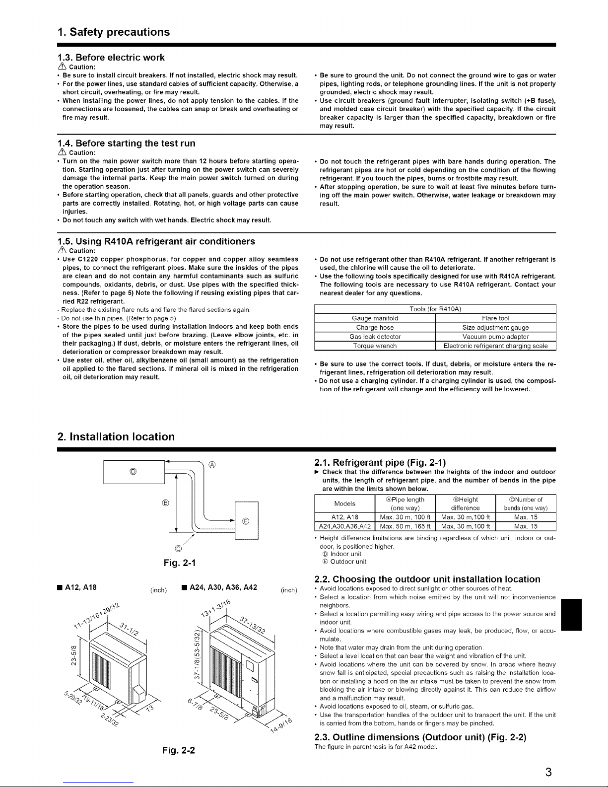
2. Installation location
• A12, A18
@
(inch)
®
/
©
Fig. 2-1
• A24, A30, A36, A42
Fig. 2-2
(inch)
2.1. Refrigerant pipe (Fig. 2-1)
I_ Check that the difference between the heights of the indoor and outdoor
units, the length of refrigerant pipe, and the number of bends in the pipe
are within the limits shown below.
Models @Pipe length ®Height ®Number of
(one way) difference bends (one way)
A12, A18 Max. 30 m, 100 ft Max. 30 m,100 ft Max. 15
A24,A30,A36,A42 Max. 50 m, 165 ft Max. 30 m,100 ft Max. 15
• Height difference limitations are binding regardless of which unit, indoor or out-
door, is positioned higher.
® Indoor unit
® Outdoor unit
2.2. Choosing the outdoor unit installation location
• Avoid locations exposed to direct sunlight or other sources of heat.
• Select a location from which noise emitted by the unit will not inconvenience
neighbors.
• Select a location permitting easy wiring and pipe access to the power source and
indoor unit.
• Avoid locations where combustible gases may leak, be produced, flow, or accu-
mulate.
• Note that water may drain from the unit during operation.
• Select a level location that can bear the weight and vibration of the unit.
• Avoid locations where the unit can be covered by snow. In areas where heavy
snow fall is anticipated, special precautions such as raising the installation loca-
tion or installing a hood on the air intake must be taken to prevent the snow from
blocking the air intake or blowing directly against it. This can reduce the airflow
and a malfunction may result.
• Avoid locations exposed to oil, steam, or sulfuric gas.
• Use the transportation handles of the outdoor unit to transport the unit. If the unit
is carried from the bottom, hands or fingers may be pinched.
2.3. Outline dimensions (Outdoor unit) (Fig. 2-2)
The figure in parenthesis is for A42 model.
3
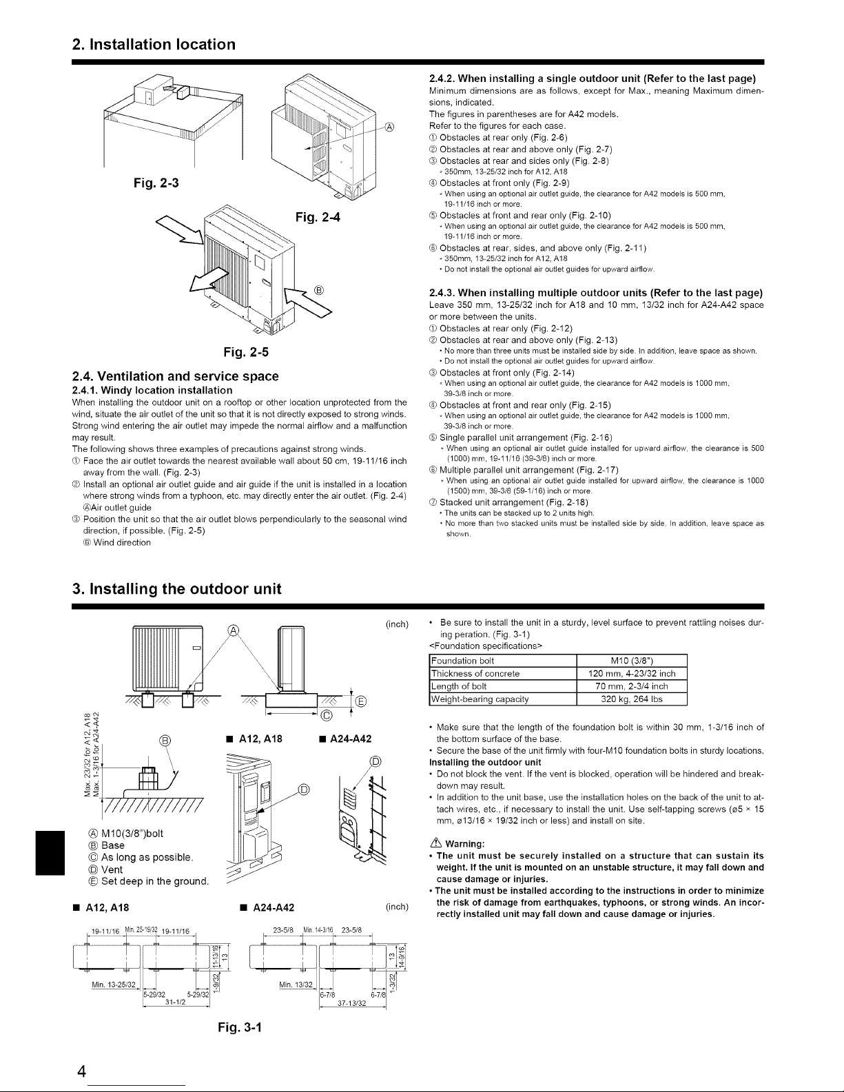
2. Installation location
Fig. 2-3
Fig. 2-4
®
Fig. 2-5
2.4. Ventilation and service space
2.4.1. Windy location installation
When installing the outdoor unit on a rooftop or other location unprotected from the
wind, situate the air outlet of the unit so that it is not directly exposed to strong winds.
Strong wind entering the air outlet may impede the normal airflow and a malfunction
may result.
The following shows three examples of precautions against strong winds.
OPFace the air outlet towards the nearest available wall about 50 cm, 19-11/16 inch
away from the wall. (Fig. 2-3)
® Install an optional air outlet guide and air guide if the unit is installed in a location
where strong winds from a typhoon, etc. may directly enter the air outlet. (Fig. 2-4)
@Air outlet guide
® Position the unit so that the air outlet blows perpendicularly to the seasonal wind
direction, if possible. (Fig. 2-5)
® Wind direction
2.4.2. When installing a single outdoor unit (Refer to the last page)
Minimum dimensions are as follows, except for Max., meaning Maximum dimen-
sions, indicated.
The figures in parentheses are for A42 models.
Refer to the figures for each case.
® Obstacles at rear only (Fig. 2-6)
@ Obstacles at rear and above only (Fig. 2-7)
® Obstacles at rear and sides only (Fig. 2-8)
* 350mm, 13-25/32 inchfor A12, A18
Obstacles at front only (Fig. 2-9)
* When usingan optionalair outlet guide, theclearance forA42 models is 500 ram,
19-11/16 inchor more.
® Obstacles at front and rear only (Fig. 2-10)
* When usingan optionalair outlet guide, theclearance forA42 models is 500 ram,
19-11/16 inchor more.
@ Obstacles at rear, sides, and above only (Fig. 2-11 )
* 350mm, 13-25/32 inchfor A12, A18
• Donot install the optional airoutlet guides for upward airflow.
2.4.3. When installing multiple outdoor units (Refer to the last page)
Leave 350 mm, 13-25/32 inch for A18 and 10 mm, 13/32 inch for A24-A42 space
or more between the units.
_) Obstacles at rear only (Fig. 2-12)
Q Obstacles at rear and above only (Fig. 2-13)
• Nomorethan three units mustbe installedside by side. tn addition, leave space as shown.
• Donot install the optional airoutlet guides for upward airflow.
® Obstacles at front only (Fig. 2-14)
* When usingan optionalair outlet guide, theclearance forA42 models is I000 ram,
39-3/8 inch or more.
Obstacles at front and rear only (Fig. 2-15)
. When using an optionalair outlet guide,the clearance forA42 models isI000 ram,
39-3/8 inch or more.
® Single parallel unit arrangement (Fig. 2-16)
* When using an optional air outlet guide installed for upward airflow, the clearance is 500
(1000) mm, 19-11/16 (39-3/8)inch or more.
@ Multiple parallel unit arrangement (Fig. 2-17)
* When using an optional air outlet guide installed for upward airflow, the clearance is 1000
(1500) mm, 39-3/8 (59-1/16) inch ormore.
L_ Stacked unit arrangement (Fig. 2-18)
• Theunits can be stacked upto 2units high.
• No more than twostacked units must be installed side by side. tn addition, leave space as
shown.
3. Installing the outdoor unit
® M10(3/8")bolt
® Base
® As long as possible.
® Vent
® Set deep in the ground.
• A12, A18
! 19-11/16 _in 25-19"3L 19-11/16 +_
• LT
Min1325/32720'32311/252
(inch)
i®
.1©
• A24-A42
®
• A24-A42 (inch)
23-5/8 Min14-3/1623-5/8
Min.13/32_ yT 37_13/32
• Be sure to install the unit in a sturdy, level surface to prevent rattling noises dur-
ing peration. (Fig. 3-1)
<Foundation specifications>
Foundation bolt M10 (3/8")
Thickness of concrete 120 ram, 4-23/32 inch
Length of bolt 70 ram, 2-3/4 inch
Weight-bearing capacity 320 kg, 264 Ibs
• Make sure that the length of the foundation bolt is within 30 ram, 1-3/16 inch of
the bottom surface of the base.
• Secure the base of the unit firmly with four-M10 foundation bolts in sturdy locations.
Installing the outdoor unit
• Do not block the vent. If the vent is blocked, operation will be hindered and break-
down may result.
• In addition to the unit base, use the installation holes on the back of the unit to at-
tach wires, etc., if necessary to install the unit. Use self-tapping screws 0a5 x 15
mm, _13/16 x 19/32 inch or less) and install on site.
Warning:
• The unit must be securely installed on a structure that can sustain its
weight. If the unit is mounted on an unstable structure, it may fall down and
cause damage or injuries.
• The unit must be installed according to the instructions in order to minimize
the risk of damage from earthquakes, typhoons, or strong winds. An incor-
rectly installed unit may fall down and cause damage or injuries.
Fig. 3-1
4
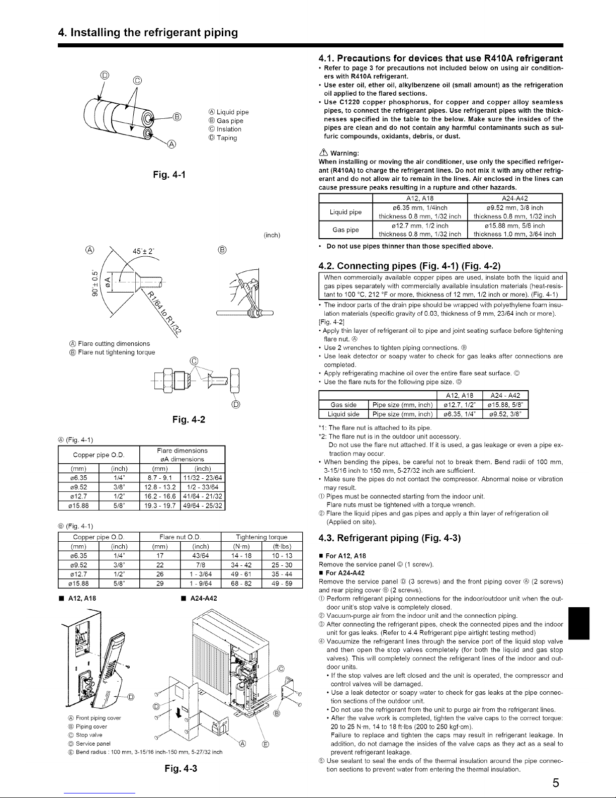
4. Installing the refrigerant piping
© ©
@ Liquid pipe
(_ Gas pipe
@ Inslation
@ Taping
Fig. 4-1
(inch)
@ Flare cutting dimensions
(_ Flare nut tightening torque
@
®
®
Fig. 4-2
@ (Fig. 4-1)
Flare dimensions
Copper pipe O.D.
_A dimensions
(ram) (inch) (ram) (inch)
_6.35 1/4" 8.7 - 9.1 11/32 - 23/64
_9.52 3/8" 12.8 - 13.2 1/2 - 33/64
_12.7 1/2" 16.2- 16.6 41/64 - 21/32
_15.88 5/8" 19.3- 19.7 49/64 - 25/32
® (Fig. 4-1)
Copper pipe O.D.
(mm) (inch)
_6.35 1/4"
_9.52 3/8"
_12.7 1/2"
_15.88 5/8"
Flare nut O.D. Tightening torque
(ram) (inch) (N.m) (ft.lbs)
17 43/64 14 - 18 10 - 13
22 7/8 34 - 42 25 - 30
26 1 - 3/64 49 - 61 35 - 44
29 1 - 9/64 68 - 82 49 - 59
• A12, A18 • A24-A42
@ Front piping cover
® Piping cover
@ Stop valve
® Service panel
® Bend radius : 100 ram, 3-15/16 inch-150 ram, 5-27/32 inch
Fig. 4-3
4.1. Precautions for devices that use R410A refrigerant
• Refer to page 3 for precautions not included below on using air condition-
ers with R410A refrigerant.
• Use ester oil, ether oil, alkylbenzene oil (small amount) as the refrigeration
oil applied to the flared sections.
• Use C1220 copper phosphorus, for copper and copper alloy seamless
pipes, to connect the refrigerant pipes. Use refrigerant pipes with the thick-
nesses specified in the table to the below. Make sure the insides of the
pipes are clean and do not contain any harmful contaminants such as sul-
furic compounds, oxidants, debris, or dust.
Z_ Warning:
When installing or moving the air conditioner, use only the specified refriger-
ant (R410A) to charge the refrigerant lines. Do not mix it with any other refrig-
erant and do not allow air to remain in the lines. Air enclosed in the lines can
cause pressure peaks resulting in a rupture and other hazards.
A12, A18 A24-A42
e6.35 mm, 1/4inch e9.52 mm, 3/8 inch
Liquid pipe thickness 0.8 mm, 1/32 inch thickness 0.8 mm, 1/32 inch
e12.7 mm, 1/2 inch e15.88 mm, 5/8 inch
Gas pipe thickness 0.8 mm, 1/32 inch thickness 1.0 mm, 3/84 inch
Do not use pipes thinner than those specified above.
4.2. Connecting pipes (Fig. 4-1) (Fig. 4-2)
When commercially available copper pipes are used, inslate both the liquid and
gas pipes separately with commercially available insulation materials (heat-resis-
tant to 100 °C, 212 °F or more, thickness of 12 mm, 1/2 inch or more). (Fig. 4-1)
• The indoor parts of the drain pipe should be wrapped with polyethylene foam insu-
lation materials (specific gravity of 0.03, thickness of 9 mm, 23/64 inch or more).
[Fig. 4-2]
• Apply thin layer of refrigerant oil to pipe and joint seating surface before tightening
flare nut. @
• Use 2 wrenches to tighten piping connections. ®
• Use leak detector or soapy water to check for gas leaks after connections are
completed.
• Apply refrigerating machine oil over the entire flare seat surface. ©
• Use the flare nuts for the following pipe size. ®
A12, A18 A24 - A42
Gas side Pipe size (mm, inch) e12.7, 1/2" _15.88, 5/8"
Liquid side Pipe size (mm, inch) _6.35, 1/4" _9.52, 3/8"
"1: The flare nut is attached to its pipe.
*2: The flare nut is in the outdoor unit accessory.
Do not use the flare nut attached. If it is used, a gas leakage or even a pipe ex-
traction may occur.
• When bending the pipes, be careful not to break them. Bend radii of 100 ram,
3-15/16 inch to 150 ram, 5-27/32 inch are sufficient.
• Make sure the pipes do not contact the compressor. Abnormal noise or vibration
may result.
(_ Pipes must be connected starting from the indoor unit.
Flare nuts must be tightened with a torque wrench.
Q Flare the liquid pipes and gas pipes and apply a thin layer of refrigeration oil
(Applied on site).
4.3. Refrigerant piping (Fig. 4-3)
• For A12, A18
Remove the service panel ® (1 screw).
• For A24-A42
Remove the service panel ® (3 screws) and the front piping cover @ (2 screws)
and rear piping cover ® (2 screws).
(_ Perform refrigerant piping connections for the indoor/outdoor unit when the out-
door unit's stop valve is completely closed.
Q Vacuum-purge air from the indoor unit and the connection piping.
® After connecting the refrigerant pipes, check the connected pipes and the indoor
unit for gas leaks. (Refer to 4.4 Refrigerant pipe airtight testing method)
Vacuumize the refrigerant lines through the service port of the liquid stop valve
and then open the stop valves completely (for both the liquid and gas stop
valves). This will completely connect the refrigerant lines of the indoor and out-
door units.
• If the stop valves are left closed and the unit is operated, the compressor and
control valves will be damaged.
• Use a leak detector or soapy water to check for gas leaks at the pipe connec-
tion sections of the outdoor unit.
• Do not use the refrigerant from the unit to purge air from the refrigerant lines.
• After the valve work is completed, tighten the valve caps to the correct torque:
20 to 25 N.m, 14 to 18 ft.lbs (200 to 250 kgf.cm).
Failure to replace and tighten the caps may result in refrigerant leakage. In
addition, do not damage the insides of the valve caps as they act as a seal to
prevent refrigerant leakage.
® Use sealant to seal the ends of the thermal insulation around the pipe connec-
tion sections to prevent water from entering the thermal insulation.
5
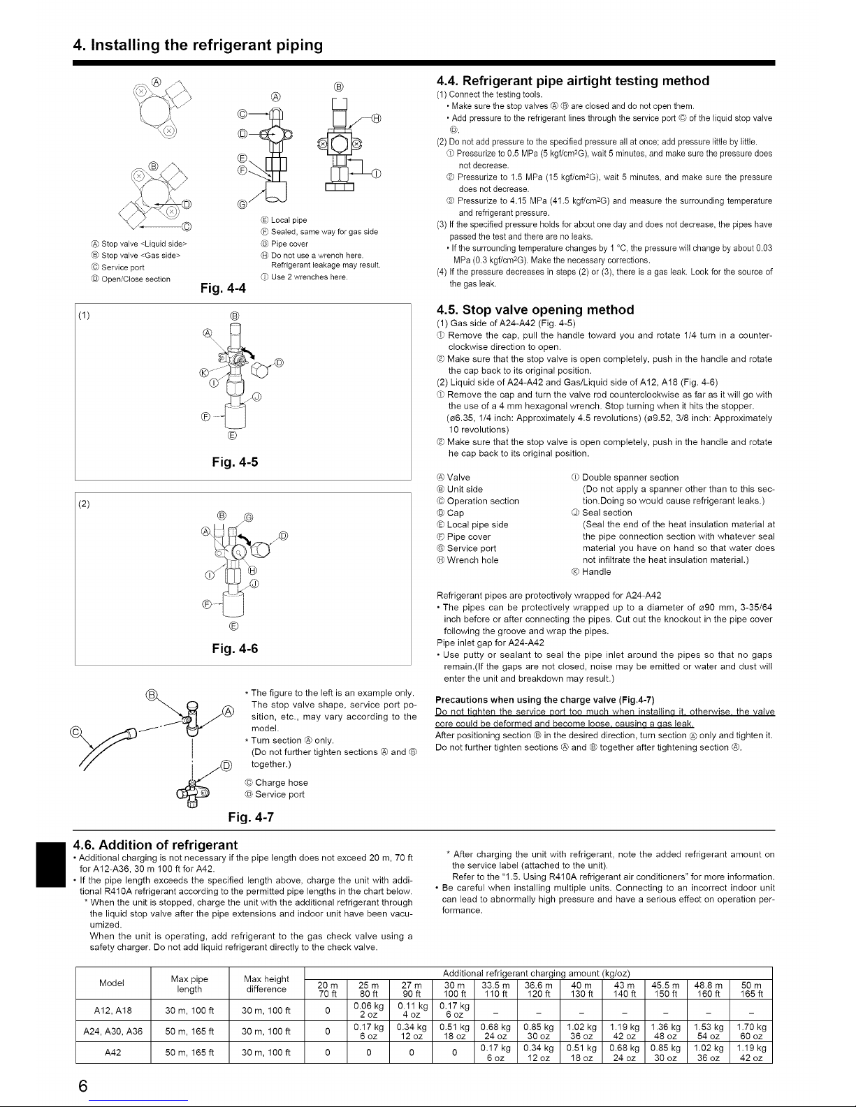
4. Installing the refrigerant piping
@ Stop valve <Liquid side>
Stop valve <Gas side>
© Service port
Open/Close section
Fig. 4-4
®
®
Local pipe
(_ Sealed, same way for gas side
@ Pipe cover
(_) Do not use a wrench here.
Refrigerant leakage may result.
(_ Use 2 wrenches here.
(1) ®
....
®
Fig. 4-5
(2)
® /9
®
Fig. 4-6
* The figure to the left is an example only.
The stop valve shape, service port po-
sition, etc., may vary according to the
model.
* Turn section @ only.
(Do not further tighten sections @ and ®
together.)
© Charge hose
Service port
Fig. 4-7
4.4. Refrigerant pipe airtight testing method
(1) Connect thetesting tools.
• Make sure thestop valves @ ® are closed and do notopen them.
• Add pressure to the refrigerant lines through the service port © of the liquid stop valve
©.
(2) Do not add pressure to the specified pressure all at once; add pressure little by little.
dPPressurize to 0.5 MPa (5 kgf/cm2G), wait 5 minutes, and make sure the pressure does
not decrease.
® Pressurize to 1.5 MPa (15 kgf/cm2G), wait 5 minutes, and make sure the pressure
does not decrease.
® Pressurize to 4.15 MPa (41.5 kgf/cm2G) and measure the surrounding temperature
and refrigerant pressure.
(3) If the specified pressure holds for about one day and does not decrease, the pipes have
passed the test and there are no leaks.
• Ifthe surrounding temperature changes by 1 °C, the pressure will change by about 0.03
MPa (0.3 kgf/cm2G). Make the necessary corrections.
(4) If the pressure decreases in steps (2) or (3), there is a gas leak. Look for the source of
the gas leak.
4.5. Stop valve opening method
(1) Gas side of A24-A42 (Fig. 4-5)
dP Remove the cap, pull the handle toward you and rotate 1/4 turn in a counter-
clockwise direction to open.
® Make sure that the stop valve is open completely, push in the handle and rotate
the cap back to its original position.
(2) Liquid side of A24-A42 and Gas/Liquid side of A12, A18 (Fig. 4-6)
dPRemove the cap and turn the valve rod counterclockwise as far as it will go with
the use of a 4 mm hexagonal wrench. Stop turning when it hits the stopper.
(_6.35, 1/4 inch: Approximately 4.5 revolutions) (_9.52, 3/8 inch: Approximately
10 revolutions)
® Make sure that the stop valve is open completely, push in the handle and rotate
he cap back to its original position.
@ Valve
® Unit side
© Operation section
@ Cap
® Local pipe side
® Pipe cover
@ Service port
@ Wrench hole
(_ Double spanner section
(Do not apply a spanner other than to this sec-
tion.Doing so would cause refrigerant leaks.)
@ Seal section
(Seal the end of the heat insulation material at
the pipe connection section with whatever seal
material you have on hand so that water does
not infiltrate the heat insulation material.)
Handle
Refrigerant pipes are protectively wrapped for A24-A42
• The pipes can be protectively wrapped up to a diameter of _a90 ram, 3-35/64
inch before or after connecting the pipes. Cut out the knockout in the pipe cover
following the groove and wrap the pipes.
Pipe inlet gap for A24-A42
• Use putty or sealant to seal the pipe inlet around the pipes so that no gaps
remain.(If the gaps are not closed, noise may be emitted or water and dust will
enter the unit and breakdown may result.)
Precautions when using the charge valve (Fig.4-7)
Do not tiqhten the service port too much when installinq it, otherwise, the valve
core could be deformed and become loose causina a aas leak.
After positioning section @ in the desired direction, turn section @ only and tighten it.
Do not further tighten sections @ and ® together after tightening section @.
4.6. Addition of refrigerant
• Additional charging is not necessary if the pipe length does not exceed 20 m, 70 ft
for A12-A36, 30 m 100 ft for A42.
• If the pipe length exceeds the specified length above, charge the unit with addi-
tional R410A refrigerant according to the permitted pipe lengths in the chart below.
* When the unit is stopped, charge the unit with the additional refrigerant through
the liquid stop valve after the pipe extensions and indoor unit have been vacu-
umized.
When the unit is operating, add refrigerant to the gas check valve using a
safety charger. Do not add liquid refrigerant directly to the check valve.
* After charging the unit with refrigerant, note the added refrigerant amount on
the service label (attached to the unit).
Refer to the "1.5. Using R410A refrigerant air conditioners" for more information.
• Be careful when installing multiple units. Connecting to an incorrect indoor unit
can lead to abnormally high pressure and have a serious effect on operation per-
formance.
Model Max pipe Max height Additional refrigerant charging amount (kg/oz)
length difference 20 m 25 m 27 m 30 m 33.5 m 36.6 m 40 m 43 m 45.5 m 48.8 m 50 m
70ft 80ft 90ft 100ft 110ft 120ft 130ft 140ft 150ft 160ft 165ft
0.06kg 0.11kg 0.17kg
A12, A18 30m, 100ft 30m, 100ft 0 2oz 4oz 6oz .....
A24, A30, A36 50m, 165ft 30m, 100ft 0 0.17kg 0.34kg 0.51kg 0.68kg 0.85kg 1.02kg 1.19kg 1.36kg 1.53kg 1.70kg
6 oz 12 oz 18 oz 24 oz 30 oz 36 oz 42 oz 48 oz 54 oz 60 oz
0.17 kg 0.34 kg 0.51 kg 0.68 kg 0.85 kg 1.02 kg 1.19 kg
A42 50 m, 165ft 30m, 100ft 0 0 0 0
6 oz 12 oz 18 oz 24 oz 30 oz 36 oz 42 oz
6
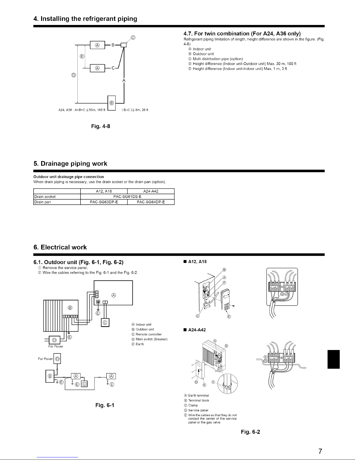
4. Installing the refrigerant piping
©
A
|
A24, A36 : A+B+C<50m, 165ft _B-C I< 8m,26ft
4.7. For twin combination (For A24, A36 only)
Refrigerant piping limitation of length, height difference are shown in the figure. (Fig.
4-8)
@ Indoor unit
® Outdoor unit
@ Multi distribution pipe (option)
@ Height difference (Indoor unit-Outdoor unit) Max. 30 m, 100 ft
@ Height difference (Indoor unit-Indoor unit) Max. 1 m, 3 ft
Fig. 4-8
5. Drainage piping work
Outdoor unit drainage pipe connection
When drain piping is necessary, use the drain socket or the drain pan (option).
A12, A18 I A24-A42
Drain socket PAC-SG61DS-E
Drain pan PAC-SG63DP-E I PAC-SG64DP-E
6. Electrical work
6.1. Outdoor unit (Fig. 6-1, Fig. 6-2)
d.) Remove the service panel.
® Wire the cables referring to the Fig. 6-1 and the Fig. 6-2.
For Power
®
Fig. 6-1
@ tndoor unit
® Outdoor unit
@ Remote controller
® Main switch (Breaker)
® Earth
• A12, A18
@
• A24-A42
_f
®
@ Earth terminal
® Terminal block
® Clamp
® Service panel
® Wire the cables so that they do not
contact the center of the service
panel or the gas valve.
Fig. 6-2
7
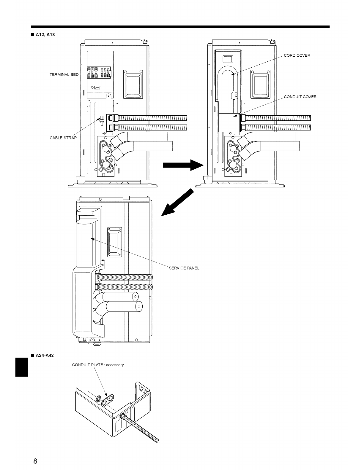
• A12, A18
o "-,'_ o "-,_
CABLE STR l
\
o
_" SERVICE PANEL
• A24-A42
CONDUIT PLATE : accessory
8
6. Electrical work
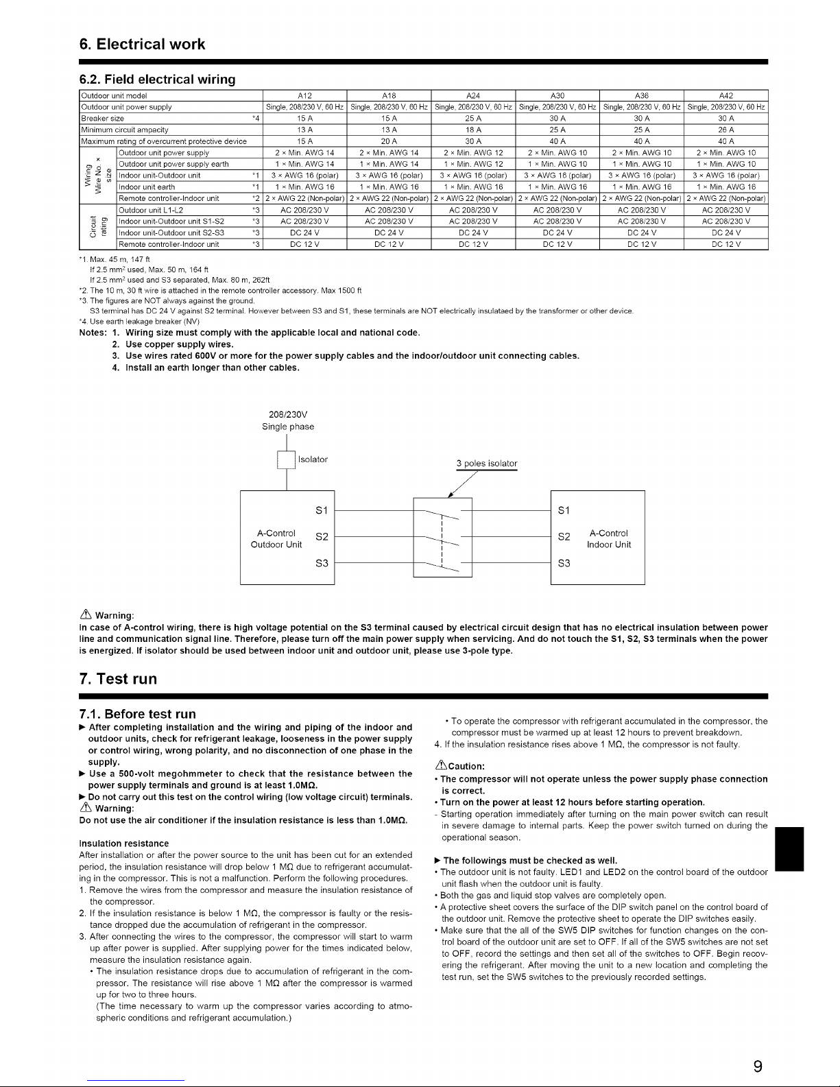
6.2. Field electrical wiring
Outdoor unit model A12 A18 A24 A30 A36 A42
Outdoor unit power supply Single,208/230V, 60 Hz Single,208/230V,60Hz Single,208/230V,60Hz Single,208/230V, 60Hz Single,208/230V,60Hz Single,208/230V, 60 Hz
Breakersize *4 15A 15 A 25A 30 A 30 A 30A
Minimumcircuit ampacity 13A 13 A 18A 25 A 25 A 26A
Maximumrating ofovercurrent protectivedevice 15A 20 A 30 A 40A 40 A 40 A
Outdoor unit power supply 2 x Min. AWG14 2 x Min. AWG 14 2 x Min. AWG12 2 xMin. AWG 10 2 x Min. AWG 10 2 x Min.AWG 10
x Outdoor unit power supply earth 1 x Min. AWG 14 I × Min. AWG14 I x Min. AWG 12 1 xMin. AWG 10 I × Min.AWG 10 I x Min.AWG I0
_Td N¢ tndoorunit-Outdoorunit "1 3xAWG16(polar) 3xAWG16(poiar) 3xAWG16(polar) 3xAWG16(polar) 3xAWG16(poiar) 3xAWG16(polar)
_ tndoor unit earth "1 ] x Min. AWG 16 ] x Min. AWG 16 ] x Min. AWG 18 ] x Min. AWG 16 ] x Min.AWG 16 ] x Min.AWG 18
Remote contro{ler-lndoor unit *2 2 xAWG 22(Non-polar) 2 x AWG 22 (Non-polar) 2 x AWG22 (Non-polar) 2 x AWG22 (Non-polar) 2 xAWG22 (Non-polar) 2 xAWG 22 (Non-polar)
Outdoor unit I_1-I_2 *3 AC 208/230 V AC 208/230 V AC 208/230 V AC 208/230 V AC 208/230 V AC 208/230 V
,5,___ tndoor unit-Outdoor unit Sl-S2 *3 AC 208/230 V AC 208/230 V AC 208/230 V AC 208/230 V AC 208/230 V AC 208/230 V
_ N tndoor unit-Outdoor unit S2-S3 *3 DC 24 V DC 24 V DC 24 V DC 24 V DC 24 V DC 24 V
Remote contro{ler-lndoor unit *3 DC 12 V DC 12 V DC 12 V DC 12 V DC 12 V DC 12 V
"I. Max. 45 m, 147 ft
tf2.5 mm 2used, Max. 50 m, 164 ft
if 2.5 mm 2 used and S3 separated, Max. 80 m, 262ft
*2. The 10 m, 30 ft wire is attached in the remote controller accessory. Max 1500 ft
*3. The figures are NOT always against the ground.
S3 terminai has DC 24 V against S2 terminal. However between S3 and Sl, these terminals are NOT electrically insulataed by the transformer or other device.
*4. Use earth leakage breaker (NV)
Notes: 1, Wiring size must comply with the applicable local and national code.
2. Use copper supply wires.
3, Use wires rated 600V or more for the power supply cables and the indoor/outdoor unit connecting cables,
4, Install an earth longer than other cables.
208/230V
Single phase
Isolator
Sl
A-Control S2
Outdoor Unit
S3
3 poles isolator
/
I
I
I
I
Sl
S2 A-Control
Indoor Unit
S3
Z_ Warning:
In case of A-control wiring, there is high voltage potential on the S3 terminal caused by electrical circuit design that has no electrical insulation between power
line and communication signal line. Therefore, please turn off the main power supply when servicing. And do not touch the Sl, S2, S3 terminals when the power
is energized. If isolator should be used between indoor unit and outdoor unit, please use 3-pole type.
7. Test run
7.1. Before test run
I_ After completing installation and the wiring and piping of the indoor and
outdoor units, check for refrigerant leakage, looseness in the power supply
or control wiring, wrong polarity, and no disconnection of one phase in the
supply.
I_ Use a 500-volt megohmmeter to check that the resistance between the
power supply terminals and ground is at least 1.0MQ.
I_ Do not carry out this test on the control wiring (tow voltage circuit) terminals.
/_ Warning:
Do not use the air conditioner if the insulation resistance is less than 1.0MQ.
Insulation resistance
After installation or after the power source to the unit has been cut for an extended
period, the insulation resistance will drop below 1 MG due to refrigerant accumulat-
ing in the compressor. This is not a malfunction. Perform the following procedures.
1. Remove the wires from the compressor and measure the insulation resistance of
the compressor.
2. If the insulation resistance is below 1 M_, the compressor is faulty or the resis-
tance dropped due the accumulation of refrigerant in the compressor.
3. After connecting the wires to the compressor, the compressor will start to warm
up after power is supplied. After supplying power for the times indicated below,
measure the insulation resistance again.
• The insulation resistance drops due to accumulation of refrigerant in the com-
pressor. The resistance will rise above 1 M_ after the compressor is warmed
up for two to three hours.
(The time necessary to warm up the compressor varies according to atmo-
spheric conditions and refrigerant accumulation.)
• To operate the compressor with refrigerant accumulated in the compressor, the
compressor must be warmed up at least 12 hours to prevent breakdown.
4. If the insulation resistance rises above 1 MD, the compressor is not faulty.
Z_Caution:
• The compressor will not operate unless the power supply phase connection
is correct.
• Turn on the power at least 12 hours before starting operation.
- Starting operation immediately after turning on the main power switch can result
in severe damage to internal parts. Keep the power switch turned on during the
operational season.
I_ The followings must be checked as well.
• The outdoor unit is not faulty. LED1 and LED2 on the control board of the outdoor
unit flash when the outdoor unit is faulty.
• Both the gas and liquid stop valves are completely open.
• A protective sheet covers the surface of the DIP switch panel on the control board of
the outdoor unit. Remove the protective sheet to operate the DIP switches easily.
• Make sure that the all of the SW5 DIP switches for function changes on the con-
trol board of the outdoor unit are set to OFF. If all of the SW5 switches are not set
to OFF, record the settings and then set all of the switches to OFF. Begin recov-
ering the refrigerant. After moving the unit to a new location and completing the
test run, set the SW5 switches to the previously recorded settings.
9
7. Test run
7.2. Test run
7.2.1. Using SW4 in outdoor unit
1) PUH Type, PUZ Type
SW4-1 ON
SW4-2 OFF Cooling operation
BW4-1 ON
SW4-2 ON Heating operation
2) PUY Type
SW4-1 t ON t Cooling operation
SW4-2 ON or OFF
* After performing the test run, set SW4-1 to OFF.
• After power is supplied, a small clicking noise may be heard from the inside of
the outdoor unit. The electronic expansion valve is opening and closing. The unit
is not faulty.
• A few seconds after the compressor starts, a clanging noise may be heard from
the inside of the outdoor unit. The noise is coming from the check valve due to
the small difference in pressure in the pipes. The unit is not faulty.
The test run operation mode cannot be changed by DIP switch SW4-2 during
the test run. (To change the test run operation mode during the test run, stop
the test run by DIP switch SW4-1. After changing the test run operation mode,
resume the test run by switch SW4-1.)
7.2.2. Using remote controller
Refer to the indoor unitinstallation manual.
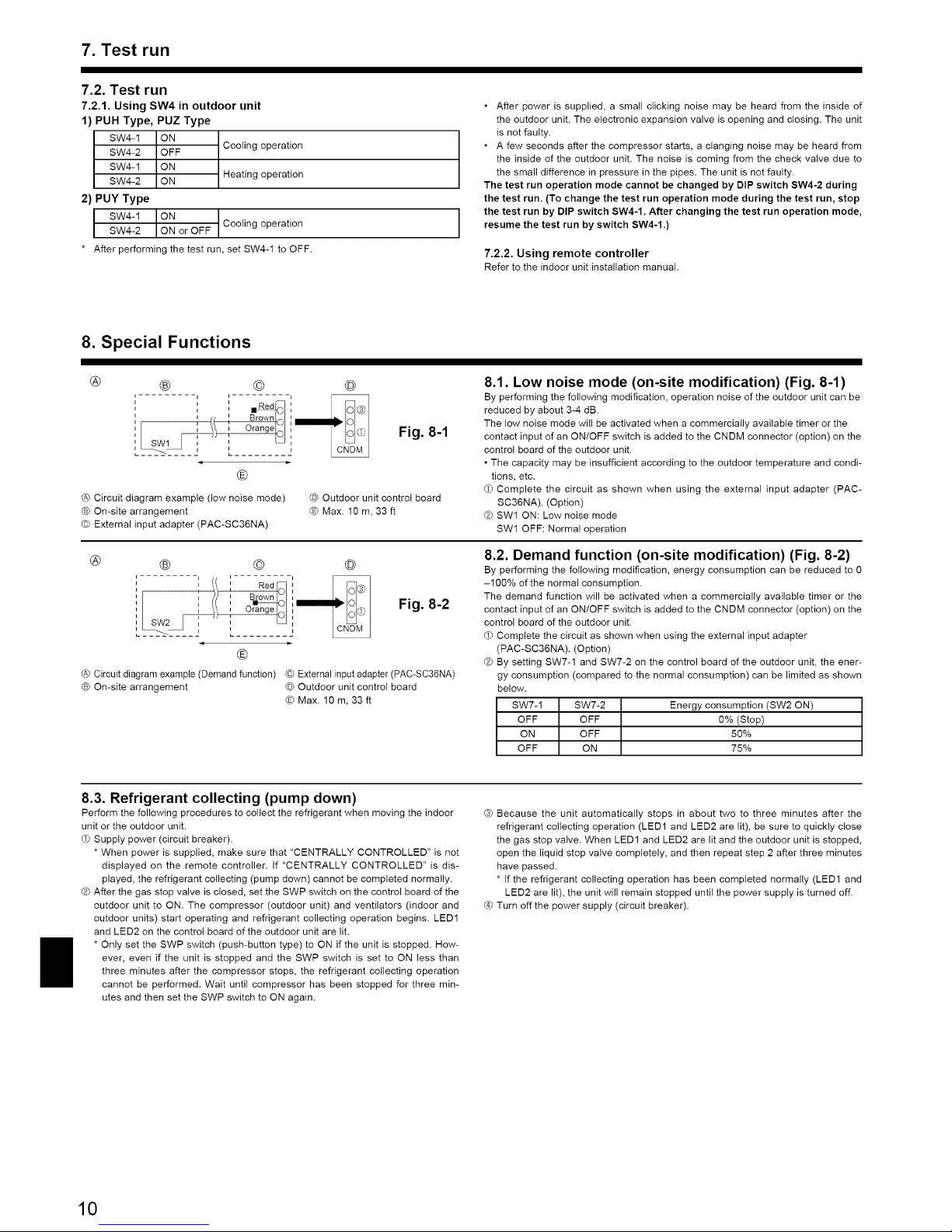
8. Special Functions
®
® ®
i r
ii ii iRed_
' (1 II Brownl,_l
I ' ° a° ld
®
@ Circuit diagram example (low noise mode)
® On-site arrangement
© External input adapter (PAC-SC36NA)
®
Fig. 8-1
Outdoor unit control board
©Max. 1Om, 33ft
8.1. Low noise mode (on-site modification) (Fig. 8-1)
By performing the following modification, operation noise of the outdoor unit can be
reduced by about 3-4 dB.
The low noise mode will be activated when a commercially available timer or the
contact input of an ON/OFF switch is added to the CNDM connector (option) on the
control board of the outdoor unit.
• The capacity may be insufficient according to the outdoor temperature and condi-
tions, etc.
Complete the circuit as shown when using the external input adapter (PAC-
SC36NA). (Option)
Q SW1 ON: Low noise mode
SWl OFF: Normal operation
®
® ®
, , l! : medg]
_ _, Q
i
n
®
Fig. 8-2
®
@ Circuit diagram example (Demand function) © External input adapter (PAC-SC36NA)
® On-site arrangement @ Outdoor unit control board
©Max. 10 m, 33 ft
8.2. Demand function (on-site modification) (Fig. 8-2)
By performing the following modification, energy consumption can be reduced to 0
-100% of the normal consumption.
The demand function will be activated when a commercially available timer or the
contact input of an ONtOFF switch is added to the CNDM connector (option) on the
control board of the outdoor unit.
Complete the circuit as shown when using the external input adapter
(PAC-SC36NA). (Option)
Q By setting SW7-1 and SW7-2 on the control board of the outdoor unit, the ener-
gy consumption (compared to the normal consumption) can be limited as shown
below.
SW7-1 SW7-2 Energy consumption (SW2 ON)
OFF OFF 0% (Stop)
ON OFF 50%
OFF ON 75%
8.3. Refrigerant collecting (pump down)
Perform the following procedures to collect the refrigerant when moving the indoor
unit or the outdoor unit.
OPSupply power (circuit breaker).
* When power is supplied, make sure that "CENTRALLY CONTROLLED" is not
displayed on the remote controller. If "CENTRALLY CONTROLLED" is dis-
played, the refrigerant collecting (pump down) cannot be completed normally.
® After the gas stop valve is closed, set the SWP switch on the control board of the
outdoor unit to ON. The compressor (outdoor unit) and ventilators (indoor and
outdoor units) start operating and refrigerant collecting operation begins. LED1
and LED2 on the control board of the outdoor unit are lit.
* Only set the SWP switch (push-button type) to ON if the unit is stopped. How-
ever, even if the unit is stopped and the SWP switch is set to ON less than
three minutes after the compressor stops, the refrigerant collecting operation
cannot be performed. Wait until compressor has been stopped for three min-
utes and then set the SWP switch to ON again.
G Because the unit automatically stops in about two to three minutes after the
refrigerant collecting operation (LED1 and LED2 are lit), be sure to quickly close
the gas stop valve. When LED1 and LED2 are lit and the outdoor unit is stopped,
open the liquid stop valve completely, and then repeat step 2 after three minutes
have passed.
* If the refrigerant collecting operation has been completed normally (LED1 and
LED2 are lit), the unit will remain stopped until the power supply is turned off.
Turn off the power supply (circuit breaker).
10
9. System control (Fig. 9-1)
®SW1-3~6 oFFON
3 4 5 6
®SWl-3~6 oFFON
3 4 5 6
@SWl-3~6 oFFON
3 4 5 6
TB1 ___ TB1
TB5 \__ "_"
E3<DE3 $
@ Outdoor unit
® Indoor unit
© Master remote controller
© Subordinate remote controller
® Standard 1:1 (Refrigerant address = 00)
® Simultaneous twin (Refrigerant address =01)
@ Simultaneous twin (Refrigerant address = 02)
',._ ............... J
Fig. 9-1
* Set the refrigerant address using the DIP switch of the outdoor unit.
(_ Wiring from the Remote Control
This wire is connected to TB5 (terminal board for remote controller) of the indoor
unit (non-polar).
Q When a Different Refrigerant System Grouping is Used,
Up to 16 refrigerant systems can be controlled as one group using the slim MA
remote controller.
Note:
In single refrigerant system(twin), there is no need of wiring@,
sw1
Function table
<SWI>
[oO 1
Function
1 Compulsory
defrosting
2 Error history
SWl
clear
function
3 Refrigerant
settings
4 system ad-
5 dress setting
6
Operation according to switch setting
ON OFF
Start Normal
Clear Normal
Settings for outdoor unit addresses
0to 15
11

Fig. 2-6
4 i i¸ _'_o
_'_iiiiiiy¸ _,, _ i_,,,_';....
....._i_i;_,_!_i_ii_i_i_ii_',¸¸¸ 03
Fig. 2-7
7_,"7_(_h" .
"©_
Fig. 2-8
inch
Fig. 2-9
Fig. 2-10
o-<_d,9.
Fig. 2-11
Fig. 2-13 Fig. 2-14
Fig. 2-15
Fig. 2-16
12
Fig. 2-17
Fig. 2-18

Index
1. Consignes de securit6 .......................................... 13
2. Emplacement pour I'installation ................................... 14
3. Installation de I'appareil exterieur ................................. 15
4. Installation de la tuyauterie du refrig6rant ........................... 16
5. Mise en place du tuyau d'ecoulement ............................... 18
1. Consignes de sdcurit_
6. Installations electriques .......................................... 18
7. Marche d'essai ................................................ 20
8. Fonctions speciales ............................................ 21
9. Contr61e du syst_me (Fig. 9-1) .................................... 22
I_ Avantdesecurit_".d'installerle climatiseur, lire attentivement toutes les "Consignes
I_ VeuilleZavantdeC°nsulterconnecter°Uvotre°btenirsysteme.lapermission votre compagnie d _ ectr c t_
z_ Avertissement:
Precautions & suivre pour eviter tout danger de blessure ou de d_ces de I'
utilisateur.
Une fois I'installation termin6e, expliquer les "Consignes de securit6", I'utilisation et I'
entretien de I'appareil au client conform6ment aux informations du mode d'emploi et
effectuer I'essai de fonctionnement en continu pour garantir un fonctionnement normal.
Le manuel d'installation et le mode d'emploi doivent 6tre fournis & I'utilisateur qui dolt
Ies conserver. Ces manuels doivent 6galement 6tre transmis aux nouveaux utilisateurs.
(_: Indique un el6ment qui dolt _tre mis & la terre.
Z_ Precaution:
Decrit les precautions qui doivent 6tre prises pour _viter d'endommager I'appareil.
_'k Avertissement:
• L'appareil ne dolt pas 6tre installe par I'utilisateur. Contacter un revendeur
ou un technicien agr_ pour installer I'appareil. Si I'appareil n'est pas cor-
rectement installS, des fuites d'eau, des chocs electriques ou des incendies
peuvent se produire.
• Pour I'installation, respecter les instructions du manuel d'installation et
utiliser des outils et des composants de tuyau specialement con_:us pour
une utilisation avec le refrigerant R410A. La pression du r_frigerant R410A
du syst_me HFC est 1,6 fois sup_rieure a celle des refrigerants tradition-
nets. Si des composants de tuyau non adapt_s au refrigerant R410A sont
utilis_s et si I'appareil n'est pas correctement installe, les tuyaux peuvent
_clater et provoquer des dommages ou des blessures. Des fuites d'eau, des
chocs electriques et des incendies peuvent egalement se produire.
• L'appareil dolt _tre installe conformement aux instructions pour reduire les
risques de dommages lies a des tremblements de terre, des typhons ou des
vents violents. Une installation incorrecte peut entrainer la chute de I'appa-
reil et provoquer des dommages ou des blessures.
• L'appareil dolt _tre solidement install_ sur une structure pouvant supporter
son poids. Si I'appareil est fixe sur une structure instable, it risque de
tomber et de provoquer des dommages ou des blessures.
• Si le climatiseur est installe darts une petite piece, certaines mesures doi-
vent _tre prises pour _viter que la concentration de r_frigerant ne depasse
le seuil de s_curite en cas de fuite. Consulter un revendeur pour obtenir les
mesures adequates et ainsi _viter de depasser la concentration autorisee.
En cas de fuite de refrigerant et de depassement du seuil de concentration,
des risques lies au manque d'oxyg_ne dans la piece peuvent survenir.
• A_rer la piece en cas de fuite de r_frig_rant Iors de I'utilisation. Le contact du
refrigerant avec une flamme peut provoquer des _manations de gaz toxiques.
• Toutes les installations _lectriques doivent _tre effectuees par un technicien
qualifi_ conformement aux r_glementations locales et aux instructions
fournies dans ce manuel. Les appareils doivent _tre ailment,s par des lignes
_lectriques adapt_es. Utiliser la tension correcte et des coupe-circuits. Des
lignes electriques de capacite insuffisante ou des installations _tectriques
incorrectes peuvent provoquer un choc _lectrique ou un incendie.
z_ Avertissement:
Prendre soin de lire les etiquettes se trouvant sur I'appareil principal.
• Utiliser le cuivre phosphoreux C1220, pour des tuyaux sans soudure en
cuivre et en alliage de cuivre, pour raccorder les tuyaux de r_frigerant. Si
les tuyaux ne sont pas correctement raccord_s, la mise & la terre de I'appa-
reil ne sera pas conforme et des chocs _lectriques peuvent se produire.
• N'utiliser que les c&bles specifies pour les raccordements. Les connexions
doivent _tre correctement effectuees sans tension sur les bornes. Si les
c&bles ne sont pas correctement connectes ou installes, une surchauffe ou
un incendie peut se produire.
• Le couvercle du bloc de sortie de I'appareil exterieur dolt _tre solidement
fix_. S'il n'est pas correctement install_ et si des poussieres et de l'humidit_ s'
infiltrent darts I'appareil, un choc electrique ou un incendie peut se produire.
• Lors de I'installation ou du d_placement du climatiseur, n'utiliser que le
refrigerant specifi_ (R410A) pour remplir les tuyaux de r_frigerant. Ne pas
le melanger avec un autre refrigerant et faire le vide d'air dans les tuyaux.
La presence d'air darts les tuyaux peut provoquer des pointes de pression
entrainant une rupture et d'autres risques.
• N'utiliser que les accessoires agrees par Mitsubishi Electric et contacter un
revendeur ou un technicien agre_ pour les installer. Si les accessoires ne
sont pas correctement installes, une fuite d'eau, un choc electrique ou un
incendie peut se produire.
• Ne pas changer I'appareil. Consulter un revendeur en cas de reparations. Si
les modifications ou reparations ne sont pas correctement effectuees, une
fuite d'eau, un choc _lectrique ou un incendie peut se produire.
• L'utilisateur ne dolt jamais essayer de reparer ou de deplacer I'appareil.
Si I'appareil n'est pas correctement installe, des fuites d'eau, des chocs
_lectriques ou des incendies peuvent se produire. Si le climatiseur dolt _tre
r_par_ ou deplace, contacter un revendeur ou un technicien agree.
• Une fois I'installation terminee, verifier les _ventuelles fuites de refrigerant.
Si le r_frigerant fuit dans la piece et entre en contact avec la flamme d'un
chauffage ou d'une cuisiniere, des gaz toxiques peuvent se d_gager.
1.1. Avant I'installation
/'_ Precaution:
• Ne pas utiliser I'appareil dans un environnement inhabituel. Site climati-
seur est installe dans des endroits exposes a la vapeur, a I'huile volatile
(notamment I'huile de machine), au gaz sulfurique, a une forte teneur en set,
par exemple, a la mer, ou dans des endroits ou I'appareil sera recouvert de
neige, les performances peuvent consid_rablement diminuer et les pi_ces
internes de I'appareil _tre endommagees.
• Ne pas installer I'appareil dans des endroits ou des gaz de combustion peu-
vent s'echapper, se degager ou s'accumuler. L'accumulation de gaz de com-
bustion autour de I'appareil peut provoquer un incendie ou une explosion.
• L'appareil ext_rieur produit de la condensation Iors du fonctionnement du
chauffage. Pr_voir un syst_me de drainage autour de I'appareil exterieur au
cas ou la condensation provoquerait des dommages.
• Lors de I'installation de I'appareil dans un h6pital ou un centre de com-
munications, se preparer au bruit et aux interferences _tectroniques. Les
inverseurs, les appareils electrom_nagers, les _quipements medicaux
haute fr_quence et de communications radio peuvent provoquer un dys-
fonctionnement ou une d_faillance du climatiseur. Le climatiseur peut
_galement endommager les equipements m_dicaux et de communications,
perturbant ainsi les soins et reduisant la qualit_ d'affichage des ecrans.
1.2. Avant I'installation (deplacement)
/'_ Precaution:
• Transportez et installez les appareils avec precaution. L'appareil dolt _tre
transporte par 2 personnes ou plus, car il p_se 20 kg, 44 Ibs minimum. Ne pas
tirer les rubans d'emballage. Portez des gants de protection pour sortir I'ap-
pareil de son emballage et pour le deplacer, car vous risquez de vous blesser
les mains sur les ergots ou les ar_tes des autres pi_ces.
• Veiller a eliminer le materiel d'emballage en toute securite. Le materiel d'
emballage (clous et autres pieces en metal ou en bois) peut provoquer des
blessures.
• La base et les fixations de I'appareil ext_rieur doivent _tre verifiees r_gu-
li_rement pour eviter qu'elles ne se desserrent, se fissurent ou subissent
d'autres dommages. Si ces d_fauts ne sont pas corrig_s, I'appareil peut
tomber et provoquer des dommages ou des btessures.
• Ne pas nettoyer le climatiseur a I'eau au risque de provoquer un choc elec-
trique.
• Serrer les ecrous _vas_s, conformement aux specifications, a I'aide d'une
cle dynamometrique. Si les ecrous sont trop serres, ils peuvent se casser
apr_s un certain temps et provoquer une fuite de r_frig_rant.
13

1. Consignes de sdcurit_
1.3. Avant I'installation electrique
Precaution:
• Veiller a installer des coupe-circuits. Dans le cas contraire, un choc elec-
trique pout se produire.
• Pour los lignes _lectriques, utiliser des c&bles standard de capacite suf-
fisante. Dans le cas contraire, un court-circuit, une surchauffe ou un in-
cendie pout se produire.
• Lors de l'installation des lignes electriques, ne pas mettre los c&bles sous
tension. Si los connexions sont desserrees, los c_bles peuvent se rompre
et provoquer une surchauffe ou un incendie.
• Veiller a mettre I'appareil a la terre. Ne pas relier le fil de terre aux conduites
de gaz ou d'eau, aux paratonnerres ou aux lignes de terre t_l_phoniques. Une
mise a la terre incorrecte de I'appareil pout provoquer un choc electrique.
• Utiliser des coupe-circuits (disjoncteur de fuite a la terre, interrupteur d'
isolement (fusible +B) et disjoncteur a boitier moul_) a la capacit_ specifi_e.
Si ta capacite du coupe-circuit est superieure a cello sp_cifi_e, une d_fail-
lance ou un incendie pout se produire.
1.4. Avant la marche d'essai
/'_ Precaution:
• Activer I'interrupteur principal au moins 12 heures avant la raise en fonc-
tionnement de I'appareil. L'utilisation de I'appareil juste apres sa raise sous
tension pout endommager serieusement los pi_ces internes. Laisser l'inter-
rupteur active pendant la periode d'utilisation.
• Avant d'utiliser I'appareil, v_rifier que tous los panneaux, toutes los protec-
tions et los autres pieces de s_curite sont correctement install_s. Los pi_ces
tournantes, chaudes ou a haute tension peuvent provoquer des blessures.
• Ne pas toucher los interrupteurs los mains humides au risque de provoquer
un choc electrique.
• Ne pas toucher los tuyaux de refrigerant los mains nues Iors de I'utilisa-
tion. Los tuyaux de r_frigerant sont chauds ou froids en fonction de I'etat
du r_frigerant qu'ils contiennent. Toucher los tuyaux pout provoquer des
brQlures ou des gelures.
• A la fin de I'utilisation de I'appareil, attendre au moins cinq minutes avant
de desactiver I'interrupteur principal. Dans le cas contraire, une fuite d'eau
ou une d_faillance pout se produire.
1.5. Utilisation de climatiseurs utilisant le refrigerant R410A
Precaution:
• Utiliser le cuivre phosphoreux C1220, pour des tuyaux sans soudure en cuivre
et en alliage de cuivre, pour raccorder los tuyaux de refrigerant. Verifier que
I'interieur des tuyaux est propre et depourvu de tout agent nocif tel que des
composes sulfuriques, des oxydants, des debris ou des saletes. Utiliser des
tuyaux d'epaisseur specifiee. (So reporter a la page 16). Respecter los instruc-
tions suivantes en cas de reutilisation de tuyaux de refrigerant R22 existants.
- Remplacer los ecrous evases existants et evaser de nouveau los sections evasees.
- Ne pas utiliser de tuyaux fins. (So reporter & la page 16)
• Stocker a I'interieur los tuyaux & utiliser pendant I'installation et couvrir
los deux extr_mites jusqu'au processus de brasage. (Laisser los joints de
coude, etc. dans leur emballage.) L'inflltration de poussi_res, de d_bris ou d'
humidit_ dans los tuyaux de r_frigerant pout affecter la qualite de I'huile ou
endommager le compresseur.
• Appliquer une petite quantit_ d'huile ester, ether ou alkylbenz_ne comme
hullo r_frigerante sur los sections _vas_es. Le melange d'huile minerale et d'
hullo r_frigerante pout affecter la qualite de I'huile.
• Ne pas utiliser un r_frigerant autre que le r_frigerant R410A. Si c'est le cas,
le chtore pout affecter la qualite de I'huile.
• Utiliser los outils suivants sp_cialement con_:us pour une utilisation avec le
refrigerant R410A. Los outils suivants sont n_cessaires pour utiliser le refri-
gerant R410A. En cas de questions, contacter le revendeur le plus proche.
2. Emplacement pour I'installation
Outils (pour R410A)
Collecteur jauge Outil d'evasement
Tuyau de charge Jauge de reglage de la taille
Detecteur de fuite de gaz Adaptateur pour pompe a vide
Cle dynamometrique EcheIIe electronique de charge de refrigerant
• Veiller & utiliser los outils adapt_s. L'infiltration de poussi_res, de debris ou
d'humidite dans los tuyaux de r_frigerant pout affecter la qualite de I'huile
refrig_rante.
• Ne pas utiliser un cylindre de charge. L'utilisation d'un cylindre de charge
pout modifier la composition du r_frigerant et r_duire son efficacit_.
• A12, A18
@
®
/
©
Fig. 2-1
(inch)
• A24, A30, A36, A42
Fig. 2-2
(inch)
2.1. Tuyaux de r_frigerant (Fig. 2-1)
I_ V_rifier que la difference de hauteur entre los appareils int_rieur et ext_rieur,
la Iongueur du tuyau de refrigerant et le hombre de coudes permis dans le
tuyau se situent au sein des limites reprises dans le tableau ci-dessous.
Mod61es _ Longueur du ® Difference de © Nombre de
tuyau (un sens) haueur ooudes (un sens)
A12, A18 Max. 30 m, 100 ft Max. 30 m,100 ft Max. 15
A24,A30,A36,A42 Max. 50 m, 165 ft Max. 30 m,100 ft Max. 15
• Les specifications concemant la difference d'elevation s'appliquent & toutes dis-
positions des appareils interieurs et exterieurs, sans tenir compte de celui qui est
le plus eleve.
© Appareil interieur
® Appareil exterieur
2.2. Selection de I'emplacement d'installation de I'ap-
pareil exterieur
• Eviter les endroits exposes au rayonnement solaire direct oua d'autres sources de chaleur.
• Selectionner un endroit oQ le bruit de I'appareil n'incommodera pas le voisinage.
• Selectionner un endroit permettant un acces facile des cables et tuyaux a la
source d'alimentation et & I'appareil interieur.
• Eviter les endroits exposes & des risques de fuite, d'echappement ou d'accumu-
lation de gaz.
• Ne pas oublier que des gouttes d'eau peuvent couler de I'appareiI Iors de son utilisation.
• Selectionner un endroit de niveau pouvant supporter le poids et les vibrations de I'appareil.
• Eviter les endroits oQ I'appareil peut _tre recouvert de neige. Dans les zones ot_les
chutes de neige importantes sont pr_visibles, certaines precautions (par ex., relever
I'emplacement d'instalIation ou installer une hotte sur I'arrivee d'air) doivent _tre
prises pour _viter que la neige ne bloque I'arriv_e d'air ou ne tombe directement des-
sus. La circulation de I'air risque de diminuer et d'entratner un dysfonctionnement.
• Eviter les endroits exposes a I'huile, a la vapeur ou au gaz sulfurique.
• Utiliser les poignees de transport (quatre emplacements & gauche, & droite, & I'
avant et & I'arri_re) de I'appareil exterieur pour le deplacer. Transporter I'appareil
par le bas peut provoquer des pincements aux mains ou aux doigts.
2.3. Dimensions exterieures (Appareil exterieur) (Fig. 2-2)
Le chiffre entre parentheses concerne les mod61es A42.
14

2. Emplacement pour I'installation
Fig. 2-3
Fig. 2-4
®
Fig. 2-5
2.4. Ventilation et espace de service
2.4.1. Installation _ un endroit expos_ au vent
Lors de I'installation de I'appareil ext@ieur sur un toit ou a d'autres endroits non
proteg6s du vent, diriger la sortie d'air de I'appareil vers le c6te qui n'est pas directe-
ment expose aux vents forts. Le vent soufflant dans la sortie d'air peut emp_cher Fair
de circuler normalement et provoquer un dysfonctionnement.
Voici trois exemples de precautions a prendre.
(_ Positionner la sortie d'air vers le tour le plus proche eta environ 50 cm, 19-11/16
inch de celui-ci. (Fig. 2-3)
Q Installer un guidage d'air et un guidage de sortie d'air en option si I'appareil a et6
place a un endroit oQ les vents violents d'un typhon, etc. peuvent directement s'
engouffrer dans la sortie d'air.
@ Guidage de sortie d'air
(_ Placer I'appareil de sorte que la sortie d'air souffle dans la direction perpendicu-
laire a celle des vents saisonniers, si celle-ci est connue. (Fig. 2-5)
@ Sens du vent
2.4.2. Lors de I'installation d'un seul appareil ext_rieur (Voir en
derni_re page)
Le dimensions minimales sont les suivantes, _ I'exception des valeurs Max., indi-
quant les dimensions maximales.
Le chiffre entre parentheses concerne les modeles A42.
Utiliser les chiffres pour chaque cas.
(_ Obstacles uniquement a I'arriere (Fig. 2-6)
@ Obstacles uniquement a I'arriere et au-dessus (Fig. 2-7)
(_ Obstacles uniquement a I'arriere et sur les c6tes (Fig. 2-8)
* 350ram, 13-25/32 inch pour A12,A18
Obstacles uniquement a I'avant (Fig. 2-9)
* Lors deI'utitisation d'un guidage de sortied'air en option, lejeu des modetesA42 est de
500 ram,19-11/16 inch minimum.
(_ Obstacles uniquement a I'avant eta I'arriere (Fig. 2-10)
* Lors deI'utitisation d'un guidage de sortied'air en option, lejeu des modetesA42 est de
500 ram,19-11/16 inch minimum.
@ Obstacles uniquement a I'arriere, sur les c6tes et au-dessus (Fig. 2-11 )
* 350mm, 13-25/32 inchpour A12,A18
. Ne pas utiliser lesguidages de sortie d'air en option pourundebit d'air vers lehaut.
2.4.3. Lors de I'installation de plusieurs appareils ext_rieurs (Voir
en derni_re page)
Pour A18, laisser 350 mm, 13-25/32 inch et pour A24-A42, laisser 10 mm, 13/32
inch d'espace entre les appareils.
(_ Obstacles uniquement a I'arriere (Fig. 2-12)
Q Obstacles uniquement a I'arriere et au-dessus (Fig. 2-13)
•Nepas installerc6tea cTteplusde troisappareils.Espaceregalementlesappareils,commeillustr&
• Nepasutiliser les guidages de sortie d'air en option pour un debit d'air vers le haut.
(_ Obstacles uniquement a I'avant (Fig. 2-14)
• Lors de I'utitisation d'un guidage de sortie d'air en option, le jeu des modetes A42 est de
1000 ram, 39-3/8 inch minimum.
Obstacles uniquement a I'avant et a I'arriere (Fig. 2-15)
• Lors de I'utitisation d'un guidage de sortie d'air en option, le jeu des modetes A42 est de
1000 ram, 39-3/8 inch minimum.
(_ Disposition pour un seul appareil parallele (Fig. 2-16)
• Lots de I'utitisation d'un guidage de sortie d'air en option installe pour un debit d'air vers le
haut, te jeu est de500 (1000) mm, 19-11/16 (39-3/8) inch minimum.
@ Disposition pour plusieurs appareils paralleles (Fig. 2-17)
• Lots de I'utitisation d'un guidage de sortie d'air en option installe pour un debit d'air vers le
haut, le jeu est de 1000(1500) ram, 39-3/8 (59-1/16) inch minimum.
L_ Disposition pour appareils empiles (Fig. 2-18)
• tlest possibled'empiter jusqu'a deux appareils.
• Ne pas installer cTtea cSteplus de deux appareils empiles. Espaceregalement les appar-
eits,comme ilIustr&
3. Installation de I'appareil ext_rieur
@ Boulon M10 (3/8 _me de pouce)
® Base
® Aussi long que possible.
® Ventilateur
® Profond6ment enfonc6 dans la terre
• A12, A18
/
_19-11/16 ! in 25-19 :L 19-11/16 _ _1
Min. 13-25/32 15,-29/3_'_231-1/2 5- __'129/32"-
(inch)
• A12, A18 • A24-A42
®
• A24-A42 (inch)
23-5/8 Min14-3/1623-5/8
Min 13/32_J y8 37_13/32 6_7_/8 "_'
• Bien installer I'appareil sur une surface solide et de niveau, de fa£on a eviter tout
bruit de crecelle pendant le fonctionnement. (Fig. 3-1 )
<Specifications de la fondation>
Boulon de fondation M10 (3/8")
Epaisseur de beton 120 mm, 4-23/32 inch
Longueur des boulons 70 mm, 2-3/4 inch
Resistance au poids 320 kg, 264 Ibs
• S'assurer que la Iongueur des boulons de fondation ne depasse pas 30 mm,
1-3/16 inch par rapport a la surface inf@ieure de la base.
• Fixer fermement la base de I'appareil avec quatre boulons de fondation M10 pla-
ces _ des endroits suffisamment robustes.
Installation de I'appareil ext_rieur
• Ne pas bloquer le ventilateur. Si le ventilateur est bloque, I'appareil sera ralenti et
risque d'etre endommag&
• Pour installer I'appareil, utiliser, si necessaire et en plus de la base de I'appareil,
les orifices d'installation situes a I'arriere pour fixer les cables, etc. Utiliser des vis
autotaraudeuses (_5 x 15 mm, e13/16 x 19/32 inch moins) et installer I'appareil
sur site.
/_k Avertissement:
• L'appareil dolt 6tre solidement install_ sur une structure pouvant supporter
son poids. Si I'appareil est fix_ sur une structure instable, il risque de
tomber et de provoquer des dommages ou des blessures.
• L'appareil dolt 6tre installe conform_ment aux instructions pour reduire les
risques de dommages li_s a des tremblements de terre, des typhons ou des
vents violents. Une installation incorrecte peut entrainer la chute de I'appa-
reil et provoquer des dommages ou des blessures.
Fig. 3-1
15

4. Installation de la tuyauterie du rdfrigdrant
© ©
@ Conduit de liquide
(_ Conduit de gaz
© Isolation thermique
@ Rubanage
Fig. 4-1
(inch)
@ Dimension de I'evasement
® Couple de serrage du raccord conique
©
\
®
®
Fig. 4-2
@ (Fig. 4-1)
Dimensions evasement
Diam. ext. Tuyau en cuivre
Dimensions eA
(mm) (inch) (mm) (inch)
e6,35 1/4" 8,7 - 9.1 11/32 - 23/64
e9,52 3/8" 12,8 - 13,2 1/2 - 33/64
e12,7 1/2" 16,2- 16,6 41/64- 21/32
_15,88 5/8" 19,3- 19,7 49/64- 25/32
® (Fig. 4-1)
Diam. ext. Tuyau en cuivre Diam.ext. raccord conique
(mm) (inch) (mm) (inch)
e6,35 1/4" 17 43/64
e9,52 3/8" 22 7/8
e12,7 1/2" 26 1 - 3/64
_15,88 5/8" 29 1 - 9/64
Couple de serrage
(N.m) (ft.lbs)
14 - 18 10 - 13
34 - 42 25 - 30
49 - 61 35 - 44
68 - 82 49 - 59
• A12, A18 • A24-A42
@ Couvercle de ia tuyauterie avant
® Couvercle de ia tuyauterie
@ Vanne d'arret
® Panneau de service
® Rayon de cintrage : 100 mm, 3-15/16 inch-150 mm, 5-27/32 inch
Fig. 4-3
16
4.1. Consignes pourappareils utilisant le refrigerant R410A
• Se reporter a la page 14 pour les consignes non reprises ci-dessous con-
cernant I'utilisation de climatiseurs avec un refrigerant R410A.
• Appliquer une petite quantite d'huile ester, _ther ou alkylbenzene comme
huile r_frig_rante sur les sections _vas_es.
• Utiliser le cuivre phosphoreux C1220, pour des tuyaux sans soudure en cuivre
et en alliage de cuivre, pour raccorder les tuyaux de refrigerant. Utiliser les
tuyaux de refrigerant dont I'epaisseur est specifiee clans le tableau ci-dessous.
Verifier que I'interieur des tuyaux est propre et depourvu de tout agent nocif
tel que des composes sulfuriques, des oxydants, des debris ou des saletes.
/_ Avertissement:
Lors de I'installation ou du deplacement du climatiseur, n'utiliser que le re-
frigerant sp_cifie (R410A) pour remplir les tuyaux de r_frigerant. Ne pas le
melanger avec un autre r_frig_rant et faire le vide d'air dans les tuyaux. La
presence d'air dans les tuyaux peut provoquer des pointes de pression en-
trainant une rupture et d'autres risques.
A12, A18 A24-A42
Conduit de _6,35 mm, 1/4inch _9,52 mm, 3/8 inch
liquide epaisseur 0,8 mm, 1/32 inch epaisseurs 0,8 mm, 1/32 inch
_12,7 mm, 1/2 inch e15,88 mm, 5/8 inch
Conduit de gaz epaisseur 0,8 mm, 1/32 inch epaisseur 1,0 mm, 3/64 inch
Ne pas utiliser de tuyaux plus fins que ceux specifi_s ci-dessus,
4.2. Connexion des tuyaux (Fig. 4-1) (Fig. 4-2)
I En cas d'utilisation de tuyaux en cuivre disponibles sur le marche, isoler separe-
ment les tuyaux de liquide et de gaz avec un mat@iau isolant vendu dans le
commerce (resistant a une temp@ature de 100 °C, 212 °F ou plus, et d'une
epaisseur de 12 mm, 1/2 inch ou plus). (Fig. 4-1)
• Les parties int@ieures du tuyau d'ecoulement doivent egalement 6tre entourees
de matiere isolante en mousse de polyethylene (avec une poids specifique de 0,03
et de 9 mm, 23/64 inch d'epaisseur ou plus).
[Fig. 4-2]
• Appliquer un film mince d'huile refrigerante sur la surface du tuyau et du support
du joint avant de serrer I'ecrou evase. @
• Utiliser deux cles pour serrer les connexions des tuyaux. ®
• Lorsque le raccord des tuyaux est termin_, utiliser un d_tecteur de fuite de gaz ou
une solution savonneuse a base d'eau pour s'assurer qu'il n'y ait pas de fuite de gaz.
• Appliquer de I'huile refrig@ante sur toute la surface evasee du fond. ®
• Utiliser les ecrous evases correspondant aux tallies de tuyaux suivantes. ®
A12, A18 A24 - A42
C6te gaz Diam_tre du tuyau (mm, inch) _12,7, 1/2" e15,88, 5/8"
C6te liquide Diam6tre du tuyau (mm, inch) _6,35, 1/4" _9,52, 3/8"
"1: Le raccord conique est fixe a son tuyau.
*2: Le raccord conique se trouve dans I'accessoire pour appareil exterieur.
Ne pas utiliser le raccord conique fixe : cela pourrait provoquer une fuite de
gaz, voire I'extraction du tuyau.
• Veiller a ne pas rompre les tuyaux Iors de leur courbure. Des rayons de courbure
compris entre 100 mm, 3-15/16 inch a 150 mm, 5-27/32 inch suffisent.
• V@ifier que les tuyaux ne touchent pas le compresseur. Des vibrations ou des
bruits anormaux pourraient se produire.
@ Raccorder les tuyaux en commengant par I'appareil interieur.
Serrer les ecrous evases & I'aide d'une cle dynamometrique.
® Evaser les conduits de liquide et de gaz, puis appliquer un film mince d'huile re-
frigerante (application sur site).
4.3. Mise en place des tuyaux de r_frigerant (Fig. 4-3)
• Pour A12, A18
Retirer le panneau de service ® (1 vis).
• Pour A24-A42
Retirer le panneau de service ® (3 vis) le cache-tuyaux avant @ (2 vis) et le ca-
chetuyaux arri@e ® (2 vis).
@ Effectuer les raccordements des tuyaux de refrigerant de I'appareil int@ieur/ex-
t@ieur Iorsque la vanne d'arr_t de I'appareil ext@ieur est completement fermee.
@ Faire le vide d'air de rappareil interieur et des tuyaux de raccordement.
® Une fois les tuyaux de refrig@ant raccordes, verifier les eventuelles fuites de
gaz dans les tuyaux raccordes et I'appareil interieur. (Voir 4.4. Test d'etancheite
des tuyaux de refrig@ant.)
@ Vider les tuyaux de refrig@ant par rorifice de service de ta vanne d'arr_t de liquide, puis
ouvrir completement les vannes d'arr_t (degaz et de liquide). Cette operation permet te
raccordement complet des tuyaux de refrig@ant des appareits int@ieur et ext@ieur.
• Faire fonctionner I'appareil sans avoir ouvert les vannes d'arr6t risque d'en-
dommager le compresseur et la vanne de commande.
• Utiliser un d_tecteur de fuites ou de I'eau savonneuse pour verifier les _ventuelles
fuites de gaz aux sections de raccerdement des tuyaux de I'appareil ext@ieur.
• Ne pasutiliser le refrig@ant de I_appareilpour faire le vide d_airdes tuyaux de refrig@ant.
• Apr_s avoir utilise les vannes, resserrer leurs capuchons au couple correct :20
25 N.m, 14 a 18 ft.lbs (200 a 250 kgf.cm).
Si les capuchons sont mal replaces ou resserres, une fuite de refrigerant peut
se produire. Veiller egalement & ne pas endommager I'int@ieur des capuchons
des vannes car leur etancheite emp_che les fuites de refrigerant.
® Appliquer un agent d'etancheite sur les extremites de I'isolation thermique aut-
our des sections de raccordement des tuyaux afin d'emp_cher I'eau de penetrer
dans I'isolation thermique.

4. Installation de la tuyauterie du rdfrigdrant
@ Vanne d'arr6t <c6te liquide>
(_ Vanne d'arr6t <c6te gaz>
O Orifice pour l'entretien
(_ Section d'ouverture/fermeture
Fig. 4-4
®
®
(_ Tuyau local
(_ Hermetique, idem pour le c6te gaz
@ Fourrure du tuyau
(_ Ne pas utiliser de cle ici.
tl pourrait y avoir des fuites de
refrig6rant.
(_ Utiliser deux ctes ici.
(1) ®
®
Fig. 4-5
(2)
®
fb
®
Fig. 4-6
La figure agauche n'est represent6e
qu'a titre d'exemple.
La forme de la vanne d'arr6t, la po-
sition de l'ouverture de service, etc.,
peuvent differer selon te modeie.
Toumez {a section @ uniquement.
(Ne serrez pas davantage les sec-
tions @ et _ I'une centre I'autre.)
© Flexibte de charge
Ouverture de service
Fig. 4-7
4.4. Test d'etanch_ite des tuyaux de r_frigerant
(1) Connecter les outils de test.
• Verifier que les vannes d'arr_t @ et ® sent fermees et ne pas les ouvrir.
• Ajouter de la pression dans les tuyaux de refrig@ant par I'orifice de service ©
de la vanne d'arr6t de liquide @.
(2) Ne pas ajouteren une seule fois de pressiona la pression sp_cifi6e rnais progressivement.
(_ Pressuriser jusqu'a 0,5 MPa (5 kgf/cm2G), attendre cinq minutes et v@ifier
que la pression ne diminue pas.
Q Pressuriser jusqu'a 1,5 MPa (15 kgf/cm2G), attendre cinq minutes et v@ifier
que la pression ne diminue pas.
(_ Pressuriser jusqu'a 4,15 MPa (41,5 kgf/cm2G), puis mesurer la temp@ature
ambiante et la pression du refrig@ant.
(3) Si la pression specifi6e se maintient pendant environ une journee sans diminu-
er, les tuyaux ne presentent pas de fuite.
• Si la temp@ature ambiante varie de 1 °C, la pression varie d'environ 0,03 MPa
(0,3 kgf/cm2G). Apporter les corrections necessaires.
(4) Si la pression diminue _ I'etape (2) ou (3), il y a une fuite de gaz. Rechercher I'
origine de la fuite de gaz.
4.5. Comment ouvrir la vanne d'arr_t
(1) C6te gaz de A24-A42 (Fig. 4-5)
(_ Enlever le capuchon, ramener la poignee vers sol et la toumer d'un quart de
tour en sens inverse des aiguilles d'une montre pour ouvrir la vanne.
Q Verifier que la vanne d'arr_t est completement ouverte, appuyer sur la poignee
et tourner le capuchon pour le ramener sur sa position d'origine.
(2) C6te liquide de A24-A42 et c6te gaz/liquide de A12, A18 (Fig. 4-6)
(_ Retirez le bouchon, et tournez la tige de soupape a fond dans le sens antiho-
raire avec une cle hexagonale de 4 mm. Arr_tez de toumer quand elle frappe
la retenue. (_6,35, 1/4 inch: env. 4,5 tours) (_9,52, 3/8 inch: env. 10 tours)
Q Verifier que la vanne d'arr_t est completement ouverte, appuyer sur la poignee
et tourner le capuchon pour le ramener sur sa position d'origine.
@ Vanne
® C6te appareil
© Cote de fonctionnement
@ Capuchon
® C6te tuyau local
(_ Gaine du tuyau
@ Orifice pour I'entretien
@ Orifice pour la cle
(_ C6te cle double
(Utiliser une cle de ce c6te uniquement. Dans le cas
contraire, une fuite de liquide pourrait en resulter.)
@ C6te joint d'etancheite
(Etancher I'extr_mit_ de I'isolation thermique du
c6te du raccord du tuyau avec un produit d'_tan-
ch_ite quelconque pour eviter toute infiltration d'
eau dans Ie mat@ieI d'isolation thermique.)
Poignee
Les tuyaux de refrigerant sont entoures d'une couche de protection pour A24-A42
• Les tuyaux peuvent _tre entoures, apres ou avant avoir ete raccordes, d'une
couche de protection allant jusqu'& _90 ram, 3-35/64 inch. Decouper la rondelle
defon_able du cache-tuyaux en suivant la rainure et envelopper les tuyaux.
Orifice d'entree du tuyau pour A24-A42
• Appliquer du mastic ou un agent d'etancheite sur I'entree des tuyaux pour eviter
tout espace.
(Si les espaces ne sont pas supprimes, I'appareil risque de fonctionner bruyam-
ment ou d'etre endommage & cause d'une infiltration d'eau et de poussi@es).
Precautions a prendre Iors de I'utilisation de la soupape de charge (Fig. 4-8)
Ne serrez pas trop I'ouverture de service au moment de I'installer, car vous pour-
riez deformer le cords de la souDaDe et des fuites Dourraient se Droduire.
Apres avoir pose la section (_ dans la direction desiree, tournez la section @
uniquement et serrez-la.
Ne serrez pas davantage les sections @ et (_ I'une contre I'autre apres avoir serre
la section @.
4.6. Ajout de produit r_frigerant
• Une charge supplementaire n'est pas necessaire si la Iongueur du tuyau ne de-
passe pas 20 m, 70 ft pour A12-A36, 30 m 100 ft pour A42.
• Si la Iongueur du tuyau depasse la Iongueur specifiee ci-dessus, recharger I'appa-
reil en gaz refrigerant R410A en fonction des Iongueurs de tuyau autorisees dans
le tableau ci-dessous.
* Une fois I'appareil arr_te, le charger de refrig@ant supplementaire par la vanne
d'arr_t de liquide apres avoir vide les extensions de tuyaux et !'appareil interieur.
Lors de I'utilisation de I'appareil, ajouter du refrig@ant par le clapet de non-retour
du gaz a I'aide d'un chargeur de securite. Ne pas ajouter de refrigerant liquide
directement par le clapet de non-retour.
* Une fois I'appareil charge de refrigerant, noter la quantite de refrigerant ajoute
sur I'etiquette de service (collee sur I'appareil).
Pour plus d'informations, se reporter a la section "1.5. Utilisation de climati-
seurs utilisant le refrig@ant R410A".
• L'installation de plusieurs appareils dolt se faire avec precaution. Le raccorde-
ment a un appareil interieur defaillant peut entratner une pression anormalement
elevee et alt@er s@ieusement les performances de I'appareil.
ModUle
Quantite de charge de refrigerant ajoute (kgioz)
Longueur de
tuyau max.
30m, 100ft
50m, 165ft
50m, 165ft
Diff@ence de
20m 25m 27m 30m
hauteur max.
71ft 80ft 90ft 100ft
30m, 100ft 0 0,06kg 0,11 kg 0,17kg
2 oz 4 oz 6 oz
0,17 kg 0,34 kg 0,51 kg
30 m, 100 ft 0 6 oz 12 oz 18 oz
30m, 100ft 0 0 0 0
33,5m 36,6m 40m 43m 45,5m 48,8m 50m
110ft 120ft 130ft 140ft 150ft 160ft 165ft
A12, A18 .......
0,68kg 0,85kg 1,02kg 1,19kg 1,36kg 1,53kg 1,70kg
A24, A30, A36 24 oz 30 oz 36 oz 42 oz 48 oz 54 oz 60 oz
A42 0,17 kg 0,34 kg 0,51 kg 0,68 kg 0,85 kg 1,02 kg 1,19 kg
6 oz 12 oz 18 oz 24 oz 30 oz 36 oz 42 oz
17

4. Installation de la tuyauterie du rdfrigdrant
CB: C
A
!
A24, A36 :A+B+C <50m, 165ft J_ B-C I< 8m, 26ft
4.7. Pour une double combinaison (Pour A24, A36
uniquement)
La limite de la Iongueur des tuyaux de refrig6rant ainsi que la difference de hauteur
sont indiquees sur la figure. (Fig. 4-8)
@ Appareil interieur
® Appareil exterieur
© Tuyau _ distribution multiple (facultatif)
© Difference de hauteur (appareil interieur - appareil exterieur) Max. 30 m,100 ft
® Difference de hauteur (appareil interieur - appareil interieur) Max. 1 m, 3 ft
Fig. 4-8
5. Mise en place du tuyau d'dcoulement
Raccordement du tuyau d'_coulement de I'appareil ext_rieur
Lersqu'un tuyau d'ecoulement s'av_re necessaire, utiliser la douille de drainage eu la cuvette de drainage (en option).
A12, A18 I A24-A42
Douille de drainage PAC-SG61DS-E
Cuvette de drainage PAC-SG63DP-E I PAC-SG64DP-E
6. Installations dlectriques
6.1. Appareil exterieur (Fig. 6-1, Fig. 6-2)
Retirer le panneau de service.
Q Effectuer le c_blage conformement aux figures 6-1 et 6-2.
L
Pour alimentation
aPii°Urent_
®
@ Appareil interieur
© Appareil exterieur
© Tel6commande
© Interrupteur/fusible principal
(Disjoncteur)
© Mise a ta terre
Fig. 6-1
• A12, A18
®
• A24-A42
@ Borne de terre
(_ Embase de borne
© Attache
(_ Panneau de service
© Acheminer les cables de maniere qu'ils ne touchent pas
le centre du panneau de service ou la vanne de gaz.
Fig. 6-2
18

6. Installations dlectriques
• A12, A18
o "-_ o -,_
_PANNEAU DE
SERVICE
• A24-A42
PLAQUETTE DE TUBE: accessoire
19

6. Installations dlectriques
6.2. C&blage des champs electriques
Modele de I'appareitexterieur A12 A18 A24 A30 A36 A42
Appareitexterieur alimentation Mon0phas&208/230V 60HzMonophas&208/230V,60HzM0nophas&208/230V,60HzMon0phas&208/230V60Hz M0nophas&208/230V,60Hz M0nophas&208/230V,60Hz
Taifle du disjoncteur *4 15 A 15A 25 A 30 A 30 A 30A
Courant admissible minimum du circuit 13A 13A 18 A 25 A 25 A 26A
Valeur nominate maximumdu dispositif de 15 A 20 A 30A 40 A 40 A 40 A
orotection contre lessurintensites
Appareilexterieur alimentation 2 x Min. AWG 14 2 xMin. AWG 14 2 x Min.AWG 12 2 x Min.AWG 10 2 x Min.AWG 10 2 x Min. AWG 10
x Mise a {aterre de Falimentationde I x Min. AWG 14 1 xMin. AWG 14 I x Min.AWG 12 I x Min.AWG I0 1x Min. AWG I0 I x Min.AWG 10
_ __ I'appareitexterieur
o _ Appareil interieur-appareit exterieur "1 3 x AWG 16(polar) 3 x AWG 16 (polar) 3 xAWG 16 (polar) 3 x AWG 16(polar) 3 x AWG 16 (polar) 3 x AWG16 (polar)
_ Miseataterredel'appareitinterieur "1 1xMin. AWG16 1 xMin. AWG16 1xMin. AWG16 1xMin. AWG16 1 xMin. AWG16 1xMin. AWG16
o 7o Raccordement de la commande
*2 2×AWG22(Non-polarise)2xAWG22(Non-polarise)2x AWG22(Non-polarise)2 ×AWG22(Non-polarise)2 xAWG22(Non-polarise)2×AWG22(Non-polarise)
distance-appareil interieur
Appareilexterieur L1-L2 *3 AC 208/230 V AC 208/230 V AC 208/230 V AC 208/230 V AC 208/230 V AC 208/230V
_ Appareilinterieur-appareilexterieurSl-S2 *3 AC 208/230V AC 208/230V AC 208/230 V AC 208/230 V AC 208/230 V AC 208/230 V
o Appareilinterieur-appareilexterieurS2-S3 *3 DC 24 V DC 24 V DC 24 V DC24 V DC 24 V DC24 V
_- _ Raccordement de la commande
*3 DC12 V DC 12V DC 12V DC 12 V DC 12V DC 12V
distance-appareil interieur
"I. 45 m, 147ft max.
En cas d'utilisation de 2,5 ram2,Iongueur maxi. de 50 m, 164 ft
En cas d'utilisation de 2,5 ram2et S3 separ6, tongueur maxi. de80m, 262ft
*2. Un cablede I0 m,30ft est fixe a la tel6commande. Max. 1500ft
*3. Les chiffresne s'appliquent PAS toujours a lamise a Ia terre.
La borne $3 presenteune difference de 24 V CC par rapporta la borne $2. Les bornesS3 etSl ne sent pasisotees electriquement par le transformateur ou tout autre appareil.
*4. Utitiser undisjoncteur defuite a laterre (NV).
Remarques: 1. La taille des ills dolt 6tre conforme aux reglementations nationales et locales pertinentes.
2. Utiliser des fils d'alimentation en cuivre.
3. Utiliser des ills d'une intensit_ nominale de 600V ou plus pour les c&bles d'alimentation et les c_bles de raccordement de I'appareil interieur/l'ap-
pareil exterieur.
4. Installer un c&ble de terre plus long que les autres c_bles.
208/230V
Monophase
I ISectionneur
Sectionneur tripolaire
/
Sl
Appareil
exterieur de S2
"commande A"
S3
I
-q___-
I
I
Sl
s2Appareil interieur
de"commandeA"
S3
/_ Avertissement:
S'il s'agit d'un c&blage de commande A, un risque de haute tension existe sur la borne S3 en raison d'une conception de circuit electrique d_pourvue d'un
isolant electrique entre la ligne de commande et la ligne de signal de communication. Par consequent, mettre I'alimentation principale hors tension Iors de I'
entretien. Veiller egalement a ne pas toucher les bornes Sl, S2 et S3 Iorsque I'alimentation est sous tension. S'il faut placer un sectionneur entre les appareils
ext_rieur et int_rieur, en utiliser un de type tripolaire.
7. Marche d'essai
7.1. Avant la marche d'essai
I_ Lorsque I'installation, le tuyautage et le c&blage des appareils int_rieur et
ext_rieur sont termines, verifier I'absence de fuites de r_frig_rant, la fixa-
tion des c&bles d'alimentation et de commande, I'absence d'erreur de po-
larit_ et contr61er qu'aucune phase de I'alimentation n'est deconnectee.
I_ Utiliser un m_gohm-m_tre de 500V pour s'assurer que la resistance entre
les terminaux d'alimentation electrique et la terre soit au moins de 1,0 MQ.
I_ Ne pas effectuer ce test sur les terminaux des c&bles de contrSte (circuit
basse tension).
Avertissement:
Ne pas utiliser le climatiseur si la resistance de I'isolation est inferieure & 1,0 M_.
R6sistance de I'isolation
Apr6s I'installation ou apr6s la coupure prolongee de la source d'alimentation, la
resistance de I'isolation chutera en dega d'l M_ en raison de I'accumulation de re-
frigerant dans le compresseur. II ne s'agit pas d'un dysfonctionnement. Respectez
les procedures suivantes.
1. Retirer les c_bles du compresseur et mesurer la resistance de I'isolation ducompresseur.
2. Si la resistance de I'isolation est inferieure & 1 M_, le compresseur est d6faillant
ou du refrig6rant s'est accumul6 dans le compresseur.
3. Apres avoir connecte les c_bles au compresseur, celui-ci commence & chauffer
des qu'il est sous tension. Apres avoir mis sous tension le compresseur pendant
les durees indiquees ci-dessous, mesurer de nouveau la resistance de I'isolation.
• La resistance de I'isolation chute en raison de I'accumulation de r6frigerant
dans le compresseur. La resistance depassera 1 M_ apres que le compres-
seur a chauffe pendant deux ou trois heures.
(Le temps mis par le compresseur pour chauffer varie selon les conditions at-
mospheriques et I'accumulation de r6frigerant).
• Pour faire fonctionner le compresseur dans lequel s'est accumule du refri-
gerant, il est necessaire de le faire chauffer pendant au moins 12 heures afin d'
eviter toute defaillance.
4. Si la resistance de I'isolation depasse 1 M_, le compresseur n'est pas defectueux.
Z_ Precaution:
• Le compresseur fonctionnera uniquement si les connexions des phases de I'
alimentation _lectrique sont correctes.
• Mettez I'appareil sous tension au moins 12 heures avant de le faire fonctionner.
- La mise en marche de I'appareil immediatement apres sa mise sous tension pour-
rait provoquer de serieux deg_ts aux elements internes. Ne mettez pas I'appareil
hors tension pendant la saison de fonctionnement.
I_ Les points suivants doivent _tre contrSl_s egalement.
• L'appareil exterieur n'est pas d_fectueux. Les t_moins 1 et 2 (LED1 et LED2) sur la
carte de commande de I'appareil exterieur clignotent Iorsque celui-ci est d_fectueux.
• Les vannes d'arr_t de liquide et de gaz sont completement ouvertes.
• Une feuille protectrice recouvre la surface du panneau des commutateurs DIP sur la
carte de commande de I'appareil ext_rieur. Retirer Ia feuille protectrice pour utiliser
aisement les commutateurs DIP.
• Verifier que tousles commutateurs DIP SW5 de changement de fonction sur la
carte de commande de I'appareil exterieur sont regles sur OFF. Si tous les com-
mutateurs SW5 ne sont pas desactives, enregistrer les parametres, puis desac-
tiver tousles commutateurs. Commencer a recuperer le refrigerant. Une fois I'
appareil installe a son nouvel emplacement et la marche d'essai effectuee, regler
les commutateurs SW5 sur les parametres precedemment definis.
20

7. Marche d'essai
7.2. Marche d'essai
7.2.1. Utilisation de SW4 dans I'appareil ext_rieur
1) Type PUH, Type PUZ
SW4-1 ON
Fonctionnement du rafrafchissement
SW4-2 OFF
SW4-1 ON
Fonctionnement du chauffage
SW4-2 ON
2) Type PUY
SW4-2SW4-1} ®NONor OFF t Fonctionnement du rafra_chissement
* Apres avoir effectue I'essai de fonctionnement, placer SW 4-1 sur OFF.
• Une fois sous tension, un cliquetis provenant de I'interieur de I'appareil exterieur
se fait entendre. Le detendeur electronique s'ouvre et se ferme. L'appareil n'est
pas defectueux.
• Quelques secondes apres le demarrage du compresseur, un bruit metallique
provenant de I'interieur de I'appareil exterieur peut retentir. Le bruit provient de
la valve de contr61e et s'explique par une difference de pression minime dans
les tuyaux. L'appareil n'est pas defectueux.
Le mode d'essai ne peut pas _tre modifie via le commutateur DIP SW4-2
Iors de la marche d'essai. (Pour ce faire, arr6ter I'essai via le commutateur
DIP SW4-1. Une fois le mode modifi_, reprendre I'essai via le commutateur
SW4-1 .)
7.2.2. Utilisation de la t_l_commande
Reportez-vous au manuel d'installation de I'appareil interieur.
8. Fonctions spdciales
®
® ® ®
r i r I_
', ', ', .Red_ ',
II ' ( II S..... I(%1
,, , o,ao01oli
®
Fig. 8-1
@ Exemplede diagramme de circuit (mode_ faiblebruit) @ Carte de commande de I'
® Disposition sur site appareil exterieur
@ Adaptateur d'entree externe (PAC-SC36NA) ® Max. 10 m, 33 ft
8.1. Mode a faible bruit (modification sur site) (Fig. 8-1)
En apportant la modification suivante, le bruit de fonctionnement de I'appareil exte-
rieur peut _tre reduit d'environ 3 & 4 dB.
Le mode & faible bruit est active Iorsqu'un temporisateur disponible dans le com-
merce ou I'entree par contact d'un commutateur MARCHE/ARRET est ajoute au
connecteur CNDM (option) sur la carte de commande de I'appareil exterieur.
• La capacite peut _tre insuffisante en fonction de la temperature et des conditions
exterieures, etc.
Etablir le circuit comme illustre Iors de I'utilisation de I'adaptateur d'entree ex-
terne (PAC-SC36NA). (Option)
Q SW1 active : Mode & faible bruit
SWl desactiv6 : Fonctionnement normal
®
® ®
i- I '
, , //: Redr
: I
®
Fig. 8-2
®
@ Exemple de diagramme de circuit (Fonc- ® Carte de commande de I'appareil
tions speciales) exterieur
® Disposition sur site ® Max. 10 m, 33 ft
® Adaptateur d'entr6e exteme (PAC-SC36NA)
8.2. Fonctions speciales (modification sur site) (Fig. 8-2)
En apportant les modifications suivantes, la consommation electrique peut _tre
reduite de 0-100 % par rapport & la consommation normale.
Cette fonction sp6ciale sera activee Iorsqu'une minuterie disponible dans le com-
merce ou I'entr6e par contact d'un commutateur ON/OFF (marche/arr_t) sera ajoutee
au connecteur CNDM (en option) sur ie panneau du contr61eur de I'appareil exterieur.
(_ Etablir le circuit comme illustre lots de I'utilisation de I'adaptateur d'entree ex-
terne (PAC-SC36NA). (Option)
Q En installant les commutateurs SW7-1 et SW7-2 sur le panneau du contr61eur
de I'appareil exterieur, la consommation electrique (par rapport & la consomma-
tion normale) sera reduite comme indiquee ci-dessous.
SW7-1 SW7-2 Consommation electrique (SW2 ON)
OFF OFF 0% (Arr_t)
ON OFF 50%
OFF ON 75%
8.3. R_cup_ration du r_frigerant (Aspiration)
Effectuer les operations suivantes pour recuperer le refrigerant en cas de deplace-
ment des appareils interieur ou exterieur.
(D Mettre sous tension (coupe-circuit).
* Lots de la raise sous tension, verifier que "CENTRALLY CONTROLLED" ne s'
affiche pas sur la telecommande. Si "CENTRALLY CONTROLLED" s'affiche,
la recuperation de refrigerant ne peut pas s'effectuer normalement.
Une lois la vanne d'arr_t de gaz fermee, activer le commutateur SWP sur la
carte de commande de I'appareil exterieur. Le compresseur (appareil exterieur)
et les ventilateurs (appareils interieur et exterieur) s'enclenchent et la recupera-
tion du refrigerant commence. Les temoins DEL 1 et 2 de la carte de commande
de I'appareil exterieur s'allument.
* N'activer que le commutateur SWP (type bouton-poussoir) si I'appareil est ar-
r_t& Toutefois, la recuperation de refrigerant ne peut pas s'effectuer m_me si I'
appareil est arr_te et le commutateur SWP active moins de trois minutes apres
I'arr_t du compresseur. Attendre trois minutes apres I'arr_t du compresseur et
activer de nouveau le commutateur SWP.
® L'appareil s'arr_tant automatiquement deux a trois minutes apres la recuperation
de refrigerant (temoins DEL 1 et 2 allumes), veiller a fermer rapidement la vanne
d'arr6t de gaz. Lorsque les temoins DEL 1 et 2 sont allumes et que I'appareil
exterieur est arr_te, ouvrir la vanne d'arr_t de liquide au maximum et repeter I'
etape ® apres trois minutes.
* Si la recuperation de refrigerant s'effectue normalement, (temoins DEL 1 et 2
a!lumes), I'appareil reste arr_te jusqu'a la raise hors tension.
@ Mettre hors tension (coupe-circuit).
21

9. Contr61e du syst_me (Fig. 9-1)
®SW1 -3~6 oFFON
3 4 5 6
®SWl -3~6 oFFON
3 4 5 6
@SWl -3~6 oFFON
3 4 5 6
TB1 ___ TBI [
(fTTB4- T_
TB__\ T
E3<DE3 $
@ Appareil exterieur
® Appareil int@ieur
® Tel6commande principale
® Tel6commande secondaire
® Standard 1:1 (Adresse de refrig@ant = 00)
@ Jumele simuttane (Adresse de refrig@ant = 01)
® Double simultane (Adresse du refrig6rant =02)
mB51_
Fig. 9-1
* Regler I'adresse de refrig6rant avec le commutateur DIP de I'appareil ext@ieur.
q} C_blage depuis la tel6commande
Ce fil se raccorde & TB5 (hornier de la t61ecommande) de I'appareil interieur (non
polaire).
Q Lors de I'utilisation d'un groupe a systeme de refrig@ant different
II est possible de contr61er un maximum de 16 systames de refrig@ant comme
un groupe unitaire avec la t61ecommande MA plate.
Remarque:
II n'est pas necessaire d'effectuer de c&blage ® dans les syst_mes de refri-
geration simples (jumele).
sw1
Tableau des
fonctions
<SWI>
Fonction
1 Degivrage
obligatoire
Reglag- 2 Historiquedes
es des erreurs effacee
fonctions 3 R6glage des
du SW1 4 adresses du
5 systeme de
6 r6frig6rant
Fonctionnementselonlereglageducomrnutateur
ON OFF
Marche Normal
Effacer Normal
Reglages des adresses des
appareils exterieurs de 0 _ 15
22

._/'__
Fig. 2-6 Fig. 2-7
Fig. 2-9 Fig. 2-10
75/7_
"©_),
Fig. 2-8
inch
9-3/8 (59-1/16)
__13/16 (t9-11/16)
Fig. 2-11
Fig. 2-13
co
Fig. 2-14
Fig. 2-15
Fig. 2-16
Fig. 2-17
Fig. 2-18
23

Contenido
1. Medidas de Seguridad .......................................... 24
2. Lugar en que se instalara ........................................ 25
3. Instalaci6n de la unidad exterior ................................... 26
4. Instalaci6n de los tubos del refrigerante ............................. 27
5. Tuberia de drenaje ............................................. 29
1. Medidas de Seguridad
6. Trabajo electrico .............................................. 29
7. Prueba de funcionamiento ....................................... 31
8. Funciones especiales ........................................... 32
9. Sistema de control (Fig. 9-1) ...................................... 33
• Antesdidasdedeseguridad".instalarla unidad, asegl_rese de haber leido el capitulo de "Me-
• Antes de conectar el sistema, informe a serv c o de sum n stro o pida epermiso para efectuar la conexi6n.
/_k Atenci6n:
Describe las precauciones que deben tenerse en cuenta para evitar el riesgo
de lesiones o muerte del usuario.
Z_ Cuidado:
Describe las precauciones que deben tenerse en cuenta para evitar dahos en
la unidad.
Despues de terminar la instalaci6n, explique las "Medidas de Seguridad", funciona-
miento y mantenimiento de la unidad al cliente segt3n el Manual de instrucciones y
realice una prueba para asegurarse de que funciona correctamente. Entregue una
copia del Manual de instalaci6n y del Manual de instrucciones al usuario. Estos
manuales deben pasar a usuarios posteriores del equipo.
_: Indica una pieza que debe estar conectada a tierra.
Atencibn:
Lea atentamente las etiquetas adheridas a la unidad principal.
/_ Atenci6n:
• El usuario no debe instalar la unidad. La instalacibn del aire acondicionado
debe correr a cargo del distribuidor o t_cnico autorizado. La instalacibn
incorrecta de la unidad puede provocar escapes de agua, descargas electri-
cas o incendios.
• Para la instalaci6n, siga las instrucciones del Manual de instalaci6n y uti-
lice las herramientas y piezas de fontaneria especificamente disehados
para utilizar con el refrigerante R410A. El refrigerante R410A en el sistema
de HFC puede asimilar una presi6n 1,6 veces superior a la de los refriger-
antes convencionales. Si los accesorios de fontaneria que se instalan no
estan fabricados para et refrigerante R410A, los tubos se pueden quemar
y causar dahos o lesiones. Ademas, pueden producirse escapes de agua,
descargas electricas o incendios.
• La unidad debe instalarse segun las instrucciones para reducir posibles
dahos en caso de terremoto, huracan o vientos fuertes. Si no se instala cor-
rectamente, la unidad podria caerse y provocar dahos o lesiones.
• La unidad debe instalarse firmemente sobre una estructura capaz de sopor-
tar su peso. Si la unidad se instala sobre una estructura inestable, podria
caerse y provocar dahos o lesiones.
• Si el equipo de aire acondicionado se instala en una sala pequeha deberan
tomarse medidas para prevenir que la concentracibn de refrigerante exceda
los limites de seguridad en caso de fugas. Pregunte a un distribuidor pot
las medidas adecuadas para evitar que la concentracibn exceda los limites.
Si se produce una fuga de refrigerante que sobrepase los limites de con-
centraci6n, la estancia en la sala puede set peligrosa pot falta de oxigeno.
• Si se produce una fuga de refrigerante durante el funcionamiento, ventile
la sala. Si el refrigerante entra en contacto con una llama, se desprenderan
gases nocivos.
• Todas las conexiones electricas deberan ser realizadas por un tecnico cualifi-
cado segen la normativa local y las instrucciones de este manual. Cada unidad
debe tener su linea electrica y se deben usar disyuntores y un voltaje correcto.
El uso de lineas electricas con una capacidad insuficiente o una conexi6n
electrica incorrecta puede provocar descargas electricas o incendios.
• Utilice tubos de cobre fosforoso det tipo C1220 y tubos de aleacibn de co-
bre sin costuras para conectar los tubos del refrigerante.Si los tubos no se
conectan correctamente, la unidad no estar_ bien puesta a tierra y puede
provocar descargas el_ctricas.
• Utilice s61o cables especificados para el cableado. Las conexiones se de-
ben realizar con seguridad sin corriente en los terminales. Si los cables no
est_n bien conectados o no se han instalado correctamente, puede pro-
ducirse sobrecalentamiento o un incendio.
• La cubierta det bloque de terminales de la unidad exterior tiene que estar
bien sujeta. Si la cubierta no se instala correctamente y el polvo y la hume-
dad entran en la unidad, se pueden producir una descarga electrica o un
incendio.
• Cuando instale o mueva el equipo de aire acondicionado, utilice s61o el
refrigerante indicado (R410A) para cargar los tubos de refrigerante. No Io
mezcle con otro tipo de refrigerante y vacie completamente de aire los tu-
bos. El aire que quede en los tubos puede provocar picos de presibn que
causarian su rotura y otros da_os.
• Utilice s61o accesorios autorizados por Mitsubishi Electric y pida a su dis-
tribuidor o a un t_cnico autorizado que se los instale. Si los accesorios no
se instalan correctamente, pueden producirse escapes de agua, descargas
electricas o incendios.
• No modiflque la unidad. Para las reparaciones, acuda a su distribuidor. Si
las modificaciones o las reparaciones no se realizan correctamente, pu-
eden producirse escapes de agua, descargas electricas o incendios.
• El usuario nunca debe intentar reparar la unidad o moverla de sitio. Si la
unidad no se instala correctamente, pueden producirse escapes de agua,
descargas electricas o incendios. Si debe reparar o mover el equipo de aire
acondicionado, acuda a su distribuidor o t_cnico autorizado.
• Tras haber realizado la instalacibn, compruebe si hay fugas de refrigerante. Si
en caso de fuga el refrigerante entra en contacto con las llamas de un calen-
tador o de un equipo de cocina portatil, se desprenderan gases nocivos.
1.1. Cuestiones previas a la instalaci6n
Z_ Cuidado:
• No utilice la unidad en un ambiente enrarecido. Este aire acondicionado no
se puede instalar en areas expuestas a vapor, aceite esencial (incluyendo el
aceite para maquinas) o al humo sulfl_rico, ni en areas con alto contenido en
sal, como playas, o en zonas donde la nieve pueda cubrir la unidad, ya que
pueden reducir significativamente su rendimiento y dafiar las piezas internas.
• No instale la unidad donde se puedan verter, producir, circular o acumular
gases inflamables. Si se acumula gas inflamable en zonas prbximas a la
unidad, se podria producir un incendio o una explosibn.
• La unidad exterior produce condensaci6n cuando funciona como calefac-
ci6n. Asegurese de habilitar drenaje alrededor de la unidad exterior si la
condensacibn puede provocar dahos.
• Si instala la unidad en un hospital o en un centro de comunicaciones,
recuerde que la unidad produce ruidos e interferencias electrbnicas. Los
conmutadores, aparatos dom_sticos, equipos medicos de alta frecuencia y
las comunicaciones de radio pueden provocar un mal funcionamiento o la
averia del equipo de aire acondicionado. El equipo de aire acondicionado
tambien puede afectar los equipos medicos e interrumpir los cuidados
medicos, asi como los equipos de comunicacibn y dahar la calidad de la
pantalla.
1.2. Cuestiones previas a la instalaci6n (reubicaci6n)
Z_ Cuidado:
• Extreme las precauciones al transportar o instalar las unidades. Se nece-
sitan dos o mbs personas para Ilevar la unidad porque pesa 20 kg, 44 Ibs o
m_s. No la sujete pot las bandas de embalaje. Utilice guantes protectores
para sacar la unidad de la caja y para moverla, ya que se podria lastimar las
manos con las aletas o con los bordes de alguna de las piezas.
• Guarde los embalajes en un lugar seguro. Los materiales de embalaje, como
clavos y otras piezas de metal o de madera pueden producir pinchazos y
otras lesiones.
• La base y los aditamentos de fijacion de la unidad exterior deben com-
probarse peri6dicamente para detectar posibles roturas, tuercas flojas
o cualquier otro daho que hayan podido sufrir. Si no se solucionan esos
problemas, la unidad podria caerse y causar dahos o lesiones.
• No limpie con agua el equipo de aire acondicionado. Puede sufrir una des-
carga electrica.
• Apriete las tuercas de abocardado a los niveles recomendados mediante
una tlave dinamometrica. Si las aprieta demasiado, se pueden romper al
cabo de un tiempo y producirse fugas de refrigerante.
24

1. Medidas de Seguridad
1.3. Antes de la instalaci6n electrica
Cuidado:
• Asegurese de instalar disyuntores. Si no se instalan, se podrian producir
descargas el_ctricas.
• Use cables estandar de suficiente capacidad para las lineas el_ctricas. Si
no Io hace asi, se podria producir un cortocircuito, un sobrecalentamiento
o un incendio.
• Cuando instale las lineas etectricas, los cables no deben tenet corriente. Si
las conexiones se aflojan, los cables se podrian cruzar o romper y se po-
dria producir un incendio o un sobrecalentamiento.
• Asegt_rese de instalar una toma de tierra. No conecte el cable de tierra alas
tomas de tierra de las tuberias de gas o de agua, de postes de iluminaci6n
o de telefono. Si la unidad no est_ bien conectada a la linea de tierra, se pu-
ede producir una descarga el_ctrica.
• Utilice disyuntores (interruptor de falta de tierra, interruptor aistante (+fus-
ible B) e interruptores en caja motdeada) con la potencia especificada. Si
la potencia del interruptor es mayor que la especificada, puede ocurrir un
incendio o una averia.
1.4. Antes de realizar las pruebas de funcionamiento
Cuidado:
• Conecte la corriente al menos 12 horas antes de que empiece a funcionar
el equipo. Si se acciona inmediatamente despu_s de haberlo conectado a la
corriente, pueden producirse dahos graves en las piezas internas. Mantenga
la unidad conectada a la corriente durante la temporada de funcionamiento.
• Antes de que comience a funcionar el equipo, compruebe que todos los
paneles y protectores estan instalados correctamente. Las piezas girato-
rias, calientes o de alto voltaje pueden provocar lesiones.
• No toque ningun interruptor con las manos mojadas. Puede sufrir una des-
carga electrica.
• No toque la tuberia det refrigerante sin guantes mientras durante et funcio-
namiento. La tuberia del refrigerante esta caliente o frio segun las condicio-
nes de la corriente de refrigerante. Si toca la tuberia puede sufrir quemadu-
ras por el calor o por et frio.
• Una vez deje de funcionar el aparato, espere cinco minutos antes de apagar
el interruptor principal. De Io contrario, se puede producir un goteo de agua
o una averia.
1.5. Utilizaci6n del refrigerante R410A para equipos de
aire acondicionado
Cuidado:
• Utilice tubos de cobre fosforoso det tipo C1220 y tubos de aleacibn de co-
bre sin costuras para conectar los tubos del refrigerante. Aseg_rese de que
el interior de tas tuberias esta limpio y que no contienen ningun contami-
nante dahino como compuestos sulfuricos, oxidantes, impurezas o polvo.
Utilice tuberias con el grosor especificado. (Consulte la pagina 27) Tenga
en cuenta to siguiente si reutiliza tuberias que contenian refrigerante R22.
- Sustituya las tuercas de abocardado existentes y vuelva aabocardar las secciones
abocardadas.
- No use tuberias de poco grosor. (Consulte la pagina 27)
• Almacene las tuberias que se deban instalar en el interior y mantenga los
orificios tapados hasta el momento de instalarlas. (Deje las juntas articula-
das y otras piezas en sus embalajes.) Si el polvo, los restos o la humedad
entran en las tuberias de refrigeracion, se puede producir el deterioro del
aceite o una averia en el aparato.
• Utilice aceite de _ster, de _ter o alquilobenceno (en pequehas cantidades)
para recubrir las secciones abocardadas. Si se mezcla aceite mineral con
aceite de refrigeracion se puede deteriorar el aceite.
• No utilice otro refrigerante que no sea R410A. Si utiliza otro refrigerante, el
cloro provocara el deterioro det aceite.
• Utilice las siguientes herramientas especialmente disehadas para usar con
el refrigerante R410A. Se necesitan las siguientes herramientas para utilizar
el refrigerante R410A. Si tiene alguna duda, consulte con su distribuidor
mas cercano.
Herramientas (para R410A)
Man6metro Abocardador
Manguera de carga Ajustador del tamafio
Detector de fugas de gas Adaptador de la bomba de vacio
Llave dinamometrica Bascula electr6nica de carga del refrigerante
• Asegt_rese de utilizar las herramientas adecuadas. Si el polvo, los restos
o la humedad entran en las tuberias de refrigeracibn, se puede producir el
deterioro del aceite de refrigeracibn.
• No utilice un cilindro de carga. Si utiliza un cilindro de carga, variara la com-
posicibn del refrigerante y no sera tan eficaz.
2. Lugar en que se instalar&
• A12, A18
@
®
/
©
Fig. 2-1
(inch)
• A24, A30, A36, A42
Fig. 2-2
(inch)
2.1. Tuberia de refrigerante (Fig. 2-1)
I_ Compruebe que la diferencia de altura entre las unidades interior y exteri-
or, la Iongitud del tubo de refrigerante y la cantidad de codos en la tuberia
se encuentren dentro de los limites que se indican a continuacibn.
Modelos @ Longitud de las ® Diferencia © NOmerode
tuberias (un sentido) de altura codos (un sentido)
A12, A18 Max. 30 m, 100 ft Max, 30 m,100 ft Max. 15
A24,A30,A36,A42 Max. 50 m, 165 ft Max, 30 m, 100 ft Max. 15
• Las limitaciones de diferencia de altura son obligatorias sin importar que unidad,
la interior o la exterior, esta colocada mas alta.
© Unidad interior
® Unidad exterior
2.2. Eleccion del lugar de instalacion de la unidad exterior
• No instale la unidad en lugares expuestos directamente al sol o a otras fuentes
de calor.
• Escoja un lugar donde el ruido de la unidad no moleste a los vecinos.
• Escoja un lugar donde sea facil instalar el cableado y las tuberias y acceder a la
fuente de alimentaci6n y a la unidad exterior.
• No instale la unidad donde se puedan verter, producir, circular o acumular gases
inflamables.
• Durante el funcionamiento, la unidad puede perder agua.
• Escoja un lugar nivelado que pueda soportar el peso y la vibraci6n de la unidad.
• No instale la unidad en lugares donde la pueda cubrir la nieve. En zonas propen-
sas alas nevadas intensas, se deben tomar medidas de precauci6n, como pot
ejemplo, situar la unidad elevada o instalar una protecci6n en la entrada de aire
para evitar que la nieve la obstruya o fluya directamente contra esta. Esto reduce
la corriente de aire e impide que la unidad funcione correctamente.
• No instale la unidad en lugares expuestos a aceite, vapor o humo sulftJrico.
• Utilice las asas de transporte de la unidad exterior parar transportarla. Si transporta
la unidad tomandola por la parte inferior se podria lesionar las manos o los dedos.
2.3. Dimensiones exteriores (Unidad exterior) (Fig. 2-2)
La cifra que aparece en parentesis es para los modelos A42.
25

2. Lugar en que se instalar_
Fig. 2-3
Fig. 2-4
®
Fig. 2-5
2.4. Ventilaci6n y espacio de servicio
2.4.1. Instalaci6n en lugares expuestos al viento
Cuando instale una unidad en el tejado o en otros lugares desprotegidos del viento,
la salida de aire de la unidad no debe quedar expuesta directamente al viento fuerte.
Si el viento fuerte entra en la salida de aire puede impedir la circulaci6n normal del
aire y causar un mal funcionamiento.
A continuaci6n se muestran tres ejemplos de precauciones a tomar contra el viento
fuerte.
dP Coloque la salida de aire de frente a la pared mas pr6xima a una distancia de
unos 50 cm, 19-11/16 inch de ella. (Fig. 2-3)
® Si la unidad esta situada en un lugar expuesto a vientos fuertes como huracanes
que puedan entrar en la salida de aire coloque una guia para la salida de aire o
una guia de aire.
@ Guia para la salida de aire
® Coloque la unidad de manera que la salida de aire sople en direcci6n perpen-
dicular a la direcci6n estacional del viento, si la conoce. (Fig. 2-5)
® Direcci6n del viento
3. Instalacibn de la unidad exterior
2.4.2. Cuando se instala una unidad exterior simple (Consulte la p_-
gina anterior)
Las dimensiones minimas son las siguientes, excepto para max. (dimensiones
maximas), las cuales tambien estan indicadas.
Las cifras que aparecen en parentesis son para los modelos A42.
Consulte los nt3meros correspondientes para cada caso.
® Obstaculos s61o en la parte trasera (Fig. 2-6)
@ Obstaculos s61o en la parte trasera y superior (Fig. 2-7)
® Obstaculos s61o en la parte trasera y los laterales (Fig. 2-8)
* 350ram, 13-25/32 inch para A12, A18
Obstaculos s61o en la parte delantera (Fig. 2-9)
* Si utiliza unaguia para salida de aire opcional, el espacio librepara losmodelos A42 debe
ser de 500 ram, 19-11/16inch o mas.
® Obstaculos s61o en la parte delantera y trasera (Fig. 2-10)
* Si utiliza unaguia para salida de aire opcionaI, el espacio libre para los modetos A42 debe
ser de 500 ram, 19-11/16inch o mas.
@ Obstaculos s61o en la parte trasera, los laterales y superior (Fig. 2-11)
* 350ram, 13-25/32 inch para A12, A18
• Noutilice las guias parasalida deaire opcionalespara corrientede aire hacia arriba.
2.4.3. Cuando instale varias unidades exteriores (Consulte la p_gina
anterior)
Deje 350 mm, 13-25/32 inch para A18 y 10 mm, 13/32 inch para A24-A42 de hol-
gura o mas entre las unidades.
(_ Obstaculos s61o en la parte trasera (Fig. 2-12)
Q Obstaculos s61o en la parte trasera y superior (Fig. 2-13)
• Nose deben instalar mas de tres unidadescorrelativas. Ademas, se debe dejar el espacio
indicado.
• Noutilice {asguias para salida de aire opcionales para corriente de aire hacia arriba.
® Obstaculos s61o en la parte delantera (Fig. 2-14)
* Si utitiza una guiapara salida de aire opcional, el espacio libre para los modelos A42debe
ser de 1000ram, 39-3/8inch o mas.
Obstaculos s61o en la parte delantera y trasera (Fig. 2-15)
* Si utiliza unaguia para salida de aire opcional, el espacio librepara losmodelos A42 debe
ser de 1000ram, 39-3/8inch o mas.
® Disposici6n en paralelo de unidades simples (Fig. 2-16)
* Si utiliza un guiapara saIidade aire opcionat instatadapara queel airesalga hacia arriba, el
espacio libre debeser de500 (1009) ram, 19-11/16(39-3/8) incho mas.
@ Disposici6n en paralelo de varias unidades (Fig. 2-17)
. Si utiliza unguia para saIida de aireopcionaI instatadapara queel airesalga hacia arriba,el
espacio libre debeser de 1009(1508) ram, 39-3/8 (59-I/16) incho mas.
L_ Disposici6n de unidad apilada (Fig. 2-18)
• Sepueden apilarhasta dos unidadesde aItura.
• No se deben instalar mas de dos unidadescorrelativas. Ademas, se debe dejar el espacio
indicado.
(inch)
O3 O4
J
@ Pemo M1O(3/8")
® Base
® Lo mas largoposible.
® Salida de aire
(_ Profondement enfonce dartsla terre
i®
.1©
• A24-A42
®
• A12, A18
_ Min" 13-2_32 5-2_/9/3231,-1/2 5-L_,
• A24-A42 (inch)
23-5/8 ivlin14-3/1623-5/8
Min 13/32_ YT37_13/32
Fig. 3-1
• Cerci6rese de instalar la unidad en una superficie robusta y nivelada para evitar
los ruidos de traqueteo durante la operaci6n. (Fig. 3-1)
<Especificaciones de la cimentaci6n>
Perno de cimentaci6n M10 (3/8")
Grosor del hormig6n 120 mm, 4-23/32 inch
Longitud del perno 70 ram, 2-3/4 inch
Capacidad de soporte de peso 320 kg, 264 Ibs
• Cerci6rese de que la Iongitud del perno de cimentaci6n este dentro de 30 mm,
1-3/16 inch de la superficie inferior de la base.
• Asegure firmemente la base de la unidad con cuatro pernos de cimentaci6n M10
en lugares robustos.
Instalacion de la unidad exterior
• No obstruya la salida de aire. Si se obstruye la salida de aire, se puede dificultar
el funcionamiento del aparato y puede causar una averia.
• Ademas de la base de la unidad, utilice los orificios de instalaci6n situados en
la parte trasera de la unidad para afiadirle cables u otros elementos necesarios
para instalar la unidad. Utilice tirafondos (_5 x 15 mm, _13/16 x 19/32 inch o me-
nos) para instalar el equipo.
Atencibn:
• La unidad debe instalarse firmemente sobre una estructura capaz de sopor-
tar su peso. Si la unidad se instala sobre una estructura inestable, podria
caerse y provocar dahos o lesiones.
• La unidad debe instalarse segun las instrucciones para reducir posibles
dahos en caso de terremoto, hurac_n o vientos fuertes. Si no se instala cor-
rectamente, la unidad podria caerse y provocar dahos o lesiones.
26

4. Instalacibn de los tubos del refrigerante
© ©
@ Tubo de liquido
(_ Tubo de gas
@ Aislamiento termico
@ Forrado con cinta
Fig. 4-1
(inch)
@ Dimensiones del corte abocinado
® Torsi6n de apriete de la tuerca abocardada
©
®
®
Fig. 4-2
@ (Fig. 4-1)
Dimensiones de abocinado
Tubo de cobre O.D.
dimensiones _A
(ram) (inch) (ram) (inch)
_6,35 1/4" 8,7 - 9,1 11/32 - 23/64
_9,52 3/8" 12,8 - 13,2 1/2 - 33/64
_12,7 1/2" 16,2- 16,6 41/64 - 21/32
_15,88 5/8" 19,3- 19,7 49/64 - 25/32
® (Fig. 4-1)
Tubo de cobre O.D.
(mm) (inch)
_6,35 1/4"
_9,52 3/8"
_12,7 1/2"
_15,88 5/8"
Tuerca de abocardado O.D. Torsi6n de apriete
(ram) (inch) (N.m) (ft.lbs)
17 43/64 14 - 18 10 - 13
22 7/8 34 - 42 25 - 30
26 1 - 3/64 49 - 61 35 - 44
29 1 - 9/64 68 - 82 49 - 59
• A12, A18 • A24-A42
@ Cubierta de la tuberia frontal
® Cubierta de la tuberia
® Valvula de parada
® Panel de servicio
® Radio del codo: 100 ram, 3-15/16 inch-150 ram, 5-27/32 inch
Fig. 4-3
4.1. Precauciones a tomar en equipos que utilicen el
refrigerante R410A
• Consulte la p_gina 25 para las precauciones a tomar en equipos que utili-
cen el refrigerante R410A y que no se encuentren a continuacibn.
• Utilice aceite de ester, de _ter o alquilobenceno (en pequehas cantidades)
para recubrir las secciones abocardadas.
• Utilice tubos de cobre fosforoso del tipo C1220 y tubos de aleacion de cobre
sin costuras para conectar los tubos del refrigerante. Utilice tuberias para
refrigerante del grosor especificado en la tabla siguiente. Asegt_rese de que
el interior de las tuberias esta limpio y que no contienen ningt_n contami-
nante nocivo como compuestos sulft_ricos, oxidantes, restos o polvo.
/_k Atencibn:
Cuando instale o mueva el equipo de aire acondicionado, utilice s61o et re-
frigerante indicado (R410A) para cargar los tubos de refrigerante. No Io mez-
cle con otro tipo de refrigerante y vacie completamente de aire los tubos. El
aire que quede en los tubos puede provocar picos de presibn que causarian
su rotura y otros dahos.
A12, A18 A24-A42
Tubo de liquido e6,35 mm, 1/4inch e9,52 ram, 3/8 inch
grosor 0,8 mm, 1/32 inch grosor 0,8 mm, 1/32 inch
e12,7 mm, 1/2 inch e15,88 mm, 5/8 inch
Tubo de gas
grosor 0,8 mm, 1/32 inch grosor 1,0 mm, 3/64 inch
No utilice tubos con un grosor menor del es )ecificado a continuacibn.
4.2. Tubos de conexi6n (Fig. 4-1) (Fig. 4-2)
Si se utilizan tubes de cobre convencionales, aisle los tubes de gas y liquido I
separadamente con materiales aislantes (resistente al calor hasta 100 °C, 212 °Fo mas, espesor de 12 mm 1/2 inch o mas). (Fig. 4-1)
• Las piezas interiores del tubo de drenaje tienen que estar envueltas en materia-
les aislantes de espuma de polietileno (gravedad especifica de 0,03 y espesor de
9 ram, 23/64 inch o mas).
[Fig. 4-2]
• Aplique una capa delgada de aceite refrigerante a la superficie tubo y de la junta
de asiento antes de apretar la tuerca de abocardado. @
• Utilice dos Ilaves de apriete para apretar las conexiones de los tubes. ®
• Utilice un detector de fugas o agua jabonosa para comprobar posibles fugas de
gas una vez realizadas las conexiones.
• Aplique aceite refrigerante para maquinas en toda la superficie abocinada. @
• Utilice las tuercas abocardadas para el siguiente tamafio de tubed& ®
A12, A18 A24 - A42
Tubo de liquido Tamafio de la tuberia (mm, inch) e12,7, 1/2" e15,88, 5/8"
Tubo de gas Tamafio de la tuberia (mm, inch) e6,35, 1/4" e9,52, 3/8"
"1: La tuerca abocardada esta acoplada a su tuberia.
*2: La tuerca abocardada esta en el accesorio de la unidad exterior.
No use la tuerca abocardada adjunta. Si se usa, podria ocurrir una fuga de gas
o incluso la extracci6n de una tuberia.
• Cuando doble los tubos, tenga cuidado de no romperlos. Un radio de curvatura
de 100 ram, 3-15/16 inch a 150 mm, 5-27/32 inch es suficiente.
• Asegt3rese de que las tuberias no tocan el compresor. Podria producir ruidos o
vibraciones extrafias.
(_ Las tuberias se deben conectar empezando por la unidad interior.
Las tuercas abocardadas se deben apretar con una Ilave dinamometrica.
Q Caliente el tubo de liquido y el tubo de gas y aplique una fina capa de aceite de
refrigeraci6n (aplicado directamente).
4.3. Tubos de refrigerante (Fig. 4-3)
• Para A12, A18
Elimine el panel de servicio ® (1 tornillo).
• Para A24-A42
Quite el panel de servicio ® (3 tornillos) y la cubierta de la tuberia frontal @ (2 tor-
nillos) y cubierta de la tuberia posterior ® (2 tornillos).
(_ Realice las conexiones de los tubos de refrigerante de la unidad interior/exterior
con la valvula de parada de la unidad exterior completamente cerrada.
Q Purgue el aire del sietema por succi6n en la unidad interior y tubos de conexi6n.
® Trae conectar las tuberias de refrigerante con la unidad interior, compruebe que
no haya fugas de gas. (Consulte apartado 4.4. Prueba de fuga de gas del tubo
de refrigerante.)
Aspire las lineas de refrigerante a traves del punto de reparaciones de la valvula
de parada de liquido y a continuaci6n, abra completamente las valvulas de para-
da (tanto las de liquido como las de gas). Esta operaci6n le permitira conectar
completamente las lineas refrigerantes de las unidades interiores y exteriores.
• Si deja cerradas las valvulas de parada y pone en marcha la unidad, el com-
presor y la valvula de control sufriran dafios.
• Utilice un detector de fugas o jab6n y agua para detectar las fugas de gas en
las juntas de las conexiones de los tubos de la unidad exterior.
• No utilice el refrigerante desde la unidad para purgar el aire de las lineas de
refrigerante.
• Tras haber realizado los trabajos en las valvulas, ajuste las tuercas de las
valvulas a la presi6n adecuada: 20 a 25 N.m, 14 a 18 ft.lbs (200 a 250 kgf.cm).
Si no sustituye o aprieta bien las tuercas puede provocar una fuga de refrig-
erante. Ademas, evite dafiar el interior de las valvulas ya que funcionan como
selladoras para evitar fugas de refrigerante.
® Utilice un sellador para proteger las conexiones de los tubos y los extremos del
material aislante no se impregnen de agua.
27

4. Instalacibn de los tubos del refrigerante
@ Vatvuta de retencion <Lade de liquido>
Vatvuia de retencion <Lade de gas>
© Puerto de servicio
Secci6n Abierto/Cerrado
®
®
®f d
(D Tube local
(_ Sellado, igualpara lado de gas
Cubierta deltubo
(_ No utitice una Ilaveaqui.
Podria producirse una perdida de
refdgerante.
(_ Utilicedos Ilavesaqui.
Fig. 4-4
(1) ®
....
®
Fig. 4-5
(2)
®
Fig. 4-6
* La figura de la izquierda no es rnas
que un ejemplo.
La forma de la vgltvuta de parada, la
posici6n del puerto de servicio, etc.
pueden variar en funcidn del modelo.
* Gire unicarnente la secci6n (_).
(No siga apretando las secciones (_)
y (_ juntas.)
@ Manguera de carga
(_ Puerto de servicio
Fig. 4-7
4.4. Prueba de fuga de gas del tubo de refrigerante
(1) Conecte las herramientas para pruebas.
•AsegQrese de que las valvulas de parada @ ® estan cerradas y no las abra.
• A_ada presi6n alas lineas de refrigerante a traves del punto © para repara-
clones de valvula de parada de liquido@.
(2) No a_ada presi6n al nivel especificado de golpe; hagalo poco a poco.
0) Presurice a 0,5 MPa (5 kgf/cm2G), espere cinco minutos y compruebe que la
presi6n no se ha reducido.
® Presurice a 1,5 MPa (15 kgf/cm2G), espere cinco minutos y compruebe que
la presi6n no se ha reducido.
® Presurice a 4,15 MPa (41,5 kgf/cm2G) y tome la temperatura ambiental y la
presi6n del refrigerante.
(3) Si la presi6n especificada se mantiene estable durante un dia y no se reduce,
las tuberias han pasado la prueba y no existe riesgo de fugas.
• Si la temperatura ambiental cambia 1 °C, la presi6n variara unos 0,03 MPa (0,3
kgf/cm2G). Haga las correcciones necesarias.
(4) Si la presi6n se reduce en los pasos (2) o (3), hay una fuga de gas. Busque el
punto de fuga del gas.
4.5. Metodo de abertura de la v_lvula de retenci6n
(1) Lado del gas de A24-A42 (Fig. 4-5)
0) Quite la tapa, tire de la manivela hacia usted y gire 1/4 de vuelta hacia la izqui-
erda para abrir.
® Cerci6rese de que la valvula de parada este completamente abierta, empuje la
manivela y enrosque la tapa en su posici6n original.
(2) Lado del liquido de A24-A42 y lado del gas/liquido de A12, A18 (Fig. 4-6)
0) Abra la tapa y gire la varilla de valvula hacia la izquierda hasta su tope, utili-
zando una Ilave hexagonal de 4 mm. Deje de girar cuando Ilega al tope. (_6,35,
1/4 inch: Aproximadamente 4,5 revoluciones) (_9,52, 3/8 inch: Aproximada-
mente 10 revoluciones)
® Cerci6rese de que la valvula de parada este completamente abierta, empuje la
manivela y enrosque la tapa en su posici6n original.
@ Valvula
® Lado de la unidad
© Secci6n de operaci6n
Tapa
® Lado del tubo local
® Cubierta del tubo
@ Puerto de servicio
@ Orificio de Ilave
(_ Secci6n de Ilave doble
(No utilice una Ilave en ninguna otra secci6n.De
hacerlo podria provocar fugas de refrigerante).
@ Secci6n de sellado (Selle el extremo del mate-
rial termoaislante en la secci6n de conexi6n del
tubo con cualquier material sellante disponible,
de modo que el agua no se filtre a traves del
material termoaislante).
Manivela
Las tuberias de refrigerante estan envueltas con una protecci6n para A24-A42
• Los tubos se pueden envolver para su protecci6n hasta un diametro de _90
mm, 3-35/64 inch antes de conectar los tubos. Corte la tapa del tubo siguiendo
la guia y envuelva los tubos.
Hueco de entrada de la tuberia para A24-A42
• Utilice masilla de minio o un sellador para sellar el extremo del tuvo alrededor
del tubo para que no queden espacios vacios. (Si no se tapan los vacios, se
puede producir ruido o puede entrar agua o polvo y la unidad se podria averiar.)
Precauciones al utilizar la v:Nvula de carga (Fig. 4-8)
No aDriete demasiado el puerto de servicio cuando Io instale de Io contrario el
nQcleo de la valvula podria deformarse V quedar suelto, provocando fuqas de qas.
Tras situar la secci6n (_ en la direcci6n deseada, gire Qnicamente la secci6n @ y
aprietela.
No siga apretando las secciones @ y (_ juntas tras apretar la secci6n @.
4.6. ASadido de refrigerante
• No es necesario realizar una carga adiciona! si la Iongitud de la tuberia no supera
los 20 m (70 ft) para A12-A36, o los 30 m (100 ft) para A42.
• Si la Iongitud de la tuberia es superior a la especificada, cargue la unidad con
refrigerante R410A adicional de acuerdo con las longitudes de tuberia permitidas
mostradas en la tabla siguiente.
* Con la unidad parada, cargueIa con el refrigerante adicional a traves de Ia vatvula de
parada de liquido despues de haber aspirado los tubos y Ia unidad interior. Si ta uni-
dad esta en marcha, aSada refrigerante a ta valvula de retenci6n de gas con un car-
gador seguro. No afiada refrigerante tiquido directamente a la valvula de retenci6n.
* Despues de haber cargado la unidad con refrigerante, apunte la cantidad de
refrigerante a_adida en la etiqueta de mantenimiento (adjunta a la unidad).
Para mas informaci6n, consulte la secci6n "1.5. Utilizaci6n del refrigerante
R410A para equipos de aire acondicionado".
• Tenga cuidado cuando instale varias unidades. Si conecta los tubos a una uni-
dad interior incorrecta puede provocar una presi6n elevada anormal y ocasionar
graves problemas al funcionamiento.
Modelo
Cantidad de carga de refrigerante adicional (kgioz)
Longitud maxima
de la tuberia
30m, 100ft
50m, 165ft
50m, 165ft
Diferencia
20m 25m 27m 30m
maxima de altura
71ft 80ft 90ft 100ft
30m, 100ft 0 0,06kg 0,11 kg 0,17kg
2 oz 4 oz 6 oz
30m, 100ft 0 0,17kg 0,34kg 0,51 kg
6 oz 12 oz 18 oz
30m, 100ft 0 0 0 0
33,5m 36,6m 40m 43m 45,5m 48,8m 50m
110fl 120fl 130fl 140fl 150fl 160fi 165fi
A12, A18 .......
A24, A30, A36 0,68kg 0,85kg 1,02kg 1,19kg 1,36kg 1,53kg 1,70kg
24 oz 30 oz 36 oz 42 oz 48 oz 54 oz 60 oz
A42 0,17 kg 0,34 kg 0,51 kg 0,68 kg 0,85 kg 1,02 kg 1,19 kg
6 oz 12 oz 18 oz 24 oz 30 oz 36 oz 42 oz
28

4. Instalacibn de los tubos del refrigerante
©
A
|
A24, A36 : A+B+C<50m, 165ft _B-C I< 8m,26ft
4.7. Para combinaci6n doble (s61o para A24 y A36)
La limitaci6n de diferencia de Iongitud y altura del tube refrigerante aparece en la
figura. (Fig. 4-8)
@ Unidad interior
® Unidad exterior
@ Tubo de distribuci6n mQltiple (opci6n)
@ Diferencia de altura (Unidad interior-Unidad exterior) Max. 30 m, 100 ft
® Diferencia de altura (Unidad interior-Unidad interior) Max. 1 m, 3 ft
Fig. 4-8
5. Tuberia de drenaje
Conexibn de la tuberia de drenaje con la unidad exterior
Cuando sea necesarie drenar la tuberia, use la toma de drenaje o la bateria de drenaje (opcional).
A12, A18 I A24-A42
Toma de drenaje PAC-SG61 DS-E
Bateria de drenaje PAC-SG63DP-E I PAC-SG64DP-E
6. Trabajo el_ctrico
6.1. Unidad exterior (Fig. 6-1, Fig. 6-2)
d.) Extraiga el panel de servicie.
® Tienda los cables de acuerde con la Fig. 6-1 y Fig. 6-2.
®
@ Unidad interior
® Unidad exterior
@ Controlador remote
• A12, A18
@
• A24-A42
Para la Alimentaci6n
AP'_rmael_tac_
Fig. 6-1
® interrupter/fusible principal
(Diferenciat)
® Conexi6n a tierra
_f
@ Tierradelterminal
® Bloque de terminales
@ Grapa
® Panel de servicio
® Enrute los cables de modo que no entren en contacto
con el centre del panel de servicioo la vatvula de gas.
Fig. 6-2
29

6. Trabajo el_ctrico
• A12, A18
BANCO DE
TERMINALES
BRIDA DE
SUJECION DE
CABLES
O
_ PANEL DE
SERVlCIO
• A24-A42
PLACA DEL CONDUCTO: accesorio
3O

6. Trabajo el_ctrico
6.2. Conexi6n electrica de campo
ModeIodela unidadexterior A12 A18 A24 A30 A36 A42
Unidadexterior alimentaci6n Monofase,208/230V,60Hz Monofase,208/230V,60Hz Monofase,208/230V,60Hz Monofase,208/230V,60Hz Monofase,208/230V,60Hz Monofase,208/230V, 60Hz
Tamar_odel disyuntor *4 15A 15 A 25 A 30A 30 A 30 A
Amperaje minimo del circuito 13A 13 A 18 A 25A 25 A 26 A
Capacidad maximadel dispositivo de 15A 20 A 30A 40 A 40 A 40A
3rotecci6n contra sobrecorriente
Unidadexterior alimentaci6n 2 x Min. AWG 14 2 x Min. AWG14 2 x Min. AWG 12 2 x Min. AWG 10 2 x Min. AWG 10 2 x Min. AWG10
x o Cable a tierra de tafuente de I x Min. AWG 14 1 x Min. AWG 14 I x Min. AWG 12 I x Min. AWG 10 1 x Min. AWG 10 I x Min. AWG 10
°_ alimentaci6n de la unidad exterior
_ E Unidad interior-unidad exterior "1 3xAWG 16 (polar) 3 x AWG18 (polar) 3 x AWG 16 (polar) 3 xAWG 16 (polar) 3 xAWG 18(polar) 3 x AWG 16 (polar)
o o _ Cabteatierradelaunidadinterior "1 1 xMin. AWG16 1×Min. AWG16 1xMin. AWG16 1 xMin. AWG16 1 xMin. AWG16 1×Min. AWG16
Control remoto - unidad interior *2 2 x AWG 22(Non-polar) 2 xAWG 22 (Non-polar) 2 x AWG22(Non-polar) 2 x AWG22 (Non-polar) 2 xAWG22(Non-polar) 2 xAWG 22 (Non-polar)
o Unidadexterior L1-L2 *3 AC208/230 V AC 208/230 V AC 208/230 V AC 208/230 V AC 208/230 V AC 208/230V
o _ Unidadinterior-unidad exterior $1-$2 *3 AC 208/230 V AC 208/230 V AC 208/230 V AC 208/230 V AC 208/230 V AC 208/230 V
5 Unidadinterior-unidad exterior $2-$3 *3 DC 24 V DC24 V DC 24 V DC 24 V DC 24 V DC 24V
rY Control remoto - unidad interior *3 DC 12 V DC 12V DC 12 V DC12 V DC 12V DC 12 V
"I. Max. 45 m, 147 ft
Si se utitizan 2,5 ram2, max. 50 m, 164 ft
Si se utitizan 2,5 ram2 y separaci6n $3, max. 80 m, 262 ft
*2. Se co{oca un cable de 10 m,30 ft aI accesorio del controlador remoto, max.1500 ft
*3. Los valores NO siempre se aptican a la toma a tierra.
El terminal $3 dispone de DC24V frente aI terminal S2. Entre $3 y $1, estos terminales no estan aistados electricamente per el transformador u otto dispositivo.
*4. Utilice un disyuntor automatico de fugas a tierra (NV).
Notas: 1, El diametro de los cables debe cumplir la normativa local y nacional.
2. Utilice cables de cobre.
3. Utilice cables con un regimen nominal de 600 V
teriodexterior.
4. Instale un cable de toma de tierra m&s largo que
208/230 V
Monefasicos
Aislante
o superior para los cables de la fuente de alimentacibn y los cables de conexibn de las unidades in-
el resto de los cables.
Aislantede3 polos
Y
Sl
Unidad Extema S2
de "Control A"
S3
I
I
I
I
Sl
S2 Unidad Intema
de "Control A"
S3
Z_ Atencibn:
Si hay un cableado de control A habr_ un alto voltaje potencial en et terminal S3 causado por un diseho de circuito electrico que no incluye aislamiento entre la
linea de alimentacibn y la linea de sehal de comunicaci6n. Por etlo es necesario que desconecte la alimentacibn principal antes de reparar la unidad. No toque
nunca los terminales Sl, S2 y S3 mientras este conectada la alimentacibn electrica. Si debe utilizar el aislante entre la unidad interior y la unidad exterior, utilice
el tipo de aislante de 3 polos.
7. Prueba de funcionamiento
7.1. Antes de realizar las pruebas
I_ Despues de la instalacibn de tubos y cables en las unidades interior y
exterior, compruebe que no haya escapes de refrigerante, que no se haya
aflojado ni la fuente de alimentacibn ni el cableado de control, que la po-
laridad no sea errbnea y que no se haya desconectado ninguna fase de la
alimentaci6n.
I_ Utilice un megaohmimetro de 500 V para comprobar que la resistencia en-
tre los bornes de alimentacibn y la tierra es como minimo de 1,0 MQ.
I_ No efectue esta prueba en los bornes de los cables de control (circuito de
bajo voltaje).
/'_ Atencibn:
No utilice el aire acondicionado si la resistencia de aislamiento es inferior a 1,0 MQ.
Resistencia del aistamiento
Despues de la instalaci6n, o despues de un prolongado periodo de desconexi6n del
aparato, la resistencia del aislamiento sera inferior a 1 M£3debido a la acumulaci6n
de refrigerante en el compresor. Esto no es una averia. Siga los siguientes pasos:
1. Retire los cables del compresor y mida la resistencia del aislamiento del compresor.
2. Si la resistencia del aislamiento es menor de 1 MG, el compresor esta dafiado o
la resistencia ha descendido per la acumulaci6n de refrigerante en el compresor.
3. Despues de conectar los cables al compresor, este empezara a calentarse
despues de volver a restablecerse el suministro de corriente. Despues de resta-
blecer la corriente segt3n los intervalos que se detallan a continuaci6n, vuelva a
medir la resistencia del aislamiento.
• La resistencia del aislamiento se reduce debido a la acumulaci6n de refrig-
erante en el compresor. La resistencia volvera a subir pot encima de 1 M£3
despues de que el compresor haya funcionado durante dos o tres horas.
(El tiempo requerido para calentar el compresor varia segQn las condiciones
atmosfericas y la acumulaci6n de refrigerante.)
• Para hacer funcionar un compresor con refrigerante acumulado, se debe
calentar durante al menos 12 horas para evitar que se averie.
4. Si Ia resistencia deI aisIamiento es superior a 1 MQ, el compresor no esta averiado.
Z_Cuidado:
• El compresor no funcionara a menos que la conexibn de fase de la fuente
de alimentaci6n sea correcta.
• Conecte la corriente al menos 12 horas antes de que empiece a funcionar el
equipo.
- Si se acciona inmediatamente despues de haberlo conectado a la corriente,
pueden producirse dafios graves en las piezas internas. Mantenga la unidad co-
nectada a la corriente durante la temporada de funcionamiento.
I_Tambi_n debe comprobar Io siguiente.
• La unidad exterior no esta averiada. Los indicadores LED1 y LED2 del cuadro de
control parpadean cuando la unidad exterior esta averiada.
• Tanto las valvulas de gas como las de liquido estan completamente abiertas.
• La superficie del panel de los conmutadores DiP del cuadro de control de la unidad
exterior esta protegida por una tapa. Quite Ia tapa pretectora para manejar los con-
mutadores DIP facilmente.
• AsegL_rese de que todos los conmutadores DIP SW5 para controlar el funcio-
namiento situados en el cuadro de control estan en posici6n OFF [DESACTI-
VADOS]. Si todos los interruptores SW5 no estan en posici6n OFF [DESACTI-
VADOS], apunte la configuraci6n y cambie todos los interruptores a la posici6n
OFF. Empiece a retirar el refrigerante. Despues de cambiar la unidad de lugar y
haber realizado la prueba de funcionamiento, vuelva los interruptores SW5 a la
posici6n que se habia anotado previamente.
31

7. Prueba de funcionamiento
7.2. Prueba de funcionamiento
7.2.1. AI usar SW4 en la unidad exterior
1) Tipo PUH, Tipo PUZ
SW4-1 ON
Funcionamiento del enfriamiento
SW4-2 OFF
SW4-1 ON
Funcionamiento del de la calefacci6n
SW4-2 ON
2) Tipo PUY
SW4-1 _ON ] Funcionamiento del del enfriaminto
SW4-2 / ON or OFF I
* Despues de la realizaci6n de las pruebas, ponga SW4-1 en OFF.
• Despues de conectar la corriente, se puede oir un pequefio "clic" del interior de
la unidad exterior. La valvula electr6nica de expansi6n se ira abriendo y cer-
rando. La unidad no esta averiada.
• A los pocos segundos de funcionar ei compresor, se puede oir un pequefio
sonido metalico de! interior de la unidad exterior. El sonido Io produce la valvula
de retenci6n por la pequefia diferencia de presi6n de las tuberias. La unidad no
esta averiada.
El modo de prueba de funcionamiento no se puede cambiar por el conmuta-
dor DIP SW4-2 durante la prueba. (Para cambiar el modo de prueba de func-
ionamiento durante la prueba, pare la prueba con el conmutador DIP SW4-1.
Despu_s de cambiar el modo de prueba de funcionamiento, reanude la prueba
con el conmutador SW4-1.)
7.2.2. Uso del control remoto
Consulte el manual de instalaci6n de launidad interior.
8. Funciones especiales
®
® ® ®
1 1 iRed[_ 1
' (f 'i Br°wnI,QI
i ' O a° eloli
®
@ Ejemplo de diagrama de circuito (_ Cuadro de control de
(modo de reducci6n del ruido) la unidad exterior
® Arreglo in situ ® Max. 10 m, 33 ft
© Adaptador de contacto externo (PAC-SC36NA)
®
Fig. 8-1
8.1. Modode reduccion delruido (modificacionin situ) (Fig.8-1)
Si Ileva a cabo las siguientes modificaciones, puede reducir el ruido de la unidad
exterior en 3 o 4 dB.
El modo de reducci6n del ruido se activara cuando afiada un programador (dis-
ponible en los comercios) o sial conector CNDM (que se vende por separado) del
cuadro de control de la unidad exterior se le afiade una entrada por contacto de un
interrupter de EndendidotApagado.
• La capacidad puede ser insuficiente dependiendo de la temperatura exterior y las
® ® ®
condiciones, etc.
(_ Complete el circuito come se muestra utilizando el adaptador de contacto ex-
terno (PAC-SC36NA). (Se vende pot separado)
Q SW1 en posici6n ON: Mode de reducci6n del ruido
SWl en posici6n OFF: Funcionamiento normal
i
;- II Red FO], , //',
,,
®
8.2. Funcion de demanda (modificacion in situ) (Fig. 8-2)
Si Ileva a cabo la siguiente modificaci6n, el consume de energia se puede reducir
@ Ejemplo de diagrama de circuito
(Funci6n de demanda)
® Disposition sur site
© Adaptador de contacto externo (PAC-SC36NA)
Fig. 8-2
Cuadro de control de
la unidad exterior
®Max. 10m, 33ft
a 0-100% del consumo normal.
La funci6n de demanda se activara al agregar un temporizador comercial o la en-
trada de contacto de un interruptor ON/OFF al conector CNDM (opcional) del panel
de control de la unidad exterior.
(_ Complete el circuito come se muestra utilizando el adaptador de contacto ex-
terno (PAC-SC36NA). (opcional)
Q Si se ajustan los interruptores SW7-1 y SW7-2 exterior, el consume de energia
(en comparaci6n) limitarse tal y como se muestra mas abajo.
SW7-1 SW7-2 Consumo de energia (SW2 ON)
OFF OFF 0% (detenido)
ON OFF 50%
OFF ON 75%
8.3. Recuperaci6n del refrigerante (vaciado)
Para recuperar el refrigerante cuando mueva la unidad interior o exterior siga los
siguientes pasos.
dP Fuente de alimentaci6n (disyuntor).
* Cuando haya restablecido la corriente, asegt3rese de que en la pantalla del
controlador remoto no aparece "CENTRALLY CONTROLLED". Si aparece
"CENTRALLY CONTROLLED" no se puede recuperar el refrigerante (vaciado)
de manera normal.
® Despues de cerrar la valvula de gas, sitL_eel interruptor SWP del cuadro de con-
trol de la unidad exterior en posici6n ON. El compresor (unidad exterior) y los
ventiladores (unidad interior y exterior) se ponen en marcha y empieza e pro-
ceso de recuperaci6n del refrigerante. Los indicadores LED1 y LED2 del cuadro
de control de la unidad exterior estan encendidos.
* S61o coloque el interrupter SWP (bot6n tipo pulsador) en la posici6n ON si
la unidad esta parada. AtJn y asi, incluso si la unidad esta parada y el inter-
ruptor SWP esta en posici6n ON menos de tres minutos despues de que el
compresor se haya parado, la operaci6n de recuperaci6n del refrigerante no
se puede realizar. Espere tres minutos despues que el compresor se haya
parado y vuelva a poner el interruptor SWP en posici6n ON.
(_ Dado que la unidad se para automaticamente al cabo de dos o tres minutes
despues de terminar el proceso de recuperaci6n del refrigerante (LED1 y LED2
estan encendidos), asegt3rese de cerrar rapidamente la valvula de parada de
gas. Cuando los indicadores LED1 y LED2 esten encendidos y la unidad exte-
rior este parada, abra completamente la valvula de parada de liquido y repita el
paso _ al cabo de tres minutes.
* Si la operaci6n de recuperaci6n del refrigerante se ha completado con exito
(los indicadores LED1 y LED2 estan encendidos), la unidad continuara parada
hasta que se corte la corriente.
Corte la corriente (disyuntor).
32

9. Sistema de control (Fig. 9-1)
®SW1-3~6 oFFON
3 4 5 6
®SWl-3~6 oFFON
3 4 5 6
@SWl-3~6 oFFON
3 4 5 6
TB1 ___ TB1
TB5 \__ T
E3<DE3 $
@ Unidad exterior
® Unidad interior
© Control remote principal
© Control remoto secundario
® Est_ndar 1:1 (Direcci6n de refrigerante = 00)
® Doble simultaneo (Direcci6nde refrigerante= 01)
@ Sistema dobIe simuItaneo (direcci6n de refrig-
erante = 02)
TB51 "_
Fig. 9-1
* Ajuste la direcci6n de refrigerante utilizando el interruptor DIP de la unidad exterior.
Cableado desde el control remoto
Este cable se conecta a TB5 (bloque de terminales del control remoto) de la uni-
dad interior (sin polaridad).
Q Cuando este utilizando un agrupamiento de sistemas de refrigerante diferente
Utilizando un control remoto fine MA podran controlarse como un grupo hasta
16 sistemas de refrigerante.
Nota:
Si se utiliza un _nico sistema refrigerante (doble) no es necesario Ilevar cable
aQ,
SW1
Tabla de
funciones
<SWI>
[oO 1
FuncionamientosegQnel ajuste del interruptor
Funci6n Activado Desactivado
1 Deses-
carchado Iniciar Normal
obligatorio
2 Borrado
SWl del registro Borrar Normal
Ajustes hist6rico de
de fun-
errores
ci6n
3 Ajuste de la Ajustes de las direcciones 0
4 direcci6n del a 15 de la unidad exterior
5 sistema
6 refrigerante
33

Fig. 2-6
•cy_'_/"_
Fig. 2-7 Fig. 2-8
inch
Fig. 2-9
Fig. 2-10 Fig. 2-11
Fig. 2-12 Fig. 2-13
co
Fig. 2-14
Fig. 2-15
Fig. 2-16
34
Fig. 2-17
Fig. 2-18

This product is designed and intended for use in the residential,
commercial and light-industrial environment.
Please be sure to put the contact address/telephone number on
this manual before handing it to the customer.
,_ MITSUBISHI ELECTRIC CORPORATION
HEAD OFFICE: TOKYO BLDG., 2-7-3, MARUNOUCHI, CHIYODA-KU, TOKYO 100-8310, JAPAN
BG79U896H05 Printed in Japan
 Loading...