

Mitsubishi PUY-P200YEM-A, PUHY-P200YEM-A, PUY-P315YEM-A, PUHY-P250YEM-A, PUY-P250YEM-A Service Handbook
...
AIR CONDITIONERS CITY MULTI
Models PUHY-P200YEM-A, P250YEM-A, P315YEM-A
PUY-P200YEM-A, P250YEM-A, P315YEM-A
PURY-P200YEM-A, P250YEM-A
CMB-P104, P105, P106, P108, P1010, P1013, P1016V-F
PUHY-200YEM-A, 250YEM-A, 315YEM-A
PUY-200YEM-A, 250YEM-A, 315YEM-A
PUHY-250YEMK-A, 315YEMK-A
PUHY-200YEMC-A, 250YEMC-A, 315YEMC-A
Service Handbook

Contents
¡ PRECAUTIONS FOR DEVICES THAT USE R407C REFRIGERANT .... 3
[1] Storage of Piping Material................................................................. 4
[2] Piping Machining............................................................................... 5
[3] Necessary Apparatus and Materials and Notes on Their Handling .. 6
[4] Brazing.............................................................................................. 7
[5] Airtightness Test................................................................................ 8
[6] Vacuuming ........................................................................................ 8
[7] Charging of Refrigerant..................................................................... 9
[8] Dryer ................................................................................................. 9
™ COMPONENT OF EQUIPMENT ...........................................................
10
[1] Appearance of Components ........................................................... 10
[2] Refrigerant Circuit Diagram and Thermal Sensor........................... 19
[3] Electrical Wiring Diagram................................................................ 24
[4] Standard Operation Data ................................................................ 29
[5] Function of Dip SW and Rotary SW................................................ 38
£ TEST RUN ............................................................................................. 43
[1] Before Test Run ..............................................................................43
[2] Test Run Method ............................................................................. 47
¢ GROUPING REGISTRATION OF INDOOR UNITS WITH REMOTE
CONTROLLER.......................................................................................
48
∞ CONTROL.............................................................................................. 54
[1] Control of Outdoor Unit ................................................................... 54
[2] Control of BC Controller.................................................................. 61
[3] Operation Flow Chart...................................................................... 62
[4] List of Major Component Functions ................................................ 68
[5] Resistance of Temperature Sensor................................................. 71
§ REFRIGERANT AMOUNT ADJUSTMENT ............................................
72
[1] Refrigerant Amount and Operating Characteristics ........................ 72
[3] Refrigerant Volume Adjustment Mode Operation ........................... 75
¶ TROUBLESHOOTING ...........................................................................
80
[1] Principal Parts................................................................................. 80
[2] BC Controller Disassembly Procedure ..........................................
[3] Self-diagnosis and Countermeasures Depending on the Check
Code Displayed..............................................................................1
115
18
[4] LED Monitor Display ..................................................................... 143
• PREPARATION, REPAIRS AND REFRIGERANT REFILLING WHEN
REPAIRING LEAKS .............................................................................
177
[3]
Location of leaks: Extension piping or indoor units (when cooling)177
[4] Location of leaks: Outdoor unit (when heating) ............................ 179
178
ª CHECK THE COMPOSITION OF THE REFRIGERANT
(R407 unit only) ......................................................................................
180
[1]
[2] Location of leaks: Outdoor unit (Cooling mode)............................ 177
Location of leaks: Extension piping or indoor units
(Heating mode)
[2] Adjustment and Judgement of Refrigerant Amount ........................ 72
- 1 -
Safety precautions
Before installation and electric work
Before installing the unit, make sure you read all
the “Safety precautions”.
The “Safety precautions” provide very important
points regarding safety. Make sure you follow
them.
This equipment may not be applicable to
EN61000-3-2: 1995 and EN61000-3-3: 1995.
This equipment may have an adverse effect on
equipment on the same electrical supply system.
Please report to or take consent by the supply
authority before connection to the system.
Symbols used in the text
Warning:
Describes precautions that should be observed to
prevent danger of injury or death to the user.
Caution:
Describes precautions that should be observed to
prevent damage to the unit.
Symbols used in the illustrations
: Indicates an action that must be avoided.
: Indicates that important instructions must be followed.
: Indicates a part which must be grounded.
: Beware of electric shock (This symbol is displayed on the
main unit label.) <Color: Yellow>
Warning:
Carefully read the labels affixed to the main unit.
Warning:
• Use the specified cables for wiring. Make the connections
securely so that the outside force of the cable is not
applied to the terminals.
- Inadequate connection and fastening may generate heat and
cause a fire.
• Have all electric work done by a licensed electrician
according to “Electric Facility Engineering Standard” and
“Interior Wire Regulations”and the instructions given in
this manual and always use a special circuit.
- If the power source capacity is inadequate or electric work is
performed improperly, electric shock and fire may result.
• Securely install the cover of control box and the panel.
- If the cover and panel are not installed properly, dust or water
may enter the outdoor unit and fire or electric shock may
result.
• After completing service work, make sure that refrigerant
gas is not leaking.
- If the refrigerant gas leaks and is exposed to a fan heater,
stove, oven, or other heat source, it may generate noxious
gases.
• Do not reconstruct or change the settings of the protection
devices.
- If the pressure switch, thermal switch, or other protection
device is shorted and operated forcibly, or parts other than
those specified by Mitsubishi Electric are used, fire or
explosion may result.
- 2 -
¡ PRECAUTIONS FOR DEVICES THAT USE R407C REFRIGERANT
Caution
Do not use the existing refrigerant piping.
• The old refrigerant and refrigerator oil in the existing
piping contains a large amount of chlorine which may
cause the refrigerator oil of the new unit to deteriorate.
Use refrigerant piping made of phosphorus deoxidized copper and copper alloy seamless pipes and
tubes”. In addition, be sure that the inner and outer
surfaces of the pipes are clean and free of hazardous
sulphur, oxides, dust/dirt, shaving particles, oils,
moisture, or any other contaminant.
• Contaminants on the inside of the refrigerant piping
may cause the refrigerant residual oil to deteriorate.
Store the piping to be used during installation indoors
and keep both ends of the piping sealed until just
before brazing. (Store elbows and other joints in a
plastic bag.)
• If dust, dirt, or water enters the refrigerant cycle,
deterioration of the oil and compressor trouble may
result.
Use ester oil, ether oil or alkylbenzene (small
amount) as the refrigerator oil to coat flares and
flange connections.
• The refrigerator oil will degrade if it is mixed with a
large amount of mineral oil.
Use liquid refrigerant to seal the system.
• If gas refrigerant is used to seal the system, the composition of the refrigerant in the cylinder will change
and performance may drop.
Do not use a refrigerant other than R407C.
• If another refrigerant (R22, etc.) is used, the chlorine
in the refrigerant may cause the refrigerator oil to deteriorate.
Use a vacuum pump with a reverse flow check valve.
• The vacuum pump oil may flow back into the refrigerant cycle and cause the refrigerator oil to deteriorate.
Do not use the following tools that have been used
with conventional refrigerants.
(Gauge manifold, charge hose, gas leak detector, reverse flow check valve, refrigerant charge base,
vacuum gauge, refrigerant recovery equipment)
• If the conventional refrigerant and refrigerator oil are
mixed in the R407C, the refrigerant may deteriorated.
• If water is mixed in the R407C, the refrigerator oil
may deteriorate.
• Since R407C does not contain any chlorine, gas
leak detectors for conventional refrigerants will not
react to it.
Do not use a charging cylinder.
• Using a charging cylinder may cause the refrigerant
to deteriorate.
Be especially careful when managing the tools.
• If dust, dirt, or water gets in the refrigerant cycle, the
refrigerant may deteriorate.
If the refrigerant leaks, recover the refrigerant in the
refrigerant cycle, then recharge the cycle with the
specified amount of the liquid refrigerant indicated
on the air conditioner.
• Since R407C is a nonazeotropic refrigerant, if additionally charged when the refrigerant leaked, the composition of the refrigerant in the refrigerant cycle will
change and result in a drop in performance or abnormal stopping.
- 3 -
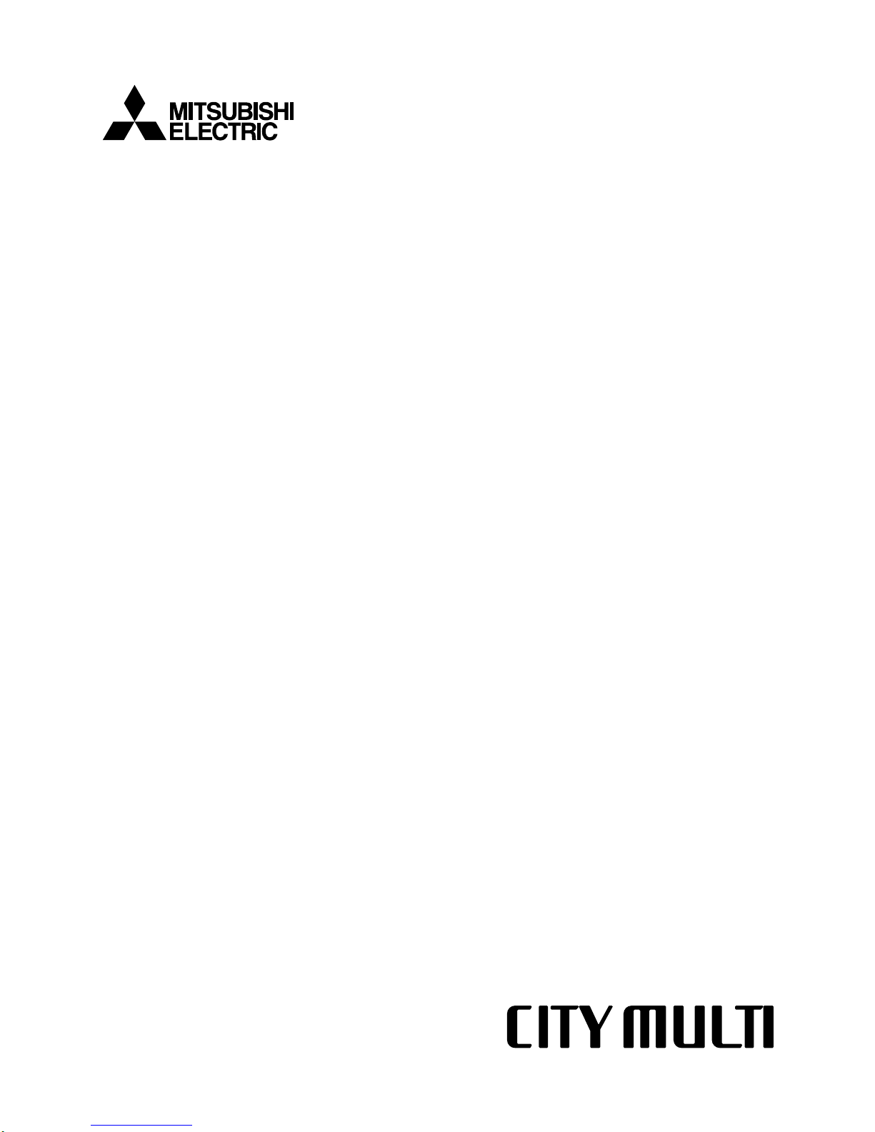
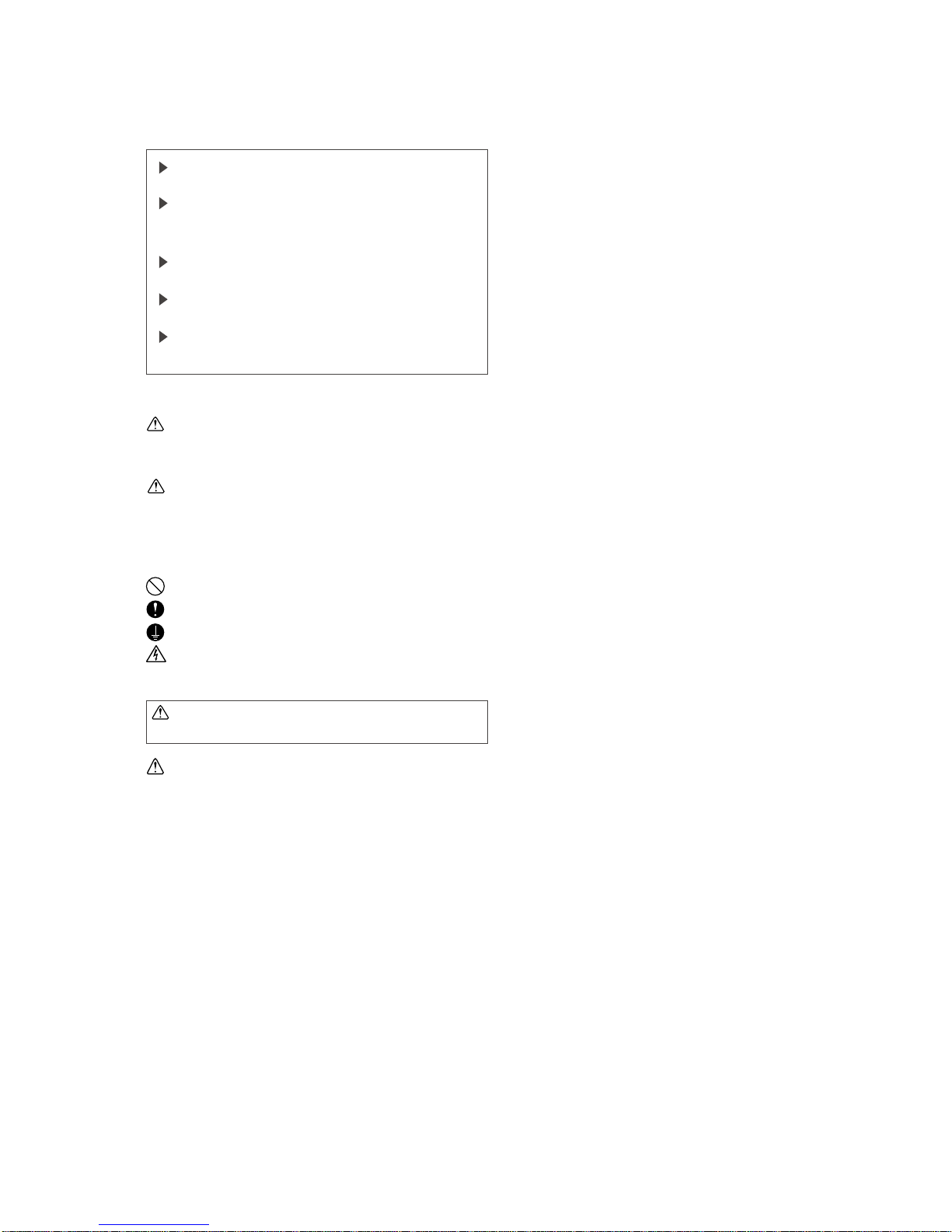
[1] Storage of Piping Material
(1) Storage location
Store the pipes to be used indoors. (Warehouse at site or owner’s warehouse)
Storing them outdoors may cause dirt, waste, or water to infiltrate.
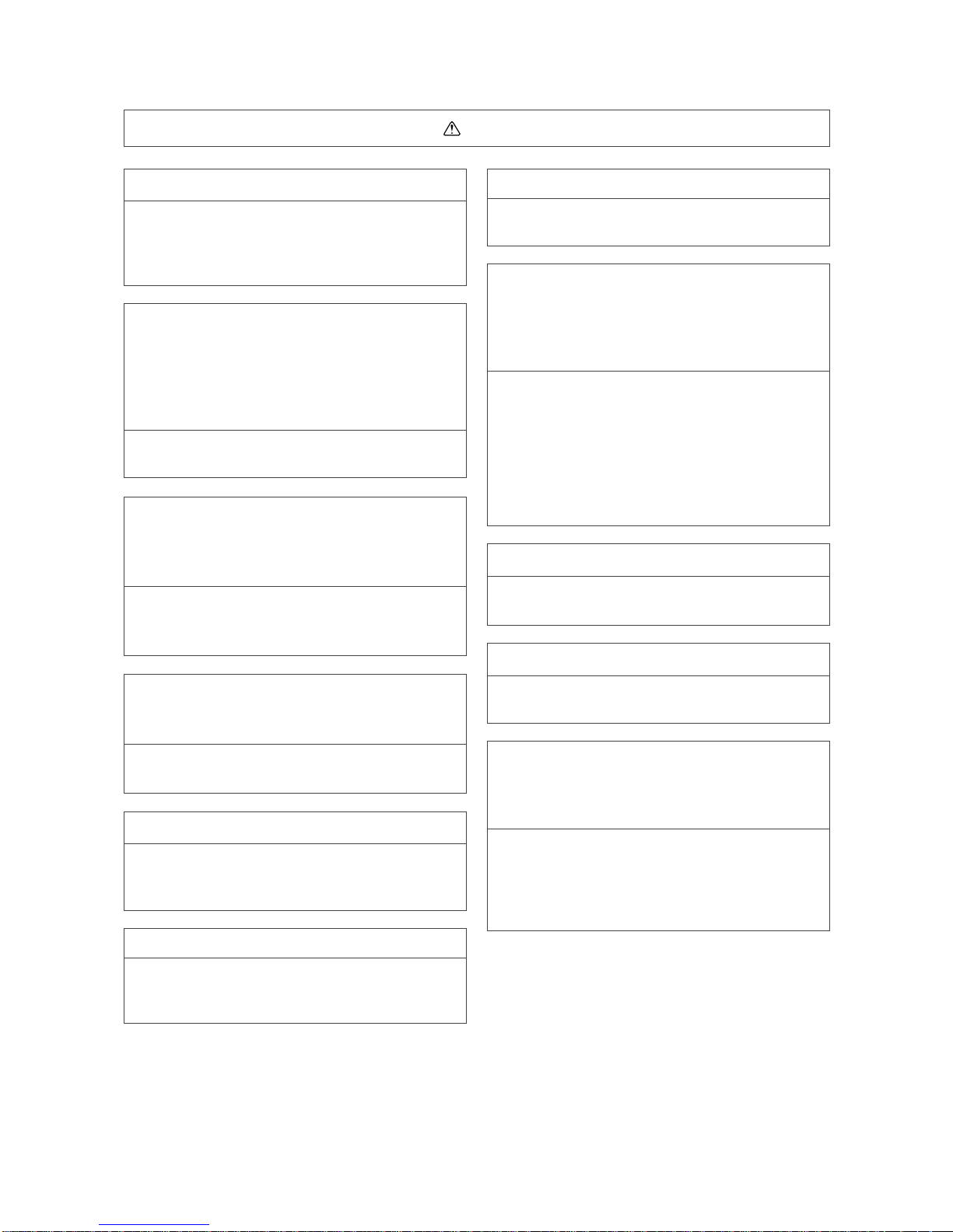
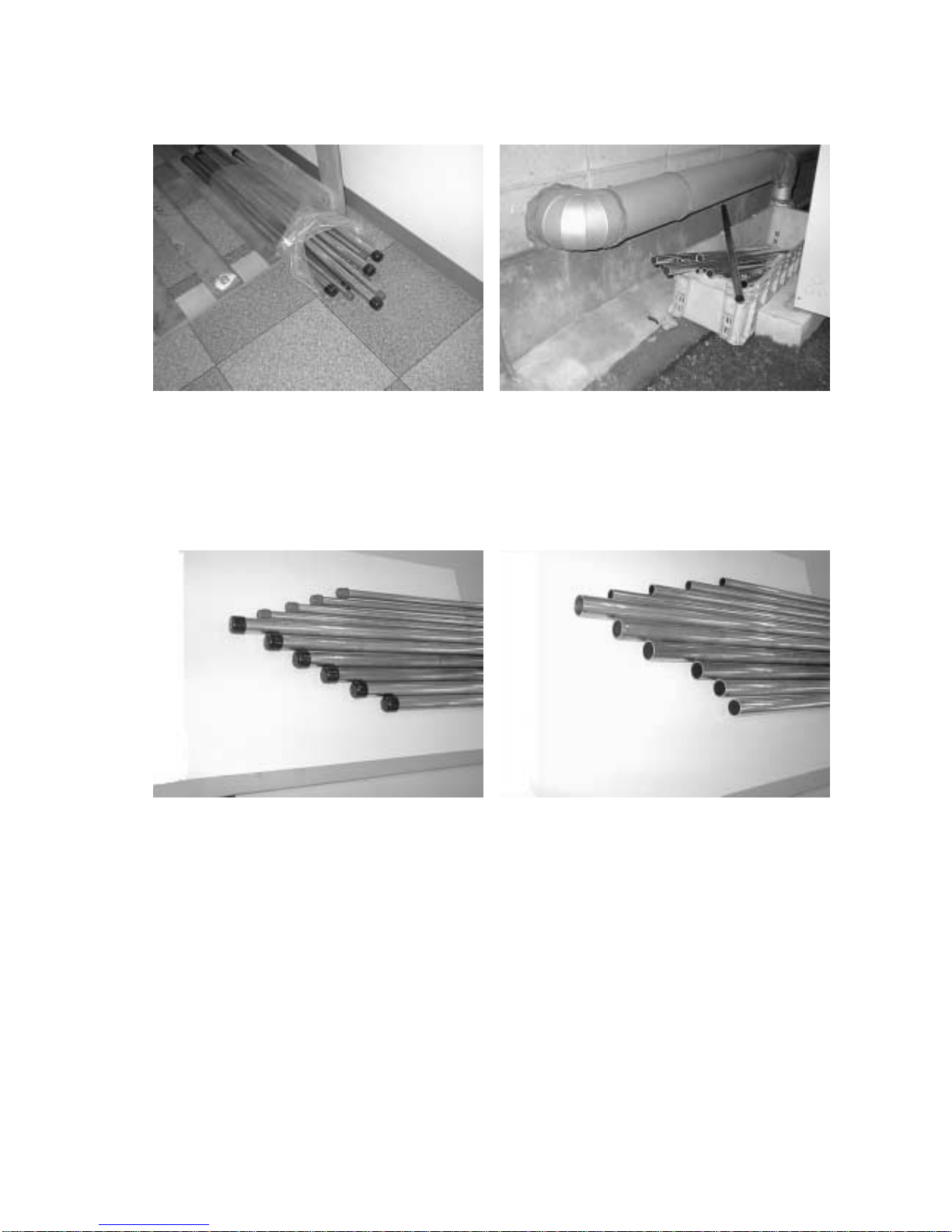
(2) Pipe sealing before storage
Both ends of the pipes should be sealed until immediately before brazing.
Wrap elbows and T’s in plastic bags for storage.
✻
The new refrigerator oil is 10 times more hygroscopic than the conventional refrigerator oil (such as Suniso). Water
infiltration in the refrigerant circuit may deteriorate the oil or cause a compressor failure. Piping materials must be
stored with more care than with the conventional refrigerant pipes.
OK
OK
NG
NG
- 4 -
[2] Piping Machining
Use ester oil, ether oil or alkylbenzene (small amount) as the refrigerator oil to coat flares and flange connections.
Use only the necessary minimum quantity of oil.
Reason :
1. The refrigerator oil used for the equipment is highly hygroscopic and may introduce water inside.
Notes :
• Introducing a great quantity of mineral oil into the refrigerant circuit may also cause a compressor failure.
• Do not use oils other than ester oil, ether oil or alkylbenzene.
- 5 -
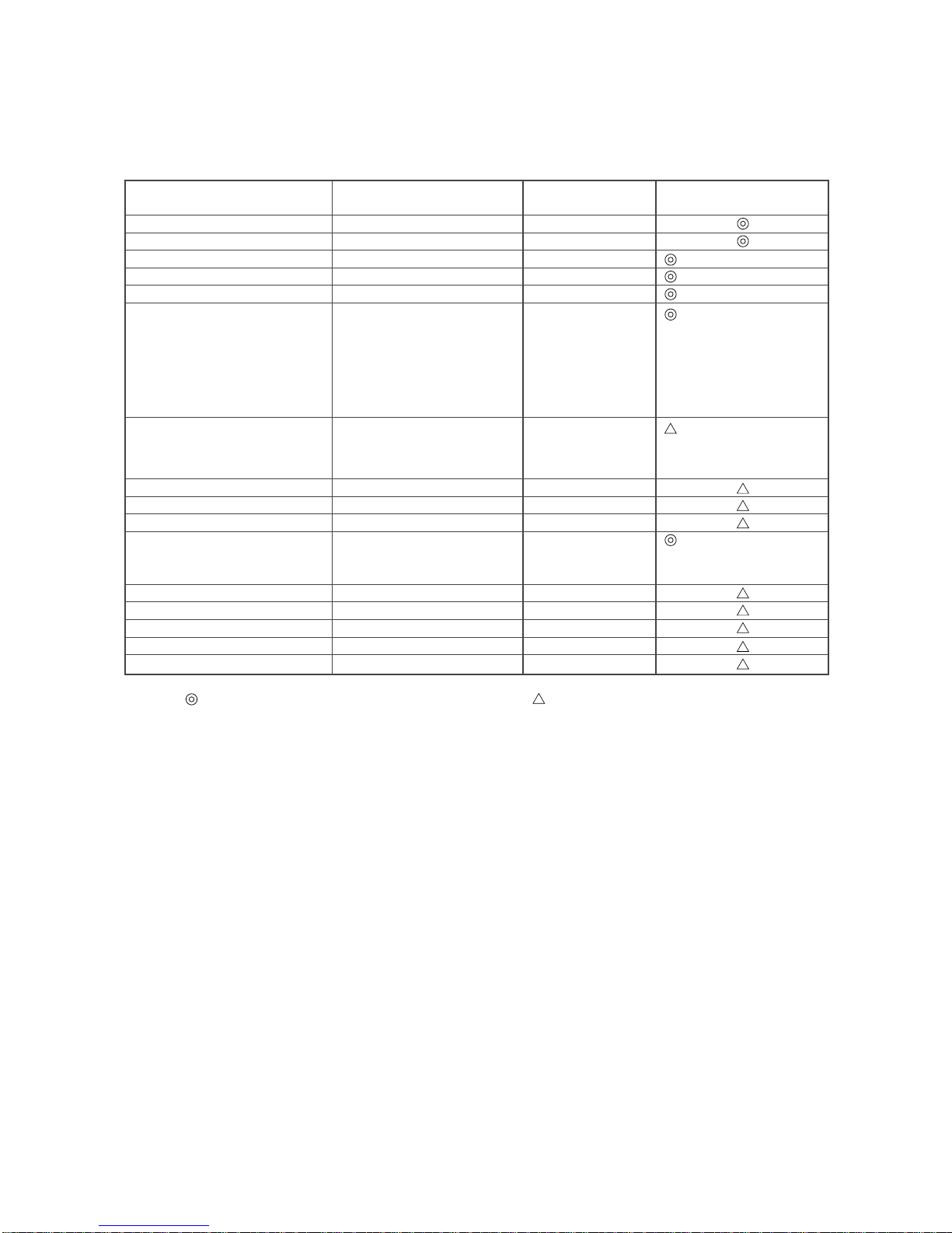
[3] Necessary Apparatus and Materials and Notes on Their Handling
The following tools should be marked as dedicated tools for R407C.
<<Comparison of apparatus and materials used for R407C and for R22>>
Apparatus Used Use R22 R407C
Gauge manifold Evacuating, refrigerant filling Current product
Charging hose Operation check Current product
Charging cylinder Refrigerant charging Current product Do not use.
Gas leakage detector Gas leakage check Current product Shared with R134a
Refrigerant collector Refrigerant collection R22 For R407C use only
Refrigerant cylinder Refrigerant filling R22
Vacuum pump Vacuum drying Current product
Vacuum pump with a check valve Current product
Flare tool Flaring of pipes Current product
Bender Bending of pipes Current product
Application oil Applied to flared parts Current product
Torque wrench Tightening of flare nuts Current product
Pipe cutter Cutting of pipes Current product
Welder and nitrogen cylinder Welding of pipes Current product
Refrigerant charging meter Refrigerant charging Current product
Vacuum gauge Checking the vacuum degree Current product
Symbols :
To be used for R407C only. Can also be used for conventional refrigerants.
Tools for R407C must be handled with more care than those for conventional refrigerants. They must not come into contact
with any water or dirt.
Identification of dedicated use for R407C
:Record refrigerant
name and put brown
belt on upper part of
cylinder.
Can be used by
attaching an adapter
with a check valve.
Ester oil or Ether oil or
Alkybenzene (Small
amount)
- 6 -
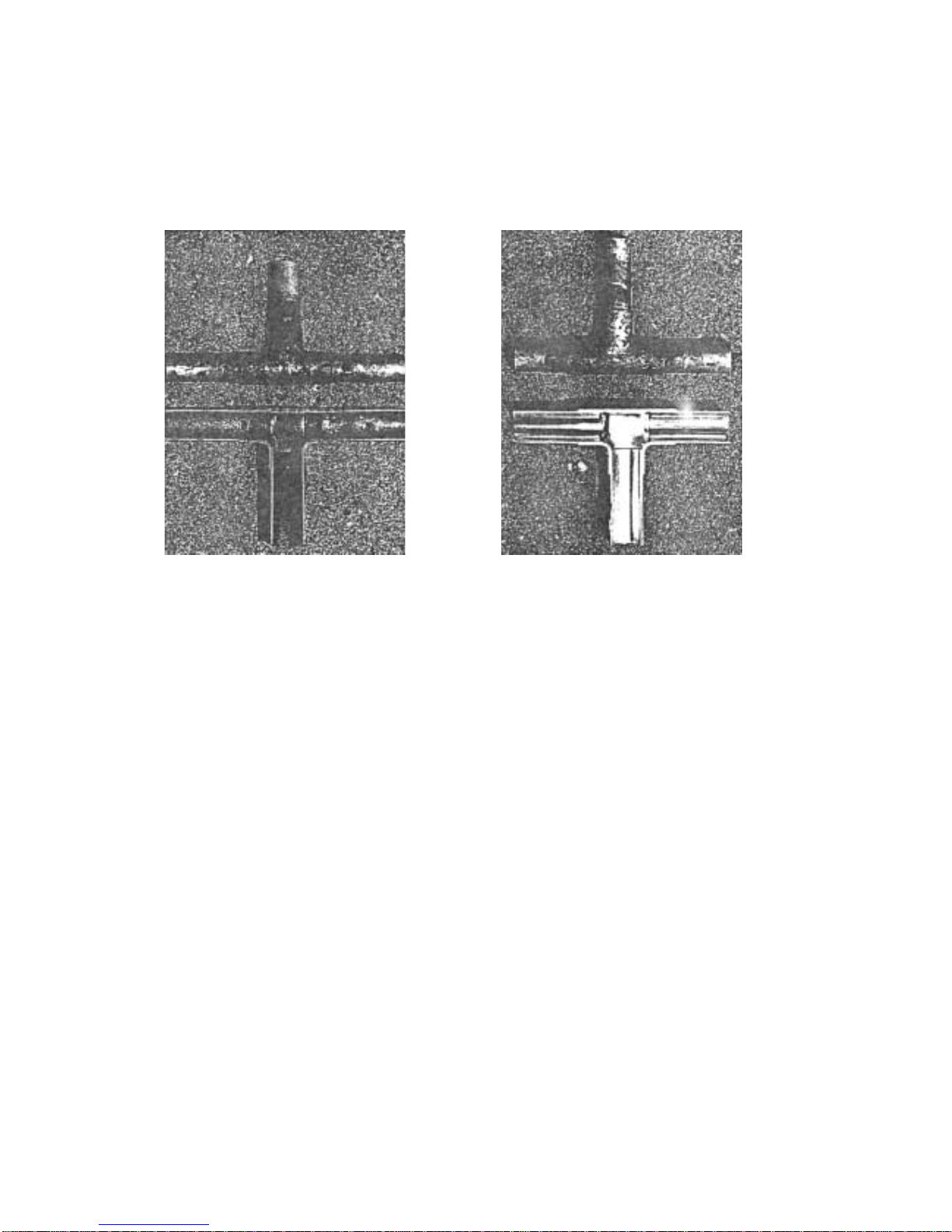
[4] Brazing
No changes from the conventional method, but special care is required so that foreign matter (ie. oxide scale, water, dirt,
etc.) does not enter the refrigerant circuit.
Example : Inner state of brazed section
When non-oxide brazing was not used When non-oxide brazing was used
Items to be strictly observed :
1. Do not conduct refrigerant piping work outdoors on a rainy day.
2. Apply non-oxide brazing.
3. Use a brazing material (BCuP-3) which requires no flux when brazing between copper pipes or between a copper pipe
and copper coupling.
4. If installed refrigerant pipes are not immediately connected to the equipment, then br az e and seal both ends of them.
Reasons :
1. The new refrigerant oil is 10 times more hygroscopic than the conventional oil. The probability of a machine failure if
water infiltrates is higher than with conventional refrigerant oil.
2. A flux generally contains chlorine. A residual flux in the refrigerant circuit may generate sludge.
Note :
• Commercially available antioxidants may have adverse effects on the equipment due to its residue, etc. When
applying non-oxide brazing, use nitrogen.
- 7 -
[5] Airtightness Test
No changes from the conventional method. Note that a refrigerant leakage detector for R22 cannot detect R407C
leakage.
Halide torch R22 leakage detector
Items to be strictly observed :
1. Pressurize the equipment with nitrogen up to the design pressure and then judge the equipment’s airtightness, taking
temperature variations into account.
2. When investigating leakage locations using a refrigerant, be sure to use R407C.
3. Ensure that R407C is in a liquid state when charging.
Reasons :
1. Use of oxygen as the pressurized gas may cause an explosion.
2. Charging with R407C gas will lead the composition of the remaining refrigerant in the cylinder to change and this
refrigerant can then not be used.
Note :
• A leakage detector for R407C is sold commercially and it should be purchased.
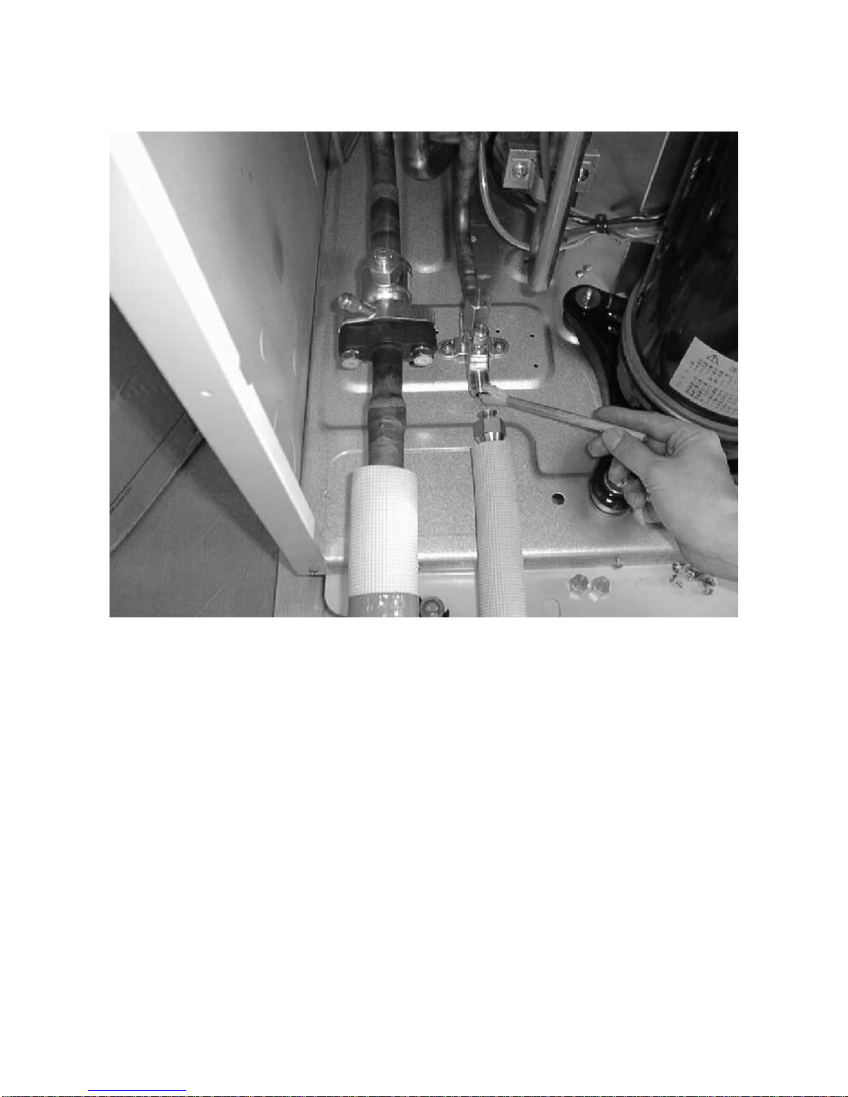
[6] Vacuuming
1. Vacuum pump with check valve
A vacuum pump with a check v alve is required to prevent the vacuum pump oil from flowing back into the refrigerant
circuit when the vacuum pump power is turned off (power failure).
It is also possible to attach a check valve to the actual vacuum pump afterwards.
2. Standard degree of vacuum for the vacuum pump
Use a pump which reaches 65Pa or below after 5 minutes of operation.
In addition, be sure to use a vacuum pump that has been properly maintained and oiled using the specified oil. If the
vacuum pump is not properly maintained, the degree of vacuum may be too low.
3. Required accuracy of the vacuum gauge
Use a vacuum gauge that can measure up to 650Pa. Do not use a general gauge manifold since it cannot measure a
vacuum of 650Pa.
4. Evacuating time
• Evacuate the equipment for 1 hour after 650Pa has been reached.
• After envacuating, leave the equipment for 1 hour and make sure the that vacuum is not lost.
5. Operating procedure when the vacuum pump is stopped
In order to prevent a backflow of the vacuum pump oil, open the relief valve on the vacuum pump side or loosen the
charge hose to drawn in air before stopping operation.
The same operating procedure should be used when using a vacuum pump with a check valve.
NG
NG
- 8 -
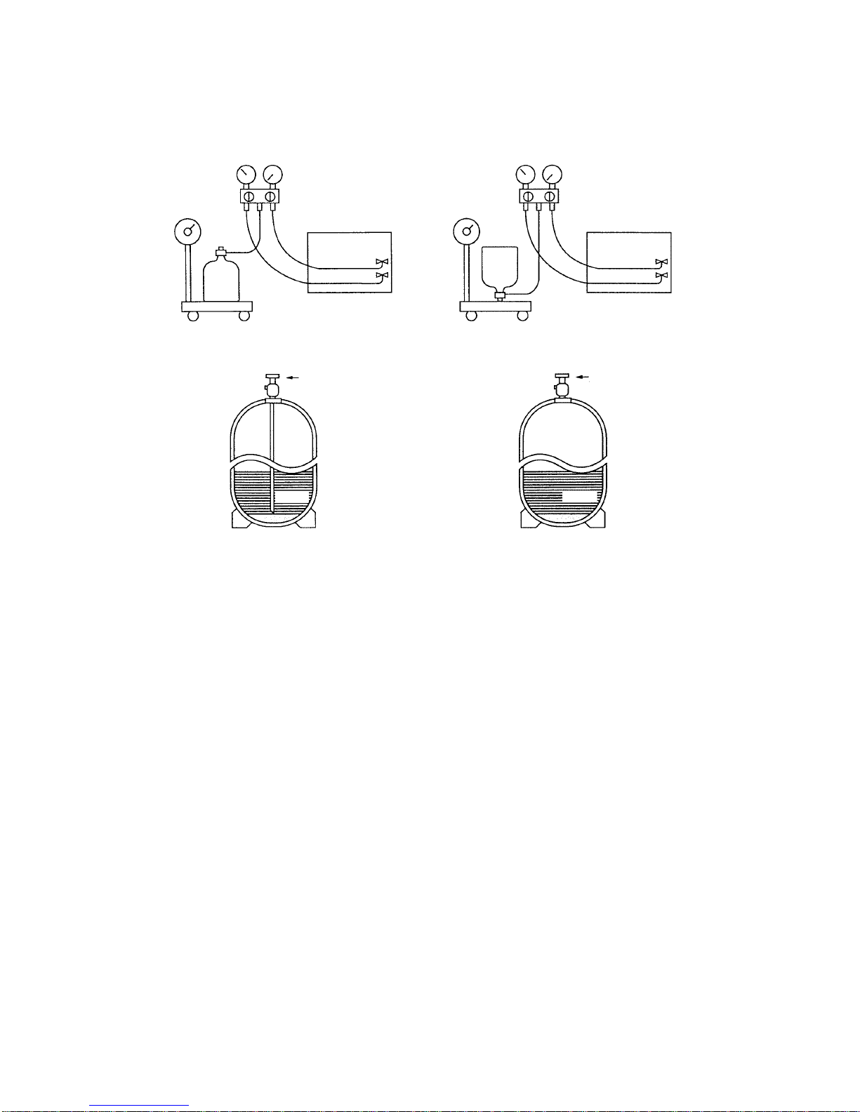
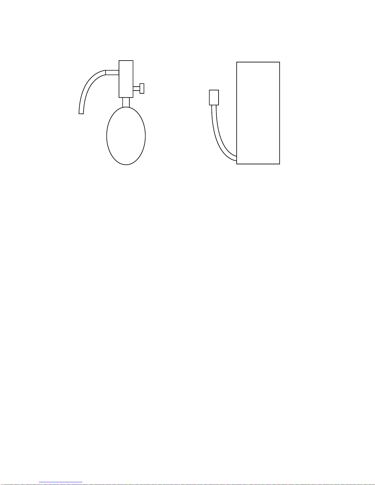
[7] Charging of Refrigerant
R407C must be in a liquid state when charging, because it is a non-azeotropic refrigerant.
For a cylinder with a syphon attached For a cylinder without a syphon attached
Cylinder color identification R407C-Gray Charged with liquid refrigerant
R410A-Pink
Reasons :
1. R407C is a mixture of 3 refrigerants, each with a different evaporation temperature. Therefore, if the equipment is
charged with R407C gas, then the refrigerant whose ev apor ation temperature is closest to the outside temper ature is
charged first while the rest of refrigerants remain in the cylinder.
Note :
• In the case of a cylinder with a syphon, liquid R407C is charged without turning the cylinder up side down. Check the
type of cylinder before charging.
[8] Dryer
1. Replace the dryer when the refrigerant circuit is opened (Ex. Change the compressor, full gas leakage). Be sure to
replace the dryer with a CITY MULTI (For use with R407C).
If any other product is used, the unit will be damaged.
2. Opening the refrigerant circuit after changing to a new dryer is less than 1 hour. The replacement of the dryer should
be the last operation performed.
Cylin-
der
Cylin-
der
Valve
Valve
Liquid
Liquid
- 9 -
™ COMPONENT OF EQUIPMENT
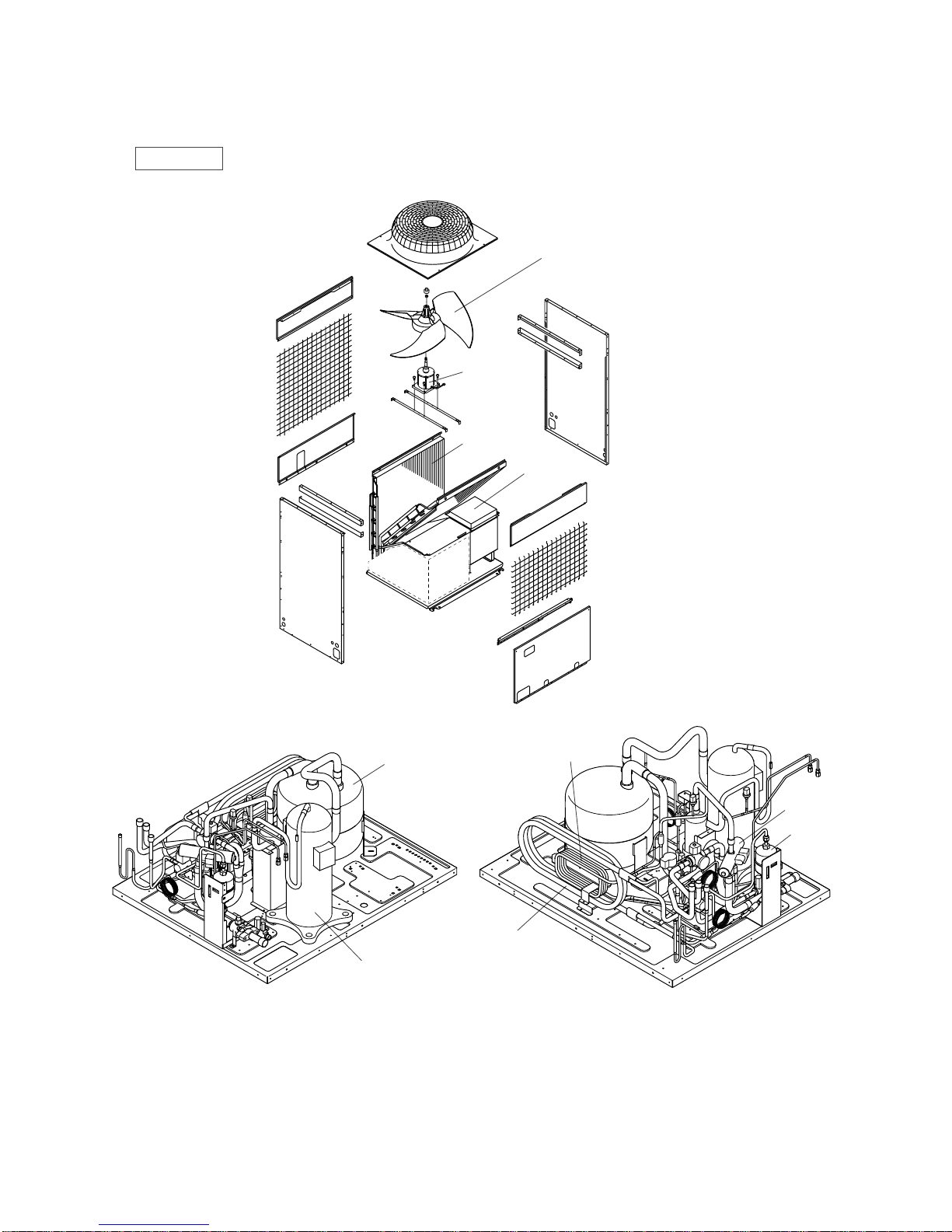
[1] Appearance of Components
Outdoor unit
• PUHY-P200, 250, 315YEM-A
Propeller fan
Accumlator
CSC
SCC
4way valve
Dryer
Compressor
Fan motor
Heat exchanger
Control box
- 10 -
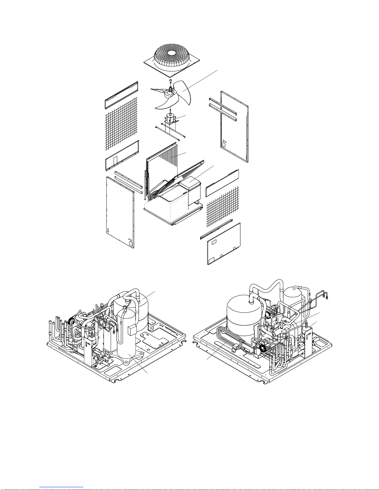
• PURY-P200·250YEM-A
Propeller fan
Accumulator
CSC
4way valve
Dryer
Compressor
Fan motor
Heat exchanger
Control box
- 11 -
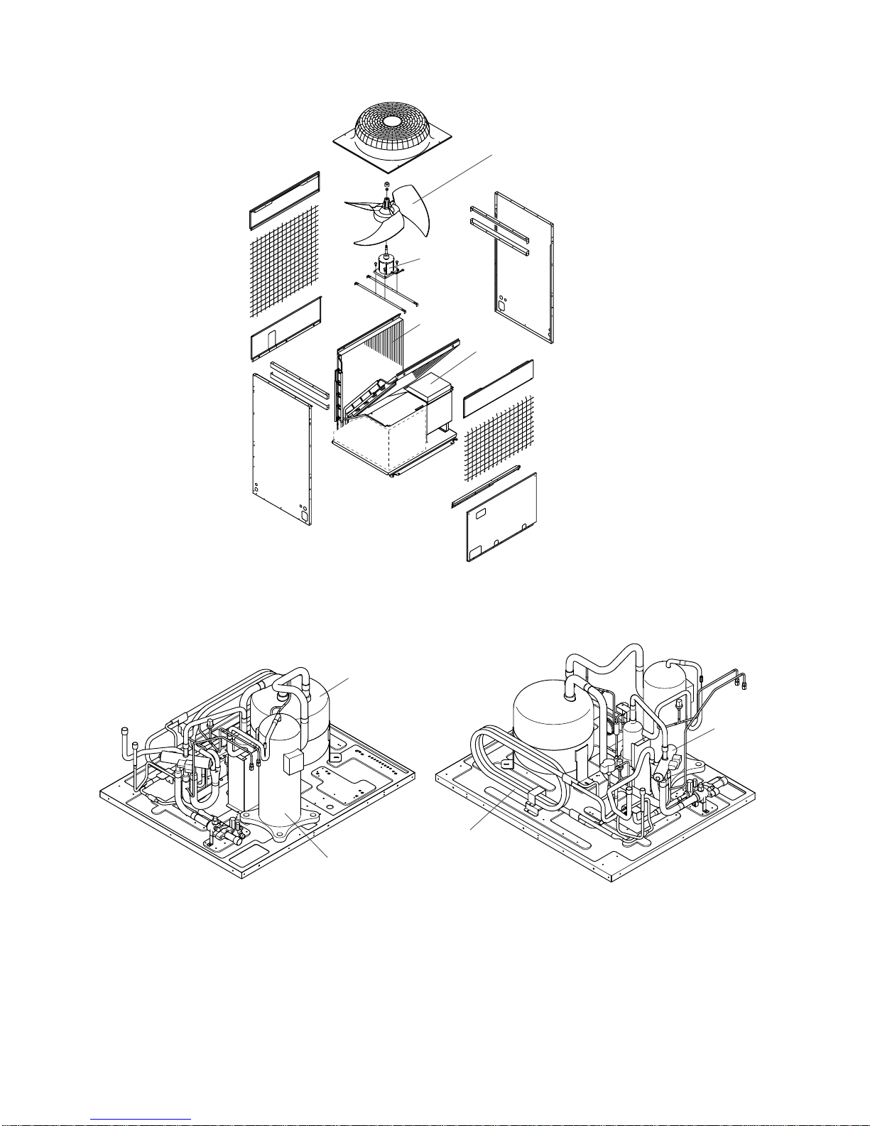
• PUHY-200, 250, 315YEM(K,C)-A
Propeller fan
Fan motor
Heat exchanger
Control box
Accumulator
SCC
4way valve
Compressor
- 12 -
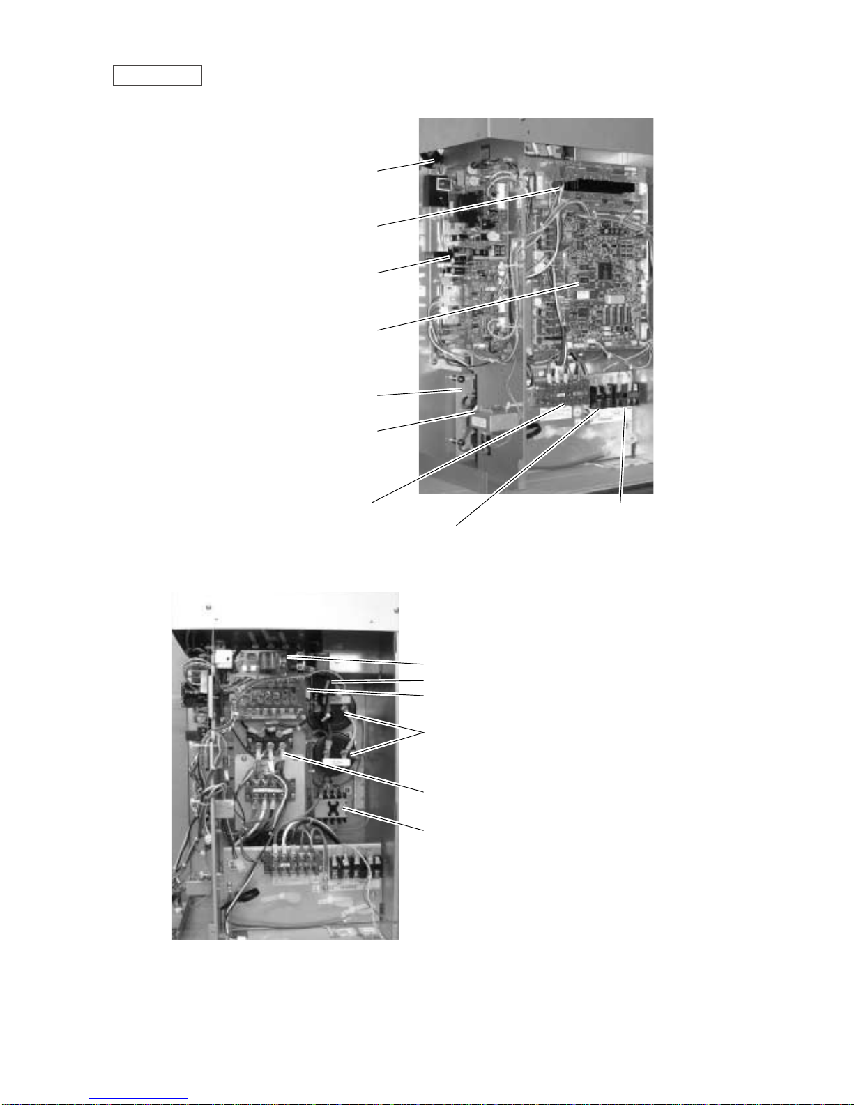
Controller Box
FANCON board
ACCT
INV board
MAIN board
Noise filter
Choke coil (L2)
Terminal block TB1A Power Source
Terminal block TB7 Transmission (Centralized control)
Terminal block TB3 Transmission
Inteligent Power Module (IPM)
G/A board
DCCT
Diode stack (DS)
Magnetic contactor (52C)
Capacitor (C2, C3)
(Smoothing capacitor)
- 13 -
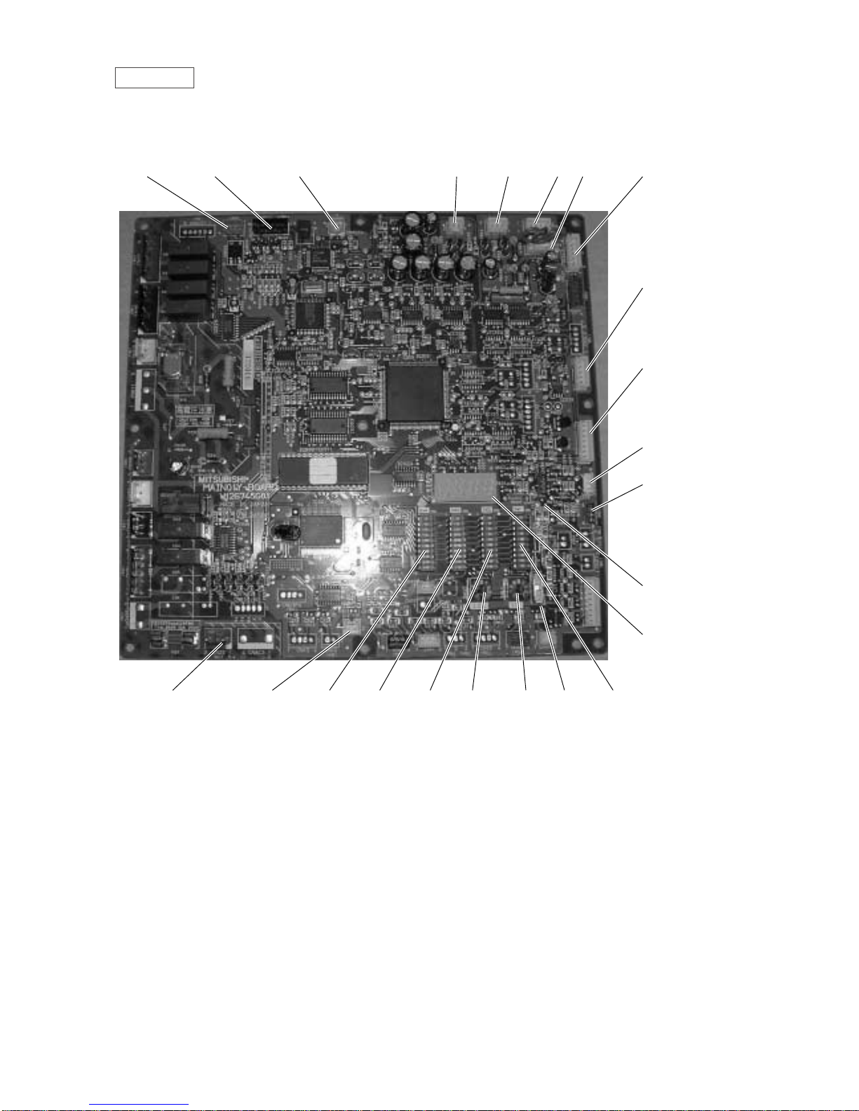
MAIN board
• PUHY / PURY
CN51
Indication distance
3-4 Compressor
ON/OFF
3-5 T rouble
CNRS3
Serial transmission to
INV board
CN3D
SW1
CNTR CNFC1
CNVCC4
Power source
for control(5V)
CN20
Power supply
3 L1
1 N
SW3
SW4
SW2 SWU2
SWU1
CNS1 CNS2 CN40 CN41 CNVCC3
Power Source
for control
1-2 30V
1-3 30V
4-6 12V
5-6 5V
CN3S
CN3N
LD1
Service LED
SWU3
CNTYP1
- 14 -
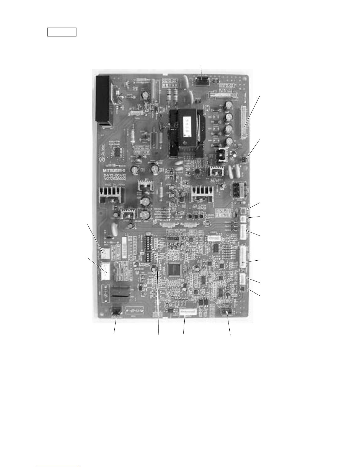
INV board
CNDR2
Out put to
G/A board
CNTH
CNCT
DCCT
CN15V2
Power supply
CNFG
Frame grounding
for IPM control
CNCT2
ACCT
CNAC2 I
Power source
1 L2
3 N
5 G
CN52AC
Control for
52C
CNRS2CN FAN
Control for MF1
Serial transmission
to MAIN board
SW1
CNVDC
1-4
DC-560V
CNVCC4
Power supply (5V)
CNL2
Choke coil
CNVCC2
Power supply
1-2 30V, 1-3 30V
4-6 12V, 5-6 5V
- 15 -
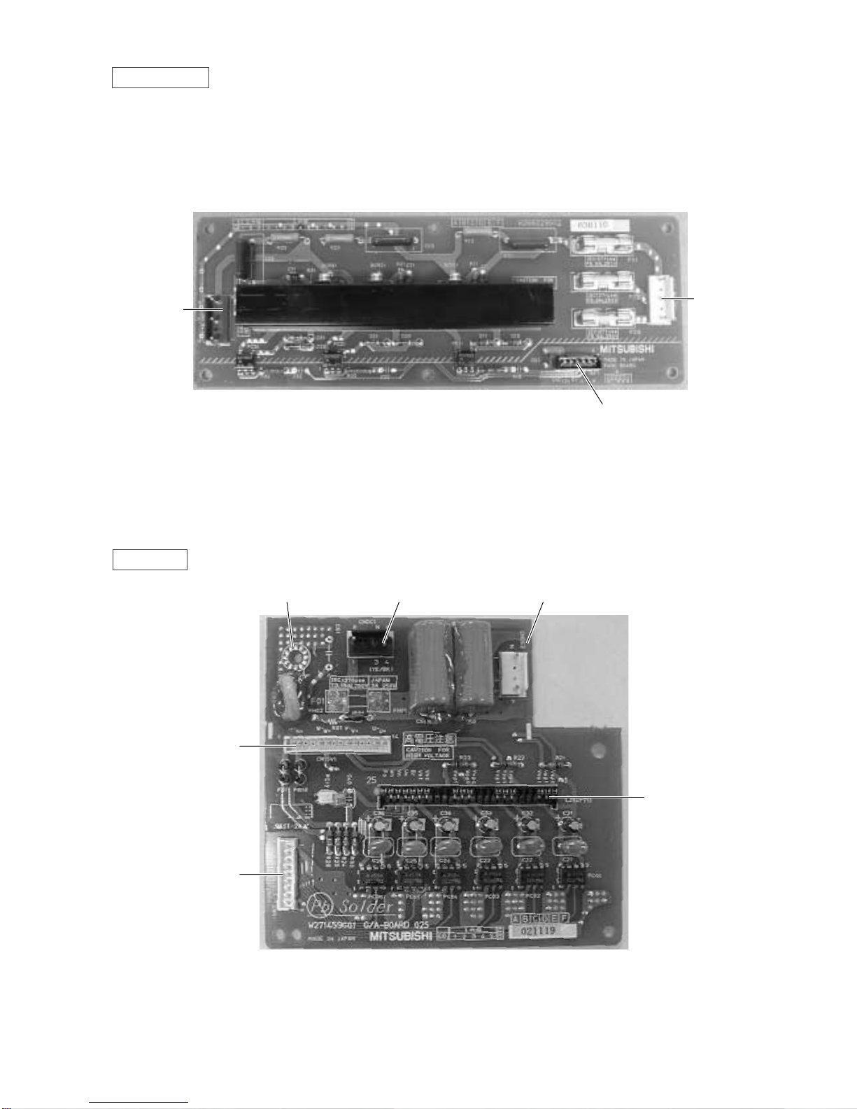
FANCON board
CNFAN
CNPOW
CNFC2
CN15V1
CNDR1
CNIPM1
G/A board
Terminal for
signal grounding
CNDC1 CNDC2
- 16 -
- 17 -
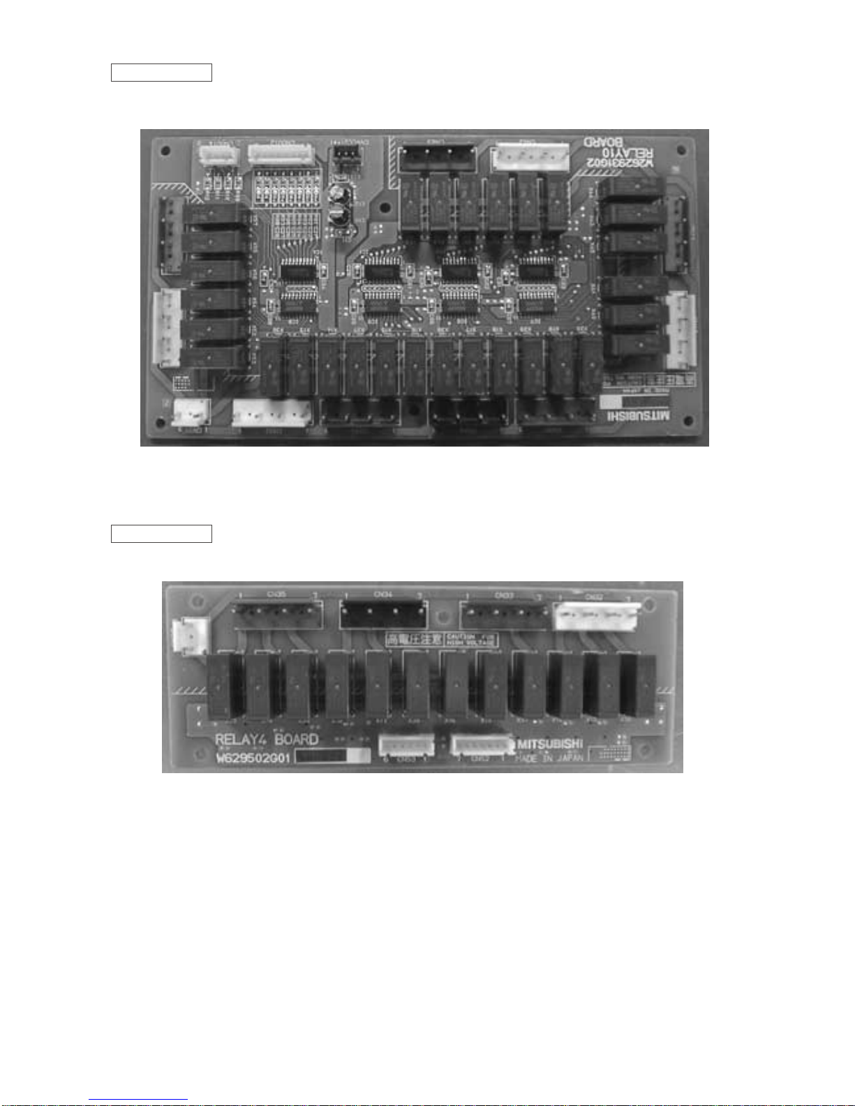
RELAY 10 board
RELAY 4 board
- 18 -
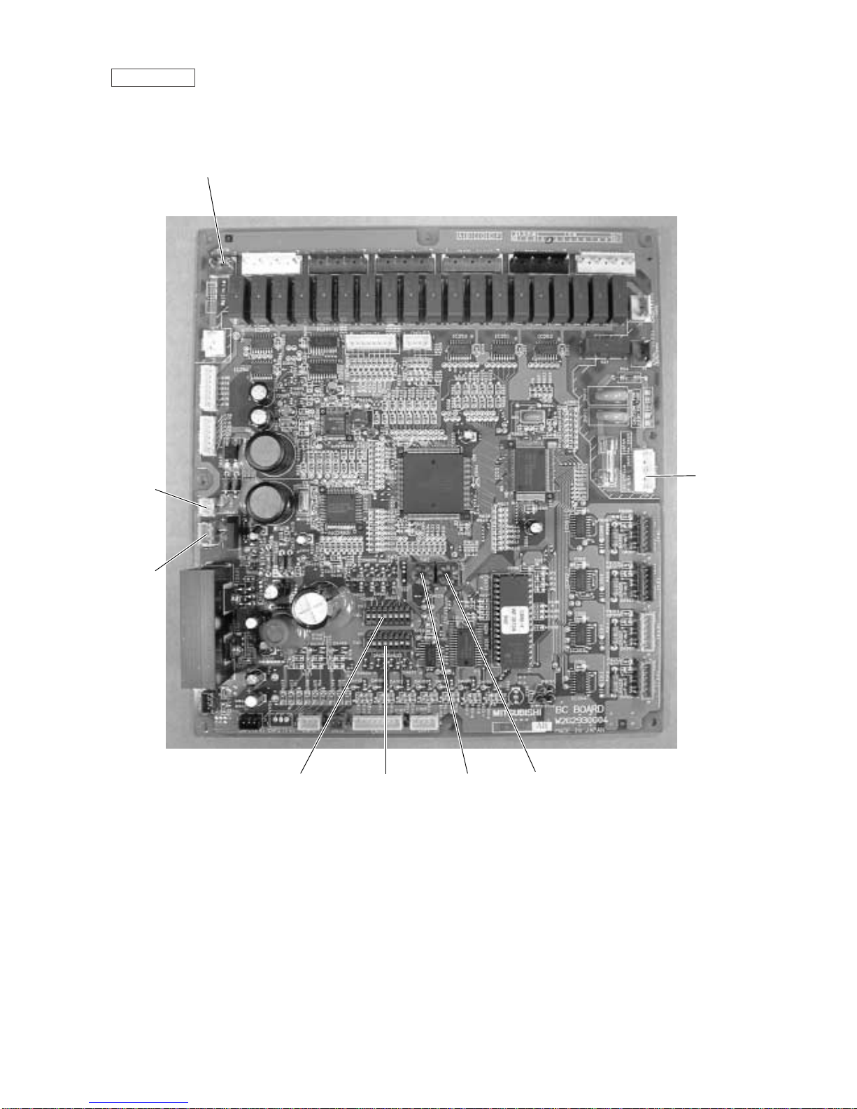
BC controller
SW4 SW5 SW2 SW1
CN12
Power
supply
1 EARTH
3 N
5 L
CN02
M-NET
transmission
CN03
CNTR
63HS
63LS
63H
ST4
SV1
SV3
SV4
BV2
ST3
ST2
TH7
TH1
TH6
TH8
TH2
CP4Drier ST10
ST9
TH5
SCC
LEV1
Comp
Accumulator
ST7
ST6
CP1
CP3
ST8
ST5
O/S
Indoor units
CJ1 CJ2
BV1
ST1
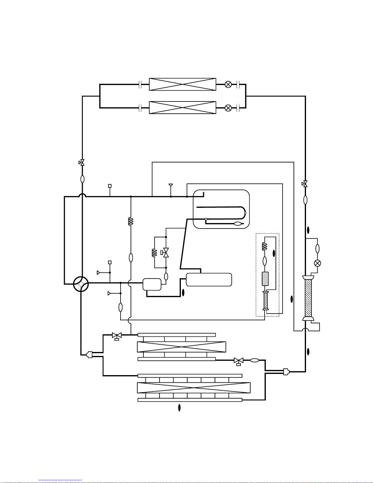
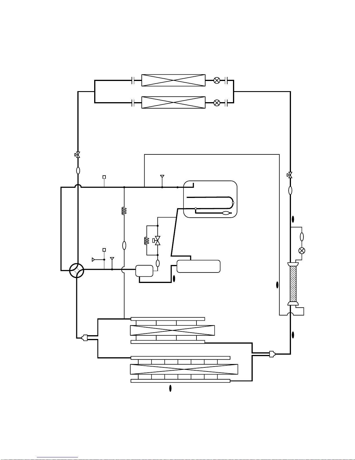
[2] Refrigerant Circuit Diagram and Thermal Sensor
1PUHY-P200/250/315YEM-A
- 19 -
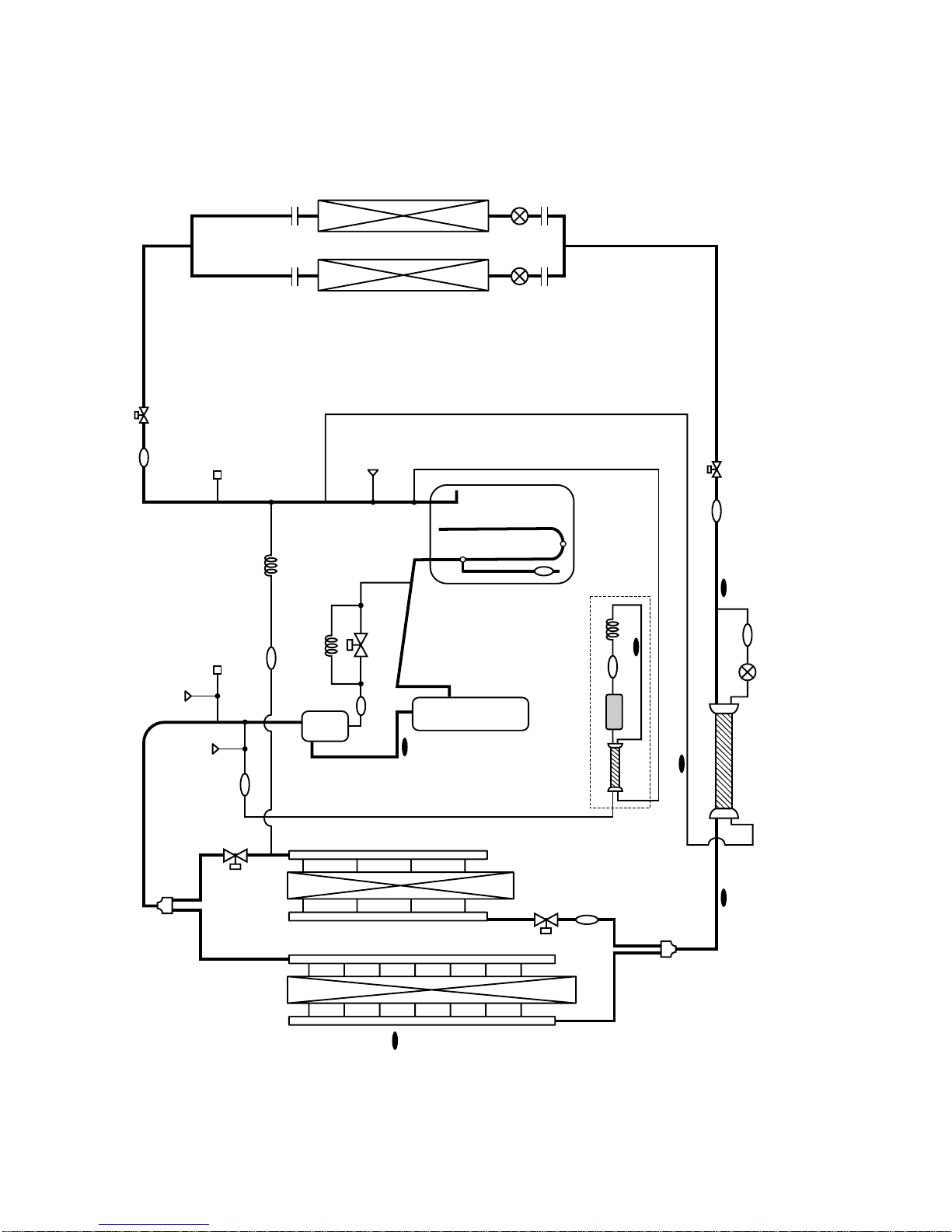
2PUY-P200/250/315YEM-A
63HS
63LS
63H
ST4
SV1
SV3
SV4
BV2
ST3
ST2
TH7
TH1
TH6
TH8
TH2
CP4Drier ST10
ST9
TH5
SCC
LEV1
Comp
Accumulator
ST7
ST6
CP1
CP3
ST8
ST5
O/S
Indoor units
CJ1 CJ2
ST1
BV1
- 20 -
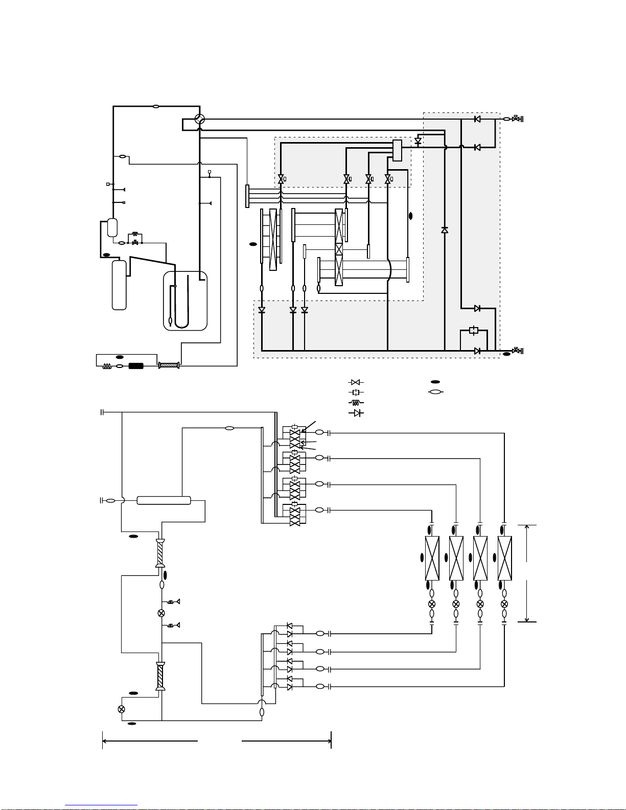
3 PURY-P200/250YEM-A
TH23
TH21
TH22
LEV
SVC
SVA
SVB
Indoor
units
BC controller
CMB-P104V-F
Gas/liquid separator
63HS1
LEV1
63HS3
LEV3
TH12
TH11
TH15
TH16
: Solenoid valve
: Orifice
: Capillary
: Check valve
: Thermal sensor
: Strainer
SP : Service port
ACC : Accumulator
CP1
SV1
ST3
TH1
TH2
TH6
TH7
CP2 ST4
Drier
HEXf1
HEXf2
HEXf3
HEXb
CS circuit
Comp
Accumulator
ST7
ST6
O/S
CJ1
63HS
63H
ST2
21S4
ST8
63LS
CV2
CV3
CV7
ST1
BV1
SV3 SV4 SV5 SV6
CV5
Orifice
CV6
CV8 CV9 CV10
TH5
BV2
CV4
ST9
ST10
ST11
ST5
Check Valves Block
Solenoid Valves Block
CJ2
- 21 -
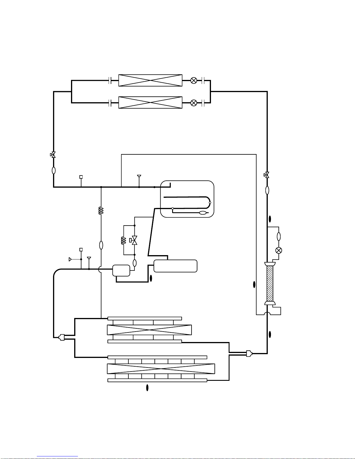
4 PUHY-200/250/315YEM(K,C)-A
63HS
63LS
63H
ST4
SV1
BV2
ST3
ST2
TH7
TH1
TH6
TH8
TH5
SCC
LEV1
Comp
Accumulator
ST7
ST6
CP1
CP3
ST8
O/S
Indoor units
CJ1 CJ2
BV1
ST1
- 22 -
5PUY-200/250/315YEM-A
63HS
63LS
63H
ST4
SV1
BV2
ST3
ST2
TH7
TH1
TH6
TH8
TH5
SCC
LEV1
Comp
Accumulator
ST7
ST6
CP1
CP3
ST8
O/S
Indoor units
CJ1 CJ2
ST1
BV1
- 23 -
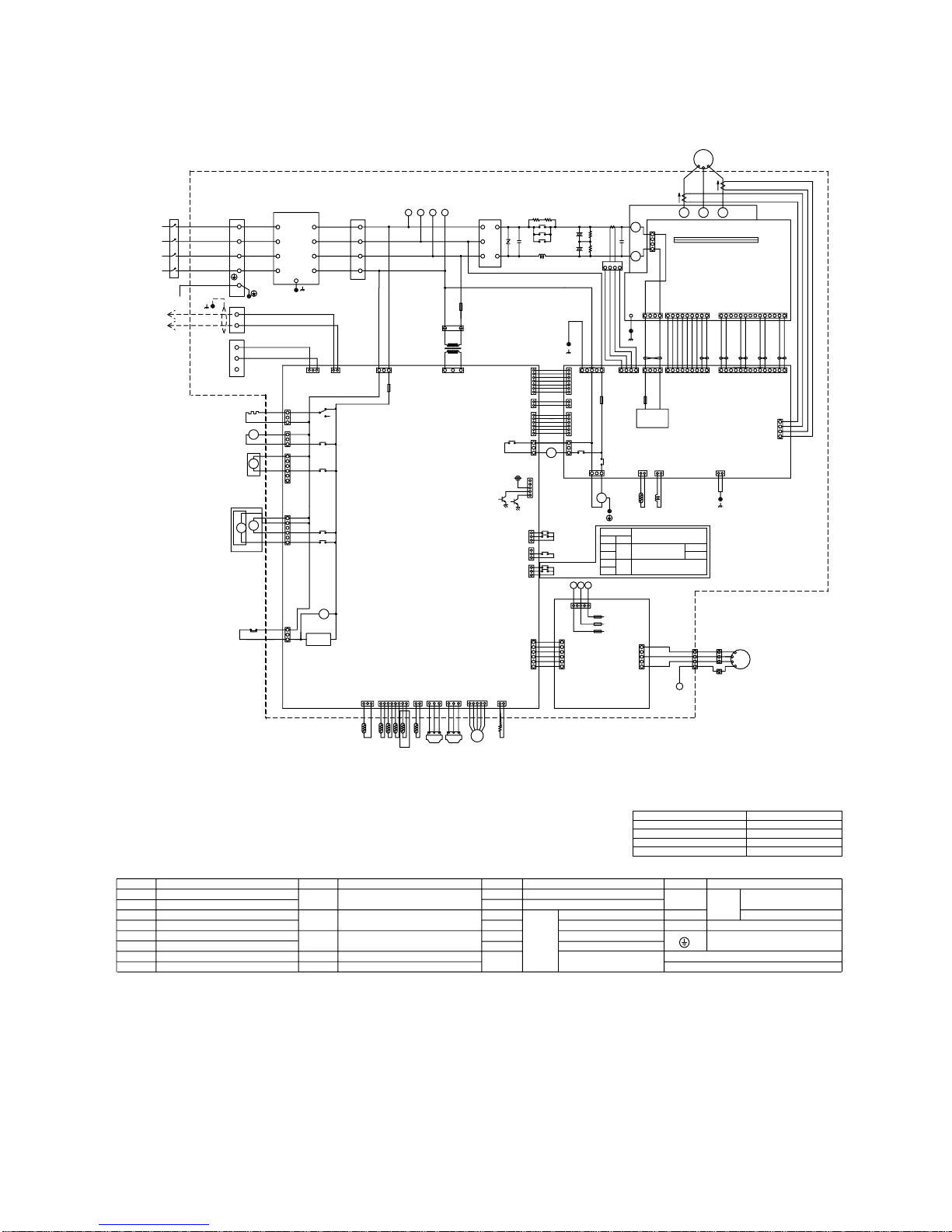
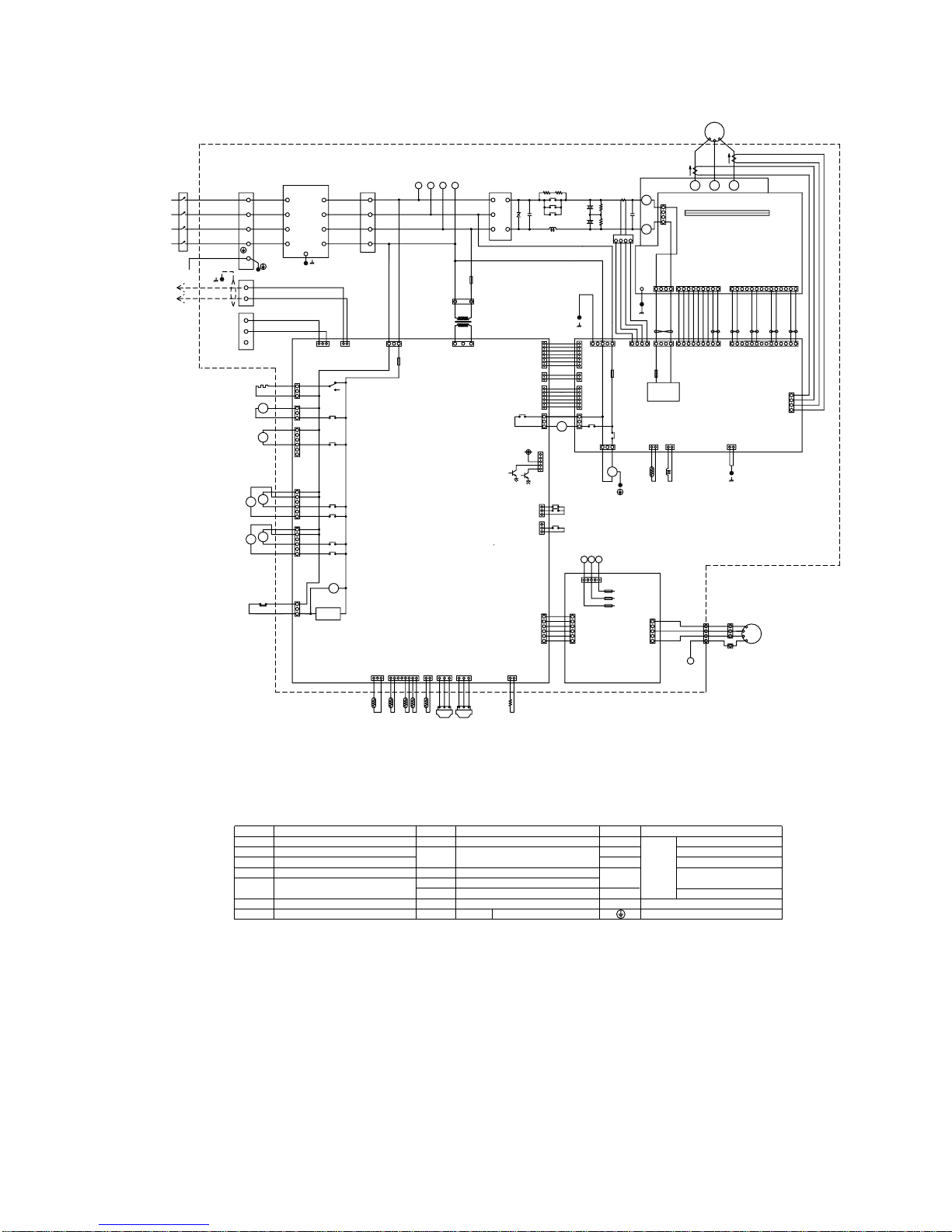
[3] Electrical Wiring Diagram
1 PU(H)Y-(P)200·250·315YEM(K,C)-A
<SYMBOL EXPLANATION>
Noise
Filter
Terminal
Block
N
L3
L2
L1
N
L3
L2
L1
Blue
Black
White
Red
NF
Blue
Black
Red
White
L1
TB1B
BOX BODY
N
L3
L2
High pressure
switch
Crank case heater
(Compressor)
circuit
detection
CN34
(6P)
6
5
4
3
2
1
1
2
3
CN38
(3P)
X10
X04
21S4
63H
(3P)
CN32
CH1
SV1
X01
X02
(3P)
CNS2
2
(2P)
CNS1
13 112
2
3
2
1
(3P)
CN33
3
CN36
(6P)
6
5
4
3
2
1
X06
X07
SV3
SV4
L1L2L3
N
ACCT
-W
BOX BODY
BOX BODY THHS
Diode
stack
Blue
Red
White
Black
Brown
Red
BOX BODY
(INV board)
Power circuit board
L2
MF1
(2P)
CNFG
(2P)
CNL2
(14P)
CN15V2
(3P)
CNTR
(3P)
CNFAN
(7P)
CNRS3
(6P)
CNVCC2
(6P)
CNVCC3
(2P)
CNVCC4
(7P)
CNRS2
X10
X01
X02
52C
3
2
1
6
5
1
2
3
4
5
6
7
1
2
1
4
3
2
2
938716
21432
21
12
12
3
Black
Red
Motor
(Compressor)
V
MC1
W
U
White
CNTR1
1A F
250VAC
F3
T01
R3
R2
C3
C4
C2
DCL
+
+
52C
R1
R5
C1
ZNR4
+
-
DS
2A F
250VAC
F1
4:Compressor ON/OFF
5:Trouble
12V
(2P)
CNTH
(4P)
CNVDC
4321
(4P)
CNCT
3
(3P)
CN52CAC
2
(3P)
CNX10
1
(5P)
CNAC21
(5P)
CN51
(2P)
CNVCC4
2
(3P)
CN20
31
2A T
250VAC
F01
2A T
700VDC
F02
1
5
3
2
2
4
1
3
6
5
1
2
3
4
5
6
7
1
2
1
4
3
2
1
CNDC1
(4P)
123
4
12345
987612345
CNDR2
(9P)
14131110 12
121011 1314
54321 6789
543216789
Yel low
Orange
Purple
Black
White
Gray
5
1
2
3
4
UVW
P
N
Gate amp board
(G/A board)
IPM
CNDR1
(9P)
CN15V1
(14P)
Orange
Brown
4
CNCT2
(4P)
ACCT
-U
Green
1
2
3
4
CNDC2
(4P)
123
4
DCCT
BOX BODY
Fan control board
(Fancon board)
(5P)
CNPOW
L3L2L1
15423
F02 250VAC 6.3A F
F03 250VAC 6.3A F
F01 250VAC 6.3A F
N
3
4
2
1
3
1
2
4
5
CNFC2
(6P)
1
2
3
4
5
6
1
2
3
4
5
6
(6P)
CNFC1
Control circuit board
(MAIN board)
(3P)
CN3D
2
3
1
Fan motor
(Heat exchanger)
V
W
N
U
MF
1
3
2
CN3S
(3P)
(5P)
CNFAN
CN04
(3P)
CN3N
2
3
1
SNOW
DEMAND
NIGHT MODE
OR COMPRESSOR
ON/OFF
OFF
ON
1-2
CN3N
OFF
ON
1-3
ON
OFF
Mode
Auto
Normal
changeover
HEAT
COOL
DC-DC
Converter
Symbol
DCL
ACCT-U,W
52C
ZNR4 Varistor
DC reactor (Power factor improvement)
Current Sensor
Magnetic contactor (Inverter main circuit)
N a m e
Fan motor (Radiator panel)MF1
Solenoid valve (Discharge--suction bypass)SV1
4--way valve
21S4
❇1
Symbol
63HS
SV3
❇2
Solenoid valve
(Heat exchanger capacity control)
SV4
❇1,❇2
Solenoid valve
(Heat exchanger capacity control)
LEV1
High pressure sensor
63LS Low pressure sensor
Electric expansion valve
(Sub-cool coil bypass)
N a m e
Choke coil (Transmission)L2
IPM Intelligent power module
TH5
TH2
❇2
TH1
N a m eSymbol
OA temp. detect
Pipe temp. detect
liquid outlet temp. detect
at Sub--cool coil
TH7
TH6
Saturation evapo. temp. detect
Discharge pipe temp. detect
Thermistor
Thermistor
bypass outlet temp. detect
at Sub--cool coil
TH8
Symbol N a m e
N a m e
THHS Radiator panel temp. detect
Aux. relayX1~10
Earth terminal
DCCT
Current Sensor
Refer to the service handbook
about the switch operations.
❇2
❇1
❇1
12
R20
CNTYP1
(2P)
TH6
(3P)
CNL
(3P)
CNH
(2P)
CN01
(8P)
CN02
(3P)
CN03
63LS
321
63HS
Red
White
Black
Red
White
Black
TH2
TH1
321
3213212187632112345
TH7TH5
❇
2
LEV1
(5P)
CNLV1
54321
TH8
~
~
~
PUHY-P200/250YEM-A
PUY-P200/250YEM-A
PUY-200/250YEM-A
PUHY-200/250YEM-A
All exists
“❇1”
are not existed
“❇2”
are not existed
“❇1”
and
“❇2”
are not existed
<DIFFERENCE OF APPLIANCE>
Appliance
BOX BODY
BOX BODY
Terminal
Block
Controller Box
Inverter
M2
M1
TB3
controller
remote
Indoor and
Connect to
Yellow
Green/
Blue
Black
Red
White
PE
L1
L2
TB1A
50/60Hz
3N~380/400/415V
Power source
L3
N
N
PE
L3
L1
M1
L2
TB7
M2
S
- 24 -
2 PURY-P200·250YEM-A
Symbol
DCL
DCCT
ACCT-U,W
52C
ZNR4 Varistor
(Power factor improvement)
DC reactor
Current Sensor
Current Sensor
(Inverter main circuit)
Magnetic contactor
N a m e Symbol
Choke coil(Transmission)
SV1
L2
63HS
Solenoid valve (Discharge--suction bypass)
SV3~SV6
Fan motor (Radiator panel)
MF1
4--way valve21S4
High pressure sensor
Low pressure sensor
63LS
N a m e
Solenoid valve
(Heat exchanger capacity control)
IPM Intelligent power module
TH5
TH2
<SYMBOL EXPLANATION>
TH1
N a m eSymbol
OA temp. detect
Pipe temp. detect
liquid outlet temp. detect
at Sub--cool coil
TH7
TH6
Saturation evapo. temp. detect
Discharge pipe temp. detect
Radiator panel temp. detectTHHS
Aux. relay
X1~10
Thermistor
Thermistor
Earth terminal
BOX BODY
BOX BODY
Noise
Filter
Terminal
Block
Terminal
Block
N
L3
L2
L1
N
L3
L2
L1
Blue
Black
White
Red
NF
Blue
Black
Red
White
L1
TB1B
BOX BODY
N
L3
L2
Controller Box
Inverter
M2
M1
TB3
controller
remote
Indoor and
Connect to
Yellow
Green/
Blue
Black
Red
White
PE
L1
L2
TB1A
50/60Hz
3N~380/400/415V
Power source
L3
N
N
PE
L3
L1
M1
L2
High pressure
switch
Crank case heater
(Compressor)
circuit
detection
CN34
(6P)
6
5
4
3
2
1
1
2
3
CN38
(3P)
X10
X04
21S4
63H
(3P)
CN32
TB7
CH1
SV1
X01
X02
(3P)
CNS2
2
(2P)
CNS1
13 112
2
3
2
1
(3P)
CN33
3
M2
S
CN36
(6P)
CN37
(6P)
6
5
4
3
2
1
6
5
4
3
2
1
X06
X08
X07
X07
SV3
SV4
SV5
SV6
L1L2L3
N
ACCT
-W
BOX BODY
BOX BODY THHS
Diode
stack
Blue
Red
White
Black
Brown
Red
BOX BODY
(INV board)
Power circuit board
L2
MF1
(2P)
CNFG
(2P)
CNL2
(14P)
CN15V2
(3P)
CNTR
(3P)
CNFAN
(7P)
CNRS3
(6P)
CNVCC2
(6P)
CNVCC3
(2P)
CNVCC4
(7P)
CNRS2
X10
X01
X02
52C
3
2
1
6
5
1
2
3
4
5
6
7
1
2
1
4
3
2
2
938716
21432
21
1
2
12
3
Black
Red
Motor
(Compressor)
V
MC1
W
U
White
CNTR1
1A F
250VAC
F3
T01
R3
R2
C3
C4
C2
DCL
+
+
52C
R1
R5
C1
ZNR4
+
-
DS
2A F
250VAC
F1
4:Compressor ON/OFF
5:Trouble
12V
(2P)
CNTH
(4P)
CNVDC
4321
(4P)
CNCT
3
(3P)
CN52CAC
2
(3P)
CNX10
1
(5P)
CNAC21
(5P)
CN51
(2P)
CNVCC4
2
(3P)
CN20
31
2A T
250VAC
F01
2A T
700VDC
F02
1
5
3
2
2
4
1
3
6
5
1
2
3
4
5
6
7
1
2
1
4
3
2
1
CNDC1
(4P)
123
4
12345
987612345
CNDR2
(9P)
14131110 12
121011 1314
54321 6789
543216789
Yellow
Orange
Purple
Black
White
Gray
5
1
2
3
4
UVW
P
N
Gate amp board
(G/A board)
IPM
CNDR1
(9P)
CN15V1
(14P)
Orange
Brown
4
CNCT2
(4P)
ACCT
-U
Green
1
2
3
4
CNDC2
(4P)
123
4
DCCT
BOX BODY
Fan control board
(Fancon board)
(5P)
CNPOW
L3L2L1
15423
F02 250VAC 6.3A F
F03 250VAC 6.3A F
F01 250VAC 6.3A F
N
3
4
2
1
3
1
2
4
5
CNFC2
(6P)
1
2
3
4
5
6
1
2
3
4
5
6
(6P)
CNFC1
Control circuit board
(MAIN board)
(3P)
CN3D
2
3
1
Fan motor
(Heat exchanger)
V
W
N
U
MF
1
3
2
CN3S
(3P)
(5P)
CNFAN
CN04
SNOW
DEMAND
NIGHT MODE
OR COMPRESSOR
ON/OFF
Refer to the service handbook
about the switch operations.
12
R20
CNTYP1
(2P)
TH6
(3P)
CNL
(3P)
CNH
(2P)
CN01
(8P)
CN02
(3P)
CN03
63LS
321
63HS
Red
White
Black
Red
White
Black
TH2 TH1
321
3213212187632112345
TH7TH5
DC-DC
Converter
~
~
~
- 25 -
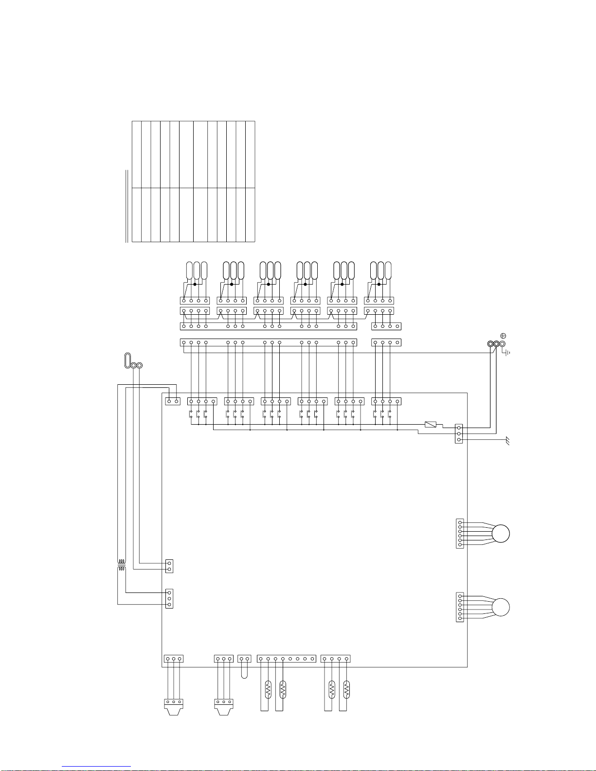
Symbol explanation
F01
250VAC
6.3A F
T6
T2
T3
T4
T5
T1
PE
3
2
1
3
2
1
EARTH
Fuse AC250V 6.3A F
F01
1
2
142
3
4
3
432
1
432
1
SV6C
SV6A
SV6B
1
234
1
234
123
4
1
234
123
4
123
4
123
4
123
4
123
4
SV5C
SV5A
SV5B
SV4B
SV4A
SV4C
SV3B
SV3A
SV3C
SV2B
SV2A
SV2C
123
4
161514
765
142
3
131211
10
9
8
423
TerminalT1~6
Terminal block
(for Transmission)
TB02
Terminal block
(for power source)
TB01
Note:TB02 is terminal block for transmission.
Never connect power line to it.
Solenoid valve
Solenoid valve
Solenoid valve
Expansion valve
Thermister sensor
Transformer
NameSymbol
SV1
~6A
SV1
~6B
SV1
~6C
TR
TH11,12,15,16
LEV1,3
PS1,3 Pressure sensor
Transmission line
Shield wire
~220V~240V 50/60Hz
Power source
CONT.board
LEV1
161514
131211
10
9
8
765
1
SV1C
SV1A
SV1B
3
1
CNTR
CN02
CN12
153
753
1
753
1
753
1
753
1
753
1
753
1
TR
X2
X1
X30
X4
X3
X31
X6
X5
X32
X8
X7
X33
X10X9X34
X12
X11
X35
}
}
DC 30V
654321654321
LEV3
1
2
3
CNP1
123
CNP3
211234567
8
432
1
12321
CN03
CN13
CN10
CN11
CN07 CN05
L
N
TH11
TH12
TH15
TH16
PS1
PS3
22V
TB02
M2
M1
CN26
CN27
CN28
CN29
CN30
CN31
TB01
220
~240V
- 26 -
3 CMB-P104, P105, P106V-F
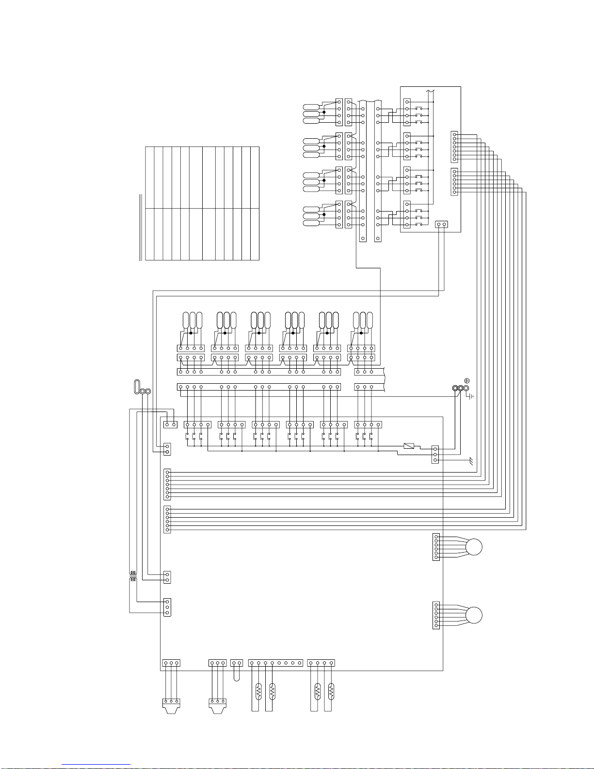
Symbol explanation
F01
250VAC
6.3A F
T6
T7T8T9T10
T1
T2
T3
T4
T5
PE
3
2
1
3
2
1
EARTH
Fuse AC250V 6.3A F
F01
SV6B
SV6A
SV6C
123
4
1
234
33
2
1
2
1
1
2
34
1
2
34
1
2
34
1
2
34
1
2
34
1
2
34
1
2
34
1
2
34
SV7B
SV8B
SV9B
SV10B
SV7A
SV8A
SV9A
SV10A
SV7C
SV8C
SV9C
SV10C
131415
101112
9
78
6
5
4
4
87
6
5
12 11 10
915 14 13
16
16
RELAY4 Board
161514
765
142
3
131211
10
9
8
161514
765
142
3
10
9
8
131211
4
4
4
4
4
3
3
3
3
3
2
2
2
2
2
1
1
1
1
1
SV5C
SV5A
SV5B
SV4B
SV4A
SV4C
SV3B
SV3A
SV3C
SV2B
SV2A
SV2C
SV1C
SV1A
SV1B
123
4
2341234
234
234
1
1
1
TerminalT1~10
Power source
}
L
N
~220V~240V 50/60Hz
TB02
TB01
Terminal block
(for Transmission)
Solenoid valve
Solenoid valve
Solenoid valve
Terminal block
(for power source)
Pressure sensor
Expansion valve
Thermister sensor
Transformer
NameSymbol
SV1
~10A
SV1
~10B
SV1
~10C
TR
TH11,12,15,16
LEV1,3
PS1,3
Note:TB02 is terminal block for transmission.
Never connect power line to it.
Transmission line
Shield wire
CONT.board
CN38
1
3
1
CNTR
CN50
CN51
7654321123456
CN02
CN12
1
53
753
1
753
1
753
1
753
1
753
1
753
1
3
TR
X2
X1
X30
X4
X3
X31
X6
X5
X32
X8
X7
X33
X10X9X34
X12
X11
X35
}
DC 30V
6
54321
6
54321
LEV3 LEV1
1
2
3
CNP1
1
2
3
CNP3
2
1
1
234
5
6
7
8
432
1
12321
CN03
CN13
CN10
CN11
CN07 CN05
TH11
TH12
TH15
TH16
PS1
PS3
22V
TB02
M2
M1
CN26
CN27
CN28
CN29
CN30
CN31
TB01
220
~240V
7654321123456
CN35
CN32
CN33
CN34
CN39
3
1
X14
X13
X36
X37
X15
X16
X18
X17
X38
X39
X19
X20
CN52CN53
57317531753175133 3
- 27 -
4 CMB-P108, P1010V-F
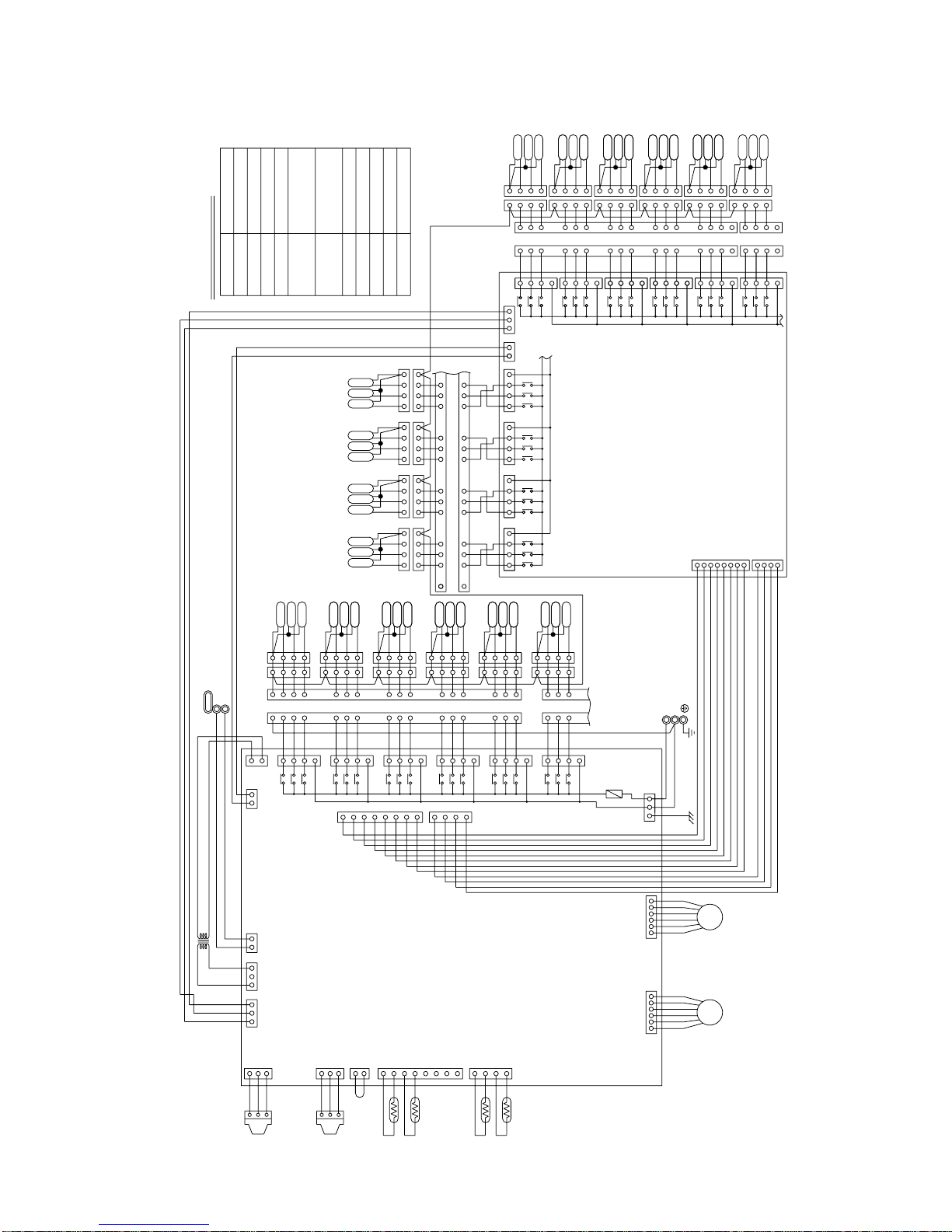
Symbol explanation
EARTH
1
2
3
1
2
3
PE
TH11,12,15,16
T6
T2
T3
T4
T5
T1
T7
T8T9
T10
T16
T12
T13
T14
T15
T11
F01
250VAC
6.3A F
RELAY10 board
CONT.board
CN39
13
135
CN12
CNOUT3
CNOUT1
13571357135713571357135
7
135
7
135
7
135
7
135
7
135
7
753
1
1357 1357 1357
13
21
CNVCC2
3
X54
X57
X53
X52
X56
X55
CN45
CN44
CN42
CN43
X49
X50
X46
X47
X51
X48
123
8765432
1
4
CNOUT2
CNOUT4
CN41
CN40
X41
X44
X40
X43
X42
X45
CN34
CN35
X20
X18
X19
X17
X39
X38
3
CNVCC1
12
X16
X15
X37
X36
X13
X14
X2
X1
X30
X4
X3
X31
X6
X5
X32
X8
X7
X33
X10X9X34
X12
X11
X35
}
}
DC 30V
654321654321
LEV3 LEV1
123
CNP1
123
CNP3
211234567
8
432
1
12321
CN03
CN02
CN13
CN10
CN11
CN07 CN05
33
CN33
1357
CN32
TH11
TH12
TH15
TH16
PS1
PS3
22V
TR
TB02
M2
M1
CN38
CN26
CN27
CN28
CN29
CN30
CN31
TB01
220
~240V
3
1
CNTR
4
1
2
3
4
5
6
7
8
3
2
1
Note1:TB02 is terminal block for transmission.
Never connect power line to it.
TB02
TB01
Terminal block
(for Transmission)
Solenoid valve
Solenoid valve
Solenoid valve
Terminal block
(for power source)
Pressure sensor
Expansion valve
Thermister sensor
Transformer
NameSymbol
SV1
~16A
SV1
~16B
SV1
~16C
TR LEV1,3
PS1,3
Shield wire
Transmission line
Power source
~220V~240V 50/60Hz
N
L
T1~16 Terminal
1
2
1233
432
1
432
1
SV6C
SV6A
SV6B
1
234
1
234
123
4
1
234
123
4
123
4
123
4
123
4
123
4
SV5C
SV5A
SV5B
SV4B
SV4A
SV4C
SV3B
SV3A
SV3C
SV2B
SV2A
SV2C
123
4
16
15
14
765
142
3
131211
10
9
8
423
16
15
14
131211
10
9
8
765
1
SV1C
SV1A
SV1B
432 143 2 143 1432 1
432 1432 1432
2
1432 1
131415 101112 9 78654
487 6512 11 10 915 14 13
124
3
432
1
432
1
SV16C
SV16A
SV16B
1
234
1
234
123
4
1
234
123
4
123
4
123
4
123
4
123
4
SV15C
SV15A
SV15B
SV14B
SV14A
SV14C
SV13B
SV13A
SV13C
SV12B
SV12A
SV12C
123
4
161514
7
6
51423
13
121110
9
8
231
SV11C
SV11A
SV11B
124
3
161415
131112
10
798
654
16
16
SV10C
SV10A
SV10B
SV9C
SV9A
SV9B
SV8C
SV8A
SV8B
SV7C
SV7B
SV7A
Fuse AC250V 6.3A F
F01
- 28 -
5 CMB-P1013, P1016V-F
·Cooling mode
Outdoor unit
Items
PUHY-P200YEM-A
PUY-P200YEM-A
PUHY-P250YEM-A
PUY-P250YEM-A
Indoor
Outdoor
Quantity
Quantity in operation
Model
Main pipe
Branch pipe
Total piping length
27.0/19.0 27.0/19.0
35.0/24.0 35.0/24.0
4
4
4
4
71 63 50 20 100 71 63 20
55
10 10 10 10 10 10 10 10
45 45
Hi Hi Hi Hi Hi Hi Hi Hi
11.7 11.7
270 420 360 250 360 270 420 250
122 150
2.00/0.55 2.08/0.54
81 80
42 44
16 16
17 17
20 20
55
44 44
20 22
13 13
20 20
14 14
0.23 0.23
10.6 9.7 14.4 13.2
380 415 380 415
Indoor unit fan notch
Refrigerant volume
Total current
Volts
Indoor unit
SC (LEV1)
High pressure/Low pressure (after O/S)
(before Accumulator)
Pressure
DB/WB
Set
–
m
–
kg
A
V
Pulse
MPa
˚C
Condition
Sectional temperature
Outdoor unit
LEV opening
Inlet
Outlet
Outdoor
unit
Indoor
unit
OC
Ambient temp.
Indoor unit
Piping
Discharge (TH1)
Heat exchanger outlet (TH5)
Accumulator
Suction (Comp)
CS circuit (TH2)
Shell bottom (Comp)
SCC outlet (TH7)
Bypass outlet (TH8)
LEV inlet
Heat exchanger outlet
[4] Standard Operating Data
1 PU(H)Y-P200·250YEM-A
- 29 -

Outdoor unit
Items
PUHY-P200YEM-A PUHY-P250YEM-A
Indoor
Outdoor
Quantity
Quantity in operation
Model
Main pipe
Branch pipe
Total piping length
20.0/– 20.0/–
7.0/6.0 7.0/6.0
44
44
55
71 63 50 20 100 71 63 20
10 10 10 10 10 10 10 10
45 45
Hi Hi Hi Hi Hi Hi Hi Hi
11.7 11.7
290 470 410 250 330 290 470 250
00
2.10/0.43 2.10/0.38
73 80
0 –2
20
20
42
–4 –6
33 33
34 34
60 60
0.28 0.28
11.4 10.5 15.1 13.8
380 415 380 415
Indoor unit fan notch
Refrigerant volume
Total current
V
olts
Indoor unit
SC (LEV1)
High pressure/Low pressure (after O/S)
(before Accumulator)
Pressure
DB/WB
Set
–
m
–
kg
A
V
Pulse
MPa
˚C
Condition
Sectional temperature
Outdoor unit
LEV opening
Discharge (TH1)
Heat exchanger inlet (TH5)
Accumulator
Suction (Comp)
CS circuit (TH2)
Shell bottom (Comp)
Heat exchanger outlet
Heat exchanger inlet
Inlet
Outlet
Outdoor
unit
Indoor
unit
OC
Ambient temp.
Indoor unit
Piping
·Heating
- 30 -

2 PU(H)Y-P315YEM-A
Outdoor unit
Items
Cooling Operation Heating Operation
Indoor
Outdoor
Quantity
Quantity in operation
Model
Main pipe
Branch pipe
Total piping length
27.0/19.0 20/
-
35.0/24.0 7.0/6.0
4
4
4
4
125 71 63 40 125 71 63 40
55
10 10 10 10 10 10 10 10
45 45
Hi Hi Hi Hi Hi Hi Hi Hi
13.7 13.7
360 270 420 330 420 240 470 380
156 0
2.15/0.52
2.1/0.36
92 85
46 0
16 –2
17 –2
20 0
5–8
50 39
24 /
12 /
20 60
14 34
0.23 0.28
18.7 17.2 19.8 18.2
380 415 380 415
Indoor unit fan notch
Refrigerant volume
Total current
V
olts
Indoor unit
SC (LEV1)
High pressure/Low pressure (after O/S)
(before Accumulator)
Pressure
DB/WB
Set
–
m
–
kg
A
V
Pulse
MPa
˚C
Condition
Sectional temperature
Outdoor unit
LEV opening
Inlet
Outlet
Outdoor
unit
Indoor
unit
OC
Ambient temp.
Indoor unit
Piping
Discharge (TH1)
Heat exchanger outlet (TH5)
Accumulator
Suction (Comp)
CS circuit (TH2)
Shell bottom (Comp)
SCC outlet (TH7)
Bypass outlet (TH8)
LEV inlet/Heat exchanger inlet
LEV outlet/Heat exchanger outlet
- 31 -

·Cooling
3 PURY-P200·250YEM-A
Outdoor unit
Items
PURY-P200YEM-A PURY-P250YEM-A
Indoor
Outdoor
Quantity
Quantity in operation
Model
Main pipe
Branch pipe
Total piping length
27.0/19.0 27.0/19.0
35.0/24.0 35.0/24.0
4
55
4
4
4
71 63 50 20 100 71 63 20
55555555
25 25
Hi Hi Hi Hi Hi Hi Hi Hi
11.7 11.7
330 460 430 300 410 330 460 300
2000 140 2000 150
2.00/0.55
2.08/0.54
1.9/1.9
1.98/1.98
81 80
42 44
16 16
17 17
20 20
55
44 44
20 20
14 14
0.23 0.23
380 415 380 415
10.6 9.7 14.4 13.2
Indoor unit fan notch
Refrigerant volume
Compressor volts
Outdoor unit
Indoor unit
BC controller (1, 3)
High pressure/Low pressure
BC controller liquid/Intermediate
Pressure
DB/WB
Q’ty
–
m
–
kg
V
A
Pulse
MPa
˚C
Condition
Sectional temperature
LEV opening
Discharge (TH1)
Heat exchanger outlet (TH5)
Accumulator
Suction (Comp)
CS circuit (TH2)
Shell bottom (Comp)
LEV inlet
Heat exchanger outlet
Inlet
Outlet
Outdoor
unit
Indoor
unit
OC
Ambient temp.
Indoor unit
Piping
- 32 -

·Heating
Outdoor unit
Items
PURY-P200YEM-A PURY-P250YEM-A
Indoor
Outdoor
Quantity
Quantity in operation
Model
Main pipe
Branch pipe
Total piping length
20.0/– 20.0/–
7.0/6.0 7.0/6.0
4
4
4
4
71 63 50 20 100 71 63 20
55
55555555
25 25
Hi Hi Hi Hi Hi Hi Hi Hi
11.7 11.7
600 950 750 400 750 600 950 400
110 700 110 800
2.10/0.43 2.10/0.38
2.00/1.77 2.00/1.67
73 80
0 –2
20
20
42
–4 –6
33 33
60 60
34 34
0.28 0.28
380 415 380 415
11.4 10.5 15.1 13.8
Indoor unit fan notch
Refrigerant volume
Compressor volts
Outdoor unit total current
Indoor unit
BC controller (1, 3)
High pressure/Low pressure
BC controller liquid/Intermediate
Pressure
DB/WB
Q’ty
–
m
–
kg
V
A
Pulse
MPa
˚C
Condition
Sectional temper
ature
LEV opening
Discharge (TH1)
Heat exchanger outlet (TH5)
Accumulator
Suction (Comp)
CS circuit
Shell bottom (Comp)
Heat exchanger inlet
Heat exchanger outlet
Inlet
Outlet
(TH2)
Outdoor
unit
Indoor
unit
OC
Ambient temp.
Indoor unit
Piping
- 33 -

·Cooling
Outdoor unit
Items
PU(H)Y-200YEM-A PUHY-200YEMC-A
Indoor
Outdoor
Quantity
Quantity in operation
Model
Main pipe
Branch pipe
Total piping length
27.0/19.0 27.0/19.0
35.0/24.0 35.0/24.0
4
4
4
4
71 63 50 20 71 63 50 20
55
10 10 10 10 10 10 10 10
45 45
Hi Hi Hi Hi Hi Hi Hi Hi
11.7 11.7
270 420 360 250 270 420 360 250
122 122
1.95/0.55 2.14/0.58
85 87
42 44
16 16
17 17
20 20
42 42
20 20
13 13
20 20
14 14
10.4 9.5 14.5 13.3
380 415 380 415
Indoor unit fan notch
Refrigerant volume
Total current
Volts
Indoor unit
SC (LEV1)
High pressure/Low pressure (after O/S)
(before Accumulator)
Pressure
DB/WB
Set
–
m
–
kg
A
V
Pulse
MPa
˚C
Condition
Sectional temperature
Outdoor unit
LEV opening
Inlet
Outlet
Outdoor
unit
Indoor
unit
Ambient temp.
Indoor unit
Piping
Discharge (TH1)
Heat exchanger outlet (TH5)
Accumulator
Suction (Comp)
Shell bottom (Comp)
SCC outlet (TH7)
Bypass outlet (TH8)
LEV inlet
Heat exchanger outlet
4 PU(H)Y-200·250·315YEM(K,C)-A
- 34 -

Outdoor unit
Items
Indoor
Outdoor
Quantity
Quantity in operation
Model
Main pipe
Branch pipe
Total piping length
PUHY-250YEMC-A
PU(H)Y-250YEM-A
PUHY-250YEMK-A
PU(H)Y-315YEM-A
PUHY-315YEMK-A
PUHY-315YEMC-A
27.0/19.0 27.0/19.0
35.0/24.0 35.0/24.0
4
4
4
4
71 63 50 20 125 71 63 40
55
10 10 10 10 10 10 10 10
45 45
Hi Hi Hi Hi Hi Hi Hi Hi
11.7 13.7
360 270 420 250 360 270 420 330
150 156
2.16/0.58 2.08/0.52
86 96
42 46
16 16
17 17
20 20
42 42
20 24
13 12
20 20
14 14
19.6 18.0 19.9 18.2
380 415
27.0/19.0
35.0/24.0
4
4
71 63 50 20
5
10 10 10 10
45
Hi Hi Hi Hi
11.7
360 270 420 250
150
2.02/0.54
84
42
16
17
20
42
20
13
20
14
14.1 12.9
380 415 380 415
Indoor unit fan notch
Refrigerant volume
Total current
Volts
Indoor unit
SC (LEV1)
High pressure/Low pressure
(after O/S)(before Accumulator)
Pressure
DB/WB
Set
–
m
–
kg
A
V
Pulse
MPa
˚C
Condition
Sectional temperature
Outdoor unit
LEV opening
Inlet
Outlet
Outdoor
unit
Indoor
unit
Ambient temp.
Indoor unit
Piping
Discharge (TH1)
Heat exchanger outlet (TH5)
Accumulator
Suction (Comp)
Shell bottom (Comp)
SCC outlet (TH7)
Bypass outlet (TH8)
LEV inlet
Heat exchanger outlet
·Cooling
- 35 -

·Heating
Outdoor unit
Items
PUHY-200YEM-A
PUHY-200YEMC-A
PUHY-250YEM-A
PUHY-250YEMK-A
PUHY-250YEMC-A
Indoor
Outdoor
Quantity
Quantity in operation
Model
Main pipe
Branch pipe
Total piping length
20.0/– 20.0/–
7.0/6.0 7.0/6.0
44
44
55
71 63 50 20 100 71 63 20
10 10 10 10 10 10 10 10
45 45
Hi Hi Hi Hi Hi Hi Hi Hi
11.7 11.7
290 470 410 250 330 290 470 250
00
2.04/0.43 2.04/0.38
77 84
0 –2
20
20
42
31 31
34 34
60 60
11.2 10.2 14.8 13.5
380 415 380 415
Indoor unit fan notch
Refrigerant volume
Total current
V
olts
Indoor unit
SC (LEV1)
High pressure/Low pressure (after O/S)
(before Accumulator)
Pressure
DB/WB
Set
–
m
–
kg
A
V
Pulse
MPa
˚C
Condition
Sectional temperature
Outdoor unit
LEV opening
Discharge (TH1)
Heat exchanger inlet (TH5)
Accumulator
Suction (Comp)
Shell bottom (Comp)
Heat exchanger outlet
Heat exchanger inlet
Inlet
Outlet
Outdoor
unit
Indoor
unit
Ambient temp.
Indoor unit
Piping
- 36 -

Outdoor unit
Items
PU(H)Y-315YEM-A
PUHY-315YEMK-A
PUHY-315YEMC-A
Indoor
Outdoor
Quantity
Quantity in operation
Model
Main pipe
Branch pipe
Total piping length
20.0/–
7.0/6.0
4
4
5
125 71 63 40
10 10 10 10
45
Hi Hi Hi Hi
13.7
360 270 420 330
0
2.00/0.38
85
0
–2
–2
0
37
34
60
18.2 16.6
380 415
Indoor unit fan notch
Refrigerant volume
Total current
V
olts
Indoor unit
SC (LEV1)
High pressure/Low pressure (after O/S)
(before Accumulator)
Pressure
DB/WB
Set
–
m
–
kg
A
V
Pulse
MPa
˚C
Condition
Sectional temperature
Outdoor unit
LEV opening
Discharge (TH1)
Heat exchanger inlet (TH5)
Accumulator
Suction (Comp)
Shell bottom (Comp)
Heat exchanger outlet
Heat exchanger inlet
Inlet
Outlet
Outdoor
unit
Indoor
unit
Ambient temp.
Indoor unit
Piping
·Heating
- 37 -

1 PU(H)Y-P200·250·315YEM-A
Switch Function
Function according to switch operation Switch set timing
When off When on When off When on
SWU
SW1
SW2
SW3
SW4
1~2
1~8
3
9~10
1
2
3
4
5
6
7
8
9
10
1
2
3
4
5
6
7
8
9
10
1
2
3
Unit address setting
Refrigerant model
For self diagnosis/
operation monitoring
–
Centralized control switch
Deletion of connection
information.
Deletion of error history.
Refrigerant amount adjustments
–
Disregard ambient air
sensor errors, liquid
overflow errors.
Forced defrosting
Defrost prohibited timer
–
–
SW3-2 Function valid/
invalid
Indoor unit test operation
Defrosting start temperature of TH
Defrosting end temperature of TH5.
Opening angle of IC except
when heater thermostat is
ON during defrosting.
–
Pump down
Target Tc (High pressure)
in Heating
–
Models
Models
Models
SW4-2 Function valid/
invalid
Configuration compensation value
–
Set on 51~100 with the dial switch.
LED Monitering Displa
See Note2.
R407C R22
y
–
Centralized control not
connected.
Storing of refrigeration
system connection
information.
–
Ordinary control
–
Errors valid.
Ordinary control
39 min.
–
–
SW3-2 Function invalid
Stop all indoor units.
(no operation)
–
Ordinary control
49˚C
–
Invalid
–
–
Centralized control
connected.
Deletion of refrigeration
system connection
information.
Deletion
Adjustment operation
–
Disregard errors.
Start forced defrosting.
90 min.
–
–
SW3-2 Function valid
All indoor units test
operation ON.
–7˚C
For 2minutes.For 2minutes.
2000
–
Pump down
53˚C
–
Valid
–
Before power is turned on.
During normal operation when power
is on.
Should be set on OFF.
Before power is turned on.
Before power is turned on.
During normal operation when power
is on.
During normal operation when power is on
(only when switching from OFF/ON)
–
During normal operation when power
is on.
During normal operation when power
is on. (Except during defrosting)
–
–
During normal operation when power
is on.
When SW3-1 is ON after power is
turned on.
During normal operation when power
is on.
During normal operation when power
is on. (Except during defrosting)
–
During normal operation
(only when switching from OFF/ON)
During normal operation when power
is on.
–
–
Before power is turned on.
Before power is turned on.
During normal operation when power
is on.
When SW4-1 in ON.
–
––– –
––– –
––– –
Night mode/Step demand
SWU3
R407C
Exist
R407C
Different unit model error
(7130)
Not exist
Different unit model error
(7130)
R22
R22
TH2
Night mode
PUHY-(P)YEM-A PUY-(P)YEM-A
Step demand
During normal operation when power is on.
––– –
––– –
During normal
operation when
power is on.
10 minutes or
more after
compressor
starts.
Note 1
Note 2
• SWU1~2=00 when shipped from the factory. Other factory settings are indicated by shaded portions.
• If the address is set from 01 to 50, it automatically becomes 100.
•
The refrigerant model is recognized with SW3 and TH2.
Changes as shown below by on off change
0% 3%
6% 9% 12% –6% –3% 0%
4
5
6
7
8
9
10
[5] Function of Dip SW and Rotary SW
(1) Outdoor unit
Before power is turned on.
SW3-9
OFF
OFF
P200YEM-A
P315YEM-A
P250YEM-A
ON
–
ON
SW3-10
10˚C15˚C
– 10˚C
- 38 -

2 PURY-P200·250YEM-A
Switch Function
Function according to switch operation Switch set timing
When off When on When off When on
SWU
SW1
SW2
SW3
SW4
1~2
1~8
9~10
1
2
3
3
4
5
6
7
8
9
10
1
2
3
4
5
6
7
8
9
10
1
2
3
Unit address setting
For self diagnosis/
operation monitoring
–
Centralized control switch
Deletion of connection
information.
Deletion of error history.
–
Disregard ambient air
sensor errors, liquid
overflow errors.
Forced defrosting
Defrost prohibited timer
–
–
SW3-2 Function valid/
invalid
Indoor Unit Test operation
Defrosting start temperature of TH7.
Defrosting end temperature of TH5 and TH7.
–
Pomp down operation
Target Tc (High pressure)
at Heating
–
–
Models
SW4-2 function valid/
Invalid
Configuration compensation value
–
Set on 51~100 with the dial switch.
LED monitering display
–
Centralized control not
connected.
Storing of refrigeration
system connection
information.
–
–
Errors valid.
Ordinary control
43 minutes.
–
–
SW3-2 Function invalid
Stop all indoor units.
–10°C
10
For 2minutes. For 2minutes.
°C
–
Invalid
49˚C
–
–
Model P200
Invalid
–
–
Centralized control
connected.
Deletion of refrigeration
system connection
information.
Deletion
–
Disregard errors.
Start forced defrosting.
90 minutes.
–
–
SW3-2 Function valid
All indoor units test
operation ON.
–7°C
15°C
–
Valid
53˚C
–
–
Model P250
Valid
–
Before power is turned on.
During normal operation when power
is on.
Should be set on OFF.
Before power is turned on.
Before power is turned on.
During normal operation when power
is on.
–
––– –
During normal operation when power
is on.
During normal operation when power
is on. (Except during defrosting)
–
–
During normal operation when power
is on.
When SW3-1 is ON after power is
turned on.
During normal operation when power
is on.
During normal operation when power
is on. (Except during defrosting)
–
During compressor stop when power
is on.
During normal operation when power
is on.
–
–
Before power is turned on.
During normal operation when power
is on.
when SW4-1 in ON.
–
During normal
operation when
power is on.
10 minutes or
more after
compressor
starts.
Note:
• SWU1~2=00 when shipped from the factory. Other factory settings are indicated by shaded portions.
• If the address is set from 01 to 50, it automatically becomes 100.
Changes as shown below by on off change
0% 3% 6% 9% 12% –6%
–3% 0%
4 ––– –
5 ––– –
6 ––– –
7
8 ––– –
9 ––– –
10 ––– –
Night mode/Step demand Night mode
Step demand
During normal operation when power is on.
R407C R22
Before power is turned on.
SWU3
R407C
Exist
R407C
Different unit model error
(7130)
Not exist
Different unit model error
(7130)
R22R22
TH2
•
The refrigerant model is recognized with SW3 and TH2.
Refrigerant model
- 39 -

3 PU(H)Y-200·250·315YEM(K,C)-A
Switch Function
Function according to switch operation Switch set timing
When off When on When off When on
SWU
SW1
SW2
SW3
SW4
1~2
1~8
3
9~10
1
2
3
4
5
6
7
8
9
10
1
2
3
4
5
6
7
9
10
1
2
3
Unit address setting
Refrigerant model
For self diagnosis/
operation monitoring
–
Centralized control switch
Deletion of connection
information.
Deletion of error history.
Refrigerant amount adjustments
–
Disregard ambient air
sensor errors, liquid
overflow errors.
Forced defrosting
Defrost prohibited timer
–
–
SW3-2 Function valid/
invalid
Indoor unit test operation
Defrosting start temperature of TH
Defrosting end temperature of TH5.
Opening angle of IC except
when heater thermostat is
ON during defrosting.
–
Pump down
Target Tc (High pressure)
in Heating
Models
Models
Models
SW4-2 Function valid/
invalid
–
Set on 51~100 with the dial switch.
LED Monitering Displa
R407C R22
y
–
Centralized control not
connected.
Storing of refrigeration
system connection
information.
–
Ordinary control
–
Errors valid.
Ordinary control
39 min.
–
–
SW3-2 Function invalid
Stop all indoor units.
– 6°C
10°C
(no operation)
–
Ordinary control
49˚C
Invalid
–
–
Centralized control
connected.
Deletion of refrigeration
system connection
information.
Deletion
Adjustment operation
–
Disregard errors.
Start forced defrosting.
90 min.
–
–
SW3-2 Function valid
All indoor units test
operation ON.
–3°C
15°C
For 2minutes.For 2minutes.
2000
–
Pump down
53˚C
Valid
–
Before power is turned on.
During normal operation when power
is on.
Should be set on OFF.
Before power is turned on.
Before power is turned on.
During normal operation when power
is on.
During normal operation when power is on
(only when switching from OFF/ON)
–
During normal operation when power
is on.
During normal operation when power
is on. (Except during defrosting)
–
–
During normal operation when power
is on.
When SW3-1 is ON after power is
turned on.
During normal operation when power
is on.
During normal operation when power
is on. (Except during defrosting)
–
During normal operation
(only when switching from OFF/ON)
During normal operation when power
is on.
8 ––– –
––– –
–
Before power is turned on.
Before power is turned on.
During normal operation when power
is on.
–
––– –
––– –
––– –
Night mode/Step demand
SWU3
R407C
Exist
R407C
Different unit model error
(7130)
Not exist
Different unit model error
(7130)
R22
R22
TH2
Night mode
PUHY-(P)YEM-A PUY-(P)YEM-A
Step demand
During normal operation when power is on.
––– –
––– –
During normal
operation when
power is on.
10 minutes or
more after
compressor
starts.
Note 1
• SWU1~2=00 when shipped from the factory. Other factory settings are indicated by shaded portions.
• If the address is set from 01 to 50, it automatically becomes 100.
•
The refrigerant model is recognized with SW3 and TH2.
4
5
6
7
8
9
10
Before power is turned on.
See Note2.
Note 2
SW3-10
OFF
OFF
200YEMK-A
250YEM(K,C)-A
315YEM(K,C)-A
ON
200YEMC-A
ON
SW3-9
- 40 -

(2) Indoor unit
DIP SW1, 3
Model P71 P80 P100 P125 P140 P200 P250
Capacity (model name) code
14 16 20 25 28 40 50
SW2 setting
Model P20 P25 P32 P40 P50 P63
Capacity (model name) code
45 681013
SW2 setting
ON
OFF
ON
OFF
ON
OFF
ON
OFF
ON
OFF
ON
OFF
ON
OFF
ON
OFF
ON
OFF
ON
OFF
ON
OFF
ON
OFF
ON
OFF
Note 1: The shaded part indicates the setting at factory shipment. (For the SW not being shaded, refer to the
2: When both SW1-7 and SW1-8 are being set to ON, the fan stops at the heating thermostat of OFF.
table belo
Note 3: The DipSW setting is only effective during unit stopping (remote controller OFF) for SW1,2,3 and 4 commonly
and the power source is not required reset.)
w.)
Setting of DIP SW2
Indoor unit inlet
None
100h
Ineffective
Fan output display
At stationary heating
Very low speed
SW1-7 setting
Ineffective
Ineffective
Heat pump
None
None
None
1st setting
Down blow B, C
Effective
–
Effective
–
–
Built in remote controller
Provided
2500h
Effective
Thermo. ON signal display
Always at heat.
Low speed
Set airflow
Effective
Effective
Cool.only
Provided
Provided
Provided
2nd setting
Horizontal
–
Ineffective
Ineffective
–
–
Room temp. sensor position
Clogged filter detect.
Filter duration
OA intake
Remote display select.
Humidifier control
Heating thermo. OFF airflow
Heating thermo. OFF airflow
Power failure automatic
return
Power source start/stop
Model selection
Louver
Vane
Vane swing function
Vane horizontal angle
V
Vane first angle
ane angle set for cooling
–
Heating 4deg up
–
–
Alw
PLFY-VLMD-B only
ays ineffective for PKFY-P.VAM
Not provided for PKFY-P.VAM
Provided for PLFY-P.VGM (ON) setting
Always down blow B,C for PKFY-P.VAM
Horizontal (ON) setting for PLFY-P. VLMD-A
Ineffective (ON) setting for floor
standing
SW1
SW3
1
2
3
4
5
6
7
8
9
10
1
2
3
4
5
6
7
8
9
10
Switch SW name
Operation by SW
Switch set timing
OFF ON OFF ON
Remarks
At unit stopping
(at remote
controller OFF)
Cooling capacity saving
for PKFY-P. VAM,
effective/ineffective
Model
Switch
SW1
SW3
3
6
7
3
4
6
8
PLFY-P
VAM-A(2)
OFF
OFF
VLMD-B
VKM-A
OFF
ON
ON
ON
OFFONON
ON
PEFY-P
VML-A VMH-A
20~80VMM-A
100~140VMM-A
OFF
OFF ON
OFF ON
ON
ON
OFF
OFF
OFF
OFF
ON OFF
ON OFF ON
ON
ON
ON
OFF
PDFY-P
PFFY-P
PCFY-P
PKFY-P
VM-A
ON
VLRM-A, VLEM-A
OFF
VGM-A
PMFY-P
VBM-A
ON
VAM-A VGM-A
OFF OFF
OFF
OFF
OFF
OFF
OFF
- 41 -

Ceiling height
3 3.5 m
2 2.8 m
1 2.3 m
Switch Function Operation by switch Switch set timing
SWA
SWA
SWA
SWB
SWC
Ceiling height setting
External static
pressure setting
For options
Setting of air outlet opening
Airflow control
(PLFY-P-VKM-A) (PCFY-P-VGM-A)
(PLFY-P125VLMD-B)
(PLFY-P-VKM-A)
(PLFY-P-VKM-A, PCFY-P-VGM-A, PKFY-P-VGM-A, PDFY-P-VM-A)
❇
The ceiling
height is
changed by
SWB setting.
❇
As this switch is used by interlocking with SWC,
refer to the item of SWC for detail.
SWA
SWB
123
2-way 3.5 m 3.8 m 3.8 m
3-way 3.0 m 3.3 m 3.5 m
4-way 2.7 m 3.0 m 3.5 m
❇
Set to the option to install the high efficiency
filter
Always after powering
Always after powering
Always after powering
Always after powering
Always after powering
3
1
2
2-way
4-way
3-way
3
1
2
3
1
2
3
1
2
Option
Standard
(PDFY-P20 ~ 80VM-A, PEFY-P20 ~ 80VMM-A)
100Pa
50Pa
30Pa
❇
For other models, change the setting of static pressure by replacing the connector.
Setting of DIP SW4 Setting of DIP SW5
12345
ON OFF ON OFF
ON OFF ON OFF
OFF
OFF
OFF OFF ON
ON OFF OFF
OFF
ON
ON
OFF ON OFF ON
OFF
OFF
OFF ON ON
ON
–
–
–
–
–
–
––
–
–––
–
–
–
–
–
–
ON ON
ON
ON
OFF
OFF
OFF
OFF
OFF
OFF OFF OFF
–
ON ON ON
–
OFF OFF OFF
–
ON OFF OFF
–
OFF OFF ON
–
ON ON ON OFF
PMFY-P-VBM-A
PLFY-P125VLMD-B
PDFY-P20 ~ 80VM-A
PLFY-P40 ~ 63VKM-A
PLFY-P80 ~ 125VAM-A(2)
PCFY-P-VGM-A
PKFY-P-VGM-A
PKFY-P-VAM-A
PEFY
PLFY-P20~100VLMD-B
-P20 ~ 80VMM-A
PFFY-P-VLEM-A, P-VLRM-A
PEFY-P20 ~ 32VML-A
PEFY-P40 ~ 140VMH-A
PEHY-P200·250VMH-A
PDFY-P100·125VM-A
PEFY-P100 ~ 140VMM-A
Model Circuit board used
SW4
Phase control
Relay selection
220V
240V
- 42 -

£ TEST RUN
[1] Before Test Run
(1) Check points before test run
1 Neither refrigerant leak nor loose power source/ transmission lines should be found.
2 Confirm that the resistance between the power source terminal block and the ground exceeds 2MΩ by measur-
ing it with a DC500V megger. Do not run if it is lower than 2MΩ.
Note) Never apply the megger to the MAIN board. If applied, the MAIN board will be broken.
3 Confirm that the Ball valve at both gas and liquid sides is being fully opened.
Note) Certainly close the cap.
45Be sure that the cr
Prior to Ver.E
The number of indoor units and the total number of remote controllers id displayed within the parenthesis ( ).
16 (32)
16 (32)
200 or lower
200 or higher
After Ver.F
20 (40)
16 (32)
(
❇
1)
Capability of the
connected indoor units
Number of connected indoor units that
can be connected without a RP.
Remote controller type
Remote controller PAR-F 25MA
ankcase heater has been powered by turning the main power source on at least 12 hours
before starting the test run. The shorter powering time causes compressor trouble.
(2) Caution at inverter check
Because the inverter power portion in outdoor unit electrical part box have a lot of high voltage portion, be sure to follow
the instructions shown below.
During energizing power source, never touch inverter power portion because high voltage (approx. 580V) is
applied to inverter power portion.
When checking,
Shut off main power source, and check it with tester, etc.
Allow 10 minutes after shutting off main power source.
Open the MAIN board mounting panel, and check whether voltage of both ends of electrolytic capacitor is
20V or less.
1
2
1
2
3
If any of the power supply wires (L1, L2, L3, N, ) are mistakenly connected, it is possible to damage the unit.
Please exercise caution.
6
A transmission booster (RP) is required when the number of connected indoor unit models in a cooling system
exceeds the number of models specified in the chart below.
Note: The maximum number of units that can be controlled is determined by the indoor unit model, the type of
remote controller and their capabilities.
(
❇
1) If even one unit that is higher than 200 exists in the cooling system, the maximum capacity will be “200 or
higher”.
❇
Please refer to the installation manual for more details.
❇
Before turning power on to the outdoor unit, first turn on the transmission booster. (If the outdoor unit are mistakenly
turned on first, turn on the transmission booster and then reset the outdoor unit power.)
- 43 -

(3) Check points for test run when mounting options
(4) Attention for mounting drain water lifting-up mechanism
Check point
Local remote controller displays code
No. “2503”, and the mechanism stops.
No overflow from drain pan.
Drain water comes out by operations of
drain pump.
Sound of pump operations is heard, and
drain water comes out.
No water leakage from connecting
portions of water piping.
Water is supplied to water supply tank,
and float switch is operating.
Built-in optional parts
Mounting of drain
water removing
mechanism
Mounting of permeable film humidifier
Content of test run
Release connector of pump circuit,
check error detection by pouring
water into drain pan water inlet.
After that, connect connector of
circuit.
Check pump operations and drainage status in cooling (test run) mode.
Check humidifier operations and water
supply status in heating (test run) mode.
1
2
3
4
5
Result
1
2
3
Work
Disassembling and
assembling of drain
water removing
mechanism
Mounting of float
switch
Electric wiring
Float switch moves smoothly.
Float switch is mounted on
mounting board straigh and
without deformation.
Float switch has no contact with
copper pipe.
Wiring procedure is exactly followed.
Connector portion is tightly hooked.
Content of test run
Lead wire from the control box is not
damaged.
Rubber cap is properly inserted into
drain water outlet of the drain pan?
Insulation of gas and liquid
pipe is dealt with as shown in the
right figure?
Drain pan and piping cover are
mounted without gap?
Drain pan hooked on cut projection
of the mechanism?
Float switch is installed without contacting
the drain pan?
No mistakes in wiring?
Connectors connected securely and
tightly?
No tension on lead wire when sliding
on control box?
1
2
3
1
2
3
Check point Result
Insulation pipe
No gap
- 44 -

- 45 -
(5) Check points for system structure
ex. PURY-P200YEM-A
Check points from installation work to test run.
Trouble
Not operate.
Not cool (at cooling).
Not heat (at heating).
Not cool, not heat, error stop.
Condensation drip in piping.
Not cool, not heat, error stop.
Water leak, condensation drip in drain piping.
Error stop, not operate.
Electric shock.
Error stop, not operate.
Some electric parts should be damaged.
Classification
Installation and
piping
Power source
wiring
Portion
1
2
3
4
5
6
7
8
1
2
3
4
Check item
Instruction for selecting combination of outdoor unit,
and indoor unit followed? (Maximum number of indoor
units which can be connected, connecting model name,
and total capacity.)
Follow limitation of refrigerant piping length? For example, 80m or less (total length : 240m) at the farthest.
Connecting piping size of branch piping correct?
Refrigerant piping diameter correct?
Refrigerant leak generated at connection?
Insulation work for piping properly done?
Specified amount of refrigerant replenished?
Pitch and insulation work for drain piping properly done?
Specified switch capacity and wiring diameter of main
power source used?
Proper grounding work done on outdoor unit?
The phases of the L line (L1, L2, L3) correct?
L line and N line connected correct?

Classification
Transmission
line
Portion Check item
¡
Limitation of transmission line length followed? For
example, 200m or less (total length : 500m) at the farthest.
™ 1.25mm2 or more transmission line used?
(Remote controller 10m or less 0.75mm
2
)
£ 2-core cable used for transmission line?
¢
Transmission line apart from power source line by 5cm or more?
∞ One refrigerant system per transmission line?
§
The short circuit connector is changed form CN41 to
CN40 on the MAIN board when the system is centralized
control? (Just one outdoor unit. Not all outdoor units.)
¶ • No connection trouble in transmission line?
• Connection of wrong remote controller line terminals?
• MA Remote controller : TB15
• M-NET Remote controller : TB5
Trouble
Erroneous operation, error stop.
Erroneous operation, error stop.
Error stop in case multiple-core
cable is used.
Erroneous operation, error stop.
Not operate.
Not operate.
Error stop or not operate.
Never finish the initial mode.
System set
Before starting
Error stop or not operate.
Can not be properly set with power
source turned on.
Not operate.
Set temperature not obtained at
heating operations (Thermostat
stop is difficult)
Error stop.
Error stop, compressor trouble.
1
2
1
2
3
4
Address setting properly done? (M-NET Remote
controller, indoor unit and outdoor unit.)
Setting of address No. done when shutting off power
source?
Address numbers not duplicated?
Tur ned on SW3-8 on indoor unit circuit board when
mounting room thermistor sensor?
Refrigerant piping ball valve (Liquid pressure pipe, gas
pressure pipe) opened?
Turn on power source 12 hours before starting operations?
STAND BY
DEFROST
ERROR CODE
D A I L Y
AUTO OFF
CENTRALLY CONTROLLED
CLOCK
REMAINDER
ON OFF
˚C
1Hr.
NOT AVAILABLE
˚C
CHECK MODE
FILTER
CHECK
TEST RUN
LIMIT TEMP.
ON/OFF
TEMP
FILTER
CHECK TEST
ON OFF
CLOCK
PAR-F27MEA
TIMER SET
2 31
STAND BY
DEFROST
ERROR CODE
D A I L Y
AUTO OFF
CENTRALLY CONTROLLED
CLOCK
REMAINDER
ON OFF
˚C
1Hr.
NOT AVAILABLE
˚C
CHECK MODE
FILTER
CHECK
TEST RUN
LIMIT TEMP.
ON/OFF
TEMP
FILTER
CHECK TEST
ON OFF
CLOCK
PAR-F27MEA
TIMER SET
Breakers
for Current
Leakage
Switch
- 46 -

[2] Test Run Method
Operation procedure
1
Turn on universal power supply at least 12 hours before getting started Displaying “HO” on display panel for
about two minutes
2 Press
TEST RUN
button twice Displaying “TEST RUN’’ on display panel
3 Press
selection button Make sure that air is blowing out
4
Press
select button to change from cooling to heating operation, and vice versa Make sure that
warm or cold air is blowing out
5 Press
adjust button Make sure that air blow is changed
6 Press
or button to change wind Make sure that horizontal or downward blow is adjustable.
7 Make sure that indoor unit fans operate normally
8 Make sure that interlocking devices such as ventilator operate normally if any
9 Press
ON/OFF
button to cancel test run Stop operation
Note 1: If check code is displayed on remote controller or remote controller does not operate normally.
2: Test run automatically stops operating after two hours by activation of timer set to two hours.
3: During test run, test run remaining time is displayed on time display section.
4: During test run, temperature of liquid pipe in indoor unit is displayed on remote controller room temperature
display section.
5: When pressing
adjust button, depending on the model, “NOT AVAILABLE” may be displayed on remote
controller. However, it is not a malfunction.
6: When pressing
or button, depending on the model, “NOT AVAILABLE” may be displayed on
remote controller. However, it is not a malfunction.
- 47 -

¢
GROUPING REGISTRATION OF INDOOR UNITS WITH M-NET REMOTE CONTROLLER
(1) Switch function
• The switch operation to register with the remote controller is shown below:
Registration/
ordinary mode
selector switch
Registration/ordinar
mode selection switch
Switch to assign indoor
unit address
Registration switch
Confirmation switch
Delete switch
Registered mode
selector switch
Switch to assign
interlocked unit address
A + B
C
D
E
F
G
H
This switch selects the ordinary mode or registered mode (ordinary
mode represents that to operate indoor units).
❇
To select the registered mode, press the
FILTER
+
switch continuously for over 2 seconds under stopping state.
[Note] The registered mode can not be obtained for a while after
powering.
Pressing the
FILTER
+
switch displays “CENTRALLY
CONTROLLED”.
This switch assigns the unit address for “INDOOR UNIT ADDRESS
NO.”
This switch is used for group/interlocked registration.
This switch is used to retrieve/identify the content of group and
interkloced (connection information) registered.
This switch is used to retrieve/identify the content of group and
interlocked (connection information) registered.
This switch selects the case to register indoor units as group (group
setting mode) or that as interlocked (interlocked setting mode).
❇
The unit address is shown at one spot for the group setting mode
while at two spots for the interlocked setting mode.
This switch assigns the unit address of “OA UNIT ADDRESS NO.”
Symbol
of switch
G Registered mode
selector switch
E Confirmation switch
C Switch to assign
indoor unit address
H Switch to assign inter-
locked unit address
D Registration switch
A
+
FILTER
TEST RUN
Name Name of actual switch Description
of TEMP
of TIMER SET
CLOCK ON OFF
B
Registration/
ordinary mode
selector switch
STAND BY
DEFROST
ERROR CODE
D A I L Y
AUTO OFF
CENTRALLY CONTROLLED
CLOCK
REMAINDER
ON OFF
˚C
1Hr
NOT AVAILABLE
˚C
CHECK MODE
FILTER
CHECK
TEST RUN
LIMIT TEMP.
ON/OFF
TEMP
FILTER
CHECK TEST
ON OFF
CLOCK
PAR-F27MEA
TIMER SET
F Delete switch
- 48 -

(2) Attribute display of unit
• At the group registration and the confirmation/deletion of registration/connection information, the type (attribute) of the
unit is displayed with two English characters.
Display Type (Attribute) of unit/controller
Indoor unit connectable to remote controller
Outdoor unit
Local remote controller
System controller (MJ)
[Description of registration/deletion/retrieval]
• The items of operation to be performed by the remote controller are given below. Please see the relating paragraph for
detail.
¡ Group registration of indoor unit
• The group of the indoor units and operating remote controller is registered.
• It is usually used for the group operation of indoor units with different refrigerant system.
™ Retrieval/identification of group registration information of indoor units
• The address of the registered indoor units in group is retrieved (identified).
£ Retrieval/identification of registration information
• The connection information of any unit (indoor/outdoor units, remote controller or the like) is retrieved (identified).
¢ Deletion of group registration information of indoor units
• The registration of the indoor units under group registration is released (deleted).
∞ Deletion of the address not existing
• This operation is to be conducted when “6607” error (No ACK error) is displayed on the remote controller caused by
the miss setting at test run, or due to the old memory remained at the alteration/modification of the group composition.
Caution:
When MELANS (MJ-103MTRA for example) is being connected, do not conduct the group/pair registration using
the remote controller. The group/pair registration should be conducted by MELANS. (For detail, refer to the instruc-.
tion exclusively prepared for MELANS.)
OA Processing
Lossnay
- 49 -

(3) Group registration of indoor unit
1) Registration method
• Group registration of indoor unit ........................................................................ ¡
The indoor unit to be controlled by a remote controller is registered on the remote controller.
[Registration procedure]
1 With the remote controller under stopping or at the display of “HO”, continuously press the + switch
FILTER
( A + B ) at the same time for 2 seconds to change to the registration mode. (See the figure below.)
2 Assign the indoor unit address to “INDOOR UNIT ADDRESS NO.” by operating the (Room temperature
adjustment) (C).
Then press the switch (D) to register. In the figure below, the “INDOOR UNIT ADDRESS NO.” is being set
TEST RUN
to 001.
3 After completing the registration, press the + switch (A +B) at the same time for 2 seconds to
FILTER
change to the original ordinary mode (with the remote controller under stopping).
• Remote controller under stopping • “HO” under displaying
Ordinary mode
INDOOR UNIT
ADDRESS NO
ERROR CODE
OA UNIT ADDRESS NO
˚C
INDOOR UNIT
ADDRESS NO
ERROR CODE
OA UNIT ADDRESS NO
˚C
ERROR CODE
OA UNIT ADDRESS NO
˚C
1
1
Group setting mode
• Confirm the indoor unit address No.
• Confirm the connection of the transmission line.
ERROR CODE
OA UNIT ADDRESS NO
˚C
ERROR CODE
OA UNIT ADDRESS NO
˚C
• Registration complete
• Registration error
Indicates the type of unit
(Indoor unit in this case)
“88” flickers indicating registration error. (when the indoor unit.
registered is not existing)
2 Assign the
address (C)
1 Change to the
registration
mode (A + B)
3 Press the
registration
switch (D)
Remote controller
Indoor units
Group
2 + 3
ON/OFF
TEMP
FILTER
CHECK TEST
ON OFF
CLOCK
PAR-F27MEA
TIMER SET
System example
- 50 -

2) Method of retrieval/confirmation
• Retrieval/confirmation of group registration information on indoor unit ............... ™
The address of the indoor unit being registered on the remote controller is displayed.
[Operation procedure]
1 With the remote controller under stopping or at the display of “HO”, continuously press the
FILTER
+ switch (A
+ B) at the same time for 2 seconds to change to the registration mode.
2 In order to confirm the indoor unit address already registered, press
switch (E). (See figure below.) When the group
of plural sets is registered, the addresses will be displayed in order at each pressing of
switch (E).
3 After completing the registration, continuously press the
FILTER
+ switch (A + B) at the same time for 2
seconds to change to the original ordinary mode (with the remote controller under stopping).
• Retrieval/confirmation of registration information ................................................ £
The registered information on a certain unit (indoor unit, outdoor unit, remote controller or the like) is displayed.
[Operation procedure]
1 With the remote controller under stopping or at the display of “HO”, continuously press the
FILTER
+ switch (A
+ B) at the same time for 2 seconds to change to the registration mode.
2 Operate
switch (G) for the interlocked setting mode. (See figure below.)
3 Assign the unit address of which registration information is desired to confirm with the
(TIMER SET) switch
(H). Then press the switch (E) to display it on the remote controller. (See figure below.)
Each pressing of
switch (E) changes the display of registered content. (See figure below.)
4 After completing the retrieval/confirmation, continuously press the
FILTER
+ switch (A + B) at the same time
for 2 seconds to change to the original ordinary mode (with the remote controller under stopping).
• Registered
• No registration.
ERROR CODE
OA UNIT ADDRESS NO
˚C
ERROR CODE
OA UNIT ADDRESS NO
˚C
1 Press the switch for confirmation (E)
Note: Only one address will be displayed
when the registration is one even the
switch is how often pressed
Indicates the type of unit
(Indoor unit in this case)
1
1
ON/OFF
TEMP
FILTER
CHECK TEST
ON OFF
CLOCK
PAR-F27MEA
TIMER SET
- 51 -

3) Method of deletion
•Deletion of group registration information of indoor unit ...................................... ¢
[Operation procedure]
1 With the remote controller under stopping or at the display of “HO”, continuously press the
FILTER
+
switch (A + B) at the same time for 2 seconds to change to the registration mode..
2 Press the
switch (E) to display the indoor unit address registered. (As same as ™)
3 In order to delete the registered indoor unit being displayed on the remote controller, press the
CLOCK ON OFF
(F) switch
two times continuously. At completion of the deletion, the attribute display section will be shown as “– – ”.
(See figure below.)
Note: Completing the deletion of all indoor units registered on the remote controller returns to “HO” display.
4 After completing the registration, continuously press the
FILTER
+ switch (A + B) at the same time for 2
seconds to change to the original ordinary mode (with the remote controller under stopping).
ERROR CODE
OA UNIT ADDRESS NO
˚C
INDOOR UNIT
ADDRESS NO
ERROR CODE
OA UNIT ADDRESS NO
˚C
INDOOR UNIT
ADDRESS NO
ERROR CODE
OA UNIT ADDRESS NO
˚C
1 Set the address
2 Press the switch for
confirmation (E)
• Registered
• No registration
❇
Same display will appear when
the unit of “007” is not existing.
1 Press the switch for confirmation ( F)
twice continuously.
• Deletion completed
• Deletion completed
In case group registration with other
indoor unit is existing
In case no group
registration with other
indoor unit is existing
1
1
1 + 2
“– –” indicates the
deletion completed.
˚C
˚C
(Alternative
display)
˚C
˚C
(Alternative
display)
INDOOR UNIT
ADDRESS NO
ERROR CODE
OA UNIT ADDRESS NO
˚C
2
ON/OFF
TEMP
FILTER
CHECK TEST
ON OFF
CLOCK
PAR-F27MEA
TIMER SET
ON/OFF
TEMP
FILTER
CHECK TEST
ON OFF
CLOCK
PAR-F27MEA
TIMER SET
- 52 -

4) Deletion of information on address not existing
• Deletion of information on address not existing ...................................................∞
This operation is to be conducted when “6607” error (No ACK error) is displayed on the remote controller caused by
the miss setting at test run, or due to the old memory remained at the alteration/modification of group composition,
and the address not existing will be deleted.
Note: The connection information (connection between indoor unit and outdoor unit) on the refrigerant system can
not be deleted.
An example to delete the system controller of “250” from the indoor unit of “007” is shown below.
[Operation procedure]
1 With the remote controller under stopping or at the display of “HO”, continuously press the
FILTER
+ switch (A
+ B) at the same time for 2 seconds to change to the registration mode.
2 Oper
ate
switch (G) for the interlocked setting mode ( ii ). (See the figure below.)
3 Assign the unit address existing to “OA UNIT ADDRESS No.” with the
(TIMER SET) switch (H), and press
switch (E) to call the address to be deleted. (See the figure below.) As the error display on the remote controller is usually
transmitted from the indoor unit, “OA UNIT ADDRESS No.” is used as the address of the indoor unit.
4 Press the
CLOCK ON OFF
switch (F) twice. (See the figure below.)
5 After completing the deletion, continuously press the
FILTER
+ switch (A + B) at the same time for 2 seconds
to return to the original ordinary mode (with the remote controller under stopping).
INDOOR UNIT
ADDRESS NO
ERROR CODE
OA UNIT ADDRESS NO
˚C
INDOOR UNIT
ADDRESS NO
ERROR CODE
OA UNIT ADDRESS NO
˚C
(Alternative
display)
INDOOR UNIT
ADDRESS NO
ERROR CODE
OA UNIT ADDRESS NO
˚C
INDOOR UNIT
ADDRESS NO
ERROR CODE
OA UNIT ADDRESS NO
˚C
(Alternative
display)
❇
❇
INDOOR UNIT
ADDRESS NO
ERROR CODE
OA UNIT ADDRESS NO
˚C
INDOOR UNIT
ADDRESS NO
ERROR CODE
OA UNIT ADDRESS NO
˚C
(Alternative
display)
❇
When both indoor
unit and interlocked
unit addresses are
existing
Deletion of
address not
existing
1 Set the address (H)
3 Press the deletion switch (F) twice
• Deletion completed
• Deletion completed
1 + 2
3
3
2 Press the switch for
confirmation (E)
ON/OFF
TEMP
FILTER
CHECK TEST
ON OFF
CLOCK
PAR-F27MEA
TIMER SET
- 53 -

∞ CONTROL
[1] Control of Outdoor Unit
(1) Initial processing
• When turning on power source, initial processing of microcomputer is given top priority.
• During initial processing, control processing corresponding to operation signal is suspended. The control processing is resumed after initial processing is completed. (Initial processing : Data processing in microcomputer and
initial setting of each LEV opening, requiring approx. 2 minutes at the maximum.)
(2) Control at staring
• For 3 minutes after starting, 60Hz is the upper frequency limit.
(3) Bypass, capacity control
• Solenoid valve consists of bypass solenoid valve (SV1) bypassing between high pressure side and low
pressure side. The following operation will be provided.
1) Bypass solenoid valves SV1 (“open” when turned on).
Item
When starting compressor
After thermost “ON is returned
and after 3 minutes restart
When compressor stops in
cooling or heating mode
After operation stops
During defrosting operations
During oil recovery opera-
tions
During 30Hz operations, at
fall in low pressure or low
pressure saturation temperature. (3minutes or more after
starting)
When high pressure rises
(Pd)
When high pressure rises
(Pd) during 30Hz operations
(3 minutes after starting)
SV1
ON (Open) OFF (Close)
Turned on for 4 minutes
Turned on for 2 minutes
Always turned on or until HPS and LPS is within 0.2MPa.
Turned on for 3 minutes or until HPS and LPS is within 0.2MPa.
Cooling operation normally OFF and heating operation normally ON
when performing oil recovery after continuous operation at low frequency.
Ps is 0.098 MPa or less Ps is 0.196 MPa or more
Always turned on
When Pd
When Pd exceed pressure
limit
When Pd is less than 1.96 MPa.
reaches 2.7MPa or more
When Pd is 2.35MPa or less 30 seconds
Compressor
Bypass
solenoid
valve (SV1)
(4-minute)
(2-minute) (8-minute) (3-minute)
Start
Thermo.
OFF
Thermo.
ON
Defrosting time
(
❇
1)
Stop
- 54 -

(4) Frequency control
• Depending on capacity required, capacity control change and frequency change are performed to keep constant
evaporation temperature in cooling operations, and high pressure saturation temperature in heating operation.
• Frequency change is performed at the rate of 3Hz/second as follows.
1) Frequency control starting
• 60Hz is the upper limit for 3 minutes after starting.
2) Pressure control
<PU(H)Y-(P)200·250·315, PURY-P200·250>
3) Discharge temperature control
Discharge temperature (Td) of compressor is detected during operation. If the upper limit is exceeded, the frequency
is reduced. (Change rate : 5Hz of the present v alue)
• 30 seconds after starting compressor, control is performed every minute.
• Operation temperature is 110˚C : Td.
4) Periodical frequency control
Frequency controll is periodically performed except for the frequency controls at operation start, status change, and
protection.
1 Cycle of periodical frequency control
Periodical frequency control is performed every minute after the time specified below has passed.
• 60 sec after star
• 30 sec after frequency control by discharge temperature or pressure limit
2 Amount of frequency change
The amount of frequency change is controlled corresponding to evaporation temperature and high pressure
saturation temperature.
3-1 Back up of frequency control by bypass valve (PUHY-(P)200·250·315/PURY-P200·250)
During low frequency operation, frequency is backed up by turning on (opening) bypass valve (SV1).
• Cooling
3 minutes after starting compressor, bypass valve is turned on when Discharge Pressure(Pd) is higher than
2.5 MPa, and turned off when Pd is less than 2.25MPa.
• Heating
During low frequency operation,3 minutes after starting compressor, SV1 turned on when high pressure (Pd)
exceeds pressure limit of 2.5MPa and turned off when Pd falls to 2.25MPa
or less .
ON
OFF
2.25MPa 2.5MPa
The upper limit value for the high pressure (Pd) has been set for each
frequency, when this value is exceeded, the frequency is reduced every
30 seconds.
ting compressor or 30 seconds after finishing defrostoing operations
Cooling Heating
Unit Minimum
❇
❇
20Hz
...
TH6 20°C or TdSH 10deg.
❇
28Hz
...
TH6≤20°C and TdSH≤10deg.
––
Maximum Unit Minimum Maximum
(P)200YEM-A 20Hz (28Hz) (P)200YEM
(C)-A
20Hz
61Hz
61Hz
69Hz
74Hz
66Hz
(P)250YEM(C)-A 20Hz (28Hz) 79Hz
200YEMC-A 20Hz (28Hz)
250YEMK-A 20Hz (28Hz)
(P)250YEM
(K,C)-A
20Hz
(P)315YEM(K,C)-A 20Hz (28Hz) 100Hz
100Hz
86Hz
P315YEM-A 20Hz
120Hz
112Hz
3°C
37°C40°C
5°C
3°C5°C
3°C5°C
315YEM
(K,C)-A
20Hz
120Hz
91Hz
3°C5°C
Pressure limit
Compressor Frequency (Hz)
Pd
2.65MPa
2.45MPa
Max
30
79Hz
92Hz
37°C40°C
- 55 -

(5) Subcool coil control (electronic expansion valve <LEV1>) : PUHY-(P)200·250·315
• The amount of super heat detected from the bypass outlet temperature of subcool coil (TH8) is controlled to be
within a certain range for each 30 seconds.
• The opening angle is corrected and controlled depending on the outlet/inlet temperature of subcool coil (TH5, TH7)
and the discharge temperature.
• However, the valve will be closed (0) at heating and compressor stopping.
• It will fully open during defrosting.
(6) Defrost operation control
1 PU(H)Y-(P)200·250·315
1) Starting of defrost operations
•
After integrated 39 minutes : The compressor operations, defrosting operations start when – 10˚C(R407C),
– 6˚C(R22)piping temperature (TH5) is detected for 3 consecutive minutes.
• Forcible defrosting operations start by turning on forcible defrost switch (SW2-7) if 10 minutes have already elapsed
after compressor star
• Defrost prohibit timer
Defrost will last a maximum of 15 minutes. Then next defrost time will be 39 minutes.
Minimum consecutive running minutes to defrost can be increaced from 39 minutes to 90 minutes by setting SW2-8 “ON”.
t or completion of defrosting operations and will last for 10 minutes.
2) Completion of defrosting operations
Defrosting operations stop when 10 minutes : It has passed since start of defrosting operation,
or piping temperature (TH5) reaches 10˚C or more.
(Defrosting operations do not stop for 2 minutes after starting, except when piping temperature exceeds 25˚C.)
3) Defrosting prohibition
Defrosting operations do not start during oil recovery, and for 10 minutes after starting compressor.
4) Trouble during defrosting operations
When trouble is detected during defrosting operations, the defrosting operations stop, and defrosting prohibition
time decided by integrated operation time of compressor is set to be 20 minutes.
5) Change in number of operating indoor units during defrosting operations
• In case number of operating indoor units changes during defrosting operations, the defrosting operations continue,
and control of unit number change is performed after the defrosting operations are finished.
• Even in case all indoor units stop or thermostat is turned off during defrosting operations, the defrosting operations
do not stop until expected defrosting activities are completed.
- 56 -

2 PURY-P200·250
1) Starting of defrost operations
• After integrated 43 minutes of compressor operations, defrosting operations start when –10˚C
or less of piping temperature (TH7) is detected for 3 consecutive minutes.
• Defrost prohibit timer munimum from 43 minutes to 90 minutes by setting SW2-8 "ON".
Defrost will last a maximum of 15 minutes, the next defrost time will be 39 minutes.
• Forcible defrosting operations start by turning on forcible defrost switch (SW2-7) if 10 minutes have already elapsed
after compressor start or completion of defrosting operations and will last for 10 mins.
2) Completion of defrosting operations
Defrosting operations stop when 10 minutes have passed since start of defrosting operation, or piping temperature
(TH5 and TH7) reaches10˚C or more.
(Defrosting operations do not stop for 4 minutes after starting, except when piping temperature exceeds (TH5 and TH7)
25˚C.
3) Defrosting prohibition
Defrosting operations do not start during oil recovery, and for 3 minutes after starting compressor.
4) Trouble during defrosting operations
When trouble is detected during defrosting operations, the defrosting operations stop, and defrosting prohibition
time decided by integrated operation time of compressor is set to be 20 minutes.
5) Change in number of operating indoor units during defrosting operations
• In case number of operating indoor units changes during defrosting operations, the defrosting operations continue,
and control of unit number change is performed after the defrosting operations are finished.
• Even in case all indoor units stop or thermostat is turned off during defrosting operations, the defrosting operations
do not stop until e
Note 12TH5 - Y-Series
TH7 - R2-Series
TdSH=Discharge Super Heat.
xpected defrosting activities are completed.
TdsH
40<TdSH
35<TdSH<40
20<TdSH<35
10<TdSH<20
TdSH<10
-
-
-
-
15°C<TH5/TH7
AL=0
AL=0
AL=0
AL=1
AL=2
-
-
-
-
-
-
20~45Hz
AL=0
AL=1
AL=1
AL=1
AL=2
Compressor
Frequency
46~70Hz
AL=0
AL=0
AL=1
AL=1
AL=2
71Hz~Fmax
AL=0
AL=0
AL=0
AL=1
AL=2
TdsH
80<TdSH
60<TdSH<80
40<TdSH<60
10<TdSH<40
TdSH<10
-
-
-
-
-
-
-
-
-
-
-
-
-
-
-
-
TH5/TH7 5°C
AL=0
AL=1
AL=1
AL=1
AL=2
TH5/TH7
-
-
5°C<TH5/TH7
15°C
AL=0
AL=0
AL=1
AL=1
AL=2
(7) Judgment of Refrigerant amount
Accumulator design
Cooling
Heating
=Td-Tsg ( low pressure saturation temperature)
-
-
-
-
-
-
-
-
- 57 -

(8) Refrigerant Recovery Control
1) Start of Refrigerant recover in Heating Start of Refrigerant recover is Cooling
2) Refrigerant recovery operation in heating
3) Refrigerant recovery operating in cooling
• Refrigerant is recovered by opening LEV of the objective indoor units (indoor units under stop. fan, and cooling
Refrigerant is recovered by the opening of the indoor LEV further than the operation position for 30 seconds.
-
Start of Refrigerant recover in Heating
Refrigerant Recovery Control
modes, and that with heating thermostat being turned off) for 15 seconds.
• The regular capacity control of the outdoor unit and the regular LEV control of the indoor unit are not applied
during refrigerant recovery operation, but are fixed with the value before the recovery operation. These controls will
be conducted one minute after finishing the recovery operation.
• Defrosting operation is prohibited during the recovery operation, and it will be conducted after finishing the recovery operation.
Starts
LEV opening
before change
LEV opening at refrigerant recovery
(Indoor unit LEV opening 500 pulse)
Finish
15 seconds
Refrigerant recovery is performed to prevent refrigerant from accumulating in the stopping unit, the unit under
cooling mode and that with heating thermostat being turned off.
Refrigerant recovery is started when all of the items
below are satisfied.
• 30 minutes has passed after finishing previous
refrigerant recovery and compressor frequency is
greater then 60Hz or Td less than 105°C or 15
minutes has passed since previous recovery was
performed and frequency is less than 60Hz and Td is
greater than 105°C.
• 15 minutes has passed from starting the
compressor.
• A1 = 0 for 3 minutes.
• 1 minute has passed from starting the compressor.
• 30 minutes has passed after finishing previous
refrigerant recovery and compressor frequency is
greater than 60Hz or Td less than 105°C or 15
minutes has passed since previous recovery was
performed and frequency is less than 60Hz and Td is
greater than 105°C.
• Al = 0 for 3 minutes.
-
Start of Refrigerant recovery in Cooling
Refrigerant recovery is started when all of the items
below are satisfied.
• 30 minutes has passed after finishing previous
refrigerant recovery.
• Al = 0 for 3 minutes.
• Td is greater than 105°C.
-
There is some heating ON indoor unit
Full open the LEV of Stop mode, Fan mode and
Cooling mode indoor unit for 30 seconds.
-
There is no heating ON indoor unit
Open the SVC for 30 seconds.
Refrigerant recovery is started when all of the items
below are satisfied.
• 30 minutes has passed after finishing previous
refrigerant recovery.
• Al = 0 for 3 minutes.
• Td is greater than 105°C or Pd is greater than 2.45
HPa and SCO is greater than 10°C.
(9) Control of outdoor unit fan and outdoor unit heat exchanger capacity control
PU(H)Y-(P)200·250·315
1) Control system
Depending on capacity required, control outdoor fan flow rate with phase control, for maintaining evaporation
temperature (0˚C) in cooling operations, and high pressure saturated temperature (49˚C) in heating operations.
2) Control
• Outdoor unit fan stops when compressor stops.
• Fan is in full operation for 5 seconds after starting.
• Outdoor unit f
• Lower the fan strength upper limit to approximately 50% when performing night mode settings.
an stops during defrosting operations.
PU(H)Y-(P)200·250
PURY-P200·250
- 58 -

Four-way valve
Compressor
Accumulator
CS circuit
TH2
LPS
Heat e
(HPS)
xchanger
Outdoor heat exchanger
Indoor heat
exchanger
Flow control
valve
(11) Circulating composition sensor (CS circuit)
(10) Outdoor unit heat exchanger capacity control
•
• The condensing temperature (Tc) and the evaporating temperature (Te) are calculated from OC, high
pressure (HPS), and low pressure (LPS).
• The compressor frequency, the outdoor fan, and others are controlled according to the codensing temperature (T c)
and the evaporating temperature (Te).
• CS circuit configuration (Outline drawing)
1) Control method
PURY-P200·250
2) Control
3) Capacity control pattern
Operation mode Operation pattern
Solenoid valve
SV3
ON
ON
OFF
OFF
OFF
OFF
ON
ON
OFF
OFF
OFF
OFF
OFF
ON
ON
ON
ON
OFF
ON
SV6
OFF
OFF
OFF
OFF
OFF
OFF
OFF
OFF
OFF
OFF
OFF
OFF
ON
OFF
OFF
OFF
ON
ON
OFF
SV5
ON
ON
ON
OFF
ON
OFF
ON
ON
ON
OFF
ON
OFF
OFF
ON
ON
ON
ON
OFF
ON
SV4
ON
ON
ON
ON
OFF
OFF
ON
ON
ON
ON
OFF
OFF
OFF
ON
ON
ON
ON
OFF
ON
1
2
3
4
5
6
1
2
3
4
5
6
8
1
1
2
7
8
1
Full cooling
Cooling mainly
Heatling mainly
Defrosting
Full heating
• In order to stabilize the evaporation temperature during cooling and the high-pressure pressure during heating that
are required in response to performance needs, the capacity of the outdoor heat exchanger is controlled by
regulating the fan volume of the outdoor unit by phase control and controlling the number of fans and by using the
solenoid valves to vary the number of out door heat exchangers being used.
• Fan is full operation for 5 seconds after starting.
• Outdoor unit fan stops during defrosting operations.
• Lower the fan strength upper limit to approximately 50% when performing night mode settings.
As shown in the drawing below; the CS circuit has the structure to bypass part of the gas discharged from the
compressor through the capillary tube to the suction side of the compressor, exchange heat before and after the
capillary tube,and produce two phase (gaseous and liquid) refrigerant at the capillary tube outlet. The dryness
fraction of refrigerant at the capillary tube outlet is estimated from the temperature of low pressure two phase
(gaseous and liquid) refrigerant at the capillary outlet (TH2) and the pressure (LPS) to calculate the composition of
refrigerant circulating the refrigeration cycle (
OC). In this series the high-pressure liquid refrigerant temperature is
calculated based on the high pressure and ambient air temperature values. It is found by utilizing the characteristic
that the temperature of two phase (gaseous and liquid) R407C under a specified pressure changes according to
the composition and dryness fraction (gas-liquid ratio in weight).
- 59 -

(12) Control at initial starting
• The following initial start mode will be performed when the unit is started for the first time after the power has
been turned on.
<Flow chart of initial start mode>
Start of initial operation mode
Initial operation mode is finished.
Step 1
••The compressor operated at F≤38Hz.
–
–
Finished operating time reaches 5 minutes.
Step 2
••The compressor is operated at less than or equal
to F
≤
60Hz.
Operates continuously for 20 minutes and finishes.
- 60 -

Mode
Connection
2000
Superheat
control
❇
1
60
Differential
Pressure control
❇
2
2000
60
LEV1
LEV3
❇
1
❇
2
❇
3
Superheat
control
Differential
pressure control
–
Control every minute so that superheat amount detected by bypass inlet and oulet
temperatures (TH12, TH15) stay in the specified range.
Control every minute so that detected differential pressure (PS1, PS3) stay in the
specified range.
60 or more pulses are sometimes detected because of rise in liquid side pressure (PS1).
• Liquid level
control
❇
3
• Differential
pressure control
❇
2
60
Differential
Pressure control
❇
2
[2] Control of BC Controller
(1) Control of SVA, SVB and SVC
SVA, SVB and SVC are turned on and off depending on connection mode.
Cooling Heating Stop Defrost
SVA ON OFF OFF OFF
SVB OFF ON OFF OFF
SVC ON OFF OFF OFF
(2) Control of LEV
LEV opening (sj) is controlled corresponding to operation mode as follows: (Number of pulse)
Operation mode Cooling-only Heating-only Cooling-main Heating-main Stop
❇
Please confirm that the above parts of BC controllers are color-corded and shown with the name plate inside
the BC controller unit.
- 61 -

YES
NO
YES
NO
YES
YES
NO
NO
Normal operations
Trouble observed
Stop
Start
Breaker
turned on
Set indoor ad-
dress No. to remote
controller
Operation
command
Operation
mode
Error mode
Cooling-only, Heating-only,
Cooling/heating mixed
Error stop
Operation
mode
Operation
mode
52C ON
[3] Operation Flow Chart
(1) Outdoor unit
Note : 1 For about 3 minutes after turning on power source, address and group information of outdoor unit, BC controller indoor unit,
and remote controller are retrieved by remote controller, during which “HO” blinks on and off on remote controller. In case
indoor unit is not grouped to remote controller, “HO” display on remote controller continues blinking even after 3 minutes after
turning on power source.
Note : 2 Two troub le modes included indoor unit side trouble, (BC controller trouble) and outdoor unit side trouble. In the case of indoor
unit side trouble, error stop is observed in outdoor unit only when all the indoor units are in trouble. However, if one or more
indoor units are operating normally, outdoor unit shows only LED display without undergoing stop.
Note : 3 On PUHY system, operation mode conforms to mode command by indoor unit. However, when outdoor unit is under
cooling operation, the operation of indoor unit will be prohibited even by settingindoor units under operation, or indoor
unit under stopping or fan mode to heating mode. Re versely when outdoor unit is being heating operation, the same condition
will be commenced.
On PURY system, operation mode conforms to mode command by BC controller.
Note : 4 In case BC controller issues cooling/heating mixed operation mode, outdoor unit decides operation mode of cooling-main
operation or heating-main operation.
Note : 3
Note : 2
Note : 1
Fan
“HO” blinks on the remote
controller
SC coil LEV
(PUHY) fully closed
1. 52C OFF
2. Inverter output 0Hz
3. Outdoor fan Stop
4. All solenoid valve OFF
Cooling (Cooling-
only) operations
Heating (Heating-
only) operations
Cooling-main
operations
Heating-main
operations
Operation mode command to (BC controller) outdoor unit
Error code blinks on the
outdoor controller board
Error command to
BC controller
(PURY only)
Error code blinks on the
remote controller
Cooling/heating mixed
(only for PURY)
Note : 4
- 62 -

(2) BC controller (for PURY)
Note : 1 Two error modes include indoor unit side trouble, BC controller trouble, and outdoor unit side trouble. In the case of indoor
unit side trouble, error stop is observed in the concerned indoor unit only, and in the cases of BC controller and outdoor unit
side troubles, error stop is observed in all the indoor units, BC controller, and outdoor unit.
YES
NO
YES
NO
YES
NO
Normal operations
Trouble observed
Stop
Solenoid valve OFF,
LEV fully closed.
Start
Breaker
turned on
Operation
command
1.Operation mode judgement
(cooling-only, heating-only,
cooling/heating mixed)
2.Transmission to outdoor unit
Receiving operation mode
command from outdoor unit
Error mode
Cooling-only
operations
Heating-only
operations
Cooling-main
operations
Heating-main
operations
Operation mode
Operation mode
Operation mode
Cooling/heating mixed
Note : 1
Fan
Error stop
Error code blinks on the
outdoor controller board
Error command to
BC controller
Error code blinks on the
remote controller
- 63 -

(3) Indoor unit
YES
NO
YES
NO
YES
NO
YES
NO
YES
NO
YES
NO
YES
NO
YES
NO
Normal operations
Trouble observed
Stop
Start
Breaker
turned on
Operation SW
turned on
1. Protection function
self-holding cancelled.
2. Indoor unit LEV fully
closed.
Remove controller
display extinguished
3-minute drain
pump ON
FAN stop
Drain pump
ON
Error mode
Error stop
Error code blinks on
the remote controller
Indoor unit LEV
fully closed
Error code
blinks on the
outdoor
controller board
Operation mode
Heating
mode
Cooling
display
Cooling mode
Dry mode
Heating
display
Fan mode
Cooling/heating
automatic display
Cooling/heating
automatic mode
Fan display
Dry display
Prohibition Prohibition
Heating
operations
Cooling
operations
Prohibition Prohibition
Cooling/heating
automatic
operations
Dry
operation
Fan
operations
Prohibition “Remote
controller blinking”
Note :3Note :3 Note :3
Note :1
Note :2
Note :1
Note : 1 Indoor unit LEV fully closed : Opening 60 (41)
Note : 2 Two error codes include indoor unit troub le, (BC controller trouble) and outdoor unit side trouble. In the case of indoor unit
trouble, error stop is observed in the concerned indoor unit only, and in the cases of (BC controller and) outdoor unit side
troubles, error stop is observed in all the indoor units connected.
Note : 3 “Prohibition” status is observed (when several indoor units are connected to one connection, of BC controller and) when
connection mode is different from indoor unit operation mode. (Operation mode display on the remote controller blinks on
and off, fan stops, and indoor unit LEV is fully closed.)
only for PURY
Error command
to outdoor unit
- 64 -

(4) Cooling operation
YES
NO
YES
YES
NO
NO
1.Inverter output 0Hz
2.Indoor unit LEV, Subcool coil
bypass LEV fully closed
3.Solenoid valve OFF
4.Outdoor unit fan stop
5.BC controller solenoid valve OFF
(PURY)
6.BC controller LEV fully closed
(PURY)
1.Inverter frequency control
2.Indoor unit LEV, control
3.Solenoid valve control
4.Outdoor unit fan control
5.BC controller solenoid valve control
(PURY)
6.BC controller LEV control (PURY)
Cooling operation
4-way valve OFF
Indoor unit fan
operations
Test run start
Thermostat ON
Normal operations
Test run
Stop
3-minute
restart
prevention
- 65 -

YES
YES
NO
YES
YES
NO
NO
NO
(5) Heating operation
Normal operations
Defrosting operations
Stop
Test run
1.Indoor unit fan very low speed
operations
2.Inverter output 0Hz
3.Indoor unit LEV
4.Solenoid valve OFF
5.Outdoor unit fan stop
6.BC controller solenoid valve
OFF (PURY)
7.BC controller LEV fully closed
8.52C off
(PURY)
1.Indoor and outdoor unit fan
control
2.Inverter frequency control
3.Indoor unit LEV
4.Solenoid valve control
5.BC controller solenoid valve
control (PURY)
6.BC controller LEV control
7.52C control
(PURY)
1.Indoor unit fan stop
2.Inverter defrost frequency control
3.Indoor unit LEV fully opened
4.Solenoid valve control
5.Outdoor unit fan stop
6.BC controller solenoid valve control
(PURY)
7.BC controller LEV control (PUR
8.52C control
Y)
Heating operation
4-way valve ON
Defrosting
operation
Test run start
4-way valve OFF
Thermostat ON
3-minute
restart
prevention
Note : 1 When outdoor unit starts defrosting, it transmits defrost operations command to (BC controller and) indoor unit, and the
indoor unit starts defrosting operations.
Similarly when defrosting operation stops, indoor unit returns to heating operation after receiving defrost end command of
outdoor unit.
Note : 1
- 66 -

YES
NO
YES
YES
NO
(6) Dry operation
Normal operations
Thermostat ON
Stop
1.Indoor unit fan stop
2.Inverter output 0Hz
3.Indoor unit LEV
4.Solenoid valve OFF
5.Outdoor unit fan stop
6.BC controller solenoid valve OFF
(PURY)
7.BC controller LEV fully closed
8.52C off
(PURY)
1.Outdoor unit (Compressor) intermittent operations
2.Indoor unit fan intermittent operations
(Synchronized with compressor :
low speed, OFF operations)
Dry operations
4-way valve OFF
Inlet temp. 18˚C
Note : 2
Thermostat ON
Test run start
Note : 1
Note : 1 When indoor unit inlet temperature exceeds 18˚C, outdoor unit (compressor) and indoor unit fan start intermittent operations
synchronously. Operations of outdoor unit, BC controller (PURY), indoor unit LEV and solenoid valve accompanying
compressor are the same as those in cooling operations.
Note : 2 Thermostat is always kept on in test run, and indoor and outdoor unit intermittent operation (ON) time is a little longer than
normal operations.
- 67 -

Low pressure shell scroll type
with capacity control mechanism
Winding resistance:
Each phase 0.583Ω (20˚C)
Setting
2.94MPa OFF
R
120=7.465kΩ
B25/120=4057
Rt =
7.465exp{4057
( - )}
R
0=33kΩ
B
0/100=3965
Rt =
33exp{3965( - )}
-20˚C : 92kΩ
-10˚C : 55kΩ
0˚C : 33kΩ
10˚C : 20kΩ
20˚C : 13kΩ
30˚C : 8.2kΩ
R
0=15kΩ
B0/100=3460
Rt =
15exp{3460( - )}
0˚C : 15kΩ
10˚C : 9.7kΩ
20˚C : 6.4kΩ
25˚C : 5.3kΩ
30˚C : 4.3kΩ
40˚C : 3.1kΩ
[4] List of Major Component Functions
MC
63HS
63LS
63H
TH1
(discharge)
TH2
(low pressure
saturation
temperature)
TH5
(piping
temperature)
TH6 (outdoor
air temperature)
TH7
TH8
(subcool coil
bypass outlet
temperature)
Compressor
High
pressure
sensor
Low
pressure
sensor
Pressure
switch
Thermistor
Adjust refrigerant circulation by
controlling operating frequency and
capacity control valve with operating
pressure.
1) High press. detection.
2) Frequency control and high
pressure protection
1) Detects low pressure
2) Calculates the refrigerant circulation configuration.
3) Protects the low pressure
1) High pressure detection
2) High pressure protection
1) Discharge temperature detection
2) High pressure protection
20˚C : 250kΩ 70˚C : 34kΩ
30˚C : 160kΩ 80˚C : 24kΩ
40˚C : 104kΩ 90˚C : 17.5kΩ
50˚C: 70kΩ 100˚C : 13.0kΩ
60˚C: 48kΩ 110˚C : 9.8kΩ
1) Detects the saturated vapor
temperature.
2) Calculates the refrigerant circulation configuration.
3) Controls the compressor frequency.
4) Controls the outdoor unit’s fan air
volume.
1) Frequency control
2) Defrost control and liquid level
detection at heating
1) Outdoor air temperature detection
2) Fan control, liquid level heater,
and opening setting for oil return
Subcool coil bypass LEV (LEV1)
Heat exchenger inlet pipe
temperature
control (subcool coil outlet temperature)
Subcool coil bypass LEV (LEV1)
control
Name Application Specification Check method Object
Pressure
0~0.98MP
0.3V/0.098MPa
a
Vout 0.5~3.5 V
Gnd (black)
Vout (white)
Vc (DC5V) (red)
Pressure
0~2.94MP
0.1V/0.098MPa
a
Vout 0.5~3.5 V
Gnd (black)
Vout (white)
Vc (DC5V) (red)
Connector
Connector
1
273+t
1
273+t
1
273+t
Continuity check
Resistance value
check
Resistance value
check
•
PU(H)Y(P)200·250·315
• PURYP200·250
• PU(H)Y(P)200·250·315
• PURYP200·250
•
PU(H)Y(P)200·250·315
• PURYP200·250
•
PU(H)YP200·250·315
• PURYP200·250
•
PU(H)Y(P)200·250·315
• PURYP200·250
•
PU(H)Y(P)200·250·315
• PURYP200·250
•
PU(H)Y(P)200·250·315
Outdoor unit
Symbol
(function)
63HS
63LS
1
273+120
1
273+0
1
273+0
- 68 -

Name Application Specification Check method Object
Outdoor unit
Symbol
(function)
Thermistor
Solenoid
valve
Linear
expansion
valve
Linear
expansion
valve
Thermistor
THHS
SV1
(discharge suction
bypass)
SV3 ~ 4
SV3 ~ 6
LEV1
(SC coil)
LEV
TH21
(inlet air
temperature)
TH22
(piping
temperature)
TH23
(gas side
piping
temperature)
1) Detects the inverter cooling fin
temperature.
2) Provides inverter overheating
protection.
3) Controls the control box cooling
fan.
1) High/low press. bypass at starting/
stopping and capacity control at
low load
2)3)Discharge press. rise suppression
Capacity control and high press . rise
suppression (backup for frequency
control)
Control of heat exchanger capacity.
Adjustment bypass flow rate from
outdoor unit liquid line at cooling.
1) Adjust superheat of outdoor unit
heat exchanger outlet at cooling.
2) Adjust subcool of indoor unit heat
exchanger at heating.
Indoor unit control (thermostat)
21S4a 4-way valve Changes for cooling and heating
CH1 Crank case
heater
Heating of compressor refrigerant
1) Indoor unit control (freeze
prevention, hot adjust, etc.)
2) LEV control in heating operation
(Subcool detection)
LEV control in cooling operation
(Superheat detector)
R
50=17kΩ
B25/50=4170
Rt =
17exp{4170( - )}
-20˚C : 605.0kΩ50˚C : 17.0k
Ω
-10˚C : 323.3kΩ60˚C : 11.5k
Ω
0˚C : 180.9kΩ70˚C : 8.0k
Ω
10˚C : 105.4kΩ80˚C : 5.7k
Ω
20˚C : 63.8kΩ90˚C : 4.1k
Ω
30˚C : 39.9kΩ100˚C : 3.0k
Ω
40˚C : 25.7k
Ω
AC 220~240V
Open at energizing and
close at deenergizing
0~480 pulses
DC12V
Cord heater AC 220~240V
MC......1280Ω
.......45W
Opening of stepping motor
driving valve
0~2,000 pulses
R
AC220~240V
on cooling
off heating
0 = 15kΩ
B0/100 = 3460
Rt =
15exp {3460 ( - )}
0°C : 15kΩ
10°C : 9.7kΩ
20°C : 6.4kΩ
25°C : 5.3kΩ
30°C : 4.3kΩ
40°C : 3.1kΩ
• Continuity check
by tester
• Temperature of
inlet and outlet.
Continuity check
with tester for
white-red-orange
yellow-brown-blue
Resistance value
Continuity check
with tester
check
• PU(H)Y(P)200·250·315
• PURYP200·250
•
PURYP200·250
•
PU(H)Y(P)200·250
Indoor unit
1
273+50
1
273+t
1
273+t
1
273+0
Control of heat exchanger capacity.
•
PU(H)YP200·250·315
PURYP200·250
•
•
•
•
PU(H)Y(P)200·250·315
PURYP200·250
PU(H)Y(P)200·250·315
- 69 -

Name Application Specification Check method Object
BC controller
Symbol
(function)
1
273+t
Pressure
sensor
Thermistor
PS1
PS3
TH11
(liquid inlet
temperature)
TH12
(bypass outlet
pressure)
TH15
(bypass outlet
temperature)
TH16
(bypass inlet
temperature)
1) Liquid pressure (high-pressure)
detection
2) LEV control
1) Intermediate pressure detection
2) LEV control
LEV control (liquid refrigerant control)
LEV control (superheat control)
LEV control (superheat control)
LEV control (subcool control)
R
0=15kΩ
B0/100=3460
Rt =
15exp{3460( - )}
0˚C : 15kΩ
10˚C : 9.7kΩ
20˚C : 6.4kΩ
25˚C : 5.3kΩ
30˚C : 4.3kΩ
40˚C : 3.1kΩ
Continuity check
by a tester
Same as LEV of
indoor unit.
1
273+0
AC 220~240V
Open when energized
Closed when de-energized
12V DC stepping motor drive
0 to 2000 valve opening
pulse
Supplies refrigerant to cooling indoor
unit.
Supplies refrigerant to heating indoor
unit.
Supplies refrigerant to cooling indoor
unit.
Liquid level control
pressure control
Liquid level control
pressure control
SVA
SVB
SVC
LEV1
LEV3
Solenoid
valve
Electronic
expansion
valve
Pressure
0~2.94MPa
Vout 0.5~3.5 V
Gnd (black)
Vout (white)
Vc (DC5V) (red)
Connector
PS1
PS3
- 70 -

- 71 -

§ REFRIGERANT AMOUNT ADJUSTMENT
Clarify relationship between the refrigerant amount and operating characteristics of CITY MULTI, and perform service
activities such as decision and adjustment of refrigerant amount on the market.
[1] Refrigerant Amount and Operating Characteristics
The followings are refrigerant amount and operating characteristics which draw special attention.
During cooling operations, required refrigerant amount tends to increase (refrigerant in accumulator decreases)
in proportion to increase in the number of operating indoor units. However, the change of increase rate is small.
During heating operations, liquid level of accumulator is the highest when all the indoor units are operating.
Discharge temperature hardly changes when increasing or decreasing refrigerant amount with accumulator
filled with refrigerant.
Judged as over replenishment when temperature difference from low pressure saturation temperature (Te)
is 5 K or less.
[2] Adjustment and Judgement of Refrigerant Amount
(1) Symptom
The symptoms shown in the table below are the signs of excess or lack of refrigerant amount. Be sure to adjust
refrigerant amount in refrigerant amount adjustment mode, by checking operation status, judging refrigerant amount,
and performing selfdiagnosis with LED, for overall judgement of excess or lack of refrigerant amount.
Tendency of
discharge
temperature
During cooling operation at high ambient temperature the discharge
temperature may rise.
During heating operation at low ambient the discharge temperature
may rise.
The lower operating frequency is, the higher discharge temperature
tends to become of deteriorated compressor efficiency.
Comparison including
control system
Emergency stop at 1500 remote controller display (excessive
refrigerant replenishment)
Operating frequency does not fully increase, thus resulting in
insufficient capacity
Emergency stop at 1102 remote controller display (discharge
temperature trouble)
Excessive refrigerant replenishment
Insufficient refrigerant replenishment
1
2
3
4
5
1
2
3
Compressor shell temperature is 10~60 K higher than low pressure saturation temperature (Te) when
refrigerant amount is appropriate.
- 72 -

(2)
1)
Operate all the indoor units on cooling or on heating, checking the discharge temperature, sub-cooling, low pres-
sure saturation temperature, inlet temperature, shell bottom temperature, liquid level, liquid step, etc. and rendering
an overall judgment.
Judgement
Refrigerant volume tends toward
insufficient.
Rifrigerant volume tends toward
overcharge.
Condition
1 Outlet temperature is high. (100°C or higher)
2 Low pressure saturation temperature is extremely low.
3 Inlet superheating is high (if normal, SH = 20 K or lower).
4 Shell bottom temperature is high (the difference with the low pressure saturation
temperature is 60 K or greater)
5 Shell temperature is low (the difference with the low pressure saturation tem-
per
6
Liquid level AL=2 (Determined based on the extent of overheating of discharged refrigerant)
Refrigerant Volume
Checking the Operating Condition
ature is 5 K or lower).
2) Check the refrigerant volume by self-diagnosis using the LED.
Set the self-diagnosis switch (SW1) as shown below and check the past information (history) concerning the
refrigerant volume.
Set SW1 as shown in he figure at right.
If LD1 lights up, it indicates the refrigerant charge abnormal delay state just before emergency stop due to refrigerant overcharge (1500).
12345678910
ON
- 73 -

(3) Additional Refrigerant Charge Volume
At the time of shipping from the factory, the outdoor unit is charged with the amount of coolant shown in the following table, but since no extension piping is included, please carry out additional charging on-site.
Outdoor Unit Model Name
Refrigerant Charge Volume 7kg 7kg 9kg
Calculation Formula
Calculate the additional refrigerant volume by calculating the size of the extension liquid piping and its length (units: m).
Additional Refrigerant Volume
L
2: Length of ø12.7 liquid pipe (m)
L
3: Length of ø9.52 liquid pipe (m)
L
1: Length of ø19.05 liquid pipe (m)
L
4:
:
Length of ø6.35 liquid pipe (m)
r
efer to the calculation table.
In the calculation results, round up fractions smaller than 0.01 kg. (Example: 18.54 kg 18.6 kg)
( Calculation Table)
Total Capacity of
Connected Indoor Units
~160 1.5 kg
161~330 2.0
331~480 2.5
Caution : (R407C unit)
When charging with refrigerant, be sure to charge from the liquid side. If charging from the gas side, it will cause
the refrigerant composition to change inside the unit and the composition of the refrigerant remaining in the
canister will also change.
(kg) = (0.16 ✕ L1) + (0.12 ✕ L2) + (0.06 ✕ L3) + (0.024 ✕ L4) +
PU(H)Y-(P)200
PU(H)Y-(P)250
PU(H)Y-(P)315
10.5kg 10.5kg
PURY-P200 PURY-P250
- 74 -

–77–
[3]
(1)
Refrigerant Volume Adjustment Mode Operation
Procedure
Operation
Measure
The outdoor unit LEV1 diverges more than usual during cooling operation.
Depending on the operating conditions, it may be necessary either to charge with supplementary refrigerant, or to
1
drain out some, but if such a case arises, please follow the procedure given below flow chart.
TH1 TH5
TH7
A
C
Tc
Using these, judge TH1, Tc - TH5 and Tc - TH7.
12345678910
ON
12345678910
ON
12345678910
ON
12345678910
ON
f
or PU(H)Y-(P)200·250·315
12345678910
ON
Switching the function select switch (SW2-4), located on the outdoor unit's control board, ON starts
refrigerant volume adjustment mode operation and the following operation occurs. (Refrigerant recovery
mode and oil recovery mode will be invalid.)
2
Additionary, if the LED monitor display switch (SW1) on the outdoor unit's control board
is set to the composition of refrigerant circulating in the refrigeration cycle ( OC).
Note 1: Even if the refrigerant volume has reached a suitable level shortly after starting refrigerant volume
adjustment mode, if left for a sufficient length of time (once the refrigeration system has stabilized), there
are times when this level may become unsuitable.
1) The refrigerant volume is suitable.
When the refrigerant volume for TH5-TH7 is more than 5K at the outdoor unit, and 6 to 13K for SH at
the indoor unit.
2) The current volume is suitable, however, may become unsuitable after a certain length of time.
When the refrigerant volume for TH5-TH7 is less than 5K at the outdoor unit, or less than 6K for SH at
the indoor unit.
Note 2: There are times when it becomes difficult to determine the volume when performing refrigerant
adjustments if the high pressure exceeds 1.37MPa.
Note 3: Based on the following flowchart, use TH1, TH5, TH7 and Tc to adjust the refrigerant volume. Use the
self-diagnosis switch (SW1) on the outdoor unit main PCB to display TH1, TH5, TH7 and Tc.
When running refrigerant volume adjustment mode in the cooling operation, if note 2 above applies,
determine the suitable refrigerant volume after waiting until outdoor units TH 5-7 reach
more than 5K, and the indoor unit SH is in the range of 6 to 9K.
Turn on the outdoor unit self-diagnosis switch and then monitor the LED for the indoor unit SH.
1 PU(H)Y-(P)200·250·315
- 75 -

Refrigerant adjustment method PUHY-(P)200·250·315
Note 2 , Ensure that no refrigerant is released into the
atmosphere
Note 1, Operated using outdoor unit DIP SW3-1 and 3-2.
Note 3 , Always charge the system with liquid
refrigerant, if the system is charged with
gas the composition will change and
capacity will be reduced
Wait for 30minutes of
Note 1
compressor operation
= Yes
= No
Note 4 , K = Degrees Kelvin
273K = 0°C
Wait 5minutes before making next judgment.
Wait 5minutes before making next judgment.
Wait 5minutes before making next judgment
Start
All indoor units are run in
test cooling mode
Minimum of
30minutes
continuous
operation
TH1 equal or
less than
100°C
Add a small amount of
refrigerant to the low
pressure service port.
Power supply to outdoor unit
has been on for 8 hours
or
30minutes of compressor running
and a stable compressor
frequency.
Tc-TH5 is less than or
equal to 10K and
greater than or equal
to 3K
TH1 less than or
equal to 95°C
Tc-TH7 is greater
than or equal to
20K
Tc-TH5 is less
than 3K
Add asmall amount of
refrigerant at the low pressure
service port.
Add a small amount of
refrigerant at low pressure
service port.
Add a small amount of
refrigerant at low pressure
service port.
Remove a small amount of
refrigerant at lowpressure
service port.
System has the correct
amount of refrigerant
FINISH
- 76 -

(1) Procedure
Depending on the operating conditions, it may be necessary either to charge with supplementary refrigerant, or to
drain out some, but if such a case arises, please follow the procedure given below flow chart.
TH1 SC11
SC16 Pd (High pressure)
12345678910
ON
12345678910
ON
12345678910
ON
12345678910
ON
Note 1: As the refrigerant volume can not be adjusted in the heating mode, retrieve the refrigerant, evacuate air
and then fill the specified volume of refrigerant if it is necessary to adjust the refrigerant volume in the
winter season.
Note 2: When performing the refrigerant adjustments in cooling mode, the liquid must be greater than 1.37MPa.
Note 3: Judgment by the AL is at best only a rough guideline. Please do not add refrigerant based on the AL
reading alone. (Be sure to obtain calculations of the correct amount before adding refrigerant.)
Measure
A
Turn on the outdoor unit self-diagnosis switch
( machine 1 SW1 -2.7.9, machine 2 SW1 -1.2.7.9, machine 3 SW1 -3.7.9, machine 4 SW1 -1.3.7.9,
machine 5 SW1 -2.3.7.9, machine 6 SW1 -1.2.3.7.9, machine 7 SW1 -4.7.9, machine 8 SW1 -
1.4.7.9, machine 9 SW1 -2.4.7.9, machine 10 SW1 -1.2.4.7.9), and monitor the indoor unit SH at the
illuminated LED.
2 PURY-P200·250
f
or PURY-P200·250
- 77 -

Refrigerant adjustment method PURY-P200·250
Note 2 , Ensure that no refri
Note 1 , Operated using outdoor unit DIP SW3-1 and 3-2.
gerant is released into
the atmosphere
Note 3 , SC11 : Liquid refrigerant sub-cooling for
BC controller inlet
Wait for 30minutes of
Note1
Note 4 , SC16 : Liquid refrigerant sub-cooling for
compressor operation
BC controller outlet.
Note 5
, Always charge the system with liquid
refrigerant, if the system is charged with
gas the composition will change and capacity
will be reduced
Note 6
, K = Degrees Kelvin
273K = 0°C
Wait 5minutes before making next judgment.
Wait 5minutes before making next judgment.
Wait 5minutes before making next judgment
Start
All indoor units are run in
test cooling mode
Minimum of
30minutes
continuous
operation
TH1 equal or
less than
100°C
Add a small amount of
refrigerant to the low
pressure service port.
Power supply to outdoor unit
has been on for 8 hours
or
30minutes of compressor running
and a stable compressor
frequency.
SC11 is greater than
or equal to 5K
Note 3
TH1 less than or
equal to 95°C
SC16 greater than or
equal to 10K but
less than or equal to
30K. Note 4
SC16is less
than 30K
Add a small amount of
refrigerant at low pressure
service port.
Add a small amount of
refrigerant at low pressure
service port.
Remove a small amount of
refrigerant at lowpressure
service port.
System has the correct
amount of refrigerant
FINISH
Add a small amount of
refrigerant at low pressure
service port.
Are all indoor units
SHs more than 6K?
Is the LEV opening degree
stable when SH<6K?
= Yes
= No
- 78 -

Low pressure
(MPa)
Refrigerant amount
to be drawn out (kg)
N Valve
O Valve
P Flon 22 cylinder
Q R407C cylinder (Nozzle system illustrated in diagram)
R Scale
S Vacuum pump
P-YEM-A : Use a vacuum pump with a reverse flow
check valve
T A high-precision gravimeter measurable up to 0.1kg
should be used. If you are unable to prepare such a
high-precision gravimeter, you may use a charge
cylinder.
K
G
H
I
J
P
O
R
RT
Q
M
S
L
N
LO
HI
A
C
F
E
D
B
¡ Time required for recovering refrigerant from low pressure service port (minute)
0.34~0.44 0.44~0.54
0.54~0.74
1 4.0 3.5 3.5
2 8.0 7.0 6.5
3 12.0 10.5 10.0
4 16.0 14.0 13.0
5 20.0 18.0 16.5
6 24.0 21.5 19.5
7 28.0 25.0 23.0
8 32.0 28.5 26.0
9 36.0 32.0 29.5
10 40.0 35.5 32.5
11 44.0 39.0 36.0
™ Additional evacuation, refrigerant replacement, and refrigerant replacement
R2 series has unique refrigerant circuit structure which makes possible 2-pipe cooling-heating simultaneous
operations. Therefore, in the case of total replacement or replenishment of refrigerant in this system, the following
evacuation and refrigerant replenishment procedures are required.
1 Perform evacuation by connecting to system analyzer joint of service port of high pressure ball valve and high
pressure charge plug, and joint of service port of low pressure ball valve and low pressure charge plug.
2 Perform refrigerant charge from low pressure circuit only, after finishing evacuation, closing vacuum pump valve,
shutting off high pressure circuit of system analyzer, and opening valve of refrigerant cylinder.
(In case service port of ball valve and charge plug can not be jointed as shown in the figure, use two vacuum
pumps and evacuate high pressure side and low pressure side circuits separately.)
Note 1: Though refrigerant gas itself is harmless, air
tight rooms should be opened as a precortionary measure.
A Ball valve of the high pressure side
B Service port
C Ball valve of the low pressure side
D Charge plug
E High pressure
F Low pressure
G Evacuation
H Evacuation
I Replenish of refrigerant
J System analyzer
K Lo knob
L Hi knob
M 3-way joint
for PURY-P200·250
- 79 -

¶ TROUBLESHOOTING
[1] Principal Parts
Pressure Sensor
(1)
1) Check for failure by comparing the sensing pressure according to the high pressure/low pressure pressure sensor
and the pressure gauge pressure.
Set SW1 as shown below to display the high and low pressure sensor data displayed digitally by the light emitting
diode LD1.
High Pressure
(Units are kg/cm
2
G)
Low Pressure
1 In the stopped condition, compare the pressure readings from the gauge and from the LD1 display.
(a) If the gauge pressure is 0~1 kg/cm
2
G (0.0098MPa), the internal pressure is dropping due to gas leakage.
(b) If the pressure according to the LD1 display is 0~1 kg/cm
2
G (0.0098MPa), there is a faulty contact at the connec-
tor, or it is disconnected. Proceed to 4.
(c) If the pressure according to the LD1 display is 32 kg/cm
2
G (3.14MPa) for high pressure or higher, proceed to 3.
(d) If other than (a), (b) or (c), compare the pressure readings during operation. Proceed to 2.
2 Compare the pressure readings from the gauge and from the LD1 display while in the running condition.
(a) If the difference between the two pressures is within 1 kg/cm
2
G (0.098MPa), for high pressure and 0.03MPa
for low pressure both the affected pressure sensor and the main MAIN board are normal.
(b) If the difference between the two pressures exceeds 1 kg/cm
2
G (0.098MPa), for high pressure and 0.03MPa
for low pressure the affected pressure sensor is faulty (deteriorating performance).
(c) If the pressure reading in the LD1 display does not change, the affected pressure sensor is faulty.
3 Disconnect the pressure sensor from the MAIN board and check the pressure according to the LD1 display.
(a) If the pressure is 0~1 kg/cm
2
G (0.098MP for low pressurea) y, the affected pressure sensor is faulty.
(b) If the pressure is 32 kg/cm
2
G (3.14MPa) for high pressure or higher, the MAIN board is faulty.
If ambient temperature is below 30°C, main board is faulty.
If ambient temperature is above 30°C, proceed to 5.
4 Disconnect the pressure sensor from the MAIN board and shor
5
Disconnect the 63HS connector from the main board and replace it with the 63LS connector and check the LD1 display.
t out the No. 2 and No. 3 pins of the connector
(63HS, 63LS), then check the pressure by the LD1 display.
(a) If the pressure according to the LD1 displa
(a) If data is 1.37MPa or above then main board is faulty.
y is 32 kg/cm
2
G (3.14MPa) for high pressure and 1.37MPa for low
pressure , the affected pressure sensor is faulty.
(b) If other than (a), the MAIN board is f
(b) If (a) is not the problem then the 63LS sensor is faulty.
aulty.
2) Pressure sensor configuration.
The pressure sensors are configured in the circuit shown in the figure at right. If DC 5 V is applied between the red
and black wires, a voltage corresponding to the voltage between the white and black wires is output and this voltage
is picked up by the microcomputer. Output voltages are as shown below.
Output power voltage high pressure 0.1 V per (0.098MPa)
Output power voltage low pressure 0.3 V per (0.098MPa)
12345678910
ON
12345678910
ON
Connector
V
Pressure 0-2.94MPa
out 0.5~3.5 V
GND (Black)
Vout (White)
Vcc (DC5V) (Red)
63HS/
63LS
on the LD1 displa
- 80 -

- 81 -
❇
Connector connection specifications on the pressure sensor body side.
The connector’s pin numbers on the pressure sensor body side differ from the pin numbers on the main circuit board
side.
Sensor Body Side MAIN Board Side
Vcc Pin 1 Pin 3
Vout Pin 2 Pin 2
GND Pin 3 Pin 1
Solenoid Valve (SV1, 3, 4 for PU(H)Y-P200·250·315, SV1 for PU(H)Y-200·250·315)
Check if the control board’s output signals and the operation of the solenoid valves match.
Setting the self-diagnosis switch (SW1) as shown in the figure below causes the ON signal of each relay to be output to
the LED’s.
Each LED shows whether the relays for the following parts are ON or OFF. When a LED lights up, it indicates that the
relay is ON.
1) In the case of SV1 (Bypass Valve)
(a) When the compressor starts, SV1 is ON for 4 minutes, check operation by whether the solenoid valve is emitting
an operating noise.
(b) Changes in the oper
(c) SV1 goes on in accordance with the rise in high pressure in the cooling and heating mode, check operation
by LED display and the operating noise emitted by the solenoid valve.
ating condition by solenoid valve operation can be confirmed by the temperature of the
bypass circuit and the sound of the refrigerant.
12345678910
ON
2) SV3, 4 (Control of heat exchanger capacity)
3) In the case of 21S4 (Multi-directional valve)
(a) Operations can be confirmed by LED display and operating sound of solenoid valve, because one or more of
SV3, 4 are turned on depending on conditions during cooling-only operations.
(2)
Outdoor unit fan
LED Display
Fan
Stop Full speed
0 100
(3)
Multi-directional valve features
When power is OFF: Used as a conductor for the cooling circuit between the oil separator outlet and heat
exchanger, and the gas-ball valve (BV1) and accumulator.
When power is ON : Used as a conductor for the heating circuit between the oil separator and gas-ball valve, and
the heat exchanger and accumulator.
It is possible to determine whether the unit is functioning properly by checking from which point to which point the
current is flowing by monitoring the LED display, or by checking the temperature at the time at both the inlet and
outlet of the multi-directional valve. Do not to check the temperature of the oil separator by direct contact due to the
high temperature of the piping.
❇
Do not apply excessive external impact, as the valve will not function properly if the outer wall is deformed.
· The outdoor unit fan is phase control and controls the number of fan rotations. Confirm the number of rotations while
monitoring the output status of the phase control output at the LED. The fan rotates at approximately 600rpm at full
speed.
· Refer to the outdoor unit control section for details on fan control.
The fan operates at 100% for 5 seconds and then alternates between high and low pressure control.
Turn the self-diagnosis switch ON to , the phase
control output status at the LED display.
❇
There are times when the AK does not go as high as 100 when in night mode etc.
12345678
SW1
LED
12345678910
ON
12345678910
ON
Comp
operation
Comp
operation
SV1 SV3 SV4
52C1
lights
for normal
operation

- 82 -
Solenoid Valve (SV1,3-6 for PURY-P200·250)
Check if the control board’s output signals and the operation of the solenoid valves match.
Setting the self-diagnosis switch (SW1) as shown in the figure below causes the ON signal of each relay to be output to
the LED’s.
Each LED shows whether the relays for the following parts are ON or OFF. When a LED lights up, it indicates that the
relay is ON.
12345678
1) In the case of SV1 (Bypass Valve)
(a) When the compressor starts, SV1 is ON for 4 minutes, so check operation by whether the solenoid valve is
emitting an operating noise.
(b) Changes in the operating condition by solenoid valve operation can be confirmed by the temperature of the
bypass circuit and the sound of the refrigerant.
(c) SV1 goes ON in accordance with the rise in the high pressure in the cooling mode and heating mode, so check
its operation by the LED display and the operating noise emitted by the solenoid valve.
(Conditions during operation: See Control of Outdoor Unit.)
2) SV3 ~ 6 (Control of heat exchanger capacity)
(a) Operations can be confirmed by LED display and operating sound of solenoid valve, because one or more of
SV3 ~5 are turned on depending on conditions during cooling-only operations.
(b) Operation can be confirmed by LED display and operating sound of solenoid valve, because all of SV3 ~ 5 are
turned on during heating-only operations.
(c) Operations can be confirmed by LED display and operating sound of solenoid valve, because one or more of
SV3 ~6 are turned on depending on conditions during cooling-principal and heating-principal operations.
SW1
LED
12345678910
ON
12345678910
ON
Comp
operation
Comp
operation
SV1 SV3 SV4 SV5
52C1
lights
for normal
operation
(3)
12345678910
ON
SV6

(d) The refrigerant flow is as following figure. Hot gas (high pressured) flows in cooling mode and cool gas/liquid
(low pressured) flows in heating mode. Please refer to the Refrigerant Circuit Diagram.
And, ON/OFF of Solenoid valve is depends on the amount of running indoor units, ambient temperature and so
on. So please check by LED Monitor Display.
The SV coil is taken off, then it is possible to open caps and check plungers. But the special tool which is on the
Service Parts List is needed.
❇
Closed torque : 1.3N·m
- 83 -

- 84 -
Outdoor LEV
The valve opening angle changes in proportion to the number of pulses.
(Connections between the outdoor unit’s MAIN board and LEV1 (PU(H)Y-(P)200·250·315))
Pulse Signal Output and Valve Operation
1234567 8
ø1 ON OFF OFF OFF OFF OFF ON ON
ø2 ON ON ON OFF OFF OFF OFF OFF
ø3 OFF OFF ON ON ON OFF OFF OFF
ø4 OFF OFF OFF OFF ON ON ON OFF
LEV Valve Closing and Valve Opening Operations
Output (phase)
Output states
Output pulses change in the following orders when the
Valve is Closed 1 23456781
Valve is Open 8 7 6 5 4 3 2 1 8
❇
1. When the LEV opening angle does not change, all the
output phases are off.
2. When the output is out of phase or remains ON
continuously, the motor cannot run smoothly, but move
jerkily and vibrates.
❇
When the power is switched ON, a 520 pulse valve
opening signal is output to make sure the valve’s
position, so that it is definitely at point A . Pulse
signal is output for approximatly 17 seconds.
❇
When the valve operates smoothly, there is no sound
from the LEV and no vibration occurs, but when the
valve is locked, it emits a noise.
❇
Whether a sound is being emitted or not can be
determined by holding a screwdriver, etc. against it,
then placing your ear against the handle.
❇
If there is liquid refrigerant inside the LEV, the sound
may become lower.
Valve Opening Angle (Flow Rate)
Pulse Count
Valve Opening
A
Fully Open
480 pulses
Valve Closing
Brown
Blue
Orange
Yellow
:
White
(4)

- 85 -
Indoor LEV Pulse Signal and Valve Operation
Output Phase Output State
12 3 4
1 ON OFF OFF ON
2 ON ON OFF OFF
3 OFF ON ON OFF
4 OFF OFF ON ON
D
C
Valve opening
E
A
2000 Pulses
LEV Pulses
B
80-100 Pulses
Indoor Control Board
DC12V
LEV
Wire joining connector
2
2
Brown
6
5 Red
5
6
2
15 41
Blue
4
4
3
33
Orange
3
3
24
Yellow
2
2
16
White
1
1
Indoor Unit Connector
CN60
M
Indoor LEV, BC LEV1 and 2
The valve opening angle changes in proportion to the number of pulses.
(Connections between the indoor unit’s MAIN board and indoor LEV)
Pulse Signal Output and Valve Operation
LEV Valve Closing and Valve Opening Operations
Output pulses change in the following orders when the
Valve is Closed 1 2341
Valve is Open 4 3 2 1 4
❇
1. When the LEV opening angle does not change, all the
output phases are off.
2. When the output is out of phase or remains ON
continuously, the motor cannot run smoothly, but move
jerkily and vibrates.
❇
When the power is switched ON, a 2200 pulse valve
opening signal is output to make sure the valve’s
signal is output for approximatly 17 seconds.)
❇
When the valve operates smoothly, there is no sound
from the LEV and no vibration occurs, but when the
valve is lock .
❇
Whether a sound is being emitted or not can be
determined by holding a screwdriver, etc. against it,
then placing your ear against the handle.
❇
If there is liquid refrigerant inside the LEV, the sound
may become lower.
(5)
position, so that it is definitely at point A . (Pulse
ed or
E A , it emits a noise

- 86 -
1 Disconnect the control board connector and connect
the check LED as shown in the figure below.
When the base power supply is turned on, the indoor LEV
outputs pulse signals for 10 seconds, the outdoor LEV
outputs pulse signals for 17 seconds, and BC controller
outputs pulse signals for 10-20 seconds.
If the LED does not light up, or lights up and remains on,
the driver circuit is abnormal.
1 If the LEV is locked up, the drive motor turns with no
load and a small clicking sound is generated.
Generation of this sound when the LEV is fully closed
or fully open is abnormal.
Measure the resistance between the coils (red - white, red
- orange, brown - yellow, brown - blue) using a tester. They
are normal if the resistance is within 150Ω ± 10%.
Measure the resistance between the coils (gray - orange,
gray - red, gray - yellow, gray - black) using a tester. They
are normal if the resistance is within 46Ω ± 10%.
1 If you are checking the indoor unit’s LEV, operate the
indoor unit’s blower and the other indoor units in the
cooling mode, then check the piping temperatures
(liquid pipe temperatures) of the indoor units by the
operation monitor through the heat source unit’s
control board. When the fan is running, the linear
expansion valve is fully closed, so if there is leakage,
the temperature sensed by the
thermistor (liquid pipe temperature
sensor) will become low. If the
temperature is considerably low
compared to the remote control’s
intake temperature display, it can
be judged that there is not a fully
closed failure. In the case of
minimal leakage, it is not necessary to replace the
LEV if there are no other effects.
1 Check for pins not fully inserted on the connector and
check the colors of the lead wires visually.
2 Disconnect the control board’s connector and conduct
a continuity check using a tester.
Judgment methods and likely failure mode
Caution:
The specifications of the outdoor unit (outdoor LEV) and indoor unit (indoor LEV) differ. For this reason, there are
cases where the treatment contents differ, so follow the treatment specified for the appropriate LEV as indicated in
the right column.
Microcomputer
driver circuit
failure
LEV mechanism
is locked.
The LEV motor
coils have a
disconnected wire
or is shorted.
Fully closed
failure (valve
leaks)
Faulty wire
connections in
the connector or
faulty contact.
Failure Mode Judgment Method Treatment Affected LEV
Thermistor
liquid pipe
(temperature sensor)
Linear
Expansion
Valve
In the case of driver circuit
failure, replace the control
board.
Replace the LEV.
Replace the LEV coils.
Replace the LEV coils.
If there is a large amount of
leakage, replace the LEV.
Check the continuity at the
places where trouble is found.
Indoor
BC controller
Outdoor
Indoor
BC controller
Outdoor
Indoor
BC controller
Outdoor
Indoor
BC controller
Indoor
BC controller
Outdoor
Indoor, BC controller
Outdoor

- 87 -
Outdoor LEV Coil Removal Procedure (configuration)
As shown in the figure, the outdoor LEV is made in such a way that the coils and the body can be separated.
<Removing the Coils>
Fasten the body tightly at the bottom (Part A in the figure) so
that the body will not move, then pull out the coils toward the
top. If they catch on the stopper and are difficult to take out,
turn the coils left and right until the stoppers are free from the
stopper indentations, then pull the coils out.
If you take out the coils without gripping the body, undue
force may be applied to the piping and the pipe may be bent,
be sure to fasten the body in such a way that it will not
move.
<Installing the Coils>
Fasten the body tightly at the bottom (Part A in the figure) so
that the body will not move, then insert the coils from the top,
inserting the coils’ stopper securely in one of the indentations
on the body. (There are four indentations for the stopper on
the body around its circumference, and it doesn’t matter which
indentation is used. However, be careful not to apply undue
force to the lead wires or twist them around inside the body.) If
the coils are inserted without gripping the body, it may exer t
undue force on the piping, causing it to become bent, so be
sure to hold the body firmly so that it won’t move when installing the coils.
Coils
Stopper
Lead Wires
Body
Indentation for
Stopper
(12 places around
the circumference)
Part A
Part A

- 88 -
Check Valves Block PURY-P200·250
The refrigerant flow in the pipe 6, 7, 8 and 9 are depend on ON/OFF of the SV3, 4, 5 and 6.
Please confirm by LED monitor display.
You can open the cap of valve A, B and C, but 3 types of hexagon socket screw keys. The size is as follows.
❇
Closed torque : A : 0.17N·m
B : 2.0N·m
C : 1.3N·m
(6)

- 89 -
Inverter
(7)
a. Replace only the compressor if only the compressor is found to be defective.
(Overcurrent will flow through the inverter if the compressor is damaged, however, the power supply is automati-
cally cut when overcurrent is detected, protecting the inverter from damage.)
b. Replace the defective components if the inverter is found to be defective.
c. If both the compressor and the inverter are found to be defective, replace the defective components of both devi-
ces.
1) Inverter related defect identification and countermeasures
Error display/failure condition Measure/inspection item
[1]
Inverter related errors
(0403, 4220, 4230, 4240, 4250, 4260, 5110, 5301)
[2]
Main power breaker trip
[3]
Main power earth leakage breaker trip
[4]
Only the Compressor does not operate.
[6]
Noise has penetrated the peripheral device.
[7]
Sudden malfunction
(as a result of external noise.)
[5]
The compressor always vibrates strongly or emits an abnormal noise.
¶ [7] Check the details of the inverter error in the error log at
the outdoor PCB LED monitor display.
¶ [6] Perform the measures corresponding to the error code
and error details determined using the remote control error
display self diagnosis and countermeasures.
a. Check the breaker capacity.
b. Electrical system short circuit or grounding other than the
inverter
c. Refer to 3)-[1] if not a, or b.
a. Check to ensure that power supply wiring, etc. of the
peripheral device is not in close contact with the power
supply wiring of outdoor unit.
b. Check to ensure that the inverter output wiring is not in
close contact with the power supply wiring and transmission
lines.
c. Check to ensure that the transmission line shield wiring is
being used properly in the necessary environment, and that
the shield wire ground is appropriate.
b. Check to ensure that the transmission line shield wiring is
being used properly in the necessary environment, and that
the shield wire ground is appropriate.
1. Due to a large capacity electrolytic capacitor used in the inverter, voltage still flows through even after cutting the main power, creating
the possibility of electric shock. As a result, wait for a sufficient length of time (5-10 min) after cutting the main power and check the
voltage at both terminals of the electrolytic capacitor to performing any checks on the inverter.
2. Damage will result to the components of IPM, etc. if the inverter wiring is not properly secured with screws, or if the connector has not
been properly inserted. It is likely that any errors occurring after replacing components are the result of wiring mistakes. Ensure that
the wiring, screws, connectors and Faston, etc. are properly inserted.
3. Do not remove or insert inverter connectors with the main power supply on, as this will result in damage to the PCB.
4. The current sensor will be damaged if current flows without connecting to the PCB. Always insert connectors into the corresponding
PCB when running the inverter.
c. Check to ensure that the neither the transmission line or
external connection wiring run close to another power
supply system or run through the same conduct pipe.
e. Attach a ferrite core to the inverter output wiring. (Please
contact the factory for details of the service part settings)
g. If this problem occurs suddenly, there is a possibility that
the inverter output is ground ed. Proceed to 2)-[3].
f. Change the power to another system.
❇
Contact the factory for cases other than those listed above.
❇
Contact the factory for cases other than those listed above.
d. Meg defect for electrical system other than the inverter
a. Check to ensure that the unit is grounded.
· Check the inverter frequency at the LED monitor and
proceed to 2)-[3] if the status is operational.
a. Earth leakage breaker capacity/sensitivity current check
b. Meg defect for electrical system other than the inverter
c. Refer to 3)-[1] if not a, or b.
Go to 2)-[3].

- 90 -
Treatment of Inverter Output Related Troubles
2)
Check item Phenomena Treatment
[1]
Check the
INV board
error
detection
circuit.
Perform the following:
1Disconnect INV board
CNDR2. After removing, turn
on the outdoor unit and check
the error status. (The
compressor does not operate
because CNDR2, which
carries the IPM drive signal,
has been disconnected.)
1 IPM/overcurrent error.
(4250 detailed No. 101, 102, 103,
104, 105, 106, 107)
· Replace INV board.
[2]
Check for
compressor
ground fault
or coil error.
Disconnect the compressor wiring, and check the compressor
Meg, and coil resistance.
1Compressor Meg failure
Error if less than 1MΩ.
❇
When no refrigerant is
accumulated in the compressor.
2Compressor coil resistance failure
Coil resistance value of 0.58Ω
(20°C)
· Replace compressor
Check whether the refrigerant is accumulating in the compressor again.
[3]
Check to see
if the inverter
is damaged.
❇
Perform this
check if an
error occurs
immediately
before or
after turning
on the compressor.
Perform the following:
1Reconnect the connector re-
moved at item [1].
2Disconnect the compressor
wiring.
3Turn on SW1-1 on the INV
board. Operate the outdoor
unit after above steps. Check
the inverter output voltage.
❇
It is recommend to use the
tester used to determine the ¶
[1] (7) 5) IPM troubleshooting
when checking the inverter
output voltage.
❇
Measure when the inverter
output frequency is stable.
1 IPM/overcurrent error.
(4250 detailed No. 101, 102, 103,
104, 105, 106, 107)
2There is a high possibility of an
inverter circuit error if the voltage
unbalance across all wiring is
greater than 5% or 5V.
3No voltage unbalance across all
wiring
2No voltage unbalance across all
wiring
· Refer to item [5] for inverter circuit trouble.
[4]
Check to see
if the inverter
is damaged.
❇
Perform this
check if an
error occurs
during
steady operation.
Turn on the outdoor unit.
Check the inverter output voltage.
❇
It is recommend to use the
tester used to determine the ¶
[1] (7) 5) IPM troubleshooting
when checking the inverter
output voltage.
❇
Measure when the inverter
output frequency is stable.
1There is a high possibility of an
inverter circuit error if the voltage
unbalance across all wiring is
greater than 5% or 5V.
· Refer to item [5] for inverter circuit trouble.
See item [2].
Proceed to item [5] however if there is no
problem at [2]. Replace the compressor if
there is no problem at [5].
See item [2].
Proceed to item [5] however if there is no
problem at [2]. Replace the compressor if
there is no problem at [5].
2 ACCT sensor circuit error.
(5301 detailed No. 117)
See to ¶ [1] (7) 4)
"Current Sensor ACCT"
Check the resistance and replace if
erroneous. Replace the INV board if the
ACCT status is normal.
3 DCCT sensor circuit error.
(5301 detailed No. 118)
· Replace DCCT
Turn on the outdoor unit again after
replacing the DCCT. If an error occurs:
· Replace the INV PCB
(The DCCT condition can be regarded as
normal.)
4 ACCT sensor circuit error.
(5301 detailed No. 115)
· INV board error detection circuit is normal.
Because IPM can not drive, if the CNDR2
is disconnected.

- 91 -
Trouble Measures when Main Power Breaker Tripped
3)
Check item Phenomena Treatment
[5]
Check the inverter circuit
trouble.
1Check to see if the IPM screw
terminal is loose.
3Check the resistances be-
tween each terminal of IPM.
Refer to ¶ [1] (7) 5) for details on IPM troubleshooting.
2Check the exterior of the IPM.
1Screw terminal is loose. · Check all IPM screw terminals and tighten.
2IPM is cracked due to swelling.
3Resistance error between each
terminal of IPM.
4All normal for items 1-3 above
· IPM replacement
Check the operation in [3] or [4] after
replacing the IPM.
In the case of an output voltage
unbalance or error recurrence:
Replace the G/A board
In the case of an output voltage unbalance
or error recurrence after replacement:
Replace the INV board
· IPM replacement
Check the operation in [3] or [4] after
replacing the IPM.
In the case of an output voltage
unbalance or error recurrence:
Replace the G/A board
In the case of an output voltage unbalance
or error recurrence after replacement:
Replace the INV board
· IPM replacement
In the case of an output voltage unbalance
or error recurrence after replacement:
Replace the G/A board
In the case of an output voltage unbalance
or error recurrence after replacement:
Replace the INV board
Check item
[1]
[2]
[3]
Phenomena Treatment
Perform Meg check between the
terminals in the power terminal block
Tba.
Turn on the power again and check
once more.
Turn on the outdoor unit and check
that it operates normally.
1Zero to several ohm, or Meg
failure.
1Operates normally without tripping
the main breaker.
2Main power breaker trip
1Main power breaker trip
2No remote control display
Check each part in the main inverter circuit.
❇
Refer to "Simple checking Procedure for
individual components of main inverter
circuit".
a. Diode Stack
b. IPM
c. Rush current protection resistor
d. Electromagnetic relay
e. DC reactor
f. Noise filter
a. There is a possibility that the wiring shorted
momentarily.
Trace the short and repair.
b. If a. above is not the case, there is a
possibility that there was a compressor
failure.
· A compressor ground fault can be considered.
Go to (2)-[2].

- 92 -
Simple Checking Procedure for Individual Components of Main Inverter Circuit
4)
Part name Judgement method
Diode Stack
Refer to "Determining Diode Stack Troubleshooting" (VII-¢-5-(6))
IPM
(Intelligent Power Module)
Rush current protection resistor
R1, R5
Electromagnetic contactor (52C)
DC reactor DCL
Cooling fan (MF1)
Current sensor
ACCT
Refer to "Determining IPM interference" (VII-¢-5-(5))
Measure the resistance between terminals: 47Ω±10%
Measure the resistance between terminals: 1Ω or lower (almost 0Ω)
Measure the resistance between terminals and the chassis:
Measure the resistance between terminals : 0.1k~1.5kΩ
Measure the resistance value at each terminal.
Disconnect the CNCT2 target connector
and check the resistance between
terminals: 280Ω±30Ω
1-2PIN (U-phase)
3-4PIN (W-phase)
❇ Check the ACCT connecting phase and direction.
U
Check Location
A1-A2
1/L1-2/T1
3/L2-4/T2
5/L3-6/T3
Judgement value
0.1k~1.3kΩ
A2
1/L1 3/L2 5/L3
2/T1 4/T2 6/T3
A1
W ACCT-WACCT-U
UV
IPM
W
Transformar (To1)
Measure the resistance between terminals on the primary side (CNTR1) : 1.0k~2.5kΩ
Measure the resistance between terminals on the secondary side (CNTR) : 20~60Ω

- 93 -
5) Intelligent Power Module (IPM)
The measured v
Measure resistances between each terminal of IPM with tester, and use the results for troubleshooting.
alues for troubleshooting are shown in the table below.
6) Diode stack
P
(Restrictions to applicable tester are the same as those of IPM)
erform continuity check with tester. Judged as normal if the following characteristics are observed.
123
1
2
3
+
–
W
• External view • Internal circuit diagram
• Judged value
∞
∞
∞
P
P
Tester
Black
N
5~
200
Ω
5~
200
Ω
5~
200
Ω
5~
200
Ω
5~
200
Ω
5~
200
Ω
U
V
W
NUVW
∞
∞∞∞
∞
∞
+
+
Tester
Black
–
1
2
3
–
123
N
P
B
V
V
U
P
W
N
B
U
3
2
1
6
5
4
9
8
7
11
13
10
14
15
12
16
Pre-Driver
Pre-Driver
Pre-Driver
Pre-Driver
Pre-Driver
Pre-Driver
Over heating
Temperature sensor
protection circuit
16 10 7 4 1
1 Focus on whether there is a complete open (∞Ω) state or short-circuit (~0Ω).
The measured resistance value is a guideline and may deviate slightly.
Measure between several similar measurement points.
If the value does not differ by more than double or half from the other points, then judge the state as OK.
2 Restrictions to applicable tester
Use a tester with an internal power of 1.5V or more.
❇
Battery type tester
A card tester with button battery has a low applied voltage, so the resistance value of the diode characteristics
cannot be measured correctly.
Use a measurement range that measures the low resistance when possible. An accurate measurement with less
fluctuation will be possible.
5~
200
Ω
5~
200
Ω
5~
200
Ω
5~
200
Ω
5~
200
Ω
5~
200
Ω
Tester
Red
∞∞∞
Tester
Red

- 94 -
7) Caution at replacement of inverter parts
1 Fully check wiring for incorrect and loose connection.
The incorrect or loose connection of the power circuit part wiring like IPM and diode module causes to damage the
IPM. Therefore, check the wiring fully. As the insufficient tightening of screws is difficult to find, tighten them together
additionally after finishing other works. For the wiring of the base for IPM, observe the wiring diagram below carefully as it has many terminals.
2 Coat the grease for radiation provided uniformly onto the radiation surface of IPM /diode modules.
Coat the grease for radiation on the full surface in a thin layer, and fix the module securely with the screw for
fastening. As the radiation grease attached on the wiring terminal causes poor contact, wipe it off if attached.
Motor
(Compressor)
G/A board
Red
UVW
N
P
White Black
Black
Capacitor
(C2,C3)
Red
IPM
CNDC2
C4

- 95 -
[2] Trouble and remedy of remote controller
(In the case of MA remote controller)
Phenomena Factors Check method and handling
1
2
If pushing the remote
control operation SW
does not make a
sound such as feep
with the crystal
display lamp out, and
no operate is
possible.
(An appropriate
display on the
remote control is not
on.)
When turning on the
remote control
operation SW, a
temporary operation
display is indicated,
and the display lights
out immediately, the
unit stops.
1) Power supply from transformers is not turned on in
Indoor Unit.
1 The original power supply of Indoor Unit is not
turned on.
2 The connector (CND. CNT, CN3T) on the
controller board in the room has come off.
3
Fuse on the control board in Indoor Unit has melting down.
Transformer defects or damage to unit.
2) MA remote controller has been wired incorrectly.
1 Break of the MA remote controller line and the
connection to the terminals has come off.
2 Short circuit of the MA remote control wiring
3 Reversed connections of the wiring on remote
controller.
4 Incorrect connection of the MA remote control wiring
to the transmission line terminal block (TB 5).
5 Reversed connections between the MA remote
control wiring in the indoor unit and AC 200V
power supply wiring.
6 Reversed connection between the MA remote
control wiring in the indoor unit and M-NET
transmission wiring.
3) The maximum number of MA remote controllers
connected to one is unit exceeded (two units).
4) The wiring length of the MA remote line and the
used electric wire diameter is out of specifications.
5) The wiring of the remote display output to the
outdoor unit is short circuited, or the relay is
connected with reversed polarity.
6) Defective of the controller board in the room
7) Defects of MA remote control
1) M-NET transmission power supply from the outdoor unit is not
supplied.
1 The original power supply of the outdoor unit is not turned on.
2 Disconnection of connectors on the board of the outdoor unit.
Main board --- CNS1, CNVCC3
INV board --- CNAC2, CNVCC1, CNL2
3 Power supply circuit defects of the outdoor unit.
(For detail, refer to Pages 127)
•
INV board defects
•
Blown fuse (F1 on INV Board)
•
Diode stack destruction
•
Prevention resistance of rush current (R1) damage
2) T ransmission line short
3) Wiring mistakes of the M-NET transmission line on the side of
the outdoor unit
1 Break of transmission line, and removal of terminal block
2 The room transmission line is wired to the transmission line
terminal block (TB7) for the central control by mistakes.
4) M-NET transmission line break on the side of the room unit
5)
Disconnection off wiring between the M-NET transmission terminal block
(TB 5) and the room controller board CN2M and pulls off of connectors
a) Check the MA remote control terminal
voltage (between A and B).
i) In the case of voltage DC8.5- 12V,
the remote controller is defective.
ii) In the case of voltage not available:
•
Check the left described 1) and 3),
after checking , if these are factors,
then modifications should be
performed.
•
If there are no factors of the left
described 1) and 3), move to b).
b) Remove the remote control wiring from
the terminal block TB13 for the MA
remote control in the indoor unit, and
check voltage between A and B.
i) In the case of voltage DC9-12V
Check the left described 2) and 4), if
these are factors, then modifications
should be performed.
ii) In the case of voltage not available:
•
Recheck the left described 1) once
again, if this is a factor, them
modifications should be performed.
•
If there are no factors in the left
described 1), check the wiring for the
remote display (the relay polarity, etc.)
•
If there are no factors, replace the
controller board in the indoor unit.
In the case of item 1), the
LED 1 on the controller
board in the unit is off.
In the case of factors 2) and
3) Indicated by 7102 error
code on the self-diagnosis
LED of the outdoor unit.

- 96 -
Phenomena Factors
3 When the remote
control SW is turned
on, the indication
goes off after
approximately 20- 30
seconds, and indoor
unit stops.
1) Power supply from the transformer is not available to the control board of BC controller.
1 The original power supply of the BC controller is not turned on.
2 Removal of connectors (CN12, CN38, CNTR) on the control board of the BC controller.
3 Fuse on the control board of the BC controller is blown.
4 Transformer defects of the BC controller and a malfunction.
5 Defects on the control board of the BC controller
Check method and handling
NO
YES
NO
NO
YES
YES
YES
NO
❇
1
Check the BC controller
power terminal block
voltage
220 ~ 240V?
Fuse blown off
Removed?
Within spec.?
Fuse check on the
board
Connector removal
checks
(CN03, CN12, CNTR)
Connector connection
defects
Modify the defective
places
Check for factors of
transformer cut
Earth route on the board
Earth route of sensor
and LEV
Check for resistance
value of transformer
BC controller
Defects for the
control board
Verify the power
supply wiring original
power supply.
Power supply
reapplying
220 ~ 240V circuit
short and ground
checks
❇
1 As for transformer checks, It is subject to the failure judgment method of main parts in 4.5.

- 97 -
4 “HO” indication on
the remote controller
is not lit, and the
ON/OFF switch does
not work.
1) The M-NET transmission power supply form the
outdoor unit is not supplied.
1 The original power supply of Indoor Unit is not
turned on.
2 The connector on the controller board in Indoor
Unit is removed.
Main board ----CNS1, CNVCC3
INV board----CNAC2, CNVCC1, CNL2
3
Power supply circuit defects of the outdoor unit.
(For detail, refer to Pages 127)
•
INV board defects
•
Diode stack defects
•
Prevention resistance of rush current (R1)
damage.
2) Short circuit of the M-NET transmission line
3) Error wiring of the M-NET transmission line on the
side of the outdoor unit
1 A break of the transmission line or terminal block
removal
2 Indoor Unit transmission line is wired to the
transmission line terminal block (TB7) for the
central control by mistake.
4) M-NET transmission line break on the side of Indoor
Unit (Short/ Open)
5)
Loose or disconnection of wiring between the M-NET
transmission terminal block (TB 5) of Indoor Unit and
Indoor Unit controller board CN2M and disconnection of
connectors
6) Error wiring of the MA remote control
1 Short circuit of the MA remote wiring
2 A break of the MA remote control line (No.2) and
disconnection
of the terminal block connection
3
Reversed wiring, cross-over in the group control
4 Wire by mistakes the MA remote control to the
terminal block (TB5) for the transmission line
5
Connect by mistakes the M-NET transmission line to
the MA remote control terminal block (TB13)
7) The unit address is not “00” as it should be with
automatic address setting.
8) The address of
Indoor Unit
becomes 51 or more.
9) The master and slave setting of the MA remote
control becomes the slave setting.
10)Use the M-NET remote control in spite of the
automatic address.
11)Defects for the room controller board (MA remote
communication circuits)
12)Defects for the remote controller
Check method and handling
Phenomena Factors
In the case of 2), 3) and 7)
factors, indicate 7102 errors
by the self-diagnosis LED of
the outdoor unit.
NO
NO
YES
YES
NO
YES
YES
Check for 2) and 3) of
factors
Modify the defective
places
7120 error display?
Check for 11) item
Check for 4) item
19 ~ 12V?
Check the items of
5), 6), 8), 9), and 10)
Defects of the indoor
unit controller board or
MA remote control
Factors available?
Modify the defective
places
Modify the defective
places
Check for the terminal
block (TB15) voltage
for the transmission
line of the indoor unit
NO
The same
phenomena in all unit of the same
refrigerant system happen?
Self-diagnosis LED
checks
YES
NO
Factors
available?
Check for 1) item
Change the M-NET
remote control to the
MA remote control.

- 98 -
(In the case of M-NET remote controller)
Symptom Cause Checking method & countermeasure
1
2
Despite pressing of
remote controller
ON/OFF switch,
operation does not
start and there is no
electronic sound.
(No powering signal
appears.)
At about 10 seconds
after turning remote
controller operation
switch ON, the
display distinguishes
and the operation
stops.
1) M-NET transmission power source is not supplied
from outdoor unit.
1 Main power source of outdoor unit is not
connected.
2 Disconnection of connector on outdoor unit circuit
board.
Main board : CNS1, CNVCC3
INV board :CNAC2, CNVCC1, CNL2
3 Faulty power source circuit of outdoor unit.
• Faulty INV board,
• Blown fuse (F1 on INV board)
• Broken diode stack
• Broken resistor (R1) for rush current protection
2) Short circuit of transmission line.
3) Erroneous wiring of M-NET transmission line at outdoor unit.
1 Transmission line disconnection or slipping off from terminal
block.
2 Erroneous connection of indoor/outdoor transmission line to
TB7.
4) Disconnection of transmission wiring at remote controller.
5) Faulty remote controller.
The cause of 2) and 3) is
displayed with self-diagnosis
LED for 7102 error.
1) Power source is not fed to indoor unit from transformer.
1
2
3
4
5
Main power source of indoor unit is not turned on.
Disconnection of connector (CND, CNT, CN3T) on indoor controller board.
Blown fuse on indoor controller board.
Faulty or disconnected transformer of indoor unit.
Faulty indoor controller board.
2) Faulty outdoor control circuit board uncontrolled.
As normal transmission is fails between indoor and outdoor units, outdoor unit model can not be
recognized.
Checking method & countermeasure
a) Check transmission terminal block of
remote controller for voltage.
i) In case of 17 ~ 30V
Faulty network remote controller
ii) In case of less than 17V
See “Transmission Power Circuit
(30V) Check Procedure”.
Check indoor LED3
Lighting?
Check for the change of LED
display by operating dip switch
SW1 for self-diagnosis.
Extinguishing or
unable to confirm
Check indoor unit
power source terminal
block voltage
AC 220~240V?
Check fuse on circuit
board
Blown?
Check connection of connector (CND, CNT , CN3T)
Disconnected
Check transformer
resistance value
Within rated?
Check self-diagnosis
function of outdoor unit
Changed?
Faulty indoor
controller board
Check main power source
of power source wiring.
Apply power
source again.
Check 220V~240V
circuit for short circuit
and ground fault.
Improper connector
connection
Check cause of transformer disconnection.
•Ground fault on circuit
board
•Ground fault on
sensor, LEV
Check self-diagnosis function after powering outdoor unit again.
Changed?
Accidental
trouble
Faulty outdoor unit
control circuit board
Repair
faulty point.
NO
YES
YES
NO
NO
YES
YES
NO
NO
YES
YES
Lighting
❇
1 Check the transformer in accordance with the “TROUBLE SHOOTING” in the indoor unit’s service handbook.
NO
❇
1

- 99 -
Symptom Cause
3 “HO” display on re-
mote controller does
not disappear and
ON/OFF switch is
ineffective.
(Without using MELANS)
1) Outdoor unit address is set to “00”
2) Erroneous address.
1 Address setting of indoor unit to be coupled with remote controller incorrect.
(Indoor unit = remote controller - 100.)
2 Address setting of remote controller incorrect.
(Remote controller = indoor unit + 100.)
3) Faulty wiring of transmission terminal block TB5 of indoor unit in the same group with remote
controller.
4) Centralized control SW2-1 of outdoor unit is turned ON.
5) Setting to interlocking system from indoor unit (Switch 3-1 = OFF), while Fresh Master is intended to
be use by remote controller operation (indoor unit attribute).
6) Disconnection or faulty wiring of indoor unit transmission line.
7) Disconnection between indoor unit M-NET transmission line terminal block (TB5) and connector
CN2M.
8) More than 2 sets of power supply connector (CN40) are inserted into centralized control transmission line of outdoor unit.
9) Faulty outdoor unit control circuit board.
10)Faulty indoor controller board.
11)Faulty remote controller.
(Interlocking control with MELANS)
12)No grouping registration from MELANS (Neglecting to set the relation between indoor unit and
network remote controller).
13)Disconnection of centralized control transmission line (TB7) at outdoor unit.
14)At system connected with MELANS, power supply connector (CN40) is inserted to centralized
control transmission line of outdoor unit.
Checking method & countermeasure
In case MELANS is not used
In case with MELANS used
When MELANS is used, “HO” display on the remote controller will disappear at the group registration of the indoor unit and local
remote controller.
If “HO” does not disappear after the registration, check the items 12) ~ 14) in the Cause column.
Same symptom for all
units in a single refrigerant system?
Check outdoor unit
address
51 ~ 100?
Check centralized
control switch SW2-1 at
outdoor unit
ON?
Faulty outdoor unit
control circuit board
Outdoor unit
address setting miss
Switch setting
miss
Change from
ON to OFF
Address setting
miss of remote
controller
Indoor address
setting miss
Transmission line
wiring miss of indoor unit M-NET
Disconnection
of CN2M
connector
Setting miss of
Fresh Master
SW3-1
Repair spot
in trouble
Confirm address of remote
controller with “HO” displayed
Indoor unit + 100?
Check address of
coupling indoor unit
Remote controller
-100?
Check voltage of indoor unit MNET transmission terminal block
17 ~ 30V?
Check connection between indoor unit M-NET transmission terminal block (TB5) and connector CN2M
Disconnection
Check Fresh Master SW3-1
Faulty indoor controller board
or remote controller
ON?
NO
NO
NO
YES
YES
YES
NO
YES
YES
YES
YES
NO
NO
NO
NO
YES
 Loading...