

Mitsubishi PURY-P-YMF-C, PURY-YMF-C Installation Manual

Air-Conditioners For Building Application
OUTDOOR UNIT
PURY-P-YMF-C
PURY-YMF-C
GB
D
F
INSTALLATION MANUAL
For safe and correct use, please read this installation manual thoroughly before installing the air-conditioner unit.
INSTALLATIONSHANDBUCH
Zum sicheren und ordnungsgemäßen Gebrauch der Klimageräte das Installationshandbuch gründlich durchlesen.
MANUEL D’INSTALLATION
Veuillez lire le manuel d’installation en entier avant d’installer ce climatiseur pour éviter tout accident et vous assurer d’une utilisation correcte.
MANUAL DE INSTALA CIÓN
Para un uso seguro y correcto, lea detalladamente este manual de instalación antes de montar la unidad de aire acondicionado.
MANUALE DI INSTALLAZIONE
Per un uso sicuro e corretto, leggere attentamente questo manuale di installazione prima di installare il condizionatore d’aria.
INSTALLATIEHANDLEIDING
Voor een veilig en juist gebruik moet u deze installatiehandleiding grondig doorlezen voordat u de airconditioner installeert.
MANUAL DE INSTALAÇÃO
Para segurança e utilização correctas, leia atentamente este manual de instalação antes de instalar a unidade de ar condicionado.
E°XEIPI¢IO O¢H°IøN E°KATA™TA™H™
°И· ·ЫК¿ПВИ· О·И ЫˆЫЩ‹ ¯Ъ‹ЫЛ, ·Ъ·О·ПВ›ЫЩВ ‰И·‚¿ЫВЩВ ЪФЫВ¯ЩИО¿ ·˘Щfi ЩФ ВБ¯ВИЪ›‰ИФ ВБО·Щ¿ЫЩ·ЫЛ˜ ЪИУ ·Ъ¯›ЫВЩВ ЩЛУ
ВБО·Щ¿ЫЩ·ЫЛ ЩЛ˜ МФУ¿‰·˜ ОПИМ·ЩИЫМФ‡.
РУКОВОДСТВО ПО УСТАНОВКЕ
Для осторожного и правильного использования прибора необходимо тщательно ознакомиться с данным руководством по
установке до выполнения установки кондиционера.
E
I
NL
P
GR
RU
TR
MONTAJ ELK‹TABI
Emniyetli ve do¤ru biçimde nas›l kullan›laca¤›n› ö¤renmek için lütfen klima cihaz›n› monte etmeden önce bu elkitab›n› dikkatle okuyunuz.
4
AAFA
[Fig. 4.0.1]
(1)
B
<A>
>
450
=
>
450
=
A
<A> Top view
<B> Side view
<C> When there is little space up to an
obstruction
A: Front
B: No restrictions on wall height (left
and right)
C: Air outlet guide (Procured at the site)
<B>(2)
>
45°
=
>
1000
>
300
=
=
(5)
>
450
E
=
DD
AA
>
>
1000
=
450
D
>
>
450
450
=
=
E
AAAAA
>
>
450
=
=
D
E
>
450
=
450
=
E
>
250
=
<C>
C
DD
E
AA
>
450
=
>
900
=
<A> <B>(3)
>
450
>
L
1
=
>
L
2
=
A
A
>
L
1
=
>
L
2
=
Hh
E
>
=
1000
E
A
=
>
450
=
D
A
450
(4) <A>
>
L
2
=
<B>
>
L
1
=
>
L
2
=
A
>
L
1
=
650
Hh
h
325
H
A
5 6
[Fig. 5.0.1]
<
40°
=
>
7 m
=
[Fig. 6.1.1]
B
A
A: M10 anchor bolt procured
at the site.
B: Corner is not seated.
>
1000
=
[Fig. 6.1.2]
26
80
38
A
6.1
160
D
>
=
1000
D Must be open
E Wall height (H)
F No restrictions on wall height
15
5555
29
57
560
B
760
C
990
840 880
A: Bottom piping through hole
B: (bolt hole)
C: (bolt hole for old models)
910
6.2
>
7 m
=
[Fig. 6.2.1]
>
100
=
2
7
[Fig. 7.2.1]
A: BC controller
B: Indoor unit (20~140)
C: Indoor unit (200, 250)
A
A
a
b
BB
g
i
j
B
c
d e
BB
7.2
A (mm)
PURY-(P)200 ø19.05 ø25.4
A
f
h
C
PURY-(P)250 ø19.05 ø28.58
Ç Connection of outdoor
unit/BC controller
B (mm)
Î Total capacity of indoor units ‰ Liquid line Ï Gas line
~ 80 ø9.52 ø15.88
81 ~ 160 ø9.52 ø19.05
a, b, c, d, e (mm)
Ì Model number ‰ Liquid line Ï Gas line
20,25,32,40 ø6.35 ø12.7
50,63,80 ø9.52 ø15.88
100,125,140 ø9.52 ø19.05
f, g, h, i, j
B
Ì Model number
200 ø12.7 ø9.52 ø25.4 ø19.05 ø15.88
250 ø12.7 ø9.52 ø28.58 ø19.05 ø15.88
Å High press pipe ı Low press pipe
ø 19.05 (Flare)
ø 25.4 (Flange)
ø 28.58 (Frange)
‰ Liquid line Ï Gas line
fghi j
8
[Fig. 8.2.2] [Fig. 8.2.3][Fig. 8.2.1]
(This figure shows the valve in the fully open state.)
L
3
1
M
<A> [Ball valve (gas side)]
A
O
B
C
8.2
E
<B> [Ball valve (liquid side)]
S
E
F
S
O
G
D
A: Valve stem
B: Stopper pin
C: Packing (Accessory)
D: Connecting pipe (Accessory)
I
H
J
K
E: Open (Operate slowly)
F: Cap, copper packing
G: Service port
H: Flare nut
I: ø19.05
J: ø25.4 (PURY-(P)200)
ø28.58 (PURY-(P)250)
K: Field piping
L: Close-packed packing
M: Hollow packing
[Fig. 8.3.1]
A
C
[Fig. 8.3.3]
8.3
F
B
C
LO
D
HI
E
J
A Nitrogen gas
B To indoor unit
G
C System analyzer
D Lo Knob
H
E Hi Knob
I
F Stop valve
G Liquid pipe
H Gas pipe
I Outdoor unit
J Service port
[Fig. 8.3.2]
LO HI
B
A
D
E
F
C
G
H
I
J
M
K
L
A: System analyzer
B: Lo Knob
C: Hi Knob
D: Ball valve
E: Liquid pipe
F: Gas pipe
G: Service port
H: Three-way joint
I: Valve
J: Valve
K: Cylinder
L: Scale
M: Vacuum pump
3
8.4
B
A
D
C
E
[Fig. 8.4.1]
B
A
D
A: Steel wire B: Piping
C: Asphaltic oily mastic or asphalt
D: Heat insulation material A
E: Outer covering B
[Fig. 8.4.2]
E
B
D
A: Liquid pipe B: Gas pipe
C: Electric wire D: Finishing tape
E: Insulater
[Fig. 8.4.3]
[Fig. 8.4.4]
<A> Inner wall (concealed)
A B
<C> Outer wall (exposed)
E
I
<D> Floor (fireproofing)
B
C
E
E
A
<B> Outer wall
D
C
D
A B
G
B
9
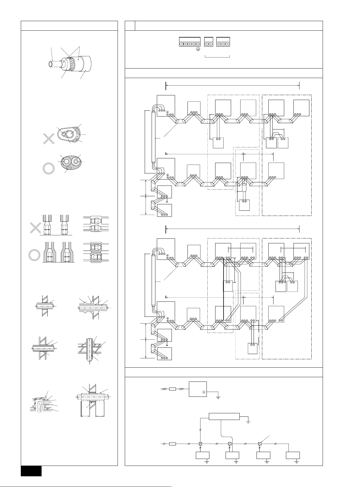
[Fig. 9.2.1]
9.2
A: Power source
B: Transmission line
L1 L2L3 N M1M2 M1M2 S
TB1
TB3 TB7
AB
9.3
L
[Fig. 9.3.1]
OC
(51)
TB3
M1 M2
M1 M2 S
TB7
2
D
L
OC
(53)
TB3
M1 M2
M1 M2 S
TB7
6
Power Supply
L
7
L
Unit
M1M2S
MJ103
M1M2S
(52)
M1 M2 S
BC
(54)
M1 M2 S
BC
1
r
L
3
[Fig. 9.3.2]
OC
(51)
TB3
M1 M2
M1 M2 S
TB7
2
D
L
OC
(53)
TB3
M1 M2
M1 M2 S
TB7
6
Power Supply
L
F
7
L
Unit
M1M2
MJ103
M1M2
S
S
(52)
M1 M2 S
BC
(54)
M1 M2 S
BC
L
3
1
A
IC
(01)
TB5
M1 M2 S
AB AB AB
(101)
RC
IC
(03)
TB5
M1 M2 S
IC
(02)
TB5
M1 M2 S
L
4
IC
(04)
TB5
M1 M2 S
5
L
4
r
AB
(104)
RC
IC
(05)
TB5
M1 M2 S
2
r
r
(105)
RC
E
IC
(07)
TB5
M1 M2 S
B
L
1
A
M1 M2 S
M1 M2 S
1
c
IC
(05)
TB15
TB5
ABABAB
E
IC
(07)
TB15
TB5
A: Group 1
B: Group 3
C: Group 5
D: Shielded Wire
E: Sub Remote
( ): Address
IC
(01)
TB5 TB15
M1 M2 1 2S
IC
(03)
TB5
M1 M2 S
IC
c
2
(02)
TB15
TB5
12
M1 M2 S
1
c
3
c
MA
L
4
IC
(04)
TB5
M1 M2 S
TB15
12
AB
TB15
12
B
C
3
(155)
RC
C
c
12
1
c
c
MAMAMA
12
Controller
IC
(06)
TB5
M1 M2 S
IC
2
(06)
TB15
TB5
12
M1 M2 S
4
3
c
<E> Roof pipe shaft
G
D
<F> Penetrating portion on
fire limit and boundary wall
I
B
H
F
9.4
[Fig. 9.4.1]
J
3 N~380 - 450 V
A
1m1m
A
B
A: Switch (Breakers for Wiring and Current Leakage)
B: Outdoor Unit C: BC Controller
D: Pull Box E: Indoor Unit
C
A: Sleeve B: Heat insulating material
C: Lagging D: Caulking material
E: Band F: Waterproofing laye
G: Sleeve with edge H: Lagging material
~220 - 240 V
I: Mortar or other incombustible caulking
J: Incombustible heat insulation material
4
A
E E
D
E E
Contents
1. Safety precautions ...................................................................................... 5
1.1. Before installation and electric work .......................................... 5
1.2. Precautions for devices that use R407C refrigerant.................. 5
1.3. Before getting installed.............................................................. 6
1.4. Before getting installed (moved) - electrical work...................... 6
1.5. Before starting the test run ........................................................ 6
2. Specifications.............................................................................................. 6
3. Confirmation of parts attached ................................................................... 6
4. Space required around unit ........................................................................ 7
5. Lifting method and weight of product .......................................................... 7
6. Installation of unit ........................................................................................ 7
6.1. Installation ................................................................................. 7
6.2. Connecting direction for refrigerant piping ................................ 7
7. Refrigerant piping installation ..................................................................... 7
7.1. Caution ...................................................................................... 7
1. Safety precautions
1.1. Before installation and electric work
s Before installing the unit, make sure you read all the “Saf ety
precautions”.
s The “Safety precautions” provide very important points re-
garding safety. Make sure you follow them.
Symbols used in the text
Warning:
Describes precautions that should be observed to prevent danger of injury
or death to the user.
Caution:
Describes precautions that should be observed to prevent damage to the
unit.
Symbols used in the illustrations
: Indicates an action that must be avoided.
: Indicates that important instructions must be followed.
: Indicates a part which must be grounded.
: Beware of electric shock. (This symbol is displa y ed on the main unit label.)
<Color: yellow>
Warning:
Carefully read the labels affixed to the main unit.
Warning:
• Ask the dealer or an authorized technician to install the air conditioner.
- Improper installation b y the user ma y result in water leakage , electric shock,
or fire.
• Install the unit at a place that can withstand its weight.
- Inadequate strength may cause the unit to fall down, resulting in injuries.
• Use the specified cables for wiring. Make the connections securely so
that the outside force of the cable is not applied to the terminals.
- Inadequate connection and fastening may generate heat and cause a fire.
• Prepare for str ong winds and earthquakes and install the unit at the specified place.
- Improper installation may cause the unit to topple and result in injury.
• Alwa ys use an filter and other accessories specified by Mitsubishi Electric.
- Ask an authoriz ed technician to install the accessories. Improper installation
by the user may result in water leakage, electric shock, or fire.
• Never repair the unit. If the air conditioner must be repaired, consult the
dealer.
- If the unit is repaired improperly, water leakage, electric shock, or fire may
result.
• Do not touch the heat exchanger fins.
- Improper handling may result in injury.
• If refrigerant gas leaks during installation work, ventilate the room.
- If the refrigerant gas comes into contact with a flame, poisonous gases will
be released.
• Install the air conditioner according to this Installation Manual.
- If the unit is installed improperly, water leakage, electric shock, or fire may
result.
• Have all electric work done by a licensed electrician according to “Electric Facility Engineering Standard” and “Interior Wire Regulations”and
the instructions given in this manual and always use a special circuit.
7.2. Refrigerant piping system.......................................................... 8
8. Additional Refrigerant Charge .................................................................... 8
8.1. Calculation of Additional Refrigerant Charge ............................ 8
8.2. Caution for piping connection/valve operation........................... 8
8.3. Airtight test, evacuation, and refrigerant charging..................... 9
8.4. Thermal insulation of refrigerant piping ................................... 10
9. Wiring........................................................................................................ 10
9.1. Caution .................................................................................... 10
9.2. Control box and connecting position of wiring......................... 10
9.3. Wiring transmission cables...................................................... 10
9.4. Wiring of main power supply and equipment capacity ............ 11
10. Test run ..................................................................................................... 12
10.1. The following phenomena do not represent trouble
(emergency) ............................................................................ 12
- If the power source capacity is inadequate or electric work is performed improperly, electric shock and fire may result.
• Securely install the outdoor unit terminal cover (panel).
- If the terminal cov er (panel) is not installed properly, dust or water may enter
the outdoor unit and fire or electric shock may result.
• When installing and moving the air conditioner to another site, do not
charge the it with a refrigerant different from the refrigerant (R407C or
R22) specified on the unit.
- If a diff erent refrigerant or air is mix ed with the original refrigerant, the refrig-
erant cycle may malfunction and the unit may be damaged.
• If the air conditioner is installed in a small room, measures must be taken
to prevent the refrigerant concentration from exceeding the safety limit
even if the refrigerant should leak.
- Consult the dealer regarding the appropriate measures to pre vent the saf ety
limit from being exceeded. Should the refrigerant leak and cause the safety
limit to be exceeded, hazards due to lack of oxygen in the room could result.
• When moving and reinstalling the air conditioner, consult the dealer or
an authorized technician.
- If the air conditioner is installed improperly, water leakage, electric shock, or
fire may result.
• After completing installation work, make sure that refrigerant gas is not
leaking.
- If the refrigerant gas leaks and is exposed to a fan heater, stove, oven, or
other heat source, it may generate noxious gases.
• Do not reconstruct or change the settings of the protection devices.
- If the pressure switch, thermal switch, or other protection device is shorted
and operated forcibly, or parts other than those specified by Mitsubishi Electric are used, fire or explosion may result.
• To dispose of this product, consult your dealer.
• The installer and system specialist shall secure safety against leakage
according to local regulation or standards.
- Following standards may be applicable if local regulation are not available.
• Pay a special attention to the place, such as a basement, etc. where refrigeration gas can stay, since refrigeration is heavier than the air.
1.2. Precautions for devices that use R407C
refrigerant
Caution:
• Do not use the existing refrigerant piping.
- The old refrigerant and refrigerator oil in the existing piping contains a large
amount of chlorine which may cause the refrigerator oil of the new unit to
deteriorate.
• Use refrigerant piping made of phosphorus deo xidized copper and copper alloy seamless pipes and tubes. In addition, be sure that the inner
and outer surfaces of the pipes are clean and free of hazardous sulphur ,
oxides, dust/dirt, shaving particles, oils, moisture, or any other contaminant.
- Contaminants on the inside of the refrigerant piping may cause the refriger-
ant residual oil to deteriorate.
• Store the piping to be used during installation indoors and keep both
ends of the piping sealed until just before brazing. (Store elbows and
other joints in a plastic bag.)
- If dust, dirt, or water enters the refrigerant cycle, deterioration of the oil and
compressor trouble may result.
• Use ester oil, ether oil or alkylbenz ene (small amount) as the refrigerator
oil to coat flares and flange connections.
- The refrigerator oil will degrade if it is mixed with a large amount of mineral
oil.
• Use liquid refrigerant to fill the system.
- If gas refrigerant is used to seal the system, the composition of the refriger-
ant in the cylinder will change and performance may drop.
GB
D
F
E
INL
PGRRUTR
5
• Do not use a refrigerant other than R407C.
- If another refrigerant (R22, etc.) is used, the chlorine in the refrigerant may
cause the refrigerator oil to deteriorate.
• Use a vacuum pump with a reverse flow check valve.
- The v acuum pump oil ma y flow bac k into the refrigerant cycle and cause the
refrigerator oil to deteriorate.
• Do not use the following tools that are used with conventional refrigerants.
(Gauge manifold, charge hose, gas leak detector , reverse flow chec k valve,
refrigerant charge base, refrigerant recovery equipment)
- If the conventional refrigerant and refrigerator oil are mixed in the R407C,
the refrigerant may deteriorated.
- If water is mixed in the R407C, the refrigerator oil may deteriorate.
- Since R407C does not contain any chlorine, gas leak detectors for conven-
tional refrigerants will not react to it.
• Do not use a charging cylinder.
- Using a charging cylinder may cause the refrigerant to deteriorate.
• Be especially careful when managing the tools.
- If dust, dirt, or water gets in the refrigerant cycle, the refrigerant ma y deterio-
rate.
1.3. Before getting installed
Caution:
• Do not install the unit where combustible gas may leak.
GB
- If the gas leaks and accumulates around the unit, an explosion may result.
• Do not use the air conditioner where food, pets, plants, precision instruments, or artwork are kept.
- The quality of the food, etc. may deteriorate.
• Do not use the air conditioner in special environments.
D
- Oil, steam, sulfuric smoke, etc. can significantly reduce the performance of
the air conditioner or damage its parts.
• When installing the unit in a hospital, communication station, or similar
place, provide sufficient protection against noise.
- The inverter equipment, private power generator, high-frequency medical
F
E
INL
PGRRUTR
equipment, or radio communication equipment may cause the air conditioner
to operate erroneously, or fail to operate. On the other hand, the air conditioner may affect such equipment by creating noise that disturbs medical
treatment or image broadcasting.
• Do not install the unit on a structure that may cause leakage.
- When the room humidity exceeds 80 % or when the drain pipe is clogged,
condensation may drip from the indoor unit. P erform collective drainage w ork
together with the outdoor unit, as required.
1.4. Before getting installed (moved) - elec-
trical work
Caution:
• Ground the unit.
- Do not connect the ground wire to gas or water pipes, lightning rods, or
telephone ground lines. Improper grounding may result in electric shock.
• The reverse phase of L lines (L
but the reverse phase of L lines and N line can be not be detected.
- The some electric parts should be damaged when power is supplied under
the miss wiring.
• Install the power cable so that tension is not applied to the cable.
- Tension may cause the cable to break and generate heat and cause a fire.
1, L2, L3) can be detected (Error cord: 4103),
• Install an leak circuit breaker, as required.
- If an leak circuit breaker is not installed, electric shock may result.
• Use power line cables of sufficient current carrying capacity and rating.
- Cables that are too small may leak, generate heat, and cause a fire.
• Use only a circuit breaker and fuse of the specified capacity.
- A fuse or circuit breaker of a larger capacity or a steel or copper wire may
result in a general unit failure or fire.
• Do not wash the air conditioner units.
- Washing them may cause an electric shock.
• Be careful that the installation base is not damaged by long use.
- If the damage is left uncorrected, the unit may fall and cause personal injury
or property damage.
• Install the drain piping according to this Installation Manual to ensure
proper drainage. Wrap thermal insulation around the pipes to prevent
condensation.
- Improper drain piping may cause water leakage and damage to furniture
and other possessions.
• Be very careful about product transportation.
- Only one person should not carry the product if it weighs more than 20 kg.
- Some products use PP bands for packaging. Do not use an y PP bands f or a
means of transportation. It is dangerous.
- Do not touch the heat exchanger fins. Doing so may cut your fingers.
- When transporting the outdoor unit, suspend it at the specified positions on
the unit base. Also support the outdoor unit at four points so that it cannot
slip sideways.
• Safely dispose of the packing materials.
- P acking materials, such as nails and other metal or wooden parts, may cause
stabs or other injuries.
- Tear apart and throw away plastic packaging bags so that children will not
play with them. If children play with a plastic bag which was not torn apart,
they face the risk of suffocation.
1.5. Before starting the test run
Caution:
• Turn on the power at least 12 hours before starting operation.
- Starting operation immediately after turning on the main power switch can
result ibésevere damage to internal parts. Keep the power switch turned on
during the operational season.
• Do not touch the switches with wet fingers.
- Touching a switch with wet fingers can cause electric shock.
• Do not touch the refrigerant pipes during and immediately after operation.
- During and immediately after operation, the refriger ant pipes are may be hot
and may be cold, depending on the condition of the refrigerant flowing through
the refrigerant piping, compressor, and other refrigerant cycle parts. Your
hands may suffer burns or frostbite if you touch the refrigerant pipes.
• Do not operate the air conditioner with the panels and guards removed.
- Rotating, hot, or high-voltage parts can cause injuries.
• Do not turn off the power immediately after stopping operation.
- Always wait at least five minutes before turning off the power. Otherwise,
water leakage and trouble may occur.
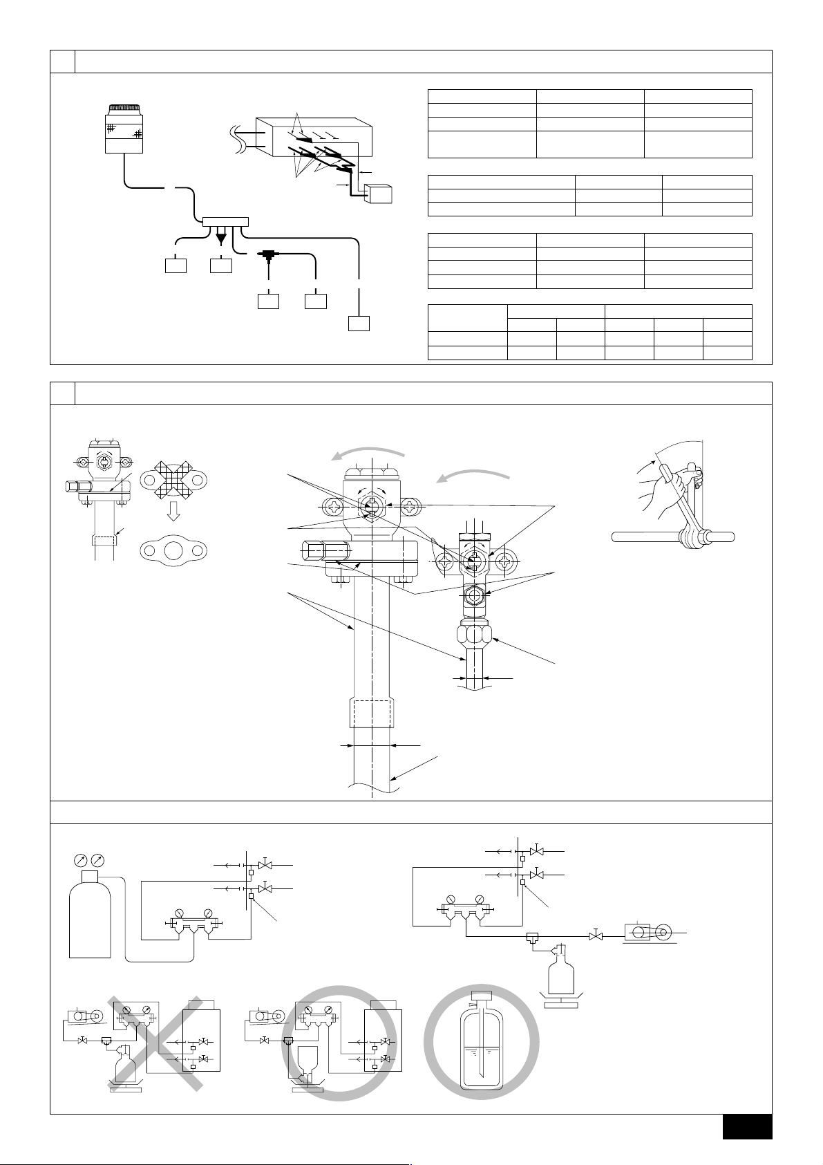
2. Specifications
Model
Noise level
Net weight
Maximum refrigerant pressure
External static pressure
Indoor units
Operation temperature
Total capacity
Model / Quantity
PURY-(P)200YMF-C PURY-(P)250YMF-C
56 dB <A> 57 dB <A>
PURY-200 : 238 kg PURY-250 : 240 kg
PURY-P200 : 241 kg PURY-P250 : 247 kg
2.94 MPa
0 Pa
50 ~ 150 %
20 ~ 200 / 1 ~ 15 20 ~ 250 / 1 ~ 16
Cooling mode: – 5 °CDB ~ 43 °CDB
Heating mode: – 15 °CWB ~ 15.5 °CWB
3. Confirmation of parts attached
1 Panel installation plate × 2 2 Conduit mounting plate × 1 3 Tapping screw M4 × 2
4 Connecting pipe × 1 (Connecting pipe is fixed with the unit.) 5 Packing (inside ø23, outsideø35) × 1
6
4. Space required around unit
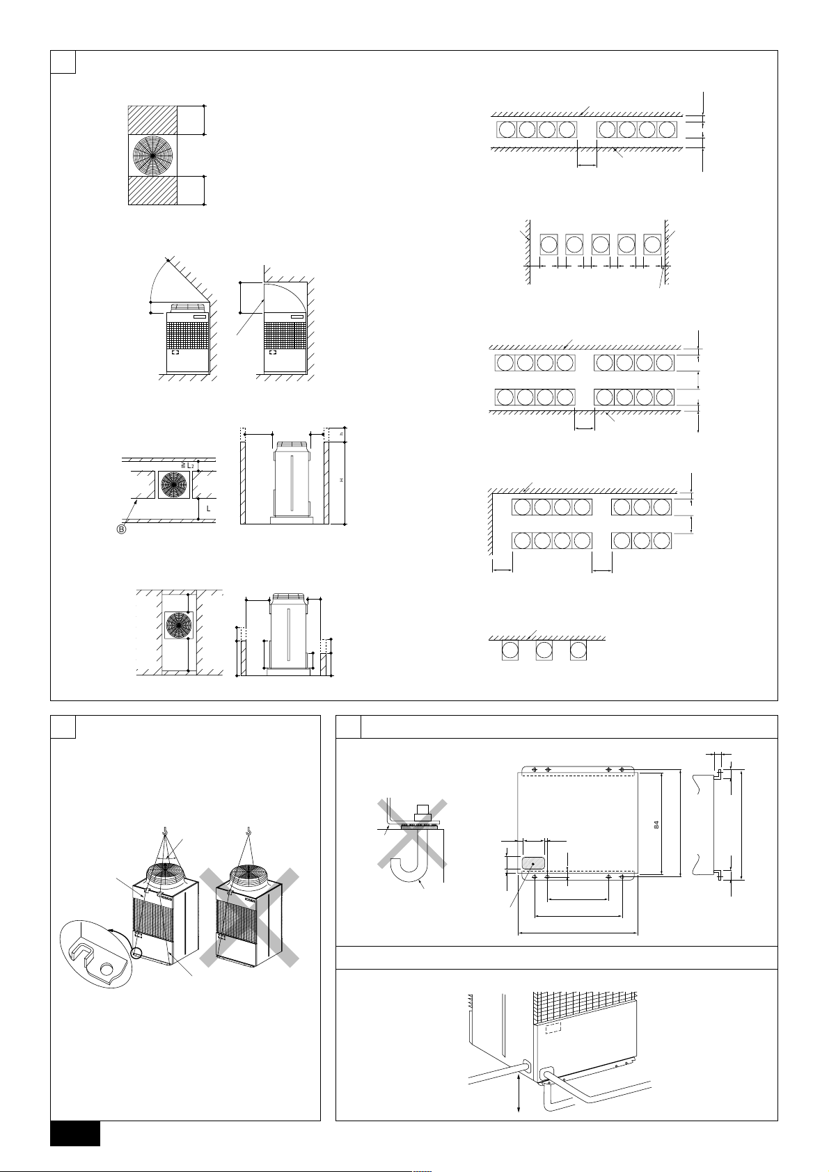
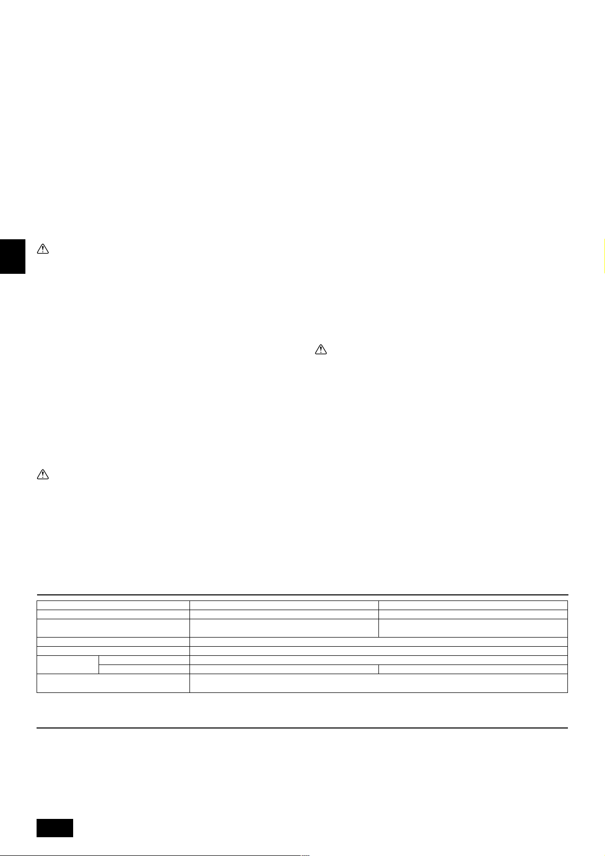
[Fig. 4.0.1] (P.2)
<A> Top view <B> Side view
<C> When there is little space up to an obstruction
A Front
B No restrictions on wall height (left and right)
C Air outlet guide (Procured at the site)
D Must be open E Wall height (H)
F No restrictions on wall height
1: 450 L2: 450
L
(1) Basic space required
A space of at least 250 mm is necessary at the back for inlet air. Taking servicing,
etc. from the rear into account, a space of about 450 mm should be provided, the
same as at the front.
(2) When there is an obstruction above the unit
(3) When inlet air enters from right and left sides of unit
• Wall heights (H) of the front and the back sides shall be within overall height of
unit.
• When the total height is exceeded, add the “h” dimension of the Fig. 4.0.1 to L
and L2.
(4) When unit is surrounded by walls
Note:
• Wall heights (H) of the front and the back sides shall be within overall
height of unit.
• If the panel height is exceeded, add the “h” dimension of the Fig. 4.0.1 to
L
1 and L2.
L1: 450 L2: 450
Example: When h is 100,
(5) Collective installation and continuous installation
• Space required for collective installation and continuous installation:
• Open in the two directions.
• In case wall height (H) exceeds overall height of unit, add “h” dimension (h =
• If there is a wall at both the front and the rear of the unit, install up to four units
1
the L
1 dimension becomes 450 + 100 = 550 mm.
When installing several units, lea ve the space between each bloc k considering
passage for air and people.
wall height <H> – overall height of unit) to * marked dimension.
consecutively in the side direction and provide a space of 1000 mm or more as
inlet space/passage space for each four units.
5. Lifting method and weight of product
[Fig. 5.0.1] (P.2)
Caution:
Be very careful to carry product.
- Do not have only one person to carry product if it is more than 20 kg.
- PP bands are used to pack some products. Do not use them as a mean for transportation because they are dangerous.
- Do not touch heat exchanger fins with your bare hands. Otherwise you may get a cut in your hands.
- Tear plastic packaging bag and scrap it so that children cannot play with it. Otherwise plastic packaging bag may suffocate children to death.
- When carrying in outdoor unit, be sure to support it at four points. Carrying in and lifting with 3-point support may make outdoor unit unstable, resulting in a fall of it.
GB
D
F
6. Installation of unit
6.1. Installation
[Fig. 6.1.1] (P.2)
A M10 anchor bolt procured at the site. B Corner is not seated.
• Fix unit tightly with bolts so that unit will not fall down due to earthquake or
gust.
• Use concrete or angle for foundation of unit.
• Vibration may be transmitted to the installation section and noise and vibration
may be generated from the floor and walls, depending on the installation conditions. Therefore, provide ample vibrationproofing (cushion pads, cushion
frame, etc.).
• Be sure that the corners are firmly seated. If the corners are not firmly seated,
the installation feet may be bent.
Warning:
• Be sure to install unit in a place strong enough to withstand its weight.
Any lack of strength may cause unit to fall down, resulting in a personal
injury.
• Have installation work in order to protect against a strong wind and earthquake.
7. Refrigerant piping installation
City Multi R2 Series is constituted by an end branching system in which the refrigerant piping from outdoor unit is branched at BC controller and connected to each
indoor unit.
The connection method adapted is flange connection for low pressure pipe and
flare connection for high pressure pipe between outdoor unit and BC controller,
and flare connection between BC controller and indoor unit. Brazing connection is
employed for joint pipe set and branch pipe set.
Warning:
Always use extreme care to prevent the refrigerant gas (R407C or R22) from
leaking while using fire or flame. If the refrigerant gas comes in contact with
the flame from any source, such as a gas stove, it breaks down and generates a poisonous gas which can cause gas poisoning. Never weld in an
unventilated room. Always conduct an inspection for gas leakage after installation of the refrigerant piping has been completed.
Any installation deficiency may cause unit to fall down, resulting in a
personal injury.
When building the foundation, give full attention to the floor strength, drain water
disposal <during operation, drain water flows out of the unit>, and piping and wiring routes.
Down piping and down wiring precautions
When down piping and down wiring are performed, be sure that foundation and
base work does not block the base through holes. When do wn piping is performed,
make the foundation at least 100 mm high so that the piping can pass under the
bottom of the unit.
[Fig. 6.1.2] (P.2)
A Bottom piping through hole B (bolt hole)
C (bolt hole for old models)
6.2. Connecting direction for refrigerant piping
[Fig. 6.2.1] (P.2)
7.1. Caution
1 Use the following materials for refrigeration piping.
• Material: Use refrigerant piping made of phosphorus deoxidized copper.
In addition, be sure that the inner and outer surfaces of the pipes are clean
and free of hazardous sulphur, oxides, dust/dirt, shaving particles, oils,
moisture, or any other contaminant. (For R407C models)
2 Commercially available piping often contains dust and other materials. Alwa ys
blow it clean with a dry inert gas.
3 Use care to prevent dust, water or other contaminants from entering the piping
during installation.
4 Reduce the number of bending portions as much as possible, and make bend-
ing radius as big as possible.
5 Always observe the restrictions on the refrigerant piping (such as rated length,
the difference between high/low pressures, and piping diameter). F ailure to do
so can result in equipment failure or a decline in heating/cooling performance.
E
INL
PGRRUTR
7
 Loading...