

AIR CONDITIONER
2014
Service Handbook
PURY-WP200, WP250YJM-A
CMB-WP108V-G
Model
3rd edition
ii
HWE1113B GB
Safety Precautions
Before installing the unit, thoroughly read the following safety precautions.
Observe these safety precautions for your safety.
WARNING
This symbol is intended to alert the user to the presence of important instructions that must be followed to avoid
the risk of serious injury or death.
CAUTION
This symbol is intended to alert the user to the presence of important instructions that must be followed to avoid
the risk of serious injury or damage to the unit.
After reading this manual, give it to the user to retain for future reference.
Keep this manual for easy reference. When the unit is moved or repaired, give this manual to those who provide these
services.
When the user changes, make sure that the new user receives this manual.
WARNING
Do not use refrigerant other than the type indicated in
the manuals provided with the unit and on the nameplate.
Doing so may cause the unit or pipes to burst, or result in
explosion or fire during use, during repair, or at the time of
disposal of the unit.
It may also be in violation of applicable laws.
MITSUBISHI ELECTRIC CORPORATION cannot be held
responsible for malfunctions or accidents resulting from the
use of the wrong type of refrigerant.
Ask your dealer or a qualified technician to install the
unit.
Improper installation by the user may result in water leakage, electric shock, smoke, and/or fire.
Properly install the unit on a surface that can withstand the weight of the unit.
Unit installed on an unstable surface may fall and cause injury.
Only use specified cables. Securely connect each cable so that the terminals do not carry the weight of the
cable.
Improperly connected or fixed cables may produce heat
and start a fire.
Take appropriate safety measures against strong
winds and earthquakes to prevent the unit from falling.
If the unit is not installed properly, the unit may fall and
cause serious injury to the person or damage to the unit.
Do not make any modifications or alterations to the
unit. Consult your dealer for repair.
Improper repair may result in water leakage, electric shock,
smoke, and/or fire.
Do not touch the heat exchanger fins.
The fins are sharp and dangerous.
In the event of a refrigerant leak, thoroughly ventil ate
the room.
If refrigerant gas leaks and comes in contact with an open
flame, poisonous gases will be produced.
Properly install the unit according to the instructions
in the installation manual.
Improper installation may result in water leakage, electric
shock, smoke, and/or fire.
Have all electrical work performed by an authorized
electrician according to the local regulations and instructions in this manual, and a dedicated circuit must
be used.
Insufficient capacity of the power supply circuit or improper
installation may result in malfunctions of the unit, electric
shock, smoke, and/or fire.
ii
HWE1113B GB
WARNING
Securely attach the terminal block cover (panel) to the
unit.
If the terminal block cover (panel) is not installed properly,
dust and/or water may infiltrate and pose a risk of electric
shock, smoke, and/or fire.
Only use the type of refrigerant that is indicated on the
unit when installing or reinstalling the unit.
Infiltration of any other type of refrigerant or air into the unit
may adversely affect the refrigerant cycle and may cause
the pipes to burst or explode.
When installing the unit in a small room, exercise caution and take measures against leaked refrigerant
reaching the limiting concentration.
Consult your dealer with any questions regarding limiting
concentrations and for precautionary measures before installing the unit. Leaked refrigerant gas exceeding the limiting concentration causes oxygen deficiency.
Consult your dealer or a specialist when moving or reinstalling the unit.
Improper installation may result in water leakage, electric
shock, and/or fire.
After completing the service work, check for a gas
leak.
If leaked refrigerant is exposed to a heat source, such as a
fan heater, stove, or electric grill, poisonous gases may be
produced.
Do not try to defeat the safety features of the unit.
Forced operation of the pressure switch or the temperature
switch by defeating the safety features of these devices, or
the use of accessories other than the ones that are recommended by MITSUBISHI may result in smoke, fire, and/or
explosion.
Only use accessories recommended by MITSUBISHI.
Ask a qualified technician to install the unit. Improper installation by the user may result in water leakage, electric
shock, smoke, and/or fire.
Control box houses high-voltage parts.
When opening or closing the front panel of the control box,
do not let it come into contact with any of the internal components. Before inspecting the inside of the control box,
turn off the power, keep the unit off for at least 10 minutes,
and confirm that the voltage between FT-P and FT-N on
INV Board has dropped to DC20V or less. (It takes about
10 minutes to discharge electricity after the power supply is
turned off.)
iiiiii
HWE1113B GB
Precautions for handling units for use with R410A
CAUTION
Do not use the existing refrigerant piping.
A large amount of chlorine that may be contained in the re-
sidual refrigerant and refrigerating machine oil in the existing piping may cause the refrigerating machine oil in the
new unit to deteriorate.
R410A is a high-pressure refrigerant and can cause the
existing pipes to burst.
Use refrigerant pipes made of phosphorus deoxidized
copper. Keep the inner and outer surfaces of the pipes
clean and free of such conta minants as sulfur, oxide s,
dust, dirt, shaving particles, oil, and water.
These types of contaminants inside the refrigerant pipes
may cause the refrigerant oil to deteriorate.
Store the pipes to be installed indoors, and keep both
ends of the pipes sealed until immedia tely before brazing. (Keep elbows and other joints wrapped in plastic.)
Infiltration of dust, dirt, or water into the refrigerant system
may cause the refrigerating machine oil to deteriorate or
cause the unit to malfunction.
Use a small amount of ester oil, ether oil, or alkylbenzene to coat flares and flanges.
Infiltration of a large amount of mineral oil may cause the refrigerating machine oil to deteriorate.
Charge liquid refrigerant (as opposed to gaseous refrigerant) into the system.
If gaseous refrigerant is charged into the system, the composition of the refrigerant in the cylinder will change and
may result in performance loss.
Use a vacuum pump with a reverse-flow check valve.
If a vacuum pump that is not equipped with a reverse-flow
check valve is used, the vacuum pump oil may flow into the
refrigerant cycle and cause the refrigerating machine oil to
deteriorate.
Prepare tools for exclusive use with R410A. Do not use
the following tools if they have been used with the conventional refrigerant (gauge manifold, chargin g hose,
gas leak detector, reverse-flow check valve, refrigerant
charge base, vacuum gauge, and refrigerant recovery
equipment.).
If the refrigerant or the refrigerating machine oil left on
these tools are mixed in with R410A, it may cause the refrigerating machine oil to deteriorate.
Infiltration of water may cause the refrigerating machine
oil to deteriorate.
Gas leak detectors for conventional refrigerants will not
detect an R410A leak because R410A is free of chlorine.
Do not use a charging cylinder.
If a charging cylinder is used, the composition of the refrigerant will change, and the unit may experience power loss.
Exercise special care when handling the tools for use
with R410A.
Infiltration of dust, dirt, or water into the refrigerant system
may cause the refrigerating machine oil to deteriorate.
iv
HWE1113B GB
Before installing the unit
WARNING
Do not install the unit where a gas leak may occur.
If gaseous refrigerant leaks and piles up around the unit, it
may be ignited.
Do not use the unit to keep food items, animals, plants,
artifacts, or for other special purposes.
The unit is not designed to preserve food products.
Do not use the unit in an unusual environment.
Do not install the unit where a large amount of oil or steam
is present or where acidic or alkaline solutions or chemical
sprays are used frequently. Doing so may lead to a remarkable drop in performance, electric shock, malfunctions, smoke, and/or fire.
The presence of organic solvents or corrosive gas (i.e.
ammonia, sulfur compounds, and acid) may cause gas
leakage or water leakage.
When installing the unit in a hospital, take appropriate
measures to reduce noise interference.
High-frequency medical equipment may interfere with the
normal operation of the air conditioner or vice versa.
Do not install the unit on or over things that cannot get
wet.
When the humidity level exceeds 80% or if the drainage
system is clogged, the indoor unit may drip water. Drain water is also discharged from the outdoor unit. Install a centralized drainage system if necessary.
vv
HWE1113B GB
Before installing the unit (moving and reinstalling the unit) and performing
electrical work
CAUTION
Properly ground the unit.
Do not connect the grounding wire to a gas pipe, water pipe,
lightning rod, or grounding wire from a telephone pole. Improper grounding may result in electric shock, smoke, fire,
and/or malfunction due to noise interference.
Do not put tension on the power supply wires.
If tension is put on the wires, they may break and result in
excessive heat, smoke, and/or fire.
Install an earth leakage breaker to avoid the risk of
electric shock.
Failure to install an earth leakage breaker may result in
electric shock, smoke, and/or fire.
Use the kind of power supply wires that are specified
in the installation manual.
The use of wrong kind of power supply wires may result in
current leak, electric shock, and/or fire.
Use breakers and fuses (current breaker, remote
switch <switch + Type-B fuse>, moulded case circuit
breaker) with the proper current capacity.
The use of wrong capacity fuses, steel wires, or copper
wires may result in malfunctions, smoke, and/or fire.
Do not spray water on the air conditioner or immerse
the air conditioner in water.
Otherwise, electric shock and/or fire may result.
When handling units, always wear protective gloves to
protect your hands from metal parts and high-temperature parts.
Periodically check the installation base for damage.
If the unit is left on a damaged platform, it may fall and
cause injury.
Properly install the drain pipes according to the instructions in the installation manual. Keep them insulated to avoid dew condensation.
Improper plumbing work may result in water leakage and
damage to the furnishings.
Exercise caution when transporting products.
Products weighing more than 20 kg should not be carried
alone.
Do not carry the product by the PP bands that are used on
some products.
Do not touch the heat exchanger fins. They are sharp and
dangerous.
When lifting the unit with a crane, secure all four corners
to prevent the unit from falling.
Properly dispose of the packing materials.
Nails and wood pieces in the package may pose a risk of
injury.
Plastic bags may pose a risk of choking hazard to chil-
dren. Tear plastic bags into pieces before disposing of
them.
vi
HWE1113B GB
Before the test run
CAUTION
Turn on the unit at least 12 hours before the test run.
Keep the unit turned on throughout the season. If the unit is
turned off in the middle of a season, it may result in malfunctions.
To avoid the risk of electric shock or malfunction of the
unit, do not operate switches with wet hands.
Do not touch the refrigerant pipes with bare hands during and immediately after operation.
During or immediately after operation, certain parts of the
unit such as pipes and compressor may be either very cold
or hot, depending on the state of the refrigerant in the unit
at the time. To reduce the risk of frost bites and burns, do
not touch these parts with bare hands.
Do not operate the unit without panels and safety
guards.
Rotating, high-temperature, or high-voltage parts on the unit
pose a risk of burns and/or electric shock.
Do not turn off the power immediately after stopping
the operation.
Keep the unit on for at least five minutes before turning off
the power to prevent water leakage or malfunction.
Do not operate the unit without the air filter.
Dust particles may build up in the system and cause malfunctions.
Use circulation and makeup water that meet the waterquality standards.
Degradation of water quality can result in water leakage.
In areas where temperature drops to freezing during
the periods of non-use, blow the water out of the pipes
or fill the pipes with anti-freeze solution.
Not doing so may cause the water to freeze, resulting in
burst pipes and damage to the unit or the furnishings.

CONTENTS
HWE1113B GB
I
Read Before Servicing
[1] Read Before Servicing.............................................................................................................. 3
[2] Necessary Tools and Materials .......................................... ... .... ... ... ... ... .... ... ... ... .... ... ... ... ... ...... 4
[3] Piping Materials......................................................................... ... ... ... ... .... ... ... ... .... ... ............... 5
[4] Storage of Piping............................................................................. ... ... .... ... ... ... .... ... ............... 7
[5] Pipe Processing............................... ... ... ... ... .... ... ... ... .... ... ... ... .... ... ... ... ... .... ... ... ... .... ... ............... 7
[6] Brazing...................... ... .......................................... ... .... ... ... ... ................................................... 8
[7] Air Tightness Test............................ ... ... ... ... .... .......................................... ... ... ... .... ... ............... 9
[8] Vacuum Drying (Evacuation)........................................ ... ... ... .... ... ... ... ... .... ... ... ... ....................10
[9] Refrigerant Charging ................................... .... ... ... ... .... ... ... ... .... ... ... ... ... .... ... .......................... 12
[10] Remedies to be taken in case of a Refrigerant Leak............................................................ 12
[11] Characteristics of the Conventional and the New Refrigerants ............................................13
[12] Notes on Refrigerating Machine Oil...................................................................................... 14
[13] Water piping..........................................................................................................................15
II
Restrictions
[1] System configuration .......... ... ... ... .... .......................................... ... ... ... ... ................................. 21
[2] Types and Maximum allowable Length of Cables.............. ... .... ... ... ... ... .... ... ... ... .... ... ... ... ... .... 22
[3] Switch Settings and Address Settings....................................... ... ... ... ... .... ... ... ... .... ... ... ... ... .... 23
[4] Sample System Connection ............................... ... ... .... ... ... ... .... ... ... ... ... .... ... ... ....................... 29
[5] An Example of a System to which an MA Remote Controller is connected ........................... 30
[6] An Example of a System to which an ME Remote Controller is connected ........................... 40
[7] An Example of a System to which both MA Remote Controller and ME Remote
Controller are connected ................................................. ... ... .... ... ... ... ... .... ... ... .......................42
[8] Restrictions on Pipe Length................................ ... ... .... ... ... ... .... ... ... ... ... .... ... ... ... .... ... ... ... ....... 45
III
Outdoor Unit Components
[1] Outdoor Unit Components and Refrigerant Circuit................................................................. 49
[2] Control Box of the Outdoor Unit..............................................................................................51
[3] Outdoor Unit Circuit Board......................................................................................................52
[4] HBC Controller Components.............. ... ... ... .... ... ... ... .... ... ... ... .... ... ... ... ... .... ... ... ... .... ... ... ... ... .... 57
[5] Control Box of the HBC Controller.......................................................................................... 59
[6] HBC Controller Circuit Board................................. ... .... ... ... ... .... ... ... ... ... .... ... ... ... .... ... ... ... ... .... 60
IV
Remote Controller
[1] Functions and Specifications of MA and ME Remote Controllers ..........................................65
[2] Group Settings and Interlock Settings via the ME Remote Controller.................................... 66
[3] Interlock Settings via the MA Remote Controller............................................. ... .... ...... ... ... .... 70
[4] Using the built-in Temperature Sensor on the Remote Controller.......................................... 71
V
Electrical Wiring Diagram
[1] Electrical Wiring Diagram of the Outdoor Unit.............................................. ... ... .... ... ... ... ... .... 75
[2] Electrical Wiring Diagram of the HBC Controller ... ... .... ... ... ... .... ... ... ... ... .... ... ... ... .... ... ... ... ... .... 76
[3] Electrical Wiring Diagram of Transmission Booster.. .... ... ...... .... ... ... ... ... .... ... ... ... .... ... ... ... ... .... 78
VI
Refrigerant Circuit
[1] Refrigerant Circuit Diagram ....................................................................................................81
[2] Principal Parts and Functions............................................. ... .... ... ... ... .................................... 83
VII
Control
[1] Functions and Factory Settings of the Dipswitches................................................................ 89
[2] Controlling the Outdoor Unit ...................................................................................................96
[3] Controlling HBC Controller ................................................................................................... 106
[4] Operation Flow Chart............................................................................................................111
VIII
Test Run Mode
[1] Items to be checked before a Test Run................................................................................ 119
[2] Test Run Method ..................................................................................................................120
[3] Operating Characteristic and Refrigerant Amount................................................................ 121
[4] Adjusting the Refrigerant Amount......................................................................................... 121
[5] Refrigerant Amount Adjust Mode.......................................................................................... 123
[6] The following symptoms are normal............................................. ... ... ... .... ... ... ... .... ... ... ... ... .. 123
[7] Standard Operation Data (Reference Data) ......................................................................... 124

HWE1113B GB
IX
Troubleshooting
[1] Error Code Lists............................... ... ... ... ... .... ... ... ... .... ... ... ... .... ... ... .....................................129
[2] Responding to Error Display on the Remote Controller........................................................ 133
[3] Investigation of Transmission Wave Shape/Noise ............................................................... 204
[4] Troubleshooting Principal Parts............................................................................................ 207
[5] Refrigerant Leak................. ... ... ... .... ... ... ... ... .... ... ... ... .... ... ... ... .... ... ... ... ... .... ... ... .....................229
[6] Compressor Replacement Instructions........ .... ... ... ... .... ... ... ... .... ... ... ... ... .... ... ... ... .... ... ... ... ... .. 231
[7] Servicing the HBC controller.................................................................................................237
[8] Troubleshooting Using the Outdoor Unit LED Error Display............... ... .... ... ... ... .... ... ... ... ... .. 239
[9] Instructions for debris removal operation.............................................................................. 240
[10] Instructions for the air vent operation ................................................................................. 241
[11] Instructions for the water pump replacement...................................................................... 242
X
LED Monitor Display on the Outdoor Unit Board
[1] How to Read the LED on the Service Monitor......................................................................245

- 1 -
HWE1113B GB
I
Read Before Servicing
[1] Read Before Servicing................. ... ... ... .... ... ... ... ... .... ... ... ... .... .......................................... ..3
[2] Necessary Tools and Materials..........................................................................................4
[3] Piping Materials .................................................................................................................5
[4] Storage of Piping ...................................................... ... ... ... .... ............................................7
[5] Pipe Processing................. ... ... .... .......................................... ... ... ... .... ... ... ... ... .... ... ... ... ......7
[6] Brazing...............................................................................................................................8
[7] Air Tightness Test..............................................................................................................9
[8] Vacuum Drying (Evacuation)...........................................................................................10
[9] Refrigerant Charging........................................................................................................12
[10] Remedies to be taken in case of a Refrigerant Leak.......................................................12
[11] Characteristics of the Conventional and the New Refrigerants .......................................13
[12] Notes on Refrigerating Machine Oil.................................................................................14
[13] Water piping.................... ... ... ... .......................................... .... ... ... ... .... ... ... ... ... .... ... ... .......15

- 2 -
HWE1113B GB

[ I Read Before Servicing ]
- 3 -
HWE1113B GB
I Read Before Servicing
[1] Read Before Servicing
1. Check the type of refrigerant used in the system to be serviced.
Refrigerant Type
Multi air conditioner for building application CITY MULTI R2 YJM-A series (for exclusive use with HBC controller): R410A
2. Check the symptoms exhibited by the unit to be serviced.
Refer to this service handbook for symptoms relating to the refrigerant cycle.
3. Thoroughly read the safety precautions at the beginning of this manual.
4. Preparing necessary tools: Prepare a set of tools to be used exclusively with each type of refrigerant.
Refer to "Necessary Tools and Materials" for information on the use of tools.(page 4)
5. Verification of the connecting pipes: Verify the type of refrigerant used for the unit to be moved or replaced.
Use refrigerant pipes made of phosphorus deoxidized copper. Keep the inner and outer surfaces of the pipes clean and free
of such contaminants as sulfur, oxides, dust, dirt, shaving particles, oil, and water.
These types of contaminants inside the refrigerant pipes may cause the refrigerant oil to deteriorate.
6. If there is a leak of gaseous refrigerant and the remaining refrigerant is exposed to an open flame, a poisonous gas
hydrofluoric acid may form. Keep workplace well ventilated.
CAUTION
Install new pipes immediately after removing old ones to keep moisture out of the refrigerant circuit.
The use of refrigerant that contains chloride, such as R22, will cause the refrigerating machine oil to deteriorate.
[ I Read Before Servicing ]
- 4 -
HWE1113B GB
[2] Necessary Tools and Materials
Prepare the following tools and materials necessary for installing and servicing the unit.
Tools for use with R410A (Adaptability of tools that are for use with R22 or R407C)
1. To be used exclusively with R410A (not to be used if used with R22 or R407C)
2. Tools and materials that may be used with R410A with some restrictions
3. Tools and materials that are used with R22 or R407C that may also be used with R410A
4. Tools and materials that must not be used with R410A
Tools for R410A must be handled with special care to keep moisture and dust from infiltrating the cycle.
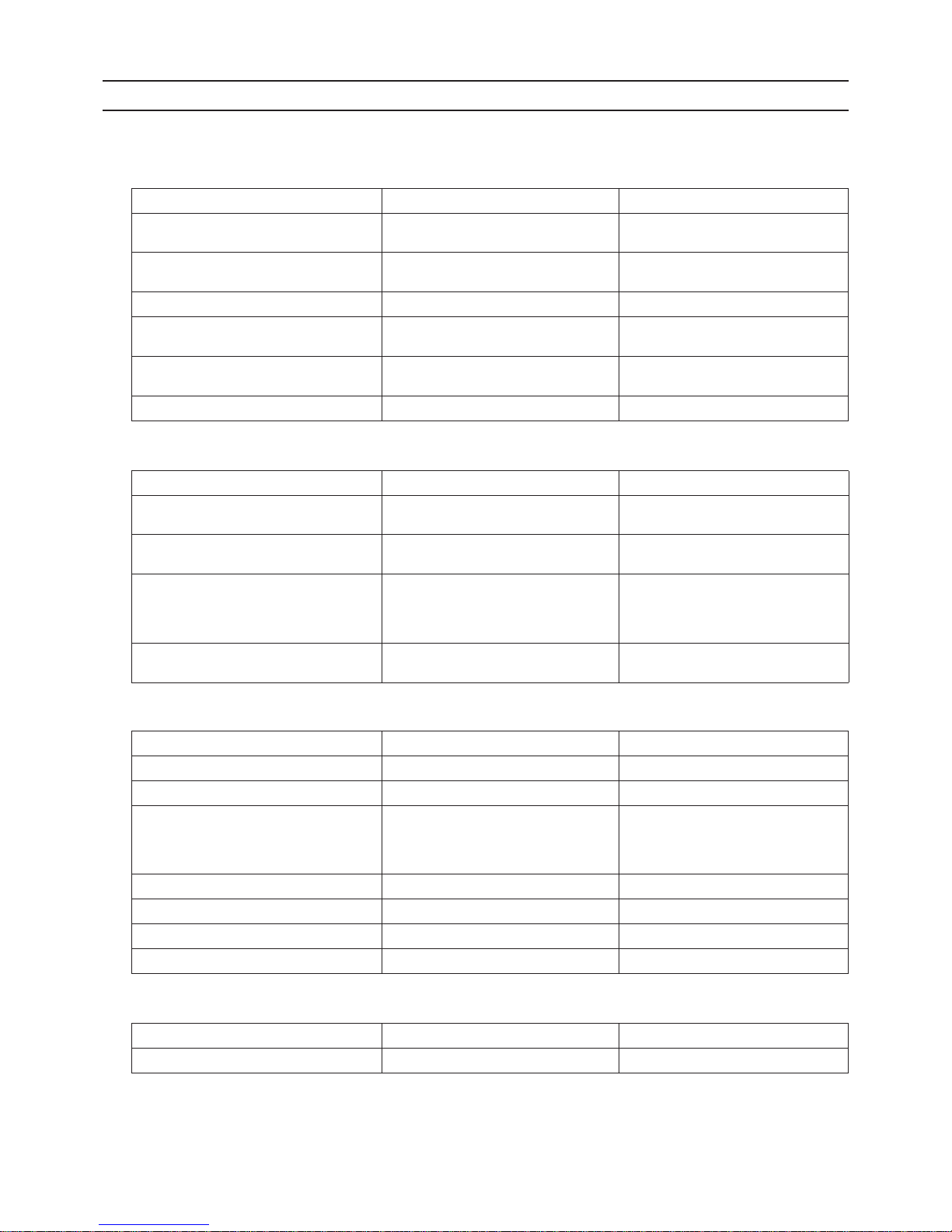
Tools/Materials Use Notes
Gauge Manifold Evacuation and refrigerant charging Higher than 5.09MPa[738psi] on the
high-pressure side
Charging Hose Evacuation and refrigerant charging The hose diameter is larger than the
conventional model.
Refrigerant Recovery Cylinder Refrigerant recovery
Refrigerant Cylinder Refrigerant charging The refrigerant type is indicated. The
cylinder is pink.
Charging Port on the Refrigerant Cylinder Refrigerant charging The charge port diameter is larger
than that of the current port.
Flare Nut Connection of the unit with the pipes Use Type-2 Flare nuts.
Tools/Materials Use Notes
Gas Leak Detector Gas leak detection The ones for use with HFC refrigerant
may be used.
Vacuum Pump Vacuum drying May be used if a check valve adapter
is attached.
Flare Tool Flare processing Flare processing dimensions for the
piping in the system using the new re-
frigerant differ from those of R22. Re-
fer to I [3] Piping Materials.
Refrigerant Recovery Equipment Refrigerant recovery May be used if compatible with
R410A.
Tools/Materials Use Notes
Vacuum Pump with a Check Valve Vacuum drying
Bender Bending pipes
Torque Wrench Tightening flare nuts Only the flare processing dimensions
for pipes that have a diameter of
ø12.7 (1/2") and ø15.88 (5/8") have
been changed.
Pipe Cutter Cutting pipes
Welder and Nitrogen Cylinder Welding pipes
Refrigerant Charging Meter Refrigerant charging
Vacuum Gauge Vacuum level check
Tools/Materials Use Notes
Charging Cylinder Refrigerant charging Prohibited to use
[ I Read Before Servicing ]
- 5 -
HWE1113B GB
[3] Piping Materials
1. Copper pipe materials
The distinction between O-materials (Soft Annealed) and 1/2H-materials (Light Annealed) is made based on the strength of
the pipes themselves.
2. Types of copper pipes
3. Piping materials/Radial thickness
Use refrigerant pipes made of phosphorus deoxidized copper.
The operation pressure of the units that use R410A is higher than that of the units that use R22.
Use pipes that have at least the radial thickness specified in the chart below.
(Pipes with a radial thickness of 0.7 mm or less may not be used.)
For the models for use with R410A, pipes made with O-material (soft annealed) cannot be used unless they have a diameter
of at least ø19.05 (3/4") and a radial thickness of 1.2 t. Use pipes made with 1/2H-material (light annealed).
The figures in the radial thickness column are based on the Japanese standards and provided only as a reference. Use pipes
that meet the local standards.
O-material (Soft Annealed) Soft copper pipes (ann ealed copper pipes). They can easily be bent with hands.
1/2H-material (Light Annealed) Hard copper pipes (straight pipes). They are stronger than the O-material (Soft An-
nealed) at the same radial thickness.
Maximum working pressure Refrigerant type
3.45 MPa [500psi] R22, R407C etc.
4.30 MPa [624psi] R410A etc.
Pipe size (mm[in]) Radial thickness (mm) Type
ø6.35 [1/4"] 0.8t
O-material (Soft Annealed)
ø9.52 [3/8"] 0.8t
ø12.7 [1/2"] 0.8t
ø15.88 [5/8"] 1.0t
ø19.05 [3/4"] 1.0t
1/2H-material,
H-material
(Light Annealed, Skin Hard)
ø22.2 [7/8"] 1.0t
ø25.4 [1"] 1.0t
ø28.58 [1-1/8"] 1.0t
ø31.75 [1-1/4"] 1.1t
ø34.93 [1-3/8"] 1.2t
ø41.28 [1-5/8"] 1.4t
Do not use the existing piping!
[ I Read Before Servicing ]
- 6 -
HWE1113B GB
4. Thickness and refrigerant type indicated on the piping materials
Ask the pipe manufacturer for the symbols indicated on the piping material for new refrigerant.
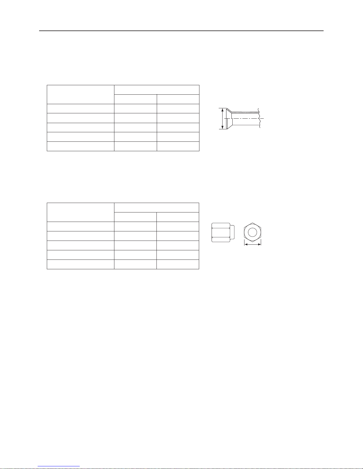
5. Flare processing (O-material (Soft Annealed) and OL-material only)
The flare processing dimensions for the pipes that are used in the R410A system are larger than those in the R22 system.
(ø19.05 pipes should have a radial thickness of 1.2 t and be made of annealed materials.)
If a clutch-type flare tool is used to flare the pipes in the system using R410A, the length of the pipes must be between 1.0
and 1.5 mm. For margin adjustment, a copper pipe gauge is necessary.
6. Flare nut
The flare nut type has been changed to increase the strength. The size of some of the flare nuts have also been changed.
The figures in the radial thickness column are based on the Japanese standards and provided only as a reference. Use pipes
that meet the local standards.
Flare processing dimensions (mm[in])
Pipe size (mm[in])
A dimension (mm)
R410A R22, R407C
ø6.35 [1/4"] 9.1 9.0
ø9.52 [3/8"] 13.2 13.0
ø12.7 [1/2"] 16.6 16.2
ø15.88 [5/8"] 19.7 19.4
ø19.05 [3/4"] 24.0 23.3
Flare nut dimensions (mm[in])
Pipe size (mm[in])
B dimension (mm)
R410A R22, R407C
ø6.35 [1/4"] 17.0 17.0
ø9.52 [3/8"] 22.0 22.0
ø12.7 [1/2"] 26.0 24.0
ø15.88 [5/8"] 29.0 27.0
ø19.05 [3/4"] 36.0 36.0
Dimension A
Dimension B
[ I Read Before Servicing ]
- 7 -
HWE1113B GB
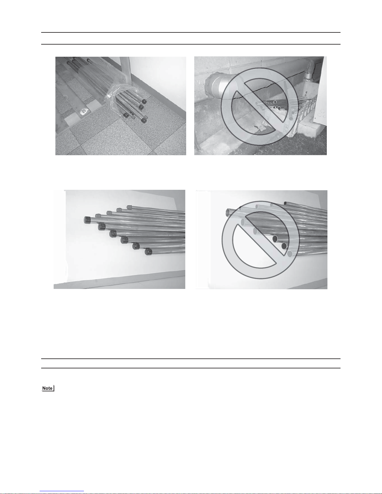
[4] Storage of Piping
1. Storage location
Store the pipes to be used indoors. (Warehouse at site or owner's warehouse)
If they are left outdoors, dust, dirt, or moisture may infiltrate and contaminate the pipe.
2. Sealing the pipe ends
Both ends of the pipes should be sealed until just before brazing.
Keep elbow pipes and T-joints in plastic bags.
The new refrigerator oil is 10 times as hygroscopic as the conventional refrigerating machine oil (such as Suniso) and, if not
handled with care, could easily introduce moisture into the system. Keep moisture out of the pipes, for it will cause the oil to
deteriorate and cause a compressor failure.
[5] Pipe Processing
Use a small amount of ester oil, ether oil, or alkylbenzene to coat flares and flanges.
Use a minimum amount of oil.
Use only ester oil, ether oil, and alkylbenzene.
[ I Read Before Servicing ]
- 8 -
HWE1113B GB
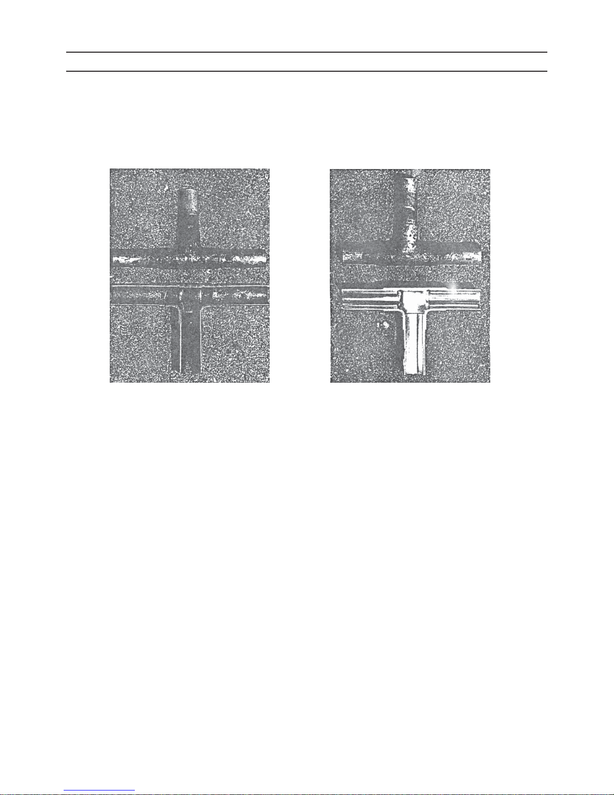
[6] Brazing
No changes have been made in the brazing procedures. Perform brazing with special care to keep foreign objects (such as oxide
scale, water, and dust) out of the refrigerant system.
Example: Inside the brazed connection
1. Items to be strictly observed
Do not conduct refrigerant piping work outdoors if raining.
Use non-oxidized solder.
Use a brazing material (BCuP-3) that requires no flux when brazing between copper pipes or between a copper pipe and
copper coupling.
If installed refrigerant pipes are not immediately connected to the equipment, then braze and seal both ends.
2. Reasons
The new refrigerating machine oil is 10 times as hygroscopic as the conventional oil and is more likely to cause unit failure if
water infiltrates into the system.
Flux generally contains chloride. Residual flux in the refrigerant circuit will cause sludge to form.
3. Notes
Do not use commercially available antioxidants because they may cause the pipes to corrode or refrigerating machine oil to
deteriorate.
Use of oxidized solder for brazing Use of non-oxidized solder for brazing
[ I Read Before Servicing ]
- 9 -
HWE1113B GB
[7] Air Tightness Test
No changes have been made in the detection method. Note that a refrigerant leak detector for R22 will not detect an R410A leak.
1. Items to be strictly observed
Pressurize the equipment with nitrogen up to the design pressure (4.15MPa[601psi]), and then judge the equipment's air tight-
ness, taking temperature variations into account.
Refrigerant R410A must be charged in its liquid state (vs. gaseous state).
2. Reasons
Oxygen, if used for an air tightness test, poses a risk of explosion. (Only use nitrogen to check air tightness.)
Refrigerant R410A must be charged in its liquid state. If gaseous refrigerant in the cylinder is drawn out first, the composition
of the remaining refrigerant in the cylinder will change and become unsuitable for use.
3. Notes
Procure a leak detector that is specifically designed to detect an HFC leak. A leak detector for R22 will not detect an
HFC(R410A) leak.
Halide torch R22 leakage detector
[ I Read Before Servicing ]
- 10 -
HWE1113B GB
[8] Vacuum Drying (Evacuation)
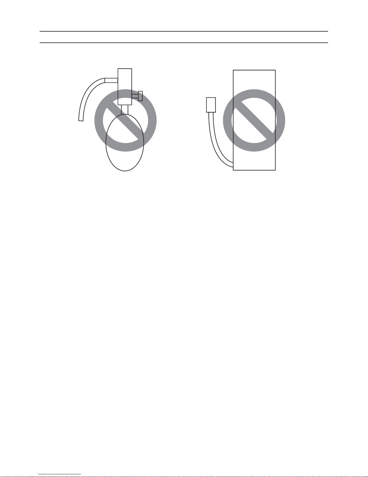
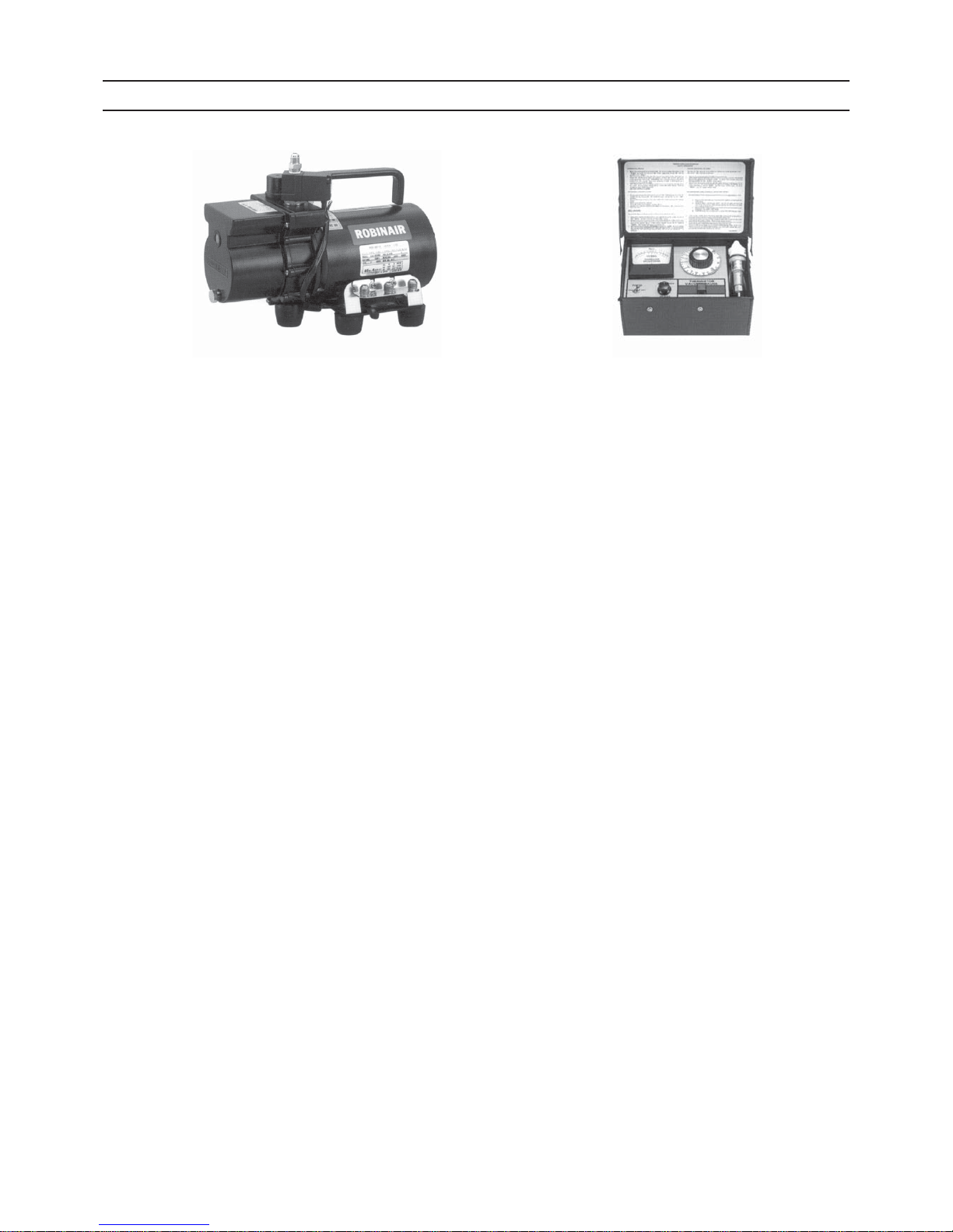
1. Vacuum pump with a reverse-flow check valve (Photo1)
To prevent the vacuum pump oil from flowing into the refrigerant circuit during power OFF or power failure, use a vacuum
pump with a reverse-flow check valve.
A reverse-flow check valve may also be added to the vacuum pump currently in use.
2. Standard of vacuum degree (Phot o 2)
Use a vacuum pump that attains 0.5Torr(65Pa) or lower degree of vacuum after 5 minutes of operation, and connect it directly
to the vacuum gauge. Use a pump well-maintained with an appropriate lubricant. A poorly maintained vacuum pump may not
be able to attain the desired degree of vacuum.
3. Required precision of vacuum gauge
Use a vacuum gauge that registers a vacuum degree of 5Torr(650Pa) and measures at intervals of 1Torr(130Pa). (A recommended vacuum gauge is shown in Photo2.)
Do not use a commonly used gauge manifold because it cannot register a vacuum degree of 5Torr(650Pa).
4. Evacuation time
After the degree of vacuum has reached 5Torr(650Pa), evacuate for an additional 1 hour. (A thorough vacuum drying re-
moves moisture in the pipes.)
Verify that the vacuum degree has not risen by more than 1Torr(130Pa) 1hour after evacuation. A rise by less than
1Torr(130Pa) is acceptable.
If the vacuum is lost by more than 1Torr(130Pa), conduct evacuation, following the instructions in section 6. Special vacuum
drying.
5. Procedures for stopping vacuum pump
To prevent the reverse flow of vacuum pump oil, open the relief valve on the vacuum pump side, or draw in air by loosening
the charge hose, and then stop the operation.
The same procedures should be followed when stopping a vacuum pump with a reverse-flow check valve.
6. Special vacuum drying
When 5Torr(650Pa) or lower degree of vacuum cannot be attained after 3 hours of evacuation, it is likely that water has pen-
etrated the system or that there is a leak.
If water infiltrates the system, break the vacuum with nitrogen. Pressurize the system with nitrogen gas to
0.5kgf/cm
2
G(0.05MPa) and evacuate again. Repeat this cycle of pressurizing and evacuation either until the degree of vac-
uum below 5Torr(650Pa) is attained or until the pressure stops rising.
Only use nitrogen gas for vacuum breaking. (The use of oxygen may result in an explosion.)
(Photo1) 15010H (Photo2) 14010
Recommended vacuum gauge:
ROBINAIR 14010 Thermistor Vacuum Gauge

[ I Read Before Servicing ]
- 11 -
HWE1113B GB
7. Notes
To evacuate air from the entire system
Applying a vacuum through the check joints at the refrigerant service valve on the high and low pressure sides (BV1
and 2) is not enough to attain the desired vacuum pressure.
Be sure to apply a vacuum through the check joints at the refrigerant service valve on the high an d low pressure
sides (BV1 and 2) and also through the check joints on the high and low pressure sides (CJ1 and 2).
To evacuate air only from the outdoor units
Apply a vacuum through the check joints on the high and low pressure sides (CJ1, and 2).
Open the valves in the HBC controller, and switch on the power to the outdoor units, HBC controllers, and indoor
units before performing evacuation so that all refrigerant circuits will be open. (By switching on the power to the indoor units, normal M-NET communication will be maintained.)
[ I Read Before Servicing ]
- 12 -
HWE1113B GB
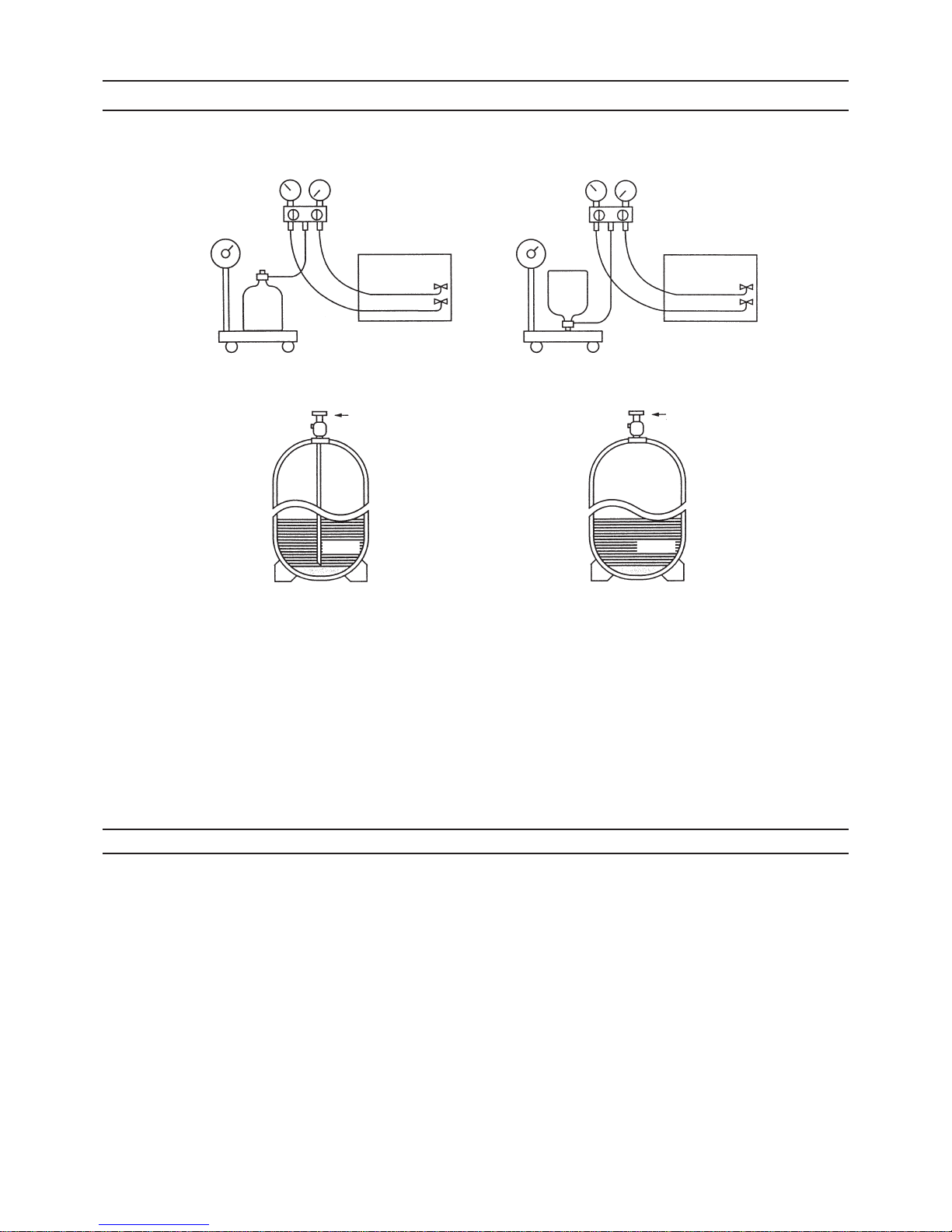
[9] Refrigerant Charging
1. Reasons
R410A is a pseudo-azeotropic HFC blend (boiling point R32=-52°C[-62°F], R125=-49°C[-52°F]) and can almost be handled
the same way as a single refrigerant, such as R22. To be safe, however, draw out the refrigerant from the cylinder in the liquid
phase. If the refrigerant in the gaseous phase is drawn out, the composition of the remaining refrigerant will change and become unsuitable for use.
2. Notes
When using a cylinder with a siphon, refrigerant is charged in the liquid state without the need for turning it upside down. Check
the type of the cylinder on the label before use.
[10] Remedies to be taken in case of a Refrigerant Leak
If the refrigerant leaks out, it may be replenished. The entire refrigerant does not need to be replaced. (Charge refrigerant in the
liquid state.)
Refer to "IX [5] Refrigerant Leak."(page 229)
Cylinder with a siphon
Cylinder color R410A is pink. Refrigerant charging in the liquid state
Cylinder
liquid
Valve Valve
liquid
Cylinder
Cylinder without a siphon
[ I Read Before Servicing ]
- 13 -
HWE1113B GB
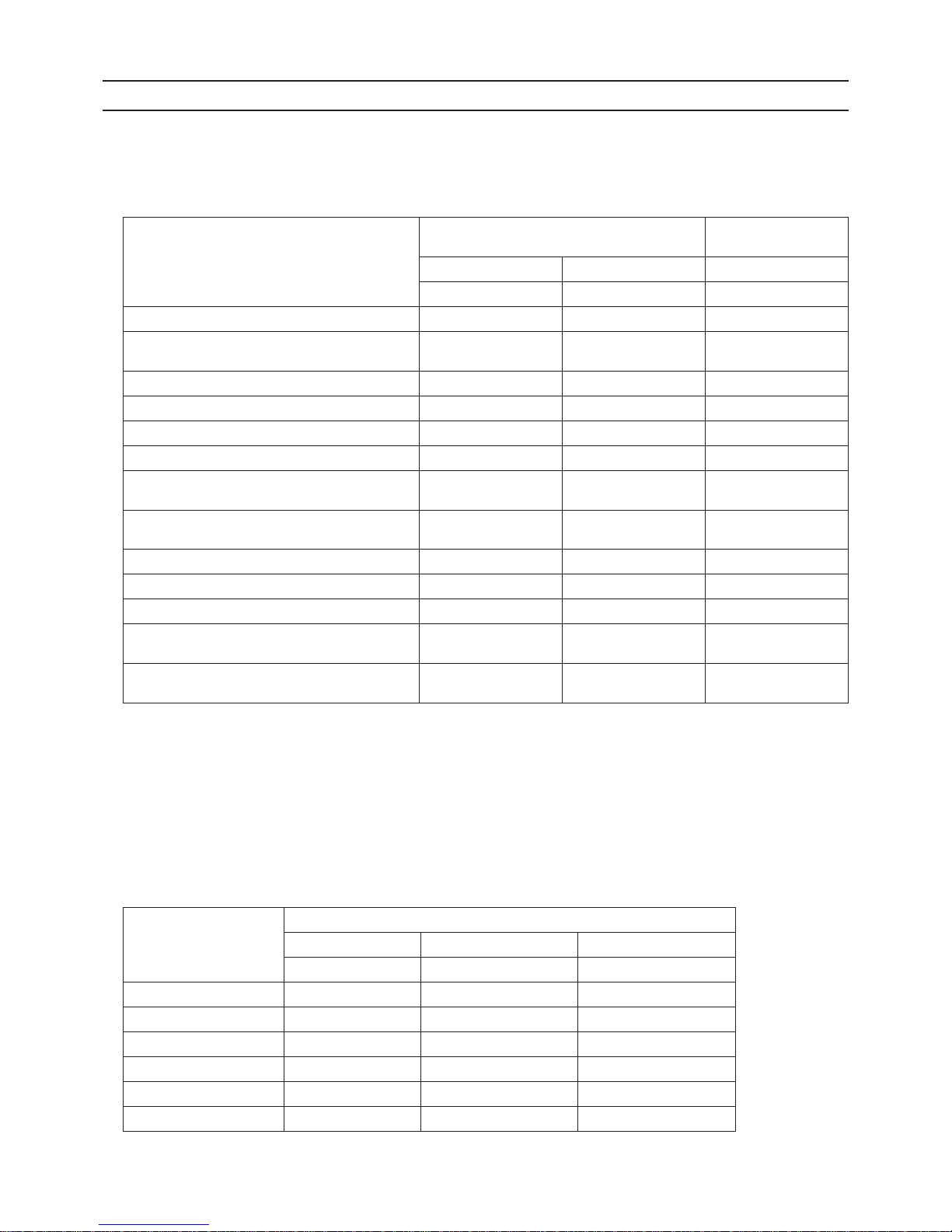
[11] Characteristics of the Conventional and the New Refrigerants
1. Chemical property
As with R22, the new refrigerant (R410A) is low in toxicity and chemically stable nonflammable refrigerant.
However, because the specific gravity of vapor refrigerant is greater than that of air, leaked refrigerant in a closed room will
accumulate at the bottom of the room and may cause hypoxia.
If exposed to an open flame, refrigerant will generate poisonous gases. Do not perform installation or service work in a confined area.
*1 When CFC11 is used as a reference
*2 When CO
2
is used as a reference
2. Refrigerant composition
R410A is a pseudo-azeotropic HFC blend and can almost be handled the same way as a single refrigerant, such as R22. To
be safe, however, draw out the refrigerant from the cylinder in the liquid phase. If the refrigerant in the gaseous phase is drawn
out, the composition of the remaining refrigerant will change and become unsuitable for use.
If the refrigerant leaks out, it may be replenished. The entire refrigerant does not need to be replaced.
3. Pressure characteristics
The pressure in the system using R410A is 1.6 times as great as that in the system using R22.
New Refrigerant (HFC type) Conventional Refriger-
ant (HCFC type)
R410A R407C R22
R32/R125 R32/R125/R134a R22
Composition (wt%) (50/50) (23/25/52) (100)
Type of Refrigerant Pseudo-azeotropic
Refrigerant
Non-azeotropic
Refrigerant
Single Refrigerant
Chloride Not included Not included Included
Safety Class A1/A1 A1/A1 A1
Molecular Weight 72.6 86.2 86.5
Boiling Point (°C/°F) -51.4/-60.5 -43.6/-46.4 -40.8/-41.4
Steam Pressure
(25°C,MPa/77°F,psi) (gauge)
1.557/226 0.9177/133 0.94/136
Saturated Steam Density
(25°C,kg/m
3
/77°F,psi)
64.0 42.5 44.4
Flammability Nonflammable Nonflammable Nonflammable
Ozone Depletion Coefficient (ODP)
*1
0 0 0.055
Global Warming Coefficient (GWP)
*2
1730 1530 1700
Refrigerant Charging Method Refrigerant charging in
the liquid state
Refrigerant charging in
the liquid state
Refrigerant charging in
the gaseous state
Replenishment of Refrigerant after a Refrigerant
Leak
Available Available Available
Temperature (°C/°F)
Pressure (gauge)
R410A R407C R22
MPa/psi MPa/psi MPa/psi
-20/-4 0.30/44 0.18/26 0.14/20
0/32 0.70/102 0.47/68 0.40/58
20/68 1.34/194 0.94/136 0.81/117
40/104 2.31/335 1.44/209 1.44/209
60/140 3.73/541 2.44/354 2.33/338
65/149 4.17/605 2.75/399 2.60/377
[ I Read Before Servicing ]
- 14 -
HWE1113B GB
[12] Notes on Refrigerating Machine Oil
1. Refrigerating machine oil in the HFC refrigerant system
HFC type refrigerants use a refrigerating machine oil different from that used in the R22 system.
Note that the ester oil used in the system has properties that are different from commercially available ester oil.
2. Effects of contaminants
*1
Refrigerating machine oil used in the HFC system must be handled with special care to keep contaminants out.
The table below shows the effect of contaminants in the refrigerating machine oil on the refrigeration cycle.
3. The effects of contaminants in the refrigerating machine oil on the refrigeration cycle.
Refrigerant Refrigerating machine oil
R22 Mineral oil
R407C Ester oil
R410A Ester oil
*1. Contaminants is defined as moisture, air, processing oil, dust/dirt, wrong types of refrigerant, and refrigerating machine oil.
Cause Symptoms Effects on the refrigerant cycle
Water infiltration Frozen expansion valve
and capillary tubes
Clogged expansion valve and capillary tubes
Poor cooling performance
Compressor overheat
Motor insulation failure
Burnt motor
Coppering of the orbiting scroll
Lock
Burn-in on the orbiting scroll
Hydrolysis
Sludge formation and adhesion
Acid generation
Oxidization
Oil degradation
Air infiltration Oxidization
Infiltration of
contaminants
Dust, dirt
Adhesion to expansion valve and capillary
tubes
Clogged expansion valve, capillary tubes, and
drier
Poor cooling performance
Compressor overheat
Infiltration of contaminants into the compressor
Burn-in on the orbiting scroll
Mineral oil
etc.
Sludge formation and adhesion Clogged expansion valve and capillary tubes
Poor cooling performance
Compressor overheat
Oil degradation Burn-in on the orbiting scroll

[ I Read Before Servicing ]
- 15 -
HWE1113B GB
[13] Water piping
1. Precautions for water piping
Consider the following when installing a water piping system.
(1) Design pressure of the water piping
Use a water pipe that is strong enough to withstand the design pressure (1.0 MPa).
(2) Water pipe type
Use of plastic pipe is recommended.Do not use chloride plastic pipes.
When using copper pipes, be sure to braze the pipes under a nitrogen purge. (Oxidation during may shorten the life of the
pump.)
(3) Expansion tank
Install an expansion tank to accommodate expanded water.
(4) Drain piping
Install the drain pipe with a downward inclination of between 1/100 and 1/200. To prevent drain water from freezing in winter,
install the drain pipe as steep an angle as practically possible and minimize the straight line. For cold climate installation, take
an appropriate measure (e.g., drain heater) to prevent the drain water from freezing.
(5) Insulation
Cover the water pipe with insulating materials with the specified thickness or more to prevent thermal loss or condensation
from collecting.
(6) Air vent valve
Install air vent valves to the highest places where air can accumulate.
(7) Maintenance valve
It is recommended to install valves on the inlet/outlet for each HBC controller branch for maintenance.
(8) Water pressure gauge
Install a water pressure gauge to check the charged pressure.
[ I Read Before Servicing ]
- 16 -
HWE1113B GB
2. Notes on corrosion
(1) Water quality
It is important to check the water quality beforehand. See table below (Circulating water/Makeup Water Quality Standards).
(2) Debris in the water
Sand, pebbles, suspended solids, and corrosion products in water can damage the metal pipe and heat exchanger on the
HBC controller and may cause corrosion. When installing, prevent debris from entering the water. If there is debris in the water, perform debris removal operation after test run by cleaning the strainers inside the HBC controller. (Refer to other sections
for how to perform a test run.)
(3) Connecting pipes made of different materials
Connecting pipes used for HBC controller and indoor unit are copper alloy pipes. If steel pipes are connected tothe pipes, the
contact surface will corrode. Do not use steel pipes to avoid corrosion.
(4) Residual air
Residual air in the pipe results in water pump malfunction, noise, or water pipe corrosion in the water circuit. Ensure air is
purged before use. (Refer to other sections for how to perform air vent operation.)
pH (25°C[77°F])
Electric conductivity
Chloride ion
Sulfate ion
Acid consumption (pH4.8)
Total hardness
Calcium hardness
Ionic silica
Iron
Copper
Sulfide ion
Ammonium ion
Residual chlorine
Free carbon dioxide
Ryzner stability index
Standard items
Reference items
Items
Lower mid-range
temperature water system
7.0 ~ 8.0
30 or less
[300 or less]
50 or less
50 or less
50 or less
70 or less
50 or less
30 or less
1.0 or less
1.0 or less
not to be
detected
0.3 or less
0.25 or less
0.4 or less
–
7.0 ~ 8.0
30 or less
[300 or less]
50 or less
50 or less
50 or less
70 or less
50 or less
30 or less
0.3 or less
0.1 or less
not to be
detected
0.1 or less
0.3 or less
4.0 or less
–
Tendency
Recirculating
water
[68<T<140°F]
[20<T<60°C]
Make-up
water
Corrosive
Scale-
forming
Reference : Guideline of Water Quality for Refrigeration and Air Conditioning
Equipment. (JRA GL02E-1994)
(mg Cl
-
/)
(mg SO
4
2-
/)
(mg CaCO3/)
(mg CaCO3/)
(mg CaCO3/)
(mg SiO2/)
(mg Fe/ )
(mg Cu/ )
(mg S
2-
/)
(mg NH
4
+
/)
(mg Cl/ )
(mg CO2/ )
(mS/m) (25°C[77°F])
(μS/cm) (25°C[77°F])
[ I Read Before Servicing ]
- 17 -
HWE1113B GB
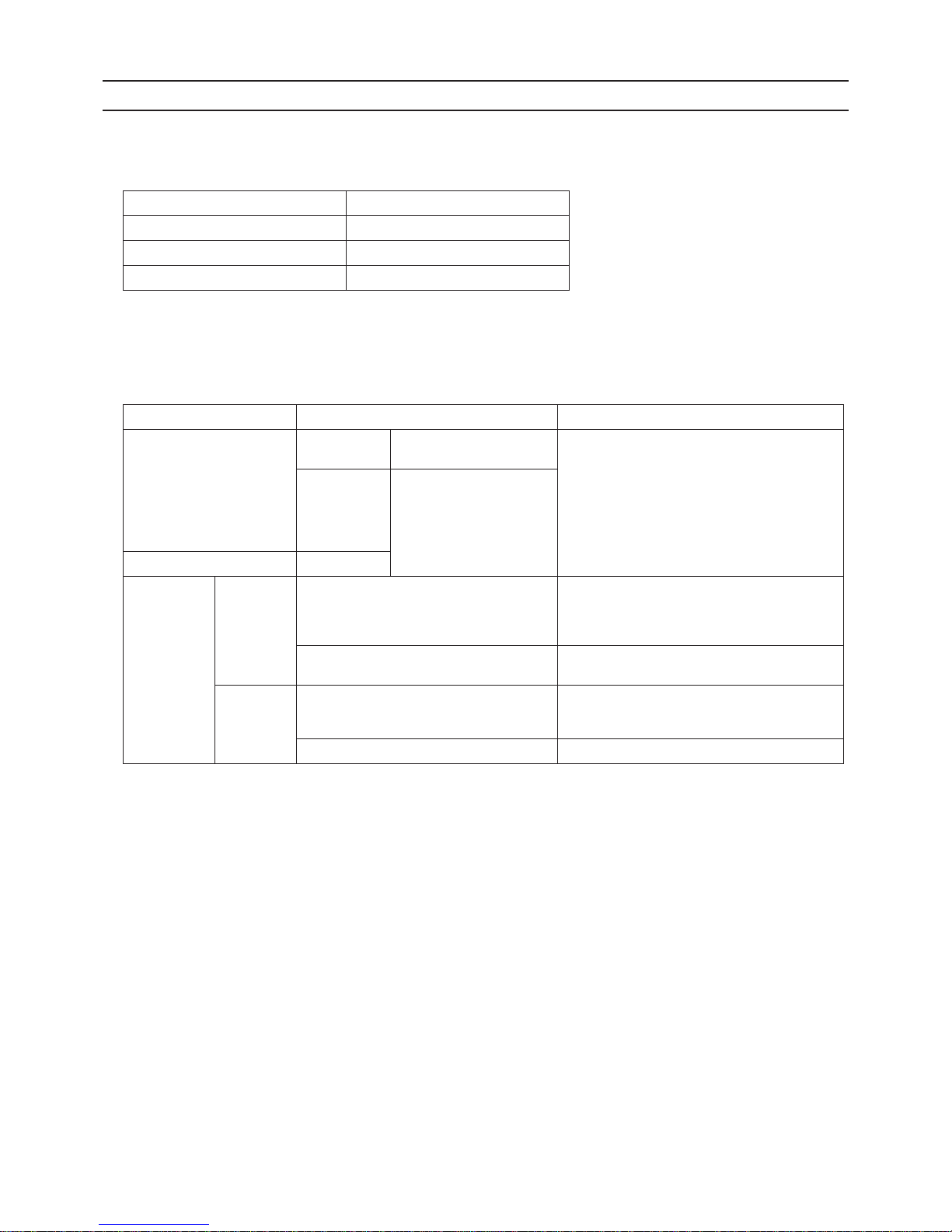
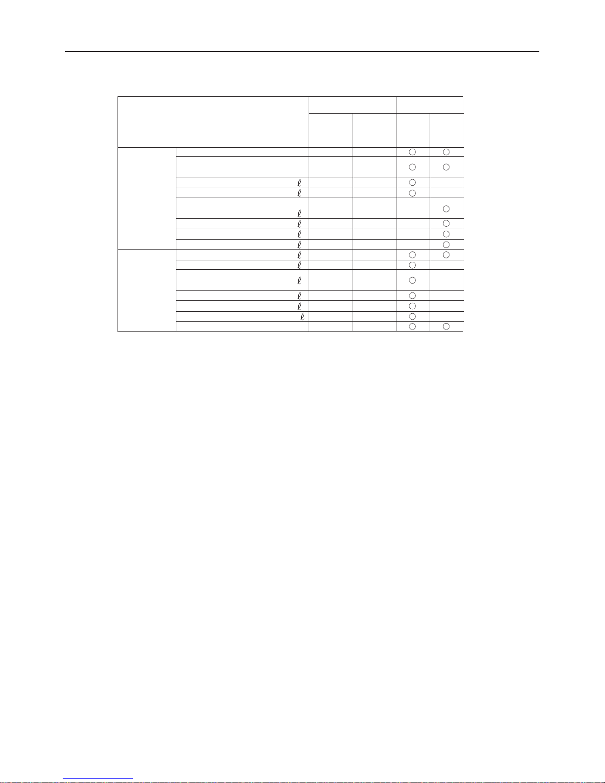
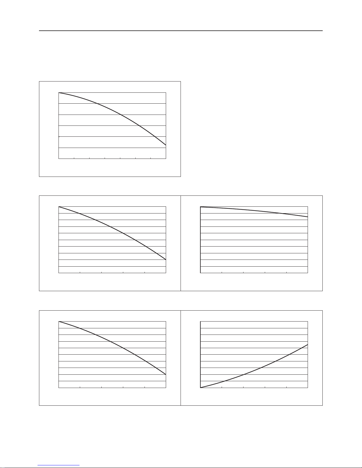
3. Correction by brine concentration
In HYBRID CITY MULTI system, brine should be used to prevent the system from freezing. Refer to the following graphs for the
capacity correction by brine.Refer to (1) for brine concentration, (2) and (3) for capacity correction by brine concentration.
(1) Brine concentration
Use propylene glycol solution for antifreeze.
Refer to the following graph to estimate the brine concentration required for freeze protection.
(2) Capacity correction by brine concentration (cooling)
(3) Capacity correction by brine concentration (heating)
010203040506070
Freezing Temperature [
°C
]
0
-5
-10
-15
-20
-25
-30
Brine concentration [wt%]
01020304050
Ratio of cooling capacit y
1
0.99
0.98
0.97
0.96
0.95
0.94
0.93
0.92
0.91
0.9
Brine concentration [wt%]
PURY-WP200, 250YJM-A
01020304050
Ratio of cooling input
1
0.99
0.98
0.97
0.96
0.95
0.94
0.93
0.92
0.91
0.9
Brine concentration [wt%]
01020304050
Ratio of heating capacity
1
0.99
0.98
0.97
0.96
0.95
0.94
0.93
0.92
0.91
0.9
Brine concentration [wt%]
PURY-WP200, 250YJM-A
01020304050
Ratio of heating input
1.2
1.18
1.16
1.14
1.12
1.1
1.08
1.06
1.04
1.02
1
Brine concentration [wt%]

[ I Read Before Servicing ]
- 18 -
HWE1113B GB

- 19 -
HWE1113B GB
II
Restrictions
[1] System configuration .......................................................................................................21
[2] Types and Maximum allowable Length of Cables ...........................................................22
[3] Switch Settings and Address Settings.............................................................................23
[4] Sample System Connection.............................................................................................29
[5] An Example of a System to which an MA Remote Controller is connected.....................30
[6] An Example of a System to which an ME Remote Controller is connected.....................40
[7] An Example of a System to which both MA Remote Controller and
ME Remote Controller are connected..............................................................................42
[8] Restrictions on Pipe Length.............................................................................................45

- 20 -
HWE1113B GB

[ II Restrictions ]
- 21 -
HWE1113B GB
II Restrictions
[1] System configuration
1. Table of compatible indoor units
The table below summarizes the types of indoor units that are compatible with different types of outdoor units.
(1) Standard combinations
1) "Maximum total capacity of connectable indoor units" refers to the sum of the numeric values in the indoor unit model names.
2) If the total capacity of the indoor units that are connected to a given outdoor unit exceeds the capacity of the outdoor unit, the
indoor units will not be able to perform at the rated capacity when they are operated simultaneously. Select a combination of
units so that the total capacity of the connected indoor units is at or below the capacity of the outdoor unit whenever possible.
Outdoor units HBC controller Maximum total capacity
of connectable indoor
units
Maximum number
of connectable in-
door units
Types of connectable
indoor units
WP200 YJM-A CMB-WP108V-G 100 - 300 15 WP15- WP50 models
Indoor units for use with
HBC controller
WP250
YJM-A
125 - 375 18

[ II Restrictions ]
- 22 -
HWE1113B GB
[2] Types and Maximum allowable Length of Cables
1. Wiring work
(1) Notes
1) Have all electrical work performed by an authorized electrician according to the local regulations and instructions in this manual.
2) Install external transmission cables at least 5cm [1-31/32"] away from the power supply cable to avoid noise interference.
(Do not put the control cable and power supply cable in the same conduit tube.)
3) Provide grounding for the outdoor unit as required.
4) Run the cable from the electric box of the indoor or outdoor unit in such way that the box is accessible for servicing.
5) Do not connect power supply wiring to the terminal block for transmission line. Doing so will damage the electronic components on the terminal block.
6) Use 2-core shielded cables as transmission cables.
Use a separate 2-core control cable for each refrigerant system. Do not use a single multiple-core cable to connect indoor
units that belong to different refrigerant systems. The use of a multiple-core cable may result in signal transmission errors and
malfunctions.
The figures above show a system to which two outdoor units are connected, but only a single outdoor unit can be connected
in an HVRF system.
(2) Control wiring
Different types of control wiring are used for different systems.
Refer to section "[5] An Example of a System to which an MA Remote Controller is connected - [7] An Example of a System
to which both MA Remote Controller and ME Remote Controller are connected" before performing wiring work.
Types and maximum allowable length of cables
Control lines are categorized into 2 types: transmission line and remote controller line.
Use the appropriate type of cables and observe the maximum allowable length specified for a given system. If a given system
has a long transmission line or if a noise source is located near the unit, place the unit away from the noise source to reduce
noise interference.
1) M-NET transmission line
Cable type
Facility
type
All facility types
Type Shielded cable CVVS, CPEVS, MVVS
Number of
cores
2-core cable
Cable size La rger than 1.25mm
2
[AWG16]
Maximum transmission
line distance between the
outdoor unit and the farthest indoor unit
200 m [656ft] max.
Maximum transmission
line distance for centralized control and Indoor/
outdoor transmission line
(Maximum line distance
via outdoor unit)
500 m [1640ft] max.
*The maximum overall line length from the power supply unit on the transmission lines for
centralized control to each outdoor unit or to the system controller is 200m [656ft] max.
TB3TB7TB3TB
7
TB3TB7TB3TB
7
TB3TB7TB3TB
7
TB3TB7TB3TB
7
TB3: Terminal block for indoor-outdoor transmission line TB7: Terminal block for centralized control
multiple-core cable
HBC Controller
Indoor unit
Remote Controller
Remote Controller
2-core shielded cable
2-core shielded cable
Outdoor unit
HBC Controller
Indoor unit
Outdoor unit

[ II Restrictions ]
- 23 -
HWE1113B GB
2) Remote controller wiring
*1 MA remote controller refers to MA remote controller (PAR-20MAA, PAR-21MAA), MA simple remote controller, and
wireless remote controller.
*2 ME remote controller refers to ME remote controller and ME simple remote controller.
*3 The use of cables that are smaller than 0.75mm
2
[AWG18] is recommended for easy handling.
*4 When connected to the terminal block on the Simple remote controller, use cables that meet the cable size specifi-
cations shown in the parenthesis.
[3] Switch Settings and Address Settings
1. Switch setting
Refer to section "[5] An Example of a System to which an MA Remote Controller is connected - [7] An Example of a System
to which both MA Remote Controller and ME Remote Controller are connected" before performing wiring work.
Set the switches while the power is turned off.
If the switch settings are changed while the unit is being powered, those changes will not take effect, and the unit will not
function properly.
*1. Applicable when LOSSNAY units are connected to the indoor-outdoor transmission line.
*2. The outdoor units in the same refrigerant circuit are automatically designated as OC and OS in the order of capacity
from large to small (if two or more units have the same capacity, in the order of address from small to large).
*3. Turn off the power to all the outdoor units in the same refrigerant circuit.
MA remote controller
*1
ME remote controller
*2
Cable type
Type VCTF, VCTFK, CVV, CVS, VVR, VVF, VCT Shielded cable MVVS
Number of
cores
2-core cable 2-core cable
Cable size
0.3 to 1.25mm
2 *3
[AWG22 to 16]
(0.75 to 1.25mm
2 ) *4
[AWG18 to 16]
0.3 to 1.25mm
2 *3
[AWG22 to 16]
(0.75 to 1.25mm
2 ) *4
[AWG18 to 16]
Maximum overall line
length
200 m [656ft] max.
The section of the cable that exceeds 10m
[32ft] must be included in the maximum indoor-outdoor transmission line distance.
Units on which to set the switches Symbol Units to which the power must be shut off
CITY MULTI indoor unit Main/sub unit IC Outdoor units
*3
and Indoor units
LOSSNAY, OA processing unit
*1
LC Outdoor units
*3
and LOSSNAY
ATW Booster Unit BU Outdoor units and Booster Unit
Water Hex Unit AU Outdoor units and Water Hex Unit
ME remote controller Main/sub remote
controller
RC Outdoor units
*3
MA remote controller Main/sub remote
controller
MA Indoor units
CITY MULTI outdoor unit
*2
OC,OS Outdoor units
*3
HBC controller HB Outdoor units
*3
and HBC controller

[ II Restrictions ]
- 24 -
HWE1113B GB
2. M-NET Address settings
(1) Address settings table
The need for address settings and the range of address setting depend on the configuration of the system.
*1. If a given address overlaps any of the addresses that are assigned to other units, use a different, unused address within the setting
range.
*2. To set the outdoor unit address or the auxiliary outdoor unit address to "100," set the rotary switches to "50."
*3. To set the ME remote controller address to "200," set the rotary switches to "00."
*4. Some models of indoor units have two or three control boards.
Assign an address to the No.1, No. 2, and No. 3 control boards so that the No. 2 control board address equals the No. 1 control board
address plus 1, and that the No. 3 control board address equals the No. 1 control board address plus 2.
*5. The outdoor units in the same refrigerant circuit are automatically designated as OC, and OS. They are designated as OC, and OS in
the descending order of capacity (ascending order of address if the capacities are the same).
*6. No address settings are required for units in a system with a single outdoor unit (with some exceptions).
Address setting is required if a sub BC controller is connected.
*7. If a given address overlaps any of the addresses that are assigned to other units, use a different, unused address within the setting
range.
Unit or controller Sy m-
bol
Address
setting
range
Setting method Factory
address
setting
CITY MULTI
indoor unit
Main/sub unit IC 0, 01 to
50
*1 *4 *6*7
Assign the smallest address to the main indoor unit in the
group, and assign sequential address numbers to the rest of
the indoor units in the same group.
00
M-NET
adapter
M-NET control interface
Free Plan
adapter
LOSSNAY, OA processing unit LC 0, 01 to
50
*1 *4 *6*7
Assign an arbitrary but unique address to each of these units
after assigning an address to all indoor units.
00
ATW Booster Unit BU
Water Hex Unit AU
ME remote
controller
Main remote
controller
RC 101 to 150 Add 100 to the smallest address of all the indoor units in the
same group.
101
Sub remote
controller
RC 151 to
200
*3
Add 150 to the smallest address of all the indoor units in the
same group.
MA remote controller MA No address settings required. (The main/sub setting must be made if 2 re-
mote controllers are connected to the system.)
Main
CITY MULTI outdoor unit OCOS0, 51 to
100
*1 *2
*6*7
Assign an address that equals the lowest address of the in-
door units in the same refrigerant circuit plus 50.
Assign sequential addresses to the outdoor units in the
same refrigerant circuit. The outdoor units in the same refrigerant circuit are automatically designated as OC and
OS.
*5
00
Auxiliary outdoor unit
HBC controller HB 0, 51 to
100
*1 *2 *6
Assign an address that equals the address of the outdoor
unit in the same refrigerant system plus 1.
If a given address overlaps any of the addresses that are
assigned to the outdoor units, use a different, unused
address within the setting range.
00
System controller
Group remote controller
GRSC201 to 250 Assign an address that equals the sum of the smallest group
number of the group to be controlled and 200.
201
System remote controller
SR
SC
Assign an arbitrary but unique address within the range list ed
on the left to each unit.
ON/OFF remotecontroller
AN
SC
Assign an address that equals the sum of the smallest group
number of the group to be controlled and 200.
Schedule timer (compatible with M-NET)STSC
Assign an arbitrary but unique address within the range list ed
on the left to each unit.
202
Central controller
AG-150A
GB-50ADA
G(B)-50A
TRSC0, 201 to
250
Assign an arbitrary but unique address within the range list ed
on the left to each unit. The address must be set to "0" to control the K-control unit.
000
LM adapter SC 201 to 250 Assign an arbitrary but unique address within the range listed
on the left to each unit.
247

[ II Restrictions ]
- 25 -
HWE1113B GB
(2) Power supply switch connector connection on the outdoor unit
(Factory setting: The male power supply switch connector is connected to CN41.)
There are limitations on the total number of units that are connectable to each refrigerant system. Refer to the DATABOOK
for details.
*1 The need for a power supply unit for transmission lines depends on the system configuration. Some controllers, such as
GB-50ADA, have a function to supply power to the transmission lines.
*2 The replacement of the power jumper connector from CN41 to CN40 must be performed on only one outdoor unit in the
system.
(3) Settings for the centralized control switch for the outdoor unit (Factory setting: SW2-1 are set to OFF.)
*1. Set SW2-1 on all outdoor units in the same refrigerant circuit to the same setting.
*2. When only the LM adapter is connected, leave SW2-1 to OFF (as it is).
(4) Selecting the position of temperature detection for the indoor unit (Factory setting: SW1-1 set to "OFF".)
To stop the fan during heating Thermo-OFF (SW1-7 and 1-8 on the indoor units to be set to ON), use the built-in thermistor
on the remote controller or an optional thermistor.
1) To use the built-in sensor on the remote controller, set the SW1-1 to ON.
Some models of remote controllers are not equipped with a built-in temperature sensor.
Use the built-in temperature sensor on the indoor unit instead.
When using the built-in sensor on the remote controller, install the remote controller where room temperature can be detected.
(Note) Factory setting for SW1-1 on the indoor unit of the All-Fresh Models is ON.
2) When an optional temperature sensor is used, set SW1-1 to OFF, and set SW3-8 to ON.
When using an optional temperature sensor, install it where room temperature can be detected.
(5) Various start-stop controls (Indoor unit settings)
Each indoor unit (or group of indoor units) can be controlled individually by setting SW 1-9 and 1-10.
*1. Do not cut off power to the outdoor unit. Cutting off the power supply to the outdoor unit will cut off the power supply to the belt
heater and may cause the compressor to malfunction when the unit is put back into operation.
*2. Not applicable to units with a built-in drain pump or humidifier.
*3. Models with a built-in drain pump cannot be turned on/off by the plug indi vidually. Al l the units in the same re frigerant circuits wi ll
be turned on or off by the plug.
*4. Requires that the dipswitch settings for all the units in the group be made.
*5. To control the external input to and output from the air conditioners with the PLC software for general equipment via the AG-150A,
GB-50ADA, or G(B)-50A, set SW1-9 and SW1-10 to ON. With these settings made, the power start-stop function becomes dis-
abled. To use the auto recovery function after power fail ure while these settings are made, set SW1-5 to ON.
System configuration
Connection to
the system controller
Power supply unit
for transmission
lines
Group operation
of units in a system with multiple
outdoor units
Power supply switch connector connection
System with one
outdoor unit
_ _ _ Leave CN41 as it is
(Factory setting)
System with multiple outdoor units
Not connected _ Not grouped
Grouped Disconnect the male connector from the fe-
male power supply switch connector (CN41)
and connect it to the female power supply
switch connector (CN40) on only one of the
outdoor units.
*2
*Connect the S (shielded) terminal on the
terminal block (TB7) on the outdoor unit
whose CN41 was replaced with CN40 to
the ground terminal ( ) on the electric box.
With connection
to the indoor
unit system
Not required Grouped/not
grouped
With connection
to the centralized control system
Not required*1
(Powered from
the outdoor unit)
Grouped/not
grouped
Required *1 Grouped/not
grouped
Leave CN41 as it is
(Factory setting)
System configuration Centralized control switch settings
Connection to the system controller Not connected Leave it to OFF. (Factory setting)
Connection to the system controller Connected ON
Function
Operation of the indoor unit when the operation is resumed after the unit
was stopped
Setting (SW1)
*4 *5
910
Power ON/OFF by the
plug
*1,*2,*3
Indoor unit will go into operation regardless of its operation status before
power off (power failure). (In approx. 5 minutes)
OFF ON
Automatic restoration
after power failure
Indoor unit will go into operation if it was in operation when the power was
turned off (or cut off due to power failure). (In approx. 5 minutes)
ON OFF
Indoor unit will remain stopped regardless of its operation status before
power off (power failure).
OFF OFF

[ II Restrictions ]
- 26 -
HWE1113B GB
(6) Miscellaneous settings
Cooling-only setting for the indoor unit: Cooling only model (Factory setting: SW3-1 "OFF.")
When using indoor unit as a cooling-only unit, set SW3-1 to ON.
(7) Variou s types of control using input-output signal connector on the outdoor unit (various connection options)
*4. By setting Dip SW5-5, the Low-noise mode can be switched between the Capacity priority mode and the Low-noise pri-
ority mode.
When SW5-5 is set to ON: The low-noise mode always remains effective.
When SW5-5 is set to OFF: The low noise mode is cancelled when certain outside temperatur e or pressure criteria are
met, and the unit goes into normal operation (capacity priority mode).
*5. Each outdoor unit in the system with multiple outdoor units requires the signal input/output setting to be made.
*6. Take out signals from the outdoor unit (OC) if multiple outdoor units exist in a single system.
CAUTION
1) Wiring should be covered by insulation tube with supplementary insulation.
2) Use relays or switches with IEC or equivalent standard.
3) The electric strength between accessible parts and control circuit should have 2750V or more.
Type Usage Function
Terminal
to be
used
*1
*1. For detailed drawing, refer to "Example of wiring connection".
Option
Input Prohibiting cooling/heating operation (thermo OFF) by an external
input to the outdoor unit.
DEMAND (level) CN3D
*2
*2. For details, refer to the next section "Demand control".
Adapter for
external input
(PACSC36NA-E)
Performs a low level noise operation of the outdoor unit by an external input to the outdoor unit.
* It can be used as the silent operation device for each refrigerant
system.
Low-noise mode
(level)
*3 *4
*3. Low-noise mode is valid when Dip SW4-4 on the outdoor unit is set to OFF. When DIP SW4-4 is set to ON, 4 levels of
on-DEMAND are possible, using different configurations of low-noise mode input and DEMAND input settings.When 2
or more outdoor units exist in one refrigerant circuit system, 8 levels of on-DEMAND are possible.
Forces the outdoor unit to perform a fan operation by receiving signals from the snow sensor.
*5
Snow sensor signal
input (level)
CN3S
Cooling/heating operation can be changed by an external input to
the outdoor unit (OC).
Auto-changeover CN3N
Out-
put
How to extract signals from the outdoor unit
*It can be used as an operation status display device.
*It can be used for an interlock operation with external devices.
Operation status of
the compressor
*5
CN51 Adapter for
external output
(PACSC37SA-E)
Error status
*6
Low-noise mod is effective. Capacity priority mode becomes effective.
Cooling Heating Cooling Heating
TH7<30°C[86°F] and
63HS1<32kg/cm
2
TH7>3°C[37°F] and
63LS>4.6kg/cm
2
TH7>35°C[95°F] or
63HS1>35kg/cm
2
TH7<0°C[32°F] or
63LS<3.9kg/cm
2

[ II Restrictions ]
- 27 -
HWE1113B GB
Example of wiring connection
(1) CN51
(2) CN3S
CN51
X
Y
L
1
L
2
ecruos rewop pmaL
Distant control
board
Relay circuit Adapter
1
Outdoor unit
control board
Preparations
in the field
Maximum cable
length is 10m
5
4
3
X
Y
L1 : Outdoor unit error display lamp
L2 : Compressor operation lamp (compressor running state)
X, Y : Relay (coil =<0.9W : DC12V)
1. Optional part : PAC-SC37SA-E or field supply.
2. Optional part : PAC-SC36NA-E or field supply.
X : Relay
Snow sensor : The outdoor fan runs when X is closed
in stop mode or thermostat mode.
X
CN3S
Preparations
in the field
Maximum cable
length is 10m
Adapter
2
Outdoor unit
control board
2
3
1
Contact rating voltage >= DC15V
Contact rating current >= 0.1A
Minimum applicable load =< 1mA at DC
Relay circuit
(3) CN3N
2. Optional part : PAC-SC36NA-E or field supply.
Preparations
in the field
OFF
CoolingONHeating
Normal
Y
OFF
ON
X
Contact rating voltage >= DC15V
Contact rating current >= 0.1A
Minimum applicable load =< 1mA at DC
X : Cooling / Heating
Y : Validity / Invalidity of X
X,Y : Relay
CN3N
X
Y
Relay circuit
Adapter
2
Outdoor unit
control board
Maximum cable
length is 10m
1
2
3
(4) CN3D
2. Optional part : PAC-SC36NA-E or field supply.
X : Low-noise mode
X : Low-noise mode
Y : Compressor ON/OFF
X,Y : Relay
Contact rating voltage >= DC15V
Contact rating current >= 0.1A
Minimum appicable load =< 1mA at DC
Y
X
CN3D
Preparations
in the field
Maximum cable
length is 10m
Adapter
2
Outdoor unit
control board
3
2
1
Relay circuit
2. Optional part : PAC-SC36NA-E or field supply.
X
CN3D
Preparations
in the field
Maximum cable
length is 10m
Adapter
2
Outdoor unit
control board
2
3
1
X : Relay
fan frequency and maximum compressor frequency.
Contact rating voltage >= DC15V
Contact rating current >= 0.1A
Minimum applicable load =< 1mA at DC
Low-noise mode : The noise level is reduced by controlling the maximum
Relay circuit

[ II Restrictions ]
- 28 -
HWE1113B GB
3. Demand control
1) General outline of control
Demand control is performed by using the external signal input to the 1-2 and 1-3 pins of CN3D on the outdoor units (OC and OS).
Between 2 and 8 steps of demand control is possible by setting Dip SW4-4 on the outdoor units (OC and OS).
*1 Available demand functions
Single-outdoor-unit system: 2 and 4 steps shown in the rows 1 and 2 in the table above only.
Two-outdoor-unit system OC+OS : 2-8 steps shown in the rows 1, 2, 3, and 4 in the table above only.
*2 External signal is input to CN3D on the outdoor unit whose SW4-4 i s set to ON. When SW4-4 is set to OFF on all outdoor units,
the signal is input to the CN3D on the OC.
Outdoor units whose SW4-4 is set to ON are selectable in a single refrigerant system.
*3 If wrong sequence of steps are taken, the units may go into the Thermo-OFF (compressor stop) mode.
Ex) When switching from 100% to 50%
(Incorrect) 100%ĺ0%ĺ50% The units may go into the Thermo-OFF mode.
(Correct) 100%ĺ75%ĺ50%
*4 The percentage of the demand listed in the table above is an approximate value based on the compressor volume and does
not necessarily correspond with the actual capacity.
*5 Notes on using demand control in combination with the low-noise mode
To enable the low-noise mode, it is necess ary to short-circuit 1-2 pin of CN3D o n the outdoor unit whose SW4-4 is set to OFF.
When SW4-4 is set to ON on all outdoor units, the following operations cannot be performed.
Performing 4-step demand in combination with the low-noise operation in a single-outdoor-unit system.
Performing 8-step demand in combination with the low-noise operation in a two-outdoor-unit system.
2) Contact input and control content
2-step demand control
The same control as the Thermo-OFF is performed by closing 1-3 pin of CN3D.
4-step demand control (When SW4-4 is set to ON on an outdoor unit)
Demand capacity is shown below.
8-step demand control (When SW4-4 is set to ON on two outdoor units)
Demand capacity is shown below.
*1. The outdoor units whose SW4-4 is set to ON are designated as No. 1 and No. 2 in the order of address from small to large.
Ex) When outdoor units whose SW4-4 is set to ON are designated as OC and OS, OC=No. 1 and OS=No. 2.
No Demand control switch
DipSW4-4
Input to CN3D*
2
OC OS
1 2 steps (0-100%) OFF OFF OC
2
4 steps (0-50-75-100%)
ON OFF OC
3OFFONOS
4
8 steps
(0-25-38-50-63-75-88-100%)
ON ON OC and OS
CN3D
1-3
Open 100%
Close 0%
CN3D 1-2P
1-3P Open Close
Open 100% 75%
Close 0% 50%
8-step demand No.2 CN3D
1-2P Open Short-circuit
No.1 CN3D 1-2P 1-3P Open Short-circuit Open Short-circuit
Open Open 100% 50% 88% 75%
Short-circuit 50% 0% 38% 25%
Short-circuit Open 88% 38% 75% 63%
Short-circuit 75% 25% 63% 50%

[ II Restrictions ]
- 29 -
HWE1113B GB
[4] Sample System Connection
Examples of typical system connection are shown on pages [5] to [7].
Refer to the Installation Manual that came with each device or controller for details.
(1) An example of a system to which an MA remote controller is connected
(2) An example of a system to which an ME remote controller is connected
(3) An example of a system to which both MA remote controller and ME remote controller are connected
System
configuration
Connection to the system controller
Address start up for in-
door and outdoor units
Notes
1
System with one out-
door unit
NO
Automatic
address setup
2
System with one out-
door unit
NO
Manual
address setup
Connection of
multiple LOSSNAY units
3
Grouping of units in a
system with multiple
outdoor units
NO
Manual
address setup
4
System with one out-
door unit
With connection to transmission line
for centralized control
Manual
address setup
5
System with one out-
door unit
With connection to indoor-outdoor
transmission line
Manual
address setup
System
configuration
Connection to the system controller
Address start up for indoor
and outdoor units
Notes
1
System with one out-
door unit
With connection to transmission line
for centralized control
Manual
address setup
System
configuration
Connection to the system controller
Address start up for indoor and outdoor units
Notes
1
System with one out-
door unit
With connection to transmission
line for centralized control
Manual
address setup
*MA remote controller and ME remote controller cannot both be connected to the same group.

- 30 -
[ II Restrictions ]
GBHWE1113B
[5] An Example of a System to which an MA Remote Controller is connected
1. System with one outdoor unit (automatic address setup for both indoor and outdoor units)
(1) Sample control wiring
(2) Cautions
1) ME remote controller and MA remote controller cannot
both be connected to the same group of indoor units.
2) No more than 2 MA remote controllers can be connected
to a group of indoor units.
3) When the number of the connected indoor units is as
shown in the table below, one or more transmission
boosters (sold separately) are required.
To connect two transmission boosters, connect them in
parallel. (Observe the maximum number of connectable
indoor units that are listed in the specifications for each
outdoor unit.)
4) Automatic address setup is not available if start-stop input(CN32, CN51, CN41) is used for a group operation of
indoor units. Refer to "[5] 2. Manual address setup for
both indoor and outdoor units"(page 32)
5) To connect more than 2 LOSSNAY units to indoor units
in the same system, refer to "[5] 2. An example of a system with one outdoor unit to which 2 or more LOSSNAY
units are connected".(page 32)
(3) Maximum allowable length
1) Indoor/outdoor transmission line
Maximum distance (1.25mm
2
[AWG16] or larger)
L1 +L2+L3+L4+L5 200m[656ft]
L1 +L2+L3+L11+L12+L13 200m[656ft]
2) Transmission line for centralized control
No connection is required.
3) MA remote controller wiring
Maximum overall line length
(0.3 to 1.25mm
2
[AWG22 to 16])
m1 200m [656ft]
m2+m3 200m [656ft]
m4+m5 200m [656ft]
IC
TB5
M1
M2
M1
M2
M1
M2
M1
M2
M1
M2
M1
M2
S
TB
15
12
00
IC
TB5STB
15
12
00
A1 B2
MA
A1 B2
MA
A1 B2
RC
LC
TB5
S
00
IC
TB5
S
12
TB
15
IC
TB5STB
15
12
0000
IC
TB5STB
15
12
00
A1 B2
MA
A1 B2
MA
A1 B2
MA
GroupGroup
GroupGroup
A1 B2
MA
m1
L11
m2
L4 L5
L12 L13
m3
m5
m4
Interlock operation with
the ventilation unit
*1. The figures above show a system to which two
outdoor units are connected, but only a single
outdoor unit can be connected in an HVRF
system.
*1
HB
00
OC
00
TB7
M1 M2
S
TB3
OS
00
TB7
M1 M2 M1 M2 M1 M2
S
TB3
TB02
M1 M2
S
L3L1 L2
Leave the male
connector on
CN41 as it is.
SW2-1 OFF
Leave the male
connector on
CN41 as it is.
SW2-1 OFF
Number of transmission
booster (sold separately) required
1 unit 2 units
When the P200 and P250 models are not included in the connected indoor units
27 - 50 units -
When the P200 and P250 models are included in the connected indoor units
21 - 39 units 40 - 50 units

[ II Restrictions ]
31- 31 -
HWE1113B GB
(4) Wiring method
1) Indoor/outdoor transmission line
Daisy-chain terminals M1 and M2 of the terminal block
for indoor-outdoor transmission line (TB3) on the outdoor
units (OC and OS), of the terminal block for indoor-outdoor transmission line (TB02) on the HBC controller
(HB), and of the terminal block for indoor-outdoor transmission line (TB5) on each indoor unit (IC). (Non-polarized two-wire)
Only use shielded cables.
The outdoor units in the same refrigerant circuit are automatically designated as OC and OS in the order of capacity from large to small (if two or more units have the
same capacity, in the order of address from small to
large).
Shielded cable connection
Daisy-chain the ground terminal ( ) on the outdoor
units (OC and OS), the S terminal of the terminal block
(TB02) on the HBC controller (HB), and the S terminal of
the terminal block (TB5) on the indoor unit (IC) with the
shield of the shielded cable.
2) Transmission line for centralized control
No connection is required.
3) MA remote controller wiring
Connect terminals 1 and 2 on the terminal block for MA
remote controller line (TB15) on the indoor unit (IC) to the
terminal block on the MA remote controller (MA).
(Non-polarized two-wire)
When 2 remote controllers are connected to the system
When 2 remote controllers are connected to the system,
connect terminals 1 and 2 of the terminal block (TB15) on
the indoor unit (IC) to the terminal block on the two MA
remote controllers.
Set one of the MA remote controllers as a sub controller.
(Refer to the Instruction Manual for the MA remote controller for the setting method.)
Group operation of indoor units
To perform a group operation of indoor units (IC), daisychain terminals 1 and 2 on the terminal block (TB15) on
all indoor units (IC) in the same group, and then connect
terminals 1 and 2 on the terminal block (TB15) on the indoor unit on one end to the terminal block on the MA remotecontroller. (Non-polarized two-wire)
When performing a group operation of indoor units that
have different functions, "Automatic indoor/outdoor addresssetup" is not available.
4) LOSSNAY connection
Connect terminals M1 and M2 on the terminal
block(TB5) on the indoor unit (IC) to the appropriate terminals on the terminal block (TB5) on LOSSNAY (LC).
(Non-polarized two-wire)
Interlock operation setting with all the indoor units in the
same system will automatically be made. (It is required
that the Lossnay unit be turned on before the outdoorunit.)
When performing an interlocked operation of part of the
indoor units in the system with a LOSSNAY unit, using a
LOSSNAY unit alone without interlocking it with any
units, performing an interlock operation of more than 16
indoor units with a LOSSNAY unit, or connecting two or
more LOSSNAY units to the same refrigerant system,
the automatic IC/OC address setup function is not available.
5) Switch setting
No address settings required.
(5) Address setting method
The outdoor units in the same refrigerant circuit are automatically designated as OC and OS.
They are designated as OC and OS in the descending order of capacity (ascending order of address if the capacities are the
same).
Proce-
dures
Unit or controller
Address set-
ting range
Setting method Notes
Factory
setting
1 Indoor unit Main unit IC No settings
required.
- Port number setting is required
To perform a group operation of indoor units that feature different functions, the
automatic IC/OC address
setup function is not available.
00
Sub unit IC
2 LOSSNAY LC No settings
required.
-00
3MA
remote controller
Main
remote controller
MA No settings
required.
-Main
Sub
remote controller
MA Sub
remote controller
Settings to be
made with the
Sub/Main
switch
4 Outdoor unit OCOSNo settings
required.
-00
5 Auxiliary
outdoor unit
HBC
controller
HB No settings
required.
-00

- 32 -
[ II Restrictions ]
GBHWE1113B
2. An example of a system with one outdoor unit to which 2 or more LOSSNAY units are connected
(manual address setup for both indoor and outdoor units)
(1) Sample control wiring
(2) Cautions
1) ME remote controller and MA remote controller cannot
both be connected to the same group of indoor units.
2) No more than 2 MA remote controllers can be connected
to a group of indoor units.
3) When the number of the connected indoor units is as
shown in the table below, one or more transmission
boosters (sold separately) are required.
To connect two transmission boosters, connect them in
parallel. (Observe the maximum number of connectable
indoor units that are listed in the specifications for each
outdoor unit.)
(3) Maximum allowable length
1) Indoor/outdoor transmission line
Same as [5] 1.
2) Transmission line for centralized control
No connection is required.
3) MA remote controller wiring
Same as [5] 1.
L3
HB
53
OC
51
TB7
S
TB3
TB02
S
IC
TB5STB
15
12
01
IC
TB5STB
15
12
02
A1 B2
MA
A1 B2
MA
LC
TB5
S
05
IC
TB5
S
12
TB
15
IC
TB5STB
15
12
0403
LC
TB5
S
06
A1 B2
MA
* If the HB address overlaps any of the addresses that are assigned to either the OC or OS, use a different, unused address.
OC and OS addresses (lowest indoor unit address in the group plus 50) have higher priority than the HB address.
L11
L4 L5
L12 L13
OS
52
TB7
M1 M2
M1 M2
M1 M2
M1 M2
M1 M2
M1M2 M1M2 M1 M2
M1M2M1M2M1M2
S
TB3
L1 L2
GroupGroup
Group
Interlock operation with the ventilation unit
Leave the male
connector on
CN41 as it is.
SW2-1 OFF
Leave the male
connector on
CN41 as it is.
SW2-1 OFF
*1. The figures above show a system to which two
outdoor units are connected, but only a single
outdoor unit can be connected in an HVRF
system.
*1
Number of transmission
booster (sold separately)
required
1 unit 2 units
When the P200 and P250 models are not
included in the connected indoor units
27 - 50
units
-
When the P200 and P250 models are included in the connected indoor units
21 - 39
units
40 - 50
units

[ II Restrictions ]
33- 33 -
HWE1113B GB
(4) Wiring method
1) Indoor/outdoor transmission line
Daisy-chain terminals M1 and M2 of the terminal block
for indoor-outdoor transmission line (TB3) on the outdoor
units (OC and OS), of the terminal block for indoor-outdoor transmission line (TB02) on the HBC controller
(HB), and of the terminal block for indoor-outdoor transmission line (TB5) on each indoor unit (IC). (Non-polarized two-wire)
Only use shielded cables.
The outdoor units in the same refrigerant circuit are automatically designated as OC and OS in the order of capacity from large to small (if two or more units have the
same capacity, in the order of address from small to
large).
Shielded cable connection
Daisy-chain the ground terminal ( ) on the outdoor
units (OC and OS), the S terminal of the terminal block
(TB02) on HB, and the S terminal of the terminal block
(TB5) on the indoor unit (IC) with the shield of the shielded cable.
2) Transmission line for centralized control
No connection is required.
3) MA remote controller wiring
Same as [5] 1.
When 2 remote controllers are connected to the system
Same as [5] 1.
Group operation of indoor units
Same as [5] 1.
4) LOSSNAY connection
Connect terminals M1 and M2 on the terminal block
(TB5) on the indoor unit (IC) to the appropriate terminals
on the terminal block (TB5) on LOSSNAY (LC). (Non-polarized two-wire)
Interlock setting between the indoor units and LOSS-
NAY units must be entered on the remote controller. (Refer to "IV [3] Interlock Settings via the MA Remote
Controller" or the installation manual for the MA remote
controller for the setting method.)
5) Switch setting
Address setting is required as follows.
(5) Address setting method
The outdoor units in the same refrigerant circuit are automatically designated as OC and OS.
They are designated as OC and OS in the descending order of capacity (ascending order of address if the capacities are the
same).
Proce-
dures
Unit or controller
Address
setting
range
Setting method Notes
Fac-
tory
set-
ting
1 Indoor
unit
Main unit IC 01 to 50
Assign the smallest address to the main
unit in the group.
Port number setting is
required
To perform a group op-
eration of indoor units
that feature different
functions, designate
the indoor unit in the
group with the greatest
number of functions as
the main unit.
00
Sub unit
Assign sequential numbers starting with
the address of the main unit in the same
group +1. (Main unit address +1, main unit
address +2, main unit address +3, etc.)
2 LOSSNAY LC 01 to 50
Assign an arbitrary but unique address to
each of these units after assigning an address to all indoor units.
None of these addresses may
overlap any of the indoor unit
addresses.
00
3MA
remote
controller
Main
remote
controller
MA No set-
tings required.
-Main
Sub
remote
controller
MA Sub
remote
controller
Settings to be made with the Sub/
Main switch
4 Outdoor unit OCOS51 to 100
Assign sequential addres s to the outdoor
units in the same refrigerant circuit.
The outdoor units are automatically des-
ignated as OC and OS.(Note)
To set the address to 100,
set the rotary switches to 50.
If the address that is as-
signed to the HBC contro ller
overlaps any of the addresses that are assigned to the
outdoor units, use a different, unused address within
the setting range.
00
5 Auxiliary
outdoor
unit
HBC controller
HB 51 to 100 OC (or OS if it exists) +1

- 34 -
[ II Restrictions ]
GBHWE1113B
3. Group operation of units in a system with multiple outdoor units
(1) Sample control wiring
(2) Cautions
1) ME remote controller and MA remote controller cannot
both be connected to the same group of indoor units.
2) No more than 2 MA remote controllers can be connected
to a group of indoor units.
3) Do not connect the terminal blocks (TB5) on the indoor
units that are connected to different outdoor units with
each other.
4) Replacement of male power jumper connector (CN41)
must be performed only on one of the outdoor units.
5) Provide grounding to S terminal on the terminal block for
transmission line for centralized control (TB7) on only
one of the outdoor units.
6) When the number of the connected indoor units is as
shown in the table below, one or more transmission
boosters (sold separately) are required.
To connect two transmission boosters, connect them in
parallel. (Observe the maximum number of connectable
indoor units that are listed in the specifications for each
outdoor unit.)
(3) Maximum allowable length
1) Indoor/outdoor transmission line
Maximum distance (1.25mm
2
[AWG16] or larger)
L11+L12 200m [656ft]
L21+L22 200m [656ft]
2) Transmission line for centralized control
L31+L21 200m [656ft]
3) MA remote controller wiring
Same as [5] 1.
4) Maximum line distance via outdoor unit
(1.25mm
2
[AWG16] or larger)
L12(L11)+L31+L22(L21) 500m [1640ft]
IC
TB5STB
15
12
01
IC
TB5STB
15
12
03
A1 B2
MA
A1 B2
MA
LC
TB5
S
07
IC
TB5
S
12
TB
15
IC
TB5STB
15
12 12
0402
IC
TB5 TB15
S
05
A1 B2
MA
Group
IC
TB5STB
15
12
06
A1 B2
MA
GroupGroup
Group
To be left
unconnected
m2
m3
Interlock operation with
the ventilation unit
L12
L22
L11
L21
OC
Move the male connector
from CN41 to CN40.
SW2-1 OFF
Leave the male
connector on
CN41 as it is.
SW2-1 OFF
Leave the male
connector on
CN41 as it is.
SW2-1 OFF
Leave the male
connector on
CN41 as it is.
SW2-1 OFF
TB3
TB7
S
51
OS
TB3
TB7
M1 M2
M1 M2
M1 M2
M1 M2
M1 M2
M1 M2 M1 M2
M1 M2
M1 M2
M1 M2
M1 M2
M1 M2
M1 M2M1 M2
M1 M2
M1 M2
M1 M2
S
52
OC
TB3
TB7
S
55
OS
TB3
TB7
S
56
L31
To be left
unconnected
*1. The figures above show a system to which two
outdoor units are connected, but only a single
outdoor unit can be connected in an HVRF
system.
*1
*1
S
S
HB
TB02
53
HB
TB02
57
To be left
unconnected
To be connected
Number of transmission booster (sold separately) required
1 unit 2 units
When the P200 and P250
models are not included in the
connected indoor units
27 - 50 units -
When the P200 and P250
models are included in the
connected indoor units
21 - 39 units 40 - 50 units

[ II Restrictions ]
35- 35 -
HWE1113B GB
(4) Wiring method
1) Indoor/outdoor transmission line
Same as [5] 2.
Shielded cable connection
Same as [5] 2.
2) Transmission line for centralized control
Daisy-chain terminals M1 and M2 on the terminal block for
transmission line for centralized control (TB7) on the outdoor units (OC) in different refrigerant circuits and on the OC
and OS (Note a) in the same refrigerant circuit. (Note b)
If a power supply unit is not connected to the transmission
line for centralized control, replace the power jumper connector on the control board from CN41 to CN40 on only one
of the outdoor units.
a) The outdoor units in the same refrigerant circuit are automat-
ically designated as OC and OS in the order of capacity from
large to small (if two or more units have the same ca paci ty,
in the order of address from small to large).
b) If TB7's on the outdoor units in the same refrigerant circuit
are not daisy-chained, connect the transmissio n line fo r the
central control system to TB7 of the OC. (Note a).To maintain the central control even during an OC failure or a power
failure, connect TB7 on OC and OS together. (If there is a
problem with the outdoor unit whose power jumper was
moved from CN41 to CN40, central control is not possible,
even if TB7's are daisy-chained.)
Only use shielded cables.
Shielded cable connection
Daisy-chain the S terminal on the terminal block (TB7) on
the outdoor units (OC, OS) with the shield wire of the
shielded cable. Short-circuit the earth terminal ( ) and
the S terminal on the terminal block (TB7) on the outdoor
unit whose power jumper connector is mated with CN40.
3) MA remote controller wiring
Same as [5] 1.
When 2 remote controllers are connected to the system
Same as [5] 1.
Group operation of indoor units
Same as [5] 1.
4) LOSSNAY connection
Same as [5] 2.
5) Switch setting
Address setting is required as follows.
(5) Address setting method
The outdoor units in the same refrigerant circuit are automatically designated as OC and OS.
They are designated as OC and OS in the descending order of capacity (ascending order of address if the capacities are the
same).
Proce-
dures
Unit or controller
Address
setting
range
Setting method Notes
Fac-
tory
set-
ting
1 Indoor
unit
Main unit IC 01 to 50
Assign the smallest address to the main
unit in the group.
Port number setting is
required
To perform a group op-
eration of indoor units
that feature different
functions, designate
the indoor unit in the
group with the greatest
number of functions as
the main unit.
00
Sub unit
Assign sequential numbers starting with
the address of the main unit in the same
group +1. (Main unit address +1, main unit
address +2, main unit address +3, etc.)
2 LOSSNAY LC 01 to 50
Assign an arbitrary but unique address to
each of these units after assigning an address to all indoor units.
None of these addresses may
overlap any of the indoor unit
addresses.
00
3MA
remote
controller
Main
remote
controller
MA No set-
tings required.
-Main
Sub
remote
controller
MA Sub
remote
controller
Settings to be made with the Sub/
Main switch
4 Outdoor unit OCOS51 to 100
Assign sequential addres s to the outdoor
units in the same refrigerant circuit.
The outdoor units are automatically des-
ignated as OC and OS.(Note)
To set the address to 100,
set the rotary switches to 50.
If the address that is as-
signed to the HBC contro ller
overlaps any of the addresses that are assigned to the
outdoor units, use a different, unused address within
the setting range.
00
5 Auxiliary
outdoor
unit
HBC controller
HB 51 to 100 OC (or OS if it exists) +1

- 36 -
[ II Restrictions ]
GBHWE1113B
4. A system in which a system controller is connected to the transmission line for centralized control and which is powered from an outdoor unit
(1) Sample control wiring
(2) Cautions
1) ME remote controller and MA remote controller cannot both be connected to the same group of indoor units.
2) No more than 2 MA remote controllers can be connected to a group
of indoor units.
3) Do not connect the terminal blocks (TB5) on the indoor units that are
connected to different outdoor units with each other.
4) Replacement of male power jumper connector (CN41) must be performed only on one of the outdoor units.
(not required if power to the transmission line for centralized control
is supplied from a controller wit h a power-supply function, such as
GB-50ADA)
5) Short-circuit the sh ield terminal (S termin al) and the earth terminal (
) on the terminal block for transmission line for centralized control
(TB7) on the outdoor unit whose power jumper connector is mated
with CN40.
6) When the number of the connected i ndoor units is as shown in the
table below, one or more transmissio n boosters (sold separately)
are required.
To connect two transmission boost ers, connect them in parallel.
(Observe the maximum number of conn ectable indoor u nits that are
listed in the specifications for each outdoor unit.)
7) When a power supply unit is connected to the t ransmissi on
line for centralized control, leave the power jumper connector on CN41 as it is (factory setting).
(3) Maximum allowable length
1) Indoor/outdoor transmission line
Same as [5] 3.
2) Transmission line for centralized control
L31+L32(L21) 200m [656ft]
3) MA remote controller wiring
Same as [5] 1.
4) Maximum line distance via outdoor unit
(1.25mm
2
[AWG16] or larger)
L32+L31+L12(L11) 500m [1640ft]
L32+L22(L21) 500m [1640ft]
L12(L11)+L31+L22(L21) 500m[1640ft]
IC
TB5STB
15
12
01
IC
TB5STB
15
12
02
A1B
2
MA
A1B
2
MA
LC
TB5
S
07
IC
TB5
S
12
TB
15
IC
TB5STB
15
12
0504
LC
TB5
S
08
IC
TB5STB
15
12
03
A1B
2
MA
IC
TB5STB
15
12
06
A1B
2
MA
A1B
2
MA
m3
L31
System controller
ABS
Note1
Note 3
Note 3
L32
OC
To be connected
m2 m1
Note1 When only the LM adapter is connected, leave SW2-1 to OFF (as it is).
Note2 LM adapters require the power supply capacity of single-phase AC 220 - 240V.
Note3 The figures above show a system to which two outdoor units are connected,
but only a single outdoor unit can be connected in an HVRF system.
TB3
TB7
S
51
OS
TB3
TB7
M1 M2 M1 M2
M1 M2
M1 M2
M1 M2
M1 M2
M1 M2 M1M2
M1 M2
M1 M2M1 M2M1 M2
M1 M2
M1 M2
M1 M2M1 M2
M1 M2 M1 M2
S
52
OC
TB3
TB7
S
55
OS
TB3
TB7
S
56
Group
Group
Group
Group Group
Interlock operation with
the ventilation unit
Move the male connector
from CN41 to CN40.
SW2-1 OFF
Leave the male
connector on
CN41 as it is.
SW2-1 OFF
Leave the male
connector on
CN41 as it is.
SW2-1 OFF
Leave the male
connector on
CN41 as it is.
SW2-1 OFF
To be left
unconnected
To be left
unconnected
To be left
unconnected
S
HB
TB02
53
S
HB
TB02
57
L22
L21
L12
L11
Number of transmission booster
(sold separately) required
1 unit 2 units
When the P200 and P250 models
are not included in the connected
indoor units
27 - 50 units -
When the P200 and P250 models
are included in the connected in door units
21 - 39 units 40 - 50 units

[ II Restrictions ]
37- 37 -
HWE1113B GB
(4) Wiring method
1) Indoor/outdoor transmission line
Same as [5] 2.
Only use shielded cables.
Shielded cable connection
Same as [5] 2.
2) Transmission line for centralized control
Daisy-chain terminals A and B on the system controller, terminals M1 and M2 on the terminal block for transmission line for
centralized control (TB7) on the outdoor units (OC) in different
refrigerant circuits and on the outdoor units (OC and OS) (Note
a) in the same refrigerant circuit. (Note b)
When both of the following conditions are met, move the power
jumper connector on the control board from CN41 to CN40 on
only one of the outdoor units: (1) No power supply units are connected to the transmission line for centralized control AND (2)
No controllers with a power-supply function are connected to
the system.
If a system controller is connected, set the central control switch
(SW2-1) on the control board of all outdoor units to "ON."
a) The outdoor units in the same refrigerant circuit are automatical-
ly designated as OC and OS in the order of capacity from large
to small (if two or more units have the same capacity, in the order of address from small to large).
b) If TB7's on the outdoor units in the same refrigerant circuit are
not daisy-chained, connect the transmission line for the central
control system to TB7 of the OC. (Note a).To maintain the central control even during an OC failure or a power failure, connect
TB7 on OC and OS together. (If there is a problem with the outdoor unit whose power jumper was moved from CN41 to CN40,
central control is not possible, even if TB7's are daisy-chained.)
Only use shielded cables.
Shielded cable connection
Daisy-chain the S terminal of the terminal block (TB7) on the
system controller, OC, and OS with the shield of the shielded
cable. Short-circuit the earth terminal ( ) and the S terminal
on the terminal block (TB7) on the outdoor unit whose power
jumper connector is mated with CN40.
3) MA remote controller wiring
Same as [5] 1.
When 2 remote controllers are connected to the system
Same as [5] 1.
Group operation of indoor units
Same as [5] 1.
4) LOSSNAY connection
Connect terminals M1 and M2 on the terminal block (TB5) on
the indoor unit (IC) to the appropriate terminals on the terminal
block for indoor-outdoor transmission line (TB5) on LOSSNAY
(LC). (Non-polarized two-wire)
Indoor units must be interlocked with the LOSSNAY unit
using the system controller. (Refer to the operation manual for the system controller for the setting method.) Interlock setting from the remote controller is required if the
ON/OFF remote controller alone or the LM adapter alone
is connected.
5) Switch setting
Address setting is required as follows.
(5) Address setting method
The outdoor units in the same refrigerant circuit are automatically designated as OC and OS.
They are designated as OC and OS in the descending order of capacity (ascend ing order of address if the c apacities are the same).
Proce-
dures
Unit or controller
Ad-
dress
setting
range
Setting method Notes
Fac-
tory
set-
ting
1 Indoor
unit
Main unit IC 01 to
50
Assign the smallest address to the main unit
in the group.
Port number setting is
required
To perform a group op-
eration of indoor units
that feature different
functions, designate
the indoor unit in the
group with the greatest
number of functions as
the main unit.
00
Sub unit
Assign sequential numbers starti ng with the
address of the main unit in the same group
+1. (Main unit address +1, main unit address
+2, main unit address +3, etc.)
2 LOSSNAY LC 01 to
50
Assign an arbitrary but unique address to
each of these units after assigning an address
to all indoor units.
None of these addresses may
overlap any of the indoor unit
addresses.
00
3MA
remote
controller
Main
remote controller
MA
No settings required.
-
Make the same indoor unit
group settings with the system
controller as the ones that
were made with the MA remote
controller.
Main
Sub
remote controller
MA
Sub
remote
controller
Settings to be made with the Sub/
Main switch
4 Outdoor unit (Note) OC
OS
51 to 100 Assign sequential address to the outdoor
units in the same refrigerant circuit.
The outdoor units are automatica lly desig-
nated as OC and OS.(Note)
To set the address to 100,
set the rotary switches to 50.
If the address that is as-
signed to the HBC controller
overlaps any of the addresses that are assigned to the
outdoor units, use a different, unused address within
the setting range.
00
5 Auxiliary
outdoor
unit
HBC controller
HB
51 to 100
OC (or OS if it exists) +1

- 38 -
[ II Restrictions ]
GBHWE1113B
5. An example of a system in which a system controller is connected to the indoor-outdoor transmission line (except
LM adapter)
(1) Sample control wiring
(2) Cautions
1) ME remote controller and MA remote controller cannot both be connected to the same group of indoor units.
2) No more than 2 MA remote controllers can be connected to a group
of indoor units.
3) Do not connect the terminal blocks (TB5) on the indoor units that are
connected to different outdoor units with each other.
4) Replacement of male power jumper connector (CN41) must be performed only on one of the outdoor units.
(not required if power to the transmission line for centralized control
is supplied from a controller wit h a power-supply function, such as
GB-50ADA)
5) Provide grounding to S terminal on the terminal block for transmission line for centralized control (TB7) on only one of the outdoor
units.
6) A maximum of 3 system controllers can be connected to the indoo routdoor transmission line, with the exception that only one G(B)-50A
may be connected.
7) When the total number of indoor units exceeds 20 (12 if one or more
indoor units of the 200 model or above is connected), it may not be
possible to connect a system controller to the indoor-outdoor transmission line.
8) When the number of the connected i ndoor units is as shown in the
table below, one or more transmissio n boosters (sold separately)
are required.
To connect two transmission boost ers, connect them in parallel.
(Observe the maximum number of conn ectable indoor u nits that are
listed in the specifications for each outdoor unit.)
(3) Maximum allowable length
1) Indoor/outdoor transmission line
Maximum distance (1.25mm
2
[AWG16] or larger)
L11+L12 200m [656ft]
L21+L22 200m [656ft]
L25 200m [656ft]
2) Transmission line for centralized control
L31+L21 200m [656ft]
3) MA remote controller wiring
Same as [5] 1.
4) Maximum line distance via outdoor unit
(1.25mm
2
[AWG16] or larger)
L25+L31+L12(L11) 500m [1640ft]
L12(L11)+L31+L22(L21) 500m [1640ft]
IC
TB5STB
15
12
01
IC
TB5STB
15
12
02
A1B
2
MA
A1B
2
MA
LC
TB5
S
07
IC
TB5
S
12
TB
15
IC
TB5STB
15
12
0504
LC
TB5
S
08
IC
TB5STB
15
12
03
A1B
2
MA
IC
TB5STB
15
12
06
A1B
2
MA
A1B
2
MA
GroupGroupGroup
Group Group
m3
Interlock operation with
the ventilation unit
OC
Connect
m2 m1
Note1 LM adapters cannot be connected to the indoor-outdoor transmission line.
Note2 The figures above show a system to which two outdoor units are connected,
but only a single outdoor unit can be connected in an HVRF system.
TB3
TB7
S
51
OS
TB3
TB7
S
52
OC
TB3
TB7
S
55
OS
TB3
TB7
S
56
L31
ABS
L25
M2M1 M2M1
M2M1
M2M1
M2M1
M2M1 M2M1
M2M1 M2M1
M2M1
M2M1
M2M1M2M1
M2M1
M2M1
M2M1
M2M1
M2M1
Not
Connect
Not
Connect
Not
Connect
CN41 CN40 Replace
SW2-1 OFF ON
SW2-1 OFF ON
Leave the male
connector on
CN41 as it is.
SW2-1 OFF ON
Leave the male
connector on
CN41 as it is.
SW2-1 OFF ON
Leave the male
connector on
CN41 as it is.
System controller
Note1
Note2
Note2
S
HB
TB02
53
S
HB
TB02
57
L22
L21
L12
L11
Number of transmission
booster (sold separately)
required
1 unit 2 units
When the P200 and P250 models are not
included in the connected indoor units
27 - 50
units
-
When the P200 and P250 models are included in the connected indoor units
21 - 39
units
40 - 50
units

[ II Restrictions ]
39- 39 -
HWE1113B GB
(4) Wiring method
1) Indoor/outdoor transmission line
Daisy-chain terminals M1 and M2 of the t erminal block for indooroutdoor transmission line (TB3) on the outdoor units (OC and OS)
(Note a), of the terminal block for indoor-outdoor transmission line
(TB02) on the main and sub BC controllers (BC and BS), of the terminal block for indoor-outdoor transmission line (TB5) on each indoor unit (IC), and the S terminal of the system controller.(Nonpolarized two-wire)
Only use shielded cables.
a) The outdoor units in the same refrigerant circuit are automatically
designated as OC and OS in the order of capacity from large to small
(if two or more units have the same capaci ty, in the order of addre ss
from small to large).
Shielded cable connection
Daisy-chain the ground termi nal ( ) on the outdoor units (OC and
OS), the S terminal of the terminal bloc k (TB 02) on th e BC and BS,
and the S terminal of the terminal block (TB5) on the indoor unit (IC)
with the shield of the shielded cable.
2) Transmission line for centralized control
Daisy-chain terminals M1 and M2 on the term inal block for transmission line for centralized control (TB7) on the outdoor units (OC) in
different refrigerant circuits an d on the OC and OS in the same refrigerant circuit.(Note b)
When both of the following conditions are met, move the power
jumper connector on the control bo ar d fr om C N4 1 to C N4 0 on o nly
one of the outdoor units: (1) No power supply units are connected to
the transmission line for centralized control AND (2) No controllers
with a power-supply function are connected to the system.
Set the central control switch (SW2-1) on the control board of all outdoor units to "ON."
b) If TB7's on the outdoor units in the same refrigerant circuit are not
daisy-chained, connect the transmission line for the central control
system to TB7 of the OC. (Note a).To maint ain the central control
even during an OC failure or a power failure, connect TB7 on OC
and OS together. (If there is a problem with the outdoor unit whose
power jumper was moved from CN41 to CN40, central control is not
possible, even if TB7's are daisy-chained.)
Only use shielded cables.
Shielded cable connection
Daisy-chain the S terminal on the terminal block (TB7) on the outdoor units (OC, OS) with the shield wire of the shielded cable. Shortcircuit the earth terminal ( ) and the S terminal on the terminal
block (TB7) on the outdoor unit whose power jumper connector is
mated with CN40.
3) MA remote controller wiring
Same as [5] 1.
When 2 remote controllers are connected to the system
Same as [5] 1.
Group operation of indoor units
Same as [5] 1.
4) LOSSNAY connection
Connect terminals M1 and M2 on the terminal block (TB5) on the indoor units (IC) to the appropriate terminals on the terminal block for
indoor-outdoor transmission line (TB5) on LOSSNAY (LC). (Non-polarized two-wire)
Indoor units must be interlocked with the LOSSNAY unit using the
system controller. (Refer to the operation manual for the system
controller for the setting method.) Interlock setting from the remote
controller is required if the ON/OFF remote controller alone is connected.
5) Switch setting
Address setting is required as follows.
(5) Address setting method
The outdoor units in the same refrigerant circuit are automatically designated as OC and OS.
They are designated as OC and OS in the descending order of capacity (ascend ing order of address if the c apacities are the same).
Proce-
dures
Unit or controller
Ad-
dress
setting
range
Setting method Notes
Fac-
tory
setting
1 Indoor
unit
Main unit IC 01 to
50
Assign the smallest address to the main unit
in the group.
Port number setting is
required
To perform a group op-
eration of indoor units
that feature different
functions, designate
the indoor unit in the
group with the greatest
number of functions as
the main unit.
00
Sub unit
Assign sequential numbers starting with the
address of the main unit in the same group
+1. (Main unit address +1, main unit address
+2, main unit address +3, etc.)
2 LOSSNAY LC 01 to
50
Assign an arbitrary but unique address to
each of these units after assigning an address
to all indoor units.
None of these addresses may
overlap any of the indoor unit
addresses.
00
3MA
remote
controller
Main
remote controller
MA
No settings required.
-
Make the same indoor unit
group settings with the system
controller as the ones that
were made with the MA remote
controller.
Main
Sub
remote controller
MA
Sub
remote
controller
Settings to be made with the Sub/
Main switch
4 Outdoor unit OC
OS
51 to 100 Assign sequential address to the outdoor
units in the same refrigerant circuit.
The outdoor units are automatically desig-
nated as OC and OS.(Note)
To set the address to 100,
set the rotary switches to 50.
If the address that is as-
signed to the HBC controller
overlaps any of the addresses that are assigned to the
outdoor units, use a different, unused address within
the setting range.
00
5 Auxiliary
outdoor
unit
HBC controller
HB
51 to 100
OC (or OS if it exists) +1

- 40 -
[ II Restrictions ]
GBHWE1113B
[6] An Example of a System to which an ME Remote Controller is connected
(1) Sample control wiring
(2) Cautions
1) ME remote controller and MA remote controller cannot both be
connected to the same group of indoor units.
2) No more than 2 ME remote controllers can be connected to a
group of indoor units.
3) Do not connect the terminal blocks (TB5) on the indoor units that
are connected to different outdoor units with each other.
4) Replace the power jumper connector of the control board from
CN41 to CN40 on only one of the outdoor units.
(not required if power to the transmission line for centralized
control is supplied from a controller with a power-supply function, such as GB-50ADA)
5) Provide an electrical path to ground for the S terminal on the terminal block for centralized control on only one of the outdoor
units.
6) When the number of the connected indoor units is as shown in
the table below, one or more transmission boosters (sold separately) are required.
To connect two transmission boosters, connect them in parallel.
(Observe the maximum number of connectable indoor units that
are listed in the specifications for each outdoor unit.)
7) When a power supply unit is connected to the t ransmissi on
line for centralized control, leave the power jumper connector on CN41 as it is (factory setting).
(3) Maximum allowable length
1) Indoor/outdoor transmission line
Same as [5] 3.
2) Transmission line for centralized control
Same as [5] 4.
3) ME remote controller wiring
Maximum overall line length
(0.3 to 1.25mm
2
[AWG22 to 16])
m1 10m [32ft]
m2+m3 10m [32ft]
If the standard-supplied cable must be extended, use a
cable with a diameter of 1.25mm
2
[AWG16]. The section
of the cable that exceeds 10m [32ft] must be included in
the maximum indoor-outdoor transmission line distance
described in (1).
When connected to the terminal block on the Simple remote controller, use cables that meet the following cable
size specifications: 0.75 - 1.25 mm
2
[AWG18-16].
4) Maximum line distance via outdoor unit
(1.25 mm
2
[AWG16] or large)
Same as [5] 4.
IC
TB5STB
15
12
01
IC
TB5STB
15
12
02
LC
TB5
S
07
IC
TB5
S
12
TB
15
IC
TB5STB
15
12
0504
LC
TB5
S
08
IC
TB5STB
15
12
03
IC
TB5STB
15
12
06
A1 B2
RC
101
A1 B2
RC
102
A1 B2
RC
103
Group
Group
Group
Group Group
To be connected
M1M2
M1M2M1M2
M1M2 M1 M2 M1M2 M1 M2
L31
ABS
L32
OC
m1
TB3
TB7
M1 M2
S
51
OS
TB3
TB7
M1M2
M1M2 M1M2
S
52
OC
TB3
TB7
S
55
OS
TB3
TB7
S
56
To be left
unconnected
Interlock operation with the ventilation unit
Note1 When only the LM adapter is connected, leave SW2-1 to OFF (as it is).
Note2 LM adapters require the power supply capacity of single-phase AC 220 - 240V.
System controller
Note1
SW2-1 OFF ON
Leave the male
connector on
CN41 as it is.
SW2-1 OFF ON
Leave the male
connector on
CN41 as it is.
SW2-1 OFF ON
Move the male connector
from CN41 to CN40.
SW2-1 OFF ON
Leave the male
connector on
CN41 as it is.
M1M2
M1M2 M1M2
M1M2 M1M2
To be left
unconnected
To be left
unconnected
Note
3 The figures above show a system to which two outdoor units are connected,
but only a single outdoor unit can be connected in an HVRF system.
Note3
Note3
104
A1 B2
RC
154
A1 B2
RC
m3
106
A1 B2
RC
m2
S
HB
TB02
53
S
HB
TB02
57
L12
L11
L22
L21
M1M2
M1M2
Number of transmission
booster (sold separately)
required
1 unit 2 units 3 units
When the P200 and P250 models are not
included in the connected indoor units
15 - 34
units
35 - 50
units
-
When the P200 and P250 models are included in the connected indoor units
11 - 26
units
27 - 42
units
43 - 50
units

[ II Restrictions ]
41- 41 -
HWE1113B GB
(4) Wiring method
1) Indoor/outdoor transmission line
Same as [5] 2.
Shielded cable connection
Same as [5] 2.
2) Transmission line for centralized control
Same as [5] 4.
Shielded cable connection
Same as [5] 4.
3) ME remote controller wiring
ME remote controller is connectable anywhere on the in-
door-outdoor transmission line.
When 2 remote controllers are connected to the system
Refer to the section on Switch Setting.
Performing a group operation (including the group
operation of units in different refrigerant circuits).
Refer to the section on Switch Setting.
4) LOSSNAY connection
Same as [5] 4.
5) Switch setting
Address setting is required as follows.
(5) Address setting method
The outdoor units in the same refrigerant circuit are automatically designated as OC and OS.
They are designated as OC and OS in the descending order of capacity (ascending order of address if the capacities are the
same).
Proce-
dures
Unit or controller
Ad-
dress
setting
range
Setting method Notes
Fac-
tory
setting
1 Indoor
unit
Main unit IC 01 to
50
Assign the smallest address to the main unit
in the group.
Port number setting is
required
To perform a group op-
eration of indoor units
that have different functions, set the indoor unit
in the group with the
greatest number of
functions as the main
unit.
00
Sub unit
Assign sequential numbers starting with the
address of the main unit in the same group
+1. (Main unit address +1, main unit address
+2, main unit address +3, etc.)
2 LOSSNAY LC 01 to
50
Assign an arbitrary but unique address to
each of these units after assigning an address
to all indoor units.
None of these addresses may
overlap any of the indoor unit
addresses.
00
3ME
remote
controller
Main
remote controller
RC 101 to
150
Add 100 to the main unit address in
the group
It is not necessary to set the
100s digit.
To set the address to 200,
set the rotary switches to 00.
101
Sub
remote controller
RC 151 to
200
Add 150 to the main unit address in
the group
4 Outdoor unit OC
OS
51 to 100 Assign sequential address to the outdoor
units in the same refrigerant circuit.
The outdoor units are automatically desig-
nated as OC and OS.(Note)
To set the address to 100,
set the rotary switches to 50.
If the address that is as-
signed to the HBC controller
overlaps any of the addresses that are assigned to the
outdoor units, use a different, unused address within
the setting range.
00
5 Auxiliary
outdoor
unit
HBC controller
HB
51 to 100
OC (or OS if it exists) +1

- 42 -
[ II Restrictions ]
GBHWE1113B
[7] An Example of a System to which both MA Remote Controller and ME Remote Controller are connected
(1) Sample control wiring
(2) Cautions
1) Be sure to connect a system controller.
2) ME remote controller and MA remote controller cannot both be connected to the same group of indoor units.
3) Assign to the indoor units connected to the MA remote controller addresses that are smaller than those of the indoor units that are connected to the ME remote controll er.
4) No more than 2 ME remote controllers can be connected to a group
of indoor units.
5) No more than 2 MA remote controllers can be connected to a group
of indoor units.
6) Do not connect the terminal blocks (TB5) on the indoor units that are
connected to different outdoor units with each other.
7) Replace the power jumper connector of the control boar d from CN41
to CN40 on only one of the outdoor units.
(not required if power to the transmission line for centralized control
is supplied from a controller wit h a power-supply function, such as
GB-50ADA)
8) Provide an electrical path to ground for the S terminal on the terminal
block for centralized contro l on only one of the outdoor units.
9) When the number of the connected i ndoor units is as shown in the
table below, one or more transmissio n boosters (sold separately)
are required.
To connect two transmission boost ers, connect them in parallel.
(Observe the maximum number of conn ectable indoor u nits that are
listed in the specifications for each outdoor unit.)
10) When a power supply unit is connected to the transmission line for centralized control, leave the power jumper
connector on CN41 as it is (factory setting).
IC
TB5STB
15
12
01
IC
TB5STB
15
12
02
IC
TB5STB
15
12
06
106
IC
TB5STB
15
12
05
A1 B2
MA
A1 B2
RC
A1 B2
MA
IC
TB5
S
12
TB
15
IC
TB5STB
15
12
0403
104
A1 B2
RC
OC
TB3
TB7
S
51
OS
TB3
TB7
S
52
OC
TB3
TB7
S
54
OS
TB3
TB7
S
55
L31
ABS
L32
SW2-1 OFF ON
Leave the male
connector on
CN41 as it is.
SW2-1 OFF ON
Leave the male
connector on
CN41 as it is.
To be left
unconnected
To be left
unconnected
To be left
unconnected
To be connected
System controller
Note1
Note1 When only the LM adapter is connected, leave SW2-1 to OFF (as it is).
Note2 LM adapters require the power supply capacity of single-phase AC 220 - 240V.
Note3 The figures above show a system to which two outdoor units are connected,
but only a single outdoor unit can be connected in an HVRF system.
M1M2
M1M2
M1M2
M1M2
M1M2 M1M2 M1M2
M1M2M1M2M1 M2
M1 M2M1 M2M1 M2
M1 M2M1 M2
Note3
Note3
S
HB
TB02
53
S
HB
TB02
56
L22
L21
L12
L11
SW2-1 OFF ON
Leave the male
connector on
CN41 as it is.
SW2-1 OFF ON
Move the male connector
from CN41 to CN40.
Group Group
GroupGroup
M1M2
Number of transmission booster
(sold separately) required
1 unit 2 units 3 un its
When the P200 and P250 models are not included in the connected indoor units
15 - 34
units
35 - 50
units
-
When the P200and P250 models
are included in the connected in door units
11 - 26
units
27 - 42
units
43 - 50
units

[ II Restrictions ]
43- 43 -
HWE1113B GB
(3) Maximum allowable length
1) Indoor/outdoor transmission line
Same as [5] 3.
2) Transmission line for centralized control
Same as [5] 4.
3) MA remote controller wiring
Same as [5] 1.
4) ME remote controller wiring
Same as [6]
5) Maximum line distance via outdoor unit
(1.25 mm
2
or larger)
Same as [5] 4.
(4) Wiring method
1) Indoor/outdoor transmission line
Same as [5] 2.
Shielded cable connection
Same as [5] 2.
2) Transmission line for centralized control
Same as [5] 4.
Shielded cable connection
Same as [5] 4.
3) MA remote controller wiring
(When 2 remote controllers are connected to the system
Group operation of indoor units)
Same as [5] 1.
4) ME remote controller wiring
(When 2 remote controllers are connected to the system
Group operation of indoor units)
Same as [6]
5) LOSSNAY connection
Same as [5] 4.
6) Switch setting
Address setting is required as follows.

- 44 -
[ II Restrictions ]
GBHWE1113B
(5) Address setting method
The outdoor units in the same refrigerant circuit are automatically designated as OC and OS.
They are designated as OC and OS in the descending order of capacity (ascend ing order of address if the c apacities are the same).
Pro-
ce-
dure
s
Unit or controller
Ad-
dress
set-
ting
range
Setting method Notes
Factory set-
ting
1 Opera-
tion with
the
MA remote
controller
Indoor
unit
Main
unit
IC 01 to
50
Assign the smallest address to
the main unit in the group.
Assign an address smaller than that of
the indoor unit that is connected to the
ME remote controller.
Enter the same indoor unit group set-
tings on the system controller as the
ones that were entered on the MA remote controller.
To perform a group operation of indoor
units that have different fu nctions, designate the indoor unit in the group with
the greatest number of
Port number setting is required
00
Sub
unit
IC 01 to
50
Assign sequential numbers starting with the address of the main
unit in the same group +1. (Main
unit address +1, main unit address
+2, main unit address +3, etc.)
MA
remote
controller
Main remote
controller
MA
No
settings required.
-
Main
Sub
remote
controller
MA
Sub
remote
controller
Settings to be made according
to the remote controller function selection
2 Opera-
tion with
the
ME remote
controller
Indoor
unit
Main
unit
IC 01 to 50Assign the smallest address
to the main unit in the group.
Assign an address higher than those of
the indoor units that are connected to
the MA remote controller.
Make the initial settings for the indoor
unit group settings via the system controller.
To perform a group operation of indoor
units that have different functions, designate the indoor unit in the group with
the greatest number of functions as the
main unit.
Port number setting is required.
Addresses that are assigned to the in-
door units that are connected to the sub
BC controller should be higher than the
addresses that are assigned to the indoor units that are connected to the
main BC controller.
00
Sub
unit
IC 01 to
50
Assign sequential numbers
starting with the address of the
main unit in the same group
+1. (Main unit address +1,
main unit address +2, main
unit address +3, etc.)
ME
remote
controller
Main remote
controller
RC 101 to
150
Add 100 to the main unit address in the group.
It is not necessary to set the 100s
digit.
To set the address to 200, set it to
00.
101
Sub
remote
controller
RC 151 to
200
Add 150 to the main unit address in the group.
3 LOSSNAY LC 01 to
50
Assign an arbitrary but unique
address to each of these units
after assigning an address to
all indoor units.
None of these addresses may overlap any of the indoor unit addresses.
00
4 Outdoor unit OCOS51 to
100
Assign sequential addres s to the
outdoor units in the same refrigerant circuit.
The outdoor units are automati-
cally designated as OC and
OS.(Note)
To set the address to 100, set it to 50.
If the address that is assigned to the
HBC controller overlaps any of the addresses that are assigned to the outdoor units, use a different, unus ed
address within the setting range.
00
5 Auxiliary
outdoor
unit
HBC controller
HB 51 to
100
OC (or OS if it exists) +1

[ II Restrictions ]
- 45 -
HWE1113B GB
[8] Restrictions on Pipe Length
1) All the indoor units that are connected to the same port must be in the same group and Thermo-ON/OFF operation simultaneously. For all the indoor units in the group, the room temperature needs to be monitored via the connected remote controller.
a
H,H'
h1
A
h2
Outdoor unit
HBC controller
B
d
c
Branch joint
Indoor Indoor
Indoor
(WP15 - WP50 models)
Maximum of 3 units per port
Total capacity of WP80 or below
Unit: m [ft]
Operation Pipe sections Allowable length of pipes
Length Total pipe length A+B+a+c+d
No restrictions
Between outdoor unit and HBC controller A 110 [360] or less
Between HBC controller and indoor unit B+d 60 [196] or less
Height
difference
Between HBC controller and outdoor
units
H,H' 50 [164] or less
Between indoor unit and HBC controller h1 15[49](10[32]) or less
Between indoor units h2 15[49](10[32]) or less

[ II Restrictions ]
- 46 -
HWE1113B GB
1. Refrigerant pipe size
(1) Between outdoor unit and HBC controller (Part A)
(2) Between HBC controller and indoor units (Sections a, c, and d)
2. Connecting the HBC controller
(1) Size of the pipe that fits the standard HBC controller ports
*Only the outdoor units for exclusive use with HBC controller can be connected to the HBC controller.
Unit : mm [inch]
Outdoor units High-pressure pipe Low-pressure pipe
WP200 ø15.88 [5/8"] ø19.05 [3/4"]
WP250 ø19.05 [3/4 "] ø22.2 [7/8"]
Unit : mm [inch]
Indoor unit Inlet pipe size Outlet pipe size
P15 - P50 20A [I.D. 13/16"] 20A [I.D. 13/16"]
Unit : mm [inch]
Operation
Pipe sections
High-pressure side (liquid) Low-pressure side (gas)
Outdoor unit side WP200 ø15.88 [5/8"] (Brazed connection) ø19.05 [3/4"] (Brazed connection)
WP250 ø19.05 [3/4"] (Brazed connection) ø22.2 [7/8"] (Brazed connection)
Indoor unit side 20A [I.D. 13/16"] 20A [I.D. 13/16"]
1) To connect multiple indoor units to a port
Maximum total capacity of connected indoor units: P80 or below
Maximum number of connectable indoor units: 3 units
Branch joints are field-supplied.
All the indoor units that are connected to the same port must be in the same group and Thermo-ON/OFF opera-
tion simultaneously. For all the indoor units in the group, the room temperature needs to be monitored via the
connected remote controller.
IndoorIndoorIndoorIndoor
HBC controller
Maximum of 3 units per port
Total capacity of P80 or below
P50 model or below
Note 1
A
B
To outdoor unit
Connection: Brazed connection
The pipe size for the all ports on the HBC controller is the same.
To connect other types of indoor units described in the previous section, follow the procedure below.
(All the indoor units that are connected to the
same port must be in the same group and
Thermo-ON/OFF operation simultaneously. For
all the indoor units in the group, the room
temperature needs to be monitored via the
connected remote controller.)

- 47 -
HWE1113B GB
III
Outdoor Unit Components
[1] Outdoor Unit Components and Refrigerant Circuit..........................................................49
[2] Control Box of the Outdoor Unit.......................................................................................51
[3] Outdoor Unit Circuit Board...............................................................................................52
[4] HBC Controller Components ...........................................................................................57
[5] Control Box of the HBC Controller............ ... ... ... ... .... ... ... ... .... ... ... ... .... ... ... .......................59
[6] HBC Controller Circuit Board...........................................................................................60

- 48 -
HWE1113B GB

[ III Outdoor Unit Components ]
- 49 -
HWE1113B GB
III Outdoor Unit Components
[1] Outdoor Unit Components and Refrigerant Circuit
1. Front view of a outdoor unit
(1) PURY-WP200, WP250YJM-A
Fan
Control
Box
Fan guard
Fin guard
Front panel
Heat exchanger

[ III Outdoor Unit Components ]
- 50 -
HWE1113B GB
2. Refrigerant circuit
(1) PURY-WP200, WP250YJM-A
High-pressure switch
(63H1)
Low pressure sensor
(63LS)
High pressure sensor
(63HS1)
Accumulator
(ACC)
Solenoid valve (SV1a)
Compressor cover
Compressor
(COMP)
Oil separator (O/S)
High pressure check joint(CJ1)
Low pressure
check joint(CJ2)
Refrigerant service valve
on the low pressure side (BV1)
Refrigerant service
valve on the high
pressure side
(BV2)
Check valve block
assembly (CV2a)
Check valve
(CV4a)
Check valve
(CV3a)
Check valve
(CV6a)
Check valve
(CV10a)
Check valve
(CV9a)
Check valve
(CV8a)
Solenoid valve
(SV5b)
Solenoid valve block
(SV4a, SV4b,
SV4c, SV4d)
Check valve
(CV5a)
Solenoid valve
(SV9)
Solenoid valve
(SV2)
4-way valve
(21S4a)
Check valve
assembly (CV7a)
Solenoid valve
(SV5c)

[ III Outdoor Unit Components ]
- 51 -
HWE1113B GB
[2] Control Box of the Outdoor Unit
1) Exercise caution not to damage the bottom and the front panel of the control box. Damage to these parts affect the waterproof
and dust proof properties of the control box and may result in damage to its internal components.
2) Faston terminals have a locking function. Make sure the cable heads are securely locked in place. Press the tab on the terminals to remove them.
<HIGH VOLTAGE WARNING>
Control box houses high-voltage parts.
When opening or closing the front panel of the control box, do not let it come into contact with any of
the internal components.
Before inspecting the inside of the control box, turn off the power, keep the unit off for at least 10 minutes,
and confirm that the voltage between FT-P and FT-N on INV Board has dropped to DC20V or less.
(It takes about 10 minutes to discharge electricity after the power supply is turned off.)
Control board
DC reactor (DCL)
Electromagnetic relay(72C)
Noise filter
Note.1
INV board
Fan board
Rush current protection resistor
(R1,R5) Note.2
Terminal block for transmission
line (TB3, TB7)
M-NET board
Terminal block for power supply
L1,L2,L3,N,
(TB1)
Capacitor(C100)

[ III Outdoor Unit Components ]
- 52 -
HWE1113B GB
[3] Outdoor Unit Circuit Board
1. Outdoor unit control board
LED2
Lit during normal
CPU operation
CN72
72C
driving output
Serial communication signal input
GND (
INV board)
Output 17VDC
CN801
Pressure switch
connection
CN4
GND
Serial communication signal output
LEV
driving output
LED1
Service LED
SWU1,2
Address switch
SW1-5
Dip
switch
Sensor
input
CNVCC2
Output 12VDC
Output 5VDC
GND
CNIT
Output 12VDC
GND
Output 5VDC
Power supply detection input
Power supply ON/OFF signal output
CNS2
Transmission line input/output
for centralized control system (30VDC)
CN41
Power supply for
centralized control OFF
CN40
Power supply for
centralized control ON
CN102
Indoor/outdoor transmission line input/output (30VDC)
Power supply input for centralized control system (30VDC)
External signal input (contact input)
F01
Fuse
250V AC/3.15A
CNAC
L1
N
LED3
Lit
when powered
Actuator
driving output
Output 12VDC
Compressor
ON/OFF output
Error output
CN51
CNAC2
L1
N
CNDC
Bus voltage input
P
N
CN2
CN332
Output 18VDC
GND
(
Fan board
)

[ III Outdoor Unit Components ]
- 53 -
HWE1113B GB
2. M-NET board
Power supply output for centralized control system
Indoor/outdoor transmission line input/output
CN102
CNS2
Transmission line input/output for
centralized control system
CNIT
12VDC input
GND
5VDC input
Power supply detection output
Power supply ON/OFF
signal input
LED1
Power supply for
indoor
transmission line
TP1,2
Check pins for
indoor/outdoor
transmission line
TB7
Terminal block for
transmission line for
centralized control
TB3
Indoor/outdoor
transmission block
Ground terminal for
transmission line
Grounding
Grounding
CN04
Bus voltage input
P
N
Grounding

[ III Outdoor Unit Components ]
- 54 -
HWE1113B GB
3. INV board
1) Before inspecting the inside of the control box, turn off the power, keep the unit off for at least 10 minutes, and confirm that
the voltage between FT-P and FT-N on INV Board has dropped to DC20V or less.
It takes about 10 minutes to discharge electricity after the power supply is turned off.
SC-L1
Input(L1)
SC-L2
Input(L2)
SC-L3
Input(L3)
IGBT
(Rear)
Bus voltage check
terminal (P)
Note
Bus voltage check
terminal (N)
Note 1
SC-P2
Bus voltage Input(P)
SC-P1
Rectifier diode output (P)
LED1
Lit: Inverter in normal operation
Blink: Inverter error
CN6
Open: No-load operation setting
Short-circuited: Normal setting
CN5V
GND
5VDC output
RSH1
Overcurrent detection
resistor
CN4
GND
(Fan Board)
Serial communication
signal output
CN2
S
erial communication
signal output
GND
17VDC input
SC-V
Inverter output(V)
CNTYP Inverter
board type
SC-W
Inverter output(W)
SC-U
Inverter output(U)
CT22
Current sensor(W)
CT12
Current sensor(U)
C30 C37
Smoothing capacitor
CN1
Bus voltage output
N
P
CT3
Current sensor(L3)

[ III Outdoor Unit Components ]
- 55 -
HWE1113B GB
4. Fan board
CNVDC
Bus voltage input
N
P
CNINV
Inverter output
W
V
U
CN18V
Input 18VDC
GND
LED3
Lit during normal
CPU operation
CN4
GND
Serial communication signal output
CN5
GND(Control board)
Serial communication signal output
CN21
Serial communication signal output
GND(INV board)
Input 17VDC
CN22
GND(INV board)
Input 5VDC
Serial communication signal input
GND(INV board)
Output 17VDC
LED1
Inverter in normal operation
LED2
Inverter error
DIP IPM Rear
R630,R631
Overcurrent detection
resistor

[ III Outdoor Unit Components ]
- 56 -
HWE1113B GB
5. Noise Filter
CN4
Output
(Rectified L2-N current)
P
N
CN5
Output
(Rectified L2-N current)
P
N
TB21
Input/output(L1)
TB22
Input/output(L2)
TB23
Input/output(L3)
TB24
Input(N)
CN1B
Input
L3
L2
CN1A
Input
N
L1
Grounding
F1,F2,F3,F4
Fuse
250VAC 6.3A
CN3
Output
L1
N
Grounding
CN2
Surge absorber circuit
Surge absorber circuit
Short circuit
Short circuit

[ III Outdoor Unit Components ]
- 57 -
HWE1113B GB
[4] HBC Controller Components
1. CMB-WP108V-G
(1) Front
Optional sub-drain pan can be installed.
(2) Front right side (heating)
Drain
Water supply
Expansion tank
Low pressure pipe
High pressure pipe
Flow to Indoor unit
Return
Sub-Drain pan(Optional parts)
Pump 1
Water pressure
protection valves
Heating plate
heat exchangers
PS1
Strainer
Air purge valves

[ III Outdoor Unit Components ]
- 58 -
HWE1113B GB
(3) Rear right side (cooling)
(4) Top side
Pump 2
SV1
LEV3LEV1LEV2
21S4Ma
21S4Mb
Strainer
Water pressure protection valves
Water purge valve
MV1a
MV2a
MV1h
MV2h
FCV3a (the bottom of MV2a)
FCV3h (the bottom of MV2h)

[ III Outdoor Unit Components ]
- 59 -
HWE1113B GB
[5] Control Box of the HBC Controller
1. CMB-WP108V-G
HBC controller board
Terminal block for
transmission line
Power supply circuit board
Terminal block for
power supply
AC reactor (ACL)

[ III Outdoor Unit Components ]
- 60 -
HWE1113B GB
[6] HBC Controller Circuit Board
1. HBC controller circuit board
SW1SW2
SW3
SW4
SW5

[ III Outdoor Unit Components ]
- 61 -
HWE1113B GB
2. Power supply circuit board

[ III Outdoor Unit Components ]
- 62 -
HWE1113B GB

- 63 -
HWE1113B GB
IV
Remote Controller
[1] Functions and Specifications of MA and ME Remote Controllers ...................................65
[2] Group Settings and Interlock Settings via the ME Remote Controller.............................66
[3] Interlock Settings via the MA Remote Controller.............................................................70
[4] Using the built-in Temperature Sensor on the Remote Controller...................................71

- 64 -
HWE1113B GB

[ IV Remote Controller ]
- 65 -
HWE1113B GB
IV Remote Controller
[1] Functions and Specifications of MA and ME Remote Controllers
There are two types of remote controllers: ME remote controller, which is connected on the indoor-outdoor transmission
line, and MA remote controller, which is connected to each indoor unit.
1. Comparison of functions and specifications between MA and ME remote controllers
2. Remote controller selection criteria
MA remote controller and ME remote controller have different functions and characteristics. Choose the one that better suits
the requirements of a given system. Use the following criteria as a reference.
Functions/specifications MA remote controller
*1*2
*1. MA remote controller refers to MA remote controller (PAR-20MAA, PAR-21MAA), MA simple remote controller, and wire-
less remote controller.
*2. Either the MA remote controller or the ME remote controller can be connected when a group operation of units in a sys-
tem with multiple outdoor units is conducted or when a system controller is connected.
ME remote controller
*2*3
*3. ME remote controller refers to ME remote controller and ME simple remote controller.
Remote controller address settings Not required Required
Indoor/outdoor unit address set-
tings
Not required (required only by a system
with one outdoor unit)
*4
*4. Depending on the system configuration, some systems with one outdoor unit may require address settings.
Required
Wiring method Non-polarized 2-core cable
To perform a group operation, daisy-
chain the indoor units using non-polarized 2-core cables.
Non-polarized 2-core cable
Remote controller connection Connectable to any indoor unit in the
group
Connectable anywhere on the indoor-outdoor transmission line
Interlock with the ventilation unit Each ind oor unit can individually be in-
terlocked with a ventilation unit. (Set up
via remote controller in the group.)
Each indoor unit can individually be interlocked with a ventilation unit. (Set up via
remote controller.)
Changes to be made upon grouping change
MA remote controller wiring between indoor units requires rewiring.
Either the indoor unit address and remote
controller address must both be changed,
or the registration information must be
changed via MELANS.
MA remote controller
*1*2
ME remote controller
*1*2
There is little likelihood of system expansion and group-
ing changes.
Grouping (floor plan) has been set at the time of instal-
lation.
There is a likelihood of centralized installation of remote
controllers, system expansion, and grouping changes.
Grouping (floor plan) has not been set at the time of in-
stallation.
To connect the remote controller directly to the OA pro-
cessing unit.
*1. ME remote controller and MA remote controller cannot both be connected to the same group of indoor units.
*2. A system controller must be connected to a system to which both MA remote controller and ME remote controller are con-
nected.
<System with MA remote controller> <System with ME remote controllers>
MA remote controller
Outdoor unit
Indoor unit
BC
controller
M-NET transmission line
(indoor/outdoor transmission line)
groupgroup
ME remote controller
Outdoor unit
Indoor unit
BC
controller
M-NET transmission line
(indoor/outdoor transmission line)
groupgroup

[ IV Remote Controller ]
- 66 -
HWE1113B GB
[2] Group Settings and Interlock Settings via the ME Remote Controller
1. Group settings/interlock settings
<Deletion error>
[Normal display]
(B) Interlock Settings (A) Group Settings
Indoor unit address display window
Indoor unit
address
display window
Interlocked unit
address
display window
Make the following settings to perform a group operation of units that are connected to different outdoor units or to manually set up the
indoor/outdoor unit address.
(A) Group settings...........Registration of the indoor units to be controlled with the remote controller,
and search and deletion of registered information.
(B) Interlock settings........Registration of LOSSNAY units to be interlocked with the indoor units,
and search and deletion of registered information
[Operation Procedures]
(1) Address settings
Register the indoor unit to be controlled with the remote controller.
Bring up either the blinking display of HO by turning on the unit or the
normal display by pressing the ON/OFF button.
The display window must look like one of the two figures below to proceed to the
next step.
1
2
Bring up the Group Setting window.
-Press and hold buttons [FILTER] and [ ]
simultaneously for 2 seconds to bring up the display as
shown below.
3
A
C
D
B
Select the unit address.
-
Select the address of the indoor unit to be registered by pressing
button
[TEMP. ( ) or ( )] to advance or go back
through the addresses.
Register the indoor unit whose address appears on the
display.
- Press button [TEST] to register the indoor unit address
whose address appears on the display.
- If registration is successfully completed, unit type will appear
on the display as shown in the figure below.
- If the selected address does not have a corresponding indoor
unit, an error message will appear on the display. Check the
address, and try again.
5
<Successful completion of registration>
Unit type (Indoor unit in this case)
blinks to indicate a registration error.
(Indicates that selected address does not have a
corresponding unit.)
4
To register the addresses for multiple indoor units, repeat
steps and above.
3
4
To search for an address,
go to section (2) Address Search.
To next page.
To search for an address,
go to section (2) Address Search.
Bring up the Interlock Setting window.
-Press button [ ] to bring up the following display.
Press again to go back to the Group Setting window as shown
under step .
6
G
2
Both the indoor unit address and
interlocked unit address will be
displayed together.
Bring up the address of the indoor unit and the address of the
LOSSNAY to be interlocked on the display.
- Select the address of the indoor unit to be registered by pressing
button [TEMP. ( ) or ( )] to advance or go back through
the addresses.
- Select the address of the LOSSNAY unit to be interlocked by
pressing button [TIMER SET ( ) or ( )] to advance or go back
through the interlocked unit addresses.
7
8
C
H
Make the settings to interlock LOSSNAY units with indoor
units.
- Press button [TEST] while both the indoor unit address and
the address of the LOSSNAY units to be interlocked
are displayed to enter the interlock setting.
- Interlock setting can also be made by bringing up the
LOSSNAY address in the indoor unit address display
window and the indoor unit address in the interlocked unit
address display window.
D
(Displayed alternately)
If registration is successfully
completed, the two displays as
shown on the left will appear
alternately.
If the registration fails,
will blink on the display.
(Indicates that the selected
address does not have a
corresponding unit.)
NOTE : Interlock all the indoor units in the group with the
LOSSNAY units; otherwise, the LOSSNAY units will
not operate.
[Blinking display of HO ]
?
A
F
D
B
H
G
C
E
PAR-F27MEA
ON/OFF
CENTRALLY CONTROLLED
DAILY
AUTO OFF
REMAINDER
CLOCK
ON OFF
˚C
CHECK MODE
FILTER
TEST RUN
LIMIT TEMP.
˚C
1Hr.
NOT AVAILABLE
STAND BY
DEFROST
FILTER
CHECK TEST
TEMP.
TIMER SET
CLOCK→ON→OFF

[ IV Remote Controller ]
- 67 -
HWE1113B GB
<Entry found>
<No entries found>
(C) To return to the normal display
When all the group settings and interlock settings are made, take the
following step to go back to the normal display.
Press and hold buttons [FILTER] and [ ]
simultaneously for 2 seconds to go back to the
window as shown in step .
(2) Address search
To search for the address of indoor units that have been entered into
the remote controller, follow steps and .
(A) To search group settings
Unit type
(Indoor unit in this case)
- When only one unit address is registered, the same address
will remain on the display regardless of how many times the
button is pressed.
- When the address of multiple units are registered
(i.e. 011, 012, 013 ), they will be displayed one at a time in
an ascending order with each pressing of button [ ] .
To delete an address, go to
section (3) Address Deletion.
To go back to the normal display,
follow step .
(Displayed alternately)
To delete an address,
go to section (3) Address Deletion .
Bring up the address of another registered unit on the
display.
- After completing step , a subsequent pressing of button
[ ] will bring up the address of another registered
unit.
(The display method is the same as the one in step .)
Address of an interlocked
LOSSNAY unit
Address of another
interlocked unit
Bring up on the display the address of the LOSSNAY unit
that was interlocked with the indoor unit in step .
- With each pressing of button [ ], the address of the
LOSSNAY and indoor unit that is interlocked with it will be
displayed alternately.
LOSSNAY can be searched in the same manner by bringing up
the LOSSNAY address in the Interlocked unit address display window.
(B) Interlock setting search
After performing step , proceed as follows:
Bring up the address of the indoor unit to be searched on
the display.
- Select the address of the indoor unit to be searched by pressing
button [TIMER SET ( ) or ( )] to advance or go back
through the interlocked addresses.
Repeat steps and in the previous page to interlock
all the indoor units in a group with the LOSSNAY unit.
7
8
To go back to the normal display,
follow step .
To search for an address,
go to section (2) Address Search.
(3) Address deletion
The addresses of the indoor units that have been entered into the remote controller can be deleted by deleting the group settings.
The interlock settings between units can be deleted by deleting the interlock settings.
Follow the steps in section (2) Address Search to find the address to be deleted and perform deletion with the address being displayed in the
display window. To delete an address, the address must first be bought up on the display.
Delete the registered indoor unit address or the interlock setting between units.
- Press button ? [CLOCK ON OFF] twice while either the indoor unit address or the address of the interlocked unit is displayed on the
display to delete the interlock setting.
(Displayed alternately)
10
A
B
1
Bring up the Group Setting window.
- Each pressing of button [ ] will bring up the address of a
registered indoor unit and its unit type on the display.
11
E
1
2
E
10
E
13
13
13
12
14
12
6
E
H
9
10
F
15

[ IV Remote Controller ]
- 68 -
HWE1113B GB
2. Remote controller function selection via the ME remote controller
(A) To delete group settings
(B) To delete interlock settings
<Successful completion of deletion>
will be displayed in the room temperature display window.
- If a transmission error occurs, the selected setting will not be
deleted, and the display will appear as shown below.
In this case, repeat the steps above.
(Displayed alternately)
<Deletion error>
will be displayed in the room temperature display window.
(4) Making (A) Group settings and (B) Interlock settings of a group from any arbitrary remote controller
(A) Group settings and (B) Interlock settings of a group can be made from any arbitrary remote controller.
Refer to (B) Interlock Settings under section 1 Group Settings/Interlock Settings for operation procedures.
Set the address as shown below.
(A) To make group settings
Interlocked unit address display window...Remote controller address
Indoor unit address display window...........The address of the indoor unit to be controlled with the remote controller
(B) To make interlock settings
Interlocked unit address display window...LOSSNAY address
Indoor unit address display window..........The address of the indoor unit to be interlocked with the LOSSNAY
If deletion is successfully
completed, will appear in
the unit type display window.
If the deletion fails, will
appear in the unit type display
window. In this case, repeat the
steps above.
- -
To go back to the normal display, follow step .
10
In the remote controller function selection mode, the settings for four types of functions can be made or changed as necessary.
4) Narrowed preset temperature range mode
The default temperature ranges are 19 C to 30 C in the cooling/dry mode and 17 C to 28 C in the heating mode and 19 C to 28 C in the auto mode.
By changing these ranges (raising the lower limit for the cooling/dry mode and lowering the upper limit for the heating mode), energy can be saved.
When making the temperature range setting on the simultaneous cooling/heating type units that supports the automatic operation mode to save on
energy consumption, enable the Skip-Auto-Mode setting to make the automatic operation mode unselectable. If the automatic operation mode is
selected, the energy-saving function may not work properly.
When connected to the air conditioning units that do not support the automatic operation mode, the setting for the Skip-Auto-Mode, restricted preset
temperature range mode (AUTO), and operation mode display selection mode are invalid. If an attempt is made to change the preset temperature range,
“LIMIT TEMP .” appears on the display .
NOTE
[Normal display]
4
5
PAR-F27MEA
ON/OFF
FILTER
CHECK TEST
TEMP.
TIMER SET
CLOCKĺONĺOFF
1
3
2
: Press and hold the [CHECK] and
[ ] buttons simultaneously
for two seconds.
: [SET TEMP.
( ) ]
button
: [SET TEMP.
( ) ]
button
3) Room temperature display selection mode (Display or non-display of room temperature)
Although the suction temperature is normally displayed on the remote controller, the setting can be changed so that it will not appear on the
remote controller.
2) Operation mode display selection mode (Display or non-display of COOL/HEAT during automatic operation mode)
When the automatic operation mode is selected, the indoor unit will automatically perform a cooling or heating operation based on the room
temperature. In this case, or will appear on the remote controller display.
This setting can be changed so that only will appear on the display.
1) Skip-Auto-Mode setting
The automatic operation mode that is supported by some simultaneous cooling/heating type units can be made unselectable via the ME remote
controller.
[Function selection mode sequence on the remote controller]
Normal display
1 1
3
3
3
2
2
2
3
2
3
2
3
2
3
2
Skip-Auto-Mode setting
*1 *1
*2
*2
Temperature range setting mode (AUTO)
Room temperature display selection mode
*1 : Skip-Auto-Mode is enabled
*2 : Skip-Auto-Mode is disabled
Operation mode display selection mode (Display or non-display of the automatic mode)
Restricted preset temperature range mode (Heating)
Restricted preset temperature range mode (Cooling)
Remote controller function selection mode

[ IV Remote Controller ]
- 69 -
HWE1113B GB
[Lower limit temperature]: Appears in the preset temperature display window [Upper limit temperature: Appears in the time display window
[Settable range for the lower limit temperature] : 19 C
30 C (Settable up to the upper limit temperature that is shown on the display)
[Settable range for the upper limit temperature] : 30 C 19 C (Settable up to the lower limit temperature that is shown on the display)
[Settable range for the lower limit temperature] : 17 C
28 C (Settable up to the upper limit temperature that is shown on the display)
[Settable range for the upper limit temperature] : 28 C 17 C
(Settable up to the lower limit temperature that is shown on the display)
[Settable range for the lower limit temperature] : 19 C
28 C (Settable up to the upper limit temperature that is shown on the display)
[Settable range for the upper limit temperature] : 28 C 19 C
(Settable up to the lower limit temperature that is shown on the display)
will light up in the display window, and the temperature range for the cooling/dry mode will appear on the display.
[Operation Procedures]
1. Press the [ON/OFF] button on the remote controller to bring the unit to a stop. The display will appear as shown in the previous page (Normal
display).
2. Press buttons [CHECK] and [ ] simultaneously for 2 seconds to go into the “Skip-Auto-Mode setting.”
under the remote controller function selection mode. Press button [SET TEMP. ( )] or [SET TEMP. ( )] to go into the other four modes
under the remote controller function selection mode.
1
2
3
Skip-Auto-Mode setting (Making the automatic operation mode unselectable)
“ ” blinks and either “ON” or “OFF” lights up on the controller. Pressing the [TIMER SET ( ) or ( )] button switches
between “ON” and “OFF.”
This setting is valid only when the controller is connected to the simultaneous cooling/heating type air conditioning units that
support the automatic operation mode.
When set to “ON,” the automatic operation mode is available for selection in the function selection mode.
When set to “OFF,” the automatic operation mode is not available for selection in the function selection mode, and an automatic operation
cannot be performed.
(The automatic operation mode is skipped in the function selection mode sequence.)
[The left figure shows the display that appears when the current temperature range setting is between 19 C and 30 C in the Cool/Dry mode,
and the lower limit temperature is selected to be set.]
2) Temperature range setting for heating
4
Switch between the Lower and Upper limit temperature setting by pressing the [CLOCK-ON-OFF] button. The selected temperature setting blinks.
“ ” and the settable temperature range for heating appear on the display.
As with the Cool/Dry mode, use the [CLOCK-ON-OFF] button and the [TIMER SET ( ) or ( )] to set the temperature range.
5
Room temperature display selection mode (Switching between the display or non-display of room temperature on the controller)
When set to “ON,” room temperature always appears on the display during operation.
When set to “OFF,” room temperature does not appear on the display during operation.
5
4
“ ” and the temperature range for the automatic operation mode appear on the display.
As with the Cool/Dry mode, use the [CLOCK-ON-OFF] button and the [TIMER SET ( ) or ( )] to set the temperature range.
5
4
3) Temperature range setting for the automatic mode
˚ C ˚ C
“ 88 C ” blinks and either “ON” or “OFF” lights up on the controller. Pressing the [TIMER SET ( ) or ( )] button
switches between “ON” and “OFF.”
4
Operation mode display selection mode (Changing the type of display that appears during the automatic mode operation)
will blink, and either
“ON”
or “OFF” will light up.
Press button [TIMER SET ( ) or ( )] in this state to
switch between “ON” and “OFF.”
4
When it is set to ON, will appear on the display during automatic operation mode.
When it is set to OFF, only will appear on the display during automatic operation mode.
When connected to the air conditioning units that do not support the automatic operation mode, the setting for this mode is invalid.
[TIMER SET ( ) (( ))] button
[TIMER SET ( ) (( ))] button
[TIMER SET ( ) (( ))] button
[TIMER SET ( ) (( ))] button
Restricted preset temperature range mode (The range of preset temperature can be changed.)
1) Temperature range setting for the cooling/dry mode
Press button [TIMER SET ( ) or ( )] to set the lower limit temperature to the desired temperature.
4
When connected to the air conditioning units that do not support the automatic operation mode, the setting for this mode is invalid.

[ IV Remote Controller ]
- 70 -
HWE1113B GB
[3] Interlock Settings via the MA Remote Controller
1. LOSSNAY interlock setting (Make this setting only when necessary.)
(1) MA Remote Controller (PAR-21MAA)
[Operation Procedures]
<Indoor unit address and indoor unit> <LOSSNAY address and LOSSNAY>
- Without interlocked LOSSNAY settings
Search result
- The indoor unit address and the interlocked LOSSNAY address will appear alternately.
Press the [ON/OFF] button on the remote controller to bring the unit to a stop.
The display window on the remote controller must look like the figure below to proceed to step .
NOTE: When using LOSSNAY units in conjunction, interlock the addresses of all indoor units within the group and address of LOSSNAY units.
Perform this operation to enter the interlock setting between the LOSSNAY and the indoor units to which the remote controller is connected, or to
search and delete registered information.
* When the upper controller is connected, make the setting using the upper controller.
In the following example, the address of the indoor unit is 05 and the address of the LOSSNAY unit is 30.
2
< 1. Registration Procedures >
Indoor unit address LOSSNAY address
Press the [TEST] button to register the address of the selected indoor unit and the interlocked LOSSNAY unit.
- Registration completed
The registered indoor unit address and IC, and the interlocked LOSSNAY address and LC will appear alternately.
- Registration error
If the registration fails, the indoor unit address and the LOSSNAY address will be displayed alternately.
Registration cannot be completed: The selected unit address does not have a corresponding indoor unit or a LOSSNAY unit.
Registration cannot be completed: Another LOSSNAY has already been interlocked with the selected indoor unit.
1
3
2
Press and hold the [FILTER] and [ ] buttons simultaneously for two seconds to perform a search for the LOSSNAY that is interlocked with the
indoor unit to which the remote controller is connected.
If no settings are necessary, exit the window by pressing and holding the [FILTER] and [ ] buttons simultaneously for 2 seconds.
Go to step 1. Registration Procedures to make the interlock settings with LOSSNAY units, or go to step 2. Search Procedures to search for a
particular LOSSNAY unit.
Go to step 3. Deletion Procedures to delete any LOSSNAY settings.
To interlock an indoor unit with a LOSSNAY unit, press the [ TEMP. ( ) or ( )] button on the remote controller that is connected to the indoor
unit, and select its address (01 to 50).
Press the [ CLOCK ( ) or ( )] button to select the address of the LOSSNAY to be interlocked (01 to 50).
5
4
7
6

[ IV Remote Controller ]
- 71 -
HWE1113B GB
[4] Using the built-in Temperature Sensor on the Remote Controller
1. Selecting the position of temperature detection (Factory setting: SW1-1 on the controller board on the indoor unit is
set to OFF.)
To use the built-in sensor on the remote controller, set the SW1-1 on the controller board on the indoor unit to ON.
Some models of remote controllers are not equipped with a built-in temperature sensor. Use the built-in temperature sensor
on the indoor unit instead.
When using the built-in sensor on the remote controller, install the remote controller where room temperature can be detected.
<Indoor unit address>
- Search completed (No interlocked settings with a LOSSNAY exist.)
- The selected address does not have a corresponding indoor unit.
< 2. Search Procedures >
< 3. Deletion Procedures >
Press the [ MENU] button to search for the address of the LOSSNAY unit that is interlocked with the selected indoor unit.
- Search completed (With a LOSSNAY connection)
The indoor unit address and IC, and the interlocked LOSSNAY address and LC will appear alternately.
Take the following steps to delete the interlock setting between a LOSSNAY unit and the interlocked indoor unit from the remote controller
that is connected to the indoor unit.
Find the address of the LOSSNAY to be deleted (See section 2. Search Procedures. ), and bring up the result of the search for both the
indoor unit and LOSSNAY on the display.
Press the [ ON/OFF] button twice to delete the address of the LOSSNAY unit that is interlocked with the selected indoor unit.
- Registration completed
The indoor unit address and , and the interlocked LOSSNAY address and will appear alternately.
-Deletion error
If the deletion fails
8
9
10
11
To search for the LOSSNAY unit that is interlocked with a particular indoor unit, enter the address of the indoor unit into the remote controller that is
connected to it.

[ IV Remote Controller ]
- 72 -
HWE1113B GB

- 73 -
HWE1113B GB
V
Electrical Wiring Diagram
[1] Electrical Wiring Diagram of the Outdoor Unit.................................................................75
[2] Electrical Wiring Diagram of the HBC Controller .............................................................76
[3] Electrical Wiring Diagram of Transmission Booster.........................................................78

- 74 -
HWE1113B GB

[ V Electrical Wiring Diagram ]
- 75 -
HWE1113B GB
V Electrical Wiring Diagram
[1] Electrical Wiring Diagram of the Outdoor Unit
(1) PURY-WP200, WP250YJM-A
+
-
+
++
+
2
1
+
++
++
32
32
L3L2L1
Noise
Filter
C11
R6
3
TB22
DB1
U
F1,F2,F3
AC250V
6.3A T
U
C5
C9
C2
1
1
1
L1 L2
TB23
5
C6
L3
U
3
CN1B
TB1
R1
U
C7
6
CN2
CN1A
R3
C1
TB21
C3
3
3
1
black
red
CN4
blue
C10
DSA
1
Z1
4
C4
U
Z2 Z3
F2
R2
Z4
F1
F3
R5
F4
AC250V
6.3A T
C8
white
Z5
R4
D1
CN5
red
TB24
N
L
N
1
CN3
green
3
L3 N
L1
L2
Power Source
3N~
50/60Hz
380/400/415V
Discharge suction bypass
SV2
SV2
SV9
SV4c
CN508
black
X10
5
1
*1.Single-dotted lines indicate wiring not supplied with the unit.
*2.Dot-dash lines indicate the control box boundaries.
*3.Refer to the Data book for connecting input/output signal connectors.
*4.Daisy-chain terminals (TB3) on the outdoor units in the
same refrigerant system together.
*5.Faston terminals have a locking function.
Make sure the terminals are securely locked
in place after insertion. Press the tab
on the terminals to remove them.
*6.Control box houses high-voltage parts.
Before inspecting the inside of the
control box,turn off the power,keep
the unit off for at least 10 minutes,
and confirm that the voltage between
FT-P and FT-N on INV Board has dropped
to DC20V or less.
X11
X12
356
1
CN509
blue1CN510
yellow
X09
3
6
Unit address
setting
CN504
green
CT12
C31
C33
SV4b
R631
X13
3
6
red
CNIT
yellow
CNS2
t
°
1
1
LED1
Display
setting
CN51
12V
Function
setting
SW1
10
1
CN212
CNTYP4
green
*3
3
2
Compressor ON/OFF output
Error detection output
CN201
Z25
1
4
1
1
1
TH3
3
ONOFF
SW2
10
1
SWU2
LED1
C35
C37
R31
R33
R30
ON
SW3
10
Control Board
TH7
CN40
63HS1
CN41
TH6
t
°
t
TH4
3
2
2
2
1
SW5
LED3:Lit when powered
1
3
R322R34 R35
C363C34
SC-V
CT22
SC-U
V
1
1
1
1
t
LED3:CPU in
operation
4
CNTYP2
black
6
yellow
CN3K
*3
3
5
U
blue
CN3N
544
CN21
blue
1
3
TB7 Power
selecting
connector
CN102
CNVDC
2
1
IPM
2
1
4
TP1
W
DCL
V
black
72C
white
red
321
ON
OFF
1
M-NET power
supply circuit
123
M-NET Board
12
1
Power failure
detection circuit
1
CNAC2
black
CN502
Indoor/Outdoor
transmission
cable
INV Board
red
3
CNT01
U
4
ON
2
1's
digit
THHS
1
CNIT
red
S
2
1
CN990
1
3
W
TB3
10's
digit
OFF
LED2:CPU in operation
5
2
CNS2
yellow
TB7
1
CNDC
pink
M1
2
2
red
6
MS
3~
1
1
t
C100
*5
3
3
U
1
4
LED1:Power supply to
Indoor/Outdoor
transmission line
SV4d
ZNR01
M2
32
M1
black
Central control
transmission
cable
*6
SC-L1
1
4
ONOFF
FT-N
R5
M
3~
Motor
(Compressor)
°
CN5V
yellow
5
2
3
3
3
red
CN3S
1
1
CN04
red
1
CN2
2
3
CN4
X05
2
2
Fan motor
(Heat exchanger)
SC-P2
P
1
CN211
CN202
red
TH5
°
N
CN1
M2
2
TP2
LED1:Normal operation(Lit)
/ Error(Blink)
2
CN503
blue
5
X04
4
*4
SC-W
C32
SC-L3
CH11
CN506
1
2
CN72
red
3
P
63H1
CN801
yellow
1
2
CN332
blue
21
OFF
SW4
10
black
1
CNT02
11
CN3D
432
1
21
CPU power
supply circuit
CNAC
red
2
1
F01
AC250V
3.15A T
1
t
CN507
red
ONOFF
10
SWU1
white
CN213
red
SC-L2
3
Z24
7
4
°
3 21122
7
1
2
CN5
1
CN4
red
CNINV
3
4
R630
1
1
C630
white
3
red
CN22
red
C631
5
F01
DC700V
4A T
1
CNTYP5
green
4
LED2:Error
21S4a
1
LED1:Normal
operation
2
3
2
X02
X03
CN18V
blue
5
1
7
CN4
3
CN6
2
°
IPM
4
SC-P1
FT-P
black
C30
red
CT3
72C
C1
CN2
CNTYP
black
R1
black
6
3
RSH1
CN102
1
1
1
FAN Board
63LS
ZNR1
U
3
SV5b
X08
SV4a
X07
356
SV1a
1
SV5c
SV5b
<Symbol explanation>
DCL
SV1a
SV4a,b,c,d
CT12,22,3
CH11
72C
63LS
63HS1
63H1
Symbol
21S4a
SV5c
Z24,25
THHS
TH7
TH6
TH5
TH4
TH3
TB7
TB3
TB1
SV9
DC reactor
Solenoid
valve
Crankcase heater(for heating the compressor)
Current sensor(AC)
Magnetic relay(inverter main circuit)
Low pressure
Discharge pressure
High pressure protection for the
outdoor unit
Pressure
switch
Pressure
sensor
Explanation
4-way valve(Cooling/Heating switching)
For opening/closing the bypass
circuit under the O/S
Heat exchanger capacity control
Liquid pipe temperatureThermistor
Discharge pipe temperature
ACC inlet pipe temperature
OA temperature
IPM temperature
Function setting connector
Power supply
Indoor/Outdoor transmission
cable
Central control transmission
cable
Terminal
block
Heat exchanger inlet pipe
temperature
For opening/closing the bypass
circuit
Heat exchanger low pressure
bypass
For opening/closing the bypass
circuit

[ V Electrical Wiring Diagram ]
- 76 -
HWE1113B GB
[2] Electrical Wiring Diagram of the HBC Controller
(1) CMB-WP108V-G
DSA001
F001
250VAC
6.3A F
X002
X006
X003
ACL
SV1
21S4Mb 21S4Ma
ZNR001
L001
ZNR002
C004
C010
C006
C008
X001
R004
DB001
PC101
IC101
T101
C011C012C101
R120
R119
R102
R101
C003
C009
C005
C002
C007
1
ON
OFF
1
OFF
ON
1
OFF
ON
SW3
1010
SW4
8
SW5
X(See next page for the details)
LEV1
WP1
WP2
LEV2 LEV3
1
3
1
7
2
6
3
5
4
4
5
3
6
2
1
2
32 1
7
1
2
1
1 1
1
123
2 2
2
3 3
34
11 24 45 56 6
PS1
FS
TH12
TH11
T31c
T31b
T31a
T31f
T31d
TH13
TH14
T31e
T31h
T31g
TH34
TH35
TH36
TH37
TH16
TH33
TH15
TH32
666
555
444
333222
111
Control Board
Power Board
1
1
1
1
1
11
1
3
1
1
1
1
2
2
2
2
2
22
2
1
2
2
2
2
3
3
3
3
3
33
3
3
3
3
3
4
4
4
4
4
55
4
4
4
4
4
5
5
5
5
5
77
5
5
5
6
6
6
667
7
99
6
653
1
1
355371
CNLEV1 CNLEV2 CNLEV3
CN005
CNAC
CN002
CN001
CN001
CN002
CN006
CN203
CN204
CN401
CN103
+13V
CN101
CN518
CN512
CN201 CN003
CN101
CN003
CN501
CN502(Red)
CN504(Yellow)
CN506(Blue)
CN505
CN510
CN503(Blue)
CN508(Red)
CN509(Blue)
CN511(Red)
TO NEXT INDOOR UNIT
PULL BOX
FUSE(16A)
BREAKER(16A)
POWER SUPPLY
~220V–240V
50Hz/60Hz
Indoor/outdoor
Transmission Line
t°
t°
t°
t°
t°
t°
t°t°t°
t°
t°
t°
t°
t°t°t°
t°t°t°
t°
MMM
S(SHIELD)
TB02
M2
M1
N
TB01
L
LED1
SW1SW2
SWP2SWP1 SWP3
110
(Blue)
(Yellow) (Green)
(Red)
(Green)
(Green)
(Blue)
(Blue)
(Yellow)
(Red)
(Red)
(Blue)
(Red)
(Red)
(Red)
(Red)
UU

[ V Electrical Wiring Diagram ]
- 77 -
HWE1113B GB
(2) CMB-WP108V-G (Detail of X section)
M
MMMMMMMM
MMMMMMMMMMMMMMM
MV2a
MV1a MV1b MV1c MV1d MV1e MV1f MV1g MV1h
MV2b MV2c MV2d MV2e MV2f MV2g MV2hFCV3a FCV3b FCV3c FCV3d FCV3e FCV3f FCV3g FCV3h
1 11 11 11 11 11 11 11 1
2 22 22 22 21 11 11 11 1
2 22 22 22 22 22 22 22 2
3 33 33 33 3
3 33 33 33 33 33 33 33 34 44 44 44 45 55 55 55 5
4 44 44 44 45 55 55
55 56 66 66 66 67 77 77 77 78 88 88 88 8
8 88 88 88 87 77 77 77 76 66 66 66 65 55 55 55 54 44 44 44 43 33 33 33 32 22 22 22 21 11 11 11 1
NOTE:1.TB02 is transmission terminal block.
Never connect power line to it.
2.The initial set values of switch on
Control Board are as follows.
Port No. 1 Port No. 2 Port No. 3 Port No. 4 Port No. 5 Port No. 6 Port No. 7 Port No. 8
SW1:0
SW2:0
Pressure sensor
Symbol Symbol
Name Name
AC reactor
Thermister sensor
Expansion valve
TB01
Terminal block
(for power source)
TB02
Terminal block
(for Transmission)
Fuse AC250V 6.3A F
4 way valve
Pump
3 way valve
2 way valve
Float switch
F001
21S4Ma,21S4Mb
WP1,WP2
MV1a~h,MV2a~h
FCV3a~h
FS
Solenoid valve
SVM1
CN202 CN208 CN214
CN206 CN212CN204 CN210 CN216
CN201 CN207 CN213
CN205 CN211CN203 CN209 CN215
CN301 CN304 CN307
CN302(Red) CN305(Red) CN308(Red)
CN303(Yellow) CN306(Yellow)
CN801 CN804 CN807
CN802(Red) CN805(Red) CN808(Red)
CN803(Yellow) CN806(Yellow)
(Yellow) (Yellow)(Red) (Red) (Red)(Yellow) (Yellow)(Red) (Red) (Red)
LEV1~3
PS1
TH11~16,TH32~37,
T31a~h
ACL
(Symbol explanation)

[ V Electrical Wiring Diagram ]
- 78 -
HWE1113B GB
[3] Electrical Wiring Diagram of Transmission Booster
220 - 240VAC
Terminal block for power supply
(TB1)
L
Red
Red Red
White
Green
250V 5A
Grounding
Red
Red
Red
U
U
White
White White
White
White
White Blue Red Red
DSA
White
White
Blue
Red
Red
Red
Red
Varistor
Varistor
Noise filter
Stabilized power supply
4
3
2
1
1
2
3
CN2
CN1
Black
Black
Black
Black
Green/Yellow
1
2
3
E
4
Choke coil
1 2
CN3
1 2 1 2
CN4
CN2
1
2
CN1
Electronic control board
Black
White
Red
Red
Black
S
B
A
S
B
A
Terminal block 2 for
transmission line (TB3)
Expanded (indoor unit) side
Terminal block 1 for
transmission line (TB2)
Expanded (outdoor unit) side

- 79 -
HWE1113B GB
VI
Refrigerant Circuit
[1] Refrigerant Circuit Diagram .............................................................................................81
[2] Principal Parts and Functions..........................................................................................83

- 80 -
HWE1113B GB

[ VI Refrigerant Circuit ]
- 81 -
HWE1113B GB
VI Refrigerant Circuit
[1] Refrigerant Circuit Diagram
1. Outdoor unit
(1) PURY-WP200, WP250YJM-A(-BS)
COMP
O/S
ST3
SV1a
CP1
TH4
63H1
63HS1
ST17
CJ1
SV9 CP2
SV2
63LS
TH5
CJ2
21S4a
ST7 ST6
Acc
SV4dSV4cSV4bSV4a
HEX
SV5b
CV9a CV10aCV8a
TH7
CV4a CV6a
CV7a
TH6
BV2
BV1
CV2aCV3a CV5a
SV5c
TH3
ST1
*
*
Solenoid valve block

[ VI Refrigerant Circuit ]
- 82 -
HWE1113B GB
2. HBC controller
(1) CMB-WP108V-G
SVM1
HIC
TH15
TH16
The 4-way valve direction for each mode
Cooling-main Heating-main
21S4Mb 21S4Ma
Cooling
Heating
Mixed-mode
0
1
0
1
0
0
*The figure above shows the operation in the cooling mode.
LEV3
TH12
S
S
LEV1
TH13
PS1
TH11
TH14
Water WaterWater
HEX1b
HEX2b
HEX1a
HEX2a
Water
Cooling-main
heat exchanger
Heating-main
heat exchanger
21S4Ma
21S4Mb
HBC water system
HBC refrigerant system
TH33
TH32
TH34
TH37
Water pump WP2
Air purge valves
Refrigerant Refrigerant Refrigerant Refrigerant
Water pressure
protection valves
Water pressure
protection valves
Water pump WP1
TH36
TH35
S
Water purge
valve
Expansion
tank
Water
supply
MV1a
MV1b
MV1c
MV1d
MV1e
MV1f
MV1g
MV1h
S
TH31a
TH31b
TH31c
TH31d
TH31e
TH31f
TH31g
TH31h
MV2a
Port No. 1
Port No. 2
Port No. 3
Port No. 4
Port No. 5
Port No. 6
Port No. 7
Port No. 8
FCV3a
MV2b
FCV3b
MV2c
FCV3c
MV2d
FCV3d
MV2e
FCV3e
MV2f
FCV3f
MV2g
FCV3g
MV2h
FCV3h
M
M
M
M
M
M
M
M
M
M
M
M
M
M
M
M
M
M
M
M
M
M
M
M
LEV2
PS
High-pressure
pipe
Low-pressure
pipe
TH2
TH2
TH2
TH2
TH2
TH2
TH2
TH2
TH3
TH3
TH3
TH3
TH3
TH3
TH3
TH3

[ VI Refrigerant Circuit ]
- 83 -
HWE1113B GB
[2] Principal Parts and Functions
1. Outdoor unit
Part
name
Symbols
(functions)
Notes Usage Specifications
Check meth-
od
Compressor
MC1
(Comp1)
Adjusts the amount of circulating
refrigerant by adjusting the operating frequency based on the operating pressure data
Low-pressure shell scroll
compressor
Wirewound resistance
20°C[68°F] : 0.323 ohm
High
pressure
sensor
63HS1 1) Detects high pressu re
2) Regulates frequency and provides high-pressure protection
Low
pressure
sensor
63LS 1) Detects low pressure
2) Provides low-pressure protection
Pressure
switch
63H1 1) Detects high pressure
2) Provides high-pressure protection
4.15MPa[601psi] OFF setting
Thermistor
TH4
(Discharge)
1) Detects discharge air temperature
2) Provides high-pressure protection
Degrees Celsius Resistance
check
0°C[32°F] :698kohm
10°C[50°F] :413kohm
20°C[68°F] :250kohm
30°C[86°F] :160kohm
40°C[104°F] :104kohm
50°C[122°F] : 70kohm
60°C[140°F] : 48kohm
70°C[158°F] : 34kohm
80°C[176°F] : 24kohm
90°C[194°F] :17.5kohm
100°C[212°F] :13.0kohm
110°C[230°F] : 9.8kohm
Pressure
0~4.15 MPa [601psi]
Vout 0.5~3.5V
0.071V/0.098 MPa [14psi]
Pressure [MPa]
=1.38 x Vout [V]-0.69
Pressure [psi]
=(1.38 x Vout [V] - 0.69) x 145
GND (Black)
Vout (White)
Vcc (DC5V) (Red)
Connector
63HS1
1
123
2
3
Pressure
0~1.7 MPa [247psi]
Vout 0.5~3.5V
0.173V/0.098 MPa [14psi]
Pressure [MPa]
=0.566 x Vout [V] - 0.283
Pressure [psi]
=(0.566 x Vout [V] - 0.283) x 145
GND (Black)
Vout (White)
Vcc (DC5V) (Red)
Connector
63LS
1
123
2
3
R = 7.465k
120
R = 4057
R =
7.465
25/120
t
4057
273 t
1
393
1
exp

[ VI Refrigerant Circuit ]
- 84 -
HWE1113B GB
Thermistor
TH3
(Pipe
temperature)
Controls defrosting during heating
operation
Degrees Celsius
0°C[32°F] :15kohm
10°C[50°F] :9.7kohm
20°C[68°F] :6.4kohm
25°C[77°F] :5.3kohm
30°C[86°F] :4.3kohm
40°C[104°F] :3.1kohm
Resistance
check
TH7
(Outdoor temperature)
1) Detects outdoor air temperature
2) Controls fan operation
TH5 Fan operated on the 63LS and
TH5 values.
TH6 Controls defrosting during heating
operation
THHS
Inverter
heat sink temperature
Controls inverter cooling fan
based on THHS temperature
Degrees Celsius
0°C[32°F] :161kohm
10°C[50°F] :97kohm
20°C[68°F] :60kohm
25°C[77°F] :48kohm
30°C[86°F] :39kohm
40°C[104°F] :25kohm
Solenoid
valve
SV1a
Discharge-suction
bypass
1) High/low pressure bypass at
start-up and stopping, and
capacity control during lowload operation
2) High-pressure-rise prevention
AC220 - 240V
Open while being powered/
closed while not being powered
Continuity
check with a
tester
SV2
SV4a - SV4d
Heat
exchanger
capacity control
Controls outdoor unit heat exchanger capacity
SV5b
Heat
exchanger
capacity control
Prevents high-pressure-rise
Controls defrost cycle
AC220 - 240V
Closed while being powered/
open while not being powered
SV5c Allows the refrigerant to pass
through the bypass pipe to prevent an accumulation of liquid refrigerant
AC220 - 240V
Open while being powered/
closed while not being powered
SV9 High-pressure-rise prevention AC220 - 240V
Open while being powered/
closed while not being powered
Heater CH11 Heats the refrigerant in the com-
pressor
Cord heater
1280 ohm 45W
Resistance
check
4-way
valve
21S4a Changeover between heating and
cooling
AC220-240V
Dead: cooling cycle
Live: heating cycle
Continuity
check with a
tester
Fan
motor
FAN motor 1 Regulates the heat exchanger ca-
pacity by adjusting the operating
frequency and operating the propeller fan based on the operating
pressure.
AC342V, 50.5Hz, 920W
Part
name
Symbols
(functions)
Notes Usage Specifications
Check meth-
od
R = 15k
0
R = 3460
R = 15
0/80
t
3460
273 t
1
273
1
exp
R = 17k
50
R = 4016
R = 17
25/120
t
4016
273 t
1
323
1
exp

[ VI Refrigerant Circuit ]
- 85 -
HWE1113B GB
2. Indoor Unit
Part
Name
Symbol
(functions)
Notes Usage Specification Check method
Thermistor
TH1
(Suction air
temperature)
Indoor unit control (Thermo)
0°C [32°F]:15kohm
10°C [50°F] :9.7kohm
20°C [68°F]:6.4kohm
25°C [77°F] :5.3kohm
30°C [86°F] :4.3kohm
40°C [104°F] :3.1kohm
Resistance check
TH2
(Pipe temperature from
HBC controller)
Indoor unit control (Inlet water
temperature detection)
TH3
(Pipe temperature to HBC
controller)
Indoor unit control (Outlet water temperature detection)
Temperature
sensor (Indoor air temperature)
Indoor unit control (Thermo)
1
273+t
R0=15k
R
0/80
=3460
Rt =
15exp{3460( - )}
1
273

[ VI Refrigerant Circuit ]
- 86 -
HWE1113B GB
3. HBC controller
Part name Symbols Notes Usage Specifications Check method
Solenoid
valve
SVM1 Refriger-
ant side
Opens during the cooling mode
and defrost cycle
AC220-240V
Open when energized/
closed when de-energized
Continuity check
with a tester
4-way
valve
21S4Ma,b Refriger-
ant side
Switches between heating and
cooling
AC220-240V
Open when energized/
closed when de-energized
Continuity check
with a tester
LEV LEV1 Refriger-
ant side
Supplies refrigerant to HEX1a
and HEX1b
DC12V
Opening of a valve driven by
a stepping motor
0~3000 pulses
Refer to the section "Continuity
Test with aTester".
Continuity between white, red,
and orange.
Continuity between yellow,
brown, and blue.
LEV2 Refriger-
ant side
Supplies refrigerant to HEX2a
and HEX2b
LEV3 Refriger-
ant side
Subcool control
Thermistor TH11,12,
T13,14
Refrigerant side
1) Compressor frequency control
2) LEV opening adjustment
0°C[32°F] : 15kohm
10°C[50°F] :9.7kohm
20°C[68°F] :6.4kohm
25°C[77°F] :5.3kohm
30°C[86°F] :4.3kohm
40°C[104°F] :3.1kohm
TH15,16 Bypass superheat amount ad-
justment
TH31a~h Water
side
Indoor unit circulating water control
TH32,33 Indoor unit circulating water con-
trol
TH34,35 Water pump error detection
TH36,37 Water pump suction water tem-
perature detection
Pressure
sensor
PS1 Refriger-
ant side
1) Detects high pressure
2) LEV controll
3-way
valve
MV1a~h
MV2a~h
*1
Water
side
Switches the water flow path de-
pending on the operation mode
DC12V
Opening of a valve driven by
a stepping motor
*2
Water flow
rate control valve
FCV3a~h
*1
Water
side
Temperature difference control
Controls the water flow to each
indoor unit
DC12V
Opening of a valve driven by
a stepping motor
*3
Pump PUMP1,2 Water
side
Temperature difference control
Controls the water flow to each
indoor unit
Rated voltage DC268V
Specified voltage DC0-6V
Water
pressure
protection
valve
CPV1~7 Water
side
Trips when the internal pressure
in the water circuit rises
Operating pressure: 490
kPa
*1. The names of port "a" through "h" are corresponding to port 1 through 8.
*2. Valve opening is controlled with 0, 800,1600 pulses. In the Maintenance Tool, "0" indicates 0 pulse, "1" indicates 1600
pulses, and "2" indicates 800 pulses.
*3. For the degree of valve opening, "0" indicates fully open and "1600" indicates fully closed.
Yellow
White
Red
Orange
Brown Blue
M
R = 15k
0
R = 3460
R = 15
0/80
t
3460
273 t
1
273
1
exp
Pressure
0~4.15 MPa [601psi]
Vout 0.5~3.5V
0.071V/0.098 MPa [14psi]
Pressure [MPa]
=1.38 x Vout [V]-0.69
Pressure [psi]
=(1.38 x Vout [V] - 0.69) x 145
GND (Black)
Vout (White)
Vcc (DC5V) (Red)
Connector
PS1
1
123
2
3

- 87 -
HWE1113B GB
VII
Control
[1] Functions and Factory Settings of the Dipswitches.................. ... ... .... ... ... ... ... .... ... ... ... ....89
[2] Controlling the Outdoor Unit ........................................................ ... .... ... ..........................96
[3] Controlling HBC Controller........................................... ... ... .... ... ... ... .... ... ... ... ... .... ... ... ... ..106
[4] Operation Flow Chart.....................................................................................................111

- 88 -
HWE1113B GB

[ VII Control ]
- 89 -
HWE1113B GB
VII Control
[1] Functions and Factory Settings of the Dipswitches
1. Outdoor unit
(1) Control board
1) Unless otherwise specified, leave the switch to OFF where indicated by "-," which may be set to OFF for a reason.
2) A: Only the switch on either the OC or OS needs to be set for the setting to be effective on both units.
B: The switches on both the OC and OS need to be set to the same setting for the setting to be effective.
C: The setting is effective for the unit on which the setting is made.
3) Refer to "VII [2] Controlling the Outdoor Unit" for details.(page 96)
4) Target evaporating temperature will change as shown in the table below each time SW2-9 is turned ON and OFF.
5) OS is described in this manual, however OS does not exist because only a single outdoor unit can be connected in an HVRF
system.
Switch Function
Function according to switch setting Switch setting timing
Units that re-
quire switch
setting
Note.2
OFF ON OFF ON OC OS
SWU 1-2 Unit address setting Set to 00 or 51-100 with the dial switch Before power on C C
SW1 1-10
For self-diagnosis/
operation monitoring
Refer to the LED monitor display on the
outdoor unit board.
Anytime after power on
CC
SW2
1
Centralized control
switch
Without connection
to the centralized
controller
With connection to
the centralized controller
Before power on
BB
2
Deletion of connection information
Normal control Deletion Before power on
A-
3
Deletion of error history SW
Storage of IC/OC
error history
Deletion of IC/OC
error history
Anytime after power on
(When switched from OFF
to ON)
CC
4 Pump down mode Norma l control Pump down mode
After being energized and
while the compressor is
stopped
A-
5- - - - -6- - - - --
7
Forced defrost
(Note 3)
Normal control
Forced defrost
starts
10 minutes
after compressor
startup
Anytime after power
on (When
switched
from OFF to
ON)
AA
8
Defrost timer setting
(Note 3)
50 minutes 90 minutes
Anytime after power on
(When switched from OFF
to ON)
BB
9
Target evaporating
temperature setting
(Note 4)
0°C [32°F]
-2°C [28°F]
/-4°C [25°F]
/-6°C [21°F]
Anytime after power on
(When switched from OFF
to ON)
A-
10 - - - - - -
SW2-9 OFF → ON → OFF → ON → OFF → ON
Target evaporating
temperature
0
[32 ] [32 ] [32 ][25 ]
-2
[28 ]
00-4
[21 ]
-6

[ VII Control ]
- 90 -
HWE1113B GB
1) Unless otherwise specified, leave the switch to OFF where indicated by "-," which may be set to OFF for a reason.
2) A: Only the switch on either the OC or OS needs to be set for the setting to be effective on both units.
B: The switches on both the OC and OS need to be set to the same setting for the setting to be effective.
C: The setting is effective for the unit on which the setting is made.
3) The noise level is reduced by controlling the compressor frequency and outdoor fan rotation speed
A setting of CN3D is required.(page 28)
4) Refer to "VII [2] Controlling the Outdoor Unit" -5- Defrost Operation Control.(page 99)
5) OS is described in this manual, however OS does not exist because only a single outdoor unit can be connected in an HVRF
system.
Switch Function
Function according to switch setting Switch setting timing
Units that re-
quire switch
setting
Note.2
OFF ON OFF ON OC OS
SW3
1
Test run mode: enabled/disabled
SW3-2 disabled SW3-2 enabled Anytime after power on
A-
2
Test run mode: ON/
OFF
Stops all ICs
Sends a test-run
signal to all IC
After power on and when
SW3-1 is on.
A-
3
Defrost start temperature
(Note 4)
-8°C [18°F] -5°C [23°F] Anytime after power on
BB
4
Defrost end temperature
(Note 4)
7°C [45°F] 12°C [54°F]
Anytime after power on
(except during defrost operation)
BB
5- - - - -6
Temperature unit
setting
Centigrade Fahrenheit Anytime after power on
CC
7
Heating mode selection at low outside
temperature
Performance priority mode
COP priority mode Anytime after power on
A-
8- - - - --
9
Model setting
(High static pressure
setting (outdoor))
Outdoor standard
static pressure
Outdoor high static
pressure
Before being energized
CC
10
Model setting
(High static pressure
setting (outdoor))
High static pressure
60Pa
High static pressure
30Pa
Before being energized
CC
SW4
1
Enable/disenable high
sensible operation
Normal operation
mode
High sensible heat
operation mode
Before being energized
A-
2- - - - -3- - - - --
4
Low-noise mode/
step demand switching
Low-noise mode
(Note 3)
Step demand mode Before being energized
CC
5- - - - --
6
Cumulative compressor operation
time data deletion
Cumulative compressor operation
time data is retained.
Cumulative compressor operation
time data is deleted.
Anytime after power on
(when the unit is turned
on)
CC
7- - - - -8- - - - -9- - - - --
10 - - - - - -

[ VII Control ]
- 91 -
HWE1113B GB
1) Unless otherwise specified, leave the switch to OFF where indicated by "-," which may be set to OFF for a reason.
2) A: Only the switch on either the OC or OS needs to be set for the setting to be effective on both units.
B: The switches on both the OC and OS need to be set to the same setting for the setting to be effective.
C: The setting is effective for the unit on which the setting is made.
3) When set to the capacity priority mode and if the following conditions are met, the quiet mode will terminate, and the unit will
go back into the normal operation mode.
Cooling-only/Cooling-main: Outside temperature is high or high pressure is high.
Heating-only/Heating-main: Outside temperature is low or low pressure is low. (page 26)
4) The table below summarizes the factory settings for dipswitches SW5-1 through SW5-4, and SW5-7. The factory setting for
all other dipswitches is OFF.
5) OS is described in this manual, however OS does not exist because only a single outdoor unit can be connected in an HVRF
system.
(2) INV board
Functions are switched with the following connector.
CN6 short-circuit connector is mated with the mating connector.
Leave the short-circuit connector on the mating connector during normal operation to enable error detection and protect the
equipment from damage.
Switch Function
Function according to switch setting Switch setting timing
Units that re-
quire switch
setting
Note.2
OFF ON OFF ON OC OS
SW5
1
Model selection See the table below (Note 4) Before being energized
CC
2
3
4
5
Low-noise mode
selection
Capacity priority
mode(Note 3)
Low-noise mode Before being energized
A-
6- - - - -7 Model selection See the table below (Note 4). Before being energized B B
8- - - - -9- - - - --
10 Backup heating Di sabled Enabled Anytime after power on A -
SW 5
model
12347
OFF ON OFF OFF ON WP200 model
ON ON OFF OFF ON WP250 model
Connector Function
Function according to connec-
tor
Setting timing
Enabled Disabled Enabled Disabled
CN6 shortcircuit con-
nector
Enabling/disabling the following error
detection functions;
ACCT sensor failure
(5301 Detail No. 115)
ACCT sensor circuit failure
(5301 Detail No.117)
IPM open/ACCT erroneous wiring
(5301 Detail No. 119)
Detection of ACCT erroneous wiring
(5301 Detail No.120)
Error detection enabled
Error detection disable
(No load operation is possible.)
Anytime after power on
 Loading...