

Mitsubishi Electric PURY-RP200, PURY-RP250, PURY-RP300YJM-BM, PURY-RP300YJM-B Service Manual
Service Handbook
Service Handbook
PURY-RP200, RP250, RP300YJM-B
Model
2011
AIR CONDITIONER
ii
HWE10140 GB
Safety Precautions
Before installing the unit, thoroughly read the following safety precautions.
Observe these safety precautions for your safety.
WARNING
This symbol is intended to alert the user to the presence of important instructions that must be followed to avoid
the risk of serious injury or death.
CAUTION
This symbol is intended to alert the user to the presence of important instructions that must be followed to avoid
the risk of serious injury or damage to the unit.
After reading this manual, give it to the user to retain for future reference.
Keep this manual for easy reference. When the unit is moved or repaired, give this manual to those who provide these
services.
When the user changes, make sure that the new user receives this manual.
WARNING
Do not use refrigerant other than the type indicated in
the manuals provided with the unit and on the nameplate.
Doing so may cause the unit or pipes to burst, or result in
explosion or fire during use, during repair, or at the time of
disposal of the unit.
It may also be in violation of applicable laws.
MITSUBISHI ELECTRIC CORPORATION cannot be held
responsible for malfunctions or accidents resulting from the
use of the wrong type of refrigerant.
Ask your dealer or a qualified technician to install the
unit.
Improper installation by the user may result in water leakage, electric shock, smoke, and/or fire.
Properly install the unit on a surface that can withstand the weight of the unit.
Unit installed on an unstable surface may fall and cause injury.
Only use specified cables. Securely connect each cable so that the terminals do not carry the weight of the
cable.
Improperly connected or fixed cables may produce heat
and start a fire.
Take appropriate safety measures against strong
winds and earthquakes to prevent the unit from falling.
If the unit is not installed properly, the unit may fall and
cause serious injury to the person or damage to the unit.
Do not make any modifications or alterations to the
unit. Consult your dealer for repair.
Improper repair may result in water leakage, electric shock,
smoke, and/or fire.
Do not touch the heat exchanger fins.
The fins are sharp and dangerous.
In the event of a refrigerant leak, thoroughly ventilate
the room.
If refrigerant gas leaks and comes in contact with an open
flame, poisonous gases will be produced.
When installing the All-Fresh type units, take it into
consideration that the outside air may be discharged
directly into the room when the thermo is turned off.
Direct exposure to outdoor air may have an adverse effect
on health. It may also result in food spoilage.
Properly install the unit according to the instructions
in the installation manual.
Improper installation may result in water leakage, electric
shock, smoke, and/or fire.
Have all electrical work performed by an authorized
electrician according to the local regulations and instructions in this manual, and a dedicated circuit must
be used.
Insufficient capacity of the power supply circuit or improper
installation may result in malfunctions of the unit, electric
shock, smoke, and/or fire.
ii
HWE10140 GB
WARNING
Securely attach the terminal block cover (panel) to the
unit.
If the terminal block cover (panel) is not installed properly,
dust and/or water may infiltrate and pose a risk of electric
shock, smoke, and/or fire.
Only use the type of refrigerant that is indicated on the
unit when installing or reinstalling the unit.
Infiltration of any other type of refrigerant or air into the unit
may adversely affect the refrigerant cycle and may cause
the pipes to burst or explode.
When installing the unit in a small room, exercise caution and take measures against leaked refrigerant
reaching the limiting concentration.
Consult your dealer with any questions regarding limiting
concentrations and for precautionary measures before installing the unit. Leaked refrigerant gas exceeding the limiting concentration causes oxygen deficiency.
Consult your dealer or a specialist when moving or reinstalling the unit.
Improper installation may result in water leakage, electric
shock, and/or fire.
After completing the service work, check for a gas
leak.
If leaked refrigerant is exposed to a heat source, such as a
fan heater, stove, or electric grill, poisonous gases may be
produced.
Do not try to defeat the safety features of the unit.
Forced operation of the pressure switch or the temperature
switch by defeating the safety features of these devices, or
the use of accessories other than the ones that are recommended by MITSUBISHI may result in smoke, fire, and/or
explosion.
Only use accessories recommended by MITSUBISHI.
Ask a qualified technician to install the unit. Improper installation by the user may result in water leakage, electric
shock, smoke, and/or fire.
Control box houses high-voltage parts.
When opening or closing the front panel of the control box,
do not let it come into contact with any of the internal components. Before inspecting the inside of the control box,
turn off the power, keep the unit off for at least 10 minutes,
and confirm that the voltage between FT-P and FT-N on
INV Board has dropped to DC20V or less. (It takes about
10 minutes to discharge electricity after the power supply is
turned off.)
iiiiii
HWE10140 GB
Precautions for handling units for use with R410A
CAUTION
Use refrigerant piping made of phosph orus deoxidized
copper and copper alloy seamle ss pipes an d tubes. In
addition, be sure that the inner and outer surfaces and
the end faces of the existing and new pipes are clean
and free of hazardous sulphur, oxides, dust/dirt, shaving particles, oils, moisture, or any other contaminant.
Contaminants on the inside of the refrigerant piping may
cause the refrigerant oil to deteriorate or cause the air conditioning unit to malfunction.
Store the new piping to be used during installation indoors and keep both ends of the piping sealed until
just before brazing. (Store elbows and other joints in a
plastic bag.)
If dust, dirt, or water enters the refrigerant cycle, deterioration of the oil and compressor failure may result.
Use a small amount of ester oil, ether oil, or alkylbenzene to coat flares and flanges.
Infiltration of a large amount of mineral oil may cause the refrigerant oil to deteriorate or ca u s e th e a i r co nd i tioning unit
to malfunction.
Charge liquid refrigerant (as opposed to gaseous refrigerant) into the system.
If gaseous refrigerant is charged into the system, the composition of the refrigerant in the cylinder will change and
may result in performance loss.
Use a vacuum pump with a reverse-flow check valve.
If a vacuum pump that is not equipped with a reverse-flow
check valve is used, the vacuum pump oil may flow into the
refrigerant cycle and cause the refrigerating machine oil to
deteriorate.
Prepare tools for exclusive use with R410A. Do not use
the following tools if they have been used with the conventional refrigerant (gauge manifold, charging hose,
gas leak detector, reverse-flow check valve, refrigerant
charge base, vacuum gauge, and refrigerant recovery
equipment.).
If the refrigerant or the refrigerating machine oil left on
these tools are mixed in with R410A, it may cause the refrigerating machine oil to deteriorate.
Infiltration of water may cause the refrigerating machine
oil to deteriorate.
Gas leak detectors for conventional refrigerants will not
detect an R410A leak because R410A is free of chlorine.
Do not use a charging cylinder.
If a charging cylinder is used, the composition of the refrigerant will change, and the unit may experience power loss.
Exercise special care when handling the tools for use
with R410A.
Infiltration of dust, dirt, or water into the refrigerant system
may cause the refrigerating machine oil to deteriorate.
iv
HWE10140 GB
Before installing the unit
WARNING
Do not install the unit where a gas leak may occur.
If gaseous refrigerant leaks and piles up around the unit, it
may be ignited.
Do not use the unit to keep food items, animals, plants,
artifacts, or for other special purposes.
The unit is not designed to preserve food products.
Do not use the unit in an unusual environment.
Do not install the unit where a large amount of oil or steam
is present or where acidic or alkaline solutions or chemical
sprays are used frequently. Doing so may lead to a remarkable drop in performance, electric shock, malfunctions, smoke, and/or fire.
The presence of organic solvents or corrosive gas (i.e.
ammonia, sulfur compounds, and acid) may cause gas
leakage or water leakage.
When installing the unit in a hospital, take appropriate
measures to reduce noise interference.
High-frequency medical equipment may interfere with the
normal operation of the air conditioner or vice versa.
Do not install the unit on or over things that cannot get
wet.
When the humidity level exceeds 80% or if the drainage
system is clogged, the indoor unit may drip water. Drain water is also discharged from the outdoor unit. Install a centralized drainage system if necessary.
vv
HWE10140 GB
Before installing the unit (moving and reinstalling the unit) and performing
electrical work
CAUTION
Properly ground the unit.
Do not connect the grounding wire to a gas pipe, water pipe,
lightning rod, or grounding wire from a telephone pole. Improper grounding may result in electric shock, smoke, fire,
and/or malfunction due to noise interference.
Do not put tension on the power supply wires.
If tension is put on the wires, they may break and result in
excessive heat, smoke, and/or fire.
Install an earth leakage breaker to avoid the risk of
electric shock.
Failure to install an earth leakage breaker may result in
electric shock, smoke, and/or fire.
Use the kind of power supply wires that are specified
in the installation manual.
The use of wrong kind of power supply wires may result in
current leak, electric shock, and/or fire.
Use breakers and fuses (current breaker, remote
switch <switch + Type-B fuse>, moulded case circuit
breaker) with the proper current capacity.
The use of wrong capacity fuses, steel wires, or copper
wires may result in malfunctions, smoke, and/or fire.
Do not spray water on the air conditioner or immerse
the air conditioner in water.
Otherwise, electric shock and/or fire may result.
When handling units, always wear protective gloves to
protect your hands from metal parts and high-temperature parts.
Periodically check the installation base for damage.
If the unit is left on a damaged platform, it may fall and
cause injury.
Properly install the drain pipes according to the instructions in the installation manual. Keep them insulated to avoid dew condensation.
Improper plumbing work may result in water leakage and
damage to the furnishings.
Exercise caution when transporting products.
Products weighing more than 20 kg should not be carried
alone.
Do not carry the product by the PP bands that are used on
some products.
Do not touch the heat exchanger fins. They are sharp and
dangerous.
When lifting the unit with a crane, secure all four corners
to prevent the unit from falling.
Properly dispose of the packing materials.
Nails and wood pieces in the package may pose a risk of
injury.
Plastic bags may pose a risk of choking hazard to chil-
dren. Tear plastic bags into pieces before disposing of
them.
vi
HWE10140 GB
Before the test run
CAUTION
Turn on the unit at least 12 hours before the test run.
Keep the unit turned on throughout the season. If the unit is
turned off in the middle of a se ason, it may result in malfu nctions.
To avoid the risk of electric shock or malfunction of the
unit, do not operate switches with wet hands.
Do not touch the refrigerant pipes with bare hands during and immediately after operation.
During or immediately after operation, certain parts of the
unit such as pipes and compressor may be either very cold
or hot, depending on the state of the refrigerant in the unit
at the time. To reduce the risk of frost bites and burns, do
not touch these parts with bare hands.
Do not operate the unit without panels and safety
guards.
Rotating, high-temperature, or high-voltage parts on the unit
pose a risk of burns and/or electric shock.
Do not turn off the power immediately after stopping
the operation.
Keep the unit on for at least five minutes before turning off
the power to prevent water leakage or malfunction.
Do not operate the unit without the air filter.
Dust particles may build up in the system and cause malfunctions.

CONTENTS
HWE10140 GB
I Read Before Servicing
[1] Read Before Servicing.............................................................................................................. 3
[2] Necessary Tools and Materials ................................................................................................ 4
[3] Storage of Piping................................ ... ... ... .... ... ... ............................................. .... ... ............... 5
[4] Pipe Processing.................................. ... ... ............................................. .... ... ... ... ...................... 5
[5] Brazing......................... .................................................................................... ... .... .................. 6
[6] Air Tightness Test............................ ... ... ... ... .... ... ... ............................................. ...................... 7
[7] Vacuum Drying (Evacuation)....................................................................................................8
[8] Refrigerant Charging ..............................................................................................................10
[9] Remedies to be taken in case of a Refrigerant Leak....................................... ... .... ... ... ... ... .... 10
[10] Characteristics of the Conventional and the New Refrigerants ............................................ 11
[11] Notes on Refrigerating Machine Oil...................................................................................... 12
II Restrictions
[1] System configuration.......................... ... ................................................................................. 15
[2] Types and Maximum allowable Length of Cables ..................................................................16
[3] Switch Settings and Address Settings.................................................................................... 22
[4] Sample System Connection ...................................................... ... ... ... ... ................................. 28
[5] An Example of a System to which an MA Remote Controller is connected ...........................30
[6] An Example of a System to which an ME Remote Controller is connected ...........................42
[7] An Example of a System to which both MA Remote Controller and
ME Remote Controller are connected .................................................................................... 44
[8] Restrictions on Pipe Length...................................... .... ... ... ... .... ... ... ... .................................... 47
III Outdoor Unit Components
[1] Outdoor Unit Components and Refrigerant Circuit................................................................. 57
[2] Control Box of the Outdoor Unit..............................................................................................59
[3] Outdoor Unit Circuit Board......................................................................................................60
[4] BC Controller Components........................................................................ ... ... ... .... ................ 65
[5] Control Box of the BC Controller ............................................................................................68
[6] BC Controller Circuit Board .......................................................... ... ... ... .... ... ... ... .................... 69
IV Remote Controller
[1] Functions and Specifications of MA and ME Remote Controllers .......................................... 73
[2] Group Settings and Interlock Settings via the ME Remote Controller.................................... 74
[3] Interlock Settings via the MA Remote Controller.................................................................... 78
[4] Using the built-in Temperature Sensor on the Remote Controller.......................................... 79
V Electrical Wiring Diagram
[1] Electrical Wiring Diagram of the Outdoor Unit........................................................................ 83
[2] Electrical Wiring Diagram of the BC Controller.......................................................................84
[3] Electrical Wiring Diagram of Transmission Booster................................................................ 93
VI Refrigerant Circuit
[1] Refrigerant Circuit Diagram .................................................................................................... 97
[2] Principal Parts and Functions... ... .... ... ... ... ............................................. .... ... ... ... .... ... ... ... ... .. 101
VII Control
[1] Functions and Factory Settings of the Dipswitches.............................................................. 111
[2] Controlling the Outdoor Unit ................................................................................................. 117
[3] Controlling BC Controller......................................................................................................128
[4] Operation Flow Chart............................................................................................................129
VIII Test Run Mode
[1] Items to be checked before a Test Run................................................................................137
[2] Test Run Method ..................................................................................................................138
[3] Operating Characteristic and Refrigerant Amount................................................................ 139
[4] Adjusting the Refrigerant Amount......................................................................................... 139
[5] Refrigerant Amount Adjust Mode.......................................................................................... 142
[6] The following symptoms are normal..................................................................................... 144
[7] Standard Operation Data (Reference Data)......................................................................... 145

CONTENTS
HWE10140 GB
IX Troubleshooting
[1] Error Code Lists............................................................................ ... ... ... .... ........................... 151
[2] Responding to Error Display on the Remote Controller........................................................ 154
[3] Investigation of Transmission Wave Shape/Noise ............................................................... 226
[4] Troubleshooting Principal Parts............................................................................................ 229
[5] Refrigerant Leak.............................. ... ............................................. ... ... .... ... ... ..................... 260
[6] Compressor Replacement Instructions......................................................... ... ... .... ... ... ........ 262
[7] Servicing the BC controller ................................................................................................... 269
[8] Troubleshooting Using the Outdoor Unit LED Error Display.................. .... ... ... ... .... ... ... ... ... .. 272
X LED Monitor Display on the Outdoor Unit Board
[1] How to Read the LED on the Service Monitor...................................................................... 275

- 1 -
HWE10140 GB
I Read Before Servicing
[1] Read Before Servicing................. ... ... ... .... ... ... ... ... .... ... ............................................. ... ......3
[2] Necessary Tools and Materials..........................................................................................4
[3] Storage of Piping ........ .... ... ... ... .... ... ... .......................................... ... .... ... ... ... ... .... ... ............5
[4] Pipe Processing................. ... ... .... ... ... ............................................. .... ...............................5
[5] Brazing...............................................................................................................................6
[6] Air Tightness Test..............................................................................................................7
[7] Vacuum Drying (Evacuation).............................................................................................8
[8] Refrigerant Charging........................................................................................................10
[9] Remedies to be taken in case of a Refrigerant Leak.......................................................10
[10] Characteristics of the Conventional and the New Refrigerants .......................................11
[11] Notes on Refrigerating Machine Oil.................................................................................12

- 2 -
[ I Read Before Servicing ]
- 3 -
HWE10140 GB
I Read Before Servicing
[1] Read Before Servicing
1. Check the type of refrigerant used in the system to be serviced.
Refrigerant Type
Multi air conditioner for building application REPLACE MULTI YJM-B series R410A
2. Check the symptoms exhibited by the unit to be serviced.
Refer to this service handbook for symptoms relating to the refrigerant cycle.
3. Thoroughly read the safety precautions at the beginning of this manual.
4. Preparing necessary tools: Prepare a set of tools to be used exclusively with each type of refrigerant.
Refer to the manuals that came the tools for the correct usage.
5. Verification of the connecting pipes: Verify the type of refrigerant used for the unit to be moved or replaced.
Use refrigerant piping made of phosphorus deoxidized copper. Keep the inner and outer surfaces of the new pipes and the
end of the existing pipes clean and free of such contaminants as sulfur, oxides, dust, dirt, shaving particles, oil, and moisture.
These types of contaminants inside the refrigerant pipes may cause the refrigerant oil to deteriorate.
6. If there is a leak of gaseous refrigerant and the remaining refrigerant is exposed to an open flame, a poisonous gas
hydrofluoric acid may form. Keep workplace well ventilated.
CAUTION
Install new pipes immediately after removing old ones to keep moisture out of the refrigerant circuit.
The use of refrigerant that contains chloride, such as R22, will cause the refrigerating machine oil to deteriorate.
[ I Read Before Servicing ]
- 4 -
HWE10140 GB
[2] Necessary Tools and Materials
Prepare the following tools and materials necessary for installing and servicing the un it.
Tools for use with R410A (Adaptability of tools that are for use with R22 or R40 7C)
1. To be used exclusively with R410A (not to be used if used with R22 or R407C)
2. Tools and materials that may be used with R410A with some restrictions
3. Tools and materials that are used with R22 or R407C that may also be used with R410A
4. Tools and materials that must not be used with R410A
Tools for R410A must be handled with special care to keep moisture and dust from infiltrating the cycle.
Tools/Materials Use Notes
Gauge Manifold Evacuation and refrigerant charging Higher than 5.09MPa[738psi] on the
high-pressure side
Charging Hose Evacuation and refrigerant charging The hose diameter is larger than the
conventional model.
Refrigerant Recovery Cylinder Refrigerant recovery
Refrigerant Cylinder Refrigerant charging The refrigerant type is indicated. The
cylinder is pink.
Charging Port on the Refrigerant Cylinder Refrigerant charging The charge port diameter is larger
than that of the current port.
Flare Nut Connection of the unit with the pipes Use Type-2 Flare nuts.
Tools/Materials Use Notes
Gas Leak Detector Gas leak detection The ones for use with HFC refrigerant
may be used.
Vacuum Pump Vacuum drying May be used if a check valve adapter
is attached.
Flare Tool Flare processing Flare processing dimensions for the
piping in the system using the new re-
frigerant differ from those of R22.
Refrigerant Recovery Equipment Refrigerant recovery May be used if compatible with
R410A.
Tools/Materials Use Notes
Vacuum Pump with a Check Valve Vacuum drying
Bender Bending pipes
Torque Wrench Tightening flare nuts Only the flare processing dimensions
for pipes that have a diameter of
ø12.70 (1/2") and ø15.88 (5/8") have
been changed.
Pipe Cutter Cutting pipes
Welder and Nitrogen Cylinder Welding pipes
Refrigerant Charging Meter Refrigerant charging
Vacuum Gauge Vacuum level check
Tools/Materials Use Notes
Charging Cylinder Refrigerant charging Prohibited to use
[ I Read Before Servicing ]
- 5 -
HWE10140 GB
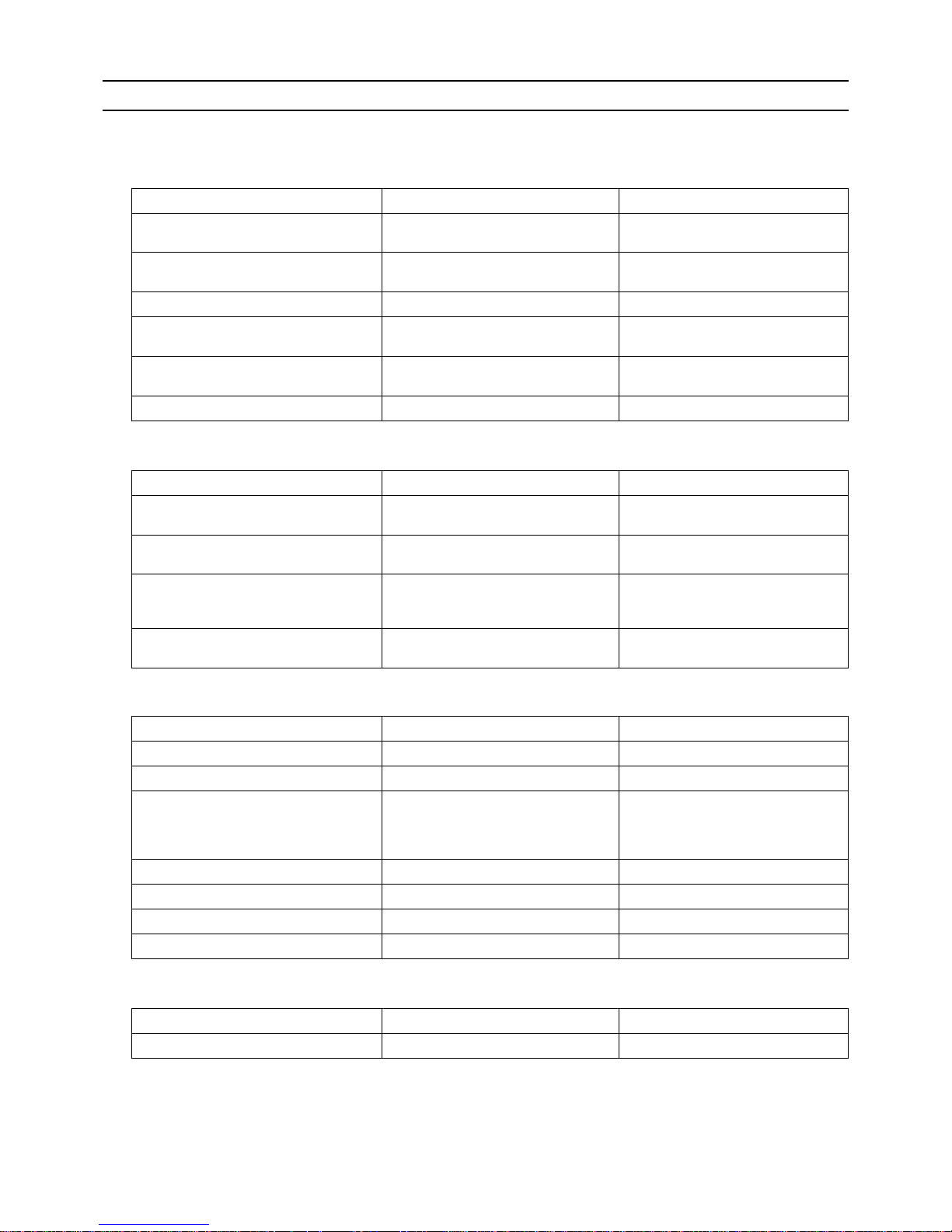
[3] Storage of Piping
1. Storage location
Store the piping materials indoors until they are ready to be installed (e.g., storage room on site or at the installer's premise).
If left outdoors, dust, dirt, or moisture may infiltrate and contaminate the pipe, resulting in malfunctions.
2. Sealing the pipe ends
Both ends of the pipes should be sealed until just before brazing.
Keep elbows and T-joints wrapped in plastic bags to keep dust, dirt, and moisture out.
The new refrigerant oil is more than ten times as hygroscopic as the conventional refrigerant oil, such as Suniso, and is more
likely to introduce moisture into the system. To prevent the deterioration of refrigerant oil and resultant compressor failure,
store piping materials with special care to keep moisture out.
[4] Pipe Processing
Use a small amount of ester oil, ether oil, or alkylbenzene to coat flares and flanges.
Use a minimum amount of oil.
Use only ester oil, ether oil, and alkylbenzene.

[ I Read Before Servicing ]
- 6 -
HWE10140 GB
[5] Brazing
No changes have been made in the brazing procedures. Perform brazing with special care to keep foreign objects (such as oxide
scale, water, and dust) out of the refrigerant system.
Example: Inside the brazed connection
1. Items to be strictly observed
Do not conduct refrigerant piping work outdoors if raining.
Use non-oxidized solder.
Use a brazing material (BCuP-3) that requires no flux when brazing between copper pipes or between a copper pipe and
copper coupling.
If installed refrigerant pipes are not immediately connected to the equipment, then braze and seal both ends.
2. Reasons
Refrigerant oil for use with R410A is more than ten times as hygroscopic as the conventional refrigerant oil and is more likely
to introduce moisture into the system, requiring special care in handling to prevent malfunctions.
Do not use flux, which usually contains chloride and form sludge in the refrigerant circuit.
3. Notes
Do not use commercially available antioxidants because they may cause the pipes to corrode or refrigerating machine oil to
deteriorate.
Use of oxidized solder for brazing Use of non-oxidized solder for brazing
[ I Read Before Servicing ]
- 7 -
HWE10140 GB
[6] Air Tightness Test
No changes have been made in the detection method. Note that a refrigerant leak detector for R22 will not detect an R410A leak.
1. Items to be strictly observed
Pressurize the system with nitrogen to the design pressure (REPLACE MULTI Y(PUHY-RP): 3.3 MPa [479 psi]; REPLACE
MULTI R2 (PURY-RP): 3.6 MPa [523 psi]), and check for refrigerant leakage. Take the temperature fluctuations into account
when measuring pressure.
Refrigerant R410A must be charged in its liquid state (vs. gaseous state).
2. Reasons
Oxygen, if used for an air tightness test, poses a risk of explosion. (Only use nitrogen to check air tightness.)
Refrigerant R410A must be charged in its liquid state. If gaseous refrigerant in the cylinder is drawn out first, the composition
of the remaining refrigerant in the cylinder will change and become unsuitable for use.
3. Notes
R410A does not contain chloride, so leak detectors for use with older types of refrigerants will not detect an R410A leak. Be
sure to use a leak detector designed for use with R410A.
Halide torch R22 leakage detector
[ I Read Before Servicing ]
- 8 -
HWE10140 GB
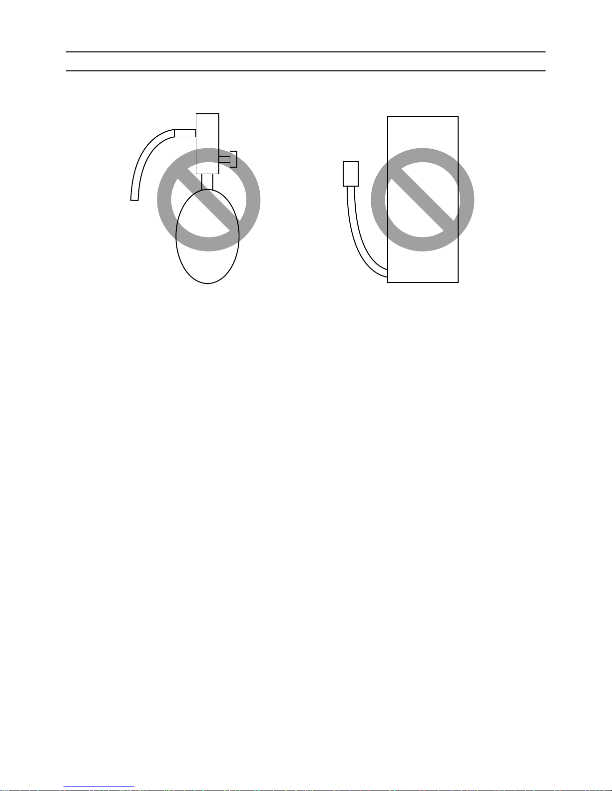
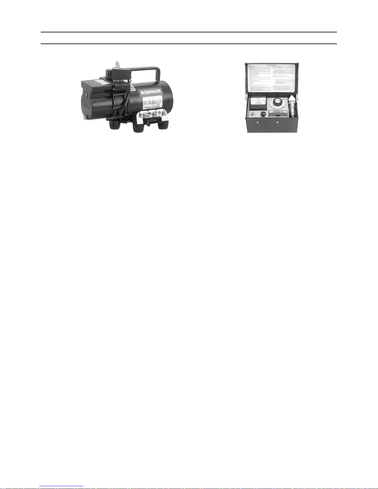
[7] Vacuum Drying (Evacuation)
1. Vacuum pump with a reverse-flow check valve (Photo1)
To prevent the vacuum pump oil from flowing into the refrigerant circuit during power OFF or power failure, use a vacuum
pump with a reverse-flow check valve.
A reverse-flow check valve may also be added to the vacuum pump currently in use.
2. Standard of vacuum degree (Photo 2)
Use a vacuum pump that attains 0.5Torr(65Pa) or lower degree of vacuum after 5 minutes of operation, and connect it directly
to the vacuum gauge. Use a pump well-maintained with an appropriate lubricant. A poorly maintained vacuum pump may not
be able to attain the desired degree of vacuum.
3. Required precision of vacuum gauge
Use a vacuum gauge that registers a vacuum degree of 5Torr(650Pa) and measures at intervals of 1Torr(130Pa). (A recommended vacuum gauge is shown in Photo2.)
Do not use a commonly used gauge manifold because it cannot register a vacuum degree of 5Torr(650Pa).
4. Evacuation time
After the degree of vacuum has reached 5Torr(650Pa), evacuate for an additional 1 hour. (A thorough vacuum drying re-
moves moisture in the pipes.)
Verify that the vacuum degree has not risen by more than 1Torr(130Pa) 1hour after evacuation. A rise by less than
1Torr(130Pa) is acceptable.
If the vacuum is lost by more than 1Torr(130Pa), conduct evacuation, following the instructions in section 6. Special vacuum
drying.
5. Procedures for stopping vacuum pump
To prevent the reverse flow of vacuum pump oil, open the relief valve on the vacuum pump side, or draw in air by loosening
the charge hose, and then stop the operation.
The same procedures should be followed when stopping a vacuum pump with a reverse-flow check valve.
6. Special vacuum drying
When 5Torr(650Pa) or lower degree of vacuum cannot be attained after 3 hours of evacuation, it is likely that water has pen-
etrated the system or that there is a leak.
If water infiltrates the system, break the vacuum with nitrogen. Pressurize the system with nitrogen gas to
0.5kgf/cm
2
G(0.05MPa) and evacuate again. Repeat this cycle of pressurizing and evacuation either until the degree of vac-
uum below 5Torr(650Pa) is attained or until the pressure stops rising.
Only use nitrogen gas for vacuum breaking. (The use of oxygen may result in an explosion.)
(Photo1) 15010H (Photo2) 14010
Recommended vacuum gauge:
ROBINAIR 14010 Thermistor Vacuum Gauge

[ I Read Before Servicing ]
- 9 -
HWE10140 GB
7. Notes
To evacuate air from the entire system
Applying a vacuum through the check joints at the refrigerant service valve on the high and low pressure sides (BV1
and 2) is not enough to attain the desired vacuum pressure.
Be sure to apply a vacuum through the check joints at the refrigerant service valve on the high and low pressure
sides (BV1 and 2) and also through the check joints on the high and low pressure sides (CJ1 and 2).
To evacuate air only from the outdoor units
Apply a vacuum through the check joints on the high and low pressure sides (CJ1, and 2).
To evacuate air from the indoor units and exte ns ion pipes
Apply a vacuum through the check joints at the refrigerant service valve on the high and low pressure sides (BV1
and 2).

[ I Read Before Servicing ]
- 10 -
HWE10140 GB
[8] Refrigerant Charging
1. Reasons
R410A is a pseudo-azeotropic HFC blend (boiling point R32=-52°C[-62°F], R125=-49°C[-52°F]) and can almost be han dled
the same way as a single refrigerant, such as R22. To be safe, however, draw out the refrigerant from the cylinder in the liquid
phase. If the refrigerant in the gaseous phase is drawn out, the composition of the remaining refrigeran t will change and become unsuitable for use.
2. Notes
When using a cylinder with a siphon, refrigerant is charged in the liquid state without the need for turning it upside down. Check
the type of the cylinder on the label before use.
[9] Remedies to be taken in case of a Refrigerant Leak
If the refrigerant leaks out, it may be replenished. The entire refrigerant does not need to be replaced. (Charge refrigerant in the
liquid state.)
Refer to "IX [5] Refrigerant Leak."(page 260)
Cylinder with a siphon
Cylinder color R410A is pink. Refrigerant charging in the liquid state
Cylinder
liquid
Valve Valve
liquid
Cylinder
Cylinder without a siphon
[ I Read Before Servicing ]
- 11 -
HWE10140 GB
[10] Characteristics of the Conventional and the New Refrigerants
1. Chemical property
As with R22, the new refrigerant (R410A) is low in toxicity and chemically stable nonflammable refrigerant.
However, because the specific gravity of vapor refrigerant is greater than that of air, leaked refrigerant in a closed room will
accumulate at the bottom of the room and may cause hypoxia.
If exposed to an open flame, refrigerant will generate poisonous gases. Do not perform installation or service work in a confined area.
*1 When CFC11 is used as a reference
*2 When CO
2
is used as a reference
2. Refrigerant composition
R410A is a pseudo-azeotropic HFC blend and can almost be handled the same way as a single refrigerant, such as R22. To
be safe, however, draw out the refrigerant from the cylinder in the liquid phase. If the refrigerant in the gaseous phase is drawn
out, the composition of the remaining refrigerant will change and become unsuitable for use.
If the refrigerant leaks out, it may be replenished. The entire refrigerant does not need to be replaced.
3. Pressure characteristics
The pressure in the system using R410A is 1.6 times as great as that in the system using R22.
New Refrigerant (HFC type) Conventional Refriger-
ant (HCFC type)
R410A R407C R22
R32/R125 R32/R125/R134a R22
Composition (wt%) (50/50) (23/25/52) (100)
Type of Refrigerant Pseudo-azeotropic
Refrigerant
Non-azeotropic
Refrigerant
Single Refrigerant
Chloride Not included Not included Included
Safety Class A1/A1 A1/A1 A1
Molecular Weight 72.6 86.2 86.5
Boiling Point (°C/°F) -51.4/-60.5 -43.6/-46.4 -40.8/-41.4
Steam Pressure
(25°C,MPa/77°F,psi) (gauge)
1.557/226 0.9177/133 0.94/136
Saturated Steam Density
(25°C,kg/m
3
/77°F,psi)
64.0 42.5 44.4
Flammability Nonflammable Nonflammable Nonflammable
Ozone Depletion Coefficient (ODP)
*1
0 0 0.055
Global Warming Coefficient (GWP)
*2
1730 1530 1700
Refrigerant Charging Method Refrigerant charging in
the liquid state
Refrigerant charging in
the liquid state
Refrigerant charging in
the gaseous state
Replenishment of Refrigerant after a Refrigerant
Leak
Available Available Available
Temperature (°C/°F)
Pressure (gauge)
R410A R407C R22
MPa/psi MPa/psi MPa/psi
-20/-4 0.30/44 0.18/26 0.14/20
0/32 0.70/102 0.47/68 0.40/58
20/68 1.34/194 0.94/136 0.81/117
40/104 2.31/335 1.44/209 1.44/209
60/140 3.73/541 2.44/354 2.33/338
65/149 4.17/605 2.75/399 2.60/377
[ I Read Before Servicing ]
- 12 -
HWE10140 GB
[11] Notes on Refrigerating Machine Oil
1. Refrigerating machine oil in the HFC refrigerant system
HFC type refrigerants use a refrigerating machine oil different from that used in the R22 system.
Note that the ester oil used in the system has properties that are different from commercially available ester oil.
2. Effects of contaminants
*1
Refrigerating machine oil used in the HFC system must be handled with special care to keep contaminants out.
The table below shows the effect of contaminants in the refrigerating machine oil on the refrigeration cycle.
3. The effects of contaminants in the refrigerating machine oil on the refrigeration cycle.
Refrigerant Refrigerating machine oil
R22 Mineral oil
R407C Ester oil
R410A Ester oil
*1. Contaminants is defined as moisture, air, processing oil, dust/dirt, wrong types of refrigerant, and refrigerating machine oil.
Cause Symptoms Effects on the refrigerant cycle
Water infiltration Frozen expansion valve
and capillary tubes
Clogged expansion valve and capillary tubes
Poor cooling performance
Compressor overheat
Motor insulation failure
Burnt motor
Coppering of the orbiting scroll
Lock
Burn-in on the orbiting scroll
Hydrolysis
Sludge formation and adhesion
Acid generation
Oxidization
Oil degradation
Air infiltration Oxid ization
Infiltration of
contaminants
Dust, dirt
Adhesion to expansion valve and capillary
tubes
Clogged expansion valve, capillary tubes, and
drier
Poor cooling performance
Compressor overheat
Infiltration of contaminants into the compressor
Burn-in on the orbiting scroll
Mineral oil
etc.
Sludge formation and adhesion Clogged expansion valve and capillary tubes
Poor cooling performance
Compressor overheat
Oil degradation Burn-in on the orbiting scroll

- 13 -
HWE10140 GB
II Restrictions
[1] System configuration .......................................................................................................15
[2] Types and Maximum allowable Length of Cables ...........................................................16
[3] Switch Settings and Address Settings.............................................................................22
[4] Sample System Connection.............................................................................................28
[5] An Example of a System to which an MA Remote Controller is connected.....................30
[6] An Example of a System to which an ME Remote Controller is connected.....................42
[7] An Example of a System to which both MA Remote Controller and
ME Remote Controller are connected..............................................................................44
[8] Restrictions on Pipe Length.............................................................................................47

- 14 -
[ II Restrictions ]
- 15 -
HWE10140 GB
II Restrictions
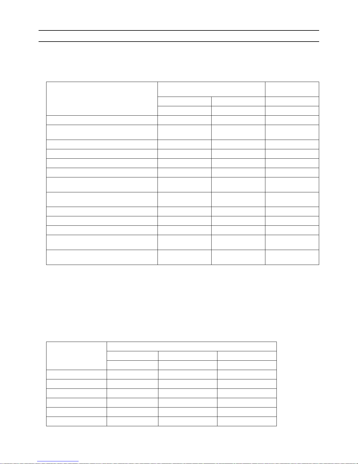
[1] System configuration
1. Table of compatible indoor units
The table below summarizes the types of indoor units that are compa ti ble with different types of outdoor units.
(1) Standard combinations
1) "Maximum total capacity of connectable indoor units" refers to the sum of the numeric values in the indoor unit model names.
2) If the total capacity of the indoor units that are connected to a given outdoor unit exceeds the capacity of the outdoor unit, the
indoor units will not be able to perform at the rated capacity when they are operated simultaneously. Select a combination of
units so that the total capacity of the connected indoor units is at or below the capacity of the outdoor unit whenever possible.
Outdoor
units
Composing units Maximum total capacity
of connectable indoor
units
Maximum number
of connectable in-
door units
Types of connectable in-
door units
P200 - - 100 - 300 20 P15 - P250 models
R410A series indoor units
P250 - - 125 - 375 25
P300 - - 150 - 450 30
[ II Restrictions ]
- 16 -
HWE10140 GB
[2] Types and Maximum allowable Length of Cables
1. Wiring work
(1) Notes
1) Have all electrical work performed by an authorized electrician according to the local regulations and instructions in this manual.
2) Install external transmission cables at least 5cm [1-31/32"] away from the power supply cable to avoid noise interference.
(Do not put the control cable and power supply cable in the same conduit tube.)
3) Provide grounding for the outdoor unit as required.
4) Run the cable from the electric box of the indoor or outdoor unit in such way that the box is accessible for servicing.
5) Do not connect power supply wiring to the terminal block for transmission line. Doing so will damage the electronic components on the terminal block.
6) Use 2-core shielded cables as transmission cables.
Use a separate 2-core control cable for each refrigerant system. Do not use a single multiple-core cable to connect indoor
units that belong to different refrigerant systems. The use of a multiple-core cable may result in signal transmission errors and
malfunctions.
(2) Control wiring
Different types of control wiring are used for different systems.
Refer to section "[5] An Example of a System to which an MA Remote Controller is connected - [7] An Example of a System
to which both MA Remote Controller and ME Remote Controller are connected" before performi ng wiring work.
Types and maximum allowable length of cables
Control lines are categorized into 2 types: transmission line and remote controller line.
Use the appropriate type of cables and observe the maximum allowable length specified for a given system. If a given system
has a long transmission line or if a noise source is located near the unit, place the unit away from the noise source to reduce
noise interference.
1) M-NET transmission line
Cable type
Facility
type
All facility types
Type Shielded cable CVVS, CPEVS, MVVS*1
Number of
cores
2-core cable
Cable size Larger than 1.25mm
2
[AWG16]
Maximum transmission
line distance between the
outdoor unit and the farthest indoor unit
200 m [656ft] max.
Maximum transmission
line distance for centralized control and Indoor/
outdoor transmission line
(Maximum line distance
via outdoor unit)
500 m [1640ft] max.
*The maximum overall line length from the power supply unit on the transmission lines for
centralized control to each outdoor unit or to the system controller is 200m [656ft] max.
*1 If unshielded cables are used, consult your dealer.
TB3TB
7
TB3TB
7
TB3TB
7
TB3TB
7
TB3: Terminal block for indoor-outdoor transmission line TB7: Terminal block for centralized control
multiple-core cable
BC Controller
Indoor unit
Remote Controller
Remote Controller
2-core shielded cable
2-core shielded cable
Outdoor unit
BC Controller
Indoor unit
Outdoor unit

[ II Restrictions ]
- 17 -
HWE10140 GB
2) Remote controller wiring
*1 MA remote controller refers to MA remote controller (PAR-20MAA, PAR-21MAA), MA simple remote controller, and
wireless remote controller.
*2 ME remote controller refers to ME remote controller and ME simple remote controller.
*3 The use of cables that are smaller than 0.75mm
2
[AWG18] is recommended for easy handling.
*4 When connected to the terminal block on the Simple remote controller, use cabl es that meet the cable size specifi-
cations shown in the parenthesis.
MA remote controller
*1
ME remote controller
*2
Cable type
Type VCTF, VCTFK, CVV, CVS, VVR, VVF, VCT Shielded cable MVVS
Number of
cores
2-core cable 2-core cable
Cable size
0.3 to 1.25mm
2 *3
[AWG22 to 16]
(0.75 to 1.25mm2 )
*4
[AWG18 to 16]
0.3 to 1.25mm
2 *3
[AWG22 to 16]
(0.75 to 1.25mm2 )
*4
[AWG18 to 16]
Maximum overall line
length
200 m [656ft] max.
The section of the cable that exceeds 10m
[32ft] must be included in the maximum indoor-outdoor transmission line distance.
[ II Restrictions ]
- 18 -
HWE10140 GB
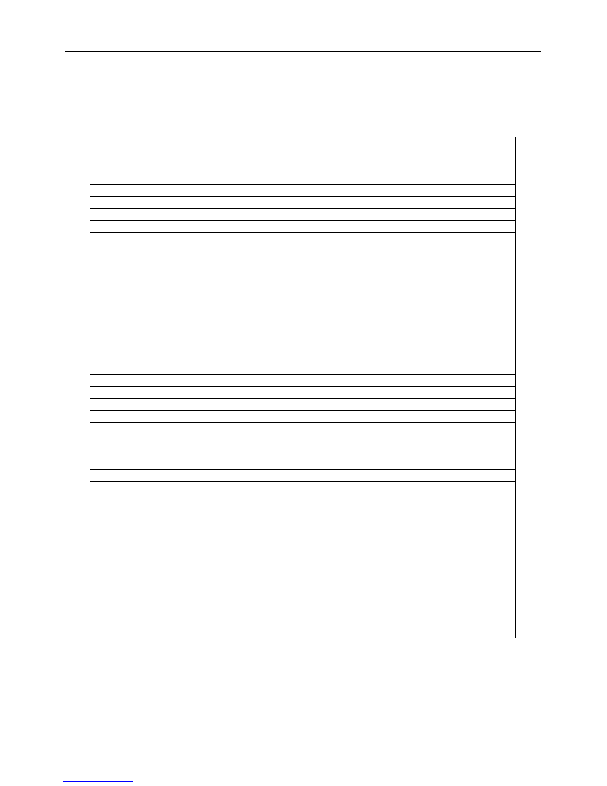
(3) Reusability check of the existing transmission lines for Replace Multi units
Check the existing wires for damage to insulation by measuring the resistance between the lead and the
ground with a 500 V ohmmeter. If the insulation resistance is less than 100 MΩ, replace the wires.
Check items Notes
1. Remote controller cable (MA remote controller)
(1) Length
(2) Cable size
(3) Number of cores
(4) Cable type (shielded/unshielded)
2. Remote controller cable (ME remote controller)
(1) Length *1
(2) Cable size
(3) Number of cores
(4) Cable type (shielded/unshielded)
3. Remote controller cable (system controller)
(1) Length *1
(2) Cable size
(3) Number of cores
(4) Cable type (shielded/unshielded)
4. Indoor-outdoor transmission line
(1) Refrigerant system (Single/Multiple)
(2) Length of transmission line to the farthest unit *1
(3) Cable size
(4) Number of cores
(5) Cable type (shielded/unshielded)
(6) Number of connected indoor units
5. Centralized control transmission line
(1) Length of transmission line to the farthest unit *1
(2) Cable size
(3) Number of cores
(4) Cable type (shielded/unshielded)
7. Noise-related problems with the old units
Existing transmission lines reusability checklist
Obtain the system configuration drawing, fill out the checklist, and make a decision based on them.
Use the flowcharts on the following pages to determine the reusability of the existing transmission lines.
*1: If the remote controller (ME/System controller) length exceeds 10 m, include the exceeded length in the calculation of the
transmission line length (indoor-outdoor transmission line/centralized control system).
(5) System controller connection (Indoor unit
system/centralized control system)
6. Availability of system configuration drawing (Obtain one as
much as possible.)
8. Are there any high-frequency medical equipment in the adjacent
area that could cause noise-interference?
(Write down the nature of the problem in the “Notes” column,
if any.)
(Write down the specific nature of the concerns in the “Notes”
column, if any.)
Findings
Shielded/Unshielded
Shielded/Unshielded
Shielded/Unshielded
Indoor/Centralized
Single/Multiple
Shielded/Unshielded
Shielded/Unshielded
Available/Not available
Available/Not available
m
mm
2
m
mm
2
m
mm
2
m
mm
2
m
mm
2
Cores
Cores
Cores
Cores
units
Cores
Available/Not available
[ II Restrictions ]
- 19 -
HWE10140 GB
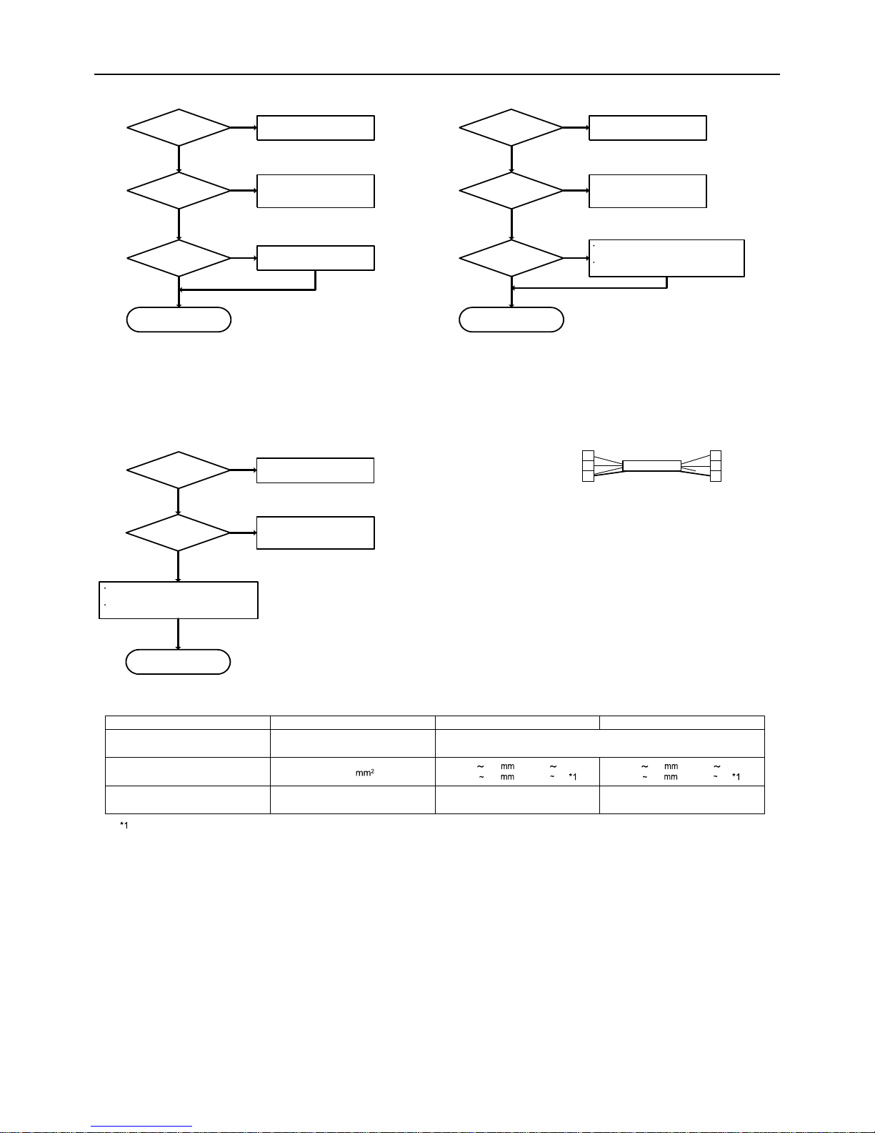
Table A
Is the 2-core cable used?
Is the 2-core cable used?
Is the 2-core cable used?
YES
NO
YES
NO
YES
YES YES
NO
YES
NO
YES
YES
YES
Reusability of MA remote controller wiring
Reusability of System controller wiring
Reusability of M-NET remote controller witing
NO
Is the wiring length
less than 200m?
Is the wiring of
less than 10m?
Refer to Table A.
Handle the non-using wiring as
shown in figure A.
NO
Please contact MITSUBISHI
ELECTRIC.
NO
Please contact MITSUBISHI
ELECTRIC.
NO
Please contact MITSUBISHI
ELECTRIC.
Refer to Table A.
Handle the non-using wiring as
shown in figure A.
Refer to Table A.
Handle the non-using wiring as
shown in figure A.
If the wiring is more than 10m, include the
exceeding length to the total wiring length.
When 10m is exceeded, use the shielded
cable for exceeding length.
If the wiring is more than 10m, include the
exceeding length to the total wiring length.
When 10m is exceeded, use the shielded
cable for exceeding length.
Make wiring length less than
200m.
Is the shielded
wiring used?
Is the shielded
wiring used?
Is the shielded
wiring used?
Go to "Reusability of
Transmission line".
Go to "Reusability of
Transmission line".
Go to "Reusability of
Transmission line".
shielded wire
A
B
S
A
B
S
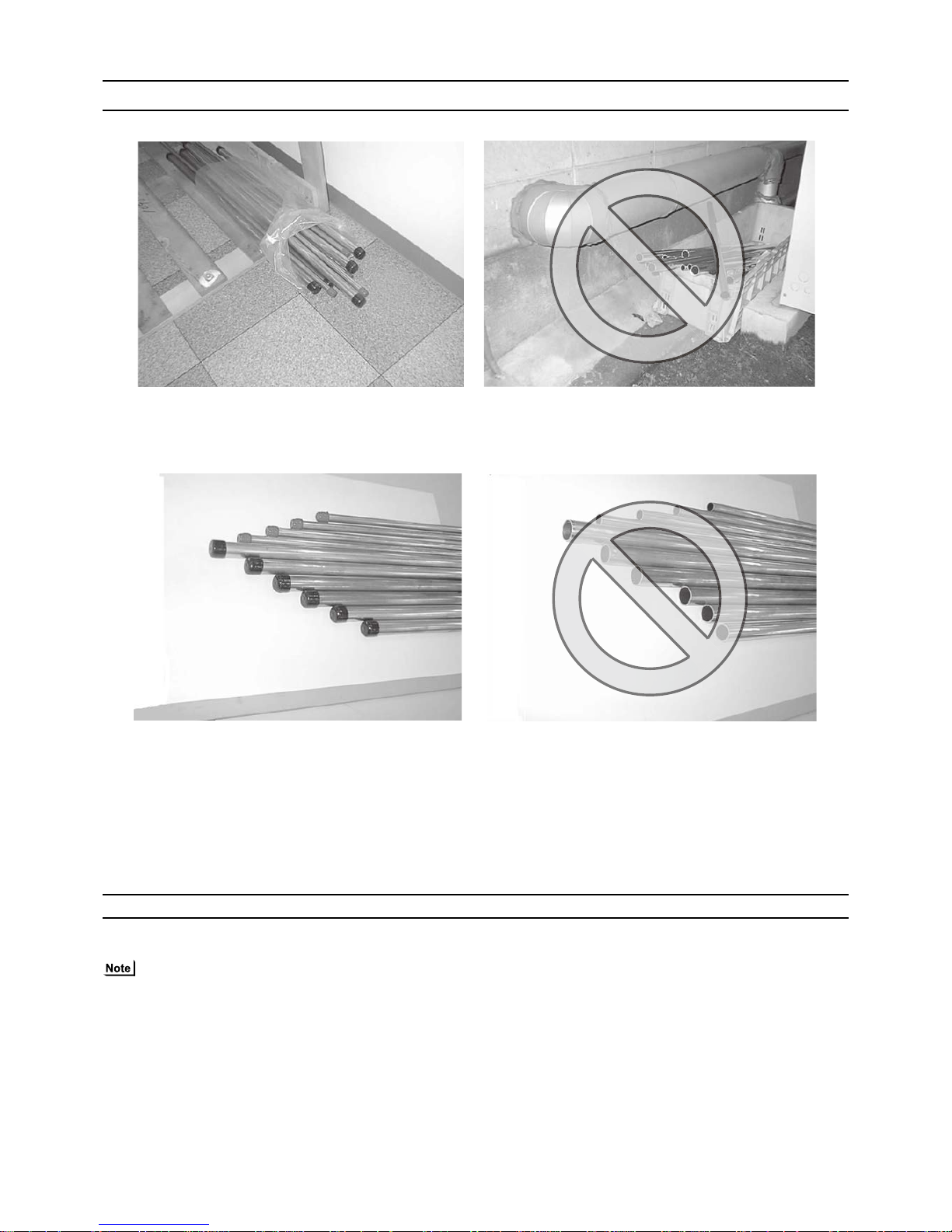
Figure A. Non-using wiring
Side:
Close to power supply unit
(Outdoor unit, Power supply unit)
Non using wiring on the power supply side (Outdoor unit, Power supply
unit) should be connected to the shield terminal. The non-using wiring on
the opposite side should be open and insulated.
Type of cable
Cable size
Remarks
Sheathed 2-core cable (unshielded)
CVV
2
Shielding wire (2-core)
CVVS, CPEVS or MVVS
Transmission cables ME Remote controller cables
CVVS, MVVS : PVC insulated PVC jacketed shielded control cable
CPEVS : PE insulated PVC jacketed shielded communication cable
Connected with simple remote controller.
CVV : PV insulated PVC sheathed control cable
—
Max length : 200m [656ft]
(Li)
MA Remote controller cables
When 10m [32ft] is exceeded, use the
shielded cable for exceeding length.
More than 1.25 [AWG16]
2
0.3 1.25 [AWG22 16]
(0.75 1.25 [AWG18 16])
2
2
0.3 1.25 [AWG22 16]
(0.75 1.25 [AWG18 16])
[ II Restrictions ]
- 20 -
HWE10140 GB
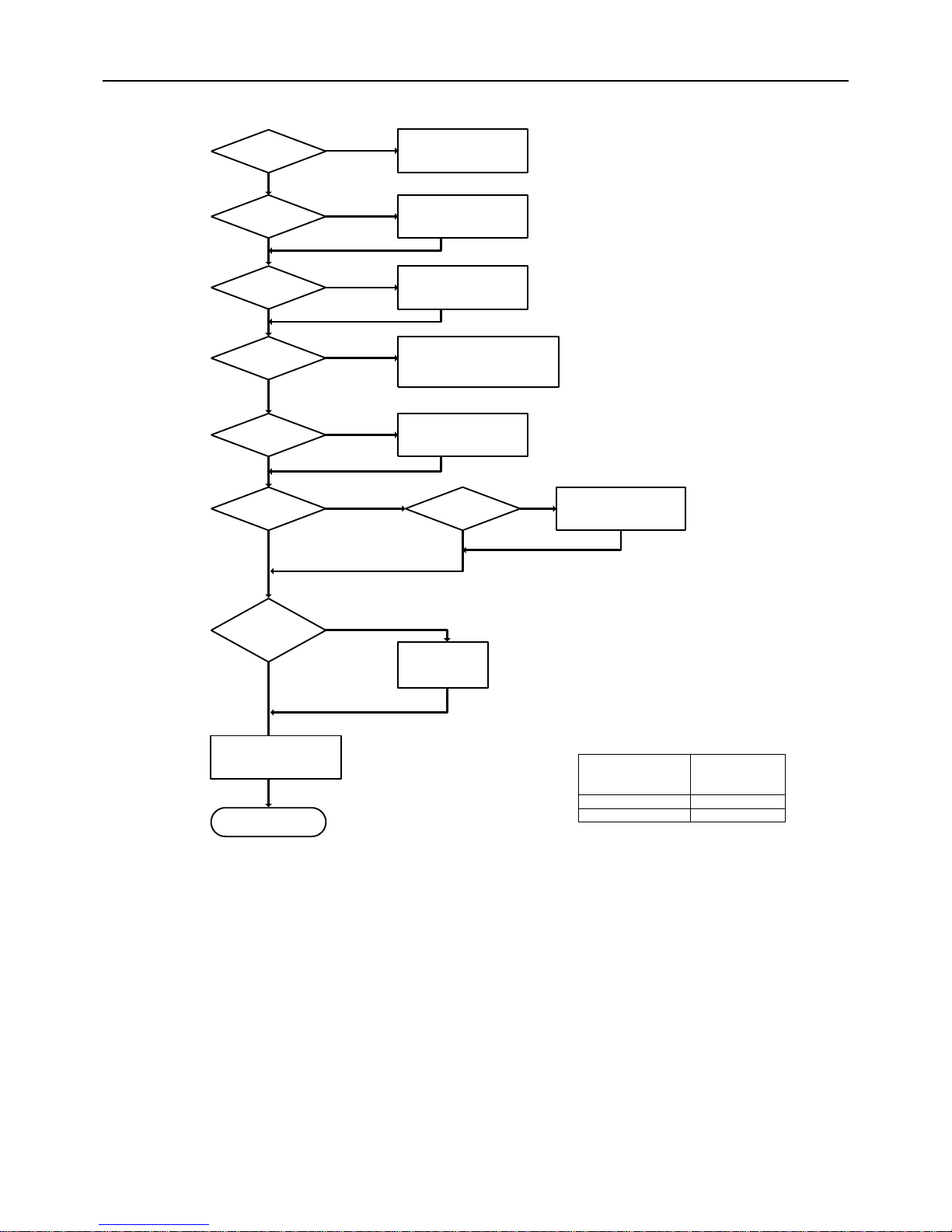
Reusability of Transmission line
Is the 2-core cable used?
Is the shielded wiring used?
Refer to Table A.
Fix the ground fault current.
Less than 200m More than 0.5mm
2
Less than 130m More than 0.3mm
2
Wiring diameter
Chart A. Centralized transmission line applicable diameter
YES
YES
NO
Please contact MITSUBISHI
ELECTRIC.
NO
YES
NO
YES
NO
YES
NO
YES
NO
NO
YES
YES
NO
Is the current in
normal state without
ground fault?
Is the farthest
transmission line between OU and
IU less than 200m?
Farthest transmission line of
centralized controller must be less
than 200m.
To find out the reusability, check the number
of indoor units, farthest length of
transmission line, and read the applicable
diameter from diagram B.
Handle the wiring that are not used
as shown in figure A.
Farthest transmission line for
centralized control system must be
less than 500m.
Is the farthest
transmission line of centralized
control system less
than 500m?
Does the diameter of the
transmission line match the
figures in Table A?
Length between power
supply unit to outdoor unit
and system controller
Shielded wiring should be connected
to the terminal at the power supply
unit side (outdoor unit).
Is the system stand-alone?
Existing transmission line can
be reused.
ࠛ
Is the diameter of
the current wiring thicker
than the diameter read
from chart A?
Change the centralized
transmission line
diameter to more than
1.25mm
2
.
[ II Restrictions ]
- 21 -
HWE10140 GB
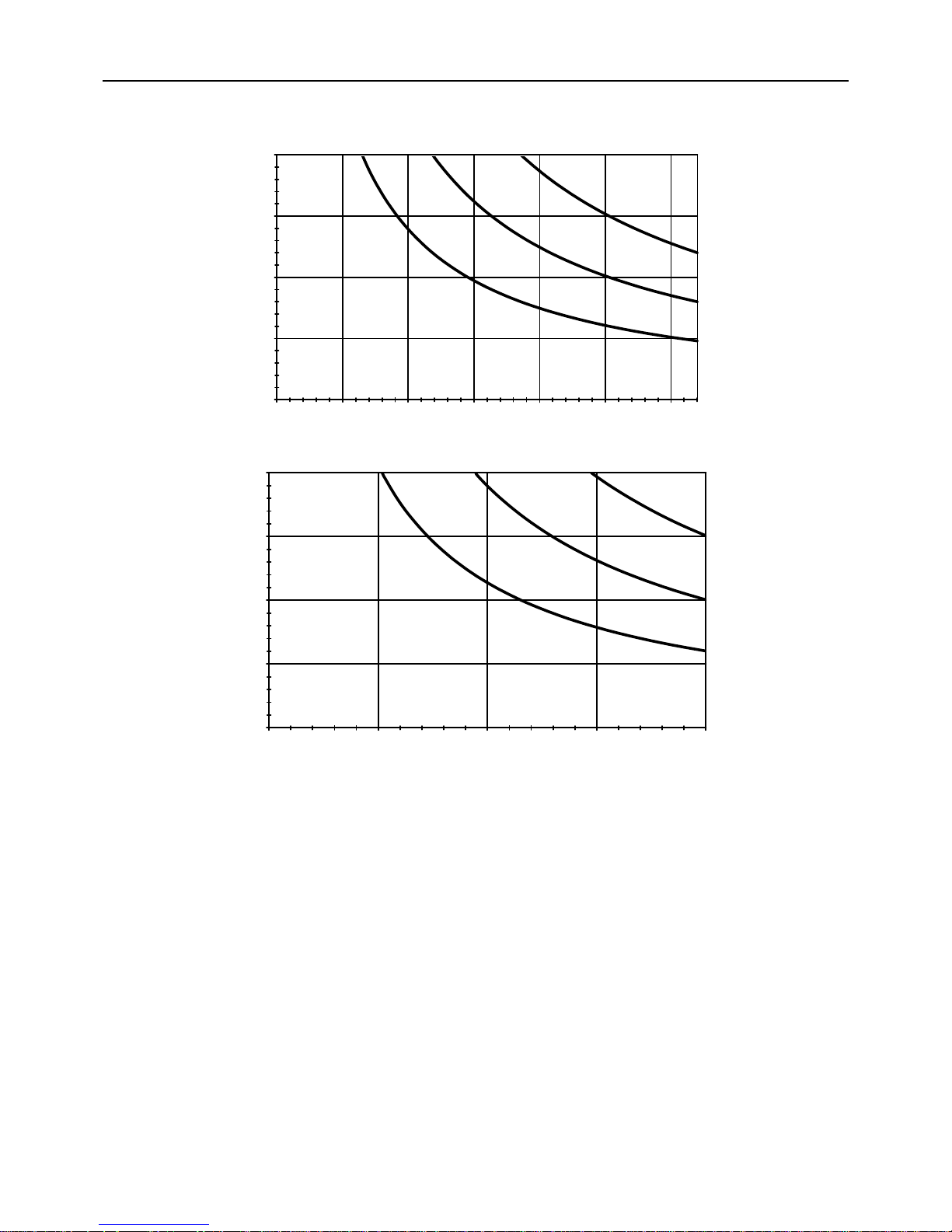
0
50
100
150
200
0 5 10 15 20 25 32
30
Number of indoor units
Length of transmission line to the farthest unit (m)
0.75mm
2
0.5mm
2
MA remote controller
Diagram B Checking the cable size
0.3mm
2
1.25mm
2
M-NET remote controller
Number of indoor units
Length of transmission line to the farthest unit (m)
0.5mm
2
0.75mm
2
0.3mm
2
1.25mm
2
0
50
100
150
200
0 5 10 15 20

[ II Restrictions ]
- 22 -
HWE10140 GB
[3] Switch Settings and Address Settings
1. Switch setting
Refer to section "[5] An Example of a System to which an MA Remote Controller is connected - [7] An Example of a System
to which both MA Remote Controller and ME Remote Controller are connected" before performi ng wiring work.
Set the switches while the power is turned off.
If the switch settings are changed while the unit is being powered, those changes will not take effect, and the unit will not
function properly.
*1. Applicable when LOSSNAY units are connected to the indoor-outdoor transmission line.
*2. The outdoor units in the same refrigerant circuit are automatically designated as OC in the order of capacity from large
to small (if two or more units have the same capacity, in the order of address from small to large).
*3. Turn off the power to all the outdoor units in the same refrigerant circuit.
Units on which to set the switches Symbol Units to which the power must be shut off
CITY MULTI indoor unit Main/sub unit IC Outdoor units
*3
and Indoor units
LOSSNAY, OA processing unit
*1
LC Outdoor units
*3
and LOSSNAY
ATW Booster Unit BU Outdoor units and Booster Unit
Water Hex Unit AU Outdoor units and Water Hex Unit
ME remote controller Main/sub remote
controller
RC Outdoor units
*3
MA remote controller Main/sub remote
controller
MA Indoor units
CITY MULTI outdoor unit
*2
OC Outdoor units
*3
BC controller Main BC Outdoor units
*3
and BC controller
Sub1, 2 BS1, BS2 Outdoor units
*3
and BC controller

[ II Restrictions ]
- 23 -
HWE10140 GB
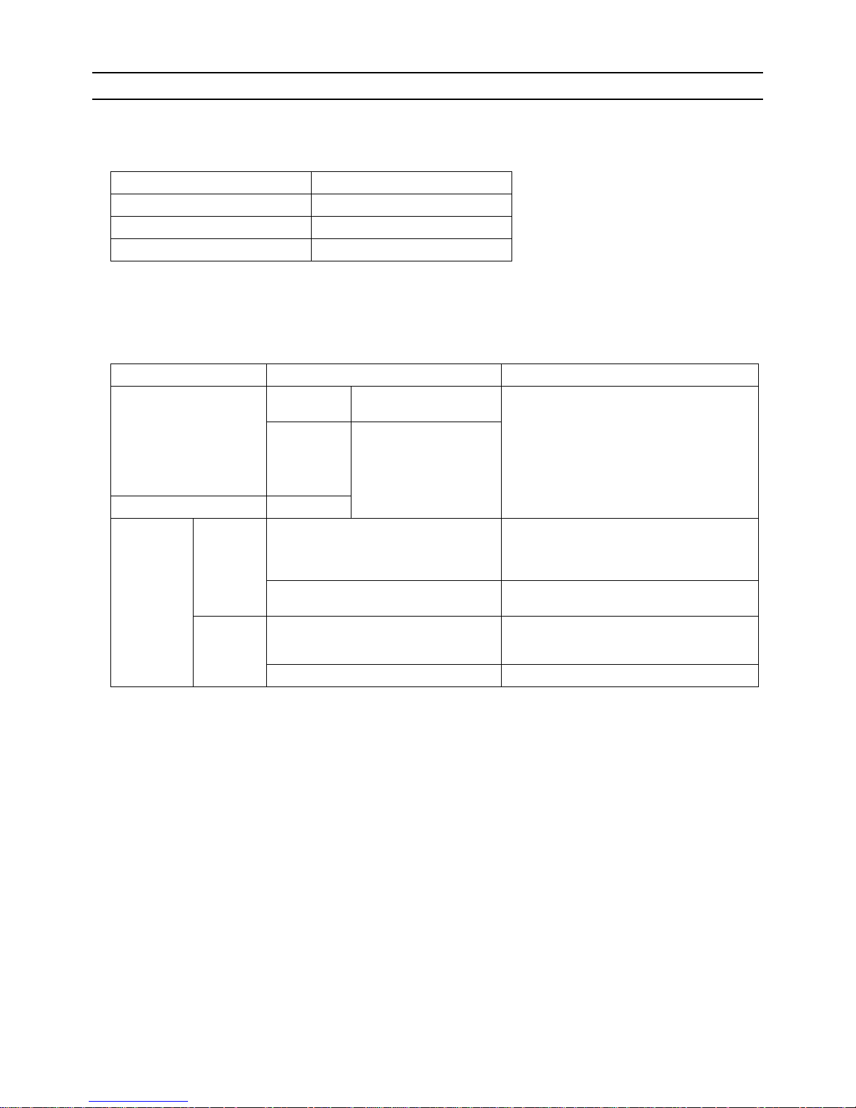
2. M-NET Address settings
(1) Address settings table
The need for address settings and the range of address setting depend on the configuration of the system.
*1. If a given address overlaps any of the addresses that are assigned to other units, use a different, unused address within the
setting range.
*2. To set the outdoor unit address or the auxiliary outdoor unit address to "100," set the rotary switches to "50."
*3. To set the ME remote controller address to "200," set the rotary switches to "00."
*4. Some models of indoor units have two or three control boards.
Assign an address to the No.1, No. 2, and No. 3 control boards so that the No. 2 control board address equals the No. 1 control
board address plus 1, and that the No. 3 control board address equals the No. 1 control board address plus 2.
*5. No address settings are required for units in a system with a single outdoor unit (with some exceptions).
Address setting is required if a sub BC controller is connected.
Unit or controller Sym-
bol
Address
setting
range
Setting method Factory
address
setting
CITY MULTI
indoor unit
Main/sub unit IC 0, 01 to
50
*1 *4 *5
Assign the smallest address to the main indoor unit in the
group, and assign sequential address numbers to the rest
of the indoor units in the same group.
In an R2 system with a sub BC controller, make the settings for the indoor units in the following order.
(i) Indoor unit to be connected to the main BC controller
(ii) Indoor unit to be connected to sub BC controller 1
(iii) Indoor unit to be connected to sub BC controller 2
Make the settings for the indoor units in the way that the
formula "(i) < (ii) < (iii)" is true.
00
M-NET
adapter
M-NET control interface
Free Plan
adapter
LOSSNAY, OA processing unit LC 0, 01 to
50
*1 *4 *5
Assign an arbitrary but unique address to each of these
units after assigning an address to all indoor units.
00
ATW Booster Unit BU
Water Hex Unit AU
ME remote
controller
Main remote
controller
RC 101 to
150
Add 100 to the smallest address of all the indoor units in
the same group.
101
Sub remote
controller
RC 151 to
200
*3
Add 150 to the smallest address of all the indoor units in
the same group.
MA remote controller MA No address settings required. (The main/sub setting must be made if
2 remote controllers are connected to the system.)
Main
CITY MULTI outdoor unit OC 0, 51 to
100
*1 *2
*5
Assign an address that equals the lowest address of the in-
door units in the same refrigerant circuit plus 50.
00
Auxiliary
outdoor unit
BC controller
(main)
BC 0, 51 to
100
*1 *2
*5
Assign an address that equals the address of the outdoor
unit in the same refrigerant system plus 1.
If a given address overlaps any of the addresses that are
assigned to the outdoor units or to the sub BC controller,
use a different, unused address within the setting range.
00
BC controller
(sub1, 2)
BS1
BS2
51 to
100
*2
Assign an address to both the sub BC controller 1 and 2
that equals the lowest address of the indoor units that
are connected to each of them plus 50.
If a sub BC controller is connected, the automatic startup
function is not available.
System
controller
Group remote controller
GRSC201 to
250
Assign an address that equals the sum of the smallest
group number of the group to be controlled and 20 0.
201
System remote controller
SR
SC
Assign an arbitrary but unique address within the range
listed on the left to each unit.
ON/OFF remote controller
AN
SC
Assign an address that equals the sum of the smallest
group number of the group to be controlled and 20 0.
Schedule timer (compatible with M-NET)STSC
Assign an arbitrary but unique address within the range
listed on the left to each unit.
202
Central controller
G(B)-50A
TRSC0, 201 to
250
Assign an arbitrary but unique address within the range
listed on the left to each unit. The address must be set to
"0" to control the K-control unit.
000
LM adapter SC 201 to
250
Assign an arbitrary but unique address within the range
listed on the left to each unit.
247

[ II Restrictions ]
- 24 -
HWE10140 GB
(2) Power supply switch connector connection on the ou tdoo r unit
(Factory setting: The male power supply switch connector is connected to CN41.)
*1 The need for a power supply unit for transmission lines depends on the system configuration.
*2 The replacement of the power jumper connector from CN41 to CN40 must be performed on only one outdoor unit in the
system.
(3) Settings for the centralized control switch for the outdoor unit (Factory setting: SW2-1 are set to OF F.)
*1 Set SW2-1 on all outdoor units in the same refrigerant circuit to the same setting.
*2 When only the LM adapter is connected, leave SW2-1 to OFF (as it is).
(4) Selecting the position of temperature detection for the indo or unit (Facto ry setting : SW1-1 set to "OFF".)
To stop the fan during heating Thermo-OFF (SW1-7 and 1-8 on the indoor units to be set to ON), use the built-in thermistor
on the remote controller or an optional thermistor.
1) To use the built-in sensor on the remote controller, set the SW1-1 to ON.
Some models of remote controllers are not equipped with a built-in temperature sensor.
Use the built-in temperature sensor on the indoor unit instead.
When using the built-in sensor on the remote controller, install the remote controller where room temperature can be detected.
(Note) Factory setting for SW1-1 on the indoor unit of the All-Fresh Models is ON .
2) When an optional temperature sensor is used, set SW1-1 to OFF, and set SW3-8 to ON.
When using an optional temperature sensor, install it where room temperature can be detected .
(5) Various start-stop controls (Indoor unit settings)
Each indoor unit (or group of indoor units) can be controlled individually by setting SW 1-9 and 1-10.
*1. Do not cut off power to the outdoor unit. Cutting off the power supply to the outdoor unit will cut off the power supply to the
crankcase heater and may cause the compressor to malfunction when the unit is put back into operation.
*2. Not applicable to units with a built-in drain pump or humidifier.
*3. Models with a built-in drain pump cannot be turned on/off by the plug individually. All the units in the same refrigerant cir-
cuits will be turned on or off by the plug.
*4. Requires that the dipswitch settings for all the units in the group be made.
*5. To control the external input to and output from the air conditioners with the PLC software for general equipment via the
G(B)-50A, set SW1-9 and SW1-10 to ON. With these settings made, the power start-stop function becomes disabled. To
use the auto recovery function after power failure while these settings are made, set SW1-5 to ON.
System configuration
Connection to
the system controller
Power supply unit
for transmission
lines
Group operation
of units in a system with multiple
outdoor units
Power supply switch connector connection
System with
one outdoor unit
_ _ _ Leave CN41 as it is
(Factory setting)
System with
multiple outdoor
units
Not connected _ Not grouped
Grouped Disconnect the male connector from the fe-
male power supply switch connector (CN41)
and connect it to the female power supply
switch connector (CN40) on only one of the
outdoor units.
*2
*Connect the S (shielded) terminal on the ter-
minal block (TB7) on the outdoor unit whose
CN41 was replaced with CN40 to the
ground terminal ( ) on the electric box.
With connection
to the indoor
unit system
Not required Grouped/not
grouped
With connection
to the centralized control
system
Not required
*1
(Powered from the
outdoor unit)
Grouped/not
grouped
Required *
1
Grouped/not
grouped
Leave CN41 as it is
(Factory setting)
System configuration Centralized control switch settings *
1
Connection to the system controller Not connected Leave it to OFF. (Factory setting)
Connection to the system controller Connected *
2
ON
Function
Operation of the indoor unit when the operation is resumed after the unit was
stopped
Setting (SW1)
*4 *5
910
Power ON/OFF by
the plug
*1,*2,*3
Indoor unit will go into operation regardless of its operation status before power
off (power failure). (In approx. 5 minutes)
OFF ON
Automatic restoration
after power failure
Indoor unit will go into operation if it was in operation when the power was
turned off (or cut off due to power failure). (In approx. 5 minutes)
ON OFF
Indoor unit will remain stopped regardless of its operation status before power
off (power failure).
OFF OFF

[ II Restrictions ]
- 25 -
HWE10140 GB
(6) Miscellaneous settings
Cooling-only setting for the indoor unit: Cooling only model (Factory setting: SW3-1 "OFF.")
When using indoor unit as a cooling-only unit, set SW3-1 to ON.
(7) Various types of contro l using input-output signal connector on the outdo or unit (various connection options)
*4. By setting Dip SW5-5, the Low-noise mode can be switched between the Capacity priority mode and the Low-noise pri-
ority mode.
When SW5-5 is set to ON: The Low-noise mode always remains effective.
When SW5-5 is set to OFF: The Low-noise mode is cancelled when certain outside temperature or pressure criteria are
met, and the unit goes into normal operation (capacity priority mode).
*5. Each outdoor unit in the system with multiple outdoor units requires the signal input/output setting to be made.
*6. Take out signals from the outdoor unit (OC) if multiple outdoor units exist in a single system.
CAUTION
1) Wiring should be covered by insulation tube with supplementary insulation.
2) Use relays or switches with IEC or equivalent standard.
3) The electric strength between accessible parts and control circuit should have 2750V or more.
Type Usage Function
Terminal
to be
used
*1
*1. For detailed drawing, refer to "Example of wiring connection".
Option
Input Prohibiting cooling/heating operation (thermo OFF) by an external
input to the outdoor unit.
*It can be used as the DEMAND control device for each system.
DEMAND (level) CN3D
*2
*2. For details, refer to (1) through (4) shown below.
Adapter for
external input
(PACSC36NA-E)
Performs a low level noise operation of the outdoor unit by an external input to the outdoor unit.
* It can be used as the silent operation device for each refrigerant
system.
Low-noise mode
(level)
*3*4
*3. Low-noise mode is valid when Dip SW4-4 on the outdoor unit is set to OFF. When DIP SW4-4 is set to ON, 4 levels of
on-DEMAND are possible, using different configurations of low-noise mode input and DEMAND input settings.
Forces the outdoor unit to perform a fan operation by receiving signals from the snow sensor.
*5
Snow sensor signal
input (level)
CN3S
Cooling/heating operation can be changed by an external input to
the outdoor unit.
Auto-changeover CN3N
Out-
put
How to extract signals from the outdoor unit
*It can be used as an operation status display device.
*It can be used for an interlock operation with external devices.
Operation status of
the compressor
*5
CN51 Adapter for
external output
(PACSC37SA-E)
Error status
*6
Low-noise mode is effective Capacity priority mode becomes effective
Cooling Heating Cooling Heating
TH7 < 30°C [86°F]
and
63HS1 < 32kg/cm
2
TH7 > 3°C [37°F]
and
63LS > 4.6kg/cm
2
TH7 > 35°C [95°F]
or
63HS1 > 35kg/cm
2
TH7 < 0°C [32°F]
or
63LS < 3.9kg/cm
2

[ II Restrictions ]
- 26 -
HWE10140 GB
Example of wiring connection
(1) CN51
(2) CN3S
CN51
X
Y
L
1
L
2
ecruos rewop pmaL
Distant control
board
Relay circuit Adapter
1
Outdoor unit
control board
Preparations
in the field
Maximum cable
length is 10m
5
4
3
X
Y
L1 : Outdoor unit error display lamp
L2 : Compressor operation lamp (compressor running state)
X, Y : Relay (coil =<0.9W : DC12V)
1. Optional part : PAC-SC37SA-E or field supply.
2. Optional part : PAC-SC36NA-E or field supply.
X : Relay
Snow sensor : The outdoor fan runs when X is closed
in stop mode or thermostat mode.
X
CN3S
Preparations
in the field
Maximum cable
length is 10m
Adapter
2
Outdoor unit
control board
2
3
1
Contact rating voltage >= DC15V
Contact rating current >= 0.1A
Minimum applicable load =< 1mA at DC
Relay circuit
(3) CN3N
2. Optional part : PAC-SC36NA-E or field supply.
Preparations
in the field
OFF
CoolingONHeating
Normal
Y
OFF
ON
X
Contact rating voltage >= DC15V
Contact rating current >= 0.1A
Minimum applicable load =< 1mA at DC
X : Cooling / Heating
Y : Validity / Invalidity of X
X,Y : Relay
CN3N
X
Y
Relay circuit
Adapter
2
Outdoor unit
control board
Maximum cable
length is 10m
1
2
3
(4) CN3D
2. Optional part : PAC-SC36NA-E or field supply.
X : Low-noise mode
X : Low-noise mode
Y : Compressor ON/OFF
X,Y : Relay
Contact rating voltage >= DC15V
Contact rating current >= 0.1A
Minimum appicable load =< 1mA at DC
Y
X
CN3D
Preparations
in the field
Maximum cable
length is 10m
Adapter
2
Outdoor unit
control board
3
2
1
Relay circuit
2. Optional part : PAC-SC36NA-E or field supply.
X
CN3D
Preparations
in the field
Maximum cable
length is 10m
Adapter
2
Outdoor unit
control board
2
3
1
X : Relay
fan frequency and maximum compressor frequency.
Contact rating voltage >= DC15V
Contact rating current >= 0.1A
Minimum applicable load =< 1mA at DC
Low-noise mode : The noise level is reduced by controlling the maximum
Relay circuit

[ II Restrictions ]
- 27 -
HWE10140 GB
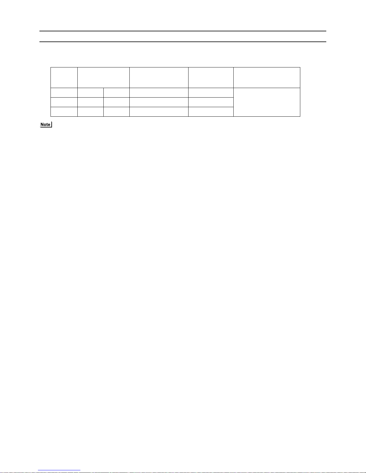
(8) Demand control
1) General outline of control
Demand control is performed by using the external signal input to the 1-2 and 1-3 pins of CN3D on the outdoor units (OC).
Between 2 and 4 steps of demand control is possible by setting Dip SW4-4 on the outdoor units (OC).
*1 If wrong sequence of steps are taken, the units may go into the Thermo-OFF (compressor stop) mode.
Ex) When switching from 100% to 50%
(Incorrect) 100%→0%→50% The units may go into the Thermo-OFF mode.
(Correct) 100%→75%→50%
*2 The percentage of the demand listed in the table above is an approximate value based on the compressor volume and does
not necessarily correspond with the actual capacity.
*3 Notes on using demand control in combination with the low-noise mode
To enable the low-noise mode, it is necessary to short-circuit 1-2 pin of CN3D on the outdoor un it whose SW4-4 is set to OFF.
2) Contact input and control content
2-step demand control
The same control as the Thermo-OFF is performed by closing 1-3 pin of CN3D.
4-step demand control (When SW4-4 is set to ON on an outdoor unit)
Demand capacity is shown below.
No Demand control switch
DipSW4-4
Input to CN3D
OC
1 2 steps (0-100%) OFF OC
2 4 steps (0-50-75-100%) ON OC
CN3D
1-3
Open 100%
Close 0%
CN3D 1-2P
1-3P Open Close
Open 100% 75%
Close 0% 50%

[ II Restrictions ]
- 28 -
HWE10140 GB
[4] Sample System Connection
Examples of typical system connection are shown on pages [5] to [7].
Refer to the Installation Manual that came with each device or controller for details.
(1) An example of a system to which an MA remote controller is connected
(2) An example of a system to which an ME remote controller is connected
(3) An example of a system to which both MA remote controller and ME remote contro ller are connected
System
configuration
Connection to the system controller
Address start up for indoor and outdoor units
Notes
1
System with one out-
door unit
NO
Automatic
address setup
2
System with one out-
door unit
NO
Manual
address setup
Connection of
multiple LOSSNAY units
3
Grouping of units in a
system with multiple
outdoor units
NO
Manual
address setup
4
System with one out-
door unit
With connection to transmission line
for centralized control
Manual
address setup
5
System with one out-
door unit
With connection to indoor-outdoor
transmission line
Manual
address setup
6
System with one out-
door unit
With connection to transmission line
for centralized control
Manual
address setup
Connection of
multiple LOSSNAY units
System
configuration
Connection to the system controller
Address start up for indoor
and outdoor units
Notes
1
System with one out-
door unit
With connection to transmission line
for centralized control
Manual
address setup
System
configuration
Connection to the system controller
Address start up for indoor and outdoor units
Notes
1
System with one out-
door unit
With connection to transmission
line for centralized control
Manual
address setup

[ II Restrictions ]
- 29 -
HWE10140 GB

- 30 -
[ II Restrictions ]
GBHWE10140
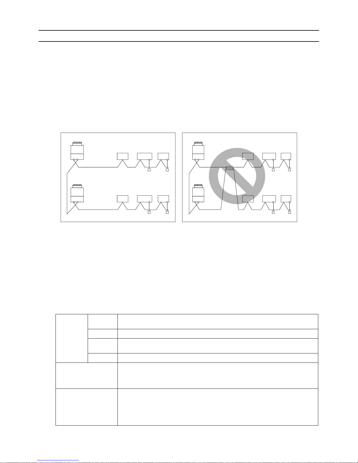
[5] An Example of a System to which an MA Remote Controller is connected
1. System with one outdoor unit (automatic address setup for both indoor and outd oor units)
(1) Sample control wiring
(2) Cautions
1) ME remote controller and MA remote controller cannot
both be connected to the same group of indoor units.
2) No more than 2 MA remote controllers can be connected
to a group of indoor units.
3) When the number of the connected indoor units is as
shown in the table below, one or more transmission
boosters (sold separately) are required.
To connect two transmission boosters, connect them in
parallel. (Observe the maximum number of connectable
indoor units that are listed in the specifications for each
outdoor unit.)
The table above shows the number of transmission
boosters that is required by the system with three BC
controllers. For each BC controller that is subtracted
from the above-mentioned system, two additional indoor
units can be connected.
4) Automatic address setup is not available if start-stop input(CN32, CN51, CN41) is used for a group operation of
indoor units. Refer to [5] 2. "Manual address setup for
both indoor and outdoor units"
5) To connect more than 2 LOSSNAY units to indoor units
in the same system, refer to section [5] 2. "An example of
a system with one outdoor unit to which 2 or more LOSSNAY units are connected".
(3) Maximum allowable length
1) Indoor/outdoor transmission line
Maximum distance (1.25mm
2
[AWG16] or larger)
L1 +L2+L3+L4 200m[656ft]
L1 +L2+L11+L12+L13 200m[656ft]
2) Transmission line for centralized control
No connection is required.
3) MA remote controller wiring
Maximum overall line length
(0.3 to 1.25mm
2
[AWG22 to 16])
m1 200m [656ft]
m2+m3 200m [656ft]
m4+m5 200m [656ft]
IC
TB5
M1
M2
M1
M2
M1
M2
M1
M2
M1
M2
M1
M2
S
TB
15
12
00
IC
TB5STB
15
12
00
A1 B2
MA
A1 B2
MA
A1 B2
RC
LC
TB5
S
00
IC
TB5
S
12
TB
15
IC
TB5STB
15
12
0000
IC
TB5STB
15
12
00
A1 B2
MA
A1 B2
MA
A1 B2
MA
GroupGroup
GroupGroup
A1 B2
MA
m1
L11
m2
L3 L4
L12 L13
m3
m5
m4
Interlock operation with
the ventilation unit
*1. When BS is connected to the system,
automatic address setup is not available.
BC
00
OC
00
TB7
M1 M2
S
TB3
M1 M2
TB02
M1 M2
S
*1
BS
TB02
00
S
M1M2
L2L1
Leave the male
connector on
CN41 as it is.
SW2-1 OFF
Number of transmission
booster (sold separately) required
1 unit 2 units
When the 200 and 250 models
are not included in the connected indoor units
27 - 50 units -
When the 200 and 250 models
are included in the connected
indoor units
21 - 39 units 40 - 50 units

[ II Restrictions ]
31- 31 -
HWE10140 GB
(4) Wiring method
1) Indoor/outdoor transmission line
Daisy-chain terminals M1 and M2 of the terminal block
for indoor-outdoor transmission line (TB3) on the outdoor
units (OC), of the terminal block for indoor-outdoor transmission line (TB02) on the main BC controller (BC), and
of the terminal block for indoor-outdoor transmission line
(TB5) on each indoor unit (IC). (Non-polarized two-wire)
Only use shielded cables.
Shielded cable connection
Daisy-chain the ground terminal ( ) on the outdoor
units (OC), the S terminal of the terminal block (TB02) on
the BC controller (BC), and the S terminal of the terminal
block (TB5) on the indoor unit (IC) with the shield of the
shielded cable.
2) Transmission line for centralized control
No connection is required.
3) MA remote controller wiring
Connect terminals 1 and 2 on the terminal block for MA
remote controller line (TB15) on the indoor unit (IC) to the
terminal block on the MA remote controller (MA).
(Non-polarized two-wire)
When 2 remote controllers are connected to the system
When 2 remote controllers are connected to the system,
connect terminals 1 and 2 of the terminal block (TB15) on
the indoor unit (IC) to the terminal block on the two MA
remote controllers.
Set one of the MA remote controllers as a sub controller.
(Refer to the Instruction Manual for the MA remote controller for the setting method.)
Group operation of indoor units
To perform a group operation of indoor units (IC), daisychain terminals 1 and 2 on the terminal block (TB15) on
all indoor units (IC) in the same group, and then connect
terminals 1 and 2 on the terminal block (TB15) on the indoor unit on one end to the terminal block on the MA remotecontroller. (Non-polarized two-wire)
When performing a group operation of indoor units that
have different functions, "Automatic indoor/outdoor addresssetup" is not available.
4) LOSSNAY connection
Connect terminals M1 and M2 on the terminal
block(TB5) on the indoor unit (IC) to the appropriate terminals on the terminal block (TB5) on LOSSNAY (LC).
(Non-polarized two-wire)
Interlock operation setting with all the indoor units in the
same system will automatically be made. (It is required
that the Lossnay unit be turned on before the outdoorunit.)
When performing an interlocked operation of part of the
indoor units in the system with a LOSSNAY unit, using a
LOSSNAY unit alone without interlocking it with any
units, performing an interlock operation of more than 16
indoor units with a LOSSNAY unit, or connecting two or
more LOSSNAY units to the same refrigerant system,
the automatic IC/OC address setup function is not available.
5) Switch setting
No address settings required.
(5) Address setting method
Proce-
dures
Unit or controller
Address set-
ting range
Setting method Notes
Factory
setting
1 Indoor unit Main unit IC No settings
required.
- Port number setting is required
To perform a group operation of indoor units that feature different functions, the
automatic IC/OC address
setup function is not available.
00
Sub unit IC
2 LOSSNAY LC No settings
required.
-00
3MA
remote controller
Main
remote controller
MA No settings
required.
-Main
Sub
remote controller
MA Sub
remote controller
Settings to be
made with the
Sub/Main
switch
4 Outdoor unit OC No settings
required.
-00
5 Auxiliary
outdoor unit
BC
controller
BC No settings
required.
-00

- 32 -
[ II Restrictions ]
GBHWE10140
2. An example of a system with one outdoor unit to which 2 or more LOSSNAY units are connected
(manual address setup for both indoor and outdoor units)
(1) Sample control wiring
(2) Cautions
1) ME remote controller and MA remote controller cannot
both be connected to the same group of indoor units.
2) No more than 2 MA remote controllers can be connected
to a group of indoor units.
3) When the number of the connected indoor units is as
shown in the table below, one or more transmission
boosters (sold separately) are required.
To connect two transmission boosters, connect them in
parallel. (Observe the maximum number of connectable
indoor units that are listed in the specifications for each
outdoor unit.)
The table above shows the number of transmission
boosters that is required by the system with three BC
controllers. For each BC controller that is subtracted
from the above-mentioned system, two additional indoor
units can be connected.
(3) Maximum allowable length
1) Indoor/outdoor transmission line
Same as [5] 1.
2) Transmission line for centralized control
No connection is required.
3) MA remote controller wiring
Same as [5] 1.
L2
BC
53
OC
51
TB7
S
TB3
TB02
S
IC
TB5STB
15
12
01
IC
TB5STB
15
12
02
A1 B2
MA
A1 B2
MA
LC
TB5
S
05
IC
TB5
S
12
TB
15
IC
TB5STB
15
12
0403
LC
TB5
S
06
A1 B2
MA
* If the BC address overlaps any of the addresses that are assigned to either the OC or BS, use a different, unused address.
OC, and BS addresses (lowest indoor unit address in the group plus +50) have higher priority than the BS address.
IC
TB5
S
12
TB
15
IC
TB5STB
15
12
0807
A1 B2
MA
A1 B2
MA
M1M2M1M2
L11
L3 L4
L12 L13
M1 M2
M1 M2
M1 M2
M1M2 M1M2 M1M2
M1M2M1M2M1M2
M1 M2
TB02
S
57
BS
L1
GroupGroup
Group
Interlock operation with the ventilation unit
Leave the male
connector on
CN41 as it is.
SW2-1 OFF
Number of transmission
booster (sold separately)
required
1 unit 2 units
When the 200 and 250 models are not included in the connected indoor units
27 - 50
units
-
When the 200 and 250 models are included in the connected indoor units
21 - 39
units
40 - 50
units

[ II Restrictions ]
33- 33 -
HWE10140 GB
(4) Wiring method
1) Indoor/outdoor transmission line
Daisy-chain terminals M1 and M2 of the terminal block
for indoor-outdoor transmission line (TB3) on the outdoor
units (OC), of the terminal block for indoor-outdoor transmission line (TB02) on the main and sub BC controllers
(BC and BS), and of the terminal block for indoor-outdoor
transmission line (TB5) on each indoor unit (IC). (Nonpolarized two-wire)
Only use shielded cables.
Shielded cable connection
Daisy-chain the ground terminal ( ) on the outdoor
units (OC), the S terminal of the terminal block (TB02) on
BC and BS, and the S terminal of the terminal block
(TB5) on the indoor unit (IC) with the shield of the shielded cable.
2) Transmission line for centralized control
No connection is required.
3) MA remote controller wiring
Same as [5] 1.
When 2 remote controllers are connected to the system
Same as [5] 1.
Group operation of indoor units
Same as [5] 1.
4) LOSSNAY connection
Connect terminals M1 and M2 on the terminal block
(TB5) on the indoor unit (IC) to the appropriate terminals
on the terminal block (TB5) on LOSSNAY (LC). (Non-polarized two-wire)
Interlock setting between the indoor units and LOSS-
NAY units must be entered on the remote controller. (Refer to "IV [3] Interlock Settings via the MA Remote
Controller" or the installation manual for the MA remote
controller for the setting method.)
5) Switch setting
Address setting is required as follows.
(5) Address setting method
Proce-
dures
Unit or controller
Address
setting
range
Setting method Notes
Fac-
tory
setting
1 Indoor
unit
Main unit IC 01 to 50
Assign the smallest address to the main
unit in the group.
In a system with a sub BC controller,
make the settings for the indoor units in
the following order.
(i) Indoor unit to be connected to the mai n
BC controller
(ii) Indoor unit to be connected to sub BC
controller 1
(iii) Indoor unit to be connec ted to sub BC
controller 2
Make the settings for the indoor units in
the way that the formula "(i) < (ii) < (iii)"
is true.
Port number setting is
required
To perform a group op-
eration of indoor units
that feature different
functions, designate
the indoor unit in the
group with the greatest
number of functions as
the main unit.
00
Sub unit
Assign sequential numbers starting with
the address of the main unit in the same
group +1. (Main unit address +1, main unit
address +2, main unit address +3, etc.)
2 LOSSNAY LC 01 to 50
Assign an arbitrary but unique address to
each of these units after assigning an address to all indoor units.
None of these addresses may
overlap any of the indoor unit
addresses.
00
3MA
remote
controller
Main
remote
controller
MA No set-
tings required.
-Main
Sub
remote
controller
MA Sub
remote
controller
Settings to be made with the Sub/
Main switch
4 Outdoor unit OC 51 to 100
To set the address to 100,
set the rotary switches to 50.
If the addresses that is as-
signed to the main BC controller overlaps any of the
addresses that are assigned
to the outdoor units or to the
sub BC controller, use a different, unused address within the setting range.
The use of a sub BC control-
ler requires the connection
of a main BC controller.
00
5 Auxiliary
outdoor
unit
BCcontroller (Sub)
BS 51 to 100
Assign an address that equals the su m of
the smallest address of the indoor units
that are connected to the sub BC controller
and 50.
BC controller (Main)
BC OC+1

- 34 -
[ II Restrictions ]
GBHWE10140
3. Group operation of units in a system with multiple outdoor units
(1) Sample control wiring
(2) Cautions
1) ME remote controller and MA remote controller cannot
both be connected to the same group of indoor units.
2) No more than 2 MA remote controllers can be connected
to a group of indoor units.
3) Do not connect the terminal blocks (TB5) on the indoor
units that are connected to different outdoor units with
each other.
4) Replacement of male power jumper connector (CN41)
must be performed only on one of the outdoor units.
5) Provide grounding to S terminal on the terminal block for
transmission line for centralized control (TB7) on only
one of the outdoor units.
6) When the number of the connected indoor units is as
shown in the table below, one or more transmission
boosters (sold separately) are required.
To connect two transmission boosters, connect them in
parallel. (Observe the maximum number of connectable
indoor units that are listed in the specifications for each
outdoor unit.)
The left table shows the number of transmission boost-
ers that is required by the system with three BC controllers. For each BC controller that is subtracted from the
above-mentioned system, two additional indoor units
can be connected.
(3) Maximum allowable length
1) Indoor/outdoor transmission line
Maximum distance (1.25mm
2
[AWG16] or larger)
L11 200m [656ft]
L21 200m [656ft]
2) Transmission line for centralized control
L31+L21 200m [656ft]
3) MA remote controller wiring
Same as [5] 1.
4) Maximum line distance via outdoor unit
(1.25mm
2
[AWG16] or larger)
L11+L31+L21 500m [1640ft]
IC
TB5STB
15
12
01
IC
TB5STB
15
12
03
A1 B2
MA
A1 B2
MA
LC
TB5
S
07
IC
TB5
S
12
TB
15
IC
TB5STB
15
12 12
0402
IC
TB5 TB15
S
05
A1 B2
MA
Group
IC
TB5STB
15
12
06
A1 B2
MA
GroupGroup
Group
To be left
unconnected
m2
m3
Interlock operation with
the ventilation unit
L11
L21
OC
Move the male connector
from CN41 to CN40.
SW2-1 OFF
Leave the male
connector on
CN41 as it is.
SW2-1 OFF
TB3
TB7
S
51
M1 M2
M1 M2
M1 M2
M1 M2 M1 M2
M1 M2
M1 M2
M1 M2
M1 M2
M1 M2
M1 M2M1 M2
M1 M2
OC
TB3
TB7
S
55
L31
S
S
BC
TB02
53
BC
TB02
57
To be connected
Number of transmission booster (sold separately) required
1 unit 2 units
When the 200 and 250 models
are not included in the connected indoor units
27 - 50 units -
When the 200 and 250 models
are included in the connected
indoor units
21 - 39 units 40 - 50 units

[ II Restrictions ]
35- 35 -
HWE10140 GB
(4) Wiring method
1) Indoor/outdoor transmission line
Same as [5] 2.
Shielded cable connection
Same as [5] 2.
2) Transmission line for centralized control
Daisy-chain terminals M1 and M2 on the terminal block
for transmission line for centralized control (TB7) on the
outdoor units (OC) in different refrigerant circuits and on
the OC in the same refrigerant circuit
If a power supply unit is not connected to the transmission line for centralized control, replace the power jumper connector on the control board from CN41 to CN40 on
only one of the outdoor units.
Only use shielded cables.
Shielded cable connection
Daisy-chain the S terminal on the terminal block (TB7) on
the outdoor units (OC) with the shield wire of the shielded
cable. Short-circuit the earth terminal ( ) and the S terminal on the terminal block (TB7) on the outdoor unit
whose power jumper connector is mated with CN40.
3) MA remote controller wiring
Same as [5] 1.
When 2 remote controllers are connected to the system
Same as [5] 1.
Group operation of indoor units
Same as [5] 2.
4) LOSSNAY connection
Same as [5] 2.
5) Switch setting
Address setting is required as follows.
(5) Address setting method
Proce-
dures
Unit or controller
Address
setting
range
Setting method Notes
Fac-
tory
setting
1 Indoor
unit
Main unit IC 01 to 50
Assign the smallest address to the main
unit in the group.
In a system with a sub BC controller,
make the settings for the indoor units in
the following order.
(i) Indoor unit to be connected to the mai n
BC controller
(ii) Indoor unit to be connected to sub BC
controller 1
(iii) Indoor unit to be connec ted to sub BC
controller 2
Make the settings for the indoor units in
the way that the formula "(i) < (ii) < (iii)"
is true.
Port number setting is
required
To perform a group op-
eration of indoor units
that feature different
functions, designate
the indoor unit in the
group with the greatest
number of functions as
the main unit.
00
Sub unit
Assign sequential numbers starting with
the address of the main unit in the same
group +1. (Main unit address +1, main unit
address +2, main unit address +3, etc.)
2 LOSSNAY LC 01 to 50
Assign an arbitrary but unique address to
each of these units after assigning an address to all indoor units.
None of these addresses may
overlap any of the indoor unit
addresses.
00
3MA
remote
controller
Main
remote
controller
MA No set-
tings required.
-Main
Sub
remote
controller
MA Sub
remote
controller
Settings to be made with the Sub/
Main switch
4 Outdoor unit OC 51 to 100
To set the address to 100,
set the rotary switches to 50.
If the addresses that is as-
signed to the main BC controller overlaps any of the
addresses that are assigned
to the outdoor units or to the
sub BC controller, use a different, unused address within the setting range.
The use of a sub BC control-
ler requires the connection
of a main BC controller.
00
5 Auxiliary
outdoor
unit
BCcontroller (Sub)
BS 51 to 100
Assign an address that equals the su m of
the smallest address of the indoor units
that are connected to the sub BC controller
and 50.
BC controller (Main)
BC OC+1

- 36 -
[ II Restrictions ]
GBHWE10140
4. A system in which a system controller is connected to the transmission line for centralize d control and which is powered from an outdoor unit
(1) Sample control wiring
(2) Cautions
1) ME remote controller and MA remote controller cannot both be connected to the same group of indoor units.
2) No more than 2 MA remote controllers can be connected to a group
of indoor units.
3) Do not connect the terminal blocks (TB5) on the indoor units that are
connected to different outdoor units with each other.
4) Replacement of male power jumper connector (CN41) must be performed only on one of the outdoor units.
5) Short-circuit the sh ield terminal (S termin al) and the earth terminal (
) on the terminal block for transmission line for centralized control
(TB7) on the outdoor unit whose power jumper connector is mated
with CN40.
6) When the number of the connected indoor units is as shown in the
table below, one or more transmission boosters (sold separately)
are required.
To connect two transmission boost ers, connect them in parallel.
(Observe the maximum number of conn ectable indoor u nits that are
listed in the specifications for each outdoor unit.)
The left table shows the number of transmission boosters
that is required by the system with three BC controllers. For
each BC controller that is subtracted from the above-mentioned system, two additional indoor units can be connected .
7) When a power supply unit is connected to the transmission
line for centralized control, leave the power jumper connector on CN41 as it is (factory setting).
(3) Maximum allowable length
1) Indoor/outdoor transmission line
Same as [5] 3.
2) Transmission line for centralized control
L31+L32(L21) 200m [656ft]
3) MA remote controller wiring
Same as [5] 1.
4) Maximum line distance via outdoor unit
(1.25mm
2
[AWG16] or larger)
L32+L31+L11 500m [1640ft]
L32+L21 500m [1640ft]
L11+L31+L21 500m[1640ft]
IC
TB5STB
15
12
01
IC
TB5STB
15
12
02
A1B
2
MA
A1B
2
MA
LC
TB5
S
07
IC
TB5
S
12
TB
15
IC
TB5STB
15
12
0504
LC
TB5
S
08
IC
TB5STB
15
12
03
A1B
2
MA
IC
TB5STB
15
12
06
A1B
2
MA
A1B
2
MA
m3
L31
System controller
ABS
Note1
L32
OC
To be connected
m2 m1
Note1 When only the LM adapter is connected,
leave SW2-1 to OFF (as it is).
Note2 LM adapters require the power supply
capacity of single-phase AC 220 - 240V.
TB3
TB7
S
51
M1M2
M1M2
M1M2
M1M2
M1M2 M1M2
M1M2
M1M2M1M2M1M2
M1M2
M1M2
M1M2
M1M2
OC
TB3
TB7
S
55
Group
Group
Group
Group Group
Interlock operation with
the ventilation unit
Move the male connector
from CN41 to CN40.
SW2-1 OFF
Leave the male
connector on
CN41 as it is.
SW2-1 OFF
To be left
unconnected
S
BC
TB02
53
S
BC
TB02
57
L21
L11
Number of transmission booster
(sold separately) required
1 unit 2 units
When the 200 and 250 models are
not included in the connected indoor units
27 - 50 units -
When the 200 and 250 models are
included in the connected indoor
units
21 - 39 units 40 - 50 units

[ II Restrictions ]
37- 37 -
HWE10140 GB
(4) Wiring method
1) Indoor/outdoor transmission line
Same as [5] 2.
Only use shielded cables.
Shielded cable connection
Same as [5] 2.
2) Transmission line for centralized control
Daisy-chain terminals A and B on the system controlle r, terminals M1 and M2 on the terminal block for transmission line
for centralized control (TB7) on the outdoor units (OC) in different refrigerant circuits and on the outdoor units (OC) in
the same refrigerant circuit.
If a power supply unit is not connected to the transmission
line for centralized control, replace the power jumper connector on the control board from CN41 to CN40 on o nly one
of the outdoor units.
If a system controller is connected, set the central control
switch (SW2-1) on the control board of all outdoor units to
"ON."
Only use shielded cables.
Shielded cable connection
Daisy-chain the S terminal of the terminal block (TB7) on
the system controller, OC with the shield of the shielded
cable. Short-circuit the earth terminal ( ) and the S terminal on the terminal block (TB7) on the outdoor unit
whose power jumper connector is mated with CN40.
3) MA remote controller wiring
Same as [5] 1.
When 2 remote controllers are connected to the system
Same as [5] 1.
Group operation of indoor units
Same as [5] 1.
4) LOSSNAY connection
Connect terminals M1 and M2 on the terminal block
(TB5) on the indoor unit (IC) to the appropriate terminals
on the terminal block for indoor-outdoor transmission line
(TB5) on LOSSNAY (LC). (Non-polarized two-wire)
Indoor units must be interlocked with the LOSSNAY unit
using the system controller. (Refer to the operation manual for the system controller for the setting method.) Interlock setting from the remote controller is required if the
ON/OFF remote controller alone or the LM adapter alone
is connected.
5) Switch setting
Address setting is required as follows.
(5) Address setting method
Proce-
dures
Unit or controller
Ad-
dress
setting
range
Setting method Notes
Fac-
tory
setting
1 Indoor
unit
Main unit IC 01 to
50
Assign the smallest address to the main unit
in the group.
In a system with a sub BC controller, make
the settings for the indoor units in the following order.
(i) Indoor unit to be connected to the main BC
controller
(ii) Indoor unit to be connected to sub BC
controller 1
(iii) Indoor unit to be connected to sub BC
controller 2
Make the settings for the indoor units in the
way that the formula "(i) < (ii) < (iii)" is true.
Port number setting is
required
To perform a group op-
eration of indoor units
that feature different
functions, designate
the indoor unit in the
group with the greatest
number of functions as
the main unit.
00
Sub unit
Assign sequential numbers starting with the
address of the main unit in the same group
+1. (Main unit address +1, main unit address
+2, main unit address +3, etc.)
2 LOSSNAY LC 01 to
50
Assign an arbitrary but unique address to
each of these units after assigning an address
to all indoor units.
None of these addresses may
overlap any of the indoor unit
addresses.
00
3MA
remote
controller
Main
remote controller
MA
No settings required.
-
Make the same indoor unit
group settings with the system
controller as the ones that
were made with the MA remote
controller.
Main
Sub
remote controller
MA
Sub
remote
controller
Settings to be made with the Sub/
Main switch
4 Outdoor unit (Note) OC
51 to 100 To set the address to 100,
set the rotary switches to 50.
If the addresses that is as-
signed to the main BC controller overlaps any of the
addresses that are assigned
to the outdoor units or to the
sub BC controller, use a different, unused address within the setting range.
The use of a sub BC control-
ler requires the connection
of a main BC controller.
00
5 Auxiliary
outdoor
unit
BCcontroller (Sub)
BS
51 to 100 Assign an address that equals the sum of the
smallest address of the indoor u nits that are
connected to the sub BC controller and 50.
BC controller (Main)
BC OC+1

- 38 -
[ II Restrictions ]
GBHWE10140
5. An example of a system in which a system controller is connected to the indoor-outdoor transmission line (except
LM adapter)
(1) Sample control wiring
(2) Cautions
1) ME remote controller and MA remote controller cannot both be connected to the same group of indoor units.
2) No more than 2 MA remote controllers can be connected to a group
of indoor units.
3) Do not connect the terminal blocks (TB5) on the indoor units that are
connected to different outdoor units with each other.
4) Replacement of male power jumper connector (CN41) must be performed only on one of the outdoor units.
5) Provide grounding to S terminal on t he terminal block for transmission line for centralized control (TB7) on only one of the outdoor
units.
6) A maximum of 3 system controllers can be connected to the indoo routdoor transmission line, with the exception that only one G(B)-50A
may be connected.
7) When the total number of indoor units exceeds 20 (12 if one or more
indoor units of the 200 model or above is connected), it may not be
possible to connect a system controller to the indoor-outdoor transmission line.
8) When the number of the connected indoor units is as shown in the
table below, one or more transmission boosters (sold separately)
are required.
To connect two transmission boost ers, connect them in parallel.
(Observe the maximum number of conn ectable indoor u nits that are
listed in the specifications for each outdoor unit.)
The table above shows the number of transmission boosters that is
required by the system with three BC cont rollers. For each BC controller that is subtracted from the above-mentioned system, two additional indoor units can be connected.
(3) Maximum allowable length
1) Indoor/outdoor transmission line
Maximum distance (1.25mm
2
[AWG16] or larger)
L11 200m [656ft]
L21 200m [656ft]
L25 200m [656ft]
2) Transmission line for centralized control
L31+L21 200m [656ft]
3) MA remote controller wiring
Same as [5] 1.
4) Maximum line distance via outdoor unit
(1.25mm
2
[AWG16] or larger)
L25+L31+L11 500m [1640ft]
L11+L31+L21 500m [1640ft]
IC
TB5STB
15
12
01
IC
TB5STB
15
12
02
A1B
2
MA
A1B
2
MA
LC
TB5
S
07
IC
TB5
S
12
TB
15
IC
TB5STB
15
12
0504
LC
TB5
S
08
IC
TB5STB
15
12
03
A1B
2
MA
IC
TB5STB
15
12
06
A1B
2
MA
A1B
2
MA
GroupGroupGroup
Group Group
m3
Interlock operation with
the ventilation unit
OC
Connect
m2 m1
Note1 LM adapters cannot be connected to the
indoor-outdoor transmission line.
TB3
TB7
S
51
OC
TB3
TB7
S
55
L31
ABS
L25
M2M1
M2M1
M2M1
M2M1 M2M1
M2M1 M2M1
M2M1
M2M1
M2M1M2M1
M2M1
M2M1
M2M1
Not
Connect
CN41 CN40 Replace
SW2-1 OFF ON
SW2-1 OFF ON
Leave the male
connector on
CN41 as it is.
System controller
Note1
S
BC
TB02
53
S
BC
TB02
57
L21
L11
Number of transmission
booster (sold separately)
required
1 unit 2 units
When the 200 and 250 models are not included in the connected indoor units
27 - 50
units
-
When the 200 and 250 models are included in the connected indoor units
21 - 39
units
40 - 50
units

[ II Restrictions ]
39- 39 -
HWE10140 GB
(4) Wiring method
1) Indoor/outdoor transmission line
Daisy-chain terminals M1 and M2 of the ter minal block for indooroutdoor transmission line (TB3) on the outdoor units (OC), of the terminal block for indoor-outdoor transmission line (TB02) on the main
and sub BC controllers (BC and BS), of the terminal block for indooroutdoor transmission line (TB5) on each indoor unit (IC), and the S
terminal of the system controller.( No n -p olarized two-wire)
Only use shielded cables.
Shielded cable connection
Daisy-chain the ground terminal ( ) on the outdoor units (OC), the
S terminal of the terminal block (TB02) on the BC and BS, and the
S terminal of the terminal block (TB5) on the indoor unit (IC) with the
shield of the shielded cable.
2) Transmission line for centralized control
Daisy-chain terminals M1 and M2 on the termin al block for transmission line for centralized control (TB7) on the outdoor units (OC) in
different refrigerant circuits and on the OC in the same refrigerant
circuit.
If a power supply unit is not connected to the transmission line for
centralized control, replace the power jumper connector on the control board from CN41 to CN40 on only one of the outdoor units.
Set the central control switch (SW2-1) on the control board of all outdoor units to "ON."
Only use shielded cables.
Shielded cable connection
Daisy-chain the S terminal on the terminal block (TB7) on the outdoor units (OC) with the shield wire of the shielded cable. Short-circuit the earth terminal ( ) and the S terminal on the terminal block
(TB7) on the outdoor unit whose power jumper connector is mated
with CN40.
3) MA remote controller wiring
Same as [5] 1.
When 2 remote controllers are connected to the system
Same as [5] 1.
Group operation of indoor units
Same as [5] 1.
4) LOSSNAY connection
Connect terminals M1 and M2 on the terminal block (TB5) on the indoor units (IC) to the appropriate terminals on the terminal block for
indoor-outdoor transmission line (TB5) on LOSSNAY (LC). (Non-polarized two-wire)
Indoor units must be interlocked with the LOSSNAY unit using the
system controller. (Refer to the op eration manual for the system
controller for the setting method.) Interlock setting from the remote
controller is required if the ON/OFF remote controller alone is connected.
5) Switch setting
Address setting is required as follows.
(5) Address setting method
Proce-
dures
Unit or controller
Ad-
dress
setting
range
Setting method Notes
Fac-
tory
setting
1 Indoor
unit
Main unit IC 01 to
50
Assign the smallest address to the main unit
in the group.
In a system with a sub BC controller, make
the settings for the indoor units in the following order.
(i) Indoor unit to be connected to the main BC
controller
(ii) Indoor unit to be connected to sub BC
controller 1
(iii) Indoor unit to be connected to sub BC
controller 2
Make the settings for the indoor units in the
way that the formula "(i) < (ii) < (iii)" is true.
Port number setting is
required
To perform a group op-
eration of indoor units
that feature different
functions, designate
the indoor unit in the
group with the greatest
number of functions as
the main unit.
00
Sub unit
Assign sequential numbers starting with the
address of the main unit in the same group
+1. (Main unit address +1, main unit address
+2, main unit address +3, etc.)
2 LOSSNAY LC 01 to
50
Assign an arbitrary but unique address to
each of these units after assigning an address
to all indoor units.
None of these addresses may
overlap any of the indoor unit
addresses.
00
3MA
remote
controller
Main
remote controller
MA
No settings required.
-
Make the same indoor unit
group settings with the system
controller as the ones that
were made with the MA remote
controller.
Main
Sub
remote controller
MA
Sub
remote
controller
Settings to be made with the Sub/
Main switch
4 Outdoor unit OC
51 to 100 To set the address to 100,
set the rotary switches to 50.
If the addresses that is as-
signed to the main BC controller overlaps any of the
addresses that are assigned
to the outdoor units or to the
sub BC controller, use a different, unused address within the setting range.
The use of a sub BC control-
ler requires the connection
of a main BC controller.
00
5 Auxiliary
outdoor
unit
BCcontroller (Sub)
BS
51 to 100 Assign an address that equals the sum of the
smallest address of the indoor u nits that are
connected to the sub BC controller and 50.
BC controller (Main)
BC OC+1

- 40 -
[ II Restrictions ]
GBHWE10140
6. A system with multiple BC controller connections (with a system controller connected to the centralized control line)
(1) Sample control wiring
(2) Cautions
1) ME remote controller and MA remote controller cannot both be connected to the same group of indoor units.
2) No more than 2 MA remote controllers can be connected to a group
of indoor units.
3) Do not connect the terminal blocks (TB5) on the indoor units that are
connected to different outdoor units with each other.
4) Replacement of male power jumper connector (CN41) must be performed only on one of the outdoor units.
5) Short-circuit the S (shield) terminal of the terminal block for the central control unit (TB7) and the g round terminal ( ) on the outdoor
unit whose power jumper was moved from CN41 to CN40.
6) When the number of the connected indoor units is as shown in the
table below, one or more transmission boosters (sold separately)
are required.
To connect two transmission boost ers, connect them in parallel.
(Observe the maximum number of conn ectable indoor u nits that are
listed in the specifications for each outdoor unit.)
The table above shows the number of transmission boost-
ers that is required by the system with three BC contro llers.
For each BC controller that is subtracted from the abovementioned system, two additional indoor units can be connected.
7) When a power supply unit is connected to the transmission
line for centralized control, leave the power jumper connector on CN41 as it is (factory setting).
(3) Maximum allowable length
1) Indoor/outdoor transmission line
Maximum distance (1.25mm
2
[AWG16] or larger)
L11 200m [656ft]
L21 200m [656ft]
2) Transmission line for centralized control
L31+L32(L21) 200m [656ft]
3) MA remote controller wiring
Maximum overall line length
(0.3 to 1.25mm
2
[AWG22 to 16])
m1 200m [656ft]
m2+m3 200m [656ft]
4) Maximum line distance via outdoor unit
(1.25mm
2
[AWG16] or larger)
L32+L31+L11 500m [1640ft]
L32+L21 500m [1640ft]
L11+L31+L21 500m[1640ft]
OC
TB3
TB7
S
51
L31
ABS
L32
OC
TB3
TB7
S
54
SW2-1 OFF ON
Move the male connector
from CN41 to CN40
Group
Group Group Group
Group Group Group
To be left
unconnected
To be connected
M1M2 M1M2
M1M2
M1M2
M1M2
*1 When only the LM adapter is connected, leave SW2-1 to OFF (as it is).
*2 LM adapters require the power supply capacity of single-phase AC 220 - 240V.
IC
TB5STB
15
12
01
IC
TB5STB
15
12
02
IC
TB5STB
15
12
04
IC
TB5STB
15
12
06
A1 B2
MA
A1 B2
MA
A1 B2
MA
IC
TB5
S
12
TB
15
IC
TB5STB
15
12
0503
L11
L21
IC
TB5STB
15
12
07
IC
TB5STB
15
12
08
A1 B2
MA
IC
TB5STB
15
12
09
IC
TB5STB
15
12
10
A1 B2
MA
A1 B2
MA
BC
BC
TB02
S
53 57
TB02
M1M2
S
BS
TB02
S
BS
TB02
S
1 1 2 1 222 12
57
1 1 2 1 1
LC
TB5
S
14
323 1
Numbers in the square indicate port numbers.
Connection to BC controllers
56 59
Interlock operation with the ventilation unit
IC
TB5STB
15
12
11
IC
TB5STB
15
12
12
A1 B2
MA
61
BS
TB02
S
1 2
LC
TB5
S
13
12
m2
m3
m1
SW2-1 OFF ON
Leave the male
connector on
CN41 as it is.
System
controller
Note1
M1M2
M1M2 M1M2 M1M2 M1M2 M1M2 M1M2 M1M2 M1M2 M1M2
M1M2 M1M2
M1M2
M1M2
M1M2
M1M2
M1M2
Number of transmission
booster (sold separately)
required
1 unit 2 units
When the 200 and 250 models are not included in the connected indoor units
27 - 50
units
-
When the 200 and 250 models are included in the connected indoor units
21 - 39
units
40 - 50
units

[ II Restrictions ]
41- 41 -
HWE10140 GB
(4) Wiring method
1) Indoor/outdoor transmission line
Daisy-chain terminals M1 and M2 of the ter minal block for indoor-
outdoor transmission line (TB3) on the outdoor units (OC), of the terminal block for indoor-outdoor transmission line (TB02) on the main
and sub BC controllers (BC and BS), and of the terminal block for
indoor-outdoor transmission line (TB5) on each indoor unit (IC).
(Non-polarized two-wire)
Only use shielded cables.
Shielded cable connection
Daisy-chain the ground termina l ( ) on the outdoor units (OC), the
S terminal of the terminal block (TB02) on the BC and BS, and the
S terminal of the terminal block (TB5) on the indoor unit (IC) with the
shield of the shielded cable.
2) Transmission line for centralized control
Daisy-chain terminals A and B of the syst em con trolle r, M1 and M2
terminals of TB7 (terminal block for centralized control system connection) on the outdoor units (OC) in different refrigerant systems,
and M1 and M2 terminals of TB7 (terminal block for centralized control system connection) on the outdoor units (OC) in the same refrigerant circuit.
If a power supply unit is not connected to the transmission line for
centralized control, replace the power jumper connector on the control board from CN41 to CN40 on only one of the outdoor units.
When connecting a system controller, set the centralized control
switch (SW2-1) on the control board of all indoor units to "ON."
Only use shielded cables.
Shielded cable connection
Daisy-chain the S terminal of the terminal block (TB7) on the system
controller, OC with the shield of the shielded cable. Short-circuit the
earth terminal ( ) and the S terminal on the terminal block (TB7)
on the outdoor unit whose power jumper connector is mated with
CN40.
3) MA remote controller wiring
Same as [5] 1.
When 2 remote controllers are connected to the system
Same as [5] 1.
Group operation of indoor units
Same as [5] 1.
4) LOSSNAY connection
Connect terminals M1 and M2 on the terminal block (TB5) on the in-
door unit (IC) to the appropriate terminals on the terminal block for
indoor-outdoor transmission line (TB5) on LOSSNAY (LC). (Non-polarized two-wire)
Indoor units must be interlocked with the LOSSNAY unit us-
ing the system controller. (Refer to the operation manual for
the system controller for the setting method.) Interlock setting from the remote controller is required if the ON/ OFF remote controller alone or the LM adapter alone is co nnected.
5) Switch setting
Address setting is required as fo llows.
(5) Address setting method
Pro
cedures
Unit or controller
Ad-
dress
setting
range
Setting method Notes
Fact
ory
setting
1 Indoor
unit
Main unit IC 01 to 50
Assign the smallest address to the main unit in the
group.
In a system with a sub BC controller, make the set -
tings for the indoor units in the fol lowing order.
(i) Indoor unit to be connecte d to the main BC control-
ler
(ii) Indoor unit to be connected to sub BC controller 1
(iii) Indoor unit to be connected to sub BC controller 2
Make the settings for the indo or units in the way that
the formula "(i) < (ii) < (iii)" is true.
Port number setting is re-
quired
To perform a group opera-
tion of indoor units that
feature different functions,
designate the indoor unit
in the group with the
greatest number of functions as the main unit.
00
Sub unit
Assign sequential numbers s tarting with th e address o f
the main unit in the same group +1. (Main unit address
+1, main unit address +2, main unit address +3, etc.)
2 LOSSNAY LC 01 to 50
Assign an arbitrary but unique ad dress to each of the se
units after assigning an address to all indoor units.
None of these addresses may
overlap any of the indoor unit addresses.
00
3MA
remote
controller
Main remote
controller
MA
No settings required.
-
Make the same indoor unit group
settings with the system controller
as the ones that were made with
the MA remote controller.
Mai
n
Sub remote controller
MA
Sub remote
controller
Settings to be made with the Sub/Main switch
4 Outdoor unit OC
51 to 100 The sum of the smallest address of the indoor units in
the same system and 50.
To set the address to 100, set
the rotary switches to 50.
00
5 Auxilia-
ry outdoor
unit
BC
controller
(Sub)
BS
51 to 100 Assign an address that equals the sum of the smallest
address of the indoor units that are connected to the
sub BC controller and 50.
To set the address to 100, set
the rotary switches to 50.
If the addresses that is assigned
to the main BC controller overlaps any of the addresses that
are assigned to the outdoor
units or to the sub BC controller, use a different, unused address within the setting range .
The use of a sub BC controller
requires the connection of a
main BC controller.
00
BC controller
(Main)
BC 51 to
100
OC+1

- 42 -
[ II Restrictions ]
GBHWE10140
[6] An Example of a System to which an ME Remote Controller is connected
(1) Sample control wiring
(2) Cautions
1) ME remote controller and MA remote controller cannot both
be connected to the same group of indoor units.
2) No more than 2 ME remote controllers can be connected to
a group of indoor units.
3) Do not connect the terminal blocks (TB5) on the indoor units
that are connected to different outdoor units with each other.
4) Replace the power jumper connector of the control board
from CN41 to CN40 on only one of the outdoor units.
5) Provide an electrical path to ground for the S terminal on the
terminal block for centralized contro l on only one of the outdoor units.
6) When the number of the connected indoor units is as shown
in the table below, one or more transmission boosters (sold
separately) are required.
To connect two transmission boosters, connect them in parallel. (Observe the maximum number of connectable indoor
units that are listed in the specifications for each outdoor
unit.)
The left table shows the number of transmission boosters
that is required by the system with three BC controllers. For
each BC controller that is subtracted from the above-mentioned system, two additional indoor units can be connected .
7) When a power supply unit is connected to the transmission
line for centralized control, leave the power jumper connector on CN41 as it is (factory setting).
(3) Maximum allowable length
1) Indoor/outdoor transmission line
Same as [5] 3.
2) Transmission line for centralized control
Same as [5] 4.
3) ME remote controller wiring
Maximum overall line length
(0.3 to 1.25mm
2
[AWG22 to 16])
m1 10m [32ft]
m2+m3 10m [32ft]
If the standard-supplied cable must be extended, use a
cable with a diameter of 1.25mm
2
[AWG16]. The section
of the cable that exceeds 10m [32ft] must be included in
the maximum indoor-outdoor transmission line distance
described in (1).
When connected to the terminal block on the Simple remote controller, use cables that meet the following cable
size specifications: 0.75 - 1.25 mm
2
[AWG18-16].
4) Maximum line distance via outdoor unit
(1.25 mm
2
[AWG16] or large)
Same as [5] 4.
IC
TB5STB
15
12
01
IC
TB5STB
15
12
02
LC
TB5
S
07
IC
TB5
S
12
TB
15
IC
TB5STB
15
12
0504
LC
TB5
S
08
IC
TB5STB
15
12
03
IC
TB5STB
15
12
06
A1 B2
RC
101
A1 B2
RC
102
A1 B2
RC
103
Group
Group
Group
Group Group
To be connected
M1M2
M1M2M1M2
M1M2 M1M2 M1M2 M1M2
L31
ABS
L32
OC
m1
TB3
TB7
M1M2
S
51
M1M2
OC
TB3
TB7
S
55
Interlock operation with the ventilation unit
*1 When only the LM adapter is connected, leave SW2-1 to OFF (as it is).
*2 LM adapters require the power supply capacity of single-phase AC 220 - 240V.
System controller
Note1
SW2-1 OFF ON
Leave the male
connector on
CN41 as it is.
SW2-1 OFF ON
Move the male connector
from CN41 to CN40.
M1M2
M1M2
M1M2
To be left
unconnected
104
A1 B2
RC
154
A1 B2
RC
m3
106
A1 B2
RC
m2
S
BC
TB02
53
S
BC
TB02
57
L11
L21
M1M2
M1M2
Number of transmission booster
(sold separately) required
1 unit 2 units 3 units
When the 200 and 250 models
are not included in the connected
indoor units
15 - 34
units
35 - 50
units
-
When the 200 and 250 models
are included in the connected indoor units
11 - 26
units
27 - 42
units
43 - 50
units

[ II Restrictions ]
43- 43 -
HWE10140 GB
(4) Wiring method
1) Indoor/outdoor transmission line
Same as [5] 1.
Shielded cable connection
Same as [5] 1.
2) Transmission line for centralized control
Same as [5] 4.
Shielded cable connection
Same as [5] 4.
3) ME remote controller wiring
ME remote controller is connectable anywhere on the in-
door-outdoor transmission line.
When 2 remote controllers are connected to the system
Refer to the section on Switch Setting.
Performing a group operation (including the group
operation of units in different refrigerant circuits).
Refer to the section on Switch Setting.
4) LOSSNAY connection
Same as [5] 4.
5) Switch setting
Address setting is required as follows.
(5) Address setting method
Proce-
dures
Unit or controller
Ad-
dress
setting
range
Setting method Notes
Fac-
tory
setting
1 Indoor
unit
Main unit IC 01 to
50
Assign the smallest address to the main unit
in the group.
In a system with a sub BC controller, make
the settings for the indoor units in the following order.
(i) Indoor unit to be connected to the main BC
controller
(ii) Indoor unit to be connected to sub BC
controller 1
(iii) Indoor unit to be connected to sub BC
controller 2
Make the settings for the indoor units in the
way that the formula "(i) < (ii) < (iii)" is true.
Port number setting is
required
To perform a group op-
eration of indoor units
that have different functions, set the indoor unit
in the group with the
greatest number of
functions as the main
unit.
00
Sub unit
Assign sequential numbers starting with the
address of the main unit in the same group
+1. (Main unit address +1, main unit address
+2, main unit address +3, etc.)
2 LOSSNAY LC 01 to
50
Assign an arbitrary but unique address to
each of these units after assigning an address
to all indoor units.
None of these addresses may
overlap any of the indoor unit
addresses.
00
3ME
remote
controller
Main
remote controller
RC 101 to
150
Add 100 to the main unit address in
the group
It is not necessary to set the
100s digit.
To set the address to 200,
set the rotary switches to 00.
101
Sub
remote controller
RC 151 to
200
Add 150 to the main unit address in
the group
4 Outdoor unit OC
51 to 100 To set the address to 100,
set the rotary switches to 50.
If the addresses that is as-
signed to the main BC controller overlaps any of the
addresses that are assigned
to the outdoor units or to the
sub BC controller, use a different, unused address within the setting range.
The use of a sub BC control-
ler requires the connection
of a main BC controller.
00
5 Auxiliary
outdoor
unit
BCcontroller (Sub)
BS
51 to 100 Assign an address that equals the sum of the
smallest address of the indoor u nits that are
connected to the sub BC controller and 50.
BC controller (Main)
BC OC +1

- 44 -
[ II Restrictions ]
GBHWE10140
[7] An Example of a System to which both MA Remote Controller and ME Remote Controller are connected
(1) Sample control wiring
(2) Cautions
1) Be sure to connect a system controller.
2) ME remote controller and MA remote controller cannot both be connected to the same group of indoor units.
3) Assign to the indoor units connected to the MA remote controller addresses that are smaller than those of the indoor units that are connected to the ME remote controller.
4) No more than 2 ME remote controllers can be connected to a group
of indoor units.
5) No more than 2 MA remote controllers can be connected to a group
of indoor units.
6) Do not connect the terminal blocks (TB5) on the indoor units that are
connected to different outdoor units with each other.
7) Replace the power jumper connector of the control boar d from CN41
to CN40 on only one of the outdoor units.
8) Provide an electrical path to ground for the S terminal on the terminal
block for centralized control on only one of the outdoor units.
9) When the number of the connected indoor units is as shown in the
table below, one or more transmission boosters (sold separately)
are required.
To connect two transmission boost ers, connect them in parallel.
(Observe the maximum number of conn ectable indoor u nits that are
listed in the specifications for each outdoor unit.)
The left table shows the number of transmission boost-
ers that is required by the system with three BC controllers. For each BC controller that is subtracted from the
above-mentioned system, two additional indoor units
can be connected.
10) When a power supply unit is connected to the transmission line for centralized control, leave the power jumper
connector on CN41 as it is (factory setting).
(3) Maximum allowable length
1) Indoor/outdoor transmission line
Same as [5] 3.
2) Transmission line for centralized control
Same as [5] 4.
3) MA remote controller wiring
Same as [5] 1.
4) ME remote controller wiring
Same as [6]
5) Maximum line distance via outdoor unit
(1.25 mm
2
or larger)
Same as [5] 4.
IC
TB5STB
15
12
01
IC
TB5STB
15
12
02
IC
TB5STB
15
12
06
106
IC
TB5STB
15
12
05
A1 B2
MA
A1 B2
RC
A1 B2
MA
IC
TB5
S
12
TB
15
IC
TB5STB
15
12
0403
104
A1 B2
RC
OC
TB3
TB7
S
51
OC
TB3
TB7
S
54
L31
ABS
L32
SW2-1 OFF ON
Leave the male
connector on
CN41 as it is.
To be left
unconnected
To be connected
System controller
Note1
*1 When only the LM adapter is connected, leave SW2-1 to OFF (as it is).
*2 LM adapters require the power supply capacity of single-phase AC 220 - 240V.
M1M2
M1M2
M1M2 M1M2 M1M2
M1M2M1M2M1M2
M1 M2M1 M2
M1 M2
S
BC
TB02
53
S
BC
TB02
56
L21
L11
SW2-1 OFF ON
Move the male connector
from CN41 to CN40.
Group Group
GroupGroup
M1M2
Number of transmission booster
(sold separately) required
1 unit 2 units 3 units
When the 200 and 250 models
are not included in the connected
indoor units
15 - 34
units
35 - 50
units
-
When the 200 and 250 models
are included in the connected indoor units
11 - 26
units
27 - 42
units
43 - 50
units

[ II Restrictions ]
45- 45 -
HWE10140 GB
(4) Wiring method
1) Indoor/outdoor transmission line
Same as [5] 1.
Shielded cable connection
Same as [5] 1.
2) Transmission line for centralized control
Same as [5] 4.
Shielded cable connection
Same as [5] 4.
3) MA remote controller wiring
(When 2 remote controllers are connected to the system
Group operation of indoor units)
Same as [5] 1.
4) ME remote controller wiring
(When 2 remote controllers are connected to the system
Group operation of indoor units)
Same as [6]
5) LOSSNAY connection
Same as [5] 4.
6) Switch setting
Address setting is required as follows.

- 46 -
[ II Restrictions ]
GBHWE10140
(5) Address setting method
Pro-
ce-
dure
s
Unit or controller
Ad-
dress
set-
ting
range
Setting method Notes
Factory set-
ting
1 Opera-
tion with
the
MA remote
controller
Indoor
unit
Main
unit
IC 01 to
50
Assign the smallest address to
the main unit in the group.
In a system with a sub BC con-
troller, make the settings for the
indoor units in the following order.
(i) Indoor unit to be connected to
the main BC controller
(ii) Indoor unit to be connected to
sub BC controller 1
(iii) Indoor unit to be connected to
sub BC controller 2
Make the settings for the indoor
units in the way that the formula "(i)
< (ii) < (iii)" is true.
Assign an address smaller than that of
the indoor unit that is connected to the
ME remote controller.
Enter the same indoor unit group set-
tings on the system controller as the
ones that were entered on the MA remote controller.
To perform a group operation of indoor
units that have different functions, designate the indoor unit in the group with
the greatest number of
Port number setting is required
00
Sub
unit
IC 01 to
50
Assign sequential numbers starting with the address of the main
unit in the same group +1. (Main
unit address +1, main unit address
+2, main unit address +3, etc.)
MA
remote
controller
Main remote
controller
MA
No
settings required.
-
Main
Sub
remote
controller
MA
Sub
remote
controller
Settings to be made according
to the remote controller function selection
2 Opera-
tion with
the
ME remote
controller
Indoor
unit
Main
unit
IC 01 to 50Assign the smallest address
to the main unit in the group.
Assign an address higher than those of
the indoor units that are connected to
the MA remote controller.
Make the initial settings for the indoor
unit group settings via the system controller.
To perform a group operation of indoor
units that have different functions, designate the indoor unit in the group with
the greatest number of functions as the
main unit.
Port number setting is required.
Addresses that are assigned to the in-
door units that are connected to the sub
BC controller should be higher than the
addresses that are assigned to the indoor units that are connected to the
main BC controller.
00
Sub
unit
IC 01 to
50
Assign sequential numbers
starting with the address of the
main unit in the same group
+1. (Main unit address +1,
main unit address +2, main
unit address +3, etc.)
ME
remote
controller
Main remote
controller
RC 101 to
150
Add 100 to the main unit address in the group.
It is not necessary to set the 100s
digit.
To set the address to 200, set it to
00.
101
Sub
remote
controller
RC 151 to
200
Add 150 to the main unit address in the group.
3 LOSSNAY
Booster Unit, Water Hex
Unit
LC
BU,
AU
01 to
50
Assign an arbitrary but unique
address to each of these units
after assigning an address to
all indoor units.
None of these addresses may overlap any of the indoor unit addresses.
00
4 Outdoor unit OC 51 to
100
To set the address to 100, set it to 50.
If the addresses that is assigned to the
main BC controller overlaps any of the
addresses that are assigned to the outdoor units or to the sub BC controller,
use a different, unused address within
the setting range.
The use of a sub BC controller requires
the connection of a main BC controller.
00
5 Auxiliary
outdoor
unit
BCcontroller (Sub)
BS 51 to
100
Assign an address that equals the
sum of the smallest address of the
indoor units that are connected t o
the sub BC controller and 50.
BC controller
(Main)
BC OC+1

[ II Restrictions ]
- 47 -
HWE10140 GB
[8] Restrictions on Pipe Length
1. Determining the reusability of the existing piping
Mitsubishi Electric Corporation cannot be held responsibility for the problems arising from the use of the existing pipes. Before
installing the new air conditioning system, the existing piping system must be checked for refrigerant gas leaks, strength (material/thickness), and for corrosion.
Major points to consider when evaluating the reusability of the existing piping
(1) Repl acing City Multi units with Replace Multi units
The existing piping system can be reused unless there have been problems with the system.
(Make sure that the system has not experienced frequent malfunctions due to refrigerant gas leaks or required additional refrigerant charge frequently.)
1) Replacing the existing units with Replace Multi units with the same capacity→The existing pipes can be used as they are.
2) Replacing the existing units with Replace Multi units with different capacity→Make sure that the existing piping system meet
the piping size, piping length, and maximum vertical separation requirements for the Replace Multi system.
(2) Replacing units other than City Multi units with Replace Multi units
1) Make sure that the existing packaged air conditioning system is operating normally.
(Make sure that the system has not experienced frequent malfunctions due to refrigerant gas leaks or required additional refrigerant charge frequently.)
2) Find out the type of the refrigerant oil used in the existing system.
Suniso, MS, HAB, Barrel Freeze, and Freol are acceptable. If other types of refrigerant oil is used, check on the compatibility.
3) T-shaped branch pipes can be reused.
Branch pipes that are subject to pressure loss (e.g., Mr. SLIM multi distributor) cannot be used in the Replace Multi system.
They should be replaced with new branch pipes.
Using the manufacturer name, model name, and the number of units connected to estimate the branching types and pipe
sizes.
4) Make sure that the existing piping system meet the piping size, piping length, and maximum vertical separation requirements
for the Replace Multi system.
Criteria for determining the reusability of the existing piping
Item Evaluation criteria Other evaluation materials
Pipe size/length Refer to "Restrictions on Pipe Length" and "Refrigerant pipe
size" in the following pages.
N/A
Refrigerant oil
type
Suniso, MS, HAB, Barrel Freeze, and Freol Manufacturer, model type/name,
and manufacturing year
Air tightness
Pressurize the system to REPLACE MULTI Y(PUHY-RP): 3.3
MPa [479 psi]; REPLACE MULTI R2 (PURY-RP): 3.6 MPa [523
psi], and leave it for a day to check for pressure loss.
Units in the existing system are operating normally.
Branch pipe
type
T-shaped branch pipes Manufacturer, model type/name,
and manufacturing year
Insulation Insulation and caulking are not coming off. N/A
Piping system The vertical separation requirement is met. N/A
Radial thickness
of the refrigerant
pipe
The figures in the radial thickness column are based on the
Japanese standards and provided only as a reference. Use
pipes that meet the local standards.
WARNING
Do not let refrigerant (R410A) leak in the presence of an open flame or other heat source. If refrigerant comes in
contact with an open flame, it will break down and produce toxic gases. Do not weld in a confined space. Perform a
leak test upon completion of refrigerant pipe installation.
WARNING
When installing or relocating the unit, check that no substance other than the specified refrigerant (R410A) is present
in the refrigerant circuit.
Presence of foreign substance or air can cause abnormal pressure rise or explosion.
CAUTION
Use refrigerant piping made of phosphorus deoxidized copper. Keep the inner and outer surfaces of the pipes clean
and free of such contaminants as sulfur, oxides, dust, dirt, shaving particles, oil, and moisture.
Contaminants in the refrigerant piping may cause the refrigerant oil to deteriorate.

[ II Restrictions ]
- 48 -
HWE10140 GB
CAUTION
Charge refrigerant in the liquid state.
If gaseous refrigerant is drawn out of the cylinder first, the composition of the refrigerant in the cylinder will change
and become unsuitable for use. It will also lead to performance loss.
CAUTION
Store the piping materials indoors, and keep both ends of the pipes sealed until immediately before brazing.
(Keep elbows and other joints in plastic bags.)
Infiltration of dust, dirt, or water into the refrigerant system may cause the refrigerant oil to deteriorate or damage the
compressor.
CAUTION
Do not use a charging cylinder.
The use of a charging cylinder will change the composition of the refrigerant in the cylinder. It will also lead to per-
formance loss.

[ II Restrictions ]
- 49 -
HWE10140 GB
Determining the reusability of the existing piping
YES
YES
YES
YES
YES
YES
YES
NO
NO
NO
NO
NO
YES
NO
NO
NO
Does the piping diameter
and piping length match
our guideline?
Check the type of the branch pipes.
Y
-pipes must be replaced with T
-pipes
made by Mitsubishi Electric.
Make sure the piping length and vertical
separation requirements are met.
The vertical height difference needs to be
50m or less between IU and OU (if OU is
below IU, 40m or less). And also, height
difference between each IU is 15m or less.
AND
The vertical separation between IU and BC
controller should be 15 m or less.
Aren't two or more indoor units
connected to each BC
controller port?
Do the existing
pipes hold enough
air tightness?
All branch pipes are connected
with the indoor units.
Is the piping correctly covered
with heat insulation material?
Does the piping meet the
strength requirements?
(material,thickness,anti
corrosion)
Conduct heat insulation.
Please have air tight test on site.
The existing piping can be reused.
Use a new piping.
Did the existing unit before the
replacement operate without
any gas leak?
Cut the branch pipe completely that are not
in use, and seal it.
Is the piping air tight?
Start
YES
YES
YES
NO
NO
NO
NO
YES
YES
YES
NO
NO
Please contact your local
distributor.
Are the existing pipes still
connected with indoor units and the
outdoor units? (excluding sealed
branch pipes that are
not in use)
Exisiting piping cannot be
reused. Use new piping.
If the piping is left disconnected, there is a
possibility of contamination and corrosion
inside the pipe. Do not reuse such pipes.
Is the existing unit
Mitsubishi Electric unit?
Is the capacity of new
replacement unit the same as that
of the existing unit?
Check the piping size and length.
Is the refrigerant oil SUNISO, MS,
Barrel Freeze, HAB or Freol?
Take the refrigerant oil recovery
procedures described in the Mineral
Oil Collection (Refrigerant Oil
Recovery) Manual.
Do you know what kind of
refrigerant oil is used in the
existing system?

[ II Restrictions ]
- 50 -
HWE10140 GB
2. Restrictions on pipe length
(1) System that req uires 16 BC con t ro ller ports or fewer <System with only the main BC controller or standard BC con-
troller>
1) To connect the P100 through P140 models of indoor units, use an optional junction pipe kit (Model: CMY-R160-J1) and merge
the two ports before connecting them. (In that case, set DIP SW4-6 on the BC controller to ON.)
It is also possible to connect the P100 through P140 models of units to a port, although the cooling performance will somewhat
decrease. (In that case, set DIP SW4-6 on the BC controller to OFF.)
(The factory setting for DIP SW4-6 is OFF. )
2) Do not connect the P200 or P250 models of indoor units and other models of indoor units at the same port.
3) All the units that are connected to the same ports can only be operated in the same operation mode (cooling/heating).
4) Do not use the existing Y-shaped twinning pipe.
Make sure to change the twinning pipe to the one for use with R410A.
If the existing twinning pipe is T-shaped, there is no need to change.
a
b
HH'
h1
A
h2
Outdoor unit
BC controller
Reducer (P15 - P50 models)
(Supplied with the BC Controller)
B
d
c
Junction pipe
(CMY-R160-J1)
*Use a main BC controller when connecting the outdoor units of
P400 model or above.
Branch joint
Indoor Indoor Indoor
Indoor
(P15 - P80 models) (P100 - P250 models)
Maximum of 3 units per port
Total capacity of P80 or below
Unit: m [ft]
Operation Pipe sections Allowable length of pipes
Length Total pipe length A+B+a+b+c+d 220 [721] or less
Total pipe length from the outdoor unit
to the farthest indoor unit
A+B+d 100 [328] or less
(Equivalent length 125 [410] or less)
Between outdoor unit and BC controller
A 70 [229] or less
Between BC controller and indoor unit B+d 30 [98] or less
Height
difference
Between indoor
and outdoor units
Outdoor unit
above indoor unit
H 50 [164] or less
Outdoor unit below indoor unit
H' 40 [131] or less
Between indoor unit and BC controller h1 15[49](10[32]) or less
*1
Between indoor units h2 15[49](10[32]) or less
*1
*1. When the capacity of the connected indoor units is P200 or above, use the figures in the parentheses as a reference.

[ II Restrictions ]
- 51 -
HWE10140 GB
(2) System that requires more than 16 BC controller ports or with multiple BC controllers
Unit: m [ft]
Operation Pipe sections Allowable length of pipes
Length Total pipe length A+B+C+D+E+a+b+c+d+e+f 220 [721] or less
Total pipe length from the outdoor unit to the farthest indoor
unit
A+C+E+f 100 [328] or less
(Equivalent length 125 [410] or less)
Between outdoor unit and BC
controller
A 70 [229] or less
Between BC controller and indoor unit
B+d or C+D+e
or C+E+f
30 [98] or less
Height
difference
Between indoor
and outdoor
units
Outdoor unit
above indoor unit
H 50 [164] or less
Outdoor unit
below indoor unit
H' 40 [131] or less
Between indoor unit and BC
controller
h1 15 [49](10[32]) or less
*1
*1. When the capacity of the connected indoor units is P200 or above, use the figures in the parentheses as a reference.
Between indoor units h2 15 [49](10[32]) or less
*1
Between the BC controller
(main or sub) and the sub BC
controller
h3 15 [49] or less
Branch joint
Branch joint
a
C
b
HH'
h1
h1
B
c
d
f
h3
D
E
A
e
h1
h2
Outdoor unit
BC controller (main)
BC controller (sub)
BC controller (sub)
Indoor Indoor Indoor Indoor
Indoor
Indoor
Reducer (P15 - P50 models)
(Supplied with the BC Controller)
(P15 - P80 models) (P100 - P250 models)
Maximum of 3 units per port
Total capacity of P80 or below
Junction pipe
(CMY-R160-J1)

[ II Restrictions ]
- 52 -
HWE10140 GB
1) A system that requires more than 16 BC controller ports requires two or three BC controllers (main and sub), and three pipes
will be used between the main and the sub BC controllers.
2) When connecting two sub BC controllers, observe the maximum allowable length in the table above.
3) When connecting two sub BC controllers, install them in parallel.
4) To connect the P100 through P140 models of indoor units, use an optional junction pipe kit (Model: CMY-R160-J1) and merge
the two ports before connecting them. (In that case, set DIP SW4-6 on the BC controller to ON.)
It is also possible to connect the P100 through P140 models of units to a port, although the cooling performance will somewhat
decrease. (In that case, set DIP SW4-6 on the BC controller to OFF.)
(The factory setting for DIP SW4-6 is OFF. )
5) Do not connect the P200 or P250 models of indoor units and other models of indoor units at the same port.
6) All the units that are connected to the same ports can only be operated in the same operation mode (cooling/heating).
7) The maximum capacity of the indoor units that is connectable to the CMB-P-V-GB1 types of sub BC controllers is P350 or
below (when two GB1 type controllers are connected P350 or below for both combined).
The maximum total capacity of indoor units that is connectable to the sub BC controller CMB-P1016V-HB1 is P350 or below.
If at least one CMB-P1016V-HB1 unit is connected, the maximum total capacity of connectable indoor units to a system with
two sub controllers is P450 or below.
8) Do not use the existing Y-shaped twinning pipe.
Make sure to change the twinning pipe to the one for use with R410A.
If the existing twinning pipe is T-shaped, there is no need to change.

[ II Restrictions ]
- 53 -
HWE10140 GB
3. Refrigerant pipe size
(1) Between outdoor unit and the first twinning pipe (Part A)
(2) Between BC controller and indoor unit (Sections a, b, c, d, e, and f )
(3) Between the main and sub BC controllers (Section C)
Select the proper size pipes for the main unit based on the total capacity of the indoor units that are connected to both sub
BC controllers. Select the proper size pipes for the sub controller side based on the total capacity of the indoor units that are
connected to the sub controller.
Unit : mm [inch]
Outdoor units
Refrigerant pipe size Connection to outdoor unit and BC controller
Low-pressure pipe High-pressure pipe Low-pressure pipe Hig h-pressure pipe
200
ø28.58 [1-1/8"] ø19.05 [3/4"] ø28.58 [1-1/8"] ø19.05 [3/4"]250
300
Unit : mm [inch]
Indoor unit
Refrigerant pipe size Indoor unit connection
(Flare connection for all models)
Liquid pipe Gas pipe Liquid pipe Gas pipe
P15, P40 ø6.35 [1/4"] ø12.7 [1/2"] ø6.35 [1/4"] ø12.7 [1/2"]
P50, P80 ø9.52 [3/8"] ø15.88 [5/8"] ø9.52 [3/8"] ø15.88 [5/8"]
P100, P140 ø9.52 [3/8"] ø19.05 [3/4"] ø9.52 [3/8"] ø19.05 [3/4"]
P200
ø12.7 [1/2"]
ø25.4 [1"] or
ø28.58 [1-1/8"]
ø12.7 [1/2"]
ø25.4 [1"] or
ø28.58 [1-1/8"]
P250 ø12.7 [1/2"] ø28.58 [1-1/8"] ø12.7 [1/2"] ø28.58 [1-1/8"]
Unit : mm [inch]
Indoor unit
Refrigerant pipe size (Brazed connection on all models )
Liquid pipe High-pressure gas pipe Low-pressure gas pipe
- P200
ø9.52 [3/8"]
ø15.88 [5/8"] ø19.05 [3/4"]
P201 - P300 ø19.05 [3/4"] ø22.2 [7/8"]

[ II Restrictions ]
- 54 -
HWE10140 GB
4. Connecting the BC controller
(1) Size of the pipe that fits the standard BC controller ports
P200 - P350 models
* BC controllers can only be connected to P200 - P300 models of outdoor units.
Unit : mm [inch]
Operation
Pipe sections
High-pressure side (liquid) Low-pressure side (gas)
Outdoor unit side PURY-RP200YJM-B ø15.88 [5/8"]
(Brazed connection)
ø19.05 [3/4"]
(Brazed connection)
PURY-RP250YJM-B
PURY-RP300YJM-B
ø19.05 [3/4"]
(Brazed connection)
ø22.2 [7/8"]
(Brazed connection)
Indoor unit side ø9.52 [3/8"] (Flare connection)
ø15.88 [5/8"]
(Flare connection)
IndoorIndoorIndoor
Indoor
IndoorIndoor
BC controller
Maximum of 3 units per port
Total capacity of P80 or below
(All units connected to the same port
must be in the same operating mode.)
Branch joint
*2
Junction pipe kit
(Model name:
CMY-R160-J1)
(Optional accessory)
P50 model or below P63-P80 models P100-P250 models
The ports of the BC controller accommodates the pipes on P63-P140 models of indoor units.
To connect other types of indoor units, follow the procedure below.
3*
A
B
*1
Reducer
(Standard
supplied parts)
To outdoor unit
Connection: Brazed connection

- 55 -
HWE10140 GB
III Outdoor Unit Components
[1] Outdoor Unit Components and Refrigerant Circuit..........................................................57
[2] Control Box of the Outdoor Unit.......................................................................................59
[3] Outdoor Unit Circuit Board...............................................................................................60
[4] BC Controller Components..............................................................................................65
[5] Control Box of the BC Controller......................................................................................68
[6] BC Controller Circuit Board..............................................................................................69

- 56 -

[ III Outdoor Unit Components ]
- 57 -
HWE10140 GB
III Outdoor Unit Components
[1] Outdoor Unit Components and Refrigerant Circuit
1. Front view of a outdoor unit
(1) PURY-RP200, RP250, RP300YJM-B
Fan
Control Box
Fan guard
Fin guard
Fin guard
Front panel
Heat exchanger

[ III Outdoor Unit Components ]
- 58 -
HWE10140 GB
2. Refrigerant circuit
(1) PURY-RP200, RP250, RP300YJM-B
High-pressure switch
(63H1)
Low pressure sensor
(63LS)
High pressure sensor
(63HS1)
Accumulator
(ACC)
Solenoid valve (SV8) Linear expansion valve
(SLEV)
Compressor (COMP)
Oil separator (O/S)
Valve to be switched upon completion
of refrigerant oil collection (BV3)
Oil tank (top)/Refrigerant oil collector (bottom)
High pressure
check joint (CJ1)
Low pressure
check joint (CJ2)
Refrigerant service
valve on the low
pressure side (BV2)
Solenoid valve (SV1a)
Refrigerant service
valve on the high
pressure side (BV1)
Solenoid valve (SV5b)
Solenoid valve block
(SV4a, SV4b, SV4c, SV4d)
Check valve block
assembly (CV2a)
Check valve (CV11a)
Check valve (CV4a)
Check valve (CV7a)
Check valve (CV12a)
Check valve (CV5a)
Oil-sampling port
(CJ5)
Solenoid valve (SV9)
Solenoid valve (SV2)4-way valve (21S4a)
2-way valve (SV6)
Refrigerant oil discharge port (CJ4)
Automatic refrigerant charge port (CJ3)
Solenoid valve (SV5c)
High-pressure switch
(63H2)
Intermediate pressure
sensor (63HS2)
Check valve (CV8a)
Check valve (CV9a)
Check valve
(CV10a)
Check valve
(CV3a)
Check valve
(CV6a)

[ III Outdoor Unit Components ]
- 59 -
HWE10140 GB
[2] Control Box of the Outdoor Unit
1) Exercise caution not to damage the bottom and the front panel of the control box. Damage to these parts affect the waterproof and dust proof properties of the control box and may result in damage to its internal components.
2) Faston terminals have a locking function. Make sure the cable heads are securely locked in place. Press the tab on the terminals to remove them.
<HIGH VOLTAGE WARNING>
Control box houses high-voltage parts.
When opening or closing the front panel of the control box, do not let it come into contact with any of
the internal components.
Before inspecting the inside of the control box, turn off the power, keep the unit off for at least 10 minutes,
and confirm that the voltage between FT-P and FT-N on INV Board has dropped to DC20V or less.
(It takes about 10 minutes to discharge electricity after the power supply is turned off.)
Control board
DC reactor (DCL)
Electromagnetic relay(72C)
Noise filter
Note.1
INV board
Fan board
Rush current protection resistor
(R1,R5) Note.2
Terminal block for transmission
line (TB3, TB7)
M-NET board
Terminal block for power supply
L1,L2,L3,N,
(TB1)
Capacitor(C100)

[ III Outdoor Unit Components ]
- 60 -
HWE10140 GB
[3] Outdoor Unit Circuit Board
1. Outdoor unit control board
LED2
Lit during normal
CPU operation
CN72
72C
driving output
Serial communication signal input
GND (
INV board)
Output 17VDC
CN801
Pressure switch
connection
CN4
GND
Serial communication signal output
LEV
driving output
LED1
Service LED
SWU1,2
Address switch
SW1-5
Dip
switch
Sensor
input
CNVCC2
Output 12VDC
Output 5VDC
GND
CNIT
Output 12VDC
GND
Output 5VDC
Power supply detection input
Power supply ON/OFF signal output
CNS2
Transmission line input/output
for centralized control system (30VDC)
CN41
Power supply for
centralized control OFF
CN40
Power supply for
centralized control ON
CN102
Indoor/outdoor transmission line input/output (30VDC)
Power supply input for centralized control system (30VDC)
External signal input (contact input)
F01
Fuse
250V AC/3.15A
CNAC
L1
N
LED3
Lit
when powered
LED3
Lit
when powered
Actuator
driving output
Output 12VDC
Compressor
ON/OFF output
Error output
CN51
CNAC2
L1
N
CNDC
Bus voltage input
P
N
CN2
CN332
Output 18VDC
GND
(
Fan board
)

[ III Outdoor Unit Components ]
- 61 -
HWE10140 GB
2. M-NET board
Power supply output for centralized control system
Indoor/outdoor transmission line input/output
CN102
CNS2
Transmission line input/output for
centralized control system
CNIT
12VDC input
GND
5VDC input
Power supply detection output
Power supply ON/OFF
signal input
LED1
Power supply for
indoor
transmission line
TP1,2
Check pins for
indoor/outdoor
transmission line
TB7
T erminal block for
transmission line for
centralized control
TB3
Indoor/outdoor
transmission block
Ground terminal for
transmission line
Grounding
Grounding
CN04
Bus voltage input
P
N
Grounding

[ III Outdoor Unit Components ]
- 62 -
HWE10140 GB
3. INV board
1) Before inspecting the inside of the control box, turn off the power, keep the unit off for at least 10 minutes, and confirm that
the voltage between FT-P and FT-N on INV Board has dropped to DC20V or less.
It takes about 10 minutes to discharge electricity after the power supply is turned off.
SC-L1
Input(L1)
SC-L2
Input(L2)
SC-L3
Input(L3)
IGBT
(Rear)
Bus voltage check
terminal (P)
Note
Bus voltage check
terminal (N)
Note 1
SC-P2
Bus voltage Input(P)
SC-P1
Rectifier diode output (P)
LED1
Lit: Inverter in normal operation
Blink: Inverter error
CN6
Open: No-load operation setting
Short-circuited: Normal setting
CN5V
GND
5VDC output
RSH1
Overcurrent detection
resistor
CN4
GND
(Fan Board)
Serial communication
signal output
CN2
S
erial communication
signal output
GND
17VDC input
SC-V
Inverter output(V)
CNTYP Inverter
board type
SC-W
Inverter output(W)
SC-U
Inverter output(U)
CT22
Current sensor(W)
CT12
Current sensor(U)
C30 C37
Smoothing capacitor
CN1
Bus voltage output
N
P
CT3
Current sensor(L3)

[ III Outdoor Unit Components ]
- 63 -
HWE10140 GB
4. Fan board
CNVDC
Bus voltage input
N
P
CNINV
Inverter output
W
V
U
CN18V
Input 18VDC
GND
LED3
Lit during normal
CPU operation
CN4
GND
Serial communication signal output
CN5
GND(Control board)
Serial communication signal output
CN21
Serial communication signal output
GND(INV board)
Input 17VDC
CN22
GND(INV board)
Input 5VDC
Serial communication signal input
GND(INV board)
Output 17VDC
THBOX
Thermistor
(Control box internal temperature
detection)
LED1
Inverter in normal operation
LED2
Inverter error
DIP IPM Rear
R630,R631
Overcurrent detection
resistor

[ III Outdoor Unit Components ]
- 64 -
HWE10140 GB
5. Noise Filter
CN4
Output
(Rectified L2-N current)
P
N
CN5
Output
(Rectified L2-N current)
P
N
TB21
Input/output(L1)
TB22
Input/output(L2)
TB23
Input/output(L3)
TB24
Input(N)
CN1B
Input
L3
L2
CN1A
Input
N
L1
Grounding
F1,F2,F3,F4
Fuse
250VAC 6.3A
CN3
Output
L1
N
Grounding
CN2
Surge absorber circuit
Surge absorber circuit
Short circuit
Short circuit

[ III Outdoor Unit Components ]
- 65 -
HWE10140 GB
[4] BC Controller Components
1. CMB-P V-G1, GA1
(1) Front
(2) Rear view <G type>
Liquid pipe (Indoor unit side)
Gas pipe (Indoor unit side)
SVM1
LEV3
LEV1
TH16
TH15TH12
Tube in tube heat exchanger
Gas/Liquid separator
PS1
PS3
TH11

[ III Outdoor Unit Components ]
- 66 -
HWE10140 GB
(3) Rear view <GA type>
TH11
Gas/Liquid separator
LEV3
LEV1
PS1
PS3
SVM2
SVM1
TH15TH12Tube in tube heat exchanger

[ III Outdoor Unit Components ]
- 67 -
HWE10140 GB
2. CMB-P V-GB1, HB1
(1) Front
(2) Rear view
Liquid pipe (Indoor unit side)
Gas pipe (Indoor unit side)
TH12
LEV3
TH15

[ III Outdoor Unit Components ]
- 68 -
HWE10140 GB
[5] Control Box of the BC Controller
1. CMB-P1016V-G1, GA1, HA1
Relay board
Transformer
Terminal block for
transmission line
BC controller board
Terminal block for
power supply

[ III Outdoor Unit Components ]
- 69 -
HWE10140 GB
[6] BC Controller Circuit Board
1. BC controller circuit board (BC board)
SW1SW2
SW5
SW6
SW4

[ III Outdoor Unit Components ]
- 70 -
HWE10140 GB
2. RELAY BOARD (RELAY 4 board)
3. RELAY BOARD (RELAY 10 board)

- 71 -
HWE1014011/2/9 GB
IV Remote Controller
[1] Functions and Specifications of MA and ME Remote Controllers ...................................73
[2] Group Settings and Interlock Settings via the ME Remote Controller.............................74
[3] Interlock Settings via the MA Remote Controller.............................................................78
[4] Using the built-in Temperature Sensor on the Remote Controller...................................79

- 72 -

[ IV Remote Controller ]
- 73 -
HWE10140 GB
IV Remote Controller
[1] Functions and Specifications of MA and ME Remote Controllers
There are two types of remote controllers: ME remote controller, which is connected on the indoor-outdoor transmission
line, and MA remote controller, which is connected to each indoor unit.
1. Comparison of functions and specifications between MA and ME remote controllers
2. Remote controller selection criteria
MA remote controller and ME remote controller have different functions and characteristics. Choose the one that better suits
the requirements of a given system. Use the following criteria as a reference.
Functions/specifications MA remote controller
*1*2
*1. MA remote controller refers to MA remote controller (PAR-20MAA, PAR-21MAA), MA simple remote controller, and wire-
less remote controller.
*2. Either the MA remote controller or the ME remote controller can be connected when a group operation of units in a sys-
tem with multiple outdoor units is conducted or when a system controller is connected.
ME remote controller
*2*3
*3. ME remote controller refers to ME remote controller and ME simple remote controller.
Remote controller address settings Not required Required
Indoor/outdoor unit address set-
tings
Not required (required only by a system
with one outdoor unit)
*4
*4. Depending on the system configuration, some systems with one outdoor unit may require address settings.
Required
Wiring method Non-polarized 2-core cable
∗To perform a group operation, daisy-
chain the indoor units using non-polarized 2-core cables.
Non-polarized 2-core cable
Remote controller connection Connectable to any indoor unit in the
group
Connectable anywhere on the indoor-outdoor transmission line
Interlock with the ventilation unit Each indoor unit can ind ividually be in-
terlocked with a ventilation unit. (Set up
via remote controller in the group.)
Each indoor unit can individually be interlocked with a ventilation unit. (Set up via
remote controller.)
Changes to be made upon grouping change
MA remote controller wiring between indoor units requires rewiring.
Either the indoor unit address and remote
controller address must both be changed,
or the registration information must be
changed via MELANS.
MA remote controller
*1*2
ME remote controller
*1*2
There is little likelihood of system expansion and group-
ing changes.
Grouping (floor plan) has been set at the time of instal-
lation.
There is a likelihood of centralized installation of remote
controllers, system expansion, and grouping changes.
Grouping (floor plan) has not been set at the time of in-
stallation.
To connect the remote controller directly to the OA pro-
cessing unit.
*1. ME remote controller and MA remote controller cannot both be connected to the same group of indoor units.
*2. A system controller must be connected to a system to which both MA remote controller and ME remote controller are con-
nected.
<System with MA remote controller> <System with ME remote controllers>
MA remote controller
Outdoor unit
Indoor unit
BC
controller
M-NET transmission line
(indoor/outdoor transmission line)
groupgroup
ME remote controller
Outdoor unit
Indoor unit
BC
controller
M-NET transmission line
(indoor/outdoor transmission line)
groupgroup

[ IV Remote Controller ]
- 74 -
HWE10140 GB
[2] Group Settings and Interlock Settings via the ME Remote Controller
1. Group settings/interlock settings
<Deletion error>
[Normal display]
(B) Interlock Settings (A) Group Settings
Indoor unit address display window
Indoor unit
address
display window
Interlocked unit
address
display window
Make the following settings to perform a group operation of units that are connected to different outdoor units or to manually set up the
indoor/outdoor unit address.
(A) Group settings...........Registration of the indoor units to be controlled with the remote controller,
and search and deletion of registered information.
(B) Interlock settings........Registration of LOSSNAY units to be interlocked with the indoor units,
and search and deletion of registered information
[Operation Procedures]
(1) Address settings
Register the indoor unit to be controlled with the remote controller.
Bring up either the blinking display of HO by turning on the unit or the
normal display by pressing the ON/OFF button.
The display window must look like one of the two figures below to proceed to the
next step.
1
2
Bring up the Group Setting window.
-Press and hold buttons [FILTER] and [ ]
simultaneously for 2 seconds to bring up the display as
shown below.
3
A
C
D
B
Select the unit address.
-
Select the address of the indoor unit to be registered by pressing
button
[TEMP. ( ) or ( )] to advance or go back
through the addresses.
Register the indoor unit whose address appears on the
display.
- Press button [TEST] to register the indoor unit address
whose address appears on the display.
- If registration is successfully completed, unit type will appear
on the display as shown in the figure below.
- If the selected address does not have a corresponding indoor
unit, an error message will appear on the display. Check the
address, and try again.
5
<Successful completion of registration>
Unit type (Indoor unit in this case)
blinks to indicate a registration error.
(Indicates that selected address does not have a
corresponding unit.)
4
To register the addresses for multiple indoor units, repeat
steps and above.
3
4
T o search for an address,
go to section (2) Address Search.
T o next page.
T o search for an address,
go to section (2) Address Search.
Bring up the Interlock Setting window .
-Press button [ ] to bring up the following display.
Press again to go back to the Group Setting window as shown
under step .
6
G
2
Both the indoor unit address and
interlocked unit address will be
displayed together.
Bring up the address of the indoor unit and the address of the
LOSSNAY to be interlocked on the display.
- Select the address of the indoor unit to be registered by pressing
button [TEMP. ( ) or ( )] to advance or go back through
the addresses.
- Select the address of the LOSSNAY unit to be interlocked by
pressing button [TIMER SET ( ) or ( )] to advance or go back
through the interlocked unit addresses.
7
8
C
H
Make the settings to interlock LOSSNAY units with indoor
units.
- Press button [TEST] while both the indoor unit address and
the address of the LOSSNAY units to be interlocked
are displayed to enter the interlock setting.
- Interlock setting can also be made by bringing up the
LOSSNAY address in the indoor unit address display
window and the indoor unit address in the interlocked unit
address display window.
D
(Displayed alternately)
If registration is successfully
completed, the two displays as
shown on the left will appear
alternately.
If the registration fails,
will blink on the display.
(Indicates that the selected
address does not have a
corresponding unit.)
NOTE : Interlock all the indoor units in the group with the
LOSSNAY units; otherwise, the LOSSNAY units will
not operate.
[Blinking display of HO ]
?
A
F
D
B
H
G
C
E
PAR-F27MEA
ON/OFF
CENTRALLY CONTROLLED
DAILY
AUTO OFF
REMAINDER
CLOCK
ON OFF
˚C
CHECK MODE
FILTER
TEST RUN
LIMIT TEMP.
˚C
1Hr.
NOT AVAILABLE
STAND BY
DEFROST
FILTER
CHECK TEST
TEMP.
TIMER SET
CLOCK→ON→OFF

[ IV Remote Controller ]
- 75 -
HWE10140 GB
<Entry found>
<No entries found>
(C) To return to the normal display
When all the group settings and interlock settings are made, take the
following step to go back to the normal display.
Press and hold buttons [FILTER] and [ ]
simultaneously for 2 seconds to go back to the
window as shown in step .
(2) Address search
To search for the address of indoor units that have been entered into
the remote controller, follow steps and .
(A) To search group settings
Unit type
(Indoor unit in this case)
- When only one unit address is registered, the same address
will remain on the display regardless of how many times the
button is pressed.
- When the address of multiple units are registered
(i.e. 011, 012, 013 ), they will be displayed one at a time in
an ascending order with each pressing of button [ ] .
To delete an address, go to
section (3) Address Deletion.
To go back to the normal display,
follow step .
(Displayed alternately)
T o delete an address,
go to section (3) Address Deletion .
Bring up the address of another registered unit on the
display.
- After completing step , a subsequent pressing of button
[ ] will bring up the address of another registered
unit.
(The display method is the same as the one in step .)
Address of an interlocked
LOSSNAY unit
Address of another
interlocked unit
Bring up on the display the address of the LOSSNAY unit
that was interlocked with the indoor unit in step .
- With each pressing of button [ ], the address of the
LOSSNAY and indoor unit that is interlocked with it will be
displayed alternately.
LOSSNAY can be searched in the same manner by bringing up
the LOSSNAY address in the Interlocked unit address display window.
(B) Interlock setting search
After performing step , proceed as follows:
Bring up the address of the indoor unit to be searched on
the display.
- Select the address of the indoor unit to be searched by pressing
button [TIMER SET ( ) or ( )] to advance or go back
through the interlocked addresses.
Repeat steps and in the previous page to interlock
all the indoor units in a group with the LOSSNAY unit.
7
8
To go back to the normal display,
follow step .
To search for an address,
go to section (2) Address Search.
(3) Address deletion
The addresses of the indoor units that have been entered into the remote controller can be deleted by deleting the group settings.
The interlock settings between units can be deleted by deleting the interlock settings.
Follow the steps in section (2) Address Search to find the address to be deleted and perform deletion with the address being displayed in the
display window. To delete an address, the address must first be bought up on the display.
Delete the registered indoor unit address or the interlock setting between units.
- Press button ? [CLOCK ON OFF] twice while either the indoor unit address or the address of the interlocked unit is displayed on the
display to delete the interlock setting.
(Displayed alternately)
10
A
B
1
Bring up the Group Setting window.
- Each pressing of button [ ] will bring up the address of a
registered indoor unit and its unit type on the display.
11
E
1
2
E
10
E
13
13
13
12
14
12
6
E
H
9
10
F
15

[ IV Remote Controller ]
- 76 -
HWE10140 GB
2. Remote controller function selection via the ME remote controller
(A) To delete group settings
(B) To delete interlock settings
<Successful completion of deletion>
will be displayed in the room temperature display window.
- If a transmission error occurs, the selected setting will not be
deleted, and the display will appear as shown below.
In this case, repeat the steps above.
(Displayed alternately)
<Deletion error>
will be displayed in the room temperature display window.
(4) Making (A) Group settings and (B) Interlock settings of a group from any arbitrary remote controller
(A) Group settings and (B) Interlock settings of a group can be made from any arbitrary remote controller.
Refer to (B) Interlock Settings under section 1 Group Settings/Interlock Settings for operation procedures.
Set the address as shown below.
(A) To make group settings
Interlocked unit address display window...Remote controller address
Indoor unit address display window...........The address of the indoor unit to be controlled with the remote controller
(B) To make interlock settings
Interlocked unit address display window...LOSSNAY address
Indoor unit address display window..........The address of the indoor unit to be interlocked with the LOSSNAY
If deletion is successfully
completed, will appear in
the unit type display window.
If the deletion fails, wil l
appear in the unit type display
window. In this case, repeat the
steps above.
- -
To go back to the normal display, follow step .
10
In the remote controller function selection mode, the settings for four types of functions can be made or changed as necessary.
4) Narrowed preset temperature range mode
The default temperature ranges are 19 C to 30 C in the cooling/dry mode and 17 C to 28 C in the heating mode and 19 C to 28 C in the auto mode.
By changing these ranges (raising the lower limit for the cooling/dry mode and lowering the upper limit for the heating mode), energy can be saved.
When making the temperature range setting on the simultaneous cooling/heating type units that supports the automatic operation mode to save on
energy consumption, enable the Skip-Auto-Mode setting to make the automatic operation mode unselectable. If the automatic operation mode is
selected, the energy-saving function may not work properly.
When connected to the air conditioning units that do not support the automatic operation mode, the setting for the Skip-Auto-Mode, restricted preset
temperature range mode (AUTO), and operation mode display selection mode are invalid. If an attempt is made to change the preset temperature range,
“LIMIT TEMP .” appears on the display .
NOTE
[Normal display]
4
5
PAR-F27MEA
ON/OFF
FILTER
CHECK TEST
TEMP.
TIMER SET
CLOCK→ON→OFF
1
3
2
: Press and hold the [CHECK] and
[ ] buttons simultaneously
for two seconds.
: [SET TEMP.
( ) ]
button
: [SET TEMP.
( ) ]
button
3) Room temperature display selection mode (Display or non-display of room temperature)
Although the suction temperature is normally displayed on the remote controller, the setting can be changed so that it will not appear on the
remote controller.
2) Operation mode display selection mode (Display or non-display of COOL/HEAT during automatic operation mode)
When the automatic operation mode is selected, the indoor unit will automatically perform a cooling or heating operation based on the room
temperature. In this case, or will appear on the remote controller display.
This setting can be changed so that only will appear on the display.
1) Skip-Auto-Mode setting
The automatic operation mode that is supported by some simultaneous cooling/heating type units can be made unselectable via the ME remote
controller.
[Function selection mode sequence on the remote controller]
Normal display
1 1
3
3
3
2
2
2
3
2
3
2
3
2
3
2
Skip-Auto-Mode setting
*1 *1
*2
*2
Temperature range setting mode (AUTO)
Room temperature display selection mode
*1 : Skip-Auto-Mode is enabled
*2 : Skip-Auto-Mode is disabled
Operation mode display selection mode (Display or non-display of the automatic mode)
Restricted preset temperature range mode (Heating)
Restricted preset temperature range mode (Cooling)
Remote controller function selection mode

[ IV Remote Controller ]
- 77 -
HWE10140 GB
[Lower limit temperature]: Appears in the preset temperature display window [Upper limit temperature: Appears in the time display window
[Settable range for the lower limit temperature] : 19 C
30 C (Settable up to the upper limit temperature that is shown on the display)
[Settable range for the upper limit temperature] : 30 C 19 C (Settable up to the lower limit temperature that is shown on the display)
[Settable range for the lower limit temperature] : 17 C
28 C (Settable up to the upper limit temperature that is shown on the display)
[Settable range for the upper limit temperature] : 28 C 17 C
(Settable up to the lower limit temperature that is shown on the display)
[Settable range for the lower limit temperature] : 19 C
28 C (Settable up to the upper limit temperature that is shown on the display)
[Settable range for the upper limit temperature] : 28 C 19 C (Settable up to the lower limit temperature that is shown on the display)
will light up in the display window, and the temperature range for the cooling/dry mode will appear on the display.
[Operation Procedures]
1. Press the [ON/OFF] button on the remote controller to bring the unit to a stop. The display will appear as shown in the previous page (Normal
display).
2. Press buttons [CHECK] and [ ] simultaneously for 2 seconds to go into the “Skip-Auto-Mode setting.”
under the remote controller function selection mode. Press button [SET TEMP. ( )] or [SET TEMP. ( )] to go into the other four modes
under the remote controller function selection mode.
1
2
3
Skip-Auto-Mode setting (Making the automatic operation mode unselectable)
“ ” blinks and either “ON” or “OFF” lights up on the controller. Pressing the [TIMER SET ( ) or ( )] button switches
between “ON” and “OFF.”
This setting is valid only when the controller is connected to the simultaneous cooling/heating type air conditioning units that
support the automatic operation mode.
When set to “ON,” the automatic operation mode is available for selection in the function selection mode.
When set to “OFF,” the automatic operation mode is not available for selection in the function selection mode, and an automatic operation
cannot be performed.
(The automatic operation mode is skipped in the function selection mode sequence.)
[The left figure shows the display that appears when the current temperature range setting is between 19 C and 30 C in the Cool/Dry mode,
and the lower limit temperature is selected to be set.]
2) Temperature range setting for heating
4
Switch between the Lower and Upper limit temperature setting by pressing the [CLOCK-ON-OFF] button. The selected temperature setting blinks.
“ ” and the settable temperature range for heating appear on the display.
As with the Cool/Dry mode, use the [CLOCK-ON-OFF] button and the [TIMER SET ( ) or ( )] to set the temperature range.
5
Room temperature display selection mode (Switching between the display or non-display of room temperature on the controller)
When set to “ON,” room temperature always appears on the display during operation.
When set to “OFF,” room temperature does not appear on the display during operation.
5
4
“ ” and the temperature range for the automatic operation mode appear on the display.
As with the Cool/Dry mode, use the [CLOCK-ON-OFF] button and the [TIMER SET ( ) or ( )] to set the temperature range.
5
4
3) Temperature range setting for the automatic mode
˚ C
˚ C
“ 88 C ” blinks and either “ON” or “OFF” lights up on the controller. Pressing the [TIMER SET ( ) or ( )] button
switches between “ON” and “OFF.”
4
Operation mode display selection mode (Changing the type of display that appears during the automatic mode operation)
will blink, and either
“ON”
or “OFF” will light up.
Press button [TIMER SET ( ) or ( )] in this state to
switch between “ON” and “OFF.”
4
When it is set to ON, will appear on the display during automatic operation mode.
When it is set to OFF, only will appear on the display during automatic operation mode.
When connected to the air conditioning units that do not support the automatic operation mode, the setting for this mode is invalid.
[TIMER SET ( ) (( ))] button
[TIMER SET ( ) (( ))] button
[TIMER SET ( ) (( ))] button
[TIMER SET ( ) (( ))] button
Restricted preset temperature range mode (The range of preset temperature can be changed.)
1) Temperature range setting for the cooling/dry mode
Press button [TIMER SET ( ) or ( )] to set the lower limit temperature to the desired temperature.
4
When connected to the air conditioning units that do not support the automatic operation mode, the setting for this mode is invalid.

[ IV Remote Controller ]
- 78 -
HWE10140 GB
[3] Interlock Settings via the MA Remote Controller
1. LOSSNAY interlock setting (Make this setting only when necessary.)
[Operation Procedures]
<Indoor unit address and indoor unit> <LOSSNAY address and LOSSNAY>
- Without interlocked LOSSNAY settings
Search result
- The indoor unit address and the interlocked LOSSNAY address will appear alternately.
Press the [ON/OFF] button on the remote controller to bring the unit to a stop.
The display window on the remote controller must look like the figure below to proceed to step .
NOTE: When using LOSSNAY units in conjunction, interlock the addresses of all indoor units within the group and address of LOSSNA Y units.
Perform this operation to enter the interlock setting between the LOSSNAY and the indoor units to which the remote controller is connected, or to
search and delete registered information.
* When the upper controller is connected, make the setting using the upper controller.
In the following example, the address of the indoor unit is 05 and the address of the LOSSNAY unit is 30.
2
< 1. Registration Procedures >
Indoor unit address LOSSNAY address
Press the [TEST] button to register the address of the selected indoor unit and the interlocked LOSSNAY unit.
- Registration completed
The registered indoor unit address and IC, and the interlocked LOSSNAY address and LC will appear alternately.
- Registration error
If the registration fails, the indoor unit address and the LOSSNAY address will be displayed alternately.
Registration cannot be completed: The selected unit address does not have a corresponding indoor unit or a LOSSNAY unit.
Registration cannot be completed: Another LOSSNAY has already been interlocked with the selected indoor unit.
1
3
2
Press and hold the [FILTER] and [ ] buttons simultaneously for two seconds to perform a search for the LOSSNAY that is interlocked with the
indoor unit to which the remote controller is connected.
If no settings are necessary, exit the window by pressing and holding the [FILTER] and [ ] buttons simultaneously for 2 seconds.
Go to step 1. Registration Procedures to make the interlock settings with LOSSNAY units, or go to step 2. Search Procedures to search for a
particular LOSSNAY unit.
Go to step 3. Deletion Procedures to delete any LOSSNAY settings.
To interlock an indoor unit with a LOSSNAY unit, press the [ TEMP. ( ) or ( )] button on the remote controller that is connected to the indoor
unit, and select its address (01 to 50).
Press the [ CLOCK ( ) or ( )] button to select the address of the LOSSNAY to be interlocked (01 to 50).
5
4
7
6

[ IV Remote Controller ]
- 79 -
HWE10140 GB
[4] Using the built-in Temperature Sensor on the Remote Controller
1. Selecting the position of temperature detection (Factory setting: SW1-1 on the controller board on the indoor unit is
set to OFF.)
To use the built-in sensor on the remote controller, set the SW1-1 on the controller board on the indoor unit to ON.
Some models of remote controllers are not equipped with a built-in temperature sensor. Use the built-in temperature sensor
on the indoor unit instead.
When using the built-in sensor on the remote controller, install the remote controller where room temperature can be detected.
<Indoor unit address>
- Search completed (No interlocked settings with a LOSSNAY exist.)
- The selected address does not have a corresponding indoor unit.
< 2. Search Procedures >
< 3. Deletion Procedures >
Press the [ MENU] button to search for the address of the LOSSNAY unit that is interlocked with the selected indoor unit.
- Search completed (With a LOSSNAY connection)
The indoor unit address and IC, and the interlocked LOSSNAY address and LC will appear alternately.
Take the following steps to delete the interlock setting between a LOSSNAY unit and the interlocked indoor unit from the remote controller
that is connected to the indoor unit.
Find the address of the LOSSNAY to be deleted (See section 2. Search Procedures. ), and bring up the result of the search for both the
indoor unit and LOSSNAY on the display.
Press the [ ON/OFF] button twice to delete the address of the LOSSNAY unit that is interlocked with the selected indoor unit.
- Registration completed
The indoor unit address and , and the interlocked LOSSNAY address and will appear alternately.
-Deletion error
If the deletion fails
8
9
10
11
To search for the LOSSNAY unit that is interlocked with a particular indoor unit, enter the address of the indoor unit into the remote controller that is
connected to it.

- 80 -
[ IV Remote Controller ]
GBHWE10140

- 81 -
HWE10140 GB
V Electrical Wiring Diagram
[1] Electrical Wiring Diagram of the Outdoor Unit.................................................................83
[2] Electrical Wiring Diagram of the BC Controller................................................................84
[3] Electrical Wiring Diagram of Transmission Booster.........................................................93

- 82 -

[ V Electrical Wiring Diagram ]
- 83 -
HWE10140 GB
V Electrical Wiring Diagram
[1] Electrical Wiring Diagram of the Outdoor Unit
(1) PURY-RP200, RP250, RP300YJM-B
Discharge suction bypass
SV2
Middle pressure control
Heat exchanger low pressure bypass
Heat exchanger capacity control
SV5c
SV6
4-way valve (Cooling/Heating switching)
Explanation
Symbol
63H1
Pressure
switch
High pressure protection for the
outdoor unit
Symbol
Explanation
Solenoid
valve
Discharge pressure
Pressure
sensor
63HS1
63H2
Low pressure
Magnetic relay (inverter main circuit)
Current sensor (AC)
Crankcase heater (for heating the compressor)
DC reactor
63LS
72C
CH11
CT12, 22, 3
DCL
63HS2
Pressure protection for pre-
existing pipes
Middle pressure
Solenoid
valve
SV1a
SV4a, b, c, d
SLEV
Oil flow control
21S4a
Terminal
block
Thermistor
Liquid pipe temperature
Discharge pipe temperature
For opening/closing the bypass
circuit
ACC inlet pipe temperature
Heat exchanger inlet pipe
temperature
OA temperature
IPM temperature
Function setting connector
Power supply
Indoor/Outdoor transmission
cable
Central control transmission
cable
For opening/closing the bypass
circuit
SV5b
Z24, 25
THHS
TH7
TH6
SV8
TH5
TH4
TH3
TB7
TB3
TB1
SV9
For opening/closing the bypass
circuit under the O/S
Refrigerant charging port for
auto-charge
*1. Single-dotted lines indicate wiring
not supplied with the unit.
*2. Dot-dash lines indicate the control
box boundaries.
*3. Refer to the Data book for connecting
input/output signal connectors.
*4. Faston terminals have a locking
function. Make sure the terminals
are securely locked in place after
insertion. Press the tab on the
terminals to remove them.
*5. Control box houses high-voltage parts.
Before inspecting the inside of the
control box, turn off the power, keep
the unit off for at least 10 minutes,
and confirm that the voltage between
FT-P and FT-N on INV Board has dropped
to DC20V or less.
<Symbol explanation>
3
5
1
SV8
X06
SV4d
X11
SV4c
3121
P
63H2
M
SLEV
65432
1
CNLVD
blue
63HS2
312
CN992
yellow
123
5
1
X12
SV6
3
1
CNTYP
black
C100
SW1
ONOFF
1
10
SW2
ONOFF
1
10
SW3
ONOFF
1
1's
digit
LED1
Display
setting
LED2: CPU in operation
C5
Z5
C3
C2
F2
R1
R2
3
3
Z241Z25
CNTYP5
green
CNTYP4
green
2
4
F1
CNTYP2
black
R3
Z1 Z2
R34
C30
C32
C34
C36
213
63LS
63HS1
213
321
CN202
red
CN201
2
10
OFF
1
TB1
black
F3
N
L3L2L1
F4
AC250V
6.3A T
black
white
L
F1,F2,F3
AC250V
6.3A T
DSA
R35
CT3
R4
white
R33
SC-L3
R30
U
red white
D1
1
R5
R32
red
CNIT
R6
CN2
3
1
2
C31
CN18V
blue
W
6
yellow
CNS2
5
U
TB7 Power
selecting
connector
Z4
Function
setting
CN5
red
4
51
C11
CN4
red
3
TB21
CN1B
L1
14
LED1: Power supply to
Indoor/Outdoor transmission line
1
ZNR01
CN1A
U
MS
3~
6235
red
Noise
Filter
ON
OFF
TB22
CN3
green
TB24
3
Fan motor
(Heat exchanger)
N
C33
TB23
1
CN211
TH4
4
IPM
FAN Board
F01
DC700V
4A T
1
LED3: Lit when powered
*4
M
3~
black
1
U
red
DB1
2
2
N
72C
1
Central control
transmission
cable
Motor
(Compressor)
black
V
Indoor/Outdoor
transmission
cable
SC-P2
4
1
CN41
CN40
4
CN3D
123
C7
C8
red
CN3S
12
3
TP2TP1
CT12
black
L2
L3L2
R5
U
LED1: Normal
operation
1
3
L1
3
SWU2
red
2
C35
3
M2
1
3
M-NET power
supply circuit
CN213
red
1
63H1
P
1
white
CNIT
red
SWU1
10
*3
CN51
5432
CN102
CN04
red
2
SC-L2
red
CN212
2
SC-P1
4
TH6
1
4
CNS2
yellow
TB3
32
TB7
SC-U
S
M-NET Board
CN1
black
C37
CN5V
yellow
C1
C9
10's
digit
C10
Unit address
setting
CN6
4
DCL
3
1
LED1: Normal operation (lit)
/ Error (blink)
1
CN990
3
blue
CN3N
1
*3
1
LED3: CPU in
operation
2
CNAC
red
21
R1
2
1
3
TH7
TH3
TH5
11
M1
F01
AC250V
3.15A T
3
M1
CN4
1
CN2
1
M2
SC-V
U
IPM
CT22
CNAC2
black
2
6
5
72C
1
CN4CN332
blue
5
Power failure
detection circuit
2
1
U
21
SW4
ONOFF
1
CNINV
CN2
CN102
432
1
1
CNDC
pink
123
CPU power
supply circuit
ON
2
CN72
red
10
SW5
LED1
Control Board
SC-W
5
SC-L1
4
1
7
2
3
CN801
yellow
CNT01
21
CNT02
13 1
W
2
234
1
CN21
blue
U
2
CNVDC
114
7
CN4
blue
Compressor ON/OFF output
Error detection output
1
C631
4
1
1
12V
Indoor/Outdoor
transmission
cable
LED2: Error
R63031R631
2
CN22
red
Z3
CN5
2
R31
1
C6
Power Source
3N~
50/60Hz
380/400/415V
2
5C17
RSH1
THHS
FT-P
*5
P
N
FT-N
C4
INV Board
1
C630
+++
+
+++
+
3
red
L3
1
2
1
1
+
+
-
V
2
1
CN502 X02
SV1a
CH11
3
1
CN503
blue
X03
21S4a
1
3
CN504
green
X04
6
3
CN506
X05
SV5b
SV4a
6
5
CN507
red
3
1
X07
X08
SV4b
653
1
CN508
black
X09
X10
SV2
6
5
1
CN509
blue
X14
SV5c
X13
CN510
yellow
3
6
SV9

[ V Electrical Wiring Diagram ]
- 84 -
HWE10140 GB
[2] Electrical Wiring Diagram of the BC Controller
(1) CMB-P104V-G1 model
LEV3
TR
TB02
CN26
3
1
CN12
1
53
CN05
(Red)
6
54
3
2
1
CONT.B
1
2
CN02
3
CNP1
123
CNP3
211234567
8
432
1
12321
CN03
(Yellow)
CN13
(Red)
CN10
CN11
CN07
(Yellow)
TH11
TH12
TH15
TH16
PS1
PS3
6
54
3
2
1
LEV1
TB01
S(SHIELD)
M2
M1
220V~240V
20V~22V
L
Note: 1.TB02 is transmission
terminal block.
Never connect power
line to it.
2.The initial set values
of switch on CONT.B
are as follows.
SW1:0
SW2:0
123
4
10
9
8
423
10
214
3
243
756
432
123
4
123
4
234
9
8
765
753
1
753
1
753
1
CN27(Red)
CN28(Blue)
1
1
1
1
234
13
12
11
16
15
14
13
12
11
151614
123
4
1
753
1
CN29(Green)
123
123
1
3
CN36(Green)
N
ZNR01
ZNR02
CNTR
(Red)
X02
X01
X30
X31
X03
X04
X06
X05
X32
X33
X07
X08
X21
SVM1
SV1B
SV1A
SV1C
SV2C
SV2A
SV2B
SV3C
SV3A
SV3B
SV4C
SV4A
SV4B
T1
T2
T3
T4
Indoor/outdoor
Transmission Line
POWER SUPPLY
~220V–240V
50Hz/60Hz
BREAKER(16A)
FUSE(16A)
PULL BOX
TO NEXT INDOOR UNIT
1
3
1
3
2
2
t°
t°
t°
t°
MM
UU
LD1:CPU in
operation
8
1
ON
SW4
8
OFF
SW5
1
OFF
ON
ON
OFF
1
SW6
8
DSA
(Black)
F01
250VAC
6.3A F
10 1
SW1SW2
Symbol
TR
TH11,12,15,16
LEV1,3
PS1,3
CONT.B
TB01
TB02
SV1~4A,B,C
SVM1
T1~4
F01
Name
Transformer
Thermister sensor
Expansion valve
Pressure sensor
Circuit
BC controller
board
Terminal block
(for power source)
Terminal block
(for Transmission)
Solenoid valve
Solenoid valve
Terminal
Fuse AC250V 6.3A F
(Symbol explanation)

[ V Electrical Wiring Diagram ]
- 85 -
HWE10140 GB
(2) CMB-P105,106V-G1 models
Note: 1.TB02 is transmission
terminal block.
Never connect power
line to it.
2.The initial set values
of switch on CONT.B
are as follows.
SW1:0
SW2:0
Symbol
TR
TH11,12,15,16
LEV1,3
PS1,3
CONT.B
TB01
TB02
SV1~6A,B,C
SVM1
T1~6
F01
Name
Transformer
Thermister sensor
Expansion valve
Pressure sensor
Circuit
BC controller
board
Terminal block
(for power source)
Terminal block
(for Transmission)
Solenoid valve
Solenoid valve
Terminal
Fuse AC250V 6.3A F
(Symbol explanation)
ZNR02
ZNR01
LEV1LEV3
TH16
TH15
TH12
TH11
CN31(Yellow)
CN30(Black)
135
7
135
7
135
1
432
1
432
1
432
1
123
4
123
4
3
4
324
1
2
1
141615
11
12
13
141516
11
12
13
432
1
1
1
1
135
7
135
7
135
7
567
8
9
432
432
1
432
1
234
657
342
341
2
10
324
8
9
10
432
1
20V~22V 220V~240V
TB01
123456
PS3
PS1
CN11
CN10
CN13
(Red)
CN03
(Yellow)
12321
123
4
876
5432112
CNP3
321
CNP1
(Black)
3
CN02
2
1
CONT.B
123456 3 51
CN12
1
CNTR
(Red)
3
CN26
TR
132
123
3
1
TB02
M2
M1
S(SHIELD)
CN07
(Yellow)
CN05
(Red)
CN27(Red)
CN28(Blue)
CN29(Green)
L
N
CN36(Green)
X30
X01
X02
X04
X03
X31
X32
X05
X06
X08
X07
X33
X10
X09
X34
X35
X11
X12
X21
SV1B
SV1A
SV1C
SV2C
SV2A
SV2B
SV3C
SV3A
SV3B
SV4C
SV4A
SV4B
SV5C
SV5A
SV5B
SV6C
SV6A
SV6B
T1
T2
T3
T4
T5
T6
SVM1
TO NEXT INDOOR UNIT
PULL BOX
FUSE(16A)
BREAKER(16A)
POWER SUPPLY
~220V–240V
50Hz/60Hz
Indoor/outdoor
Transmission line
223
1
3
1
t°
t°
t°
t°
MM
UU
LD1:CPU in
operation
SW6
8
SW5
8
SW4
8
ON
OFF
1
ON
OFF
1
OFF
ON
1
DSA
SW2 SW1
110
CMB-P106V-G1 ONLY
F01
250VAC
6.3A F

[ V Electrical Wiring Diagram ]
- 86 -
HWE10140 GB
(3) CMB-P108,1010V-G1 models
111
ZNR02
ZNR01
LEV1LEV3
321
32 1
REL.B
CNTR
(Red)
1
3
CN26
CN38
31
53
1
76543211234567
CN50
PS3
PS1
TR
TH16
TH15
TH12
TH11
CN11
CN10
CN02CN03
(Yellow)
12321
123
4
876
5432112
CNP3
321
321
1 2 3 4561 2 3 456
CONT.B
CN52
1
3
CN39
1234567
220V~240V
20V~22V
123
4
123
4
33
2
1
2
1
16
15
14
765
13
12
11
10
9
8
16
15
14
765
10
9
8
13
12
11
4
4
4
4
3
3
3
3
2
2
2
2
1
1
1
1
234
123
4
234
234
1
1
1
753
1
753
1
753
1
753
1
753
1
7
142
3
142
3
432
1
123
4
531
123
4123412341234
1
23423423
4
234
131415
101112 9 78654
487
6512 11 10 915 14 1316
16
CN35(Blue)
CN32
CN33(Red)
CN34(Black)
57317531753175133 3
CN12
CN36(Green)
1
3
S(SHIELD)
TB02
M2
M1
CNP1
(Black)
CN13
(Red)
CN07
(Yellow)
CN05
(Red)
CN27(Red)
CN28(Blue)
CN29(Green)
CN30(Black)
CN31(Yellow)
N
TB01
L
X02
X01
X30
X31
X03
X04
X06
X05
X32
X33
X07
X08
X12
X11
X35
X34
X09
X10
X21
X20
X19
X39
X18
X17
X38
X37
X15
X16
X36
X13
X14
SV10C
SV10A
SV10B
SV9C
SV9A
SV9B
SV8C
SV8A
SV8B
T8T9T10
SV7C
SV7A
SV7B
T7
SVM1
SV1B
SV1A
SV1C
SV2C
SV2A
SV2B
SV3C
SV3A
SV3B
SV4C
SV4A
SV4B
SV5C
SV5A
SV5B
SV6C
SV6A
SV6B
T1
T2
T3
T4
T5
T6
TO NEXT INDOOR UNIT
PULL BOX
FUSE(16A) BREAKER(16A)
POWER SUPPLY
~220V–240V
50Hz/60Hz
Indoor/outdoor
Transmission line
1
3
231
2
t°
t°
t°
t°
MM
UU
LD1:CPU in
operation
SW6
8
SW5
8
SW4
8
ON
OFF
1
ON
OFF
1
OFF
ON
1
DSA
F01
250VAC
6.3A F
CMB-P1010V-G1 ONLY
10 1
SW1SW2
Note: 1.TB02 is transmission
terminal block.
Never connect power
line to it.
2.The initial set values
of switch on CONT.B
are as follows.
SW1:0
SW2:0
Symbol
TR
TH11,12,15,16
LEV1,3
PS1,3
REL.B
CONT.B
TB01
TB02
SV1~10A,B,C
SVM1
T1~10
F01
Name
Transformer
Thermister sensor
Expansion valve
Pressure sensor
Circuit Relay
board BC controller
Terminal block
(for power source)
Terminal block
(for Transmission)
Solenoid valve
Solenoid valve
Terminal
Fuse AC250V 6.3A F
(Symbol explanation)
,

[ V Electrical Wiring Diagram ]
- 87 -
HWE10140 GB
(4) CMB-P1013,1016V-G1 models
111
ZNR01 ZNR02
LEV1LEV3
1357 1357 135733 1357
432 143 2 1432 1432 1
432 1432432432
131415 101112 9 78654
487 6512 11 10 915 14 13
16
16
1
1
11
13571357135
71357135713
5
1
2
1233
432
1
432
1
123
4
123
4
123
4
123
4
234
123
4
123
4
123
4
123
4
234
161514
765
423
131211
1098
423
161514
13
12
11
10
9
8
765
1
3
135
135
7
135
7
7
5
CN42
CN43(Red)
CN41(Green)
135
7
135
7
7
CN45(Green)
CN44(Yellow)
124
3
432
1
432
1
123
4
123
4
123
4
123
4
123
4
123
4
123
4
123
4
123
4
123
4
161514
7
6
51423
13
121110
9
8
231
124
3
161415
131112
10
798
654
20V~22V
220V~240V
PS3
PS1
123
876
5
432
1
4
CNTR
(Red)
1
3
CN26
CN38
TR
TH16
TH15
TH12
TH11
CN11
CN10
CN02
CN03
(Yellow)
12321
123
4
8765432
112
CNP3
321
CNP1
(Black)
321
1
2
3
45
6
1
2
3
45
6
CNOUT4
CNOUT2
4
1234567
832
1
31
CNOUT1
CNOUT3
CN12
53
1
31
CN39
CONT.B
REL.B
213
CNVCC2
(Blue)
3
CNVCC1
(Blue)
12
1
3
1
3
123
2
CN13
(Red)
CN05
(Red)
CN07
(Yellow)
CN27(Red)
CN28(Blue)
CN29(Green)
CN30(Black)
CN31(Yellow)
CN36(Green)
CN35(Blue)
CN34(Black)
CN33(Red)
CN32
CN40
(Yellow)
S(SHIELD)
TB02
M2
M1
TB01
N
L
X30
X01
X02
X04
X03
X31
X32
X05
X06
X08
X07
X33
X10
X09
X34
X35
X11
X12
X21
X39
X19
X20
X38
X17
X18
X16
X15
X37
X14
X13
X36
X42
X40
X41
X43
X44
X45
X46
X47
X48
X49
X50
X51
X54
X52
X53
X57
X55
X56
SV1B
SV1A
SV1C
SV2C
SV2A
SV2B
SV3C
SV3A
SV3B
SV4C
SV4A
SV4B
SV5C
SV5A
SV5B
SV6C
SV6A
SV6B
T1
T2
T3
T4
T5
T6
SVM1
SV12C
SV12A
SV12B
SV13C
SV13A
SV13B
T12
T13
SV11C
SV11A
SV11B
T11
SV14C
SV14A
SV14B
SV15C
SV15A
SV15B
SV16C
SV16A
SV16B
T14
T15
T16
SV10C
SV10A
SV10B
SV9C
SV9A
SV9B
SV8C
SV8A
SV8B
T8T9
T10
SV7C
SV7A
SV7B
T7
PULL BOX
FUSE(16A) BREAKER(16A)
POWER SUPPLY
~220V–240V
50Hz/60Hz
TO NEXT
INDOOR UNIT
Indoor/outdoor
Transmission line
221
3
1
3
t°
t°
t°
t°
MM
UU
LD1:CPU in
operation
SW6
8
SW5
8
SW4
8
ON
OFF
1
ON
OFF
1
OFF
ON
1
DSA
10 1
SW1SW2
CMB-P1016V–G1 ONLY
F01
250VAC
6.3A F
Note: 1.TB02 is transmission terminal block.
Never connect power line to it.
2.The initial set values of switch on CONT.B
are as follows.
SW1:0
SW2:0
Symbol
TR
TH11,12,15,16
LEV1,3
PS1,3
REL.B
CONT.B
TB01
TB02
SV1~16A,B,C
SVM1
T1~16
F01
Name
Transformer
Thermister sensor
Expansion valve
Pressure sensor
Circuit Relay
board BC controller
Terminal block
(for power source)
Terminal block
(for Transmission)
Solenoid valve
Solenoid valve
Terminal
Fuse AC250V 6.3A F
(Symbol explanation)
CMB-P1013,1016V-G1

[ V Electrical Wiring Diagram ]
- 88 -
HWE10140 GB
(5) CMB-P108,1010V-GA1 models
ZNR02
ZNR01
32 1
32 1
3214
4321
1
3
1
3
3331571357135713 75
CN32
16
16 131415 9101112 56784
45687912 11 1015 14 13
432 1 43 2 1 43 2 1 4321
432 1 43 2 1 43 2 1 43 21
135
432
1
123
4
324
1
324
1
7
135
7
135
7
135
7
135
7
135
7
1
1
1
4
3
2
432
432
1
432
1
1
1
1
2
2
2
2
3
3
3
3
4
4
4
4
11
12
13
8
9
10
567
141516
8
9
10
11
12
13
567
141516
1
2
1233
432
1
432
1
20V~22V
220V~240V
7654321
CN52
CONT.B
6
54
3
2
1
6
54
3
2
1
LEV3 LEV1
123
123
CNP3
211234567
8
432
1
12321
CN02
CN10
CN11
TH11
TH12
TH15
TH16
TR
PS1
PS3
CN50
76543211234567
1
35
CN12
13
CN38
3
1
REL.B
CNP1
(Black)
CN13
(Red)
CN07
(Yellow)
CN05
(Red)
S(SHIELD)
TB02
M2
M1
CNTR
(Red)
L
N
TB01
CN39
CN35(Blue)
CN34(Black)
CN33(Red)
1
3
CN03
(Yellow)
X30
X01
X02
X04
X03
X31
X32
X05
X06
X08
X07
X33
X10
X09
X34
X35
X11
X12
X21
X60
X16
X15
X37
X14
X13
X36
X39
X19
X20
X38
X17
X18
SV10C
SV10A
SV10B
SV9C
SV9A
SV9B
SV8C
SV8A
SV8B
T8T9
T10
SV7C
SV7A
SV7B
T7
SVM2
SVM1
SV1B
SV1A
SV1C
SV2C
SV2A
SV2B
SV3C
SV3A
SV3B
SV4C
SV4A
SV4B
SV5C
SV5A
SV5B
SV6C
SV6A
SV6B
T1
T2
T3
T4
T5
T6
POWER SUPPLY
~220V–240V
50Hz/60Hz
BREAKER(16A)
PULL BOX
FUSE(16A)
TO NEXT INDOOR UNIT
Indoor/outdoor
Transmission line
2
132
3
1
t°
t°
t°
t°
UU
MM
LD1:CPU in
operation
SW6
8
SW5
8
SW4
8
ON
OFF
1
ON
OFF
1
OFF
ON
1
DSA
SW2 SW1
110
CMB-P1010V-GA1 ONLY
F01
250VAC
6.3A F
CN26
CN27(Red)
CN28(Blue)
CN29(Green)
CN30(Black)
CN31(Yellow)
CN46(Yellow)
CN36(Green)
Note: 1.TB02 is transmission
terminal block.
Never connect power
line to it.
2.The initial set values
of switch on CONT.B
are as follows.
SW1:0
SW2:0
Symbol
TR
TH11,12,15,16
LEV1,3
PS1,3
REL.B
CONT.B
TB01
TB02
SV1~10A,B,C
SVM1,2
T1~10
F01
Name
Transformer
Thermister sensor
Expansion valve
Pressure sensor
Circuit Relay
board BC controller
Terminal block
(for power source)
Terminal block
(for Transmission)
Solenoid valve
Solenoid valve
Terminal
Fuse AC250V 6.3A F
(Symbol explanation)
CMB-P108,1010V-GA1

[ V Electrical Wiring Diagram ]
- 89 -
HWE10140 GB
(6) CMB-P1013,1016V-GA1 models
SW2 SW1
110
SW6
8
SW5
8
SW4
8
ON
OFF
1
ON
OFF
1
OFF
ON
1
CONT.B
LD1:CPU in
operation
MM
CN07
(Yellow)
CN05
(Red)
654321654321
LEV3 LEV1
CNTR
(Red)
CN45(Green)
CN44(Yellow)
CN43(Red)
CN41(Green)
CN40
(Yellow)
CN34(Black)
CN33(Red)
CN35(Blue)
N
L
TB01
CN13
(Red)
CNP1
(Black)
CNVCC1
(Blue)
CN03
(Yellow)
M1
M2
TB02
S(SHIELD)
213
CNVCC2
(Blue)
312
REL.B
CN39
13
1
35
CN12
CNOUT3
CNOUT1
13
123
8765432
1
4
CNOUT2
CNOUT4
123
123
CNP3
211234567
8
432
1
12321
CN02
CN10
CN11
TR
CN38
3
1
4
1234567
832
1
PS1
PS3
220V~240V20V~22V
456
897
10
1211131514
16
342
1
132
8
9
101112
13
32415
6
7
141516
432
1
432
1
432
1
432
1
432
1
432
1
432
1
432
1
432
1
432
1
123
4
1
3
4
342
1
7
753
1
753
1
CN42
5
7
753
1
753
1
531
3
1
567
8
9
10
11
12
13
141516
324
8
9
10
111213
324
567
141516
432
432
1
432
1
432
1
432
1
432
432
1
432
1
432
1
432
1
123
4
123
4
33
2
1
2
1
CN31(Yellow)
CN30(Black)
CN29(Green)
CN28(Blue)
CN27(Red)
CN26
753
1
753
1
753
1
753
1
753
1
753
1
11
1
1
16
16
131415 9101112 56784
45687912 11 1015 14 13
1234123412341234
1234123412341234
CN32
753133753175317531
3
131
CN36(Green)
CN46(Yellow)
3
22
311
2
ZNR01
ZNR02
321
321
t°
t°
TH11
TH12
t°
t°
TH15
TH16
UU
POWER SUPPLY
~220V–240V
50Hz/60Hz
PULL BOX
TO NEXT
INDOOR UNIT
BREAKER(16A)
FUSE(16A)
SV10C
SV10A
SV10B
SV9C
SV9A
SV9B
SV8C
SV8A
SV8B
SV7C
SV7A
SV7B
T7
T8
T9
T10
X57
X55
X56
X54
X52
X53
X49
X50
X51
X46
X47
X48
X43
X44
X45
X42
X40
X41
X14
X13
X36
X16
X15
X37
X38
X17
X18
X39
X19
X20
X60
X21
X35
X11
X12
X10
X09
X34
X08
X07
X33
X32
X05
X06
X04
X03
X31
X30
X01
X02
SV11C
SV11A
SV11B
T11
SV12C
SV12A
SV12B
SV13C
SV13A
SV13B
SV14C
SV14A
SV14B
SV15C
SV15A
SV15B
SV16C
SV16A
SV16B
T12
T13
T14
T15
T16
SVM2
SVM1
SV1B
SV1A
SV1C
SV2C
SV2A
SV2B
SV3C
SV3A
SV3B
SV4C
SV4A
SV4B
SV5C
SV5A
SV5B
SV6C
SV6A
SV6B
T1
T2
T3
T4
T5
T6
Indoor/outdoor
Transmission line
CMB-P1016V-GA1 ONLY
DSA
F01
250VAC
6.3A F
Note: 1.TB02 is transmission terminal block.
Never connect power line to it.
2.The initial set values of switch on CONT.B
are as follows.
SW1:0
SW2:0
SymbolTRTH11,12,15,16
LEV1,3
PS1,3
REL.B
CONT.B
TB01
TB02
SV1~16A,B,C
SVM1,2
T1~16
F01
Name
Transformer
Thermister sensor
Expansion valve
Pressure sensor
Circuit Relay
board BC controller
Terminal block
(for power source)
Terminal block
(for Transmission)
Solenoid valve
Solenoid valve
Terminal
Fuse AC250V 6.3A F
(Symbol explanation)
,

[ V Electrical Wiring Diagram ]
- 90 -
HWE10140 GB
(7) CMB-P104V-GB1 model
ZNR02
ZNR01
LEV3
TR
CN26
3
1
CN12
1
53
CN02
211234567
8
432
1
12321
CN10
CN11
TH12
TH15
6
54
3
2
1
220V~240V
20V~22V
123
4
10
9
8
423
10
214
3
243
756
432
123
4
123
4
234
9
8
765
753
1
753
1
753
1
1
1
1
1
234
13
12
11
16
15
14
13
12
11
151614
123
4
1
753
1
CN03
(Yellow)
CN13
(Red)
TB01
N
L
CN07
(Yellow)
CNTR
(Red)
CN27(Red)
CN28(Blue)
CN29(Green)
X30
X01
X02
X04
X03
X31
X32
X05
X06
X08
X07
X33
T4
T3
T2
T1
SV4B
SV4A
SV4C
SV3B
SV3A
SV3C
SV2B
SV2A
SV2C
SV1C
SV1A
SV1B
PULL BOX
BREAKER(16A)
FUSE(16A)
POWER SUPPLY
~220V–240V
50Hz/60Hz
M
t°
t°
UU
SW6
8
SW5
8
SW4
8
ON
OFF
1
ON
OFF
1
OFF
ON
1
DSA
F01
250VAC
6.3A F
10 1
SW1SW2
CONT.B
LD1:CPU in
operation
TO NEXT
INDOOR UNIT
TB02
S(SHIELD)
M2
M1
Indoor/outdoor
Transmission Line
Note: 1.TB02 is transmission
terminal block.
Never connect power
line to it.
2.The initial set values
of switch on CONT.B
are as follows.
SW1:0
SW2:0
Symbol
TR
TH12,15
LEV3
CONT.B
TB01
TB02
SV1~4A,B,C
T1~4
F01
Name
Transformer
Thermister sensor
Expansion valve
Circuit
BC controller
board
Terminal block
(for power source)
Terminal block
(for Transmission)
Solenoid valve
Terminal
Fuse AC250V 6.3A F
(Symbol explanation)

[ V Electrical Wiring Diagram ]
- 91 -
HWE10140 GB
(8) CMB-P108V-GB1 model
REL.B
CNTR
(Red)
1
3
CN26
CN38
31
53
1
76543211234567
CN50
TR
TH15
TH12
CN11
CN10
CN02
CN03
12321
123
4
876
5432112
1
2
3
45
6
CONT.B
CN52
1
3
CN39
1234567
220V~240V
20V~22V
123
4
123
4
33
2
1
2
1
16
15
14
7
6
5
13
12
11
10
9
8
16
15
14
7
6
5
10
9
8
13
12
11
4
4
4
4
3
3
3
3
2
2
2
2
1
1
1
1
234
123
4
234
234
1
1
1
753
1
753
1
753
1
753
1
753
1
7
142
3
142
3
432
1
123
4
531
12341234
12341234
131415
101112
9
78
6
5
4
4
87
6
5
12
1
1
10
9
15 14 13
16
16
CN32
571751753175133 3
CN12
TB02
S(SHIELD)
M2
M1
CN13
(Red)
CN07
(Yellow)
N
L
TB01
CN27(Red)
CN28(Blue)
CN29(Green)
CN30(Black)
CN35(Blue)
CN34(Black)
CN33(Red)
CN31(Yellow)
LEV3
ZNR02
ZNR01
X14
X13
X36
X16
X15
X37
X38
X17
X18
X39
X19
X20
X30
X01
X02
X04
X03
X31
X32
X05
X06
X08
X07
X33
X10
X09
X34
X35
X11
X12
SV8C
SV8A
SV8B
T8
SV7C
SV7A
SV7B
T7
SV1B
SV1A
SV1C
SV2C
SV2A
SV2B
SV3C
SV3A
SV3B
SV4C
SV4A
SV4B
SV5C
SV5A
SV5B
SV6C
SV6A
SV6B
T1
T2
T3
T4
T5
T6
BREAKER(16A)
FUSE(16A)
UU
M
t°
t°
POWER SUPPLY
~220V–240V
50Hz/60Hz
PULL BOX
TO NEXT INDOOR UNIT
Indoor/outdoor
Transmission line
LD1:CPU in
operation
8
SW5
8
SW4
8
ON
OFF
1
ON
OFF
1
OFF
ON
1
SW6
F01
250VAC
6.3A F
DSA
10 1
SW1SW2
Note: 1.TB02 is transmission
terminal block.
Never connect power
line to it.
2.The initial set values
of switch on CONT.B
are as follows.
SW1:0
SW2:0
Symbol
TR
TH12,15
LEV3
REL.B
CONT.B
TB01
TB02
SV1~8A,B,C
T1~8
F01
Name
Transformer
Thermister sensor
Expansion valve
Circuit Relay
board BC controller
Terminal block
(for power source)
Terminal block
(for Transmission)
Solenoid valve
Terminal
Fuse AC250V 6.3A F
(Symbol explanation)
 Loading...