

Mitsubishi PURY-RP200YJM-B, PURY-RP200YJM-BS, PURY-RP300YJM-B, PURY-RP250YJM-BS, PURY-RP250YJM-B Instruction Manual
...
For use with R410A
GBDFEIP
MINERAL OIL COLLECTION (REFRIGERANT OIL RECOVERY) INSTRUCTIONS MANUAL
ANLEITUNGSHANDBUCH FÜR DIE MINERALÖLSAMMLUNG
(KÄLTEMITTELÖLENTNAHME)
MANUEL D’INSTRUCTIONS POUR LA COLLECTE D’HUILE MINÉRALE
(RÉCUPÉRATION DE L’HUILE FRIGORIFIQUE)
MANUAL DE INSTRUCCIONES PARA LA RECOGIDA DE ACEITE MINERAL
(RECUPERACIÓN DE ACEITE REFRIGERANTE)
RACCOLTA DELL ’OLIO MINERALE (RECUPERO DELL’OLIO REFRIGERANTE)
MANUALE DI ISTRUZIONI
MANUAL DE INSTRUÇÕES DE RECOLHA DE ÓLEO MINERAL
(RECUPERAÇÃO DO ÓLEO REFRIGERANTE)
Air Conditioners For Building Application
Outdoor Unit
PURY-RP200·250·300YJM-B(-BS)
2
GB
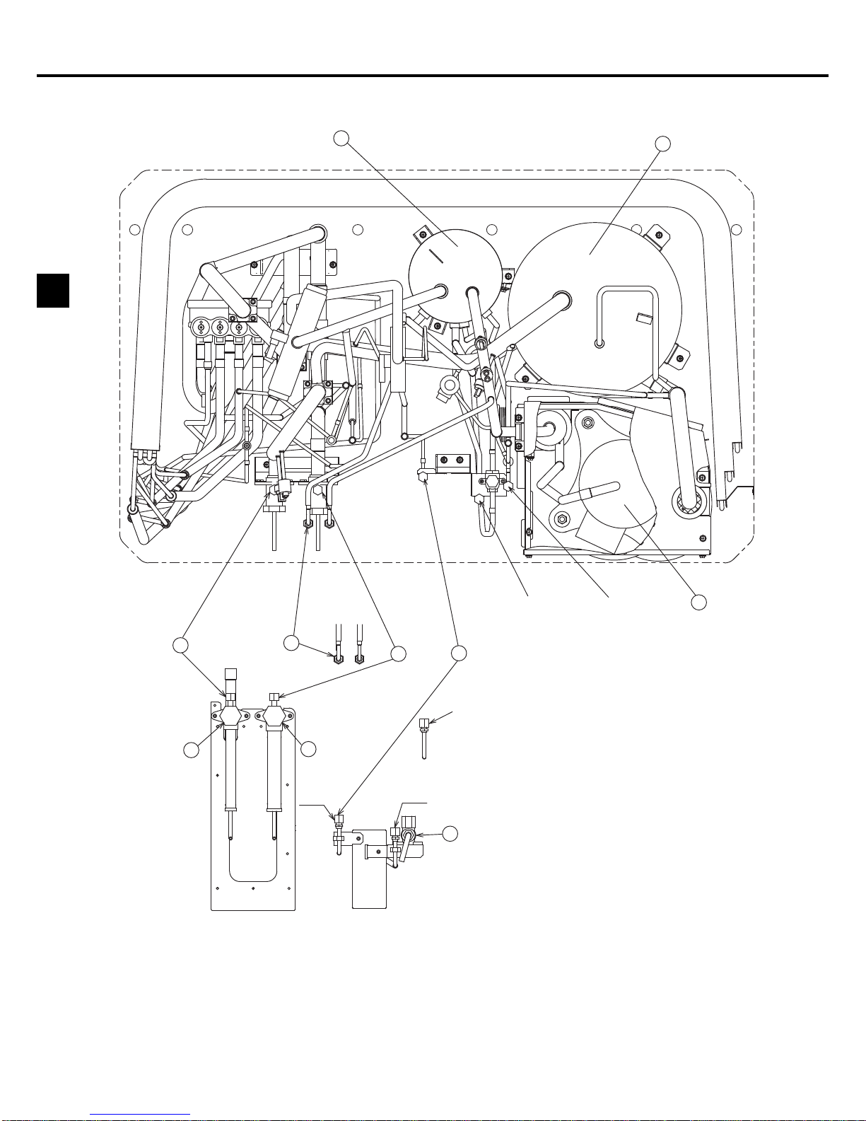
1. Unit Components
Figure 1 Top view of the refrigerant pipes inside an outdoor unit
CJ5
CJ5
CJ4
CJ2 CJ1
B
C
A
I
H
J
G
F
D
CJ4
CJ3
E
Figure 2 Valve types allocations
A: Refrigerant charge port (for automatic
charging only)
B: Check joint on the low-pressure side
A port through which additional refrigerant
is charged after the completion of
refrigerant oil recovery operation
C: Service port on the high-pressure valve
Connecting port to the refrigerant circuit
• Evacuation port (high-pressure side)
• A port through which refrigerant for the
indoor units is charged
D: Service port on the low-pressure valve
Connecting port to the refrigerant circuit
• Evacuation port (low-pressure side)
• A port through which refrigerant for the
indoor units is charged
E: A valve to be closed after the completion
of refrigerant oil recovery operation (BV3)
(Be sure to close this valve after the
completion of refrigerant oil recovery
operation.)
F: High-pressure valve
G: Low-pressure valve
H:O/T
I:ACC
J:COMP
CJ3: Refrigerant charge port
CJ4: Oil sampling port
CJ5: Refrigerant oil discharge port
3
GB
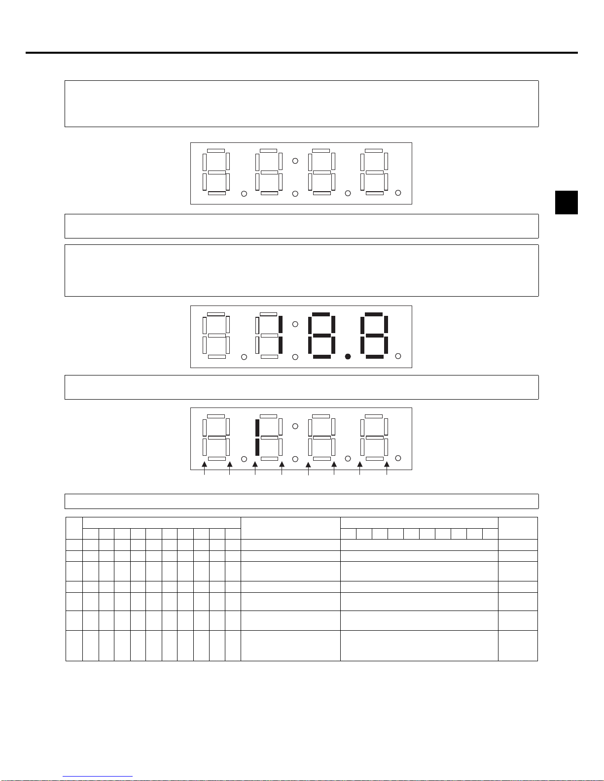
2. Refrigerant Oil Recovery Operation Flow
2.1 Refrigerant oil recovery operation monitor display
(*1) The initial remaining time that indicates the refrigerant oil recovery is 80. A countdown will start on step 3 in the cooling mode.
The countdown does not include the time for checking the refrigerant charge amount.
(*2) S-1: Refrigerant oil recovery complete, S-0: Refrigerant oil recovery incomplete,
r-1: Refrigerant charge adjustment complete, r-0: Refrigerant charge adjustment incomplete.
1. How to read the LED on the service monitor
Units' operation status can be monitored on the LED display by setting the dipswitches SW1-1 through 1-10 on the MAIN board of the
outdoor units.
Four 7-segment LEDs are used to display numerical values, flags, and alphabets to display various information.
The LEDs display such information as pressure and temperature in numerical values and operating conditions and the ON/OFF status of
solenoid valve as flags.
● Display of numerical values
Example:When the pressure sensor reads 18.8 kg/cm
2
G (Item No. 58)
* The unit of pressure is in kg/cm
2
G.
* Use the following conversion formula to convert the displayed value into a value in SI unit (MPa).
SI unit (MPa) = Displayed value (kg/cm
2
G) 0.098
● Flag display (Each set of two lines in vertical alignment indicates a flag.)
Example:Outdoor unit in the 3-minute restart delay mode. (Item No. 14)
2. Table of items that can be monitored on the LED on the outdoor unit circuit board
No
SW1
Display content
LED display
Notes
12345678910
LD1 LD2 LD3 LD4 LD5 LD6 LD7 LD8 LD9
LD10
580101110000High pressure (kgf/cm2G) -99.9 to 999.9
591101110000Low pressure (kgf/cm
2
G) -99.9 to 999.9
600011110000
Intermediate pressure
(kgf/cm
2
G)
-99.9 to 999.9
45 1 0 1 1 0 1 0 0 0 0 Discharge temperature (°C) -99.9 to 999.9
1311100000100
Refrigerant oil recovery operation
steps
rEP
steps
Reversed
display
1220101111000
Refrigerant oil recovery
remaining time
(*1)
0 to 9999
1200001111000
Refrigerant oil recovery
completion indicator flag
Refrigerant charge adjustment
completion indicator flag
S-1 (0)
r-1 (0)
(*2)
Reversed
display
7SEG LED
LD1 LD2 LD3 LD4
LD5
LD6 LD7 LD8
 Loading...