

Mitsubishi Electric PURY-P200, PURY-P400YGM-A, PURY-P450, PURY-P500, PURY-P550 Service Manual
...
Models PURY-P200, P250, P300, P350, P400YGM-A
PURY-P450, P500, P550, P600, P650YGM-A
Service Handbook
AIR CONDITIONERS CITY MULTI

Contents
1 Read Before Servicing ................................................................ 6
[1] Items to Be Checked .............................................................. 6
[2] Necessary Tools and Materials .............................................. 7
[3] Piping Materials ...................................................................... 8
[4] Storage of Piping Material ...................................................... 10
[5] Piping Machining .................................................................... 11
[6] Brazing.................................................................................... 12
[7]
Airtightness Test
...................................................................... 13
[8] Vacuuming .............................................................................. 13
[9] Vacuum Drying........................................................................ 14
[10] Changing Refrigerant.............................................................. 15
[11] Remedies to be taken in case of a refrigerant leak................ 15
[12]
Characteristics of the Conventional and the New Refrigerants
.. 16
[13] Notes on Refrigerating Machine Oil........................................ 17
2 Restrictions .................................................................................. 18
[1] Electrical Work & M-NET control............................................ 18
[2] Types of Switch Setting and Address Setting ........................ 19
[3] Examples of system connection ............................................ 21
[4] Restrictions on Refrigerant Piping Length.............................. 37
3 Components of the Outdoor Unit ................................................ 44
[1] Appearance of the Components and Refrigerant Circuit........ 44
[2] Control Box ............................................................................ 50
[3] Circuit Board .......................................................................... 52
[4] BC controller (inside the panel) .............................................. 57
[5] BC control box ........................................................................ 60
[6] BC controller board ................................................................ 60
4 Remote Controller........................................................................ 62
[1]
Functions and Specifications of MA and ME Remote Controllers
.... 62
[2] Group Setting and Interlocking Settings that are Made on
an ME Remote Controller...................................................... 63
[3]
Interlocking Setting that is Made on the MA Remote Controller
...... 66
[4] Switching to the built-in Thermo on the remote controller...... 67
5 Electrical Wiring Diagram ............................................................ 68
[1] PURY-P200, P250, P300, P350, P400YGM-A ...................... 68
[2] PURY-P450, P500, P550, P600, P650YGM-A ...................... 69
[3] CMB-P104V-G ........................................................................ 70
[4] CMB-P105, 106V-G ................................................................ 71
[5] CMB-P108, 1010V-G .............................................................. 72
[6] CMB-P1013, 1016V-G ............................................................ 73
[7] CMB-P104V-GB ...................................................................... 74
[8] CMB-P108V-GB ...................................................................... 75
[9] CMB-P108, 1010V-GA............................................................ 76
[10] CMB-P1013, 1016V-GA.......................................................... 77
6 Refrigerant Circuit ........................................................................ 78
[1] Refrigerant Circuit Diagram .................................................... 78
[2] Functions of Principal Parts.................................................... 82
[3] BC controller .......................................................................... 84
7 Control.......................................................................................... 86
[1] Dip Switch Functions and Their Factory Settings .................. 86
[2] Controlling the Outdoor Unit .................................................. 91
[3] Operation Flow Chart ............................................................ 102

8 Test Run ...................................................................................... 108
[1] Check Items before Test Run.................................................. 108
[2] Test Run Method .................................................................... 108
[3] Operating Characteristics and Refrigerant Amount................ 109
[4] Adjustment and Judgment of Refrigerant Amount ................ 109
[5] Refrigerant Volume Adjustment Mode Operation .................. 111
[6] Symptoms that do not Signify Problems ................................ 113
[7]
Standard Operation Data (Reference Data)
.............................. 114
9 Troubleshooting ............................................................................ 122
[1] Check Code List .................................................................... 122
[2] Responding to Error Display on the Remote Controller ........ 125
[3] Investigation of Transmission Wave Shape/Noise .................. 159
[4] Troubleshooting of Principal Parts .......................................... 162
[5] Refrigerant Leak .................................................................... 189
[6]
Compressor Replacement Instructions (only P450-P650 types)
.... 191
[7]
Collecting the Cooling Liquid from the Accumulator (Only P450-P650 types)
.. 192
[8] BC controller service instruction ............................................ 193
0 LED display.................................................................................. 196
[1] LED Monitor Display .............................................................. 196
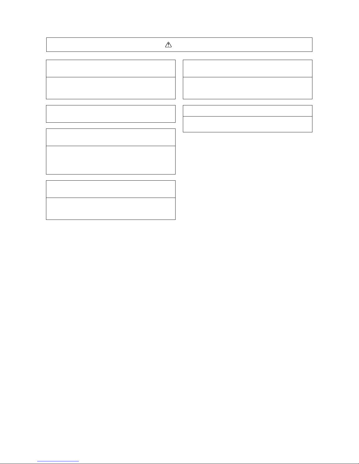
Safety Precautions
Symbols used in the text
Warning:
Failure to follow all instructions may result in serious personal injury or death.
Caution:
Failure to follow all instructions may result in personal injury or damage to the unit.
Symbols used in the illustrations
: Indicates an action that must be avoided.
: Indicates that important instructions must be followed.
: Indicates a part which must be grounded.
: Beware of electric shock (This symbol is displayed on the main unit label.) <Color : Yellow>
Warning : Carefully read the labels affixed to the main unit.
Before installing the unit, be sure to carefully read all of the following safety precautions.
These precautions provide important information regarding safety. Be sure to follow them to ensure safety.
After reading this handbook, hand it over to those who will be using the unit.
The user of the unit should keep this manual at hand and make it available to those who will be performing
repairs or relocating the unit.
Also, make it available to the new user when the user changes hands.
Be sure to carefully follow each step in this
handbook when installing the unit.
• Improper installation may result in water leak,
electric shock, smoke or fire.
Securely attach the terminal cover (panel) on the
unit.
• If installed improperly, dust and/or water may enter
the unit and present a risk of electric shock, smoke,
or fire.
Only use Refrigerant R410A as indicated on the
unit when installing or relocating the unit.
• The use of any other refrigerant or an introduction of
air into the unit circuit may cause the unit to run an
abnormal cycle and cause the unit to burst.
Do not make any changes or modifications to the
unit. In case of problems, consult the dealer.
• If repairs are not made properly, the unit may leak
water and present a risk of electric shock, or it may
produce smoke or cause fire.
Have all electrical work performed by a licensed
electrician according to the local regulations and
the instructions given in this manual. Secure a
circuit designated exclusively to the unit.
• Improper installation or a lack of circuit capacity may
cause the unit to malfunction or present a risk of
electric shock, smoke, and fire.
Have the unit professionally installed.
• Improper installation by an unqualified person may
result in water leak, electric shock, or fire.
Only use specified cables for wiring. Securely
connect each cable, and make sure that the cables
are not straining the terminals.
• Cables not connected securely and properly may
generate heat and cause fire.
Place the unit on a stable, level surface that
withstands the weight of the unit to prevent the
unit from tipping over or falling causing injury as a
result.
Take necessary safety measures against typhoons
and earthquakes to prevent the unit from falling
over.
- 1 -
When relocating the air conditioner, consult the
dealer or a specialist.
• Improper installation may result in water leak,
electric shock, or fire.
• Consult the dealer for necessary measures to take.
After completing the service work, check for a
refrigerant gas leak.
• If leaked gas refrigerant is exposed to a heart
source such as fan heater, stove, and electric grill,
noxious gases may form.
In the event of a refrigerant gas leak, provide
adequate ventilation to the room.
• If leaked refrigerant gas is exposed to a heat source,
noxious gases may form.
With All-Fresh type air conditioners, outdoor air
may be directly blown into the room upon thermo
off. Take this into consideration when installing the
unit.
• Direct exposure to outdoor air may present a health
hazard, and it may also cause food items to
deteriorate.
When installing the unit in a small room, safeguard
against hypoxia that results from leaked refrigerant
reaching the threshold level.
Do not touch the fins on the heat exchanger with
bare hands: they are sharp and dangerous.
Precautions for Handling Units for Use with R410A
Caution
Warning : Carefully read the labels affixed to the main unit.
Do not try to defeat the safety features of the
devices, and do not change the settings.
• Defeating the safety features on the unit such as the
pressure switch and temperature switch or using
parts other than those specified by Mitsubishi
Electric may result in fire or explosion.
Use refrigerant pipes made of C1220 phosphorus
deoxidized copper categorized under H3000
(Copper and Copper Alloy Seamless Pipes and
Tubes), a standard set by JIS. Keep the inner and
outer surfaces of the pipes clean and free of
contaminants such as sulfur, oxides, dust/dirt,
shaving particles, oils, and moisture.
• Contaminants inside the refrigerant piping will cause
the refrigerant oil to deteriorate.
Do not use the following tools that have been used
with the conventional refrigerants.Prepare tools
that are for exclusive use with R410A.
(Gauge manifold, charging hose, gas leak detector,
reverse-flow check valve, refrigerant charge base,
vacuum gauge, and refrigerant recovery
equipment.)
• If refrigerant and /or refrigerant oil left on these tools
are mixed in with R410A, or if water is mixed with
R410A, it will cause the refrigerant to deteriorate.
• Since R410A does not contain chlorine, gas-leak
detectors for conventional refrigerators will not work.
Only use specified parts.
• Have the unit professionally installed.
Improper installation may cause water leak, electric
shock, smoke, or fire.
Use a vacuum pump with a reverse-flow-check
valve.
• If other types of valves are used, the vacuum pump
oil will flow back into the refrigerant cycle and cause
the refrigerator oil to deteriorate.
Do not use the existing refrigerant piping
• The old refrigerant and refrigerator oil in the existing
piping contain a large amount of chlorine, which will
cause the refrigerator oil in the new unit to
deteriorate.
• R410A is a high-pressure refrigerant, and the use of
the existing piping may result in bursting.
- 2 -
Before Installing the Unit
Warning
Caution
Store the piping to be used during installation
indoors, and keep both ends of the piping sealed
until immediately before brazing. (Keep elbows and
other joints wrapped in plastic.)
• If dust, dirt, or water enters the refrigerant cycle, it
may cause the oil in the unit to deteriorate or may
cause the compressor to malfunction.
Use a small amount of ester oil, ether oil, or
alkylbenzene to coat flares and flange connections.
• A large amount of mineral oil will cause the
refrigerating machine oil to deteriorate.
Do not use a charging cylinder.
• The use of charging cylinder will change the
composition of the refrigerant and lead to power
loss.
Exercise special care when handling the tools.
• An introduction of foreign objects such as dust, dirt,
or water into the refrigerant cycle will cause the
refrigerating machine oil to deteriorate.
Only use R410A refrigerant.
• The use of refrigerants containing chlorine (i.e. R22)
will cause the refrigerant to deteriorate.
Use liquid refrigerant to charge the system.
• Charging the unit with gas refrigerant will cause the
refrigerant in the cylinder to change its composition
and will lead to a drop in performance.
Do not install the unit in a place where there is a
possibility of flammable gas leak.
• Leaked gas accumulated around the unit may start a
fire.
Do not use the unit to preserve food, animals,
plants, artifacts, or for other special purposes.
• The unit is not designed to provide adequate
conditions to preserve the quality of these items.
When installing the unit in a hospital, take
necessary measures against noise.
• High-frequency medical equipment may interfere
with the normal operation of the air conditioning unit
or the air conditioning unit may interfere with the
normal operation of the medical equipment.
Do not use the unit in an unusual environment.
• The use of the unit in the presence of a large
amount of oil, steam, acid, alkaline solvents, or
special types of sprays may lead to a remarkable
drop in performance and/or malfunction and
presents a risk of electric shock, smoke, or fire.
• The presence of organic solvents, corroded gas
(such as ammonia, sulfur compounds, and acid)
may cause gas or water leak.
Do not place the unit on or over things that may
not get wet.
• When humidity level exceeds 80% or when the
drainage system is clogged, indoor units may drip
water.
• Installation of a centralized drainage system for the
outdoor unit may also need to be considered to
prevent water drips from the outdoor units.
- 3 -
Before Installing (Relocating) the Unit or Performing Electric Work
Caution
Do not spray water on the air conditioners or
immerse the air conditioners in water.
• Water on the unit presents a risk of electric shock.
Install a breaker for current leakage at the power
source to avoid the risk of electric shock.
• Without a breaker for current leakage, there is a risk
of electric shock, smoke, or fire.
Use wires that are specified in the installation
manual.
• The use of other types of wires presents a risk of
electrical current leak, electric shock, smoke, or fire.
Periodically check the platform on which the unit is
placed for damage to prevent the unit from falling.
• If the unit is left on a damaged platform, it may
topple over, causing injury.
Ground the unit.
• Do not connect the grounding on the unit to gas
pipes, water pipes, lightning rods, or the grounding
terminals of telephones. Improper grounding
presents a risk of electric shock, smoke, fire, or the
noise caused by improper grounding may cause the
unit to malfunction.
Use breakers and fuses (electrical current breaker,
remote switch <switch + Type-B fuse>, molded
case circuit breaker) with a proper current
capacity.
• The use of large-capacity fuses, steel wire, or
copper wire may damage the unit or cause smoke or
fire.
When installing draining pipes, follow the
instructions in the manual, and make sure that they
properly drain water so as to avoid dew
condensation.
• If not installed properly, they may cause water leaks
and damage the furnishings.
Make sure the wires are not subject to tension.
• If the wires are too taut, they may break or generate
heat and/or smoke and cause fire.
Exercise caution when transporting products.
• Do not try to move equipments over 20kg (approx.
44 lbs.) alone.
• Do not use the PP bands used on some packages
for transportation.
• Wear protective gloves to avoid injury caused by
touching the fins on the heat exchanger with bare
hands.
• When using a suspension bolt to transport the heatsource unit, use a four-point suspension. A threepoint suspension does not provide adequate stability
and presents a risk of accidents.
Properly dispose of the packing materials.
• Things such as nails and wood pieces may be
included in the package. Dispose of them properly to
prevent injury.
• Plastic bags present a choking hazard to children.
Tear up the plastic bags before disposing of them to
prevent accidents.
- 4 -
Before the Test Run
Caution
Turn on the unit at least 12 hours before the test
run.
• Keep the unit on throughout the season.
Turning the unit off during the season may cause
problems.
Do not turn off the power immediately after
stopping the unit.
• Allow for at least five minutes before turning off the
unit; otherwise, the unit may leak water or
experience other problems.
Do not operate the unit without panels and safety
guards in their proper places.
• They are there to keep the users from injury from
accidentally touching rotating, high-temperature, or
high-voltage parts.
Do not touch the refrigerant pipes with bare hands
during and immediately after operation.
• Depending on the state of the refrigerant in the
system, certain parts of the unit such as the pipes
and compressor may become very cold or hot and
may subject the person to frost bites or burning.
Do not operate switches with wet hands to avoid
electric shock.
Do not operate the unit without air filters.
• Dust particles in the air may clog the system and
cause malfunction.
- 5 -

- 6 -
¡¡
Read Before Servicing
[1] Items to Be Checked
1. Verify the type of refrigerant used by the unit to be serviced.
Refrigerant Type : R410A
2. Check the symptom exhibited by the unit to be serviced.
Look in this service handbook for symptoms relating to the refrigerant cycle.
3. Be sure to carefully read the Safety Precautions at the beginning of this document.
4. Prepare necessary tools: Prepare tools exclusive for use with each refrigerant type.
Refer to P7 for more information.
5. If the refrigerant circuit is opened (to repair a gas leak etc.), the dryer needs to be replaced.
Only use the dryer designed specifically for Citi Multi YGM-A. The use of other dryers may result in malfunctions.
✻ Replace the dryer after completing all the repairs on the refrigerant circuit.
(If left exposed to air, the dryer will absorb moisture. Replace the dryer as quickly as possible after removing
the old one.)
✻ When all of the following conditions are met, the replacement of drier is not necessary.
(1) Do not leave the refrigerant circuit longer than 2 hours.
(2) Cover the opening end with a cap or tape to keep moisture from entering.
(3) Also cover the opening end of the new part with a cap or tape
(4) Do not perform the task in the rain.
(5) Evacuate the refrigerant circuit as specified.
6. Verification of the connecting pipes: Verify the type of refrigerant used for the unit to be
moved or replaced.
• Use pipes made of phosphorus deoxidized copper. Keep the inner and outer surfaces of the pipes clean and
free of contaminants such as sulfur, oxides, dust/dirt, shaving particles, oils, and moisture.
• Contaminants inside the refrigerant piping will cause the refrigerant oil to deteriorate.
7. If there is a gas leak or if the remaining refrigerant is exposed to an open flame, a noxious gas
hydrofluoric acid may form. Keep workplace well ventilated.
CAUTION
1. Install new pipes immediately after removing old ones to keep moisture out of the refrigerant circuit.
2. Chloride in some types of refrigerants such as R22 will cause the refrigerating machine oil to
deteriorate.
- 7 -
[2] Necessary Tools and Materials
Prepare the following tools and materials necessary for installing and servicing the unit.
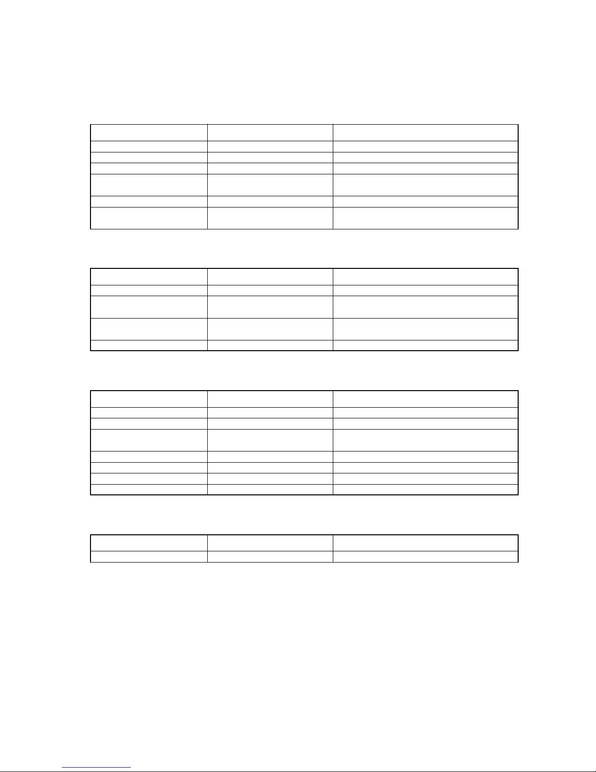
[Necessary tools for use with R410A (Adaptability of tools that are for use with R22 and R407C)]
1. To be used exclusively with R410A (not to be used if used with R22 or R407C)
Tools/Materials NotesUse
Gauge Manifold
Charging Hose
Refrigerant Recovery Equipment
Refrigerant Cylinder
Refrigerant Cylinder Charging Port
Flare Nut
Evacuating, refrigerant charging
Evacuating, refrigerant charging
Refrigerant recovery
Refrigerant charging
Refrigerant charging
Connecting the unit to piping
5.09MPa on the High-pressure side.
Hose diameter larger than the conventional ones.
Write down the refrigerant type.
Pink in color at the top of the cylinder.
Hose diameter larger than the conventional ones.
Use Type-2 Flare nuts.
(That are in compliance with JIS B 8607).
2. Tools and materials that may be used with R410A with some restrictions
Tools/Materials NotesUse
Gas leak detector
Vacuum Pump
Flare Tool
Refrigerant Recovery Equipment
Detection of gas leaks
Vacuum drying
Flare machining of piping
Recovery of refrigerant
The ones for HFC type refrigerant may be used.
May be used if a reverse flow check adaptor is
attached.
Changes have been made in the flare machining
dimension. Refer to the next page.
May be used if designed for use with R410A.
3. Tools and materials that are used with R22 or R407C that can also be used with R410A
Tools/Materials NotesUse
Vacuum Pump with a Check valve
Bender
Torque Wrench
Pipe Cutter
Welder and Nitrogen Cylinder
Refrigerant Charging Meter
Vacuum Gauze
Vacuum drying
Bending pipes
Tightening flare nuts
Cutting pipes
Welding pipes
Refrigerant charging
Checking vacuum degree
Only ø 12.70 (1/2”) and ø 15.88 (5/8”) have a
larger flare machining dimension.
4. Tools and materials that must not be used with R410A
Tools/Materials NotesUse
Charging Cylinder Refrigerant Charging Must not be used with R410A-type units.
Tools for R410A must be handled with special care; keep moisture and dust from entering the
cycle.
Type-O pipes Soft copper pipes (annealed copper pipes)
They can be bent easily with hands.
Type-1/2H pipes Hard copper pipes (straight pipes)
Stronger than type-O pipes of the same radial thickness.
- 8 -
[3] Piping Materials
NOOK
New Piping Existing Piping
Do not use the existing piping!
<Types of copper pipe>
• The distinction between type-O and type-1/2H pipes is made based on the strength of the pipes themselves.
• Type-O pipes are soft and can easily be bent with hands.
• Type-1/2H pipes are considerably stronger than type-O pipes of the same radial thickness.
Use pipes made of phosphorus deoxidized copper.
Since the operation pressure of the units that use R401A is higher than that of the units for use with R22, use
pipes with at least the radial thickness specified in the chart below.
(Pipes with a radial thickness of 0.7 mm or less may not be used.)
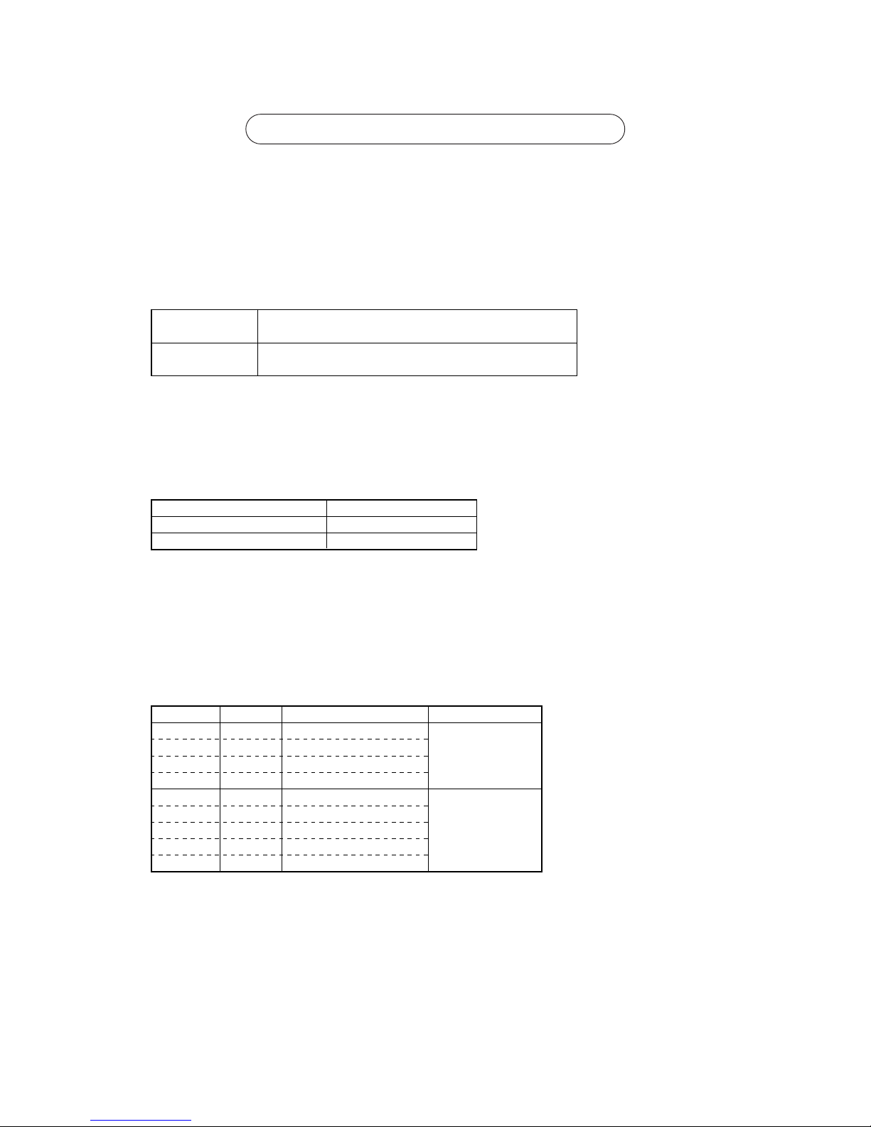
Maximum Operation Pressure Applicable Refrigerants
3.45 MPa
4.30 MPa
R22, R407C etc.
R410A
<Types of Copper Pipes (Reference)>
✻ Use pipes that meet the local standards.
Type-O pipes
Type-1/2H or
H pipes
Size(mm) Size(inch) Radial Thickness(mm) Type
ø 6.35
ø 9.52
ø 12.7
ø 15.88
ø 19.05
ø 22.2
ø 25.4
ø 28.58
ø 31.75
1/4”
3/8”
1/2”
5/8”
3/4”
7/8”
1”
1 1/8”
1 1/4”
0.8t
0.8t
0.8t
1.0t
1.0t
1.0t
1.0t
1.0t
1.1t
<Piping Materials/Radial Thickness>
✻ Although it was possible to use type-O for pipes with a size of up to ø19.05 (3/4”) with conventional refriger-
ants, use type-1/2H pipes for units that use R410A. (Type-O pipes may be used if the pipe size is
ø19.05 and
the radial thickness is 1.2t.)
✻ The table shows the standards in Japan. Using this table as a reference, choose pipes that meet the local
standards.
- 9 -
“Radial thickness” and “Refrigerant Types” are indicated on the insulation material on the piping materials for the
new refrigerant.
Indication of the radial thickness (mm) Indication of the refrigerant type
Radial thickness Symbols
0.8
1.0
08
10
Refrigerant type Symbol
Type1 R22, R407C
Type2 R410A
1
2
<Example of the symbols indicated on the insulation material>
The type of piping materials can also be found on the package.
<Example of a label found on the package>
~08-2~
Appears every 1 m
2 : common to type 1 and type 2
Refrigerant Type : R22,R407C,R410A
Bore diameter and radial thickness of the copper piping : 9.52✕0.8, 15.88✕1.0
<Indication of the radial thickness and refrigerant type on the piping materials>
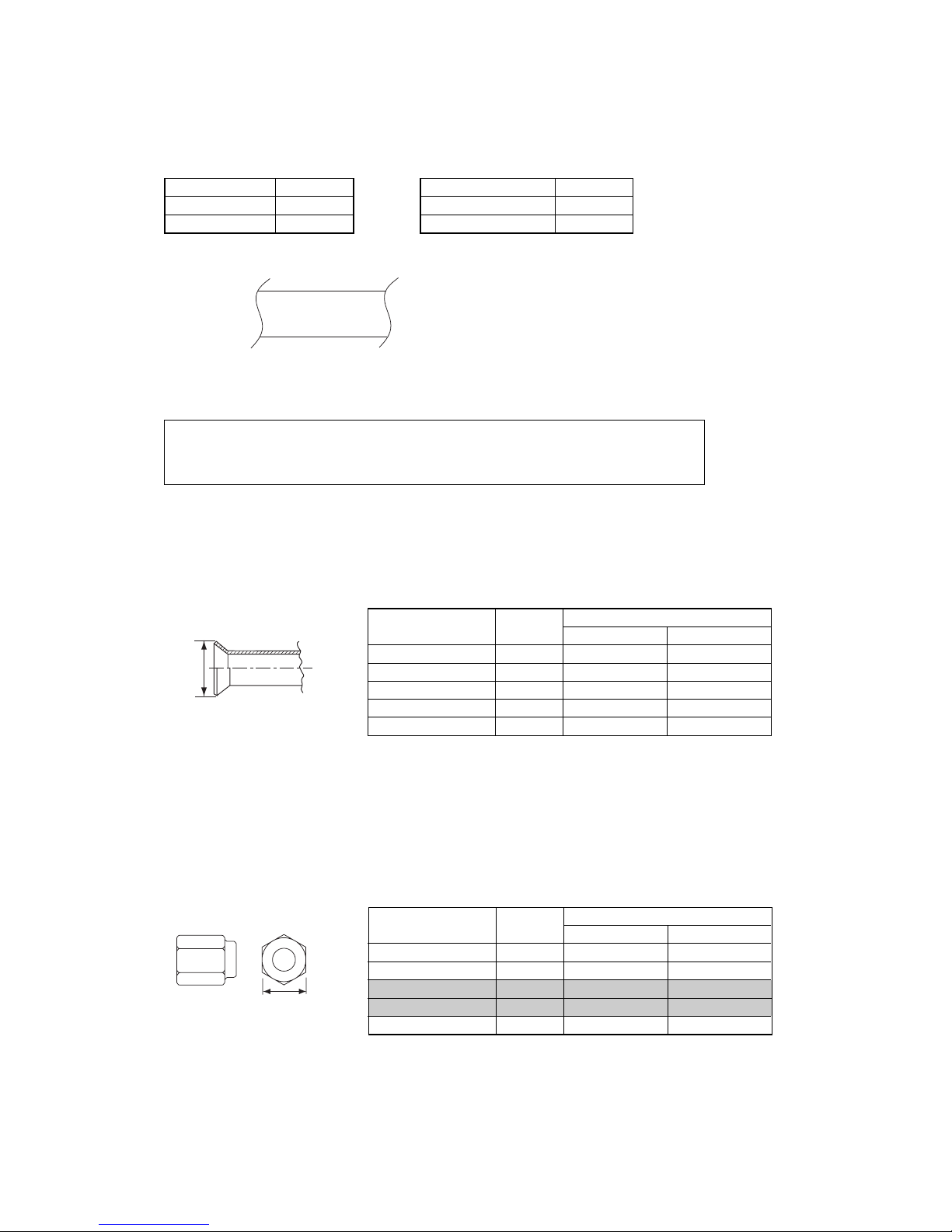
The flare machining dimensions for units that use R410A is larger than those for units that use R22 in order to
increase air tightness.
If a clutch type flare tool is used to machine flares on units that use R410A, make the protruding part of the
pipe between 1.0 and 1.5mm. Copper pipe gauge for adjusting the length of pipe protrusion is useful.
Flare Machining Dimension(mm)
External dimension
of pipes
Size
Dimension A
R410A
ø 6.35
ø 9.52
ø 12.7
ø 15.88
ø 19.05
1/4”
3/8”
1/2”
5/8”
3/4”
9.1
13.2
16.6
19.7
24.0
R22
9.0
13.0
16.2
19.4
23.3
Dimension A
<Flare Machining (type-O and OL only)>
Type-2 flare nuts instead of type-1 s are used to increase the strength. The size of some of the flare nuts have
also been changed.
Flare nut dimension(mm)
External dimension
of pipes
Size
Dimension B
R410A(Type2)
ø 6.35
ø 9.52
ø 12.7
ø 15.88
ø 19.05
1/4”
3/8”
1/2”
5/8”
3/4”
17.0
22.0
26.0
29.0
36.0
R22(Type1)
17.0
22.0
24.0
27.0
36.0
Dimension B
<Flare Nut>
✻ The table shows the standards in Japan. Using this table as a reference, choose pipes that meet the local
standards.
Store the pipes to be used indoors. (Warehouse at site or owner’s warehouse)
Storing them outdoors may cause dirt, waste, or water to infiltrate.
Both ends of the pipes should be sealed until immediately before brazing.
Wrap elbows and T’s in plastic bags for storage.
✻
The new refrigerator oil is 10 times more hygroscopic than the conventional refrigerator oil (such as Suniso). Water
infiltration in the refrigerant circuit may deteriorate the oil or cause a compressor failure. Piping materials must be
stored with more care than with the conventional refrigerant pipes.
OK
OK
NO
NO
- 10 -
[4] Storage of Piping Material
1. Storage location
2. Pipe sealing before storage

Use ester oil, ether oil or alkylbenzene (small amount) as the refrigerator oil to coat flares and flange connections.
Reason :
1. The refrigerator oil used for the equipment is highly hygroscopic and may introduce water inside.
Notes :
• Introducing a great quantity of mineral oil into the refrigerant circuit may also cause a compressor failure.
• Do not use oils other than ester oil, ether oil or alkylbenzene.
- 11 -
[5] Piping Machining
No changes from the conventional method, but special care is required so that foreign matter (ie. oxide scale, water, dirt,
etc.) does not enter the refrigerant circuit.
Example : Inner state of brazed section
When non-oxide brazing was not used When non-oxide brazing was used
Items to be strictly observed :
1. Do not conduct refrigerant piping work outdoors on a rainy day.
2. Apply non-oxide brazing.
3. Use a brazing material (BCuP-3) which requires no flux when brazing between copper pipes or between a copper pipe
and copper coupling.
4. If installed refrigerant pipes are not immediately connected to the equipment, then braze and seal both ends of them.
Reasons :
1. The new refrigerant oil is 10 times more hygroscopic than the conventional oil. The probability of a machine failure if
water infiltrates is higher than with conventional refrigerant oil.
2. A flux generally contains chlorine. A residual flux in the refrigerant circuit may generate sludge.
Note :
• Commercially available antioxidants may have adverse effects on the equipment due to its residue, etc. When
applying non-oxide brazing, use nitrogen.
- 12 -
[6] Brazing
No changes from the conventional method. Note that a refrigerant leakage detector for R22 or R407C cannot detect
R410A leakage.
Halide torch R22 or R407C leakage detector
Items to be strictly observed :
1. Pressurize the equipment with nitrogen up to the design pressure and then judge the equipment’s airtightness, taking
temperature variations into account.
2. When investigating leakage locations using a refrigerant, be sure to use R410A.
3. Ensure that R410A is in a liquid state when charging.
Reasons :
1. Use of oxygen as the pressurized gas may cause an explosion.
2. Charging with R410A gas will lead the composition of the remaining refrigerant in the cylinder to change and this
refrigerant can then not be used.
Note :
• A leakage detector for R410A is sold commercially and it should be purchased.
1. Vacuum pump with check valve
A vacuum pump with a check valve is required to prevent the vacuum pump oil from flowing back into the refrigerant
circuit when the vacuum pump power is turned off (power failure).
It is also possible to attach a check valve to the actual vacuum pump afterwards.
2. Standard degree of vacuum for the vacuum pump
Use a pump which reaches 65Pa or below after 5 minutes of operation.
In addition, be sure to use a vacuum pump that has been properly maintained and oiled using the specified oil. If the
vacuum pump is not properly maintained, the degree of vacuum may be too low.
3. Required accuracy of the vacuum gauge
Use a vacuum gauge that can measure up to 650Pa. Do not use a general gauge manifold since it cannot measure a
vacuum of 650Pa.
4. Evacuating time
• Evacuate the equipment for 1 hour after 650Pa has been reached.
• After envacuating, leave the equipment for 1 hour and make sure the that vacuum is not lost.
5. Operating procedure when the vacuum pump is stopped
In order to prevent a backflow of the vacuum pump oil, open the relief valve on the vacuum pump side or loosen the
charge hose to drawn in air before stopping operation.
The same operating procedure should be used when using a vacuum pump with a check valve.
NO
NO
- 13 -
[7] Airtightness Test
[8] Vacuuming
Recommended vacuum gauge : ROBINAIR 14010 Thermistor Vacuum Gauge
1. Vacuum pump with reverse-flow check valve (Photo 1)
To prevent vacuum pump oil from flowing back into the refrigerant circuit upon turning off the vacuum pump’s power
source, use a vacuum pump equipped with a reverse flow check valve.
A check valve may also be added to the vacuum pump currently in use.
2. Standard of vacuum degree (Photos 1 and 2)
Use a vacuum pump that shows a vacuum degree of 65Pa or less after 5 minutes of operation. Use a pump wellmaintained with an appropriate lubricant.
3. Required precision of vacuum gauge
Use a vacuum gauge that registers a vacuum degree of 650Pa and measures at intervals of 130Pa. (A recommended
vacuum gauge is shown in Photo 2.)
Do not use a vacuum gauge that does not register a vacuum degree of 650Pa.
4. Evacuation time
• After the vacuum gauge has registered the vacuum degree of 650Pa, evacuate for 1 hour. (A thorough vacuum drying
removes moisture in the pipes.)
• Verify that the vacuum degree has not risen by more than 130Pa 1 hour after evacuation. A rise by less than 130Pa is
acceptable.
• If it has exceeded by more than 130Pa, conduct vacuuming following the instructions in the “6. Special vacuum drying”
section.
5. Procedures for stopping vacuum pump
To prevent the reverse flow of vacuum pump oil, open the relief valve on the vacuum pump side, or draw in air by
loosening the charge hose, and then stop the operation.
The same procedures should be followed when stopping a vacuum pump with a reverse-flow check valve.
6. Special vacuum drying
• When 650Pa or lower degree of vacuum cannot be attained after 3 hours of evacuation, it is likely that water has
penetrated the system or that there is a leak. When water infiltration is suspected, vacuum with nitrogen gas.
After breaking the vacuum, pressurize the system with nitrogen gas to a degree of 0.05MPa, and conduct an evacuation
again. Repeat it until 650Pa or lower degree of vacuum is attained or the vacuum pressure rise will be lost.
• Only use nitrogen gas for vacuum breaking. (Use of oxygen may cause an explosion.)
Photo 1 15010H Photo 2 14010
- 14 -
[9] Vacuum Drying
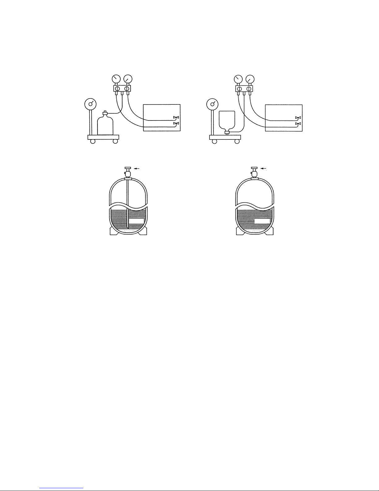
R410A must be in a liquid state when charging.
For a cylinder with a syphon attached For a cylinder without a syphon attached
Cylinder color identification R407C-Gray Charged with liquid refrigerant
R410A-Pink
Reasons :
1.
Note :
• In the case of a cylinder with a syphon, liquid R410A is charged without turning the cylinder up side down. Check the
type of cylinder before charging.
Cylin-
der
Cylin-
der
Valve
Val ve
Liquid
Liquid
R410A is a pseudo-azeotropic refrigerant (boiling point R32 = -52˚C, R125 = -49˚C) and can roughly be handled
in the same way as R22; however, be sure to fill the refrigerant from the liquid side, for doing so from the gas
side will somewhat change the composition of the refrigerant in the cylinder.
When refrigerant leaks, additional refrigerant may be charged. (Add the refrigerant from the liquid side.)
✻Refer to 9-[5].
- 15 -
[10] Changing Refrigerant
[11] Remedies to be taken in case of a refrigerant leak
Composition (wt%)
Type of refrigerant
Chloride
Safety Class
Molecular Weight
Boiling Point
Steam Pressure (25
˚C,MPa)(gauge)
Saturated Steam Density (25
˚C,kg/m3)
Flammability
Ozone Depletion Coefficient (ODP)✻1
Global Warming Coefficient (GWP)✻2
Refrigerant charging method
Addition of refrigerant in case of a leak
R410A
R32/R125
(50/50)
Simulated azeotropic
refrigerant
Not contained
A1/A1
72.6
-51.4
1.557
64.0
Non-flammable
0
1730
Liquid charging
Possible
R407C
R32/R125/R134a
(23/25/52)
Non-azeotropic
refrigerant
Not contained
A1/A1
86.2
-43.6
0.9177
42.5
Non-flammable
0
1530
Liquid charging
Possible
New Refrigerant
(HFC system)
Conventional Refrigerant
(HCFC system)
R22
R22
(100)
Single refrigerant
Contained
A1
86.5
-40.8
0.94
44.4
Non-flammable
0.055
1700
Gas charging
Possible
✻1: When CFC11 is used as a reference ✻2: When CO
2 is used as a reference
- 16 -
[12] Characteristics of the Conventional and the New Refrigerants
1. Chemical property
As with R22, the new refrigerant (R410A) is low in toxicity and a chemically stable non-flammable refrigerant.
However, because the specific gravity of steam is greater than that of air, leaked refrigerant in a closed room will
accumulate at the bottom of the room and may cause hypoxia. Also, leaked refrigerant exposed directly to an
open flame will generate noxious gasses. Use the unit in a well-ventilated room.
R410A
MPa
0.30
0.70
1.34
2.31
3.73
4.17
-20
0
20
40
60
65
R407C
MPa
0.18
0.47
0.94
1.44
2.44
2.75
R22
MPa
0.14
0.40
0.81
1.44
2.33
2.60
Pressure (gauge)
Temperature (
˚C)
3. Pressure Characteristics
The pressure in the units that use R410A is 1.6 times as great as that in the units that use R22.
2. Refrigerant Composition
Because R410A is a simulated azeotropic refrigerant, it can be handled in almost the same manner as a single
refrigerant such as R22. However, if the refrigerant is removed in the vapor phase, the composition of the refriger
ant in the cylinder will somewhat change.
Remove the refrigerant in the liquid phase. Additional refrigerant may be added in case of a refrigerant leak.
- 17 -
Refrigerant Refrigerating machine oil
R22
R407C
R410A
Mineral oil
Ester oil
Ester oil
[13] Notes on Refrigerating Machine Oil
1. Refrigerating Machine Oil in the HFC Refrigerant System
HFC type refrigerants use a refrigerating machine oil different from that used in the R22 refrigerant system.
Please note that the ester oil sealed in the unit is not the same as commercially available ester oil.
Cause Symptom
Clogged expansion valve and capillary
Poor cooling performance
Compressor overheat
Poor motor insulation
Motor burning
Coppering of the orbiting part
Locking
Burning in the orbiting part
Expansion valve/capillary
Poor cooling performance
Drier clogging
Compressor overheat
Burning in the orbiting part
Expansion valve and capillary clogging
Poor cooling performance
Compressor overheat
Burning in the orbiting part
Effects on the refrigeration cycle
Sludge formation
Generation of acid
Oxidization
Oil degradation
Water infiltration
Air infiltration
Infiltration
of
contaminants
Dust, dirt
Mineral oil
etc.
Expansion valve and capillary freeze
Hydrolysis
Oxidization
Adhesion to expansion valve and capillary
Infiltration of contaminants into the compressor
Sludge formation and adhesion
Oil degradation
2. Effects of the ✻Contaminants in the System
Refrigerating machine oil used in the HFC system must be handled more carefully than conventional mineral oils.
The table below shows the effects of air, moisture, and contaminants in the refrigerating machine oil on the refrigeration cycle.
✻ “ Contaminants ” is defined as moisture, air, process oil, dust/dirt, the wrong types of refrigerant and refrigerat-
ing machine oil.
<The Effects of Air, Moisture, and Contaminants in the Refrigerating Machine Oil on the Refrigeration Cycle.>
OK NO
➀ Follow ordinance of your governmental organization for technical standard related to electrical equipment, wiring
regulations, and guidance of each electric power company.
➁ Wiring for control (hereinafter referred to as transmission line) shall be (5cm or more) apart from power source wiring so
that it is not influenced by electric noise from power source wiring. (Do not insert transmission line and power source wire
in the same conduit.)
➂ Be sure to provide designated grounding work to outdoor unit.
➃ Give some allowance to wiring for electrical part box of indoor and outdoor units, because the box is sometimes removed
at the time of service work.
➄ Never connect 380~415V(220~240V )power source to terminal block of transmission line.If connected,electrical parts
will be burnt out
➅ Use 2-core shield cable for transmission line. If transmission lines of different systems are wired with the same multiple-
core cable, the resultant poor transmitting and receiving will cause erroneous operations.
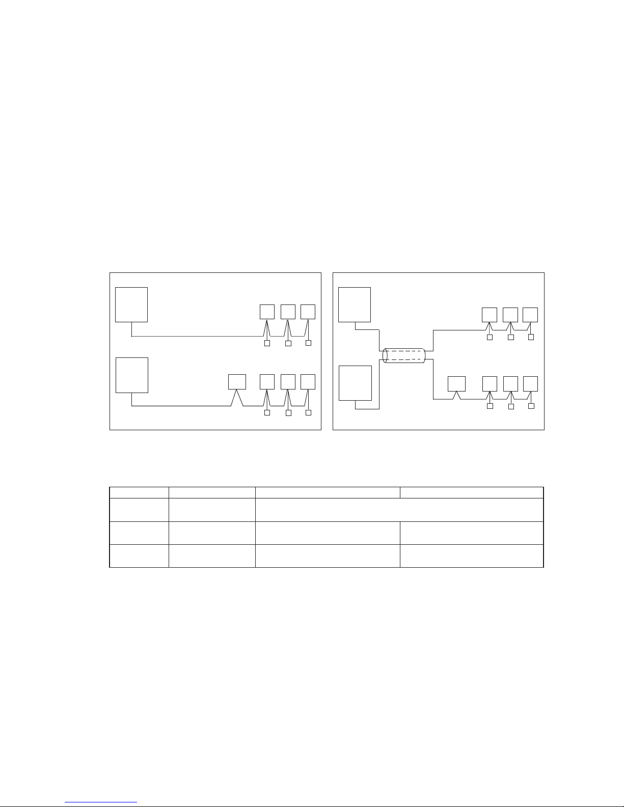
Outdoor
unit
Indoor unit
Remote
BC controller
controller
2-core cable
2-core cable
Outdoor
unit
Remote
controller
Indoor unit
Multiple-
core cable
BC controller
Type of cable
Cable diameter
Remarks
Sheathed 2-core cable (unshielded)
CVV
0.3
~ 1.25mm
2
(0.75 ~ 1.25mm2) ✻1
More than 1.25mm
2
Shielding wire (2-core)
CVVS or CPEVS
When 10m is exceeded, use cables with
the same specification as transmission cables.
0.3 ~ 1.25mm
2
(0.75 ~ 1.25mm2) ✻1
Max length : 200m
Transmission cables M-NET Remote controller cables MA Remote controller cables
CVVS : PVC insulated PVC jacketed shielded control cable
CPEVS : PE insulated PVC jacketed shielded communication cable
CVV : PV insulated PVC sheathed control cable
—
✻
1 Connected with simple remote controller.
- 18 -
™™
Restrictions
[1] Electrical Work & M-NET control
1. Attention
2. Types of control cable
00
00
101
Main
00
201
201
201
202
000
247
Address (1) setting varies depending on the system configuration. See “[3] Examples of system connection”
section for details.
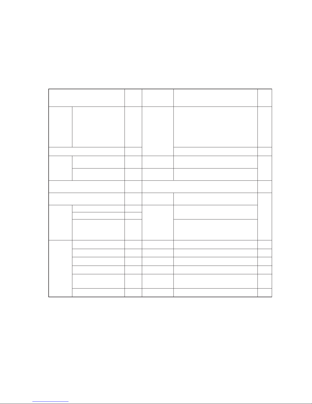
Unit or controller Symbol
Address
Setting method
setting range
Indoor unit Main/sub units IC
Lossnay LC
M-NET
remote
controller
Main remote controller RC
Sub remote controller RC
MA remote controller MA
Outdoor unit OC
System
controller
Group remote controller GR, SC
System remote controller SR, SC
ON/OFF remote controller AN, SC
ST, SCSchedule timer (for M-NET)
Centralized controller TR, SC
(Note 5)
LM adapter SC
0, 01~50
(Note 1)
101~150
151~200
(Note 2)
0, 51~100
(Note 1, 3, 4)
52~100
(Note 3, 4)
201~250
201~250
201~250
201~250
0, 201~250
201~250
Notes:
Factory
setting
Type and method of switch setting
Switch setting vary depending on the system configuration. Make sure to read “[3] Examples of system connection”
before conducting electrical work. Turn off the power before setting the switch. Operating the switch while the unit is
being powered will not change the setting, and the unit will not properly function.
1. Address setting is not required for a single refrigerant system (with a few exception).
2. When setting M-NET remote controller address to “200,” make it “00.”
3. When setting the outdoor unit and outdoor auxiliary unit address to “100,” make it “50.”
4. When an address in a system overlapped with the outdoor unit or BC controller (Main) address of other refrigerant system,
choose an another address within theset range that is not in use (with a few exceptions).
5. When controlling the K-control units;
(1) A K-transmission converter (Model name: PAC-SC25KA) is required. To set the address for the K-transmission converter,
set it to thelowest address of the K-control unit to be controlled + 200.
(2) Set the address of the system controller (G-50A) to “0.” The K-control unit can only be controlled by the system controller
with theaddress “0.”
(3) To control both K-control unit and M-NET model unit, make the address of the K-control unit larger than that of the indoor
unit of M-NET model.
Group-register on the system controller so that the group No. and the lowest address of the K-controlled indoor units
belonging to thegroup will be identical.
Use the address that equals the sum of the smallest indoor
unit address in the same refrigerant system and 50.
Use the address that equals the sum of the smallest
address of the indoor unit out of all the indoor units
that are connected to the BC controller and 50.
When a sub BC controller is connected, the automatic
start up function will not be available.
Auxiliary
units
Hex. unit
BC controller (Sub)
OS
BC
BS
Use the address that equals the sum of the address of the
outdoor unit in the same refrigerant system and 1.
BC controller (Main)
Choose any number within the range of addresses shown left.
However when using with the upper SC setting, or wishing to
control the k-control units, set to “0.”
Assign the smallest address to the indoor unit to
become the main unit within the same group, and
then use sequential numbers to assign an address
to all the indoor units in the group. (Note 5)
If applicable, set the sub BC controllers in an R2
system in the following order:
(1)
Indoor unit to be connected to the main BC controller
(2)
Indoor unit to be connected to No.1 sub BC controller
(3)
Indoor unit to be connected to No.2 sub BC controller
Set the address so that (1) < (2) < (3)
Assign any unused address after setting all indoor units.
Set to the lowest address of the indoor main unit
within the same group + 150.
Set to the lowest No. of the group to be controlled + “200.”
Set to the lowest No. of the group desired tobe controlled + “200.”
Choose any number within the range of addresses shown left.
Choose any number within the range of ad-dresses shown left.
Choose any number within the range of addresses shown left.
Set to the lowest address of the indoor main unit
within the same group + 100.
No address setting required. (When operating with 2 remote controllers,
the main/sub selector switch must be set.
- 19 -
[2] Types of Switch Setting and Address Setting
1. Switch setting
2. Address setting
- 20 -
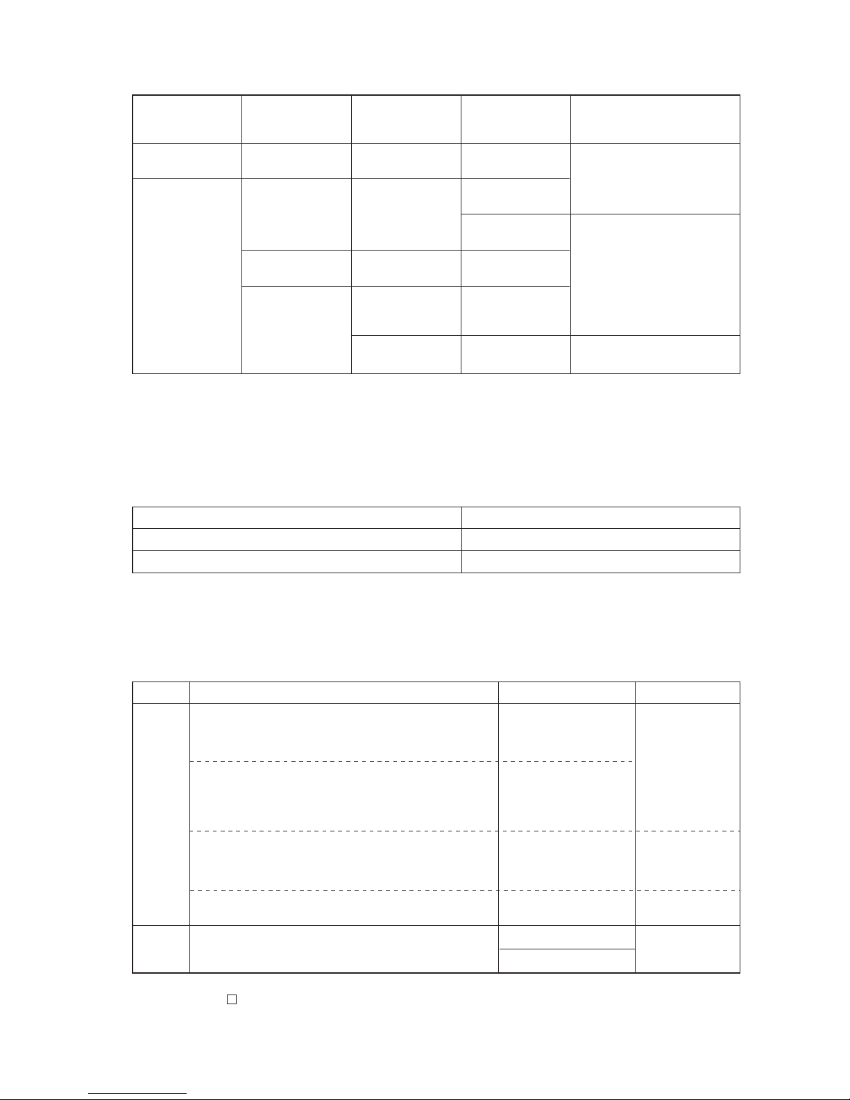
System
Configuration
Single refrigerant
system
___
_
Multiple refrigerant
system
Connection with
the system
controller
Power supply unit
for the
transmission lines
Unnecessary
Unnecessary (Note2)
(Supplied from the
outdoor unit)
Applicable
Grouping operation
of different
refrigerant systems
n/a
applicable
applicable // n/a
applicable // n/a
applicable // n/a
The setting of the power supply
selecting connector
Use CN41 as is (Factory setting)
Replace the CN41 with CN40 on
only one of the outdoor units.
✻
Connect the S terminal of the TB7
(terminal block on the outdoor
unit) on the outdoor unit whose
CN41 was replaced with CN40 to
the earth terminal of the electric
box.
Use CN41 as is (Factory setting)
n/a
Connected with the
indoor units
Connected with the
centralized system
Notes:
1. Will limit the total connectable units in the refrigerant system.
2. The need for a power supply unit for the transmission lines depends on the system configuration. Refer to “ DATA BOOK ” for
more details.
Setting the power supply selecting connector for the outdoor unit (Factory setting: CN41 is connected.)(2)
System configuration Setting of the centralized controller switch (SW 2-1)
Connection system with the system controller n/a Leave it to OFF. (Factory setting)
Connection system with the system controller applicable (Note 1) ON
Note:
1. When connecting only the LM adapter, leave SW2-1 to OFF.
Note:
1.
Refer to section “ 7 [2] 13. Demand control ” for detailed information on demand control settings.
Setting the centralized control switch on the outdoor unit (factory setting: SW2-1 OFF )(3)
Category
Output
Input
Usage
Cooling operation is disabled (thermo OFF) by the external
input to the outdoor units.
✻ Can be used as an on-demand control for each refrigerant
system.
Quiet operation of outdoor units is run with an external input to
the outdoor units.
(Night mode can be run under the following conditions: Outdoor
air temperature below 30
˚C when running a cooling operation
and above 3˚C when running a heating operation.)
Forces the outdoor units to run a fan operation by receiving the
snow signal from the snow sensor.
The operation mode can be switched between cooling and
heating with an external input to the outdoor units.
Outdoor units’ signal output
✻ Can be used as a device that displays the operation status
✻ Can run an interlocking control operation with external devices
Function
Demand (level)
Night mode or Demand
(Level) ✻
Note1
Snow sensor
Signal input (level)
You can switch the operation mode between cooling and
heating by input from the outside to the outdoor unit.
Auto-changeover
Compressor in operation
Abnormal operation status
CN3S
CN3N
CN3D
CN51
Terminal to be used
Various types of control using the connectors on the outdoor unit for input-output signal
(various types of connections with optional parts)
(4)
IC
TB5TB02TB7 TB3 TB
15
12
00
IC
TB5 TB
15
12
00
A1 B2
MA
A1 B2
MARC
TB5
00
IC
TB5
12
TB
15
IC
TB5 TB
15
12
0000
IC
TB5 TB
15
12
00
A1 B2
MA
A1 B2
MA
A1 B2
MA
MA
m1
L11
m2
L3 L4
L12 L13
m3
m5
m4
NO
NO
NO
L2L1
A1 B2
A1 B2
a. Indoor/outdoor transmission line
Farthest length (1.25mm2 or more)
L1 + L2 + L3 + L4 200m
L1 + L2 + L11 + L12 + L13 200m
b. Centralized control transmission line
No connection is required.
c. MA remote controller wiring
Total length (0.3 ~ 1.25mm2)
m1 200m
m2 + m3 200m
m4 + m5 200m
Note 1. For the connection to the terminal block of compact
remote controller, employ wire with a diameter of 0.75
~ 1.25mm
2
Control wiring example
Group
Prohibited items Allowable length
1. M-NET and MA remote controllers can not be connected together to the indoor unit within the same group.
2. MA remote controller of 3 units or more can not be connected
to the indoor unit within the same group.
3. When the total number of indoor units exceeds 26 units Including that above Type 200, a transmission booster is required.
4. In the case when start/stop input (CN32, CN51, CN41) is used
by indoor group operation, the “Automatic address set-up”
can not be employed. Please refer to 1. (2) “ Manual address
set-up.”
5. For the connection of LOSSNAY with more than 2 units in a
single refrigerant system, refer to the following “Connection
of 2 LOSSNAY units in refrigerant system.”
Interlocking with ventilation
– Example to use shielded wire –
Group
Group
Group
LC
≤
≤
≤
≤
≤
✻1BC and BS are found only in the R2 system.
When connected to the BS, indoor-outdoor automatic
address start up function will not be available.
00
OC
BC
✻
1
✻
1
00
00
TB02
BS
S
M1M2
S
M1M2
S
M1M2
S
M1M2
S
M1M2
S
M1M2
S
M1M2
S
M1M2
S
M1M2
M1M2
- 21 -
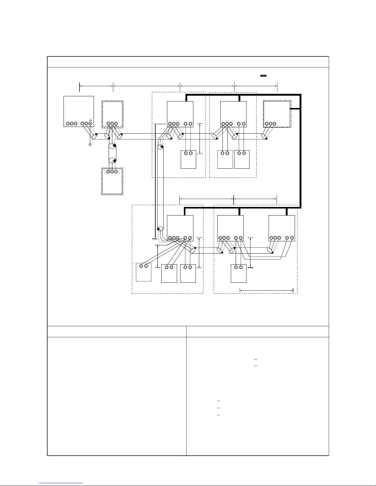
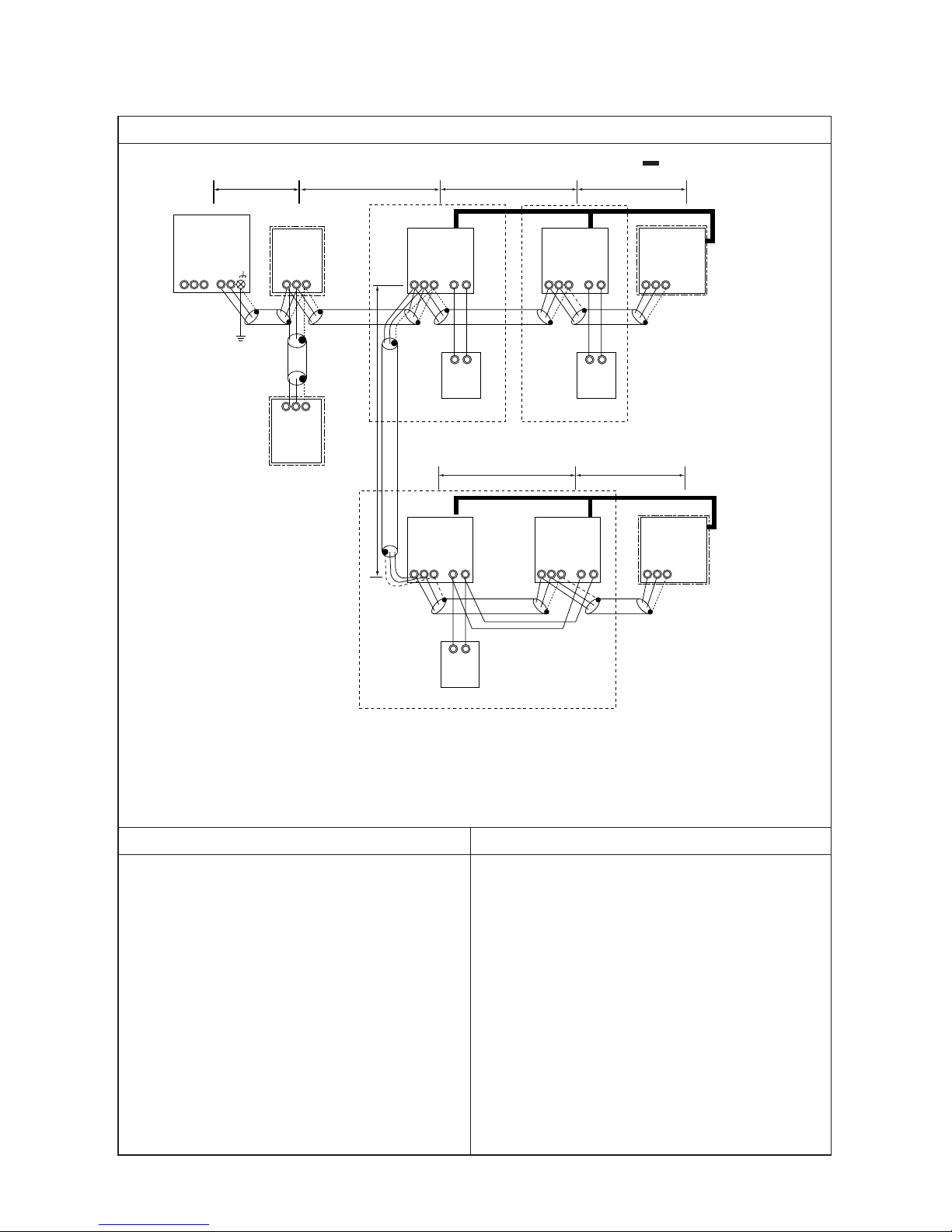
[3] Examples of system connection
1. System using MA remote controller
(1) In the case of single refrigerant system (Automatic address set-up)
Wiring method • Address setting method
a. Indoor/outdoor transmission line
❉ When the transmission line is long or noise sources are located near the unit, recommend to use shielded wire.
Connection of shielded wire:
For the earth of shielded wire, apply jumper wiring connection between the earth screw of OC and the S-terminal of
IC terminal block (TB5).
b. Centralized control transmission line
Connection is not required.
c. MA remote controller wiring
Connect the 1, 2 terminals of MA remote controller wiring terminal block (TB15) on IC to the terminal block of MA
remote controller (MA). (with non-polarity two wires)
❉ MA remote controller can be connected to A-type indoor unit or later.
For 2-remote controller operation:
To employ 2-remote controller operation, connect 1, 2 terminals of the terminal block (TB15) on IC to the terminal
block of two MA remote controllers.
❉ Set the main/sub selector switch of one MA remote controller to the sub remote controller. (For the setting method,
see the installation manual of MA remote controller.)
For indoor group operation:
For the group operation of IC, connect 1, 2 terminals of the terminal block (TB15) on all ICs within the same group,
and connect 1, 2 terminals of the terminal block (TB15) on another IC to the terminals of MA remote controller.
(with non-polarity two wires)
❉ To operate the indoor units with different function in the same group, refer to 1. (2).
d. LOSSNAY connection
❉ Linked and registered automatically with all indoor units within a refrigerant system.
❉ Please refer to the 1. (2) “Manual address set-up,” when interlocking partial indoor units with Lossnay, using
Lossnay alone without interlocking, interlocking indoor units and Lossnay for over 16 units within a refrigerant
system, or connecting LOSSNAY for over 2 units in a refrigerant system.
e. Switch setting
Address setting is not required.
Order
Unit or controller
Address
Setting method Caution
Factory
setting range
setting
Main unit IC
Not required
Not required
–00
1 Indoor unit
Sub unit IC
2 LOSSNAY LC Not required –
3
MA remote
Main uni
Hex. unit
BC controller
t MA Not required –
Main
controller
Sub unit MA Sub unit
4 Outdoor unit OC
–
5
Auxiliary
units
OS
BC
• Refer to 1. (2) to operate indoor units
with different function in the same
group.
Set with main/sub
selector switch.
00
00
Daisy-chain the M1 and M2 terminals of the indoor-outdoor transmission terminal block (TB3) on the outdoor unit (OC),
M1 and M2 terminals of the indoor-outdoor transmission terminal block (TB3) on the heat exchanger unit (OS), M1 and
M2 terminals of the indoor-outdoor transmission line terminal block (TB02) on the BC controller (BC), and M1 and M2
terminals of the indoor-outdoor transmission line terminal block (TB5) on each indoor unit. (with non-polarity two wires)
Apply jumper wiring to connect M1, M2 terminals of the terminal block (TB5) on IC to the indoor/outdoor
transmission terminal block (TB5) on LOSSNAY (LC). (with non-polarity two wires)
- 22 -
L2L1
OC
TB3
TB7 TB02
TB02
IC
TB5 TB
15
12
01
IC
TB5 TB
15
12
02
A1 B2
MA
A1 B2
MA
TB5
05
IC
TB5
12
TB
15
IC
TB5 TB
15
12
0403
TB5
06
A1 B2
MA
L11
L3 L4
L12 L13
a. Indoor/outdoor transmission line
The same as 1. (1)
b. Centralized control transmission line
No connection is required.
c. MA remote controller wiring
The same as 1. (1)
Control wiring example
Group
Prohibited items Allowable length
1. M-NET and MA remote controllers can not be connected together to the indoor unit within the same group.
2. MA remote controller of 3 units or more can not be connected
to the indoor unit within the same group.
3. When the total number of indoor units exceeds 26 units including that above Type 200, a transmission booster is required.
Interlocking with ventilation
– Example to use shielded wire –
Group
Group
LC
LC
✻1.BC and BS are found only in the R2 system.
51
52
53
BC✻1
BS
✻1
S
M1M2
S
M1M2
S
M1M2
S
M1M2
S
M1M2
S
M1M2
S
M1M2
S
M1M2
S
M1M2
M1M2
- 23 -
1. System using MA remote controller
(2) In the case of single refrigerant system connecting 2 or more LOSSNAY units (Manual address set-up)
- 24 -
1 Indoor unit
2 LOSSNAY
3
MA remote
controlle
4 Outdoor unit
r
Main unit
Sub unit
Main unit
BC Controller
(sub)
Hex. unit
BC Controller
(main)
Sub unit
IC
LC
MA
OC
MA
01 ~ 50
01 ~ 50
Not required
52 ~ 100
51 ~ 100
Not required
Wiring method • Address setting method
a. Indoor/outdoor transmission line
Connection of shielded wire:
b. Centralized control transmission line
No connection is required.
c. MA remote controller wiring
For 2-remote controller operation:
For indoor group operation:
The same as 1. (1)
The same as 1. (1)
The same as 1. (1)
The same as 1. (1)
The same as 1. (1)
d. LOSSNAY connection
❉ The interlocking registration of the indoor unit and Lossnay from the remote controller is required. (For the regis-
tration method, see the installation manual of remote controllers.)
e. Switch setting
Address setting is required as listed below.
Order
Unit or controller
Address
Setting method Caution
Factory
setting range
setting
• Set
•
•
the lowest address within
a same group to the indoor unit
desired to be the main unit.
[Main unit +1, +2, +3, .... ]
Set any address after setting al
5
Auxiliary
units
BS
OS
BC
Set with main/sub selector switch.
l
indoor units.
–
00
00
Main
00
• When operating indoor
units with different function
within a same group, assign the indoor unit with the
most plenty of function to
the main unit.
• Set the address not to be
overlapped with the indoor
unit address.
The lowest address of indoor unit
within refrigerant system + 50
The address of the indoor unit
connected to the sub BC controller must be larger than that
of the indoor unit connected to
the main BC controller.
If applicable, set the sub BC
controllers in an R2 system in
the following order:
(1)
Indoor unit to be connected
to the main BC controller
(2)
Indoor unit to be connected
to No.1 sub BC controller
(3)
Indoor unit to be connected
to No.2 sub BC controller
Set the address so that (1) < (2) < (3)
•
Use the address that equals the
sum of the smallest indoor unit
address out of all the indoor
units that are connected to the
sub BC controller and 50.
Outdoor unit address +1
Requires a branch-number setting.
Set to the main unit address within a same group in serial order
Apply jumper wiring to connect M1, M2 terminals of the terminal block (TB5) on the indoor unit (IC) to the terminal
block (TB5) on Lossnay (LC). (with non-polarity two wires)
• To set the address to “100,”
set it to “50”.
• If the address of the heat
exchanger unit or main BC
controller overlaps with the
address of the outdoor unit
or the sub BC controller,
use an unused address
within the setting range.
• The use of a sub BC controller requires a main BC
controller.
- 25 -
IC
TB5 TB
15
12
01
IC
TB5 TB
15
12
03
A1 B2
MA
A1 B2
MA
TB5
06
IC
TB5
12
TB
15
IC
TB5 TB
15
12 12
0402
IC
TB5 TB15
05
A1 B2
MA
L3 L4
L23 L24
NO
L1 L2
L22L21
L31
m2
m3
a. Indoor/outdoor transmission line
Farthest length (1.25mm
2
or more)
L1 + L2 + L3 + L4 200m
L21 + L22 + L23 + L24 200m
b. Centralized control transmission line
Farthest length via outdoor unit (1.25mm
2
or more)
L1 + L2 + L3 + L4 + L31 + L21 + L22 + L23 + L24 500m
c. MA remote controller wiring
The same as 1. (1)
Control wiring example
Group
Prohibited items Allowable length
1. M-NET and MA remote controllers can not be connected together to the indoor unit within the same group.
2. MA remote controller of 3 units or more can not be connected
to the indoor unit within the same group.
3. Do not connect together the terminal blocks (TB5) of the indoor unit connected to different outdoor units.
4. Replacement of the power supply selecting connector (CN41)
on the outdoor unit should be done only on one outdoor unit.
5. Grounding of S-terminal of the centralized control terminal
block (TB7) on outdoor unit should be done only on one outdoor unit.
6. When the total number of indoor units exceeds 26 units including that above Type 200, a transmission booster is required.
Interlocking with ventilation
– Example to use shielded wire –
Group
Group
LC
≤
≤
≤
NO
✻1.BC and BS are found only in the R2 system.
S
M1M2
S
M1M2
S
M1M2
S
M1M2
S
M1M2
S
M1M2M1M2
S
M1M2
S
M1M2
S
M1M2
S
M1M2
S
M1M2
M1M2
51
55
53
54
52
Connect
OC
OC
Leave CN41
as it is.
CN41→CN40
Replace
TB02
TB02
TB02
TB7 TB3
TB7 TB3
BC✻1
BC
✻1
BS
✻1
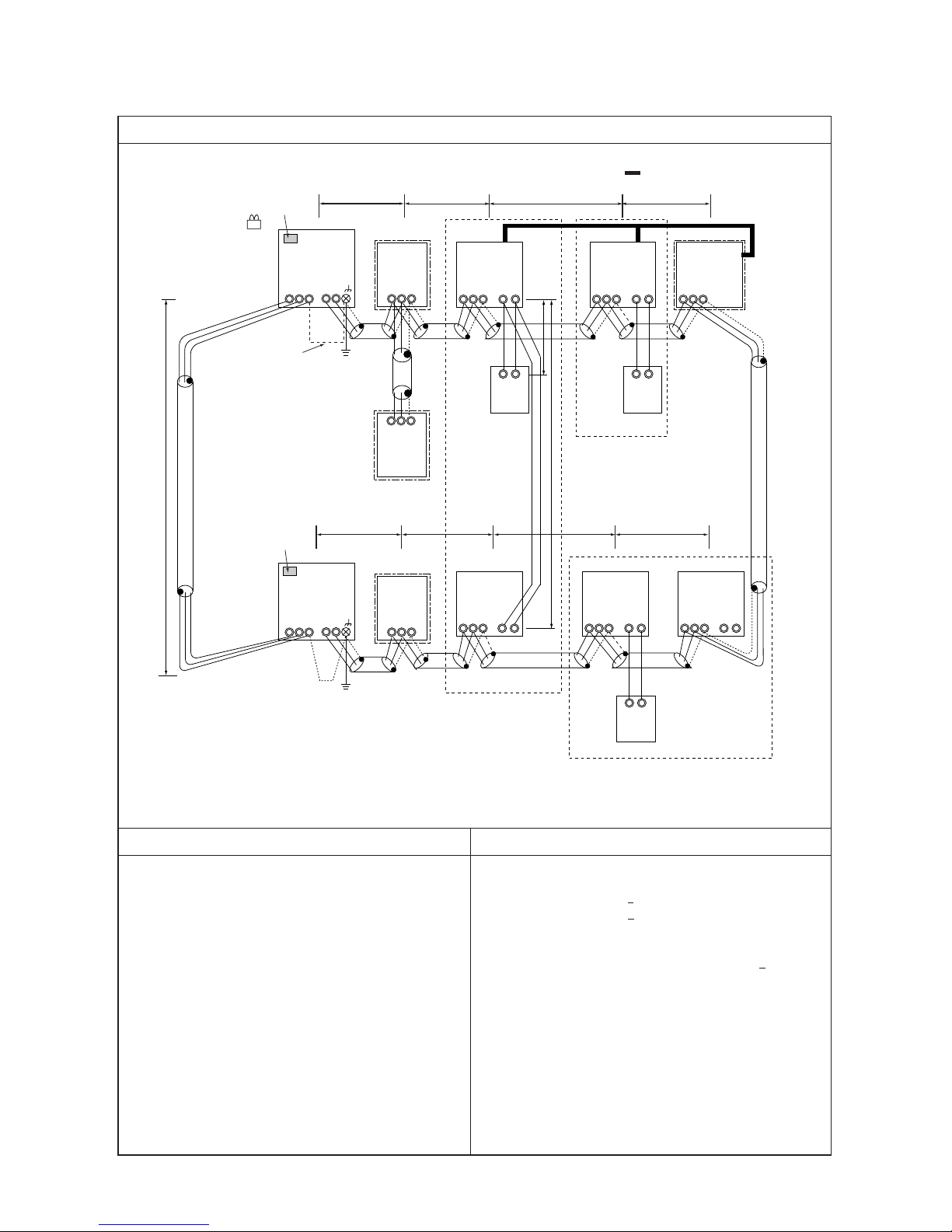
1. System using MA remote controller
(3) In the case of different refrigerant grouping operation
- 26 -
Wiring method • Address setting method
a. Indoor/outdoor transmission line
❉
Make sure to use shielded wire.
Connecting of shielded wire:
The same as 1. (1)
b. Centralized control transmission line
Apply jumper wiring between M1, M2 terminals of centralized control transmission line terminal blocks (TB7) on
each OC. For one OC only, replace the power selecting connector (CN41) with (CN40).
❉ Make sure to use shielded wire.
Connecting of shielded wire:
Apply jumper wiring to connect the shielded earth to S-terminal of the terminal block (TB7) on each OC. Connect Sterminal of the terminal block (TB7) on the one OC with (CN40) replaced to the earth screw ( ) of the electrical parts box.
c. MA remote controller wiring The same as 1. (1)
For 2-remote controller operation: The same as 1. (1)
For indoor unit group operation: The same as 1. (2)
d. LOSSNAY connection The same as 1. (2)
e. Switch setting
Address setting is required as follows.
Daisy-chain the M1 and M2 terminals of the indoor-outdoor transmission terminal block (TB3) on the outdoor unit (OC),
M1 and M2 terminals of the indoor-outdoor transmission terminal block (TB3) on the heat exchanger unit (OS), M1 and
M2 terminals of the indoor-outdoor transmission line terminal block (TB02) on the BC controller (BC), and M1 and M2
terminals of the indoor-outdoor transmission line terminal block (TB5) on each indoor unit. (with non-polarity two wires)
1 Indoor unit
2 LOSSNAY
3
MA remote
controlle
4 Outdoor unit
r
Main unit
Sub unit
Main uni
t
BC Controller
(sub)
Hex. unit
BC Controller
(main)
Sub unit
IC
LC
MA
OC
MA
01 ~ 50
01 ~ 50
Not required
52 ~ 100
51 ~ 100
Not required
Order
Unit or controller
Address
Setting method Caution
Factory
setting range
setting
• Set
•
•
the lowest address within
a same group to the indoor unit
desired to be the main unit.
[Main unit +1, +2, +3, .... ]
Set any address after setting al
5
Auxiliary
units
BS
OS
BC
Set with main/sub selector switch.
l
indoor units.
–
00
00
Main
00
• When operating indoor
units with different function
within a same group, assign the indoor unit with the
most plenty of function to
the main unit.
• Set the address not to be
overlapped with the indoor
unit address.
The lowest address of indoor unit
within refrigerant system + 50
The address of the indoor unit
connected to the sub BC controller must be larger than that
of the indoor unit connected to
the main BC controller.
If applicable, set the sub BC
controllers in an R2 system in
the following order:
(1)
Indoor unit to be connected
to the main BC controller
(2)
Indoor unit to be connected
to No.1 sub BC controller
(3)
Indoor unit to be connected
to No.2 sub BC controller
Set the address so that (1) < (2) < (3)
•
Use the address that equals the
sum of the smallest indoor unit
address out of all the indoor
units that are connected to the
sub BC controller and 50.
Outdoor unit address +1
Requires a branch-number setting.
Set to the main unit address within a same group in serial order
• To set the address to “100,”
set it to “50”.
• If the address of the heat
exchanger unit or main BC
controller overlaps with
the address of the outdoor
unit or the sub BC controller, use an unused address within the setting
range.
• The use of a sub BC controller requires a main BC
controller.
- 27 -
IC
TB5 TB
15
12
01
IC
TB5 TB
15
12
02
A1 B2
MA
A1 B2
MA
TB5
05
IC
TB5
12
TB
15
IC
TB5 TB
15
12
0403
TB5
06
A1 B2
MA
L3L2L1 L4
L23L22L21 L24
L31
L32
NO
a. Indoor/outdoor transmission line
The same as 1. (3)
b. Centralized control transmission line
Farthest length via outdoor unit (1.25mm2 or more)
L32 + L31 + L1 + L2 + L3 + L4 500m
L32 + L21 + L22 + L23 + L24 500m
L1 +L2 + L3 + L4 + L31 + L21 + L22 + L23 + L24 500m
c. MA remote controller wiring
The same as 1. (1)
Control wiring example
Group
Prohibited items Allowable length
1. M-NET and MA remote controllers can not be connected together to the indoor unit within the same group.
2. MA remote controller of 3 units or more can not be connected
to the indoor unit within the same group.
3. Do not connect together the terminal blocks (TB5) of the indoor unit connected to different outdoor units.
6. When the total number of indoor units exceeds 26 units Including that above Type 200, a transmission booster is required.
Interlocking with ventilation
– Example to use shielded wire –
Group
Group
LC
LC
Notes:
1. Leave SW2-1 as “OFF” when connecting LM adapter only.
2. LM adapter requires the power source of 1-phase AC 230V.
Note 2
System controller
≤
≤
≤
4. Replacement of the power supply selecting connector (CN41)
on the outdoor unit should be done only on one outdoor unit.
5. Grounding work is required for S-terminal of the centralized
control transmission block (TB7) on one outdoor unit only.
✻1.BC and BS are found only in the R2 system.
NO
TB02TB7 TB3
Note 1
Note 1
CN41→CN40 Replace
SW2-1 OFF→ON
51
53
54
55
52
Connect
OC
OC
TB7 TB02
TB02
TB3
Leave CN41 as it is.
SW2-1 OFF→ON
BC✻1
BC
✻1
BS
✻1
S
M1M2
S
M1M2
S
M1M2
S
M1M2
S
M1M2
S
M1M2M1M2
S
M1M2
S
M1M2
S
M1M2
S
M1M2
S
M1M2
S
M1M2M1M2
1. System using MA remote controller
(4) In the case of connecting system controller to centralized control transmission line

- 28 -
Wiring method • Address setting method
a. Indoor/outdoor transmission line
Connection of shielded wire:
The same as 1. (3)
The same as 1. (1)
c. MA remote controller wiring
For 2-remote controller operation:
For indoor group operation:
The same as 1. (1)
The same as 1. (1)
The same as 1. (1)
d. LOSSNAY connection
Apply jumper wiring to connect M1, M2 terminals of the terminal block (TB5) on (IC) to the terminal block (TB5) on
the indoor/outdoor transmission line terminal block (TB5) on Lossnay (LC). (with non-polarity two wires)
❉ The interlocking registration of the indoor unit and LOSSNAY from the system controller is required. (For the
registration method, see the installation manual of the system remote controllers.) When connecting ON/OFF
remote controller and LM adaptor only, the interlocking registration from the remote controller is required.
e. Switch setting
Address setting is required as listed below.
b. Centralized control transmission line
Apply jumper wiring between M1, M2 terminals of centralized control transmission line terminal blocks (TB7) on
each OC. On one OC only, replace the power selecting connector (CN41) with (CN40). Set the centralized control
switch (SW2-1) on the main board of all outdoor units to “ON.”
❉ Make sure to use shielded wire.
Connection of shielded wire:
Apply jumper wiring to connect the shielded earth to S-terminal of the terminal block (TB7) on each OC. Connect
S-terminal of the terminal block (TB7) on one OC with (CN40) connected to the earth screw ( ) of the electrical parts box.
1 Indoor unit
2 LOSSNAY
3
MA remote
controlle
4 Outdoor unit
r
Main unit
Sub unit
Main uni
t
BC Controller
(sub)
Hex. unit
BC Controller
(main)
Sub unit
IC
LC
MA
OC
MA
01 ~ 50
01 ~ 50
Not required
52 ~ 100
51 ~ 100
Not required
Order
Unit or controller
Address
Setting method Caution
Factory
setting range
setting
• Set
•
•
the lowest address within
a same group to the indoor unit
desired to be the main unit.
[Main unit +1, +2, +3, .... ]
Set any address after setting al
5
Auxiliary
units
BS
OS
BC
Set with main/sub selector switch.
l
indoor units.
–
00
00
Main
00
• When operating indoor
units with different function
within a same group, assign the indoor unit with the
most plenty of function to
the main unit.
• Set the address not to be
overlapped with the indoor
unit address.
The lowest address of indoor unit
within refrigerant system + 50
The address of the indoor unit
connected to the sub BC controller must be larger than that
of the indoor unit connected to
the main BC controller.
If applicable, set the sub BC
controllers in an R2 system in
the following order:
(1)
Indoor unit to be connected
to the main BC controller
(2)
Indoor unit to be connected
to No.1 sub BC controller
(3)
Indoor unit to be connected
to No.2 sub BC controller
Set the address so that (1) < (2) < (3)
•
Use the address that equals the
sum of the smallest indoor unit
address out of all the indoor
units that are connected to the
sub BC controller and 50.
Outdoor unit address +1
Requires a branch-number setting.
Set to the main unit address within a same group in serial order
• To set the address to “100,”
set it to “50”.
• If the address of the heat
exchanger unit or main BC
controller overlaps with
the address of the outdoor
unit or the sub BC controller, use an unused address within the setting
range.
• The use of a sub BC controller requires a main BC
controller.

NO
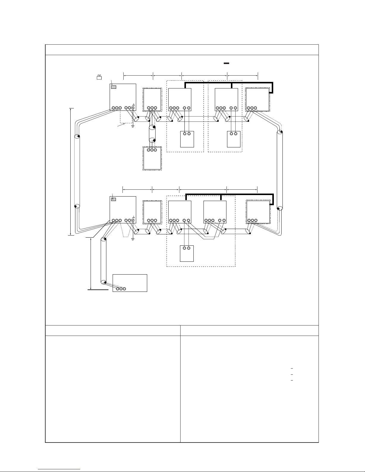
Control wiring example
Prohibited items Allowable length
Connection to the BC controller
Numbers in the squares indicate pipe-end
connection number.
– Example to use shielded wire –
System controller
Note 2
Note 1
IC
TB5 TB
15
12
01
IC
TB5 TB
15
12
02
IC
TB5 TB
15
12
04
IC
TB5 TB
15
12
06
A1 B2
MA
A1 B2
MA
A1 B2
MA
IC
TB5
12
TB
15
IC
TB5 TB
15
12
0503
GroupGroup
Group Group
L2
L22
L3
IC
TB5 TB
15
12
07
IC
TB5 TB
15
12
08
A1 B2
MA
Group
L6L5 L7
IC
TB5 TB
15
12
09
IC
TB5 TB
15
12
10
A1 B2
MA
Group
L26 L27
L4
L23 L24 L25
A1 B2
MA
L31
L32
S
M1M2
S
M1M2SM1M2
S
M1M2
S
M1M2
S
M1M2SM1M2
S
M1M2
S
M1M2SM1M2
S
M1M2M1M2
S
M1M2
S
M1M2
S
M1M2SM1M2
S
M1M2
S
M1M2
S
M1M2SM1M2
S
M1M2
M1M2
OC
TB3
TB7
51
BC
BC
TB02
52 57
OC
TB3
TB7
53
TB02
BS
TB02
BS
TB02
L1
L21
CN41→CN40 Replace
SW2-1 OFF→ON
Leave CN41 as it is.
SW2-1 OFF→ON
1 1 2 1 222 12
57
1 1 2 4 4323 4
54 59
IC
TB5 TB
15
12
11
IC
TB5 TB
15
12
12
A1 B2
MA
Group
L9 L10
61
BS
TB02
1 212
L8
Connect
1. M-NET and MA remote controllers can not be connected together to the indoor unit within the same group.
2. MA remote controller of 3 units or more can not be connected
to the indoor unit within the same group.
3. Do not connect together the terminal blocks (TB5) of the indoor unit connected to different outdoor units.
6. When the total number of indoor units exceeds 26 units Including that above Type 200, a transmission booster is required.
4. Replacement of the power supply selecting connector (CN41)
on the outdoor unit should be done only on one outdoor unit.
5. Grounding work is required for S-terminal of the centralized
control transmission block (TB7) on one outdoor unit only.
Notes:
1. Leave SW2-1 as “OFF” when connecting LM adapter only.
2. LM adapter requires the power source of 1-phase AC 230V.
a. Indoor/outdoor transmission line
Farthest length (1.25mm2 or more)
L1 + L2 + L3 + L4 + L5 + L6 + L7 + L8 + L9 + L10 200m
L21 + L22 + L23 + L24 + L25 + L26 + L27 200m
b. Centralized control transmission line
Farthest length via outdoor unit (1.25mm
2
or more)
L32 + L31 + L1 + L2 + L3 + L4 + L5 + L6+ L7 + L8 + L9 + L10
c. MA remote controller wiring
The same as 1. (1)
≤
≤
L32 + L21 + L22 + L23 + L24 + L25 + L26 + L27
L1 + L2 + L3 + L4 + L5 + L6 + L7 + L8 + L9 + L10
500m
≤
500m
≤
+ L31 + L21 + L22 + L23 + L24 + L25 + L26 + L27 500m
≤
- 29 -
1. System using MA remote controller
(5)
Connecting (multiple) BC controllers in R2 systems (with the system controller connected to the transmission lines for centralized control

1 Indoor unit
2 LOSSNAY
3
MA remote
controller
Outdoor unit
4
Main unit
Sub unit
Main unit
BC Controller
(sub)
BC Controller
(main)
Sub unit
IC
LC
MA
OC
MA
01 ~ 50
01 ~ 50
Not required
52 ~ 100
51 ~ 100
Sub unit
Wiring method • Address setting method
a. Indoor/outdoor transmission line
Connection of shielded wire: The same as 1. (1)
Connection of shielded wire The same as 1. (4)
b. Centralized control transmission line
The same as 1. (4)
c. MA remote controller wiring The same as 1. (1)
For 2-remote controller operation: The same as 1. (1)
For indoor group operation: The same as 1. (1)
d. LOSSNAY connection The same as 1. (4)
e. Switch setting Address setting is required as listed below.
Order
Unit or controller
Address
Setting method Caution
Factory
setting range
setting
[Main unit +1, +2, +3, .... ]
5
Auxiliary
units
BS
BC
Set with main/sub selector switch.
–
00
00
Main
00
• Assign the smallest address
within the group to the indoor
unit to become the main unit.
• The address of the indoor unit
connected to the sub BC controller must be larger than that
of the indoor unit connected to
the main BC controller.
•
If applicable, set the sub BC
controllers in an R2 system in
the following order:
(1)
Indoor unit to be connected
to the main BC controller
(2)
Indoor unit to be connected
to No.1 sub BC controller
(3)
Indoor unit to be connected
to No.2 sub BC controller
Set the address so that (1) < (2) < (3)
• To set the address to “100,”
set it to “50”.
• If the address of the heat
exchanger unit or main BC
controller overlaps with
the address of the outdoor
unit or the sub BC controller, use an unused address within the setting
range.
• The use of a sub BC controller requires a main BC
controller.
•
Using the system controller,
make the same indoor group
setting that was made with
the MA remote controller.
• Set the address not to be
overlapped with the indoor
unit address.
• R2 types require a branch
number setting.
Use the address that equals the
sum of the smallest indoor unit
address out of all the indoor
units that are connected to the
sub BC controller and 50.
The lowest address of indoor unit
within refrigerant system + 50
Outdoor unit address +1
Set to the main unit address within a same group in serial order
Connect terminals M1 and M2 of the indoor-outdoor transmission line terminal block (TB3) on the outdoor unit (OC)
to the terminals M1 and M2 of the indoor-outdoor transmission terminal block (TB02) of the main BC controller (BC)
and the sub BC controller (BS) and terminals M1 and M2 of the indoor-outdoor transmission terminal block (TB5) on
each indoor unit (IC).
❉ Make sure to use shielded wire.
Set any address after setting all
indoor units.
- 30 -

- 31 -
IC
TB5 TB
15
12
01
IC
TB5 TB
15
12
02
A1 B2
MA
A1 B2
MA
TB5
05
IC
TB5
12
TB
15
IC
TB5 TB
15
12
0403
TB5
06
A1 B2
MA
L3L2L1 L4
L23L22L21 L24
L31
L25
NO
a. Indoor/outdoor transmission line
Farthest length (1.25mm2 or more)
L1 + L2 + L3 + L4 200m
L21 + L22 + L23 + L24 200m
L25 200m
b. Centralized control transmission line
Farthest length via outdoor unit (1.25mm2 or more)
L25 + L31 + L1 + L2 + L3 + L4 500m
L1 + L2 + L3 + L4 + L31 + L21 + L22 + L23 + L24 500m
c. MA remote controller wiring
The same as 1. (1)
Control wiring example
Group
Prohibited items Allowable length
1. M-NET and MA remote controllers can not be connected together to the indoor unit within the same group.
2. MA remote controller of 3 units or more can not be connected
to the indoor unit within the same group.
3. Do not connect together the terminal blocks (TB5) of the indoor unit connected to different outdoor units.
4. Replacement of the power supply selecting connector (CN41)
on the outdoor unit should be done only on one outdoor unit.
5. Grounding work is required for S-terminal of the centralized
control transmission block (TB7) on one outdoor unit only.
6. The system controller connectable to the indoor/outdoor transmission line counts for 3 sets maximum. While G-50 counts
for only 1 set
7. When the total number of indoor units exceeds 26 sets, th e
system controller may not be connected to the indoor/outdoor transmission line.
8. When the total number indoor units exceed 18 sets and they
includes Type 200 or above, the system controller may not
be connected to the indoor/outdoor transmission line.
Interlocking with ventilation
– Example to use shielded wire –
Group
Group
LC
LC
Note 1
System controller
Note 1. LM adaptor may not be connected to indoor/outdoor transmission line.
≤
≤
≤
≤
≤
✻1.BC and BS are found only in the R2 system.
NO
OC
TB3
TB7
51
✻1 BC
TB02
55
OC
TB3
TB7
53
✻1 BC
TB02
54
TB02
52
✻1 BS
Connect
CN41→CN40 Replace
SW2-1 OFF→ON
Leave CN41 as it is.
SW2-1 OFF→ON
S
M1M2
S
M1M2
S
M1M2
S
M1M2
S
M1M2
S
M1M2M1 M2
S
M1M2
S
M1M2
S
M1M2
S
M1M2
S
M1M2
S
M1M2M1 M2
1. System using MA remote controller
(6) In the case of connecting system controller to indoor/outdoor transmission line (excluding LM adaptor)

- 32 -
Wiring method • Address setting method
a. Indoor/outdoor transmission line
)
❉ Make sure to use shielded wire.
Connection of shielded wire:
For the grounding of shielded wire, apply jumper wiring between the grounding screw of OC, S-terminal of the
terminal block (TB3), and S-terminal of the system controller.
b. Centralized control transmission line
Apply jumper wiring between M1, M2 terminals of centralized control transmission line terminal blocks (TB7) on
each OC. On one OC only, replace the power selecting connector (CN41) with (CN40). Set the centralized control
switch (SW2-1) on the main board of all outdoor units to “ON.”
❉ Make sure to use shielded wire.
Connection of shielded wire:
Apply jumper wiring to connect the shielded earth to S-terminal of the terminal block (TB7) on each OC. Connect Sterminal of the terminal block (TB7) on one OC with (CN40) connected to the earth screw ( ) of the electrical parts box.
c. MA remote controller wiring
The same as 1. (1)
For 2-remote controller operation:
The same as 1. (1)
For indoor unit group operation:
The same as 1. (2)
d. LOSSNAY connection
Apply jumper wiring to connect M1, M2 terminals of the terminal block (TB5) on (IC) to the terminal block (TB5) on
the indoor/outdoor transmission line terminal block (TB5) on Lossnay (LC). (with non-polarity two wires)
❉ The interlocking registration of the indoor unit and Lossnay is required from the system controller. (For the
registration method, see the instruction manual of system controller.)
To connect ON/OFF remote controller only, interlocking registration from the remote controller is required.
e. Switch setting Address setting is required as follows.
Daisy-chain the M1 and M2 terminals of the indoor-outdoor transmission terminal block (TB3) on the outdoor unit (OC),
M1 and M2 terminals of the indoor-outdoor transmission terminal block (TB3) on the heat exchanger unit (OS), M1 and
M2 terminals of the indoor-outdoor transmission line terminal block (TB02) on the BC controller (BC), and M1 and M2
terminals of the indoor-outdoor transmission line terminal block (TB5) on each indoor unit. (with non-polarity two wires)
1 Indoor unit
2 LOSSNAY
3
MA remote
controlle
4 Outdoor unit
r
Main unit
Sub unit
Main uni
t
BC Controller
(sub)
Hex. unit
BC Controller
(main)
Sub unit
IC
LC
MA
OC
MA
01 ~ 50
01 ~ 50
Not required
52 ~ 100
51 ~ 100
Not required
Order
Unit or controller
Address
Setting method Caution
Factory
setting range
setting
Set any address after setting all
indoor units.
5
Auxiliary
units
BS
OS
BC
Set with main/sub selector switch.
–
00
00
Main
00
The lowest address of indoor unit
within refrigerant system + 50
• Set the lowest address within a
same group to the indoor unit
desired to be the main unit.
• The address of the indoor unit
connected to the sub BC
controller must be larger than that
of the indoor unit connected to
the main BC controller.
•
If applicable, set the sub BC
controllers in an R2 system in the
following order:
(1) Indoor unit to be connected to
the main BC controller
(2) Indoor unit to be connected to
No.1 sub BC controller
(3) Indoor unit to be connected to
No.2 sub BC controller
Set the address so that (1) < (2) < (3)
Set to the main unit address within a
same group in serial order
[Main unit +1, +2, +3,....]
Use the address that equals the
sum of the smallest indoor unit address out of all the indoor units that
are connected to the sub BC controller and 50.
Outdoor unit address +1
• When operating indoor units
with different function within a
same group, as-sign the
indoor unit with the most
plenty of function to the main
unit.
• Requires a branch-number
setting.
• Set the address not to be
overlapped with the indoor
unit address.
• To set the address to “100,”
set it to “50”.
• If the address of the heat ex-
changer unit or main BC controller overlaps with the address of the outdoor unit or
the sub BC controller, use an
unused address within the setting range.
• The use of a sub BC controller
requires a main BC controller.

- 33 -
IC
TB5 TB
15
12
01
101
103
102
IC
TB5 TB
15
12
02
A1 B2
RC
A1 B2
RC
TB5
05
IC
TB5
12
TB
15
IC
TB5 TB
15
12
0403
TB5
06
A1 B2
RC
L3 L4
L23 L24
L2L1
L22L21
L31
L32
NO
Control wiring example
Group
Prohibited items Allowable length
Interlocking with ventilation
– Example to use shielded wire –
Group
Group
LC
LC
Note 2
System controller
✻1.BC and BS are found only in the R2 system.
1. A group of indoor units cannot be connected to both M-NET
remote controller and MA remote controllers.
2. No more than 2 M-NET remote controllers can be connected
to a group of indoor units.
3. Do not connect the TB5’s (Terminal block) of the indoor
units that are connected to different outdoor units.
4. Replace CN41 (power supply switch connector on outdoor
units) on only one of the outdoor units.
5. Ground the S terminal of TB7 on only one of the outdoor
units.
6. Transmission line booster is necessary when the total
number of connected indoor units exceeds 20 (19 with 1 BC
and 18 with 1 BC and BS each).
7. Transmission line booster is necessary if the system
includes indoor units of 200 or higher and the total number
of indoor units exceeds 16 (15 with 1 BC and 14 with 1 BC
and BS each).
a. Indoor/outdoor transmission line
b. Centralized control transmission line
c. M-NET remote controller wiring
The same as 2. (1)
The same as 1. (4)
The same as 1. (3)
S
M1M2
S
M1M2
S
M1M2
S
M1M2
S
M1M2
S
M1M2M1M2
S
M1M2
S
M1M2
S
M1M2
S
M1M2
S
M1M2
S
M1M2M1M2
NO
OC
TB3
TB7
51
✻1 BC
TB02
55
OC
TB3
TB7
53
✻1 BC
TB02
54
TB02
52
✻1 BS
Connect
Note1
Note1
Notes:
1. Leave SW2-1 as “OFF” when connecting LM adapter only.
2. LM adapter requires the power source of 1-phase AC 230V.
CN41→CN40 Replace
SW2-1 OFF→ON
Leave CN41 as it is.
SW2-1 OFF→ON
2. System Using the M-NET Remote Controller
(1) System with the system controller connected to the transmission lines for centralized control

- 34 -
BC Controller
(sub)
Hex. unit
BC Controller
(main)
52 ~ 100
5
Auxiliary
units
BS
OS
BC
00
Use the address that equals the
sum of the smallest indoor unit address out of all the indoor units that
are connected to the sub BC controller and 50.
Outdoor unit address +1
a. Indoor/outdoor transmission line
Connection of shielded wire:
b. Centralized control transmission line
c. M-NET remote controller wiring
The same as 1. (3)
For 2-remote controller operation:
The same as 1. (1)
Connection of shielded wire:
The same as 1. (4)
The same as 1. (4)
For a 2-remote-controller operation, connect each of the terminals M1 and M2 of the IC terminal block to the two
RC terminal blocks respectively.
Indoor unit group operation
To operate IC
’s as a group, connect the M1, M2 terminals of the terminal block on the main IC in the group with
the RC terminal block (with non-polar two wires)
❉M-NET remote controller can be connected at any point on the indoor/outdoor transmission line.
❉To run a group operation of indoor units that have different functions, select the unit with the greatest number
of functions as the main unit.
The same as 1. (4)
For indoor unit group operation:
d. LOSSNAY connection
M-NET remote controller wiring
Connect each of the M1 and M2 terminals of TB5 (indoor/outdoor transmission line terminal block) on the IC to
the terminals on the M-NET remote controller.
e. Switch setting Address setting is required as follows.
1 Indoor unit
2 LOSSNAY
3
M-NET
remote
controller
4 Outdoor unit
Main unit
Sub unit
Main unit
Sub unit
IC
OC
LC
RC
RC
01 ~ 50
01 ~ 50
51 ~ 100
101 ~ 150
151 ~ 200
Order
Unit or controller
Address
Setting method Caution
Factory
setting range
setting
00
00
101
00
Starting with the number main unit
address +1, assign a sequential
number to each of the rest of the
indoor units.
After all indoor units have received
an address, use any remaining
number and assign it to the Lossnay
unit. units.
The smallest indoor unit address in
the same refrigerant system +50
The address of the main unit in the
same group +100
The address of the main unit in the
same group +150
• Assign the smallest address within
the group to the indoor unit to
become the main unit.
• Assign a larger address to the
indoor unit that is connected to the
R2-type sub BC controller than the
one assigned to the indoor unit
connected to the main BC
controller.
•
If applicable, set the sub BC controllers in an R2 system in the following order:
(1) Indoor unit to be connected to
the main BC controller
(2) Indoor unit to be connected to
No.1 sub BC controller
(3) Indoor unit to be connected to
No.2 sub BC controller
Set the address so that (1) < (2) < (3)
• Make the initial setting of the
indoor unit group setting with
the system controller
(MELANS).
• Branch numbers must be set
for a system with R2.
• The Lossnay address must not
overlap with the indoor unit
address.
• 100
’s digit does not need to be
set.
• Set the address to “ 00 ” when
setting it to “ 200 ”.
• Set the address to “ 50 ” when
setting it to “ 100 ”.
Wiring method • Address setting method
• To set the address to “100,” set
it to “50”.
• If the address of the heat exchanger unit or main BC controller overlaps with the address of the outdoor unit or the
sub BC controller, use an unused address within the setting range.
• The use of a sub BC controller
requires a main BC controller.

- 35 -
IC
TB5 TB
15
12
01
IC
TB5 TB
15
12
02
IC
TB5 TB
15
12
04
104
IC
TB5 TB
15
12
06
A1 B2
MA
A1 B2
RC
A1 B2
MA
IC
TB5
12
TB
15
IC
TB5 TB
15
12
0503
L2L1
L22L21
L3 L4
L23 L24
105
A1 B2
RC
L31
L32
NO
a. Indoor/outdoor transmission line
The same as 1. (3)
b. Centralized control transmission line
The same as 1. (4)
c-1. MA remote controller wiring
The same as 1. (1)
c-2. M-net remote controller wiring
The same as 2. (1)
Control wiring example
Group
Prohibited items Allowable length
1. Make sure to connect the system controller.
2. M-NET and MA remote controllers can not be connected together to the indoor unit within a same group.
3. M-NET remote controller of 3 units or more can not be connected to the indoor unit within a same group.
6.
7.
8. When the total number of indoor units exceeds 20 sets, transmission line booster is required.
9. When the total number of indoor units exceed 16 sets and
they include Type 200 or above, the transmission line booster
is required.
– Example to use shielded wire –
Group
Group
Note 2
System controller
Notes:
1. Leave SW2-1 as “OFF” when connecting LM adapter only.
2. LM adapter requires the power source of 1-phase AC 230V.
Note1
Note1
Group
Replacement of the power supply selecting connector (CN41)
on the outdoor unit should be done only on one outdoor unit.
Grounding work is required for S-terminal of the centralized
control transmission block (TB7) on one outdoor unit only.
CN41→CN40 Replace
SW2-1 OFF→ON
Leave CN41 as it is.
SW2-1 OFF→ON
4. MA remote controller of 3 units or more can not be connected
to the indoor unit within a same group.
5. Do not connect together the terminal blocks (TB5) of the indoor unit connected to different outdoor units.
OC
TB3
TB7
51
✻2 BC
TB02
55
OC
TB3
TB7
53
✻2 BC
TB02
54
TB02
52
✻2 BS
NO
Connect
S
M1M2
S
M1M2
S
M1M2
S
M1M2
S
M1M2
S
M1M2M1M2
S
M1M2
S
M1M2
S
M1M2
S
M1M2
S
M1M2
S
M1M2M1M2
3. System where MA remote controller and M-NET remote controller coexist

- 36 -
Indoor
unit
MA
remote
controller
Indoor
unit
M-NET
remote
controller
Wiring method • Address setting method
a. Indoor/outdoor transmission line The same as 1. (3)
Connection of shielded wire: The same as 1. (1)
b. Centralized control transmission line The same as 1. (4)
Connection of shielded wire: The same as 1. (4)
c-1. MA remote controller wiring, For 2-remote controller operation: , For indoor unit group operation:
The same as 1. (1)
c-2. M-NET remote controller, For 2-remote controller operation: , For indoor unit group operation:
The same as 2. (1)
d. Lossnay connection The same as 1. (4)
e. Switch setting Address setting is required as follows.
Operation
with MA
remote
controller
Operation
with M-NET
remote
ontroller
Lossnay
Outdoor unit
IC
MA
MA
IC
RC
RC
LC
OC
01 ~ 50
Not
required
Sub remote
controller
01 ~ 50
101 ~ 150
151 ~ 200
01 ~ 50
51 ~ 100
52 ~ 100
Order
Unit or controller
Address
Setting method Caution
Factory
setting range
setting
–
00
Main
00
101
00
00
00
Main
unit
Sub
unit
Main
unit
Sub
unit
Main
unit
Sub
unit
Main
unit
Sub
unit
1
2
3
4
BC Controller
(sub)
BC Controller
(main)
5
Auxiliary
units
BS
BC
• To set the address to “100,” set it
to “50”.
• If the address of the heat exchanger unit or main BC controller overlaps with the address of
the outdoor unit or the sub BC
controller, use an unused address within the setting range.
• The use of a sub BC controller requires a main BC controller
Use the address that equals the
sum of the smallest indoor unit address out of all the indoor units that
are connected to the sub BC controller and 50.
Outdoor unit address +1
Hex. unit OS
• Set the lowest address within
asame group to the indoor unit
desired to be the main unit.
• Assign a larger address to the
indoor unit that is connected to the
R2-type sub BC controller than the
one assigned to the indoor unit
connected to the main BC
controller.
•
If applicable, set the sub BC controllers in an R2 system in the following order:
(1) Indoor unit to be connected to
the main BC controller
(2) Indoor unit to be connected to
No.1 sub BC controller
(3) Indoor unit to be connected to
No.2 sub BC controller
Set the address so that (1) < (2) < (3)
• After setting the address of the
indoor unit to be operated with MA
controller, set the lowest address
among the same group to the
indoor unit desired to be the main
unit.
• Assign a larger address to the
indoor unit that is connected to the
R2-type sub BC controller than the
one assigned to the indoor unit
connected to the main BC
controller.
• Set lower address than that of
the indoor unit connected to
M-NET remote controller.
• Initially set the same setting
detail as that of indoor unit group
executed in the wiring of MA
remote controller with system
controller.
• Branch numbers must be set for
a system with R2.
• Initially set the same setting
detail as that of indoor unit group
with system controller.
• Branch numbers must be set for
a system with R2.
• 100 digits are not required to set.
• When setting the address as
“200,” make it “00.”.
• When setting the address to
“100,” make it “50.”
• Set so that not duplicating with
the indoor unit addresses.
Set to the main unit address within
a same group in serial order.
[Main unit +1, +2, +3,]
Set to the main unit address within
a same group in serial order.
[Main unit +1, +2, +3,]
Main unit address inside a same
group + 100
After setting all indoor units, set any
address.
The lowest address of indoor unit
within refrigerant system + 50
Main unit address inside a same
group + 150
Set by using the main/sub selector
switch

- 37 -
For the piping connection, the end branching system is applied where the end of refrigerant piping from the outdoor unit is
branched and connected to each indoor unit. As the piping connection method, the indoor unit is applied with flare connection, outdoor unit gas piping is flange connection, and liquid piping is flare connection. For the branching, brazed connection
is applied.
Warning
Be careful not to leak refrigerant gas (R410A) near a fire. Refrigerant gas if touched a fire of gas oven and the like will
be decomposed to generate poisonous gas leading to gas-poisoning. Do not conduct welding work in a closed room.
Run a gas leak test after completing refrigerant piping work.
Do not use a charging cylinder.
• Using a charging cylinder may cause the refrigerant to
deteriorate.
Do not use existing refrigerant piping.
• The old refrigerant and refrigerator oil in the existing piping
contains a large amount of chlorine which may cause the
refrigerantor oil of the new unit to deteriorate.
Store the piping to be used during installation indoors
and keep both ends of the piping sealed until just
before brazing.
(Store elbows and other joints in a plastic bag.)
• If dust, dirt, or water enters the refrigerant cycle,
deterioration of the oil and compressor trouble may result.
Caution
Caution
Caution
Do not use a refrigerant other than that indicated on
the equipment at installation or movement.
• Mixing of different refrigerant or air makes the refrigeration cycle
abnormal causing breakage and the like.
Warning
Caution
Use refrigerant piping phosphorus deoxidized copper. In addition, be sure that the inner and outer surface of the pipes are clean and free of hazardous
sulphur, oxides, dust/dirt, shaving particles, oils,
moisture, or any other contaminant.
• Contaminants on the inside of the refrigerant piping may cause
the refrigerant residual oil to deteriorate.
Caution
Use liquid refrigerant to fill the system.
• If gas refrigerant is used to seal the system, the composition of
the refrigerant in the cylinder will change and performance may
drop.
[4] Restrictions on Refrigerant Piping Length

- 38 -
B
A
a
b
c
d
e
400
350
300
250
200
30 40 50 60 70 80 90 100 110
70
60
40
30
50
10
20
0
0 5 10 15
Note 1: Use the figures in the parentheses if the capacity of the connected indoor units is P200 type or above.
Note 2: Refer to the graph below for restrictions on refrigerant piping length when the total piping length exceeds 300 m.
Note 3: Refer to the graph below for restrictions on refrigerant piping length when the piping length between the BC
controller and the farthest indoor unit exceeds 40 m. (except P250-type indoor units)
Note 4: When indoor units of P200 type or above are connected, neither branch joints nor branch headers can be used.
Note 5: Do not connect P200- or P250-type indoor units and other types of indoor units at the same pipe end connection.
[16 branches or less (the use of only the main BC controller or standard BC controller)]
Outdoor unit
BC controller
Indoor unit
Indoor unit
Indoor unit
Indoor unit Indoor unit
110 m or less
40 m or less
(P141~P250 types: 2-line merge)
• Restrictions on piping length
Total piping length (m)
Piping length between main BC controller
and farthest indoor unit (m)
• Height difference and branch piping length between
BC controller and indoor unit. (A)
Distance between outdoor unit and
BC controller (m)
Height difference between main BC controller and
farthest indoor unit (m)
Maximum of 3 units per branch joint
Total capacity of P140 or less
(All units connected to the same
branch joint must be in the same mode.)
Junction
pipe
(option)
Branch pipe (for Y-series)
CMY-Y102S-G
H = 50 m or less (outdoor unit above)
H’ = 40 m or less (outdoor unit below)
h1 = 15 m or less
h2 = 15 m or less
Total piping length
A + B + a + b + c + d + e
Piping length
Farthest piping length
Between outdoor unit - BC controller
Height difference
Between BC controller and indoor unit
Between indoor unit and BC controller
Between indoor units
Between indoor unit
and outdoor unit
Outdoor unit above
Outdoor unit below
300 m less (Note 2)
A + e
150 m or less
(175 m equivalent length or less)
A 110 m or less
e 40 m or less (Note 3)
H 50 m or less
H’ 40 m or less
h1 15 m or less (10 m or less) (Note 1)
h2 15 m or less (10 m or less) (Note 1)
Item Piping sections Allowable value
1. Line-branch method

B
A
a
b
c
d
e
400
350
300
250
200
30 40 50 60 70 80 90 100 110
70
60
40
30
50
10
20
0
0 5 10 15
Note:
A system with more than 16 branching requires 2 to 3 BC controllers (main/sub) and 3 pipes between BC controllers.
Note 1: Refer to the graph below for restrictions on refrigerant piping when the total piping length exceeds 300 m.
Note 2: Refer to the graph below for restrictions on refrigerant piping length when the piping length between the BC
controller and the farthest indoor unit exceeds 40 m. (except P250-type indoor units)
Note 3: Use the figures in the parentheses if the capacity of the connected indoor units is P200 type or above.
Note 4: When indoor units of type P200 or above are connected, neither branch joints nor branch headers can be used.
Note 5: When 2 sub BC controllers are connected, include them in the figures in the table above.
Note 6: When 2 sub BC controllers are connected, connect them in parallel.
C
Note 6
f
g
h3
h4
[Systems that requires more than 16 pipe-end connections or with multiple BC controllers
(with a use of both main and sub controllers)]
BC controller (main)
Indoor unit
Indoor unit
Indoor unit
Indoor unit Indoor unit
BC controller
(sub)
110 m or less
40 m or less
<With more than 16 branching>
(P141~P250 types: 2-line merge)
• Restrictions on piping length
Total piping length (m)
Piping length between main BC controller
and farthest indoor unit (m)
• Height difference and branch piping length between
BC controller and indoor unit. (A)
Distance between outdoor unit and
BC controller (m)
Height difference between main BC controller and
farthest indoor unit (m)
Maximum of 3 units per branch joint
Total capacity of P140 or less
(All units connected to the same
branch joint must be in the same mode.)
Junction
pipe
(option)
Branch pipe (for Y-series)
CMY-Y102S-G
H = 50 m or less (outdoor unit above)
H’ = 40 m or less (outdoor unit below)
h1 = 15 m or less
h2 = 15 m or less
Total piping length
A + B + C + a + b + c + d + e + f + g
Piping length
Farthest piping length
Between outdoor unit - BC controller
Height difference
Between BC controller and indoor unit
Between indoor unit and BC controller
Between indoor units
Between indoor unit
and outdoor unit
Outdoor unit above
Outdoor unit below
300 m less
A + C + g or A + e
150 m or less
(175 m equivalent length or less)
A 110 m or less
e or C + g 40 m or less (Note 2)
Between main BC controller and sub BC controller
h3 15 m or less
H 50 m or less
H’ 40 m or less
h1 15 m or less (10 m or less) (Note 3)
h2 15 m or less (10 m or less) (Note 3)
Between indoor (main BC controller) and
indoor (sub BC controller) units
h4
15 m or less (10 m or less)
(Notes 3 and 5)
Indoor unitIndoor unit
Item Piping sections Allowable value
Outdoor unit
- 39 -

Note 1: Outdoor units and BC controllers are supplied with flanges with a short copper pipe as a part used to connect to the
low pressure pipe.
✻ When 2 sub controllers are connected, determine the pipe size on the main side based
on the total capacity of the indoor units that are connected to the 2 sub controllers, and
determine the pipe size on the sub controller side based on the total capacity of the
units that are connected.
Note 2: Use pipes that are specified in the section “Read Before Servicing: [3] Piping Materials.”
1Between outdoor unit and BC controller (Part A)
2Between BC controller and indoor unit (Parts a, b, c, d, and e)
3Between main BC controller and sub BC controller (Part C)
Item
Refrigerant piping
size
High pressure
pipe
Low pressure
pipe
High pressure
pipe
Low pressure
pipe
Outdoor unit
PURY-P400
YGM-A
ø 28.58 (Brazed)ø 25.4 (Brazed)ø 22.2 (Brazed)ø 19.05 (Brazed)
ø 22.2 (Brazed)ø 19.05 (Brazed)ø 15.88 (Brazed)
ø 28.58ø 25.4ø 22.2ø 19.05
ø 22.2ø 19.05ø 15.88
PURY-P350
YGM-A
PURY-P300
YGM-A
PURY-P250
YGM-A
PURY-P200
YGM-A
End connection
of outdoor unit
and BC controller
Item
Refrigerant piping
size
Liquid pipe
Gas pipe
Liquid pipe
Gas pipe
Indoor unit
ø 22.2ø 15.88ø 12.7
ø 9.52ø 6.35
ø 22.2ø 15.88
ø 19.05
ø 19.05ø 12.7
ø 9.52ø 6.35
250200
63, 71, 80, 100
125, 140
20, 25, 32
40, 50
End connection
of indoor unit
(Flare connection
for all unit types)
Item
Refrigerant piping
size
(Use brazing for
all units.)
Low pressure
Liquid pipe
Liquid pipe
High pressure
Gas pipe
Indoor unit
ø 28.58ø 19.05 ø 22.2
ø 19.05ø 15.88
ø 12.7ø 9.52
P301~P350P201~P300~P200
Item
Refrigerant piping
size
High pressure
pipe
Low pressure
pipe
High pressure
pipe
Low pressure
pipe
Outdoor unit
PURY-P650
YGM-A
ø 28.58 (Brazed)
ø 25.4 (Brazed)ø 22.2 (Brazed)
ø 28.58
ø 25.4ø 22.2
PURY-P600
YGM-A
PURY-P550
YGM-A
PURY-P500
YGM-A
PURY-P450
YGM-A
End connection
of outdoor unit
and BC controller
- 40 -
2. Refrigerant piping size

1 Total capacity of connectable indoor units: P140 or below (P250 or below when a junction pipe is used)
2 The number of connectable indoor units: 3 max.
3 Branch pipe: Use Type CMY-Y102S-G (option)
4 Selection of refrigerant piping (pipe size of the A and B in the figure above): Use the total capacity of the
downstream indoor units to determine the proper pipe size, using the table below as a reference.
Use an optional junction pipe kit and merge the 2
joints
Use the reducer that is supplied with the BC
controller
(1) BC controller (standard model) end connection piping size
[P200-P350 types]
Note: Use the flare nut provided with the BC controller
Liquid pipe side: 3/8F
(flare)
Gas pipe side: 5/8F
(flare)
Liquid pipe side: 3/8F
(flare)
Gas pipe side: 5/8F
(flare)
Provided with a thermal
insulation cover
Liquid pipe side:
ø 6.35 ID
Gas pipe side:
ø 12.7 ID
Liquid pipe side:
ø 9.52 ID
Gas pipe side:
ø 19.05 ID
(ø 22.2 with reducer)
Total capacity of the indoor units
P140 or below ø 15.88ø 9.52
P141~P200 ø 19.05ø 9.52
P201~P250
(❈) With reducer
ø 22.2 (❈)ø 9.52
Gas pipeLiquid pipe
To outdoor unit
✻1
Reduce
(supplied)
✻1: To connect P20-P50 type indoor units
✻3: To connect multiple indoor units to a branch joint (or to a junction pipe)
✻2: To connect P200 or P250 type indoor units
(or when the total capacity of the indoor units
exceeds P141)
The size of the branch end connection on the BC controller is designed to fit P50-P140 type indoor units.
To connect other types of indoor units, perform the following procedures.
✻2
Junction
pipe kit
(Type: CMYR160-J)
(option)
Branch pipe
(Type: CMY-Y102S-G)(option)
✻3
Maximum of 3 units per branch joint
Total capacity of P140 or less
(All units connected to the same
branch joint must be in the same mode.)
End connection:
brazed connection
BC controller
Item
Outdoor
unit side
Indoor unit side
High-pressure side
(liquid side)
Low-pressure side
(gas side)
Piping sections
ø 15.88
(Brazed)
ø 19.05
(Brazed)
ø 22.2
(Brazed)
ø 19.05
(Brazed)
ø 28.58
(Brazed)
ø 9.52
(Flare)
ø 15.88
(Flare)
✻ BC controllers (standard model) can only be connected to P200-P350
outdoor units.
PURY-P200YGM-A
PURY-P250YGM-A
PURY-P300YGM-A
PURY-P350YGM-A
70
234
Indoor unitIndoor unitIndoor unitIndoor unitIndoor unit Indoor unit
P50 type
or below
P63-P140
types
P200-P250
types
BA
- 41 -
3. Connecting the BC controllers

The size of the branch end connection on the BC controller is designed to fit P63-P140 type indoor units.
To connect other types of indoor units, perform the following procedures.
✻1: To connect P20-P50 type indoor units, use the reducer that is supplied with the BC controller
✻2: To connect P200 or P250 type indoor units (or when the total capacity of the indoor units exceeds P141),
use an optional junction pipe kit (Type: CMY-R160-J) and merge the 2 joints.
✻3: To connect multiple indoor units to a branch joint (or to a junction pipe)
• Total capacity of connectable indoor units : P140 or below (P250 or below when a junction pipe is used)
• The number of connectable indoor units : 3 max.
• Selection of refrigerant piping (pipe size of the A and B in the figure above)
: Use the total capacity of the downstream indoor units to determine the proper pipe size, using the
table below as a reference.
(2) BC controller (main) end connection piping size
Total capacity of the indoor units
P140 or below ø 15.88ø 9.52
P141~P200 ø 19.05ø 9.52
P201~P250
(❈) With reducer
ø 22.2 (❈)ø 9.52
Gas pipeLiquid pipe
To outdoor unit
✻1
Reducer
(supplied)
✻2
Junction pipe kit
(Type: CMY-R160-J)
(option)
Branch pipe (Type: CMY-Y102S-G)
(For CITY MULTI Y series, option)
Maximum of 3 units per branch joint.
Total capacity of P140 or less
(All units connected to the same
branch joint must be in the same mode.)
End connection:
brazed connection
Main BC controller
Item
High-pressure side
(liquid side)
Low-pressure side
(gas side)
Piping sections
ø 19.05
(Brazed)
ø 22.2
(Brazed)
ø 28.58
(Brazed)
ø 15.88
(Brazed)
ø 19.05
(Brazed)
ø 22.2
(Brazed)
ø 28.58
(Brazed)
ø 9.52
(Flare)
ø 15.88
(Flare)
PURY-P250YGM-A
PURY-P200YGM-A
PURY-P300YGM-A
PURY-P350YGM-A
PURY-P450YGM-A
PURY-P400YGM-A
PURY-P500YGM-A
PURY-P550YGM-A
PURY-P600YGM-A
PURY-P650YGM-A
Outdoor
unit side
Indoor unit side
Indoor unitIndoor unitIndoor unitIndoor unitIndoor unit Indoor unit
P50 type
or below
P63-P140
types
P200-P250
types
BA
- 42 -

The size of the branch end connection on the BC controller is designed to fit P63-P140 type indoor units.
To connect other types of indoor units, perform the following procedures.
✻1: To connect P20-P50 type indoor units, use the reducer that is supplied with the BC controller
✻2: To connect P200 or P250 type indoor units (or when the total capacity of the indoor units exceeds P141),
use an optional junction pipe kit (Type: CMY-R160-J) and merge the 2 joints.
✻3: To connect multiple indoor units to a branch joint (or to a junction pipe)
• Total capacity of connectable indoor units : P140 or below (P250 or below when a junction pipe is used)
• The number of connectable indoor units : 3 max.
• Selection of refrigerant piping (pipe size of the A and B in the figure above)
: Use the total capacity of the downstream indoor units to determine the proper pipe size, using the
table below as a reference.
(3) BC controller (sub) end connection piping size
Total capacity of the indoor units
P140 or below ø 15.88ø 9.52
P141~P200 ø 19.05ø 9.52
P201~P250
(❈) With reducer
ø 22.2 (❈)ø 9.52
Gas pipeLiquid pipe
Main BC controller
✻1
Reducer
(supplied)
✻2
Junction pipe kit
(Type: CMY-R160-J)
(option)
Branch pipe (Type: CMY-Y102S-G)
(For CITY MULTI Y series, option)
Maximum of 3 units per branch joint.
Total capacity of P140 or less
(All units connected to the same
branch joint must be in the same mode.)
End connection:
brazed connection
Sub BC controller
Item
BC
controller
side
High-pressure side
(liquid side)
Low-pressure side
(gas side)
Piping sections
ø 19.05
(Brazed)
ø 15.88
(Brazed)
ø 22.2
(Brazed)
ø 19.05
(Brazed)
ø 28.58
(Brazed)
Liquid side
ø 9.52
(Brazed)
ø 12.7
(Brazed)
Total capacity of indoor units
connected to applicable BC controller
P200 type and below
P201-P300 types
P301 types and above
Indoor unitIndoor unitIndoor unitIndoor unitIndoor unit Indoor unit
P50 type
or below
P63-P140
types
P200-P250
types
BA
- 43 -

- 44 -
££
Components of the Outdoor Unit
[1] Appearance of the Components and Refrigerant Circuit
< P200, P250, P300, P350-Types >
[ Front view of the unit ]
[ Rear view of the unit ]
Heat exchanger
Fan guard
Heat exchanger
Fan guard

- 45 -
Drier
Accumulator
Ball valve on high-pressure side
Inverter
compressor
Ball valve on low-pressure side
Check valve
block
4-way valve
Discharge
muffler
Pressure switch
High-pressure
pressure sensor
High-pressure check joint
Accumulator
Solenoid valve block
Low-pressure sensor
4-way valve
< P200, P250, P300, P350-Types >
[ Front view of the refrigerant circuit ]
[ Rear view of the refrigerant circuit ]

- 46 -
Heat exchanger
Fan guard
Heat exchanger
Fan guard
< P400-type >
[ Front view of the unit ]
[ Rear view of the unit ]

- 47 -
Drier
Accumulator
Ball valve on
high-pressure side
Inverter
compressor
Ball valve on
low-pressure side
Discharge
muffler
Pressure switch
High-pressure
pressure sensor
High-pressure check joint
Check joint on
low-pressure side
Low-pressure sensor
Low-pressure sensor4-way valve
Accumulator
Oil separator Low-pressure sensor Solenoid valve block
< P400-type >
[ Front view of the refrigerant circuit ]
[ Rear view of the refrigerant circuit ]

- 48 -
Fan guard
Heat
exchanger
Fan guard
Heat
exchanger
< P450, P500, P550, P600, P650-Types >
[ Front view of the unit ]
[ Rear view of the unit ]

- 49 -
Accumulator
Inverter compressor (No.1) Oil balancer tube Commercial power supply
compressor (No.2)
Oil separator (No.1) Oil separator (No.2)
Pressure
switch
Drier
Ball valve on
low-pressure side
Ball valve on
high-pressure side
4-way valve (21S4b)
4-way valve (21S4a)
High-pressure
pressure sensor
High-pressure
check joint
Low-pressure check joint
Check valve block 1
Solenoid valve block 2
Check valve block 2
Solenoid valve block 1
Low-pressure
pressure sensor
< P450, P500, P550, P600, P650-Types >
[ Front view of the refrigerant circuit ]
[ Rear view of the refrigerant circuit ]

- 50 -
Power supply terminal
block (TB1)
Main board
Transmission line
terminal block
for centralized control
(TB7)
Indoor/outdoor
transmission
terminal block
(TB3)
INV board
Choke coil
(L1, L2)
Transformer
DCL (back)
Noise filter
Rush current protection resistor
(R11, R12)
Electromagnetic relay
(52C1)
Smoothing capacitor
(C11, C12)
DCCT
(P250-P400 types only)
Gate amp board
(G/A board)
Diode stack (DS1)
FAN board
ACCT-U phase ACCT-W phase
[2] Control Box
< P200~P400-Type >
[ Appearance ]
[ Under the circuit board cover ]

- 51 -
Power supply terminal
block (TB1)
Transmission line
terminal block
for centralized control
(TB7)
Indoor/outdoor
transmission
terminal block
(TB3)
FILTER
board
Relay board
(RELAY BOARD)
Relay board
(RELAY02-BOARD)
Main
board
INV board
Choke coil
(L1, L2)
Transformer
DCL (back)
Gate amp board
(G/A board)
FAN board
Diode stack
(DS)
Smoothing
capacitor
(C11, C12)
Rush current
protection resistor
(R11, R12)
Electromagnetic
contactor (52C1)
Noise filter
Electromagnetic
contactor (52F)
Fuse
AC660V 50A
Electromagnetic
contactor (52C2)
Overcurrent
relay (51C2)
< P450~P650-Type >
[ Appearance ]
[ Under the circuit board cover ]

- 52 -
CNVCC1
Controlled
source input
1–2
DC30V
1–3
DC30V
4–5
DC7V
4–6
DC12V
7–8
DC7V
CNRS3BLD2
CNAC3
Power output
3
L1
1
L2
CN20
Power intput
5
L1
CN21
Power intput
3
L2
1
N
LD1
Service LED
SW5 SW4 SW3 SW2
SWU2 SWU1
SW1
CNLVB
CN3S
CN3D
CN3N
CNRS3A CNS1 CNS2 CN40 CN41
CNRT1
CNOUT1
CN52C
Control for
52C1
CN51
3–4
Compressor
ON/OFF
3–5
Trouble
CN38
[3] Circuit Board
1. Main board

- 53 -
CNVCC1
Power supply
1–2
DC30V
1–3
DC30V
4–5
DC7V
4–6
DC12V
7–8
DC7V
CN15V2
Power supply
for IPM control
F02CNVDC
SW1
SW2
CN52C
CNFAN CNRS1 CNRS2
Serial
transmission
for MAIN board
CNCT2
CNAC2
Power Source
5
L2
3
N
1
G
CNTH
CNCT
CNDR2
2. INV board

- 54 -
CNVDC
DC bus voltage input
1–3
LED1
LED2
SW2
CNTRIPM (back)
CNN Fan motor output Fuse CNRS2
3. FAN board

- 55 -
52C2, 52F, CH12
Power input (AC220
~240V)
51C2
Detection output
CNOUT2
Relay driving input
CNRT2
1–5
1
–
3
CNCH
CH12 Power output
1–3
AC220~240V
CN51C2
51C2 contact input
CN52F
52F
driving output
1–3
AC220~240V
CN52C2
52C2
drivingoutput
1–5
AC220~240V
CN01
CH12 output
3–5
AC220~240V
CNAC1
CH12 power input
1–3
AC220~240V
CNIN
relay driving input
CNX10
4. Relay board (RELAY BOARD)
5. Relay board (RELAY02-BOARD)

- 56 -
CNFG CNL2CNL1
CNOUT
Controlled
source output
CNIN
Controlled
source input
6. Filter board
CNDR1
CN15V1
CNDC1 CNDC2
CNIPM1
7. G/A board

- 57 -
Gas pipe
(indoor unit side)
Liquid pipe
(indoor unit side)
LEV3
SVM2
PS1
PS3
LEV2
TH11
LEV1
LEV2PS3SVM1
PS1
LEV1 LEV3
TH15
TH16 TH12
TH11
SVM2
SVM1
High-pressure side (outdoor unit side)
✻ No SVM2 on G type
[4] BC controller (inside the panel)
< CMB-P V-G(A) >
[ Front (CMB-P1016V-G(A) is shown in the picture) ]
< CMB-P1016V-G >

- 58 -
Gas-liquid separator
Double pipe heat exchanger
Gas-liquid separator
Double pipe heat exchanger
[ Rear view (CMB-P1016V-G(A) is shown in the picture) ]
< CMB-P1016V-G >
< CMB-P1016V-GA >

- 59 -
LEV3a TH25
TH22
< CMB-P V-GB>
[ Front view (CMB-P104V-GB is shown in the picture) ]
[ Rear view (CMB-P104V-GB is shown in the picture) ]

- 60 -
BC controller board
Relay board
Terminal block
for power supply
Terminal block
for transmission
Transformer
SW1SW2
SW4
SW5
[5] BC control box
[ BC controller control box (CMB-P1016V-GA is shown in the picture) ]
[6] BC controller board
[ BC controller board ]

- 61 -
[ Relay board (RELAY 4 board) ]
[ Relay board (RELAY 10 board) ]

- 62 -
Function/specification
Remote controller address setting
Not required Required
Indoor/outdoor unit address
setting
Not required (applicable only in the case
of single refrigerant systems)(Note 3)
Required
Wiring method Non-polar 2 wires
✻
Daisy-chain the indoor units with non-polar
2 wires when running a group operation.
Non-polar 2 wires
Installation location of
remote controller
Connectable to any indoor unit in the
group
Connectible at any point on the
indoor/outdoor transmission line
Interlocking with the
ventilation unit
Each indoor unit can individually be
interlocked with a ventilation unit.
(Registered on the remote controller in
the same group)
Each indoor unit can individually be
interlocked with a ventilation unit.
(Registered on the remote controller)
Making group changes
(Note 1) MA remote controller includes MA remote controllers, MA compact remote controllers, and wireless remote controllers.
(Note 2) M-NET remote controller includes ME remote controllers and compact remote controllers.
(Note 3) Depending on the system configuration, even a single refrigerant system may require an address setting.
(Note 4) Either an MA remote controller or an M-NET remote controller can be connected to a group of multiple-refrigerant systems
or when a system controller is connected.
(Note 1) M-NET remote controllers and MA remote controllers cannot both be connected to the same group of indoor units.
(Note 2) A system controller must be connected to a system that has both MA remote controllers and M-NET remote controllers.
MA remote controller wires between
indoor units require rewiring.
Indoor unit and remote controller
addresses must be changed, or the
registration information must be changed
using MELANS.
M-NET(ME)Remote Controller (Notes 2, 4)MA remote controller (Notes 1, 4)
MA remote controller (Notes 1, 2)
< A system using an MA remote controller > < System using an M-NET remote controller >
• Low chances of system expansion and grouping
changes are expected.
• Grouping (floor plan) has been decided at the
time of installation.
• High chances of centralized installation of remote
controllers, system expansion, and grouping changes.
• Grouping (floor plan) has not been decided at the
time of installation.
• Direct connection of the remote controller to the
Lossnay inside the heater-humidifier.
M-NET (ME) remote controller (Notes 1, 2)
MA remote controller
Outdoor unit
Indoor unit M-NET remote controller
Outdoor unit
Indoor unit
M-NET transmission line
(indoor/outdoor transmission line)
M-NET transmission line
(indoor/outdoor transmission line)
GroupGroup GroupGroup
¢¢
Remote Controller
[1] Functions and Specifications of MA and ME Remote Controllers
There are two types of remote controllers: M-NET (ME) remote controller, which is connected
on the indoor/outdoor transmission line, and MA remote controller, which is connected to
each indoor unit.
1. Comparison of Functions and Specifications of MA and ME Remote Controllers
2. Selecting the Best Type of Remote Controller
Select either the MA remote controller or the M-NET remote controller to take full advantage of a given system.
The following information is provided as a reference for selection.

- 63 -
(A) Group registration
2
Displaying “GROUP REGISTRATION”.
- Press and hold down the A [FILTER] and B [Louver (
)]
buttons at the same time for two seconds. The display shown
below appears.
Set the unit address No.
- Press the c [TEMP. (
) and ( )] buttons. The unit address
No. decreases and increases. Set it to the indoor unit address
No. you want to register.
4
Register the indoor unit address No. you have set.
- Press the D [TEST] button to register the indoor unit address
No. being displayed.
- When registration is completed normally, the unit type is displayed as shown below.
- If the specified indoor unit does not exist, an error message
will be displayed. Make sure there are indoor units and repeat the operation above.
<When registration completed normally>
<If an error message appears>
5 To register multiple indoor units, repeat steps 3 and 4.
(B) Interlock registration
6
Displaying “INTERLOCK REGISTRATION”
- Press the [Mode selection (
)] button. The
display shown below appears. If the button is pressed again,
the display returns to 2 GROUP REGISTRATION .
7
Displaying address No. of LOSSNAY and any indoor unit address No. you want to interlock.
- Press the C [TEMP. (
) and ( )] buttons. INDOOR UNIT ADDRESS NO. decreases and increases. Set it to the indoor unit
address No. you want to interlock.
- Press the HG [Time selection (
) and ( )] buttons. INTERLOCKED UNIT ADDRESS NO. decreases and increases. Set
it to the LOSSNAY address No. you want to interlock.
8
Register to interlock LOSSNAY with indoor unit.
- Press the D [TEST] button. The display shown below appears,
and the indoor unit being displayed at INDOOR UNIT ADDRESS and the LOSSNAY being displayed at INTERLOCKED
UNIT ADDRESS are interlocked.
- The above can also be registered similarly by displaying the
LOSSNAY address at INDOOR UNIT ADDRESS and the indoor unit address at INTERLOCKED UNIT ADDRESS .
NOTE:
INDOOR UNIT ADDRESS and
INTERLOCKED UNIT ADDRESS
are displayed at the same time
To confirm the addresses, go
to (2) Registered address
confirmation .
Displays the unit type. (Indoor unit in this case.)
“ ” will flash as a registration error.
(If the registered indoor unit does not exist)
If registration is completed
normally, the display alternates as
shown in the figure at the left.
If a registration error occurs,
will flash. (Indicates that the
unit does not exist.)
INDOOR UNIT ADDRESS
INDOOR UNIT
ADDRESS
INTERLOCKED
UNIT ADDRESS
PAR-F27MEA
TIMER SET
ON/OFF
FILTER
CHECK TEST
TEMP.
CLOCK ON OFF
To confirm the addresses, go
to (2) Registered address
confirmation .
(Alternate display)
This operation should be performed to set a group of indoor units between different refrigerant systems and to manually raise the indoor/outdoor unit
addresses.
(A) Group setting ........... To register the indoor units you want to control with the remote
controller, confirm the registered units, or delete registered units.
(B) Interlock setting........ To register the LOSSNAY to be interlocked with indoor units, con-
firm the registered units, or delete registered units.
[ H0 flashing display] [OFF display]
[Setting Procedure]
(1) Address registration
Register the indoor unit address you want to control with the remote controller.
1
Display “H0”, which flashes when the power is on, or OFF using the [ON/OFF] button.
The liquid crystal displays are shown below. If any of these displays is different, the next
set cannot be performed.
C
G
E
H
B
F
A
D
3
“
”
“
”
“
”
”
“
”
“
””
“
“
”
”
“
“
”
“
”“
”
”
”
”
“
“
“
“
“
· Interlock all the units in a group with the LOSSNAY. If not
interlocked, the LOSSNAY will not operate.
· If an SC is connected, make an interlocking setting with the SC.
[2] Group Setting and Interlocking Settings that are Made on an ME Remote Controller
1. Group setting/interlocking setting

- 64 -
(B) Interlocked registration information confirmation
After performing step 6, proceed as follows:
B
B
C
Display the indoor unit address No. you want to confirm.
- Press the H [Time selection (
) and ( )] buttons. The interlocked unit address decreases and increases. Set it to the indoor unit address No. you want to confirm.
Displaying the LOSSNAY address No. interlocked at step .
- Press the E [Timer selection (
)] button. The interlocked
LOSSNAY address No. and indoor unit address No. are alternately displayed.
D Displaying another registered unit address No.
- After step C, press the E [Timer selection (
)] button again.
Another registered unit address No. is displayed.
(The display method is the same as step C.)
(C)Returning to the normal state
When all the group registration and interlock registration operations
are completed, return to the normal state as described below.
Press and hold down the [FILTER] and B [Louver
(
)] buttons at the same time for two seconds. The re-
mote controller returns to the state of 1.
(2) Registered address confirmation
Display the indoor unit address No. registered in the remote controller by performing steps 1 and 2.
Repeat steps 79 and 8 above to interlock all the indoor units
in a group with the LOSSNAY.
To return to the normal state,
go to step 0.
To confirm the addresses, go
to (2) Registered address confirmation .
(A) Group registration information confirmation
A Displaying “GROUP REGISTRATION”
- Each time you press the E [Timer selection (
)] button, the
registered indoor unit address No. and unit type are displayed.
<Registered>
<Not registered>
- When there is one registration, one address No. is displayed no
matter how many times the button is pressed.
- When there are multiple registrations (ex: 011 , 012 , 013 ,
the address Nos.) are displayed in 011 012 013 order each
time the E [Timer selection (
)] button is pressed.
Indicates the unit type.
(Indoor unit in this case.)
The above can also be confirmed similarly by displaying the LOSSNAY
address at the interlocked unit address.
Address of unit that is
interlocked
To delete an address, go to
(3) Address deletion
”.
To return to the normal state,
go to step 0.
(Alternate display)
Address of another
registered unit
(Alternate display)
To delete an address, go to
(3) Address deletion .
(3) Address deletion
Group registration information deletion deletes the indoor units registered in the remote controller.
Interlocked registration information deletion deletes the interlock between units.
Both deletion operations perform the address confirmation processing of (2) and are performed in the state in which the unit you want to delete was
displayed.
E
Deleting registered indoor unit or interlock between units.
- Press the F [Time selection(
CLOCK ON OFF
)] button two times in succession. The displayed indoor unit address or the interlock between units is
deleted.
When the information is deleted, the display shown below appears.
A
”
“
“
”
“
”
“
→→
”
“
“
0
→→
”

- 65 -
(A) Deleting group registration information
<When completed normally>
- If there is a transmission error, registration is not deleted and
the display shown below appears.
In this case, repeat the operations above.
<When an error occurs>
When deletion was completed
normally,
is displayed at the
unit type display.
If a deletion error occurred,
is displayed at the unit type
display. In this case, repeat the
operations described above.
(B) When deleting interlocked registration
is displayed at the room temperature display.
is displayed at the room temperature display.
To return to the normal state, go to step 0.
(Alternate display)
(4) (A) Group registration and (B) Interlock registration of another group using an arbitrary remote controller
(A) Group registration and (B) Interlock registration of another group can be performed using an arbitrary remote controller.
For a description of the operation procedure, see (B) Interlock registration of section [2] 1. Group setting/interlocking setting.
Set the address No. as shown below.
(A) When performing group registration
Interlocked unit address ... Remote controller address No.
Indoor unit address ........... Indoor unit address No. you want to control with the remote controller
(B) When performing interlock registration
Interlocked unit address ... LOSSNAY address No.
Indoor unit address ........... Indoor unit address No. which is interlocked with LOSSNAY
”
“
”
“
”
“
”
“
”
“
2. Remote controller functions selection
In the remote controller function selection mode, three functions can be selected and changed. Select and change these functions, as required.
For the operating instructions refer to (6) How to select the remote controller functions of 3 How to Operate in Instruction Book.
(A) Operation mode display selection mode (
AUTO mode heating/cooling display selection)
When the AUTO mode was selected with the remote controller, the indoor unit is judged from the room temperature and heating or cooling is
performed automatically. In this case, AUTO COOLING or AUTO HEATING is displayed at the remote controller. However, only AUTO without
COOLING or HEATING can also be displayed.
(B) Room temperature display selection mode (
Room temperature display/no display selection)
Normally, the intake air temperature is displayed at the remote controller. However, no display can also be selected.
(C)
Set temperature range limit mode
Ordinarily, the set temperature can be freely set over the 19
˚C to 30˚C range for cooling and dry and the 17 ˚C to 28˚C range for heating. However ,
for cooling and dry, the lower limit temperature and for heating, the upper limit temperature can be limited to a preset temperature. If the set
temperature range is made higher for cooling and dry and is set lower for heating by this method, excessive cooling and heating can be prevented
and energy can be saved.
CAUTION
When the normal set temperature adjustment range was changed using a remote controller connected to a simultaneous
cooling/heating air condition with an AUTO mode, the AUTO mode cannot be selected with the [Mode selection] button.
”
“
””””
“
”
“
“ “ “
”
“
”
“
”
“
”
“
PAR-F27MEA
ON/OFF
FILTER
CHECK TEST
TEMP.
TIMER SET
CLOCK ON OFF
1
2
3
[Remote controller function selection mode transition]
[Remote controller OFF window display]
1
2
3
:Press and hold down the [CHECK] and
[Mode selection] buttons at the same
time for 2 seconds
:[TEMP.
( )]
button
:[TEMP.
( )]
button
OFF window
Operation mode display selection mode
Room temperature display selection mode
Set temperature adjustment range limit mode (cool/dry)
Set temperature adjustment range limit mode (heat)
Remote controller function selection modes
23
4
11
→
→
32
→
→
32
→
→
32
→
→

- 66 -
˚C
˚C
˚C
LIMIT TEMP.
˚C
LIMIT TEMP.
[Time selection ( ) (( ))] button
[Time selection ( ) (( ))] button
[PROCEDURE]
1. Set the air conditioner to the off state with the remote controller [ON/OFF] button. The remote controller display shifts to the OFF window display
shown at the left.
2. When the [CHECK] and [Mode selection] buttons 1 are pressed and held down at the same time for two seconds, the remote controller switches to
the remote controller function selection mode and the “OPERATION MODE DISPLAY SELECTION MODE” window appears. The other three modes
can be selected by operating the [TEMP.] ( ) button 23 or ( ) button . Display the mode whose function you want to change.
OPERATION MODE DISPLAY SELECTION MODE (When you want to change the AUTO mode display)
•“AUTO” “COOL/HEAT” flashes and “ON” or “OFF” lights. Each time the [Time selection ( ) or ( )] button 4 is pressed in this state, the “ON” and
“OFF” display is switched.
• When “ON” was selected, “AUTO ” “COOL” or “AUTO” “HEAT” is displayed during AUTO mode operation.
• When “OFF” was selected, only “AUTO ” is displayed during AUTO mode operation.
[When set temperature adjustment range in cool/dry mode is 19 °C to 30 °C]
2) Each time the [Time selection (
) or ( )] button 4 is pressed, the lower limit temperature value is increased or decreased. Set it to the desired
set temperature adjustment range.
ROOM TEMPERATURE DISPLAY SELECTION MODE (When you want to change room temperature display/no display)
•“88 °C” flashes at the room temperature display and “ON” or “OFF” lights. Each time the [Time selection ( ) or ( )] button 4 is pressed in this
state, the “ON” and “OFF” display is switched.
• When “ON” was selected, the room temperature is continuously displayed in the ON window.
• When “OFF” was selected, the room temperature is not displayed in the ON window.
SET TEMPERATURE RANGE LIMIT MODE (When you want to change the set temperature adjustment range)
1) Cool/dry mode temperature selection
“COOL/DRY” and “LIMIT TEMP.” light on the display and the set temperature adjustment range in the cool (dry) mode is displayed.
The lower limit temperature of the set temperature display flashes. This temperature value can be set and changed.
[Lower limit temperature adjustment range]: 19 °C
30 °C (Upper limit temperature 30°C is fixed. Only the lower limit temperature
can be changed.)
[When set temperature adjustment range was set to 24 °C to 30 °C]
3) When the [TEMP. (
)] button 2 is pressed after the setting above, the remote controller switches to the heat mode temperature selection window.
“HEAT” and “LIMIT TEMP.” light on the display and the heat mode set temperature adjustment range is displayed.
The upper limit temperature value can be changed by pressing the [Time selection (
) or ( )] button 4, the same as cool/dry mode temperature
selection.
Upper limit temperature adjustment range: 17 °C to 28 °C (The lower limit temperature 17°C is fixed. Only the upper limit temperature can be
changed.)
3. At the end of selection of each function, release the remote controller function selection mode and display the OFF window by pressing the [CHECK]
and [Mode selection] buttons 1 at the same time for two seconds.
Perform this operation when you want to register the LOSSNAY, confirm the registered units, or delete the
registered units controlled by the remote controller.
The following uses indoor unit address 05 and LOSSNAY address 30 as an example to describe the
setting procedure.
[Setting Procedure]
1 Stop the air conditioner using the remote controller A [ON/OFF] button.
If the OFF display shown below does not appear at this time, step 2 cannot be performed.
2 Press and hold down the [FILTER] and cB [Louver] buttons at the same time for two
seconds. The display shown below appears. The remote controller confirms the registered
LOSSNAY addresses of the currently connected indoor units.
Make this setting only when interlocked operation with LOSSNAY is necessary with CITY MULTI
models.)
(This setting cannot be made with Mr. SLIM air conditioners.)
FUNCTION
TIMER SET
PAR-20MAA
D
G
E
H
ON/OFF
FILTER
CHECK TEST
TEMP.
FUNCTION
CF
A
B
[3] Interlocking Setting that is Made on the MA Remote Controller
Lossnay interlocking setting

- 67 -
3 Registration confirmation result
- The indoor unit address and registered LOSSNAY address are displayed alternately.
- When LOSSNAY are not registered
4 If registration is unnecessary, end registration by pressing and holding down the B [FILTER] and c [Louver] buttons at the same time for two
seconds.
If a new LOSSNAY must be registered, go to step 1. Registration procedure. If you want to confirm another LOSSNAY, go to step 2. Confirmation
procedure. To delete a registered LOSSNAY, go to step 3. Deletion procedure.
< 1. Registration procedure >
Set the address of the LOSSNAY and the indoor unit connected by the remote controller you want to register using the D [TEMP. (
) and ( )]
buttons. (01 to 50)
Set the address of the LOSSNAY you want to register using the E [TIMER SET (
) and ( )] buttons. (01 to 50)
Press the F [TEST] button, and register the set indoor unit address and LOSSNAY address.
- Registration end display
The indoor unit address and “IC” and LOSSNAY address and “LC” are alternately displayed.
- Registration error display
If the address was not correctly registered, the indoor unit address and registered LOSSNAY address are alternately displayed.
Cannot be registered because the registered indoor unit or LOSSNAY does not exist.
Cannot be registered because another LOSSNAY was registered at the registered indoor unit.
< 2. Confirmation procedure >
Set the address of the indoor unit connected by the remote controller whose LOSSNAY you want to confirm using the D [TEMP.]
( ) and ( )
buttons. (01 to 50)
Press the G [Timer selection] button and confirm the LOSSNAY address registered at the set indoor unit address.
- Confirmation end display (When LOSSNAY is connected.)
The indoor unit address and “IC” and registered LOSSNAY address and “LC” are alternately displayed.
FUNCTION
FUNCTION
<Indoor unit address and indoor unit display>
<LOSSNAY address display and LOSSNAY display>
FUNCTION
FUNCTION
Indoor unit address LOSSNAY address
FUNCTION
FUNCTION
FUNCTION
FUNCTION
FUNCTION
FUNCTION
FUNCTION
<Indoor unit address>
FUNCTION
FUNCTION
- Confirmation end display (When LOSSNAY is not connected.) Registered indoor unit address does not exist.
FUNCTION
FUNCTION
FUNCTION
FUNCTION
FUNCTION FUNCTION
< 3. Deletion procedure >
Use this procedure when you want to delete registration of indoor units connected by the remote controller and LOSSNAY.
0 Confirm (see 2. Confirmation procedure) the LOSSNAY you want to delete and display the indoor units and LOSSNAY confirmation results.
A Press the H [TIMER SET] button twice and delete registration of the LOSSNAY registered at the set indoor unit.
- Deletion end display
Indoor unit address and “– –” and registered LOSSNAY address and “– –” are alternately displayed.
- Deletion error display
When deletion was not performed properly.
[4] Switching to the built-in Thermo on the remote controller
1. Selecting the position of temperature detection by the indoor unit
(Factory setting: SW1-1 “OFF” )
To use the built-in sensor in the remote controller, set the SW1-1 on the indoor unit to ON.
✻ Some remote controllers are not equipped with a built-in sensor. Use the built-in sensor on the indoor unit
instead.
✻ When using the built-in sensor on the remote controller, install the remote controller where room tempera-
ture can be detected.

- 68 -
∞∞
Electrical Wiring Diagram
[1] PURY-P200, P250, P300, P350, P400YGM-A
DC Current Sensor
DC reactor (Power factor improvement)
Magnetic contactor (Inverter main circuit)
Crank case heater (Compressor)
Solenoid valve
(Discharge-suction bypass)
Thermistor
Discharge pipe temp. detect
Pipe temp.detect (Hex outlet)
OA temp.detect
liquid outlet temp.detect
at Sub-cool coil
Radiator panel temp. detect
High pressure switch
High pressure sensor
Low pressure sensor
Choke coil (Transmission)
Function device
Earth terminal
Z20
L1, L2
63LS
63HS
63H1
THHS1
TH7
TH6
TH5
TH11
Solenoid valve
(Heat exchanger capacity control)
SV4a~d
SV1, 2
4-way valve
21S4a
CH11
Fan motor (Radiator panel)
MF1
52C1
DCL1
DCCT1 ✻3
ACCT1
AC Current Sensor
Symbol Name
< Symbol explanation >
All exists
PURY-P250, 300,
350, 400YGM-A
PURY-P200YGM-A
“ ✻3 ” do not exist
Model name Appliance
< Defference of appliance >
NOTE:The broken lines indicate field wiring.
Compressor
ON/OFF
SHORTOPEN
OPEN
SHORT
CN3D 1-2P
CN3D 1-3P
100%
0%
75%
OPEN
SHORT
SHORT
OPEN OFF
ON
✻1:
Function according to switch operation.
(SW4-7,CN3D 1-2P, and CN3D 1-3P)
50%
NIGHT
MODE
CN3D
1-2P
OFF
ON
SW4-7:OFF (Compressor ON/OFF
and NIGHT MODE)
CN3D
1-3P
SW4-7:ON (STEP DEMAND)
Breakers for wiring
Breakers for current leakage
PURY-P350YGM-A
PURY-P200,250,300YGM-A
40A
PURY-P400YGM-A 60A
30A
)
1
CN04
2
3
Fan motor
(Heat exchanger)
1
U
V
W
2
3
191
14 14
1
9
1
shield
✻1
✻1
or STEP DEMAND
SNOW
Compressor ON/OFF
NIGHT MODE
SV2
SV
4a
SV
4b
(Transformer)
INDOOR/
OUTDOOR
TRANSMISSION
LINE
CENTRAL
CONTROL
TRANSMISSION
LINE
red
black
CNRS3B
✻3
CNINV
CNTR
123
65432
1
Trouble
Compressor ON/OFF
LD1
ON
OFF
SW2
14
123
CNRS3A
T01
CNAC3
SW1
SWU2
SWU3
SWU1
SW2SW3SW4SW5
black
CN3S
red
CNVCC1
CN51
12V
CN3D
321
54321
321
ON ONONOFFOFF ONOFF ONOFF OFF
1
1
10
1
10
1
10
1
10 10
Unit address setting
CN52C
yellow
SV
4d
CN38
green
CN36
CN35
red
CN33
CN32
CH11
CNS2
blue
CNS1
blue
123
Z20
123
123
123
12345
6
123456789
2 1 2 1 3 2 12 1 3 2 1 3 2 18 7 6 5 4 3 2 1
TH6TH5TH7 TH11
63LS
R22
63HS
R23
1 2 3 1 2 3
CN02CNTYP1
red
CNL
black
CN01
CNTYP4
SV1
63H1
21S
4a
CNH
CNTYP5
52
C1
CN20
X01
X03
X04
X05
X06
X07
X08
X09
X11
X52
CN21
blue
F01
250VAC
6.3A T
F02
250VAC
6.3A T
1 2 3 4 5
1 2 3
L1L2L3
NN
L1L2L3
N
E
(Terminal Block)
Power source
3N~
380/400/415V
50/60Hz
black
red
~~~
+
+
+
-
C12
C14
red
1 2 3 4
(Diode stack)
white black
432
1
CNDC2
IPM1
MC1
Gate amp board 1
P
N
(G/A BOARD)
Power circuit board 1
FILTER
BOARD
(INV BOARD)
FAN control board
(FAN BOARD)
Control circuit board
(MAIN BOARD)
Motor
(Compressor)
ACCT-W
ACCT-U
ACCT1
CNVDC
1 2 3
C11
R14
R13
R11 R12
(Noise Filter)
TB1
TB3
TB7
ACNF1 DS1
C15
52C1
DCL1
DCCT1
ZNR14
1234567
8
1234567
1234567
1234567
1234567
8
1234567
8
CNFG
blue
1 2
1 2
L1L2
1 2
CNL1CNL2
CNOUT
green
CNIN
blue
012
12345
6
CN34
red
SV
4c
CN15V1
CNDC1
UVW
black
CNDR1
123
4
1 2 3 4 5 6 7 8
CNVCC1
1 2 3 4 5
CNAC2
MF1
CNFAN
red
1 4
1 6
ON
OFF
ON
OFF
LED1 operation
LED2 error
LED1 operation
LED2 error
321
CNFG
UVW
blue
1
2
CNCT2
blue
432
1
123
4
CNTH
green
THHS1
1 2 3 4 5 6 7
1 2 3 4
1 2
CNCT
SW1 SW2
X01
CNRS1
CNDC2
black
CN15V2
CNDR2
M1M2M2SM1
1 2 3
1 2
shield
F02
700VDC
2A T
black
white
red
white
detection
circuit
detection
circuit
detection
circuit
red
black
L1L2L3
F01
250VAC
2A T
Refer to the service handbook
about the switch operations.
CNRS2
Inverter controller box
MF
red
white
black
blue
PE
red
white
black
blue

- 69 -
[2] PURY-P450, P500, P550, P600, P650YGM-A
DC Current Sensor
DC reactor (Power factor improvement)
Magnetic contactor (Inverter main circuit)
Magnetic contactor (No.2 Compressor)
Overload relay (No.2 Compressor)
Magnetic contactor (Fan motor)
Crank case heater (Compressor)
Solenoid valve
(Discharge-suction bypass)
Thermistor
Discharge pipe temp. detect
Pipe temp.detect (Hex outlet)
OA temp.detect
liquid outlet temp.detect
at Sub-cool coil
Radiator panel temp. detect
High pressure switch
High pressure sensor
Low pressure sensor
Choke coil (Transmission)
Function device
Earth terminal
Z20
L1, L2
63LS
63HS
63H1, 2
THHS1
TH7
TH6
TH5
TH11,12
Solenoid valve
(Heat exchanger capacity control)
SV5a, b
SV4a~d
SV1, 2, 3
4-way valve
21S4a, b
CH11,12
Fan motor (Radiator panel)
MF3
52F
51C2
52C2
52C1
DCL1
DCCT1
ACCT1
AC Current Sensor
Symbol Name
< Symbol explanation >
NOTE:The broken lines indicate field wiring.
Compressor
ON/OFF
SHORTOPEN
OPEN
SHORT
CN3D 1-2P
CN3D 1-3P
100%
0%
75%
OPEN
SHORT
SHORT
OPEN OFF
ON
✻1:
Function according to switch operation.
(SW4-7,CN3D 1-2P, and CN3D 1-3P)
50%
NIGHT
MODE
CN3D
1-2P
OFF
ON
SW4-7:OFF (Compressor ON/OFF
and NIGHT MODE)
CN3D
1-3P
SW4-7:ON (STEP DEMAND)
Breakers for wiring
Breakers for current leakage
PURY-P550,600,650YGM-A
CENTRAL
CONTROL
TRANSMISSION
LINE
INDOOR/
OUTDOOR
TRANSMISSION
LINE
PURY-P450,500YGM-A
75A
60A
Power source
3N~
380/400/415V
50/60Hz
)
123
123
4
Fan motor
(Heat exchanger)
123
Fan motor
(Heat exchanger)
Motor
(Compressor)
123
119
1414
1
9
1
shield
SNOW
✻1
or STEP DEMAND
Compressor ON/OFF
NIGHT MODE
12312
3
CNTR
321
(Transformer)
54321
12345
6
12345
CNRT1
red
CNOUT1
yellow
CNOUT2
12V
green
SV3
SV
5b
321
CNAC3
black
SV
5a
5 4 3 2 1
13 14
95 96
52
C2
A2 A1
CNRT2
12345
CNOUT2
A2 A1
52F
123
4
CN51C2
51C2
52C2
CH12
CN05
MF2
MF1
CN04
UVW
UVW
UVW
52F
CN52C2
blue
CN52F
yellow
CNCH
blue
123
123
123
black
white
red
(Compressor)
Motor
(G/A BOARD)
Gate amp board 1
MC2
F12
AC660V
50A F
F11
AC660V
50A F
SV
4a
CN13
TH12
4 3 2 1
black
CNAC1
black
CNAC2
321
321
1 2 3 4 5 6
CNIN
blue
CN02
black
CN03 X4 X3 X2
X2
X1
X3
1 2 3 4 5 61 2 3 4 5 6
1234567
CNRS3B
CNINV
65432
1
Trouble
Compressor ON/OFF
ON
OFF
1234567
CNRS3A
1234567
8
CN3S
red
CNVCC1
CN51
CN3D
321
54321
321
ON ONONOFFOFF
SWU3
SW1SW2SW3SW4SW5
SWU2 SWU1
ONOFF ONOFF OFF
1
1
10
1
10
1
10
1
10 10
Unit address setting
✻1
CN52C
63H1
63H2
yellow
SV
4d
CN38
green
CN36
CN35
red
CN33
CN32
CNS2
blue
CNS1
blue
123
Z20
123
123
123
12345
6
123456789
2 1 2 1 3 2 12 1 3 2 1 3 2 18 7 6 5 4 3 2 1
TH6TH5TH7 TH11
63LS
R22
63HS
R23
1 2 3 1 2 3
CN02CNTYP1
red
CNL
black
CN01
CNTYP4
SV1
SV2
21S
4a
21S
4b
CNH
LD1
CNTYP5
52
C1
CN20
X01
X02
X03
X04
X05
X06
X07
X08
X09
X52
CN21
TB7
TB3
blue
F01
250VAC
6.3A T
F02
250VAC
6.3A T
1 2 3 4 5
1 2 3
(Terminal Block)
black
red
C12
red
1 2 3 4
(Diode stack)
white black
432
1
CNDC2
IPM1
UVM
MC1
ACCT-W
ACCT-U
ACCT1
CNVDC
SW2
14
1 2 3
C11
R14
R13
R11 R12
(Noise Filter)
1234567
8
1234567
8
CNFG
blue
1 2 1 2
L1L2
1 2
CNL1CNL2
CNOUT
green
CNIN
blue
012
12345
6
CN34
CH11
red
SV
4c
CN15V1
CNDC1
black
CNDR1
123
4
SV
4b
1 2 3 4 5 6 7 8
CNVCC1
1 2 3 45
CNAC2
MF3
CNFAN
red
1 4
1 6
ON
OFF
ON
OFF
321
CNFG
blue
1
2
CNCT2
blue
432
1
123
4
CNTH
X01
green
THHS1
1 2 3 4 5 6 7
1 2 3 4
1 2
CNCT
CNRS1
CNDC2
black
CN15V2
CNDR2
SW1 SW2
M1M2M2SM1
1 2 3 1 2
shield
F02
700VDC
2A T
black
white
red
red
white
black
detection
circuit
detection
circuit
detection
circuit
red
black
L1NL2
L3
L1NL2
L3
L1
~
+
+
+
-
~
~
N
E
L2
L3
red
TB1 ACNF1
DS1
ZNR14 C15
52C1
C14
P
N
DCL1
DCCT1
blue
white
black
red
blue
51C2
52C2
WU
V
white
black
F01
250VAC
2A T
Refer to the service handbook
about the switch operations.
CNRS2
1234567
Inverter controller box
T01
Power circuit board 1
(INV BOARD)
LED1 operation
LED2 error
LED1 operation
LED2 error
FILTER
BOARD
(FAN BOARD)
RELAY - BOARD2
RELAY - BOARD1
FAN control board
(MAIN BOARD)
Control circuit board
PE

- 70 -
[3] CMB-P104V-G
CONT.B
Pressure sensor
TR
TH11,12,15,16
LEV1,3
PS1,3
Symbol Name
Transformer
Thermister sensor
Expansion valve
SV1
~4A,B,C Solenoid valve
TB01
Terminal block
(for power source)
TB02
Terminal block
(for Transmission)
T1
~4 Terminal
F01
Fuse AC250V 6.3A F
Solenoid valveSVM1
TR
TB02
CN26
3
1
CN12
1
53
CN05
6
54
3
2
1
CONT.B
1
2
CN02
3
CNP1
123
CNP3
211234567
8
4
3
2
1
12321
CN03
CN13
CN10
CN11
CN07
TH11
TH12
TH15
TH16
PS1
PS3
6
54
3
2
1
TB01
LEV3 LEV1
S(SHIELD)
M2
M1
220V
~240V20V~22V
L
123
4
10
9
8
423
10
214
3
SV3A
SV3B
SV2B
SV3C
SV2C
SV2A
243
756
4
3
2
123
4
1
234
234
9
8
7
6
5
SV1C
SV1A
SV1B
7
5
3
1
7
5
3
1
7
5
3
1
X2
X1
X30
X4
X3
X31
X6
X5
X32
CN27(Red)
CN28(Blue)
1
1
1
1
234
13
12
11
16
15
14
13
12
11
SV4B
SV4C
SV4A
151614
1
234
1
7
5
3
1
X8
X7
X33
CN29(Green)
SVM1
123
1
2
3
1
3
CN36(Green)
X21
N
ZNR01
ZNR02
CNTR
(Red)
2
2
PE
3
1
3
1
T2
T3
T1
T4
PE
TO NEXT INDOOR UNIT
PULL BOX
FUSE(16A)
BREAKER(16A)
POWER SUPPLY
~220V-240V
50Hz/60Hz
Indoor/outdoor
Transmission Line
ON
OFF
1
SW5
OFF
8
SW4
ON
1
8
BC controller
Circuit
board
SW2 SW1
110
F01
250VAC
6.3A F
(Black)
(Red)
(Yellow)
(Red)
(Yellow)
DSA
Note:1.TB02 is transmission terminal block.
Never connect power line to it.
2.The initial set values of switch on
CONT.B are as follows.
SW1:0
SW2:0
Symbol explanation

- 71 -
[4] CMB-P105, 106V-G
Symbol explanation
Fuse AC250V 6.3A F
F01
TerminalT1
~6
TB02
TB01
CONT.B
Circuit
board
BC
controller
Terminal block
(for Transmission)
Solenoid valve
Solenoid valve
Terminal block
(for power source)
Pressure sensor
Expansion valve
Thermister sensor
Transformer
NameSymbol
SV1
~6A,B,C
SVM1
TR
TH11,12,15,16
LEV1,3
PS1,3
Note: 1. TB02 is transmission terminal block.
Never connect power line to it.
2. The initial set values of switch on
CONT.B are as follows.
SW1:0
SW2:0
F01
250VAC
6.3A F
CMB-P106V-G ONLY
10 1
SW1SW2
(Black)
(Red)
(Yellow) (Red)
DSA
(Red)
(Yellow)
8
1
ON
SW4
8
OFF
SW5
1
OFF
ON
T5
T4
T6
T1
T3
T2
1
3
1
322
Indoor/outdoor
Transmission line
PE
PE
50Hz/60Hz
~ 220V-240V
POWER SUPPLY
BREAKER(16A)
FUSE(16A)
PULL BOX
TO NEXT INDOOR UNIT
CN31(Yellow)
CN30(Black)
X35
X11
X12
X34
X9
X10
X33
X7
X8
135
7
135
7
135
1
4
3
2
1
4
3
2
1
4
3
2
1
SV6B
SV6A
SV6C
123
4
123
4
3
4
324
1
2
1
141615
SV4A
SV4C
SV5B
SV4B
SV5C
SV5A
111213
141516
111213
4
3
2
1
1
1
1
X32
X5
X6
X31
X3
X4
X30
X1
X2
135
7
135
7
135
7
SV1B
SV1A
SV1C
567
8
9
4
3
2
4
3
2
1
4
3
2
1
234
657
342
SV2A
SV2C
SV3C
SV2B
SV3B
SV3A
3
4
1
2
10
324
8910
4
3
2
1
20V~22V 220V~240V
LEV1LEV3
TB01
123456
PS3
PS1
TH16
TH15
TH12
TH11
CN11
CN10
CN13
CN03
12321
123
4
8
7
6
5
4
3
2
1
1
2
CNP3
321
CNP1
3
CN02
2
1
CONT.B
123456
351
CN12
1
CNTR
3
CN26
TR
1
3
2
123
SVM1
3
1
X21
TB02
M2
M1
S(SHIELD)
CN07 CN05
ZNR01
CN27(Red)
CN28(Blue)
CN29(Green)
ZNR02
L
N
CN36(Green)

- 72 -
[5] CMB-P108, 1010V-G
Symbol explanation
Fuse AC250V 6.3A F
F01
TerminalT1
~10
TB02
TB01
REL.B
CONT.B
Circuit
board
Relay
BC controller
Terminal block
(for Transmission)
Solenoid valve
Solenoid valve
Terminal block
(for power source)
Pressure sensor
Expansion valve
Thermister sensor
Transformer
NameSymbol
SV1
~10A,B,C
SVM1
TR
TH11,12,15,16
LEV1,3
PS1,3
Note:
1. TB02 is transmission
terminal block.
Never connect power
line to it.
2. The initial set values
of switch on CONT.B
are as follows.
SW1:0
SW2:0
SW2 SW1
110
CMB-P1010V-G ONLY
F01
250VAC
6.3A F
(Black)
(Red)
(Yellow)
(Red)
DSA
(Yellow)
81
OFF
ON
SW4
SW5
OFF
ON
81
2
132
3
1
T6
T2
T3
T4
T5
T1
T7T8T9
T10
Indoor/outdoor
Transmission line
50Hz/60Hz
~220V-240V
POWER SUPPLY
BREAKER(16A)FUSE(16A)
PULL BOX
TO NEXT INDOOR UNIT
PE
PE
REL.B
SVM1
32 1
32 1
CNTR
1
3
CN26
CN38
31
531
76543211234567
CN50CN50
PS3
PS1
TR
TH16
TH15
TH12
TH11
CN11
CN10
CN02CN03
12321
123
4
8765432
112
CNP3
321
3
2
1
LEV1LEV3
123456123456
CONT.B
CN52
1
3
CN39
1234567
220V~240V20V~22V
SV6B
SV6A
SV6C
123
4
1
234
33
2
1
2
1
16
15
14
765
13
12
11
10
9
8
16
15
14
765
10
9
8
13
12
11
4
4
4
4
3
3
3
3
2
2
2
2
1
1
1
1
SV5C
SV5A
SV5B
SV4B
SV4A
SV4C
SV3B
SV3A
SV3C
SV2B
SV2A
SV2C
234
123
4
234
234
1
1
1
753
1
753
1
753
1
753
1
753
1
7
X4
X3
X31
X6
X5
X32
X8
X7
X33
X10X9X34
X12
X11
X35
142
3
142
3
432
1
SV1C
SV1A
SV1B
123
4
531
X2
X1
X30
1234123412341234
1234123412341234
SV7B
SV8B
SV9B
SV10B
SV7A
SV8A
SV9A
SV10A
SV7C
SV8C
SV9C
SV10C
131415 101112 9 78654
487 6512 11 10 915 14 1316
16
CN35(Blue)
CN32
CN33(Red)
CN34(Black)
X14
X13
X36
X37
X15
X16
X18
X17
X38
X39
X19
X20
57317531753175133 3
CN12
CN36(Green)
1
3
X21
S(SHIELD)
TB02
M2
M1
CNP1
CN13
CN07
CN05
CN27(Red)
CN28(Blue)
CN29(Green)
CN30(Black)
CN31(Yellow)
N
TB01
L
ZNR02
ZNR01
(Red)

- 73 -
[6] CMB-P1013, 1016V-G
Symbol explanation
Fuse AC250V 6.3A F
F01
TerminalT1
~16
TB02
TB01
REL.B
CONT.B
Circuit
board
Relay
BC controller
Terminal block
(for Transmission)
Solenoid valve
Solenoid valve
Terminal block
(for power source)
Pressure sensor
Expansion valve
Thermister sensor
Transformer
NameSymbol
SV1
~16A,B,C
SVM1
TR
TH11,12,15,16
LEV1,3
PS1,3
Note: 1. TB02 is transmission terminal block.
Never connect power line to it.
2. The initial set values of switch on CONT.B are as follows.
SW1:0
SW2:0
18
81
1
X41
3
135
135
7
135
7
7
5
X49
X50
X46
X47
X48
X44
X40
X43
X42
X45
135
7
135
7
7
X54
X57
X53
X52
X56
X55
X51
124
3
124
3
432
1
432
1
123
4
123
4
123
4
123
4
123
4
123
4
123
4
123
4
123
4
123
4
161514
7
6
51423
13
121110
161514
13
121110
9
8
231
798
654
1
3
123
2
SVM1
1357 1357 1357
X20
X18
X19
X17
X39
X38
X16
X15
X37
X36
X13
X14
33 1357
432 1432 1432 143 2 1
4321432 1432 14321
131415 101112 9 7865
4
4
87 6512 11 10 915 14 13
16
16
11
11
135
7135713571357135713
5
X2
X1
X30
X4
X3
X31
X6
X5
X32
X8
X7
X33
X10X9X34
X12
X11
X35
1
2
1233
432
1
432
1
123
4
123
4
123
4
123
4
234
123
4
123
4
123
4
123
4
234
161514
765
423
131211
1098
423
161514
131211
10
9
8
765
123
8765432
1
4
1
3
12321
123
4
8765432
112
321
321
123456123456
4
12345678321
31
531
31213
312
1
3
X21
CMB-P1016V-G ONLY
F01
250VAC
6.3A F
SW2 SW1
110
(Black)
(Red)
(Red)
(Yellow)
(Blue)
DSA
ON
OFF
SW5
OFF
SW4
ON
T16
T12
T13
T14
T15
T11
T7T8T9
T10
T6
T2
T3
T4
T5
T1
3
1
3
122
Indoor/outdoor
Transmission line
TO NEXT
50Hz/60Hz
~220V-240V
POWER SUPPLY
BREAKER(16A)FUSE(16A)
PULL BOX
PE
PE
INDOOR UNIT
CN42
SV16C
SV16A
SV16B
SV15C
SV15A
SV15B
SV14B
SV14A
SV14C
SV13B
SV13A
SV13C
SV12B
SV12A
SV12C
SV11C
SV11A
SV11B
REL.B
CN40
CN32
SV10C
SV10A
SV10B
SV9C
SV9A
SV9B
SV8C
SV8A
SV8B
SV7C
SV7B
SV7A
SV6C
SV6A
SV6B
SV5C
SV5A
SV5B
SV4B
SV4A
SV4C
SV3B
SV3A
SV3C
SV2B
SV2A
SV2C
SV1C
SV1A
SV1B
(Yellow)
CN43(Red)
CN41(Green)
CN45(Green)
CN44(Yellow)
20V~22V 220V~240V
PS3
PS1
CNTR
CN26
CN38
TR
TH16
TH15
TH12
TH11
CN11
CN10
CN02CN03
CNP3
CNP1
CNOUT4
CNOUT2
CNOUT1
CNOUT3
CN12
CN39
CONT.B
CNVCC2
CNVCC1
LEV3 LEV1
CN13
CN05
CN07
(Yellow)(Blue)
(Red)
CN27(Red)
CN28(Blue)
CN29(Green)
CN30(Black)
CN31(Yellow)
CN36(Green)
CN35(Blue)
CN34(Black)
CN33(Red)
S(SHIELD)
TB02
M2
M1
TB01
N
L
ZNR02
ZNR01

- 74 -
[7] CMB-P104V-GB
Symbol explanation
Fuse AC250V 6.3A F
F01
TerminalT1
~4
TB02
TB01
CONT.B
Circuit
board
BC
controller
Terminal block
(for Transmission)
Solenoid valve
Terminal block
(for power source)
Expansion valve
Thermister sensor
Transformer
NameSymbol
SV1
~4A,B,C
TR
TH12,15
LEV3
Note: 1. TB02 is transmission terminal block.
Never connect power line to it.
2. The initial set values of switch on
CONT.B are as follows.
SW1:0
SW2:0
SW2 SW1
110
F01
250VAC
6.3A F
(Yellow)
(Red)
(Yellow)
DSA
ON
OFF
1
SW5
OFF
8
SW4
ON
1
8
T2
T3
T1
T4
Indoor/outdoor
Transmission Line
PULL BOX
TO NEXT INDOOR UNIT
50Hz/60Hz
220V~240V
POWER SUPPLY
BREAKER(16A)
FUSE(16A)
PE
PE
TR
CN26
3
1
CN12
153
CONT.B
CN02
211234567
8
4
3
2
1
12321
CN10
CN11
TH12
TH15
654321
LEV3
220V~240V20V~22V
123
4
10
9
8
423
10
214
3
SV3A
SV3B
SV2B
SV3C
SV2C
SV2A
243
756
4
3
2
1
234
1
234
234
9
8
7
6
5
SV1C
SV1A
SV1B
7
5
3
1
7
5
3
1
7
5
3
1
X2
X1
X30
X4
X3
X31
X6
X5
X32
1
1
1
1
234
13
12
11
16
15
14
13
12
11
SV4B
SV4C
SV4A
151614
1
234
1
7
5
3
1
X8
X7
X33
TB02
S(SHIELD)
M2
M1
CN03
CN13
TB01
N
L
CN07
(Red)
CNTR
CN27(Red)
CN28(Blue)
CN29(Green)
ZNR01 ZNR02

- 75 -
[8] CMB-P108V-GB
Symbol explanation
Fuse AC250V 6.3A F
F01
TerminalT1
~8
TB02
TB01
REL.B
CONT.B
Circuit
board
Relay
BC controller
Terminal block
(for Transmission)
Solenoid valve
Terminal block
(for power source)
Expansion valve
Thermister sensor
Transformer
NameSymbol
SV1
~8A,B,C
TR
TH12,15
LEV3
Note:
1. TB02 is transmission
terminal block.
Never connect power
line to it.
2. The initial set values
of switch on CONT.B
are as follows.
SW1:0
SW2:0
SW2 SW1
110
(Red)
(Yellow)
DSA
F01
250VAC
6.3A F
81
OFF
ON
SW4
SW5
OFF
ON
81
T6
T2
T3
T4
T5
T1
T7T8
Indoor/outdoor
Transmission line
PE
TO NEXT INDOOR UNIT
PULL BOX
FUSE(16A) BREAKER(16A)
POWER SUPPLY
~220V-240V
50Hz/60Hz
PE
REL.B
CNTR
1
3
CN26
CN38
31
531
7654321
CN50
TR
TH15
TH12
CN11
CN10
CN02CN03
12321
123
4
8765432
112
LEV3
123456
CONT.B
CN52
1
3
CN39
1234567
220V~240V20V~22V
SV6B
SV6A
SV6C
123
4
123
4
33
2
1
2
1
161514
765
13
12
11
10
9
8
161514
765
10
9
8
13
12
11
4
4
4
4
3
3
3
3
2
2
2
2
1
1
1
1
SV5C
SV5A
SV5B
SV4B
SV4A
SV4C
SV3B
SV3A
SV3C
SV2B
SV2A
SV2C
234
123
4
234
234
1
1
1
7
531
7
531
7
531
753
1
753
1
7
X4
X3
X31
X6
X5
X32
X8
X7
X33
X10X9X34
X12
X11
X35
142
3
142
3
432
1
SV1C
SV1A
SV1B
123
4
531
X2
X1
X30
12341234
12341234
SV7B
SV8B
SV7A
SV8A
SV7C
SV8C
131415 101112 9 78654
487 6512 11 10 915 14 1316
16
CN32
X14
X13
X36
X37
X15
X16
X18
X17
X38
X39
X19
X20
57317531753175133 3
CN12
TB02
S(SHIELD)
M2
M1
(Red)
CN13
CN07
ZNR01 ZNR02
N
L
TB01
CN27(Red)
CN28(Blue)
CN29(Green)
CN30(Black)
CN35(Blue)
CN34(Black)
CN33(Red)
CN31(Yellow)

- 76 -
[9] CMB-P108, 1010V-GA
Symbol explanation
Fuse AC250V 6.3A F
F01
TerminalT1
~10
TB02
TB01
REL.B
CONT.B
Circuit
board
Relay
BC controller
Terminal block
(for Transmission)
Solenoid valve
Solenoid valve
Terminal block
(for power source)
Pressure sensor
Expansion valve
Thermister sensor
Transformer
NameSymbol
SV1
~10A,B,C
SVM1,2
TR
TH11,12,15,16
LEV1~3
PS1,3
Note:
1. TB02 is transmission
terminal block.
Never connect power
line to it.
2. The initial set values
of switch on CONT.B
are as follows.
SW1:0
SW2:0
CMB-P1010V-GA ONLY
F01
250VAC
6.3A F
10 1
SW1SW2
(Black)
(Red)
(Yellow) (Red)(Blue)
DSA
18
ON
OFF
SW5
SW4
ON
OFF
18
T10
T9 T8 T7
T1
T5
T4
T3
T2
T6
1
3
231
2
Indoor/outdoor
Transmission line
PE
PE
TO NEXT INDOOR UNIT
FUSE(16A)
PULL BOX
BREAKER(16A)
POWER SUPPLY
~220V-240V
50Hz/60Hz
SVM2
SVM1
32 1
321
3214
4321
3331571357157175
X20
X19
X39
X38
X17
X18
X16
X15
X37
X36
X13
X14
CN32
16
16 131415 9101112 56784
45687912 11 1015 14 13
SV10C
SV9C
SV8C
SV7C
SV10A
SV9A
SV8A
SV7A
SV10B
SV9B
SV8B
SV7B
432 1 43 2 1 43 21 432 1
4321 4321 4321 4321
7654321
CN52
REL.B
CN39
CN35(Blue)
CN34(Black)
CN33(Red)
1
3
1
3
1
3
CN46(Yellow)
X21
X60
X30
X1
X2
135
432
1
SV1B
SV1A
SV1C
123
4
324
1
X35
X11
X12
X34
X9
X10
X33
X7
X8
X32
X5
X6
X31
X3
X4
713571357135713571357
1
1
1
432
432
432
1
432
SV2C
SV2A
SV2B
SV3C
SV3A
SV3B
SV4C
SV4A
SV4B
SV5B
SV5A
SV5C
1
1
1
1
2
2
2
2
3
3
3
3
4
4
4
4
8
9
10
111213
567
141516
123
324
1
8
9
10
111213
567
141516
123
432
1
432
1
SV6C
SV6A
SV6B
20V~22V 220V~240V
CONT.B
654321654321
LEV3 LEV1
123
123
CNP3
211234567
8
432
1
12321
CN02
CN10
CN11
TH11
TH12
TH15
TH16
TR
PS1
PS3
CN50
7654321
135
CN12
13
CN38
CN26
3
1
654321
LEV2
CNP1
CN13
CN07 CN05CN06
S(SHIELD)
TB02
M2
M1
ZNR02
ZNR01
CNTR
(Red)
CN27(Red)
CN28(Blue)
CN29(Green)
CN31(Yellow)
CN30(Black)
CN36(Green)
L
N
TB01
CN03
(Yellow)

- 77 -
[10] CMB-P1013, 1016V-GA
Symbol explanation
Fuse AC250V 6.3A F
F01
TerminalT1
~16
TB02
TB01
REL.B
CONT.B
Circuit
board
Relay
BC controller
Terminal block
(for Transmission)
Solenoid valve
Solenoid valve
Terminal block
(for power source)
Pressure sensor
Expansion valve
Thermister sensor
Transformer
NameSymbol
SV1
~16A,B,C
SVM1,2
TR
TH11,12,15,16
LEV1~3
PS1,3
Note: 1. TB02 is transmission terminal block.
Never connect power line to it.
2. The initial set values of switch on CONT.B are as follows.
SW1:0
SW2:0
F01
250VAC
6.3A F
(Red)
CMB-P1016V-GA ONLY
SW2 SW1
110
(Black)
(Red)
(Yellow)
(Blue)
DSA
(Blue)
18
ON
OFF
SW5
OFF
8
SW4
ON
1
PE
PE
50Hz/60Hz
~220V-240V
POWER SUPPLY
TO NEXT
INDOOR UNIT
BREAKER(16A)FUSE(16A)
PULL BOX
T16
T12
T13
T14
T15
T11
T7T8T9
T10
T6
T2
T3
T4
T5
T1
3
1
3
1
2
2
Indoor/outdoor
Transmission line
X60
CN46(Yellow)
133
CNOUT4
CNOUT2
4
1234567
832
1
CN12
531
TB01
L
N
LEV1
123456
CN05
2
113
2
2
3
SVM1
SVM2
1
3
135
135
7
135
7
7
5
X49
X50
X48
135
7
135
7
7
X54
X57
X53
X52
X56
X55
X51
1
243
4
3
1
432
1
SV16C
SV16A
SV16B
123
4
123
4
123
4
123
4
123
4
123
4
123
4
123
4
123
4
SV15C
SV15A
SV15B
SV14B
SV14A
SV14C
SV13B
SV13A
SV13C
SV12B
SV12A
SV12C
123
4
161514
7
6
51423
13
121110
9
8
1
243
161514
7
6
51423
13
121110
9
8
SV11C
SV11A
SV11B
REL.B
CN43(Red)
CN44(Yellow)
CN45(Green)
X21
CN36(Green)
1
1357 1357 1357
X20
X18
X19
X17
X39
X38
X16
X15
X37
X36
X13
X14
33 1357
CN32
432 1432 143 2 1432 1
432 143 2143214321
131415 101112 9 78654
487 6512 11 10 915 14 13
16
16
SV10C
SV10A
SV10B
SV9C
SV9A
SV9B
SV8C
SV8A
SV8B
SV7C
SV7B
SV7A
1
1
11
1357135
71357135713571357
X2
X1
X30
X4
X3
X31
X6
X5
X32
X8
X7
X33
X10X9X34
X12
X11
X35
CN26
CN27(Red)
CN28(Blue)
CN29(Green)
CN30(Black)
CN31(Yellow)
1
2
1233
432
1
432
1
SV6C
SV6A
SV6B
123
4
123
4
123
4
123
4
234
123
4
123
4
123
4
123
4
SV5C
SV5A
SV5B
SV4B
SV4A
SV4C
SV3B
SV3A
SV3C
SV2B
SV2A
SV2C
234
161514
765
423
131211
10
9
8
423
161514
131211
10
9
8
765
SV1C
SV1A
SV1B
X41
CN42
X46
X47
X44
X40
X43
X42
X45
20V~22V 220V~240V
PS3
PS1
123
8765432
1
4
1
3
CN38
TR
TH16
TH15
TH12
TH11
CN11
CN10
CN02
12321
123
12345612345
6
4
8765432
112
CNP3
321
321
31
CNOUT1
CNOUT3
31
CN39
CONT.B
213
CNVCC2
312
LEV3
S(SHIELD)
TB02
M2
M1
CN03
(Yellow)
CNVCC1
(Blue)
CNP1
CN13
CN07
LEV2
CN06
ZNR02ZNR01
CN35(Blue)
CN33(Red)
CN34(Black)
(Yellow)
CN40
CN41(Green)
(Red)
CNTR

- 78 -
§§
Refrigerant Circuit
[1] Refrigerant Circuit Diagram
< PURY-P200, P250, P300, P350, P400YGM-A >
TH11
21S4a
COMP
1
O/S
CJ1
ACC
63HS
CJ2
TH6
TH7
63LS
63H1
ST6
ST14
ST17
TH5
BV2
BV1ST1
ST15
ST16
Drier
CV10a
CV4a
CV5a
CV2a
CV3a
CV6a
Orifice
SV4a
SV4b
SV4c
SV4d
Solenoid Valves Block
Check Valves Block
CV9a
CV8a
CV7a
HEXb1
HEXf3
HEXf2
HEXf1
ST11 ST10
CP1
SV2
SV1

- 79 -
< PURY-P450, P550, P600, P650YGM-A >
TH11
TH12
21S4b
21S4a
COMP
1
COMP
2
O/S O/S
CJ1
CJ3
ACC
63HS
CJ2
TH6
TH7
63LS
63H1
63H2
ST5
ST6
ST13
ST14
ST17
ST18 ST19
TH5
BV2
BV1
ST1
ST15
ST16
Drier
CV10a
CV4a
CV2a
CV 3a
CV4b CV5b
CV2b
CV3b
CV6b
CV5a
CV6a
Orifice
SV4a
SV4b
SV4c
SV4d
SV5a
SV5b
CV 7b
Solenoid Valves Block1
Solenoid Valves Block2
Check Valves Block1
Check Valves Block2
CV9a
CV8a
CV7a
HEXb1
HEXb2 HEXf4
HEXf3
HEXf2
HEXf1
ST12 ST11 ST10
ST7
CV2
Oil
Tank
CV1
CP2
CP1
SV2
SV3
SV1
ø 19.05
ø 6.35

- 80 -
< CMB-P104,105,106,108,1010,1013,1016V-G >
< CMB-P104,108V-GB >
TH15
TH12
LEV3
LEV1
TH16
PS1 PS3
TH11
SVM1
HIC-B
Gas/Liquid
Separator
Solenoid
valves Block
Check
valves Block
TH25
TH22
LEV3a
CP
Solenoid
valves Block
Check
valves Block

- 81 -
< CMB-P108,1010,1013,1016V-GA >
TH15
TH12
LEV3
LEV1
TH16
PS1
PS3
TH11
Solenoid
valves Block
SVM1
SVM2
Gas pipe
(high pressure side)
Gas/Liquid
Separator
LEV2
Liquid pipe
Check
valves Block
Gas pipe
(low pressure side)

Name Notes Function Specification Check method
Symbol
(function)
1
273+t
Compressor
High
-pressure
sensor
Pressure
switch
Thermistor
MC1
MC2
63HS
P450-P650
types only
R
120=7.465kΩ
R25/120=4057
Rt =
7.465exp{4057( - )}
Resistance value
check
Resistance value
check
1
393
1
273+t
R0=15kΩ
R0/80=3460
Rt =
15exp{3460( - )}
1
273
Pressure
0~4.15MPa
Vout 0.5~3.5V
0.071V/0.098MPa
Pressure [MPa]
=1.38✕Vout[V]-0.69
Gnd (Black)
Vout (White)
Vcc (DC5V) (red)
Connector
63HS
1
123
2
3
Adjusts the volume of circulating refrigerant by controlling the operating
frequency with the operating pressure.
Secures a constant amount of circulating refrigerant when the operating
load exceeds MC1 s ability to control
the refrigerant amount.
(P200-type)
High-pressure shell scroll type
Winding resistance
20˚C : 0.72Ω
(P250-P400 types)
Low-pressure shell scroll type
Winding resistance
20˚C : 0.583Ω
Low-pressure shell scroll type
Winding resistance
20˚C : 1.981Ω
63H1
63H2
TH11, 12
(Discharge)
TH5
(Piping temperature)
TH6
(Outdoor air
temperature)
TH7
THHS
Inverter
heat sink
temperature
Heat sink
63H2 on P450
-P650 types only
TH12 on
P450-P650
types only
1 Detects high pressure
2 Protects high pressure
Controls defrost during heating
operation
1 Detects discharge temperature
2 Protects high pressure
1 Detects outdoor temperature
2 Controls fan operation
Controls defrost during heating
operation
Controls inverter cooling fan, using
THHS temperature.
0˚C : 698kΩ 60˚C : 48kΩ
10˚C : 413kΩ 70˚C : 34kΩ
20˚C : 250kΩ 80˚C : 24kΩ
30˚C : 160kΩ 90˚C : 17.5kΩ
40˚C : 104kΩ 100˚C : 13.0kΩ
50˚C : 70kΩ 110˚C : 9.8kΩ
0˚C : 15kΩ 25˚C : 5.3kΩ
10˚C : 9.7kΩ 30˚C : 4.3kΩ
20˚C : 6.4kΩ 40˚C : 3.1kΩ
1
273+t
R0=17kΩ
R25/120=4170
Rt =
17exp{4170( - )}
1
323
0˚C : 181kΩ 25˚C : 50kΩ
10˚C : 105kΩ 30˚C : 40kΩ
20˚C : 64kΩ 40˚C : 26kΩ
4.15MPa Set to OFF
1 Detects high pressure
2 Regulates frequency and protects
high pressure.
Low
-pressure
sensor
63LS
Pressure
0~1.7MPa
Vout 0.5~3.5V
0.173V/0.098MPa
Pressure [MPa]
=0.566✕Vout[V]-0.283
Gnd (Black)
Vout (White)
Vcc (DC5V) (red)
Connector
63LS
1
123
2
3
1 Detects low-pressure
2 Protects low-pressure
- 82 -
[2] Functions of Principal Parts
1. Outdoor Unit

Name FunctionNotes Specification Check method
Symbol
(function)
Solenoid
valve
SV1
Dischargesuction bypass
SV3
Dischargesuction bypass
SV4a~4d
Heat exchanger
capacity control
SV5a, 5b
Heat exchanger
capacity control
21S4b
P450-P650
types only
P400-P650
types only
1
High/low pressure bypass at
starting and stopping, and capacity
control during low-load operation
2 High-pressure rise suppression
Provides compressor protection
when Compressor No. 2 is at a stop
SV2
Dischargesuction bypass
Low-pressure down suppression
Controls outdoor unit heat exchanger
capacity.
Heats refrigerants in the compressor.
4-way
valve
21S4a
Switches between cooling and heating cycles.
Switches between cooling and heating cycles.
AC220
~240V
Open when energized
Closed when not energized
AC220
~240V
Closed when energized
Open when not energized
Resistance value
check
Continuity check
with a tester
Cord heater AC220
~240V
CH11,CH12·····1280Ω 45W
AC220
~240V
De-energized : cooling cycle
Energized : heating cycle
Continuity check
with a tester
CH12 on
P450-P650
types only
1
273+t
R0=15kΩ
R0/80=3460
Rt =
15exp{3460( - )}
1
273
0˚C : 15kΩ 30˚C : 4.3kΩ
10˚C : 9.7kΩ 40˚C : 3.1kΩ
20˚C : 6.4kΩ
25˚C : 5.3kΩ
CH11, 12
Crankcase
heater
Heater
Name FunctionNotes Specification Check method
Symbol
(function)
Linear
expansion
valve
Thermistor
LEV
TH1
(Suction air
temperature)
TH2 (Piping
temperature)
TH3 (Gas-side
piping
temperature)
TH4
(Outdoor air
temperature)
Temperature
sensor
(Indoor
air temperature)
1 Adjusts superheat at the indoor
heat exchanger outlet during
cooling
2 Adjusts subcool at the indoor heat
exchanger outlet during cooling
1 Indoor unit control (Anti-
freeze/heat adjustment)
2 LEV control during heating
operation (subcool detection)
Indoor unit control (Thermo)
LEV control during cooling operation
(superheat detection)
Indoor unit control (Thermo)
Indoor unit control (Thermo)
DC12V
Opening of stepping motor
driving valve 0-(1400) pulses
Resistance value
check
Refer to the section
on continuity test
with a tester
Continuity between
white-red-orange
Continuity between
yellow-brown-blue
YellowMBlueBrown
White
Red
Orange
- 83 -
2. Indoor Unit

Name Notes Function Specification Check method
Symbol
(function)
Pressure
sensor
Thermistor
LEV
63HS1
(Liquid side)
63HS3
(Mid point)
TH11
(Liquid inlet
temperature)
Pressure
0~4.15MPa
Vout 0.5~3.5V
0.071V/0.098MPa
Pressure [MPa]
=1.38✕Vout[V]-0.69
63HS
1
123
2
3
1 Detects mid-point pressure
2 LEV control
LEV control (liquid level control)
TH12
(By-pass outlet
temperature)
LEV control (Superheat)
TH15
(By-pass outlet
temperature)
LEV control (Superheat)
TH16
(By-pass outlet
temperature)
LEV control (Subcool)
AC220~240V
Open when being powered
Open when not being powered
Continuity test
with a tester
DC12V
Opening of stepping motor
driving valve 0-2000 pulses
Same as the
indoor LEV
LEV1
Liquid level control
Pressure difference control
LEV3
Liquid level control
Pressure difference control
1
273+t
R0=15kΩ
R0/100=3460
Rt =
15exp{3460( - )}
1
273
0˚C : 15kΩ
10˚C : 9.7kΩ
20˚C : 6.4kΩ
25˚C : 5.3kΩ
30˚C : 4.3kΩ
40˚C : 3.1kΩ
1
Detects liquid-side (high pressure)
pressure
2 LEV control
Solenoid
valve
SVM1
Open during all-cooling and defrost
operations
SV
A
Supplies refrigerant to indoor units in
cooling operation
SV
B
Supplies refrigerant to indoor units in
heating operation
SV
C
Supplies refrigerant to indoor units in
cooling operation
GND
Vout
Vcc (DC5V)
(Black)
(White)
(red)
Connector
- 84 -
[3] BC controller
1. G type

Name Notes Function Specification Check method
Symbol
(function)
Pressure
sensor
Thermistor
LEV
63HS1
(Liquid side)
63HS3
(Mid point)
TH11
(Liquid inlet
temperature)
Pressure
0~4.15MPa
Vout 0.5~3.5V
0.071V/0.098MPa
Pressure [MPa]
=1.38✕Vout[V]-0.69
GND
Vout
Vcc (DC5V)
(Black)
(White)
(red)
Connector
63HS
1
123
2
3
1 Detects mid-point pressure
2 LEV control
LEV control (liquid level control)
TH12
(By-pass outlet
temperature)
LEV control (Superheat)
TH15
(By-pass
inlet
temperature)
LEV control (Superheat)
TH16
(Liquid
temperature)
LEV control (Subcool)
AC220~240V
Open when being powered
Open when not being powered
Continuity test
with a tester
DC12V
Opening of stepping motor
driving valve 0-2000 pulses
Same as the
indoor LEV
LEV1
LEV2
Liquid level control
Pressure difference control
LEV3
Liquid level control
Pressure difference control
1
273+t
R0=15kΩ
R0/100=3460
Rt =
15exp{3460( - )}
1
273
0˚C : 15kΩ
10˚C : 9.7kΩ
20˚C : 6.4kΩ
25˚C : 5.3kΩ
30˚C : 4.3kΩ
40˚C : 3.1kΩ
1
Detects liquid-side (high pressure)
pressure
2 LEV control
Solenoid
valve
SVM1
Open during all-cooling and defrost
operations
SVM2
Pressure difference control
Supplies refrigerant to indoor units in
cooling operation
Supplies refrigerant to indoor units in
heating operation
Supplies refrigerant to indoor units in
cooling operation
SV A
SV
B
SV
C
- 85 -
2. GA type
Name Notes Function Specification Check method
Symbol
(function)
Thermistor
LEV
TH22
(By-pass outlet
temperature)
LEV control (Superheat)
TH25
(By-pass
inlet
temperature)
LEV control (Superheat)
AC220~240V
Open when being powered
Open when not being powered
Continuity test
with a tester
DC12V
Opening of stepping motor
driving valve 0-2000 pulses
Same as the
indoor LEV
LEV3a
Pressure difference control
1
273+t
R0=15kΩ
R
0/100=3460
Rt =
15exp{3460( - )}
1
273
0˚C : 15kΩ
10˚C : 9.7kΩ
20˚C : 6.4kΩ
25˚C : 5.3kΩ
30˚C : 4.3kΩ
40˚C : 3.1kΩ
Solenoid
valve
Supplies refrigerant to indoor units in
cooling operation
Supplies refrigerant to indoor units in
heating operation
Supplies refrigerant to indoor units in
cooling operation
SV A
SV
B
SV
C
3. GB type

- 86 -
SW4
SW5
1
2
3
4
1
2
3
4
5
5
6
6
7
7
8
8
9
9
–
Pump down operation
Heating Tcm
–
Unit model selection
–
–
–
Night mode/Step demand Night mode Demand function Before power on
–
–
SW3
1
2
3
4
5
6
7
8
9
10
10
10
Not connected to the
centralized control
Ordinary control
Ordinary control
–
Ordinary control
50 minutes
–
–
SW3-2 invalid
Stops all ICs
-10 (-8 for 400-type units
and above)
10 (15 for 450-type units and
above)
–
–
Ordinary control
49˚C
Refer to the next page
–
–
–
–
–
Before power on
Before power on
Unit model selection Refer to the next page Before power on
Before power on
Before power on
Anytime after power on (When switched
from OFF to ON)
Anytime after power on
(Except during initial start up mode/becomes
ineffective 2 hours after compressor start up)
–
Anytime after power on (When switched
from OFF to ON)
–
–
Anytime after power on
After power on and when SW3-1 is on.
Anytime after power on
Anytime after power on (except during
defrost operation)
–
After power on and while compressor is stopped
Anytime after power on
–
–
–
–
.
–
–
Switch Function
Function according to switch setting Switch setting timing
OFF ON OFF ON
SWU
SW2
1~2
1
2
3
4
5
6
7
8
9
10
Unit address setting
Centralized control switch
Deletion of connection
information
Deletion of error history
Refrigerant amount
adjustment
–
Forced defrost
Defrost timer setting
–
–
Test run: valid/invalid
Test run: ON/OFF
Defrost start temperature
Defrost end temperature
Set to 00 or 51-100 with the dial switch
Anytime after power on
SW1
1~10
For self-diagnosis/operation
monitoring
Refer to the LED monitor display on the outdoor unit board
10 minutes after
compressor start up
Anytime after power
on (When switched
from OFF to ON)
Connected to the centralized
control
Deletion
Deletion of IC/OC error
history
Storage of IC/OC error
history
Refrigerant amount
adjustment mode
–
–
–
–
–
Start forced defrosting
90 minutes
–
–
SW3-2 valid
Test runs all ICs
-7 (-5 for 400-type units and
above)
15 (20 for 450-type units and
above)
–
Pump down operation
53˚C
–
–– ––
–
––––
–
–
–– ––
Emergency operation
valid/invalid
Valid
Anytime after power on
Invalid
–
–
–– ––
–– ––
–– ––
–– ––
–– ––
–– ––
–– ––
–– ––
–– ––
–– ––
Note: All are set to OFF at factory shipment
¶¶
Control
[1] Dip Switch Functions and Their Factory Settings
1. Outdoor unit
(1) Main board

- 87 -
DipSW3-9
DipSW5-1
OFF ON
OFF Standard specification
ON
High-static pressure
(60Pa) specification
Standard specification
High-static pressure
(30Pa) specification
Switch Function
Function according to switch setting Switch setting timing
OFF ON OFF ON
SW1
SW2
1
2
3
4
5
6
1
2
3
4
Enabling/disabling the following error
detection functions:
ACCT, DCCT sensor circuit error
(530X Detail No. 115, 116)
ACCT, DCCT sensor error
(530X Detail No. 117, 118)
IPM open/Disconnected CNCT2
(530X Detail No. 119)
Detection of erroneous wiring
(530X Detail No. 120)
–
–
Inverter address
–
–
–
Error detection enabled
–
–
0
–
–
–
Error detection disabled
–
–
1
–
–
–
Anytime after power on
–
–
––––
––––
––––
Always leave it to ON
–
–
–
Note 1 Except for SW2-1, all are set to OFF at factory shipment.
Unless otherwise specified, set the switch to OFF where indicated by “ ––,” which may be set to a certain setting for a reason.
Note 2 Leave SW1-1 off during normal operation. If it is turned on, errors cannot be detected and the unit may be damaged.
Switch Function
Function according to switch setting Switch setting timing
OFF ON OFF ON
SW2 1
2
3
4
Inverter address
–
–
–
0
–
–
–
5
–
–
–
Always leave it to ON
–
–
–
Note 1 Except for SW2-1, all are set to OFF at factory shipment.
Unless otherwise specified, set the switch to OFF where indicated by “ ––,” which may be set to a certain setting for a reason.
(2) INV board
(3) FAN board

- 88 -
SW1
1
2
3
4
5
6
7
8
9
10
1
2
3
4
5
7
8
9
10
DIP SW1, 3
Switch Function
Function according to switch operation
Switch set timing
Remarks
OFF ON OFF ON
Room temp. sensor position
Clogged filter detect.
Filter duration
OA intake
Remote display select.
Humidifier control
Heating thermo. OFF airflow
Heating thermo. OFF airflow
Power failure automatic
return
Power source start/stop
Model selection
Louver
Vane
Vane swing function
Vane horizontal angle
–
Heating 4K up
–
–
Indoor unit inlet
None
100h
Ineffective
Fan output display
At stationary heating
Very low speed
SW1-7 setting
Ineffective
Ineffective
Heat pump
None
None
None
1st setting
–
Effective
–
–
Built in remote controller
Provided
2500h
Effective
Thermo. ON signal display
Always at heat.
Low speed
Set airflow
Effective
Effective
Cooling only
Provided
Provided
Provided
2nd setting
–
Ineffective
–
–
Always ineffective for PKFY-P.VAM
Not provided for PKFY-P.VAM
Ineffective (ON) setting for floorstanding
Cooling capacity saving
for PKFY-P. VAM,
effective/ineffective
At unit
stopping
(at remote
controller
OFF
)
SW3
Note:
When both SW1-7 and SW1-8 are being set to ON, the fan stops at the heating thermostat of OFF.
Model P20 P25 P32 P40 P50 P63 P71
Capacity code
4 5 6 8 101314
(model name)
SW2 setting
ON
OFF
ON
OFF
ON
OFF
ON
OFF
ON
OFF
ON
OFF
ON
OFF
Model P80 P100 P125 P140 P200 P250
Capacity code
16 20 25 28 40 50
(model name)
SW2 setting
ON
OFF
ON
OFF
ON
OFF
ON
OFF
ON
OFF
ON
OFF
Setting of DIP SW2
6 Vane angle set for cooling Down blow B, C Horizontal Always down blow B,C for PKFY-P.VAM
2. Indoor unit

- 89 -
Setting of DIP SW5
Option
Standard
220V
240V
ON
ON : 220V
230V
OFF : 240V
OFF
(PLFY-P·VLMD-E)
Switch Function Operation by switch Switch set timing
Ceiling height
setting
External static
pressure setting
Setting of air outlet
opening
Airflow control
For other models, change the setting of static pressure by replacing
the connector.
Set to the option to install the high efficiency filter.
Always after powering
Always after powering
Always after powering
Always after powering
Ceiling height
33.5m
22.8m
12.3m
123
2-way
4.0m
(3.3m)
4.2m
(3.5m)
–
3-way
3.6m
(3.0m)
4.0m
(3.3m)
4.2m
(3.5m)
4-way
Values in the parenthese are for
P32~80 types.
3.2m
(2.7m)
3.6m
(3.0m)
4.2m
(3.5m)
SWB
SWA
3
2
1
(PCFY-P-VGM-E)
(PDFY-P20 ~ 80VM-E, PEFY-P20 ~ 80VMM-E)
3
2
1
100Pa
50Pa
30Pa
(PLFY-P-VAM-E)
2-way
3-way
4-way
(PLFY-P-VAM-E, PCFY-P-VGM-E, PKFY-P-VGM-E, PDFY-P-VM-E)
SWA
SWA
SWB
SWC

1 Model type setting
Model type setting
Model type setting
OFF ON
SW4
2~8
SW587
1~6
Switch Function
Function according to the switch setting
Switch setting timing
Refer to the “Model type setting” below
Refer to the “Model type setting” below
Always leave it to OFF
Before powering
Before powering
–
–
–
–
–
R410A –
–
–
–
OFF ON
OFF
ON
Type GA Type GB
SW5-8
SW5-7
• Model type setting
Type G
- 90 -
3. BC controller (main board)
1ON234
Before powering
Before powering
Before powering
Before powering
Removing the cover shows switches at the lower part of the remote controller unit. By operating these switches, the
controller main/sub, and other function will be set.
In normal case, do not change the setting except No.1 switch used to set the main/sub. (All setting at factory shipment
are "ON."
Remote controller unit
Switch
Function ON OFF Action by switching Switch set timing
1
Remote controller
Main Sub
main/sub
2
At powering of Normal Timer mode
remote controller start up start up
3
Cooling/heating display
Yes No
Yes No
at automatic setting
4
Inlet temperature
display
Sets one to "Sub" when connecting 2 sets in
1 group.
Sets to "Timer mode start up" so desired at power
failure return when the schedule timer is connected.
Sets to "No" when not desiring to display
"Cooling" or "Heating."
Sets to "No" when not desiring to display
inlet temperature.
Selector switch Remote controller unit
remote
4. Remote controller
(1) MA remote controller (PAR-20MAA)

- 91 -
0
1
2
3
4
5
6
7
8
9
0
1
2
3
4
5
6
7
8
9
0
1
2
3
4
5
6
7
8
9
0
1
2
3
4
5
6
7
8
9
Set the address of the remote controller with the rotary switch.
Address setting range Setting method
Main remote controller 101 ~ 150 Set to the lowest indoor main unit address + 100.
Sub remote controller 151 ~ 200 Set to the lowest indoor main unit address + 150.
Setting of rotary switch Address No.
01 ~ 99 101 ~ 199 being added with 100
00 200
Note : To set addresses, use a precision screwdriver [(–), 20mm (w)], and apply load less than 19.6N.
Operating with a method other than above may damage the rotary switch.
10 digits 1 digit
(left) (right)
Remote controller unit
Rotary switch
Example: In case of address 108
(2) ME remote controller (PAR-F27MEA)
[2] Controlling the Outdoor Unit
1. Initial control
• When the power is turned on, the initial processing of the microcomputer is given top priority.
• During the initial processing, control processing of the operation signal is suspended. The control processing is
resumed after the initial processing is completed.
(Initial processing: processing of the data inside the microcomputer and initial setting of each LEV opening,
requiring up to approximately 2 minutes.)
• During the initial processing, the LED monitor on the outdoor unit’s main board displays “S/W version”, “refrig-
erant type”, “heat pump”, “cooling only and capacity” in turn every second.
2. Control at start-up
• The upper limit of frequency during the first 3 minutes of the operation is 50Hz.
• When the power is turned on, normal operation will start after the initial start-up mode (to be described later)
has been completed (with a restriction on the frequency).

- 92 -
No.1 Compressor
Stopped Stopped OFF
In operation Stopped ON
In operation In operation OFF
No.2 Compressor SV3
When low pressure (LPS) drops in
heating-only or heating-main operation
(5 or more minutes after compressor startup)
When low pressure (LPS)
drops below 0.25 MPa.
When low pressure (LPS)
rises above 0.39 MPa.
Item
ON OFF
SV2
ON for 4 minutes
ON for 2 minutes
Always ON. (Exception : OFF when HPS-LPS 0.2MPa)
ON for 3 minutes. (Exception : OFF when HPS 0.2MPa)
Always ON
Always OFF during cooling operation and always ON
during heating operation when running an oil-recovery operation after running a
continuous operation at low frequency.
When low pressure (LPS) drops
below 0.23 MPa.
When low pressure (LPS) exceeds
0.38 MPa.
When Pd exceeds 3.77 MPa
When Pd is or below 3.43MPa and
30 seconds has passed
SV1
Operation Timing
ON (Open) OFF (Close)
At No. 1 compressor start up
or at No. 2 compressor start up
(P450-P650 types only)
After the restoration of thermo
or 3 minutes after restart
During cooling or heating operation
with the compressor stopped
After the operation has stopped
During defrost operation
(See figure
✻1 below)
During oil-recovery operation
During an operation with the
compressor running at 30Hz
When low pressure (LPS) drops
(After 3 minutes have past since
start up)
When high pressure (Pd) rises
[ Example of an SV1 operation ]
Start
up
Thermo. Thermo. Defros-
ting
Time
Stop
OFF ON
Compressor
Bypass solenoid
valve (SV1)
(4-minute)
(2-minute) (8-minute) (3-minute)
3. Bypass control
Bypass solenoid valves (P200-P400: SV1, SV2, P450-P650: SV1, SV2, SV3), which bypass the high- and lowpressure sides, operate in the following manner.
(1) Bypass solenoid valve (SV1) (ON = Open)
(3) Bypass Valve (SV3, P450-P650 types only) (ON = Open)
• The opening SV3 is controlled by the configuration of No.1 and No.2 compressor operations.
(2) Bypass solenoid valve (SV2) (Open when ON)

- 93 -
Model Frequency/cooling Frequency/heating Speed
P200 type 30~81Hz 30~92Hz 3Hz/sec.
P250 type 20~69Hz 20~85Hz 3Hz/sec.
P300 type 20~83Hz 20~98Hz 3Hz/sec.
P350 type 20~95Hz 20~102Hz 3Hz/sec.
P400 type 20~100Hz 20~103Hz 3Hz/sec.
P450 type (50/60Hz) 20~70/56Hz 20~83/73Hz 3Hz/sec.
P500 type (50/60Hz) 20~85/73Hz 20~92/84Hz 3Hz/sec.
P550 type (50/60Hz) 20~96/88Hz 20~99/93Hz 3Hz/sec.
P600 type (50/60Hz) 20~104/98Hz 20~109/105Hz 3Hz/sec.
P650 type (50/60Hz)
✻ The maximum frequency during heating operation is affected by the outdoor air
temperature to a certain extent.
20~112/107Hz 20~110/113Hz 3Hz/sec.
4. Frequency control
• Depending on the capacity required, the frequency of the compressor is controlled to keep constant the evaporation temperature (0˚C = 0.71MPa) during cooling operation and condensing temperature (49˚C = 2.88MPa)
during heating operation.
• The capacity of the P200-P400 is controlled solely by the inverter-driven compressor, and the capacity of
P450-P650 is controlled by No.1 and No.2 compressors.
• The following table shows the frequency change of the inverter compressor during normal operation.
(1) No. 2 compressor operation/stop (P450-P650 types only)
1 No. 2 compressor going from stop to in-operation
When No.1 compressor does not meet the capacity requirement, No.2 compressor will start its operation.
2 No. 2 compressor going from in-operation to stop
When an operation of both No.1 and No.2 compressors exceeds the capacity requirement, No.2 compressor will stop its operation.
(2) Pressure limit
The maximum limit of high pressure (Pd) is set for each frequency level. If this limit is exceeded, the frequency
will be reduced every 30 seconds.
(3) Discharge temperature limit
The discharge temperature (Td) of the compressor in operation is detected, and if it exceeds the upper limit,
the frequency is reduced by 5 Hz.
• Control is performed 30 seconds after compressor start-up and every 30 seconds thereafter.
• Operating temperature is 105˚C for P200 type and 115˚C for P250-P650 types.
(4) Periodic frequency control
Frequency control other than the ones performed at startup, upon status change, and for protection is called
periodic frequency control (conversent control) and is performed in the following manner.
1 Periodic control cycle
Periodic control is performed after the following time has passed
(a) 30 seconds after either compressor start up or the completion of defrost operation
(b) 30 seconds after frequency control by discharge temperature or by pressure limit
2 The amount of frequency change
The amount of frequency change is controlled to approximate the target value based on the evaporation
temperature (Te) and condensing temperature (Tc).

- 94 -
5. Defrost operation control
(1) Starting the defrost operation
• Defrost operation is started when the pipe temperature (TH5) of -10˚C or below (-8˚C or below for P400-
type and above) has continuously been detected for 3 minutes after the integrated compressor operation
time of 50 minutes have passed.
• If 10 minutes have passed since compressor start-up or since the completion of defrost operation, forced
defrost operation will start by turning on the forced defrost switch (DIPSW2-7).
• Even if the defrost prohibit timer is set to 90 minutes, the actual defrost prohibit time for the next operation
will be 50 minutes if defrosting took 12 minutes.
(2) Defrost operation
(3) Completion of defrost operation
• Defrost operation will stop when 12 minutes have past since the beginning of defrost operation or when the
piping temperature (TH5) of 10˚C or above has been continuously detected for 2 minutes. (TH5 above 7˚C for
2 minitues for P400 models and above)
• Defrost operation will not stop its operation for 2 minutes once started unless the piping temperature
exceeds 25˚C within 2 minutes, in which case the operation will stop.
(Above 20˚C within 2 minitues for P400 type models and above)
(4) Problems during defrost operation
• If a problem is detected during defrost operation, the operation will be stopped, and the defrost prohibition
time based on the integrated compressor operation time will be set to 20 minutes.
(5) Change in the number of operating indoor units during defrost operation
• Even when there is a change in the number of operating indoor units during defrost operation, the operation
will continue, and an adjustment will be made after the completion of the defrost operation.
• Defrost operation will be continued, even if the indoor units stop or if thermo is turned off, until it has run its
course.
Compressor frequency
Outdoor unit fan Stopped
SV1 ON
SV2 ON
SV3 (P450-P650 types only) ON
21S4a OFF
21S4b (P400-P650 types only) OFF
BC controller LEV12 G-type : 4000, GA-type : 6000
BC controller LEV34
G-type : 1000, GA-type : 2000
BC controller LEV3a
60 (fully closed)
BC controller SVM1
ON
BC controller SVM2
OFF
Model No.1 Compressor No. 2 Compressor
P200 type 72
–
P250 type 65 –
P300 type 65 –
P350 type 65 –
P400 type 114 –
P450 type (50/60Hz) 110/100 ON (50/60Hz)
P500 type (50/60Hz) 110/100 ON (50/60Hz)
P550 type (50/60Hz) 110/100 ON (50/60Hz)
P600 type (50/60Hz) 110/100 ON (50/60Hz)
P650 type (50/60Hz) 110/100 ON (50/60Hz)

- 95 -
6. Refrigerant recovery control
Refrigerant is recovered at each pipe-end connection of the BC controller to prevent the refrigerant from accumulating in the indoor units in heating operation, stopping mode (fan mode), cooling mode and heating mode
with thermo off.
Refrigerant recovery is also performed during cooling operation to prevent an excessive accumulation of refrigerant in the outdoor heat exchanger (P200-P400 types only).
(1) Initiation of refrigerant recovery
[Cooling only, cooling main, heating only, heating main]
Refrigerant recovery operation begins when all of the following conditions are met:
1 [Cooling only, cooling main:5minutes, heating only, heating main: 15minutes] have past since the conclu-
sion of the last refrigerant recovery and the following conditions are met
P200 :Td >95˚C
P250~P400 :Td >105˚C
P450~P650 :Td1 >105˚C or Td2 >105˚C
2 The mode at the pipe-end connection is not in the 3-minute restart suspension mode.
(2) Refrigerant recovery operation
1 The mode at the pipe-end connection is in the mode other than heating with thermo on.
Turn on SV C at the pipe-end connection for 30 seconds (The corresponds to each pipe-end connection number.)
2 The LED1 and LED3 openings are increased.
7. Outdoor unit fan
(1) Control method
• The air volume of outdoor unit fan is controlled by the inverter control to maintain a constant evaporation
temperature (0˚C = 0.71 MPa) during cooling operation and constant condensing temperature
(49˚C = 2.88MPa) during heating operation, depending on the required capacity.
(2) Control
• Outdoor unit fan stops while the compressor is stopped (except when there is an input from snow sensor).
• The fan operates at full speed for 5 seconds after start up (except the units with high static pressure specifi-
cations).
• The outdoor unit fan stops during defrost operation.

Flow chart of initial operation mode
Start of initial operation mode
Step 1
P200
P250~P400
P450~P650
• Operation of only No.1 compressor
Exception : completed if discharge super heat reaches above 25
˚C within
5 minutes of start up.
:
:
:
Step 3
• Forced operation of only No.2 compressor
• Completed in the integrated operation time of 5 minutes
Completion of initial operation
f 50Hz and completed in the continuous integrated operation time
of 20 minutes or the integrated time of 90 minutes.
f 60Hz and completed in the continuous integrated operation time
of 20 minutes or the integrated time of 90 minutes.
For the first 30minutes f 60Hz, 30minutes and on f 85Hz.
No.2 compressor not in operation.
Completed in the integrated operation time of 40 minutes.
P450~P650 types
P200~P400 type
- 96 -
SV5b
ON
SV5a
ON
SV4d
OFF
SV4c
Solenoid valve
ON
SV4b
ON
SV4a
ON
Operation
pattern
1
Operation
mode
Cooling
only
Heating only
Defrosting
Cooling
main
Heating
main
Note 1 : 21S4b and 21S4c are not energized during cooling cycle and energized during heating cycle.
Note 2 : SV5a and SV5b are not energized when it is open and energized when it is closed.
OFFOFFOFFONONON
2
OFFOFFOFFONONOFF
3
OFFOFFOFFOFFONOFF
4
OFFOFFOFFONOFFOFF
5
OFFOFFOFFOFFOFFOFF
6
ONONOFFONONON
1
OFFOFFOFFONONON
2
OFFOFFOFFONONOFF
3
OFFOFFOFFOFFONOFF
4
OFFOFFOFFONOFFOFF
5
OFFOFFOFFOFFOFFOFF
6
OFFOFFONOFFOFFOFF
8
ONONOFFONONON
1
ONONOFFONONON
1
OFFOFFOFFONONON
2
OFFOFFONONONON
7
OFFOFFONOFFOFFOFF
8
ONONOFFONONON
1
SV4d
OFF
SV4c
Solenoid valve
ON
SV4b
ON
SV4a
ON
Operation
pattern
1
Operation
mode
Cooling
only
Heating only
Defrosting
Cooling
main
Heating
main
OFFONONON
2
OFFONONOFF
3
OFFOFFONOFF
4
OFFONOFFOFF
5
OFFOFFOFFOFF
6
OFFONONON
1
OFFONONON
2
OFFONONOFF
3
OFFOFFONOFF
4
OFFONOFFOFF
5
OFFOFFOFFOFF
6
ONOFFOFFOFF
8
OFFONONON
1
OFFONONON
1
OFFONONON
2
ONONONON
7
ONOFFOFFOFF
8
OFFONONON
1
[P450-P650types]
[P200-P400types]
8. Control at initial startup
• If the unit is started within 2 hours of power on when the outdoor temperature is below a certain degree
(below 5˚C for cooling operation and below -5˚C for heating operation), the unit will be on the stand-by mode
and will not start for 30 minutes after power on. (P200 type only)
• When the unit is started for the first time, it will run the following course of operation.
(3) Patterns of outdoor unit heat exchanger capacity control

No.1 compressor
ON/OFF
No.2 compressor
ON/OFF
Completion of initial start up operation
40 minutes
Step 1 Step 3
5 minutes
- 97 -
4250 → reset → retry
→ 4240 → reset
→ emergency operation
Emergency operation with
only No.1 compressor
✻ After a “ retry ” operation, if a
different type of error that is
listed under <Inverter error> on
the left is detected, an
emergency operation is run
after a reset.
Pattern of emergency
operation mode
Error source
Outdoor
unit
Codes of the errors that allow
an emergency operation
Heatsink thermistor 4230
<Inverter error>
Over-current break 4250
Overload protection 4240
Heatsink overheat protection 4230
Cooling fan error 4260
Bus voltage drop protection 4220
IDC sensor/circuit error 5301
VDC sensor/circuit error 4200
THHS sensor/circuit error 5110
IPM communication error 0403
Over-current protection 4108
Codes of the errors that do not
allow an emergency operation
All errors other than the ones
listed on the left
Operation
Emergency operation with only
No.2 compressor
Problems with No.1
(INV)
Problems with No.2
< Initial start-up control of P450-P650 type units: Time chart >
9. Emergency operation mode (P450-P650 types only)
Emergency operation mode is an operation that the unit runs on a first-aid basis when problems occur with the
compressors (No.1, No.2). It can be started by performing an error reset on the remote controller.
[Example1]
(1) Starting an emergency operation
1 Occurrence of error → error source and error code displays on the remote controller
2 Error reset on the remote controller
3 If the remote controller displays the type of error that allows an emergency operation, (as in above) (refer to
the table below) the unit will begin “ retry ” operation. (Same usual operation as the operation after error
reset.)
4 When the same type of error is detected during the “ retry ” operation Item 3 above, perform another error
reset on the remote controller and run an emergency operation suitable for the type of the error.
(2) Finishing the emergency operation mode
[Finishing conditions]
When one of the following conditions is met, emergency operation will end.
1 When an integrated operation time of compressor in cooling mode operation has reached 4 hours.
2 When an integrated operation time of compressor in heating mode operation has reached 2 hours.
3 When an error is detected that does not allow the unit to run an emergency operation.
[Control at the completion of and after an emergency operation]
• To end the operation, stop the compressor and bring up the error code on the display on the remote
controller.
• If another error reset is performed upon finishing an emergency operation, the unit will run a “ retry ”
operation again and will repeat the procedures
1 through 4 under section (1) above.
• To finish an emergency operation and to run a current-carrying operation after correcting the error, perform
a power reset.
<Restrictions under heating initial start-up mode>
When the compressor discharge (SH) is low, or the discharge pressure is low under heating-only, heating-main,
and cooling-main modes, the capacity total of indoor units which can be operated will be restricted. (other than
when there is only one indoor unit.)
[Capacity total of indoor units which can be operated]
P200 type outdoor unit: P89 type or smaller
P250~P650 type outdoor unit: P139 type or smaller
 Loading...