

Mitsubishi PUHZ-RP100VHA, PUHZ-RP50VHA, PUHZ-RP125VHA, PUHZ-RP140VHA, PUHZ-RP100YHA Service Manual
...
SPLIT-TYPE, HEAT PUMP AIR CONDITIONERS
SERVICE MANUAL
R410A
Outdoor unit
[model names]
PUHZ-RP35VHA
PUHZ-RP50VHA
PUHZ-RP60VHA
PUHZ-RP71VHA
PUHZ-RP100VHA
PUHZ-RP125VHA
PUHZ-RP140VHA
[Service Ref.]
PUHZ-RP35VHA
PUHZ-RP50VHA
PUHZ-RP60VHA
PUHZ-RP71VHA
PUHZ-RP100VHA
PUHZ-RP125VHA
PUHZ-RP140VHA
June 2005
No.OC334
• This manual describes only
service data of the outdoor
units.
PUHZ-RP100YHA
PUHZ-RP125YHA
PUHZ-RP140YHA
PUHZ-RP100YHA
PUHZ-RP125YHA
PUHZ-RP140YHA
CONTENTS
1. REFERENCE MANUAL··································2
2. SAFETY PRECAUTION··································3
3. FEATURES ·····················································7
4. SPECIFICATIONS···········································8
5. DATA·····························································10
6. OUTLINES AND DIMENSIONS····················15
7. WIRING DIAGRAM·······································18
8. WIRING SPECIFICATIONS··························21
9.
REFRIGERANT SYSTEM DIAGRAM
10. TROUBLESHOOTING ··································29
11. FUNCTION SETTING····································85
12.
MONITORING THE OPERATION DATA BY THE REMOTE CONTROLLER
13. DISASSEMBLY PROCEDURE ···················101
14. PARTS LIST················································123
··············26
············91
PUHZ-RP60VHA
PUHZ-RP71VHA
1
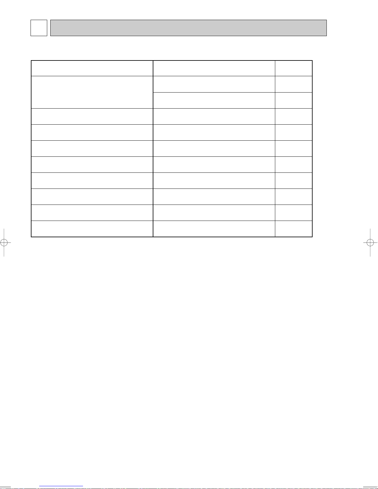
Model name Service Ref.
Service
Manual No.
PLA-RP35/50/60/71AA PLA-RP35/50/60/71AA.UK OC335
PLA-RP100/125/140AA PLA-RP100/125/140AA.UK
PLA-RP35/50/60/71AA OC327
PLA-RP100/125/140AA.UK
PCA-RP50/60/71GA PCA-RP50/60/71GA OC328
PCA-RP100/125/140GA PCA-RP100/125/140GA
PCA-RP71/125HA PCA-RP71/125HA OC329
PKA-RP35/50GAL PKA-RP35/50GAL OC330
PKA-RP60/71/100FAL PKA-RP60/71/100FAL OC331
PSA-RP71/100/125/140GA PSA-RP71/100/125/140GA OC332
PEA-RP71/100/125/140EA PEA-RP71/100/125/140EA.TH-A OC326
PEAD-RP35/50/60/71EA PEAD-RP35/50/60/71EA.UK PEAD-RP100/125/140EA PEAD-RP100/125/140EA.UK
PEAD-RP60/71/100GA PEAD-RP60/71/100GA.UK -
1-2.TECHNICAL DATA BOOK
Manual No. OCS01
REFERENCE MANUAL
1-1. INDOOR UNIT’S SERVICE MANUAL
2
2 SAFETY PRECAUTION
Use new refrigerant pipes.
Make sure that the inside and outside of refrigerant piping is clean and it has no contamination
such as sulfur hazardous for use, oxides, dirt,
shaving particles, etc.
In addition, use pipes with specified thickness.
Store the piping to be used during installation
indoors and keep both ends of the piping sealed
until just before brazing. (Leave elbow joints, etc.
in their packaging.)
Use ester oil, ether oil or alkylbenzene oil (small
amount) as the refrigerant oil applied to flares
and flange connections.
In case of using the existing pipes for R22, be careful with
the followings.
· For RP100, 125 and 140, be sure to perform replacement
operation before test run.
· Change flare nut to the one provided with this product.
Use a newly flared pipe.
· Avoid using thin pipes.
Charge refrigerant from liquid phase of gas
cylinder.
If the refrigerant is charged from gas phase, composition
change may occur in refrigerant and the efficiency will be
lowered.
Do not use refrigerant other than R410A.
If other refrigerant (R22 etc.) is used, chlorine in refrigerant can cause deterioration of refrigerant oil etc.
Use a vacuum pump with a reverse flow check
valve.
Vacuum pump oil may flow back into refrigerant cycle and
that can cause deterioration of refrigerant oil etc.
Use the following tools specifically designed for
use with R410A refrigerant.
The following tools are necessary to use R410A refrigerant.
Keep the tools with care.
If dirt, dust or moisture enter into refrigerant cycle, that can
cause deterioration of refrigerant oil or malfunction of compressor.
Do not use a charging cylinder.
If a charging cylinder is used, the composition of refrigerant will change and the efficiency will be lowered.
Flare tool
Electronic refrigerant
charging scale
Vacuum pump adaptor
Size adjustment gauge
Gauge manifold
Torque wrench
Gas leak detector
Charge hose
Tools for R410A
Contamination inside refrigerant piping can cause deterioration of refrigerant oil etc.
If dirt, dust or moisture enter into refrigerant cycle, that can
cause deterioration of refrigerant oil or malfunction of compressor.
If large amount of mineral oil enter, that can cause deterioration of refrigerant oil etc.
Ventilate the room if refrigerant leaks during
operation. If refrigerant comes into contact with
a flame, poisonous gases will be released.
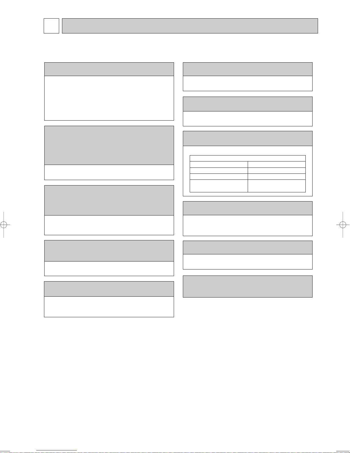
2-1. CAUTIONS RELATED TO NEW REFRIGERANT
Cautions for units utilizing refrigerant R410A
[1] Cautions for service
(1) Perform service after collecting the refrigerant left in unit completely.
(2) Do not release refrigerant in the air.
(3) After completing service, charge the cycle with specified amount of refrigerant.
(4) When performing service, install a filter drier simultaneously.
Be sure to use a filter drier for new refrigerant.
[2] Additional refrigerant charge
When charging directly from cylinder
· Check that cylinder for R410A on the market is syphon type.
· Charging should be performed with the cylinder of syphon stood vertically. (Refrigerant is charged from liquid phase.)
3
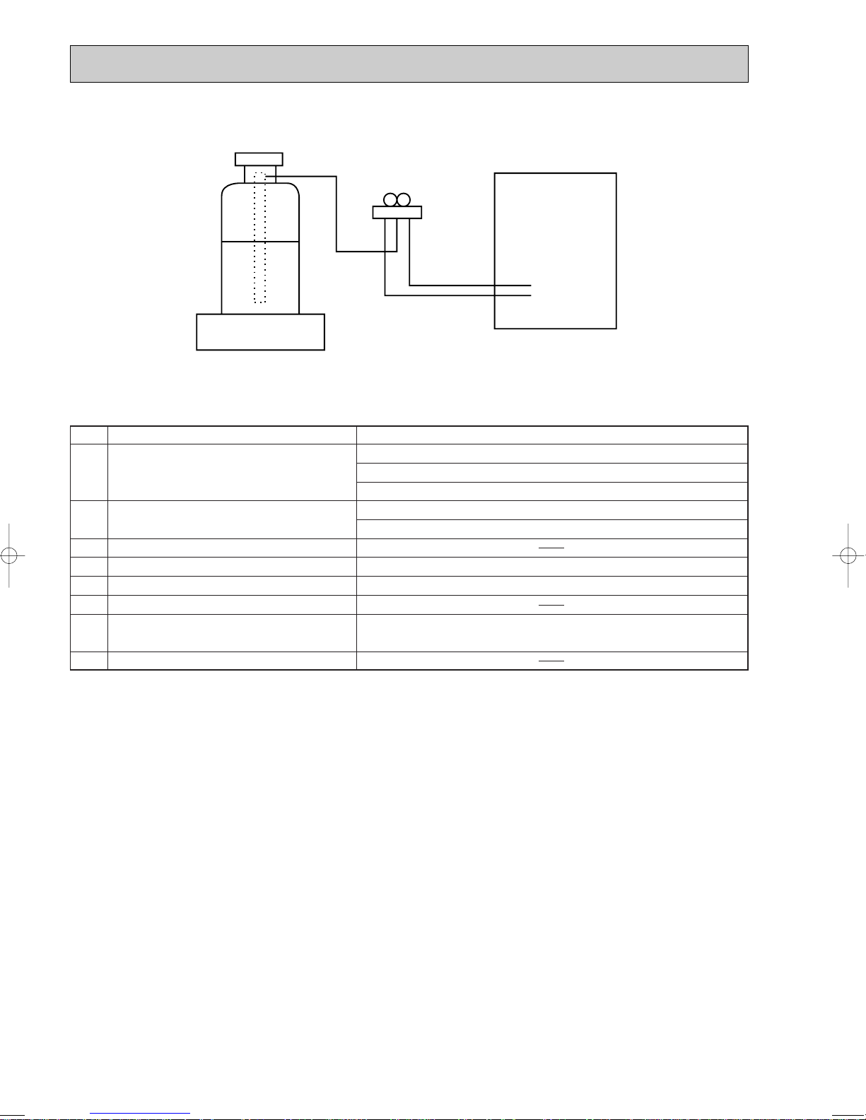
Unit
Gravimeter
[3] Service tools
Use the below service tools as exclusive tools for R410A refrigerant.
No. Specifications
1 Gauge manifold ·Only for R410A
·Use the existing fitting
·Use high-tension side pressure of 5.3MPa·G or over.
2 Charge hose ·Only for R410A
·Use pressure performance of 5.09MPa·G or over.
3 Electronic scale
4 Gas leak detector ·Use the detector for R134a, R407C or R410A.
5 Adaptor for reverse flow check ·Attach on vacuum pump.
6 Refrigerant charge base
7 Refrigerant cylinder ·Only for R410A Top of cylinder (Pink)
8 Refrigerant recovery equipment
specifications
Cylinder with syphon
. (UNF1/2)
4
2-2. CHANGED POINT
Connecting a new air conditioner
1Flaring work should be done so that flare meets the dimension for R410A.
Use flare nut provided with indoor and outdoor unit.
2When using gas piping of [19.05mm for RP100, 125 or 140.
Make sure that DIP SW8-1 on outdoor unit controller board is set to ON.
WThis is to keep the pressure on pipes within permissible range.
●Use different diameter joint or adjust the piping size by brazing.
3When using pipes larger than specified size for RP35, 50, 60 or 71.
Make sure that DIP SW8-1 on outdoor unit controller board is set to ON.
W
This is to prevent oil flow ratio from lowering due to the decrease in flowing refrigerant.
●Use different diameter joint or adjust the piping size by brazing.
4When existing pipes are specified size.
The pipes can be reused referring to TECHNICAL DATA BOOK (OCS01).
●Use different diameter joint or adjust the piping size by brazing.
★When using existing pipes for RP100, 125 and 140.
Make sure that DIP SW8-2 on outdoor unit controller board is set to ON and perform
replacement operation.
wChemical compounds containing chlorine left in existing pipes are collected by rep lace filter.
●The air conditioner automatically performs cooling operation through replace filter
for about 2 hours.
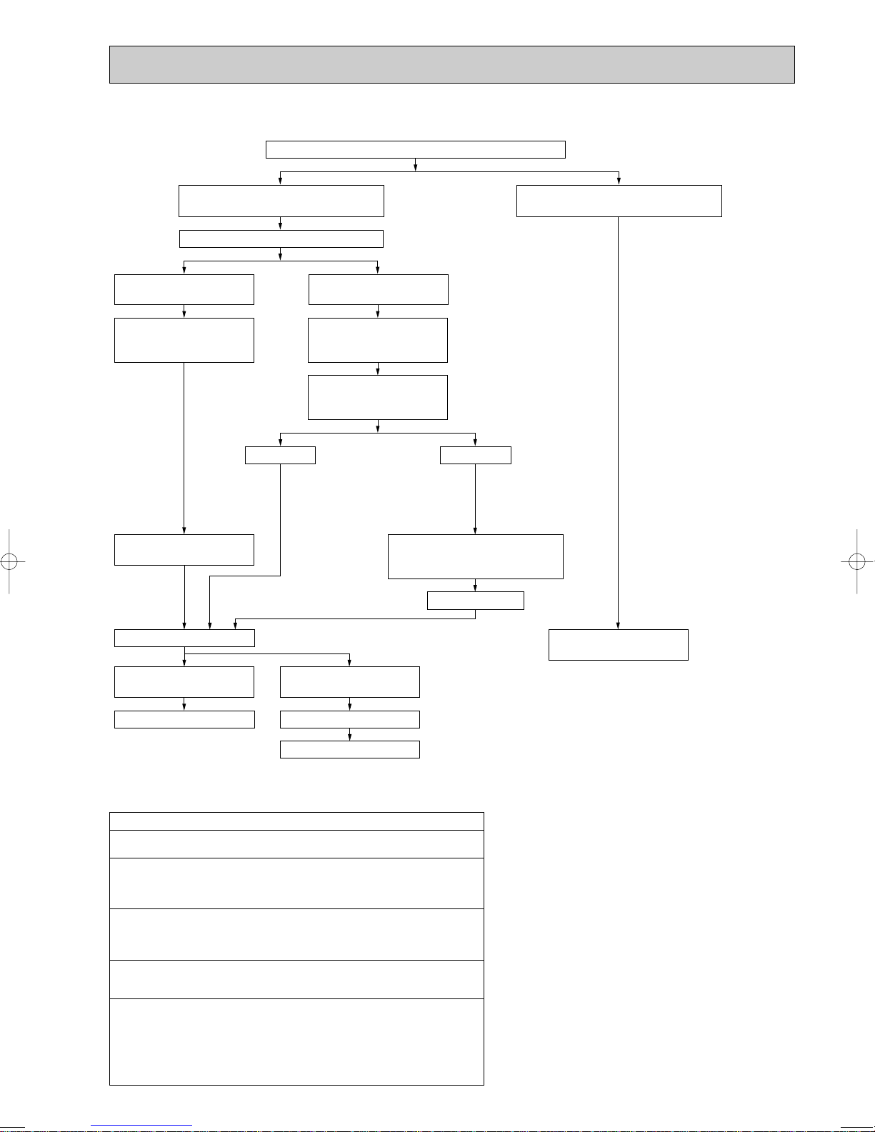
Measure the existing pipe thickness and check for damage.
Check if existing air conditioner can operate.
Existing air conditioner can
operate.
Disconnect existing air conditioner from piping.
Existing pipes can be reused.
In case the unit is RP35, 50,
60 or 71 which utilizes AB oil.
In case the unit is RP100, 125
or 140 which utilize ester oil.
Perform cooling operation
for about 30 minutes and
then do a pump down work.
Use a refrigerant recovery
equipment to collect the refrigerant.
Check the oil condition
when collecting the refrigerant.
Disconnect existing air conditioner
from pipes and clean pipes using
cleaning device.
Existing air conditioner
cannot operate.
The existing pipe thickness meets specifications and the pipes are not damaged.
The existing pipe thickness does not meet
specifications or the pipes are damaged.
Oil is clean.
Connect a new air conditioner. Connect a new air conditioner.
Perform replacement operation.
Oil is dirty.
Attach a filter drier.
When the compressor bearings
are glazed, rotation scratches
are present, or the compressor
breaks down, iron particles or
oil deterioration will blacken the
oil.
·When performing replacement operation, make sure that DIP SW8-2 on outdoor unit controller board is
set to ON.
wChemical compounds containing chlorine left in existing pipes are collected by replace filter.
●The air conditioner automatically performs cooling operation through replace filter for about 2 hours.
Existing pipes cannot be
reused. Use new pipes.
• Precautions when reusing existing R22 refrigerant pipes
(1) Flowchart
5
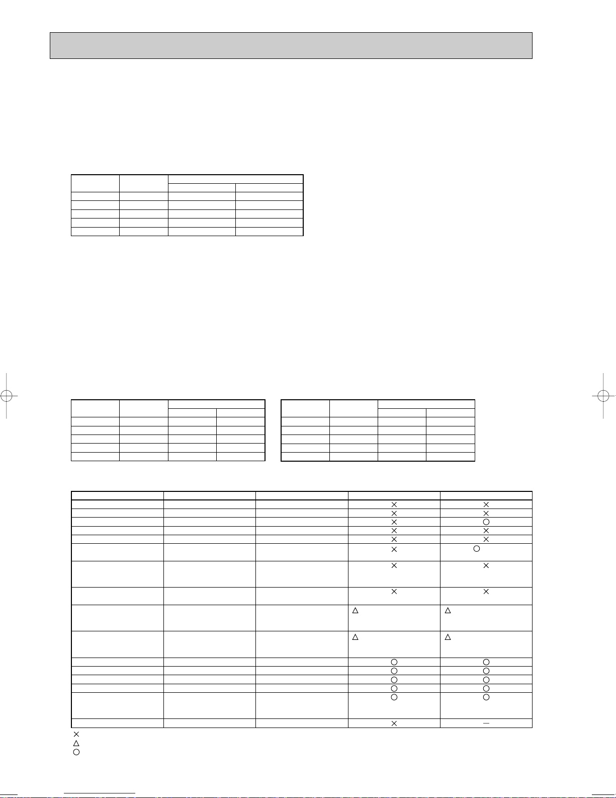
(2) Cautions for refrigerant piping work
1/4”
3/8”
1/2”
5/8”
3/4”
6.35
9.52
12.70
15.88
19.05
0.8
0.8
0.8
1.0
—
0.8
0.8
0.8
1.0
1.0
Nominal
dimensions
Diagram below: Piping diameter and thickness
Outside
diameter
(mm)
Thickness
(mm)
R410A R22
1/4”
3/8”
1/2”
5/8”
3/4”
6.35
9.52
12.70
15.88
19.05
9.1
13.2
16.6
19.7
—
9.0
13.0
16.2
19.4
23.3
Nominal
dimensions
Flare cutting dimensions
Outside
diameter
Dimension A
( )
+0
-0.4
(mm)
R410A R22
1/4”
3/8”
1/2”
5/8”
3/4”
6.35
9.52
12.70
15.88
19.05
17.0
22.0
26.0
29.0
—
17.0
22.0
24.0
27.0
36.0
Nominal
dimensions
Flare nut dimensions
Outside
diameter
Dimension B
(mm)
R410A
w
w36.0mm for
indoor unit
of RP100,
125 and 140
R22
Gauge manifold
Charge hose
Gas leak detector
Refrigerant recovery equipment
Refrigerant cylinder
Applied oil
Safety charger
Charge valve
Vacuum pump
Flare tool
Bender
Pipe cutter
Welder and nitrogen gas cylinder
Refrigerant charging scale
Vacuum gauge or thermistor vacuum gauge and
vacuum valve
Charging cylinder
Air purge and refrigerant charge
Operation check and the two above
Gas leak check
Collection of refrigerant
Refrigerant charge
Apply to flared section
Prevent compressor malfunction
when charging refrigerant by
spraying liquid refrigerant
Prevent gas from blowing out
when detaching charge hose
Vacuum drying and air
purge
Flaring work of piping
Bend the pipes
Cut the pipes
Weld the pipes
Charge refrigerant
Check the degree of vacuum. (Vacuum
valve prevents back flow of oil and refrigerant to thermistor vacuum gauge)
Charge refrigerant
Tool exclusive for R410A
Tool exclusive for R410A
Tool for HFC refrigerant
Tool exclusive for R410A
Tool exclusive for R410A
Ester oil and alkylbenzene
oil (minimum amount)
Tool exclusive for R410A
Tool exclusive for R410A
Tools for other refrigerants can
be used if equipped with adopter for reverse flow check
Tools for other refrigerants
can be used by adjusting
flaring dimension
Tools for other refrigerants can be used
Tools for other refrigerants can be used
Tools for other refrigerants can be used
Tools for other refrigerants can be used
Tools for other refrigerants
can be used
Tool exclusive for R410A
Tools and materials Use R410A tools Can R22 tools be used?
(Usable if equipped
with adopter for rever se flow)
(Usable by adjusting
flaring dimension)
Can R407C tools be used?
Ester oil:
Alkylbenzene oil: minimum amount
(Usable if equipped
with adopter for rever se flow)
(Usable by adjusting
flaring dimension)
: Prepare a new tool. (Use the new tool as the tool exclusive for R410A.)
: Tools for other refrigerants can be used under certain conditions.
: Tools for other refrigerants can be used.
New refrigerant R410A is adopted for replacement inverter series. Although the refrigerant piping work for R410A is same
as for R22, exclusive tools are necessary so as not to mix with different kind of refrigerant. Furthermore as the working
pressure of R410A is 1.6 time higher than that of R22, their sizes of flared sections and flare nuts are different.
1Thickness of pipes
Because the working pressure of R410A is higher compared to R22, be sure to use refrigerant piping with thickness
shown below. (Never use pipes of 0.7mm or below.)
2Dimensions of flare cutting and flare nut
The component molecules in HFC refrigerant are smaller compared to conventional refrigerants. In addition to that,
R410A is a refrigerant, which has higher risk of leakage because of its working pressure higher than that of other refrigerants. Therefore, to enhance airtightness and intensity, flare cutting dimension of copper pipe for R410A have been specified separately from the dimensions for other refrigerants as shown below. The dimension B of flare nut for R410A also
have partly been changed to increase intensity as shown below. Set copper pipe correctly referring to copper pipe flaring
dimensions for R410A below. For 1/2” and 5/8”, the dimension B changes.
Use torque wrench corresponding to each dimension.
Dimension A
3Tools for R410A (The following table shows whether conventional tools can be used or not.)
6
Dimension B
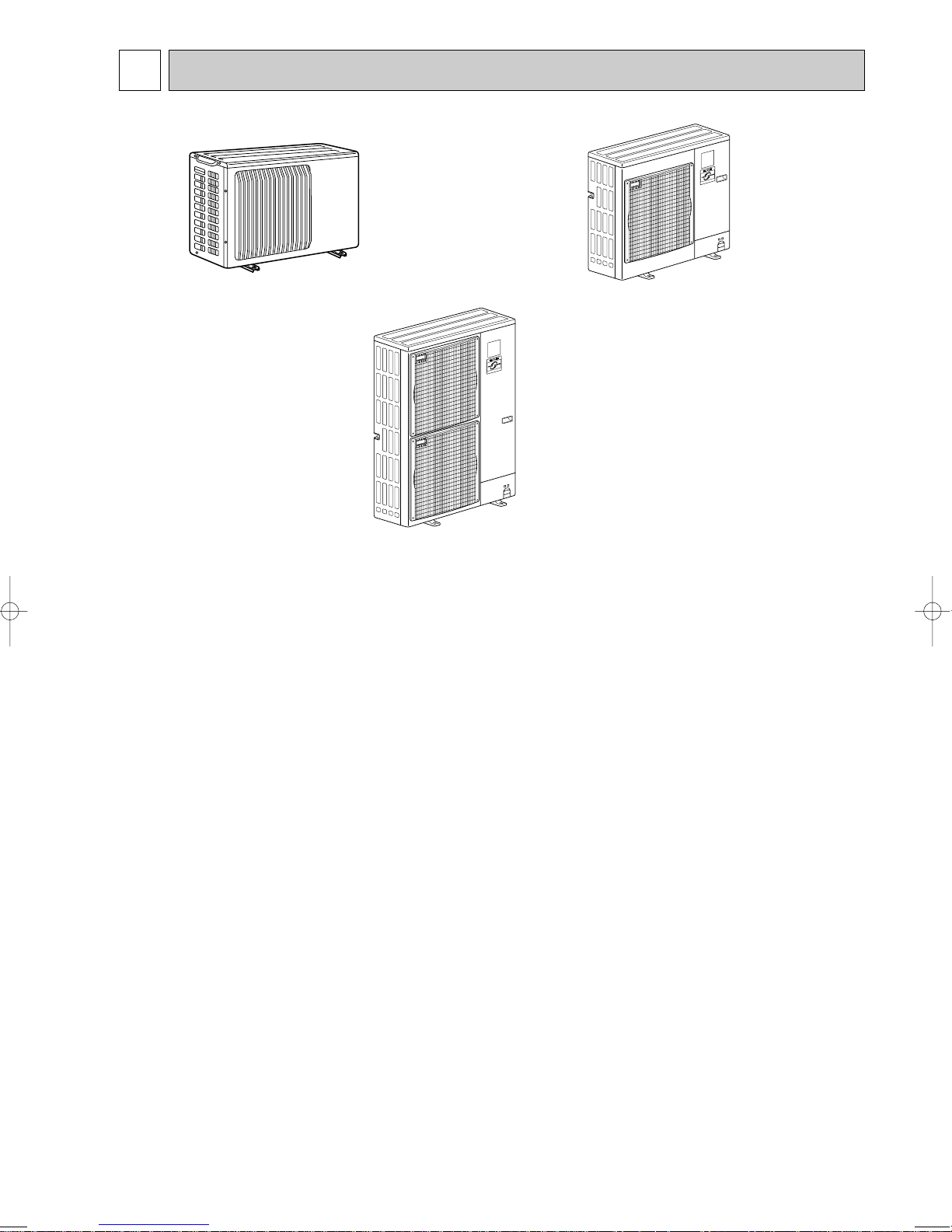
3 FEATURES
PUHZ-RP35VHA
PUHZ-RP50VHA
PUHZ-RP60VHA
PUHZ-RP71VHA
PUHZ-RP100VHA
PUHZ-RP125VHA
PUHZ-RP140VHA
PUHZ-RP100YHA
PUHZ-RP125YHA
PUHZ-RP140YHA
CHARGELESS SYSTEM
PRE-CHARGED REFRIGERANT IS SUPPLIED FOR PIPING LENGTH AT SHIPMENT.
(Max.30m(PUHZ-RP35~RP140))
The refrigerant circuit with LEV(Linear Expansion Valve) and power receiver always control the optimal refrigerant
level regardless of the length (30m max. and 5m min.) of piping. The additional refrigerant charging work during
installation often causes problems. Heretofore it is completely eliminated. This unique system improves the quality
and reliability of the work done. It also helps to speed up the installation time.
7
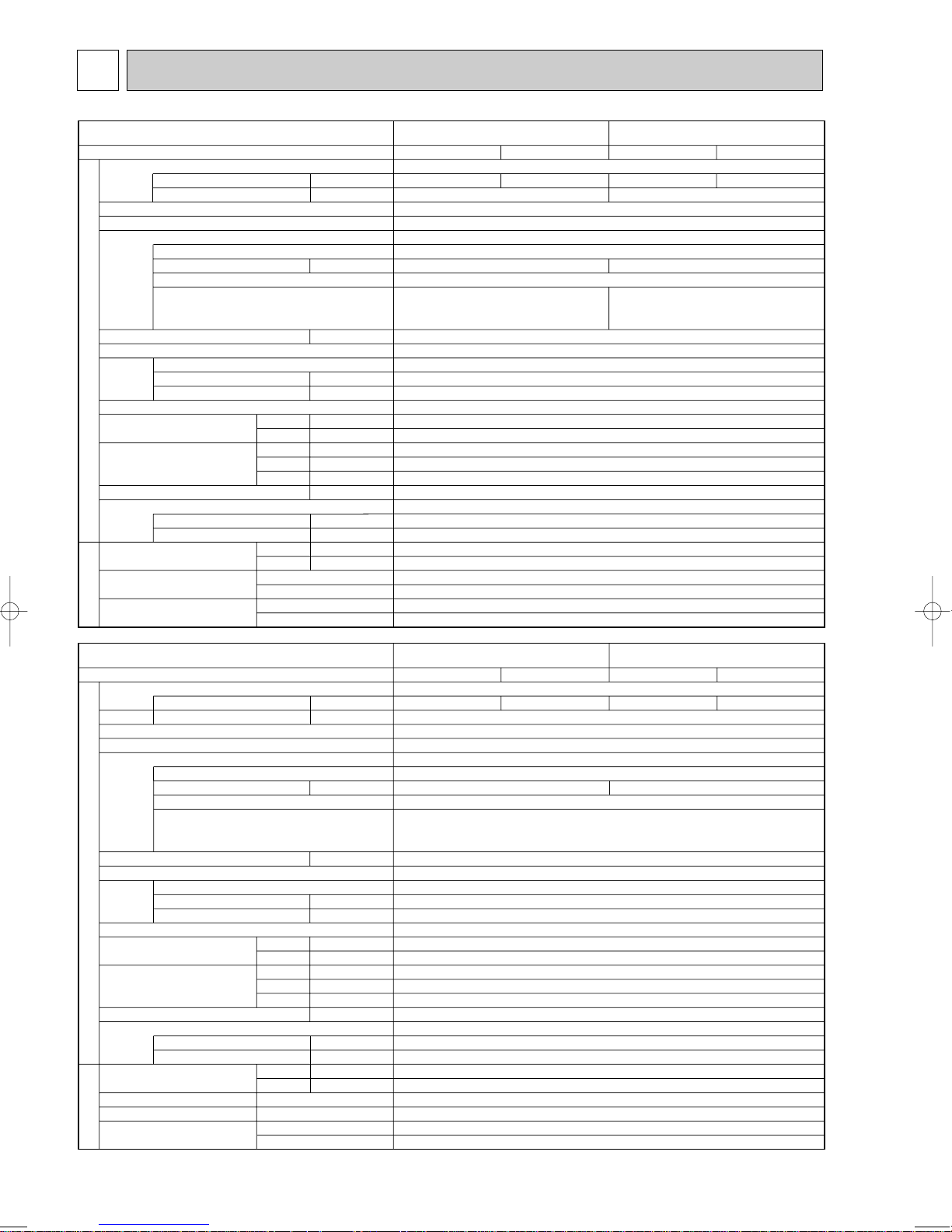
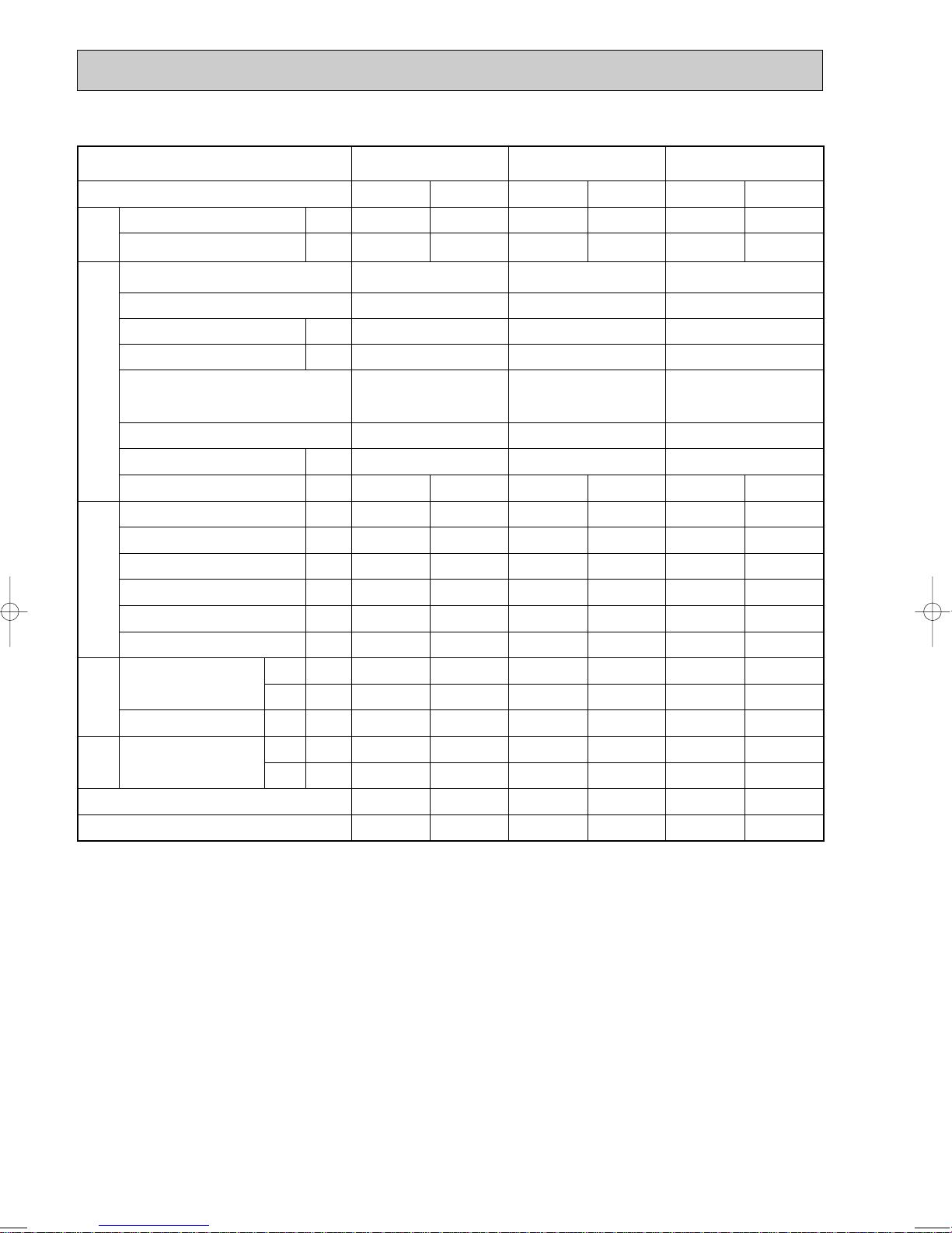
4 SPECIFICATIONS
Service Ref.
Mode
Power supply (phase, cycle, voltage)
External finish
Refrigerant control
Compressor
Crankcase heater
Heat exchanger
Fan Fan(drive) o No.
OUTDOOR UNIT
Defrost method
Noise level
Dimensions
Weight
Refrigerant
Pipe size O.D.
Connection method
Between the indoor &
outdoor unit
REFRIGERANT PIPING
Running current
Max. current
Model
Motor output
Starter type
Protection devices
Fan motor output
Airflow
Charge
Oil (Model)
/min(CFM
K
Cooling
Heating
W
D
H
Liquid
Gas
Indoor side
Outdoor side
Height difference
Piping length
mm(in.)
mm(in.)
mm(in.)
kg(lbs)
kg(lbs)
mm(in.)
mm(in.)
kW
W
kW
dB
dB
PUHZ-RP35VHA PUHZ-RP50VHA
Cooling
A
A
)
L
4.01
HP switch
Discharge thermo
Heating
Single, 50Hz, 230V
4.23
13
Munsell 3Y 7.8/1.1
Linear Expansion Valve
Hermetic
SNB130FLBH
0.8
Line start
Plate fin coil
Propeller fan o 1
0.043
35(1,240)
Reverse cycle
800(31-1/2)
330+23(11-13/16+7/8)
600(23-5/8)
45(99)
R410A
2.5(5.5)
0.45(NEO22)
6.35(1/4)
12.7(1/2)
Flared
Flared
Max. 30m
Max. 50m
—
44
46
Cooling
6.16
Discharge thermo
Heating
6.47
13
1.1
HP switch
Service Ref.
Mode
Power supply (phase, cycle, voltage)
External finish
Refrigerant control
Compressor
Crankcase heater
Heat exchanger
Fan Fan(drive) o No.
OUTDOOR UNIT
Defrost method
Noise level
Dimensions
Weight
Refrigerant
Pipe size O.D.
Connection method
Between the indoor &
outdoor unit
REFRIGERANT PIPING
Running current
Max. current
Model
Motor output
Starter type
Protection devices
Fan motor output
Airflow
Charge
Oil (Model)
/min(CFM
K
Cooling
Heating
W
D
H
Liquid
Gas
Indoor side
Outdoor side
Height difference
Piping length
mm(in.)
mm(in.)
mm(in.)
kg(lbs)
kg(lbs)
mm(in.)
mm(in.)
kW
W
kW
dB
dB
PUHZ-RP60VHA
Cooling
A
A
)
L
6.61
Heating
Single, 50Hz, 230V
7.50
Linear Expansion Valve
19
Munsell 3Y 7.8/1.1
Hermetic
TNB220FMBH
Line start
HP switch
Discharge thermo
—
Plate fin coil
Propeller fan o 1
0.060
55(1,940)
Reverse cycle
47
48
950(37-3/8)
330+30(13+1-3/16)
943(37-1/8)
75(165)
R410A
3.5(7.7)
0.87(NEO22)
9.52(3/8)
15.88(5/8)
Flared
Flared
Max. 30m
Max. 50m
PUHZ-RP71VHA
Cooling
8.04
Heating
9.74
1.61.4
8

Service Ref.
Mode
Power supply (phase, cycle, voltage)
External finish
Refrigerant control
Compressor
Crankcase heater
Heat exchanger
Fan Fan(drive) o No.
OUTDOOR UNIT
Defrost method
Noise level
Dimensions
Weight
Refrigerant
Pipe size O.D.
Connection method
Between the indoor &
outdoor unit
REFRIGERANT PIPING
Running current
Max. current
Model
Motor output
Starter type
Protection devices
Fan motor output
Airflow
Charge
Oil (Model)
/min(CFM
K
Cooling
Heating
W
D
H
Liquid
Gas
Indoor side
Outdoor side
Height difference
Piping length
mm(in.)
mm(in.)
mm(in.)
mm(in.)
mm(in.)
A
A
kW
W
kW
dB
dB
kg(lbs)
kg(lbs)
L
PUHZ-RP100VHA
Cooling
12.33
)
49
51
Heating
13.94
Cooling
Single 50Hz, 230V
15.80
28
Munsell 3Y 7.8/1.1
Linear Expansion Valve
Hermetic
ANV33FDDMT
2.41.9
Line start
HP switch
LP switch
Discharge thermo
—
Plate fin coil
Propeller fan o 2
0.060+0.060
100(3,530)
Reverse cycle
950(37-3/8)
330+30(13+1-3/16)
1,350(53-1/8)
121(267)
R410A
5.0(11.0)
1.40(MEL56)
9.52(3/8)
15.88(5/8)
Flared
Flared
Max. 30m
Max. 75m
Heating
17.50
50
52
PUHZ-RP140VHAPUHZ-RP125VHA
Cooling
20.73
Heating
20.37
29.5
2.9
Service Ref.
Mode
Power supply (phase, cycle, voltage)
Running current
Max. current
External finish
Refrigerant control
Compressor
Model
Motor output
Starter type
Protection devices
Crankcase heater
Heat exchanger
Fan Fan(drive) o No.
Fan motor output
OUTDOOR UNIT
Defrost method
Airflow
Noise level
Dimensions
Weight
Refrigerant
Charge
Oil (Model)
Pipe size O.D.
Connection method
Between the indoor &
outdoor unit
REFRIGERANT PIPING
/min(CFM
K
Cooling
Heating
W
D
H
mm(in.)
mm(in.)
mm(in.)
kg(lbs)
kg(lbs)
Liquid
Gas
mm(in.)
mm(in.)
Indoor side
Outdoor side
Height difference
Piping length
kW
W
kW
dB
dB
PUHZ-RP100YHA
Cooling
Heating
Cooling
Heating
PUHZ-RP140YHAPUHZ-RP125YHA
Cooling
Heating
3phase, 50Hz, 400V
A
3.79
A
13
4.33
4.85
13
5.41
6.49
6.37
13
Munsell 3Y 7.8/1.1
Linear Expansion Valve
Hermetic
ANV33FDBMT
2.41.9
2.9
Line start
HP switch
LP switch
Discharge thermo
—
Plate fin coil
Propeller fan o 2
0.060+0.060
)
100(3,530)
Reverse cycle
49
51
50
52
950(37-3/8)
330+30(13+1-3/16)
1,350(53-1/8)
135(298)
R410A
5.0(11.0)
L
1.40(MEL56)
9.52(3/8)
15.88(5/8)
Flared
Flared
Max. 30m
Max. 75m
9
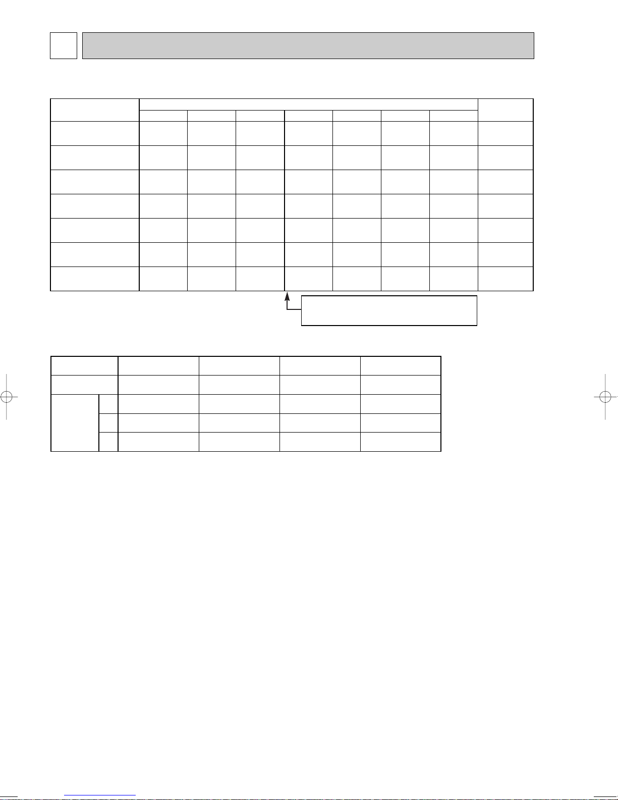
5 DATA
Piping length (one way)
10m
20m
30m
40m
50m
Factory
charged
2.1
2.1
3.1
3.1
4.6
4.6
4.6
2.3
2.3
3.3
3.3
4.8
4.8
4.8
2.5
2.5
3.5
3.5
5.0
5.0
5.0
2.7
2.7
4.1
4.1
5.6
5.6
5.6
2.9
2.9
4.7
4.7
6.2
6.2
6.2
60m
—
—
—
—
6.8
6.8
6.8
75m
—
—
—
—
7.4
7.4
7.4
2.5
2.5
3.5
3.5
5.0
5.0
5.0
Service Ref.
PUHZ-RP35VHA
PUHZ-RP50VHA
PUHZ-RP60VHA
PUHZ-RP71VHA
PUHZ-RP100VHA
PUHZ-RP100YHA
PUHZ-RP125VHA
PUHZ-RP125YHA
PUHZ-RP140VHA
PUHZ-RP140YHA
U-V
U-W
W-V
Unit
Compressor model
Winding
Resistance
( " )
ANV33FDDMT
(at 20°C)
0.266
0.266
0.266
SNB130FLBH
0.300 ~ 0.340
0.300 ~ 0.340
0.300 ~ 0.340
PUHZ-RP100,125,140VHA
ANV33FDBMT
1.064
1.064
1.064
PUHZ-RP100,125,140YHA
PUHZ-RP35,50VHA
TNB220FMBH
0.865 ~ 0.895
0.865 ~ 0.895
0.865 ~ 0.895
PUHZ-RP60,71VHA
5-1. REFILLING REFRIGERANT CHARGE (R410A : kg)
Longer pipe than 30m, additional charge is
required.
5-2. COMPRESSOR TECHNICAL DATA
10
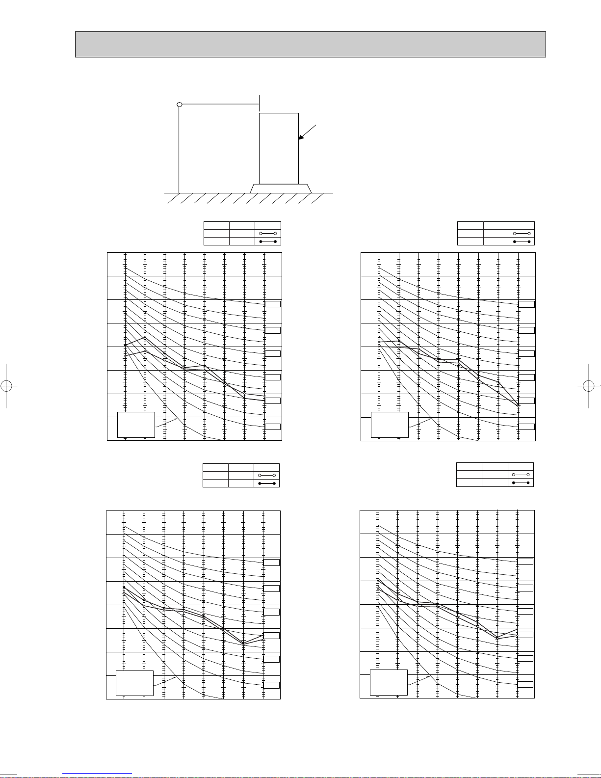
5-3. NOISE CRITERION CURVES
90
80
70
60
50
40
30
20
10
63 125 250 500 1000 2000 4000 8000
APPROXIMATE
THRESHOLD OF
HEARING FOR
CONTINUOUS
NOISE
OCTAVE BAND SOUND PRESSURE LEVEL, dB (0 dB = 0.0002 µbar)
BAND CENTER FREQUENCIES, Hz
NC-60
NC-50
NC-40
NC-30
NC-20
NC-70
PUHZ-RP100VHA
PUHZ-RP100YHA
COOLING
MODE
HEATING
49
SPL(dB)
51
LINE
90
80
70
60
50
40
30
20
10
63 125 250 500 1000 2000 4000 8000
APPROXIMATE
THRESHOLD OF
HEARING FOR
CONTINUOUS
NOISE
OCTAVE BAND SOUND PRESSURE LEVEL, dB (0 dB = 0.0002 µbar)
BAND CENTER FREQUENCIES, Hz
NC-60
NC-50
NC-40
NC-30
NC-20
NC-70
PUHZ-RP125VHA
PUHZ-RP140VHA
PUHZ-RP125YHA
PUHZ-RP140YHA
COOLING
MODE
HEATING
50
SPL(dB)
52
LINE
90
80
70
60
50
40
30
20
10
63 125 250 500 1000 2000 4000 8000
APPROXIMATE
THRESHOLD OF
HEARING FOR
CONTINUOUS
NOISE
NC-60
NC-50
NC-40
NC-30
NC-20
NC-70
OCTAVE BAND SOUND PRESSURE LEVEL, dB (0 dB = 0.0002 µbar)
BAND CENTER FREQUENCIES, Hz
PUHZ-RP35VHA
PUHZ-RP50VHA
COOLING
MODE
HEATING
44
SPL(dB)
46
LINE
MICROPHONE
1m
1.5m
UNIT
GROUND
PUHZ-RP60VHA
PUHZ-RP71VHA
SPL(dB)
MODE
COOLING
HEATING
90
80
LINE
47
48
OCTAVE BAND SOUND PRESSURE LEVEL, dB (0 dB = 0.0002 µbar)
70
60
50
40
30
APPROXIMATE
20
THRESHOLD OF
HEARING FOR
CONTINUOUS
NOISE
10
63 125 250 500 1000 2000 4000 8000
BAND CENTER FREQUENCIES, Hz
NC-70
NC-60
NC-50
NC-40
NC-30
NC-20
11
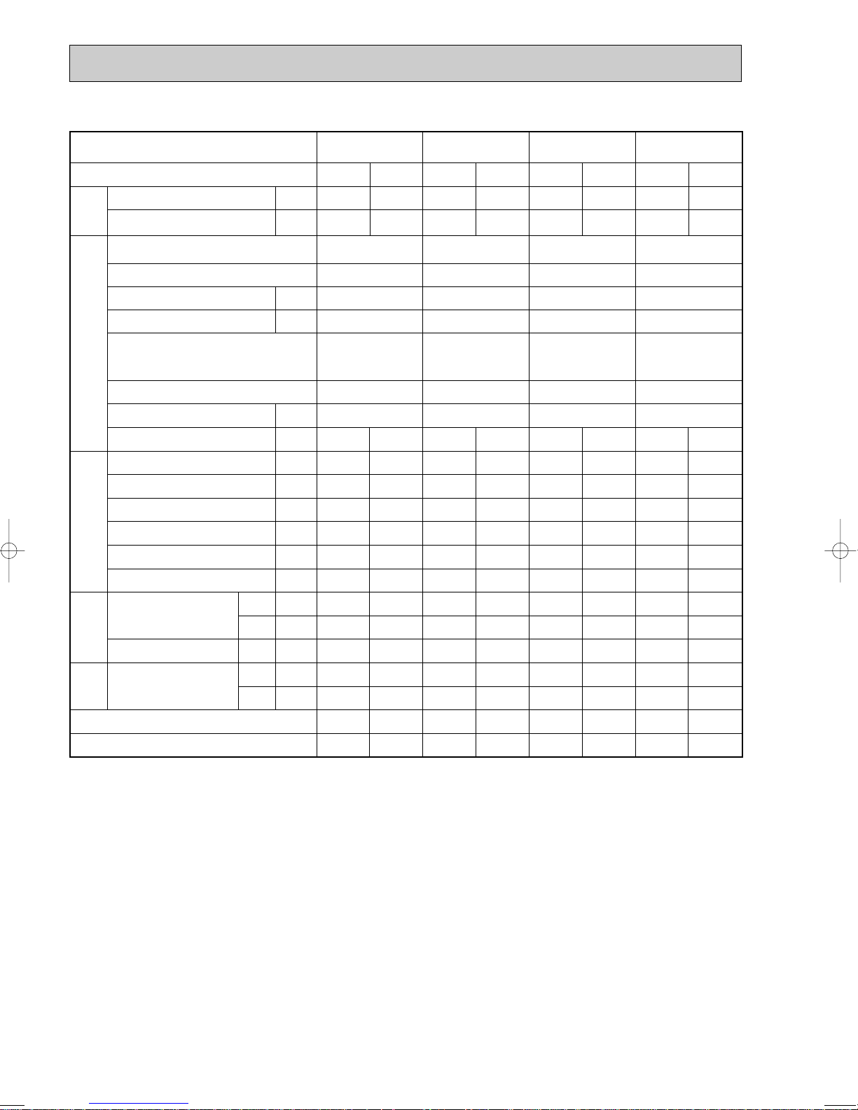
5-4. STANDARD OPERATION DATA
TotalElectrical circuitRefrigerant circuitIndoor side
Outdoor
side
Representative matching
SHF
BF
W
kW
Mode
Capacity
Input
PLA-RP71AA
PLA-RP71AA
Cooling
7,100
1.97
Heating
8,000
2.34
8.04
2.68
0.94
70
46
10
5
27
19
14.2
35
24
0.74
0.18
9.74
2.87
0.73
74
48
1
5
20
15
41.6
7
6
—
—
1 , 50
230
0.79
PUHZ-RP71VHA
1 , 50
230
Phase , Hz
Volts
Amperes
Outdoor unit
Phase , Hz
Volts
Current
Discharge pressure
Suction pressure
Discharge temperature
Condensing temperature
Suction temperature
Ref. pipe length
Intake air temperature
Discharge air temperature
Intake air temperature
V
A
V
A
MPa
MPa
°C
°C
°C
m
°C
°C
°C
°C
°C
Indoor unit
D.B.
W.B.
D.B.
D.B.
W.B.
PLA-RP35AA PLA-RP50AA PLA-RP60AA
PLA-RP35AA PLA-RP50AA PLA-RP60AA
Cooling
3,600
1.07
Heating
4,100
1.12
Cooling
5,000
1.55
Heating
6,000
1.62
Cooling
6,000
1.65
Heating
7,000
1.85
4.01
2.70
1.01
70
46
15
5
27
19
15.6
35
24
0.89
0.11
4.23
2.69
0.74
71
41
2
5
20
15
35.5
7
6
—
—
6.16
2.91
0.99
73
49
11
5
27
19
15.4
35
24
0.86
0.14
6.47
2.76
0.67
77
44
-1
5
20
15
37.8
7
6
—
—
6.61
2.60
0.99
65
44
12
5
27
19
14.3
35
24
0.78
0.14
7.50
2.63
0.70
81
44
8
5
20
15
40.9
7
6
—
—
1 , 50
230
0.79
PUHZ-RP35VHA
1 , 50
230
1 , 50
230
0.79
PUHZ-RP50VHA
1 , 50
230
1 , 50
230
0.79
PUHZ-RP60VHA
1 , 50
230
The unit of pressure has been changed to MPa based on international SI system.
The conversion factor is : 1(MPa)=10.2(kgf/ff)
12
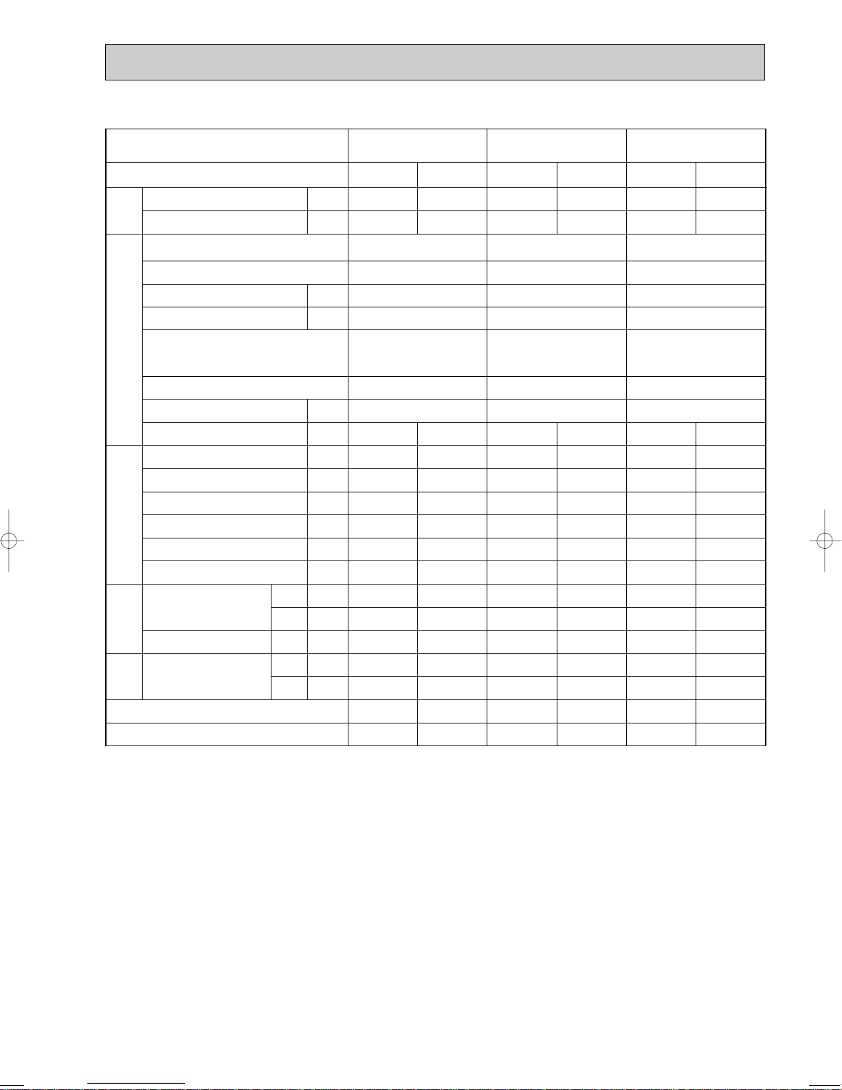
Representative matching
PLA-RP100AA PLA-RP125AA PLA-RP140AA
Mode
Capacity
TotalElectrical circuitRefrigerant circuitIndoor side
Input
Indoor unit
Phase , Hz
Volts
Amperes
Outdoor unit
Phase , Hz
Volts
Current
Discharge pressure
Suction pressure
Discharge temperature
Condensing temperature
Suction temperature
Ref. pipe length
Intake air temperature
Discharge air temperature
Intake air temperature
side
Outdoor
SHF
BF
D.B.
W.B.
D.B.
D.B.
W.B.
W
kW
V
A
V
A
MPa
MPa
°C
°C
°C
m
°C
°C
°C
°C
°C
Cooling
10,000
3.03
PLA-RP100AA PLA-RP125AA PLA-RP140AA
PUHZ-RP100VHA PUHZ-RP125VHA PUHZ-RP140VHA
12.33
2.63
0.92
70
45
11
5
27
19
14.0
35
24
0.75
0.15
1 , 50
230
1.25
1 , 50
230
Heating
11,200
3.39
13.94
2.80
0.72
76
48
3
5
20
15
41.6
7
6
—
—
Cooling
12,500
3.89
15.80
2.72
0.89
70
46
8
5
27
19
12.2
35
24
0.74
0.06
Heating
14,000
4.27
1 , 50
230
1.64
1 , 50
230
17.50
2.77
0.71
77
47
1
5
20
15
45.5
7
6
—
—
The unit of pressure has been changed to MPa based on international SI system.
The conversion factor is : 1(MPa)=10.2(kgf/ff)
Cooling
14,000
4.99
20.73
2.86
0.80
79
48
8
5
27
19
11.2
35
24
0.71
0.06
Heating
16,000
4.91
1 , 50
230
1.64
1 , 50
230
20.37
3.03
0.69
83
51
1
5
20
15
49.5
7
6
—
—
13
Representative matching
PLA-RP100AA
PLA-RP125AA
PLA-RP140AA
Mode
Capacity
TotalElectrical circuitRefrigerant circuitIndoor side
Input
Indoor unit
Phase , Hz
Volts
Amperes
Outdoor unit
Phase , Hz
Volts
Current
Discharge pressure
Suction pressure
Discharge temperature
Condensing temperature
Suction temperature
Ref. pipe length
Intake air temperature
Discharge air temperature
Intake air temperature
side
Outdoor
SHF
BF
kW
MPa
MPa
D.B.
W.B.
D.B.
D.B.
W.B.
W
V
A
V
A
°C
°C
°C
m
°C
°C
°C
°C
°C
Cooling
10,000
3.03
PLA-RP100AA PLA-RP125AA PLA-RP140AA
PUHZ-RP100YHA PUHZ-RP125YHA PUHZ-RP140YHA
3.79
2.63
0.92
70
45
11
5
27
19
14.0
35
24
0.75
0.15
1 , 50
230
1.25
3 , 50
400
Heating
11,200
3.39
4.33
2.80
0.72
76
48
3
5
20
15
41.6
7
6
—
—
Cooling
12,500
3.89
4.85
2.72
0.89
70
46
8
5
27
19
12.2
35
24
0.74
0.06
Heating
14,000
4.27
1 , 50
230
1.64
3 , 50
400
5.41
2.77
0.71
77
47
1
5
20
15
45.5
7
6
—
—
The unit of pressure has been changed to MPa based on international SI system.
The conversion factor is : 1(MPa)=10.2(kgf/ff)
Cooling
14,000
4.99
6.49
2.86
0.80
79
48
8
5
27
19
11.2
35
24
0.71
0.06
Heating
16,000
4.91
1 , 50
230
1.64
3 , 50
400
6.37
3.03
0.69
83
51
1
5
20
15
49.5
7
6
—
—
14
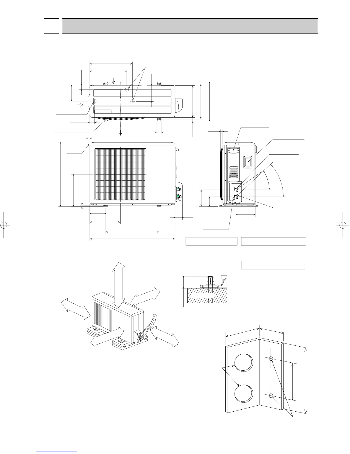
6 OUTLINES AND DIMENSIONS
PUHZ-RP35VHA
PUHZ-RP50VHA
400
347.5
Air intake
43.6
152
Air intake
[33 drain hole
45.4
4-10 o 21 oval hole
(M10 foundation bolt)
18
Handle for
moving
Air discharge
600
300
10
150
287.5
Installation bolt pitch: 500
800
Free space around the outdoor unit
(basic example)
100 mm or more as long as
no obstacle is placed on the
rear and light-and-left sides
of the unit.
100 mm or more
w 1
500 mm or more
w 2
2 sides should be open in
the right, left and rear side.
w 1
100 mm or more
Basically open
[33 drain hole
155
40
350 mm or more
330
365
300
23
32.5
155
90
69
Service port
1. FOUNDATION BOLTS
Please secure the unit firmly
with 4 foundation (M10) bolts.
(Bolts, washer and nut must
be purchased locally.)
<Foundation bolt height>
FOUNDATION
18 or below
Unit : mm
Service panel
Service panel
for charge plug
Connection for
liquid pipe
35
43
Connection for
gas pipe
183
2. PIPING-WIRING DIRECTION
Piping and wiring connection can
be made from the rear direction only.
3. ATTACHING THE CONDUIT
In order to attach the conduit, it is
necessary to fix the metal plate with
2 screws to the back panel. Procure
the metal plate and make screw holes
locally. It is recommended to use the
metal plate shown below. Align the
metal plate to the marks on the unit
and attach it.
w The position and the size of
conduit hole depend on the
conduit to be used.
40
20
Minimum installation space for outdoor unit
w 1 In the place where short cycle tends to occur, cooling and heating
capacity and power consumption might get lowered 10%. Air outlet
guide (optional PAC-SG58SG) will help them improve.
w 2 If air discharges to the wall, the surface might get stained.
15
w Conduit hole
60
Holes for metal plate fixing screw
w The size of hole depends on the
screw to be used.
80

PUHZ-RP60VHA
O
ver 10m
m
FRE
E
O
ver 500m
m
Over 100m
m
O
ver 10m
m
PUHZ-RP71VHA
Unit : mm
16
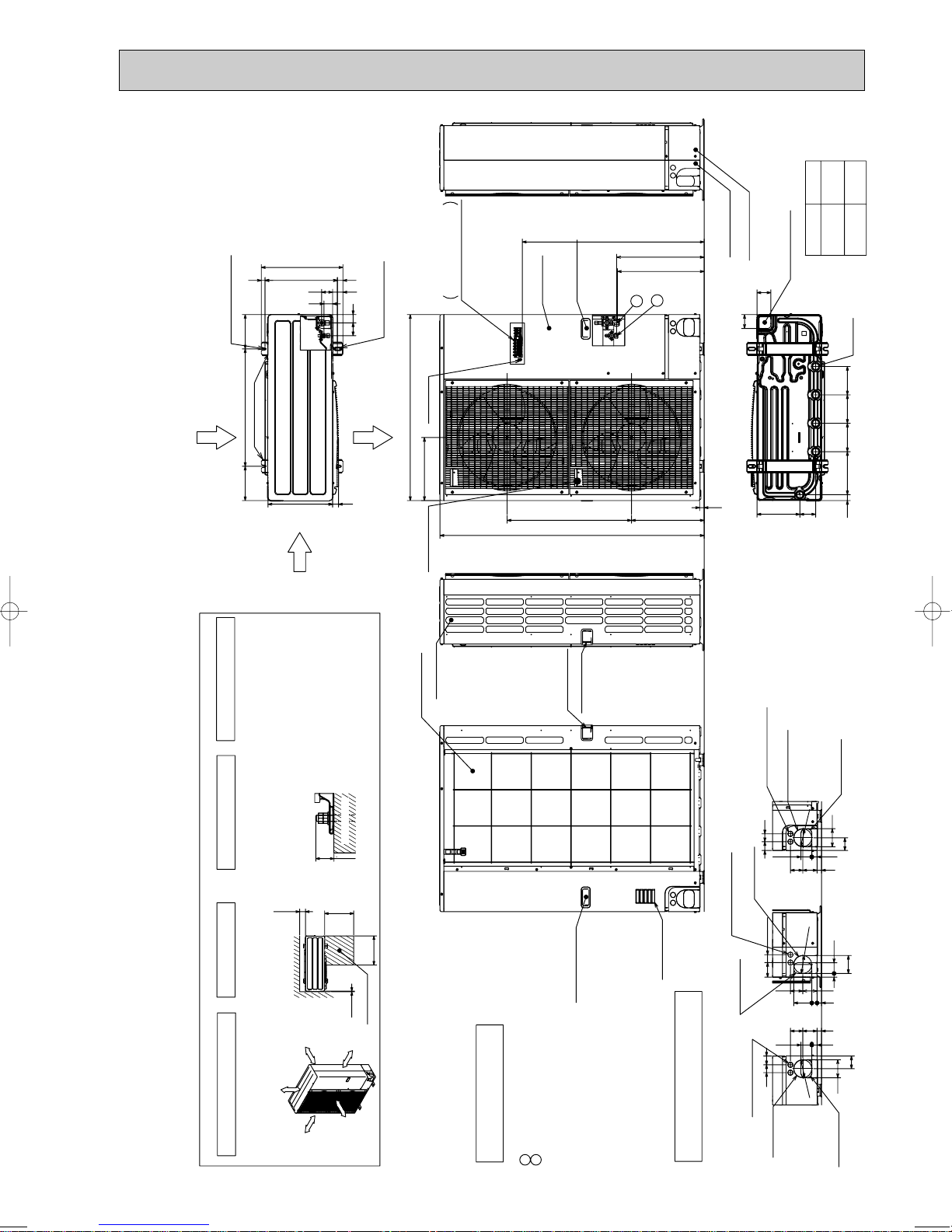
PUHZ-RP100VHA PUHZ-RP100YHA
Over
Over
Over
Over
Less than
Piping and wiring connections
can be made from 4 directions:
FRONT,Right,Rear and Below.
4 PIPING-WIRING DIRECTIONS
3 FOUNDATION BOLTS2 SERVICE SPACE
1 FREE SPACE (Around the unit)
Please secure the unit firmly
with 4 foundation (M10) bolts.
(Bolts and washers must be
purchased locally.)
<Foundation bolt height>
Dimensions of space needed
for service access are
shown in the below diagram.
The diagram below shows a
basic example.
Explantion of particular details are
given in the installation manuals etc.
FREE
O
v
e
r
1
0
m
m
O
v
e
r
1
0
m
m
O
v
e
r
1
5
0
m
m
O
v
e
r
1
5
0
m
m
30
FOUNDATION
10
500
500
100
Service space
PUHZ-RP125VHA PUHZ-RP125YHA
PUHZ-RP140VHA PUHZ-RP140YHA
Unit : mm
A
1,076
930
2-U Shaped notched holes
(Foundation Bolt M10)
600175 175
Rear Air Intake
Installation Feet
417
37028 19
5653
45
330
Side Air Intake
42
66
2-12o36 Oval holes
(Foundation Bolt M10)
Air Discharge
30
Terminal connection
Left • • • Power supply wiring
950
Earth terminal
322
Handle for moving
Right • • Indoor/Outdoor wiring
Service panel
A
Handle for moving
635371
1350
2
1
w1 447
w1 443
Front piping cover
Rear piping cover
71
23
Bottom piping hole
(Knock-Out)
71
81 219
RP·VHA
RP·YHA
Drain hole
(5-[33)
14514522030 145
Side Air Intake
Rear Air Intake
17
Handle for moving
Handle for moving
Handle for moving
Indication of STOP VALVE connection location.
Refrigerant LIQUID pipe connection (FLARE)[ 9.52 (3/8F)
Refrigerant GAS pipe connction (FLARE)[15.88 (5/8F)
• • •
• • •
Example of Notes
• • •
2
1
w1
Power supply wiring hole
(2-[27Knock-Out)
Rear trunking hole
(Knock-Out)
Rear piping hole
92
[92
4045
5527
637323
Right trunking hole
(Knock-Out)
(2-[27Knock-Out)
4075
[92
5519
Power supply wiring hole
Air intake
6373
Right piping hole
(Knock-Out)
922723
637323
5527
40 45
[92
Power supply wiring hole
(2-[27Knock-Out)
Piping Knock-Out Hole Details
Front trunking hole
(Knock-Out)
Front piping hole
(Knock-Out)
65
92
65
92
(Knock-Out)

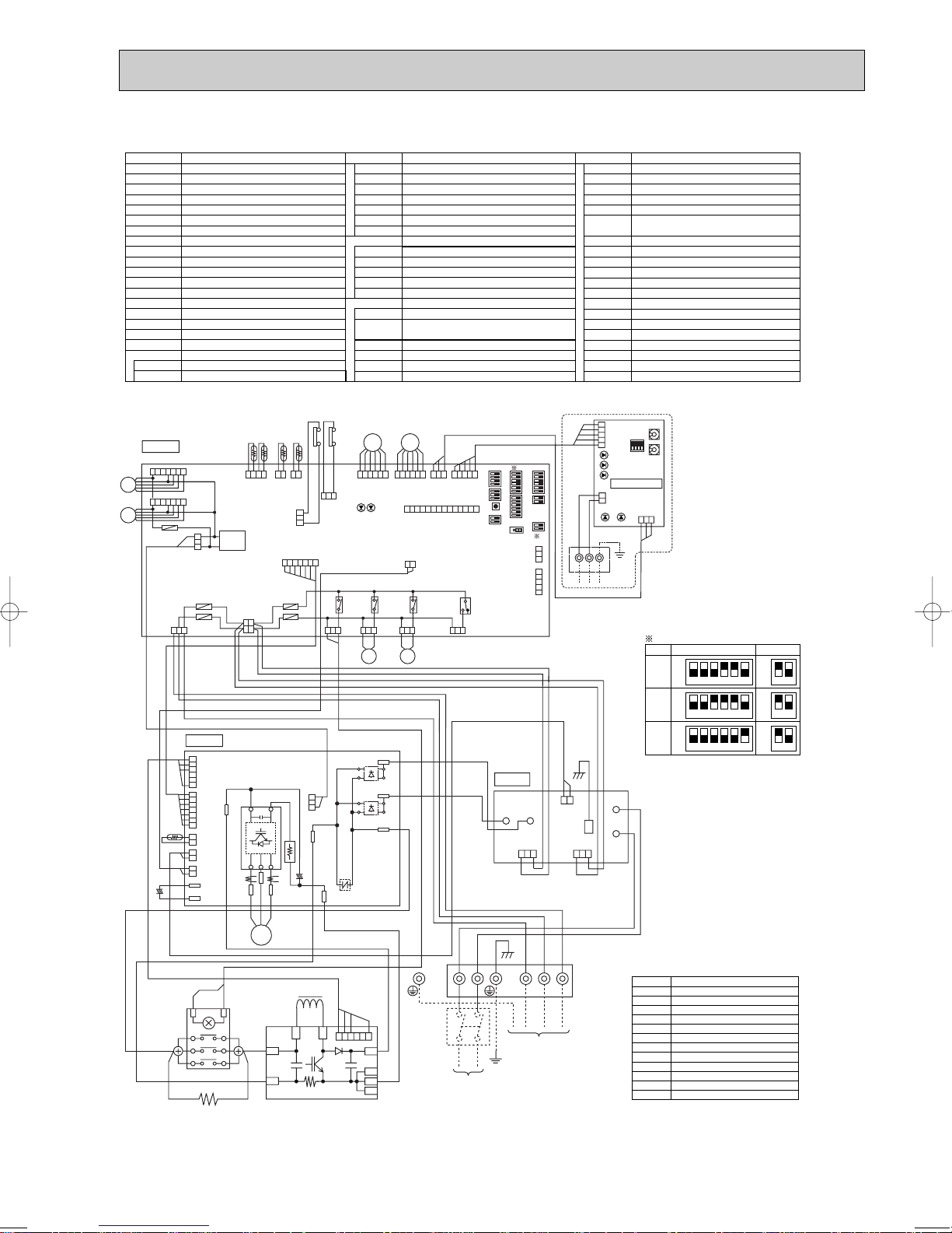
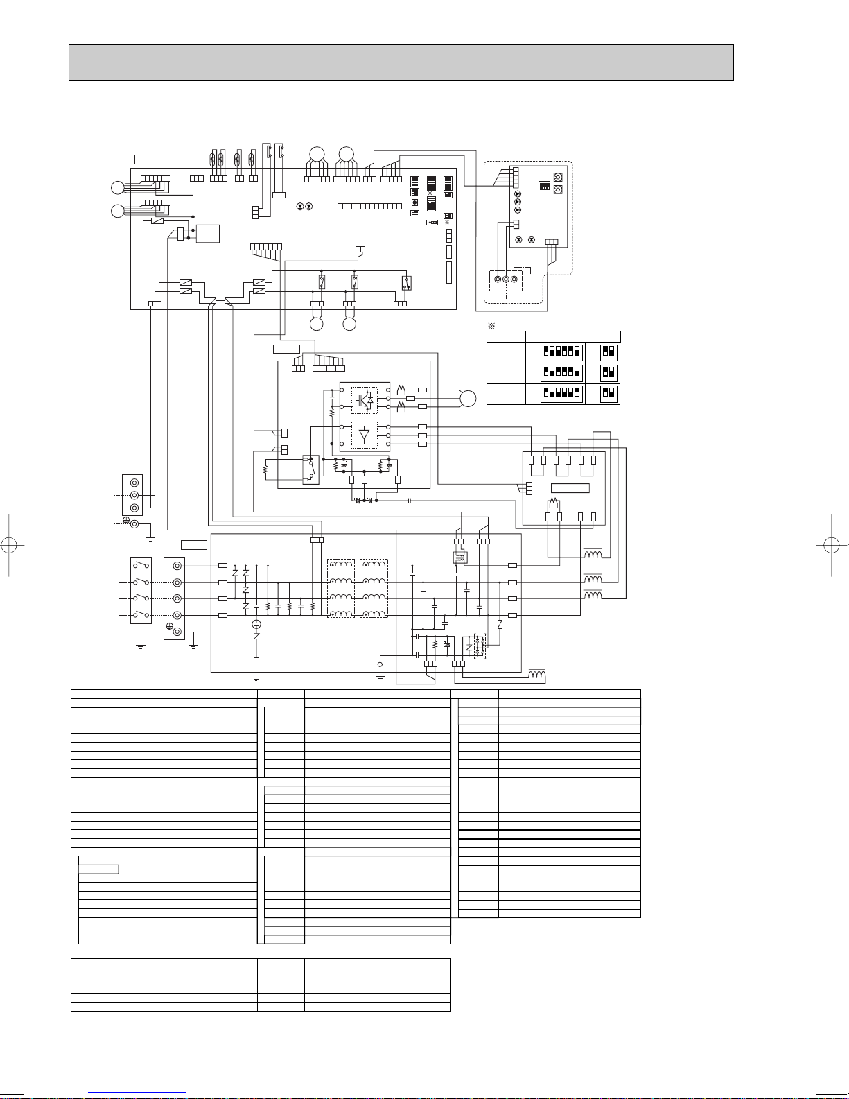
7 WIRING DIAGRAM
123456
OFF
ON
35V
MODEL
SW6
1 MODEL SELECT
2 RP60/71V only
SW10
12
OFF
ON
123456
OFF
ON
50V
12
OFF
ON
123456
OFF
ON
60V
12
OFF
ON
123456
OFF
ON
71V
12
OFF
ON
TB1
MC
MF1
21S4
63H
TH3
TH4
TH6
TH7
TH8
LEV(A),LEV(B)
ACL
Terminal Block (Power Supply, Indoor/Outdoor)
Motor for Compressor
Fan Motors
Solenoid Valve (Four-Way Valve)
High Pressure Switch
SV Solenoid Valve (Bypass Valve)
Thermistor (Outdoor Pipe)
Thermistor (Discharge)
Thermistor (Outdoor 2-Phase Pipe)
Thermistor (Outdoor)
Thermistor (Radiator Panel)
Electronic Expansion Valve
Reactor
Power Circuit Board
Connection Terminal (U/V/W-Phase)
Connector
P.B.
U/V/W
Noise Filter Circuit Board
Connection Terminal (L-Phase)
Connection Terminal (Ground)
N.F.
LI/LO
Connection Terminal (N-Phase)
NI/NO
E
Fuse (6.3 A)
Controller Circuit Board
Connector
Switch (Forced Defrost, Defect History
Record Reset, Refrigerant Address)
Switch (Test Operation)
Switch (Function Switch)
Switch (Function Setup)
Switch (Pump Down)
Connector (Emergency Operation)
CNAC1/2
F1~4
SW1
SW4
SW5
SW7
Switch
SW8
SWP
CN31
CNAC
CNDC
CNS
CNM
SV2
CNVMNT
CNDM
CN2~5
LED1,LED2
Light Emitting Diodes
(Operation Inspection Indicators)
Connector
Connector
Connector
Connector (A-Control Service Inspection Kit)
Connector
Connector
(Connected to Optional M-NET Adapter Board)
Connector
( Connected for Option (Contact Input))
C.B.
Converter
PFC
Inverter
IPM
Main Smoothing Capacitor
CB1~CB3
Connector
CN5
Connector
CN52C
52C Relay
52C
SYMBOL NAME SYMBOL NAME SYMBOL NAME
Connection Terminal (L/N-Phase)
R/S
CNMNT
Connector
(Connected to Optional M-NET Adapter Board)
Switch (Model Select)
SW6
Switch
SW9
Switch (Model Select)
SW10
X51,X52,X55
Reray
CNF1
Connector
SS
Connector (Connection for Option)
SYMBOL
M-NET ADAPTER
NAME
TB7
CN5
CND
CN2M
SW1
SW11
Terminal Block (M-net connection)
Connector (Transmission)
Connector (Power Supply)
Connector (M-NET communication)
Switch (Status of communication)
Switch (Address setting : 1st digit)
SW12
LED1
LED2
LED3
LED4
LED5
Switch (Address setting : 2nd digit)
LED (Power Supply : DC5V)
LED (Connection to Outdoor Unit)
LED (Transmission : Sending)
LED (Transmission : Recelving)
LED (Power Supply : DC12V)
CN3
(WHT)
CN5
(RED)
CN2
(WHT)
CN4
(WHT)
21
12
CN52C
(BLK)
52C
21
TH8
2
12
1672345
N.F.
LO
NO
CNAC2
(RED)
13
CNAC1
(WHT)
13
12
(RED)
CN5
NI
E
LI
L N S1 S2 S3
NO FUSE
BREAKER
POWER SUPPLY
~/N
230V 50Hz
INDOOR
UNIT
TB1
ACL
MC
U
V
W
R
S
PFC
CB1 CB2 CB3
IPM
P.B.
CN5
(WHT)
123
LED2
SW1
SW11
SW12
LED3
LED4
TB7
LED1
LED5
45321
21
CND
(WHT)
CN2M
(WHT)
M-NET SUBSTRATE
M-NET
ABS
When M-NET adaptor is connected
CNVMNT
(WHT)
321
13
CNDM
(WHT)
CN51
(WHT)
321
54213
CNMNT
(WHT)
CNM
(WHT)
45321
LEV-A
(WHT)
LEV-A
C.B.
456321
LEV-B
(RED)
LEV-B
456321
TH7/6
(RED)
63H
(YLW)
TRANS
X55
X51
TH3
(WHT)
CNDC
(PNK)
CNF1
(WHT)
TH4
(WHT)
TH7 TH6 TH3 TH4
43212121
SW7
SW6SW1
SW9SW10
CN31
1110 12 13 14
657891234
MF1
65714
CN2
(WHT)
CNS
(WHT)
CNAC
(WHT)
CN4
(WHT)
SV2
(BLU)
13
SS
(WHT)
21S4
(GRN)
43221
1
CN52C
(RED)
12
567
LED1
LED2
3
13
X52
F1
F2
F5
F4
F3
1
1
132
21
43
SW5SW8SW4 SWP
13
SV21S4
1
PUHZ-RP35VHA PUHZ-RP50VHA
PUHZ-RP60VHA PUHZ-RP71VHA
18
PUHZ-RP100VHA PUHZ-RP125VHA PUHZ-RP140VHA
TB1
MC
MF1,MF2
21S4
63H
63L
TH3
TH4
TH6
TH7
TH8
LEV-A,B
DCL
52C
Terminal Block (Power Supply, Indoor/Outdoor )
Motor for Compressor
Fan Motors
Solenoid Valve (Four-Way Valve)
High Pressure Switch
SV Solenoid Valve (Bypass Valve)
Low Pressure Switch
Thermistor (Outdoor Pipe)
Thermistor (Discharge)
Thermistor (Outdoor 2-Phase Pipe)
Thermistor (Outdoor)
Thermistor (Heat Sink)
Electronic Expansion Valve
Reactor
52C Relay
RS
Rush Current Protect Resistor
ACTM
Active Filter Module
CB
Main Smoothing Capacitor
Power Circuit Board
Connection Terminal (U/V/W-Phase)
Connector
Connector
Diode Bridge
P.B.
TABU/V/W
Noise Filter Circuit Board
Connection Lead (L-Phase)
Connection Terminal (Ground)
N.F.
LI/LO
Connection Lead (N-Phase)
NI/NO
EI
Controller Circuit Board
Switch (Model Select)
Switch (Pump Down)
Connector (Emergency Operation)
Switch
SW8
SW10
SWP
CN31
C.B.
CN2~5
CNDC
Connector
CNAF
DS2,3
Power Module
IPM
SYMBOL NAME SYMBOL NAME SYMBOL NAME
Connection Terminal (L/N-Phase)
Connection Terminal (DC Voltage)
TABS/T
TABP1/P2/P
Connection Terminal (DC Voltage)
TABN1/N2/N
Switch
SW9
Connector
CNAC1/2
Connector
CN5
Fuse (6.3 A)
Switch (Forced Defrost, Defect History Record
Reset, Refrigerant Address)
Switch (Test Operation)
Switch (Function Switch)
Switch (Model Select)
F1~4
SW1
SW4
SW5
SW6
Switch (Function Setup)
SW7
LED1,LED2
Light Emitting Diodes
(Operation Inspection Indicators)
CNAC
CNDC
CNS
Connector
Connector
Connector
CN2
Connector
CNF1
Connector
CNF2
Connector
52C
Connector
21S4
Connector
CNM
SV2
CNMNT
CNVMNT
CNDM
Connector (A-Control Service Inspection Kit)
Connector
Connector (Connected to Optional M-NET Adapter Board)
Connector (Connected to Optional M-NET Adapter Board)
Connector ( Connected for Option (Contact Input))
SS
Connector (Connection for Option)
123456
OFF
ON
100V
MODEL
SW6
1MODEL SELECT
SW10
12
OFF
ON
123456
OFF
ON
125V
12
OFF
ON
123456
OFF
ON
140V
12
OFF
ON
SYMBOL
M-NET ADAPTER
NAME
TB7
CN5
CND
CN2M
SW1
SW11
SW12
LED1
LED2
LED3
LED4
LED5
Terminal Block (M-net connection)
Connector (Transmission)
Connector (Power Supply)
Connector (M-NET communication)
Switch (Status of communication)
Switch (Address setting : 1st digit)
Switch (Address setting : 2nd digit)
LED (Power Supply : DC5V)
LED (Connection to Outdoor Unit)
LED (Transmission : Sending)
LED (Transmission : Recelving)
LED (Power Supply : DC12V)
NO FUSE
BREAKER
POWER SUPPLY
~/N
230V 50Hz
INDOOR
UNIT
12
123456
(RED)
CNAC2
CN5
(RED)
(WHT)
CNAC1
LO
LI
NI
NO
EI
-
+
N.F.
DCL
52C
TB1
L N S1 S2 S3
RS
ACTM
31 31
L1
L2
P
N1
N2
I
CN5
(WHT)
123
LED2
SW1
SW11
SW12
LED3
LED4
TB7
LED1
LED5
45321
21
CND
(WHT)
CN2M
(WHT)
M-NET SUBSTRATE
M-NET
ABS
When M-NET adaptor is connected
CNVMNT
(WHT)
321
13
CNDM
(WHT)
CN51
(WHT)
321
54213
CNMNT
(WHT)
CNM
(WHT)
45321
LEV-A
(WHT)
LEV-A
C.B.
456321
LEV-B
(RED)
LEV-B
456321
TH7/6
(RED)
63H
(YLW)
TRANS
F5
X55
X51
TH3
(WHT)
CNDC
(PNK)
CNF1
(WHT)
CNF2
(WHT)
TH4
(WHT)
TH7 TH6 TH3 TH4
43212121
SW7
SW6SW1
SW9SW10
CN31
1110 1213 14
657891234
65714
MF1
MF2
65714
CN2
(WHT)
CNS
(WHT)
CNAC
(WHT)
CN4
(WHT)
SV2
(BLU)
13
SS
(WHT)
21S4
(GRN)
52C
(BLK)
432211567
LED1
LED2
3
13
X52
X53
F1
F2
F4
F3
1
1
132
21
43
SW5SW8SW4 SWP
13
321
P.B.
13
MC
CNDC
(PNK)
+
+
-
~
~
+
-
~
~
+
+
-
IPM
TABU
TABN
TABP
TABV
TABW
TABS
DS3
DS2
TABT
TABP1
TABN2
TABN1
TABP2
432156
CN3
(WHT)
CNAF
(WHT)
4321567
CN2
(WHT)
CN4
(WHT)
CN5
(RED)
TH8
212121
U
CB
V
W
SV21S4
13
63L
(RED)
1
19
PUHZ-RP100YHA PUHZ-RP125YHA PUHZ-RP140YHA
TB1
MC
MF1,MF2
21S4
63H
63L
TH3
TH4
TH6
TH7
LEV
ACL1~ACL4
Terminal Block (Power Supply )
TB7 Terminal Block (M-NET connection )
CN5
Connector (
Transmission)
CND
Connector (
Power Supply)
CN2M
Connector (
M-NET communication)
SW1
Switch (
Status of communication)
SW11
Switch (
Address setting: 1st digit)
SW12 Switch (Address setting. 2nd digit )
LED1
LED (
Power Supply: DC5V)
LED2
LED (
Connection to Outdoor Unit)
LED3
LED (
Transmission: Sending)
LED4
LED (
Transmission: Receiving)
LED5
LED (
Power Supply: DC12V)
TB2 Terminal Block (Indoor/Outdoor )
Motor for Compressor
Fan Motor
Solenoid Valve (Four-Way Valve)
High Pressure Switch
SV Solenoid Valve (Bypass Valve)
Low Pressure Switch
Thermistor (Outdoor Pipe)
Thermistor (Discharge)
Thermistor (Outdoor 2-Phase Pipe)
Thermistor (Outdoor)
Linear Expansion Valve
Reactor
RS
Rush Current Protect Resistor
CB1,CB2
Main Smoothing Capacitor
CK
Capacitor
Power Circuit Board
Connection Terminal (U/V/W-Phase)
Connector
Connector
P.B.
TB-U/V/W
Noise Filter Circuit Board
Connection Terminal (
L1/L2/L3/N-Power Supply)
N.F.
LI1/LI2/LI3/NI
Connection Terminal (
L1/L2/L3/N-Power Supply)
LO1/LO2/LO3/NO
Controller Circuit Board
Switch (Pump Down)
Connector (Emergency Operation)
Switch (Function Switch)
SW8
SWP
CN31
C.B.
CN2
CNAC1
Connector
CNAC2
Connector
CNCT
Connector
CNDC
Connector
N-IN
Connector
CK-OU
Connector
CN7
Connector
CNL
Connection Terminal (Ground)
GD1
Connection Terminal (L1-Power Supply)
L1-A1/IN
SYMBOL
M-NET ADAPTER
NAME SYMBOL NAME SYMBOL NAME
Connection Terminal
TB-P2
Connection Terminal
TB-C1
Connection Terminal
TB-N1
Connector
CN4
Connector
CN5
Connector
CN7
Current Trans
CT1, CT2
Connection Terminal (
L1/L2/L3-Power Supply)
TB-L1/L2/L3
Switch (Function Switch)
SW9
Switch (Model Select)
SW10
Connection Terminal (L1-Power Supply)
L1-A2/OU
Connection Terminal (L2-Power Supply)
L2-A2/OU
Connection Terminal (L3-Power Supply)
L3-A2/OU
Converter Circuit Board
CONV.B
FUSE (6.3 A)
Switch (Forced Defrost, Defect History Record
Reset, Refrigerant Adress)
Switch (Function Switch)
Switch (Function Switch)
F1,F2
SW1
SW5
Switch (Model Select)
SW6
SW7
FUSE (6.3 A)
F3,F4
Switch (Test Operation)
SW4
CNAC
CNDC
CNS
Connector
Connector
Connector
CN2
Connector
CN4
Connector
LEV-A/LEV-B
Connector (LEV)
63H
Connector (High Pressure Switch)
63L
Connector (Low Pressure Switch)
TH3
Connector (Thermistor)
TH4
Connector (Thermistor)
TH7/6
Connector (Thermistor)
CNF1/CNF2
Connector (Fan Motor Operation)
LED1/LED2
LED (Operatiion Inspection Indicators)
21S4
Connector (Four-Way Valve)
CNM
SV2
CNMNT
CNVMNT
Connector (A-Control Service Inspection Kit)
Connector (Bypass Valve)
Connector (Connect to Optional M-NET Adapter Board)
Connector (Connect to Optional M-NET Adapter Board)
CN3S
Connector ( Connection for Option)
CNDM
Connector ( Connection for Option)
CN51
Connector ( Connection for Option)
SS
Connector (Connection for Option)
LEV-A
(WHT)
LEV
456321
31
321
3
321
321
31
31
2121
21
13
LEV-B
(RED)
LEV
456321
CNVMNT
(WHT)
CN4
(WHT)
CNMNT
(WHT)
CNM
CN3S
(WHT)
CNDM
(WHT)
CN51
(WHT)
321
321321
45321
45321
CN5
(WHT)
123
LED2
SW1
SW11
SW12
LED3
LED4
TB7
LED1
LED5
4 5321
21
CND
(WHT)
CN2M
(WHT)
M-NET
ABS
M-NET ADAPTER (OPTION)
SW7
SW6
SW1
SW9
SW4
SW10
SWP SW5SW8
CN31
1
1
1110 12 1314
657891234
6571234
6571234
12
34
21
LED1
LED2
TH7/6
(RED)
CN3N
63L
(RED)
63H
(YLW)
TH3
(WHT)
CNS
(WHT)
13
21S4
(GRN)
TH4
(WHT)
TH7 TH6 TH3 TH4
63H 63L
43212121
45671
45671
MF1
TRANS
MF2
CNF1
(WHT)
CNF2
(WHT)
13
CNDC
(PNK)
CN2
(WHT)
CNAC
(WHT)
21S4
13
SV2
(BLU)
X55
X51
X52
13
SS
(WHT)
SV
+
-
-
+
ACL1
ACL2
ACL3
ACL4
CN7
(WHT)
CN2
(WHT)
CT2
TB-P2
CB1 CB2 CK
TB-C1
L3-OU
L2-OU
L1-OU
L3-A2
L2-A2
L1-A2
L1-A1
L1-IN
N-IN
CK-OU
TB-N1
TB-W
BLK
WHT
RED
BLK
WHT
RED
BLK
BLU
WHT
RED
BLK
BLU
WHT
RED
TB-V
TB-U
TB-L3
TB-L2
TB-L1
CT1
W
V
U
MC
CN4
(WHT)
CNAC1
(WHT)
CN7
(WHT)
CN5
(RED)
CNCT
(RED)
CNAC2
(RED)
CNL
(BLU)
31
CNDC
(PNK)
RS
P.B.
C.B.
N.F.
CONV.B.
LO1
GD1
GD2
LO2
LO3
NO
LI1
LI2
LI3
NI
L1
L2
L3
N
TB1
NO FUSE
BREAKER
TB2
S1
S2
S3
POWER SUPPLY
3N~
400V
50Hz
INDOOR
UNIT
12
F2
F5
F1
F3
F4
31
MODELS
100Y
SW6 SW10
125Y
140Y
( 1 MODEL SELECT)
ON
OFF
123456
ON
OFF
12
ON
OFF
12
ON
OFF
12
ON
OFF
123456
ON
OFF
123456
20
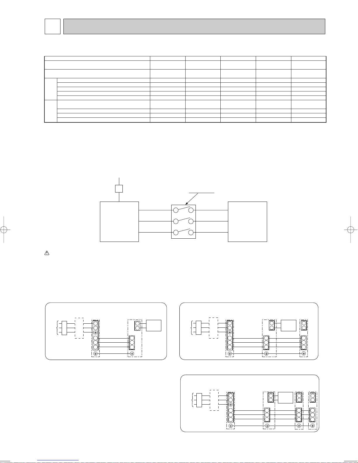
8 WIRING SPECIFICATIONS
1
2
S1
S2
S3
S1
S2
S3
Indoor/outdoor
unit connection
cable
Indoor
unit
Unit
power
supply
Outdoor
unit
Remote
controller
L
B
N
B Earth leakage breaker
C wiring circuit breaker or
isolating switch
C
B
B Earth leakage breaker
C wiring circuit breaker or
isolating switch
C
L
N
1
2
1
2
S1
Indoor
unit
S2
S3
S1
S2
S3
S1
S2
S3
Unit
power
supply
Indoor/outdoor
unit connection
cable
Indoor
unit
Outdoor
unit
Remote
controller
B
B Earth leakage breaker
C wiring circuit breaker or
isolating switch
C
1
2
1
2
1
2
S1
S2
S3
S1
S2
S3
S1
S2
S3
S1
S2
S3
Indoor/outdoor
connection cable
Indoor
unit
Unit
power
supply
Indoor
unit
Indoor
unit
Outdoor
unit
Remote
controller
L
N
8-1. FIELD ELECTRICAL WIRING (power wiring specifications)
Outdoor unit model
Outdoor unit power supply
Outdoor unit input capacity *1
Main switch (Breaker)
Outdoor unit power supply
)
2
Outdoor unit power supply earth
Indoor unit-Outdoor unit *2
Wiring
Indoor unit-Outdoor unit earth *2
Wire No. o
size (mm
Remote controller-Indoor unit *3
Outdoor unit L-N (single)
Outdoor unit L1-N, L2-N, L3-N (3 phase)
Indoor unit-Outdoor unit S1-S2 *4
Indoor unit-Outdoor unit S2-S3 *4
Circuit rating
Remote controller-Indoor unit *4
*1. A breaker with at least 3 mm contact separation in each poles shall be provided. Use non-fuse breaker (NF) or earth leakage breaker (NV).
*2. Refer to 8-3.
*3. The 10 m wire is attached in the remote controller accessory.
*4. The figures are NOT always against the ground.
S3 terminal has DC 24 V against S2 terminal. However between S3 and S1, these terminals are NOT electrically insulataed by the transformer or other device.
Notes: 1. Wiring size must comply with the applicable local and national code.
2. Power supply cords and Indoor/Outdoor unit connecting cords shall not be lighter than polychloroprene sheathed flexible cord. (Design 245 IEC 57)
3. Install an earth longer than other cables.
230V
Single phase
RP35, 50V RP60, 71V RP100, 125V RP140V RP100, 125, 140Y
~/N (single), 50 Hz, ~/N (single), 50 Hz, ~/N (single), 50 Hz, ~/N (single), 50 Hz, 3N ~ (3phase), 50 Hz,
230 V 230 V 230 V 230 V 400 V
16 A 25 A 32 A 40 A 16 A
2 o Min. 1.5 2 o Min. 2.5 2 o Min. 4 2 o Min. 6 4 o Min. 1.5
1 o Min. 1.5 1 o Min. 2.5 1 o Min. 4 1 o Min. 6 1 o Min. 1.5
3 o 1.5 (Polar) 3 o 1.5 (Polar) 3 o 1.5 (Polar) 3 o 1.5 (Polar) 3 o 1.5 (Polar)
1 o Min. 1.5 1 o Min. 1.5 1 o Min. 1.5 1 o Min. 1.5 1 o Min. 1.5
2 o 0.3 (Non-polar) 2 o 0.3 (Non-polar) 2 o 0.3 (Non-polar) 2 o 0.3 (Non-polar) 2 o 0.3 (Non-polar)
*4
AC 230 V AC 230 V AC 230 V AC 230 V AC 230 V
AC 230 V AC 230 V AC 230 V AC 230 V AC 230 V
DC 24 V DC 24 V DC 24 V DC 24 V DC 24 V
DC 12 V DC 12 V DC 12 V DC 12 V DC 12 V
A-Control
Outdoor Unit
Isolator
S1
S2
S3
3 poles isolator
S1
S2
S3
A-Control
Indoor Unit
Warning:
In case of A-control wiring, there is high v oltage potential on the S3 terminal caused by electrical circuit design that has no electrical insulation between po wer line
and communication signal line. Therefore, please turn off the main power supply when servicing. And do not touch the S1, S2, S3 terminals when the power is
energized. If isolator should be used between indoor unit and outdoor unit, please use 3-poles type.
1:1 system Synchronized twin and triple system Electrical wiring
• Synchronized twin
• Synchronized triple
21
H
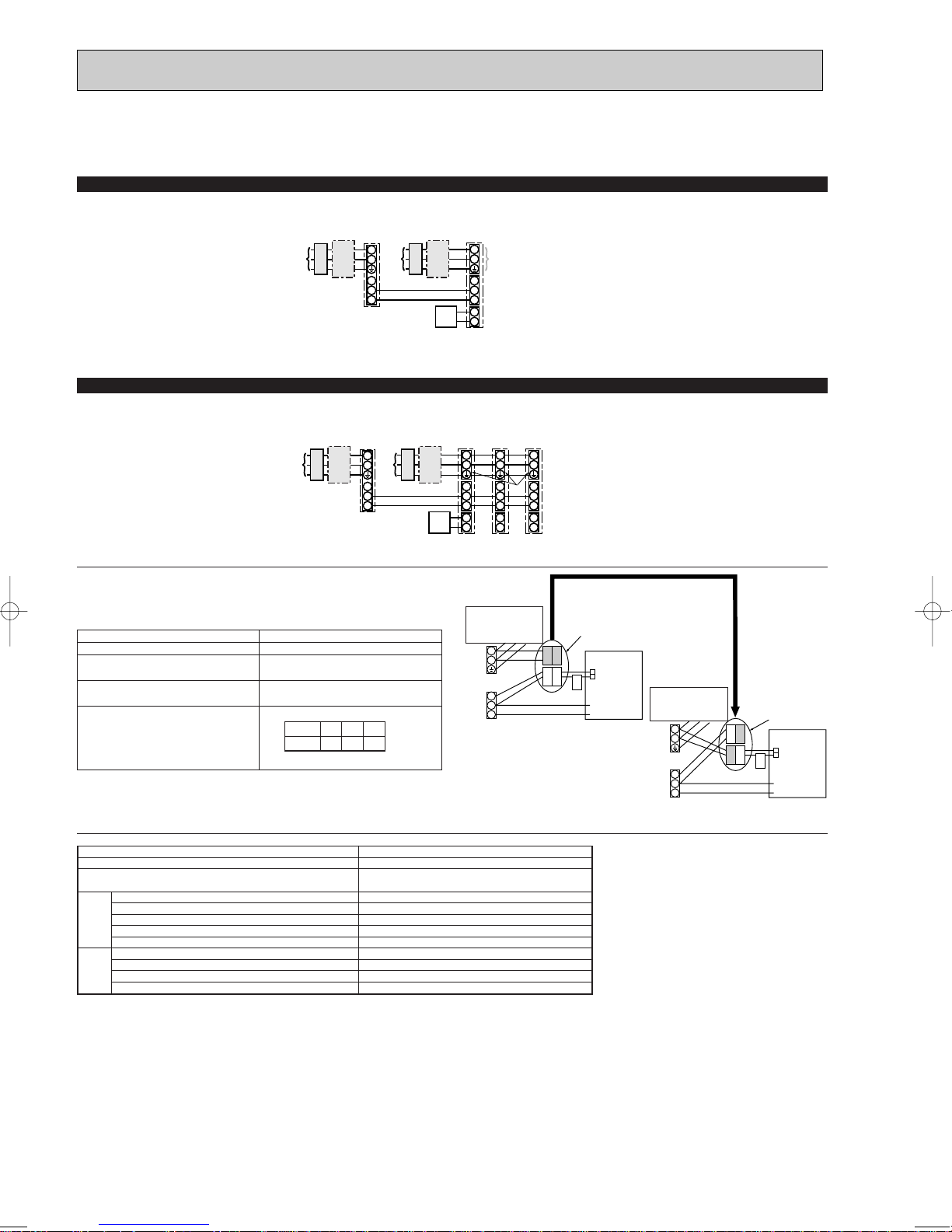
8-2. SEPARATE INDOOR UNIT/ OUTDOOR UNIT POWER SUPPLIES
The following connection patterns are available.
The outdoor unit power supply patterns vary on models.
1:1 System
<For models without heater>
* The optional indoor power supply terminal kit is required.
D
L
N
CB
A
JEB
S1
S2
S3
G
L
N
C
S1
S2
S3
1
F
2
* Affix a label B that is included with the manuals near each wiring diagram for the indoor and outdoor units.
Simultaneous twin/triple system
<For models without heater>
* The optional indoor power supply terminal kits are required.
D
L
N
JBC
C
AB
S1
S2
S3
E
* Affix a label B that is included with the manuals near each wiring diagram for the indoor and outdoor units.
If the indoor and outdoor units have separate power supplies, refer to the table at the
below. If the optional indoor power supply terminal kit is used, change the indoor unit
electrical box wiring refering to the figure in the right and the DIP switch settings of the
outdoor unit control board.
Indoor unit specifications
Indoor power supply terminal kit (option)
Indoor unit electrical box connector connection change
Label affixed near each wiring diagram
for the indoor and outdoor units
Required
Required
Required
Outdoor unit DIP switch settings (when
using separate indoor unit/outdoor unit
power supplies only)
ON
OFF 1 2
3
(SW8)
GGHG
L
L
N
S1
S2
S3
1
F
2
Electric heater
(For models with
heater)
Indoor unit power supplied from outdoor unit
(when shipped from factory)
L
N
N
S1
S1
S2
S2
S3
S3
1
1
2
2
Connectors (connections when shipped
from the factory are for indoor unit power
supplied from outdoor unit)
BLUE
L
N
S1
S2
S3
BLUE
YELLOW
YELLOW
CND
* There are three types of labels (labels A, B, and C). Affix the appropriate labels to
the units according to the wiring method.
A Outdoor unit power supply
B Earth leakage breaker
C Wiring circuit breaker or isolating switch
D Outdoor unit
E Indoor unit/outdoor unit connecting cords
F Remote controller
G Indoor unit
H Option
J
A
B
C
D
E
F
G
H
J
ORANGE
CND
Indoor unit
control board
Indoor unit power supply
Outdoor unit power supply
Earth leakage breaker
Wiring circuit breaker or isolating switch
Outdoor unit
Indoor unit/outdoor unit connecting cords
Remote controller
Indoor unit
Option
Indoor unit power supply
If the indoor and
outdoor units have
separate power
supplies, change the
connections of the
connectors as shown
in the following
figure.
Electric heater
(For models with
heater)
L
N
S1
S2
S3
Separate indoor unit/outdoor unit power
supplies
YELLOW
BLUE
YELLOW
BLUE
Connectors
CND
Indoor unit
control board
ORANGE
CND
Indoor unit model
Indoor unit power supply
Indoor unit input capacity
Main switch (Breaker)
Indoor unit power supply
Indoor unit power supply earth
)
2
Indoor unit-Outdoor unit
(mm
Wiring
Indoor unit-Outdoor unit earth
Wire No. o size
Remote controller-Indoor unit *3
Indoor unit L-N *4
Indoor unit-Outdoor unit S1-S2 *4
Indoor unit-Outdoor unit S2-S3 *4
rating
Circuit
Remote controller-Indoor unit *4
*1. A breaker with at least 3 mm contact separation in each pole shall be provided. Use non-fuse breaker (NF) or earth leakage breaker (NV).
*2. Max. 120 m
For PUHZ-RP100/125/140 YHA application, use shield wires. The shield part must be grounded with the indoor unit OR the outdoor unit, NOT with both.
*3.The 10 m wire is attached in the remote controller accessory. Max. 500 m
*4.The figures are NOT always against the ground.
Notes: 1. Wiring size must comply with the applicable local and national code.
2. Power supply cords and indoor unit/outdoor unit connecting cords shall not be lighter than polychloroprene sheathed flexible cord.
(Design 245 IEC 57)
3. Install an earth longer than other cables.
RP35~140
~/N (single), 50 Hz, 230 V
*1
*2
16 A
2 o Min. 1.5
1 o Min. 1.5
2 o Min. 0.3
–
2 o 0.3 (Non-polar)
AC 230 V
–
DC24 V
DC12 V
22
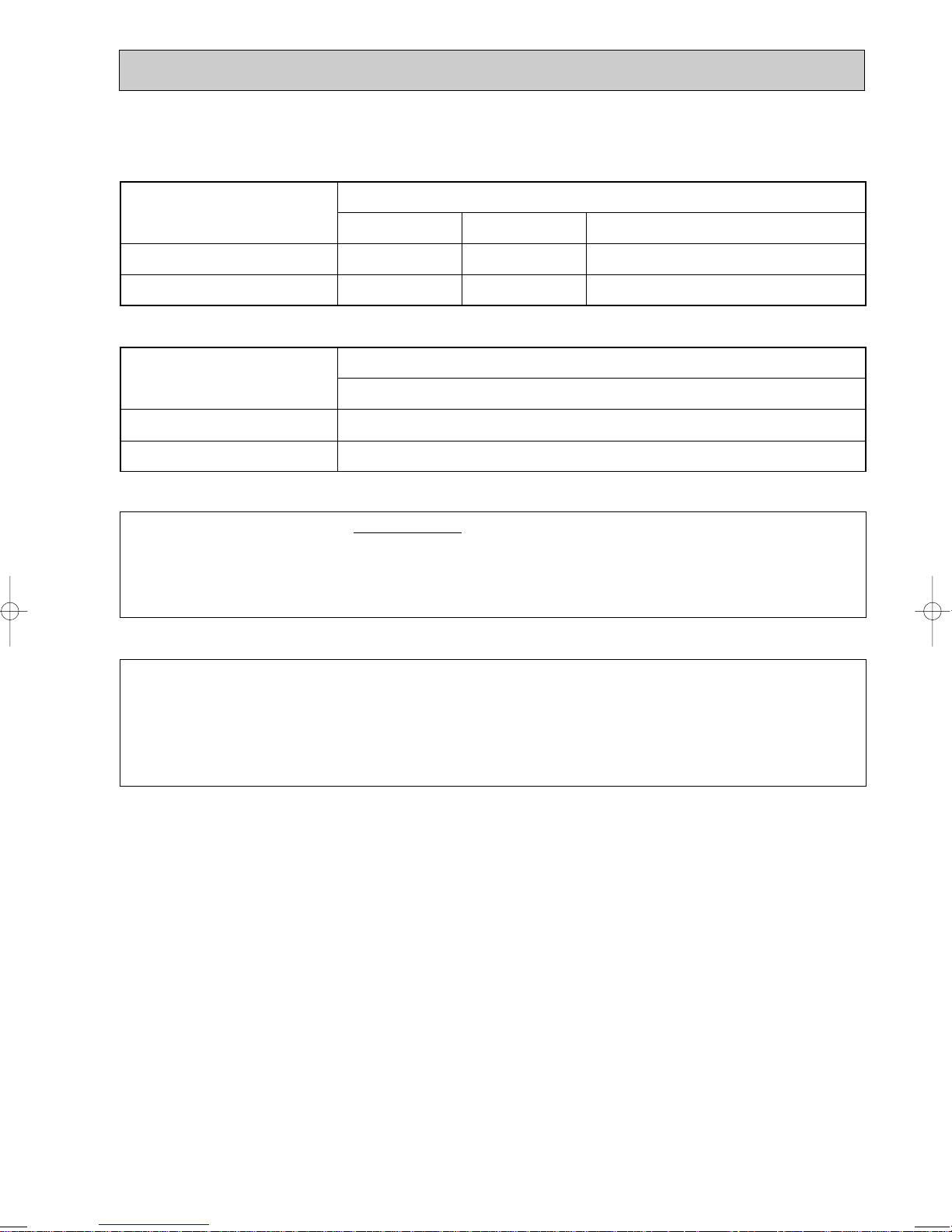
8-3. INDOOR – OUTDOOR CONNECTING CABLE
The cable shall not be lighter than design 245 IEC or 227 IEC.
w The Max. cable length may vary depending on the condition of installation, humidity or materials, etc.
Indoor unit-Outdoor unit
Outdoor power supply
Max. 45m
3 o 1.5 (polar)
1 o Min. 1.5
Max. 50m
3 o 2.5 (polar)
1 o Min. 2.5
Max. 80m
3 o 2.5 (polar) and S3 separated
1 o Min. 2.5
Indoor unit-Outdoor unit earth
Wire No. o Size (E)
Be sure to connect the indoor-outdoor connecting cables directly to the units (no intermediate
connections).
Intermediate connections can lead to communication errors if water enters the cables and causes
insufficient insulation to ground or a poor electrical contact at the intermediate connection point.
(If an intermediate connection is necessary, be sure to take measures to prevent water from entering
the cables.)
When the shield line is not used, several dB is exceeded with 30 ~ 40 MHz .
(There is a possibility to be used by the wireless for the ship etc. though it is not used for
radio and TV.)
Indoor unit-Outdoor unit
Indoor/Outdoor separate
power supply
Max. 120m
2 o Min. 0.3
—
Indoor unit-Outdoor unit earth
Wire No. o Size (E)
w The optional indoor power supply terminal kit is necessary
For 100, 125, 140Y application, use shield wire. (For EMC DIRECTIVE)
The shield part must be grounded with the indoor unit or the outdoor unit, not with both.
23
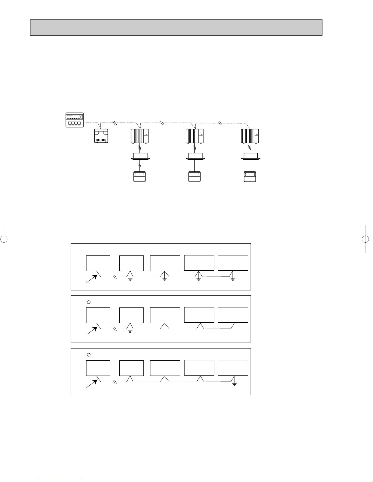
8-4. M-NET WIRING METHOD
Group
remote
controller
Refrigerant
address 00
M-NET
address 01
A-control
remote
controller
A-control
remote
controller
A-control
remote
controller
Refrigerant
address 00
M-NET
address 02
Refrigerant
address 00
M-NET
address 03
Power
supply
unit for
transmission
wire
Central
remote
controller
M-NET transmission wire
✕ Bad example (Multi spot grounding of shield wire)
Good example 1 (Single spot grounding of shield wire)
Power
supply
appliance
M-NET type
outdoor unit
Central
remote
controller
Power
supply
appliance
M-NET type
outdoor unit
M-NET type
outdoor unit
M-NET type
outdoor unit
M-NET transmission wire
M-NET type
outdoor unit
M-NET type
outdoor unit
Central
remote
controller
Power
supply
appliance
M-NET type
outdoor unit
M-NET transmission wire
M-NET type
outdoor unit
M-NET type
outdoor unit
Good example 2 (Single spot grounding of shield wire)
(Points to notice)
(1) Outside the unit, transmission wires should stay away from electric wires in order to prevent electromagnetic noise from
making an influence on the signal communication. Place them at intervals of more than 5cm. Do not put them in the same
conduit tube.
(2) Terminal block (TB7) for transmission wires should never be connected to 220~240V power supply. If it is connected,
electronic parts on M-NET p.c. board may be burn out.
(3) Use 2-core x 1.25mm2shield wire (CVVS, CPEVS) for the transmission wire. Transmission signals may not be sent or
received normally if different types of transmission wires are put together in the same multi-conductor cable. Never do this
because this may cause a malfunction.
It would be ok if M-NET wire (non-polar, 2-cores) is arranged in addition to the wiring for A-control.
(4) Ground only one of any appliances through M-NET transmission wire (shield wire). Communication error may occur due to
the influence of electromagnetic noise.
“Ed” error will appear on the LED display of outdoor unit.
“0403” error will appear on the central-control remote controller.
If there are more than two grounding spots on the shield wire, noise may enter into the shield wire because the ground wire
To avoid communication errors caused by noise, make sure to observe the single spot grounding method described in the
and shield wire form one circuit and the electric potential difference occurs due to the impedance difference among grounding spots. In case of single spot grounding, noise does not enter into the shield wire because the ground wire and shield
wire do not form one circuit.
installation manual.
24

1
2
3
4
5
6
7
8
9
0
1
2
3
4
5
6
7
8
9
0
1
2
3
4
5
6
7
8
9
0
1
2
3
4
5
6
7
8
9
0
1
2
3
4
5
6
7
8
9
0
1
2
3
4
5
6
7
8
9
0
12
~
50
M-NET Address No.
<Setting example>
Switng
setting
SW11
ones
digit
SW12
tens
digit
OFF
ON
1
2
3
4
5
6
1
2
3
4
5
6
1
2
3
4
5
6
1
2
3
4
5
6
1
2
3
4
5
6
1
2
3
4
5
6
1
2
3
4
5
6
1
2
3
4
5
6
1
2
3
4
5
6
1
2
3
4
5
6
1
2
3
4
5
6
1
2
3
4
5
6
1
2
3
4
5
6
1
2
3
4
5
6
1
2
3
4
5
6
1
2
3
4
5
6
0
Refuigrant
address
OFF
ON
8
OFF
ON
1
OFF
ON
9
OFF
ON
10
OFF
ON
11
OFF
ON
12
OFF
ON
13
OFF
ON
14
OFF
ON
15
OFF
ON
2
OFF
ON
3
OFF
ON
4
OFF
ON
5
OFF
ON
6
OFF
ON
7
System
controller
A-control
remote
controller
Group A Group B Group C
A-control
remote
controller
TB5
A-control
remote
controller
Refrigerant
address 00
M-NET
address 01
Refrigerant
address 00
M-NET
address 02
Refrigerant
address 01
M-NET
address 03
Refrigerant
address 00
M-NET
address 04
Power
supply
unit for
transmission
wire
A-control
remote
controller
A-control
remote
controller
TB5
Group A Group B
Refrigerant
address 00
M-NET
address 01
Refrigerant
address 01
M-NET
address 02
Refrigerant
address 00
M-NET
address 04
Refrigerant
address 01
M-NET
address 03
Refrigerant
address 02
M-NET
address 05
System
controller
Power
supply
unit for
transmission
wire
● M-NET wiring
(1) Use 2-core x 1.25mm
(Excluding the case connecting to system controller.)
(2) Connect the wire to the M-NET terminal block.Connect one core of the
transmission wire (non-polar) to Aterminal and the other to B. Peel the
shield wire, twist the shield part to a string and connect it to S terminal.
(3) In the system which several outdoor units are being connected, the terminal
(A, B, S) on M-NET terminal block should be individually wired to the other
2
shield wire for electric wires.
M-NET
terminal
block
ABS
Transmission
wire
Shield
part
Ground
wire
outdoor unit’s terminal, i.e. Ato A, B to B and S to S.In this case, choose one of those outdoor units and drive a screw
to fix an ground wire on the plate as shown on the right figure.
8-4-1. M-NET address setting
In A-control models, M-NET address and refrigerant address should be set only for the outdoor unit. Similar to Free Combo
system, there is no need to set the address of outdoor unit and remote controller. To construct a central control system, the
setting of M-NET address should be conducted only upon the outdoor unit. The setting range should be 1 to 50 (the same as
that of the indoor unit in Free Combo system), and the address number should be consecutively set in a same group.
Address number can be set by using rotary switches
(SW11 for ones digit and SW12 for tens digit), which
is located on the M-NET board of outdoor unit.
(Factory setting: all addresses are set to “0”.)
8-4-2. Refrigerant address setting
In case of multiple grouping system (multiple refrigerant circuits in one group), indoor units should be connected by remote
controller wiring (TB5) and the refrigerant address needs to be set. Leave the refrigerant addresses to “00” if the group setting is not conducted. Set the refrigerant address by using DIP SW1-3 to -6 on the outdoor controller board. [Factory setting:
all switches are OFF. (All refrigerant addresses are “00”.)]
8-4-3. Regulations in address settings
In case of multiple grouping system, M-NET and refrigerant address settings should be done as explained in the above section. Set the lowest number in the group for the outdoor unit whose refrigerant address is “00” as its M-NET address.
w Refrigerant addresses can be overlapped if they are in the different group.
w In group B, M-NET address of the outdoor unit whose refrigerant address is “00” is not set to the minimum in the group. As
“3” is right for this situation, the setting is wrong. Taking group A as a good sample, set the minimum M-NET address in
the group for the outdoor unit whose refrigerant address is “00”.
25
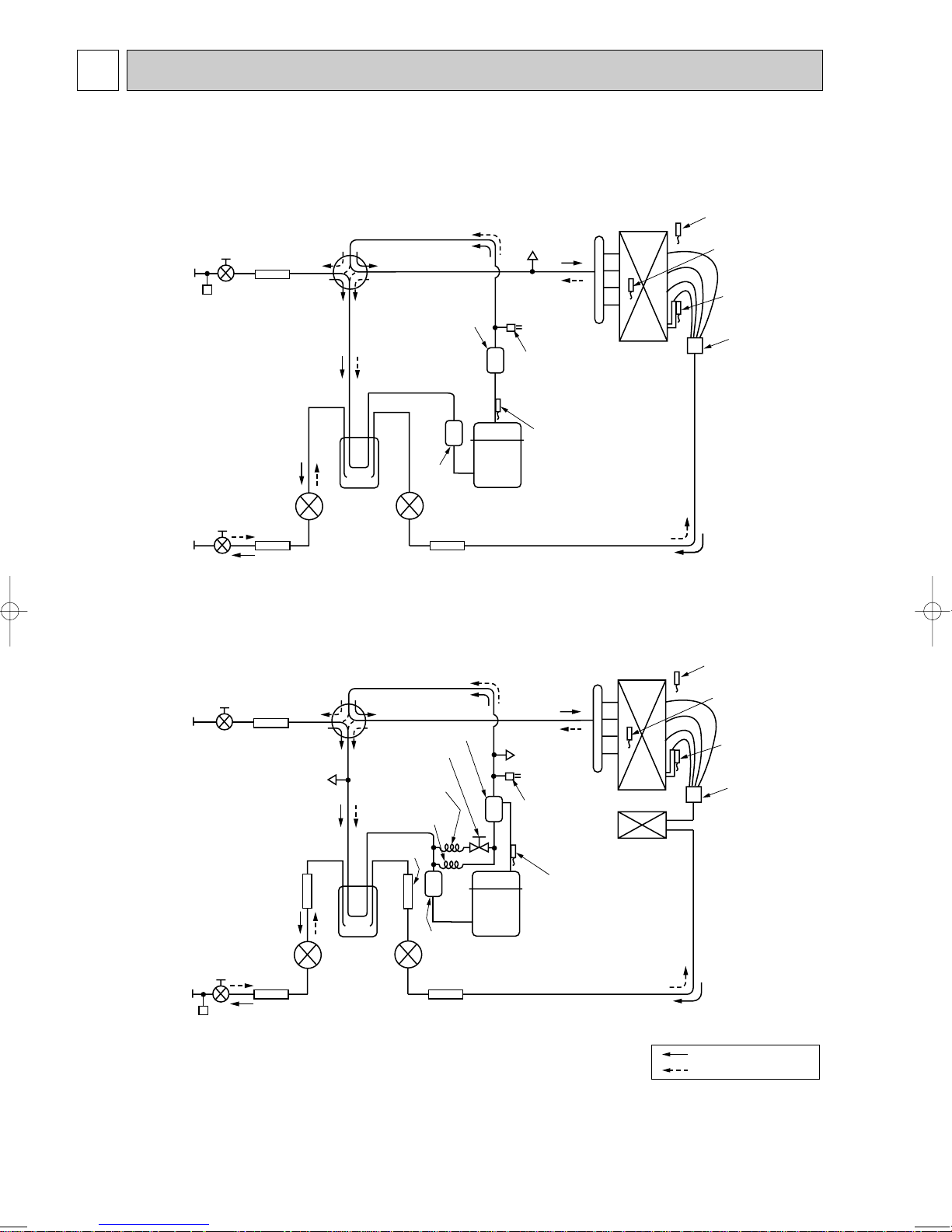
9 REFRIGERANT SYSTEM DIAGRAM
Thermistor TH7
(Outdoor)
Heat exchanger
Refrigerant GAS pipe
connection(1/2F)
Refrigerant LIQUID pipe
connection(1/4F)
Stop valve
Strainer
#100
Power
receiver
Linear
expansion valve B
Thermistor TH6
(Outdoor 2-phase pipe)
Thermistor TH3
(Outdoor pipe)
Charge plug
High pressure
switch 63H
Thermistor TH4
(Discharge)
Compressor
Strainer
#50
Solenoid valve
(Four-way valve)
Muffler
Distributor
Linear expansion valve A
Strainer
#100
Muffler
Stop valve
(with service port)
Distributor
Thermistor TH7
(Outdoor)
Heat exchanger
Refrigerant GAS pipe
connection(5/8F)
Refrigerant LIQUID pipe
connection(3/8F)
Stop valve
(with service port)
Strainer
#100
Power
receiver
Linear
expansion
valve B
Linear expansion valve A
Strainer
#100
Strainer
#100
Strainer
#100
Thermistor TH6
(Outdoor 2-phase pipe)
Thermistor TH3
(Outdoor pipe)
Charge plug
(Low pressure)
Charge plug
(High pressure)
High pressure
switch 63H
Bypass valve
Oil separator
Thermistor TH4
(Discharge)
Muffler
Strainer
#50
4-way valve
Compressor
Ball valve
Capillary tube
O.D.4.0OI.D.2.4OL500
Capillary tube
O.D.2.5OI.D.0.6OL1000
Refrigerant flow in cooling
Refrigerant flow in heating
PUHZ-RP35VHA
PUHZ-RP50VHA
PUHZ-RP60VHA
PUHZ-RP71VHA
26
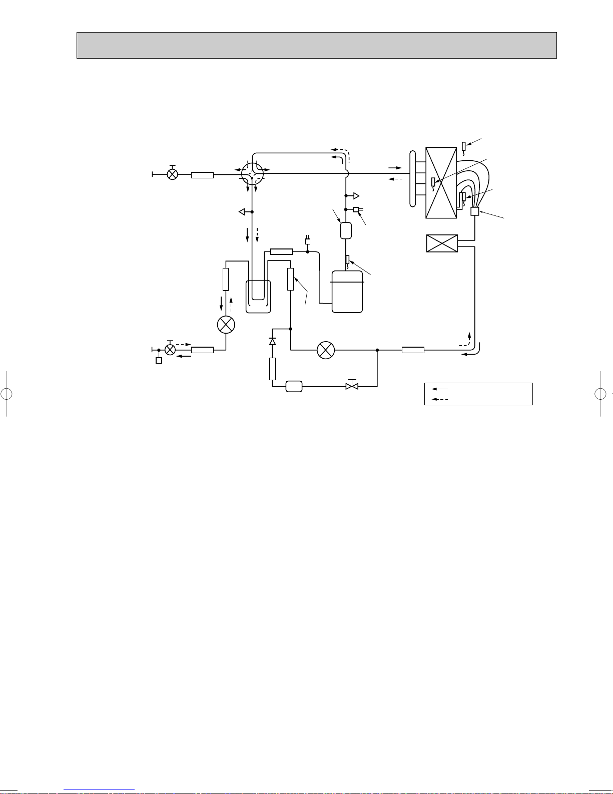
PUHZ-RP100VHA PUHZ-RP100YHA
Distributor
Thermistor TH7
(Outdoor)
Heat exchanger
Refrigerant GAS pipe
connection(5/8F)
Refrigerant LIQUID pipe
connection(3/8F)
Stop valve
(with service port)
Strainer
#100
Power
receiver
Linear
expansion valve B
Linear expansion valve A
Strainer
#100
Strainer
#100
Strainer
#100
Thermistor TH6
(Outdoor 2-phase pipe)
Thermistor TH3
(Outdoor pipe)
Charge plug
(Low pressure)
Charge plug
(High pressure)
High pressure
switch 63H
Replace filter
Thermistor TH4
(Discharge)
Compressor
Strainer
#50
Solenoid valve
(Four-way valve)
Strainer
#100
Strainer
#100
Low pressure
switch 63L
Muffler
Ball valve
Restrictor
valve
Solenoid valve
(Bypass valve)
Refrigerant flow in cooling
Refrigerant flow in heating
PUHZ-RP125VHA PUHZ-RP125YHA
PUHZ-RP140VHA PUHZ-RP140YHA
27
1. Refrigerant collecting (pump down)
TEST RUN
OFF
12
ON
<SW4>
AB
CD
A Stop C operation
B Cooling D Heating
Perform the following procedures to collect the refrigerant when moving the indoor unit or the outdoor unit.
1Turn on the power supply (circuit breaker).
wWhen power is supplied, make sure that “CENTRALLY CONTROLLED” is not displayed on the remote controller. If
“CENTRALLY CONTROLLED” is displayed, the refrigerant collecting (pump down) cannot be completed normally.
2After the liquid stop valve is closed, set the SWP switch on the control board of the outdoor unit to ON. The compressor
(outdoor unit) and ventilators (indoor and outdoor units) start operating and refrigerant collecting operation begins. LED1 and
LED2 on the control board of the outdoor unit are lit.
wSet the SWP switch (push-button type) to ON in order to perform refrigerant collecting operation only when the unit is
stopped. However, refrigerant collecting operation cannot be performed until compressor stops even if the unit is stopped.
Wait three minutes until compressor stops and set the SWP switch to ON again.
3Because the unit automatically stops in about two to three minutes after the refrigerant collecting operation (LED1 is not lit
and LED2 is lit), be sure to quickly close the gas stop valve.
wIn case the outdoor unit is stopped when LED1 is lit and LED2 is not lit, open the liquid stop valve completely, and then
repeat step 2 three minutes later.
wIf the refrigerant collecting operation has been completed normally (LED1 is not lit and LED2 is lit), the unit will remain
stopped until the power supply is turned off.
4Turn off the power supply (circuit breaker.)
2. Unit replacement operation
When reusing the existing pipes that carried R22 refrigerant for the RP100, RP125 and RP140 models, replacement
operation must be performed before performing a test run.
1If new pipes are used, these procedures are not necessary.
2If existing pipes that carried R22 refrigerant are used for the RP71 model, these procedures are not necessary.
(The replace-ment operation cannot be performed.)
3During replacement operation, “C5” is displayed on “A-Control Service Tool(PAC-SK52ST)”. (This is applied to only RP100,
RP125 and RP140 models.)
• Replacement operation procedures
1Turn on the power supply.
2Set DIP switch SW8-2 on the control board of the outdoor unit to ON to start replacement operation.
• The replacement operation is performed using the cooling system. Cool air will flow from the indoor unit during the replacement operation.
• During the replacement operation, is displayed on the remote controller and LED1 (green) and LED2 (red) on the
control board of the outdoor unit flash together.
3Replacement operation requires at least two hours to complete.
• After setting switch SW8-2 to ON, the unit automatically stops after two hours.
• Replacement operation can be performed repeatedly by setting switch SW8-2 from OFF to ON. Make sure to perform the
operation more than 2 hours. (If the operation is performed less than 2 hours, the existing pipes cannot be cleaned
enough and the unit may be damaged.)
• If replacement operation is performed over 2 hours, this action is recorded into nonvolatile memory of control board.
4Set switch SW8-2 to OFF. (Replacement operation is completed.)
wThe unit can be operated normally by remote controller even if SW8-2 remains ON.
wIf the indoor temperature is less than 15:, the compressor will operate intermittently but the unit is not faulty.
3. Start and finish of test run
• Operation from the indoor unit
Execute the test run using the installation manual for the indoor unit.
• Operation from the outdoor unit
By using the DIP switch SW4 on the control board of outdoor unit, test run can be started and finished, and its operation
mode (cooling/heating) can be set up.
1Set the operation mode (cooling/heating) using SW4-2.
2Turn on SW4-1 to start test run with the operation mode set by SW4-2.
3Turn off SW4-1 to finish the test run.
• There may be a faint knocking sound around the machine room after power is supplied, but this is
no problem with product because the linear expansion pipe is just moving to adjust opening pulse.
• There may be a knocking sound around the machine room for several seconds after compressor
starts operating, but this is no problem with product because the check valve, itself, generates the
sound because pressure difference is small in the refrigerant circuit.
Note:
The operation mode cannot be changed by SW4-2 during test run. (To change test run mode, stop the unit by SW4-1,
change the operation mode and restart the test run by SW4-1.)
28
10 TROUBLESHOOTING
Unit conditions at service
Error code
Actions to be taken for service (summary)
The inferior phenomenon is
reoccurring.
Displayed
Not displayed
Judge what is wrong and take a corrective action according
to “10-4. Self-diagnosis action table”.
Conduct trouble shooting and ascertain the cause of the
inferior phenomenon according to “10-5. Troubleshooting
by inferior phenomena”.
The inferior phenomenon is
not reoccurring.
Logged
Not logged
1Consider the temporary defects such as the work of
protection devices in the refrigerant circuit including
compressor, poor connection of wiring, noise and etc.
Re-check the symptom, and check the installation
environment, refrigerant amount, weather when the
inferior phenomenon occurred, matters related to wiring
and etc.
2Reset error code logs and restart the unit after finishing
service.
3There is no abnormality concerning of parts such as
electrical component, controller board, remote controller
and etc.
1Re-check the abnormal symptom.
2Conduct trouble shooting and ascertain the cause of the
inferior phenomenon according to “10-5. Troubleshooting
by inferior phenomena”.
3Continue to operate unit for the time being if the cause
is not ascertained.
4There is no abnormality concerning of parts such as
electrical component, controller board, remote controller
and etc.
10-1. TROUBLESHOOTING
<Error code display by self-diagnosis and actions to be taken for service (summary)>
Present and past error codes are logged and displayed on the wired remote controller and control board of outdoor unit.
Actions to be taken for service, which depends on whether or not the inferior phenomenon is reoccurring at service, are summarized in the table below. Check the contents below before investigating details.
10-2. CHECK POINT UNDER TEST RUN
(1) Before test run
• After installation of indoor and outdoor units, piping work and electric wiring work, re-check that there is no refrigerant leak-
age, loosened connections and incorrect polarity.
• Measure impedance between the ground and the power supply terminal block(L, N) on the outdoor unit by 500V Merger and
check that it is 1.0M" or over.
wDon’t use 500V Merger to indoor/outdoor connecting wire terminal block(S1, S2, S3) and remote controller terminal block
(1, 2). This may cause malfunction.
• Make sure that test run switch (SW4) is set to OFF before turning on power supply.
• Turn on power supply twelve hours before test run in order to protect compressor.
• For specific models which requires higher ceiling settings or auto-recovery feature from power failure, make proper changes
of settings referring to the description of “Selection of Functions through Remote Controller”.
Make sure to read operation manual before test run. (Especially items to secure safety.)
29
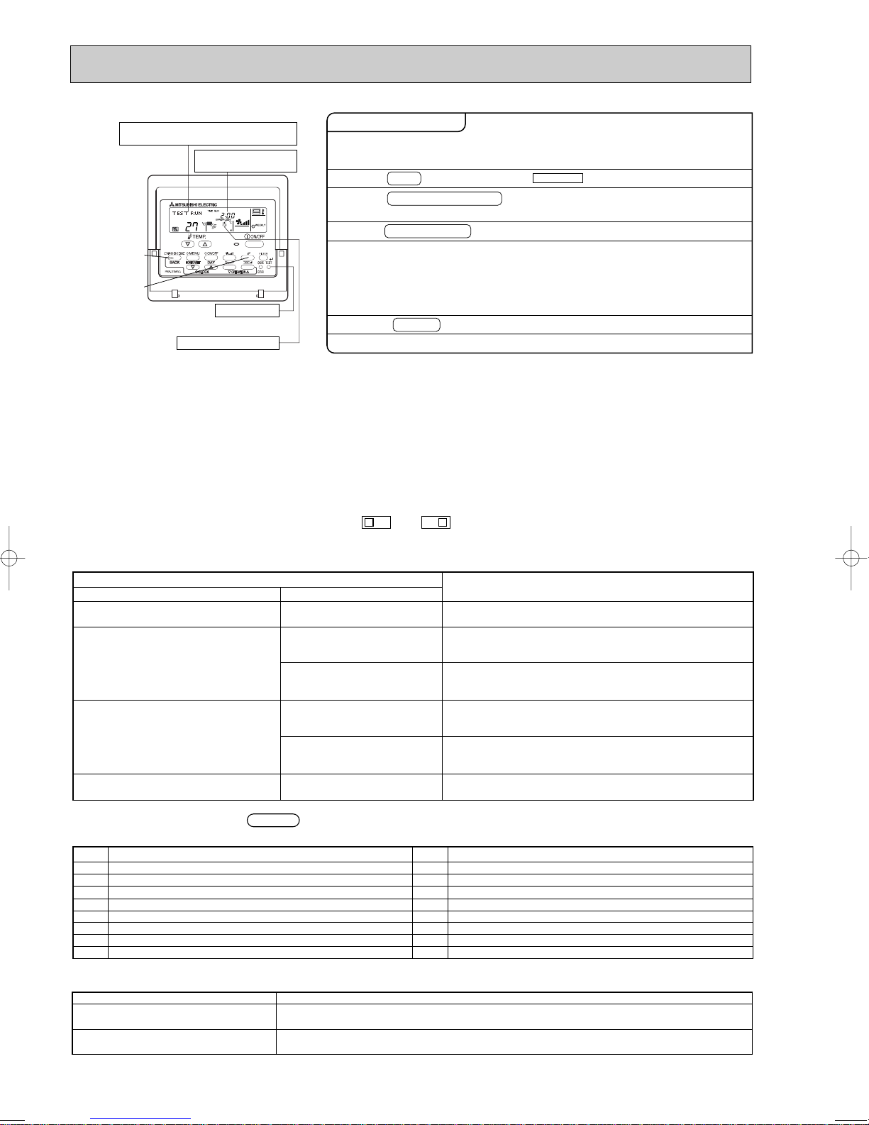
"TEST RUN" and the currently selected
LCD
Contents of inferior phenomena
P1
P2
P4
P5
P6
P8
P9
Fb
Abnormality of room temperature thermistor
Abnormality of pipe temperature thermistor/Liquid
Abnormality of drain sensor
Drain overflow protection is working.
Freezing/overheating protection is working.
Abnormality of pipe temperature
Abnormality of pipe temperature thermistor/Cond./Eva
Abnormality of indoor controller board
LCD
Contents of inferior phenomena
U1~UP
F3~F9
E0~E5
E6~EF
----
FFFF
Malfunction outdoor unit
Malfunction
outdoor unit
Remote controller transmitting error
Indoor/outdoor unit communication error
No error history
No applied unit
LED1
(microcomputer power supply)
LED2
(remote controller)
LED3
(indoor/outdoor communication)
Lits when power is supplied.
Lits when power is supplied for wired remote controller.
The indoor unit should be connected to the outdoor unit with address “0” setting.
Flash when indoor and outdoor unit are communicating.
operation mode are displayed altemately.
Displays the remaining
test run time.
B
C
[TEST] button
A
Pipe (liquid) temperature
Operating procedures
1. Turn on the main power supply.
2. Press TEST button twice.
A
3. Press OPERATION SWITCH
button.
4. Press AIR DIRECTION button.
5. Check the outdoor unit fan for
correct running.
6. Press the ON/OFF button to reset the test run in progress.
7. Register the contact number.
B
C
While the room temperature display on the remote
controller is “PLEASE WAIT”, the remote controller is disabled.
Wait until “PLEASE WAIT” disappears before using remote controller.
“PLEASE WAIT” appears for about 2 minutes after power
supply is turned on. w1
The TEST RUN appears on the screen.
Cooling mode:
Heating mode: Check if warm air blows. (It takes a little
while until warm air blows.)
Check for correct motion of auto-vanes.
The outdoor unit features automatic capacity control to
provide optimum fan speeds. Therefore, the fan keeps
running at a low speed to meet the current outside air
condition unless it exceeds its available maximum power.
Then, in actuality, the fan may stop or run in the reverse
direction depending on the outside air, but this does not
mean malfunction.
Check if cool air blows and water is drained.
• In case of test run, the OFF timer will be activated, and the test run will automatically stop after two hours.
• The room temperature display section shows the pipe temperature of indoor units during the test run.
• Check that all the indoor units are running properly in case of simultaneous twin and triple operation. Malfunctions may not
be displayed regardless of incorrect wiring.
w1 After turning on the power supply, the system will go into startup mode, “PLEASE WAIT” will blink on the display section of
the room
temperature, and lamp(green) of the remote controller will flash.
As to INDOOR BOARD LED, LED1 will be lit up, LED2 will either be lit up in case the address is 0 or turned off in case the
address is not 0. LED3 will blink.
As to OUTDOOR BOARD LED, LED1(green) and LED2(red) will light up. (After the startup mode of the system finishes,
LED2(red) will be turned off.)
In case OUTDOOR BOARD LED is digital display, — and — will be displayed alternately every second.
• If one of the above operations doesn’t function correctly, the causes written below should be considered. Find causes from
the symptoms.
The below symptoms are under test run mode. “startup” in the table means the display status of w1 written above.
Symptoms in test run mode
Remote Controller Display
Remote controller displays “PLEASE
WAIT”, and
After power is turned on, “PLEASE WAIT”
is displayed for 3 minutes, then error code
is displayed.
No display appears even when remote
controller operation switch is turned on.
(Operation lamp does not light up.)
Display appears but soon disappears
even when remote controller is operated.
cannot be operated.
OUTDOOR BOARD LED Display
< > indicates digital display.
After “startup” is displayed, only
green lights up. <00>
After “startup” is displayed,
green(once) and red(once) blink
alternately. <F1>
After “startup” is displayed,
green(once) and red(twice) blink
alternately. <F3, F5, F9>
After “startup” is displayed,
green(twice) and red(once) blink
alternately. <EA. Eb>
After “startup” is displayed, only
green lights up. <00>
After “startup” is displayed, only
green lights up. <00>
• After power is turned on, “PLEASE WAIT” is displayed for 2
minutes during
• Incorrect connection of outdoor terminal block (L
S1, S2, S3.)
• Outdoor unit’s safeguard installation connector is open.
• Incorrect wiring between the indoor and outdoor unit (Polarity
is wrong for S1, S2, S3.)
• Remote controller transmission wire short.
• There is no outdoor unit of address 0.
(Address is other than 0.)
• Remote controller transmission wire burnout.
• After canceling function selection, operation is not possible for
about 30 seconds. (Normal)
system startup. (Normal)
Cause
1, L2, L3 and
w Press the remote controller’s CHECK button twice to perform self-diagnosis. See the table below for the contents of LCD
display.
See the table below for details of the LED display (LED 1, 2, 3) on the indoor controller board.
30
 Loading...