

Mitsubishi Electric PUHZ-P HA Installation Manual
MONTÖR İÇİN
ДЛЯ УСТАНОВИТЕЛЯ
TIL INSTALLATØREN
FÖR INSTALLATÖREN
PARA O INSTALADOR
ΓΙΑ ΑΥΤΟΝ ΠΟΥ ΚΑΝΕΙ ΤΗΝ ΕΓΚΑΤΑΣΤΑΣΗ
PER L’INSTALLATORE
PARA EL INSTALADOR
VOOR DE INSTALLATEUR
POUR L’INSTALLATEUR
FÜR INSTALLATEURE
FOR INSTALLER
Air-Conditioners
Кондиционеры
PUHZ-P·HA Series
INSTALLATION MANUAL
For safe and correct use, read this manual and the indoor unit installation manual thoroughly before installing
the air-conditioner unit. English is original. The other languages versions are translation of the original.
РУКОВОДСТВО ПО УСТАНОВКЕ
Для обеспечения безопасной и надлежащей эксплуатации внимательно прочтите данное руководство
и руководство по установке внутреннего прибора перед установкой кондиционера. Языком оригинала
является английский. Версии на других языках являются переводом оригинала.
INSTALLATIONSHANDBUCH
Aus Sicherheitsgründen und zur richtigen Verwendung vor der Installation die vorliegende Bedienungsanleitung
und die Installationsanleitung der Innenanlage gründlich durchlesen die Klimaanlage. Das Original ist in Englisch.
Die anderen Sprachversionen sind vom Original übersetzt.
MANUEL D’INSTALLATION
Avant d’installer le climatiseur, lire attentivement ce manuel, ainsi que le manuel d’installation de l’appareil
intérieur pour une utilisation sûre et correcte. L’anglais est l’original. Les versions fournies dans d’autres
langues sont des traductions de l’original.
INSTALLATIEHANDLEIDING
Lees deze handleiding en de installatiehandleiding van het binnenapparaat zorgvuldig door voordat u met het
installeren van de airconditioner begint. Het Engels is het origineel. De andere taalraat versies zijn vertalingen van
het origineel.
MANUAL DE INSTALACIÓN
Para un uso correcto y seguro, lea detalladamente este manual y el manual de instalación de la unidad interior
antes de instalar la unidad de aire acondicionado. El idioma original del documento es el inglés. Las versiones en
los demás idiomas son traducciones del original.
MANUALE DI INSTALLAZIONE
Per un uso sicuro e corretto, leggere attentamente il presente manuale ed il manuale d’installazione dell’unità
interna prima di installare il condizionatore d’aria. Il testo originale è redatto in lingua Inglese. Le altre versioni
linguistiche rappresentano traduzioni dell’originale.
EΓΧEIPIΔIO OΔHΓIΩN EΓKATAΣTAΣHΣ
Για σωστή και ασφαλή χρήση, διαβάστε προσεκτικά αυτό το εγχειρίδιο καθώς και το εγχειρίδιο εγκατάστασης
της εσωτερικής μονάδας, προτού εγκαταστήσετε τη μονάδα του κλιματιστικού. Η γλώσσα του πρωτοτύπου
είναι η αγγλική. Οι εκδόσεις άλλων γλωσσών είναι μεταφράσεις του πρωτοτύπου.
MANUAL DE INSTALAÇÃO
Para uma utilização segura e correcta, leia atentamente este manual e o manual de instalação da unidade
interior antes de instalar o aparelho de ar condicionado. O idioma original é o inglês. As versões em outros
idiomas são traduções do idioma original.
INSTALLATIONSMANUAL
Læs af sikkerhedshensyn denne manual samt manualen til installation af indendørsenheden grundigt, før du
installerer klimaanlægget. Engelsk er originalen. De andre sprogversioner er oversættelser af originalen.
INSTALLATIONSMANUAL
Läs bruksanvisningen och inomhusenhetens installationshandbok noga innan luftkonditioneringen installeras
så att den används på ett säkert och korrekt sätt. Engelska är originalspråket. De övriga språkversionerna är
översättningar av originalet.
MONTAJ ELKİTABI
Emniyetli ve doğru kullanım için, klima cihazını monte etmeden önce bu kılavuzu ve iç ünite montaj kılavuzunu
tamamıyla okuyun. Aslı İngilizce’dir. Diğer dillerdeki sürümler aslının çevirisidir.
Türkçe
Русский
English
Deutsch
Français
Nederlands
Español
Italiano
Eλληνικά
Português
Dansk
Svenska
2
Contents
1. Safety precautions . . . . . . . . . . . . . . . . . . . . . . . . . . . . . . . . . . . . . . . . . . . . . . 2
2. Installation location . . . . . . . . . . . . . . . . . . . . . . . . . . . . . . . . . . . . . . . . . . . . . 3
3. Installing the outdoor unit . . . . . . . . . . . . . . . . . . . . . . . . . . . . . . . . . . . . . . . . . 4
4. Installing the refrigerant piping . . . . . . . . . . . . . . . . . . . . . . . . . . . . . . . . . . . . . 5
5. Drainage piping work . . . . . . . . . . . . . . . . . . . . . . . . . . . . . . . . . . . . . . . . . . . . 7
6. Electrical work . . . . . . . . . . . . . . . . . . . . . . . . . . . . . . . . . . . . . . . . . . . . . . . . . 7
7. Test run . . . . . . . . . . . . . . . . . . . . . . . . . . . . . . . . . . . . . . . . . . . . . . . . . . . . . . 8
8. Special functions . . . . . . . . . . . . . . . . . . . . . . . . . . . . . . . . . . . . . . . . . . . . . . . 9
9. System control (Fig. 9-1) . . . . . . . . . . . . . . . . . . . . . . . . . . . . . . . . . . . . . . . . . 9
10. Serial number . . . . . . . . . . . . . . . . . . . . . . . . . . . . . . . . . . . . . . . . . . . . . . . . . 10
1. Safety precautions
► Before installing the unit, make sure you read all the “Safety precau-
tions”.
► Please report to or take consent by the supply authority before connec-
tion to the system.
► PUHZ-P•YHA is designed for commercial and light industrial applications.
After installation work has been completed, explain the “Safety precautions,” use,
and maintenance of the unit to the customer according to the information in the
Operation Manual and perform the test run to ensure normal operation. Both the
Installation Manual and Operation Manual must be given to the user for keeping.
These manuals must be passed on to subsequent users.
: Indicates a part which must be grounded.
Warning:
Carefully read the labels affi xed to the main unit.
Warning:
• The unit must not be installed by the user. Ask a dealer or an authorized
technician to install the unit. If the unit is installed incorrectly, water leakage, electric shock, or fi re may result.
• For installation work, follow the instructions in the Installation Manual and
use tools and pipe components specifi cally made for use with R410A refrig-
erant. The R410A refrigerant in the HFC system is pressurized 1.6 times the
pressure of usual refrigerants. If pipe components not designed for R410A
refrigerant are used and the unit is not installed correctly, the pipes may
burst and cause damage or injuries. In addition, water leakage, electric
shock, or fi re may result.
• The unit must be installed according to the instructions in order to minimize
the risk of damage from earthquakes, typhoons, or strong winds. An incorrectly installed unit may fall down and cause damage or injuries.
• The unit must be securely installed on a structure that can sustain its
weight. If the unit is mounted on an unstable structure, it may fall down and
cause damage or injuries.
• If the air conditioner is installed in a small room, measures must be taken to
prevent the refrigerant concentration in the room from exceeding the safety
limit in the event of refrigerant leakage. Consult a dealer regarding the appropriate measures to prevent the allowable concentration from being exceeded. Should the refrigerant leak and cause the concentration limit to be
exceeded, hazards due to lack of oxygen in the room may result.
• Ventilate the room if refrigerant leaks during operation. If refrigerant comes
into contact with a fl ame, poisonous gases will be released.
• All electric work must be performed by a qualifi ed technician according to
local regulations and the instructions given in this manual. The units must
be powered by dedicated power lines and the correct voltage and circuit
breakers must be used. Power lines with insuffi cient capacity or incorrect
electrical work may result in electric shock or fi re.
• Use C1220 copper phosphorus, for copper and copper alloy seamless
pipes, to connect the refrigerant pipes. If the pipes are not connected correctly, the unit will not be properly grounded and electric shock may result.
• Use only specifi ed cables for wiring. The wiring connections must be made
securely with no tension applied on the terminal connections. Also, never
splice the cables for wiring (unless otherwise indicated in this document).
Failure to observe these instructions may result in overheating or a fi re.
• The terminal block cover panel of the outdoor unit must be fi rmly attached.
If the cover panel is mounted incorrectly and dust and moisture enter the
unit, electric shock or fi re may result.
• When installing or relocating, or servicing the outdoor unit, use only the
specifi ed refrigerant (R410A) to charge the refrigerant lines. Do not mix it
with any other refrigerant and do not allow air to remain in the lines.
If air is mixed with the refrigerant, then it can be the cause of abnormal high
pressure in the refrigerant line, and may result in an explosion and other
hazards.
The use of any refrigerant other than that specifi ed for the system will cause
mechanical failure or system malfunction or unit breakdown. In the worst
case, this could lead to a serious impediment to securing product safety.
• Use only accessories authorized by Mitsubishi Electric and ask a dealer
or an authorized technician to install them. If accessories are incorrectly
installed, water leakage, electric shock, or fi re may result.
• Do not alter the unit. Consult a dealer for repairs. If alterations or repairs are
not performed correctly, water leakage, electric shock, or fi re may result.
• The user should never attempt to repair the unit or transfer it to another
location. If the unit is installed incorrectly, water leakage, electric shock, or
fi re may result. If the air conditioner must be repaired or moved, ask a dealer
or an authorized technician.
• After installation has been completed, check for refrigerant leaks. If refrigerant leaks into the room and comes into contact with the fl ame of a heater or
portable cooking range, poisonous gases will be released.
1.1. Before installation
Caution:
• Do not use the unit in an unusual environment. If the air conditioner is installed in areas exposed to steam, volatile oil (including machine oil), or
sulfuric gas, areas exposed to high salt content such as the seaside, or
areas where the unit will be covered by snow, the performance can be signifi cantly reduced and the internal parts can be damaged.
• Do not install the unit where combustible gases may leak, be produced,
fl ow, or accumulate. If combustible gas accumulates around the unit, fi re or
explosion may result.
Warning:
Describes precautions that must be observed to prevent danger of injury or
death to the user.
Caution:
Describes precautions that must be observed to prevent damage to the unit.
• The outdoor unit produces condensation during the heating operation.
Make sure to provide drainage around the outdoor unit if such condensation is likely to cause damage.
• When installing the unit in a hospital or communications offi ce, be prepared
for noise and electronic interference. Inverters, home appliances, highfrequency medical equipment, and radio communications equipment can
cause the air conditioner to malfunction or breakdown. The air conditioner
may also affect medical equipment, disturbing medical care, and communications equipment, harming the screen display quality.
1.2. Before installation (relocation)
Caution:
• Be extremely careful when transporting or installing the units. 2 or more
persons are needed to handle the unit, as it weighs 20 kg or more. Do not
grasp the packaging bands. Wear protective gloves to remove the unit from
the packaging and to move it, as you can injure your hands on the fi ns or
the edge of other parts.
• Be sure to safely dispose of the packaging materials. Packaging materials,
such as nails and other metal or wooden parts may cause stabs or other
injuries.
• The base and attachments of the outdoor unit must be periodically checked
for looseness, cracks or other damage. If such defects are left uncorrected,
the unit may fall down and cause damage or injuries.
• Do not clean the air conditioner unit with water. Electric shock may result.
• Tighten all fl are nuts to specifi cation using a torque wrench. If tightened too
much, the fl are nut can break after an extended period and refrigerant can
leak out.
Caution:
• Do not vent R410A into the Atmosphere:

950
3
30+30
943 (1350)
175
60
0
370
3
1. Safety precautions
1.3. Before electric work
Caution:
• Be sure to install circuit breakers. If not installed, electric shock may result.
• For the power lines, use standard cables of suffi cient capacity. Otherwise,
a short circuit, overheating, or fi re may result.
• When installing the power lines, do not apply tension to the cables. If the
connections are loosened, the cables can snap or break and overheating or
fi re may result.
• Be sure to ground the unit. Do not connect the ground wire to gas or water
pipes, lighting rods, or telephone grounding lines. If the unit is not properly
grounded, electric shock may result.
• Use circuit breakers (ground fault interrupter, isolating switch (+B fuse),
and molded case circuit breaker) with the specifi ed capacity. If the circuit
breaker capacity is larger than the specifi ed capacity, breakdown or fi re
may result.
1.4. Before starting the test run
Caution:
• Turn on the main power switch more than 12 hours before starting operation. Starting operation just after turning on the power switch can severely
damage the internal parts. Keep the main power switch turned on during the
operation season.
• Before starting operation, check that all panels, guards and other protective
parts are correctly installed. Rotating, hot, or high voltage parts can cause
injuries.
• Do not touch any switch with wet hands. Electric shock may result.
• Do not touch the refrigerant pipes with bare hands during operation. The
refrigerant pipes are hot or cold depending on the condition of the fl owing
refrigerant. If you touch the pipes, burns or frostbite may result.
• After stopping operation, be sure to wait at least fi ve minutes before turn-
ing off the main power switch. Otherwise, water leakage or breakdown may
result.
1.5. Using R410A refrigerant air conditioners
Caution:
• Use new refrigerant pipes.
Note the following if reusing existing pipes that carried R22 refrigerant.
- Be sure to clean the pipes and make sure that the insides of the pipes are clean.
- Replace the existing fl are nuts and fl are the fl ared sections again.
- Do not use thin pipes. (Refer to page 5)
• Use C1220 copper phosphorus, for copper and copper alloy seamless
pipes, to connect the refrigerant pipes. Make sure the insides of the pipes
are clean and do not contain any harmful contaminants such as sulfuric
compounds, oxidants, debris, or dust. Use pipes with the specifi ed thick-
ness. (Refer to page 5)
• Store the pipes to be used during installation indoors and keep both ends
of the pipes sealed until just before brazing. (Leave elbow joints, etc. in
their packaging.) If dust, debris, or moisture enters the refrigerant lines, oil
deterioration or compressor breakdown may result.
• Use ester oil, ether oil, alkylbenzene oil (small amount) as the refrigeration
oil applied to the fl ared sections. If mineral oil is mixed in the refrigeration
oil, oil deterioration may result.
• Do not use refrigerant other than R410A refrigerant. If another refrigerant is
used, the chlorine will cause the oil to deteriorate.
• Use a vacuum pump with a reverse fl ow check valve.
If the vacuum pump oil fl ows backward into the refrigerant lines, refrigerant
oil deterioration may result.
• Use the following tools specifi cally designed for use with R410A refrigerant.
The following tools are necessary to use R410A refrigerant. Contact your
nearest dealer for any questions.
Tools (for R410A)
Gauge manifold Flare tool
Charge hose Size adjustment gauge
Gas leak detector Vacuum pump adapter
Torque wrench Electronic refrigerant charging scale
• Be sure to use the correct tools. If dust, debris, or moisture enters the refrigerant lines, refrigeration oil deterioration may result.
• Do not use a charging cylinder. If a charging cylinder is used, the composition of the refrigerant will change and the effi ciency will be lowered.
2. Installation location
Fig. 2-2
P100-P140
Fig. 2-1
2.1. Refrigerant pipe (Fig. 2-1)
Check that the difference between the heights of the indoor and outdoor
units, the length of refrigerant pipe, and the number of bends in the pipe are
within the limits shown below.
Models
A Pipe length
(one way)
B Height difference C
Number of bends
(one way)
P100, P125, P140 Max. 50 m Max. 30 m Max. 15
• Height difference limitations are binding regardless of which unit, indoor or outdoor, is positioned higher.
D Indoor unit
E Outdoor unit
2.2. Choosing the outdoor unit installation location
• Avoid locations exposed to direct sunlight or other sources of heat.
• Select a location from which noise emitted by the unit will not inconvenience
neighbors.
• Select a location permitting easy wiring and pipe access to the power source and
indoor unit.
• Avoid locations where combustible gases may leak, be produced, fl ow, or accu-
mulate.
• Note that water may drain from the unit during operation.
• Select a level location that can bear the weight and vibration of the unit.
• Avoid locations where the unit can be covered by snow. In areas where heavy
snow fall is anticipated, special precautions such as raising the installation location or installing a hood on the air intake must be taken to prevent the snow from
blocking the air intake or blowing directly against it. This can reduce the airfl ow
and a malfunction may result.
• Avoid locations exposed to oil, steam, or sulfuric gas.
• Use the transportation handles of the outdoor unit to transport the unit. If the unit
is carried from the bottom, hands or fi ngers may be pinched.
2.3. Outline dimensions (Outdoor unit) (Fig. 2-2)
The fi gure in parenthesis is for P125, P140 models.
A
B
E
D
C
(mm)
950
25
330
370
600 600
175 175
E
4
2. Installation location
2.4. Ventilation and service space
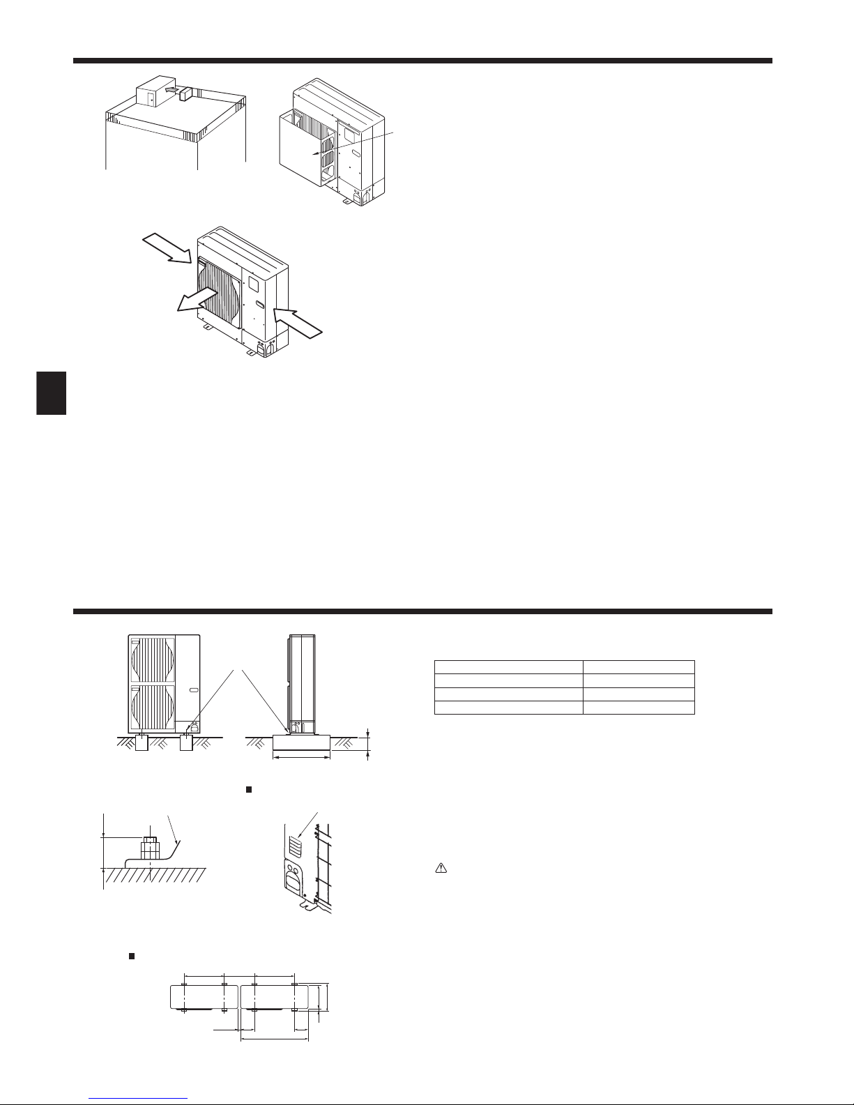
2.4.1. Windy location installation
When installing the outdoor unit on a rooftop or other location unprotected from the
wind, situate the air outlet of the unit so that it is not directly exposed to strong winds.
Strong wind entering the air outlet may impede the normal airfl ow and a malfunction
may result.
The following shows three examples of precautions against strong winds.
1 Face the air outlet towards the nearest available wall about 50 cm away from the
wall. (Fig. 2-3)
2 Install an optional air guide if the unit is installed in a location where strong winds
from a typhoon, etc. may directly enter the air outlet. (Fig. 2-4)
A Air outlet guide
3 Position the unit so that the air outlet blows perpendicularly to the seasonal wind
direction, if possible. (Fig. 2-5)
B Wind direction
Fig. 2-4
P100-P140
Fig. 2-3
D
C
A
B
A
B
Fig. 2-5
Fig. 3-1
2.4.2. When installing a single outdoor unit (Refer to the last page)
Minimum dimensions are as follows, except for Max., meaning Maximum dimensions, indicated.
The fi gures in parentheses are for P125, P140 models.
Refer to the fi gures for each case.
1 Obstacles at rear only (Fig. 2-6)
2 Obstacles at rear and above only (Fig. 2-7)
3 Obstacles at rear and sides only (Fig. 2-8)
4 Obstacles at front only (Fig. 2-9)
* When using an optional air outlet guide, the clearance for P125, P140 models is 500 mm or
more.
5 Obstacles at front and rear only (Fig. 2-10)
* When using an optional air outlet guide, the clearance for P125, P140 models is 500 mm or
more.
6 Obstacles at rear, sides, and above only (Fig. 2-11)
• Do not install the optional air outlet guides for upward airfl ow.
2.4.3. When installing multiple outdoor units (Refer to the last page)
Leave 10 mm for P100-P140 space or more between the units.
1 Obstacles at rear only (Fig. 2-12)
2 Obstacles at rear and above only (Fig. 2-13)
• No more than three units must be installed side by side. In addition, leave space as shown.
• Do not install the optional air outlet guides for upward airfl ow.
3 Obstacles at front only (Fig. 2-14)
* When using an optional air outlet guide, the clearance for P125. P140 models is 1000 mm
or more.
4 Obstacles at front and rear only (Fig. 2-15)
* When using an optional air outlet guide, the clearance for P125, P140 models is 1000 mm
or more.
5 Single parallel unit arrangement (Fig. 2-16)
* When using an optional air outlet guide installed for upward airfl ow, the clearance is 500
(1000) mm or more.
6 Multiple parallel unit arrangement (Fig. 2-17)
* When using an optional air outlet guide installed for upward airfl ow, the clearance is 1000
(1500) mm or more.
7 Stacked unit arrangement (Fig. 2-18)
• The units can be stacked up to two units high.
• No more than two stacked units must be installed side by side. In addition, leave space as
shown.
3. Installing the outdoor unit
• Be sure to install the unit in a sturdy, level surface to prevent rattling noises during
peration. (Fig. 3-1)
<Foundation specifi cations>
Foundation bolt M10 (3/8")
Thickness of concrete 120 mm
Length of bolt 70 mm
Weight-bearing capacity 320 kg
• Make sure that the length of the foundation bolt is within 30 mm of the bottom
surface of the base.
• Secure the base of the unit fi rmly with four-M10 foundation bolts in sturdy loca-
tions.
Installing the outdoor unit
• Do not block the vent. If the vent is blocked, operation will be hindered and break-
down may result.
• In addition to the unit base, use the installation holes on the back of the unit to
attach wires, etc., if necessary to install the unit. Use self-tapping screws (ø5 × 15
mm or less) and install on site.
Warning:
• The unit must be securely installed on a structure that can sustain its
weight. If the unit is mounted on an unstable structure, it may fall down and
cause damage or injuries.
• The unit must be installed according to the instructions in order to minimize
the risk of damage from earthquakes, typhoons, or strong winds. An incorrectly installed unit may fall down and cause damage or injuries.
A M10 (3/8") bolt
B Base
C As long as possible.
D Vent
E Set deep in the ground.
Max. 30 for P100-P140
(mm)
Min. 10
Min. 360
P100-P140
5
4. Installing the refrigerant piping
4.1. Precautions for devices that use R410A refrigerant
• Refer to page 3 for precautions not included below on using air conditioners with R410A refrigerant.
• Use ester oil, ether oil, alkylbenzene oil (small amount) as the refrigeration
oil applied to the fl ared sections.
• Use C1220 copper phosphorus, for copper and copper alloy seamless
pipes, to connect the refrigerant pipes. Use refrigerant pipes with the thicknesses specifi ed in the table to the below. Make sure the insides of the
pipes are clean and do not contain any harmful contaminants such as sulfuric compounds, oxidants, debris, or dust.
Warning:
When installing or relocating, or servicing the outdoor unit, use only the specifi ed refrigerant (R410A) to charge the refrigerant lines. Do not mix it with any
other refrigerant and do not allow air to remain in the lines.
If air is mixed with the refrigerant, then it can be the cause of abnormal high
pressure in the refrigerant line, and may result in an explosion and other hazards.
The use of any refrigerant other than that specifi ed for the system will cause
mechanical failure or system malfunction or unit breakdown. In the worst
case, this could lead to a serious impediment to securing product safety.
P100-P140
Liquid pipe ø9.52 thickness 0.8 mm
Gas pipe ø15.88 thickness 1.0 mm
• Do not use pipes thinner than those specifi ed above.
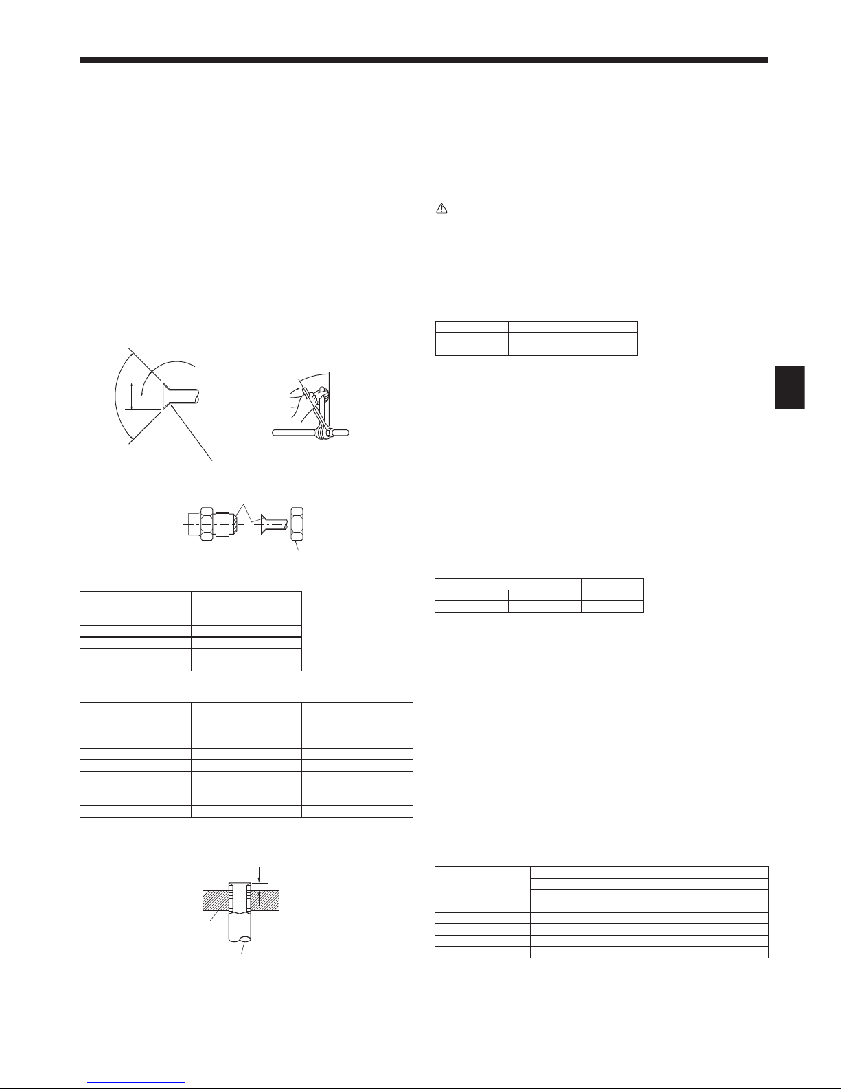
4.2. Connecting pipes (Fig. 4-1)
• When commercially available copper pipes are used, wrap liquid and gas pipes
with commercially available insulation materials (heat-resistant to 100°C or more,
thickness of 12 mm or more). Direct contact with the bare piping may result in
burns or frostbite.
• Be sure to separate thermal insulation for gas and liquid refrigerant pipes.
• The indoor parts of the drain pipe should be wrapped with polyethylene foam
insulation materials (specifi c gravity of 0.03, thickness of 9 mm or more).
• Apply thin layer of refrigerant oil to pipe and joint seating surface before tightening
fl are nut. A
• Use 2 wrenches to tighten piping connections. B
• Use leak detector or soapy water to check for gas leaks after connections are
completed.
• Apply refrigerating machine oil over the entire fl are seat surface. C
• Use the fl are nuts for the following pipe size. D
P100-P140
Gas side Pipe size (mm) ø15.88
Liquid side Pipe size (mm) ø9.52
• When bending the pipes, be careful not to break them. Bend radius of 100 mm to
150 mm are suffi cient.
• Make sure the pipes do not contact the compressor. Abnormal noise or vibration
may result.
1 Pipes must be connected starting from the indoor unit.
Flare nuts must be tightened with a torque wrench.
2 Flare the liquid pipes and gas pipes and apply a thin layer of refrigeration oil (Ap-
plied on site).
• When usual pipe sealing is used, refer to Table 1 for fl aring of R410A refrigerant
pipes.
The size adjustment gauge can be used to confi rm A measurements.
A (Fig. 4-1)
Copper pipe O.D.
(mm)
Flare dimensions
øA dimensions (mm)
ø6.35 8.7 - 9.1
ø9.52 12.8 - 13.2
ø12.7 16.2 - 16.6
ø15.88 19.3 - 19.7
ø19.05 23.6 - 24.0
B (Fig. 4-1)
Copper pipe O.D.
(mm)
Flare nut O.D.
(mm)
Tightening torque
(N·m)
ø6.35 17 14 - 18
ø6.35 22 34 - 42
ø9.52 22 34 - 42
ø12.7 26 49 - 61
ø12.7 29 68 - 82
ø15.88 29 68 - 82
ø15.88 36 100 - 120
ø19.05 36 100 - 120
A Flare cutting dimensions
B Flare nut tightening torque
A B
C
D
A Die
B Copper pipe
A
B
Fig. 4-1
Fig. 4-2
A
Table 1 (Fig. 4-2)
Copper pipe O.D.
(mm)
A (mm)
Flare tool for R410A Flare tool for R22·R407C
Clutch type
ø6.35 (1/4") 0 - 0.5 1.0 - 1.5
ø9.52 (3/8") 0 - 0.5 1.0 - 1.5
ø12.7 (1/2") 0 - 0.5 1.0 - 1.5
ø15.88 (5/8") 0 - 0.5 1.0 - 1.5
ø19.05 (3/4") 0 - 0.5 1.0 - 1.5
90°±0.5°
45°±2°
R0.4 - R0.8
øA
6
G
F
E
D
C
A
A
D
E
B
C
G
F
E
D
B
4. Installing the refrigerant piping
Fig. 4-3
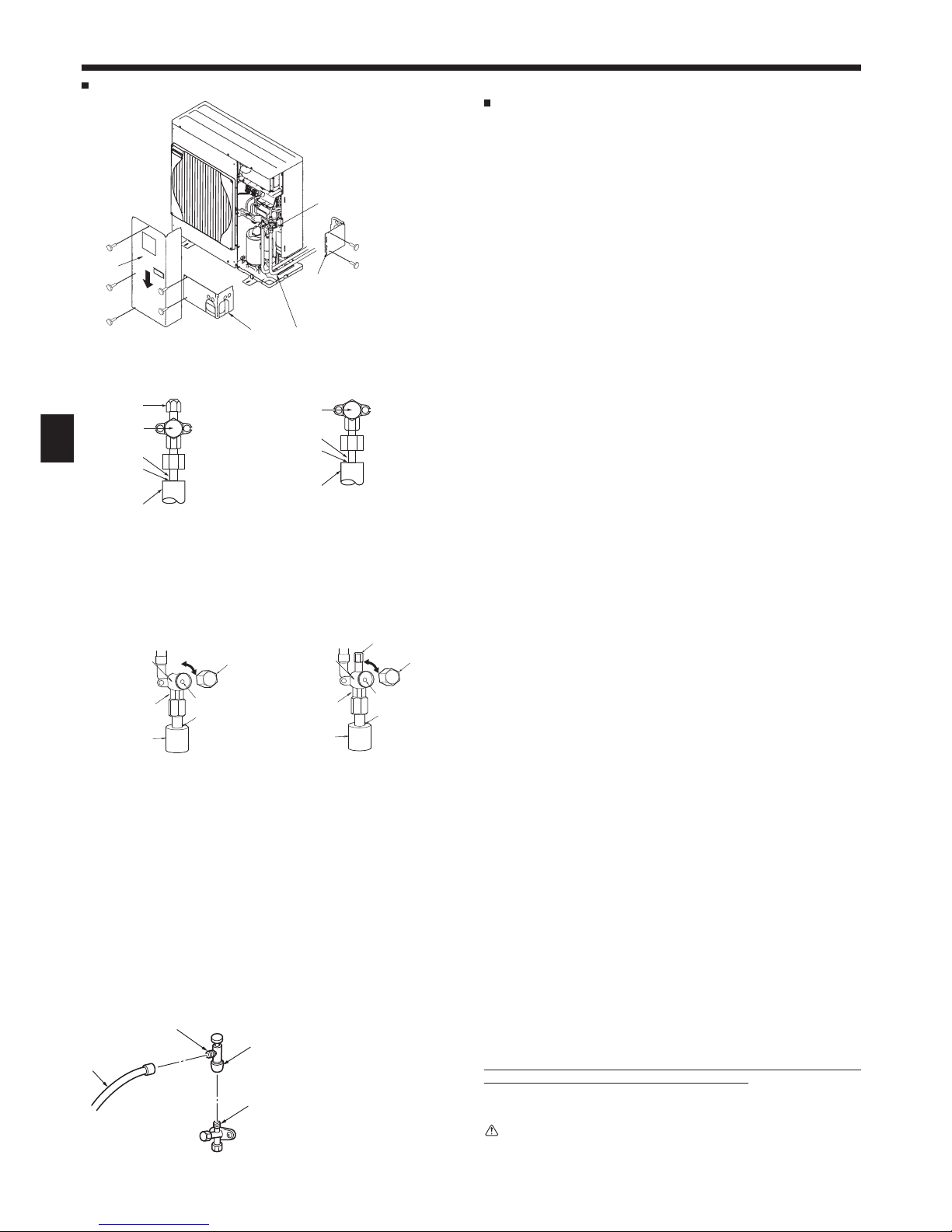
P100-P140
A Front piping cover
B Piping cover
C Stop valve
D Service panel
E Bend radius : 100 mm-150 mm
A Stop valve <Liquid side>
B Stop valve <Gas side>
C Service port
D Open/Close section
Fig. 4-4
Fig. 4-5 Fig. 4-6
C
H
A
I
E
B
(1) (2)
4.3. Refrigerant piping (Fig. 4-3)
For P100-P140
Remove the service panel D (3 screws) and the front piping cover A (2 screws) and
rear piping cover B (2 screws).
1 Perform refrigerant piping connections for the indoor/outdoor unit when the out-
door unit’s stop valve is completely closed.
2 Vacuum-purge air from the indoor unit and the connection piping.
3 After connecting the refrigerant pipes, check the connected pipes and the indoor
unit for gas leaks. (Refer to 4.4 Refrigerant pipe airtight testing method)
4 A high-performance vacuum pump is used at the stop valve service port to main-
tain a vacuum for an adequate time (at least 1 hour after reaching –101 kPa (5
Torr)) in order to vacuum dry the inside of the pipes. Always check the degree of
vacuum at the gauge manifold. If there is any moisture left in the pipe, the degree
of vacuum is sometimes not reached with short-time vacuum application.
After vacuum drying, completely open the stop valves (both liquid and gas) for the
outdoor unit. This completely links the indoor and outdoor refrigerant circuits.
• If the vacuum drying is inadequate, air and water vapor remain in the refrigerant circuits and can cause abnormal rise of high pressure, abnormal drop of
low pressure, deterioration of the refrigerant machine oil due to moisture, etc.
• If the stop valves are left closed and the unit is operated, the compressor and
control valves will be damaged.
• Use a leak detector or soapy water to check for gas leaks at the pipe connection sections of the outdoor unit.
• Do not use the refrigerant from the unit to purge air from the refrigerant lines.
• After the valve work is completed, tighten the valve caps to the correct torque:
20 to 25 N·m (200 to 250 kgf·cm).
Failure to replace and tighten the caps may result in refrigerant leakage. In
addition, do not damage the insides of the valve caps as they act as a seal to
prevent refrigerant leakage.
5 Use sealant to seal the ends of the thermal insulation around the pipe connection
sections to prevent water from entering the thermal insulation.
4.4. Refrigerant pipe airtight testing method
(1)
Connect the testing tools.
• Make sure the stop valves A B are closed and do not open them.
• Add pressure to the refrigerant lines through the service port C of the liquid
stop valve A.
(2)
Do not add pressure to the specifi ed pressure all at once; add pressure little by
little.
1 Pressurize to 0.5 MPa (5 kgf/cm²G), wait 5 minutes, and make sure the pres-
sure does not decrease.
2 Pressurize to 1.5 MPa (15 kgf/cm²G), wait 5 minutes, and make sure the pres-
sure does not decrease.
3 Pressurize to 4.15 MPa (41.5 kgf/cm²G) and measure the surrounding tem-
perature and refrigerant pressure.
(3)
If the specifi ed pressure holds for about one day and does not decrease, the pipes
have passed the test and there are no leaks.
• If the surrounding temperature changes by 1 °C, the pressure will change by
about 0.03 MPa (0.3 kgf/cm²G). Make the necessary corrections.
(4)
If the pressure decreases in steps (2) or (3), there is a gas leak. Look for the
source of the gas leak.
4.5. Stop valve opening method
The stop valve opening method varies according to the outdoor unit model. Use the
appropriate method to open the stop valves.
(1)
Gas side of P100-P140 (Fig. 4-5)
1 Remove the cap and turn the valve rod counterclockwise as far as it will go with
the use of a 5 mm hexagonal wrench. Stop turning when it hits the stopper.
(ø 15.88: Approximately 13 revolutions)
2 Make sure that the stop valve is open completely and rotate the cap back to its
original position.
(2)
Liquid side of P100-P140 (Fig. 4-6)
1 Remove the cap and turn the valve rod counterclockwise as far as it will go with
the use of a 4 mm hexagonal wrench. Stop turning when it hits the stopper.
(ø9.52: Approximately 10 revolutions)
2 Make sure that the stop valve is open completely and rotate the cap back to its
original position.
Refrigerant pipes are protectively wrapped for P100-P140
• The pipes can be protectively wrapped up to a diameter of ø90 before or after
connecting the pipes. Cut out the knockout in the pipe cover following the groove
and wrap the pipes.
Pipe inlet gap for P100-P140
• Use putty or sealant to seal the pipe inlet around the pipes so that no gaps remain.
(If the gaps are not closed, noise may be emitted or water and dust will enter the
unit and breakdown may result.)
H Double spanner section
(Do not apply a spanner other than to this section. Doing
so would cause coolant leaks.)
I Seal section
(Seal the end of the heat insulation material at the pipe
connection section with whatever seal material you have
on hand so that water does not infi ltrate the heat insula-
tion material.)
A Valve
B Unit side
C Cap
D Local pipe side
E Pipe cover
F Service port
G Wrench hole
H
D
E
G
F
A
G
I
D
C
B
Precautions when using the charge valve (Fig. 4-7)
Do not tighten the service port too much when installing it, otherwise, the valve core
could be deformed and become loose, causing a gas leak.
After positioning section B in the desired direction, turn section A only and tighten it.
Do not further tighten sections A and B together after tightening section A.
Warning:
When installing the unit, securely connect the refrigerant pipes before starting
the compressor.
* The fi gure to the left is an example only.
The stop valve shape, service port position,
etc., may vary according to the model.
* Turn section A only.
(Do not further tighten sections A and B
together.)
C Charge hose
D Service port
A
B
C
D
Fig. 4-7
E Local pipe
F Sealed, same way for gas side
G Pipe cover
S3
S3
S2
S1
S2S1LN
LN
S1 S2 S3
L1 L2 L3 N
S1 S2 S3
7
4.6. Addition of refrigerant
• Additional charging is not necessary if the pipe length does not exceed 20 m for
P100 and 30 m for P125-P140.
• If the pipe length is exceeded, charge the unit with additional R410A refrigerant
according to the permitted pipe lengths in the following table.
* When the unit is stopped, charge the unit with the additional refrigerant through
the liquid stop valve after the pipe extensions and indoor unit have been vacuumized.
When the unit is operating, add refrigerant to the gas check valve using a
safety charger. Do not add liquid refrigerant directly to the check valve.
* After charging the unit with refrigerant, note the added refrigerant amount on
the service label (attached to the unit).
Refer to the “1.5. Using R410A refrigerant air conditioners” for more informa-
tion.
• Be careful when installing multiple units. Connecting to an incorrect indoor unit
can lead to abnormally high pressure and have a serious effect on operation
performance.
Model
Permitted
pipe
length
Permitted
vertical
difference
Additional refrigerant charging amount
21 - 30 m 31 - 40 m 41 - 50 m
P100
-50 m -30 m
0.6 kg 1.2 kg 1.8 kg
P125,
P140
– 0.6 kg 1.2 kg
4. Installing the refrigerant piping
4.7. For twin/triple combination
Refrigerant piping limitation of length, height difference are shown in the fi gure. (Fig.
4-8)
A Indoor unit
B Outdoor unit
C Multi distribution pipe (option)
D Height difference (Indoor unit-Outdoor unit) Max. 30 m
E Height difference (Indoor unit-Indoor unit) Max. 1 m
P100-P140 : A+B+C(+D) ≤ 50 m
5. Drainage piping work
B–C
B–D ≤ 8 m
C–D
A
C
A
A
B
D
E
B
C
A
D
Outdoor unit drainage pipe connection
When drain piping is necessary, use the drain socket or the drain pan (option).
Fig. 4-8
B
C ≤ 20 m
D
P100-P140
Drain socket PAC-SG61DS-E
Drain pan PAC-SG64DP-E
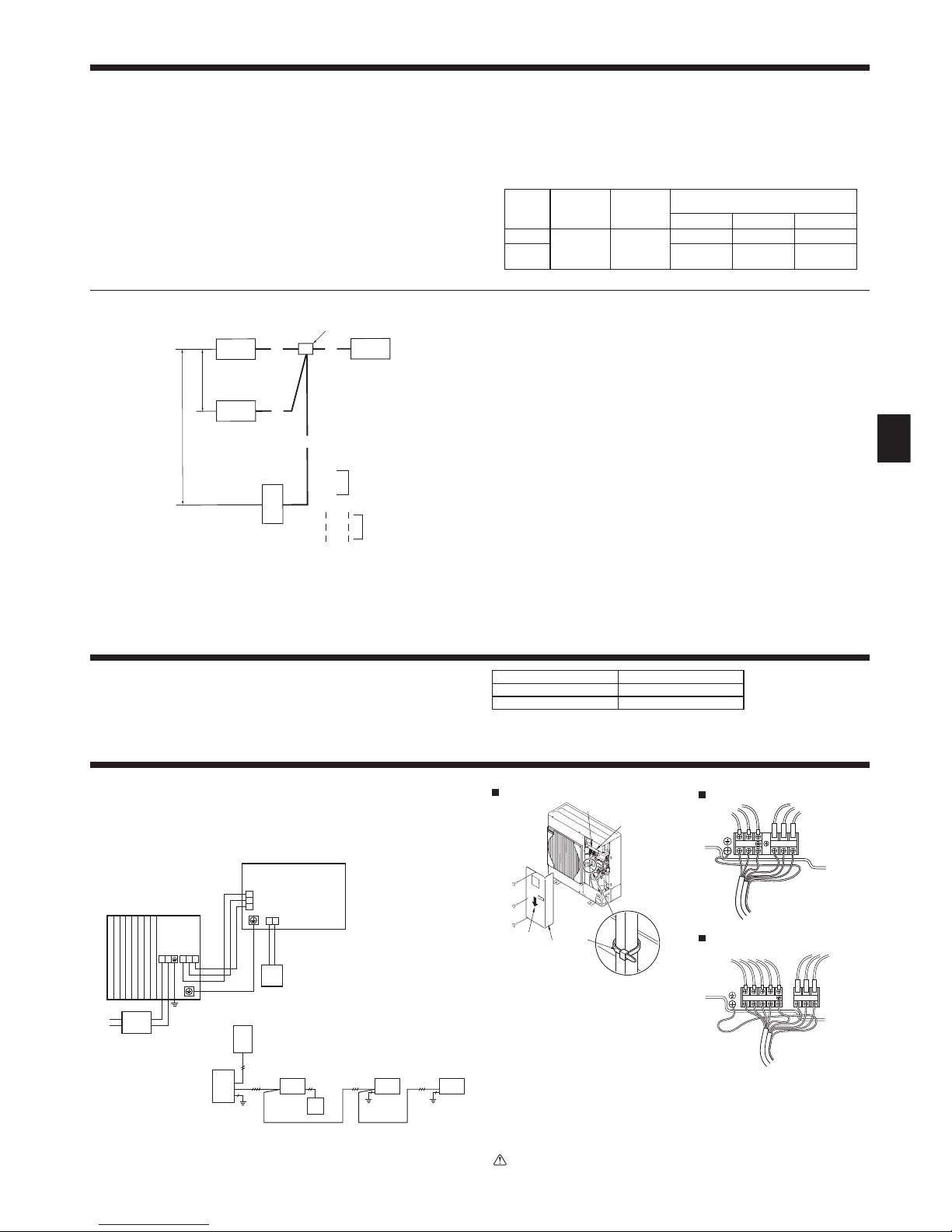
6. Electrical work
6.1. Outdoor unit (Fig. 6-1, Fig. 6-2)
1 Remove the service panel.
2 Wire the cables referring to the Fig. 6-1 and the Fig. 6-2.
C
Fig. 6-1
A Indoor unit
B Outdoor unit
C Remote controller
D Main switch (Breaker)
E Earth
A Earth terminal
B Terminal block
C Clamp
D Service panel
E Wire the cables so that they do not
contact the center of the service
panel or the gas valve.
Fig. 6-2
A
B
D
D
AAAB
C
E
E
E
For Power For Power
A
B
C
E
D
P100-P140
P100-P140V
P100-P140Y
Caution:
Be sure to install N-Line. Without N-Line, it could cause damage to unit.
 Loading...