

Mitsubishi PUHZ-P250YHA, PUHZ-P200YHA3R3, PUHZ-P250YHA3, PUHZ-P250YHA3R1, PUHZ-P250YHA3R2 Service Manual
...
SERVICE MANUAL
No. OCH424
REVISED EDITION-D
SPLIT-TYPE, HEAT PUMP AIR CONDITIONERS
R410A
November 2010
Outdoor unit
[Model names]
PUHZ-P200YHA
PUHZ-P250YHA
PUHZ-P200YHA3
PUHZ-P250YHA3
[Service Ref.]
PUHZ-P200YHA
PUHZ-P250YHA
PUHZ-P200YHA3
PUHZ-P200YHA3R1
PUHZ-P200YHA3R2
PUHZ-P200YHA3R3
PUHZ-P250YHA3
PUHZ-P250YHA3R1
PUHZ-P250YHA3R2
PUHZ-P250YHA3R3
PUHZ-P200YHA3R1/R2/R3
PUHZ-P250YHA3R1/R2/R3
Note:
• This manual describes only
service data of the outdoor
units.
• RoHS compliant products
have <G> mark on the
spec name plate.
CONTENTS
1. TECHNICAL CHANGES
.................................
2
2. REFERENCE MANUAL
..................................
2
3. SAFETY PRECAUTION
..................................
3
4. FEATURES
......................................................
6
5. SPECIFICATIONS
...........................................
7
6. DATA
...............................................................
8
7. OUTLINES AND DIMENSIONS
....................
10
8. WIRING DIAGRAM
.......................................
12
9. WIRING SPECIFICATIONS
..........................
13
10.
REFRIGERANT SYSTEM DIAGRAM
...............
18
11. TROUBLESHOOTING
...................................
20
12. FUNCTION SETTING
....................................
70
13.
MONITORING THE OPERATION DATA BY THE REMOTE CONTROLLER
....
77
14. EASY MAINTENANCE FUNCTION
..............
87
15. DISASSEMBLY PROCEDURE
.....................
90
PARTS CATALOG (OCB424)
Revision:
• PUHZ-P200/250YHA3R3
have been added in
REVISED EDITION-D.
• Some descriptions have
been modified.
• Please void OCH424
REVISED EDITION-C.
2
2
REFERENCE MANUAL
Model name Service Ref.
Service
Manual No.
PLA-RP35/50/60/71/100/125/140BA
PLA-RP71/100/125/140BA2
PLA-RP35/50/60/71/100/125/140BA(#2).UK
PLA-RP35/50/60/71BA
1
.UK
PLA-RP71/100/125BA2.UK
PLA-RP140BA2R1.UK
OCH412
OCB412
PCA-RP71/125HA
OC329
PCA-RP71/125HA(#1)
PCA-RP50/60/71/100/125/140GA PCA-RP50/60/71/100/125/140GA(#1)
OC328
PCA-RP50GA2 PCA-RP50GA2(#1)
PKA-RP35/50GAL PKA-RP35/50GAL(#1)
OC330
PKA-RP60/71/100FAL PKA-RP60/71/100FAL(#1)
PKA-RP50FAL2 PKA-RP50FAL2(#1)
OC331
PEAD-RP60/71/100GA
PEAD-RP60/71/100GA(#1).UK
HWE0506
PEA-RP200/250/400/500GA
PEA-RP200/250/400/500GA.TH-AF
PEA-RP200/250GA.TH-AFMF
HWE0708A
PEAD-RP50/60/71/125/140EA
PEAD-RP35/100EA2
PEAD-RP50/60/71/125/140EA(#1).UK
PEAD-RP35/100EA2(#1).UK
HWE0521
PKA-RP60/71/100KAL
PKA-RP60/71/100KAL.TH
OCH452
OCB452
PCA-RP50/60/71/100/125/140KA
PCA-RP50/60/71/100/125/140KA
OCH454
OCB454
PKA-RP35/50HAL
PKA-RP35/50HAL
OCH453
OCB453
PLA-RP100BA3 PLA-RP100BA3
OCH459
OCB459
PEAD-RP35/50/60/71/100/125/140JA(L)
PEAD-RP35/50/60/71/100/125/140JA(L)(R1).UK
HWE08130
BWE08240
BWE09220
INDOOR UNIT’S SERVICE MANUAL
1
TECHNICAL CHANGES
PUHZ-P200YHA3R2 PUHZ-P200YHA3R3
PUHZ-P250YHA3R2 PUHZ-P250YHA3R3
• The mounting location of CHARGE PLUG has been changed.
• THERMISTOR has been changed (Discharge, black → Shell, white (These are compatible)).
• The part numbers have been modified. (The parts that are new numbers are compatible with old numbers)
<For all models> FRONT PANEL, TOP PANEL, FUSE (F3, 4)
<For 200Y models> ACCUMULATOR
PUHZ-P200YHA3R1 PUHZ-P200YHA3R2
PUHZ-P250YHA3R1 PUHZ-P250YHA3R2
• POWER BOARD (P.B.) has been changed.
• CONTROLLER BOARD (C.B.) has been changed. (S/W version up)
PUHZ-P200YHA3 PUHZ-P200YHA3R1
PUHZ-P250YHA3 PUHZ-P250YHA3R1
• FAN GRILLES and FRONT PANEL have been changed.
PUHZ-P200YHA PUHZ-P200YHA3
PUHZ-P250YHA PUHZ-P250YHA3
• OUTDOOR CONTROLLER BOARD (C.B.) has been changed.
(S/W has been changed: Corresponding to the additional combination between PKA-RP•HAL/KAL, PCA-RP•KA and PEAD-RP•JA(L))
3
3
SAFETY PRECAUTION
Cautions for units utilizing refrigerant R410A
3-2. CAUTIONS RELATED TO NEW REFRIGERANT
Use new refrigerant pipes.
Store the piping to be used indoors during
installation, and both ends of the piping sealed
until just before brazing. (Leave elbow joints, etc.
in their packaging.)
The refrigerant oil applied to flare and flange
connections must be ester oil, ether oil or
alkylbenzene oil in a small amount.
In case of using the existing pipes for R22, be careful with
the followings.
· Be sure to clean the pipes and make sure that the insides
of the pipes are clean.
· Change flare nut to the one provided with this product.
Use a newly flared pipe.
· Avoid using thin pipes.
Charge refrigerant from liquid phase of gas
cylinder.
If the refrigerant is charged from gas phase, composition
change may occur in refrigerant and the efficiency will be
lowered.
Do not use refrigerant other than R410A.
If other refrigerant (R22 etc.) is used, chlorine in refrigerant can cause deterioration of refrigerant oil etc.
Use a vacuum pump with a reverse flow check
valve.
Vacuum pump oil may flow back into refrigerant cycle and
that can cause deterioration of refrigerant oil etc.
Use the following tools specifically designed for
use with R410A refrigerant.
The following tools are necessary to use R410A refrigerant.
Handle tools with care.
If dirt, dust or moisture enters into refrigerant cycle, that can
cause deterioration of refrigerant oil or malfunction of compressor.
Do not use a charging cylinder.
If a charging cylinder is used, the composition of refrigerant will change and the efficiency will be lowered.
Flare tool
Electronic refrigerant
charging scale
Vacuum pump adaptor
Size adjustment gauge
Gauge manifold
Torque wrench
Gas leak detector
Charge hose
Tools for R410A
Contamination inside refrigerant piping can cause deterioration of refrigerant oil etc.
If dirt, dust or moisture enters into refrigerant cycle, that can
cause deterioration of refrigerant oil or malfunction of compressor.
If large amount of mineral oil enters, that can cause deterioration of refrigerant oil etc.
Make sure that the inside and outside of refrigerant piping is clean and it has no contaminants
such as sulfur, oxides, dirt, shaving particles, etc,
which are hazard to refrigerant cycle.
In addition, use pipes with specified thickness.
Ventilate the room if refrigerant leaks during
operation. If refrigerant comes into contact with
a flame, poisonous gases will be released.
3-1. ALWAYS OBSERVE FOR SAFETY
Before obtaining access to terminal, all supply circuits must be disconnected.
Preparation for the repair service
· Prepare the proper tools.
· Prepare the proper protectors.
· Provide adequate ventilation.
· After stopping the operation of the air conditioner, turn off the power-supply breaker.
· Discharge the condenser before the work involving the electric parts.
Precautions during the repair service
· Do not perform the work involving the electric parts with wet hands.
· Do not pour water into the electric parts.
· Do not touch the refrigerant.
· Do not touch the hot or cold areas in the refrigerating cycle.
· When the repair or the inspection of the circuit needs to be done without turning off the power, exercise great caution not
to touch the live parts.
4
Gravimeter
Unit
[3] Service tools
Use the below service tools as exclusive tools for R410A refrigerant.
No. Tool name Specifications
1 Gauge manifold · Only for R410A
· Use the existing fitting
specifications
. (UNF1/2)
· Use high-tension side pressure of 5.3MPa·G or over.
2 Charge hose · Only for R410A
· Use pressure performance of 5.09MPa·G or over.
3 Electronic scale
4 Gas leak detector · Use the detector for R134a, R407C or R410A.
5 Adaptor for reverse flow check · Attach on vacuum pump.
6 Refrigerant charge base
7 Refrigerant cylinder · Only for R410A · Top of cylinder (Pink)
· Cylinder with syphon
8 Refrigerant recovery equipment
[1] Cautions for service
(1) Perform service after recovering the refrigerant left in unit completely.
(2) Do not release refrigerant in the air.
(3) After completing service, charge the cycle with specified amount of refrigerant.
(4) When performing service, install a filter drier simultaneously.
Be sure to use a filter drier for new refrigerant.
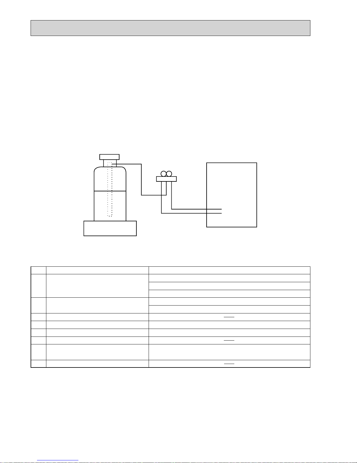
[2] Additional refrigerant charge
When charging directly from cylinder
· Check that cylinder for R410A on the market is syphon type.
· Charging should be performed with the cylinder of syphon stood vertically. (Refrigerant is charged from liquid phase.)
5
Cautions for refrigerant piping work
New refrigerant R410A is adopted for replacement inverter series. Although the refrigerant piping work for R410A is same as
for R22, exclusive tools are necessary so as not to mix with different kind of refrigerant. Furthermore as the working pressure
of R410A is 1.6 times higher than that of R22, their sizes of flared sections and flare nuts are different.
1Thickness of pipes
Because the working pressure of R410A is higher compared to R22, be sure to use refrigerant piping with thickness
shown below. (Never use pipes of 0.7 mm or below.)
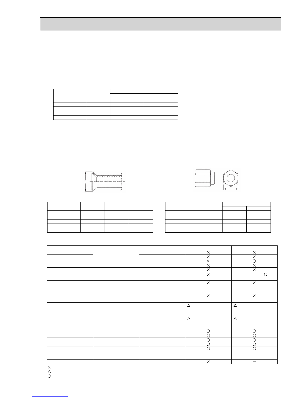
2Dimensions of flare cutting and flare nut
The component molecules in HFC refrigerant are smaller compared to conventional refrigerants. In addition to that,
R410A is a refrigerant, which has higher risk of leakage because its working pressure is higher than that of other refrigerants. Therefore, to enhance airtightness and intensity, flare cutting dimension of copper pipe for R410A has been specified separately from the dimensions for other refrigerants as shown below. The dimension B of flare nut for R410A also
has partly been changed to increase intensity as shown below. Set copper pipe correctly referring to copper pipe flaring
dimensions for R410A below. For 1/2 and 5/8 inch, the dimension B changes.
Use torque wrench corresponding to each dimension.
3Tools for R410A (The following table shows whether conventional tools can be used or not.)
1/4
3/8
1/2
5/8
3/4
6.35
9.52
12.70
15.88
19.05
0.8
0.8
0.8
1.0
—
0.8
0.8
0.8
1.0
1.0
Nominal
dimensions(inch)
Diagram below: Piping diameter and thickness
Outside
diameter
(mm)
Thickness
(mm)
R410A R22
1/4
3/8
1/2
5/8
3/4
6.35
9.52
12.70
15.88
19.05
9.1
13.2
16.6
19.7
24.0
9.0
13.0
16.2
19.4
23.3
Nominal
dimensions(inch)
Flare cutting dimensions
Outside
diameter
Dimension A
( )
+0
-0.4
(mm)
R410A R22
1/4
3/8
1/2
5/8
3/4
6.35
9.52
12.70
15.88
19.05
17.0
22.0
26.0
29.0
36.0
17.0
22.0
24.0
27.0
36.0
Nominal
dimensions(inch)
Flare nut dimensions
Outside
diameter
Dimension B
(mm)
R410A R22
Gauge manifold
Charge hose
Gas leak detector
Refrigerant recovery equipment
Refrigerant cylinder
Applied oil
Safety charger
Charge valve
Vacuum pump
Flare tool
Bender
Pipe cutter
Welder and nitrogen gas cylinder
Refrigerant charging scale
Vacuum gauge or thermistor vacuum gauge and
vacuum valve
Charging cylinder
Air purge, refrigerant charge and
Operation check
Gas leak check
Refrigerant recovery
Refrigerant charge
Apply to flared section
Prevent compressor malfunction
when charging refrigerant by
spraying liquid refrigerant
Prevent gas from blowing out
when detaching charge hose
Vacuum drying and air
purge
Flaring work of piping
Bend the pipes
Cut the pipes
Weld the pipes
Charge refrigerant
Check the degree of vacuum. (Vacuum
valve prevents back flow of oil and refrigerant to thermistor vacuum gauge)
Refrigerant charge
Tool exclusive for R410A
Tool exclusive for R410A
Tool for HFC refrigerant
Tool exclusive for R410A
Tool exclusive for R410A
Ester oil, ether oil and
alkylbenzene
oil
(minimum amount)
Tool exclusive for R410A
Tool exclusive for R410A
Tools for other refrigerants can
be used if equipped with adopter for reverse flow check
Tools for other refrigerants
can be used by adjusting
flaring dimension
Tools for other refrigerants can be used
Tools for other refrigerants can be used
Tools for other refrigerants can be used
Tools for other refrigerants can be used
Tools for other refrigerants
can be used
Tool exclusive for R410A
Tools and materials Use R410A tools Can R22 tools be used?
(Usable if equipped
with adopter for rever se flow)
(Usable by adjusting
flaring dimension)
Can R407C tools be used?
Ester oil, ether oil:
Alkylbenzene oil: minimum amount
(Usable if equipped
with adopter for rever se flow)
(Usable by adjusting
flaring dimension)
: Prepare a new tool. (Use the new tool as the tool exclusive for R410A.)
: Tools for other refrigerants can be used under certain conditions.
: Tools for other refrigerants can be used.
Dimension A
Dimension B
6
4
FEATURES
CHARGELESS SYSTEM
PRE-CHARGED REFRIGERANT IS SUPPLIED FOR PIPING LENGTH AT SHIPMENT. (Max. 30m)
The refrigerant circuit with LEV (Linear Expansion Valve) and Accumulator always control the optimal refrigerant level regardless of the length (30 m max. and 5 m min.) of piping. The additional refrigerant charging work during installation often causes
problems. It is completely eliminated by chargeless system. This unique system improves the quality and reliability of the work
done. It also helps to speed up the installation time.
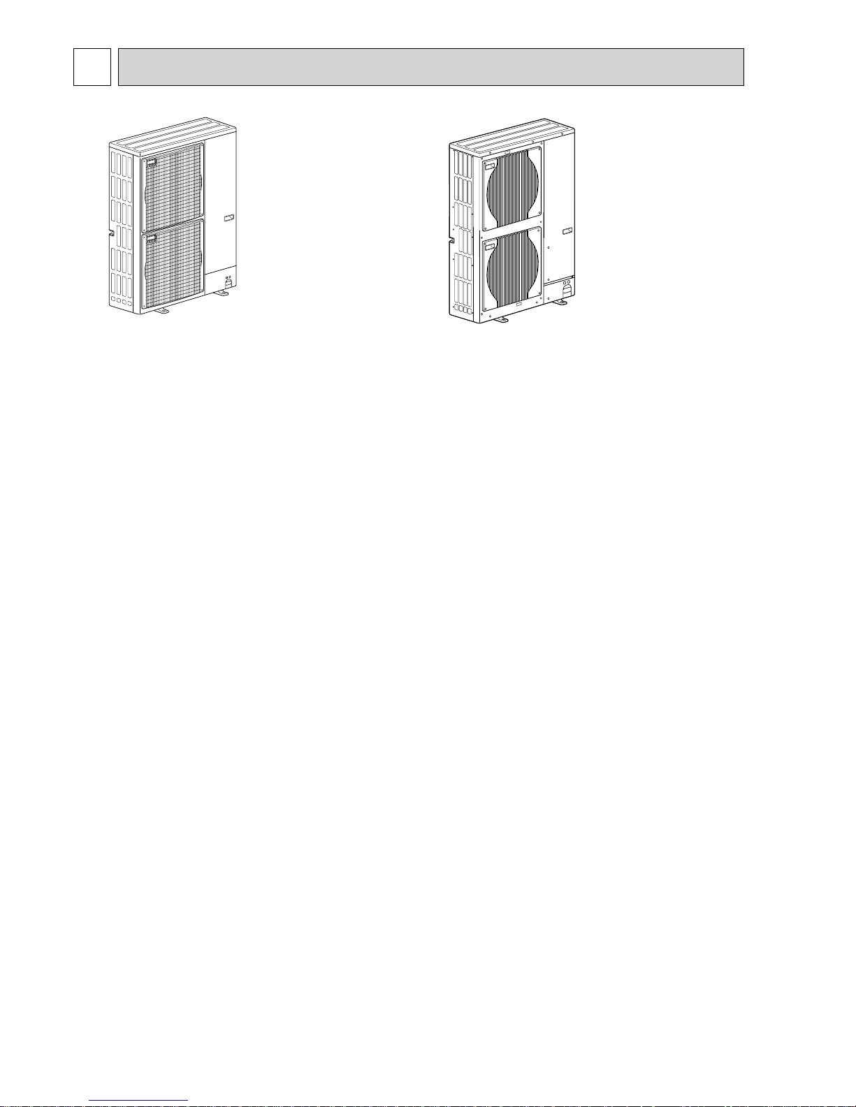
PUHZ-P200YHA
PUHZ-P250YHA
PUHZ-P200YHA3
PUHZ-P250YHA3
PUHZ-P200YHA3R1
PUHZ-P250YHA3R1
PUHZ-P200YHA3R2
PUHZ-P250YHA3R2
PUHZ-P200YHA3R3
PUHZ-P250YHA3R3
7
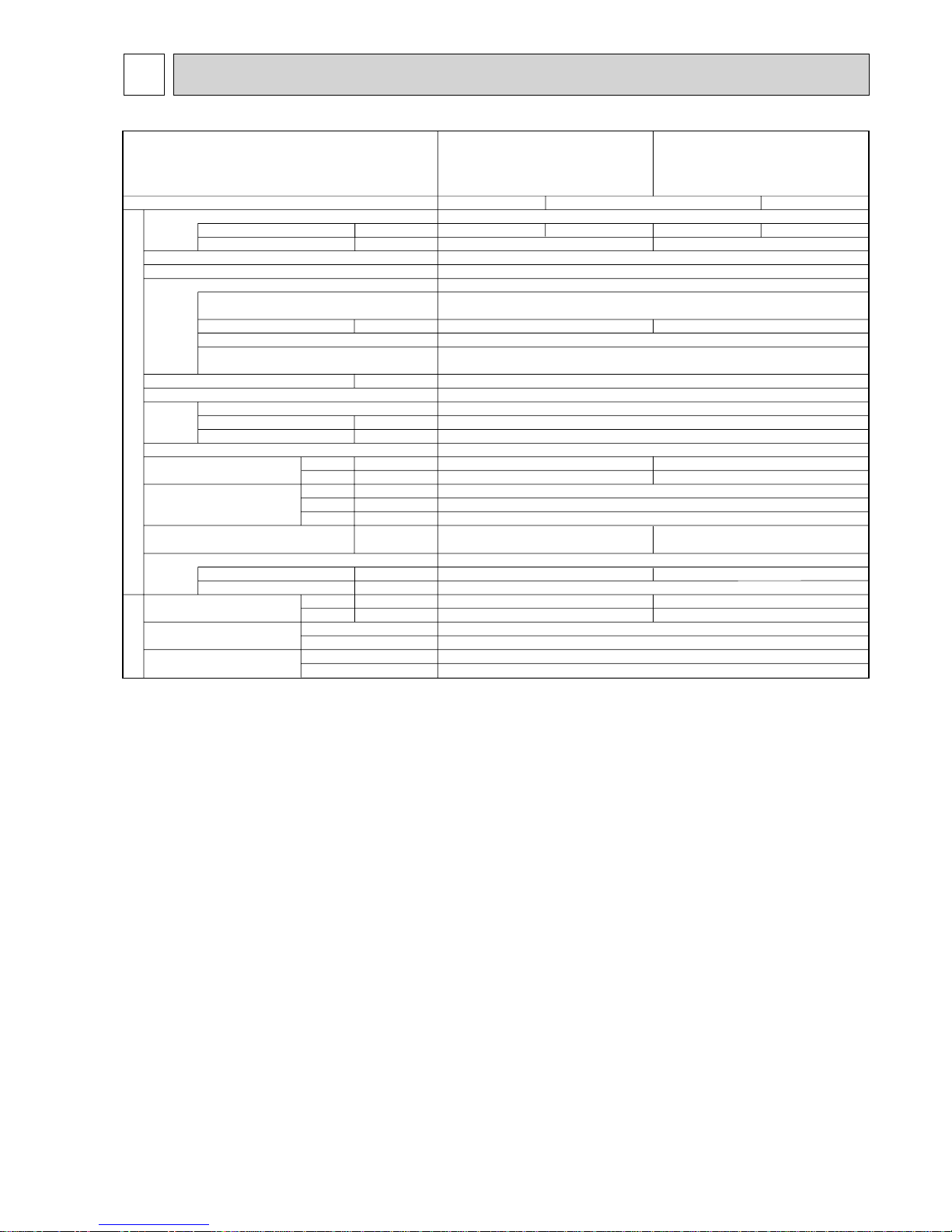
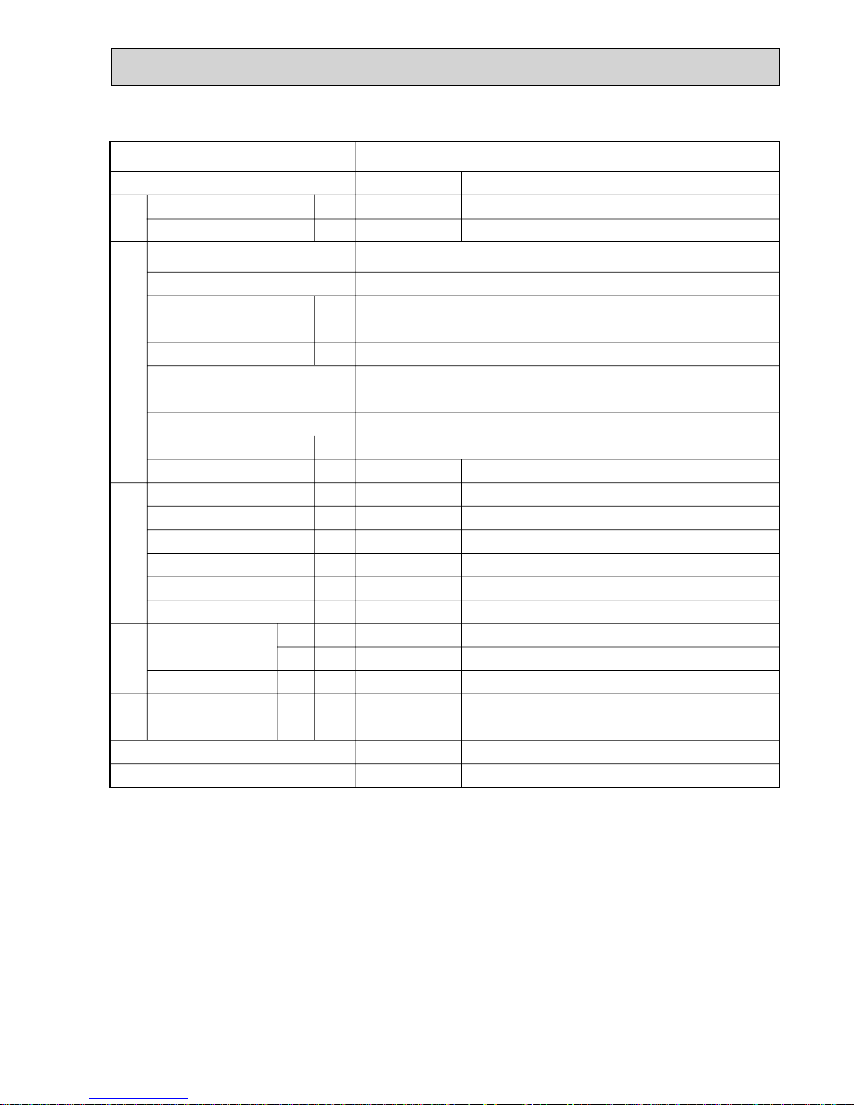
5
SPECIFICATIONS
A
A
kW
W
kW
*
/min(L/s
)
dB
dB
mm(in.)
mm(in.)
mm(in.)
kg(lbs)
kg(lbs)
L
mm(in.)
mm(in.)
Power supply (phase, cycle, voltage)
Running current
Max. current
External finish
Refrigerant control
Compressor
Model
Motor output
Starter type
Protection devices
Crankcase heater
Heat exchanger
Fan Fan(drive) % No.
Fan motor output
Airflow
Defrost method
Noise level
Dimensions
Weight
Refrigerant
Charge
Oil (Model)
Pipe size O.D.
Connection method
Between the indoor &
outdoor unit
Mode
Cooling
Heating
W
D
H
Liquid
Gas
Indoor side
Outdoor side
Height difference
Piping length
Service Ref.
PUHZ-P250YHA
PUHZ-P250YHA3
PUHZ-P250YHA3R1
PUHZ-P250YHA3R2
PUHZ-P250YHA3R3
PUHZ-P200YHA
PUHZ-P200YHA3
PUHZ-P200YHA3R1
PUHZ-P200YHA3R2
PUHZ-P200YHA3R3
Cooling
9.47
Munsell 3Y 7.8/1.1
Linear Expansion Valve
Hermetic
YHA: ANB52FFJMT or ANB52FFPMT
YHA3(R1, R2, R3): ANB52FFPMT
Line start
—
Plate fin coil
Propeller fan % 2
0.150 + 0.150
130(2170)
Reverse cycle
950(37-3/8)
330 + 30(13+1-3/16)
1,350(53-1/8)
R410A
2.30(FV50S)
Flared
Flared & Brazing
Max. 30m
Max. 70m
Heating
9.88
Cooling
11.0
21
5.5
Heating
12.0
HP switch
Discharge thermo
3 phase 50Hz, 400V
OUTDOOR UNIT
REFRIGERANT PIPING
4.7
19
59
59
126(278)
5.8(12.8)
9.52(3/8)
25.4(1)
59
59
YHA, YHA3R3: 133(294)/
YHA3(R1,R2): 135(298)
7.1(15.7)
12.7(1/2)
25.4(1)
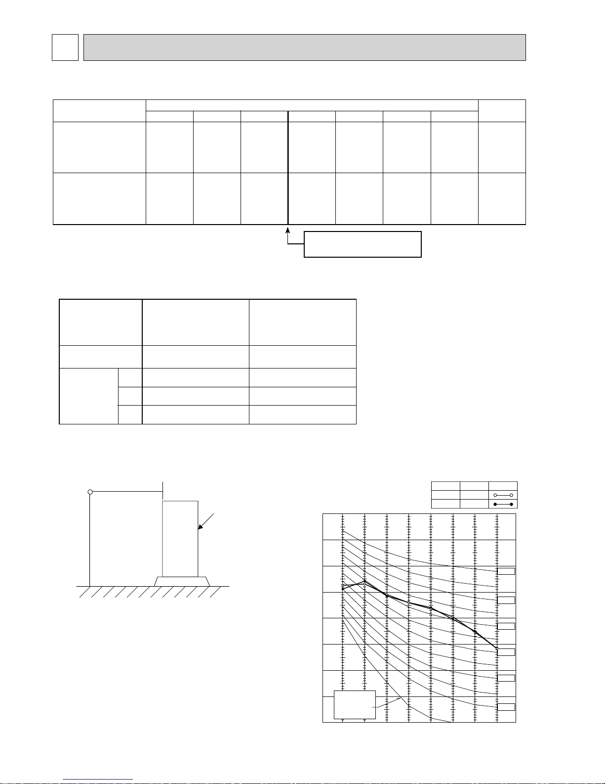
8
90
80
70
60
50
40
30
20
10
63 125 250 500 1000 2000 4000 8000
APPROXIMATE
THRESHOLD OF
HEARING FOR
CONTINUOUS
NOISE
OCTAVE BAND SOUND PRESSURE LEVEL, dB (0 dB = 0.0002 μbar)
BAND CENTER FREQUENCIES, Hz
NC-60
NC-50
NC-40
NC-30
NC-20
NC-70
PUHZ-P200YHA
PUHZ-P250YHA
PUHZ-P200YHA3(R1/R2/R3)
PUHZ-P250YHA3(R1/R2/R3)
COOLING
MODE
HEATING
59
SPL(dB)
59
LINE
6
DATA
6-1. REFILLING REFRIGERANT CHARGE (R410A : kg)
6-2. COMPRESSOR TECHNICAL DATA
Piping length (one way)
10m
20m
30m
40m
50m
Factory
charged
4.8
5.9
5.3
6.5
5.8
7.1
6.7
8.3
7.6
9.5
60m
8.5
10.7
70m
9.4
11.9
5.8
7.1
Service Ref.
PUHZ-P200YHA
PUHZ-P200YHA3
PUHZ-P200YHA3R1
PUHZ-P200YHA3R2
PUHZ-P200YHA3R3
PUHZ-P250YHA
PUHZ-P250YHA3
PUHZ-P250YHA3R1
PUHZ-P250YHA3R2
PUHZ-P250YHA3R3
U-V
U-W
W-V
Unit
Compressor model
Winding
Resistance
( )
(at 20°C)
ANB52FFJMT
ANB52FFPMT
0.30
0.30
0.30
PUHZ-P200, 250YHA
PUHZ-P200, 250YHA3
PUHZ-P200, 250YHA3R1
PUHZ-P200, 250YHA3R2
PUHZ-P200, 250YHA3R3
ANB52FFPMT
0.30
0.30
0.30
For pipe longer than 30 m,
additional charge is required.
6-3. NOISE CRITERION CURVES
1.5m
1m
MICROPHONE
UNIT
GROUND
9
PEA-RP250GAPEA-RP200GA
PEA-RP250GA
PEA-RP200GA
3, 50
3, 50
400
400
1.18
1.00
2.302.00
PUHZ-P250YHA
PUHZ-P250YHA3
PUHZ-P250YHA3R1/R2/R3
PUHZ-P200YHA
PUHZ-P200YHA3
PUHZ-P200YHA3R1/R2/R3
3, 503, 50
400
400
HeatingCooling
HeatingCooling
12.011.0
9.889.47
19,000 22,400 22,000 27,000
7.21 7.36 8.44 8.47
74.074.873.775.6
45.149.643.249.7
-2.37.1
-0.88.0
7.57.5
7.57.5
2027
2027
1519
1519
39.115.4
35.717.1
735
735
624
624
0.86
0.81
0.150.18
—
—
—
—
2.67
(27.2)
2.94
(30.0)
2.96
(30.2)
2.59
(26.4)
0.62
(6.32)
0.86
(8.75)
0.87
(8.87)
0.64
(6.53)
Electrical circuitRefrigerant circuitIndoor side
Outdoor
side
Representative matching
SHF
BF
Mode
Capacity
Input
Total
(kgf/%)
(kgf/%)
Phase , Hz
Voltage
Input
Current
Outdoor unit
Phase , Hz
Voltage
Current
Discharge pressure
Suction pressure
Discharge temperature
Condensing temperature
Suction temperature
Ref. pipe length
Intake air temperature
Discharge air temperature
Intake air temperature
V
kW
A
V
A
MPa
MPa
°C
°C
°C
m
°C
°C
°C
°C
°C
Indoor unit
D.B.
W.B.
D.B.
D.B.
W.B.
W
kW
The unit of pressure has been changed to MPa based on international SI system.
The conversion factor is: 1(MPa)=10.2(kgf/cm²)
6-4. STANDARD OPERATION DATA
10
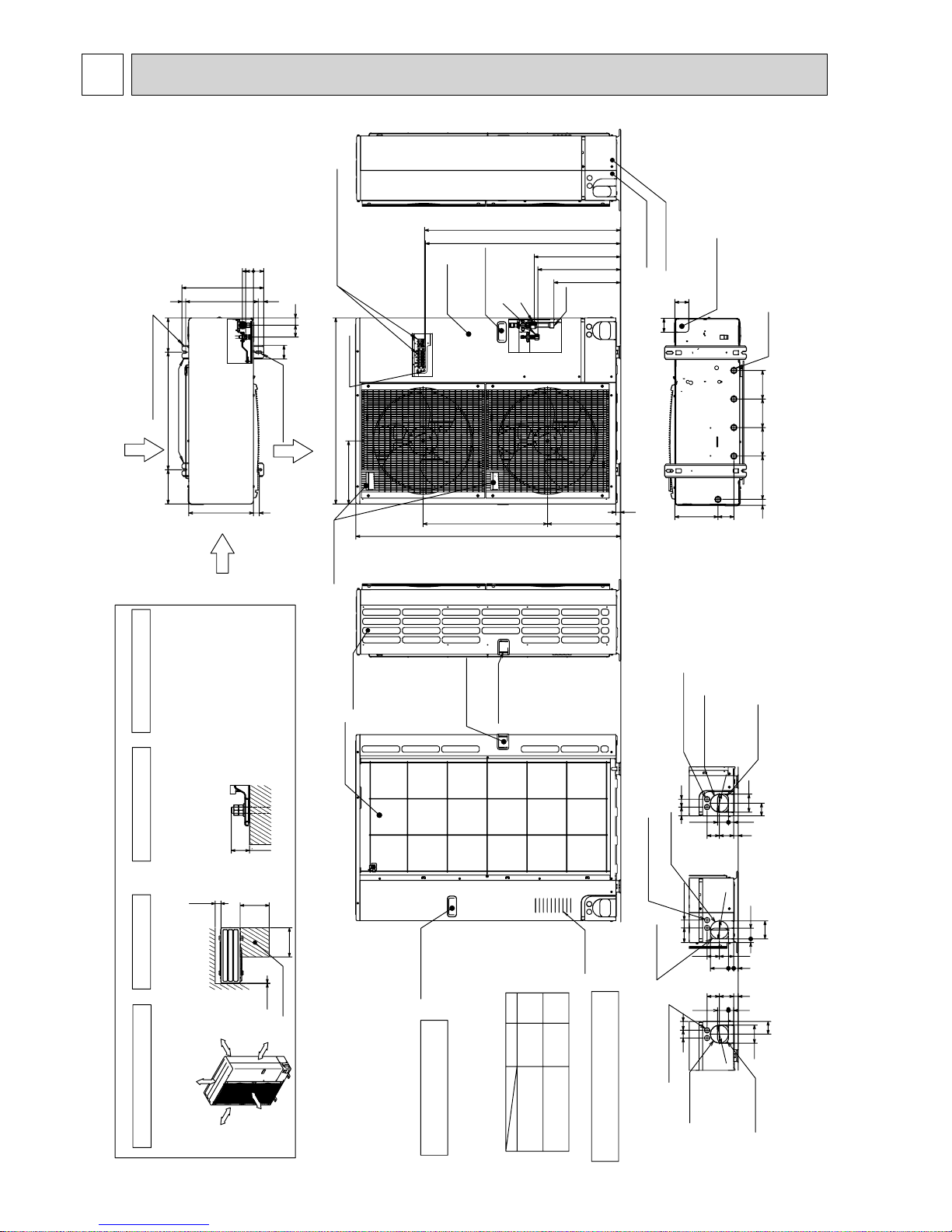
Rear piping cover
Front piping cover
Side Air Intake
Handle for moving
Piping Knockout Hole Details
637323
5527
92
65
4045
Power supply wiring hole
(2-:27Knockout)
Rear trunking hole
(Knockout)
Rear piping hole
(Knockout)
:92
922723
6373
4075
92
5519
Power supply wiring hole
(2-:27Knockout)
Right trunking hole
(Knockout)
Right piping hole
(Knockout)
:92
637323
5527
40 45
65
92
Power supply wiring hole
(2-:27Knockout)
Front trunking hole
(Knockout)
Front piping hole
(Knockout)
:92
Over
Over
Over
Over
Less than
Piping and wiring connections
can be made from 4 directions:
front, right, rear and below.
4 PIPING-WIRING DIRECTIONS
3 FOUNDATION BOLTS2 SERVICE SPACE
1 FREE SPACE (Around the unit)
Please secure the unit firmly
with 4 foundation (M10) bolts.
(Bolts and washers must be
purchased locally.)
<Foundation bolt height>
Dimensions of space needed
for service access are
shown in the below diagram.
The diagram below shows a basic
example.
Explanation of particular details are
given in the installation manuals etc.
30
FOUNDATION
10
500
500
150
Service space
FREE
Over 10mm
Over 10mm
Over 150mm
Over 1000mm
53
40560
70
175600175
33030
37028 19
417
60 37
2-12%36 oval holes
(Foundation Bolt M10)
2-U Shaped notched holes
(foundation Bolt M10)
Side Air Intake
Rear Air Intake
Air Discharge
Installation Feet
999
995
*1 A
*2 339
950
322
23
371 635
1350
*1 439
Handle for moving
Handle for moving
Terminal Connections
Left···Power supply wiring
Right···Indoor/Outdoor wiring
Service Panel
(
Earth terminal
Brazing
)
PUHZ-P250YHA
PUHZ-P250YHA3
PUHZ-P200YHA
PUHZ-P200YHA3
:9.52
(3/8 inch)
:12.7
(1/2 inch)
421
A
447
· · · ·Refrigerant GAS pipe connection (FLARE):19.05 (3/4 inch)
· · · ·Refrigerant LIQUID pipe connection (FLARE)
*1· · · ·Indication of STOP VALVE connection location
*2· · · ·Refrigerant GAS PIPE connection(BRAZING) O.D:25.4
Example of Notes
14514514522030
81 219
71
71
Drain hole
(5-:33)
Bottom piping hole
(Knockout)
Side Air Intake
Air Intake
Rear Air Intake
Handle for moving
Handle for moving
PUHZ-P200YHA
PUHZ-P250YHA
PUHZ-P200YHA3
PUHZ-P250YHA3
Unit : mm
7 OUTLINES AND DIMENSIONS
11
Rear piping cover
Front piping cover
Side Air Intake
Handle for moving
Piping Knockout Hole Details
637323
5527
92
65
4045
Power supply wiring hole
(2-:27Knockout)
Rear trunking hole
(Knockout)
Rear piping hole
(Knockout)
:92
922723
6373
4075
92
5519
Power supply wiring hole
(2-:27Knockout)
Right trunking hole
(Knockout)
Right piping hole
(Knockout)
:92
637323
5527
40 45
65
92
Power supply wiring hole
(2-:27Knockout)
Front trunking hole
(Knockout)
Front piping hole
(Knockout)
:92
Over
Over
Over
Over
Less than
Piping and wiring connections
can be made from 4 directions:
front, right, rear and below.
4 PIPING-WIRING DIRECTIONS
3 FOUNDATION BOLTS2 SERVICE SPACE
1 FREE SPACE (Around the unit)
Please secure the unit firmly
with 4 foundation (M10) bolts.
(Bolts and washers must be
purchased locally.)
<Foundation bolt height>
Dimensions of space needed
for service access are
shown in the below diagram.
The diagram below shows a basic
example.
Explanation of particular details are
given in the installation manuals etc.
30
FOUNDATION
10
500
500
150
Service space
53
40560
70
175600175
33030
37028 19
417
60 37
2-12%36 oval holes
(Foundation Bolt M10)
2-U Shaped notched holes
(foundation Bolt M10)
Side Air Intake
Rear Air Intake
Air Discharge
Installation Feet
999
995
*1 A
*2 339
950
322
23
371 635
1350
*1 439
Handle for moving
Handle for moving
Terminal Connections
Left···Power supply wiring
Right···Indoor/Outdoor wiring
Service Panel
(
Earth terminal
Brazing
)
PUHZ-P250YHA3R1
PUHZ-P250YHA3R2
PUHZ-P250YHA3R3
PUHZ-P200YHA3R1
PUHZ-P200YHA3R2
PUHZ-P200YHA3R3
:9.52
(3/8 inch)
:12.7
(1/2 inch)
421
A
447
· · · ·Refrigerant GAS pipe connection (FLARE):19.05(3/4 inch)
· · · ·Refrigerant LIQUID pipe connection (FLARE)
*1· · · ·Indication of STOP VALVE connection location
*2· · · ·Refrigerant GAS PIPE connection (BRAZING) O.D:25.4
Example of Notes
14514514522030
81 219
71
71
Drain hole
(5-:33)
Bottom piping hole
(Knockout)
Side Air Intake
Air Intake
Rear Air Intake
Handle for moving
Handle for moving
Over 10mm
Over 10mm
Over 150mm
Over 1000mm
FREE
PUHZ-P200YHA3R1
PUHZ-P250YHA3R1
PUHZ-P200YHA3R2
PUHZ-P250YHA3R2
PUHZ-P200YHA3R3
PUHZ-P250YHA3R3
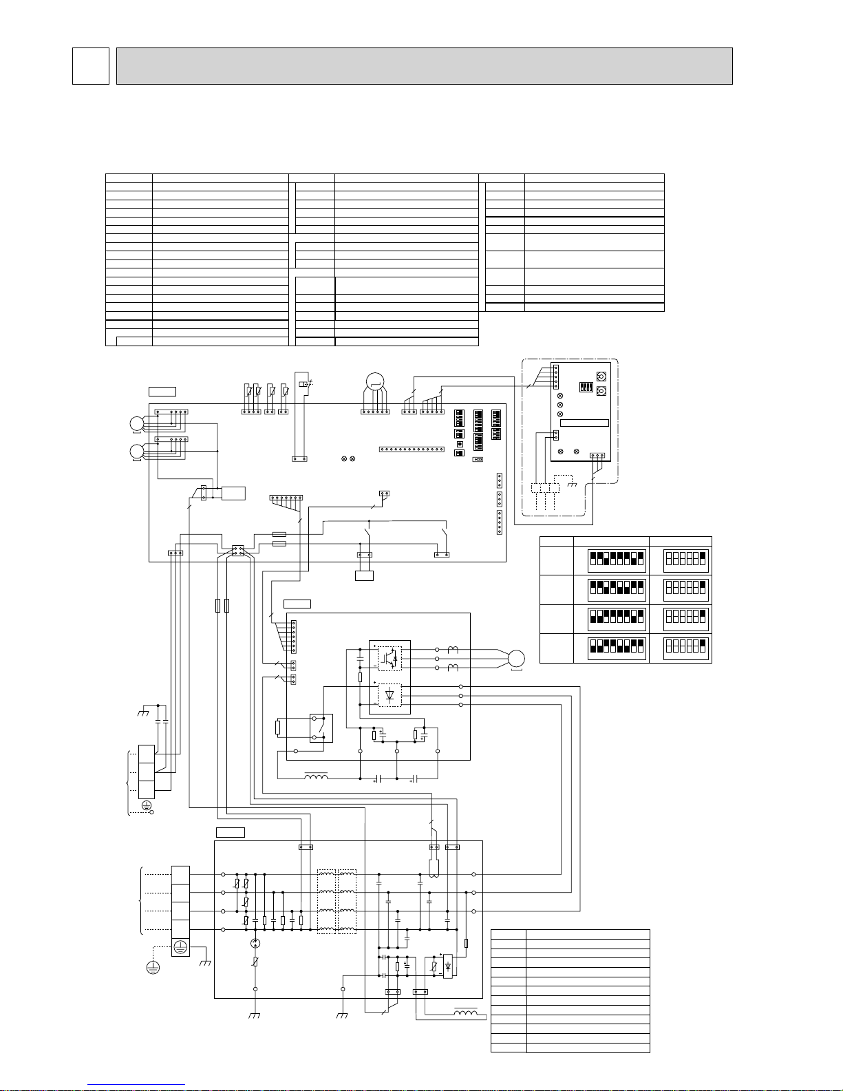
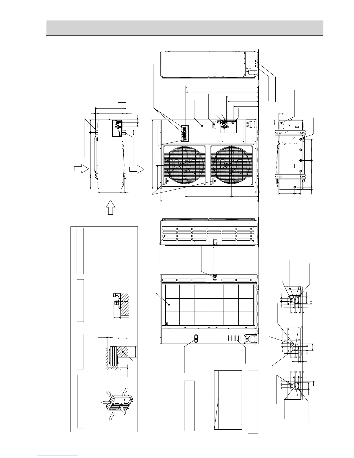
12
PUHZ-P200YHA PUHZ-P250YHA PUHZ-P200YHA3 PUHZ-P250YHA3
PUHZ-P200YHA3R1 PUHZ-P250YHA3R1 PUHZ-P200YHA3R2 PUHZ-P250YHA3R2
PUHZ-P200YHA3R3 PUHZ-P250YHA3R3
TH7/6
(RED)
TH3
(WHT)
TH4
(WHT)
TH7TH6 TH3 TH4
412121
t° t° t° t°
63H
LEV-A
(WHT)
LEV-A
M
LED1
LED2
61
CNVMNT
(WHT)
31
CNMNT
(WHT)
CNM
(WHT)
51
35
5
141
63H
(YLW)
31
CN2
(WHT)
7
7
1
CN2
(WHT)
7
7
1
CNDM
(WHT)
CN3S
(WHT)
CN51
(WHT)
131315
X51
X52
SW7
SW6SW1
SW9
CN31
+1+1
SW5SW8SW4
SWP
CN4
(WHT)
12
1313
2
21S4
SS
(WHT)
21S4
(GRN)
CNAC
(WHT)
F4
F3
21
43
2
3
1
CNDC
(PNK)
CNS
(WHT)
31
TRANS
CNF1
(WHT)
CNF2
(WHT)
MF1
MS
3~
7
1
7
1
MF2
MS
3~
C. B.
P. B .
CN5
(WHT)
31
LED2
SW1
SW11
SW12
LED3
LED4
TB7
LED1
LED5
2
1
CND
(WHT)
CN2M
(WHT)
M-NET ADAPTER
M-NET
ABS
When M-NET adapter is connected
3
5
1
2
2
1
2
2
1
CN4
(WHT)
CN5
(RED)
WHT
FUSE1
FUSE2
WHT
REDRED
MS
3~
POWER
SUPPLY
3N~
400V 50Hz
INDOOR
UNIT
TB1
L3
L2
L1
N
U
U
UU
U
31
2
2
13
CNDC
(PNK)
CNL
(BLU)
3112
CNCT
(RED)
CNAC2
(RED)
31
CNAC1
(WHT)
BLK
BLK
WHT
WHT
U
LO 1
LO 2
LO3
LI 1
LI 2
LI 3
NI
RED
WHT
BLU
BLK
GRN/YLW
GD2GD1
RED
WHT
BLK
N. F.
TB2
DCL
ACL4
S3
S2
S1
ORN
YLW
CY2
CY1
BRN
RED
RED
RS
RED
WHT
WHT
WHT
BLK
BLK
BLK
X52A
BLK
BLK
TB-P2
TB-P1
TB-C1 TB-N1
CB1 CB2
W
V
MC
U
TB-L1
TB-L2
TB-L3
SC-U
SC-V
SC-W
RED
MODEL
SW6
+1 MODEL SELECT
SW5-6 +2
12345678
+2 SW5 -1 to 5 : Function Switch
OFF
123456
OFF
ON
200YHA
200YHA3
200YHA3R1
ON
12345678
OFF
123456
OFF
ON
ON
12345678
OFF
123456
OFF
ON
200YHA3R2
200YHA3R3
ON
12345678
OFF
123456
OFF
ON
250YHA3R2
250YHA3R3
ON
250YHA
250YHA3
250YHA3R1
FUSE1, FUSE2
Connector<Connection for Option>
CN51
Relay
X51,X52
Connector<Connection for Option>
CN3S
TB1
MC
MF1,MF2
21S4
63H
TH3
TH4
TH6
TH7
LEV-A
DCL
Terminal Block<Power Supply>
TB2 Terminal Block<Indoor/Outdoor>
Motor for Compressor
Fan Motor
Solenoid Valve (Four-Way Valve)
High Pressure Switch
Thermistor<Outdoor Pipe>
SC-U/V/W
TB-L1/L2/L3
Connection Terminal<U/V/W-Phase>
Thermistor<Discharge>
Thermistor<Outdoor 2-Phase Pipe>
Thermistor<Outdoor>
Fuse<
T15AL250V>
Capacitor
Electronic Expansion Valve
Reactor
ACL4
Reactor
Connection Terminal<L1/L2/L3-Power supply>
P.B .
Power Circuit Board
RS
Rush Current Protect Resistor
CB1,CB2
CY1,CY2
Main Smoothing Capacitor
Connection Terminal
Noise Filter Circuit Board
Connection Terminal<
L1/L2/L3/NI-Power supply>
Connection Terminal<Ground>
52C Relay
N.F.
LI1/ LI2/LI3/NI
LO1/ LO2/LO3
Connection Terminal<
L1/L2/L3-Power supply>
GD1,GD2
Controller Circuit Board
C.B.
TB-C1
X52A
Connection Terminal
TB-N1
SYMBOL
[LEGEND]
NAME SYMBOL NAME SYMBOL NAME
Connection Terminal
TB-P1
Connection Terminal
TB-P2
Switch<Function Setup>
Switch<Function Setup>
Switch<Forced Defrost, Defect History Record
Reset, Refrigerant Address>
Switch<Test Operation>
Switch<Function Switch>
Switch<Model Select>
SW7
SW1
SW4
SW5
SW6
SW8
Switch
SW9
Switch<Pump Down>
SWP
Connector<Emergency Operation>
LED<Operation Inspection Indicators>
CN31
F3,F4
CNMNT
CNVMNT
CNDM
Connector
< Connected for Option (Contact Input)>
Fuse< T6.3AL250V>
LED1,LED2
CNM
Connector<A-Control Service Inspection Kit>
SS
Connector<Connection for Option>
Connector
<Connected to Optional M-NET Adapter Board>
Connector
<Connected to Optional M-NET Adapter Board>
Terminal Block(M-NET connection)
Connector<Transmission>
Connector<Power Supply>
LED<Power Supply:DC5V>
LED<Power Supply:DC12V>
LED<Connection to Outdoor Unit>
LED<Transmission:Sending>
LED<Transmission:Receiving>
Connector<M-NET communication>
SYMBOL
NAME
Switch<Address setting:2nd digit>
Switch<Status of communication>
Switch<Address setting:1st digit>
TB7
CN5
CND
CN2M
SW1
SW11
SW12
LED1
LED2
LED3
LED4
LED5
M-NET ADAPTER
The black square (■) indicates a switch position.
8 WIRING DIAGRAM
13
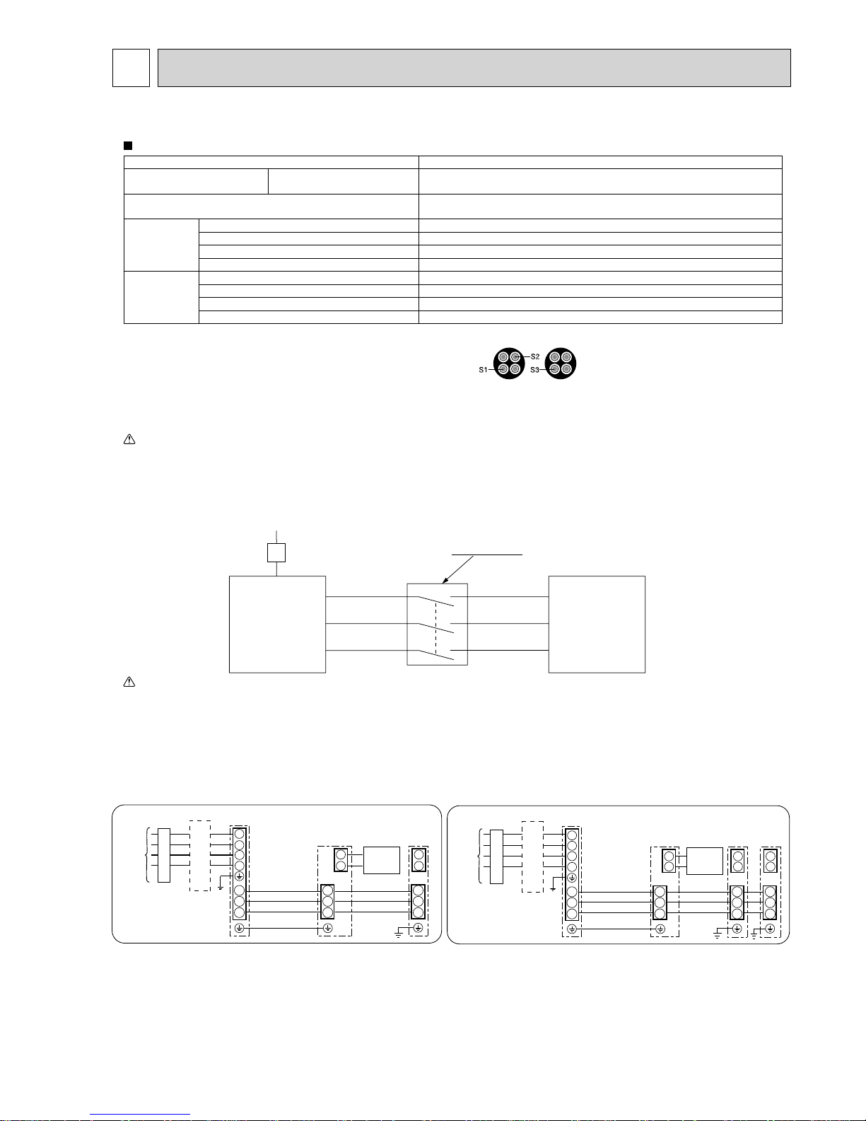
9 WIRING SPECIFICATIONS
9-1. FIELD ELECTRICAL WIRING (power wiring specifications)
S1
S2
S3
S1
S2
S3
A-Control
Outdoor Unit
3 poles isolator
400V
3 phase
Isolator
A-Control
Indoor Unit
P200, P250
Outdoor unit model P200, 250
Outdoor unit
Power supply
Phase
Frequency & Voltage
3N~(3ph 4-wires), 50 Hz,
400 V
Outdoor unit input capacity *1
Main switch (Breaker)
32 A
Outdoor unit power supply 5 % Min. 4
Indoor unit-Outdoor unit *2 Cable length 50 m : 3 % 4 (Polar)/Cable length 80 m : 3 % 6 (Polar)
Indoor unit-Outdoor unit earth 1 % Min. 2.5
Remote controller-Indoor unit *3 2 % 0.3 (Non-polar)
Wiring
Wire No. %
size(mm²)
Circuit rating
Outdoor unit L1-N, L2-N, L3-N AC 230 V
Indoor unit-Outdoor unit S1-S2 *4 AC 230 V
Indoor unit-Outdoor unit S2-S3 *4 DC 24 V
Remote controller-Indoor unit *4 DC 12 V
*1 A breaker with at least 3.0 mm contact separation in each pole shall be provided. Use earth leakage breaker (NV).
*2 Max. 80 m Total Max. including all indoor/indoor connection is 80 m.
Use one cable for S1 and S2 and another for S3 as shown in the picture.
Max. 50m Total Max. for PEA-200, 250, 400, 500
Wiring size 3%1.5 (Polar)
*3 The 10 m wire is attached in the remote controller accessory.
*4 The figures are NOT against the ground.
S3 terminal has DC 24 V against S2 terminal. However between S3 and S1, these terminals are not electrically insulated by the transformer or other device.
Notes: 1. Wiring size must comply with the applicable local and national code.
2. Power supply cords and Indoor unit/Outdoor unit connecting cords shall not be lighter than polychloroprene sheathed flexible cord.
(Design 60245 IEC 57)
3. Use an earth wire which is longer than the other cords so that it will not become disconnected when tension is applied.
Warning:
In case of A-control wiring, there is high voltage potential on the S3 terminal caused by electrical circuit design that has no electrical insulation
between power line and communication signal line. Therefore, please turn off the main power supply when servicing.
And do not touch the S1, S2, S3 terminals when the power is energized. If isolator should be used between indoor unit and outdoor unit, please use
3-pole type.
Caution: Be sure to install N-line. Without N-line, it could damage the unit.
Earth leakage breaker
wiring circuit breaker or
isolating switch
1
2
1
2
S1
Indoor
unit
S2
S3
S1
S2
S3
S1
S2
S3
Unit
power
supply
Indoor/outdoor
unit connection
cable
Indoor
unit
Outdoor
unit
Remote
controller
Outdoor
unit
L
3
L2
L1
N
Earth leakage breaker
wiring circuit breaker or
isolating switch
1
2
1
2
1
2
S1
S2
S3
S1
S2
S3
S1
S2
S3
S1
S2
S3
Indoor/outdoor
connection cable
Indoor
unit
Indoor
unit
Indoor
unit
Remote
controller
Unit
power
supply
Outdoor
unit
L
3
L2
L1
N
Synchronized twin and triple system Electrical wiring
• Synchronized twin • Synchronized triple
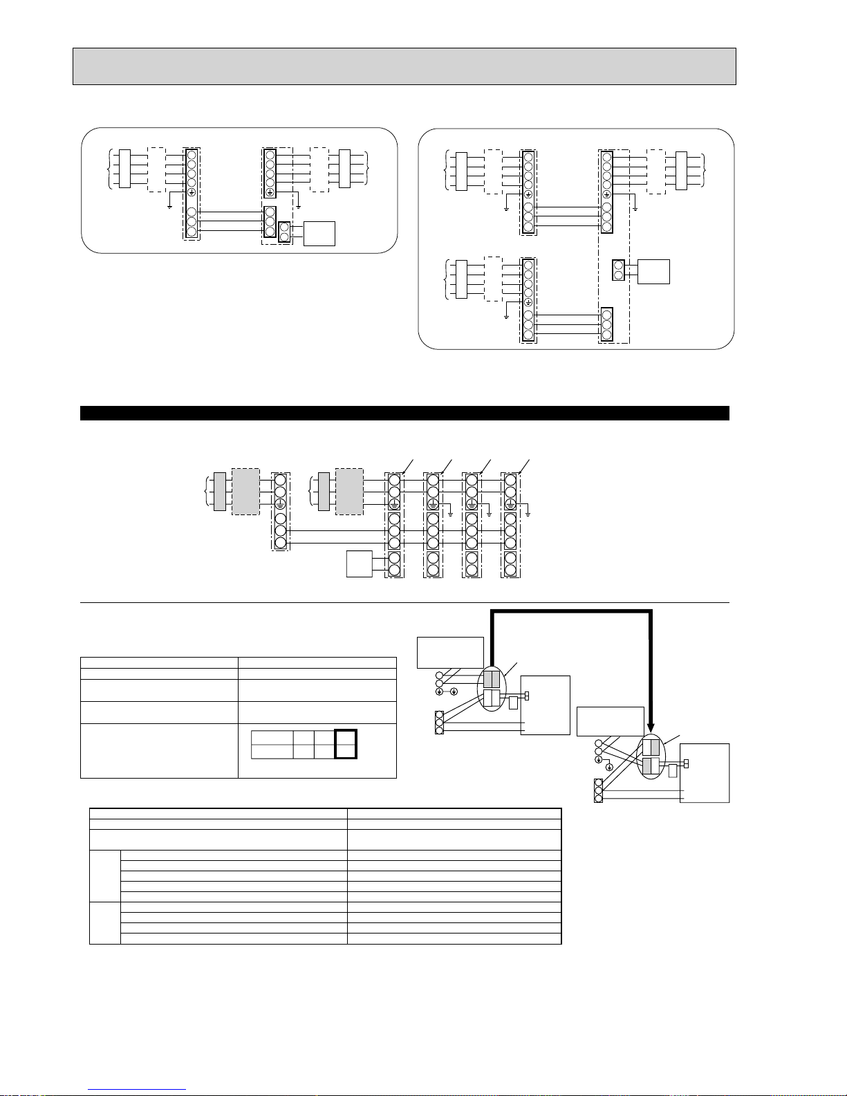
14
<For models without heater>
*
The optional indoor power supply terminal kit is required.
* Affix a label B that is included with the manuals near each wiring diagram for the indoor and outdoor units.
If the indoor and outdoor units have separate power supplies, refer to the table below.
If the optional indoor power supply terminal kit is used, change the indoor unit electrical
box wiring referring to the figure in the right and the DIP switch settings of the
outdoor unit control board.
Indoor power supply terminal kit (option)
Indoor unit electrical box connector connection change
Label affixed near each wiring diagram
for the indoor and outdoor units
Outdoor unit DIP switch settings (when
using separate indoor unit/outdoor unit
power supplies only)
Indoor unit specifications
Required
Required
Required
Electric heater
(For models with
heater)
Connectors (connections when shipped
from the factory are for indoor unit power
supplied from outdoor unit.)
Indoor unit power supplied from outdoor unit
(when shipped from factory)
If the indoor and
outdoor units have
separate power
supplies, change the
connections of the
connectors as shown
in the following
figure.
Connectors
Indoor unit
control board
Separate indoor unit/outdoor unit power
supplies
Electric heater
(For models with
heater)
S1
S2
S3
L
N
BLUE
BLUE
YELLOW
YELLOW
CND
CND
ORANGE
CND
ORANGE
S1
S2
S3
L
N
YELLOW
BLUE
BLUE
YELLOW
CND
Indoor unit
control board
* There are 3 types of labels (Labels A, B, and C). Affix the appropriate labels to
the units according to the wiring method.
ON
OFF
Set the SW8-3 to ON.
1 2 (SW8)
3
Simultaneous twin/triple/four system
* Affix a label B that is included with the manuals near each wiring diagram for the indoor and outdoor units.
Outdoor unit power supply
Earth leakage breaker
Wiring circuit breaker or isolating switch
Outdoor unit
Indoor unit/outdoor unit connecting cables
Remote controller
Indoor unit
Option
Indoor unit power supply
*1. A breaker with at least 3.0 mm contact separation in each pole shall be provided. Use earth leakage breaker (NV).
The breaker shall be provided to ensure disconnection of all active phase conductor of the supply.
*2. Max. 120 m
*3. The 10 m wire is attached in the remote controller accessory. Max. 500 m
*4. The figures are NOT always against the ground.
Notes: 1. Wiring size must comply with the applicable local and national code.
2. Power supply cables and indoor unit/outdoor unit connecting cables shall not be lighter than polychloroprene sheathed
flexible cable. (Design 60245 IEC 57)
3. Install an earth longer than other cables.
Indoor unit model
Indoor unit power supply
Indoor unit input capacity
*1
Main switch (Breaker)
Indoor unit power supply
Indoor unit power supply earth
Indoor unit-Outdoor unit
*2
Indoor unit-Outdoor unit earth
Remote controller-Indoor unit
*3
Indoor unit L-N *4
Indoor unit-Outdoor unit S1-S2 *4
Indoor unit-Outdoor unit S2-S3 *4
Remote controller-Indoor unit *4
RP35~140
~/N (single), 50 Hz, 230 V
16 A
2% Min. 1.5
1% Min. 1.5
2% Min. 0.3
–
2 % 0.3 (Non-polar)
AC 230 V
–
DC24 V
DC12 V
Circuit
rating
Wiring
Wire No. % size
(mm
2
)
Indoor unit earth
L
N
L
N
S1
S2
S3
S1
S2
S3
1
2
L
N
S1
S2
S3
1
2
L
N
S1
S2
S3
1
2
L
N
S1
S2
S3
1
2
9-2. SEPARATE INDOOR UNIT/ OUTDOOR UNIT POWER SUPPLIES
S1
S2
S3
Indoor/outdoor
unit connection
cable
Indoor
unit
Unit
power
supply
Unit
power
supply
Outdoor
unit
L
1
L2
L3
N
S1
S2
S3
L1
L2
L3
N
1
2
Remote
controller
Earth leakage breaker
wiring circuit breaker or
isolating switch
1:1 System (Indoor : PEA-200, 250) 1:2 System (Indoor : PEA-400, 500)
S1
S2
S3
Indoor/outdoor
unit connection
cable
Indoor
unit
Unit
power
supply
Unit
power
supply
Outdoor
unit No.1
L
1
L2
L3
N
S1
S2
S3
L1
L2
L3
N
Earth leakage breaker
wiring circuit breaker or
isolating switch
S1
S2
S3
Indoor/outdoor
unit connection
cable
TB4-1
TB4-2
Unit
power
supply
Outdoor
unit No.2
L
1
L2
L3
N
S1
S2
S3
1
2
Remote
controller
15
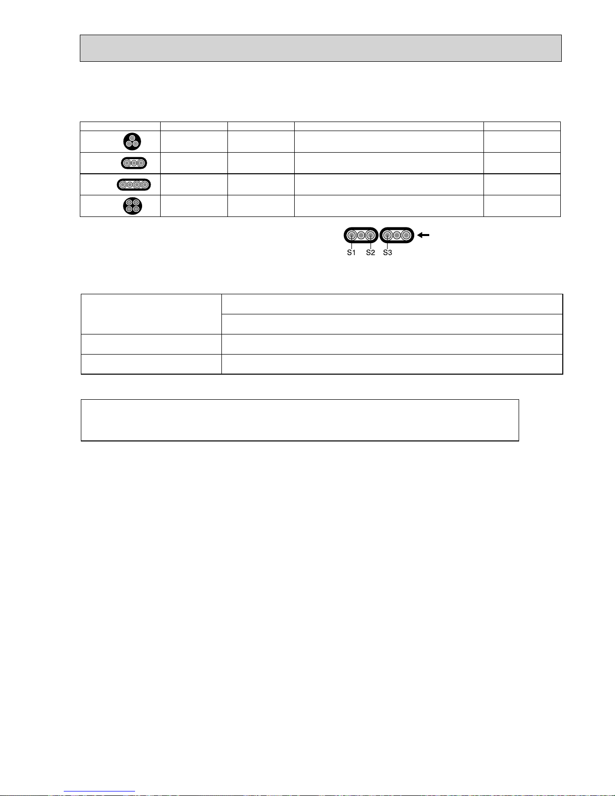
9-3. INDOOR – OUTDOOR CONNECTING CABLE
Be sure to connect the indoor-outdoor connecting cables directly to the units (no intermediate connections).
Intermediate connections can lead to communication errors if water enters the cables and causes insufficient
insulation to earth or a poor electrical contact at the intermediate connection point.
Indoor unit-Outdoor unit
Indoor/Outdoor separate
power supply
Max. 120m
2 % Min. 0.3
—
Indoor unit-Outdoor unit earth
Wire No. % Size ($)
+ The optional indoor power supply terminal kit is necessary.
WIRING SPECIFICATIONS FOR 220-240 V 50 Hz
(INDOOR-OUTDOOR CONNECTING CABLE)
Cross section of cable Wire size (mm2) Number of wires Polarity L (m)*6
Round
2.5 3
Clockwise : S1-S2-S3
* Pay attention to stripe of yellow and green.
(30)
*2
Flat
2.5 3
Not applicable
(Because center wire has no cover finish)
Not applicable
*5
Flat
1.5 4
From left to right : S1-Open-S2-S3
(18)
*3
Round
2.5 4
Clockwise : S1-S2-S3-Open
*Connect S1 and S3 to the opposite angle.
(30)
*4
*1 : Power supply cords of appliances shall not be lighter than design 60245 IEC or
227 IEC.
*2 : In case that cable with stripe of yellow and green is available.
*3 : In case of regular polarity connection (S1-S2-S3), wire size is 1.5 mm².
*4 : In case of regular polarity connection (S1-S2-S3).
*5 : In the flat cables are connected as this picture, they can be used up to 30 m.
*6 : Mentioned cable length is just a reference value.
It may be different depending on the condition of installation, Humidity
or materials, etc.
(3C Flat cable × 2)
16
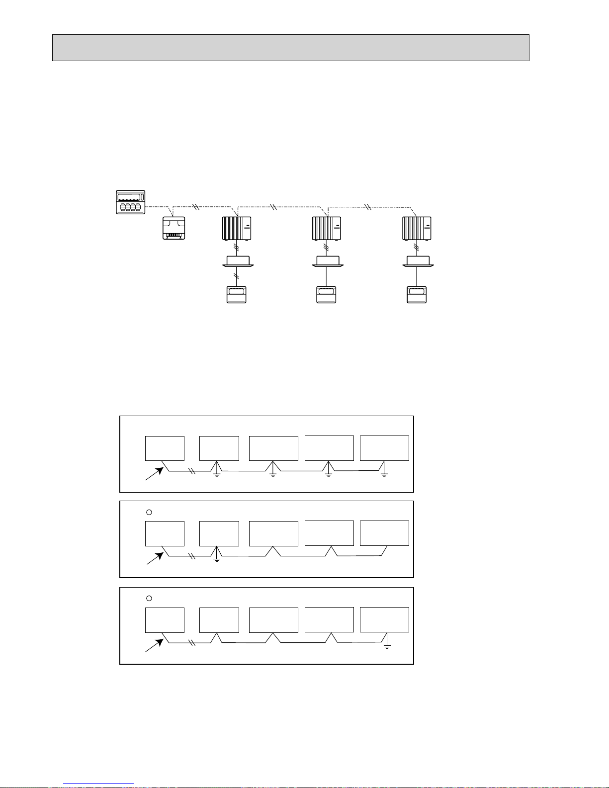
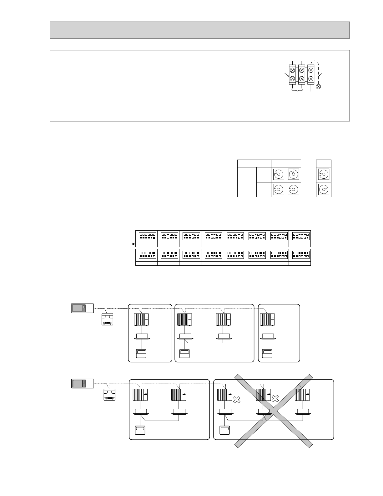
9-4. M-NET WIRING METHOD
(Points to note)
(1) Outside the unit, transmission wires should stay away from electric wires in order to prevent electromagnetic noise from
making an influence on the signal communication. Place them at intervals of more than 5 cm. Do not put them in the same
conduit tube.
(2) Terminal block (TB7) for transmission wires should never be connected to 220~240 V power supply. If it is connected,
electronic parts on M-NET P.C. board may burn out.
(3) Use 2-core × 1.25 mm² shield wire (CVVS, CPEVS) for the transmission wire. Transmission signals may not be sent or
received normally if different types of transmission wires are put together in the same multi-conductor cable. Never do this
because this may cause a malfunction.
It would be ok if M-NET wire (non-polar, 2-cores) is arranged in addition to the wiring for A-control.
(4) Earth only one of any appliances through M-NET transmission wire (shield wire). Communication error may occur due to
the influence of electromagnetic noise.
“Ed” error will appear on the LED display of outdoor unit.
“0403” error will appear on the central-control remote controller.
If there are more than 2 earthing spots on the shield wire, noise may enter into the shield wire because the earth wire and
shield wire form 1 circuit and the electric potential difference occurs due to the impedance difference among earthing spots.
In case of single spot earthing, noise does not enter into the shield wire because the earth wire and shield wire do not form
1 circuit.
To avoid communication errors caused by noise, make sure to observe the single spot earthing method described in the
installation manual.
Group
remote
controller
Refrigerant
address 00
M-NET
address 01
A-control
remote
controller
A-control
remote
controller
A-control
remote
controller
Refrigerant
address 00
M-NET
address 02
Refrigerant
address 00
M-NET
address 03
Power
supply
unit for
transmission
wire
Central
remote
controller
M-NET transmission wire
×
Bad example (Multi spot earthing of shield wire)
Good example 1 (Single spot earthing of shield wire)
Power
supply
appliance
M-NET type
outdoor unit
Central
remote
controller
Power
supply
appliance
M-NET type
outdoor unit
M-NET type
outdoor unit
M-NET type
outdoor unit
M-NET transmission wire
M-NET type
outdoor unit
M-NET type
outdoor unit
Central
remote
controller
Power
supply
appliance
M-NET type
outdoor unit
M-NET transmission wire
M-NET type
outdoor unit
M-NET type
outdoor unit
Good example 2 (Single spot earthing of shield wire)
17
9-4-3. Regulations in address settings
In case of multiple grouping system, M-NET and refrigerant address settings should be done as explained in the above section. Set the lowest number in the group for the outdoor unit whose refrigerant address is “00” as its M-NET address.
w Refrigerant addresses can be overlapped if they are in the different group.
w In group B, M-NET address of the outdoor unit whose refrigerant address is “00” is not set to the minimum in the group. As
“3” is right for this situation, the setting is wrong. Taking group A as a good sample, set the minimum M-NET address in the
group for the outdoor unit whose refrigerant address is “00”.
9-4-1. M-NET address setting
In A-control models, M-NET address and refrigerant address should be set only for the outdoor unit. Similar to CITY MULTI
system, there is no need to set the address of outdoor unit and remote controller. To construct a central control system, the
setting of M-NET address should be conducted only upon the outdoor unit. The setting range should be 1 to 50 (the same as
that of the indoor unit in CITY MULTI system), and the address number should be consecutively set in a same group.
Address number can be set by using rotary switches
(SW11 for ones digit and SW12 for tens digit), which
is located on the M-NET board of outdoor unit.
(Initial setting: all addresses are set to “0”.)
9-4-2. Refrigerant address setting
In case of multiple grouping system (multiple refrigerant circuits in one group), indoor units should be connected by remote
controller wiring (TB5) and the refrigerant address needs to be set. Leave the refrigerant addresses to “00” if the group setting is not conducted. Set the refrigerant address by using DIP SW1-3 to -6 on the outdoor controller board. [Initial setting: all
switches are OFF. (All refrigerant addresses are “00”.)]
1
2
3
4
5
6
7
8
9
0
1
2
3
4
5
6
7
8
9
0
1
2
3
4
5
6
7
8
9
0
1
2
3
4
5
6
7
8
9
0
1
2
3
4
5
6
7
8
9
0
1
2
3
4
5
6
7
8
9
0
12
~
50
M-NET Address No.
<Setting example>
Switch
setting
SW11
ones
digit
SW12
tens
digit
OFF
ON
1
2
3
4
5
6
1
2
3
4
5
6
1
2
3
4
5
6
1
2
3
4
5
6
1
2
3
4
5
6
1
2
3
4
5
6
1
2
3
4
5
6
1
2
3
4
5
6
1
2
3
4
5
6
1
2
3
4
5
6
1
2
3
4
5
6
1
2
3
4
5
6
1
2
3
4
5
6
1
2
3
4
5
6
1
2
3
4
5
6
1
2
3
4
5
6
0
Refrigerant
address
OFF
ON
8
OFF
ON
1
OFF
ON
9
OFF
ON
10
OFF
ON
11
OFF
ON
12
OFF
ON
13
OFF
ON
14
OFF
ON
15
OFF
ON
2
OFF
ON
3
OFF
ON
4
OFF
ON
5
OFF
ON
6
OFF
ON
7
System
controller
A-control
remote
controller
Group A Group B Group C
A-control
remote
controller
TB5
A-control
remote
controller
Refrigerant
address 00
M-NET
address 01
Refrigerant
address 00
M-NET
address 02
Refrigerant
address 01
M-NET
address 03
Refrigerant
address 00
M-NET
address 04
Power
supply
unit for
transmission
wire
A-control
remote
controller
A-control
remote
controller
TB5
Group A Group B
Refrigerant
address 00
M-NET
address 01
Refrigerant
address 01
M-NET
address 02
Refrigerant
address 00
M-NET
address 04
Refrigerant
address 01
M-NET
address 03
Refrigerant
address 02
M-NET
address 05
System
controller
Power
supply
unit for
transmission
wire
● M-NET wiring
(1) Use 2-core × 1.25mm² shield wire for electric wires.
(Excluding the case connecting to system controller.)
(2) Connect the wire to the M-NET terminal block. Connect one core of the
transmission wire (non-polar) to M1 terminal and the other to M2. Peel the
shield wire, twist the shield part to a string and connect it to S terminal.
(3) In the system which several outdoor units are being connected, the terminal
(M1, M2, S) on M-NET terminal block should be individually wired to the other
outdoor unit’s terminal, i.e. M1 to M1, M2 to M2 and S to S. In this case, choose one of those outdoor units and drive a
screw to fix an earth wire on the plate as shown on the right figure.
Transmission
wire
Shield
part
M-NET
terminal
block
Earth
wire
M1 M2 S
18
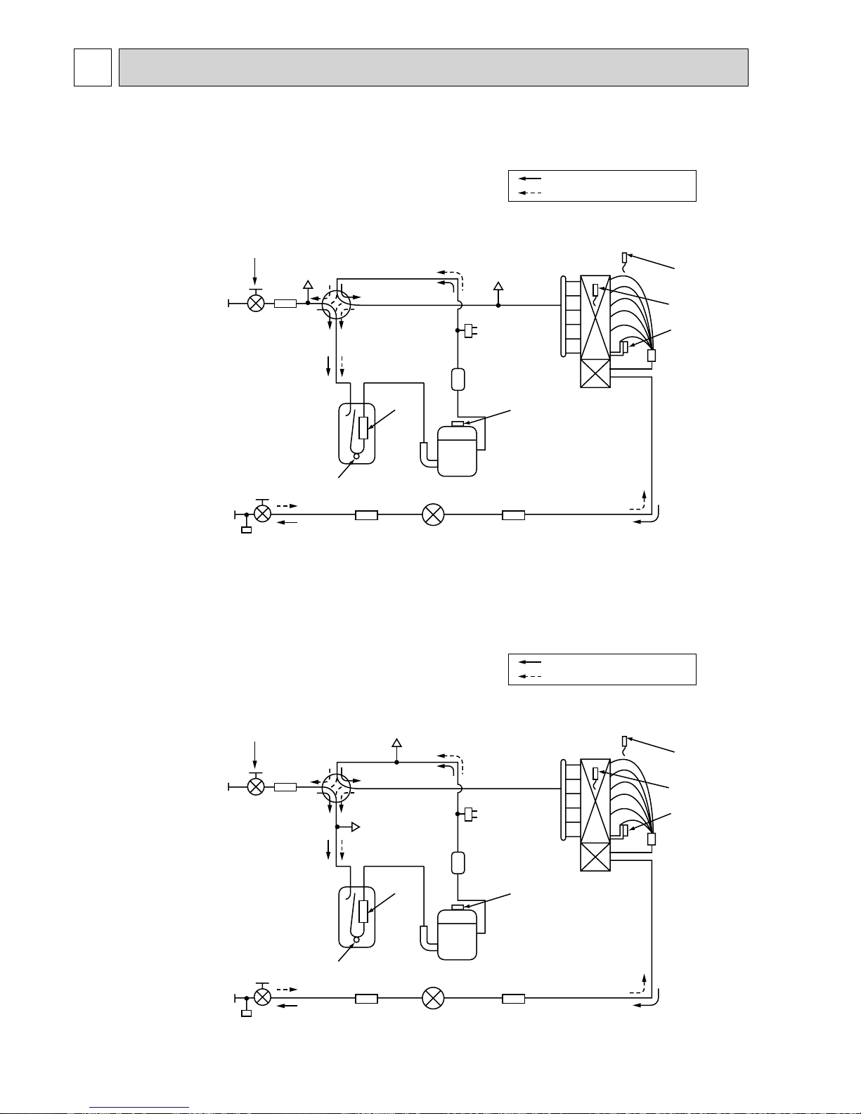
Outdoor heat exchanger
Thermistor
(TH3)
Thermistor
(TH6)
Thermistor
(TH7)
Distributor
Service
port
(check)
Service
port
(check)
Accumulator
Compressor
Refrigerant GAS pipe
:25.4(:1 inch)
Refrigerant LIQUID pipe
P200 : :9.52(:3/8 inch)
P250 : :12.7(:1/2 inch)
Stop valve
(with service port)
4-way valve
High pressure
protect switch
Linear expansion valve
Thermistor
(TH4)
Muffler
Ball valve
(#50)
Strainer
Strainer
(#40)
Strainer
(#100)
Strainer
(#100)
Strainer
(#100)
Refrigerant flow in cooling
Refrigerant flow in heating
10 REFRIGERANT SYSTEM DIAGRAM
PUHZ-P200YHA PUHZ-P250YHA PUHZ-P200YHA3 PUHZ-P250YHA3
PUHZ-P200YHA3R1 PUHZ-P250YHA3R1 PUHZ-P200YHA3R2 PUHZ-P250YHA3R2
PUHZ-P200YHA3R3 PUHZ-P250YHA3R3
Outdoor heat exchanger
Thermistor
(TH3)
Thermistor
(TH6)
Thermistor
(TH7)
Distributor
Service port
(check)
Service
port
(check)
Accumulator
Compressor
Refrigerant GAS pipe
:25.4(:1 inch)
Refrigerant LIQUID pipe
P200 : :9.52(:3/8 inch)
P250 : :12.7(:1/2 inch)
Stop valve
(with service port)
4-way valve
High pressure
protect switch
Linear expansion valve
Thermistor
(TH4)
Muffler
Ball valve
(#50)
Strainer
Strainer
(#40)
Strainer
(#100)
Strainer
(#100)
Strainer
(#100)
Refrigerant flow in cooling
Refrigerant flow in heating

19
10-1. Refrigerant recovering (pump down)
Perform the following procedures to recover refrigerant while operating the indoor unit or the outdoor unit.
1 Turn on the power supply (circuit breaker).
w When power is supplied, make sure that “CENTRALLY CONTROLLED” is not displayed on the remote controller. If
“CENTRALLY CONTROLLED” is displayed, the refrigerant recovering (pump down) cannot be completed normally.
2 After the liquid stop valve is closed, set the SWP switch on the control board of the outdoor unit to ON. The compressor
(outdoor unit) and fan (indoor and outdoor units) start operating and refrigerant recovering operation begins. LED1 and
LED2 on the control board of the outdoor unit are lit.
w
Set the SWP switch (push-button type) to ON in order to perform refrigerant recovering operation only when the unit is
stopped. However, refrigerant recovering operation cannot be performed until compressor stops even if the unit is stopped.
Wait for 3 minutes until compressor stops and set the SWP switch to ON again.
3 Because the unit automatically stops in about 2 to 3 minutes after the refrigerant recovering operation (LED1 is not lit and
LED2 is lit), be sure to quickly close the gas stop valve.
w In case the outdoor unit is stopped when LED1 is lit and LED2 is not lit, open the liquid stop valve completely, and then
repeat step 2 3 minutes later.
w If the refrigerant recovering operation has been completed normally (LED1 is not lit and LED2 is lit), the unit will remain
stopped until the power supply is turned off.
4 Turn off the power supply (circuit breaker).
Warning:
When pumping down the refrigerant, stop the compressor before disconnecting the refrigerant pipes. The compressor may burst if air etc. get into it.
10-2. Start and finish of test run
• Operation from the indoor unit
Execute the test run using the installation manual for the indoor unit.
• Operation from the outdoor unit
By using the DIP switch SW4 on the control board of outdoor unit, test run can be started and finished, and its operation
mode (cooling/heating) can be set up.
1 Set the operation mode (cooling/heating) using SW4-2.
2 Turn on SW4-1 to start test run with the operation mode set by SW4-2.
3 Turn off SW4-1 to finish the test run.
• There may be a faint knocking sound around the machine room after power is supplied, but this is
no problem with product because the linear expansion valve is just moving to adjust opening pulse.
• There may be a knocking sound around the machine room for several seconds after compressor
starts operating. But this is not a problem with product because the check valve itself generates the
sound due to small pressure difference in the refrigerant circuit.
Note:
The operation mode cannot be changed by SW4-2 during test run. (To change test run mode, stop the unit by SW4-1,
change the operation mode and restart the test run by SW4-1.)
OFF
12
ON
<SW4>
Stop Operation
Cooling Heating
20
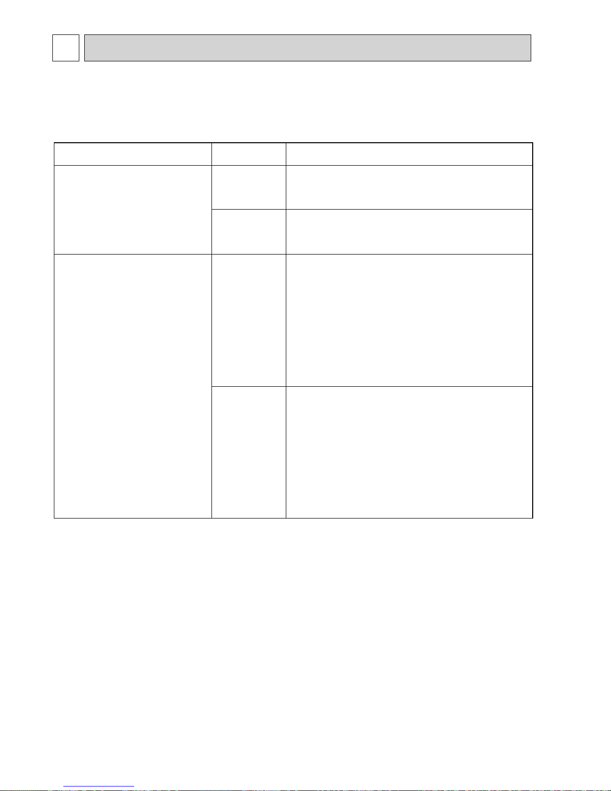
11 TROUBLESHOOTING
11-1. TROUBLESHOOTING
<Error code display by self-diagnosis and actions to be taken for service (summary)>
Present and past error codes are logged and displayed on the wired remote controller and control board of outdoor unit.
Actions to be taken for service, which depends on whether or not the trouble is reoccurring at service, are summarized in the
table below. Check the contents below before investigating details.
Unit conditions at service
Error code
Actions to be taken for service (summary)
The trouble is reoccurring.
Displayed
Not displayed
Judge what is wrong and take a corrective action according
to “11-4. Self-diagnosis action table”.
Conduct troubleshooting and ascertain the cause of the
trouble according to “11-5. Troubleshooting by inferior
phenomena”.
The trouble is not reoccurring.
Logged
Not logged
Consider the temporary defects such as the work of
protection devices in the refrigerant circuit including
compressor, poor connection of wiring, noise and etc.
Re-check the symptom, and check the installation
environment, refrigerant amount, weather when the
trouble occurred, matters related to wiring and etc.
Reset error code logs and restart the unit after finishing
service.
There is no abnormality in electrical component,
controller board, remote controller and etc.
Re-check the abnormal symptom.
Conduct trouble shooting and ascertain the cause of the
trouble
according to “11-5. Troubleshooting
by inferior
phenomena”.
Continue to operate unit for the time being if the cause
is not ascertained.
There is no abnormality concerning of parts such as
electrical component, controller board, remote controller
and etc.
11-2. CHECK POINT UNDER TEST RUN
(1) Before test run
• After installation of indoor and outdoor units, piping work and electric wiring work, re-check that there is no refrigerant leak-
age, loosened connections and incorrect polarity.
• Measure impedance between the ground and the power supply terminal block (L, N) on the outdoor unit by 500V Megger
and check that it is 1.0M" or over.
wDo not use 500V Megger to indoor/outdoor connecting wire terminal block (S1, S2, S3) and remote controller terminal block
(1, 2). This may cause malfunction.
• Make sure that test run switch (SW4) is set to OFF before turning on power supply.
• Turn on power supply 12 hours before test run in order to protect compressor.
• For specific models which requires higher ceiling settings or auto-recovery feature from power failure, make proper changes
of settings referring to the description of “Selection of Functions through Remote Controller”.
• Make sure to read operation manual before test run. (Especially items to secure safety.)
21
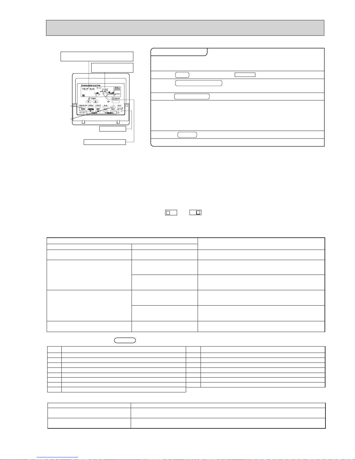
[TEST] button
Pipe (liquid) temperature
Displays the remaining
test run time.
"TEST RUN" and the currently selected
operation mode are displayed alternately.
• In case of test run, the OFF timer will be activated, and the test run will automatically stop after 2 hours.
• The room temperature display section shows the pipe temperature of indoor units during the test run.
• Check that all the indoor units are running properly in case of simultaneous twin and triple operation. Malfunctions may not
be displayed regardless of incorrect wiring.
w1 After turning on the power supply, the system will go into startup mode, “PLEASE WAIT” will blink on the display section of
the room temperature, and lamp (green) of the remote controller will flash.
As to INDOOR BOARD LED, LED1 will be lit up, LED2 will either be lit up in case the address is 0 or turned off in case the
address is not 0. LED3 will blink.
As to OUTDOOR BOARD LED, LED1 (green) and LED2 (red) will be lit up. (After the startup mode of the system finishes,
LED2 (red) will be turned off.)
In case OUTDOOR BOARD LED is digital display, — and — will be displayed alternately every second.
• If one of the above operations does not function correctly, the causes written below should be considered. Find causes from
the symptoms.
The below symptoms are under test run mode. “Startup” in the table means the display status of w1 written above.
Remote Controller Display
Symptoms in test run mode
OUTDOOR BOARD LED Display
Cause
Remote controller displays “PLEASE
WAIT”, and
cannot be operated.
After power is turned on, “PLEASE WAIT”
is displayed for 3 minutes, then error code
is displayed.
No display appears even when remote
controller operation switch is turned on.
(Operation lamp does not light up.)
Display appears but soon disappears
even when remote controller is operated.
• After power is turned on, “PLEASE WAIT” is displayed for 2
minutes during
system startup. (Normal)
• Incorrect connection of outdoor terminal block (L
1, L2, L3 and
S1, S2, S3.)
• Outdoor unit’s protection device connector is open.
• Incorrect wiring between the indoor and outdoor unit (Polarity
is wrong for S1, S2, S3.)
• Remote controller transmission wire short.
• There is no outdoor unit of address 0.
(Address is other than 0.)
• Remote controller transmission wire open.
• After canceling function selection, operation is not possible for
about 30 seconds. (Normal)
After “startup” is displayed, only
green lights up. <00>
After “startup” is displayed,
green(once) and red(once) blink
alternately. <F1>
After “startup” is displayed,
green(once) and red(twice) blink
alternately. <F3, F5, F9>
After “startup” is displayed,
green(twice) and red(once) blink
alternately. <EA. Eb>
After “startup” is displayed, only
green lights up. <00>
After “startup” is displayed, only
green lights up. <00>
< > indicates digital display.
2. Press TEST button twice.
1. Turn on the main power supply.
3. Press OPERATION SWITCH
button.
4. Press AIR DIRECTION button.
5. Check the outdoor unit fan for
correct running.
6. Press the ON/OFF button to reset the test run in progress.
7. Register the contact number.
While the room temperature display on the remote
controller is “PLEASE WAIT”, the remote controller is disabled.
Wait until “PLEASE WAIT” disappears before using remote controller.
“PLEASE WAIT” appears for about 2 minutes after power
supply is turned on. +1
The outdoor unit features automatic capacity control to
provide optimum fan speeds. Therefore, the fan keeps
running at a low speed to meet the current outside air
condition unless it exceeds its available maximum power.
Then, in actuality, the fan may stop or run in the reverse
direction depending on the outside air, but this does not
mean malfunction.
Check for correct motion of auto-vanes.
Cooling mode:
Check if cool air blows and water is drained.
Heating mode: Check if warm air blows. (It takes a little
while until warm air blows.)
The TEST RUN appears on the screen.
Operating procedures
w Press the remote controller’s CHECK button twice to perform self-diagnosis. See the table below for the contents of LCD display.
LCD
Contents of trouble
P1
P2
P4
P5
P6
P8
P9
Fb
Abnormality of room temperature thermistor
Abnormality of pipe temperature thermistor/Liquid
Abnormality of drain sensor/Float switch connector open
Drain overflow protection is working.
Freezing/overheating protection is working.
Abnormality of pipe temperature
Abnormality of pipe temperature thermistor/Cond./Eva
Abnormality of indoor controller board
LCD
Contents of trouble
U1~UP
F3~F9
E0~E5
E6~EF
----
FFFF
PA
Malfunction outdoor unit
Malfunction
outdoor unit
Remote controller transmitting error
Indoor/outdoor unit communication error
No error history
No applied unit
Forced compressor stop (due to water leakage abnormality)
LED1
(microprocessor power supply)
LED2
(remote controller)
LED3
(indoor/outdoor communication)
Lights when power is supplied.
Lights when power is supplied for wired remote controller.
The indoor unit should be connected to the outdoor unit with address “0” setting.
Flashes when indoor and outdoor unit are communicating.
See the table below for details of the LED display (LED 1, 2, 3) on the indoor controller board.
22
ON/OFF
TEMP
FAN
VANE
MODE
CHECK
LOUVER
TEST RUN
AUTO STOP
AUTO START
h
min
TEST RUN
RESET
SET
CLOCK
,
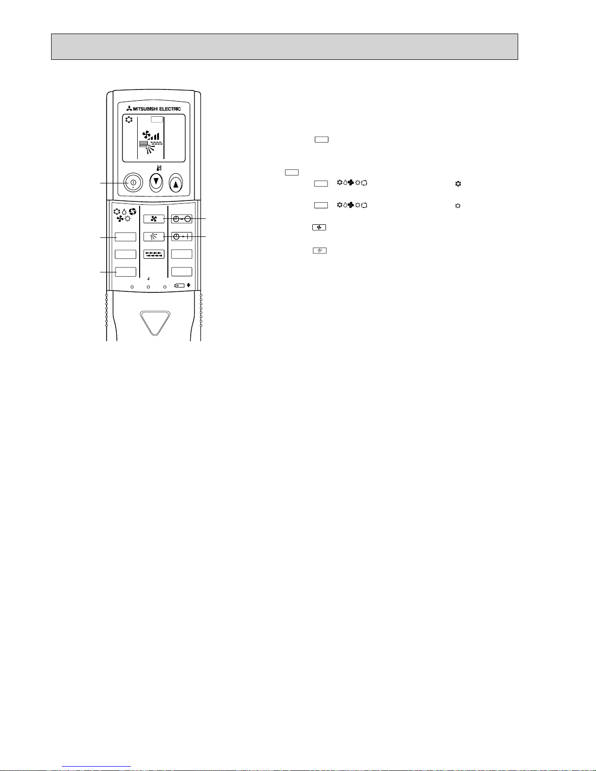
Test run [for wireless remote controller]
Measure an impedance between the power supply terminal block on
the outdoor unit and ground with a 500V Megger and check that it is
equal to or greater than 1.0M".
1 Turn on the main power to the unit.
2 Press the button twice continuously.
(Start this operation from the status of remote controller display
turned off.)
A and current operation mode are displayed.
3 Press the ( ) button to activate mode, then
check whether cool air is blown out from the unit.
4 Press the ( ) button to activate mode, then
check whether warm air is blown out from the unit.
5 Press the button and check whether strong air is blown out
from the unit.
6 Press the button and check whether the auto vane operates
properly.
7 Press the ON/OFF button to stop the test run.
Note:
• Point the remote controller towards the indoor unit receiver
while following steps 2 to 7.
• It is not possible to run in FAN, DRY or AUTO mode.
MODE
MODE
COOL
HEAT
TEST RUN
FAN
VANE
TEST RUN
23
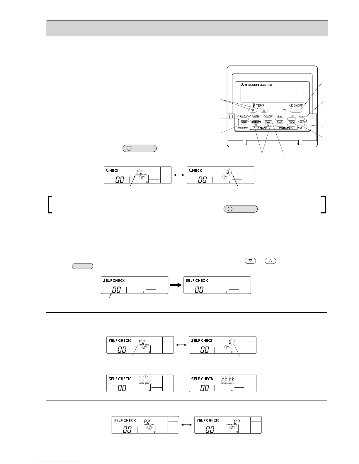
11-3. HOW TO PROCEED "SELF-DIAGNOSIS"
11-3-1. When a Problem Occurs During Operation
If a problem occurs in the air conditioner, the indoor and outdoor units will stop,
and the problem is shown in the remote controller display.
[CHECK] and the refrigerant address are displayed on the temperature
display , and the error code and unit number are displayed alternately as
shown below.
(If the outdoor unit is malfunctioning, the unit number will be "00".)
In the case of group control, for which one remote controller controls
multiple refrigerant systems, the refrigerant address and error code of the
unit that first experienced trouble (i.e., the unit that transmitted the error
code) will be displayed.
T o clear the error code, press the button.
ON/OFF
When using remote-/local-controller combined operation, cancel the error code after turning off remote operation. During
central control by a MELANS controller, cancel the error code by pressing the
ON/OFF
button.
11-3-2. Self-Diagnosis During Maintenance or Service
Since each unit has a function that stores error codes, the latest check code can be recalled even if it is cancelled by the remote
controller or power is shut off.
Check the error code history for each unit using the remote controller.
Switch to self-diagnosis mode.
Press the
CHECK
button twice within 3 seconds. The display content
will change as shown below.
Set the unit number or refrigerant address you want to diagnose.
Press the [TEMP] buttons ( and ) to select the desired number
or address. The number (address) changes between [01] and [50] or [00]
Display self-diagnosis results.
<When there is error code history>
Reset the error history.
Display the error history in the diagnosis result display screen (see step
).
Error code (2 or 4 digits)
(Alternating Display)
Address (3 digits) or unit number (2 digits)
The refrigerant address will begin to flash
approximately 3 seconds after being
selected and the self-diagnosis process will begin.
Unit number or refrigerant address
to be diagnosed
Error code (2 or 4 digits)
(Alternating Display)
Address (3 digits) or unit number (2 digits)
<When there is no error code history> <When there is no corresponding unit>
and
[15].
24
Transmission data from remote controller
Transmission data on transmission path
When the number of data errors is "02":
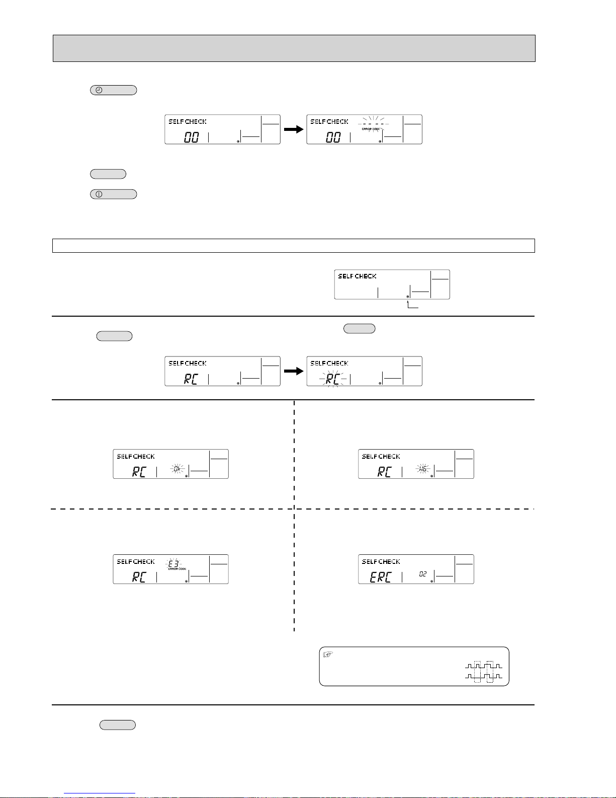
Press the
ON/OFF
button twice within 3 seconds. The self-diagnosis
address or refrigerant address will blink.
When the error history is reset, the display will look like the one shown below.
However, if you fail to reset the error history, the error content will be displayed
again.
Cancel self-diagnosis.
Self-diagnosis can be cancelled by the following 2 methods.
Press the
CHECK
button twice within 3 seconds. Self-diagnosis will be cancelled and the screen will return to the previous state in effect before the
start of self-diagnosis.
Press the
ON/OFF
button. Self-diagnosis will be cancelled and the indoor unit will stop.
11-3-3. Remote Controller Diagnosis
If the air conditioner cannot be operated from the remote controller, diagnose the remote controller as explained below.
First, check that the power-on indicator is lit.
If the correct voltage (DC12 V) is not supplied to the remote controller, the
indicator will not light.
If this occurs, check the remote controller's wiring and the indoor unit.
Switch to the remote controller self-diagnosis mode.
Press the
CHECK
button for 5 seconds or more. The display content
will change as shown below.
Press the
FILTER
button to start self-diagnosis.
Remote controller self-diagnosis result
[When the remote controller is functioning correctly]
Check for other possible causes, as there is no problem with the remote
controller.
[When the remote controller malfunctions]
(Error display 1) "NG" blinks. ©The remote controller's transmitting-receiv-
ing circuit is defective.
The remote controller must be replaced with a new one.
[Where the remote controller is not defective, but cannot be operated.]
(Error display 2) [E3], [6833] or [6832] blinks.
© Transmission is not possible.
There might be noise or interference on the transmission path, or the indoor
unit or other remote controllers are defective. Check the transmission path
and other controllers.
(Error display 3)
"ERC" and the number of data errors are displayed.
© Data error has occurred.
The number of data errors is the difference between the number of bits sent
from the remote controller and the number actually transmitted through the
transmission path. If such a problem is occurring, the transmitted data is
affected by noise, etc. Check the transmission path.
To cancel remote controller diagnosis
Press the
CHECK
button for 5 seconds or more. Remote controller diagnosis will be cancelled, "PLEASE WAIT" and operation lamp will blink. After
approximately 30 seconds, the state in effect before the diagnosis will be restored.
Power on indicator
25
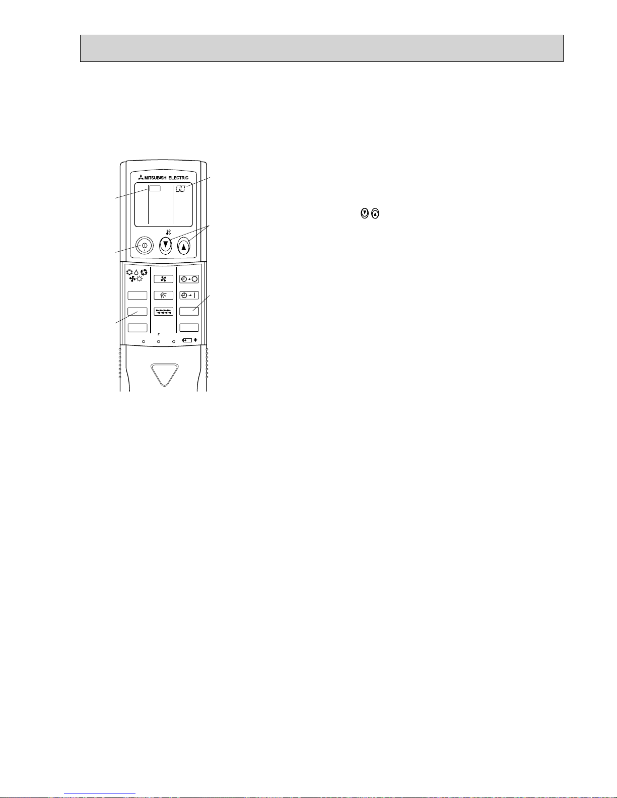
• "CHECK" lights, and refrigerant
address "00" blinks.
• Check that the remote controller's
display has stopped before continuing.
• Select the refrigerant address of the
indoor unit for the self-diagnosis.
Note: Set refrigerant address using the
outdoor unit’s DIP switch (SW1).
(For more information, see the
outdoor unit installation manual.)
• If an air conditioner error occurs, the
indoor unit's sensor emits an intermit tent buzzer sound, the operation lamp
blinks, and the error code is output.
(It takes 3 seconds at most for error
code to appear.)
• The check mode is cancelled.
[Procedure]
1. Press the CHECK button twice.
2. Press the temperature
buttons.
3. Point the remote controller at the
sensor on the indoor unit and
press the HOUR button.
4. Point the remote controller at the
sensor on the indoor unit and
press the ON/OFF button.
<Malfunction-diagnosis method at maintenance service>
11-3-4. Malfunction-diagnosis method by wireless remote controller
<In case of trouble during operation>
When a malfunction occurs to air conditioner, both indoor unit and outdoor unit will stop and operation lamp blinks to inform
unusual stop.
ON/OFF
TEMP
FAN
VANE
MODE
CHECK
LOUVER
TEST RUN
AUTO STOP
AUTO START
h
min
RESET
SET
CLOCK
CHECK
CHECK
display
Temperature
button
CHECK
button
Refrigerant
address
display
HOUR
button
ON/OFF
button
26
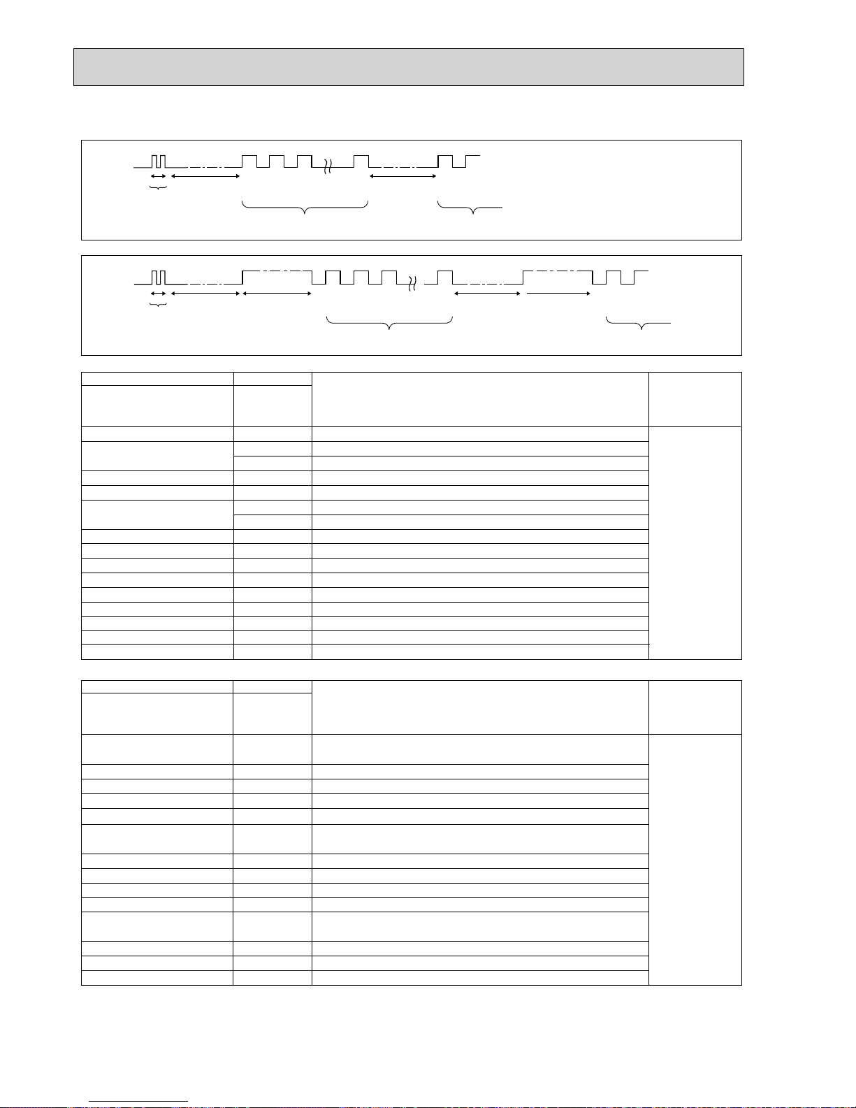
[Output pattern A] Errors detected by indoor unit
[Output pattern B]
E9
*1If the beeper does not sound again after the initial
2 beeps to confirm the self-check start signal was received and
the OPERATION INDICATOR lamp does not come on,
there are no error records.
*2If the beeper sounds 3 times continuously “beep, beep, beep (0.4 + 0.4 + 0.4 sec.)” after the initial 2 beeps to confirm
the self-check start signal was received, the specified refrigerant address is incorrect.
OPERATION
INDICATOR
lamp blink
pattern
Beep Beep Beep Beep Beep Beep Beep
Off
Approx. 2.5 sec.OnApprox. 3 sec.On0.5 sec.On0.5 sec.On0.5 sec.On0.5 sec.
Off
Approx. 2.5 sec.OnApprox. 3 sec.On0.5 sec.On0.5 sec.
· · · Repeated
Number of blinks/beeps in pattern indicates the check
code in the following table (i.e., n=5 for “U2”)
Number of blinks/beeps in pattern indicates
the check code in the following table
n
th
1st2nd3
rd
1st2
nd
Self-check
starts
(Start signal
received)
Beeper sounds
[Output pattern B]
OPERATION
INDICATOR
lamp blink
pattern
Beep
Beep Beep Beep Beep Beep Beep
Off
Approx. 2.5 sec.On0.5 sec.On0.5 sec.On0.5 sec.
On
0.5 sec.
Off
Approx. 2.5 sec.On0.5 sec.On0.5 sec.
· · · Repeated
Number of blinks/beeps in pattern indicates the check
code in the following table (i.e., n=5 for “P5”)
Number of blinks/beeps in pattern indicates
the check code in the following table
n
th
1st2nd3
rd
1st2
nd
Self-check
starts
(Start signal
received)
Beeper sounds
• Refer to the following tables for details on the check codes.
[Output pattern A]
Beeper sounds/OPERATION
INDICATOR lamp blinks Check code
Symptom Remark
(Number of times)
Wireless remote controller
Wired remote controller
Beeper sounds/OPERATION
INDICATOR lamp blinks Check code
(Number of times)
Wireless remote controller
Wired remote controller
1P1
Intake sensor error
P9 Pipe (TH5) sensor error
2
P2 Pipe (TH2) sensor error
3E6,E7
Indoor/outdoor unit communication error
4 P4 Drain sensor error/Float switch connector open
5
PA
Forced compressor stop (due to water leakage abnormality)
6
P6
Freezing/Overheating protection operation
7 EE Communication error between indoor and outdoor units
8P8Pipe temperature error
9 E4, E5 Remote controller signal receiving error
10
–
11
–
–
–
Errors detected by unit other than indoor unit (outdoor unit, etc.)
Symptom Remark
1
Indoor/outdoor unit communication error
2
(Transmitting error) (Outdoor unit)
3
Open/short of outdoor unit thermistors
4
Compressor overcurrent interruption (When compressor locked)
5
Abnormal high discharging temperature/insufficient refrigerant
6
Abnormal high pressure (63H operated)/Overheating
protection operation
7
Abnormal temperature of heatsink
8
Outdoor unit fan protection stop
9
Compressor overcurrent interruption/Abnormality of power module
10
Abnormality of superheat due to low discharge temperature
11
Abnormality such as overvoltage or voltage shortage and
abnormal synchronous signal to main circuit/Current sensor error
12
13
U2
U5
UP
U3,U4
UF
U1,Ud
U8
U6
U7
U9,UH
Others
–
–
–
–
14
Other errors (Refer to the technical manual for the outdoor unit.)
For details, check
the LED display
of the outdoor
controller board.
12 Fb
Indoor unit control system error (memory error, etc.)
–
E0, E3
– E1, E2 Remote controller control board error
Remote controller transmission error
Compressor overcurrent interruption
As for indoor
unit, refer to
indoor unit's
service manual.
P5
Drain pump error
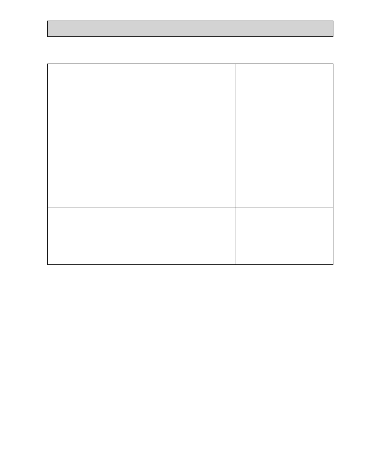
27
11-4. SELF-DIAGNOSIS ACTION TABLE
<Abnormalities detected when the power is turned on>
Error Code
Abnormal point and detection method
Case
Judgment and action
None
—
1 No voltage is supplied to terminal
block(TB1) of outdoor unit.
a) Power supply breaker is
turned off.
b) Contact failure or disconnec-
tion of power supply
terminal
c) Open phase (L2 or N phase)
2 Electric power is not supplied to
outdoor controller circuit board.
a) Disconnection of connector
(CNDC)
3 Disconnection of reactor
(ACL4)
4 Disconnection of outdoor noise
filter circuit board or parts failure in outdoor noise filter circuit
board
5 Defective outdoor controller
circuit board
1 Check following items.
a) Power supply breaker
b), c) Connection of power supply terminal
block (TB1)
2 Check connection of the connector (CNDC)
on the outdoor controller circuit board.
Check connection of the connector CNDC on
the outdoor noise filter circuit board.
Refer to 11-9.
3 Check connection of reactor. (ACL4)
4 a) Check connection of outdoor noise filter
circuit board.
b) Replace outdoor noise filter circuit board.
Refer to 11-9.
5 Replace controller board (When items above
are checked but the units cannot be repaired).
F5
(5201)
63H connector open
Abnormal if 63H connector circuit is open
for 3 minutes continuously after power supply.
63H: High-pressure switch
1 Disconnection or contact failure
of 63H connector on outdoor
controller circuit board
2 Disconnection or contact failure
of 63H
3 63H is operating due to defec-
tive parts.
4 Defective outdoor controller
circuit board
1 Check connection of 63H connector on
outdoor controller circuit board.
Refer to 11-9.
2 Check the 63H side of connecting wire.
3 Check continuity by tester.
Replace the parts if the parts are defective.
4 Replace outdoor controller circuit board.
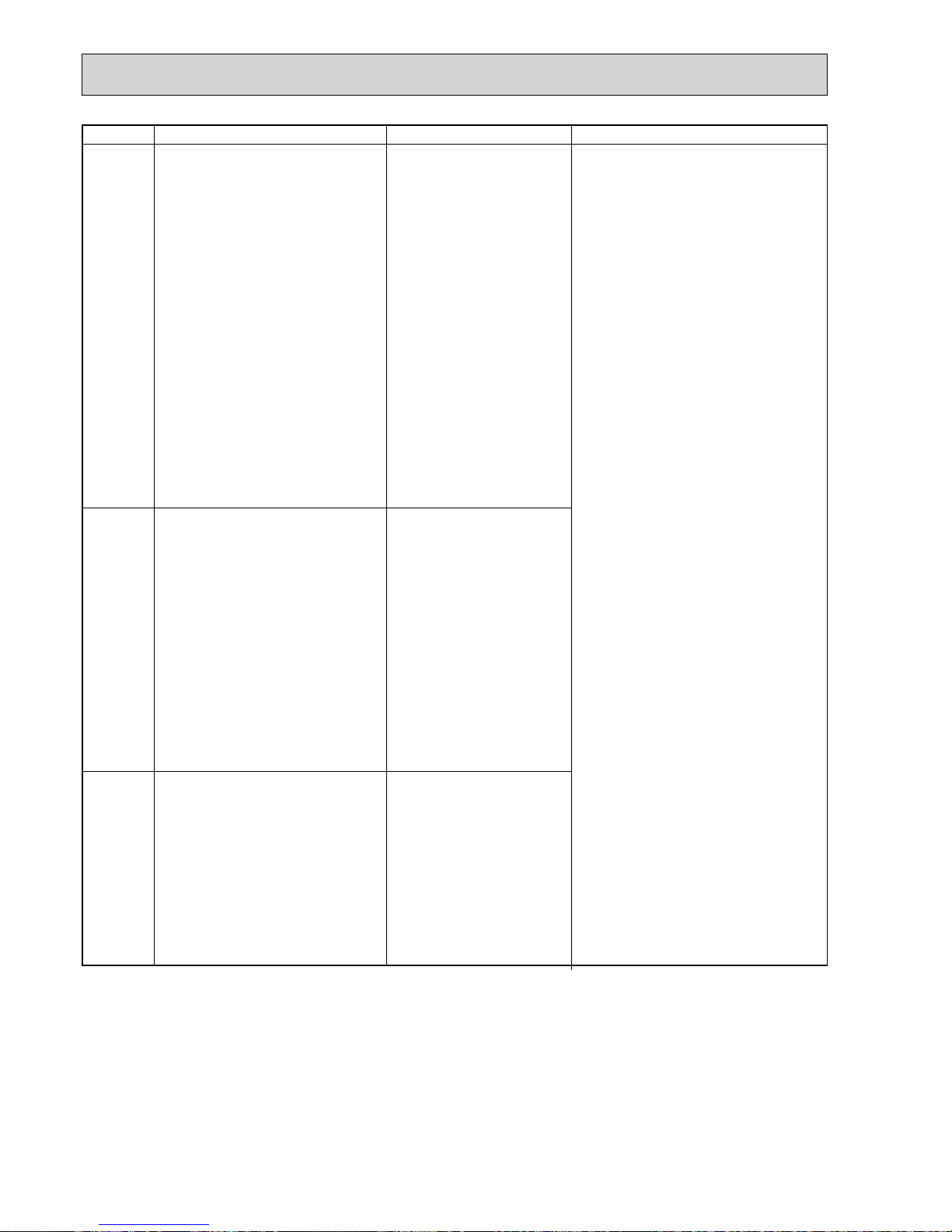
28
Error Code
Abnormal point and detection method
Judgment and action
Eb
(6845)
Miswiring of indoor/outdoor unit
connecting wire (converse wiring or disconnection)
Outdoor controller circuit board can
automatically set the unit number of indoor
units.
Abnormal if the indoor unit number cannot be set within 4 minutes after power on
because of miswiring (converse wiring or
disconnection) of indoor/outdoor unit connecting wire.
EC
(6846)
Start-up time over
The unit cannot finish start-up process
within 4 minutes after power on.
Case
1 Contact failure of indoor/
outdoor unit connecting wire
2 Diameter or length of indoor/
outdoor unit connecting wire is
out of specified capacity.
7 2 or more outdoor units have
refrigerant address “0” .
(In case of group control)
8 Noise has entered into power
supply or indoor/outdoor unit
connecting wire.
1 Contact failure or miswiring of
indoor/outdoor unit connecting
wire
2 Diameter or length of indoor/
outdoor unit connecting wire is
out of specified capacity.
4 Defective transmitting receiving
circuit of outdoor controller circuit
board
5 Defective transmitting receiving
circuit of indoor controller board
6 Defective indoor power board
7 2 or more outdoor units have
refrigerant address “0”.
(In case of group control)
8 Noise has entered into power
supply or indoor/outdoor unit
connecting wire.
Indoor/outdoor unit connector
miswiring, excessive number of units
1. Outdoor controller circuit board can
automatically check the number of
connected indoor units. Abnormal if the
number cannot be checked automatically due to miswiring of indoor/outdoor
unit connecting wire and etc. after power
is turned on for 4 minutes.
2. Abnormal if outdoor controller circuit
board recognizes excessive number of
indoor units.
1 Check disconnection or looseness or polar-
ity of indoor/outdoor unit connecting wire of
indoor and outdoor units.
2 Check diameter and length of indoor/outdoor
unit connecting wire.
Total wiring length: 80m
(Including wiring connecting each indoor unit
and between indoor and outdoor unit)
Also check if the connection order of flat
cable is S1, S2, S3.
3 Check the number of indoor units that are
connected to one outdoor unit. (If EA is
detected.)
4~6 Turn the power off once, and on again to
check.
Replace outdoor controller circuit board,
indoor controller board or indoor power
board if abnormality occurs again.
7 Check if refrigerant addresses (SW1-3 to
SW1-6 on outdoor controller circuit board)
are overlapping in case of group control
system.
8 Check transmission path, and remove the
cause.
w The descriptions above, 1-8, are for EA, Eb
and EC.
1 Contact failure or miswiring of
indoor/outdoor unit connecting
wire
2 Diameter or length of indoor/
outdoor unit connecting wire is
out of specified capacity.
3 Excessive number of indoor
units are connected to 1 outdoor unit. (5 units or more)
4 Defective transmitting receiving
circuit of outdoor controller
circuit board
5 Defective transmitting receiving
circuit of indoor controller board
6 Defective indoor power board
7 2 or more outdoor units have
refrigerant address “0” .
(In case of group control)
8 Noise has entered into power
supply or indoor / outdoor unit
connecting wire.
EA
(6844)
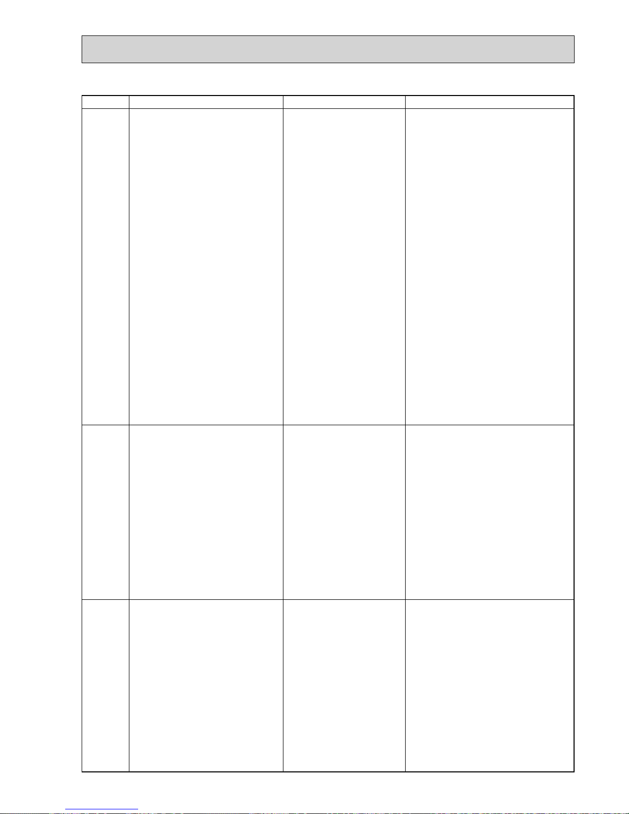
29
Error Code
Abnormal point and detection method
Judgment and action
U1
(1302)
High pressure (High-pressure switch
63H operated)
Abnormal if high-pressure switch 63H operated ( w ) during compressor operation.
w 4.15 MPa
63H : High-pressure switch
1 Short cycle of indoor unit
2 Clogged filter of indoor unit
3 Decreased airflow caused by
dirt of indoor fan
4 Dirt of indoor heat exchanger
5 Locked indoor fan motor
6 Malfunction of indoor fan motor
7 Defective operation of stop
valve (Not full open)
8 Clogged or broken pipe
9 Locked outdoor fan motor
0 Malfunction of outdoor fan
motor
1 Short cycle of outdoor unit
2 Dirt of outdoor heat exchanger
3 Decreased airflow caused by
defective inspection of outside
temperature thermistor
(It detects lower temperature
than actual temperature.)
4 Disconnection or contact failure
of connector (63H) on outdoor
controller board
5 Disconnection or contact failure
of 63H connection
6 Defective outdoor controller
board
7 Defective action of linear
expansion valve
8 Malfunction of fan driving
circuit
1~6 Check indoor unit and repair defect.
7 Check if stop valve is fully open.
8 Check piping and repair defect.
9~2 Check outdoor unit and repair defect.
3 Check the inspected temperature of outside
temperature thermistor on LED display.
(SW2 on A-Control Service Tool : Refer to
11-10.)
4~6 Turn the power off and check F5 is
displayed when the power is turned again.
When F5 is displayed, refer to “Judgment
and action” for F5.
7 Check linear expansion valve.
Refer to 11-6.
8 Replace outdoor controller board.
Case
U2
(1102)
High discharging temperature
(1) Abnormal if discharge temperature
thermistor (TH4) exceeds 125: or
110: continuously for 5 minutes.
Abnormal if condenser/evaporator
temperature thermistor (TH5) exceeds
40: during defrosting and discharge
temperature thermistor (TH4) exceeds
110:.
(2) Abnormal if discharge superheat
(Cooling: TH4 – TH5 / Heating: TH4 –
TH6) exceeds 70: continuously for 10
minutes.
1
Overheated compressor opera-
tion caused by shortage of
refrigerant
2 Defective operation of stop
valve
3 Defective thermistor
4 Defective outdoor controller
board
5 Defective action of linear
expansion valve
6 Clogging with foreign objects in
refrigerant circuit
w Clogging occurs in the parts
which become below freez-
ing point when water enters in
refrigerant circuit.
1 Check intake superheat.
Check leakage of refrigerant.
Charge additional refrigerant.
2 Check if stop valve is fully open.
34 Turn the power off and check if U3 is dis-
played when the power is turned on again.
When U3 is displayed, refer to “Judgement
and action” for U3.
5 Check linear expansion valve.
Refer to 11-6.
6 After recovering refrigerant, remove water
from entire refrigerant circuit under vacuum
more than 1 hour.
<Abnormalities detected while unit is operating>
U3
(5104)
Open/short circuit of discharge
temperature thermistor (TH4)
Abnormal if open (3: or less) or short
(217: or more) is detected during
compressor operation.
(Detection is inoperative for 10 minutes
of compressor starting process and for 10
minutes after and during defrosting.)
1 Disconnection or contact
failure of connector (TH4) on
the outdoor controller circuit
board
2 Defective thermistor
3 Defective outdoor controller
circuit board
1 Check connection of connector (TH4) on the
outdoor controller circuit board.
Check breaking of the lead wire for
thermistor (TH4). Refer to 11-9.
2 Check resistance value of thermistor (TH4) or
temperature by microprocessor.
(Thermistor/TH4: Refer to 11-6.)
(SW2 on A-Control Service Tool: Refer to
11-10.)
3 Replace outdoor controller board.
 Loading...