

Mitsubishi PUHZ-P100VHA3, PUHZ-P140VHA3, PUHZ-P125VHA2, PUHZ-P125VHA3, PUHZ-P100VHA4 Service Manual
...
SERVICE MANUAL
No.OCH415
REVISED EDITION-F
R410A
December 2012
PUHZ-P100VHA4.UK
PUHZ-P100YHA2.UK
CONTENTS
1. TECHNICAL CHANGES
.................................
2
2. REFERENCE MANUAL
..................................
3
3. SAFETY PRECAUTION
..................................
3
4. FEATURES
......................................................
7
5. SPECIFICATIONS
...........................................
8
6. DATA
.............................................................
12
7. OUTLINES AND DIMENSIONS
....................
15
8. WIRING DIAGRAM
.......................................
23
9. WIRING SPECIFICATIONS
..........................
29
10.
REFRIGERANT SYSTEM DIAGRAM
...............
34
11. TROUBLESHOOTING
...................................
37
12. FUNCTION SETTING
....................................
99
13. EASY MAINTENANCE FUNCTION
............
112
14.
MONITORING THE OPERATION DATA BY THE REMOTE CONTROLLER
..
116
15. DISASSEMBLY PROCEDURE
...................
127
PARTS CATALOG (OCB415)
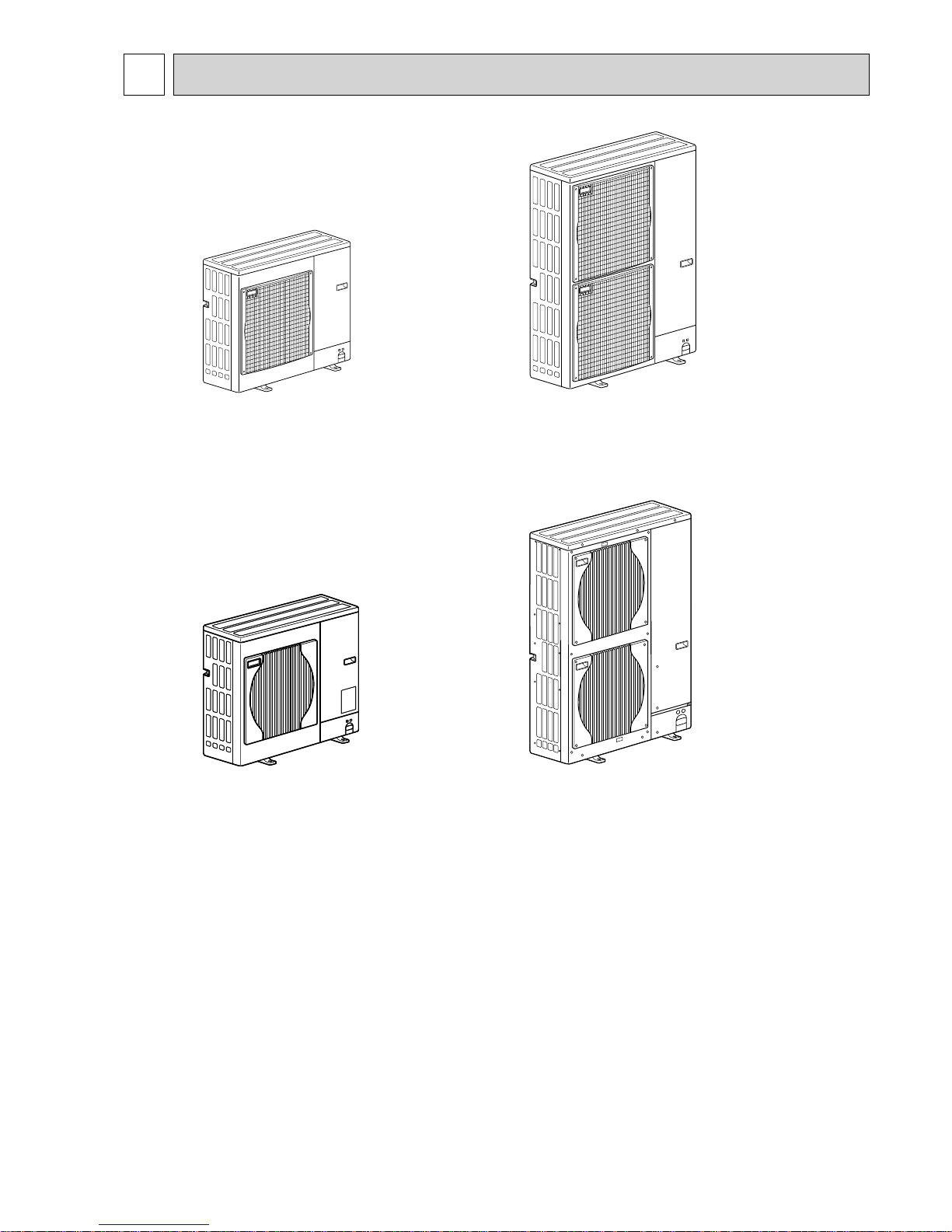
Outdoor unit
[Model names]
PUHZ-P100VHA2
PUHZ-P125VHA2
PUHZ-P140VHA2
PUHZ-P100VHA3
PUHZ-P125VHA3
PUHZ-P140VHA3
PUHZ-P100VHA4
PUHZ-P100YHA
PUHZ-P100YHA2
PUHZ-P125YHA
PUHZ-P140YHA
[Service Ref.]
Refer to page 2.
Note:
• RoHS compliant products have
<G> mark on the spec name
plate.
Revision:
• PUHZ-P100VHA4.UK,
PUHZ-P100YHA2.UK,
PUHZ-P125/140VHA3R3.UK
and PUHZ-P125/140YHAR2.UK
have been added in REVISED
EDITION-F.
• Some descriptions have been
modified.
• Please void OCH415
REVISED EDITION-E.
SPLIT-TYPE, HEAT PUMP AIR CONDITIONERS

2
PUHZ-P125VHA2.UK PUHZ-P125VHA21.UK
PUHZ-P140VHA2.UK PUHZ-P140VHA21.UK
4-WAY VALVE and COIL (21S4) have been changed.
1
TECHNICAL CHANGES
PUHZ-P100VHA2.UK PUHZ-P100VHA3.UK
PUHZ-P125VHA21.UK PUHZ-P125VHA3.UK
PUHZ-P140VHA21.UK PUHZ-P140VHA3.UK
• OUTDOOR CONTROLLER BOARD (C.B) has been changed.
(Corresponding to the additional combination between PKA-RP
•HAL/KAL, PCA-RP•KA and PEAD-RP•JA(L))
* In case of UL error, the compressor may be damaged if the unit is restarted by remote controller.
To avoid the damage, unit has the system that is not able to be restarted unless the power is turned OFF once.
PUHZ-P100VHA3.UK PUHZ-P100VHA3R1.UK
PUHZ-P125VHA3.UK PUHZ-P125VHA3R1.UK
PUHZ-P140VHA3.UK PUHZ-P140VHA3R1.UK
• Fan grille has been changed.
• Structural parts have been changed. (Munsell 5Y 7/1 → 3Y 7.8/1.1)
PUHZ-P100VHA3R1.UK PUHZ-P100VHA3R2.UK
PUHZ-P125VHA3R1.UK PUHZ-P125VHA3R2.UK
PUHZ-P140VHA3R1.UK PUHZ-P140VHA3R2.UK
• Thermistor <Discharge/TH4> has been changed to Thermistor <Comp. Surface/TH32>.
• Electrical parts, Controller circuit board (C.B.), Power circuit board (P.B.), Noise filter circuit board (N.F.) and Active filter mod-
ule (ACTM)(inclucling P.B.) have been changed.
PUHZ-P100YHA.UK PUHZ-P100YHAR1.UK
PUHZ-P125YHA.UK PUHZ-P125YHAR1.UK
PUHZ-P140YHA.UK PUHZ-P140YHAR1.UK
• Power circuit board (P.B.) has been changed.
• Controller circuit board (C.B.) has been changed. (S/W version up)
[Service Ref.]
PUHZ-P100VHA2.UK
PUHZ-P125VHA2.UK
PUHZ-P125VHA2
1
.UK
PUHZ-P140VHA2.UK
PUHZ-P140VHA2
1
.UK
PUHZ-P100VHA3.UK
PUHZ-P100VHA3R1.UK
PUHZ-P100VHA3R2.UK
PUHZ-P100VHA4.UK
PUHZ-P125VHA3.UK
PUHZ-P125VHA3R1.UK
PUHZ-P125VHA3R2.UK
PUHZ-P125VHA3R3.UK
PUHZ-P140VHA3.UK
PUHZ-P140VHA3R1.UK
PUHZ-P140VHA3R2.UK
PUHZ-P140VHA3R3.UK
PUHZ-P100YHA.UK
PUHZ-P100YHAR1.UK
PUHZ-P100YHA2.UK
PUHZ-P125YHA.UK
PUHZ-P125YHAR1.UK
PUHZ-P125YHAR2.UK
PUHZ-P140YHA.UK
PUHZ-P140YHAR1.UK
PUHZ-P140YHAR2.UK
PUHZ-P125VHA3R2.UK PUHZ-P125VHA3R3.UK
PUHZ-P140VHA3R2.UK PUHZ-P140VHA3R3.UK
PUHZ-P125YHAR1.UK PUHZ-P125YHAR2.UK
PUHZ-P140YHAR1.UK PUHZ-P140YHAR2.UK
• Compressor has been changed.
PUHZ-P100VHA3R2.UK PUHZ-P100VHA4.UK
PUHZ-P100YHAR1.UK PUHZ-P100YHA2.UK
• Electrical parts, Controller circuit board (C.B.), Power circuit board (P.B.) and Noise filter circuit board (N.F.) have been
changed.
OCH415F
3
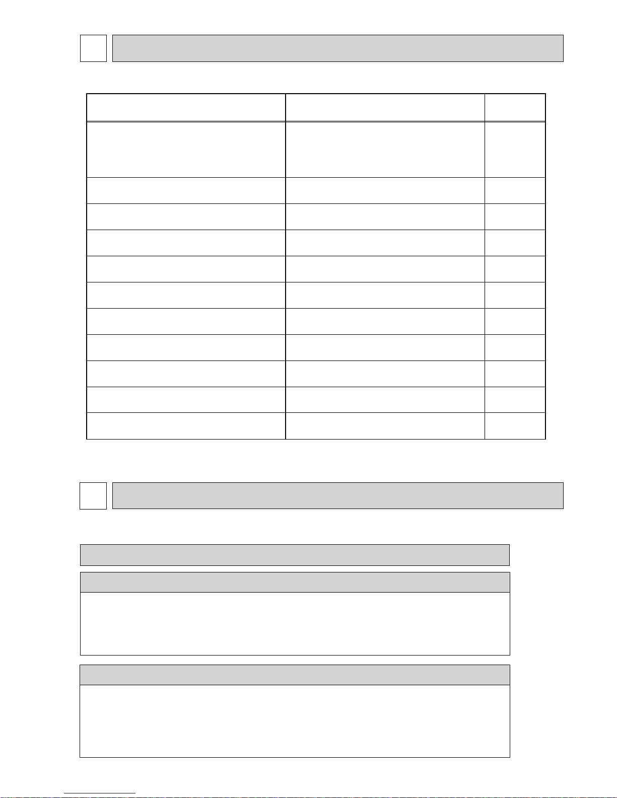
2
REFERENCE MANUAL
Model name Service Ref.
Service
Manual No.
PLA-RP50/60/71/100/125/140BA
PLA-RP140BA2
PLA-RP50/60/71/100/125/140BA.UK
PLA-RP50/60/71/100/125/140BA#2.UK
PLA-RP50/60/71BA
1.UK
PLA-RP50/60/71BAR3.UK
PLA-RP140BA2R1.UK
OCH412
OCB412
PCA-RP71/125HA
OC329
PCA-RP71/125HA(#1)
PCA-RP50/60/71/100/125/140GA PCA-RP50/60/71/100/125/140GA(#1)
OC328
PCA-RP50GA2 PCA-RP50GA2(#1)
PKA-RP50GAL PKA-RP50GAL(#1)
OC330
PKA-RP60/71/100FAL PKA-RP60/71/100FAL(#1)
PKA-RP50FAL2 PKA-RP50FAL2(#1)
OC331
PEAD-RP60/71/100GA
PEAD-RP60/71/100GA(#1).UK
HWE0506
PEAD-RP50/60/71/125/140EA
PEAD-RP100EA2
PEAD-RP50/60/71/125/140EA(#1).UK
PEAD-RP100EA2(#1).UK
HWE0521
PKA-RP60/71/100KAL
PKA-RP60/71/100KAL.TH
OCH452
OCB452
PKA-RP35/50HAL
PKA-RP35/50HAL
PCA-RP50/60/71/100/125/140KA
PCA-RP50/60/71/100/125/140KA
OCH454
OCB454
OCH453
OCB453
PEAD-RP35/50/60/71/100/125/140JA(L)
PEAD-RP35/50/60/71/100/125/140JA(L).UK
HWE08130
BWE08240
INDOOR UNIT’S SERVICE MANUAL
3
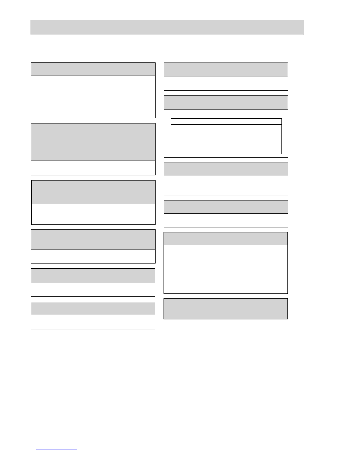
SAFETY PRECAUTION
3-1. ALWAYS OBSERVE FOR SAFETY
Before obtaining access to terminal, all supply circuits must be disconnected.
Preparation before the repair service.
• Prepare the proper tools.
• Prepare the proper protectors.
• Provide adequate ventilation.
• After stopping the operation of the air conditioner, turn off the power-supply breaker.
• Discharge the condenser before the work involving the electric parts.
Precautions during the repair service.
• Do not perform the work involving the electric parts with wet hands.
• Do not pour water into the electric parts.
• Do not touch the refrigerant.
• Do not touch the hot or cold areas in the refrigerating cycle.
• When the repair or the inspection of the circuit needs to be done without turning off the power,
exercise great caution not to touch the live parts.
OCH415F
4
Cautions for units utilizing refrigerant R410A
3-2. CAUTIONS RELATED TO NEW REFRIGERANT
Use new refrigerant pipes.
Store the piping indoors, and both ends of the
piping sealed until just before brazing.
(Leave elbow joints, etc. in their packaging.)
In case of using the existing pipes for R22, be careful with
the followings.
· Be sure to clean the pipes and make sure that the insides
of the pipes are clean.
· Change flare nut to the one provided with this product.
Use a newly flared pipe.
· Avoid using thin pipes.
Charge refrigerant from liquid phase of gas
cylinder.
If the refrigerant is charged from gas phase, composition change
may occur in refrigerant and the efficiency will be lowered.
Do not use refrigerant other than R410A.
If other refrigerant (R22 etc.) is used, chlorine in refrigerant can cause deterioration of refrigerant oil etc.
Use a vacuum pump with a reverse flow check
valve.
Vacuum pump oil may flow back into refrigerant cycle and
that can cause deterioration of refrigerant oil etc.
Use the following tools specifically designed for
use with R410A refrigerant.
The following tools are necessary to use R410A refrigerant.
Handle tools with care.
If dirt, dust or moisture enters into refrigerant cycle, that can
cause deterioration of refrigerant oil or malfunction of compressor.
Do not use a charging cylinder.
If a charging cylinder is used, the composition of refrigerant will change and the efficiency will be lowered.
Flare tool
Electronic refrigerant
charging scale
Vacuum pump adaptor
Size adjustment gauge
Gauge manifold
Torque wrench
Gas leak detector
Charge hose
Tools for R410A
Contamination inside refrigerant piping can cause deterioration of refrigerant oil etc.
If dirt, dust or moisture enters into refrigerant cycle, that can
cause deterioration of refrigerant oil or malfunction of compressor.
If large amount of mineral oil enters, that can cause deterioration of refrigerant oil etc.
Ventilate the room if refrigerant leaks during
operation. If refrigerant comes into contact with
a flame, poisonous gases will be released.
Make sure that the inside and outside of refrigerant piping is clean and it has no contaminants
such as sulfur, oxides, dirt, shaving particles, etc,
which are hazard to refrigerant cycle.
In addition, use pipes with specified thickness.
The refrigerant oil applied to flare and flange
connections must be ester oil, ether oil or
alkylbenzene oil in a small amount.
Never use any refrigerant other than that specified.
Doing so may cause a burst, an explosion, or fire when the
unit is being used, serviced, or disposed of.
Correct refrigerant is specified in the manuals and on the
spec labels provided with our products.
We will not be held responsible for mechanical failure,
system malfunction, unit breakdown or accidents caused
by failure to follow the instructions.
Use the specified refrigerant only.
OCH415F

5
Gravimeter
Unit
[3] Service tools
Use the below service tools as exclusive tools for R410A refrigerant.
[1] Cautions for service
(1) Perform service after recovering the refrigerant left in unit completely.
(2) Do not release refrigerant in the air.
(3) After completing service, charge the cycle with specified amount of refrigerant.
(4) When performing service, install a filter drier simultaneously.
Be sure to use a filter drier for new refrigerant.
[2] Additional refrigerant charge
When charging directly from cylinder
· Check that cylinder for R410A on the market is syphon type.
· Charging should be performed with the cylinder of syphon stood vertically. (Refrigerant is charged from liquid phase.)
No.
Tool name
Specifications
1
Gauge manifold
· Only for R410A
· Use the existing fitting
specifications
. (UNF1/2)
· Use high-tension side pressure of 5.3 MPa·G or over.
2
Charge hose
· Only for R410A
· Use pressure performance of 5.09 MPa·G or over.
3
Electronic scale
—
4
Gas leak detector · Use the detector for R134a, R407C or R410A.
5
Adaptor for reverse flow check · Attach on vacuum pump.
6
Refrigerant charge base
—
7
Refrigerant cylinder
· Only for R410A · Top of cylinder (Pink)
· Cylinder with syphon
8
Refrigerant recovery equipment
—
OCH415F
6
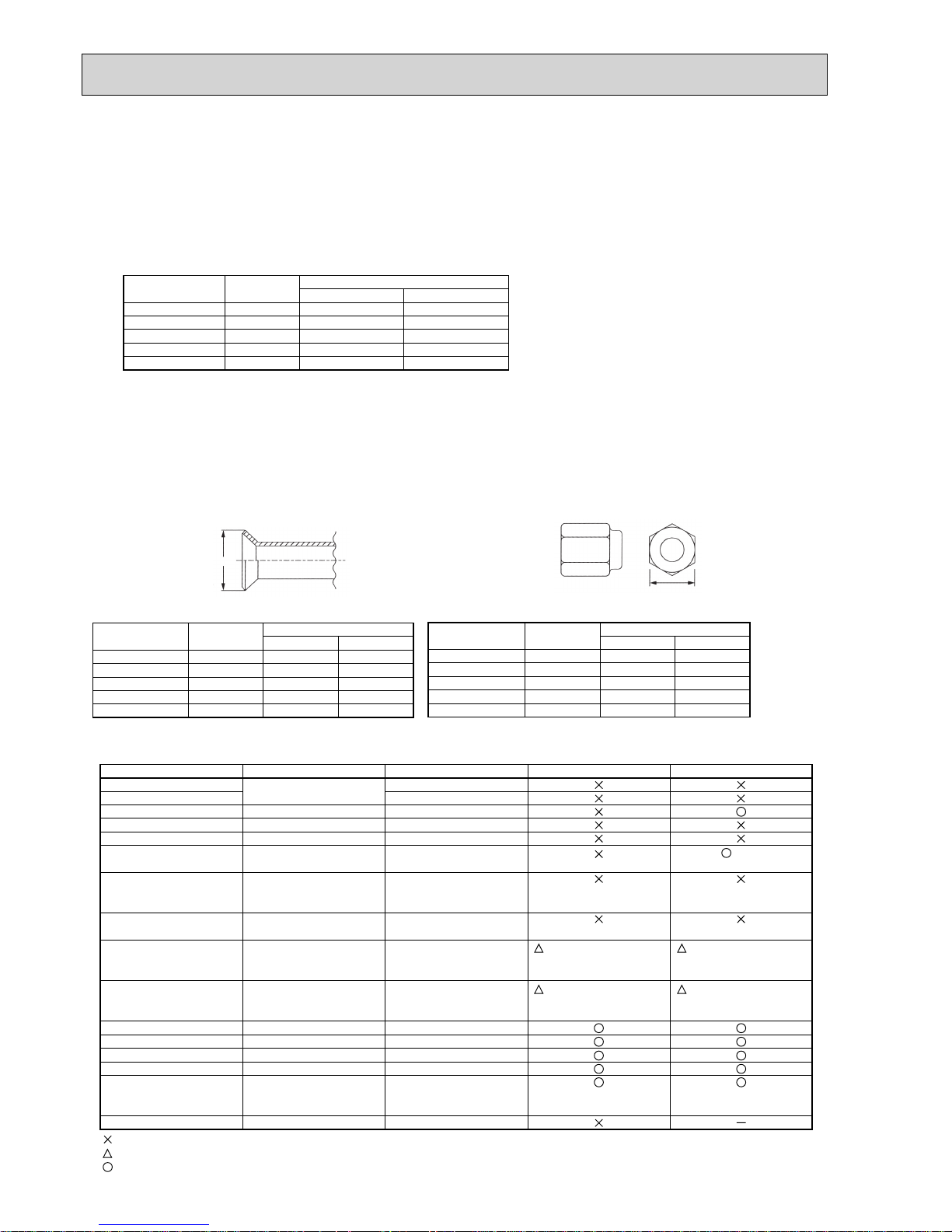
Cautions for refrigerant piping work
New refrigerant R410A is adopted for replacement inverter series. Although the refrigerant piping work for R410A is same
as for R22, exclusive tools are necessary so as not to mix with different kind of refrigerant. Furthermore, as the working
pressure of R410A is 1.6 times higher than that of R22, their sizes of flared sections and flare nuts are different.
1 Thickness of pipes
Because the working pressure of R410A is higher compared to R22, be sure to use refrigerant piping with thickness shown
below. (Never use pipes of 0.7 mm or below.)
2 Dimensions of flare cutting and flare nut
The component molecules in HFC refrigerant are smaller compared to conventional refrigerants. In addition to that,
R410A is a refrigerant, which has higher risk of leakage because its working pressure is higher than that of other refrigerants. Therefore, to enhance airtightness and intensity, flare cutting dimension of copper pipe for R410A have been specified separately from the dimensions for other refrigerants as shown below. The dimension B of flare nut for R410A also
have partly been changed to increase intensity as shown below. Set copper pipe correctly referring to copper pipe flaring
dimensions for R410A below. For 1/2 and 5/8 inch, the dimension B changes. Use torque wrench corresponding to each
dimension.
3 Tools for R410A (The following table shows whether conventional tools can be used or not.)
1/4
3/8
1/2
5/8
3/4
6.35
9.52
12.70
15.88
19.05
0.8
0.8
0.8
1.0
—
0.8
0.8
0.8
1.0
1.0
Nominal
dimensions(inch)
Diagram below: Piping diameter and thickness
Outside
diameter
(mm)
Thickness
(mm)
R410A R22
1/4
3/8
1/2
5/8
3/4
6.35
9.52
12.70
15.88
19.05
9.1
13.2
16.6
19.7
—
9.0
13.0
16.2
19.4
23.3
Nominal
dimensions(inch)
Flare cutting dimensions
Outside
diameter
Dimension A
( )
+0
-0.4
(mm)
R410A R22
1/4
3/8
1/2
5/8
3/4
6.35
9.52
12.70
15.88
19.05
17.0
22.0
26.0
29.0 *
—
17.0
22.0
24.0
27.0
36.0
Nominal
dimensions(inch)
Flare nut dimensions
Outside
diameter
Dimension B
(mm)
R410A
* 36.0mm for
indoor unit
of RP100,
125 and 140
R22
Gauge manifold
Charge hose
Gas leak detector
Refrigerant recovery equipment
Refrigerant cylinder
Applied oil
Safety charger
Charge valve
Vacuum pump
Flare tool
Bender
Pipe cutter
Welder and nitrogen gas cylinder
Refrigerant charging scale
Vacuum gauge or thermistor vacuum gauge and
vacuum valve
Charging cylinder
Air purge, refrigerant charge and
Operation check
Gas leak check
Refrigerant recovery
Refrigerant charge
Apply to flared section
Prevent compressor malfunction
when charging refrigerant by
spraying liquid refrigerant
Prevent gas from blowing out
when detaching charge hose
Vacuum drying and air
purge
Flaring work of piping
Bend the pipes
Cut the pipes
Weld the pipes
Refrigerant charge
Check the degree of vacuum. (Vacuum
valve prevents back flow of oil and refrigerant to thermistor vacuum gauge)
Refrigerant charge
Tool exclusive for R410A
Tool exclusive for R410A
Tool for HFC refrigerant
Tool exclusive for R410A
Tool exclusive for R410A
Ester oil and alkylbenzene
oil (minimum amount)
Tool exclusive for R410A
Tool exclusive for R410A
Tools for other refrigerants can
be used if equipped with adopter for reverse flow check
Tools for other refrigerants
can be used by adjusting
flaring dimension
Tools for other refrigerants can be used
Tools for other refrigerants can be used
Tools for other refrigerants can be used
Tools for other refrigerants can be used
Tools for other refrigerants
can be used
Tool exclusive for R410A
Tools and materials Use R410A tools Can R22 tools be used?
(Usable if equipped
with adopter for rever se flow)
(Usable by adjusting
flaring dimension)
Can R407C tools be used?
Ester oil:
Alkylbenzene oil: minimum amount
(Usable if equipped
with adopter for rever se flow)
(Usable by adjusting
flaring dimension)
: Prepare a new tool. (Use the new tool as the tool exclusive for R410A.)
: Tools for other refrigerants can be used under certain conditions.
: Tools for other refrigerants can be used.
Dimension A
Dimension B
OCH415F
7
4 FEATURES
CHARGELESS SYSTEM
PRE-CHARGED REFRIGERANT IS SUPPLIED FOR PIPING LENGTH AT SHIPMENT.
(Max. 30m (PUHZ-P125/P140))
The refrigerant circuit with LEV (Linear Expansion Valve) and Accumulator always control the optimal refrigerant level regardless
of the length (30m max. and 5m min.) of piping. The additional refrigerant charging work during installation often causes problems. Heretofore it is completely eliminated. This unique system improves the quality and reliability of the work done. It also helps
to speed up the installation time.
PUHZ-P100VHA2.UK
PUHZ-P100VHA3.UK
PUHZ-P125VHA2.UK
PUHZ-P140VHA2.UK
PUHZ-P125VHA21.UK
PUHZ-P140VHA2
1.UK
PUHZ-P100VHA3R1.UK
PUHZ-P100VHA3R2.UK
PUHZ-P100VHA4.UK
PUHZ-P100YHA.UK
PUHZ-P100YHAR1.UK
PUHZ-P100YHA2.UK
PUHZ-P125VHA3R1.UK
PUHZ-P140VHA3R1.UK
PUHZ-P125VHA3R2.UK
PUHZ-P140VHA3R2.UK
PUHZ-P125VHA3R3.UK
PUHZ-P140VHA3R3.UK
PUHZ-P125YHA.UK
PUHZ-P140YHA.UK
PUHZ-P125YHAR1.UK
PUHZ-P140YHAR1.UK
PUHZ-P125YHAR2.UK
PUHZ-P140YHAR2.UK
OCH415F
8
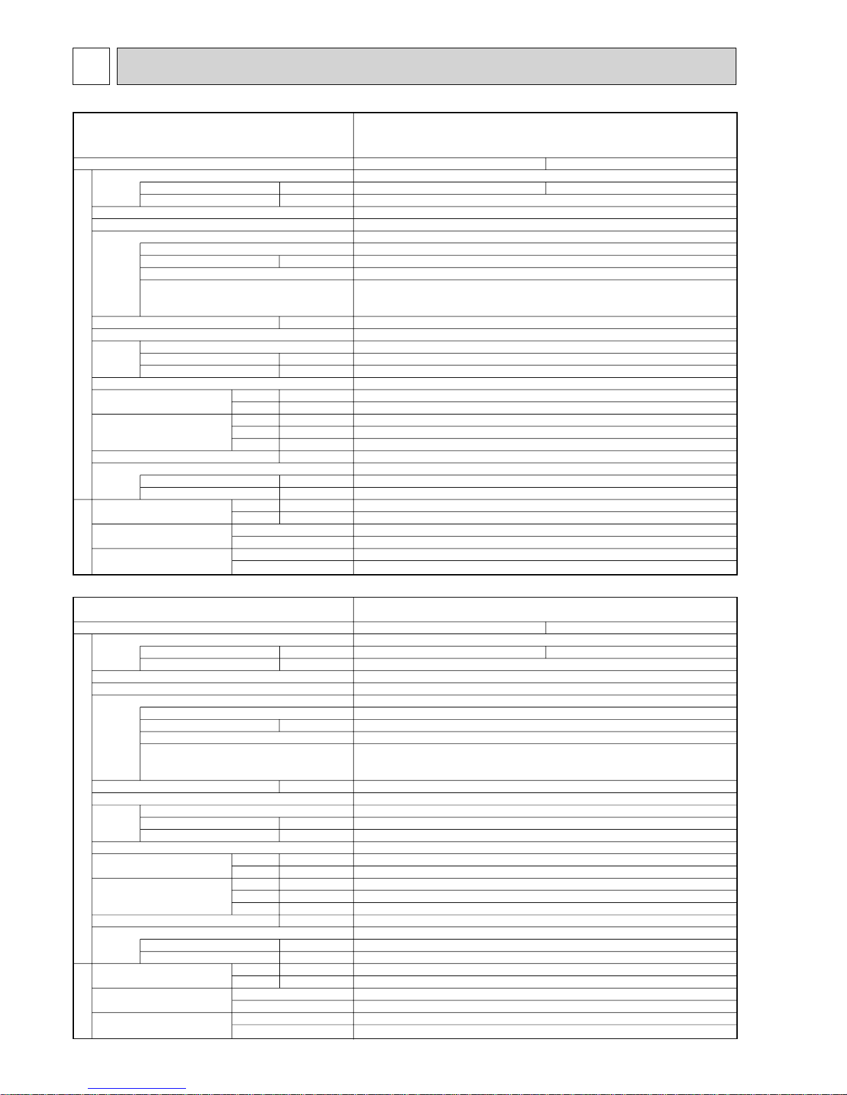
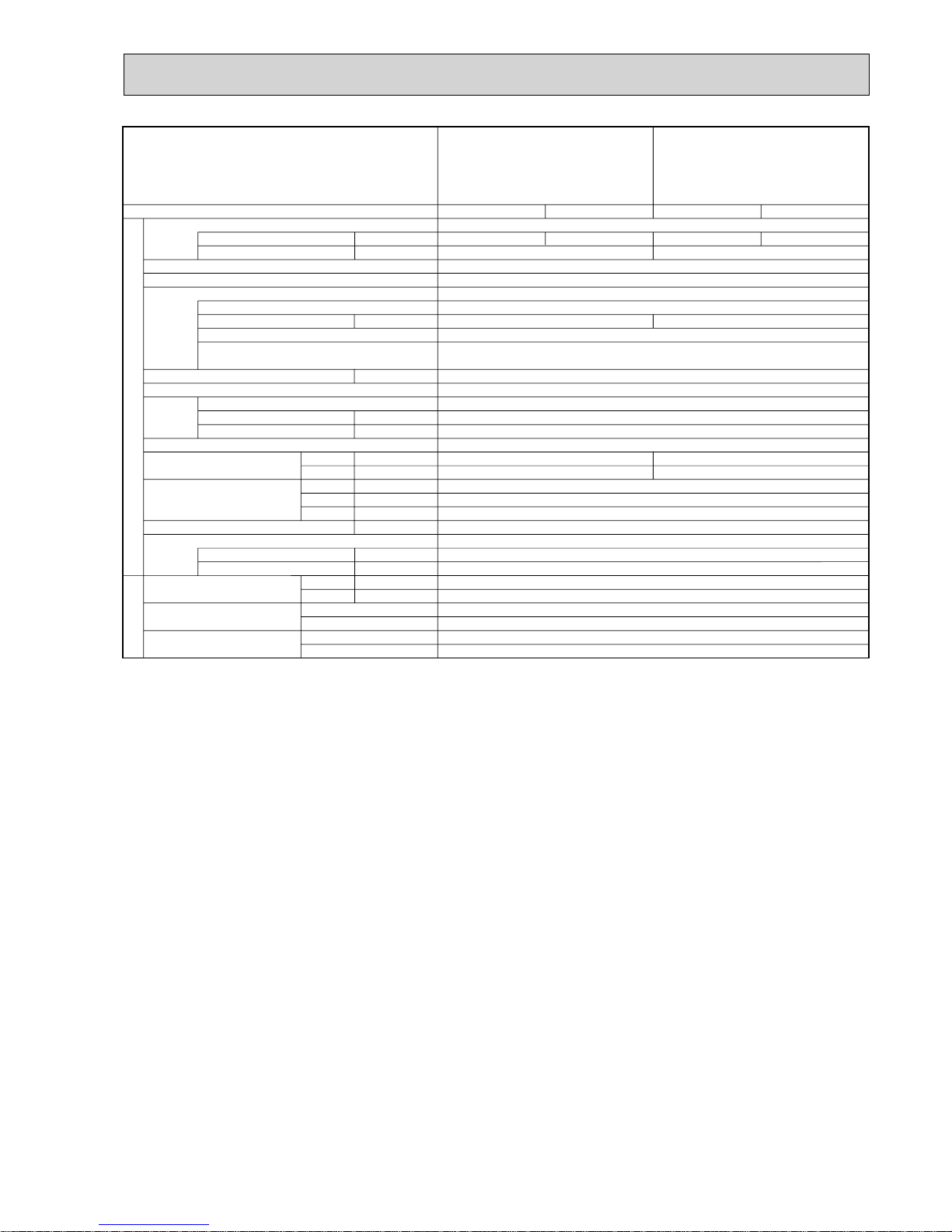
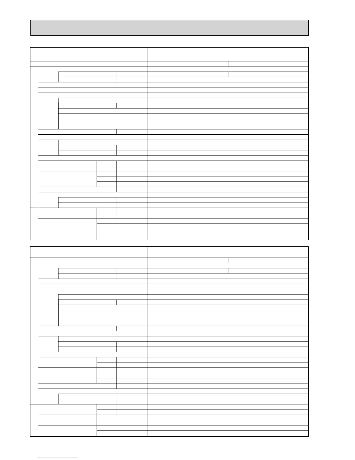
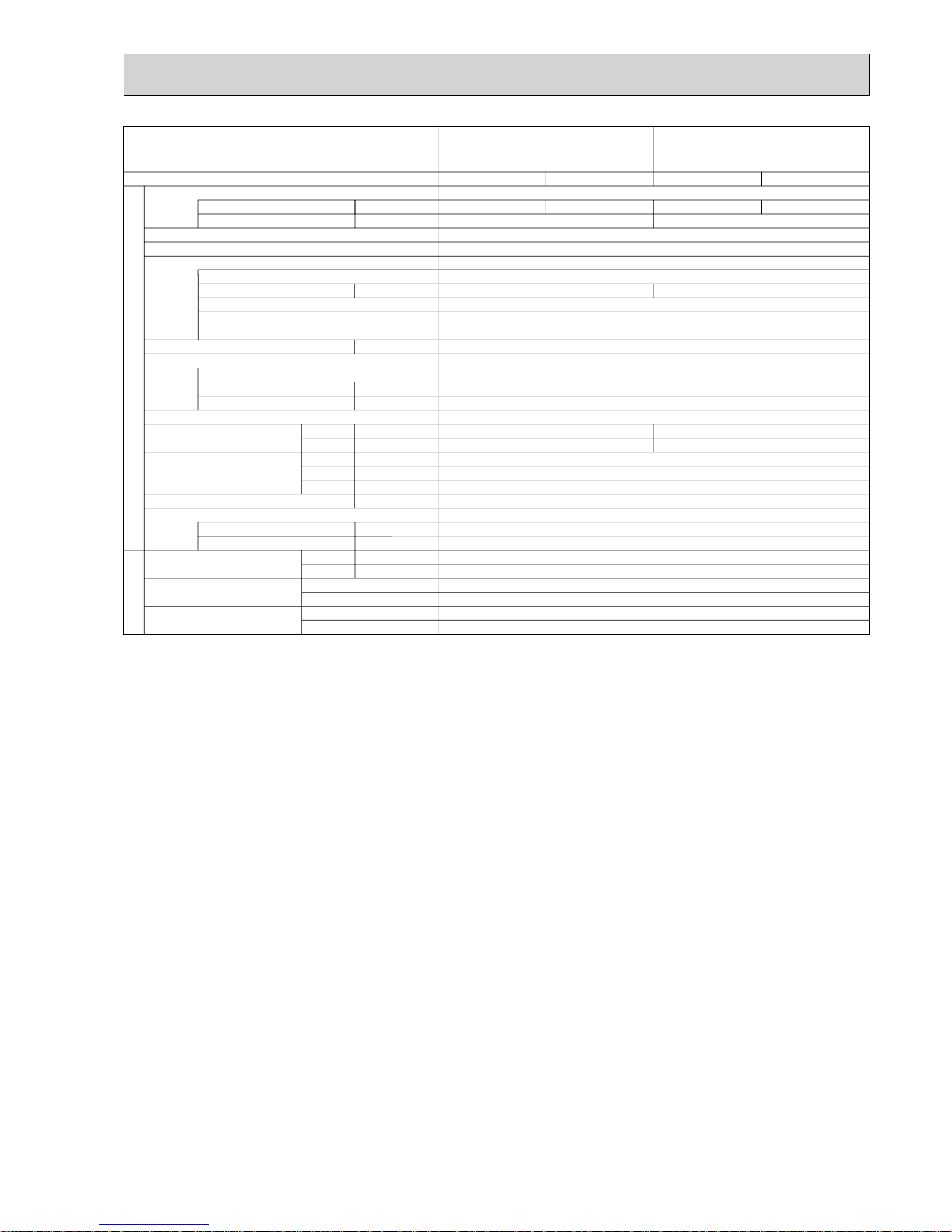
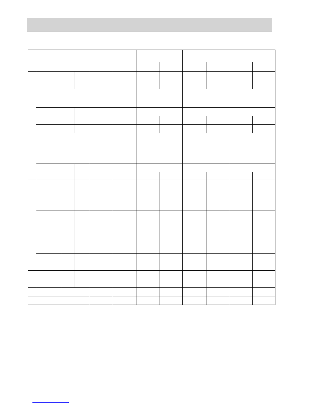
5 SPECIFICATIONS
A
A
kW
W
kW
*
/min(CFM
)
dB
dB
mm(in.)
mm(in.)
mm(in.)
kg(lbs)
kg(lbs)
L
mm(in.)
mm(in.)
Power supply (phase, cycle, voltage)
Running current
Max. current
External finish
Refrigerant control
Compressor
Model
Motor output
Starter type
Protection devices
Crankcase heater
Heat exchanger
Fan Fan(drive) % No.
Fan motor output
Airflow
Defrost method
Noise level
Dimensions
Weight
Refrigerant
Charge
Oil (Model)
Pipe size O.D.
Connection method
Between the indoor &
outdoor unit
Mode
Cooling
Heating
W
D
H
Liquid
Gas
Indoor side
Outdoor side
Height difference
Piping length
Service Ref.
PUHZ-P100VHA2.UK
PUHZ-P100VHA3.UK
PUHZ-P100VHA3R1.UK
PUHZ-P100VHA3R2.UK
Cooling
12.26
Munsell 5Y 7/1 / Munsell 3Y 7.8/1.1 (VHA3R1 / R2)
Linear Expansion Valve
Hermetic
TNB220FLHMT
2.9
Inverter
—
Plate fin coil
Propeller fan % 1
0.060
60(2120)
Reverse cycle
50
54
950(37-3/8)
330+30(13+1-3/16)
943(37-1/8)
75(165)
R410A
3.0(6.6)
0.87(FV50S)
9.52(3/8)
15.88(5/8)
Flared
Flared
Max. 30m
Max. 50m
Heating
12.62
HP switch
Discharge thermo/Comp. surface thermo (VHA3R2)
Single, 50Hz, 230V
OUTDOOR UNIT
REFRIGERANT PIPING
28
A
A
kW
W
kW
*
/min(CFM
)
dB
dB
mm(in.)
mm(in.)
mm(in.)
kg(lbs)
kg(lbs)
L
mm(in.)
mm(in.)
Power supply (phase, cycle, voltage)
Running current
Max. current
External finish
Refrigerant control
Compressor
Model
Motor output
Starter type
Protection devices
Crankcase heater
Heat exchanger
Fan Fan(drive) % No.
Fan motor output
Airflow
Defrost method
Noise level
Dimensions
Weight
Refrigerant
Charge
Oil (Model)
Pipe size O.D.
Connection method
Between the indoor &
outdoor unit
Mode
Cooling
Heating
W
D
H
Liquid
Gas
Indoor side
Outdoor side
Height difference
Piping length
Service Ref. PUHZ-P100VHA4.UK
Cooling
13.98
Munsell 3Y 7.8/1.1
Linear Expansion Valve
Hermetic
TNB220FLHMT
2.9
Inverter
—
Plate fin coil
Propeller fan % 1
0.060
60(2120)
Reverse cycle
50
54
950(37-3/8)
330+30(13+1-3/16)
943(37-1/8)
75(165)
R410A
3.0(6.6)
0.87(FV50S)
9.52(3/8)
15.88(5/8)
Flared
Flared
Max. 30m
Max. 50m
Heating
14.70
HP switch
Comp. surface thermo
Single, 50Hz, 230V
OUTDOOR UNIT
REFRIGERANT PIPING
28
OCH415F
9
A
A
kW
W
kW
*
/min(CFM
)
dB
dB
mm(in.)
mm(in.)
mm(in.)
kg(lbs)
kg(lbs)
L
mm(in.)
mm(in.)
Power supply (phase, cycle, voltage)
Running current
Max. current
External finish
Refrigerant control
Compressor
Model
Motor output
Starter type
Protection devices
Crankcase heater
Heat exchanger
Fan Fan(drive) % No.
Fan motor output
Airflow
Defrost method
Noise level
Dimensions
Weight
Refrigerant
Charge
Oil (Model)
Pipe size O.D.
Connection method
Between the indoor &
outdoor unit
Mode
Cooling
Heating
W
D
H
Liquid
Gas
Indoor side
Outdoor side
Height difference
Piping length
Service Ref.
PUHZ-P140VHA2.UK
PUHZ-P140VHA2
1.UK
PUHZ-P140VHA3.UK
PUHZ-P140VHA3R1.UK
PUHZ-P140VHA3R2.UK
PUHZ-P140VHA3R3.UK
PUHZ-P125VHA2.UK
PUHZ-P125VHA2
1.UK
PUHZ-P125VHA3.UK
PUHZ-P125VHA3R1.UK
PUHZ-P125VHA3R2.UK
PUHZ-P125VHA3R3.UK
Cooling
17.37
Munsell 5Y 7/1 / Munsell 3Y 7.8/1.1 (VHA3R1/R2/R3)
Linear Expansion Valve
Hermetic
TNB306FPGM/TNB306FPGMT (VHA3R3)
Inverter
30
Plate fin coil
Propeller fan % 2
0.060+0.060
100(3,530)
Reverse cycle
950(37-3/8)
330+30(13+1-3/16)
1,350(53-1/8)
99(218)
R410A
4.5(9.9)
0.87(FV50S)
9.52(3/8)
15.88(5/8)
Flared
Flared
Max. 30m
Max. 50m
Heating
16.74
Cooling
22.48
29.5
3.9
Heating
21.31
HP switch
Discharge thermo/Comp. surface thermo (VHA3R2/R3)
Single 50Hz, 230V
OUTDOOR UNIT
REFRIGERANT PIPING
3.4
28
52
56
51
55
OCH415F
10
A
A
kW
W
kW
*
/min(CFM
)
dB
dB
mm(in.)
mm(in.)
mm(in.)
kg(lbs)
kg(lbs)
L
mm(in.)
mm(in.)
Power supply (phase, cycle, voltage)
Running current
Max. current
External finish
Refrigerant control
Compressor
Model
Motor output
Starter type
Protection devices
Crankcase heater
Heat exchanger
Fan Fan(drive) % No.
Fan motor output
Airflow
Defrost method
Noise level
Dimensions
Weight
Refrigerant
Charge
Oil (Model)
Pipe size O.D.
Connection method
Between the indoor &
outdoor unit
Mode
Cooling
Heating
W
D
H
Liquid
Gas
Indoor side
Outdoor side
Height difference
Piping length
Service Ref.
PUHZ-P100YHA.UK
PUHZ-P100YHAR1.UK
Cooling
4.78
Munsell 3Y 7.8/1.1
Linear Expansion Valve
Hermetic
TNB220FLCMT
2.9
Inverter
—
Plate fin coil
Propeller fan % 1
0.060
60(2120)
Reverse cycle
50
54
950(37-3/8)
330+30(13+1-3/16)
943(37-1/8)
77(170)
R410A
3.0(6.6)
0.87(FV50S)
9.52(3/8)
15.88(5/8)
Flared
Flared
Max. 30m
Max. 50m
Heating
5.05
HP switch
Discharge thermo/Comp. surface thermo (YHAR1)
3phase, 50Hz, 400V
OUTDOOR UNIT
REFRIGERANT PIPING
13
A
A
kW
W
kW
*
/min(CFM
)
dB
dB
mm(in.)
mm(in.)
mm(in.)
kg(lbs)
kg(lbs)
L
mm(in.)
mm(in.)
Power supply (phase, cycle, voltage)
Running current
Max. current
External finish
Refrigerant control
Compressor
Model
Motor output
Starter type
Protection devices
Crankcase heater
Heat exchanger
Fan Fan(drive) % No.
Fan motor output
Airflow
Defrost method
Noise level
Dimensions
Weight
Refrigerant
Charge
Oil (Model)
Pipe size O.D.
Connection method
Between the indoor &
outdoor unit
Mode
Cooling
Heating
W
D
H
Liquid
Gas
Indoor side
Outdoor side
Height difference
Piping length
Service Ref. PUHZ-P100YHA2.UK
Cooling
5.00
Munsell 3Y 7.8/1.1
Linear Expansion Valve
Hermetic
TNB220FLCMT
2.9
Inverter
—
Plate fin coil
Propeller fan % 1
0.060
60(2120)
Reverse cycle
50
54
950(37-3/8)
330+30(13+1-3/16)
943(37-1/8)
77(170)
R410A
3.0(6.6)
0.87(FV50S)
9.52(3/8)
15.88(5/8)
Flared
Flared
Max. 30m
Max. 50m
Heating
5.26
HP switch
Comp. surface thermo
3phase, 50Hz, 400V
OUTDOOR UNIT
REFRIGERANT PIPING
13
OCH415F
11
A
A
kW
W
kW
*
/min(CFM
)
dB
dB
mm(in.)
mm(in.)
mm(in.)
kg(lbs)
kg(lbs)
L
mm(in.)
mm(in.)
Power supply (phase, cycle, voltage)
Running current
Max. current
External finish
Refrigerant control
Compressor
Model
Motor output
Starter type
Protection devices
Crankcase heater
Heat exchanger
Fan Fan(drive) % No.
Fan motor output
Airflow
Defrost method
Noise level
Dimensions
Weight
Refrigerant
Charge
Oil (Model)
Pipe size O.D.
Connection method
Between the indoor &
outdoor unit
Mode
Cooling
Heating
W
D
H
Liquid
Gas
Indoor side
Outdoor side
Height difference
Piping length
Service Ref.
PUHZ-P140YHA.UK
PUHZ-P140YHAR1.UK
PUHZ-P140YHAR2.UK
PUHZ-P125YHA.UK
PUHZ-P125YHAR1.UK
PUHZ-P125YHAR2.UK
Cooling
6.18
Munsell 3Y 7.8/1.1
Linear Expansion Valve
Hermetic
TNB306FPNM/TNB306FPNMT (YHAR2)
Inverter
30
Plate fin coil
Propeller fan % 2
0.060+0.060
100(3,530)
Reverse cycle
950(37-3/8)
330+30(13+1-3/16)
1,350(53-1/8)
101(223)
R410A
4.5(9.9)
0.87(FV50S)
9.52(3/8)
15.88(5/8)
Flared
Flared
Max. 30m
Max. 50m
Heating
6.09
Cooling
7.92
13
3.9
Heating
7.58
HP switch
Discharge thermo/Comp. surface thermo (YHAR1/R2)
3phase, 50Hz, 400V
OUTDOOR UNIT
REFRIGERANT PIPING
3.4
13
52
56
51
55
OCH415F
12
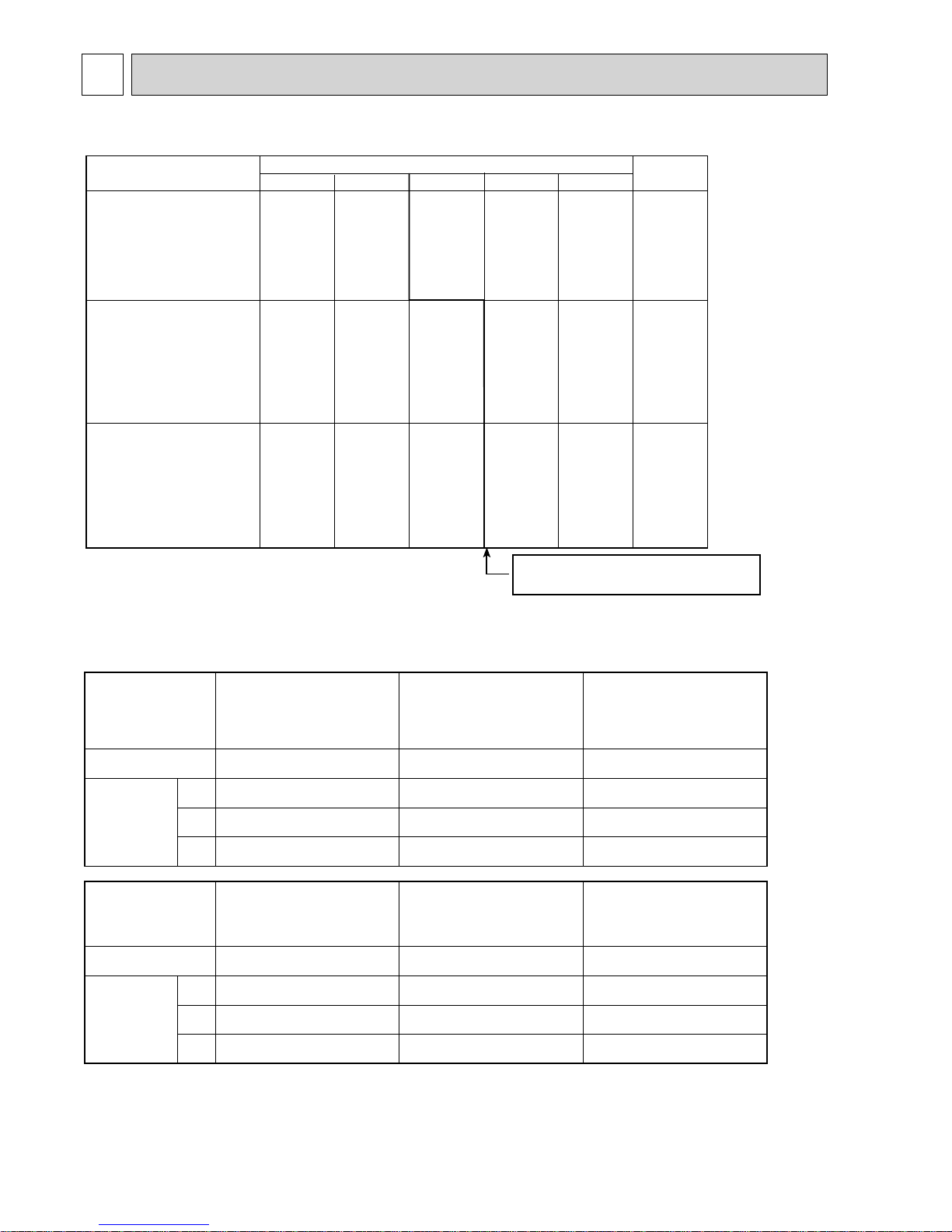
6 DATA
6-1. REFILLING REFRIGERANT CHARGE (R410A : kg)
6-2. COMPRESSOR TECHNICAL DATA
Piping length (one way)
10m
20m
30m
40m
50m
Initial
charged
2.9
4.3
4.3
3.0
4.4
4.4
3.6
4.5
4.5
4.2
5.1
5.1
4.8
5.7
5.7
3.0
4.5
4.5
Service Ref.
PUHZ-P100VHA2.UK
PUHZ-P100VHA3.UK
PUHZ-P100VHA3R1.UK
PUHZ-P100VHA3R2.UK
PUHZ-P100VHA4.UK
PUHZ-P100YHA.UK
PUHZ-P100YHAR1.UK
PUHZ-P100YHA2.UK
PUHZ-P125VHA2.UK
PUHZ-P125VHA2
1.UK
PUHZ-P125VHA3.UK
PUHZ-P125VHA3R1.UK
PUHZ-P125VHA3R2.UK
PUHZ-P125VHA3R3.UK
PUHZ-P125YHA.UK
PUHZ-P125YHAR1.UK
PUHZ-P125YHAR2.UK
PUHZ-P140VHA2.UK
PUHZ-P140VHA2
1.UK
PUHZ-P140VHA3.UK
PUHZ-P140VHA3R1.UK
PUHZ-P140VHA3R2.UK
PUHZ-P140VHA3R3.UK
PUHZ-P140YHA.UK
PUHZ-P140YHAR1.UK
PUHZ-P140YHAR2.UK
U-V
U-W
W-V
Service Ref.
Compressor model
Winding
Resistance
( )
TNB306FPGM
(at 20˚C)
0.53
0.53
0.53
TNB306FPGMT
0.53
0.53
0.53
PUHZ-P125,140VHA2.UK
PUHZ-P125,140VHA2
1.UK
PUHZ-P125,140VHA3.UK
PUHZ-P125,140VHA3R1.UK
PUHZ-P125,140VHA3R2.UK
TNB220FLHMT
0.88
0.88
0.88
PUHZ-P100VHA2.UK
PUHZ-P100VHA3.UK
PUHZ-P100VHA3R1.UK
PUHZ-P100VHA3R2.UK
PUHZ-P100VHA4.UK
U-V
U-W
W-V
Service Ref.
Compressor model
Winding
Resistance
( )
TNB306FPNM
1.02
1.02
1.02
TNB306FPNMT
1.02
1.02
1.02
PUHZ-P125YHA.UK
PUHZ-P140YHA.UK
PUHZ-P125YHAR1.UK
PUHZ-P140YHAR1.UK
TNB220FLCMT
1.41
1.41
1.41
PUHZ-P100YHA.UK
PUHZ-P100YHAR1.UK
PUHZ-P100YHA2.UK
PUHZ-P125,140VHA3R3.UK
PUHZ-P140YHAR2.UK
Additional charge is required for pipes
longer than 20 or 30m.
OCH415F
13
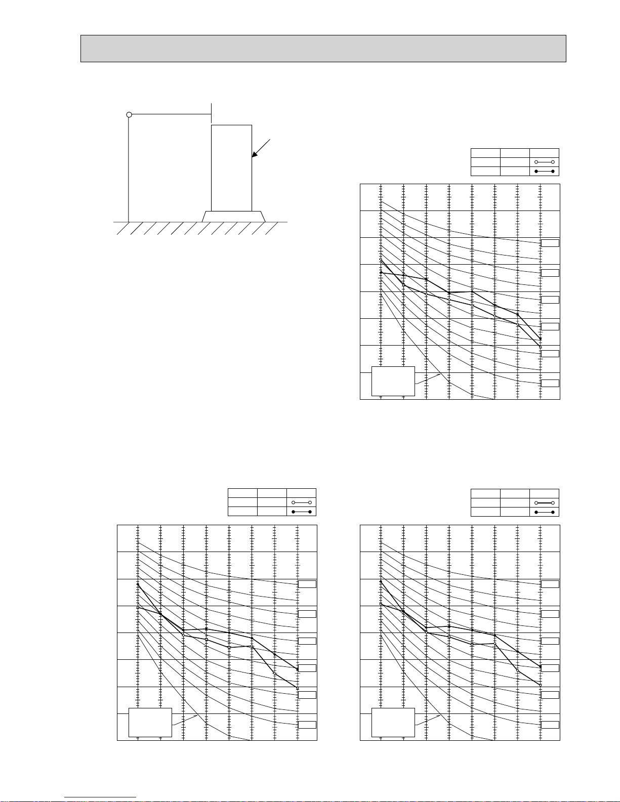
6-3. NOISE CRITERION CURVES
1.5m
1m
MICROPHONE
UNIT
GROUND
90
80
70
60
50
40
30
20
10
63 125 250 500 1000 2000 4000 8000
APPROXIMATE
THRESHOLD OF
HEARING FOR
CONTINUOUS
NOISE
NC-60
NC-50
NC-40
NC-30
NC-20
NC-70
OCTAVE BAND SOUND PRESSURE LEVEL, dB (0 dB = 0.0002 μbar)
PUHZ-P100VHA2.UK
PUHZ-P100VHA3.UK
PUHZ-P100VHA3R1.UK
PUHZ-P100VHA3R2.UK
PUHZ-P100VHA4.UK
PUHZ-P100YHA.UK
PUHZ-P100YHAR1.UK
PUHZ-P100YHA2.UK
COOLING
MODE
HEATING
50
SPL(dB)
54
LINE
90
80
70
60
50
40
30
20
10
63 125 250 500 1000 2000 4000 8000
APPROXIMATE
THRESHOLD OF
HEARING FOR
CONTINUOUS
NOISE
OCTAVE BAND SOUND PRESSURE LEVEL, dB (0 dB = 0.0002 μbar)
BAND CENTER FREQUENCIES, Hz
NC-60
NC-50
NC-40
NC-30
NC-20
NC-70
PUHZ-P125VHA2.UK
PUHZ-P125VHA21.UK
PUHZ-P125VHA3.UK
PUHZ-P125VHA3R1.UK
PUHZ-P125VHA3R2.UK
PUHZ-P125VHA3R3.UK
PUHZ-P125YHA.UK
PUHZ-P125YHAR1.UK
PUHZ-P125YHAR2.UK
COOLING
MODE
HEATING
51
SPL(dB)
55
LINE
90
80
70
60
50
40
30
20
10
63 125 250 500 1000 2000 4000 8000
APPROXIMATE
THRESHOLD OF
HEARING FOR
CONTINUOUS
NOISE
OCTAVE BAND SOUND PRESSURE LEVEL, dB (0 dB = 0.0002 μbar)
BAND CENTER FREQUENCIES, Hz
NC-60
NC-50
NC-40
NC-30
NC-20
NC-70
PUHZ-P140VHA2.UK
PUHZ-P140VHA21.UK
PUHZ-P140VHA3.UK
PUHZ-P140VHA3R1.UK
PUHZ-P140VHA3R2.UK
PUHZ-P140VHA3R3.UK
PUHZ-P140YHA.UK
PUHZ-P140YHAR1.UK
PUHZ-P140YHAR2.UK
COOLING
MODE
HEATING
52
SPL(dB)
56
LINE
OCH415F
14
6-4. STANDARD OPERATION DATA
The unit of pressure has been changed to MPa based on international SI system.
The conversion factor is : 1 (MPa) = 10.2 (kgf/cm²)
TotalElectrical circuitRefrigerant circuitIndoor side
Outdoor
side
Representative matching
SHF
BF
W
kW
Mode
Capacity
Input
Phase , Hz
Volts
Input
Amperes
Outdoor unit
Phase , Hz
Volts
Current
Discharge pressure
Suction pressure
Discharge temperature
Condensing temperature
Suction temperature
Ref. pipe length
Intake air
temperature
Discharge air
temperature
Intake air
temperature
V
kW
A
V
A
MPa
(.f/%)
MPa
(.f/%)
°C
°C
°C
m
°C
°C
°C
°C
°C
Indoor unit
D.B.
W.B.
D.B.
D.B.
W.B.
PLA-RP100BA PLA-RP125BA PLA-RP140BA(2)
PLA-RP100BA
PLA-RP100BA
PLA-RP100BA PLA-RP125BA PLA-RP140BA(2)
Cooling
9,400
3.12
Heating
11,200
3.28
Cooling
9,400
3.12
Heating
11,200
3.28
Cooling
12,300
4.09
Heating
14,000
4.11
Cooling
13,600
5.21
Heating
16,000
4.98
12.26 / 4.78
2.90
(29.6)
0.92
(9.4)
72.7
48.6
10.1
5
27
19
14.8
35
24
0.74
0.21
12.62 / 5.05
2.57
(26.2)
0.62
(6.3)
75.5
41.4
0.1
5
20
15
43.4
7
6
—
—
13.98 / 5.00
2.90
(29.6)
0.92
(9.4)
72.7
48.6
10.1
5
27
19
14.8
35
24
0.74
0.21
14.70 / 5.26
2.57
(26.2)
0.62
(6.3)
75.5
41.4
0.1
5
20
15
43.4
7
6
—
—
17.37 / 6.18
2.68
(27.3)
0.86
(8.8)
67.8
45.5
6.8
5
27
19
13.6
35
24
0.71
0.18
16.74 / 6.09
2.56
(26.1)
0.68
(6.9)
64.5
43.4
1.3
5
20
15
44.2
7
6
—
—
22.48 / 7.92
2.79
(28.5)
0.79
(8.1)
72.7
47.0
4.4
5
27
19
12.9
35
24
0.71
0.14
21.31 / 7.58
2.75
(28.1)
0.64
(6.5)
70.8
47.2
1.0
5
20
15
48.0
7
6
—
—
1 , 50
230
1/3 , 50
230 / 400
1 , 50
230
1 /3, 50
230 / 400
1 , 50
230
1 /3, 50
230 / 400
PUHZ-P100VHA2
PUHZ-P100VHA3
PUHZ-P100YHA
PUHZ-P100VHA4
PUHZ-P100YHA2
PUHZ-P125VHA2
PUHZ-P125VHA3
PUHZ-P125YHA
PUHZ-P140VHA2
PUHZ-P140VHA3
PUHZ-P140YHA
0.14
0.94
0.13
0.87
1 , 50
230
1/3 , 50
230 / 400
0.14
0.94
0.13
0.87
0.15
1.00
0.14
0.94
0.16
1.07
0.15
1.00
OCH415F
15
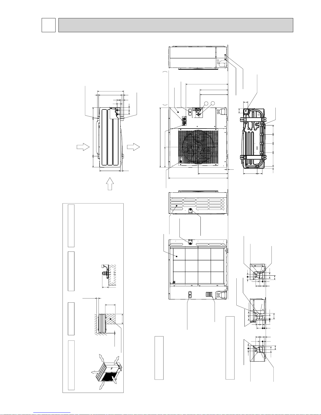
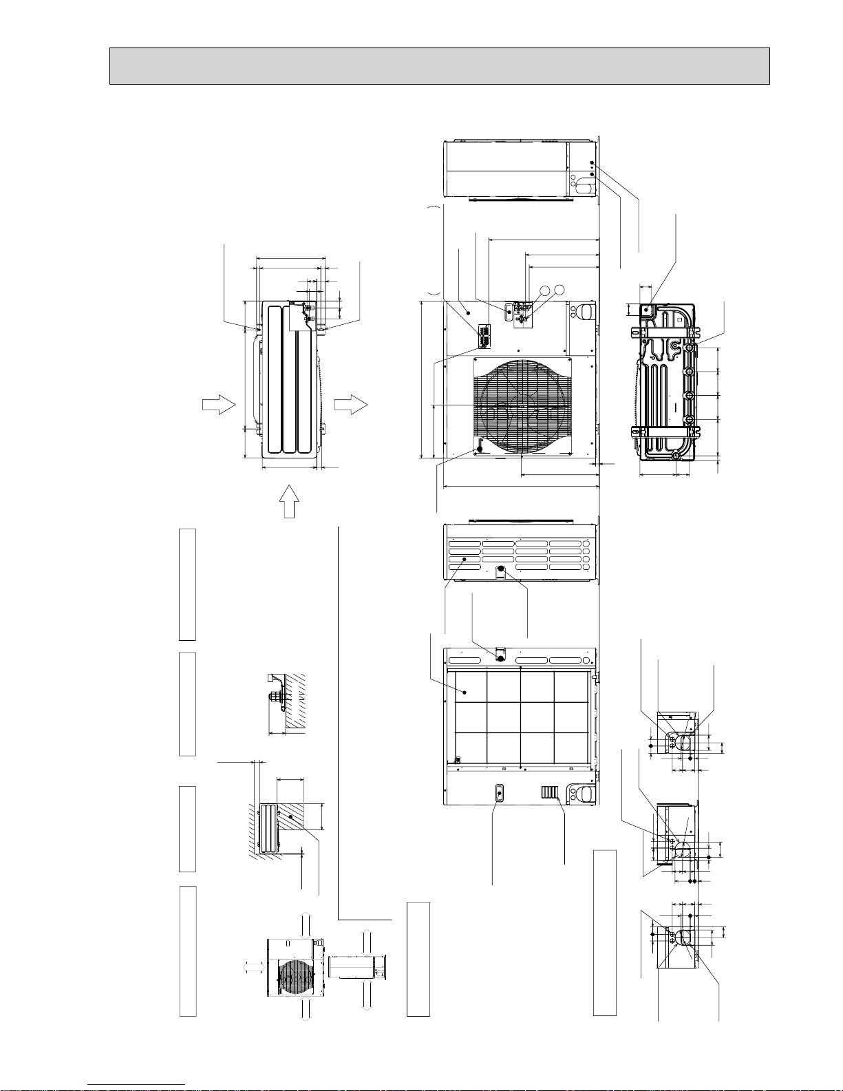
7 OUTLINES AND DIMENSIONS
417
66 42
45
56
(19)37028
53
175600175
330
2-12%36 oval holes
(Foundation Bolt M10)
Air Discharge
Rear Air Intake
Side Air Intake
2-U Shaped notched holes
(Foundation Bolt M10)
Installation Feet
30
Over
Over
Less than
Piping and wiring connections
can be made from 4 directions:
front, right rear and below.
4 PIPING-WIRING DIRECTIONS
3 FOUNDATION BOLTS2 SERVICE SPACE
1 FREE SPACE (Around the unit)
Piping Knockout Hole Details
Example of Notes
···Refrigerant GAS pipe connection (FLARE)W15.88(5/8 inch)
···Refrigerant LIQUID pipe connection (FLARE)W 9.52(3/8 inch)
+1 ···Indication of STOP VALVE connection location.
The diagram below shows a
basic example.
Explanation of particular details is
given in the installation manuals etc.
Over10
500
500
Over100
Dimensions of space needed
for service access are
shown in the below diagram.
Service space
30
Please secure the unit firmly
with 4 foundation (M10) bolts.
(Bolts and washers must be
purchased locally.)
<Foundation bolt height>
Handle for moving
Side Air Intake
Front piping cover
Rear piping cover
14522030 145
81 219
145
71
71
Drain hole
(5-W33)
Bottom piping hole
(Knockout)
Air Intake
Rear Air Intake
Handle for moving
Handle for moving
23
943
473
950
322
+1 447
+1 443
670
Terminal Connections
Left···Power supply wiring
Right···Indoor/Outdoor wiring
Earth terminal
Service panel
Handle for moving
Handle for moving
1
2
19 55
23 27 92
92
4075
73 63
Right piping hole
(Knockout)
Right trunking hole
(Knockout)
Power supply wiring hole
(2-W27Knockout)
W
92
27 55
7323 63
40
92
65
45
Front piping hole
(Knockout)
Front trunking hole
(Knockout)
Power supply wiring hole
(2-W27Knockout)
W
92
4045
65
92
27 55
23
73 63
Rear piping hole
(Knockout)
Rear trunking hole
(Knockout)
Power supply wiring hole
(2-W27Knockout)
W
92
FOUNDATION
Over 10mm
Over 10mm
Over 500mm
Over 100mm
FREE
Unit : mm
OUTDOOR UNIT
PUHZ-P100VHA2.UK
PUHZ-P100VHA3.UK
OCH415F
16
Less than
Over
Over
Over
Over
Handle for moving
Side Air Intake
Front piping cover
Rear piping cover
Air intake
Rear Air Intake
Handle for moving
Handle for moving
Terminal connection
Left···Power supply wiring
Right···Indoor/Outdoor wiring
Earth terminal
Service panel
Handle for moving
1
2
The diagram below shows a
basic example.
Explanation of particular details is
given in the installation manuals etc.
Dimensions of space needed
for service access are
shown in the below diagram.
<Foundation bolt height>
Please secure the unit firmly
with 4 foundation (M10) bolts.
(Bolts and washers must be
purchased locally.)
Air Discharge
Rear Air Intake
Side Air Intake
···Refrigerant GAS pipe connection (FLARE)W15.88(5/8 inch)
···Refrigerant LIQUID pipe connection (FLARE)W 9.52(3/8 inch)
+1 ···Indication of STOP VALVE connection location.
Example of Notes
Piping Knockout Hole Details
1 FREE SPACE (Around the unit)
2 SERVICE SPACE
3 FOUNDATION BOLTS
4 PIPING-WIRING DIRECTIONS
Piping and wiring connections
can be made from 4 directions:
front, right, rear and below.
30
FOUNDATION
150
500
500
10
Service space
600175 175
330
417
42
66
53 56
45
(19)
28 370
2-U Shaped notched holes
(Foundation Bolt M10)
2-12 x 36 Oval holes
(Foundation Bolt M10)
Installation Feet
30
45 40
65
92
27 55
23
73 63
Rear piping hole
(Knockout)
Rear trunking hole
(Knockout)
Power supply wiring hole
(2-
W
27Knockout)
W
92
19 55
92
75 40
73 63
23
27 92
Right piping hole
(Knockout)
Right trunking hole
(Knockout)
Power supply wiring hole
(2-
W
27Knockout)
W
92
92
65
4540
27 55
23 73
63
Front piping hole
(Knockout)
Front trunking hole
(Knockout)
Power supply wiring hole
(2-
W
27Knockout)
W
92
14514522030 145
81 219
71
71
Bottom piping hole
(Knockout)
Drain hole
(5-W33)
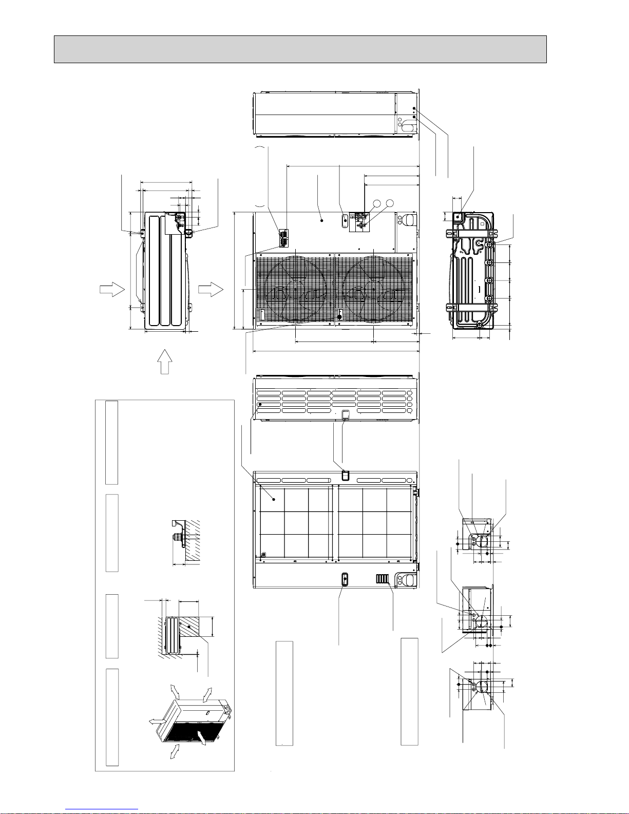
1350
23
950
1076
+1 447
+1 443
371
635
322
Handle for moving
Over 10mm
Over 10mm
Over 1000mm
Over 150mm
FREE
Unit : mm
PUHZ-P125VHA2.UK
PUHZ-P140VHA2.UK
PUHZ-P125VHA2
1.UK
PUHZ-P140VHA2
1.UK
PUHZ-P125VHA3.UK
PUHZ-P140VHA3.UK
OCH415F

17
417
66 42
45
56
(19)37028
53
175600175
330
2-12%36 oval holes
(Foundation Bolt M10)
Air Discharge
Rear Air Intake
Side Air Intake
2-U Shaped notched holes
(Foundation Bolt M10)
Installation Feet
30
Over
Over
Less than
Piping and wiring connections
can be made from 4 directions:
front, right rear and below.
4 PIPING-WIRING DIRECTIONS
3 FOUNDATION BOLTS2 SERVICE SPACE
1 FREE SPACE (Around the unit)
Piping Knockout Hole Details
Example of Notes
···Refrigerant GAS pipe connection (FLARE)W15.88(5/8 inch)
···Refrigerant LIQUID pipe connection (FLARE)W 9.52(3/8 inch)
+1 ···Indication of STOP VALVE connection location.
The diagram below shows a
basic example.
Explanation of particular details is
given in the installation manuals etc.
Over10
500
500
Over100
Dimensions of space needed
for service access are
shown in the below diagram.
Service space
30
Please secure the unit firmly
with 4 foundation (M10) bolts.
(Bolts and washers must be
purchased locally.)
<Foundation bolt height>
Handle for moving
Side Air Intake
Front piping cover
Rear piping cover
14522030 145
81 219
145
71
71
Drain hole
(5-W33)
Bottom piping hole
(Knockout)
Air Intake
Rear Air Intake
Handle for moving
Handle for moving
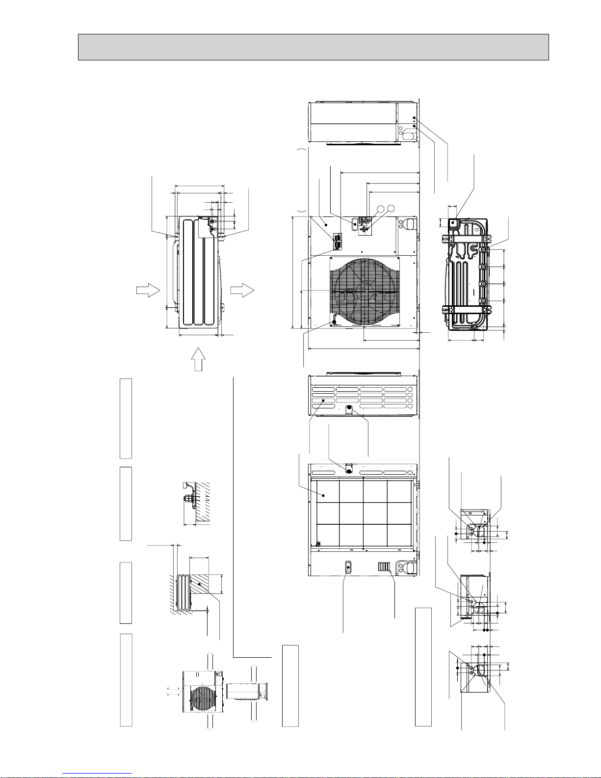
23
943
473
950
322
+1 447
+1 443
670
Terminal Connections
Left···Power supply wiring
Right···Indoor/Outdoor wiring
Earth terminal
Service panel
Handle for moving
Handle for moving
1
2
19 55
23 27 92
92
4075
73 63
Right piping hole
(Knockout)
Right trunking hole
(Knockout)
Power supply wiring hole
(2-W27Knockout)
W
92
27 55
7323 63
40
92
65
45
Front piping hole
(Knockout)
Front trunking hole
(Knockout)
Power supply wiring hole
(2-W27Knockout)
W
92
4045
65
92
27 55
23
73 63
Rear piping hole
(Knockout)
Rear trunking hole
(Knockout)
Power supply wiring hole
(2-W27Knockout)
W
92
FOUNDATION
over 100mm
over 500mm
over 10mm
FREE
over 10mm
Unit : mm
PUHZ-P100VHA3R1.UK
OCH415F

18
Less than
Over
Over
Over
Over
Handle for moving
Side Air Intake
Front piping cover
Rear piping cover
Air intake
Rear Air Intake
Handle for moving
Handle for moving
Terminal connection
Left···Power supply wiring
Right···Indoor/Outdoor wiring
Earth terminal
Service panel
Handle for moving
1
2
The diagram below shows a
basic example.
Explanation of particular details is
given in the installation manuals etc.
Dimensions of space needed
for service access are
shown in the below diagram.
<Foundation bolt height>
Please secure the unit firmly
with 4 foundation (M10) bolts.
(Bolts and washers must be
purchased locally.)
Air Discharge
Rear Air Intake
Side Air Intake
···Refrigerant GAS pipe connection (FLARE)W15.88(5/8 inch)
···Refrigerant LIQUID pipe connection (FLARE)W 9.52(3/8 inch)
+1 ···Indication of STOP VALVE connection location.
Example of Notes
Piping Knockout Hole Details
1 FREE SPACE (Around the unit)
2 SERVICE SPACE
3 FOUNDATION BOLTS
4 PIPING-WIRING DIRECTIONS
Piping and wiring connections
can be made from 4 directions:
front, right, rear and below.
30
FOUNDATION
150
500
500
10
Service space
600175 175
330
417
42
66
53 56
45
(19)
28 370
2-U Shaped notched holes
(Foundation Bolt M10)
2-12 x 36 Oval holes
(Foundation Bolt M10)
Installation Feet
30
45 40
65
92
27 55
23 73 63
Rear piping hole
(Knockout)
Rear trunking hole
(Knockout)
Power supply wiring hole
(2-
W
27Knockout)
W
92
19 55
92
75
40
73 63
23 27 92
Right piping hole
(Knockout)
Right trunking hole
(Knockout)
Power supply wiring hole
(2-
W
27Knockout)
W
92
92
65
4540
27 55
23 73
63
Front piping hole
(Knockout)
Front trunking hole
(Knockout)
Power supply wiring hole
(2-
W
27Knockout)
W
92
14514522030 145
81 219
71
71
Bottom piping hole
(Knockout)
Drain hole
(5-W33)
1350
23
950
1076
+1 447
+1 443
371 635
322
Handle for moving
Over 10mm
Over 10mm
Over 150mm
Over 1000mm
FREE
Unit : mm
PUHZ-P125VHA3R1.UK
PUHZ-P140VHA3R1.UK
OCH415F
19
PUHZ-P100VHA3R2.UK
PUHZ-P100VHA4.UK
Unit : mm
417
56 41
41
54
(19)370
28
53
175600175
330
2-12%36 oval holes
(Foundation Bolt M10)
Air Discharge
Rear Air Intake
Side Air Intake
2-U Shaped notched holes
(Foundation Bolt M10)
Installation Feet
30
Over
Over
Less than
Piping and wiring connections
can be made from 4 directions:
front, right rear and below.
4 PIPING-WIRING DIRECTIONS
3 FOUNDATION BOLTS2 SERVICE SPACE
1 FREE SPACE (Around the unit)
Piping Knockout Hole Details
Example of Notes
···Refrigerant GAS pipe connection (FLARE)W15.88(5/8 inch)
···Refrigerant LIQUID pipe connection (FLARE)W 9.52(3/8 inch)
+1 ···Indication of STOP VALVE connection location.
The diagram below shows a
basic example.
Explanation of particular details is
given in the installation manuals etc.
Over10
500
500
Over100
Dimensions of space needed
for service access are
shown in the below diagram.
Service space
30
Please secure the unit firmly
with 4 foundation (M10) bolts.
(Bolts and washers must be
purchased locally.)
<Foundation bolt height>
Handle for moving
Side Air Intake
Front piping cover
Rear piping cover
14522030 145
81 219
145
71
71
Drain hole
(5-W33)
Bottom piping hole
(Knockout)
Air Intake
Rear Air Intake
Handle for moving
Handle for moving
23
943
473
950
322
+1 447
+1 431
670
Terminal Connections
Left···Power supply wiring
Right···Indoor/Outdoor wiring
Earth terminal
Service panel
Handle for moving
Handle for moving
1
2
19 55
23 27 92
92
4075
73 63
Right piping hole
(Knockout)
Right trunking hole
(Knockout)
Power supply wiring hole
(2-W27Knockout)
W
92
27 55
73
23 63
40
92
65
45
Front piping hole
(Knockout)
Front trunking hole
(Knockout)
Power supply wiring hole
(2-W27Knockout)
W
92
4045
65
92
27 55
23 73
63
Rear piping hole
(Knockout)
Rear trunking hole
(Knockout)
Power supply wiring hole
(2-W27Knockout)
W
92
FOUNDATION
over 100mm
over 500mm
over 10mm
FREE
over 10mm
OCH415F
20
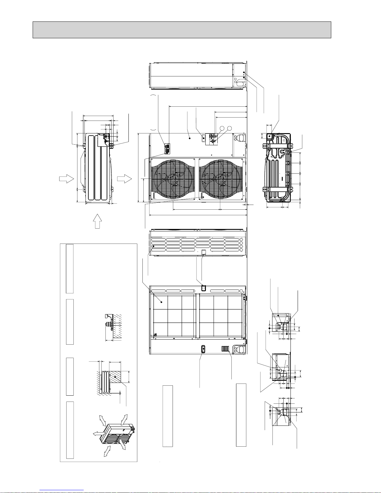
PUHZ-P125VHA3R2.UK
PUHZ-P140VHA3R2.UK
PUHZ-P125VHA3R3.UK
PUHZ-P140VHA3R3.UK
Unit : mm
Less than
Over
Over
Over
Over
Handle for moving
Side Air Intake
Front piping cover
Rear piping cover
Air intake
Rear Air Intake
Handle for moving
Handle for moving
Terminal connection
Left···Power supply wiring
Right···Indoor/Outdoor wiring
Earth terminal
Service panel
Handle for moving
1
2
The diagram below shows a
basic example.
Explanation of particular details is
given in the installation manuals etc.
Dimensions of space needed
for service access are
shown in the below diagram.
<Foundation bolt height>
Please secure the unit firmly
with 4 foundation (M10) bolts.
(Bolts and washers must be
purchased locally.)
Air Discharge
Rear Air Intake
Side Air Intake
···Refrigerant GAS pipe connection (FLARE)W15.88(5/8 inch)
···Refrigerant LIQUID pipe connection (FLARE)W 9.52(3/8 inch)
+1 ···Indication of STOP VALVE connection location.
Example of Notes
Piping Knockout Hole Details
1 FREE SPACE (Around the unit)
2 SERVICE SPACE
3 FOUNDATION BOLTS
4 PIPING-WIRING DIRECTIONS
Piping and wiring connections
can be made from 4 directions:
front, right, rear and below.
30
FOUNDATION
150
500
500
10
Service space
600175 175
330
417
41
56
53 54
41
(19)28 370
2-U Shaped notched holes
(Foundation Bolt M10)
2-12 x 36 Oval holes
(Foundation Bolt M10)
Installation Feet
30
45 40
65
92
27 55
23
73 63
Rear piping hole
(Knockout)
Rear trunking hole
(Knockout)
Power supply wiring hole
(2-
W
27Knockout)
W
92
19 55
92
75 40
73 63
23 27 92
Right piping hole
(Knockout)
Right trunking hole
(Knockout)
Power supply wiring hole
(2-
W
27Knockout)
W
92
92
65
45
40
27 55
23 73
63
Front piping hole
(Knockout)
Front trunking hole
(Knockout)
Power supply wiring hole
(2-
W
27Knockout)
W
92
14514522030 145
81 219
71
71
Bottom piping hole
(Knockout)
Drain hole
(5-W33)
1350
23
950
1076
+1 447
+1 431
371 635
322
Handle for moving
Over 10mm
Over 10mm
Over 150mm
Over 1000mm
FREE
OCH415F
21
PUHZ-P100YHA.UK
PUHZ-P100YHAR1.UK
PUHZ-P100YHA2.UK
Unit : mm
417
56 41
41
54
(19)370
28
53
175600175
330
2-12%36 oval holes
(Foundation Bolt M10)
Air Discharge
Rear Air Intake
Side Air Intake
2-U Shaped notched holes
(Foundation Bolt M10)
Installation Feet
30
Over
Over
Less than
Piping and wiring connections
can be made from 4 directions:
front, right rear and below.
4 PIPING-WIRING DIRECTIONS
3 FOUNDATION BOLTS2 SERVICE SPACE
1 FREE SPACE (Around the unit)
Piping Knockout Hole Details
Example of Notes
···Refrigerant GAS pipe connection (FLARE)W15.88(5/8 inch)
···Refrigerant LIQUID pipe connection (FLARE)W 9.52(3/8 inch)
+1 ···Indication of STOP VALVE connection location.
The diagram below shows a
basic example.
Explanation of particular details is
given in the installation manuals etc.
Over10
500
500
Over100
Dimensions of space needed
for service access are
shown in the below diagram.
Service space
30
Please secure the unit firmly
with 4 foundation (M10) bolts.
(Bolts and washers must be
purchased locally.)
<Foundation bolt height>
Handle for moving
Side Air Intake
Front piping cover
Rear piping cover
14522030 145
81 219
145
71
71
Drain hole
(5-W33)
Bottom piping hole
(Knockout)
Air Intake
Rear Air Intake
Handle for moving
Handle for moving
23
943
473
950
322
+1 447
+1 431
589
Terminal Connections
Left···Power supply wiring
Right···Indoor/Outdoor wiring
Earth terminal
Service panel
Handle for moving
Handle for moving
1
2
19 55
23 27 92
92
40
75
73 63
Right piping hole
(Knockout)
Right trunking hole
(Knockout)
Power supply wiring hole
(2-W27Knockout)
W
92
27 55
73
23 63
40
92
65
45
Front piping hole
(Knockout)
Front trunking hole
(Knockout)
Power supply wiring hole
(2-W27Knockout)
W
92
4045
65
92
27 55
23 73
63
Rear piping hole
(Knockout)
Rear trunking hole
(Knockout)
Power supply wiring hole
(2-W27Knockout)
W
92
FOUNDATION
over 100mm
over 500mm
over 10mm
FREE
over 10mm
OCH415F

22
Unit : mm
PUHZ-P125YHA.UK
PUHZ-P140YHA.UK
PUHZ-P125YHAR1.UK
PUHZ-P140YHAR1.UK
PUHZ-P125YHAR2.UK
PUHZ-P140YHAR2.UK
Less than
Over
Over
Over
Over
Handle for moving
Side Air Intake
Front piping cover
Rear piping cover
Air intake
Rear Air Intake
Handle for moving
Handle for moving
Terminal connection
Left···Power supply wiring
Right···Indoor/Outdoor wiring
Earth terminal
Service panel
Handle for moving
1
2
The diagram below shows a
basic example.
Explanation of particular details is
given in the installation manuals etc.
Dimensions of space needed
for service access are
shown in the below diagram.
<Foundation bolt height>
Please secure the unit firmly
with 4 foundation (M10) bolts.
(Bolts and washers must be
purchased locally.)
Air Discharge
Rear Air Intake
Side Air Intake
···Refrigerant GAS pipe connection (FLARE)W15.88(5/8 inch)
···Refrigerant LIQUID pipe connection (FLARE)W 9.52(3/8 inch)
+1 ···Indication of STOP VALVE connection location.
Example of Notes
Piping Knockout Hole Details
1 FREE SPACE (Around the unit)
2 SERVICE SPACE
3 FOUNDATION BOLTS
4 PIPING-WIRING DIRECTIONS
Piping and wiring connections
can be made from 4 directions:
front, right, rear and below.
30
FOUNDATION
150
500
500
10
Service space
600175 175
330
417
41
56
53 54
41
(19)28 370
2-U Shaped notched holes
(Foundation Bolt M10)
2-12 x 36 Oval holes
(Foundation Bolt M10)
Installation Feet
30
45 40
65
92
27 55
23
73 63
Rear piping hole
(Knockout)
Rear trunking hole
(Knockout)
Power supply wiring hole
(2-
W
27Knockout)
W
92
19 55
92
75 40
73 63
23 27 92
Right piping hole
(Knockout)
Right trunking hole
(Knockout)
Power supply wiring hole
(2-
W
27Knockout)
W
92
92
65
45
40
27 55
23 73
63
Front piping hole
(Knockout)
Front trunking hole
(Knockout)
Power supply wiring hole
(2-
W
27Knockout)
W
92
14514522030 145
81 219
71
71
Bottom piping hole
(Knockout)
Drain hole
(5-W33)
1350
23
950
994
+1 447
+1 431
371 635
322
Handle for moving
Over 10mm
Over 10mm
Over 150mm
Over 1000mm
FREE
OCH415F
23
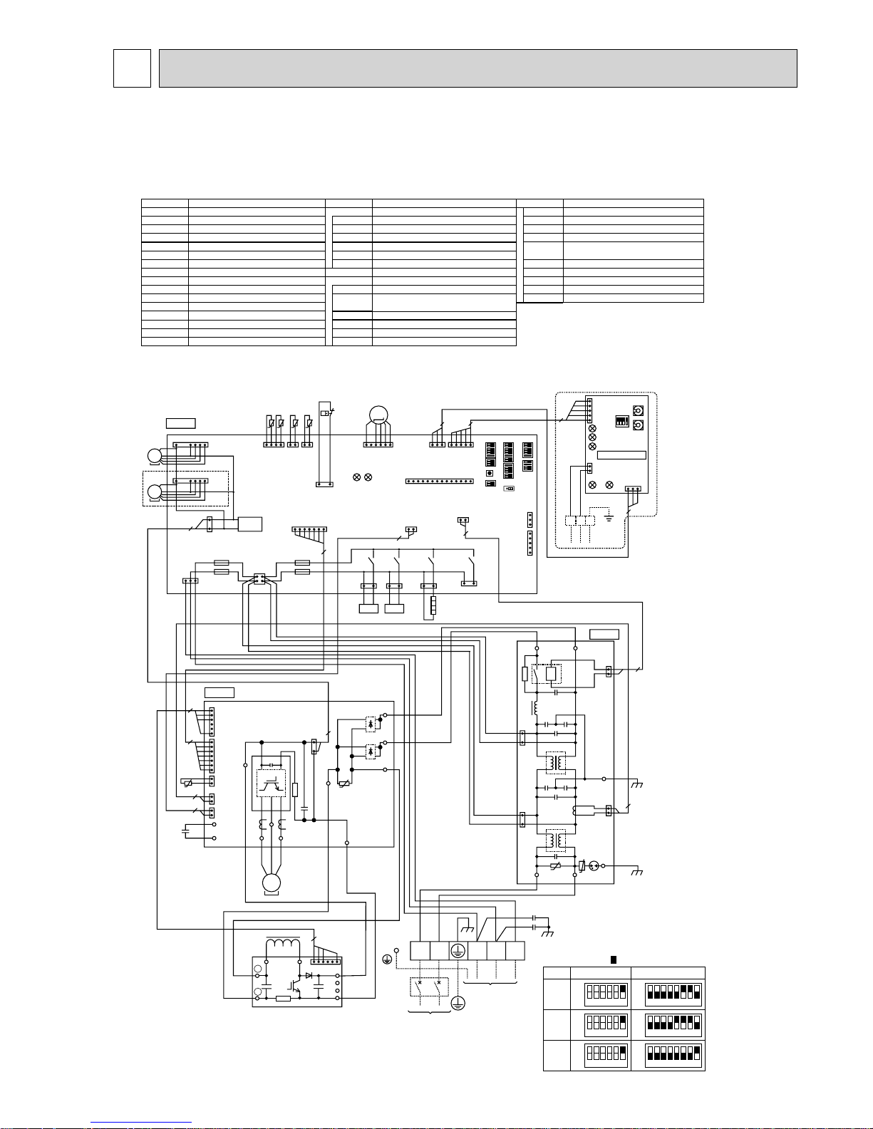
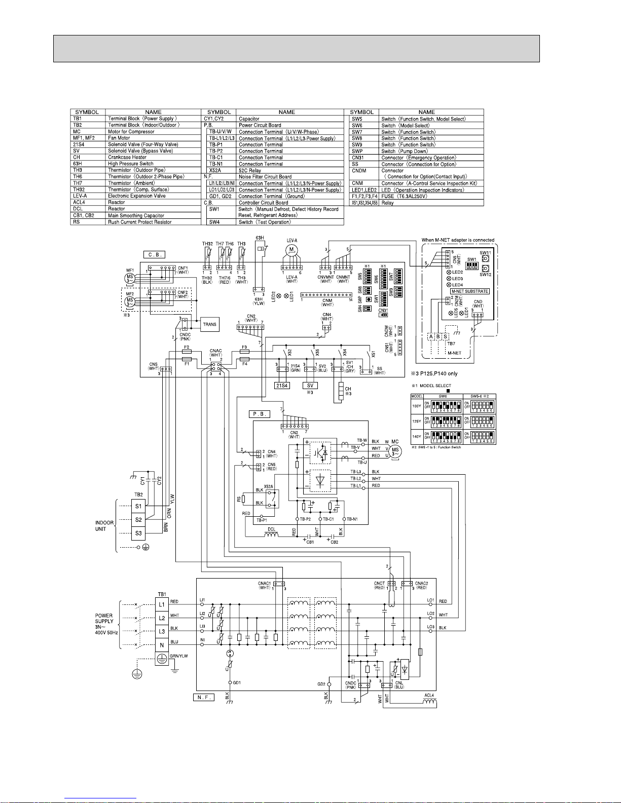
8 WIRING DIAGRAM
123456
OFF
ON
100V
MODEL
SW5-6
+
3
+ 1 MODEL SELECT
123456
OFF
ON
125V
123456
78
78
78
OFF
ON
140V
123456
OFF
ON
SW6
123456
OFF
ON
123456
OFF
ON
TB1
MC
MF1,MF2
21S4
63H
TH3
TH4
TH6
TH7
TH8
LEV-A
DCL
Terminal Block<Power Supply, Indoor/Outdoor >
Motor Compressor
Fan Motors
Solenoid Valve (Four-Way Valve)
High Pressure Switch
SV Solenoid Valve (Bypass Valve)
CH Crankcase Heater
Thermistor<Outdoor Pipe>
Thermistor<Discharge>
Thermistor<Outdoor 2-Phase Pipe>
Thermistor<Outdoor>
Thermistor<Heatsink>
Electronic Expansion Valve
Reactor
ACTM
Active Filter Module
CB
Main Smoothing Capacitor
Diode Bridge
Noise Filter Circuit Board
N.F.
Controller Circuit Board
Switch<Pump Down>
Connector<Emergency Operation>
SWP
CN31
C.B.
DS2,3
Power Module
IPM
SYMBOL NAME SYMBOL NAME SYMBOL NAME
Connection Terminal<DC V oltage>
Connection Terminal<L/N- Phase>
TABP1/P2/P
TABS/T
Connection Terminal<DC V oltage>
TABN1/N2/N
Power Circuit Board
Connection Terminal<U/V/W-Phase>
P.B .
TABU/V/W
Fuse<T6.3AL250V>
Switch<Forced Defrost, Defect History Record
Reset, Refrigerant Address>
Switch<Test Operation>
Switch<Function Switch>
Switch<Model Select>
F1~F4
SW1
SW4
SW5
SW6
SW8
Switch
SW9
Switch<Function Setup>
SW7
Switch
LED1,LED2
Light Emitting Diodes
<Operation Inspection Indicators>
CNM
CNMNT
CNVMNT
CNDM
Connector<A-Control Service Inspection Kit>
Connector<Connected to Optional M-NET Adapter Board>
Connector<Connected to Optional M-NET Adapter Board>
Connector<Connected for Option (Contact Input)>
X51,X52,X54,X55
Relay
CNVMNT
(WHT)
CNMNT
(WHT)
CNM
(WHT)
CN5
(WHT)
CN2M
(WHT)
CND
(WHT)
CN4
(WHT)
CN2
(WHT)
21S4
(GRN)
SS
(WHT)
CN52C
(BLK)
CN5
(RED)
(RED)
CNAC2
(WHT)
CNAC1
NO
LO
SV2
(BLU)
+ 2
CNDM
(WHT)
CN51
(WHT)
5
5
5
3
1
1
5
1
16
1
12
CN52C
(RED)
1
1
1
3
5
2
2
14
3
LEV-A
(WHT)
LED2
LED1
TH7/6
(RED)
TH3
(WHT)
CNF1
(WHT)
CNF2
(
WHT)
CNS
(
WHT)
CNAC
(
WHT)
CNDC
(
PNK)
F2
F1
F3
X52
X55
X51
F4
21S4
TRANS
MF1
C.B.
+ 2
MS
3~
63H
(YLW)
TH4
(WHT)
63H
LEV-A
M
TH7 TH6 TH3 TH4
SW7
SW6SW1
SW9
CN31
+ 1+ 1
SW5SW8SW4 SWP
TABN
TABP
DCL
UVW
MC
P
L1 L2
Io
N1
N2
CN3
(WHT)
CNAF
(WHT)
CNDC
(PNK)
CN2
(WHT)
IPM
TABT
DS3
DS2
TABS
TABP1
U
TH8
CN4
(WHT)
CN5
(RED)
CB
17
14
7
7
1
31
12
34
4
7
1
1
7
1
2
6
3
2
–~
~
~
~
+
1
+
+
–
3
2
1
1
122
1
3
1
1
2
2
7
31
t°t° t°t°
MF2
MS
3~
MS
3~
31
SV
52C
31
SV1/CH
(GRY)
CH
+
2
X54
31
N.F.
P.B.
LED2
LED3
LED4
LED5
LED1
31
3
SW1
SW11
SW12
TB7
M-NET SUBSTRATE
M-NET
ABS
When M-NET adaptor is connected
1
2
2
2
+
1
2
4
+
16
TABP2
TABN2
TABN1
TABURED
BLK
TABW
TABVWHT
–
+
3
2
2
1
1
3
1
U
U
1
2
2
E2
EI
CY1
CY2
TB1
S3S2S1NL
INDOOR
UNIT
LI
NI
POWER SUPPLY
~/N 230V 50Hz
ACTM
—
+ 2 P125, P140 only
+ 3 SW5-1 to 5: Function Switch
t°
The black square ( ) indicates a switch position.
PUHZ-P100VHA2.UK PUHZ-P125VHA2.UK PUHZ-P140VHA2.UK
PUHZ-P125VHA2
1.UK PUHZ-P140VHA21.UK
PUHZ-P100VHA3.UK PUHZ-P125VHA3.UK PUHZ-P140VHA3.UK
PUHZ-P100VHA3R1.UK PUHZ-P125VHA3R1.UK PUHZ-P140VHA3R1.UK
OCH415F
24
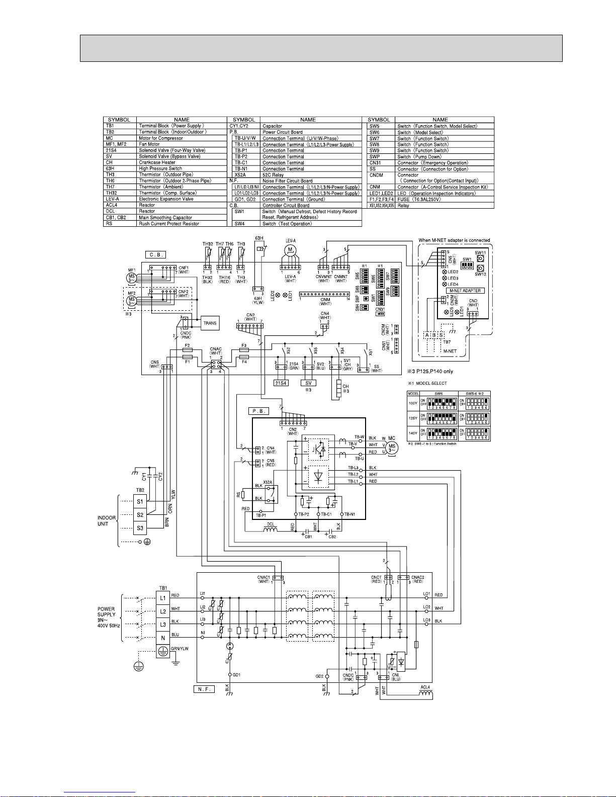
PUHZ-P100VHA3R2.UK PUHZ-P125VHA3R2.UK PUHZ-P140VHA3R2.UK
PUHZ-P125VHA3R3.UK PUHZ-P140VHA3R3.UK
The black square ( ) indicates a switch position.
OCH415F
25
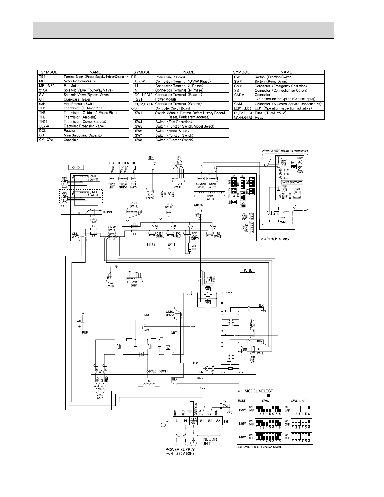
PUHZ-P100VHA4.UK
12345678
OFF
ON
100V
MODEL
SW6
*1 MODEL SELECT
*2 SW5 -1 to 5 : Function Switch
SW5-6 *2
OFF
ON
123456
TB1
MC
MF1
21S4
TH3
TH6
TH7
DCL
Terminal Block <Power Supply, Indoor/Outdoor>
Motor for Compressor
Fan Motor
Solenoid Valve (Four-Way Valve)
63H High Pressure Switch
Thermistor <Liquid>
Thermistor <2-Phase Pipe>
Thermistor <Ambient>
TH8
Thermistor (internal) <Heat Sink>
TH32
Thermistor <Comp. Surface>
Linear Expansion Valve
Reactor
CB
Main Smoothing Capacitor
CY1, CY2
Capacitor
Controller Circuit Board
C.B.
SYMBOL NAME SYMBOL NAME SYMBOL NAME
Switch <Function Switch>
Switch <Manual Defrost, Defect History, Record
Reset, Refrigerant Address>
Switch <Test Operation>
Switch <Function Switch, Model Select>
Switch <Model Select>
SW7
SW1
SW4
SW5
SW6
Switch <Function Switch>
SW8
Switch <Pump Down>
SWP
Connector <Emergency Operation>
CN31
LED1, LED2
F1, F2, F3, F4
LED <Operation Inspection Indicators>
CNM
CNDM
Connector <Connection for Option>
Connector <Connection for Option>
Fuse <T6.3AL250V
>
X51, X52, X54, X55
Relay
SS
Connector <Connection for Option>
LEV-A
Power Module
Connection Terminal <Reactor>
Connection Terminal <Ground>
DCL1, DCL2
IGBT
EI, E2, E3, E4
P.B.
Power Circuit Board
Connection Terminal <U/V/W-Phase>
NI
Connection Terminal <N-Phase>
LI
Connection Terminal <L-Phase>
U/V/W
Switch <Function Switch>
SW9
CN5
(WHT)
31
TB7
2
1
CND
(WHT)
CN2M
(WHT)
M-NET ADAPTER
M-NET
ABS
When M-NET adapter is connected
CNVMNT
(WHT)
31
CNDM
(WHT)
CN51
(WHT)
3
1
5
1
CNMNT
(WHT)
CNM
(WHT)
51
LEV-A
(WHT)
LEV-A
C. B.
3
5
TH7/6
(RED)
63H
(YLW)
TRANS
X51
TH3
(WHT)
CNDC
(PNK)
CNF1
(WHT)
TH7 TH6 TH3
4121
SW7
SW6SW1
SW9
CN31
141
MF1
MS
3~
M
7
1
CN2
(WHT)
CNS
(WHT)
CNAC
(WHT)
CN4
(WHT)
SS
(WHT)
21S4
(GRN)
2
1
LED1
LED2
X52
F1
F2
F4
F3
*1*1
21
43
SW5SW8SW4 SWP
21S4
61
3
1
3
1
2
31
7
1
7
7
2
t° t° t°
TH32
(BLK)
TH32
21
t°
13
SV2
(BLU)
SV1
/CH
(GRY)
X55
13
X54
13 13
CN52C
(RED)
331
63H
5
3
5
1
DCL2
IGBT
N2
P2
MS
3~
U
U
V
V
W
W
CN2
(WHT)
CN4
(WHT)
1
7
1
2
2
P. B.
CNDC
(PNK)
BLK
WHT
CY1
CY2
LINI
EI
E4
E2
E3
POWER SUPPLY
~/N 230V 50Hz
INDOOR
UNIT
TB1
L N S1 S2 S3
MC
3
1
3
1
2
REDRED
CNAC1
(WHT)
CNAC2
(RED)
1
3
1
3
CN52C
(RED)
52C
52C
BLU
YLW
GRN/YLW
ORN
BRN
RED
WHT
RED
BLK
BLK
BLK
BLK
RED
BRN
ORN
WHT
DCL1
DCL
CB
t°
TH8
3
BLK
WHT
The black square ( ) indicates a switch position.
OCH415F
26
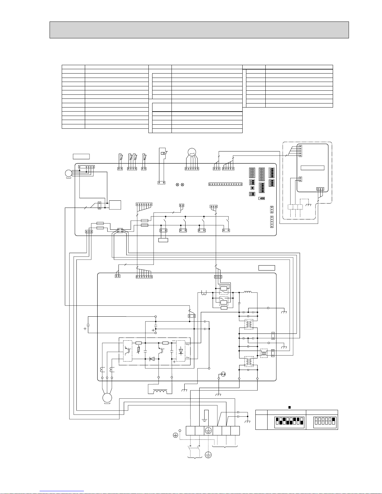
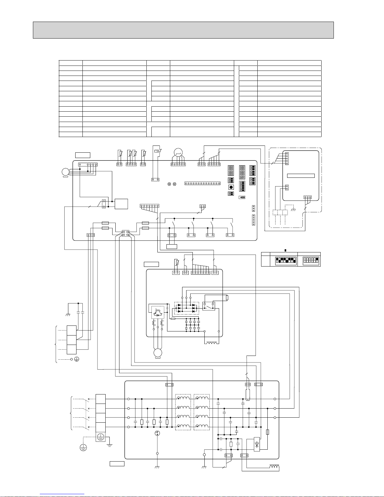
PUHZ-P100YHA.UK PUHZ-P125YHA.UK PUHZ-P140YHA.UK
The black square ( ) indicates a switch position.
OCH415F
27
The black square (■) indicates a switch position.
PUHZ-P100YHAR1.UK PUHZ-P125YHAR1.UK PUHZ-P140YHAR1.UK
PUHZ-P125YHAR2.UK PUHZ-P140YHAR2.UK
OCH415F
28
PUHZ-P100YHA2.UK
The black square ( ) indicates a switch position.
SYMBOL NAME SYMBOL NAME SYMBOL NAME
TB1 Terminal Block <Power Supply> RS Rush Current Protect Resistor SW4 Switch <Test Operation>
TB2 Terminal Block <Indoor/Outdoor> CY1, CY2 Capacitor SW5 Switch <Function Switch, Model Select>
MC Motor for Compressor P.B. Power Circuit Board SW6 Switch <Model Select>
MF1 Fan Motor TB-U/V/W
Connection Terminal
<U/V/W-Phase> SW7 Switch <Function Switch>
21S4 Solenoid Valve (Four-Way Valve)
TB-L1/L2/L3 Connection Terminal <L1/L2/L3-Power Supply>
SW8 Switch <Function Switch>
63H Hign Pressure Switch TB-P1/P3
Connection Terminal
SW9 Switch <Function Switch>
TH3 Thermistor <Liquid> X52CA 52C Relay SWP Switch <Pump Down>
TH6 Thermistor <2-Phase Pipe> N.F. Noise Filter Circuit Board CN31 Connector <Emergency Operation>
TH7 Thermistor <Ambient>
LI1/LI2/LI3/NI
Connection Terminal <L1/L2/L3/N-Power Supply>
SS Connector <Connection for Option>
TH8 Thermistor <Heat Sink>
LO1/LO2/LO3
Connection Terminal <L1/L2/L3-Power Supply>
CNDM Connector <Connection for Option>
TH32 Thermistor <Comp. Surface> GD1, GD2
Connection Terminal
<Ground> CNM Connector <Connection for Option>
LEV-A Linear Expansion Valve C.B. Controller Circuit Board
LED1, LED2
LED <Operation Inspection Indicators>
DCL Reactor
SW1
Switch <Manual Defrost, Defect History,
Record Reset, Refrigerant Address>
F1, F2, F3, F4
Fuse <T6.3AL250V>
ACL4 Reactor
X51, X52, X54, X55
Relay
TH8
t°
LEV-A
(WHT)
61
3
CNVMNT
(WHT)
CN4
(WHT)
CNMNT
(WHT)
3151
CN5
(WHT)
31
TB7
5
1
2
5
1
CND
(WHT)
CN2M
(WHT)
M-NET
When M-NET adapter is connected
1
2
3
4
CNS
(WHT)
13
21S4
(GRN)
MF1
TRANS
CNF1
(WHT)
1
3
CNDC
(PNK)
CN2
(WHT)
CNAC
(WHT)
13
SV2
(BLU)
X55
X51
X52
13
SS
(WHT)
ACL4
BLK
BLK
WHT
WHT
WHT
RED
BLK
BLU
GRN/YLW
WHT
RED
CNAC1
(WHT)
CNCT
(RED)
CNAC2
(RED)
CNL
(BLU)
CNDC
(PNK)
P.B.
C.B.
N.F.
LO1
GD2
LO2
LO3
LI1
LI2
LI3
NI
TB1
TB2
POWER
SUPPLY
3N~
400V 50Hz
INDOOR
UNIT
1
F2
F1
F3
F4
TH7/6
(RED)
63H
(YLW)
TH3
(WHT)
TH7 TH6 TH3
4121
3
1
t° t° t°
TH32
(BLK)
TH32
21
t°
63H
2
2
1
7
2
3
722
7
1
71
3121
LEV-A
M
LED1
LED2
CNM
(WHT)
1
14
3
1
5
1
3
5
CNDM
(WHT)
CN51
(WHT)
SW7
SW6SW1
SW9
CN31
*1*1
SW5SW8SW4 SWP
21S4
ABS
+
+
1331
31
L1
L2
L3
N
S1
S2
S3
YLW
CY2
CY1
ORN
BLK
BRN
MS
3~
2
2
M-NET ADAPTER
BLK
GD1
13
SV1
/CH
(GRY)
X54
12345678
OFF
ON
100Y
MODEL
SW6
* 1 MODEL SELECT
* 2 SW5 -1 to 5 : Function Switch
SW5-6 *2
OFF
ON
123456
RS
CN6
(WHT)
CN5
(RED)
CN2
(WHT)
CN4
(WHT)
TB-U
TB-V
TB-W
U
W
V
DCL
RED
WHT
BLK
MC
WHT
RED
BLK
RED
RED
X52CA
MS
3~
71212211
TB-P3
TB-P1
TB-L3
TB-L2
TB-L1
+
-
+-
+++
+++
OCH415F
29
9 WIRING SPECIFICATIONS
Outdoor unit model
Outdoor unit power supply
Outdoor unit input capacity
*1
Main switch (Breaker)
Outdoor unit power supply
Indoor unit-Outdoor unit *2
Indoor unit-Outdoor unit earth *2
Remote controller-Indoor unit *3
Outdoor unit L-N (single)
*4
Outdoor unit L1-N, L2-N, L3-N (3 phase)
Indoor unit-Outdoor unit S1-S2 *4
Indoor unit-Outdoor unit S2-S3 *4
Remote controller-Indoor unit *4
Wiring
Wire No.%
size (mm
2
)
Circuit rating
P100, 125V P140V
~/N (single), 50 Hz, ~/N (single), 50 Hz,
230 V 230 V
32 A 40 A
3 % Min. 4 3 % Min. 6
3 % 1.5 (Polar) 3 % 1.5 (Polar)
1 % Min. 1.5 1 % Min. 1.5
2 % 0.3 (Non-polar) 2 % 0.3 (Non-polar)
AC 230 V AC 230 V
AC 230 V AC 230 V
DC 24 V DC 24 V
DC 12 V DC 12 V
P100,125,140Y
3N~ (3ph,4-wires),
50Hz, 400 V
16 A
5 % Min. 1.5
3 % 1.5 (Polar)
1 % Min. 1.5
2 % 0.3 (Non-polar)
AC 230 V
AC 230 V
DC 24 V
DC 12 V
*1. A breaker with at least 3 mm contact separation in each pole shall be provided. Use earth leakage breaker(NV).
*2. Refer to 9-3.
*3. The 10 m wire is attached in the remote controller accessory.
*4. The figures are NOT always necessarily the voltage to ground.
S3 terminal has DC 24 V against S2 terminal. However between S3 and S1, these terminals are NOT electrically insulated by the transformer or other device.
Notes: 1. Wiring size must comply with the applicable local and national code.
2. Power supply cords and Indoor/Outdoor unit connecting cords shall not be lighter than polychloroprene sheathed flexible cord. (Design 60245 IEC 57)
3. Install an earth longer than other cables.
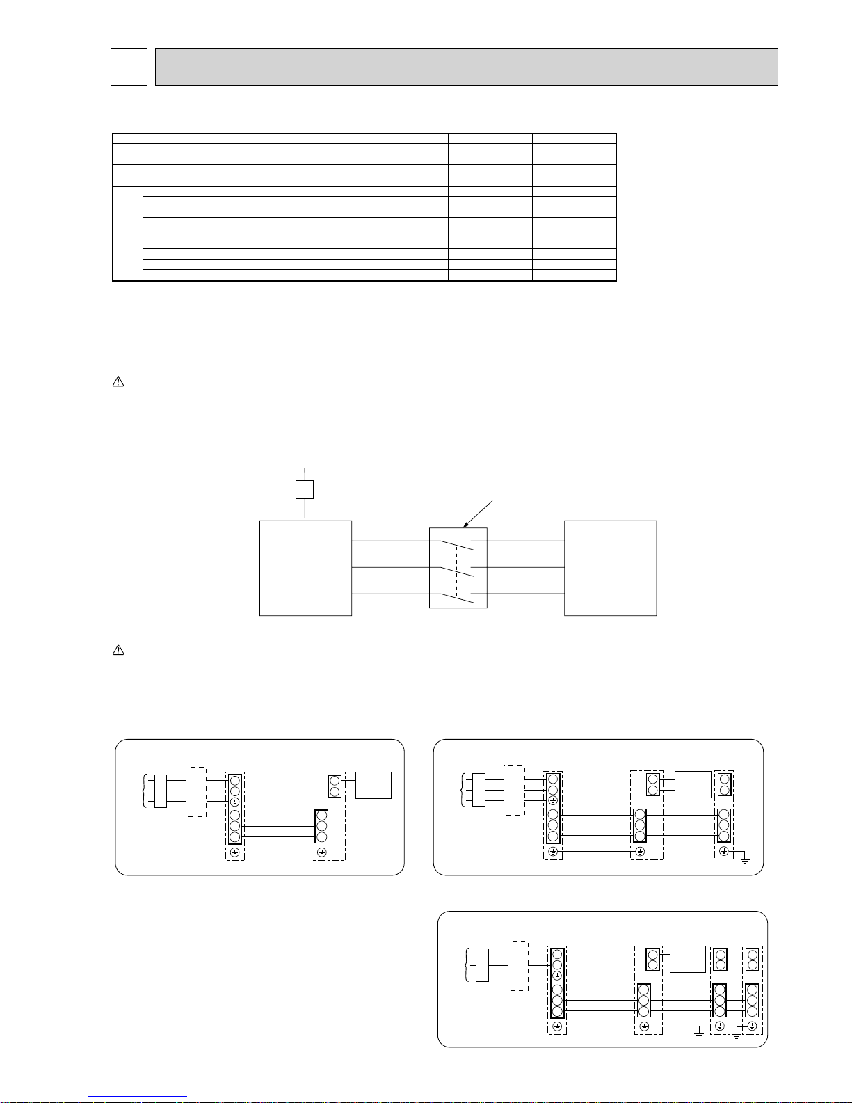
Warning:
In case of A-control wiring, there is high v oltage potential on the S3 terminal caused by electrical circuit design that has no electrical insulation between po wer line
and communication signal line.Therefore, please turn off the main power supply when servicing. And do not touc h the S1, S2, S3 terminals when the power is
energized. If isolator should be used between indoor unit and outdoor unit, please use 3-pole type.
S1
S2
S3
S1
S2
S3
A-Control
Outdoor Unit
3 poles isolator
Power supply
Isolator
A-Control
Indoor Unit
Caution: Be sure to install N-Line. Without N-Line, it could cause damage to the unit.
Make sure that the current leakage breaker is one compatible with higher harmonics.
Always use a current leakage breaker that is compatible with higher harmonics as this unit is equipped with an inverter.
The use of an inadequate breaker can cause the incorrect operation of inverter.
9-1. FIELD ELECTRICAL WIRING (power wiring specifications)
1
2
S1
S2
S3
S1
S2
S3
Indoor/outdoor
unit connection
cable
Indoor
unit
Unit
power
supply
Outdoor
unit
Remote
controller
L
N
Earth leakage breaker
wiring circuit breaker or
isolating switch
Earth leakage breaker
wiring circuit breaker or
isolating switch
L
N
1
2
1
2
S1
Indoor
unit
S2
S3
S1
S2
S3
S1
S2
S3
Unit
power
supply
Indoor/outdoor
unit connection
cable
Indoor
unit
Outdoor
unit
Remote
controller
Earth leakage breaker
wiring circuit breaker or
isolating switch
1
2
1
2
1
2
S1
S2
S3
S1
S2
S3
S1
S2
S3
S1
S2
S3
Indoor/outdoor
connection cable
Indoor
unit
Unit
power
supply
Indoor
unit
Indoor
unit
Outdoor
unit
Remote
controller
L
N
1:1 system Synchronized twin and triple system Electrical wiring
• Synchronized twin
• Synchronized triple
OCH415F
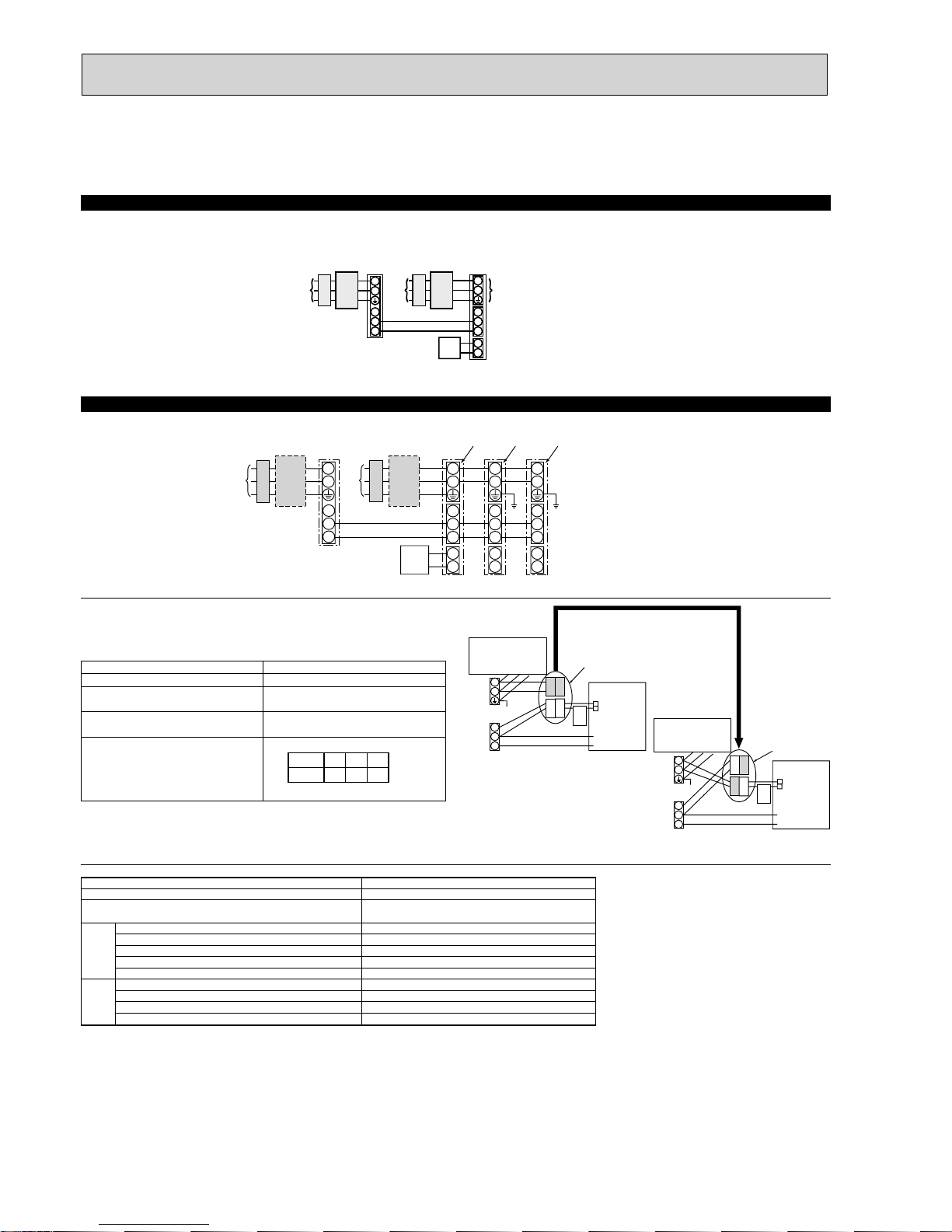
30
The following connection patterns are available.
The outdoor unit power supply patterns vary on models.
1:1 System
<For models without heater>
* The optional indoor power supply terminal kit is required.
S1
S2
L
N
1
2
L
N
S1
S2
S3
S3
* Affix a label B that is included with the manuals near each wiring diagram for the indoor and outdoor units.
Outdoor unit power supply
Earth leakage breaker
Wiring circuit breaker or isolating switch
Outdoor unit
Indoor unit/outdoor unit connecting cords
Remote controller
Indoor unit
Option
Indoor unit power supply
<For models without heater>
* The optional indoor power supply terminal kits are required.
Simultaneous twin/triple system
If the indoor and outdoor units have separate power supplies, refer to the table below.
If the optional indoor power supply terminal kit is used, change the indoor unit
electrical box wiring referring to the figure in the right and the DIP switch settings of
the outdoor unit control board.
* Affix a label B that is included with the manuals near each wiring diagram for the indoor and outdoor units.
Outdoor unit power supply
Earth leakage breaker
Wiring circuit breaker or isolating switch
Outdoor unit
Indoor unit/outdoor unit connecting cords
Remote controller
Indoor unit
Option
Indoor unit power supply
ON
OFF 1 2
(SW8)
3
Indoor power supply terminal kit (option)
Indoor unit electrical box connector connection change
Label affixed near each wiring diagram
for the indoor and outdoor units
Outdoor unit DIP switch settings (when
using separate indoor unit/outdoor unit
power supplies only)
Indoor unit specifications
Required
Required
Required
*1. A breaker with at least 3 mm contact separation in each pole shall be provided. Use earth leakage breaker (NV).
*2. Max. 120 m
*3. The 10 m wire is attached in the remote controller accessory. Max. 500 m
*4. The figures are NOT always necessarily the voltage to ground.
Notes: 1. Wiring size must comply with the applicable local and national code.
2. Power supply cords and indoor unit/outdoor unit connecting cords shall not be lighter than polychloroprene sheathed flexible cord.
(Design 60245 IEC 57)
3. Install an earth longer than other cables.
Indoor unit model
Indoor unit power supply
Indoor unit input capacity
*1
Main switch (Breaker)
Indoor unit power supply
Indoor unit power supply earth
Indoor unit-Outdoor unit
*2
Indoor unit-Outdoor unit earth
Remote controller-Indoor unit
*3
Indoor unit L-N *4
Indoor unit-Outdoor unit S1-S2 *4
Indoor unit-Outdoor unit S2-S3 *4
Remote controller-Indoor unit *4
RP35~140
~/N (single), 50 Hz, 230 V
16 A
2% Min. 1.5
1% Min. 1.5
2% Min. 0.3
–
2 % 0.3 (Non-polar)
AC 230 V
–
DC24 V
DC12 V
Circuit
rating
Wiring
Wire No. % size
(mm
2
)
Electric heater
(For models with
heater)
Connectors (connections when shipped
from the factory are for indoor unit power
supplied from outdoor unit)
Indoor unit power supplied from outdoor unit
(when shipped from factory)
If the indoor and
outdoor units have
separate power
supplies, change the
connections of the
connectors as shown
in the following
figure.
Connectors
Indoor unit
control board
Separate indoor unit/outdoor unit power
supplies
Electric heater
(For models with
heater)
S1
S2
S3
L
N
BLUE
BLUE
YELLOW
YELLOW
CND or
CN01
S1
S2
S3
L
N
YELLOW
BLUE
BLUE
YELLOW
Indoor unit
control board
* There are three types of labels (labels A, B and C). Affix the appropriate labels to
the units according to the wiring method.
Set the SW8-3 to ON.
CND or
CN01
Indoor unit earth
L
N
L
N
S1
S2
S3
S1
S2
S3
1
2
L
N
S1
S2
S3
1
2
L
N
S1
S2
S3
1
2
9-2. SEPARATE INDOOR UNIT/OUTDOOR UNIT POWER SUPPLIES
OCH415F
 Loading...