

Mitsubishi PKA-M50HAL, PUZ-ZM71VHA, PKA-M50HA, PUHZ-ZRP71VHA2, PKA-M35HAL Service Manual
...
SERVICE MANUAL
Notes:
• This manual describes
service data of the
indoor units only.
• RoHS compliant prod-
ucts have <G> mark on
the spec name plate.
CONTENTS
1. REFERENCE MANUAL
...................................
2
2. SAFETY PRECAUTION
...................................
3
3. PARTS NAMES AND FUNCTIONS
.................
8
4. SPECIFICATIONS
...........................................
12
5. NOISE CRITERION CURVES
.........................
13
6. OUTLINES AND DIMENSIONS
......................
14
7. WIRING DIAGRAM
.........................................
15
8. REFRIGERANT SYSTEM DIAGRAM
............
17
9. TROUBLESHOOTING
....................................
18
10. FUNCTION SETTING
....................................
34
11. SPECIAL FUNCTION
.....................................
35
12. DISASSEMBLY PROCEDURE
.......................
37
Indoor unit
[Model Name] [Service Ref.]
PARTS CATALOG (OCB660)
INDOOR UNIT
PKA-M35HA
PKA-M35HA
PKA-M50HA
PKA-M50HA
PKA-M35HAL
PKA-M35HAL
PKA-M50HAL
PKA-M50HAL
SPLIT-TYPE, HEAT PUMP AIR CONDITIONERS
SPLIT-TYPE, AIR CONDITIONERS
No. OCH660
March 2017
R32/R410A

2
1
REFERENCE MANUAL
OUTDOOR UNIT’S SERVICE MANUAL
Model name Service Ref. Service manual No.
PUZ-ZM35/50VKA
PUZ-ZM71VHA
PUZ-ZM35/50VKA
PUZ-ZM71VHA
OCH653
OCB653
PUZ-ZM100/140VKA
PUZ-ZM100/140YKA
PUZ-ZM100/140VKA.UK
PUZ-ZM100/140YKA.UK
OCH654
OCB654
PUHZ-ZRP35/50VKA2
PUHZ-ZRP71VHA2
PUHZ-ZRP35/50VKA2(-ER/ET)
PUHZ-ZRP71VHA2(-ER/ET)
OCH635
OCB635
PUHZ-ZRP100/140VKA3
PUHZ-ZRP100/140YKA3
PUHZ-ZRP200/250YKA2
PUHZ-ZRP100/140VKA3.UK
PUHZ-ZRP100/140YKA3.UK
PUHZ-ZRP200/250YKA2.UK
OCH645
OCB645
PUHZ-P100VHA5
PUHZ-P125/140VHA4
PUHZ-P100YHA3
PUHZ-P125/140YHA2
PUHZ-P100VHA5.UK
PUHZ-P125/140VHA4.UK
PUHZ-P100YHA3.UK
PUHZ-P/125140YHA2.UK
OCH646
OCB646
PUHZ-P200/250YKA2 PUHZ-P200/250YKA2.UK
OCH647
OCB647
PUHZ-SHW112VHA
PUHZ-SHW112YHA
PUHZ-SHW140YHA
PUHZ-SHW112VHAR4.UK
PUHZ-SHW112YHAR4.UK
PUHZ-SHW140YHAR4.UK
OCH526
OCB526
PUHZ-SHW230YKA2 PUHZ-SHW230YKA2
OCH594
OCB594
PUHZ-FRP71VHA PUHZ-FRP71VHA
OCH544
OCB544
OCH660
3
SAFETY PRECAUTION
2
Cautions for units utilising refrigerant R32/R410A
2-2. CAUTIONS RELATED TO NEW REFRIGERANT
Use new refrigerant pipes.
Make sure that the inside and outside of refrigerant piping is clean and it has no contamination
such as sulfur hazardous for use, oxides, dirt,
shaving particles, etc.
In addition, use pipes with specified thickness.
In case of using the existing pipes for R22, be careful with
the following:
· Be sure to clean the pipes and make sure that the insides
of the pipes are clean.
· Change flare nut to the one provided with this product.
Use a newly flared pipe.
· Avoid using thin pipes.
Charge refrigerant from liquid phase of gas
cylinder.
If the refrigerant is charged from gas phase, composition
change may occur in refrigerant and the efficiency will be
lowered.
Do not use refrigerant other than R32/R410A.
If other refrigerant (R22, etc.) is used, chlorine in refrigerant can cause deterioration of refrigerant oil, etc.
Use a vacuum pump with a reverse flow check
valve.
Vacuum pump oil may flow back into refrigerant cycle and
that can cause deterioration of refrigerant oil, etc.
Use the following tools specifically designed for
use with R32/R410A refrigerant.
The following tools are necessary to use R32/R410A refrigerant.
Handle tools with care.
If dirt, dust or moisture enters into refrigerant cycle, that can
cause deterioration of refrigerant oil or malfunction of compressor.
Do not use a charging cylinder.
If a charging cylinder is used, the composition of refrigerant will change and the efficiency will be lowered.
Flare tool
Electronic refrigerant
charging scale
Vacuum pump adaptor
Size adjustment gauge
Gauge manifold
Torque wrench
Gas leak detector
Charge hose
Tools for R32/R410A
Contamination inside refrigerant piping can cause deterioration of refrigerant oil, etc.
· In case of reconnecting the refrigerant pipes after
detaching, make the flared part of pipe re-fabricated.
Ventilate the room if refrigerant leaks during
operation. If refrigerant comes into contact with
a flame, poisonous gases will be released.
Store the piping indoors, and both ends of the
piping sealed until just before brazing.
(Leave elbow joints, etc. in their packaging.)
If dirt, dust or moisture enters into refrigerant cycle, that can
cause deterioration of refrigerant oil or malfunction of compressor.
The refrigerant oil applied to flare and flange
connections must be ester oil, ether oil or
alkylbenzene oil in a small amount.
If large amount of mineral oil enters, that can cause deterioration of refrigerant oil, etc.
Never use any refrigerant other than that specified.
Doing so may cause a burst, an explosion, or fire when the
unit is being used, serviced, or disposed of.
Correct refrigerant is specified in the manuals and on the
spec labels provided with our products.
We will not be held responsible for mechanical failure,
system malfunction, unit breakdown or accidents caused
by failure to follow the instructions.
Use the specified refrigerant only.
2-1. ALWAYS OBSERVE FOR SAFETY
Before obtaining access to terminal, all supply
circuits must be disconnected.
MEANINGS OF SYMBOLS DISPLAYED ON THE UNIT
WARNING
This mark is for R32 refrigerant only. Refrigerant type is written on nameplate of outdoor unit.
Read the OPERATION MANUAL carefully before operation.
Service personnel are required to carefully read the OPERATION MANUAL and INSTALLATION MANUAL before operation.
Further information is available in the OPERATION MANUAL, INSTALLATION MANUAL, and the like.
OCH660

4
[1] Warning for service
(1) Do not alter the unit.
(2) For installation and relocation work, follow the instructions in the Installation Manual and use tools and pipe
components specifically made for use with refrigerant specified in the outdoor unit installation manual.
(3) Ask a dealer or an authorized technician to install, relocate and repair the unit.
(4) This unit should be installed in rooms which exceed the floor space specified in outdoor
unit installation manual.
Refer to outdoor unit installation manual.
(5) For appliances not accessible to the general public.
(6) Refrigerant pipes connection shall be accessible for maintenance purposes.
(7) If the air conditioner is installed in a small room or closed room, measures must be taken to prevent the refrig-
erant concentration in the room from exceeding the safety limit in the event of refrigerant leakage. Should the
refrigerant leak and cause the concentration limit to be exceeded, hazards due to lack of oxygen in the room may
result.
(8) Keep gas-burning appliances, electric heaters, and other fire sources (ignition sources) away from the location
where installation, repair, and other air conditioner work will be performed.
If refrigerant comes into contact with a flame, poisonous gases will be released.
(9) When installing or relocating, or servicing the air conditioner, use only the specified refrigerant written on out-
door unit to charge the refrigerant lines.
Do not mix it with any other refrigerant and do not allow air to remain in the lines.
If air is mixed with the refrigerant, then it can be the cause of abnormal high pressure in the refrigerant line, and
may result in an explosion and other hazards.
(10) After installation has been completed, check for refrigerant leaks. If refrigerant leaks into the room and comes
into contact with the flame of a heater or portable cooking range, poisonous gases will be released.
(11) Do not use low temperature solder alloy in case of brazing the refrigerant pipes.
(12) When performing brazing work, be sure to ventilate the room sufficiently. Make sure that there are no hazardous
or flammable materials nearby.
When performing the work in a closed room, small room, or similar location, make sure that there are no refrigerant leaks before performing the work.
If refrigerant leaks and accumulates, it may ignite or poisonous gases may be released.
(13) Do not install the unit in places where refrigerant may build-up or places with poor ventilation such as a semi-
basement or a sunken place in outdoor: Refrigerant is heavier than air, and inclined to fall away from the leak
source.
(14) Do not use means to accelerate the defrosting process or to clean, other than those recommended by the manu-
facturer.
(15) The appliance shall be stored in a room without continuously operating ignition sources (for example: open
flames, an operating gas appliance or an operating electric heater).
(16) Do not pierce or burn.
(17) Be aware that refrigerants may not contain an odour.
(18) Pipe-work shall be protected from physical damage.
(19) The installation of pipe-work shall be kept to a minimum.
(20) Compliance with national gas regulations shall be observed.
(21) Keep any required ventilation openings clear of obstruction.
(22) Servicing shall be performed only as recommended by the manufacturer.
(23) The appliance shall be stored in a well-ventilated area where the room size corresponds to the room area as
specified for operation.
(24) Maintenance, service and repair operations shall be performed by authorized technician with required qualifica-
tion.
[2] Cautions for service
(1) Perform service after recovering the refrigerant left in unit completely.
(2) Do not release refrigerant in the air.
(3) After completing service, charge the cycle with specified amount of refrigerant.
(4) When performing service, install a filter drier simultaneously.
Be sure to use a filter drier for new refrigerant.
[3] Additional refrigerant charge
When charging directly from cylinder
(1) Check that cylinder for R32/R410A available on the market is a syphon type.
(2) Charging should be performed with the cylinder of syphon stood vertically. (Refrigerant is charged from liquid phase.)
OCH660

5
[4] Cautions for unit using R32 refrigerant
Basic work procedures are the same as those for conventional units using refrigerant R410A. However, pay careful
attention to the following points.
(1) Information on servicing
(1-1) Checks on the Area
Prior to beginning work on systems containing flammable refrigerants, safety checks are necessary to ensure that the
risk of ignition is minimized.
For repair to the refrigerating systems, (1-3) to (1-7) shall be completed prior to conducting work on the systems.
(1-2) Work Procedure
Work shall be undertaken under a controlled procedure so as to minimize the risk of a flammable gas or vapor being
present while the work is being performed.
(1-3) General Work Area
All maintenance staff and others working in the local area shall be instructed on the nature of work being carried out.
Work in confined spaces shall be avoided. The area around the workspace shall be sectioned off. Ensure that the con-
ditions within the area have been made safe by control of flammable material.
(1-4) Checking for Presence of Refrigerant
The area shall be checked with an appropriate refrigerant detector prior to and during work, to ensure the technician is
aware of potentially toxic or flammable atmospheres. Ensure that the leak detection equipment being used is suitable
for use with all applicable refrigerants, i.e. non-sparking, adequately sealed or intrinsically safe.
(1-5) Presence of Fire Extinguisher
If any hot work is to be conducted on the refrigeration equipment or any associated parts, appropriate fire extinguishing
equipment shall be available to hand.
Have a dry powder or CO2 fire extinguisher adjacent to the charging area.
(1-6) No Ignition Sources
No person carrying out work in relation to a refrigeration system which involves exposing any pipe work shall use any
sources of ignition in such a manner that it may lead to the risk of fire or explosion. All possible ignition sources, includ-
ing cigarette smoking, should be kept sufficiently far away from the site of installation, repairing, removing and disposal,
during which refrigerant can possibly be released to the surrounding space. Prior to work taking place, the area around
the equipment is to be surveyed to make sure that there are no flammable hazards or ignition risks. “No Smoking” signs
shall be displayed.
(1-7) Ventilated Area
Ensure that the area is in the open or that it is adequately ventilated before breaking into the system or conducting any
hot work. A degree of ventilation shall continue during the period that the work is carried out. The ventilation should
safely disperse any released refrigerant and preferably expel it externally into the atmosphere.
(1-8) Checks on the Refrigeration Equipment
Where electrical components are being changed, they shall be fit for the purpose and to the correct specification. At all
times the manufacturer’s maintenance and service guidelines shall be followed. If in doubt, consult the manufacturer’s
technical department for assistance.
The following checks shall be applied to installations using flammable refrigerants:
•
The charge size is in accordance with the room size within which the refrigerant containing parts are installed.
•
The ventilation machinery and outlets are operating adequately and are not obstructed.
•
Marking to the equipment continues to be visible and legible. Markings and signs that are illegible shall be corrected.
•
Refrigeration pipe or components are installed in a position where they are unlikely to be exposed to any substance
which may corrode refrigerant containing components, unless the components are constructed of materials which are
inherently resistant to being corroded or are suitably protected against being corroded.
(1-9) Checks on Electrical Devices
Repair and maintenance to electrical components shall include initial safety checks and component inspection proce-
dures. If a fault exists that could compromise safety, then no electrical supply shall be connected to the circuit until it is
satisfactorily dealt with. If the fault cannot be corrected immediately but it is necessary to continue operation, an ade-
quate temporary solution shall be used. This shall be reported to the owner of the equipment so all parties are advised.
Initial safety checks shall include that:
•
capacitors are discharged: this shall be done in a safe manner to avoid possibility of sparking;
•
no live electrical components and wiring are exposed while charging, recovering or purging the system;
•
there is continuity of earth bonding
(2) Repairs to Sealed Components
(2-1) During repairs to sealed components, all electrical supplies shall be disconnected from the equipment being worked
upon prior to any removal of sealed covers, etc. If it is absolutely necessary to have an electrical supply to equipment
during servicing, then a permanently operating form of leak detection shall be located at the most critical point to warn
of a potentially hazardous situation.
(2-2) Particular attention shall be paid to the following to ensure that by working on electrical components, the casing is not
altered in such a way that the level of protection is affected. This shall include damage to cables, excessive number of
connections, terminals not made to original specification, damage to seals, incorrect fitting of glands, etc.
Ensure that the apparatus is mounted securely.
Ensure that seals or sealing materials have not degraded to the point that they no longer serve the purpose of prevent-
ing the ingress of flammable atmospheres.
Replacement parts shall be in accordance with the manufacturer’s specifications.
OCH660

6
Continued to the next page
(3) Repair to intrinsically Safe Components
Do not apply any permanent inductive or capacitance loads to the circuit without ensuring that this will not exceed the
permissible voltage and current permitted for the equipment in use.
Intrinsically safe components are the only types that can be worked on while live in the presence of a flammable atmos-
phere. The test apparatus shall be at the correct rating.
Replace components only with parts specified by the manufacturer. Other parts may result in the ignition of refrigerant in
the atmosphere from a leak.
(4) Cabling
Check that cabling will not be subject to wear, corrosion, excessive pressure, vibration, sharp edges or any other adverse
environmental effects. The check shall also take into account the effects of aging or continual vibration from sources such
as compressors or fans.
(5) Detection of Flammable Refrigerants
Under no circumstances shall potential sources of ignition be used in the searching for or detection of refrigerant leaks.
A halide torch (or any other detector using a naked flame) shall not be used.
(6) Leak Detection Methods
Electronic leak detectors may be used to detect refrigerant leaks but, in the case of flammable refrigerants, the sensitivity
may not be adequate, or may need re-calibration. (Detection equipment shall be calibrated in a refrigerant-free area.)
Ensure that the detector is not a potential source of ignition and is suitable for the refrigerant used. Leak detection equip-
ment shall be set at a percentage of the LFL of the refrigerant and shall be calibrated to the refrigerant employed, and the
appropriate percentage of gas (25% maximum) is confirmed.
Leak detection fluids are suitable for use with most refrigerants but the use of detergents containing chlorine shall be
avoided as the chlorine may react with the refrigerant and corrode the copper pipe-work.
If a leak is suspected, all naked flames shall be removed/extinguished.
If a leakage of refrigerant is found which requires brazing, all of the refrigerant shall be recovered from the system, or
isolated (by means of shut off valves) in a part of the system remote from the leak. For appliances containing flammable
refrigerants, oxygen free nitrogen (OFN) shall then be purged through the system both before and during the brazing pro-
cess.
(7) Removal and Evacuation
When breaking into the refrigerant circuit to make repairs – or for any other purpose conventional procedures shall be
used. However, for flammable refrigerants it is important that best practice is followed since flammability is a considera-
tion. The following procedure shall be adhered to:
• remove refrigerant
• purge the circuit with inert gas
• evacuate
• purge again with inert gas
• open the circuit by cutting or brazing.
The refrigerant charge shall be recovered into the correct recovery cylinders. For appliances containing flammable refrig-
erants, the system shall be “flushed” with OFN to render the unit safe. This process may need to be repeated several
times.
Compressed air or oxygen shall not be used for purging refrigerant systems.
For appliances containing flammable refrigerants, flushing shall be achieved by breaking the vacuum in the system with
OFN and continuing to fill until the working pressure is achieved, then venting to atmosphere, and finally pulling down to
a vacuum. This process shall be repeated until no refrigerant is within the system. When the final OFN charge is used,
the system shall be vented down to atmospheric pressure to enable work to take place. This operation is absolutely vital
if brazing operations on the pipe-work are to take place.
Ensure that the outlet for the vacuum pump is not close to any ignition sources and that ventilation is available.
(8) Charging Procedures
In addition to conventional charging procedures, the following requirements shall be followed:
•
Ensure that contamination of different refrigerants does not occur when using charging equipment. Hoses or lines
shall be as short as possible to minimize the amount of refrigerant contained in them.
•
Cylinders shall be kept upright.
•
Ensure that the refrigeration system is earthed prior to charging the system with refrigerant.
•
Label the system when charging is complete (if not already).
•
Extreme care shall be taken not to overfill the refrigeration system.
Prior to recharging the system, it shall be pressure-tested with the appropriate purging gas. The system shall be leaktested on completion of charging but prior to commissioning. A follow up leak test shall be carried out prior to leaving the
site.
(9) Decommissioning
Before carrying out this procedure, it is essential that the technician is completely familiar with the equipment and all its
detail. It is recommended good practice that all refrigerants are recovered safely. Prior to the task being carried out, an
oil and refrigerant sample shall be taken in case analysis is required prior to re-use of reclaimed refrigerant. It is essential
that electrical power is available before the task is commenced.
a) Become familiar with the equipment and its operation.
OCH660

7
b) Isolate system electrically.
c) Before attempting the procedure, ensure that:
• mechanical handling equipment is available, if required, for handling refrigerant cylinders;
• all personal protective equipment is available and being used correctly;
• the recovery process is supervised at all times by a competent person;
• recovery equipment and cylinders conform to the appropriate standards.
d) Pump down refrigerant system, if possible.
e) If a vacuum is not possible, make a manifold so that refrigerant can be removed from various parts of the system.
f) Make sure that cylinder is situated on the scales before recovery takes place.
g) Start the recovery machine and operate in accordance with manufacturer’s instructions.
h) Do not overfill cylinders. (No more than 80 % volume liquid charge).
i) Do not exceed the maximum working pressure of the cylinder, even temporarily.
j) When the cylinders have been filled correctly and the process completed, make sure that the cylinders and the equip-
ment are removed from site promptly and all isolation valves on the equipment are closed off.
k) Recovered refrigerant shall not be charged into another refrigeration system unless it has been cleaned and checked.
(10) Labelling
Equipment shall be labelled stating that it has been de-commissioned and emptied of refrigerant. The label shall be
dated and signed. For appliances containing flammable refrigerants, ensure that there are labels on the equipment stat-
ing the equipment contains flammable refrigerant.
(11) Recovery
When removing refrigerant from a system, either for servicing or decommissioning, it is recommended good practice
that all refrigerants are removed safely. When transferring refrigerant into cylinders, ensure that only appropriate refrig-
erant recovery cylinders are employed. Ensure that the correct number of cylinders for holding the total system charge
are available. All cylinders to be used are designated for the recovered refrigerant and labelled for that refrigerant (i.e.
special cylinders for the recovery of refrigerant). Cylinders shall be complete with pressure-relief valve and associated
shut-off valves in good working order. Empty recovery cylinders are evacuated and, if possible, cooled before recovery
occurs.
The recovery equipment shall be in good working order with a set of instructions concerning the equipment that is at
hand and shall be suitable for the recovery of all appropriate refrigerants including, when applicable, flammable refrigerants. In addition, a set of calibrated weighing scales shall be available and in good working order. Hoses shall be com-
plete with leak-free disconnect couplings and in good condition. Before using the recovery machine, check that it is in
satisfactory working order, has been properly maintained and that any associated electrical components are sealed to
prevent ignition in the event of a refrigerant release. Consult manufacturer if in doubt.
The recovered refrigerant shall be returned to the refrigerant supplier in the correct recovery cylinder, and the relevant
waste transfer note arranged. Do not mix refrigerants in recovery units and especially not in cylinders. If compressors or
compressor oils are to be removed, ensure that they have been evacuated to an acceptable level to make certain that
flammable refrigerant does not remain within the lubricant. The evacuation process shall be carried out prior to returning
the compressor to the suppliers. Only electric heating to the compressor body shall be employed to accelerate this pro-
cess. When oil is drained from a system, it shall be carried out safely.
OCH660
8
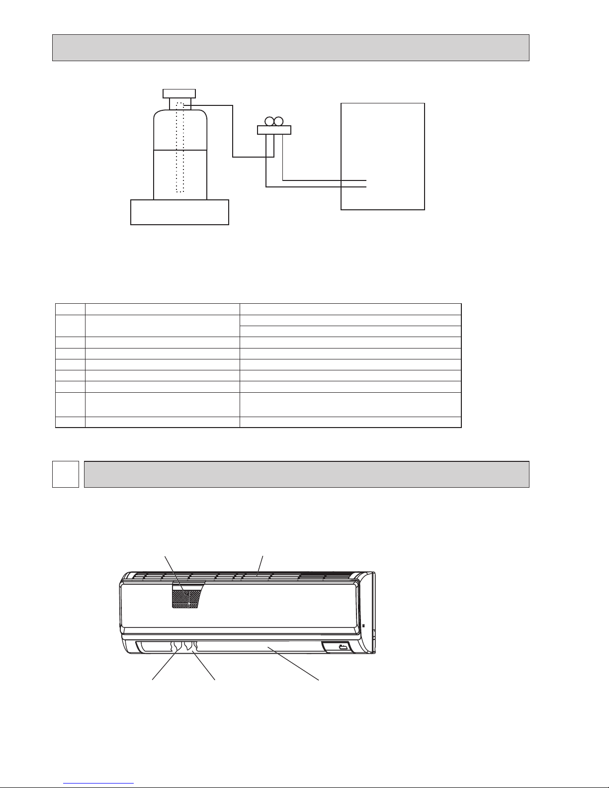
3
PARTS NAMES AND FUNCTIONS
3-1. Indoor unit
Filter
Air intake
Louver
Air outlet
Vane
[5] Service tools
Use the below service tools as exclusive tools for R32/R410A refrigerant.
No. Tool name Specications
1.
Gauge manifold · Use the existing fitting
specifications
. (UNF1/2)
· Use high-tension side pressure of 5.3MPa·G or over.
2. Charge hose
· Use pressure performance of 5.09MPa·G or over.
3.
Electronic weighing scale
―
4.
Gas leak detector · Use the detector for R32 or R410A.
5.
Adaptor for reverse flow check · Attach on vacuum pump.
6.
Refrigerant charge base
―
7.
Refrigerant cylinder · Top of cylinder (R32 or R410A refrigerant)
· Cylinder with syphon
8.
Refrigerant recovery equipment
―
Electronic weighing scale
Unit
OCH660
9
ON/OFF TEMP
FAN
VANE
TEST RUN
AUTO STOP
AUTO START
h
min
LOUVER
MODE
CHECK
RESETSET CLOCK
MODEL SELECT
NOT AV AILABLE
CHECK
TEST RUN
°C
AMPM
AMPM
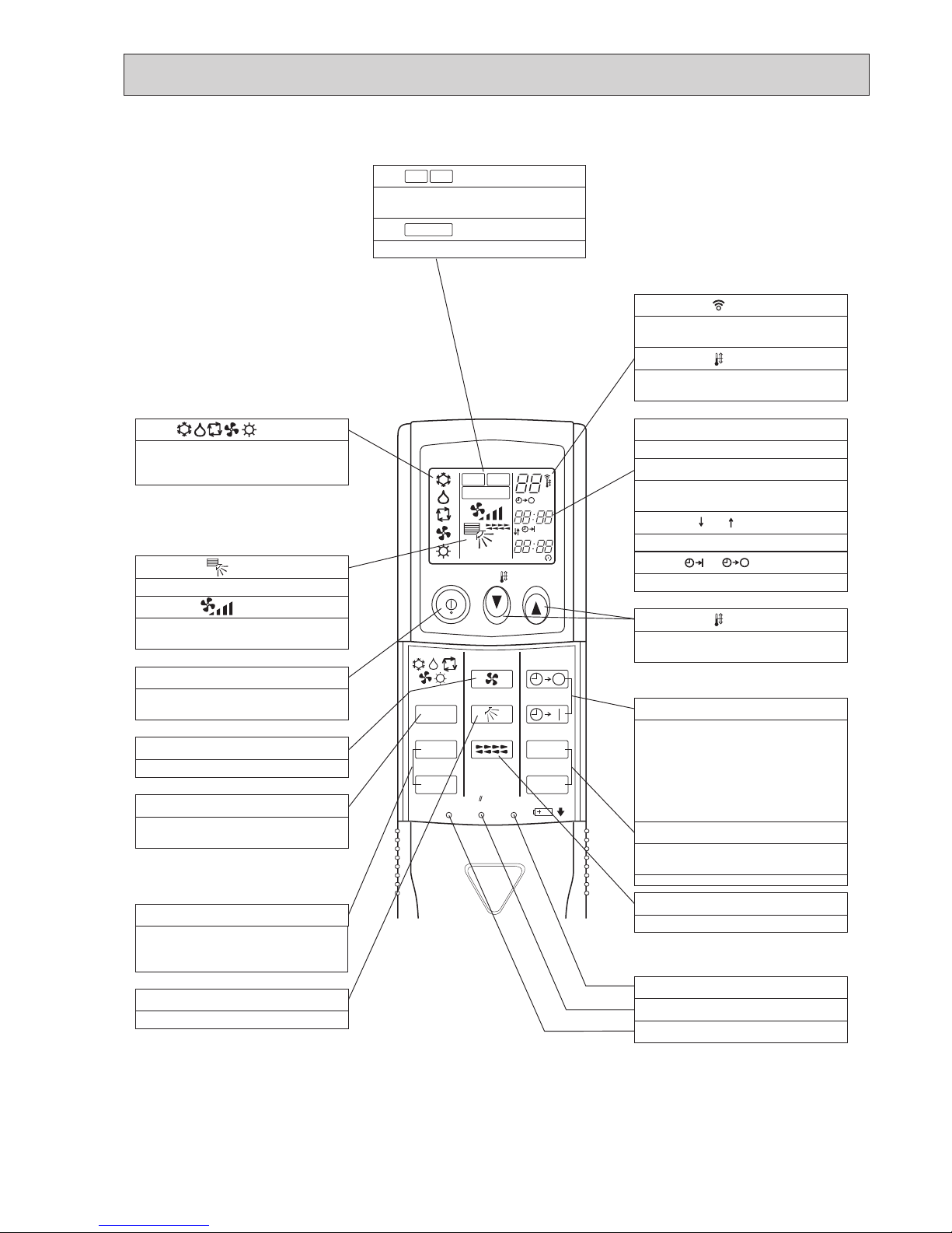
VANE CONTROL button
Used to change the air flow direction.
CLOCK button
RESET button
SET button
ON/OFF button
The unit is turned ON and OFF alternately
each time
the button is pressed.
MODE SELECT button
Used to switch the operation mode between
cooling, drying, heating, auto and fan mode.
CHECK-TEST RUN buttons
Only press this button to perform an
inspection check or test operation.
Do not use it for normal operation.
FAN SPEED SELECT button
Used to change the fan speed.
TIMER display
Displays when in timer operation or when
setting timer.
buttons
SET TEMPERATURE button sets any desired
room temperature.
CLOCK display
Displays the current time.
“ ” “ ” display
Displays the order of timer operation.
“ ” “ ” display
Displays whether timer is on or off.
Buttons used to set the “hour and minute” of
the current time and timer settings.
“h” and “min” buttons
display
display
FAN SPEED display indicates which fan
speed has been selected.
display
The vertical direction of air flow is indicated.
display
Blinks when model is selected.
display
display
CHECK and TEST RUN display indicate that
the unit is being checked or test-run.
display
OPERATION MODE display
Operation mode display indicates which
operation mode is in effect.
AUTO STOP (OFF timer): when this switch
is set, the air conditioner will be
automatically stopped at the preset time.
AUTO START (ON timer): when this switch is
set, the air conditioner will be automatically
started at the preset time.
MODEL SELECT
CHECK
TEST RUN
LOUVER button
Changes left/right airflow direction.
(Not available for this model.)
SET TEMP. display indicates the desired
temperature which is set.
Lights up while the signal is transmitted to
the indoor unit when the button is pressed.
TIMER CONTROL buttons
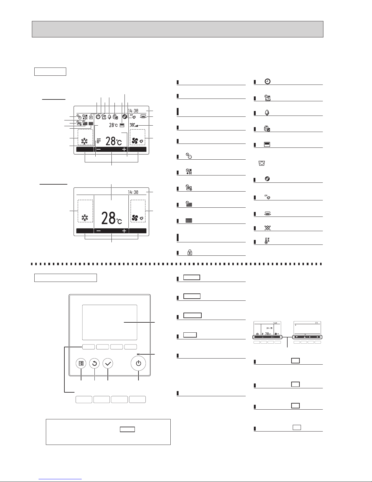
3-2. Wireless remote controller (Option for HA model)
OCH660
10
The functions which can be used are restricted according to each model.
The main display can be displayed in 2 different modes: "Full" and "Basic."
The initial setting is "Full."
Fri
Mode Temp. Fan
Room
Cool Auto
Set temp.
Fri
Cool
Mode Temp. Fan
AutoSet temp.
1
2
3
4
5
21
20
4
3
191716
15
14
13
12
6
8
10
1
11
7
9
22
5
2
Fan speed setting appears here.
4 Fan speed
Appears while the units are operated in the
energy-save mode.
Appears while the outdoor units are operated in
the silent mode.
Preset temperature appears here.
Appears when the ON/OFF operation is centrally
controlled.
Current time appears here.
Appears when the buttons are locked.
Indoor unit operation mode appears here.
Appears when the operation mode is centrally
controlled.
15
16
2 Preset temperature
6
12
1 Operation mode
7
Appears when the units are operated in the
energy-save mode with 3D i-see Sensor.
18
Indicates the louver setting.
Indicates the ventilation setting.
Appears when the On/Off timer or Night setback
function is enabled.
20
21
13
Indicates when filter needs maintenance.
Appears when the filter reset function is centrally
controlled.
Appears when the preset temperature is centrally
controlled.
10
9
8
Appears when the Weekly timer is enabled.
14
Appears when the preset temperature range is
restricted.
22
Functions of the corresponding buttons appear
here.
5 Button function guide
Appears when the built-in thermistor on the
remote controller is activated to monitor the
room temperature (a).
appears when the thermistor on the
indoor unit is activated to monitor the room
temperature.
17
3 Clock
(See the Installation Manual.)
Current room temperature appears here.
11 Room temperature
(See the Installation Manual.)
Note: All icons are displayed for explanation.
5
6
1234
Press to turn ON/OFF the indoor unit.
1 ON/OFF button
This lamp lights up in green while the unit
is in operation. It blinks while the remote
controller is starting up or when there is
an error.
Press to save the setting.
Main display: Press to change the operation
mode.
Main menu: Press to move the cursor down.
Press to return to the previous screen.
Main
display
: Press to decrease temperature.
Main menu: Press to move the cursor up.
Press to bring up the Main menu.
Main
display
: Press to increase temperature.
Main menu: Press to go to the previous page.
Operation settings will appear.
When the backlight is off, pressing any
button turns the backlight on and it
will stay lit for a certain period of time
depending on the screen.
Main
display
: Press to change the fan speed.
Main menu: Press to go to the next page.
6 ON/OFF lamp
2 SELECT button
7 Function button F1
3 RETURN button
8 Function button F2
4 MENU button
9 Function button F3
5 Backlit LCD
10 Function button F4
Fri
Room
Set temp.
Mode Temp. Fan
Cool Auto
Main
Main display:
Cursor Page
Main menu
Vane·Louver·Vent. (Lossnay)
High power
Timer
Weekly timer
OU silent mode
The functions of the function buttons
change depending on the screen. Refer
to the button function guide that appears
at the bottom of the LCD for the functions
they serve on a given screen.
When the system is centrally controlled,
the button function guide that
corresponds to the locked button will not
appear.
Main display Main menu
Function guide
7 8 9 0 7 8 9 0
• When the backlight is off, pressing any button turns the backlight on and
does not perform its function. (except for the ON/OFF button)
• Most settings (except ON/OFF, mode, fan speed, temperature) can be
made from the Menu screen.
Display
Full mode
Basic mode
Controller interface
Function buttons
10987
18
Indicates the vane setting.
19
3-3. WIRED REMOTE CONTROLLER (OPTION) <PAR-32MAA>
OCH660
11
Not all functions are available on all models of indoor units.
Energy saving
Auto return
Schedule
Night setback
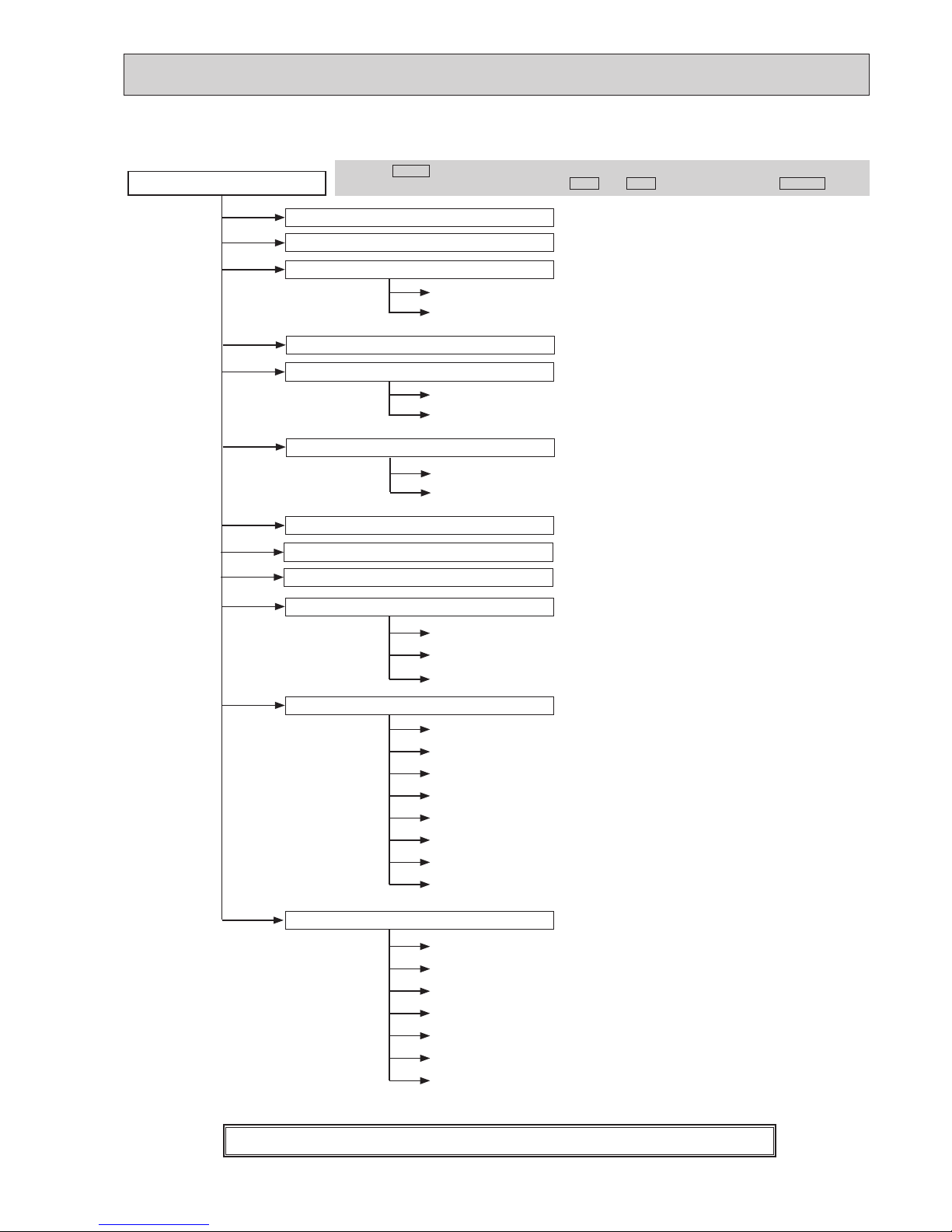
Main menu
Press the
MENU
button.
Move the cursor to the desired item with the
F1
and
F2
buttons, and press the
SELECT
button.
Vane · Louver · Vent. (Lossnay)
High power
Weekly timer
Restriction
Maintenance
Initial setting
ON/OFF timer
Auto-OFF timer
Temp. range
Operation lock
Manual vane angle
Main/Sub
Timer
Main display
Contrast
Display details
Auto mode
Administrator password
Language selection
Service
Input maintenance info.
Function setting
Check
Self check
Maintenance password
Remote controller check
Test run
Clock
Auto descending panel
Menu structure
Filter information
Error information
3D i-see Sensor
OCH660
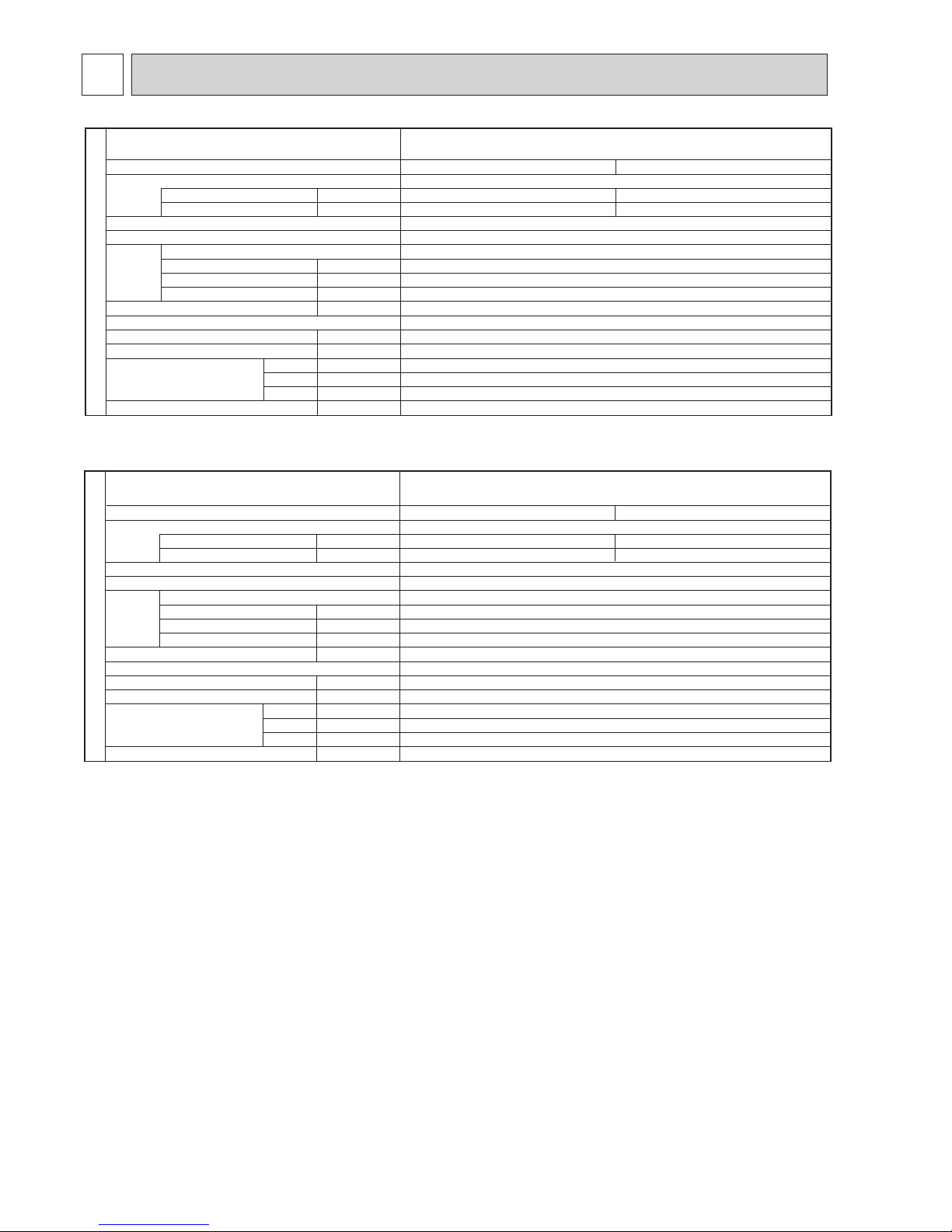
12
SPECIFICATIONS
4
Cooling
0.04
0.40
Heating
0.03
0.30
Single phase, 50Hz, 230V
Munsell 1.0Y 9.2/0.2
Plate fin coil
Line flow fan (direct) o 1
0.030
9-10.5-12 (320-370-425)
0 (direct blow)
–
Wireless remote controller & built-in
36-40-43
16 (5/8)
898 (35-3/8)
249 (9-13/16)
295 (11-5/8)
13 (29)
kW
A
kW
K/min (CFM)
Pa (mmAq)
kW
dB
mm (inch)
mm (inch)
mm (inch)
mm (inch)
kg (lb)
Mode
Power supply (phase, cycle, voltage)
Input
Running current
External finish (Panel)
Heat exchanger
Fan Fan (drive) o No.
Fan motor output
Airflow (Low-Middle-High)
External static pressure
Booster heater
Operation control & Thermostat
Noise level (Low-Middle-High)
Field drain pipe I.D.
Dimensions
Weight
W
D
H
INDOOR UNIT
PKA-M50HA
PKA-M50HAL
Service Ref.
Cooling
0.04
0.40
Heating
0.03
0.30
Single phase, 50Hz, 230V
Munsell 1.0Y 9.2/0.2
Plate fin coil
Line flow fan (direct) o 1
0.030
9-10.5-12 (320-370-425)
0 (direct blow)
–
Wireless remote controller & built-in
36-40-43
16 (5/8)
898 (35-3/8)
249 (9-13/16)
295 (11-5/8)
13 (29)
kW
A
kW
K/min (CFM)
Pa (mmAq)
kW
dB
mm (inch)
mm (inch)
mm (inch)
mm (inch)
kg (lb)
Mode
Power supply (phase, cycle, voltage)
Input
Running current
External finish (Panel)
Heat exchanger
Fan Fan (drive) o No.
Fan motor output
Airflow (Low-Middle-High)
External static pressure
Booster heater
Operation control & Thermostat
Noise level (Low-Middle-High)
Field drain pipe I.D.
Dimensions
Weight
W
D
H
INDOOR UNIT
PKA-M35HA
PKA-M35HAL
Service Ref.
OCH660
13
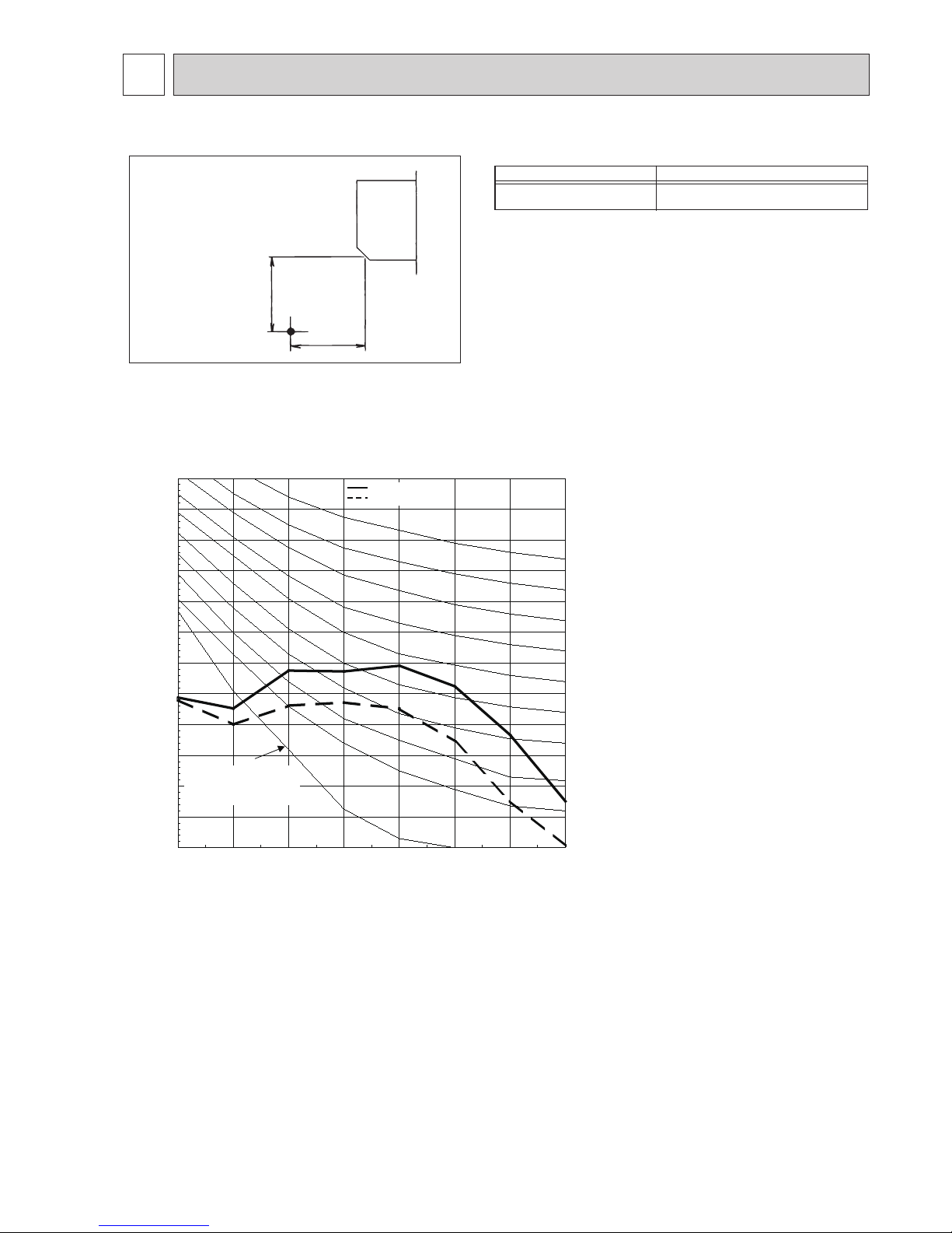
5
NOISE CRITERION CURVES
* Measured in anechoic room.
PKA-M35/50HA(L)
36 - 40 - 43
Sound level dB (A)
Sound level at anechoic room : Low-Middle-High
1.0m
1.0m
Measurement location
Model
5-1. SOUND LEVELS
5-2. NOISE CRITERION CURVES
10.0
15.0
20.0
25.0
30.0
35.0
40.0
45.0
50.0
55.0
60.0
65.0
70.0
63 125 250 500 1k 2k 4k 8k
NC-60
NC-50
Octave band pressure level (dB) 0dB=20μPa
Approximate minimum
audible limit on
continuous noise
NC-40
Octave band center frequencies (Hz)
NC-20
NC-30
High
OCH660
 Loading...