

Page 1
SPLIT-TYPE AIR CONDITIONERS
TECHNICAL & SERVICE MANUAL
2000
No. OC212
REVISED EDITION-A
Floor StandingSeries PSH/PSA
Indoor unit
[Model names] [Service Ref.]
R407C
2000, 2001 2000 2001
PSH-P3GAH
PSH-P4GAH
PSH-P5GAH
PSH-P6GAH
PSA-P3GA
PSA-P4GA
PSA-P5GA
PSA-P6GA
PSH-P3GAH PSH-P3GAH1
PSH-P4GAH PSH-P4GAH1
PSH-P5GAH PSH-P5GAH1
PSH-P6GAH PSH-P6GAH1
PSA-P3GA PSA-P3GA1
PSA-P4GA PSA-P4GA1
PSA-P5GA PSA-P5GA1
PSA-P6GA PSA-P6GA1
•PSH-P3GAH1,
PSH-P4GAH
PSH-P5GAH
PSH-P6GAH
PSA-P3GA
PSA-P4GA
PSA-P5GA
PSA-P6GA
in REVISED EDITION-A.
•Please void OC212.
•Refer to the OCT03
REVISED EDITION-C
as for control relation.
This manual does not
cover outdoor units.
When serving them,
please refer to the
service manual
No.OC180 REVISED
EDITION-A, OC261 and
this manual in a set.
1,
1,
1,
1,
1,
1 and
1 are added
CONTENTS
1.TECHNICAL CHANGES ························2
2.
COMBINATION OF INDOOR AND OUTDOOR UNITS
3.SAFETY PRECAUTION·························3
4. PART NAMES AND FUNCTIONS········5
5. SPECIFICATIONS·································9
6. DATA···················································17
7. OUTLINES AND DIMENSIONS··········45
8. WIRING DIAGRAM ·····························47
9.
REFRIGERANT SYSTEM DIAGRAM
10. TROUBLE SHOOTING·······················50
11. DISASSEMBLY PROCEDURE···········51
12. PARTS LIST········································54
13 . OPTIONAL PARTS·········BACK COVER
···2
······48
Page 2
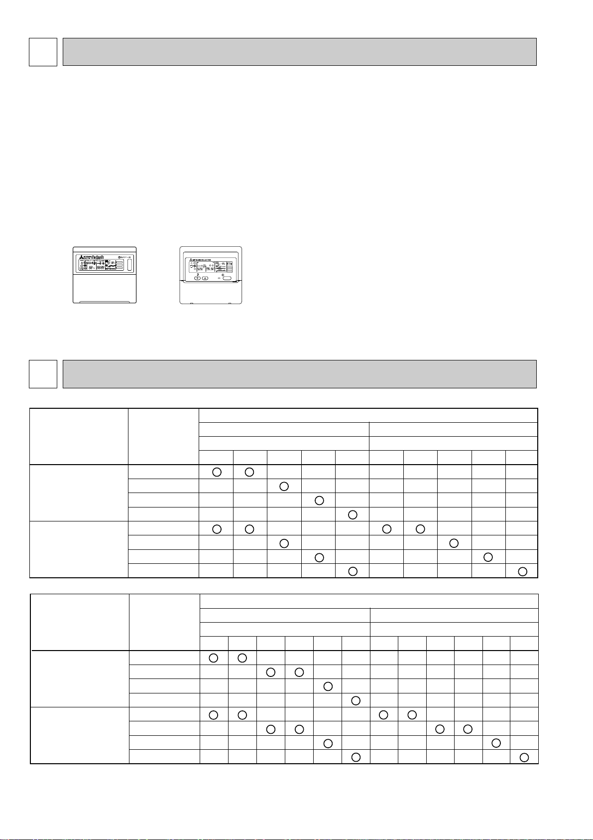
1
Heat pump type
Outdoor unit (OC180REVISED EDITION-A)
PUH-P · VGA / YGA
Cooling only type
PU-P · VGA / YGA
Heat pump with
electric heater
PSH-P3GAH
PSH-P4GAH
PSH-P5GAH
PSH-P6GAH
PSA-P3GA
PSA-P4GA
PSA-P5GA
PSA-P6GA
Heat pump without
electric heater
or
Cooling only
6Y
—
—
—
—
—
—
—
5Y
—
—
—
—
—
—
—
4Y
—
—
—
—
—
—
—
3Y
—
—
—
—
—
—
—
3V
—
—
—
—
—
—
—
6Y
—
—
—
—
—
—
5Y
—
—
—
—
—
—
4Y
—
—
—
—
—
—
3Y
—
—
—
—
—
—
3V
—
—
—
—
—
—
Indoor unit
Heat pump type
Outdoor unit (OC261)
PUH-P · VGAA.UK / YGAA.UK
Cooling only type
PU-P · VGAA.UK / YGAA.UK
Heat pump with
electric heater
PSH-P3GAH1
PSH-P4GAH1
PSH-P5GAH1
PSH-P6GAH1
PSA-P3GA1
PSA-P4GA1
PSA-P5GA1
PSA-P6GA1
Heat pump without
electric heater
or
Cooling only
6Y
—
—
—
—
—
—
—
5Y
—
—
—
—
—
—
—
4V
—
—
—
—
—
—
—
3Y
—
—
—
—
—
—
—
3V
—
—
—
—
—
—
—
6Y
—
—
—
—
—
—
5Y
—
—
—
—
—
—
4V
—
—
—
—
—
—
3Y
—
—
—
—
—
—
3V
—
—
—
—
—
—
4Y
—
—
—
—
—
—
—
4Y
—
—
—
—
—
—
Indoor unit
FILTER
CHECK MODE
TEST RUN
ON/OFF
CENTRALLY CONTROLLED
ERROR CODE
CLOCK
ON OFF
˚C
CHECK
CHECK MODE
FILTER
TEST RUN
FUNCTION
˚C
1Hr.
NOT AVAILABLE
STAND BY
DEFROST
TEMP.
TECHNICAL CHANGES
PSH-P3GAH ➔ PSH-P3GAH1 PSA-P3GA ➔ PSA-P3GA1
PSH-P4GAH ➔ PSH-P4GAH1 PSA-P4GA ➔ PSA-P4GA1
PSH-P5GAH ➔ PSH-P5GAH1 PSA-P5GA ➔ PSA-P5GA1
PSH-P6GAH ➔ PSH-P6GAH1 PSA-P6GA ➔ PSA-P6GA1
● Outdoor units which are connected to PSH-P·GAH1 and PSA-P·GA1 have been added.
● ROOM TEMPERATURE THERMISTOR has changed because it has made the lead wire longer in order to improve work
efficiency.
● FAN MOTOR CAPACITOR has changed because it no longer meets the criteria of UL Standards.
● FAN GUARD has changed because it has become an individual part, which was once specified as a part combined with
BELL MOUTH.
● The parts No. of REMOTE CONTROLLER has changed.
(The following parts numbers are interchangeable.)
➔
[ T7W E03 713 ] [ T7W E07 713 ]
2
COMBINATION OF INDOOR AND OUTDOOR UNITS
2
Page 3

3
SAFETY PRECAUTION
Cautions for using with the outdoor unit which adopts R407C refrigerant.
· Do not use the existing refrigerant piping.
-The old refrigerant and refrigerant oil in the existing piping contains a large amount of chlorine which may cause the refrigerant oil of the new unit to deteriorate.
· Do not use copper pipes which are broken, deformed or discolour .
In addition, be sure that the inner surfaces of the pipes are clean, free of hazardous sulphur and oxides, or have no dust /
dirt, shaving particles, oils, moisture or any other contamination.
-If there is a large amount of residual oil (hydraulic oil, etc.) inside the piping and joints, deterioration of the refrigerant oil will
result.
· Store the piping to be used during installation indoors and keep both ends of the piping sealed until just before
brazing. (Store elbows and other joints in a plastic bag.)
-If dust, dirt, or water enters the refrigerant cycle, deterioration of the oil and compressor trouble may result.
· Use ester oil, ether oil or alkyl benzene (small amount) as the refrigerant oil to coat flares and flange connections.
-The refrigerant oil will degrade if it is mixed with a large amount of mineral oil.
Use liquid refrigerant to fill the system.
-If gas refrigerant is used to fill the system, the composition of the refrigerant in the cylinder will change and performance
may drop.
· Do not use a refrigerant other than R407C.
-If another refrigerant (R22, etc.) is used, the chlorine in the refrigerant may cause the refrigerant oil to deteriorate.
· Use a vacuum pump with a reverse flow check valve.
-The vacuum pump oil may flow back into the refrigerant cycle and cause the refrigerant oil to deteriorate.
· Do not use the following tools that are used with conventional refrigerant.
(Gauge manifold , charge hose, gas leak detector, reverse flow check valve, refrigerant charge base, vacuum gauge,
refrigerant recovery equipment)
-If the conventional refrigerant and refrigerant oil are mixed in the R407C, the refrigerant may deteriorated.
-If water is mixed in the R407C, the refrigerant oil may deteriorate.
-Since R407C does not contain any chlorine, gas leak detectors for conventional refrigerant will not react to it.
· Do not use a charging cylinder.
-Using a charging cylinder may cause the refrigerant to deteriorate.
· Be especially careful when managing the tools.
-if dust, dirt, or water gets in the refrigerant cycle, the refrigerant may deteriorate.
· Do not use the drier which is sold in the field.
-The drier for R407C refrigerant is per-attached to outdoor unit refrigerant circuit.
-Some drier in the field are not in conformity with R407C refrigerant .
3
Page 4
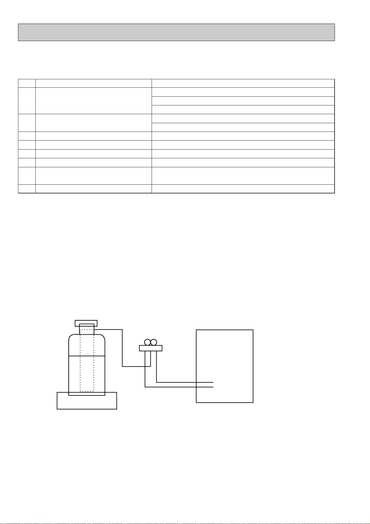
Gravimeter
Unit
[1] Service tools
Use the below service tools as exclusive tools for R407C refrigerant.
No. Tool name Specifications
1 Gauge manifold ·Only for R407C.
·Use the existing fitting SPECIFICATIONS. (UNF7/16)
·Use high-tension side pressure of 3.43MPa·G or over.
2 Charge hose ·Only for R407C.
·Use pressure performance of 5.10MPa·G or over.
3 Electronic scale
4 Gas leak detector ·Use the detector for R407C.
5 Adapter for reverse flow check. ·Attach on vacuum pump.
6 Refrigerant charge base.
7 Refrigerant cylinder. ·For R407C ·Top of cylinder (Brown)
·Cylinder with syphon
8 Refrigerant recovery equipment.
[2] Notice on repair service
·After recovering the all refrigerant in the unit, proceed to working.
·Do not release refrigerant in the air.
·After completing the repair service, recharge the cycle with the specified amount of
liquid refrigerant.
[3] Refrigerant recharging
(1) Refrigerant recharging process
1Direct charging from the cylinder.
·R407C cylinder are available on the market has a syphon pipe.
·Leave the syphon pipe cylinder standing and recharge it.
(By liquid refrigerant)
(2) Recharge in refrigerant leakage case
·After recovering the all refrigerant in the unit, proceed to working.
·Do not release the refrigerant in the air.
·After completing the repair service, recharge the cycle with the specified amount of
liquid refrigerant.
4
Page 5
4
Disperses air
up and down
Disperses air left
and right.
Removes dust and pollutants from intake air.
(Intakes air from room.)
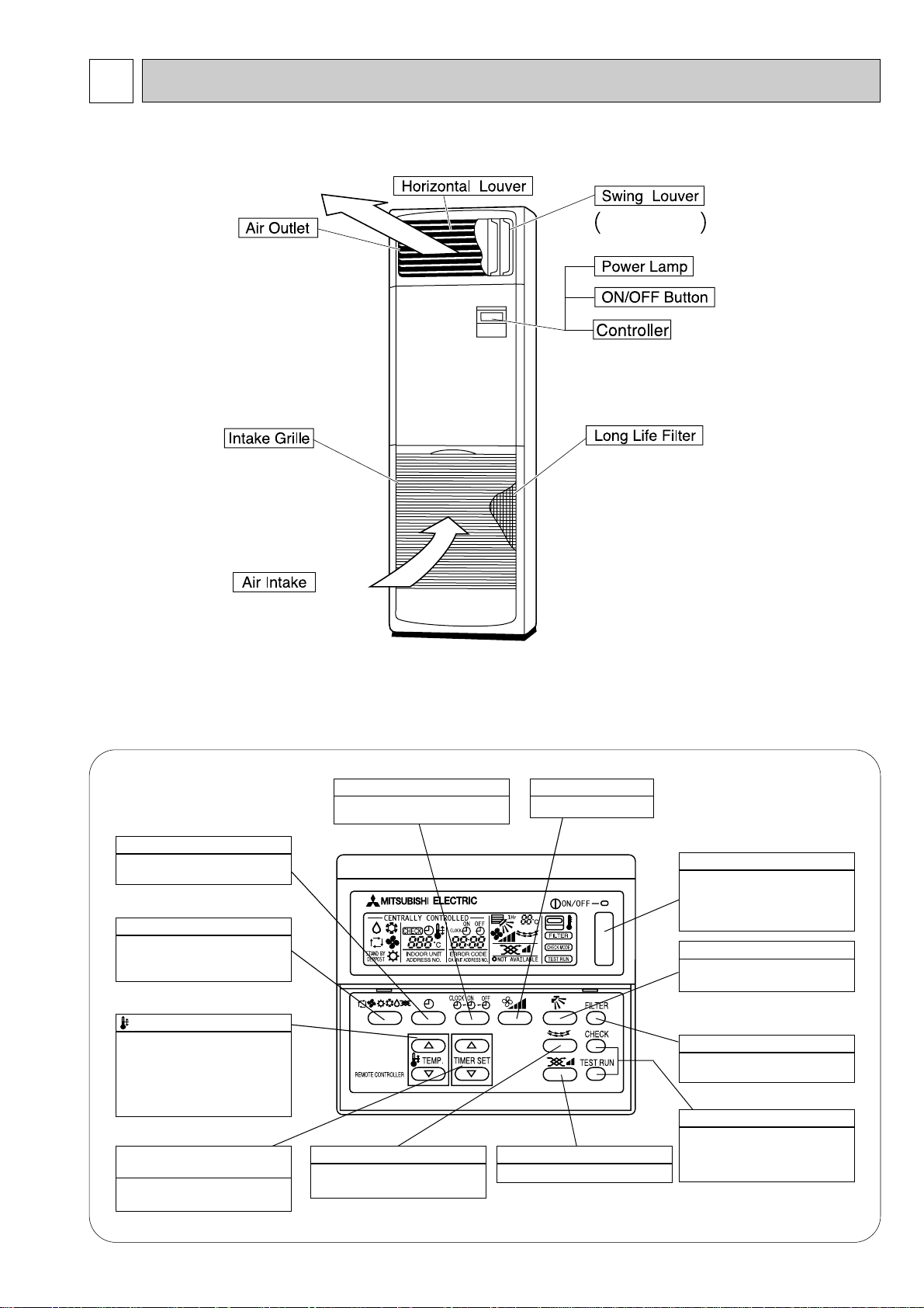
PART NAMES AND FUNCTIONS
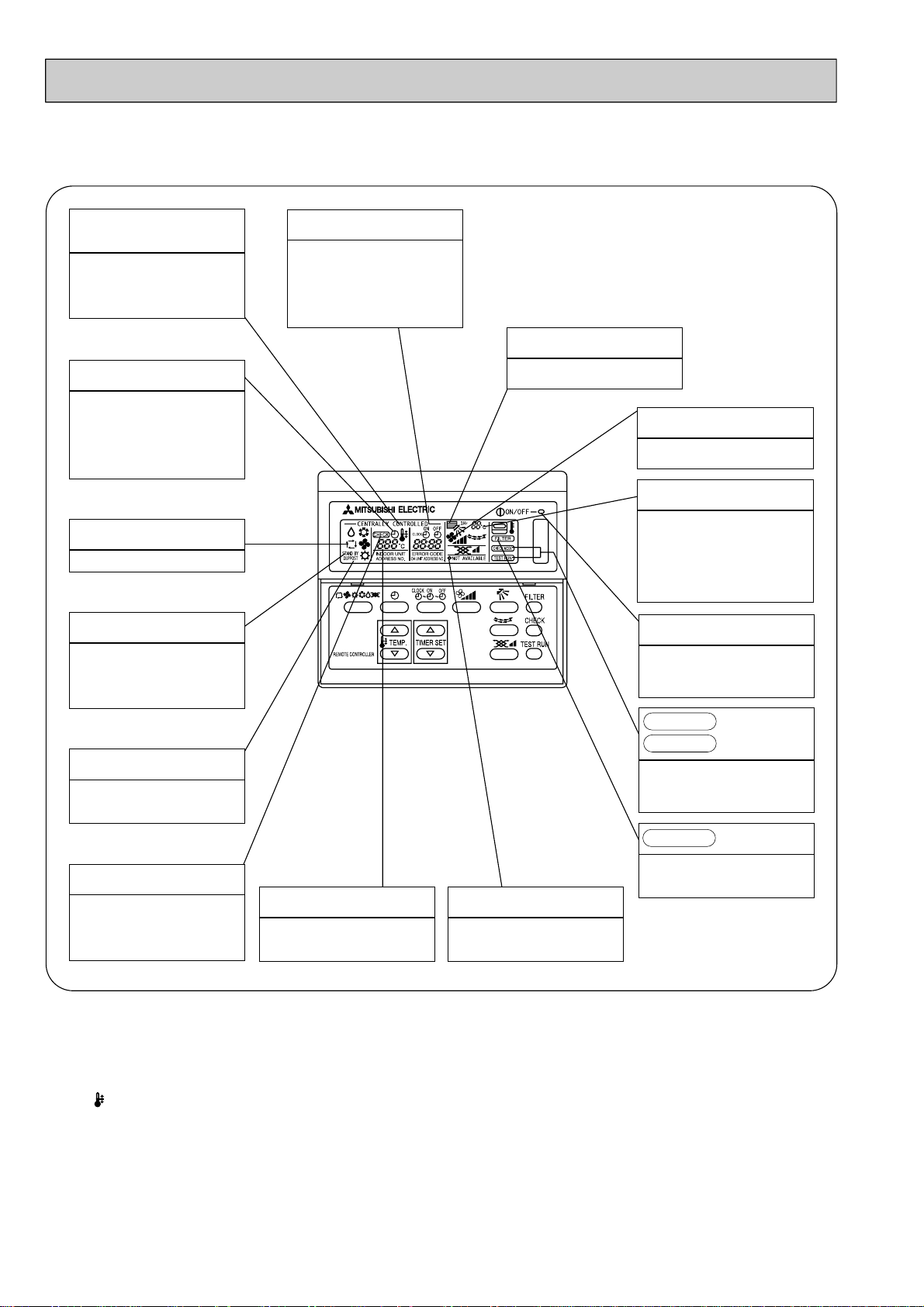
● Indoor (Main) Unit
● Controller
Once the controls are set, the same operation mode can be repeated by simply pressing the ON/OFF button.
PSH-P3/4/5/6GAH, PSA-P3/4/5/6GA
● Operation buttons
AIR SPEED button
This sets the fan speed.
VENTILATION button
This set the ventilation fan speed.
ON/OFF button
This switches between the operation and stop modes each time it is
pressed. The lamp on this button
lights during operation.
AIR DIRECTION button
This adjusts the vertical angle of
the ventilation.
(This button does not operate in
this model)
FILTER button
This resets the filter service indication display.
CHECK-TEST RUN button
Only press this button to perform
an inspection check or test operation Do not use it for normal operation.
TIMER button
This switches between continuous
operation and the timer operation.
OPERATION SWITCH button
Press this button to switch the
cooler electronic dry (dehumidify)
automatic and heater modes.
TEMP. ADJUSTMENT button
This sets the room temperature
The temperature setting can be
performed in 1°C units
Setting range
Cooler 19°C to 30°C
Heater 17°C to 28°C
TIMER ADJUSTMENT
button
This adjust the current time, start
time and stop time.
TIME SETTING button
This sets of switches the current
time. start time and stop time.
LOUVER button
This switches the horizontal fan
motion ON and OFF.
5
Page 6
PSH-P3/4/5/6GAH, PSA-P3/4/5/6GA
● Display
CENTRALLY
CONTROLLED display
This indicates when the unit is con-
trolled by optional features such as
central control type remote controller.
TIMER display
This indicates when the continuous
operation and time operation modes
are set.
It also display the time for the timer
operation at the same time as when
it is set.
OPERATION MODE display
This indicates the operation mode.
STANDBY display
This indicates when the standby
mode is set from the time the sleep
operation starts until the heating air
is discharged.
DEFROST display
This indicates when the defrost oper-
ation is performed.
CLOCK display
The current time , start time and stop
time can be displayed in ten second
intervals by pressing the time switch
button. The start time or stop time is
always displayed during the timer
operation.
In this display example on the bottom left, a condition where all display lamps light is shown for explanation purposes although this differs
from actual operation.
AIR DIRECTION display
The selected fan speed is displayed.
FAN SPEED display
This displays the air direction.
ROOM TEMPERATURE display
The temperature of the suction air is
displayed during operation. The display range is 8° to 39°C. The display
flashes 8°C when the actual temperature is less than 8° and flashes
39°C when the actual temperature is
greater than 39°C.
Operation lamp
This lamp lights during operation,
goes off when the unit stops and
flashes when a malfunction occurs.
CHECK MODE
TEST RUN
This display lights in the check mode
or when a test operation is performed.
display
CHECK display
This indicates when a malfunction
has occurred in the unit which should
be checked.
SET TEMPERATURE display
This displays the selected setting
temperature.
FILTER
This lamp lights when the filter need
to be cleaned.
POWER display
This lamp lights when electricity is
supplied to the unit.
display
Caution
● Only the Power display lights when the unit is stopped and power supplied to the unit.
● When power is turned ON for the first time the (CENTRAL CTRL) display appears to go off momentarily but this is not a
malfunction.
● When the central control remote control unit, which is sold separately, is used the ON-OFF button, operation switch button
and TEMP. adjustment button do not operate.
● “NOT AVAILABLE” is displayed when the Air direction button are pressed.This indicates that this room unit is not equipped
with the fan direction adjustment function and the louver function.
● When power is turned ON for the first time, it is normal that “H0” is displayed on the room temperature indication (For max.
2minutes). Please wait until this “H0” indication disappear then start the operation.
6
Page 7
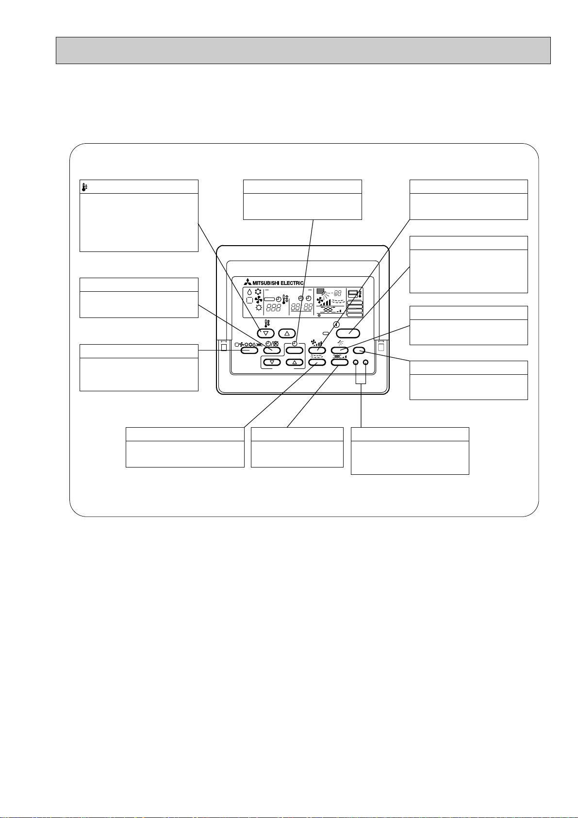
● Controller
PAR-20MAA
ON/OFF
CENTRALLY CONTROLLED
ERROR CODE
CLOCK
ON OFF
˚C
CHECK
CHECK MODE
FILTER
TEST RUN
FUNCTION
˚C
1Hr.
NOT AVAILABLE
STAND BY
DEFROST
FILTER
CHECK TEST
TEMP.
TIMER SET
Press this button to switch the cooler,
electronic dry (dehumidify), automatic
and heater modes.
OPERATION SWITCH button
This sets the room temperature. The
temperature setting can be performed
in 1: units
Setting range
Cooler 19: to 30:
Heater 17: to 28:
TEMP. ADJUSTMENT button
This switches between continuous
operation and the timer operation.
TIMER button
This switches between the operation
and stop modes each time it is pressed.
The lamp on this button lights during
operation.
ON/OFF button
Only press this button to perform an
inspection check or test operation.
Do not use it for normal operation.
CHECK-TEST RUN button
This switch the horizontal fan motion
ON and OFF.
(Not available for this model.)
This sets the ventilation
fan speed.
LOUVER button VENTILATION button
This adjusts the vertical angle of the
ventilation.
AIR DIRECTION button
This resets the filter service indication
display
FILTER button
This sets the current time, start time
and stop time.
TIME SETTING button
This sets the ventilation fan speed.
AIR SPEED button
Once the controls are set, the same operation mode can be repeated by simply pressing the ON/OFF button.
PSH-P3/4/5/6GAH1, PSA-P3/4/5/6GA1
● Operation buttons
7
Page 8
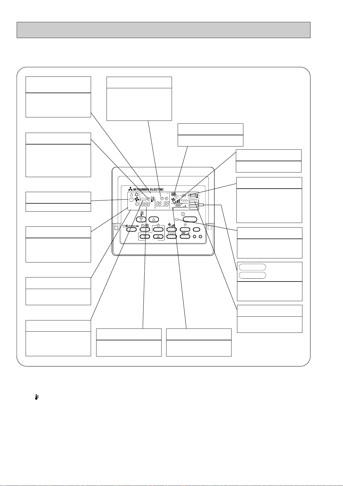
PSH-P3/4/5/6GAH1, PSA-P3/4/5/6GA1
PAR-20MAA
ON/OFF
CENTRALLY CONTROLLED
ERROR CODE
CLOCK
ON OFF
˚C
CHECK
CHECK MODE
FILTER
TEST RUN
FUNCTION
˚C
1Hr.
NOT AVAILABLE
STAND BY
DEFROST
FILTER
CHECK TEST
TEMP.
TIMER SET
● Display
CENTRALLY
CONTROLLED display
This indicates when the unit is con-
trolled by optional features such as
central control type remote controller.
TIMER display
This indicates when the continuous
operation and time operation modes
are set.
It also display the time for the timer
operation at the same time as when
it is set.
OPERATION MODE display
This indicates the operation mode.
STANDBY display
The [STANDBY] symbol is only
displayed from the time the heating
operation starts unit the heated air
begins to blow.
DEFROST display
This indicates when the defrost oper-
ation is performed.
CLOCK display
The current time , start time and stop
time can be displayed in ten second
intervals by pressing the time switch
button. The start time or stop time is
always displayed during the timer
operation.
In this display example on the bottom left, a condition where all display lamps light is shown for explanation purposes although this differs
from actual operation.
AIR DIRECTION display
This displays the air direction.
AIR SPEED display
The selected fan speed is displayed.
ROOM TEMPERATURE display
The temperature of the suction air
is displayed during operation. The
display range is 8°C to 39°C. The
display flashes 8°C when the actual
temperature is less than 8°C and
flashes 39°C when the actual temperature is greater than 39°C.
Operation lamp
This lamp lights during operation,
goes off when the unit stops and
flashes when a malfunction occurs.
CHECK MODE
TEST RUN
This display lights in the check mode
or when a test operation is performed.
display
FILTER display
CHECK display
This indicates when a malfunction
has occurred in the unit which should
be checked.
SET TEMPERATURE display
This displays the selected setting
temperature.
Caution
● Only the Power display lights when the unit is stopped and power supplied to the unit.
● When the central control remote control unit, which is sold separately, is used the ON-OFF button, operation switch button
and TEMP. adjustment button do not operate.
● “NOT AVAILABLE” is displayed when the Air speed button are pressed.This indicates that this room unit is not equipped
with the fan direction adjustment function and the louver function.
● When power is turned ON for the first time, it is normal that “H0” is displayed on the room temperature indication (For max.
2minutes). Please wait until this “H0” indication disappear then start the operation.
POWER display
This lamp lights when electricity is
supplied to the unit.
This lamp lights when the filter need
to be cleaned.
8
Page 9
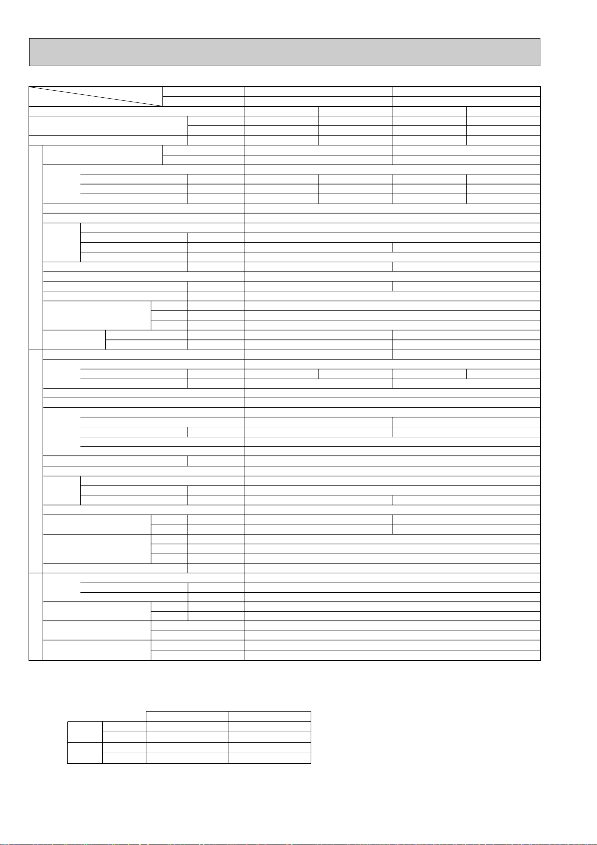
SPECIFICATIONS5
Service Ref.
With Electric heater
Without Electric heater
With Electric heater
Without Electric heater
With Electric heater
Without Electric heater
Item
Btu/h
W
kW
kW
A
A
kW
K/min(CFM)
Pa(mmAq)
kW
dB
mm(in.)
mm(in.)
mm(in.)
mm(in.)
kg(lbs)
kg(lbs)
A
A
kW
W
kW
K
/min(CFM
)
dB
dB
mm(in.)
mm(in.)
mm(in.)
kg(lbs)
kg(lbs)
L
mm(in.)
mm(in.)
Function
Capacity w1
Total input w1
Service Ref.
Power supply
Input w2
Running current w2
Starting current w2
External finish
Heat exchanger
Fan Fan(drive) x No.
Fan motor output
Airflow(Lo-Hi)
External static pressure
Booster heater w2
Operation control & Thermostat
Noise level(Lo-Hi)
Unit drain pipe O.D.
Dimensions
Weight
Service Ref.
Power supply
Running current
Starting current
External finish
Refrigerant control
Compressor
Model
Motor output
Starter type
Protection devices
Crankcase heater
Heat exchanger
Fan Fan(drive) x No.
Fan motor output
Airflow
Defrost method
Noise level
Dimensions
Weight
Refrigerant
Charge
Oil (Model)
Pipe size O.D.
Connection method
Between the indoor &
outdoor unit
INDOOR UNITOUTDOOR UNIT
REFRIGERANT PIPING
PSH-P3GAH
PSA-P3GA
PSH-P4GAH
PSA-P4GA
Cooling
26,300
7,700
3.48
0.16
0.68
–
14.64 / 5.46
Cooling
33,100
9,700
3.65
0.26
1.10
–
5.49
Heating
30,400 (37,500)
8,900 (11,000)
3.63 (5.73)
0.16 <2.26>
0.68 <9.42>
–
15.43 / 5.76
Heating
37,000 (46,200)
10,850 (13,550)
3.76 (6.46)
0.26 <2.96>
0.11 <12.33>
–
5.79
W
D
H
Cooling
Heating
W
D
H
Liquid
Gas
Indoor side
Outdoor side
Height difference
Piping length
Notes1.Rating Conditions (ISO T1)
Cooling :Indoor : D.B. 27˚C(80˚F), W.B. 19˚C (66˚F) Outdoor : D.B. 35˚C(95˚F), W.B. 24˚C (75˚F)
Heating :Indoor : D.B. 20˚C(68˚F) Outdoor : D.B. 7˚C(45˚F), W.B. 6˚C (43˚F)
Refrigerant piping length (one way) : 5m (16ft)
3. Above data based on indicated voltage
Indoor Unit Single phase 240V 50Hz
Outdoor Unit Single phase 240V 50Hz / 3 phase 415V 50Hz
2. Guaranteed operating range
Upper limit
Lower limit
Upper limit
Lower limit
Indoor
D.B. 35˚C, W.B. 22.5˚C
D.B. 19˚C, W.B. 15˚C
D.B. 28˚C
D.B. 17˚C
Outdoor
D.B. 46˚C
D.B. -5˚C
D.B. 24˚C, W.B. 18˚C
D.B. -11˚C, W.B. -12˚C
Cooling
Heating
w1 : ( ) Shows the total rating when booster heater operates.
w2 : < > Shows the only booster heater rating.
0.03
15-18 <530-636>
<2.1>
40-45
270(10-5/8)
45(99)
43(95)
PUH-P3VGA / PUH-P3YGA
Single phase, 50Hz, 220-230-240V / 3 phase, 50Hz, 380-400-415V(4wires)
93 / 41
NE52VNJM / NE52YDJM
2.5
Propeller (direct) x 1
0.070
50(1,770)
49
51
855(33-5/8)
82(181)
3.7(8.2)
15.88(5/8)
0.07
24-31 <847-1,059>
<2.7>
44-49
350(13-3/4)
53(117)
51(112)
PUH-P4YGA
3 phase, 50Hz, 380-400-415V(4wires)
45
NE56YDJM
2.7
Propeller (direct) x 2
0.070+0.070
85(3,000)
51
53
1,260(49-5/8)
96(212)
4.0(8.8)
19.05(3/4)
Single phase, 50Hz, 220-230-240V
Munsell 0.70Y 8.59 / 0.97
Plate fin coil
Centrifugal(direct) x 1
0(direct blow)
Remote controller & built-in
20(13/16)
600(23-5/8)
1,900(74-13/16)
Munsell 5Y 8/1
Linear Expansion Valve
Hermetic
Line start
38
Plate fin coil
Reverse cycle
900(35-7/16)
330+20(13+3/4)
R407C
1.6(Ester)MEL56
9.52(3/8)
Flared
Flared
Max. 50m
Max. 50m
VGA...Inner thermostat, HP switch, Discharge thermo.
YGA...Thermal relay, Discharge thermo, HP switch, Anti-phase protector.
PSH-P3GAH
PSA-P3GA
PSH-P4GAH
PSA-P4GA
1.1.Heat pump type Rating Conditions (ISO T1)
9
Page 10
Rating Conditions (ISO T1)
Service Ref.
With Electric heater
Without Electric heater
With Electric heater
Without Electric heater
With Electric heater
Without Electric heater
Item
Btu/h
W
kW
kW
A
A
kW
K/min(CFM)
Pa(mmAq)
kW
dB
mm(in.)
mm(in.)
mm(in.)
mm(in.)
kg(lbs)
kg(lbs)
A
A
kW
W
kW
K
/min(CFM
)
dB
dB
mm(in.)
mm(in.)
mm(in.)
kg(lbs)
kg(lbs)
L
mm(in.)
mm(in.)
Function
Capacity w1
Total input w1
Service Ref.
Power supply
Input w2
Running current w2
Starting current w2
External finish
Heat exchanger
Fan Fan(drive) x No.
Fan motor output
Airflow(Lo-Hi)
External static pressure
Booster heater w2
Operation control & Thermostat
Noise level(Lo-Hi)
Unit drain pipe O.D.
Dimensions
Weight
Service Ref.
Power supply
Running current
Starting current
External finish
Refrigerant control
Compressor
Model
Motor output
Starter type
Protection devices
Crankcase heater
Heat exchanger
Fan Fan(drive) x No.
Fan motor output
Airflow
Defrost method
Noise level
Dimensions
Weight
Refrigerant
Charge
Oil (Model)
Pipe size O.D.
Connection method
Between the indoor &
outdoor unit
INDOOR UNITOUTDOOR UNIT
REFRIGERANT PIPING
PSH-P5GAH
PSA-P5GA
PSH-P6GAH
PSA-P6GA
Cooling
42,700
12,500
5.62
0.30
1.26
–
8.39
Cooling
48,500
14,200
6.46
0.38
1.62
–
10.17
Heating
46,700 (57,000)
13,700 (16,700)
5.88 (8.88)
0.30 <3.00>
1.26 <12.5>
–
8.74
Heating
54,600 (64,800)
16,000 (19,000)
6.50 (9.50)
0.38 <3.00>
1.62 <12.5>
–
10.28
W
D
H
Cooling
Heating
W
D
H
Liquid
Gas
Indoor side
Outdoor side
Height difference
Piping length
Notes1.Rating Conditions (ISO T1)
Cooling :Indoor : D.B. 27˚C(80˚F), W.B. 19˚C (66˚F) Outdoor : D.B. 35˚C(95˚F), W.B. 24˚C (75˚F)
Heating :Indoor : D.B. 20˚C(68˚F) Outdoor : D.B. 7˚C(45˚F), W.B. 6˚C (43˚F)
Refrigerant piping length (one way) : 5m (16ft)
3. Above data based on indicated voltage
Indoor Unit Single phase 240V 50Hz
Outdoor Unit 3 phase 415V 50Hz
2. Guaranteed operating range
Upper limit
Lower limit
Upper limit
Lower limit
Indoor
D.B. 35˚C, W.B. 22.5˚C
D.B. 19˚C, W.B. 15˚C
D.B. 28˚C
D.B. 17˚C
Outdoor
D.B. 46˚C
D.B. -5˚C
D.B. 24˚C, W.B. 18˚C
D.B. -11˚C, W.B. -12˚C
Cooling
Heating
26-33 <918-1,165>
<3.0>
46-51
53(117)
51(112)
PUH-P5YGA
79
HE86YAA
4.3
95(3,360)
53
55
27-35 <953-1,236>
<3.0>
47-52
55(121)
53(117)
PUH-P6YGA
84
HE101YAA
5.1
100(3,530)
55
57
Single phase, 50Hz, 220-230-240V
Munsell 0.70Y 8.59 / 0.97
Plate fin coil
Centnifugal (direct) x 1
0.11
0 (direct blow)
built-in
20(13/16)
600(23-5/8)
350(13-3/4)
1,900(74-13/16)
3 Phase, 50Hz, 380-400-415V(4wires)
Munsell 5Y 8/1
Linear Expansion Valve
Hermetic
Line start
Anti-phase protector, Internal thermostat, LP switch, HP switch,Thermal relay,Discharge thermo
38
Plate fin coil
Propeller (direct) x 2
0.075+0.075
Reverse cycle
1050(41-5/16)
330+20(13+3/4)
1,260(49-5/8)
122(269)
R407C
5.8(12.8)
2.0 (Ester)MEL32
9.52(3/8)
19.05(3/4)
Flared
Flared
Max. 50m
Max. 50m
w1 : ( ) Shows the total rating when booster heater operates.
w2 : < > Shows the only booster heater rating.
PSH-P5GAH
PSA-P5GA
PSH-P6GAH
PSA-P6GA
10
Page 11
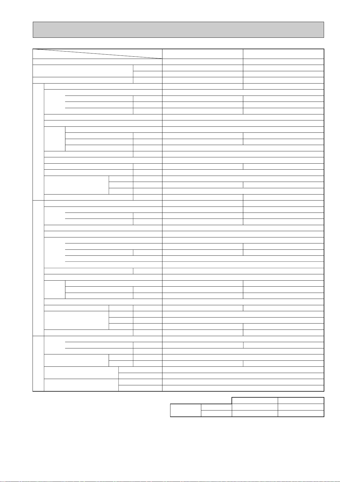
1.2.Cooling only type Rating Conditions (ISO T1)
Item
Function
Capacity
Total input
Service Ref.
Power supply
Input
Running current
Starting current
External finish
Heat exchanger
Fan
Booster heater
INDOOR UNIT
Operation control & Thermostat
Noise level(Lo-Hi)
Unit drain pipe O.D.
Dimensions
Weight
Service Ref.
Power supply
External finish
Refrigerant control
Compressor
Crankcase heater
Heat exchanger
Fan
OUTDOOR UNIT
Defrost method
Noise level
Dimensions
Weight
Refrigerant
Pipe size O.D.
PIPING
Connection method
Fan(drive))No.
Fan motor output
Airflow(Lo-Hi)
External static pressure
Running current
Starting current
Model
Motor output
Starter type
Protection devices
Fan(drive))No.
Fan motor output
Airflow
Charge
Compressor oil (Model)
REFRIGERANT
Between the indoor & outdoor unit
Notes1. Rating Conditions (ISO T1)
Cooling : Indoor : D.B. 27:(80
Outdoor : D.B. 35:(95
Refrigerant piping length (one way) : 5m(16ft)
Service Ref.
K/min <CFM>
W
D
H
K/min <CFM>
Cooling
W
D
H
Liquid
Gas
Indoor side
Outdoor side
Height difference
Piping length
o
F), W.B. 19:(66oF)
o
F), W.B. 24:(75oF)
Btu/h
W
kW
kW
A
A
kW
Pa(mmAq)
kW
dB
mm(in.)
mm(in.)
mm(in.)
mm(in.)
kg(lbs)
A
A
kW
W
kW
dB
mm(in.)
mm(in.)
mm(in.)
kg(lbs)
kg(lbs)
L
mm(in.)
mm(in.)
PSA-P3GA PSA-P4GA
Cooling
26,300
7,700
3.48
PSA-P3GA
Single phase, 50Hz, 220-230-240V
0.16
0.68
–
Munsell 0.70Y 8.59 / 0.97
Plate fin coil
Centrifugal (direct) ✕ 1
0.03
15-18 <530-636>
0(direct blow)
—
built-in
40-45 44-49
20(13/16)
600( 23-5/8 )
270 (10-5/8) 350 (13-3/4)
1,900 (74-13/16)
43(95)
PU-P3VGA / PU-P3YGA
Single-phase, 50Hz, 220-230-240V / 3-phase, 50Hz,380-400-415V(4wires)
14.64 / 5.46
93 / 41
Munsell 5Y 8/1
Linear Expansion Valve
NE52VNJM / NE52YDJM
2.5
VGA...Inner thermostat. High-pressure switch Discharge thermo
YGA...Anti-phase protector, Thermal relay, Discharge thermo, High-pressure switch
Propeller (direct) ✕ 1
0.070
50 (1,770)
49 51
900(35-7/16)
330 + 20(13+3/4)
855(33-5/8)
82(181)
3.7(8.2) 4.0(8.8)
1.6(Ester) MEL56
15.88(5/8) 19.05(3/4)
3-phase, 50Hz,380-400-415V(4wires)
Hermetic
Line start
38
Plate fin coil
—
R407C
9.52(3/8)
Flared
Flared
Max. 50m
Max. 50m
Cooling
33,100
9,700
3.65
PSA-P4GA
0.26
1.10
–
0.07
24-31 <847-1,059>
51(112)
PU-P4YGA
5.49
45
NE56YDJM
2.7
Propeller (direct) ✕ 2
0.070+ 0.070
85 (3,000)
1,260(49-5/8)
96(212)
2. Guaranteed operating range
Cooling
Upper limit
Lower limit
Indoor
D.B. 35:, D.B. 22.5:
D.B. 19:, D.B. 15:
Outdoor
D.B. 46:
D.B. -5:
3. Above data based on indicated voltage
Indoor Unit Single phase 240V 50Hz
Outdoor Unit Single phase 240V 50Hz / 3 phase 415V 50Hz
11
Page 12
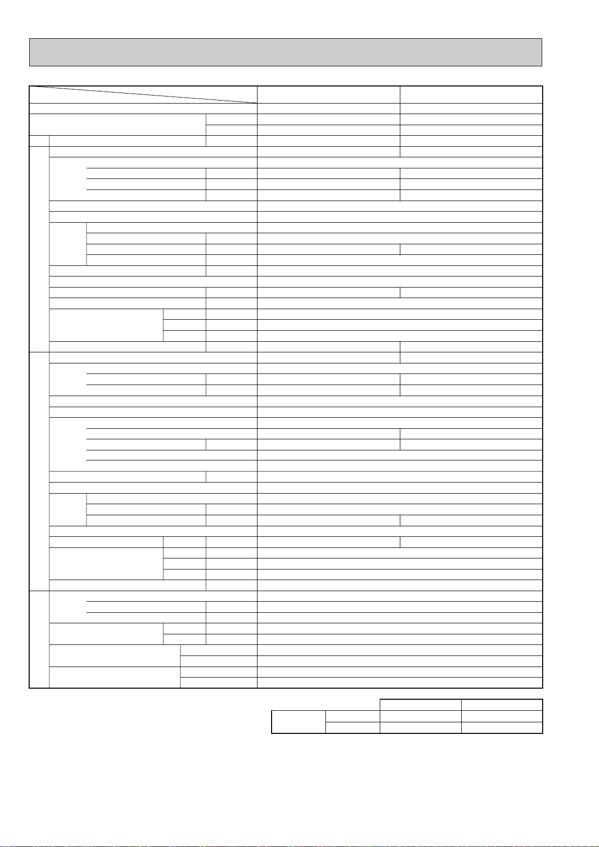
Rating Conditions (ISO T1)
OUTDOOR UNIT
REFRIGERANT
PIPING
Service Ref.
Power supply
External finish
Heat exchanger
Fan
Booster heater
Operation control & Thermostat
Noise level(Lo-Hi)
Unit drain pipe O.D.
Dimensions
Weight
Service Ref.
Power supply
External finish
Refrigerant control
Compressor
Crankcase heater
Heat exchanger
Fan
Defrost method
Noise level
Dimensions
Weight
Refrigerant
Pipe size O.D.
Connection method
Between the indoor & outdoor unit
Indoor side
Outdoor side
Height difference
Piping length
Liquid
Gas
Cooling
mm(in.)
mm(in.)
kg(lbs)
dB
mm(in.)
mm(in.)
mm(in.)
kg(lbs)
W
D
H
kW
K/min <CFM>
kW
W
L
Input
Running current
Starting current
Fan(drive))No.
Fan motor output
Airflow(Lo-Hi)
External static pressure
Running current
Starting current
Model
Motor output
Starter type
Protection devices
Fan(drive))No.
Fan motor output
Airflow
Charge
Compressor oil (Model)
A
A
dB
mm(in.)
mm(in.)
mm(in.)
mm(in.)
kg(lbs)
W
D
H
kW
K/min <CFM>
Pa(mmAq)
kW
kW
A
A
Btu/h
W
kW
Item
Service Ref.
Function
Total input
Upper limit
Lower limit
Indoor
D.B. 35:, W.B. 22.5:
D.B. 19:, W.B. 15:
Outdoor
D.B. 46:
D.B. -5:
Cooling
PSA-P5GA PSA-P6GA
Cooling
42,700
12,500
5.62
0.30
1.26
–
0.38
1.62
–
Cooling
48,500
14,200
6.46
PSA-P5GA
Single phase, 50Hz, 220-230-240V
PSA-P6GA
Munsell 0.70Y 8.59 / 0.97
Plate fin coil
Cantrifugal(direct)✕1
0.11
0(direct blow)
—
built-in
46-51 47-52
26-33<918-1,165> 27-35<953-1,236>
20(13/16)
600(23-5/8)
350(13-3/4)
1900(74-13/16)
51(112)
PU-P5YGA
53(117)
PU-P6YGA
HE86YAA
4.3
HE101YAA
5.1
95(3,360) 100(3,530)
122(269)
53 55
3 phases, 50Hz, 380-400-415V (4 wires)
—
R407C
5.8(12.8)
2.0(Ester)MEL32
1050(41-5/16)
330+20(13+3/4)
1,260(49-5/8)
Munsell 5Y 8/1
Linear Expansion Valve
Hermetic
Line start
Anti-phase protector, Internal thermostat, LP switch, HP switch,Thermal relay,Discharge thermo
38
Plate fin coil
Propeller (direct)✕2
0.075+0.075
8.39
79
10.17
84
9.52(3/8)
19.05(3/4)
Flared
Flared
Max. 50m
Max. 50m
INDOOR UNIT
Capacity
2. Guaranteed operating range
Notes1. Rating Conditions (ISO T1)
Cooling : Indoor : D.B. 27:(80
Outdoor : D.B. 35:(95
Refrigerant piping length (one way) : 5m(16ft)
3. Above data based on indicated voltage
Indoor Unit Single phase 240V 50Hz
Outdoor Unit 3 phase 415V 50Hz
o
F), W.B. 19:(66oF)
o
F), W.B. 24:(75oF)
12
Page 13
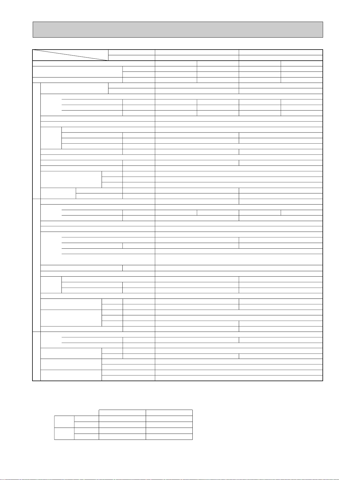
2.1.Heat pump type Rating Conditions (ISO T1)
Service Ref.
With Electric heater
Without Electric heater
With Electric heater
Without Electric heater
With Electric heater
Without Electric heater
Item
Btu/h
W
kW
kW
A
A
kW
K/min(CFM)
Pa(mmAq)
kW
dB
mm(in.)
mm(in.)
mm(in.)
mm(in.)
kg(lbs)
kg(lbs)
A
A
kW
W
kW
K
/min(CFM
)
dB
dB
mm(in.)
mm(in.)
mm(in.)
kg(lbs)
kg(lbs)
L
mm(in.)
mm(in.)
Function
Capacity w1
Total input w1
Service Ref.
Power supply
Input w2
Running current w2
Starting current w2
External finish
Heat exchanger
Fan Fan(drive) x No.
Fan motor output
Airflow(Lo-Hi)
External static pressure
Booster heater w2
Operation control & Thermostat
Noise level(Lo-Hi)
Unit drain pipe O.D.
Dimensions
Weight
Service Ref.
Power supply
Running current
Starting current
External finish
Refrigerant control
Compressor
Model
Motor output
Starter type
Protection devices
Crankcase heater
Heat exchanger
Fan Fan(drive) x No.
Fan motor output
Airflow
Defrost method
Noise level
Dimensions
Weight
Refrigerant
Charge
Oil (Model)
Pipe size O.D.
Connection method
Between the indoor &
outdoor unit
INDOOR UNITOUTDOOR UNIT
REFRIGERANT PIPING
PSH-P3GAH1
PSA-P3GA1
PSH-P4GAH1
PSA-P4GA1
Cooling
26,300
7,700
3.41
0.16
0.68
–
14.8 / 5.29
Cooling
33,000
9,700
3.78
0.26
1.10
–
15.7 / 5.55
Heating
31,700 (38,800)
9,300 (11,400)
3.48 (5.58)
0.16 <2.26>
0.68 <9.42>
–
15.76 / 5.63
Heating
37,000 (46,200)
10,850 (13,550)
3.89 (6.59)
0.26 <2.96>
0.11 <12.33>
–
16.58 / 5.86
W
D
H
Cooling
Heating
W
D
H
Liquid
Gas
Indoor side
Outdoor side
Height difference
Piping length
Notes1.Rating Conditions (ISO T1)
Cooling :Indoor : D.B. 27˚C(80˚F), W.B. 19˚C (66˚F) Outdoor : D.B. 35˚C(95˚F), W.B. 24˚C (75˚F)
Heating :Indoor : D.B. 20˚C(68˚F) Outdoor : D.B. 7˚C(45˚F), W.B. 6˚C (43˚F)
Refrigerant piping length (one way) : 5m (16ft)
3. Above data based on indicated voltage
Indoor Unit Single phase 240V 50Hz
Outdoor Unit Single phase 240V 50Hz / 3 phase 415V 50Hz
2. Guaranteed operating range
Upper limit
Lower limit
Upper limit
Lower limit
Indoor
D.B. 35˚C, W.B. 22.5˚C
D.B. 19˚C, W.B. 15˚C
D.B. 28˚C
D.B. 17˚C
Outdoor
D.B. 46˚C
D.B. -5˚C
D.B. 24˚C, W.B. 18˚C
D.B. -11˚C, W.B. -12˚C
Cooling
Heating
0.03
15-18 <530-636>
<2.1>
40-45
270(10-5/8)
45(99)
43(95)
PUH-P3VGAA.UK / PUH-P3YGAA.UK
93 / 47
NE52VNJMT / NE52YDKMT
2.5
Propeller (direct) x 1
0.070
50(1,770)
49
51
855(33-5/8)
82(181)
3.3(7.3)
15.88(5/8)
0.07
24-31 <847-1,059>
<2.7>
44-49
350(13-3/4)
53(117)
51(112)
PUH-P4VGAA.UK / PUH-P4YGAA.UK
99 / 49
NE56VNJMT / NE56YDKMT
2.7
Propeller (direct) x 2
0.070+0.070
85(3,000)
51
53
1,260(49-5/8)
96(212)
4.0(8.8)
19.05(3/4)
Single phase, 50Hz, 220-230-240V
Munsell 0.70Y 8.59 / 0.97
Plate fin coil
Centrifugal(direct) x 1
0(direct blow)
Remote controller & built-in
20(13/16)
600(23-5/8)
1,900(74-13/16)
Single phase, 50Hz, 220-230-240V / 3 phase, 50Hz, 380-400-415V(4wires)
Munsell 5Y 7/1
Linear Expansion Valve
Hermetic
Line start
38
Plate fin coil
Reverse cycle
900(35-7/16)
330+20(13+3/4)
R407C
1.3(Ester)MEL56
9.52(3/8)
Flared
Flared
Max. 50m
Max. 50m
VGAA.UK...Inner thermostat, HP switch, Discharge thermo.
YGAA.UK...Thermal relay, Discharge thermo, HP switch.
w1 : ( ) Shows the total rating when booster heater operates.
w2 : < > Shows the only booster heater rating.
PSH-P3GAH
1
PSA-P3GA1
PSH-P4GAH1
PSA-P4GA1
13
Page 14
Rating Conditions (ISO T1)
Service Ref.
With Electric heater
Without Electric heater
With Electric heater
Without Electric heater
With Electric heater
Without Electric heater
Item
Btu/h
W
kW
kW
A
A
kW
K/min(CFM)
Pa(mmAq)
kW
dB
mm(in.)
mm(in.)
mm(in.)
mm(in.)
kg(lbs)
kg(lbs)
A
A
kW
W
kW
K
/min(CFM
)
dB
dB
mm(in.)
mm(in.)
mm(in.)
kg(lbs)
kg(lbs)
L
mm(in.)
mm(in.)
Function
Capacity w1
Total input w1
Service Ref.
Power supply
Input w2
Running current w2
Starting current w2
External finish
Heat exchanger
Fan Fan(drive) x No.
Fan motor output
Airflow(Lo-Hi)
External static pressure
Booster heater w2
Operation control & Thermostat
Noise level(Lo-Hi)
Unit drain pipe O.D.
Dimensions
Weight
Service Ref.
Power supply
Running current
Starting current
External finish
Refrigerant control
Compressor
Model
Motor output
Starter type
Protection devices
Crankcase heater
Heat exchanger
Fan Fan(drive) x No.
Fan motor output
Airflow
Defrost method
Noise level
Dimensions
Weight
Refrigerant
Charge
Oil (Model)
Pipe size O.D.
Connection method
Between the indoor &
outdoor unit
INDOOR UNITOUTDOOR UNIT
REFRIGERANT PIPING
PSH-P5GAH1
PSA-P5GA1
PSH-P6GAH1
PSA-P6GA1
Cooling
42,300
12,400
5.06
0.30
1.26
–
7.60
Cooling
47,700
14,000
5.81
0.38
1.62
–
9.03
Heating
49,800 (60,000)
14,600 (17,600)
5.35 (8.35)
0.30 <3.00>
1.26 <12.5>
–
8.15
Heating
58,300 (68,500)
17,100 (20,100)
6.11 (9.11)
0.38 <3.00>
1.62 <12.5>
–
9.56
W
D
H
Cooling
Heating
W
D
H
Liquid
Gas
Indoor side
Outdoor side
Height difference
Piping length
Notes1.Rating Conditions (ISO T1)
Cooling :Indoor : D.B. 27˚C(80˚F), W.B. 19˚C (66˚F) Outdoor : D.B. 35˚C(95˚F), W.B. 24˚C (75˚F)
Heating :Indoor : D.B. 20˚C(68˚F) Outdoor : D.B. 7˚C(45˚F), W.B. 6˚C (43˚F)
Refrigerant piping length (one way) : 5m (16ft)
3. Above data based on indicated voltage
Indoor Unit Single phase 240V 50Hz
Outdoor Unit 3 phase 415V 50Hz
2. Guaranteed operating range
Upper limit
Lower limit
Upper limit
Lower limit
Indoor
D.B. 35˚C, W.B. 22.5˚C
D.B. 19˚C, W.B. 15˚C
D.B. 28˚C
D.B. 17˚C
Outdoor
D.B. 46˚C
D.B. -5˚C
D.B. 24˚C, W.B. 18˚C
D.B. -11˚C, W.B. -12˚C
Cooling
Heating
26-33 <918-1,165>
<3.0>
46-51
53(117)
51(112)
PUH-P5YGAA.UK
65.5
ZR61KCE-TFD
3.5
95(3,360)
55
56
4.6 (10.1)
1.690 (Ester) MMMA-POE
27-35 <953-1,236>
<3.0>
47-52
55(121)
53(117)
PUH-P6YGAA.UK
74.0
ZR72KCE-TFD
4.2
100(3,530)
57
58
4.9 (10.8)
1.774 (Ester) MMMA-POE
Single phase, 50Hz, 220-230-240V
Munsell 0.70Y 8.59 / 0.97
Plate fin coil
Centnifugal (direct) x 1
0.11
0 (direct blow)
built-in
20(13/16)
600(23-5/8)
350(13-3/4)
1,900(74-13/16)
3 Phase, 50Hz, 380-400-415V(4wires)
Munsell 5Y 7/1
Linear Expansion Valve
Hermetic
Line start
Internal thermostat, HP switch,Thermal relay,Discharge thermo
38
Plate fin coil
Propeller (direct) x 2
0.070+0.070
Reverse cycle
1050(41-5/16)
330+20(13+3/4)
1,260(49-5/8)
122(269)
R407C
9.52(3/8)
19.05(3/4)
Flared
Flared
Max. 50m
Max. 50m
w1 : ( ) Shows the total rating when booster heater operates.
w2 : < > Shows the only booster heater rating.
PSH-P5GAH
1
PSA-P5GA1
PSH-P6GAH1
PSA-P6GA1
14
Page 15
2.2.Cooling only type Rating Conditions (ISO T1)
Item
Function
Capacity
Total input
Service Ref.
Power supply
Input
Running current
Starting current
External finish
Heat exchanger
Fan
Booster heater
INDOOR UNIT
Operation control & Thermostat
Noise level(Lo-Hi)
Unit drain pipe O.D.
Dimensions
Weight
Service Ref.
Power supply
External finish
Refrigerant control
Compressor
Crankcase heater
Heat exchanger
Fan
OUTDOOR UNIT
Defrost method
Noise level
Dimensions
Weight
Refrigerant
Pipe size O.D.
PIPING
Connection method
Fan(drive))No.
Fan motor output
Airflow(Lo-Hi)
External static pressure
Running current
Starting current
Model
Motor output
Starter type
Protection devices
Fan(drive))No.
Fan motor output
Airflow
Charge
Compressor oil (Model)
REFRIGERANT
Between the indoor & outdoor unit
Notes1. Rating Conditions (ISO T1)
Cooling : Indoor : D.B. 27:(80
Outdoor : D.B. 35:(95
Refrigerant piping length (one way) : 5m(16ft)
Service Ref.
K/min <CFM>
W
D
H
K/min <CFM>
Cooling
W
D
H
Liquid
Gas
Indoor side
Outdoor side
Height difference
Piping length
o
F), W.B. 19:(66oF)
o
F), W.B. 24:(75oF)
Btu/h
W
kW
kW
A
A
kW
Pa(mmAq)
kW
dB
mm(in.)
mm(in.)
mm(in.)
mm(in.)
kg(lbs)
A
A
kW
W
kW
dB
mm(in.)
mm(in.)
mm(in.)
kg(lbs)
kg(lbs)
L
mm(in.)
mm(in.)
PSA-P3GA1 PSA-P4GA1
Cooling
26,300
7,700
3.41
PSA-P3GA
15-18 <530-636>
270 (10-5/8) 350 (13-3/4)
PU-P3VGAA.UK / PU-P3YGAA.UK
Single-phase, 50Hz, 220-230-240V / 3-phase, 50Hz,380-400-415V(4wires)
14.81 / 5.29
NE52VNJMT / NE52YDKMT
VGAA.UK...Inner thermostat. High-pressure switch, Discharge thermo
YGAA.UK...Anti-phase protector, Thermal relay, Discharge thermo, High-pressure switch
Propeller (direct) ✕ 1
50 (1,770)
855(33-5/8)
82(181)
3.3(7.3) 4.0(8.8)
15.88(5/8) 19.05(3/4)
1
Single phase, 50Hz, 220-230-240V
0.16
0.68
–
Munsell 0.70Y 8.59 / 0.97
Plate fin coil
Centrifugal (direct) ✕ 1
0.03
0(direct blow)
—
built-in
40-45 44-49
20(13/16)
600( 23-5/8 )
1,900 (74-13/16)
43(95)
PU-P4VGAA.UK / PU-P4YGAA.UK
93 / 47
Munsell 5Y 7/1
Linear Expansion Valve
Hermetic
NE56VNJMT / NE56YDKMT
2.5
Line start
38
Plate fin coil
0.070
—
49 51
900(35-7/16)
330 + 20(13+3/4)
R407C
1.3(Ester) MEL56
9.52(3/8)
Flared
Flared
Max. 50m
Max. 50m
Cooling
33,000
9,700
3.78
PSA-P4GA
24-31 <847-1,059>
51(112)
15.71 / 5.55
Propeller (direct) ✕ 2
0.070+ 0.070
85 (3,000)
1,260(49-5/8)
96(212)
1
0.26
1.10
–
0.07
99 / 49
2.7
2. Guaranteed operating range
Cooling
Upper limit
Lower limit
Indoor
D.B. 35:, D.B. 22.5:
D.B. 19:, D.B. 15:
Outdoor
D.B. 46:
D.B. -5:
3. Above data based on indicated voltage
Indoor Unit Single phase 240V 50Hz
Outdoor Unit Single phase 240V 50Hz / 3 phase 415V 50Hz
15
Page 16
Rating Conditions (ISO T1)
OUTDOOR UNIT
REFRIGERANT
PIPING
Service Ref.
Power supply
External finish
Heat exchanger
Fan
Booster heater
Operation control & Thermostat
Noise level(Lo-Hi)
Unit drain pipe O.D.
Dimensions
Weight
Service Ref.
Power supply
External finish
Refrigerant control
Compressor
Crankcase heater
Heat exchanger
Fan
Defrost method
Noise level
Dimensions
Weight
Refrigerant
Pipe size O.D.
Connection method
Between the indoor & outdoor unit
Indoor side
Outdoor side
Height difference
Piping length
Liquid
Gas
Cooling
mm(in.)
mm(in.)
kg(lbs)
dB
mm(in.)
mm(in.)
mm(in.)
kg(lbs)
W
D
H
kW
K/min <CFM>
kW
W
L
Input
Running current
Starting current
Fan(drive))No.
Fan motor output
Airflow(Lo-Hi)
External static pressure
Running current
Starting current
Model
Motor output
Starter type
Protection devices
Fan(drive))No.
Fan motor output
Airflow
Charge
Compressor oil (Model)
A
A
dB
mm(in.)
mm(in.)
mm(in.)
mm(in.)
kg(lbs)
W
D
H
kW
K/min <CFM>
Pa(mmAq)
kW
kW
A
A
Btu/h
W
kW
Item
Service Ref.
Function
Total input
Upper limit
Lower limit
Indoor
D.B. 35:, W.B. 22.5:
D.B. 19:, W.B. 15:
Outdoor
D.B. 46:
D.B. -5:
Cooling
PSA-P5GA1 PSA-P6GA1
Cooling
42,700
12,400
5.06
0.30
1.26
–
0.38
1.62
–
Cooling
47,700
14,000
5.81
PSA-P5GA
1
Single phase, 50Hz, 220-230-240V
PSA-P6GA
1
Munsell 0.70Y 8.59 / 0.97
Plate fin coil
Cantrifugal(direct)✕1
0.11
0(direct blow)
—
built-in
46-51 47-52
26-33<918-1,165> 27-35<953-1,236>
20(13/16)
600(23-5/8)
350(13-3/4)
1900(74-13/16)
51(112)
PU-P5YGAA.UK
53(117)
PU-P6YGAA.UK
ZR61KCE-TFD
3.5
ZR72KCE-TFD
4.2
4.6(10.1)
1.690MMMA-POE
4.9 (10.8)
1.774MMMA-POE
95(3,360) 100(3,530)
122(269)
55 57
3 phases, 50Hz, 380-400-415V (4 wires)
—
R407C
1050(41-5/16)
330+20(13+3/4)
1,260(49-5/8)
Munsell 5Y 7/1
Linear Expansion Valve
Hermetic
Line start
Internal thermostat, HP switch,Thermal relay,Discharge thermo
38
Plate fin coil
Propeller (direct)✕2
0.070+0.070
7.60
65.5
9.03
74.0
9.52(3/8)
19.05(3/4)
Flared
Flared
Max. 50m
Max. 50m
INDOOR UNIT
Capacity
2. Guaranteed operating range
Notes1. Rating Conditions (ISO T1)
Cooling : Indoor : D.B. 27:(80
Outdoor : D.B. 35:(95
Refrigerant piping length (one way) : 5m(16ft)
3. Above data based on indicated voltage
Indoor Unit Single phase 240V 50Hz
Outdoor Unit 3 phase 415V 50Hz
o
F), W.B. 19:(66oF)
o
F), W.B. 24:(75oF)
16
Page 17
DATA6
Outdoor intake air D.B.(°C)
20 25 30
Indoor
Intake air
D.B.(°C)
Indoor
Intake air
W.B.(°C)
20
20
20
22
22
22
24
24
24
26
26
26
28
28
28
30
30
30
32
32
32
34
34
34
16
18
20
16
18
20
16
18
20
16
18
20
16
18
20
16
18
20
16
18
20
16
18
20
CA
7,623
8,162
8,778
7,623
8,162
8,778
7,623
8,162
8,778
7,623
8,162
8,778
7,623
8,162
8,778
7,623
8,162
8,778
7,623
8,162
8,778
7,623
8,162
8,778
SHC(W)
4,726
4,081
3,336
5,336
4,734
4,038
5,946
5,387
4,740
6,556
6,040
5,442
7,166
6,693
6,145
7,623
7,346
6,847
7,623
7,999
7,549
7,623
8,162
8,251
SHF
0.62
0.50
0.38
0.70
0.58
0.46
0.78
0.66
0.54
0.86
0.74
0.62
0.94
0.82
0.70
1.00
0.90
0.78
1.00
0.98
0.86
1.00
1.00
0.94
P.C.
2.78
2.84
2.92
2.78
2.84
2.92
2.78
2.84
2.92
2.78
2.84
2.92
2.78
2.84
2.92
2.78
2.84
2.92
2.78
2.84
2.92
2.78
2.84
2.92
CA
7,392
7,931
8,586
7,392
7,931
8,586
7,392
7,931
8,586
7,392
7,931
8,586
7,392
7,931
8,586
7,392
7,931
8,586
7,392
7,931
8,586
7,392
7,931
8,586
SHC(W)
4,583
3,966
3,262
5,174
4,600
3,949
5,766
5,234
4,636
6,357
5,869
5,323
6,948
6,503
6,010
7,392
7,138
6,697
7,392
7,772
7,384
7,392
7,931
8,070
SHF
0.62
0.50
0.38
0.70
0.58
0.46
0.78
0.66
0.54
0.86
0.74
0.62
0.94
0.82
0.70
1.00
0.90
0.78
1.00
0.98
0.86
1.00
1.00
0.94
P.C.
2.94
2.99
3.06
2.94
2.99
3.06
2.94
2.99
3.06
2.94
2.99
3.06
2.94
2.99
3.06
2.94
2.99
3.06
2.94
2.99
3.06
2.94
2.99
3.06
CA
7,161
7,662
8,355
7,161
7,662
8,355
7,161
7,662
8,355
7,161
7,662
8,355
7,161
7,662
8,355
7,161
7,662
8,355
7,161
7,662
8,355
7,161
7,662
8,355
SHC(W)
4,440
3,831
3,175
5,013
4,444
3,843
5,586
5,057
4,511
6,158
5,670
5,180
6,731
6,282
5,848
7,161
6,895
6,517
7,161
7,508
7,185
7,161
7,662
7,853
SHF
0.62
0.50
0.38
0.70
0.58
0.46
0.78
0.66
0.54
0.86
0.74
0.62
0.94
0.82
0.70
1.00
0.90
0.78
1.00
0.98
0.86
1.00
1.00
0.94
P.C.
3.11
3.20
3.27
3.11
3.20
3.27
3.11
3.20
3.27
3.11
3.20
3.27
3.11
3.20
3.27
3.11
3.20
3.27
3.11
3.20
3.27
3.11
3.20
3.27
1.PERFORMANCE DATA
1) COOLING CAPACITY<1>
PSH-P3GAH / PUH-P3VGA, PUH-P3YGA
PSA-P3GA / PU(H)-P3VGA, PU(H)-P3YGA
Notes CA : Capacity (W) SHC(W) : Sensible heat capacity
P.C. : Power consumption (kW) SHF : Sensible heat factor
17
Page 18
Outdoor intake air D.B.(°C)
35 40 45
Indoor
Intake air
D.B.(°C)
Indoor
Intake air
W.B.(°C)
20
20
20
22
22
22
24
24
24
26
26
26
28
28
28
30
30
30
32
32
32
34
34
34
16
18
20
16
18
20
16
18
20
16
18
20
16
18
20
16
18
20
16
18
20
16
18
20
CA
6,853
7,392
8,008
6,853
7,392
8,008
6,853
7,392
8,008
6,853
7,392
8,008
6,853
7,392
8,008
6,853
7,392
8,008
6,853
7,392
8,008
6,853
7,392
8,008
SHC(W)
4,249
3,696
3,043
4,797
4,287
3,684
5,345
4,879
4,324
5,894
5,470
4,965
6,442
6,061
5,606
6,853
6,653
6,246
6,853
7,244
6,887
6,853
7,392
7,528
SHF
0.62
0.50
0.38
0.70
0.58
0.46
0.78
0.66
0.54
0.86
0.74
0.62
0.94
0.82
0.70
1.00
0.90
0.78
1.00
0.98
0.86
1.00
1.00
0.94
P.C.
3.34
3.43
3.51
3.34
3.43
3.51
3.34
3.43
3.51
3.34
3.43
3.51
3.34
3.43
3.51
3.34
3.43
3.51
3.34
3.43
3.51
3.34
3.43
3.51
CA
6,545
7,161
7,700
6,545
7,161
7,700
6,545
7,161
7,700
6,545
7,161
7,700
6,545
7,161
7,700
6,545
7,161
7,700
6,545
7,161
7,700
6,545
7,161
7,700
SHC(W)
4,058
3,581
2,926
4,582
4,153
3,542
5,105
4,726
4,158
5,629
5,299
4,774
6,152
5,872
5,390
6,545
6,445
6,006
6,545
7,018
6,622
6,545
7,161
7,238
SHF
0.62
0.50
0.38
0.70
0.58
0.46
0.78
0.66
0.54
0.86
0.74
0.62
0.94
0.82
0.70
1.00
0.90
0.78
1.00
0.98
0.86
1.00
1.00
0.94
P.C.
3.58
3.69
3.76
3.58
3.69
3.76
3.58
3.69
3.76
3.58
3.69
3.76
3.58
3.69
3.76
3.58
3.69
3.76
3.58
3.69
3.76
3.58
3.69
3.76
CA
6,237
6,699
7,238
6,237
6,699
7,238
6,237
6,699
7,238
6,237
6,699
7,238
6,237
6,699
7,238
6,237
6,699
7,238
6,237
6,699
7,238
6,237
6,699
7,238
SHC(W)
3,867
3,350
2,750
4,366
3,885
3,329
4,865
4,421
3,909
5,364
4,957
4,488
5,863
5,493
5,067
6,237
6,029
5,646
6,237
6,565
6,225
6,237
6,699
6,804
SHF
0.62
0.50
0.38
0.70
0.58
0.46
0.78
0.66
0.54
0.86
0.74
0.62
0.94
0.82
0.70
1.00
0.90
0.78
1.00
0.98
0.86
1.00
1.00
0.94
P.C.
3.88
3.97
4.04
3.88
3.97
4.04
3.88
3.97
4.04
3.88
3.97
4.04
3.88
3.97
4.04
3.88
3.97
4.04
3.88
3.97
4.04
3.88
3.97
4.04
COOLING CAPACITY<2>
PSH-P3GAH / PUH-P3VGA, PUH-P3YGA
PSA-P3GA / PU(H)-P3VGA, PU(H)-P3YGA
Notes CA : Capacity (W) SHC(W) : Sensible heat capacity
P.C. : Power consumption (kW) SHF : Sensible heat factor
18
Page 19

COOLING CAPACITY<3>
PSH-P4GAH / PUH-P4VGA
PSA-P4GA / PU(H)-P4VGA
Indoor
Intake air
D.B.(°C)
20
20
20
22
22
22
24
24
24
26
26
26
28
28
28
30
30
30
32
32
32
34
34
34
Indoor
Intake air
W.B.(°C)
16
18
20
16
18
20
16
18
20
16
18
20
16
18
20
16
18
20
16
18
20
16
18
20
CA
9,603
10,282
11,058
9,603
10,282
11,058
9,603
10,282
11,058
9,603
10,282
11,058
9,603
10,282
11,058
9,603
10,282
11,058
9,603
10,282
11,058
9,603
10,282
11,058
SHC(W)
5,954
5,141
4,202
6,722
5,964
5,087
7,490
6,786
5,971
8,259
7,609
6,856
9,027
8,431
7,741
9,603
9,254
8,625
9,603
10,076
9,510
9,603
10,282
10,395
Outdoor intake air D.B.(°C)
20 25 30
SHF
0.62
0.50
0.38
0.70
0.58
0.46
0.78
0.66
0.54
0.86
0.74
0.62
0.94
0.82
0.70
1.00
0.90
0.78
1.00
0.98
0.86
1.00
1.00
0.94
P.C.
2.92
2.97
3.07
2.92
2.97
3.07
2.92
2.97
3.07
2.92
2.97
3.07
2.92
2.97
3.07
2.92
2.97
3.07
2.92
2.97
3.07
2.92
2.97
3.07
CA
9,312
9,991
10,816
9,312
9,991
10,816
9,312
9,991
10,816
9,312
9,991
10,816
9,312
9,991
10,816
9,312
9,991
10,816
9,312
9,991
10,816
9,312
9,991
10,816
SHC(W)
7,553
4,996
4,110
6,518
5,795
4,975
7,263
6,594
5,840
8,008
7,393
6,706
8,753
8,193
7,571
9,312
8,992
8,436
9,312
9,791
9,301
9,312
9,991
10,167
SHF
0.62
0.50
0.38
0.70
0.58
0.46
0.78
0.66
0.54
0.86
0.74
0.62
0.94
0.82
0.70
1.00
0.90
0.78
1.00
0.98
0.86
1.00
1.00
0.94
P.C.
3.08
3.14
3.21
3.08
3.14
3.21
3.08
3.14
3.21
3.08
3.14
3.21
3.08
3.14
3.21
3.08
3.14
3.21
3.08
3.14
3.21
3.08
3.14
3.21
CA
9,021
9,652
10,525
9,021
9,652
10,525
9,021
9,652
10,525
9,021
9,652
10,525
9,021
9,652
10,525
9,021
9,652
10,525
9,021
9,652
10,525
9,021
9,652
10,525
SHC(W)
5,593
4,826
3,999
6,315
5,598
4,841
7,036
6,370
5,683
7,758
7,142
6,525
8,480
7,914
7,367
9,021
8,686
8,209
9,021
9,458
9,051
9,021
9,652
9,893
SHF
0.62
0.50
0.38
0.70
0.58
0.46
0.78
0.66
0.54
0.86
0.74
0.62
0.94
0.82
0.70
1.00
0.90
0.78
1.00
0.98
0.86
1.00
1.00
0.94
P.C.
3.27
3.36
3.43
3.27
3.36
3.43
3.27
3.36
3.43
3.27
3.36
3.43
3.27
3.36
3.43
3.27
3.36
3.43
3.27
3.36
3.43
3.27
3.36
3.43
Notes CA : Capacity (W) SHC(W) : Sensible heat capacity
P.C. : Power consumption (kW) SHF : Sensible heat factor
19
Page 20

Outdoor intake air D.B.(°C)
35 40 45
Indoor
Intake air
D.B.(°C)
Indoor
Intake air
W.B.(°C)
CA
8,633
9,312
10,088
8,633
9,312
10,088
8,633
9,312
10,088
8,633
9,312
10,088
8,633
9,312
10,088
8,633
9,312
10,088
8,633
9,312
10,088
8,633
9,312
10,088
SHC(W)
5,352
4,656
3,833
6,043
5,401
4,640
6,734
6,146
5,448
7,424
6,891
6,255
8,115
7,636
7,062
8,633
8,381
7,869
8,633
9,126
8,676
8,633
9,312
9,483
SHF
0.62
0.50
0.38
0.70
0.58
0.46
0.78
0.66
0.54
0.86
0.74
0.62
0.94
0.82
0.70
1.00
0.90
0.78
1.00
0.98
0.86
1.00
1.00
0.94
P.C.
3.50
3.60
3.69
3.50
3.60
3.69
3.50
3.60
3.69
3.50
3.60
3.69
3.50
3.60
3.69
3.50
3.60
3.69
3.50
3.60
3.69
3.50
3.60
3.69
CA
8,245
9,021
9,700
8,245
9,021
9,700
8,245
9,021
9,700
8,245
9,021
9,700
8,245
9,021
9,700
8,245
9,021
9,700
8,245
9,021
9,700
8,245
9,021
9,700
SHC(W)
5,112
4,511
3,686
5,772
5,232
4,462
6,431
5,954
5,238
7,091
6,676
6,014
7,750
7,397
6,790
8,245
8,119
7,566
8,245
8,841
8,342
8,245
9,021
9,118
SHF
0.62
0.50
0.38
0.70
0.58
0.46
0.78
0.66
0.54
0.86
0.74
0.62
0.94
0.82
0.70
1.00
0.90
0.78
1.00
0.98
0.86
1.00
1.00
0.94
P.C.
3.76
3.87
3.94
3.76
3.87
3.94
3.76
3.87
3.94
3.76
3.87
3.94
3.76
3.87
3.94
3.76
3.87
3.94
3.76
3.87
3.94
3.76
3.87
3.94
CA
7,857
8,439
9,118
7,857
8,439
9,118
7,857
8,439
9,118
7,857
8,439
9,118
7,857
8,439
9,118
7,857
8,439
9,118
7,857
8,439
9,118
7,857
8,439
9,118
SHC(W)
4,871
4,220
3,465
5,500
4,895
4,194
6,128
5,570
4,924
6,757
6,245
5,653
7,386
6,920
6,383
7,857
7,595
7,112
7,857
8,270
7,841
7,857
8,439
8,571
SHF
0.62
0.50
0.38
0.70
0.58
0.46
0.78
0.66
0.54
0.86
0.74
0.62
0.94
0.82
0.70
1.00
0.90
0.78
1.00
0.98
0.86
1.00
1.00
0.94
P.C.
4.07
4.16
4.23
4.07
4.16
4.23
4.07
4.16
4.23
4.07
4.16
4.23
4.07
4.16
4.23
4.07
4.16
4.23
4.07
4.16
4.23
4.07
4.16
4.23
20
20
20
22
22
22
24
24
24
26
26
26
28
28
28
30
30
30
32
32
32
34
34
34
16
18
20
16
18
20
16
18
20
16
18
20
16
18
20
16
18
20
16
18
20
16
18
20
COOLING CAPACITY<4>
PSH-P4GAH / PUH-P4YGA
PSA-P4GA / PU(H)-P4YGA
Notes CA : Capacity (W) SHC(W) : Sensible heat capacity
P.C. : Power consumption (kW) SHF : Sensible heat factor
20
Page 21

COOLING CAPACITY<5>
PSH-P5GAH / PUH-P5YGA
PSA-P5GA / PU(H)-P5YGA
Indoor
Intake air
D.B.(°C)
20
20
20
22
22
22
24
24
24
26
26
26
28
28
28
30
30
30
32
32
32
34
34
34
Indoor
Intake air
W.B.(°C)
16
18
20
16
18
20
16
18
20
16
18
20
16
18
20
16
18
20
16
18
20
16
18
20
CA
12,375
13,250
14,250
12,375
13,250
14,250
12,375
13,250
14,250
12,375
13,250
14,250
12,375
13,250
14,250
12,375
13,250
14,250
12,375
13,250
14,250
12,375
13,250
14,250
Outdoor intake air D.B.(°C)
20 25 30
SHC(W)
7,425
6,360
5,130
8,415
7,420
6,270
9,405
8,480
7,410
10,395
9,540
8,550
11,385
10,600
9,690
12,375
11,660
10,830
12,375
12,720
11,970
12,375
13,250
13,110
SHF
0.60
0.48
0.36
0.68
0.56
0.44
0.76
0.64
0.52
0.84
0.72
0.60
0.92
0.80
0.68
1.00
0.88
0.76
1.00
0.96
0.84
1.00
1.00
0.92
P.C.
4.50
4.58
4.72
4.50
4.58
4.72
4.50
4.58
4.72
4.50
4.58
4.72
4.50
4.58
4.72
4.50
4.58
4.72
4.50
4.58
4.72
4.50
4.58
4.72
CA
12,000
12,875
13,938
12,000
12,875
13,938
12,000
12,875
13,938
12,000
12,875
13,938
12,000
12,875
13,938
12,000
12,875
13,938
12,000
12,875
13,938
12,000
12,875
13,938
SHC(W)
7,200
6,180
5,018
8,160
7,210
6,133
9,120
8,240
7,248
10,080
9,270
8,363
11,040
10,300
9,478
12,000
11,330
10,593
12,000
12,360
11,708
12,000
12,875
12,823
SHF
0.60
0.48
0.36
0.68
0.56
0.44
0.76
0.64
0.52
0.84
0.72
0.60
0.92
0.80
0.68
1.00
0.88
0.76
1.00
0.96
0.84
1.00
1.00
0.92
P.C.
4.75
4.83
4.95
4.75
4.83
4.95
4.75
4.83
4.95
4.75
4.83
4.95
4.75
4.83
4.95
4.75
4.83
4.95
4.75
4.83
4.95
4.75
4.83
4.95
11,625
12,438
13,563
11,625
12,438
13,563
11,625
12,438
13,563
11,625
12,438
13,563
11,625
12,438
13,563
11,625
12,438
13,563
11,625
12,438
13,563
11,625
12,438
13,563
CA
SHC(W)
6,975
5,970
4,883
7,905
6,965
5,968
8,835
7,960
7,053
9,765
8,955
8,138
10,695
9,950
9,223
11,625
10,945
10,308
11,625
11,940
11,393
11,625
12,438
12,478
SHF
0.60
0.48
0.36
0.68
0.56
0.44
0.76
0.64
0.52
0.84
0.72
0.60
0.92
0.80
0.68
1.00
0.88
0.76
1.00
0.96
0.84
1.00
1.00
0.92
P.C.
5.03
5.17
5.28
5.03
5.17
5.28
5.03
5.17
5.28
5.03
5.17
5.28
5.03
5.17
5.28
5.03
5.17
5.28
5.03
5.17
5.28
5.03
5.17
5.28
Notes CA : Capacity (W) SHC(W) : Sensible heat capacity
P.C. : Power consumption (kW) SHF : Sensible heat factor
21
Page 22

Outdoor intake air D.B.(°C)
35 40 45
Indoor
Intake air
D.B.(°C)
Indoor
Intake air
W.B.(°C)
CA
11,125
12,000
13,000
11,125
12,000
13,000
11,125
12,000
13,000
11,125
12,000
13,000
11,125
12,000
13,000
11,125
12,000
13,000
11,125
12,000
13,000
11,125
12,000
13,000
SHC(W)
6,675
5,760
4,680
7,565
6,720
5,720
8,455
7,680
6,760
9,345
8,640
7,800
10,235
9,600
8,840
11,125
10,560
9,880
11,125
11,520
10,920
11,125
12,000
11,960
SHF
0.60
0.48
0.36
0.68
0.56
0.44
0.76
0.64
0.52
0.84
0.72
0.60
0.92
0.80
0.68
1.00
0.88
0.76
1.00
0.96
0.84
1.00
1.00
0.92
P.C.
5.40
5.54
5.68
5.40
5.54
5.68
5.40
5.54
5.68
5.40
5.54
5.68
5.40
5.54
5.68
5.40
5.54
5.68
5.40
5.54
5.68
5.40
5.54
5.68
CA
10,625
11,625
12,500
10,625
11,625
12,500
10,625
11,625
12,500
10,625
11,625
12,500
10,625
11,625
12,500
10,625
11,625
12,500
10,625
11,625
12,500
10,625
11,625
12,500
SHC(W)
6,375
5,580
4,500
7,225
6,510
5,500
8,075
7,440
6,500
8,925
8,370
7,500
9,775
9,300
8,500
10,625
10,230
9,500
10,625
11,160
10,500
10,625
11,625
11,500
SHF
0.60
0.48
0.36
0.68
0.56
0.44
0.76
0.64
0.52
0.84
0.72
0.60
0.92
0.80
0.68
1.00
0.88
0.76
1.00
0.96
0.84
1.00
1.00
0.92
P.C.
5.79
5.96
6.07
5.79
5.96
6.07
5.79
5.96
6.07
5.79
5.96
6.07
5.79
5.96
6.07
5.79
5.96
6.07
5.79
5.96
6.07
5.79
5.96
6.07
CA
10,125
10,875
11,750
10,125
10,875
11,750
10,125
10,875
11,750
10,125
10,875
11,750
10,125
10,875
11,750
10,125
10,875
11,750
10,125
10,875
11,750
10,125
10,875
11,750
SHC(W)
6,075
5,220
4,230
6,885
6,090
5,170
7,695
6,960
6,110
8,505
7,830
7,050
9,315
8,700
7,990
10,125
9,570
8,930
10,125
10,440
9,870
10,125
10,875
10,810
SHF
0.60
0.48
0.36
0.68
0.56
0.44
0.76
0.64
0.52
0.84
0.72
0.60
0.92
0.80
0.68
1.00
0.88
0.76
1.00
0.96
0.84
1.00
1.00
0.92
P.C.
6.27
6.41
6.52
6.27
6.41
6.52
6.27
6.41
6.52
6.27
6.41
6.52
6.27
6.41
6.52
6.27
6.41
6.52
6.27
6.41
6.52
6.27
6.41
6.52
20
20
20
22
22
22
24
24
24
26
26
26
28
28
28
30
30
30
32
32
32
34
34
34
16
18
20
16
18
20
16
18
20
16
18
20
16
18
20
16
18
20
16
18
20
16
18
20
COOLING CAPACITY<6>
PSH-P5GAH / PUH-P5YGA
PSA-P5GA / PU(H)-P5YGA
Notes CA : Capacity (W) SHC(W) : Sensible heat capacity
P.C. : Power consumption (kW) SHF : Sensible heat factor
22
Page 23

COOLING CAPACITY<7>
PSH-P6GAH / PUH-P6YGA
PSA-P6GA / PU(H)-P6YGA
Indoor
Intake air
D.B.(°C)
20
20
20
22
22
22
24
24
24
26
26
26
28
28
28
30
30
30
32
32
32
34
34
34
Indoor
Intake air
W.B.(°C)
16
18
20
16
18
20
16
18
20
16
18
20
16
18
20
16
18
20
16
18
20
16
18
20
CA
14,058
15,052
16,188
14,058
15,052
16,188
14,058
15,052
16,188
14,058
15,052
16,188
14,058
15,052
16,188
14,058
15,052
16,188
14,058
15,052
16,188
14,058
15,052
16,188
Outdoor intake air D.B.(°C)
20 25 30
SHC(W)
7,872
6,623
5,180
8,997
7,827
6,475
10,122
9,031
7,770
11,246
10,235
9,065
12,371
11,440
10,360
13,496
12,644
11,655
14,058
13,848
12,950
14,058
15,052
14,245
SHF
0.56
0.44
0.32
0.64
0.52
0.40
0.72
0.60
0.48
0.80
0.68
0.56
0.88
0.76
0.64
0.96
0.84
0.72
1.00
0.92
0.80
1.00
1.00
0.88
P.C.
5.17
5.26
5.43
5.17
5.26
5.43
5.17
5.26
5.43
5.17
5.26
5.43
5.17
5.26
5.43
5.17
5.26
5.43
5.17
5.26
5.43
5.17
5.26
5.43
CA
13,632
14,626
15,833
13,632
14,626
15,833
13,632
14,626
15,833
13,632
14,626
15,833
13,632
14,626
15,833
13,632
14,626
15,833
13,632
14,626
15,833
13,632
14,626
15,833
SHC(W)
7,634
6,435
5,067
8,724
7,606
6,333
9,815
8,776
7,600
10,906
9,946
8,866
11,996
11,116
10,133
13,087
12,286
11,400
13,632
13,456
12,666
13,632
14,626
13,933
SHF
0.56
0.44
0.32
0.64
0.52
0.40
0.72
0.60
0.48
0.80
0.68
0.56
0.88
0.76
0.64
0.96
0.84
0.72
1.00
0.92
0.80
1.00
1.00
0.88
P.C.
5.46
5.56
5.68
5.46
5.56
5.68
5.46
5.56
5.68
5.46
5.56
5.68
5.46
5.56
5.68
5.46
5.56
5.68
5.46
5.56
5.68
5.46
5.56
5.68
13,206
14,129
15,407
13,206
14,129
15,407
13,206
14,129
15,407
13,206
14,129
15,407
13,206
14,129
15,407
13,206
14,129
15,407
13,206
14,129
15,407
13,206
14,129
15,407
CA
SHC(W)
7,395
6,217
4,930
8,452
7,347
6,163
9,508
8,477
7,395
10,565
9,608
8,628
11,621
10,738
9,860
12,678
11,868
11,093
13,206
12,999
12,326
13,206
14,129
13,558
SHF
0.56
0.44
0.32
0.64
0.52
0.40
0.72
0.60
0.48
0.80
0.68
0.56
0.88
0.76
0.64
0.96
0.84
0.72
1.00
0.92
0.80
1.00
1.00
0.88
P.C.
5.78
5.94
6.07
5.78
5.94
6.07
5.78
5.94
6.07
5.78
5.94
6.07
5.78
5.94
6.07
5.78
5.94
6.07
5.78
5.94
6.07
5.78
5.94
6.07
Notes CA : Capacity (W) SHC(W) : Sensible heat capacity
P.C. : Power consumption (kW) SHF : Sensible heat factor
23
Page 24

Outdoor intake air D.B.(°C)
35 40 45
Indoor
Intake air
D.B.(°C)
Indoor
Intake air
W.B.(°C)
CA
12,638
13,632
14,768
12,638
13,632
14,768
12,638
13,632
14,768
12,638
13,632
14,768
12,638
13,632
14,768
12,638
13,632
14,768
12,638
13,632
14,768
12,638
13,632
14,768
SHC(W)
7,077
5,998
4,726
8,088
7,089
5,907
9,099
8,179
7,089
10,110
9,270
8,270
11,121
10,360
9,452
12,132
11,451
10,633
12,638
12,541
11,814
12,638
13,632
12,996
SHF
0.56
0.44
0.32
0.64
0.52
0.40
0.72
0.60
0.48
0.80
0.68
0.56
0.88
0.76
0.64
0.96
0.84
0.72
1.00
0.92
0.80
1.00
1.00
0.88
P.C.
6.20
6.36
6.52
6.20
6.36
6.52
6.20
6.36
6.52
6.20
6.36
6.52
6.20
6.36
6.52
6.20
6.36
6.52
6.20
6.36
6.52
6.20
6.36
6.52
CA
12,070
13,206
14,200
12,070
13,206
14,200
12,070
13,206
14,200
12,070
13,206
14,200
12,070
13,206
14,200
12,070
13,206
14,200
12,070
13,206
14,200
12,070
13,206
14,200
SHC(W)
6,759
5,811
4,544
7,725
6,867
5,680
8,690
7,924
6,816
9,656
8,980
7,952
10,622
10,037
9,088
11,587
11,093
10,224
12,070
12,150
11,360
12,070
13,206
12,496
SHF
0.56
0.44
0.32
0.64
0.52
0.40
0.72
0.60
0.48
0.80
0.68
0.56
0.88
0.76
0.64
0.96
0.84
0.72
1.00
0.92
0.80
1.00
1.00
0.88
P.C.
6.65
6.85
6.98
6.65
6.85
6.98
6.65
6.85
6.98
6.65
6.85
6.98
6.65
6.85
6.98
6.65
6.85
6.98
6.65
6.85
6.98
6.65
6.85
6.98
CA
11,502
12,354
13,348
11,502
12,354
13,348
11,502
12,354
13,348
11,502
12,354
13,348
11,502
12,354
13,348
11,502
12,354
13,348
11,502
12,354
13,348
11,502
12,354
13,348
SHC(W)
6,441
5,636
4,271
7,361
6,424
5,339
8,281
7,412
6,407
9,202
8,401
7,475
10,122
9,389
8,543
11,042
10,377
9,611
11,502
11,366
10,678
11,502
12,354
11,746
SHF
0.56
0.44
0.32
0.64
0.52
0.40
0.72
0.60
0.48
0.80
0.68
0.56
0.88
0.76
0.64
0.96
0.84
0.72
1.00
0.92
0.80
1.00
1.00
0.88
P.C.
7.20
7.36
7.49
7.20
7.36
7.49
7.20
7.36
7.49
7.20
7.36
7.49
7.20
7.36
7.49
7.20
7.36
7.49
7.20
7.36
7.49
7.20
7.36
7.49
20
20
20
22
22
22
24
24
24
26
26
26
28
28
28
30
30
30
32
32
32
34
34
34
16
18
20
16
18
20
16
18
20
16
18
20
16
18
20
16
18
20
16
18
20
16
18
20
COOLING CAPACITY<8>
PSH-P6GAH / PUH-P6YGA
PSA-P6GA / PU(H)-P6YGA
Notes CA : Capacity (W) SHC(W) : Sensible heat capacity
P.C. : Power consumption (kW) SHF : Sensible heat factor
24
Page 25

COOLING CAPACITY<9>
PSH-P3GAH1 / PUH-P3VGAA.UK, PUH-P3YGAA.UK
PSA-P3GA1 / PU(H)-P3VGAA.UK, PU(H)-P3YGAA.UK
Indoor
Intake air
D.B.(°C)
20
20
20
22
22
22
24
24
24
26
26
26
28
28
28
30
30
30
32
32
32
34
34
34
Indoor
Intake air
W.B.(°C)
16
18
20
16
18
20
16
18
20
16
18
20
16
18
20
16
18
20
16
18
20
16
18
20
CA
7,623
8,162
8,778
7,623
8,162
8,778
7,623
8,162
8,778
7,623
8,162
8,778
7,623
8,162
8,778
7,623
8,162
8,778
7,623
8,162
8,778
7,623
8,162
8,778
SHC(W)
4,726
4,081
3,336
5,336
4,734
4,038
5,946
5,387
4,740
6,556
6,040
5,442
7,166
6,693
6,145
7,623
7,346
6,847
7,623
7,999
7,549
7,623
8,162
8,251
Outdoor intake air D.B.(°C)
20 25 30
SHF
0.62
0.50
0.38
0.70
0.58
0.46
0.78
0.66
0.54
0.86
0.74
0.62
0.94
0.82
0.70
1.00
0.90
0.78
1.00
0.98
0.86
1.00
1.00
0.94
P.C.
2.73
2.78
2.86
2.73
2.78
2.86
2.73
2.78
2.86
2.73
2.78
2.86
2.73
2.78
2.86
2.73
2.78
2.86
2.73
2.78
2.86
2.73
2.78
2.86
CA
7,392
7,931
8,586
7,392
7,931
8,586
7,392
7,931
8,586
7,392
7,931
8,586
7,392
7,931
8,586
7,392
7,931
8,586
7,392
7,931
8,586
7,392
7,931
8,586
SHC(W)
4,583
3,966
3,262
5,174
4,600
3,949
5,766
5,234
4,636
6,357
5,869
5,323
6,948
6,503
6,010
7,392
7,138
6,697
7,392
7,772
7,384
7,392
7,931
8,070
SHF
0.62
0.50
0.38
0.70
0.58
0.46
0.78
0.66
0.54
0.86
0.74
0.62
0.94
0.82
0.70
1.00
0.90
0.78
1.00
0.98
0.86
1.00
1.00
0.94
P.C.
2.88
2.93
3.00
2.88
2.93
3.00
2.88
2.93
3.00
2.88
2.93
3.00
2.88
2.93
3.00
2.88
2.93
3.00
2.88
2.93
3.00
2.88
2.93
3.00
CA
7,161
7,662
8,355
7,161
7,662
8,355
7,161
7,662
8,355
7,161
7,662
8,355
7,161
7,662
8,355
7,161
7,662
8,355
7,161
7,662
8,355
7,161
7,662
8,355
SHC(W)
4,440
3,831
3,175
5,013
4,444
3,843
5,586
5,057
4,511
6,158
5,670
5,180
6,731
6,282
5,848
7,161
6,895
6,517
7,161
7,508
7,185
7,161
7,662
7,853
SHF
0.62
0.50
0.38
0.70
0.58
0.46
0.78
0.66
0.54
0.86
0.74
0.62
0.94
0.82
0.70
1.00
0.90
0.78
1.00
0.98
0.86
1.00
1.00
0.94
P.C.
3.05
3.14
3.21
3.05
3.14
3.21
3.05
3.14
3.21
3.05
3.14
3.21
3.05
3.14
3.21
3.05
3.14
3.21
3.05
3.14
3.21
3.05
3.14
3.21
Notes CA : Capacity (W) SHC(W) : Sensible heat capacity
P.C. : Power consumption (kW) SHF : Sensible heat factor
25
Page 26

Outdoor intake air D.B.(°C)
35 40 45
Indoor
Intake air
D.B.(°C)
Indoor
Intake air
W.B.(°C)
20
20
20
22
22
22
24
24
24
26
26
26
28
28
28
30
30
30
32
32
32
34
34
34
16
18
20
16
18
20
16
18
20
16
18
20
16
18
20
16
18
20
16
18
20
16
18
20
CA
6,853
7,392
8,008
6,853
7,392
8,008
6,853
7,392
8,008
6,853
7,392
8,008
6,853
7,392
8,008
6,853
7,392
8,008
6,853
7,392
8,008
6,853
7,392
8,008
SHC(W)
4,249
3,696
3,043
4,797
4,287
3,684
5,345
4,879
4,324
5,894
5,470
4,965
6,442
6,061
5,606
6,853
6,653
6,246
6,853
7,244
6,887
6,853
7,392
7,528
SHF
0.62
0.50
0.38
0.70
0.58
0.46
0.78
0.66
0.54
0.86
0.74
0.62
0.94
0.82
0.70
1.00
0.90
0.78
1.00
0.98
0.86
1.00
1.00
0.94
P.C.
3.27
3.36
3.44
3.27
3.36
3.44
3.27
3.36
3.44
3.27
3.36
3.44
3.27
3.36
3.44
3.27
3.36
3.44
3.27
3.36
3.44
3.27
3.36
3.44
CA
6,545
7,161
7,700
6,545
7,161
7,700
6,545
7,161
7,700
6,545
7,161
7,700
6,545
7,161
7,700
6,545
7,161
7,700
6,545
7,161
7,700
6,545
7,161
7,700
SHC(W)
4,058
3,581
2,926
4,582
4,153
3,542
5,105
4,726
4,158
5,629
5,299
4,774
6,152
5,872
5,390
6,545
6,445
6,006
6,545
7,018
6,622
6,545
7,161
7,238
SHF
0.62
0.50
0.38
0.70
0.58
0.46
0.78
0.66
0.54
0.86
0.74
0.62
0.94
0.82
0.70
1.00
0.90
0.78
1.00
0.98
0.86
1.00
1.00
0.94
P.C.
3.51
3.61
3.68
3.51
3.61
3.68
3.51
3.61
3.68
3.51
3.61
3.68
3.51
3.61
3.68
3.51
3.61
3.68
3.51
3.61
3.68
3.51
3.61
3.68
CA
6,237
6,699
7,238
6,237
6,699
7,238
6,237
6,699
7,238
6,237
6,699
7,238
6,237
6,699
7,238
6,237
6,699
7,238
6,237
6,699
7,238
6,237
6,699
7,238
SHC(W)
3,867
3,350
2,750
4,366
3,885
3,329
4,865
4,421
3,909
5,364
4,957
4,488
5,863
5,493
5,067
6,237
6,029
5,646
6,237
6,565
6,225
6,237
6,699
6,804
SHF
0.62
0.50
0.38
0.70
0.58
0.46
0.78
0.66
0.54
0.86
0.74
0.62
0.94
0.82
0.70
1.00
0.90
0.78
1.00
0.98
0.86
1.00
1.00
0.94
P.C.
3.80
3.89
3.96
3.80
3.89
3.96
3.80
3.89
3.96
3.80
3.89
3.96
3.80
3.89
3.96
3.80
3.89
3.96
3.80
3.89
3.96
3.80
3.89
3.96
COOLING CAPACITY<10>
PSH-P3GAH1 / PUH-P3VGAA.UK, PUH-P3YGAA.UK
PSA-P3GA1 / PU(H)-P3VGAA.UK, PU(H)-P3YGAA.UK
Notes CA : Capacity (W) SHC(W) : Sensible heat capacity
P.C. : Power consumption (kW) SHF : Sensible heat factor
26
Page 27

COOLING CAPACITY<11>
PSH-P4GAH1 / PUH-P4VGAA.UK, PUH-P4YGAA.UK
PSA-P4GA1 / PU(H)-P4VGAA.UK, PU(H)-P4YGAA.UK
Indoor
Intake air
D.B.(°C)
20
20
20
22
22
22
24
24
24
26
26
26
28
28
28
30
30
30
32
32
32
34
34
34
Indoor
Intake air
W.B.(°C)
16
18
20
16
18
20
16
18
20
16
18
20
16
18
20
16
18
20
16
18
20
16
18
20
CA
9,603
10,282
11,058
9,603
10,282
11,058
9,603
10,282
11,058
9,603
10,282
11,058
9,603
10,282
11,058
9,603
10,282
11,058
9,603
10,282
11,058
9,603
10,282
11,058
SHC(W)
5,954
5,141
4,202
6,722
5,964
5,087
7,490
6,786
5,971
8,259
7,609
6,856
9,027
8,431
7,741
9,603
9,254
8,625
9,603
10,076
9,510
9,603
10,282
10,395
Outdoor intake air D.B.(°C)
20 25 30
SHF
0.62
0.50
0.38
0.70
0.58
0.46
0.78
0.66
0.54
0.86
0.74
0.62
0.94
0.82
0.70
1.00
0.90
0.78
1.00
0.98
0.86
1.00
1.00
0.94
P.C.
3.02
3.08
3.18
3.02
3.08
3.18
3.02
3.08
3.18
3.02
3.08
3.18
3.02
3.08
3.18
3.02
3.08
3.18
3.02
3.08
3.18
3.02
3.08
3.18
CA
9,312
9,991
10,816
9,312
9,991
10,816
9,312
9,991
10,816
9,312
9,991
10,816
9,312
9,991
10,816
9,312
9,991
10,816
9,312
9,991
10,816
9,312
9,991
10,816
SHC(W)
5,773
4,996
4,110
6,518
5,795
4,975
7,263
6,594
5,840
8,008
7,393
6,706
8,753
8,193
7,571
9,312
8,992
8,436
9,312
9,791
9,301
9,312
9,991
10,167
SHF
0.62
0.50
0.38
0.70
0.58
0.46
0.78
0.66
0.54
0.86
0.74
0.62
0.94
0.82
0.70
1.00
0.90
0.78
1.00
0.98
0.86
1.00
1.00
0.94
P.C.
3.19
3.25
3.33
3.19
3.25
3.33
3.19
3.25
3.33
3.19
3.25
3.33
3.19
3.25
3.33
3.19
3.25
3.33
3.19
3.25
3.33
3.19
3.25
3.33
CA
9,021
9,652
10,525
9,021
9,652
10,525
9,021
9,652
10,525
9,021
9,652
10,525
9,021
9,652
10,525
9,021
9,652
10,525
9,021
9,652
10,525
9,021
9,652
10,525
SHC(W)
5,593
4,826
3,999
6,315
5,598
4,841
7,036
6,370
5,683
7,758
7,142
6,525
8,480
7,914
7,367
9,021
8,686
8,209
9,021
9,458
9,051
9,021
9,652
9,893
SHF
0.62
0.50
0.38
0.70
0.58
0.46
0.78
0.66
0.54
0.86
0.74
0.62
0.94
0.82
0.70
1.00
0.90
0.78
1.00
0.98
0.86
1.00
1.00
0.94
P.C.
3.38
3.48
3.55
3.38
3.48
3.55
3.38
3.48
3.55
3.38
3.48
3.55
3.38
3.48
3.55
3.38
3.48
3.55
3.38
3.48
3.55
3.38
3.48
3.55
Notes CA : Capacity (W) SHC(W) : Sensible heat capacity
P.C. : Power consumption (kW) SHF : Sensible heat factor
27
Page 28

Outdoor intake air D.B.(°C)
35 40 45
Indoor
Intake air
D.B.(°C)
Indoor
Intake air
W.B.(°C)
CA
8,633
9,312
10,088
8,633
9,312
10,088
8,633
9,312
10,088
8,633
9,312
10,088
8,633
9,312
10,088
8,633
9,312
10,088
8,633
9,312
10,088
8,633
9,312
10,088
SHC(W)
5,352
4,656
3,833
6,043
5,401
4,640
6,734
6,146
5,448
7,424
6,891
6,255
8,115
7,636
7,062
8,633
8,381
7,869
8,633
9,126
8,676
8,633
9,312
9,483
SHF
0.62
0.50
0.38
0.70
0.58
0.46
0.78
0.66
0.54
0.86
0.74
0.62
0.94
0.82
0.70
1.00
0.90
0.78
1.00
0.98
0.86
1.00
1.00
0.94
P.C.
3.63
3.72
3.82
3.63
3.72
3.82
3.63
3.72
3.82
3.63
3.72
3.82
3.63
3.72
3.82
3.63
3.72
3.82
3.63
3.72
3.82
3.63
3.72
3.82
CA
8,245
9,021
9,700
8,245
9,021
9,700
8,245
9,021
9,700
8,245
9,021
9,700
8,245
9,021
9,700
8,245
9,021
9,700
8,245
9,021
9,700
8,245
9,021
9,700
SHC(W)
5,112
4,511
3,686
5,772
5,232
4,462
6,431
5,954
5,238
7,091
6,676
6,014
7,750
7,397
6,790
8,245
8,119
7,566
8,245
8,841
8,342
8,245
9,021
9,118
SHF
0.62
0.50
0.38
0.70
0.58
0.46
0.78
0.66
0.54
0.86
0.74
0.62
0.94
0.82
0.70
1.00
0.90
0.78
1.00
0.98
0.86
1.00
1.00
0.94
P.C.
3.89
4.01
4.08
3.89
4.01
4.08
3.89
4.01
4.08
3.89
4.01
4.08
3.89
4.01
4.08
3.89
4.01
4.08
3.89
4.01
4.08
3.89
4.01
4.08
CA
7,857
8,439
9,118
7,857
8,439
9,118
7,857
8,439
9,118
7,857
8,439
9,118
7,857
8,439
9,118
7,857
8,439
9,118
7,857
8,439
9,118
7,857
8,439
9,118
SHC(W)
4,871
4,220
3,465
5,500
4,895
4,194
6,128
5,570
4,924
6,757
6,245
5,653
7,386
6,920
6,383
7,857
7,595
7,112
7,857
8,270
7,841
7,857
8,439
8,571
SHF
0.62
0.50
0.38
0.70
0.58
0.46
0.78
0.66
0.54
0.86
0.74
0.62
0.94
0.82
0.70
1.00
0.90
0.78
1.00
0.98
0.86
1.00
1.00
0.94
P.C.
4.21
4.31
4.38
4.21
4.31
4.38
4.21
4.31
4.38
4.21
4.31
4.38
4.21
4.31
4.38
4.21
4.31
4.38
4.21
4.31
4.38
4.21
4.31
4.38
20
20
20
22
22
22
24
24
24
26
26
26
28
28
28
30
30
30
32
32
32
34
34
34
16
18
20
16
18
20
16
18
20
16
18
20
16
18
20
16
18
20
16
18
20
16
18
20
COOLING CAPACITY<12>
PSH-P4GAH1 / PUH-P4VGAA.UK, PUH-P4YGAA.UK
PSA-P4GA1 / PU(H)-P4VGAA.UK, PU(H)-P4YGAA.UK
Notes CA : Capacity (W) SHC(W) : Sensible heat capacity
P.C. : Power consumption (kW) SHF : Sensible heat factor
28
Page 29

COOLING CAPACITY<13>
PSH-P5GAH1 / PUH-P5YGAA.UK
PSA-P5GA1 / PU(H)-P5YGAA.UK
Indoor
Intake air
D.B.(°C)
20
20
20
22
22
22
24
24
24
26
26
26
28
28
28
30
30
30
32
32
32
34
34
34
Indoor
Intake air
W.B.(°C)
16
18
20
16
18
20
16
18
20
16
18
20
16
18
20
16
18
20
16
18
20
16
18
20
CA
12,276
13,144
14,136
12,276
13,144
14,136
12,276
13,144
14,136
12,276
13,144
14,136
12,276
13,144
14,136
12,276
13,144
14,136
12,276
13,144
14,136
12,276
13,144
14,136
SHC(W)
7,366
6,309
5,089
8,348
7,361
6,220
9,330
8,412
7,351
10,312
9,464
8,482
11,294
10,515
9,612
12,276
11,567
10,743
12,276
12,618
11,874
12,276
13,144
13,005
Outdoor intake air D.B.(°C)
20 25 30
SHF
0.60
0.48
0.36
0.68
0.56
0.44
0.76
0.64
0.52
0.84
0.72
0.60
0.92
0.80
0.68
1.00
0.88
0.76
1.00
0.96
0.84
1.00
1.00
0.92
P.C.
4.05
4.12
4.25
4.05
4.12
4.25
4.05
4.12
4.25
4.05
4.12
4.25
4.05
4.12
4.25
4.05
4.12
4.25
4.05
4.12
4.25
4.05
4.12
4.25
CA
11,904
12,772
13,826
11,904
12,772
13,826
11,904
12,772
13,826
11,904
12,772
13,826
11,904
12,772
13,826
11,904
12,772
13,826
11,904
12,772
13,826
11,904
12,772
13,826
SHC(W)
7,142
6,131
4,977
8,095
7,152
6,083
9,047
8,174
7,190
9,999
9,196
8,296
10,952
10,218
9,402
11,904
11,239
10,508
11,904
12,261
11,614
11,904
12,772
12,720
SHF
0.60
0.48
0.36
0.68
0.56
0.44
0.76
0.64
0.52
0.84
0.72
0.60
0.92
0.80
0.68
1.00
0.88
0.76
1.00
0.96
0.84
1.00
1.00
0.92
P.C.
4.28
4.35
4.45
4.28
4.35
4.45
4.28
4.35
4.45
4.28
4.35
4.45
4.28
4.35
4.45
4.28
4.35
4.45
4.28
4.35
4.45
4.28
4.35
4.45
CA
11,532
12,338
13,454
11,532
12,338
13,454
11,532
12,338
13,454
11,532
12,338
13,454
11,532
12,338
13,454
11,532
12,338
13,454
11,532
12,338
13,454
11,532
12,338
13,454
SHC(W)
6,919
5,922
4,843
7,842
6,909
5,920
8,764
7,896
6,996
9,687
8,883
8,072
10,609
9,870
9,149
11,532
10,857
10,225
11,532
11,844
11,301
11,532
12,338
12,378
SHF
0.60
0.48
0.36
0.68
0.56
0.44
0.76
0.64
0.52
0.84
0.72
0.60
0.92
0.80
0.68
1.00
0.88
0.76
1.00
0.96
0.84
1.00
1.00
0.92
P.C.
4.53
4.66
4.76
4.53
4.66
4.76
4.53
4.66
4.76
4.53
4.66
4.76
4.53
4.66
4.76
4.53
4.66
4.76
4.53
4.66
4.76
4.53
4.66
4.76
Notes CA : Capacity (W) SHC(W) : Sensible heat capacity
P.C. : Power consumption (kW) SHF : Sensible heat factor
29
Page 30

Outdoor intake air D.B.(°C)
35 40 45
Indoor
Intake air
D.B.(°C)
Indoor
Intake air
W.B.(°C)
CA
11,036
11,904
12,896
11,036
11,904
12,896
11,036
11,904
12,896
11,036
11,904
12,896
11,036
11,904
12,896
11,036
11,904
12,896
11,036
11,904
12,896
11,036
11,904
12,896
SHC(W)
6,622
5,714
4,643
7,504
6,666
5,674
8,387
7,619
6,706
9,270
8,571
7,738
10,153
9,523
8,769
11,036
10,476
9,801
11,036
11,428
10,833
11,036
11,904
11,864
SHF
0.60
0.48
0.36
0.68
0.56
0.44
0.76
0.64
0.52
0.84
0.72
0.60
0.92
0.80
0.68
1.00
0.88
0.76
1.00
0.96
0.84
1.00
1.00
0.92
P.C.
4.86
4.98
5.11
4.86
4.98
5.11
4.86
4.98
5.11
4.86
4.98
5.11
4.86
4.98
5.11
4.86
4.98
5.11
4.86
4.98
5.11
4.86
4.98
5.11
CA
10,540
11,532
12,400
10,540
11,532
12,400
10,540
11,532
12,400
10,540
11,532
12,400
10,540
11,532
12,400
10,540
11,532
12,400
10,540
11,532
12,400
10,540
11,532
12,400
SHC(W)
6,324
5,535
4,464
7,167
6,458
5,456
8,010
7,380
6,448
8,854
8,303
7,440
9,697
9,226
8,432
10,540
10,148
9,424
10,540
11,071
10,416
10,540
11,532
11,408
SHF
0.60
0.48
0.36
0.68
0.56
0.44
0.76
0.64
0.52
0.84
0.72
0.60
0.92
0.80
0.68
1.00
0.88
0.76
1.00
0.96
0.84
1.00
1.00
0.92
P.C.
5.21
5.36
5.46
5.21
5.36
5.46
5.21
5.36
5.46
5.21
5.36
5.46
5.21
5.36
5.46
5.21
5.36
5.46
5.21
5.36
5.46
5.21
5.36
5.46
CA
10,044
10,788
11,656
10,044
10,788
11,656
10,044
10,788
11,656
10,044
10,788
11,656
10,044
10,788
11,656
10,044
10,788
11,656
10,044
10,788
11,656
10,044
10,788
11,656
SHC(W)
6,026
5,178
4,196
6,830
6,041
5,129
7,633
6,904
6,061
8,437
7,767
6,994
9,240
8,630
7,926
10,044
9,493
8,859
10,044
10,356
9,791
10,044
10,788
10,724
SHF
0.60
0.48
0.36
0.68
0.56
0.44
0.76
0.64
0.52
0.84
0.72
0.60
0.92
0.80
0.68
1.00
0.88
0.76
1.00
0.96
0.84
1.00
1.00
0.92
P.C.
5.64
5.77
5.87
5.64
5.77
5.87
5.64
5.77
5.87
5.64
5.77
5.87
5.64
5.77
5.87
5.64
5.77
5.87
5.64
5.77
5.87
5.64
5.77
5.87
20
20
20
22
22
22
24
24
24
26
26
26
28
28
28
30
30
30
32
32
32
34
34
34
16
18
20
16
18
20
16
18
20
16
18
20
16
18
20
16
18
20
16
18
20
16
18
20
COOLING CAPACITY<14>
PSH-P5GAH1 / PUH-P5YGAA.UK
PSA-P5GA1 / PU(H)-P5YGAA.UK
Notes CA : Capacity (W) SHC(W) : Sensible heat capacity
P.C. : Power consumption (kW) SHF : Sensible heat factor
30
Page 31

Outdoor intake air D.B.(°C)
20 25 30
Indoor
Intake air
D.B.(°C)
Indoor
Intake air
W.B.(°C)
CA
13,860
14,840
15,960
13,860
14,840
15,960
13,860
14,840
15,960
13,860
14,840
15,960
13,860
14,840
15,960
13,860
14,840
15,960
13,860
14,840
15,960
13,860
14,840
15,960
SHC(W)
7,762
6,530
5,107
8,870
7,717
6,384
9,979
8,904
7,661
11,088
10,091
8,938
12,197
11,278
10,214
13,306
12,466
11,491
13,860
13,653
12,768
13,860
14,840
14,045
SHF
0.56
0.44
0.32
0.64
0.52
0.40
0.72
0.60
0.48
0.80
0.68
0.56
0.88
0.76
0.64
0.96
0.84
0.72
1.00
0.92
0.80
1.00
1.00
0.88
P.C.
4.65
4.74
4.88
4.65
4.74
4.88
4.65
4.74
4.88
4.65
4.74
4.88
4.65
4.74
4.88
4.65
4.74
4.88
4.65
4.74
4.88
4.65
4.74
4.88
CA
13,440
14,420
15,610
13,440
14,420
15,610
13,440
14,420
15,610
13,440
14,420
15,610
13,440
14,420
15,610
13,440
14,420
15,610
13,440
14,420
15,610
13,440
14,420
15,610
SHC(W)
7,526
6,345
4,995
8,602
7,498
6,244
9,677
8,652
7,493
10,752
9,806
8,742
11,827
10,959
9,990
12,902
12,113
11,239
13,440
13,266
12,488
13,440
14,420
13,737
SHF
0.56
0.44
0.32
0.64
0.52
0.40
0.72
0.60
0.48
0.80
0.68
0.56
0.88
0.76
0.64
0.96
0.84
0.72
1.00
0.92
0.80
1.00
1.00
0.88
P.C.
4.91
5.00
5.11
4.91
5.00
5.11
4.91
5.00
5.11
4.91
5.00
5.11
4.91
5.00
5.11
4.91
5.00
5.11
4.91
5.00
5.11
4.91
5.00
5.11
CA
13,020
13,930
15,190
13,020
13,930
15,190
13,020
13,930
15,190
13,020
13,930
15,190
13,020
13,930
15,190
13,020
13,930
15,190
13,020
13,930
15,190
13,020
13,930
15,190
SHC(W)
7,291
6,129
4,861
8,333
7,244
6,076
9,374
8,358
7,291
10,419
9,472
8,506
11,458
10,587
9,722
12,499
11,701
10,937
13,020
12,816
12,152
13,020
13,930
13,367
SHF
0.56
0.44
0.32
0.64
0.52
0.40
0.72
0.60
0.48
0.80
0.68
0.56
0.88
0.76
0.64
0.96
0.84
0.72
1.00
0.92
0.80
1.00
1.00
0.88
P.C.
5.20
5.35
5.46
5.20
5.35
5.46
5.20
5.35
5.46
5.20
5.35
5.46
5.20
5.35
5.46
5.20
5.35
5.46
5.20
5.35
5.46
5.20
5.35
5.46
20
20
20
22
22
22
24
24
24
26
26
26
28
28
28
30
30
30
32
32
32
34
34
34
16
18
20
16
18
20
16
18
20
16
18
20
16
18
20
16
18
20
16
18
20
16
18
20
COOLING CAPACITY<15>
PSH-P6GAH1 / PUH-P6YGAA.UK
PSA-P6GA1 / PU(H)-P6YGAA.UK
Notes CA : Capacity (W) SHC(W) : Sensible heat capacity
P.C. : Power consumption (kW) SHF : Sensible heat factor
31
Page 32

Outdoor intake air D.B.(°C)
35 40 45
Indoor
Intake air
D.B.(°C)
Indoor
Intake air
W.B.(°C)
CA
12,460
13,440
14,560
12,460
13,440
14,560
12,460
13,440
14,560
12,460
13,440
14,560
12,460
13,440
14,560
12,460
13,440
14,560
12,460
13,440
14,560
12,460
13,440
14,560
SHC(W)
6,978
5,914
4,659
7,974
6,989
5,824
8,971
8,064
6,989
9,968
9,139
8,154
10,965
10,214
9,318
11,962
11,290
10,483
12,460
12,365
11,648
12,460
13,440
12,813
SHF
0.56
0.44
0.32
0.64
0.52
0.40
0.72
0.60
0.48
0.80
0.68
0.56
0.88
0.76
0.64
0.96
0.84
0.72
1.00
0.92
0.80
1.00
1.00
0.88
P.C.
5.58
5.72
5.87
5.58
5.72
5.87
5.58
5.72
5.87
5.58
5.72
5.87
5.58
5.72
5.87
5.58
5.72
5.87
5.58
5.72
5.87
5.58
5.72
5.87
CA
11,900
13,020
14,000
11,900
13,020
14,000
11,900
13,020
14,000
11,900
13,020
14,000
11,900
13,020
14,000
11,900
13,020
14,000
11,900
13,020
14,000
11,900
13,020
14,000
SHC(W)
6,664
5,729
4,480
7,616
6,770
5,600
8,568
7,812
6,720
9,520
8,854
7,840
10,472
9,895
8,960
11,424
10,937
10,080
11,900
11,978
11,200
11,900
13,020
12,320
SHF
0.56
0.44
0.32
0.64
0.52
0.40
0.72
0.60
0.48
0.80
0.68
0.56
0.88
0.76
0.64
0.96
0.84
0.72
1.00
0.92
0.80
1.00
1.00
0.88
P.C.
5.98
6.16
6.27
5.98
6.16
6.27
5.98
6.16
6.27
5.98
6.16
6.27
5.98
6.16
6.27
5.98
6.16
6.27
5.98
6.16
6.27
5.98
6.16
6.27
CA
11,340
12,180
13,160
11,340
12,180
13,160
11,340
12,180
13,160
11,340
12,180
13,160
11,340
12,180
13,160
11,340
12,180
13,160
11,340
12,180
13,160
11,340
12,180
13,160
SHC(W)
6,350
5,359
4,211
7,258
6,334
5,264
8,165
7,308
6,317
9,072
8,282
7,370
9,979
9,257
8,422
10,886
10,231
9,475
11,340
11,206
10,528
11,340
12,180
11,581
SHF
0.56
0.44
0.32
0.64
0.52
0.40
0.72
0.60
0.48
0.80
0.68
0.56
0.88
0.76
0.64
0.96
0.84
0.72
1.00
0.92
0.80
1.00
1.00
0.88
P.C.
6.48
6.62
6.74
6.48
6.62
6.74
6.48
6.62
6.74
6.48
6.62
6.74
6.48
6.62
6.74
6.48
6.62
6.74
6.48
6.62
6.74
6.48
6.62
6.74
20
20
20
22
22
22
24
24
24
26
26
26
28
28
28
30
30
30
32
32
32
34
34
34
16
18
20
16
18
20
16
18
20
16
18
20
16
18
20
16
18
20
16
18
20
16
18
20
COOLING CAPACITY<16>
PSH-P6GAH1 / PUH-P6YGAA.UK
PSA-P6GA1 / PU(H)-P6YGAA.UK
Notes CA : Capacity (W) SHC(W) : Sensible heat capacity
P.C. : Power consumption (kW) SHF : Sensible heat factor
32
Page 33

Refrigerant piping length (one way)
Service Ref.
5m 10m 15m 20m 25m 30m 35m 40m 45m 50m
PSH-P3GAH
PSA-P3GA
PSH-P3GAH
1
PSA-P3GA
1
PSH-P4GAH
PSA-P4GA
PSH-P4GAH
1
PSA-P4GA
1
PSH-P5GAH
PSA-P5GA
PSH-P5GAH
1
PSA-P5GA
1
PSH-P6GAH
PSA-P6GA
PSH-P6GAH
1
PSA-P6GA
1
1.00
1.00
1.00
1.00
0.981
0.989
0.981
0.975
0.968
0.980
0.968
0.955
0.952
0.970
0.952
0.935
0.940
0.960
0.940
0.918
0.925
0.950
0.925
0.900
0.913
0.940
0.913
0.884
0.900
0.930
0.900
0.869
0.886
0.920
0.886
0.855
0.874
0.910
0.874
0.840
Cooling capacity correction factors
OUTDOOR D.B.(°C)
TOTAL INPUT (RATIO) CAPACITY (RATIO)
INDOOR W.B.(°C)
INDOOR W.B.(°C)
1.4
1.2
1.0
0.8
10
22
20
18
16
22
20
18
16
20 30 46400-5
1.2
1.0
0.8
0.6
0.4
Cooling
33
Page 34

2.) HEATING CAPACITY
Service Ref.
15
20
25
15
20
25
15
20
25
15
20
25
CA
-10 -5 0 5 10 15
Outdoor intake air W.B.(°C)
Indoor
Intake
air
D.B.(°C)
P.C.
2.14
2.32
2.47
2.22
2.41
2.56
3.47
3.76
4.00
3.84
4.16
4.42
CA P.C. CA P.C. CA P.C. CA P.C. CA P.C.
5,652
5,429
5,251
6,890
6,619
6,402
8,700
8,357
8,083
10,160
9,760
9,440
2.36
2.54
2.76
2.44
2.63
2.86
3.82
4.12
4.47
4.23
4.55
4.94
6,141
5,874
5,696
7,487
7,161
6,944
9,453
9,042
8,768
11,040
10,560
10,240
2.72
2.94
3.19
2.82
3.05
3.31
4.41
4.76
5.17
4.88
5.27
5.72
6,853
6,497
6,230
8,355
7,921
7,595
10,549
10,001
9,590
12,320
11,680
11,200
3.27
3.52
3.74
3.38
3.65
3.87
5.29
5.70
6.06
5.85
6.31
6.70
8,989
8,678
8,188
10,959
10,579
9,982
13,837
13,358
12,604
16,160
15,600
14,720
3.63
3.92
4.19
3.76
4.06
4.34
5.88
6.35
6.79
6.50
7.02
7.51
10,146
9,790
9,434
12,369
11,935
11,501
15,618
15,070
14,522
18,240
17,600
16,960
3.92
4.21
4.52
4.06
4.36
4.68
6.35
6.82
7.32
7.02
7.54
8.09
11,303
10,903
10,502
13,780
13,291
12,803
17,399
16,783
16,166
20,320
19,600
18,880
PSH-P3GAH
PSA-P3GA
PSH-P4GAH
PSA-P4GA
PSH-P5GAH
PSA-P5GA
PSH-P6GAH
PSA-P6GA
Service Ref.
15
20
25
15
20
25
15
20
25
15
20
25
CA
-10 -5 0 5 10 15
Outdoor intake air W.B.(°C)
Indoor
Intake
air
D.B.(°C)
P.C. CA P.C. CA P.C. CA P.C. CA P.C. CA P.C.
PSH-P3GAH
1
PSA-P3GA1
PSH-P4GAH1
PSA-P4GA1
PSH-P5GAH1
PSA-P5GA1
PSH-P6GAH1
PSA-P6GA1
2.05
2.23
2.37
2.30
2.49
2.65
3.16
3.42
3.64
3.60
3.91
4.15
5,906
5,673
5,487
6,890
6,619
6,402
9,271
8,906
8,614
10,859
10,431
10,089
2.26
2.44
2.64
2.53
2.72
2.96
3.48
3.75
4.07
3.97
4.28
4.64
6,417
6,138
5,952
7,487
7,161
6,944
10,074
9,636
9,344
11,799
11,286
10,944
2.61
2.82
3.06
2.92
3.15
3.42
4.01
4.33
4.71
4.58
4.95
5.38
7,161
6,789
6,510
8,355
7,921
7,595
11,242
10,658
10,220
13,167
12,483
11,970
3.13
3.38
3.58
3.50
3.77
4.01
4.82
5.19
5.51
5.50
5.93
6.29
9,393
9,068
8,556
10,959
10,579
9,982
14,746
14,235
13,432
17,271
16,673
15,732
3.48
3.76
4.02
3.89
4.20
4.49
5.35
5.78
6.18
6.11
6.60
7.06
10,602
10,230
9,858
12,369
11,935
11,501
16,644
16,060
15,476
19,494
18,810
18,126
3.76
4.04
4.33
4.20
4.51
4.84
5.78
6.21
6.66
6.60
7.09
7.61
11,811
11,393
10,974
13,780
13,291
12,803
18,542
17,885
17,228
21,717
20,948
20,178
Refrigerant piping length (one way)
Service Ref.
5m 10m 15m 20m 25m 30m 35m 40m 45m 50m
PSH-P3GAH
PSA-P3GA
PSH-P3GAH
1
PSA-P3GA1
PSH-P4GAH
PSA-P4GA
PSH-P4GAH
1
PSA-P4GA1
PSH-P5GAH
PSA-P5GA
PSH-P5GAH
1
PSA-P5GA1
PSH-P6GAH
PSA-P6GA
PSH-P6GAH
1
PSA-P6GA1
1.00
1.00
1.00
1.00
0.998
0.998
0.998
0.998
0.995
0.995
0.995
0.995
0.993
0.993
0.993
0.993
0.990
0.990
0.990
0.990
0.988
0.988
0.988
0.988
0.985
0.985
0.985
0.985
0.983
0.983
0.983
0.983
0.980
0.980
0.980
0.980
0.978
0.978
0.978
0.978
OUTDOOR W.B. (°C)
INDOOR D.B. (°C)
INDOOR D.B. (°C)
TOTAL INPUT (RATIO) CAPACITY (RATIO)
1.4
1.2
1.0
15
20
25
25
20
15
0.8
0.6
0.4
1.4
1.2
1.0
0.8
0.6
0.4
-12 -10 -5 0 5 10 15
Correcting the capacity line influenced by frosting.
Not correcting the capacity line influenced by frosting.
PUH-P3V/YGA, PUH-P4YGA, PUH-P5YGA, PUH-P6YGA
PU-P3V/YGA, PU-P4YGA, PU-P5YGA, PU-P6YGA
PUH-P3V/YGAA.UK, PUH-P4V/YGAA.UK, PUH-P5YGAA.UK, PUH-P6YGAA.UK
PU-P3V/YGAA.UK, PU-P4V/YGAA.UK, PU-P5YGAA.UK, PU-P6YGAA.UK
Notes CA : Capacity (W)
P.C. : Power consumption (kW)
Heating capacity correction factors
Heating
34
Page 35

2. ELECTRICAL DATA
Indoor
Outdoor
Input (kW)
Current (A)
Starting current (A)
Current (A)
Mode
Capacity (W)
Total Input (kW)
Service
Ref.
Indoor
unit
Outdoor unit
With heater
Without heater
Cooling
7,500
3.44
0.14
0.64
84
15.55
Heating
8,800
3.59
0.14
0.64
84
16.40
Cooling
7,500
3.44
0.14
0.64
38
5.54
Heating
8,800
3.59
0.14
0.64
38
5.84
PUH-P3YGA
(10,600)
(5.35)
(10,600)
(5.35)
PUH-P3VGA
PSH-P3GAH
PSA-P3GA
<1.76>
<8.00>
<1.76>
<8.00>
w ( ) shows the total rating when booster heater operates.
< > shows the only booster heater rating.
Cooling
9,500
3.58
0.22
1.02
41
5.55
Heating
10,650
3.69
0.22
1.02
41
5.86
Cooling
12,200
5.56
0.26
1.20
72
8.92
Heating
13,400
5.81
0.26
1.20
72
9.29
Cooling
14,000
6.34
0.34
1.56
77
10.72
Heating
15,600
6.44
0.34
1.56
77
10.94
(12,920)
(5.96)
(15,920)
(8.33)
(18,100)
(8.96)
<2.27>
<10.32>
<2.52>
<11.45>
<2.52>
<11.45>
PSH-P4GAH
PSA-P4GA
PUH-P4YGA
PSH-P5GAH
PSA-P5GA
PUH-P5YGA
PSH-P6GAH
PSA-P6GA
PUH-P6YGA
Cooling
7,600
3.46
0.15
0.66
89
15.08
Heating
8,850
3.61
0.15
0.66
89
15.89
(10,750)
(5.54)
<1.93>
<8.39>
Cooling
7,600
3.46
0.15
0.66
40
5.46
Heating
8,850
3.61
0.15
0.66
40
5.75
(10,750)
(5.54)
<1.83>
<8.39>
Indoor
Outdoor
Input (kW)
Current (A)
Starting current (A)
Current (A)
Mode
Capacity (W)
Total Input (kW)
Service
Ref.
Indoor
unit
Outdoor unit
PUH-P3YGAPUH-P3VGA
PSH-P3GAH
PSA-P3GA
With heater
Without heater
PSH-P4GAH
PSA-P4GA
PUH-P4YGA
PSH-P5GAH
PSA-P5GA
PUH-P5YGA
PSH-P6GAH
PSA-P6GA
PUH-P6YGA
Cooling
9,600
3.62
0.24
1.06
43
5.48
Heating
10,750
3.73
0.24
1.06
43
5.78
Cooling
12,350
5.59
0.28
1.23
76
8.59
Heating
13,550
5.85
0.28
1.23
76
8.95
Cooling
14,100
6.40
0.36
1.59
81
10.36
Heating
15,800
6.47
0.36
1.59
81
10.53
(13,230)
(6.21)
(16,310)
(8.61)
(18,500)
(9.23)
<2.48>
<10.78>
<2.76>
<12.00>
<2.76>
<12.00>
w ( ) shows the total rating when booster heater operates.
< > shows the only booster heater rating.
Cooling
7,700
3.48
0.16
0.68
93
14.64
Heating
8.900
3.63
0.16
0.68
93
15.43
Cooling
7,700
3.48
0.16
0.68
41
5.46
Heating
8.900
3.63
0.16
0.68
41
5.76
(11,000)
(5.73)
(11,000)
(5.73)
<2.10>
<8.75>
<2.10>
<8.75>
Indoor
Outdoor
Input (kW)
Current (A)
Starting current (A)
Current (A)
Mode
Capacity (W)
Total Input (kW)
Service
Ref.
Indoor
unit
Outdoor unit
PUH-P3YGAPUH-P3VGA
PSH-P3GAH
PSA-P3GA
With heater
Without heater
PSH-P4GAH
PSA-P4GA
PUH-P4YGA
PSH-P5GAH
PSA-P5GA
PUH-P5YGA
PSH-P6GAH
PSA-P6GA
PUH-P6YGA
Cooling
9,700
3.65
0.26
1.10
45
5.49
Heating
10,850
3.76
0.26
1.10
45
5.79
Cooling
12,500
5.62
0.30
1.26
79
8.39
Heating
13,700
5.88
0.30
1.26
79
8.74
Cooling
14,200
6.46
0.38
1.62
84
10.17
Heating
16,000
6.50
0.38
1.62
84
10.28
(13,550)
(6.46)
(16,700)
(8.88)
(19,000)
(9.50)
<2.70>
<11.25>
<3.00>
<12.50>
<3.00>
<12.50>
w ( ) shows the total rating when booster heater operates.
< > shows the only booster heater rating.
2.1. Heat pump type
Rating Conditions (ISO T1)
……
Indoor
Outdoor… 220V 50Hz Single phase / 380V 50Hz 3phase
Indoor
Outdoor… 230V 50Hz Single phase / 400V 50Hz 3phase
220V 50Hz Single phase
……
230V 50Hz Single phase
……
Indoor
240V 50Hz Single phase
Outdoor… 240V 50Hz Single phase / 415V 50Hz 3phase
35
Page 36

2.2. Cooling only type
Indoor
Outdoo
Input (kW)
Current (A)
Starting current (A)
Current (A)
Mode
Capacity (W)
Total Input (kW)
Cooling
7,500
3.44
0.14
0.64
84
15.55
PSA-P3GA
Cooling
7,500
3.44
0.14
0.64
38
5.54
PU-P3YGA
PU-P3VGA
Service Ref.
Indoor unit
Outdoor unit
Cooling
9,500
3.58
0.22
1.02
41
5.55
Cooling
12,200
5.56
0.26
1.20
72
8.92
Cooling
14,000
6.34
0.34
1.56
77
10.72
PU-P4YGA PU-P5YGA PU-P6YGA
PSA-P4GA
PSA-P5GA
PSA-P6GA
Indoor
Outdoo
Input (kW)
Current (A)
Starting current (A)
Current (A)
Mode
Capacity (W)
Total Input (kW)
Cooling
7,600
3.46
0.15
0.66
89
15.08
PSA-P3GA
Cooling
7,600
3.46
0.15
0.66
40
5.46
PU-P3YGA
PU-P3VGA
Service Ref.
Indoor unit
Outdoor unit
Cooling
9,600
3.62
0.24
1.06
43
5.48
Cooling
12,350
5.59
0.28
1.23
76
8.59
Cooling
14,100
6.40
0.36
1.59
81
10.36
PU-P4YGA PU-P5YGA PU-P6YGA
PSA-P4GA
PSA-P5GA
PSA-P6GA
Indoor
Outdoo
Input (kW)
Current (A)
Starting current (A)
Current (A)
Mode
Capacity (W)
Total Input (kW)
Cooling
7,700
3.48
0.16
0.68
93
14.64
PSA-P3GA
Cooling
7,700
3.48
0.16
0.68
41
5.46
PU-P3YGA
PU-P3VGA
Service Ref.
Indoor unit
Outdoor unit
Cooling
9,700
3.65
0.26
1.10
45
5.49
Cooling
12,500
5.62
0.30
1.26
79
8.39
Cooling
14,200
6.46
0.38
1.62
84
10.17
PU-P4YGA PU-P5YGA PU-P6YGA
PSA-P4GA
PSA-P5GA
PSA-P6GA
Rating Conditions (ISO T1)
……
Indoor
220V 50Hz Single phase
Outdoor… 220V 50Hz Single phase / 380V 50Hz 3phase
……
Indoor
230V 50Hz Single phase
Outdoor… 230V 50Hz Single phase / 400V 50Hz 3phase
……
Indoor
240V 50Hz Single phase
Outdoor… 240V 50Hz Single phase / 415V 50Hz 3phase
36
Page 37

2.3. Heat pump type
Indoor
Outdoor
Input (kW)
Current (A)
Starting current (A)
Current (A)
Mode
Capacity (W)
Total Input (kW)
Service
Ref.
Indoor
unit
Outdoor unit
With heater
Without heater
Cooling
7,500
3.37
0.14
0.64
85
16.16
Heating
9,200
3.45
0.14
0.64
85
17.19
Cooling
7,500
3.37
0.14
0.64
43
5.78
Heating
9,200
3.45
0.14
0.64
43
6.15
PUH-P3YGAA.UK
(10,960)
(5.21)
(10,960)
(5.21)
PUH-P3VGAA.UK
PSH-P3GAH1
PSA-P3GA1
<1.76>
<8.00>
<1.76>
<8.00>
Cooling
9,500
3.71
0.22
1.02
44
6.06
Heating
10,650
3.82
0.22
1.02
44
6.40
PUH-P4YGAA.UK
(12,920)
(6.09)
<2.27>
<10.32>
w ( ) shows the total rating.
< > shows the only booster heater rating.
Cooling
9,500
3.71
0.22
1.02
91
17.13
Heating
10,650
3.82
0.22
1.02
91
18.08
Cooling
12,200
5.00
0.26
1.20
65.5
8.30
Heating
14,400
5.29
0.26
1.20
65.5
8.90
Cooling
13,800
5.71
0.34
1.56
74
9.86
Heating
16,900
6.05
0.34
1.56
74
10.44
(12,920)
(6.09)
(16,940)
(7.81)
(19,420)
(8.57)
<2.27>
<10.32>
<2.52>
<11.45>
<2.52>
<11.45>
PUH-P4VGAA.UK
PSH-P4GAH1
PSA-P4GA1
PSH-P5GAH1
PSA-P5GA1
PUH-P5YGAA.UK
PSH-P6GAH1
PSA-P6GA1
PUH-P6YGAA.UK
Indoor
Outdoor
Input (kW)
Current (A)
Starting current (A)
Current (A)
Mode
Capacity (W)
Total Input (kW)
Service
Ref.
Indoor
unit
Outdoor unit
With heater
Without heater
Cooling
7,600
3.39
0.15
0.66
89
15.45
Heating
9,250
3.47
0.15
0.66
89
16.45
Cooling
7,600
3.39
0.15
0.66
45
5.49
Heating
9,250
3.47
0.15
0.66
45
5.84
PUH-P3YGAA.UK
(11,180)
(5.40)
(11,180)
(5.40)
PUH-P3VGAA.UK
PSH-P3GAH1
PSA-P3GA1
<1.93>
<8.39>
<1.93>
<8.39>
Cooling
9,600
3.75
0.24
1.06
47
5.76
Heating
10,750
3.86
0.24
1.06
47
6.08
PUH-P4YGAA.UK
(13,230)
(6.34)
<2.48>
<10.78>
w ( ) shows the total rating.
< > shows the only booster heater rating.
Cooling
9,600
3.75
0.24
1.06
95
16.39
Heating
10,750
3.86
0.24
1.06
95
17.30
Cooling
12,300
5.03
0.28
1.23
65.5
7.89
Heating
14,500
5.32
0.28
1.23
65.5
8.46
Cooling
13,900
5.76
0.36
1.59
74
9.37
Heating
17,000
6.08
0.36
1.59
74
9.92
(13,230)
(6.34)
(17,270)
(8.08)
(19,760)
(8.84)
<2.48>
<10.78>
<2.76>
<12.00>
<2.76>
<12.00>
PUH-P4VGAA.UK
PSH-P4GAH1
PSA-P4GA1
PSH-P5GAH1
PSA-P5GA1
PUH-P5YGAA.UK
PSH-P6GAH1
PSA-P6GA1
PUH-P6YGAA.UK
Indoor
Outdoor
Input (kW)
Current (A)
Starting current (A)
Current (A)
Mode
Capacity (W)
Total Input (kW)
Service
Ref.
Indoor
unit
Outdoor unit
With heater
Without heater
Cooling
7,700
3.41
0.16
0.68
93
14.81
Heating
9,300
3.48
0.16
0.68
93
15.76
Cooling
7,700
3.41
0.16
0.68
47
5.29
Heating
9,300
3.48
0.16
0.68
47
5.63
PUH-P3YGAA.UK
(11,400)
(5.58)
(11,400)
(5.58)
PUH-P3VGAA.UK
PSH-P3GAH1
PSA-P3GA1
<2.10>
<8.75>
<2.10>
<8.75>
Cooling
9,700
3.78
0.26
1.10
49
5.55
Heating
10,850
3.89
0.26
1.10
49
5.86
PUH-P4YGAA.UK
(13,550)
(6.59)
<2.70>
<11.25>
w ( ) shows the total rating.
< > shows the only booster heater rating.
Cooling
9,700
3.78
0.26
1.10
99
15.71
Heating
10,850
3.89
0.26
1.10
99
16.58
Cooling
12,400
5.06
0.30
1.26
65.5
7.60
Heating
14,600
5.35
0.30
1.26
65.5
8.15
Cooling
14,000
5.81
0.38
1.62
74
9.03
Heating
17,100
6.11
0.38
1.62
74
9.56
(13,550)
(6.59)
(17,600)
(8.35)
(20,100)
(9.11)
<2.70>
<11.25>
<3.00>
<12.50>
<3.00>
<12.50>
PUH-P4VGAA.UK
PSH-P4GAH1
PSA-P4GA1
PSH-P5GAH1
PSA-P5GA1
PUH-P5YGAA.UK
PSH-P6GAH1
PSA-P6GA1
PUH-P6YGAA.UK
Rating Conditions (ISO T1)
……
Indoor
220V 50Hz Single phase
Outdoor… 220V 50Hz Single phase / 380V 50Hz 3phase
……
Indoor
230V 50Hz Single phase
Outdoor… 230V 50Hz Single phase / 400V 50Hz 3phase
……
Indoor
240V 50Hz Single phase
Outdoor… 240V 50Hz Single phase / 415V 50Hz 3phase
37
Page 38

2.4. Cooling only type
Indoor
Outdoor
Input (kW)
Current (A)
Starting current (A)
Current (A)
Mode
Capacity (W)
Total Input (kW)
Cooling
7,500
3.37
0.14
0.64
85
16.16
PSA-P3GA
1
Cooling
7,500
3.37
0.14
0.64
43
5.78
PU-P3YGAA.UK
PU-P3VGAA.UK
Service Ref.
Indoor unit
Outdoor unit
Cooling
9,500
3.71
0.22
1.02
91
17.13
Cooling
12,200
5.00
0.26
1.20
65.5
8.30
Cooling
13,800
5.71
0.34
1.56
74
9.86
PU-P4VGAA.UK
Cooling
9,500
3.71
0.22
1.02
44
6.06
PU-P4YGAA.UK PU-P5YGAA.UK PU-P6YGAA.UK
PSA-P4GA
1
PSA-P5GA
1
PSA-P6GA
1
Indoor
Outdoor
Input (kW)
Current (A)
Starting current (A)
Current (A)
Mode
Capacity (W)
Total Input (kW)
Cooling
7,600
3.39
0.15
0.66
89
15.45
PSA-P3GA
1
Cooling
7,600
3.39
0.15
0.66
45
5.49
PU-P3YGAA.UK
PU-P3VGAA.UK
Service Ref.
Indoor unit
Outdoor unit
Cooling
9,600
3.75
0.24
1.06
95
16.39
Cooling
12,300
5.03
0.28
1.23
65.5
7.89
Cooling
13,900
5.76
0.36
1.59
74
9.37
PU-P4VGAA.UK
Cooling
9,600
3.75
0.24
1.06
47
5.76
PU-P4YGAA.UK PU-P5YGAA.UK PU-P6YGAA.UK
PSA-P4GA
1
PSA-P5GA
1
PSA-P6GA
1
Indoor
Outdoor
Input (kW)
Current (A)
Starting current (A)
Current (A)
Mode
Capacity (W)
Total Input (kW)
Cooling
7,700
3.41
0.16
0.68
93
14.81
PSA-P3GA
1
Cooling
7,700
3.41
0.16
0.68
47
5.29
PU-P3YGAA.UK
PU-P3VGAA.UK
Service Ref.
Indoor unit
Outdoor unit
Cooling
9,700
3.78
0.26
1.10
99
15.71
Cooling
12,400
5.06
0.30
1.26
65.5
7.60
Cooling
14,000
5.81
0.38
1.62
74
9.03
PU-P4VGAA.UK
Cooling
9,700
3.78
0.26
1.10
49
5.55
PU-P4YGAA.UK PU-P5YGAA.UK PU-P6YGAA.UK
PSA-P4GA
1
PSA-P5GA
1
PSA-P6GA
1
Rating Conditions (ISO T1)
……
Indoor
220V 50Hz Single phase
Outdoor… 220V 50Hz Single phase / 380V 50Hz 3phase
……
Indoor
230V 50Hz Single phase
Outdoor… 230V 50Hz Single phase / 400V 50Hz 3phase
……
Indoor
240V 50Hz Single phase
Outdoor… 240V 50Hz Single phase / 415V 50Hz 3phase
38
Page 39

3. STANDARD OPERATION DATA
Electrical circuit
Total
Refrigerant circuit
Indoor side
Outdoor
side
Capacity
Input
Indoor unit
Service Ref.
Phase, Hz
Volts
Amperes
Outdoor unit Service Ref.
Phase, Hz
Volts
Amperes
Discharge pressure
Suction pressure
Discharge temperature
Condensing temperature
Suction temperature
Ref. pipe length
Intake air temperature
Discharge air temperature
Intake air temperature
Mode
Service Ref.
SHF
BF
W
KW
V
A
V
A
°C
°C
°C
m
°C
°C
°C
°C
°C
Cooling
7,700
3.48
0.68
14.64/5.46
2.31
0.47
83.0
51.7
4.0
5
27
19
11.5
35
24
0.72
0.09
Heating
8,900
3.63
0.68
15.43/5.76
2.30
0.40
83.0
—
-1.4
5
20
15
45.5
7
6
—
—
PSH-P3GAH
PSA-P3GA
PSH-P3GAH
PSA-P3GA
1, 50
240
PUH-P3VGA
PUH-P3YGA
1/3, 50
240 / 415
Cooling
9,700
3.65
1.10
5.49
2.01
0.54
70.1
46.5
8.4
5
27
19
13.3
35
24
0.72
0.09
Heating
10,850
3.76
1.10
5.79
2.30
0.42
80.7
—
1.1
5
20
15
39.5
7
6
—
—
PSH-P4GAH
PSA-P4GA
PSH-P4GAH
PSA-P4GA
1, 50
240
PUH-P4YGA
3, 50
415
Cooling
12,500
5.62
1.26
8.39
2.25
0.50
78.7
50.0
4.8
5
27
19
12.5
35
24
0.74
0.13
Heating
13,700
5.88
1.26
8.74
2.50
0.43
87.0
—
-0.1
5
20
15
43.8
7
6
—
—
PSH-P5GAH
PSA-P5GA
PSH-P5GAH
PSA-P5GA
1, 50
240
PUH-P5YGA
3, 50
415
Cooling
14,200
6.46
1.62
10.17
2.32
0.47
81.1
51.3
3.4
5
27
19
10.9
35
24
0.69
0.12
Heating
16,000
6.50
1.62
10.28
2.30
0.42
79.1
—
-1.0
5
20
15
47.5
7
6
—
—
PSH-P6GAH
PSA-P6GA
PSH-P6GAH
PSA-P6GA
1, 50
240
PUH-P6YGA
3, 50
415
[11,000]
[5.73]
[13,550]
[6.46]
[16,700]
[8.88]
[19,000]
[9.50]
(23.6)
(4.8)
(23.5)
(4.1)
(20.6)
(5.5)
(23.5)
(4.3)
(23.0)
(5.1)
(23.5)
(4.4)
(23.7)
(4.8)
(23.5)
(4.3)
With Electric heater
Without Electric heater
With Electric heater
Without Electric heater
MPa
(Of/F)
MPa
(Of/F)
D.B.
W.B.
D.B.
D.B.
W.B.
3.1 Heat pump type
Rating Conditions (ISO T1)
The unit of pressure has been changed to Mpa on the international system of unit (SI unit system).
The converted score against the traditional unit system can be gotten according to the formula below.
1(Mpa)=10.2(OOf/FF)
39
Page 40

3.2 Cooling only type
Electrical circuit Total Refrigerant circuit
Indoor side
Outdoor
side
Capacity
Input
Indoor unit Service Ref.
Phase, Hz
Volts
Amperes
Outdoor unit Service Ref.
Phase, Hz
Volts
Amperes
Discharge pressure
Suction pressure
Discharge temperature
Condensing temperature
Suction temperature
Ref. pipe length
Intake air temperature
Discharge air temperature
Intake air temperature
Mode
Service Ref.
SHF
BF
W
KW
V
A
V
A
°C
°C
°C
m
°C
°C
°C
°C
°C
PSA-P3GA
Cooling
7,700
3.48
PSA-P3GA
1, 50
240
0.68
PU-P3VGA
PU-P3YGA
1/3, 50
240 / 415
14.64/5.46
2.31
0.47
83.0
51.7
4.0
5
27
19
11.5
35
24
0.72
0.09
PSA-P4GA
Cooling
10,800
3.65
PSA-P4GA
1, 50
240
1.10
PU-P4YGA
3, 50
415
5.49
2.01
0.54
70.1
46.5
8.4
5
27
19
13.3
35
24
0.72
0.09
PSA-P5GA
Cooling
12,500
5.02
PSA-P5GA
1, 50
240
1.26
PU-P5YGA
3, 50
415
8.39
2.25
0.50
78.7
50.0
4.8
5
27
19
12.5
35
24
0.74
0.13
PSA-P6GA
Cooling
14,200
6.46
PSA-P6GA
1, 50
240
1.62
PU-P6YGA
3, 50
415
10.17
2.32
0.47
81.1
51.3
3.4
5
27
19
10.9
35
24
0.69
0.12
(23.6)
(4.8)
(20.5)
(5.5)
(23.0)
(5.1)
(23.7)
(4.8)
D.B.
W.B.
D.B.
D.B.
W.B.
Rating Conditions (ISO T1)
The unit of pressure has been changed to Mpa on the international system of unit (SI unit system).
The converted score against the traditional unit system can be gotten according to the formula below.
1(Mpa)=10.2(OOf/FF)
40
Page 41

3.3 Heat pump type
Electrical circuit
Total
Refrigerant circuit
Indoor side
Outdoor
side
Capacity
Input
Indoor unit
Service Ref.
Phase, Hz
Volts
Amperes
Outdoor unit Service Ref.
Phase, Hz
Volts
Amperes
Discharge pressure
Suction pressure
Discharge temperature
Condensing temperature
Suction temperature
Ref. pipe length
Intake air temperature
Discharge air temperature
Intake air temperature
Mode
Service Ref.
SHF
BF
W
KW
V
A
V
A
°C
°C
°C
m
°C
°C
°C
°C
°C
Cooling
7,700
3.41
0.68
14.81/5.29
2.31
0.47
83.0
51.7
4.0
5
27
19
11.5
35
24
0.72
0.09
Heating
9,300
3.48
0.68
15.76/5.63
2.30
0.40
83.0
—
-1.4
5
20
15
46.0
7
6
—
—
PSH-P3GAH
1
PSA-P3GA1
PSH-P3GAH1
PSA-P3GA1
1, 50
240
1/3, 50
240 / 415
PUH-P3VGAA.UK
PUH-P3YGAA.UK
PUH-P4VGAA.UK
PUH-P4YGAA.UK
PUH-P5YGAA.UK PUH-P5YGAA.UK
Cooling
9,700
3.78
1.10
15.71/5.55
2.01
0.54
70.1
46.5
8.4
5
27
19
13.3
35
24
0.72
0.09
Heating
10,850
3.89
1.10
16.58/5.86
2.30
0.42
80.7
—
1.1
5
20
15
39.5
7
6
—
—
PSH-P4GAH
1
PSA-P4GA1
PSH-P4GAH1
PSA-P4GA1
1, 50
240
1/3, 50
240 / 415
Cooling
12,400
5.06
1.26
7.60
2.25
0.50
78.7
50.0
4.8
5
27
19
12.5
35
24
0.74
0.13
Heating
14,600
5.35
1.26
8.15
2.50
0.43
87.0
—
-0.1
5
20
15
45.4
7
6
—
—
PSH-P5GAH
1
PSA-P5GA1
PSH-P5GAH1
PSA-P5GA1
1, 50
240
3, 50
415
Cooling
14,000
5.81
1.62
9.03
2.32
0.47
81.1
51.3
3.4
5
27
19
10.9
35
24
0.69
0.12
Heating
17,100
6.11
1.62
9.56
2.30
0.42
79.1
—
-1.0
5
20
15
49.4
7
6
—
—
PSH-P6GAH
1
PSA-P6GA1
PSH-P6GAH1
PSA-P6GA1
1, 50
240
3, 50
415
[11,400]
[5.58]
[13,550]
[6.59]
[17,600]
[8.35]
[20,100]
[9.11]
(23.6)
(4.8)
(23.5)
(4.1)
(20.6)
(5.5)
(23.5)
(4.3)
(23.0)
(5.1)
(23.5)
(4.4)
(23.7)
(4.8)
(23.5)
(4.3)
With Electric heater
Without Electric heater
With Electric heater
Without Electric heater
MPa
(Of/F)
MPa
(Of/F)
D.B.
W.B.
D.B.
D.B.
W.B.
Rating Conditions (ISO T1)
The unit of pressure has been changed to Mpa on the international system of unit (SI unit system).
The converted score against the traditional unit system can be gotten according to the formula below.
1(Mpa)=10.2(OOf/FF)
41
Page 42

3.4 Cooling only type
Air flow
Air speed
Coverage range
m
3
/min
m/sec
m
18
2.6
8.3
31
4.5
14.3
33
4.8
15.2
35
4.9
16.1
Air flow
Air speed
Coverage range
m
3
/min
m/sec
m
18
2.6
8.3
31
4.5
14.3
33
4.8
15.2
35
4.9
16.1
PSH-P3GAH
PSA-P3GA
PSH-P4GAH
PSA-P4GA
PSH-P5GAH
PSA-P5GA
PSH-P6GAH
PSA-P6GA
PSH-P3GAH
1
PSA-P3GA1
PSH-P4GAH1
PSA-P4GA1
PSH-P5GAH1
PSA-P5GA1
PSH-P6GAH1
PSA-P6GA1
Electrical circuit Total Refrigerant circuit
Indoor side
Outdoor
side
Capacity
Input
Indoor unit Service Ref.
Phase, Hz
Volts
Amperes
Outdoor unit Service Ref.
Phase, Hz
Volts
Amperes
Discharge pressure
Suction pressure
Discharge temperature
Condensing temperature
Suction temperature
Ref. pipe length
Intake air temperature
Discharge air temperature
Intake air temperature
Mode
Service Ref.
SHF
BF
W
KW
V
A
V
A
°C
°C
°C
m
°C
°C
°C
°C
°C
PSA-P3GA
1
Cooling
7,700
3.41
PSA-P3GA
1
1, 50
240
0.68
PU-P3VGAA.UK
PU-P3YGAA.UK
1/3, 50
240 / 415
14.81/5.29
2.31
0.47
83.0
51.7
4.0
5
27
19
11.5
35
24
0.72
0.09
PSA-P4GA
1
Cooling
9,700
3.78
PSA-P4GA
1
1, 50
240
1.10
PU-P4VGAA.UK
PU-P4YGAA.UK
1/3, 50
240 / 415
15.71/5.55
2.01
0.54
70.1
46.5
8.4
5
27
19
13.3
35
24
0.72
0.09
PSA-P5GA
1
Cooling
12,400
5.06
PSA-P5GA
1
1, 50
240
1.26
PU-P5YGAA.UK
3, 50
415
7.60
2.25
0.50
78.7
50.0
4.8
5
27
19
12.5
35
24
0.74
0.13
PSA-P6GA
1
Cooling
14,000
5.81
PSA-P6GA
1
1, 50
240
1.62
PU-P6YGAA.UK
3, 50
415
9.03
2.32
0.47
81.1
51.3
3.4
5
27
19
10.9
35
24
0.69
0.12
(23.6)
(4.8)
(20.5)
(5.5)
(23.0)
(5.1)
(23.7)
(4.8)
D.B.
W.B.
D.B.
D.B.
W.B.
Rating Conditions (ISO T1)
The unit of pressure has been changed to Mpa on the international system of unit (SI unit system).
The converted score against the traditional unit system can be gotten according to the formula below.
1(Mpa)=10.2(OOf/FF)
4. OUTLET AIR SPEED AND COVERAGE RANGE
42
Page 43

5. NOISE CRITERION CURVES
PSH-P3GAH
PSA-P3GA
PSH-P3GAH
1
NOTCH
Hi
Lo
PSA-P3GA1
SPL(dB)
45
40
LINE
PSH-P4GAH
PSA-P4GA
PSH-P4GAH
PSA-P4GA1
NOTCH
SPL(dB)
Hi
Lo
LINE
49
44
1
90
80
70
60
50
40
30
OCTAVE BAND SOUND PRESSURE LEVEL, dB re 0.0002 MICRO BAR
APPROXIMATE
20
HERESHOLD OF
REARING FOR
CONTINUOUS
NOISE
10
63 125 250 500 1000 2000 4000 8000
BAND CENTER FREQUENCIES, Hz
PSH-P5GAH
PSA-P5GA
PSH-P5GAH
1
PSA-P5GA1
NOTCH
Hi
Lo
SPL(dB)
51
46
NC-70
NC-60
NC-50
NC-40
NC-30
NC-20
LINE
90
80
70
60
50
40
30
OCTAVE BAND SOUND PRESSURE LEVEL, dB re 0.0002 MICRO BAR
APPROXIMATE
20
HERESHOLD OF
REARING FOR
CONTINUOUS
NOISE
10
63 125 250 500 1000 2000 4000 8000
BAND CENTER FREQUENCIES, Hz
NC-70
NC-60
NC-50
NC-40
NC-30
NC-20
90
80
70
60
50
40
30
OCTAVE BAND SOUND PRESSURE LEVEL, dB re 0.0002 MICRO BAR
APPROXIMATE
20
HERESHOLD OF
REARING FOR
CONTINUOUS
NOISE
10
63 125 250 500 1000 2000 4000 8000
BAND CENTER FREQUENCIES, Hz
NC-70
NC-60
NC-50
NC-40
NC-30
NC-20
43
Page 44

1m
1m
unit
about 1.4m
MICROPHONE
floor
Ambient temperature 27˚C
Test conditions are based on JIS Z8731
90
80
70
60
50
40
30
20
10
63 125 250 500 1000 2000 4000 8000
APPROXIMATE
HERESHOLD OF
REARING FOR
CONTINUOUS
NOISE
NC-60
NC-50
NC-40
NC-30
NC-20
NC-70
OCTAVE BAND SOUND PRESSURE LEVEL, dB re 0.0002 MICRO BAR
BAND CENTER FREQUENCIES, Hz
PSH-P6GAH
PSA-P6GA
PSH-P6GAH
1
PSA-P6GA1
NOTCH
Hi
Lo
SPL(dB)
52
47
LINE
44
Page 45

7
125
240
Front side
Metal fixture
against overturning
controller
Rear side
Knock out hole
for branch duct
100
10
3838
50260
130130
766
1900
608
50
115
714 123
767
110
480
590
216
40
82730
2010
111
15
130
132
VIEW "A"
A
340
370
520
260
240
130 71
530
600
270
250
70
180
235
Knock out hole for
wiring.[27
(Provided on both sides)
Knock out hole for refrigerant and drainage.
90 60 oval (Provided on both sides)
Knock out hole for piping and wiring
(140 80 oval)
20
105
Terminal block for
indoor/outdoor
connection.
Electrical parts box
Liquid pipe [9.52(3/8F)
1. Service access allows for
insertion of screw driver.
2. Adjustable
Gas pipe [15.88(5/8F)
Drain pipe
Terminal block for
heater power supply
(Only PSH-P•GAH)
95
46122
47
Front side
Rear side
Knock out hole
for bottom fixing
Knock out hole
for under-piping
Knock out hole for
under-piping(120 70 oval)
277
160
20
218
175
90
55 143
100
95
40 66
186
100 or more 100 or more
2
5 or more
1
300 or more
Front 1,000 or more
10
OUTLINES AND DIMENSION
1. INDOOR UNIT
PSH-P3GAH
PSA-P3GA
PSH-P3GAH1
PSA-P3GA1
Unit:mm
45
Page 46

PSH-P4GAH / PSA-P4GA
125
240
Front side
Metal fixture
against overturning
controller
Rear side
Knock out hole
for branch duct
100
10
3838
50260
130130
766
1900
608
50
115
714 123
767
110
480
590
216
40
82730
2010
111
15
130
132
340
370
520
260
240
130 71
530
600
350
330
70
260
315
Knock out hole for
wiring.[27 (Provided on both sides)
Knock out hole for refrigerant and drainage.
90 60 oval (Provided on both sides)
Knock out hole for piping and wiring
(140 80 oval)
20
105
Electrical parts box
Liquid pipe [9.52(3/8F)
1. Service access allows for
insertion of screw driver.
2. Adjustable
Gas pipe [19.05(3/4F)
Drain pipe
95
46122
47
Front side
Rear side
Knock out hole
for bottom fixing
Knock out hole
for under-piping
Knock out hole for
under-piping(120 70 oval)
277
120
20
218
255
140
77
201
120
95
40 66
261
100 or more 100 or more
2
5 or more
1
300 or more
Front 1,000 or more
10
VIEW "A"
A
Terminal block for
indoor/outdoor
connection.
Terminal block for
heater power supply
(Only PSH-P•GAH)
PSH-P5GAH / PSA-P5GA
PSH-P6GAH / PSA-P6GA
PSH-P4GAH1 / PSA-P4GA1
PSH-P5GAH1 / PSA-P5GA1
PSH-P6GAH1 / PSA-P6GA1
Unit:mm
46
Page 47

8
NAME
SYMBOL
NAME
SYMBOL SYMBOL
NAME
CN2
R.B
HEATER
HEATER THERMAL SWITCH
THERMAL FUSE (110°C 16A)
HEATER
26H
FS1,2
HEATER CONTACTOR88H
H
CONNECTOR(PROGRAM TIMER)
REMOTE CONTROLLER BOARD
TRANSMISSON LINE)
TERMINAL BLOCK(REMOTE CONTROLLER
TB6
RELAY(FAN MOTOR)X6
X5
X4
X2
SWE
SW2
SW1
JUMPER WIRE(MODEL SELECTION)
JUMPER WIRE(CAPACITY CORD)
SWITCH(EMERGENCY OPERATION)
RELAY(LOUVER)
RELAY(FAN MOTOR)
RELAY(FAN MOTOR)
LED3
LED2
POWER SUPPLY(R.B)
TRANSMISSOION(INDOOR • OUTDOOR)
I.B
CN2L
CN41
CN32
LED1
INDOOR CONTROLLER BOARD
CONNECTOR(LOSSNAY)
CONNECTOR(HA TERMINAL-A)
CONNECTOR(REMOTE SWITCH)
POWER SUPPLY(I.B)
FUSE(4A)
INDOOR POWER BOARD
VARISTOR
P.B
F1
ZNR
CAPACITOR(FAN MOTOR)
FAN MOTOR
LOUVER MOTOR
TERMINAL BLOCK(HEATER)
TB2
ML
MF
TB4
(INDOOR/OUTDOOR CONNECTING LINE)
TERMINAL BLOCK
ROOM TEMPERATURE THERMISTOR
(0°C/15k",25°C/5.4k" DETECT)
COND./EVA. TEMPERATURE THERMISTOR
PIPE TEMPERATURE THERMISTOR/LIQUID
(0°C/15k",25°C/5.4k" DETECT)
(0°C/15k",25°C/5.4k" DETECT)
TH1
TH2
TH5
C
NOTES:
1.Since the outdoor side electric wiring may change be sure to check the
outdoor unit electric wiring for servicing.
2.Indoor and outdoor connecting wires are made with polarities,make wiring
matching terminal numbers(S1,S2,S3).
3.Make sure that the main power supply of the booster heater is independent.
4.Symbols used in wiring diagram above are, :Connector, :Terminal (block).
J21 J22 J23 J24
J21 J22 J23 J24
J21 J22 J23 J24
J24J23J22
OFF
ON
4321
Manufacture
<For manufacture>
SW1
SW2
MODELS
J14J13J12J11 J15
Service board
OFF
ON
4321
OFF
ON
4321
J21
OFF
ON
4321
3GA(H)
4GA(H)
5GA(H)
6GA(H)
123 5
ON
OFF
4
<For service board>
Abnormality of the signal transmission between remote controller
and indoor unit.
( “EE” indicates abnormality of combination).
Abnormality of the signal transmission between indoor unit outdoor unit
E6 EF
E0 E5
Abnormality of pipe temperture thermistor/liquid(TH2).
Abnormality of room temperture thermistor(TH1).
Symptom
Abnormality of pipe temperature thermistor/Cond./Eva.(TH5).
Abnormality of pipe temperature.
Freezing/overheating protection is working.
P2
P1
Check code
P6
P8
P9
Abnormality in outdoor unit.Refer to outdoor unit wiring diagram.
U0 UL
F F F F
No corresponding unit.
No trouble generated in the past.
Abnormality in outdoor unit.Refer to outdoor unit wiring diagram.
- - - -
F1 F9
Please set the voltage using the
remote controller.
For the setting method,please refer to
the indoor unit installation Manual.
PE
PE
TB1
TB1
CN24
1
BLU
2
3
2
1
CN31
2
1
2
1
1
2
1
2
J24
J23
J22
P.B
ZNR
X4X5
LOUVER
CNL
(YLW)
13
X6X5
X6
1357
RED
C
ORN
MF
FAN
(WHT)
LED3 LED2 LED1
R.B
INDOOR UNIT
TRANSMISSION WIRE
DC12V
J21
OFF
ON
SWE
SW2
WIRELESS
INTAKE
CN20
(RED)
LIQUID
CN21
(WHT)
REMOCON
CN22
(BLU)
CN90
(WHT)
POWER
CN2D
(WHT)
POWER
CN03
(RED)
S3
S2
S1
N
L
F1
OUTDOOR
CN01(BLU)
3
2
1
<PU(H)-P3/P4VGAA.UK>
<PU(H)-P3VGA>
POWER SUPPLY
(1PHASE)
220-240V 50Hz
OUTDOOR UNIT
S1
S3
S2
CONT.BOARD
CN02(WHT)
CN2S(WHT)
DC14V
1
2
3
2
1
TH1
CN2
TB6
I.B
TH2
ML
513
CN41
CN2L
CN32
X4
X2
X2
BLK
BLU
YLW
WHT
YLW
YLW
YLW
ORN
BRN
WHT
BLK
YLW
ORN
BRN
SW1
J11
J12
J13
J14
J15
L3
L2
L1
S1
S3
S2
TB4
N
<PU(H)-P3YGA 6YGA>
<PU(H)-P3YGA~6YGAA.UK>
POWER SUPPLY
3N-(3PHASE 4WIRES)
380-415V 50Hz
TH5
1
2
PIPE
CN29
(BLK)
BLU
PE
<Only models PSH-P · GAH>
WHT
RED RED
YLW
RED
RED
88H
2
1
I.B
26H
6
5
6
1
HEATER
CN24
(YLW)
FS1FS2
BLU
BRN
5
2
1
3
88H
H
TB2
N
L
YLW
YLW
POWER SUPPLY
(1PHASE)
220-240V 50Hz
WIRING DIAGRAM
PSH-P3GAH, PSH-P4GAH, PSH-P5GAH, PSH-P6GAH
PSH-P3GAH1, PSH-P4GAH1, PSH-P5GAH1, PSH-P6GAH1
PSA-P3GA, PSA-P4GA, PSA-P5GA, PSA-P6GA
PSA-P3GA1, PSA-P4GA1, PSA-P5GA1, PSA-P6GA1
47
Page 48

9
Indoor unit
Outdoor unit
Thermistor
(TH2)
Strainer
Flexible tube
Service
port
Accumulator
Ball valve
Strainer
Compressor
Refrigerant pipe
19.05A({3/4")
(with heat insulator)
Refrigerant pipe
9.52A({3/8")
(with heat insulator)
Stop valve
(with service port)
Strainer
4-way valve
Service
port
High pressure
protect switch
Thermistor
(TH3)
Capillary tube
(O.D.4.0✕I.D.3.0-R200)✕2pcs
Distributor
with
strainer
Flared
connection
Drier
Strainer
Liner expansion valve
Bypass
valve
Thermistor
(TH5)
Thermistor
(TH1)
Muffler
Thermistor
(TH4)
Thermistor
(TH6)
Distributor
with
strainer
Strainer
Capillary
tube w1
Refrigerant flow in cooling
Refrigerant flow in heating
w1 : O.D.4.0✕I.D.3.0-R450(PUH-P6YGA)
O.D.4.0✕I.D.2.0-R400(PUH-P5YGA)
Indoor unit
Outdoor unit
Thermistor
(TH5)
Strainer
Flexible tube
Service
port
Accumulator
Ball valve
Strainer
Compressor
Refrigerant pipe
19.05A({3/4")
(with heat insulator)
Refrigerant pipe
9.52A({3/8")
(with heat insulator)
Stop valve
(with service port)
Strainer
4-way valve
Service
port
High pressure
protect switch
Thermistor
(TH3)
Capillary tube
(O.D.4.0✕I.D.3.0-R350)✕2pcs
Distributor
with
strainer
Flared
connection
Refrigerant flow in cooling
Refrigerant flow in heating
Strainer
Liner expansion valve
Drier
Thermistor
(TH1)
Indoor coil
thermistor
(TH2)
Thermistor
(TH4)
Muffler
Thermistor
(TH6)
Distributor
with
strainer
Strainer
Indoor unit
Outdoor unit
Thermistor
(TH1)
Strainer
Flared
connection
Flexible tube
Service
port
Accumulator
Ball valve
Strainer
Compressor
Refrigerant pipe
(with heat insulator)
Refrigerant pipe
(with heat insulator)
Stop valve
(with service port)
Strainer
4-way valve
Service
port
High pressure
protect switch
Outdoor heat exchanger
Thermistor
(TH3)
Distributor
with
strainer
Thermistor
(TH6)
Distributor
with
strainer
Strainer
Drier
Indoor coil
thermistor
(TH2)
Thermistor
(TH5)
Muffler
Thermistor(TH4)
Linear expansion valve
Strainer
Refrigerant flow in cooling
Refrigerant flow in heating
REFRIGERANT SYSTEM DIAGRAM
PSH-P3GAH, PSA-P3GA / PUH-P3VGA, PUH-P3YGA
PSH-P3GAH
1, PSA-P3GA1 / PUH-P3VGAA.UK, PUH-P3YGAA.UK
PSH-P4GAH, PSA-P4GA / PUH-P4YGA
PSH-P4GAH1, PSA-P4GA1 / PUH-P4VGAA.UK, PUH-P4YGAA.UK
Unit : mm
<4-way valve solenoid coil>
Heating : ON
Cooling : OFF
PSH-P5GAH, PSA-P5GA / PUH-P5YGA
PSH-P5GAH1,PSA-P5GA1 / PUH-P5YGAA.UK
PSH-P6GAH, PSA-P6GA / PUH-P6YGA
PSH-P6GAH1,PSA-P6GA1 / PUH-P6YGAA.UK
48
Page 49

PSA-P3GA / PU-P3VGA, PU-P3YGA
Indoor unit
Outdoor unit
Thermistor
(TH2)
Strainer
Flexible tube
Service
port
Accumulator
Ball valve
Strainer
Compressor
Refrigerant pipe
19.05A({3/4")
(with heat insulator)
Refrigerant pipe
9.52A({3/8")
(with heat insulator)
Stop valve
(with service port)
Strainer
Service
port
High pressure
protect switch
Thermistor
(TH3)
Capillary tube
(O.D.4.0✕I.D.3.0- 200)✕2pcs
Distributor
with
strainer
Flared
connection
Drier
Strainer
Liner expansion valve
Thermistor
(TH5)
Thermistor
(TH1)
Thermistor
(TH4)
Thermistor
(TH6)
Distributor
with
strainer
Strainer
Refrigerant flow in cooling
Indoor unit
Outdoor unit
Thermistor
(TH5)
Strainer
Flexible tube
Service
port
Accumulator
Ball valve
Strainer
Compressor
Refrigerant pipe
19.05A({3/4")
(with heat insulator)
Refrigerant pipe
9.52A({3/8")
(with heat insulator)
Stop valve
(with service port)
Strainer
Service
port
High pressure
protect switch
Thermistor
(TH3)
Capillary tube
(O.D.4.0✕I.D.3.0-R350)✕2pcs
Distributor
with
strainer
Flared
connection
Refrigerant flow in cooling
Strainer
Liner expansion valve
Drier
Thermistor
(TH1)
Indoor coil
thermistor
(TH2)
Thermistor
(TH4)
Thermistor
(TH6)
Distributor
with
strainer
Strainer
Indoor unit
Outdoor unit
Thermistor
(TH1)
Strainer
Flared
connection
Flexible tube
Service
port
Accumulator
Ball valve
Strainer
Compressor
Refrigerant pipe
15.88A({5/8")
(with heat insulator)
Refrigerant pipe
9.52A({3/8")
(with heat insulator)
Stop valve
(with service port)
Strainer
Service
port
High pressure
protect switch
Outdoor heat exchanger
Thermistor
(TH3)
Distributor
with
strainer
Thermistor
(TH6)
Distributor
with
strainer
Strainer
Drier
Indoor coil
thermistor
(TH2)
Thermistor
(TH5)
Thermistor(TH4)
Linear expansion valve
Strainer
Refrigerant flow in cooling
PSA-P3GA1 / PU-P3VGAA.UK, PUH-P3YGAA.UK
PSA-P4GA / PU-P4YGA
PSA-P4GA
1 / PU-P4VGAA.UK, PUH-P4YGAA.UK
Unit : mm
PSA-P5GA / PU-P5YGA
PSA-P5GA
1 / PU-P5YGAA.UK
PSA-P6GA / PU-P6YGA
PSA-P6GA1 / PU-P6YGAA.UK
49
Page 50

10 TROUBLESHOOTING
White
Orage
Red
Black
Blue
Yellow
White
Orage
Red
Blue
Black
Brown
Yellow
Measure the resistance of each heater element by using a tester.
Heater
(Only P3~P6GAH)
Normal
Abnormal
P3
18.9"
0.7kW 80V
P4
14.7"
0.9kW 80V
P5, P6
13.2"
1kW 80V
Open or short
Parts name Check points
Disconnect the connector then measure the resistance using a tester.
(Surrounding temperature 10:~30:)
(Refer to the next pege for a detail.)
Room temperature
thermistor (TH1)
Pipe temperature
thermistor (TH2)
Condenser/evaporator
temperature thermistor
(TH5)
Normal
4.3k"~9.6k"
Abnormal
Open or short
Fan motor
P3, P4
P5, P6
Measure the resistance between the terminals using a tester.
(Winding temperature 20:)
Abnormal
Open or short
White–Black
Black–Blue
Blue–Yellow
Black–Red
Motor terminal
or
Relay connector
P3
112.1"
22.1"
41.0"
178.5"
P4
91.5"
18.0"
29.6"
174.9"
Normal
Abnormal
Open or short
White–Brown
Brown–Black
Black–Blue
Blue–Yellow
Yellow–Red
Motor terminal
or
Relay connector
P5
28.0"
6.9"
13.3"
8.4"
53.6"
P6
21.7"
7.8"
14.3"
7.7"
54.4"
Normal
Measure the resistance between the terminals using a tester.
(Surrounding temperature 25:)
Louver motor
Normal
11000~13000"
Abnormal
Open or short
HOW TO CHECK THE PARTS
PSH-P3/4/5/6GAH, PSH-P3/4/5/6GAH1
PSA-P3/4/5/6GA, PSA-P3/4/5/6GA1
<Thermistor Characteristic graph>
Thermistor for
lower temperature
Thermistor R0=15kΩ ±3%
Fixed number of B=3480kΩ ±2%
Rt=15exp { 3480( ) }
0: 15kΩ
10: 9.6kΩ
20: 6.3kΩ
25: 5.4kΩ
30: 4.3kΩ
40: 3.0kΩ
Room temperature thermistor(TH1)
Pipe temperature thermistor(TH2)
Condenser/evaporator temperature
thermistor(TH5)
1
273+t
1
273
< Thermistor for lower temperature >
50
40
30
20
Resistance (K")
10
0
-20 -10 0 10 20 30 40 50
50
Temperature (:)
Page 51

11
DISASSEMBLY PROCEDURE
PSH-P3GAH, PSH-P3GAH1
OPERATING PROCEDURE PHOTOS
1. Removing the intake grille
(1) Remove the screw at the center of the knob of
the intake grille.
(2) Pull the knob of the intake grille toward you.
(3) Remove the 2 hangers.
(4) Lift the intake grille to remove.
2. Removing the indoor controller board
(1) Remove the intake grille.
(2) Remove the 3 screws of the electrical parts
cover and remove the electrical parts cover.
(3) Disconnect the fan motor connector and the
connectors on the indoor controller board.
(4) Unhook the catch of the controller case by
opening, and remove the indoor controller board.
Photo 1
Hanger
Photo 2
Bell mouth
Knob
Intake grill
*
Screws
Electrical
parts cover
Fan nut & washer
Indoor fan
3. Removing the room temperature thermistor
(1) Remove the intake grille.
(2) Remove the electrical parts cover.
(3) Take out the room temperature thermistor with
the holder. (See Photo 3.)
(4) Pull the room temperature thermistor out of the
holder.
(5) Disconnect the red connector CN20 on the
indoor controller board.
4. Removing the indoor fan and the indoor fan
motor
(1) Remove the intake grille.
(2) Remove the fan GUARD.
(3) Turn the bell mouth clockwise to remove.
(4) Remove the fan nut and the washer.
(5) Pull out the indoor fan. (See Photo 2.)
(6) Remove the 2 screws of the wiring cover and
remove the wiring cover.
(7) Remove the 4 fan-motor nuts and remove the
indoor fan motor.
(8) Remove the electrical parts cover.
(9) Disconnect the fan motor connector.
(See Photo 3.)
Photo 3
Heater connector
Room
temperature
thermistor
Photo 4
Indoor fan
motor
Capacitor
Screws
Fan motor connector Indoor controller board
Relay
Electrical parts box
Controller case
Transformer
Wiring cover
Catches
Nuts
51
Page 52

OPERATING PROCEDURE PHOTOS
5. Removing the front panel
(1) Remove the intake grille.
(2) Remove the 2 screws at the lower part of the
front panel.
(3) Pull the front panel down to remove.
(4) Disconnect the blue connector of the controller.
6. Removing the louver motor
(1) Remove the intake grille.
(2) Remove the front panel.
(3) Remove the 5 screws of the swing louver and
remove the swing louver.
(4) Remove the 2 screws of the louver motor and
remove the louver motor.
(5) Remove the electrical parts cover.
(6) Disconnect the yellow connector CNL (LOUVER)
on the indoor controller board.
Photo 5
Front panel
Photo 6
Swing
louver
screws
Photo 7
Swing louver
Swing louver
Top panel
Louver motor
Controller
Screws
Screws
Swing
louver
Screws
Screws
7. Removing the indoor coil thermistor
(1) Remove the intake grille.
(2) Remove the front panel.
(3) Remove the 10 screws of the insulation panel
and remove the insulation panel .
(4) Remove the swing louver.
(5) Remove the screw of the piping cover and
remove the piping cover.
(6) Remove the indoor coil thermistor from the
holder on the copper pipe.
(7) Remove the electrical parts cover.
(8) Disconnect the connector CN21 on the indoor
controller board.
Photo 8
Insulation panel
Photo 9
<Back view of swing louver>
Piping cover
Screw
Screw
Indoor heat
exchanger
Indoor coil
thermistor
52
Page 53

OPERATING PROCEDURE PHOTOS
8. Removing the booster heater
(1) Remove the intake grille.
(2) Remove the front panel.
(3) Remove the insulation panel.
(4) Remove the green connector of the heater.
9. Removing the indoor heat exchanger
(1) Remove the intake grille.
(2) Remove the front panel.
(3) Remove the insulation panel.
(4) Remove the 6 screws of the top panel and
remove the top panel.
(5) Remove the swing louver.
(6) Remove the electrical parts box.
(7) Remove the 3 screws of the drain pan support
and remove the drain pan support.
(8) Remove the 4 screws of the indoor heat
exchanger to remove it.
Photo 10
Photo 11
Drain pan
support
Electrical
parts box
Swing louver
Booster heater
Screws
Screws
Indoor heat
exchanger
Screws
Pipe support
Screws
10. Removing the drain pan
(1) Remove the intake grille.
(2) Remove the front panel.
(3) Remove the insulation panel.
(4) Remove the top panel.
(5) Remove the swing louver.
(6) Remove the electrical parts box and the drain
pan support.
(7) Remove the pipe support.
(8) Remove the drain pan.
53
Photo 12
Drain pan
Indoor heat exchanger
Drain pan support
Page 54

12
P3
GAH
GAH1
GAH
GAH1
P4,P5,P6
No.
Part No.
Part Name
Specification
PSH
Remarks
(Drawing No.)
Wiring
Diagram
Symbol
Recom-
mended
Q'ty
Price
Unit
Amount
1
2
3
4
5
6
7
8
9
10
11
12
13
14
15
16
17
REAR PANEL
REAR PANEL
SIDE PANEL L
SIDE PANEL L
BASE
BASE
SIDE PANEL R
SIDE PANEL R
INTAKE GRILLE
AIR FILTER
REMOTE CONTROLLER
REMOTE CONTROLLER
FRONT PANEL
GUIDE VANE (H)
VANE ARM (H)
SWING LOUVER
VANE ARM (V)
GUIDE VANE (V)
LOUVER MOTOR
CRANK
TOP PANEL
TOP PANEL
DRAIN SOCKET
1
1
1
1
1
1
1
1
8
1
1
1
6
1
1
1
1
1
1
1
1
1
1
1
1
8
1
1
1
6
1
1
1
1
R.B
R.B
ML
1
1
1
1
1
1
1
1
8
1
1
1
6
1
1
1
1
1
1
1
1
1
1
1
1
8
1
1
1
6
1
1
1
1
R01 71G 676
R01 85G 676
R01 71G 662
R01 85G 662
R01 71G 686
R01 85G 686
R01 71G 661
R01 85G 661
T7W E00 691
R01 A28 500
T7W E03 713
T7W E07 713
R01 71G 651
R01 71G 035
R01 71G 019
T7W 87J 003
R01 71G 021
R01 71G 038
T7W 87J 222
R01 71G 060
R01 71G 641
R01 85G 641
R01 12G 523
PARTS LIST
STRUCTURAL PARTS
PSH-P3GAH
PSH-P4GAH
PSH-P5GAH
PSH-P6GAH
PSH-P3GAH1
PSH-P4GAH1
PSH-P5GAH1
PSH-P6GAH1
16 15 12
1
2
14 13
11
10
9
8
7
6
5
4
Part numbers that are circled are not shown in the figure.
3
54
Page 55

STRUCTURAL PARTS
P3
GA GA
1 GA GA1
P4,P5,P6
No.
Part No.
Part Name
Specification
PSA
Remarks
(Drawing No.)
Wiring
Diagram
Symbol
Recommended
Q'ty
Price
Unit
Amount
1
2
3
4
5
6
7
8
9
10
11
12
13
14
15
16
17
REAR PANEL
REAR PANEL
SIDE PANEL L
SIDE PANEL L
BASE
BASE
SIDE PANEL R
SIDE PANEL R
INTAKE GRILLE
AIR FILTER
REMOTE CONTROLLER
REMOTE CONTROLLER
FRONT PANEL
GUIDE VANE (H)
VANE ARM (H)
SWING LOUVER
VANE ARM (V)
GUIDE VANE (V)
LOUVER MOTOR
CRANK
TOP PANEL
TOP PANEL
DRAIN SOCKET
1
1
1
1
1
1
1
1
8
1
1
1
6
1
1
1
1
1
1
1
1
1
1
1
1
8
1
1
1
6
1
1
1
1
R.B
R.B
ML
1
1
1
1
1
1
1
1
8
1
1
1
6
1
1
1
1
1
1
1
1
1
1
1
1
8
1
1
1
6
1
1
1
1
R01 71G 676
R01 85G 676
R01 71G 662
R01 85G 662
R01 71G 686
R01 85G 686
R01 71G 661
R01 85G 661
T7W E00 691
R01 A28 500
T7W E03 713
T7W E07 713
R01 71G 651
T7W E00 035
R01 71G 019
T7W E00 003
R01 71G 021
T7W E00 038
T7W 87J 222
R01 71G 060
R01 71G 641
R01 85G 641
R01 12G 523
PSA-P3GA
PSA-P4GA
PSA-P5GA
PSA-P6GA
PSA-P3GA1
PSA-P4GA1
PSA-P5GA1
PSA-P6GA1
16 15 12
1
2
14 13
11
10
9
8
7
6
5
4
3
Part numbers that are circled are not shown in the figure.
55
Page 56

FUNCTIONAL PARTS
Unit
Amount
Recom-
mended
Q’ty
Part No. Part Name
Specification
PSH
Remarks
(Drawing No.)
Wiring
Diagram
Symbol
No.
1
2
3
4
5
6
7
8
9
10
11
12
13
14
15
16
17
18
19
20
21
22
23
R01 A28 529
T7W E00 239
R01 580 255
R01 653 255
R01 E01 255
T7W E13 716
T7W E07 716
R01 71G 215
T7W 551 762
T7W 552 762
R01 71G 117
R01 85G 117
R01 71G 527
R01 08K 097
T7W 87J 675
R01 A28 675
T7W E00 119
R01 71G 114
R01 85G 114
T7W E01 202
R01 E41 202
T7W E01 313
T7W E09 310
R01 110 700
T7W 23J 706
T7W 551 300
T7W E14 300
T7W E22 202
T7W E23 202
T7W E32 480
T7W E33 480
T7W E00 675
DRAIN PAN
FUSE
FAN MOTOR CAPACITOR
FAN MOTOR CAPACITOR
FAN MOTOR CAPACITOR
TERMINAL BLOCK
TERMINAL BLOCK
HEATER RELAY
FAN MOTOR
FAN MOTOR
SCROLL
SCROLL
DRAIN HOSE
SPL WASHER
FAN GUARD
FAN GUARD
BELL MOUTH
SIROCCO FAN
SIROCCO FAN
THERMISTOR (ROOM TEMPERATURE)
THERMISTOR (ROOM TEMPERATURE)
POWER BOARD
INDOOR CONTROLLER BOARD
HEATER THERMAL SWITCH
THERMAL FUSE
HEATER ELEMENT
HEATER ELEMENT
THERMISTOR (PIPE TEMPERATURE
)
THERMISTOR (COND TEMPERATURE)
HEAT EXCHANGER
HEAT EXCHANGER
HEATER GUARD
250V 4A
3.5MF 440V
4.0MF 440V
4.0MF 440V
(S1,S2,S3)
(L,N,;)
LY-3F 12VDC
PA8V30-SA
PA8V70-SA
OFF80: ON60:
110:16A 250V
700W 80V
900W 80V
1
1
1
1
1
1
1
1
1
1
1
1
1
1
1
1
1
2
3
1
1
1
1
1
1
1
1
1
1
1
1
1
1
1
1
1
1
1
1
1
2
3
1
1
1
1
1
1
1
1
1
1
1
1
1
1
1
1
1
1
1
1
2
3
1
1
1
F1(I.B)
C
C
C
TB4
TB2
88H
MF
MF
TH1
TH1
P.B
I.B
26H
FS 1,2
H
H
TH2
TH5
Price
P3 P4
GAH
1
1
1
1
1
1
1
1
1
1
1
1
1
1
1
1
1
2
3
1
1
1
1
GAH1
GAH
GAH1
PSH-P3GAH
PSH-P4GAH
PSH-P3GAH1
PSH-P4GAH1
22
21
20
19
18
17
1
2
3
16
15
14
4
13
5
6
7
8
9
12
11
Part numbers that are circled are not shown in the figure.
56
10
Page 57

FUNCTIONAL PARTS
Unit
Amount
Recom-
mended
Q’ty
Part No. Part Name
Specification
PSH
Remarks
(Drawing No.)
Wiring
Diagram
Symbol
No.
1
2
3
4
5
6
7
8
9
10
11
12
13
14
15
16
17
18
19
20
21
22
R01 A28 529
T7W E00 239
R01 736 255
T7W E13 716
T7W E07 716
R01 71G 215
T7W 553 762
T7W 554 762
R01 85G 117
R01 71G 527
R01 08K 097
T7W 87J 675
R01 A28 675
T7W E00 119
R01 85G 114
T7W E01 202
R01 E41 202
T7W E01 313
T7W E09 310
R01 110 700
T7W 23J 706
T7W 553 300
T7W E22 202
T7W E23 202
T7W E34 480
T7W E35 480
DRAIN PAN
FUSE
FAN MOTOR CAPACITOR
TERMINAL BLOCK
TERMINAL BLOCK
HEATER RELAY
FAN MOTOR
FAN MOTOR
SCROLL
DRAIN HOSE
SPL WASHER
FAN GUARD
FAN GUARD
BELL MOUTH
SIROCCO FAN
THERMISTOR (ROOM TEMPERATURE)
THERMISTOR (ROOM TEMPERATURE)
POWER BOARD
INDOOR CONTROLLER BOARD
HEATER THERMAL SWITCH
THERMAL FUSE
HEATER ELEMENT
THERMISTOR (PIPE TEMPERATURE
)
THERMISTOR (COND TEMPERATURE)
HEAT EXCHANGER
HEAT EXCHANGER
250V 4A
5.0MF 440V
(S1,S2,S3)
(L,N,;)
LY-3F 12VDC
PA8V110-SA
PA8V120-SA
OFF80: ON60:
110: 16A 250V
1000W 80V
1
1
1
1
1
1
1
1
1
1
1
1
1
1
1
1
1
2
3
1
1
1
1
1
1
1
1
1
1
1
1
1
1
1
1
1
1
1
1
2
3
1
1
1
1
1
1
1
1
1
1
1
1
1
1
1
1
1
1
1
1
2
3
1
1
1
1
1
1
1
1
1
1
1
1
1
1
1
1
1
1
1
1
2
3
1
1
1
F1(I.B)
C
TB4
TB2
88H
MF
MF
TH1
TH1
P.B
I.B
26H
FS 1,2
H
TH2
TH5
Price
P5 P6
GAH1
GAH
GAH1
GAH
PSH-P5GAH
PSH-P6GAH
PSH-P5GAH1
PSH-P6GAH1
22
21
20
19
18
17
1
2
3
16
15
14
4
13
5
6
7
8
9
12
11
Part numbers that are circled are not shown in the figure.
57
10
Page 58

FUNCTIONAL PARTS
Unit
Amount
Recom-
mended
Q’ty
Part No. Part Name
Specification
PSA
Remarks
(Drawing No.)
Wiring
Diagram
Symbol
No.
1
2
3
4
5
6
7
8
9
10
11
12
13
14
15
16
17
R01 A28 529
T7W E00 239
R01 580 255
R01 653 255
R01 E01 255
T7W E13 716
T7W 551 762
T7W 552 762
R01 71G 117
R01 85G 117
R01 71G 527
R01 08K 097
T7W 87J 675
R01 A28 675
T7W E00 119
R01 71G 114
R01 85G 114
T7W E01 202
R01 E41 202
T7W E01 313
T7W E09 310
T7W E22 202
T7W E23 202
T7W E32 480
T7W E33 480
DRAIN PAN
FUSE
FAN MOTOR CAPACITOR
FAN MOTOR CAPACITOR
FAN MOTOR CAPACITOR
TERMINAL BLOCK
FAN MOTOR
FAN MOTOR
SCROLL
SCROLL
DRAIN HOSE
SPL WASHER
FAN GUARD
FAN GUARD
BELL MOUTH
SIROCCO FAN
SIROCCO FAN
THERMISTOR (ROOM TEMPERATURE)
THERMISTOR (ROOM TEMPERATURE)
POWER BOARD
INDOOR CONTROLLER BOARD
THERMISTOR (PIPE TEMPERATURE
)
THERMISTOR (COND TEMPERATURE)
HEAT EXCHANGER
HEAT EXCHANGER
250V 4A
3.5MF 440V
4.0MF 440V
4.0MF 440V
(S1,S2,S3)
PA8V30-SA
PA8V70-SA
1
1
1
1
1
1
1
1
1
1
1
1
1
1
1
1
1
1
1
1
1
1
1
1
1
1
1
1
1
1
1
1
1
1
1
1
1
1
1
1
1
1
1
1
1
1
1
1
1
1
1
1
1
1
1
1
1
1
1
1
1
1
1
1
1
1
1
1
F1(I.B)
C
C
C
TB4
MF
MF
TH1
TH1
P.B
I.B
TH2
TH5
Price
P3 P4
GA
GA1GAGA1
PSA-P3GA
PSA-P4GA
PSA-P3GA1
PSA-P4GA1
17
16
15
1
2
3
4
14
13
12
11
5
6
7
10
9
8
58
Page 59

FUNCTIONAL PARTS
Unit
Amount
Recom-
mended
Q’ty
Part No. Part Name
Specification
PSA
Remarks
(Drawing No.)
Wiring
Diagram
Symbol
No.
1
2
3
4
5
6
7
8
9
10
11
12
13
14
15
16
17
R01 A28 529
T7W E00 239
R01 736 255
T7W E13 716
T7W 553 762
T7W 554 762
R01 85G 117
R01 71G 527
R01 08K 097
T7W 87J 675
R01 A28 675
T7W E00 119
R01 85G 114
T7W E01 202
R01 E41 202
T7W E01 313
T7W E09 310
T7W E22 202
T7W E23 202
T7W E34 480
T7W E35 480
DRAIN PAN
FUSE
FAN MOTOR CAPACITOR
TERMINAL BLOCK
FAN MOTOR
FAN MOTOR
SCROLL
DRAIN HOSE
SPL WASHER
FAN GUARD
FAN GUARD
BELL MOUTH
SIROCCO FAN
THERMISTOR (ROOM TEMPERATURE)
THERMISTOR (ROOM TEMPERATURE)
POWER BOARD
INDOOR CONTROLLER BOARD
THERMISTOR (PIPE TEMPERATURE
)
THERMISTOR (COND TEMPERATURE)
HEAT EXCHANGER
HEAT EXCHANGER
250V 4A
5.0MF 440V
(S1,S2,S3)
PA8V110-SA
PA8V120-SA
1
1
1
1
1
1
1
1
1
1
1
1
1
1
1
1
1
1
1
1
1
1
1
1
1
1
1
1
1
1
1
1
1
1
1
1
1
1
1
1
1
1
1
1
1
1
1
1
1
1
1
1
1
1
1
1
1
1
1
1
1
1
1
1
1
1
1
1
F1(I.B)
C
TB4
MF
MF
TH1
TH1
P.B
I.B
TH2
TH5
Price
P5 P6
GA GA
1 GA GA1
PSA-P5GA
PSA-P6GA
PSA-P5GA1
PSA-P6GA1
17
16
15
1
2
3
4
5
6
59
14
12
7
13
8
11
10
9
Page 60

13
OPTIONAL PARTS
1. REFRIGERANT PIPES
Service Ref. : PSH-P3GAH / PSA-P3GA
PSH-P3GAH1 / PSA-P3GA1
Part No.
Pipe length
Pipe size O.D.
Connection method
Service Ref. : PSH-P4,P5,P6GAH/PSA-P4,P5,P6GA
PSH-P4,P5,P6GAH
Part No.
Pipe length
Pipe size O.D.
Connection method
Note 1. How to connect refrigerant pipes.
Factory supplied optional refrigerant pipings contain refrigerant at the above atmospheric pressures.
As long as connection takes no more than 5 minutes, no air will enter, and there will be no need for
air purging.
Remove the blind caps and make the connections within 5 minutes. After the connections for the
indoor and outdoor units are made, open the stop valve on the outdoor unit to allow refrigerant gas
to flow.
If piping length exceeds 5m, an additional charge of refrigerant is needed.
Note 2. The following main parts are contained in the optional refrigerant piping kit.
Heat insulating cover, vinyl tapes, nipples, sleeve and flange (for wall hole).
PAC-05FFS-E
5m
Indoor unit : Flared Outdoor unit : Flared
1/PSA-P4,P5,P6GA1
PAC-SC51PI-E
5m
Indoor unit : Flared Outdoor unit : Flared
PAC-07FFS-E
7m
Liquid : { 9.52 Gas : { 15.88
PAC-SC52PI-E
7m
Liquid : { 9.52 Gas : { 19.05
PAC-10FFS-E
10m
PAC-SC53PI-E
10m
PAC-15FFS-E
15m
PAC-SC54PI-E
15m
2. CENTRALIZED REMOTE CONTROLLER
Allows individual or combined control of up to 16 units. When using this controller, a program timer adapter (PAC-825AD) is
also needed.
Part No. PAC-805RC
3. PROGRAM TIMER ADAPTER
This adapter is needed when a centralized remote controller (PAC-805RC) is used.
Part No. PAC-825AD
4. TIMER ADAPTER
This adapter is needed for system control and for operation via external contacts.
Part No. PAC-SA89TA-E
5. MULTIPLE REMOTE CONTROLLER ADAPTER
This adapter is needed for remote indication (operation/check).
Part No. PAC-SA88HA-E
6.PROGRAM TIMER
Part No. PAC-SC32PTA
HEAD OFFICE: MITSUBISHI DENKI BLDG., 2-2-3, MARUNOUCHI, CHIYODA-KU, TOKYO100-8310, JAPAN
CCopyright 2000 MITSUBISHI ELECTRIC ENGINEERING CO., LTD.
Distributed in Oct. 2001. No. OC212 REVISED EDITION-A 50
Issued in Mar. 2000. No. OC212 42
Made in Japan.
New publication, effective Oct. 2001.
Specifications subject to change without notice.
 Loading...