

Page 1
SPLIT-TYPE AIR CONDITIONERS
ADVANCED AND EVER ADVANCING
TECHNICAL & SERVICE MANUAL
1997
No. OC141
Floor StandingSeries PS
Indoor unit
[Model names]
PS-3GJA
PS-4GJSA
[Service Ref.]
PS-3GJA
PS-4GJSA
1
1
This manual does not cover the
following outdoor units. When
serving them, please refer to
the service manual No. OC149
and this manual in a set.
[Service Ref.]
PU-3VJA
PU-3YJA
PU-3NJA
PU-4VLJSA
PU-4YJSA
PU-4TJSA
CONTENTS
1. FEATURES..........................................2
2. PART NAMES AND FUNCTIONS ......3
3. SPECIFICATIONS...............................5
4. DATA ...................................................7
5. OUTLINES AND DIMENSIONS ........10
6. WIRING DIAGRAM ...........................12
7.
REFRIGERANT SYSTEM DIAGRAM
8. OPERATION FLOW-CHART ............14
9. MICROPROCESSOR CONTROL .....17
10. TROUBLESHOOTING ......................25
11. DISASSEMBLY PROCEDURE .........27
12. PARTS LIST......................................30
13. OPTIONAL PARTS ...........................34
2.UK
2.UK
1.UK
2.UK
2.UK
1.UK
..13
The Slim Line.
From Mitsubishi Electric.
Page 2
1 FEATURES
i
.
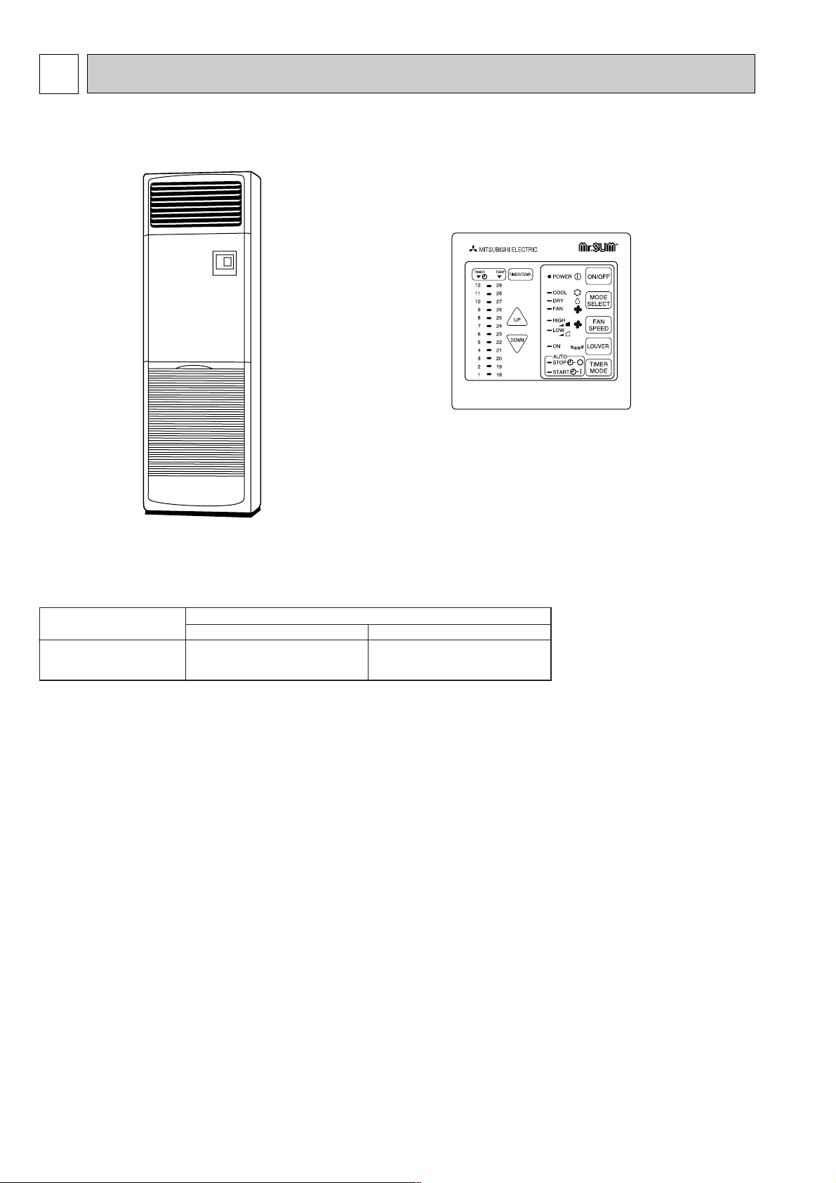
Floor StandingSeries PS
(The controller is built in the indoor unit)
Indoor unit
controller
Service Ref. Cooling capacity/50/60Hz
W Btu/h
PS-3GJA
PS-4GJSA
Rating condition (JIS B8616)
Indoor : 27°CDB, 19°CWB
Outdoor : 35°CDB, 24°CWB
1 7,200/7,900 24,600/27,000
1 9,800/10,900 33,400/37,200
1. OPTIMAL PERFORMANCE AND EFFICIENT MAINTENANCE
(1) PEACEFUL SILENCE THROUGH WHISPER-QUIET OPERATION
This top quality floor-standing model guarantees near-silent operation through a newly developed low-noise fan. Air-duct
design has also been optimized through the adoption of microslit fans. Perfect for shops and office meeting-rooms.
(2) LONG LIFE FILTER
The long life filter allows 2,500 hours of maintenance-free operation in office environments not so dusty.
(3) SMOOTH REMOVAL
An open grill system permits filters to be removed smoothly and easily.
(4) EASY CLEANING
Dirt can be cleaned off simply because vanes are flockless.
2. INSTALLATION TIME GREATLY REDUCED
(1) EFFECTIVE PIPE CONNECTION
Raising the pipe connection position facilitates pipe arrangement, thus shortening installation time.
(2) CONVENIENT WIRING
A raised wire connection position means that wiring work can be conveniently implemented.
(3) WEIGHT REDUCTION
The use of plastics as assembly materials has realized a reduction in weight of 22kg. (PS-5 GJSA 72kg ➔ 51kg)
(4) PIPE DIRECTIONS
Pipes can be installed in four directions (rear, left, right, and bottom sides.)
2
Page 3
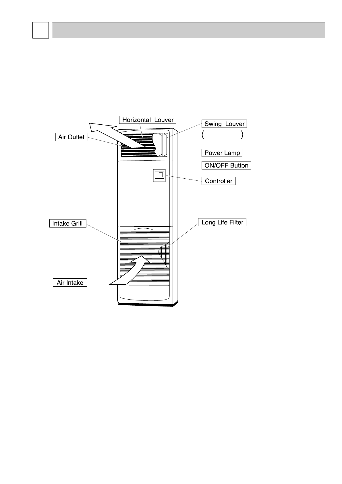
PART NAMES AND FUNCTIONS2
Disperses air
up and down
Disperses air left
and right.
Removes dust and pollutants from inhaled air.
(Inhales air from room.)
● Indoor (Main) Unit
PS-3GJA
PS-4GJSA1
1
3
Page 4
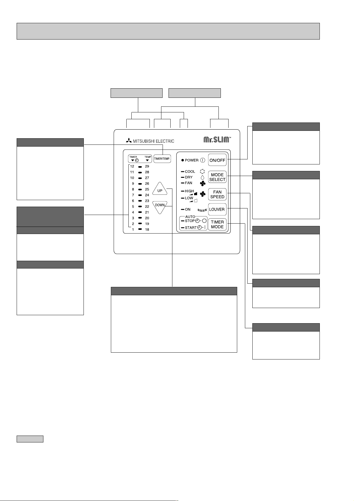
● Controller
i
.
Settings remain in effect' until changed. The air
conditioner can be operated by simply pressing
ON/OFF button once settings have been made.
TIMER/TEMP. button
This button is used to
change between display of
room temperature and
display of remaining time
on the timer during “AUTO
STOP” operation.
Green lamps light in
selected display mode.
Lamps display remaining
time on the timer or room
temperature.
Remaining timer time display
Lamps indicate time remaining
until timer stops operation.
Green lamps display the
remaining number of hours.
Room temperature display
Lamps display temperature
settings actual room
temperatures.
●Temperature settings :
Green lamps light.
●Temperature in room :
Green lamps flash.
(Example display readings are
for explanations only, so actual
display readings will differ.)
Display panel
Operating panel
UP and DOWN buttons
●Temperature control (While green “TEMP” lamp
is lighting.)
Use UP and DOWN buttons to set desired
temperature between 18 and 29 °C.
●Timed operation (While green “TIMER“ lamp is
lighting.)
Use UP and DOWN buttons to set timed
operation between one and twelve hours.
ON/OFF button
Pressing button starts
operation. Pressing again
stops operation.
Green lamp remains lit
during operation.
MODE SELECT button
This button is used to
change between cooling,
DRYING and ventilation
operation modes. One of
three green lamps lights to
indicate mode in effect.
FAN SPEED button
This button is used to
change between low and
high fan speeds. One of
two green lamps lights to
indicate which fan speed is
in effect.
LOUVER button
This button is used to
switch swing louver
ON/OFF.
TIMER MODE button
Used to select timed
starting or stopping. Green
lamp lights to indicate timer
mode selected.
Attention
● Pressing the UP and DOWN buttons together for more than two seconds will initiate the “test run” or “self-diagnostic” mode.
Avoid pressing these buttons simultaneously during normal operation. Press the ON/OFF button to cancel test run or selfdiagnostic mode.
● All green lamps turn off when air conditioner is OFF.
● Avoid operation of buttons with fingernails or other sharp objects. Sharp objects may scratch operating panel.
4
Page 5
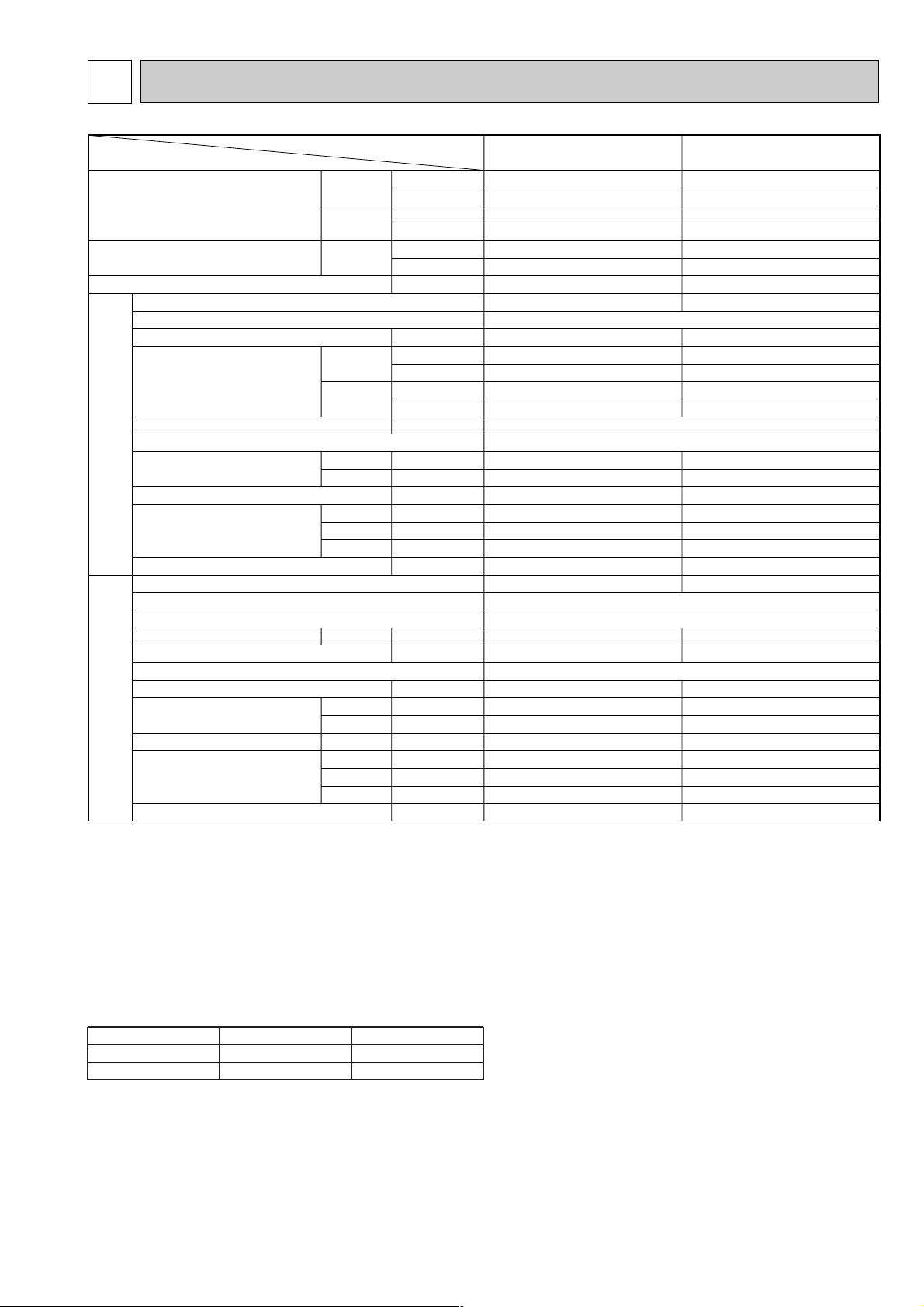
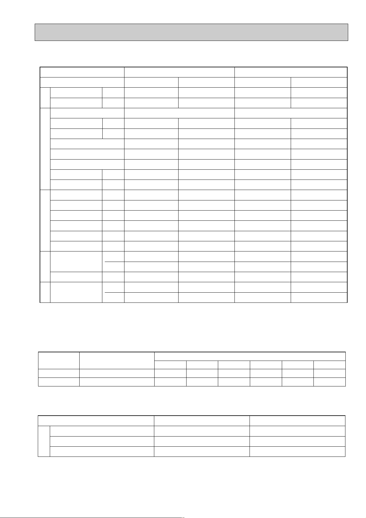
SPECIFICATIONS3
Cooling capacity
W1
Total input (50/60Hz)
Indoor
unit
Cooling capacity (SSA)
W2
Outdoor
unit
Service Ref.
External finish
Fan motor output
Airflow Hi-Lo
External static pressure
Operation control & Thermostat
Noise level High-Low
Cond. drain connection O.D.
Dimensions
Weight
Service Ref.
External finish
Refrigerant (R-22) control
Crankcase heater
Compressor output
Protection devices
Fan motor output
Air flow
Noise level
Dimensions
Weight
50Hz
60Hz
50Hz
60Hz
50Hz
60Hz
H
W
D
60Hz
50/60Hz
50Hz
60Hz
50/60Hz
W
D
H
W
Btu/h
W
Btu/h
kW
kW
m
3
/min
CFM
m
3
/min
CFM
mmAq,Pa
dB (A)
dB (A)
mm (in.)
mm (in.)
mm (in.)
mm (in.)
kg (lbs)
W
Btu/h
W
kW
kW
m
3
/min(CFM)
m
3
/min(CFM)
dB (A)
mm (in.)
mm (in.)
mm (in.)
kg (lbs)
Service Ref.
Item
7,200
24,600
7,900
27,000
6,800
23,200
3.32/3.60
Munsell 0.70 Y 8.59/0.97
PS-3GJA
1 PS-4GJSA1
0.03
17 -14
600 - 494
17 -14
600 - 494
0 (Direct blow)
Built-in
42 - 37
42 - 37
26(1)
1900(74 - 13/16)
600(23 - 5/8)
270(10 - 5/8)
43(95)
Munsell 5Y 7/1
Capillary tube
PU-3VJA2.UK,3YJA2.UK,3NJA1.UK
PU-4VLJSA2.UK,4YJSA2.UK,4TJSA1.UK
32/32
2.2
W5
0.085
50 (1765)
50 (1765)
52/53
870 (34-1/4)
295(11 - 5/8)
850 (33-7/16)
73 (161)
PS-4GJSA
1
9,800
33,400
10,900
37,200
9,400
32,000
3.57/4.53
0.07
28 - 22
988 - 776
30 - 22
1059 - 776
47 - 42
48 - 42
26(1)
1900(74 - 13/16)
600(23 - 5/8)
350(13 - 3/4)
51(112)
32/32
2.7
0.065 + 0.065
95 (3352)
95 (3352)
54/55
870 (34-1/4)
295(11 - 5/8)
1,258 (49-1/2)
94 (207)
PS-3GJA
1
1. STANDARD SPECIFICATIONS
Notes :
W1 Rating conditions (JIS B8616) W4 Capacity of crankcase heater (W) based on 220 volts.
Indoor : 27°C (80°F) DB, 19°C (66°F)WB W5V, N
Outdoor : 35°C (95°F) DB, 24°C (75°F)WB T, Y
Refrigerant piping length (one way) : 5m (16ft) Thermal relay (PU-3YJSA
W2 Rating conditions (SSA 385, 386) VL
Indoor : 29°C (84°F) DB, 19°C (66°F)WB Thermal switch.
Outdoor : 46°C (115°F) DB, 24°C (75°F)WB
W3 Total input bassed on indicated voltage
Service Ref.
50Hz
60Hz
PS-3GJA1
1ph 220V/1ph 220V
1ph 220V/1ph 220V
(Indoor / Outdoor)
PS-4GJSA1
1ph 220V/3ph 380V
1ph 220V/3ph 220V
...
Inner thermostat, HP switch, LP switch.
...
Thermal switch, Reversed-phase protector, HP switch, LP switch,
...
Inner thermostat,HP switch,LP switch
2, PU-4YJSA2, PU-4TJSA2)
5
Page 6
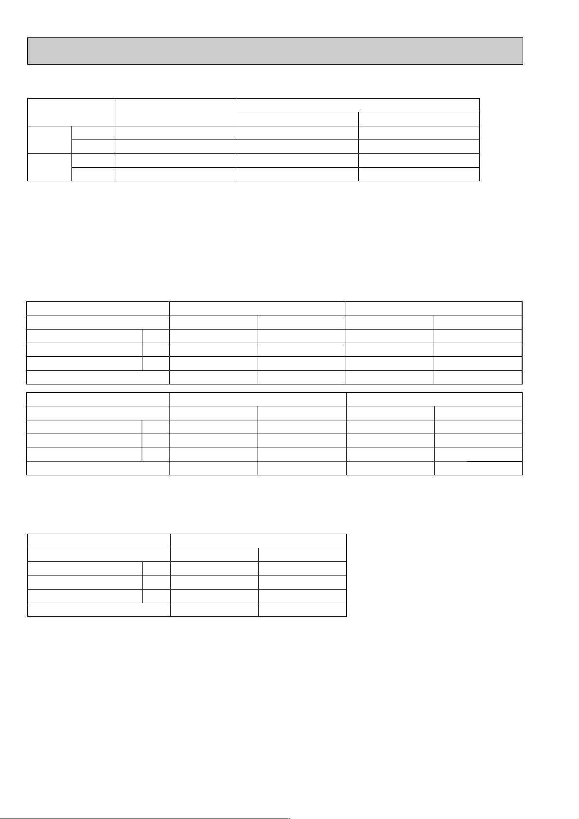
2. POWER SUPPLY & MODEL NAMES
50Hz
60Hz
1 ph.
3 ph.
1 ph.
3 ph.
220, 230, 240V
380/220, 400/230, 415/240V
220V
220V
PU-3VJA
2.UK
PU-3YJA2.UK
PU-3NJA1.UK
—
PU-4VLJSA
2.UK
PU-4YJSA2.UK
—
PU-4TJSA
1.UK
PS-3GJA1 PS-4GJSA1
Service Ref. (Indoor unit)
Service Ref. (Outdoor unit)
Power supply
Service Ref.
Current
Input
Starting current
Outdoor unit
A
kW
A
V : 220V 50Hz
PS-3GJA
1
0.64
0.14
0.8
PU-3
PS-4GJSA
1
1.02
0.22
1.5
PU-4
V : 230V 50Hz
PS-3GJA
1
0.66
0.15
1.5
PU-3
PS-4GJSA
1
1.06
0.24
1.5
PU-4
Power supply (1 Phase)
Service Ref.
Current
Input
Starting current
Outdoor unit
A
kW
A
V : 240V 50Hz
PS-3GJA
1
0.68
0.16
0.8
PU-3
PS-4GJSA
1
1.10
0.26
1.5
PU-4
Power supply (1 Phase)
N : 220V 60Hz
0.73
0.16
0.8
PU-3
1.20
0.26
1.5
PU-4
PS-3GJA
1 PS-4GJSA1
Service Ref.
Current
Input
Starting current
Outdoor unit
A
kW
A
N : 220V 60Hz
PS-3GJA
1
0.73
0.16
0.8
PU-3
PS-4GJSA
1
1.20
0.26
1.5
PU-4
Power supply (1 Phase)
Notes : 1. Power supply key N
.......
1ph, 220V,60Hz T
...
V(L)
1ph, 220, 230, 240V 50Hz Y
2. Primary power supplies for all indoor units are single-phase. 50Hz, 4 wires
3. ELECTRICAL SPECIFICATIONS
(1). Rating conditions -JIS B 8616
Series PS Indoor Unit (Single Phase)
Indoor : 27°C (80°F) DB, 19°C (66°F) WB
{
Outdoor : 35°C (95°F) DB
...
3ph. 220V, 60Hz
...
3ph. 380/220, 400/230, 415/240V,
(2). Rating conditions -SSA385,386
Series PS Indoor Unit (Single Phase)
6
Indoor : 29°C (84°F) DB, 19°C (66°F) WB
{
Outdoor : 46°C (115°F) DB,24°C (75°F) WB
Page 7
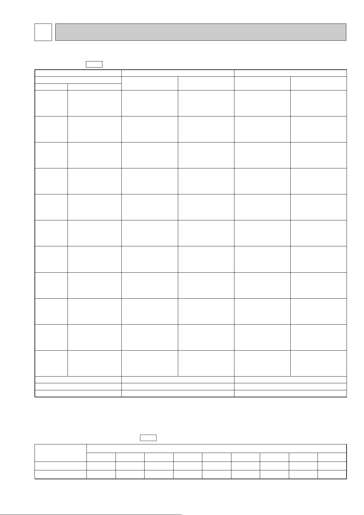
DATA4
Indoor WBOutdoor DB
PS-3GJA
1
T.C.
C.F.
(T.I.)
PS-4GJSA
1
T.C.
C.F.
(T.I.)
Service Ref.
Temperature
16$C
18$C
19$C
19.4$C
20$C
22$C
16$C
18$C
19$C
19.4$C
20$C
22$C
16$C
18$C
19$C
19.4$C
20$C
22$C
16$C
18$C
19$C
19.4$C
20$C
22$C
16$C
18$C
19$C
19.4$C
20$C
22$C
16$C
18$C
19$C
19.4$C
20$C
22$C
16$C
18$C
19$C
19.4$C
20$C
22$C
16$C
18$C
19$C
19.4$C
20$C
22$C
16$C
18$C
19$C
19.4$C
20$C
22$C
16$C
18$C
19$C
19.4$C
20$C
22$C
16$C
18$C
19$C
19.4$C
20$C
22$C
(60.8$F)
(64.4$F)
(66.2$F)
(67$F)
(68$F)
(71.6$F)
(60.8$F)
(64.4$F)
(66.2$F)
(67$F)
(68$F)
(71.6$F)
(60.8$F)
(64.4$F)
(66.2$F)
(67$F)
(68$F)
(71.6$F)
(60.8$F)
(64.4$F)
(66.2$F)
(67$F)
(68$F)
(71.6$F)
(60.8$F)
(64.4$F)
(66.2$F)
(67$F)
(68$F)
(71.6$F)
(60.8$F)
(64.4$F)
(66.2$F)
(67$F)
(68$F)
(71.6$F)
(60.8$F)
(64.4$F)
(66.2$F)
(67$F)
(68$F)
(71.6$F)
(60.8$F)
(64.4$F)
(66.2$F)
(67$F)
(68$F)
(71.6$F)
(60.8$F)
(64.4$F)
(66.2$F)
(67$F)
(68$F)
(71.6$F)
(60.8$F)
(64.4$F)
(66.2$F)
(67$F)
(68$F)
(71.6$F)
(60.8$F)
(64.4$F)
(66.2$F)
(67$F)
(68$F)
(71.6$F)
7.2
7.7
7.9
8.0
8.2
8.7
7.1
7.5
7.8
7.9
8.0
8.5
6.8
7.3
7.5
7.6
7.7
8.2
6.7
7.1
7.4
7.5
7.6
8.1
6.5
7.0
7.2
7.3
7.4
7.9
6.2
6.7
6.9
7.0
7.1
7.6
6.2
6.6
6.9
6.9
7.1
7.6
5.9
6.4
6.6
6.7
6.8
7.3
5.9
6.3
6.5
6.6
6.7
7.2
5.6
6.0
6.2
6.3
6.5
6.9
5.5
5.9
6.1
6.2
6.3
6.8
0.81
0.82
0.83
0.83
0.84
0.86
0.84
0.85
0.86
0.86
0.87
0.89
0.90
0.92
0.93
0.93
0.94
0.96
0.93
0.95
0.96
0.97
0.97
0.99
0.96
0.99
1.00
1.00
1.01
1.04
1.03
1.06
1.07
1.08
1.08
1.11
1.04
1.06
1.08
1.08
1.09
1.12
1.10
1.12
1.14
1.15
1.16
1.20
1.11
1.14
1.15
1.16
1.17
1.21
1.16
1.19
1.21
1.22
1.23
1.28
1.19
1.22
1.24
1.25
1.26
1.31
9.8
10.5
10.8
10.9
11.1
11.8
9.6
10.2
10.6
10.7
10.9
11.6
9.3
9.9
10.2
10.3
10.5
11.2
9.1
9.7
10.0
10.2
10.3
11.0
8.9
9.5
9.8
9.9
10.1
10.8
8.5
9.1
9.4
9.5
9.7
10.3
8.4
9.0
9.3
9.5
9.6
10.3
8.1
8.6
8.9
9.1
9.3
9.9
8.0
8.6
8.9
9.0
9.2
9.8
7.6
8.2
8.5
8.6
8.8
9.4
7.4
8.0
8.3
8.4
8.6
9.2
0.81
0.82
0.83
0.83
0.84
0.86
0.84
0.85
0.86
0.86
0.87
0.89
0.90
0.92
0.93
0.93
0.94
0.96
0.93
0.95
0.96
0.97
0.97
0.99
0.96
0.99
1.00
1.00
1.01
1.04
1.03
1.06
1.07
1.08
1.08
1.11
1.04
1.06
1.08
1.08
1.09
1.12
1.10
1.12
1.14
1.15
1.16
1.20
1.11
1.14
1.15
1.16
1.17
1.21
1.16
1.19
1.21
1.22
1.23
1.28
1.19
1.22
1.24
1.25
1.26
1.31
21$C
(69.8$F)
25$C
(77$F)
30$C
(86$F)
32.2$C
(90$F)
35$C
(95$F)
40$C
(104$F)
40.6$C
(105$F)
45$C
(113$F)
46$C
(115$F)
50$C
(122$F)
52$C
(125.5$F)
17
0.10
0.70
28
0.16
0.76
Evaporator airflow (CMM)
Bypass factors
S.H.F. at rating conditions
PS-3GJA1
PS-4GJSA1
Refrigerant piping Iength (one way)
5m (16ft)
1.0
1.0
10m (33ft)
0.978
0.984
5m (49ft)
0.962
0.974
20m (66ft)
0.948
0.964
25m (82ft)
0.934
0.954
30m (98ft)
0.921
0.944
35m (115ft)
—
0.935
40m (131ft)
—
0.926
45m (148ft)
—
—
Service Ref.
1. PERFORMANCE DATA
Cooling capacity
50Hz
Notes : 1. T.C. : Total capacity ( ✕ 103W)
Cooling capacity correction factors
C.F. (T.I.) : Correction factors of Total input (Indoor unit input + Outdoor unit input)
2. (°F) = 32 + 9 / 5 (°C)
3. Guaranteed operating range (cooling)
...
(Btu / h)
.
=
. (W) ✕ 3.4, (kcal / h) = (W) ✕ 0.86
Lower limit ... Indoor : 21°C (70°F) DB, 15.5°C (60°F) WB, Outdoor : 21°C (70°F) DB.
{
Upper limit
50Hz
...
Indoor : 35°C (95°F) DB, 22.5°C (72.5°F) WB, Outdoor : 52°C (125.5°F) DB.
WVL
...
Outdoor : 46°C (115°F) DB.
7
Page 8
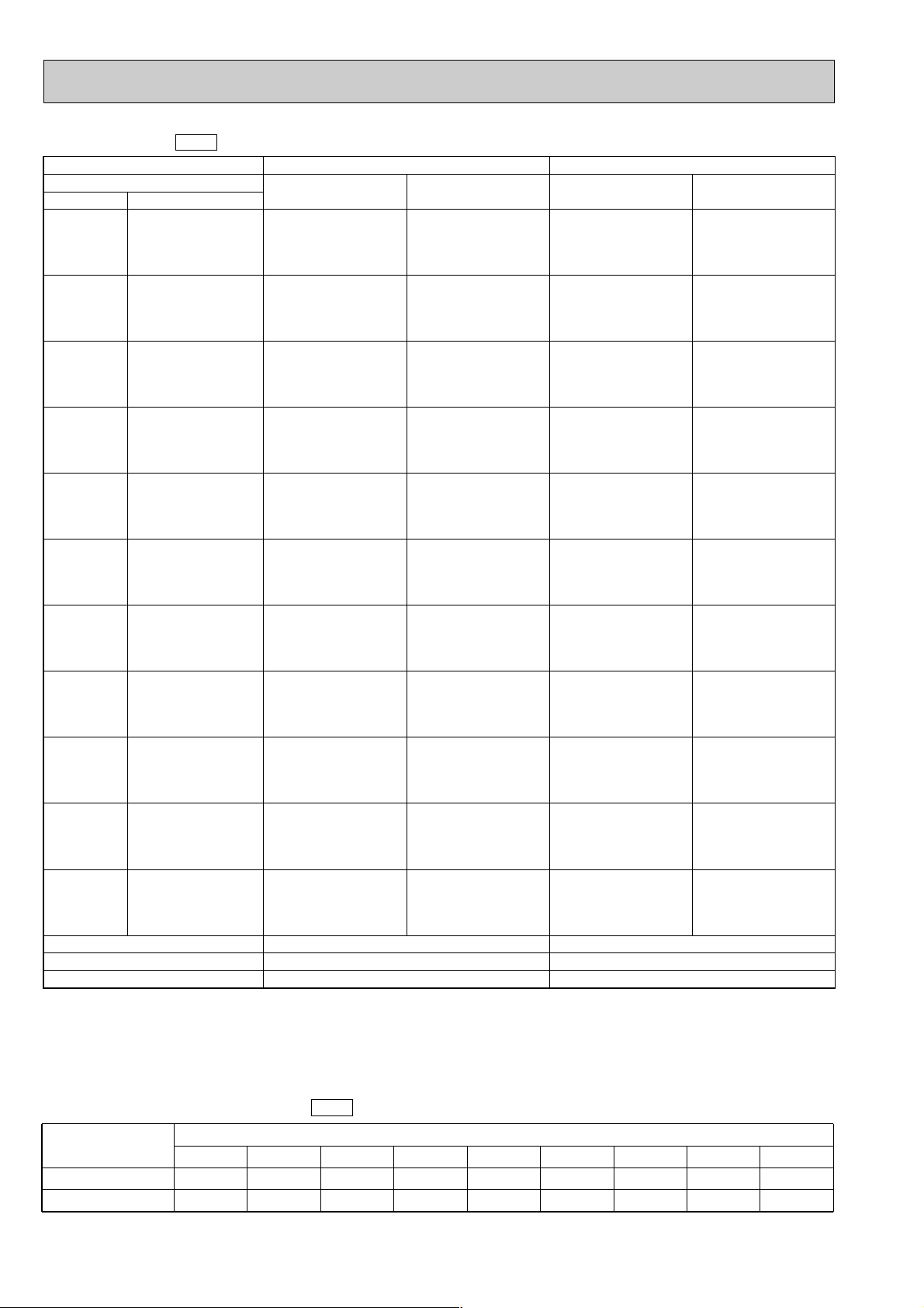
Cooling capacity
60Hz
Service Ref.
Temperature
Indoor WBOutdoor DB
21$C
(69.8$F)
25$C
(77$F)
30$C
(86$F)
32.2$C
(90$F)
35$C
(95$F)
40$C
(104$F)
40.6$C
(105$F)
45$C
(113$F)
46$C
(115$F)
50$C
(122$F)
52$C
(125.5$F)
16$C
18$C
19$C
19.4$C
20$C
22$C
16$C
18$C
19$C
19.4$C
20$C
22$C
16$C
18$C
19$C
19.4$C
20$C
22$C
16$C
18$C
19$C
19.4$C
20$C
22$C
16$C
18$C
19$C
19.4$C
20$C
22$C
16$C
18$C
19$C
19.4$C
20$C
22$C
16$C
18$C
19$C
19.4$C
20$C
22$C
16$C
18$C
19$C
19.4$C
20$C
22$C
16$C
18$C
19$C
19.4$C
20$C
22$C
16$C
18$C
19$C
19.4$C
20$C
22$C
16$C
18$C
19$C
19.4$C
20$C
22$C
(60.8$F)
(64.4$F)
(66.2$F)
(67$F)
(68$F)
(71.6$F)
(60.8$F)
(64.4$F)
(66.2$F)
(67$F)
(68$F)
(71.6$F)
(60.8$F)
(64.4$F)
(66.2$F)
(67$F)
(68$F)
(71.6$F)
(60.8$F)
(64.4$F)
(66.2$F)
(67$F)
(68$F)
(71.6$F)
(60.8$F)
(64.4$F)
(66.2$F)
(67$F)
(68$F)
(71.6$F)
(60.8$F)
(64.4$F)
(66.2$F)
(67$F)
(68$F)
(71.6$F)
(60.8$F)
(64.4$F)
(66.2$F)
(67$F)
(68$F)
(71.6$F)
(60.8$F)
(64.4$F)
(66.2$F)
(67$F)
(68$F)
(71.6$F)
(60.8$F)
(64.4$F)
(66.2$F)
(67$F)
(68$F)
(71.6$F)
(60.8$F)
(64.4$F)
(66.2$F)
(67$F)
(68$F)
(71.6$F)
(60.8$F)
(64.4$F)
(66.2$F)
(67$F)
(68$F)
(71.6$F)
Evaporator airflow (CMM)
Bypass factors
S.H.F. at rating conditions
Notes : 1. T.C. : Total capacity ( ✕ 103W)
C.F. (T.I.) : Correction factors of Total input (Indoor unit input + Outdoor unit input)
2. (°F) = 32 + 9 / 5 (°C)
3. Guaranteed operating range (cooling)
...
(Btu / h)
PS-3GJA
T.C.
7.9
8.4
8.7
8.8
9.0
9.5
7.8
8.3
8.5
8.6
8.8
9.4
7.5
8.0
8.2
8.3
8.5
9.0
7.3
7.8
8.1
8.2
8.3
8.9
7.2
7.6
7.9
8.0
8.2
8.7
6.8
7.3
7.6
7.7
7.8
8.3
6.8
7.3
7.5
7.6
7.8
8.3
6.5
7.0
7.2
7.3
7.5
8.0
6.4
6.9
7.1
7.2
7.4
7.9
6.2
6.6
6.9
6.9
7.1
7.6
6.0
6.5
6.7
6.8
6.9
7.4
.
=
. (W) ✕ 3.4, (kcal / h) = (W) ✕ 0.86
Lower limit ... Indoor : 21°C (70°F) DB, 15.5°C (60°F) WB, Outdoor : 21°C (70°F) DB.
{
Upper limit
1
C.F.
(T.I.)
0.81
0.82
0.83
0.83
0.84
0.86
0.84
0.85
0.86
0.86
0.87
0.89
0.90
0.92
0.93
0.93
0.94
0.96
0.93
0.95
0.96
0.97
0.97
0.99
0.96
0.99
1.00
1.00
1.01
1.04
1.03
1.06
1.07
1.08
1.08
1.11
1.04
1.06
1.08
1.08
1.09
1.12
1.10
1.12
1.14
1.15
1.16
1.20
1.11
1.14
1.15
1.16
1.17
1.21
1.16
1.19
1.21
1.22
1.23
1.28
1.19
1.22
1.24
1.25
1.26
17
0.10
0.69
...
Indoor : 35°C (95°F) DB, 22.5°C (72.5°F) WB, Outdoor : 52°C (125.5°F) DB.
1.31
T.C.
10.9
11.7
12.0
12.2
12.4
13.1
10.7
11.4
11.8
11.9
12.1
12.9
10.3
11.0
11.3
11.5
11.7
12.5
10.1
10.8
11.2
11.3
11.5
12.3
10.5
10.9
11.0
11.3
12.0
10.1
10.4
10.6
10.8
11.5
10.0
10.4
10.5
10.7
11.4
10.0
10.1
10.3
11.0
10.0
10.2
10.9
10.5
10.3
9.9
9.4
9.4
9.0
9.6
8.9
9.5
9.9
8.5
9.1
9.5
9.6
9.8
8.3
8.9
9.2
9.4
9.6
PS-4GJSA
1
30
0.16
0.74
C.F.
(T.I.)
0.81
0.82
0.83
0.83
0.84
0.86
0.84
0.85
0.86
0.86
0.87
0.89
0.90
0.92
0.93
0.93
0.94
0.96
0.93
0.95
0.96
0.97
0.97
0.99
0.96
0.99
1.00
1.00
1.01
1.04
1.03
1.06
1.07
1.08
1.08
1.11
1.04
1.06
1.08
1.08
1.09
1.12
1.10
1.12
1.14
1.15
1.16
1.20
1.11
1.14
1.15
1.16
1.17
1.21
1.16
1.19
1.21
1.22
1.23
1.28
1.19
1.22
1.24
1.25
1.26
1.31
Cooling capacity correction factors
Service Ref.
PS-3GJA1
PS-4GJSA1
8
5m (16ft)
1.0
1.0
10m (33ft)
0.971
0.980
60Hz
5m (49ft)
0.950
0.966
Refrigerant piping Iength (one way)
20m (66ft)
0.931
0.952
25m (82ft)
0.913
0.939
30m (98ft)
0.896
0.926
35m (115ft)
—
0.914
40m (131ft)
—
0.902
45m (148ft)
—
—
Page 9
Mode
Total
Electrical circuit
Refrigerant circuit
Indoor unit
Outdoor
unit
Capacity
Input
Indoor unit Service Ref.
Phase, Hz
Volts
Amperes
Outdoor unit Service Ref.
Phase, Hz
Volts
Amperes
Discharge pressure
Suction pressure
Discahrge temperature
Condensing temperature
Suction temperature
Ref. pipe length
Intake air temperature
Discharge air temperature
Intake air temperature
W
kW
$C
$C
$C
m
DB$C
WB$C
DB$C
DB$C
WB$C
PS-3GJA
1
Cooling
7,200
3.32
PS-3GJA
1
1, 50
220
0.64
PU-3VJA
2.UK
1, 50
220
15.1
61.5
2.6
5.8
5
27
19
12.3
35
24
Cooling
7,900
3.60
1, 60
220
0.73
PU-3NJA
1.UK
1, 60
220
17.6
70.1
5.5
4.0
5
27
19
11.5
35
24
PS-4GJSA
1
Cooling
9,800
3.57
PS-4GJSA
1
1, 50
220
1.02
PU-4YJSA
2.UK
3, 50
380
5.7
64.9
48.9
6.3
5
27
19
14.1
35
24
Cooling
10,900
4.53
1, 60
220
1.20
PU-4TJSA
1.UK
3, 60
220
12.2
75.0
52.0
4.9
5
27
19
14.6
35
24
Service Ref.
V
A
V
A
MPa·G
(Of/F·G)
MPa·G
(Of/F·G)
2.0
(20.4)
2.14
(21.8)
1.83
(18.7)
1.99
(20.3)
0.47
(4.8)
0.45
(4.6)
0.50
(5.1)
0.47
(4.8)
3. STANDARD OPERATION DATA
PS-3GJA1
PS-4GJSA1
Outdoor unit precharged (kg)
(up to 20)
V…3.08,Y…2.88,N…3.5
VL…3.8,Y…4.6, T…4.6
0.06(0.13)
0.15(0.33)
0.12(0.26)
0.30(0.66)—0.45(0.99)—0.6(1.32)
—
—
25m(82ft) 30m(98ft) 35m(115ft) 40m(131ft) 45m(148ft)
Piping length(one way)
20m(66ft)
0
0
Service Ref.
Standard
Air flow m3/min
Air speed m/sec
Coverage range m
PS-3GJA
1
17
2.6
8.4
PS-4GJSA
1
28
4.2
13.6
The unit or pressure has been changed to Mpa based on the international SI system.
The conversion factor is :
4. ADDITIONAL REFRIGERANT CHARGE (R-22 : kg (Ibs))
5. OUTLET AIR SPEED AND COVERAGE RANGE
1(Mpa·G)=10(Of/F·G)
9
Page 10
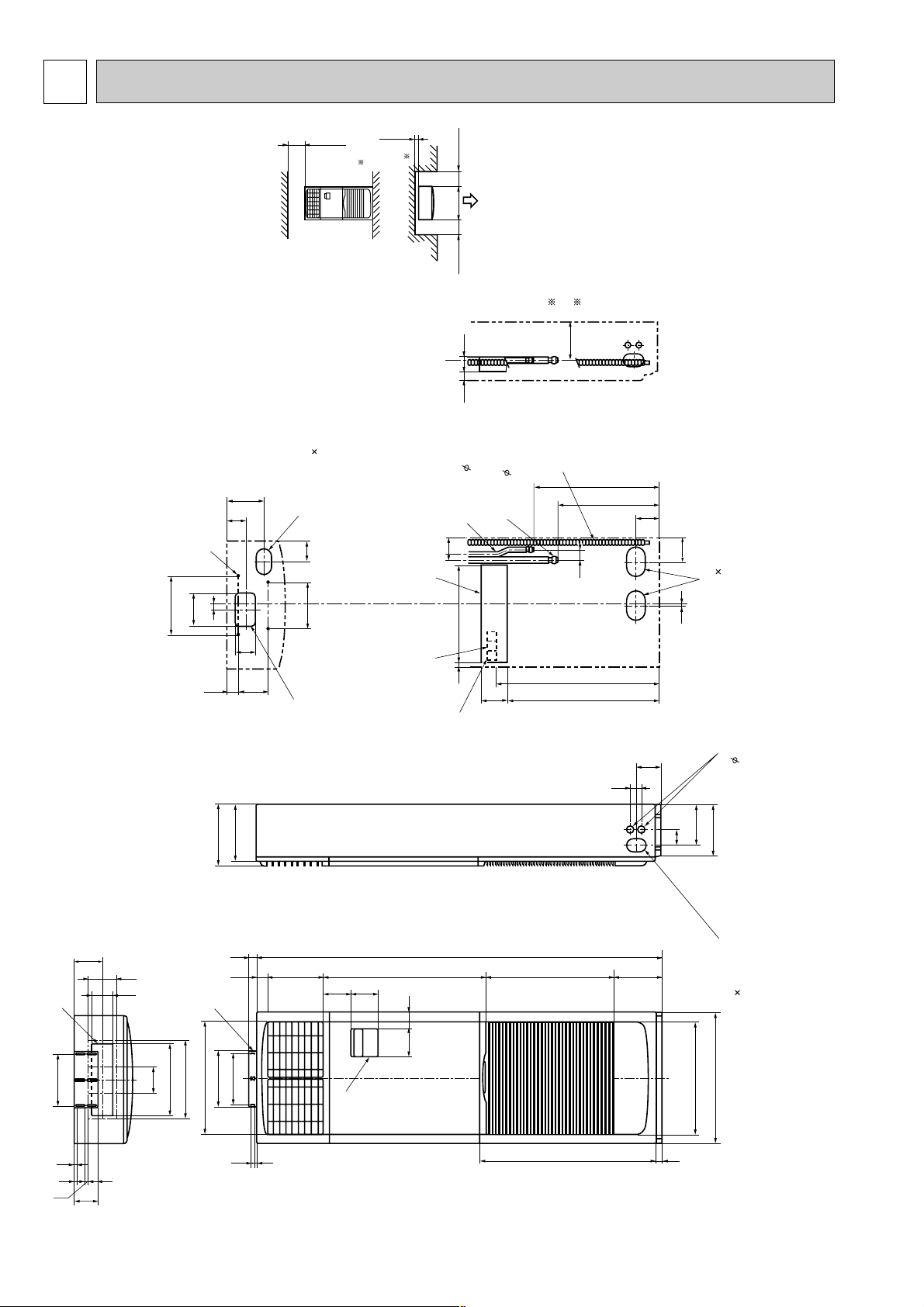
5 OUTLINES AND DIMENSIONS
125
240
Front side
Metal fixture
against overturning
controller
Rear side
Front side
Rear side
Knock out hole
for branch duct
Knock out hole
for bottom fixing
Knock out hole
for under-piping
Knock out hole for
under-piping(120 70 oval)
100
10
3838
50260
130130
766
1900
608
50
115
714 123
767
110
480
590
216
40
82730
2010
111
15
130
132
277
160
20
218
175
90
55143
100
340
370
520
260
240
130 71
530
600
270
250
70
180
235
Knock out hole for
wiring. 27
(Provided on both sides)
Knock out hole for refrigerant and drainage.
90 60 oval (Provided on both sides)
Knock out hole for piping and wiring
(140 80 oval)
20
105
Terminal block
for control
Electrical parts box
Liquid pipe 9.52(3/8F)
1. Service access allows for
insertion of screw driver.
2. Adjustable
Gas pipe 15.88(5/8F)
Drain pipe
Terminal block
for power supply
95
46122
47
95
40 66
186
100 or more 100 or more
2
5 or more
1
300 or more
Front 1,000 or more
1. INDOOR UNIT
PS-3GJA
1
Unit : mm
10
Page 11
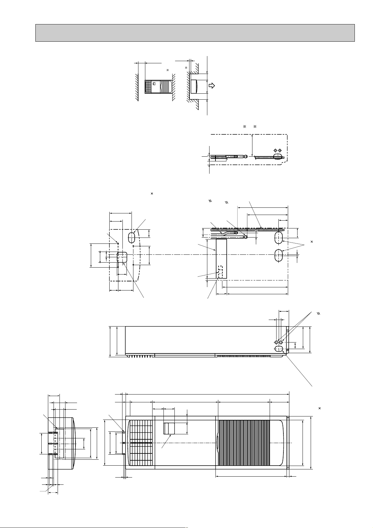
PS-4GJSA1
125
240
Front side
Metal fixture
against overturning
controller
Rear side
Front side
Rear side
Knock out hole
for branch duct
Knock out hole
for bottom fixing
Knock out hole
for under-piping
Knock out hole for
under-piping(120 70 oval)
100
10
3838
50260
130130
766
1900
608
50
115
714 123
767
110
480
590
216
40
82730
2010
111
15
130
132
277
120
20
218
255
140
77
201
120
340
370
520
260
240
130 71
530
600
350
330
70
260
315
Knock out hole for
wiring. 27 (Provided on both sides)
Knock out hole for refrigerant and drainage.
90 60 oval (Provided on both sides)
Knock out hole for piping and wiring
(140 80 oval)
20
105
Terminal block
for control
Electrical parts box
Liquid pipe 9.52(3/8F)
1. Service access allows for
insertion of screw driver.
2. Adjustable
Gas pipe 19.05(3/4)
Drain pipe
Terminal block
for power supply
95
46122
47
95
40 66
261
100 or more 100 or more
2
5 or more
1
300 or more
Front 1,000 or more
Unit : mm
11
Page 12

6 WIRING DIAGRAM
N
L
TWIN-1TWIN-2
CN2ACN2B
OFF
ON
GRN/YLW
I.B
TB2
TO OUTDOOR UNIT
CONNECTING WIRES
DC12V(non-polar)
21
T
ML
X6 X5 X4
X6 X5 X4
ZNR
FUSE1
X2
X2
FUSE2
C
MF
CNR120
LD7LD8
SW7
SW6
SW5
SW8
SW4
SW3
SW2
SW1
LD12
LD11
LD6
LD10
LD5
LD4
LD9
LD3
LD1
LD24
LD23
LD22
LD21
LD20
LD19
LD18
LD17
LD16
LD15
LD14
LD13
CN31
HEATER
123
CN2
TIMER
12345
CN50
DRAIN
CN20
INTAKE
12
CN21
PIPE
1
12
L.TEST
CN28
CN120
TO.RC
OUTDOOR
CN30
123
TRANS
CN4T
1234
CNT
TRANS
31
CND
POWER
31
CNL
LOUVER
317531
SW1
MULTIPLE
CN51
RT1
RT2
12
OFF
ON
SW3
SW2
FAN1
POWER SUPPLY
~ (1 PHASE)
AC220 ~ 240V 50Hz
AC220V 60Hz
YLW/GRN
YLW
ORN
RED
10.6VAC
14.5VAC
WHT
220V
230V
YLW
BG79N700H01
R.B
TB1
ORN
RED
ORN
YLW
BRN
BRN
RED
RED
240V
BLU
BRN
YLW
YLW
WHT
YLW
BLU
BLK
12
PS-3GJA1, PS-4GJSA1
SYMBOL
C
CN2<I.B>
CN2A<I.B>
CN2B<I.B>
CN28<I.B>
CN51<I.B>
FUSE1,2<I.B>
I.B
LD1<R.B>
LD3<R.B>
LD4<R.B>
LD5<R.B>
LD6<R.B>
LD7<R.B>
LD8<R.B>
INDOOR FAN MOTOR CAPACITOR
NAME
TIMER ADAPTOR CONNECTOR
TRANSMISSION WIRES No.1 CONNECTOR
TRANSMISSION WIRES No.2 CONNECTOR
TIME SHORTENING CONNECTOR
MULTIPLE CONNECTOR
FUSE<6.3A>
INDOOR CONTROLLER BOARD
RUN INDICATOR LED
COOLING INDICATOR LED
HEATING INDICATOR LED
FAN HIGH INDICATOR LED
LOUVER ON INDICATOR LED
TEMPERATURE MODE TEMPERATURE LED
TIMER MODE INDICATOR LED
SYMBOL
LD9<R.B>
LD10<R.B>
LD11<R.B>
LD12<R.B>
LD13~24
<R.B>
MF
ML
R.B
RT1
RT2
SW1<I.B>
SW2<I.B>
SW3<I.B>
SW1<R.B>
DRY INDICATOR LED
NAME
FAN LOW INDICATOR LED
OFF TIMER INDICATOR LED
ON TIMER INDICATOR LED
TEMPERATURE/TIMER
REMAINING TIME INDICATOR LED
INDOOR FUN MOTOR
LOUVER MOTOR
CONTROLLER BOARD
ROOM TEMPERATURE THERMISTOR
(0˚C/15k1, 25˚C/5.4k1 DETECT)
INDOOR COIL THERMISTOR
(0˚C/15k1, 25˚C/5.4k1 DETECT)
FUNCTION SWITCH
UNIT SWITCH
EMERGENCY OPERATION SWITCH
ON/OFF SWITCH
SYMBOL
SW2<R.B>
SW3<R.B>
SW4<R.B>
SW5<R.B>
SW6<R.B>
SW7<R.B>
SW8<R.B>
T
TB1
TB2
X2<I.B>
X4,X5,X6<I.B>
ZNR
OPERATION MODE SWITCH
NAME
FAN SPEED SWITCH
LOUVER ON/OFF SWITCH
DISPLAY SWITCH
RAISES SET TEMPERATURE/TIMER SWITCH
LOWERS SET TEMPERATURE/TIMER SWITCH
TIMER MODE SWITCH
TRANSFORMER
POWER SUPPLY TERMINAL BLOCK
INDOOR/OUTDOOR
CONNECTING WIRE TERMINAL BLOCK
LOUVER MOTOR RELAY
INDOOR FAN RELAY
VARISTOR
NOTES :
1. Since the indoor transformer (T) is connected with 220V power, if 230,240V power is used. Change the wiring connection showing fig : W1.
fig : W1
When power supply is
230V
240V
220V
230V
240V
RED
ORANGE
YELLOW
2. Since the outdoor side electric wiring may change be sure to check the outdoor unit electric wiring for servicing.
3. Symbols used in wiring diagram above are. :connector / :Terminal block
4. Emergency operation
If remote controller of microcomputer fails but there is no other trouble, emergency operation is possible by setting dip switch (SW3<I.B>) on the indoor
controller board.
[Check items]
[Emergency operation procedure]
(1) Compressor and fan.
(2) Check the trouble position using self diagnostic function. If the result of self diagnosis indicates protective device such as freeze protection is functioning,
emergency operation is not possible unless the cause is removed.
(1) Set the dip switch (SW3<I.B>) on the indoor controller board to 1 • 2 on and 3 off for cooling.
Emergency operation will be continuous operation mode due to power ON/OFF (ON/OFF with remote controller is not possible).
(2) Turn on outdoor unit side circuit breaker, and then indoor unit side circuit breaker in this order.
(3) During emergency operation, the indoor fan runs on high speed but swing louver remains stop.
(4) Thermostat will not function.
(5) Emergency cooling should be limited to 10 hours maximum (the indoor unit heat exchanger may freeze.)
12
Page 13

REFRIGERANT SYSTEM DIAGRAM7
Indoor heat
exchanger
Distributor
with strainer
Outdoor heat
exchanger
(With insulator) option
Ball valve
(with service port)
Flared
connection
Flexible tube
Compressor
flow of refrigerant
wSize of capillary tube for injection
w
Capillary
tube
Capillary tube for
injection
Flared
connection
Low pressure
switch
High pressure
switch
Refrigerant pipe
15.88 (5/8F)
(With insulator) option
Refrigerant pipe
9.52 (3/8F)
Strainer
OUTDOOR UNIT
PS-3GJA
1
PS-3GJA
(With insulator) option
Refrigerant pipe
19.05 (3/4F)
PS-4GJSA
PS-4GJSA
1
PU-3JA
PU-4JSA
Ball
valve
Check
plug
Charge
plug
Accumulator
Only PU-3NJA,3VJA
3YJA,4TJSA,4YJSA
PU-3 (O.D.3.2 o I.D.1.8 -R800) o 2pcs
PU-3VJA O.D.3.2 o I.D. 2.0 - R 520
PU-3YJA O.D.3.2 o I.D. 1.4 - R 800
PU-3NJA O.D.3.2 o I.D. 1.6 - R 500
PU-4YJSA/4TJSA O.D.3.2 o I.D. 1.2 - R 500
PU-4 (O.D.3.2 o I.D.2.0 -R840) o 2pcs
INDOOR UNIT
PS-3GJA1/PU-3VJA2.UK,PU-3YJA2.UK,PU-3NJA1.UK
PS-4GJSA
1/PU-4VLJSA2.UK,PU-4YJSA2.UK,PU-4TJSA1.UK
13
Page 14
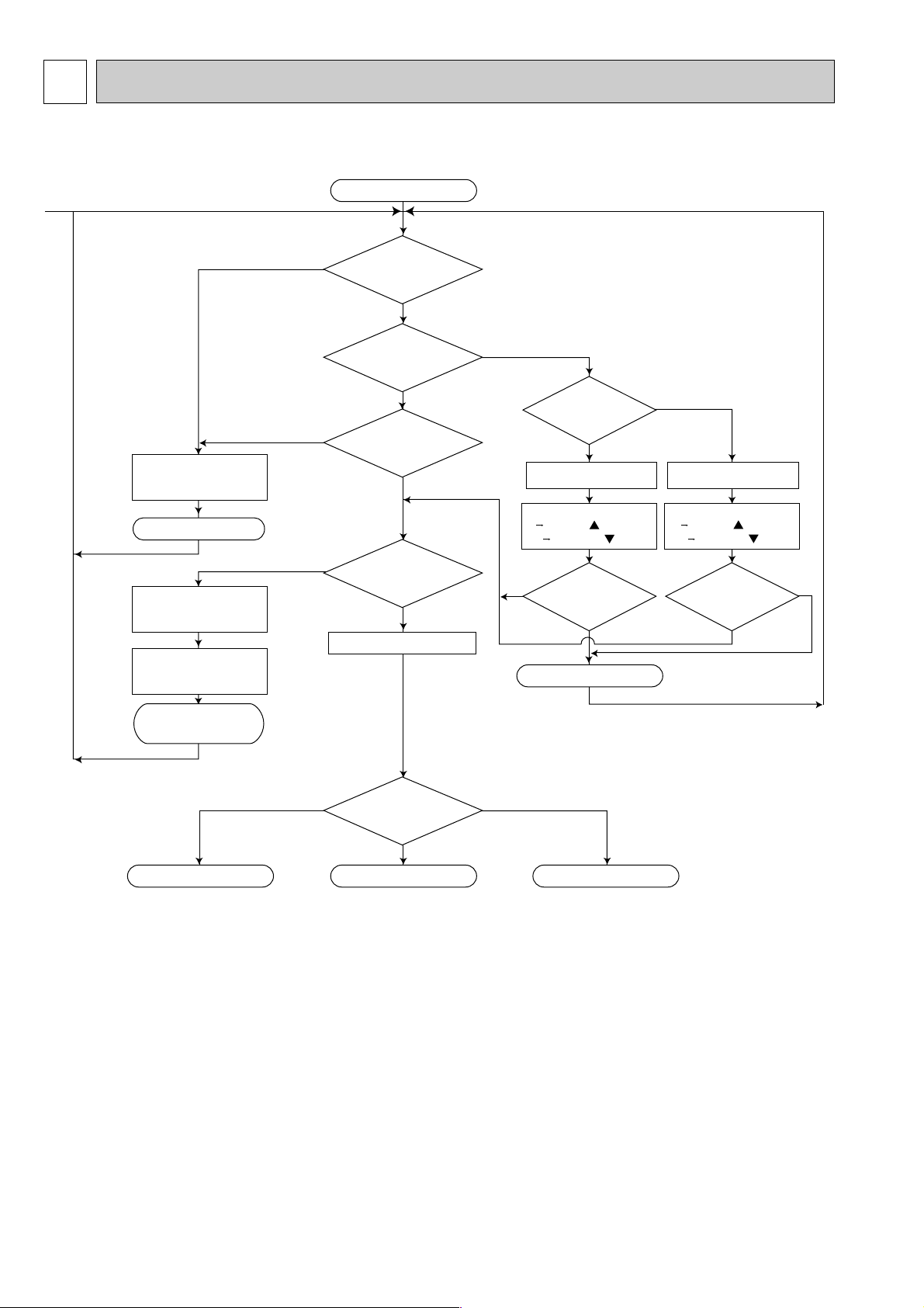
8 OPERATION FLOW-CHART
1
Start
POWER SUPPLY
Live
ON/OFF
button ON
TIMER MODE
button ON
During
operation
AUTO STOP lamp ON AUTO START lamp ON
Auto start timer
1 12Hr up/ press
12 1Hr down/ press
Abnormal
operation mode
MODE SELECT
button
EMERGENCY
ALL STOP
STOP
STOP
Self-diagnostic function
Indicate & Memory
Protection device
Self hold
Protection device
Self hold reset
COOL OPERATION
DRY OPERATIONFAN OPERATION
POWER lamp ON
NO
NO
NO
NO
NO
NO
NO
DRYFAN
COOL
YES
YES
YES YES
YES
YES
YES
<Note 1>
<Note 3>
<Note 2>
<Note 4>
Auto stop timer
1 12Hr up/ press
12 1Hr down/ press
Set time Elapsed time=0
Set time Elapsed time=0
Models : PS-GJA
1. Main operation
Note 1. Refer to page 22 for timer mode details.
Note 2. The unit starts operation by pressing the ON / OFF switch when unit is OFF.
During operation, the unit stops operation by pressing the ON / OFF switch.
In addition, operation can be turned ON / OFF with the contralized remote controller or the remote switch.
Note 3. The factors which cause "abnormal operation mode" are as follows.
●Outdoor unit abnormal operation.
●Fault of room temperature thermistor (RT1).
●Fault of indoor coil thermistor (RT2).
●Indoor coil frost protection mode.
Refer to page 25 for abnormal operation mode details.
Note 4. The compressor will not start for 3 minutes after the stop.
14
Page 15

1
3-minute
time delay
Compressor start
3 minutes elapse
Compressor
start 10 minutes
elapse
Compressor
start 16 minutes
elapse
6-minute
time delay
Coil frost
protection
Coil frost
prevention
Indoor coil
temperature
1$C or below
Indoor coil
temperature 10$C
or more
3-minute time delay
Coil frost
prevention release
Coil frost
prevention set
Range C
Allowance release
Compressor ON Compressor OFF
NO
NO
NO
NO
NO
NO
NO
NO
NO
NO
YES
YES
YES
YES
YES
YES
YES
YES
YES
YES
YES
YES
YES
YES
NO
NO
NO
NO
COOL operation
<Note 5>
<Note 6>
<Note 7>
Compressor
thermostat ON
Allowance release
Allowance
Allowance set
6-minute time delay
Coil frost
protection
check mode
Continue
1 minute
Fan speed LOW
Fan speed LOW
5 minutes elapse
Outdoor unit abnor-
mality check mode
2. COOL operation
Note 5. The thermostat is continuously ON during the test run.
Note 6. Refer to page 18~19 for coil frost protection.
Note 7. Range A : Indoor coil temperature is more than 5 degrees above room temperature.
Range B : Indoor coil temperature is within 5 degrees either way of room temperature.
Range C : Indoor coil temperature is more than 5 degrees below room temperature.
15
Page 16

1
1
DRY operation
FAN operation
Compressor ON
Compressor OFF
10 minutes completed
Compressor ON
3 min.elapse
Compressor
thermostat ON
Compressor
thermostat ON
Compressor ON
time completed
FAN speed
button HIGHT
Fan stop
Compressor OFF
FAN speed HIGHT FAN speed LOW
Compressor ON
time set
Compressor ON
Fan speed LOW
Compressor OFF
10-minute timer start
Room temperature
18 C or below
NO
NO
NO
NO
NO
NO
NO
YES
YES
YES
YES
YES
YES
YES
YES
YES
<Note 5>
<Note 8>
<Note 5>
<Note 9>
<Note 10>
3-minute
time delay
NO
YES
3. DRY operation
Note 8. When the room temperature is 18°C or below, the compressor can not turn ON. When the room temperature rises to
18°C or above, the compressor will start operation after a 3-minute time delay.
Note 9. Refer to page 20 for the compressor operation time.
Note 10. In DRY operation, the indoor fan runs on the low speed during the compressor ON and stops during the compressor
OFF.
4. FAN operation
16
Page 17

MICROPROCESSOR CONTROL9
i
.
1.OUTLINE OF MICROPROCESSOR CONTROL
INPUT to controller
● OFF-ON switching.
● COOL/DRY-FAN selector switching.
● HIGH-LOW fan speed switching.
● Swing louvers SWING-FIXED switching.
● TIMER mode selector switching.
● Thermostat setting.
● Timer setting.
● Self diagnostic troubleshooting.
● Test run switching.
Indoor unit
CONTROLLER
● Transmits and receives orders.
12
12VDC
OUTPUT to controller
● Indication LED lights.
Polar, twelve (12) - core cable
INPUT from indoor unit
● Room temperature thermistor.
● Indoor coil thermistor.
OUTPUT to indoor unit
● Fan : ON - OFF.
● Fan speed : HIGH - LOW
● Swing louvers : ON-OFF.
● Emergency stop.
INPUT from outdoor unit
● Compressor protection device working
OUTPUT to outdoor unit
INDOOR CONTROLLER BOARD
● Receives orders from controller and temperature data from indoor
unit.
● Processes orders and data.
● Transmits the power of indication LED to remote controller
● Controls indoor and outdoor operation.
● Self diagnostic function.
W System control operation.<Optional>
W Emergency operation.
Non - polar, two (2) - core cable
Outdoor unit
12VDC
OUTDOOR UNIT
● Receives order from indoor
controller.
● Emergency stop.
● Compressor motor and outdoor fan motor :
ON - OFF
17
Page 18

2. INDOOR UNIT CONTROL
i
.
2-1 COOL operation
<COOL operation time chart>
Operation starts by
POWER button
ON.
ON
Thermostat
OFF
<How to operate>
1 Press POWER ON/OFF button.
2 Press MODE SELECT button to set operation mode to COOL.
3 Check lamp is ON and set desired temperature with UP
TEMP.
i ▼
or DOWN button.
NOTES : 1. When lamp is ON, press TIMER/TEMP button
TIMER
▼ w
to change the display to temperature mode.
2. Set temperature changes by 1°C in the range 18 ~ 29°C
each time UP or DOWN button is pressed.
3. The lighting lamp shows the set temperature, and the
flashing lamp shows the room temperature.
When the room temperature is equal to the set
temperature, the lamp keeps lighting, 0.5 seconds brightly
and 0.5 seconds faintly.
Room temperature
becomes equal to
set temperature.
Room temperature
rises above set
temperature.
Operation stops by
POWER button
OFF.
LOW or HIGHLOW or HIGH
Indoor fan
Louver
Compressor
ON
OFF
ON
OFF
ON
OFF
Depends on remote controller setting
MIN. 3 minutes 1
W1 Even if the room temperature rise above the set temperature during this period, the compressor will not start until this
period has ended.
(1) Compressor control
1 3-minute time delay
To prevent overload, the compressor will not start within 3 minutes after stop.
2 The compressor runs when the room temperature is higher than the set temperature.
The compressor stops when the room temperature is equal to or lower than the set temperature.
3 The compressor stops in check mode or during protective functions.
4 Coil frost prevention
To prevent indoor coil frost, the compressor will stop when the indoor coil thermistor (RT2) reads 1°C or below after the
compressor has been continuously operated for 16 minutes or more. The coil frost prevention is released under any of
the following conditions.
● The indoor coil thermistor rises to 10°C or above.
● The room temperature becomes equal to or lower than the set temperature.
● COOL mode is stopped or changed to another mode.
NOTE : By cutting the jumper wire JR02 on the indoor controller board, the temperature to start coil frost prevention
changes from 1°C to -3°C.
18
Page 19

➄ Coil frost protection
i
.
When indoor coil temperatuer becomes -15°C or below,coil frost protection will proceed as follows.
<Start condition>
After the compressor has been continuously operated for 3 minutes or more, and the indoor coil temperature has been 15°C or below for 3 minutes, the coil frost protection will start.
<Coil frost protection>
Compressor stops for 6 minutes, and then restarts.
lf the start condition is satisfied again during the first 10 minutes of compressor operation, both the indoor and outdoor
units stop, and the remote controller displays this occurrence.
<Termination conditions>
Coil frost protection is released when the start condition is not satisfied again during the allowance, or when the COOL
mode stops or changes to another mode.
(2) Indoor fan control
Indoor fan speed LOW/HIGH depends on the remote controller setting.
However, if an outdoor unit abnormality is detected, the indoor fan speed will be LOW, regardless of the remote controller
setting.
(3) Louver control
Louver operation (SWING LOUVER ON / OFF) depends on the remote controller setting.
(4) Detecting abnormalities in the outdoor unit
After the compressor has been continuously operated for 3 minutes, if the difference between the indoor coil temperature
and the room temperature is out of RANGE C for 1 minute, the indoor fan speed will turn to LOW. Five minutes later, if
the difference is still out of RANGE C, the outdoor unit is functioning abnormally. Thus, the compressor will stops and the
remote controller will display this occurrence.
RANGE A : Indoor coil temperature is more than 5 degrees above room temperature.
RANGE B : Indoor coil temperature is within 5 degrees either way of room temperature.
RANGE C : Indoor coil temperature is more than 5 degrees below room tempetature.
2-2 DRY operation
<How to operate>
1 Press POWER ON/OFF button.
2 Press MODE SELECT button to set operation mode to DRY.
3 Check lamp is ON and set desired temperature with UP
TEMP.
i ▼
or DOWN button.
NOTES : 1. When lamp is ON, press DISPLAY SELECT
TIMER
▼ w
button to change the display to temperature mode.
2. Set temperature changes by 1°C in the range 18 ~ 29°C
each time UP or DOWN button is pressed.
3. The lighting lamp shows the set temperature, and the
flashing lamp shows the room temperature.
When the room temperature is equal to the set
temperature, the lamp keeps lighting, 0.5 seconds brightly
and 0.5 seconds faintly.
19
Page 20

<DRY operation time chart>
MIN. 3 minutes 2
ON
Thermostat
Indoor fan
Louver
Compressor
ON
LOW speedLOW speed
ON
OFF
OFF
ON
OFF
OFF
Operation starts by
POWER button
ON.
Operation stops by
POWER button
OFF.
Room temperature
becomes equal to
set temperature.
Room temperature
rises above set
temperature.
Depends on remote controller setting
W2 Even if the room temperature rises above the set temperature during this period, the compressor will not
start until this period has ended.
(1) Compressor control
1 3-minute time delay
To prevent overload, the compressor will not start within 3 minutes after stop.
2 The compressor runs when the room temperature is higher than the set temperature.
The compressor stops when the room temperature is equal to or lower than the set temperature.
3 The compressor stops in check mode or during protective functions.
4 The compressor will not start when the room temperature is below 18°C.
The compressor starts intermittent operation when the power is turned ON with room temperature above 18°C. The
compressor ON/OFF time depends on the thermostat ON/OFF and the room temperatures as follows.
After 3-minute compressor operation,
● If the room temperature thermistor reads above 28°C with thermostat ON, the compressor will operate for 6 more
minutes and then stop for 3 minutes.
● If the room temperature thermistor reads 26°C~28°C with thermostat ON, the compressor will operate for 4 more
minutes and then stop for 3 minutes.
● If the room themperature thermistor reads 24°C~26°C with thermostat ON, the compressor will operate for 2 more
minutes and then stop for 3 minutes.
● If the room temperature thermistor reads below 24°C with thermostat ON, the compressor will stop for 3 minutes.
● If the thermostat is OFF, regardless of room temperature, the compressor will stop for 10 minutes.
5 Coil frost protection
Coil frost protection in DRY operation is the same as in COOL operation.
6 Coil frost prevention
Coil frost prevention does not operate in DRY operation.
(2) Indoor fan control
The indoor fan runs on LOW speed during compressor operation. The fan speed cannot be changed with the remote
controller.
Also, the indoor fan does not run during compressor OFF.
(3) Louver
Same as in COOL operation.
(4) Detecting abnormalities in the outdoor unit
An abnormality in the outdoor unit can not be detected in DRY operation.
20
Page 21

2-3 FAN operation
i
.
<How to operate>
1 Press POWER ON/OFF button.
2 Press MODE SELECT button to set operation mode to FAN.
NOTE : Temperature can not be set in FAN operation.
1 Indoor fan control
The indoor fan speed LOW/HIGH depends on the remote controller setting.
2 Louver control
The louver operation ON/OFF depends on the remote controller setting.
21
Page 22

2-4 TIMER operation
12
11
10
9
8
7
6
5
4
3
2
1
29
28
27
26
25
24
23
22
21
20
19
18
Green
lamps
Remaining time:2 hour
59 minutes to 2 hour
TIMER TEMP.
12
11
10
9
8
7
6
5
4
3
2
1
29
28
27
26
25
24
23
22
21
20
19
18
1 hour 59 minutes
to 1 hour
TIMER TEMP.
12
11
10
9
8
7
6
5
4
3
2
1
29
28
27
26
25
24
23
22
21
20
19
18
59 minutes to 0
TIMER TEMP.
12
11
10
9
8
7
6
5
4
3
2
1
29
28
27
26
25
24
23
22
21
20
19
18
Time counting
is completed.
TIMER TEMP.
iii
i
i
.
<Timer function>
AUTO STOP ·········Air conditioner stops after the set time lapses.
AUTO START ········Air conditioner starts after the set time lapses.
<How to operate
●
AUTO STOP timer>
1 While ● POWER lamp is lighting, press TIMER MODE button.
■■■
AUTO
STOP
TIMER
and lamps turn ON.
▲
w
2 Set the time for the AUTO STOP timer with the UP or DOWN button.
NOTE : The time setting is in 1 hour units up to 12 hours.
3 With the lapse of time, the timer lamps turn OFF one by one, showing
the remaining time.
4 To cancel the AUTO STOP timer and continue operation, press the
TIMER MODE button.
To cancel the AUTO STOP timer and stop operation, press the
POWER ON/OFF button.
<How to operate AUTO START timer>
1 While ❍ POWER lamp is OFF, press TIMER MODE button.
■■■
AUTO
START
TIMER
and lamps turn ON.
▲
w
2 Set the time for the AUTO START timer with the UP or DOWN button.
NOTE : The time setting is in 1 hour units up to 12 hours.
3 With the lapse of time, the timer lamps turn OFF one by one, showing
the remaining time.
4 To cancel the AUTO START timer and keep the unit OFF, press the
TIMER MODE button.
To cancel the AUTO START timer and start operation, press the
POWER ON/OFF button.
<Remaining time display>
The green lamps show the remaining time until the time is up. When the time is up, the green lamps are all off.
NOTE : When AUTO STOP timer is active, the remaining time display can be changed to the temperature display by pressing
DISPLAY SELECT
22
button.
Page 23

2-5 Test run
The unit starts the test run by pressing both the UP and DOWN buttons simultaneously for more than two seconds during
TIMER
▼ w
● The test run automatically stops in 2 hours.
● Set temperature is not displayed during test run.
● To cancel the test run, press the POWER ON/OFF button.
lamp ON or the unit OFF.
2-6 Emergency operation
When the remote controller or microprocessor
malfunctions and no other trouble exists, emergency
operation is available by setting the dipswitch on the
indoor controller board.
[Check items]
1 Make sure the compressor and the fans are running
normally.
2 Locate the trouble with the self-doagnostic function. If
the self-doagnostic function indicates that the
protection device (such as coil frost protection)is
functioning, the sources must be removed before
attempting emergency operation.
Emergency operation ON/OFF is activated not with
the remote controller but with the circuit breaker.
[Emergency operation procedure]
1 Cooling operation is available by setting the dipswitch
SW3 1 and 2 ON and 3 OFF on the indoor
controller board.
2 To start emergency operation, turn the outdoor side
circuit breaker ON first, and then the indoor side
circuit breaker ON.
3 During emergency operation, the indoor fan runs on
HIGH speed, the compressor runs continuously, and
the louver stops.
4 Thermostat will not function.
5 Do not use emergency cooling operation for more
than 10 hours, as the indoor coil may freeze.
2-7 Auto Restart function
Unit can be start / stop by turning the breaker ON / OFF.
1) Cutting the JR06 on the indoor board.
Unit can be start / stop using the remote controller. Only in case the unit was operated before a power cut, the unit will
restart automatically after power is back
JR06 Auto restart
Available Not effective
Not available Effective
2) Short all the CN2 on the indoor board.
Unit can not be start/ stop using remote controller.
Unit will restart autmatically whether the unit was operated or stopped when the power was cut off.
Optional timer adapter
PAC-SA89TA-E
ORN
1
2CN2
3
BRN
RED
23
Page 24

2-8 Function of jumper wire and dipswitch on indoor controller board
1. Jumper wire
1 JR01
2 JR02
3 JR03
4 JR04
5 JR05
6 JR06
2. Dipswitch
1 SW1 (Function switch)
...
Jumper wire for the auto vanes.
Cut JR01 for the unit WITHOUT auto vanes.
...
Jumper wire for the temperature to start coil frost prevention
Cutting JR02 changes the temperature from +1°C to -3°C.
...
Jumper wire for set temperature adjustment in HEAT mode. (not applicable)
In HEAT operation, heated air stagnates in the upper part of the room. The indoor unit installed in the upper part of the
room will detect the air temperature higher than the actual temperature in the living space. This difference is about 4
degrees. Therefore, the temperature detected by the room temperature thermistor should be corrected 4 degrees down.
The unit with JR04 attached will make this adjustment.
...
Jumper wire for the indoor fan speed during thermostat OFF in HEAT mode (not applicable)
Cutting JR04 changes the speed from Extra-Low to Low.
...
Jumper wire for detecting abnormalities in the outdoor unit
Cutting JR05 makes this detection unavailable. (Occurrence of abnormality can not be detected. )
...
Jumper wire for auto restart function
Cutting JR06 makes the auto restart function available.
ON
OFF
1 2 3
SW1-1) Switch for power supply
ON : 220V
OFF : 230V, 240V
SW1-2) Switch for single or twin control
ON : Twin control
OFF : Single control
SW1-3) Switch for unit number in twin control (This switch is valid when SW1-2 is ON. )
ON : Unit No. 2
OFF : Unit No. 1
2 SW2 (Unit switch)
ON
OFF
1 2 3
4
SW2-1) Switch for air conditioner with or without electric heater
ON : Unit with electric heater
OFF : Unit without electric heater (PS-GJA)
SW2-2) Switch for air conditioner with or without heat pump (keep this switch OFF for PS-GJA)
ON : Unit with heat pump
OFF : Unit without heat pump
SW2-3) Switch for function code (keep this switch OFF for PS-GJA)
ON : 1
OFF : 0
SW2-4) Switch for function code (keep this switch OFF for PS-GJA)
ON : 1
OFF : 0
3 SW3 (Emergency operation switch)
Normal operation
ON
OFF
1
2 3
For emergency cooling
ON
OFF
1 2 3
24
Page 25

TROUBLESHOOTING10
1. SELF-DIAGNOSTIC FUNCTION
! When trouble occurs during operation, the unit stops and enters the self-diagnostic mode, and displays the trouble
location with the timer lamps on the remote controller. All the other lamps are OFF.
@ To activate the self-diagnostic function for service, press the UP and DOWN buttons simultaneously for more than two
seconds during operation with lamp ON.
# The timer lamps show the latest trouble. Trouble data is memorized until the next trouble occurs, even when the breaker
turns OFF. To clear the memory, press the UP and DOWN buttons simultaneously for more than two seconds during the
test run.
$ All buttons except the POWER ON/OFF button are unavailable during the self-diagnostic mode.
% To release the self-diagnostic mode, press the POWER ON/OFF button.
12
12
TIMER
TEMP.
▲
w
i
29
29
▲
TEMP.
i ▼
Unit
Trouble location
Transmission error
in twin control
Outdoor unit
Cause
● Wrong wiring between No. 1
and No. 2 units
● Poor connector contact
● Wrong wiring between
indoor/outdoor units
● Outdoor unit abnormality
detection
● Malfunction of outdoor coil
thermistor
● Reversed phase detected
Measures
● Check dipswitch setting
● Check wiring
● Check wiring
● Check outdoor unit
● Check outdoor coil thermistor
11
11
10
10
9
9
8
8
7
7
6
6
5
5
4
4
3
3
2
2
1
1
28
28
27
27
26
26
25
25
24
24
23
23
22
22
21
21
20
20
19
19
18
18
Unit
No.1
Unit
No.2
Unit
No.1
Unit
No.2
Unit
No.1
Unit
No.2
Unit
No.1
Unit
No.2
Unit
No.1
Unit
No.2
Room
temperature
thermistor
(RT1)
Indoor coil
thermistor
(RT2)
Drain sensor
(DS)
Drain
overflow
protection
Coil frost
or overheat
prevention
● Poor connector contact
● Thermistor malfunction
● Poor connector contact
● Thermistor malfunction
● Poor connector contact
● Thermistor malfunction
● Drain pump malfunction
● Drain sensor improperly
mounted
● Air passage short cycle
● Air filter clogged
● Indoor fan malfunction
● Check connector
● Check thermistor
➔ No trouble ➔ replace indoor
● Check connector
● Check thermistor
➔ No trouble ➔ replace indoor
● Check connector
● Check thermistor
➔ No trouble ➔ replace indoor
● Check drain pump
● Check drain sensor
➔ No trouble ➔ replace indoor
● Remove blockage
● Check air filter
● Check indoor fan
}
controller
board.
}
controller
board.
}
controller
board.
}
controller
board.
(Indicates that the unit is in self-diagnostic mode)
25
Page 26

2. OTHER TROUBLES AND CAUSES
Louvers do not work.
Unit stops after 5 to
20 seconds operation
Power ON/OFF button
does not work.
Louvers motor does not work.
Connector is poorly connected.
Louver is poorly assembled.
Indoor controller board is damaged.
Protection function is working.
Indoor/outdoor
connecting wire is
connected incorrectly.
Indoor/outdoor
connecting wire shorts.
Compressor protector is
damaged.
Deicer is broken.
Remote controller is
damaged.
Transmission wire is
poorly connected.
Transmission wire is
damaged.
Connector is poorly
connected.
Louvers motor is damaged.
Louvers motor relay is damaged.
Refer to check code on remote controller.
26
Page 27

DISASSEMBLY PROCEDURE8
OPERATING PROCEDURE PHOTOS
W This unit is PS-GJ(S)
1. Removing the intake grill
(1) Remove the screw at the center of the knob of
the intake grill.
(2) Pull the knob of the intake grill toward you.
(3) Remove the 2 hangers.
(4) Lift the intake grill to remove.
2. Removing the indoor controller board
(1) Remove the intake grill.
(2) Remove the 3 screws of the electrical parts
cover and remove the electrical parts cover.
(3) Disconnect the fan motor connector and the
connectors on the indoor controller board.
(4) Unhook the catch of the controller case by
opening, and remove the indoor controller board.
Photo 1
Knob
Hanger
Photo 2 W
Bell mouth
Intake grill
Screws
Electrical
parts cover
Fan nut & washer
Indoor fan
3. Removing the room temperature thermistor
(1) Remove the intake grill.
(2) Remove the electrical parts cover.
(3) Take out the room temperature thermistor with
the holder. (See Photo 3.)
(4) Pull the room temperature thermistor out of the
holder.
(5) Disconnect the red connector CN20 on the
indoor controller board.
4. Removing the indoor fan and the indoor fan
motor
(1) Remove the intake grill.
Turn the bell mouth clockwise to remove.
(3) Remove the fan nut and the washer.
(4) Pull out the indoor fan. (See Photo 2.)
(5) Remove the 2 screws of the wiring cover and
remove wiring cover.
(6) Remove the 4 fan-motor nuts and remove the
indoor fan motor.
(7) Remove the electrical parts cover.
(8) Disconnect the fan motor connector.
(See Photo 3.)
Photo 3
Capacitor
Room
temperature
thermistor
Photo 4
Indoor fan
motor
Screws
Fan motor connector Indoor controller board
Controller case
Transformer
Electrical parts box
Wiring cover
Catches
Nuts
27
Page 28

OPERATING PROCEDURE PHOTOS
5. Removing the front panel
(1) Remove the intake grill.
(2) Remove the 2 screws at the lower part of the
front panel.
(3) Pull the front panel down to remove.
(4) Disconnect the blue connector of the controller.
6. Removing the louver motor
(1) Remove the intake grill.
(2) Remove the front panel.
(3) Remove the 5 screws of the swing louver and
remove the swing louver.
(4) Remove the 2 screws of the louver motor and
remove the louver motor.
(5) Remove the electrical parts cover.
(6) Disconnect the terminal “VANE” on the indoor
controller board.
Photo 5
Front panel
Photo 6
Swing
louver
screws
Photo 7
Swing louver
Swing louver
Top panel
Louver motor
Controller
Screws
Screws
Swing
louver
Screws
Screws
7. Removing the indoor coil thermistor
(1) Remove the intake grill.
(2) Remove the front panel.
(3) Remove the 10 screws of the insulation panel
and remove the insulation panel.
(4) Remove the swing louver.
(5) Remove the screw of the piping cover and
remove the piping cover.
(6) Remove the indoor coil thermistor from the
holder on the copper pipe.
(7) Remove the electrical parts cover.
(8) Disconnect the connector CN21 on the indoor
controller board.
Photo 8
Insulation panel
Photo 9
<Back view of swing louver>
Piping cover
Screw
Screw
Indoor heat
exchanger
Indoor coil
thermistor
28
Page 29
OPERATING PROCEDURE PHOTOS
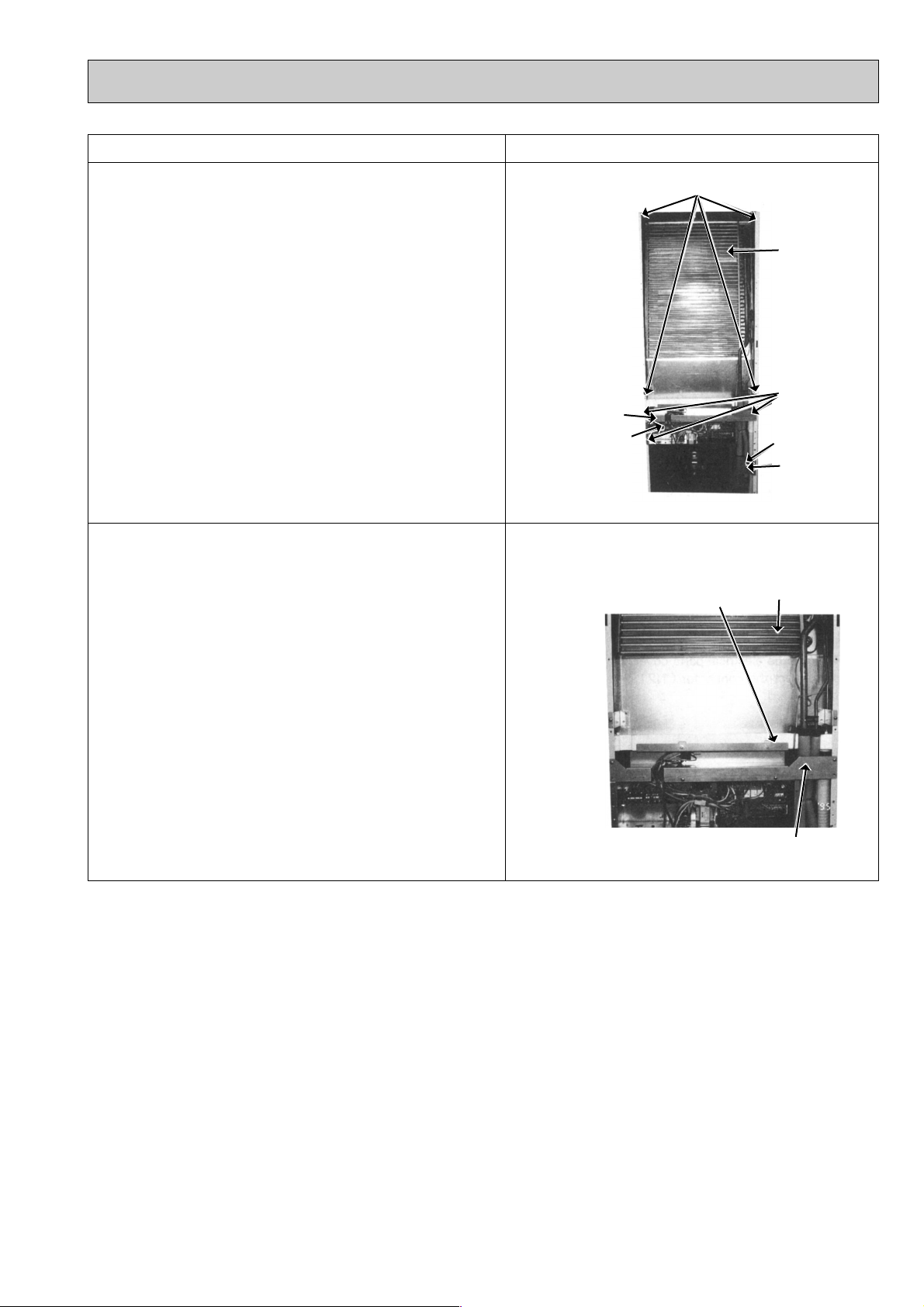
8. Removing the indoor heat exchanger
(1) Remove the intake grill.
(2) Remove the front panel.
(3) Remove the insulation panel.
(4) Remove the 6 screws of the top panel and
remove the top panel.
(5) Remove the swing louver.
(6) Remove the electrical parts box.
(7) Remove the 3 screws of the drain pan support
and remove the drain pan support.
(8) Remove the 4 screws of the indoor heat
exchanger and remove the indoor heat
exchanger.
9. Removing the drain pan
(1) Remove the intake grill.
(2) Remove the front panel.
(3) Remove the insulation panel.
(4) Remove the top panel.
(5) Remove the swing louver.
(6) Remove the electrical parts box and the drain
pan support.
(7) Remove the pipe support.
(8) Remove the drain pan.
Photo 10
Drain pan
support
Photo 11
Electrical
parts box
Screws
Drain pan
Indoor heat
exchanger
Screws
Pipe support
Screws
Indoor heat exchanger
Drain pan support
29
Page 30

9 PARTS LIST
Unit
Amount
Recommended
Q’ty
Part No. Part Name Specification
Q’ty/set
PS-3
GJA,GJA
1
Remarks
(Drawing No.)
Wiring
Diagram
Symbol
No.
1
2
3
4
5
6
7
8
9
10
11
12
13
14
15
16
17
18
19
20
21
22
R01 71G 661
R01 71G 662
R01 71G 641
R01 71G 676
T7W 87J 003
R01 71G 038
R01 71G 035
R01 71G 021
R01 71G 019
T7W 87J 222
R01 71G 060
T7W 12K 200
—
T7W 022 304
R01 71G 651
R01 71G 691
R01 71G 054
R01 71G 500
R01 71G 686
R01 12G 523
—
—
RIGHT SIDE PANEL
LEFT SIDE PANEL
TOP PANEL
REAR PANEL
SWING LOUVER
GUIDE VANE (V)
GUIDE VANE (H)
VANE ARM (V)
VANE ARM (H)
LOUVER MOTOR
CRANK
CONTROLLER
ATTACHMENT
CONTROLLER CABLE
FRONT PANEL
INTAKE GRILLE
MAGNET CATCH
AIR FILTER
BASE
DRAIN SOCKET
I
NSULATION PLATE
HANGER
1
1
1
1
1
6
8
1
1
1
1
1
1
1
1
1
2
1
1
1
1
2
(BG02L461H02)
(BG00J547G07)
(BG88H096H02)
ML
R.B
Price
STRUCTURAL PARTS
PS-3GJA
PS-3GJA
1
Part numbers that are circled are not shown in the figure.
30
Page 31

STRUCTURAL PARTS
Unit
Amount
Recom-
mended
Q’ty
Part No. Part Name Specification
Q’ty/set
PS-4
GJSA,GJSA
1
Remarks
(Drawing No.)
Wiring
Diagram
Symbol
No.
1
2
3
4
5
6
7
8
9
10
11
12
13
14
15
16
17
18
19
20
21
22
R01 85G 661
R01 85G 662
R01 85G 641
R01 85G 676
T7W 87J 003
R01 71G 038
R01 71G 035
R01 71G 021
R01 71G 019
T7W 87J 222
R01 71G 060
T7W 12K 200
—
T7W 022 304
R01 71G 651
R01 71G 691
R01 71G 054
R01 71G 500
R01 85G 686
R01 12G 523
—
—
RIGHT SIDE PANEL
LEFT SIDE PANEL
TOP PANEL
REAR PANEL
SWING LOUVER
GUIDE VANE (V)
GUIDE VANE (H)
VANE ARM (V)
VANE ARM (H)
LOUVER MOTOR
CRANK
CONTROLLER
ATTACHMENT
CONTROLLER CABLE
FRONT PANEL
INTAKE GRILLE
MAGNET CATCH
AIR FILTER
BASE
DRAIN SOCKET
INSULATION PLATE
HANGER
1
1
1
1
1
6
8
1
1
1
1
1
1
1
1
1
2
1
1
1
1
2
(BG02L461H02)
(BG00J547G07)
(BG88H096H02)
ML
R.B
Price
PS-4GJSA
PS-4GJSA
1
Part numbers that are circled are not shown in the figure.
31
Page 32

FUNCTIONAL PARTS
Unit
Amount
Recom-
mended
Q’ty
Part No. Part Name
Specification
Q’ty/set
PS-3
GJA,GJA
1
Remarks
(Drawing No.)
Wiring
Diagram
Symbol
No.
1
2
3
4
5
6
7
8
9
10
11
12
13
14
15
16
17
18
19
20
21
22
T7W 079 480
R01 06A 202
T7W 87J 202
T7W 551 762
R01 71G 114
R01 71G 117
R01 71G 119
R01 71G 529
R01 71G 527
T7W 90J 310
T7W 520 239
T7W 523 716
T7W 515 716
T7W 87J 799
R01 580 255
—
—
—
—
—
R01 08K 097
T7W 87J 675
HEAT EXCHANGER
ROOM TEMPERATURE
THERMISTOR
INDOOR COIL THERMISTOR
INDOOR FAN MOTOR
SIROCCO FAN
SCROLL
FAN GUARD ASSY
DRAIN PAN
DRAIN HOSE
INDOOR CONTROLLER BOARD
FUSE
TERMINAL BLOCK
TERMINAL BLOCK
TRANSFORMER
INDOOR FAN MOTORCAPACITOR
CONTROL BOX COVER
COIL COVER
CONTROLLER CASE
PIPE SUPPORT
WIRING COVER
SPL WASHER
FAN GUARD
PA8V30-SA
250V 6.3A
3P (L,N,;)
2P (1, 2)
3.5+ 440V
1
1
1
1
1
1
1
1
1
1
2
1
1
1
1
1
1
1
1
1
1
1
(BG02J715G02)
(BG25L487H03)
(BG25V886H03)
(BG02F916H08)
(BG02L366H04)
RT1
RT2
MF
I.B
F1,2(I.B)
TB1
TB2
T
C
Price
PS-3GJA
PS-3GJA
1
17
32
8
11
15
13
12
4
6
20
18
9
10
19
14
21
16
5
22
7
Page 33

Unit
Amount
Recom-
mended
Q’ty
Part No. Part Name Specification
Q’ty/set
PS-4
GJSA,GJSA
1
Remarks
(Drawing No.)
Wiring
Diagram
Symbol
No.
1
2
3
4
5
6
7
8
9
10
11
12
13
14
15
16
17
18
19
20
21
22
R01 96G 480
R01 06A 202
R01 87J 202
T7W
552 762
R01 85G 114
R01 85G 117
R01 71G 119
R01 71G 529
R01 71G 527
T7W
90J 310
T7W
520 239
T7W
523 716
R01 515 716
T7W
87J 799
R01 653 255
—
—
—
—
—
R01 08K 097
T7W
87J 675
HEAT EXCHANGER
ROOM TEMPERATURETHERMISTOR
INDOOR COIL THERMISTOR
INDOOR FAN MOTOR
SIROCCO FAN
SCROLL
FAN GUARD ASSY
DRAIN PAN
DRAIN HOSE
INDOOR CONTROLLER BOARD
FUSE
TERMINAL BLOCK
TERMINAL BLOCK
TRANSFORMER
INDOOR FAN MOTOR CAPACITOR
CONTROLLER BOX COVER
COIL COVER
CONTROLLER CASE
PIPE SUPPORT
WIRING COVER
SPL WASHER
FAN GUARD
PA8V70-SA
250V 6.3A
3P (L,N,;)
2P (1, 2)
4.0+F 440V
1
1
1
1
1
1
1
1
1
1
2
1
1
1
1
1
1
1
1
1
1
1
(BG02J715G02)
(BG25L487H03)
(BG25B573H05)
(BG02F916H09)
(BG07L366H04)
RT1
RT2
MF
I,B
F1,2<I.B>
TB1
TB2
T
C
Price
FUNCTIONAL PARTS
PS-4GJSA
PS-4GJSA
1
17
8
15
13
11
12
20
18
16
10
19
14
5
4
6
9
7
22
21
33
Page 34

10 OPTIONAL PARTS
1. REFRIGERANT PIPES
Service Ref. : PS-3GJA1
Part No.
Pipe length
Pipe size O.D.
Connection method
Service Ref. : PS-4GJSA1
PAC-05FFS-E
5m
PAC-07FFS-E
7m
Liquid : { 9.52 Gas : {15.88
Indoor unit : Flared Outdoor unit : Flared
PAC-10FFS-E
10m
PAC-15FFS-E
15m
Pat No.
Pipe length
Pipe size O.D.
Connection method
Note 1. How to connect refrigerant pipes.
Factory supplied optional refrigerant pipings contain refrigerant at the above atmospheric pressures.
As long as connection takes no more than 5 minutes, no air will enter, and there will be no need for
air purging.
Remove the blind caps and make the connections within 5 minutes. After the connections for the
indoor and outdoor units are made, open the stop valve on the outdoor unit to allow refrigerant gas
to flow.
If piping length exceeds 5m, an additional charge of refrigerant is needed.
Note 2. The following main parts are contained in the optional refrigerant piping kit.
Heat insulating cover, vinyl tapes, nipples, sleeve and flange (for wall hole), connecting cables.
PAC-SC51P1-E5mPAC-SC52P1-E
7m
Liquid : { 9.52 Gas : {19.05
Indoor unit : Flared Outdoor unit : Flared
PAC-SC53P1-E
10m
PAC-SC54P1-E
15m
2. CENTRALIZED REMOTE CONTROLLER
Allows individual or combined control of up to 16 units. When using this controller, a program timer adapter (PAC-825AD) is
also needed.
Part No. PAC-805RC
3. PROGRAM TIMER ADAPTER
This adapter is needed when a program timer (PAC-SK65PT) or a centralized remote controller (PAC-805RC) in used.
Part No. PAC-825AD
4. TIMER ADAPTER
This adapter is needed for system control and for operation via external contacts.
Part No. PAC-SA89TA-E
5. MULTIPLE REMOTE CONTROLLER ADAPTER
This adapter is needed for remote indication (operation/check).
Part No. PAC-SA88HA-E
34
Page 35

Page 36

© Copyright 1997 MITSUBISHI ELECTRIC ENGINEERING CO.,LTD New publication, effective Jun. 1997
HEAD OFFICE MITSUBISHI DENKI BLDG. MARUNOUCHI TOKYO 100 TELEX J24532 CABLE MELCO TOKYO
Issued in Jun. 1997. No.OC141 510
Specifications subject to change without notice
 Loading...