

Page 1
TECHNICAL & SERVICE MANUAL
SPLIT-TYPE AIR CONDITIONERS
Indoor unit
[Model name] [Service Ref.]
PS-3GJA
PS-3GJA
2
No. OC209
Floor StandingSeries PS
This service manual describes only
the change points.
Please refer to OC141 REVISED
EDITION-A as to excluding this
manual.
This manual does not cover the
following outdoor units.
When serving them, please refer to
the service manual
No.OC 149 REVISED EDITION-B
No.OC202 and this manual in a set.
[Service Ref.]
PU-3VJC.UK (OC202)
PU-3YJC.UK (OC202)
PU-3NJA1.UK
(OC149REVISED-EDITION-B)
1. TECHNICAL CHANGE··························3
2. SPECIFICATIONS ································4
3. DATA······················································6
4.
REFRIGERANT SYSTEM DIAGRAM
······8
5. PARTS LIST ··········································9
CONTENTS
ADVANCED AND EVER ADVANCING
1999
Page 2

Page 3
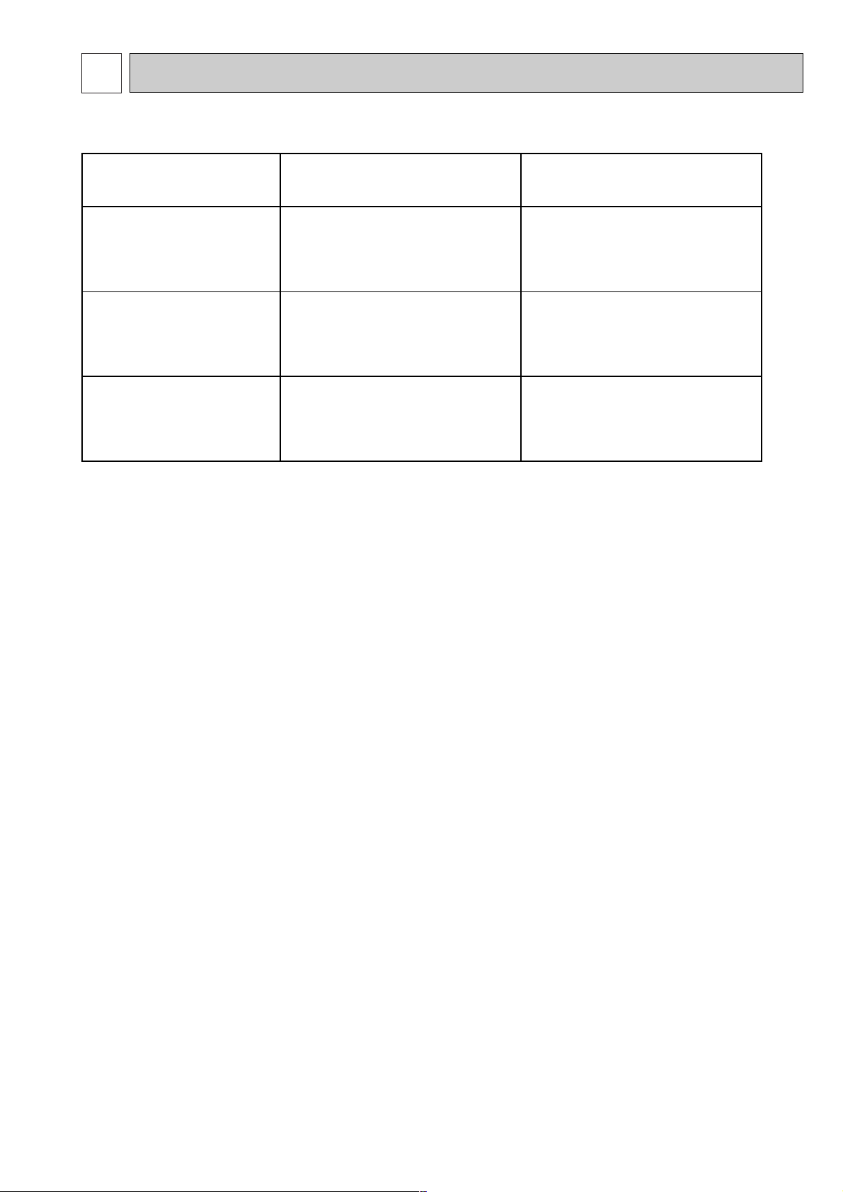
TECHNICAL CHANGE
1
3
CHANGE POINTS PS-3GJA1 PS-3GJA2
COOLING CAPACITY
OUT DOOR UNIT
COMPRESSOR
OUT PUT
2.2kW (PU-3YJA
2.UK) 2.4kW (PU-3YJC.UK)
24,600 Btu/h
7,200 W
PU-3VJA
2.UK
PU-3YJA
2.UK
26,300 Btu/h
7,700 W
PU-3VJC.UK
PU-3YJC.UK
Differences between the connection with PS-3GJA1
Page 4
2
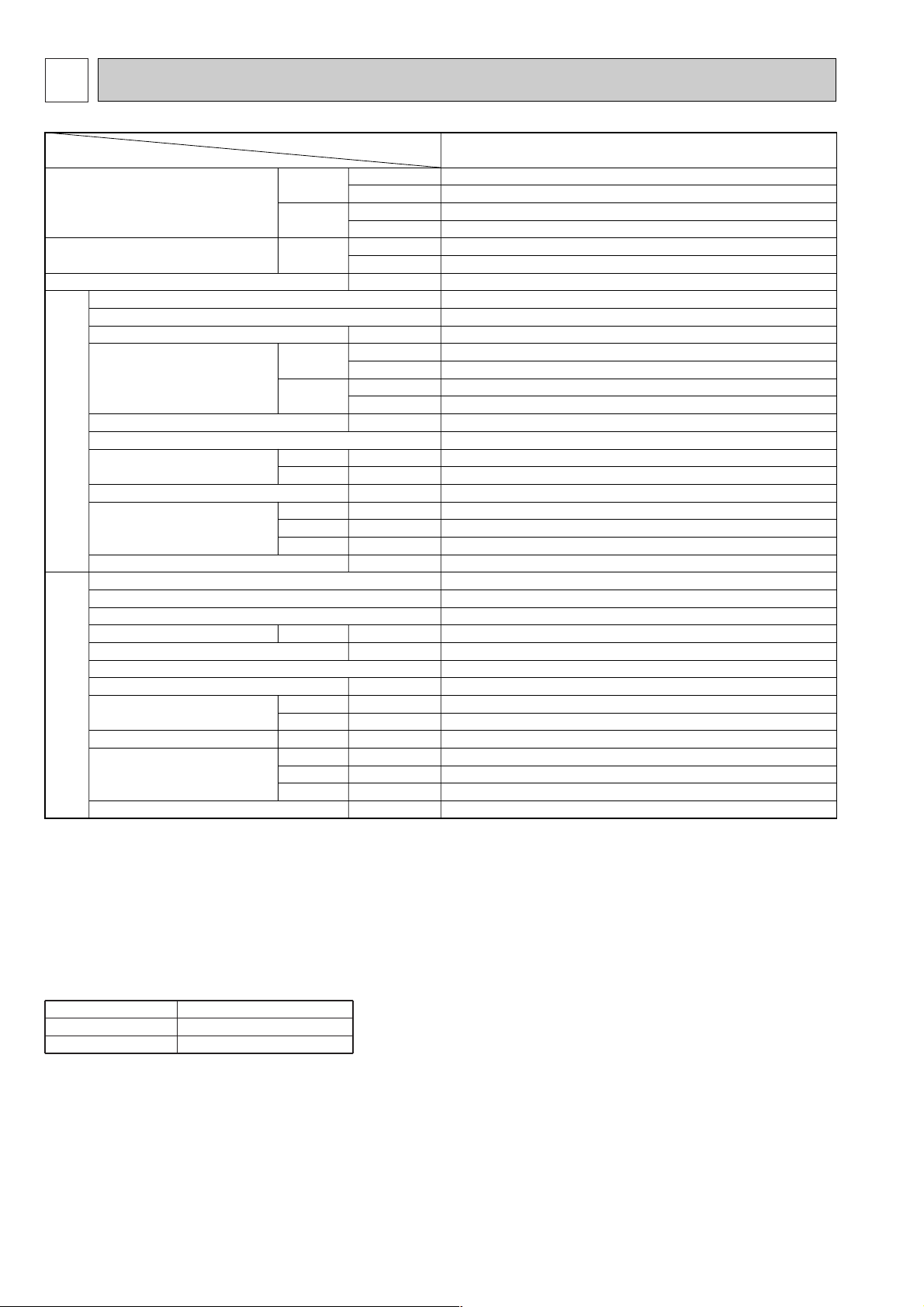
SPECIFICATIONS
4
Notes :
W1 Rating conditions (JIS B8616) W4 Capacity of crankcase heater (W) based on 220 volts.
Indoor : D.B. 27°C (80°F), W.B. 19°C (66°F) W5 Noise level is measured in an unacoustic room based on JIS conditions.
Outdoor : D.B. 35°C (95°F), W.B. 24°C (75°F) W6V, N
...
Inner thermostat, HP switch, LP switch.
Refrigerant piping length (one way) : 5m (16ft) Y
........
Thermal switch, Reversed-phase protector, HP switch, LP switch,
W2 Rating conditions (SSA 385, 386) Thermal relay
Indoor : D.B. 29°C (84°F), W.B. 19°C (66°F)
Outdoor : D.B. 46°C (115°F), W.B. 24°C (75°F)
W3 Total input based on indicated voltage
(Indoor / Outdoor)
Cooling capacity
W1
Total input (50/60Hz)
W3
Indoor
unit
Cooling capacity (SSA)
W2
Outdoor
unit
Service Ref.
External finish
Fan motor output
Airflow Hi-Lo
External static pressure
Operation control & Thermostat
Noise level High-Low
W5
Unit drain pipe O.D.
Dimensions
Weight
Service Ref.
External finish
Refrigerant (R-22) control
Crankcase heater
Compressor output
Protection devices
Fan motor output
Air flow
Noise level W5
Dimensions
Weight
50Hz
60Hz
50Hz
60Hz
50Hz
60Hz
H
W
D
60Hz
50/60Hz
50Hz
60Hz
50/60Hz
W
D
H
W
Btu/h
W
Btu/h
kW
kW
m
3
/min
CFM
m
3
/min
CFM
Pa(mmAq)
dB
dB
mm(in.)
mm(in.)
mm(in.)
mm(in.)
kg(lbs)
W
Btu/h
W
kW
kW
m
3
/min(CFM)
m
3
/min(CFM)
dB
mm(in.)
mm(in.)
mm(in.)
kg(lbs)
Service Ref.
Item
7,700
26,300
7,900
27,000
6,800
23,200
3.32/3.60
PS-3GJA
2
Munsell 0.70 Y 8.59/0.97
0.03
17 -14
600 - 494
17 -14
600 - 494
0(Direct blow)
Built-in
42 - 37
42 - 37
20(13/16)
1900(74 - 13/16)
600(23 - 5/8)
270(10 - 5/8)
43(95)
PU-3VJC.UK, 3YJC.UK, 3NJA1.UK
Munsell 5Y 7/1
Capillary tube
32/38
(V)2.2, (Y)2.4 / (N)2.2
W6
0.085
50(1765)
50(1765)
52/53
870(34-1/4)
295(11 - 5/8)
850(33-7/16)
73(161)
PS-3GJA
2
1. STANDARD SPECIFICATIONS
Service Ref.
50Hz
60Hz
PS-3GJA2
1ph 220V/1ph 220V,3ph 380V
1ph 220V/1ph 220V
Page 5

5
2. POWER SUPPLY & MODEL NAMES
Notes : 1. Power supply key N
.......
1ph, 220V,60Hz Y
...
3ph. 380/220, 400/230, 415/240V,
V
.......
1ph, 220, 230, 240V 50Hz 50Hz, 4 wires
2. Primary power supplies for all indoor units are single-phase.
3. ELECTRICAL SPECIFICATIONS
Rating conditions -JIS B 8616
{
Indoor : D.B. 27°C (80°F), W.B. 19°C (66°F)
Outdoor : D.B. 35°C (95°F), W.B. 24°C (75°F)
-
SSA385,386
{
Indoor : D.B. 29°C (84°F), W.B. 19°C (66°F)
Outdoor : D.B. 46°C (115°F), W.B. 24°C (75°F)
50Hz
60Hz
1 ph.
3 ph.
1 ph.
220, 230, 240V
380/220, 400/230, 415/240V
220V
PU-3VJC
.UK
PU-3YJC.UK
PU-3NJA1.UK
PS-3GJA2
Indoor unit Service Ref.
Outdoor unit Service Ref.
Power supply
Service Ref. : PS-3GJA2
Current
Input
Starting current
Outdoor unit
A
kW
A
V : 220V 50Hz
0.64
0.14
0.8
PU-3
V : 230V 50Hz
0.66
0.15
0.8
PU-3
V : 240V 50Hz
0.68
0.16
0.8
PU-3
N : 220V 60Hz
0.72
0.16
0.8
PU-3
Power supply (1 Phase)
Page 6

3
DATA
6
1. PERFORMANCE DATA
Cooling capacity 50Hz
Service Ref. PS-3GJA2
Temperature T.C.
Outdoor D.B.
21˚C
(69.8˚F)
Indoor W.B.
16˚C
18˚C
19˚C
19.4˚C
20˚C
22˚C
(60.8˚F)
(64.4˚F)
(66.2˚F)
(67˚F)
(68˚F)
(71.6˚F)
7.7
8.2
8.5
8.6
8.7
9.3
C.F.
(T.I.)
0.81
0.82
0.83
0.83
0.84
0.86
25˚C
(77˚F)
16˚C
18˚C
19˚C
19.4˚C
20˚C
22˚C
(60.8˚F)
(64.4˚F)
(66.2˚F)
(67˚F)
(68˚F)
(71.6˚F)
7.6
8.1
8.3
8.4
8.6
9.1
0.84
0.85
0.86
0.86
0.87
0.89
30˚C
(86˚F)
16˚C
18˚C
19˚C
19.4˚C
20˚C
22˚C
(60.8˚F)
(64.4˚F)
(66.2˚F)
(67˚F)
(68˚F)
(71.6˚F)
7.3
7.8
8.0
8.1
8.3
8.8
0.90
0.92
0.93
0.93
0.94
0.96
32.2˚C
(90˚F)
16˚C
18˚C
19˚C
19.4˚C
20˚C
22˚C
(60.8˚F)
(64.4˚F)
(66.2˚F)
(67˚F)
(68˚F)
(71.6˚F)
7.2
7.6
7.9
8.0
8.1
8.7
0.93
0.95
0.96
0.97
0.97
0.99
35˚C
(95˚F)
16˚C
18˚C
19˚C
19.4˚C
20˚C
22˚C
(60.8˚F)
(64.4˚F)
(66.2˚F)
(67˚F)
(68˚F)
(71.6˚F)
7.0
7.5
7.7
7.8
7.9
8.5
0.96
0.99
1.00
1.00
1.01
1.04
40˚C
(104˚F)
16˚C
18˚C
19˚C
19.4˚C
20˚C
22˚C
(60.8˚F)
(64.4˚F)
(66.2˚F)
(67˚F)
(68˚F)
(71.6˚F)
6.7
7.1
7.4
7.5
7.6
8.1
1.03
1.06
1.07
1.08
1.08
1.11
Service Ref.
PS-3GJA2
Temperature
T.C.
Outdoor D.B.
Indoor W.B.
C.F.
(T.I.)
40.6˚C
(105˚F)
16˚C
18˚C
19˚C
19.4˚C
20˚C
22˚C
(60.8˚F)
(64.4˚F)
(66.2˚F)
(67˚F)
(68˚F)
(71.6˚F)
6.6
7.1
7.3
7.4
7.6
8.1
1.04
1.06
1.08
1.08
1.09
1.12
45˚C
(113˚F)
16˚C
18˚C
19˚C
19.4˚C
20˚C
22˚C
(60.8˚F)
(64.4˚F)
(66.2˚F)
(67˚F)
(68˚F)
(71.6˚F)
6.3
6.8
7.0
7.1
7.3
7.8
1.10
1.12
1.14
1.15
1.16
1.20
46˚C
(115˚F)
16˚C
18˚C
19˚C
19.4˚C
20˚C
22˚C
(60.8˚F)
(64.4˚F)
(66.2˚F)
(67˚F)
(68˚F)
(71.6˚F)
6.3
6.7
7.0
7.1
7.2
7.7
1.11
1.14
1.15
1.16
1.17
1.21
50˚F
(122˚F)
16˚C
18˚C
19˚C
19.4˚C
20˚C
22˚C
(60.8˚F)
(64.4˚F)
(66.2˚F)
(67˚F)
(68˚F)
(71.6˚F)
6.0
6.4
6.7
6.8
6.9
7.4
1.16
1.19
1.21
1.22
1.23
1.28
52˚C
(125.5˚F)
16˚C
18˚C
19˚C
19.4˚C
20˚C
22˚C
(60.8˚F)
(64.4˚F)
(66.2˚F)
(67˚F)
(68˚F)
(71.6˚F)
5.9
6.3
6.5
6.6
6.8
7.3
1.19
1.22
1.24
1.25
1.26
1.31
Evaporator airflow (m
3
/min) 17
Bypass factors
S.H.F. at rating conditions
0.10
0.70
PS-3GJA2
Refrigerant piping Iength (one way)
5m (16ft)
1.0
10m (33ft)
0.978
15m (49ft)
0.962
20m (66ft)
0.948
25m (82ft)
0.934
30m (98ft)
0.921
35m (115ft)—40m (131ft)—45m (148ft)—50m (164ft)
—
Service Ref.
Notes : 1. T.C. : Total capacity ( ✕ 103W)
...
(Btu / h)
.
=
. (W) ✕ 3.4, (kcal / h) = (W) ✕ 0.86
C.F. (T.I.) : Correction factors of Total input (Indoor unit input + Outdoor unit input)
2. (°F) = 32 + 9 / 5 (°C)
Lower limit ... Indoor : D.B. 21°C (70°F), W.B. 15.5°C (60°F), Outdoor : D.B. 21°C (70°F)
3. Guaranteed operating range (cooling)
{
Upper limit
...
Indoor : D.B. 35°C (95°F), W.B. 22.5°C (72.5°F),Outdoor : D.B. 52°C (125.5°F)
Cooling capacity correction factors 50Hz
Page 7

2. STANDARD OPERATION DATA
Standard
Service Ref.
Mode
Capacity
Total
Input
Indoor unit Service Ref.
Phase, Hz
Volts
Amperes
Outdoor unit Service Ref.
Electrical circuit
Phase, Hz
Volts
Amperes
Discharge pressure
Suction pressure
Discahrge temperature
Condensing temperature
Suction temperature
Refrigerant circuit
Ref. pipe length
Intake air temperature
Indoor unit
Discharge air temperature
Intake air temperature
unit
Outdoor
W
kW
V
A
V
A
MPa
(kgf/mm
MPa
(kgf/mm
°C
°C
°C
m
D.B. °C
W.B. °C
D.B. °C
D.B. °C
W.B. °C
PS-3GJA
Cooling Cooling
7,700
3.32
PS-3GJA
1, 50
220
0.64
PU-3VJC
.UK
1, 50
220
15.1
2
)
2
)
2.0
(20.4)
0.47
(4.8)
85.5
2.6
5.8
5
27
19
11.7
35
24
2
7,900
3.60
2
1, 60
220
0.73
PU-3NJA
1, 60
220
17.6
2.14
(21.8)
0.45
(4.6)
70.1
5.5
4.0
5
27
19
11.5
35
24
1.UK
The unit of pressure has been changed to MPa based on SI (International System of Unit) in accordance with I.S.O.
(International Organization for Standardization).
The conversion factor is :
1(MPa)=10.2(Of/F)
3. ADDITIONAL REFRIGERANT CHARGE (R-22 : kg (Ibs))
Service Ref.
PS-3GJA2
Outdoor unit precharged (kg)
(up to 20)
V…2.8, Y…2.8, N…3.5 0.06(0.13) 0.12(0.26) — — —
20m(66ft)
0
25m(82ft) 30m(98ft) 35m(115ft) 40m(131ft) 45m(148ft)—50m(164ft)
Piping length(one way)
4. OUTLET AIR SPEED AND COVERAGE RANGE
PS-3GJA
Air flow m3/min
Air speed m/sec
Coverage range m
2
17
2.6
8.4
7
Page 8

4
REFRIGERANT SYSTEM DIAGRAM
PS-3GJA2 / PU-3VJC.UK, PU-3YJC.UK
Refrigerant pipe ø15.88(5/8")
Indoor heat
exchanger
strainer
Indoor coil
thermistor
RT2
Distributor
with
strainer
Refrigerant pipe ø9.52(3/8")
(with heat insulator) option
(with insulator) option
Flexible tube
Flared
connection
Flared
connection
strainer
Low pressure
switch
Ball
valve
Ball valve
(with service port)
Charge
pIug
Accumulator
(O.D.3.2 oI.D.1.8 o800mm)
o2pcs
Check
pIug
Compressor
UNIT : mm(inch)
High pressure
switch
strainer
Capillary tube
D.P.R.
(Discharge pressure regulator)
Outdoor heat
exchanger
flow of refrigerant
8
Page 9

PARTS LIST
5
9
Part numbers that are circled are not shown in the figure.
STRUCTURAL PARTS
PS-3GJA
PS-3GJA
1
PS-3GJA2
Unit
Amount
Recommended
Q’ty
Part No.
Part Name Specification
Q’ty/set
PS-3
Remarks
(Drawing No.)
Wiring
Diagram
Symbol
No.
1
2
3
4
5
6
7
8
9
10
11
12
13
14
15
16
17
18
19
20
21
22
R01 71G 661
R01 71G 662
R01 71G 641
R01 71G 676
T7W 87J 003
T7W E00 003
R01 71G 038
T7W E00 038
R01 71G 035
T7W E00 035
R01 71G 021
R01 71G 019
T7W 87J 222
R01 71G 060
T7W 12K 200
—
T7W E00 305
R01 71G 651
R01 71G 691
T7W E00 691
R01 71G 054
R01 A28 500
R01 71G 686
R01 12G 523
—
—
RIGHT SIDE PANEL
LEFT SIDE PANEL
TOP PANEL
REAR PANEL
SWING LOUVER
SWING LOUVER
GUIDE VANE (V)
GUIDE VANE (V)
GUIDE VANE (H)
GUIDE VANE (H)
VANE ARM (V)
VANE ARM (H)
LOUVER MOTOR
CRANK
CONTROLLER BOARD
ATTACHMENT
CONTROLLER CABLE
FRONT PANEL
INTAKE GRILLE
INTAKE GRILLE
MAGNET CATCH
AIR FILTER
BASE
DRAIN SOCKET
I
NSULATION PLATE
HANGER
1
1
1
1
1
6
8
1
1
1
1
1
1
1
1
1
2
1
1
1
1
2
1
1
1
1
1
6
8
1
1
1
1
1
1
1
1
1
1
1
1
1
2
(BG02L461H02)
(BG00J547G10)
(BG88H096H04)
ML
R.B
Price
GJA, GJA
1
GJA2
Page 10

FUNCTIONAL PARTS
PS-3GJA
PS-3GJA
1
PS-3GJA2
17
Part No. Part Name
No.
T7W 079 480
1
R01 06A 202
2
T7W 87J 202
3
T7W 551 762
4
R01 71G 114
5
R01 71G 117
6
T7W E00 119
7
R01 A28 529
8
R01 71G 527
9
T7W 90J 310
10
T7W 520 239
11
T7W 523 716
12
T7W 515 716
13
T7W 87J 799
14
R01 580 255
15
16
17
18
19
20
R01 08K 097
21
T7W 87J 675
22
—
—
—
—
—
HEAT EXCHANGER
ROOM TEMPERATURE
INDOOR COIL THERMISTOR
INDOOR FAN MOTOR
SIROCCO FAN
SCROLL
BELL MOUTH
DRAIN PAN
DRAIN HOSE
INDOOR CONTROLLER BOARD
FUSE
TERMINAL BLOCK
TERMINAL BLOCK
TRANSFORMER
INDOOR FAN MOTOR CAPACITOR
CONTROL BOX COVER
COIL COVER
CONTROLLER CASE
PIPE SUPPORT
WIRING COVER
SPL WASHER
FAN GUARD
15
13
8
11
12
20
THERMISTOR
18
16
10
19
14
5
4
6
9
7
22
21
Specification
PA8V30-SA
250V 6.3A
3P (L,N,;)
2P (1, 2)
3.5µF 440V
Q’ty/set
PS-3
GJA, GJA1 GJA2
1
1
1
1
1
1
1
1
1
1
2
1
1
1
1
1
1
1
1
1
1
1
1
1
1
1
1
1
1
1
1
1
2
1
1
1
1
1
1
1
1
1
1
1
Remarks
(Drawing No.)
(BG02J715G02)
(BG25L487H05)
(BG25V886H03)
(BG02F916H08)
(BG02L366H04)
Wiring
Diagram
Symbol
RT1
RT2
MF
I.B
F1,2(I.B)
TB1
TB2
T
C
Recommended
Q’ty
Unit
Price
Amount
10
Page 11

Page 12

© Copyright 1999 MITSUBISHI ELECTRIC ENGINEERING CO.,LTD
Issued in Nov. 1999. No.OC209 242
Printed in Japan
New publication, effective Nov. 1999
Specifications subject to change without notice
HEAD OFFICE MITSUBISHI DENKI BLDG. MARUNOUCHI TOKYO 100-8310 TELEX J24532 CABLE MELCO TOKYO
 Loading...