

Page 1

Procon
IO-INTERFACE
FOR INSTALLERS
INSTALLATION MANUAL
Version 1.01
For safe and correct use, please read this installation manual thoroughly before installing the
PROCON IO-INTERFACE.
MITSUBISHI ELECTRIC
Page 2

Page 2 of 24
Page 3

Page 3 of 24
Contents
1. Safety Precautions ............................................................................................................................................... 8
2. Product Overview ................................................................................................................................................. 9
2.1. Basic Features .............................................................................................................................................. 9
2.2. Extended features ......................................................................................................................................... 9
2.3. Advanced Energy Save Features.................................................................................................................. 9
2.4. Relay Output ................................................................................................................................................. 9
3. Supplied Wiring Looms...................................................................................................................................... 10
4. Size and weight................................................................................................................................................... 10
5. Electrical wiring and installation ....................................................................................................................... 11
5.1. Precautions on electrical wiring................................................................................................................... 11
5.2. Wiring Connections: .................................................................................................................................... 11
5.3. External Connections .................................................................................................................................. 12
5.3.1. Digital inputs........................................................................................................................................... 12
5.3.2. Analogue Inputs ..................................................................................................................................... 12
5.3.3. Relay outputs ......................................................................................................................................... 12
6. Description of Features...................................................................................................................................... 13
6.1. Basic Parameter Control ............................................................................................................................. 13
6.2. The ‘Lock’ Input........................................................................................................................................... 13
6.3. Energy Save Modes.................................................................................................................................... 13
6.3.1. Auto/Fan................................................................................................................................................. 13
6.3.2. Dead Band Mode ................................................................................................................................... 14
6.4. Relay Outputs ............................................................................................................................................. 15
6.4.1. On/Off..................................................................................................................................................... 15
6.4.2. Fault ....................................................................................................................................................... 15
6.4.3. Thermo................................................................................................................................................... 15
6.5. Mode Monitor .............................................................................................................................................. 15
7. LED Indications on the Unit............................................................................................................................... 16
8. Applicable Air Conditioning Models ................................................................................................................. 17
8.1. Using twin / triple / quad systems................................................................................................................ 17
8.1.1. When using Fault output......................................................................................................................... 17
8.1.2. When not using Fault output................................................................................................................... 17
8.2. Using single splits in a group....................................................................................................................... 18
8.2.1. When using Fault output......................................................................................................................... 18
8.2.2. When not using Fault output................................................................................................................... 18
8.3. Using MXZ splits ......................................................................................................................................... 19
9. Important Notes .................................................................................................................................................. 20
10. Additional Information ....................................................................................................................................... 21
10.1. Appendix A: Analogue Input Ranges ........................................................................................................ 21
10.1.1. Setpoint: ............................................................................................................................................ 21
10.1.2. Mode:................................................................................................................................................. 21
10.1.3. Fan Speed ......................................................................................................................................... 21
10.2. Appendix B: Dip Switches Settings .......................................................................................................... 21
10.2.1. SW1-1 to SW1-4 Lock Settings (When Lock Input is Activated)........................................................ 21
10.2.2. SW2-1 to SW2-5 Energy Save Settings - Auto/Fan Algorithm........................................................... 22
10.2.3. SW2-1 to SW2-5 Energy Save Settings - Deadband Algorithm......................................................... 22
10.2.4. SW2-5 Reset settings when energy save deadband mode is not required........................................ 23
10.2.5. SW2-6 Heating / Cooling Output ....................................................................................................... 23
10.3. Revision History: ......................................................................................................................................... 23
Page 4

Page 4 of 24
A 1 x Procon IO-Interface
B 1 x Manual
1
A
[Fig. 1]
Included Items
B
Page 5
Page 5 of 24
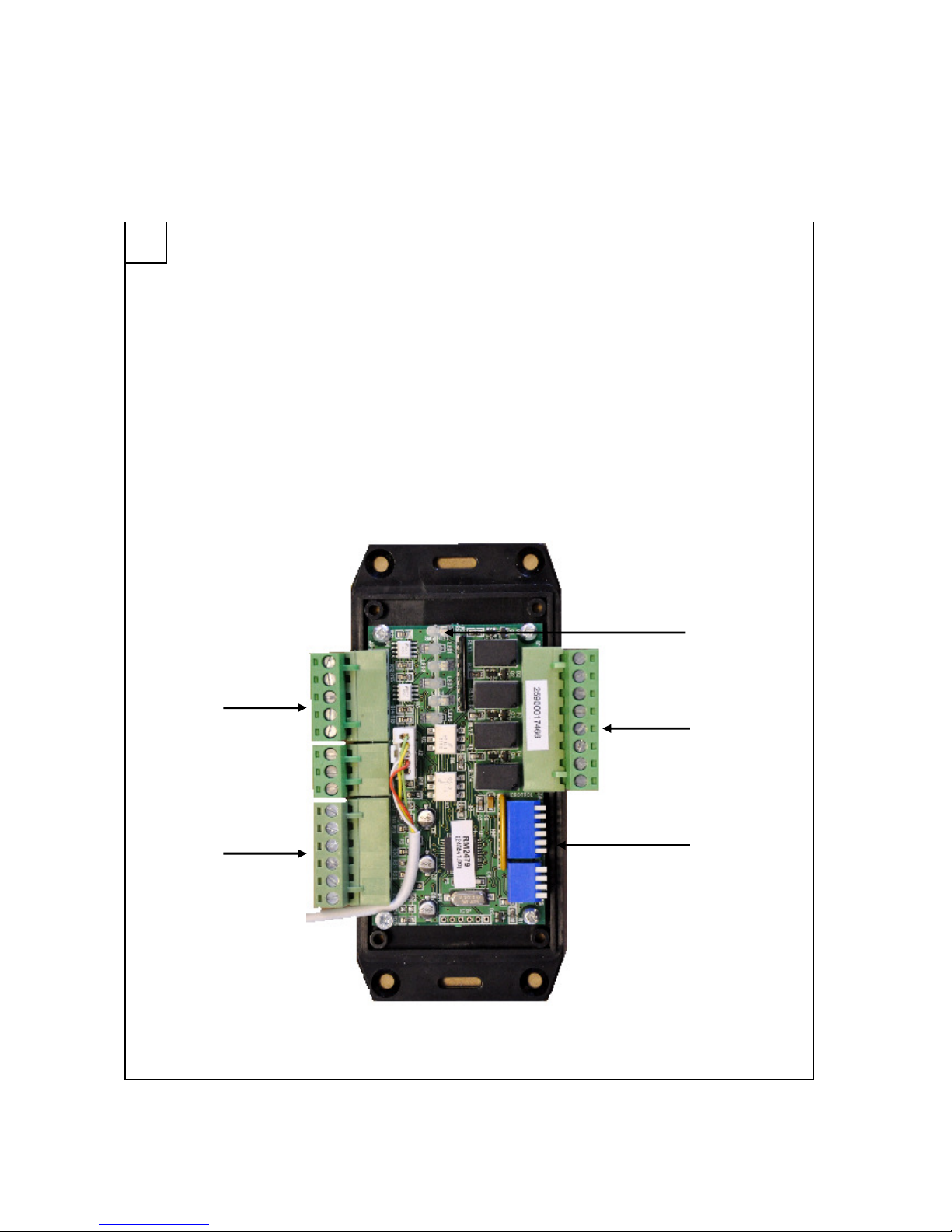
A Digital Inputs
B Analogue Inputs
C Dip Switch
D Digital Outputs
E Status LEDs
2
[Fig. 2]
Inside of Units
C
A
B
D
E
Page 6
Page 6 of 24
3
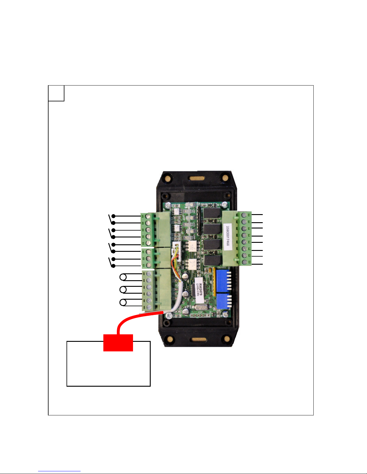
[Fig. 3]
Wiring Diagram
On/Off
Lock
Energy Save
External Fault
Setpoint
Mode
Fan Speed
Run
Heat/Cool
INDOOR UNIT PCB
CN105
or CN92
Page 7

Page 7 of 24
Quick set up
Step 1:
Unpack the Procon IO-Interface and secure it in place.
Step 2:
Set the dip switches on the Procon IO-Interface depending of the requirements.
Step 3:
Connect inputs and outputs depending of the requirements.
Step 4:
Connect the Procon IO-Interface to the CN105 terminal on the indoor unit.
Step 5:
Check that the power LED is flashing for some time (start up time) and then becomes solid. The comms
LED will then start flashing.
Step 6:
Check the output LED matches the indoor unit settings (On/Off, Heat/Cool…).
Important note:
When using energy save features, it is important to use a remote sensor (PAC-SE41TS) or the remote controller
sensor to accurately read the room temperature.
Page 8
Page 8 of 24
1. Safety Precautions
Symbols used in the text
Warning:
Describes precautions that should be observed to prevent danger of injury or death to the user.
Caution:
Describes precautions that should be observed to prevent damage to the unit.
Warning:
• Ask the dealer or an authorised technician to install the unit
- Improper installation by the user may result in water leakage, electric shock, or fire
• Use the specified cables for wiring. Make the connections securely so that any outside forces acting on the cables are
not applied to the terminals
- Inadequate connection and fastening may generate heat and cause a fire
• Never repair the unit. If the controller must be repaired, consult the dealer
- If the unit is repaired improperly, electric shock, or fire may result
• When handling this product, always wear protective equipment. EG: Gloves, full arm protection and safety glasses
- Improper handling may result in injury
• Have all electric work done by a licensed electrician according to "Electric Facility Engineering Standard", "Interior Wire
Regulations" and the instructions given in this manual and always use a special circuit
- If the power source capacity is inadequate or electric work is performed improperly, electric shock and fire may result
• Keep the electric parts away from any water - washing water etc…
- Contact may result in electric shock, fire or smoke
• Do not reconstruct or change the settings of the protection devices
- If the protection device is shorted or operated forcibly, or parts other than those specified by Mitsubishi Electric are used, fire or
explosion may result
• To dispose of this product, consult your dealer
Caution:
• Safely dispose of the packing materials
- Packing materials, such as nails and other metal or wooden parts, may cause stabs or other injuries
- Tear apart and throw away plastic packaging bags so that children will not play with them - If children
play with a plastic bag which has not been torn apart, they face the risk of suffocation
Before installing the unit, make sure you re
ad all the
“Safety precautions”
The “Safety precautions” provide very important points
regarding safety. Make sure you
follow them
Warning:
Carefully read the labels affixed to the main unit
Page 9

Page 9 of 24
2. Product Overview
The Procon IO-Interface unit is a versatile interface module for use on equipment fitted with either a CN105 or CN92
terminal.
The unit features Digital-Analogue Input / Digital Output and can provide a wide range of control features with bit switch
selection as detailed below:
2.1. Basic Features
Parameter control using digital and analogue inputs for:
- On/Off
- Setpoint
- Mode
- Fan Speed
State monitoring via relay outputs of:
- On/Off
- Error
2.2. Extended features
Ability to ‘lock’ the parameters in 2.1 against alteration by the remote controller.
External error input to allow monitoring of the error state of associated air conditioners.
2.3. Advanced Energy Save Features
Two selectable energy saving algorithms.
- Timed Auto / Fan
- Deadband Mode
2.4. Relay Output
Two relay outputs to allow control of external equipment based on the control status of the unit.
- ‘Thermo’ output which is active when the unit is not at setpoint and is working to achieve setpoint.
- ‘Active operational mode’ (selectable as Heating or Cooling)
Page 10

Page 10 of 24
3. Supplied Wiring Looms
The unit is provided with a 1.5 meter five wire connection loom to connect from the IO-Interface to CN105 or CN92 on
the associated air conditioner.
The loom is already internally connected to the IO-INTERFACE and has a plug on the free end.
4. Size and weight
The Procon IO-Interface details are:
- Height 138 mm
- Width 85 mm
- Depth 32 mm
- Weight 0.37kg
Page 11

Page 11 of 24
5. Electrical wiring and installation
5.1. Precautions on electrical wiring
Warning:
Electrical work should be done by qualified electrical engineers / electrician in accordance with "Engineering Standards for
Electrical Installation" and supplied installation manuals. Dedicated circuits should also be used. If the power circuit lacks
capacity or has an installation failure, it may cause a risk of electric shock or fire.
5.2. Wiring Connections:
Wiring connections must be made before the unit is mounted.
Disconnect all supplies to the air conditioner unit before installation.
Fig 1 : Terminal Layout
Connect the plug on the flying lead from the IO-INTERFACE to connector CN105 or CN92 on the associated air
conditioner.
Connect the analogue and digital inputs and outputs to the desired controlling equipment taking note of the required
signal levels (See Appendix A).
Digital Inputs
Digital Outputs
Flying Lead
Analogue Inputs
Page 12

Page 12 of 24
5.3. External Connections
5.3.1. Digital inputs
The four digital inputs are:
- On
- Lock
- Energy Save
- Remote Fault
The four inputs are all activated by contact closure. The switching voltage is 5v DC at approx 1mA.
5.3.2. Analogue Inputs
The three analogue inputs are:
- Setpoint
- Mode
- Fan Speed
Each operates over a range of 0-10v DC.
For signal information see Appendix A.
5.3.3. Relay outputs
The four relay outputs are:
- On
- Fault
- Thermo
- Active
The contacts are normally open contacts with a switching capacity of 1A at 24v (AC or DC).
Page 13

Page 13 of 24
6. Description of Features
6.1. Basic Parameter Control
The unit has a digital input for control of On/Off and three analogue inputs for control of Setpoint, Mode and Fan
Speed.
A change to any of these inputs will be transmitted to the air conditioner.
The analogue inputs work in bands. For details of the required voltages see Appendix A.
6.2. The ‘Lock’ Input
Normally the parameters are only transmitted to the associated unit on change. If the ‘Lock’ digital input is active then
the parameter values will be transmitted approximately every 5 seconds thus overriding any changes which may have
been made from other sources.
It is possible to select which parameters are ‘locked’ using bit switch SW1.
Each of the 4 switches on this bank controls one of the parameters and if ON will result in that parameter being
‘locked’.
For bit switch information see Appendix B.
6.3. Energy Save Modes
When using energy save features, it is important to use a remote sensor (PAC-SE41TS) or the remote
controller sensor to accurately read the room temperature.
The unit offers two energy save modes:
6.3.1. Auto/Fan
Auto/Fan is selected by setting bit switch SW2-1 to OFF and setting either or both of bit switches SW2-2 and SW2-3
ON.
In this mode the unit will put the air conditioner into AUTO whenever a momentary signal is applied to the ‘Energy
Save’ input or whenever the on/off state is changed from OFF to ON.
The unit will operate in AUTO for a fixed period set by bit switches SW2-2 and SW2-3 after which it will revert to the
mode as requested on the mode analogue input (no connection to this input will give FAN).
The AUTO period may be re-initialised at any time.
For bit switch information see Appendix B.
Page 14

Page 14 of 24
The diagram below shows an example of the Auto/Fan function.
6.3.2. Dead Band Mode
Dead Band mode is selected by setting bit switch SW2-1 to ON and activating the ‘Energy Save’ input.
In this mode the unit uses high and low setpoints to control the operation of the air conditioner. The selected parameter
values for Setpoint and Mode are ignored by the system.
Operation in Dead Band Mode
Temperature rising:
- When the room temperature is above the high setpoint then the unit will be placed in COOL mode with a
local setpoint of 19 degrees
- As the room temperature falls below [High Setpoint-1] degrees the air conditioner will switch to FAN mode
Temperature falling:
- When the room temperature is below the low setpoint then the unit will be placed in HEAT mode with a
local setpoint of 28 degrees
- As the room temperature rises above [Low Setpoint+1] degrees the air conditioner will switch to FAN
mode.
High and Low setpoints are set by bit switch SW2 as detailed in Appendix B.
The diagram below shows an example of the dead band mode function.
Page 15

Page 15 of 24
6.4. Relay Outputs
There are 4 relay outputs each of which has an associated LED
6.4.1. On/Off
The relay and the LED both energise when the unit is ON and de-energise when it is off. The LED will flash when the
unit is ON but in standby mode.
6.4.2. Fault
The Relay and LED both energise when the unit is in a fault condition or the external fault input is active.
6.4.3. Thermo
The relay and LED both energise when the unit is:
- More than 1 degrees below the local setpoint in Heat or Auto modes
- More than 1 degrees above the local setpoint in Cool or Auto modes
6.5. Mode Monitor
The relay and LED energise in the selected mode (Heat or Cool). – See Appendix B for mode selection.
Page 16

Page 16 of 24
7. LED Indications on the Unit
LED1 is the top LED.
The unit has 6 LEDs which are all visible through the case of the unit.
Their functions are:
- LED1: ‘Power’ - Blue
o During the establishing of communications this LED will flash approximately once per second.
Once communication is established the LED will remain permanently ON
- LED2 : ‘Run’ – Green
o The Run LED will illuminate when the associated unit is ON. This LED flashing indicates a
‘Standby’ or ‘Fault’ condition
- LED3 : ‘Fault’ – Red
o The Fault LED will illuminate when the associated unit is in a fault condition or when the
‘External Fault’ input is activated
- LED4: ‘Thermo’ – Yellow
o This LED will illuminate when the associated unit is in the ‘Thermo’ state i.e.
o More than 1 degrees below the local setpoint in Heat or Auto modes
o More than 1 degrees above the local setpoint in Cool or Auto modes
- LED5: ‘Active State’ – Yellow
o This LED will illuminate when the associated unit is in the selected ‘Active’ state (Heat or Cool as
selected by bit switch)
- LED 6: ‘Comms’ – Yellow
o The Comms LED displays the communications activity and should be flashing approximately
once per second
Page 17

Page 17 of 24
8. Applicable Air Conditioning Models
Below is a list of Air Conditioning models that can be connected to this unit:
- M series product range (includes MXZ)
- Mr Slim product range (includes S series) *
Please note that:
- T he split units must have CN92 / CN105 connection. This connection is only on units produced on or
after 2006
8.1. Using twin / triple / quad systems
It is recommended to use one IO-Interface per indoor unit, however if the fault output is not used one IO-Interface can
be used per twin / triple / quad system.
8.1.1.
When using Fault output
8.1.2.
When not using Fault output
IO Interface IO Interface IO Interface
Fault output Fault output Fault output
IO Interface
Page 18

Page 18 of 24
8.2. Using single splits in a group
It is recommended to use one IO-Interface per indoor unit, however if the fault output is not used one IO-Interface can
be used per twin / triple / quad system.
8.2.1.
When using Fault output
8.2.2.
When not using Fault output
IO Interface
Fault output
IO Interface
Fault output
IO Interface
Page 19

Page 19 of 24
8.3. Using MXZ splits
One IO-Interface must be installed per indoor unit when using a MXZ system.
IO Interface IO Interface IO Interface
Page 20

Page 20 of 24
9. Important Notes
− The cable used to connect the IO-Interface to the indoor unit cannot be extended as it is low voltage
− The split units must have CN92 / CN105 connection. This connection is only on units produced on or after
2006
− When using energy save features, it is important to use a remote sensor (PAC-SE41TS) or the remote
controller sensor to accurately read the room temperature
Page 21

Page 21 of 24
10. Additional Information
10.1. Appendix A: Analogue Input Ranges
10.1.1. Setpoint:
Temp
17 18 19 20 21 22 23 24 25 26 27 28 29 30
Volts
1.0 1.5 2.0 3.0 3.5 4.0 4.5 5.5 6.0 6.5 7.0 8.0 8.5 9.0
Valid setpoint ranges are: AUTO 19 to 28 degrees
HEAT 17 to 28 degrees
COOL 19 to 30 degrees
If the input is outside the valid range then the air conditioner will use the nearest available setpoint.
10.1.2. Mode:
Mode
FAN HEAT COOL AUTO
Volts
0 - 2v 3 - 4.5 5.5 - 7 8 - 10
Available modes depend on the air conditioner model type. Invalid inputs will use the nearest available mode.
10.1.3. Fan Speed
Speed
Low Mid 1 Mid 2 High
Volts
0 - 2 3 – 4.5 5.5 – 7 8 - 10
Available speeds depend on the air conditioner model type. Invalid inputs will use the nearest available speed.
10.2. Appendix B: Dip Switches Settings
10.2.1. SW1-1 to SW1-4 Lock Settings (When Lock Input is Activated)
SW1-1 On/Off
SW1-2 Setpoint
SW1-3 Mode
SW1-4 Fan Speed
To activate the lock function, the ON input must be closed.
Page 22

Page 22 of 24
10.2.2. SW2-1 to SW2-5 Energy Save Settings -
Auto/Fan Algorithm
SW2-1 OFF: Auto/Fan Algorithm
SW2-2 and SW2-3 OFF: Algorithm Inactive
SW2-2 ON, SW2-3 OFF: AUTO time = 0.5 Hrs
SW2-2 OFF, SW2-3 ON: AUTO time = 1.0 Hrs
SW2-2 ON, SW2-3 ON: AUTO time = 2.0 Hrs
Summary:
SW2-1 OFF OFF OFF OFF
SW2-2 OFF ON OFF ON
SW2-3 OFF OFF ON ON
SW2-4 - - - SW2-5 - - - Inactive 0.5h 1h 2h
In this mode the unit will put the air conditioner into AUTO whenever a momentary signal is applied to the ‘Energy
Save’ input or whenever the on/off state is changed from OFF to ON.
10.2.3.
SW2-1 to SW2-5 Energy Save Settings -
Deadband Algorithm
SW2-1 ON: Deadband Algorithm
SW2-2 and SW2-3 control the LOW setpoint
SW2-4 and SW2-5 control the HIGH setpoint
Low setpoint:
SW2-2 and SW3 both OFF = 18 C
SW2-2 ON, SW2-3 OFF = 19 C
SW2-2 OFF, SW2-3 ON = 20 C
SW2-2 ON, SW2-3 ON = 21 C
High setpoint:
SW2-4 and SW-5 both OFF = 25 C
SW2-4 ON, SW2-5 OFF = 24 C
SW2-4 OFF, SW2-5 ON = 23 C
SW2-4 ON, SW2-5 ON = 22 C
If switches SW2-2, SW2-3, SW2-4 and SW2-5 are all ON this represents an invalid situation and the setpoints will be
reset to 20 and 23 deg C.
Summary:
SW2-1 ON ON ON ON ON ON ON ON ON
SW2-2 OFF ON OFF ON - - - - ON
SW2-3 OFF OFF ON ON - - - - ON
SW2-4 - - - - OFF ON OFF ON ON
SW2-5 - - - - OFF OFF ON ON ON
18C 19C 20C 21C 25C 24C 23C 22C 20/23C
To activate the Deadband energy save function, the Energy Save input must be closed.
Page 23

Page 23 of 24
10.2.4.
SW2-4 and SW2-5 Reset settings when energy save deadband mode is not
required
To retain fan coil values through a power out set SW2-4 and SW2-5 both OFF.
To re-load fan coil values from the IO_Interface inputs after a power out set SW2-4 ON and SW2-5 ON.
This option is not available (or needed) when using Energy Save Deaband Mode.
10.2.5.
SW2-6 Heating / Cooling Output
SW2-6 OFF: The heating / cooling output relay and the LED5 will energise when the unit is in cooling mode or in auto
cooling mode.
SW2-6 ON: The heating / cooling output relay and the LED5 will energise when the unit is in heating mode or in auto
heating mode.
10.3. Revision History:
Ver 1.00 28th May 2010 Final version
Ver 1.01 14th September 2010 Added 10.2.4 (SW2-4 and SW2-5 reset settings)
Page 24

Page 24 of 24
This product is designed and intended for use in the residential, commercial and light-
industrial environment.
The product at hand is based on the following EU regulations:
• Low Voltage Directive 73/23/EEC
• Electromagnetic Compatibility Directive 89/336/EEC
Please be sure to put the contact address/telephone number on
this manual before handing it to the customer.
MITSUBISHI ELECTRIC UK
MITSUBISHI ELECTRIC UK, TRAVELLERS LA NE, HATFIELD HERTFORDSHIRE, AL10 8XB
 Loading...