

Page 1

Procon
A1M
FOR INSTALLERS
INSTALLATION MANUAL
Version 1.1.1
For safe and correct use, please read this installation manual thoroughly before installing the PROCON A1M.
MITSUBISHI ELECTRIC
Page 2

Page 3

• i •
Preface
Safety warnings
Caution:
Do not expose to rain or moisture.
Shielded Signal Cables:
Use only shielded cables for connecting peripherals to any Procon A1M device to reduce the
possibility of interference with radio communications services. Using shielded cables ensures that
you maintain the appropriate EMC classification for the intended environment.
CE Notice:
This product has been determined to be in compliance with 2004/108/EC (EMC Directive) and
amendments of the European Union.
European Union, Class A:
Class A products are intended for use in non-residential/non-domestic environments. Class A
products may also be utilized in residential/domestic environments but may cause interference
and require the user to take adequate corrective measures.
This is a Class A product. In a domestic environment this product may cause radio frequency
interference in which case the user may be required to take adequate measures.
A “Declaration of Conformity” in accordance with the preceding directives and standards has
been made and is available on request.
If this equipment does cause interference with radio communications services, which can be
determined by turning the equipment off and on, you are encouraged to try to correct the
interference by one or more of the following measures:
Reorient the receiving antenna.
Relocate the Procon A1M with respect to the receiver.
Move the Procon A1M away from the receiver.
If necessary, consult a Procon A1M technical support representative or an experienced
radio/television or EMC technician for additional suggestions.
Disclaimer
Warranty:
All products manufactured on behalf of Mitsubishi Electric UK are warranted against defective
materials for a period of three years from the date of delivery to the original purchaser.
Warning:
Mitsubishi Electric UK assumes no liability for damages consequent to the user of this product.
We reserve the right to change this manual at any time without notice. The information furnished
by us is believed to be accurate and reliable. However, no responsibility is assumed by us for its
use, nor for any infringements of patents or other rights of third parties resulting from its use.
Page 4
Page 1 of 12
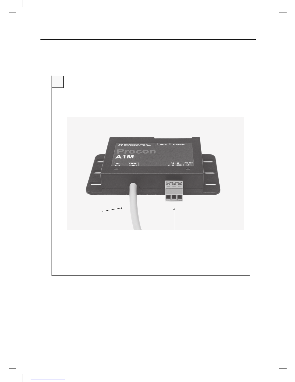
A RS-485 connector
B CN105/CN92 connection lead
1
[Fig. 1]
A
B
Page 5

Page 2 of 12
2
[Fig. 2]
Page 6

Page 3 of 12
Contents
Preface .................................................................................................................................................................................. i
Safety warnings ................................................................................................................................................................. i
Disclaimer.......................................................................................................................................................................... i
1. Safety precautions .................................................................................................................................................... 4
2. Overview .................................................................................................................................................................... 5
3. Settings ...................................................................................................................................................................... 6
3.1. Modbus Slave ID ................................................................................................................................................ 6
3.2. Baud rate ............................................................................................................................................................ 6
3.3. Other communication settings ........................................................................................................................... 6
3.4. RS-485 termination ............................................................................................................................................ 6
4. Installation ................................................................................................................................................................. 7
4.1. Physical connection between the Procon A1M and M-, S-, and P-Series indoor units .................................... 7
4.2. Power supply ...................................................................................................................................................... 7
4.3. Modbus connections .......................................................................................................................................... 7
5. Status LEDs ............................................................................................................................................................... 8
6. Modbus connection .................................................................................................................................................. 9
6.1. Modbus background .......................................................................................................................................... 9
6.2. Modbus connections .......................................................................................................................................... 9
7. Modbus tables ......................................................................................................................................................... 10
7.1. Modbus registers .............................................................................................................................................. 10
7.2. Discrete Inputs ................................................................................................................................................. 10
7.3. Coils ................................................................................................................................................................. 10
7.4. Input registers .................................................................................................................................................. 10
7.5. Holding registers .............................................................................................................................................. 11
Page 7

Page 4 of 12
1. Safety precautions
Symbols used in the text
Warning:
Describes precautions that should be observed to prevent danger of injury or death to the user.
Caution:
Describes precautions that should be observed to prevent damage to the unit.
Warning:
Ask the dealer or an authorised technician to install the unit
- Improper installation by the user may result in electric shock, or fire
Use the specified cables for wiring. Make the connections securely so that any outside forces acting on the cables are
not applied to the terminals
- Inadequate connection and fastening may generate heat and cause a fire
Never repair the unit. If the controller must be repaired, consult the dealer
- If the unit is repaired improperly, electric shock, or fire may result
Have all electric work done by a licensed electrician according to "Electric Facility Engineering Standard", "Interior Wire
Regulations" and the instructions given in this manual and always use a special circuit
- If the power source capacity is inadequate or electric work is performed improperly, electric shock and fire may result
Keep the electric parts away from any water - washing water etc…
- Contact may result in electric shock, fire or smoke
To dispose of this product, consult your dealer
Caution:
Safely dispose of the packing materials
- Packing materials, such as nails and other metal or wooden parts, may cause stabs or other injuries
- Tear apart and throw away plastic packaging bags so that children will not play with them - If children play with a plastic bag
which has not been torn apart, they face the risk of suffocation
Before installing the unit, make sure you read all the
“Safety precautions”
The “Safety precautions” provide very important points
re
g
arding safety. Make sure you follow them
Page 8

Page 5 of 12
2. Overview
The Procon A1M Protocol Converter is used for remote monitoring and control of M-, S- and P-series split air
conditioning systems. It acts as a gateway between the split system and external third party equipment.
The A1M continuously reads data from the indoor unit and changes configuration when necessary. Because the
reading is continuous the A1M always stores up-to-date data. This data is then available to external devices through
the RS-485 port using the Modbus RTU software protocol. Values can be read and changed via this connection.
Please refer to the Modbus section for further information.
The A1M is powered from the indoor unit when connected via the CN105/CN92 connector, hence no external power
supply is needed.
Caution:
MAC-397IF and MAC-399IF units cannot be connected when the Procon A1M is connected, as the same CN105/CN92
connector is used.
Figure 1 shows the A1M converter.
Figure 2 shows the CN105/CN92 connector on the indoor unit PCB that the A1M connects to.
Page 9

Page 6 of 12
3. Settings
There is a bank of 8 DIP switches on the Procon A1M PCB labelled as ‘CONFIGURATION’. These switches are used
to configure the Modbus Slave ID and the RS-485 baud rate.
3.1. Modbus Slave ID
Any Modbus Slave ID in the range 1 – 31 can be chosen using switches 1 – 5. The address is set in binary, where the
switch positions have the following values:
Switch number
V
alue when switch is set to ON
1 1
2 2
3 4
4 8
5 16
To get the Slave ID, add together the value for each switch set to ON. For example, to set address 13, set switches 1,
3 and 4 ON (1 + 4 + 8 = slave ID 13).
Please note: Each Procon A1M connected to the same RS-485 network must be set to a unique address.
3.2. Baud rate
The baud rate can be set to values from 1200 up to 115200 baud using DIP switches 6 – 8 as follows:
Baud rate Switch 6 Switch 7 Switch 8
1200 OFF OFF OFF
2400 ON OFF OFF
4800 OFF ON OFF
9600 ON ON OFF
19200 OFF OFF ON
38400 ON OFF ON
57600 OFF ON ON
115200 ON ON ON
3.3. Other communication settings
All other communication settings are fixed:
- 8 Data Bits
- No Parity
- 1 Stop Bit
3.4. RS-485 termination
RS-485 termination resistors can also be enabled on the A1M PCB using a single jumper. These settings are
summarised below:
Jumper Setting Description
Not connected No termination or pull-up resistors enabled
LK1 Pull-up resistor A enabled
LK2 RS-485 termination resistor enabled
LK3 Pull-down resistor B enabled
Page 10

Page 7 of 12
4. Installation
4.1. Physical connection between the Procon A1M and M-, S-, and P-Series
indoor units
The Procon A1M has a 1 metre flying lead to connect directly into the CN105/CN92 connector on the indoor unit
controller PCB. As an example, Figure 2 shows this connection on a Mr Slim indoor unit.
4.2. Power supply
The Procon A1M is powered from the CN105/CN92 connector and hence does not require an external power supply.
4.3. Modbus connections
The Procon A1M has a 3-way screw terminal to provide Modbus RTU communication via RS-485. Figure 1 shows the
RS-485 connections. The Modbus section contains further detail of the Modbus communications.
Page 11

Page 8 of 12
5. Status LEDs
There are 2 status LEDs on the Procon A1M. The LED indications are as follows:
LED Name Colou
r
Functionality
LED1 Green
Lit when A1M is powered, flashing indicates valid communication
with the indoor unit.
LED2 Green
Lit when A1M is powered, flashing indicates valid Modbus
communication.
Please note: if one or both of the LEDs are permanently on, this indicates that the Procon A1M is powered
successfully, but no communication traffic is present. In this case please check the Slave ID settings, and ensure the
CN105/CN92 connector is seated correctly.
Page 12

Page 9 of 12
6. Modbus connection
6.1. Modbus background
Modbus is a master-slave protocol, which means there are two types of Modbus device, Modbus Masters and Modbus
Slaves.
Slave devices simply wait until they receive a command from a Master, act upon that command and send a reply to the
Master. Slaves do not have the ability to send commands to other devices on the bus. Master devices are responsible
for sending commands to slave devices and receiving data. Modbus only permits there to be one Master device on the
bus at any one time, but up to 247 slaves can be connected at a time.
Modbus is most commonly used over RS-485, which is a hardware standard allowing multiple devices to be connected
on the same bus.
Each Slave device must have a unique ID on the bus, which is referred to as a Slave ID. Each Modbus command the
Master sends will contain this Slave ID and only the Slave with that Slave ID will reply.
6.2. Modbus connections
For communication over RS-485 all 3 connections are needed. These are labelled A, B and GND. Please refer to the
connection diagrams below.
Caution:
The RS-485 cable must be a shielded data cable. Mains flex or other unshielded cable should not be used. The cable
shield should be connected to GND at one end only.
Caution:
RS-485 has polarised data connections. It is crucial that all ‘A’s are connected together, all ‘B’s are connected together
and all ‘GND’s are connected together.
Caution:
The RS-485 cable must be daisy-chained in a bus network. T-junctions (e.g. star network wiring) are not permitted.
Caution:
RS-485 biasing jumpers must be fitted on the M2M. Please refer to the diagram below.
Page 13

Page 10 of 12
7. Modbus tables
7.1. Modbus registers
Modbus Slave devices store data in registers. There are four register types and each type has its own register bank.
The register types are summarised below:
Register Name Register Type Description
Discrete Input Digital Input
Read only register used for holding status information which holds
a value of 0 or 1.
Coil Digital Output Read and write accessible register which holds a value of 0 or 1.
Input Register Analogue Input
Read only register used for status information which holds a 16-bit
value (0-65535)
Holding Register Analogue Output
Read and write accessible register used for status information
which holds a 16-bit value (0-65535)
7.2. Discrete Inputs
This device has no Discrete Inputs.
7.3. Coils
Coils are read using function code 01 and written to using either function code 05 or 15. Function code 05 is used when
writing to a single coil register, function code 15 is used for writing to multiple coil registers in the same command.
Coils (Digital Outputs)
Register Name
Location
(decimal)
Length Details
Drive On/Off 0 1
0x00 = Drive off
0x01 = Drive on
7.4. Input registers
Input Registers are read using function code 04.
Input Registers (Analogue Inputs)
Register Name
Location
(decimal)
Length Details
Room Temperature in °C 0 1
Holds a temperature value in °C multiplied
by 10.
E.g. a value of 200 = 20°C
Fault Code 1 1
0x8000 = No error
0x6999 = Bad communication with indoor
unit
Page 14

Page 11 of 12
7.5. Holding registers
Holding Registers are read using function code 03 and written to using either function code 06 or 16. Function code 06
is used when writing to a single holding register, function code 16 is used for writing to multiple holding registers in the
same command.
Holding Registers (Analogue Outputs)
Register Name
Location
(decimal)
Length Details
Drive Mode 0 1
0x01 = Heating
0x02 = Humidity reduction
0x03 = Cooling
0x07 = Ventilation, clean air operation
0x08 = Auto Operation
0x09 = i-see heating operation
*
0x0A = i-see humidity reduction
*
0x0B = i-see cooling
*
* indicates a read only value, writing this
value will have no effect
Temperature Setpoint in °C 1 1
Holds a temperature value in °C multiplied
by 10.
E.g. a value of 200 = 20°C
Fan Speed 2 1
0x00 = Auto
0x02 = Quiet
0x03 = Weak
0x05 = Strong
0x06 = Very strong (SH i)
Air Direction 3 1
0x00 = Auto
0x01 = Position 1
0x02 = Position 2
0x03 = Position 3
0x04 = Position 4
0x05 = Position 5
0x07 = Swing
Page 15

Page 12 of 12
Page 16

Please be sure to put the contact address/telephone number on
this manual before handing it to the customer.
MITSUBISHI ELECTRIC UK
MITSUBISHI ELECTRIC UK, TRAVELLERS LANE, HATFIELD, HERTFORDSHIRE, AL10 8XB
 Loading...