

Mitsubishi PRH-P8(200)MYA, PRH-P10(250)MYA, PRH-P16(400)MYA, PRH-P20(500)MYA Service Manual
Page 1

TECHNICAL & SERVICE MANUAL
AIR-COOLED ROOFTOP
PACKAGED AIR CONDITIONERS
For use with the R407C
2007
HEAT PUMP PRH-P8MYA
PRH-P10MYA
PRH-P16MYA
PRH-P20MYA
PRH-P200MYA
PRH-P250MYA
PRH-P400MYA
PRH-P500MYA
Models
<Unit>
Page 2

....................................
...................................
..............................................................................................................................
................................................................................................................
.........................................................................................................................
.....................................................................................................
.....................................................................................
..................................................................................
............................................................................................
....................................................................................................................
.................................................................................................................
.......................................................................................................
.........................................................................................................
...........................................................................................
....................................................................................................................................
.......................................................................
...................................................................................................
...................................................................................................
...................................................................................................
...................................................................................................
..............................................................................................
...........................................
.......................................................................................................
.........................................................................
..............................................................................................................
...............................................................................................................
...........................................................................................................................
........................................................................................................................
.................................................................................................
.............................................................................................................
...........................................................................................................
................................................................................................................
..................................................................................................
Contents
Page
1
PRECAUTIONS FOR DEVICES THAT USE R407C REFRIGERANT
[1] Necessary Apparatus and Materials and Notes on Their Handling
[2] Brazing
[3] Airtightness Test
[4] Vacuuming
[5] Charging of Refrigerant
2
TYPICAL INSTALLATION EXAMPLE
3
MODEL-DESIGNATION BREAKDOWN
4
PART NAMES AND FUNCTIONS
5
SPECIFICATIONS
6
ELECTRICAL DATA
7
EXTERNAL DIMENSIONS
8
REMOTE CONTROLLER
9
ELECTRICAL WIRING DIAGRAM
[1] Unit
[2] Skeleton of Transmission Line Connection
0
Technical Data to Meet LVD
[1] Standard Operation Data
[2] Cooling Capacity Curves
[3] Heating Capacity Curves
[4] Reduction Ratio by Frosting
[5] Capacity/Input Ratio against Changes in Room Airflow Rate
[6] Bypass Factor Curves
[7] Cooling Sensible Heating Capacity Table
[8] Fan Performance
[9] Center of Gravity
[10] NC Curve
A SERVICE DATA
[1] Appearance of Equipment
[2] Refrigerant Circuit
[3] Refrigerant Charge
[4] Operation Range
[5] Safety & Control Devices
1
2
3
4
4
5
6
6
7
10
12
13
15
16
16
20
20
20
22
22
22
23
25
25
27
33
35
37
37
41
41
41
42
Page 3

................................................................................................................................
......................................................................................................
........................................................................................................
........................................................
............................................................
...............................................................................................
.................................................................................................................
............................................................................................
........................................................................................................
...................................................................................
....................................................................................................................................
...................................................................................................................
..........................................................................................................
............................................................................................
.............................................................................................
......................................................................
.............................................................................
.......................................................................................................................
.............................................................................................
........................................................................................................
..............................................................................................................
...................................................................................................................
.......................................................................................................................
......................................
........................................................................................
Page
B CONTROL
[1] Composition of Control
[2] Control specifications
[3] Function of switches and connectors (outdoor-side)
[4] Function of switch on indoor-side controller board
[5] Simple parts check method
[6] Reference Data
[7] Troubleshooting of each part
[8] Emergency operation
[9] Self-diagnosis and troubleshooting
C Test run
[1] Before test run
[2] Test run procedures
[3] Self-diagnosis (PAR-20MAA)
[4] Self-diagnosis (PAR-21MAA)
[5] Remote controller diagnosis (PAR-20MAA)
[6] Remote controller check (PAR-21MAA)
D INSTALLATION
[1] Space required around units
[2] Installation of the unit
[3] Duct construction
[4] Lifting method
[5] Drain piping
[6] Modification method of fan direction (From side flow to top flow)
[7] The putting condition of the belt
43
43
44
48
55
56
57
58
61
63
73
73
73
78
80
81
82
83
83
85
86
87
88
89
90
Page 4

Page 5
1
PRECAUTIONS FOR DEVICES THAT USE R407C REFRIGERANT
Caution
Use ester oil, ether oil or alkylbenzene (small
amount) as the refrigerator oil to coat flares and
flange connections.
• The refrigerator oil will degrade if it is mixed with a
large amount of mineral oil.
Use liquid refrigerant to seal the system.
• If gas refrigerant is used to seal the system, the composition of the refrigerant in the cylinder will change
and performance may drop.
Do not use a refrigerant other than R407C.
• If another refrigerant (R22, etc.) is used, the chlorine
in the refrigerant may cause the refrigerator oil to deteriorate.
Be especially careful when managing the tools.
• If dust, dirt, or water gets in the refrigerant cycle, the
refrigerant may deteriorate.
If the refrigerant leaks, recover the refrigerant in the
refrigerant cycle, then recharge the cycle with the
specified amount of the liquid refrigerant indicated
on the air conditioner.
• Since R407C is a nonazeotropic refrigerant, if additionally charged when the refrigerant leaked, the composition of the refrigerant in the refrigerant cycle will
change and result in a drop in performance or abnormal stopping.
Use a vacuum pump with a reverse flow check valve.
• The vacuum pump oil may flow back into the refrigerant cycle and cause the refrigerator oil to deteriorate.
Do not use the following tools that have been used
with conventional refrigerants.
(Gauge manifold, charge hose, gas leak detector, reverse flow check valve, refrigerant charge base,
vacuum gauge, refrigerant recovery equipment)
• If the conventional refrigerant and refrigerator oil are
mixed in the R407C, the refrigerant may deteriorated.
• If water is mixed in the R407C, the refrigerator oil
may deteriorate.
• Since R407C does not contain any chlorine, gas
leak detectors for conventional refrigerants will not
react to it.
Do not use a charging cylinder.
• Using a charging cylinder may cause the refrigerant
to deteriorate.
- 1 -
Page 6
[1] Necessary Apparatus and Materials and Notes on Their Handling
The following tools should be marked as dedicated tools for R407C.
<<Comparison of apparatus and materials used for R407C and for R22>>
Apparatus Used Use R22 R407C
Gauge manifold Evacuating, refrigerant filling Current product
Charging hose Operation check Current product
Charging cylinder Refrigerant charging Current product Do not use
Gas leakage detector Gas leakage check Current product Shared with R134a
Refrigerant collector Refrigerant collection R22 For R407C use only
Refrigerant cylinder Refrigerant filling R22 Identification of dedi-
cated use for R407C:
Record refrigerant name
and put brown belt on
upper part of cylinder.
Vacuum pump Vacuum drying Current product Can be used by attach-
ing an adapter with a
check valve.
Vacuum pump with a check valve Current product
Flare tool Flaring of pipes Current product
Bender Bending of pipes Current product
Application oil Applied to flared parts Current product Ester oil or Ether oil or
Alkybenzene (Small
amount)
Torque wrench Tightening of flare nuts Current product
Pipe cutter Cutting of pipes Current product
Welder and nitrogen cylinder Welding of pipes Current product
Refrigerant charging meter Refrigerant charging Current product
Vacuum gauge Checking the vacuum degree Current product
Symbols: To be used for R407C only. Can also be used for conventional refrigerants.
Tools for R407C must be handled with more care than those for conventional refrigerants. They must not come into contact
with any water or dirt.
- 2 -
Page 7
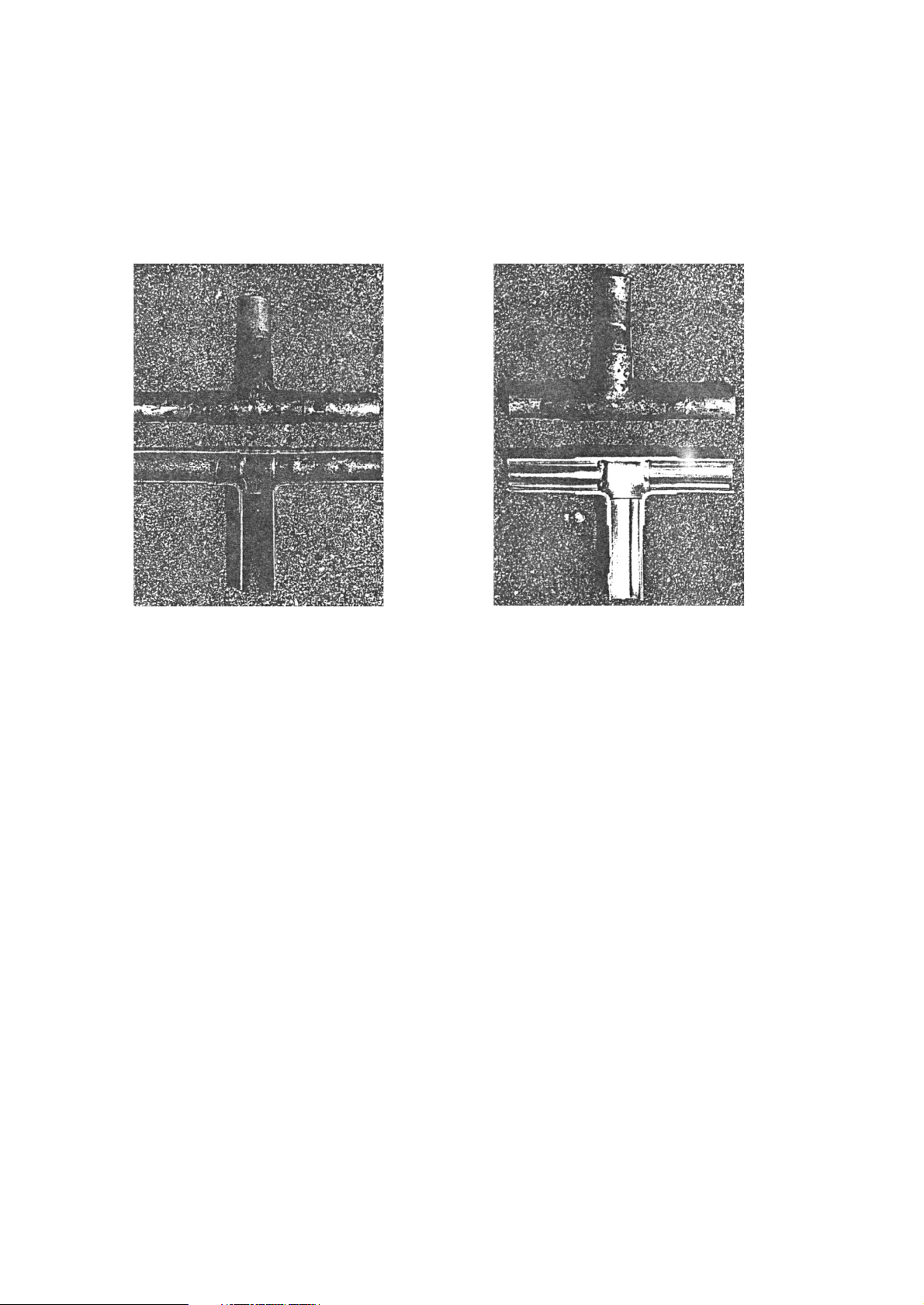
[2] Brazing
No changes from the conventional method, but special care is required so that foreign matter (ie. oxide scale, water, dirt,
etc.) does not enter the refrigerant circuit.
Example: Inner state of brazed section
When non-oxide brazing was not used When non-oxide brazing was used
Items to be strictly observed:
1. Do not conduct refrigerant piping work outdoors on a rainy day.
2. Apply non-oxide brazing.
3. Use a brazing material (BCuP-3) which requires no flux when brazing between copper pipes or between a copper
pipe and copper coupling.
4. If installed refrigerant pipes are not immediately connected to the equipment, then braze and seal both ends of them.
Reasons:
1. The new refrigerant oil is 10 times more hygroscopic than the conventional oil. The probability of a machine failure if
water infiltrates is higher than with conventional refrigerant oil.
2. A flux generally contains chlorine. A residual flux in the refrigerant circuit may generate sludge.
Note:
• Commercially available antioxidants may have adverse effects on the equipment due to its residue, etc. When
applying non-oxide brazing, use nitrogen.
- 3 -
Page 8
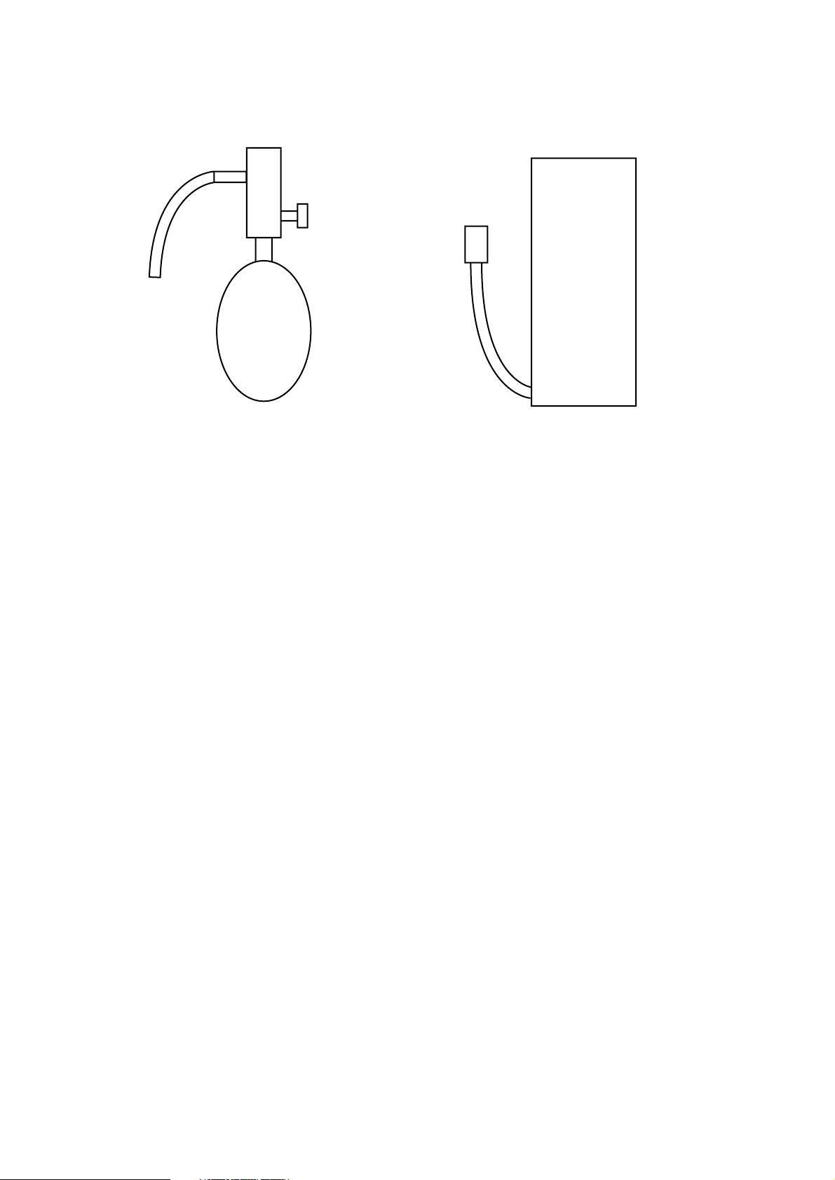
[3] Airtightness Test
No changes from the conventional method. Note that a refrigerant leakage detector for R22 cannot detect R407C leakage.
Halide torch R22 leakage detector
Items to be strictly observed:
1. Pressurize the equipment with nitrogen up to the design pressure and then judge the equipment’s airtightness, taking
temperature variations into account.
2. When investigating leakage locations using a refrigerant, be sure to use R407C.
3. Ensure that R407C is in a liquid state when charging.
Reasons:
1. Use of oxygen as the pressurized gas may cause an explosion.
2. Charging with R407C gas will lead the composition of the remaining refrigerant in the cylinder to change and this
refrigerant can then not be used.
Note:
• A leakage detector for R407C is sold commercially and it should be purchased.
[4] Vacuuming
1. Vacuum pump with check valve
A vacuum pump with a check valve is required to prevent the vacuum pump oil from flowing back into the refrigerant
circuit when the vacuum pump power is turned off (power failure).
It is also possible to attach a check valve to the actual vacuum pump afterwards.
2. Standard degree of vacuum for the vacuum pump
Use a pump which reaches 0.5 Torr (500 MICRON) or below after 5 minutes of operation.
In addition, be sure to use a vacuum pump that has been properly maintained and oiled using the specified oil. If the
vacuum pump is not properly maintained, the degree of vacuum may be too low.
3. Required accuracy of the vacuum gauge
Use a vacuum gauge that can measure up to 5 Torr. Do not use a general gauge manifold since it cannot measure a
vacuum of 5 Torr.
4. Evacuating time
• Evacuate the equipment for 1 hour after –755 mmHg (5 Torr) has been reached.
• After envacuating, leave the equipment for 1 hour and make sure the that vacuum is not lost.
5. Operating procedure when the vacuum pump is stopped
In order to prevent a backflow of the vacuum pump oil, open the relief valve on the vacuum pump side or loosen the
charge hose to drawn in air before stopping operation.
The same operating procedure should be used when using a vacuum pump with a check valve.
NO
NO
- 4 -
Page 9
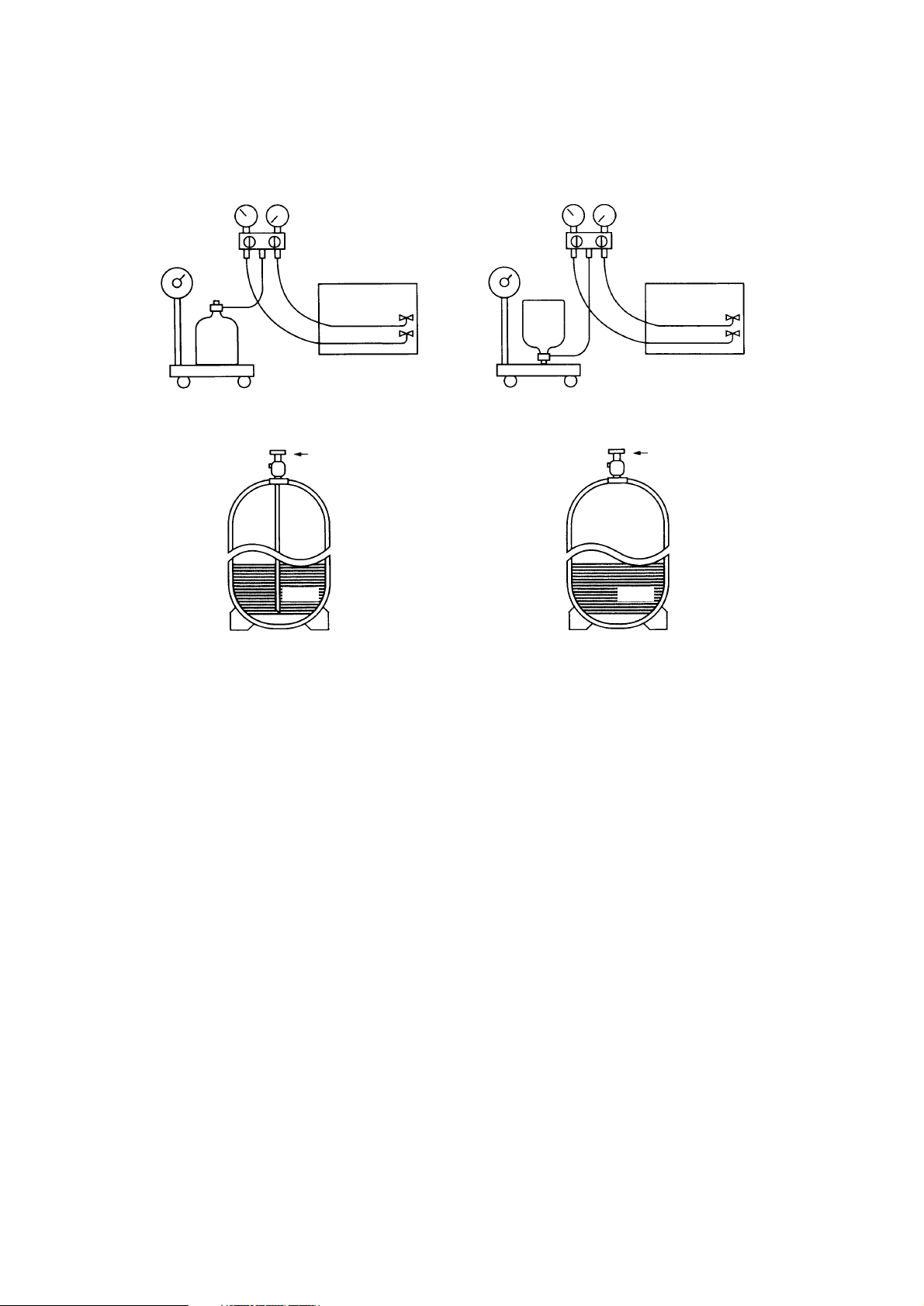
[5] Charging of Refrigerant
R407C must be in a liquid state when charging, because it is a non-azeotropic refrigerant.
For a cylinder with a syphon attached For a cylinder without a syphon attached
Cylinder color identification R407C-Gray Charged with liquid refrigerant
R410A-Pink
Reasons:
1. R407C is a mixture of 3 refrigerants, each with a different evaporation temperature. Therefore, if the equipment is
charged with R407C gas, then the refrigerant whose evaporation temperature is closest to the outside temperature is
charged first while the rest of refrigerants remain in the cylinder.
Note:
• In the case of a cylinder with a syphon, liquid R407C is charged without turning the cylinder up side down. Check the
type of cylinder before charging.
Cylin-
der
Cylin-
der
Valve
Valve
Liquid
Liquid
- 5 -
Page 10
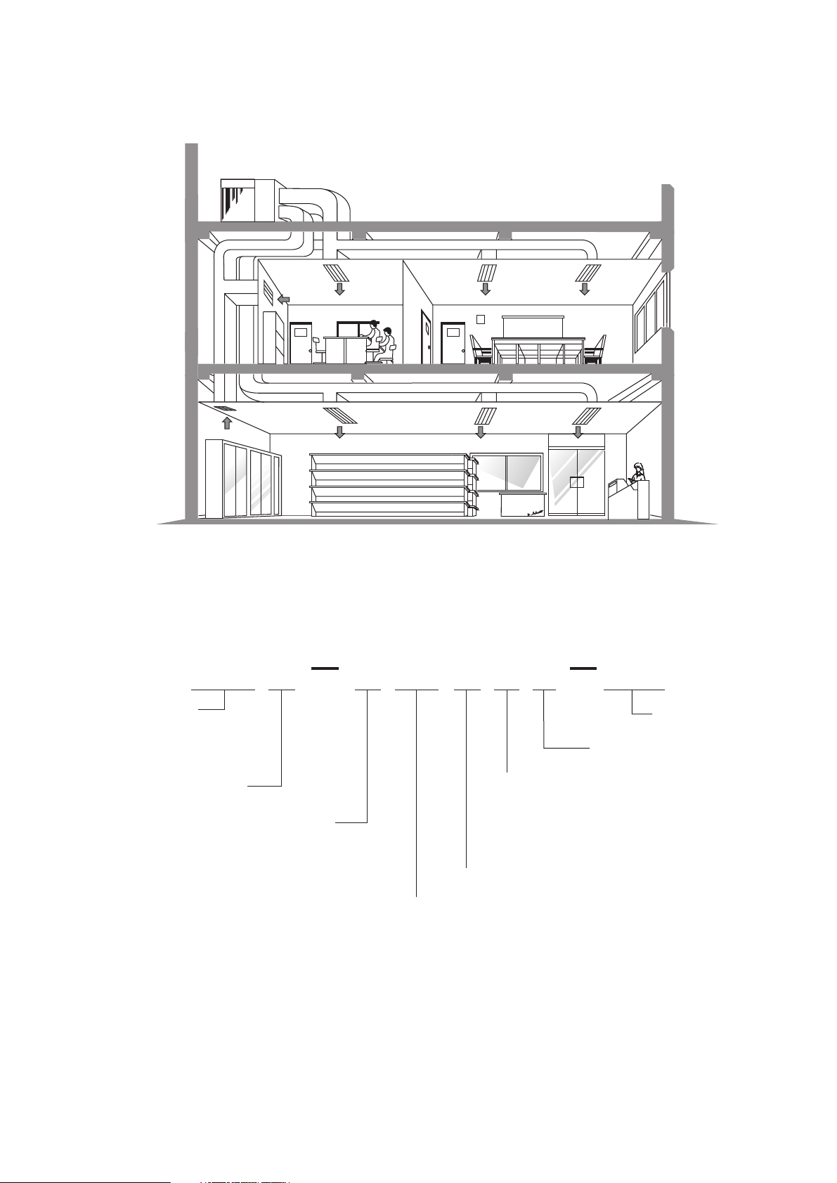
2
TYPICAL INSTALLATION EXAMPLE
3
MODEL-DESIGNATION BREAKDOWN
Series symbol
Self-contained type
(rooftop type)
Refrigerant
P=R407C
Heat pump type
Series symbol
Y=3-phase
380V,400V,415V,50Hz,3N~
Design sequence
Compressor horse power
Design sequence
Service reference
PRH
P R H P 1 0 M Y A E U
8=8HP
10=10HP
16=16HP
20=20HP
200=8HP
250=10HP
400=16HP
500=20HP
- 6 -
Page 11
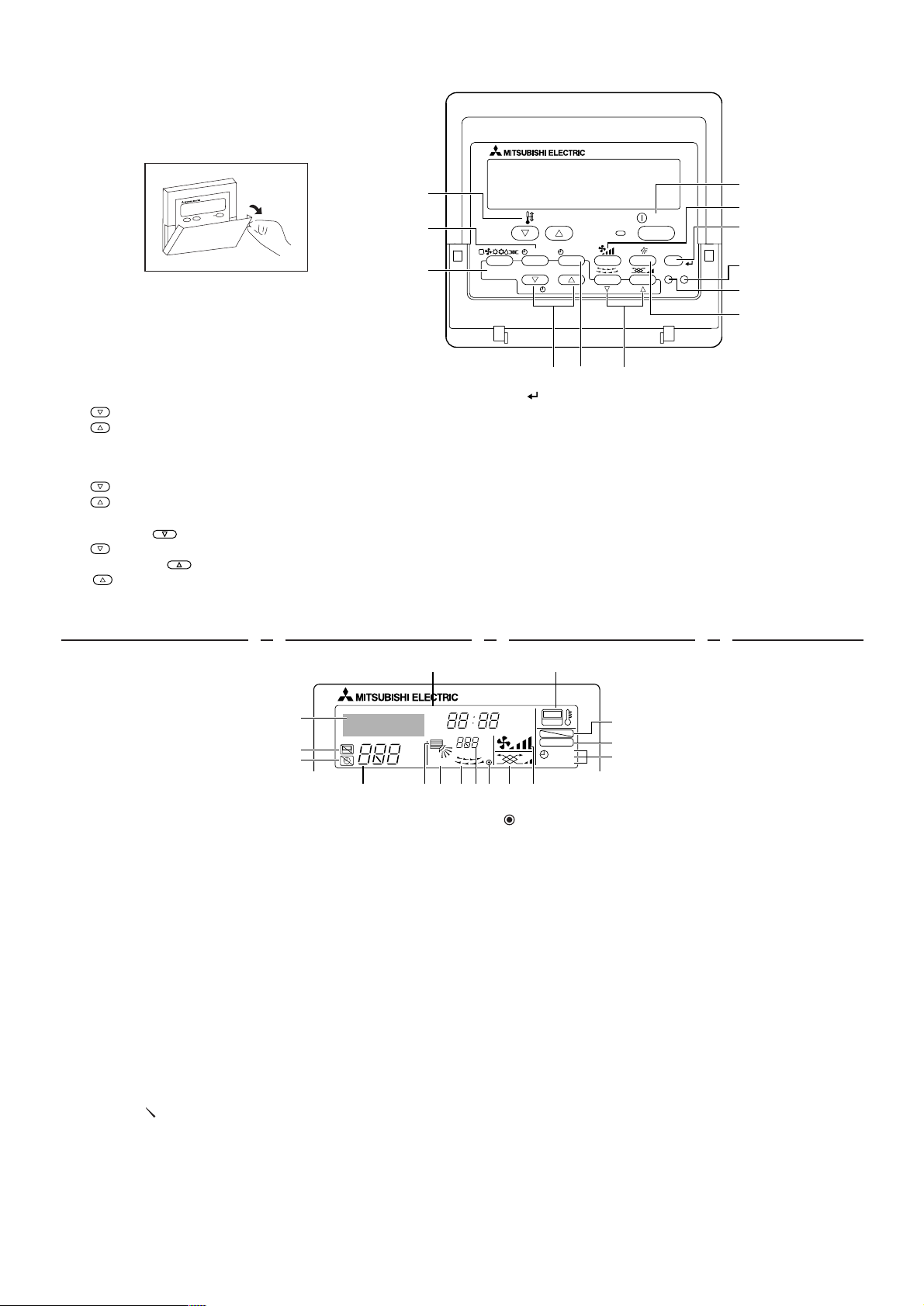
PAR-20MAA
ON/OFF
CENTRALLY CONTROLLED
ERROR CODE
CLOCK
ON OFF
ßC
CHECK
CHECK MODE
FILTER
TEST RUN
FUNCTION
ßC
1Hr.
NOT AVAILABLE
STAND BY
DEFROST
FILTER
CHECK
TEST
TEMP.
TIMER SET
1
2
3
3
0
1
2
Unit
• Return air : Sucks the ambient air in.
• Supply air : Blows the air back out into
Supply air
Return air
the room.
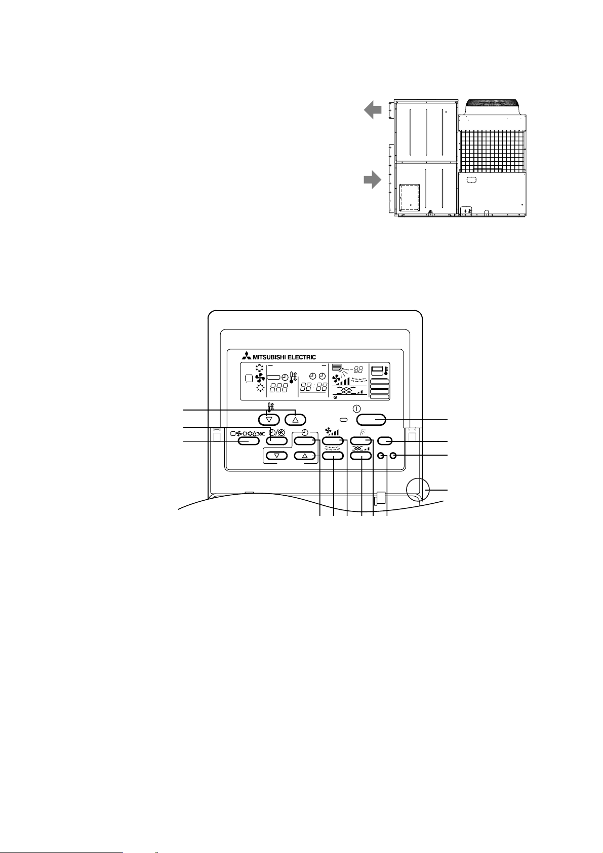
Remote controller PRH-P8, 10, 16, 20MYA (PAR-20MAA)
• Once the controls are set, the same operation mode can be repeated by simply pressing the ON/OFF button.
[Operation buttons]
[Room temperature adjustment] Button
[Timer/continuous] Button
[Selecting operation] Button
[Time selection] Button
[Time-setting] Button
[Louver] Button (This button does not operate in this model)
[Fan speed adjustment] Button
[Up/down airflow direction] Button (This button does not operate in this model)
[Ventilation] Button
[Checking/built-in] Button
[Test run] Button
[Filter] Button (This button does not operate in this model)
[ON/OFF] Button
Position of built-in room temperature
• Never expose the remote controller to direct sunlight. Doing so can result in the erroneous measurement of room temperature.
• Never place any obstacle around the lower right-hand section of the remote controller. Doing so can result in the erroneous measurement of room temperature.
456879
4
PART NAMES AND FUNCTIONS
1
2
3
4
5
6
7
8
9
0
1
2
3
- 7 -
Page 12
ON/OFF
CENTRALLY CONTROLLED
ERROR CODE
CLOCK
ON OFF
ßC
CHECK
CHECK MODE
FILTER
TEST RUN
FUNCTION
ßC
1Hr.
NOT AVAILABLE
STAND BY
DEFROST
TEMP.
D U T S Q C
GH JKLI
B A
R
P
O
N
M
E
F
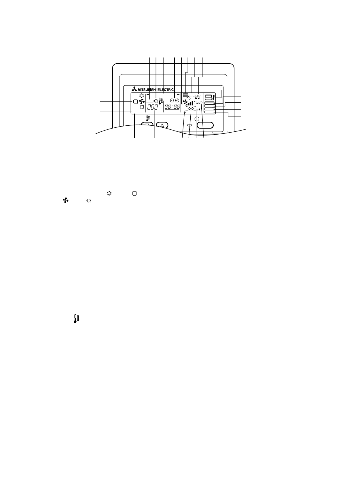
[Display]
Caution:
• Only the Power display lights when the unit is stopped and power supplied to the unit.
• When power is turned ON for the first time the (CENTRAL CTRL) display appears to go off momentarily but this is not
a malfunction.
• When the central control remote control unit, which is sold separately, is used the ON-OFF button, operation switch
button and
TEMP. adjustment button do not operate.
• “NOT AVAILABLE” is displayed when the Airflow direction button or Louver button are pressed. This indicates that
this room unit is not equipped with the fan direction adjustment function and the louver function.
• When power is turned ON for the first time, it is normal that “H0” is displayed on the room temperature indication (For
max. 2 minutes). Please wait until this “H0” indication disappear then start the operation.
A Current time/Timer
C Centralized control
D Abnormality control
E Operation mode: COOL, AUTO,
FAN, HEAT
F Preparing for Heating mode
G Defrost mode
H Set temperature
I Power ON
J Louver
K Not available function
L Ventilation
M Function setting mode
N Test run mode
O Error check mode
P Filter sign
Q Set effective for 1 hr.
R Sensor position
S Room temperature
T Airflow
U
Fan speed
- 8 -
Page 13
PAR-21MAA
ON/OFF
FILTER
CHECK
OPERATION
CLEAR
TEST
TEMP.
MENU
BACK DAY
MONITOR/SET
CLOCK
ON/OFF
1
45 67
8
9
0
A
B
C
2
3
˚F˚C
˚F˚C
ERROR CODE
AFTER
TIMER
TIME SUN MON TUE WED THU FRI SAT
ON
OFFHrAFTER
FILTER
FUNCTION
ONLY1Hr.
WEEKLY
SIMPLE
AUTO OFF
A
C
D
E
FGHIJKLM
N
O
P
B
Set Temperature buttons
Down
Up
Timer Menu button (Monitor/Set button)
Mode button (Return button)
Set Time buttons
Back
Ahead
Timer On/Off button (Set Day button)
Louver button (
Operation button)
To preceding operation number.
Ventilation button (
Operation button)
To next operation number.
ON/OFF button
F
1
2
3
4
5
6
7
8
9 an Speed button
Opening the door.
0 Filter button (<Enter> button)
A Test Run button
B Check button (Clear button)
C Airflow Up/Down button
Notes:
• If you press a button for a feature that is not installed at the indoor unit,
the remote controller will display the “Not Available” message.
• If you are using the remote controller to drive multiple indoor units, this
message will appear only if the feature is not present at the parent unit.
• Never expose the remote controller to direct sunlight. Doing so can result in the erroneous measurement of room temperature.
• Never place any obstacle around the lower right-hand section of the remote controller. Doing so can result in the erroneous measurement of
room temperature.
Day-of-Week
Shows the current day of the week.
Time/Timer Display
Shows the current time, unless the simple or Auto Off timer is set.
If the simple or Auto Off timer is set, shows the time remaining.
“Sensor” indication
Displayed when the remote controller sensor is used.
Identifies the current operation
Shows the operating mode, etc.
* Multilanguage display is supported.
“Centrally Controlled” indicator
Indicates that operation of the remote controller has been prohibited by a main controller.
“Timer Is Off” indicator
Indicates that the timer is off.
Temperature Setting
Shows the target temperature.
Up/Down Air Direction indicator
The indicator
shows the direction of the outcoming airflow.
“One Hour Only” indicator
Displayed if the airflow is set to weak and downward during COOL or DRY mode . (Oper
ation varies according to model.)
The indicator goes off after one hour, at which time the airflow direction also changes
.
Louver display
Indicates the action of the swing louver. Does not appear if the louver is stationary .
Room T
A
B
C
D
E
F
G
H
I
J emperature display
Shows the room temperature.
K
(Power On indicator)
Indicates that the power is on.
L Ventilation indicator
Appears when the unit is running in Ventilation mode.
M Fan Speed indicator
Shows the selected fan speed.
N “Locked” indicator
Indicates that remote controller buttons have been locked.
O “Clean The Filter” indicator
Comes on when it is time to clean the filter.
P Timer indicators
The indicator comes on if the corresponding timer is set.
Note:
• For purposes of this explanation, all parts of the display are shown as lit.
During actual operation, only the relevant items will be lit.
Remote contr
PRH-P200, 250, 400, 500MYA (PAR-21MAA)
oller-Button
Remote controller-Display
- 9 -
Page 14
5
SPECIFICATIONS
Model name PRH-P8MYA/P200MYA PRH-P10MYA/P250MYA
Mode
Capacity
Cooling Heating Cooling Heating
20.9
kW
kcal/h
Btu/h
kW
A
CMM
Pa
kW
CMM
kW
kW
kW
mm
dB(A)
kg
23.7 26.0 30.5
18,000 19,000 22,400 26,200
71,430 75,400 88,890 104,000
R407C
3N~ 380/400/415V 50Hz
Convertible(Side flow<factory setting> or top flow)
Sirrocco fan x 2
8.12 8.02 10.22 9.82
14.7 14.5 18.8 18.2
19
°
C to 30°C 17°C to 28°C 19°C to 30°C 17°C to 28°C
70
100
59
407
5.5
Three-phase induction motor
1.1
90
100
60
412
7.5
1.5
Cross fin
Propeller fan x 1
185
Three-phase induction motor
0.38
Cross fin
Hermetic
FVC68D(ether oil)
0.05 (240V)
Polyester powder (MUNSELL 5Y8/1)
1,715 x 2,000 x 926
Field supplied
R1
Refrigerant
Power source
Electrical
characteristics
Power consumption
Operating current
Type x Quantity
Air flow rate
External static pressure
Motor type
Motor output
Type x Quantity
Air flow rate
Motor type
Motor output
Type
Motor output
Oil type
Crankcase heater
H x W x D
Remote controller temperature setting range
Indoor-side air flow direction
Indoor-side fan
Indoor-side heat exchanger type
Outdoor-side fan
Outdoor-side heat exchanger type
Compressor
External finish
External dimension
Air filter
Drain pipe Thread
Noise level
Net weight
Protection devices High pressure switch , Low pressure switch , fuse
Over current relay(compressor , indoor-side fan motor)
inner thermal switch in outdoor-side fan motor
Note 1. Cooling and Hetaing capacity indicates the maximum value at operation under the following condition.
Cooling Indoor : 27
°
CDB/19°CWB Outdoor : 35°CDB
Heating Indoor : 20
°
CDB Outdoor : 7°CDB/6°CWB
2. The operating noise measuring point is 1m from the bottom of unit (1m from the front of the unit) in an
anechoic room. (Noise level is A-scale value)
3. Refrigerant charge volumes are factory charged.
4. The range of working voltage is with in ±10% voltage of power supply.
5. Specification subject to change without notice.
Specifications of air-source heat pump type packaged air conditioner
(Rooftop unit)
- 10 -
Page 15
- 11 -
Model name PRH-P16MYA/P400MYA PRH-P20MYA/P500MYA
Mode
Capacity
Cooling Heating Cooling Heating
41.8
kW
kcal/h
Btu/h
kW
A
CMM
Pa
kW
CMM
kW
kW
kW
mm
dB(A)
kg
47.4 52.0 61.0
36,000 40,800 44,800 52,400
142,860 150,800 177,780 208,000
R407C
3N~ 380/400/415V 50Hz
Convertible(Side flow<factory setting> or top flow)
Sirrocco fan x 2
16.60 15.94 21.44 19.24
29.6 29.2 36.6 35.4
19
°
C to 30°C 17°C to 28°C 19°C to 30°C 17°C to 28°C
140
200
62
857
5.5 x 2
Three-phase induction motor
2.2
180
200
63
872
7.5 x 2
3.7
Cross fin
Propeller fan x 2
185 x 2
Three-phase induction motor
0.38 x 2
Cross fin
Hermetic
FVC68D(ether oil)
0.05 (240V) x 2
Polyester powder (MUNSELL 5Y8/1)
1,735 x 2,000 x 2,130
Field supplied
R1
Refrigerant
Power source
Electrical
characteristics
Power consumption
Operating current
Type x Quantity
Air flow rate
External static pressure
Motor type
Motor output
Type x Quantity
Air flow rate
Motor type
Motor output
Type
Motor output
Oil type
Crankcase heater
H x W x D
Remote controller temperature setting range
Indoor-side air flow direction
Indoor-side fan
Indoor-side heat exchanger type
Outdoor-side fan
Outdoor-side heat exchanger type
Compressor
External finish
External dimension
Air filter
Drain pipe Thread
Noise level
Net weight
Protection devices High pressure switch , Low pressure switch , fuse
Over current relay(compressor , indoor-side fan motor)
inner thermal switch in outdoor-side fan motor
Note 1. Cooling and Hetaing capacity indicates the maximum value at operation under the following condition.
Cooling Indoor : 27
°
CDB/19°CWB Outdoor : 35°CDB
Heating Indoor : 20
°
CDB Outdoor : 7°CDB/6°CWB
2. The operating noise measuring point is 1m from the bottom of unit (1m from the front of the unit) in an
anechoic room. (Noise level is A-scale value)
3. Refrigerant charge volumes are factory charged.
4. The range of working voltage is with in ±10% voltage of power supply.
5. Specification subject to change without notice.
Specifications of air-source heat pump type packaged air conditioner
(Rooftop unit)
Page 16
6
ELECTRICAL DATA
VOLT
TOTAL INPUT
TOTAL RATED CURRENT
POWER FACTOR
START CURRENT
COMPRESSOR INPUT
RATED CURRENT
O/D FAN INPUT
RATED CURRENT
I/D FAN External static pressure
INPUT
RATED CURRENT
TOTAL INPUT
TOTAL RATED CURRENT
POWER FACTOR
START CURRENT
COMPRESSOR INPUT
RATED CURRENT
O/D FAN INPUT
RATED CURRENT
I/D FAN External static pressure
INPUT
RATED CURRENT
TOTAL INPUT
TOTAL RATED CURRENT
POWER FACTOR
START CURRENT
COMPRESSOR INPUT
RATED CURRENT
O/D FAN INPUT
RATED CURRENT
I/D FAN External static pressure
INPUT
RATED CURRENT
415V
400V
380V
kW
A
%
A
kW
A
kW
A
Pa
kW
A
kW
A
%
A
kW
A
kW
A
Pa
kW
A
kW
A
%
A
kW
A
kW
A
Pa
kW
A
8.12
14.7
76
111
6.96
11.9
0.31
1.1
100
0.85
1.7
8.12
14.7
79
111
6.96
11.9
0.31
1.1
100
0.85
1.7
8.12
14.7
83
111
6.96
11.9
0.31
1.1
100
0.85
1.7
8.02
14.5
76
111
6.86
11.7
0.31
1.1
100
0.85
1.7
8.02
14.5
79
111
6.86
11.7
0.31
1.1
100
0.85
1.7
8.02
14.5
84
111
6.86
11.7
0.31
1.1
100
0.85
1.7
10.22
18.8
75
134
8.71
14.9
0.31
1.1
100
1.2
2.8
10.22
18.8
78
134
8.71
14.9
0.31
1.1
100
1.2
2.8
10.22
18.8
82
134
8.71
14.9
0.31
1.1
100
1.2
2.8
9.82
18.2
75
134
8.31
14.3
0.31
1.1
100
1.2
2.8
9.82
18.2
77
134
8.31
14.3
0.31
1.1
100
1.2
2.8
9.82
18.2
81
134
8.31
14.3
0.31
1.1
100
1.2
2.8
ITEM
PRH-P8MYA/P200MYA PRH-P10MYA/P250MYA
Cooling
VOLT
TOTAL INPUT
TOTAL RATED CURRENT
POWER FACTOR
START CURRENT
COMPRESSOR INPUT
RATED CURRENT
O/D FAN INPUT
RATED CURRENT
I/D FAN External static pressure
INPUT
RATED CURRENT
TOTAL INPUT
TOTAL RATED CURRENT
POWER FACTOR
START CURRENT
COMPRESSOR INPUT
RATED CURRENT
O/D FAN INPUT
RATED CURRENT
I/D FAN External static pressure
INPUT
RATED CURRENT
TOTAL INPUT
TOTAL RATED CURRENT
POWER FACTOR
START CURRENT
COMPRESSOR INPUT
RATED CURRENT
O/D FAN INPUT
RATED CURRENT
I/D FAN External static pressure
INPUT
RATED CURRENT
415V
400V
380V
kW
A
%
A
kW
A
kW
A
Pa
kW
A
kW
A
%
A
kW
A
kW
A
Pa
kW
A
kW
A
%
A
kW
A
kW
A
Pa
kW
A
16.60
29.6
78
126
14.38
23.8
0.62
2.2
200
1.6
3.6
16.60
29.6
80
126
14.38
23.8
0.62
2.2
200
1.6
3.6
16.60
29.6
85
126
14.38
23.8
0.62
2.2
200
1.6
3.6
15.94
29.2
75
126
13.72
23.4
0.62
2.2
200
1.6
3.6
15.94
29.2
78
126
13.72
23.4
0.62
2.2
200
1.6
3.6
15.94
29.2
82
126
13.72
23.4
0.62
2.2
200
1.6
3.6
21.44
36.6
81
152
18.82
29.8
0.62
2.2
200
2.0
4.6
21.44
36.6
84
152
18.82
29.8
0.62
2.2
200
2.0
4.6
21.44
36.6
89
152
18.82
29.8
0.62
2.2
200
2.0
4.6
19.24
35.4
75
151
16.62
28.6
0.62
2.2
200
2.0
4.6
19.24
35.4
78
151
16.62
28.6
0.62
2.2
200
2.0
4.6
19.24
35.4
82
151
16.62
28.6
0.62
2.2
200
2.0
4.6
ITEM
PRH-P16MYA/P400MYA PRH-P20MYA/P500MYA
Cooling Heating HeatingCooling
Heating HeatingCooling
- 12 -
Page 17
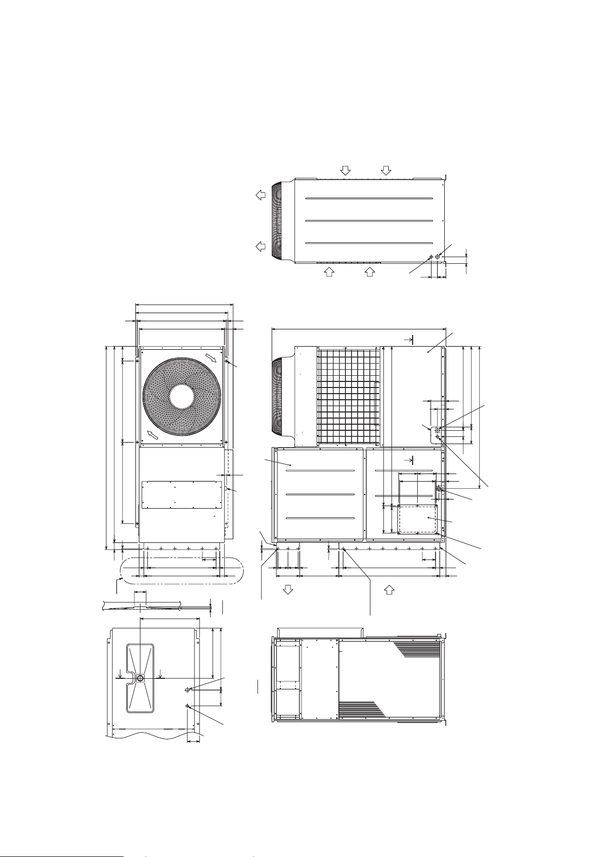
• Models PRH-P8MYA/P10MYA/P200MYA/P250MYA
7
EXTERNAL DIMENSIONS
Drain R1
Fresh air
intake
(Both side)
28- ø 3 Holes
18- ø 3 Holes
Supply air
duct flange
Return air
duct flange
Note 3
Y
Y
Y-Y
X-X
Left side view
ø 25.4 Knockout hole
<Bottom side hole for
the controller wiring>
Note 1
ø 38.1 Knockout hole
<Bottom side hole for
the power supply wiring>
Top view
Drain R1
6-14X20 holes
<For mounting
anchor bolt M8>
[Field supply]
6-
ø 3.9 holes
(Both side)
Return
air
Supply
air
Service panel
Knockout hole
ø 27 hole
<Front side hole for
the controller wiring>
(Accessory plate)
Service panel
Front view
Note 2
ø 40 hole
<Front side hole for
the power supply wiring>
(Accessory plate)
X
X
Note 1. It is possible to change to ø 27 or
ø 34 by selecting the conduit
mounting plate.
2. The hole size can be selected to
ø 27 or ø 34 or ø 40 by selecting
the conduit mounting plate.
3. These dimension of supply air and
return air duct flange are the same.
<Accessory>
• Conduit mounting plate
(Painted the same color as the unit body)
ø 27
..................................................
1pc.
ø 34
..................................................
1pc.
ø 40 and ø 27
.................................
1pc.
• Tapping screw 4X12
........................
4pcs.
Air inlet
Air outlet
Air inlet
Right side view
ø 38.1 Knockout hole
<Right side hole for
the power supply wiring>
ø 25.4 Knockout hole
<Right side hole for
the controller wiring>
270 1569
250 1579
69
18518595
350105
149
495
585
86
144
1932
2000
7X130Pitch= 910
84
5X135Pitch= 675
56
68
50
121
155 611
23
4646
36.5
135
36.5
748
10 800 800
1515
840
880
910
961
1399
10
10
43 151001001543
130
23038699560
1715
82960
165 794
65
6084
- 13 -
Page 18
- 14 -
4X150Pitch=600
10
65 65
(730)
(434)
10
150
44 13X150Pitch=1950 44
10
67
150
150
67
10
(2038)
(1312)
56 8X150Pitch=1200 56
150
50 50
5
56
6
165 794
80
169
104
839
89
155155105
290115
1030
293 525
434202
46 2038 46
1312
73080
65
80104
1661
1671
200
180
1549
2170
2200
1515
68 1932
800 800 144
2000
2130
585
495
585
111
155 611
1735
150
23
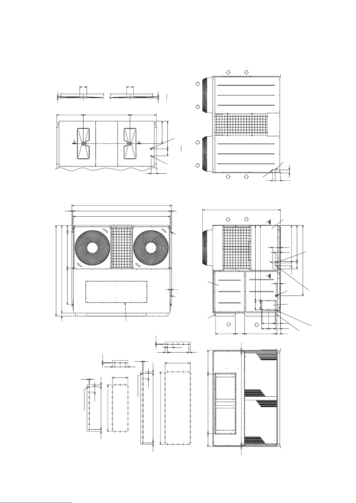
• Models PRH-P16MYA/P20MYA/P400MYA/P500MYA
Supply air cover
for top flow
Air
inlet
Air
inlet
Air
outlet
Y
Service panel
air
Return
air
Air
inlet
Fresh air
intake
(Both side)
Drain
R1
Supply air
Return air
duct flange
Note 2
duct flange
Note 2
Y
Y-Y
X-X
Left side view
ø25.4 Knockout hole
<Bottom side hole for
the controller wiring>
Note 1
ø50.8 Knockout hole
<Bottom side hole for
the power supply wiring>
Top view
Drain R1
6-14X20 holes
<For mounting
6-
ø3.9 holes
(Both side)
anchor bolt M10>
[Field supply]
ø27 hole
<Front side hole for
the controller wiring>
(Accessory plate)
Supply
Knockout hole
Service panel
Front view
Note 1
ø52 hole
<Front side hole for
the power supply wiring>
(Accessory plate)
XX
Note 1.It is possible to change to
ø40 by
selecting the conduit mounting plate.
2. Dimension of supply air and return air
duct flange are shown below.
<Accessory>
• Conduit mounting plate
(Painted the same color as
the unit body)
ø40 ············ 1pc.
············ 1pc.
············ 4pcs.
ø52 and ø27
• Tapping screw 4X12
Air
outlet
Right side view
ø50.8 Knockout hole
<Right side hole for
the power supply wiring>
ø25.4 Knockout hole
<Right side hole for
the controller wiring>
Return air
duct flange
38- ø3 Holes
24-
ø3 Holes
Supply air
duct flange
Page 19
- 15 -
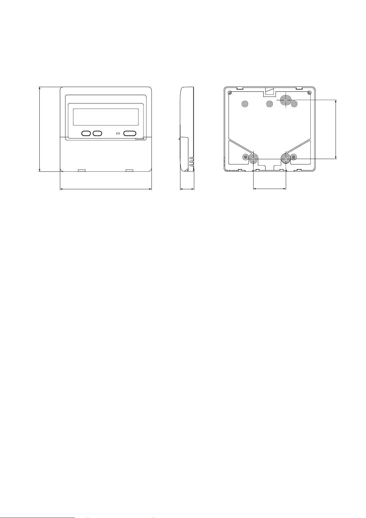
8
REMOTE CONTROLLER
(Front view) (Side view) (Rear view)
120
130
19
83.5
46
Page 20
- 16 -
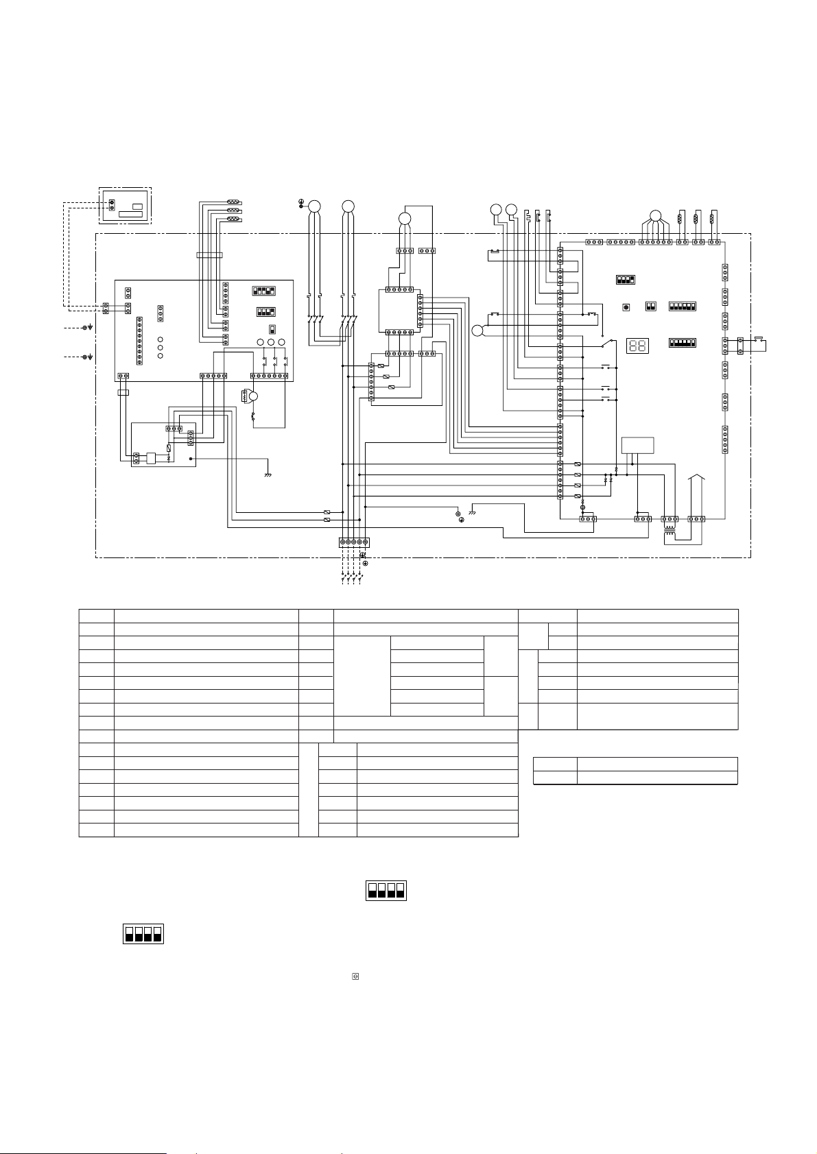
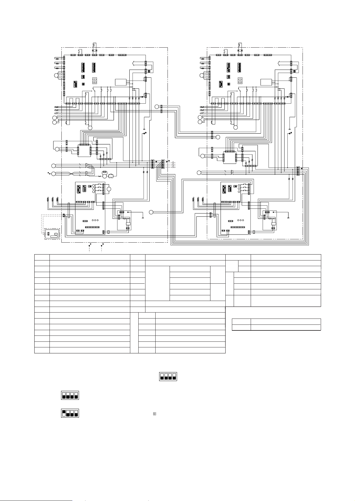
[1] Unit
9
• Models PRH-P8MYA/P10MYA
ELECTRICAL WIRING DIAGRAM
Symbol Name Symbol Name Symbol Name
IN
DOOR
-SIDE
OUT
DOOR
-SIDE
SURGE KILLER
COND/EVA TEMP
LIQUID PIPE TEMP
ROOM TEMP
COND/EVA TEMP
DISCHARGE TEMP
THERMISTOR
FERRITE CORE
FB1,FB2
CR
TH6
TH5
TH4
TH3
TH2
TH1
LIQUID PIPE TEMP
PRESSURE SWITCH (FOR CONTROL)
PRESSURE SWITCH (HIGH PRESSURE)
OVER CURRENT RELAY (INDOOR-SIDE FAN MOTOR)
FAN MOTOR (INDOOR-SIDE)
TERMINAL BLOCK
ELECTRONIC EXPANSION VALVE
CRANK CASE HEATER (COMPRESSOR)
SOLENOID VALVE
4-WAY VALVE
FAN MOTOR (OUTDOOR-SIDE)
PRESSURE SWITCH (LOW PRESSURE)
MAGNETIC CONTACTOR (COMPRESSOR)
MAGNETIC CONTACTOR (INDOOR-SIDE FAN MOTOR)
52F
51F
MF1
TB1,5
LEV
CH
SV1
21S4
OVER CURRENT RELAY (COMPRESSOR)
COMPRESSOR MOTOR
TRANSFORMERTR
MF2
MC
63H2
63H1
63L
52C
51C
FUSE (15A 250VAC CLASS T)F1,F2
Symbol Name
TERMINAL BLOCKTB6
REMOTE CONTROLLER
LED (FOR SERVICE)
AUXILIARY RELAY
SWITCHSW1-5
LED1
X01-X05
FUSE (6.3A 250VAC CLASS F)F01-F04
FUSE (6.3A 250VAC CLASS F)F10-F30
INDOOR-SIDE
CONTROLLER BOARD
X4-6
SW1
SW2
SWE
LED1
LED2
LED3
LED (TRANSMISSION<INDOOR-SIDE·OUTDOOR-SIDE>)
LED (POWER SUPPLY<REMOTE CONTROLLER>)
LED (POWER SUPPLY)
SWITCH (EMERGENCY OPERATION)
SWITCH (CAPACITY CORD)
SWITCH (MODEL SELECTION)
AUXILIARY RELAY
INDOOR-SIDE
POWER
BOARD
OUTDOOR-SIDE
CONTROLLER BOARD
N.F
BOARD
F1
ZNR
FUSE (4A 250VAC CLASS T)
VARISTOR
BLACK
(WITH INDOOR
POWER
BOARD)
BK
3
51F
PE
PE
CN90
CN2L
CN22
CN32
CN41
CN29
CN21
CN2D
DC14V
51
CN03
157
FAN
3
5321
X4 X5 X6
LCD
F1
ZNR
CN01
CN02
52F
TH6
TH5
TH4
TB5
FB1
CN2S
DC14V
SWE
SW1
REMOTE CONTROLLER
LED1
LED2
LED3
DC
14V
CN
OFF
ON
1
2
3
4
(*3)SW2
CN20
4
OFF
ON
OFF
ON
1234
INDOOR-SIDE
POWER BOARD
INDOOR-SIDE
CONTROLLER BOARD
FB2
REMOTE CONTROLLER
BOARD
1
2
RETURN AIR
DUCT
SUPPLY AIR
DUCT
CR
3
2
32
1
1
1
1
2
3
4
2
1
1
2
3
1
2
1
2
2
9
5
1
2
X6X51X4
2
6
7
8
1
TB6
2
F1
F2
5
3
531
BLACK
WHITE
RED
CNIN
LED1
SW3
12
OFF
ON
3456
(*2)SW5
65112
OFF
ON
OUTDOOR-SIDE
CONTROLLER BOARD
12
OFF
ON
SW2
34
TR
SW1SW4
OFF
C14
63H2
121
3
CN51
CN81
CN27
CN24
CN3D
DC POWER
SUPPLY
CN3N
CN3S
CN34CN28
3131
TRANSMISSION
CIRCIT
31
CNS3
CH 63L63H1
SV1
21S4
TH3TH2TH1
LEV
X05
X02
X03
X01
12
CN4
12
CN312CN2CN40CNMNTCNVMNT
CNFG
F01
F04
F02
F03
13
CN20
CNFC1
CN52
CN53
CN25
CN26
X04
CN21
CN22
CN23
52C
52C
51C
7
1
1
6
1
5
1
3
1
3
5
1
3
1
3
1
3
1
531
CNOUT1
PE
31
1
MF1
51F
52F
WHITE
1
BLUE3BLACK
RED
F30
WHITE
F20
F10
7
5
3
31
BLACK
CNOUT2
1
3
MC
L1
51C
52C
MF2
RED
TB1
ON
432
L25L3 N PE
PE
(*1)
6
POWER SUPPLY
3N
~PE
380/400/415V
50HZ
31
CNPOW
CNFC2
CNFAN
C11
CIRCUIT BREAKER
(FIELD SUPPLY)
PRH-P8MYA : 63A
PRH-P10MYA: 63A
N
L1
N.F.BOARD
L3
L2
PE
GREEN/YELLOW
F.C.
BOARD
C12
CONTROL BOX
Note:1. The dotted lines show field wiring.
2. Color of earth wire is yellow and green twisting.
3. Specification subject to change without notice.
4.This motor(*1) includes auto reset type internal thermostat.
5. SW5(
*
2)[outdoor-side controller board] is shown
In case of PRH-P8MYA setting is shown as below.
PRH-P10MYA setting.
6. SW2(
*
3)[indoor-side controller board] is shown
In case of PRH-P8MYA setting is shown as below.
PRH-P10MYA setting.
7. Emergency operation
If a trouble occurs with either the remote controller or the unit
microcomputer and no other trouble exists, emergency operation for
cooling or heating can be performed by changing the setting of
switch (SWE) on the indoor-side controller board.
8. mark is connector.
Caution,
1. To protect compressor and fan
motor (indoor-side) from
abnormal current, over current
relays is installed. Therefore,
do not change factory over
current relays is installed.
Therefore, do not change
factory set value of over current
relays.
ON
OFF
SW5
(*2)
ON
OFF
SW2
4321
(*3)
[intdoor-side controller board]
[outdoor-side controller board]
4321
Page 21
- 17 -
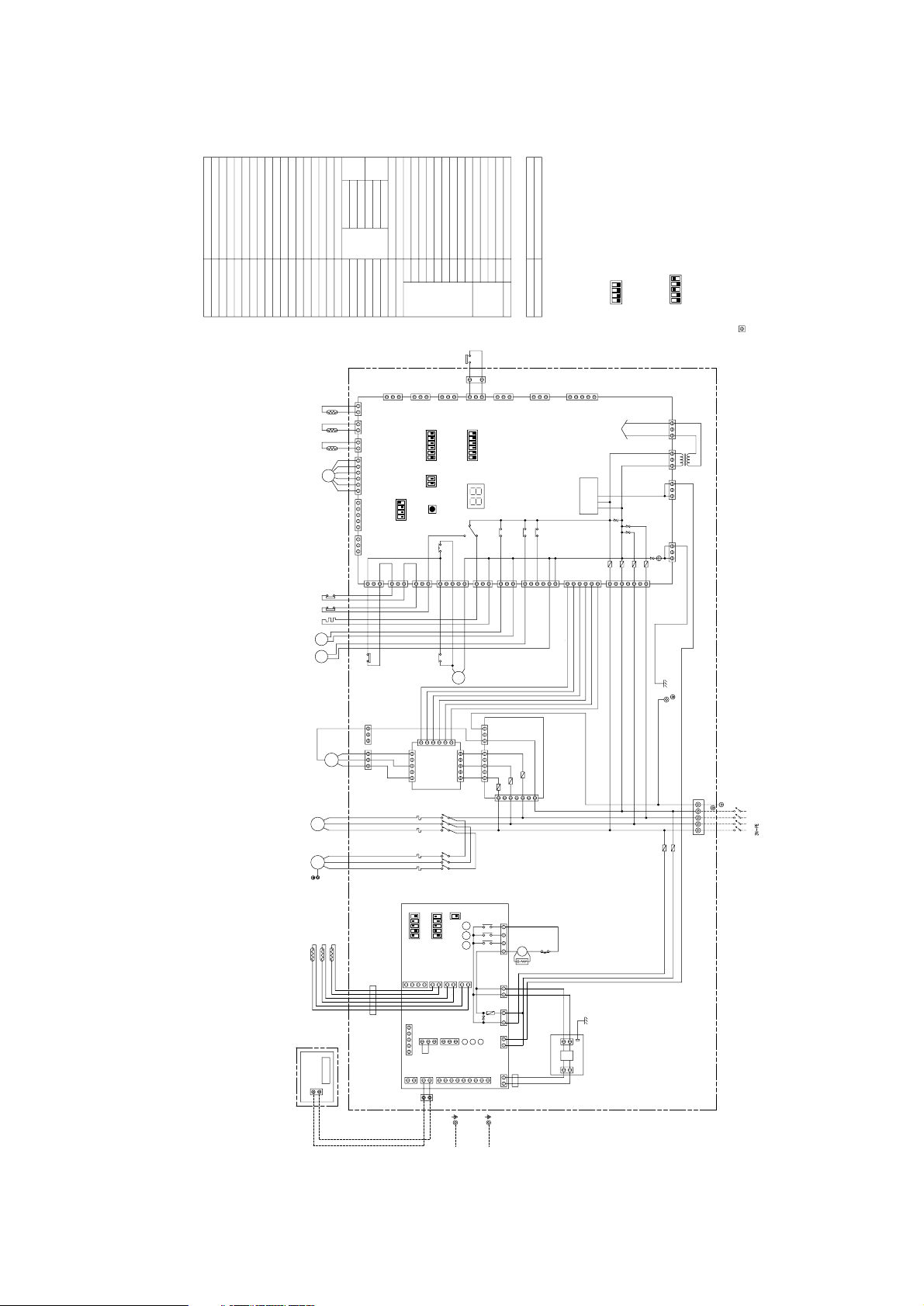
• Models PRH-P16MYA/P20MYA
Symbol Name Symbol Name Symbol Name
IN
DOOR
OUT
DOOR
SURGE KILLER
COND/EVA TEMP
LIQUID PIPE TEMP
ROOM TEMP
COND/EVA TEMP
DISCHARGE TEMP
THERMISTOR
FERRITE CORE
FB11,12,21,22
CR
TH6-1,TH6-2
TH5-1,TH5-2
TH4-1,TH4-2
TH3-1,TH3-2
TH2-1,TH2-2
TH1-1,TH1-2
LIQUID PIPE TEMP
PRESSURE SWITCH (FOR CONTROL)
PRESSURE SWITCH (HIGH PRESSURE)
OVER CURRENT RELAY (INDOOR FAN MOTOR)
FAN MOTOR (INDOOR)
TERMINAL BLOCK
ELECTRONIC EXPANSION VALVE
CRANK CASE HEATER (COMPRESSOR)
SOLENOID VALVE
4-WAY VALVE
FAN MOTOR (OUTDOOR)
PRESSURE SWITCH (LOW PRESSURE)
MAGNETIC CONTACTOR (COMPRESSOR)
51F
MF1
TB1,5,11,21
LEV1,LEV2
CH1,CH2
SV11,SV12
21S41,21S42
MAGNETIC CONTACTOR (INDOOR FAN MOTOR)
52F
OVER CURRENT RELAY (COMPRESSOR)
TR1,TR2
MF21,MF22
MC1,MC2
63H21,63H22
63H11,63H12
63L1,63L2
52C1,52C2
51C1,51C2
COMPRESSOR MOTOR
F11,12,21,22
TRANSFORMER
FUSE (15A 250VAC CLASS T)
Symbol Name
TERMINAL BLOCKTB6
REMOTE CONTROLLER
LED (FOR SERVICE)
AUXILIARY RELAY
SWITCHSW1-5
LED1
X01-X05
FUSE (6.3A 250VAC CLASS F)F01-F04
FUSE (6.3A 250VAC CLASS F)F10-F30
INDOOR
CONTROLLER BOARD
X4-6
SW1
SW2
SWE
LED1
LED2
LED3
LED (TRANSMISSION<INDOOR·OUTDOOR>)
LED (POWER SUPPLY<REMOTE CONTROLLER>)
LED (POWER SUPPLY)
SWITCH (EMERGENCY OPERATION)
SWITCH (CAPACITY CORD)
SWITCH (MODEL SELECTION)
AUXILIARY RELAY
INDOOR
POWER
BOARD
OUTDOOR
MAIN BOARD
N.F
BOARD
F1
ZNR
FUSE (4A 250VAC CLASS T)
VARISTOR
Note:1. The dotted lines show field wiring.
2. Color of earth wire is yellow and green twisting.
3. Specification subject to change without notice.
4.This motor(*1) includes auto reset type internal thermostat.
5. SW5(
*
2)[outdoor main board] shows PRH-P20MYA setting.
Control box no.1
In case of PRH-P16MYA setting is shown as below.
6. SW2(
*
3)[indoor controller board] shows
In case of PRH-P16MYA setting is shown as below.
PRH-P20MYA setting.
7. Emergency operation
If a trouble occurs with either the remote controller or the unit
microcomputer and no other trouble exists, emergency operation for
cooling or heating can be performed by changing the setting of
switch (SWE) on the indoor controller board.
8. mark is connector.
Caution,
1. To protect compressor and fan
motor (indoor) from abnormal
current, over current relays is
installed. Therefore, do not
change factory set value of
over current relays.
ON
OFF
SW5(*2)
ON
OFF
SW2
4321
(*3)
[intdoor controller board]
[outdoor main board]
4321
Control box no.2
ON
OFF
SW5(*2)
[outdoor main board]
4321
CONTROL BOX NO.2CONTROL BOX NO.1
BLACK
WHITE
RED
1
3
C19
X22
1
2
1
2
36
3
1
GREEN/YELLOW
BLUE
BLACK
WHITE
RED
L1
L2
L3
N
PE
1
2
2
1
X11
63
31
PE
N
L3
L2
L1
6
5
4
3
2
11
2
3
4
5
6
TB1
POWER SUPPLY
3N
~PE
380/400/415V
50HZ
L1
L2
L3
63H22
LED1
SW3
(*2)SW5
OUTDOOR MAIN BOARD
OFFON
SW2
TR2
SW1
SW4
OFF
C14
13
CN51
CN3D
DC POWER
SUPPLY
CN34
CN28
3
1
TRANSMISSION
CIRCUIT
3
1
CNS3
CH2
63L2
63H12
21S42
TH3-2
LEV2
X05X02
X03
X01
1
2
CN4
CNMNT
CNVMNT
CNFG
F01
1
3
CN20
CNFC1
CN52
X04
52C2
51C2
1
ON
L3
2
1
2
1
TH2-2
TH1-2
CN3
CN2
CN40
CN3S CN3N CN24 CN27 CN81
12
1
3
F04 F02 F03
357
L2NL1
61
51
CN53CN25
3131531313131
CN26CN21CN22CN23
ON OFF ONOFF
X22
1
2
3
4
5
6
2
1
4
3
2
1
52C2
SV12
MF22
(*1)
C12
C11
3
1
3
1
5
3
1
CNFC2
CNFAN
F.C .
BOARD
16
3
1
5
5
3
1
CNOUT1
CNOUT2
3
1
N.F.BOARD
F20
F30
F10
7513
CNIN
CNPOW
PE
MC2
BLACK
RED
WHITE
51C2
52C2
BLUE
BLACK
RED
WHITE
TB21
GREEN/YELLOW
GREEN/YELLOW
RED
WHITE
BLACK
RED
WHITE
BLACK
WHITE
BLACK
753
5
3
1
3
1
MF21
1
2
3
4
1
2
6
5
4
3
2
1
X11
OFFONOFFON
CN23 CN22 CN21 CN26
1313131351313
CN25 CN53
151 6
L1 N L2
753
F03F02F04
3
1
21
CN81CN27CN24CN3NCN3S
CN40
CN2
CN3
TH1-1
TH2-1
1
2
1
2
N
PE
PE
CIRCUIT BREAKER
(FIELD SUPPLY)
PRH-P16MYA: 63A
PRH-P20MYA: 70A
C12
F.C .
BOARD
PE
L3
N.F.BOARD
C11
CNFAN
CNFC2
CNPOW
1
3
6
(*1)
5
ON
TB11
52C1
51C1
MC1
3
1
CNOUT2
RED
1
3
F10
F20
F30
BLUE
1
52F
51F
MF1
1
PE
CNOUT1
1
51C1
52C1
52C1
X04
CN52
CNFC1
CN20
3
1
F01
CNFG
CNVMNT
CNMNT
CN4
2
1
X01
X03
X02
X05
LEV1
TH3-1
21S41
SV11
63H11
63L1
CH1
CNS3
1
3
TRANSMISSION
CIRCUIT
1
3
CN28
CN34
DC POWER
SUPPLY
CN3D
CN51
31
63H21
C14
OFF
SW4
SW1
TR1
SW2
ON OFF
OUTDOOR MAIN BOARD
(*2)SW5
SW3
LED1
CNIN
1
3
5
C28
X2
X1
INDOOR
POWER BOARD
BLACK
(WITH INDOOR
POWER BOARD)
C18
C18
C28
X1
X2
51F
52F
CR
F22 F12
TH4-2
TH5-2 TH6-2
FB22
1234
CN41
12 12
12
CN29CN21 CN20
1
2
3
4
SW2
(*3)
1
2
3
4
5
SW1
SWE
X4
X5
X6
X6
X5
X4
1
3
5
7
FAN
3
1
5
CN03
123
CN32
INDOOR CONTROLLER
BOARD
1
2
CN2D
DC14V
1122
CN22CN2L
789123456
CN90
FB12
2
3
1
CN01
213
BK
CN02
ZNRF1
DC14V
1
2
CN2S
DC14V
LED1 LED2 LED3
REMOTE CONTROLLER
BOARD
TB6
CN
LCD
LED1LED2 LED3
PE
987654123
2121
32
5
3
1
7
5
3
X4
X5
ONOFF
SWE
1
2
3
4
ONOFF
SW2(*3)
1
2
3
4
5
ONOFF ONOFFON OFFON OFF
SW1
12
1212432
F21
F11
X4
X5
X6
2
1
1
2
1
1
1
2
3
23
SUPPLY AIR
DUCT
RETURN AIR
DUCT
21
FB21
INDOOR CONTROLLER
BOARD
INDOOR
POWER BOARD
CN20
1
DC14V
REMOTE
CONTROLLER
CN2S
DC14V
FB11
TB5
TH4-1
TH5-1 TH6-1
CN02
CN01
ZNR
F1
X6
FAN
1
CN03
CN2D
DC14V
CN21
CN29
CN41
CN32
CN22CN2L
CN90
PE
BK
(WITH INDOOR
POWER BOARD)
BLACK
Page 22
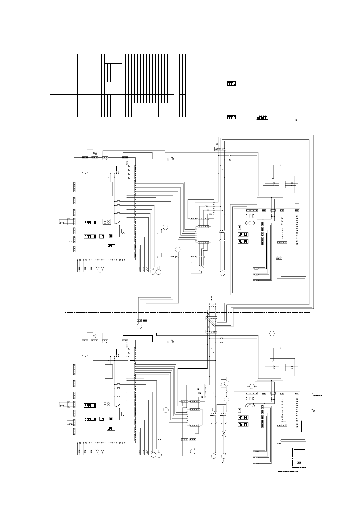
5
INDOOR
OUTDOOR
SURGE KILLER
COND/EVA TEMP
LIQUID PIPE TEMP
ROOM TEMP
COND/EVA TEMP
DISCHARGE TEMP
THERMISTOR
PRESSURE SWITCH (FOR CONTROL)
PRESSURE SWITCH (HIGH PRESSURE)
FERRITE CORE
MAGNETIC CONTACTOR (INDOOR FAN MOTOR)
OVER CURRENT RELAY (INDOOR FAN MOTOR)
FAN MOTOR (INDOOR)
TERMINAL BLOCK
ELECTRONIC EXPANSION VALVE
CRANK CASE HEATER (COMPRESSOR)
SOLENOID VALVE
4-WAY VALVE
FAN MOTOR (OUTDOOR)
PRESSURE SWITCH (LOW PRESSURE)
MAGNETIC CONTACTOR (COMPRESSOR)
FB1,FB2
CR
TH6
TH5
TH4
TH3
TH2
TH1
52F
51F
MF1
TB1,5
LEVCHSV1
21S4
OVER CURRENT RELAY (COMPRESSOR)
LIQUID PIPE TEMP
COMPRESSOR MOTOR
TRANSFORMERTR
MF2MC63H2
63H1
63L
52C
51C
FUSE (15A 250VAC CLASS T)F1,F2
NAMESYMBOL
ON
OFF
SW5
(*2)
ON
OFF
SW2
4321
(*3)
[INDOOR CONTROLLER BOARD]
[OUTDOOR MAIN BOARD]
4321
REMOTE CONTROLLER
SYMBOL
TB6 TERMINAL BLOCK
NAME
MAIN BOARD
OUTDOOR
LED (FOR SERVICE)
AUXILIARY RELAY
SWITCHSW1-5
LED1
X01-X05
FUSE (6.3A 250VAC CLASS F)F01-F04
INDOOR
CONTROLLER BOARD
POWER BOARD
INDOOR
51F
PE
PE
LCD
52F
TH6
TH5
TH4
TB5
REMOTE CONTROLLER
FB2
REMOTE CONTROLLER
BOARD
RETURN AIR
DUCT
SUPPLY AIR
DUCT
CR
1
2
TB6
F1
F2
FUSE (6.3A 250VAC CLASS F)F10-F30N.F.BOARD
FUSE (T6.3AL250V)FUSE
ZNR VARISTOR
BOARD
CONTROLLER
INDOOR X4-6
SW1
SW2
SWE
LED1
LED2
LED3
LED (TRANSMISSION<INDOOR.OUTDOOR>)
LED (POWER SUPPLY<REMOTE CONTROLLER>)
LED (POWER SUPPLY)
SWITCH (EMERGENCY OPERATION)
SWITCH (CAPACITY CORD)
SWITCH (MODEL SELECTION)
AUXILIARY RELAY
5
CN2D
CN90
CN22
CN2L
CNDK
CND
CN32
CN31
CN51
42345
FUSE
ZNR
3
1
3
1
3
11
2
DC13.1V
1573
X4 X5 X6
LED1
LED2
LED3
X4 X5 X6
21212
1
213
3654987
312
CN3C
5
CN20
CN21
CN41
CN29
123412122
1
4123
(*3)SW2
OFF
ON
FAN
1234
SW1
OFF
ON
SWE
OFF
ON
TAB1
3
1
CNSK
2
1
CN2S
DC
13.1V
FB1
5
3
531
BLACK
WHITE
RED
CNIN
LED1
SW3
12
OFF
ON
3456
(*2)SW5
65
1
12
OFF
ON
OUTDOOR MAIN BOARD
12
OFF
ON
SW2
34
TR
SW1SW4
OFF
C14
63H2
1
2
1
3
CN51
CN81
CN27
CN24
CN3D
DC POWER
SUPPLY
CN3N
CN3S
CN34CN28
3131
TRANSMISSION
CIRCIT
31
CNS3
CH 63L63H1
SV1 21S4
TH3TH2TH1
LEV
X05
X02
X03
X01
12
CN4
12
CN3
12
CN2CN40CNMNTCNVMNT
CNFG
F01
F04
F02
F03
13
CN20
CNFC1
CN52
CN53
CN25
CN26
X04
CN21
CN22
CN23
52C
52C
51C
7
1
1
6
1513135131313
1
531
CNOUT1
PE
31
1
MF1
51F
52F
WHITE
1
BLUE
3
BLACK
RED
F30
WHITE
F20
F10
753
31
BLACK
CNOUT2
1
3
MC
L1
51C
52C
MF2
RED
TB1
ON
432
L2
5
L3 N PE
PE
(*1)
6
POWER SUPPLY
380/400/415V
50HZ
31
CNPOW
CNFC2
CNFAN
C11
CIRCUIT BREAKER
(FIELD SUPPLY)
PRH-P200MYA : 50A
PRH-P250MYA : 50A
N
L1
N.F.BOARD
L3
L2
PE
GREEN/YELLOW
F.C.
BOARD
C12
CONTROL BOX
Note: 1. The dotted lines show field wiring.
2. Color of earth wire is yellow and green twisting.
3. Specification subject to change without notice.
4. This motor(*1) includes auto reset type internal thermostat.
5. SW5(*2)[OUTDOOR MAIN BOARD] shows PRH-P250MYA setting.
In case of PRH-P200MYA setting is shown as below.
6. SW2(*3)[INDOOR CONTROLLER BOARD] shows PRH-P250MYA
setting.
In case of PRH-P200MYA setting is shown as below.
7. Emergency operation
If a trouble occurs with either the remote controller or the unit
microcomputer and no other trouble exists, emergency operation for
cooling or heating can be performed by changing the setting of
switch (SWE) "ON" on the indoor controller board.
8. mark is connector.
Caution,
1. To protect compressor and fan motor (indoor) from abnormal
current, over current relays is installed. Therefore, do not change
factory set value of over current relays.
• Models PRH-P200MYA/P250MYA
- 18 -
Page 23
4
ON
OFF
SW5
(*2)
432
1
X1,X2,X11,X22
123
4
532
(*3)
1
SW2
OFF
ON
(*2)
SW5
OFF
ON
Control box no.2
NAME
TERMINAL BLOCKTB6
SYMBOL
REMOTE CONTROLLER
SYMBOL NAME
F11,F12,F21,F22 FUSE (15A 250VAC CLASS T)
51C1,51C2
52C1,52C2
63L1,63L2
63H11,63H12
63H21,63H22
MC1,MC2
MF21,MF22
TR1,TR2 TRANSFORMER
COMPRESSOR MOTOR
LIQUID PIPE TEMP
OVER CURRENT RELAY (COMPRESSOR)
21S41,21S42
SV11,SV12
CH1,CH2
LEV1,LEV2
TB1,TB5,TB11,TB21
MF1
51F
52F
TH1-1,TH1-2
TH2-1,TH2-2
TH3-1,TH3-2
TH4-1,TH4-2
TH5-1,TH5-2
TH6-1,TH6-2CRFB11,FB12,FB21,FB22
MAGNETIC CONTACTOR (COMPRESSOR)
PRESSURE SWITCH (LOW PRESSURE)
FAN MOTOR (OUTDOOR)
4-WAY VALVE
SOLENOID VALVE
CRANK CASE HEATER (COMPRESSOR)
ELECTRONIC EXPANSION VALVE
TERMINAL BLOCK
FAN MOTOR (INDOOR)
OVER CURRENT RELAY (INDOOR FAN MOTOR)
MAGNETIC CONTACTOR (INDOOR FAN MOTOR)
FERRITE CORE
PRESSURE SWITCH (HIGH PRESSURE)
PRESSURE SWITCH (FOR CONTROL)
THERMISTOR
DISCHARGE TEMP
COND/EVA TEMP
ROOM TEMP
LIQUID PIPE TEMP
COND/EVA TEMP
SURGE KILLER
OUTDOOR
INDOOR
F01-F04 FUSE (6.3A 250VAC CLASS F)
X01-X05
LED1
SW1-5 SWITCH
AUXILIARY RELAY
LED (FOR SERVICE)
OUTDOOR
MAIN BOARD
1
2
3
4
5
1
2
3
4
5
1
2
3
4
5
X2
X1
SW2
(*3)
SW1
INDOOR
CONTROLLER BOARD
INDOOR
CONTROLLER BOARD
FB22
1
INDOOR
POWER BOARD
1
2
CN2S
DC
13.1V
1
CNSK
TAB1
3
1
2
CN2L
CN22
12 12 123456789
CN90
CN51
5
3
4
CN2D
DC13.1V
CN3C
3
OFF
ON
OFF
ON
SWE
OFF
ON
123 12
CN32
3
LED1
7
21
CN20
2
CN41
CN29
CN21
1234 211
CN31
X6X5X4
135
1
2
X4
X5
X6
LED3LED2
FAN
CNDK
3
ZNR
FUSE
CND
1
3
1
X1
LED3LED2
FAN
CN3C
CNDK
1
3
ZNR
FUSE
CND
3
1
3
1
TAB1
DC
13.1V
CNSK
CN2S
3
1
1
2
4
2
CN32
123
CN90
CN2L
CN22
CN31
CN41
CN29
CN21
CN2D
DC13.1V
CN51
1
X6
1
CN20
1
1
2
X6
X5
X4
234 2121
21
SW1
OFF
ON
5
4
3
2
1
(*3)
SW2
OFF
ON
SWE
OFF
ON
X5
X4
357
1
3
5
23
12 12 321 456789
LED1
C28
X2
C18
C18
C28
51F
52F
CR
F22
F12
TH4-2
TH5-2
TH6-2
FB12
REMOTE CONTROLLER
BOARD
TB6
LCD
PE
F21
F11
2
1
SUPPLY AIR
DUCT
RETURN AIR
DUCT
FB21
INDOOR
POWER BOARD
REMOTE
CONTROLLER
FB11
TB5
TH4-1
TH5-1
TH6-1
PE
N.F.BOARD F10-F30 FUSE (6.3A 250VAC CLASS F)
FUSE FUSE (T6.3AL250V)
VARISTORZNR
AUXILIARY RELAY
AUXILIARY RELAY
SWITCH (MODEL SELECTION)
SWITCH (CAPACITY CORD)
SWITCH (EMERGENCY OPERATION)
LED (POWER SUPPLY)
LED (POWER SUPPLY<REMOTE CONTROLLER>)
LED (TRANSMISSION<INDOOR
.
OUTDOOR>)
LED3
LED2
LED1
SWE
SW2
SW1
X4-6INDOOR
CONTROLLER
BOARD
BLACK
WHITE
RED
1
3
C19
X22
1
2
1
2
36
3
1
GREEN/YELLOW
BLUE
BLACK
WHITE
RED
L1L2L3
N
PE
1
2
2
1
X11
63
3
1
PE
N
L3L2L1
65432
11
23456
TB1
POWER SUPPLY
380/400/415V
50HZ
L1L2L3
63H22
LED1
SW3
(*2)SW5
OUTDOOR MAIN BOARD
OFF
ON
SW2
TR2
SW1
SW4
OFF
C14
1
3
CN51
CN3D
DC POWER
SUPPLY
CN34
CN28
3
1
TRANSMISSION
CIRCUIT
3
1
CNS3
CH2
63L2
63H12
21S42
TH3-2
LEV2
X05
X02
X03
X01
1
2
CN4
CNMNT
CNVMNT
CNFG
F01
1
3
CN20
CNFC1
CN52
X04
52C2
51C2
1
ON
L3
212
1
TH2-2
TH1-2
CN3
CN2
CN40
CN3S CN3N CN24 CN27 CN81
1
2
1
3
F04 F02 F03
357
L2NL1
6151
CN53CN25
3131531313131
CN26CN21CN22CN23
ON
OFF
ON
OFF
X22
12345
6
2
1
432
1
52C2
SV12
MF22
(*1)
C12
C11
3
1
3
1
5
3
1
CNFC2
CNFAN
F.C.
BOARD
1
6
3
1
5
5
3
1
CNOUT1
CNOUT2
3
1
N.F.BOARD
F20
F30
F10
7513
CNIN
CNPOW
PE
MC2
BLACK
RED
WHITE
51C2
52C2
BLUE
BLACK
RED
WHITE
TB21
GREEN/YELLOW
GREEN/YELLOW
RED
WHITE
BLACK
RED
WHITE
BLACK
WHITE
BLACK
753
5
3
1
3
1
MF21
123
4
1
2
65432
1
X11
OFF
ON
OFF
ON
CN23 CN22 CN21 CN26
1313131351313
CN25 CN53
151 6
L1 N L2
753
F03F02F04
3
1
2
1
CN81CN27CN24CN3NCN3S
CN40
CN2
CN3
TH1-1
TH2-1
121
2
N
PE
PE
CIRCUIT BREAKER
(FIELD SUPPLY)
PRH-P400MYA: 63A
PRH-P500MYA: 70A
C12
F.C.
BOARD
PE
L3
N.F.BOARD
C11
CNFAN
CNFC2
CNPOW
1
3
6
(*1)
5
ON
TB11
52C1
51C1
MC1
3
1
CNOUT2
RED
1
3
F10
F20
F30
BLUE
1
52F
51F
MF1
1
PE
CNOUT1
1
51C1
52C1
52C1
X04
CN52
CNFC1
CN20
3
1
F01
CNFG
CNVMNT
CNMNT
CN4
2
1
X01
X03
X02
X05
LEV1
TH3-1
21S41
SV11
63H11
63L1
CH1
CNS3
1
3
TRANSMISSION
CIRCUIT
1
3
CN28
CN34
DC POWER
SUPPLY
CN3D
CN51
3
1
63H21
C14
OFF
SW4
SW1
TR1
SW2
ON
OFF
OUTDOOR MAIN BOARD
(*2)SW5
SW3
LED1
CNIN
1
3
5
CONTROL BOX NO.2CONTROL BOX NO.1
Control box no.1
Note: 1. The dotted lines show field wiring.
2. Color of earth wire is yellow and green twisting.
3. Specification subject to change without notice.
4. This motor(*1) includes auto reset type internal
thermostat.
5. SW5(*2)[OUTDOOR MAIN BOARD] shows PRH-
P500MYA setting.
In case of PRH-P400MYA setting is shown as below.
6. SW2(*3)[INDOOR CONTROLLER BOARD] shows
PRH-P500MYA setting.
In case of PRH-P400MYA setting is shown as below.
7. Emergency operation
If a trouble occurs with either the remote controller or
the unit microcomputer and no other trouble exists,
emergency operation for cooling or heating can be
performed by changing the setting of switch (SWE)
"ON" on the indoor controller board.
8. mark is connector.
Caution,
1. To protect compressor and fan motor (indoor) from
abnormal current, over current relays is installed.
Therefore, do not change factory set value of over
current relays.
[OUTDOOR MAIN
BOARD]
[INDOOR CONTROLLER BOARD]
[OUTDOOR MAIN
BOARD]
• Models PRH-P400MYA/P500MYA
- 19 -
Page 24
- 20 -
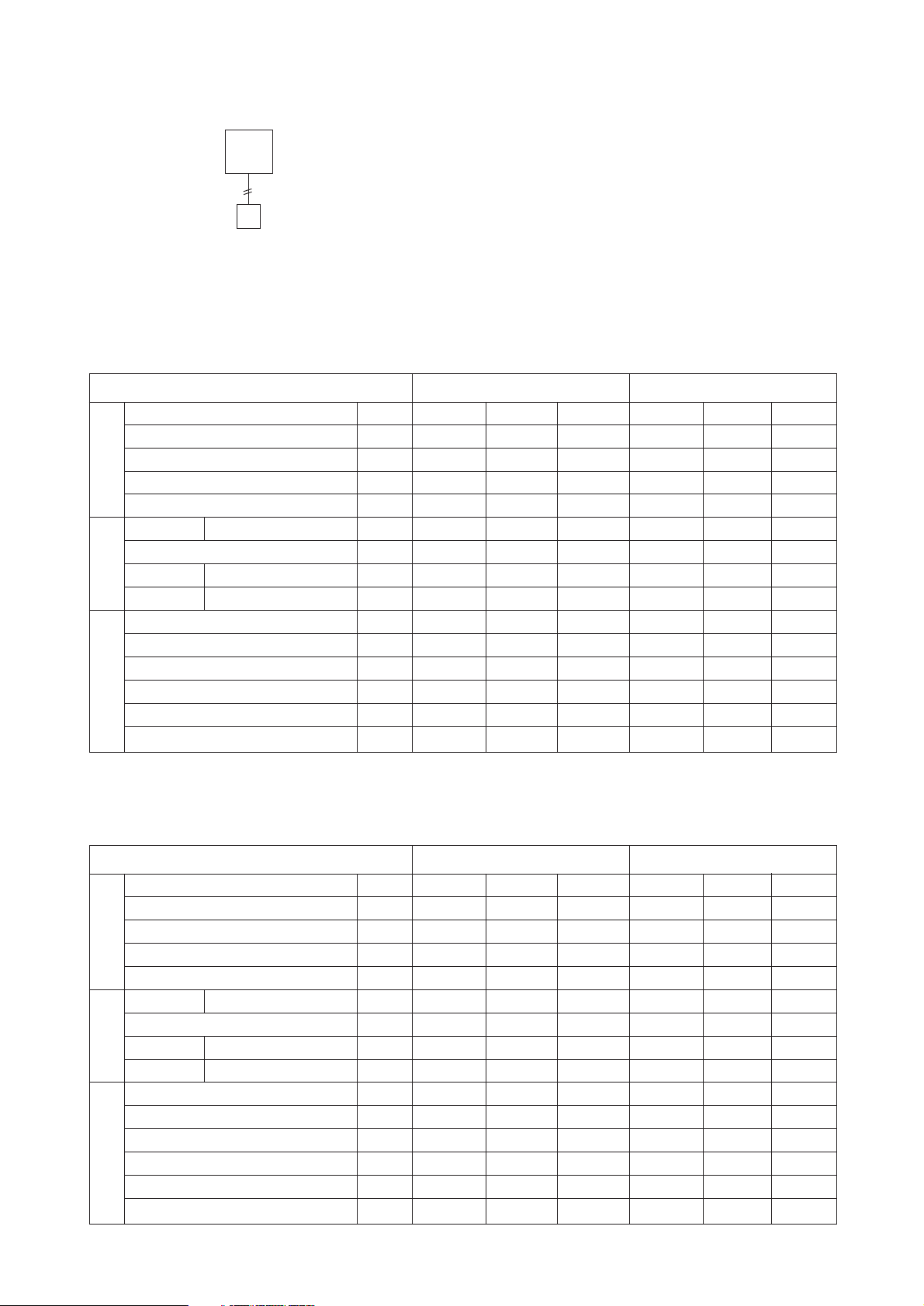
(2) PRH-P10MYA/P250MYA
(1) PRH-P8MYA/P200MYA
[1] Standard Operation Data
0
Technical Data to Meet LVD
380 400 415 380 400 415
50 50 50 50 50 50
27/19 27/19 27/19 20/– 20/– 20/–
35/– 35/– 35/– 7/6 7/6 7/6
7.7 7.7 7.7 7.7 7.7 7.7
14.7 14.7 14.7 14.5 14.5 14.5
11.9 11.9 11.9 11.7 11.7 11.7
1.1 1.1 1.1 1.1 1.1 1.1
1.7 1.7 1.7 1.7 1.7 1.7
2.25 2.25 2.25 1.72 1.72 1.72
0.56 0.56 0.56 0.38 0.38 0.38
77 77 77 66 66 66
10 10 10 -1 -1 -1
48 48 48 0 0 0
33 33 33 28 28 28
Operating condition
Operating condition Cooling Heating
Voltage V
Power source frequency Hz
Indoor air condition (DB/WB) °C
Outdoor air condition (DB/WB) °C
Refrigerant charge kg
Rated current A
Compressor current A
Rated currentO/D FAN A
Rated current A
Discharge pressure MPa
Suction pressure MPa
Discharge refrigerant temperature °C
Suction refrigerant temperature °C
Liquid pipe temperature
(at piping sensor)
°C
Compressor shell bottom temperature °C
Total
I/D FAN
Refrigerant circuit
Electrical characteristics
380 400 415 380 400 415
50 50 50 50 50 50
27/19 27/19 27/19 20/– 20/– 20/–
35/– 35/– 35/– 7/6 7/6 7/6
8.2 8.2 8.2 8.2 8.2 8.2
18.8 18.8 18.8 18.2 18.2 18.2
14.9 14.9 14.9 14.3 14.3 14.3
1.1 1.1 1.1 1.1 1.1 1.1
2.8 2.8 2.8 2.8 2.8 2.8
2.31 2.31 2.31 1.83 1.83 1.83
0.55 0.55 0.55 0.37 0.37 0.37
78 78 78 70 70 70
999–1 –1 –1
48 48 48 3 3 3
32 32 32 25 25 25
Operating condition
Operating condition Cooling Heating
Voltage V
Power source frequency Hz
Indoor air condition (DB/WB) °C
Outdoor air condition (DB/WB) °C
Refrigerant charge kg
Rated current A
Compressor current A
Rated current A
Rated current A
Discharge pressure MPa
Suction pressure MPa
Discharge refrigerant temperature °C
Suction refrigerant temperature °C
Liquid pipe temperature
(at piping sensor)
°C
Compressor shell bottom temperature °C
Total
I/D FAN
O/D FAN
Refrigerant circuit
Electrical characteristics
[2] Skeleton of Transmission Line Connection
(1) System
Unit
Remote
controller
Transmission line
Page 25
- 21 -
✻1: For each refrigerant circuit
✻1: For each refrigerant circuit
(4) PRH-P20MYA/P500MYA
(3) PRH-P16MYA/P400MYA
380 400 415 380 400 415
50 50 50 50 50 50
27/19 27/19 27/19 20/– 20/– 20/–
35/– 35/– 35/– 7/6 7/6 7/6
7.7 7.7 7.7 7.7 7.7 7.7
Operating condition
Operating condition Cooling Heating
Voltage V
Power source frequency Hz
Indoor air condition (DB/WB) °C
Outdoor air condition (DB/WB) °C
Refrigerant charge
✻1kg
Rated current A
Compressor current A
Rated currentO/D FAN A
Rated current A
Discharge pressure MPa
Suction pressure MPa
Discharge refrigerant temperature °C
Suction refrigerant temperature °C
Liquid pipe temperature
(at piping sensor)
°C
Compressor shell bottom temperature °C
Total
I/D FAN
Refrigerant circuit
Electrical characteristics
380 400 415 380 400 415
50 50 50 50 50 50
27/19 27/19 27/19 20/– 20/– 20/–
35/– 35/– 35/– 7/6 7/6 7/6
8.2 8.2 8.2 8.2 8.2 8.2
29.6
23.8
2.2
3.6
2.27
0.52
79
7
49
31
29.2
23.4
2.2
3.6
1.80
0.40
68
0
2
25
36.6
29.8
2.2
4.6
2.28
0.52
79
7
49
31
35.4
28.6
2.2
4.6
1.80
0.40
68
0
2
25
29.6
23.8
2.2
3.6
2.27
0.52
79
7
49
31
29.6
23.8
2.2
3.6
2.27
0.52
79
7
49
31
29.2
23.4
2.2
3.6
1.80
0.40
68
0
2
25
36.6
29.8
2.2
4.6
2.28
0.52
79
7
49
31
35.4
28.6
2.2
4.6
1.80
0.40
68
0
2
25
29.2
23.4
2.2
3.6
1.80
0.40
68
0
2
25
36.6
29.8
2.2
4.6
2.28
0.52
79
7
49
31
35.4
28.6
2.2
4.6
1.80
0.40
68
0
2
25
Operating condition
Operating condition Cooling Heating
Voltage V
Power source frequency Hz
Indoor air condition (DB/WB) °C
Outdoor air condition (DB/WB) °C
Refrigerant charge
✻1kg
Rated current A
Compressor current A
Rated current A
Rated current A
Discharge pressure MPa
Suction pressure MPa
Discharge refrigerant temperature °C
Suction refrigerant temperature °C
Liquid pipe temperature
(at piping sensor)
°C
Compressor shell bottom temperature °C
Total
I/D FAN
O/D FAN
Refrigerant circuit
Electrical characteristics
Page 26
[4] Reduction Ratio by Frosting
6 1.0
4 0.98
2 0.88
0 0.85
–2 0.86
–4 0.89
–6 0.92
–8 0.92
–10 0.92
Outdoor unit inlet wet bulb temperature
Heating capacity reduction ratio
(°CWB)
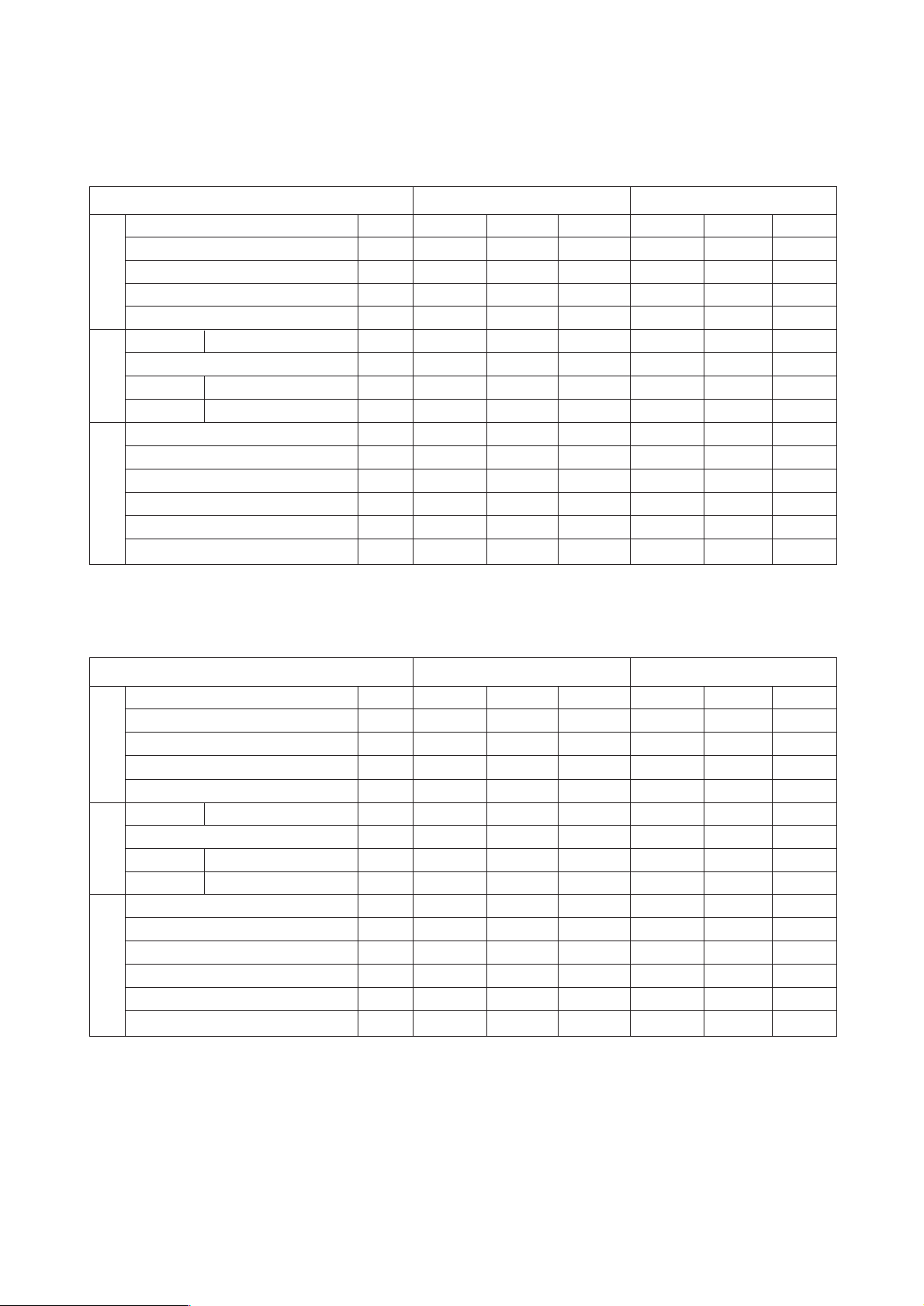
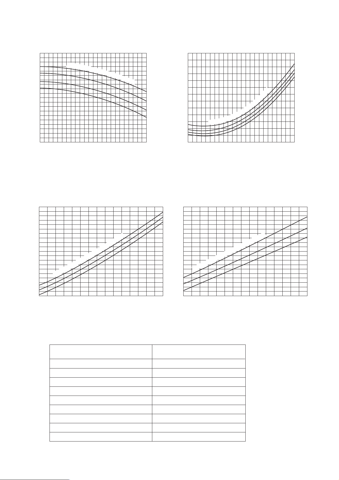
[2] Cooling Capacity Curves
[3] Heating Capacity Curves
Indoor inlet air wet
bulb temp. <˚CWB>
inlet air wet
bulb temp. <˚CWB>
Indoor
Indoor inlet air dry
bulb
temp. <˚CDB>
Indoor inlet
air dry
bulb temp. <˚CDB>
Outdoor
air
temperature
<˚CWB>
Outdoor air temperature
<˚CWB>
Outdoor air temperature
<˚CDB>
Outdoor
air
temperature
<˚CDB>
- 22 -
1.4
1.2
1
Capacity ratio
0.8
0.6
-5 -3 -1 1 3 5 7 9 1113151719212325272931333537394143
1.4
1.2
1.22
22
20
39 41 43
18
16
25
20
15
1.1
22
20
18
16
Input ratio
0.9
0.7
-5 -3 -1 1 3 5 7 9 11 13 15 17 19 21 23 25 27 29 31 33 35 37
1.4
15
20
25
1.2
1
Capacity ratio
0.8
0.6
-12 -10 -8 -6 -4 -2 0 2 4 6 8 10 12 14 16 18
1
Input ratio
0.8
0.6
-12 -10 -8 -6 -4 -2 0 2 4 6 8 10 12 14 16 18
Page 27
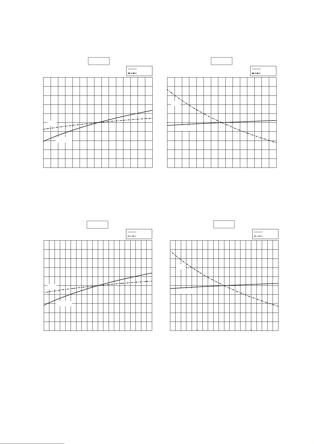
- 23 -
Capacity/Input ratio
Heating
Airflow rate (m3/min)
Capacity/Input ratio
Cooling
Airflow rate (m3/min)
Capacity/Input ratio
Airflow rate (m3/min)
Cooling
Capacity/Input ratio
Heating
Airflow rate (m3/min)
[5] Capacity/Input Ratio against Changes in Room Airflow Rate
• Model PRH-P8MYA/P200MYA
• Model PRH-P10MYA/P250MYA
0.9
1
1.1
55 65 75 85
Capacity
Input
1.1
0.9
1
55 65 75 85
Capacity
Input
0.9
1
1.1
70 80 90 100 110
Capacity
Input
0.9
1
1.1
70 80 90 100 110
Capacity
Input
Capacity
Input
Capacity
Input
Capacity
Input
Capacity
Input
Page 28
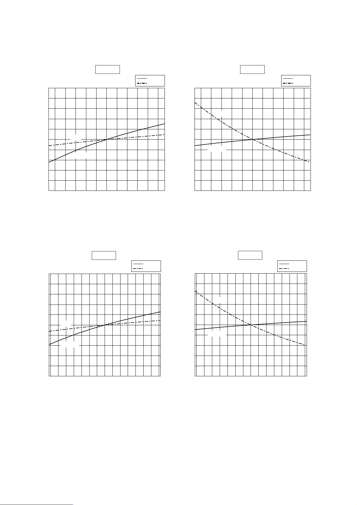
- 24 -
0.9
1.1
112 120 130 140 150 160 168
1
0.9
1
1.1
112 120 130 140 150 160 168
0.9
1
1.1
144 150 160 170 180 190 200 210 216
0.9
1
1.1
144 150 160 170 180 190 200 210 216
Capacity/Input ratio
Airflow rate (m3/min)
Capacity/Input ratio
Airflow rate (m3/min)
Capacity/Input ratio
Airflow rate (m3/min)
Capacity/Input ratio
Airflow rate (m3/min)
Capacity
Input
Capacity
Input
Capacity
Input
Capacity
Input
• Model PRH-P16MYA/P400MYA
• Model PRH-P20MYA/P500MYA
Capacity
Input
Capacity
Input
Cooling
Heating
Capacity
Input
Capacity
Input
Heating
Cooling
Page 29
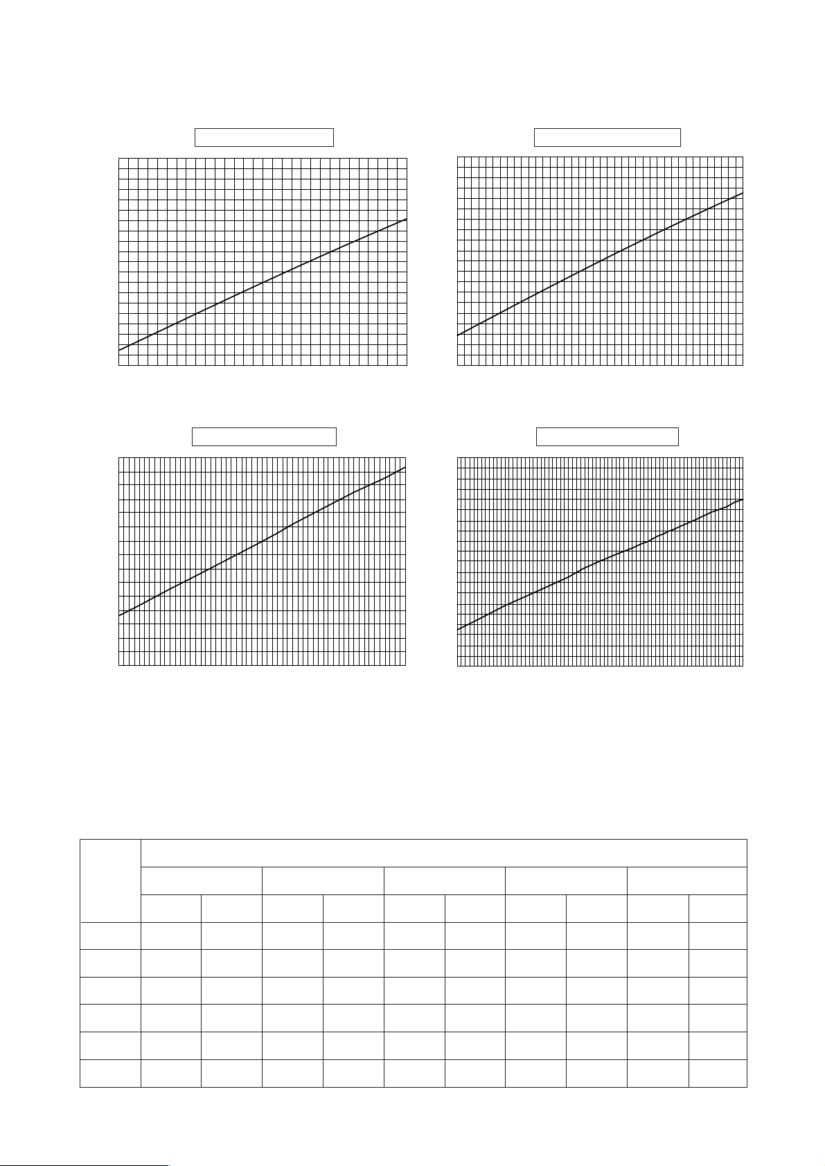
- 25 -
Bypass factor
Airflow rate (m3/min)
55
0.30
0.25
0.20
0.15
0.10
PRH-P8MYA/P200MYA
PRH-P10MYA/P250MYA
Bypass factor
Airflow rate (m3/min)
70 80 90 100 11060 65 70 75 80 85
0.30
0.25
0.20
0.15
0.10
PRH-P16MYA/P400MYA PRH-P20MYA/P500MYA
[6] Bypass Factor Curves
[7] Cooling Sensible Heating Capacity Table
(1) PRH-P8MYA/P200MYA (Airflow rate 70m3/min)
Outdoor
temp.
(°C)
20
25
30
35
40
43
Indoor inlet air temperature (DB/WB°C)
CA
18100
17500
16900
16200
15300
14800
SHC
14400
14100
13900
13600
13200
12900
CA
19300
18700
18100
17400
16600
16000
SHC
14300
14100
13800
13500
13200
12900
CA
20000
19500
18900
18000
17400
16900
SHC
15300
15100
14800
14500
14200
14000
CA
20800
20300
19700
19000
18200
17700
SHC
15300
15100
14900
14600
14300
14100
CA
21900
21500
20900
20200
19500
19000
SHC
(unit : kcal/h)
15000
14900
14700
14400
14200
14000
23/16 25/18 27/19 28/20 30/22
112 120 130 140 150 160 168
Bypass factor
0.2
0.15
0.1
0.05
Airflow rate (m3/min)
144 150 160 170 180 190 216200 210
Bypass factor
0.1
0.15
0.2
0.3
0.25
Airflow rate (m3/min)
Page 30

- 26 -
(3) PRH-P16MYA/P400MYA (Airflow rate 140m3/min)
(4) PRH-P20MYA/P500MYA (Airflow rate 180m
3
/min)
(2) PRH-P10MYA/P250MYA (Airflow rate 90m3/min)
Outdoor
temp.
(°C)
20
25
30
35
40
43
Indoor inlet air temperature (DB/WB°C)
CA
36200
35000
33800
32400
30600
29600
SHC
29500
28900
28400
27800
27000
26500
CA
38600
37400
36200
34800
33200
32000
SHC
29300
28700
28200
27700
27000
26500
CA
40000
39000
37800
36000
34800
33800
SHC
31300
30900
30400
29700
29200
28800
CA
41600
40600
39400
38000
36400
35400
SHC
31300
30900
30400
29900
29300
28900
CA
43800
43000
41800
40400
39000
38000
SHC
(unit : kcal/h)
(unit : kcal/h)
30800
30500
30000
29500
29000
28700
23/16 25/18 27/19 28/20 30/22
Outdoor
temp.
(°C)
20
25
30
35
40
43
Indoor inlet air temperature (DB/WB°
C)
CA
45000
43600
42000
40200
38200
36800
SHC
36000
35300
34600
33800
32900
32300
CA
48000
46600
45000
43200
41200
40000
SHC
35700
35100
34500
33700
32900
32400
CA
49800
48600
47000
44800
43200
42000
SHC
38200
37700
37100
36200
35500
35000
CA
51600
50400
49000
47200
45400
44000
SHC
38100
37600
37100
36400
35700
35100
CA
54600
53400
52000
50400
48400
47200
SHC
37600
37100
36600
36000
35300
34900
23/16 25/18 27/19 28/20 30/22
(unit : kcal/h)
Outdoor
temp.
(°C)
20
25
30
35
40
43
Indoor inlet air temperature (DB/WB°
C)
CA
22500
21800
21000
20100
19100
18400
SHC
18000
17700
17300
16900
16500
16200
CA
24000
23300
22500
21600
20600
20000
SHC
17900
17600
17200
16900
16400
16200
CA
24900
24300
23500
22400
21600
21000
SHC
19100
18900
18500
18100
17800
17500
CA
25800
25200
24500
23600
22700
22000
SHC
19100
18800
18500
18200
17800
17600
CA
27300
26700
26000
25200
24200
23600
SHC
18800
18600
18300
18000
17700
17400
23/16 25/18 27/19 28/20 30/22
Page 31

- 27 -
[8] Fan Performance
PRH-P8MYA/P200MYA
PRH-P10MYA/P250MYA
Air flow
85 (CMM)
(L/S)
Total static pressure (Pa)
1.1kW
1.5kW
2.2kW
1.5kW
* : factory pre setting ESP = 100 Pa
Air flow
* : factory pre setting ESP = 100 Pa
110
1830
(CMM)
(L/S)
105100
1670
9590
1500
8580
1330
7570
1170
80
1330
7570
1170
6560
1000
55
0
800
700
600
500
400
300
200
100
0
100
200
300
400
500
600
Total static pressure (Pa)
Fan speed
<rpm>
Fan speed
<rpm>
internal static pressure
internal static pressure
900
1000
1100
1200
1300
800
900
1000
1100
1200
1300
1400
1500
1400
1500
1600
1700
Page 32

- 28 -
PRH-P20MYA/P500MYA
PRH-P16MYA/P400MYA
3.7kW
2.2kW
5.5kW
3.7kW
Air flow
* : factory pre setting ESP = 200 Pa
Air flow
* : factory pre setting ESP = 200 Pa
(CMM)
(L/S)
(CMM)
(L/S)
Total static pressure (Pa) Total static pressure (Pa)
0
100
200
300
400
500
600
700
800
900
1000
110 120 130 140 150 160 170
0
100
200
300
400
500
600
700
800
900
1000
140 150 160 170 180 190 200 210 220
1830 2340 2830
2340 3000 3670
Fan speed
<rpm>
Fan speed
<rpm>
internal static pressure
internal static pressure
600
600
700
800
900
1000
1100
1200
1300
700
800
900
1000
1100
1200
1300
Page 33

- 29 -
factory pre setting
factory pre setting
< fig. in the direction of the motor axis>
< fig. in the direction of the motor axis>
PRH-P8MYA/P200MYA
PRH-P10MYA/P250MYA
CMM
L/S
rpm
mm
inch
mm
inch
inch
kW
rpm
mm
inch
mm
inch
inch
kW
rpm
mm
inch
mm
inch
inch
kW
rpm
mm
inch
mm
inch
inch
kW
-
Fan speed
(Motor side)
Pulley size
(Fan side)
Pulley size
Belt size
Motor
(poles)
Fan speed
(Motor side)
Pulley size
(Fan side)
Pulley size
Belt size
Motor
(poles)
Fan speed
(Motor side)
Pulley size
(Fan side)
Pulley size
Belt size
Motor
(poles)
Fan speed
(Motor side)
Pulley size
(Fan side)
Pulley size
Belt size
Motor
(poles)
150
Total SP (Pa)
Air flow
250
350
450
55
920
788
101.6
4
177.8
7
B57(red)
1.1
4
1059
114.3
4.5
152.4
6
B56(red)
1.1
4
1190
127
5
152.4
6
B57(red)
1.1
4
1450
127
5
127
5
B55(red)
1.5
4
60
1000
788
101.6
4
177.8
7
B57(red)
1.1
4
1059
114.3
4.5
152.4
6
B56(red)
1.1
4
1190
127
5
152.4
6
B57(red)
1.1
4
1450
127
5
127
5
B55(red)
1.5
4
70
1170
898
114.3
4.5
177.8
7
B58(red)
1.1
4
1059
114.3
4.5
152.4
6
B56(red)
1.1
4
1190
127
5
152.4
6
B57(red)
1.1
4
1450
127
5
127
5
B55(red)
1.5
4
80
1330
898
114.3
4.5
177.8
7
B58(red)
1.1
4
1059
114.3
4.5
152.4
6
B56(red)
1.1
4
1291
114.3
4.5
127
5
B55(red)
1.5
4
1450
127
5
127
5
B55(red)
1.5
4
85
1420
898
114.3
4.5
177.8
7
B58(red)
1.1
4
1059
114.3
4.5
152.4
6
B56(red)
1.1
4
1291
114.3
4.5
127
5
B55(red)
1.5
4
CMM
L/S
rpm
mm
inch
mm
inch
inch
kW
rpm
mm
inch
mm
inch
inch
kW
-
rpm
mm
inch
mm
inch
inch
kW
rpm
mm
inch
mm
inch
inch
kW
-
Fan speed
(Motor side)
Pulley size
(Fan side)
Pulley size
Belt size
Motor
(poles)
Fan speed
(Motor side)
Pulley size
(Fan side)
Pulley size
Belt size
Motor
(poles)
rpm
mm
inch
mm
inch
inch
kW
-
Fan speed
(Motor side)
Pulley size
(Fan side)
Pulley size
Belt size
Motor
(poles)
Fan speed
(Motor side)
Pulley size
(Fan side)
Pulley size
Belt size
Motor
(poles)
Fan speed
(Motor side)
Pulley size
(Fan side)
Pulley size
Belt size
Motor
(poles)
200
Total SP (Pa)
Air flow
300
400
500
600
70
1170
1008
127
5
177.8
7
B58(red)
1.5
4
1133
101.6
4
127
5
B54(red)
1.5
4
1307
127
5
139.7
5.5
B56(red)
1.5
4
1450
127
5
127
5
B55(red)
2.2
4
1609
139.7
5.5
127
5
B56(red)
2.2
4
80
1330
1008
127
5
177.8
7
B58(red)
1.5
4
1190
127
5
152.4
6
B57(red)
1.5
4
1320
139.7
5.5
152.4
6
B58(red)
1.5
4
1450
127
5
127
5
B55(red)
2.2
4
1609
139.7
5.5
127
5
B56(red)
2.2
4
90
1500
1008
127
5
177.8
7
B58(red)
1.5
4
1190
127
5
152.4
6
B57(red)
1.5
4
1320
139.7
5.5
152.4
6
B58(red)
1.5
4
1450
127
5
127
5
B55(red)
2.2
4
1609
139.7
5.5
127
5
B56(red)
2.2
4
100
1670
1008
127
5
177.8
7
B58(red)
1.5
4
1190
127
5
152.4
6
B57(red)
1.5
4
1320
139.7
5.5
152.4
6
B58(red)
2.2
4
1450
127
5
127
5
B55(red)
2.2
4
110
1830
1008
127
5
177.8
7
B58(red)
1.5
4
1190
127
5
152.4
6
B57(red)
1.5
4
1320
139.7
5.5
152.4
6
B58(red)
2.2
4
1450
127
5
127
5
B55(red)
2.2
4
Page 34

- 30 -
factory pre setting
< fig. in the direction of the motor axis>
PRH-P16MYA/P400MYA
CMM
L/S
rpm
mm
inch
mm
inch
inch
kW
rpm
mm
inch
mm
inch
inch
kW
-
rpm
mm
inch
mm
inch
inch
kW
rpm
mm
inch
mm
inch
inch
kW
-
Fan speed
(Motor side)
Pulley size
(Fan side)
Pulley size
Belt size
Motor
(poles)
Fan speed
(Motor side)
Pulley size
(Fan side)
Pulley size
Belt size
Motor
(poles)
rpm
mm
inch
mm
inch
inch
kW
-
Fan speed
(Motor side)
Pulley size
(Fan side)
Pulley size
Belt size
Motor
(poles)
Fan speed
(Motor side)
Pulley size
(Fan side)
Pulley size
Belt size
Motor
(poles)
Fan speed
(Motor side)
Pulley size
(Fan side)
Pulley size
Belt size
Motor
(poles)
250
Total SP (Pa)
Air flow
350
450
550
650
112
1870
692
127
5
254
10
B46(red)
2.2
4
844
152.4
6
254
10
B48(red)
2.2
4
875
127
5
203.2
8
B43(red)
2.2
4
1067
152.4
6
203.2
8
B44(red)
3.7
4
1119
139.7
5.5
177.8
7
B42(red)
3.7
4
120
2000
692
127
5
254
10
B46(red)
2.2
4
844
152.4
6
254
10
B48(red)
2.2
4
875
127
5
203.2
8
B43(red)
2.2
4
1067
152.4
6
203.2
8
B44(red)
3.7
4
1119
139.7
5.5
177.8
7
B42(red)
3.7
4
140
2330
692
127
5
254
10
B46(red)
2.2
4
844
152.4
6
254
10
B48(red)
2.2
4
875
127
5
203.2
8
B43(red)
2.2
4
1067
152.4
6
203.2
8
B44(red)
3.7
4
160
2670
692
127
5
254
10
B46(red)
2.2
4
844
152.4
6
254
10
B48(red)
2.2
4
875
127
5
203.2
8
B43(red)
3.7
4
1067
152.4
6
203.2
8
B44(red)
3.7
4
168
2800
692
127
5
254
10
B46(red)
2.2
4
844
152.4
6
254
10
B48(red)
3.7
4
875
127
5
203.2
8
B43(red)
3.7
4
1067
152.4
6
203.2
8
B44(red)
3.7
4
Page 35

- 31 -
factory pre setting
< fig. in the direction of the motor axis>
PRH-P20MYA/P500MYA
CMM
L/S
rpm
mm
inch
mm
inch
inch
kW
rpm
mm
inch
mm
inch
inch
kW
-
rpm
mm
inch
mm
inch
inch
kW
rpm
mm
inch
mm
inch
inch
kW
-
Fan speed
(Motor side)
Pulley size
(Fan side)
Pulley size
Belt size
Motor
(poles)
Fan speed
(Motor side)
Pulley size
(Fan side)
Pulley size
Belt size
Motor
(poles)
rpm
mm
inch
mm
inch
inch
kW
-
Fan speed
(Motor side)
Pulley size
(Fan side)
Pulley size
Belt size
Motor
(poles)
Fan speed
(Motor side)
Pulley size
(Fan side)
Pulley size
Belt size
Motor
(poles)
Fan speed
(Motor side)
Pulley size
(Fan side)
Pulley size
Belt size
Motor
(poles)
300
Total SP (Pa)
Air flow
400
500
600
700
144
2400
799
88.9
3.5
152.4
6
B37(red)
3.7
4
875
127
5
203.2
8
B43(red)
3.7
4
1008
127
5
177.8
7
B41(red)
3.7
4
1119
139.7
5.5
177.8
7
B42(red)
5.5
4
1190
127
5
152.4
6
B40(red)
5.5
4
160
2670
799
88.9
3.5
152.4
6
B37(red)
3.7
4
875
127
5
203.2
8
B43(red)
3.7
4
1008
127
5
177.8
7
B41(red)
3.7
4
1119
139.7
5.5
177.8
7
B42(red)
5.5
4
1190
127
5
152.4
6
B40(red)
5.5
4
180
3000
799
88.9
3.5
152.4
6
B37(red)
3.7
4
875
127
5
203.2
8
B43(red)
3.7
4
1008
127
5
177.8
7
B41(red)
5.5
4
1119
139.7
5.5
177.8
7
B42(red)
5.5
4
1190
127
5
152.4
6
B40(red)
5.5
4
200
3330
799
88.9
3.5
152.4
6
B37(red)
3.7
4
875
127
5
203.2
8
B43(red)
3.7
4
1008
127
5
177.8
7
B41(red)
5.5
4
1119
139.7
5.5
177.8
7
B42(red)
5.5
4
1190
127
5
152.4
6
B40(red)
5.5
4
216
3600
799
88.9
3.5
152.4
6
B37(red)
3.7
4
875
127
5
203.2
8
B43(red)
3.7
4
1008
127
5
177.8
7
B41(red)
5.5
4
1119
139.7
5.5
177.8
7
B42(red)
5.5
4
Page 36

- 32 -
(1) Shape of belt groove
(2) Shape of motor pulley boss
e
a
r
1
r
3
f
w
L
0
r2r
2
K
K
0
øP.C
16.5mm
B type
11.0mm
40˚
Sectional plan of V-belt
Shape of
V-belt
Nominal
Dia. øP.Ca(˚
)
L0WKK0ef r1r
2
r
3
V-belt
thickness
(Reference)
B
Over 125
Under 160
Over 160
Under 200
Over 200
34
15.86
36
38
16.07
16.29
12.5 5.5 9.5 19.0 12.5 0.2~0.5 0.5~1.0 1~2 11
CBA
MOTOR
CAPACITY
(kW)
1.1, 1.5
5.5
24
38
+ 0.028
+ 0.007
+ 0.028
+ 0.007
27
41
+ 0.128
+ 0.007
+ 0.128
+ 0.009
8
10
+0.018
- 0.018
+0.028
- 0.013
B
C
A
Pulley outside dimensions are shown below: (Unit : mm)
2.2, 3.7
28
+ 0.028
+ 0.007
31
+ 0.128
+ 0.007
8
+0.028
- 0.013
Page 37

[9] Center of Gravity
PRH-P8MYA/P200MYA
PRH-P10MYA/P250MYA
407
412
Item
Model name
Net weight
(kg)
(1) Caution for Lifting
G
Center of gravity
Inclining to the front
side of unit.
Protection pad
Use pads properly to
prevent the scratching
of external panel caused
by contact with sling.
Indicates the unit
front side.
Fasten here properly to
prevent unit from slipping
off from the sling at lifting.
Hanger rope (Over 8m x 2)
Must be durable against unit weight.
For the lifting of unit for movement,
Please be sure to suspend at four points,
and not to give any shock to unit.
Never apply two-point lifting as it is
dangerous.
101cm
33cm
49cm
Below 40
Name plate
Service panel
Compressor position
Suspending spot
2-point,front and rear.
G
Lift unit slowly by suspending rope uniformly so
that the rope will not slip off or unit will not incline
seriously.
Be careful that unit may fall down if the rope is
not in a proper position as the center of gravity
of unit is being inclined.
.
Warning
- 33 -
Page 38

- 34 -
PRH-P16MYA/P400MYA
PRH-P20MYA/P500MYA
857
872
Item
Model name
Net weight
(kg)
Lift unit slowly by suspending rope uniformly so
that the rope will not slip off or unit will not incline
seriously.
Be careful that unit may fall down if the rope is
not in a proper position as the center of gravity
of unit is being inclined.
.
Warning
Suspending spot
Protection pad
Name plate
Indicates the unit
front side.
Hanger rope (Over 14m
x 2)
Service panel
Center of gravity
2-point,front and rear
Must be durable against unit weight.
For the lifting of unit for movement,
Please be sure to suspend at four points,
and not to give any shock to unit.
Never apply two-point lifting as it is
dangerous.
Use pads properly to
prevent the scratching
of external panel caused
by contact with sling.
Fasten here properly to
prevent unit from slipping
off from the sling at lifting.
G
Below 40˚
107cm
105cm
51cm
Page 39

[10] NC Curve
Measurement condition
Measured
point
1m
1m
Measurement condition
Measured
point
1m
1m
Approximate minimum
audible limit on
continuous noise
70
60
50
40
30
20
63 125 250 500 1000 2000 4000 8000
10
70
60
50
40
30
20
63 125 250 500 1000 2000 4000 8000
10
Approximate minimum
audible limit on
continuous noise
OCTAVE BAND CENTER FREQUENCIES <Hz>
OCTAVE BAND
PRESSURE
LEVEL <dB> 0dB = 20µ
Pa
OCTAVE BAND CENTER FREQUENCIES <Hz>
OCT
AVE BAND
PRESSURE LEVEL
<dB>
0dB = 20
µPa
PRH-P8MYA/P200MYA
PRH-P10MYA/P250MYA
(dB)
(dB)
NC20
NC60
NC70
NC70
NC50
NC40
NC30
NC20
NC30
NC60
NC50
NC40
A characteristics
60
8000Hz
35
4000Hz
43
2000Hz
47
1000Hz
52
500Hz
59
250Hz
63
125Hz
64
63Hz
72
A characteristics
59
8000Hz
38
4000Hz
43
2000Hz
51
1000Hz
52
500Hz
58
250Hz
58
125Hz
63
63Hz
67
- 35 -
Page 40

- 36 -
Measurement condition
Measured
point
1m
1m
Measurement condition
Measured
point
1m
1m
Approximate minimum
audible limit on
continuous noise
70
60
50
40
30
20
63 125 250 500 1000 2000 4000 8000
10
70
60
50
40
30
20
63 125 250 500 1000 2000 4000 8000
10
Approximate minimum
audible limit on
continuous noise
OCTAVE BAND CENTER FREQUENCIES <Hz>
OCTAVE BAND
PRESSURE
LEVEL <dB> 0dB = 20µ
Pa
OCTAVE BAND CENTER FREQUENCIES <Hz>
OCT
AVE BAND
PRESSURE LEVEL
<dB>
0dB = 20
µPa
(dB)
(dB)
PRH-P20MYA/P500MYA
PRH-P16MYA/P400MYA
NC20
NC60
NC70
NC70
NC50
NC40
NC30
NC20
NC30
NC60
NC50
NC40
A characteristics
63
8000Hz
40
4000Hz
46
2000Hz
54
1000Hz
56
500Hz
62
250Hz
64
125Hz
65
63Hz
71
A characteristics
62
8000Hz
39
4000Hz
46
2000Hz
53
1000Hz
55
500Hz
61
250Hz
62
125Hz
64
63Hz
71
Page 41

- 37 -
[1] Appearance of Equipment
A SERVICE DATA
(with cover removed)
Propeller fan Fan guard
Outdoor-side heat exchanger
Outdoor-side
fan motor
Check joint
(high pressure)
Check joint
(low pressure)
Electrical parts box
Page 42

- 38 -
(with cover removed)
•
•
PRH-P8MYA/P10MYA (with Main Board Panel removed)
PRH-P200MYA/P250MYA (with Main Board Panel removed)
Outdoor-side controller board
Outdoor-side
F.C. board
Outdoor-side
N.F. board
Transformer Magnetic contactor for Indoor-side
fan motor <52F>
Terminal block
(remote controller transmission line)
Terminal block
(power)
Magnetic contactor
for compressor
<52C>
Overcurrent relay
<51C>
Overcurrent relay
<51F>
Indoor-side power board
Indoor-side controller board
Page 43

- 39 -
•
•
PRH-P16MYA/P20MYA (with Main Board Panel removed)
PRH-P400MYA/P500MYA (with Main Board Panel removed)
No.1 side
•
•
PRH-P16MYA/P20MYA (with Main Board Panel removed)
PRH-P400MYA/P500MYA (with Main Board Panel removed)
No.2 side
Auxiliary relay
<X2>
Outdoor-side
F.C. board
Auxiliary relay
<X11>
Auxiliary relay
<X22>
Transformer
<TR2>
Overcurrent relay
<51C2>
Magnetic contactor
for compressor
<52C2>
Transformer
<TR1>
Magnetic contactor
for compressor
<52C1>
Overcurrent relay
<51C1>
Terminal block
<TB11>
Terminal block
(power)
Terminal block
<TB21>
Outdoor-side
F.C. board
Auxiliary relay
<X1>
Overcurrent relay
<51F>
Outdoor-side
N.F. board
Outdoor-side
N.F. board
Magnetic contactor
for fan motor
<52F>
Terminal block
(remote controller transmission line)
Page 44

- 40 -
(Detail of outdoor-side machine room)
(Detail of indoor-side machine room)
Thermistor <Condenser/evaporator temp.> TH3
Thermistor
<Discharge temp.>
TH2
Thermistor <Liquid temp.> TH1 Compressor
(At the back of the heat exchanger panel (header cover).
When this screw is removed, the header cover is removed.)
Solenoid
valve
(SV1)
Electric expansion valve (LEV)
Drain connection (R1)
Drain pan
Motor pulley
Fan pulley
Fan casing
Sirroco fan
Accumulator
Pressure
switch
(63L)
Pressure
switch
(63H2)
Pressure
switch
(63H1)
4-way valve
Indoor-side
heat exchanger
Indoor-side fan motor
Velt
Page 45

- 41 -
Outdoor-side heat exchanger
Electric expansion valve
Capillary tube
Indoor-side
heat exchanger
Strainer
Strainer
Accumulator
High pressure switch
(Protection)
Low pressure
switch
(Protection)
Service port
Muffler
Compressor
Solenoid valve
Strainer
Service port
High pressure
switch (Control)
Strainer
[2] Refrigerant Circuit
Cooling
✻There are 2 circuits
for PRH-P16MYA
P20MYA
P400MYA
P500MYA
operation
Heating operation
<
<
[3] Refrigerant Charge
[4] Operation Range
-5 43
Outdoor air temperature (°CDB)
24
15
Indoor air temperature (
°CWB)
–12 18
Outdoor air temperature (°CWB)
27
15
Indoor air temperature (
°CDB)
Amount of infusion of coolant at ex-factory
R407C 7.7 kg
R407C 8.2 kg x 2
Model
PRH-P8MYA/P200MYA
PRH-P20MYA/P500MYA
R407C 8.2 kgPRH-P10MYA/P250MYA
R407C 7.7 kg x 2PRH-P16MYA/P400MYA
Cooling Heating
Page 46

- 42 -
[5] Safety & Control Devices
Compressor over current relay
High pressure switch
Indoor-side fan motor over
current relay
Fuse (Outdoor-side controller board)
(N.F. board)
(F.C. board)
Fuse
51C
51F
F
F1, F2
PRH-P20MYA/
P500MYA
22A 27A
PRH-P10MYA/
P250MYA
27A
PRH-P16MYA/
P400MYA
22A
2.8A 7.5A3.6A 5.0A
63H1 3.3MPa OFF
6.3A
Fuse (Indoor-side power board) F1 4A
15A
ITEM
Outdoor-side fan motor internal
thermostat
49F 135 ˚C OFF
PRH-P8MYA/
P200MYA
Page 47

- 43 -
3N~
380/400/415 V
50 Hz
Unit
Remote
controller
Fuse
Fuse
LED2 LED3
Fuse
DC5V for
microcomputer
DC/DC
converter
Fuse
Electrical
terminal block
Remote controller
terminal block
Remote controller
terminal block
Semiconductor
relay
Over current
relay
Magnetic
contractor
4-way valve, LEV,
solenoid valve,
crankcase heater
Key input
LCD
Send/receive
Communication
circuit
Communication
circuit
Transformer
Fan control
Fan control
Compressor
Outdoor-side fan
Indoor-side fan
Current
detection
<Supply power>
<Power>
<Indoor-side/outdoor-side controller boards communication>
LED1
DC5V
12V
5V
[1] Composition of Control
1.
Function block diagram
✻1: For each refrigerant circuit
B CONTROL
Page 48

- 44 -
[2] Control specifications
(1) Protection functions
1) The main protection devices for the unit are:
a) High pressure protection (63H1)
b) Compressor overcurrent protection (51C)
c) Liquid temp thermistor trouble (TH1)
d) Discharge temperature protection (TH2 ≥118 °C)
e) Discharge temp thermistor trouble (TH2)
f) Condenser/evaporater temp thermistor trouble (TH3)
g) Low
h) Inlet temp thermistor trouble (TH4)
i) Liquid temp thermistor trouble (TH5)
j) Condenser/evaporater temp thermistor trouble (TH6)
pressure protection (63L)
2) When tripping of a detection device is sensed, the check mode is entered and the compressor is stopped. (After 3
minutes, the compressor restarts.) Thereafter, the compressor is stopped when the specified number of check
modes or greater is sensed within the check time.
3) Check mode is released by stopping operation, changing the operation mode, or check mode time up. A check
mode is also released by stopping of operation by remote controller.
4) Detected check mode history (newest) and abnormality history (last 2 times) are memorized and are displayed on
the segment by circuit board DIP switch setting.
The operation mode when the newest abnormality was generated, the thermistor temperature (TH1,2,3), and the
thermostat ON time can also be displayed.
Protection functions
a) High pressure protection
(63H1)
b) Compressor overcurrent
protection (51C)
c) Liquid temp thermistor
trouble (TH1)
d) Discharge temperature
protection (TH2
118 °C)
e) Discharge temp ther-
mistor trouble (TH2)
f) Condenser/evaporater
temp thermistor trouble
(TH3)
g) Low pressure protection
(63L)
Operation value
3.3 MPa
P8MYA/P200MYA
: 22 A
P10MYA/P250MYA
: 27 A
Less than –39 °C or
greater than 88 °C
Less than –40 °C or
greater than 90 °C
Less than –40 °C or
greater than 90 °C
Less than –40 °C or
greater than 90 °C
Greater than 118 °C
Less than 0 °C or
greater than 216 °C
Less than –39 °C or
greater than 88 °C
0 MPa
Detection condition
Compressor operating
Compressor operating
Compressor operating except for
10 minutes at end of defrosting
and 7 minutes while compressor
starting
Compressor operating
Compressor operating except for
10 minutes at end of defrosting
and 5 minutes while compressor
starting
Compressor operating except for
10 minutes at end of defrosting
and 7 minutes while compressor
starting
Compressor operating except for
defrosting, 10 minutes at end of
defrosting
Number of
check modes
0
1 time
2 times
2 times
2 times
2 times
4 times
Check time
–
30 minutes
30 minutes
30 minutes
30 minutes
30 minutes
30 minutes
h) Inlet temp thermistor
trouble (TH4)
Cooling, heating operating
1 time
3 minutes
i) Liquid temp thermistor
trouble (TH5)
Cooling, heating operating
1 time
3 minutes
j) Condenser/evaporater
temp thermistor
trouble (TH6)
Cooling, heating operating
1 time
3 minutes
>
=
Page 49

- 45 -
(3) Fan control
Controls the fan speed based on the piping temperature (TH1) to perform cooling at low outdoor temperatures and heating
at high outdoor temperatures.
1) Control at cooling
a) When the compressor stops, the fan stops (fan output=0%).
b) When the power is turned on, or when the compressor is restated after it has been stopped for 30 minutes or
longer, the piping temperature ( TH1) determines the fan output.
When TH ≤ 25˚C Fan output = 100 %
When TH < 25˚C Fan output = 60 %
c) When the compressor is restarted within 30 minutes after it has been stopped, the fan step before the compres-
sor was stopped is selected. However, when the fan output was under 30% when the fan was stopped, 30% is
selected.
d) When the mode was changed from heating to cooling, the fan step conforms to item 2.
e) Two minutes after the fan is started, the fan step (number of units) is controlled every 30 seconds based on the
piping temperature (TH1).
f) When TH1 reaches 50˚C or higher, or when the control high pressure switch (63H2) tripped, the fan output
becomes 100%.
g) Fan output while the compressor is operating is within the 20% to 100% range.
• FAN step
The following expression determines the next fan step count nj+1:
nj + 1 = nj + ∆nj nj: Current fan step, ∆nj: Displacement step amount
nj control
• If nj + 1 ≥ 100% nj + 1 = 100%
• If nj + 1 ≥ 20% nj + 1 = 20%
• If TH1 ≥ 50 °C or 63H2 is “OFF” nj + 1=100%
FAN ∆nj Outputs are all %.
* In the night mode, the maximum value of nj is 80%. (When TH1 < 50˚C)
Target condensation
temperature 31 °C
Condensation temperature TH1
20 ≤ nj < 50
50 ≤≤ nj 100
Current
output
t > 49 °C
5
10
t = 49
t > 46
3
4
~
~
~
~
~
~
~
~
~
t = 46
t > 43
2
3
t = 43
t > 40
2
2
t = 40
t > 36
2
2
t = 36
t > 33
2
2
t = 33
t > 29
0
0
t = 29
t > 26
–2
–2
t = 26
t > 23
–2
–2
t = 23
t > 20
–3
–4
t
≤
20 ˚C
20 ˚C
–5
–10
(2) Compressor, 4-way valve, and crankcase heater control
1) Determines the operation mode and operates the compressor based on the indoor/outdoor communication or MNET communication data.
2) Compressor control has a function which prevents the compressor from restarting within 3 minutes.
3) The 4-way valve is always ON during heating (except during defrosting). In other modes, it is OFF. However, when
the operation mode was changed from heating to stop, the 4-way valve is turned off 10 minutes after the compressor was stopped.
4) While the compressor is stopped, the crankcase heater remains ON. (OFF while the compressor is operating.)
5) When the operation mode is changed while the compressor is operating, the compressor stops and 3 minutes later
restarts in the new mode.
Page 50

- 46 -
T = 17
T > 15
–3
~
~
~
~
~
~
~
~
~
2) Control at heating
a) When the compressor is stopped and during defrosting, the fan is stopped.
b) When the power is turned on, or when the compressor is restarted after being stopped for 30 minutes or longer,
the piping temperature (TH1) determines the fan step.
TH1 > 8˚C Fan output = 60%
TH1 ≤ 8˚C Fan output = 100%
c) When the compressor is restarted within 30 minutes, the fan step is the step before the compressor was stopped.
d) When the mode is changed from cooling to heating, the fan step conforms to item b).
e) When returning from defrosting, the fan step is the step before defrosting.
f) Two minutes after the fan was restarted, the fan step is controlled every 30 seconds based on the piping
temperature (TH1).
g) When TH1 is –5˚C or lower, the fan output is made 100%.
• FAN step
The following expression determines the next fan step count nj + 1:
nj + 1 = nj + ∆nj nj: Current fan step, ∆nj: Displacement step amount
nj control
• If nj + 1 ≤ 100% nj + 1 = 100%
• If nj + 1 ≤ 20% nj + 1 = 20%
• If TH1 < –5 °C nj + 1=100%
FAN ∆nj Outputs are all %.
(4) Defrosting control
1) When the following conditions are satisfied, defrosting starts:
a) When the integrated compressor operation time has exceeded T
1 (initial setting 50 minutes) and the piping
temperature (TH1) is below –10˚C
b) When the integrated compressor ˚C
Piping differential temperature ∆TH1 = TH10 – TH1
2) The defrosting prohibit time T
1 is set as following based on the defrosting time T2:
Note: T
1 is reset at the end of defrosting, or by cooling ON command.
Note: When the compressor was stopped during defrosting, T1 = 20 minutes is set to recognize the stop as
defrosting end.
3) During defrosting, all the outdoor fans are stopped and the bypass solenoid valve (SV1) is turned ON and the 4-way
valve (21S4) is turned OFF.
4) When the following conditions are satisfied, defrosting ends:
a) T
2 ≤ 2 mins TH1 ≤ 30°C
b) 2 < T
2 < 15 minutes TH1 ≤ 8°C continuous 2 minutes
c) T
2 =15 minutes
5) When the fan and 4-way valve (21S4) are turned ON at the end of defrosting, the heating mode is reset. Two
minutes after defrosting reset, the bypass solenoid valve (SV1) turns OFF.
Target evaporation
temperature 10 °C
Evaporation temperature TH1
20 ≤ nj + 1 ≤ 100
Current
output
T > 19 °C
–10
T = 19
T > 17
–4
T = 15
T > 13
–2
T = 13
T > 11
–2
T = 11
T > 8
0
T = 8
T > 6
2
T = 6
T > 4
2
T = 4
T > 2
3
T = 2
T > 0
4
T≤ 0˚C
10
Current piping temperature
Piping temperature 10 minutes after starting or
10 minutes after returning from defrosting
T
2 ≤ 3 (minutes) T1 60 (minutes)
3 < T2 < 15 40
T
2
= 15
30
Page 51

- 47 -
(6) Electronic expansion valve (LEV)
1) Initial processing after power turned on
After the power is turned on, full close processing is performed as initial drive processing.
a) A 2200 pulses down is output from power on.
b) At the end of 2200 pulse down output, 60 pulses up is output.
c) Sixty pulses up output ends initial processing. At this point, the valves are fully closed.
2) Control contents
3) Normal LEV control
a) The operation frequency when the compressor is started (including after defrosting reset) determines the stan-
dard opening angle.
b) After a) above, sub cool (SC) shown below controls the LEV opening angle.
<Definition of SC>
Cooling: SC = TH3 (outdoor-side refrigerant circuit)-TH1 (outdoor-side refrigerant circuit)
Heating: SC = TH5 (indoor-side refrigerant circuit)-TH2 (indoor-side refrigerant circuit)
<LEV control>
LEV is controlled so that SC is equal to SCm.
SC < SCm: LEV opening angle is made smaller
SC > SCm: LEV opening angle is made larger
SC = SCm: LEV opening angle remains unchanged
SCm = 5~15 (SCm is different with Indoor-side.)
4) Transient LEV control
a) When the outlet temperature (outdoor-side TH2) rises
When the outlet temperature (outdoor-side TH2) exceeds 115 °C, the LEV opening angle is made larger.
(7) Service functions
1) Abnormality history clear
a) When DIP SW1-2 is turned ON while the compressor is operating or stopped, the abnormality history is cleared.
(5) Bypass solenoid valve control (SV1)
1) Control at cooling
a) While the compressor is stopped, the solenoid valve is OFF.
b) When the power is turned on, or when the compressor is restarted after it has been stopped for 30 minutes or
longer, if the liquid temperature (TH1) is 25˚C or higher then the solenoid valve turns ON for 2 minutes.
c) When the power is turned on, or when the compressor restarted after it has been stopped for 30 minutes or
longer, the solenoid valve turns ON for 5 minutes if the liquid temperature (TH1) is staying below 25˚C.
d) The item b) or c) is applied to the mode change from heating to cooling.
e) When the previous operation mode is cooling and the compressor restarted within 30 minutes after it’s stopping
by the tripping of 63H2, the solenoid valve turns ON for 2 minutes.
2) Control at heating
a) While the compressor is stopped, the solenoid valve is OFF.
b) When the power is turned on, or when the compressor restarted after it has been stopped for 30 minutes or
longer, the solenoid valve turns ON for 2 minutes if the liquid temperature (TH1) is staying above 8˚C.
c) When the power is turned on, or when the compressor restarted after it has been stopped for 30 minutes or
longer, the solenoid valve turns ON for 5 minutes if the liquid temperature (TH1) is staying below 8˚C.
d) The item b) or c) is applied to the mode change from cooling to heating.
e) When the control pressure switch (63H2) trips, the solenoid valve turns ON.
f) If 63H2 resets 15 minutes after tripping, the solenoid valve turns OFF.
g) During defrosting, the solenoid valve turns ON.
h) When the previous operation mode is heating and the compressor restarted within 30 minutes after it’s stopping
by the tripping of 63H2, the solenoid valve turns ON for 2 minutes.
i) When the previous operation mode is heating, and the compressor restarted within 30 minutes after the tripping
of 63L, the solenoid valve turns ON for 2 minutes.
At compressor starting
At compressor stopping
At defrosting
Normal
LEV output opening angle
Initial opening angle
1000 pulses
2000 pulses (full close)
See next item
Opening angle control range
Approx. 1000 to 2000 pulses
–
–
1000 to 1500 pulses
Page 52

- 48 -
OFF
ON
123456
OFF
ON
123456
OFF
ON
123456
OFF
ON
123456
OFF
ON
123456
OFF
ON
123456
OFF
ON
123456
OFF
ON
123456
OFF
ON
123456
OFF
ON
123456
OFF
ON
123456
OFF
ON
123456
OFF
ON
123456
OFF
ON
123456
OFF
ON
123456
OFF
ON
123456
01234
56789
10 11 12 13 14
15
[3] Function of switches and connectors (outdoor-side)
(1) Function of switches
1) Function of switches
(Normal mode)
Switch
SW2
SW3
SW4
SW5
Switch effec-
tive timing
–
Running or
stopped
When power
turned on
Running or
stopped
stopped
stopped*
1
stopped
–
When power
turned on
When power
turned on
Operation by switch operation
ON OFF
––
Clear Normal
See pages 47 to 52.
Register Normal
Operate Stop
Heat Cool
Do Do not
Do not Do
Cooling only Heat pump
PRH-P20MYA
PRH-P10MYA
Normal mode
SW3 = Unrelated
Kind of
switch
DIP SW
Tact SW
DIP SW
DIP SW
Pole
1
2
3
4
5
6
1
2
3
4
5
6
1
2
1
2
3
4
Function
None
Abnormality history clear
Refrigerant system
address setting
Self diagnosis
Mode input register
Trial run
Trial run mode switching
Inlet temp. re-reading
3-phase power source
detection
Cooling only switching
Model setting
Remarks
Function
None
Night mode
Defrosting end switching
Defrosting prohibit time
switching
None
Switch effec-
tive
timing
–
stopped
stopped
stopped
–
Switch
SW1
When
CN33
shorted
(mode
switching)
Operation by switch operation
ON OFF
––
Night mode Normal mode
Fixed Training
––
Kind of
switch
DIP SW
Pole
1
2
3
4
5
6
*1 Trial run performs trail run processing by input change while stopped. (For details, see the trail run section)
*2 Mode input is entered by SW3 OFF→ON change (___↑). Press and hold down SW3 for about 2 seconds. The set
mode can be registered according to the outdoor unit setting information on page 37.
2) Switch functions at set mode change
Note: After changing the mode by CN33 shorting (mode switching), return to the normal mode by opening CN33.
3) Connector function assignment
12 °C continuous 2 minutes
8 °C continuous 2 minutes
Set input mode
CN33 = short SW3 = ON*
2
→
Shows that Nos. 3, 4, 5 , and 6 of
SW1 are ON.
Type
Connector
Connector
CN31
CN32
CN33
Function
Emergency operation
Function test
DIP switch mode switching
Operation by open/short
short open
Start Normal
Function mode Normal
Mode switching Normal
Switch effec-
tive timing
At initialization
At initialization
stopped
PRH-P16MYA
PRH-P250MYA PRH-P200MYA
PRH-P500MYA PRH-P400MYA
PRH-P8MYA
SW1
CN33
When
open
(Normal)
Page 53

- 49 -
Display Check unit
0 Outdoor-side unit
1 Indoor-side unit
Display Compressor 4-way valve Bypass solenoid valve
0 –– –
1 –– ON
2 – ON –
3 – ON ON
4ON ––
5ON – ON
6ON ON –
7ON ON ON
<Outdoor-side unit operation monitoring function>
The operation status and check code contents can be ascertained by means of the 2-digit number and symbol on digital
display light emitting diode LED2 by operating DIP switch SW2.
<Description of operation of digital display light emitting diode (LED2)>
• When ON (normal operation): Displays the operation mode.
• When blinking (Operation stopped by tripping protection device): Displays the check mode
[Tens digit: Operation mode]
Display Operation mode
O stopped
C Cooling/Dry
H Heating
d Defrost
[Units digit: Relay output]
• PRH-P8MYA/P10MYA/P16MYA/P20MYA/P200MYA/P250MYA/P400MYA/P500MYA
Display Check contents (at power on)
E8
Indoor-side/outdoor-side communication receive abnormal
(outdoor-side unit)
E9
Indoor-side/outdoor-side communication send abnormal
(outdoor-side unit)
EA
Indoor-side/outdoor-side connection erroneous wiring
Eb
Indoor-side/outdoor-side connection erroneous wiring
(indoor-side unit power failure, disconnection)
Ed Serial communication abnormal (M-NET)
E0-E7 Communication other than outdoor-side unit abnormal
F8 Input circuit faulty
Display Check contents (operating)
U2 Compressor discharge temperature abnormal, CN23 short-circuit connector unplugged
U3 Compressor discharge temp thermistor (TH2) open/short
U4 Liquid temp thermistor (TH1), Condenser/evaporater temp thermistor (TH3) open/short
U6 Compressor overcurrent protection trip (51C trip)
UE High pressure protection (63H1 trip)
UL Low pressure protection (63L trip)
P1-P9 Indoor-side unit abnormal
A0-A8 M-NET communication abnormal
SW2
LED2
ON
12 3 4 5 6
ON
OFF
(Load status)
Page 54

- 50 -
°C
°C
%
100 times
10 hours
5 pulses
Check mode 1 display method
bit 1 ..... Compressor discharge temperature
abnormal
bit 2 ..... Compressor discharge temp thermistor
abnormal (TH2)
bit 3 ..... CN23 short-circuit connector un-
plugged
bit 5 ..... Liquid temp thermistor abnormal (TH1)
SW2 setting Display contents Description of display Unit
Outdoor-side unit
liquid temperature
(TH1)
Outdoor-side unit
–39 - 88
discharge temperature (TH2)
0 - 216
FAN output
0 - 100
Number of compressor
ON/OFF
0 - 999
Compressor integrated operation time
0 - 999
Current check mode
code 1
Current check mode
code 2
LEV opening angle
(/5)
0 - 400
–39 - 88
(When 0 °C or lower, “–”and temperature are displayed
alternately.)
<Example> When –10,
every other second
–
←→ 10
0 - 216
(When 100 or higher, 100s digit and 10s and units digits
are displayed alternately.)
<Example> When 115,
every other second
1
←→ 15
0 - 100
(When 100 or higher, 100s digit and 10s and units digits
are displayed alternately.)
<Example> When 100,
every other second
1
←→ 00
0 - 999
(When 100 or higher, 100s digit and 10s and units digits
are displayed alternately.)
<Example> When 425,
every other second
4
←→ 25
0 - 999
(When 100 or higher, 100s digit and 10s and units digits
are displayed alternately.)
<Example> When 245,
every other second
2
←→ 45
Check mode segment display
method
Segment and bit correspondence
Check mode 2 display method
bit 1 ..... Overcurrent trip (Comp)
bit 2 ..... Low pressure protection
0 - 400
(When 100 or higher, 100s digit and 10s and units digits
are displayed alternately.)
<Example> When 200 ,
every other second
2
←→ 00
Self diagnosis by SW2
123456
ON
OFF
123456
ON
OFF
123456
ON
OFF
123456
ON
OFF
123456
ON
OFF
123456
ON
OFF
123456
ON
OFF
123456
ON
OFF
bit 1
bit 5
bit 2 bit 3
bit 4
bit 8
bit 6 bit 7
Page 55

- 51 -
Newest check code
Newest outdoor unit
abnormality
Check display
Operation mode when
abnormality occurred
Liquid temperature
(TH1) when abnormality occurred
– 39 - 88
COMP discharge
temperature (TH2)
when abnormality
occurred
0 - 216
Check code history (1)
(newest)
Abnormal unit No. and
check code inverted
display
Check code history (2)
(One before newest)
Abnormal unit No. and
check code inverted
display
Current thermostat
ON time
0 - 999
Number of indoor
units connected
0 - 4
When no check mode,“00”
<Example> When piping thermistor abnormal U4
Operation mode when abnormally stopped
<Example> Comp. only ON at cooling operation C4
–39 - 88
(When 0 °C or lower, “–” and temperature are displayed
alternately.)
<Example> When –15,
every other second
–
←→ 15
0 - 216
(When 100 or higher, 100s digit and 10s and units digits
are displayed alternately.)
<Example> When 130,
every other second
1
←→ 30
When no abnormality history
“0”, “←→”, “–”
When no abnormality history
“0”, “←→”, “–”
0 - 999
(When 100 or higher, 100s digit and 10s and units digits
are displayed alternately.)
<Example> When 245,
every other second
2
←→ 45
0 - 4
Code display
Code display
°C
°C
Code display
Code display
Minutes
Units
SW2 setting Display contents
Description of display
Unit
123456
ON
OFF
123456
ON
OFF
123456
ON
OFF
123456
ON
OFF
123456
ON
OFF
123456
ON
OFF
123456
ON
OFF
123456
ON
OFF
Page 56

- 52 -
Outdoor-side unit capacity is displayed as function code.
Model name function code
PRH-P8MYA/P200MYA 20
PRH-P10MYA/P250MYA 25
–40 - 90
(When 0 °C or lower, “–”and temperature are displayed
alternately.)
When there are no indoor-side unit, “00” is displayed.
8 - 39.5
When there are no indoor-side unit, “00” is displayed.
17 - 30
When there are no indoor-side unit, “00” is displayed.
Outdoor-side unit set
information 1
Outdoor-side unit set
information 2
Indoor-side unit piping
temperature (TH5)
Indoor 1
–40 - 90
Indoor-side unit
intake temperature
(TH4)
8 - 39.5
Indoor
set temperature
17 - 30
Code display
Code display
°C
°C
°C
SW2 setting Display contents Description of display Unit
Outdoor-side unit set information 1
Function setting (display valves)
3-phase power source detection Do (1) Do not (0)
Cooling only switching Cooling only (2) H/P (0)
Night mode Night mode (1) Normal mode (0)
Defrosting end time
12 °C continuous 2 minutes
(2)
8 °C continuous 2 minutes
(0)
Defrosting prohibit time Fixed (4) Training (0)
Tens digitUnits digit
Set information display values are added and displayed at each position.
PRH-P16MYA/P400MYA 20 + 20
PRH-P20MYA/P500MYA 25 + 25
123456
ON
OFF
123456
ON
OFF
123456
ON
OFF
123456
ON
OFF
123456
ON
OFF
Page 57

- 53 -
Indoor-side
control status
condenser/evaporater
temperature (TH3)
Outdoor-side
Outdoor-side unit
control status
Discharge super heat
SHd
0 - 216
Cooling: Outdoor-side
TH2
– Outdoor-side
TH3
Heating: Outdoor-side
TH2
– Indoor-side
TH6
Cooling: Outdoor-side
TH3
– Outdoor-side
TH1
Heating: Indoor-side
TH6
– Indoor-side
TH5
Sub cool Sc
0 - 130
Target sub cool step N
1 - 5
–39 - 88
–39 - 88
(When 0 °C or lower, “–”and temperature are displayed
alternately.)
<Example> When –10,
every other second
–
←→ –10
0 - 216
(When 100 or higher, 100s digit and 10s and units digits
are displayed alternately.)
<Example> When 150,
every other second
1
←→ 50
0 - 130
(When 100 or higher, 100s digit and 10s and units digits
are displayed alternately.)
<Example> When 100,
every other second
1
←→ 00
1 - 5
–
°C
–
°C
°C
–
SW2 setting Display contents Description of display Unit
Indoor-side
Control mode
Indoor-side
Ordinary
Hot adjustment
Defrosting
—
Heater ON
Freeze prevention
Surge prevention
Compressor OFF
Display
0
1
2
3
4
5
6
7
Control mode display system
Control mode display system
Outdoor-side
Control mode
Outdoor-side
Ordinary
Hot adjustment
Defrosting
—
Heater ON
Freeze prevention
Surge prevention
Compressor OFF
Display
0
1
2
3
4
5
6
7
123456
ON
OFF
123456
ON
OFF
123456
ON
OFF
123456
ON
OFF
123456
ON
OFF
123456
ON
OFF
Page 58

- 54 -
Communication demand capacity
0 - 255
Abnormal thermistor
display
1 - 3, –
Outdoor-side fan
output at abnormal
stop
0 - 100
LEV opening angle (/5)
at abnormal stop
0 - 400
Outdoor-side
condenser/evaporater
temperature
at abnormal stop
–39 - 88
Discharge super heat
(SHd) at abnormal stop
0 - 216
Cooling:
Heating:
Sub cool (Sc) at
abnormal stop
0 - 130
Cooling:
Heating:
0 - 255
When communication demand not set: 100%
(When 100 or higher, 100s digit and 10s and units digits
are displayed alternately.)
<Example> When 100,
every other second
1
←→ 100
1 - 3, –
1: Outdoor-side liquid temp thermistor (TH1)
2: Outdoor-side discharge temp thermistor (TH2)
3: Outdoor-side condenser/evaporater temp thermistor
(TH3)
–: No abnormal thermistor
0 - 100
(When 100 or higher, 100s digit and 10s and units digits
are displayed alternately.)
<Example> When 100,
every other second
–
←→ 00
0 - 400
(When 100 or higher, 100s digit and 10s and units digits
are displayed alternately.)
<Example> When 200,
every other second
2
←→ 00
–39 - 88
(When 0 °C or lower, “–”and temperature are displayed
alternately.)
<Example> When –10,
every other second
–
←→ –10
0 - 216
(When 100 °C or higher, 100s digit and 10s and units
digits are displayed alternately.)
<Example> When 150,
every other second
–
←→ 50
0 - 130
(When 100 °C or higher, 100s digit and 10s and units
digits are displayed alternately.)
<Example> When 100,
every other second
1
←→ 00
%
–
%
5 pulses
°C
°C
°C
SW2 setting Display contents
Description of display
Unit
123456
ON
OFF
123456
ON
OFF
123456
ON
OFF
123456
ON
OFF
123456
ON
OFF
123456
ON
OFF
123456
ON
OFF
Outdoor-side
TH2
– Outdoor-side
TH3
Outdoor-side
TH2
– Indoor-side
TH6
Outdoor-side
TH3
– Outdoor-side
TH1
Indoor-side
TH6
– Indoor-side
TH5
Page 59

- 55 -
Thermostat ON time up
to abnormal stop
0 - 999
LEV regular control
count n
1 - 5
Indoor-side unit
condenser/evaporater
temp temperature
(TH6)
–40 - 90
0 - 999
(When 100 or higher, 100s digit and 10s and units digits
are displayed alternately.)
<Example> When 245,
every other second
2
←→ 45
1 - 5
–40 - 90
(When 0 ˚C or lower, “–”and temperature are displayed
alternately.)
When there are no indoor-side controller board,
“00” is displayed.
Minutes
–
˚C
SW2 setting Display contents
Description of display
Unit
123456
ON
OFF
123456
ON
OFF
123456
ON
OFF
[4] Function of switch on indoor-side controller board
(1) DIP SW1 for model Selection (DIP SW1 has been set at factory)
(2) DIP SW2 for Capacity Setting (DIP SW2 has been set at factory)
(3) DIP SWE for Emergency Operation
SW1-1, -3, -4 ON, SW1-2, -5 OFF
PRH-P8MYA/16MYA : SW2-1, -2, -3 and, -4 OFF
When SWE is turned ON, FAN turns ON. Setting of emergency operation other than SWE is
performed at the outdoor-side controller board.
ON
OFF
12345
ON
OFF
1234
ON
OFF
ON
OFF
12345
ON
OFF
12345
PRH-P10MYA/20MYA: SW2-1 ON, SW2-2, -3, and, -4 OFF
ON
OFF
1234
PRH-P200/400MYA: SW2-3, -5 ON, SW2-1, -2, -4 OFF
PRH-P250/500MYA: SW2-2, -3, -5 ON, SW2-1, -4 OFF
Page 60

- 56 -
[5] Simple parts check method
• PRH-P8MYA/P10MYA/P16MYA/P20MYA
Part name
Thermistor (TH1)
<Outdoor-side liquid
temperature detection>
Thermistor (TH4)
<Indoor-side intake
temperature>
Thermistor (TH5)
<Indoor-side unit piping
temperature>
Thermistor (TH6)
<Indoor-side unit condenser/
evaporater temperature>
Thermistor (TH2)
<Discharge temperature
detection>
Thermistor (TH3)
<Outdoor-side condenser/
evaporater temperature
detection>
Outdoor-side fan motor
Compressor
Thermal protector
trip temperature
135 ± 5˚C : ON
88 ± 5˚C : OFF
Judgment instructions
Disconnect the connector and measure the resistance value with a multimeter.
(Ambient temperature 10 ˚C to 30 ˚C)
Measure the resistance value across the terminals with a multimeter. (Winding
temperature 20 ˚C)
Measure the resistance value across the terminals with a multimeter. (Winding
temperature 20 ˚C)
Normal
4.3 kΩ~9.6 kΩ
160 kΩ~410 kΩ
Abnormal
Open or short
(Based on thermistor characteristic table (next page))
TH1, 3, 4, 5, 6
TH2
White
Blue
Black
Normal
45.5 Ω
Abnormal
Open or short
Motor lead wire
Between 2 phases
Normal
PRH-P8, 16, 200, 400MYA
Each phase 1.574 Ω
PRH-P10, 20, 250, 500MYA
Each phase 1.263 Ω
Abnormal
Open or short
Open or short
Red
Indoor-side fan motor Measure the resistance value across the terminals with a multimeter. (Winding
temperature 20 ˚C)
White
Black
Red
Normal
13.2 Ω 10.2 Ω 6.4 Ω 3.4 Ω
PRH-P8MYA
P200MYA
PRH-P10MYA
P250MYA
PRH-P16MYA
P400MYA
PRH-P20MYA
P500MYA
Motor lead wire
Between 2 phases
Open or short
Abnormal
Motor lead wire
Between 2 phases
Page 61

- 57 -
[6] Reference Data
<Thermistor characteristic table>
Low temperature thermistor
Thermistor <Liquid temperature detection> (TH1, 5)
Thermistor <Condenser/evaporater temperature detection> (TH3, 6)
Thermistor <Indoor-side intake temperature (TH4)
Thermistor Ro = 15 kΩ ± 3 %
B constant = 3,460 kΩ ± 2 %
Rt = 15 exp {3,460 (–––––– – ––––)}
0 °C: 15 kΩ
10 °C: 9.7 kΩ
20 °C: 6.4 kΩ
25 °C: 5.3 kΩ
30 °C: 4.3 kΩ
40 °C: 3.1 kΩ
11
273 + t 273
Resistance
High temperature thermistor Thermistor <Discharge temperature detection> (TH2)
Thermistor (Discharge temperature detection) (TH2)
Thermistor R120 = 7.465 kΩ ± 2 %
B constant = 4,057 kΩ ± 2 %
Rt = 7.465 exp {4,057 (–––––– – ––––)}
20 °C: 250 kΩ 70 °C: 34 kΩ
30 °C: 160 kΩ 80 °C: 24 kΩ
40 °C: 104 kΩ 90 °C: 17.5 kΩ
50 °C: 70 kΩ 100 °C: 13.0 kΩ
60 °C: 48 kΩ 110 °C: 9.8 kΩ
11
273 + t 393
<Low temperature thermistor>
<High temperature thermistor>
Temperature
Resistance
Temperature
50
40
30
20
10
0
-20 -10 10 20 30 40 50 600
25
20
15
10
5
0
90 100 110 120
Page 62

- 58 -
[7] Troubleshooting of each part
(1) LEV
1) Overview of LEV operation
LEV (electronic expansion valve) receives pulse signals from the outdoor-side controller board and drives a valve
by means of a servomotor.
The valve opening angle changes in proportion to the number of pulses.
<Outdoor-side controller board and LEV>
<Pulse signal output and valve operation>
The output pulses change in the following order:
Valve closing 1 → 2 → 3 → 4 → 1
Valve opening 4 → 3 → 2 → 1 → 4
*1. When the LEV opening angle is not changed, all output
phases turn OFF.
2. When the output misses a phase or remains ON, the motor cannot rotate smoothly and makes a clacking sound
and vibrates.
White
Red
Orange
Blue
Brown
Yellow
Brown
Red
Blue
Yellow
White
Connector
Outdoor-side controller board CN40
Drive circuit
Output (phase)
No.
ø1
ø2
ø3
ø4
Output state
1234
ON OFF OFF ON
ON ON OFF OFF
OFF ON ON OFF
OFF OFF ON ON
LEV opening and closing operations
* When the power is turned on, to register the valve posi-
tion, a 2200 pulses valve close signal is output and is always set to point A .
If the valve moves smoothly, the LEV will not generate a sound
or vibration, but at E → A and when the valve is locked, a
sound louder than the sound generated by missing phase,
etc. will be generated.
* Generation of sound can be checked by placing the tip of
a screwdriver against the valve and your ear against the
handle.
Valve opening angle (flow)
Valve closing
Valve opening
Increased throttling region (80 - 100 pulses)
Full open
2000 pulses
Pulse count
D
C
A
E
B
Page 63

- 59 -
2) Judgment method and probable trouble mode
3) Electronic expansion valve motor replacement instructions
1. Description of construction
1.1 A lock nut connects the motor to the valve body.
1.2 The motor consists of a motor rotating section, rotation
transmission gear section, and a driver which converts
rotation to linear motion.
1.3 The valve body consists of a valve assembly, which
moves up and down, and an orifice.
A bellows at the top of the valve body block isolates the
refrigerant circuit from the atmosphere side.
Therefore, the motor is not exposed to the refrigerant.
2. Principle of operation
2.1 Pulses output from the outdoor-side controller board are sequentially supplied to four coils and the motor
is rotated.
The motor can be rotated in either clockwise or counterclockwise by changing the order in which the pulses are
supplied.
2.2 The gear section reduces the motor speed to 1/30 and supplies the motor rotation to the motor output shaft.
2.3 The motor output shaft is threaded and is used as a driver.
2.4 The up and down motion of the end of the driver moves the valve assembly of the valve body up and down and
controls the flow by changing the distance between the orifice and the bottom end of the valve.
Trouble mode
Microcomputer drive circuit faulty
LEV mechanism locked
LEV motor coil open or
shorted
Connector connection incorrect, or contact faulty
Judgment method
(1)Disconnect the outdoor-side controller board connector,
and connect the check LED shown below.
When the mains power is turned on, a pulse signal is output for 10 seconds.
If the LED remains OFF or ON, the drive circuit is abnormal.
(1)When the LEV is in the locked state and driven, the mo-
tor races. At this time, a soft clicking sound is generated.
When this sound is generated both when closing and
when opening, the mechanism is abnormal.
Measure the resistance between the coils (red-white, redorange, brown-yellow, brown-blue) with a multimeter.
If 150 Ω ±10%, the coil is normal.
(1)Visually check for loose connector terminals and check
the color of the lead wires.
(2) Disconnect the outdoor-side controller board
connector and check the continuity with a multimeter.
Remedy
When drive circuit is faulty, replace outdoor-side controller
board.
Replace LEV
Replace LEV coil
Check continuity of faulty point
Valve assembly
Motor
Driver
Lock nut
Refrigerant
circuit
V
alve
body
Orifice
Bellows
Page 64

- 60 -
3. Work precautions
3.1 Do not apply abnormal force to the motor.
3.2 Do not use a motor that has been dropped.
3.3 Do not remove the cap until immediately before starting work.
3.4 Do not wipe off the molybdenum.
3.5 Do not remove the packing.
3.6 Do not coat the lock nut with a substance other than
the specified lock tight, grease, etc.
4. Replacement instructions
4.1 Stop the air conditioner from the remote controller. After confirming that the air conditioner has stopped, turn off
the unit power.
4.2 Get two wrenches. Hold the flat part of the body with one wrench and loosen the lock nut with the other wrench.
The lock nut loosens when turned counterclockwise as viewed from the motor.
Always use two wrenches.
Do not hold the motor with one hand and try to loosen the lock nut with only one wrench.
4.3 When the lock nut is turned several turns, it will disengage from the threads and the motor can be removed.
4.4 Get the replacement motor. The replacement motor is limited to a motor whose driver end position has been
set at the factory for replacement use. (The driver end of factory set parts does not stick out.)
Use of a motor whose driver end position is not set is related to erroneous valve flow control or no operation.
4.5 During replacement work, be sure that dirt, foreign matter, or water does not enter the part where the motor
and valve body separate.
(Since the part exposed by separation corresponds to the mechanical part of the valve.) Do not damage the
connecting part with the tools. After removing the motor, 1
blow out the body bellows section with N2 gas, etc.
to remove the water clinging to the inside and 2 after fan stop processing of the pertinent unit in the motor
removed state, dry the bellows section by performing the cooling operation for 30 minutes.
4.6 Remove the cap of the replacement motor and butt the bottom of the motor against the top of the valve body
and hold it so that both are aligned and connect the motor to the valve body with the lock nut.
Coat the entire
periphery of the threaded part with screw lock. Be sure that the screw lock does not enter the interior.
If a defect occurs during replacement work, do not use the motor, instead use a new replacement motor.
4.7 After tightening the lock nut 2 to 3 turns by hand, hold the flat part of the body with one wrench and tighten to
the prescribed torque with a torque wrench. Tighten to a torque of 15N·m (150kgf·cm) (Control value 15 ±1N·m
(150 ± 10 kgf·cm))
If tightened too tight, the flare nut may break during use.
4.8 When tightening the lock nut, hold the motor with your hand, etc. so that strong rotation torque and bending
load are not applied.
4.9 The difference of the relative positions of the motor and body after assembly has no affect on the valve control
and open/close mechanism.
Do not try to forcefully position the motor and valve body to correct “displacement” after tightening of the lock
nut due to the difference in the positional relationship between the motor and valve body before and after
assembly.
Fixing with the clip may be impossible due to motor section deformation, but fixing of the piping is sufficient and fixing by clip is unnecessary.
4.10 Connect the connector. At this time, be sure not to pull the lead
wires forcefully. Also, firmly insert the connector up to the lock and
check that it cannot not be easily disconnected.
4.11 Turn on the unit power and operate the air conditioner from the
remote controller and confirm that there are no abnormalities.
Rotation direction
“displacement” is OK.
Motor
Packing
Molybdenum
Cap
Page 65

- 61 -
[8] Emergency operation
(CN31) on the outdoor-side controller board.
1) When the following check displays occur at the outdoor-side controller board, or when the wired remote controller
or indoor-side controller board microcomputer fails, if there are no other defects, emergency operation is possible
by connector shorting the
• Abnormalities that allow emergency operation
2) Check items and precautions when performing emergency operation
a) In addition to the abnormalities above, check the outdoor-side unit for any abnormalities. (When there is an
abnormality other than the above, emergency operation is impossible.)
b) Check the operating range. (For U4 display)
Since the outdoor-side fan always operates at full speed at emergency operation, do not operate the air
conditioner outside the range shown below.
Operation outside this range may
cause compressor trouble.
c) When performing emergency operation, set the outdoor-side controller board after setting the emergency operation
switch (SWE) on the indoor-side controller board. For the indoor emergency operation method, refer to the
indoor unit wiring diagram.
d) A power failure causes emergency operation to become continuous operation. ON/OFF, temperature adjust-
ment and other operations cannot be performed from the remote controller.
e) Since cool air is discharged from the indoor-side unit, when the outdoor-side unit starts the defrosting
operation during heating emergency operation, do not operate the air conditioner for a long time.
f) You can perform cooling emergency operation up to 10 hours. The indoor-side unit heat exchanger
may freeze.
g) At the end of emergency operation, always return the switch settings, etc. to their original state.
3) Emergency operation contents
a) The operation mode operates according to the contents set (cooling or heating) by SW4-2.
b) The fan operation condition is always 100% operation.
c) The operation mode display flashes every other second.
Display Check contents
U4
Liquid temp thermistor (TH1) open or shorted
Condenser/evaporater temp thermistor (TH3) open or shorted
E8 Indoor-side/Outdoor -side communication receive abnormal (outdoor-side unit)
E9 Indoor-side/Outdoor -side communication send abnormal (outdoor-side unit)
E0 - E7 Communication other than outdoor-side unit abnormal
Operation range (outdoor-side unit intake temperature)
Cooling greater than 20 °C
Heating less than 10 °
C
Page 66

- 62 -
Start
Piping work complete?
Check that mains power is OFF
Turn on emergency operation switch
(SWE) on indoor-side controller board
Short CN31 (emergency operation
connector) on outdoor-side controller board
Check that emergency operation starts,
and that operation mode display flashes
Set operation mode (cooling or heating) with SW4-2 on outdoor-side
board (SW4-1 not used)
SW4
Cooling Heating
OFF ON
1
2
NO
YES
4) Emergency operation method
* Before starting, recheck that the trouble allows
emergency operation.
5)
Emergency operation release method
Turn on mains power
✻1: For each refrigerant circuit
a)
Turn off mains power.
b)
Turn off emergency operation switch
(SWE) on indoor-side controller board
c)
Open CN31 (emergency operation
connector) on outdoor-side controller board
d)
Set SW4-2 as shown below
OFF ON
1
2
SW4
e)
Turn on mains power
Page 67

- 63 -
[9] Self-diagnosis and troubleshooting
<Abnormality detected at power on>
Abnormality display
None
EA
Eb
EC
F1
Meaning of abnormality display and
abnormality troubleshooting
Indoor/outdoor connection erroneous wiring
1. Outdoor-side controller board
automatically recognizes the
number of connected indoor-side
unit. However, when the number of
connected indoor unit cannot be
set due to erroneous indoor/
outdoor connection, erroneous
wiring, etc. even after 4 minutes
have elapsed since the power
was turned on, an abnormality
is recognized.
Indoor/outdoor connection erroneous wiring
Outdoor-side controller board
automatically sets the unit No. of
the indoor unit. However, when
the unit
No. of the indoor-side unit
cannot be set due to indoor/outdoor
connection erroneous wiring even
after 4 minutes
has elapsed since
the power was turned on, an
abnormality is recognized.
Start-up time over
When start-up processing does not
end even through 4 minutes has
elapsed since the power was turned
on, an abnormality is recognized.
Reverse phase detected
Cause
(1) Voltage not applied to unit terminal
block TB1.
a. Power supply circuit breaker not
closed.
b. Power supply terminals connection
faulty, or disconnected.
c. Missing phase
(2) No electricity at outdoor-side controller
board power supply connector.
a. Power supply connector contact
faulty.
b. Terminal CN20 on outdoor-side
controller board disconnected.
(3) Outdoor-side
(4) Transformer faulty
controller board faulty.
a. Blown fuse on outdoor-side
controller board.
b. Part faulty.
(1) Indoor/outdoor connection wire con-
tact faulty.
(2) Outdoor-side controller board send/
receive circuit faulty.
(3) Indoor-side controller board send/
receive circuit faulty.
(4) Noise has entered on power supply
or indoor-side/outdoor-side
controller board connection wire.
(1) Indoor/outdoor connection wire con-
tact faulty.
(2) Outdoor-side controller board send/
receive circuit faulty.
(3) Indoor-side controller board send/
receive circuit faulty.
(4) Noise has entered on power supply
or indoor-side/outdoor-side
controller board connection wire.
(1)
(1)
(2)
Indoor-side/outdoor-side controller
board connection wire contact faulty.
(2) Noise has entered on power supply
or indoor-side/outdoor-side
controller board connection wire.
Power supply reverse phase
connection.
Power supply missing phase.
Judgment method and remedy
(1)
a. Check power supply circuit breaker
b. Check power supply terminal block
connections.
c. Check power supply terminal block
connections.
(2)
a. Check power supply connector board
connections.
(3)
a. Replace fuse.
b. Replace controller board.
(However, when cannot be repaired
even through the check above was
carried out.)
(1) Check
(4) Replace transformer
if indoor/outdoor connection
wire disconnected or loose. Also
check polarity.
(2) Check by turning power off and on.
If abnormality is displayed again, replace outdoor-side controller board or
indoor-side controller board.
* LED3 of the indoor-side controller
board flashes when communication
is being performed.
(1)Check power supply terminal block
connections.
(2) Replace outdoor-side controller board
(However, when cannot be repaired
even though check above was carried
out.)
Page 68

- 64 -
<Abnormality detected during unit operation: Outdoor-side unit>
Abnormality display
U2
U3
U4
U6
Meaning of abnormality display and
abnormality troubleshooting
Discharge temperature abnormal
When the discharge thermistor temperature (TH2) exceeds 118 °C while
the compressor is operating, an abnormality is recognized.
49C trip (CN23 connector disconnected)
When connector CN23 opens while
the compressor is operating, an abnormality is recognized.
Discharge temp thermistor (TH2)
open or shorted.
When an open (0 °C or lower) or
short (216 °C or higher) is detected
while the compressor is operating, an
abnormality is recognized.
(Detection is disabled for 5 minutes
at compressor starting.)
Liquid temp thermistor (TH1) or
condenser/evaporater temp thermistor (TH3) open or shorted.
When an open (–39 °C or lower) or
short (88 °C or higher) is detected
while the compressor is operating, an
abnormality is recognized. (Detection
is disabled for 7 minutes beginning
from 10 seconds after the compressor starts and for 10 minutes after
return from defrosting.)
Compressor overcurrent trip
When the current value reaches the
overload set value or higher while the
compressor is operating, an abnormality is recognized.
P8, 200MYA ........................... 22 A
27 A
22 A x 2 pcs.
P10, 250MYA .........................
P16, 400MYA ...........
27 A x 2 pcs.P20, 500MYA ...........
Cause
(1) Compressor overheating due to insuf-
ficient refrigerant.
(2) Thermistor faulty. (TH2)
(3) Outdoor-side controller board faulty.
(1) Shorting connector CN23 on
outdoor-side controller board
dislodged or contact faulty.
(1) Connector (CN3) dislodged or con-
nect faulty.
(2) Thermistor faulty.
(3) Outdoor-side controller board faulty.
(1) Connector (TH1: CN2, TH3: CN4) dis-
lodged or contact faulty.
(2) Thermistor faulty.
(3) Outdoor-side controller board faulty.
(1) Overload operation exceeding unit us-
age range limit.
(2) Power supply terminal voltage low.
(3) Power supply missing phase.
(4) Compressor motor faulty.
(5) Compressor locked.
(6) Connector (CN23) on outdoor-side
controller board dislodged or
contact faulty.
(7) 51C
(8) Liquefied refrigerant gas entering
and accumulating in the compressor
disconnected or contact faulty.
Judgment method and remedy
(1) Check input super heat.
Check for refrigerant leakage and
check piping length.
Charge with additional refrigerant.
(2)(3)
Turn off power and restart operation
and check if U3 is displayed within 8
minutes.
When U3 is displayed, carry out U3 processing.
(Do not replace board at U2 display
only.)
(1) Repair shorting connector.
(1)Check connector contact and ther-
mistor wire.
(2) Check thermistor resistance value, or
check temperature by microcomputer.
(Check using SW2 self-diagnosis function.)
See page 54.
(3) Replace outdoor-side controller board.
(Replace board after sufficiently checking 1 and 2.)
(1)Check connector contact and ther-
mistor wire.
(2) Check thermistor resistance value or
check temperature by microcomputer.
(Check using SW2 self-diagnosis function.)
See to page 54.
(3) Replace outdoor-side controller board.
(Replace board after sufficiently checking 1 and 2)
(1) Check usage conditions.
(Check for short cycle operation.)
(2) Check power supply voltage.
(3) Check wiring for breaks and faulty con-
tact.
(4) Check motor winding resistance (See
page 53.)
(5) Replace
(8) Absence of energization in the
crankcase heater
compressor.
(6)(7)
After checking connections, restart and
check operation.
UE
High Pressure Abnormality (63H1
operation)
Considered abnormal when 63H1
goes into operation during compressor operation (3.3 MPa or above)
63H1:Pressure switch (High Pressure)
OFF:3.3 (MPa)
ON :2.65±0.2(MPa)
(1) Short cycle on the indoor-side
(2) Clogged filter on the indoor-side
(3) Reduced air flow on the indoor-side
due to dirty fan
(4) Dirty heat exchanger on the indoor-
side
(5) Fan motor lock on the indoor-side
(6) Fan motor malfunction on the indoor-
side
(7) Clogged or broken pipe
(1)~(6):During heating operation
Check the unit on the indoor-side,
and correct the problems.
(7) Check the piping, and correct the
problems.
+0
-0.15
+0
-0.15
Page 69

- 65 -
Abnormality display
UL
Meaning of abnormality display and
abnormality troubleshooting
Cause Judgment method and remedy
(8) Fan motor lock on the outdoor-side
(9) Fan motor malfunction on the outdoor
-side
(10) Short cycle on the outdoor-side
(11) Dirty heat exchanger on the outdoor
-side
(12) Reduced air flow on the outdoor-side
due to dirty fan
(
13
) Disconnected connector (63H1) on
the outdoor-side controller board or
contact failure
(14) Disconnected 63H1 or contact failure
(
15
) Controller board failure on the out-
door-side
(
16
) LEV malfunction
(Fully closed due to disconnected
wiring)
(17) Defective parts
(
18
) Drop in power supply voltage
(19) 52C failure
(8)~(12):During cooling operation
Check the unit on the outdoor-side,
and correct the problems.
(13)(14):Check the connectors
Turn off the power, and make sure F2
is displayed when the power is turned
back on.
When F2 is displayed, follow the remedy for F2.
(15) Replace the controller board on the
outdoor-side
(16) Check the LEV.
Refer to page 55.
(17) Replace high-pressure pressure
switch
(
18
) Check the input voltage at the power
supply terminal (TB1).
(
19
) Make sure 52C is operating normally.
UE
Low Pressure Abnormality (63L
operation)
Considered abnormal when 63L
goes into operation during compressor operation (0±0.02MPa or above)
63L:Pressure switch (Low Pressure)
OFF:0±0.02(MPa)
ON
:0.06±0.04(MPa)
(1) Instantaneous vacuum state due to
uneven distribution of refrigerant im-
mediately after refrigerant charging
(insufficient refrigerant in the low
pressure line)
(2) Gas leak or insufficient gas
(3) Fully closed LEV due to disconnected
wiring or locking
(4) Short cycle on the indoor-side
(5) Clogged filter on the indoor-side
(6) Reduced air flow on the indoor-side
due to dirty fan
(7) Dirty heat exchanger on the indoor-
side
(8) Fan motor lock on the indoor-side,
motor malfunction
(4)~(8) Drop in low pressure due to
reduced evaporation capacity during
cooling
(9) Short cycle on the outdoor-side
(10) Dirty heat exchanger on the outdoor-
side
(11) Fan motor lock, motor malfunction, or
FANCON board malfunction on the
outdoor-side
(9)~(11) Drop in low pressure due to
reduced evaporation capacity during
heating operation
(12) Disconnected connector (63L) on the
outdoor-side controller board or con-
tact failure
(13) Disconnected 63L or contact failure
(14) Defective controller board on the out-
door-side
(15) Defective parts
Once the low-pressure pressure error is
experienced, do not restart the unit by
power reset before taking the following
steps (Otherwise, the compressor will be
damaged.)
<Trouble Assessment>
Check for a clogged piping.
Refer to the section on troubleshooting
the LEV (p.55).
<Remedy>
After confirming that the piping is not
clogged, perform an error reset by
power reset.
Run a 10 to 15 minutes of operation in
the mode opposite to the mode in
which the protection function tripped
(Run a hating operation if the problem
happened in the cooling mode, or vice
versa.)
Follow the same procedure if no clogging in the piping was found.
(1) Restart and check the operation after
performing an error reset.
(2) Check the refrigerant amount.
(3) Run a cooling or a heating operation
and check the operating conditions.
Refer to the section on Trouble shoot-
ing the LEV.
(4)~(8):During cooling operation
Check the unit on the indoor-side, and
correct the problems.
(9)(10):During heating operation
Check the unit on the indoor-side, and
correct the problems.
(11) Check the fan on the outdoor-side
Refer to the section on Trouble shoot-
ing the Outdoor Unit Fan
(12)(13)Check the connectors
(14) Replace controller board on the out-
door-side
(15) Replace low-pressure pressure switch
Page 70

- 66 -
Abnormality display
EO
E3
E8
E9
EF
Meaning of abnormality display and
abnormality troubleshooting
Remote controller communications receive abnormal (remote
controller).
1) When transmission from refrigerant address “0” IC is not received
normally even once in 3 minutes,
an abnormality is recognized.
2) When a slave remote controller
does not receive even one signal
in 2 minutes, an abnormality is
recognized.
Remote controller communication
send abnormal (remote controller)
1) When the remote controller can
not confirm that the transmission
circuit is idle in 6 seconds, an abnormality is recognized.
2) When the remote controller cannot complete 30 continuous transmissions, an abnormality is recognized.
Indoor-outdoor communication
receive abnormal
(Outdoor-side unit)
When the outdoor-side controller
can not receive normally even
once in 3 minutes, an abnormality is
recognized.
Indoor-outdoor communication
send abnormal
(Outdoor-side unit)
1) When the outdoor-side controller
detectes reception of 30 consecutive “0” even through “1” was re-
ceived, an abnormality is recognized.
2) When the outdoor-side controller
can
not confirm that the transmission circuit is idle in 3 minutes,
an error is recognized.
Check code undefined
Displayed when an undefined check
code is received.
Cause
(1) Remote controller send/receive
circuit faulty.
(2) Refrigerant address “0” indoor-side
controller board send/receive circuit
faulty.
(3) Noise entered on remote controller
transmission line.
(1) Remote controller send/receive circuit
faulty.
(2) Noise entered on remote controller
transmission line.
(1) Indoor/outdoor connection wire con-
tact faulty.
(2) Outdoor-side controller board send/
receive circuit faulty.
(3) Indoor-side controller board send/
receive circuit faulty.
(4) Noise entered on indoor/outdoor con-
nection wire.
(1) Outdoor-side controller board send/
receive circuit faulty.
(2) Noise entered at power supply.
(3) Noise entered on indoor/outdoor con-
nection wire.
(1) Noise entered on remote controller
transmission line.
(2) Noise entered on indoor/outdoor con-
nection wire.
Judgment method and remedy
Perform remote controller diagnosis.
Take the following action based on the diagnosed result:
a) [RC OK] display
Remote controller normal.
Turn power off and on and check.
If “H0” remains on for 4 minutes or
longer, replace indoor controller board.
b) [RC NG] display
Replace remote controller.
c) [RC E3] display
[ERC00-66]
(1) Check for disconnected or loose
indoor-side unit or outdoor-side unit
indoor/outdoor connection wire.
(2)-(4)
Turn power off and on and check.
If abnormality displayed again, replace
indoor controller board or outdoor-side
controller board.
(1)(2)(3)
Turn power off and on and check.
If abnormality displayed again, replace
indoor controller board or outdoor-side
controller board.
(1)(2)
Turn power off and on and check.
If abnormality displayed again, replace
indoor-side controller board or
outdoor-side controller board.
Noise, etc. probable
cause.
Page 71

- 67 -
<Abnormality detected during unit operation: Indoor-side unit>
Abnormality display
P1
P2
P4
Meaning of abnormality display and
abnormality troubleshooting
Intake sensor abnormal
1) If thermistor open or short is detected and the compressor enters
the 3 minutes restart prevention
mode and does not return to normal after 3 minutes, an abnormality is recognized.
(If returned, returns to normal operation.)
2) Always detected during cool, dry,
and heat operations.
Short: 90 °C or higher
Open: –40 °C or lower
Piping (liquid pipe) sensor
abnormal
1) If thermistor short or open is detected and the compressor enters
the 3 minutes restart prevention
mode and does not return to normal after 3 minutes, an abnormality is recognized.
(If returned, returns to normal operation.)
2) Always detected during cool, dry,
and heat (except during defrosting) operation.
Short: 90 °C or higher
Open: –40 °C or lower
Drain sensor abnormal
1) If thermistor short or open continuously detected for 30 seconds, the
compressor enters the check
mode and turns off and the indoor
-side fan turns off.
2) When another short or open is
continuously detected for 30 seconds in the check mode, an abnormality is recognized.
(If returned, returns to normal operation.)
3) Always detected during cool, dry,
and drain pump operation.
Short: 90 °C or higher
Open: –20 °C or lower
Cause
(1) Thermistor characteristics faulty.
(2) Connector contact faulty.
(Insertion faulty)
(3)Thermistor wiring open or contact
faulty.
(4) Indoor-side controller board faulty.
(1) Thermistor characteristics faulty.
(2) Connector contact faulty.
(Insertion faulty)
(3)Thermistor wiring open or contact
faulty.
(4)Faulty refrigerant circuit, etc. has
caused thermistor temperature to rise
to 90 °C or higher or drop to –40 °C
or lower.
(5) Indoor-side controller board faulty.
(1) Thermistor characteristics faulty.
(2) Connector contact faulty.
(Insertion faulty)
(3) Drain sensor wiring open or contact
faulty.
(4) Indoor-side controller board faulty.
Judgment method and remedy
(1)-(3)
Check thermistor resistance value
0 °C ...... 15.0 kΩ
10 °C ........ 9.7 kΩ
20 °C ........ 6.4 kΩ
30 °C ........ 5.3 kΩ
40 °C ........ 3.1 kΩ
Open or faulty contact can be detected
by applying force (pulling, bending) to
lead wire while measuring thermistor
resistance.
(2) Check for connector faulty contact.
After reinserting connector, turn on
power and recheck operation.
(4) Check remote controller room tempera-
ture display.
If there is a difference between actual
room temperature and displayed room
temperature after checking that there
are no problems at (1)-(3), replace indoor-side controller board.
If there are no problems above, there
are no abnormalities.
Turn power off and on and operate.
(1)-(3)
Check thermistor resistance value.
For characteristic, see above (P1).
(2) Check for connector faulty contact.
After reinserting connector, turn on
power and recheck operation.
(4) Operate in trail run mode and check
piping temperature with remote controller. When piping temperature is abnormally low (cooling) or high (heating),
refrigerant circuit is probably faulty.
(5) Check test run mode piping tempera-
ture with remote controller.
If there is a difference between actual
piping temperature and displayed piping temperature when there are no abnormalities at (1)-(4), replace indoor
-side controller board. If there is no
problem above, there are no
abnormalities.
Turn on power and operate.
(1)-(3)
Check thermistor resistance value.
0 °C .... 6.0 kΩ
10 °C .... 3.9 kΩ
20 °C .... 2.6 kΩ
30 °C .... 1.8 kΩ
40 °C .... 1.3 kΩ
(2) Check connector for faulty contact.
After reinserting connector, turn on
power and recheck operation.
(4) If abnormality reproduced by shorting
between drain sensor connector CN31
pins 1 and 2 and operating air
conditioner, replace indoor-side
controller board.
If there are no problems above, there
are no abnormalities.
T
urn on power and operate.
Page 72

- 68 -
<Abnormality detected during unit operation: Indoor-side unit>
Abnormality display
P5
P6
Meaning of abnormality display and
abnormality troubleshooting
Drain overflow protection operation
1) When the drain sensor thermistor
overheats and the temperature
rise is small, the compressor enters the check mode and is turned
off and the indoor-side fan is
turned off.
2) If the state above is detected again
in the check mode, drain pump
abnormality is recognized.
3) Always detected during drain
pump operation.
Freezing/excessive rise protection
operation
1) Freezing protection
When the piping temperature remains at –15 °C or lower for 3 minutes after 3 minutes have elapsed
since the compressor started, the
compressor enters the 6 minutes
restart prohibit mode and if the
piping temperature again remains
at –15 °C for 3 minutes within 16
minutes after 6 minutes restarting,
an abnormality is recognized.
2) Excessive rise protection
When a piping temperature rise
to 70 °C or higher is detected after the compressor starts, the
compressor enters the 6 minutes
restart prohibit mode. If a piping
temperature rise up to 70 °C or
higher is detected again within 10
minutes after 6 minutes restarting,
an abnormality is recognized.
Cause
(1) Drain pump trouble.
(2) Drain faulty.
Drain pump clogged.
Drain pipe clogged.
(3) Water droplets on drain sensor.
Drain water waves created by transmission of drain water from lead wire,
clogged filter, etc.
(4) Indoor-side controller board faulty.
<Cool and dry>
(1) Filter is clogged (insufficient air flow).
(2) Air duct short cycle.
(3) Low load operation (low temperature)
exceeding allowable range.
(4) Indoor-side fan motor faulty.
(5) Outdoor-side fan control faulty
(intermediate period, winter).
(6) Refrigerant overcharged.
(7) Refrigerant circuit faulty (clogged).
<Heat>
(1) Filter clogged (insufficient air flow)
(2) Air duct short cycle.
(3) Overload operation (high tempera-
ture) exceeding allowable range.
(4) Indoor-side fan motor faulty.
(5) Outdoor-side fan control faulty
(intermediate period)
(6) Refrigerant overcharged.
(7) Refrigerant circuit faulty (clogged)
(8) Unit bypass circuit faulty.
Judgment method and remedy
(1) Check drain up mechanism.
(2) Check drain characteristic.
(3) Check drain sensor lead wire arrange-
ment and check for filter clogging.
(4) If abnormality reproduced by shorting
between drain sensor connector CN31
pins 1 and 2 and operating air conditioner, replace indoor-side controller
board.
If there are no problems above, there
are no abnormalities.
Turn on the power and operate.
<Cool and dry>
(1) Check filter for clogging.
(2) Remove obstruction.
(4) Check indoor-side fan motor
operation and winding resistance.
(5) Check outdoor-side fan motor
operation.
(6)(7)
Check refrigerant circuit operation.
<Heat>
(1) Check filter for clogging.
(2) Remove obstruction.
(4) Check indoor-side fan motor
operation and winding resistance.
(5) Check outdoor-side fan motor
operation.
(6)-(8)
Check refrigerant circuit operation.
Page 73

- 69 -
<Abnormality detected during unit operation: Indoor-side unit>
Abnormality display
P8
Meaning of abnormality display and
abnormality troubleshooting
Piping temperature abnormal
<Cool>
When the piping temperature stays
outside the cooling area for 1 minute
after 3 minutes have elapsed since
the compressor was started, the indoor-side fan operates at low speed.
If the piping temperature does not
return to the cooling area after
5 minutes operation at low speed, an
abnormality is recognized.
Note 1) It takes a minimum of 9 min-
utes for an abnormality to be
detected.
Note 2) At dry operation, P8 abnor-
mality is not detected.
<Heat>
When the piping temperature falls
outside the heating area and enters
the ventilation area after compressor
operation and the end of hot adjust,
the indoor-side fan stops and the
piping temperature does not
return to the heating area within
20 minutes after 10 seconds have
elapsed after it left the heating
area, an abnormality is recognized.
Note 3) It takes a minimum of 22
minutes and a maximum of
27 minutes for an abnormal-
ity to be detected.
Note 4) Except during defrosting
(Detected again after de-
frosting return.)
Cause
(1) Indoor-side intake piping thermistor
temperature differential small.
- Insufficient refrigerant
- Piping thermistor holder dislodged.
- Refrigerant circuit faulty.
(2) Indoor-side intake piping thermistor
detection faulty.
Judgment method and remedy
(1) Operate in test run mode and check
piping temperature.
(2) Check remote controller room tempera-
ture display and piping temperature in
test run mode.
P9
Piping (2-phase pipe) sensor
abnormal
1) If thermistor short or open is de-
tected and the compressor enters
the 3 minutes restart prevention
mode and does not return to normal after 3 minutes, an abnormality is recognized.
(If returned, returns to normal operation.)
2) Always detected during cool, dry,
and heat (except during defrosting) operation.
Short: 90 °C or higher
Open: –40 °C or lower
(1) Thermistor characteristics faulty.
(2) Connector contact faulty.
(Insertion faulty)
(3)Thermistor wiring open or contact
faulty.
(4)Faulty refrigerant circuit, etc. has
caused thermistor temperature to rise
to 90 °C or higher or drop to –40 °C
or lower.
(5) Indoor-side controller board faulty.
(1)-(3)
Check thermistor resistance value.
For characteristic, see page 41.
(2) Check for connector faulty contact.
After reinserting connector, turn on
power and recheck operation.
(4) Operate in trail run mode and check
piping temperature with remote controller. When piping temperature is abnormally low (cooling) or high (heating),
refrigerant circuit is probably faulty.
(5) Check test run mode piping tempera-
ture with remote controller.
If there is a difference between actual
piping temperature and displayed piping temperature when there are no abnormalities at (1)-(4), replace indoor
-side controller board. If there is no
problem above, there are no
abnormalities.
Turn on power and operate.
Page 74

- 70 -
<Abnormality detected during unit operation: Indoor-side unit>
Abnormality display
E4
Meaning of abnormality display and
abnormality troubleshooting
Remote control communication receive abnormal
1) When the indoor-side controller
board can not receive data
normally from the remote
controller or another indoor-side
controller board even once in
3 minutes, an abnormality is
recognized.
2) When the indoor-side controller
board can not receive signals
even once in 2 minutes, an
abnormality is recognized.
Cause
(1) Remote controller transmission line
contact faulty.
(2) All remote controllers set as “slave”
remote controller.
(3) Remote controller send/receive circuit
faulty.
(4) Indoor-side controller board send/
receive circuit faulty.
(5) Noise entered on remote controller
transmission line.
Judgment method and remedy
(1) Check if the unit or remote controller
transmission line disconnected or
loose.
(2) Set one remote controller as “master”.
When there are no problems at the
above
(3) Perform remote controller diagnosis.
a) [RC OK] display
Remote controller normal.
Check by turning power off and on.
If the abnormality occurs again, replace
indoor-side controller board.
b) [RC NG] display
Replace remote controller.
c) [RC E3] display
[ERC00-66] noise, etc. is probable
cause.
Page 75

- 71 -
<Troubleshooting and repair by symptom>
Symptom and operation when normal
1. No remote controller display
2. Remote controller displays “H0” unchanged.
3. When remote controller operation
switch pressed, operation display
appears but immediately disappears.
4. Does not beep and air conditioner
does not operate even when operated with wireless remote controller.
(Operation display appears on wireless remote controller.)
5. When operated with wireless remote controller, beeps but does not
operate.
6. Remote controller display is normal
and cooling operation is performed,
but without any capacity (does not
cool).
Cause
(1) DC14V is not supplied to remote con-
troller.
(No power O display on liquid crystal
panel.)
(2) DC14V is supplied to remote controller
but nothing is displayed.
- “H0” not displayed
- “H0” displayed
(1)Remote controller displays “H0” for
maximum of 2 minutes for starting after
power turned on.
(2) Indoor-remote controller communication
faulty.
(3) Outdoor-indoor controller boards
communication faulty.
(1) Operation switch is disabled for approxi-
mately 30 seconds after function select
operation from remote controller is released.
(1) Wireless remote controller and
indoor-side controller board pair
number setting mismatched.
(2) Cause of item 1.
(1) Air conditioner does not operate for a
maximum of 2 minutes after the power
is turned on.
(2) Set to local operation prohibit mode.
- Remote start/stop adapter is connected to CN32 on indoor-side
controller board.
- Air conditioner is connected to
MELANS and is set to local operation
prohibit mode from centralized controller, etc.
(3) Cause of item 2.
(1) Insufficient refrigerant.
(2) Filter clogged.
(3) Outdoor-side heat exchanger clogged.
(4) Air duct short cycle.
(5) LEV malfunction
Symptom judgment and remedy
(1) Check LED2 on indoor-side controller board.
1)Steady light
Check remote controller wire open or faulty
contact.
2)Flashing
Check for remote controller wire short.
3)Not lit
Check outdoor-side controller refrigerant
address.
(2) Make the following judgment:
- When “H0” is not displayed, remote controller is faulty.
- When “H0” is displayed, see item 2.
(1) Normal operation.
(2) Remote controller self-diagnosis.
(3) When outdoor-indoor controller boards cannot
communicate, “H0” is displayed for a
maximum 6 minutes.
Check LED3 on indoor-side controller board.
1) Does not flash
Check indoor/outdoor controller boards
connection cable for erroneous wiring.
(S1 and S2 or S3 open)
2) Flashes
Indoor/outdoor contorller boards connection
cable is normal.
(1) Normal operation.
(1) Check pair number setting.
(2) Item check of item 1.
(1) Normal operation.
(2) Normal operation.
(3) Item check of item 2.
(1) - When there is leakage, discharge tempera-
ture rises. Therefore, check by measuring
temperature.
- Check for gas leakage from piping connections, etc.
(2) Open intake grille and check filter. Clean filter,
and remove dust and dirt.
(3) - Since both indoor-side piping temperature
and outlet pressure rise when filter clogged,
judge by measuring outlet pressure.
- Clean heat exchanger.
(4) Remove obstruction.
(5)
Check refrigerant circuit operation state.
Page 76

- 72 -
Symptom and operation when normal
7. Remote controller display is normal
and heating operation is performed
but without any capacity (does no
t
heat).
Cause
(1) Insufficient refrigerant.
(2) Refrigerant piping heat insulation insuf-
ficient.
(3) Filter clogged.
(4) Indoor-side heat exchanger clogged.
(5) Air duct short cycle.
(6) LEV malfunction
Symptom judgment and remedy
(1) - Since the discharge temperature rises when
there is leakage, judge by measuring the temperature.
- Check piping connections, etc. for gas leakage.
(2) Check heat insulation.
(3) Open intake grille and check filter.
Clean filter, and remove dust and dirt.
(4) - Since the indoor-side piping temperature
and outlet pressure rise when the heat
exchanger is clogged, judge by measuring
the outlet pressure.
- Clean heat exchanger.
(5) Remove obstruction.
(6)
Check refrigerant circuit operation state.
Page 77

- 73 -
C Test run
[1] Before test run
The test run can be carried out either from the unit or remote controller.
1. Check list
[2] Test run procedures
1. PRH-P8, 10, 16, 20MYA (Remote controller: PAR-20MAA)
Operating procedures
(A)
(5)
(2)
(3)
• After wiring of units are complete, check that refrigerant is not leaking, the power and control wires are not loose,
and the poles are not reversed.
• Use a 500 V insulation resistance tester to make sure that the resistance between the power terminal and the
ground is 1.0 MΩ or more. If it is less than 1.0 MΩ, do not operate the unit.
• Make sure there is no malfunction in the unit. (If there is a malfunction, you can diagnose it using LED1 on the
outdoor-side controller board.)
• Check the electrical power phase. If the phase is reversed, the fan may rotate in the wrong direction or stop, or
unusual sounds may be produced.
• Starting at least 12 hours before the test run, send current through the crankcase heater. (If the current is running
for a shorter period of time, damage to the compressor could result.)
• For specific models requiring changing of settings for selection of power supply ON/OFF capability, make proper
changes referring to the description for Selection of Functions through Remote Controller.
After the above checks are complete, carry out the test run as indicated in the following outline.
(1) Turn on the main power supply
While the room temperature display on the remote controller reads “CENTRALLY CONTROLLED”, the remote
controller is disabled. Turn off the “CENTRALLY CONTROLLED” display before using the remote controller.
(2) Press “TEST RUN” button twice
(A) The “TEST RUN” indicator should light up.
(3) Press button
Cooling mode: Cool air should start to blow.
Heating mode: Warm air should start to blow (after a while).
(4) Press button
Check for correct motion of auto-vanes.
(5) Check the outdoor-side fan for correct running
The unit features automatic capacity control to provide optimum outdoor-side fan speeds. The fan keeps running
at a low speed to meet the current outside air condition unless it exceeds its available maximum power. Then, in
actuality, the fan may stop or run in the reverse direction depending on the outside air, which does not mean
malfunction.
STAND BY
DEFROST
CENTRALLY CONTROLLED
CHECK
ßC
TEMP.
CLOCK
ERROR CODE
ON OFF
1Hr.
NOT AVAILABLE
ßC
FILTER
CHECK MODE
TEST RUN
FUNCTION
ON/OFF
FILTER
PAR-20MAA
CHECK TEST
TIMER SET
Page 78

- 74 -
(6) Press the “ON/OFF” button to reset the test run in progress
• The test run will be automatically shut down after two hours in response to the AUTO STOP setting of two hours
on the timer.
• During the test run, the room temperature display shows the unit indoor-side liquid piping temperatures.
• In the case of the test run, the OFF timer will activate, and the test run will automatically stop after two hours.
• The room temperature display section shows the control temperature for the units during the test run.
• Check that the units are running properly operation.
Malfunctions may not be displayed even if the wiring is incorrect.
(*1)
After turning ON the power, the system will go into startup mode, and the remote controller operation lamp (red) and
the room temperature display section’s “H0” will flash. Also, in the case of the indoor-side controller board substrata
LEDs, LED 1 and LED 2 light up (when address is 0) or become dim (when address is not 0), and LED 3 flashes. In
the case of the outdoor-side controller board substrata LED 1 display, and are displayed alternatively at
1-second intervals.
• If one of the above operations does not function correctly, the following causes should be considered, and if
applicable, dealt with. (The following symptoms have been determined under test run mode. Note that “startup” in
the chart means the *1 display above.)
– –
Symptoms
Remote Controller Display Outdoor Substrate LED Display
Cause
Remote controller is displaying “H0”, and operation
is not possible.
After power is turned ON, “H0” is displayed for 3
mins., then error code is displayed.
Power is turned ON, and “EE” or “EF” are displayed
after “H0” is displayed.
Display messages do not appear even when remote
controller operation switch is turned ON (operation
lamp does not light up).
Operation display appears but soon disappears even
when remote controller operations are executed.
After “startup” display, “00” is displayed (correct operation).
After “startup” display, error code is
displayed.
After “startup” display, “F1” (negative
phase) is displayed.
After “startup” display, “00” or “EE” is
displayed (“EE” is displayed when a
test run is made).
After “startup” display, “EA” (error for
number of units) or “Eb” (unit number
error) is displayed.
After “startup” display, “00” is displayed (correct operation).
After “startup” display, “00” is displayed (correct operation).
After “startup” display, “00” is displayed (correct operation).
• After power is turned ON, system startup lasts for about 2 mins., and “H0”
is displayed (correct operation).
• Outdoor-side unit’s safeguard installation connector is open.
• Negative phase and open phase of outdoor unit’s power terminal board
(Single phase: L, N,
/triple phase: L1, L2, L3, N, )
• Incorrect connection of outdoor terminal board (Single phase: L, N,
/
triple phase: L1, L2, L3, N,
grounding and S1, S2, S3)
• Unit construction differ
• Wiring for the unit is not connected correctly. (Polarity is wrong for S1, S2,
S3)
• Remote controller transmission wire short
• There is no unit for address 0 (address is something other than 0).
• Remote controller transmission wire burnout
• After cancellation of function selection, operation is not possible for about
30 secs. (correct operation).
* Press the remote controller’s “CHECK” button twice consecutively to be able to run a self diagnosis. See the chart below for content of error code displays.
LCD Nonconformity Content
E6 ~ EF Signal error between indoor-side controller
board and outdoor-side controller board
- - - - No error history
FFFF No relevant unit
LCD Nonconformity Content LCD Nonconformity Content
P8 Pipe temperature error
P9 Piping (2-phase pipe) sensor error
U0 ~ UP Unit nonconformity
F1 ~ FA Unit nonconformity
E0 ~ E5 Signal error between remote controller and
unit
P1 Suction sensor error
P2 Piping (liquid pipe) sensor error
P4 Drain sensor error
P5 Drain overflow safeguard operation
P6 Freezing/overheating safeguard operation
See the chart below for details of the LED displays (LED 1, 2, 3) on the indoor-side controller board.
LED 1 (microcomputer power supply) Displays the ON/OFF of power for control. Check that this is lit during normal use.
LED 2 (remote controller feed) Displays the ON/OFF of feed to wired remote controller. Is only lit for the unit of outdoor-side controller board with address “00”.
LED 3 (indoor and outdoor signals) Displays signal between indoor-side and outdoor-side controller boards. Check that this is flashing during normal use.
Page 79

ON/OFF
TEMP.
˚C
˚C
“CENTRALLY CONTROLLED”
indicator
1 Turn on the main power supply
While the display on the remote controller indicates “
”, the remote controller
is disabled. Turn off the “
” indicator before using the remote controller.
2 Press the [TEST] button twice successively within three seconds. Test
run starts.
“TEST RUN” and “OPERATION MODE” are displayed alternately.
3 Press [
] button
Cooling/drying mode: Cool air should start to blow.
Heating mode: Warm air should start to blow (after a while).
4 Check the outdoor unit fan for correct running
The outdoor unit features automatic capacity control to provide optimum fan
speeds. The fan keeps running at a low speed to meet the current outside air
condition unless it exceeds its available maximum power. Then, in actuality,
the fan may stop or run in the reverse direction depending on the outside air,
which does not mean malfunction.
5 Press the [
ON/OFF] button to reset the test run in progress
• The test run will be automatically shut down after two hours in response to the
AUTO STOP setting of two hours on the timer.
• During the test run, the room temperature display shows the indoor unit tubing
temperatures.
• In the case of the test run, the OFF timer will activate, and the test run will
automatically stop after two hours.
• The room temperature display section shows the control temperature for the
indoor units during the test run.
• Check that all the indoor units are running properly for simultaneous twin and
triple operation.
Malfunctions may not be displayed even if the wiring is incorrect.
6 Register a telephone number
The telephone number of the repair shop, sales office, etc., to contact if an
error occurs can be registered in the remote controller. The telephone number
will be displayed when an error occurs.
For registration procedures, refer to Function selection of remote controller.
(Page11)
Operation mode display
“TEST RUN” and “OPERATION MODE” are
displayed alternately.
Timer stops test run after two hours.
Piping temperature display
Stop test run by pressing the [
ON/OFF] button.
During test run, the RUN lamp remains on.
[TEST] button
[
] button
(*1)
After turning ON the power, the system will go into startup mode, and the remote
controller operation lamp (green) and the display section’s “PLEASE WAIT” will
flash. Also, in the case of the indoor substrate LEDs, LED 1 and LED 2 light up
(when address is 0) or become dim (when address is not 0), and LED 3 flashes. In
the case of the outdoor substrate LED display,
and are displayed
alternatively at 1-second intervals.
• If one of the above operations does not function correctly, the following causes
should be considered, and if applicable, dealt with. (The following symptoms
have been determined under test run mode. Note that “startup” in the chart
means the *1 display above.)
Symptoms
Remote Controller Display Outdoor Substrate LED Display
Cause
Remote controller is displaying “PLEASE WAIT”, and
operation is not possible.
After power is turned ON, “PLEASE WAIT” is dis-
played for 3 mins., then error code is displayed.
Power is turned ON, and “EE” or “EF” are displayed
after “PLEASE WAIT” is displayed.
Display messages do not appear even when remote
controller operation switch is turned ON (operation
lamp does not light up).
Operation display appears but soon disappears even
when remote controller operations are executed.
After “startup” display, “00” is displayed (correct operation).
After “startup” display, error code is
displayed.
After “startup” display, “F1” (negative
phase) is displayed.
After “startup” display, “00” or “EE” is
displayed (“EE” is displayed when a
test run is made).
After “startup” display, “EA” (error for
number of units) or “Eb” (unit number
error) is displayed.
After “startup” display, “00” is displayed (correct operation).
After “startup” display, “00” is displayed (correct operation).
After “startup” display, “00” is displayed (correct operation).
• After power is turned ON, system startup lasts for about 2 mins., and
“PLEASE WAIT” is displayed (correct operation).
• Outdoor unit’s safeguard installation connector is open.
• Negative phase and open phase of outdoor unit’s power terminal board
(Single phase: L, N,
/triple phase: L1, L2, L3, N, )
• Incorrect connection of outdoor terminal board (Single phase: L, N,
/
triple phase: L1, L2, L3, N,
grounding and S1, S2, S3)
• Outdoor unit and indoor unit construction differ
• Wiring for the indoor and outdoor unit is not connected correctly. (Polarity
is wrong for S1, S2, S3)
• Remote controller transmission wire short
• There is no outdoor unit for address 0 (address is something other than
0).
• Remote controller transmission wire burnout
• After cancellation of function selection, operation is not possible for about
30 secs. (correct operation).
˚C
PAR-21MAA
ON/OFF
FILTER
CHECK
OPERATION
CLEAR
TEST
TEMP.
MENU
BACK DAY
MONITOR/SET
CLOCK
ON/OFF
2. PRH-P200, 250, 400, 500MYA
(Remote controller: PAR-21MAA)
Operating procedures
- 75 -
Page 80

* Press the remote controller’s “CHECK” button twice consecutively to be able to run a self-check. See the chart below for content of error code displays.
LCD Nonconformity Content
E6 ~ EF Signal error between indoor and outdoor
units
- - - - No error history
FFFF No relevant unit
LCD Nonconformity Content LCD Nonconformity Content
P8 Tube temperature error
P9
Open/short in condenser/evaporator temp thermistor
U0 ~ UP Outdoor unit nonconformity
F1 ~ FA Outdoor unit nonconformity
E0 ~ E5 Signal error between remote controller and
indoor unit
P1 Suction sensor error
P2 Open/short in liquid temp thermistor
P4 Drain sensor error
P5 Drain overflow safeguard operation
P6 Freezing/overheating safeguard operation
See the chart below for details of the LED displays (LED 1, 2, 3) on the indoor substrate.
LED 1 (microcomputer power supply) Displays the ON/OFF of power for control. Check that this is lit during normal use.
LED 2 (remote controller feed) Displays the ON/OFF of feed to wired remote controller. Is only lit for indoor unit linked to outdoor unit with address “00”.
LED 3 (indoor and outdoor signals) Displays signal between indoor and outdoor units. Check that this is flashing during normal use.
3. Outdoor-side controller board
(1) Check Items
• After installation of unit, and electric wiring work,check that the unit is free from leaks loosened of refrigerant,
connections,and incorrect polarity.
• Check that there is no negative phase and open phase. (The F1 message for negative phase and the F2 message
for open phase will flash at LED 1 on the outdoor-side controller board substrate. If this happens,rewire correctly.)
• Measure the impedance between power terminals (Single phase: L, N, /triple phase: L1, L2, L3, N, ) and the
ground with a 500 V Megger and check that it is 1.0 M or more. Do not operate the equipment if measurement is
less than 1.0 M.
• When there is no error at the unit. (If there is an error at the unit, it can be evaluated at LED 1 [digital display]
of the outdoor-side controller board.)
• After checking the above, execute the test run in accordance with the following.
- 76 -
Page 81

- 77 -
(2)
(3)
T
How to handle problems with the test run
est run start and finish
• Operation from the outdoor-side controller board
Execute settings for test run start,finish and operation mode (cooling, heating) using the DIP switch SW 4 on the
outdoor-side controller board substrate.
a) Set the operation mode (cooling, heating) using SW 4-2
b) Turn ON SW 4-1, The operation mode for SW 4-2 will be adhered to, and the test run will commence
c) Turn OFF SW 4-1 to finish the test run
• There may be a faint knocking noise emitted from the proximity of the fan during the test run. This is torque
fluctuation occurring due to control of fan revolutions. There is no problem with the product.
Note:
The SW 4-2 operation mode cannot be changed during the test run. (To change test run mode, stop the equipment
with
As there are 2 circuits for PRH-P16, 20, 400, 500MYA, make the same setting on other outdoor-side controller boards.
SW 4-1, change the operation mode, then restart test run with SW 4-1.)
• If the 2-hour timer is set,the test run will stop automatically after 2 hours.
• During the test run,the room temperature display on the indoor-side will indicate the temperature of the indoor-side
piping.
cooling
run
<SW4>
heating
ON
1
2
stop
OFF
Remote controller communication – reception error
Remote controller communication – transmission error
Remote controller communication – reception error
Remote controller communication – transmission error
Communication between indoor-side and outdoor-side controller boards – reception error
Communication between indoor-side and outdoor-side controller boards – transmission error
Communication between indoor-side and outdoor-side controller boards – reception error
Communication between indoor-side and outdoor-side controller boards – transmission error
Connection wiring error (interference, loose)
Connection wiring error (interference, loose)
Excessive time in use
Serial communication error
Serial communication error
Reverse phase, out of phase verification
Faulty input circuit
Duplicated M-NET address setting
M-NET error in PH/W transmission
M-NET bus busy
M-NET communication error with P transmission
M-NET error – no ACK
M-NET error- no response
Undefined error code
Discharge temperature error
CN23 Short-circuit Connector Unplugged
Open/short in discharge temp thermistor
Open/short in liquid temp or condenser/evaporater temp thermistor
Compressor overcurrent interruption (51C operation)
High pressure error (63H1 operation)
Low pressure error (63L operation)
Power synchronous idle circuit error
Inlet sensor error
Piping (liquid pipe) sensor error
Drain sensor error
Drain overflow protector operation
Water leak error
Freeze prevention operation
Surge prevention operation
Piping temperature error
Piping (2-phase pipe) sensor error
Error details
Remote controller
display
Remote Controller
Remote Controller
Indoor-side controller board
Indoor-side controller board
Indoor-side controller board
Indoor-side controller board
Outdoor-side controller board
Outdoor-side controller board
Outdoor-side controller board
Outdoor-side controller board
Outdoor-side controller board
Outdoor-side controller board
M-NET board
Outdoor-side controller board
Outdoor-side controller board
M-NET board
M-NET board
M-NET board
M-NET board
M-NET board
M-NET board
–
Outdoor-side controller board
Outdoor-side controller board
Outdoor-side controller board
Outdoor-side controller board
Outdoor-side controller board
Outdoor-side controller board
Outdoor-side controller board
Outdoor-side controller board
Indoor-side controller board
Indoor-side controller board
Indoor-side controller board
Indoor-side controller board
Indoor-side controller board
Indoor-side controller board
Indoor-side controller board
Indoor-side controller board
Indoor-side controller board
6831,6834
6832,6833
6831,6834
6832,6833
6740,6843
6841,6842
6840,6843
6841,6842
6844
6845
6846
0403
0403
4103
4115
6600
6602
6603
6606
6607
6608
undefined
1102
1108
5104
5105
4101
1302
1300
4115
5101
5102
2503
2502
2500
1503
1504
1110
5103
E0
E3
E4
E5
E6
E7
E8
E9
EA
EB
EC
ED
EE
F1
F8
A0
A2
A3
A6
A7
A8
EF
U2
U2
U3
U4
U6
UE
UL
F8
P1
P2
P4
P5
P5
P6
P6
P8
P9
Error code list: details
MELANS displayProblem location
Page 82

- 78 -
[3] Self-diagnosis (PAR-20MAA)
Use the remote controller to look up the unit error history.
1. Change to self-diagnosis mode
Press the CHECK button twice within three seconds to show
the following
2. Select the refrigerant address number to be selfdiagnosed
Press the buttons to scroll through the
refrigerant address numbers (00 to 15)and select the
refrigerant address number to be self-diagnosed.
After three seconds from making the change,the lit refrigerant
address to be self-diagnosed will start to flash,and selfdiagnosis will commence.
1.
2.
Item
Operation mode/relay output
Outdoor-side control condition
Indoor-side control
condition
Error code history 1
Error code history 2
Display contents
tens place O: stop
C: cooling
H: heating
d: defrosting
units place 1: SV1 Relay output = SV1 + 21S4 + 52C
2: 21S4
4: 52C
Ex. During cooling mode, when 52C and
SV1 are ON: C5
When an error occurs, the error
code and error signal (*1) are
displayed in alternation.
Control mode display system
The error code (ex. U8, UA) and error indicator (*1) are displayed in alternation.
• Depending on the position of the SW2 switch on the outdoor-side controller board, the segments light up to indicate
the running
condition of the unit and the particulars of the check code.
SW2 setting
123456
000000
011110
010110
011100
111100
*1 Display system for error indicator
The indicator corresponds to the following numbers
0 .......... Outdoor-side
1 .......... Indoor-side
Indoor-side
Outdoor-side
Nothing
(IC1)
Control mode
Indoor-side
Ordinary
Hot adjustment
Defrosting
—
Heater ON
Freeze prevention
Surge prevention
Compressor OFF
Display
0
1
2
3
4
5
6
7
Outdoor-side
←
←
←
←
←
←
←
←
1Hr.
ßC
FILTER
CHECK MODE
FUNCTION
1Hr.
ßC
FILTER
CHECK MODE
FUNCTION
ßC
ßC
CLOCK
CLOCK
ON OFF
ON OFF
STAND BY
DEFROST
STAND BY
DEFROST
CHECK
INDOOR UNIT
ADDRESS NO
CHECK
INDOOR UNIT
ADDRESS NO
Page 83

- 79 -
4. Reset error history
Display the error history at the self-diagnosis result display screen
3.
The address for self-diagnosis will flash when the
button is pressed twice within three seconds.
The diagram on the left will be displayed when error history has
been reset.
Note that the error content will be redisplayed if error history
resetting is unsuccessful.
a) Alternating display
5. Canceling self-diagnosis
The following two methods can be used to cancel self-diagnosis.
Press the CHECK button twice within three seconds to cancel
self-diagnosis. The display screen will return to the status before
self-diagnosis. Press the 1 ON/OFF button to cancel selfdiagnosis. The unit will stop. (This operation is ineffectual when
operation is prohibited.)
CLOCK ON OFF
STAND BY
DEFROST
INDOOR UNIT
ADDRESS NO
ERROR CODE
CLOCK
ON OFF
ßC
1Hr.
ßC
CHECK MODE
FILTER
CHECK
FUNCTION
STAND BY
DEFROST
INDOOR UNIT
ADDRESS NO
ERROR CODE
CLOCK
ON OFF
ßC
1Hr.
ßC
CHECK MODE
FILTER
CHECK
FUNCTION
(2)
(3)
4.
5.
(2) When there is no error history
(3)
When the address does not exist
3. Self-diagnosis result display
See the above chart for details of error code contents.
(1) When there is an error history
a) Alternating display
b) Error code
c) Attribute of error search
d) Unit number
3. (1)
STAND BY
DEFROST
CHECK
INDOOR UNIT
ADDRESS NO
ßC
b)
ON OFF
CLOCK
ERROR CODE
1Hr.
ßC
FILTER
CHECK MODE
FUNCTION
c)
a)
STAND BY
DEFROST
CHECK
INDOOR UNIT
ADDRESS NO
ßC
CLOCK
ON OFF
1Hr.
ßC
FILTER
CHECK MODE
FUNCTION
d)
1Hr.
ßC
FILTER
CHECK MODE
FUNCTION
a)
1Hr.
ßC
FILTER
CHECK MODE
FUNCTION
ßC
ßC
ON OFF
CLOCK
ERROR CODE
ON OFF
CLOCK
CHECK
STAND BY
DEFROST
STAND BY
DEFROST
INDOOR UNIT
ADDRESS NO
CHECK
INDOOR UNIT
ADDRESS NO
1Hr.
ßC
FILTER
CHECK MODE
FUNCTION
ßC
CLOCK
ON OFF
CHECK
STAND BY
DEFROST
INDOOR UNIT
ADDRESS NO
STAND BY
DEFROST
CHECK
INDOOR UNIT
ADDRESS NO
ßC
ON OFF
CLOCK
ERROR CODE
1Hr.
ßC
FILTER
CHECK MODE
FUNCTION
Page 84

Retrieve the error history of each unit using the remote controller.
1 Switch to the self check mode.
When the H [CHECK] button is pressed twice successively within three seconds, the display shown below appears.
2 Set the address or refrigerant address No. you want to self check.
When the F [
TEMP. ( ) and ( )] buttons are pressed, the address decreases and increases between 01 and 50 or 00 and 15. Set it to the address
No. or refrigerant address No. you want to self check.
Approximately three seconds after the change operation, the self check refrigerant address changes from flashing to a steady light and self check begins.
Self check address or self check refrigerant address
3 Self check result display <Error history> (For the contents of the error code, refer to 13. Troubleshooting, error code list.)
4 Error history reset
The error history is displayed in 3 Self check results display.
5 Self check reset
There are the following two ways of resetting self check.
Press the H [CHECK] button twice successively within three seconds
→ Resets self check and returns to the state before self check.
Press the I [
ON/OFF] button → Self check resets and indoor units stop.
(When operation is prohibited, this operation is ineffective.)
Error code 4 digits or error code 2 digits
Address 3 digits or unit address No. 2 digits
<When opposite side does not exist>
<When there is no error history>
When the D [ MENU] button is pressed twice successively within three seconds, the self check address or refrigerant address flashes.
When the error history was reset, the display shown below appears.
When error history reset failed, the error contents are displayed again.
ERROR CODE
ERROR CODE ERROR CODE
ERROR CODE ERROR CODE
ERROR CODE
[4] Self-diagnosis (PAR-21MAA)
- 80 -
Page 85

- 81 -
1. First, check the electricity current marker
If the correct voltage (DC 12 V) is not displayed on the remote
controller, the electric current marker will be lit. If the electricity
current marker is not lit, check the remote controller wiring
and the unit.
(1) Electric current marker
2. Transfer to remote control mode
Hold down the CHECK button for five seconds or more to
display the diagram on the left.
Press the FILTER button to commence diagnosis of remote
controller.
3. Remote controller diagnosis results
(1) The remote control is functioning correctly.
Check other possible causes as there are no problems
with the remote controller.
(2) The remote controller has a nonconformity.
The remote controller must be replaced.
Error display 1 (“NG”) flashes to show a nonconformity in
the transmitter-receiver circuit.
Potential problems other than those diagnosed for
the remote controller.
(1) Single transmission not possible if error display 2 (“E3”)
flashes.
There is “noise” on the transmission line, or damage of
other remote controllers for the units can be
considered. Check the transmission path and other
controllers.
(2) Data error has occurred when error display three shows
“ERC” and number of data errors.
Number of generated data errors (maximum 66 errors).
The number of generated data errors stands for the
difference in the number of bits of transmitted data from
the remote controller and the actual number of bits that
were transmitted along the transmission path. If this error
occurs, “noise”, etc., is interfering with the transmission
data. Check the transmission path.
[5] Remote controller diagnosis (PAR-20MAA)
If operation cannot be carried out from the remote controller,use this function to
diagnose the remote controller.
1.
2.
3. (1)
(2)
(1)
(2)
4. Cancel the remote controller diagnosis
Hold down the CHECK button for five seconds or more to cancel the remote controller diagnosis. The “H0” operation
lamp will flash, and the display screen will return to the status before remote controller diagnosis in approximately 30
seconds.
L) Remote controller transmission data
M) Transmission data at transmission path
K) When the number of data
errors generated is 02
ßC
CLOCK
ON OFF
CLOCK
STAND BY
DEFROST
INDOOR UNIT
ADDRESS NO
(1)
1Hr.
ßC
FILTER
CHECK MODE
FUNCTION
1Hr.
ßC
FILTER
CHECK MODE
FUNCTION
ßC
CLOCK
ON OFF
CHECK
STAND BY
DEFROST
INDOOR UNIT
ADDRESS NO
1Hr.
1Hr.
ßC
CHECK MODE
FUNCTION
ßC
CHECK MODE
FUNCTION
FILTER
FILTER
STAND BY
DEFROST
STAND BY
DEFROST
CHECK
INDOOR UNIT
ADDRESS NO
CHECK
INDOOR UNIT
ADDRESS NO
ßC
ßC
CLOCK
CLOCK
ON OFF
ON OFF
STAND BY
DEFROST
STAND BY
DEFROST
STAND BY
DEFROST
1Hr.
1Hr.
1Hr.
CHECK
INDOOR UNIT
ADDRESS NO
CHECK
INDOOR UNIT
ADDRESS NO
CHECK
INDOOR UNIT
ADDRESS NO
ßC
ßC
ßC
CLOCK
CLOCK
CLOCK
ON OFF
ON OFF
ON OFF
ßC
CHECK MODE
FUNCTION
ßC
CHECK MODE
ßC
CHECK MODE
FILTER
FILTER
FUNCTION
FILTER
FUNCTION
Page 86

When remote controller is faulty
(Error display 1) “NG” flashes
→ Remote controller send/receive circuit abnormal
Remote controller switching is necessary.
(Error display 3) “ERC” and data error count are displayed
→ Data error generation
“Data error count” is the difference between the number of bits of remote controller
send data and the number of bits actually sent to the transmission line. In this case,
the send data was disturbed by the noise, etc. Check the transmission line.
Send data on transmission line
When data error count is 02
Remote controller send data
3 Remote controller check result
When remote controller is normal
Since there is no problem at the remote controller, check for other causes.
When the problem is other than the checked remote controller
(Error code 2) “E3” “6833” “6832” flash
→ Cannot send
There is noise on the transmission line, or the indoor unit or another remote controller is faulty. Check the transmission line and the other remote controllers.
4 Remote controller check reset
When the H [CHECK] button is held down for five seconds or longer, remote controller check resets and the “PLEASE WAIT” and RUN lamp flash. Approximately 30
seconds later, the remote controller returns to the state before remote controller check.
ERROR CODE
If operation cannot be carried out from the remote controller, use this function to diagnose the remote controller.
Power mark
1 First check the power mark.
When normal voltage (DC12V) is not applied to the remote controller, the power
mark goes off.
When the power mark is off, check the remote controller wiring and the indoor
unit.
2 Switch to the remote controller check mode.
When the H [CHECK] button is held down for five seconds or longer, the display shown below appears.
When the A [FILTER] button is pressed, remote controller check begins.
[6] Remote controller check (PAR-21MAA)
- 82 -
Page 87

- 83 -
D INSTALLATION
All series of air conditioners are designed for outdoor installations and are to be placed on a slab or rooftop, however if
the air conditioner is to be installed in a plant room application, please contact your equipment supplier prior to
installation.
1. Basic space required
A space of at least 250 mm is necessary at the back for inlet air. Taking
servicing, etc. from the rear into account, a space of about 450 mm should
be provided, the same as at the front.
2. When there is an obstruction above the unit
3. When unit is surrounded by walls
Note:
• Wall heights (H) of the front and the back sides shall be within
overall height of unit.
• If the panel height is exceeded, add the “h” dimension to L
1 and
L
2.
L
1: 450 L2: 250
Example: When h is 100,
the L
1 dimension becomes 450 + 100 = 550 mm.
4. Continuous installation
• Space required for collective installation and continuous installation:
When installing several units, leave the space between each unit
considering passage for air and people.
• Open in the two directions.
• In case wall height (H) exceeds overall height of unit, add “h” dimension
(h = wall height <H> – overall height of unit) to * marked dimension.
[1] Space required around units
<B>
2.
300
45
<A>
250
450
1.
650
325
A
H
h
Hh
L
1
=
>
L
2
=
>
<A>
<B>
3.
L1
A
L2
4.
<A> Top view
<B> Side view
A Front
B Must be open
C Wall height (H)
L
1: 450 L2: 250
250
450
450
A
A
A
C
B
B
*
• Models PRH-P8, 10, 200, 250MYA
Page 88

- 84 -
<B>
2.
<A>
1.
<A>
<B> <C>
3.
4.
<A> Top view <B> Front view <C> Side view
A Front
B Must be open
C Wall height (H)
L
1: 450 L2: 450 L3: 250
C
A
A
A
A
A
B
B
• Models PRH-P16, 20, 400, 500MYA
250
450
450
300
45
L
1
L
2
L
3
L
3
L
1
L
2
315
670
670
hH
hH
hH
450
900
900
*
1. Basic space required
A space of at least 250 mm is necessary at the right side for inlet air.
Taking servicing, etc. from the right side into account, a space of about
450 mm should be provided, the same as at the front and back.
2. When there is an obstruction above the unit
3. When unit is surrounded by walls
Note:
• Wall heights (H) of the front and the back sides shall be within
overall height of unit panel.
• If the panel height is exceeded, add the “h” dimension to L
1, L2
and L
3.
L
1: 450 L2: 450 L3: 250
Example: When h is 100,
the L
1 dimension becomes 450 + 100 = 550 mm.
4. Continuous installation
• Space required for continuous installation:
When installing several units, leave the space between each unit
considering passage for air and people.
• Open in the two directions.
• In case wall height (H) exceeds overall height of unit, add “h” dimension
(h = wall height <H> – overall height of unit) to * marked dimension.
Page 89

- 85 -
Installation of the unit
• Fix unit tightly with bolts so that unit will not fall down due to earthquake or gust.
• Use concrete or angle for foundation of unit.
• Vibration may be transmitted to the installation section and noise and vibration may be generated from the
floor and walls, depending on the installation conditions. Therefore, provide ample vibrationproofing (cushion
pads, cushion frame, etc.).
• Be sure that the corners are firmly seated. If the corners are not firmly seated, the installation feet may be
bent.
•
When making foundation of unit, put a stander in the middle of unit base.
.
Warning:
• Be sure to install unit in a place strong enough to withstand its weight.
Any lack of strength may cause unit to fall down, resulting in a personal injury.
• Have installation work in order to protect against a strong wind and earthquake.
Any installation deficiency may cause unit to fall down, resulting in a personal injury.
When building the foundation, give full attention to the floor strength, drain water disposal <during operation,
drain water flows out of the unit>, and wiring routes.
Down wiring precautions
When down wiring are performed, be sure that foundation and base work does not block the base through
holes.
[2]
A
A
A
Bottom wiring through hole
B
B
BB
(bolt hole)
A Bottom wiring through hole
B (bolt hole)
2130952170
B
880
840
105
2200
55
55
15
144
611
155
2000
2000
155 611
144
800
800
ø50.8
A
B
800
B
800
ø25.4 ø38.1
ø25.4
Stander
• Models PRH-P8, 10, 200, 250MYA
• Models PRH-P16, 20, 400, 500MYA
A M10 anchor bolt procured
at the site.
B Corner is not seated.
B
A
A M10 anchor bolt procured
at the site.
B Corner is not seated.
B
A
A
Page 90

- 86 -
1. In case of side flow unit (factory setting) is equipped with horizontal supply and return air openings. Duct
connection to the unit should be made with duct flanges and secured directly to the air openings with flexible duct
connectors to avoid normal noise transmission.
2. For vertical air supply, a field supply plenum should be used.
The figure above shows the recommended method for duct connection.
3. In case of top flow unit (modified when installed) is equipped with vertical supply and horizontal return air openings.
Duct connection to the unit should be made with duct flanges and securely attached to the air openings with
flexible duct connectors.
4. To prevent air leakage, all duct seams should be taped.
Ducts run in air spaces that are not air-conditioned must be insulated and provided with a vapor barrier.
Ducts exposed to the outside must be weather proofed.
For quiet operation, we recommend that the insulation on the supply duct be placed inside, lining the duct.
5. Where ducts from the outside enter a building, the duct openings in the building should be sealed with weather
stripping to prevent rain, duct, sand, etc. from entering the building.
6. Fans will not accept any external resistance to airflow and what provision is available if ductwork is to be fitted to
the external fans.
7. Correctly sized filters must be fitted and there is no provision within the unit, however the filters (field supply) may
be installed in the return air.
8. Duct earth wiring must be connected to the earth point of unit ( mark point).
.
Caution:
•
Do not step on the unit.
-Step on the unit may deform top panel and result in injury.
• Outlet duct is 850 mm or more necessary to construct.
• To connect the air conditioner main body and the duct for potential equalization.
• In case of top flow unit (PRH-P16MYA/P20MYA/P400MYA/P500MYA) keep 500mm or more for canvas
duct space.
[3] Duct construction
• Models PRH-P8, 10, 200, 250MYA
• Models PRH-P16, 20, 400, 500MYA
A
C
E
F
B
G
D
<A>
<B>
A
A
A
B
B
E
F
A
H
I
500
<A> Ex. Side flow
<B> Ex. Top flow
A Duct
F
H
Canvas duct
(Keep 500mm or more for
canvas duct space)
I Top panel
B Roof curb
C Single duct divider
D Plenum divider
E Insulator
K
850 mm or more
eep duct-w
G Rainproof the part where the
duct flange is screwed on
(Top flow only).
ork length
A
C
E
F
B
D
<A>
<B>
A
A
A
B
B
E
F
A
G
Page 91

- 87 -
[4] Lifting method
.
Caution:
• Be very careful to carry product.
- Do not have only one person to carry product if it is more than 20 kg.
- PP bands are used to pack some products. Do not use them as a mean for transportation because they are
dangerous.
- Do not touch heat exchanger fins with your bare hands. Otherwise you may get a cut in your hands.
- Tear plastic packaging bag and scrap it so that children cannot play with it. Otherwise plastic packaging bag
may suffocate children to death.
- When carrying in outdoor unit, be sure to support it at four points. Carrying in and lifting with 3-point support
may make outdoor unit unstable, resulting in a fall of it.
• Protect the corners on the unit that come in contact with the sling with padding.
• Models PRH-P8, 10, 200, 250MYA
• Models PRH-P16, 20, 400, 500MYA
40
14 m
14 m
8m
8m
40
˚
Page 92

- 88 -
[5] Drain piping
1. The condensate drain socket (R1) is provided. The drain pipe is connected to the drain socket.
2. The drain pipe must be provided with a trap on the outside of the unit and also installed at an incline for proper
drainage, as shown in the figures above.
3. To prevent dew condensation and leakage, provide drain pipes with insulation.
4. Upon completion of the piping work, check that there is no leakage and that the water drains off properly.
A Drain piping
B Socket R1
C Drain trap
D The drain pipe should e
below the level.
xtend
E
>
=
2 × External static pressure
F
>
=
2 × E
70
24
69
1399
A
C
E
F
B
D
B
• Models PRH-P8, 10, 200, 250MYA • Models PRH-P16, 20, 400, 500MYA
23
89
1549
B
Page 93

- 89 -
[6] Modification method of fan direction (From side flow to top flow)
This product can be changed from side flow to top flow in the field.
Modify if necessary as follows.
1 Remove the top panel A, cover (outer side) B, flange C, panel D and cover (inner side) F. (STEP 1)
2 Modify the fan E direction. (STEP 2)
When working with the fan E suspended, do not rope the shaft of the fan.
3 Re-install the top panel A, cover B, flange C and panel D. (STEP 3)
*Between flange C, top panel A, and screw fittings should be adequately waterproofed.
Note:
• In the case of top flow, the inner cover F is not necessary.
• Models PRH-P8, 10, 200, 250MYA
• Models PRH-P16, 20, 400, 500MYA
STEP 3STEP 1 STEP 2
C
FB
A
D
E
B
D
C
A
STEP 3STEP 1 STEP 2
C
E Fan F Cover (inner side) ········ 2pcsD PanelA Top panel B Cover (outer side) C Flange
ABF
D
C
E
A
B
D
Page 94

- 90 -
[7] The putting condition of the belt
A
K
K
K
K
K
figure2 Belt tensionfigure1 Parallel degree of pulley
pulley
parallel angle
pulley
K ( )
10 or less gap of 3mm every 1m
note
table 1
Flexion load(W)
A=0.016xC(mm)
type
135
22 29
Flexion load W
(N)
table 2
smaller out diameter
(mm)
136 160
161
27 34
29 37
B
pulley
C
1. Set the parallel angle of the fan and the motor pulley as shown in the table and figure 1 below.
2. Set the tension of the per one belt when the flexion load is within the range as shown in the figure 1 and table
2 below at the proper flexion. (A = 0.016 × C mm)
3. Adjust the suitable tension after the belt sit properly across the pulley (after more 24-28 hours working).
When the new belt is used, adjust the suitable tension about the 1.3 times of the maximum value of the flexion
load.
4. Readjust the belt every 2,000 hours after the first adjustment.
Exchange the belt when the belt’s surroundings length has expanded by 2% including the first expansion of
the belt. (about 1%) (about 8,000 hours converted working time)
Page 95

Page 96

New publication, effective Apr. 2007.
Specifications subject to change without notice.
HWE07090
Printed in Malaysia
 Loading...