

Page 1
Air-Conditioners
ROOFTOP UNIT
PRH-P400, 500MYA
FOR INSTALLER
FÜR INSTALLATEURE
POUR L’INSTALLATEUR
PARA EL INSTALADOR
PER L’INSTALLATORE
VOOR DE INSTALLATEUR
FÖR INSTALLATÖREN
PARA O INSTALADOR
INSTALLATION MANUAL
For safe and correct use, please read this operation manual thoroughly before operating the air-conditioner unit.
INSTALLATIONSHANDBUCH
Zum sicheren und ordnungsgemäßen Gebrauch der Klimageräte das Installationshandbuch gründlich durchlesen.
GB
D
F
E
I
MANUEL D’INSTALLATION
Veuillez lire le manuel d’installation en entier avant d’installer ce climatiseur pour éviter tout accident et vous assurer d’une utilisation
correcte.
MANUAL DE INSTALACIÓN
Para un uso seguro y correcto, lea detalladamente este manual de instalación antes de montar la unidad de aire acondicionado.
MANUALE DI INSTALLAZIONE
Per un uso sicuro e corretto, leggere attentamente questo manuale di installazione prima di installare il condizionatore d’aria.
INSTALLATIEHANDLEIDING
Voor een veilig en juist gebruik moet u deze installatiehandleiding grondig doorlezen voordat u de airconditioner installeert.
INSTALLATIONSMANUAL
Läs denna installationsmanual noga för säkert och korrekt bruk innan luftkonditioneringen installeras.
MANUAL DE INSTALAÇÃO
Para segurança e utilização correctas, leia atentamente este manual de instalação antes de instalar a unidade de ar condicionado.
NL
SW
P
Page 2
3
[Fig. 3.1.1]
GB
D
(1)
(3)
250
450
450
<A> <B>
L
2
L
3
L
A
1
315
<B>(2)<A>
(4)
C
450
*
45
300
A
900
B
<C>
A
L
3
L
1
L
2
900
A
hH
hH
670
670
hH
A
B
<A> Top view
<B> Front view
<C> Side view
A Front
B Must be open
C Wall height (H)
L1: 450 L2: 450 L3: 250
F
NL
SWI
E
4
5
[Fig. 4.0.1]
[Fig. 5.1.1]
40°
14 m
14 m
B
15
55
2200
[Fig. 5.1.3]
B
A
A M10 anchor bolt procured at the site.
B Corner is not seated.
2130952170
P
[Fig. 5.1.2]
2
A
ø50.8
ø25.4
155
611
B
A
A Stander
800
2000
B
800
144
A Bottom wiring through hole
B (bolt hole)
55
Page 3
6
[Fig.6.0.1]
B
A Drain piping
B
23
89
1549
E
70
C
F
A
D
B Socket R1
C Drain trap
D The drain pipe should extend below the level.
>
2 × External static pressure
E
=
>
F
2 × E
=
7
[Fig.7.0.1]
<A>
B
[Fig.7.0.2]
56
44 4413 × 150 Pitch = 1950
A
C
24 - ø3 Holes
(1312)
A
(2038)
B
F
A
D
E
568 × 150 Pitch = 1200
38 - ø3 Holes
B
A
10(434)
2 × 150 Pitch = 300
10
6767
10
4 × 150 Pitch = 600
(730)
F
A
<B>
E
H
I
G
500
A
<A> Ex. Side flow
<B> Ex. Top flow
A Duct
B Roof curb
C Single duct divider
D Plenum divider
E Insulator
F Keep duct-work length 850 mm or more
G Rainproof the part where the duct flange is screwed on (Top
flow only).
H Canvas duct (Keep 500 mm or more for canvas duct space)
I Top panel
GB
D
B
<A>
293 1312 525
A
F
43420273080
46 2038 46
B
10
6565
<B>
293 1312 525
249 434
A
NL
B
SWI
[Fig.7.1.1]
A
A Fresh air inlet (on both sides)
A
[Fig.7.1.2]
73080
46 2038 46
<A> In case of side flow
<B> In case of top flow
A Outlet duct flange
B Inlet duct flange
7.1
E
B
A Filter (Field supply)
B Fresh air inlet duct (Field supply)
P
3
Page 4
30
46
30
30120
83.5
C
A
B
D
8
[Fig.8.1.1]
(1)
8.1
8.2
[Fig.8.2.1]
A
GB
D
F
A Remote controller profile
B Required clearances surrounding
the remote controller
C Temperature sensor
D Installation pitch
(2)
<A> For installation in the switch box: <B> For direct installation on the wall
D
C
E
F
H
C Wall D Conduit
E Lock nut F Bushing
G Switch box H Remote controller cord
I Seal with putty.
(3)
<A> For installation in the switch box <B> For direct installation on the wall
C
I
G
D
select one of the following:
E
B-1.
B-2.
I
I
D
H
A To TB5 on the unit
B Terminal block TB6 in remote controller
No polarity
[Fig.8.3.1]
(1) (2)
[Fig.8.3.2]
8.3
AB
B
TB6
NL
SWI
E
P
9
G
C Switch box for two pieces D Remote controller cord
E Cross-recessed, pan-head screw
G Seal the remote controller cord service entrance with putty
H Wood screw
[Fig. 9.0.1]
(1) Normal Connecting
BC
A
A Power supply
B Earth leakage breaker
C Wiring circuit breaker or isolating switch
D Remote controller
E Address
PRH-P400, 500
L1 L2 L3 N
(2) Grouping (8 units)
D
BCA
B
A
B
A
C
C
PRH-P400, 500
E
(0, 1)
L1 L2 L3 N
·
·
·
·
·
PRH-P400, 500
E
(12, 13)
L1 L2 L3 N
PRH-P400, 500
E
(14, 15)
L1 L2 L3 N
D
4
Page 5

9
9.1
[Fig. 9.1.1]
[Fig. 9.2.1]
B
0
8
OFF ON
1
2
3
4
5
6
OFF ON
1
2
3
4
5
6
1
9
OFF ON
1
2
3
4
5
6
OFF ON
1
2
3
4
5
6
9.2
C
ø52
C
ø40
C
D
A When installing conduct from bottom panel
B When installing conduct from front panel
C Mounting plate (attached)
D Knock-out hole
ø40
ø50.8
A
OFF ON
1
2
3
2
4
5
6
OFF ON
1
2
3
10
4
5
6
OFF ON
1
2
3
3
4
5
6
OFF ON
1
2
3
11
4
5
6
10
OFF ON
1
2
3
4
4
5
6
OFF ON
1
2
3
12
4
5
6
[Fig. 10.0.1]
OFF ON
1
2
3
5
4
5
6
OFF ON
1
2
3
13
4
5
6
OFF ON
1
2
3
6
4
5
6
OFF ON
1
2
3
14
4
5
6
OFF ON
1
2
3
7
4
5
6
OFF ON
1
2
3
15
4
5
6
[Fig. 10.0.2]
K
K
K
A
A=0.016xC(mm)
A
GB
C
K
K
<A>
<B>
D
<A> Parallel degree of pulley
<B> Belt tension
A Flexion load (W)
11
C
12
[Fig. 11.0.1]
FB
[Fig.12.2.1]
F
STEP 1 STEP 2
A
A
E
C
B
STEP 3
NL
SWI
D
E
2
P
A
B
D
A Top panel B Cover (outer side) C Flange D Panel E Fan F Cover (inner side)···2pcs
14
[Fig.14.1.1]
AEFD
2
TB5 TB5 TB5
1
BC
A Unit
B Main remote controller
C Subordinate remote controller
D Refrigerant address = 00, 01
E Refrigerant address = 02, 03
F Refrigerant address = 04, 05
<SW4>
OFF
1
2
12.2
ON
C
D
A Stop
B Cooling
C Operation
D Heating
AA
5
Page 6
Contents
1. Safety precautions ...................................................................................... 6
1.1. Before installation and electric work .......................................... 6
1.2. Precautions for devices that use R407C refrigerant .................. 6
1.3. Before getting installed .............................................................. 7
1.4. Before getting installed (moved) - electrical work ...................... 7
1.5. Before starting the test run ........................................................ 7
2. Unit accessories ......................................................................................... 7
3. Selecting an installation site ....................................................................... 7
3.1. Space required around unit ....................................................... 7
4. Lifting method and weight of product .......................................................... 8
5. Installation of unit ........................................................................................ 8
5.1. Installation ................................................................................. 8
6. Drain piping work ........................................................................................ 8
7. Duct work .................................................................................................... 8
7.1. Fresh air inlet, duct installations, and operating restrictions ...... 9
8. Remote controller ....................................................................................... 9
8.1. Installing procedures ................................................................. 9
8.2. Connecting procedures ............................................................. 9
1. Safety precautions
GB
1.1. Before installation and electric work
s Before installing the unit, make sure you read all the “Safety
precautions”.
s The “Safety precautions” provide very important points re-
D
F
NL
SWI
garding safety. Make sure you follow them.
Symbols used in the text
Warning:
Describes precautions that should be observed to prevent danger of injury
or death to the user.
Caution:
Describes precautions that should be observed to prevent damage to the
unit.
Symbols put on the unit
: Indicates an action that must be avoided.
: Indicates that important instructions must be followed.
: Indicates a part which must be grounded.
: Indicates that caution should be taken with rotating parts. (This symbol is
displayed on the main unit label.) <Color: yellow>
: Beware of electric shock. (This symbol is displayed on the main unit label.)
<Color: yellow>
Warning:
Carefully read the labels affixed to the main unit.
8.3. Fitting the upper case ................................................................ 9
8.4. Function selection ................................................................... 10
9. Electrical wiring ......................................................................................... 13
9.1. Address settings ...................................................................... 14
9.2. Wiring connection .................................................................... 14
10. Specifications for installing the belt ........................................................... 14
11. Modification method of fan direction (From side flow to top flow).............. 14
12. Test run ...................................................................................................... 15
12.1. Before test run ......................................................................... 15
12.2. Test run procedures................................................................. 15
12.3. Self-check ................................................................................ 16
12.4. Remote controller check .......................................................... 17
13. Troubleshooting ......................................................................................... 18
13.1. How to handle problems with the test run ............................... 18
13.2. The following occurrences are not problems or errors ............ 19
14. System control .......................................................................................... 19
14.1. System settings ....................................................................... 19
14.2. Examples of refrigerant system address setting ..................... 20
14.3. Capacity control setting method (PRH-P400, 500MYA only) .. 20
• Have all electric work done by a licensed electrician according to “Electric Facility Engineering Standard” and “Interior Wire Regulations” and
the instructions given in this manual and always use a special circuit.
- If the power source capacity is inadequate or electric work is performed im-
properly, electric shock and fire may result.
• Securely install the unit terminal cover (panel).
- If the terminal cover (panel) is not installed properly, dust or water may enter
the unit and fire or electric shock may result.
• When re-charging the refrigerant circuit after installation or relocation of
the unit, only use the specified refrigerant (R407).
- If a different refrigerant or air is mixed with the original refrigerant, the refrig-
erant cycle may malfunction and the unit may be damaged.
• When moving and reinstalling the air conditioner, consult the dealer or
an authorized technician.
- If the air conditioner is installed improperly, water leakage, electric shock, or
fire may result.
• Do not reconstruct or change the settings of the protection devices.
- If the pressure switch, thermal switch, or other protection device is shorted
and operated forcibly, or parts other than those specified by Mitsubishi Electric are used, fire or explosion may result.
• Do not step on the unit.
- Step on the unit may deform top panel and result in injury.
• To dispose of this product, consult your dealer.
• The installer and system specialist shall secure safety against leakage
according to local regulation or standards.
- Following standards may be applicable if local regulation are not available.
• Pay a special attention to the place, such as a basement, etc. where refrigeration gas can stay, since refrigeration is heavier than the air.
• The appliance is not intended for use by young children or infirm persons without supervision.
• Young children should be supervised to ensure that they do not play
with the appliance.
Warning:
• Ask the dealer or an authorized technician to install the air conditioner.
- Improper installation by the user may result in water leakage, electric shock,
or fire.
• Install the unit at a place that can withstand its weight.
- Inadequate strength may cause the unit to fall down, resulting in injuries.
• Use the specified cables for wiring. Make the connections securely so
that the outside force of the cable is not applied to the terminals.
- Inadequate connection and fastening may generate heat and cause a fire.
E
• Prepare for strong winds and earthquakes and install the unit at the specified place.
- Improper installation may cause the unit to topple and result in injury.
• Always use other accessories specified by Mitsubishi Electric.
- Ask an authorized technician to install the accessories. Improper installation
by the user may result in water leakage, electric shock, or fire.
• Never repair the unit. If the air conditioner must be repaired, consult the
P
dealer.
- If the unit is repaired improperly, water leakage, electric shock, or fire may
result.
• Do not touch the heat exchanger fins.
- Improper handling may result in injury.
• When handling this product, always wear protective equipment.
EG: Gloves, full arm protection namely boiler suit, and safety glasses.
- Improper handling may result in injury.
• Install the air conditioner according to this Installation Manual.
-
If the unit is installed improperly, water leakage, electric shock, or fire may result.
6
1.2. Precautions for devices that use R407C
refrigerant
Caution:
• Use liquid refrigerant to fill the system.
- If gas refrigerant is used to seal the system, the composition of the refrigerant in the cylinder will change and performance may drop.
• Do not use a refrigerant other than R407C.
- If another refrigerant (R22, etc.) is used, the chlorine in the refrigerant may
cause the refrigerator oil to deteriorate.
• Use a vacuum pump with a reverse flow check valve.
- The vacuum pump oil may flow back into the refrigerant cycle and cause the
refrigerator oil to deteriorate.
• Do not use the following tools that are used with conventional refrigerants.
(Gauge manifold, charge hose, gas leak detector, reverse flow check valve,
refrigerant charge base, refrigerant recovery equipment)
- If the conventional refrigerant and refrigerator oil are mixed in the R407C,
the refrigerant may deteriorated.
- If water is mixed in the R407C, the refrigerator oil may deteriorate.
- Since R407C does not contain any chlorine, gas leak detectors for conven-
tional refrigerants will not react to it.
• Do not use a charging cylinder.
- Using a charging cylinder may cause the refrigerant to deteriorate.
• Be especially careful when managing the tools.
- If dust, dirt, or water gets in the refrigerant cycle, the refrigerant may deteriorate.
Page 7
1.3. Before getting installed
Caution:
• Do not install the unit where combustible gas may leak.
- If the gas leaks and accumulates around the unit, an explosion may result.
• Do not use the air conditioner where food, pets, plants, precision instruments, or artwork are kept.
- The quality of the food, etc. may deteriorate.
• Do not use the air conditioner in special environments.
- Oil, steam, sulfuric smoke, etc. can significantly reduce the performance of
the air conditioner or damage its parts.
• When installing the unit in a hospital, communication station, or similar
place, provide sufficient protection against noise.
- The inverter equipment, private power generator, high-frequency medical
equipment, or radio communication equipment may cause the air conditioner
to operate erroneously, or fail to operate. On the other hand, the air conditioner may affect such equipment by creating noise that disturbs medical
treatment or image broadcasting.
• Do not install the unit on a structure that may cause leakage.
- When the room humidity exceeds 80 % or when the drain pipe is clogged,
condensation may drip from the indoor unit. Perform collective drainage work
together with the outdoor unit, as required.
1.4. Before getting installed (moved) - elec-
trical work
Caution:
• Ground the unit.
- Do not connect the ground wire to gas or water pipes, lightning rods, or
telephone ground lines. Improper grounding may result in electric shock.
• The reverse phase of L lines (L
but the reverse phase of L lines and N line can be not be detected.
- The some electric parts should be damaged when power is supplied under
the miss wiring.
• Install the power cable so that tension is not applied to the cable.
- Tension may cause the cable to break and generate heat and cause a fire.
• Install an earth leakage circuit breaker, as required.
- If an earth leakage circuit breaker is not installed, electric shock may result.
• Use power line cables of sufficient current carrying capacity and rating.
- Cables that are too small may leak, generate heat, and cause a fire.
• Use only a circuit breaker and fuse of the specified capacity.
- A fuse or circuit breaker of a larger capacity or a steel or copper wire may
result in a general unit failure or fire.
1, L2, L3) can be detected (Error cord: 4103),
• Do not wash the air conditioner units.
- Washing them may cause an electric shock.
• Be careful that the installation base is not damaged by long use.
- If the damage is left uncorrected, the unit may fall and cause personal injury
or property damage.
• Install the drain piping according to this Installation Manual to ensure
proper drainage. Wrap thermal insulation around the pipes to prevent
condensation.
- Improper drain piping may cause water leakage and damage to furniture
and other possessions.
• Be very careful about product transportation.
- Only one person should not carry the product if it weighs more than 20 kg.
- Some products use PP bands for packaging. Do not use any PP bands for a
means of transportation. It is dangerous.
- Do not touch the heat exchanger fins. Doing so may cut your fingers.
- When transporting the outdoor unit, suspend it at the specified positions on
the unit base. Also support the outdoor unit at four points so that it cannot
slip sideways.
• Safely dispose of the packing materials.
- Packing materials, such as nails and other metal or wooden parts, may cause
stabs or other injuries.
- Tear apart and throw away plastic packaging bags so that children will not
play with them. If children play with a plastic bag which was not torn apart,
they face the risk of suffocation.
1.5. Before starting the test run
Caution:
• Turn on the power at least 12 hours before starting operation.
- Starting operation immediately after turning on the main power switch can
result in severe damage to internal parts. Keep the power switch turned on
during the operational season.
• Do not touch the switches with wet fingers.
- Touching a switch with wet fingers can cause electric shock.
• Do not touch the refrigerant pipes during and immediately after operation.
- During and immediately after operation, the refrigerant pipes are may be hot
and may be cold, depending on the condition of the refrigerant flowing through
the refrigerant piping, compressor, and other refrigerant cycle parts. Your
hands may suffer burns or frostbite if you touch the refrigerant pipes.
• Do not operate the air conditioner with the panels and guards removed.
- Rotating, hot, or high-voltage parts can cause injuries.
GB
D
F
2. Unit accessories
1 Conduit mounting plate × 2 2 Tapping screw M4 × 4 3 Remote controller
3. Selecting an installation site
• Select a site with sturdy fixed surface sufficiently durable against the weight of
unit.
• Before installing unit, the routing to carry in unit to the installation site should
be determined.
• Select a site where the unit is not affected by entering air.
• Select a site where the flow of supply and return air is not blocked.
• Select a site which allows the supply air to be distributed fully in room.
• Do not install unit at a site with oil splashing or steam in much quantity.
• Do not install unit at a site where combustible gas may generate, flow in, stagnate or leak.
• Do not install unit at a site where equipment generating high frequency waves
(a high frequency wave welder for example) is provided.
• Do not install unit at a site where fire detecter is located at the supply air side.
(Fire detector may operate erroneously due to the heated air supplied during
heating operation.)
• When special chemical product may scatter around such as site chemical plants
and hospitals, full investigation is required before installing unit. (The plastic
components may be damaged depending on the chemical product applied.)
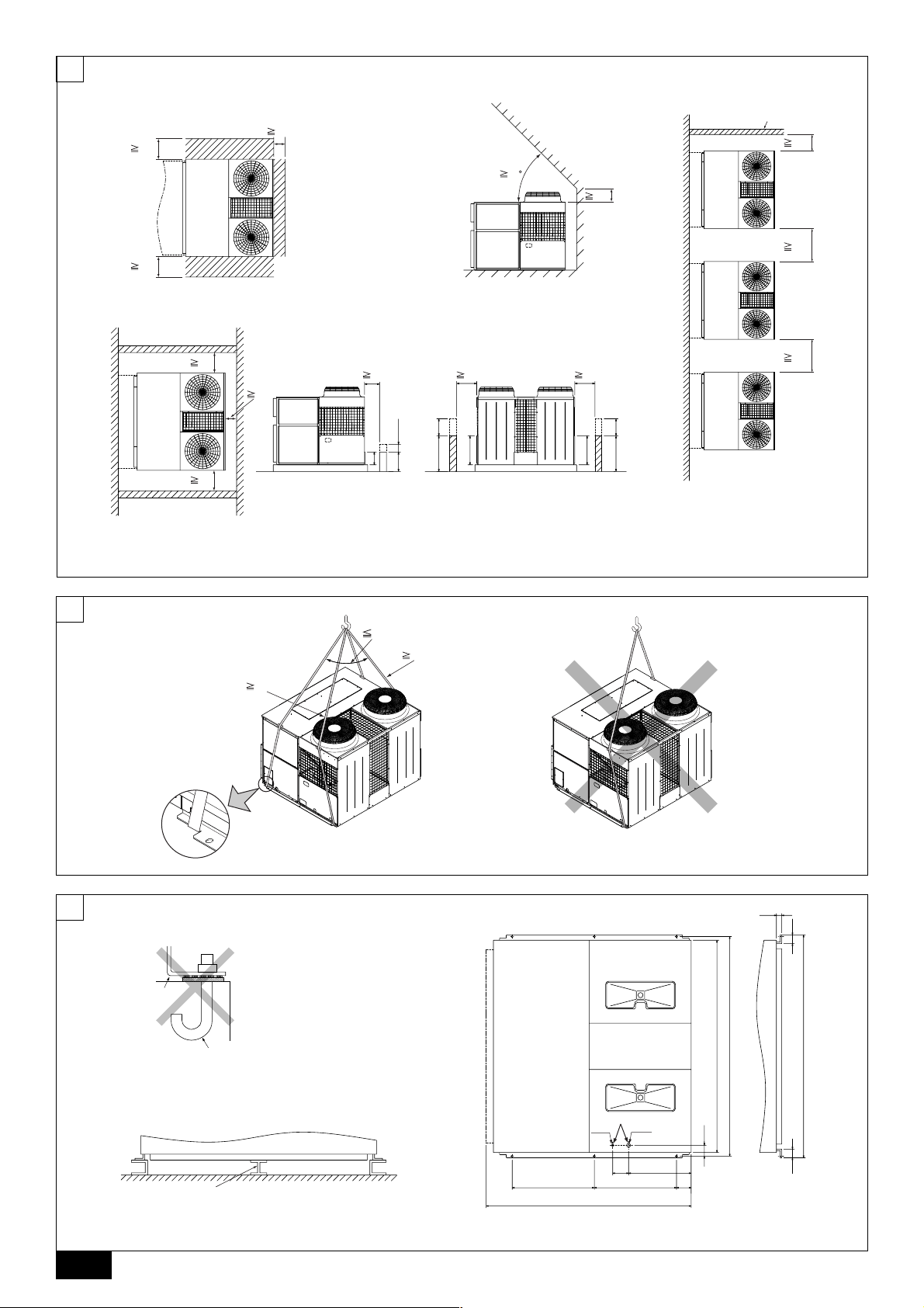
3.1. Space required around unit
[Fig. 3.1.1] (P.2)
<A> Top view <B> Front view
<C> Side view
A Front B Must be open
C Wall height (H)
L1: 450 L2: 450 L3: 250
(1) Basic space required
A space of at least 250 mm is necessary at the right side for inlet air. Taking servicing, etc. from the right side into account, a space of about 450 mm should be
provided, the same as at the front and back.
(2) When there is an obstruction above the unit
(3) When unit is surrounded by walls
Note:
• Wall heights (H) of the front and the back sides shall be within overall
height of unit panel.
• If the panel height is exceeded, add the “h” dimension of the Fig. 3.1.1 to
L
Example: When h is 100,
(4) Continuous installation
• Space required for continuous installation:
When installing several units, leave the space between each unit considering
passage for air and people.
• Open in the two directions.
• In case wall height (H) exceeds overall height of unit, add “h” dimension (h =
wall height <H> – overall height of unit) to * marked dimension.
1, L2 and L3.
L1: 450 L2: 450 L3: 250
the L
1 dimension becomes 450 + 100 = 550 mm.
NL
SWI
E
P
7
Page 8
4. Lifting method and weight of product
[Fig. 4.0.1] (P.2)
Caution:
• Be very careful to carry product.
- Do not have only one person to carry product if it is more than 20 kg.
- PP bands are used to pack some products. Do not use them as a mean for transportation because they are dangerous.
- Do not touch heat exchanger fins with your bare hands. Otherwise you may get a cut in your hands.
- Tear plastic packaging bag and scrap it so that children cannot play with it. Otherwise plastic packaging bag may suffocate children to death.
- When carrying in outdoor unit, be sure to support it at four points. Carrying in and lifting with 3-point support may make outdoor unit unstable, resulting in a fall of it.
• Protect the corners on the unit that come in contact with the sling with padding.
5. Installation of unit
5.1. Installation
[Fig. 5.1.1] (P.2)
A M10 anchor bolt procured at the site. B Corner is not seated.
• Fix unit tightly with bolts so that unit will not fall down due to earthquake or
gust.
• Use concrete or angle for foundation of unit.
• Vibration may be transmitted to the installation section and noise and vibration
GB
may be generated from the floor and walls, depending on the installation conditions. Therefore, provide ample vibrationproofing (cushion pads, cushion
frame, etc.).
• Be sure that the corners are firmly seated. If the corners are not firmly seated,
the installation feet may be bent.
[Fig. 5.1.2] (P.2)
D
A Stander
• When making foundation of unit, put a stander in the middle of unit base.
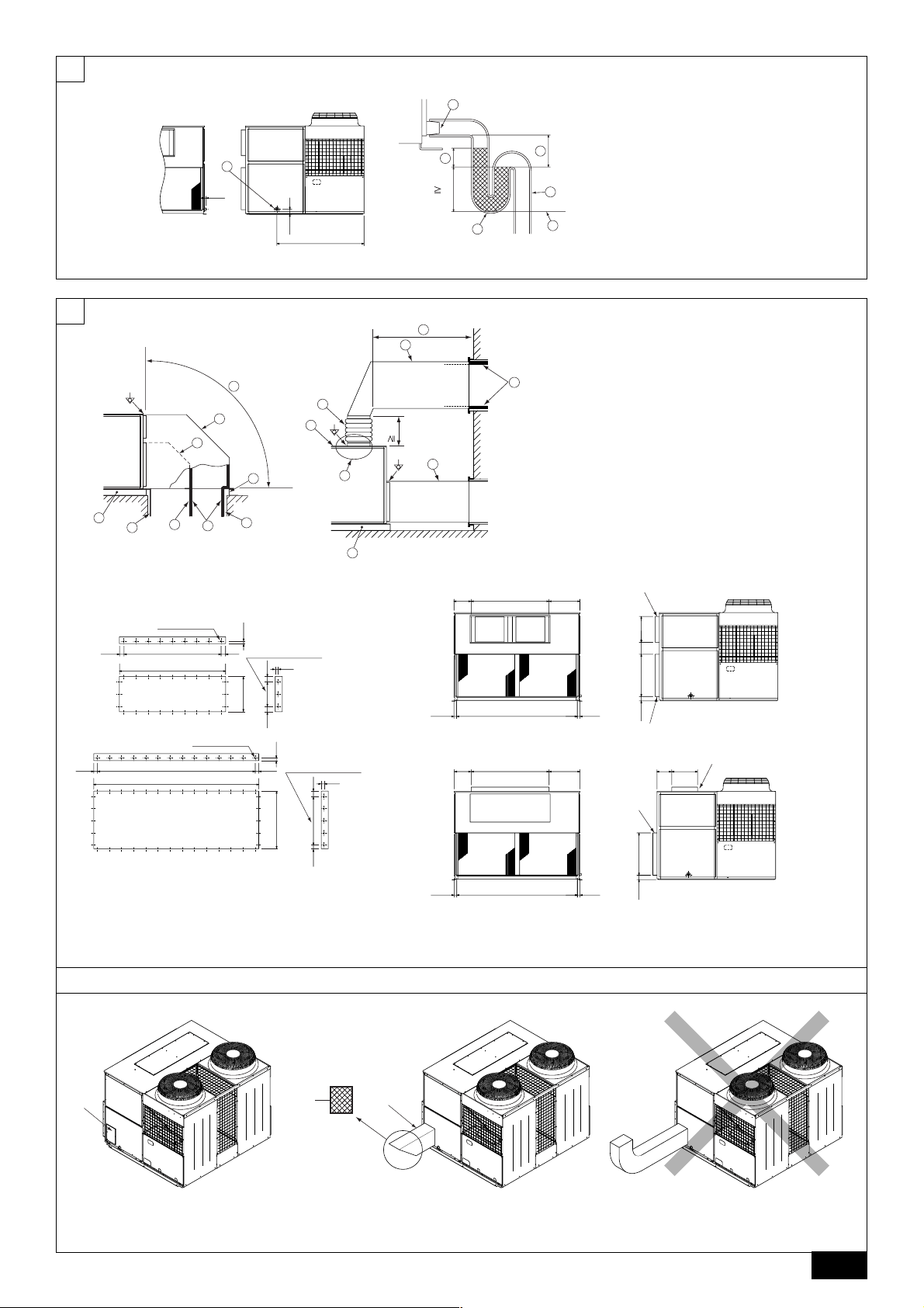
6. Drain piping work
F
[Fig. 6.0.1] (P.3)
A Drain piping B Socket R1
C Drain trap
D The drain pipe should extend below this level.
>
E
2 × External static pressure
=
>
F
2 × E
=
NL
Warning:
• Be sure to install unit in a place strong enough to withstand its weight.
Any lack of strength may cause unit to fall down, resulting in a personal
injury.
• Have installation work in order to protect against a strong wind and earthquake.
Any installation deficiency may cause unit to fall down, resulting in a
personal injury.
When building the foundation, give full attention to the floor strength, drain water
disposal <during operation, drain water flows out of the unit>, and wiring routes.
Down wiring precautions
When down wiring are performed, be sure that foundation and base work does not
block the base through holes.
[Fig. 5.1.3] (P.2)
A Bottom wiring through hole B (bolt hole)
1. The condensate drain socket (R1) is provided. The drain pipe is connected to
the drain socket.
2. The drain pipe must be provided with a trap on the outside of the unit and also
installed at an incline for proper drainage, as shown [Fig. 6.0.1] (P.3).
3. To prevent dew condensation and leakage, provide drain pipes with insulation.
4. Upon completion of the piping work, check that there is no leakage and that
the water drains off properly.
7. Duct work
1. In case of side flow unit (factory setting) is equipped with horizontal supply and
return air openings. Duct connection to the unit should be made with duct
SWI
flanges and secured directly to the air openings with flexible duct connectors
to avoid normal noise transmission.
2. For vertical air supply, a field supply plenum should be used.
The figure below shows the recommended method for duct connection.
3. In case of top flow unit (modified when installed) is equipped with vertical supply and horizontal return air openings. Duct connection to the unit should be
made with duct flanges and securely attached to the air openings with flexible
duct connectors.
Since the sirocco fan cannot be replace without remove the top panel in top
flow position, a maintenance space to remove the top panel is required. For
that, canvas duct must be constructed between duct flange and duct.
4. To prevent air leakage, all duct seams should be taped.
E
Ducts run in air spaces that are not air-conditioned must be insulated and
provided with a vapor barrier.
Ducts exposed to the outside must be weather proofed.
For quiet operation, we recommend that the insulation on the supply duct be
placed inside, lining the duct.
5. Where ducts from the outside enter a building, the duct openings in the building should be sealed with weather stripping to prevent rain, dust, sand, etc.
P
from entering the building.
6. Fans will not accept any external resistance to airflow and what provision is
available if ductwork is to be fitted to the external fans.
7. Correctly sized filters must be fitted and there is no provision within the unit,
however the filters (field supply) may be installed in the return air.
8. Duct earth wiring must be connected to the earth point of unit (
[Fig. 7.0.1] (P.3)
<A> Ex. Side flow
<B> Ex. Top flow
A Duct B Roof curb
C Single duct divider D Plenum divider
E Insulator
F Keep duct-work length 850 mm or more
G Rainproof the part where the duct flange is screwed on (Top flow only).
H Canvas duct (Keep 500 mm or more for canvas duct space)
I Top panel
Caution:
• Do not step on the unit.
- Step on the unit may deform top panel and result in injury.
• Outlet duct is 850 mm or more necessary to construct.
• To connect the air conditioner main body and the duct for potential equalization.
• In case of top flow unit, keep 500 mm or more for canvas duct space.
Mount holes for outlet duct flange and inlet duct.
[Fig. 7.0.2] (P.3)
<A> In case of side flow
<B> In case of top flow
A Outlet duct flange B Inlet duct flange
mark point).
8
Page 9
7.1. Fresh air inlet, duct installations, and
operating restrictions
This unit has an fresh air inlet on each side of the unit. Use the one that suits a
particular application.
[Fig. 7.1.1] (P.3)
A Fresh air inlet (on both sides)
Caution:
11
1 Properly seal duct connections.
11
22
2 Install a proper size filter at the opening of the inlet, and clean the filter
22
on a regular basis.
8. Remote controller
33
3 Install a duct longer than 850 mm or block the opening of the inlet with a
33
wire net to keep hands out of the inlet.
44
4 The opening of the connected duct must not be facing up as rain or snow
44
will enter the duct.
55
5 Be sure that the temperature of the mixed air (return air and outside air)
55
falls within the following ranges:
In the case of cooling operation: mixed air temperature 15
(30 - 80% RH)
In the case of heating operation: mixed air temperature 15
66
6 Install a reverse air-flow prevention plate inside return and supply ducts
66
to prevent the back flow of air during unit stoppage.
[Fig. 7.1.2] (P.3)
A Filter (Field supply)
B Fresh air inlet duct (Field supply)
°CWB - 24 °CWB
°CDB - 32 °CDB
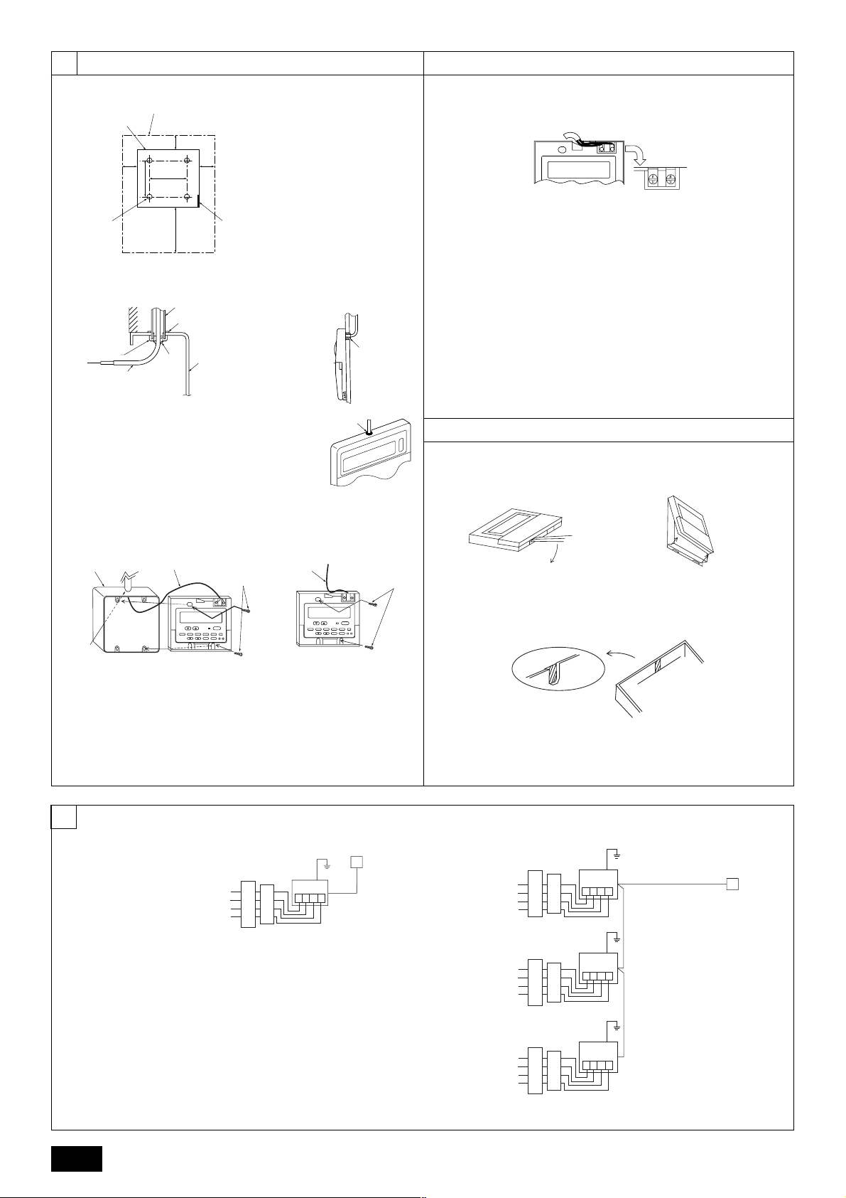
8.1. Installing procedures
(1) Select an installing position for the remote controller (switch box).
Be sure to observe the following precautions.
[Fig. 8.1.1.(1)] (P.4)
A Remote controller profile
B Required clearances surrounding the remote controller
C Temperature sensor D Installation pitch
1 The temperature sensors are located on both remote controller and unit. To
use the temperature sensor on the remote controller, mainly use the remote
controller for temperature setting or room temperature detection. Install the
remote controller in such an area that can detect average room temperatures,
free of direct sunlight, airflow from the air conditioner, and other such heating
source.
2 In either case when the remote controller is installed in the switch box or on the
wall, provide the clearances indicated in the diagram.
Note:
Check that there is no electric wire left close to the remote controller sensor.
If any electric wire is near the sensor, the remote controller may fail to detect
a correct room temperature.
3 Procure the following parts locally:
Switch box for two pieces
Thin copper conduit tube
Lock nuts and bushings
(2) Seal the service entrance for the remote controller cord with putty to
prevent possible invasion of dew drops, water, cockroaches or worms.
<A> For installation in the switch box:
• When the remote controller is installed in the switch box, seal the junction
between the switch box and the conduit tube with putty.
<B> For direct installation on the wall select one of the following:
B-1. To lead the remote controller cord from the back of the controller:
• Prepare a hole through the wall to pass the remote controller cord (in order to
run the remote controller cord from the back), then seal the hole with putty.
B-2. To run the remote controller cord through the upper portion:
• Run the remote controller cord through the cut-out upper case, then seal the
cut-out notch with putty similarly as above.
[Fig. 8.1.1.(2)] (P.4)
C Wall D Conduit E Lock nut
F Bushing G Switch box
H Remote controller cord I Seal with putty
(3) Install the lower case in the switch box or on the wall.
[Fig. 8.1.1.(3)] (P.4)
<A> For installation in the switch box
C Switch box for two pieces D Remote controller cord
E Cross-recessed, pan-head screw
G Seal the remote controller cord service entrance with putty
<B> For direct installation on the wall
H Wood screw
Caution:
Do not over-tighten the screws to possible deformed or broken lower case.
Note:
• Select a flat place for installation.
• Be sure to use two or more locations for securing of the remote controller in the switch box or on the wall.
8.2. Connecting procedures
• The remote controller cord can be extended up to a maximum of 200 m. Use
electric wires or (two-core) cables of 0.3 mm
tion of remote controller. Do not use multi-conductor cables to prevent possible malfunction of the unit.
(1) Connect the remote controller cord to the terminal block at the lower
case.
[Fig. 8.2.1] (P.4)
A To TB5 on the unit
B Terminal block TB6 in remote controller
No polarity
Caution:
• Do not use crimp-style terminals for connection to the remote controller
terminal block to eliminate contact with the boards and resultant trouble.
• Prevent remote cord chips from getting into the remote controller. Electric shock or malfunction may result.
2
to 1.25 mm2 for making connec-
8.3. Fitting the upper case
[Fig. 8.3.1] (P.4)
(1) To remove the upper case, put a slotted screwdriver tip in the latches as
shown in the diagram then move the screwdriver in the direction of arrow.
(2) To install the upper case, put the upper latches (at two locations) first,
then fit the upper case into the lower case as illustrated.
[Fig. 8.3.2] (P.4)
Note:
Wiring hole for installing directly on the wall (or open wiring)
• Cut off the shaded area from the upper case using a knife, nippers, etc.
• Take out the remote control cord connected to the terminal block via this
portion.
Caution:
• Do not move the screwdriver while inserting the tip far into the latches to
prevent broken latches.
• Be sure to put the upper case securely in the latches by pressing it until
a snap sounds. Loosely inserted, the upper case may fall down.
Note:
The operating section is covered with a protective sheet. Before using the
unit, remember to remove the protective sheet.
GB
D
F
NL
SWI
E
P
9
Page 10
8.4. Function selection
PAR-21MAA
ON/OFF
FILTER
CHECK
OPERATION
CLEAR
TEST
TEMP.
MENU
BACK DAY
MONITOR/SET
CLOCK
ON/OFF
F
G
C
D
B
I
A
H
E
<Wired remote controller type>
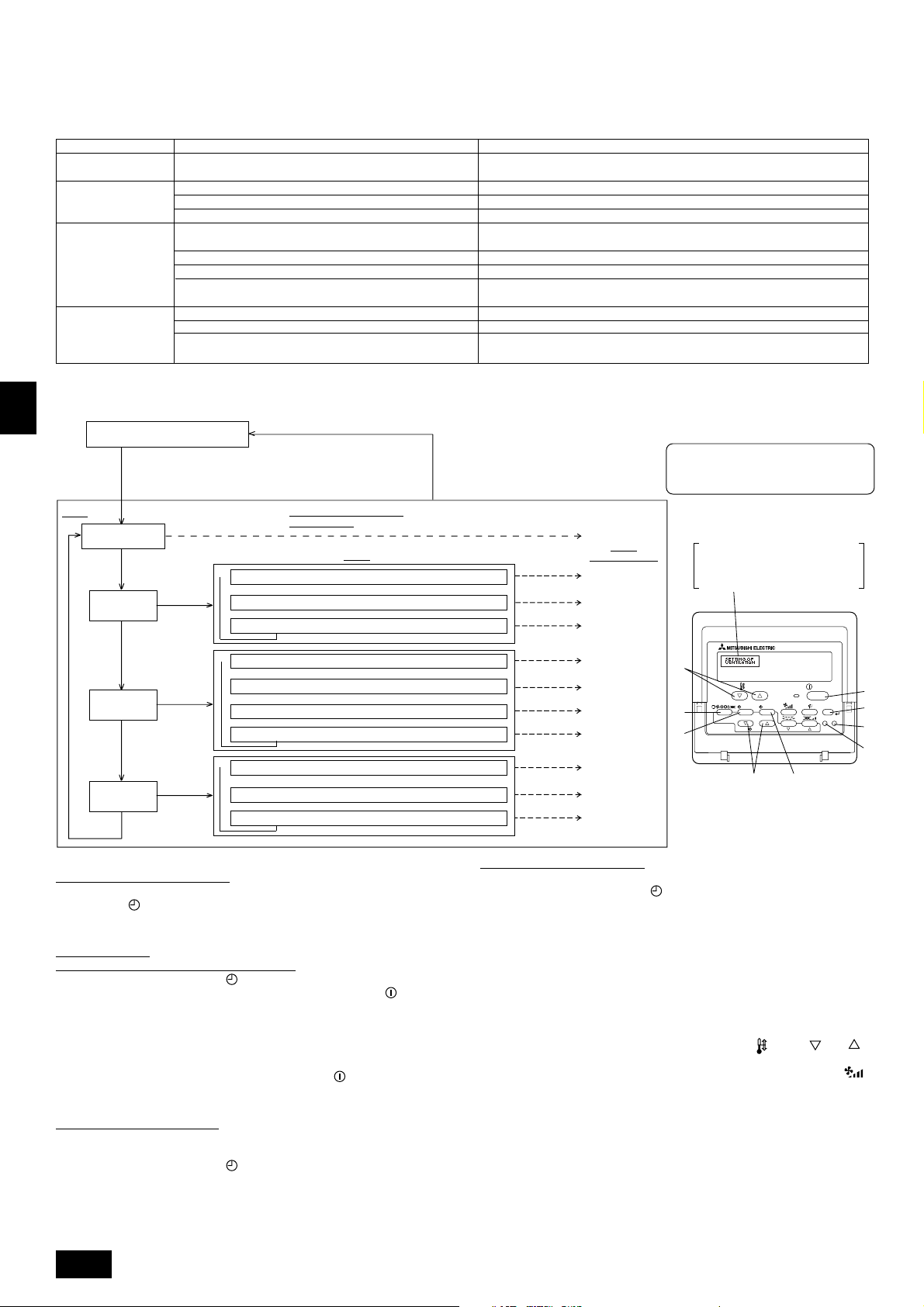
(1) Function selection of remote controller
The setting of the following remote controller functions can be changed using the remote controller function selection mode. Change the setting when needed.
Item 1
1.Change Language
Language setting to display
Item 2
• Display in multiple languages is possible.
(“CHANGE LANGUAGE”)
2.Function limit
(“FUNCTION
SELECTION”)
3.Mode selection
(“MODE SELECTION”)
(1)
Operation function limit setting (operation lock) (“LOCKING FUNCTION”)
(2) Use of automatic mode setting (“SELECT AUTO MODE”)
(3) Temperature range limit setting (“LIMIT TEMP FUNCTION”)
(1) Remote controller main/sub setting (“CONTROLLER MAIN/SUB”)
(2) Use of clock setting (“CLOCK”)
(3) Timer function setting (“WEEKLY TIMER”)
(4) Contact number setting for error situation (“CALL.”)
• Setting the range of operation limit (operation lock)
• Setting the use or non-use of “automatic” operation mode
• Setting the temperature adjustable range (maximum, minimum)
• Selecting main or sub remote controller
*
When two remote controllers are connected to one group, one controller must be set to sub.
• Setting the use or non-use of clock function
• Setting the timer type
• Contact number display in case of error
• Setting the telephone number
4.Display change
(“DISP MODE SETTING”)
(1) Temperature display °C/°F setting (“TEMP MODE °C/°F”)
(2)
Suction air temperature display setting (“ROOM TEMP DISP SELECT”)
(3)
Automatic cooling/heating display setting (“AUTO MODE DISP C/H”)
• Setting the temperature unit (°C or °F) to display
• Setting the use or non-use of the display of indoor (suction) air temperature
• Setting the use or non-use of the display of “Cooling” or “Heating” display during
operation with automatic mode
[Function selection flowchart]
[1] Stop the air conditioner to start remote controller function selection mode. → [2] Select from item1. → [3] Select from item2. → [4] Make the setting. (Details
are specified in item3) → [5] Setting completed. → [6] Change the display to the normal one. (End)
GB
D
F
NL
SWI
Normal display (Display when the
air condition is not running)
(Hold down the E button and press the D button for two
seconds.)
* The display cannot be changed during the unit function
selection, the test run and the self diagnosis.
Item 1
Change Language
(“CHANGE LANGUAGE”)
Press the E
button.
Function limit
(“FUNCTION
SELECTION”)
Press the
E button.
Press the
E button.
Mode selection
(“MODE
SELECTION”)
Press the
E button.
Display change
(“DISP MODE
SETTING”)
Press the G button.
Press the
G button.
Press the
G button.
Press the
G button.
(Hold down the E button and press
the D button for two seconds.)
* The remote controller records the
setting that is made in this way.
Remote Controller Function
Selection Mode
Item 2
Operation function limit setting (“LOCKING FUNCTION”)
→
→
→
→
Use of automatic mode setting (“SELECT AUTO MODE”)
→
Temperature range limit setting (“LIMIT TEMP FUNCTION”)
Remote controller main/sub setting (“CONTROLLER MAIN/SUB”)
Use of clock setting (“CLOCK”)
→→→
Timer function setting (“WEEKLY TIMER”)
Contact number setting for error situation (“CALL.”)
Temperature display °C/°F setting (“TEMP MODE °C/°F”)
Suction air temperature display setting (“ROOM TEMP DISP SELECT”)
→→
Automatic cooling/heating display setting (“AUTO MODE DISP C/H”)
Press the G button.
Press the G button.
Press the G button.
Press the D
button.
Press the D
button.
Press the D
button.
Item 3 (Setting content)
See [4]-1
Item 3
(Setting content)
See [4]-2. (1)
See [4]-2. (2)
See [4]-2. (3)
See [4]-3. (1)
See [4]-3. (2)
See [4]-3. (3)
See [4]-3. (4)
See [4]-4. (1)
See [4]-4. (2)
See [4]-4. (3)
NOTE
Timer operation stops when the display for
remote controller function selection is changed
to the normal one.
Dot display
The language that is selected in
CHANGE LANGUAGE mode
appears on this display. English is set
in this manual.
[Detailed setting]
[4] -1. CHANGE LANGUAGE setting
The language that appears on the dot display can be selected.
• Press the [
MENU] button to change the language.
1 Japanese (JP), 2 English (GB), 3 German (D), 4 Spanish (E), 5 Russian
(RU), 6 Italian (I), 7 Chinese (CH), 8 French (F)
[4] -2. Function limit
(1) Operation function limit setting (operation lock)
• To switch the setting, press the [
1 no1: Operation lock setting is made on all buttons other than the [
E
button.
ON/OFF] button.
ON/OFF]
2 no2: Operation lock setting is made on all buttons.
3 OFF (Initial setting value):
Operation lock setting is not made.
* To make the operation lock setting valid on the normal screen, it is necessary to
press buttons (Press and hold down the [FILTER] and [
the same time for two seconds.) on the normal screen after the above setting is
P
made.
ON/OFF] buttons at
(2) Use of automatic mode setting
When the remote controller is connected to the unit that has automatic operation
mode, the following settings can be made.
• To switch the setting, press the [
1 ON (Initial setting value):
The automatic mode is displayed when the operation mode is selected.
2 OFF:
The automatic mode is not displayed when the operation mode is selected.
10
ON/OFF] button.
(3) Temperature range limit setting
After this setting is made, the temperature can be changed within the set range.
• To switch the setting, press the [
ON/OFF] button.
1 LIMIT TEMP COOL MODE:
The temperature range can be changed on cooling/dry mode.
2 LIMIT TEMP HEAT MODE:
The temperature range can be changed on heating mode.
3 LIMIT TEMP AUTO MODE:
The temperature range can be changed on automatic mode.
4 OFF (initial setting): The temperature range limit is not active.
* When the setting, other than OFF, is made, the temperature range limit setting
on cooling, heating and automatic mode is made at the same time. However, the
range cannot be limited when the set temperature range has not changed.
• To increase or decrease the temperature, press the [
TEMP ( ) or ( )]
button.
• To switch the upper limit setting and the lower limit setting, press the [
button. The selected setting will flash and the temperature can be set.
• Settable range
Cooling/Dry mode: Lower limit: 19°C ~ 30°C Upper limit: 30°C ~ 19°C
Heating mode: Lower limit: 17°C ~ 28°C Upper limit: 28°C ~ 17°C
Automatic mode: Lower limit: 19°C ~ 28°C Upper limit: 28°C ~ 19°C
* The settable range varies depending on the unit to connect (Mr. Slim units, Free-
plan units, and intermediate temperature units)
]
Page 11
[4] -3. Mode selection setting
(1) Remote controller main/sub setting
• To switch the setting, press the [
1 Main: The controller will be the main controller.
2 Sub: The controller will be the sub controller.
(2) Use of clock setting
• To switch the setting, press the [
1 ON: The clock function can be used.
2 OFF: The clock function cannot be used.
(3) Timer function setting
• To switch the setting, press the [
followings.).
1 WEEKLY TIMER (Initial setting value):
2 AUTO OFF TIMER: The auto off timer can be used.
3 SIMPLE TIMER: The simple timer can be used.
4 TIMER MODE OFF: The timer mode cannot be used.
* When the use of clock setting is OFF, the “WEEKLY TIMER” cannot be used.
(4) Contact number setting for error situation
• To switch the setting, press the [
1 CALL OFF: The set contact numbers are not displayed in case of error.
2 CALL **** *** ****: The set contact numbers are displayed in case of error.
CALL_: The contact number can be set when the display is as shown
(2) Unit Function Selection
Set the functions of each unit from the remote controller, as required. The functions of each unit can be selected only from the remote controller.
Set the functions by selecting the necessary items from Table 1 and Table 2. (Default settings are also shown below)
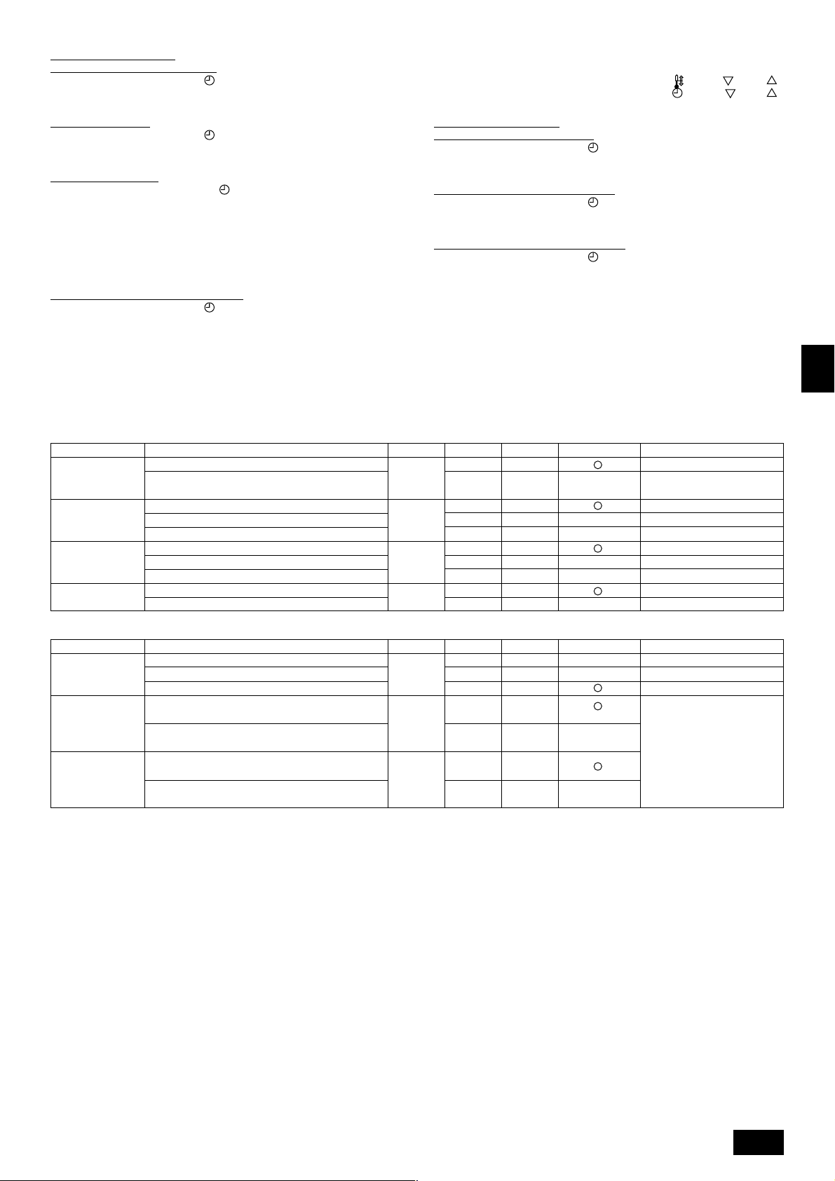
Table 1. Itemized functions of the entire refrigerant system (select unit number 00 to 15)
Function
Power failure
automatic recovery
Indoor temperature
detection
LOSSNAY
connectivity
Power voltage
The weekly timer can be used.
on the left.
Not available
Available
Unit operating average
Set by unit’s remote controller
Remote controller’s internal sensor
Not Supported
Supported (unit is not equipped with outdoor-air intake)
Supported (unit is equipped with outdoor-air intake)
240 V
220 V, 230 V
ON/OFF] button.
ON/OFF] button.
ON/OFF] button (Choose one of the
ON/OFF] button.
Settings
• Setting the contact numbers
To set the contact numbers, follow the following procedures.
Move the flashing cursor to set numbers. Press the [
button to move the cursor to the right (left). Press the [
button to set the numbers.
[4] -4. Display change setting
(1) Temperature display °C/°F setting
• To switch the setting, press the [
1 °C: The temperature unit °C is used.
2 °F: The temperature unit °F is used.
(2) Suction air temperature display setting
• To switch the setting, press the [
1 ON: The suction air temperature is displayed.
2 OFF: The suction air temperature is not displayed.
(3) Automatic cooling/heating display setting
• To switch the setting, press the [
1 ON: One of “Automatic cooling” and “Automatic heating” is displayed under the
automatic mode is running.
2 OFF: Only “Automatic” is displayed under the automatic mode.
Mode no. Setting no. Check Default settings
01
02 2
03 2
04
1
2
1
3
1
3
1
2
ON/OFF] button.
ON/OFF] button.
ON/OFF] button.
Approx. 4-minute wait-period
after power is restored.
TEMP. ( ) and ( )]
CLOCK ( ) and ( )]
GB
Remarks
D
F
Table 2. Itemized functions of the unit (select unit numbers 01 to 04 or AL)
Function
Filter sign
Fan operation
during thermo off
in heating
operation
Fan operation
during thermo off
in cooling
operation
Note:
When the indoor unit functions were changed using the function selection after installation is complete, always indicate the set contents by entering 嘷 or other
mark in the appropriate check field of Table 1 and Table 2.
100 Hr
2500 Hr
No filter sign indicator
Operation
Stop
Operation
Stop
Settings
Mode no. Setting no. Check Default settings Remarks
07 2
25
27
1
3
3
2
1
2
When selecting fan operation
“Stop”, set setting no. of Mode
no. “02” in Table 1 to “3”. Be sure
to place the remote controller
inside the room to be air-conditioned so that it can monitor the
room temperature.
NL
SWI
E
P
11
Page 12
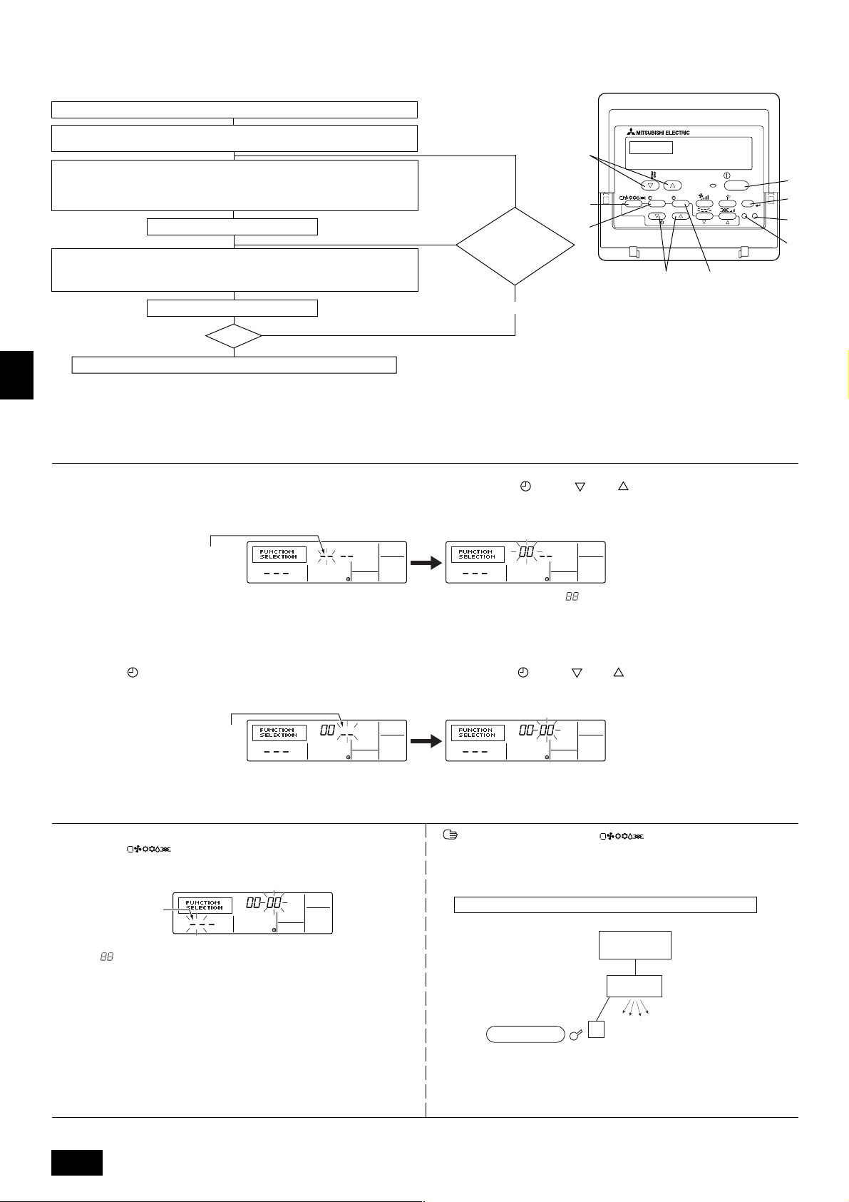
[Function selection flow]
First grasp the function selection flow. The following describes setting of “Power voltage” of Table 1 as an example.
(For the actual setting procedure, see [Setting procedure] 1 to 0.)
1 Check the function selection set contents.
2 Switch to the FUNCTION SELECTION mode.
(Press A and B simultaneously in the remote controller OFF state.)
3 Refrigerant address specification → 00 (Outdoor unit specification)
4 Unit address No. specification → 00 (Indoor unit specification)
(Buttons C and D operation)
5 Registration (Press button E.)
6 Mode No. Selection → 04 (Power voltage)
7 Setting No. selection → 2 (220 V, 230 V)
(Buttons F and G operation)
(Unnecessary for single refrigerant system.)
(Specified indoor unit →
Fan operation)
NO
YES
Change
refrigerant
address and unit
address No.?
F
TEMP.
MENU
E
G
BACK DAY
PAR-21MAA
ON/OFF
MONITOR/SET
CLOCK
OPERATION
ON/OFF
FILTER
CHECK
CLEAR
I
A
TEST
B
H
C
D
8 Register (Press button E.)
End?
NO
9
YES
0 Ending function display (Press buttons A and B simultaneously.)
GB
[Procedure] (Set only when change is necessary.)
1 Check the set contents of each mode. When the set contents of a mode were changed by function selection, the functions of that mode also change.
Check the set contents as described in steps 2 to 7 and change the setting based on the entries in the Table 1 and Table 2. (Refer default settings, when change the
setting)
D
2 Set the remote controller to Off.
Press and hold down the A [FILTER] and B [TEST] buttons at the same time
for two seconds or longer.
“FUNCTION SELECTION” blinks for a while, then the remote controller display
changes to the display shown below.
F
Refrigerant address display
* If the remote controller enters the OFF state after the “FUNCTION SELECTION” and room temperature displays “ ” have flashes for two seconds, communication is
probably abnormal. Make sure there are no noise sources near the transmission line.
Note:
If you make a mistake during operation, end function selection by step
NL
4 Set the indoor unit address No.
Press the D [
ON/OFF] button. The unit address No. display “– –” flashes.
??
? and repeat selection from step
??
3 Set the outdoor unit refrigerant address No.
When the C [
CLOCK ( ) and ( )] buttons are pressed, the refrigerant
address No. decreases and increases between 00 and 15. Set it to the refrigerant address No. whose function you want to select.
(This step is unnecessary for single refrigerant system.)
22
2.
22
When the C [ CLOCK ( ) and ( )] buttons are pressed, the unit address
No. changes in 00 → 01 → 02 → 03 → 04 → AL order. Set it to the unit address
No. of the indoor unit whose functions you want to set.
Unit address No. display
SWI
* When setting mode 01 to 04, set the unit address No. to “00”.
* When setting modes 07, 25, 27:
- When setting functions for a unit in an independent system, set the unit number to 01.
5 Refrigerant address and unit address No. registration
Press the E [ ] button. The refrigerant address and unit address No.
are registered.
After a while, the mode No. display “– –” flashes.
Mode No. display
E
* When “
address is not in the system.
When “F” is displayed at the unit address No. display, and when it flashes together with the refrigerant address display, the selected unit address No. does
not exist. Correctly set the refrigerant address and unit address No. by repeat-
P
ing steps 2 and 3.
” flashes at the room temperature display, the selected refrigerant
When registered using the E [ ] button, the registered indoor unit
begins fan operation. When you want to know the location of the indoor units of
the unit address No. whose functions were selected, check here. When the unit
address No. is 00 or AL, all the indoor units of the selected refrigerant address
perform the fan operation.
Ex) When refrigerant address 00, unit address No. = 01 registered
Refrigerant address 00
Outdoor side
Indoor side
Registration
Unit address
No. 01
Fan operation
Remote Controller
* When grouping by different refrigerant systems and an indoor unit other than
the specified refrigerant address performs the fan operation, the refrigerant
address set here is probably duplicated.
Recheck the refrigerant address at the outdoor unit DIP switches.
12
Page 13
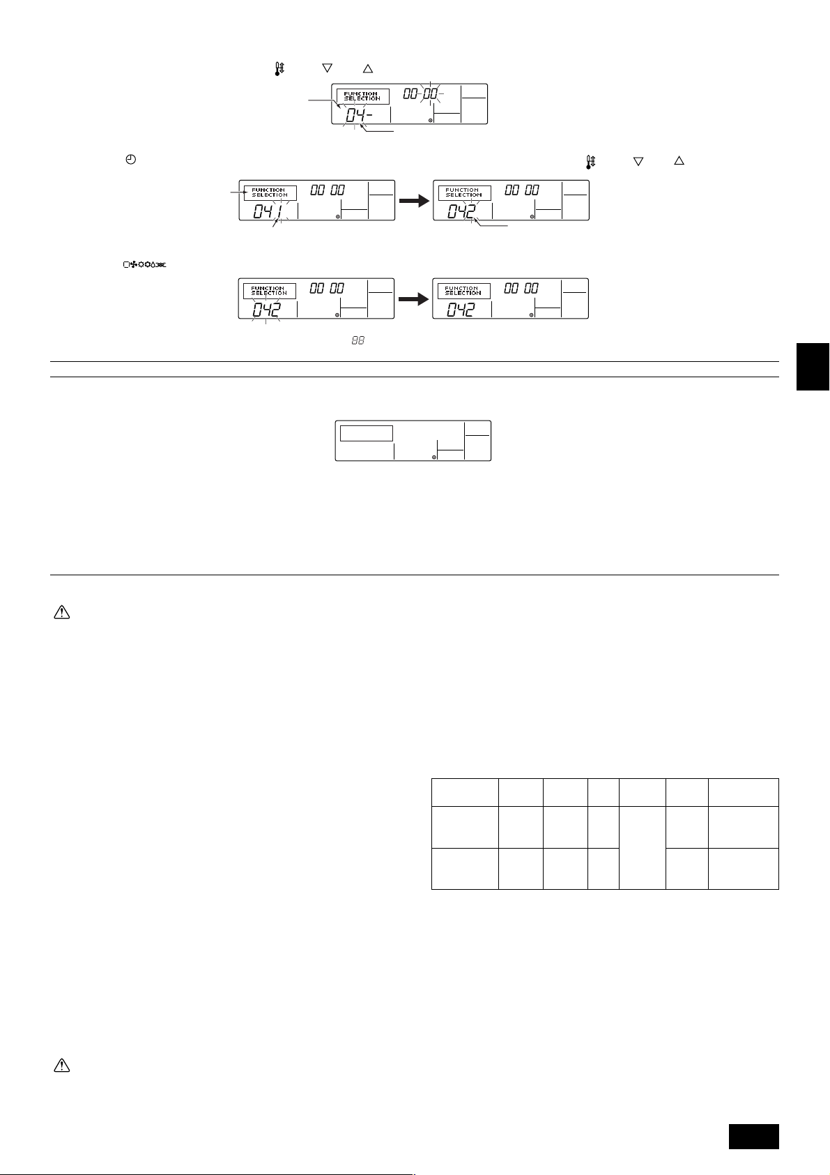
6 Mode No. selection
Select the mode No. you want to set with the F [
Mode No. display
7 Select the setting contents of the selected mode.
When the G [
Use this to check the currently set contents.
MENU] button is pressed, the current setting No. flashes.
Setting No. display
TEMP. ( ) and ( )] buttons. (Only the settable mode numbers can be selected.)
Mode No. 04 = Power voltage
Select the setting No. using the F [
TEMP. ( ) and ( )] buttons.
Setting No. 1 = 240 V
8 The contents set at steps 3 to 7 are registered.
When the E [
and setting ends.
* When “– –” appears at the mode No. and setting No. displays and “
Make sure there are no noise sources near the transmission line.
9 To select more functions, repeat steps 3 to 8.
0 End function selection.
Press and hold down the A [FILTER] and B [TEST] buttons at the same time for two seconds or longer.
After a while, the function selection display disappears and the remote controller returns to the air conditioner off display.
* Do not operate the air conditioner from the remote controller for 30 seconds after the end of function selection.
Note:
When the functions of an indoor unit were changed by function selection after the end of installation, always indicate the set contents by entering a 嘷 or other
mark in the appropriate check field of Table 1 and Table 2.
] button is pressed, the mode No. and setting No. flash and registration begins. The flashing mode No. and setting No. change to a steady light
” flashes at the room temperature display, communication is probably abnormal.
Setting No. 2 = 220 V, 230 V
9. Electrical wiring
Precautions on electrical wiring
Warning:
• Electrical work should be done by qualified electrical engineers in accordance with “Engineering Standards For Electrical Installation” and supplied installation manuals. Special circuits should also be used. If the
power circuit lacks capacity or has an installation failure, it may cause a
risk of electric shock or fire.
• Always use the designated cable for wiring, and connect it correctly. Secure it so that the cable applies no external pressure to the terminal connection. If the connection is faulty or the cable is not fully secured, overheating or fire could result.
• Be sure to use specified cables and connect them firmly so that no external wiring force is exerted on terminal connections. Loose connections
may cause heat or fire.
1. Be sure to take power from the special branch circuit.
2. Be sure to install an earth leakage breaker to the power.
3. Install the unit to prevent that any of the control circuit cables (remote controller) is brought in direct contact with the power cable outside the unit.
4. Ensure that there is no slack on all wire connections.
5. Remote controller cable above the ceiling may be bitten by mice. Use as many
metal pipes as possible to insert the cable into them for protection. Where the
remote controller cable is exposed, protect the cable by running it through a
metal pipe.
6. Never connect the power cable to leads for the remote controller cables. Otherwise the cables would be broken.
7. Fix power source wiring to control box by using buffer bushing for tensible force
(PG connection or the like).
8. Set up the unit so that the wiring for the remote controller and the M-NET
(MELANS) wiring do not produce electrical interference with the power supply
cable. (Do not route them together in the same conduit.)
9. Be sure to provide designated grounding work to the unit.
10. Give some allowance to wiring for electrical part box of the unit, because the
box is sometimes removed at the time of service work.
Caution:
• Be sure to put the unit to the ground on the outdoor unit side. Do not
connect the earth cable to any gas pipe, water pipe, lightening rod, or
telephone earth cable. Incomplete grounding may cause a risk of electric
shock.
• Some installation sites may required installation of an earth leakage
breaker. Failure to install it may result in an electric shock.
• Always use an earth leakage breaker and fuse with the specified capac-
ity. Use of a fuse with a capacity larger than that specified, or use of a
piece of wire or copper wire may cause breakdown or fire.
• Depending on the location of the unit, a current leakage breaker may be
required. If a current leakage breaker is not installed, electric shock could
result.
• Do not use breakers or fuses with a capacity different from the correct
one. If large-capacity fuses, wire, or copper wiring are used, accident or
fire may result.
The following table is an example. The selection of other capacities should be
determined in accordance with the relevant standards.
[Wiring example] (For metal pipe)
Pow er
Breaker
Capacity
Cable
2
PRH-P400MYA
PRH-P500MYA
Note:
*1: This device is intended for the connection to a power supply system with
a maximum permissible system impedance ZMAX of 0.06
0.04
supply.
The user has to ensure that this device is connected only to a power
supply system which fulfills the requirement above.
If necessary, the user can the ask the public power supply company for
the system impedance at the interface point.
16 mm
or thicker
25 mm
or thicker
63 A 63 A
2
70 A 70 A
Ω: PRH-P500 at the interface point (power service box) of the user’s
Fuse
Remote
controller
cable
Cable or
wire of
0.3 ~
1.25 mm
(Max. DC
12 V)
Ground-
ing wire
16 mm
2
25 mm
or
thicker
or
thicker
Max. Permissive
system
impedance *1
2
0.06 Ω
2
0.04 Ω
Ω: PRH-P400,
13
GB
D
F
NL
SWI
E
P
Page 14
[Selecting earth leakage breaker (NV)]
To select NF or NV instead of a combination of Class B fuse with switch, use the
following:
Fuse (class B) 63 A 70 A
Earth leakage NV100-SW NV100-SW
breaker ELB 60 A 75 A
(with over-load protection) 100 mA 0.1s or less 100 mA 0.1s or less
NV is a product name of MITSUBISHI.
• Power supply cords of appliances shall not be lighter than design 245 IEC57.
• A switch with at least 3 mm contact separation in each pole shall be provided
by the Air conditioner installation.
Example
[Fig. 9.0.1] (P.4)
(1) Normal Connecting
(2) Grouping (8 units)
A Power supply B Earth leakage breaker
C Wiring circuit breaker or isolating switch
D Remote controller E Address
[Unit-MA remote controller cable/cord] (For metal pipe)
MA remote controller
2 core cable
0.3 ~ 1.25 mm
Max. 200 m
2
Types of cable/cord
GB
Number of cable/cord
Diameter of cable/cord
Total extention
When extending the remote controller cable,
remote controller cables shall not be
lighter than design 245 IEC53.
D
9.1. Address settings
Unit address settings
• During address setting, set all the dip switches SW1 (3 - 6) on the outdoor-side
controller board to <when shipped from factory: 00, 01>. (Address setting is
not necessary for 1:1)
• Functions of SW1 according to switch setting are shown below.
• To control a group of units, address must be assigned to each unit.
(SW1 of outdoor-side contoroller)
OFF ON
1
2
3
4
5
6
[Fig. 9.1.1] (P.5)
1–
2 Error history clear
3 Refrigerant system
address setting
4 ↑
switching
5 ↑
SW1 function
6 ↑
Model
Functions according to switch setting
ON
–
Clear
Unit address
Settings 0 ~ 15
OFF
–
Ordinary
9.2. Wiring connection
• Using the conduit mounting plates
Conduit mounting plates are supplied in two sizes (ø40, ø52). Use the mounting plate that fits the outer diameter of the wire to be used.
[Fig. 9.2.1] (P.5)
A When installing conduct from bottom panel
B When installing conduct from front panel
C Mounting plate (attached)
D Knock-out hole
10. Specifications for installing the belt
1. Set the parallel angle of the fan and the motor pulley as shown in the
[Fig. 10.0.1] and table 1.
F
2. Set the tension of the per one belt when the flexion load is within the range as
shown in the [Fig. 10.0.2] and table 2 below at the proper flexion.
3. Adjust the suitable tension after the belt sit properly across the pulley (after
more 24 - 28 hours working).
When the new belt is used, adjust the suitable tension about the 1.3 times of
the maximum value of the flexion load.
4. Readjust the belt every 2,000 hours after the first adjustment.
NL
Exchange the belt when the belt’s surroundings length has expanded by 2 %
including the first expansion of the belt. (about 1 %)
(about 8,000 hours converted working time)
When selecting fan operation “Stop” (Mode no. 25 “2” in table 2 of page 11),
readjust the belt every 1,000 hours after the first adjustment.
[Fig. 10.0.1] / [Fig. 10.0.2] (P.5)
SWI
<A> Parallel degree of pulley
<B> Belt tension
A Flexion load (W)
table 1
pulley
table 2
type
pulley
pulley
smaller out diameter
B
parallel angle
10 or less
(mm)
~ 135
136 ~ 160
161 ~
11. Modification method of fan direction (From side flow to top flow)
This product can be changed from side flow to top flow in the field.
Modify if necessary as follows.
[Fig. 11.0.1] (P.5)
E
A Top panel B Cover (outer side) C Flange
D Panel E Fan F Cover (inner side)···2pcs
1 Remove the top panel A, cover (outer side) B, flange C, panel D and cover
(inner side) F. (STEP 1)
2 Modify the fan E direction. (STEP 2)
When working with the fan E suspended, do not rope the shaft of the fan.
3 Re-install the top panel A, cover B, flange C and panel D. (STEP 3)
* Between flange C, top panel A, and screw fittings should be adequately
waterproofed.
K (
"
)
gap of 3 mm every 1 m
Flexion load W
(N)
22 ~ 29
27 ~ 34
29 ~ 37
note
P
14
Note:
In the case of top flow, the inner cover
FF
F is not necessary.
FF
Page 15
12. Test run
12.1. Before test run
The test run can be carried out either from the unit or remote controller.
1. Checklist
• After wiring of units are complete, check that refrigerant is not leaking, the
power and control wires are not loose, and the poles are not reversed.
• Use a 500 V insulation resistance tester to make sure that the resistance between the power terminal and the ground is 1.0 MΩ or more. If it is less than
1.0 MΩ, do not operate the unit.
• Make sure there is no malfunction in the unit. (If there is a malfunction, you
can diagnose it using LED1 on the outdoor-side controller board.)
• Check the electrical power phase. If the phase is reversed, the fan may rotate
in the wrong direction or stop, or unusual sounds may be produced.
• Starting at least 12 hours before the test run, send current through the
crankcase heater. (If the current is running for a shorter period of time,
damage to the compressor could result.)
• For specific models requiring changing of settings for selection of power supply ON/OFF capability, make proper changes referring to the description for
Selection of Functions through Remote Controller.
After the above checks are complete, carry out the test run as indicated in the
following outline.
4 Check the outdoor-side fan for correct running
The unit features automatic capacity control to provide optimum outdoor-side
fan speeds. The fan keeps running at a low speed to meet the current outside
air condition unless it exceeds its available maximum power. Then, in actuality,
the fan may stop or run in the reverse direction depending on the outside air,
which does not mean malfunction.
5 Press the [
ON/OFF] button to reset the test run in progress
• The test run will be automatically shut down after two hours in response to the
AUTO STOP setting of two hours on the timer.
• During the test run, the room temperature display shows the unit indoor-side
liquid piping temperatures.
• In the case of the test run, the OFF timer will activate, and the test run will
automatically stop after two hours.
• The room temperature display section shows the control temperature for the
units during the test run.
• Check that the units are running properly operation.
Malfunctions may not be displayed even if the wiring is incorrect.
6 Register a telephone number
The telephone number of the repair shop, sales office, etc., to contact if an
error occurs can be registered in the remote controller. The telephone number
will be displayed when an error occurs.
For registration procedures, refer to 8.4 Function selection of remote control-
12.2. Test run procedures
1) Remote controller
Operating procedures
1 Turn on the main power supply
While the display on the remote controller indicates “
is disabled. Turn off the “
“CENTRALLY CONTROLLED”
indicator
” indicator before using the remote controller.
2 Press the [TEST] button twice successively within three seconds. Test
run starts.
“TEST RUN” and “OPERATION MODE” are displayed alternately.
3 Press [
] button
Cooling mode: Cool air should start to blow.
Heating mode: Warm air should start to blow (after a while).
”, the remote controller
˚C
TEMP.
˚C
ON/OFF
ler.
MENU
MONITOR/SET
BACK DAY
PAR-21MAA
TEMP.
˚C
ON/OFF
ON/OFF
CLOCK
OPERATION
FILTER
CHECK
CLEAR
Operation mode display
“TEST RUN” and “OPERATION MODE” are
displayed alternately.
Timer stops test run after two hours.
Piping temperature display
Stop test run by pressing the [ ON/OFF] button.
During test run, the RUN lamp remains on.
TEST
[TEST] button
[ ] button
(*1)
After turning ON the power, the system will go into startup mode, and the remote
controller operation lamp (green) and the display section’s “PLEASE WAIT” will
flash. Also, in the case of the indoor-side controller board substrate LEDs, LED 1
and LED 2 light up (when address is 0) or become dim (when address is not 0), and
LED 3 flashes. In the case of the outdoor-side controller board substrate LED 1
display,
and are displayed alternatively at 1-second intervals.
• If one of the above operations does not function correctly, the following causes
should be considered, and if applicable, dealt with. (The following symptoms
have been determined under test run mode. Note that “startup” in the chart
means the *1 display above.)
Remote Controller Display Outdoor Substrate LED Display
Symptoms
Remote controller is displaying “PLEASE WAIT”, and
operation is not possible.
After power is turned ON, “PLEASE WAIT” is displayed for 3 mins., then error code is displayed.
Power is turned ON, and “EE” or “EF” are displayed
after “PLEASE WAIT” is displayed.
After “startup” display, “00” is displayed (correct operation).
After “startup” display, error code is
displayed.
After “startup” display, “F1” (negative
phase) is displayed.
After “startup” display, “00” or “EE” is
displayed (“EE” is displayed when a
• After power is turned ON, system star tup lasts for about 2 mins., and
“PLEASE WAIT” is displayed (correct operation).
• Outdoor-side unit’s safeguard installation connector is open.
• Negative phase and open phase of outdoor unit’s power terminal board
(Single phase: L, N,
• Incorrect connection of outdoor terminal board (Single phase: L, N,
triple phase: L1, L2, L3, N,
• Unit construction differ
Cause
/triple phase: L1, L2, L3, N, )
grounding and S1, S2, S3)
test run is made).
Display messages do not appear even when remote
controller operation switch is turned ON (operation
lamp does not light up).
After “startup” display, “EA” (error for
number of units) or “Eb” (unit number
error) is displayed.
After “startup” display, “00” is dis-
• Wiring for the unit is not connected correctly. (Polarity is wrong for S1, S2,
S3)
• Remote controller transmission wire short
• There is no unit for address 0 (address is something other than 0).
played (correct operation).
After “startup” display, “00” is dis-
• Remote controller transmission wire burnout
played (correct operation).
Operation display appears but soon disappears even
when remote controller operations are executed.
After “startup” display, “00” is dis-
played (correct operation).
• After cancellation of function selection, operation is not possible for about
30 secs. (correct operation).
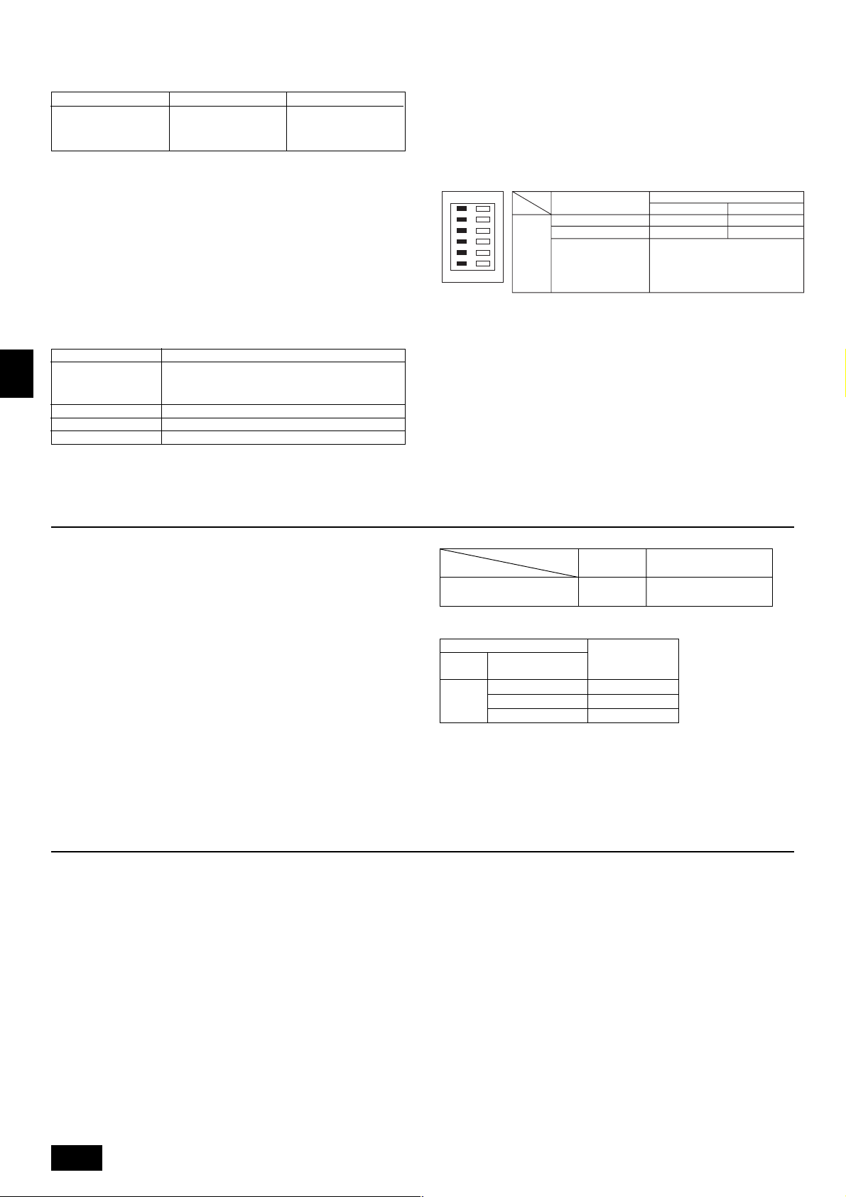
* Press the remote controller’s “CHECK” button twice consecutively to be able to run a self-check. See the chart below for content of error code displays.
LCD Nonconformity Content
P1 Suction sensor error
P2 Piping (liquid pipe) sensor error
P4 Drain sensor error
P5 Drain overflow safeguard operation
P6 Freezing/overheating safeguard operation
LCD Nonconformity Content LCD Nonconformity Content
P8 Pipe temperature error
P9 Piping (2-phase pipe) sensor error
U0 - UP Unit nonconformity
F1 - FA Unit nonconformity
E6 - EF Signal error between indoor-side controller
board and outdoor-side controller board
- - - - No error history
FFFF No relevant unit
E0 - E5 Signal error between remote controller and
unit
GB
D
F
NL
SWI
/
E
P
15
Page 16
See the chart below for details of the LED displays (LED 1, 2, 3) on the indoor-side controller board.
LED 1 (microcomputer power supply) Displays the ON/OFF of power for control. Check that this is lit during normal use.
LED 2 (remote controller feed) Displays the ON/OFF of feed to wired remote controller. Is only lit for the unit of outdoor-side controller board with address “00”.
LED 3 (indoor and outdoor signals) Displays signal between indoor-side and outdoor-side controller boards. Check that this is flashing during normal use.
2) Unit
1) Check Items
• After installation of the unit, and electric wiring work, check that the unit is free
from leaks of refrigerant, loosened connections, and incorrect polarity.
• Check that there is no negative phase and open phase. (The F1 message for
negative phase and the F2 message for open phase will flash at LED 1 on the
outdoor-side controller board. If this happens, rewire correctly.)
• Measure the impedance between power terminals (Single phase: L, N, /
triple phase: L1, L2, L3, N,
that it is 1.0 MΩ or more. Do not operate the equipment if measurement is less
than 1.0 MΩ.
• When there is no error at the unit.
(If there is an error at the unit, it can be evaluated at LED 1 [digital display] of
the outdoor-side controller board.)
•
The stop valves are open both the liquid and gas sides.
After checking the above, execute the test run in accordance with the following.
2) Test run start and finish
GB
The following setting is valid for only one applicable system. Make the same
setting to the other systems, so that the test run can be performed.
• Operation from the indoor-side controller board
Execute the test run using the installation manual for the indoor-side controller
board.
) and the ground with a 500 V Megger and check
D
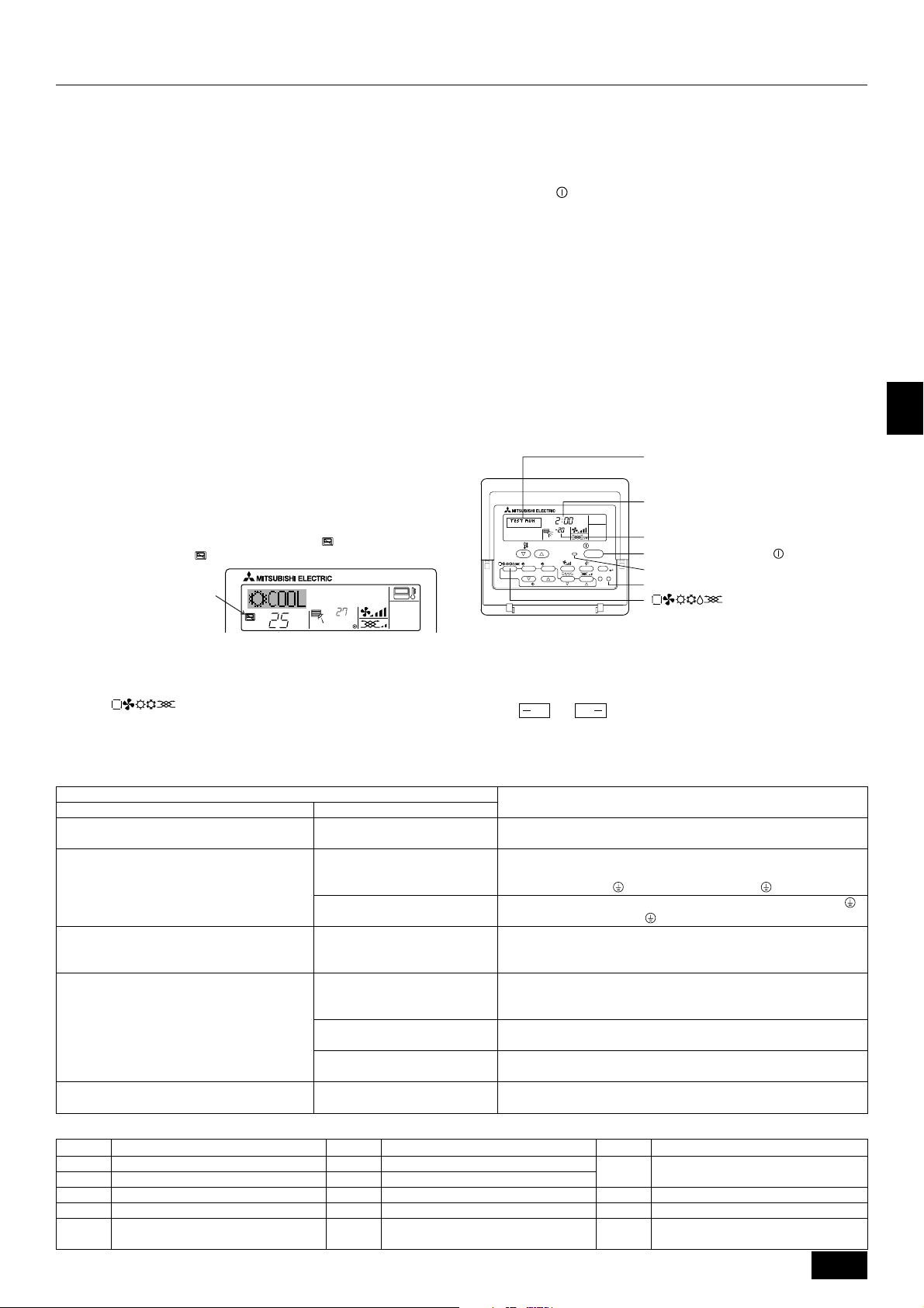
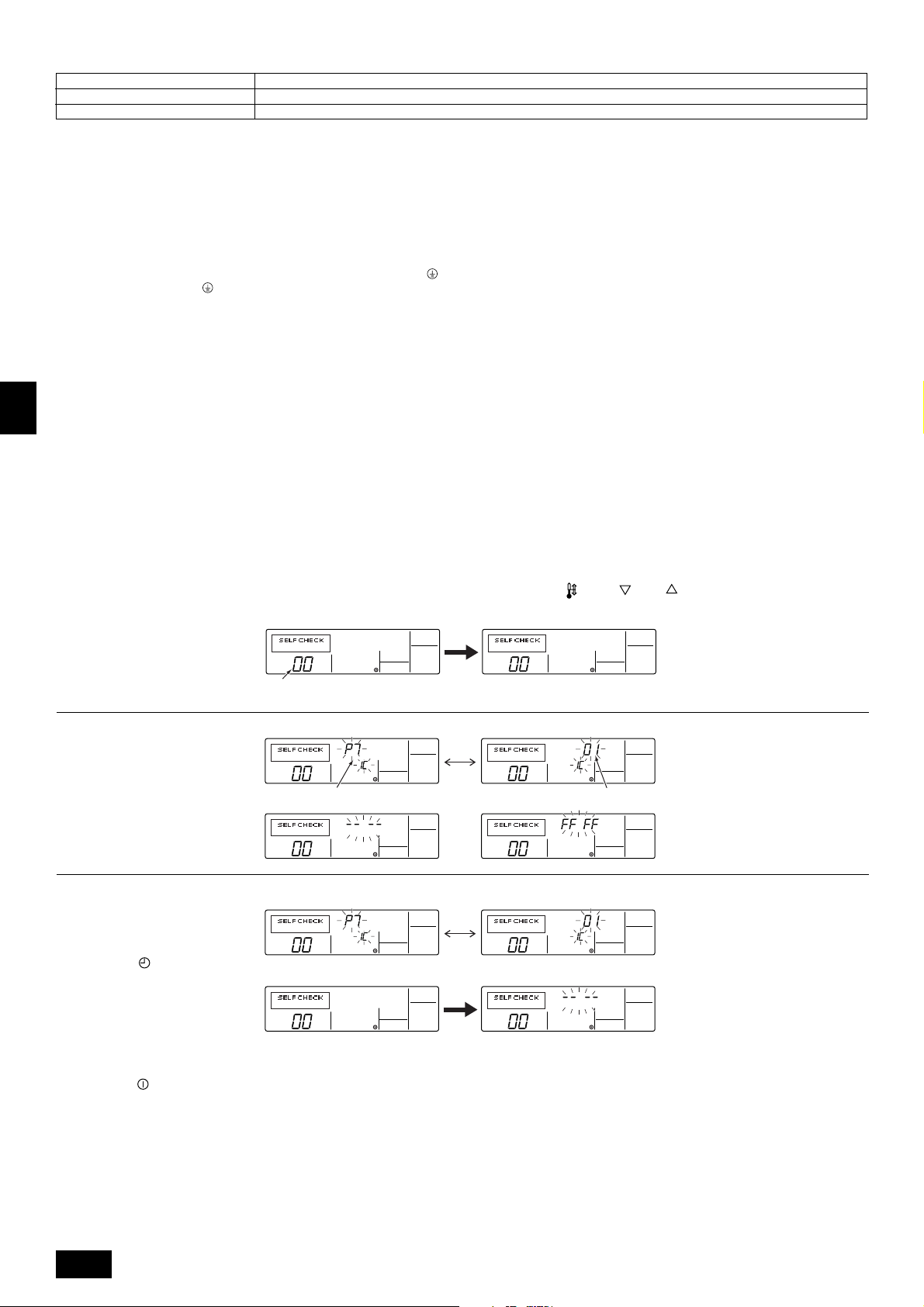
12.3. Self-check
Retrieve the error history of each unit using the remote controller.
1 Switch to the self check mode.
When the H [CHECK] button is pressed twice successively within three seconds, the display shown below appears.
F
• Operation from the outdoor-side controller board
Execute settings for test run start, finish and operation mode (cooling, heating)
using the DIP switch SW 4 on the outdoor-side controller board.
[Fig. 12.2.1] (P.5)
A Stop B Cooling
C Operation D Heating
1 Set the operation mode (cooling, heating) using SW 4-2
2 Turn ON SW 4-1, The operation mode for SW 4-2 will be adhered to, and
the test run will commence
3 Turn OFF SW 4-1 to finish the test run
• There may be a faint knocking noise emitted from the proximity of the fan
during the test run. This is torque fluctuation occurring due to control of fan
revolutions. There is no problem with the product.
Note:
The SW 4-2 operation mode cannot be changed during the test run. (To change
test run mode, stop the equipment with SW 4-1, change the operation mode,
then restart test run with SW 4-1.)
• If the 2-hour timer is set, the test run will stop automatically after 2 hours.
• During the test run, the room temperature display shows the unit indoor-side
liquid piping temperatures.
2 Set the address or refrigerant address No. you want to self check.
When the F [
creases and increases between 01 and 50 or 00 and 15. Set it to the address
No. or refrigerant address No. you want to self check.
TEMP. ( ) and ( )] buttons are pressed, the address de-
Self check address or self check refrigerant address
NL
3 Self check result display <Error history> (For the contents of the error code, refer to 13. Troubleshooting, error code list.)
ERROR CODE
Error code 4 digits or error code 2 digits
SWI
4 Error history reset
The error history is displayed in 3 Self check results display.
When the D [ MENU] button is pressed twice successively within three seconds, the self check address or refrigerant address flashes.
<When there is no error history>
ERROR CODE ERROR CODE
ERROR CODE ERROR CODE
E
5 Self check reset
There are the following two ways of resetting self check.
Press the H [CHECK] button twice successively within three seconds → Resets self check and returns to the state before self check.
Press the I [
P
ON/OFF] button → Self check resets and indoor units stop.
(When operation is prohibited, this operation is ineffective.)
Approximately three seconds after the change operation, the self check refrigerant address changes from flashing to a steady light and self check begins.
<When opposite side does not exist>
When the error history was reset, the display shown below appears.
When error history reset failed, the error contents are displayed again.
Address 3 digits or unit address No. 2 digits
ERROR CODE
16
Page 17
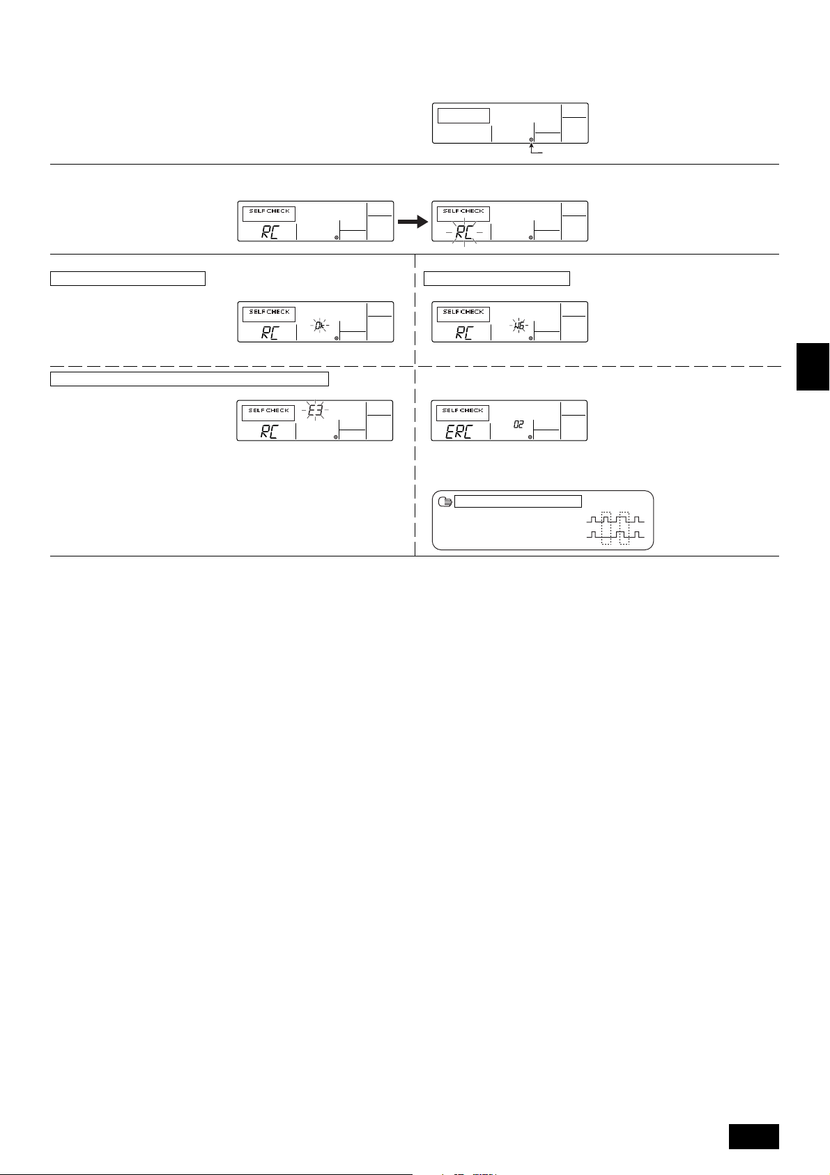
12.4. Remote controller check
If operation cannot be carried out from the remote controller, use this function to diagnose the remote controller.
1 First check the power mark.
When normal voltage (DC12V) is not applied to the remote controller, the power
mark goes off.
When the power mark is off, check the remote controller wiring and the indoor
unit.
2 Switch to the remote controller check mode.
When the H [CHECK] button is held down for five seconds or longer, the display shown below appears.
3 Remote controller check result
When remote controller is normal
When the A [FILTER] button is pressed, remote controller check begins.
When remote controller is faulty
(Error display 1) “NG” flashes → Remote controller send/receive circuit abnormal
Power mark
Since there is no problem at the remote controller, check for other causes.
When the problem is other than the checked remote controller
(Error code 2) “E3” “6833” “6832” flash → Cannot send
ERROR CODE
There is noise on the transmission line, or the indoor unit or another remote controller is faulty. Check the transmission line and the other remote controllers.
4 Remote controller check reset
When the H [CHECK] button is held down for five seconds or longer, remote controller check resets and the “PLEASE WAIT” and RUN lamp flash. Approximately 30
seconds later, the remote controller returns to the state before remote controller check.
Remote controller switching is necessary.
(Error display 3) “ERC” and data error count are displayed → Data error generation
“Data error count” is the difference between the number of bits of remote controller
send data and the number of bits actually sent to the transmission line. In this case,
the send data was disturbed by the noise, etc. Check the transmission line.
When data error count is 02
Remote controller send data
Send data on transmission line
GB
D
F
NL
SWI
17
E
P
Page 18
13. Troubleshooting
13.1. How to handle problems with the test run
Error code list: details
GB
D
F
NL
Remote controller
display
E0
E1, E2
E3
E4
E5
E6
E7
E8
E9
EA
EB
EC
ED
EE
F1
F8
A0
A2
A3
A6
A7
A8
EF
U2
U2
U3
U4
U6
UE
UL
F8
P1
P2
P4
P5
P5
P6
P6
P8
P9
MELANS display
6831,6834
6201,6202
6832,6833
6831,6834
6832,6833
6740,6843
6841,6842
6840,6843
6841,6842
6844
6845
6846
0403
0403
4103
4115
6600
6602
6603
6606
6607
6608
undefined
1102
1108
5104
5105
4101
1302
1300
4115
5101
5102
2503
2502
2500
1503
1504
1110
5103
Remote controller communication – reception error
Remote controller board error
Remote controller communication – transmission error
Remote controller communication – reception error
Remote controller communication – transmission error
Communication between indoor-side and outdoor-side controller boards – reception error
Communication between indoor-side and outdoor-side controller boards – transmission error
Communication between indoor-side and outdoor-side controller boards – reception error
Communication between indoor-side and outdoor-side controller boards – transmission error
Connection wiring error (interference, loose)
Connection wiring error (interference, loose)
Excessive time in use
Serial communication error
Serial communication error
Reverse phase, out of phase verification
Faulty input circuit
Duplicated M-NET address setting
M-NET error in PH/W transmission
M-NET bus busy
M-NET communication error with P transmission
M-NET error – no ACK
M-NET error – no response
Undefined error code
Discharge temperature error
CN23 Short-circuit Connector Unplugged
Open/short in discharge temp thermistor
Open/short in liquid temp or condenser/evaporater temp thermistor
Compressor overcurrent interruption (51C operation)
High pressure error (63H1 operation)
Low pressure error (63L operation)
Power synchronous idle circuit error
Inlet sensor error
Piping (liquid pipe) sensor error
Drain sensor error
Drain overflow protector operation
Water leak error
Freeze prevention operation
Surge prevention operation
Piping temperature error
Piping (2-phase pipe) sensor error
Error details
Problem location
Remote Controller
Remote Controller
Remote Controller
Indoor-side controller board
Indoor-side controller board
Indoor-side controller board
Indoor-side controller board
Outdoor-side controller board
Outdoor-side controller board
Outdoor-side controller board
Outdoor-side controller board
Outdoor-side controller board
Outdoor-side controller board
M-NET board
Outdoor-side controller board
Outdoor-side controller board
M-NET board
M-NET board
M-NET board
M-NET board
M-NET board
M-NET board
–
Outdoor-side controller board
Outdoor-side controller board
Outdoor-side controller board
Outdoor-side controller board
Outdoor-side controller board
Outdoor-side controller board
Outdoor-side controller board
Outdoor-side controller board
Indoor-side controller board
Indoor-side controller board
Indoor-side controller board
Indoor-side controller board
Indoor-side controller board
Indoor-side controller board
Indoor-side controller board
Indoor-side controller board
Indoor-side controller board
SWI
E
P
18
Page 19

• Depending on the position of the SW2 switch on the outdoor unit board, the segments light up to indicate the running condition of the unit and the particulars of the check
code.
SW2 setting
123456
000000
Operation mode/relay output
Item
tens place O: stop
C: cooling
H: heating
d: defrosting
units place 1: SV1
2: 21S4
4: 52C
When an error occurs, the error code
and error signal (*1) are displayed in
alternation.
Display contents
Relay output = SV1 + 21S4 + 52C
Ex. During cooling mode, when 52C and SV1 are ON: C5
011110
010110
011100
111100
*1 Display system for error indicator
The indicator corresponds to the following numbers
0 ............. Outdoor unit (OC1, OC2)
1 ............. Indoor unit (IC1, IC2)
Outdoor unit control condition
Indoor-side control condition (IC1)
Error code history 1
Error code history 2
Control mode display system
Nothing
The error code (ex. U8, UA) and error indicator (*1) are displayed in alternation.
Indoor-side
Outdoor-side
Display
0
1
2
3
4
5
6
7
Hot adjustment
Freeze prevention
Surge prevention
Compressor OFF
Control mode
Indoor-side
Ordinary
Defrosting
—
Heater ON
Outdoor-side
←
←
←
←
←
←
←
←
13.2. The following occurrences are not problems or errors
Problem
The fan setting changes during heating.
The fan stops during heating.
When the switch is turned ON, the fan does
not begin to operate.
The outdoor-side fan turns in reverse or stops,
and an unusual sound is heard.
Note:
If indoor-side fan does not operate, check the over-current relay on the fan motor to determine whether it has been tripped.
If the over-current relay has been tripped, reset it after eliminating the cause of the problem (e.g. motor lock).
To reset the over-current relay, open the control box and press the green claw on bottom-right of the relay until a click is heard. Release the claw and check that
it returns to its original position.
Note that if it is pressed too hard it will not return to its original position.
Remote controller display
Ordinary display
Defrosting display
Heating preparations
underway
Ordinary display
Cause
During thermostat OFF mode, light air or low air operation will take place.
During thermostat ON mode, light air or low air will switch automatically to set notch on
the basis of time or piping temperature.
During defrosting, the fan will stop.
After the switch is turned to ON or until the piping temperature reaches 35°C, there will
be 5 minutes of light air operation. After that there will be 2 minutes of low air operation,
then set notch will begin (hot adjustment control).
There is a risk of the power to the unit being connected in reverse phase. Be sure to
check that the phase is correct.
GB
D
F
NL
SWI
14. System control
14.1. System settings
[Fig. 14.1.1] (P.5)
A Unit B Main remote controller
C Subordinate remote controller D Refrigerant address = 00, 01
E Refrigerant address = 02, 03 F Refrigerant address = 04, 05
* Set the refrigerant address using the DIP switch of the outdoor-side controller
board.
1 Wiring from the Remote Control
This wire is connected to TB5 (terminal board for remote controller) of the unit
(non-polar).
2 When a Different Refrigerant System Grouping is Used
Up to 16 refrigerant systems can be controlled as one group using the MA remote
controller.
PRH-P400, 500MYA has two refrigeration systems per unit.
Note:
In single refrigerant system, there is no need of wiring
SW1
Function table
<SW1>
ON
OFF
123456
SW1
function
settings
Function
1 Compulsory de-
frosting
2 Error history clear
3
Refrigerant sys-
4
tem address set-
5
ting
6
Operation according to switch setting
ON OFF
Start Normal
Clear Normal
Settings for outdoor unit addresses 0 to 15
22
2.
22
E
P
19
Page 20
14.2. Examples of refrigerant system address
setting
Ex.
1
* Set the refrigerant system address of one unit to 00 for the power supply to the
remote controller.
(The refrigerant system address is set to 00 (OC1), 01 (OC2) when shipped from
the factory.)
Do not duplicate the refrigerant system address settings within the same system.
Unit
PRH-P400,
500MYA
Unit
OC1
OC2
Unit refrigerant
system address
00
01
Remote controller
power supply unit
14.3. Capacity control setting method (PRHP400, 500MYA only)
With the PRH-P400, 500MYA which has two outdoor-side units, the capacity can
be controlled to 0 %, 50 % or 100 %.
This is set by setting the outdoor-side unit side dip switches as shown in the table
below before turning the power on.
DipSW5-1
No.1 outdoor-side unit
OFF
No.2 outdoor-side unit
ON
GB
D
⳯
F
NL
SWI
E
P
20
Page 21
Inhalt
1. Sicherheitsvorkehrungen .......................................................................... 21
1.1. Vor Installations- und Elektroarbeiten...................................... 21
1.2. Vorsichtsmaßnahmen für Vorrichtungen, die das Kältemittel
R407C verwenden ................................................................... 22
1.3. Vor der Aufstellung .................................................................. 22
1.4. Vor dem Einbau (der Ortsveränderung) - Elektroarbeiten ....... 22
1.5. Vor Installationsbeginn ............................................................ 22
2. Zubehör .................................................................................................... 23
3. Einen Aufstellort wählen ........................................................................... 23
3.1. Vorgeschriebener Freiraum um das Anlage ............................ 23
4. Hebemethode und Gewicht der Klimaanlage ........................................... 23
5. Einbau der Klimaanlage ............................................................................ 23
5.1. Einbau ..................................................................................... 23
6. Rohrleitungen verlegen ............................................................................. 24
7. Arbeiten am Strömungskanal ................................................................... 24
7.1. Frischluftzufuhr, Strömungskanalinstallation und Betriebsein-
schränkungen .......................................................................... 24
8. Fernbedienung .......................................................................................... 24
8.1. Installationsabläufe .................................................................. 24
8.2. Anschlußverfahren .................................................................. 25
1. Sicherheitsvorkehrungen
1.1. Vor Installations- und Elektroarbeiten
s Vor dem Einbau der Anlage vergewissern, daß Sie alle Infor-
mationen über “Sicherheitsvorkehrungen” gelesen haben.
s Die “Sicherheitsvorkehrungen” enthalten sehr wichtige
Sicherheitsgesichtspunkte. Sie sollten sie unbedingt befolgen.
Im Text verwendete Symbole
Warnung:
Beschreibt Vorkehrungen, die beachtet werden sollten, um den Benutzer vor
der Gefahr von Verletzungen oder tödlicher Unfälle zu bewahren.
Vorsicht:
Beschreibt Vorkehrungen, die beachtet werden sollten, um die Anlage vor
Schäden zu bewahren.
An der Anlage angebrachte Zeichen
: Verweist auf eine Handlung, die unterbleiben muß.
: Verweist auf wichtige Anweisungen, die befolgt werden müssen.
: Verweist auf ein Teil, das geerdet werden muß.
: Zeigt an, daß bei rotierenden Teilen Vorsichtgeboten ist. (Dieses Symbol
findet sich als Aufkleber auf der Hauptanlage.) <Farbe: gelb>
: Gefahr von elektrischem Schlag. (Dieses Symbol findet sich als Aufkleber
auf der Hauptanlage.) <Farbe: gelb>
Warnung:
Die auf der Hauptanlage angebrachten Aufkleber sorgfältig lesen.
Warnung:
• Bitten Sie Ihren Fachhändler oder einen geprüften Fachtechniker, die Installation der Anlage vorzunehmen.
- Unsachgemäße Installation durch den Benutzer kann Wasseraustritt, Strom-
schläge oder Brände verursachen.
• Die Anlage an einem Ort installieren, der genügend Tragkraft für deren
Gewicht besitzt.
- Bei ungenügender Tragkraft kann das Anlage herunterfallen und Verletzun-
gen verursachen.
• Zur Verdrahtung die angegebenen Kabel verwenden. Die Anschlüsse so
sichern, daß Zugspannung von außen nicht auf die Klemmen wirken kann.
- Falscher Anschluß und falsche Befestigung führen zu Wärmebildung und
verursachen Brände.
• Vorsorge gegen heftige Windstöße und Erdbeben treffen, und die Anlage
an dem angegebenen Ort installieren.
- Durch unsachgemäße Installation kann die Anlage herunterfallen und Ver-
letzungen verursachen.
• Stets Zubehör gemäß Angaben von Mitsubishi Electric verwenden.
- Einen geprüften Techniker bitten, die Zusatzeinrichtungen zu installieren.
Unsachgemäße Installation durch den Benutzer kann zu Wasseraustritt,
Stromschlägen oder Bränden führen.
8.3. Anbringung des oberen Kastens ............................................. 25
8.4. Funktionswahl.......................................................................... 25
9. Elektroverdrahtung .................................................................................... 29
9.1. Einstellung der Adresse .......................................................... 29
9.2. Kabelanschluß ......................................................................... 29
10. Installation des Riemens ........................................................................... 30
11. Änderung der Gebläserichtung (von seitlichen Zufuhr auf Zufuhr von oben) .... 30
12. Testlauf ..................................................................................................... 30
12.1. Vor dem Testlauf ...................................................................... 30
12.2. Testlaufverfahren ..................................................................... 30
12.3. Selbsttest ................................................................................. 32
12.4. Test der Fernbedienung .......................................................... 33
13. Fehlerbehebung ........................................................................................ 34
13.1. Handhabung von Problemen beim Testlauf ............................. 34
13.2. Die folgenden Erscheinungen stellen keine Probleme oder
Fehler dar ................................................................................ 35
14. Kontrolle des Systems .............................................................................. 35
14.1. Systemeinstellungen ............................................................... 35
14.2. Beispiele für die Kältemittel-Adresseneinstellung ................... 36
14.3. Einstellungsverfahren für Kapazitätssteuerung
(nur PRH-P400, 500MYA) ....................................................... 36
• Die Anlage niemals selbst reparieren. Wenn die Anlage repariert werden
muß, wenden Sie bitte sich an den Fachhändler.
- Wenn die Anlage unsachgemäß repariert wird, kann dies zu Wasseraustritt,
Stromschlägen oder Bränden führen.
• Nicht die Wärmetauscherleitung berühren.
- Unsachgemäße Handhabung kann zu Verletzungen führen.
• Tragen Sie bei der Handhabung dieses Erzeugnisses immer Schutzausrüstung, d.h. Handschuhe, vollen Armschutz wie einen Overall und eine
Schutzbrille.
- Unsachgemäße Handhabung kann zu Verletzungen führen.
• Die Anlage gemäß Anweisungen in diesem Installations-handbuch installieren.
- Bei unsachgemäßer Installation kann dies zu Wasseraustritt, Stromschlägen
oder Bränden führen.
• Elektroarbeiten durch einen zugelassenen Fachelektriker in Übereinstimmung mit dem “Electric Facility Engineering Standard” - (Technische
Normen für Elektroeinrichtungen), den “Interior Wire Regulations” - (Vorschriften zur Innenverdrahtung) und den in diesem Handbuch gegebenen Anweisungen vornehmen. Anlage auch immer an einen gesonderten Stromkreis anschließen.
- Wenn die Leistung der Stromquelle ungenügend ist oder die Elektroarbeiten
unsachgemäß ausgeführt wurden, kann dies zu Stromschlägen und zu Bränden führen.
• Die Abdeckung der Elektroanschlüsse (Abdeckplatte) fest anbringen.
- Wenn die Abdeckung der Elektroanschlüsse (Abdeckplatte) nicht sachge-
mäß angebracht wurde, kann Staub oder Wasser in die Anlage eindringen
und Brände oder Stromschläge verursachen.
• Nach Verbringen an einen anderen Standort Anlage nur mit dem vorgeschriebenen Kältemittel (R407) füllen.
- Wenn das ursprüngliche Kältemittel mit einem anderen Kältemittel oder mit
Luft vermischt wird, kann dies zu Fehlfunktionen des Kältemittelkreislaufs
führen und die Anlage beschädigt werden.
• Beim Verbringen der Anlage an einen anderen Ort einen Fachhändler
oder einen geprüften Techniker zur Neuaufstellung hinzuziehen.
- Bei unsachgemäßer Installation der Anlage kann Wasser austreten, und es
können Stromschlage oder Brände verursacht werden.
• Die Einstellungen der Schutzvorrichtungen nicht neu einrichten oder
ändern.
- Wenn Druckschalter, Thermoschalter oder eine andere Schutzvorrichtung
kurzgeschlossen oder mit Gewalt betätigt wird oder wenn andere als die von
Mitsubishi Electric angegebenen Teile verwendet werden, besteht Brandoder Explosionsgefahr.
• Nicht auf die Anlage steigen.
- Wenn jemand auf die Anlage steigt, kann die Oberplatte verformt werden,
und es besteht die Gefahr von Verletzungen.
• Zum Entsorgen dieses Gerätes wenden Sie sich an Ihren Fachhändler.
• Der Installateur und der Systemfachmann müssen für die Sicherung gegen Wasseraustritt gemäß den örtlichen Bestimmungen und Normen
sorgen.
- Falls keine örtlichen Bestimmungen bestehen, sind die nachstehenden Nor-
men anzuwenden.
• Besondere Beachtung ist den örtlichen Verhältnissen wie etwa dem Kellergeschoß etc. zu schenken, wo sich Kältemittelgas ansammeln kann, da
Kältemittel schwerer als Luft ist.
• Das Gerät ist nicht für unbeaufsichtigte Verwendung durch junge Kinder
oder gebrechliche Personen gedacht.
• Junge Kinder sollten beaufsichtigt werden, um sicherzustellen, dass sie
nicht mit dem Gerät spielen.
GB
D
F
NL
SWI
E
P
21
Page 22
1.2. Vorsichtsmaßnahmen für Vorrichtungen, die das Kältemittel R407C verwenden
Vorsicht:
• Zur Füllung des Systems flüssiges Kältemittel verwenden.
- Wenn Kältemittelgas zur Füllung des Systems verwendet wird, ändert sich
die Zusammensetzung des Kältemittels im Zylinder, so daß die Leistung
abfallen kann.
• Kein anderes Kältemittel als R407C verwenden.
- Bei Verwendung eines anderen Kältemittels (R22 etc.) kann das Chlor zur
Qualitätsminderung des Kältemaschinenöls führen.
• Eine Vakuumpumpe mit einem Reverse Flow (Gegenstrom)-Rückschlagventil verwenden.
- Das Öl der Vakuumpumpe fließt in den Kältemittelkreislauf zurück und führt
zur Qualitätsminderung des Kältemaschinenöls.
• Folgende Vorrichtungen, die bei herkömmlichen Kältemitteln verwendet
werden, nicht einsetzen.
(Meßrohrleitung, Füllschlauch, Gasaustrittsdetektor, Reverse Flow
(Gegenstrom)- Rückschlagventil, Kältemittelfüllständer, Kältemittelaufbereitungseinrichtungen)
- Wenn ein herkömmliches Kältemittel und Kältemaschinenöl mit R407C ver-
mischt werden, kann dies zur Qualitätsminderung des Kältemaschinenöls
GB
D
führen.
- Wenn R407C mit Wasser vermischt wird, kann dies zur Qualitätsminderung
des Kältemaschinenöls führen.
- Da R407C kein Chlor enthält, reagieren Gasaustrittssuchgeräte für herkömm-
liche Kältemittel nicht darauf.
• Keinen Füllzylinder verwenden.
- Bei Verwendung eines Füllzylinders kann das Kältemittel verderben.
• Beim Einsatz der Handhabungsvorrichtungen besondere Sorgfalt walten lassen.
- Wenn Staub, Schmutz oder Wasser in den Kältemittelkreislauf gelangt, kann
dies zur Qualitätsminderung des Kältemittels führen.
1.3. Vor der Aufstellung
F
NL
SWI
Vorsicht:
• Anlage nicht an Orten installieren, wo brennbares Gas austreten kann.
- Wenn Gas austritt und sich um die Anlage herum ansammelt, kann dies zu
einer Explosion führen.
• Anlage nicht an Orten verwenden, wo sich Lebensmittel, Tiere, Pflanzen,
Präzisionswerkzeuge oder Kunstgegenstände befinden.
- Die Qualität der Lebensmittel etc. kann sich verschlechtern.
• Anlage nicht unter besonderen Umfeldbedingungen einsetzen.
- Dichter Öldampf, Dampf oder schwefelhaltiger Rauch können die Leistung
der Klimageräte erheblich beeinträchtigen oder Teile der Anlage beschädigen.
• Bei Installation der Anlage in einem Krankenhaus, einer Rundfunkstation oder an ähnlichen Orten für ausreichend Lärmschutz sorgen.
- Der Betrieb der Anlage kann gestört oder unterbrochen werden, wenn sie
durch Aufnahmegeräte, private Stromerzeugungseinrichtungen, medizinische
Hochfrequenzgeräte oder Rundfunkeinrichtungen beeinflußt wird, und umgekehrt kann der Betrieb der Anlage die Funktion dieser Geräte und Einrichtungen beeinträchtigen und Lärm erzeugen, der ärztliche Behandlungen stört
oder Bildübertragungen beeinträchtigt.
• Die Anlage nicht auf Baueinrichtungen installieren, die Wasseraustritt
verursachen können.
- Wenn die Luftfeuchtigkeit 80 % übersteigt oder wenn die Abwasserleitung
verstopft ist, kann Kondenswasser aus der Innenanlage tropfen. Daher die
vorgesehene Sammelabwasserleitung der Außenanlage einrichten.
E
P
1.4. Vor dem Einbau (der Ortsveränderung)
- Elektroarbeiten
Vorsicht:
• Erdung der Anlage.
- Die Erdungsleitung nicht an Gas- oder Wasserrohre, Beleuchtungsstäbe oder
an die Erdleitungen von Telefonen anschließen. Unsachgemäße Erdung kann
zu Stromschlägen führen.
• Die Gegenphase von L-Leitungen (L
(Fehlerkabel: 4103), aber die Gegenphase von L-Leitungen und N-Leitung kann nicht festgestellt werden.
- Wenn bei fehlerhafter Verdrahtung Strom zugeführt wird, können einige
Elektroteile beschädigt werden.
• Netzstromleitungen so anbringen, daß keine Zugspannung auf die Kabel
ausgeübt wird.
- Zugspannung kann Kabelbruch, Wärmebildung und Brände verursachen.
• Installieren Sie bei Bedarf einen Erdschlussunterbrecher.
- Wenn kein Erdschlussunterbrecher installiert ist, kann es zu Stromschlägen
kommen.
• Netzstromkabel mit ausreichender Stromstärke und Nennwertauslegung
verwenden.
- Zu kleine Kabel können Fehlstrom verursachen, Wärme erzeugen und Brand
ausbrechen lassen.
• Nur Stromunterbrecher und Sicherungen der angegebenen Leistung verwenden.
- Eine Sicherung oder ein Stromunterbrecher von größerer Stärke oder Stahl-
oder Kupferdraht können zum Ausfall der Anlage oder zum Ausbruch von
Bränden führen.
• Klimaanlage nicht waschen.
- Waschen der Anlage kann Stromschläge verursachen.
• Sorgfältig darauf achten, daß die Installationsplatte durch langen Gebrauch nicht beschädigt wird.
- Wenn der Schaden nicht behoben wird, kann die Anlage herunterfallen und
Personenschäden oder Schäden an der Einrichtung hervorrufen.
• Zur Gewährleistung eines ordnungsgemäßen Wasserablaufs die Abwasserleitung gemäß Anweisungen in diesem Installationshandbuch installieren. Rohrleitungen mit Wärmeisolierung versehen, um
Kondenswasserbildung zu verhindern.
- Unsachgemäß angebrachte Abwasserleitungen können Wasseraustritt ver-
ursachen und Schäden an Möbeln oder sonstigen Einrichtungsgegenständen
nach sich ziehen.
• Beim Transport der Anlage sehr sorgfältig vorgehen.
- Wenn der Gegenstand mehr als 20 kg wiegt, nicht nur eine Person zum
Tragen einsetzen.
- Bei einigen Produkten besteht die Verpackung aus Kunststoffbändern. Zum
Transport keine Kunststoffbänder verwenden.
- Nicht die Rippen des Wärmetauschers berühren. Man kann sich dadurch die
Finger verletzen.
- Beim Transport der Außenanlage diese an den angegebenen Stellen der
Grundplatte der Anlage aufhängen. Auch die Außenanlage an vier Punkten
unterstützen, damit sie nicht zur Seite wegrutschen kann.
• Verpackungsmaterial sicher entsorgen
- Verpackungsmaterial, wie Nägel und andere Metall- oder Holzteile, können
Stichwunden oder sonstige Verletzungen verursachen.
- Kunststoffbeutel zerreißen und entsorgen, damit Kinder nicht mit ihnen spie-
len. Wenn Kinder mit Kunstoffbeutel spielen, die nicht zerrissen wurden, besteht Erstickungsgefahr.
1, L2, L3) kann festgestellt werden
1.5. Vor Installationsbeginn
Vorsicht:
• Strom mindestens 12 Stunden vor Betriebsbeginn einschalten.
- Betriebsbeginn unmittelbar nach Einschalten des Netzschalters kann zu
schwerwiegenden Schäden der Innenteile führen. Während der Saison Netzschalter eingeschaltet lassen.
• Schalter nicht mit nassen Fingern berühren.
- Berühren eines Schalters mit nassen Fingern kann einen Stromschlag ver-
ursachen.
• Kältemittelrohrleitung nicht während oder unmittelbar nach Betrieb berühren.
- Während und unmittelbar nach Betrieb sind die Kältemittelrohrleitungen, je
nach Durchfluß des Kältemittels durch die Kältemittelrohrleitung, den Kompressor und andere Teile des Kältemittelkreislaufs, manchmal heiß und
manchmal kalt. Sie können sich die Hände verbrennen oder Frostverletzungen
erleiden, wenn Sie die Kältemittelrohrleitung berühren.
• Klimageräte nicht bei abgenommenen Verkleidungen und Schutzabdeckungen betreiben.
- Drehende, heiße oder unter Hochspannung stehende Teile können Verlet-
zungen verursachen.
22
Page 23
2. Zubehör
1 Rohrleitungshalteplatten × 2 2 Selbstschneidende Schrauben M4 × 4 3 Fernbedienung
3. Einen Aufstellort wählen
• Einen Aufstellort mit stabiler, fester Fläche, die für das Gewicht der Anlage
haltbar genug ist, wählen.
• Vor Einbau der Anlage muß der Weg zum Transport der Anlage an den Aufstellort festgelegt werden.
• Einen Aufstellort wählen wo die Anlage nicht durch eindringende Luft beeinflußt wird.
• Einen Aufstellort wählen wo der Strom der Zu- und Abluft nicht behindert ist.
• Einen Aufstellort wählen wo die Luft aus der Anlage sich vollständig im Raum
verteilen kann.
• Die Anlage nicht an einem Ort aufstellen, wo in größeren Mengen Öl verspritzt
oder Dampf erzeugt wird.
• Die Anlage nicht an einem Or t aufstellen, wo brennbares Gas erzeugt werden,
hereinströmen, verbleiben oder austreten kann.
• Die Anlage nicht an einem Ort aufstellen, wo durch Einrichtungen Hochfrequenzwellen entstehen können (z.B. durch ein Hochfrequenz-Schweißgerät).
• Die Anlage nicht an einem Ort aufstellen, wo sich an derSeite, wo die Luftaustritt, ein Feuermelder befindet. (Der Feuermelder kann versehentlich in Gang
gesetzt werden, wenn während des Heizbetriebs Warmluft austritt)
• Wo spezielle chemische Produkte im Raum verteilt sein können, wie in chemischen Anlagen und Krankenhäusern, ist vor Aufstellung der Anlage eine umfassende Untersuchung erforderlich. (Die Kunststoffteile können je nach Art
der chemischen Produkte, denen sie ausgesetzt sind, beschädigt werden)
3.1. Vorgeschriebener Freiraum um das
Anlage
[Fig. 3.1.1] (P.2)
<A> Ansicht von oben <B> Vorderansicht
<C> Seitenansicht
A Vorderseite B (Muß offen sein)
C Wandhöhe (H)
L1: 450 L2: 450 L3: 250
(1) Grundlegender Platzbedarf
Auf der rechten Seite muss ein Freiraum von mindestens 250 mm für Luftzufuhr
eingehalten werden. Unter Berücksichtigung von Wartung u. Ä. von rechts muss
ebenso wie an der Vorder- und Rückseite ein Freiraum von etwa 450 mm vorgesehen werden.
(2) Wenn sich oberhalb der Anlage ein Hindernis befindet
(3) Wenn die Klimaanlage von Wänden umgeben ist
Hinweis:
• Wandhöhen (H) an der Vorder- und Rückseite müssen innerhalb der Gesamthöhe der Anlageplatte liegen.
• Wenn die Gesamthöhe überschritten wird, L
on in Fig.3.1.1 hinzufügen.
L1: 450 L2: 450 L3: 250
Beispiel: Wenn h = 100,
ergibt sich ein Maß L
(4) Fortlaufende Installation
• Erforderlicher Freiraum für permanente Installation:
Bei Aufstellung mehrerer Anlage ausreichend Abstand zwischen den Anlagen
lassen, um eine ausreichende Luftzirkulation und eine gute Erreichbarkeit zu
gewährleisten.
• In zwei Richtungen offen.
• Falls die Wandhöhe die Gesamthöhe der Klimaanlage überschreitet, ist in der
folgenden Tabelle die oben gezeigte Dimension “h” (h = Wandhöhe <H> - Gesamthöhe der Klimaanlage) zu der mit * markierten Dimension hinzuzufügen.
1 von 450 + 100 = 550 mm.
1, L2 und L3 die “h”-Dimensi-
GB
D
F
4. Hebemethode und Gewicht der Klimaanlage
[Fig. 4.0.1] (P.2)
Vorsicht:
• Vorsicht beim Transport des Aggregats.
- Keine Lasten über 20 kg allein tragen.
- Einige Produkte sind eventuell mit PP-Bändern verschnürt. PP-Bänder sind gefährlich und sollten nicht für den Transport eines Produkts verwendet werden.
- Darauf achten, die Kühlrippen des Wärmeaustauschers nicht mit den bloßen Händen zu berühren. Eine falsche Handhabung kann Schnitte verursachen.
- Plastikverpackungsbeutel nach dem Auspacken zerkleinern und entsorgen, so daß Kinder nicht damit spielen können. Plastikbeutel in Kinderhänden können zum Tod
durch Ersticken führen.
- Das Außenaggregat an vier Punkten aufgehängt tragen. Eine 3-Punkt-Aufhängung ist zum Anheben und Tragen des Anlage nicht ausreichend und kann dazu führen,
daß das Anlage fällt.
• Kanten der Anlage, die mit den Transportbändern in Berührung kommen, polstern.
5. Einbau der Klimaanlage
5.1. Einbau
[Fig. 5.1.1] (P.2)
A Vor Ort zu beschaffender Ankerbolzen M10.
B Ecke sitzt nicht einwandfrei.
• Die Klimaanlage, wie in der Abbildung gezeigt, fest mit Schrauben verankern,
so daß auch bei starken Windstößen oder Erschütterungen durch Erdbeben
usw. ausreichend Standfestigkeit gewährleistet ist.
• Für das Stellgerüst Zement oder Winkelstahl verwenden.
• Je nach Installationsbedingungen können im Aufstellbereich Schwingungen
entstehen sowie Geräusche und Schwingungen an Boden und Wänden erzeugt
werden. Daher reichlich Vibrationsschutz (Polstermaterial etc.) vorsehen.
• Dafür sorgen, daß die Ecken einen festen Sitz haben. Wenn dies nicht der Fall
ist, können sich die Befestigungsfüße verbiegen.
[Fig. 5.1.2] (P.2)
A Ständer
• Beim Bau des Fundamentes für das Anlage in der Mitte der Grundplatte einen
Ständer anbringen.
Warnung:
• Die für den Einbau gewählte Aufstellfläche muß dem Gewicht des Anlage
mühelos standhalten.
Eine nicht ausreichend stabile Standfläche kann dazu führen, daß das
Anlage umfällt und Personen verletzt.
• Das Aggregat wie in der Anleitung beschrieben einbauen, um Schäden
durch starken Wind oder Erdebenerschütterungen zu vermeiden.
Fehler beim Einbau können dazu führen, daß das Anlage umfällt und
Unfälle mit Personenverletzungen verursacht.
Beim Bauen des Fundaments beachten Sie die Tragfähigkeit des Bodens, den
Abwasseranschluss “beim Betrieb läuft Wasser aus dem Gerät” und die Kabelführung.
Vorsichtsmaßregeln zur Abverdrahtung
Beim Ausführen der Abverdrahtung stellen Sie sicher, dass Fundament- und Basisarbeiten nicht die Basisdurchlauflöcher blockieren.
[Fig. 5.1.3] (P.2)
A Bodenverdrahtungs-Durchführungsloch
B (Bolzenöffnung)
NL
SWI
E
P
23
Page 24
6. Rohrleitungen verlegen
[Fig. 6.0.1] (P.3)
A Rohrleitung
B Anschluß R1
C Geruchverschluß
D Das Auslaufrohr sollte bis unter diesen Pegel reichen.
>
E
2 × externer statischer Außendruck
=
>
F
2 × E
=
7. Arbeiten am Strömungskanal
1. Im Falle von seitlicher Luftzufuhr (Werkseinstellung) ist die Anlage mit horizontalen Luftzu- und -abfuhröffnung versehen. Der Anschluß der Strömungskanäle
an die Anlage sollte mit Strömungskanalflanschen vorgenommen werden und
sie sollten mit flexiblen Flanschverbindern direkt an die Luftöffnungen befestigt werden, um eine Geräuschübertragung zu vermeiden.
2. Bei vertikaler Luftzufuhr sollte ein vor Ort beschafftes Plenum verwendet werden.
Die folgende Abbildung zeigt die empfohlene Methode zum Anschluß der
Strömungskanäle.
GB
3. Im Falle einer Luftzufuhr von oben (bei Installation eingerichtet) ist die Anlage
mit vertikalen Luftzufuhr- und horizontalen Luftabfuhröffnungen versehen. Der
Anschluß der Strömungskanäle an die Anlage sollte mit Strömungskanalflanschen vorgenommen werden und sie sollten mit flexiblen Flanschverbindern
direkt an die Luftöffnungen befestigt werden.
Da in einer Position mit Luftströmung an der Oberseite das Sirocco-Gebläse
D
nicht ohne Entfernen der oberen Platte abgenommen werden kann, ist für die
Abnahme der oberen Platte genügend Freiraum zu lassen. Dazu muss der
Segeltuch-Luftkanal zwischen Luftkanalflansch und Luftkanal eingerichtet
werden.
4. Um Luftlecks zu vermeiden, sollten alle Stöße der Strömungskanäle abge-
dichtet werden.
Strömungskanäle, die in nicht klimatisierten Räumen verlaufen, müssen iso-
F
liert und mit einer Feuchtigkeitssperre versehen werden.
Strömungskanäle, die außerhalb des Gebäudes verlaufen, müssen wetterfest
sein.
Wir empfehlen für einen geräuscharmen Betrieb, die Isolierung für den Zufuhrströmungskanal im Inneren anzubringen und den Kanal so auszufüttern.
5. Wenn Luftkanäle von der Außenseite in das Gebäude geführt werden, müs-
sen die Durchbrüche für den Luftkanal im Gebäude mit wetterfesten Schutz-
NL
streifen versiegelt werden, damit Regen, Staub, Sand etc. nicht in das Gebäu-
de eindringen können.
6. Gebläse verkraften keinen äußeren Widerstand für den Luftfluß und Vorkeh-
rungen sind verfügbar, wenn Strömungskanäle an den externen Gebläsen
angebracht werden.
7. Filter in korrekter Größe müssen angebracht werden; innerhalb der Anlage ist
keine Möglichkeit dazu vorhanden, die (vor Ort beschafften) Filter können aber
SWI
in der Abluft installiert werden.
8. Die Strömungskanalerdung muß an den Erdungsanschluß der Anlage ange-
E
schlossen werden (
[Fig. 7.0.1] (P.3)
<A> Beispiel Seitliche Luftzufuhr
<B> Beispiel Luftzufuhr von oben
A Strömungskanal B Dachoberfläche
C Einzelströmungskanal-Teiler D Plenum-Teiler
E Isolierung
F Strömungskanallänge 850 mm oder länger
G Den Teil regenfest abdichten, wo der Strömungskanalflansch angeschraubt ist
(nur Luftzufuhr von oben).
H Segeltuch-Luftkanal (500 mm oder mehr Freiraum für Segeltuch-Luftkanal vor-
sehen).
I Obere Platte
Markierung).
1. Der Anschluß (R1) für das Kondenswasserauslaufrohr befindet sich im Lieferumfang. Das Auslaufrohr wird an den Anschluß angeschlossen.
2. Das Auslaufrohr muß außerhalb der Anlage mit einem Geruchverschluß ver-
sehen werden und außerdem für eine ordnungsgemäßen Ablauf mit einem
Gefälle verlegt werden, wie in [Fig. 6.0.1] (P. 3) gezeigt.
3. Um Tropfenbildung zu vermeiden, Auslaufrohrleitungen isolieren.
4. Nach Abschluß der Rohrleitungsarbeiten überprüfen, daß keine Lecks vor-
handen sind und das Wasser ordnungsgemäß abläuft.
Vorsicht:
• Nicht auf die Anlage steigen.
- Wenn jemand auf die Anlage steigt, kann die Oberplatte verformt werden,
und es besteht die Gefahr von Verletzungen.
• Der Ausgangsströmungskanal muß auf 850 mm oder mehr ausgelegt
werden.
• Den Hauptkörper der Klimaanlage und den Strömungskanal zum potentiellen Ausgleich miteinander verbinden.
• Bei einem Anlage mit Luftströmung an der Oberseite 500 mm oder mehr
Freiraum für Segeltuch-Luftkanal vorsehen.
Befestigungslöcher für Flansch des Ausgangsführungskanals und Eingangsströmungskanals.
[Fig. 7.0.2] (P.3)
<A> Beispiel Seitliche Luftzufuhr
<B> Beispiel Luftzufuhr von oben
A Flansch Luftabfuhrströmungskanal B Flansch Luftzufuhrströmungskanal
7.1. Frischluftzufuhr, Strömungskanal-
installation und Betriebseinschränkungen
Diese Anlage verfügt auf jeder Seite über eine Frischluftzufuhr. Wählen Sie die für
Ihre Zwecke geeignete.
[Fig. 7.1.1] (P.3)
A Frischluftzufuhr (auf beiden Seiten)
Vorsicht:
11
1 Strömungskanalstöße ordnungsgemäß abdichten.
11
22
2 An der Öffnung einen Filter in geeigneter Größe installieren und den Fil-
22
ter regelmäßig reinigen.
33
3 Strömungskanal länger als 850 mm installieren oder die Öffnung mit ei-
33
nem Drahtgitter versperren, damit niemand mit der Hand in die Anlage
gelangen kann.
44
4 Die Öffnung des montierten Strömungskanal darf nicht nach oben wei-
44
sen, weil sonst Regen oder Schnee in den Strömungskanal gelangt.
55
5 Vergewissern Sie sich, daß sich die Temperatur der Mischluft (Abfuhrluft
55
und Außenluft) in den folgenden Bereichen befindet:
Beim Kühlen: Mischlufttemperatur 15
Beim Heizen: Mischlufttemperatur 15
66
6 Luftrückfluß-Sperrplatten in den Abluft- und Luftzufuhrströmungskanälen
66
installieren, um einen Rückfluß der Luft bei Stillstand der Anlage zu verhindern.
[Fig. 7.1.2] (P.3)
A Filter (vor Ort beschafft)
B Frischluftzufuhr-Strömungskanal (vor Ort beschafft)
° CWB ~ 24° CWB (30 ~ 80% RH)
° CDB ~ 32° CDB
8. Fernbedienung
P
8.1. Installationsabläufe
(1) Aufstellungsort für Fernbedienung (Schaltkasten) auwählen.
Dabei nachstehende Vorsichtsmaßnahmen beachten.
[Fig. 8.1.1.(1)] (P.4)
A Form der Fernbedienung
B Erforderliche Freiräume um die Fernbedienung herum
C Temperaturfühler D Installationsteilung
24
1 Die Temperaturfühler befinden sich sowohl an der Fernbedienung als auch an
der Innenanlage. Den Temperaturfühler an der Fernbedienung hauptsächlich
zur Temperatureinstellung oder zur Ermittlug der Raumtemperatur verwenden.
Die Fernbedienung an einer Stelle anbringen, an der die durchschnittliche
Raumtemperatur festgestellt werden kann, ohne daß sie durch direktes Sonnenlicht, Luftstrom aus der Klimaanlage oder sonstige Heizquellen beeinflußt wird.
Page 25
2 In jedem Falle, ob nun die Fernbedienung im Schaltkasten oder an der Wand
befestigt wird, dafür sorgen, daß die in der Zeichnung angegebenen Freiräume
eingehalten werden.
Hinweis:
Vergewissern, daß sich in der Nähe des Fühlers der Fernbedienung keine
Elektroleitung befindet. Wenn sich eine Elektroleitung nahe dem Fühler befindet, kann die Fernbedienung u.U. die richtige Raumtemperatur nicht feststellen.
3 Folgende Teile vor Ort beschaffen:
Schaltkasten für zwei Teile
Dünnes Kupferleitungsrohr
Kontermuttern und Buchsen/Leitungsdurchführungen
(2) Den Wartungszugang des Fernbedienungskabel mit Kitt oder Dichtungs-
mittel abdichten, um das mögliche Eindringen von Tau, Wasser, Kakerlaken oder Würmern und Raupen zu verhindern.
<A> Zur Installation des Schaltkasten:
• Wenn die Fernbedienung im Schaltkasten installiert wird, die Verbindung zwischen Schaltkasten und Leitungsrohrdurchführung mit Kitt abdichten.
<B> Bei Installation direkt an der Wand wie folgt vorgehen:
B-1. Zur Führung des Fernbedienungskabels von der Rückseite der Steue-
rung:
• Ein Loch für das Anschlußkabel der Fernbedienung durch die Wand brechen
(damit das Kabel der Fernbedienung von hinten durchgeführt werden kann),
dann das Loch mit Kitt abdichten.
B-2. Zur Führung des Fernbedienungskabels durch die Oberseite:
• Das Fernbedienungskabel durch einen Einschnitt im oberen Gehäuse führen,
dann den Einschnitt in ähnlicher Weise wie oben mit Kitt abdichten.
[Fig. 8.1.1.(2)] (P.4)
C Wand/Mauer D Rohrleitung E Kontermutter
F Buchse/Rohrleitungsführung G Schaltkasten
H Kabel der Fernbedienung I Mit Kitt abdichten
(3) Den unteren Kasten im Schaltkasten oder an der Wand befestigen.
[Fig. 8.1.1.(3)] (P.4)
<A> Bei Installation im Schaltkasten
C Schaltkasten für zwei Stück D Kabel der Fernbedienung
E Zylinderkopfschraube mit Kreuzschlitz
G Bedienungszugang des Kabels der Fernbedienung mit Kitt abdichten.
<B> Bei Installation direkt an der Wand
H Holzschraube
Vorsicht:
Die Schrauben nicht zu stark anziehen, damit der untere Kasten nicht deformiert wird oder bricht.
Hinweis:
• Zur Installation einen ebenen Platz auswählen.
• Darauf achten, daß zur Sicherung der Fernbedienung im Schaltkasten
oder an der Wand zwei oder mehr Plätze vorgesehen werden.
8.2. Anschlußverfahren
• Das Kabel der Fernbedienung kann auf max. 200 m verlängert werden. Ver-
wenden Sie zum Anschluss einer Fernbedienung Elektroleitungen oder (2adrige) Kabel von 0,3mm
licher Fehlfunktionen der Anlage keine mehradrigen Kabel.
(1) Schließen Sie das Fernbedienungskabel an die Klemmleiste im unteren
Gehäuse an.
[Fig. 8.2.1] (P.4)
A Zu TB5 an der Anlage
B Klemmleiste TB6 auf der Fernbedienung
Keine Polarität
2
bis 1,25 mm2. Verwenden Sie zur Vermeidung mög-
Vorsicht:
• Zum Anschluß an die Klemmleiste der Fernbedienung keine Quetschkontakte verwenden, um unerwünschte Kontakte mit der Tafel und daraus resultierende Störungen zu vermeiden.
• Achten Sie darauf, dass keine metallenen Schnipsel in die Fernbedienung gelangen. Dies kann zu einem elektrischen Schlag oder zu Fehlfunktionen führen.
8.3. Anbringung des oberen Kastens
[Fig. 8.3.1] (P.4)
(1) Zum Abnehmen des oberen Kastens die Spitze eines flachen Schrau-
benziehers, wie auf der Zeichnung dargestellt, in der Verriegelung ansetzen, dann den Schraubenzieher in Pfeilrichtung drehen.
(2) Zur Installierung des oberen Gehäuses bringen Sie zunächst die oberen
Verriegelungen (an 2 Stellen) an, und fügen Sie dann, wie abgebildet, das
obere Gehäuse in das untere Gehäuse ein.
[Fig. 8.3.2] (P.4)
Hinweis:
Kabelloch für die direkte Wandinstallation (oder offene Verkabelung)
• Schneiden Sie mit einem Messer, einer Kneifzange usw. den schattierten
Teil vom oberen Gehäuse ab.
• Ziehen Sie das Kabel der Fernbedienung heraus, das an den Anschlußblock über diesen Ausschnitt angeschlossen ist.
Vorsicht:
• Den Schraubenzieher nicht drehen, wenn die Spitze weit in die Verriegelungen hineinreicht, damit diese nicht brechen.
• Achten Sie bitte darauf, das obere Gehäuse sicher in den Verriegelungen
anzubringen, indem Sie es nach unten drücken, bis ein hörbares Einrasten erfolgt. Locker eingefügt kann das obere Gehäuse herunterfallen.
Hinweis:
Der Arbeitsbereich ist mit einem Schutzblech abgedeckt. Vor Benutzung der
Anlage daran denken, das Schutzblech abzunehmen.
8.4. Funktionswahl
<Typ verdrahtete Fernbedienung>
(1) Funktionsauswahl an der Fernbedienung
Die Einstellung der folgenden Fernbedienungsfunktionen kann mit dem Auswahlmodus der Fernbedienungsfunktion geändert werden. Ändern Sie die Einstellung nach Bedarf.
Eintrag 1
1.Sprache ändern
(“CHANGE LANGUAGE”)
2.Funktionsgrenzen
(“Funktion auswahlen”)
3.
Auswahl der Betriebsart
(“Betriebsart wahlen”)
4.Änderung der Anzeige
(“Anzeige betriebsart”)
[Flussdiagramm der Funktionsauswahl]
[1] Stoppen Sie die Klimaanlage, um den Funktionsauswahlmodus der Fernbedienung zu starten → [2] Wählen Sie aus Eintrag 1 aus. → [3] Wählen Sie aus
Eintrag 2 aus. → [4] Nehmen Sie die Einstellung vor. (Einzelheiten werden in Eintrag 3 angegeben) → [5] Einstellung abgeschlossen. → [6] Umschaltung der
Anzeige auf Normalbetrieb. (Ende)
Einstellung der angezeigten Sprache
(1) Einstellung der Funktionsgrenzen bei der Bedienung (Operation
Lock) (“Sperr-Funktion”)
(2)
Einstellung der Benutzung der Betriebsar t Automatisch (“Auswahl autobetrieb”)
(3) Einstellung der Temperaturgrenzen (“Limit temp Funktion”)
(1) Haupt-/Nebenfunktion der Fernbedienung (“Haupt/Neben
controller”)
(2) Benutzung der Uhreinstellung (“Uhr”)
(3) Einstellung der Timer-Funktion (“Wochenzeit schalt uhr”)
(4) Kontaktnummer für den Fall von Fehlfunktionen (“CALL.”)
(1) Temperatureinstellung in °C/°F (“Wechsel °C/°F”)
(2)
Einstellung der Anzeige der Luftansaugtemperatur (“Raum TEMP gewahlt”)
(3)
Einstellung der automatischen Kühl-/Heizanzeige (“Auto Betrieb C/H”)
Eintrag 2
• Anzeige in mehreren Sprachen ist möglich.
• Einstellung der Funktionsgrenzen bei der Bedienung (Operation Lock)
• Einstellung, ob die Betriebsart “Automatisch” benutzt wird oder nicht
• Einstellung des Temperaturbereichs (Maximum, Minimum)
• Auswahl der Funktion als Haupt-/Nebenfernbedienung
* Wenn zwei Fernbedienungen in einer Gruppe angeschlossen sind, muss eine
der beiden als Nebengerät arbeiten.
• Einstellung, ob die Zeitfunktionen benutzt werden oder nicht
• Einstellen des Timer-Typs
• Anzeige der Kontaktnummer für den Fall von Fehlfunktionen
• Einstellen der Telefonnummer
• Einstellen der Temperaturanlage der Anzeige (°C oder °F)
•
Einstellung, ob die Temperatur der (angesaugten) Innenluft angezeigt wird oder nicht
• Einstellung, ob “Cooling” oder “Heating” (Kühlen/Heizen) in der Betriebsart Au-
tomatisch angezeigt werden oder nicht
Eintrag 3 (Inhalt der Einstellungen)
GB
D
F
NL
SWI
E
P
25
Page 26
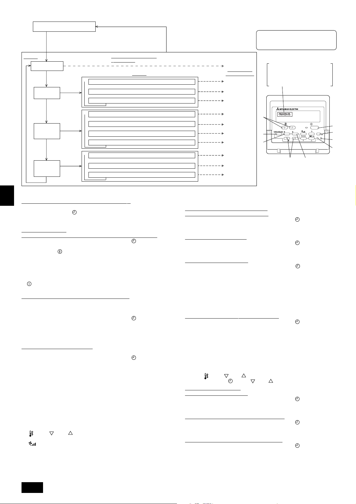
GB
PAR-21MAA
ON/OFF
FILTER
CHECK
OPERATION
CLEAR
TEST
TEMP.
MENU
BACK DAY
MONITOR/SET
CLOCK
ON/OFF
F
G
C
D
B
I
A
H
E
Normalbetriebsanzeige (Anzeige
bei deaktivierter Klimaanlage)
(Halten Sie die Taste E gedrückt und drücken Sie Taste
zwei Sekunden lang.)
* Die Anzeige lässt sich während der Funktionsauswahl,
des Testlaufs und der Selbstdiagnose nicht ändern.
Eintrag 1
Sprache ändern
(“CHANGE LANGUAGE”)
Drücken Sie
Taste E.
Funktionsgrenzen
(“Funktion
auswahlen”)
Drücken Sie
Taste E.
Drücken Sie
Taste E.
Auswahl der
Betriebsart
(“Betriebsart
wahlen”)
Drücken Sie
Taste E.
Änderung der
Anzeige
(“Anzeige
betriebsart”)
Drücken Sie Taste G.
→
Drücken Sie
Taste G.
→
Drücken Sie
Taste G.
Drücken Sie
Taste G.
→ Temperatureinstellung in °C/°F (“Wechsel °C/°F”)
D
Funktionsauswahlmodus der
Fernbedienung
Eintrag 2
Einstellung der Funktionsgrenzen bei der Bedienung (“Sperr-Funktion”)
→
Einstellung der Benutzung der Betriebsart Automatisch (“Auswahl autobetrieb”)
→
Einstellung der Temperaturgrenzen (“Limit temp Funktion”)
Haupt-/Nebenfunktion der Fernbedienung (“Haupt/Neben controller”)
Benutzung der Uhreinstellung (“Uhr”)
Einstellung der Timer-Funktion (“Wochenzeit schalt uhr”)
Kontaktnummer für den Fall von Fehlfunktionen (“CALL.”)
Einstellung der Anzeige der Luftansaugtemperatur (“Raum TEMP gewahlt”)
→→→→→
Einstellung der automatischen Kühl-/Heizanzeige (“Auto Betrieb C/H”)
(Halten Sie die Taste E gedrückt und drükken Sie Taste D zwei Sekunden lang.)
* Die Fernbedienung speichert die
vorgenommenen Änderungen.
Drücken Sie Taste G.
Drücken Sie Taste G.
Drücken Sie Taste G.
Drücken Sie
Taste D.
Drücken Sie
Taste D.
Drücken Sie
Taste D.
Siehe [4]-1
Eintrag 3 (Inhalt
der Einstellungen)
Siehe [4]-2. (1)
Siehe [4]-2. (2)
Siehe [4]-2. (3)
Siehe [4]-3. (1)
Siehe [4]-3. (2)
Siehe [4]-3. (3)
Siehe [4]-3. (4)
Siehe [4]-4. (1)
Siehe [4]-4. (2)
Siehe [4]-4. (3)
HINWEIS
Der Timer-Betrieb stoppt, wenn die Anzeige des
Funktionsauswahlmodus auf die Normalbetriebsanzeige umschaltet.
Punktmatrixanzeige
Die mit CHANGE LANGUAGE
(Sprache einstellen) eingestellte
Sprache wird hier angezeigt. In den
Darstellungen dieser Anleitung ist
Englisch ausgewählt.
[Genaue Einstellung]
D
[4] -1. Einstellung CHANGE LANGUAGE (Sprache ändern)
Die Sprache des Punktmatrix-Displays kann eingestellt werden.
• Drücken Sie die Taste [
MENU], um die Sprache einzustellen.
1 Japanisch (JP), 2 Englisch (GB), 3 Deutsch (D), 4 Spanisch (E),
5 Russisch (RU), 6 Italienisch (I), 7 Chinesisch (CH), 8 Französisch (F)
[4] -2. Funktionsgrenzen
F
(1) Einstellung der Funktionsgrenzen bei der Bedienung (Operation Lock)
• Zur Umschaltung der Einstellung drücken Sie die Taste [
ON/OFF].
1 no1: Die Einstellung der Bedienungssperre (Operation Lock) gilt für alle Tasten
außer der [
ON/OFF]-Taste.
2 no2: Die Einstellung der Bedienungssperre gilt für alle Tasten.
3 OFF (Anfängliche Einstellungswert) :
Die Einstellung der Bedienungssperre wird nicht vorgenommen.
* Damit die Bedienungssperre (Operation Lock) in der normalen Anzeige gültig ist
NL
(müssen Sie die [FILTER]-Taste gedrückt halten und währenddessen die Taste
[
ON/OFF] zwei Sekunden lang drücken) nachdem Sie die obige Einstellung
durchgeführt haben.
(2) Einstellung der Benutzung der Betriebsart Automatisch
Wenn die Fernbedienung an einem Anlage angeschlossen ist, bei dem ein automatischer Betrieb möglich ist, können die folgenden Einstellungen vorgenommen
werden.
SWI
• Zur Umschaltung der Einstellung drücken Sie die Taste [
ON/OFF].
1 ON (Anfängliche Einstellungswert):
Die Betriebsart Automatisch wird angezeigt, wenn diese Betriebsart ausgewählt wird.
2 OFF:
Die Betriebsart Automatisch wird nicht angezeigt, wenn diese Betriebsart ausgewählt wird.
(3) Einstellung der Temperaturgrenzen
Nach dieser Einstellung kann die Temperatur im eingestellten Bereich verändert werden.
• Zur Umschaltung der Einstellung drücken Sie die Taste [ ON/OFF].
1 Limit Kuhl Temp:
Der Temperaturbereich kann in der Betriebsart Kühlen/Trocknen geändert werden.
2 Limit Heiz Temp:
Der Temperaturbereich kann in der Betriebsart Heizen geändert werden.
3 Limit Auto Temp:
E
Der Temperaturbereich kann in der Betriebsart Automatisch geändert werden.
4 OFF (Anfangseinstellung):
Die Temperaturbereichsgrenzen sind nicht aktiv.
* Wenn eine andere Einstellung als OFF gewählt wird, werden die Temperatur-
bereichsgrenzen für Kühlen, Heizen und automatischen Betrieb gleichzeitig eingestellt. Der Bereich kann jedoch nicht begrenzt werden, wenn der eingestellte
Temperaturbereich sich nicht geändert hat.
P
• Um die Temperatur zu erhöhen oder zu verringern, drücken Sie die Taste
[
TEMP ( ) oder ( )].
• Um die Obergrenze und die Untergrenze einzustellen, drücken Sie die Taste
[
] (Gebläsegeschwindigkeit). Die ausgewählte Einstellung blinkt, und die
Temperatur kann eingestellt werden.
• Einstellbarer Bereich
Betriebsart Kühlen/Trocknen: Untergrenze: 19°C bis 30°C Obergrenze: 30°C bis 19°C
Betriebsart Heizen: Untergrenze: 17°C bis 28°C Obergrenze: 28°C bis 17°C
Betriebsart Automatisch: Untergrenze: 19°C bis 28°C Obergrenze: 28°C bis 19°C
26
* Der einstellbare Bereich hängt vom angeschlossenen Anlage ab (Mr.-Slim-An-
lage, Free-Plan-Anlage und Zwischentemperaturanlage)
[4] -3. Einstellen der Auswahl der Betriebsart
(1) Haupt-/Nebenfunktion der Fernbedienung
• Zur Umschaltung der Einstellung drücken Sie die Taste [
ON/OFF].
1 Haupt: Die Fernbedienung fungiert als Hauptfernbedienung.
2 Neben: Die Fernbedienung fungiert als Nebenfernbedienung.
(2) Benutzung der Uhreinstellung
• Zur Umschaltung der Einstellung drücken Sie die Taste [
ON/OFF].
1 ON : Die Clock-Funktion kann benutzt werden.
2 OFF : Die Clock-Funktion kann nicht benutzt werden.
(3) Einstellung der Timer-Funktion
• Zur Umschaltung der Einstellung drücken Sie die Taste [
ON/OFF] (Wählen
Sie einen der folgenden Einträge aus.).
1 Wochenzeit schalt uhr (Anfängliche Einstellungswert):
Der Wochen-Timer kann benutzt werden.
2 Auto Zeit funktion Aus: Der Auto-Off-Timer kann benutzt werden.
3 Einfnche zeit funktion: Der einfache Timer kann benutzt werden.
4 Zeitschaltuhr Aus: Der Timer-Modus kann nicht benutzt werden.
* Wenn die Verwendung der Clock-Einstellung auf OFF steht, kann “Wochenzeit
schalt uhr” nicht benutzt werden.
(4) Kontaktnummer für den Fall von Fehlfunktionen
• Zur Umschaltung der Einstellung drücken Sie die Taste [
ON/OFF].
1 CALL OFF : Die eingestellten Kontaktnummern werden im Falle von
Fehlfunktionen nicht angezeigt.
2 CALL **** *** **** : Die eingestellten Kontaktnummern werden im Falle von
Fehlfunktionen angezeigt.
CALL_ : Die Kontaktnummer kann eingegeben werden, wenn das
Display so aussieht wie links gezeigt.
• Eingabe der Kontaktnummern
Zur Eingabe der Kontaktnummern gehen Sie wie folgt vor.
Bewegen Sie den blinkenden Cursor auf die eingestellten Nummern. Drücken Sie
die Taste [
Drücken Sie die Taste [
TEMP. ( ) Und ( )] um den Cursor nach rechts (links) zu bewegen.
CLOCK ( ) Und ( )] um die Nummern einzustellen.
[4] -4. Einstellung der Anzeige
(1) Temperatureinstellung in °C/°F
• Zur Umschaltung der Einstellung drücken Sie die Taste [
ON/OFF].
1 °C: Für die Temperatur wird die Anlage Celsius (°C) verwendet.
2 °F: Für die Temperatur wird die Anlage Fahrenheit (°F) verwendet.
(2) Einstellung der Anzeige der Luftansaugtemperatur
• Zur Umschaltung der Einstellung drücken Sie die Taste [
ON/OFF].
1 ON: Die Temperatur der Ansaugluft wird angezeigt.
2 OFF: Die Temperatur der Ansaugluft wird nicht angezeigt.
(3) Einstellung der automatischen Kühl-/Heizanzeige
• Zur Umschaltung der Einstellung drücken Sie die Taste [
1 ON:
Entweder “Automatic cooling” (Automatisches Kühlen) oder “Automatic heating”
ON/OFF].
(Automatisches Heizen) wird in der Betriebsart Automatisch angezeigt.
2 OFF: Nur “Automatic” wird in der Betriebsart Automatisch angezeigt.
Page 27
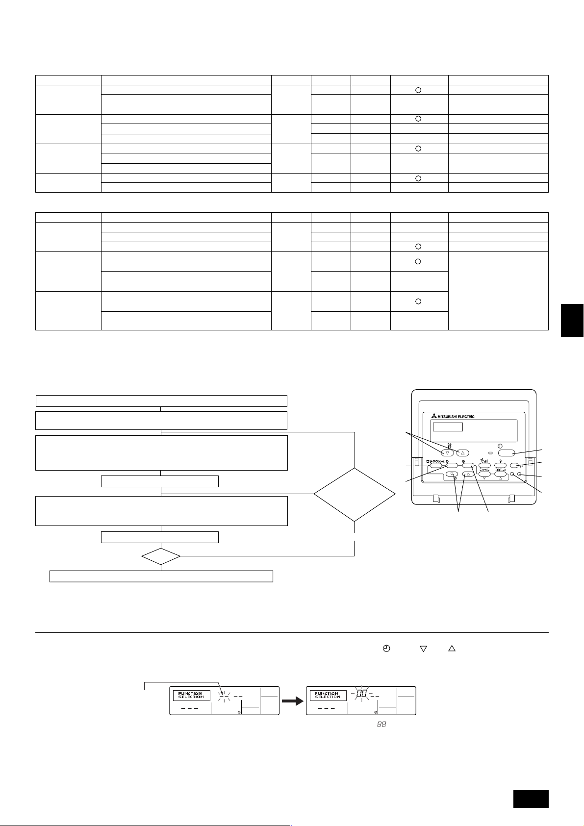
(2) Anlagenfunktionsauswahl
Stellen Sie bitte bei Bedarf die Funktionen jeder Anlage von der Fernbedienung aus ein. Die Funktion jeder Anlage kann nur von der Fernbedienung aus gewählt werden.
Stellen Sie die Funktionen durch Wahl der notwendigen Positionen aus Tabelle 1 und Tabelle 2 ein. (Standardeinstellungen sind unten ebenfalls dargestellt.)
Tabelle 1. In Einzelpunkten aufgeführte Funktionen des gesamten Kältemittelsystems (wählen Sie Anlage Nummer 00 bis 15)
Funktion
Automatische
Wiederherstellung
nach Netzstromausfall
Erkennung der
Innentemperatur
LOSSNAYVerbindung
Netzstrom
Einstellungen
Nicht verfügbar
Verfügbar
Betriebsdurchschnitt der Anlage
Einstellung durch Fernbedienung der Anlage
Interner Sensor der Fernbedienung
Nicht unterstützt
Unterstützt (Anlage nicht mit Außen-Lufteinlaß ausgestattet)
Unterstützt (Anlage mit Außen-Lufteinlaß ausgestattet)
240 V
220 V, 230 V
Betriebsart Nr.
01
02 2
03 2
04
Einstellung Nr.
1
2
1
3
1
3
1
2
Prüfen
Standardeinstellungen
Etwa 4 Minuten nach dem Wiederherstellen des Netzstroms warten.
Bemerkungen
Tabelle 2. In Einzelpunkten aufgeführte Funktionen der Anlage (wählen Sie die Anlagenummern 01 bis 04 oder AL)
Funktion
Filterzeichen
Gebläsebetrieb bei
Thermo aus im
Heizbetrieb
Gebläsebetrieb
während ausgeschalteter Heizung
im Kühlbetrieb
Einstellungen
100 Std.
2500 Std.
Keine Filterzeichenanzeige
Betrieb
Stop
Betrieb
Stop
Betriebsart Nr.
07 2
25
27
Einstellung Nr.
1
3
3
2
1
2
Prüfen
Standardeinstellungen
Beim Wählen des Gebläsebetriebs
“Stopp” stellen Sie die Einstellnummer von Betriebsart Nr. “02” in
Tabelle 1 to “3”. Stellen Sie sicher,
daß sich die Fernbedienung innerhalb des zu klimatisierenden Raums
befindet, so daß sie die Raumtemperatur überwachen kann.
Bemerkungen
Hinweis:
Wenn die Funktionen der Innenanlage nach abgeschlossener Installation mit der Funktionswahl geändert worden sind, geben Sie stets durch Eingabe von 嘷
oder einer anderen Kennzeichnung im zugehörigen Prüffeld von Tabelle 1 oder Tabelle 2 den Inhalt der Einstellungen an.
[Funktion Auswahlablauf]
Sehen Sie sich zuerst den Funktionsablauf an. Als Beispiel wird nachfolgend die Einstellung der “Netzstrom” in Tabelle 1 gezeigt.
(Den aktuellen Einstellvorgang sehen Sie in [Einstellverfahren] 1 bis 0.)
1 Prüfung der Inhalte der Funktionsauswahl.
2 Schalten Sie in den FUNKTIONSAUSWAHL-Betrieb.
(Drücken Sie gleichzeitig im AUS-Status der Fernbedienung die Tasten A und B.)
F
3
Kühlsystemadresse angegeben → 00 (Außenanlagenangabe)
(Nicht notwendig bei einem Kühlsystem.)
4
Anlagen-Adressennummer angegeben → 00 (Innenanlagenangabe)
(Tasten C und D -Betrieb)
5 Anmeldung (Taste E drücken.)
(Angegebene Innenanlage→
Ventilatorbetrieb)
6 Auswahl Betriebsnummer → 04 (Netzstrom)
7 Einstellung Betriebsnummer → 2 (220V, 230V)
(Tasten
F
und G -Betrieb)
NEIN
JA
Kühlsystemadresseund AnlagenAdressennummer
ändern?
E
G
TEMP.
MENU
BACK DAY
MONITOR/SET
PAR-21MAA
C
CLOCK
ON/OFF
OPERATION
D
ON/OFF
FILTER
CHECK
CLEAR
TEST
GB
D
F
I
A
B
H
NL
SWI
8 Anmeldung (Taste E drücken.)
Ende?
NEIN
9
JA
0 Anzeige Abschlußfunktion (Tasten A und B gleichzeitig drücken.)
[Verfahren] (Nur einstellen, wenn Änderung nötig.)
1 Einstellungen für jeden Betrieb prüfen. Wurden Einstellungen einer Betriebsart mit der Funktionsauswahl geändert, ändern sich auch die Funktionen dieser Betriebsart.
Überprüfen Sie den Inhalt der Einstellungen wie in den Schritten 2 bis 7 beschrieben, und ändern Sie die Einstellungen gemäß Eingaben in Tabelle 1 und Tabelle 2.
(Beachten Sie bei Änderung der Einstellung die Standardeinstellungen.)
2 Fernbedienung AUS schalten.
Drücken und halten Sie die Tasten A [FILTER] und B [TEST] gleichzeitig für
zwei Sekunden oder länger.
“Funktion sauswahl” blinkt für einige Zeit. Dann zeigt die Anzeige der Fernbe-
dienung die nachfolgend zu sehenden Änderungen.
Anzeige Kühlsystem-Adresse
3 Außenanlagen-Kühlsystemadressennummer einstellen.
Werden die Tasten C [
CLOCK ( ) und ( )] gedrückt, erhöht oder verringert sich die Kühlsystem-Adressennunmmer zwischen 00 und 15. Stellen Sie
die Kühlsystem-Adressennummer ein, deren Funktion Sie wählen möchten.
(Dieser Schritt ist bei einem Kühlsystem nicht notwendig.)
* Schaltet die Fernbedienung in den AUS-Betrieb, nachdem “Funktion sauswahl” und Raumtemperaturanzeige “ ” für zwei Sekunden geblinkt haben, ist die Kommuni-
kation möglicherweise unnormal. Prüfen Sie, ob in der Nähe der Übertragungskabel Störfrequenzen auftreten.
Hinweis:
Sollte während des Vorgangs ein Fehler auftreten, beenden Sie die Funktionswahl mit Schritt
??
? und wiederholen Sie den Vorgang ab Schritt
??
22
2.
22
27
E
P
Page 28
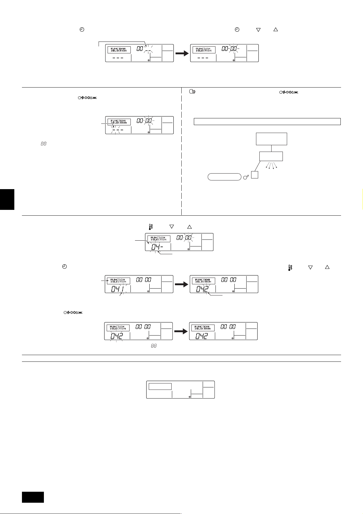
4 Innenanlagen-Adressennummer einstellen.
Drücken Sie die Taste D [
nummer “– –” blinkt.
Anzeige Anlagen-Adressennummer
* Stellen Sie die Betriebsart 01 bis 04 ein, stellen Sie die Anlagen-Adressennummer auf “00”.
* Wenn die Betriebsarten 07, 25, 27 eingestellt werden:
• Bei Einstellung der Funktionen für eine Anlage in einem unabhängigen System stellen Sie bitte die Nummer der Anlage auf 01.
5 Anmeldung der Kühlsystemadresse und Anlagen-Adressennummer
Drücken Sie die Taste E [
adressennummer sind angemeldet.
Nach einiger Zeit blinkt die Anzeige der Betriebsnummer “– –” blinkt.
Betriebsnummer anzeigen
* Blinkt “ ” in der Anzeige der Raumtemperatur, ist die angewählte Kühlsystem-
adresse nicht im System.
Wird “F” in der Anzeige der Anlagen-Adressennummer angezeigt, und blinkt sie
zusammen mit der Anzeige der Kühlsystemadresse, besteht die gewählte An-
GB
lagen-Adressennummer nicht. Korrigieren Sie die Adresse des Kühlsystems
und die Nummer der Anlagenadresse, indem Sie die Schritte 2 und 3 wiederholen.
D
6 Auswahl Betriebsnummer
Stellen Sie die gewünschte Betriebsnummer mit den Tasten F [
ON/OFF]. Die Anzeige der Anlagen-Adressen-
]. Die Kühlsystemadresse- und Anlagen-
TEMP. ( ) und ( )] ein. (Es können nur einstellbare Betriebsnummern gewählt werden.)
Werden die Tasten C [ CLOCK ( ) und ( )] gedrückt, ändert sich die AnlagenAdressennummer in der Reihenfolge in 00 → 01 → 02 → 03 → 04 → AL. Stellen Sie die
Anlagen-Adressennummer der Innenanlage ein, deren Funktionen Sie einstellen möchten.
Erfolgte eine Registrierung mit der Taste E [ ] , startet die angemeldete Innenanlage den Ventilatorbetrieb. Möchten Sie den Standort der Innenanlagen mit der Anlagen-Adressennummer, deren Funktionen Sie gewählt haben,
wissen, prüfen Sie hier. Lauten die Anlagenadressennummer n 00 oder AL, starten alle Innenanlagen der gewählten Kühlsystemadressen den Ventilatorbetrieb.
Ex) Lautet die Kühlsystemadresse 00, ist die Anlagen-Adressennummer = 01 angemeldet
Anmeldung
* Wenn eine Gruppe mit unterschiedlichen Kühlsystemen und eine andere Innen-
anlage als die angegebene Kühlsystemadresse den Ventilatorbetrieb startet,
ist die eingestellte Kühlsystemadresse möglicherweise dupliziert worden.
Überprüfen Sie noch einmal die Kältemitteladresse auf den DIP-Schaltern der
Außenanlage.
Kühlsystemadresse = 00
Innenseitige
Fernbedienung
Außenseitige
AnlagenAdressennummer 01
Ventilatorbetrieb
F
7 Wählen Sie die Einstellungen im Einstellbetrieb.
Wird die Taste G [
hier den Inhalt der aktuellen Einstellung prüfen.
NL
8 Die Einstellungen der Schritte 3 bis 7 sind angemeldet.
Wird die Taste E [
Einstellnummern zu einer ständigen Anzeige, ist die Einstellung beendet.
SWI
* Erscheint “– –” als Betriebs- und Einstellungsnummer und blinkt “
Prüfen Sie, ob in der Nähe der Übertragungskabel Störfrequenzen auftreten.
9 Zur Wahl weiterer Funktionen wiederholen Sie die Schritte 3 bis 8.
0 Auswahl Abschlußfunktion
Drücken und halten Sie die Tasten A [FILTER] und B [TEST] gleichzeitig für zwei Sekunden oder länger.
Nach einiger Zeit wird die Funktionsauswahl-Anzeige gelöscht und die Fernbedienung schaltet in die Aus-Anzeige der Klimaanlage zurück.
MENU] gedrückt, blinkt die aktuelle Nummer. Sie können
Anzeige Einstellungsnummer.
Betriebsnummer anzeigen
Betriebsnummer 04 = Netzstrom
Stellen Sie die Einstellungsnummer mit den Tasten F [ TEMP. ( ) und ( ) ] ein.
Einstellungsnr. 1 = 240V
] gedrückt, blinken die Betriebs- und die Einstellungsnummer und die Anmeldung ist beendet. Wechseln die blinkenden Betriebs- und
” in der Anzeige Raumtemperatur, ist die Kommunikation möglicherweise unnormal.
Einstellungsnummer. 2 = 220 V, 230 V
E
* Schalten Sie die Klimaanlage für 30 Sekunden nach dem Beenden der Funktionsauswahl von der Fernbedienung aus nicht ein.
Hinweis:
Wenn die Funktionen einer Innenanlage nach abgeschlossener Installation mit der Funktionswahl geändert worden sind, geben Sie stets durch Eingabe eines
嘷 oder einer anderen Kennzeichnung im zugehörigen Prüffeld von Tabelle 1 oder Tabelle 2 den Inhalt der Einstellungen an.
P
28
Page 29
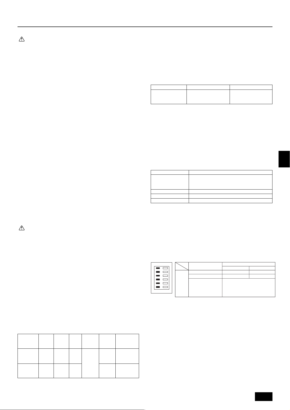
9. Elektroverdrahtung
Vorsichtsmaßnahmen bei der elektrischen Verdrahtung
Warnung:
• Elektroarbeiten sollten nur durch qualifizierte Fachelektriker gemäß ’Engineering Standards for Electrical Installation’ - ’Technische Normen für
Elektroinstallation’ und gemäß Installationshandbüchern vorgenommen
werden. Es sollten auch eigens eingerichtete Stromkreise verwendet werden. Wenn der Stromkreis zu schwach ausgelegt ist oder Installationsfehler aufweist, besteht die Gefahr von Stromschlägen oder Brand.
• Zur Verdrahtung stets die dafür vorgesehenen Kabel verwenden und diese ordnungsgemäß anschließen. Den Anschluß so sichern, daß das Kabel keine äußere Zugspannung auf den Klemmenanschluß ausübt. Bei
fehlerhaftem Anschluß oder wenn das Kabel nicht vollkommen sicher
angebracht ist, kann dies zu Überhitzung oder zu einem Brand führen.
• Darauf achten, die angegebenen Kabel zu verwenden und diese fest anzuschließen, damit keine äußere Zugspannung auf die Klemmenanschlüsse ausgeübt wird. Lose Anschlüsse können Überhitzung oder einen Brand verursachen.
1. Dafür sorgen, daß die Netzstromversorgung über einen gesonderten Strom-
kreis erfolgt.
2. Dafür sorgen, daß ein Erdschlußstromunterbrecher in den Stromkreis instal-
liert wird.
3. Die Anlage so installieren, daß verhindert wird, daß eines der Steuerkreis-
kabel (Fernbedienung) in direkten Kontakt mit dem Netzstromkabel außerhalb
der Anlage gebracht werden kann.
4. Dafür sorgen, daß keiner der Elektroleitungsanschlüsse zu lose gespannt ist
oder einen Wackelkontakt aufweist.
5. Fernbedienungskabel, die oberhalb der Decke angeordnet sind, können Mäuseverbiß ausgesetzt sein. Daher Kabel zum Schutz soweit wie möglich in Metallrohre verlegen.
6. Netzstromkabel niemals an die Zuleitung für die Übertragungskabel anschlie-
ßen, da sonst die Kabel brechen können.
7. Bei Befestigung der Netzstromleitung an den Steuerkasten darauf achten, daß
eine Pufferbuchse gegen Zugspannung angebracht wird (PG-Anschluß oder
ähnliches).
8. Installieren Sie die Anlage so, daß die Kabel für die Fernbedienung und denje-
nigen für das M-NET (MELANS) keine elektrischen Störungen mit dem Netzstromkabel verursachen. (Verlegen Sie nicht beide im gleichen Kreislauf.)
9. Stellen Sie sicher, daß die Anlage ordnungsgemäß geerdet wird.
10. Lassen Sie ausreichend Lose in den Kabeln des Elektrikkastens der Anlage,
da der Kasten bei einigen Wartungsarbeiten entfernt werden muß.
Vorsicht:
• Dafür sorgen, daß die Anlage zur Seite der Außenanlage hin geerdet wird.
Die Erdleitung nicht an Gasrohre, Wasserrohre, Beleuchtungsstäbe oder
Telefonerdleitungen anschließen. Unsachgemäße Erdung kann zu Stromschlägen führen.
• Bestimmte Aufstellorte machen die Installation eines
Erdschlußstromunterbrechers erforderlich. Nichtbeachtung kann zu einem Stromschlag führen.
• Stets einen Erdschlußstromunterbrecher und eine Sicherung der angegebenen Kapazität verwenden. Die Verwendung einer Sicherung mit einer größeren als der angegebenen Kapazität oder die Verwendung eines
Stücks Draht oder von Kupferdraht kann zum Ausfall der Anlage oder zu
einem Brand führen.
• Je nach Aufstellungsort der Anlage ist u.U. ein Fehlstrom-Trennschalter
erforderlich. Wenn kein Fehlstrom-Trennschalter installiert ist, können
Stromschläge entstehen.
• Keine Trennschalter oder Sicherungen verwenden, deren Kapazität von
der richtigen abweicht. Wenn Sicherungen, Leitungsdrähte oder Kupferleitungen mit großer Kapazität verwendet werden, kann dies zu Unfällen
oder Bränden führen.
Die folgende Tabelle ist ein Beispiel. Die Wahl anderer Kapazitäten muß entsprechend den jeweiligen Normen festgelegt werden.
[Verdrahtungsbeispiel] (Für Metallrohrleitung)
PRH-P400MYA
PRH-P500MYA
Netz-
stromkabel
2
16 mm
oder
dicker
2
25 mm
oder
dicker
Unterbrecher
Kapazität
63 A 63 A 0,06 Ω
70 A 70 A 0,04 Ω
Sicherung
Kabel der
Fernbedienung
Kabel oder
Elektroleitung
von 0,3 ~ 1,25
2
(max. DC
mm
12 V)
Erdleitung
16 mm
oder dicker
25 mm
oder dicker
Maximale
permissive
Systemimpedanz *1
2
2
Hinweis:
Dieses Gerät ist ausgelegt auf den Anschluß an eine Netzstromversorgung
*1:
mit einer maximalen Systemimpedanz ZMAX von 0,06
:
PRH-P500 am Übergabepunkt (
des Benutzers.
Der Benutzer muß sicherstellen, daß dieses Gerät nur an eine Stromversorgung angeschlossen wird, die obige Bedingung erfüllt.
Wenn nötig, kann der Benutzer beim Stromversorgungsunternehmen die
Systemimpedanz am Übergabepunkt erfragen.
[Wahl des Erdschlußunterbrechers (NV)]
Bei Wahl eines NF oder NV anstelle der Kombination einer Sicherung der Klasse
B mit einem Schalter wie folgt vorgehen:
Sicherung (Klasse B) 63 A 70 A
Erdschlußunterbrecher
ELB 60 A 75 A
(mit Überlastschutz) 100 mA 0,1s oder weniger 100 mA 0,1s oder weniger
• Die Netzstromkabel für Geräte sollen mindestens dem Entwurf 245 IEC57.
• Bei der Installierung der Klimaanlage ist ein Schalter mit einem Kontaktab-
stand von mindestens 3 mm für jeden Pol vorzusehen.
Beispiel
[Fig. 9.0.1] (P.4)
(1) Normaler Anschluß
(2) Gruppierung (8 Anlagen)
A Netzanschluß B Erdschlussunterbrecher
C Stromunterbrecher oder Trennschalter
D Fernbedienung E Adresse
[Kabel MA-Fernbedienung Anlage] (für Metallrohr)
Kabeltyp
Anzahl der Kabel
Kabeldurchmesser
Gesamtlänge
Wenn das Fernbedienungskabel verlängert wird, soll-
ten die Fernbedienungskabel mindestens 245 IEC53
entsprechen.
Strom
ableitkasten) der Stromversorgung
NV100-SW NV100-SW
NV ist eine Produktbezeichunug von MITSUBISHI
MA-Fernbedienung
2-adriges Kabel
0,3 ~ 1,25 mm
maximal 200 m
Ω
: PRH-P400, 0,04
2
9.1. Einstellung der Adresse
Einstellungen der Anlageadresse
• Setzen Sie bei den Adreßeinstellungen alle DIP-Schalter SW1 (3 ~ 6) auf der
außenseitigen Schalttafel auf <Werkseinstellung: 00, 01>. (Für 1:1)
• Funktionen von SW1 entsprechend der Schaltereinstellung werden unten aufgeführt.
• Zur Steuerung einer Gruppe von Anlagen muß jeder Anlage eine Adresse
zugewiesen werden.
(SW1 der außenseitigen Schalttafel)
OFF ON
1
2
3
4
5
6
[Fig. 9.1.1] (P.5)
1 –
2
Fehleraufzeichnung gelöscht
3 Adresseneinstellung
des Kältemittelsystems
4 ↑
5 ↑
Schaltung der
SW1 Funktion
6 ↑
Modell
Funktionen entsprechend der Schalterstellung
EIN
––
Gelöscht
Anlagenadreßeinstellungen 0 ~ 15
AUS
Normal
9.2. Kabelanschluß
• Verwendung der Rohrleitungshalteplatten
Rohrleitungshalteplatten werden in zwei Größen (ø40, ø52) geliefert. Zum Einsatz kommt die Montageplatte, die dem äußeren Durchmesser der zu verwendenden Elektroleitung entspricht.
[Fig. 9.2.1] (P.5)
A Bei Installation des Schutzrohres von der Bodenplatte
B Bei Installation des Schutzrohres von der Frontplatte
C Befestigungsplatte (angebracht)
D Ausbrechöffnung
Ω
GB
D
F
NL
SWI
E
P
29
Page 30

10. Installation des Riemens
1. Stellen Sie den Parallelwinkel von Gebläse und Motorriemenscheibe ein wie in
[Fig. 10.0.1] und Tabelle 1 gezeigt.
2. Stellen Sie die Riemenspannung so ein, daß sich der Riemen innerhalb des
Bereichs eindrücken läßt wie in [Fig. 10.0.2] und unten in Tabelle 2 gezeigt.
3. Spannen Sie den Riemen nach, nachdem er ordnungsgemäß auf dem Riemenrad sitzt (nach 24 bis 28 Betriebsstunden).
Wenn ein neuer Riemen verwendet wird, stellen Sie die Spannung etwa auf
das 1,3-fache des maximalen Biegekraft-Werts ein.
4. Spannen Sie den Riemen nach der ersten Einstellung alle 2.000 Stunden.
Tauschen Sie den Riemen aus, wenn er sich um 2 % gelängt hat, die Erstausdehnung (etwa 1 %) eingeschlossen.
(etwa 8.000 Betriebsstunden)
Beim Wählen des Gebläsebetriebs “Stopp” (Betriebsart Nr. 25 “2” in Tabelle 2
von Seite 27), stellen Sie den Riemen alle 1.000 Stunden nach der Feineinstellung nach.
[Fig. 10.0.1] / [Fig. 10.0.2] (P.5)
<A> Parallellauf der Riemenscheibe
<B> Riemenspannung
A Biegekraft (W)
Tabelle 1
Riemenscheibe
Riemenscheibe
Tabelle 2
Riemenscheibe
Ty p
B
Parallelwinkel
Kleinerer Außendurch-
messer (mm)
~ 135
136 ~ 160
161 ~
K (
"
)
10 oder weniger
Biegekraft W
(N)
22 ~ 29
27 ~ 34
29 ~ 37
Abstand von 3 mm pro Meter
GB
11. Änderung der Gebläserichtung (von seitlichen Zufuhr auf Zufuhr von oben)
Bei diesem Gerät kann die Luftzufuhr von seitlicher Zufuhr auf Zufuhr von oben
umgestellt werden.
Modifizierung wie im folgenden beschrieben.
D
[Fig. 11.0.1] (P.5)
A Obere Verkleidung B Abdeckung (Außenseite) C Flansch
D Panel E Gebläse
F Abdeckung (Innenseite)···2 Stk.
F
1 Die obere Verkleidung A, Abdeckung (Außenseite) B, Flansch C, Verklei-
dung D und Abdeckung (Innenseite) F abnehmen. (Schritt 1)
2 Richtung des Gebläses E ändern. (Schritt 2)
Bei Einsatz des Gebläses E in hängender Stellung die Gebläsewelle nicht
anseilen.
3 Obere Verkleidung A, Abdeckung B, Flansch C and Verkleidung D wieder
anbringen. (Schritt 3)
* Zwischen Flansch C, obere Verkleidung A und Schraubfassungen muss für
ausreichende Wasserabdichtung gesorgt werden.
Hinweis:
Bei Luftzufuhr von oben ist die Innenabdeckung
FF
F nicht erforderlich.
FF
Hinweis
12. Testlauf
NL
12.1. Vor dem Testlauf
Der Testlauf kann entweder von der Anlage direkt oder über die Fernbedienung
durchgeführt werden.
1. Prüfliste
• Nach der Verdrahtung der Anlagen prüfen, daß kein Kältemittel austritt, daß
Netzstrom- und Steuerleitungen nicht locker und die Pole nicht umgekehrt
SWI
angeschlossen sind.
• Mit einem Isolationswiderstandsprüfer von 500 V sicherstellen, daß der Widerstand zwischen der Netzklemme und der Erde 1,0 MΩ oder mehr beträgt.
Hat er weniger als 1,0 MΩ, darf die Anlage nicht in Betrieb genommen werden.
• Vergewissern, daß die Anlage keine Fehlfunktion aufweist. (Wenn es eine
Fehlfunktion gibt, können Sie diese mit der LED1 auf der außenseitigen Schalttafel diagnostizieren.)
• Die Netzstromphase überprüfen. Wenn die Phase umgekehrt ist, dreht sich
der Ventilator möglicherweise in der falschen Richtung oder schaltet sich ab.
Auch kann ein unübliches Geräusch erzeugt werden.
• Wenigstens 12 Stunden vor dem Testlauf Strom durch die Kurbelgehäuse-
E
heizung leiten. (Wenn Strom nur für einen kürzeren Zeitraum durchgeleitet
wird, kann dies zu Schäden am Kompressor führen.)
• Bei Modellen, die eine Änderung der Einstellungen für die Wahl von NETZSTROM EIN/AUS-Möglichkeiten erfordern, sachgemäße Änderungen unter
Beachtung der Beschreibung für die Wahl von Funktionen durch die Fernbedienung vornehmen.
Nach Abschluß der oben genannten Prüfungen den Testlauf, wie nachstehend
P
dargestellt, durchführen.
12.2. Testlaufverfahren
1) Fernbedienung
Betriebsabläufe
1 Netzstrom einschalten
Wenn die Anzeige auf der Fernbedienung “
ausgeschaltet. Schalten Sie vor Benutzung der Fernbedienung die Anzeige
“
” aus.
Anzeige “CENTRALLY CONTROLLED”
(ZENTRAL GESTEUERT)
2 Taste [TEST] innerhalb von drei Sekunden zweimal drücken. Der Test
beginnt.
“TEST RUN” (TESTLAUF) und “OPERATION MODE” (BETRIEBSART) wer-
den abwechselnd angezeigt.
3 Die Taste [
Kühlen: Kaltluft wird ausgeblasen.
Heizen: Warmluft wird ausgeblasen (nach einer Weile).
4 Gebläse der außenanlage auf einwandfreien Lauf überprüfen
Die Anlage führt automatische Leistungskontrollen durch, um eine optimale
Geschwindigkeit des außenseitigen Gebläses zu gewährleisten. Das Gebläse
läuft zunächst mit niedriger Geschwindigkeit weiter, um den aktuellen Außenluftbedingungen zu entsprechen, bis es die maximal verfügbare Energie über-
schreitet. Dann kann das Gebläse im Einzelfall anhalten oder je nach Außenluft-
bedingungen in umgekehrter Richtung laufen. Dies ist keine Fehlfunktion.
] drücken
” anzeigt, ist die Fernbedienung
˚C
TEMP.
˚C
ON/OFF
30
Page 31

5 [ ON/OFF] (NETZSTROM EIN/AUS)-Taste drücken, um den in Gang be-
findlichen Testlauf in die Grundeinstellung zurückzuschalten
• Der Testlauf schaltet sich nach zwei Stunden als Reaktion auf die AUTO STOPEinstellung von zwei Stunden im Zeitschalter aus.
• Während des Testlaufs zeigt die Raumtemperaturanzeige die Temperatur der
innenseitigen Rohrleitung.
• Bei Testlauf wird der OFF-Timer aktiviert, und der Testlauf stoppt automatisch
nach zwei Stunden.
• Die Raumtemperatur-Sektion zeigt während des Testlaufs die Steuertemperatur
für die Anlagen.
• Prüfen, ob die Anlagen alle ordnungsgemäß arbeiten.
Fehlfunktionen werden nicht angezeigt, auch wenn die Verdrahtung falsch ist.
6 Speichern Sie eine Telefonnummer ein
Die Telefonnummer eines Reparaturbetriebs, Verkaufsbüros usw. kann für eine
Kontaktaufnahme bei auftretenden Fehlern in die Fernbedienung eingespeichert
werden. Die Telefonnummer wird angezeigt, wenn ein Fehler aufgetreten ist.
Bezüglich des Anmeldeverfahrens beachten Sie bitte 8.4 Funktionswahl der
Fernbedienung.
Symptome
Anzeige der Fernbedienung Außen-Substrat-LED
Die Fernbedienung zeigt “PLEASE WAIT”, und Betrieb ist unmöglich.
Nach dem Einschalten erscheint “PLEASE WAIT” 3
Min. lang, und danach erscheint der Fehlercode.
Nach der “Startup” Anzeige erscheint
“00” (richtige Bedienung).
Nach der “Startup” Anzeige erscheint
der Fehlercode.
Nach der “Startup” Anzeige erscheint
“F1” (negative Phase).
Das Gerät schaltet ein, und “EE” oder “EF” rscheintn
unter “PLEASE WAIT”.
Nach der “Startup” Anzeige erscheint
“00” oder “EE” (“EE” erscheint bei
Testlauf).
Die Displaymeldungen erscheinen nicht, auch wenn
der Schalter für Fernbedienung eingeschaltet ist
(Betriebslämpchen leuchtet nicht auf).
Nach der “Startup” Anzeige erscheint
“EA” (Fehler für Anzahl der Anlagen)
oder “Eb” (Fehler der Anlagennummer).
Nach der “Startup” Anzeige erscheint
“00” (richtige Bedienung).
Nach der “Startup” Anzeige erscheint
“00” (richtige Bedienung).
Die Betriebsanzeige erscheint, aber verschwindet bald wieder, wenn Fernbedienungsfunktionen ausgeführt werden.
Nach der “Startup” Anzeige erscheint
“00” (richtige Bedienung).
Anzeige der Betriebsart
“Test RUN” (TESTLAUF) und “OPERATION MODE”
(BETRIEBSART) werden abwechselnd angezeigt.
Der Timer stoppt den Testlauf nach zwei Stunden.
MENU
MONITOR/SET
BACK DAY
PAR-21MAA
TEMP.
˚C
ON/OFF
ON/OFF
CLOCK
OPERATION
FILTER
CHECK
CLEAR
Anzeige der Rohrtemperatur
Test stoppen, indem Sie die Taste [ ON/OFF] drücken.
Während des Testlaufs leuchtet die Lampe BETRIEB.
TEST
Taste [TEST]
Taste [ ]
(*1)
Nach Einschalten des Netzstroms (Schalterstellung ON (EIN)) schaltet die Anlage
in den Anfahrbetrieb, und die Betriebskontrolllampe (grün) der Fernbedienung sowie der Display-Bereich “PLEASE WAIT” blinken. Auch im Falle von Innen-SteuerSchalttafel-Substrat-LEDs leuchten LED1 und LED2 auf (wenn die Adresse 0) ist
oder erlöschen (wenn die Adresse nicht 0 ist), und LED3 blinkt. Bei Außen- Steuer-Schalttafel-Substrat-LED 1 erscheinen
und abwechselnd in In-
tervallen von 1 Sekunde.
• Wenn einer der obigen Vorgänge nicht korrekt funktioniert, können die folgenden Ursachen erwogen werden, und ggf angesprochen werden. (Die folgenden Symptome werden im Testlaufmodus bestimmt. Beachten Sie, daß “Star-
ten” in der Tabelle sich auf die Anzeige *1 oben bezieht.)
Ursache
• Nach dem Einschalten dauert der Systemstart etwa 2 Minuten, und
“PLEASE WAIT” erscheint (richtige Bedienung).
• Die Steckverbindung der außenseitigen Schutzinstallation ist offen.
• Negative Phase und offene Phase des Netzklemmleiste der Außenanlage
(Einzelphase: L, N,
/Dreifachphase: L1, L2, L3, N, ).
• Falscher Anschluß der Außenanlagen-Klemmleiste (Einzelphase: L, N, /
Dreifachphase: L1, L2, L3, N,
Erdung und S1, S2, S3).
• Anlagenkonstruktion unterschiedlich
• Verdrahtung der Anlage ist nicht richtig ausgeführt. (Falsche Polung für
S1, S2, S3)
•Übertragungsdraht-Kurzschluß der Fernbedienung
• Es gibt keine Anlage für Adresse 0 (andere Adresse als 0).
• Durchbrennen des Fernbedienungsdrahts.
• Nach Aufheben der Funktionswahl ist Betrieb etwa 30 s nicht möglich
(korrekter Betrieb).
GB
D
F
NL
* Um einen Selbsttest durchführen zu können, drücken Sie auf der Fernbedienung die Taste “CHECK” (TEST) zweimal nacheinander. Angaben über Fehlercode-Anzei-
gen finden Sie in der Tabelle unten. Siehe Tabelle unten für Inhalt der Fehlercode-Anzeigen.
LCD Nonkonformität-Inhalt
P1 Ansaugsensorfehler
P2 Rohr- (Flüssigkeitsrohr) Sensorfehler
P4 Ablaufsensorfehler
P5 Ablaufüberlaufschutz-Betrieb
P6 Einfrieren/Überhitzen-Schutz-Betrieb
LCD Nonkonformität-Inhalt LCD Nonkonformität-Inhalt
P8 Rohrtemperaturfehler
P9 Rohr- (2-Phasen-Rohre) Sensorfehler
U0 - UP Anlagen-Nonkonformität
F1 - FA Anlagen-Nonkonformität
E6 - EF
Signalfehler zwischen innenseitiger SteuerSchalttafel und außenseitiger Steuer-Schalttafel
- - - - Keine Fehlergeschichte
FFFF Kein relevante Anlage
E0 - E5 Signalfehler zwischen Fernbedienung und
Anlage
Siehe folgende Tabelle für Einzelheiten zu den LED-Anzeigen (LED 1, 2, 3) auf der innenseitigen Steuer-Schalttafel.
LED1 (Mikrocomputergesteuerte Netzversorgung) Zeigt den Ein/Aus-Zustand zur Steuerung an. Prüfen, ob diese Anzeige bei normaler Verwendung leuchtet.
LED2 (Fernbedienungszuleitung) Zeigt den Ein/Aus-Zustand der Zuführung für verdrahtete Fernbedienung an. Leuchtet nur für die außenseitige Steu-
er-Schalttafel mit der Adresse “00”.
LED3 (Signale für lnnenanlage und Außenanlage)
Zeigt Signale zwischen innenseitigen und außenseitigen Steuer-Schalttafeln an. Prüfen, ob diese LED bei normaler Verwendung blinkt.
SWI
E
P
31
Page 32

2) Anlage
1) Prüfpunkte
• Nach der Installation der Anlage sowie der Elektroarbeiten prüfen, daß keine
Kältemittellecks, lockere Verbindungen und Anschlüsse mit falscher Polung
vorhanden sind.
• Prüfen, ob keine negative Phase und offene Phase vorliegt. (Die Meldung F1
für negative Phase und F2 für offene Phase blinken an LED 1 auf der
außenseitigen Steuer-Schalttafel. In diesem Fall korrekt neu verdrahten.)
• Die Impedanz zwischen Betriebsstromklemmen (Einzelphase: L, N,
Dreifachphase: L1, L2, L3, N,
prüfen und sicherstellen, daß sie 1,0 MΩ oder mehr beträgt. Nicht das Gerät
betreiben, wenn die Messung weniger als 1,0 MΩ ergibt.
• Wenn an der Anlage keine Fehler vorliegt.
(Wenn ein Fehler an der Außenanlage vorliegt, kann sie bei LED 1 [digitale
Anzeige] der außenseitigen Steuer-Schalttafel bewertet werden.)
• Die Absperr ventile sind sowohl an der Flüssigkeits- als auch der Gasseite offen.
Die Absperrventile nachprüfen, dann wie folgt einen Testlauf ausführen.
2) Testlaufstart und Ende
Die folgende Einstellung gilt nur für ein zugehöriges System. Die gleiche Einstellung an den anderen Systemen vornehmen, damit der Testlauf durchgeführt werden kann.
• Betrieb von der innenseitigen Steuer-Schalttafel aus
GB
Den Testlauf mit der Installationsanleitung für die innenseitige Steuer-Schalttafel ausführen.
) und Masse mit einem 500 V Kurbelinduktor
12.3. Selbsttest
Lassen Sie sich die Fehlerhistorie für jede Anlage an der Fernbedienung anzeigen.
D
1 Schalten Sie in den Selbsttest-Betrieb.
Wird die Taste H [CHECK] zweimal nacheinander, innerhalb von drei Sekunden gedrückt, wird die nachfolgende Abbildung angezeigt.
F
• Betrieb von der außenseitigen Steuer-Schalttafel aus
Die Einstellungen für Testlaufstart, Ende und Betriebsart (Kühlen, Heizen) mit
dem DIP-Schalter SW 4 an der außenseitigen Steuer-Schalttafel ausführen.
[Fig. 12.2.1] (P.5)
A Stopp C Betrieb
B kühlen D Heizen
1 Die Betriebsart (Kühlen, Heizen) mit SW 4-2 einstellen
2 SW 4-1 auf ON stellen. Die Betriebsart für SW 4-2 wird eingehalten, und
/
der Testlauf beginnt
3 TSW 4-1 auf OFF stellen, um den Testlauf zu beenden
• Leichte Klopfgeräusche können vom Bereich des Gebläses beim Testlauf hör-
bar werden. Diese Drehmomentschwankungen treten aufgrund der Steuerung
der Gebläseumdrehungen auf. Sie stellen keine Störung am Produkt dar.
Hinweis:
Die SW 4-2 Betriebstart kann während des Testlaufs nicht gestartet werden.
(Zum Ändern des Testlaufs das Gerät mit SW 4-1 stoppen, die Betriebsart
ändern, und dann den Testlauf mit SW 4-1 neu starten.)
• Wenn der 2-Stunden Zeitschalter eingestellt ist, wird der Testlauf automatisch
nach 2 Stunden abgeschaltet.
• Während des Testlaufs zeigt die Raumtemperaturanzeige die Temperatur der
innenseitigen Rohrleitung.
2 Stellen Sie die Adresse oder die Adresse des Kühlsystems ein, die Sie prüfen
möchten.
Werden die Tasten F [
gert sich die Adresse zwischen 01 und 50 oder 00 und 15. Stellen Sie die Adresse
oder Adresse des Kühlsystems ein, die Sie prüfen möchten.
TEMP. ( ) und ( )] gedrückt, erhöht oder verrin-
Selbsttestadresse oder Selbsttestadresse des Kühlsystems
3
Anzeige des Selbsttestergebnisses <Fehlerhistorie> (Bezüglich des Inhalts der Fehlercodes beachten Sie bitte 13. Fehlerbehebung, Liste der Fehlercodes.)
NL
ERROR CODE
Fehlerkode 4 Ziffern oder Fehlerkode 2 Ziffern
SWI
4 Fehlerhistorie zurücksetzen
Die Fehlerhistorie ist in der 3 Selbsttestergebnis-Anzeige zu sehen.
Wird die Taste D [ MENU] zweimal innerhalb von drei Sekunden gedrückt,
blinkt die Selbsttestadresse oder Kühlsystemadresse.
<Wenn keine Fehlerhistorie vorliegt>
ERROR CODE ERROR CODE
ERROR CODE ERROR CODE
E
5 Selbsttest zurücksetzen
Es gibt die folgenden zwei Möglichkeiten, einen Selbsttest zurückzusetzen.
Drücken Sie die Taste H [CHECK] zweimal innerhalb von drei Sekunden → Selbsttest wird zurückgesetzt und Rückkehr zum Status vor dem Selbsttest.
Taste I [
P
ON/OFF] drücken. → Selbsttest wird zurückgesetzt und die Innenanlage stoppt.
(Ist ein Betrieb nicht möglich, ist diese Operation wirkungslos.)
Ungefähr drei Sekunden nach dem Ändern der Betriebsart ändert sich die
Selbsttestadresse des Kühlsystems von einer blinkenden in eine ständige Anzeige und der Selbsttest beginnt.
Adresse 3 Ziffern oder Anlagen-Adressennummer 2 Ziffern
<Wenn die gegenüberliegende Seite nicht existiert>
Wurde die Fehlerhistorie zurückgesetzt, sehen Sie die folgende Anzeige.
War die Fehlerhistorie nicht korrekt zurückgesetzt, wird der Fehler weiterhin angezeigt.
ERROR CODE
32
Page 33

12.4. Test der Fernbedienung
Wenn Betrieb nicht von der Fernbedienung ausgeführt werden kann, diese Funktion zur Diagnostizierung der Fernbedienung verwenden.
1 Prüfen Sie zuerst die Anzeige der Spannungsversorgung.
Fehlt die normale Spannung (DC 12V) an der Fernbedienung, leuchtet die Anzeige der Spannungsversorgung nicht.
Leuchtet die Spannungsanzeige nicht, prüfen Sie die Kabel der Fernbedienung
und der Innenanlage.
2 Schalten Sie in den Prüfbetrieb der Fernbedienung.
Wird die Taste H [CHECK] zweimal nacheinander, innerhalb von fünf Sekunden oder länger gedrückt, wird die nachfolgende Abbildung angezeigt.
3 Ergebnis der Fernbedienungsprüfung
Wenn die Fernbedienung normal funktioniert
Wird die Taste A [FILTER] gedrückt, beginnt die Prüfung der Fernbedienung.
Wenn die Fernbediemnung fehlerhaft funktioniert
(Fehleranzeige 1) “NG” blinkt → Sende-/Empfangsschaltkreis der Fernbedienung fehlerhaft
Spannungsanzeige
Sind an der Fernbedienung keine Probleme festzustellen, prüfen Sie andere Ursachen.
Wenn ein anderes Problem, als die geprüfte Fernbedienung vorliegt
(Fehlerkode 2) “E3” “6833” “6832” blinkt → Keine Sendung
ERROR CODE
Störfrequenzen auf dem Übertragungskabel oder der Innenanlage bzw. andere
Fernbedienungen sind fehlerhaft. Prüfung des Übertragungskabels und der anderen Fernbedienungen.
4 Fernbedienungsprüfung zurücksetzen
Wird die Taste H [CHECK] für fünf Sekunden oder länger gedrückt gehalten, wird die Prüfung der Fernbedienung zurückgesetzt und die “PLEASE WAIT” und RUN
(BETRIEB)-Lampen blinken. Ungefähr 30 Sekunden später schaltet die Fernbedienung in den Status vor der Prüfung.
Umschaltung der Fernbedienungen ist notwendig.
(Fehleranzeige 3) “ERC” und Datenfehler-Zähler werden angezeigt → Datenfehler-Generierung
“Datenfehler-Zähler” ist der Unterschied zwischen der Anzahl der Datenbits, die
Fernbedienung sendet und der Anzahl der Datenbits, die aktuell an das Übertragungskabel geschickt werden. In diesem Fall werden die Sendedaten durch Störfrequenzen
usw. gestört. Prüfen Sie das Übertragungskabel.
Wenn der Datenfehler-Zähler 02 anzeigt
Sendedaten der Fernbedienung
Sendedaten auf dem Übertragungskabel
GB
D
F
NL
SWI
33
E
P
Page 34

13. Fehlerbehebung
13.1. Handhabung von Problemen beim Testlauf
Fehlercode-Liste: Einzelheiten
GB
D
F
NL
Fernbedienungs-
Anzeige
E0
E1, E2
E3
E4
E5
E6
E7
E8
E9
EA
EB
EC
ED
EE
F1
F8
A0
A2
A3
A6
A7
A8
EF
U2
U2
U3
U4
U6
UE
UL
F8
P1
P2
P4
P5
P5
P6
P6
P8
P9
MELANS-Anzeige
6831, 6834
6201, 6202
6832, 6833
6831, 6834
6832, 6833
6740, 6843
6841, 6842
6840, 6843
6841, 6842
6844
6845
6846
0403
0403
4103
4115
6600
6602
6603
6606
6607
6608
nicht definiert
1102
1108
5104
5105
4101
1302
1300
4115
5101
5102
2503
2502
2500
1503
1504
1110
5103
Fernbedienungsdatenaustausch - Empfangsfehler
Fehler auf der Schalttafel der Fernbedienung
Fernbedienungsdatenaustausch - Übertragungsfehler
Fernbedienungsdatenaustausch - Empfangsfehler
Fernbedienungsdatenaustausch - Übertragungsfehler
Datenaustausch zwischen innenseitigen und außenseitigen Steuer-Schalttafeln
Datenaustausch zwischen innenseitigen und außenseitigen Steuer-Schalttafeln
Datenaustausch zwischen innenseitigen und außenseitigen Steuer-Schalttafeln
Datenaustausch zwischen innenseitigen und außenseitigen Steuer-Schalttafeln
Fehler der Elektroanschlußleitung (Störung, locker)
Fehler der Elektroanschlußleitung (Störung, locker)
Übermäßiger Zeitaufwand
Fehler im seriellen Datenaustausch
Fehler im seriellen Datenaustausch
Phasenumkehr, Nachweis der Phasenverschiebung
Fehlerhafter Eingangsstromkreis
Doppelte M-NET-Adresseneinstellung
M-NET-Fehler bei der PH/W Übertragung
M-NET-Bus belegt
M-NET-Datenaustauschfehler bei der P-Übertragung
M-NET-Fehler - kein ACK
M-NET-Fehler - keine Reaktion
Nicht definierter Fehlercode
Entladungstemperaturfehler
CN23 Kurzschluß, Stecker herausgezogen
Ablauftemperatur-Thermistor offen/kurzgeschlossen
Thermistor der Flüssigkeitstemperatur oder der Verdichter-/Verdampfertemperatur offen/kurzgeschlossen
Unterbrechung durch Kompressor/Überstrom (51C Betrieb)
Fehler durch Hochdruck (63H1 Betrieb)
Fehler durch Niederdruck (63L Betrieb)
Fehler durch Netzstrom synchronen Ruhestrom
Fehler des Eingangsfühlers
Fehler des Rohrleitungsfühlers
Fehler des Abflußfühlers
Abflußüberlaufschutzbetrieb
Fehler durch Wasseraustritt
Vereisungsschutzbetrieb
Stoßspannungsschutzbetrieb
Fehler der Rohrleitungstemperatur
Rohr- (2-Phasen-Rohre) Sensorfehler
Einzelne Fehler
- Empfangsfehler
- Übertragungsfehler
- Empfangsfehler
- Übertragungsfehler
Ortsbestimmung des
Problems
Fernbedienungs
Fernbedienungs
Fernbedienungs
Innenseitige Steuer-Schalttafel
Innenseitige Steuer-Schalttafel
Innenseitige Steuer-Schalttafel
Innenseitige Steuer-Schalttafel
Außenseitige Steuer-Schalttafel
Außenseitige Steuer-Schalttafel
Außenseitige Steuer-Schalttafel
Außenseitige Steuer-Schalttafel
Außenseitige Steuer-Schalttafel
Außenseitige Steuer-Schalttafel
M-NET-Schalttafel
Außenseitige Steuer-Schalttafel
Außenseitige Steuer-Schalttafel
M-NET-Schalttafel
M-NET-Schalttafel
M-NET-Schalttafel
M-NET-Schalttafel
M-NET-Schalttafel
M-NET-Schalttafel
–
Außenseitige Steuer-Schalttafel
Außenseitige Steuer-Schalttafel
Außenseitige Steuer-Schalttafel
Außenseitige Steuer-Schalttafel
Außenseitige Steuer-Schalttafel
Außenseitige Steuer-Schalttafel
Außenseitige Steuer-Schalttafel
Außenseitige Steuer-Schalttafel
Innenseitige Steuer-Schalttafel
Innenseitige Steuer-Schalttafel
Innenseitige Steuer-Schalttafel
Innenseitige Steuer-Schalttafel
Innenseitige Steuer-Schalttafel
Innenseitige Steuer-Schalttafel
Innenseitige Steuer-Schalttafel
Innenseitige Steuer-Schalttafel
Innenseitige Steuer-Schalttafel
SWI
E
P
34
Page 35

• Je nach Stellung des Schalters SW2 auf der Schalttafel der Außenanlage beginnen die Segmente zu leuchten, um die Arbeitsbedingungen der Anlage und die
Besonderheiten des Prüfcodes anzuzeigen.
SW2 Einstellung
123456
000000
Betriebsart/Relaisausgabe
Position
Zehnerstelle O: Stopp
C: Kühlen
H: Heizen
d: Enteisen
Einerstelle 1: SV1
2: 21S4
4: 52C
Wenn ein Fehler auftritt, werden der
Fehlercode und das Fehlersignal (*1)
abwechselnd angezeigt.
Inhalt der Anzeige
Relaisausgang = SV1 + 21S4 + 52C
Beispiel: Im Kühlbetrieb, wenn 52C und SV1 eingeschal-
tet sind ON/AUS: C5
011110
010110
011100
111100
*1 Displaysystem für Fehleranzeige
Die Anzeige entspricht den folgenden Zahlen
0 .............Außenanlage (OC1, OC2)
1 .............Innenanlage (IC1, IC2)
Steuerbedingung der Außenanlage
Steuerbedingung der
Innenseitige
Fehlercode-Aufzeichnung 1
Fehlercode-Aufzeichnung 2
System der Steuerbetriebsanzeige
(IC1)
Nichts
Der Fehlercode (z.B. U8, UA) und die Fehleranzeige (*1) werden abwechselnd angezeigt.
Innenseitige
Außenseitige
Anzeige
0
1
2
3
4
5
6
7
Innenseitige
Normal
Wärmeeinstellung
Enteisen
—
Heizung ON/EIN
Frostschutz
Schutz gegen Stromstoß
Kompressor OFF/AUS
Steuerbetrieb
Außenseitige
←
←
←
←
←
←
←
←
13.2. Die folgenden Erscheinungen stellen keine Probleme oder Fehler dar
Problem
Die Gebläseeinstellung ändert sich während des
Heizens.
Das Gebläse schaltet sich während des Heizens aus.
Wenn der Schalter eingeschaltet wurde (Schalterstellung ON/EIN), beginnt das Gebläse nicht zu arbeiten.
Das außenseitige Gebläse dreht sich in falscher
Richtung oder hält an, und es ist ein ungewöhnli-
ches Geräusch hörbar.
Hinweis:
Wenn das innenseitige Gebläse nicht arbeitet, das Überlastungsschutzrelais am Gebläsemotor darauf prüfen, ob es ausgelöst hat.
Wenn das Überlastungsschutzrelais ausgelöst hat, nach Beseitigung der Ursache des Problems (z.B. Blockade des Motors) zurücksetzen.
Zum Zurücksetzen des Überlastungsschutzrelais den Steuerkasten öffnen und die grüne Klaue rechts unten am Relais drücken, bis ein Klick zu vernehmen ist.
Klaue loslassen und prüfen, ob sie in ihre Ausgangsposition zurückkehrt.
Beachten, daß sie nicht in die Ausgangsposition zurückkehrt, wenn sie zu fest gedrückt wurde.
Anzeige der Fernbedienung
Normal-Anzeige
Enteisungs-Anzeige
Heizungsvorbereitungen im
Gange
Normal-Anzeige
Bei ausgeschaltetem Thermostat (Schalterstellung OFF/AUS) findet Leichtluft- oder
Ursache
Niedrigluftbetrieb statt.
Bei eingeschaltetem Thermostat (Schalterstellung ON/EIN) schaltet sich Leichtluft
oder Niedrigluft automatisch auf die Kontaktstellung, die auf der Zeit oder
Rohrleitungstemperatur beruht.
Während der Enteisung schaltet sich das Gebläse aus.
Nach Einschalten des Schalters (Schalterstellung ON/EIN) oder bis die Rohrleitungstemperatur 35 °C erreicht, erfolgt 5 Minuten lang Leichtluftbetrieb. Danach erfolgt 2
Minuten lang Niedrigluftbetrieb, danach beginnt die eingestellte Kontaktstellung
(Wärmeeinstellungssteuerung).
Es besteht die Gefahr, daß der Netzanschluß zur Anlage als Phasenumkehr vorgenommen wurde. Durch Überprüfen vergewissern, daß die Phase richtig ist.
GB
D
F
NL
SWI
14. Kontrolle des Systems
14.1. Systemeinstellungen
[Fig. 14.1.1] (P.5)
A Anlage B Haupt-Fernbedienung
C Neben-Fernbedienung D Kältemitteladresse = 00, 01
E Kältemitteladresse = 02, 03 F Kältemitteladresse = 04, 05
* Die Kältemitteladresse mit dem DIP-Schalter der außenseitigen Steuer-Schalt-
tafel einstellen.
1 Verdrahtung von der Fernbedienung
Der Draht ist an TB5 (Klemmleiste für Fernbedienung) der Anlage angeschlossen
(nichtpolar).
2 Wenn eine andere Kältemittelsystem-Gruppierung verwendet wird.
Bis zu 16 Kältemittelsysteme können mit der flachen MA Fernbedienung als eine
Gruppe gesteuert werden.
Modell PRH-P400, 500MYA besitzt zwei Kältemittelsysteme je Anlage.
35
E
P
Page 36

Hinweis:
Bei einem Einfachkältemittelsystem, ist die Verdrahtung
22
2 nicht nötig.
22
SW1
Funktionstabelle
<SW1>
ON
OFF
123456
SW1
Funktionseinstellungen
Funktion
1 Vorgeschriebene
Enteisung
2 Fehlerhergang
gelöscht
Adressenein-
3
stellung des
4
Kältemittel-
5
systems
6
Betrieb gemäß Schaltereinstellung
ON/EIN OFF/AUS
Start Normal
gelöscht Normal
Einstellungen für
Außenanlagenadressen 0 ~
15
14.2. Beispiele für die Kältemittel-Adresseneinstellung
Beispiel1Anlage
PRH-P400,
500MYA
* Die Kältemittel-Adresse einer Anlage auf 00 für die Betriebsstromversorgung
GB
zur Fernbedienung einstellen.
(Werkseitig ist die Kältemittel-Adresse auf 00 (OC1), 01 (OC2) eingestellt.)
Die Kältemittel-Adresse nicht innehalb des gleichen Systems doppelt verwenden.
Anlage
OC1
OC2
Anlagen-
Kältemittel-
adresse
00
01
Fernbedienung-
Betriebs-
stromversorgungsanlage
⳯
14.3. Einstellungsverfahren für Kapazitäts-
D
Beim Modell PRH-P400, 500MYA, das zwei Außenanlage hat, kann die Kapazitätssteuerung auf 0 %, 50 % oder 100 % eingestellt werden.
Die Einstellung erfolgt vor Einschalten des Netzstroms durch Einstellen der DipSchalter am Außenanlage, wie in der unten stehenden Tabelle dargestellt.
F
steuerung (nur PRH-P400, 500MYA)
Dip-Schalter 5-1
Außenanlage Nr.1
AUS
Außenanlage Nr.2
EIN
NL
SWI
E
P
36
Page 37

Table des matières
1. Consignes de sécurité .............................................................................. 37
1.1. Avant l’installation de l’appareil et l’installation électrique ....... 37
1.2. Précautions à prendre avec les dispositifs utilisant
le réfrigérant R407C ................................................................ 38
1.3. Avant de procéder à l’installation............................................. 38
1.4. Avant de procéder à l’installation (déplacement)-installation
électrique ................................................................................. 38
1.5. Avant d’effectuer l’essai........................................................... 38
2. Accessoires de l’appareil .......................................................................... 39
3. Comment choisir le lieu d’installation ........................................................ 39
3.1. Espace requis autour de l’appareil .......................................... 39
4. Comment soulever l’appareil et poids de l’appareil .................................. 39
5. Installation de l’appareil ............................................................................ 39
5.1. Installation ............................................................................... 39
6. Tuyauterie de drainage ............................................................................. 40
7. Raccords des conduites ........................................................................... 40
7.1. Admission d’air frais, installation des conduits, et restrictions
de fonctionnement ................................................................... 40
8. Télécommande ......................................................................................... 40
8.1. Méthodes d’installation ............................................................ 40
8.2. Méthodes de connnexion ........................................................ 41
8.3. Assembler la partie supérieure ............................................... 41
1. Consignes de sécurité
1.1. Avant l’installation de l’appareil et l’installation électrique
s Avant d’installer le climatiseur, lire attentivement toutes les
“Consignes de sécurité”.
s Les “Consignes de sécurité” reprennent des points très im-
portants concernant la sécurité. Veillez bien à les suivre.
Symboles utilisés dans le texte
Avertissement:
Précautions à suivre pour éviter tout danger de blessure ou de décès de
l’utilisateur.
Précaution:
Précautions à suivre pour éviter tout endommagement de l’appareil.
Symboles figurant sur l’appareil
: Indique une action qui doit être évitée.
: Indique des instructions importantes à suivre.
: Indique un élément à mettre à la terre.
: Indique la nécessité de faire attention aux pièces tournantes. (Ce symbole
se trouve sur l’étiquette de l’appareil principal.) <Couleur: jaune>
: Danger d’électrocuition. (Ce symbole se trouve sur l’étiquette de l’appareil
principal.) <Couleur: jaune>
Avertissement:
Lisez soigneusement les étiquettes se trouvant sur l’appareil
principal.
Avertissement:
• Demandez à votre revendeur ou à un technicien agréé d’installer le cli-
matiseur.
- En cas de mauvaise installation, il y aurait un risque de fuite d’eau, d’électrocution ou d’incendie.
• Installer l’appareil dans un endroit capable de supporter son poids.
- Autrement l’appareil risque de tomber et de blesser quelqu’un.
• Utilisez les câbles mentionnées pour les raccordements. Assurez-vous
que les connexions soient effectués correctement de façon à ce que la
force externe du câble ne s’applique pas aux bornes.
- Un mauvais raccordement pourrait provoquer une surchauffe, voire un in-
cendie.
• Prévoir les vents violents et les tremblements de terre et en tenir compte
pour l’emplacement adéquat de l’appareil.
- L’appareil pourrait tomber et par conséquent blesser quelqu’un si l’installa-
tion n’est pas effectuée correctement.
• Toujours utiliser les autres accessoires spécifiés par Mitsubishi Electric.
- Demandez à un technicien agréé d’installer les accessoires. Une mauvaise
installation par l’utilisateur pourrait provoquer des fuites d’eau, électrocution
ou un incendie.
8.4. Sélection des fonctions ........................................................... 41
9. Câblage électrique .................................................................................... 45
9.1. Réglage des adresses ............................................................. 45
9.2. Raccordement du câblage ...................................................... 46
10. Spécifications pour l’installation de la courroie ......................................... 46
11. Méthode de modification de la direction du ventilateur
(du débit latéral au débit supérieur) .......................................................... 46
12. Marche d’essai .......................................................................................... 46
12.1. Avant la marche d’essai .......................................................... 46
12.2. Méthodes de marche d’essai .................................................. 46
12.3. Auto-vérification ....................................................................... 48
12.4. Vérification de la télécommande ............................................. 49
13. Guide de dépannage ................................................................................ 50
13.1. Comment remédier aux problèmes survenant lors de l’essai
de fonctionnement ................................................................... 50
13.2. Les situations suivantes ne constituent pas des problèmes ou
des erreurs de fonctionnement................................................ 51
14. Contrôle du système ................................................................................. 51
14.1. Réglage du système ................................................................ 51
14.2. Exemple de paramétrage des adresses de réfrigérant ........... 52
14.3. Méthode de réglage du contrôle de capacité
(seulement pour le PRH-P400, 500MYA) ................................ 52
• Ne réparez jamais vous-même l’appareil. En cas de réparation nécessaire, veuillez consulter le revendeur.
- Toute mauvaise réparation pourrait résulter en des fuites d’eau, chocs élec-
triques ou incendies.
• Ne touchez jamais les ailettes de l’échangeur de chaleur.
- Vous risqueriez de vous blesser.
• Toujours revêtir des vêtements de protection pour manipuler ce produit.
Par ex. : gants, protection intégrale des bras par combinaison et lunettes
de sécurité.
- Vous risqueriez de vous blesser.
• Installez le climatiseur en respectant les instructions du manuel d’installation.
- En cas d’installation incorrecte, il y aura un risque de fuites d’eau, d’électro-
cution ou d’incendie.
• Demandez à un électricien qualifié d’effectuer l’installation électrique conformément aux “Normes concernant les installations électriques” et les
“Réglementations sur le câblage intérieur” ainsi que les instructions de
ce manuel; utilisez toujours un circuit différent.
- Si la capacité de la source d’alimentation n’est pas adéquate ou si l’installa-
tion électrique n’est pas effectuée correctement, il y aura un risque d’électrocution ou d’incendie.
• Fixer fermement le couvercle des bornes (panneau) de l’appareil.
- Si le couvercle des bornes (panneau) n’est pas installé correctement, de la
poussière ou de l’eau peut pénétrer dans l’appareil et causer un incendie ou
un choc électrique.
• Lors de la recharge du circuit de réfrigérant après l’installation ou le changement de place de l’appareil, seulement utiliser le réfrigérant spécifié
(R407).
- Lorsqu’un réfrigérant différent est mélangé au réfrigérant d’origine, il se peut
que le cycle du réfrigérant ne fonctionne pas correctement et que l’appareil
soit endommagé.
• Veuillez consulter votre revendeur ou un technicien agréé lors du déplacement et de l’installation du climatiseur dans un différent endroit.
- Une mauvaise installation du climatiseur pourrait résulter en fuites d’eau,
électrocution ou un incendie.
• Ne réarrangez pas et ne changez pas les réglages des dispositifs de sécurité.
- Si l’interrupteur de pression, l’interrupteur thermique ou tout autre dispositif
de sécurité sont court-circuités ou utilisés avec trop de force, ou si toutes
autres pièces que celles spécifiées par Mitsubishi Electric sont utilisées, il y
aura un risque d’incendie ou d’explosion.
• Ne montez jamais sur l’unité.
- Monter sur l’unité peut déformer le panneau supérieur et risque de se bles-
ser.
• Pour vous débarrasser de ce produit, consultez votre concessionnaire.
• Le technicien-installateur prendra toutes les précautions nécessaires pour
éviter toutes fuites conformément aux réglementations ou normes locales.
- Les normes suivantes sont parfois applicables s’il n’existe aucune régle-
mentation locale.
• Faites particulièrement attention à l’endroit d’installation, par exemple
un sous-sol, etc. où le gaz réfrigérant peut s’accumuler, étant donné que
le réfrigérant est plus lourd que l’air.
• Ne pas permettre l’usage de cet appareil à des enfants en bas âge ou à
des handicapés sans supervision.
• Toujours prendre toutes les précautions nécessaires pour éviter que des
enfants en bas âge jouent avec cet appareil.
GB
D
F
NL
SWI
E
P
37
Page 38

1.2. Précautions à prendre avec les dispositifs utilisant le réfrigérant R407C
Précaution:
• Utilisez un réfrigérant liquide pour remplir le système.
- Si l’on utilise du gaz réfrigérant pour rendre le système hermétique, la composition du réfrigérant se trouvant dans le cylindre changera et il se peut que
la performance ne soit plus aussi bonne.
• Utilisez uniquement du réfrigérant R407C.
- Si on utilise un autre réfrigérant (R22, etc.), le chlore présent dans le réfrigérant provoquera la détérioration de l’huile réfrigérante.
• Utilisez une pompe à vide équipée d’une valve de contrôle de flux inverse.
- Il se peut que l’huile de la pompe à vide reparte dans le cycle du réfrigérant
ce qui entraînerait la détérioration de l’huile réfrigérante.
• N’utilisez pas les outils énumérés ci-dessous, destinés aux réfrigérants
traditionnels.
(Jauge collectrice, tuyau de charge, détecteur de fuite de gaz, valve de
contrôle de flux inverse, base de remplissage du réfrigérant, équipements
de récupération de réfrigérant).
- Si l’on mélange un réfrigérant courant à l’huile réfrigérante dans le R407C, il
se peut que le réfrigérant se détériore.
- Si de l’eau se mélange au R407C, il se peut que l’huile réfrigérante se dété-
riore.
- Etant donné que le R407C ne contient pas de chlore, les détecteurs de fuite
GB
D
de gaz conçus pour les réfrigérants traditionnels ne réagiront pas en cas de
fuite du R407C.
• N’utilisez pas de cylindre de charge.
- Autrement le réfrigérant pourrait se détériorer.
• Faites particulièrement attention lors de l’utilisation des outils.
- Si de la poussière, de la saleté ou de l’eau s’infiltre dans le cycle du réfrigé-
rant, il se peut que le réfrigérant se détériore.
1.3. Avant de procéder à l’installation
• Utilisez uniquement un disjoncteur et un fusible de la valeur indiquée.
- Si un fusible ou disjoncteur de plus grande valeur ou un fil en acier ou en
cuivre est utilisé, il se peut que l’appareil ne fonctionne pas ou qu’il y ait un
risque d’incendie.
• Ne lavez pas les différents éléments du climatiseur.
- Autrement il y aurait un risque de choc électrique.
• Assurez-vous que la base d’installation ne soit pas abîmée à cause d’un
usage prolongé.
- Si l’endommagement n’est pas réparé, l’appareil pourrait tomber et par con-
séquent blesser quelqu’un ou abîmer le mobilier ou d’autres biens.
• Installez les tuyaux d’écoulement conformément aux instructions du
manuel d’installation afin d’assurer que l’écoulement se fait correctement. Enveloppez les tuyaux de matériaux isolants afin d’empêcher la
formation de condensation.
- Si les tuyaux d’écoulement ne sont pas installés correctement, il se peut
qu’il y ait des fuites d’eau et par conséquent des dégâts au mobilier ou à
d’autres biens.
• Faites attention pendant le transport de l’appareil.
- Cet appareil doit être porté par au moins deux personnes s’il pèse plus de
20kg.
- Certains appareils sont empaquetés à l’aide de courroies PP. N’utilisez pas
de courroies PP pour le transport de l’appareil, car cela est dangereux.
- Ne touchez pas les ailettes de l’échangeur de chaleur. Vous pourriez vous
couper les doigts.
- Lors du transport de l’appareil extérieur, suspendez-le de la façon indiquée
sur la base de l’appareil. Fournir un support à quatre points à l’appareil extérieur afin de l’empêcher de glisser sur les côtés.
• Jetez les emballages dans un endroit où ils ne présenteront aucun risque pour quiconque.
- Il est possible de se blesser sur les matériaux utilisés pour l’emballage, par
exemple les clous ou autres pièces métalliques ou en bois.
- Déchirez et jetez les sacs d’emballage en plastique de façon à ce qu’ils
soient hors de la portée des enfants pour éviter tout risque de suffocation.
1.5. Avant d’effectuer l’essai
Précaution:
• N’installez pas l’appareil dans un endroit sujet aux fuites de gas inflammables.
F
- S’il y a une fuite de gaz et que le gaz s’accumule autour de l’appareil, il y
aura des risques d’explosion.
• N’utilisez pas le climatiseur près d’animaux ou de plantes ou près d’aliments, d’instruments de précision ou d’objets d’art.
- La qualité d’aliments etc. pourrait en souffrir.
• N’utilisez pas le climatiseur dans certains environnements.
- L’huile, la vapeur, la fumée sulfurique, etc. peuvent considérablement ré-
NL
SWI
duire la performance du climatiseur ou en endommager les pièces.
• Lors de l’installation de l’appareil dans un hôpital, une station de communications ou tout endroit similaire, veillez à ce qu’il soit correctement
protégé contre le bruit.
- Les équipements onduleurs, générateurs privés, équipements médicaux à
haute fréquence ou de communication radiophonique peuvent empêcher le
climatiseur de fonctionner ou de fonctionner proprement. De plus, il se peut
que le climatiseur ait un effet nuisible sur ce genre d’équipements en faisant
du bruit qui gênerait les traitements médicaux ou l’envoi d’images.
• N’installez pas l’appareil sur une structure qui pourrait causer des fuites.
- Lorsque l’humidité de la pièce dépasse 80 % ou lorsque le tuyau d’écoule-
ment est bouché, il se peut que des gouttes d’eau tombent de l’appareil
intérieur. Veillez à fournir une voie d’écoulement pour l’appareil intérieur et
l’appareil extérieur si nécessaire.
1.4. Avant de procéder à l’installation (dé-
placement)-installation électrique
Précaution:
• Mettez l’appareil à la terre.
- Ne branchez pas le fil de mise à la terre à un tuyau de gaz ou d’eau, un
E
P
paratonnerre ou câble téléphonique de terre. Une mauvaise mise à la terre
peut provoquer des risques d’électrocution.
• L’inversion de phase des lignes L (L
d’erreur: 4103), mais l’inversion de phase des lignes L et de la ligne N ne
peut être détectée.
- La mise sous tension de l’appareil alors que le câblage est défectueux ris-
que d’endommager certains composants électriques.
• Installez le câble d’alimentation de façon à ce qu’il ne soit pas tendu.
- Autrement le fil pourrait se rompre, engendrant un surchauffage et par con-
séquent des risques d’incendie.
• Installer un disjoncteur de mise à la terre, comme spécifié.
- Sans disjoncteur de mise à la terre, il y aura risque d’électrocution.
• Utilisez des câbles d’alimentation dont la capacité à distribuer le courant
et la valeur nominale sont adéquates.
- Si les câbles sont trop petits, il est possible qu’il y ait des fuites, entraînant un
surchauffage qui en retour pourrait causer un incendie.
1, L2, L3) peut être détectée (code
Précaution:
• Mettez l’appareil sous tension au moins 12 heures avant de le faire fonctionner.
- La mise en marche de l’appareil immédiatement après sa mise sous tension
pourrait provoquer de sérieux dégâts aux éléments internes. Ne mettez pas
l’appareil hors tension pendant la saison de fonctionnement.
• Ne touchez pas les interrupteurs avec les doigts mouillés.
- Vous risqueriez d’être électrocuté.
• Ne touchez pas les tuyaux de réfrigérant pendant ou immédiatement après
le fonctionnement.
- Les tuyaux sont parfois chauds ou froids pendant ou immédiatement après
le fonctionnement de l’appareil, selon la condition du réfrigérant coulant dans
les tuyaux de réfrigérant, le compresseur et les autres parties du cycle du
réfrigérant. En les touchant vous risqueriez de brûler ou geler les mains.
• Ne faites pas fonctionner le climatiseur lorsque les panneaux et dispositifs de sécurité ont été enlevés.
- Les éléments tournants, chauds ou sous haute tension peuvent en effet être
dangereux et vous risqueriez de vous blesser.
38
Page 39

2. Accessoires de l’appareil
1 Plaque de montage du conduit × 2 2 Vis autotauraudeuse M4 × 4 3 Télécommande
3. Comment choisir le lieu d’installation
• Choisir un endroit avec une surface stable suffisamment résistante pour le
poids de l’appareil.
• Avant d’installer l’appareil, déterminer la manière de l’acheminer au lieu d’installation.
• Choisir un endroit où le bon fonctionnement de l’appareil ne peut pas être
affecté par un courant d’air.
• Sélectionner un endroit où le débit d’alimentation en air et de retour d’air n’est
pas perturbé.
• Sélectionner un emplacement qui permet de répartir l’air équitablement dans
toute la pièce.
• Ne pas installer l’appareil dans un endroit sujet à des éclaboussures de graisse
ou à de grandes quantités de vapeur.
• Ne pas installer l’appareil dans un endroit avec arrivée de gaz combustible,
entrepôt de gaz ou sujet à des fuites de gaz.
• Ne pas installer l’appareil dans un endroit contenant des équipements qui produisent des ondes de haute fréquence (comme une machine à souder fonctionnant par ondes de haute fréquence).
• Ne pas installer l’appareil dans un endroit où le détecteur incendie est situé du
côté de l’arrivée d’air. (Le détecteur d’incendie risque de se déclencher par
erreur suite à l’alimentation en air chaud pendant le fonctionnement du chauffage.)
• En cas de présence de produits chimiques sur les lieux d’installation, comme
dans des usines chimiques ou des hôpitaux, une étude approfondie s’avère
nécessaire avant de procéder à l’installation de l’appareil. (Certains produits
chimiques peuvent en effet endommager les composants plastiques du climatiseur.)
3.1. Espace requis autour de l’appareil
[Fig. 3.1.1] (P.2)
<A> Vue du dessus <B> Vue frontale
<C> Vue latérale
A Face avant B (Doit être ouvert)
C Hauteur du mur (H)
L1: 450 L2: 450 L3: 250
(1) Espace minimum requis
Un espace d’au moins 250 mm à droite de l’appareil est nécessaire pour permettre l’entrée d’air. Prévoyez un espace d’environ 450 mm à droite de l’appareil ainsi
qu’à l’avant et à l’arrière afin de rendre possibles les travaux d’entretien, etc.
(2) Lorsqu’il y a une obstruction au-dessus de l’appareil
(3) Lorsque l’appareil est entouré de murs
Remarque:
• La hauteur des murs (H) à l’avant et à l’arrière de l’appareil doit se situer
dans les limites de la hauteur globale des panneaux de l’appareil.
• Lorsque la hauteur globale est dépassée, ajoutez la dimension “h” indiquée sur le croquis ci-dessus aux chiffres L
L1: 450 L2: 450 L3: 250
Exemple: Lorsque h = 100,
(4) Installation en continu
• Espace requis pour l’installation en continu :
• Ouvert dans les deux sens.
• Si la hauteur du mur (H) dépasse la hauteur globale de l’appareil, ajoutez la
la dimension L
Lors de l’installation de plusieurs appareils, laisser un espace entre chaque
appareil en gardant à l’esprit le passage de l’air et des personnes.
dimension “h” ( h = hauteur du mur <H>-la hauteur globale de l’appareil) à la
dimension indiquée d’un *.
1 est alors 450 + 100 = 550 mm.
1, L2 et L3 du Fig.3.1.1.
GB
D
F
4. Comment soulever l’appareil et poids de l’appareil
[Fig. 4.0.1] (P.2)
Précaution:
• Faites très attention pendant le transport de l’appareil.
- Portez l’appareil par au moins 2 personnes si celui-ci pèse plus de 20 kg.
- Les courroies PP servent à emballer certains éléments. Ne les utilisez pas pour transporter l’appareil, car elles peuvent se révéler dangereuses.
- Ne touchez pas les ailettes de l’échangeur de chaleur avec les mains nues. Vous pourriez vous couper les mains.
- Déchirez l’emballage plastique et jetez-le dans un endroit où il sera hors de la portée des enfants. Un enfant pourrait s’étouffer en y jouant avec.
- Lors du transport de l’appareil extérieur, veillez à ce qu’il soit bien supporté à quatre points différents. Il risquerait d’être déséquilibré et par conséquent de tomber s’il
était transporté et soulevé à trois points seulement.
• Protéger les coins de l’appareil en contact avec la bretelle de suspension à l’aide de rembourrage.
5. Installation de l’appareil
5.1. Installation
[Fig. 5.1.1] (P.2)
A Boulon d’ancrage M10 fourni sur place
B Coin n’est pas correctement en place.
• Fixez l’appareil fermement à l’aide de boulons comme l’indique le croquis cidessous de sorte qu’il ne puisse tomber même en cas de tremblement de
terre ou de tempête.
• Utilisez du béton ou une cornière pour les fondations de l’appareil.
• Il se peut que des vibrations soient transmises à la section d’installation et que
des bruits ou vibrations proviennent du sol et des murs, selon les conditions
d’installation. Par conséquent, fournir assez de protection anti-vibrations (tampons, bâti d’amortissement, etc.).
• Veillez à ce que les coins soient fermement en place. Autrement les semelles
de l’installation plieraient.
[Fig. 5.1.2] (P.2)
A Support
• Lorsque vous réalisez les fondations, placez un support au milieu de la base
de l’appareil.
Avertissement:
• Installez toujours l’appareil dans un endroit pouvant supporter son poids.
Dans le cas contraire, l’appareil pourrait tomber et par conséquent blesser quelqu’un.
• Effectuez les travaux nécessaires afin d’assurer la protection de l’appareil contre les vents violents et les tremblements de terre.
Toute installation défectueuse risquerait de causer la chute de l’appareil
et par conséquent de blesser quelqu’un.
Lorsque l’on construit des fondations, il faut faire attention à la résistance du sol,
aux dispositif de vidange d’eau (pendant l’opération, l’eau de vidange s’écoule de
l’unité.) et le parcour du câblage.
Précautions lors de la pose du câblage
Lors de la pose du câblage s’assurer que les fondations et la structure ne bloquent
pas les orifices de la structure.
[Fig. 5.1.3] (P.2)
A Câbles inférieurs par le trou
B (Orifice du boulon)
NL
SWI
E
P
39
Page 40

6. Tuyauterie de drainage
[Fig. 6.0.1] (P.3)
A Tuyauterie de drainage
B Raccord R1
C Trappe de drainage
D Le tuyau de drainage doit s’étendre au-dessous de ce niveau.
>
E
2 × la pression statique externe
=
>
F
2 × E
=
7. Raccords des conduites
1. Dans le cas du débit latéral (réglage en usine) l’appareil est équipé d’orifices
d’admission et de retour d’air horizontaux. Les raccords des conduits à l’appareil doivent se faire à l’aide de brides de conduits et être attachés directement
aux orifices d’air avec des raccords flexibles de conduits pour éviter tout bruit
normal de transmission.
2. Pour l’alimentation d’air verticale, utiliser un plénum fourni sur place.
La figure ci-dessous montre la méthode recommandée pour raccorder le conduit.
GB
3. Dans le cas du débit supérieur (modifié à l’installation), l’appareil est équipé
d’orifices d’admission d’air verticaux et de retour d’air horizontaux. Les raccords des conduits à l’appareil doivent être effectués à l’aide de brides de
conduits et attachés fermement aux orifices d’air à l’aide de raccords de conduits flexibles.
Le ventilateur sirocco ne pouvant être remplacé qu’en retirant le panneau su-
D
périeur en position de débit supérieur, il est nécessaire de laisser un espace
d’entretien au-dessus de l’appareil. Par conséquent, un conduit en toile doit
être montés entre la bride et le conduit.
4. Pour éviter toute fuite d’air, tout joint de conduit doit être scellé au ruban.
Les conduits passant dans des espaces non climatisés doivent être isolés et
doivent avoir un pare-vapeur.
Les conduits exposés à l’extérieur doivent être protégés des intempéries.
F
Pour un fonctionnement silencieux, il est recommandé que l’isolation du conduit d’alimentation soit placée à l’intérieur, revêtant le conduit.
5. A l’endroit où les conduits provenant de l’extérieur entrent dans le bâtiment,
les ouvertures par lesquelles les conduits passent doivent être calfeutrées pour
éviter les infiltrations de pluie, poussière, sable, etc. à l’intérieur du bâtiment.
6. Les ventilateurs n’accepteront aucune résistance externe au flux d’air ni à la
provision disponible si les conduits doivent être installés aux ventilateurs ex-
NL
ternes.
7. Des filtres de la taille correcte doivent être installés et il n’existe aucune provi-
sion dans l’appareil. Les filtres (fournis sur place) peuvent toutefois être installés dans le retour d’air.
8. La terre des conduits doit être raccordée au point de terre de l’appareil (point
SWI
marqué
[Fig. 7.0.1] (P.3)
).
<A> Sortie débit latéral
<B> Sortie débit supérieur
A Conduit B Courbe du toit
C Diviseur de conduit simple D Diviseur de Plénum
E Isolant
F Maintenir la longueur des conduits à 850 mm ou plus
G Rendre étanches les parties où les brides de conduits sont raccordées (débit
supérieur seulement).
H Conduit en toile (laissez un espace d’au moins 500 mm pour le conduit en toile)
I Panneau supérieur
E
8. Télécommande
1. Le raccord de drainage du condensat (R1) est fourni. Le tuyau de drainage est
raccordé au raccord de drainage.
2. Le tuyau de drainage doit être fourni avec une trappe sur l’extérieur de l’appa-
reil et aussi installé à un certain angle pour un drainage correct, comme décrit
sur [Fig. 6.0.1] (P.3).
3. Pour éviter toute condensation de buée et toute fuite, fournir des tuyaux de
drainage isolés.
4. Lorsque l’installation de la tuyauterie est terminée, vérifier qu’il n’y a pas de
fuite et que l’eau s’évacue correctement.
Précaution:
• Ne montez jamais sur l’unité.
- Monter sur l’unité peut déformer le panneau supérieur et risque de se bles-
ser.
• La conduite d’évacuation doit avoir au moins 850 mm de long.
• L’unité principale du climatiseur et les conduits doivent avoir une alimentation électrique identique.
• Dans le cas d’un appareil à débit supérieur, laissez un espace d’au moins
500 mm pour le conduit en toile.
Orifices de montage pour les collerettes du conduit d’évacuation et du conduit d’arrivée.
[Fig. 7.0.2] (P.3)
<A> En cas de débit latéral
<B> En cas de débit supérieur
A Bride de conduit de sortie B Bride de conduit d’admission
7.1. Admission d’air frais, installation des
conduits, et restrictions de fonctionnement
Cet appareil possède un orifice d’admission d’air frais de chaque côté. Utiliser
celui qui correspond à l’application particulière que l’on veut en faire.
[Fig. 7.1.1] (P.3)
A Admission d’air frais (des deux côtés)
Précaution:
11
1 Sceller les raccords de conduits correctement.
11
22
2 Installer un filtre de taille correcte à l’ouverture de l’admission et net-
22
toyer le filtre régulièrement.
33
3 Installer un conduit de taille supérieure à 850 mm ou bloquer l’ouverture
33
de l’admission à l’aide d’une petite grille pour empêcher de mettre ses
mains dans l’admission.
44
4 L’ouverture du conduit raccordé ne doit pas faire face vers le haut car de
44
l’eau de pluie ou de la neige y entrerait.
55
5 S’assurer que la température de l’air mélangé (air de retour et air exté-
55
rieur) soit dans les plages de températures suivantes :
Pour le refroidissement: température d’air mélangé 15
sur brut) ~ 24
Pour le chauffage: température d’air mélangé 15
sec) ~ 32
66
6 Installer une plaque anti-retour de débit d’air dans les conduits de retour
66
et d’admission pour empêcher le retour de débit d’air à l’arrêt de l’appareil.
[Fig. 7.1.2] (P.3)
A Filtre (Fourni sur place)
B Conduit d’admission d’air frais (Fourni sur place)
°C WB (humidité sur brut) (30 ~ 80% RH)
°C DB (Humidité sur sec)
°C WB (humidité
°C DB (humidité sur
8.1. Méthodes d’installation
(1) Sélectionner l’endroit d’installation de la télécommande (boîte de com-
mutation)
P
Vous assurer d’avoir observé les précautions suivantes.
[Fig. 8.1.1.(1)] (P.4)
A Description de la télécommande
B Espaces nécessaires autour de la télécommande
C Détecteur de température. D Emplacement de l’installation
40
1 Les détecteurs de température se trouvent sur la télécommande et l’appareil
intérieur. Pour utiliser le détecteur de température de la télécommande, utiliser
surtout la télécommande pour régler la température ou détecter la tempéra-
ture ambiante. Installer la télécommande dans un endroit où elle pourra détec-
ter les températures ambiantes moyennes, hors de portée de la lumière directe
du soleil, des flux d’air du climatiseur, et tout autre source de chauffage.
2 Que la télécommande se trouve dans la boîte de commutation ou au mur,
vous assurer que les espaces indiqués sur le diagramme soient respectés.
Remarque:
Vérifier qu’aucun fil électrique ne se trouve près du détecteur de la télécommande. Si un fil électrique se trouve près du détecteur, il se peut que la télécommande ne détecte pas la température ambiante correcte.
Page 41

3 Fournir les pièces suivantes localement:
Boîte de commutation pour deux pièces
Tuyau de conduit en cuivre fin
Contre-écrous et manchons
(2) Sceller l’entrée de service du cordon de la télécommande avec du mastic
pour éviter toute invasion possible de rosée, d’eau, de cafards ou de
vers.
<A> Pour l’installation dans la boîte de commutation:
• Lorsque la télécommamde est installée dans la boîte de commutation, sceller
la jonction entre la boîte de commutation et le tuyau du conduit avec du mastic.
<B> Pour une installation directe au mur, choisir une des méthodes suivantes:
B-1. Pour faire passer le cordon de la télécommande derrière la télécom-
mande:
• Faire un trou dans le mur pour passer le cordon de la télécommande (afin de
faire passer le cordon de la télécommande par derrière), puis sceller le trou
avec du mastic.
B-2. Pour faire passer le cordon de la télécomamnde à travers la partie supé-
rieure:
• Faire passer le cordon de la télécommande à travers la partie supérieure coupée, puis sceller l’encoche avec du mastic de la même façon que ci-dessus.
[Fig. 8.1.1.(2)] (P.4)
C Mur D Conduit E Contre-écrou
F Manchon G Boîte de commutation
H Cordon de la télécommande I Sceller avec du mastic
(3) Installer la partie inférieure dans la boîte de commutation ou sur le mur.
[Fig. 8.1.1.(3)] (P.4)
<A> Pour l’installer dans la boîte de commutation
C Boîte de commutation pour deux pièces
D Cordon de la télécommande
E Vis à tête cylindrique bombée large à empreinte cruciforme
G Sceller l’entrée de service du cordon de la télécommande avec du mastic.
<B> Pour l’installer directement au mur
H Vis en bois
Précaution:
Ne pas trop serrer les vis pour éviter toute déformation ou endommagement
possible de la partie inférieure.
Remarque:
• Choisir une surface lisse pour l’installation.
• Vous assurer d’utiliser deux emplacements ou plus pour attacher
fermement la télécommande dans la boîte de commutation ou au mur.
8.2. Méthodes de connnexion
• Le cordon de la télécommande peut être rallongé jusqu’à 200 m maximum. Utiliser des fils électriques ou des câbles (à deux âmes) de 0,3 à 1,25 mm
connexion de la télécommande. Ne pas utiliser de câbles multiconducteurs pour
éviter tout fonctionnement défectueux de l’appareil.
(1) Connecter le cordon de la télécommande au bloc de sortie de la partie
inférieure.
[Fig. 8.2.1] (P.4)
A Vers TB5 sur l’appareil
B Bloc de sortie TB6 dans la télécommande
Pas de polarité
Précaution:
• Ne pas utiliser de bornes à sertir pour la connexion au bloc de sortie de
la télécommande pour éliminer tout contact avec les tableaux et les problèmes qui pourraient en résulter.
• Empêchez les déchets du cordon de tomber dans la commande à distance, au risque de provoquer un choc électrique ou un dysfonctionnement.
2
pour la
8.3. Assembler la partie supérieure
[Fig. 8.3.1] (P.4)
(1) Pour enlever la partie supérieure, insérer le bout d’un tournevis dans les
loqueteaux (voir diagramme) puis faire bouger le tournevis dans le sens
de la flèche.
(2) Pour installer la partie supérieure, mettre les loqueteaux supérieurs (à
deux endroits) en premier, puis engager la partie supérieure dans la partie inférieure ; voir l’illustration.
[Fig. 8.3.2] (P.4)
Remarque:
Orifice de câblage pour installer la commande à distance directement sur le
mur (ou ouverture pour le raccordement)
• Découpez la zone tramée de la par tie supérieure à l’aide d’un couteau, de
pinces coupantes, etc.
• Faites-y passer le cordon de la commande à distance connecté au bloc
de sorties.
Précaution:
• Ne pas bouger le tournevis lorsque vous l’enfoncez dans les loqueteaux
pour éviter de les briser.
• S’assurer que la partie supérieure est bien dans les loqueteaux en appuyant dessus jusqu’à entendre un bruit sec. Si la partie supérieure n’est
pas correctement insérée, elle pourrait tomber.
Remarque:
La partie fonction est recouverte d’une feuille de protection. Avant d’utiliser
l’appareil, ne pas oublier de l’enlever.
GB
D
F
NL
8.4. Sélection des fonctions
<Type de télécommande à fil>
(1) Sélection des fonctions de la commande à distance
Le réglage des fonctions de la commande suivantes peut être modifié à l’aide du mode de sélection des fonctions de la commande à distance. Modifiez le réglage au besoin.
Elément 1
1.
Modification de la langue
(“CHANGE LANGUAGE”)
2. Limitation des fonctions
(“SELECTION FONCTIONS”)
3.Sélection des modes
(“SELECTION DU MODE”)
4.
Modification de l’affichage
(“AFFICHAGE SOUS MENU”)
[Organigramme de sélection des fonctions]
[1]
Arrêtez le climatiseur pour activer le mode de sélection des fonctions de la commande à distance. → [2] Sélectionnez l’élément 1. → [3] Sélectionnez l’élément 2. →
[4] Effectuez le réglage (vous trouverez plus de détails dans la colonne Elément 3). → [5] Réglage terminé. → [6] Repassez à l’affichage normal (fin).
Réglage des langues d’affichage
(1)
Réglage de la limitation des fonctions de fonctionnement (ver-
rouillage de fonctionnement) (“BLOCAGE FONCTIONS”)
(2)
Utilisation du réglage du mode automatique (“SELECTION DU MODE AUTO”)
(3)
Réglage de la limitation de la plage de températures (“LIMITATION TEMPERATURE”)
(1)
Réglage de la commande à distance principale/secondaire
(“TELCOMMANDE MAITRE/ESCLAVE”)
(2) Utilisation du réglage de l’horloge (“AFFICHAGE HORLOGE”)
(3) Réglage de la fonction de minuterie (“PROG HEBDO MADAIRE”)
(4) Réglage du numéro à contacter en cas d’erreur (“CALL.”)
(1)
Réglage de l’affichage de la température °C/°F (“TEMPERATURE °C/°F”)
(2)
Réglage de l’affichage de la température de l’air d’aspiration (“TEMPERATURE AMBIANTE”)
(3)
Réglage de l’affichage du refroidissement/chauffage automatique (“AFFICHAGE AUTO F/C”)
Elément 2
• L’affichage en plusieurs langues est possible.
•
Réglage de la plage de limitation de fonctionnement (verrouillage de fonctionnement)
• Activation ou désactivation du mode de fonctionnement “automatique”
• Réglage de la plage de températures ajustable (maximum, minimum)
• Sélection de la commande à distance principale ou secondaire
* Lorsque deux commandes à distance sont connectées à un groupe, l’une des
deux doit être réglée en tant que commande secondaire.
• Activation ou désactivation de la fonction d’horloge
• Réglage du type de minuterie
• Affichage du numéro à contacter en cas d’erreur
• Réglage du numéro de téléphone
• Réglage de l’unité de température (°C ou °F) à afficher
•
Activation ou désactivation de l’affichage de la température de l’air (d’aspiration) intérieur
• Activation ou désactivation de l’affichage “Cooling” (Refroidissement) ou
“Heating” (Chauffage) pendant le fonctionnement en mode automatique
Elément 3 (contenu de réglage)
SWI
E
P
41
Page 42

GB
PAR-21MAA
ON/OFF
FILTER
CHECK
OPERATION
CLEAR
TEST
TEMP.
MENU
BACK DAY
MONITOR/SET
CLOCK
ON/OFF
F
G
C
D
B
I
A
H
E
Affichage normal (affichage lorsque
le climatiseur ne fonctionne pas)
(Maintenez la touche E enfoncée et appuyez sur la touche D pendant deux secondes.)
*
L’affichage ne peut pas être modifié pendant la sélection des fonc-
tions de l’appareil, l’essai de fonctionnement et l’auto-diagnostic.
Elément 1
Change Language
(“CHANGE LANGUAGE”)
Appuyez sur
la touche E.
Limitation des
fonctions
(“SELECTION
FONCTIONS”)
Appuyez sur
la touche E.
Sélection des
(“SELECTION
DU MODE”)
Modification de
l’affichage
(“AFFICHAGE
SOUS MENU”)
modes
Appuyez sur
la touche
Appuyez sur la
touche E.
Appuyez sur
la touche G.
Appuyez sur la
touche E.
Appuyez sur
la touche G.
Appuyez sur la touche G.
Réglage de la limitation des fonctions de fonctionnement (“BLOCAGE FONCTIONS”)
→
Utilisation du réglage du mode automatique (“SELECTION DU MODE AUTO”)
G.
Réglage de la limitation de la plage de températures (“LIMITATION TEMPERATURE”)
Réglage de la commande à distance principale/secondaire (“TELCOMMANDE MAITRE/ESCLAVE”)
→
Utilisation du réglage de l’horloge (“AFFICHAGE HORLOGE”)
Réglage de la fonction de minuterie (“PROG HEBDO MADAIRE”)
Réglage du numéro à contacter en cas d’erreur (“CALL.”)
→
Réglage de l’affichage de la température °C/°F (“TEMPERATURE °C/°F”)
Réglage de l’affichage de la température de l’air d’aspiration (“TEMPERATURE AMBIANTE”)
Réglage de l’affichage du refroidissement/chauffage automatique (“AFFICHAGE AUTO F/C”)
Mode de sélection des fonctions de
la commande à distance
Elément 2
→
→
→→→→→
(Maintenez la touche E enfoncée et appuyez
sur la touche D pendant deux secondes.)
* De la sorte, la commande à distance enregis-
tre les réglages effectués.
Appuyez sur la touche G.
Appuyez sur la touche G.
Appuyez sur la touche G.
Appuyez sur
la touche D.
Appuyez sur
la touche D.
Appuyez sur
la touche D.
Reportez-vous au
point [4]-1
Elément 3
(contenu de réglage)
Reportez-vous au
point [4]-2. (1)
Reportez-vous au
point [4]-2. (2)
Reportez-vous au
point [4]-2. (3)
Reportez-vous au
point [4]-3. (1)
Reportez-vous au
point [4]-3. (2)
Reportez-vous au
point [4]-3. (3)
Reportez-vous au
point [4]-3. (4)
Reportez-vous au
point [4]-4. (1)
Reportez-vous au
point [4]-4. (2)
Reportez-vous au
point [4]-4. (3)
REMARQUE
Le fonctionnement de la minuterie est
interrompu lorsque l’affichage de sélection des
fonctions de la commande à distance passe à
l’affichage normal.
Ecran à pixels
Cet écran s’affiche dans la langue
sélectionnée dans le mode CHANGE
LANGUAGE (Modification de la langue).
L’anglais est sélectionné dans ce manuel.
[Réglage détaillé]
D
[4] -1. Réglage CHANGE LANGUAGE (Modification de la langue)
La langue d’affichage de l’écran à pixels peut être sélectionnée.
• Appuyez sur la touche [
MENU] pour modifier la langue.
1 Japonais (JP), 2 Anglais (GB), 3 Allemand (D), 4 Espagnol (E), 5 Russe
(RU), 6 Italien (I), 7 Chinois (CH), 8 Français (F)
[4] -2. Limitation des fonctions
(1)
Réglage de la limitation des fonctions de fonctionnement (verrouillage de fonctionnement)
F
• Pour commuter le réglage, appuyez sur la touche [ ON/OFF].
1 no1: Le réglage du verrouillage de fonctionnement est appliqué à toutes les
touches autres que la touche [
ON/OFF].
2 no2: Le réglage du verrouillage de fonctionnement est appliqué à toutes les
touches.
3 OFF (valeur de réglage initial):
Le réglage du verrouillage de fonctionnement n’est pas appliqué.
NL
* Pour appliquer le réglage du verrouillage de fonctionnement à l’écran normal, il
est nécessaire d’appuyer sur les touches (Appuyez simultanément sur les touches [FILTER] et [
ON/OFF] en même temps et les maintenir enfoncées pendant deux secondes.) sur l’écran normal après avoir effectué le réglage ci-dessus.
(2) Utilisation du réglage du mode automatique
Lorsque la commande à distance est connectée à l’appareil disposant du mode de
SWI
fonctionnement automatique, les réglages suivants peuvent être effectués.
• Pour commuter le réglage, appuyez sur la touche [
ON/OFF].
1 ON (valeur de réglage initial):
Le mode automatique s’affiche lorsque ce mode de fonctionnement est sélec-
tionné.
2 OFF:
Le mode automatique ne s’affiche pas lorsque ce mode de fonctionnement est
sélectionné.
(3) Réglage de la limitation de la plage de températures
Une fois ce réglage effectué, la température peut être modifiée dans la plage définie.
• Pour commuter le réglage, appuyez sur la touche [ ON/OFF].
1 LIMITE TEMP MODE FROID:
Le mode de la plage de températures peut être modifié en mode refroidisse-
E
ment/déshumidification.
2 LIMITE TEMP MODE CHAUD:
Le mode de la plage de températures peut être modifié en mode chauffage.
3 LIMITE TEMP MODE AUTO:
Le mode de la plage de températures peut être modifié en mode automatique.
4 OFF (programmation initiale):
La limitation de la plage de températures n’est pas active.
P
* Lorsqu’un réglage autre que OFF est sélectionné, le réglage de la limitation de
la plage de températures des modes refroidissement, chauffage et automatique
s’effectue en même temps. Toutefois, la plage ne peut pas être limitée lorsque la
plage de températures réglée n’a pas été modifiée.
• Pour augmenter ou diminuer la température, appuyez sur la touche [
(
) ou ( )].
• Pour commuter entre le réglage maximal et minimal, appuyez sur la touche
[
]. Le réglage sélectionné clignote et la température peut être réglée.
42
TEMP
• Plage réglable
Mode refroidissement/déshumidification :
Limite inférieure : 19°C à 30°C Limite supérieure : 30°C à 19°C
Mode chauffage :
Limite inférieure : 17°C à 28°C Limite supérieure : 28°C à 17°C
Mode automatique :
Limite inférieure : 19°C à 28°C Limite supérieure : 28°C à 19°C
* La plage réglable varie en fonction de l’appareil à connecter (Mr. Slim, Free-plan
et à température intermédiaire)
[4] -3. Réglage de la sélection des modes
(1) Réglage de la commande à distance principale/secondaire
• Pour commuter le réglage, appuyez sur la touche [
ON/OFF].
1 Maitre : La commande devient la commande principale.
2 Esclave : La commande devient la commande secondaire.
(2) Utilisation du réglage de l’horloge
• Pour commuter le réglage, appuyez sur la touche [
ON/OFF].
1 ON: La fonction d’horloge peut être utilisée.
2 OFF: La fonction d’horloge ne peut pas être utilisée.
(3) Réglage de la fonction de minuterie
• Pour commuter le réglage, appuyez sur la touche [
ON/OFF] (Choisissez
l’une des fonctions suivantes.).
1 PROG HEBDO MADAIRE (valeur de réglage initial):
La minuterie hebdomadaire peut être utilisée.
2 PROG HORAIRE ARRET AUTO:
L’arrêt différé automatique peut être utilisé.
3 PROG HORAIRE SIMPLIFIE:
La minuterie simple peut être utilisée.
4 PROG HORAIRE INACTIF:
Le mode de minuterie ne peut pas être utilisé.
* Lorsque l’utilisation du réglage de l’horloge est définie sur OFF, la fonction “PROG
HEBDO MADAIRE” ne peut pas être utilisée.
(4) Réglage du numéro à contacter en cas d’erreur
• Pour commuter le réglage, appuyez sur la touche [
1 CALL OFF:
Les numéros à contacter définis ne s’affichent pas en cas d’erreur.
ON/OFF].
2 CALL **** *** ****: Les numéros à contacter définis s’affichent en cas d’erreur.
CALL_: Le numéro à contacter peut être réglé lorsque l’affichage est
tel qu’illustré à gauche.
• Réglage des numéros à contacter
Pour régler les numéros à contacter, effectuez la procédure suivante.
Déplacez le curseur clignotant sur les numéros réglés. Appuyez sur la touche
[
TEMP. ( ) et ( )] pour déplacer le curseur vers la droite (gauche). Appuyez
sur la touche [
CLOCK ( ) et ( )] pour régler les numéros.
[4] -4. Réglage de l’affichage
(1) Réglage de l’affichage de la température °C/°F
• Pour commuter le réglage, appuyez sur la touche [
ON/OFF].
1 °C: L’unité de température °C est utilisée.
2 °F: L’unité de température °F est utilisée.
(2) Réglage de l’affichage de la température de l’air d’aspiration
• Pour commuter le réglage, appuyez sur la touche [
ON/OFF].
1 ON: La température de l’air d’aspiration s’affiche.
2 OFF: La température de l’air d’aspiration ne s’affiche pas.
Page 43

(3) Réglage de l’affichage du refroidissement/chauffage automatique
• Pour commuter le réglage, appuyez sur la touche [
1 ON:
L’une des fonctions “Automatic cooling” (Refroidissement automatique) ou
ON/OFF].
“Automatic heating” (Chauffage automatique) s’affiche en mode automatique.
2 OFF:
Seule la fonction “Automatic” (Automatique) s’affiche en mode automatique.
(2) Sélection des fonctions de l’appareil
Régler les fonctions de chaque appareil à l’aide de la télécommande, comme spécifié. La fonction de chaque appareil peut être sélectionnée uniquement à l’aide de la
télécommande.
Régler les fonctions en sélectionnant les éléments nécessaires dans les Tableaux 1 et 2 (les paramètres par défaut sont également indiqués ci-dessous).
Tableau 1. Fonctions détaillées du système de réfrigérant tout entier (sélection d’un numéro d’appareil de 00 à 15)
Fonction
Restauration
automatique après une
coupure de courant
Détection de la température intérieure
Connectivité
LOSSNAY
Tension d’alimentation
Non disponible
Disponible
Moyenne de fonctionnement de l’appareil
Réglée par la télécommande de l’appareil
Détecteur interne de la télécommande
Non supportée
Supportée (l’appareil n’est pas équipé d’une prise d’air extérieure)
Supportée (l’appareil est équipé d’une prise d’air extérieure)
240 V
220 V, 230 V
Paramètre
No. de modèle No. de réglage
1
01
2
1
02 2
3
1
03 2
3
04
1
2
Vérification
Réglages par défaut
Remarques
Période d’attente d’environ 4 minutes la restauration du courant
Tableau 2. Fonctions détaillées de l’appareil (sélection de numéros d’appareil de 01 à 04 ou AL)
Fonction
Signe du filtre
Fonctionnement du
ventilateur pendant
l’arrêt thermo en
opération de chauffage
Ventilation en
mode thermique
coupé et en mode
de refroidissement
Paramètre
100 heures
2500 heures
Pas d’indicateur de signe du filtre
Fonctionnement
Stop
Fonctionnement
Stop
No. de modèle No. de réglage
1
07 2
3
3
25
2
1
27
2
Vérification
Réglages par défaut
Remarques
Lorsque vous sélectionnez “Stop” (arrêt) pour le fonctionnement du ventilateur, faites le réglage de numéro du
numéro de mode “02” dans le tableeau
1 à “3”. S’assurer de bien placer la télécommande à l’intérieur de la pièce à
climatiser de sorte qu’elle puisse contrôler la température ambiante.
Remarque:
En cas de modification des fonctions de l’appareil intérieur à l’aide de la sélection des fonctions une fois l’installation terminée, toujours indiquer les contenus
définis en entrant 嘷 ou un autre signe dans le champ de contrôle approprié des Tableaux 1 et 2.
GB
D
F
[Sélection des fonctions de la soufflerie]
D’abord, saisissez la sélection des fonctions de la soufflerie. Ci-dessous se trouve la description du réglage de la “Tension d’alimentation” du Tableau 1, à titre d’exemple.
(Pour la procédure de réglage réelle, reportez-vous aux opérations 1 à 0: [Procédure de réglage.])
1 Vérifiez le contenu des réglages de la sélection des fonctions.
2 Commutez vers le mode sélection des fonctions
(Appuyez simultanément sur les touches A et B de la commande à distance hors tension.)
3 Spécification de l’adresse du réfrigérant →
4
Spécification du N° de l’adresse de l’apparei→ 00 (spécification de l’appareil intérieur)
(Pas nécessaire pour les systèmes à un seul réfrigérant.)
00 (spécification de l’appareil extérieur)
(Utilisez les touches C et D)
5 Enregistrement (Appuyez sur la touche E.)
(Appareil intérieur spécifié → Fonctionnement de la soufflerie)
6 Sélection du N° de mode → 04 (Tension d’alimentation)
7 Sélection du N° de réglage → 2 (220 V, 230 V)
(Utilisez les touches F et G)
8 Enregistrez (Appuyez sur la touche E.)
Fin ?
NON
NON
OUI
Modifiez l’adresse
du réfrigérant et le
N° d’adresse de
l’appareil ?
9
F
TEMP.
MENU
E
G
BACK DAY
PAR-21MAA
ON/OFF
MONITOR/SET
CLOCK
C
OPERATION
D
ON/OFF
FILTER
CHECK
CLEAR
TEST
OUI
0 Affichage de fin des fonctions (Appuyez simultanément sur les touches A et B.)
NL
I
A
B
H
SWI
E
P
43
Page 44

[Procédure de réglage] (Réglez uniquement lorsque la modification est nécessaire)
1 Vérifiez le réglage de chaque mode. Lorsque le réglage d’un mode a été modifié par la sélection des fonctions, les fonctions de ce mode sont également modifiées.
Cocher les contenus définis tel que décrit aux étapes 2 à 7 et modifier le réglage en fonction des entrées des Tableaux 1 et 2 (consulter les paramètres par défaut lors
de la modification d’un paramètre).
2 Réglez la commande à distance sur OFF.
Appuyez simultanément sur les touches A [FILTER] et B [TEST] et mainte-
nez-les enfoncées pendant au moins deux secondes.
“SELECTION FONCTIONS” clignote pendant quelques secondes, puis l’affichage de la commande à distance change, comme illustré ci-dessous.
Affichage d’adresse du
réfrigérant
* Si la commande à distance se remet en position OFF après qu’elle ait affiché, pendant deux secondes, “SELECTION FONCTIONS” et “ ” comme température de la
pièce, la communication est probablement anormale. Vérifiez qu’il n’y a aucune source d’interférences à proximité de la ligne de transmission.
Remarque:
Si vous commettez une erreur pendant l’opération, terminez la sélection de la fonction comme indiqué à l’opération
4 Réglez le N° d’adresse de l’appareil intérieur.
Appuyez sur la touche D [
clignote sur l’affichage.
Affichage du N°
GB
* Lors du réglage des modes 01 à 04, réglez le N° d’adresse de l’appareil sur “00”
* Lors du réglage des modes 07, 25, 27:
• Lors du réglage des fonctions d’un appareil dans un système indépendant, définissez le numéro d’appareil sur 01.
D
5 Adresse du réfrigérant et enregistrement du N° d’adresse de l’appareil.
Appuyez sur la touche E [
l’appareil sont enregistrés.
Après quelques secondes, le N° “– –” du mode clignote sur l’affichage.
Affichage du N°
F
* Si “
NL
du mode
” clignote sur l’affichage de la température de la pièce, l’adresse du
réfrigérant sélectionnée n’est pas dans le système.
Si l’affichage indique “F” pour le N° d’adresse de l’appareil, et s’il clignote en
même temps que l’adresse du réfrigérant, le N° d’adresse de l’appareil n’existe
pas. Réglez correctement le N° d’adresse du réfrigérant et celui de l’adresse de
l’appareil en répétant les opérations 2 à 3.
d’adresse de l’appareil
ON/OFF]. Le N° d’adresse de l’appareil “– –”
]. Les N° d’adresse du réfrigérant et de
SWI
6 Sélection du N° de mode
Sélectionnez le N° de mode que vous désirez régler avec les touches F [
3 Réglez le N° d’adresse du réfrigérant de l’appareil extérieur.
Si vous appuyez sur les touches C [
du réfrigérant augmente ou diminue entre 00 et 15. Réglez-le sur le N° d’adresse
du réfrigérant dont vous désirez sélectionner la fonction.
(Ceci n’est pas nécessaire pour les systèmes à un seul réfrigérant.)
??
? et recommencez la sélection à partir de l’opération
??
Si vous appuyez sur les touches C [
de l’appareil change dans l’ordre 00 → 01 → 02 → 03 → 04 → AL. Réglez le N°
d’adresse de l’appareil intérieur dont vous voulez régler les fonctions.
Si vous enregistrez les appareils en utilisant la touche E [ ], l’appa-
reil intérieur enregistré enclenche le démarrage de la soufflerie. Si vous voulez
connaître l’emplacement des appareils intérieurs répondant au N° d’adresse
dont vous avez sélectionné les fonctions, vérifiez ici. Si le N° d’adresse de
l’appareil est 00 ou AL, tous les appareils intérieurs de l’adresse de réfrigérant
sélectionnée sont en mode soufflerie.
Ex) Lorsque l’adresse du réfrigérant est 00, le N° d’adresse de l’appareil enregistré est N° = 01
Intérieur
Enregistrement
* Lorsqu’il s’agit d’un regroupement par différents systèmes réfrigérants et qu’il y
a un appareil intérieur, autre que celui spécifié par l’adresse du réfrigérant, qui
est en mode de soufflerie, l’adresse du réfrigérant réglée ici est probablement
répétée.
Contrôler de nouveau l’adresse de réfrigérant au niveau des commutateurs
DIP de l’appareil extérieur.
TEMP. ( ) et ( )]. (Vous ne pouvez sélectionnez que les N° de mode réglables.)
Commande à distance
CLOCK ( ) et ( )], le N° d’adresse
CLOCK ( ) et ( )], le N° d’adresse
Adresse du réfrigérant = 00
Extérieur
N° de l’adresse
de l’appareil 01
Fonctionnement
de la soufflerie
22
2.
22
Affichage du N° du mode
7 Sélectionnez le réglage du mode sélectionné.
Si vous appuyez sur la touche G [
gnote. Utilisez cette fonction pour vérifier le réglage actuel.
E
Affichage du N° de
réglage
8 Les réglages effectués aux opérations 3 à 7 sont enregistrés.
P
Si vous appuyez sur la touche E [
clignoter lorsque les réglages sont terminés.
* Si “– –” apparaît à la place du N° de mode et du N° de réglage et que “
Vérifiez qu’il n’y a pas de source d’interférences à proximité de la ligne de transmission.
9 Pour sélectionner davantage de fonctions, répétez les opérations 3 à 8.
MENU], le N° du réglage actuel cli-
Réglage N° 1 = 240 V
], le N° du mode et le N° du réglage clignotent et l’enregistrement commence. Les N° du mode et du réglage s’arrêtent de
44
Mode N° 04 = Tension d’alimentation
Sélectionnez le N° de réglage en utilisant les touches F [ TEMP. ( ) et ( )].
Réglage N° 2 = 220 V, 230 V
” clignote pour la température de la pièce, la communication est probablement anormale.
Page 45

0 Terminez la sélection des fonctions.
Appuyez simultanément sur les touches A [FILTER] et B [TEST] et maintenez-les enfoncées pendant au moins deux secondes.
Après quelques secondes, l’affichage de la sélection des fonctions disparaît et l’affichage du mode climatiseur éteint réapparaît sur la commande à distance.
* Durant les 30 secondes qui suivent la fin de la sélection des fonctions, n’enclenchez pas le climatiseur depuis la commande à distance.
Remarque:
En cas de modification des fonctions de l’appareil intérieur à l’aide de la sélection des fonctions une fois l’installation terminée, toujours indiquer les contenus
définis en entrant un 嘷 ou un autre signe dans le champ de contrôle approprié des Tableaux 1 et 2.
9. Câblage électrique
Précautions à prendre lors du câblage électrique
Avertissement:
• Les travaux électriques doivent être menés à bien par des électriciens
qualifiés, conformément aux normes à respecter “pour les installations
électriques” et conformément aux explications données dans les manuels
d’installation. Des circuits spéciaux doivent être utilisés. Si l’installation
électrique n’est pas suffisamment puissante ou si elle n’est pas conforme, elle peut présenter un risque d’électrocution ou d’incendie.
• Toujours utiliser les câbles spécifiés et les raccorder correctement. Les
fixer de telle sorte qu’ils n’exercent pas de pression au niveau du connecteur. Si la connexion est défectueuse ou si le câble n’est pas correctement attaché, vous risquez une surchauffe, voire un incendie.
• Toujours utiliser les câbles indiqués pour les connexions de sorte
qu’aucune force externe ne s’applique aux bornes. Des connexions incorrectes peuvent en effet provoquer une surchauffe voire un incendie.
1. Veiller à prendre l’alimentation sur le circuit réservé.
2. Installer un coupe-circuit avec mise à la terre en cas de fuite de courant.
3. Installer l’appareil de sorte qu’aucun des câbles de commande des circuits
(télécommande) n’entre en contact direct avec le câble d’alimentation situé à
l’extérieur de l’appareil.
4. Vérifier qu’il n’y ait pas de jeu dans les raccordements des câbles.
5. Des câbles de commande à distance situés au-dessus du plafond risquent
d’être rongés par les souris. Utiliser autant de gaines métalliques que possible
pour y introduire les câbles en vue de les protéger. A chaque endroit où le
câble de commande à distance est exposé, le protéger en le faisant passer
dans une gaine métallique.
6. Ne jamais raccorder le câble d’alimentation aux fils des câbles de commande
à distance, sinon les câbles risquent de se rompre.
7. Fixer les câbles d’alimentation à la boîte de commandes et utiliser des man-
chons-ressorts pour force d’extension (raccord PG ou similaire).
8. Installer l’appareil de sorte que le câblage de la commande à distance et le
câblage M-NET (MELANS) ne produisent pas d’interférence électrique avec le
câble d’alimentation électrique (ne pas acheminer ensemble dans le même
conduit).
9. S’assurer de fournir les raccords à la terre nécessaires à l’appareil.
10. Fixer les câbles d’alimentation à la boîte de commandes et utiliser des man-
chons-ressorts pour force d’extension (raccord PG ou similaire). Raccorder
les câbles de commandes au bornier de transmission par l’orifice à dégager
de la boîte de commandes, à l’aide de manchons ordinaires.
Précaution:
• Mettre l’appareil à la terre du côté de l’appareil extérieur. Ne pas raccorder le câble de terre à une conduite de gaz, à une conduite d’eau, à un
paratonnerre ou à un câble de terre téléphonique. Une mauvaise mise à
la terre peut constituer un danger d’électrocution.
• Certains sites d’installation peuvent demander l’application d’un disjoncteur (coupe-circuit) de fuite à la terre. Si aucun disjoncteur n’est installé,
il pourrait y avoir un risque d’électrocution.
• Ne pas utiliser de coupe-circuit ou de fusible présentant une capacité
différente de celle spécifiée. L’utilisation de fusible de plus grande capacité ou d’un morceau de fil ou de câble en cuivre risque de provoquer
des pannes voire un incendie.
• Certains sites d’installation peuvent demander l’application d’un disjoncteur (coupe-circuit) de fuite à la terre. Si aucun disjoncteur n’est installé,
il pourrait y avoir un risque d’électrocution.
• Ne pas utiliser de coupe-circuit ou de fusible présentant une capacité
différente de celle spécifiée. L’utilisation de fusibles de plus grande capacité ou d’un morceau de fil ou de câble en cuivre risque de provoquer
des problèmes voire un incendie.
Le tableau suivant est un exemple. La sélection d’autres capacités doit être déter-
minée en fonction des normes pertinentes en vigueur.
[Wiring example] (Pour des tuyaux métalliques)
Câble
d’alimen-
PRH-P400MYA
PRH-P500MYA
Remarque:
*1: Ce dispositif a pour but la connexion à un système d’alimentation électri-
que avec une impédance max. permise du système ZMAX de 0,06
PRH-P400, 0,04
tion) de l’alimentation de l’utilisateur.
L’utilisateur doit s’assurer que ce dispositif est raccordé à un système
d’alimentation électrique qui remplisse les conditions ci-dessus.
Si nécessaire, l’utilisateur peut ensuite demander à l’entreprise publique
fournissant l’électricité quelle est l’impédance du système au point d’interface.
[Sélection de coupe-circuits de fuite à la terre (NV)]
Pour sélectionner des coupe-circuits NF ou NV au lieu d’une combinaison de fusible de Classe B avec interrupteur, utiliser les modèles suivants:
(avec protection contre la surcharge)
• Les câbles d’alimentation électrique des appareils raccordés ne doivent pas
être inférieurs aux normes 245 IEC57.
• Le climatiseur doit être équipé d’un interrupteur à écartement des contacts de
3 mm au minimum.
Exemple
[Fig. 9.0.1] (P.4)
[Appareil-MA câble/cordon de commande à distance] (Pour gaine métallique)
Types de câble/cordon
Nombre de câbles/cordons
Diamètre du câble/cordon
Rallonge totale
16 mm2 ou
plus épais
25 mm
plus épais
Fusible (classe B) 63 A 70 A
Coupe-circuit de fuite NV100-SW NV100-SW
à la terre (ELB) 60 A 75 A
(1) Connexion normale
(2) Groupement (8 appareils)
A Alimentation B Coupe-circuit de fuite à la terre
C Disjoncteur de circuit ou sectionneur
D Commande à distance E Adresse
Capacité du
coupe-
tation
circuits
63 A
2
ou
70 A
Ω : PRH-P500 au point d’interface (panneau de distribu-
100mA 0,1s ou moins 100mA 0,1s ou moins
NV est un nom de produit déposé par MITSUBISHI.
Lorsque l’on rallonge le câble de la commande à
distance, les câbles de la commande à distance
ne doivent pas être plus légers que 245 IEC53.
Câble de la
télécom-
Fusible
mande
Câble ou
63 A
70 A
Commande à distance MA
16 mm2 ou
fil de 0,3 à
plus épais
2
1,25 mm
(max. DC
25 mm
12 V)
plus épais
Câble à 2 âmes
0,3 ~ 1,25 mm
Max. 200 m
Câble
de terre
2
Impédance max.
du système
permise *1
0,06 Ω
ou
0,04 Ω
2
Ω :
9.1. Réglage des adresses
Réglages d’adresses de l’appareil
• Pendant le réglage de l’adresse, régler tous les commutateurs DIP SW1 (3 ~
6) sur le panneau de contrôle extérieur sur <expédié d’usine : 00, 01>. (Le
réglage de l’adresse n’est pas nécessaire pour 1:1)
• Les fonctions de SW1 selon le réglage du commutateur sont décrites ci-dessous
• Pour contrôler un groupe d’appareils, une adresse doit être assignée à chaque
appareil.
GB
D
F
NL
SWI
E
P
45
Page 46

(SW1 du contrôleur extérieur)
OFF ON
1
2
3
4
5
6
[Fig. 9.1.1] (P.5)
1 –
2 Effacement de l’historique d’erreurs
3
SW1
4 ↑
la fonction du
5 ↑
Commutation de
6 ↑
Modèle
Réglage des adresses
du système réfrigérant
Fonctions selon le réglage du commutateur
Activé
–
Supprimer
Réglages de l’adresse de l’appareil
Désactivé
–
Ordinaire
0 ~ 15
9.2. Raccordement du câblage
• A l’aide des plaques de montage des conduits
Les plaques de montage des conduits sont disponibles en deux dimensions
(ø40, ø52). Utilisez la plaque de montage qui correspond au diamètre extérieur du câble utilisé.
[Fig. 9.2.1] (P.5)
A Lors de la mise en place du conduit par le panneau inférieur
B Lors de la mise en place du conduit par le panneau avant
C Plaque de montage (attachée)
D Orifice à dégager
10. Spécifications pour l’installation de la courroie
1. Régler l’angle parallèle du ventilateur et de la poulie à moteur comme décrit
sur la [Fig. 10.0.1] et le tableau 1.
2. Régler la tension de la courroie à la flexion correcte quand la charge de flexion
est dans les limites décrites dans la [Fig. 10.0.2] et le tableau 2 ci-dessous.
3. Ajuster la tension correcte après que la courroie ait été placée correctement
sur la poulie (après plus de 24 à 28 heures de fonctionnement).
Quand la nouvelle courroie est utilisée, ajuster la tension correcte à environ
1,3 fois la valeur maximum de la charge de flexion.
GB
4. Ré-ajuster la courroie toutes les 2.000 heures après ce premier réglage.
Changer la courroie lorsque la longueur d’entourage de la courroie s’est éten-
due de 2%, y compris la première extension de la courroie (d’environ 1%)
(environ 8.000 heures, converti en temps de travail)
Lorsque vous sélectionnez “Stop” (numéro de mode 25 “2” dans le tableau 2 à
la page 43) pour le fonctionnement du ventilateur, réajustez la courroie toutes
les 1.000 heures à compter du premier réglage.
D
11.
Méthode de modification de la direction du ventilateur (du débit latéral au débit supérieur)
F
Ce produit peut être modifié du débit latéral au débit supérieur sur place.
Modifier si nécessaire comme suit.
[Fig. 11.0.1] (P.5)
A Panneau supérieur B Couvercle (Côté ext érieur)
C Bride D Panneau E Ventilateur
NL
F Couvercle (côté intérieur)···2 pcs
[Fig. 10.0.1] / [Fig. 10.0.2] (P.5)
<A> Degré parallèle de poulie
<B> Tension de courroie
A Charge de flexion (W)
tableau 1
poulie
tableau 2
type
B
1
Retirer le panneau supérieur A, le couvercle (côté extérieur) B, la bride C, le panneau
2 Modifier la direction E du ventilateur (ETAPE 2).
Si vous travaillez avec le ventilateur suspendu E, ne bloquez pas l’axe du
ventilateur.
3 Ré-installer le panneau supérieur A, le couvercle B, la bride C et le panneau
D (ETAPE 3).
* Entre la bride C, le paneau supérieur A et les raccords filetés doit être faite
l’imperméabilisation adéquate.
Angle parallèle
poulie
poulie
Diamètre externe plus
petit (mm)
~ 135
136 ~ 160
161 ~
D
et le couvercle (côté intérieur)
K (" )
10 ou moins
Charge de flexion
W (N)
22 ~ 29
27 ~ 34
29 ~ 37
F (ETAPE 1).
Espace de 3 mm tous les 1 m
Remarque
SWI
12. Marche d’essai
12.1. Avant la marche d’essai
La marche d’essai peut être effectuée à partir de l’appareil ou de la commande à
distance.
1. Liste de vérifications
• Après avoir terminé le câblage des appareils, vérifier si le réfrigérant ne fuit
pas, si les câbles d’alimentation et de commande ne sont pas détachés et si la
polarité n’est pas inversée.
• Utiliser un testeur de résistance de l’isolation à 500 V pour s’assurer que la résis-
E
tance entre la borne d’alimentation et la terre est égale ou supérieure à 1,0 MΩ.
Si cette résistance est inférieure à 1,0 MΩ, ne pas faire fonctionner l’appareil.
• Vérifier si l’appareil fonctionne correctement. (En cas de dysfonctionnement,
la diode LED1 du tableau de contrôle du côté extérieur vous permet d’en
diagnostiquer la cause.)
• Vérifier la phase d’alimentation électrique. Si la phase est inversée, le ventila-
P
teur risque de fonctionner à l’envers ou de s’arrêter ou vous pourriez entendre
des sons bizarres.
• Au moins 12 heures avant l’essai de fonctionnement, envoyer du courant dans
le carter du chauffage. (Si l’appareil n’est pas assez longtemps sous tension,
vous risquez d’endommager le compresseur.)
• Pour certains modèles ayant besoin de réglages différents pour la sélection
de capacité ON/OFF d’alimentation électrique, faire les changements en suivant la description pour “La sélection de fonctions à l’aide de la télécommande”.
Lorsque les vérifications ci-dessus sont terminées, effectuer l’essai de fonctionnement comme indiqué dans les instructions suivantes.
46
Remarque:
Pour le cas du débit supérieur, le couvercle intérieur
FF
F n’est pas nécessaire.
FF
12.2. Méthodes de marche d’essai
1) Télécommande
Méthodes d’opération
1 Activer l’alimentation secteur
Lorsque “
sactivée. Eteindre le voyant “
2 Appuyez deux fois de suite en l’espace de trois secondes sur la touche
[TEST]. L’essai de fonctionnement commence.
“TEST RUN” (MARCHE D’ESSAI) et “OPERATION MODE” (MODE DE FONC-
TIONNEMENT) s’affichent alternativement.
3 Appuyer sur le bouton [
Mode Rafraichissement: De l’air frais commencera à s’échapper.
Mode chauffage: De l’air chaud commencera à s’échapper (au bout d’un mo-
ment).
” s’affiche sur l’écran de la télécommande, cette dernière est dé-
Voyant “CENTRALLY
CONTROLLED”
” avant d’utiliser la télécommande.
˚C
TEMP.
]
˚C
ON/OFF
Page 47

4 Vérifier que le ventilateur de l’appareil extérieur marche correctement
L’appareil est équipé d’un contrôle de capacité automatique et peut ainsi four-
nir les vitesses optimales du ventilateur extérieur. Le ventilateur continue de
marcher à une vitesse faible suivant la condition actuelle de l’air extérieur, sauf
si celle-ci est trop forte pour la puissance maximum possible du ventilateur.
Dans ce cas, en réalité, il est possible que le ventilateur s’arrête ou marche
dans le sens opposé selon l’air extérieur, mais cela ne signifie pas que le
fonctionnement est défectueux.
5 Appuyer sur le bouton [
ON/OFF] pour reprogrammer la marche d’es-
sai en cours
• La marche d’essai s’arrêtera automatiquement au bout de deux heures, selon
la programmation AUTO STOP de deux heures du minuteur.
• Durant la marche d’essai, l’affichage de la température ambiante affiche les
températures des liquides de la tuyauterie de l’appareil intérieur.
• Dans le cas d’une marche d’essai, le minuteur d’arrêt se déclenche, et la marche d’essai s’arrête automatiquement au bout de deux heures.
• La section d’affichage de température de la pièce montre la température de
contrôle des appareils pendant la marche d’essai.
• Vérifier que tous les appareils fonctionnent correctement.
Les anomalies de fonctionnement peuvent ne pas s’afficher même si le câ-
blage est incorrect.
6 Enregistrez un numéro de téléphone
Le numéro de téléphone de l’atelier de réparation, de l’agence commerciale,
etc., à contacter en cas de panne peut être enregistré dans la télécommande.
Le numéro de téléphone s’affichera en cas d’erreur. Pour prendre connaissance des procédures d’enregistrement, consultez le mode d’emploi de l’ap-
pareil intérieur.
Pour les procédures d’enregistrement, se reporter à la section 8.4 Sélection
des fonctions de la télécommande.
Affichage du mode de fonctionnement
“TEST RUN” (MARCHE D’ESSAI) et “OPERATION
MODE” (MODE DE FONCTIONNEMENT) s’affichent
alternativement.
La minuterie arrête l’essai de fonctionnement après
deux heures.
Affichage de la température des tuyaux
Arrêtez l’essai de fonctionnement en appuyant sur la touche
TEST
Pendant l’essai de fonctionnement, le témoin RUN (fonctionnement) reste allumé.
Touche [TEST]
Touche [ ]
[ ON/OFF]
MENU
MONITOR/SET
BACK DAY
PAR-21MAA
TEMP.
˚C
ON/OFF
ON/OFF
CLOCK
OPERATION
FILTER
CHECK
CLEAR
(*1)
Après la mise sous tension, le système passe en mode de démarrage, et le voyant
de fonctionnement de la télécommande (vert) et le voyant “PLEASE WAIT” de
l’écran clignotent. Par ailleurs, dans le cas des LED de substrat du panneau de
contrôle intérieur, LED 1 et LED 2 s’allument (lorsque l’adresse est 0) ou elles
s’obscurcissent (si l’adresse est autre que 0) et la LED 3 clignote. Dans le cas de
l’affichage de la LED 1 de substrat du panneau de contrôle extérieur,
et
s’affichent alternativement à intervalles d’une seconde.
• Si l’une des opérations ci-dessus ne s’effectue pas correctement, considérer
les causes suivantes et, le cas échéant, les corriger. (Les symptômes ci-des-
sous ont été déterminés en mode de marche d’essai. Noter que la rubrique
“démarrage”, dans le tableau, représente l’affichage *1 ci-dessus.)
GB
D
Affichage de la télécommande
Symptômes
La télécommande affiche “PLEASE WAIT”, et le fonctionnement est impossible.
Après la mise sous tension, “PLEASE WAIT” s’affi-
che pendant 3 minutes, puis un code d’erreur apparaît.
L’appareil se met sous tension, et “EE” ou “EF” s’af-
fichent après “PLEASE WAIT”.
Affichage LED du substrat extérieury
Après l’affichage de “démarrage”, “00”
s’affiche (fonctionnement correct).
Après l’affichage de “démarrage”, un
code d’erreur s’affiche.
Après l’affichage de “démarrage”,
“F1” (phase négative) s’affiche.
Après l’affichage de “démarrage”,
“00” ou “EE” s’affiche (“EE” s’affiche
• Après la mise sous tension, le démarrage du système dure environ 2 mi-
nutes, puis “PLEASE WAIT” s’affiche (fonctionnement correct).
• Le connecteur d’installation de sécurité de l’appareil extérieur est ouvert.
• Phase négative et phase d’ouverture du bornier d’alimentation de l’appa-
reil extérieur (monophasé : L, N,
• Connexion incorrecte du bornier de l’appareil extérieur (monophasé : L,
/triphasé L1, L2, L3, N, , mise à la terre et S1, S2, S3)
N,
• La construction des appareils est différente
Cause
/triphasé : L1, L2, L3, N, )
pendant une marche d’essai).
Aucun message d’affichage n’apparaît, bien que le
commutateur de marche de la télécommande soit
enclenché (ON) (le voyant de marche ne s’allume
pas).
Après l’affichage de “démarrage”, “EA”
(erreur de nombre d’appareils) ou “Eb”
(erreur de numéro d’appareil) s’affiche.
Après l’affichage de “démarrage”, “00”
• Le câblage de l’appareil n’est pas effectué correctement. (erreur de polarité pour S1, S2 et S3).
• Court-circuit du fil de transmission de la télécommande
• Il n’y a pas d’appareil pour l’adresse 0. (l’adresse est autre que 0).
s’affiche (fonctionnement correct).
Après l’affichage de “démarrage”, “00”
• Fil de transmission de la télécommande brûlé
s’affiche (fonctionnement correct).
L’affichage de marche apparaît, mais il disparaît
aussitôt bien que la télécommande soit actionnée.
Après l’affichage de “démarrage”, “00”
s’affiche (fonctionnement correct).
• Après annulation de la sélection de fonction, le fonctionnement est impossible pendant environ 30 secondes (fonctionnement correct).
* Appuyer deux fois de suite sur la touche “CHECK” (VÉRIFICATION) de la télécommande pour pouvoir effectuer une auto-vérification. Pour la signification des codes
d’erreurs, voir le tableau ci-dessous. Pour la signification des codes d’erreur, voir le tableau ci-dessous.
Ecran LCD
P1 Erreur de détecteur d’aspiration
P2 Erreur du capteur de tuyauterie (liquides)
P4 Erreur de détecteur de vidange
P5
P6 Opération de protection contre le gel/la sur-
Signification de non conformité
Ecran LCD
P8 Erreur de température de tuyauterie
P9
U0 - UP Non-conformité de l’appareil
Opération de protection contre le trop-plein de vidange
F1 - FA Non-conformité de l’appareil
E0 - E5 Erreur de signal entre la télécommande et
chauffe
Signification de non conformité
Erreur du capteur de tuyauterie (tuyau diphasique)
l’appareil
Ecran LCD
E6 - EF
Signification de non conformité
Erreur de signal entre le panneau du contrôleur
intérieur et le panneau du contrôleur extérieur
- - - - Pas d’historique d’erreurs
FFFF Pas d’appareil concerné
Voir le tableau ci-dessous pour les détails d’affichage des LED (LED 1, 2, 3) sur le panneau de contrôle intérieur.
LED1 (Alimentation du microprocesseur) Affiche la marche/arrêt de l’alimentation de commande. Vérifier si elle est allumée en fonctionnement normal.
LED2 (Transmission à la télecommande) Affiche la marche/arrêt de la transmission à la télécommande. Ne s’allume que pour l’appareil dont le panneau
de contrôle extérieur possède l’adresse “00”.
LED3 (Signaux intérieurs et extérieurs)
Affiche le signal entre les panneaux de contrôle intérieurs et extérieurs. Vérifier si elle clignote en fonctionnement normal.
F
NL
SWI
E
P
47
Page 48

2) Appareil
1) Points de vérification
• Après l’installation de l’appareil et les travaux de câblage, vérifier pour voir s’il
y a des fuites de réfrigérant, des connexions lâches et des polarités incorrectes.
• Vérifier qu’il n’y a pas de phase négative ni de phase ouverte. (Le message F1
pour la phase négative et F2 pour la phase ouverte clignotera à la LED 1 du
panneau de contrôle extérieur. Dans ce cas, re-câbler correctement.)
• Mesurer l’impédance entre les bornes d’alimentation (monophasé: L, N,
phasé : L1, L2, L3, N,
vérifier s’il y a 1,0 MΩ ou plus. Ne pas faire fonctionner l’appareil si la mesure
indique moins de 1,0 MΩ.
• S’il n’y a pas d’erreur sur l’appareil
(S’il y a une erreur sur l’appareil, cela se vérifie avec la LED 1 [affichage numérique] du panneau de contrôle extérieur.)
• Les vannes d’arrêt sont ouvertes aux deux extrémités, liquide et gaz.
Après avoir vérifié les points ci-dessus, effectuer une marche d’essai en procédant comme suit.
2) Démarrage et arrêt de la marche d’essai
Le réglage suivant n’est valable que pour un système applicable. Effectuez le
même réglage sur les autres systèmes afin de pouvoir réaliser l’essai.
• Depuis le panneau de contrôle intérieur
GB
Effectuer la marche d’essai en suivant les instructions du manuel d’installation
du panneau de contrôle intérieur.
12.3. Auto-vérification
D
Récupérez l’historique des erreurs de chaque appareil en utilisant la commande à distance.
1 Commutez vers le mode de vérification automatique.
Si vous appuyez deux fois de suite sur la touche H [CHECK] (vérification) dans
les trois secondes, l’affichage illustré ci-dessous apparaît.
) et la mise à la terre avec un ohmmètre de 500 V et
/tri-
• Depuis le panneau de contrôle extérieur
Effectuer les réglages de démarrage, d’arrêt et de mode de fonctionnement de
la marche d’essai (rafraîchissement, chauffage) à l’aide du commutateur DIP
SW4 du panneau de contrôle extérieur.
[Fig. 12.2.1] (P.5)
A Arrêt B Rafraîchissement
C Fonctionnement D Chauffage
1 Régler le mode de fonctionnement (rafraîchissement, chauffage) à l’aide
du SW 4-2
2 Régler SW 4-1 sur ON. Le mode de fonctionnement de SW 4-2 sera res-
pecté, et la marche d’essai commence
3 Régler SW 4-1 sur OFF pour arrêter la marche d’essai
• Il se peut qu’un bruit de cognement se fasse entendre au voisinage du ventilateur pendant la marche d’essai. Il s’agit d’une fluctuation de couple qui se
produit sous l’effet des rotations du ventilateur. Ceci est normal.
Remarque:
Il n’est pas possible de modifier le mode de fonctionnement de SW 4-2 pendant
la marche d’essai. (Pour le modifier, arrêter l’appareil avec SW 4-1, modifier le
mode de fonctionnement, puis recommencer la marche d’essai avec SW 4-1.)
• Si le programmateur de deux heures est activé, l’essai de fonctionnement
s’arrêtera automatiquement après deux heures.
• Durant la marche d’essai, l’affichage de la température ambiante affiche les
températures des liquides de la tuyauterie de l’appareil intérieur.
2
Réglez l’adresse ou le N° d’adresse du réfrigérant que vous voulez vérifier automatiquement. Si vous appuyez sur les touches F [
augmente ou diminue entre 01 et 50 ou entre 00 et 15. Réglez le N° d’adresse ou
le N° d’adresse de réfrigérant que vous voulez vérifier automatiquement.
TEMP. ( ) et ( )], l’adresse
F
Vérifiez automatiquement une adresse ou une adresse de
réfrigérant
3 Affichage des résultats de la vérification automatique : <Historique des erreurs> (Pour le détail du code d’erreur, se reporter à la liste des codes d’erreurs de la section 13.
Guide de dépannage.)
Environ trois secondes après la modification, l’adresse du réfrigérant à vérifier
automatiquement arrête de clignoter et la vérification automatique commence.
NL
ERROR CODE
Code d’erreur à 4 chiffres ou code d’erreur à 2 chiffres
<Lorsqu’il n’y a pas d’historique des erreurs>
ERROR CODE ERROR CODE
<Lorsque le côté opposé n’existe pas.>
Adresse à 3 chiffres ou numéro d’adresse d’appareil à 2 chiffres
SWI
4 Réinitialisation de l’historique des erreurs
L’historique des erreurs apparaît sur 3 L’affichage des résultats de la vérification automatique.
ERROR CODE ERROR CODE
Si vous appuyez deux fois de suite en trois secondes sur la touche D [ MENU]
(sélection de la minuterie), l’adresse de la vérification automatique ou celle du
réfrigérant clignote.
E
5 Réinitialisation de la vérification automatique
Vous pouvez réinitialiser la vérification automatique de deux manières:
Appuyez deux fois de suite en trois secondes sur la touche H [CHECK] → La vérification automatique se réinitialise et le programme revient à l’opération précédente.
Appuyez sur la touche I [
P
ON/OFF] → La vérification automatique est réinitialisée et l’appareil intérieur s’arrête.
(Si cette opération est interdite, elle n’a aucun effet.)
Lors de la réinitialisation de l’historique des erreurs, l’affichage illustré ci-dessous apparaît. Lors de l’échec de la réinitialisation de l’historique, l’affichage
indique à nouveau le contenu des erreurs.
ERROR CODE
48
Page 49

12.4. Vérification de la télécommande
Si l’appareil ne répond pas aux ordres de la télécommande, utiliser cette fonction pour diagnostiquer la télécommande.
1 Vérifiez d’abord le témoin d’alimentation.
Si la commande à distance n’est pas alimentée par une tension normale (DC
12V), le témoin d’alimentation ne s’allume pas.
Si le témoin d’alimentation ne s’allume pas, vérifiez le raccordement entre la
commande à distance et l’appareil intérieur.
2 Passez au mode de vérification de la commande à distance.
Si vous maintenez la touche H [CHECK] pendant au moins cinq secondes,
l’affichage illustré ci-dessous apparaît.
3 Résultat de la vérification de la commande à distance
Lorsque la commande à distance est normale
Si vous appuyez sur la touche A [FILTER] (filtre), la vérification de la commande
à distance commence.
Lorsque la commande à distance est défectueuse
(Affichage d’erreur 1) “NG” clignote → Anomalie au niveau du circuit d’envoi/de réception de la commande à distance.
Témoin d’alimentation
Si toutefois il n’y a pas de problème à la commande à distance, vérifiez les autres
causes possibles.
Si le problème vient d’autres éléments que de la commande à distance vérifiée
(Code d’erreur 2) “E3” “6833” “6832” clignote → Ne peut pas envoyer
ERROR CODE
Il y a des interférences sur la ligne de transmission, l’appareil intérieur ou une
autre commande à distance est défectueux. Vérifiez la ligne de transmission et les
autres commandes à distance.
4 Redémarrage de la vérification de la commande à distance
Lorsque vous maintenez la touche H [CHECK] enfoncée pendant au moins cinq secondes, la vérification de la commande à distance recommence et les témoins
“PLEASE WAIT” et RUN clignotent. Environ 30 secondes plus tard, la commande à distance revient au programme antérieur à la vérification.
Il faut alors activer la commande à distance.
(Affichage d’erreur 3) “ERC” et un compte d’erreur de données s’affichent → Géné-
ration d’une erreur de données
“Le compte d’erreur de données” représente la différence entre le nombre de bits
des données à envoyer à la commande à distance et le nombre de bits finalement
envoyé à la ligne de transmission. Dans ce cas, les données envoyées étaient perturbées par les interférences, etc. Vérifiez la ligne de transmission.
Quand le compte d’erreur de données est 02
Données à envoyer à la commande à distance
Données envoyées à la ligne de transmission
GB
D
F
NL
SWI
49
E
P
Page 50

13. Guide de dépannage
13.1. Comment remédier aux problèmes survenant lors de l’essai de fonctionnement
Liste des codes d’erreurs: description
GB
D
F
NL
SWI
Affichage de la
commande à
distance
E0
E1, E2
E3
E4
E5
E6
E7
E8
E9
EA
EB
EC
ED
EE
F1
F8
A0
A2
A3
A6
A7
A8
EF
U2
U2
U3
U4
U6
UE
UL
F8
P1
P2
P4
P5
P5
P6
P6
P8
P9
Affichage MELANS
6831, 6834
6201, 6202
6832, 6833
6831, 6834
6832, 6833
6740, 6843
6841, 6842
6840, 6843
6841, 6842
6844
6845
6846
0403
0403
4103
4115
6600
6602
6603
6606
6607
6608
non défini
1102
1108
5104
5105
4101
1302
1300
4115
5101
5102
2503
2502
2500
1503
1504
1110
5103
Description des problèmes
Communication de la commande à distance – erreur de réception
Erreur de carte de la télécommande
Communication de la commande à distance – erreur de transmission
Communication de la commande à distance – erreur de réception
Communication de la commande à distance – erreur de transmission
Communication entre les panneaux de contrôle intérieur et extérieur
Communication entre les panneaux de contrôle intérieur et extérieur
Communication entre les panneaux de contrôle intérieur et extérieur
Communication entre les panneaux de contrôle intérieur et extérieur
Erreur de raccordement de câblage (interférences, fils détachés)
Erreur de raccordement de câblage (interférences, fils détachés)
Temps d’utilisation excessif
Erreur de communication série
Erreur de communication série
Phase inversée, vérification déphasée
Circuit d’entrée défectueux
Réglage d’adresse M-NET répété
Erreur M-NET dans la transmission PH/W
Bus M-NET occupé
Erreur de communication M-NET avec la transmission P
Erreur M-NET – Pas d’ACK
Erreur M-NET - Pas de réponse
Code d’erreur non défini
Erreur de température de décharge
Connecteur de court-circuit CN23 débranché
Ouverture/court-circuit au niveau du Thermistor de la température d’évacuation
Ouverture/court-circuit au niveau de la température liquide ou du Thermistor de température du condensateur/de l’évaporateur
Interruption suite à une surtension du compresseur (51C activé)
Problème de haute pression (63H1 activé)
Problème de pression insuffisante (63L activé)
Problème au niveau du circuit d’alimentation synchronisé à l’arrêt
Problème au niveau du capteur d’entrée
Erreur du capteur de tuyauterie (liquides)
Problème au niveau du capteur d’écoulement
Protecteur de débit excessif d’écoulement activé
Problème de fuite d’eau
Dispositif de prévention contre le gel activé
Dispositif de prévention contre les pointes de tension activé
Problème au niveau de la température des tuyaux
Erreur du capteur de tuyauterie (tuyau diphasique)
– erreur de réception
– erreur de transmission
– erreur de réception
– erreur de transmission
Emplacement du
Panneau de contrôle intérieur
Panneau de contrôle intérieur
Panneau de contrôle intérieur
Panneau de contrôle intérieur
Panneau de contrôle extérieur
Panneau de contrôle extérieur
Panneau de contrôle extérieur
Panneau de contrôle extérieur
Panneau de contrôle extérieur
Panneau de contrôle extérieur
Panneau de contrôle extérieur
Panneau de contrôle extérieur
Panneau de contrôle extérieur
Panneau de contrôle extérieur
Panneau de contrôle extérieur
Panneau de contrôle extérieur
Panneau de contrôle extérieur
Panneau de contrôle extérieur
Panneau de contrôle extérieur
Panneau de contrôle extérieur
Panneau de contrôle intérieur
Panneau de contrôle intérieur
Panneau de contrôle intérieur
Panneau de contrôle intérieur
Panneau de contrôle intérieur
Panneau de contrôle intérieur
Panneau de contrôle intérieur
Panneau de contrôle intérieur
Panneau de contrôle intérieur
problème
Affichage de la
commande
Affichage de la
commande
Affichage de la
commande
Tableau M-NET
Tableau M-NET
Tableau M-NET
Tableau M-NET
Tableau M-NET
Tableau M-NET
Tableau M-NET
–
E
P
50
Page 51

• En fonction de l’emplacement du commutateur SW2 sur le tableau de l’appareil extérieur, les segments s’allument pour indiquer la condition de fonctionnement de
l’appareil et les particularités du code de vérification.
Réglage SW2
123456
000000
011110
010110
Mode de fonctionnement/sortie relais
Condition de commande de l’appareil
extérieur
Condition de commande de
intérieur
Elément
Emplacement des dizaines O: arrêt
Emplacement des unités 1: SV1
En cas de problème, le code d’er-
reur et le signal d’erreur (*1) s’affi-
chent alternativement.
Système d’affichage du mode de
commande
(IC1)
Rien
Intérieur
Extérieur
Contenu de l’affichage
C: refroidissement
H: chauffage
d: dégel
2: 21S4
4: 52C
Affichage
0
1
2
3
4
5
6
7
Sortie relais = SV1 + 21S4 + 52C
Ex. En mode de refroidissement, lorsque 52C
et SV1 sont activés (ON): C5
Mode de commande
Intérieur
Ordinaire
Réglage chaud
Dégel
—
Chauffage activé (ON)
Prévention contre le gel
Prévention contre les
pointes de tension
Compresseur
désactivé (OFF)
Extérieur
←
←
←
←
←
←
←
←
GB
D
011100
111100
*1 Système d’affichage pour l’indicateur d’erreur
L’indicateur correspond aux numéros suivants
0 .............Appareil extérieur (OC1, OC2)
1 .............Appareil intérieur (IC1, IC2)
13.2.
Remarque:
Si le ventilateur de l’appareil intérieur ne fonctionne pas, vérifier le relais de surintensité du moteur pour déterminer s’il a été déclenché.
Si le relais de surintensité a été déclenché, le réinitialiser après élimination de la cause du problème (blocage du moteur, par exemple).
Pour réinitialiser le relais de surintensité, ouvrir le boîtier de commande et appuyer sur la griffe verte du côté inférieur droit du relais jusqu’à ce qu’un clic
retentisse. Relâcher la griffe et vérifier qu’elle reprend sa position d’origine.
Ne pas oublier que si elle est trop enfoncée, elle ne reprendra pas sa position d’origine.
Les situations suivantes ne constituent pas des problèmes ou des erreurs de fonctionnement
Le réglage du ventilateur change en mode
chauffage.
Le ventilateur s’arrête en mode chauffage.
Lors de l’activation de l’interrupteur, le ventilateur ne se met pas en marche.
Le ventilateur de l’appareil extérieur tourne à l’en-
vers ou s’arrête et on entend un bruit inhabituel.
Historique des codes d’erreurs 1
Historique des codes d’erreurs 2
Problème Cause
Affichage de la commande à distance
Préparatifs pour le chauffage en
Le code d’erreur (ex. U8, UA) et l’indicateur d’erreur (*1) s’affichent alternativement.
En mode de thermostat désactivé, une ventilation est légère ou souffle vers le bas.
Affichage ordinaire
Affichage de dégivrage
cours
Affichage ordinaire
En mode de thermostat activé (ON) la soufflerie légère ou la soufflerie vers le bas
passeront automatiquement à la soufflerie programmée en fonction de l’heure ou
de la température des tuyaux.
Le ventilateur reste à l’arrêt pendant le dégivrage.
Après l’activation de l’interrupteur ou tant que la température des tuyaux n’a pas
atteint 35 °C, une soufflerie légère fonctionnera pendant 5 minutes. Après cela, la
soufflerie vers le bas s’active pendant 2 minutes puis la fonction programmée
démarre (contrôle du réglage de la chaleur).
Il existe un risque de raccorder l’alimentation de l’appareil en inversant les phases. Vérifier toujours si la phase est correcte.
F
NL
SWI
14. Contrôle du système
14.1. Réglage du système
[Fig. 14.1.1] (P.5)
A Appareil B Télécommande principale
C Télécommande secondaire D Adresse de réfrigérant = 00, 01
E Adresse de réfrigérant = 02, 03 F Adresse de réfrigérant = 04, 05
*Régler l’adresse de réfrigérant avec le commutateur DIP du panneau de con-
trôle extérieur.
1 Câblage depuis la télécommande
Ce fil est raccordé à TB5 (bornier de la télécommande) de l’appareil (non-polaire).
2 Lors de l’utilisation d’un groupe à système de réfrigérant différent
Il est possible de contrôler un maximum de 16 systèmes de réfrigérant comme un
groupe unitaire avec la télécommande MA plate.
Le PRH-P400, 500MYA comprend deux systèmes de réfrigération par appareil.
Remarque:
Il n’est pas nécessaire d’effectuer de câblage
gération simples.
SW1
Tableau des
fonctions
<SW1>
ON
OFF
123456
Réglages des
fonctions du
SW1
Fonction
1Dégivrage obliga-
toire
2 Historique des er-
reurs effacée
3
Réglage des
4
adresses du sys-
5
tème de réfrigé-
6
rant
22
2 dans les systèmes de réfri-
22
Fonctionnement selon le
réglage du commutateur
ON OFF
Marche Normal
Effacer Normal
Réglages des adresses des
appareils extérieurs de 0 ~ 15
51
E
P
Page 52

14.2. Exemple de paramétrage des adresses
de réfrigérant
Ex.
Appareil
PRH-P400,
1
500MYA
*Régler l’adresse du système de réfrigérant d’un appareil sur 00 pour l’alimenta-
tion électrique de la télécommande.
(Par défaut, l’adresse de réfrigérant est 00 (OC1), 01 (OC2).)
Ne pas faire d’attribution multiple pour une même adresse à l’intérieur d’un même
système.
Appareil
Adresse du système de
réfrigérant pour l’appareil
OC1
OC2
00
01
Unité d’alimentation électrique
pour la télécommande
⳯
14.3. Méthode de réglage du contrôle de capacité (seulement pour le PRH-P400,
500MYA)
Avec le PRH-P400, 500MYA, qui est composé de deux appareils extérieurs, la
capacité peut être contrôlée à 0 %, 50 % ou 100 %.
Ce réglage s’effectue à l’aide des commutateurs DIP de l’appareil extérieur, comme
indiqué dans le tableau ci-dessous, avant de mettre l’appareil sous tension.
GB
DIP SW5-1
Appareil extérieur n° 1
OFF
Appareil extérieur n° 2
ON
D
F
NL
SWI
E
P
52
Page 53

Contenido
1. Precauciones ............................................................................................ 53
1.1. Antes de la instalación y de las conexiones eléctricas ............ 53
1.2. Precauciones para aparatos que utilizan refrigerante R407C ... 54
1.3. Antes de la instalación ............................................................ 54
1.4. Montaje eléctrico previo a la instalación .................................. 54
1.5. Antes de iniciar el funcionamiento de prueba ......................... 54
2. Accesorios de la unidad ............................................................................ 54
3. Selección de un lugar para la instalación ................................................. 55
3.1. Espacio necesario alrededor de la unidad .............................. 55
4. Método de levantamiento y peso del producto ......................................... 55
5. Instalación de la unidad ............................................................................ 55
5.1. Instalación ............................................................................... 55
6. Tareas con la tubería de drenaje .............................................................. 56
7. Empalme de los conductos ....................................................................... 56
7.1. Entrada de aire fresco, instalación de conductos y
limitaciones de funcionamiento ............................................... 56
8. Control remoto .......................................................................................... 56
8.1. Procedimientos de instalación ................................................. 56
8.2. Procedimientos de conexión ................................................... 57
8.3. Fijación de la caja superior ..................................................... 57
8.4. Selección de funciones ........................................................... 57
1. Precauciones
1.1. Antes de la instalación y de las conexiones eléctricas
s Antes de instalar la unidad, asegúrese de haber leído el ca-
pítulo de “Precauciones”.
s Las “Precauciones” señalan aspectos muy importantes so-
bre seguridad. Es importante que se cumplan todos.
Símbolos utilizados en el texto
Advertencia:
Describe precauciones que deben tenerse en cuenta para evitar el riesgo de
lesiones o muerte del usuario.
Precaución:
Describe precauciones que deben tenerse en cuenta para evitar el riesgo de
dañar la unidad.
Símbolos que aparecen en la unidad
: Indica una acción que debe impedirse.
: Indica que deben seguirse unas instrucciones importantes.
: Indica una pieza que debe conectarse a tierra.
: Indica que debe tenerse cuidado con piezas que giran. (Este símbolo apa-
rece en la etiqueta de la unidad principal.) <Color: amarillo>
: Peligro de descarga eléctrica. (Este símbolo aparece en la etiqueta de la
unidad principal.) <Color: amarillo>
Advertencia:
Lea atentamente las etiquetas adheridas a la unidad principal.
Advertencia:
• La instalación del aire acondicionado debe correr a cargo del distribui-
dor o de un técnico autorizado.
- Una instalación incorrecta realizada por el usuario puede provocar fugas de
agua, descargas eléctricas o fuego.
• Instale la unidad en un lugar resistente que pueda soportar su peso.
- Una resistencia inadecuada podría provocar la caída de la unidad provocando lesiones.
• Utilice los cables especificados para la instalación eléctrica. Realice las
conexiones asegurándose de que cualquier tracción de los cables no
afectará a los terminales.
- La conexión y fijación inadecuadas pueden provocar calor y causar un in-
cendio.
• Prepare la zona contra fuertes rachas de viento y terremotos e instale la
unidad en el lugar especificado.
- La instalación inadecuada puede provocar que la unidad caiga y provoque
lesiones.
9. Cableado eléctrico .................................................................................... 61
9.1. Configuraciones de dirección .................................................. 61
9.2. Conexión de cableado ............................................................. 61
10. Especificaciones para instalar la correa ................................................... 62
11. Método para la modificación de la dirección del ventilador
(de flujo lateral a flujo superior) ................................................................ 62
12. Prueba de funcionamiento ........................................................................ 62
12.1. Antes de realizar las pruebas .................................................. 62
12.2. Procedimientos para la prueba de funcionamiento ................. 62
12.3. Comprobación automática ...................................................... 64
12.4. Comprobación del control remoto ........................................... 65
13. Localización y reparación de averías ........................................................ 66
13.1. Cómo resolver los problemas con la ejecución del test .......... 66
13.2. Las siguientes incidencias no suponen un problema o un error .... 67
14. Control del sistema ................................................................................... 67
14.1. Ajuste del sistema ................................................................... 67
14.2. Ejemplos del ajuste de la dirección de refrigerante ................. 68
14.3. Método de ajuste de control de capacidad
(PRH-P400, 500MYA únicamente) .......................................... 68
• Utilice siempre accesorios especificados por Mitsubishi Electric.
- Solicite a un técnico autorizado que instale los accesorios. Una instalación
incorrecta realizada por el usuario puede provocar fugas de agua, descargas eléctricas o fuego.
• No repare nunca la unidad. Si la unidad requiere reparación, avise a su
distribuidor.
- Si la unidad se repara incorrectamente, pueden producirse fugas de agua,
descargas eléctricas o fuego.
• No toque las aletas del intercambiador de calor.
- Una manipulación incorrecta podría provocar lesiones.
• Cuando manipule este producto, utilice siempre un equipo protector, por
ejemplo guantes, protección completa para los brazos como un overol y
gafas de seguridad.
- Una manipulación incorrecta podría provocar lesiones.
• Instale el aire acondicionado según se indica en este manual de instalación.
- Si la unidad se instala de forma incorrecta, pueden producirse fugas de agua,
descargas eléctricas o fuego.
• Las conexiones eléctricas deberán ir a cargo de un electricista autorizado según las leyes y disposiciones legales vigentes, según este manual
de instrucciones y siempre con un circuito especial dedicado.
- Si el amperaje de la fuente de alimentación es inadecuada o el tendido eléc-
trico es incorrecto, pueden producirse fugas de agua, descargas eléctricas
o fuego.
• Instale la tapa de terminales (panel) de la unidad de forma segura.
- Si la tapa de terminales (panel) no se instala correctamente, puede entrar
polvo o agua en la unidad y producirse un incendio o descarga eléctrica.
• Cuando recargue el circuito del refrigerante después de la instalación o
recolocación de la unidad, utilice únicamente el refrigerante especificado (R407).
- Si se mezcla un refrigerante distinto o aire con el refrigerante original, el
ciclo de refrigeración funcionará mal y la unidad puede quedar dañada.
• Cuando mueva o reinstale el acondicionador de aire, consulte con el distribuidor o con un técnico autorizado.
- Si el acondicionador de aire se instala incorrectamente, pueden producirse
fugas de agua, descargas eléctricas o fuego.
• No reconstruya ni cambie los ajustes de los dispositivos de protección.
- Si se cortocircuitan o manipulan con fuerza los interruptores de presión,
térmico u otro sistema de protección o si se utilizan piezas distintas a las
especificadas por Mitsubishi Electric, puede producirse fuego o explosión.
• No pise ni ponga sus pies sobre la unidad.
- Si pisa la unidad puede deformar el panel superior y sufrir una lesión.
• Consulte con su proveedor cuando desee deshacerse de este producto.
• Las personas responsables de la instalación y del sistema deberán garantizar la seguridad frente al riesgo de posibles fugas de acuerdo con la
normativa local.
- Si no existiera una normativa local establecida, entonces deberían aplicarse
los criterios adecuados a tal fin.
• Debe prestar especial atención a la ubicación (por ejemplo un sótano o
lugar de similares características) en lo que a contención del gas refrigerante se refiere ya que resulta más pesado que el aire.
• El equipo no fue diseñado para usar por niños pequeños o personas
débiles sin vigilancia.
• Los niños pequeños deben ser vigilados constantemente para que no
jueguen con el equipo.
GB
D
F
E
NL
SWI
P
53
Page 54

1.2. Precauciones para aparatos que utilizan refrigerante R407C
Precaución:
• Utilice líquido refrigerante para llenar el sistema.
- Si se utiliza gas refrigerante para sellar el sistema, cambiará la composición
del refrigerante en el cilindro, disminuyendo así el rendimiento.
• No utilice un refrigerante distinto al R407C.
- Si se utiliza otro refrigerante (R22, etc.), el cloro puede deteriorar el aceite
refrigerador.
• Utilice una bomba de vacío con una válvula de retención.
- El aceite de la bomba de vacío podría introducirse en el circuito del refrigerante y deteriorar el aceite refrigerador.
• No emplee las herramientas siguientes, que se utilizan con los
refrigerantes convencionales.
(Manómetro distribuidor, manguera de carga, detector de fugas, válvula
de retención, base de carga del refrigerante, equipo de recuperación del
refrigerante)
- Si se mezcla refrigerante convencional o aceite refrigerador con el R407C,
éste podría deteriorarse.
- Si se mezcla agua con el R407C, el aceite refrigerador podría deteriorarse.
- Los detectores de fugas de gas de los refrigerantes convencionales no reac-
cionan ante el R407C, porque éste no contiene cloro.
• No utilice cilindros de carga
- El refrigerante podría estropearse.
GB
• Vaya con mucho cuidado al manejar las herramientas.
- Si entra polvo, suciedad o agua en el ciclo del refrigerante, el refrigerante
puede deteriorarse.
1.3. Antes de la instalación
D
F
E
NL
SWI
Precaución:
• No instale la unidad en lugares donde puedan producirse fugas de gas.
- Si hay pérdidas de gas y éste se acumula alrededor de la unidad, podría
producirse una explosión.
• No utilice el aire acondicionado en lugares en los que se guarde comida,
animales domésticos, plantas, instrumentos de precisión u obras de arte.
- Podrían deteriorarse.
• No utilice el equipo de aire acondicionado en entornos especiales.
- Aceite, vapor, gas sulfúrico, etc. pueden reducir de forma considerable el
rendimiento del aparato o deteriorar sus piezas.
• Si instala la unidad en un hospital, una central de comunicaciones u otro
lugar de características similares, proteja convenientemente el aparato
para que no produzca ruido.
- El equipo inversor, los generadores, el equipo médico de alta frecuencia o el
de emisión de radio pueden provocar que el aparato funcione de forma errónea o que no funcione. A su vez, el aire acondicionado puede incidir en
dicho equipo creando ruido que distorsione el tratamiento médico o la transmisión de la imagen.
• No instale la unidad sobre una estructura en la que puedan producirse
fugas.
- Cuando la humedad de la habitación supera el 80 % o cuando la tubería de
drenaje está obstruida, puede que la unidad interior gotee a causa de la
condensación. En tal caso, drene las dos unidades conjuntamente como se
indica.
1.4. Montaje eléctrico previo a la instalación
Precaución:
• Conecte la unidad a tierra.
- No conecte la toma de tierra a tuberías de gas o agua, a un pararrayos o
cables del teléfono que vayan por el suelo. Una toma a tierra incorrecta puede producir descargas eléctricas.
• La fase inversa de las líneas L (L
del error: 4103), pero no puede detectarse la fase inversa de las Líneas L
y la línea N.
- Podrían dañarse algunas piezas eléctricas cuando se suministre la corrien-
te eléctrica en condiciones de tendido eléctrico defectuoso.
• Instale el cable de alimentación de modo que no quede tenso.
- Si está tenso, el cable puede romperse o calentarse hasta producir un in-
cendio.
• Instale un disyuntor de derivación a tierra.
- Si no se instala, pueden producirse descargas eléctricas.
• Utilice cables de alimentación de capacidad y gama de corriente adecuadas.
- Si los cables son demasiado pequeños, pueden producirse fugas o pueden
recalentarse y causar un incendio.
• Utilice un interruptor de circuito y un fusible exclusivamente de la capacidad indicada.
- Un fusible o un interruptor de circuito de mayor capacidad o uno de acero o
cobre podría provocar una avería o un incendio en la unidad.
• No lave las unidades de aire acondicionado con agua.
- Si lo hace, podría producirse una descarga eléctrica.
• Compruebe que la plataforma de instalación no se haya deteriorado a
causa de un uso prolongado.
- Si no se arregla, la unidad podría caerse y producir daños personales o
materiales.
• Instale las tuberías de drenaje como se indica en este Manual de instalación para asegurar un drenaje correcto. Forre las tuberías con un aislante térmico para evitar que se produzca condensación.
- Un drenaje incorrecto de las tuberías producirá escapes de agua que pue-
den dañar los muebles u otros bienes.
• Tenga cuidado con el transporte del producto.
- No conviene que lo cargue una sóla persona si el producto pesa más de
20 kg.
- En algunos productos se utilizan cintas de polipropileno (PP) para el emba-
laje. No las utilice para transportar el producto, ya que resulta peligroso.
- No toque las láminas del intercambiador térmico, ya que podría cortarse los
dedos.
- Al transportar la unidad exterior, colóquela en su plataforma según se indi-
ca. Además, fije la unidad exterior por cuatro puntos para que no resbale por
un lado.
• Retire los materiales de embalaje de forma segura.
- Los materiales de embalaje como clavos y otras piezas metálicas o de ma-
dera pueden producir cortes u otras heridas.
- Separe y retire las bolsas de embalaje de plástico para que los niños no
jueguen con ellas y corran el riesgo de ahogarse.
1, L2, L3) puede ser detectada (conductor
1.5. Antes de iniciar el funcionamiento de
prueba
Precaución:
• Conecte la corriente al menos 12 horas antes de que empiece a funcionar el equipo.
- Si se acciona inmediatamente después de haberlo conectado a la corriente,
pueden producirse daños graves en las piezas internas. Mantenga la unidad
conectada a la corriente durante la temporada de funcionamiento.
• No toque los enchufes con los dedos mojados.
- Si lo hace, puede producirse una descarga eléctrica.
• No toque las tuberías de refrigerante durante el funcionamiento e inmediatamente después de éste.
- En esos momentos, las tuberías estarán frías o calientes, según la tempera-
tura del refrigerante que pasa por ellas, el compresor y las demás piezas del
circuito. Si toca las tuberías en tal estado, puede sufrir quemaduras o congelación en las manos.
• No accione el equipo de aire acondicionado cuando se hayan extraído
los paneles y las protecciones.
- Las piezas rotativas, calientes o con un alto voltaje podrían causar daños.
2. Accesorios de la unidad
1 Placa de montaje del conducto × 2 2 Tornillo autorroscante M4 × 4 3 Controlador remoto
P
54
Page 55

3. Selección de un lugar para la instalación
• Seleccione un lugar con una superficie fija resistente que pueda soportar el
peso de la unidad.
• Antes de instalar la unidad, debe deter minarse el trayecto que debe recorrerse
para transportarla hasta el lugar de la instalación.
• Seleccione un lugar en el que la unidad no se vea afectada por las corrientes
de aire.
• Seleccione un lugar en el que el flujo del aire de entrada y de salida no quede
bloqueado.
• Seleccione un lugar desde el que sea posible distribuir el aire por toda la
habitación.
• No instale la unidad en un lugar en donde puedan producirse salpicaduras de
aceite o vapor.
• No instale la unidad en un lugar en donde se puede generar, acumular o fugar
gas combustible.
• No instale la unidad en un lugar donde haya equipo que genere ondas de alta
frecuencia (por ejemplo, un soldador de ondas de alta frecuencia).
• No instale la unidad en un lugar en el que haya un equipo detector de incendios instalado en el lado de la salida del aire (El detector de incendios podría
interpretar erróneamente el calor producido por la unidad cuando funciona
como calefacción).
• Cuando se haya de hacer la instalación en lugares donde puedan abundar los
productos químicos, como hospitales o plantas químicas, conviene hacer algunos estudios antes de instalar la unidad. (Los componentes de plástico podría dañarse según el tipo de productos químicos de los que se trate.)
3.1. Espacio necesario alrededor de la uni-
dad
[Fig. 3.1.1] (P.2)
<A> Vista superior <B> Vista frontal
<C> Vista lateral
A Delante
B Debe estar abierto C Altura de pared (H)
L1: 450 L2: 450 L3: 250
(1) Espacio básico necesario
Se requieren al menos 250 mm en la parte derecha para la toma de aire. Si se
considera la necesidad de acceso para servicio técnico por la parte derecha, hará
falta un espacio de 450 mm, igual que por delante y por detrás.
(2) Cuando haya una obstrucción sobre la unidad
(3) Cuando la unidad está rodeada de paredes
Nota:
• La altura de las paredes (H) en la parte delantera y trasera estará dentro
de los límites de la altura total de la unidad.
• Cuando se exceda de la altura total, añada la dimensión “h” de la figura
anterior a L
Ejemplo: Si la altura h es 100,
(4) Instalación continua
• Se requiere espacio para la instalación continua:
Cuando instale varias unidades, deje espacio entre cada unidad para el paso
de personas y circulación de aire.
• Abierto en las dos direcciones.
• En el caso de que la altura de la pared (H) exceda a la altura total de la unidad,
añada “h” (h = altura de pared <H>-altura total de la unidad) a la dimensión
señalada con un *.
1,L2 y L3 en la Fig.3.1.1.
L1: 450 L2: 450 L3: 250
la dimensión L
1 será 450 + 100 = 550 mm.
GB
D
F
4. Método de levantamiento y peso del producto
[Fig. 4.0.1] (P.2)
Precaución:
• Tenga mucho cuidado durante el transporte.
- Si la unidad pesa más de 20 kg no puede llevarla una sola persona.
- Para el empaquetado de varios productos juntos se suelen utilizar bandas de polipropileno (PP). No los utilice para transporte ya que son peligrosos.
- No toque las láminas del intercambiador térmico con las manos desnudas, podría cortarse muy fácilmente.
- Rompa las bolsas de plástico y tírelas para que los niños no jueguen con ellas. Las bolsas de plástico pueden causar la muerte por asfixia.
- Cuando transporte la unidad exterior asegúrese de que la lleva apoyada en cuatro puntos. El transporte o elevación de la unidad apoyada sobre 3 puntos puede ser
demasiado inestable y causar su caída.
• Proteja con relleno las esquinas de la unidad que entren en contacto con la eslinga.
5. Instalación de la unidad
5.1. Instalación
[Fig. 5.1.1] (P.2)
A Los tornillos de anclaje M10 se adquirirán en el lugar de instalación.
B La esquina no está bien asentada.
• Fije la unidad firmemente con tornillos como se muestra en la figura para
evitar que la unidad pueda caer por un terremoto o ráfaga fuerte de viento.
• Utilice cemento o una escuadra para fundamentar la unidad.
• La vibración de la unidad puede transmitirse a la zona de instalación produciendo ruido y vibraciones en suelo y paredes según el tipo de instalación. Por
ello deben incluirse aislamiento contra vibraciones (marcos o topes de caucho, etc.).
• Asegúrese de que las esquinas se asientan bien. Si no están bien asentadas,
los pies de la unidad podrían doblarse.
[Fig. 5.1.2] (P.2)
A Soporte
• Cuando construya los cimientos de la unidad, coloque un soporte en el medio
de la base.
Advertencia:
• Asegúrese de instalar la unidad en un lugar lo suficientemente resistente para aguantar el peso.
Cualquier escasez de resistencia puede provocar la caída de la unidad
con riesgo de lesiones personales.
• Procure que la instalación quede bien protegida contra fuertes vientos o
terremotos.
Cualquier deficiencia de la instalación puede provocar al caída de la unidad con riesgo de lesiones personales.
Cuando construya los cimientos, preste atención a la fortaleza del piso, los desagües, <durante la instalación, el agua del desagüe fluye hacia el exterior de la
unidad> y las rutas de cableado.
Precauciones para el cableado descendente
Cuando instale el cableado descendente, asegúrese que el trabajo de los cimientos y la base no bloqueen los agujeros de paso inferiores.
[Fig. 5.1.3] (P.2)
A Cableado inferior de los orificios de paso B (agujero para tornillo)
E
NL
SWI
P
55
Page 56

6. Tareas con la tubería de drenaje
[Fig. 6.0.1] (P.3)
A Tubería de drenaje B Toma R1
C Sifón de drenaje
D La tubería de drenaje debe instalarse por debajo de este nivel.
>
E
2 × Presión estática externa
=
>
F
2 × E
=
7. Empalme de los conductos
1. La unidad de flujo lateral (ajuste de fábrica) está equipada con aberturas de
suministro y retorno de aire horizontales. La conexión del conducto a la unidad
debe realizarse con bridas y fijarse directamente a las aberturas de aire con
conectores de conducto flexibles para evitar la transmisión de ruido.
2. Para el suministro de aire vertical, debe utilizarse un distribuidor de aire, no
suministrado.
La siguiente ilustración muestra el método recomendado para la conexión de
conductos.
GB
3. La unidad de flujo superior (modificada al instalarse) está equipada con aberturas de suministro vertical y retorno de aire horizontal. La conexión del conducto a la unidad debe realizarse con bridas de conducto y fijarse firmemente
a las aberturas de aire con conectores de conducto flexibles.
Como el ventilador Siroco no puede ser reemplazado sin quitar el panel superior en posición de flujo superior, se requiere disponer de espacio de acceso
para servicio técnico para quitar el panel superior. Por este motivo, debe cons-
D
truirse un conducto de lona entre el conducto y las bridas del mismo.
4. Para evitar fugas de aire, deben encintarse todas las juntas del conducto.
El recorrido de los conductos en espacios de aire no acondicionado debe
aislarse e instalarse una barrera de vapor.
Los conductos expuestos al exterior deben ser a prueba de intemperie.
Para un funcionamiento silencioso, recomendamos que el aislamiento del conducto de suministro se coloque en el interior, forrando el conducto.
F
5. Cuando los conductos del exterior entren en el edificio, las aberturas de los
conductos del edificio deben sellarse con cinta a prueba de intemperie para
evitar que entre lluvia, polvo, arena, etc. en el edificio.
6. Los ventiladores no admitirán ninguna resistencia externa al flujo de aire y la
previsión está disponible si el conducto va a fijarse a los ventiladores externos.
7. Deben instalarse filtros de tamaño correcto y no hay previsión en la unidad,
E
NL
sin embargo, los filtros (no suministrados) pueden instalarse en el retorno de
aire.
8. La puesta a tierra del conducto debe conectarse al punto de tierra de la unidad
SWI
(punto con la marca
[Fig. 7.0.1] (P.3)
<A> Ex. Flujo lateral
<B> Ex. Flujo superior
A Conducto
B Marco del tejado
C Separador de conducto sencillo
D Separador de distribuidor de aire
E Aislamiento
F El conducto debe tener una longitud de 850 mm o más
G Impeabilice la parte en donde se atornillan las bridas del conducto (Flujo supe-
rior solamente).
H Conducto de lona (Mantenga un espacio de 500 mm o más para el conducto de
lona)
I Panel superior
).
1. Se suministra la toma de drenaje de condensación (R1). La tubería de drenaje
se conecta a la toma de drenaje.
2. La tubería de drenaje debe instalarse con un sifón en el exterior de la unidad
y con la inclinación de drenaje adecuada, como se muestra en [Fig. 6.0.1]
(P.3).
3. Para evitar condensación de rocío y fugas, instale aislamiento en las tuberías
de drenaje.
4. Al finalizar la instalación de las tuberías, compruebe que no hay fugas y que el
agua se drena correctamente.
Precaución:
• No pise ni ponga sus pies sobre la unidad.
- Si pisa la unidad puede deformar el panel superior y sufrir una lesión.
• El conducto de salida deberá tener de 850 mm o más.
• Conectar el cuerpo principal del acondicionador de aire y el conducto
con la misma potencia.
• En el caso de la unidad de flujo superior, mantenga un espacio de 500 mm
o más para el conducto de lona.
Orificios de montaje para la brida del conducto de salida y el conducto de
entrada.
[Fig. 7.0.2] (P.3)
<A> Para flujos laterales
<B> Para flujos superiores
A Brida del conducto de salida
B Brida del conducto de entrada
7.1. Entrada de aire fresco, instalación de
conductos y limitaciones de funcionamiento
Esta unidad tiene una entrada de aire fresco en cada lateral. Utilice la que se
adapte a sus necesidades.
[Fig. 7.1.1] (P.3)
A Entrada de aire fresco (en ambos laterales)
Precaución:
11
1 Selle adecuadamente las conexiones de conductos.
11
22
2 Instale un filtro de tamaño adecuado en la abertura de la entrada y limpie
22
el filtro regularmente.
33
3 Instale un conducto de longitud superior a 850 mm o bloquee la abertura
33
de la entrada con una red de alambre para evitar introducir las manos en
la entrada.
44
4 La abertura del conducto conectado no debe orientarse hacia arriba para
44
evitar la entrada de lluvia o nieve en el conducto.
55
5 Asegúrese de que la temperatura del aire mezclado (retorno de aire y
55
aire exterior) está dentro de los siguientes rangos:
Para funcionamiento de enfriamiento: temperatura del aire mezclado
15
°CWB ~ 24 °CWB (bulbo húmedo), 30 ~ 80% RH
Para funcionamiento de calentamiento: temperatura del aire mezclado
15
°CDB ~ 32 °CDB (bulbo seco)
66
6 Instale una placa de prevención de flujo de aire invertido en el interior de
66
los conductos de retorno y suministro para evitar el flujo de retorno de
aire durante la parada de la unidad.
[Fig. 7.1.2] (P.3)
A Filtro (no suministrado)
B Conducto de entrada de aire fresco (no suministrado)
8. Control remoto
8.1. Procedimientos de instalación
(1) Seleccione una posición adecuada para el control remoto (Caja de inte-
P
rruptores).
Asegúrese de tomar las siguientes precauciones.
[Fig. 8.1.1.(1)] (P.4)
A Perfil del control remoto
B Espacios necesarios alrededor del control remoto
C Sensor de temperatura D Paso de instalación
56
1 Hay sensores de temperatura tanto en el control remoto como en la unidad
interior. Si desea usar el sensor de temperatura del control remoto, úselo fundamentalmente para fijar la temperatura o para detectar la temperatura de la
habitación. Instale el control remoto en una zona desde la que pueda detectar
la temperatura media de la habitación, lejos de la luz directa del sol, de la
corriente de aire del aparato o de cualquier otra fuente de calor.
2 Tanto si el control remoto está instalado en la caja de interruptores como si
está en la pared, deje a su alrededor los espacios indicados en el diagrama.
Page 57

Nota:
Compruebe que ningún cable eléctrico pase cerca del sensor del control
remoto. La proximidad de algún cable eléctrico puede provocar que el control remoto no pueda detectar correctamente la temperatura de la habitación.
3 Tendrá que adquirir las siguientes piezas no suministradas con la unidad:
Caja de interruptores para dos piezas
Tubo conductor de cobre fino
Tuercas y casquillos de seguridad
(2) Selle la entrada del cable del control remoto con masilla para evitar que
puedan entrar gotas de rocío, agua, cucarachas o gusanos.
<A> Para instalarlo en la caja de interruptores:
• Cuando el control remoto esté instalado en la caja de interruptores, selle con
masilla la junta entre la caja de interruptores y el tubo conductor.
<B> Para instalarlo directamente en la pared, elija uno de los siguientes
métodos:
B-1. Para pasar el cable del control remoto por detrás del control:
• Haga un agujero en la pared para pasar el cable de control remoto (de forma
que pase por detrás) y después selle el agujero con masilla.
B-2. Para pasar el cable del control remoto por la parte de arriba:
• Pase el cable del control remoto a través de la muesca de la caja superior y
selle después la muesca con masilla, igual que en el caso anterior.
[Fig. 8.1.1.(2)] (P.4)
C Pare d D Conducto
E Tuerca de seguridad F Casquillo
G Caja de interruptores H Cable del control remoto
I Sellar con masilla
(3) Instalación de la caja inferior en la caja de interruptores o en la pared.
[Fig. 8.1.1.(3)] (P.4)
<A> Para instalarla en la caja de interruptores
C Caja de interruptores para dos piezas
D Cable del control remoto
E Tornillo de estrella y de cabeza troncocónica
G Sellar la entrada del cable de control remoto con masilla
<B> Para instalarla en la pared
H Tornillo para madera
Precaución:
No apriete los tornillos en exceso para evitar que la caja inferior se deforme
o se rompa.
Nota:
• Elija un lugar plano para la instalación.
• Asegúrese de usar dos o más lugares para la sujeción del control remoto: en la caja de interruptores o en la pared.
8.2. Procedimientos de conexión
• El cable del control remoto puede tener hasta un máximo de 200 m. Utilice
cables eléctricos o cables (bifilares) entre 0,3 mm
nexión al control remoto. No use cables multiconductores para evitar posibles
fallos de la unidad.
(1) Conecte el cable del control remoto al bloque de terminales de la caja
inferior.
[Fig. 8.2.1] (P.4)
A A TB5 en la unidad
B Bloque de terminales TB6 en el control remoto
Sin polaridad
Precaución:
• No use terminales de tipo ondulado para las conexiones del bloque de
terminales del control remoto para evitar contactos con los paneles y los
consiguientes problemas.
• Evite que los pequeños fragmentos del cable del controlador remoto se
introduzcan en este. Podría producirse una descarga eléctrica o un funcionamiento defectuoso.
2
y 1,25 mm2 para la co-
8.3. Fijación de la caja superior
[Fig. 8.3.1] (P.4)
(1) Para quitar la caja superior, ponga la punta de un destornillador plano en
los enganches como se muestra en el diagrama y después gire el destornillador en la dirección indicada por la flecha.
(2) Para instalar la caja superior, en primer lugar ponga los enganches su-
periores (en dos posiciones) y después fije la caja superior en la inferior
de la forma que se muestra en la ilustración.
[Fig. 8.3.2] (P.4)
Nota:
Orificio de cableado para instalar directamente en la pared (o cableado abierto)
• Quite la parte sombreada de la caja superior cortándola con un cuchillo,
alicates, etc.
• Saque el cable del controlador remoto que está conectado al bloque de
terminales por esta parte.
Precaución:
• No mueva el destornillador cuando esté metiendo la punta entre los enganches para evitar que se rompan.
• Asegúrese de que la caja superior quede fijada en los enganches presionando hasta que se oiga un chasquido. Si la caja superior queda suelta
podría caerse.
Nota:
La sección operativa está cubierta por una placa protectora.
Antes de usar la unidad, acuérdese de quitar esa placa protectora.
GB
D
F
E
NL
8.4. Selección de funciones
<control remoto de tipo cableado>
(1) Selección de funciones del controlador remoto
El ajuste de las siguientes funciones del controlador remoto se puede cambiar utilizando el modo Selección de función del controlador remoto. Cambie el ajuste cuando sea necesario.
Ítem 1
1.Cambio de idioma
(“CHANGE LANGUAGE”)
2.Límite de funciones
(“SELECCIÓN DE
FUNCIÓNES”)
3.Selección de modo
(“SELECCIÓN DE MODO”)
4.Cambio de indicador
(“MOSTRAR MODO”)
[Diagrama de flujo de selección de función]
[1] Apague el acondicionador de aire para iniciar el modo Selección de función del controlador remoto. → [2] Seleccione del Ítem1. → [3] Seleccione del Ítem2.
→ [4] Realice el ajuste. (Los detalles se especifican en el Ítem 3) → [5] Ajuste finalizado. → [6] Cambie el indicador al modo normal. (Fin)
Ajuste del idioma que aparece en el indicador
(1) Ajuste del límite de funciones (bloqueo de funciones) (“FUNCIÓN
BLOQUEADA”)
(2) Uso del ajuste de modo automático (“SELECCIÓN MODO AUTO”)
(3)
Ajuste del límite de rango de temperatura (“LIMIT TEMP CONSIGNA”)
(1) Ajuste del controlador remoto principal/secundario (“CONTROL
PRINCIPAL/SECUNDARIO”)
(2) Uso del ajuste del reloj (“RELOJ”)
(3)
Ajuste de la función de temporizador (“TEMPORIZA-DOR SEMANAL”)
(4) Ajuste de número de contacto en caso de error (“CALL.”)
(1)
Ajuste del indicador de temperatura °C/°F (“TEMP. GRADOS °C/°F”)
(2)
Ajuste del indicador de temperatura del aire de aspiración (“MOSTRAR TEMP.”)
(3) Ajuste del indicador de refrigeración/calefacción automática
(“MOSTRAR F/C EN AUTO”)
Ítem 2
• El indicador puede aparecer en distintos idiomas.
• Ajuste del rango de límite de funcionamiento (bloqueo de funcionamiento)
• Ajuste del uso (o no) del modo de funcionamiento “automático”
• Ajuste del rango de temperatura (máximo, mínimo)
• Selección del controlador remoto principal o secundario
* Si se conectan dos controladores remotos a un grupo, uno de los controladores
debe seleccionarse como secundario.
• Ajuste del uso (o no) de la función de reloj
• Ajuste del tipo de temporizador
• Indicador del número de contacto en caso de error
• Ajuste del número de teléfono
• Ajuste de la unidad de temperatura (°C o °F) que debe aparecer en el indicador
•
Ajuste del uso (o no) del indicador de temperatura del aire (aspiración) del interior
• Ajuste del uso (o no) del indicador de “Cooling” (Refrigeración) o “Heating”
(Calefacción) durante el funcionamiento en modo automático
Ítem 3 (Contenido de ajuste)
SWI
P
57
Page 58

GB
PAR-21MAA
ON/OFF
FILTER
CHECK
OPERATION
CLEAR
TEST
TEMP.
MENU
BACK DAY
MONITOR/SET
CLOCK
ON/OFF
F
G
C
D
B
I
A
H
E
Indicador normal (Indicador que aparece
cuando el acondicionador de aire está apagado)
(Mantenga pulsado el botón E y presione el botón D durante
dos segundos).
*
El indicador no se puede cambiar durante la selección de función
de la unidad, la prueba de funcionamiento y el autodiagnóstico.
Ítem 1
Presione el
botón E.
Presione el
botón E.
Presione el
botón G.
Presione el
botón E.
Presione el
botón G.
Presione el botón G.
Presione el
botón G.
Cambio de idioma
(“CHANGE LANGUAGE”)
Límite de funciones
(“SELECCIÓN DE
FUNCIÓNES”)
Presione el
botón E.
Selección de modo
(“SELECCIÓN DE
MODO”)
Cambio de
indicador
(“MOSTRAR
MODO”)
(Mantenga pulsado el botón E y presione el botón D durante dos segundos).
* El controlador remoto registra el ajuste
que se hace de esta forma.
Modo de selección de función
del controlador remoto
Ítem 2
Ajuste del límite de funciones (“FUNCIÓN BLOQUEADA”)
→
→
→
→
Uso del ajuste de modo automático (“SELECCIÓN MODO AUTO”)
→
Ajuste del límite de rango de temperatura (“LIMIT TEMP CONSIGNA”)
Ajuste del controlador remoto principal/secundario (“CONTROL PRINCIPAL/SECUNDARIO”)
Uso del ajuste del reloj (“RELOJ”)
Ajuste de la función de temporizador (“TEMPORIZA-DOR SEMANAL”)
Ajuste de número de contacto en caso de error (“CALL.”)
Ajuste del indicador de temperatura °C/°F (“TEMP. GRADOS °C/°F”)
Ajuste del indicador de temperatura del aire de aspiración (“MOSTRAR TEMP.”)
→→→→→
Ajuste del indicador de refrigeración/calefacción automática (“MOSTRAR F/C EN AUTO”)
Presione el botón G.
Presione el botón G.
Presione el botón G.
Presione el
botón D
Presione el
botón D
Presione el
botón D
Vea [4]-1
Ítem 3 (Contenido
de ajuste)
Vea [4]-2. (1)
Vea [4]-2. (2)
Vea [4]-2. (3)
Vea [4]-3. (1)
Vea [4]-3. (2)
Vea [4]-3. (3)
Vea [4]-3. (4)
Vea [4]-4. (1)
Vea [4]-4. (2)
Vea [4]-4. (3)
NOTA
El funcionamiento del temporizador se detiene
cuando se cambia al modo Normal el indicador
de selección de función del controlador remoto.
Indicador de puntos
El idioma que se selecciona en el
modo Cambio de idioma aparece en
este indicador. En este manual se ha
seleccionado el inglés.
[Ajuste detallado]
D
[4] -1. Ajuste de Cambio de idioma
Se puede seleccionar el idioma que aparece en el indicador de puntos.
• Presione el botón [
MENU] para cambiar el idioma.
1 Japonés (JP), 2 Inglés (GB), 3 Alemán (D), 4 Español (E),
5 Ruso (RU), 6 Italiano (I), 7 Chino (CH), 8 Francés (F)
[4] -2. Límite de funciones
(1) Ajuste del límite de funciones (bloqueo de funciones)
F
• Para cambiar el ajuste, presione el botón [
ON/OFF].
1 no1: Se realiza el ajuste de bloqueo de funcionamiento en todos los botones
salvo en el botón [
ON/OFF].
2 no2: Se realiza el ajuste de bloqueo de funcionamiento en todos los botones.
3 OFF (Valor del ajuste inicial): No se realiza el bloqueo de funcionamiento.
* Para que el bloqueo de funcionamiento sea válido en la pantalla normal, hay
E
que presionar los botones (Presione y mantenga pulsados a la vez los botones
NL
[FILTER] y [
ON/OFF] durante dos segundos) en la pantalla normal una vez
que se ha realizado el ajuste anterior.
(2) Uso del ajuste de modo automático
Cuando se conecta el controlador remoto a la unidad que tiene ajustado el modo
funcionamiento automático, se pueden realizar los siguientes ajustes.
• Para cambiar el ajuste, presione el botón [
1 ON (Valor del ajuste inicial):
SWI
Aparece el modo automático cuando se selecciona el modo de funcionamiento.
ON/OFF].
2 OFF:
No aparece el modo automático cuando se selecciona el modo de funcionamiento.
(3) Ajuste del límite de rango de temperatura
Una vez que se realiza el ajuste, se puede cambiar la temperatura dentro del
rango establecido.
• Para cambiar el ajuste, presione el botón [
ON/OFF].
1 LIMIT TEMP MODO FRÍO :
El rango de temperatura se puede cambiar en modo refrigeración/secado.
2 LIMIT TEMP MODO CALOR :
El rango de temperatura se puede cambiar en modo calefacción.
3 LIMIT TEMP MODO AUTO :
El rango de temperatura se puede cambiar en modo automático.
4 OFF (ajuste inicial) : No está activo el límite de rango de temperatura.
* Cuando se ajusta una posición distinta de la de desactivación (OFF), se ajusta a
la vez el límite de rango de temperatura en modo refrigeración, calefacción y
automático. No obstante, no se puede limitar el rango cuando no ha cambiado el
rango de temperatura establecido.
• Para disminuir o aumentar la temperatura, presione el botón [
(
P
)].
• Para cambiar el ajuste de límite superior y el ajuste de límite inferior, presione
el botón [
]. El ajuste seleccionado parpadeará y ya se puede ajustar la
TEMP ( ) o
temperatura.
• Rango ajustable
Modo Refrigeración/Secado :
Modo Calefacción : Límite inferior: 17°C a 28°C Límite superior: 28°C a 17°C
Modo Automático : Límite inferior: 19°C a 28°C Límite superior: 28°C a 19°C
* El rango ajustable varía en función de la unidad que hay que conectar (unidades
Mr. Slim, Free-plan y de temperatura intermedia)
58
Límite inferior: 19°C a 30°C Límite superior: 30°C a 19°C
[4] -3. Ajuste de selección de modo
(1) Ajuste del controlador remoto principal/secundario
• Para cambiar el ajuste, presione el botón [
ON/OFF].
1 Principal : El controlador será el principal.
2 Secundario : El controlador será el secundario.
(2) Uso del ajuste del reloj
• Para cambiar el ajuste, presione el botón [
ON/OFF].
1 ON: Se puede usar la función de reloj.
2 OFF: No se puede usar la función de reloj.
(3) Ajuste de la función de temporizador
• Para cambiar el ajuste, presione el botón [
ON/OFF] (Elija una de las si-
guientes funciones).
1 TEMPORIZADOR SEMANAL (Valor del ajuste inicial) :
Se puede usar el temporizador semanal.
2 APAGADO AUTOMÁTICO : Se puede usar el temporizador de desactivación
automática.
3 TEMPORIZADOR SIMPLE : Se puede usar el temporizador simple.
4 TEMPORIZADOR APAGADO : No se puede usar el modo temporizador.
* Cuando el uso del ajuste de reloj está desactivado (OFF), no se puede usar el
“TEMPORIZADOR SEMANAL”.
(4) Ajuste de número de contacto en caso de error
• Para cambiar el ajuste, presione el botón [
ON/OFF].
1 CALL OFF: Los números de contacto establecidos no aparecen en el
indicador en caso de error.
2 CALL **** *** ****: Los números de contacto establecidos aparecen en el indi-
cador en caso de error.
CALL_: El número de contacto se puede ajustar cuando el indicador
aparece según se muestra a la izquierda.
• Ajuste de los números de contacto
Para ajustar los números de contacto, proceda del siguiente modo.
Mueva el cursor parpadeante para ajustar los números. Presione el botón
[
TEMP. ( ) y ( )] para mover el cursor a la derecha (izquierda). Presione el
botón [
CLOCK ( ) y ( )] (Reloj) para ajustar los números.
[4] -4. Ajuste del cambio de indicador
(1) Ajuste del indicador de temperatura °C/°F
• Para cambiar el ajuste, presione el botón [
ON/OFF].
1 °C : Se utiliza la unidad de temperatura en °C.
2 °F : Se utiliza la unidad de temperatura en °F.
(2) Ajuste del indicador de temperatura del aire de aspiración
• Para cambiar el ajuste, presione el botón [
ON/OFF].
1 ON: Aparece la temperatura del aire de aspiración.
2 OFF: No aparece la temperatura del aire de aspiración.
(3) Ajuste del indicador de refrigeración/calefacción automática
• Para cambiar el ajuste, presione el botón [
ON/OFF].
1 ON: Aparece la posición “Automatic cooling” (Refrigeración automática) o
“Automatic heating” (Calefacción automática) en el modo automático.
2 OFF:
Sólo aparece la posición “Automatic» (Automático) en el modo automático.
Page 59

(2) Selección de función de la unidad
Ajuste las funciones de cada unidad con el control remoto según sea necesario. La función de cada unidad sólo se puede seleccionar con el control remoto.
Ajuste las funciones seleccionando los elementos adecuados en las tablas 1 y 2. (Los ajustes predeterminados también aparecen abajo).
Tabla 1. Lista completa de funciones de todo el sistema de refrigerante (selección de números de unidad 00 a 15)
Función
Recuperación
automática de fallo
de alimentación
Detección de la
temperatura de la
sala
Conectividad
LOSSNAY
Voltaje de
alimentación
No disponible
Ajustes
Disponible
Media de funcionamiento de la unidad
Ajustada con el controlador remoto de la unidad
Sensor interno del control remoto
No soportada
Soportada (la unidad no está equipada con entrada de aire exterior)
Soportada (la unidad está equipada con entrada de aire exterior)
240 V
220 V, 230 V
Núm. de modo
01
02 2
03 2
04
Núm. de ajuste
1
2
1
3
1
3
1
2
Verificación
Ajustes por defecto
Observaciones
Período de unos 4 minutos después de
haberse restablecido la alimentación
Tabla 2. Lista completa de funciones de la unidad (selección de números de unidad de 01 a 04 o AL)
Función
Señalización de filtro
Funcionamiento del
ventilador durante el modo
termostato en off en el
proceso de calentamiento.
Funcionamiento del
ventilador durante
desconexión de termostato
en modo de refrigeración
100 horas
Ajustes
2500 horas
Sin indicador de señalización del filtro
Funcionamiento
Parada
Funcionamiento
Parada
Núm. de modo
07 2
25
27
Núm. de ajuste
1
3
3
2
1
2
Verificación
Ajustes por defecto
Observaciones
Cuando ajuste la función del ventilador “Stop”, ajuste el número de
la función en el Modo “02” en la
Tabla 1 hasta “3”. Asegúrese de
colocar el controlador remoto en
el interior de la sala que desee
acondicionar de modo que pueda
controlar la temperatura de la sala.
Nota:
Si las funciones de una unidad interior se han cambiado utilizando la selección de funciones una vez ha finalizado la instalación, indique siempre los contenidos del ajuste introduciendo 嘷 u otra marca en el campo apropiado de las tablas 1 y 2.
GB
D
[Flujo de selección de función]
Primero coloque el flujo de selección de función. A continuación se describe, como ejemplo, el ajuste “Voltaje de alimentación” de la Tabla 1. (Para el procedimiento de ajuste
real, consulte [Procedimiento de ajuste] de 1 a 0).
1 Compruebe el contenido de ajuste de la selección de función.
2 Cambie al modo Selección de función.
(Presione las letras A y B simultáneamente con el controlador remoto desactivado (OFF)).
F
3
Especificación de la dirección de refrigerante→ 00 (Especificación de la unidad exterior)
4
Especificación del N° de dirección de unidad→ 00 (Especificación de la unidad interior)
(No es necesario para un solo sistema de refrigerante).
(Funcionamiento de los botones C y D)
(
5 Registro (Presione el botón E).
6 Selección del N° de modelo → 04 (Voltaje de alimentación)
7 Selección del N° de ajuste → 2 (220V, 230V)
Unidad interior especificada →
Funcionamiento del ventilador)
(Funcionamiento de los botones F y G)
8 Registro (Pulse el botón E.)
¿Finalización?
NO
NO
SÍ
¿Se cambia el N° de
dirección de
refrigerante y de
dirección de la unidad?
9
E
G
TEMP.
MENU
BACK DAY
MONITOR/SET
PAR-21MAA
C
CLOCK
ON/OFF
OPERATION
D
ON/OFF
FILTER
CHECK
CLEAR
TEST
SÍ
0
Indicador de la función de finalización (Pulse los botones A y B simultáneamente).
[Procedimiento de ajuste] (Ajuste sólo si el cambio es necesario)
1
Compruebe el contenido de ajuste de cada modo. Cuando el contenido de ajuste de un modo se cambia mediante la selección de función, las funciones de ese modo también cambian.
Compruebe los contenidos ajustados tal y como se ha descrito en los pasos 2 a 7 y cambie la configuración de acuerdo con las entradas de las tablas 1 y 2. (Al cambiar la
configuración, consulte los ajustes predeterminados).
2 Ajuste el controlador remoto en la posición de desactivación (Off).
Pulse y mantenga pulsados los botones A [FILTER] y B [TEST] al mismo
tiempo durante dos segundos o más.
El indicador “SELECCIÓN DE FUNCIÓNES” parpadeará unos segundos y luego el indicador del controlador remoto cambiará al siguiente indicador.
Indicador de dirección de
refrigerante
3 Ajuste el N° de dirección de refrigerante de la unidad exterior.
Cuando presiona los botones C [
CLOCK ( ) y ( )], el N° de dirección de
refrigerante disminuye y aumenta de 00 a 15. Ajústelo al N° de dirección de
refrigerante en el que quiere que se seleccione la función.
(No es necesario que realice esto paso en el sistema de refrigeración simple).
F
E
I
NL
A
B
H
SWI
P
* Si el controlador remoto accede al estado OFF después de aparecer el indicador de “SELECCIÓN DE FUNCIÓNES” y de temperatura de la habitación “ ” parpadean
durante dos segundos, es probable que la comunicación no sea normal. Asegúrese de que no haya fuentes de ruido cerca de la línea de transmisión.
Nota:
Si se produce algún error durante le funcionamiento, finalice la selección de función mediante el paso
??
? y repita la selección a partir del paso
??
22
2.
22
59
Page 60

4 Ajuste del N° de dirección de la unidad interior.
Pulse el botón D [
unidad parpadeará.
* Cuando ajuste el modo de 01 a 04, ajuste el N° de dirección de la unidad en “00”.
* Cuando ajuste los modos 07, 25, 27:
• Al ajustar funciones de una unidad en un sistema independiente, ajuste el número de la unidad a 01.
5 Registro de la dirección de refrigerante y N° de dirección de la unidad
Pulse el botón E [
de dirección de la unidad.
Después de unos segundos, el indicador “– –” del N° de modo parpadeará.
Indicador de N° de modo
* Cuando “
dirección de refrigerante seleccionada no está en el sistema.
Cuando aparece una “F” en el indicador de N° de dirección de la unidad y
GB
cuando parpadea junto con el indicador de dirección de refrigerante, no existe
el N° de dirección de la unidad seleccionada. Ajuste correctamente la dirección
de refrigerante y el N° de dirección de la unidad repitiendo los pasos 2 y 3.
ON/OFF]. El indicador “– –” del N° de dirección de la
Indicador de N° de
dirección de la unidadr
]. Se registrarán la dirección de refrigerante y el N°
” parpadea en el indicador de temperatura de la habitación, la
D
6 Selección del N° de modo
F
Seleccione el N° de modo que quiere ajustar pulsando los botones F [
TEMP. ( ) y ( )]. (Sólo se pueden seleccionar los números de los modos ajustables).
Cuando se presionan los botones C [
ción de la unidad cambia en el orden siguientes 00 → 01 → 02 → 03 → 04 →
AL. Ajústelo al N° de dirección de unidad de la unidad interior cuyas funciones
desea ajustar.
Cuando registre utilizando el botón E [ ], la unidad interior registrada arrancará el funcionamiento del ventilador. Cuando quiera conocer la ubicación de las unidades interiores del N° de dirección de la unidad interior
cuyas funciones fueron seleccionadas, compruébelo aquí. Cuando el N° de la
dirección de la unidad sea 00 o AL, todas las unidades interiores de la dirección de refrigerante seleccionada activan el funcionamiento del ventilador.
Ex) Cuando la dirección de refrigerante es 00, el N° de dirección de la unidad registrada es = 01
Dirección del refrigerante=00
Lado interior
Registro
Controlador remoto
* Cuando agrupe varios sistemas diferentes de refrigerante y una unidad interior
distinta de la dirección de refrigerante especificada que activa el funcionamiento el ventilador, es probable que la dirección de refrigerante ajustada se duplique.
Vuelva a comprobar la dirección del refrigerante en los interruptores DIP de la
unidad exterior.
CLOCK ( ) y ( )], el N° de direc-
Lado exterior
N° de dirección
de unidad 01
Funcionamiento del ventilador
Indicador de N° de modo
N° de modo 04 = Voltaje de alimentación
7 Seleccione el contenido de ajuste del modo seleccionado.
E
Si pulsa el botón G [
NL
para comprobar el contenido actualmente establecido.
8 Se registrará el contenido ajustado en los pasos 3 a 7.
SWI
Si presiona el botón E [
a una luz fija y finaliza el ajuste.
* Cuando aparece “– –” en el N° de modo, se muestra el N° de ajuste y parpadea “
comunicación no sea normal. Asegúrese de que no haya fuentes de ruido cerca de la línea de transmisión.
9 Para seleccionar más funciones, repita los pasos 3 a 8.
0 Finalización de selección de función.
Pulse y mantenga pulsados los botones A [FILTER] y B [TEST] al mismo tiempo durante dos segundos o más.
Después de unos segundos, el indicador de selección de función desaparecerá y el controlador remoto volverá a mostrar el indicador de desactivación del acondicionador de aire.
* No ponga el acondicionador de aire en funcionamiento desde el controlador remoto durante 30 segundos después de haber finalizado la selección de función.
Nota:
P
Si las funciones de una unidad interior se han cambiado utilizando la selección de funciones una vez ha finalizado la instalación, indique siempre los
contenidos del ajuste introduciendo 嘷 u otra marca en el campo apropiado de las tablas 1 y 2.
MENU], parpadeará el N° de ajuste actual. Utilícelo
Indicador de N° de ajuste
N° de ajuste 1 = 240V
] , el N° de modo y el N° de ajuste parpadearán y comenzará el registro. El N° de modo y el N° de ajuste que parpadean cambian
Seleccione el N° de ajuste utilizando los botones F [ TEMP. ( ) y ( )].
N° de ajuste 2 = 220V, 230V
” en el indicador de la temperatura de la habitación, es probable que la
60
Page 61

9. Cableado eléctrico
Precauciones con el cableado eléctrico
Advertencia:
• Los trabajos eléctricos deben ser realizados por personal técnico cualificado siguiendo las disposiciones Normas técnicas para las instalaciones eléctricas y de los manuales de instalación suministrados. También
pueden usarse circuitos especiales. Si la potencia del circuito es insuficiente o hay fallos en la instalación, se corre el riesgo de que se produzca algún cortocircuito o incendio.
• Utilice siempre el cable designado y conéctelo correctamente. Fíjelo de
forma que el cable no ejerza presión externa sobre la conexión del terminal. Si la conexión es defectuosa o el cable no está bien fijado, podría
producirse un sobrecalentamiento o un incendio.
• Asegúrese de utilizar los cables especificados y conéctelos firmemente
de forma que no se ejerza ninguna fuerza externa sobre las conexiones
de los terminales. Las conexiones flojas pueden producir un
sobrecalentamiento o un incendio.
1. Asegúrese de desconectar la alimentación del circuito derivado especial.
2. Asegúrese de instalar un interruptor de pérdidas a tierra.
3. Instale la unidad evitando que cualquiera de los cables del circuito de control
(controlador remoto) entre en contacto directo con el cable de alimentación
del exterior de la unidad.
4. Asegúrese de que no ha quedado ninguna conexión suelta.
5. Si instala el cable del controlador remoto por encima del techo, puede ser
mordido por un roedor. Utilice tantos tubos metálicos como sea posible para
proteger el cable. Proteja el cable del controlador remoto que quede expuesto
pasándolo por un tubo metálico.
6. No conecte nunca el cable de alimentación a las conexiones de los cables del
controlador remoto. Si lo hace, los cables podrían romperse.
7. Instale los cables de alimentación principal a la caja de control; utilice para ello
un manguito intermedio para absorber las tensiones (conexión PG o similar).
8. Ajuste la unidad de modo que el cableado del controlador remoto y el cableado
de M-NET (MELANS) no produzcan interferencias eléctricas con el cable de
alimentación. (No los instale en el mismo conducto).
9. Asegúrese de proporcionar una puesta a tierra adecuada a la unidad.
10. Deje suficiente margen al cableado del cuadro eléctrico de la unidad, porque a
veces el cuadro se retira para realizar el mantenimiento.
Precaución:
• Asegúrese de poner la unidad exterior en el suelo. No conecte el cable
de tierra al tubo del gas, al tubo del agua, a la barra de un pararrayos o al
cable de tierra del teléfono. Si no se hace la toma de tierra de forma
completa podría producirse un cortocircuito.
• Algunos sitios pueden requerir la instalación de un disyuntor de fugas a
tierra. Si no instala este aparato podría recibir una descarga eléctrica.
• Utilice siempre un disyuntor de fugas a tierra y un fusible de la capacidad especificada. La utilización de fusibles de capacidad mayor a la especificada o la utilización de una pieza de alambre o cobre puede producir una avería o un incendio.
• Puede ser necesario un disyuntor de fugas de corriente, dependiendo de
la ubicación de la unidad. Si no instala este aparato, podría recibir una
descarga eléctrica.
• No utilice disyuntores o fusibles con una capacidad que no sea la correcta. Si utiliza fusibles, cables o cableado de cobre de mayor capacidad, podría producirse un accidente o un incendio.
La siguiente tabla es un ejemplo. La selección de las capacidades debe determinarse de acuerdo con los estándares relevantes.
[Ejemplo de cableado] (Para tuberías metálicas)
Cable de
alimenta-
PRH-P400MYA
PRH-P500MYA
Nota:
*1: Este dispositivo está diseñado para conectarse a un sistema de alimen-
tación con una impedancia máxima permitida ZMAX de 0,06
P400, 0,04
del suministro del usuario.
El usuario debe garantizar que este dispositivo sólo se conecta a un
sistema de alimentación que cumpla los requisitos anteriores.
Si fuera necesario, el usuario puede consultar a la compañía distribuidora
sobre la impedancia del sistema en el punto de conexión.
Grosor mínimo 16 mm
Grosor mínimo 25 mm
Ω : PRH-P500 en el punto de conexión (panel de distribución)
ción
Capacidad
interruptor
2
2
del
63 A
70 A
Fusible
63 A
70 A
Cable del
control
remoto
Cable de
entre 0,3 y
2
1,25 mm
(máx. DC
12 V)
Cableado
de puesta
a tierra
Grosor míni-
2
mo 16 mm
Grosor míni-
2
mo 25 mm
Impedancia
máx. permitida
del sistema *1
0,06 Ω
0,04 Ω
Ω : PRH-
[Selección de un interruptor de pérdidas a tierra (NV)]
Para seleccionar un interruptor NF o NV en lugar de una combinación de fusible
de Clase B con commutador, use lo siguiente:
Fusible (clase B) 63 A 70 A
interruptor contra NV100-SW NV100-SW
tierras ELB 60 A 75 A
(con protección contra sobrecargas)
• Los cables de alimentación de los equipos no pueden tener un diseño menor
a 245 IEC57.
• La instalación del acondicionador de aire debe hacer se con un interruptor
que tenga una separación de contacto de por lo menos 3 mm en cada polo.
Ejemplo
[Fig. 9.0.1] (P.4)
(1) Conexión normal
(2) Agrupamiento (8 unidades)
A Suministro de energía B Interruptor contra tierras
C Interruptor de cableado o interruptor de aislamiento
D Controlador remoto E Dirección
[Cable del controlador remoto MA de la unidad] (para tubo metálico)
Tipos de cable
Número de cables
Diámetro de cable
Longitud total
100mA, máximo 0,1s 100mA, máximo 0,1s
NV es un nombre comercial de MITSUBISHI.
Al realizar la instalación, tenga en cuenta que los
cables del controlador remoto no deben ser de
características inferiores a 245 IEC53.
Controlador remoto MA
Cable bifilar
0,3 ~ 1,25 mm
Máx. 200 m
2
9.1. Configuraciones de dirección
Ajustes de dirección de la unidad
• Durante el ajuste de dirección, ajuste todos los interruptores DIP SW1 (3 - 6)
en el panel del controlador del lado exterior a <ajuste de fábrica: 00, 01>. (El
ajuste de dirección no es necesario para sistemas 1:1).
• A continuación se muestran las funciones de SW1 de acuerdo con el ajuste
del interruptor.
• Para controlar un grupo de unidades, la dirección debe asignarse a cada unidad.
(SW1 del controlador del lado exterior)
OFF ON
1
2
3
4
5
6
[Fig. 9.1.1] (P.5)
1–
2
Borrado del registro histórico de errores
3
Configuración de dirección
del sistema de refrigerante
4 ↑
función SW1
5 ↑
Conmutación de
6 ↑
Modelo
Funciones de acuerdo con el ajuste del interruptor
ENCENDIDO
–
Borrado
Dirección de la unidad Ajustes 0 ~ 15
APAGADO
–
Habitual
9.2. Conexión de cableado
• Uso de las placas de montaje del conducto
Las placas de montaje del conducto se suministran en dos tamaños (ø40,
ø52). Utilice la placa de montaje que se ajuste al diámetro exterior del cable
que vaya a utilizar.
[Fig. 9.2.1] (P.5)
A Cuando instale el conducto desde el panel inferior
B Cuando instale el conducto desde el panel frontal
C Placa de montaje (colocada)
D Orificio de extracción
GB
D
F
E
NL
SWI
P
61
Page 62

10. Especificaciones para instalar la correa
1. Ajuste el ángulo paralelo del ventilador y la polea del motor como se muestra
en [Fig. 10.0.1] y en la tabla 1.
2. Ajuste la tensión de la correa cuando la carga de flexión esté dentro del rango, como se muestra a continuación en [Fig. 10.0.2] y en la tabla 2, a la
flexión adecuada.
3. Ajuste la tensión adecuada después de que la correa se asiente correctamente en la polea (pasadas 24 a 28 horas de funcionamiento).
Cuando utilice una correa nueva, ajuste la tensión adecuada alrededor de 1,3
veces el valor máximo de la carga de flexión.
4. Reajuste la correa cada 2.000 horas después del primer ajuste.
Cambie la correa cuando la longitud de la correa se haya incrementado en un
2%, incluyendo la primera expansión de la correa. (sobre un 1%)
(sobre 8.000 horas de funcionamiento)
Cuando seleccione la función “Stop” del ventilador (Modo 25 “2” en la tabla 2
de la página 59) reajuste la correa cada 1.000 horas luego del primer ajuste.
[Fig. 10.0.1] / [Fig. 10.0.2] (P.5)
<A> Grado paralelo de la polea
<B> Tensión de la correa
A Carga de flexión (W)
GB
11.
Método para la modificación de la dirección del ventilador (de flujo lateral a flujo superior)
En este producto puede cambiarse de flujo lateral a flujo superior.
Si fuera necesario, modifíquelo como se indica.
[Fig. 11.0.1] (P.5)
D
A Panel superior B Tapa (lado exterior) C Brida
D Panel E Ventilador
F Tapa (lado interno)···2 piezas
F
tabla 1
polea
tabla 2
tipo
B
1 Quite el panel superior A, tapa (lado externo) B, brida C, panel D y tapa
(lado interno) F. (PASO 1)
2 Modifique la dirección del ventilador E. (PASO 2)
Cuando funcione con el ventilador E suspendido, no sujete con una cuerda el
eje del ventilador.
3
Vuelva a instalar el panel superior A, la tapa B, la brida C y el panel D.
(PASO 3)
* Deberá estar adecuadamente impermeabilizada el área entre la pestaña C,
Nota:
En el caso del flujo superior, las tapa interna
ángulo paralelo
polea
polea
diámetro exterior
mínimo (mm)
~ 135
136 ~ 160
161 ~
y el panel superior A, y los accesorios de los tornillos.
K (
"
)
10 o inferior
Carga de flexión W
(N)
22 ~ 29
27 ~ 34
29 ~ 37
holgura de 3 mm cada 1 m
FF
F
FF
Nota
no es necesaria.
12. Prueba de funcionamiento
12.1. Antes de realizar las pruebas
E
NL
La prueba de funcionamiento debe realizarse desde la unidad o desde el controlador remoto.
1. Comprobaciones
• Después de realizar el cableado de las unidades, compruebe que no hay
fugas de refrigerante, que los cables de alimentación y control no están flojos
y que la polaridad no está invertida.
SWI
• Utilice un probador de resistencia al aislamiento de 500 V para cerciorarse de
que la resistencia entre el terminal de potencia y el de tierra sea de 1,0 MΩ o
superior. Si es inferior a 1,0 MΩ, no haga funcionar la unidad.
• Asegúrese de que la unidad no presenta un funcionamiento defectuoso. (Si
hay un funcionamiento defectuoso, puede diagnosticarlo utilizando el LED1
en el panel del controlador del lado exterior).
• Compruebe la fase de energía eléctrica. Si la fase está invertida, es posible
que el ventilador gire en la dirección incorrecta o que se detenga, o podrían
producirse ruidos inusuales.
• Arranque la unidad al menos 12 hora antes de realizar la ejecución del test
para enviar corriente a través del calentador del cárter. (Si se genera corriente
durante un periodo de tiempo inferior, podría dañarse el compresor.)
• Para los modelos que requieran cambios de los ajustes para la selección de
la capacidad de alimentación ON/OFF, realice los cambios apropiados consultando la descripción de selección de funciones con el controlador remoto.
Después de efectuar las comprobaciones anteriores, lleve a cabo la prueba de
funcionamiento tal y como se indica continuación.
12.2. Procedimientos para la prueba de fun-
P
cionamiento
1) Controlador remoto
Procedimientos operativos
1 Encienda la fuente de alimentación principal
Si la pantalla del control remoto muestra “
nectado. Desactive el indicador “
”, el control remoto está desco-
” antes de utilizar el controlador remoto.
62
Indicador “CENTRALLY CONTROLLED”
(CONTROLADO CENTRALMENTE)
2 Presione el botón [TEST] dos veces sucesivamente durante tres segun-
dos. Se inicia la prueba de funcionamiento.
“TEST RUN” (CICLO DE PRUEBA) y “OPERATION MODE” (MODO DE OPERACIÓN) aparecen alternativamente.
3 Pulse el botón [
Modo de refrigeración: Debe empezar a salir aire frío.
Modo de calefacción: Debe empezar a salir aire caliente (después de un rato).
4 Comprobación del correcto funcionamiento del ventilador de la unidad
exterior
La unidad dispone de un control automático de capacidad para proporcionar
velocidades óptimas del ventilador del lado exterior. El ventilador se mantiene
girando a una velocidad baja para ajustarse a las condiciones del aire exterior, salvo que sobrepase su máximo de potencia disponible. Entonces el ventilador puede pararse o girar en sentido inverso, dependiendo del aire exterior.
Eso no quiere decir que no funcione bien.
5 Pulse el botón [
funcionamiento en marcha
• El proceso de prueba de funcionamiento se parará automáticamente a las dos
horas, en respuesta al período de dos horas establecido para el valor AUTO
STOP del temporizador.
• Durante la prueba de funcionamiento, la visualización de la temperatura de la
sala muestra la temperatura del líquido de las tuberías del lado interior de la
unidad.
• En el caso de la prueba de funcionamiento, el temporizador de desconexión
(OFF), y la prueba de funcionamiento se parará automáticamente después de
dos horas.
• La sección de visualización de la temperatura de la sala muestra la temperatura de control para las unidades durante la prueba de funcionamiento.
• Compruebe que las unidades funcionan correctamente.
El mal funcionamiento puede no visualizarse incluso auneuqe el cableado sea
incorrecto.
ON/OFF] para reinicializar el proceso de prueba de
]
˚C
TEMP.
˚C
ON/OFF
Page 63

6 Registre un número de teléfono
El controlador remoto permite registrar el número de teléfono de la tienda de
electrodomésticos, distribuidor, etc. con quien se deba contactar en caso de
error. El número aparecerá si se produce algún error. Para más información
sobre el procedimiento de registro, consulte 8.4 Selección de funciones del
control remoto.
Indicador del modo de funcionamiento
Aparece alternativamente el indicador “TEST RUN”
(CICLO DE PRUEBA) y “OPERATION MODE”
(MODO DE FUNCIONAMIENTO).
El temporizador detiene la prueba de funcionamiento
después de dos horas.
Indicador de la temperatura de las tuberías
Detiene la prueba de funcionamiento pulsando el botón [ ON/OFF].
Durante la prueba de funcionamiento, la luz de funcionamiento (RUN) se mantiene encendida.
TEST
Botón [TEST]
Botón [ ]
MENU
MONITOR/SET
BACK DAY
PAR-21MAA
TEMP.
˚C
ON/OFF
ON/OFF
CLOCK
OPERATION
FILTER
CHECK
CLEAR
(*1)
Después de haber conectado la alimentación, el sistema entrará en el modo de
inicio y la lámpara de operación del control remoto (verde) y la sección “PLEASE
WAIT” de la pantalla se iluminarán. Además, en los LED de sustrato del panel del
controlador del lado interior, el LED 1 y el LED 2 se iluminan (cuando la dirección
es 0) o se iluminan débilmente (cuando la dirección no es 0) y el LED 3 parpadea.
La visualización del LED 1 del panel del controlador del lado exterior, muestra
alternativamente
y en intervalos de 1 segundo.
• Si una de las operaciones mencionadas no funcionada correctamente, habrá
que tener en cuenta las causas siguientes y, si es necesario, hacer frente a
ellas. (Los síntomas siguientes se han determinado en el modo de prueba de
funcionamiento. Tenga en cuenta que “inicio” de la tabla significa la visualización de *1 de arriba.)
Visualización del control remoto
Síntomas
El control remoto está visualizando “PLEASE WAIT”,
i operación no será posible.
Después de haberse conectado la alimentación, se
visualiza “PLEASE WAIT” durante 3 min., y después
se visualizará el código de error.
La alimentación se conecta y, después de haberse
visualizado “PLEASE WAIT”, se visualizan “EE” o
“EF”.
Visualización del LED de substrato exterior
Después de la visualización de “inicio”, se
visualiza “00” (funcionamiento correcto).
Después de la visualización de “inicio”, se visualiza el código de error.
Después de la visualización de “inicio”, se visualiza “F1” (fase negativa).
Después de la visualización de “inicio”,
se visualiza “00” o “EE” (“EE” se
visualiza cuando se realiza la prueba
• Después de haber conectado la alimentación, el inicio del sistema durará
unos 2 min., y se visualizará “PLEASE WAIT” (funcionamiento correcto).
El conector de la instalación de seguridad de la unidad del lado exterior está abierto.
•
• Fase negativa y fase abierta del bloque de terminales de alimentación de
la unidad exterior (monofásica: L, N, /trifásica: L1, L2, L3, N, )
• Conexión incorrecta del bloque de terminales (monofásica: L, N,
trifásica: L1, L2, L3, N,
• La construcción de las unidades es diferente.
Causa
puesta a tierrra, y S1, S2, S3)
de funcionamiento.
Los mensajes de visualización no aparecen incluso
aunque el interruptor de función del control remoto
está en ON (la lámpara de operación no se enciende).
Después de la visualización de “ini-
cio”, se visualiza “EA” (error para el
número de unidades) o “Eb” (error
de número de unidades).
Después de la visualización de “inicio”,
• El cableado de la unidad no está conectado correctamente. (La polaridad
es errónea para S1, S2, S3.)
• Cortocircuito en el cableado de transmisión del control.
• No hay unidad para la dirección 0 (la dirección es diferente a 0).
se visualiza “00” (funcionamiento correcto).
Después de la visualización de “ini-
• El cableado de transmisión del control remoto está quemado.
cio”, se visualiza “00” (funcionamien-
to correcto).
La visualización de funcionamiento aparece, pero
desaparece pronto incluso aunque se ejecutan las
operaciones de control remoto.
Después de la visualización de “ini-
cio”, se visualiza “00” (funcionamien-
to correcto).
• Después de la cancelación de la selección de función, la operación no
será posible durante unos 30 seg. (funcionamiento correcto).
* Pulse el botón “CHECK” (COMPROBACIÓN) dos veces consecutivamente para poder efectuar la prueba automática de comprobación. Consulte el siguiente diagrama
para conocer el contenido de las pantallas de código de error.
LCD Contenido de disconformidad
P1 Error del sensor de succión
P2 Error del sensor de la tubería (líquido)
P4 Error del sensor de drenaje
P5 Operación de protección contra el rebose
LCD Contenido de disconformidad LCD Contenido de disconformidad
P8 Error de temperatura de la tubería
P9 Error del sensor de la tubería (bifásica)
U0 - UP Inconformidad de la unidad
F1 - FA Inconformidad de la unidad
E6 - EF
Error de señal entre el panel del controlador del lado
interior y el panel del controlador del lado exterior
- - - - Sin historia de errores
FFFF Sin unidad relevante
de drenaje
P6 Operación de protección contra con-
gelación/recalentamiento
E0 - E5 Error de señal entre el controlador remoto
y la unidad
GB
/
D
F
E
NL
SWI
Consulte la siguiente tabla para más detalles sobre las visualizaciones LED (LED 1, 2, 3) en el panel de control del lado interior.
LED 1 (fuente de alimentación del microprocesador) Muestra la conexión/desconexión de la alimentación para el control. Compruebe que se ilumina durante el uso
normal.
LED 2 (alimentación del control remoto) Muestra la conexión/desconexión de alimentación para el controlador remoto cableado. Sólo se ilumina para el
panel del controlador del lado exterior con dirección “00”.
LED 3 (señales de las unidades interior y exterior) Muestra la señal entre los paneles del controlador del lado interior y exterior. Compruebe que parpadea durante
el uso normal.
63
P
Page 64

2) Unidad
1) Puntos de comprobación
• Después de la instalación de la unidad y del trabajo de cableado eléctrico,
compruebe que la unidad no presenta fugas de refrigerante, conexiones flojas
o polaridad incorrecta.
• Compruebe que no haya fase negativa ni fase abierta. (El mensaje F1 para la
fase negativa y el mensaje F2 para la fase abierta parpadearán en el LED 1 del
panel del controlador del lado exterior. Si esto sucede, realice las conexiones
correctamente).
• Mida la impedancia entre los ter minales de alimentación (monofásia: L, N,
trifásica: L1, L2, L3, N,
que sea de 1,0 MΩ o más. No utilice el equipo si el resultado de la medición es
inferior a 1,0 MΩ.
• Cuando no hay errores en la unidad.
(Si hay un error en la unidad, éste puede evaluarse en el LED 1 [visualización
digital] del panel del controlador del lado exterior).
• Las válvulas de parada están abiertas en los dados de líquido y de gas.
Después de haber realizado las comprobaciones anteriores, ejecute la prueba de funcionamiento de acuerdo con lo siguiente.
2) Inicio y finalización de la prueba de funcionamiento
El ajuste siguiente sólo es válido para un sistema. Realice el mismo ajuste en
los demás sistemas, de modo que pueda llevarse a cabo el funcionamiento de
GB
prueba.
• Funcionamiento desde el panel del controlador del lado interior
Realice la prueba de funcionamiento utilizando la instalación manual para el
panel del controlador del lado interior.
y tierra con un megóhmetro de 500 V y compruebe
• Funcionamiento desde el panel del controlador del lado exterior
Realice los ajustes para el inicio de la prueba de funcionamiento, finalización
y modo de funcionamiento (enfriamiento, calentamiento) utilizando el interruptor DIP SW 4 en el panel del controlador del lado exterior.
[Fig. 12.2.1] (P.5)
A Parada B Enfriamiento
C Operación D Calefacción
1 Ajuste el modo de operación (enfriamiento, calefacción) utilizando SW 4-2
2 Ponga en ON SW 4-1. El modo de operación para SW 4-2 se vinculará, y
/
se iniciará la prueba
3 Para finalizar la prueba de funcionamiento, ponga en OFF SW 4-1
• Durante la prueba de funcionamiento puede haber un ruido débil de golpeteo
emitido en la proximidad del ventilador. Ésta es la fluctuación del par que ocurre debido al control de las revoluciones del ventilador. No significa problema
del producto.
Nota:
El modo de operación de SW 4-2 no podrá cambiarse durante la prueba de
funcionamiento. (Para cambiar el modo de prueba de funcionamiento, pare
el equipo con SW 4-1, cambie el modo de operación, y después reinicie la
prueba de funcionamiento SW 4-1.)
• Si ajusta el temporizador en 2 horas, la ejecución del test finalizará
automáticamente después de 2 horas.
• Durante la prueba de funcionamiento, la visualización de la temperatura de la
sala muestra la temperatura del líquido de las tuberías del lado interior de la
unidad.
D
12.3. Comprobación automática
Recupere el historial de errores de cada unidad con el controlador remoto.
1 Cambie al modo autocomprobación.
Cuando pulse el botón H [CHECK] dos veces sucesivamente durante tres segundos, el siguiente indicador aparecerá.
F
Dirección de autocomprobación o dirección de refrigerante
E
NL
Indicador del resultado de autocomprobación <historial de error> (Para conocer el contenido del código de error, consulte 13. Localización y reparación de averías, lista de códigos de error).
3
SWI
4 Restablecimiento del historial de error
El historial de error se muestra en el indicador 3 de los resultados de autocomprobación.
de autocomprobación
ERROR CODE
Código de error de 4 dígitos o código de error de 2 dígitos
<Cuando no hay un historial de error>
ERROR CODE ERROR CODE
ERROR CODE ERROR CODE
2 Ajuste la dirección o el N° de la dirección de refrigerante que quiere
autocomprobar.
Cuando presiona los botones F [
ye y aumenta entre 01 y 50 o 00 y 15. Ajústelo al N° de dirección o al N° de
dirección de refrigerante que quiere autocomprobar.
Aproximadamente tres segundos después de la operación de cambio, la dirección de refrigerante de autocomprobación cambia del estado de parpadeo a
una luz fija y comienza la autocomprobación.
Dirección de 3 dígitos o N° de dirección de la unidad de 2 dígitos
<Cuando no existe le lado opuesto>
TEMP. ( ) y ( )], la dirección disminu-
Cuando presiona el botón D [
tres segundos, parpadeará la dirección de autocomprobación o la dirección de
refrigerante.
5 Restablecimiento de la autocomprobación
Hay dos formas de restablecer la autocomprobación.
Pulse el botón H [CHECK] dos veces sucesivamente durante tres segundos → Restablece la autocomprobación y vuelve al estado anterior.
P
Pulse el botón I [
ON/OFF]. → Se restablece la autocomprobación y las unidades interiores se paran.
MENU] dos veces sucesivamente durante
(Cuando se prohíbe el funcionamiento, esta operación no resulta efectiva).
Cuando se restablece el historial de error, aparece el siguiente indicador.
Cuando falla el restablecimiento del historial de error, vuelve a aparecer el contenido de error.
ERROR CODE
64
Page 65

12.4. Comprobación del control remoto
Si la operación no puede realizarse desde el control remoto, utilice esta función para disgnosticarlo.
1 Compruebe primero la marca de alimentación.
Cuando el controlador remoto no tiene un voltaje normal (DC12V) la marca de
alimentación se apaga.
Cuando la marca de alimentación está apagada, compruebe el cableado del
controlador remoto y la unidad interior.
2 Cambie al modo de comprobación del controlador remoto.
Cuando mantiene presionado el botón H [CHECK] durante cinco segundos o
más, aparecerá el siguiente indicador.
3 Resultado de comprobación del controlador remoto
Cuando el controlador remoto funciona con normalidad
Cuando presiona el botón A [FILTER], comienza la comprobación del controlador remoto.
Cuando el controlador remoto falla
(Indicador de error 1) parpadea “NG” → El circuito de envío/recepción del controla-
dor remoto no funciona con normalidad
Marca de alimentación
Como no hay ningún problema en el controlador remoto, compruebe otras causas.
Cuando el problema no se debe al controlador remoto comprobado
(Código de error 2) parpadeará “E3” “6833” “6832” → No puede enviar
ERROR CODE
Hay ruido en la línea de transmisión, falla la unidad interior u otro controlador
remoto. Compruebe la línea de transmisión y los otros controladores remotos.
4 Restablecimiento de la comprobación del controlador remoto
Cuando mantiene pulsado el botón H [CHECK] durante cinco segundos o más, la comprobación del controlador remoto se restablece y parpadean “PLEASE WAIT” y la
luz de funcionamiento. Aproximadamente 30 segundos después, el controlador remoto vuelve al estado anterior a la comprobación del mismo.
Es necesario cambiar el controlador remoto.
(Indicador de error 3) aparecen “ERC” y el contador de errores de datos → Generación de error de datos
El “Contador de errores de datos” es la diferencia entre el número de bits de los datos de envío del
controlador remoto y el número de bits que realmente se envían a la línea de transmisión. En estos casos,
los datos de envío se han distribuido debido al ruido o causa similar. Compruebe la línea de transmisión.
Cuando el contador de errores de datos es 02
Datos de envío del controlador remoto
Datos de envío de la línea de transmisión
GB
D
F
E
NL
SWI
65
P
Page 66

13. Localización y reparación de averías
13.1. Cómo resolver los problemas con la ejecución del test
Lista de códigos de error: detalles
controlador remoto
GB
D
F
E
NL
Visualización del
E0
E1, E2
E3
E4
E5
E6
E7
E8
E9
EA
EB
EC
ED
EE
F1
F8
A0
A2
A3
A6
A7
A8
EF
U2
U2
U3
U4
U6
UE
UL
F8
P1
P2
P4
P5
P5
P6
P6
P8
P9
Visualización
MELANS
6831, 6834
6201, 6202
6832, 6833
6831, 6834
6832, 6833
6740, 6843
6841, 6842
6840, 6843
6841, 6842
6844
6845
6846
0403
0403
4103
4115
6600
6602
6603
6606
6607
6608
indefinido
1102
1108
5104
5105
4101
1302
1300
4115
5101
5102
2503
2502
2500
1503
1504
1110
5103
Detalles de error
Comunicación del controlador remoto –error de recepción
Error de tarjeta del control remoto
Comunicación del controlador remoto – error de transmisión
Comunicación del controlador remoto – error de recepción
Comunicación del controlador remoto – error de transmisión
Comunicación entre los paneles del controlador del lado interior y exterior
Comunicación entre los paneles del controlador del lado interior y exterior
Comunicación entre los paneles del controlador del lado interior y exterior
Comunicación entre los paneles del controlador del lado interior y exterior
Error de conexión de cableado (interferencia, cable flojo)
Error de conexión de cableado (interferencia, cable flojo)
Tiempo de utilización excesivo
Error de comunicación en serie
Error de comunicación en serie
Fase inversa, fuera de la fase de verificación
Circuito de entrada defectuoso
Configuración de la dirección M-NET por duplicado
Error M-NET en la transmisión PH/W
Enlace M-NET ocupado
Error de comunicación M-NET con la transmisión P
Error M-NET – sin ACK
Error M-NET – sin respuesta
Código de error indefinido
Error de temperatura de descarga
Conector de cortocircuito CN23 desenchufado
Termistor de la temperatura de descarga abierto/cortocircuitado
Ter mistor de la temperatura evaporada/condensada o de la temperatura de líquido abierto/cortocircuitado
Interrupción por sobrecorriente del compresor (operación 51C)
Error de alta presión (operación 63H1)
Error de baja presión (operación 63L)
Error del circuito de ralentí de sincronización de potencia
Error del sensor de entrada
Error del sensor de la tubería (líquido)
Error del sensor de drenaje
Funcionamiento del protector de desbordamiento del drenaje
Error de pérdidas de agua
Funcionamiento de prevención de escarchado
Funcionamiento de prevención de sobrecarga
Error de temperatura de las tuberías
Error del sensor de la tubería (bifásica)
– error de recepción
– error de transmisión
– error de recepción
– error de transmisión
Localización del problema
Controlador Remoto
Controlador Remoto
Controlador Remoto
Panel del controlador del lado interior
Panel del controlador del lado interior
Panel del controlador del lado interior
Panel del controlador del lado interior
Panel del controlador del lado exterior
Panel del controlador del lado exterior
Panel del controlador del lado exterior
Panel del controlador del lado exterior
Panel del controlador del lado exterior
Panel del controlador del lado exterior
Tarjeta M-NET
Panel del controlador del lado exterior
Panel del controlador del lado exterior
Tarjeta M-NET
Tarjeta M-NET
Tarjeta M-NET
Tarjeta M-NET
Tarjeta M-NET
Tarjeta M-NET
–
Panel del controlador del lado exterior
Panel del controlador del lado exterior
Panel del controlador del lado exterior
Panel del controlador del lado exterior
Panel del controlador del lado exterior
Panel del controlador del lado exterior
Panel del controlador del lado exterior
Panel del controlador del lado exterior
Panel del controlador del lado interior
Panel del controlador del lado interior
Panel del controlador del lado interior
Panel del controlador del lado interior
Panel del controlador del lado interior
Panel del controlador del lado interior
Panel del controlador del lado interior
Panel del controlador del lado interior
Panel del controlador del lado interior
SWI
P
66
Page 67

• Dependiendo de la posición del interruptor SW2 en el panel de la unidad exterior, se encenderán las luces de segmentos para indicar el estado de ejecución de la
unidad y los códigos de comprobación.
Configuración
SW2 123456
000000
Modo de funcionamiento /salida del relé
Ítem
lugar de las decenas O: parada
C: refrigeración
H: calefacción
d: desescarchado
lugar de las unidades 1: SV1
2: 21S4
4: 52C
Cuando se produce un error, el código y la señal del error (*1) se
visualizan alternativamente.
Contenidos de la visualización
Salida del relé = SV1 + 21S4 + 52C
Ej. Durante el modo de refrigeración, cuando 52C y SV1
estén en la posición ON: C5
011110
010110
011100
111100
*1 Sistema de visualización del indicador de error
El indicador corresponde a los siguientes números
0 .............Unidad exterior (OC1, OC2)
1 .............Unidad interior (IC1, IC2)
Estado de control de la unidad exterior
Estado de control del lado interior (IC1)
Historial del código de errores 1
Historial del código de errores 2
Sistema de visualización del modo
de control
Nada
El código de error (ej. U8, UA) y el indicador de error (*1) se visualizan alternativamente.
Lado interior
Lado exterior
Visualización
0
1
2
3
4
5
6
7
Ajuste del calor
Desescarchado
Calentador en ON
Prevención de escarchado
Prevención de sobrecarga
Compresor en OFF
Modo de control
Lado interior
Normal
—
Lado exterior
←
←
←
←
←
←
←
←
13.2. Las siguientes incidencias no suponen un problema o un error
Problema
La configuración del ventilador cambia durante la calefacción.
El ventilador se detiene durante la calefacción.
Al encender el interruptor, el ventilador no comienza a funcionar.
El ventilador del lado exterior gira al revés o
se detiene y se oye un sonido inusual.
Nota:
Si el ventilador del lado interior no funciona, compruebe si se ha disparado el relé de sobreintensidad del motor del ventilador.
Si se ha desconectado el relé de sobrecorriente, vuelva a conectarlo después de eliminar la causa del problema (por ejemplo, bloqueo del motor).
Para volver a conectar el relé de sobrecorriente, abra la caja de control y presione el gancho verde en la parte inferior derecha del relé hasta escuchar un clic.
Suelte el gancho y compruebe que vuelve a su posición original.
Tenga en cuenta que si lo presiona demasiado fuerte, no volverá a su posición original.
Visualización del
controlador remoto
Visualización normal
Visualización de
desescarchado
Preparativos de calefacción
en curso
Visualización normal
Causa
Durante el modo termostato en OFF, se producirá un funcionamiento suave o de nivel bajo.
Durante el modo termostato en ON, el funcionamiento suave o de nivel bajo cambiará
automáticamente al valor prefijado por el tiempo o temperatura de la tubería.
Durante el desescarchado, el ventilador se detendrá.
Después de colocar el interruptor en la posición ON o antes hasta que la temperatura
de la tubería alcance los 35°C, se producirán 5 minutos de funcionamiento suave. A
continuación, se producirán 2 minutos de funcionamiento a nivel bajo para después
comenzar el ajuste prefijado (control de ajuste del calor).
Existe la posibilidad de que la alimentación de la unidad esté conectada en fase invertida. Compruebe que la fase es correcta.
GB
D
F
E
NL
SWI
14. Control del sistema
14.1. Ajuste del sistema
[Fig. 14.1.1] (P.5)
A Unidad B Control remoto principal
C Control remoto secundario D Dirección de refrigerante = 00, 01
E Dirección de refrigerante = 02, 03 F Dirección de refrigerante = 04, 05
*
Ajuste la dirección del refrigerante utilizando el interruptor DIP del panel del controlador del lado exterior.
1 Cableado desde el control remoto
Este cable está conectado a TB5 (panel de terminales del controlador remoto) de
la unidad (sin polaridad).
2 Cuando esté utilizando un agrupamiento de sistemas de refrigerante diferente
Utilizando un control remoto fino MA podrán controlarse como un grupo hasta 16
sistemas de refrigerante.
PRH-P400, 500MYA cuenta con dos sistemas de refrigeración por unidad.
67
P
Page 68

Nota:
Si se utiliza un único sistema refrigerante no es necesario llevar cable a
22
2.
22
SW1
Tabla de funciones
<SW1>
ON
OFF
123456
SW1
Ajustes
de
función
Función
1 Desescarchado
obligatorio
Borrado del registro
2
histórico de errores
3
Ajuste de la direc-
4
ción del sistema
5
refrigerante
6
Funcionamiento según el ajuste del interruptor
Activado Desactivado
Iniciar Normal
Borrar Normal
Ajustes de las direcciones 0
~ 15 de la unidad exterior
14.2. Ejemplos del ajuste de la dirección de
refrigerante
Ej.
Unidad
PRH-P400,
1
500MYA
* Ajuste la dirección del sistema refrigerante de una unidad a 00 para la alimenta-
GB
ción del controlador remoto.
(La dirección del sistema refrigerante está ajustada en 00 (OC1), 01 (OC2) cuando
sale de la fábrica.)
No duplique el ajuste de la dirección del sistema refrigerante dentro del mismo
sistema.
14.3. Método de ajuste de control de capaci-
D
Unidad
Dirección del sistema
refrigerante de la unidad
OC1
OC2
00
01
Control remoto de la unidad de
suministro de energía eléctrica
⳯
dad (PRH-P400, 500MYA únicamente)
Como PRH-P400, 500MYA cuenta con dos unidades del lado exterior, la capacidad puede ser controlada al 0 %, 50 % o 100 %.
Este ajuste se realiza colocando los interruptores DIP correspondientes a las unidades del lado exterior, tal como se indica en la siguiente tabla, antes de activar el
aparato.
F
Interruptor DIP
SW5-1
Unidad núm.1 del lado exterior
OFF
Unidad núm.2 del lado exterior
ON
E
NL
SWI
P
68
Page 69

Indice
1. Misure di sicurezza ................................................................................... 69
1.1. Prima dell’installazione e dell’esecuzione dei collegamenti
elettrici ..................................................................................... 69
1.2. Precauzioni per le unità che usano il refrigerante R407C ....... 70
1.3. Prima di installare l’unità ......................................................... 70
1.4. Prima dell’installazione (trasporto) - collegamenti elettrici ...... 70
1.5. Prima di iniziare la prova di funzionamento ............................. 70
2. Accessori dell’unità ................................................................................... 71
3. Selezione del luogo d’installazione ........................................................... 71
3.1. Spazio necessario attorno all’unità ......................................... 71
4. Metodo di sollevamento e peso del prodotto ............................................ 71
5. Installazione dell’unità ............................................................................... 71
5.1. Installazione ............................................................................ 71
6. Collegamento della tubazione di drenaggio .............................................. 72
7. Sistemazione dei condotti ......................................................................... 72
7.1. Ingresso di aria fresca, installazione dei condotti e limitazioni
del funzionamento ................................................................... 72
8. Comando a distanza ................................................................................. 73
8.1. Procedure di installazione ....................................................... 73
8.2. Procedure di collegamento ...................................................... 73
1. Misure di sicurezza
1.1. Prima dell’installazione e dell’esecuzione dei collegamenti elettrici
s Leggere attentamente la sezione “Misure di sicurezza” pri-
ma di far funzionare l’unità.
s La sezione “Misure di sicurezza” contiene informazioni im-
portanti sulla sicurezza di funzionamento dell’unità. Accertarsi che vengano seguite perfettamente.
Simboli utilizzati nel testo
Avvertenza:
Descrive le precauzioni da prendere per evitare il rischio di lesioni, anche
mortali, per l’utente.
Cautela:
Descrive le precauzioni da prendere per evitare il danneggiamento dell’unità.
Simboli utilizzati sull’unità
: Indica un’azione da evitare.
: Indica la necessità di rispettare un’istruzione importante.
: Indica la necessità di collegare un componente a massa.
: Indica che occorre operare con grande cautela con le parti rotanti. (Questo
simbolo è visualizzato sull’etichetta dell’unità principale.) <Colore: giallo>
: Attenzione alle scosse elettriche. (Questo simbolo è visualizzato sull’eti-
chetta dell’unità principale.) <Colore: giallo>
Avvertenza:
Leggere attentamente le etichette attaccate all’unità principale.
Avvertenza:
• Chiedere al distributore o ad una società autorizzata di installare l’unità.
- Se l’unità non è installata correttamente, vi è il rischio di perdite d’acqua, di
scosse elettriche o di incendio.
• Installare l’unità in un punto in grado di reggerne il peso.
- Se l’unità è montata su una struttura non adatta, vi è il rischio che cada con
conseguenze anche gravi.
• Utilizzare solo cavi specifici per i cablaggi. I collegamenti devono essere
eseguiti in modo sicuro ed occorre evitare che i cavi siano troppo tesi
rispetto ai raccordi terminali.
- Collegamenti non corretti ed un’installazione impropria possono creare un
surriscaldamento con rischio di incendio.
• Predisporre l’unità sul punto indicato in modo tale da minimizzare il rischio di venti forti e terremoti.
- Un’installazione eseguita in modo non corretto rischia di cadere e di causare
danni o lesioni.
• Utilizzare soltanto accessori indicati da Mitsubishi Electric.
- Chiedere al proprio distributore o ad una società autorizzata di installarli. Se
questi non sono installati correttamente, vi è il rischio di perdite d’acqua, di
scosse elettriche o di incendio.
8.3. Montaggio della scatola superiore .......................................... 73
8.4. Selezione delle funzioni ........................................................... 74
9. Cablaggi elettrici ....................................................................................... 77
9.1. Impostazione indirizzo ............................................................. 78
9.2. Collegamento dei cavi ............................................................. 78
10. Specifiche per l’installazione della cinghia ................................................ 78
11. Metodo di modifica della direzione del ventilatore
(dal flusso laterale al flusso dall’alto) ........................................................ 78
12. Prova di funzionamento ............................................................................ 79
12.1. Operazioni preliminari alla prova di funzionamento ................ 79
12.2. Procedure per la prova di funzionamento ............................... 79
12.3. Autocontrollo ........................................................................... 81
12.4. Controllare del comando a distanza ........................................ 81
13. Ricerca dei guasti ..................................................................................... 82
13.1. Come risolvere i problemi della prova di funzionamento ......... 82
13.2. Le situazioni seguenti non costituiscono né problemi né errori ... 83
14. Controllo del sistema ................................................................................ 83
14.1. Impostazioni del sistema ......................................................... 83
14.2. Esempi di impostazioni dell’indirizzo sistema refrigerante ...... 84
14.3. Metodo di impostazione del controllo della capacità
(solo PRH-P400, 500MYA) ...................................................... 84
• Non riparare mai l’unità. Qualora debba essere riparata, consultare il proprio distributore.
- In caso di riparazione non effettuata correttamente, vi è il rischio di perdite
d’acqua, di scosse elettriche o di incendio.
• Non toccare le alette dello scambiatore di calore.
- Una manipolazione non corretta può essere alla base di lesioni.
• Per maneggiare questo prodotto indossare sempre abiti protettivi, ad
esempio, guanti, protezioni complete per le braccia (abiti da lavoro specifici per caldaie) e occhiali protettivi.
- Una manipolazione non corretta può essere alla base di lesioni.
• Installare l’unità conformemente a quanto indicato nel manuale di installazione.
- In caso di installazione non effettuata correttamente, vi è il rischio di perdite
d’acqua, di scosse elettriche o di incendio.
• Tutti i lavori elettrici devono essere eseguiti da un elettricista esperto,
nel pieno rispetto degli standard normativi locali sulle installazioni elettriche e suoi circuiti interni, oltre che delle istruzioni contenute nel presente manuale. Le unità devono essere alimentate da una linea specifica.
- Linee di alimentazione con una capacità insufficiente o raccordate in modo
inadatto possono causare scosse elettriche o un incendio.
• Fissare saldamente il coperchio del blocco terminale dell’unità (pannello).
- Se il coperchio del blocco terminale (pannello) non è installato correttamen-
te, polvere o acqua potrebbero penetrare nell’unità con un conseguente rischio di scosse elettriche o incendio.
• In caso di installazione o di spostamento dell’unità in un altro luogo, non
utilizzare un refrigerante diverso da quello specificato (R407).
- Qualora venisse mischiato un refrigerante diverso a quello originale, vi è il
rischio di un cattivo funzionamento del circuito, con conseguenti danni all’unità.
• In caso di spostamento o di reinstallazione del condizionatore d’aria, consultare il proprio distributore od una società specializzata.
- In caso di installazione non effettuata correttamente, vi è il rischio di perdite
d’acqua, di scosse elettriche o di incendio.
• Non rimodellare o modificare le caratteristiche dei dispositivi di protezione.
- Se il pressostato, l’interruttore termico od un altro dispositivo di protezione
viene messo in corto e fatto funzionare in modo non opportuno, o se vengono utilizzate parti diverse da quelle specificate dalla Mitsubishi Electric, vi è
il rischio di incendio o esplosione.
• Non calpestare l’unità.
- Calpestando l’unità se ne può deformare il pannello superiore e rimanere
feriti.
• Per eliminare questo prodotto, consultare il proprio concessionario.
• L’installatore e lo specialista del sistema adotteranno le misure di sicurezza destinate ad evitare le perdite conformemente ai regolamenti ed
agli standard locali.
- In mancanza di regolamenti locali, saranno applicabili i seguenti standard.
• Dedicare un’attenzione par ticolare al luogo di installazione, come la base
di appoggio, ecc.., in cui potrebbe esservi un accumulo di gas refrigerante, dato che questo è più pesante dell’aria.
• L’apparecchio non è progettato per essere usato dai bambini piccoli o
dalle persone inferme senza sorveglianza.
• I bambini piccoli devono essere controllati per assicurarsi che non giochino con l’apparecchio.
GB
D
F
INL
E
P
69
Page 70

1.2. Precauzioni per le unità che usano il
refrigerante R407C
Cautela:
• Riempire il sistema di liquido refrigerante.
- In caso di uso di gas refrigerante per sigillare il sistema, la composizione del
refrigerante nel cilindro subirà una modifica ed il rendimento può diminuire
notevolmente.
• Utilizzare esclusivamente refrigerante di tipo R407C.
- In caso d’uso di un refrigerante di altro tipo (R22, ecc...), il cloro presente nel
refrigerante può causare un deterioramento dell’olio.
• Usare una pompa a vuoto con una valvola di controllo dell’inversione di
flusso.
- L’olio della pompa a vuoto può fluire nel circuito refrigerante e causare un
deterioramento dell’olio.
• Non usare i seguenti attrezzi, utilizzati di solito con i refrigeranti convenzionali.
(Raccordo del manometro, tubo flessibile di carica, rivelatore di perdite
di gas, valvola di controllo del flusso invertito, base di carica del refrigerante, equipaggiamento di recupero di refrigerante.)
- Qualora il liquido refrigerante e l’olio refrigerante di tipo convenzionale ve-
nissero mischiati con l’R407C, l’olio refrigerante potrebbe deteriorasi.
- Qualora venisse mischiata dell’acqua all’R407C, l’olio refrigerante potrebbe
deteriorarsi.
- Poiché l’R407C non contiene cloro, i rivelatori di perdite di gas per refrige-
GB
D
ranti convenzionali non saranno di alcuna utilità.
• Non utilizzare una bombola di carica.
- L’uso di una bombola di carica può causare un deterioramento dell’olio refri-
gerante.
• Usare gli attrezzi con grande precauzione.
- In caso di ingresso di polvere, sporcizia o acqua nel circuito refrigerante, il
refrigerante rischia di deteriorarsi.
1.3. Prima di installare l’unità
Cautela:
• Non installare l’unità in un luogo in cui potrebbero esservi perdite di gas.
- In caso di perdite di gas, questo potrebbe accumularsi all’attorno all’unità ed
F
INL
esplodere.
• Non tenere generi alimentari, animali domestici, piante, strumenti di precisione od opere d’arte nella zona della portata d’aria del condizionatore.
- La qualità dei generi alimentari, ecc... potrebbe deteriorarsi.
• Non usare il condizionatore in ambienti speciali.
- Gli oli, i vapori, i fumi solforici, ecc.., possono ridurre in modo significativo il
rendimento dell’unità e danneggiare le sue parti interne.
• Durante l’installazione dell’unità in un ospedale, in un centro di trasmissione o luogo simile, occorre prevedere una sufficiente protezione acustica.
- Il condizionatore d’aria può funzionare in modo errato o non funzionare del
tutto se disturbato da un’apparecchiatura inverter, da un generatore elettrico
ad uso privato, da un’apparecchiatura medica ad alta frequenza o da un
equipaggiamento di comunicazione radio. Per converso, il condizionatore
d’aria può influenzare negativamente il funzionamento di tali equipaggiamenti
creando rumori in grado di disturbare il trattamento medico o la trasmissione
di immagini.
• Non installare l’unità su una struttura che potrebbe causare una perdita.
- Se l’umidità della stanza supera l’80 % o se il tubo di drenaggio è intasato,
l’acqua può gocciolare dalla sezione interna. Effettuare quindi un drenaggio
sia di questa che della sezione esterna se necessario.
• Utilizzare, per le linee di alimentazione, cavi standard con una capacità
sufficiente.
- In caso contrario, vi è il rischio di perdite, di generazione di calore o di incen-
dio.
• Usare soltanto un interruttore del circuito e fusibili della capacità specificata.
- In presenza di un interruttore del circuito o di fusibili di capacità superiore, un
cavo di acciaio o di rame può causare un guasto generale o un incendio.
• Non lavare un condizionatore d’aria.
- Ciò potrebbe causare una scossa elettrica.
• Accertarsi che la base di installazione non sia danneggiata dal lungo
uso.
- Qualora non si provveda a rimediare a tale inconveniente, l’unità rischia di
cadere e di causare danni o lesioni.
• Installare la tubazione di drenaggio rispettando quanto raccomandato
nel presente manuale di installazione, in modo da assicurare un corretto
drenaggio. Avvolgere nastro isolante termico attorno ai tubi per evitare
la formazione di condensa.
- Una tubazione di drenaggio non conforme può causare perdite d’acqua e
danni ai mobili ed agli altri beni.
• Stare molto attenti durante il trasporto dell’unità.
- Se il suo peso supera i 20 kg, essa non deve essere trasportata da una
persona sola.
- Alcune unità sono imballate con nastri PP. Evitare di usare tali nastri come
mezzo di trasporto. Ciò può essere pericoloso.
- Non toccare le alette degli scambiatori di calore a mani nude, per evitare di
tagliarsi le mani.
- Durante il trasporto della sezione esterna, sospenderla nei punti specificati
sulla base dell’unità. Sostenere inoltre la sezione esterna nei quattro punti in
modo da non farla scivolare sui lati.
• Accertarsi di eliminare in modo sicuro i materiali di imballaggio.
- I materiali di imballaggio, come ganci e parti metalliche o di legno, possono
provocare ferite.
- Rimuovere ed eliminare tutti i sacchetti di plastica in modo che i bambini non
li usino per giocare. I giochi con i sacchetti di plastica sono molto pericolosi
in quanto i bambini corrono il rischio di soffocamento.
1.5. Prima di iniziare la prova di funziona-
mento
Cautela:
• Accendere l’interruttore di alimentazione principale almeno 12 ore prima
dell’avvio dell’unità.
- Un immediato avvio dell’unità dopo l’accensione di questo interruttore può
danneggiare le parti interne della stessa. Tenere acceso l’interruttore di alimentazione principale durante la stagione di funzionamento.
• Non toccare alcun interruttore con le dita bagnate.
- Questo potrebbe causare una scossa elettrica.
• Non toccare i tubi del refrigerante con le mani nude durante ed immediatamente dopo il funzionamento.
- Talvolta, questi tubi sono roventi o ghiacciati, in funzione delle condizioni del
refrigerante, del compressore e degli altri componenti del circuito refrigerante. I tubi potrebbero in questo caso causare scottature o congelamento.
• Prima di iniziare il funzionamento dell’unità, controllare che tutti i pannelli, e le protezioni siano installate correttamente.
- Le parti rotanti, roventi o ad alta tensione possono produrre conseguenze
gravi.
1.4. Prima dell’installazione (trasporto) collegamenti elettrici
Cautela:
• Messa a terra dell’unità.
E
- Non collegare mai il filo di massa ad un tubo del gas, ad un tubo dell’acqua,
ad un conduttore di illuminazione o ad un filo di messa a terra del telefono.
Ciò può infatti creare scosse elettriche.
• È possibile rivelare la fase di inversione delle linee L (L
di anomalia: 4103), mentre non è possibile rivelare la fase di inversione
delle linee L e della linea N.
- Alcune parti elettriche potrebbero risultare danneggiate dall'alimentazione
P
del sistema durante la fase anomala.
• Installare le linee di alimentazione in modo che i cavi non siano in tensione.
- La tensione potrebbe causare una rottura dei cavi, con la generazione di
calore e il rischio di incendio.
• Installare un interruttore del circuito per dispersione verso terra, se necessario.
- In mancanza di un interruttore del circuito per dispersione verso terra, vi è il
rischio di scosse elettriche.
1, L2, L3) (Codice
70
Page 71

2. Accessori dell’unità
1 Piastra di montaggio condotto × 2 2 Vite autofilettante M4 × 4 3 Comando a distanza
3. Selezione del luogo d’installazione
• Selezionare un luogo provvisto di una superficie sufficientemente resistente
per sopportare il peso dell’unità.
• Prima di installare l’unità, definire con precisione il cammino da percorrere con
la stessa fino al luogo d’installazione.
• Selezionare un luogo in cui l’unità non si trovi esposta all’ingresso d’aria.
• Selezionare un luogo in cui l’ingresso e l’uscita dell’aria non siano bloccati.
• Selezionare un luogo che consenta la completa distribuzione dell’aria all’interno del locale.
• Non installare l’unità in un luogo caratterizzato dalla presenza di spruzzi d’olio
o di vapori in grandi quantità.
• Non installare l’unità in luoghi caratterizzati dalla generazione, dalla permanenza o dalla fuoriuscita di gas combustibili.
• Non installare l’unità nei pressi di macchine generatrici di onde ad alta frequenza (come una saldatrice ad alta frequenza, per esempio).
• Non installare l’unità in un luogo in cui un rilevatore d’incendio verrebbe a
trovarsi nei pressi dell’uscita dell’aria. (Il rilevatore d’incendio potrebbe infatti
funzionare in modo non corretto a seguito dell’aria calda soffiata durante l’attivazione della fase di riscaldamento.)
• Qualora dei prodotti chimici siano stati sparsi sul luogo dell’installazione, come
all’interno di stabilimenti chimici o ospedali, occorre procedere ad un’attenta
valutazione della situazione prima di installare l’unità. (I componenti di plastica
potrebbero infatti essere danneggiati dai prodotti chimici presenti.)
3.1. Spazio necessario attorno all’unità
[Fig. 3.1.1] (P.2)
<A> Veduta dall’alto <B> Vista anteriore
<C> Veduta laterale
A Parte anteriore B Lato aperto
C Altezza parete (H)
L1: 450 L2: 450 L3: 250
(1) Spazio di base necessario
È necessario lasciare uno spazio di almeno 250 mm sul lato destro per l’ingresso
dell’aria. Per gli interventi di manutenzione dal lato destro, occorre lasciare uno
spazio di circa 450 mm. Lo stesso vale per i lati anteriore e posteriore.
(2) Se vi è una struttura sopra l’unità
(3) Quando l’unità è circondata da pareti
Nota:
• L’altezza delle pareti (H) che fronteggiano i lati anteriore e posteriore dell’unità non deve superare l’altezza complessiva del pannello dell’unità
stessa.
• Qualora l’altezza delle pareti superi l’altezza totale dell’unità, aggiungere
la dimensione “h” indicata sopra ai valori L
L1: 450 L2: 450 L3: 250
Esempio: Se h = 100,
(4) Installazione continua
• Spazio necessario per l’installazione continua:
• Aperto nelle due direzioni.
• Qualora l’altezza delle pareti (H) superi l’altezza totale dell’unità, aggiungere
la dimensione L
Se si installano più unità, lasciare uno spazio libero sufficiente tra un’unità e
l’altra per il passaggio dell’aria e delle persone.
la dimensione “h” (h = altezza parete <H> - altezza totale dell’unità) alla dimensione marcata con *.
1 diventa 450 + 100 = 550 mm.
1, L2 e L3 ripresi nella Fig.3.1.1.
GB
D
F
4. Metodo di sollevamento e peso del prodotto
[Fig. 4.0.1] (P.2)
Cautela:
• Trasportare il prodotto con molta cautela.
- Evitare di far trasportare il prodotto da una sola persona se il suo peso supera i 20 kg.
- Per l’imballaggio di alcuni prodotti vengono utilizzati dei nastri in polipropilene. Evitare di usarli come mezzo di trasporto in quanto può essere pericoloso.
- Evitare di toccare le alette dello scambiatore di calore a mani nude, per evitare di tagliarsi.
- Rimuovere ed eliminare tutti i sacchetti di plastica in modo che i bambini non li usino per giocare. I giochi con i sacchetti di plastica sono infatti molto pericolosi in quanto
i bambini corrono un rischio di soffocamento.
- Durante il trasporto della sezione esterna, accertarsi che sia attaccata in quattro punti. Qualora essa venga trasportata e sollevata con soli tre punti di attacco, può
divenire instabile e rischiare di cadere.
• Proteggere gli spigoli dell’unità che entrano in contatto con l’imbracatura imbottita.
5. Installazione dell’unità
5.1. Installazione
[Fig. 5.1.1] (P.2)
A Bullone di ancoraggio M10 di fornitura locale.
B L’angolo è mal posizionato.
• Fissare saldamente l’unità con gli appositi bulloni, come indicato nella figura
sottostante, per evitare che cada a seguito di un eventuale terremoto o forti
raffiche di vento.
• Utilizzare calcestruzzo o elementi a squadra per la base di appoggio dell’unità.
• In funzione delle condizioni dell’installazione, è possibile che si assista alla
trasmissione di vibrazioni ed alla generazione di rumori e vibrazioni a partire
dal pavimento e dalle pareti. Si raccomanda pertanto di prevedere un’efficace
protezione contro questi inconvenienti (cuscini ammortizzatori, telai
antivibrazioni, ecc...).
• Accertarsi che gli angoli siano correttamente posizionati, in modo da evitare il
piegamento dei piedi di appoggio.
[Fig. 5.1.2] (P.2)
A Sostegno
• Quando si predispone la base di appoggio per l’unità, collocare un sostegno al
centro di tale base.
Cautela:
• Accertarsi di installare l’unità su una superficie abbastanza resistente
da sostenerne il peso, in modo da evitare che cada, con il rischio di lesioni personali.
• Installare l’unità in modo tale da proteggerla contro forti raffiche di vento
e terremoto, in modo da evitare che cada, con il rischio di lesioni personali.
Quando si prepara la base, prestare la massima attenzione alla sua resistenza, al
condotto di scarico <durante il funzionamento, l’unità scarica acqua> e alla disposizione dei cavi elettrici.
Precauzioni per la disposizione dei cavi elettrici
Quando si dispongono i cavi elettrici, accertarsi che la base del condizionatore
non ostruisca i fori per i cavi.
[Fig. 5.1.3] (P.2)
A Foro inferiore per il passaggio dei cavi elettrici
B (foro del bullone)
INL
E
P
71
Page 72

6. Collegamento della tubazione di drenaggio
[Fig. 6.0.1] (P.3)
A Tubazione di drenaggio B Manicotto di giunzione R1
C Sifone di drenaggio
D Il tubo di drenaggio dovrebbe estendersi al di sotto di questo livello.
>
E
2 × pressione statica esterna
=
>
F
2 × E
=
7. Sistemazione dei condotti
1. In caso di flusso laterale (impostazione di fabbrica), l’unità è dotata di aperture
per l’uscita e l’ingresso dell’aria. I condotti devono essere collegati all’unità
mediante le flange dei condotti e fissati direttamente alle aperture dell’aria
tramite connettori flessibili al fine di evitare la normale trasmissione del rumore.
2. In caso di uscita dell’aria in senso verticale, utilizzare una camera a
sovrappressione locale.
La figura sottostante indica il metodo consigliato per il collegamento dei con-
GB
dotti.
3. In caso di flusso dall’alto, l’unità (modificata nel corso dell’installazione) è dotata di un’apertura per l’uscita dell’aria in senso verticale e di un’apertura per
l’ingresso dell’aria in senso orizzontale. I condotti devono essere collegati all’unità mediante le flange dei condotti e fissati direttamente alle aperture dell’aria tramite connettori flessibili.
Dato che non è possibile sostituire il ventilatore scirocco senza rimuovere il
D
pannello superiore nella posizione di flusso dall’alto, occorre lasciare lo spazio
necessario per la rimozione del pannello superiore. A tale scopo, inserire un
dotto di canovaccio tra la flangia del condotto e il condotto.
4. Per evitare perdite d’aria, tutte le giunture dei condotti devono essere avvolte
con del nastro isolante.
I condotti installati in luoghi privi di aria condizionata devono essere isolati e
F
dotati di una barriera al vapore.
I condotti esposti all’ambiente esterno devono essere resistenti alle condizioni
atmosferiche.
Per un funzionamento silenzioso, si consiglia di collocare il materiale isolante
all’interno del condotto di uscita, in modo da rivestire il condotto stesso.
5. Se i condotti entrano in un edificio dall’esterno, le aperture per i condotti pre-
senti nell’edificio devono essere sigillate mediante guarnizioni di tenuta, per
evitare che pioggia, polvere, sabbia o altro entrino nell’edificio.
6. Se i condotti vanno fissati ai ventilatori esterni, i ventilatori non sopporteranno
alcuna resistenza esterna alla portata d’aria.
7. È necessario installare i filtri delle dimensioni appropriate nell’unità. I filtri (lo-
cali) possono essere installati nella parte dell’uscita dell’aria.
8. Il cavo di messa a terra dei condotti deve essere collegato al punto di messa a
INL
terra dell’unità (indicato da
[Fig. 7.0.1] (P.3)
<A> Esempio di flusso laterale
<B> Esempio di flusso dall’alto
A Condotto
B Bordo del tetto
C Separatore condotto singolo
D Separatore camera a sovrappressione
E Isolante
F Il condotto deve essere lungo almeno 850 mm.
G Isolare a tenuta d’acqua la parte in cui sono inserite le viti nella flangia del con-
E
H Dotto di canovaccio (lasciare uno spazio di almeno 500 mm)
I Pannello superiore
dotto (solo per il flusso dall’alto).
).
1. Il manicotto di giunzione (R1) è fornito con l’unità. Il tubo di drenaggio va collegato al manicotto di giunzione.
2. Per un corretto drenaggio, è necessario dotare il tubo di drenaggio di un sifone
nella parte esterna dell’unità e installare la tubazione di drenaggio in modo
che risulti inclinata. [Fig. 6.0.1] (P.3).
3. Per evitare la formazione di condensa ed eventuali perdite, isolare i tubi di
drenaggio.
4. Una volta completato il collegamento della tubazione di drenaggio, verificare
che non vi siano perdite e che l’acqua venga scaricata correttamente.
Cautela:
• Non calpestare l’unità.
- Calpestando l’unità se ne può deformare il pannello superiore e rimanere
feriti.
• Il condotto di uscita deve essere lungo almeno 850 mm.
• I potenziali elettrici dell’unità principale e del condotto devono essere gli
stessi.
•
In caso di unità con flusso dall’alto, lasciare uno spazio di almeno 500 mm
per il dotto di canovaccio.
Fori di montaggio della flangia del condotto di uscita e del condotto di ingresso.
[Fig. 7.0.2] (P.3)
<A> In caso di flusso laterale
<B> In caso di flusso dall’alto
A Flangia del condotto di uscita
B Flangia del condotto di ingresso
7.1. Ingresso di aria fresca, installazione dei
condotti e limitazioni del funzionamento
Questa unità è dotata di un ingresso per l’aria fresca su ogni lato. Utilizzare l’in-
gresso adatto alla situazione specifica.
[Fig. 7.1.1] (P.3)
A Ingresso aria fresca (su entrambi i lati)
Cautela:
11
1 Sigillare i collegamenti dei condotti in modo appropriato.
11
22
2 Installare un filtro delle dimensioni corrette in corrispondenza dell’aper-
22
tura dell’ingresso dell’aria e pulire il filtro regolarmente.
33
3 Installare un condotto più lungo di 850 mm o bloccare l’apertura dell’in-
33
gresso con una rete metallica in modo da non inserirvi le mani accidentalmente.
44
4 L’apertura del condotto collegato non deve essere rivolta verso l’alto,
44
per evitare che pioggia o neve entrino nel condotto.
55
5 Accertarsi che la temperatura dell’aria mischiata (aria in ingresso e aria
55
in uscita) sia compresa nei seguenti intervalli:
In modalità di raffreddamento: temperatura dell’aria mischiata di 15
~ 24
°CWB (30 ~ 80% RH)
In modalità di riscaldamento: temperatura dell’aria mischiata di 15
~ 32
°CDB
66
6 Installare una piastra di protezione all’interno dei condotti di ingresso e
66
di uscita per evitare il riflusso dell’aria durante l’arresto dell’unità.
[Fig. 7.1.2] (P.3)
A Filtro (locale)
B Condotto di ingresso dell’aria fresca (locale)
°CWB
°CDB
P
72
Page 73

8. Comando a distanza
8.1. Procedure di installazione
(1) Selezionare un luogo adatto per l’installazione del comando a distanza
(scatola degli interruttori).
Accertarsi di osservare le seguenti precauzioni.
[Fig. 8.1.1.(1)] (P.4)
A Sagoma del comando a distanza
B Spazi necessari attorno al comando a distanza
C Sensore di temperatura D Distanza di installazione
1 I sensori della temperatura sono situati sia sul comando a distanza che sulla
sezione interna. Il sensore di temperatura del comando a distanza è particolarmente utile quando questo componente viene utilizzato per impostare la
temperatura o rilevare la temperatura della stanza. Installare il comando a distanza in un punto tale che consenta la rilevazione delle temperature medie
della stanza, lontano dalla luce diretta del sole, dalla portata d’aria del condizionatore e da altre fonti di calore.
2 Sia che il comando a distanza sia installato nella scatola degli interruttori che
sulla parete, è importante lasciare gli spazi liberi indicati nello schema.
Nota:
Controllare che non vi siano fili elettrici nei presi del sensore del comando a
distanza, in quanto ciò potrebbe influenzare negativamente il corretto rilevamento della temperatura della stanza.
3 Procurarsi i seguenti componenti localmente:
Scatola degli interruttori
Tubo conduttore in rame sottile
Controdadi e boccole
(2) Sigillare l’apertura di servizio del cavo del comando a distanza con ma-
stice, per evitare la possibile entrata di condensa, acqua, scarafaggi o
vermi.
<A> Per installazione nella scatola degli interruttori:
• Quando il comando a distanza è installato in questa scatola, occorre sigillare
con mastice l’attacco fra la scatola ed il tubo del conduttore.
<B> Per un’installazione diretta sul muro, selezionare uno dei seguenti metodi:
B-1. Per far scorrere il cavo del comando a distanza dalla parte posteriore
dell’unità di comando:
• Praticare un foro sulla parete per poter far passare il cavo del comando a
distanza (per far scorrere il cavo dalla parte posteriore) e sigillare poi il foro
con mastice.
B-2. Per far passare il cavo del comando a distanza attraverso la sezione
superiore:
• Far passare il cavo del comando a distanza attraverso la scatola superiore e
sigillare poi la scanalatura con mastice, come indicato al punto precedente.
[Fig. 8.1.1.(2)] (P.4)
C Parete D Condotto E Controdado
F Boccola G Scatola degli interruttori
H Cavo del comando a distanza I Sigillare con mastice
(3) Installare la scatola inferiore nella scatola degli interruttori o sulla parete.
[Fig. 8.1.1.(3)] (P.4)
<A> In caso di installazione nella scatola degli interruttori
C Scatola degli interruttori D Cavo del comando a distanza
E Incassato a croce, vite della vaschetta
G Sigillare l’apertura di servizio del cavo del comando a distanza con mastice.
<B> In caso di installazione sulla parete
H Vite per legno
Cautela:
Evitare di serrare eccessivamente le viti per non deformare o rompere la
scatola inferiore.
Nota:
• Selezionare un punto perfettamente piatto per l’installazione.
• Fissare in almeno due punti il comando a distanza nella scatola degli
interruttori o sulla parete.
8.2. Procedure di collegamento
• Il cavo del comando a distanza può essere prolungato fino a 200 m. Per il
collegamento del comando a distanza, usare dei fili elettrici o cavi a doppio
conduttore che presentino una sezione compresa fra 0,3 e 1,25 mm
di usare cavi a conduttori multipli per impedire il funzionamento non corretto
dell’unità.
(1) Collegare il cavo del comando a distanza al blocco terminale della scato-
la inferiore.
[Fig. 8.2.1] (P.4)
A A TB5 sull’unità
B Blocco terminale TB6 nel comando a distanza
Assenza di polarità
2
. Evitare
Cautela:
• Evitare di usare morsetti del tipo a grinze per effettuare i collegamenti
con il blocco terminale del comando a distanza, per eliminare qualsiasi
contatto con i bordi dell’unità ed i disturbi che ne derivano.
• Impedire l’ingresso di pezzettini di cavo nel comando a distanza. Ciò
potrebbe causare scosse elettriche o malfunzionamenti.
8.3. Montaggio della scatola superiore
[Fig. 8.3.1] (P.4)
(1) Per rimuovere la scatola superiore, inserire la punta di un cacciavite
scanalato nelle chiusure, come mostrato nello schema, e spingere poi il
cacciavite in direzione della freccia.
(2) Per installare la scatola superiore, montare in primo luogo le chiusure
superiori (in due punti), quindi inserire la scatola superiore nella scatola
inferiore, come mostrato.
[Fig. 8.3.2] (P.4)
Nota:
Foro per il cablaggio per l’installazione direttamente sulla parete (o cablaggio
aperto)
• Rimuovere la parte ombreggiata dalla scatola superiore mediante un
coltellino, una pinzetta o un altro attrezzo adatto.
• Estrarre, attraverso questa parte, il cavo del comando a distanza collegato al blocco terminale.
Cautela:
• Evitare di muovere il cacciavite mentre si inserisce la sua punta nelle
chiusure, per evitare di romperle.
• Accertarsi di inserire saldamente la scatola superiore nelle chiusure, premendo fino ad avvertire uno scatto. Se inserita in modo non corretto, la
scatola superiore rischia di cadere.
Nota:
La sezione operativa è coperta da un foglio di protezione.
Prima di usare l’unità, ricordarsi di rimuovere il foglio di protezione.
GB
D
F
INL
73
E
P
Page 74

8.4. Selezione delle funzioni
PAR-21MAA
ON/OFF
FILTER
CHECK
OPERATION
CLEAR
TEST
TEMP.
MENU
BACK DAY
MONITOR/SET
CLOCK
ON/OFF
F
G
C
D
B
I
A
H
E
<Tipo di comando a distanza con filo>
(1) Selezione delle funzioni del comando a distanza
L’impostazione delle funzioni del comando a distanza elencate di seguito può essere modificata mediante la modalità di selezione delle funzioni del comando a distanza.
Modificare l’impostazione se necessario.
Elemento 1
1.Modifica lingua
Impostazione lingua visualizzata sul display
Elemento 2
• La visualizzazione in più lingue è possibile.
(“CHANGE LANGUAGE”)
2.Limite funzioni
(“SELEZIONE FUNZIONI”)
3.Selezione modalità
(“SELEZIONE MODO”)
(1)
Impostazione limite funzioni di funzionamento (blocco funzionamento) (“BLOCCO FUNZIONI”)
(2)
Uso impostazione modalità automatica (“SELEZIONE MODO AUTO”)
(3)
Impostazione limite intervallo temperatura (“LIMITAZIONE TEMPAERATURA”)
(1) Impostazione comando a distanza principale/asservito (“CON-
TROLLO MAIN/SUB”)
•
Impostazione dell’intervallo del limite di funzionamento (blocco funzionamento)
• Impostazione dell’uso o meno della modalità di funzionamento “automatica”
• Impostazione dell’intervallo regolabile della temperatura (massima, minima)
• Selezione del comando a distanza principale o asservito
* Se due comandi a distanza sono collegati a un unico gruppo, un comando a
distanza deve essere impostato come asservito.
(2) Uso impostazione orologio (“OROLOGIO”)
(3) Impostazione funzione timer (“TIMER SETTIMANALE”)
(4) Impostazione numero da chiamare in caso di errore (“CALL.”)
• Impostazione dell’uso o meno della funzione orologio
• Impostazione del tipo di timer
• Visualizzazione del numero da chiamare in caso di errore
• Impostazione del numero di telefono
4.Modifica display
( “ IMPOSTAZIONE
MODO DISPLAY”)
(1)
Impostazione display temperatura °C/°F (“TEMPERATURA °C/°F”)
(2)
Impostazione display temperatura aria aspirata (“TEMPERATURA AMBIENTE”)
(3) Impostazione display raffreddamento/riscaldamento automatico
(“AUTO C/ H”)
• Impostazione dell’unità di temperatura (°C o °F) visualizzata
•
Impostazione dell’uso o meno del display della temperatura dell’aria interna (aspirata)
• Impostazione dell’uso o meno del display “Cooling” (Raffreddamento) o “Heating”
(Riscaldamento) durante il funzionamento nella modalità automatica
[Flusso di selezione delle funzioni]
[1] Arrestare il climatizzatore per avviare la modalità di selezione delle funzioni del comando a distanza. → [2] Selezionare una voce dell’elenco Elemento 1. →
GB
[3] Selezionare una voce dell’elenco Elemento 2. → [4] Eseguire l’impostazione. (I dettagli sono specificati nell’elenco Elemento 3.) → [5] Impostazione
completata. → [6] Reimpostare il display normale. (Fine)
Display normale (quando il
climatizzatore non è in funzione)
D
Elemento 1
Modifica lingua
(“CHANGE LANGUAGE”)
F
Limite funzioni
(“SELEZIONE
FUNZIONI”)
Premere il
pulsante E.
Selezione
modalità
(“SELEZIONE MODO”)
INL
Modifica display
(“IMPOSTAZIONE
MODO DISPLAY”)
(Tenere premuto il pulsante E, quindi premere il pulsante D per
due secondi.)
* Non è possibile modificare il display durante la selezione delle
funzioni dell’unità, la prova di funzionamento e l’autodiagnosi.
Modalità di selezione delle funzioni
del comando a distanza
Elemento 2
→
→
→→→→→
Premere il
pulsante E.
Premere il
pulsante G.
Premere il
pulsante E.
Premere il
pulsante G.
Premere il
pulsante E.
Premere il
pulsante G.
Premere il pulsante G.
Impostazione limite funzioni di funzionamento (“BLOCCO FUNZIONI”)
→
Uso impostazione modalità automatica (“SELEZIONE MODO AUTO”)
Impostazione limite intervallo temperatura (“LIMITAZIONE TEMPAERATURA”)
Impostazione comando a distanza principale/asservito (“CONTROLLO MAIN/SUB”)
→
Uso impostazione orologio (“OROLOGIO”)
Impostazione funzione timer (“TIMER SETTIMANALE”)
Impostazione numero da chiamare in caso di errore (“CALL.”)
Impostazione display temperatura °C/°F (“TEMPERATURA °C/°F”)
→
Impostazione display temperatura aria aspirata (“TEMPERATURA AMBIENTE”)
Impostazione display raffreddamento/riscaldamento automatico (“AUTO C/H”)
(Tenere premuto il pulsante E, quindi premere il pulsante D per due secondi.)
* In questo modo il comando a distanza
registra l’impostazione eseguita.
Premere il pulsante G.
Premere il pulsante G.
Premere il pulsante G.
Premere il
pulsante D.
Premere il
pulsante D.
Premere il
pulsante D.
Elemento 3 (descrizione dell’impostazione)
NOTA
Il funzionamento del timer si arresta quando il
display di selezione delle funzioni del comando a
distanza viene sostituito con il display normale.
Vedere [4]-1
Elemento 3 (descrizione
dell’impostazione)
Vedere [4]-2. (1)
Vedere [4]-2. (2)
Vedere [4]-2. (3)
Vedere [4]-3. (1)
Vedere [4]-3. (2)
Vedere [4]-3. (3)
Vedere [4]-3. (4)
Vedere [4]-4. (1)
Vedere [4]-4. (2)
Vedere [4]-4. (3)
Display a matrice di punti
La lingua selezionata mediante la funzione
CHANGE LANGUAGE (Cambia lingua) viene
visualizzata in questo display. Nel presente
manuale è impostata la lingua inglese.
[Impostazione dettagliata]
[4] -1. Impostazione CHANGE LANGUAGE (Cambia lingua)
La lingua visualizzata nel display a matrice di punti può essere selezionata.
• Per cambiare lingua, premere il pulsante [
MENU].
1 Giapponese (JP), 2 Inglese (GB), 3 Tedesco (D), 4 Spagnolo (E),
5 Russo (RU), 6 Italiano (I), 7 Cinese (CH), 8 Francese (F)
[4] -2. Limite funzioni
(1) Impostazione limite funzioni di funzionamento (blocco funzionamento)
E
• Per attivare o disattivare l’impostazione, premere il pulsante [
ON/OFF].
1 no1: L’impostazione di blocco del funzionamento viene eseguita per tutti i pul-
santi, tranne il pulsante [
2 no2:
L’impostazione di blocco del funzionamento viene eseguita per tutti i pulsanti.
ON/OFF].
3 OFF (Impostazione iniziale):
L’impostazione di blocco del funzionamento non viene eseguita.
* Per rendere effettiva l’impostazione di blocco del funzionamento nel display nor-
P
male, è necessario premere e tenere premuti contemporaneamente per due
secondi i pulsanti [FILTER] e [
ON/OFF] sul display normale dopo avere ese-
guito la suddetta impostazione.
(2) Uso impostazione modalità automatica
Quando il comando a distanza è collegato a un’unità che funziona in modalità
automatica, è possibile eseguire le impostazioni seguenti.
• Per attivare o disattivare l’impostazione, premere il pulsante [
1 ON (Impostazione iniziale):
Quando viene selezionata la modalità di funzionamento, la modalità automati-
ca viene visualizzata.
74
ON/OFF].
2 OFF:
Quando viene selezionata la modalità di funzionamento, la modalità automati-
ca non viene visualizzata.
(3) Impostazione limite intervallo temperatura
Una volta eseguita questa impostazione, è possibile modificare la temperatura
entro l’intervallo impostato.
• Per attivare o disattivare l’impostazione, premere il pulsante [
ON/OFF].
1 LIMITAZIONE MODO COOL:
L’intervallo di temperatura può essere modificato nella modalità di raffredda-
mento/deumidificazione.
2 LIMITAZIONE MODO HEAT:
L’intervallo di temperatura può essere modificato nella modalità di riscaldamento.
3 LIMITAZIONE MODO AUTO:
L’intervallo di temperatura può essere modificato nella modalità automatica.
4 OFF (impostazione iniziale): Il limite dell’intervallo di temperatura non è attivo.
* Quando viene eseguita un’impostazione diversa da OFF, contemporaneamente
viene impostato il limite dell’intervallo di temperatura nelle modalità di raffreddamento, riscaldamento e automatica. Tuttavia, tale intervallo non può essere limitato se l’intervallo di temperatura impostato non è stato modificato.
• Per aumentare o ridurre la temperatura, premere il pulsante [
(
)].
TEMP ( ) o
• Per impostare il limite superiore e il limite inferiore, premere il pulsante [
L’impostazione selezionata lampeggia ed è possibile impostare la temperatura.
]
Page 75

• Intervallo impostabile
Modalità di raffreddamento/deumidificazione :
Modalità di riscaldamento :
Modalità automatica :
*L’intervallo impostabile varia a seconda dell’unità da collegare (unità Mr. Slim,
unità Free Plan o unità a temperatura intermedia).
[4] -3. Selezione della modalità
(1) Impostazione comando a distanza principale/asservito
• Per attivare o disattivare l’impostazione, premere il pulsante [
1 Main: Il comando a distanza viene impostato come principale.
2 Sub: Il comando a distanza viene impostato come asservito.
(2) Uso impostazione orologio
• Per attivare o disattivare l’impostazione, premere il pulsante [
1 ON: La funzione orologio può essere utilizzata.
2 OFF: La funzione orologio non può essere utilizzata.
(3) Impostazione funzione timer
• Per attivare o disattivare l’impostazione, premere il pulsante [
gliere una delle impostazioni seguenti.)
1 TIMER SETTIMANALE (Impostazione iniziale) :
2 AUTO OFF TIMER: È possibile utilizzare il timer a disattivazione automatica.
3 TIMER SEMPLIFICATO:
4 TIMER OFF: Non è possibile utilizzare la modalità timer.
* Se l’orologio è impostato in modo da non essere usato (OFF), non è possibile
utilizzare il “TIMER SETTIMANALE”.
Limite inferiore: 19°C a 30°C Limite superiore: 30°C a 19°C
Limite inferiore: 17°C a 28°C Limite superiore: 28°C a 17°C
Limite inferiore: 19°C a 28°C Limite superiore: 28°C a 19°C
ON/OFF].
ON/OFF].
ON/OFF] (Sce-
È possibile utilizzare il timer settimanale.
È possibile utilizzare il timer semplice.
(4) Impostazione numero da chiamare in caso di errore
• Per attivare o disattivare l’impostazione, premere il pulsante [
1 CALL OFF: I numeri da chiamare impostati non vengono visualizzati in
2 CALL **** *** ****: I numeri da chiamare impostati vengono visualizzati in caso
CALL_: Quando il display è come quello mostrato a sinistra, è possi-
• Impostazione dei numeri da chiamare
Per impostare i numeri da chiamare, attenersi alla procedura seguente.
Spostare il cursore lampeggiante per impostare i numeri. Premere i pulsanti
[
TEMP. ( ) e ( )] per spostare il cursore verso destra e verso sinistra. Pre-
mere i pulsanti [
[4] -4. Impostazione del display
(1) Impostazione display temperatura °C/°F
• Per attivare o disattivare l’impostazione, premere il pulsante [
1 °C: Viene utilizzata l’unità di temperatura °C.
2 °F: Viene utilizzata l’unità di temperatura °F.
(2) Impostazione display temperatura aria aspirata
• Per attivare o disattivare l’impostazione, premere il pulsante [
1 ON: La temperatura dell’aria aspirata viene visualizzata.
2 OFF: La temperatura dell’aria aspirata non viene visualizzata.
(3) Impostazione display raffreddamento/riscaldamento automatico
• Per attivare o disattivare l’impostazione, premere il pulsante [
1 ON:
Nella modalità automatica vengono visualizzati “Automatic cooling” (Raffreddamento automatico) e “Automatic heating” (Riscaldamento automatico).
2 OFF:
Nella modalità automatica viene visualizzato solo “Automatic” (Automatica).
caso di errore.
di errore.
bile impostare i numeri da chiamare.
CLOCK ( ) e ( )] per impostare i numeri.
ON/OFF].
ON/OFF].
ON/OFF].
ON/OFF].
GB
(2) Selezione delle funzioni dell’unità
Impostare le funzioni di ogni unità mediante il comando a distanza, in base alle esigenze. La funzione di ogni unità può essere selezionata solo mediante il comando a
distanza.
Impostare le funzioni selezionando le voci appropriate nella Tabella 1 e nella Tabella 2. (Le impostazioni predefinite sono indicate di seguito.)
Tabella 1. Funzioni specifiche dell’intero sistema refrigerante (selezionare i numeri di unità da 00 a 15)
Funzione
Recupero automatico
da interruzioni di
corrente
Rilevamento temperatura in interni
Collegabilità
LOSSNAY
Tensione
Tabella 2. Funzioni specifiche dell’unità (selezionare i numeri di unità da 01 a 04 o AL)
Funzione
Simbolo filtro
Azionamento della
ventola a termostato
spento durante il
riscaldamento
Funzionamento della
ventola in modalità di
raffreddamento con il
termostato disattivato
Nota:
Ogni volta che vengono modificate le impostazioni di funzione dell’unità interna al termine dell’installazione, accertarsi di registrare le funzioni impostate
immettendo un 嘷 o un altro simbolo nel campo appropriato della Tabella 1 e della Tabella 2.
Non disponibile
Disponibile
Media di funzionamento unità
Impostato dal comando a distanza dell’unità
Sensore interno del comando a distanza
Non supportata
Supportata (unità priva di presa di ingresso aria esterna)
Supportata (unità dotata di presa di ingresso aria esterna)
240 V
220 V, 230 V
100 ore
2500 ore
Nessuna indicazione di simbolo filtro
Funzionamento
Arresto
Funzionamento
Arresto
Impostazioni
Impostazioni
Numero di modo
Numero di modo
Numero di impostazione
01
02 2
03 2
04
Numero di impostazione
07 2
25
27
Controllo
1
2
1
3
1
3
1
2
Controllo
1
3
3
2
1
2
Impostazioni predefinite
Circa 4 minuti di attesa dopo il
ripristino dell’alimentazione.
Impostazioni predefinite
Quando si seleziona la funzione di arresto della ventola, impostare il numero di impostazione del numero di modo
“02” nella tabella 1 su “3”. Accertarsi che
il comando a distanza si trovi nella stanza in cui deve essere attivata l’aria condizionata, in modo da poter monitorare
la temperatura della stanza.
Notas
Notas
D
F
INL
E
75
P
Page 76

[Flusso di selezione delle funzioni]
Comprendere innanzitutto il flusso di selezione delle funzioni. Di seguito, viene descritta a titolo di esempio l’impostazione della “Tensione” della Tabella 1. (Per la procedura
d’impostazione effettiva, vedi [Procedura d’impostazione] da 1 a 0.)
1 Controllare il contenuto della selezione delle funzioni.
2 Commutare sulla modalità Selezione delle funzioni.
(Premere simultaneamente A e B nello stato OFF del comando a distanza.)
F
3 Specifica indirizzo refrigerante → 00 (specifica sezione esterna)
(Non è necessario per un sistema con un solo refrigerante.)
4 Specifica N° indirizzo unità → 00 (specifica sezione interna)
(Funzionamento pulsanti C e D)
5 Registrazione (Premere il pulsante E.)
(Funzionamento ventilatore →
Sezione interna specificata)
6 Selezione N° modalità → 04 (Tensione)
Selezione N° impostazione
7
→ 2 (220 V, 230 V)
(Funzionamento pulsanti F e G)
NO
JA
Modificare indirizzo
refrigerante e
indirizzo unità. N°?
E
G
TEMP.
MENU
MONITOR/SET
BACK DAY
PAR-21MAA
C
CLOCK
ON/OFF
OPERATION
D
ON/OFF
FILTER
CHECK
CLEAR
TEST
I
A
B
H
8 Registrare (Premere pulsante E.)
Fine?
NO
9
JA
0 Display funzione di fine (Premere simultaneamente i pulsanti A e B.)
GB
[Procedura d’impostazione][Impostare solo quando è necessario.]
1
Controllare il contenuto delle impostazioni di ogni modalità. Se il contenuto di una modalità è stato cambiato con la selezione delle funzioni, anche le funzioni di quel modo cambiano.
Verificare le funzioni impostate come descritto nei punti da 2 a 7, quindi modificare l’impostazione in base alle funzioni riportate nella Tabella 1 e nella Tabella 2.
(Quando si modifica l’impostazione, fare riferimento alle impostazioni predefinite.)
2 Impostare il comando a distanza su OFF.
D
Tenere premuti contemporaneamente i pulsanti [FILTER] A e [TEST] B per
almeno due secondi.
“SELEZIONE FUNZIONI” lampeggia per un po, quindi il display del comando a
distanza cambia nel display mostrato sotto.
Display indirizzo refrigerante
3 Impostare il N° dell’indirizzo del refrigerante della sezione esterna.
Quando vengono premuti i pulsanti [
CLOCK ( ) e ( )] C , il N° dell’indirizzo del refrigerante diminuisce e aumenta fra 00 e 15. Impostarlo sul N° dell’indirizzo del refrigerante di cui si vuole selezionare la funzione.
(Questo punto non è necessario per un sistema con un unico refrigerante.)
F
* Se il comando a distanza entra nello stato OFF dopo che i display “SELEZIONE FUNZIONI” e della temperatura ambiente “
problema di comunicazione. Accertarsi che non vi siano sorgenti di rumore vicino alla linea di trasmissione.
Nota:
Se si commette un errore durante il funzionamento, terminare la selezione delle funzioni con il punto
??
? e ripetere la selezione dal punto
??
4 Impostare il N° dell’indirizzo della sezione interna.
Premere il pulsante [
“– –” lampeggia.
ON/OFF] D Il display del N° dell’indirizzo dell’unità
Quando vengono premuti i pulsanti
dell’unità cambia nell’ordine 00 → 01 → 02 → 03 → 04 → AL. Impostarlo sul N°
dell’indirizzo dell’unità della sezione interna di cui si vuole impostare la funzione.
Display N° indirizzo unità
” lampeggiano per due secondi, vi è un
22
2.
22
[ CLOCK ( ) e ( )] C
, il N° dell’indirizzo
INL
* Impostando la modalità da 01 a 04, impostare il N° dell’indirizzo dell’unità su “00”.
* Impostando le modalità da 07, 25, 27:
• Quando si impostano le funzioni per un’unità in un sistema indipendente, impostare il numero dell’unità su 01.
5 Registrazione indirizzo refrigerante e N° indirizzo unità
Premere il pulsante [
] E. Vengono registrati l’indirizzo del refrigerante e il N° dell’indirizzo dell’unità.
Dopo un certo tempo, il display del N° della modalità “– –” lampeggia.
Display N° modalità
E
* Quando “
” lampeggia nel display della temperatura ambiente, l’indirizzo
del refrigerante selezionato non è nel sistema.
Quando viene visualizzato “F” nel display del N° dell’indirizzo dell’unità, e quando lampeggia insieme con il display dell’indirizzo del refrigerante, il N° dell’indi-
rizzo dell’unità selezionata non esiste. Impostare correttamente l’indirizzo del
refrigerante e il N° dell’indirizzo dell’unità ripetendo i punti 2 e 3.
P
Se si registra utilizzano il pulsante [ ] E, la sezione interna registrata inizia a far funzionare il ventilatore. Se si desidera conoscere la posizione
delle sezioni interne del N° dell’indirizzo dell’unità le cui funzioni sono state
selezionate, controllare qui. Quando il N° dell’indirizzo dell’unità è 00 o AL,
tutte le sezioni interne dell’indirizzo del refrigerante selezionato fanno funzionare il ventilatore.
Es) Quando l’indirizzo del refrigerante è 00, viene registrato 01 come N° dell’indirizzo dell’unità.
Indirizzo refrigerante = 00
Sezione esterna
Sezione interna
Registrazione
N° indirizzo
unità 01
Funzionamento ventilatore
Comando a distanza
* Raggruppando diversi sistemi refrigeranti e quando una sezione interna diver-
sa da quella dell’indirizzo del refrigerante specificato fa funzionare il ventilatore,
l’indirizzo del refrigerante impostato qui è probabilmente duplicato.
Riassegnare l’indirizzo refrigerante con gli interruttori DIP dell’unità esterna.
76
Page 77

6 Selezione N° modalità
Selezionare il N° della modalità che si desidera impostare utilizzando i pulsanti [
impostabili.)
Display N° modalità
TEMP. ( ) and ( )] F. (Si possono selezionare solo i numeri delle modalità
Modalità N° 04 = Tensione
7 Selezionare il contenuto dell’impostazione della modalità selezionata.
Quando viene premuto il pulsante [
tuale lampeggia. Utilizzarlo per controllare il contenuto attualmente impostato.
Impostazione N° display
8 Il contenuto impostato ai punti da 3 a 7 viene registrato.
Quando si preme il pulsante [ ] E , il N° della modalità e il N° dell’impostazione lampeggiano e la registrazione inizia. Il N° della modalità e il N° dell’impostazione
cessano di lampeggiare e l’impostazione termina.
* Quando appare “– –” nei display del N° della modalità e del N° dell’impostazione, e “
comunicazione. Accertarsi che non vi siano sorgenti di rumore nelle vicinanze della linea di trasmissione.
9 Per selezionare più funzioni, ripetere i punti da 3 a 8.
0 Fine della selezione delle funzioni.
Tenere premuti i pulsanti [FILTER] A e [TEST] B contemporaneamente per almeno due secondi.
Dopo un certo tempo, il display di selezione delle funzioni scompare e il comando a distanza ritorna nella posizione OFF.
* Non far funzionare il climatizzatore dal comando a distanza per 30 secondi dopo il termine della selezione delle funzioni.
Nota:
Ogni volta che vengono modificate le impostazioni di funzione dell’unità interna al termine dell’installazione, accertarsi di registrare le funzioni impostate
immettendo un 嘷 o un altro simbolo nel campo appropriato della Tabella 1 e della Tabella 2.
MENU] G, il N° dell’impostazione at-
Impostazione N° 1 = 240 V
Selezionare il N° dell’impostazione utilizzando i pulsanti [ TEMP. ( ) e ( )]
F.
Impostazione N° 2 = 220 V, 230 V
” lampeggia nel display della temperatura ambiente, vi è un problema di
GB
D
F
9. Cablaggi elettrici
Precauzioni da adottare per i cablaggi elettrici
Avvertenza:
• I collegamenti elettrici devono essere eseguiti da personale qualificato
conformemente agli standard tecnici per le installazioni elettriche, forniti
con i manuali d’installazione. Occorre inoltre usare circuiti speciali. Qualora il circuito non possieda la capacità sufficiente o sia stato installato
in modo non corretto, può esservi un rischio di cortocircuito o di incendio.
• Ai fini del cablaggio, usare sempre il cavo previsto, collegandolo opportunamente e fissandolo in modo tale da non sottoporre le connessioni
dei terminali a sforzi. Un difetto della connessione o il fissaggio errato
del cavo, possono provocare surriscaldamento o incendio.
• Usare cavi con le specifiche consigliate e fissarli saldamente in modo
che le connessioni dei terminali non siano sottoposte a sforzi. Qualora le
connessioni non siano fissate saldamente, sussiste il rischio di
surriscaldamento o incendio.
1. Accertarsi di alimentare l’unità con lo speciale circuito.
2. Accertarsi di installare un interruttore del circuito per dispersione verso terra
sul circuito di alimentazione.
3. Installare l’unità in modo da impedire che uno qualsiasi dei cavi del circuito di
comando (comando a distanza) entri in contatto diretto con il cavo di alimentazione situato al di fuori dell’unità.
4. Accertarsi che le connessioni di tutti i cavi non siano allentate.
5. È possibile che il cavo del comando a distanza sopra il soffitto venga morso
dai topi. Utilizzare il maggior numero possibile di tubi metallici e inserirvi il cavo
in modo da proteggerlo. Nei punti in cui è esposto, proteggere il cavo del comando a distanza facendolo passare attraverso un tubo metallico.
6. Non collegare mai il cavo di alimentazione ai conduttori dei cavi del comando
a distanza, per evitare che questi si rompano.
7. Fissare il cavo di alimentazione alla scatola di comando usando una speciale
boccola per forze di tensione (connessione PG o simile).
8. Installare l’unità in modo che i cavi del comando a distanza e i cavi M-NET
(MELANS) non producano interferenze elettriche con il cavo di alimentazione.
(Non inserirli assieme nello stesso condotto.)
9. Accertarsi di collegare il cavo di messa a terra dell’unità in modo corretto.
10. Lasciare uno spazio libero sufficiente per il cablaggio della scatola delle parti
elettriche dell’unità, perché tale scatola viene talvolta rimossa durante gli interventi di manutenzione.
Cautela:
• Accertarsi di collegare l’unità a terra sul lato della sezione esterna. Non
collegare il cavo di massa a qualsiasi tubo del gas, tubo dell’acqua, asta
di illuminazione o cavo di messa a terra del telefono. In caso di non rispetto di queste norme vi è il rischio di scosse elettriche.
• Alcune installazioni richiedono l’adozione di un interruttore per dispersione verso terra la cui assenza può provocare scosse elettriche.
• Usare esclusivamente interruttori e fusibili con la capacità corretta. L’utilizzo di fusibili, cavi o fili di rame di capacità troppo elevata può provocare guasti o incendi.
• In funzione del luogo di installazione dell’unità, si renderà necessario un
interruttore per dispersione verso terra la cui assenza può causare scosse elettriche.
• Non usare interruttori o fusibili aventi capacità diversa da quella prevista. L’uso di fusibili, cavi o cablaggio di rame aventi capacità troppo elevata, può causare incidenti o incendi.
La tabella seguente è a titolo di esempio. La selezione delle altre capacità deve
essere definita conformemente agli standard relativi.
[Esempio di cablaggio] (Per tubazioni metalliche)
Cavo di
alimenta-
PRH-P400MYA
PRH-P500MYA
Nota:
*1: Questo dispositivo è inteso per il collegamento a un sistema di alimenta-
zione con un’impedenza di sistema massima ZMAX consentita di 0,06
PRH-P400, 0,04 Ω PRH-P500 nel punto di interfacciamento (panello di
distribuzione) dell’alimentatore dell’utente.
L’utente deve accertarsi che tale dispositivo venga collegato esclusivamente a un sistema di alimentazione che soddisfi il requisito sopra indicato.
Se necessario, è possibile rivolgersi alla società fornitrice di energia elettrica pubblica per conoscere l’impedenza di sistema nel punto di
interfacciamento.
16
più spesso
25 mm
più spesso
zione
mm
2
o
2
o
Capacità
dell’inter-
ruttore
63 A
70 A
Fusibile
63 A
70 A
a distanza
Cavo o filo
da 0,3 ~
1,25 mm
(max. DC
12 V)
Cavo del
comando
2
Cavo di
messa a
terra
16
mm
più spesso
25 mm
più spesso
Impedenza
massima consentita
*1
2
o
0,06 Ω
2
o
0,04 Ω
77
INL
E
P
Ω
Page 78

[Selezione di un interruttore del circuito per dispersione verso terra (NV)]
Per selezionare un interruttore NF o NV, invece di una combinazione di fusibili
della Classe B con interruttore, procedere come segue:
Fuse (class B) 63 A 70 A
Interruttore del circuito per NV100-SW NV100-SW
dispersione verso terra ELB 60 A 75 A
(con protezione contro sovraccarico)
• I cavi di alimentazione delle apparecchiature non devono essere più leggeri
del modello 245 IEC57.
• Un interruttore con la separazione per contatto di almeno 3 mm in ciascun
polo deve essere fornito con l’installazione del condizionatore d’aria.
Esempio
[Fig. 9.0.1] (P.4)
(1) Collegamento normale
(2) Raggruppamento (8 unità)
A Alimentazione B Interruttore dispersione di massa
C Interruttore di circuito cablaggio o interruttore di isolamento
D Unità del comando a distanza E Indirizzo
[Cavo/filo tra il comando a distanza MA e l’unità] (Per tubo metallico)
Tipi di cavo/filo
GB
Numero cavo/filo
Diametro cavo/filo
Estensione totale
Quando si estende il cavo del comando a distanza, i
cavi del comando a distanza non devono essere più
leggeri di quanto specificato in 245 IEC53.
max 100 mA 0,1s max 100 mA 0,1s
NV è la denominazione del prodotto Mitsubishi.
Comando a distanza MA
cavo a 2 conduttori
0,3 ~ 1,25 mm
Max 200 m
2
D
9.1. Impostazione indirizzo
Impostazioni dell’indirizzo dell’unità
• Durante l’impostazione dell’indirizzo, impostare tutti gli interruttori DIP SW1 (3
- 6) della scheda del controller della sezione esterna 00, 01, come da
impostazione di fabbrica. (Non è necessario impostare l’indirizzo per 1:1)
•
Le funzioni di SW1 in base all’impostazione dell’interruttore sono indicate sotto.
• Per controllare un gruppo di unità, è necessario assegnare un indirizzo a cia-
scuna unità.
(SW1 del controller della sezione esterna)
OFF ON
1
2
3
4
5
6
[Fig. 9.1.1] (P.5)
1 –
2
Azzeramento storico errori
3
Impostazione indirizzo
impianto refrigerante
4 ↑
5 ↑
funzione SW1
Commutazione
6 ↑
Modello
Funzioni in base all’impostazione dell’interruttore
ON
–
Azzeramento
Impostazioni indirizzo unità 0 ~ 15
OFF
–
Ordinario
9.2. Collegamento dei cavi
• Utilizzo delle piastre di montaggio dei condotti
Le piastre di montaggio dei condotti sono fornite in due dimensioni (ø40 e
ø52). Utilizzare la piastra di montaggio della dimensione adatta in base al diametro esterno del cavo da collegare.
[Fig. 9.2.1] (P.5)
A Qualora l’installazione del conduttore avvenga dal pannello inferiore
B Qualora l’installazione del conduttore avvenga dal pannello frontale
C Piastra di montaggio (allegato)
D Foro di espulsione
10. Specifiche per l’installazione della cinghia
F
1. Impostare l’angolo parallelo del ventilatore e della puleggia motore come illu-
strato nella [Fig. 10.0.1] e nella tabella 1.
2. Impostare la tensione per la cinghia alla flessione appropriata quando il carico
di rottura a flessione è compreso nell’intervallo indicato nella [Fig. 10.0.2] e
nella tabella 2 riportata di seguito.
3. Regolare la tensione una volta che la cinghia è posizionata correttamente sul-
la puleggia (dopo più di 24 a 28 ore di funzionamento).
Quando si utilizza una cinghia nuova, regolare la tensione in modo che corrisponda a 1,3 volte il valore massimo del carico di rottura a flessione.
4. Regolare nuovamente la cinghia una volta trascorse 2.000 ore dalla prima
regolazione.
Sostituire la cinghia quando la lunghezza si è estesa del 2% inclusa la prima
INL
estensione della cinghia (circa 1%).
(Ciò equivale a circa 8.000 ore di funzionamento.)
Quando si seleziona la funzione di arresto della ventola (numero di modo 25
“2” nella tabella 2 a pagina 75), regolare la cinghia ogni 1.000 ore dopo la
prima impostazione.
11.
Metodo di modifica della direzione del ventilatore (dal flusso laterale al flusso dall’alto)
Questo prodotto consente di modificare la direzione del flusso laterale impostando
il flusso dall’alto.
E
Se necessario, eseguire le seguenti modifiche.
[Fig. 11.0.1] (P.5)
A Pannello superiore B Coperchio (lato esterno) C Flangia
D Pannello E Ventilatore
F Coperchio (lato interno)···2 parti
P
[Fig. 10.0.1] / [Fig. 10.0.2] (P.5)
<A> Angolo parallelo della puleggia
<B> Tensione della cinghia
A Carico di rottura a flessione (W)
tabella 1
puleggia
tabella 2
tipo
B
1 Rimuovere il pannello superiore A, il coperchio (lato esterno) B, la flangia C,
il pannello D e il coperchio (lato interno) F. (PASSAGGIO 1)
2 Modificare la direzione del ventilatore E. (PASSAGGIO 2)
Quando si utilizza il ventilatore E sospeso, non fissare l’asta del ventilatore
mediante una corda.
3 Ricollocare il pannello superiore A, il coperchio B, la flangia C e il pannello
D. (PASSAGGIO 3)
* La sezione tra la flangia C, il pannello superiore A e gli alloggiamenti delle
angolo parallelo
puleggia
puleggia
diametro esterno più
piccolo (mm)
~ 135
136 ~ 160
161 ~
viti devono essere isolati adeguatamente in modo che siano a tenuta.
K (" )
10 o inferiore
Carico di rottura a
flessione W (N)
22 ~ 29
27 ~ 34
29 ~ 37
spazio di 3 mm per ogni
metro
Nota
78
Nota:
Per il flusso dall’alto, il coperchio interno
FF
F non è necessario.
FF
Page 79

12. Prova di funzionamento
12.1. Operazioni preliminari alla prova di fun-
zionamento
La prova di funzionamento può essere eseguita sia con l’unità che con il comando
a distanza.
1. Elenco per la spunta
• Al termine del collegamento dei cavi dell’unità, controllare che non vi siano
perdite di refrigerante, che i cavi di alimentazione e di controllo non siano
allentati e che i poli non siano stati invertiti.
• Usare un misuratore di resistenza di isolamento da 500 V per controllare che
la resistenza tra il terminale di alimentazione e la terra sia pari a 1,0 MΩ o
superiore. Se così non fosse, non azionare l’unità.
• Verificare il corretto funzionamento dell’unità. (L’eventuale cattivo funziona-
mento può essere diagnosticato mediante il LED1 della scheda del controller
della sezione esterna.)
• Controllare la fase di alimentazione elettrica. Qualora sia invertita, il ventilatore potrà ruotare nella direzione sbagliata, fermarsi o emettere un suono strano.
• Accendere il sistema almeno 12 ore prima di eseguire la prova di funzionamento, in modo da alimentare la resistenza del carter. Qualora il sistema non
sia rimasto acceso per almeno 12 ore, il compressore ne può essere danneggiato.
• In caso di installazione di modelli specifici che richiedono una modifica delle
impostazioni per la selezione di funzionalità di attivazione/disattivazione dell’alimentazione, fare riferimento alla sezione relativa alla selezione delle funzioni tramite il comando a distanza.
Ultimati i controlli di cui sopra, eseguire la prova di funzionamento come da
istruzioni sottostanti.
12.2. Procedure per la prova di funzionamento
6 Registrare un numero di telefono
È possibile registrare nel telecomando il numero di telefono del negozio di
riparazioni, dell’ufficio vendite, ecc., da contattare in caso di problemi. Se si
verifica un errore, il numero di telefono viene visualizzato sul display.
Per le procedure di registrazione, vedere la sezione 8. 4 relativa alle impostazioni
di funzione del comando a distanza.
Display della modalità di funzionamento
“TEST RUN” (PROVA DI FUNZIONAMENTO) e
“OPERATION MODE” (MODALITÀ DI FUNZIONA-
MENTO) vengono visualizzati alternatamente.
Il timer arresta la prova di funzionamento dopo due ore.
MENU
BACK DAY
MONITOR/SET
PAR-21MAA
TEMP.
˚C
ON/OFF
ON/OFF
CLOCK
OPERATION
FILTER
CHECK
CLEAR
Display della temperatura della tubazione
Arrestare la prova di funzionamento premendo il pulsante
[ ON/OFF].
Durante la prova di funzionamento, la spia RUN resta accesa.
TEST
Pulsante [TEST]
Pulsante [ ]
(*1)
Dopo l’accensione, il sistema passa al modo di avviamento e la spia di funzionamento del comando a distanza (verde) e l’indicazione “PLEASE WAIT” (ATTEN-
DERE) nel display lampeggiano. Inoltre, per i LED sottostrato della scheda del
controller della sezione interna, il LED 1 e il LED 2 si illuminano (quando l’indirizzo
è 0) o diventano fiochi (quando l’indirizzo non è 0) e il LED 3 lampeggia. Per il LED
1 sottostrato della scheda del controller della sezione esterna,
e
vengono visualizzati alternatamente a intervalli di 1 secondo.
• Se una delle operazioni sopra descritte non funziona correttamente, considerare le seguenti cause e se necessario porvi rimedio. (I seguenti sintomi sono
stati determinati nel modo di prova di funzionamento. Notare che “avviamento”
nella tabella indica la visualizzazione *1 sopra.)
GB
D
1) Comando a distanza
Procedure operative
1 Accendere l’interruttore di alimentazione principale
Quando il display del comando a distanza visualizza “
stanza è disattivato. Disattivare l’indicatore “
” prima di usare il comando a
distanza.
Indicatore “CENTRALLY
CONTROLLED” (CONTROLLATO CENTRALMENTE)
˚C
TEMP.
2 Premere due volte il pulsante [TEST] successivamente entro tre secon-
di. Inizia la prova di funzionamento.
“TEST RUN” (PROVA DI FUNZIONAMENTO) e “OPERATION MODE” (MO-
DALITÀ DI FUNZIONAMENTO) vengono visualizzati alternatamente.
3 Premere il pulsante [
]
Modalità di raffreddamento: Viene soffiata l’aria fredda.
Modalità di riscaldamento: Viene soffiata l’aria calda (dopo un certo periodo).
4 Controllare il corretto funzionamento del ventilatore della sezione esterna
L’unità presenta funzioni di controllo automatico che consentono di impostare
la velocità ottimale del ventilatore della sezione esterna. Detto ventilatore, infatti, funziona alla velocità più adatta alle condizioni ambientali esterne. Esso
può anche arrestarsi o funzionare in senso inverso, in funzione appunto delle
caratteristiche dell’aria esterna, senza che ciò sia considerato un cattivo funzionamento del sistema.
5 Premere il pulsante [
ON/OFF] per ripristinare la prova di funziona-
mento
• La prova di funzionamento verrà disattivata automaticamente dopo due ore,
conformemente all’avvenuta impostazione di due ore con la procedura AUTO
SETTING (IMPOSTAZIONE AUTOMATICA).
• Durante la prova di funzionamento, il display della temperatura ambiente
visualizza la temperatura della tubazione del liquido della sezione interna dell’unità.
• Nel caso della prova di funzionamento, si attiva il timer di spegnimento e la
prova di funzionamento si interrompe automaticamente dopo due ore.
• La sezione che visualizza la temperatura della stanza indica la temperatura di
controllo per le unità durante la prova di funzionamento.
• Controllare che le unità funzionino correttamente.
”, il comando a di-
˚C
ON/OFF
F
INL
E
P
79
Page 80

Indicazione sul comando a distanza
Il comando a distanza visualizza “PLEASE WAIT” e
il funzionamento non è possibile.
Dopo l’accensione, “ PLEASE WAIT” rimane
visualizzato per 3 minuti e quindi viene visualizzato
un codice di errore.
Il sistema si accende e “EE” o “EF” sono visualizzati
dopo che è stato visualizzato “PLEASE WAIT”.
Non appaiono messaggi di indicazione anche se l’interruttore di funzionamento del comando a distanza
è attivato (ON) (la spia di funzionamento non si illumina).
Sintomi
GB
Le indicazioni di funzionamento appaiono ma scompaiono poco dopo anche se si eseguono le operazioni del comando a distanza.
D
* Premere due volte di seguito il tasto “CHECK” (CONTROLLI) del comando a distanza per eseguire l’autocontrollo. Vedere la tabella seguente per il significato delle
indicazioni di codice di errore. Vedere la tabella sotto per il significato delle indicazioni di codice di errore.
LCD Natura dell’anomalia
P1 Errore sensore di suzione
P2 Errore sensore tubazioni (liquido)
F
P4 Errore sensore di drenaggio
P5 Operazione di protezione sovrafflusso dre-
naggio
P6 Operazione di protezione congelamento/
surriscaldamento
Indicazione LED sottostrato unità esterna
Dopo la visualizzazione di “avviamento”, viene visualizzato “00” (funzionamento corretto).
Dopo la visualizzazione di “avviamento”, viene visualizzato un codice
di errore.
Dopo la visualizzazione di “avviamento”, viene visualizzato “F1” (fase
negativa).
Dopo la visualizzazione di “avviamento”, viene visualizzato “00” o “EE” (“EE”
viene visualizzato quando si esegue
la prova di funzionamento).
Dopo la visualizzazione di “avviamento”, viene visualizzato “EA” (errore per il numero di unità) o “Eb”
(errore di numero unità).
Dopo la visualizzazione di “avviamento”, viene visualizzato “00” (funzionamento corretto).
Dopo la visualizzazione di “avviamento”, viene visualizzato “00” (funzionamento corretto).
Dopo la visualizzazione di “avviamento”, viene visualizzato “00” (funzionamento corretto).
LCD Natura dell’anomalia LCD Natura dell’anomalia
P8 Errore di temperatura tubazioni
P9 Errore sensore tubazioni (tubazione a 2
fasi)
U0 - UP Anomalia dell’unità
F1 - FA Anomalia dell’unità
E0 - E5 Errore di segnale tra il comando a distanza
e l’unità
• Dopo l’accensione, l’avviamento del sistema dura circa 2 minuti e viene
visualizzato “PLEASE WAIT” (funzionamento corretto).
• Il connettore per l’installazione protettiva dell’unità esterna è aperto.
• Fase negativa e fase aperta del blocco terminali di alimentazione dell’uni-
tà esterna (fase singola: L, N,
• Collegamento erroneo del blocco terminali esterno (fase singola: L, N,
/fase tripla: L1, L2, L3, N, collegamento a massa e S1, S2, S3)
• La costruzione delle unità è differente.
• Il cablaggio per l’unità non è collegato correttamente. (La polarità è errata
per S1, S2, S3)
• Cortocircuito del filo di trasmissione del comando a distanza
• Non esiste un’unità per l’indirizzo 0. (l’indirizzo è diverso da 0).
• Bruciatura del filo di trasmissione del comando a distanza
• Dopo l’annullamento della selezione funzioni, il funzionamento non è pos-
sibile per circa 30 secondi (funzionamento corretto).
E6 - EF
- - - - Nessun errore rilevato
FFFF Nessuna unità rilevante
Causa
/fase tripla: L1, L2, L3, N, )
Errore di segnale tra la scheda del controller della
sezione interna e quella della sezione esterna
Vedere la tabella sottostante per dettagli sulle indicazioni LED (LED 1, 2, 3) della scheda del controller della sezione interna.
LED 1 (alimentazione microcomputer) Visualizza lo stato ON/OFF dell’alimentazione per il controllo. Controllare che sia illuminato durante il funzionamento normale.
LED 2 (fornitura comando a distanza) Visualizza lo stato ON/OFF dell’alimentazione per il comando a distanza con filo. Si illumina solo per l’unità della scheda del
controller della sezione esterna con indirizzo “00”.
LED 3 (segnali interni ed esterni)
2) Unità
INL
1) Punti da controllare
• Dopo l’installazione dell’unità e il collegamento dei cavi elettrici, controllare
che l’unità non presenti perdite di refrigerante, collegamenti allentati o polarità
erronee.
• Controllare che non esistano fasi negative e fasi aperte. (Il messaggio F1 per
la fase negativa e il messaggio F2 per la fase aperta lampeggiano al LED 1
della scheda del controller della sezione esterna. In questo caso ricollegare
correttamente.)
• Misurare l’impedenza tra i terminali di alimentazione (fase singola: L, N,
fase tripla: L1, L2, L3, N,
che sia di 1,0 MΩ o più. Non attivare il sistema se la misurazione è inferiore a
1,0 MΩ.
• Quando non vi sono errori all’unità.
E
(Se vi è un errore all’unità, tale errore può essere valutato al LED 1 [indicazione digitale] della scheda del controller della sezione esterna.)
• Le valvole di arresto sono aperte su entrambi i lati liquido e gas.
Dopo aver controllato quanto sopra, eseguire la prova di funzionamento secondo quanto segue.
2) Inizio e fine della prova di funzionamento
P
La seguente impostazione è valida per un solo sistema applicabile. Impostare
gli altri sistemi nello stesso modo, per poter eseguire la prova di funzionamento.
• Funzionamento dalla scheda del controller della sezione interna
Per eseguire la prova di funzionamento, fare riferimento al manuale di installazione per la scheda del controller della sezione interna.
) e la massa con un Megger da 500 V e verificare
Visualizza il segnale tra le schede del controller delle sezioni interna ed esterna. Controllare che lampeggi durante il funzionamento normale.
• Funzionamento dalla scheda del controller della sezione esterna
Eseguire le impostazioni per inizio, fine e modalità di funzionamento (raffreddamento, riscaldamento) della prova di funzionamento usando l’interruttore
DIP SW 4 della scheda del controller della sezione esterna.
[Fig. 12.2.1] (P.5)
A Arresto B Raffreddamento
C Funzionamento D Riscaldamento
1 Impostare il modo di funzionamento (raffreddamento, riscaldamento)
usando SW 4-2
2 Regolare SW 4-1 su ON. Il modo di funzionamento impostato con SW 4-2
/
viene usato e la prova di funzionamento comincia
3 Regolare SW 4-1 su OFF per concludere la prova di funzionamento
• Si possono sentire deboli battiti emessi vicino alla ventola durante la prova di
funzionamento. Queste sono fluttuazioni di momento di forze dovute al controllo dei giri della ventola. Non si tratta di un problema del prodotto.
Nota:
Il modo di funzionamento impostato con SW 4-2 non può essere cambiato
durante la prova di funzionamento. (Per cambiare il modo della prova di funzionamento, fermare l’apparecchio con SW 4-1, cambiare il modo di funzionamento e quindi riavviare la prova di funzionamento con SW 4-1.)
• Il timer viene attivato per interrompere automaticamente la prova di funzionamento dopo due ore.
• Durante la prova di funzionamento, il display della temperatura ambiente
visualizza la temperatura della tubazione del liquido della sezione interna dell’unità.
80
Page 81

12.3. Autocontrollo
Ricerca lo storico degli errori di ciascuna unità utilizzando il comando a distanza.
1 Commutare sulla modalità di autocontrollo.
Premendo due volte il pulsante di controllo [CHECK] H in successione entro
tre secondi, appare il display mostrato sotto.
2 Impostare il N° dell’indirizzo o il N° dell’indirizzo del refrigerante di cui si deside-
ra fare l’autocontrollo.
Quando vengono premuti i pulsanti [
menta e diminuisce fra 01 e 50 o fra 00 e 15. Impostarlo sul N° dell’indirizzo o
sul N° dell’indirizzo del refrigerante di cui si desidera eseguire l’autocontrollo.
TEMP. ( ) and ( )] F, l’indirizzo au-
Autocontrollo indirizzo o autocontrollo indirizzo refrigerante
3
Display risultati autodiagnosi <Storico errori> (Per il significato dei codici di errore, vedere l’elenco dei codici di errore nella sezione 13. Ricerca dei guasti)
ERROR CODE
Codice di errore a 4 cifre o codice di errore a 2 cifre
4 Reset storico errori
Lo storico degli errori viene visualizzato nel display dei risultati di autocontrollo 3.
Quando si preme due volte il pulsante [ MENU] D successivamente per tre
secondi, l’autocontrollo dell’indirizzo o dell’indirizzo del refrigerante lampeggia.
5 Reset autocontrollo
Vi sono due modi per ripristinare l’autocontrollo.
Premere due volte il pulsante di controllo [CHECK] H in successione entro tre secondi. → Ripristinare l’autocontrollo e ritornare nello stato precedente all’autocontrollo.
Premere il pulsante [
ON/OFF] I. → Viene ripristinata l’autocontrollo e le sezioni interne si arrestano.
<Quando non c’è lo storico degli errori>
ERROR CODE ERROR CODE
ERROR CODE ERROR CODE
(Se il funzionamento è vietato, questa operazione è inefficace.)
Circa tre secondi dopo l’operazione di modifica, l’indirizzo del refrigerante cessa di lampeggiare e inizia l’autocontrollo.
Indirizzo a 3 cifre o N° indirizzo unità a 2 cifre
<Quando non esiste il lato opposto>
Quando è stato ripristinato lo storico degli errori, appare il display mostrato sotto.
Quando il resettaggio dello storico degli errori non funziona, viene nuovamente
visualizzato il contenuto degli errori.
ERROR CODE
GB
D
F
12.4. Controllare del comando a distanza
Se non è possibile eseguire operazioni dal comando a distanza, usare questa funzione per diagnosticare il comando a distanza.
1 Per prima cosa controllare il segno della corrente.
Quando non viene applicata la tensione normale (DC12V) al comando a distanza, il segno della corrente sparisce.
Quando il segno della corrente è sparito controllare il cablaggio del comando a
distanza e della sezione interna.
2 Commutare sulla modalità di controllo del comando a distanza.
Quando si tiene premuto il pulsante di controllo [CHECK] H per almeno cinque
secondi, appare il display mostrato sotto.
3 Risultato controllo comando a distanza
Quando il comando a distanza è normale
Poiché non vi sono problemi con il comando a distanza, verificare le altre cause.
Se il problema non riguarda il comando a distanza controllato
(Codice errore 2) “E3” “6833” “6832” lampeggiano → Non è possibile inviare
ERROR CODE
Se la linea di trasmissione è rumorosa o la sezione interna o un altro comando a
distanza sono difettosi, controllare la linea di trasmissione e l’altro comando a
distanza.
Quando si preme il pulsante [FILTER] A, inizia il controllo del comando a distanza.
Quando il comando a distanza è difettoso
(Display errore 1) “NG” lampeggia → Circuito invio/ricezione comando a distanza anormale
È necessario commutare il comando a distanza.
(Display errore 3) “ERC” e il conteggio degli errori nei dati vengono visualizzati → Generazione errori nei dati
“Conteggio errori nei dati” è la differenza fra il numero di bit dei dati inviati con il comando
a distanza e il numero di bit effettivamente inviati alla linea di trasmissione. In questo
caso, i dati inviati erano disturbati dal rumore, ecc. Controllare la linea di trasmissione.
Quando il conteggio degli errori nei dati è 02
Dati inviati con il comando a distanza
Dati inviati sulla linea di trasmissione
Segno della corrente
INL
E
P
81
Page 82

4 Reset controllo comando a distanza
Quando si tiene premuto il pulsante di controllo [CHECK] H per almeno cinque secondi, il controllo del comando a distanza viene ripristinato e le spie “PLEASE WAIT”
(ATTENDERE) e “RUN” lampeggiano. Circa 30 secondi dopo, il comando a distanza ritorna nello stato precedente al controllo.
13. Ricerca dei guasti
13.1. Come risolvere i problemi della prova di funzionamento
Elenco dei codici di errore: particolarità
Display dell’unità del
comando a distanza
E0
E1, E2
E3
E4
E5
E6
E7
E8
E9
EA
GB
D
F
INL
EB
EC
ED
EE
F1
F8
A0
A2
A3
A6
A7
A8
EF
U2
U2
U3
U4
U6
UE
UL
F8
P1
P2
P4
P5
P5
P6
P6
P8
P9
Display
MELANS
6831, 6834
6201, 6202
6832, 6833
6831, 6834
6832, 6833
6740, 6843
6841, 6842
6840, 6843
6841, 6842
6844
6845
6846
0403
0403
4103
4115
6600
6602
6603
6606
6607
6608
indeterminato
1102
1108
5104
5105
4101
1302
1300
4115
5101
5102
2503
2502
2500
1503
1504
1110
5103
Particolarità degli errori
Comunicazione dell’unità di comando a distanza – errore di ricezione
Errore della scheda del comando a distanza
Comunicazione dell’unità di comando a distanza – errore di trasmissione
Comunicazione dell’unità di comando a distanza – errore di ricezione
Comunicazione dell’unità di comando a distanza – errore di trasmissione
Comunicazione tra le schede del controller delle sezioni interna ed esterna
Comunicazione tra le schede del controller delle sezioni interna ed esterna
Comunicazione tra le schede del controller delle sezioni interna ed esterna
Comunicazione tra le schede del controller delle sezioni interna ed esterna
Errore del cablaggio di connessione (interferenze, allentamento)
Errore del cablaggio di connessione (interferenze, allentamento)
Uso prolungato
Errore di comunicazione in serie
Errore di comunicazione in serie
Fase di inversione, oltre la fase di verifica
Circuito di entrata difettoso
Duplicazione impostazione indirizzo in rete
Errore dell’unità di trasmissione in PH/W
Linea di trasmissione occupata
Errore di comunicazione dell’unità con trasmissione P
Errore dell’unità – non ACK
Errore dell’unità – nessuna risposta
Codice di errore indeterminato
Errore temperatura di scarico
Connettore cortocircuito CN23 non inserito
Termistore aperto/corto della temperatura di scarico
Termistore aperto/corto della temperatura evaporatore/condensatore della temperatura del liquido
Interruzione del compressore per sovracorrente (funzionamento 51C)
Anomalia dovuta a pressione troppo elevata (funzionamento 63H1)
Anomalia dovuta a pressione troppo bassa (funzionamento 63L)
Errore del circuito vuoto dell’alimentazione sincronica
Anomalia del sensore di ingresso
Errore sensore tubazioni (liquido)
Anomalia del sensore di drenaggio
Funzionamento dell’unità di protezione per traboccamento drenaggio
Errore perdita acqua
Operazione di prevenzione gelo
Operazione di prevenzione sovracorrenti
Anomalia temperatura tubazione
Errore sensore tubazioni (tubazione a 2 fasi)
– errore di ricezione
– errore di trasmissione
– errore di ricezione
– errore di trasmissione
Ubicazione problemi
Comando a Distanza
Comando a Distanza
Comando a Distanza
Scheda del controller della sezione interna
Scheda del controller della sezione interna
Scheda del controller della sezione interna
Scheda del controller della sezione interna
Scheda del controller della sezione esterna
Scheda del controller della sezione esterna
Scheda del controller della sezione esterna
Scheda del controller della sezione esterna
Scheda del controller della sezione esterna
Scheda del controller della sezione esterna
Pannello in rete
Scheda del controller della sezione esterna
Scheda del controller della sezione esterna
Pannello in rete
Pannello in rete
Pannello in rete
Pannello in rete
Pannello in rete
Pannello in rete
–
Scheda del controller della sezione esterna
Scheda del controller della sezione esterna
Scheda del controller della sezione esterna
Scheda del controller della sezione esterna
Scheda del controller della sezione esterna
Scheda del controller della sezione esterna
Scheda del controller della sezione esterna
Scheda del controller della sezione esterna
Scheda del controller della sezione interna
Scheda del controller della sezione interna
Scheda del controller della sezione interna
Scheda del controller della sezione interna
Scheda del controller della sezione interna
Scheda del controller della sezione interna
Scheda del controller della sezione interna
Scheda del controller della sezione interna
Scheda del controller della sezione interna
E
P
82
Page 83

• A seconda della posizione dell’interruttore SW2 sul pannello della sezione esterna, i segmenti si illuminano per indicare le condizioni di funzionamento dell’unità e i
particolari del codice di controllo.
Impostazione
dell’interruttore SW 2 123456
000000
011110
010110
011100
111100
*1 Sistema di display per indicatori di errore
L’indicatore equivale ai numeri seguenti
0 .............Sezioni esterna (OC1, OC2)
1 .............Sezioni interne (IC1, IC2)
Modalità di funzionamento/uscita relè
Condizione di controllo della sezione
esterna
Condizione di controllo della sezione interna
Cronologia codici di errore 1
Cronologia codici di errore 2
Articolo
Visualizzazione del display
decimali O: arresto
unità 1: SV1
Quando si verifica un guasto, il relativo codice e il segnale (*1) vengono
visualizzati alternativamente.
Sistema di display della modalità
di controllo
(IC1)
Niente
Il codice di errore (ad es., U8, UA) e il relativo indicatore (*1) vengono visualizzati alternativamente.
C: raffreddamento
H: riscaldamento
d: sbrinamento
2: 21S4
4: 52C
Sezione interna
Sezione esterna
Uscita relè = SV1 + 21S4 + 52C
Es. Durante la modalità di raffreddamento, quando 52C e
SV1 vengono attivati: C5
Display
0
1
2
3
4
5
6
7
Regolazione calore
Riscaldatore attivato
Prevenzione sovracorrenti
Compressore disattivato
Modalità di controllo
Sezioni interne
Normale
Sbrinamento
—
Prevenzione gelo
Sezioni esterna
←
←
←
←
←
←
←
←
GB
D
F
13.2. Le situazioni seguenti non costituiscono né problemi né errori
Problema
L’impostazione del ventilatore viene modifica
durante la fase di riscaldamento.
Il ventilatore si arresta durante la fase di riscaldamento.
Quando l’interruttore viene attivato, il ventilatore non entra in funzionamento.
Il ventilatore della sezione esterna ruota in
senso contrario o si arresta e si sente un rumore strano.
Nota:
Qualora il ventilatore della sezione interna non funzioni, controllare se non è scattato il relè di sovracorrente del motore del ventilatore.
Se il relè di sovracorrente è scattato, ristabilirlo dopo avere eliminato la causa del problema (per esempio blocco del motore).
Per ristabilire il relè di sovracorrente, aprire il regolatore di tensione e premere il gancetto verde sulla parte inferiore del relè fino ad udire uno scatto. Liberare
il gancetto ed assicurarsi che torni nella posizione originale.
Si fa rilevare che in caso di pressione eccessiva, il gancetto non tornerà nella posizione originale.
Display dell’unità del
comando a distanza
Display normale
Display di sbrinamento
Operazioni di riscaldamento in
corso
Display normale
Causa
Con il termostato disattivato, verrà attivato il funzionamento a velocità lenta.
Con il termostato attivato, l’aria raggiungerà automaticamente il valore impostato in
base alla temperatura della tubazione e ai tempi.
Il ventilatore si arresta durante la fase di sbrinamento.
Dopo aver attivato l’interruttore o finché la temperatura della tubazione non avrà raggiunto i 35 °C, il funzionamento avverrà a velocità lenta per 5 minuti. Quindi, si avrà un
funzionamento a bassa velocità per 2 minuti potendo poi procedere all’impostazione.
(Controllo di regolazione dell’aria calda.)
Dato il rischio di collegare l’alimentazione all’unità in fase di inversione, controllare la
correttezza della fase stessa.
14. Controllo del sistema
14.1. Impostazioni del sistema
[Fig. 14.1.1] (P.5)
A Unità B Comando a distanza principale
C Comando a distanza secondario D Indirizzo refrigerante = 00, 01
E Indirizzo refrigerante = 02, 03 F Indirizzo refrigerante = 04, 05
* Impostare l’indirizzo refrigerante usando l’interruttore DIP della scheda del
controller della sezione esterna.
1 Collegamento dal comando a distanza
Questo filo è collegato a TB5 (blocco terminali per comando a distanza) dell’unità
(non polare).
2 Quando si usano diversi raggruppamenti di sistema refrigerante.
Si possono controllare come gruppo unico fino a 16 sistemi refrigerante usando il
comando a distanza MA.
PRH-P400, 500MYA è dotato di due sistemi refrigeranti per unità.
INL
E
P
83
Page 84

Nota:
In un sistema con un unico refrigerante, non occorre il cablaggio
SW1
Tabella delle
funzioni
<SW1>
ON
OFF
123456
SW1
Impostazioni
funzione
Funzione
1 Sbrinamento
obbligatorio
2 Azzeramento
cronistoria errore
Impostazione
3
indirizzo sistema
4
5
refrigerante
6
Funzionamento secondo
l’impostazione dell’interruttore
Attivazione Disattivazione
Avvio Normale
Azzeramento Normale
Impostazioni per gli indirizzi
unità esterna da 0 ~ 15
14.2. Esempi di impostazioni dell’indirizzo
sistema refrigerante
Es.
Unità
PRH-P400,
1
500MYA
GB
* Impostare l’indirizzo sistema refrigerante di un’unità su 00 per l’alimentazione
del comando a distanza.
(l’indirizzo sistema refrigerante è impostato su 00 (OC1), 01 (OC2) come
impostazione predefinita.)
Non duplicare l’impostazione dell’indirizzo sistema refrigerante nello stesso sistema.
D
14.3. Metodo di impostazione del controllo
Indirizzo sistema refrigerante
Unità
OC1
OC2
dell’unità
00
01
Unità di alimentazione
di comando a distanza
⳯
della capacità (solo PRH-P400, 500MYA)
Con il sistema PRH-P400, 500MYA dotato di due unità esterne, è possibile controllare la capacità allo 0%, al 50% o al 100%.
A tale scopo, prima di attivare l’alimentazione, impostare gli interruttori DIP delle
unità esterne nel modo indicato nella tabella riportata di seguito.
F
DipSW5-1
Unità esterna n. 1
OFF
Unità esterna n. 2
ON
22
2.
22
INL
E
P
84
Page 85

Inhoud
1. Veiligheidsvoorschriften ............................................................................ 85
1.1. Voordat u gaat installeren en de elektrische aansluitingen
aanbrengt ................................................................................ 85
1.2. Voorzorgsmaatregels voor apparaten die gebruik maken van
de koelstof R407C ................................................................... 86
1.3. Voordat u het apparaat installeert ........................................... 86
1.4. Voordat u het apparaat installeert (verplaatst) - elektrische
bedrading ................................................................................ 86
1.5. Voordat u het apparaat laat proefdraaien ................................ 86
2. Accessoires van het apparaat ................................................................... 87
3. Keuze van de installatieplaats .................................................................. 87
3.1. Ruimte benodigd rondom het apparaat ................................... 87
4. Methode van optakelen en gewicht van product ....................................... 87
5. Installatie van het apparaat ....................................................................... 87
5.1. Installatie ................................................................................. 87
6. Werkzaamheden aan de afvoerpijpen ...................................................... 88
7. Werkzaamheden aan kanalen .................................................................. 88
7.1. Buitenluchtinlaat, kanaalinstallaties en gebruiksbeperkingen ... 88
8. Afstandbediening ...................................................................................... 89
8.1. Installatieprocedures ............................................................... 89
8.2. Aansluitprocedures .................................................................. 89
1. Veiligheidsvoorschriften
1.1. Voordat u gaat installeren en de elektrische aansluitingen aanbrengt
s Lees alle “Veiligheidsvoorschriften” voordat u het apparaat
installeert.
s In de “Veiligheidsvoorschriften” staan belangrijke instructies
met betrekking tot de veiligheid. Volg ze zorgvuldig op.
Symbolen die in de tekst worden gebruikt
Waarschuwing:
Beschrijft maatregelen die genomen moeten worden om het risico van verwonding of dood van degebruiker te voorkomen.
Voorzichtig:
Beschrijft maatregelen die genomen moeten worden om schade aan het apparaat te voorkomen.
Symbolen die op het apparaat zijn aangebracht
: Geeft een handeling aan die u beslist niet moet uitvoeren.
: Geeft aan dat er belangrijke instructies moeten worden opgevolgd.
: Geeft een onderdeel aan dat moet worden geaard.
: Geeft aan dat u voorzichtig dient te zijn met roterende onderdelen. (Dit
symbool staat op de sticker op het apparaat.) <Kleur: geel>
: Geeft aan dat er een risico van elektrische schokken bestaat. (Dit symbool
staat op de sticker op het apparaat.) <Kleur: geel>
Waarschuwing:
Lees de stickers die op het apparaat zijn aangebracht aandachtig.
Waarschuwing:
• Vraag de dealer of een erkende installateur om de airconditioner te in-
stalleren.
- Onjuiste installatie door de gebruiker kan resulteren in lekkage, een elektrische schok of brand.
• Installeer het apparaat op een plaats die het gewicht ervan kan dragen.
- Onvoldoende draagkracht kan ertoe leiden dat het apparaat valt, hetgeen
lichamelijk letsel kan veroorzaken.
• Gebruik de gespecificeerde verbindingskabels voor de verbindingen. Sluit
de kabels stevig aan om er zeker van te zijn dat er geen externe spankracht wordt uitgeoefend op de aansluitingen.
- Als de aansluitingen niet goed zijn aangebracht, kan dit brand door
oververhitting veroorzaken.
• Houd rekening met sterke wind en aardbevingen en installeer het apparaat op de gespecificeerde plaats.
- Een apparaat dat niet juist is geïnstalleerd kan vallen en schade of verwon-
dingen veroorzaken.
• Gebruik uitsluitend de door Mitsubishi Electric gespecificeerde accessoires.
- Alle toebehoren moeten door een erkende installateur worden geïnstalleerd.
De gebruiker mag niet zelf proberen accessoires te installeren. Verkeerd
geïnstalleerde accessoires kunnen lekkage, elektrische schokken of brand
veroorzaken.
8.3. De bovenkast bevestigen ........................................................ 89
8.4. Functiekeuze ........................................................................... 90
9. Elektrische bedrading ............................................................................... 93
9.1. Adresinstellingen ..................................................................... 94
9.2. Leidingen verbinden ................................................................ 94
10. Specificaties voor het installeren van de riem ........................................... 94
11. De ventilatorrichting wijzigen (van zijwaartse in opwaartse stroom) ......... 94
12. Proefdraaien ............................................................................................. 95
12.1. Voordat u gaat proefdraaien .................................................... 95
12.2. Procedure voor proefdraaien ................................................... 95
12.3. Zelfcontrole .............................................................................. 96
12.4. Afstandsbediening controleren ................................................ 97
13. Probleemoplossen .................................................................................... 98
13.1. Problemen oplossen tijdens het proefdraaien ......................... 98
13.2. De volgende verschijnselen zijn geen storingen of fouten ...... 99
14. Het systeem controleren ........................................................................... 99
14.1. Systeeminstellingen ................................................................ 99
14.2. Voorbeelden voor instellen van koelsysteemadressen .......... 100
14.3. Instelmethode voor capaciteitsregeling
(alleen PRH-P400, 500MYA) ................................................. 100
• Probeer nooit zelf het apparaat te repareren. Als de airconditioner moet
worden gerepareerd, dient u contact op te nemen met de dealer.
- Indien een reparatie niet juist wordt uitgevoerd, kan dit lekkage, elektrische
schokken of brand tot gevolg hebben.
• Raak de vinnen van de warmtewisselaar niet aan.
- Een onjuiste behandeling kan lichamelijk letsel veroorzaken.
• Zorg dat u altijd beschermende kleding draagt wanneer u aan dit product
werkt.
Bijvoorbeeld: handschoenen, kleding met lange mouwen zoals een over-
all en vooral ook een veiligheidsbril.
- Een onjuiste behandeling kan lichamelijk letsel veroorzaken.
• Installeer de airconditioner volgens deze installatiehandleiding.
- Onjuiste installatie kan resulteren in lekkage, een elektrische schok of brand.
• Alle werkzaamheden met betrekking tot elektriciteit moeten worden uitgevoerd door een erkend elektricien, overeenkomstig de plaatselijke wetgeving en de voorschriften die in deze handleiding worden gegeven en
altijd op een afzonderlijk elektrisch circuit.
- Een spanningsbron die onvoldoende stroom levert of elektrische bedrading
die niet goed is geïnstalleerd kan elektrische schokken of brand veroorzaken.
• De afdekplaat van de aansluitkast van het apparaat moet stevig zijn bevestigd.
- Als de afdekplaat onjuist is bevestigd, kan er stof en vocht dringen, hetgeen
elektrische schokken of brand kan veroorzaken.
• Wanneer u het koelstofcircuit na installatie of verplaatsing van het apparaat opnieuw vult, dient u alleen de gespecificeerde koelstof (R407) te
gebruiken.
- Indien een andere koelstof wordt gebruikt of indien er lucht wordt gemengd
met de oorspronkelijke koelstof, kan er een storing optreden in de koelcyclus
en kan het apparaat beschadigd raken.
• Wanneer u de airconditioner wilt verplaatsen, dient u contact op te nemen met de dealer of een erkende installateur.
- Onjuiste installatie kan resulteren in lekkage, een elektrische schok of brand.
• Breng geen wijzigingen aan in de instellingen van de beveiligingsmechanismen.
- Indien de drukschakelaar, thermische schakelaar of een ander beveiligings-
mechanisme wordt kortgesloten en incorrect wordt bediend, of er andere
onderdelen worden gebruikt dan gespecificeerd door Mitsubishi Electric, kan
er brand ontstaan of een explosie optreden.
• Ga niet bovenop het apparaat staan.
- Het bovenpaneel kan zodanig doorbuigen onder uw gewicht, dat u zich kunt
verwonden.
• Als u dit product wilt weggooien, neem dan contact op met uw dealer.
• De installateur en de systeemspecialist dienen beveiligingen tegen lekkage te verzorgen volgens de plaatselijk geldende regels en normen.
- Als er geen plaatselijk geldende regels zijn, kunnen de volgende richtlijnen
worden aangehouden.
• Schenk speciale aandacht aan de plaats van installatie, met name als dit
bijvoorbeeld een kelder is, waar gasvormige koelstof zich kan ophopen
(koelstof is zwaarder dan lucht).
• Het apparaat is niet geschikt om zonder toezicht door kleine kinderen of
minder validen bediend te worden.
• Bij kleine kinderen moet er op gelet worden dat ze niet met het apparaat
gaan spelen.
85
GB
D
F
SWIE
NL
P
Page 86

1.2. Voorzorgsmaatregels voor apparaten
die gebruik maken van de koelstof
R407C
Voorzichtig:
• Gebruik vloeibare koelstof om het systeem af te dichten.
- Indien gasvormige koelstof wordt gebruikt om het systeem af te dichten, zal
de samenstelling van de koelstof in de cilinder veranderen en kunnen de
prestaties verslechteren.
• Gebruik geen andere koelstof dan R407C.
- Indien een andere koelstof (R22, enz.) wordt gebruikt, kan het chloor in de
koelstof ervoor zorgen dat de koelmachine-olie verslechtert.
• Gebruik een vacuümpomp met een keerklep voor terugstroming.
- De olie van de vacuümpomp kan terugstromen in de koelcyclus en kan ervoor zorgen dat de koelmachine-olie verslechtert.
• Maak geen gebruik van het volgende gereedschap, dat wordt gebruikt bij
gangbare koelstoffen.
(Gasverdeelventiel, vulslang, gaslekdetector, keerklep voor terugstroming,
vulslang voor koelstof, apparatuur voor het terugwinnen van koelstof.)
- Indien de gangbare koelstof en koelmachine-olie worden gemengd met de
R407C, kan de koelstof verslechteren.
- Indien water wordt gemengd met de R407C, kan de koelmachine-olie ver-
slechteren.
- Aangezien de R407C geen chloor bevat, zullen gaslekdetectoren voor gang-
GB
D
bare koelstoffen niet op deze koelstof reageren.
• U dient geen gebruik te maken van een vulcilinder.
- Door gebruik te maken van een vulcilinder kan de koelstof verslechteren.
• Wees uiterst voorzichtig bij het hanteren van het gereedschap.
- Indien er stof, vuil of water in de koelcyclus terecht komt, kan dit verslechte-
ring van de koelstof als gevolg hebben.
1.3. Voordat u het apparaat installeert
Voorzichtig:
• Installeer dit apparaat niet op een plaats waar het kan worden blootgesteld aan ontvlambare gassen.
- Wanneer er zich een gaslekkage voordoet en dit gas zich rond het apparaat
F
SWIE
NL
ophoopt, kan dit een ontploffing veroorzaken.
• Gebruik de airconditioner niet in een ruimte waar zich voedsel, dieren,
planten, precisie-instrumenten of kunstwerken bevinden.
- De kwaliteit van het voedsel enz., kan nadelig worden beïnvloed.
• Gebruik de airconditioner niet in speciale ruimtes.
- Olie, stoom en zwavelhoudende dampen enz., kunnen de prestaties van de
airconditioner aanzienlijk verminderen of schade toebrengen aan de onderdelen.
• Wanneer het apparaat geïnstalleerd wordt in een ziekenhuis,
communicatiestation, enz., dient te worden gezorgd voor afdoende bescherming tegen geluidsoverlast.
- De airconditioner kan foutief werken of in het geheel niet werken omdat het
wordt beïnvloed door omzetapparatuur, een eigen stroomgenerator, hoogfrequente medische apparatuur of communicatieapparatuur waarbij gebruik
wordt gemaakt van radiogolven. Omgekeerd kan de airconditioner van invloed zijn op zulke apparatuur omdat het apparaat ruis produceert die een
medische behandeling of het uitzenden van beelden kan verstoren.
• Plaats het apparaat niet zo dat er lekkage kan optreden.
- Wanneer de luchtvochtigheid in de ruimte meer dan 80 % wordt of wanneer
de afvoerbuis is verstopt, kan er condensatie van het binnenapparaat aflopen. Zorg, zoals vereist, tegelijk met het buitenapparaat voor afvoering.
1.4. Voordat u het apparaat installeert (ver-
plaatst) - elektrische bedrading
• Gebruik alleen een stroomonderbreker en zekeringen met de gespecificeerde capaciteit.
- Een zekering of een stroomonderbreker met een hogere capaciteit of een
stalen of koperen draad kan een algemene storing of brand veroorzaken.
• De onderdelen van de airconditioner mogen niet worden gewassen.
- Het wassen van de onderdelen kan elektrische schokken tot gevolg hebben.
• Zorg ervoor dat de installatie plaat niet wordt beschadigd door lang gebruik.
- Wanneer schade niet wordt hersteld, kan het apparaat naar beneden vallen
en persoonlijk letsel of schade aan uw eigendommen veroorzaken.
• Installeer de afvoerpijpen overeenkomstig deze installatiehandleiding,
zodat een goede afvoer is gewaarborgd. Zorg ervoor dat de pijpen
thermisch geïsoleerd zijn, om condensatie te voorkomen.
- Gebruik van verkeerde afvoerpijpen kan lekkage en schade aan het meubi-
lair of andere eigendommen veroorzaken.
• Wees uiterst voorzichtig bij het transport van het product.
- Indien het product meer dan 20 kg weegt, dient het door meer dan één per-
soon te worden gedragen.
- Bij sommige producten worden PP-banden bij de verpakking gebruikt. Ge-
bruik geen PP-banden voor vervoer. Het is gevaarlijk.
- Raak de vinnen van de warmtewisselaar niet aan. Anders zou u zich kunnen
snijden.
- Wanneer u het buitenapparaat draagt, dient u het op te tillen bij de gespeci-
ficeerde punten aan de onderkant van het apparaat. Ondersteun het buitenapparaat eveneens op vier punten zodat het niet opzij kan glijden.
• Wees voorzichtig als u het verpakkingsmateriaal wegdoet.
- Verpakkingsmateriaal zoals klemmen en andere metalen of houten onder-
delen kunnen snijwonden of andere verwondingen veroorzaken.
- Verscheur plastic verpakkingszakken en doe ze weg zodat kinderen er niet
mee kunnen spelen. Als kinderen spelen met een plastic zak die niet gescheurd is, kan dit verstikkingsgevaar opleveren.
1.5. Voordat u het apparaat laat proefdraaien
Voorzichtig:
• Zet de netspanningschakelaar ruim twaalf uur voordat u de airconditioner
gaat gebruiken aan.
- Als u het apparaat meteen nadat u de netschakelaar heeft omgedraaid aan-
zet, kunnen de interne onderdelen ernstig beschadigd worden. Gedurende
het seizoen waarin u het apparaat gebruikt, moet u de netschakelaar altijd
aan laten staan.
• Raak schakelaars nooit met natte vingers aan.
- Het aanraken van een schakelaar met natte vingers kan een elektrische
schok veroorzaken.
• Raak de koelstofpijpen niet met blote handen aan terwijl de airconditioner
werkt of vlak nadat deze heeft gewerkt.
- Terwijl de airconditioner werkt of vlak nadat deze heeft gewerkt, zijn de koel-
stofpijpen soms heet en soms koud, afhankelijk van de toestand van de vloeistof die circuleert in de pijpen, de compressor en de andere onderdelen van
de koelstofcyclus. Uw handen kunnen verbranden of bevriezen als u de koelstofpijpen aanraakt.
• Gebruik de airconditioner niet wanneer de panelen en beveiligingen zijn
verwijderd.
- Roterende onderdelen, hete onderdelen en onderdelen onder hoge span-
ning kunnen lichamelijk letsel veroorzaken.
Voorzichtig:
• Het apparaat aarden.
- Sluit de aardleiding niet aan op een gasleiding, waterleiding, bliksemafleider
of aardleiding voor de telefoon. Een tekortkoming in de aarding kan elektrische schokken veroorzaken.
• De omgekeerde fase van de L-leidingen (L
gedetecteerd (foutcode: 4103), maar de omgekeerde fase van L-leidingen
en de N-leiding kan niet worden gedetecteerd.
- Sommige elektrische onderdelen kunnen worden beschadigd als het appa-
P
raat onder stroom wordt gezet en er zijn verkeerde verbindingen gemaakt.
• Sluit het netsnoer zo aan dat er geen spanning op het snoer staat.
- Spanning kan er voor zorgen dat het snoer breekt, kan zorgen voor
oververhitting en kan brand veroorzaken.
• Zorg dat er, zoals vereist, een stroomonderbreker wordt geïnstalleerd.
- Indien er geen stroomonderbreker wordt geïnstalleerd, kan er een elektri-
sche schok optreden.
• Gebruik voor de elektrische aansluitingen kabels met voldoende stroomcapaciteit.
- Kabels met een te lage capaciteit kunnen lekkage, oververhitting en brand
veroorzaken.
1, L2 , L3) kan worden
86
Page 87

2. Accessoires van het apparaat
1 Montageplaatje geleidingsbuis × 2 2 Tapschroef M4 × 4 3 Afstandsbediening
3. Keuze van de installatieplaats
• Kies een plaats die stevig genoeg is om het gewicht van het apparaat te dragen.
• Bepaal voor installatie van het apparaat de route voor transport naar de
installatieplaats.
• Kies een plaats waar het apparaat niet wordt blootgesteld aan harde wind.
• Kies een plaats waar de toe- en afvoerluchtstromen niet worden gehinderd.
• Kies een plaats van waaruit de toevoerlucht volledig kan worden verspreid
door de ruimte.
• Installeer het apparaat niet in een omgeving waar grote hoeveelheden olie of
stoom voorkomen.
• Installeer het apparaat niet in een omgeving waar explosieve gassen kunnen
toestromen of lekken.
• Installeer het apparaat niet in de nabijheid van apparaten die hoogfrequente
golven afgeven (zoals een hoogfrequentlasapparaat).
• Installeer het apparaat niet met de luchttoevoerzijde bij een brandmelder (de
brandmelder kan onnodig worden geactiveerd door de hete luchtstroom tijdens verwarming).
• In omgevingen waar chemische producten worden gebruikt, zoals fabrieken of
ziekenhuizen, is een uitgebreid onderzoek vereist voor installatie van het apparaat (bepaalde chemische producten kunnen de kunststofonderdelen beschadigen).
3.1. Ruimte benodigd rondom het apparaat
[Fig. 3.1.1] (P.2)
<A> Bovenaanzicht <B> Vooraanzicht
<C> Zijaanzicht
A Voorkant B Moet open zijn
C Hoogte van de wand (H)
L1: 450 L2: 450 L3: 250
(1) Minimaal benodigde ruimte
Er is voor luchttoevoer aan de rechterzijde een minimale ruimte van 250 mm nodig. Rekening houdend met onderhoud en dergelijke vanaf de rechterzijde, dient
een ruimte van ongeveer 450 mm te worden vrijgehouden, net als bij de voor- en
achterzijde.
(2) Wanneer er zich een obstakel boven het apparaat bevindt
(3) Wanneer het apparaat door wanden omringd is
Opmerking:
• De wandhoogten (H) van de voor- en achterzijden dienen binnen de algemene hoogte van het paneel van het apparaat te blijven.
• Indien de hoogte van een wand de totale hoogte van het apparaat overschrijdt, dient u de maat “h”, zoals hierboven getoond, op te tellen bij L
L2 en L3 in de Fig.3.1.1.
L1: 450 L2: 450 L3: 250
Voorbeeld: Wanneer h gelijk is aan 100,
(4) Doorlopende installatie
• Benodigde ruimte voor continue installatie:
• In de twee richtingen open laten.
• Indien de hoogte (H) van een wand de totale hoogte van het apparaat over-
wordt de afmeting L
Wanneer u een aantal apparaten installeert, dient u hiertussen voldoende ruimte
vrij te laten om vrije doorgang voor lucht en personen te waarborgen.
schrijdt, dient u de maat “h” (h = wand hoogte <H> – totale hoogte van het
apparaat) op te tellen bij de met * aangeduide maat.
1 gelijk aan 450 + 100 = 550 mm.
1,
GB
D
F
4. Methode van optakelen en gewicht van product
[Fig. 4.0.1] (P.2)
Voorzichtig:
• Wees erg voorzichtig bij het dragen van het product.
- Als het product meer dan 20 kg weegt, dient het niet door één enkele persoon gedragen te worden.
- Bij sommige producten wordt gebruik gemaakt van PP-linten voor de verpakking. Gebruik deze niet om er het product mee te vervoeren omdat ze gevaarlijk zijn.
- Raak de vinnen van de warmtewisselaar niet met blote handen aan. Anders kunt u zich snijden.
- Verscheur plastic verpakkingszakken en doe ze weg zodat kinderen er niet mee kunnen spelen. Als u dit nalaat, kunnen kinderen stikken in een plastic verpakkingszak
die niet verscheurd is.
- Wanneer u het buitenapparaat draagt, zorg ervoor dat het op vier punten gesteund wordt. Het dragen en optillen met steun op 3 punten kan het buitenapparaat
onstabiel maken, waardoor het zou kunnen vallen.
• De hoeken van het apparaat die in contact komen met de hijsstrop, dienen te worden bedekt met beschermend materiaal.
5. Installatie van het apparaat
5.1. Installatie
[Fig. 5.1.1] (P.2)
A M10 ankerbout (plaatselijk aan te schaffen) B Hoek is niet afgedicht.
• Maak het apparaat stevig vast met bouten zoals hieronder getoond wordt, zodat het apparaat niet om zal vallen bij een aardbeving of windstoot.
• Gebruik beton of een hoekprofiel voor de fundering van het apparaat.
• Afhankelijk van de omstandigheden bij de installatie, is het mogelijk dat er
trillingen doorgegeven worden aan de plaats van de installatie of dat er geluid
en trillingen via de wand en vloer worden doorgegeven. Breng daarom voldoende isolatie tegen trillingen aan (kussens of een frame voor schokdemping,
etc.).
• Zorg ervoor dat de hoeken stevig zijn afgedicht. Indien de hoeken niet stevig
worden afgedicht, kunnen de bevestigingspunten verbuigen.
[Fig. 5.1.2] (P.2)
A Standaard
• Bij het maken van een fundering voor het apparaat dient in het midden van de
basis van het apparaat een standaard te worden aangebracht.
Waarschuwing:
• Installeer het apparaat op een plaats die sterk genoeg is om het gewicht
van het apparaat te dragen.
Onvoldoende draagkracht kan ertoe leiden dat het apparaat naar beneden valt, hetgeen persoonlijk letsel kan veroorzaken.
• Installeer het apparaat zo dat het tegen harde wind en aardbevingen beschermd wordt.
Onvolkomenheden bij de installatie kunnen ertoe leiden dat het apparaat
naar beneden valt, hetgeen persoonlijk letsel kan veroorzaken.
Tijdens de opbouw van de fundering dient u te letten op het draagvermogen van
de vloer, op de waterafvoer (tijdens het gebruik stroom er water uit het apparaat)
en de bedradingsroutes.
Voorzorgen voor de omlaag lopende bedrading
Om de bedrading goed omlaag te leiden, is het belangrijk te zorgen dat het onderstel de openingen voor de bedrading niet blokkeert.
[Fig. 5.1.3] (P.2)
A Opening voor omlaag lopende bedrading B (gat voor bout)
SWIE
NL
P
87
Page 88

6. Werkzaamheden aan de afvoerpijpen
[Fig. 6.0.1] (P.3)
A Afvoerpijp B Sok R1
C Afvoerafsluiter
D De afvoerpijp moet onder dit peil uitsteken.
>
E
2 × externe statische druk
=
>
2 × E
F
=
7. Werkzaamheden aan kanalen
1. Als het apparaat in de fabriek op zijwaartse stroom is ingesteld, is het uitgerust
met horizontale toevoer- en afvoerluchtopeningen. Kanalen dienen met
kanaalflenzen op het apparaat te worden aangesloten en dienen ter voorkoming van geruis rechtstreeks aan de luchtopeningen te worden bevestigd met
buigzame kanaalverbindingsstukken.
2. Voor verticale luchttoevoer moet een plaatselijk aan te schaffen luchtverdeelkamer worden gebruikt.
De volgende afbeelding illustreert de aanbevolen methode voor het aansluiten
GB
van kanalen.
3. Als het apparaat bij installatie op opwaartse stroom is ingesteld, is het uitgerust met verticale toevoer- en horizontale afvoerluchtopeningen. Kanalen dienen met kanaalflenzen op het apparaat te worden aangesloten en dienen stevig aan de luchtopeningen te worden bevestigd met buigzame kanaalverbindingsstukken.
Aangezien de Sirocco-ventilator niet kan worden vervangen zonder dat in de
D
opwaartse stroompositie het bovenpaneel wordt verwijderd, dient onderhoudsruimte te worden aangehouden voor het verwijderen van het bovenpaneel.
Hiervoor dient tussen de kanaalflens en het luchtkanaal een kanaal van canvas te worden gemaakt.
4. Alle kanaalnaden dienen met tape te worden afgeplakt om lekken te voorkomen.
F
Kanalen die in luchtruimten zonder airconditioning lopen, moeten worden geï-
soleerd en van een vochtscherm worden voorzien.
Kanalen die aan de buitenlucht blootstaan, moeten weerbestendig worden
gemaakt.
Het verdient aanbeveling om de isolatie van het toevoerkanaal aan de binnenkant van het kanaal te plaatsen.
5. Op plaatsen waar kanalen van buiten het gebouw binnen komen, dienen de
kanaalopeningen in het gebouw met tochtband te worden afgedicht om regen,
stof, zand, enz. buiten het gebouw te houden.
6. De luchtstroom van ventilatoren mag niet worden belemmerd en de externe
ventilatoren moeten tegen obstructie worden beschermd als er kanalen aan
worden bevestigd.
7. Filters van het juiste formaat (plaatselijk aan te schaffen) moeten zonder verdere installatievoorziening worden aangebracht. Echter, de filters kunnen in de
SWIE
afvoerluchtopening worden geïnstalleerd.
8. De kanaalaardleiding moet worden aangesloten op het aardingspunt van het
apparaat (positie gemarkeerd met
[Fig. 7.0.1] (P.3)
<A> Voorb. zijwaartse stroom
NL
<B> Voorb. opwaartse stroom
A Kanaal B Dak
C Enkele kanaalverdeler D Luchtverdeelkamer
E Isolator F Kanalen moeten minimaal 850 mm lang zijn
G Maak het deel waar de leidingflens aan vast geschroefd is regenbestendig (al-
leen voor opwaartse stroom).
H Kanaal van canvas (Houd minimaal 500 mm aan voor ruimte voor het kanaal van
canvas)
I Bovenpaneel
).
1. De condensatieafvoersok (R1) wordt bijgeleverd. De afvoerpijp is verbonden
met de afvoersok.
2. De afvoerpijp moet zijn voorzien van een afsluiter aan de buitenkant van het
apparaat en moet schuin aflopend worden geïnstalleerd voor een goede af-
voer, zoals afgebeeld in [Fig. 6.0.1] (P.3).
3. Gebruik afvoerpijpen met isolatie om condensatiedruppels en lekkage te voorkomen.
4. Controleer na voltooiing van de werkzaamheden of er niets lekt en of het water
goed wordt afgevoerd.
Voorzichtig:
• Ga niet bovenop het apparaat staan.
- Het bovenpaneel kan zodanig doorbuigen onder uw gewicht, dat u zich kunt
verwonden.
• Het uitlaatkanaal moet 850 mm of langer zijn.
• Verbindt het hoofddeel van de airconditioning en het kanaal voor
spanningsvereffening.
• Bij een apparaat met opwaartse stroom houdt u voor ruimte voor het
kanaal van canvas 500 mm of meer aan.
Montageopeningen voor flenzen uitlaat- en inlaatkanaal.
[Fig. 7.0.2] (P.3)
<A> Bij zijwaartse stroom
<B> Bij opwaartse stroom
A Flens uitlaatkanaal B Flens inlaatkanaal
7.1. Buitenluchtinlaat, kanaalinstallaties en
gebruiksbeperkingen
Dit apparaat heeft aan weerszijden een buitenluchtinlaat. Gebruik de inlaat die u
bij een bepaalde toepassing het best van pas komt.
[Fig. 7.1.1] (P.3)
A Buitenluchtinlaat (aan weerszijden)
Voorzichtig:
11
1 Zorg dat kanaalaansluitingen zorgvuldig worden afgedicht.
11
22
2 Installeer een filter van het juiste formaat in de opening van de inlaat en
22
reinig het filter regelmatig.
33
3 Installeer een kanaal van minimaal 850 mm of bedek de opening van de
33
inlaat met grof draadgaas om handen uit de inlaat te houden.
44
4 Zorg dat de opening van het aangesloten kanaal niet omhoog is gericht;
44
hierdoor kan regen of sneeuw in het kanaal terechtkomen.
55
5 Zorg dat de temperatuur van de gemengde lucht (afvoerlucht en buiten-
55
lucht) binnen de volgende bereiken valt:
Bij koeling: temperatuur van gemengde lucht 15
80% RH)
Bij verwarming: temperatuur van gemengde lucht 15
66
6 Installeer een keerplaat in afvoer- en toevoerkanalen om te voorkomen
66
dat lucht terugstroomt wanneer het apparaat buiten bedrijf is.
[Fig. 7.1.2] (P.3)
A Filter (plaatselijk aan te schaffen)
B Inlaatkanaal buitenlucht (plaatselijk aan te schaffen)
°CWB ~ 24 °CWB (30 ~
°CDB ~ 32 °CDB
P
88
Page 89

8. Afstandbediening
8.1. Installatieprocedures
(1) Kies een installatieplaats voor de afstandbediening (schakeldoos).
Volg de onderstaande veiligheidsvoorschriften.
[Fig. 8.1.1.(1)] (P.4)
A Profiel afstandbediening
B Vereiste vrije ruimte rond de afstandbediening
C Temperatuursensor D Installatie-afstand
1 Zowel het binnenapparaat als de afstandbediening zijn uitgerust met een
temperatuursensor. Gebruik de temperatuursensor op de afstandbediening
hoofdzakelijk voor temperatuurinstelling of het bepalen van de temperatuur in
de ruimte. Installeer de afstandbediening in een omgeving waar deze de gemiddelde kamertemperatuur kan meten, buiten bereik van direct zonlicht, de
luchtstroom van de airconditioning en andere warmtebronnen.
2 Zorg bij installatie van de afstandbediening op de schakeldoos of aan de muur
in ieder geval voor de in het diagram aangegeven vrije ruimte.
Opmerking:
Let erop dat er geen elektrische bedrading ligt in de nabijheid van de
temperatuursensor van de afstandbediening. Dit kan ertoe leiden dat de
sensor de kamertemperatuur niet correct meet.
3 De volgende onderdelen moeten plaatselijk worden aangeschaft:
Schakeldoos voor twee exemplaren
Dunne koperen geleidingsbuis
Slotmoeren en doorvoerbuizen
(2) Sluit de opening voor het snoer van de afstandbediening af met stopverf
binnendringen van dauwdruppels, water, insecten of wormen te voorkomen.
<A> Bij installatie op de schakeldoos:
• Als u de afstandbediening op de schakeldoos installeert, sluit de aansluiting
tussen schakeldoos en de doorvoerbuis dan af met stopverf.
<B> Kies bij rechtstreekse installatie aan de muur een van de volgende
methoden:
B-1. Het snoer van de afstandbediening langs de achterzijde voeren:
• Boor een gat in de muur voor doorvoer van het snoer van de afstandbediening
(voer het snoer door de achterzijde van de afstandbediening) en sluit de opening af met stopverf.
B-2. Het snoer van de afstandbediening door de bovenzijde voeren:
• Voer het snoer van de afstandbediening door de uitsnijopening in de bovenzijde van de afstandbediening en sluit de opening af met stopverf zoals hierboven aangegeven.
[Fig. 8.1.1.(2)] (P.4)
C Muur D Geleidingsbuis E Slotmoer
F Doorvoerbuis G Schakeldoos H Snoer afstandbediening
I Afsluiten met stopverf
(3) Installeer de onderkast op de schakeldoos of aan de muur.
[Fig. 8.1.1.(3)] (P.4)
<A> Bij installatie op de schakeldoos
C Schakeldoos voor twee exemplaren
D Snoer afstandbediening E Bolkopschroef met kruisgleuf
G Sluit de opening van het snoer van de afstandbediening af met stopverf
<B> Bij rechtstreekse installatie aan de muur
H Houtschroef
Voorzichtig:
Draai de schroeven niet te vast om vervorming of barsten van de onderkast
te voorkomen.
Opmerking:
• Kies een vlakke plaats voor installatie.
• Gebruik ten minste twee bevestigingspunten voor het installeren van de
afstandbediening op de schakeldoos of aan de muur.
Voorzichtig:
• Gebruik geen krimpklemmen voor aansluiting aan de aansluitkast van
de afstandbediening om contact met de bedieningsborden en daaruit resulterende storingen te voorkomen.
• Er mogen geen stukjes van de afstandsbedieningskabel in de afstandsbediening terechtkomen. Elektrische schokken of defecten kunnen hiervan het gevolg zijn.
8.3. De bovenkast bevestigen
[Fig. 8.3.1] (P.4)
(1) Als u de bovenkast wilt verwijderen, steekt u een platte schroevendraaier
in de openingen zoals aangegeven en draait u de schroevendraaier in de
richting van de pijl.
(2) Om de bovenkast te installeren, klikt u eerst de bovenste vergrendelingen
vast (op twee plaatsen) en klikt u de bovenkast aan de onderkast zoals
getoond in de illustratie.
[Fig. 8.3.2] (P.4)
Opmerking:
Opening voor de bedrading bij bevestiging aan de muur (of open bedrading)
• Verwijder met een mes of kniptang het gearceerde deel van de bovenkast.
• Laat het afstandsbedieningssnoer dat op het aansluitblok is aangesloten, hierdoor naar buiten komen.
Voorzichtig:
• Draai de schroevendraaier niet terwijl u deze in de opening zit om te voorkomen dat u de kast beschadigt.
• Druk de bovenkast stevig in de vergrendelingen tot u een klik hoort. Als
de bovenkast niet correct geplaatst is, kan deze naar beneden vallen.
Opmerking:
Het bedieningsgedeelte is afgedekt met een beschermlaag. Vergeet niet deze
te verwijderen voordat u het apparaat gebruikt.
GB
D
F
SWIE
NL
8.2. Aansluitprocedures
• Het snoer van de afstandsbediening kan tot maximaal 200 m worden verlengd.
Gebruik elektriciteitssnoer of (tweeaderige) kabels van 0,3 mm
om het snoer te verlengen. Gebruik geen meeraderige kabels omdat deze
storingen in de afstandsbediening kunnen veroorzaken.
(1) Sluit het snoer van de afstandsbediening aan op het aansluitblok van de
onderkast.
[Fig. 8.2.1] (P.4)
A Naar TB5 op het apparaat
B Aansluitblok TB6 in afstandsbediening
Geen polariteit
2
tot 1,25 mm
2
P
89
Page 90

8.4. Functiekeuze
PAR-21MAA
ON/OFF
FILTER
CHECK
OPERATION
CLEAR
TEST
TEMP.
MENU
BACK DAY
MONITOR/SET
CLOCK
ON/OFF
F
G
C
D
B
I
A
H
E
<Afstandsbediening met snoer>
(1) Functiekeuze van de afstandsbediening
De instelling van de volgende functies van de afstandsbediening kan in de functiekeuzestand van de afstandsbediening worden gewijzigd. Wijzig de instelling indien nodig.
Item 1
1.De taal wijzigen
Instelling displaytaal
Item 2
• Weergave is mogelijk in meerdere talen.
(“CHANGE LANGUAGE”)
2.Functiebegrenzing
(“FUNCTION
SELECTION”)
3.Standkeuze
(“MODE SELECTION”)
(1)
Instelling begrenzing bedrijfsfuncties (bedrijfsblokkering) (“LOCKING FUNCTION”)
(2)
Instelling gebruik van de automatische stand (“SELECT AUTO MODE”)
(3)
Instelling van de temperatuurbegrenzingen (“LIMIT TEMP FUNCTION”)
(1) Instelling hoofd/sub-afstandsbediening (“CONTROLLER MAIN/
SUB”)
(2) Instelling klok gebruiken (“CLOCK”)
(3) Instelling van de timerfunctie (“WEEKLY TIMER”)
(4) Instelling contactnummer bij storingen (“CALL.”)
• Het instellen van de begrenzing van bedrijfsfuncties (bedrijfsblokkering)
• Instelling van het wel of niet gebruiken van de “automatische” bedrijfsstand
• Instellen van het instelbare temperatuurbereik (maximum, minimum)
• Keuze van de hoofd- of subafstandsbediening
*
Indien op één groep twee afstandsbedieningen zijn aangesloten, dient één afstandsbediening als “sub” te worden ingesteld.
• Instelling van het wel of niet gebruiken van de klokfunctie
• Instelling van het type timer
• Weergave van het te bellen nummer bij storingen
• Instelling van het telefoonnummer
4.Display wijzigen
(“DISP MODE SETTING”)
(1) Instelling temperatuurweergave °C/°F (“TEMP MODE °C/°F”)
(2)
Instelling weergave afzuigluchttemperatuur (“ROOM TEMP DISP SELECT”)
(3) Instelling weergave automatisch koelen/verwarmen (“AUTO MODE
DISP C/H”)
• Instelling van de weer te geven temperatuureenheid (°C of °F)
•
Instelling van het wel of niet gebruiken van het display van de binnen-(aanzuig)-luchttemperatuur
• Instelling van het wel of niet gebruiken van het display voor “koelen” of “verwar-
men” tijdens bedrijf in de automatische stand
[Stroomdiagram functiekeuze]
[1] Stop de airconditioner om met de selectieprocedure van de afstandsbediening te kunnen starten. → [2] Maak een keuze uit item 1. → [3] Maak een keuze uit
item 2. → [4] Voer de instelling uit. (De details worden toegelicht in item 3) → [5] Instelling voltooid. → [6] Wijzig het display naar normaal. (Einde)
GB
D
F
SWIE
Normaal display (display als de
airconditioner niet in bedrijf is)
(Houd toets E ingedrukt en druk gedurende twee seconden op toets D.)
* Het display kan niet worden gewijzigd tijdens de unitkeuze,
Item 1
De taal wijzigen
(“CHANGE LANGUAGE”)
Druk op de
E-knop.
Functiebegrenzing
(“FUNCTION
SELECTION”)
Druk op de
E-knop.
Druk op de
E-knop.
Standkeuze
(“MODE
SELECTION”)
Druk op de
E-knop.
Display wijzigen
(“DISP MODE
SETTING”)
het proefdraaien of de zelfdiagnose.
Functiekeuzestand van de
Druk op de G-knop.
→ Instelling begrenzing bedrijfsfuncties (“LOCKING FUNCTION”)
Druk op de
G-knop.
→
Druk op de
G-knop.
Druk op de
G-knop.
→
Instelling gebruik van de automatische stand (“SELECT AUTO MODE”)
Instelling van de temperatuurbegrenzingen (“LIMIT TEMP FUNCTION”)
Instelling hoofd/sub-afstandsbediening (“CONTROLLER MAIN/SUB”)
Instelling klok gebruiken (“CLOCK”)
Instelling van de timerfunctie (“WEEKLY TIMER”)
Instelling contactnummer bij storingen (“CALL.”)
Instelling temperatuurweergave °C/°F (“TEMP MODE °C/°F”)
Instelling weergave afzuigluchttemperatuur (“ROOM TEMP DISP SELECT”)
Instelling weergave automatisch koelen/verwarmen (“AUTO MODE DISP C/H”)
afstandsbediening
→
→
→→→→→
Item 2
(Houd toets E ingedrukt en druk gedurende twee seconden op toets D.)
*
De afstandsbediening legt de instelling
vast die op deze wijze is gemaakt.
Druk op de G-knop.
Druk op de G-knop.
Druk op de G-knop.
Druk op de
D-knop.
Druk op de
D-knop.
Druk op de
D-knop.
Item 3 (betekenis van de instelling)
OPMERKING
De timer stopt als het display voor de selectie
van de afstandsbedieningsfunctie is gewijzigd
naar normaal.
Zie [4]-1
Item 3 (betekenis
van de instelling)
Zie [4]-2. (1)
Zie [4]-2. (2)
Zie [4]-2. (3)
Zie [4]-3. (1)
Zie [4]-3. (2)
Zie [4]-3. (3)
Zie [4]-3. (4)
Zie [4]-4. (1)
Zie [4]-4. (2)
Zie [4]-4. (3)
Matrixdisplay
De taal die is geselecteerd in CHANGE
LANGUAGE (taal wijzigen) wordt in dit
display weergegeven. In deze
handleiding is Engels als taal ingesteld.
[Details van de instellingen]
[4] -1. Instelling CHANGE LANGUAGE (taal wijzigen)
De taal in het matrixdisplay kan worden geselecteerd.
• Druk op de [
NL
1 Japans (JP), 2 Engels (GB), 3 Duits (D), 4 Spaans (E),
MENU]-toets om de taal te wijzigen.
5 Russisch (RU), 6 Italiaans (I), 7 Chinees (CH), 8 Frans (F)
[4] -2. Functiebegrenzing
(1) Instelling begrenzing bedrijfsfuncties (bedrijfsblokkering)
• Om de instelling te wijzigen drukt u op de [
ON/OFF]-knop.
1 no1: Voor de instelling van de bedrijfsblokkering worden alle toetsen behalve
de [
ON/OFF]-knop gebruikt.
2 no2: De bedrijfsblokkering wordt via alle toetsen ingesteld.
3 OFF (Initiële instelling) : De bedrijfsblokkering wordt niet ingesteld.
* Om de instelling van de bedrijfsblokkering op het normale scherm van kracht te
laten worden, moeten de [FILTER]- en de [
ON/OFF]-knoppen gedurende twee
seconden tegelijkertijd worden ingedrukt, bij het normale scherm en nadat de
bovenstaande instelling is uitgevoerd.
P
(2) Instelling gebruik van de automatische stand
Indien de afstandsbediening aangesloten is op een unit met automatische bedrijfsstand, kunnen de volgende instellingen worden uitgevoerd.
• Om de instelling te wijzigen drukt u op de [
ON/OFF]-knoppen.
1 ON (Initiële instelling):
Als de bedrijfsstand wordt geselecteerd, wordt de automatische stand getoond.
2 OFF:
Als de bedrijfsstand wordt geselecteerd, wordt de automatische stand niet getoond.
90
(3) Instelling van de temperatuurbegrenzingen
Nadat deze instelling is gemaakt, kan de temperatuur binnen het ingestelde bereik
worden gewijzigd.
• Om de instelling te wijzigen drukt u op de [
ON/OFF]-knoppen.
1 LIMIT TEMP COOL MODE :
Het temperatuurbereik kan in de koel/droogstand worden gewijzigd.
2 LIMIT TEMP HEAT MODE :
Het temperatuurbereik kan in de verwarmingsstand worden gewijzigd.
3 LIMIT TEMP AUTO MODE :
Het temperatuurbereik kan in de automatische stand worden gewijzigd.
4 OFF (initiële instelling) : De begrenzing van het temperatuurbereik is niet geac-
tiveerd.
* Indien de instelling wordt gemaakt (behalve bij OFF (uit)), wordt tegelijkertijd de
temperatuurbegrenzing bij koelen, verwarmen en automatisch ingesteld. Het
bereik kan echter niet worden begrensd als het ingestelde temperatuurbereik
niet is gewijzigd.
•
Om de temperatuur hoger of lager te maken, drukt u op [ TEMP ( ) of ( )].
• Om naar de instelling van de bovenste en onderste begrenzing te schakelen,
drukt u op [
]. De geselecteerde instelling zal knipperen waarna het
temperatuurbereik kan worden ingesteld.
• Instelbaar bereik
Koel/droogstand : Ondergrens: 19°C t/m 30°C Bovengrens: 30°C t/m 19°C
Verwarmingsstand : Ondergrens: 17°C t/m 28°C Bovengrens: 28°C t/m 17°C
Automatische stand : Ondergrens: 19°C t/m 28°C Bovengrens: 28°C t/m 19°C
* Het instelbare gebied varieert afhankelijk van de aan te sluiten unit (Mr. Slim-
units, Free-plan-units, en tussenliggende-temperatuur-units)
Page 91

[4] -3. Standkeuze-instelling
(1) Instelling hoofd/sub-afstandsbediening
• Om de instelling te wijzigen drukt u op de [
1 Main :De afstandsbediening is de hoofd-afstandsbediening.
2 Sub : De afstandsbediening is de sub-afstandsbediening.
(2) Instelling klok gebruiken
• Om de instelling te wijzigen drukt u op de [
1 ON: De klokfunctie kan worden gebruikt.
2 OFF: De klokfunctie kan niet worden gebruikt.
(3) Instelling van de timerfunctie
• Om de instelling te wijzigen drukt u op de [
volgende.)
1 WEEKLY TIMER (Initiële instelling):
2 AUTO OFF TIMER: De auto-uit-timer kan worden gebruikt.
3 SIMPLE TIMER: De eenvoudige timer kan worden gebruikt.
4 TIMER MODE OFF: De timer kan niet worden gebruikt.
* Indien de instelling voor het gebruik van de klok OFF (uit) is, kan de “WEEKLY
TIMER” niet worden gebruikt.
(4) Instelling contactnummer bij storingen
• Om de instelling te wijzigen drukt u op de [
1 CALL OFF: De ingestelde te bellen nummers worden bij een storing niet
2 CALL **** *** ****: De ingestelde te bellen nummers worden bij een storing ge-
CALL_: Het te bellen nummer kan worden ingesteld als het display
(2) Unitfunctiekeuze
Stel de functies van het afzonderlijke apparaat vanaf de afstandsbediening in. De functie van het afzonderlijke apparaat kan alleen vanaf de afstandsbediening geselecteerd
worden.
Selecteer de functies die u wenst in te stellen uit Tabel 1 en Tabel 2. (Hieronder vindt u ook de standaardinstellingen)
Tabel 1. De functies van het gehele koelsysteem (selecteer eenheidnummer 00 tot 15)
Functie
Automatisch
herstel van
stroomuitval
Binnentemperatuurdetectie
LOSSNAYverbinding
Stroomsterkte
De weektimer kan worden gebruikt.
getoond.
toond.
verschijnt dat links wordt getoond.
Niet beschikbaar
Beschikbaar
Bedrijfsgemiddelde apparaat
Instellen met afstandsbediening van apparaat
Interne sensor van afstandsbediening
Niet ondersteund
Ondersteund (apparaat is niet voorzien van buitenluchttoevoer)
Ondersteund (apparaat is voorzien van buitenluchttoevoer)
240 V
220 V, 230 V
ON/OFF]-knop.
ON/OFF]-knop.
ON/OFF]-knop (Kies één van de
ON/OFF]-knop.
Instellingen
• Het instellen van de te bellen nummers
Om de te bellen nummers in te stellen dient u de onderstaande procedures te volgen.
Verplaats de knipperende cursor naar de in te stellen nummers. Druk op [ TEMP.
(
) en ( )]-knoppen om de cursor naar rechts of links te verplaatsen. Druk op
[
CLOCK ( ) en ( )]-knoppen om de nummers in te stellen.
[4] -4. Displayweergave-instelling
(1) Instelling temperatuurweergave °C/°F
• Om de instelling te wijzigen drukt u op de [
1 °C: Voor de temperatuur wordt de eenheid °C gebruikt.
2 °F: Voor de temperatuur wordt de eenheid °F gebruikt.
(2) Instelling weergave afzuigluchttemperatuur
• Om de instelling te wijzigen drukt u op de [
1 ON: De afzuigluchttemperatuur wordt weergegeven.
2 OFF: De afzuigluchttemperatuur wordt niet weergegeven.
(3) Instelling weergave automatisch koelen/verwarmen
• Om de instelling te wijzigen drukt u op de [
1 ON: Bij automatisch bedrijf wordt “automatisch koelen” of “automatisch ver-
warmen” weergegeven.
2 OFF: Bij automatisch bedrijf wordt alleen “automatisch” getoond.
Modusnummer
Instellingsnummer
01
02 2
03 2
04
Controle
1
2
1
3
1
3
1
2
Standaardinstellingen
ON/OFF]-knop.
ON/OFF]-knop.
ON/OFF]-knop.
Opmerkingen
Na herstel van de stroomtoevoer
ong. 4 minuten wachtperiode
GB
D
F
Tabel 2. De functies van het apparaat (selecteer eenheidnummer 01 tot 04 of AL)
Functie
Filterteken
Ventilatorwerking
bij verwarmingsgebruik zonder
thermostaat
Werking van de
ventilator tijdens
energiebesparing
bij koelen
Opmerking:
Als de functie-instellingen van het binnenapparaat na installatie worden gewijzigd, dient u de instelwaarde met 嘷 of een ander merkteken in het betreffende veld
van Tabel 1 en Tabel 2 aan te geven.
100 uur
2500 uur
Geen filtertekenindicator
In werking stellen
Stop
In werking stellen
Stop
Instellingen
Modusnummer
07 2
25
27
Instellingsnummer
1
3
3
2
1
2
Controle
Standaardinstellingen
Opmerkingen
Bij keuze van de ventilatorwerking
“Stop” dient u het instelnummer
voor modusnummer “02” in Tabel 1
in te stellen op “03”. Plaats de
afstandsbedieningseenheid in de
kamer waarvan u de temperatuur
wilt regelen, zodat de eenheid de
kamertemperatuur kan controleren.
SWIE
NL
P
91
Page 92

[Functiekeuzestroom]
Probeer eerst een overzicht te krijgen van het stroomdiagram voor de functiekeuzes. Het voorbeeld hieronder beschrijft de instelling voor “Stroomsterkte”, uit Tabel 1.
(Raadpleeg [Instelprocedure] 1 t/m ? voor meer informatie over de instelprocedure zelf.)
1 Controleer welke functies zijn ingesteld.
2 Schakel over naar de stand FUNCTIEKEUZE.
(Druk A en B tegelijkertijd in, terwijl de afstandsbediening in de stand UIT staat.)
F
3 Specificatie adres koelsysteem → 00. (Specificatie buitenapparaat.)
(Niet nodig voor enkelvoudig koelsysteem.)
4 Specificatie adresnummer apparaat → 00. (Specificatie binnenapparaat.)
(Bediening met knoppen C en D.)
5 Registratie (Druk knop E in.)
(Opgegeven binnenapparaat →
Ventilator in werking.)
6 Keuze nummer werkstand → 04 (Stroomsterkte)
7 Keuze nummer werkstand → 2 (220 V, 230 V)
(Bediening knoppen F en G)
NEE
JA
Nummer van adressen
van koelsysteem en
eenheid veranderen?
E
G
TEMP.
MENU
BACK DAY
MONITOR/SET
PAR-21MAA
ON/OFF
CLOCK
C
OPERATION
D
ON/OFF
FILTER
CHECK
CLEAR
I
A
TEST
B
H
8 Registratie (Druk knop E in.)
Einde?
NEE
9
JA
0 Einde functieaanduidingen (Druk de knoppen A en B tegelijkertijd in.)
GB
[Instelprocedure] (Alleen instellen als er een wijziging moet worden gemaakt.)
1
Controleer de instellingen van alle werkstanden. Als de instellingen van een werkstand zijn gewijzigd door een functiekeuze, worden ook de functies van die werkstand gewijzigd.
Controleer de instelwaarde zoals beschreven in stappen 2 tot 7 en wijzig de instelling op basis van de waarden in Tabel 1 en Tabel 2. (Raadpleeg de standaard-
instellingen bij het wijzigen van de instellingen)
2 Zet de afstandsbediening uit.
Houd de knoppen A [FILTER] en B [TEST] tegelijkertijd twee seconden of
D
langer ingedrukt.
De aanduiding “FUNCTION SELECTION” knippert een tijdje en het display van
de afstandsbediening verandert zoals hieronder aangegeven.
Aanduiding van koelsysteem
3 Stel het nummer van het adres van het koelsysteem van het buitenapparaat in.
Als de C [
CLOCK) ( ) of ( )]-knop wordt ingedrukt, loopt het adresnummer
op of af, tussen 00 en 15. Stel in op het nummer van het koelsysteem waarvoor
u een functie wilt kiezen.
(Deze stap is onnodig voor een enkelvoudig koelsysteem.)
F
*
Als de afstandsbediening uitgeschakeld wordt nadat de aanduidingen voor de “FUNCTION SELECTION” en voor de kamertemperatuur twee seconden lang knipperend
“
”
hebben weergegeven, is er vermoedelijk iets mis met de communicatie. Controleer of er zich geen storingsbronnen in de nabijheid van de transmissieleiding bevinden.
Opmerking:
Als ubij de bediening een fout maakt, stop dan met het instellen van de functies door stap
4 Stel het nummer voor het adres van het binnenapparaat in.
Druk de D [
ON/OFF]-knop in. De aanduiding “– –” voor het adresnummer
van het binnenapparaat knippert.
Aanduiding van nummer
van adres
00
0 uit te voeren en begin weer opnieuw met stap
00
2.
22
22
Als u de C [ CLOCK ( ) en ( )]-knoppen indrukt, verandert het adresnummer
van het binnenapparaat in deze volgorde: 00 → 01 → 02 → 03 → 04 → AL. Kies het
nummer van het adres van het binnenapparaat waarvoor u de functies wilt instellen.
* Voor het instellen van de werkstanden 01 t/m 04, stelt u het adresnummer in op “00”.
SWIE
* Bij instellen van de werkstanden 07, 25, 27:
• Zet het eenheidnummer op 01 als u de functies van een eenheid binnen een onafhankelijk systeem instelt.
5 Registratie van de adresnummers voor het koelsysteem en de apparaten
Druk de E [
]-knop in. De adresnummers van het koelsysteem en
van de apparaten worden geregistreerd.
NL
Na een tijdje begint de aanduiding voor de werkstand “– –” te knipperen.
Aanduiding voor
werkstandnummer
* Als de aanduiding “
” knippert in het display voor de kamertemperatuur,
maakt het geselecteerde koelsysteemadres geen deel uit van het systeem.
Als de aanduiding “F” wordt weergegeven in het display voor het adresnummer
van het apparaat, en als dit samen met het adres voor het koelsysteem knippert, bestaat het geselecteerde adresnummer voor het apparaat niet. Stel de
juiste adresnummers in voor het koelsysteem en de apparaten door de stappen
2 en 3 te herhalen.
P
* Als u apparaten uit verschillende koelsystemen in een groep heeft opgenomen
92
Als u de registratie uitvoert met behulp van de E [ ]-knop, begint de
ventilator van het binnenapparaat te werken. Als u de locatie van de binnenapparaten
wilt weten waarvoor u de functies heeft geselecteerd, kunt u dit hier controleren.
Als het adresnummer van het binnenapparaat “00” of “AL” is, wordt bij alle binnen-
apparaten van het geselecteerde koelsysteem de ventilator in werking gesteld.
Voorbeeld: als het adresnummer van het koelsysteem 00 is, wordt het adres
van het binnenapparaat geregistreerd als 01.
Adres koeleenheid = 00
Buitenapparaat
Binnenapparaat
Registratie
Adres apparaat
nr. 01
Ventilator in werking
Afstandsbediening
en de ventilator van een binnenapparaat uit een andere groep dan degene die
u heeft opgegeven, treedt in werking, dan is een bepaald adres vermoedelijk
gedupliceerd.
Controleer nogmaals het koelsysteemadres van de DIP-schakelaars van het
buitenapparaat.
Page 93

6 Keuze werkstandnummers
Selecteer het werkstandnummer dat u wilt instellen, met de F [
Aanduiding voor
werkstandnummer
7 Kies het instellingenoverzicht van de geselecteerde werkstand.
Als u de G [
dat moment is ingesteld. Hiermee kunt u controleren welke functies zijn ingesteld.
MENU]-knop indrukt, knippert het instelnummer waarop op
Aanduiding voor
instelnummer
TEMP. ( ) of ( )]-knoppen. (Alleen de instelbare werkstandnummers kunnen worden gekozen.)
Werkstandnummer 04 = Stroomsterkte
Kies het nummer van de instelling met behulp van de F [ TEMP. ( ) en ( )]knoppen.
Instelling nummer 1 = 240 V
8 De gemaakte instellingen van de stappen 3 t/m 7 worden geregistreerd.
Als de E [ ]-knop wordt ingedrukt, knipperen de aanduidingen voor het werkstandnummer en het nummer van de instelling en het registreren begint. Het
knipperende werkstandnummer en instellingsnummer lichten continu op en de instelling is voltooid.
* Als de aanduiding “– –”op de plaats voor het werkstandnummer en het instellingsnummer verschijnt en de aanduiding “
peratuur, is er vermoedelijk iets mis met de communicatie.
Controleer of er zich geen storingsbronnen in de nabijheid van de transmissieleiding bevinden.
9 Als u nog meer functies wilt selecteren, herhaalt u de stappen 3 t/m 8.
0 De functiekeuze van het eind.
Houd de knoppen A [FILTER] en B [TEST] tegelijkertijd meer dan twee seconden lang ingedrukt.
Na een tijdje verdwijnt het display voor de functiekeuze en in de afstandsbediening keren de aanduidingen voor een uitgeschakelde afstandsbediening terug.
* Let erop dat u, na het instellen van de functies, de airconditioner minimaal 30 seconden lang niet bediend met de afstandsbediening.
Opmerking:
Als de functie-instellingen van een binnenapparaat na installatie worden gewijzigd, dient u de instelwaarde met een 嘷 of een ander merkteken in het betreffende veld van Tabel 1 en Tabel 2 aan te geven.
Instelling nummer 2 = 220 V, 230 V
” knippert in het display voor de kamertem-
9. Elektrische bedrading
Voorzorgsmaatregelen met betrekking tot de elektrische bedrading
Waarschuwing:
• Werkzaamheden aan elektrische installaties dienen te worden uitgevoerd
door erkende elektrotechnici in overeenstemming met de geldende voorschriften en meegeleverde installatiehandleidingen. Gebruik uitsluitend
geschikte materialen. Voedingscircuits die onvoldoende capaciteit hebben of gebreken vertonen kunnen een elektrische schok of brand veroorzaken.
• Gebruik altijd de gespecificeerde kabels en sluit deze correct aan. Sluit
de kabels zo aan dat deze geen externe kracht uitoefenen op de aansluitingen. Onjuiste of losse aansluitingen kunnen verhitting of brand veroorzaken.
• Gebruik altijd de gespecificeerde kabels en sluit deze stevig aan zodat
geen externe kracht wordt uitgeoefend op de aansluitingen. Losse aansluitingen kunnen verhitting of brand veroorzaken.
1. Haal de stroom van het speciale aftakkingscircuit.
2. Installeer een aardlekschakelaar op de voeding.
3. Installeer het apparaat zo dat geen van de bedieningskabels (afstandsbediening) in direct contact kan komen met de voedingskabel buiten het apparaat.
4. Zorg dat alle draadaansluitingen stevig vastzitten.
5. De afstandsbedieningskabel boven het plafond kan door muizen worden aangevreten. Gebruik zo veel mogelijk metalen geleidingsbuizen om de kabel te
beschermen. Op plaatsen waar de afstandsbedieningskabel blootligt, dient u
de kabel te beschermen met een metalen geleidingsbuis.
6. Sluit de voedingskabel nooit aan op aansluitingen van afstandsbedieningskabels. Hierdoor kunnen de kabels breken.
7. Sluit de voedingskabels aan op de regelkast met een bufferbus voor trekkracht
(PG-aansluiting of soortgelijk).
8. Installeer het apparaat zodanig dat de kabel voor de afstandsbediening en de
M-NET- ofwel MELANS-kabel geen interferentie voor de voedingskabel opleveren. (Plaats de kabels niet samen in dezelfde geleidingsbuis.)
9. Zorg dat het apparaat afdoende geaard is.
10. Zorg dat de bedrading voor de schakelkast van het apparaat niet strak gespannen is: dit kastje wordt soms verwijderd tijdens onderhouds- of reparatiewerkzaamheden.
Voorzichtig:
• Aard het apparaat aan de zijde van het buitenapparaat. Sluit de aardleiding niet aan op een gas- of waterleiding, bliksemafleidingsinstallatie
of telefoonkabel. Onvolledige aarding kan elektrische schokken tot gevolg hebben.
• Op sommige plaatsen kan een aardlekschakelaar nodig zijn. Als er geen
aardlekschakelaar is aangebracht, kan dit leiden tot elektrische schokken.
• Gebruik uitsluitend aardlekschakelaars en zekeringen met de gespecificeerde capaciteit. Het gebruik van een zekering, draad of koperdraad met
een te grote capaciteit kan storingen of brand veroorzaken.
• Afhankelijk van de plaats van het apparaat kan een aardlekschakelaar
nodig zijn. Als er geen aardlekschakelaar is aangebracht, kan dit leiden
tot elektrische schokken.
• Gebruik uitsluitend onderbrekingsschakelaars en zekeringen met de juiste
capaciteit. Het gebruik van een zekering, draad of koperdraad met een te
grote capaciteit kan ongelukken of brand veroorzaken.
De volgende tabel dient als voorbeeld. Andere mogelijkheden moeten worden
gekozen in overeenstemming met de relevante normen.
[Bedradingsvoorbeeld] (Voor metalen pijpen)
Voedingskabel
PRH-P400MYA
PRH-P500MYA
Opmerking:
*1: Dit apparaat is bestemd vor aansluiting op een voedingssysteem met
een maximum toegestane systeemimpedantie ZMAX van 0,06
P400, 0,04
gebruikte netvoeding.
De gebruiker moet zorgen dat dit apparaat alleen wordt aangesloten op
een voedingssysteem dat voldoet aan de bovenstaande eis.
De gebruiker kan de systeemimpedantie op het interfacepunt zo nodig
navragen bij het elektriciteitsbedrijf.
16 mm
of dikker
25 mm
of dikker
Ω : PRH-P500 op het interfacepunt (distributiepaneel) van de
Capaciteit
onderbrekings-
schakelaar
2
63 A
2
70 A
Zekering
63 A
70 A
Snoer van
afstands-
bediening
Snoer of
kabel van
0,3 ~
1,25 mm
(max. DC
12 V)
Aardleiding
16 mm2 of
dikker
2
25 mm
dikker
Max. toegestane
systeemimpedantie
*1
0,06 Ω
2
of
0,04 Ω
Ω : PRH-
93
GB
D
F
SWIE
NL
P
Page 94

[Een aardlekschakelaar kiezen (NV)]
Gebruik voor het kiezen van NF of NV in plaats van een combinatie van klasse Bzekering en schakelaar de volgende:
Zekering (klasse B) 63 A 70 A
Aardlekschakelaar NV100-SW NV100-SW
ELB (met 60 A 75 A
overstroombeveiliging)
• De voedingskabels van de apparatuur mogen niet lichter zijn dan de 245 IEC57.
• Bij installatie moet er een schakelaar met een contactafstand van ten minste
3 mm tussen de polen worden opgenomen in het voedingscircuit van de airconditioning.
Voorbeeld
[Fig. 9.0.1] (P.4)
(1) Nor male aansluiting
(2) Groepering (8 eenheden)
A Voeding B Aardlekschakelaar
C Onderbrekingsschakelaar of isolatieschakelaar
D Afstandbediening E Adres
[Kabel/snoer MA-afstandsbediening] (voor metalen geleidingsbuis)
GB
Typen kabel/snoer
Nummer van kabel/snoer
Diameter van kabel/snoer
Totale lengte
100 mA 0,1s of korter 100 mA 0,1s of korter
NV is een productnaam van MITSUBISHI.
Wanneer u de kabel van de afstandsbediening verlengt, dienen de afstandsbedieningskabels niet lichter te zijn dan ontwerp 245 IEC53.
MA-afstandsbediening
Tweeaderige kabel
0,3 ~ 1,25 mm
Max. 200 m
2
D
9.1. Adresinstellingen
Adresinstellingen van het apparaat
• Zet de dip-schakelaars SW1 (3 ~ 6) op het bedieningsbord van het buitenapparaat voor het instellen van adressen 00, 01 (de fabrieksinstelling). (Voor
1:1- en hoeven geen adressen te worden ingesteld.)
• Hieronder worden de functies van SW1 overeenkomstig de schakelaarinstelling
weergegeven.
• Als u een groep apparaten wilt besturen, moet u zorgen dat aan elk apparaat
een adres wordt toegewezen.
(SW1 van bedieningskaart buitenapparaat)
OFF ON
1
2
3
4
5
6
[Fig. 9.1.1] (P.5)
1 –
2
Foutgeschiedenis wissen
3
Adresinstelling
koelstofsysteem
4 ↑
instelling
5 ↑
SW1-functie-
6 ↑
Model
Functies overeenkomstig schakelaarinstelling
AAN
–
Wissen
Adresinstellingen 0 ~ 15 voor
apparaat
UIT
–
Normaal
9.2. Leidingen verbinden
• Met de montageplaatjes van de geleidingsbuis
Montageplaten voor geleidingsbuizen worden geleverd in twee maten (ø40,
ø52). Gebruik een montageplaat die past bij de buitendiameter van de te gebruiken kabel.
[Fig. 9.2.1] (P.5)
A Bij installatie van geleidingsbuis vanaf onderpaneel
B Bij installatie van geleidingsbuis vanaf voorpaneel
C Montageplaat (bevestigd)
D Doordrukopening
10. Specificaties voor het installeren van de riem
F
1. Zet de parallelle hoek van de ventilator en de motorriemschijf zoals weergegeven in [Fig. 10.0.1] en tabel 1.
2. Stel de spanning van de enkele riem op de juiste buiging in wanneer de buigingsbelasting binnen het toegestane bereik ligt, zoals weergegeven in [Fig. 10.0.2]
en tabel 2 hieronder.
3. Wanneer de riem correct op de riemschijf is aangebracht, dient u de spanning
aan te passen (na een werktijd van minstens 24 tot 28 uur).
Bij gebruik van een nieuwe riem wijzigt u de spanning tot circa 1,3 maal de
maximumwaarde voor de buigingsbelasting.
4. Nadat de riem eenmaal is bijgesteld, dient u deze elke 2.000 uur opnieuw bij te
stellen.
Vervang de riem zodra de riemlengte 2% is toegenomen, met inbegrip van de
eerste verlenging van de riem (circa 1%).
SWIE
(gelijk aan een werktijd van circa 8.000 uur)
Bij keuze van de ventilatorwerking “Stop” (modusnummer 25 “2” in tabel 2 op
pagina 91) dient u na de eerste instelling de riem om de 1.000 gebruiksuren bij
te stellen.
NL
[Fig. 10.0.1] / [Fig. 10.0.2] (P.5)
<A> Parallelle hoek van riemschijf
<B> Riemspanning
A Buigingsbelasting (W)
tabel 1
wielschijf
tabel 2
type
B
parallelle hoek
wielschijf
wielschijf
kleinere buiten-
diameter (mm)
~ 135
136 ~ 160
161 ~
K (
10 of minder
Buigingsbelasting W
11. De ventilatorrichting wijzigen (van zijwaartse in opwaartse stroom)
Dit product kan ter plaatse worden aangepast om opwaartse in plaats van zijwaartse luchtstroom te leveren.
Pas het apparaat desgewenst als volgt aan.
[Fig. 11.0.1] (P.5)
A Bovenpaneel B Klep (buitenkant) C Flens
D Paneel E Ventilator
F Kleppen (binnenkant)···2 stuks
P
1 Verwijder het bovenpaneel A, klep B (buitenkant), flens C, paneel D en klep
F (binnenkant). (STAP 1)
2 Wijzig de richting van de ventilator E. (STAP 2)
Als u werkt met opgehangen ventilator E, bind de as van de ventilator dan
niet vast.
3 Plaats bovenpaneel A, klep B, flens C en paneel D terug. (STAP 3)
* De verbinding tussen de flens C, het bovenpaneel A en de schroef-
verbindingen moeten afdoende waterdicht worden gemaakt.
Opmerking:
In het geval van de opwaartse stroom is de binnenklep
"
)
elke meter 3 mm tussenruimte
(N)
22 ~ 29
27 ~ 34
29 ~ 37
Opmerking
FF
F niet nodig.
FF
94
Page 95

12. Proefdraaien
12.1. Voordat u gaat proefdraaien
U kunt het apparaat laten proefdraaien via de afstandsbediening of via het apparaat zelf.
1. Controlelijst
• Controleer nadat de bedrading van de apparaten is voltooid op koelstoflekkage,
losse voedings- en bedieningskabels en omgekeerde polariteit.
• Controleer met een 500 V isolatieweerstandtester of de weerstand tussen de
voedingsaansluiting en de aarde 1,0 MΩ of meer is. Als de weerstand minder
dan 1,0 MΩ is, gebruik het apparaat dan niet.
• Controleer op storing in het apparaat. (Als er een storing is, kunt u deze identificeren aan de hand van LED1 op het bedieningsbord van het buitenapparaat.)
• Controleer de fase van de voeding. Als de fase is omgekeerd, kan de ventilator in de verkeerde richting draaien of stoppen of kunnen er ongewone geluiden hoorbaar zijn.
• Schakel ten minste 12 uur voor het proefdraaien de hoofdvoeding in om
stroom door de carterverwarming te sturen. (Als de hoofdvoeding gedurende kortere tijd aanstaat, kan de compresor beschadigd raken.)
• Op specifieke modellen waarvan de instellingen moeten worden gewijzigd voor
de selectie van de AAN/UIT-voorziening, moet u de juiste instellingen opgeven overeenkomstig de omschrijving voor het instellen van functies via de
afstandsbediening.
Na het uitvoeren van de bovenstaande controles kunt u beginnen met
proefdraaien volgens de onderstaande procedure.
12.2. Procedure voor proefdraaien
1) Afstandsbediening
Bedieningsprocedure
1 Zet de hoofdschakelaar aan
Als de display van de afstandsbediening “
ning uitgeschakeld. Schakel de “
” -indicator uit voordat u de afstandsbedie-
ning gebruikt.
Aanduiding “CENTRALLY
CONTROLLED” (CENTRAAL
BESTUURD)
2 Druk de [TEST]-knop binnen drie seconden tweemaal achter elkaar in.
Het proefdraaien begint.
Afwisselend verschijnen “TEST RUN” en “OPERATION MODE” op de display.
3 Druk op de [
] -toets
Koelstand: Er moet nu koele lucht uitkomen.
Verwarmingsstand: Er moet nu warme lucht uitkomen (na een poosje).
” aangeeft, is de afstandsbedie-
˚C
TEMP.
˚C
ON/OFF
4 Controleer of de ventilator van het buitenapparaat goed werkt
Het apparaat heeft een automatische capaciteitsregeling, zodat de snelheid
van de ventilator van het buitenapparaat altijd optimaal is. De ventilator blijft op
een lage snelheid lopen en past zich aan de luchtconditie buiten aan tenzij de
snelheid van de buitenlucht boven de maximale capaciteit van de ventilator
uitkomt. De ventilator kan dan, afhankelijk van de buitenlucht, stoppen of kan
de andere kant gaan opdraaien. Dit betekent niet dat het apparaat defect is.
5 Druk op de [
ON/OFF]-toets om het proefdraaien weer in te stellen
• Het proefdraaien schakelt na twee uur automatisch uit. Dit gebeurt omdat de
‘AUTO STOP’-stand op de timer op twee uur staat.
• Tijdens het proefdraaien geeft de kamer temperatuur de temperatuur van de
vloeistofpijpen van het binnenapparaat op de display aan.
• Bij het proefdraaien zal de OFF-timer aanstaan en het proefdraaien zal na
twee uur automatisch stoppen.
• Gedurende het proefdraaien geeft de kamer temperatuurweergave de controletemperatuur voor de apparaten aan.
• Controleer of de apparaten correct functioneren.
Fouten worden niet altijd weergegeven, zelfs niet als de stroomdraden verkeerd zijn aangesloten.
6 Leg een telefoonnummer vast
Het telefoonnummer van de reparatiewerkplaats, het verkoopkantoor, enz.,
kan in de afstandsbediening worden vastgelegd, zodat u contact op kunt nemen als er zich een storing voordoet. Het telefoonnummer wordt dan getoond
als er zich een fout voordoet.
Zie voor registratieprocedures paragraaf 8.4, Functie-instellingen.
Aanduiding voor bedieningsstand
Afwisselend worden“TEST RUN” (proefdraaien) en
“OPERATION MODE” (bedrijfsstand) weergegeven.
De timer stopt het proefdraaien na twee uur.
MENU
MONITOR/SET
BACK DAY
PAR-21MAA
TEMP.
˚C
ON/OFF
ON/OFF
CLOCK
OPERATION
FILTER
CHECK
CLEAR
Aanduiding voor temperatuur in de leidingen
U kunt het proefdraaien stoppen met de [ ON/OFF]-knop.
Tijdens het proefdraaien licht de lamp PROEFDRAAIEN op.
TEST
[TEST]-knop
[ ]-knop
(*1)
Na inschakelen van de voeding (ON) gaat het systeem over op startmodus en
beginnen het groene verklikkerlampje van de afstandsbediening en de tekst
“PLEASE WAIT” te knipperen. Ook zullen LED 1 en LED 2 op het bedieningsbord
van binnenapparaten oplichten (als het adres 0 is) of uitgaan (als het adres niet 0
is) en zal LED 3 knipperen. Op het bedieningsbord van een buitenapparaat toont
LED 1 afwisselend
en met tussenpozen van 1 seconde.
• Als een van de bovenstaande handelingen niet correct functioneren moeten
de volgende oorzaken worden overwogen, en indien van toepassing verholpen worden. (De volgende symptomen zijn vastgesteld onder proefdraaimodus.
Merk op dat “starten” in het schema betrekking heeft op de *1 weergave hierboven.)
GB
D
F
SWIE
Weergave op afstandsbediening LED-scherm buiten
Symptomen
Afstandsbediening geeft “PLEASE WAIT” weer en
het apparaat werkt niet.
Nadat de stroom is aangezet (ON) wordt 3 minuten
lang “PLEASE WAIT” weergegeven, waarna een fout-
Nadat “startup” is weergegeven verschijnt “00” (correct functioneren).
Nadat “startup” is weergegeven verschijnt een foutcode.
code wordt weergegeven.
Nadat “startup” is weergegeven ver-
schijnt “F1” (negatieve fase).
De stroom is aangezet (ON) en “EE” of “EF” wordt
weergeven nadat “PLEASE WAIT” is weergegeven.
Er verschijnen geen berichten, ook niet als de schakelaar van de afstandsbediening aan (ON) wordt
gezet (het aan-lampje gaat niet branden).
Nadat “startup” is weergegeven ver-
schijnt “00” of “EE” (“EE” verschijnt
als er wordt proefgedraaid).
Nadat “startup” is weergegeven ver-
schijnt “EA” (foutief aantal eenheden)
of “Eb” (foutief eenheidnummer).
Nadat “startup” is weergegeven ver-
schijnt “00” (correct functioneren).
Nadat “startup” is weergegeven verDe weergave verschijnt maar verdwijnt snel weer
zelfs wanneer de afstandsbediening gebruikt wordt.
schijnt “00” (correct functioneren).
Nadat “startup” is weergegeven ver-
schijnt “00” (correct functioneren).
Oorzaak
• Nadat de stroom is aangezet (ON) duurt het opstarten van het systeem
ongeveer 2 minuten en verschijnt “PLEASE WAIT” (correct functioneren).
• De beveilingsinstallatieconnector van het buitenapparaat staat open.
• Negatieve fase en open fase van het stroomaansluitpaneel van het buiten-
apparaat (Enkele fase: L, N,
/drievoudige fase:L1, L2, L3, N, )
• Onjuiste verbinding op het aansluitpaneel van het buitenapparaat (Enkele
fase L, N,
/drievoudige fase L1, L2, L3, N, aarde en S1, S2, S3)
• Afwijkende apparaatconstructie
• Leidingen voor het apparaat zijn niet correct verbonden. (polariteit incorrect
voor S1, S2, S3)
• Kortsluiting in overdrachtskabel van de afstandsbediening
• Er is geen apparaat voor adres 0 (adres is iets anders dan 0).
• Overdrachtskabel van de afstandsbediening doorgebrand
• Na annuleren van een functieselectie kan het apparaat gedurende 30 se-
conden niet bediend worden (correct functioneren).
95
NL
P
Page 96

* Druk tweemaal op de toets “CHECK” (CONTROLE) van de afstandsbediening om een zelfcontrole uit te voeren. Zie onderstaand overzicht voor de betekenis van de
verschillende foutcodes. Zie het schema hieronder voor de betekenis van de verschillende foutcodes.
LCD Betekenis van foutcode
P1 Aanzuigsensorfout
P2 Vloeistofpijpsensorfout
P4 Drainagesensorfout
P5 Drainageoverstromingsbeveiliging werkt
P6 Bevriezings/oververhittingsbeveiliging werkt
Zie dit schema voor de betekenis van de LED-weergave (LED 1, 2, 3) op het bedieningsbord van het binnenapparaat.
LED 1 (stroomvoorziening voor microcomputer) Geeft aan of de stroomvoorziening ingeschakeld is. Controleer of deze LED verlicht is tijdens normaal gebruik.
LED 2 (afstandsbediening voeding) Geeft aan of de voeding naar de bekabelde afstandsbediening ingeschakeld is. Is alleen verlicht als het bedieningsbord
LED 3 (binnen- en buitensignalen) Geeft signaal weer tussen bedieningsbord buitenapparaat en bedieningsbord binnenapparaat. Controleer of deze LED
LCD Betekenis van foutcode LCD Betekenis van foutcode
P8 Pijptemperatuurfout
P9 Pijpsensorfout (2-fasenpijp)
U0 - UP Fout in apparaat
F1 - FA Fout in apparaat
E0 - E5 Signaalfout tussen afstandsbediening en
apparaat
van het buitenapparaat adres “00” heeft.
knippert tijdens normaal gebruik.
E6 - EF
FFFF Geen relevante eenheid
Signaalfout tussen bedieningsbord buitenapparaat en bedieningsbord binnenapparaat
- - - - Geen foutgeschiedenis
2) Apparaat
1) Te controleren onderdelen
• Controleer na installatie van het apparaat en elektrische bedrading of het apparaat lekkage van vloeistof vertoont, verbindigen zijn losgeraakt en of er sprake
GB
is van onjuiste polariteit.
• Controleer of er geen negatieve fase en open fase is. (Bij negatieve fase gaat
“F1” knipperen op LED 1 op het bedieningsbord van het buitenapparaat, en bij
open fase “F2”. Als dit gebeurt, dient u de bedrading te corrigeren.)
• Meet de impedantie tussen de stroomaansluitingen (Enkele fase: L, N,
drievoudige fase: L1, L2, L3, N,
D
controleer dat deze 1,0 MΩ is of meer. Gebruik het apparaat niet als de meting
lager uitvalt dan 1,0 MΩ.
• Als er geen fouten bij het apparaat zijn.
(Als er een fout bij het apparaat is, geeft LED1 [digitale weergave] op het
bedieningsbord van het buitenapparaat een indicatie van het probleem.
• De stopventielen zijn beide open (vloeistof- en gaskant).
Nadat bovenstaande is gecontroleerd gaat u proefdraaien waarbij u het vol-
F
gende in acht neemt:
2) Starten en beëindigen van het proefdraaien
De volgende instelling geldt alleen voor één bijbehorend systeem. Voer in de
andere systemen dezelfde instelling uit, zodat er proefgedraaid kan worden.
• Bediening vanaf het bedieningsbord van het binnenapparaat
Voer het proefdraaien uit aan de hand van de installatiehandleiding voor het
bedieningsbord van het binnenapparaat.
) en de aarde met een 500 V Megger en
12.3. Zelfcontrole
Haal de historie van de verschillende apparaten op, met behulp van de afstandsbediening.
1 Schakel over naar de zelfstestmodus.
SWIE
Als u de H [CHECK]-knop binnen drie seconden tweemaal achter elkaar indrukt, verschijnt het hieronder afgebeelde display.
• Bediening vanaf het bedieningsbord van het buitenapparaat
Definieer de instellingen voor het starten en beëindigen en de bedrijfsmodus
(koelen/verwarmen) van het proefdraaien door middel van de minischakelaar
SW 4 op het bedieningsbord van het buitenapparaat.
[Fig. 12.2.1] (P.5)
A Stop B koelen
C In werking stellen D Verwarmen
1 Stel de functioneringsmodus (koelen, verwarmen) in met SW 4-2
2 Schakel SW 4-1 in (ON); het proefdraaien zal beginnen waarbij de met
/
SW 4-2 gekozen functioneringsmodus aangehouden zal worden
3 Schakel SW 4-2 uit (OFF) om het proefdraaien te beëindigen
• Er kan een zacht kloppend geluid vanuit de buurt van de ventilator komen
gedurende het proefdraaien. Dit is koppelfluctuatie ten gevolge van het beheer
van de ventilatoromwentelingen. Er is geen probleem met het product.
Opmerking:
De functioneringsmodus SW 4-2 kan tijdens het proefdraaien niet gewijzigd
worden. (Om de proefdraaimodus te wijzigen stopt u het apparaat met SW 41, wijzigt de functioneringsmodus en herstart het proefdraaien met SW 4-1.)
• Als de twee-uurstimer wordt ingesteld, stopt het proefdraaien automatisch na
2 uur.
• Tijdens het proefdraaien geeft de kamertemperatuur de temperatuur van de
vloeistofpijpen van het binnenapparaat op de display aan.
2 Stel het adresnummer in van het koelsysteem waar u de zelftest wilt uitvoeren.
Als u de F [
tussen 01 en 50 of 00 en 15. Stel in op het adresnummer of op het adresnummer van het koelsysteem waar u de zelftest wilt uitvoeren.
TEMP. ( ) of ( )]-knoppen indrukt, loopt het adres op of af
NL
3 Display van de resultaten van de zelftest <foutenhistorie> (Zie het overzicht van de foutcodes in hoofdstuk 13, Problemen oplossen, voor de betekenis van de verschil-
lende foutcodes.)
Zelftestadres of adres van koelsysteem voor zelftest
ERROR CODE
Foutcode van 4 cijfers of 2 cijfers
<Als er geen foutenhistorie is>
ERROR CODE ERROR CODE
Circa 3 seconden nadat u de wijziging heeft ingevoerd, verandert de aanduiding van het adres
voor het koelsysteem voor de zelftest van knipperen in continu oplichten en de zelftest begint.
Adres van 3 cijfers of adresnummer van apparaat, met 2 cijfers
<Als de tegenovergestelde kant niet bestaat>
P
96
Page 97

4 Uitschakelen van de fouthistorie
De fouthistorie wordt weergegeven in het display 3 voor resultaten van zelftest.
ERROR CODE ERROR CODE
Als de D [ MENU]-knop binnen drie seconden tweemaal achter elkaar wordt
ingedrukt, knippert het zelftestadres of het adres van het koelsysteem.
5 Uitschakelen van de zelftest
Er zijn twee manieren om de zelftest uit te schakelen.
Druk de H [CHECK]-knop binnen drie seconden tweemaal achter elkaar in → De zelftest wordt stopgezet en het apparaat keert terug naar de stand waarin dit stond
Druk op de I [
ON/OFF] -knop → De zelftest wordt stopgezet en het binnenapparaat wordt uitgeschakeld.
(Als de bediening is geblokkeerd, kan ook deze handeling niet worden uitgevoerd.)
Als de foutenhistorie wordt uitgeschakeld, verschijnt het hieronder weergegeven display.
Als het uitschakelen van de foutenhistorie is mislukt, verschijnen de aanduidingen voor de fouten weer.
ERROR CODE
voordat de zelftest werd gestart.
12.4. Afstandsbediening controleren
Als bediening met de afstandsbediening niet mogelijk is gebruikt u de volgende functie om de afstandsbediening te controleren.
1 Controleer eerst de voedingsindicator.
Als er geen stroomtoevoer (DC12V) naar de afstandsbediening is, licht de
voedingsindicator niet op.
Als de voedingsindicator niet oplicht, controleert u eerst de bedrading van de
afstandsbediening en het binnenapparaat.
2 Stel in op de stand voor controle van de afstandsbediening.
Als de H [CHECK]-knop meer dan vijf seconden lang ingedrukt wordt gehouden, verschijnen de volgende aanduidingen in het display.
3 Resultaten van de controle van de afstandsbediening
Als er niets mis is met de afstandsbediening
Als u de A [FILTER]-knop indrukt, begint de controle van de afstandsbediening.
Als er een storing is in de afstandsbediening
(Foutaanduiding 1) De aanduiding “NG” knippert → er is iets mis met het zend-/
ontvangstcircuit van de afstandsbediening.
Voedingsindicator
GB
D
F
Aangezien er geen probleem met de afstandsbediening is, gaat u nu verder met
zoeken naar andere oorzaken.
Als er een ander probleem is dan een storing in de afstandsbediening zelf
(Foutcode 2) de aanduidingen “E3” “6833” “6832” knipperen → kan niet verzenden
ERROR CODE
Er is interferentie in of bij de transmissieleiding of een storing in het binnenapparaat
of in een andere afstandsbediening. Controleer de transmissieleiding en de andere afstandsbedieningen.
4 Uitschakelen van de controle van de afstandsbediening
Als de H [CHECK]-knop langer dan vijf seconden ingedrukt wordt gehouden, wordt de controle van de afstandsbediening stopgezet en de indicators “PLEASE WAIT”
(WACHTEN A.U.B.) en “RUN ” knipperen. Circa 30 seconden later keert de afstandsbediening terug naar de stand waarin deze stond voordat de controle werd ingeschakeld.
U moet de afstandsbediening hiervoor anders instellen.
(Foutdisplay 3) “ERC” en de datafouttelling worden weergegeven → Genereren van foutdata
De “Datafouttelling” is het verschil tussen het aantal bits dat is uitgestuurd door de afstandsbedie-
ning en het aantal bits dat naar de transmissieleiding is verzonden. Als er hier een verschil is, zijn de
verstuurde data verstoord door interferentie bij de transmissieleiding. Controleer de transmissieleiding.
Als de datafoutelling 02 is
Door afstandsbediening uitgestuurde data
Data verzonden naar transmissieleiding
SWIE
NL
P
97
Page 98

13. Probleemoplossen
13.1. Problemen oplossen tijdens het proefdraaien
Foutcodelijst: details
GB
D
F
Display afstand-
bediening
E0
E1, E2
E3
E4
E5
E6
E7
E8
E9
EA
EB
EC
ED
EE
F1
F8
A0
A2
A3
A6
A7
A8
EF
U2
U2
U3
U4
U6
UE
UL
F8
P1
P2
P4
P5
P5
P6
P6
P8
P9
MELANS-
display
6831, 6834
6201, 6202
6832, 6833
6831, 6834
6832, 6833
6740, 6843
6841, 6842
6840, 6843
6841, 6842
6844
6845
6846
0403
0403
4103
4115
6600
6602
6603
6606
6607
6608
ongedefinieerd
1102
1108
5104
5105
4101
1302
1300
4115
5101
5102
2503
2502
2500
1503
1504
1110
5103
Foutinformatie
Communicatie afstandbediening – ontvangstfout
Storing in printplaat van afstandsbediening
Communicatie afstandbediening – transmissiefout
Communicatie afstandbediening – ontvangstfout
Communicatie afstandbediening – transmissiefout
Communicatie tussen bedieningsbord binnenapparaat en bedieningsbord buitenapparaat – ontvangstfout
Communicatie tussen bedieningsbord binnenapparaat en bedieningsbord buitenapparaat – transmissiefout
Communicatie tussen bedieningsbord binnenapparaat en bedieningsbord buitenapparaat – ontvangstfout
Communicatie tussen bedieningsbord binnenapparaat en bedieningsbord buitenapparaat – transmissiefout
Bedradingsfout (interferentie, losse aansluiting)
Bedradingsfout (interferentie, losse aansluiting)
Te lang in bedrijf
Seriële-communicatiefout
Seriële-communicatiefout
Omgekeerde fase, uit-faseverificatie
Storing in invoercircuit
Duplicaat in M-NET-adresinstelling
M-NET-fout in in PH/W-transmissie
M-NET-bus bezet
M-NET-communicatiefout bij P-transmissie
M-NET-fout – geen ACK-fout
M-NET-fout – geen antwoord
Ongedefinieerde foutcode
Probleem met afvoertemperatuur
CN23-kortsluitstekker niet aangesloten
Breuk/kortsluiting in afvoertemperatuursensor
Breuk/kortsluiting in vloeistof- of condensator/verdampertemperatuursensor
Onderbreking compressor door overstroom (bewerking 51C)
Probleem met hoge druk (bewerking 63H1)
Probleem met lage druk (bewerking 63L)
Storing in voeding synchronisatiecircuit
Storing in inlaatsensor
Vloeistofpijpsensorfout
Storing in afvoersensor
Overloopbeveiliging afvoer geactiveerd
Waterlekkage
Vorstbeveiliging geactiveerd
Stroomstootbeveiliging geactiveerd
Probleem met pijptemperatuur
Pijpsensorfout (2-fasenpijp)
Plaats van de storing
Afstandbediening
Afstandbediening
Afstandbediening
Bedieningskaart binnenapparaat
Bedieningskaart binnenapparaat
Bedieningskaart binnenapparaat
Bedieningskaart binnenapparaat
Bedieningskaart buitenapparaat
Bedieningskaart buitenapparaat
Bedieningskaart buitenapparaat
Bedieningskaart buitenapparaat
Bedieningskaart buitenapparaat
Bedieningskaart buitenapparaat
M-NET-bedieningsbord
Bedieningskaart buitenapparaat
Bedieningskaart buitenapparaat
M-NET-bedieningsbord
M-NET-bedieningsbord
M-NET-bedieningsbord
M-NET-bedieningsbord
M-NET-bedieningsbord
M-NET-bedieningsbord
–
Bedieningskaart buitenapparaat
Bedieningskaart buitenapparaat
Bedieningskaart buitenapparaat
Bedieningskaart buitenapparaat
Bedieningskaart buitenapparaat
Bedieningskaart buitenapparaat
Bedieningskaart buitenapparaat
Bedieningskaart buitenapparaat
Bedieningskaart binnenapparaat
Bedieningskaart binnenapparaat
Bedieningskaart binnenapparaat
Bedieningskaart binnenapparaat
Bedieningskaart binnenapparaat
Bedieningskaart binnenapparaat
Bedieningskaart binnenapparaat
Bedieningskaart binnenapparaat
Bedieningskaart binnenapparaat
SWIE
NL
P
98
Page 99

• Afhankelijk van de stand van de SW2-schakelaar op het bedieningsbord van het buitenapparaat geeft de verlichting van de segmenten de bedrijfstoestand van het
apparaat en de bijzonderheden van de controlecode aan.
SW2-instelling
123456
000000
Bedrijfsmodus/Uitvoer relais
Item
Modus O: stop
C: koelen
H: verwarmen
d: ontdooien
Relais 1: SV1
2: 21S4
4: 52C
Als er een fout optreedt, worden de
foutcode en het foutsignaal (*1) afwisselend weergegeven.
Display-informatie
Uitvoer relais = SV1 + 21S4 + 52C
Behalve in koelmodus, met 52C en SV1 AAN: C5
011110
010110
011100
111100
*1 Weergavesysteem foutindicatie
De indicatie correspondeert met de volgende nummers
0 ............. Buitenapparaten (OC1, OC2)
1 ............. Binnenapparaat (IC1, IC2)
Bedrijfstoestand buitenapparaat
Bedrijfstoestand binnenapparaat (IC1)
Foutcodegeschiedenis 1
Foutcodegeschiedenis 2
Weergavesysteem controlemodus
Niets
De foutcode (uitgezonderd U8, UA) en foutindicatie (*1) worden afwisselend weergegeven.
Binnenapparaat
Buitenapparaten
Display
0
1
2
3
4
5
6
7
Binnenapparaat
Warm-afstelling
Verwarming AAN
Vorstbeveiliging
Stroomstootbeveiliging
Compressor UIT
Controlemodus
Buitenapparaten
Normaal
Ontdooien
—
←
←
←
←
←
←
←
←
13.2. De volgende verschijnselen zijn geen storingen of fouten
Storing
De ventilatorinstelling verandert tijdens verwarming.
De ventilator stopt tijdens verwarming.
De ventilator slaat niet aan als de schakelaar
AAN wordt gezet.
De ventilator van het buitenapparaat draait
verkeerd om en er is een vreemd geluid hoorbaar.
Opmerking:
Als de ventilator in het binnenapparaat niet werkt, controleer dan of het overstroomrelais op de ventilatormotor geactiveerd is.
Indien het overstroomrelais geactiveerd is, reset u deze nadat u de oorzaak van het probleem (bijv. geblokkeerde motor) hebt opgelost.
Om het overstroomrelais te resetten, opent u het regelkastje en drukt u op de groene klauw rechts onderop het relais tot u een klik hoort. Laat de klauw los en
controleer of deze in diens originele stand is teruggekeerd.
Let op, als deze te hard wordt ingedrukt, zal de klauw niet in diens originele stand terugkeren.
Display afstandbediening
Normale weergave
Ontdooiweergave
Voorbereiding voor verwar-
ming
Normale weergave
Oorzaak
Als de thermostaat UIT staat, draait de ventilator op lage snelheid.
Als de thermostaat AAN staat, schakelt de ventilator automatisch naar de ingestelde
snelheid op basis van tijd of pijptemperatuur.
De ventilator stopt tijdens ontdooien.
De ventilator draait 5 minuten op lage snelheid als de schakelaar AAN wordt gezet of
totdat de pijptemperatuur 35 °C bereikt. Vervolgens draait de ventilator 2 minuten op
lage snelheid en schakelt dan over naar de ingestelde snelheid (warm-afstelling).
Het is mogelijk dat de voeding van het apparaat met omgekeerde fase is aangesloten.
Controleer of de fase correct is.
GB
D
F
SWIE
NL
14. Het systeem controleren
14.1. Systeeminstellingen
[Fig. 14.1.1] (P.5)
A Apparaat B Hoofdafstandsbediening
C Nevenafstandsbediening D Koeleradres = 00, 01
E Koeleradres = 02, 03 F Koeleradres = 04, 05
* Stel het koeleradres in met de minischakelaar op het bedieningsbord van het
buitenapparaat.
1 Draden vanaf de afstandsbediening
Deze draad wordt bevestigd aan TB5 (aansluitpaneel van de afstandsbediening)
van het apparaat (niet polair).
2 Als een andere koelsysteemgroepering wordt gebruikt.
Met de dunne MA afstandsbediening kunnen tot 16 koelsystemen als één groep
worden bediend.
PRH-P400, 500MYA heeft twee koelsystemen per apparaat.
Opmerking:
Bij een enkelvoudig koelsysteem, behoeft geen overdrachtskabel te worden
aangelegd
SW1
Functietabel
ON
OFF
<SW1>
123456
22
2.
22
Functieinstellingen van
SW1
Functie
1 Gedwongen ont-
dooien
2 Fouthistorie gewist
Adresinstelling
3
koelsysteem
4
5
6
Bedrijf in overeenstemming
met de schakelaarinstelling
ON OFF
Start Normal
Clear Normal
Adresinstellingen voor de
buitenapparaten 0 t/m 15
99
P
Page 100

14.2. Voorbeelden voor instellen van koelsysteemadressen
Voorbeeld1Apparaat
PRH-P400,
500MYA
* Stel het koelsysteemadres voor een enkelvoudig apparaat in op 00 voor de stroom-
voorziening van de afstandsbediening.
(Het koelsysteemadres staat ingesteld op 00 (OC1), 01 (OC2) bij aflevering vanaf
de fabriek.)
Zorg dat er binnen een enkel systeem niet meermalen hetzelfde koelsysteemadres wordt toegepast.
Apparaat
OC1
OC2
Koelsysteemadres
voor apparaat
00
01
Voedingseenheid
afstandsbediening
14.3. Instelmethode voor capaciteitsregeling
(alleen PRH-P400, 500MYA)
Met de PRH-P400, 500MYA, die voorzien is van twee buitenapparaten, kan de
capaciteit worden geregeld op 0 %, 50 % of 100 %.
Deze instelling wordt uitgevoerd met de dip-schakelaars van het buitenapparaat,
zoals getoond in de onderstaande tabel, voordat u de spanning inschakelt.
GB
DipSW5-1
Buitenapparaat nr. 1
OFF
Buitenapparaat nr. 2
ON
D
voor de
⳯
F
SWIE
NL
P
100
 Loading...