

Page 1

AIR-COOLED ROOFTOP PACKAGED AIR CONDITIONERS
Series
HEAT PUMP : PRHG-8,10,15,20
DATA BOOK
Page 2

Specifications subject to change without notice.
CONTENTS
PAGE NUMBER
SAFETY FOR USE
FEATURES
TYPICAL INSTALLATION EXAMPLE
MODEL-DESIGNATION BREAKDOWN
SPECIFICATIONS
ELECTRICAL DATA
SELECTION PROCEDURE
CAPACITY TABLES
OPERATION RANGE
FAN PERFORMANCE
NC CURVES
OUTLINE DIMENSIONS
WIRING DIAGRAMS
ELECTRICAL OPERATION FLOW CHARTS
REFRIGERANT CYCLE SCHEMATIC
SAFETY & CONTROL DEVICES
ACCESSORY AVAILABILITY
INSTALLATION
INSTRUCTIONS FOR USE
HOW TO OPERATE
(LCD remote controller PAC-204RC)
LOW AMBIENT COOLING PARTS;
OPTION PAC-205FC (Fan controller)
1
3
4
4
5
6
7
9
18
19
24
26
28
32
34
35
35
36
43
47
51
Page 3
fire may result. If you need to have the unit
Ask your dealer or specialized subcontractor
for installation.
For installation, conduct the work correctly by
following the Installation Manual.
Install the unit on a spot sufficiently durable against
the unit weight.
All electric work must be performed by licensed
technician, according to local regulations and the
instructions given in this manual.
The units should be powered by dedicated power
lines.
Use only the specified cables for wiring. The
connections must be made secured without
tension the terminals.
The unit should be installed according to the
instructions in order to minimize the risk of damage
from earthquakes, typhoons or strong winds.
The outdoor unit must be installed on stable, level
surface, in a place where there is no accumulation
of snow , leaves or rubbish.
The outdoor unit should be installed in a location
where air and noise emitted by the unit will not
disturb the neighbors. The indoor unit should be
securely installed.
Never repair the unit, remodel or transfer it to
another site by yourself.
Use only the specified refrigerant (R-22) to charge
the refrigerant circuit.
Do not mix it with any other refrigerant and do not
allow air to remain in the circuit.
Ventilate the room if refrigerant leaks during
Installation.
After completing installation work, make sure that
refrigerant gas has not leaked.
Take a proper measure to suppress the critical
concentration of refrigerant if leaked when
installing the unit in a small room.
The terminal block cover of unit must be firmly
attached to prevent entry of dust and moisture.
Use only optional parts authorised by Mitsubishi
Electric.
Before conducting installation work, please read this “SAFETY FOR USE” carefully
for
correct installation.
Since the caution items shown here contain important description relative to safety, please
observe them without fail.
After reading, please keep it with you together the Instruction Manual, and read it again at the
movement of the unit.
Conducting installation work by yourself improperly
may cause a fire, electric shock or water leakage.
Improper installation may cause a fire, electrical shock
or water leakage.
Insufficient durability can cause an injury by the falling
down of unit.
Power lines with insufficient capacity or improper
electrical work may result in electric shock or fire.
Improper connection or fastening can cause a fire or
electrical shock.
Improper installation work can cause an injury by the
falling down of the unit.
If the unit is loosely mounted, it may fall, and cause injury.
If they are performed improperly, water leakage, electric
shock or
repaired or moved, consult your dealer.
Air enclosed in the circuit can cause high pressure resulting
in a rupture and other hazards.
The refrigerant heated generates poisonous gas by
decomposition which can cause poisoning.
If refrigerant gas has leaked and exposed to fan heater,
Please do the gas leakage inspection before starting.
stove, oven and so on, it may generate noxious gases.
The limit density is made not to be exceeded even if the
refrigerant leaks by any chance.
You are necessary to ventilation measures to prevent
the accident. If the refrigerant leaks, hypoxia accident
may caused.
For the countermeasure to be taken, consult your
dealer.
Improper mounting of the cover cause electric shock or
fire.
If the accessories are installed improperly, water
leakage, electric shock or fire may result.
Ask your dealer or an authorised company to install
them.
Erroneous handling gives a high possibility to induce serious results such as
death or heavy injury.
Erroneous handling may induce serious injury depending on the situation.
Warning
Caution
The heating of refrigerant is noted.
When the refrigerant touches the fire etc., it was decomposed and a poisonous gas is generated.
Do not use the welding machine etc., in the room close up
of the installation of the air conditioner.
Warning
SAFETY FOR USE
-1-
Page 4
Caution
The poor mounting of the panel or terminal cover may
cause the heat generation of the terminal connection,
a fire or electrical shock.
Otherwise electric shock can be resulted.
The unit should not be carried by only one person if it is
more than 20kg. It occasionally causes the damage of
the unit and health to be impaired.
Some unit use PP bands for packing. Do not use any
PP band for delivery purpose. It may cause the injury.
Do not touch the heat exchanger fins with your bear
hands.
Doing so may cut your hands.
When carrying in outdoor unit, be sure to support it at
four points. Carrying in and lifting with 3-point support
may make outdoor unit unstable, resulting in a fall of it.
Be sure to safety dispose the packing materials.
Packing materials, such as catches and other metal or
wooden parts, may cause stabs or other injuries.
The damaged base may cause the falling down of the
unit which may give injury.
Do not turn the main power switch OFF during seasons
of heavy use, doing so can result in failure.
Touching directly such part can cause a burn or
frostbite as it becomes high or low temperature
according to the refrigerant state.
Touching directly it may injure your hands.
You could be injured if you touch rotating, hot or highvoltage parts.
Dust may accumulate, and cause a failure.
Continuing the operation without eliminating the
emergency state may cause a machine trouble, fire, or
electrical shock.
Otherwise, water leakage or unit failure may occur.
If washed with water, electric shock may be caused.
Do not wash the unit with water.
Arrange the configuration of wiring not to bring up
the panel and terminal cover, and fasten the panel
and terminal cover securely.
occur.
The gas may ignite or explode when the gas leaks and
collects in surround of the unit.
The erroneous operation of air conditioner may be
induced by inverter equipment, independent power
device, medical equipment or communication
equipment.
As the use for the applications other than that
designed originally may result in the deterioration of the
quality. Consult your dealer in this regard.
Installing the unit at the following places may cause a
trouble, a place where is much machine oil, salt ,
humidity or dust, spa district, a place full of sulfur gas,
volatile gas, or corrosive gas, a place near high
frequency processing machine.
If the drain pipes are not properly insulated,
condensation will result and drip on ceiling, floor or other
possessions.
When the unit inclines, it causes the water leak and the
breakdown.
Please confirm the horizontal with the spirit level.
Improper drain piping (hose) may cause water leakage
and damage to furniture or other possessions.
Do not connect the earth wire to gas pipe, city water
pipe, lightning rod or telephone earth wire.
Improper earth connection may cause electrical shock.
Failure to mount the electric leak breaker may cause
electrical shock.
Using a wire or copper wire instead of proper capacity
can cause fire or trouble.
Other appliances connected to the same line could
cause an overload.
Otherwise, current leakage, overheating or fire may
The tighten or loosen the connections may cause
generate heat and cause fire.
Never install on the place where a combustible
gas might leak.
When the unit is installed at telecommunication
centers or hospitals, take a proper provision
against noise.
For special use as for foods, animals/plants,
precision equipment or art objects, the applicability
should be confirmed beforehand.
Do not use the unit under a special atmosphere.
Thermal insulation of the drain pipes is necessary
prevent dew condensation.
The unit should be securely installed level surface.
Install drain piping (hose) according to this
Installation Manual to ensure proper drainage.
The unit must be properly earth connected.
When installing at a watery place, provide an
electric leak breaker.
Make sure that each appliance has a main power
switch.
Use breaker or fuse with proper capacity.
For the power lines, use standard cables of
sufficient current capacity.
When installing the power lines, do not apply
tension to the cables.
When the room is high humidity or when the drain pipe
is clogged, water may drip from the indoor unit.
Do not place objects under the units to avoid
damage of condensation.
Do not handle the switch with wet hands.
Be very careful about unit transportation.
Do not leave the mounting base being damaged.
Turn on the main power switch more than 6 hours
before starting operation.
Do not touch the compressor or refrigerant piping
without wearing glove on your hands.
Do not touch the metal edges inside the unit
without wearing glove on your hands.
Do not remove the panel or the fan guard from the
unit when it is running.
Do not operate the air conditioner without the air
filter set place.
At emergency (if you smell something burning),
stop operation and turn the power source switch off.
After stopping operation, be sure to wait for five
minutes before turning off the main power switch.
Remote controller is not installed for the place
where direct sunshine strikes.
Remote controller may be broken.
Remote controller should be pushed with finger.
-2-
Page 5
FEATURES
Highly Efficient operation
The EER(Energy Efficiency Ratio) on these models
is greatly improved by revised design specifications
and by being manufactured stringently to Mitsubishi
Electric high quality standards.
High sensible cooling capacity
The sensible cooling capacity has been significantly
improved through balanced optimised heat
exchanger design.
Flexible Installation (Convertible Airflow)
The customer can select whichever side flow and
down flow in the PRHG series. The standard specification is side flow. Also the PRHG series can install
more flexible in local work, too.
Labor Saving Installation
Because of the single unit configuration, all
refrigeration work can be omitted.
The unit operation can commence immediately
after connection to the power supply, drain piping,
ducting and control system.
Minimum Floor Space
The PRHG series feature a compact design and
has been succeeded in reducing more floor space.
Flexibility of Supply Air Delivery
All series feature belt driven Supply Air fans
enabling accurate matching of actual airflow rates
to the specified quantities.
Accurate commissioning is assisted by the
capability to exchange pulleys and belts if
necessary to achieve the desired air balance.
Comfort heating
The PRHG series are designed to provide effective
heating even when the outside temperature is down
to -15˚C.
<Merit up at defrost>
Cold air stop is introduced during defrost
in PRHG8, 10.
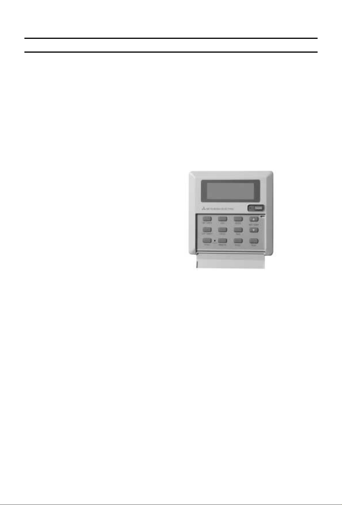
Global Remote Controller
Wide Electrical Control Capability
All series is flexible mechanical control configulation.
In addition Global Remote Controller is prepared
on standard.
The Global Remote Controller give the programmable
weekly timer, compressor anti-short cycle timer(3 min),
cool/heat/fan/auto changeover etc.
This controller utlises a microprocessor and includes
liquid crystal display with touch pad for adjustment for
control program.
The factory standard is for provision of 24volt terminal
block to enable a field wired control of contractors
choice to be connected.
Please consult your local Mitsubishi Electric Sales
office for application advice on these control.
Low Ambient Cooling Kit (option)
In applications with relatively high internal loads,
there may be a requirment for all series to operate
on cooling at low ambient conditions.
An optional accessory is available to maintain the
refrigeration circuit in balance at outdoor
temperatures as low as -5˚C.
Please consult your local Mitsubishi Electric Sales
office for application advice on this accessory.
-3-
Page 6
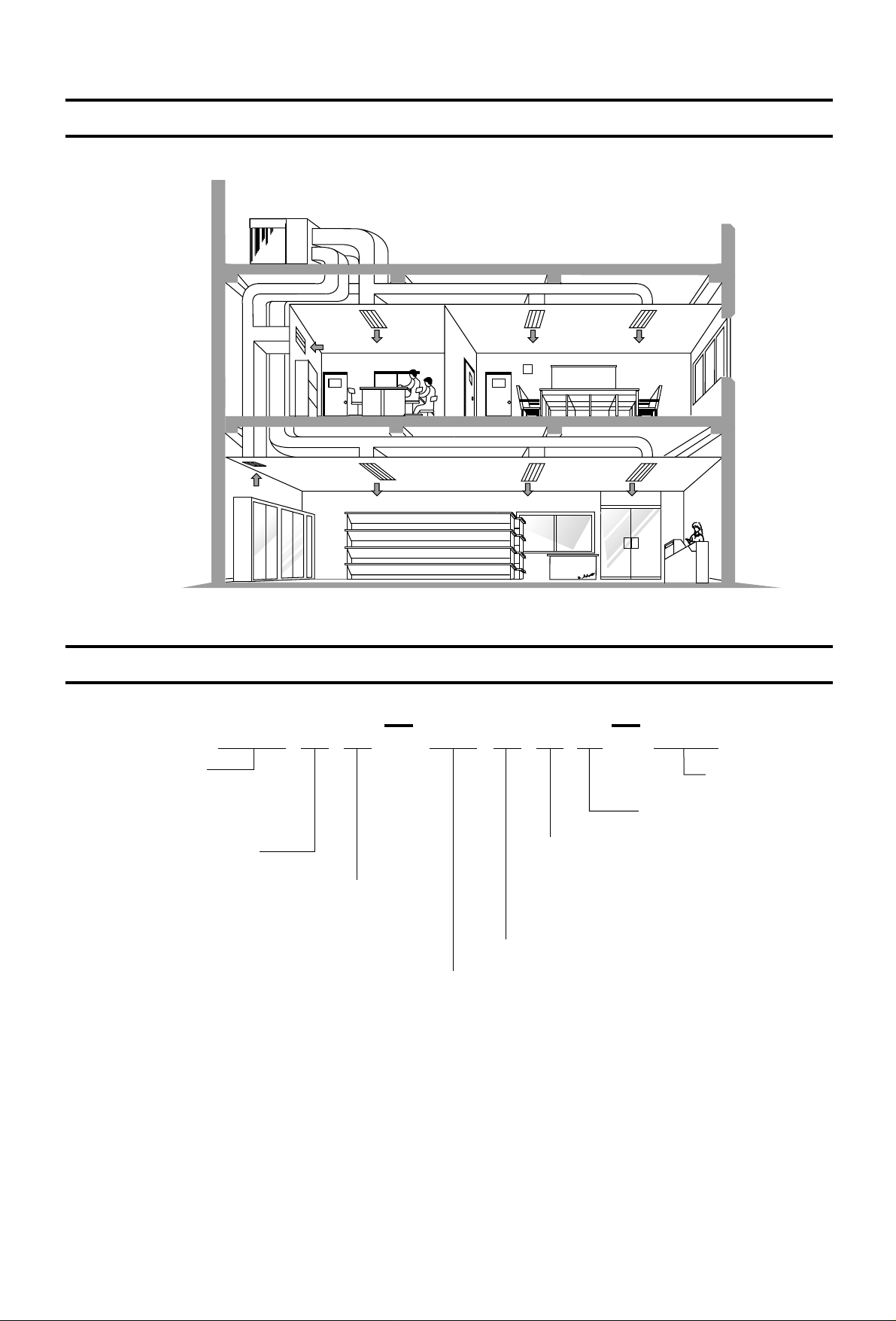
TYPICAL INSTALLATION EXAMPLE
Series symbol
Self-contained type
(rooftop type)
Series symbol
global type
Heat pump type
Series symbol
Y=3-phase
380V,400V,415V,50Hz,4 wires
Design sequence
Compressor horse power
8=8HP
10=10HP
15=15HP
20=20HP
Design sequence
Service reference
MODEL-DESIGNATION BREAKDOWN
PRHG
P R H G 1 0 M Y A E U
-4-
Page 7
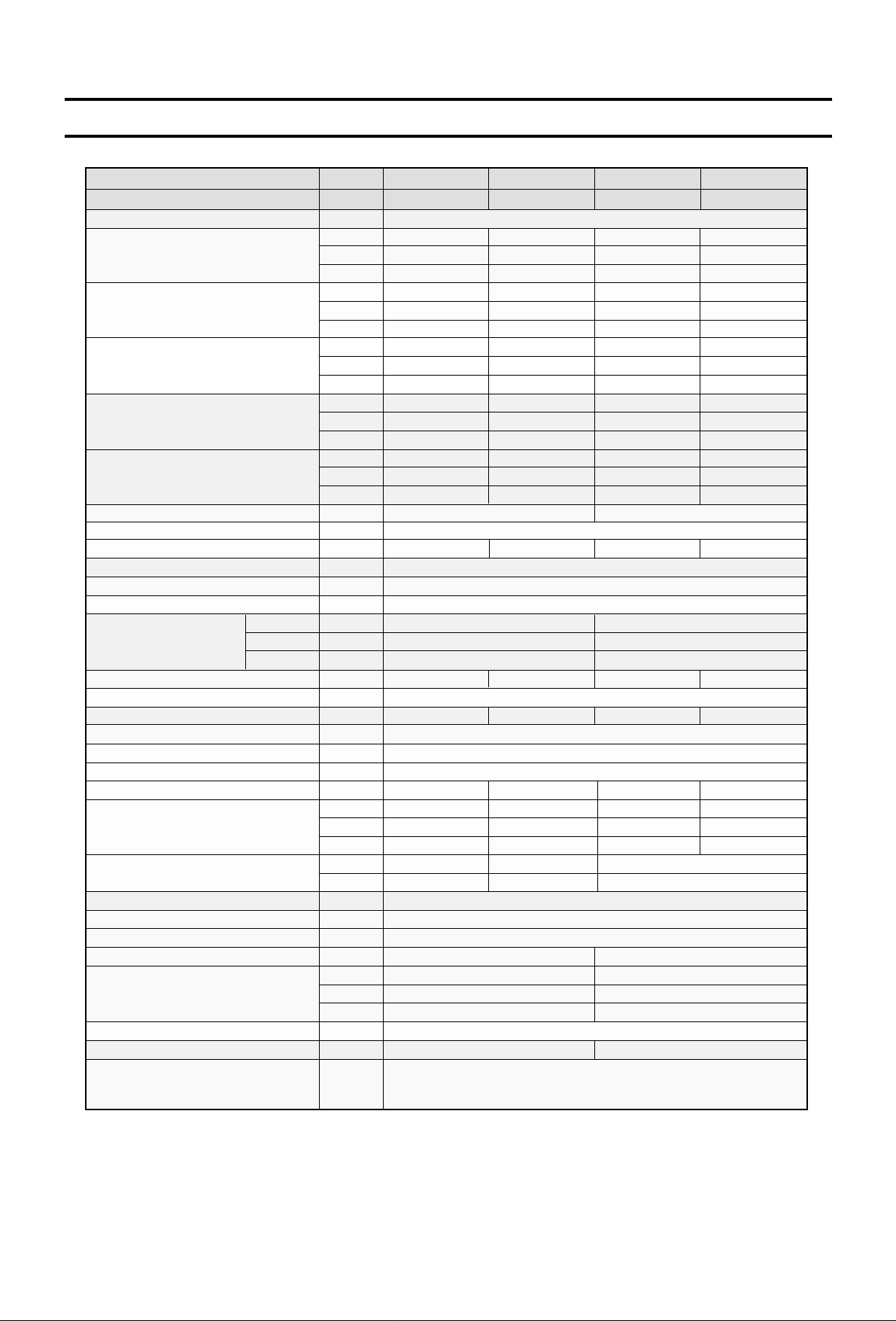
SPECIFICATIONS
Model name
Service reference
Power supply
PRHG-8MYA PRHG-10MYA PRHG-15MYA PRHG-20MYA
PRHG-8MYA-EU(S)
PRHG-10MYA-EU(S) PRHG-15MYA-EU(S) PRHG-20MYA-EU(S)
23.8 29.7
3N~ 380~415V 50Hz
46.3 60.8
Total cooling capacity
Btu/h 81,300 101,400 158,000 207,500
(Gross)
kcal/h 20,500 25,600 39,900 52,300
kW
kW
19.0 23.8 37.0 48.6
Sensible cooling capacity
Btu/h 64,900 81,300 126,300 165,900
(Gross)
Total cooling capacity
(Net)
kcal/h
kW
Btu/h
kcal/h
16,400 20,500 31,900 41,800
23.0/22.6 28.3/27.8 44.8/44.1 58.3/57.2
78,500/77,200 96,600/94,900 152,900/150,500 199,000/195,200
19,800/19,500 24,400/24,000 38,600/38,000 50,200/49,200
kW 22.6/23.0 31.5/32.0 44.8/45.5 60.1/61.2
Total heating capacity
Btu/h 77,200/78,600 107,500/109,100 152,900/155,100 205,100/208,700
(Net)
kcal/h 19,500/19,800 27,100/27,600 38,600/39,200 51,700/52,700
kW 21.8 30.1 43.3 57.6
Total heating capacity
Btu/h 74,400 102,800 147,800 196,600
(Gross)
kcal/h 18,800 25,900 37,300 49,600
Capacity steps % 0-100 0-50-100
Refrigerant R-22
Refrigerant charge 2x5.62x4.74.7 5.6
Refrigerant control Capillary tube
External finish Acrylic resin coating
Color MUNSELL 5Y8/1
Height mm 1,000 1,200
Dimension
Width mm 1,300 1,990
Depth mm 1,530 1,800
Net weight kg
kg
385 415 700 800
Compressor Hermetic line start (reciprocating)
No. x Motor output kW 5.5 7.5 2x5.5 2x7.5
Indoor coil Cross fin coil
Indoor fan Centrifugal (galvanized steel) - belt drive
Indoor fan motor Three phase cage induction motor
No. x Motor output kW 1.1 1.5 2.2 3.7
CMM 80 100 160 190
Indoor fan air flow
CFM 2,826 3,532 5,651 6,710
L/S 1,333
5/10
50/100
1,667
6.2/10
62/100
2,667
10/20
100/200
3,167
External static pressure
mmAq
Pa
Outdoor coil Cross fin coil
Outdoor fan Propeller - direct drive
Outdoor fan motor Three phase cage induction motor
No. x Motor output kW 0.55 2x0.55
CMM 160 320
Condenser fan air flow
CFM 5,651 11,302
L/S 2,667 5,333
66 70 Sound pressure level dB(A)
Drain connection mm 25.4
High pressure switch, fuse
Protection devices
Over current relay (compressor, indoor fan and outdoor fan)
Internal thermostat (compressor and outdoor fan motor)
Note 1.Cooling & Heating capacity is based on the following conditions.
Cooling : Indoor:27˚CDB , 19˚CWB ; Outdoor:35˚CDB
Heating : Indoor:21˚CDB ; Outdoor:7˚CDB , 6˚CWB
2.Refrigerant charge volumes are factory charged.
3.Gross capacity do not include a deduction for evaporator fan motor heat.
4.The measuring point of the Sound pressure level is 1m from the unit surface.
5.The range of working voltage is with in ±10% voltage of power supply.
6.Specification subject to change without notice.
-5-
Page 8
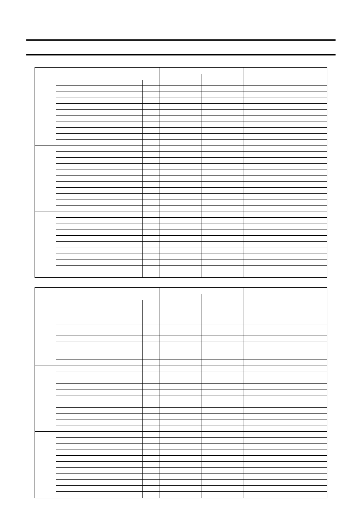
ELECTRICAL DATA
VOLT
TOTAL INPUT
TOTAL RUN CURRENT
POWER FACTOR
START CURRENT
COMPRESSOR INPUT
RUN CURRENT
O/D FAN INPUT
RUN CURRENT
I/D FAN External static pressure
INPUT
RUN CURRENT
TOTAL INPUT
TOTAL RUN CURRENT
POWER FACTOR
START CURRENT
COMPRESSOR INPUT
RUN CURRENT
O/D FAN INPUT
RUN CURRENT
I/D FAN External static pressure
INPUT
RUN CURRENT
TOTAL INPUT
TOTAL RUN CURRENT
POWER FACTOR
START CURRENT
COMPRESSOR INPUT
RUN CURRENT
O/D FAN INPUT
RUN CURRENT
I/D FAN External static pressure
INPUT
RUN CURRENT
415V
400V
380V
kW
A
%
A
kW
A
kW
A
Pa
kW
A
kW
A
%
A
kW
A
kW
A
Pa
kW
A
kW
A
%
A
kW
A
kW
A
Pa
kW
A
7.9/8.3
13.3/14.0
82%
77.8
6.6
10.4
0.5
1.5
62/100
0.8/1.2
1.4/2.1
7.9/8.3
13.8/14.5
82%
80.8
6.6
10.7
0.5
1.6
50/100
0.8/1.2
1.5/2.2
7.9/8.3
14.5/15.3
82%
85.0
6.6
11.4
0.5
1.6
50/100
0.8/1.2
1.5/2.3
6.6/7.0
11.1/11.8
83%
77.8
5.3
8.2
0.5
1.5
62/100
0.8/1.2
1.4/2.1
6.6/7.0
11.6/12.3
83%
80.8
5.3
8.5
0.5
1.6
50/100
0.8/1.2
1.5/2.2
6.6/7.0
12.1/12.9
83%
85.0
5.3
9.0
0.5
1.6
50/100
0.8/1.2
1.5/2.3
10.9/11.4
17.8/18.5
86%
76.3
9.0
14.5
0.5
1.3
62/100
1.4/1.9
2.0/2.7
10.9/11.4
18.5/19.2
86%
79.1
9.0
15.1
0.5
1.3
62/100
1.4/1.9
2.1/2.8
10.9/11.4
19.4/20.2
86%
83.3
9.0
15.9
0.5
1.4
62/100
1.4/1.9
2.1/2.9
9.4/9.9
15.3/16.0
86%
76.3
7.5
12.0
0.5
1.3
62/100
1.4/1.9
2.0/2.7
9.4/9.9
15.8/16.5
86%
79.1
7.5
12.4
0.5
1.3
62/100
1.4/1.9
2.1/2.8
9.4/9.9
16.6/17.4
86%
83.3
7.5
13.1
0.5
1.4
62/100
1.4/1.9
2.1/2.9
ITEM
PRHG-8MYA PRHG-10MYA
Cooling Heating HeatingCooling
VOLT
TOTAL INPUT
TOTAL RUN CURRENT
POWER FACTOR
START CURRENT
COMPRESSOR INPUT
RUN CURRENT
O/D FAN INPUT
RUN CURRENT
I/D FAN External static pressure
INPUT
RUN CURRENT
TOTAL INPUT
TOTAL RUN CURRENT
POWER FACTOR
START CURRENT
COMPRESSOR INPUT
RUN CURRENT
O/D FAN INPUT
RUN CURRENT
I/D FAN External static pressure
INPUT
RUN CURRENT
TOTAL INPUT
TOTAL RUN CURRENT
POWER FACTOR
START CURRENT
COMPRESSOR INPUT
RUN CURRENT
O/D FAN INPUT
RUN CURRENT
I/D FAN External static pressure
INPUT
RUN CURRENT
415V
400V
380V
kW
A
%
A
kW
A
kW
A
Pa
kW
A
kW
A
%
A
kW
A
kW
A
Pa
kW
A
kW
A
%
A
kW
A
kW
A
Pa
kW
A
15.7/16.4
26.3/27.5
83%
104.5
13.2
20.9
1.0
2.8
100/200
1.5/2.2
2.6/3.8
15.7/16.4
27.3/28.5
83%
108.4
13.2
21.7
1.0
2.9
100/200
1.5/2.2
2.7/3.9
15.7/16.4
28.7/30.0
83%
114.2
13.2
22.7
1.0
3.1
100/200
1.5/2.2
2.9/4.2
14.0/14.7
23.5/24.7
83%
101.7
11.5
18.1
1.0
2.8
100/200
1.5/2.2
2.6/3.8
14.0/14.7
24.4/25.6
83%
105.5
11.5
18.8
1.0
2.9
100/200
1.5/2.2
2.7/3.9
14.0/14.7
25.7/27.0
83%
111.1
11.5
19.7
1.0
3.1
100/200
1.5/2.2
2.9/4.2
21.0/22.1
34.2/35.7
86%
110.6
17.5
28.2
1.0
2.6
100/200
2.5/3.6
3.4/4.9
21.0/22.1
35.4/37.0
86%
114.7
17.5
29.2
1.0
2.7
100/200
2.5/3.6
3.5/5.1
21.0/22.1
37.4/39.0
86%
120.7
17.5
30.8
1.0
2.8
100/200
2.5/3.6
3.8/5.4
18.2/19.3
29.7/31.2
86%
106.1
14.7
23.7
1.0
2.6
100/200
2.5/3.6
3.4/4.9
18.2/19.3
30.8/32.4
86%
110.1
14.7
24.6
1.0
2.7
100/200
2.5/3.6
3.5/5.1
18.2/19.3
32.5/34.1
86%
115.8
14.7
25.9
1.0
2.8
100/200
2.5/3.6
3.8/5.4
ITEM
PRHG-15MYA PRHG-20MYA
Cooling Heating HeatingCooling
-6-
Page 9
1. Model Selection (With actual examples)
First step, to select the approximate model:
Based on the cooling load and the cooling capacity listed in the capacity table, select the applicable model.
Notes:
*1. The correct WB is required since it has a serious effect on the capacity.
*2. The cooling capacity decreases as the outdoor temperature increases. Therefore, the estimated highest
temperature during an air conditioning time frame is the “designed outdoor temperature”. However, it is
recommended that the abnormal outdoor temperature which may occur once or twice a year be excluded from
the calculation to avoid selection of an excessively large capacity model.
*3. The wind pressure loss of an air duct should be calculated correctly. If a value having an excessive allowance is
used, an excessively large model will be selected. Moreover, an excessively high air flow will be induced during
actual operation causing the generation of high operating sounds and carry-over of condensed water.
(Step-1) Confirmation of operation range
Confirm that the conditions given above for the model to be selected are within the operation
range listed on Page 18.
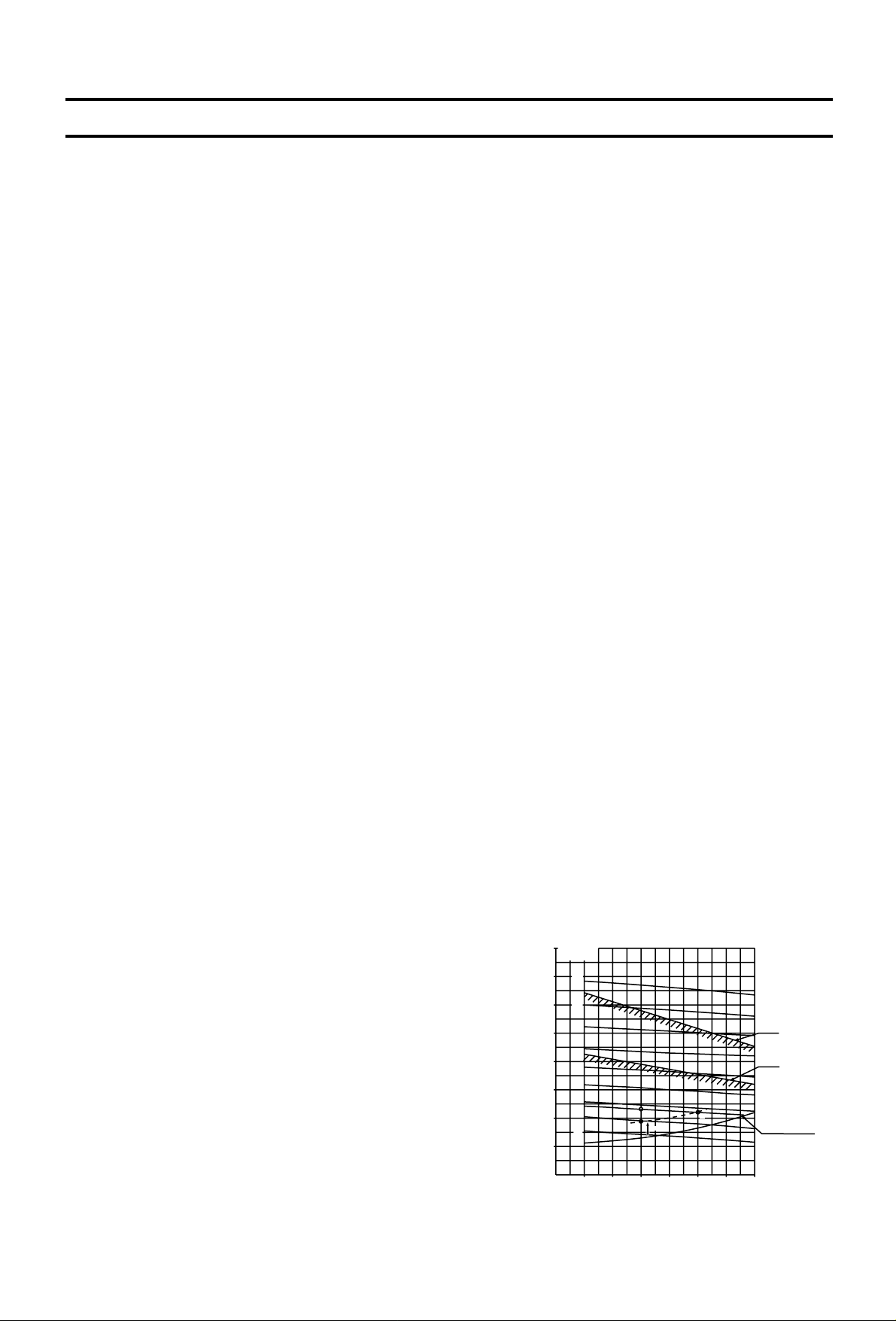
(Step-2) Calculation of actual air flow, external static pressure, and fan motor input
Based on the designed air flow and external static pressure, obtain the actual air flow and fan motor
power from the fan performance table for the model input selected. For an explanation of how to
use the fan performance table, see the following examples.
Example: PRHG-10, 50Hz
Example 1. (To operate with values near to the designed air flow and external static pressure.)
Condition : Designed air flow 100CMM
Designed external static pressure 60Pa
Calculation : The designed point is A. Therefore, duct
resistance line passing A is dotted line.
Therefore, actual point is B for
fan speed 1088rpm.
(Select a pulley near A point to fan speed.)
Actual air flow = 110CMM
Second step, to select the model:
To select the model, the following conditions must be known:
(1) Total cooling load or sensible cooling load
(2) Indoor conditioned temperature (WB*1, DB)
(3) Designed outdoor temperature (DB)*2
(4) Designed air flow
(5) Designed external static pressure (= Wind pressure loss of air duct)*3
internal static pressure
Air flow
1500
90 95 100 105
1670
(CMM)
(L/S)
1.5kw
2.2kw
900
1000
1100
1200
1300
1400
100
200
300
400
500
Total static pressure (Pa)
Fan speed
<rpm>
1500
110 115
1830
120
2000
600
700
800
1600
1700
SELECTION PROCEDURE
A
B
60Pa
-7-
Page 10
At 26˚CDB, 19˚CWB of Indoor,
Q = 28.3, SHC = 22.6, W = 9.6
Therefore, when Air flow is 110 (CMM)
Q = 28.3 ✕ 1.012 28.6 (kW)
SHC = 22.6
W = 9.6 Note * : crrection factors of air flow
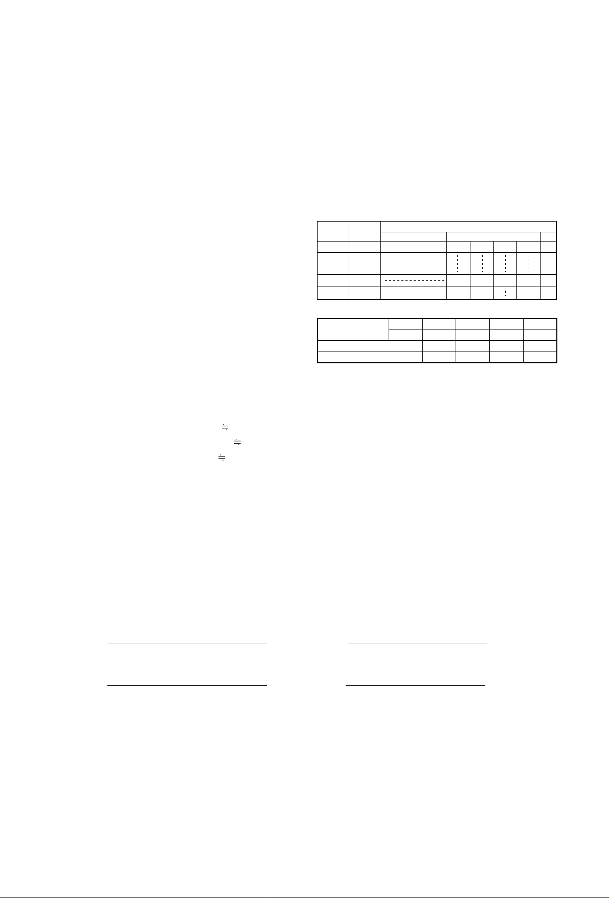
(Step-3) Calculation of net capacity
Example: PRHG-10, 50Hz cooling
Condition:
Indoor conditioned temp. : 26˚CDB, 19˚CWB
Designed outdoor temp. : 40˚CDB
Actual air flow : 110CMM
Indoor fan motor input : 1.9kW (See P.6, 17)
Outdoor fan motor input : 0.5kW (See P.6)
Calculation :
The sections of the gross capacity table applicable
for the above conditions are shown right.
Therfore, the net capacity is,
Net total cooling capacity = 28.6 (kw) - 1.9 (kW)
= 26.7 (kW)
Net sensible cooling capacity = 22.9 (kW) - 1.9 (kW)
= 21.0 (kW)
• Refrigerant cycle energy efficienty
(1) COP =
(2) EER =
• System energy efficienty
(1) COP =
(2) EER =
Notes:
1. COP : Coefficient of performance
2. EER : Energy efficiency ratio
3. Temperature condition of COP, EER (ARI Standard Ratings)
Indoor entering air temp. : 80˚FDB (=27˚CDB), 66˚FWB(=19˚CWB)
Outdoor entering air temp. : 95˚FDB (=35˚CDB)
4. Total input = Compressor input + Indoor fan motor input (page 17) + Outdoor fan motor input (page 6).
Gross total cooling capacity (kW)
Compressor input (kW)
Gross total cooling capacity (kW)
Total input (kW)
Net cooling capacity (kW)
Compressor input (kW)
Net cooling capacity (kW)
Total input (kW)
1kW = 3412Btu/h
2. Efficiency Calculation
Based on the indoor conditioned temperature (WB,DB), designed outdoor temperature (DB), and the
actual air flow obtained in Step-2, obtain the gross capacity from the gross capacity tables (pages
9~16). Then, calculate the net capacity from the formula below by using the fan motor input obtained
in Step-2.
Net capacity (kW) = Gross capacity (kW) - Fan motor input (kW)
✕ 1.012 22.9 (kW)
✕ 1.003 9.63 (kW)
28.3 22.6 0.77 9.6
OUTDOOR DB˚C
INDOOR INDOOR
40.0
Q kW
SHC kW
SHF W kW
DB˚CWB˚C
26 19.0
29.2 20.4 9.8
20.0
Factor for Various Air Flow
Air Volume
CMM
l/s
Cooling capacity
Compressor input
90
1500
0.987
0.996
100
1670
1.000
1.000
110
1830
1.012
1.003
120
2000
1.022
1.007
-8-
Page 11
Outdoor DB°C
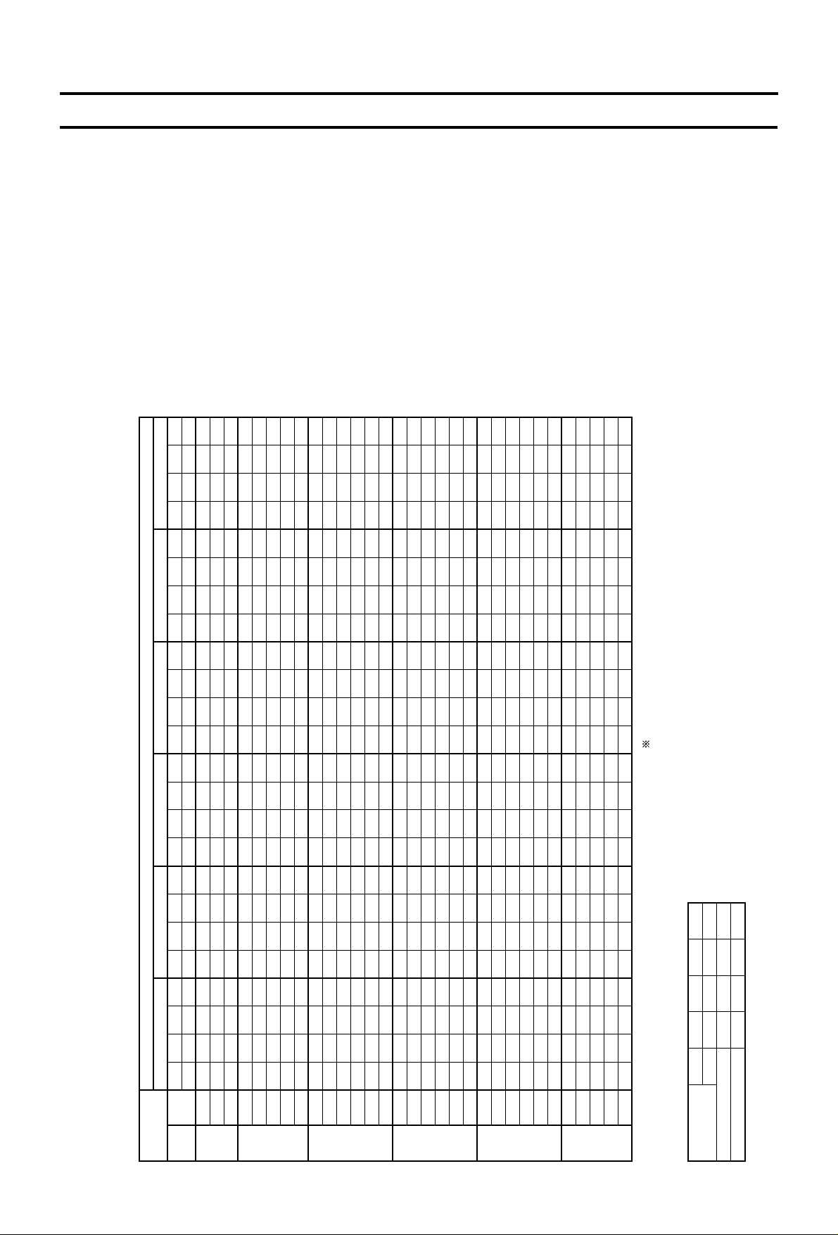
CAPACITY TABLES
Factor for Various Air Flow
Cooling Capacity (Standard Air Flow)
PRHG-8MYA
20.0
Indoor
WB°C
15161715161718191617181920211819202122231920212223242021222324
Q
kW
22.8
23.5
24.2
22.8
23.5
24.2
25.0
25.7
23.5
24.2
25.0
25.7
26.5
27.3
25.0
25.7
26.5
27.3
28.1
29.0
25.7
26.5
27.3
28.1
29.0
30.0
26.5
27.3
28.1
29.0
30.0
SHC
kW
16.2
14.8
13.3
19.2
17.6
16.2
14.8
13.4
20.4
18.9
17.5
15.9
14.6
13.1
20.5
18.8
17.2
15.8
14.3
13.1
21.6
20.1
18.6
17.1
15.7
14.4
22.8
21.6
20.0
18.6
17.1
SHF
0.71
0.63
0.55
0.84
0.75
0.67
0.59
0.52
0.87
0.78
0.70
0.62
0.55
0.48
0.82
0.73
0.65
0.58
0.51
0.45
0.84
0.76
0.68
0.61
0.54
0.48
0.86
0.79
0.71
0.64
0.57
W
kW
5.2
5.2
5.3
5.2
5.2
5.3
5.3
5.4
5.2
5.3
5.3
5.4
5.5
5.6
5.3
5.4
5.5
5.6
5.7
5.8
5.4
5.5
5.6
5.7
5.8
5.9
5.5
5.6
5.7
5.8
5.9
25.0
Q
kW
22.3
22.9
23.6
22.3
22.9
23.6
24.4
25.2
22.9
23.6
24.4
25.2
25.9
26.7
24.4
25.2
25.9
26.7
27.5
28.4
25.2
25.9
26.7
27.5
28.4
29.3
25.9
26.7
27.5
28.4
29.3
SHC
kW
15.8
14.4
13.0
19.0
17.4
15.8
14.4
13.1
20.2
18.6
17.3
15.6
14.2
12.8
20.3
18.6
17.1
15.8
14.3
12.8
21.4
19.9
18.4
16.8
15.3
14.1
22.5
21.4
19.8
18.2
16.7
SHF
0.71
0.63
0.55
0.85
0.76
0.67
0.59
0.52
0.88
0.79
0.71
0.62
0.55
0.48
0.83
0.74
0.66
0.59
0.52
0.45
0.85
0.77
0.69
0.61
0.54
0.48
0.87
0.80
0.72
0.64
0.57
W
kW
5.5
5.5
5.6
5.5
5.5
5.6
5.7
5.8
5.5
5.6
5.7
5.8
5.9
6.0
5.7
5.8
5.9
6.0
6.1
6.2
5.8
5.9
6.0
6.1
6.2
6.4
5.9
6.0
6.1
6.2
6.4
30.0
Q
kW
21.7
22.3
23.0
21.7
22.3
23.0
23.7
24.5
22.3
23.0
23.7
24.5
25.2
25.9
23.7
24.5
25.2
25.9
26.7
27.6
24.5
25.2
25.9
26.7
27.6
28.5
25.2
25.9
26.7
27.6
28.5
SHC
kW
15.6
14.3
12.7
18.7
17.2
15.6
14.2
13.0
19.8
18.6
17.1
15.4
14.1
12.7
19.9
18.4
16.9
15.5
14.2
12.7
21.1
19.7
18.1
16.6
15.2
14.0
22.2
21.0
19.5
17.9
16.5
SHF
0.72
0.64
0.55
0.86
0.77
0.68
0.60
0.53
0.89
0.81
0.72
0.63
0.56
0.49
0.84
0.75
0.67
0.60
0.53
0.46
0.86
0.78
0.70
0.62
0.55
0.49
0.88
0.81
0.73
0.65
0.58
W
kW
5.8
5.9
6.0
5.8
5.9
6.0
6.1
6.2
5.9
6.0
6.1
6.2
6.3
6.4
6.1
6.2
6.3
6.4
6.6
6.7
6.2
6.3
6.4
6.6
6.7
6.8
6.3
6.4
6.6
6.7
6.8
35.0
Q
kW
21.0
21.6
22.3
21.0
21.6
22.3
23.0
23.8
21.6
22.3
23.0
23.8
24.5
25.2
23.0
23.8
24.5
25.2
26.0
26.8
23.8
24.5
25.2
26.0
26.8
27.7
24.5
25.2
26.0
26.8
27.7
SHC
kW
15.3
14.0
12.5
18.3
16.8
15.4
14.0
12.6
19.7
18.3
16.8
15.2
13.7
12.3
19.6
18.1
16.7
15.4
13.8
12.3
20.7
19.4
17.9
16.4
15.0
13.6
22.1
20.7
19.2
17.7
16.3
SHF
0.73
0.65
0.56
0.87
0.78
0.69
0.61
0.53
0.91
0.82
0.73
0.64
0.56
0.49
0.85
0.76
0.68
0.61
0.53
0.46
0.87
0.79
0.71
0.63
0.56
0.49
0.90
0.82
0.74
0.66
0.59
W
kW
6.1
6.2
6.4
6.1
6.2
6.4
6.5
6.6
6.2
6.4
6.5
6.6
6.7
6.9
6.5
6.6
6.7
6.9
7.0
7.1
6.6
6.7
6.9
7.0
7.1
7.3
6.7
6.9
7.0
7.1
7.3
40.0
Q
kW
20.3
20.9
21.6
20.3
20.9
21.6
22.3
23.0
20.9
21.6
22.3
23.0
23.7
24.4
22.3
23.0
23.7
24.4
25.2
26.0
23.0
23.7
24.4
25.2
26.0
26.8
23.7
24.4
25.2
26.0
26.8
SHC
kW
15.0
13.8
12.1
17.9
16.5
15.1
13.8
12.4
19.4
18.1
16.7
15.0
13.5
12.2
19.2
17.7
16.4
15.1
13.6
12.2
20.5
19.0
17.6
16.1
14.6
13.1
21.8
20.5
18.9
17.4
16.1
SHF
0.74
0.66
0.56
0.88
0.79
0.70
0.62
0.54
0.93
0.84
0.75
0.65
0.57
0.50
0.86
0.77
0.69
0.62
0.54
0.47
0.89
0.80
0.72
0.64
0.56
0.49
0.92
0.84
0.75
0.67
0.60
W
kW
6.5
6.6
6.8
6.5
6.6
6.8
6.9
7.0
6.6
6.8
6.9
7.0
7.2
7.3
6.9
7.0
7.2
7.3
7.5
7.6
7.0
7.2
7.3
7.5
7.6
7.8
7.2
7.3
7.5
7.6
7.8
46.0
Q
kW
19.4
20.1
20.7
19.4
20.1
20.7
21.3
22.0
20.1
20.7
21.3
22.0
22.7
23.4
21.3
22.0
22.7
23.4
24.1
24.9
22.0
22.7
23.4
24.1
24.9
25.6
22.7
23.4
24.1
24.9
25.6
SHC
kW
14.7
13.5
11.8
17.5
16.3
14.7
13.4
11.9
19.1
17.6
16.2
14.5
13.2
11.7
18.7
17.4
15.9
14.5
13.0
11.7
20.0
18.6
17.3
15.7
14.2
12.8
21.3
20.1
18.6
17.2
15.6
SHF
0.76
0.67
0.57
0.90
0.81
0.71
0.63
0.54
0.95
0.85
0.76
0.66
0.58
0.50
0.88
0.79
0.70
0.62
0.54
0.47
0.91
0.82
0.74
0.65
0.57
0.50
0.94
0.86
0.77
0.69
0.61
W
kW
7.0
7.1
7.3
7.0
7.1
7.3
7.4
7.5
7.1
7.3
7.4
7.5
7.7
7.9
7.4
7.5
7.7
7.9
8.0
8.2
7.5
7.7
7.9
8.0
8.2
8.3
7.7
7.9
8.0
8.2
8.3
Indoor
DB°C
20
22
24
26
28
30
Q; Cooling Capacity, SHC; Sensible Heat Capacity, W; Compressor Input
Total input = Compressor input + indoor fan motor input + outdoor fan motor input
Air Volume
CMM
l/s
Cooling capacity
Compressor input
80
1330
1.000
1.000
85
1420
1.006
1.001
90
1500
1.012
1.001
95
1580
1.017
1.003
-9-
Page 12

Outdoor DB°C
Factor for Various Air Flow
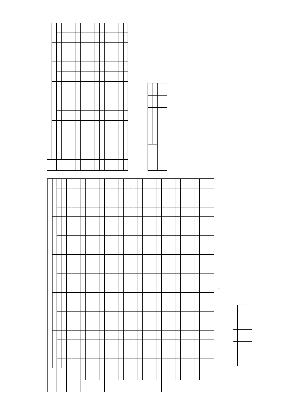
Cooling Capacity (Standard Air Flow)
PRHG-8MYA (Use for Low ambient cooling parts)
Heating Capacity (Standard Air Flow)
PRHG-8MYA
–5.0
Indoor
WB°C
15161715161718191617181920211819202122231920212223242021222324
Q
kW
25.3
26.2
27.0
25.3
26.2
27.0
27.9
28.8
26.2
27.0
27.9
28.8
29.7
30.7
27.9
28.8
29.7
30.7
31.6
32.7
28.8
29.7
30.7
31.6
32.7
33.9
29.7
30.7
31.6
32.7
33.9
SHC
kW
17.7
16.2
14.6
20.5
19.1
17.5
16.2
14.7
22.2
20.8
19.3
17.5
16.0
14.4
22.3
20.4
19.0
17.5
15.8
14.4
23.3
21.7
20.2
18.7
17.3
15.9
24.7
23.3
21.8
20.3
18.6
SHF
0.70
0.62
0.54
0.81
0.73
0.65
0.58
0.51
0.85
0.77
0.69
0.61
0.54
0.47
0.80
0.71
0.64
0.57
0.50
0.44
0.81
0.73
0.66
0.59
0.53
0.47
0.83
0.76
0.69
0.62
0.55
W
kW
4.4
4.4
4.5
4.4
4.4
4.5
4.5
4.6
4.4
4.5
4.5
4.6
4.6
4.7
4.5
4.6
4.6
4.7
4.8
4.9
4.6
4.6
4.7
4.8
4.9
5.0
4.6
4.7
4.8
4.9
5.0
0.0
Q
kW
24.9
25.7
26.5
24.9
25.7
26.5
27.4
28.2
25.7
26.5
27.4
28.2
29.2
30.1
27.4
28.2
29.2
30.1
31.0
32.1
28.2
29.2
30.1
31.0
32.1
33.2
29.2
30.1
31.0
32.1
33.2
SHC
kW
17.4
15.9
14.3
20.4
19.0
17.5
15.9
14.4
22.1
20.4
18.9
17.2
15.8
14.1
21.9
20.1
18.7
17.2
15.5
14.1
22.9
21.3
19.9
18.3
17.0
15.6
24.2
22.9
21.4
19.9
18.3
SHF
0.70
0.62
0.54
0.82
0.74
0.66
0.58
0.51
0.86
0.77
0.69
0.61
0.54
0.47
0.80
0.71
0.64
0.57
0.50
0.44
0.81
0.73
0.66
0.59
0.53
0.47
0.83
0.76
0.69
0.62
0.55
W
kW
4.4
4.4
4.5
4.4
4.4
4.5
4.5
4.6
4.4
4.5
4.5
4.6
4.6
4.7
4.5
4.6
4.6
4.7
4.8
4.9
4.6
4.6
4.7
4.8
4.9
5.0
4.6
4.7
4.8
4.9
5.0
5.0
Q
kW
24.5
25.3
26.1
24.5
25.3
26.1
27.0
27.8
25.3
26.1
27.0
27.8
28.7
29.6
27.0
27.8
28.7
29.6
30.5
31.6
27.8
28.7
29.6
30.5
31.6
32.7
28.7
29.6
30.5
31.6
32.7
SHC
kW
17.2
15.7
14.1
20.1
18.7
17.2
15.7
14.2
21.8
20.1
18.6
17.0
15.5
13.9
21.9
20.0
18.4
16.9
15.3
13.9
22.8
21.3
19.9
18.0
16.7
15.4
24.1
22.8
21.4
19.9
18.1
SHF
0.70
0.62
0.54
0.82
0.74
0.66
0.58
0.51
0.86
0.77
0.69
0.61
0.54
0.47
0.81
0.72
0.64
0.57
0.50
0.44
0.82
0.74
0.67
0.59
0.53
0.47
0.84
0.77
0.70
0.63
0.55
W
kW
4.5
4.5
4.6
4.5
4.5
4.6
4.6
4.7
4.5
4.6
4.6
4.7
4.7
4.8
4.6
4.7
4.7
4.8
4.9
5.0
4.7
4.7
4.8
4.9
5.0
5.1
4.7
4.8
4.9
5.0
5.1
10.0
Q
kW
24.1
24.9
25.7
24.1
24.9
25.7
26.5
27.3
24.9
25.7
26.5
27.3
28.2
29.1
26.5
27.3
28.2
29.1
30.0
31.0
27.3
28.2
29.1
30.0
31.0
32.1
28.2
29.1
30.0
31.0
32.1
SHC
kW
17.1
15.7
14.1
20.0
18.7
17.2
15.7
13.9
21.7
20.0
18.6
16.9
15.2
13.7
21.5
19.7
18.3
16.9
15.3
13.6
22.4
20.9
19.5
18.0
16.4
15.1
23.7
22.4
21.0
19.5
18.0
SHF
0.71
0.63
0.55
0.83
0.75
0.67
0.59
0.51
0.87
0.78
0.70
0.62
0.54
0.47
0.81
0.72
0.65
0.58
0.51
0.44
0.82
0.74
0.67
0.60
0.53
0.47
0.84
0.77
0.70
0.63
0.56
W
kW
4.7
4.7
4.8
4.7
4.7
4.8
4.8
4.9
4.7
4.8
4.8
4.9
4.9
5.0
4.8
4.9
4.9
5.0
5.1
5.2
4.9
4.9
5.0
5.1
5.2
5.3
4.9
5.0
5.1
5.2
5.3
15.0
Q
kW
23.7
24.4
25.2
23.7
24.4
25.2
26.0
26.8
24.4
25.2
26.0
26.8
27.6
28.5
26.0
26.8
27.6
28.5
29.4
30.3
26.8
27.6
28.5
29.4
30.3
31.4
27.6
28.5
29.4
30.3
31.4
SHC
kW
16.8
15.4
13.8
19.9
18.3
16.9
15.4
13.9
21.2
19.6
18.2
16.6
15.2
13.7
21.3
19.5
18.0
16.5
15.0
13.7
22.2
20.7
19.4
17.6
16.4
15.1
23.5
22.2
20.8
19.4
17.6
SHF
0.71
0.63
0.55
0.84
0.75
0.67
0.59
0.52
0.87
0.78
0.70
0.62
0.55
0.48
0.82
0.73
0.65
0.58
0.51
0.45
0.83
0.75
0.68
0.60
0.54
0.48
0.85
0.78
0.71
0.64
0.56
W
kW
4.9
4.9
5.0
4.9
4.9
5.0
5.0
5.1
4.9
5.0
5.0
5.1
5.2
5.3
5.0
5.1
5.2
5.3
5.4
5.5
5.1
5.2
5.3
5.4
5.5
5.6
5.2
5.3
5.4
5.5
5.6
Indoor
DB°C
20
22
24
26
28
30
Q; Cooling Capacity, SHC; Sensible Heat Capacity, W; Compressor Input
Total input = Compressor input + indoor fan motor input + outdoor fan motor input
Air Volume
CMM
l/s
Cooling capacity
Compressor input
80
1330
1.000
1.000
85
1420
1.006
1.001
90
1500
1.012
1.001
95
1580
1.017
1.003
Factor for Various Air Flow
Air Volume
CMM
l/s
Heating capacity
Compressor input
80
1330
1.000
1.000
85
1420
1.004
0.996
90
1500
1.090
0.992
95
1580
1.015
0.987
Indoor
DB°C
15161718192021222324252627
Q
kW
15.4
15.3
15.2
15.1
15.1
15.0
14.9
14.8
14.7
14.7
14.6
14.5
14.5
W
kW
3.6
3.6
3.6
3.6
3.6
3.7
3.7
3.7
3.7
3.8
3.8
3.8
3.8
Q
kW
13.5
13.4
13.3
13.2
13.2
13.1
13.0
12.9
12.8
12.8
12.7
12.6
12.6
W
kW
3.4
3.4
3.4
3.4
3.4
3.5
3.5
3.5
3.5
3.6
3.6
3.6
3.6
–10–15
Q
kW
17.6
17.5
17.4
17.3
17.3
17.2
17.1
17.0
17.0
16.9
16.8
16.7
16.7
W
kW
3.9
3.9
3.9
3.9
4.0
4.0
4.0
4.1
4.1
4.1
4.2
4.2
4.2
–5
Q
kW
20.1
20.0
19.9
19.9
19.8
19.7
19.6
19.5
19.5
19.4
19.3
19.2
19.2
W
kW
4.4
4.4
4.4
4.5
4.5
4.6
4.6
4.6
4.7
4.7
4.8
4.8
4.8
0
Q
kW
22.9
22.8
22.7
22.6
22.6
22.5
22.4
22.3
22.2
22.2
22.1
22.0
22.0
W
kW
4.8
4.9
4.9
5.0
5.1
5.1
5.2
5.2
5.3
5.3
5.4
5.4
5.4
5
Q
kW
26.0
25.9
25.9
25.8
25.7
25.6
25.5
25.5
25.4
25.3
25.2
25.1
25.1
W
kW
5.4
5.5
5.5
5.6
5.7
5.8
5.8
5.9
5.9
6.0
6.1
6.2
6.2
10 15
Q
kW
29.5
29.5
29.4
29.3
29.2
29.1
29.1
29.0
28.9
28.8
28.7
28.6
28.6
W
kW
6.0
6.1
6.2
6.3
6.4
6.5
6.6
6.7
6.7
6.8
6.9
7.0
7.0
OD WB°C
Q; Heating Capacity, W; Compressor Input
-10-
Page 13

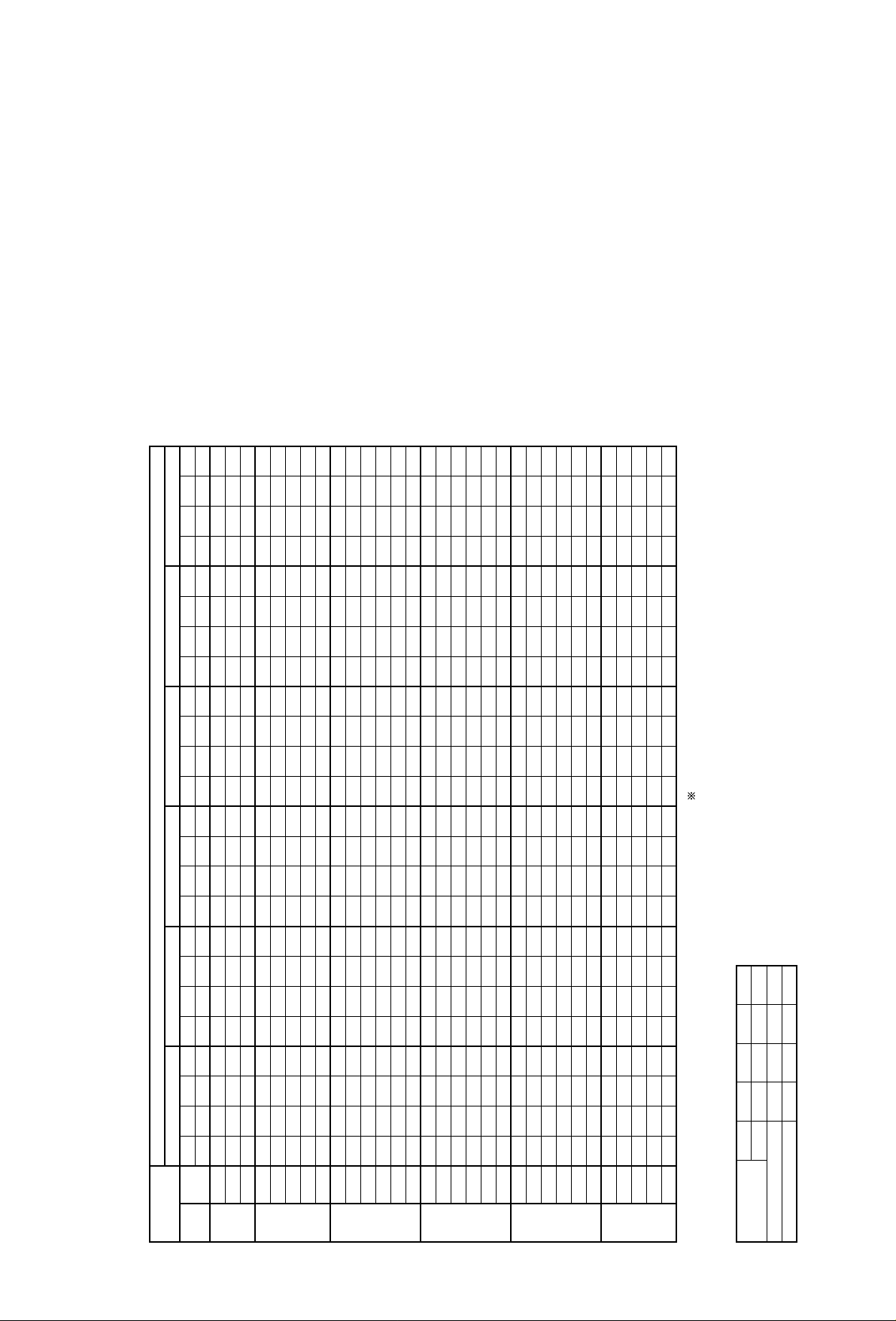
Outdoor DB°C
Factor for Various Air Flow
Cooling Capacity (Standard Air Flow)
PRHG-10MYA
20.0
Indoor
WB°C
15161715161718191617181920211819202122231920212223242021222324
Q
kW
29.4
30.4
31.4
29.4
30.4
31.4
32.4
33.5
30.4
31.4
32.4
33.5
34.6
35.7
32.4
33.5
34.6
35.7
36.8
38.0
33.5
34.6
35.7
36.8
38.0
39.2
34.6
35.7
36.8
38.0
39.2
SHC
kW
21.2
19.5
17.6
24.7
23.1
21.4
19.4
17.4
26.8
25.1
23.3
21.1
19.0
17.1
26.9
24.8
22.8
20.7
18.8
17.1
28.1
26.3
24.6
22.4
20.5
18.8
30.1
28.2
26.1
24.3
22.3
SHF
0.72
0.64
0.56
0.84
0.76
0.68
0.60
0.52
0.88
0.80
0.72
0.63
0.55
0.48
0.83
0.74
0.66
0.58
0.51
0.45
0.84
0.76
0.69
0.61
0.54
0.48
0.87
0.79
0.71
0.64
0.57
W
kW
7.1
7.2
7.3
7.1
7.2
7.3
7.4
7.5
7.2
7.3
7.4
7.5
7.6
7.7
7.4
7.5
7.6
7.7
7.9
8.0
7.5
7.6
7.7
7.9
8.0
8.2
7.6
7.7
7.9
8.0
8.2
25.0
Q
kW
28.4
29.4
30.3
28.4
29.4
30.3
31.3
32.3
29.4
30.3
31.3
32.3
33.4
34.4
31.3
32.3
33.4
34.4
35.4
36.6
32.3
33.4
34.4
35.4
36.6
37.7
33.4
34.4
35.4
36.6
37.7
SHC
kW
20.7
18.8
17.0
24.1
22.6
20.6
18.8
16.8
26.5
24.5
22.8
20.7
18.4
16.5
26.3
24.2
22.4
20.0
18.1
16.5
27.5
25.7
24.1
21.9
20.1
18.1
29.7
27.9
25.5
23.8
21.9
SHF
0.73
0.64
0.56
0.85
0.77
0.68
0.60
0.52
0.90
0.81
0.73
0.64
0.55
0.48
0.84
0.75
0.67
0.58
0.51
0.45
0.85
0.77
0.70
0.62
0.55
0.48
0.89
0.81
0.72
0.65
0.58
W
kW
7.4
7.5
7.7
7.4
7.5
7.7
7.8
7.9
7.5
7.7
7.8
7.9
8.1
8.2
7.8
7.9
8.1
8.2
8.4
8.6
7.9
8.1
8.2
8.4
8.6
8.8
8.1
8.2
8.4
8.6
8.8
30.0
Q
kW
27.3
28.2
29.1
27.3
28.2
29.1
30.0
31.0
28.2
29.1
30.0
31.0
32.1
33.0
30.0
31.0
32.1
33.0
34.0
35.1
31.0
32.1
33.0
34.0
35.1
36.1
32.1
33.0
34.0
35.1
36.1
SHC
kW
20.2
18.3
16.6
23.8
22.0
20.1
18.3
16.4
25.9
23.9
22.2
20.2
18.0
16.2
25.8
23.6
21.8
19.5
17.7
16.1
27.0
25.4
23.4
21.4
19.7
17.7
29.2
27.4
25.2
23.5
21.3
SHF
0.74
0.65
0.57
0.87
0.78
0.69
0.61
0.53
0.92
0.82
0.74
0.65
0.56
0.49
0.86
0.76
0.68
0.59
0.52
0.46
0.87
0.79
0.71
0.63
0.56
0.49
0.91
0.83
0.74
0.67
0.59
W
kW
7.8
8.0
8.1
7.8
8.0
8.1
8.3
8.5
8.0
8.1
8.3
8.5
8.6
8.8
8.3
8.5
8.6
8.8
9.0
9.2
8.5
8.6
8.8
9.0
9.2
9.4
8.6
8.8
9.0
9.2
9.4
35.0
Q
kW
26.1
27.0
27.9
26.1
27.0
27.9
28.7
29.7
27.0
27.9
28.7
29.7
30.6
31.6
28.7
29.7
30.6
31.6
32.5
33.5
29.7
30.6
31.6
32.5
33.5
34.5
30.6
31.6
32.5
33.5
34.5
SHC
kW
19.6
17.8
15.9
23.2
21.6
19.5
17.8
16.0
25.4
23.2
21.5
19.6
17.4
15.8
25.3
23.2
21.1
19.0
17.2
15.4
26.4
24.8
23.1
21.1
19.1
17.3
28.5
26.9
24.7
22.8
20.7
SHF
0.75
0.66
0.57
0.89
0.80
0.70
0.62
0.54
0.94
0.83
0.75
0.66
0.57
0.50
0.88
0.78
0.69
0.60
0.53
0.46
0.89
0.81
0.73
0.65
0.57
0.50
0.93
0.85
0.76
0.68
0.60
W
kW
8.3
8.4
8.6
8.3
8.4
8.6
8.8
9.0
8.4
8.6
8.8
9.0
9.2
9.4
8.8
9.0
9.2
9.4
9.6
9.8
9.0
9.2
9.4
9.6
9.8
10.0
9.2
9.4
9.6
9.8
10.0
40.0
Q
kW
24.4
25.7
26.6
24.4
25.7
26.6
27.4
28.3
25.7
26.6
27.4
28.3
29.2
30.1
27.4
28.3
29.2
30.1
31.0
31.9
28.3
29.2
30.1
31.0
31.9
32.9
29.2
30.1
31.0
31.9
32.9
SHC
kW
18.5
17.2
15.4
22.2
21.1
18.9
17.3
15.6
24.7
22.6
21.1
19.0
16.9
15.4
24.7
22.6
20.4
18.4
16.7
15.0
25.8
24.2
22.6
20.5
18.5
16.8
28.0
26.2
24.2
22.3
20.1
SHF
0.76
0.67
0.58
0.91
0.82
0.71
0.63
0.55
0.96
0.85
0.77
0.67
0.58
0.51
0.90
0.80
0.70
0.61
0.54
0.47
0.91
0.83
0.75
0.66
0.58
0.51
0.96
0.87
0.78
0.70
0.61
W
kW
8.8
9.0
9.2
8.8
9.0
9.2
9.4
9.6
9.0
9.2
9.4
9.6
9.8
10.0
9.4
9.6
9.8
10.0
10.2
10.4
9.6
9.8
10.0
10.2
10.4
10.7
9.8
10.0
10.2
10.4
10.7
46.0
Q
kW
23.3
24.1
24.9
23.3
24.1
24.9
25.7
26.6
24.1
24.9
25.7
26.6
27.4
28.3
25.7
26.6
27.4
28.3
29.1
30.0
26.6
27.4
28.3
29.1
30.0
30.8
27.4
28.3
29.1
30.0
30.8
SHC
kW
18.4
16.6
14.7
22.1
20.5
18.4
16.7
14.9
24.1
22.2
20.3
18.4
16.4
14.7
23.9
21.8
20.0
18.1
16.3
14.4
25.3
23.6
21.8
19.8
18.0
16.0
27.1
25.8
23.3
21.6
19.7
SHF
0.79
0.69
0.59
0.95
0.85
0.74
0.65
0.56
1.00
0.89
0.79
0.69
0.60
0.52
0.93
0.82
0.73
0.64
0.56
0.48
0.95
0.86
0.77
0.68
0.60
0.52
0.99
0.91
0.80
0.72
0.64
W
kW
9.5
9.7
9.9
9.5
9.7
9.9
10.1
10.3
9.7
9.9
10.1
10.3
10.5
10.7
10.1
10.3
10.5
10.7
10.9
11.1
10.3
10.5
10.7
10.9
11.1
11.4
10.5
10.7
10.9
11.1
11.4
Indoor
DB°C
20
22
24
26
28
30
Q; Cooling Capacity, SHC; Sensible Heat Capacity, W; Compressor Input
Total input = Compressor input + indoor fan motor input + outdoor fan motor input
Air Volume
CMM
l/s
Cooling capacity
Compressor input
90
1500
0.987
0.996
100
1670
1.000
1.000
110
1830
1.012
1.003
120
2000
1.022
1.007
-11-
Page 14
Outdoor DB°C
Factor for Various Air Flow
Cooling Capacity (Standard Air Flow)
PRHG-10MYA (Use for Low ambient cooling parts)
Heating Capacity (Standard Air Flow)
PRHG-10MYA
–5.0
Indoor
WB°C
15161715161718191617181920211819202122231920212223242021222324
Q
kW
32.7
33.8
35.0
32.7
33.8
35.0
36.2
37.5
33.8
35.0
36.2
37.5
38.8
40.1
36.2
37.5
38.8
40.1
41.4
42.8
37.5
38.8
40.1
41.4
42.8
44.3
38.8
40.1
41.4
42.8
44.3
SHC
kW
22.5
21.0
18.9
26.5
24.7
22.8
21.0
19.1
28.8
26.6
25.0
22.9
20.9
18.8
28.6
26.6
24.4
22.5
20.7
18.8
30.4
28.3
26.5
24.4
22.3
20.4
31.8
30.1
28.2
26.1
24.3
SHF
0.69
0.62
0.54
0.81
0.73
0.65
0.58
0.51
0.85
0.76
0.69
0.61
0.54
0.47
0.79
0.71
0.63
0.56
0.50
0.44
0.81
0.73
0.66
0.59
0.52
0.46
0.82
0.75
0.68
0.61
0.55
W
kW
6.3
6.3
6.4
6.3
6.3
6.4
6.5
6.6
6.3
6.4
6.5
6.6
6.7
6.8
6.5
6.6
6.7
6.8
6.9
7.0
6.6
6.7
6.8
6.9
7.0
7.0
6.7
6.8
6.9
7.0
7.0
0.0
Q
kW
32.1
33.3
34.4
32.1
33.3
34.4
35.6
36.8
33.3
34.4
35.6
36.8
38.1
39.4
35.6
36.8
38.1
39.4
40.6
42.0
36.8
38.1
39.4
40.6
42.0
43.4
38.1
39.4
40.6
42.0
43.4
SHC
kW
22.2
20.6
18.6
26.3
24.6
22.7
20.6
18.8
28.6
26.1
24.5
22.5
20.6
18.5
28.1
26.1
24.4
22.4
20.3
18.5
29.8
27.8
26.0
24.0
21.9
20.0
31.6
29.5
27.6
25.6
23.9
SHF
0.69
0.62
0.54
0.82
0.74
0.66
0.58
0.51
0.86
0.76
0.69
0.61
0.54
0.47
0.79
0.71
0.64
0.57
0.50
0.44
0.81
0.73
0.66
0.59
0.52
0.46
0.83
0.75
0.68
0.61
0.55
W
kW
6.3
6.3
6.4
6.3
6.3
6.4
6.5
6.6
6.3
6.4
6.5
6.6
6.7
6.8
6.5
6.6
6.7
6.8
6.9
7.0
6.6
6.7
6.8
6.9
7.0
7.0
6.7
6.8
6.9
7.0
7.0
5.0
Q
kW
31.6
32.8
33.9
31.6
32.8
33.9
35.0
36.3
32.8
33.9
35.0
36.3
37.5
38.7
35.0
36.3
37.5
38.7
40.0
41.4
36.3
37.5
38.7
40.0
41.4
42.7
37.5
38.7
40.0
41.4
42.7
SHC
kW
22.1
20.3
18.3
25.9
24.2
22.4
20.3
18.5
28.2
26.1
24.5
22.5
20.2
18.2
28.0
26.1
24.0
22.1
20.0
18.2
29.7
27.7
26.0
24.0
21.9
20.1
31.5
29.4
27.6
25.6
23.9
SHF
0.70
0.62
0.54
0.82
0.74
0.66
0.58
0.51
0.86
0.77
0.70
0.62
0.54
0.47
0.80
0.72
0.64
0.57
0.50
0.44
0.82
0.74
0.67
0.60
0.53
0.47
0.84
0.76
0.69
0.62
0.56
W
kW
6.4
6.4
6.5
6.4
6.4
6.5
6.6
6.7
6.4
6.5
6.6
6.7
6.8
6.9
6.6
6.7
6.8
6.9
7.0
7.1
6.7
6.8
6.9
7.0
7.1
7.2
6.8
6.9
7.0
7.1
7.2
10.0
Q
kW
31.1
32.2
33.3
31.1
32.2
33.3
34.4
35.6
32.2
33.3
34.4
35.6
36.8
38.0
34.4
35.6
36.8
38.0
39.3
40.6
35.6
36.8
38.0
39.3
40.6
41.9
36.8
38.0
39.3
40.6
41.9
SHC
kW
22.1
20.3
18.3
25.8
24.1
22.3
20.3
18.2
28.0
26.0
24.1
22.1
19.9
17.9
27.5
25.6
23.9
22.1
20.0
17.9
29.2
27.2
25.5
23.6
21.5
19.7
31.3
29.3
27.1
25.2
23.5
SHF
0.71
0.63
0.55
0.83
0.75
0.67
0.59
0.51
0.87
0.78
0.70
0.62
0.54
0.47
0.80
0.72
0.65
0.58
0.51
0.44
0.82
0.74
0.67
0.60
0.53
0.47
0.85
0.77
0.69
0.62
0.56
W
kW
6.6
6.6
6.7
6.6
6.6
6.7
6.8
6.9
6.6
6.7
6.8
6.9
7.0
7.0
6.8
6.9
7.0
7.0
7.2
7.3
6.9
7.0
7.0
7.2
7.3
7.4
7.0
7.0
7.2
7.3
7.4
15.0
Q
kW
30.5
31.6
32.7
30.5
31.6
32.7
33.7
34.9
31.6
32.7
33.7
34.9
36.1
37.3
33.7
34.9
36.1
37.3
38.5
39.7
34.9
36.1
37.3
38.5
39.7
41.0
36.1
37.3
38.5
39.7
41.0
SHC
kW
22.0
19.9
18.0
25.3
23.7
21.9
19.9
18.2
27.8
25.8
23.9
22.0
19.8
17.9
27.3
25.5
23.5
21.6
19.6
17.9
29.0
27.1
25.3
23.5
21.5
19.3
31.0
29.1
26.9
25.0
23.4
SHF
0.72
0.63
0.55
0.83
0.75
0.67
0.59
0.52
0.88
0.79
0.71
0.63
0.55
0.48
0.81
0.73
0.65
0.58
0.51
0.45
0.83
0.75
0.68
0.61
0.54
0.47
0.86
0.78
0.70
0.63
0.57
W
kW
6.8
6.9
7.0
6.8
6.9
7.0
7.0
7.1
6.9
7.0
7.0
7.1
7.2
7.3
7.0
7.1
7.2
7.3
7.5
7.6
7.1
7.2
7.3
7.5
7.6
7.8
7.2
7.3
7.5
7.6
7.8
Indoor
DB°C
20
22
24
26
28
30
Q; Cooling Capacity, SHC; Sensible Heat Capacity, W; Compressor Input
Total input = Compressor input + indoor fan motor input + outdoor fan motor input
Air Volume
CMM
l/s
Cooling capacity
Compressor input
90
1500
0.987
0.996
100
1670
1.000
1.000
110
1830
1.012
1.003
120
2000
1.022
1.007
Factor for Various Air Flow
Air Volume
CMM
l/s
Heating capacity
Compressor input
90
1500
0.991
1.013
100
1670
1.000
1.000
110
1830
1.009
0.987
120
2000
1.017
0.974
Indoor
DB°C
15161718192021222324252627
Q
kW
21.5
21.4
21.3
21.2
21.1
21.0
20.9
20.8
20.7
20.6
20.5
20.5
20.4
W
kW
5.5
5.5
5.5
5.6
5.6
5.6
5.7
5.7
5.7
5.8
5.8
5.8
5.8
Q
kW
18.7
18.6
18.5
18.4
18.3
18.2
18.1
18.0
17.9
17.8
17.8
17.8
17.7
W
kW
5.3
5.3
5.3
5.4
5.4
5.4
5.5
5.5
5.5
5.6
5.6
5.6
5.6
–10–15
Q
kW
24.6
24.5
24.4
24.3
24.2
24.1
24.0
23.9
23.8
23.7
23.5
23.5
23.4
W
kW
5.8
5.8
5.9
5.9
6.0
6.0
6.1
6.1
6.2
6.2
6.3
6.3
6.3
–5
Q
kW
28.0
27.9
27.8
27.7
27.6
27.5
27.4
27.3
27.2
27.1
26.9
26.9
26.8
W
kW
6.3
6.4
6.4
6.5
6.6
6.6
6.7
6.8
6.8
6.9
6.9
7.0
7.0
0
Q
kW
31.9
31.8
31.7
31.6
31.4
31.3
31.2
31.1
30.9
30.8
30.7
30.6
30.5
W
kW
6.9
7.0
7.1
7.1
7.2
7.3
7.4
7.4
7.5
7.6
7.7
7.7
7.8
5
Q
kW
36.5
36.4
36.2
36.1
35.9
35.8
35.7
35.5
35.3
35.2
35.1
35.0
34.8
W
kW
7.7
7.8
7.9
7.9
8.0
8.1
8.2
8.3
8.4
8.5
8.6
8.6
8.7
10 15
Q
kW
41.1
40.9
40.7
40.6
40.4
40.2
40.1
39.9
39.7
39.6
39.4
39.3
39.1
W
kW
8.4
8.5
8.6
8.7
8.8
8.9
9.0
9.1
9.2
9.3
9.4
9.5
9.6
OD WB°C
Q; Heating Capacity, W; Compressor Input
-12-
Page 15
Outdoor DB°C
Factor for Various Air Flow
Cooling Capacity (Standard Air Flow)
PRHG-15MYA
20.0
Indoor
WB°C
15161715161718191617181920211819202122231920212223242021222324
Q
kW
44.5
45.7
47.2
44.5
45.7
47.2
48.9
50.5
45.7
47.2
48.9
50.5
52.1
53.9
48.9
50.5
52.1
53.9
55.7
57.3
50.5
52.1
53.9
55.7
57.3
59.0
52.1
53.9
55.7
57.3
59.0
SHC
kW
32.0
29.2
26.0
37.8
34.7
31.6
28.9
26.3
40.2
37.3
34.7
31.8
28.7
26.4
40.6
37.4
34.4
31.8
29.0
25.8
43.4
40.1
37.2
34.5
31.5
28.3
45.8
43.1
40.7
37.2
33.6
SHF
0.72
0.64
0.55
0.85
0.76
0.67
0.59
0.52
0.88
0.79
0.71
0.63
0.55
0.49
0.83
0.74
0.66
0.59
0.52
0.45
0.86
0.77
0.69
0.62
0.55
0.48
0.88
0.80
0.73
0.65
0.57
W
kW
10.3
10.4
10.5
10.3
10.4
10.5
10.7
10.9
10.4
10.5
10.7
10.9
11.0
11.2
10.7
10.9
11.0
11.2
11.4
11.5
10.9
11.0
11.2
11.4
11.5
11.7
11.0
11.2
11.4
11.5
11.7
25.0
Q
kW
43.3
44.5
46.0
43.3
44.5
46.0
47.6
49.2
44.5
46.0
47.6
49.2
50.7
52.3
47.6
49.2
50.7
52.3
54.0
55.7
49.2
50.7
52.3
54.0
55.7
57.4
50.7
52.3
54.0
55.7
57.4
SHC
kW
31.2
28.5
25.3
37.2
34.3
31.3
28.1
25.6
39.6
36.8
34.3
31.0
27.9
25.6
40.0
36.9
33.5
30.9
28.1
25.1
42.8
39.5
36.6
34.0
31.2
28.1
45.1
42.4
39.4
36.2
32.7
SHF
0.72
0.64
0.55
0.86
0.77
0.68
0.59
0.52
0.89
0.80
0.72
0.63
0.55
0.49
0.84
0.75
0.66
0.59
0.52
0.45
0.87
0.78
0.70
0.63
0.56
0.49
0.89
0.81
0.73
0.65
0.57
W
kW
10.9
11.1
11.3
10.9
11.1
11.3
11.4
11.6
11.1
11.3
11.4
11.6
11.8
12.0
11.4
11.6
11.8
12.0
12.2
12.4
11.6
11.8
12.0
12.2
12.4
12.6
11.8
12.0
12.2
12.4
12.6
30.0
Q
kW
42.0
43.2
44.7
42.0
43.2
44.7
46.2
47.8
43.2
44.7
46.2
47.8
49.3
50.8
46.2
47.8
49.3
50.8
52.4
54.0
47.8
49.3
50.8
52.4
54.0
55.6
49.3
50.8
52.4
54.0
55.6
SHC
kW
30.7
28.1
25.0
36.5
33.7
30.8
27.7
25.3
39.3
36.2
33.7
30.6
27.6
25.4
39.7
36.3
33.0
30.5
27.8
24.3
42.1
38.9
36.1
33.5
30.2
27.2
44.4
41.7
38.8
35.6
32.2
SHF
0.73
0.65
0.56
0.87
0.78
0.69
0.60
0.53
0.91
0.81
0.73
0.64
0.56
0.50
0.86
0.76
0.67
0.60
0.53
0.45
0.88
0.79
0.71
0.64
0.56
0.49
0.90
0.82
0.74
0.66
0.58
W
kW
11.6
11.8
12.0
11.6
11.8
12.0
12.2
12.4
11.8
12.0
12.2
12.4
12.6
12.8
12.2
12.4
12.6
12.8
13.0
13.2
12.4
12.6
12.8
13.0
13.2
13.5
12.6
12.8
13.0
13.2
13.5
35.0
Q
kW
40.8
42.0
43.3
40.8
42.0
43.3
44.8
46.3
42.0
43.3
44.8
46.3
47.7
49.2
44.8
46.3
47.7
49.2
50.7
52.3
46.3
47.7
49.2
50.7
52.3
53.9
47.7
49.2
50.7
52.3
53.9
SHC
kW
30.2
27.7
24.7
35.9
33.2
30.3
27.3
24.5
39.1
35.9
33.2
30.1
27.2
24.6
39.0
35.7
32.4
30.0
26.9
24.1
41.2
38.2
35.4
32.4
29.8
27.0
43.9
41.3
38.0
35.0
31.8
SHF
0.74
0.66
0.57
0.88
0.79
0.70
0.61
0.53
0.93
0.83
0.74
0.65
0.57
0.50
0.87
0.77
0.68
0.61
0.53
0.46
0.89
0.80
0.72
0.64
0.57
0.50
0.92
0.84
0.75
0.67
0.59
W
kW
12.3
12.5
12.7
12.3
12.5
12.7
13.0
13.2
12.5
12.7
13.0
13.2
13.4
13.6
13.0
13.2
13.4
13.6
13.9
14.1
13.2
13.4
13.6
13.9
14.1
14.4
13.4
13.6
13.9
14.1
14.4
40.0
Q
kW
39.5
40.7
41.9
39.5
40.7
41.9
43.2
44.7
40.7
41.9
43.2
44.7
46.1
47.6
43.2
44.7
46.1
47.6
49.0
50.5
44.7
46.1
47.6
49.0
50.5
52.0
46.1
47.6
49.0
50.5
52.0
SHC
kW
29.6
27.3
23.9
35.2
32.6
29.7
26.8
24.1
38.7
35.6
32.4
29.5
26.7
24.3
38.4
34.9
31.8
29.5
26.5
23.2
40.7
37.3
34.7
31.9
28.8
26.0
43.3
40.9
37.2
34.3
31.2
SHF
0.75
0.67
0.57
0.89
0.80
0.71
0.62
0.54
0.95
0.85
0.75
0.66
0.58
0.51
0.89
0.78
0.69
0.62
0.54
0.46
0.91
0.81
0.73
0.65
0.57
0.50
0.94
0.86
0.76
0.68
0.60
W
kW
13.0
13.3
13.5
13.0
13.3
13.5
13.8
14.1
13.3
13.5
13.8
14.1
14.3
14.6
13.8
14.1
14.3
14.6
14.8
15.0
14.1
14.3
14.6
14.8
15.0
15.3
14.3
14.6
14.8
15.0
15.3
46.0
Q
kW
37.8
39.0
40.1
37.8
39.0
40.1
41.2
42.6
39.0
40.1
41.2
42.6
44.1
45.5
41.2
42.6
44.1
45.5
47.0
48.4
42.6
44.1
45.5
47.0
48.4
49.8
44.1
45.5
47.0
48.4
49.8
SHC
kW
29.1
26.5
23.3
34.4
32.0
28.9
26.0
23.4
37.8
34.9
31.7
28.5
26.0
23.2
37.1
34.1
31.3
28.7
25.9
22.7
39.6
36.6
34.1
31.0
28.1
25.4
41.9
40.0
36.7
33.9
30.9
SHF
0.77
0.68
0.58
0.91
0.82
0.72
0.63
0.55
0.97
0.87
0.77
0.67
0.59
0.51
0.90
0.80
0.71
0.63
0.55
0.47
0.93
0.83
0.75
0.66
0.58
0.51
0.95
0.88
0.78
0.70
0.62
W
kW
13.9
14.2
14.5
13.9
14.2
14.5
14.8
15.1
14.2
14.5
14.8
15.1
15.4
15.7
14.8
15.1
15.4
15.7
16.0
16.2
15.1
15.4
15.7
16.0
16.2
16.4
15.4
15.7
16.0
16.2
16.4
Indoor
DB°C
20
22
24
26
28
30
Q; Cooling Capacity, SHC; Sensible Heat Capacity, W; Compressor Input
Total input = Compressor input + indoor fan motor input + outdoor fan motor input
Air Volume
CMM
l/s
Cooling capacity
Compressor input
120
2000
0.962
0.984
140
2330
0.982
0.991
160
2670
1.000
1.000
180
3000
1.018
1.009
-13-
Page 16
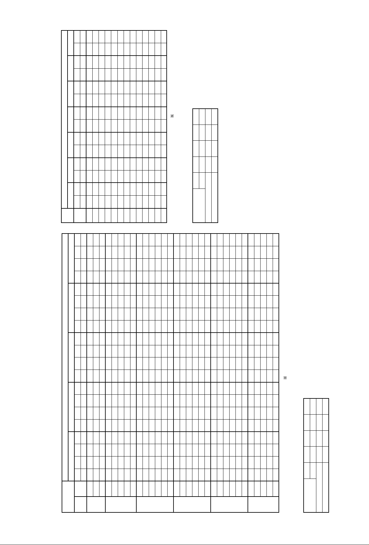
Outdoor DB°C
Factor for Various Air Flow
Cooling Capacity (Standard Air Flow)
PRHG-15MYA (Use for Low ambient cooling parts)
Heating Capacity (Standard Air Flow)
PRHG-15MYA
–5.0
Indoor
WB°C
15161715161718191617181920211819202122231920212223242021222324
Q
kW
49.4
50.9
52.6
49.4
50.9
52.6
54.6
56.5
50.9
52.6
54.6
56.5
58.4
60.5
54.6
56.5
58.4
60.5
62.7
64.6
56.5
58.4
60.5
62.7
64.6
66.6
58.4
60.5
62.7
64.6
66.6
SHC
kW
35.1
31.0
27.9
41.0
37.6
34.7
31.7
28.8
43.7
41.0
38.2
34.5
31.5
28.4
43.7
40.1
37.4
34.5
31.3
28.4
46.3
43.2
40.6
37.6
34.2
31.3
49.1
46.0
43.2
40.0
37.3
SHF
0.71
0.61
0.53
0.83
0.74
0.66
0.58
0.51
0.86
0.78
0.70
0.61
0.54
0.47
0.80
0.71
0.64
0.57
0.50
0.44
0.82
0.74
0.67
0.60
0.53
0.47
0.84
0.76
0.69
0.62
0.56
W
kW
8.8
8.9
9.0
8.8
8.9
9.0
9.1
9.2
8.9
9.0
9.1
9.2
9.3
9.4
9.1
9.2
9.3
9.4
9.5
9.6
9.2
9.3
9.4
9.5
9.6
9.7
9.3
9.4
9.5
9.6
9.7
0.0
Q
kW
48.6
50.0
51.7
48.6
50.0
51.7
53.7
55.5
50.0
51.7
53.7
55.5
57.4
59.4
53.7
55.5
57.4
59.4
61.5
63.4
55.5
57.4
59.4
61.5
63.4
65.4
57.4
59.4
61.5
63.4
65.4
SHC
kW
34.5
31.0
27.4
40.3
37.0
34.1
31.1
28.3
43.5
40.3
37.6
34.0
31.0
27.9
42.9
39.4
36.7
33.9
30.8
27.9
45.5
42.4
39.8
36.9
33.6
30.7
48.8
45.8
42.4
39.3
36.6
SHF
0.71
0.62
0.53
0.83
0.74
0.66
0.58
0.51
0.87
0.78
0.70
0.61
0.54
0.47
0.80
0.71
0.64
0.57
0.50
0.44
0.82
0.74
0.67
0.60
0.53
0.47
0.85
0.77
0.69
0.62
0.56
W
kW
8.9
9.0
9.1
8.9
9.0
9.1
9.2
9.3
9.0
9.1
9.2
9.3
9.4
9.5
9.2
9.3
9.4
9.5
9.6
9.7
9.3
9.4
9.5
9.6
9.7
9.8
9.4
9.5
9.6
9.7
9.8
5.0
Q
kW
47.9
49.2
50.9
47.9
49.2
50.9
52.8
54.7
49.2
50.9
52.8
54.7
56.5
58.5
52.8
54.7
56.5
58.5
60.5
62.4
54.7
56.5
58.5
60.5
62.4
64.3
56.5
58.5
60.5
62.4
64.3
SHC
kW
34.0
30.5
27.0
39.7
36.4
33.6
30.7
27.9
42.8
39.7
37.0
33.5
30.5
27.5
42.8
39.3
36.1
33.3
30.3
27.4
45.4
42.3
39.8
36.9
33.7
30.2
48.0
45.0
42.4
38.7
36.0
SHF
0.71
0.62
0.53
0.83
0.74
0.66
0.58
0.51
0.87
0.78
0.70
0.61
0.54
0.47
0.81
0.72
0.64
0.57
0.50
0.44
0.83
0.75
0.68
0.61
0.54
0.47
0.85
0.77
0.70
0.62
0.56
W
kW
9.1
9.2
9.3
9.1
9.2
9.3
9.4
9.5
9.2
9.3
9.4
9.5
9.6
9.7
9.4
9.5
9.6
9.7
9.8
9.9
9.5
9.6
9.7
9.8
9.9
10.1
9.6
9.7
9.8
9.9
10.1
10.0
Q
kW
47.1
48.4
50.1
47.1
48.4
50.1
51.9
53.7
48.4
50.1
51.9
53.7
55.4
57.4
51.9
53.7
55.4
57.4
59.4
61.2
53.7
55.4
57.4
59.4
61.2
63.1
55.4
57.4
59.4
61.2
63.1
SHC
kW
33.9
30.5
27.5
39.5
36.3
33.5
30.6
27.9
42.6
39.5
36.9
33.3
30.5
27.6
42.1
38.6
36.0
33.3
30.3
27.5
45.1
41.6
39.0
36.2
33.0
30.3
47.7
44.8
42.2
38.5
36.0
SHF
0.72
0.63
0.55
0.84
0.75
0.67
0.59
0.52
0.88
0.79
0.71
0.62
0.55
0.48
0.81
0.72
0.65
0.58
0.51
0.45
0.84
0.75
0.68
0.61
0.54
0.48
0.86
0.78
0.71
0.63
0.57
W
kW
9.4
9.5
9.6
9.4
9.5
9.6
9.7
9.8
9.5
9.6
9.7
9.8
10.0
10.1
9.7
9.8
10.0
10.1
10.2
10.3
9.8
10.0
10.1
10.2
10.3
10.5
10.0
10.1
10.2
10.3
10.5
15.0
Q
kW
46.2
47.5
49.1
46.2
47.5
49.1
50.9
52.6
47.5
49.1
50.9
52.6
54.3
56.3
50.9
52.6
54.3
56.3
58.2
59.9
52.6
54.3
56.3
58.2
59.9
61.8
54.3
56.3
58.2
59.9
61.8
SHC
kW
33.3
29.9
27.0
38.8
35.6
32.9
30.0
27.4
41.8
38.8
36.1
32.6
29.9
27.0
41.7
38.4
35.3
32.6
29.7
27.0
44.7
41.3
38.8
36.1
33.0
29.7
47.3
44.5
41.9
38.4
35.2
SHF
0.72
0.63
0.55
0.84
0.75
0.67
0.59
0.52
0.88
0.79
0.71
0.62
0.55
0.48
0.82
0.73
0.65
0.58
0.51
0.45
0.85
0.76
0.69
0.62
0.55
0.48
0.87
0.79
0.72
0.64
0.57
W
kW
9.8
9.9
10.0
9.8
9.9
10.0
10.1
10.2
9.9
10.0
10.1
10.2
10.4
10.5
10.1
10.2
10.4
10.5
10.7
10.8
10.2
10.4
10.5
10.7
10.8
11.0
10.4
10.5
10.7
10.8
11.0
Indoor
DB°C
20
22
24
26
28
30
Q; Cooling Capacity, SHC; Sensible Heat Capacity, W; Compressor Input
Total input = Compressor input + indoor fan motor input + outdoor fan motor input
Air Volume
CMM
l/s
Cooling capacity
Compressor input
120
2000
0.962
0.984
140
2330
0.982
0.991
160
2670
1.000
1.000
180
3000
1.018
1.009
Factor for Various Air Flow
Air Volume
CMM
l/s
Heating capacity
Compressor input
120
2000
0.973
1.025
140
2330
0.985
1.013
160
2670
1.000
1.000
180
3000
1.015
0.987
Indoor
DB°C
15161718192021222324252627
Q
kW
31.0
30.8
30.6
30.4
30.2
30.1
29.9
29.8
29.6
29.5
29.4
29.3
29.1
W
kW
7.7
7.7
7.8
7.8
7.9
7.9
8.0
8.0
8.1
8.1
8.2
8.2
8.3
Q
kW
27.5
27.3
27.1
26.9
26.6
26.5
26.3
26.2
26.0
25.9
25.8
25.7
25.5
W
kW
7.0
7.0
7.1
7.1
7.2
7.2
7.4
7.4
7.5
7.5
7.6
7.6
7.7
–10–15
Q
kW
35.1
34.9
34.7
34.5
34.4
34.3
34.1
34.0
33.8
33.7
33.6
33.5
33.3
W
kW
8.5
8.5
8.6
8.6
8.7
8.8
8.8
8.9
8.9
9.0
9.1
9.2
9.3
–5
Q
kW
39.9
39.7
39.5
39.3
39.2
39.0
38.9
38.8
38.7
38.5
38.4
38.2
38.0
W
kW
9.3
9.4
9.5
9.7
9.8
9.9
10.0
10.0
10.1
10.2
10.3
10.4
10.5
0
Q
kW
45.4
45.2
45.0
44.8
44.6
44.5
44.3
44.2
44.1
43.9
43.8
43.6
43.4
W
kW
10.4
10.5
10.6
10.8
10.9
11.1
11.2
11.3
11.4
11.5
11.6
11.7
11.9
5
Q
kW
51.6
51.4
51.2
51.0
50.8
50.6
50.5
50.3
50.2
50.0
49.8
49.6
49.4
W
kW
11.6
11.7
12.0
12.1
12.2
12.4
12.5
12.6
12.7
13.0
13.1
13.2
13.4
10 15
Q
kW
58.8
58.6
58.3
58.1
57.8
57.6
57.4
57.2
57.0
56.7
56.5
56.2
56.0
W
kW
13.0
13.2
13.3
13.5
13.7
13.8
14.1
14.2
14.4
14.5
14.7
14.9
15.0
OD WB°C
Q; Heating Capacity, W; Compressor Input
-14-
Page 17
Outdoor DB°C
Factor for Various Air Flow
Cooling Capacity (Standard Air Flow)
PRHG-20MYA
20.0
Indoor
WB°C
15161715161718191617181920211819202122231920212223242021222324
Q
kW
59.3
61.3
63.2
59.3
61.3
63.2
65.0
67.0
61.3
63.2
65.0
67.0
69.0
71.2
65.0
67.0
69.0
71.2
73.4
75.7
67.0
69.0
71.2
73.4
75.7
78.0
69.0
71.2
73.4
75.7
78.0
SHC
kW
42.7
39.2
34.8
50.4
46.6
43.0
39.0
34.8
54.6
50.6
46.2
42.2
38.0
34.2
54.0
49.6
45.5
42.0
38.2
34.1
57.0
53.1
49.8
45.5
41.6
37.4
60.0
56.2
52.1
48.4
44.5
SHF
0.72
0.64
0.55
0.85
0.76
0.68
0.60
0.52
0.89
0.80
0.71
0.63
0.55
0.48
0.83
0.74
0.66
0.59
0.52
0.45
0.85
0.77
0.70
0.62
0.55
0.48
0.87
0.79
0.71
0.64
0.57
W
kW
13.7
14.0
14.1
13.7
14.0
14.1
14.3
14.5
14.0
14.1
14.3
14.5
14.8
15.0
14.3
14.5
14.8
15.0
15.2
15.5
14.5
14.8
15.0
15.2
15.5
15.8
14.8
15.0
15.2
15.5
15.8
25.0
Q
kW
57.4
59.5
61.2
57.4
59.5
61.2
63.0
64.9
59.5
61.2
63.0
64.9
66.8
68.9
63.0
64.9
66.8
68.9
71.0
73.3
64.9
66.8
68.9
71.0
73.3
75.6
66.8
68.9
71.0
73.3
75.6
SHC
kW
41.9
38.1
33.7
49.4
45.8
41.6
37.8
34.4
53.6
49.6
45.4
41.5
37.4
33.8
52.9
48.7
44.8
41.3
37.6
33.0
55.8
52.1
48.9
44.7
41.0
37.0
58.8
55.1
51.1
47.6
43.8
SHF
0.73
0.64
0.55
0.86
0.77
0.68
0.60
0.53
0.90
0.81
0.72
0.64
0.56
0.49
0.84
0.75
0.67
0.60
0.53
0.45
0.86
0.78
0.71
0.63
0.56
0.49
0.88
0.80
0.72
0.65
0.58
W
kW
14.5
14.8
15.0
14.5
14.8
15.0
15.2
15.4
14.8
15.0
15.2
15.4
15.7
16.1
15.2
15.4
15.7
16.1
16.4
16.7
15.4
15.7
16.1
16.4
16.7
17.0
15.7
16.1
16.4
16.7
17.0
30.0
Q
kW
55.4
57.6
59.2
55.4
57.6
59.2
60.9
62.7
57.6
59.2
60.9
62.7
64.6
66.6
60.9
62.7
64.6
66.6
68.6
70.8
62.7
64.6
66.6
68.6
70.8
72.8
64.6
66.6
68.6
70.8
72.8
SHC
kW
40.4
37.4
33.2
48.2
44.9
40.8
37.1
33.2
53.0
48.5
44.5
40.8
36.8
32.6
51.8
47.7
43.9
40.6
37.0
32.6
54.5
51.0
48.0
43.9
39.6
35.7
58.1
54.6
50.1
46.7
43.0
SHF
0.73
0.65
0.56
0.87
0.78
0.69
0.61
0.53
0.92
0.82
0.73
0.65
0.57
0.49
0.85
0.76
0.68
0.61
0.54
0.46
0.87
0.79
0.72
0.64
0.56
0.49
0.90
0.82
0.73
0.66
0.59
W
kW
15.2
15.6
15.9
15.2
15.6
15.9
16.2
16.5
15.6
15.9
16.2
16.5
16.7
17.1
16.2
16.5
16.7
17.1
17.5
17.9
16.5
16.7
17.1
17.5
17.9
18.3
16.7
17.1
17.5
17.9
18.3
35.0
Q
kW
53.4
55.5
57.0
53.4
55.5
57.0
58.7
60.8
55.5
57.0
58.7
60.8
62.2
64.0
58.7
60.8
62.2
64.0
66.0
68.0
60.8
62.2
64.0
66.0
68.0
69.9
62.2
64.0
66.0
68.0
69.9
SHC
kW
39.5
36.1
31.9
47.0
43.8
39.9
35.8
32.2
51.6
47.3
43.4
40.1
35.5
32.0
51.1
46.8
42.9
39.7
35.6
31.3
54.1
50.4
46.7
42.9
38.8
35.0
57.2
53.8
49.5
45.6
41.9
SHF
0.74
0.65
0.56
0.88
0.79
0.70
0.61
0.53
0.93
0.83
0.74
0.66
0.57
0.50
0.87
0.77
0.69
0.62
0.54
0.46
0.89
0.81
0.73
0.65
0.57
0.50
0.92
0.84
0.75
0.67
0.60
W
kW
16.2
16.6
16.8
16.2
16.6
16.8
17.2
17.5
16.6
16.8
17.2
17.5
17.9
18.3
17.2
17.5
17.9
18.3
18.6
19.1
17.5
17.9
18.3
18.6
19.1
19.5
17.9
18.3
18.6
19.1
19.5
40.0
Q
kW
51.4
53.2
54.8
51.4
53.2
54.8
56.4
58.0
53.2
54.8
56.4
58.0
59.7
61.4
56.4
58.0
59.7
61.4
63.3
65.0
58.0
59.7
61.4
63.3
65.0
66.7
59.7
61.4
63.3
65.0
66.7
SHC
kW
38.6
35.1
31.2
46.3
43.1
38.9
35.0
31.3
50.5
46.6
42.3
38.9
34.6
31.3
50.2
45.8
41.8
38.7
34.8
30.6
52.8
49.6
45.4
41.8
37.7
34.0
56.1
52.8
48.7
44.9
41.4
SHF
0.75
0.66
0.57
0.90
0.81
0.71
0.62
0.54
0.95
0.85
0.75
0.67
0.58
0.51
0.89
0.79
0.70
0.63
0.55
0.47
0.91
0.83
0.74
0.66
0.58
0.51
0.94
0.86
0.77
0.69
0.62
W
kW
17.1
17.5
17.9
17.1
17.5
17.9
18.3
18.6
17.5
17.9
18.3
18.6
19.0
19.4
18.3
18.6
19.0
19.4
19.9
20.2
18.6
19.0
19.4
19.9
20.2
20.8
19.0
19.4
19.9
20.2
20.8
46.0
Q
kW
48.8
50.4
51.9
48.8
50.4
51.9
53.4
54.9
50.4
51.9
53.4
54.9
56.5
58.2
53.4
54.9
56.5
58.2
59.8
61.1
54.9
56.5
58.2
59.8
61.1
62.5
56.5
58.2
59.8
61.1
62.5
SHC
kW
37.6
34.3
30.1
44.9
41.8
37.9
33.6
29.6
49.4
45.7
41.7
37.3
33.3
30.3
48.6
44.5
40.7
37.8
33.5
28.7
52.2
48.0
44.2
40.7
36.7
32.5
55.4
51.8
47.8
43.4
40.0
SHF
0.77
0.68
0.58
0.92
0.83
0.73
0.63
0.54
0.98
0.88
0.78
0.68
0.59
0.52
0.91
0.81
0.72
0.65
0.56
0.47
0.95
0.85
0.76
0.68
0.60
0.52
0.98
0.89
0.80
0.71
0.64
W
kW
18.3
18.7
19.2
18.3
18.7
19.2
19.6
19.9
18.7
19.2
19.6
19.9
20.3
20.8
19.6
19.9
20.3
20.8
21.4
21.8
19.9
20.3
20.8
21.4
21.8
22.3
20.3
20.8
21.4
21.8
22.3
Indoor
DB°C
20
22
24
26
28
30
Q; Cooling Capacity, SHC; Sensible Heat Capacity, W; Compressor Input
Total input = Compressor input + indoor fan motor input + outdoor fan motor input
Air Volume
CMM
l/s
Cooling capacity
Compressor input
170
2830
0.977
0.995
180
3000
0.987
0.997
200
3330
1.000
1.000
220
3670
1.010
1.003
240
4000
1.020
1.007
-15-
Page 18

Outdoor DB°C
Factor for Various Air Flow
Cooling Capacity (Standard Air Flow)
PRHG-20MYA (Use for Low ambient cooling parts)
Heating Capacity (Standard Air Flow)
PRHG-20MYA
–5.0
Indoor
WB°C
15161715161718191617181920211819202122231920212223242021222324
Q
kW
65.9
68.2
70.5
65.9
68.2
70.5
72.6
75.0
68.2
70.5
72.6
75.0
77.3
80.0
72.6
75.0
77.3
80.0
82.6
85.3
75.0
77.3
80.0
82.6
85.3
88.1
77.3
80.0
82.6
85.3
88.1
SHC
kW
46.1
42.3
38.8
54.0
50.5
46.5
42.1
38.2
58.0
54.3
50.1
45.7
41.8
37.6
57.4
53.2
49.5
45.6
41.3
37.5
60.7
56.5
52.8
48.7
45.2
41.4
64.2
60.8
57.0
52.9
48.4
SHF
0.70
0.62
0.55
0.82
0.74
0.66
0.58
0.51
0.85
0.77
0.69
0.61
0.54
0.47
0.79
0.71
0.64
0.57
0.50
0.44
0.81
0.73
0.66
0.59
0.53
0.47
0.83
0.76
0.69
0.62
0.55
W
kW
11.9
12.0
12.1
11.9
12.0
12.1
12.3
12.5
12.0
12.1
12.3
12.5
12.6
12.8
12.3
12.5
12.6
12.8
12.9
13.1
12.5
12.6
12.8
12.9
13.1
13.2
12.6
12.8
12.9
13.1
13.2
0.0
Q
kW
64.8
67.0
69.2
64.8
67.0
69.2
71.3
73.6
67.0
69.2
71.3
73.6
76.0
78.5
71.3
73.6
76.0
78.5
81.1
83.7
73.6
76.0
78.5
81.1
83.7
86.4
76.0
78.5
81.1
83.7
86.4
SHC
kW
45.3
41.6
38.1
53.1
49.6
45.7
41.4
37.6
57.0
53.3
49.2
44.9
41.0
36.9
56.3
52.3
48.6
44.8
40.5
36.8
59.6
55.5
51.8
48.6
44.4
40.6
63.0
59.7
55.9
51.9
48.4
SHF
0.70
0.62
0.55
0.82
0.74
0.66
0.58
0.51
0.85
0.77
0.69
0.61
0.54
0.47
0.79
0.71
0.64
0.57
0.50
0.44
0.81
0.73
0.66
0.60
0.53
0.47
0.83
0.76
0.69
0.62
0.56
W
kW
12.0
12.2
12.3
12.0
12.2
12.3
12.4
12.6
12.2
12.3
12.4
12.6
12.7
12.9
12.4
12.6
12.7
12.9
13.0
13.2
12.6
12.7
12.9
13.0
13.2
13.4
12.7
12.9
13.0
13.2
13.4
5.0
Q
kW
63.8
66.1
68.2
63.8
66.1
68.2
70.2
72.5
66.1
68.2
70.2
72.5
74.8
77.3
70.2
72.5
74.8
77.3
79.8
82.4
72.5
74.8
77.3
79.8
82.4
85.0
74.8
77.3
79.8
82.4
85.0
SHC
kW
44.7
41.0
37.5
53.0
49.5
45.0
40.7
37.0
56.8
53.2
49.2
45.0
40.4
36.3
56.2
52.2
48.6
44.8
40.7
36.3
59.5
55.3
51.8
48.7
44.5
40.0
62.8
59.5
55.8
51.9
47.6
SHF
0.70
0.62
0.55
0.83
0.75
0.66
0.58
0.51
0.86
0.78
0.70
0.62
0.54
0.47
0.80
0.72
0.65
0.58
0.51
0.44
0.82
0.74
0.67
0.61
0.54
0.47
0.84
0.77
0.70
0.63
0.56
W
kW
12.3
12.5
12.6
12.3
12.5
12.6
12.7
12.9
12.5
12.6
12.7
12.9
13.0
13.2
12.7
12.9
13.0
13.2
13.4
13.5
12.9
13.0
13.2
13.4
13.5
13.7
13.0
13.2
13.4
13.5
13.7
10.0
Q
kW
62.7
64.9
67.0
62.7
64.9
67.0
69.0
71.2
64.9
67.0
69.0
71.2
73.4
75.8
69.0
71.2
73.4
75.8
78.3
80.8
71.2
73.4
75.8
78.3
80.8
83.4
73.4
75.8
78.3
80.8
83.4
SHC
kW
43.9
40.9
36.9
52.1
48.7
44.9
40.7
37.0
56.5
52.3
48.3
44.2
40.4
36.4
55.9
51.3
47.7
44.0
39.9
36.4
59.1
55.1
51.6
47.8
43.6
40.0
62.4
58.4
54.8
50.9
47.5
SHF
0.70
0.63
0.55
0.83
0.75
0.67
0.59
0.52
0.87
0.78
0.70
0.62
0.55
0.48
0.81
0.72
0.65
0.58
0.51
0.45
0.83
0.75
0.68
0.61
0.54
0.48
0.85
0.77
0.70
0.63
0.57
W
kW
12.7
12.9
13.0
12.7
12.9
13.0
13.1
13.3
12.9
13.0
13.1
13.3
13.5
13.6
13.1
13.3
13.5
13.6
13.8
14.0
13.3
13.5
13.6
13.8
14.0
14.2
13.5
13.6
13.8
14.0
14.2
15.0
Q
kW
61.6
63.7
65.7
61.6
63.7
65.7
67.7
69.8
63.7
65.7
67.7
69.8
72.0
74.3
67.7
69.8
72.0
74.3
76.7
79.2
69.8
72.0
74.3
76.7
79.2
81.7
72.0
74.3
76.7
79.2
81.7
SHC
kW
43.7
40.1
36.2
51.7
48.4
44.0
39.9
36.3
56.0
51.9
48.0
44.0
39.6
35.7
55.5
51.0
47.5
43.9
39.9
35.6
58.6
54.7
51.3
47.6
43.6
39.2
61.9
58.0
54.5
50.7
46.5
SHF
0.71
0.63
0.55
0.84
0.76
0.67
0.59
0.52
0.88
0.79
0.71
0.63
0.55
0.48
0.82
0.73
0.66
0.59
0.52
0.45
0.84
0.76
0.69
0.62
0.55
0.48
0.86
0.78
0.71
0.64
0.57
W
kW
13.2
13.4
13.5
13.2
13.4
13.5
13.6
13.8
13.4
13.5
13.6
13.8
14.0
14.2
13.6
13.8
14.0
14.2
14.5
14.7
13.8
14.0
14.2
14.5
14.7
15.0
14.0
14.2
14.5
14.7
15.0
Indoor
DB°C
20
22
24
26
28
30
Q; Cooling Capacity, SHC; Sensible Heat Capacity, W; Compressor Input
Total input = Compressor input + indoor fan motor input + outdoor fan motor input
Air Volume
CMM
l/s
Coolinr capacity
Compressor input
170
2830
0.977
0.995
180
3000
0.987
0.997
200
3330
1.000
1.000
220
3670
1.010
1.003
240
4000
1.020
1.007
Factor for Various Air Flow
Air Volume
CMM
l/s
Heating capacity
Compressor input
170
2830
0.985
1.020
180
3000
0.993
1.013
200
3330
1.000
1.000
220
3670
1.007
0.987
240
4000
1.015
0.974
Indoor
DB°C
15161718192021222324252627
Q
kW
41.2
40.9
40.6
40.4
40.2
40.0
39.8
39.6
39.4
39.2
39.1
38.9
38.6
W
kW
9.9
9.9
10.0
10.1
10.2
10.3
10.3
10.3
10.4
10.5
10.5
10.6
10.7
Q
kW
36.1
35.7
35.3
35.1
34.9
34.7
34.5
34.3
34.1
33.9
33.9
33.7
33.4
W
kW
9.1
9.1
9.2
9.3
9.4
9.4
9.4
9.4
9.5
9.6
9.6
9.7
9.8
–10–15
Q
kW
46.9
46.7
46.5
46.3
46.1
45.9
45.7
45.5
45.3
45.1
44.9
44.7
44.4
W
kW
10.9
11.0
11.1
11.2
11.3
11.4
11.5
11.6
11.7
11.8
11.8
11.9
12.0
–5
Q
kW
53.5
53.3
53.1
52.8
52.6
52.4
52.2
52.0
51.8
51.6
51.4
51.2
50.9
W
kW
12.2
12.3
12.4
12.5
12.6
12.7
12.8
12.9
13.1
13.2
13.2
13.3
13.4
0
Q
kW
60.9
60.6
60.4
60.2
60.0
59.8
59.6
59.4
59.2
59.0
58.7
58.4
58.1
W
kW
13.5
13.7
13.8
14.0
14.1
14.2
14.4
14.5
14.6
14.8
14.9
15.1
15.2
5
Q
kW
69.4
69.1
68.8
68.5
68.3
68.0
67.8
67.6
67.3
67.0
66.7
66.4
66.1
W
kW
15.2
15.4
15.6
15.7
15.9
16.0
16.2
16.3
16.5
16.7
16.8
17.0
17.2
10 15
Q
kW
78.8
78.5
78.2
77.9
77.6
77.3
77.0
76.6
76.3
76.0
75.6
75.3
75.0
W
kW
17.0
17.2
17.4
17.6
17.8
18.0
18.2
18.4
18.6
18.9
19.1
19.3
19.5
OD WB°C
Q; Heating Capacity, W; Compressor Input
-16-
Page 19
fan speed
Indoor fan input
fan speed
Indoor fan input
fan speed
Indoor fan input
200
CMM
L/S
rpm
kW
rpm
kW
rpm
kW
300
400
Total SP (Pa)
PRHG8
Indoor fan input
80
1330
967
1.20
1139
1.80
1305
2.42
85
1420
1036
1.27
1139
1.80
1329
2.56
90
1500
1036
1.27
1208
2.02
1329
2.56
95
1580
1036
1.27
1208
2.02
–
fan speed
Indoor fan input
fan speed
Indoor fan input
fan speed
Indoor fan input
fan speed
Indoor fan input
250
CMM
L/S
rpm
kW
rpm
kW
rpm
kW
rpm
kW
350
450
550
Total SP (Pa)
PRHG10
PRHG15
90
1500
1088
1.90
1208
2.26
1450
3.13
1595
3.96
100
1660
1088
1.90
1208
2.26
1450
3.13
–
110
1830
1139
2.16
1318
2.86
1450
3.13
–
120
2000
1139
2.16
1318
2.86
–
–
fan speed
Indoor fan input
fan speed
Indoor fan input
fan speed
Indoor fan input
fan speed
Indoor fan input
fan speed
Indoor fan input
300
CMM
L/S
rpm
kW
rpm
kW
rpm
kW
rpm
kW
rpm
kW
400
500
600
700
Total SP (Pa)
PRHG20
170
2830
798
2.98
906
3.50
997
3.97
1088
4.44
1208
5.03
180
3000
798
3.06
906
3.66
997
4.17
1088
4.66
1208
5.27
190
3170
798
3.14
906
3.82
997
4.37
1088
4.89
1208
5.51
200
3330
798
3.23
906
3.98
997
4.56
1088
5.11
1208
5.75
200
300
400
500
600
Total SP (Pa)
120
2000
659
1.58
791
1.95
886
2.27
997
2.72
1088
3.07
130
2170
659
1.68
791
2.08
886
2.43
997
2.93
1088
3.3
140
2330
659
1.79
791
2.21
886
2.58
997
3.13
1088
3.52
150
2500
659
1.89
791
2.34
906
2.83
997
3.34
–
160
2670
659
1.99
791
2.47
906
2.99
997
3.54
–
170
2830
659
2.1
791
2.6
906
3.15
997
3.75
–
180
3000
659
2.21
791
2.73
906
3.31
997
3.96
–
fan speed
Indoor fan input
fan speed
Indoor fan input
fan speed
Indoor fan input
fan speed
Indoor fan input
fan speed
Indoor fan input
CMM
L/S
rpm
kW
rpm
kW
rpm
kW
rpm
kW
rpm
kW
-17-
Page 20

-18-
OPERATION RANGE
Caution:
The use of your air conditioner
outside the range of working
temperature and humidity can
result in serious failure.
The range of working temperatures is as below.
Make sure which unit you are using and confirm the range of application.
(Note)
As an applicable humidity outside standard for both indoors and outdoors,
we recommend use within a range of 35-80% relative humidity.
However, it is a condition that there is no be dewy in surfaces of electric parts.
Range for
continuous operation
10 15 20
25
30
20
30
40
50
24
46
Indoor temp. (˚C WB)
Outdoor temp. (˚C DB)
Cooling
10
0
Range for
continuous operation
Use for low ambient
cooling parts as option
-10
-5
-15
-10
1510 302520
0
- 5
10
5
15
27
Heating
Range for
continuous operation
1510 302520 27
Outdoor temp. (˚C W B)
Indoor temp. (˚C D B)
Page 21

-19-
FAN PERFORMANCE
internal static pressure
Air flow
1330
80 85 90 95
1500
(CMM)
(L/S)
200
100
300
400
500
600
Total static pressure (Pa)
Fan speed
<rpm>
900
800
1000
1100
1200
1300
1400
1500
1.5kw
1.1kw
PRHG-8MYA
PRHG-10MYA
internal static pressure
Air flow
1500
90 95 100 105
1670
(CMM)
(L/S)
1.5kw
2.2kw
900
1000
1100
1200
1300
1400
100
200
300
400
500
Total static pressure (Pa)
Fan speed
<rpm>
1500
110 115
1830
120
2000
600
700
800
1600
1700
* : factory pre setting ESP = 100 Pa
* : factory pre setting ESP = 100 Pa
Page 22

-20-
internal static pressure
200
400
Total static pressure (Pa)
600
800
1000
Fan speed
<rpm>
600
700
800
900
1000
1100
1200
1300
Air flow
120 (CMM)140 160 180
3.7kw
2.2kw
0
3.7kw
5.5kw
internal static pressure
200
400
Total static pressure (Pa)
600
800
1000
0
Fan speed
<rpm>
600
700
800
900
1000
1100
1200
1300
Air flow
160 180 (CMM)200
2000 (L/S)2670
3000
(L/S)
3330
PRHG-20MYA
PRHG-15MYA
* : factory pre setting ESP = 200 Pa
* : factory pre setting ESP = 200 Pa
Page 23

-21-
200
Fan speed
(Motor side)
CMM
Pulley size
(Fan side)
Pulley size
Belt size
Motor
Total SP (Pa)
Air flow
L/S
rpm
mm
inch
mm
inch
inch
kW
300
Fan speed
(Motor side)
Pulley size
(Fan side)
Pulley size
Belt size
Motor
rpm
mm
inch
mm
inch
inch
kW
400
Fan speed
(Motor side)
Pulley size
(Fan side)
Pulley size
Belt size
Motor
rpm
mm
inch
mm
inch
inch
kW
80
1330
967
101.6
4
152.4
6
B30
1.1
1139
139.7
5.5
177.8
7
B34
1.1
1305
114.3
4.5
127
5
B33
1.5
85
1420
1036
127
5
177.8
7
B34
1.1
1139
139.7
5.5
177.8
7
B34
1.1
1329
139.7
5.5
152.4
6
B33
1.5
90
1500
1036
127
5
177.8
7
B34
1.1
1208
127
5
152.4
6
B32
1.1
1329
139.7
5.5
152.4
6
B33
1.5
95
1580
1036
127
5
177.8
7
B34
1.1
1208
127
5
152.4
6
B32
1.1
factory pre setting
factory pre setting
PRHG-8MYA
PRHG-10MYA
250
Total SP (Pa)
Air flow
350
450
550
120
2000
1139
137.7
5.5
177.8
7
B34
1.5
1318
127
5
139.7
5.5
B31
2.2
110
1830
1139
139.7
5.5
177.8
7
B34
1.5
1318
127
5
139.7
5.5
B31
2.2
1450
127
5
127
5
B30
2.2
100
1660
1088
114.3
4.5
152.4
6
B31
1.5
1208
127
5
152.4
6
B32
1.5
1450
127
5
127
5
B30
2.2
Fan speed
(Motor side)
Pulley size
(Fan side)
Pulley size
Belt size
Motor
Fan speed
(Motor side)
Pulley size
(Fan side)
Pulley size
Belt size
Motor
Fan speed
(Motor side)
Pulley size
(Fan side)
Pulley size
Belt size
Motor
Fan speed
(Motor side)
Pulley size
(Fan side)
Pulley size
Belt size
Motor
CMM
L/S
rpm
mm
inch
mm
inch
inch
kW
rpm
mm
inch
mm
inch
inch
kW
rpm
mm
inch
mm
inch
inch
kW
rpm
mm
inch
mm
inch
inch
kW
90
1500
1088
114.3
4.5
152.4
6
B31
1.5
1208
127
5
152.4
6
B32
1.5
1450
127
5
127
5
B30
1.5
1595
139.7
5.5
127
5
B31
2.2
Page 24

-22-
300
Fan speed
(Motor side)
CMM
Pulley size
(Fan side)
Pulley size
Belt size
Motor
Total SP (Pa)
Air flow
L/S
rpm
mm
inch
mm
inch
inch
kW
400
Fan speed
(Motor side)
Pulley size
(Fan side)
Pulley size
Belt size
Motor
rpm
mm
inch
mm
inch
inch
kW
500
Fan speed
(Motor side)
Pulley size
(Fan side)
Pulley size
Belt size
Motor
rpm
mm
inch
mm
inch
inch
kW
170 180 190 200
2830 3000 3170 3330
798 798 798 798
139.7 139.7 139.7 139.7
5.5 5.5 5.5 5.5
254 254 254 254
10 10 10 10
B42X2 B42X2 B42X2 B42X2
3.7 3.7 3.7 3.7
906 906 906 906
127 127 127 127
5555
203.2 203.2 203.2 203.2
8888
B38X2 B38X2 B38X2 B38X2
3.7 3.7 3.7 3.7
997 997 997
139.7 139.7 139.7
5.5 5.5 5.5
203.2 203.2 203.2
888
B39X2 B39X2 B39X2
3.7 3.7 3.7
997
139.7
5.5
203.2
8
B39X2
3.7
600
Fan speed
(Motor side)
Pulley size
(Fan side)
Pulley size
Belt size
Motor
rpm
mm
inch
mm
inch
inch
kW
700
Fan speed
(Motor side)
Pulley size
(Fan side)
Pulley size
Belt size
Motor
rpm
mm
inch
mm
inch
inch
kW
1088 1088 1088 1088
152.4 152.4 152.4 152.4
6666
203.2 203.2 203.2 203.2
8888
B40X2 B40X2 B40X2 B40X2
5.5 5.5 5.5 5.5
1208 1208 1208
127 127 127
555
152.4 152.4 152.4
666
B35X2 B35X2 B35X2
5.5 5.5 5.5
1208
127
5
152.4
6
B35X2
5.5
200
Fan speed
(Motor side)
CMM
Pulley size
(Fan side)
Pulley size
Belt size
Motor
Total SP (Pa)
Air flow
L/S
rpm
mm
inch
mm
inch
inch
kW
300
Fan speed
(Motor side)
Pulley size
(Fan side)
Pulley size
Belt size
Motor
rpm
mm
inch
mm
inch
inch
kW
400
Fan speed
(Motor side)
Pulley size
(Fan side)
Pulley size
Belt size
Motor
rpm
mm
inch
mm
inch
inch
kW
120 130 140 150
2000 2170 2330 2500
659 659 659 659
127 127 127 127
5555
279.4 279.4 279.4 279.4
11 11 11 11
B44X2 B44X2 B44X2 B44X2
2.2 2.2 2.2 2.2
791 791 791 791
152.4 152.4 152.4 152.4
6666
279.4 279.4 279.4 279.4
11 11 11 11
B45X2 B45X2 B45X2 B45X2
2.2 2.2 2.2 2.2
886 886 886
139.7 139.7 139.7
5.5 5.5 5.5
228.6 228.6 228.6
999
B41X2 B41X2 B41X2
2.2 2.2 2.2
906
127
5
203.2
8
B38X2
3.7
160 170 180
2670 2830 3000
659 659 659
127 127 127
555
279.4 279.4 279.4
11 11 11
B44X2 B44X2 B44X2
2.2 2.2 2.2
791 791
152.4 152.4
666
279.4 279.4 279.4
11 11 11
B45X2 B45X2 B45X2
2.2 3.7 3.7
906 906
127 127
55
203.2 203.2
88
B38X2 B38X2
3.7 3.7
906
127
5
203.2
8
B38X2
3.7
791
152.4
500
Fan speed
(Motor side)
Pulley size
(Fan side)
Pulley size
Belt size
Motor
rpm
mm
inch
mm
inch
inch
kW
600
Fan speed
(Motor side)
Pulley size
(Fan side)
Pulley size
Belt size
Motor
rpm
mm
inch
mm
inch
inch
kW
997 997 997 997
139.7 139.7 139.7 139.7
5.5 5.5 5.5 5.5
203.2 203.2 203.2 203.2
8888
B39X2 B39X2 B39X2 B39X2
3.7 3.7 3.7 3.7
1088 1088 1088
152.4 152.4 152.4
666
203.2 203.2 203.2
888
B40X2 B40X2 B40X2
3.7 3.7 3.7
997 997
139.7 139.7
5.5 5.5 5.5
203.2 203.2 203.2
8
88
B39X2 B39X2
B39X2
3.7 3.7 3.7
997
139.7
PRHG-20MYA
PRHG-15MYA
factory pre setting
factory pre setting
Page 25

-23-
(1) Shape of belt groove
(2) Shape of motor pulley boss (Unit : mm)
e
a
r
1
r
3
f
w
L
0
r2r
2
K
K
0
øP.C
16.5mm
B type
11.0mm
40˚
Sectional plan of V-belt
Shape of
V-belt
Nominal
Dia. øP.Ca(˚
)
L0WKK0ef r1r
2
r
3
V-belt
thickness
(Reference)
B
Over 125
Under 160
Over 160
Under 200
Over 200
34
15.86
36
38
16.07
16.29
12.5 5.5 9.5 19.0 12.5 0.2~0.5 0.5~1.0 1~2 11
CBA
MOTOR
CAPACITY
(kW)
1.1, 1.5
5.5
24
38
+ 0.028
+ 0.007
+ 0.028
+ 0.007
27
41
+ 0.128
+ 0.007
+ 0.128
+ 0.009
8
10
+0.018
- 0.018
+0.028
- 0.013
B
C
A
Pulley outside dimensions are shown below: (Unit : mm)
2.2, 3.7
28
+ 0.028
+ 0.007
31
+ 0.128
+ 0.007
8
+0.028
- 0.013
Page 26

-24-
NC CURVES
10
20
30
40
50
60
70
80
90
63Hz 125Hz 250Hz 500Hz 1000Hz 2000Hz 4000Hz 8000Hz
Octave-band frequency [Hz]
Octave-band level dB(0dB=20 Pa)
Condition
Cooling &
Heating
Cooling &
Heating
Cooling &
Heating
63Hz 125Hz 250Hz 500Hz 1000Hz 2000Hz 4000Hz 8000Hz
SPL
dB(A)
71.5 73.0 65.0 64.0 60.5 55.5 48.5 43.566.0
Note. The measuring point is 1m
from the comp.service panel.
50Hz
(dB)
10
20
30
40
50
60
70
80
90
63Hz 125Hz 250Hz 500Hz 1000Hz 2000Hz 4000Hz 8000Hz
Octave-band frequency [Hz]
Octave-band level dB(0dB=20 Pa)
measuring place : dead room
Note. The measuring point is 1m
from the comp.service panel.
measuring place : dead room
1m
1m
Sound pressure levels (SPL)
Condition 63Hz 125Hz 250Hz 500Hz 1000Hz 2000Hz 4000Hz 8000Hz
SPL
dB(A)
73.5 71.5 70.0 63.5 59.0 53.5 47.0 45.066.0
50Hz
(dB)
Sound pressure levels (SPL)
NC-30
NC-20
NC-40
NC-50
NC-60
NC-70
NC-30
NC-20
NC-40
NC-50
NC-60
NC-70
1m
1m
PRHG-8MYA
PRHG-10MYA
Page 27

-25-
Octave-band frequency [Hz]
Octave-band level dB(0dB=20 Pa)
10
20
30
40
50
60
70
80
90
63Hz 125Hz 250Hz 500Hz 1000Hz 2000Hz 4000Hz 8000Hz
Note. The measuring point is 1m
from the comp.service panel.
measuring place : dead room
Note. The measuring point is 1m
from the comp.service panel.
measuring place : dead room
1m
1m
10
20
30
40
50
60
70
80
90
63Hz 125Hz 250Hz 500Hz 1000Hz 2000Hz 4000Hz 8000Hz
Octave-band frequency [Hz]
Octave-band level dB(0dB=20 Pa)
NC-30
NC-20
NC-40
NC-50
NC-60
NC-70
Condition 63Hz 125Hz 250Hz 500Hz 1000Hz 2000Hz 4000Hz 8000Hz
SPL
dB(A)
71.5 77.0 69.0 66.5 65.5 60.0 53.5 50.570.0
50Hz
(dB)
Sound pressure levels (SPL)
Condition 63Hz 125Hz 250Hz 500Hz 1000Hz 2000Hz 4000Hz 8000Hz
SPL
dB(A)
75.5 75.0 71.5 68.5 64.0 58.5 49.0 45.570.0
50Hz
(dB)
Sound pressure levels (SPL)
NC-30
NC-20
NC-40
NC-50
NC-60
NC-70
1m
1m
PRHG-20MYA
PRHG-15MYA
Cooling &
Heating
Cooling &
Heating
Page 28

-26-
OUTLINE DIMENSIONS
1020
10
60150150150150150
60
150
36
170
36
170
10
49
1020
60
60150150150150150
150
10
49
10
1515
100
100
Supply air duct flange
(1342)
25
134225
25
15
25
265 1000 265
A
461300
1392
46
1071020173
1300 5151
50
31230192412135
1000
Condenser
Air inlet
Return air
Supply air
Control box
1530
A Detail
Wiring hole
71
437
Condenser
Air inlet
Return air duct flange
(1342)
25
15
25
B Detail
107 1020 173
107 1020 173
Hanger (4 places)
Return
air
Supply
air
Drain R 1
4-15X25 Mtg. holes
B
Screw for earth connection
20- ø3 Holes
20- ø3 Holes
Supply air duct flange
Return air duct flange
Return air
Supply air
C
16- ø3 Holes
19- ø3 Holes
10
261
10
10
832
812 10
160
160
160
160
96
96
49
160 160
320
160
160
49
40
100
100
41
10 1038 10
1010 368
160 160 160 160 160 160
49
49
4614014046
281
1058
372
Supply air
Return air
242
832
226
1058 15587
637
281
37245
9
9
(1342)
25
134225
25
15
25
265 1000 265
461300
1392
46
1300 51511000
1530
View C (Bottom view)
71
437
A Detail
Condenser
Air inlet
Control box
Wiring hole
Drain R 1
A
(1342)
25
15
25
B Detail
Hanger (4 places)
4-15X25 Mtg. holes
B
Screw for earth connection
Screw is accessory parts.
Accessory parts is attached on control box cover.
Screw
R washer
Spring washer
T. Lock washer
(side flow)
(down flow)
PRHG-8, 10
Condenser
Air inlet
Page 29

-27-
(side flow)
(down flow)
200
1990 5151
123
1744
123
1330
235
235
2082
25
46
2032
1990
25
46
(2032)
25
15
25
1200
428
51
428
169
124
77
1800
50
483
Control box
72 200 200 200 200 200 200 72
200
10
3434 120120120
49
10
Supply air & Return air
Duct flange
428
1744
26- ø3 Holes
Condenser
Air inlet
(3 sides)
Return air
Supply air
Drain R 1
A Detail
4-15X25 Mtg. holes
Wiring hole
Return air
Hanger (4 places)
A
B
123 1231744
123 1231744
(2032)
25
15
25
B Detail
Condenser
Air inlet
(3 sides)
Condenser
Air inlet
(3 sides)
Screw for earth connection
Return
air
Supply
air
1990 5151
1330235
235
2082
25
46
2032
1990
25
46
(2032)
25
15
25
1200
77
1800
483
8
8
C
717
359
372
79
1782 104104
1432
264294
1762
10
10
1782
91
200
200
200
200
200
200
200
200
91
372
140
140
46
46
368
10
10
359
120
120
59.5
59.5
1412
10
10
339
10
10
1432
86
180180180
180
180
86
180
180
22- ø3 Holes
24- ø3 Holes
Supply air duct flange
Return air duct flange
A Detail
Drain R 1
Return air
Supply air
View C (Bottom view)
Supply air
Return air
Control box
Wiring hole
Condenser
Air inlet
(3 sides)
A
(2032)
25
15
25
B Detail
Condenser
Air inlet
(3 sides)
Condenser
Air inlet
(3 sides)
4-15X25 Mtg. holes
B
Hanger
(4 places)
Screw is accessory parts.
Accessory parts is attached on control box cover.
Screw
R washer
Spring washer
T. Lock washer
Screw for earth connection
PRHG-15, 20
Page 30

-28-
WIRING DIAGRAMS
PRHG-8MYA
PRHG-10MYA
(STANDARD)
Lead wire
( mark wire)
WHITE
RED
L1
L1( )
GRAY
4.If the power supply is 380VAC, Change the “C03” connector
with silver color tape to red color tape.
3
Power Supply
380~415VAC
3N~PE
50Hz
3
C03
RED
SILVER
1
C03
240V
230V
5.Refer below example about wiring mark.
6.Specification subject to change without notice.
NOTE 4
AC220V
E
K
B
Fig 1.CONTROL BOX
ARRANGEMENT
SV
21S4
63H
MF2MF1
MC
&49C
CH
Q
V
U
T
S
R
P
K
G
F
E
&
&
H
L
M
N
3J
2J
1J
2D1D
2C 3C1C
EKL1EKL1
EKL1
EKL1
<Example>
Note
1.The dotted lines show field wiring.
2.The figure in the parenthesis show field supply parts.
3.Color of earth wire is yellow and green twisting.
GRAY
5
GRAY
4
6
GRAY
1
BLUE
BROWN
BROWN
25
26
27
24
BROWN
BROWN
BROWN
51
L1
23
VIOLET
VIOLET
22
21
20
N
BLUE
PINK
15
13
PINK
14
19
18
17
VIOLET
16
12
11
VIOLET
PINK
51F1
52C
RED
GRAY
RED
RED
WHITE
BLACK
RED
WHITE
BLACK
RED
WHITE
BLACK
BLACK
BLUE
BLACK
WHITE
RED
Solenoid valve
Auxiliary relay (4-way valve)
Thermostat (defrost)
Auxiliary relay (defrost)
Contactor (defrost)
Connector
4-Way valve
Timer (defrost)
NameSymbol
T1,2
21S4
C03,04,05
11~15
X1
X2
26D
HZ
SV
Crankcase heater
Internal thermostat (compressor)
Internal thermostat (fan O/D)
Auxiliary relay (check)
Auxiliary relay (compressor)
Auxiliary relay (fan)
High-pressure switch
NameSymbol
63H
FZ
CZ
30CZ,30FZ
49F
49C
CH
CR1,2 Surge killer
Over current relay(fanI/D,O/D)51F1,2
51C Over current relay(compressor)
TransformerTr
F1,F2 Fuse (3.15A)
Terminal block
Contactor (fan I/D)
TB1~3
52F
52C
Fan motor (outdoor)
Contactor (compressor)
MF2
Fan motor (indoor)MF1
MC Compressor motor
NameSymbol
LCD REMOTE CONTROLLER
(PAC-204RC)
FAN HI
4WV
COMP 1
24VAC(N)
24VAC(L)
X1
X1
X2
52F
(15 MIN)
(30 MIN)
Heating operation
26D
TB3
X2
51F2
T2T1
FZ
Caution,
1.To protect each fan motors and compressor from abnormal current,
Over current relays <51C>,<51F1,2> are installed. Therefore, Do not
change factory set value of over current relays.
2.Do not change factory set value of all timers.
5
4WVReversing valve for
COMP1
24VAC(L)
Power (Neutral)
Fan operation
Cooling or Heating operation
Power (Active)
Function
4
3
6
1
No.
TB2
Symbol
24VAC(N)
Controller connection.
PAC-204RC
terminal no.
FAN HI
FZ
5
3
CZ
TB1
L1
L2
L3
52C
51C
51F1
MF1
MC
MF2
F1
N
PE
FZ
30
FZ
52F
FZ
30
52C
CZ
30
CZ
CZ
30
AC
Tr
AC
24V
1
TB2
F2(3.15A)
PRHG-8MYA
···
50A
PRHG-10MYA
···
60A
CIRCUIT BREAKER
(FIELD SUPPLY)
6
49F
51C
63H
HZ
4
51F2
51F2
49C
X1
(3.15A)
HZ
X2
26D
T1
T2
21S4 X1
T1
T2SV
C11
1
2
3
C13
1
3
1
3
C12
1
2
C14
C03
1
C04
1
33
CH
C15
1
3
1
C05
3
TB3
FC
TB3
N
CR1 CR2
NN
X2
X1
(REF.THIS DRAWING)
CONNECTED ADDRESS
WIRE NUMBER
(REF.Fig 1)
Tr
CZ HZ
30
CZ
30
FZ
52F
51F1
51C
52C
TB2
TB1
1A
2A
F1
F2
∗
∗
Page 31

-29-
PRHG-15MYA
PRHG-20MYA
(STANDARD)
L1
L1( )
(REF.Fig 1)
<Example>
( mark wire)
Fig 1.CONTROL BOX ARRANGEMENT
4.If the power supply is 380VAC, Change the “C03” connector
with silver color tape to red color tape.
Lead wire
WIRE NUMBER
CONNECTED ADDRESS
(REF.THIS DRAWING)
Caution,
1.To protect each fan motor and compressor from abnormal current,
Over current relays<51C1,2>, <51F1~3>are installed. Therefore,
Do not change factory set value of over current relays.
2.Do not change factory set value of all timers.
3.This timer <TCZ> installed because the power supply breaker may
operate if two compressors start at the same time.
FAN HI
PAC-204RC
terminal no.
Controller connection.
24VAC(N)
Symbol
TB2
No.
1
5
6
Function
Power (Active)
Cooling or Heating operation
Fan operation
Power (Neutral)
24VAC(L)
COMP1
4
Reversing valve for Heating operation 4WV
Cooling or Heating operation
3
COMP2
7
(30
(30
(15MIN)
F2(3.15A)
7
X2
MIN)
T4
C03 C04
11
33
S42
X4
X3
X4
T2
21
D2
X1
X2
26
T2
T4
MIN)
T3 X2
N
C25
1
3
(15MIN)
X4
X3
D1
X1
26
T3
T1
X1
FC
S41
X3
HZ
T1
21
N
TB3
C15
1
3
N
CR3
CR2
CR1
N
TB3
2
1
2
C14
1
3
1
3
C12
1
C23
3
1
C13
3
1
49C2
51F3
49C1
51F2
CH2
CH1
52F
49F1
49F2
51C1 51C2
63H1 63H2
30
30
CZ2
TCZ
CZ2
52C2
30
CZ1
CZ
30
CZ1
52C1
30
FZ
FZ
30
FZ
FZ
65
43
HZTCZCZ
51F2
TB3
Tr
51C2
52C2
51C1
52C1
52F
51F1
TCZ
TB1
F2
F1
CZ2
3030
CZ1
30
FZ
HZCZ
TB2
26D1 26D2
FZ
51F3
T1 T2
T4T3
X3 X4
X2X1
1E
(PAC-204RC)
LCD REMOTE CONTROLLER
24VAC(L)
24VAC(N)
COMP 1
COMP 2
4WV
FAN HI
65
11
VIOLET
12
ORANGE
13
PINK
14
BLUE
N
PINK
15
PINK
21
19
18
17
16
VIOLET
20
VIOLET
VIOLET
22
28
ORANGE
29
ORANGE
27
C24
25
26
24
C22
23
ORANGE
30
BROWN
31
BROWN
51
32
33
BROWN
34
35
BROWN
BROWN
36
PINK
37
PINK
PINK
38
39
PINK
40
41
PINK
PINK
1
34
GRAY GRAY5GRAY6GRAY
7
GRAY
A
1B 2B 3B
4B
5B
D
C
1E 2E
&&
&
1F 2F
4F3F
1G 2G 3G 4G 5G
1H
2H
2N
1N
2M1M
LK
J
MC1
&49C1
1S
1T
CH1
MF1
P
63H1
1R
21S41
1Q
MF2
1U
2U
MF3
MC2
&49C2
2S
CH2
2T
63H2
2R
21S42
2Q
Note:1.The dotted lines show field wiring.
2.The figure in the parenthesis show field supply parts.
3.Color of earth wire is yellow and green twisting.
5.Refer right example about wiring mark.
1EJL11EJL11EJL1
1EJL1
1EJL1
RED
AC220V
1
NOTE 4
C03
SILVER
AC
230V
240V
3
C03
51C1
51F1
MF1
MC1
MF3
RED
WHITE
BLACK
RED
WHITE
BLACK
BLACK
WHITE
RED
RED
WHITE
BLACK
MF2
51C2
MC2
BLACK
WHITE
RED
X1
X2
C11
1
2
3
C21
1
2
3
52C1
52C2
52F
51F2
51F3
L1
L2
L3
N
PE
RED
WHITE
BLACK
BLUE
TB1
F1(3.15A)
TB2
1
L1
RED
51F1
C1 C2
52 52
GRAY
J
Power Supply
380~415VAC
3N~PE
50Hz
PRHG-15,20MYA
···
100A
CIRCUIT BREAKER
(FIELD SUPPLY)
∗
∗
Compressor motor
Fan motor (indoor)
Fan motor (outdoor)
Contactor (fan I/D)
Contactor (compressor)
52F
Name Name
52C1,2
MF2,3
MF1
MC1,2
Symbol Symbol
TB1~3
51F1
51F2,3
Tr
51C1,2
F1,F2
63H1,2
FZ
CZ
30CZ1,2
30FZ
TCZ
49F1,2
49C1,2
CH1,2
Timer
Auxiliary relay (check)
Auxiliary relay (check)
Auxiliary relay (compressor)
Auxiliary relay (fan)
High-pressure switch
Over current relay(fan I/D)
Over current relay(fan O/D)
Over current relay
(compressor)
Transformer
Fuse (3.15A)
Terminal block
Crankcase heater
Internal thermostat
(fan O/D)
Internal thermostat
(compressor)
Surge killerCR1~3
Connector
C03,04,
11~15,
21~25
21S41,2
HZ
T1~4
26D1,2
Auxiliary relay (defrost)
4-Way valve
Auxiliary relay
(4-Way-valve)
Timer (defrost)
Thermostat (defrost)
X1,2
X3,4
Contactor (defrost)
6.Specification subject to change without notice.
Page 32

-30-
PRHG-8MYA
PRHG-10MYA
(Use for Low ambient cooling parts <option>)
Lead wire
( mark wire)
WHITE
RED
L1
L1( )
GRAY
4.If the power supply is 380VAC, Change the “C03” connector
with silver color tape to red color tape.
3
Power Supply
380~415VAC
3N~PE
50Hz
3
C03
RED
SILVER
1
C03
240V
230V
5.Refer below example about wiring mark.
NOTE 4
AC220V
E
K
B
Fig 1.CONTROL BOX
ARRANGEMENT
SV
21S4
63H
MF2MF1
MC
&49C
CH
Q
V
U
T
S
R
P
K
G
F
E
&
&
H
L
M
N
3J
2J
1J
2D1D
2C 3C1C
EKL1EKL1
EKL1
EKL1
<Example>
Note
1.The dotted lines show field wiring.
2.The figure in the parenthesis show field supply parts.
3.Color of earth wire is yellow and green twisting.
GRAY
5
GRAY
4
6
GRAY
1
BLUE
BROWN
BROWN
25
26
27
24
BROWN
BROWN
BROWN
51
L1
23
VIOLET
VIOLET
22
21
20
N
BLUE
PINK
15
13
PINK
14
19
18
17
VIOLET
16
12
11
VIOLET
PINK
51F1
52C
RED
GRAY
RED
RED
WHITE
BLACK
RED
WHITE
BLACK
BLACK
BLUE
BLACK
WHITE
RED
Solenoid valve
Auxiliary relay (4-way valve)
Thermostat (defrost)
Auxiliary relay (defrost)
Contactor (defrost)
Connector
4-Way valve
Timer (defrost)
Name
Symbol
T1,2
21S4
C03,04,05
11~15
X1
X2
26D
HZ
SV
Crankcase heater
Internal thermostat (compressor)
Internal thermostat (fan O/D)
Thermistor
Auxiliary relay (check)
Auxiliary relay (compressor)
Auxiliary relay (fan)
High-pressure switch
NameSymbol
63H
FZ
CZ
30CZ,30FZ
<TH>
49F
49C
CH
CR1,2 Surge killer
Over current relay(fanI/D,O/D)51F1,2
51C Over current relay(compressor)
TransformerTr
F1,F2 Fuse (3.15A)
Terminal block
Contactor (fan I/D)
TB1~3
52F
52C
Fan motor (outdoor)
Contactor (compressor)
MF2
Fan motor (indoor)MF1
MC Compressor motor
NameSymbol
LCD REMOTE CONTROLLER
(PAC-204RC)
FAN HI
4WV
COMP 1
24VAC(N)
24VAC(L)
X1
X1
X2
52F
(15 MIN)
(30 MIN)
Heating operation
26D
TB3
X2
51F2
T2T1
FZ
Caution,
1.To protect each fan motors and compressor from abnormal current,
Over current relays <51C>,<51F1,2> are installed. Therefore, Do not
change factory set value of over current relays.
2.Do not change factory set value of all timers.
5
4WVReversing valve for
COMP1
24VAC(L)
Power (Neutral)
Fan operation
Cooling or Heating operation
Power (Active)
Function
4
3
6
1
No.
TB2
Symbol
24VAC(N)
Controller connection.
PAC-204RC
terminal no.
FAN HI
FZ
5
3
CZ
TB1
L1
L2
L3
52C
51C
51F1
MF1
MC
F1
N
PE
FZ
30
FZ
52F
FZ
30
52C
CZ
30
CZ
CZ
30
AC
Tr
AC
24V
1
TB2
F2(3.15A)
PRHG-8MYA
···
50A
PRHG-10MYA
···
60A
CIRCUIT BREAKER
(FIELD SUPPLY)
6
49F
51C
63H
HZ
4
51F2
51F2
49C
X1
(3.15A)
HZ
X2
26D
T1
T2
21S4 X1
T1
T2SV
C11
1
2
3
C13
1
3
1
3
C12
1
2
C14
C03
1
C04
1
33
CH
C15
1
3
1
C05
3
TB3
FC
TB3
N
CR1 CR2
NN
X2
X1
(REF.THIS DRAWING)
CONNECTED ADDRESS
WIRE NUMBER
(REF.Fig 1)
Tr
CZ HZ
30
CZ
30
FZ
52F
51F1
51C
52C
TB2
TB1
∗
∗
6.Specification subject to change without notice.
1A
2A
F1
F2
MF2
BLACK
WHITE
RED
L1
L2
L3 W
V
U
2
1
3
C11
FC
N
LOW AMBIENT
COOLING PARTS
FULL LOAD INPUT
TH
Page 33

-31-
PRHG-15MYA
PRHG-20MYA
(Use for Low ambient cooling parts <option>)
L1
L1( )
(REF.Fig 1)
<Example>
( mark wire)
Fig 1.CONTROL BOX ARRANGEMENT
4.If the power supply is 380VAC, Change the “C03” connector
with silver color tape to red color tape.
Lead wire
WIRE NUMBER
CONNECTED ADDRESS
(REF.THIS DRAWING)
Caution,
1.To protect each fan motor and compressor from abnormal current,
Over current relays<51C1,2>, <51F1~3>are installed. Therefore,
Do not change factory set value of over current relays.
2.Do not change factory set value of all timers.
3.This timer <TCZ> installed because the power supply breaker may
operate if two compressors start at the same time.
FAN HI
PAC-204RC
terminal no.
Controller connection.
24VAC(N)
Symbol
TB2
No.
1
5
6
Function
Power (Active)
Cooling or Heating operation
Fan operation
Power (Neutral)
24VAC(L)
COMP1
4
Reversing valve for Heating operation 4WV
Cooling or Heating operation
3
COMP2
7
(30
(30
(15MIN)
F2(3.15A)
7
X2
MIN)
T4
C03 C04
11
33
S42
X4
X3
X4
T2
21
D2
X1
X2
26
T2
T4
MIN)
T3 X2
N
C25
1
3
(15MIN)
X4
X3
D1
X1
26
T3
T1
X1
FC
S41
X3
HZ
T1
21
N
TB3
C15
1
3
N
CR3
CR2
CR1
N
TB3
2
1
2
C14
1
3
1
3
C12
1
C23
3
1
C13
3
1
49C2
51F3
49C1
51F2
CH2
CH1
52F
49F1
49F2
51C1 51C2
63H1 63H2
30
30
CZ2
TCZ
CZ2
52C2
30
CZ1
CZ
30
CZ1
52C1
30
FZ
FZ
30
FZ
FZ
65
43
HZTCZCZ
51F2
TB3
Tr
51C2
52C2
51C1
52C1
52F
51F1
TCZ
TB1
F2
F1
CZ2
3030
CZ1
30
FZ
HZCZ
TB2
26D1 26D2
FZ
51F3
T1 T2
T4T3
X3 X4
X2X1
1E
(PAC-204RC)
LCD REMOTE CONTROLLER
24VAC(L)
24VAC(N)
COMP 1
COMP 2
4WV
FAN HI
65
11
VIOLET
12
ORANGE
13
PINK
14
BLUE
N
PINK
15
PINK
21
19
18
17
16
VIOLET
20
VIOLET
VIOLET
22
28
ORANGE
29
ORANGE
27
C24
25
26
24
C22
23
ORANGE
30
BROWN
31
BROWN
51
32
33
BROWN
34
35
BROWN
BROWN
36
PINK
37
PINK
PINK
38
39
PINK
40
41
PINK
PINK
1
34
GRAY GRAY5GRAY6GRAY
7
GRAY
A
1B 2B 3B
4B
5B
D
C
1E 2E
&&
&
1F 2F
4F3F
1G 2G 3G 4G 5G
1H
2H
2N
1N
2M1M
LK
J
MC1
&49C1
1S
1T
CH1
MF1
P
63H1
1R
21S41
1Q
MF2
1U
2U
MF3
MC2
&49C2
2S
CH2
2T
63H2
2R
21S42
2Q
Note:1.The dotted lines show field wiring.
2.The figure in the parenthesis show field supply parts.
3.Color of earth wire is yellow and green twisting.
5.Refer right example about wiring mark.
1EJL11EJL11EJL1
1EJL1
1EJL1
RED
AC220V
1
NOTE 4
C03
SILVER
AC
230V
240V
3
C03
51C1
51F1
MF1
MC1
RED
WHITE
BLACK
BLACK
WHITE
RED
51C2
MC2
BLACK
WHITE
RED
X1
X2
C11
1
2
3
C21
1
2
3
52C1
52C2
52F
51F2
51F3
L1
L2
L3
N
PE
RED
WHITE
BLACK
BLUE
TB1
F1(3.15A)
TB2
1
L1
RED
51F1
C1 C2
52 52
GRAY
J
Power Supply
380~415VAC
3N~PE
50Hz
PRHG-15,20MYA
···
100A
CIRCUIT BREAKER
(FIELD SUPPLY)
∗
∗
Compressor motor
Fan motor (indoor)
Fan motor (outdoor)
Contactor (fan I/D)
Contactor (compressor)
52F
Name Name
52C1,2
MF2,3
MF1
MC1,2
Symbol Symbol
TB1~3
51F1
51F2,3
Tr
51C1,2
F1,F2
63H1,2
FZ
CZ
30CZ1,2
30FZ
TCZ
49F1,2
49C1,2
CH1,2
Timer
Auxiliary relay (check)
Auxiliary relay (check)
Auxiliary relay (compressor)
Auxiliary relay (fan)
High-pressure switch
Over current relay(fan I/D)
Over current relay(fan O/D)
Over current relay
(compressor)
Transformer
Fuse (3.15A)
Terminal block
Crankcase heater
Internal thermostat
(fan O/D)
Internal thermostat
(compressor)
Surge killerCR1~3
Connector
C03,04,
11~15,
21~25
21S41,2
HZ
T1~4
26D1,2
Auxiliary relay (defrost)
4-Way valve
Auxiliary relay
(4-Way-valve)
Timer (defrost)
Thermostat (defrost)
X1,2
X3,4
Contactor (defrost)
ThermistorTH1, 2
6.Specification subject to change without notice.
MF2
BLACK
WHITE
RED
L1
L2
L3 W
V
U
2
1
3
C11
FC
N
LOW AMBIENT
COOLING PARTS
FULL LOAD INPUT
TH1
MF3
BLACK
WHITE
RED
L1
L2
L3 W
V
U
2
1
3
C21
FC
N
LOW AMBIENT
COOLING PARTS
FULL LOAD INPUT
TH2
Page 34

-32-
ELECTRICAL OPERATION FLOW CHARTS
PRHG-8, 10MYA
START
POWER ON
CH ON
FZ ON
30FZ, 30CZ ON (SELF HOLD)
LCD controller
cooling ON ?
LCD controller
COMP 1 ON ?
CZ ON
CH ON
CH OFF
30CZ OFF
52F ON
MF1 OPERATE
52C ON
MC OPERATE
MF2 OPERATE
52C OFF
MC STOP
MF2 STOP
SAFETY
DEVICE OFF ?
(51F2, 49F, 49C,
63H, 51C)
FZ ON
LCD controller
heating ON ?
CZ ON
HZ ON
CH OFF
X2 OFF
21S4 ON, T1 ON
52F ON
MF1 OPERATE
52C ON
MC OPERATE
MF2 OPERATE
CH ON
52F, 52C OFF
MF1, MF2 STOP
MC STOP
21S4 OFF
T1 OFF
52F OFF
MF1, MF2 STOP
CH ON
CONTINUE ?
POWER OFF ?
END
52F, 52C OFF
MF1, MF2 STOP
MC STOP
LCD controller
COMP 1 ON ?
26D ON ?
SV, T2 ON
X1 ON (SELF HOLD)
X1, SV, T2
OFF
PASS THE 30 MIN ?
(T1)
PASS THE 15 MIN ?
(T2)
21S4, T1 ON
52F ON
MF1, MF2 OPERATE
30FZ,30CZ OFF
SERVICE CALL SERVICE CALL
SAFETY
DEVICE OFF ?
(51F1)
NO NO
YES
YES
YES
YES
YES
YES
YES
YES
YES
YES
YES
NO
NO NO
NO
Go
NO
NO
NO
NO
NO
NO
X2 ON
LCD controller OFF
()
=
Condensing
temp.
<
6±1.5°C
26D OFF ?
()
=
Condensing
temp.
>
8±1.5°C
Page 35

-33-
PRHG-15, 20MYA
START
POWER ON
CH1, 2 ON
FZ ON (SELF HOLD)
30FZ, 30CZ1, 30CZ2 ON (SELF HOLD)
LCD controller
cooling ON ?
LCD controller
COMP1 ON ?
CZ ON
TCZ ON
52F ON
MF1 OPERATE
52C1 ON
MC1 OPERATE
MF2 OPERATE
52C2 ON
MC2 OPERATE
MF3 OPERATE
LCD controller
heating ON ?
CZ ON
HZ ON
CH1 OFF
52F ON
MF1 OPERATE
52C1 ON
MC1 OPERATE
MF2 OPERATE
PASS THE 2 SEC. ?
LCD controller
COMP1 ON ?
PASS THE 2 SEC. ?
NO NO
YES
YES
YES
YES
YES
NO
CH1, CH2 ON
52F, 52C1, 52C2 OFF
MF1, MF2, MF3 STOP
MC1, MC2 STOP
30FZ, 30CZ1 30CZ2 OFF
SERVICE CALL
YES
CH1, CH2 ON
26D1 OFF ?
X4 ON ?
POWER OFF ?
END
LCD controller OFF
YES
YES
NO
NO
YES
NO
LCD controller
COMP2 ON ?
YES
YES
NO
NO
SAFETY
DEVICE (51F1)
OFF ?
CH1 ON
52C1 OFF
MC1 STOP
MF2 STOP
SERVICE CALL
30CZ1 OFF
No. 1 SAFETY
DEVICE OFF ?
(51F2, 49F1, 49C1,
63H1, 51C1)
YES
TCZ ON
LCD controller
COMP2 ON ?
YES
NO
CH OFF
52C2 ON
MC2 OPERATE
MF3 OPERATE
PASS
THE 30 MIN ON ?
(T1)
YES
YES
YES
CH1 OFF
CH2 OFF
NO
CH2 ON
52C2 OFF
MC2 STOP
MF3 STOP
SERVICE CALL
30CZ2 OFF
No. 2 SAFETY
DEVICE OFF ?
(51F3, 49F2, 49C2,
63H2, 51C2)
YES
NO NO
Go
52F, 52C1, 52C2 OFF
MF1, MF2, MF3 STOP
MC1, MC2 STOP
FZ ON (SELF HOLD)
21S41, 2 ON, T1, T2 ON
CONTINUE ?
Go
NO
NO
PASS
THE 15 MIN ON ?
(T3)
X3 ON
X3 OFF
X1 ON (SELF HOLD)
T3 ON
X1 OFF
T3 OFF
21S41 OFF
T1 OFF
MF2 STOP
21S41, T1 ON
MF2 OPERATE
YES
NO
YES
PASS
THE 30 MIN ON ?
(T2)
YES
YES
YES
NO
NO
PASS
THE 15 MIN ON ?
(T4)
X4 ON
X4 OFF
X2 ON (SELF HOLD)
T4 ON
X2 OFF
T4 OFF
21S42 OFF
T2 OFF
MF3 STOP
21S42, T2 ON
MF3 OPERATE
YES
NO
NO
NO
NO NO
X3 ON ?
Go
NO
()
=
Condensing
temp.
>
8±1.5°C
26D2 OFF ?
()
=
Condensing
temp.
>
8±1.5°C
26D1 ON ?
()
=
Condensing
temp.
<
6±1.5°C
26D2 ON ?
()
=
Condensing
temp.
<
6±1.5°C
Page 36

-34-
REFRIGERANT CYCLE SCHEMATIC
PRHG-8MYA
PRHG-10MYA
PRHG-15MYA
PRHG-20MYA
Note: 1.PRHG-15,20MYA is comprised of two refrigerant cycles.
Solenoid
valve
Strainer
(ONLY PRHG-8MYA)
Capillary T ube
(Heating)
ONLY
PRHG-8,10MYA
Check
valve
Accumulator
Muffler
Strainer Strainer
4-Way
valve
Capillary T ube
(Cooling)
Check
valve
Check
joint
Check
joint
High
pressure
switch
Compressor
Condenser
Evapolator
()
Page 37

-35-
SAFETY & CONTROL DEVICES
ACCESSORY AVAILABILITY
Compressor over current relay
High pressure switch
Indoor fan motor over current relay
Outdoor fan motor over corrent relay
Fuse (Control circuit)
Fuse (Operation circuit)
51C
51F1
51F2,3
F
F
PRHG-10MYA
22A 31.0A
2.8A 3.6A
63H 2.94MPa OFF
3.15A
3.15A
ITEM
2.5A
Outdoor fan motor internal thermostat 49F 150 ˚C OFF
Frost protector
26D, 26D1, 2
6 ± 1.5 ˚C ON, 8 ± 1.5 ˚C OFF
PRHG-15MYA PRHG-20MYA
PRHG-10MYA PRHG-15MYA PRHG-20MYA
PRHG-8MYA
PRHG-8MYA
PRHG-8MYA-EU
PRHG-10MYA-EU PRHG-15MYA-EU PRHG-20MYA-EU
(PRHG-8MYA-EUS) (PRHG-10MYA-EUS) (PRHG-15MYA-EUS) (PRHG-20MYA-EUS)
22A 31.0A
5.0A 7.5A
Low Ambient Cooling parts
Pressure Gauge
Air filter
fin guard
Anti corrosion
(Service ref.)
PAC-205FC
* Low Ambient cooling
It is possible to conduct cooling operation under an outdoor temperature even down to -5 ˚C.
Description
Model
Service ref.
Page 38

-36-
INSTALLATION
1. Space required around units
300mm(min. clearance)
Condenser inlet
700mm(min. clearance)
Electrical
control circuit
and compressor
service
Condenser inlet
300mm(min. clearance)
1,000mm(min. clearance)
Evaporator coil, air filter
service
Condenser inlet
Condenser inlet
300mm(min. clearance)
Electrical
control circuit
and compressor
service
Condenser outlet
300mm(min.
clearance)
Condenser inlet
300mm(min.
clearance)
700mm(min. clearance)
300mm(min. clearance)
1,500mm(min. clearance)
Condenser outlet
1,000mm(min. clearance)
Evaporator coil, air filter
service
1,000mm(min. clearance)
Evaporator coil, air filter
service
1,500mm(min. clearance)
Condenser outlet
PRHG-8, 10 PRHG-15, 20
2. Installation of the unit
Roof curb
Roof curb
6-ø15
Unit mounting holes
4-ø15roof mounting holes
Unit
Roof deck
Seal with tar
All series of air conditioners are designed for outdoor installations and are to be placed on a slab or rooftop, however if the
air conditioner is to be installed in a plant room application, please contact your equipment supplier prior to installation.
Access for both service and installation must be provided to the compressors, control wiring and fans as shown below.
(1) Care must be taken to prevent recirculation air.
To stabilize compressor, condensing pressures it is
recommended that wherever possible the condenser air
inlet side be faced away from prevailing winds.
(2) For rooftop installation, the type of mounting base
depends on the roof construction.
A built-up roof may not support the weight of the unit and
so it may be necessary to support the unit by adding
structural members below it.
(3) The units are equipped with hoisting plates for rigging
and hoisting of the unit.
The hoisting plates are located on the top of the unit.
When hoisting the unit with a crane, spreader bars must
be used to prevent damage to side panels by the
supporting cables.
(1) The figure shows the use of the roof curb available for
mounting these units.
(2) The curb should be sealed and fixed to the roof by
weather stripping. A suggested means of sealing the unit
and roof curb is shown below.
Page 39

-37-
3. Duct construction
4. Lifting method
Hook (as directly aligned
over the center of gravity
as possible.
6. Refrigerant charge
4.7
PRHG-8
Refrigerant
charge per circuit
(kg)
5.6
PRHG-10
PRHG-15 PRHG-20
2 × 4.7 2 × 5.6
5. Drain piping
The drain piping should have a drain trap.
A 70mm
B 2C
C 2XE. S. P
Drain trap
Drain piping
Note: ESP = External Static Pressure
Drain trap for condensate
The drain pipe
should extend
below this level.
A
B
C
Roof line
Roof curb
Roof curb
Duct
PRHG down flow unit
Insulation
Outdoor sideIndoor side
Duct connection with
a vertical air plenum
at PRHG side flow unit
Duct connection
at PRHG down flow unit
PRHG
side flow unit
Insulation
Roof curb
Roof line
Duct
Single duct
divider
Plenum
divider
Duct
Roof curb
Duct
Duct-work length 850 mm or more
The rain water come down from joint part.
So prevent rain water from entering the building.
(1) Series PRHG side flow units are equipped with horizontal supply and
return air openings. Duct connection to the unit should be made with duct
flanges and secured directly to the air openings with flexible duct
connectors to avoid normal noise transmission.
(2) For vertical air supply, a field supply plenum should be used.
The figure below shows the recommended method for duct connection.
(3) Series PRHG down flow units are equipped with vertical supply and return
air openings. Duct connection to the unit should be made with duct
flanges to avoid normal noise transmission.
(4) To prevent air leakage, all duct seams should be taped.
Ducts run in air spaces that are not air-conditioned must be insulated and
provided with a vapor barrier.
Ducts exposed to the outside must be weather proofed.
For quiet operation, we recommend that the insulation on the supply duct
be placed inside, lining the duct.
(5) Where ducts from the outside enter a building, the duct openings in the
building should be sealed with weather stripping to prevent rain, duct,
sand, etc. from entering the building.
(6) Fans will not accept any external resistance to airflow and what provision
is available if ductwork is to be fitted to the external fans.
(7) Correctly sized filters must be fitted and there is no provision within the
unit, however the filters may be installed in the return air.
(8) Duct earth wiring must be connected, refer to term 4 (outline drawing)
about earth point.
In case of down flow, we must use accessory screw attached on control
box cover.
When the unit is to be lifted and moved, attach ropes to the suspension
plates (4 pcs) provided on the top of the unit.
When the unit is lifted, it is center of gravity tends to shift the unit one side
and so balance, such as that in the figure below, should be attained.
The angles at which the ropes suspend the unit should be at least 60° at the
compressor end and at least 45° at the condenser end.
Care should be taken to avoid contact with the main unit while carrying.
An additional charge is unnecessary.
The table below shows the amount of the charge when the factory is shipped.
(1) The condensate drain fitting (R 1) is provided. The drain pipe can be led
out at the right side.
(2) The drain pipe must be provided with a trap on the outside of the unit and
also installed at an incline for proper drainage, as shown below.
(3) To prevent condensate formation and leakage, provide the drain pipe with
insulation to safeguard against sweating.
(4) Upon completion of the piping work, check that there is no leakage and
that the water drains off properly.
Page 40

-38-
7. Modification method of fan direction (From side flow to down flow)
STEP 1 STEP 3
STEP 2 STEP 4
Remove
top panel
Remove
service panel
Remove
duct flange
Remove
duct flange
Remove
Remove
low cover
Remove
supply air cover
2.Additional
casing leg
(Accessory parts)
1.Additional
side inlet cover
(Accessory parts)
Re-install
supply air cover
Re-install
fan assy
Re-install
top panel
Re-install
service panel
1.Side inlet cover 1 piece Attach on the top surface of PRHG side flow unit.
2.Casing leg 2 pieces Attach on the inside surface of service panel.( 8,10MYA )
4 pieces Attach on the inside surface of service panel.( 15,20MYA )
Modification)
Please modify as below method. (From Step1 to Step4)
(Note)
Please use screws you remove parts (Supply air cover,duct flange, low cover) ,when you re-install additional parts
(Side inlet cover, Casing leg).
8,10MYA
15,20MYA
Series PRHG side flow units are able to modified to down flow at field.
In case of needing down flow model, you can modify to down flow as below method.
Preparation)
Please confirm below accessory parts.
Page 41

-39-
8. LCD remote controller (PAC-204RC)
Switch box for
two units
Seal the wire lead-in hole completely with putty
Connecting wire
Pan-head screws
with cross holes
When installing
on switch box
Connect to
terminal
Outline (Key cover open)
Note. *1: This function can not use at above models, because the fan speed of these models is constant.
*2: If need this function, please consult your local MITSUBISHI ELECTRIC SALES office for application
advice on this function.
*3: This function can change by customer self.
If this function use, The unit will auto start at power supply come back after power failure.
Factory pre setting
PRHG setting
DIP Switch 1 DIP Switch 3 DIP Switch 4
Mode select Heat pump
DIP Switch 2
Fan speed Hi / Lo (*1)
ON
Auto change over function (*2)
OFF
Auto start at Power failure (*3)
Not Available(Hi)
ON OFF ON OFF ON OFF
Cooling only
Available
Available Not Available
Not Available Automatically
FUNCTION
(change) (Not change) (*2) (*3)
TB1
DIP SW
TB2
1
ON
234
Controller board
COMP2
COMP1
4W V
ERROR
24VAC (N)
24VAC (L)
FAN HI
FAN LO
EXT
SENSOR
JH
INT / EXT
Refer to 8-4
Refer to 9 (2)
Refer to 8-5
8.1. Confirmation of parts
The following parts are contained in the carton box together with this manual.
Please check to make sure that everything is included.
Q’TY
Remote controller (upper case, lower case) 1
Pan-head screw with cross hole M4 2
Wooden screw 4.1×16 (for installing unit directly on a wall) 2
Instruction manual 1
8.2. Outline and inside drawing
8.3. Installation
(1) Decide where you want to install the LCD remote controller (switch box)
In deciding, please observe the following precautions:
Do not install the LCD remote controller in locations, which are:
• Exposed to direct sunlight. • Susceptible to humidity and moisture.
• Near a source of heat. • Near machines emitting high-frequency waves. (High-frequency welders, etc.)
1) Procure the following parts locally : Switch box for two units
Connecting wire (Length : below 20m size : 0.3mm ~ 0.75mm)
Lock nut, bushing
(2) Install the lower case on the switch box.
8.4. Setting DIP switch
Set the DIP switches on the basis of the below table.
Caution:
• Over-tightening the screws can cause deformation
and/or cracks on the lower case.
• Install the LCD remote controller on a wall with flat
surface. Installation on an uneven surface can cause
cracks on the LCD and other failures.
Caution:
• Press the case until it snaps shut.
• To use, remove the protective sheet on the operation
section.
Caution:
• Press the case until it snaps shut.
• To use, remove the protective sheet on the operation
section.
Snap the upper case into place. Hook the two
upper claws into their slots, and shut the lower
part as shown in the right diagram.
To remove the upper case, insert a
screwdriver(-) into one of the slots and
slide it in the direction of the arrow
shown in the diagram on the right.
Page 42

-40-
Shunt jumper
Shunt jumper
Replace JH (Shunt jumper) from
INT side to EXT side.
Detail section A
Wiring of LCD remote controller
Wiring external sensor
External sensor PAC-SE40TSA
Cover
Section A
Wiring of external sensor
Printed board
Wiring of
LCD remote controller
EXT SENSOR
COMP2
COMP1
4W V
ERROR
JH
INT / EXT
24VAC (L)
24VAC (N)
FAN HI
FAN LO
LCD remote controller inside
9. Electric wiring
Control module of unit (PRHG-8,10Y) Control module of unit (PRHG-15,20Y)
Bush for wires
Screw for earth
connection
Terminal block
for power supply
wires
30CZ
30FZ
X2
Tr
52C
TB3
TB1
51C
T2T1
TB2
HZCZ FZ
26D
51F2
Terminal block for connection wires to
LCD remote controller (PAC-204RC)
52F
51F1
X1
Bush for wires
Screw for earth
connection
Terminal block
for power supply
wires
52C1
TB1
51C1
CZ HZ FZ
TB2
52C2
51C2
Tr
51F2 51F3
30 30 30 X3 X4
FZ CZ1 CZ2
T1 T2
T3 T4
TCZ
TB3
26D1 26D2
Terminal block for connection wires to
LCD remote controller (PAC-204RC)
X1 X2
52F
51F1
8.5. How to connect the external sensor (PAC-SE40TSA) to LCD remote controller.
This controller is set for using internal sensor.
If you need the external sensor, please consult your dealer and purchase option external sensor. (PAC-SE40TSA)
And please change below method.
1. Remove the cover of LCD remote controller.
2. Connect the wire of external sensor to terminal as below.
3. Replace the shunt jumper from “INT” side to “EXT” side as below.
4. Check above connection. (Refer to PAC-SE40TSA Installation manual.)
Construct the earth connection.
All electrical work must be carried out by a suitable qualified electrical trades-person and in accordance with local supply
authority requirements and associated regulators.
The unit is to be wired directly from an electrical distribution board either by a circuit breaker (preferred) or HRC fuse.
Fix power source wiring to control box by using buffer bushing for sensible force (PG connection or the like).
Connect control wiring to control terminal block through the knockout hole of control box using ordinary bushing.
NOTE: Earth wiring must be connected.
Arrangement such as terminal block in control box.
F1
F2
F1
F2
Page 43

-41-
a.
b.
c.
d.
e.
Power supply
Main switch/fuse (field supply)
Power supply wiring for unit
unit
LCD remote controller (PAC-204RC)
f.
Connection wiring for unit /
remote controller
Earth
a
b
c
g
PE
d
PRHG-8 ~ 20Y
g.
e
f
In case of PRHG-15, 20Y
Caution : This controller is damaged if mistook the connection.
PRHG-8,10 PRHG-15,20
CZ
FZ
GRAY
Tr
TB2
1
7
GRAY
36
TCZ
4
24VAC (L)
24VAC (N)
COMP1
FAN HI
COMP2
PAC-204RC
HZ1
5
4WV
Note 1. If the pow er supply is 380VAC, change the “C03” connector with
silver color tape to red color tape.
CZ HZ
FZ
GRAY TB2
1
6
GRAY
35
4
24VAC(N)
COMP1
4WV
FAN HI
24VAC(L)
PAC-204RC
AC
24V
AC
24V
Tr
33
C03
3
33
C03
3
F2
(3.15A)
C031C04
1
C03
1
SILVER
AC230V
AC240V
RED
AC220V
NOTE 1
F2
(3.15A)
C031C04
1
C03
1
SILVER
AC230V
AC240V
RED
AC220V
NOTE 1
(2) Electrical wiring
Remove the panel on the right side (PRHG-8,10Y) or the rear side (PRHG-15,20Y) of the unit and connect the units power
supply wiring to the proper terminals in the control box.
Connect the wires on the basis of the following wiring diagram. If mistook the connection, the controller is damaged.
(1) Connect the wires on the basis of the following wiring diagram.
(2) Connecting work is different each models.
Method for connecting electric wire
Please do the wiring after consulting the electric power company of jurisdiction beforehand in the instruction.
(1) The entire wiring diagram of unit.
Page 44

-42-
NV is a product of MITSUBISHI ELECTRIC.
Table above is an example. The selection of other
capacities should be determined in accordance with the
relevant standards.
Fuse
(class B)
Earth leakage breaker
(with over-load protection)
PRHG - 8MYA 50A NV50-CP 30mA 0.1s or less
PRHG - 10MYA 50A
PRHG - 15MYA 100A NV100-CP 100mA 0.1s or less
NV50-CP 30mA 0.1s or less
PRHG - 20MYA 100A NV100-CP 100mA 0.1s or less
50A
50A
100A
100A
The grounding wire must be of the same diameter as the
power cable wires. Table above is an example.
The selection of other capacities should be determined in
accordance with the relevant standards.
Breaker
capacity
Over current
protection switch
PRHG-8MYA
Power
cable
14mm
2
Earth cable
PRHG-10MYA
PRHG-15MYA
PRHG-20MYA
14mm over50A
2
22mm
2
14mm
2
50A
14mm over
2
100A 22mm over
2
38mm
2
100A
22mm over
2
50A
50A
100A
100A
11. Before starting the trial run
A
K
K
K
K
K
10. The putting condition of the belt
figure2 Belt tensionfigure1 Parallel degree of pulley
pulley
parallel angle
pulley
K ( )
10 or less gap of 3mm every 1m
note
table 1
Flexion load(W)
A=0.016xC(mm)
type
135
22 29
Flexion load W
(N)
table 2
smaller out diameter
(mm)
136 160
161
27 34
29 37
B
pulley
C
(3) Wiring example (For metal piping)
(4) Selecting earth leakage breaker (NV)
To select NF or NV instead of a combination of Class B fuse
switch use the following.
In the case of Class B fuse rated 15A.
1. Set the parallel angle of the fan and the motor pulley as shown in the table and figure 1 below.
2. Set the tension of the per one belt when the flexion load is within the range as shown in the figure 1 and table 2 below at
the proper flexion. (A = 0.016 × C mm)
3. Adjust the suitable tension after the belt sit properly across the pulley (after more 24-28 hours working).
When the new belt is used, adjust the suitable tension about the 1.3 times of the maximum value of the flexion load.
4. Readjust the belt every 2,000 hours after the first adjustment.
Exchange the belt when the belt’s surroundings length has expanded by 2% including the first expansion of the belt.
(about 1%) (about 8,000 hours converted working time)
After having installed the unit, check that:
(1) The unit is fixed securely.
(2) The unit is installed properly.
(3) The drain pipe is provided with a drain trap.
(4) The electrical wiring has been connected correctly and the terminal screws have been properly tightened.
(5) The duct work has been performed correctly.
(6) Before turning the unit on, measure the resistance between the terminals of the electrical parts and ground with a 500V
megger and check that the value is at least 1.0M ohm.
If the measured value is below 1.0M ohm, do not operate the unit.
Turn universal power supply at least 6 hours before getting test run in order to current to crank heater.
If current-carrying hours are too short, it may result in a malfunction of compressor.
(7) Check that the fans are rotating in the proper direction.
(8) Check to see whether there are refrigerant leakage, and slack power or transmission cable.
(9) Check the operation of high-pressure switch.
If the two lead wires of the outdoor unit fan motor are disconnected from the contactor and cooling is performed the highpressure switch should operate and stop the unit after 5 to 10 minutes.
Perform trial operation after completion above items.
Note:
All electrical wiring must be comply with local
electrical authority regulations.
Page 45

-43-
INSTRUCTIONS FOR USE
1. Check points for operation
Check the following points before you operate your air conditioner.
(1) Check that there is nothing blocking the flow of air from the air outlet into the air inlet.
(2) Make sure the air conditioner is properly grounded by checking the ground terminal .
Obstacle blocking air inlet
Ceiling
Inlet grille
Ceiling
Outlet grille
Obstacle blocking air inlet
Ground
Indoor Side
Outdoor Side
Page 46

-44-
2. Caution for use
Keep the following points in mind to safeguard against failures and break downs.
3. Maintenance
Fingermarks
Grease
Neutral
Cleanser
Adhesive
Paste
Isopropyl
alcohol
Heat exchanger
4. The eliminator is installed as before.
Neutral
Cleanser
Shaded
location
Pull out the eliminator
Remove the service panel
Remove the cover
• For safety, confirm that the earth terminal has been connected to the earth wire correctly.
• Never block or cover the unit’s intakes or outlets.
It will reduce the unit’s efficiency.
• To start the unit again after once stopped, be sure to turn the start switch on after 3 minutes elapsed.
Repeating stopping and starting within 3 minutes gives improper force to the machine which can cause to trip the fuse or
power source switch.
For superior performance and lasting durability,
please do not forget to conduct proper and regular
maintenance.
3.1 Cleaning the Eliminator
Clean the eliminator about once a week (If you do not use the air filter : special order or field supply) with a neutral cleanser
and leave it to dry in a shady location.
Clean more regularly if the air filter gets very dirty.
If the eliminator gets blocked, air will not be sucked in properly, and the cooling effect will deteriorate.
Failure to clean the eliminator may result in equipment breakdown or malfunctions.
3.2 Cleaning of panel
Clean dirt of panel as follows.
Use a household neutral cleanser such as for dishes or vegetables.
Motion a soft cloth with the cleanser, then wipe lightly.
Next, wipe three or four times with another soft cloth moisten with water.
Finally, wipe off all the remaining cleanser with a soft cloth.
Moisten a soft cloth with the alcohol, then wipe off lightly.
Isopropyl alcohol is sold at stores as regents in small quantities.
(Note)
Alcohol is highly combustible. Take extreme care when handling.
Also, do not use paint or adhesive thinner.
3.3 Cleaning the outdoor Heat Exchanger
If you use your air conditioner for prolonged periods, the outdoor heat exchanger
will become dirty, impairing its function and reducing air conditioners performance.
Consult your equipment supplier or air conditioning contractor on how to clean
the heat exchanger.
3.4 When beginning to use air conditioner again
Please turn on the power supply after confirming an following check is done and abnormality is not found.
Please do the following work.
It is confirmed that air inlet and outlet are not blocked.
It is confirmed that the earth connection line does not come off.
The earth connection line is installed surely in the unit.
It is confirmed that there are neither lifting, blocking, no bending about the drain-hose.
1. It is confirmed to keep the controller OFF.
2. The power supply switch is turned on.
Warning:
1. Do not wash the unit with water.
If washed with water, electrical shock may be caused.
2. Ahead of the maintenance.
For safety, turn the power source off before service work.
1.Removing the eliminator.
The eliminator is mounted in the service
panel.
(In front of the heat exchanger.)
2. The eliminator is cleaned with the cleaner or washed in clear water.
Please wash when dirty is cruel in lukewarm water by which the
neutral detergent is method.
Please do not use a hot water of 50°C or more. (It transforms
occasionally.)
It is necessary to avoid massage washing and squeeze strongly.
It must rinse enough and the detergent must not remain.
3. When the eliminator is washed in clear water, it is often dried because
of shade.
Please do not dry it to direct sunshine and a direct fire.
Page 47

-45-
3.5 When the air conditioner is not to be used for long time
If the air conditioner is not to be used for a long time due to a seasonal change, etc.,
Please do the following work.
1. The power supply switch is turned off.
If the power supply is kept on, several watts or several tends of watts will be wasted.
Also, the accumulation of dust, etc., can result in fire.
2. Filter, eliminator and drain pan are cleaned. Pay attention to throw dust in the drain.
3. Run it for 4-5 hours with the air blowing until the inside is completely dry.
Failing to do so can result the growth of unhygienic, unhealthy mold in scattered areas throughout the room.
3.6 In case of failure
(1) Never remodel the air conditioner. Consult your dealer for any repair service.
Improper repair work can result in water leakage, electric shock, fire, etc.
(2) If the poser breaker is frequently activated, get in touch with your dealer.
Leaving the unit as it is under such conditions can result in fire or failure.
(3) If the refrigeration gas blows out or leaks, stop the operation of the air conditioner.
(4) Thoroughly ventilate the room, and contact your dealer.
Leaving the unit as it is can result in accidents due to oxygen deficiency.
4. Transferring work and construction
4.1 Transfer of installation
(1) When removing and reinstalling the air conditioner when you enlarge your home, remodel or move,
consult with your dealer in advance to ascertain the cost of the professional engineering work required for
transferring the installation.
(2) Please do not mix the one other than a specified refrigerant when you add the refrigerant (R-22) at the
installation and the transferring.
(3) When moving or reinstalling the air conditioner, consult with your dealer.
Defective installation can result in electric shock, fire, etc.
4.2 Place for installation
Please do not use the unit in the following places.
(1) Place where a lot of oil (The machine oil is contained), moistures, and dust exist.
(2) Place where a lot of salinities such as beach districts exists.
(3) Place where sulfur gas, volatile gas, and corroded gas are filled.
(4) Place where acid solution is frequently used.
(5) Place where special spray is frequently used.
(6) Hot spring zone.
(7) Never machine (high cycle welding machine etc.) generating high cycle.
(8) Place where ventilation entrance of unit is closed by snowfall.
(9) The unit must be installed on stable, level surface.
The main body might corrode when the unit is used in such a place, the refrigerant leak, the performance of the unit
decrease remarkably, and it cause the damage of parts of the unit.
4.3 Regarding electric work
(1) The electrical work must be undertaken by a person who is qualified as an electric engineer according to the (technical
standard respecting electrical installation), (internal wiring rules), and the installation instruction manual with the absolute
use of exclusive circuits.
(2) Please install a special power supply in the power supply.
(3) Please install the earth connection for the electric shock prevention.
(4) Never connect the grounding wire to a gas pipe, water pipe, arrester, or telephone grounding wires.
For details, consult with your dealer.
(5) In some types of installation sites, the installation of an earth leakage breaker is mandatory.
For details, consult with your dealer.
(6) The breaker and the fuse must use the one of correct capacity.
4.4 Consideration of the noise
(1) Take sufficient measures against noise when installing the air conditioners at hospitals or communication-related
businesses.
(2) If the air conditioner is used in any of the above-mentioned environments, frequent operational failure can be excepted. It is
advisable to avoid these type of installation sites. For further details, consult with your dealer.
(3) Choose a place where cool air and noise from the outdoor air outlet of the air conditioner do not inconvenience the
neighbors.
(4) If any alien object is placed near the air outlet of the unit, decreased performance and increased noise can result.
Avoid placing any obstacles adjacent to the air outlet.
(5) If the air conditioner produces any abnormal sound, consult with your dealer.
Page 48

-46-
4.5 Disposing of the unit
When you need to dispose of the unit, consult your dealer.
If pipes are removed incorrectly, refrigerant (fluorocarbon gas) may blow out and come into contact with your skin,
causing injury. Releasing refrigerant into the atmosphere also damages the environments.
4.6 Maintenance and inspection
(1) If the air conditioner is used throughout several seasons, the insides can get dirty, reducing the performance.
(2) Depending upon the conditions of usage, foul odours can be generated and drainage can deteriorate due to dust
and dirt, etc.
Page 49

-47-
HOW TO OPERATE (LCD remote controller PAC-204RC)
If you use the LCD remote controller, you can operate below method.
Please consult operate method with dealer, if you use field supply control parts.
Display section
Before starting operation
1. ON / OFF
Start operation
Stop operation
Operation lamp
B
C
A
H
G
DEF
1
E
Warning:
Caution:
J
For purposes of explanation, all the displays on this page
are shown in their lit condition. This configuration does not
occur in the actual unit.
* Make sure that the power supply is turned ON before use.
(Keep the power supply turned ON at all times when the air
conditioner is in use. Use of the unit without power can result
in compressor failure.)
Check and confirm the power circuit before use. For the
contents, refer to
the previously described chapter [Crucial points to be
observed for safety].
[Current/start/ending time] Display
Operation mode
Displays the status of operation.
[Checking] Display
This displays indication when some abnormality occurs in
the unit.
[Set temperature] Display
Displays the set temperature.
[Operation] Lamp
Lights up during operation, goes off during stop.
[Room temperature] Display
Displays the temperature of the air sucked in during
operation.
[Fan] Display
This displays indication fan operation.
[Key lock] Display
This display indication during key lock function active.
[Timer Hold / Resume setting] Display
Press the [ON/OFF] button
Operation lamp lights up and operation starts.
Press the [ON/OFF] button again
Operation lamp goes off and operation stops.
* Once the buttons have been set, pressing of the
[ON/OFF] button only can repeat the same operation
thereafter.
* During operation, the operation lamp above the
[ON/OFF] button lights up.
Even if the operation button is pressed immediately after the
operation is once stopped, operation is not restarted for about
3 minutes.
This function protects the machine. It automatically starts
operation after the lapse of approximately 3 minutes.
Page 50

-48-
2
B
3
D F
2. Selecting operation
Operation mode display
3. Room temperature adjustment
Set temperature display and room temperature display
To change room temperature
Press the [SET TEMP] button and set the room
temperature of your choice.
Press or button once changes the setting by
1˚C.
If the pressing is continued, the setting continues to
change by 1˚C
* Indoor temperature can be set within the following
range.
Cooling 19 ~ 30 ˚C
Heating 17 ~ 28 ˚C
* It is impossible to set the room temperature by the air-
blow operation.
Press and button together, the unit of
temperature
change “˚C ” (degree-centigrade) and “˚F ”. (degreeFahrenheit)
When selecting operation
Press the [MODE] button
Consecutive press of the [MODE] button switches the
operation over to “FAN”, “COOL”, “HEAT” and “AUTO”.
For the contents of operation, check the display.
For fan
Press the [MODE] button and bring up the “FAN” display.
* The fan operation functions to circulate the air in the
room.
* The temperature of the room cannot be set by fan
operation.
Caution:
Never expose your body directly to cool air for a long time.
Excessive exposure to cool air is bad for your health, and
should therefore be avoided.
For cooling
Press the [MODE] button and bring up the “COOL”
display.
For heating
Press the [MODE] button and bring up the “HEAT”
display.
Caution:
* When the air conditioner is used together with burners,
thoroughly ventilate the area. Insufficient ventilation can
result in accidents due to oxygen deficiency.
* Never place a burner at a place where it is exposed to the
airflow from the air conditioner.
Doing so can result in imperfect combustion of the burner.
For Auto change over
Press the [MODE] button and bring up the “AUTO”
display.
This function is special order. Please consult your local
Mitsubishi Electric Sales office for application advice on
this function.
Because this function need low ambient cooling parts as
option.
Indoor temperature can be set within the following
range.
Indoor temperature setting range : 17 ~ 30 ˚C
Page 51

-49-
5
5
10
4
7
6
A
J
Current time display
Timer Hold/Resume display
7 11
5. Other function4. Time setting
8
59
1
H
Key lock
Press the [MINUTE] button three times consecutively,
the word “KEY LOCK” will displayed .
At this time, only [ON-OFF] button is valid.
This function purpose is protect from mischief of child etc.
To cancel the key lock function, Please press [MINUTE]
button three times consecutively again.
Test run
Press the [TEST] button two times consecutively.
The unit will run and finished automatically after two hours.
Clock setting
Press the [CLOCK] key one time will activate set clock
mode.
Press the [CLOCK] key again will disable set clock
mode.
Under set clock mode, the real time clock and present day
setting can be changed by pressing [DAY] button ,
[HOUR] button or [MINUTE] button .
Caution:
[CLOCK] key is not allowed to be pushed with the thing of
sharp tip.
7-Days timer setting
There are two buttons for timer. One is [ON TIMER] ,
another is
[OFF TIMER] .
Press the button one time will activate set timer mode.
Press the same button again will disable set timer mode.
Under set timer mode, the 7-days timer setting can be
changed by pressing [DAY] button , [HOUR] button or
[MINUTE] button .
Day setting
During set clock mode or set timer mode, press the [DAY]
button will change the day setting.
Hour setting
During set clock mode or set timer mode, press the [HOUR]
button will change the hour setting.
Minute setting
During set clock mode or set timer mode, press the
[MINUTE] button will change the minute setting.
Timer Hold / Resume setting
If 7-days timer is set, then the word “Timer Active” is
displayed .
To clear all the timers setting, press and hold the
[HOLD]
button until the word “Timer Active” is not displayed.
To resume the timer setting after timers have been held,
press and hold the
[HOLD] button until the word “Timer
Active” is
displayed.
Page 52

-50-
6. T roubleshooting
Before you ask for repair service, check the following points:
LCD remote controller error display
State of Machine
Cool or warm air
does not come out.
CauseLCD remote Controller
Air flows out but
it does not cool or
heat enough.
It does not run.
Troubleshooting
The liquid crystal
display shows that
it is in operation.
The liquid crystal
display shows that
it is in the state of
operation.
Improper temperature adjustment.
The earth leakage breaker is gone.
The fuse in the power supply is gone.
The power supply is turned OFF.
Power failure
The restart-preventing circuit is in operation for
3 minutes.
Windows or doors are open.
There are some obstacles at the air inlet or
outlet of the units.
The filter is filled with dust and dirt.
Turn the power supply ON.
Press the [ON/OFF] button after power restoration.
Close.
Remove.
Clean up the filter.
After checking the set temperature and inlet
temperature on the liquid crystal display, refer to
[To change room temperature] on page 6, and
operate the adjustment button.
Put in the earth leakage breaker.
Replace fuse.
Wait for a while.
(To protect the compressor, a 3-minute restartpreventing circuit is built into the unit.
Therefore, there are occasions sometimes when
the compressor does not start running immediately.
There are cases when it does not run for as long
as 3 minutes.)
“ON-OFF” display is
not lit up.
No display appears
even when the [ON/
OFF] button is
pressed.
Fan runs but compressor do not run.
The set temperature of thermostat is
excessively high for cooling.
excessively low for heating.
For temperature control,
decrease the set temperature at cooling.
increase the set temperature at heating.
The room temperature is
excessively low for cooling.
excessively high for heating.
Can not be operated as it is out of temperature
control range.
Compressor runs but stops immediately. Air outlet or inlet are blocked. Remove blocking matter.
Water or steam is discharged from the unit.
At cooling, water which places to cooling piping
and piping connection part drops.
When heating, water which places to the heat
exchanger drops.
The drain pipe is clogged due to dust, therefore
the drain water overflow.
It is not a breakdown.
Please contact and consult your dealer.
Insufficient refrigerant charge.
Contact with your installing contractor.
Wait for a while.
(Heating operation starts after ending defrosting
operation.)
On heating, the air flow stops although a set
temperature is not reached.
On heating, the air flow stops.
Outdoor unit operation shift to defrost. It is not a breakdown.
Please use as it is.
E01
E02
E03
Automatically reset to restoration error
Automatically reset to restoration error
Push the On-Off switch. (OFF to ON)
Room temperature sensor open
Room temperature sensor short
Error input from Indoor unit or Outdoor unit
Can not change to
Heat mode.
DIP switch 1 is not correct. Change the DIP switch off to on.
(Refer to Instruction manual for Installation.)
Can not change to
Heat mode when
press the “MODE” key.
Indoor unit operation shift to defrost.
(PRHG-8,10 only)
Wait for a while.
(Heating operation starts after ending defrosting
operation.)
On heating, cool air comes out.
Indoor unit operation shift to defrost.
(PRHG-15,20 only)
The wiring phase of power supply is mistaken. Modify the wir ing phase of power supply.
Indicate Cause Troubleshooting
Page 53

1. Outline
This fan controller apply to following units.
These units can be operated on cooling mode at the low ambient temperature with this optional FAN CONTROLLER.
Please read carefully this manual and install following this.
Model name Q'TY
1 set 2 set
3. Parts
There are the following parts in this box, and confirm whether there are all attached.
There are two kinds of wiring sticker in this box.
Please select the pertinent one by model name.
2. Caution
Accessory assy 1
Name
Shape
Amount 2 12 1 1 1
1
2
Earth stickerWiring sticker Screw Connector cap Spring
Connector assy
Grommet
Accessory assy 2
Name
Shape
Amount 1 1 3 3 15
Attachment Attachment Attachment Pipe cover Band
(3,4 ON) (All OFF) (1,3 ON) (1,3,4,5,6 ON)
SW0 SW1 SW2 SW3
ON ON ONONON
Model name Q'TY
PRHG-15,20PRHG-8,10
34213421342134267851
Accessory assy 2
Accessory assy 1
Installation manual
(This manual)
Fan controller
SW3
SW1
SW0
SW2
Fan controller insideControl circuit board
Only SW3 direction is different.
1. Fan controller changes the outdoor fan speed.
Strong wind is injurious to fan speed controller.
Please install the windproof when unit is influenced by strong wind such as install it on the place there is no building in
surrounding or the rooftop
2. As the case may be the operation with FAN CONTROLLER generate an electromagnetic sound from fan motor.
Please consider the soundproofing wall equipment etc. when using the fan controller in the place where the noise
becomes a problem.
There is no worry which interferes to the unit though an electromagnetic sound might be generated from fan motor.
3. When shipping the fan controller, the dip switch on the control circuit board is set as follows.
Do not change factory set of all dip switches.
LOW AMBIENT COOLING PARTS; OPTION PAC-205FC (Fan controller)
-51-
Page 54

4.1. PRHG-8,10
4.1.1. Install
Insert the thermistorThermistor position
1. The service panel and control box
cover are removed.
2. Penetrate the knockout holes at
the top panel.
The grommet (2 pieces)
install to the hole for wiring
in the top panel.
4. Confirm the thermistor holder position.
The spring insert in the thermistor holder.
The thermistor (black wiring) which is connected to the fan
controller is put in the holder.
3.
6. The earth sticker and wiring sticker are put on an following place.
1. The earth sticker is put on the pillar.
2. The wiring sticker is put on the service panel cover (inside).
Put a wiring stickerPut a earth sticker
5. Please use the pipe cover (1 piece) and fix with the band
(2 pieces).
4.1.2. Wiring
3. After connect wiring, to prevent wiring being damaged with
the fin, the pipe cover (2 pieces) and band (4 pieces)
are used.
In that time, never bundle the thermistor wiring with other
wiring.
4. After wiring ends, the wiring is bundled with a remaining band.
Never bundle the thermistor and other wiring together.
5. Ensure there is not wiring mistake found, then only install the
controller box cover and service panel.
Fan
controller
Earth sticker
Unit wiring
sticker
Fan
controller
1. Disconnect connector C11 - C11.
The connector C11 removes to the motor
side and the control box side.
2. When the fan controller is installed, the connector is
connected in the control box.
The wiring from CN04 connect to the terminal block (F/C, N)
in the control box.
Please be careful, do not damage wires by the sheet metal edges
or the fin, etc.
MF2
Control box
C11
C11
Terminal block
Pipe cover Band
Pipe
Other wiringThermistor wiring
only
Compressor
Service panel
Control box
cover
Thermistor wiring
only
Other wiring
Fan controller
wiring sticker
Instruction
assy
Fan
controller
Thermistor
wiring only
Other wiring
Top panel
Control
box
Band
Pipe cover
Thermistor
wiring only
Other wiring
Install to
the top panel.
(Screw 2 pieces)
Install to the holder.
(Screw 1 piece)
Thermistor
holder position
CN04
UVW L1 L2 L3
MF2
Terminal block
Control box
Fan controller
C11
C11
Top panel
Grommet
Wiring hole
F/C N
F/C N
Thermistor Thermistor holder
Spring
The thermistor wiring is
bundled as follows before
the pipe cover is installed.
Please use the following parts during installation of fan controller.
There are two kinds of wiring sticker, please use writing as “W881927”.
Wiring from the fan controller is passed through the hole of
procedure 2.
The thermistor and other wiring should use separate wiring hole.
The fan controller install to the top panel with the screw (2
pieces) and install to the holder with the screw (1 piece).
Accessory assy 1
Wiring sticker Earth stickerScrew
Spring
Grommet
Accessory assy 2Accessory assy 1
Use
Not
use
Attachment
ONLY PU(H)-7,8,10
Accessory assy 2
Pipe cover Band
1
Attachment
1
Attachment
311
1
3
Screw Connector
9
113152
Wiring sticker
1
Connector assy
4. Instllation
-52-
Page 55

4.2. PRHG-15,20
4.2.1. Install
Insert the thermistorThermistor position
1. The service panel and control box
cover are removed.
2. Penetrate the knockout holes at
the top panel.
The grommet (2x2 pieces)
install to the hole for wiring
in the top panel.
4.
3.
6. The earth sticker and wiring sticker are put on an following place.
1. The earth sticker (2x1 pieces) is put on the pillar.
2. The wiring sticker (1 piece) is put on the service panel cover
(inside).
1.
Put a wiring stickerPut a earth sticker
4.2.2. Wiring
3.
4. After wiring ends, the wiring is bundled with a remaining band.
Never bundle the thermistor and other wiring together.
5.
2.
Earth sticker
Please be careful, do not damage wires by the sheet metal edges
or the fin, etc.
Pipe cover Band
Pipe
Thermistor holder
position
Compressor
Thermistor wiring
only
Other wiring
Band
Pipe cover
Thermistor
wiring only
Other wiring
Service panel
Control box
cover
Fan controller
wiring sticker
Instruction assy
Unit wiring sticker
Fan controller
Install to the pillar.
(Screw 1 piece)
Install to the top panel.
(Screw 2 pieces)
Other wiring
Thermistor wiring only
Other wiring
Thermistor wiring only
Fan controller
Fan controller
Control box
MF2 MF3
Terminal block
C11
C11
C21
C21
Fan
controller
Thermistor wiring only
Other wiring
Control box
Top panel
CN04
UVW L1 L2 L3
MF2 MF3
Terminal
block
CN04
UVW L1 L2 L3
Control box
Fan controller Fan controller
C11
C11
C21
C21
Fan controller
(As well as the another side.)
6. Please use the pipe cover (2x1 pieces) and fix with the band
(2x2 pieces).
Accessory assy 1
Wiring sticker Earth stickerScrew
Spring
Grommet
Accessory assy 2Accessory assy 1
Use
Not
use
Attachment
ONLY PU(H)-7,8,10
Accessory assy 2
Pipe cover Band
1
Attachment
1
Attachment
31
1
13
Screw Connector
9
1
13152
Wiring sticker
1
Connector assy
Thermistor Thermistor holder
Spring
F/C N
F/C N
Grommet
Wiring hole
The thermistor wiring is
bundled as follows before
the pipe cover is installed.
Please use the following parts during installation of fan controller. There are two kinds of wiring sticker, please use writing as
“W881927”.
The fan controller is necessary for these models by two sets. (The following accessory parts show the fan controller one set.)
Fan
controller
Thermistor wiring only
Other wiring
Top panel
Wiring from the fan controller is passed through the hole of
procedure 2.
The thermistor and other wiring should use separate wiring hole.
The fan controller install to the top panel with the screw (2x2
pieces) and install to the pillar with the screw (2x1 pieces).
Confirm the thermistor holder position. (2 places)
The spring (2x1 pieces) insert in the thermistor holder.
The thermistor (black wiring) which is connected to the fan
controller is put in the holder.
Disconnect connector C11 - C11 and
C21 - C21.
The connector C11 and C21 remove
to the motor side and the control box
side.
When the fan controller is installed, the connector is connected
in the control box.
The wiring from CN04 connect to the terminal block (F/C, N) in
the control box.
After connect wiring, to prevent wiring being damaged with the
fin, the pipe cover (2x2 pieces) and band (2x4 pieces) are
used.
In that time, never bundle the thermistor wiring with other
wiring.
Ensure there is not wiring mistake found, then only install the
controller box cover and service panel.
-53-
Page 56

5. Before starting the trial run
Please execute the following confirmations to prevent wrong connection.
If there is wrong connection, it may damage fan controller, but also damage the unit.
Confirmation
Please intercept the power supply without fail, and secure safety when you execute detaching wiring, the connector,
and the measurement machine to the following work.
Step
Step 1
Confirmation matter Check Correspondence
Connected confirmation
Step 1-1 Is fan controller's power supply input wiring position connected correctly as
shown in installed manual?
Step 1-2 Is the phase of the connection of fan controller power supply input (TB IN)
accurate?
Step 1-3 Is the phase of the connection of fan controller output (TB OUT) accurate?
Step 1-4 Is the phase of connection of fan controller output wiring to fan motor accurate?
Step 2
Drive confirmation
Step 2-1 Does the fan rotate in a correct direction, when the unit is driven ?
Step 2-2 The thermistor for the condensing temperature detection is removed to CN01.
Drive to the cooling operation.
(The unit stops abnormally when the cooling operation drive is continued for a
long time occasionally. - High pressure switch off)
Whether LED01 has blinked is confirmed.
When the unit is in operation, the fan controller output voltage measured
in TB OUT, and checked whether the output of about 200V.
There is a problem when it is an output of about 300V.
Step 2-3 The thermistor for the condensing temperature detection is surely connected
with CN01 as before.
Step 2-4
Step 1-5 Is the thermistor for the condensing temperature detection of the attachment
connected with CN01?
Step 1-6 Is the thermistor for the condensing temperature detection accurately installed
in the unit?
Step 1-7 In case of the heat pump model, the wiring for full load input is connected with
CN04?
In case of the heat pump model and the heating drive is possible, the heating
drive is executed and the voltage of CN04 is input AC198V - 264V.
In that case, the fan must be full load drive.
(The output of the power-supply voltage is confirmed in TB OUT. )
When heating cannot be driven, step 1-7, step 1-8 is executed again.
In case of the heat pump model, the wiring for full load input is connected
accurately in control box?
Step 1-8
Troubleshooting 1,2
Troubleshooting 3
Troubleshooting 4
CN04
U
TB OUT
VW L1 L2 L3
CN01
Fan controller layout
Refer to Step 1-2
Refer to Step 1-5
Step 2-2
Step 2-3
Refer to Step 1-7
Step 2-4
U : Red
V : White
W : Black
L1 : Red
L2 : White
L3 : Black
Refer to Step 1-3
TB IN
-54-
Page 57

6. Troubleshooting (PAC-205FC)
State of Machine
Cause Check point
1. The fun does not run.
Content of confirmation
3) The transformer (T01) is defective.
4) The thyristor module (SCRM) is defective.
5) The control printing wiring board is
defective.
6) The fan motor and unit side control box
are defective.
2) Connected mistake
1) The power-supply voltage is abnormal. The value of power-supply voltage is
confirmed. (TB IN)
Fan power supply wiring is connected
with fan controller power supply taking
out part, and confirm operation.
The blinking of LED01 is confirmed.
The resistance is confirmed.
(Between the lines of primary side, and
lines of secondary side.)
The content of P15 is checked. (SCRM) The content of P15 is judgment. (SCRM)
Whether the voltage is input to fan motor is
confirmed.
Whether the fan motor operation is
confirmed.
The fan controller connection is confirmed.
The unit side connection is confirmed.
Is the power-supply voltage 342-457V?
Troubleshooting
Replace the transformer in case of abnormal
resistance.
When the voltage impression and fan motor does
not work, fan motor is defective.
When the voltage is not impressed to the fan, the
unit side control box is defective.
When there is no wrong above-mentioned,
it is assumed fan controller connection state,
if abnormality relapses, the control printing board
is defective and exchange.
Replace SCRM when abnormality is found.
At the time of turning on light. (always)
The CN01 connector is removed, and measures
resistance. When the resistance is 1 kilo-ohm or
less, repair the control printing board due to the
thermistor short-circuit breakdown.
In case of thermistor is correct, the control
printing board is defective and exchange.
At the time of turning off light.
The CN01 connector is removed, and measures
resistance. When the resistance is 25 kilo-ohm or
more, repair the control printing board due to the
thermistor open breakdown.
In case of thermistor is correct, the control
printing board is defective and exchange.
The wiring mistake is corrected.
The power supply wiring is confirmed,
and corrected.
TB OUT - fan motor
Resistance between the lines of primary side
(red and white) about 310 ohm.
Resistance between the lines of secondary
side (CN02 the connector is removed from
the printing wiring board.)
Between 1-3 pin about 0.9 ohm
CN02- thermistor
NF-SCRM-TB OUT
CNU, CNV, CNW-SCRM
(The connection is noted.)
TB IN-NF wiring
TB IN-T01-CN02.
After checking item 1)-4), when the power
supply is turned on, the blinking of LED01 is
confirmed.
Please intercept the power supply without fail, and secure safety when you execute detaching wiring, the connector,
and the measurement machine to the following work.
-55-
Page 58

State of Machine
Cause Check point Content of confirmation
4) The control printing wiring board setting
is defective.
3) Connected mistake
3) Connected mistake
2) Output wiring supply reverse-phase.
1) Power supply reverse-phase.
2) Power supply reverse-phase.
Output wiring reverse-phase.
The phase of fan motor output wiring is
confirmed. (TB OUT)
The phase of fan motor output wiring is
confirmed. (TB OUT)
The phase of input voltage is confirmed.
(TB IN)
The phase of input voltage is confirmed.
(TB IN)
The set of dip switch is confirmed. (SW0-3)
(P2)
It is confirmed that the switch setting is
corresponding to the electric wiring diagram.
The control substrate is matched to setting the
electric wiring diagram.
The fan controller connection is confirmed.
The fan controller connection is confirmed.
The input voltage is confirmed. (CN04)
Is the phase of U, V, W correct?
Is the phase of L1, L2, L3 correct?
Is the phase of U, V, W correct?
Is the phase of L1, L2, L3 correct?
Troubleshooting
The phase of U, V, W is corrected.
The connected phase is confirmed.
The wiring mistake is corrected.
The phase of L1, L2,L3 is corrected.
The phase of U, V, W is corrected.
The phase of L1, L2,L3 is corrected.
NF-SCRM-TB OUT (The connection phase
is noted.)
CNU, CNV, CNW-SCRM
(The connection is noted.)
Is not AC198-264V input in CN04?
TB IN-NF wiring (The connection phase is noted.)
2. The fan rotates
oppositely.
3. The rotation speed
of fans cannot control.
Something wrong
occurs by step2-2 drive
confirmation of installed
confirmation matter.
It becomes high-
pressure abnormal
pressure.
1) During heating drive During heating drive, there is an input in CN04 and
the fan becomes full load drive. Normality
CN04- the wiring for full load input in heating
(CN04 input is AC198-264V in heating.)
There must not be connector connection in
CNX.
(CNX is compulsion full load input.
Full load when short-circuited.)
NF-SCRM-TB OUT (The connection phase is
noted.)
CNU, CNV, CNW-SCRM
(The connection is noted.)
TB IN-NF wiring (The connection phase is
noted.)
TB IN-T01-CN02 (The connection phase is
noted.)
CN02- thermistor
The connected phase is confirmed.
The wiring mistake is corrected.
In cooling, when there is an input in CN04, wiring
of CN04 is mistake connection.
The wiring is corrected.
When there is an input in CN04, the fan is full load..
When there is a connector connection in CNX,
it is removed.
The unit side connection is confirmed.
The connected phase is confirmed.
The wiring mistake is corrected.
TB OUT - fan motor
(The phase (U, V, W) is noted.)
Position of the wiring for full load input
(In heating)
Installation position of thermistor
If the position where the thermistor is installed is
wrong, the rotation speed control of the fan as
condensing temperature is impossible.
5) The thyristor module (SCRM) is defective. The content of P14 is checked. (SCRM) The content of P14 is judgment. (SCRM) SCRM exchange when abnormality is found.
-56-
Page 59

State of Machine
Cause Check point Content of confirmation
1) Connected mistake The fan controller connection is confirmed.
Troubleshooting
6) The control printing wiring board is
defective.
The blinking of LED01 is confirmed. At the time of turning on light (always)
(There is a possibility of the thermistor short-circuit.)
The CN01 connector is removed, and measures
resistance. When the resistance is 1 kilo-ohm or
less, repair the control printing board due to the
thermistor short-circuit breakdown.
In case of thermistor is correct, the control printing
board is defective and exchange.
At the time of turning off light
(There is a possibility of the thermistor open
breakdown.)
The CN01 connector is removed, and measures
resistance. When the resistance is 25 kilo-ohm or
more, repair the control printing board due to the
thermistor open breakdown.
In case of thermistor is correct, the control printing
board is defective and exchange.
After checking item 1)-5), when the power
supply is turned on, the blinking of LED01
is confirmed.
3) The control printing wiring board is
defective.
Item 1) is checked, again.After checking item 1), there is a
possibility of a defective printed circuit
board if a normal drive is not done.
After checking item 1), if there is no problem,
the control printing board is defective and exchange .
4. The f an ne v er
becomes full load
drive. (In heating)
CN04- the wiring for full load input
(CN04 input is AC198-264V in heating.)
NF-SCRM-TB OUT
CNU, CNV, CNW-SCRM
(The connection is noted.)
TB IN-NF wiring
TB IN-T01-CN02
It is confirmed that wiring is correctly connected.
The wiring mistake is corrected.
At the time of blinking
The item 2), 3) are confirmed again, and there is
no connection mistake, the control printing board
is defective and exchange.
The wiring mistake is corrected. The unit side connection is confirmed. Position of the wiring for full load input
(In heating)
2) The thyristor module (SCRM) is defective. The content of P14 is checked. (SCRM) The content of P14 is judgment. (SCRM) Replace SCRM when abnormality is found.
-57-
Page 60

Thyristor module
(SCRM)
<Judgment Method> Measure the resistance between each of the SCRM pins and judge if there is a failure or not by the resulting
values.
<Judgment Values 1> Check between G and K.
Use the smallest resistance range on the tester.
Judgment Value: 1.5 ohm 80 ohm
<Judgment Values 2>
<External View>
<Internal Circuit Diagrams>
Check between AK1 and AK2.
Use the greatest resistance range on the tester.
Judgment Value: 60 kilo-ohm ohm
K
AK1
AK1
AK1 AK1
AK2
AK2
AK2 AK2
GKGKG
GK GK GK
K
K
AK1
AK2
G
G
K
K
AK1
AK2
G
G
G
K
G
K
-58-
Page 61

-59-
Page 62

HEAD OFFICE DENKI BLDG., MARUNOUCHI,TOKYO 100-0005,TELEX J24532 CABLE MELCO TOKYO
MITSUBISHI ELECTRIC CORPORATION
Issuued in Oct. 2001 MEE01K069
Printed in Japan.
New publication effective Oct. 2001.
Specifications subject to change without notice.
DATA BOOK PRHG
 Loading...