

Page 1

Air-Conditioners For Building Application
OUTDOOR UNIT
PUHY-RP-YJM-A (-BS)
For use with R410A
INSTALLATION MANUAL
For safe and correct use, please read this installation manual thoroughly before installing the air-conditioner unit.
INSTALLATIONSHANDBUCH
Zum sicheren und ordnungsgemäßen Gebrauch der Klimageräte das Installationshandbuch gründlich durchlesen.
MANUEL D’INSTALLATION
Veuillez lire le manuel d’installation en entier avant d’installer ce climatiseur pour éviter tout accident et vous assurer d’une utilisation correcte.
MANUAL DE INSTALACIÓN
Para un uso seguro y correcto, lea detalladamente este manual de instalación antes de montar la unidad de aire acondicionado.
MANUALE DI INSTALLAZIONE
Per un uso sicuro e corretto, leggere attentamente questo manuale di installazione prima di installare il condizionatore d’aria.
INSTALLATIEHANDLEIDING
Voor een veilig en juist gebruik moet u deze installatiehandleiding grondig doorlezen voordat u de airconditioner installeert.
MANUAL DE INSTALAÇÃO
Para segurança e utilização correctas, leia atentamente este manual de instalação antes de instalar a unidade de ar condicionado.
EΓXEIPI∆IO O∆HΓIΩN EΓKATAΣTAΣHΣ
°И· ·ЫК¿ПВИ· О·И ЫˆЫЩ‹ ¯Ъ‹ЫЛ, ·Ъ·О·ПВ›ЫЩВ ‰И·‚¿ЫВЩВ ЪФЫВ¯ЩИО¿ ·˘Щfi ЩФ ВБ¯ВИЪ›‰ИФ ВБО·Щ¿ЫЩ·ЫЛ˜ ЪИУ ·Ъ¯›ЫВЩВ ЩЛУ
ВБО·Щ¿ЫЩ·ЫЛ ЩЛ˜ МФУ¿‰·˜ ОПИМ·ЩИЫМФ‡.
РУКОВОДСТВО ПО УСТАНОВКЕ
Для осторожного и правильного использования прибора необходимо тщательно ознакомиться с данным руководством по
установке до выполнения установки кондиционера.
MONTAJ ELKMONTAJ ELK
MONTAJ ELK
MONTAJ ELKMONTAJ ELK
Emniyetli ve doqru biçimde naswl kullanwlacaqwnw öqrenmek için lütfen klima cihazwnw monte etmeden önce bu elkitabwnw dikkatle okuyunuz.
WW
TABITABI
W
TABI
WW
TABITABI
GB
D
FEINLPGRRUTRCZSVHGPOSL
INSTALLATIONSHANDBOK
Läs den här installationshandboken noga innan luftkonditioneringsenheten installeras, för säker och korrekt användning.
РЪКОВОДСТВО ЗА МОНТАЖ
За безопасна и правилна употреба, моля, прочетете внимателно това ръководство преди монтажа на климатизатора.
SWHRBGRO
Page 2
6
15
*
15
*
450
*
300
*
<A>
A
30
450
*
300
*
C
BB
C
A
100
450
*
100
*
BB
C
C
A
15
*
C
AAA
450 450
900
300
*
300
*
BB
C
C
A
[Fig. 6.0.1]
(1)
[Fig. 6.0.2]
<A> : Top view
<B> : Side view
<C> : When there is little space up to an obstruction
A : Front
B : Unit height
C : Back
D : Air outlet guide (Procured at the site)
(2)
(3)
(4)
240
45°
100
*
*
B
A
450 450
B
A
100*
450
A
50
50
*
*
<A>
*
A
CC
450
h
H
B
A
h
H
500
<B>
1000
C
*
D
50
7
[Fig. 7.0.1]
RP200 ~ RP350
8m
40°
2
8m
A
<C>
C
(mm)
1000
B
A
*
B
900 300
A : Front
B : Must be open
C :Wall height (H)
(mm)
Page 3
[Fig. 8.1.1]
8
<A> Without detachable leg
<B> With detachable leg
30mm
A
A : M10 anchor bolt procured at the site.
B :Corner is not seated.
C : Fixing bracket for hole-in anchor bolt (3 locations to fix
with screws).
D : Detachable leg
B
C
[Fig. 8.1.2]
D
9
[Fig. 9.2.1]
[RP200 ~ RP350]
A
[RP400 ~ RP650]
unit 1
30mm
A
A
B C D
a b c d
B
C
CC
unit 2
B
C D
A
A : Screws
9.2
A
A
B
e
b
a
C
C
C
unit 1
c d e
C
unit 2
D
CC
C
A
[RP700 ~ RP900]
A
A1
A
A2A1
A
B C D
a b c d
E
unit 3
unit 2unit 1
A2
E
B
C
CC
AA
A3
A
A4
E
B C D
a b c d
B
C
CCC
e
C
C
e
C
A
A1
A
1
unit 3
unit 2unit 1
A
A2
E
A : Outdoor unit
B : First branch
C : Indoor unit
D : Cap
E : Outdoor twinning kit
A
A
2
A
B
E
b
a
C
AA
A3
A4
E
C
c d e
C
A
B
b
a
c d e
C
D
CC
C
D
CC
C
3
Page 4
9
A (mm)
Å Outdoor model
RP200
RP250
RP300
RP350
RP400
RP450
RP500
RP550
RP600
RP650
RP700
RP750
RP800
RP850
RP900
*1 The pipe sizes listed in columns A1 to A3 in this table correspond to the
sizes for the models listed in the unit 1, 2, and 3 columns. When the order
of the models for unit 1, 2, and 3 change, make sure to use the appropriate
pipe size.
*2 ø25.4 for R22
B, C, D (mm)
Î Total capacity of indoor units
81 ~ 160
161 ~ 330
331 ~ 480
481 ~ 630
631 ~
Unit combination A A1 *1 A2 *1 A3 *1 A4
unit1
RP200
RP200
RP250
RP250
RP300
RP300
RP200
RP250
RP250
RP250
RP300
~ 80
unit2
-
-
-
RP200
RP250
RP250
RP300
RP300
RP350
RP250
RP250
RP250
RP300
RP300
-
-
-
-
ı Liquid pipe
unit3
-
-
-
-
-
-
-
-
-
RP250
RP250
RP300
RP300
RP300
ø9.52
ø12.7
ø12.7
ø15.88
ø15.88
ø19.05
ı Liquid pipe
ø12.7
ø12.7
ø12.7
ø15.88
ø15.88
ø15.88
ø15.88
ø15.88
ø19.05
ø19.05
ø19.05
ø19.05
ø19.05
ø19.05
ø19.05
Ç Gas pipe
ø25.4 or ø28.58
ø31.75 or ø34.93
ø38.1 or ø34.93
Ç Gas pipe
ø28.58*2
ø28.58
ø28.58
ø34.93
ø34.93
ø34.93
ø34.93
ø34.93
ø34.93
ø41.28
ø41.28
ø41.28
ø41.28
ø41.28
ø41.28
ø15.88
ø19.05
ø41.28
9.2
ı Liquid pipe
-
-
-
ø9.52
ø9.52
ø9.52
ø9.52
ø12.7
ø12.7
ø9.52
ø9.52
ø9.52
ø9.52
ø12.7
Ç Gas pipe
-
-
-
ø19.05
ø19.05
ø22.2
ø22.2
ø22.2
ø22.2
ø19.05
ø22.2
ø22.2
ø22.2
ø22.2
ı Liquid pipe
-
-
-
ø9.52
ø9.52
ø9.52
ø12.7
ø12.7
ø12.7
ø9.52
ø9.52
ø9.52
ø12.7
ø12.7
Ç Gas pipe
-
-
-
-
ø19.05
ø22.2
ø22.2
ø22.2
ø22.2
ø28.58
ø22.2
ø22.2
ø22.2
ø22.2
ø22.2
ı Liquid pipe
-
-
-
-
-
-
-
-
-
ø9.52
ø9.52
ø12.7
ø12.7
ø12.7
Ç Gas pipe
-
-
-
-
-
-
-
-
-
ø22.2
ø22.2
ø22.2
ø22.2
ø22.2
ı Liquid pipe
-
-
-
-
-
-
-
-
-
ø19.05
ø19.05
ø19.05
ø19.05
ø19.05
Ç Gas pipe
-
-
-
-
-
-
-
-
-
ø34.93
ø34.93
ø34.93
ø34.93
ø34.93
a, b, c, d, e (mm)
‰ Model number
15,20,25,32,40
50,63,71,80
100,125,140
200,250
Ï Downstream unit model total
Ó The 1st branch of P450 ~ P650
The 1st branch of P700, P750, P800
È
~ 200
201 ~ 400
401 ~ 650
651 ~
ı Liquid pipe
ø6.35
ø9.52
ø9.52
ø12.7
Ç Gas pipe
ø12.7
ø15.88
ø19.05
ø28.58
Ì Joint
CMY-Y102S-G2
CMY-Y102L-G2
CMY-Y202-G2
CMY-Y302-G2
Ô 4-Branching header
(Downstream unit
model total
CMY-Y104-G
200)
=
Å Outdoor model
P400 ~ P650
P700 ~ P900
8-Branching header
(Downstream unit
model total
CMY-Y108-G
=
400)
˜
10-Branching header
Ò
(Downstream unit
model total
CMY-Y1010-G
Outdoor twinning kit
CMY-RP100VBK
CMY-RP200VBK
=
650)
4
Page 5
9
F
G
[Fig. 9.2.2]
9.2
A
B
<A> Make sure the pipes from the twinning pipe to the outdoor unit are
sloped downwards (towards the twinning pipes).
<C> Slope of twinning pipes
F
C
C
F
±15°
F
2m
D
E
<B> When the piping on the outdoor unit side (from the twinning pipe)
exceeds 2 m, ensure a trap (gas pipe only) within 2 m.
C
F
C
<D> Pipe connection example
H
I
J
H
A : Downward slope
B : Upward slope
C : Indoor unit
D :Trap (gas pipe only)
E : Within 2 m
F :Twinning pipe
G :
Slope of the
H : Pipes on site
I :Twinning kit
J : Straight run of pipe that is 500 mm or more
twinning
pipe is at an angle within ±15° to the gro
und
5
Page 6
10
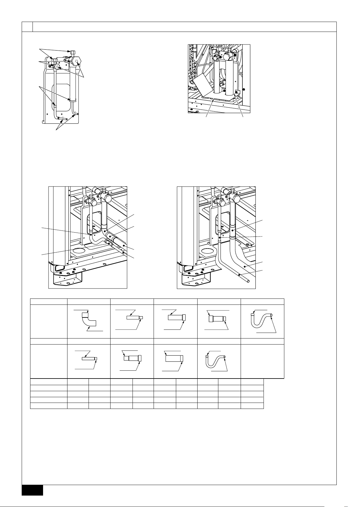
[Fig. 10.2.1] [Fig. 10.2.3]
B
<B>
10.2
<A>
C
E
[Fig. 10.2.2]
<A> Front pipe routing
98
<C>
32
<C>
D
A
<A> Refrigerant service valve
(liquid side/brazed type)
<B> Refrigerant service valve
(gas side/brazed type)
A : Shaft
B : Service port
C : Cap
D : Pinched connecting pipe severing portion
E : Pinched connecting pipe brazing portion
1
<C>
4567
A
B
<C>
AB
A : Example of closure materials (field supply)
B : Fill the gap at the site
<B> Bottom pipe routing
4567
23
<C>
A
B
<C>
No.
C Shape
No.
C Shape
PUHY-RP200YJM-A
PUHY-RP250YJM-A
PUHY-RP300YJM-A
PUHY-RP350YJM-A
<A> Front pipe routing <B> Bottom pipe routing
<C> Included with outdoor unit
A Gas pipe (field supply required) B Liquid pipe (field supply required)
C Shape
1357 9
IDø25.4
ODø25.4
<gas side> <gas side> <gas side> <liquid side>
2468
ODø12.7
IDø9.52
<liquid side>
12345678 9
11 1 1 1
11 11 1
11 11 1
11 11 1
ODø15.88
IDø12.7
<liquid side>
ODø19.05
IDø25.4
<gas side> <gas side>
ODø22.2
IDø25.4
ODø28.58
IDø25.4
ODø34.93
IDø25.4
IDø9.52
ODø9.52
<liquid side>
IDø12.7
ODø12.7
6
Page 7
10.3
F
D
C
A
B
D
E
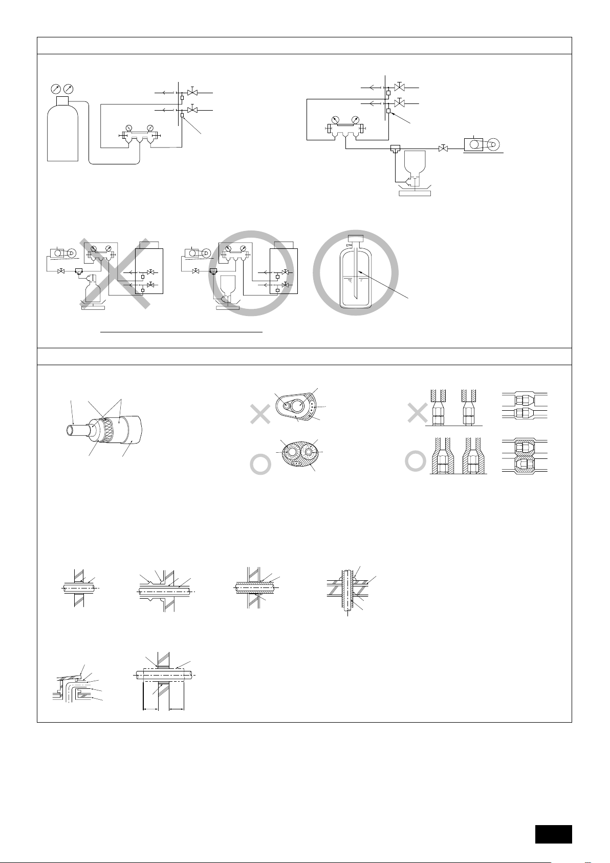
[Fig. 10.3.1]
A
C
[Fig. 10.3.3]
A : Nitrogen gas
B
B
C
LOW
D
B In case of the R410A cylinder having no syphon pipe.
HI
E
G
H
I
J
B :To indoor unit
C : System analyzer
D : Low knob
E : Hi knob
F :Valve
G : Liquid pipe
H : Gas pipe
I : Outdoor unit
J : Service port
[Fig. 10.3.2]
10.4
M
A : System analyzer
B : Low knob
C : Hi knob
D :Valve
E : Liquid pipe
F : Gas pipe
G : Service port
H : Three-way joint
I :Valve
J :Valve
K : R410A cylinder
L : Scale
M :Vacuum pump
N :To indoor unit
O : Outdoor unit
EN
N
A
LOW
B
HI
C
H
F
O
G
I
K
J
L
A
A : Syphon pipe
[Fig. 10.4.1]
A : Steel wire B : Piping
C : Asphaltic oily mastic or asphalt
D : Heat insulation material A
E : Outer covering B
[Fig. 10.4.4]
<A> Inner wall (concealed)
A B
<E> Roof pipe shaft
G
C
<F> Penetrating portion on fire
limit and boundary wall
I
D
B
H
F
<B> Outer wall
D
A
1m1m
A B
A
B
[Fig. 10.4.3][Fig. 10.4.2]
C
D
E
E
B
E
A
D
A : Liquid pipe B : Gas pipe
C : Electric wire D : Finishing tape
E : Insulator
<C> Outer wall (exposed)
E
B
I
<D> Floor (waterproofing)
D
F
G
B
A : Sleeve B : Heat insulating material
C : Lagging D : Caulking material
J
E : Band F:Waterproofing layer
G : Sleeve with edge H: Lagging material
I : Mortar or other incombustible caulking
J : Incombustible heat insulation material
7
Page 8
B
B
11
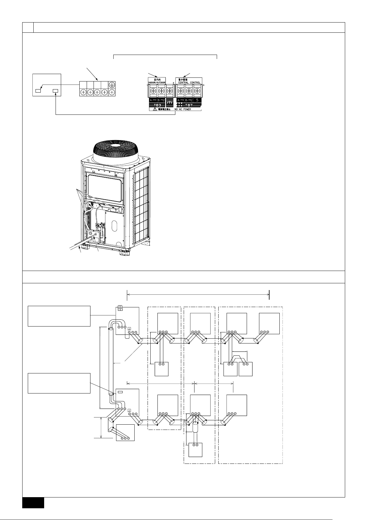
[Fig. 11.2.1]
Control box
[Fig. 11.2.2]
A
Power supply terminal block
(TB1)
L1 L2 L3 N
Terminal block for indoor –
outdoor transmission line
(TB3)
C
11.2
Terminal block for
centralized control
(TB7)
A : Power source
B :Transmission line
C : Earth screw
A : Cable strap
B : Power source line
C :Transmission line
A
[Fig. 11.3.1]
<A> Change the jumper connec-
tor from CN41 to CN40 *1
<B> SW2-1:ON *2
( ) Address
<C> Keep the jumper connector
on CN41
<B> SW2-1:ON *2
C
11.3
L
1
OC
CN40
(51)
TB3
M1M2
M1M2
S
TB7
2
L
D
L
OC
CN40
(52)
TB3
M1M2
M1M2
S
TB7
6
L
System
controller
ABS
A BC
IC
(01)
TB5
M1 M2 S
1
r
AB AB AB
(101)
RC
3
IC
(02)
TB5
M1 M2 S
IC
(04)
TB5
M1 M2 S
L
4
IC
(03)
TB5
M1 M2 S
5
L
4
r
A
B
(103)
RC
IC
(05)
TB5
M1 M2 S
2
r
(105)
RC
TB5
M1 M2 S
3
(155)
E
IC
(07)
r
M1 M2 S
RC
IC
(06)
TB5
*1: When the power supply unit is not connected to the transmission line for centralized control, disconnect the male power supply
connector (CN41) from ONE outdoor unit in the system and connect it to CN40.
*2: If a system controller is used, set SW2-1 on all of the outdoor units to ON.
8
Page 9
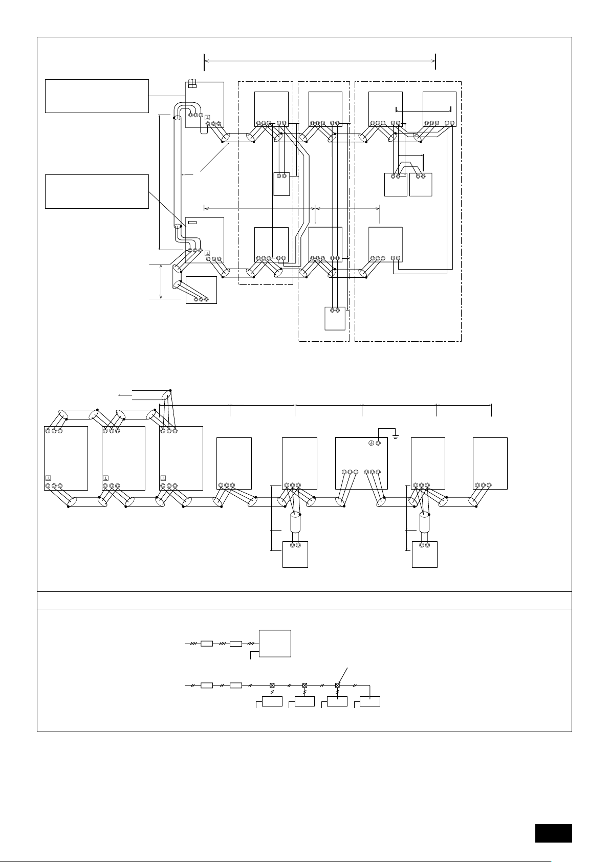
[Fig. 11.3.2]
L
1
<A> Change the jumper connec-
tor from CN41 to CN40 *1
<B> SW2-1:ON *2
<C> Keep the jumper connector
on CN41
<B> SW2-1:ON *2
A : Group 1
B : Group 3
C : Group 5
D : Shielded wire
E : Sub remote
controller
( ) Address
[Fig. 11.3.3]
To another
refrigerant system
OC
CN40
(51)
TB3
M1 M2
M1M2
S
TB7
2
L
D
L
A BC
IC
(01)
TB15
TB5
M1 M2 1 2S
2
c
3
MA
IC
(04)
TB5
M1 M2 S
1
c
L
4
IC
(05)
c
2
TB15
TB5
12
M1 M2 S
2
c
ABABAB
MAMAMA
E
TB5
M1 M2 S
1
c
c
4
(06)
IC
TB15
12
3
c
OC
(02)
TB5
M1 M2 S
L
2
IC
TB15
12
CN40
(52)
TB3
M1 M2
M1M2
S
TB7
6
L
System
controller
A
B
S
L
1
TB5
M1 M2 S
(03)
IC
IC
(07)
TB5
M1 M2 S
TB15
12
L
L
5
6
L
TB 15
3
12
AB
1
c
OS2
(53)
M1M2 S
TB7
TB3
M1M2
M1M2 S
( ) Address
[Fig. 11.4.1]
A : Switch (Breakers for
wiring and current
leakage)
B : Breakers for current
leakage
C : Outdoor unit
D : Pull box
E : Indoor unit
TB7
TB3
M1M2
OS1
(52)
M1M2 S
TB7
TB3
M1M2
3N~380–415V
L1, L2, L
3,
N
~220–240V
L, N
OC
(51)
TB5
M1M2 S
BA
BA
IC
IC
TB5
M1M2 S
4
L
1
r
RC
TB2
AB
RP
S
TB3
ABS
7
L
1
r
TB5
M1M2 S
ABAB
IC
RC
TB5
M1M2 S
IC
11.4
C
Ground
PE
PE
E
E
PE
D
E E
PE PE
9
Page 10
Contents
1. Safety precautions .................................................................................... 10
1.1. Before installation and electric work ........................................ 10
1.2. Precautions for devices that use R410A refrigerant ................. 11
1.3. Before installation ..................................................................... 11
1.4. Before installation (relocation) - electrical work ........................ 11
1.5. Before starting the test run ....................................................... 11
2. About the product ...................................................................................... 11
3. Combination of outdoor units .................................................................... 12
4. Specifications ............................................................................................ 12
5. Confirmation of parts attached .................................................................. 13
6. Space required around unit ...................................................................... 13
7. Lifting method ........................................................................................... 13
8. Installation of unit ...................................................................................... 14
8.1. Installation ............................................................................... 14
9. Refrigerant piping installation ................................................................... 14
9.1. Caution .................................................................................... 14
9.2. Refrigerant piping system ........................................................ 15
GB
1. Safety precautions
1.1. Before installation and electric work
s Before installing the unit, make sure you read all the “Safety
DFEINLPGRRUTRCZSVSLHGPO
precautions”.
s The “Safety precautions” provide very important points re-
garding safety. Make sure you follow them.
Symbols used in the text
Warning:
Describes precautions that should be observed to prevent danger of injury
or death to the user.
Caution:
Describes precautions that should be observed to prevent damage to the
unit.
Symbols used in the illustrations
: Indicates an action that must be avoided.
: Indicates that important instructions must be followed.
: Indicates a part which must be grounded.
: Beware of electric shock. (This symbol is displayed on the main unit label.)
<Color: yellow>
Warning:
Carefully read the labels affixed to the main unit.
HIGH VOLTAGE WARNING:
• Control box houses high-voltage parts.
• When opening or closing the front panel of the control box, do not let it
come into contact with any of the internal components.
• Before inspecting the inside of the control box, turn off the power, keep
the unit off for at least 10 minutes, and confirm that the voltage between
FT-P and FT-N on INV Board has dropped to DC20V or less.
(It takes about 10 minutes to discharge electricity after the power supply
is turned off.)
Warning:
• Ask the dealer or an authorized technician to install the air conditioner.
- Improper installation by the user may result in water leakage, electric shock,
or fire.
• This appliance is not intended for use by persons (including children)
with reduced physical, sensory or mental capabilities, or lack of experience and knowledge, unless they have been given supervision or instruction concerning use of the appliance by a person responsible for
their safety.
• Install the unit at a place that can withstand its weight.
- Failure to do so may cause the unit to fall down, resulting in injuries and
damage to the unit.
• Use the specified cables for wiring. Make the connections securely so
that the outside force of the cable is not applied to the terminals.
- Inadequate connection and fastening may generate heat and cause a fire.
• Prepare for strong winds and earthquakes and install the unit at the specified place.
- Improper installation may cause the unit to topple and result in injury and
damage to the unit.
10. Additional refrigerant charge ..................................................................... 15
10.1. Calculation of additional refrigerant charge ............................. 15
10.2. Precautions concerning piping connection and
valve operation ........................................................................ 16
10.3. Airtight test, evacuation, and refrigerant charging ................... 17
10.4. Thermal insulation of refrigerant piping ................................... 17
11. Wiring (For details, refer to the installation manual of
each unit and controller.) .......................................................................... 18
11.1. Caution .................................................................................... 18
11.2. Control box and connecting position of wiring ......................... 18
11.3. Wiring transmission cables...................................................... 18
11.4. Wiring of main power supply and equipment capacity ............ 20
12. Test run ..................................................................................................... 21
12.1. The following phenomena do not represent faults. ................. 21
13. Information on rating plate ........................................................................ 21
Always use filters and other accessories specified by Mitsubishi Electric.
•
- Ask an authorized technician to install the accessories. Improper installation
by the user may result in water leakage, electric shock, or fire.
• Never repair the unit. If the air conditioner must be repaired, consult the
dealer.
- If the unit is repaired improperly, water leakage, electric shock, or fire may
result.
• If the supply cord is damaged, it must be replaced by the manufacturer,
its service agent or similarly qualified persons in order to avoid a hazard.
• Do not touch the heat exchanger fins.
- Improper handling may result in injury.
• If refrigerant gas leaks during installation work, ventilate the room.
- If the refrigerant gas comes into contact with a flame, poisonous gases will
be released.
• Install the air conditioner according to this Installation Manual.
- If the unit is installed improperly, water leakage, electric shock, or fire may
result.
Have all electric work done by a licensed electrician according to “Electric
•
Facility Engineering Standard” and “Interior Wire Regulations” and the
instructions given in this manual and always use a dedicated power supply.
- If the power source capacity is inadequate or electric work is performed im-
properly, electric shock and fire may result.
• Securely install the outdoor unit terminal cover (panel).
- If the terminal cover (panel) is not installed properly, dust or water may enter
the outdoor unit and fire or electric shock may result.
• When installing and moving the air conditioner to another site, do not
charge it with a refrigerant different from the refrigerant specified on the
unit.
- If a different refrigerant or air is mixed with the original refrigerant, the refrig-
erant cycle may malfunction and the unit may be damaged.
• If the air conditioner is installed in a small room, measures must be taken
to prevent the refrigerant concentration from exceeding the safety limit if
the refrigerant should leak.
- Consult the dealer regarding the appropriate measures to prevent the safety
limit from being exceeded. Should the refrigerant leak and cause the safety
limit to be exceeded, hazards due to lack of oxygen in the room could result.
• When moving and reinstalling the air conditioner, consult the dealer or
an authorized technician.
- If the air conditioner is installed improperly, water leakage, electric shock, or
fire may result.
• After completing installation work, make sure that refrigerant gas is not
leaking.
- If the refrigerant gas leaks and is exposed to a fan heater, stove, oven, or
other heat source, it may generate noxious gases.
• Do not reconstruct or change the settings of the protection devices.
- If the pressure switch, thermal switch, or other protection device is shorted
or operated forcibly, or parts other than those specified by Mitsubishi Electric
are used, fire or explosion may result.
•To dispose of this product, consult your dealer.
• The installer and system specialist shall secure safety against leakage
according to local regulation or standards.
- The size of the wire and capacities of the switch for the main power supply
are applicable if local regulations are not available.
• Pay special attention to the place of installation, such as a basement,
etc. where refrigeration gas can accumulate, since refrigeration is heavier
than the air.
• For outdoor units that allow fresh air intake to the indoor unit, the
installation site must be carefully chosen because outdoor air can directly
blow into the room when the thermostat is turned off.
- Direct exposure to outdoor air may have harmful effects on people or food.
• Children should be supervised to ensure that they do not play with the
appliance.
10
Page 11
1.2. Precautions for devices that use R410A
refrigerant
Caution:
• Do not use existing refrigerant piping.
- The old refrigerant and refrigerator oil in the existing piping contains a large
amount of chlorine which may cause the refrigerator oil of the new unit to
deteriorate.
- R410A is a high-pressure refrigerant and can cause the existing piping to
burst.
• Use refrigerant piping made of phosphorus deoxidized copper and copper alloy seamless pipes and tubes. In addition, be sure that the inner
and outer surfaces of the pipes are clean and free of hazardous sulphur,
oxides, dust/dirt, shaving particles, oils, moisture, or any other contaminant.
- Contaminants on the inside of the refrigerant piping may cause the refriger-
ant residual oil to deteriorate.
• Store the piping to be used during installation indoors and keep both
ends of the piping sealed until just before brazing. (Store elbows and
other joints in a plastic bag.)
- If dust, dirt, or water enters the refrigerant cycle, deterioration of the oil and
compressor failure may result.
• Apply a small amount of ester oil, ether oil, or alkyl benzene to flares. (for
indoor unit)
- Infiltration of a large amount of mineral oil may cause the refrigerator oil to
deteriorate.
• Use liquid refrigerant to fill the system.
- If gas refrigerant is used to fill the system, the composition of the refrigerant
in the cylinder will change and performance may drop.
• Do not use a refrigerant other than R410A.
- If another refrigerant (R22, etc.) is mixed with R410A, the chlorine in the
refrigerant may cause the refrigerator oil to deteriorate.
• Use a vacuum pump with a reverse flow check valve.
- The vacuum pump oil may flow back into the refrigerant cycle and cause the
refrigerator oil to deteriorate.
• Do not use the following tools that are used with conventional refrigerants.
(Gauge manifold, charge hose, gas leak detector, reverse flow check valve,
refrigerant charge base, refrigerant recovery equipment)
- If the conventional refrigerant and refrigerator oil are mixed in the R410A,
the refrigerant may deteriorated.
- If water is mixed in the R410A, the refrigerator oil may deteriorate.
- Since R410A does not contain any chlorine, gas leak detectors for conven-
tional refrigerants will not react to it.
• Do not use a charging cylinder.
- Using a charging cylinder may cause the refrigerant to deteriorate.
• Be especially careful when managing the tools.
- If dust, dirt, or water gets into the refrigerant cycle, the refrigerant may dete-
riorate.
1.3. Before installation
Caution:
• Do not install the unit where combustible gas may leak.
- If the gas leaks and accumulates around the unit, an explosion may result.
• Do not use the air conditioner where food, pets, plants, precision instruments, or artwork are kept.
- The quality of the food, etc. may deteriorate.
• Do not use the air conditioner in special environments.
- Oil, steam, sulfuric smoke, etc. can significantly reduce the performance of
the air conditioner or damage its parts.
• When installing the unit in a hospital, communication station, or similar
place, provide sufficient protection against noise.
-Inverter equipment, private power generator, high-frequency medical equip-
ment, or radio communication equipment may cause the air conditioner to
operate erroneously, or fail to operate. On the other hand, the air conditioner
may affect such equipment by creating noise that disturbs medical treatment
or image broadcasting.
• Do not install the unit on a structure that may cause leakage.
- When the room humidity exceeds 80% or when the drain pipe is clogged,
condensation may drip from the indoor unit. Perform collective drainage work
together with the outdoor unit, as required.
1.4. Before installation (relocation) - electrical work
Caution:
• Ground the unit.
- Do not connect the ground wire to gas or water pipes, lightning rods, or
telephone ground lines. Improper grounding may result in electric shock.
• Never connect in reverse phases.
Never connect the Power Line L1, L2, and L3 to Terminal N.
- If the unit is miss wired, when power is supplied, some electrical parts will be
damaged.
• Install the power cable so that tension is not applied to the cable.
-Tension may cause the cable to break and generate heat and cause a fire.
• Install a leak circuit breaker, as required.
- If a leak circuit breaker is not installed, electric shock may result.
• Use power line cables of sufficient current carrying capacity and rating.
- Cables that are too small may leak, generate heat, and cause a fire.
• Use only a circuit breaker and fuse of the specified capacity.
-A fuse or circuit breaker of a larger capacity, or the use of a substitute simple
steel or copper wire may result in a general unit failure or fire.
• Do not wash the air conditioner units.
-Washing them may cause an electric shock.
• Be careful that the installation base is not damaged by long use.
- If the damage is left uncorrected, the unit may fall and cause personal injury
or property damage.
• Install the drain piping according to this Installation Manual to ensure
proper drainage. Wrap thermal insulation around the pipes to prevent
condensation.
- Improper drain piping may cause water leakage causing damage to furniture
and other possessions.
• Be very careful about transporting the product.
- One person should not carry the product. Its weight is in excess of 20kg.
- Some products use PP bands for packaging. Do not use any PP bands as a
means of transportation. It is dangerous.
- Do not touch the heat exchanger fins. Doing so may cut your fingers.
- When transporting the outdoor unit, support it at the specified positions on
the unit base. Also support the outdoor unit at four points so that it cannot
slip sideways.
• Safely dispose of the packing materials.
- Packing materials, such as nails and other metal or wooden parts, may cause
stabs or other injuries.
-Tear apart and throw away plastic packaging bags so that children will not
play with them. If children play with a plastic bag which has not been torn
apart, they face the risk of suffocation.
1.5. Before starting the test run
Caution:
•Turn on the power at least 12 hours before starting operation.
- Starting operation immediately after turning on the main power switch can
result in irreversible damage to internal parts. Keep the power switch turned
on during the operational season. Make sure of the phase order of power
supply and voltage between each phase.
• Do not touch the switches with wet fingers.
-Touching a switch with wet fingers can result in an electric shock.
• Do not touch the refrigerant pipes during and immediately after operation.
- During and immediately after operation, the refrigerant pipes may be hot or
cold, depending on the condition of the refrigerant flowing through the refrigerant piping, compressor, and other refrigerant cycle parts. Your hands may
suffer burns or frostbite if you touch the refrigerant pipes.
• Do not operate the air conditioner with the panels and guards removed.
- Rotating, hot, or high-voltage parts can cause injuries.
• Do not turn off the power immediately after stopping operation.
- Always wait at least 5 minutes before turning off the power. Otherwise,
drainage water leakage or mechanical failure of sensitive parts may occur.
• Do not touch the surface of the compressor during servicing.
- If unit is connected to a supply and not running, the crank case heater lo-
cated at the base of the compressor may still be operating.
GB
DFEINLPGRRUTRCZSVSLHGPO
2. About the product
• This unit uses R410A-type refrigerant.
• Piping for systems using R410A may be different from that for systems using
conventional refrigerant because the design pressure in systems using R410A
is higher. Refer to the Data Book for more information.
• Some of the tools and equipment used for installation with systems that use
other types of refrigerant cannot be used with the systems using R410A. Refer
to the Data Book for more information.
Caution:
• Do not vent R410A into the atmosphere.
• R410A is a Fluorinated Greenhouse gas, covered by the Kyoto Protocol
with a Global Warming Potential (GWP) = 1975.
11
Page 12

3. Combination of outdoor units
Component units of PUHY-RP400 to RP900 are listed below.
Outdoor unit model
PUHY-RP200YJM-A(-BS)
PUHY-RP250YJM-A(-BS)
PUHY-RP300YJM-A(-BS)
PUHY-RP350YJM-A(-BS)
PUHY-RP400YSJM-A(-BS)
PUHY-RP450YSJM-A(-BS)
PUHY-RP500YSJM-A(-BS)
PUHY-RP550YSJM-A(-BS)
PUHY-RP600YSJM-A(-BS)
PUHY-RP650YSJM-A(-BS)
PUHY-RP700YSJM-A(-BS)
PUHY-RP750YSJM-A(-BS)
PUHY-RP800YSJM-A(-BS)
PUHY-RP850YSJM-A(-BS)
PUHY-RP900YSJM-A(-BS)
Component unit model
PUHY-RP200YJM-A(-BS)
PUHY-RP200YJM-A(-BS)
PUHY-RP250YJM-A(-BS)
PUHY-RP250YJM-A(-BS)
PUHY-RP300YJM-A(-BS)
PUHY-RP300YJM-A(-BS)
PUHY-RP200YJM-A(-BS)
PUHY-RP250YJM-A(-BS)
PUHY-RP250YJM-A(-BS)
PUHY-RP250YJM-A(-BS)
PUHY-RP300YJM-A(-BS)
GB
4. Specifications
-
-
-
PUHY-RP200YJM-A(-BS)
PUHY-RP250YJM-A(-BS)
PUHY-RP250YJM-A(-BS)
PUHY-RP300YJM-A(-BS)
PUHY-RP300YJM-A(-BS)
PUHY-RP350YJM-A(-BS)
PUHY-RP250YJM-A(-BS)
PUHY-RP250YJM-A(-BS)
PUHY-RP250YJM-A(-BS)
PUHY-RP300YJM-A(-BS)
PUHY-RP300YJM-A(-BS)
-
-
-
-
PUHY-RP250YJM-A(-BS)
PUHY-RP250YJM-A(-BS)
PUHY-RP300YJM-A(-BS)
PUHY-RP300YJM-A(-BS)
PUHY-RP300YJM-A(-BS)
-
-
-
-
-
-
-
-
-
-
Model
Noise level (50/60Hz)
External static pressure
DFEINLPGRRUTRCZSVSLHGPO
Total capacity
Indoor
units
Quantity
Standard type
Operation
tempera-
Fresh air
ture
intake type
Model
Noise level (50/60Hz)
External static pressure
Total capacity
Indoor
units
Quantity
Standard type
Operation
tempera-
Fresh air
ture
intake type
*1: The total indoor capacity of units run simultaneously is 130% or less.
*2: To enable high static pressure with RP200, RP250, RP300 and RP350, set the DipSW on the main panel as follows.
SW3-9: ON, SW3-10 60Pa compatible: OFF, 30Pa compatible: ON
PUHY-RP200YJM-A
56dB <A>
Model
1~13
Cooling mode: – 5°CDB ~ 43°CDB
Heating mode: – 20°CWB ~ 15.5°CWB
Cooling mode: 21°CDB ~ 43°CDB
Heating mode: – 12.5°CWB ~ 20°CWB
PUHY-RP750YSJM-A
63.5dB <A>
Model
1~32
Cooling mode: – 5°CDB ~ 43°CDB
Heating mode: – 20°CWB ~ 15.5°CWB
Cooling mode: 21°CDB ~ 43°CDB
Heating mode: – 12.5°CWB ~ 20°CWB
PUHY-RP250YJM-A
57dB <A>
1~16
PUHY-RP800YSJM-A
64dB <A>
1~32
PUHY-RP300YJM-A
59dB <A>
PUHY-RP850YSJM-A
64.5dB <A>
0 Pa *2
50~130% *1
15~250
1~16
1~32
PUHY-RP350YJM-A
60dB <A>
1~20
PUHY-RP900YSJM-A
65dB <A>
1~32
PUHY-RP400YSJM-A
61dB <A>
1~20
PUHY-RP450YSJM-A
62dB <A>
0 Pa *2
50~130% *1
15~250
1~20
PUHY-RP500YSJM-A
60dB <A>
1~20
PUHY-RP550YSJM-A
61dB <A>
1~20
PUHY-RP600YSJM-A
62dB <A>
1~32
PUHY-RP650YSJM-A
6
2.5dB <A>
1~32
PUHY-RP700YSJM-A
63dB <A>
1~32
12
Page 13

5. Confirmation of parts attached
• This unit includes the following parts. Please check.
• For usage methods, refer to item 10.2.
2 Connecting pipe
ID ø9.52, OD ø12.7
<Liquid side>
1 pc.
1 pc.
1 pc.
–
8 Connecting pipe
ID ø9.52, OD ø9.52
<Liquid side>
1 pc.
1 pc.
1 pc.
–
Model
Model
RP200
RP250
RP300
RP350
RP200
RP250
RP300
RP350
1 Connecting elbow
ID ø25.4 , OD ø25.4
<gas side>
1 pc.
1 pc.
1 pc.
1 pc.
7 Connecting pipe
ID ø25.4 , OD ø34.93
<gas side>
–
–
–
1 pc.
6. Space required around unit
3 Connecting pipe
ID ø12.7 , OD ø15.88
<Liquid side>
–
–
–
1 pc.
9 Connecting pipe
ID ø12.7 , OD ø12.7
<Liquid side>
–
–
–
1 pc.
4 Connecting pipe
ID ø25.4 , OD ø19.05
<gas side>
1 pc.
–
–
–
5 Connecting pipe
ID ø25.4 , OD ø22.2
<gas side>
–
1 pc.
1 pc.
–
6 Connecting pipe
ID ø25.4 , OD ø28.58
<gas side>
1 pc.
1 pc.
1 pc.
1 pc.
GB
1 In case of single installation
• Secure enough space around the unit as shown in the figure on page 2.
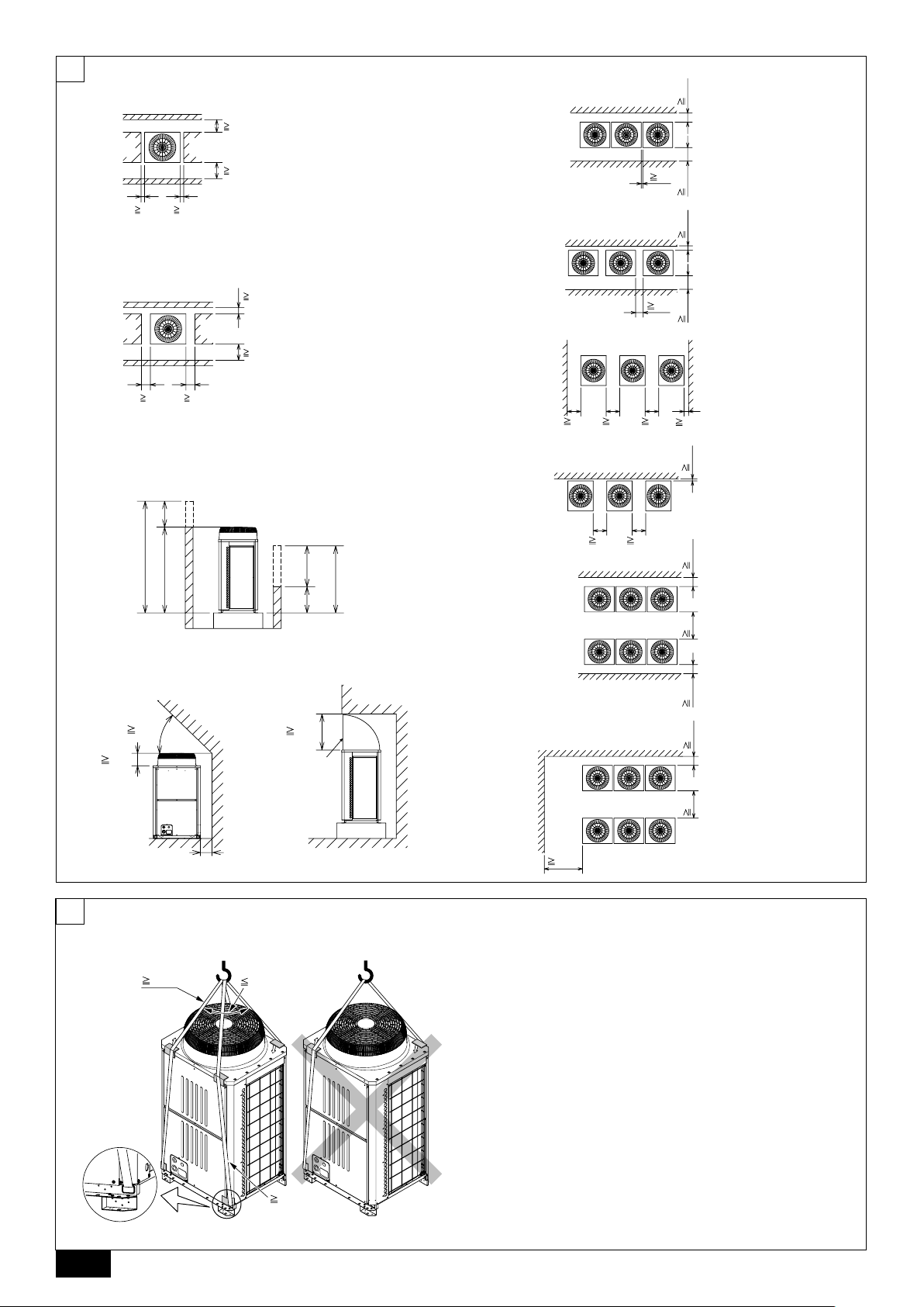
[Fig. 6.0.1] (P.2)
<A> Top view <B> Side view
<C> When there is little space up to an obstruction
A Front B Unit height
C Back D Air outlet guide (Procured at the site)
(1) If the distance is 300 mm or more between the rear side and the wall
(2) If the distance is 100 mm or more between the rear side and the wall
(3) If the wall height (H) of the front, rear or side exceeds the wall height
restriction
• When the height of the walls on the front, back or on the sides <H> exceeds
the wall height limit as defined here, add the height that exceeds the height
limit <h> to the figures that are marked with an asterisk.
7. Lifting method
[Fig. 7.0.1] (P.2)
• Use suspension ropes that will withstand the weight of the unit.
• When moving the unit, use a 4-point suspension, and avoid giving impacts to
the unit (Do not use 2-point suspension).
• Place protective pads on the unit where it comes in contact with the ropes to
protect the unit from being scratched.
• Set the angle of roping at 40° or less.
• Use 2 ropes that are each longer than 8 meters.
<Wall height limit> Front: Up to the unit height
Back: Up to 500 mm from the unit bottom
Side: Up to the unit height
(4) If there are obstacles at the upper part of the unit
2 In case of collective installation
[Fig. 6.0.2] (P.2)
A Front B Must be open
C Wall height (H)
• When multiple units are installed adjacent to each other, secure enough space
to allow for air circulation and walkway between groups of units as shown in
the figures on page 2.
• At least two sides must be left open.
• As with the single installation, add the height that exceeds the height limit <h>
to the figures that are marked with an asterisk.
• If there is a wall at both the front and the rear of the unit, install up to 6 units
consecutively in the side direction and provide a space of 1000 mm or more as
inlet space/passage space for each 6 units.
• Place protective padding at the corners of the product to protect the product
from scratches or dents that might be caused by the rope.
Caution:
Be very careful when carrying/moving the product.
- When installing the outdoor unit, suspend the unit at the specified location of the
unit base. Stabilize as necessary so that it does not move to the side and support
it at 4 points. If the unit is installed or suspended with 3-point support, the unit
may become unstable and fall.
DFEINLPGRRUTRCZSVSLHGPO
13
Page 14

8. Installation of unit
8.1. Installation
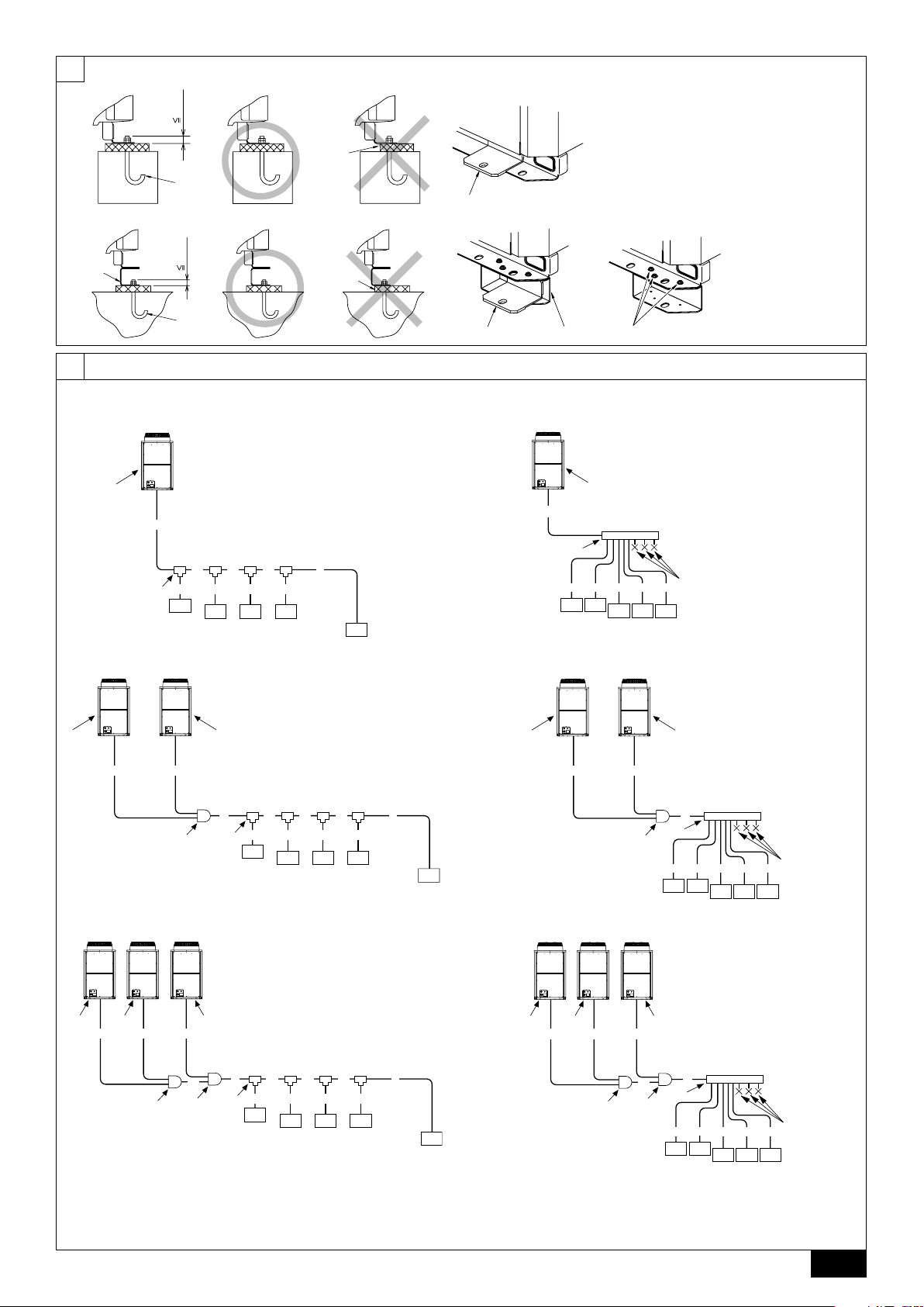
[Fig. 8.1.1] (P.3)
<A> Without detachable leg <B> With detachable leg
A M10 anchor bolt procured at the site. B Corner is not seated.
C Fixing bracket for the hole-in anchor bolt (3 locations to fix with screws).
D Detachable leg
• Fix unit tightly with bolts so that unit will not fall down due to earthquakes or
strong winds.
• Use concrete or an angle bracket as the foundation of unit.
• Vibration may be transmitted to the installation section and noise and vibration
may be generated from the floor and walls, depending on the installation conditions. Therefore, provide ample vibrationproofing (cushion pads, cushion
frame, etc.).
• Build the foundation in such way that the corner of the installation leg is securely supported as shown in the figure. (Fig. 8.1.1)
GB
When using a rubber isolating cushion, please ensure it is large enough to
cover the entire width of each of the unit's legs. If the corners are not firmly
seated, the installation feet may be bent.
• The projecting length of the anchor bolt should be less than 30 mm.
• Hole-in anchor bolts are not compatible with this product. However, if fixing
brackets are mounted on the 4 locations of the unit attachment part, hole-in
DFEINLPGRRUTRCZSVSLHGPO
anchor bolts can be used.
9. Refrigerant piping installation
The pipe is connected via a terminal-branch type connection in which refrigerant
piping from the outdoor unit is branched at the terminal and is connected to each
of the indoor units.
The method of pipe connection is as follows: flare connection for the indoor units,
gas pipes and liquid pipes for outdoor units, brazed connection. Note that the branched
sections are brazed.
Warning:
Always use extreme care to prevent the refrigerant gas from leaking while
using fire or flame. If the refrigerant gas comes in to contact with a flame
from any source, such as a gas stove, it breaks down and generates a poisonous gas which can cause gas poisoning. Never weld in an unventilated
room. Always conduct an inspection for gas leakage after installation of the
refrigerant piping has been completed.
Caution:
• Do not vent R410A into the atmosphere.
• R410A is a Fluorinated Greenhouse gas, covered by the Kyoto Protocol
with a Global Warming Potential (GWP) = 1975.
[Fig. 8.1.2]
A Screws
• The detachable leg can be removed at the site.
• Detaching the detachable leg
Loosen the three screws to detach the detachable leg (Two each in the front
and back).
If the base leg finish is damaged when detaching, be sure to repair at the site.
Warning:
• Be sure to install unit in a place strong enough to withstand its weight.
Any lack of strength may cause unit to fall down, resulting in a personal
injury.
•Have installation work in order to protect against strong winds and
earthquakes.
Any installation deficiency may cause unit to fall down, resulting in a
personal injury.
When building the foundation, give full attention to the floor strength, drain water
disposal <during operation, drain water flows out of the unit>, and piping and wiring routes.
Precautions when routing the pipes and wires below the unit (Without
detachable leg)
When routing the pipes and wires below the unit, be sure that the foundation and
base work do not block the base through-holes. Also make sure the foundation is
at least 100 mm high so that the piping can pass under the unit.
2 Commercially available piping often contains dust and other materials. Always
blow it clean with a dry inert gas.
3 Use care to prevent dust, water or other contaminants from entering the piping
during installation.
4 Reduce the number of bending portions as much as possible, and make bend-
ing radii as big as possible.
5 For indoor and outdoor branching, be sure to use the following twinning pipe
sets (sold separately).
6 Use a fitting if a specified refrigerant pipe has a different diameter from that of
a branching pipe.
7 Always observe the restrictions on the refrigerant piping (such as rated length,
height difference, and piping diameter) to prevent equipment failure or a decline in heating/cooling performance.
9.1. Caution
This unit uses refrigerant R410A. Follow the local regulations on materials and
pipe thickness when selecting pipes. (Refer to the table on the right.)
1 Use the following materials for refrigeration piping.
• Material: Use copper alloy seamless pipes made of phosphorus deoxidized copper. Ensure the inner and outer surfaces of the pipes are clean
and free from hazardous sulfur, oxide, dusts, shaving particles, oils, and
moisture (contamination).
• Size: Refer to item 9.2. for detailed information on refrigerant piping system.
Lower stream unit model
Less than 200 in total
CMY-Y102S-G2
Outdoor twinning kit model
Total outdoor model
RP400 ~ RP650
CMY-RP100VBK
** When using existing pipes, do not use the indoor twinning pipe set.
Lower stream unit model
More than 201 and less than
400 in total
CMY-Y102L-G2
Total outdoor model
RP700 ~ RP900
CMY-RP200VBK
Line branch Header branch
Indoor twinning pipe set model**
Lower stream unit model
More than 401 and less than
650 in total
CMY-Y202-G2
14
Lower stream unit model
More than 651 in total
CMY-Y302-G2
4 branching
CMY-Y104-G
8 branching
CMY-Y108-G
10 branching
10 branching
CMY-Y1010-G
CMY-Y1010-G
Page 15

8 Branching cannot be made after header branching (corresponding parts are
marked with
in the diagram below).
To the outdoor unit
To the outdoor unit
CAP
9 Either a lack or an excess of refrigerant causes the unit to make an emergency
stop. Charge the system with an appropriate amount of refrigerant. When servicing, always check the notes concerning pipe length and amount of additional
refrigerant at both locations, the refrigerant volume calculation table on the
back of the service panel and the additional refrigerant section on the labels
for the combined number of indoor units (Refer to item 9.2. for detailed information on refrigerant piping system).
0 Be sure to charge the system using liquid refrigerant.
A Never use refrigerant to perform an air purge. Always evacuate using a
vacuum pump.
B Always insulate the piping properly. Insufficient insulation will result in a de-
cline in heating/cooling performance, water drops from condensation and other
such problems (Refer to item 10.4 for thermal insulation of refrigerant piping).
C When connecting the refrigerant piping, make sure the valve of the outdoor
unit is completely closed (the factory setting) and do not operate it until the
refrigerant piping for the outdoor and indoor units has been connected, a refrigerant leakage test has been performed and the evacuation process has
been completed.
D Braze only with non-oxide brazing material for piping. Failure to do so
may damage the compressor. Be sure to perform the non-oxidation brazing with a nitrogen purge.
Do not use any commercially available anti-oxidizing agent since it may
cause pipe corrosion and degrading of the refrigerant oil.
Please contact Mitsubishi Electric for more details.
(Refer to item 10.2. for details of the piping connection and valve operation)
E Never perform outdoor unit piping connection work when it is raining.
Warning:
When installing and moving the unit, do not charge the system with any
other refrigerant other than the refrigerant specified on the unit.
- Mixing of a different refrigerant, air, etc. may cause the refrigerant cycle to malfunction and may result in severe damage.
Caution:
• Use a vacuum pump with a reverse flow check valve.
- If the vacuum pump does not have a reverse flow check valve, the vacuum
pump oil may flow back into the refrigerant cycle and cause deterioration of
the refrigerator oil.
• Do not use the tools shown below used with conventional refrigerant.
(Gauge manifold, charge hose, gas leak detector, check valve, refrigerant charge base, vacuum gauge, refrigerant recovery equipment)
- Mixing of conventional refrigerant and refrigerator oil may cause the refrig-
erator oil to deteriorate.
- Mixing of water will cause the refrigerator oil to deteriorate.
- R410A refrigerant does not contain any chlorine. Therefore, gas leak detec-
tors for conventional refrigerants will not react to it.
• Manage the tools used for R410A more carefully than normal.
- If dust, dirt, or water gets in the refrigerant cycle, the refrigerator oil will deteriorate.
• Store the piping to be used during installation indoors and keep both
ends of the piping sealed until just before brazing.
- If dust, dirt, or water gets into the refrigerant cycle, the oil will deteriorate and
the compressor may fail.
• Do not use a charging cylinder.
- Using a charging cylinder may cause the refrigerant to deteriorate.
• Do not use special detergents for washing piping.
9.2. Refrigerant piping system
Connection example
[Fig. 9.2.1] (P.3, 4)
Å Outdoor model ı Liquid pipe
Ç Gas pipe Î Total capacity of indoor units
‰ Model number Ï Downstream unit model total
Ì Joint Ó The 1st branch of P450 ~ P650
¬ The 1st branch of P700, P750, P800
Ô 4-Branching header (Downstream unit model total 200)
8-Branching header (Downstream unit model total 400)
Ò 10-Branching header (Downstream unit model total 650)
˜ Outdoor twinning kit
A Outdoor unit B First branch
C Indoor unit D Cap
E Outdoor twinning kit
*1 The pipe sizes listed in columns A1 to A3 in this table correspond to the sizes for
the models listed in the unit 1, 2, and 3 columns. When the order of the models for
unit 1, 2, and 3 change, make sure to use the appropriate pipe size.
*2 ø25.4 for R22
Precautions for outdoor unit combinations
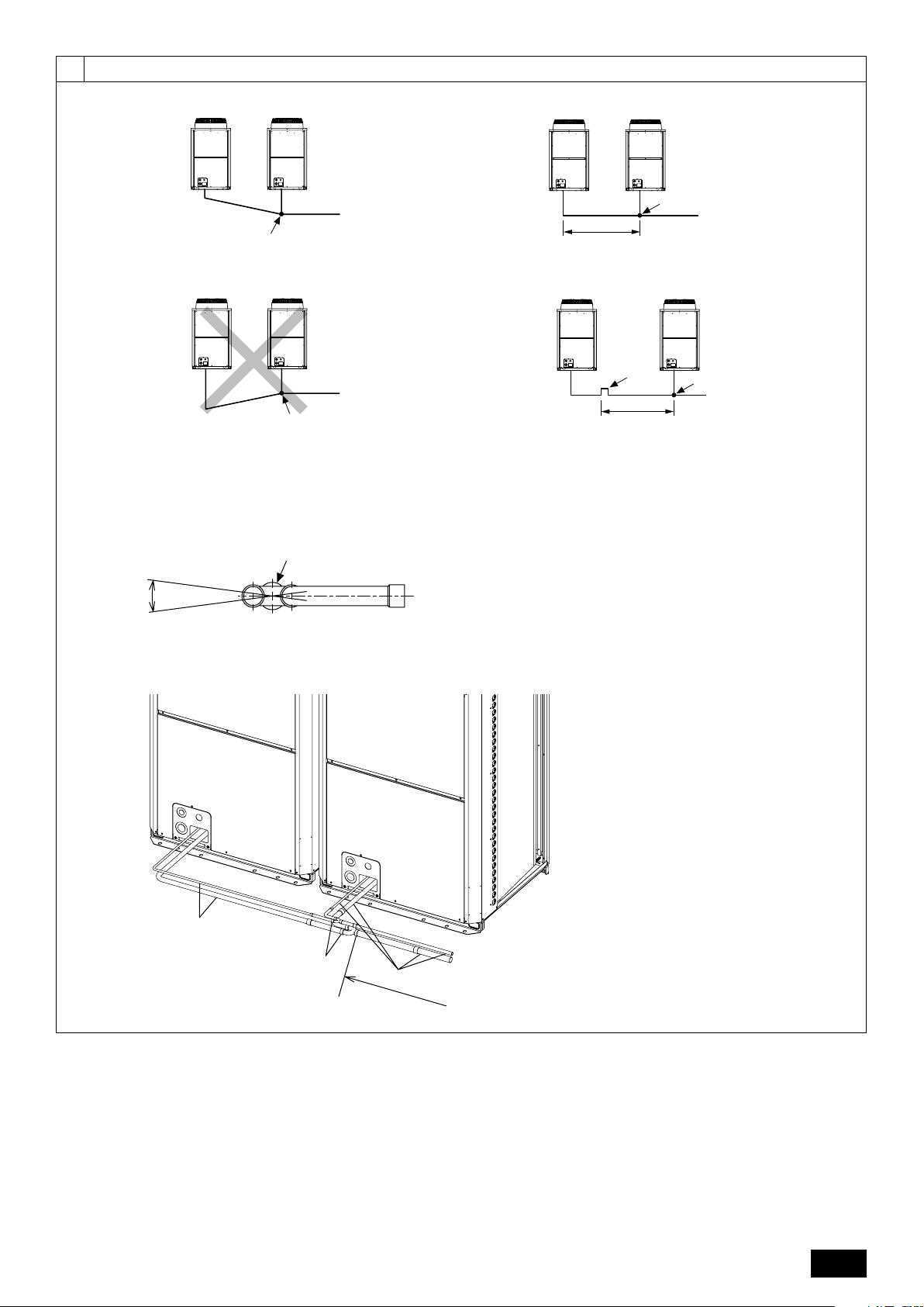
Refer to [Fig. 9.2.2] for the positioning of twinning pipes.
[Fig. 9.2.2] (P.5)
<A> Make sure the pipes from the twinning pipe to the outdoor unit are sloped
downwards (towards the twinning pipes).
<B> When the piping on the outdoor unit side (from the twinning pipe) exceeds 2 m,
ensure a trap (gas pipe only) within 2 m. Make sure the height of the trap is 200
mm or more.
If there is no trap, oil can accumulate inside the pipe, causing a shortage of oil
and may damage the compressor.
<C> Slope of twinning pipes
Make sure the slope of the twinning pipes are at an angle within ±15° to the
ground.
If the slope exceeds the specified angle, the unit may be damaged.
<D> Pipe connection example
A Downward slope B Upward slope
C Indoor unit D Tr ap (gas pipe only)
E Within 2 m F Twinning pipe
G Slope of the twinning pipes are at an angle within ±15° to the ground
H Pipes on site I Twinning kit
J Straight run of pipe that is 500 mm or more
Caution:
• Do not install traps other than the ones between outdoor units described
on a separate sheet to prevent oil backflow and compressor start-up failure.
• Do not install solenoid valves to prevent oil backflow and compressor
start-up failure.
• Do not install a sight glass because it may show improper refrigerant
flow.
If a sight glass is installed, inexperienced technicians that use the glass
may overcharge the refrigerant.
GB
DFEINLPGRRUTRCZSVSLHGPO
10. Additional refrigerant charge
At the time of shipping, the outdoor unit is charged with refrigerant.
This charge does not include the amount needed for extended piping and additional
charging of each refrigerant line will be required on site. In order that future servicing may be properly provided, always keep a record of the size and length of
each refrigerant line and the amount of additional charge by writing it in the space
provided on the outdoor unit.
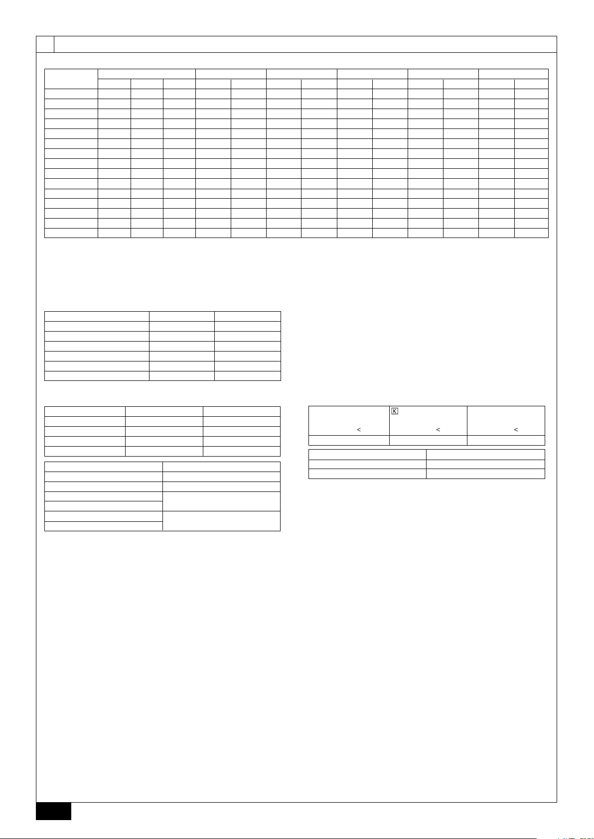
10.1. Calculation of additional refrigerant
charge
• Calculate the amount of additional charge based on the length of the piping
extension and the size of the refrigerant line.
• Use the table to the right as a guide to calculating the amount of additional
charging and charge the system accordingly.
• If the calculation results in a fraction of less than 0.1 kg, round up to the next
0.1 kg. For example, if the result of the calculation was 11.38 kg, round the
result up to 11.4 kg.
<Additional Charge>
Additional
refrigerant charge
(kg)
Liquid pipe size
Total length of
=++
ø19.05 × 0.29
(m) × 0.29 (kg/m)
Liquid pipe size
Total length of
+++ α
ø9.52 × 0.06
(m) × 0.06 (kg/m)
Liquid pipe size
Total length of
ø15.88 × 0.2
(m) × 0.2 (kg/m)
Liquid pipe size
Total length of
ø6.35 × 0.024
(m) × 0.024 (kg/m)
Liquid pipe size
Total length of
ø12.7 × 0.12
(m) × 0.12 (kg/m)
15
Page 16

<Example>
Indoor 1: 125 A: ø15.88 40 m a: ø9.52 10 m
2: 100 B: ø12.7 10 m b: ø9.52 5 m
3: 40 C: ø12.7 15 m c: ø6.35 10 m
4: 32 D: ø12.7 10 m d: ø6.35 10 m
5: 63 e: ø9.52 10 m
The total length of each liquid line is as follows:
ø15.88: A = 40 = 40 m
ø12.7: B + C + D = 10 + 15 + 10 = 35 m
ø9.52: a + b + e = 10 + 5 + 10 = 25 m
ø6.35: c + d = 10 + 10 = 20 m
Therefore,
<Calculation example>
Additional refrigerant charge
= 40 × 0.2 + 35 × 0.12 + 25 × 0.06 + 20 × 0.024 + 3.5 = 17.7 kg
Value of α
Total capacity of connecting indoor units α
GB
DFEINLPGRRUTRCZSVSLHGPO
Models ~ 80 2.0 kg
Models 81 ~ 160 2.5 kg
Models 161~ 330 3.0 kg
Models 331~ 390 3.5 kg
Models 391~ 480 4.5 kg
Models 481~ 630 5.0 kg
Models 631~ 710 6.0 kg
Models 711~ 800 8.0 kg
Models 801~ 890 9.0 kg
Models 891~1070 10.0 kg
Models 1071 ~ 12.0 kg
At the
conditions
below:
10.2. Precautions concerning piping connec-
tion and valve operation
• Conduct piping connection and valve operation accurately and carefully.
• Removing the pinched connecting pipe
When shipped, a pinched connecting pipe is attached to the on-site liquid and
gas valves to prevent gas leakage.
Ta ke the following steps 1 through 4 to remove the pinched connecting pipe
before connecting refrigerant pipes to the outdoor unit.
1 Check that the refrigerant service valve is fully closed (turned clockwise all
the way).
2 Connect a charging hose to the service port on the liquid/gas refrigerant
service valve, and extract the gas in the pipe section between the refrigerant service valve and the pinched connecting pipe (Tightening torque
12 N·m).
3 After vacuuming gas from the pinched connecting pipe, sever the pinched
connecting pipe at the location shown in [Fig.10.2.1] and drain the
refrigerant.
4 After completing 2 and 3 heat the brazed section to remove the pinched
connecting pipe.
[Fig. 10.2.1] (P.6)
<A> Refrigerant service valve (liquid side/brazed type)
<B> Refrigerant service valve (gas side/brazed type)
A Shaft
Fully closed at the factory, when connecting the piping, and when vacuuming.
Open fully after these operations are completed.
<When opening>
• Turn the shaft counterclockwise with a hexagonal wrench.
• Turn around the shaft until it stops.
<When closing>
• Turn the shaft clockwise with a hexagonal wrench.
• Turn around the shaft until it stops.
B Service port
Available for gas venting of the pinched connecting pipe, or vacuuming in the
refrigerant pipes on the site.
(Tightening torque 12 N·m)
C Cap
Remove the cap before operating the shaft. Be sure to return it to the original
position after completing the operation.
D Pinched connecting pipe severing portion
E Pinched connecting pipe brazing portion
Warning:
• The section of the pipe on the unit between the two refrigerant service
valves is filled with gas. Extract the gas in the above-mentioned pipe
section before heating the brazed section to remove the refrigerant service
valve connecting pipe.
- If the brazed section is heated without first extracting the gas, the pipe may
burst or the connecting pipe may blow off causing serious injury.
Caution:
• Place a wet towel on the refrigerant service valve before heating the brazed
section to keep the temperature of the valve from exceeding 120 ˚C.
• Direct the flame away from the wiring and metal sheets inside the unit to
prevent heat damage.
Caution:
• Do not vent R410A into the atmosphere.
• R410A is a Fluorinated Greenhouse gas, covered by the Kyoto Protocol,
with a Global Warming Potential (GWP) = 1975.
• Refrigerant pipe connection
This product includes connecting pipes for front piping and bottom post-piping.
(Refer to [Fig.10.2.2])
Check the liquid/gas piping dimensions before connecting the refrigerant pipe.
Refer to item 9.2 Refrigerant piping system for piping dimensions.
Make sure that the refrigerant pipe is not touching other refrigerants pipes, unit
panels, or base plates.
Be sure to use non-oxidative brazing when connecting pipes.
<Refrigerant piping connection examples>
[Fig.10.2.2] (P.6)
<A> Front pipe routing <B> Bottom pipe routing
<C> Included with outdoor unit
A Gas pipe (field supply required) B Liquid pipe (field supply required)
C Shape
• Front pipe routing
RP200,RP250,RP300
Liquid side
Gas side
• Bottom pipe routing
Liquid side
Gas side
*1 In the case the unit is used in combination with other outdoor units.
*2 In the case of R22.
Satisfy the minimum insertion depth in the table below when expanding on-site
piping.
• After evacuation and refrigerant charging, ensure that the handle is fully open.
If operating with the valve closed, abnormal pressure will be imparted to the
high- or low-pressure side of the refrigerant circuit, giving damage to the compressor, four-way valve, etc.
• Determine the amount of additional refrigerant charge by using the formula,
and charge refrigerant additionally through the service port after completing
piping connection work.
RP200 *1,RP250 *1
RP350
RP350 *1
RP200,RP250,
RP300,RP350 *1
RP200 *1
RP200 *2
RP250 *1,RP300 *1
RP350
RP200,RP250,RP300
RP200 *1,RP250 *1
RP350
RP350 *1
RP200,RP250,
RP300,RP350 *1
RP200 *1
RP200 *2
RP250 *1,RP300 *1
RP350
Pipe diameter (mm) Minimum insertion depth (mm)
5 or more less than 8 6
8 or more less than 12 7
12 or more less than 16 8
16 or more less than 25 10
25 or more less than 35 12
35 or more less than 45 14
Use the included connecting pipe 2 and
8 to connect.
Use the included connecting pipe 8 to con-
nect.
Use the included connecting pipe 3 and
9 to connect.
Use the included connecting pipe 9 to con-
nect.
Use the included elbow 1 and connecting
pipe 6 to connect.
Use the included elbow 1 and connecting
pipe 4 to connect.
Use the included elbow 1 to connect.
Use the included elbow 1 and connecting
pipe 5 to connect.
Use the included elbow 1 and connecting
pipe 7 to connect.
Use the included connecting pipe 2 to con-
nect.
Expand the liquid side on-site piping (ID
ø9.52)
and connect to the refrigerant service valve
piping.
Use the included connecting pipe 3 to con-
nect.
Expand the liquid side on-site piping (ID
ø12.7)
and connect to the refrigerant service valve
piping.
Use the included connecting pipe 6 to con-
nect.
Use the included connecting pipe 4 to con-
nect.
Expand the gas side on-site piping (ID
ø25.4)
and connect to the refrigerant service valve
piping.
Use the included connecting pipe 5 to con-
nect.
Use the included connecting pipe 7 to con-
nect.
16
Page 17

• After completing work, tighten the service port and cap securely so as not to
generate any gas leakage. (Refer to the table on the below for appropriate
tightening torque.)
Appropriate tightening torque:
Outer diameter of
copper pipe (mm)
ø9.52
ø12.7
ø15.88
ø19.05
ø25.4
Cap (N·m)
15
20
25
25
25
Shaft (N·m)
15
30
30
6
9
Size of hexagonal
wrench (mm)
4
4
6
8
8
Service port
(N·m)
12
Make sure to seal-off the openings for the pipe and wire retrieval.
• Small animals, rainwater, or snow entering through the openings may
10.3. Airtight test, evacuation, and refriger-
1 Airtight test
Caution:
• Keep the valve closed until refrigerant charging to the pipes to be added
on site has been completed. Opening the valve before charging the
refrigerant may cause damage to the unit.
• Do not use a leak detection additive.
[Fig. 10.2.3] (P.6)
A Example of closure materials (field supply)
B Fill the gap at the site
Make sure to seal-off the space around areas where the wires and refrigerant
pipes enter the unit to ensure that small animals, rainwater, or snow cannot enter
the unit through such openings and cause damage to the unit.
Airtight test procedure
(1) After pressurizing to the design pressure (4.15 MPa) using nitrogen gas, allow it to stand for
about one day. If the pressure does not drop, airtightness is good.
However, if the pressure drops, since the leaking point is unknown, the following bubble test
may also be performed.
(2) After the pressurization described above, spray the flare connection parts, brazed parts, and
other parts that may leak with a bubbling agent (Kyuboflex, etc.) and visually check for bubbles.
(3) After the airtight test, wipe off the bubbling agent.
Observe the following restrictions when conducting an air tightness test to prevent
negative effects on the refrigerating machine oil. Also, with nonazeotropic refrigerant (R410A), gas leakage causes the composition to change and affects performance. Therefore, perform the airtightness test cautiously.
Caution:
cause damage to the device.
ant charging
Perform with the valve of the outdoor unit closed, and pressurize the connection piping and the indoor unit from the service port provided on the valve of
the outdoor unit. (Always pressurize from both the liquid pipe and the gas pipe
service ports.)
[Fig. 10.3.1] (P.7)
A Nitrogen gas B To indoor unit C System analyzer
D Low knob E Hi knob F Valve
G Liquid pipe H Gas pipe I Outdoor unit
J Service port
Restriction
• If a flammable gas or air (oxygen) is used as the pressurization
gas, it may catch fire or explode.
GB
DFEINLPGRRUTRCZSVSLHGPO
Caution:
Only use refrigerant R410A.
- The use of other refrigerants such as R22 or R407C, which contains chlorine,
will deteriorate the refrigerating machine oil or cause the compressor to malfunction.
2 Evacuation
Evacuate with the valve of the outdoor unit closed and evacuate both the connection piping and the indoor unit from the service port provided on the valve
of the outdoor unit using a vacuum pump. (Always evacuate from the service
port of both liquid pipe and gas pipe.) After the vacuum reaches 650 Pa [abs],
continue evacuation for at least one hour or more. Then, stop the vacuum
pump and leave it for 1 hour. Ensure the degree of vacuum has not increased.
(If the degree of vacuum increase is larger than 130 Pa, water might have
entered. Apply pressure to dry nitrogen gas up to 0.05 MPa and vacuum
again.) Finally, seal in with the liquid refrigerant through the liquid pipe, and
adjust the gas piping to obtain an appropriate amount of the refrigerant during
operation.
* Never perform air purging using refrigerant.
[Fig. 10.3.2] (P.7)
A System analyzer B Low knob C Hi knob
D Valve E Liquid pipe F Gas pipe
G Service port H Three-way joint I Valve
J Valve K R410A cylinder L Scale
M Vacuum pump N To indoor unit O Outdoor unit
Note:
•Always add an appropriate amount of refrigerant. Also always charge
the system with liquid refrigerant.
• Use a gauge manifold, charging hose, and other parts for the refrigerant
indicated on the unit.
• Use a graviometer. (One that can measure down to 0.1 kg.)
• Use a vacuum pump with a reverse flow check valve.
(Recommended vacuum gauge: ROBINAIR 14830A Thermistor Vacuum
Gauge)
Also use a vacuum gauge that reaches 65 Pa [abs] or below after operating for five minutes.
3 Refrigerant Charging
Since the refrigerant used with the unit is nonazerotropic, it must be charged in
the liquid state. Consequently, when charging the unit with refrigerant from a
cylinder, if the cylinder does not have a syphon pipe, charge the liquid refrigerant by turning the cylinder upside-down as shown in Fig.10.3.3. If the cylinder
has a syphon pipe like that shown in the picture on the right, the liquid refrigerant can be charged with the cylinder standing upright. Therefore, give careful
attention to the cylinder specifications. If the unit should be charged with gas
refrigerant, replace all the refrigerant with new refrigerant. Do not use the refrigerant remaining in the cylinder.
[Fig. 10.3.3] (P.7)
A Syphon pipe B
In case of the R410A cylinder having no syphon pipe.
10.4. Thermal insulation of refrigerant piping
Be sure to add insulation work to refrigerant piping by covering liquid pipe and gas
pipe separately with enough thickness heat-resistant polyethylene, so that no gap
is observed in the joint between indoor unit and insulating material, and insulating
materials themselves. When insulation work is insufficient, there is a possibility of
condensation drip, etc. Pay special attention to insulation work in the ceiling plenum.
[Fig. 10.4.1] (P.7)
A Steel wire B Piping
C Asphaltic oily mastic or asphalt D Heat insulation material A
E Outer covering B
Heat
insulation
material A
Outer
covering B
Note:
• When using polyethylene cover as covering material, asphalt roofing shall
not be required.
• No heat insulation must be provided for electric wires.
[Fig. 10.4.2] (P.7)
[Fig. 10.4.3] (P.7)
Glass fiber + Steel wire
Adhesive + Heat - resistant polyethylene foam + Adhesive tape
Indoor Vinyl tape
Floor exposed Water-proof hemp cloth + Bronze asphalt
Outdoor Water-proof hemp cloth + Zinc plate + Oily paint
A Liquid pipe B Gas pipe C Electric wire
D Finishing tape E Insulator
17
Page 18

Penetrations
[Fig. 10.4.4] (P.7)
<A> Inner wall (concealed) <B> Outer wall
<C> Outer wall (exposed) <D> Floor (waterproofing)
<E> Roof pipe shaft
<F> Penetrating portion on fire limit and boundary wall
A Sleeve B Heat insulating material
C Lagging D Caulking material
E Band F Waterproofing layer
G Sleeve with edge H Lagging material
I Mortar or other incombustible caulking
J Incombustible heat insulation material
GB
11. Wiring (For details, refer to the installation manual of each unit and controller.)
When filling a gap with mortar, cover the penetration part with steel plate so that
the insulation material will not be caved in. For this part, use incombustible materials for both insulation and covering. (Vinyl covering should not be used.)
• Insulation materials for the pipes to be added on site must meet the following
specifications:
ø6.35 to 25.4 mm
Thickness
Temperature Resistance
* Installation of pipes in a high-temperature high-humidity environment, such as
the top floor of a building, may require the use of insulation materials thicker
than the ones specified in the chart above.
* When certain specifications presented by the client must be met, ensure that
they also meet the specifications on the chart above.
10 mm min.
Pipe size
ø28.58 to 41.28 mm
15 mm min.
100°C min.
11.1. Caution
1 Follow ordinance of your governmental organization for technical standard re-
lated to electrical equipment, wiring regulations and guidance of each electric
power company.
DFEINLPGRRUTRCZSVSLHGPO
2 Wiring for control (hereinafter referred to as transmission line) shall be (5 cm
or more) apart from power source wiring so that it is not influenced by electric
noise from power source wiring (Do not insert transmission line and power
source wire in the same conduit).
3 Be sure to provide designated grounding work the to the outdoor unit.
4 Give some allowance to wiring for electrical part box of indoor and outdoor
units, because the box is sometimes removed at the time of service work.
5 Never connect the main power source to terminal block of transmission line. If
connected, electrical parts will burn out.
6 Use 2-core shield cable for transmission line. If transmission lines of different
systems are wired with the same multiplecore cable, the resultant poor transmitting and receiving will cause erroneous operations.
7 Only the transmission line specified should be connected to the terminal block
for outdoor unit transmission.
Erroneous connection does not allow the system to operate.
8 In the case of connecting with an upper class controller or to conduct group
operation in different refrigerant systems, the control line for transmission is
required between the outdoor units in different refrigerant systems.
Connect this control line between the terminal blocks for centralized control
(2-wire line with no polarity).
9 Group is set by operating the remote controller.
11.2. Control box and connecting position of
wiring
1 Outdoor unit
1. Remove the front panel of the control box by removing the 4 screws and push-
ing it up a little before pulling it out.
2. Connect the indoor - outdoor transmission line to the terminal block (TB3) for
the indoor - outdoor transmission line.
If multiple outdoor units are connected in the same refrigerant system, daisychain TB3 (M1, M2,
outdoor transmission line for the outdoor units to TB3 (M1, M2,
only one of the outdoor units.
3. Connect the transmission lines for centralized control (between the centralized
control system and the outdoor unit of different refrigerant systems) to the
terminal block for centralized control (TB7). If the multiple outdoor units are
connected to the same refrigerant system, daisy-chain TB7 (M1, M2, S Terminal) on the outdoor units in the same refrigerant system. (*1)
*1: If TB7 on the outdoor unit in the same refrigerant system is not daisy-
chained, connect the transmission line for centralized control to TB7 on
the OC (*2). If the OC is out of order, or if the centralized control is being
conducted during the power supply shut-off, daisy-chain TB7 on the OC,
OS1, and OS2 (In the case that the outdoor unit whose power supply
connector CN41 on the control board has been replaced with CN40 is out
of order or the power is shut-off, centralized control will not be conducted
even when TB7 is daisy-chained).
*2: OC, OS1, and OS2 of the outdoor units in the same refrigerant system are
automatically identified. They are identified as OC, OS1, and OS2 in descending order of capacity (If the capacity is the same, they will be in
ascending order of their address number).
Terminal) on the outdoor units. Connect the indoor -
Te r minal) of
4. In the case of indoor-outdoor transmission line, connect the shield ground to
the grounding terminal (
control, connect it to the shield terminal (S) on the terminal block for centralized control (TB7). Furthermore, in the case of the outdoor units whose power
supply connector CN41 is replaced with CN40, short circuit the shield terminal
(S) and the grounding terminal (
5. Fix the connected wires securely in place with the cable strap at the bottom of
the terminal block. External force applied to the terminal block may damage it
resulting in a short circuit, ground fault, or a fire.
[Fig. 11.2.1] (P.8)
A Po wer source B Tr ansmission line
C Earth screw
[Fig. 11.2.2] (P.8)
A Cable strap B Po wer source line
C Tr ansmission line
2 Conduit tube installation
• Open by hammering the knockout holes for the conduit tube located on the
base and the bottom part of the front panel.
• When installing the conduit tube directly through the knockout holes, remove
the burr and protect the tube with masking tape.
• Use the conduit tube to narrow down the opening if there is a possibility of
small animals entering the unit.
). In the case of transmission lines for centralized
) in addition to the above.
11.3. Wiring transmission cables
1 Types of control cables
1. Wiring transmission cables
•Types of transmission cables: Shielding wire CVVS, CPEVS or MVVS
• Cable diameter: More than 1.25 mm
• Maximum wiring length: Within 200 m
• Maximum length of transmission lines for centralized control and indoor/outdoor transmission lines (Maximum length via outdoor units): 500 m MAX
The maximum length of the wiring between power supply unit for transmission
lines (on the transmission lines for centralized control) and each outdoor unit
and system controller is 200 m.
2. Remote control cables
• M-NET Remote Controller
Kind of remote control cable
Cable diameter
Remarks
• MA Remote Controller
Kind of remote control cable
Cable diameter
Remarks
* Connected with simple remote controller.
2
Sheathed 2-core cable (unshielded) CVV
0.3 to 1.25 mm
When 10 m is exceeded, use cable with the
same specifications as 1. Wiring transmission
cables.
Sheathed 2-core cable (unshielded) CVV
0.3 to 1.25 mm
Within 200 m
2
(0.75 to 1.25 mm2)*
2
(0.75 to 1.25 mm2)*
18
Page 19

2 Wiring examples
• Controller name, symbol and allowable number of controllers.
Name Code Possible unit connections
Outdoor unit
Indoor unit
Remote controller
Other
*1 A transmission booster (RP) may be required depending on the number of connected indoor unit controllers.
*2 OC, OS1, and OS2 of the outdoor units in the same refrigerant system are automatically identified. They are identified as OC, OS1, and OS2 in descending order of
capacity. (If the capacity is the same, they will be in ascending order of their address number.)
Main unit
Sub unit
Indoor unit controller
Remote controller (*1)
Tr ansmission booster unit
OC
OS1, OS2
IC
RC
RP
– (*2)
– (*2)
1 to 32 units per 1 OC (*1)
2 units maximum per group
0 to 1 unit per 1 OC (*1)
Example of a group operation system with multiple outdoor units (Shielding wires and address setting are
necessary.)
<Examples of transmission cable wiring>
[Fig. 11.3.1] M-NET Remote Controller (P.8)
*1: When the power supply unit is not connected to the transmission line for centralized control, disconnect the male power supply connector (CN41) from ONE
outdoor unit in the system and connect it to CN40.
*2: If a system controller is used, set SW2-1 on all of the outdoor units to ON.
[Fig. 11.3.2] MA Remote Controller (P.9)
<A> Change the jumper connector from CN41 to CN40
<B> SW2-1:ON
<C> Keep the jumper connector on CN41
A Group 1 B Group 3 C Group 5 D Shielded wire E Sub remote controller
( ) Address
[Fig. 11.3.3] Combination of outdoor units and transmission booster unit (P.9)
<Wiring Method and Address Settings>
a. Always use shielded wire when making connections between the outdoor unit (OC) and the indoor unit (IC), as well for all OC-OC, OC-OS, OS-OS, and IC-IC wiring
intervals.
b. Use feed wiring to connect terminals M1 and M2 and the earth terminal
and terminal S on the transmission line block of the indoor unit (IC). For OC and OS, connect TB3 to TB3.
c. Connect terminals 1 (M1) and 2 (M2) on the transmission line terminal block of the indoor unit (IC) that has the most recent address within the same group to the terminal
block on the remote controller (RC).
d. Connect together terminals M1, M2 and terminal S on the terminal block for central control (TB7) for the outdoor unit in a different refrigerant system (OC). For OC and
OS in the same refrigerant system, connect TB7 to TB7.
e. When the power supply unit is not installed on the central control transmission line, change the jumper connector on the control board from CN41 to CN40 on only one
outdoor unit in the system.
f. Connect the terminal S on the terminal block for central control (TB7) for the outdoor unit (OC) for the unit into which the jumper connector was inserted into CN40 in the
step above to the earth terminal
g. Set the address setting switch as follows.
*To set the outdoor unit address to 100, the outdoor address setting switch must be set to 50.
Unit Range Setting Method
Indoor unit (Main) 01 to 50 Use the most recent address within the same group of indoor units
Indoor unit (Sub) 01 to 50
Outdoor Unit (OC, OS) 51 to 100
M-NET R/C (Main) 101 to 150 Set at an IC (Main) address within the same group plus 100
M-NET R/C (Sub) 151 to 200 Set at an IC (Main) address within the same group plus 150
MA R/C – Unnecessary address setting (Necessary main/sub setting)
h. The group setting operations among the multiple indoor units is done by the remote controller (RC) after the electrical power has been turned on.
i. When the centralized remote controller is connected to the system, set centralized control switches (SW2-1) on control boards in all outdoor units (OC, OS) to “ON”.
*1 OC, OS1, and OS2 of the outdoor units in the same refrigerant system are automatically identified. They are identified as OC, OS1, and OS2 in descending order of
capacity (If the capacity is the same, they are identified in the ascending order of their address number).
in the electrical component box.
Use an address, other than that of the IC (Main) from among the units within the same group of indoor units. This must be
in sequence with the IC (Main)
Set the addresses of the outdoor units in the same refrigerant system in the order of sequential number. OC, OS1, and
OS2 are automatically identified. (*1)
on the transmission line terminal block (TB3) of each outdoor unit (OC) to terminals M1, M2
GB
DFEINLPGRRUTRCZSVSLHGPO
<Permissible Lengths>
1 M-NET Remote controller
• Max length via outdoor units: L
• Max transmission cable length: L
• Remote controller cable length: r
2 MA Remote controller
• Max length via outdoor unit (M-NET cable): L
• Max transmission cable length (M-NET cable): L
• Remote controller cable length: c
3 Transmission booster
• Max transmission cable length (M-NET cable): 1 L
1+L2+L3+L4 and L1+L2+L3+L5 and L1+L2+L6
1 and L3+L4 and L3+L5 and L6 and L2+L6
1, r2, r3, r4
If the length exceeds 10 m, use a 1.25 mm
maximum length and overall length.
1+L2+L3+L4 and L1+L2+L6
1 and L3+L4 and L6 and L2+L6
1+c2 and c1+c2+c3+c4
2 L
3 L
4 L
10 m (0.3 to 1.25 mm2)
=
200 m (0.3 to 1.25 mm2)
=
1+L2+L3+L5+L6
1+L2+L3+L5+L7
1+L2+L4
6+L5+L3+L4, L4+L3+L5+L7
200 m (1.25 mm2)
=
200 m (1.25 mm2)
=
200 m (1.25 mm2)
=
500 m (1.25 mm2 or more)
=
200 m (1.25 mm2 or more)
=
2
shielded wire. The length of this section (L8) should be included in the calculation of the
500 m (1.25 mm2 or more)
=
200 m (1.25 mm2 or more)
=
200 m (1.25 mm2)
=
19
Page 20

• Remote controller cable length: r1, r2 = 10 m (0.3 to 1.25 mm2)
If the length exceeds 10 m, use 1.25 mm
2
shielded cable and calculate the length of that portion (L4 and L7) as within the total extended
length and the longest remote length.
11.4. Wiring of main power supply and equipment capacity
Schematic Drawing of Wiring (Example)
[Fig. 11.4.1] (P.9)
A Switch (Breakers for wiring and current leakage) B Breakers for current leakage C Outdoor unit
D Pull box E Indoor unit
Thickness of wire for main power supply, capacities of the switch and system impedance
Minimum wire thickness (mm
Main cable
4
4
4
6
1.5
2.5
4.0
Branch Capacity Fuse
-
-
-
-
1.5
2.5
4.0
GB
Outdoor unit
Total operating
current of the
indoor unit
Model
PUHY-RP200YJM-A
PUHY-RP250YJM-A
PUHY-RP300YJM-A
PUHY-RP350YJM-A
16A or less
25A or less
32A or less
*1: Meets technical requirements of IEC61000-3-3
1. Use dedicated power supplies for the outdoor unit and indoor unit. Ensure OC and OS are wired individually.
2. Bear in mind ambient conditions (ambient temperature,direct sunlight, rain water,etc.) when proceeding with the wiring and connections.
3. The wire size is the minimum value for metal conduit wiring. If the voltage drops, use a wire that is one rank thicker in diameter.
Make sure the power-supply voltage does not drop more than 10%.
DFEINLPGRRUTRCZSVSLHGPO
4. Specific wiring requirements should adhere to the wiring regulations of the region.
5. Power supply cords of parts of appliances for outdoor use shall not be lighter than polychloroprene sheathed flexible cord (design 245 IEC57). For example,
use wiring such as YZW.
6. A switch with at least 3 mm contact separation in each pole shall be provided by the Air Conditioner installer.
Warning:
• Be sure to use specified wires for connections and ensure no external force is imparted to terminal connections. If connections are not fixed firmly, heating
or fire may result.
• Be sure to use the appropriate type of overcurrent protection switch. Note that generated overcurrent may include some amount of direct current.
Caution:
• Some installation sites may require attachment of an earth leakage breaker for the inverter. If no earth leakage breaker is installed, there is a danger of
electric shock.
• Do not use anything other than a breaker and fuse with the correct capacity. Using a fuse or wire of too large capacity may cause malfunction or fire.
Note:
• This device is intended for the connection to a power supply system with a maximum permissible system impedance shown in the above table at the
interface point (power service box) of the user’s supply.
• The user must ensure that this device is connected only to a power supply system which fulfils the requirement above.
If necessary, the user can ask the public power supply company for the system impedance at the interface point.
• This equipment complies with IEC 61000-3-12 provided that the short-circuit power S
user’s supply and the public system. It is the responsibility of the installer or user of the equipment to ensure, by consultation with the distribution network
operator if necessary, that the equipment is connected only to a supply with a short-circuit power S
1.5
2.5
4.0
2
)
Breaker for current leakage
4
30A 100mA 0.1sec or less
4
30A 100mA 0.1sec or less
4
30A 100mA 0.1sec or less
6
40A 100mA 0.1sec or less
20A 100mA 0.1sec or less
30A 100mA 0.1sec or less
40A 100mA 0.1sec or less
Local swtich (A)
25
25
32
40
16
25
32
is greater than or equal to S
SC
greater than or equal to S
SC
Breaker for
wiring (A) NFBGround
25
25
32
40
16
25
32
(*2) at the interface point between the
SC
30
30
30
40
20
30
40
SC
Max. Permissive
System impedance
0.26Ω
(apply to IEC61000-3-3)
(apply to IEC61000-3-3)
(apply to IEC61000-3-3)
(*2).
*1
*1
*1
S
(*2)
SC
Model S
SC
PUHY-RP200YJM 1.25
PUHY-RP250YJM 1.54
PUHY-RP300YJM 1.75
PUHY-RP350YJM 2.31
(MVA)
20
Page 21

12.Test run
12.1. The following phenomena do not represent faults.
Indoor unit does not perform cooling (heating)
Phenomenon
operation.
The auto vane rotates and begins to blow air
horizontally.
Fan setting changes during heating.
Fan stops during heating operation.
Fan does not stop while operation has been
stopped.
No setting of fan while start SW has been
turned on.
Indoor unit remote controller shows “H0” or
“PLEASE WAIT” indicator for about five minutes when turning ON universal power supply.
Drain pump does not stop when unit is
stopped.
Drain pump continues to operate while unit
has been stopped.
Indoor unit emits noise when switching from
heating to cooling and vice versa.
Immediately after startup, the indoor unit
emits the sound of the refrigerant flow.
Warm air comes from an indoor unit that is
not performing a heating operation.
Display of remote controller
“Cooling (heating)” flashes
Normal display
Normal display
Defrost display
No lighting
Heat ready
“H0” or “PLEASE WAIT” flashes
Light out
Normal display
Normal display
Normal display
When another indoor unit is performing the heating (cooling) operation, the cool-
Cause
ing (heating) operation is not performed.
If air has been blowing downward for 1 hour during cooling, the unit may
automatically change to horizontal blowing with the control operation of the auto
vane. During defrosting or immediately after heating start-up/shut-down, the auto
vane automatically rotates to blow air horizontally for a short period of time.
Ultra-low speed operation is commenced at thermostat OFF.
Light air automatically changes over to set value by time or piping temperature at
thermostat ON.
The fan is to stop during defrosting.
The fan is set to run for 1 minute after stopping to exhaust residual heat (only in
heating).
Ultra low-speed operation for 5 minutes after SW ON or until piping temperature
becomes 35°C, low speed operation for 2 minutes thereafter, and then set notch
is commenced (Hot adjust control).
The system is being started up.
Operate remote controller again after “H0” or “PLEASE WAIT” disappear.
After cooling operation stops, the unit continues to operate drain pump for three
minutes and then stops it.
Unit continues to operate drain pump if drainage is generated, even during a
stop.
This is a switching sound of the refrigerant circuit and does not imply a problem.
Unstable flow of the refrigerant emits a sound. This is temporary and does not
imply a problem.
The LEV is slightly open to prevent refrigerant, of the indoor unit that is not
performing the heating operation, from being liquefied. This does not imply a
problem.
GB
DFEINLPGRRUTRCZSVSLHGPO
13. Information on rating plate
Model
Unit combination
Refrigerant
Allowable pressure (Ps)
Net weight
Model
Unit combination
Refrigerant
Allowable pressure (Ps)
Net weight
Model
Unit combination
Refrigerant
Allowable pressure (Ps)
Net weight
MANUFACTURER: MITSUBISHI ELECTRIC CORPORATION
AIR-CONDITIONING & REFRIGERATION SYSTEMS WORKS 5-66, TEBIRA, 6-CHOME, WAKAYAMA CITY, JAPAN
RP250
RP200
6.5
230kg
RP200
6.5
230kg
RP200
6.5
230kg
-
-
9.0
HP: 4.15MPa , LP: 2.21MPa
255kg
RP400 RP450 RP500 RP550
RP200
6.5
230kg
RP700 RP750 RP800 RP850 RP900
RP250
9.0
255kg
RP300
-
9.0
255kg
RP200
6.5
230kg
RP250
9.0
255kg
RP350
9.0
255kg
RP250
9.0
255kg
RP250
9.0
255kg
-
RP250
RP250
9.0
HP: 4.15MPa , LP: 2.21MPa
255kg
RP250
RP250
9.0
255kg
RP250
9.0
9.0
255kg
255kg
RP250
9.0
9.0
HP: 4.15MPa , LP: 2.21MPa
255kg
255kg
RP300
9.0
255kg
RP250
9.0
255kg
RP600 RP650
RP300
RP300
9.0
9.0
255kg
RP300
255kg
9.0
255kg
RP250
9.0
255kg
RP300
9.0
255kg
RP300
9.0
255kg
RP350
9.0
255kg
RP300
9.0
255kg
RP300
9.0
255kg
RP300
9.0
255kg
RP300
9.0
255kg
21
Page 22

Содержание
1. Меры предосторожности ....................................................................... 106
1.1. До установки и монтажа проводки ....................................... 106
1.2. Меры предосторожности для приборов, в которых
используется хладагент R410A ............................................ 107
1.3. Перед установкой .................................................................. 107
1.4. Перед монтажом или переносом проводки ......................... 107
1.5. Перед началом тестового запуска ....................................... 107
2. Информация об изделии ....................................................................... 108
3. Комбинация наружных блоков .............................................................. 108
4. Технические характеристики ................................................................. 108
5. Подтверждение комплектности ............................................................ 109
6. Требования к пространству вокруг блока ............................................. 109
7. Способ поднимания ............................................................................... 109
8. Установка
9. Установка трубопроводов .......................................................................110
блока ......................................................................................110
8.1. Установка ................................................................................110
9.1. Внимание ................................................................................110
9.2. Установка трубопроводов хладагента .................................111
1. Меры предосторожности
1.1. До установки и монтажа проводки
X Перед установкой системы необходимо внимательно
ознакомиться с разделом “Меры предосторожности”.
X Раздел “Меры предосторожности” содержит важную
информацию по безопасности. Правила безопасности
следует соблюдать в обязательном порядке.
Символы, используемые в тексте
Предупреждение:
Несоблюдение данных предупреждений может привести к
травмированию людей или летальному исходу.
Внимание:
Несоблюдение данных инструкций может привести к выходу
оборудования из строя.
Символы, используемые в иллюстрациях
: Служит для обозначения действий, запрещенных к выполнению.
: Служит для обозначения инструкций, подлежащих выполнению.
: Служит для обозначения узла, который должен быть заземлен.
RU
: Указывает на опасность поражения электрическим током. (Данный
символ отображается на предупреждающей наклейке, закрепленной
на основном блоке.) <Цвет: желтый>
Предупреждение:
Внимательно ознакомьтесь с содержанием
предупреждающих табличек на основном блоке.
ПРЕДУПРЕЖДЕНИЕ О ВЫСОКОМ НАПРЯЖЕНИИ:
В блоке управления содержатся узлы под высоким напряжением.
•
При открывании передней панели следует принять меры к
•
исключению их контакта с внутренними компонентами.
Перед тем как приступить к осмотру внутренней части блока
•
управления, необходимо отключить питание не менее, чем на 10
минут, и убедиться в том, что напряжение между блоками FT-P и
плате инвертора упало ниже 20 вольт.
FT-N на
(Помните, что после выключения питания в системе в течение 10
минут сохраняется опасное для жизни напряжение.)
Предупреждение:
Установка кондиционера воздуха должна производиться силами
•
специалистов дилерского центра либо другим специалистом,
обладающим соответствующей квалификацией.
- Ненадлежащая установка самим пользователем может стать причиной
утечки воды, поражения электрическим током, возгорания и т.д.
Данное устройство не предназначено для использования лицами
•
(включая детей) со сниженными физическими, сенсорными и
умственными способностями, а также лицами
знаний и опыта, за исключением случаев, когда устройство
используется под присмотром или руководством человека,
ответственного за безопасность таких лиц.
Монтаж должен осуществляться на таком месте, которое является
•
достаточно прочным, чтобы выдержать вес кондиционера.
- Невыполнение данного условия может привести к падению
кондиционера и травмированию людей.
•
Для проводки используйте
в надежности подсоединения и в том, что внешние силы,
прикладываемые к кабелю, не передаются на клеммы.
- Ненадлежащим образом выполненные подсоединения и слабая
затяжка могут вызвать нагрев и последующее возгорание.
только специальные кабели. Убедитесь
, без достаточных
10. Зарядка дополнительного количества хладагента ............................... 111
10.1. Расчет необходимого количества хладагента ......................111
10.2. Меры предосторожности при соединении труб и работе с
клапанами ...............................................................................112
10.3. Проверка на герметичность, вакуумирование и зарядка
хладагентом ............................................................................113
10.4. Термоизоляция труб хладагента ...........................................113
11. Проводка (Для получения информации см. руководство
по установке каждого блока и
11.1. Внимание ................................................................................114
11.2. Панель управления и места подсоединения проводки .......114
11.3. Подсоединение кабелей передачи данных ..........................114
11.4. Подсоединение основной проводки питания и
12. Тестовый запуск ......................................................................................117
13. Информация на табличке параметров ..................................................117
•
Монтаж производится в специально предназначенном месте, с
запасом прочности на случай сильных ветров и
- Нарушение правил монтажа может привести к падению кондиционера
•
Фильтры и аксессуары, указанные компанией Mitsubishi Electric,
должны использоваться в обязательном порядке.
- Для установки аксессуаров необходимо обратиться к помощи
•
Запрещается ремонтировать кондиционер самостоятельно. При
необходимости выполнения ремонта следует обратиться в дилерский центр.
- Ненадлежащим образом выполненный ремонт может стать причиной
•
Если провод питания поврежден, производитель, обслуживающий
персонал производителя или квалифицированный персонал
должен его заменить, чтобы исключить опасность для
пользователей.
•
Запрещается прикасаться к ребрам теплообменника.
-
•
При возникновении утечки хладагента во время проведения
монтажных работ необходимо проветрить помещение.
- В результате контактирования хладагента с открытым огнем
•
Установка кондиционера воздуха должна производиться в полном
соответствии с Руководством по установке.
- Ненадлежащим образом выполненная установка может стать причиной
•
Все работы, связанные с электричеством, должны выполняться
квалифицированным электриком в полном соответствии с “Электротехническими
стандартами” и “Нормами проведения внутренней проводки” и инструкциями,
указанными в Руководстве по установке. Характеристики электропитания должны
строго соответствовать рекомендованным.
- Несоответствие характеристик подаваемого питания рекомендованным
•
Надежно установите крышку (панель) разъемов наружного блока.
- Неправильная установка крышки (панели) наружного блока приведет
•
При установке или переноске кондиционера воздуха на другое
место для его заправки следует применять только хладагент,
рекомендованный к применению с данным кондиционером.
- Использование иного хладагента, а также проникновение воздуха
•
При установке кондиционера воздуха в небольшом помещении
следует предварительно провести измерения и убедиться в том, что
в случае аварийной утечки в этом помещении не будет превышена
предельно допустимая концентрация паров хладагента.
- Для получения информации по размерам помещения обратитесь
•
Перед проведением работ по перемещению или повторной его
установке необходимо проконсультироваться с сотрудниками
дилерского центра или квалифицированным специалистом.
- Ненадлежащим образом выполненная установка может стать причиной
•
После окончания монтажных работ следует убедиться в
отсутствии утечки хладагента.
- Контакт хладагента с
•
Запрещается вносить любые изменения в конструкцию защитных
устройств и изменять их настройки.
- Короткое замыкание реле давления, теплового реле и иных защитных
характеристики оборудования ...............................................116
12.1. Следующие явления не являются признаками
неисправностей. .....................................................................117
и травмированию людей.
квалифицированного специалиста. Ненадлежащая установка самим
пользователем может стать причиной утечки воды, поражения
электрическим током, возгорания и т.д.
утечки воды, поражения электрическим током, возгорания и т.д.
Нарушение правил обращения с изделием может стать причиной травмирования.
происходит выделение ядовитых газов.
утечки воды, поражения электрическим током, возгорания и т
или нарушение правил установки могут привести с сбоям в работе
кондиционера, поражению электрическим током или возгоранию.
к попаданию пыли и воды в наружный блок, что может послужить
причиной возгорания или поражения
в систему приведет к нарушениям его циркуляции и выходу
кондиционера из строя.
в дилерский центр. Превышение концентрации паров хладагента
в случае его аварийной утечки повлечет за собой недопустимое
снижение содержания кислорода
утечки воды, поражения электрическим током, возгорания и т.д.
иными источниками тепла может привести к выделению токсичных газов.
устройств, приложение к ним физического воздействие, равно
как применение компонентов, отличных от указанных компанией
Mitsubishi Electric, может
пульта управления.) .............................114
землетрясений.
.д.
электрическим током.
в воздухе.
нагревательными приборами, кухонной плитой и
привести к возгоранию или взрыву.
106
Page 23

По вопросам, связанным с утилизацией данного изделия следует
•
обращаться в дилерский центр.
Мастер монтажа и электрик должны обеспечить защиту
•
системы от протечек в соответствии с требованиями местного
законодательства и стандартов.
- Характеристики проводки и основного выключателя питания
применимы в том случае, если отсутствуют местные стандарты.
•
Особое внимание необходимо уделять области
и особенно его основанию, где возможно скопление паров
охлаждающего газа, который тяжелее воздуха.
Необходимо с особой тщательностью выбирать место установки
•
изделий с наружным блоком, снабженным функцией подачи наружного
воздуха во внутренний блок, поскольку при отключении термостата
наружный воздух может беспрепятственно попадать в помещение.
- Подача наружного воздуха в помещение
последствия для людей или продуктов питания.
Необходимо наблюдать за детьми, чтобы они не играли с
•
устройством.
1.2.
Меры предосторожности для приборов, в
установки изделия,
может иметь нежелательные
которых используется хладагент R410A
Внимание:
Не используйте имеющиеся трубы хладагента.
•
- Использование старых труб хладагента и старого масла охлаждения,
содержащих большие количества хлора, может привести к порче
масла охлаждения нового прибора.
- R410A является хладагентом высокого давления, что может привести
к разрыву существующих труб.
•
Используйте трубы из раскисленной фосфором меди и бесшовные
трубы, выполненные из латуни. Кроме этого
и внешняя поверхность труб чистая, без частиц серы, окисей, пыли/
грязи, частиц стружки, масел, влаги или других загрязнений.
- Загрязнение внутренней поверхности труб хладагента может вызвать
ухудшение качеств компрессорного масла.
•
Храните предназначенные для установки трубы в помещении,
герметически закрытыми с обоих концов до припайки. (изменения
и другие соединения
- Попадание в контур охлаждения пыли, грязи или воды, может
привести к ухудшению эксплуатационных качеств масла и выходу
компрессора из строя.
•
Нанесите небольшое количество сложного или простого эфира или
алкилбензола на патрубки и фланцевые соединения. (для внутренних блоков)
- Масло охлаждения потеряет свои свойства при смешивании с
большим количеством минерального масла.
•
Используйте для зарядки системы жидкий хладагент.
- При использовании газообразного хладагента для зарядки системы,
состав хладагента в баллоне изменится, а рабочие показатели
прибора могут ухудшиться.
•
Разрешается использовать исключительно хладагент R410A.
- При использовании другого агента (например, R22 в смеси с R410A)
•
Используйте вакуумный насос с обратным клапаном.
- Проникновение масла вакуумного насоса в контур охлаждения может
•
Запрещается использовать следующие инструменты,
применяемые с обычными видами хладагента.
(Штуцер манометра, заправочный шланг, течеискатель, обратный
клапан, заправочное основание
- Попадание обычного хладагента и холодильного масла в R410A
- Попадание воды R410A приведет к ухудшению эксплуатационных
- Поскольку в состав R410A хлорин не входит, течеискатели,
•
Запрещается использовать заправочные баллоны.
- Использование заправочного
•
При работе с инструментом следует принимать меры предосторожности.
- Попадание в холодильный контур пыли, грязи или воды может
в нем хлора может привести к ухудшению эксплуатационных
наличие
качеств холодильного масла.
привести к ухудшению эксплуатационных качеств холодильного масла.
может привести к ухудшению эксплуатационных свойств хладагента.
свойств холодильного масла.
используемые для работы с обычными хладагентами, не применимы.
эксплуатационных свойств хладагента.
привести к ухудшению эксплуатационных свойств хладагента.
храните в пластиковом пакете.)
, оборудование для сбора хладагента)
баллона может привести к ухудшению
убедитесь, что внутренняя
1.3. Перед установкой
Внимание:
Запрещается устанавливать этот блок в местах, где возможна
•
утечка огнеопасных газов.
- Утечка газа и его скопление возле кондиционера может привести к взрыву.
Не используйте кондиционер в местах хранения продуктов
•
питания, точных инструментов, произведений искусств, а также
местах нахождения домашних животных и растений.
- Это може вызвать, например, порчу продуктов питания.
используйте кондиционер воздуха в особых условиях эксплуатации.
•
Не
- Наличие масел, пара, испарений серы и т.д. может вызвать
значительное ухудшение рабочих показателей кондиционера или
выход его компонентов из строя.
•
При установке прибора в больнице, на станции связи или в
аналогичном помещении обеспечьте достаточную защиту от шума.
- Преобразовательное оборудование, частный электрогенератор,
высоковольтное медицинское оборудование или оборудование для
радиосвязи могут вызвать сбой в работе кондиционера или его
отключение. С другой стороны, кондиционер может мешать работе
такого оборудования создаваемым шумом, который нарушает ход
медицинских процедур или радиовещания.
Не устанавливайте изделие на конструкции, которые могут вызвать утечку.
•
- При влажности в помещении свыше 80% или при засорении дренажной
трубы с внутреннего блока может капать конденсат. Дренаж внутреннего
и наружного блоков выполняется одновременно, по необходимости.
1.4.
Перед монтажом или переносом проводки
Внимание:
Заземлите изделие.
•
Не подсоединяйте провод заземления к газовой трубе, водяной трубе,
-
громоотводу или линии заземления телефонной проводки. Неправильно
выполненное заземление может стать причиной поражения электрическим током.
Соблюдайте полярность.
•
Запрещается подсоединять провода питания L1, L2 и L3 к выводу N.
- Если подключение проводки выполнено неправильно, при подаче
напряжения некоторые электрические компоненты могут выйти из строя.
Проложите сетевой кабель так, чтобы он не был натянут.
•
- Натяжение может привести к разрыву кабеля и стать причиной
перегрева и возгорания.
Надлежащим образом установите основной автоматический выключатель.
•
-
Отсутствие выключателя может привести к поражению электрическим током.
Используйте провода питания с рекомендованными характеристиками.
•
Кабели слишком малой мощности могут прогореть, вызвать перегрев и пожар.
-
Используйте автоматический выключатель и предохранитель с
•
рекомендованными характеристиками.
- Использование автоматического выключателя или предохранителя
большего номинального тока, а также применение самодельных
устройств может привести к выходу изделия из строя или возгоранию.
•
Запрещается мыть блок кондиционера.
Невыполнение этого требования может привести к поражению электрическим током.
-
В течение всего срока эксплуатации следует проверять состояние
•
монтажного основания кондиционера.
- Потеря свойств основания может привести к падению блока с
возможным травмированием людей или порчей имущества.
Для обеспечения правильного дренирования установка дренажных трубок
•
должна производиться в полном соответствии с Руководством по установке.
Во избежание конденсации влаги трубы должны быть изолированы.
- Неправильная установка дренажной системы может привести к утечке
воды и порче мебели или иного личного имущества.
Будьте очень внимательным при транспортировке изделия.
•
Запрещается переносить изделие силами одного человека. Его масса превышает 20 кг.
-
- Для упаковки некоторых изделий используются пластиковые ленты.
Не применяйте их для транспортировки. Это опасно.
Запрещается прикасаться к ребрам теплообменника. Вы можете порезаться.
-
- При перемещении наружного прибора подвешивайте его в указанных
точках основания прибора. Также поддерживайте его в четырех
точках, чтобы исключить соскальзывание.
Утилизируйте упаковочные материалы с соблюдением правил безопасности.
•
- Такие упаковочные материалы, как гвозди и другие металлические
или деревянные предметы, могут причинить порезы и иные травмы.
- Порвите пластиковый упаковочный пакет и утилизируйте так, чтобы
он был недоступен детям. Не позволяйте детям играть с пластиковой
упаковкой, это грозит летальным исходом от удушения.
1.5. Перед началом тестового запуска
Внимание:
Подключите электропитание не менее чем за 12 часов до начала работы.
•
- Запуск сразу после подключения сетевого питания может серьезно
повредить внутренние комоненты изделия. Сетевой выключатель
должен оставаться включенным в течение всего периода эксплуатации
изделия. Строго соблюдайте полярность всех подключений.
Не прикасайтесь к выключателям мокрыми руками.
•
- Прикосновение к выключателю мокрыми руками может привести к
поражению электрическим током.
•
Не прикасайтесь к трубам хладагента
после выключения прибора.
- В течение и сразу после эксплуатации прибора трубы хладагента
могут быть горячими или холодными, в зависимости от условий
протекающего в трубах, компрессоре и других компонентах
холодильного контура. Вы можете обжечь или обморозить руки при
прикосновении к трубам хладагента.
Не используйте кондиционер воздуха, если его панели и крышки сняты.
•
-
Движущиеся, горячие части или части под напряжением могут причинить травму.
•
Не отключайте питание немедленно после выключения прибора.
- Следует выждать не менее пяти минут до отключения питания. Иначе
может возникнуть утечка воды и иные неисправности.
•
Во время обслуживания не прикасайтесь к компрессору.
- Если питание подключено, то нагревательное устройство,
расположенное в основании компрессора, может работать.
во время работы и сразу
107
RU
Page 24

2. Информация об изделии
В данном изделии применяется хладагент R410A.
•
Схема трубных соединений систем, использующих хладагент R410A
•
может отличаться от систем, использующих хладагенты обычного типа,
поскольку рабочее давление систем, использующих R410A, выше. Для
получения дополнительной информации см. технические характеристики.
Некоторые инструменты и устройства, применяемые для монтажа
•
систем с другими типами хладагента, не могут использоваться
с системами, в которых используется R410A. Для получения
дополнительной информации см. технические характеристики.
Внимание:
Запрещается стравливать R410A в атмосферу.
•
•
Согласно Киотскому протоколу, R410A является фреоносодержащим газом с
потенциалом глобального потепления (ПГП) = 1975.
3. Комбинация наружных блоков
Ниже приведены кассетные модели, с PUHY-RP400 до RP900.
Модели наружной установки Кассетные модели
PUHY-RP200YJM-A(-BS) - - PUHY-RP250YJM-A(-BS) - - PUHY-RP300YJM-A(-BS) - - PUHY-RP350YJM-A(-BS) - - PUHY-RP400YSJM-A(-BS) PUHY-RP200YJM-A(-BS) PUHY-RP200YJM-A(-BS) PUHY-RP450YSJM-A(-BS) PUHY-RP200YJM-A(-BS) PUHY-RP250YJM-A(-BS) PUHY-RP500YSJM-A(-BS) PUHY-RP250YJM-A(-BS) PUHY-RP250YJM-A(-BS) PUHY-RP550YSJM-A(-BS) PUHY-RP250YJM-A(-BS) PUHY-RP300YJM-A(-BS) PUHY-RP600YSJM-A(-BS) PUHY-RP300YJM-A(-BS) PUHY-RP300YJM-A(-BS) PUHY-RP650YSJM-A(-BS) PUHY-RP300YJM-A(-BS) PUHY-RP350YJM-A(-BS) PUHY-RP700YSJM-A(-BS) PUHY-RP200YJM-A(-BS) PUHY-RP250YJM-A(-BS) PUHY-RP250YJM-A(-BS)
PUHY-RP750YSJM-A(-BS) PUHY-RP250YJM-A(-BS) PUHY-RP250YJM-A(-BS) PUHY-RP250YJM-A(-BS)
PUHY-RP800YSJM-A(-BS) PUHY-RP250YJM-A(-BS) PUHY-RP250YJM-A(-BS) PUHY-RP300YJM-A(-BS)
PUHY-RP850YSJM-A(-BS) PUHY-RP250YJM-A(-BS) PUHY-RP300YJM-A(-BS) PUHY-RP300YJM-A(-BS)
PUHY-RP900YSJM-A(-BS) PUHY-RP300YJM-A(-BS) PUHY-RP300YJM-A(-BS) PUHY-RP300YJM-A(-BS)
4. Технические характеристики
Модель
Уровень шумового давления (50/60 Гц)
Уровень внешнего статического давления
Внутренние
блоки
Диапазон
рабочих
температур
Суммарная емкость
Модель
Количество
Стандартный тип
С внутренним
блоком
RU
Модель
Уровень шумового давления (50/60 Гц)
Уровень внешнего статического давления
Внутренние
блоки
Диапазон
рабочих
температур
*1: Совокупная эффективная емкость блоков составляет 130% и менее.
*2: Для обеспечения высокого статического давления на кондиционерах RP200, RP250, RP300 и RP350 необходимо установить датчик-реле давления на
главной панели следующим образом.
SW3-9 : ON (ВКЛ), SW3-10 60 Па-совместимый: OFF (ВЫКЛ), 30 Па-совместимый: ON
Суммарная емкость
Модель
Количество
Стандартный тип
С внутренним
блоком
PUHY-RP200YJM-A PUHY-RP250YJM-A PUHY-RP300YJM-A PUHY-RP350YJM-A PUHY-RP400YSJM-A PUHY-RP450YSJM-A PUHY-RP500YSJM-A PUHY-RP550YSJM-A PUHY-RP600YSJM-A PUHY-RP650YSJM-A PUHY-RP700YSJM-A
56 дБ <A> 57 дБ <A> 59 дБ <A> 60 дБ <A> 61 дБ <A> 62 дБ <A> 60 дБ <A> 61 дБ <A> 62 дБ <A> 62,5 дБ <A> 63 дБ <A>
0 Па *2
50~130% *1
15~250
1~13 1~16 1~16 1~20 1~20 1~20 1~20 1~20 1~32 1~32 1~32
Режим охлаждения: – 5°C ~ 43°C (по сухому термометру)
Режим обогрева: – 20°C ~ 15,5°C (по смоченному термометру)
Режим охлаждения: 21°C ~ 43°C (по сухому термометру)
Режим обогрева: – 12,5°C ~ 20°C (по смоченному термометру)
PUHY-RP750YSJM-A PUHY-RP800YSJM-A PUHY-RP850YSJM-A PUHY-RP900YSJM-A
63,5 дБ <A> 64 дБ <A> 64,5 дБ <A> 65 дБ <A>
0 Па *2
50~130% *1
15~250
1~32 1~32 1~32 1~32
Режим охлаждения: – 5°C ~ 43°C
(по сухому термометру)
Режим обогрева: – 20°C ~ 15,5°C
(по смоченному термометру)
Режим охлаждения: 21°C ~ 43°C
(по сухому термометру)
Режим обогрева: – 12,5°C ~ 20°C
(по смоченному термометру)
108
Page 25

5. Подтверждение комплектности
•
Данный блок включает в себя следующие части. Убедитесь в их наличии.
•
Информация по способам использования приведена в таблице 10.2.
1 Коленчатый патрубок
Внутренний диаметр ø25,4,
Внешний диаметр ø25,4
<для газовых магистралей>
2 Соединительная трубка
Внутренний диаметр ø9,52,
Внешний диаметр ø12,7
<для жидкостных магистралей>
3 Соединительная трубка
Внутренний диаметр ø12,7,
Внешний диаметр ø15,88
<для жидкостных магистралей>
Модель RP200 1 шт.1 шт.–1 шт.–1 шт.
RP250 1 шт.1 шт.– –1 шт.1 шт.
RP300 1 шт.1 шт.– –1 шт.1 шт.
RP350 1 шт.–1 шт.– –1 шт.
4 Соединительная трубка
Внутренний диаметр ø25,4,
Внешний диаметр ø19,05
<для газовых магистралей>
5 Соединительная трубка
Внутренний диаметр ø25,4,
Внешний диаметр ø22,2
<для газовых магистралей>
6 Соединительная трубка
Внутренний диаметр ø25,4,
Внешний диаметр ø28,58
<для газовых магистралей>
7 Соединительная трубка
Внутренний диаметр ø25,4,
Внешний диаметр ø34,93
<для газовых магистралей>
8 Соединительная трубка
Внутренний диаметр ø9,52,
Внешний диаметр ø9,52
<для жидкостных магистралей>
9 Соединительная трубка
Внутренний диаметр ø12,7,
Внешний диаметр ø12,7
<для жидкостных магистралей>
Модель RP200 – 1 шт.–
RP250 – 1 шт.–
RP300 – 1 шт.–
RP350 1 шт.–1 шт.
6. Требования к пространству вокруг блока
1 В случае установки одного блока
•
Предусмотрите вокруг блока достаточный объем свободного
пространства согласно требованиям, указанным в таблице на стр. 2.
[Fig. 6.0.1] (Стр. 2)
<A> Вид сверху <B> Вид сбоку
<C> В случае недостатка места до блокировки
Передняя часть
A
Задняя часть
C
(1)
Если расстояние от стены до задней части блока составляет 300 мм и более
(2)
Если расстояние от стены до задней части блока составляет 100 мм и более
Высота блока
B
Направляющая воздушного патрубка
D
(Устанавливается на месте)
(3) Если высота стены (H) спереди, сбоку или сзади превышает
установленные ограничения по высоте стены
Если высота стены <H> спереди, сбоку или сзади превышает
•
установленные ограничения по высоте стены, указанные ниже,
прибавьте расстояние, на которое превышено ограничение <h>, к
цифрам, отмеченным звездочкой.
<Ограничение по высоте стены> Спереди: До высоты блока
Снизу: До 500 мм от нижней части блока
Сбоку: До высоты блока
(4) Если в верхней части блока имеются помехи
2 В случае установки нескольких блоков
[Fig. 6.0.2] (Стр. 2)
Передняя часть
A
Высота стены (H)
C
•
При установке нескольких блоков следует предусмотреть пространство,
обеспечивающее достаточную вентиляцию и оставляющее проходы, как
показано на стр. 2.
•
Блок должен быть открыт не менее, чем с двух сторон.
•
При установке одного блока следует прибавить расстояние, на
которое превышено ограничение по высоте стены <h>, к величинам,
отмеченным звездочкой.
•
Если перед и за устройством находятся
установите до 6 блоков в поперечном направлении и обеспечьте
свободное пространство не менее 1000 мм для забора воздуха и
доступа персонала.
Должна быть открытой
B
стены, последовательно
RU
7. Способ поднимания
[Fig. 7.0.1] (Стр. 2)
Используйте стропы, способные выдержать вес изделия.
•
При переноске изделия должны использоваться 4-точечные стропы,
•
при этом следует оберегать изделие от ударов (Не используйте 2-
точечные стропы).
Для
защиты изделия от повреждений в местах контакта со стропами
•
следует использовать защитные прокладки.
Угол строп должен составлять не более 40°.
•
Используйте 2 стропы длиной не менее 8 метров каждая.
•
•
Для защиты изделия от повреждения стропами расположите по его
углам защитные подложки.
Внимание:
При транспортировке/переноске изделия принимайте меры предосторожности.
- При установке наружного блока следует крепить изделие за
предусмотренные для этого места. Закрепите изделие в четырех точках
так, чтобы исключить его смещение. Крепление блока в трех точках
может привести к его смещению и последующему падению.
109
Page 26

8. Установка блока
8.1. Установка
[Fig. 8.1.1] (Стр. 3)
<A> Без съемной ножки <B> Со съемной ножкой
M10 анкерный болт,
A
устанавливаемый на месте.
Крепежный кронштейн для анкеров
C
со вставным болтом (крепится
винтами в трех местах).
•
Надежно закрепите блок, чтобы исключить его падение под
воздействием землетрясения или сильного ветра.
•
В качестве основания для блока используется бетон либо угловой кронштейн.
•
На монтажную часть могут передаваться вибрации, а в зависимости
от условий установки пол и стены могут генерировать вибрации
и шум. Поэтому следует обеспечить достаточную виброзащиту
(амортизирующая подушка, амортизирующая рама и т.д).
•
Основание должно изготавливаться таким образом, чтобы
обеспечивалась надежная опора для угла монтажной ножки, как
показано на рисунке (Fig. 8.1.1).
При
использовании резиновых изолирующих подушек подушка должна
иметь достаточные размеры для покрытия всей ширины ножек блока.
В случае неплотного прилегания углов может возникнуть деформация
монтажной ножки.
•
Длина выступающего торца анкерного болта не должна превышать 30 мм.
•
Анкеры со вставным болтом не могут быть использованы при установке
данного блока. Однако они могут быть использованы
четырех точках крепления установлены монтажные кронштейны.
Угол не закреплен.
B
Съемная ножка
D
в случае, если в
9. Установка трубопроводов
Труба, идущая от наружного блока, принимается распределителем и
разветвляется для соединения между внутренними блоками.
Способ подсоединения трубок следующий: соединитель с
колоколообразным расширением для внутренних блоков, газовые
и жидкостные трубки для наружных блоков, соединение спайкой.
Разветвленные секции запаяны.
Предупреждение:
При использовании открытого огня необходимо убедиться в
отсутствии утечки холодильного газа. При контактировании газа с
открытым пламенем газ разлагается, выделяя токсичные соединения,
способные вызвать серьезные отравления. Запрещается проводить
сварочные работы в непроветриваемом помещении. После завершения
монтажа соединений необходимо убедиться в отсутствии утечки газа.
RU
Внимание:
•
Запрещается стравливать R410A в атмосферу.
•
Согласно Киотскому протоколу, R410A является
фреоносодержащим газом с потенциалом глобального потепления
(ПГП) = 1975.
[Fig. 8.1.2]
Винты
A
•
Съемная ножка может быть демонтирована на месте установки.
•
Демонтаж съемной ножки
Для демонтажа ножки ослабьте три винта (Два спереди и один сзади).
Если основание ножки при ее демонтаже было повреждено,
неисправность следует устранить на месте.
Предупреждение:
•
Место установки должно обладать прочностью, достаточной,
чтобы выдержать вес блока.
Недостаточная прочность может стать причиной падения блока и
нанесения им травм людям.
Обеспечьте при установке защиту от землетрясений и сильных ветров.
•
Недостаточная надежность установки может стать причиной
падения блока и нанесения им травм людям.
При изготовлении основания следует уделять внимание вопросам
прочности пола, дренирования воды <во время работы из блока вытекает
вода>, а также прокладке труб и электропроводки.
Меры предосторожности при прокладке труб и электропроводки под
блоком (Без съемной ножки)
При прокладке
оставить достаточное место. Также необходимо убедиться в том, что высота
основания составляет не менее 100 мм для прокладки труб под блоком.
2 Имеющиеся в продаже трубы нередко содержат различные
загрязнения. Продуйте их сухим инертным газом.
3 Примите меры, чтобы исключить во время установки попадание пыли,
воды
4 Сведите к минимуму количество изгибающихся секций, радиус изгибов
делайте максимально большим.
5 Для разветвлений используйте распределительные соединения,
продаваемые отдельно.
6 Используйте специальные сочленения в случае, если диаметр трубки
хладагента отличается от диаметра распределительной трубки.
7 Соблюдайте ограничения по длине труб холодильного контура (длина,
разница высоты и диаметр трубки) для исключения повреждения
оборудования или снижения характеристик охлаждения/обогрева.
труб и электропроводки под блоком под них необходимо
Размеры: Подробная информация по трубам холодильного
•
контура приведена в таблице 9.2.
и иных загрязнений в трубы.
9.1. Внимание
В данном изделии применяется хладагент R410A. При выборе
труб и шлангов следует руководствоваться требованиями местного
законодательства, касающегося используемых материалов и толщины
труб. (См. таблицу справа.)
1 Для трубок холодильного контура используйте следующие материалы.
•
Материал: Используйте бесшовные латунные трубки,
изготовленные из раскисленной фосфором меди. Кроме этого
убедитесь, что внутренняя и внешняя поверхность труб
без частиц серы, окисей, пыли/грязи, частиц стружки, масел,
влаги или других загрязнений.
Внутренняя модель с комплектом разветвителя-двойника **
Модель блока с
нисходящим потоком
Общая длина менее
200
CMY-Y102S-G2 CMY-Y102L-G2 CMY-Y202-G2 CMY-Y302-G2 CMY-Y104-G CMY-Y108-G CMY-Y1010-G
Двойник-разветвитель для наружного блока
Общая длина от
наружного блока
RP400 ~ RP650
CMY-RP100VBK CMY-RP200VBK
** При использовании существующих труб не используйте комплект разветвителей внутренних блоков.
Модель блока с
нисходящим потоком
Общая длина более
201 и менее 400
Общая длина от
наружного блока
RP700 ~ RP900
Разветвитель трубы Коллектор
Модель блока с
нисходящим потоком
Общая длина более
401 и менее 650
чистая,
Модель блока с
нисходящим потоком
Общая длина более
651
4 разъема 8 разъемов 10 разъемов
110
Page 27

8 После разветвления коллектора дополнительное разветвление не
устанавливается (соответствующие части отмечены с помощью
в
диаграмме ниже).
К наружному блоку
К наружному
блоку
КРЫШКА
9 Недостаточное или избыточное количество хладагента в системе
приведет к аварийной остановке системы. Заправляйте строго
необходимое количество хладагента. При обслуживании справляйтесь
с записями относительно длины трубопроводов и количества
дополнительно заправленного хладагента, а также с таблицей
расчета, расположенной на задней стороне сервисной панели и
наклейками на всех внутренних блоках (см. таблицу 9.2. для получения
дополнительной информаци по системе труб хладагента).
0 Заправляйте систему жидким хладагентом.
a Запрещается использовать хладагент для продувки системы. Для
вакуумирования системы используйте только вакуумный насос.
b
Обеспечивайте надежную изоляцию труб. Недостаточная изоляция снизит
рабочие характеристики и приведет к капанию конденсата и иным проблемам
(См. табл 10.4 по информации о термоизоляции труб хладагента).
c Подсоединение труб хладагента производится при закрытом клапане
наружного блока (заводская настройка), не открывайте клапан до
завершения монтажа труб между внутренним и наружным блоком и
проведения проверки на утечку и процедуры вакуумирования.
d Пайка труб производится неоксидными твердыми припоями.
В противном случае компрессор может выйти из строя. Пайка
производится с продувкой
азотом.
Не используйте средство против окисления, это может привести к
коррозии труб и ухудшению свойств холодильного масла.
При возникновении вопросов обращайтесь в компанию Мitsubishi
Electric.
(Информация по соединению труб и управлению клапаном приведена в
таблице 10.2.)
e Запрещается паять соединения наружного блока во время дождя.
Предупреждение:
При установке и переносе блока для зарядки системы используйте
только установленный тип хладагента.
- Смешивание различных типов хладагента приведет к нарушению
холодильного цикла и серьезным повреждениям.
Внимание:
•
Используйте вакуумный насос с обратным клапаном.
- Отсутствие у насоса клапана приведет к попаданию масла насоса в
холодильный цикл и последующему ухудшению свойств холодильного
масла.
Запрещается использовать следующие инструменты,
•
применяемые с обычными видами хладагента.
(Штуцер манометра, заправочный шланг, течеискатель, обратный
клапан, заправочное основание, оборудование для сбора хладагента)
- Смешивание обычного хладагента и холодильного масла приведет к
ухудшению свойств масла.
- Попадание воды в систему приведет к ухудшению свойств масла.
- Хладагент R410A не содержит хлора. Поэтому течеискатели,
используемые для работы с обычными хладагентами, не применимы.
Обращайтесь с инструментами для R410A с особой осторожностью.
•
- Попадание в холодильный контур пыли, грязи или воды может привести
к ухудшению эксплуатационных свойств холодильного масла.
Храните предназначенные для установки трубы в помещении,
•
герметически закрытыми с обоих концов до припайки.
-
Попадание в холодильный цикл пыли, грязи или воды может привести к ухудшению
эксплуатационных свойств холодильного масла и выходу компрессора из строя.
•
Запрещается использовать заправочные баллоны.
- Использование заправочного баллона может привести к ухудшению
эксплуатационных свойств хладагента.
•
Для мытья труб не используйте специальные моющие средства.
9.2. Установка трубопроводов хладагента
Пример соединения
[Fig. 9.2.1] (Стр.3, 4)
Модели с наружным блоком Трубы для жидких хладагентов
Газовые трубы
Номер модели
Соединение
Певое разветвление кондиционеров P700, P750, P800
4-разъемный разветвитель (Общая емкость для моделей с нисходящим потоком 200)
8-разъемный разветвитель (Общая емкость для моделей с нисходящим потоком 400)
10-разъемный разветвитель (Общая емкость для моделей с нисходящим потоком 650)
Двойник-разветвитель для наружного блока
Наружный блок
A
Внутренний блок
C
Двойник-разветвитель для наружного блока
E
*1 Размеры труб в колонках с A1 по A3 в данной таблице соответствуют размерам
моделей перечисленных в колонках 1,2 и 3 блока. При изменении порядка
моделей для блоков 1,2 и 3 используйте трубы надлежащего размера.
*2 ø25,4 мм для R22
Меры предосторожности для комбинаций наружных блоков
См. [Fig. 9.2.2] по расположению двойников-разветвителей.
[Fig. 9.2.2] (Стр. 5)
<A> Разветвления должны спускаться вниз от разветвительной трубки к
наружному блоку (к разветвляющимся трубкам).
<B> Если длина труб, идущих с разветвлению от внешнего блока, превышает
два метра, необходимо предусмотреть ловушку через два метра (только для
газовых труб). Высота ловушки должна быть более 200 мм.
Отсутствие ловушки приведет к скоплению малса внутри трубы, приведя
недостатку и повреждению компрессора.
<C> Ниспадание разветвлений
Угол разветвлений по отношению к земле должен составлять ±15°.
Превышение этого значения может привести к выходу блока из строя.
<D> Пример соединения труб
Ниспадание
A
Внутренний блок
C
В предeлах 2 метров
E
Угол разветвлений по отношению
G
Трубы на месте установкиIКомплект двойника-разветвителя
H
Прямой участок трубы длиной 500 мм и более
J
B
D
F
Внимание:
•
Устанавливайте влагоуловители только между наружными
блоками, как описано на отдельном листе, чтобы не допустить
обратного тока масла и трудностей при запуске компрессора.
•
Не устанавливайте электромагнитные клапаны, чтобы не
допустить обратного тока масла и трудностей при запуске
компрессора.
•
Не устанавливайте смотровое стекло, поскольку оно может
приводить к ошибочным выводам о циркуляции
Если смотровое стекло установлено, неопытный обслуживающий
персонал может заправить чрезмерное количество хладагента.
Общая емкость внутренних блоков
Общая емкость для моделей с нисходящим потоком
Певое разветвление кондиционеров P450 ~ P650
Первое разветвление
B
Крышка
D
Восхождение
Ловушка (только для газовых труб)
Трубный двойник-разветвитель
к земле должен составлять ±15°.
хладагента.
к его
RU
10. Зарядка дополнительного количества хладагента
На сборочном предприятии система заполняется определенным
количеством хладагента.
Это количество не учитывает прокладку дополнительных трубок, поэтому
на месте монтажа необходимо дозаправить блок. Запишите длину всех
трубопроводов и количество добавленного хладагента. Это пригодится во
время проведения технического обслуживания блока.
10.1. Расчет необходимого количества
хладагента
Расчет необходимого количества хладагента производится исходя из
•
длины дополнительных труб и размера холодильного контура.
Для расчета воспользуйтесь таблицей, расположенной справа, после
•
чего заправьте систему.
Результаты расчета менее 0,1 кг округляются в большую сторону.
•
Например, 11,38 кг округляется до 11,4 кг.
<Дополнительная зарядка>
Дополнительная
зарядка
хладагентом
=
(кг)(м) × 0,29 (кг/м)(м) × 0,2 (кг/м)(м) × 0,12 (кг/м)
+
Размер трубок
для жидкости
Общая длина
ø19,05 × 0,29
Размер трубок
для жидкости
Общая длина
ø9,52 × 0,06
(м) × 0,06 (кг/м)(м) × 0,024 (кг/м)
Размер трубок
для жидкости
Общая длина
+
ø15,88 × 0,2
Размер трубок
для жидкости
Общая длина
+
ø6,35 × 0,024
Размер трубок
для жидкости
Общая длина
+
ø12,7 × 0,12
+
α
111
Page 28

<Пример>
Внутренний блок
1: 125 A: ø15,88 40 м a: ø9,52 10 м
2: 100 B: ø12,7 10 м b: ø9,52 5 м
3: 40 C: ø12,7 15 м c: ø6,35 10 м
4: 32 D: ø12,7 10 м d: ø6,35 10 м
5: 63 e: ø9,52 10 м
Общая длина жидкостных труб следующая:
ø15,88: A = 40 = 40 м
ø12,7: B + C + D = 10 + 15 + 10 = 35 M
ø9,52: a + b + e = 10 + 5 + 10 = 25 M
ø6,35: c + d = 10 + 10 = 20 м
Итого,
<Пример расчета>
Дополнительная зарядка хладагентом
= 40 × 0,2 + 35 × 0,12 + 25 × 0,06 + 20 × 0,024 + 3,5 = 17,7 кг
Значение α
Общая емкость соединений внутренних блоков
Модели ~ 80 2,0 кг
Модели 81 ~ 160 2,5 кг
Модели 161 ~ 330 3,0 кг
Модели 331 ~ 390 3,5 кг
Модели 391 ~ 480 4,5 кг
Модели 481 ~ 630 5,0 кг
Модели 631 ~ 710 6,0 кг
Модели 711 ~ 800 8,0 кг
Модели 801 ~ 890 9,0 кг
Модели 891 ~ 1070 10,0 кг
Модели 1071 ~ 12,0 кг
10.2.
Меры предосторожности при
соединении труб и работе с клапанами
•
Все работы должны выполняться аккуратно и с принятием мер
предосторожности.
•
Демонтаж пережатой соединительной трубки
Во избежание утечки газа во время перевозки блока на клапаны
газового и жидкостного хладагента устанавливается пережатая
соединительная трубка.
Выполните шаги 1–4 для демонтажа пережатой соединительной
трубки перед тем как подсоединять трубы хладагента к наружному
блоку.
Убедитесь в том, что сервисный клапан плотно закрыт (повернут по
1
часовой стрелке до упора).
2 Подсоедините зарядный шланг к сервисному штуцеру клапана
и удалите газ из трубы между сервисным клапаном и пережатой
соединительной трубкой (момент затяжки 12 Нм).
3 После удаления газа из пережатой соединительной трубки
разделите трубку в месте, показанном на
хладагент.
4 После выполнения шагов 2 и 3 нагрейте запаянную часть для
RU
демонтажа пережатой соединительной трубки.
[Fig. 10.2.1] (Стр.6)
<A> Сервисный клапан (жидкостной трубы/запаянного типа)
<B> Сервисный клапан (газовой трубы/запаянного типа)
Вал
A
Полностью закрыт при сборке, при соединении труб и при
вакуумировании.
Полностью открывается после окончания всех работ.
<При открывании>
•
Поверните вал против часовой стрелки с помощью шестигранного ключа.
• Поверните вал до упора.
<При закрывании>
• Поверните вал по часовой стрелке с помощью шестигранного ключа.
• Поверните вал до упора.
Сервисное отверстие
B
Предусмотрено для дренажа соединительной трубки или
вакуумирования труб хладагента на месте эксплуатации.
(Момент затяжки 12 Нм)
Крышка
C
Снимите крышку перед работой с валом. По окончании работ
установите крышку
Разделяемая часть пережатой соединительной трубки
D
Запаянная часть пережатой соединительной трубки
E
на место.
Предупреждение:
Данная часть трубки между сервисными клапанами заполнена
•
газом. Перед нагреванием запаянной части для ее демонтажа
необходимо удалить газ описанным выше способом.
- Невыполнение этого условия может привести к разрыву трубы при ее
нагреве и травмированию.
Внимание:
Перед нагреванием накройте сервисный клапан влажным полотенцем
•
вы избежание его нагрева выше 120˚C.
Во избежание нанесения ущерба не направляйте пламя на
•
проводку и металлические панели внутри блока.
Внимание:
Запрещается стравливать R410A в атмосферу.
•
Согласно Киотскому протоколу, R410A является фреоносодержащим
•
газом с потенциалом глобального потепления (ПГП) = 1975.
[Fig. 10.2.1], и слейте
α
Условия
указаны
ниже:
•
Подсоединение трубы хладагента
К данному изделию прилагаются соединительные трубы для передних
трубопроводов и нижних трубопроводов. (См. [Fig.10.2.2])
Перед подсоединением труб хладагента необходимо убедиться в
правильности размерности всех труб.
Размеры труб даны в пункте 9.2 раздела Установка трубопроводов хладагента.
Убедитесь в том, что труба хладагента не соприкасается с другими
трубами, панелями блока или пластинами основания.
Для пайки труб используйте неоксидный твердый припой.
<Примеры подсоединения труб хладагента>
[Fig.10.2.2] (Стр. 6)
<A> Прокладка труб спереди <B> Прокладка труб снизу
<C> Прилагается к наружному блоку
Газовая труба
A
(приобретается на месте)
Форма
C
•
Прокладка труб спереди
RP200, RP250,
RP300
Используйте прилагаемые
соединительные трубки 2 и 8 для
Жидкостная труба
B
(приобретается на месте)
подсоединения.
RP200 *1, RP250 *1 Используйте прилагаемую
соединительную трубку 8 для
Жидкостный
контур
RP350 Используйте прилагаемые
подсоединения.
соединительные трубки 3 и 9 для
подсоединения.
RP350 *1 Используйте прилагаемую
соединительную трубку 9 для
подсоединения.
RP200, RP250,
RP300, RP350 *1
Используйте прилагаемые колено
1 и соединительную трубку 6 для
подсоединения.
RP200 *1 Используйте прилагаемые колено
1
и соединительную трубку 4 для
подсоединения.
Газовый
контур
RP200 *2
Используйте прилагаемое колено 1 для
подсоединения.
RP250 *1, RP300 *1 Используйте прилагаемые колено
1 и соединительную трубку 5 для
подсоединения.
RP350 Используйте прилагаемые колено
1 и соединительную трубку 7 для
подсоединения.
Прокладка труб снизу
•
RP200, RP250,
RP300
Используйте прилагаемую
соединительную трубку 2 для
подсоединения.
RP200 *1, RP250 *1 Развальцуйте устанавливаемые
на месте внешние трубопроводы
(внутренний диаметр ø9,52) жидкостного
контура и подсоедините к трубам
Жидкостный
контур
RP350 Используйте прилагаемую
сервисного клапана.
соединительную трубку 3 для
подсоединения.
RP350 *1 Развальцуйте устанавливаемые
на месте внешние трубопроводы
(внутренний диаметр ø12,7) жидкостного
контура и подсоедините к трубам
сервисного клапана.
RP200, RP250,
RP300, RP350 *1
Используйте прилагаемую
соединительную трубку 6 для
подсоединения.
RP200 *1 Используйте прилагаемую
соединительную трубку 4 для
подсоединения.
RP200 *2 Развальцуйте устанавливаемые
Газовый
контур
на месте внешние трубопроводы
(внутренний диаметр ø25,4) газового
контура и подсоедините к трубам
сервисного клапана.
RP250 *1, RP300 *1 Используйте прилагаемую
соединительную трубку 5 для
подсоединения.
RP350 Используйте прилагаемую
соединительную трубку 7 для
подсоединения.
*1 В случае, если
данный блок используется совместно с другими
наружными блоками.
*2 В случае использования R22.
112
Page 29

При развальцовке внешних труб соблюдайте требования по минимальной
глубине запрессовки, указанные в таблице ниже.
Диаметр трубы (мм)
Минимальная глубина запрессовки (мм)
не менее 5 и менее 86
не менее 8 и менее 12 7
не менее 12 и менее 16 8
не менее 16 и менее 25 10
не менее 25 и менее 35 12
не менее 35 и менее 45 14
После вакуумирования и зарядки хладагентом полностью откройте ручку.
•
Эксплуатация блока с закрытым клапаном приведет к образованию
избыточного давления в контурах высокого и низкого давления, что
выведет из строя компрессор, четырехсторонний клапан и т.п.
•
Воспользуйтесь приведенной формулой для определения добавочного
количества хладагента и подайте его в систему через сервисный
штуцер после
После окончания работ затяните сервисный штуцер для исключения
•
окончания всех работ.
утечки газа. (Момент затяжки смотрите в таблице ниже.)
Рекомендованный момент затяжки:
Внешний диаметр
медной трубы (мм)
Крышка
(Нм)
Вал
(Нм)
Размер шестигранного
ключа (мм)
Сервисный
штуцер (Нм)
ø9,52 15 6 4
ø12,7 20 9 4
ø15,88 25 15 6
12
ø19,05 25 30 8
ø25,4 25 30 8
Внимание:
До окончания заправки добавочного количества хладагента на
•
месте установки клапан должен быть закрыт. Открывание клапана
до заправки блока может привести к выходу блока из строя.
Порядок проведения теста на герметичность Ограничение
(1) После достижения рабочего давления (4,15 МПа) азота оставьте систему в таком
состоянии на сутки. Если за сутки давление не упадет, система герметична.
Ели давление упадет, может возникнуть необходимость проведения пробы на
образование пузырей, поскольку место утечки неизвестно.
После описанного выше процесса нагнетания давления нанесите на спаянные соединения,
(2)
вальцованные соединения и т.п. течеискатель (Kyubofl ex, и т.п.) и осмотрите систему.
(3) После окончания теста вытрите средство.
Внимание:
Используйте только хладагент R410A.
- Использование других хладагентов, например, R22 или R407C,
содержащих хлор, приведет к ухудшению свойств холодильного масла и
неисправности компрессора.
2 Вакуумирование
Проводится с помощью вакуумного насоса при закрытом клапане
наружного блока подачей давления через предусмотренное для этого
отверстие на клапане наружного блока. (Вакуумирование производится
в оба отверстия труб для газа
величины 650 Па (абс.) вакуумирование проводится еще не менее часа.
После этого останавливается вакуумный насос и система оставляется
на час. Убедитесь в том, что значение вакуума не увеличивается.
(Увеличение выше 130 Па может указывать на проникновение
воды в систему. Увеличьте давление для просушки азота до 0,05
МПа и
повторите вакуумирование.) По окончании герметизируйте
с помощью жидкого хладагента и отрегулируйте газовые трубы для
должного наполнения системы.
* Не используйте для продувки хладагент.
[Fig. 10.3.2] (Стр. 7)
Анализатор системыBРукоятка Low
A
Клапан
D
Сервисное
G
отверстие
Клапан
J
Вакуумный насос
M
Примечание:
•
Добавляйте строго рассчитанное количество хладагента.
Заправляйте систему только жидким хладагентом.
•
Используйте специально предназначенные для блока штуцер
манометра, заправочный шланг и иные инструменты.
•
Используйте гравитометр. (Способный измерять до 0,1 кг.)
•
Используйте вакуумный насос с обратным клапаном.
(Рекомендованный вакуумный манометр: ROBINAIR 14830A
Thermistor Vacuum Gauge)
Также применяется вакуумный манометр, выдающий 65 Па (абс.)
после 5 минут работы.
3 Заправка
хладагента
Поскольку применяемый хладагент неазеотропичен, его необходимо
заправлять в жидком состоянии. При зарядке с помощью баллона, если
баллон не имеет сифонной трубки, для заправки следует перевернуть
и для жидкости.) После достижения
Рукоятка Hi
Трубы для жидких
E
хладагентов
Трехстороннее
H
соединение
Баллон R410A
K
К наружному блоку
N
C
Газовые трубы
F
Клапан
I
Шкала
L
Наружный блок
O
•
Не добавляйте в хладагент индикатор утечки.
[Fig. 10.2.3] (Стр.6)
A Пример изоляционных материалов (приобретаются на месте)
B Заполните промежуток на месте
Заделайте все отверстия вокруг труб и электропроводки, чтобы исключить
попадание мелких животных, дождевой воды или снега и предотвратить
повреждение блока.
Внимание:
Заделайте все отверстия прокладки труб и проводки.
Попадание мелких животных, дождевой воды или снега через
•
такие отверстия может привести к выходу блока из строя.
10.3.
Проверка на герметичность,
вакуумирование и зарядка хладагентом
1 Проверка на герметичность
Проводится при закрытом клапане наружного блока подачей давления через
предусмотренное для этого отверстие на клапане наружного блока. (Подача
давления производится в оба отверстия труб для газа и для жидкости.)
[Fig. 10.3.1] (Стр.7)
Азот
A
Рукоятка Low
D
Трубы для жидких хладагентов
G
Наружный блок
I
К наружному блокуCАнализатор системы
B
Рукоятка Hi
E
Сервисное отверстие
J
Клапан
F
Газовые трубы
H
При проведении теста принимайте следующие меры предосторожности.
В случае с неазеотропным хладагентом (R410A), утечка газа приводит к
изменению состава соединений и ухудшается рабочие характеристики.
Поэтому при проведении теста следует принимать меры предосторожности.
Использование при тесте на герметичность в качестве рабочего
•
вещества воздуха (кислорода) или огнеопасного газа может
привести к возгоранию или взрыву.
баллон, как показано в Fig. 10.3.3. Если баллон снабжен такой трубкой (см.
рисунок справа), то заправку можно вести, держа баллон вертикально.
Поэтому следует обращать внимание
на характеристики баллона. Если
блок заправляется газовым хладагентом, необходимо заменить весь
хладагент на новый. Не используйте хладагент, оставшийся в баллоне.
[Fig. 10.3.3] (Стр. 7)
Сифонная трубкаBВ случае с R410A баллон не имеет сифонной трубки.
A
10.4. Термоизоляция труб хладагента
В обязательном порядке снабдите трубы хладагента изоляцией (раздельно
газовые и жидкостные) достаточным количеством термостойкого
полиэтилена таким образом, чтобы отсутствовали зазоры между
внутренним блоком и изоляцией, а также между самими изоляционными
материалами. Недостаточная изоляция может привести к капанию
конденсата. Особое внимание уделите изоляции потолочной области.
[Fig. 10.4.1] (Стр.7)
Стальная проволока
A
Битумная мастика или битум
C
Внешнее покрытие В
E
Термоизоляционный
материал А
Внешнее
покрытие В
Стекловолокно + Стальная проволока
Клеящий материал + Теплостойкая полиэтиленовая пена
+ Клейкая лента
Внутренний
блок
Пол вокруг
блока
Наружный
блок
Пластиковая лента
Водонепроницаемый брезент +
Бронзосодерщащий битум
Водонепроницаемый брезент + Цинковая
пластина + Масляная краска
Трубопроводы
B
Термоизоляционный материал А
D
Примечание:
Использование полиэтилена в качестве покрытия делает
•
ненужным применение битума.
Термоизоляция на проводах питания не используется.
•
[Fig. 10.4.2] (Стр. 7)
Трубы для жидких хладагентов
A
Электрический провод
C
Изолятор
E
Газовые трубы
B
Отделочная лента
D
[Fig. 10.4.3] (Стр. 7)
113
RU
Page 30

Отверстия
[Fig. 10.4.4] (Стр. 7)
<A> Внутренняя стена (скрытое) <B> Внешняя стена
<C> Внешняя стена (открытое) <D> Пол (водозащита)
<E> Вал трубы на крыше
<F> Отверстия в зоне повышенной пожароопасности и граничащей стене
Хомут
A
Изоляция
C
Ремень
E
Хомут с фаской
G
Цементный раствор или иной негорючий материал
I
Несгораемый теплоизоляционный материал
J
Теплоизоляционный материал
B
Уплотнительный материал
D
Водонепроницаемый слой
F
Изоляционный материал
H
При заполнении полсти цементным раствором закройте отверстие
металлической пластиной, чтобы исключить попадание изоляционного
материала внутрь. В данной части негорючие материалы должны применяться
как для изоляции, так и для покрытия. (Не используйте виниловое покрытие.)
Изоляционные материалы, приобретаемые на месте, должны отвечать
•
следующим требованиям:
ø6,35 - 25,4 мм ø28,58 - 41,28 мм
Толщина Мин. 10 мм Мин. 15 мм
Термостойкость Мин. 100°C
Размер трубы
11.
Проводка (Для получения информации см. руководство по установке каждого блока и пульта управления.)
11.1. Внимание
1 Строго соблюдайте все требования и стандарты государственных
организаций, касающиеся электрооборудования, проведения
электротехнических работ и предписания электрических компаний.
2 Электропроводка пультов управления (далее именуемая как линия
передачи данных) должна находиться на расстоянии не менее 5 см от
провода питания, чтобы исключить возникновение помех (не используйте
для линии передачи сигнала и провода питания
3 В обязательном прядке заземлите наружный блок надлежащим образом.
4 Проводка блока подключения должна иметь запас по длине, поскольку
при проведении технического обслуживания иногда возникает
необходимость ее перемещения.
5 Запрещается подключать провод питания к блоку выводов линии передачи
данных. Это приведет к выходу из строя электрических компонентов.
Для линии передачи сигнала используется двужильный экранированный
6
кабель. Подключение линий передачи данных с помощью единого
мультиплексного кабеля приведет к сбоям в работе системы вследствие
взаимовлияния сигналов.
7 К блоку выводов наружного блока должна подключаться исключительно
указанная линия передачи данных.
Неправильное подсоединение вызовет неисправность системы.
8 В случае подключения ведущего пульта
подключения различных систем кондиционеров необходимо подключить
RU
линию передачи данных между наружными блоками различных систем
кондиционеров.
Данная линия подключается между блоками выводов центральных
пультов (двужильный провод без соблюдения полярности).
9 Группа создается автоматически пультом дистанционного управления.
единую изоляцию).
управления или комплексного
11.2. Панель управления и места
подсоединения проводки
1 Наружный блок
1. Снимите переднюю панель блока управления, открутив четыре винта и
слегка нажав на нее сверху. Вытяните панель.
2. Подсоедините линию передачи данных “внутренний блок - наружный
блок” к блоку выводов (ТВ3) линии передачи данных “внутренний блок
- наружный блок”.
Если наружные блоки составляют единую систему, последовательно
подключите их выводы TB3 (M1, M2,
передачи данных “внутренний блок - наружный блок” для наружных
блоков к выводу TB3 (M1, M2,
3. Подсоедините линии передачи данных центрального пульта (между
центральным пультом и наружным блоком другой системы) к блоку
выводов центрального пульта (TB7). Если наружные блоки составляют
единую систему, последовательно подключите их выводы TB7 (M1, M2, S).
(*1)
*1: Если ТВ7 наружного блока единой системы не подключен
последовательно, подсоедините линию передачи сигнала
центрального пульта к TB7
или центральный пульт подключался в момент отключения
электричества, подсоедините последовательно TB7 на OC, OS1
и OS2 (В случае если наружный блок, провод питания CN41
которого на пульте управления был заменен на CN40, неисправен
или отсутствует питание, централизованное управление не будет
выполняться, даже если TB7 подключен последовательно).
*2 OC, OS1 и OS2 наружных блоков в единой системе определяются
автоматически.
Они определяются как OC, OS1 и OS2 в порядке
). Подсоедините линию
) одного из наружных блоков.
на OC (*2). Если OC неисправен
* Установка
и влажности, например, на верхних этажах зданий, может потребовать
применения материалов большей толщины, чем указано выше.
* Если клиент выдвигает особые требования, убедитесь в том, что они
отвечают требованиям, перечисленным выше.
4. В случае с линией передачи сигнала “внутренний - внешний”
необходимо подсоединить провод заземления к выводу заземления
(
необходимо подсоединить провод заземления к выводу экрана (S) на
блоке выводов центрального пульта (TB7). В случае с наружными
блоками, у которых штепсель питания CN41 заменен на CN40,
напрямую подсоедините вывод экрана (S) к клемме заземления (
дополнение к указанному выше.
5. Надежно закрепите подсоединенные провода в нижней части блока
вывода с помощью фиксаторов. Физическое воздействие, приложенное
к блоку выводов, может привести к короткому замыканию, нарушению
заземления либо возгоранию.
[Fig. 11.2.1] (Стр. 8)
[Fig. 11.2.2] (Стр. 8)
2 Установка изоляционной трубы
•
Сделайте отверстия для прокладки изоляционной трубы в основании и
нижней части передней панели.
•
При проведении изоляционной трубы через проделанные отверстия следует
удалить заусеницы и защитить трубу с помощью изоляционной ленты.
•
Закройте отверстие изоляционной трубой для исключения
проникновения в блок мелких животных.
11.3.
1 Типы кабелей передачи данных
1. Подсоединение кабелей передачи данных
•
Типы кабелей передачи данных: Экранированный кабель CVVS, CPEVS
или MVVS
•
Диаметр кабеля: Более 1,25 мм
•
Максимальная длины проводки: До 200 метров
•
Максимальная длина линий передачи данных центрального пульта и
наружных/внутренних блоков (Максимальная длина через наружные
блоки): Максимум 500 м
Максимальная длина проводки между блоком питания линий передачи
данных (центрального пульта), всех наружных блоков и центрального
пульта системы составляет 200 метров.
2. Кабели пульта дистанционного управления
•
Контроллер дистанционного управления M-NET
Диаметр кабеля От 0,3 до 1,25 мм
Пульт дистанционного управления МА
•
Диаметр кабеля От 0,3 до 1,25 мм2 (От 0,75 до 1,25 мм2)*
* Соединенный с простым пультом дистанционного управления.
труб в местах, подверженных воздействию высоких температур
убывания емкости (Если емкость одинакова, порядок будет
устанавливаться в порядке уменьшения номеров).
). В случае с линией передачи сигнала центрального пульта
Источник питания
A
Винт заземления
C
Лямка кабеля
A
Линия передачи
C
Линия передачи
B
Повод питания
B
Подсоединение кабелей передачи данных
2
Тип
кабеля
Заметки
Тип кабеля
Заметки До 200 метров
Изолированный двужильный кабель
(неэкранированный) CVV
Если длина превышает 10 метров, используйте
кабель с теми же характеристиками, что и 1.
Подключение кабелей передачи данных.
Изолированный двужильный кабель (неэкранированный) CVV
2
(От 0,75 до 1,25 мм2)*
) в
114
Page 31

2 Примеры электропроводки
•
Название блока управления, символ и допустимое количество пультов управления.
Название Код Допустимое количество соединений
Наружный блок
Основной блок OC – (*2)
Подчиненный блок OS1, OS2 – (*2)
Внутренний блок Пульт управления внутреннего блока IC От 1 до 32 блоков на 1 OC (*1)
Пульт дистанционного управления Пульт дистанционного управления (*1) RC Максимум 2 блока на группу
Другие Усилитель сигнала RP От 0 до 1 блока на 1 OC (*1)
*1 В зависимости от количества подсоединенных внутренних блоков может понадобиться усилитель сигнала (RP).
*2 OC, OS1 и OS2 внутренних блоков в единой системе определяются
автоматически. Они определяются как OC, OS1 и OS2 в порядке уменьшения емкости.
(Если емкость одинакова, порядок будет устанавливаться в порядке уменьшения номеров.)
Пример комплексной системы с несколькими наружными блоками (Необходимо экранирование
проводки и назначение адресов.)
<Примеры прокладки провода передачи данных>
[Fig. 11.3.1] Пульт дистанционного управления M-NET (Стр.8)
*1: При неподсоединенном к линии передачи данных блоке обеспечения питания,отсоедините штепсель (CN41) одного наружного блока и подсоедините
его к CN40.
*2: Если используется пульт системы, переведите выключатель SW2-1 на всех наружных блоках в положение ON.
[Fig. 11.3.2] Пульт дистанционного управления MA (Стр. 9)
<A> Переключите штепсель с CN41 на CN40
<B> Выключатель SW2-1: ON
<C> Оставьте штепсель на CN41
Группа 1
A
( ) Адрес
[Fig. 11.3.3] Сочетание наружных блоков и усилителя сигнала (Стр. 9)
<Способ подключения и Назначение адресов>
a. При создании подсоединения между наружным блоком (ОС) и внутренним блоком (IC), а также для всех соединений OC-OC, OC-OS, OS-OS и IC-IC
необходимо в обязательном порядке использовать экранированный провод.
b. Для соединения выводов M1 и M2, а также клеммы заземления всех наружных блоков (OC) к выводам М
блока (IC) используйте провод питания
c. Подсоедините выводы 1 (M1) и 2 (M2) на блоке выводов провода передачи данных внутреннего блока (IC) с последним адресом с такой же группой блока
выводов пульта дистанционного управления (RC).
d. Подсоедините выводы M1, M2 и S на блоке выводов центрального пульта управления (TB7) к наружному блоку другого комплекса кондиционеров (OC).
Для OC и OS единого комплекса подсоедините TB7 к TB7.
e. Если блок питания не установлен на линии передачи сигнала центрального пульта управления, переключите штепсель панели управления с CN41 к CN40
только одного наружного блока системы.
f. Подсоедините вывод S блока выводов центрального пульта (TB7) наружного блока (OC) к блоку, к которому в CN40 был подключен штепсель, к клемме
заземления в клеммной коробке.
g. Включите кнопку назначения адресов следующим образом.
* Для назначения наружному блоку адреса 100, кнопка назначения адреса должна быть установлена на 50.
Блок Диапазон Метод установки
Внутренний блок (Основной) От 01 до 50 Используйте самый последний адрес в одной группе внутренних блоков
Внутренний блок (Подчиненный) От 01 до 50
Наружный блок (OC, OS) От 51 до 100
M-NET R/C (Основной) От 101 до 150 Используйте адрес IC (Основной) той же группы, прибавив к нему 100
M-NET R/C (Подчиненный) От 151 до 200 Используйте адрес IC (Основной) той же группы, прибавив к нему 150
MA R/C – Назначение адреса не нужно (Адрес назначается основным и подчиненным пультам)
B
Группа 3
C
Группа 5
Экранированный провод
D
Пульт дистанционного управления подчиненного блока
E
1, М2 и S на блоке передачи сигнала внутреннего
на блоке передачи сигнала (TB3). Для OC и OS, подсоедините TB3 к TB3.
Используйте адрес, отличный от адреса IC (Основной), из блоков
блоков. Адрес должен быть следующим после IC (Основной)
Назначьте наружным блокам единой системы кондиционеров порядковые номера. OC, OS1 и
OS2 идентифицируются автоматически. (*1)
одной группы внутренних
RU
h. Настройку работы комплекса внутренних блоков выполняет пульт дистанционного управления (RС) после подачи питания.
i. При подключении центрального пульта дистанционного управления к системе необходимо перевести все выключатели (SW2-1) панелей управления всех
наружных блоков (OC, OS) в положение “ON” (ВКЛ).
*1 OC, OS1 и OS2 внутренних блоков в единой системе
определяются автоматически. Они определяются как OC, OS1 и OS2 в порядке убывания емкости
(Если емкость одинакова порядок будет устанавливаться в порядке уменьшения номеров).
<Допустимая длина>
1 Пульт дистанционного управления M-NET
•
Максимальная длина через наружные блоки: L1+L2+L3+L4 и L1+L2+L3+L5 и L1+L2+L6 500 м (1,25 мм2 и более)
•
Максимальная длина провода передачи данных: L
•
Длина кабеля пульта дистанционного управления:
1 и L3+L4 и L3+L5 и L6 и L2+L6 200 м (1,25 мм
1, 2, 3, 4 10 м (от 0,3 до 1,25 мм
2
)
Если длина превышает 10 метров, воспользуйтесь экранированным проводом диаметром 1,25 мм
Длина данного участка (L
8) при расчете максимальной длины и общей длины должна учитываться.
2
и более)
2
.
2 Пульт дистанционного управления MА
•
Максимальная длина через наружный блок (кабель M-NET): L1+L2+L3+L4 и L1+L2+L6 500 м (1,25 мм2 и более)
•
Максимальная длина кабеля передачи данных (кабель M-NET): L1 и L3+L4 и L6 и L2+L6 200 м (1,25 мм2 и более)
•
Длина кабеля пульта дистанционного управления: m
1+m2 и m1+m2+m3+m4 200 м (от 0,3 до 1,25 мм
2
)
3 Усилитель сигнала
•
Максимальная длина кабеля передачи данных (кабель M-NET): 1 L
2 L
3 L
4 L
1+L2+L3+L5+L6 200 м (1,25 мм
1+L2+L3+L5+L7 200 м (1,25 мм
1+L2+L4 200 м (1,25 мм
6+L5+L3+L4, L4+L3+L5+L7 200 м (1,25 мм
2
)
2
)
2
)
2
)
115
Page 32

•
Длина кабеля пульта дистанционного управления: 1, 2 10 м (0,3 - 1,25 мм2)
Если длина превышает 10 м, используйте экранированный кабель диаметром 1,25 мм
длину этого участка (L
4 и L7) в рамках измерения общей длины и максимальной длины.
2
и измерьте
11.4. Подсоединение основной проводки питания и характеристики оборудования
Схема электропроводки (Пример)
[Fig. 11.4.1] (Стр. 9)
Выключатель (выключатели проводки и утечки тока)
A
Распаячная коробка
D
Толщина провода питания, характеристики выключателей и сопротивление системы
Минимальная толщина провода (мм
Наружный
блок
Модель
PUHY-RP200YJM-A
PUHY-RP250YJM-A
PUHY-RP300YJM-A
PUHY-RP350YJM-A
16 A и менее
Основной
кабель
Распределитель
Заземление
4-4
4-4
4-4
6-6
1,5 1,5 1,5
Рабочий ток
внутреннего
25 A и менее
2,5 2,5 2,5
блока
32 A и менее
4,0 4,0 4,0
*1: Отвечает стандарту IEC61000-3-3
1. Используйте раздельное питание для внешнего и внутреннего блоков. Убедитесь в том, что OC и OS снабжены раздельной проводкой.
2. Учитывайте внешние факторы (температура наружного воздуха, наличие прямого солнечного света, дождевая вода) при выполнении проводки
и соединений.
3. Приведенный размер провода отражает минимальное значение для проводки в металлической изоляции.
использовать провод на один размер толще в диаметре.
Убедитесь, что падение напряжения не превышает 10%.
4. В некоторых регионах могут быть специальные требования к проводке.
5. Провода питания устройств, предназначенных для использования вне помещений, не должны быть легче гибкого провода с
полихлоропреновой изоляцией (тип 245 IEC57). Например, используйте провод YZW.
6. Установщик
кондиционера должен использовать реле, расстояние между контактами которого должно составлять не менее 3 мм.
Предупреждение:
•
Используйте рекомендованные типы проводов и не подвергайте выводы проводов воздействию внешних сил. Ненадежное подсоединение
может стать причиной перегрева или возгорания.
•
Используйте реле защиты от скачков напряжения надлежащего типа. Помните, что при перегрузке напряжения может присутствовать и
постоянный ток.
Внимание:
•
В некоторых случаях может потребоваться установка на инвертере реле контроля утечки на землю. Если такое реле не установлено, существует
опасность поражения электрическим током.
RU
•
Используйте реле и плавкие предохранители рекомендованного номинального тока. Использование реле и предохранителей большего
номинального тока может привести к выходу изделия из строя или возгоранию.
Примечание:
•
Данное изделие подлежит
выше.
•
Пользователь обязан проследить за выполнением данного условия.
При необходимости пользователь обязан запросить данные по сопротивлению у компании-поставщика электроэнергии.
•
Данное оборудованием соответствует стандарту IEC 61000-3-12 при условии, что мощность при коротком замыкании S
(*2) на стыковочном устройстве между изделием и электросетью. Ответственность по обеспечению соответствия электропитания данным
требованиям (мощность короткого замыкания S
проконсультироваться со специалистами компании-поставщика электроэнергии).
подключению к электросети, сопротивление которой на блоке питания не превышает значения, указанного в таблице
выше или равна SSC (*2)) лежит на пользователе (при необходимости пользователь обязан
SC
Реле контроля утечки тока
B
Внутренний блок
E
2
)
Реле контроля утечки
тока
30 А 100 мA 0,1с и менее
30 А 100 мA 0,1с и менее
30 А 100 мA 0,1с и менее
40 А 100 мA 0,1с и менее
20 А 100 мA 0,1с и менее
30 А 100 мA 0,1с и менее
40 А 100 мA 0,1с и менее
Наружный блок
C
Локальное реле (А)
Мощность
Плавкий
предохранитель
Реле проводки
(NFB) (A)
сопротивление
25 25 30 *1
25 25 30 *1
32 32 30 *1
40 40 40 0,26 Ω
16 16 20
25 25 30
32 32 40
При падении напряжения следует
выше или равна SSC
SC
Максимально
допустимое
системы
(соотв.
IEC61000-3-3)
(соотв.
IEC61000-3-3)
(соотв.
IEC61000-3-3)
S
(*2)
SC
Модель S
PUHY-RP200YJM
PUHY-RP250YJM
PUHY-RP300YJM
PUHY-RP350YJM
116
(MVA)
SC
1,25
1,54
1,75
2,31
Page 33

12. Тестовый запуск
12.1. Следующие явления не являются признаками неисправностей.
Явление
Внутренний блок не охлаждает (не
обогревает).
Автоматические жалюзи пришли в
движение и начинают подавать воздух
горизонтально.
Настройки вентилятора во время
обогрева изменяются.
В режиме обогрева останавливается
вентилятор.
Вентилятор не останавливается после
выключения.
Не задан режим работы вентилятора при
включении питания.
Пульт дистанционного управления
внутреннего блока отображает индикатор
“H0” или “PLEASE WAIT” в течение пяти
минут после включения питания.
Дренажный насос не останавливается
после выключения блока.
Дренажный насос продолжает работать
на выключенном блоке.
При переключении из режима обогрева в режим
охлаждения и наоборот блок издает звуки.
Сразу после запуска внутренний блок
издает звуки перетекающего хладагента.
Теплый воздух выходит из блока, который
не работает в режиме обогрева.
Дисплей пульта дистанционного
Мигает сообщение
“Охлаждение (обогрев)”
Обычный дисплей Если в течение часа воздух подавался вниз, то блок может автоматически
Обычный дисплей
Режим отопления Вентилятор останавливается в данном режиме.
Отсутствует подсветка Вентилятор запрограммирован работать в течение минуты для
прогрев После включения кондиционера работа на минимальной скорости в
Мигает “H0” или “PLEASE
WAIT”
Гаснет После выключения режима охлаждения дренажный насос работает еще
Обычный дисплей Это звук переключения контура охлаждения, он не является признаком
Обычный дисплей Звук исходит от нестабилизировавшегося потока хладагента. Это
Обычный дисплей
управления
Если какой-либо другой внутренний блок работает в режиме обогрев (охлаждение),
то работа другого блока в режиме охлаждение (обогрев) невозможна.
перейти к подаче воздуха вниз. Во время или сразу после обогрева
автоматические жалюзи поворачиваются и в течение короткого периода
подают воздух в горизонтальном направлении.
При выключении термостата система начинает работать на минимальной скорости.
Прежний режим будет восстановлен автоматически при включении термостата.
выдувания остатков тепла (только в режиме обогрева).
течение 5 минут
этого работы на низкой скорости в течение 2 минут, затем включается
заданный режим (Регулировка обогрева).
Система находится в процессе запуска.
Воспользуйтесь пультом после того
WAIT” погаснут.
три минуты.
Блок включает насос в случае, если необходимо дренировать воду, даже
если блок остановлен.
неисправности.
временное явление, не являющееся неисправностью.
Это происходит вследствие открывания клапана LEV внутреннего блока для
предотвращения сжижения хладагента. Это не является неисправностью.
или до тех пор, пока трубы не прогреются до 35°C, после
Причина
, как индикаторы “H0” или “PLEASE
13. Информация на табличке параметров
Модель RP200 RP250 RP300 RP350
Сочетание блоков ---Хладагент 6,5 9,0 9,0 9,0
Допустимое
давление (Па)
Масса без упаковки 230 kg 255 kg 255 kg 255 kg
Модель RP400 RP450 RP500 RP550 RP600 RP650
Сочетание блоков RP200 RP200 RP200 RP250 RP250 RP250 RP250 RP300 RP300 RP300 RP300 RP350
Хладагент 6,5 6,5 6,5 9,0 9,0 9,0 9,0 9,0 9,0 9,0 9,0 9,0
Допустимое
давление (Па)
Масса без упаковки 230 kg 230 kg 230 kg 255 kg 255 kg 255 kg 255 kg 255 kg 255 kg 255 kg 255 kg 255 kg
Модель RP700 RP750 RP800 RP850 RP900
Сочетание блоков RP200 RP250 RP250 RP250 RP250 RP250 RP250 RP250 RP300 RP250 RP300 RP300 RP300 RP300 RP300
Хладагент 6,5 9,0 9,0 9,0 9,0 9,0 9,0 9,0 9,0 9,0 9,0 9,0 9,0 9,0 9,0
Допустимое
давление (Па)
Масса без упаковки 230 kg 255 kg 255 kg 255 kg 255 kg 255 kg 255 kg 255 kg 255 kg 255 kg 255 kg 255 kg 255 kg 255 kg 255 kg
ПРОИЗВОДИТЕЛЬ: MITSUBISHI ELECTRIC CORPORATION
AIR-CONDITIONING & REFRIGERATION SYSTEMS WORKS 5-66, TEBIRA, 6-CHOME, WAKAYAMA CITY, JAPAN
Высокое давление: 4,15 МПа,
Низкое давление: 2,21 МПа
Высокое давление: 4,15 МПа, Низкое давление: 2,21 МПа
Высокое давление: 4,15 МПа, Низкое давление: 2,21 МПа
RU
117
Page 34

This product is designed and intended for use in the residential, commer-
cial and light-industrial environment.
The product at hand is
based on the following
EU regulations:
• Low Voltage Directive 2006/95/EC
• Electromagnetic Compatibility Directive
2004/108/EC
• Pressure Equipment Directive 97/23/EC
WT05910X01
Please be sure to put the contact address/telephone number on
this manual before handing it to the customer.
HEAD OFFICE: TOKYO BLDG., 2-7-3, MARUNOUCHI, CHIYODA-KU, TOKYO 100-8310, JAPAN
Authorized representative in EU: MITSUBISHI ELECTRIC EUROPE B.V.
HARMAN HOUSE, 1 GEORGE STREET, UXBRIDGE, MIDDLESEX UB8 1QQ, U.K.
 Loading...