

Mitsubishi PM150CVA060 Datasheet
MITSUBISHI INTELLIGENT POWER MODULES
PM150CVA060
FLAT-BASE TYPE
INSULATED PACKAGE
TERMINAL CODE
1. W
FO
2. V
3. W
4. V
5. V
6. V
7. V
8. V
9. U
10. V
WPC
WP1
FO
VPC
P
VP1
FO
P
UPC
CCφ
12. V
UP1
13. NC
14. F
O
15. VNC
16. VN1
17. UN
18. VN
19. WN
AA - TYP.
(4 PLACES)
Z - TYP.
BB SQ PIN - TYP.
(19 PLACES)
DETAIL A
11. UP
VNC
VN1
WN
Rf
F
O
O
Rf
NC
GND
GND
O
= 1.5k OHM
F
O
V
CC
IN
TEMP
OUT
Si
TH
GND
GND
VN
F
O
GND
V
CC
IN
OUT
Si
GND
NWVUP
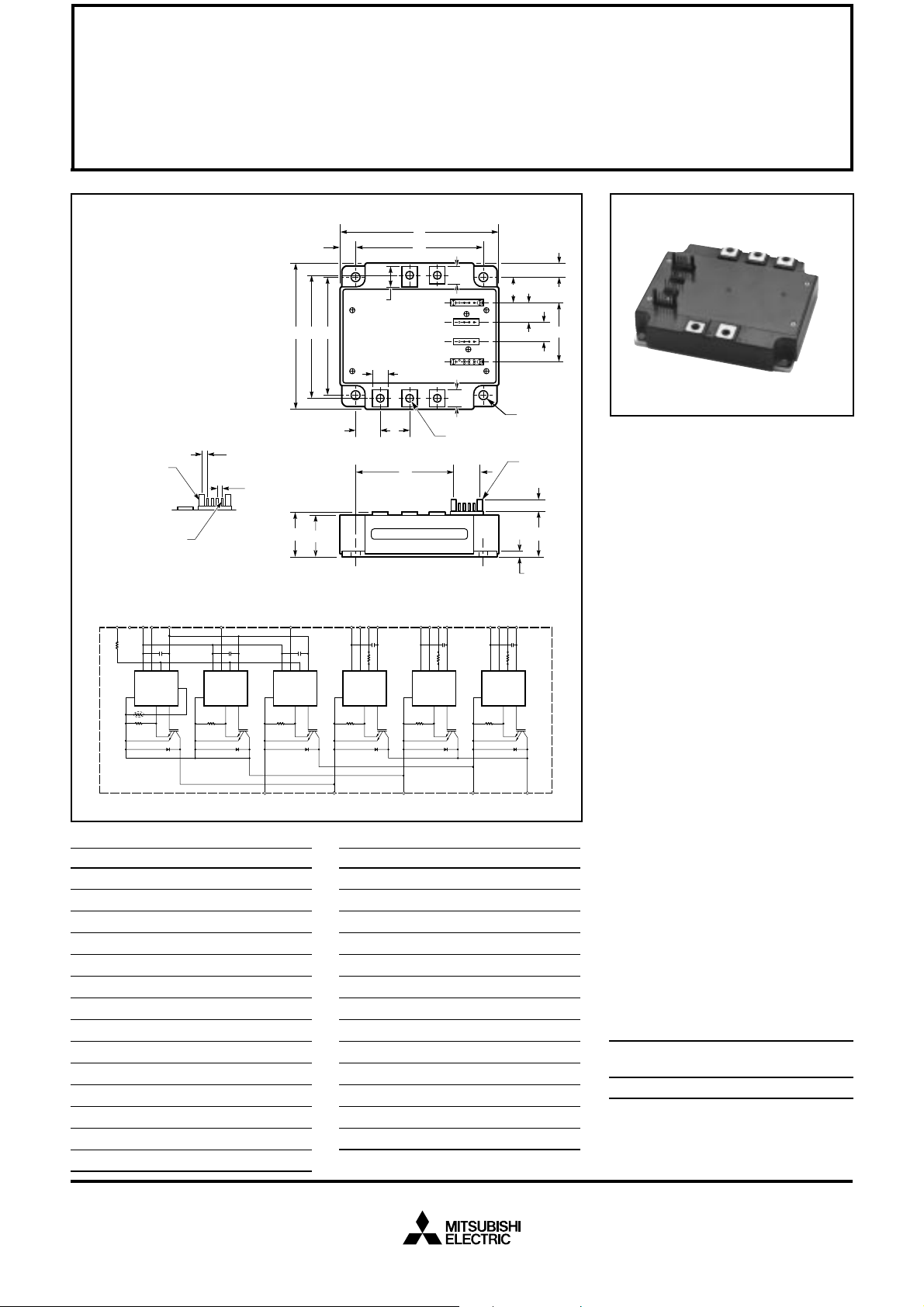
Outline Drawing and Circuit Diagram
Dimensions Inches Millimeters
A 4.72 120.0
B 4.02 102.0
C 0.95 +0.04/-0.02 24.1 +1.0/-0.5
D 4.13±0.010 105.0±0.25
E 3.43±0.010 87.0±0.25
F 0.16 4.0
G 0.95 24.1
H 0.42 10.6
J 0.87 22.0
K 3.51±0.02 89.2±0.5
L 0.47 12.0
M 0.48 12.3
N 0.77 19.5
P 0.30 7.5
B K E
C
UN
F
O
V
CC
IN
OUT
Si
UVW
N
Y
V
W
WPC
W
FO
P
F
O
GND
IN
GND
Si
Dimensions Inches Millimeters
Q 0.59 15.1
R 0.72 18.25
S M5 Metric M5
T 0.22 Dia. Dia. 5.5
U 0.56±0.010 14.1±0.25
V 1.72±0.012 43.57±0.3
W 0.57 ±0.012 14.6±0.3
X 3.35 85.2
Y 0.85 21.6
Z 0.10±0.010 2.54±0.25
AA 1.37±0.010 3.49±0.25
BB 0.02 SQ 0.64 SQ
CC
A
DP
NP
Q
L - TYP.
M
1234
5678
9101112
1314 1516
17 1819
M
J
TYP.
S NUTS (5 TYP.)
XW
OUT
V
V
GND
GND
V
VPC
V
FO
P
F
O
IN
OUT
Si
WP1
V
CC
V
V
UPC
VP1
V
CC
GND
GND
U
P
IN
0.12 +0.04/-0.02 3.0 +1.0/-0.5
R
V
U
UP1
FO
F
O
V
CC
OUT
Si
U
V
U
T (4 TYP.)
SEE
DETAIL A
H
G
F
P
Description:
Mitsubishi Intelligent Power Modules are isolated base modules designed for power switching applications operating at frequencies to
20kHz. Built-in control circuits provide optimum gate drive and protection for the IGBT and free-wheel
diode power devices.
Features:
u Complete Output Power
Circuit
u Gate Drive Circuit
u Protection Logic
– Short Circuit
– Over Temperature
– Under Voltage
Applications:
u Inverters
u UPS
u Motion/Servo Control
u Power Supplies
Ordering Information:
Example: Select the complete
part number from the table below
-i.e. PM150CVA060 is a 600V,
150 Ampere Intelligent Power Module.
Type Current Rating V
Amperes Volts (x 10)
PM 150 60
CES
Sep.1998

MITSUBISHI INTELLIGENT POWER MODULES
PM150CVA060
FLAT-BASE TYPE
INSULATED PACKAGE
Absolute Maximum Ratings, Tj = 25°C unless otherwise specified
Ratings Symbol PM150CVA060 Units
Power Device Junction Temperature T
Storage Temperature T
Case Operating Temperature T
Mounting Torque, M5 Mounting Screws — 2.5~3.5 N · m
Mounting Torque, M5 Main Terminal Screws — 2.5~3.5 N · m
Module Weight (Typical) — 730 Grams
Supply Voltage (Applied between P - N) V
Supply Voltage Protected by SC (VD = 13.5 ~16.5V, Inverter Part, Tj = 125°C Start) V
Isolation Voltage (Main Terminal to Baseplate, AC 1 min.) V
j
stg
C
CC(surge)
CC(prot.)
iso
Control Sector
Supply Voltage (Applied between V
Input Voltage (Applied between
Fault Output Supply Voltage (Applied between FO-VNC, *FO-V
Fault Output Current (Sink Current at UFO, VFO, WFO and FO Terminal) I
UP1-VUPC
UP-V
UPC
, VP-V
, V
VP1-VVPC
VPC
, WP-V
, V
WP1-VWPC
, UN · VN · WN-VNC)V
WPC
*PC
, VN1-VNC)V
)VFO20 Volts
D
CIN
FO
-20 to 150 °C
-40 to 125 °C
-20 to 100 °C
500 Volts
400 Volts
2500 Vrms
20 Volts
20 Volts
20 mA
IGBT Inverter Sector
Collector-Emitter Voltage (VD = 15V, V
Collector Current, (TC = 25°C) I
Peak Collector Current, (TC = 25°C) I
Collector Dissipation (TC = 25°C) P
= 15V) V
CIN
CES
C
CP
C
600 Volts
150 Amperes
300 Amperes
446 Watts
Sep.1998
 Loading...