

Mitsubishi PM100CSA120 Datasheet
MITSUBISHI INTELLIGENT POWER MODULES
PM100CSA120
FLAT-BASE TYPE
INSULATED PACKAGE
A
AC
B
W
3
4 5678 9 11
12
AE (15 TYP.)
W
W
W
12 14 1618
10
13 15 17 19
R
Y
AC
Y
Z
1.
V
UF
2.
V
3.
4.
V
V
5.
VF
6.
7.
VV
E
F
C
8.
V
9.
V
WF
10.
UPC
P
UPI
VPC
P
VPI
WPC
O
O
O
11.
W
WPI
V
12.
NC
V
13.
NI
V
14.
NC
15.
N
16.UU
17.
N
18.
W
19.
F
O
P
N
AA - DIA.
(4 TYP.)
Q
Q
AB - THD
J
(6 TYP.)
H
Y
T
N
BP
AH
AH
U
G
Z
AF
AG
P
N
NC
O
NC
F
GND GND
N
NI
VVW
V
CC
O
CC
O
F
F
IN
I
S
V
IN
V
TEMP
I
OUT
OUT
S
GND GND
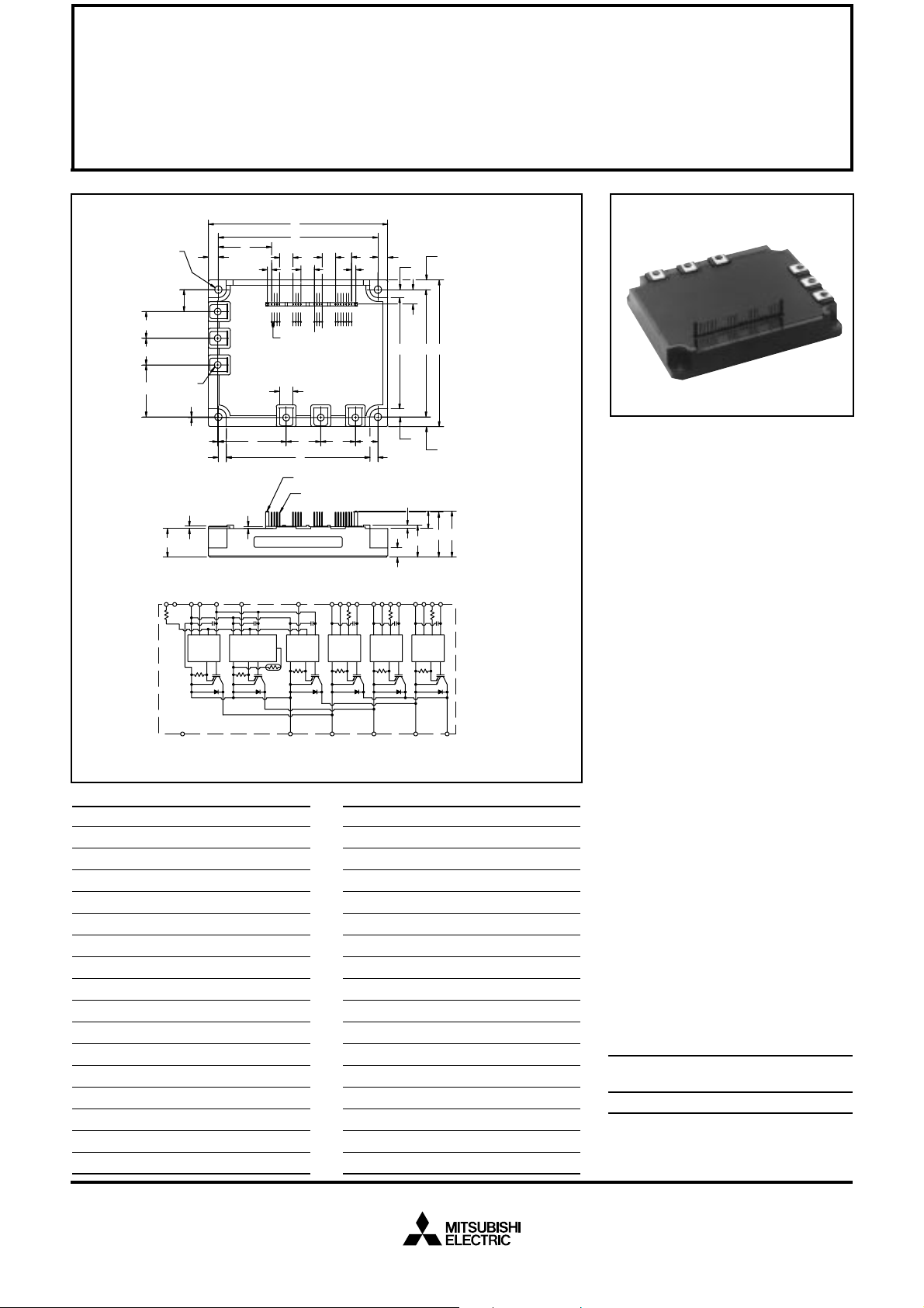
Outline Drawing and Circuit Diagram
Dimensions Inches Millimeters
A 5.31±0.04 135.0±1.0
B 4.74±0.02 120.5±0.5
C 4.33±0.04 110.0±1.0
D 4.27 108.5
E 3.76±0.02 95.5±0.5
F 3.29 83.5
G 2.01 51.0
H 1.602 40.68
J 1.54 39.0
K 1.37 34.7
L 1.33 33.7
M 1.02 26.0
N 0.95 +0.06/-0.0 24.1 +1.5/-0.0
P 0.84 21.3
Q 0.79 20.0
R 0.780 19.82
W
V
M M S
D
2.54 MM DIA. (2 TYP.)
0.5 MM SQ. PIN
(19 TYP.)
FO
WPI
WPC
N
V
W
WP
U
CC
O
CC
O
F
F
IN
I
S
GND GND
V
IN
V
I
OUT
OUT
S
GND GND
Dimensions Inches Millimeters
W 0.39 10.0
AA 0.22 Dia. Dia. 5.5
AD Metric M5 M5
AC 0.128 3.22
AD 0.10 2.6
AE 0.08 2.0
AF 0.07 1.8
AG 0.06 1.6
AH 0.02 0.5
Z
Z
Y
AD
U
X
VPC
VPI
V
VFOV
V
VP
CC
O
F
V
IN
I
OUT
S
GND GND
K
L
N
UPI
UPC
V
V
UFOUP
CC
V
FOIN
I
OUT
S
GND GND
PUVWNNC
S 0.69 17.5
T 0.65 16.5
U 0.52 13.2
V 0.43 11.0
X 0.31 8.0
Y 0.285 7.25
Z 0.24 6.0
Description:
Mitsubishi Intelligent Power Modules are isolated base modules designed for power switching applications operating at frequencies to
20kHz. Built-in control circuits provide optimum gate drive and protection for the IGBT and free-wheel
diode power devices.
Features:
u Complete Output Power
Circuit
u Gate Drive Circuit
u Protection Logic
– Short Circuit
– Over Current
– Over Temperature
– Under Voltage
Applications:
u Inverters
u UPS
u Motion/Servo Control
u Power Supplies
Ordering Information:
Example: Select the complete
part number from the table below
-i.e. PM100CSA120 is a 1200V,
100 Ampere Intelligent Power Module.
Type Current Rating V
Amperes Volts (x 10)
PM 100 120
CES
Sep.1998

MITSUBISHI INTELLIGENT POWER MODULES
PM100CSA120
FLAT-BASE TYPE
INSULATED PACKAGE
Absolute Maximum Ratings, Tj = 25°C unless otherwise specified
Ratings Symbol PM100CSA120 Units
Power Device Junction Temperature T
Storage T emperature T
Case Operating Temperature T
j
stg
C
Mounting Torque, M5 Mounting Screws — 1.47 ~ 1.96 N · m
Mounting Torque, M5 Main Terminal Screws — 1.47 ~ 1.96 N · m
Module Weight (Typical) — 920 Grams
Supply Voltage Protected by OC and SC (VD = 13.5 - 16.5V, Inverter Part, Tj = 125°C) V
Isolation Voltage (Main Terminal to Baseplate, AC 1 min.) V
CC(prot.)
iso
Control Sector
Supply Voltage (Applied between V
Input Voltage (Applied between UP-V
Fault Output Supply Voltage
UP1-VUPC
UPC
(Applied between UFO-V
Fault Output Current (Sink Current of UFO, VFO, WFO and FO T erminal) I
, VP-V
, V
VP1-VVPC
VPC
, WP-V
, VFO-V
UPC
, V
WP1-VWPC
, UN · VN · WN-VNC)V
WPC
VPC
, VN1-VNC)V
, WFO-V
WPC
, FO-VNC)
D
CIN
V
FO
FO
-20 to 150 °C
-40 to 125 °C
-20 to 100 °C
800 Volts
2500 Vrms
20 Volts
20 Volts
20 Volts
20 mA
IGBT Inverter Sector
Collector-Emitter Voltage (VD = 15V, V
Collector Current, (TC = 25°C) I
Peak Collector Current, (TC = 25°C) I
Supply Voltage (Applied between P - N) V
Supply Voltage, Surge (Applied between P - N) V
Collector Dissipation P
= 15V) V
CIN
CC(surge)
CES
C
CP
CC
C
1200 Volts
100 Amperes
200 Amperes
900 Volts
1000 Volts
595 Watts
Sep.1998
 Loading...