

Page 1
MITSUBISHI
advanced and
ever
advancingMITSUBISHI
ELECTRIC
Industrial
Sewing
INSTRUCTION
Electronic
PLK-A
Pattern
Series
Machine
MANUAL
Sewing
Machine
<Control
Unit>
A180E207P05
Page 2
Introduction
Thank you for purchasing
read
this manual thoroughly before
(Refer to
Referto
Head>
the
separate
the
"Mitsubishi Industrial Electronic
section
for
the
the
Mitsubishi Industrial Sewing Machine
use,toensure
instruction manual for
Sewing
entire
structure
Structure
and
of
the
sewing
This
long
and
safe
PLK-A
operations.
Series. Please
PLK-A05BT.)
Machine Instruction Manual < Machine
machine
Manual
head.
This manual describesthehandling methodsofthe Mitsubishi IndustrialElectronic Sewing
Machine control unit.
1.
Specifications
Describes
2.
Precautions
feature,
for
Read this section carefully together with
3.
Operation
Describes
and
advanced
the
instructionsfor preparation beforeturning on
The
basic
Operation
operation.
following
specification
are
described:
and
so
on.
the
specifications before starting operation.
the
power, basicoperation,
4.
Teaching
Method to complete the pattern data is described
based
on concrete examples
covering from the basis operating method to complicated applied operations.
It
is also explained here the methods to correct and delete the pattern data and the
method to write the completed
5.
Message
Table
data
on the floppy disk or
P-ROM.
Errors, etc. which are raised during operation ofsewing machine, are displayed on the
operation panel.
remedies.
6.
Maintenance
Describes a simple troubleshooting
It
is also explained here methods to
sewing
7.
Control
Describes
machine.
Unit
the
No part of this manual may be copied or transcribed without a
They
are designed to indicate the cause oftrouble and method of
and
repair work.
confirm
overall electric wiring diagram
the speed ofand to adjust the electronic
and
connector connection diagram.
written
permission of Mitsubishi Electric Corporation.
The contents of this manual may
Although
this manualwas
written
be
subject to
completely and
change
without notice.
carefully,ifyou
find
an error
or have a comment
COPYRIGHT©
MITSUBISHI
ELECTRIC
1993
about
the
CORPORATION
content of
the
manual,
please
inform
usofit.
Page 3
1.
Specifications
1.1
Features
1.2
Specifications
Contents
1
1
2
Precautions
2.
for
Operation
(1) Safety 3
(2) Operation environment 3
(3) Operation 3
(4) Power voltage 3
3.
Operation
3.1
Basic
Function
(1) Sewing
of
machine
Structural
Machine
control unit 4
(2) Floppy disk unit 4
(3) Applicable floppy disk 4
(4) P-ROM
cassette
(Option) 5
(5) Functions and operating method of operation panel 5 O
(6) Teaching section operation panel 7
3.2
Basic
Operation
(1) Before starting
(2) Power ON,
Method
the
home
operation 9
position return,
and
memory
check
(3) Setting operation panel 11
(4) Operation
(5) Raising/lowering
check
presser
foot
(6) Sewing operation 12
(7) Halt 12
(8) Resewing method 13
(9)
Erroneous
3.3
Advanced
(1) Electric correction of
(2) Up counter,
motion during sewing 13
Operation 13
home
position 14
down
counter
(3) Repeat sewing 15
(4) Releasing sewing
(5) Using two
step
area
limit
work holder 15
(6) Prohibiting automatic home position return operation 15
(7) Prohibitingthread trimming in halt state (switch) 15 ^
(8) Prohibiting work holder up operation in halt
state
(Input code) 15
(9) Adjusting fabric feed timing 15
(10) Sewing machine operation using free home position 16
(11) Adjusting sewing machine
the
(12) Changing
type of floppy disks 16
speed
(13) Prohibition of thread trimming motion 17
(14) Selection of
presser
weight 17
(15) 1 pedal specifications 17
(16) Selection of
(17) Pneumatic
(18) Selection of pneumatic
(19) Label
3.4
Dip Switch
thickness
pressure2stage
holder
Function
of sewing cloth 17
work holder 18
pressure
Table
switch 18
3
4
4
9
9
12
12
14
15
16
18
18
4.
Teaching
4.1
Basic
Function
(1) Pattern input
(2) Modification
(3) Write
mode
mode
mode
-1
-
19
19
19
19
19
Page 4
(4) Delete
(5) Function
(6) Communication
4.2
Pattern
(1) How to enter
mode
mode
mode
Input Mode 20
the
pattern input mode 20
(2) Normal input method 21
1) Setting of input method 21
2) Point input (To input pattem by stitch) 21
3) Linear Input (For inputting a pattern with many linear lines) 22
4) Arc input (To inputanarc) 23
5) Circular input (To input a circle) 24
6) Curve input (To input a free curve) 25
7) Broken line input (To input a pattern with many lines) 27
Code
data
8)
(3) 1 stitch
(4)
Save
input method (To input
deletion
and
function
recall function 29
code
data) 28
(5) Special input function 29
1) Overlap stitching (The
2) Inverted overlap stitching (The
to reinforce
the
same
stitch is
same
stitch) 31
sewed
stitch is
twice to reinforce
sewed
twice from
the
stitch)
the
reverse direction
3) Parallel stitching (To stitch in parallel) 32
4) Offset stitching (To stitch inside of label, etc.)
5) Zigzag stitching (To stitch a zigzag pattern) 35
6) Back tacking 1
(To eliminate thread from coming
7) Back tacking 2 (To eliminate
end
of stitching with overlapstitching)
thread
undone
at start
from coming
and
end
of stitching)
undoneatstart
and
8) Precautions for special input function 41
(6) Conversion input function 41
1) Mirror form 41
2) Rotation (To rotate to match
4.3
Modification
(1) Main functions of modification
(2) How to
Mode
enter
modification
(3) Block modification 1 (To modify a
(4) Block modification 2 (To modify a
(5)
Feed
(6) Delete
(7) Delete all
(8)
One
(9)
Same
(10) Stitching
(To
(11) Stitching
(To
(12)
Code
(13)
Code
4.4
Write
modification (To
one
stitch (Delete
stitches
stitch addition (Add
stitch addition (Add
speed
change
the
speed
change
Mode
data
data
the
delete
addition (To
change
(Delete all
modification 1
stitching
modification 2
stitching
(To
delete
one
one
speed
speed
addtothe
the
mode
pattern to
mode
set
set
the
start point of
rangeofthe
range of
the
work holder) 42
input pattern with break line) 43
the
input pattern with curve)
the
input pattern data) 46
stitch from input pattern) 46
stitches
after specified stitch from input pattern)
stitch of desired stitch length to input pattern)
same
stitch to input pattern) 48
for all stitches after specified stitch in pattern) . 49
for Nstitches after specified stitch in pattern) 50
the
input
code
data)
input
code
data) 51
(1) Media writable 53
4.5
4.6
(2) Write
(3) Write
(4) Write
Delete
Function
method
method
method
Mode
Mode
1 (When specifying
2 (When not specifying
3 (To write in
pattern
home
position compensation) 55
number) 53
pattern
number) 54
(1) Floppy disk format 56
...
...
...
19
19
19
29
29
34
37
39
42
42
43
44
..
47
..
48
51
53
56
56
- II -
Page 5
(2)
Thread
(3) Alternate stitching 58
5.
Message
6.
Maintenance
6.1
6.2
6.3 Troubleshooting
7. Control
7.1
7.2
7.3
Table
(1)
Messages
(2)
Messages
Sewing
(1) Filter 62
(2) Sewing
(3) Replacing brake lining 62
Floppy
(1) Check of input switch signal 63
(2)
Checkofoutput
(3) Confirmation
Unit
Unit
Wiring
Connecting
Connecting
trimming prohibit 57
in sewing operation 60
in teaching operation 61
Machine Drive Motor
machine
Disk Unit
drive motor (Z motor) 62
and
Repair 62
signals 64
and
adjustment of sewing
speed
Appendix
Diagram
Diagram
Diagram
ofConnector Pins
ofEach Connector
Appendix
Appendix
Appendix
60
62
62
62
66
1—4
5-^ 8
9~25
III -
Page 6
1.
Specifications
1.1
Features
The
PLK-A
Machine which won popularity provides
(1)
Pattern
series machine which Is a
storage
media
successorofthe
much
more
features
Mitsubishi Industrial Electronic Sewing
than
that.
As pattern
P-ROM
data
(P-ROMIsan
(2)
Storage
capacity
Each floppy disk
P-ROM
The
of stitches
(3)
Stitch
The
(4)
Machine
The
machinedrive motor Iscontrolledwith
stable
(5)
Teaching
The
Input. In addition,
The
(6) Modification
The
diskorP-ROM.
per
length
stitch length
drive
rotations
machine control box provides a teaching function which allows simple
data
being
pattern
storage
media, both a floppy disk
which
was
prepared by
and
P-ROM
the
conventional model
optional specifications.)
can
store
can
store
150 patterns
16 patterns
and
and
360000 stitches of sewing
8000 stitches of sewing
pattern Is up to 8000.
and
resolution
canbeInput with a resolution from 0.1 to 12.7 mm In
motor
data
control
of
the
machine.
patterns
Input
canbemodified. After
accordingtothe
canbestoredonthe
PWM
(pulsewidth modulation) system, therebyobtaining
work holder
floppy disk or P-ROM.
the
pattern
data
Is modified. It
canbeused.
canbeused
without correction.
data
data
Intotal.
The
the
canbeeasily Input.
canbestoredonthe
Intotal.
maximum number
unit of 0.1 mm.
patternstobe
easily
floppy
(7)
Correctionofhome
By
the
home
position correcting operation on
mechanically moved In
(8) LCD (Liquid Crystal)
LCD
display Is provided on
Is
designedtoIndicate various
position
the
range from 0.1 to 12.7 mm In
display
the
operation panel for convenience of operation control.
setting
values,
the
operation panel,
operation
the
unit of 0.1 mm.
procedures,
the
error
home
position
messages,
The
etc.
can
be
display
1 -
Page 7
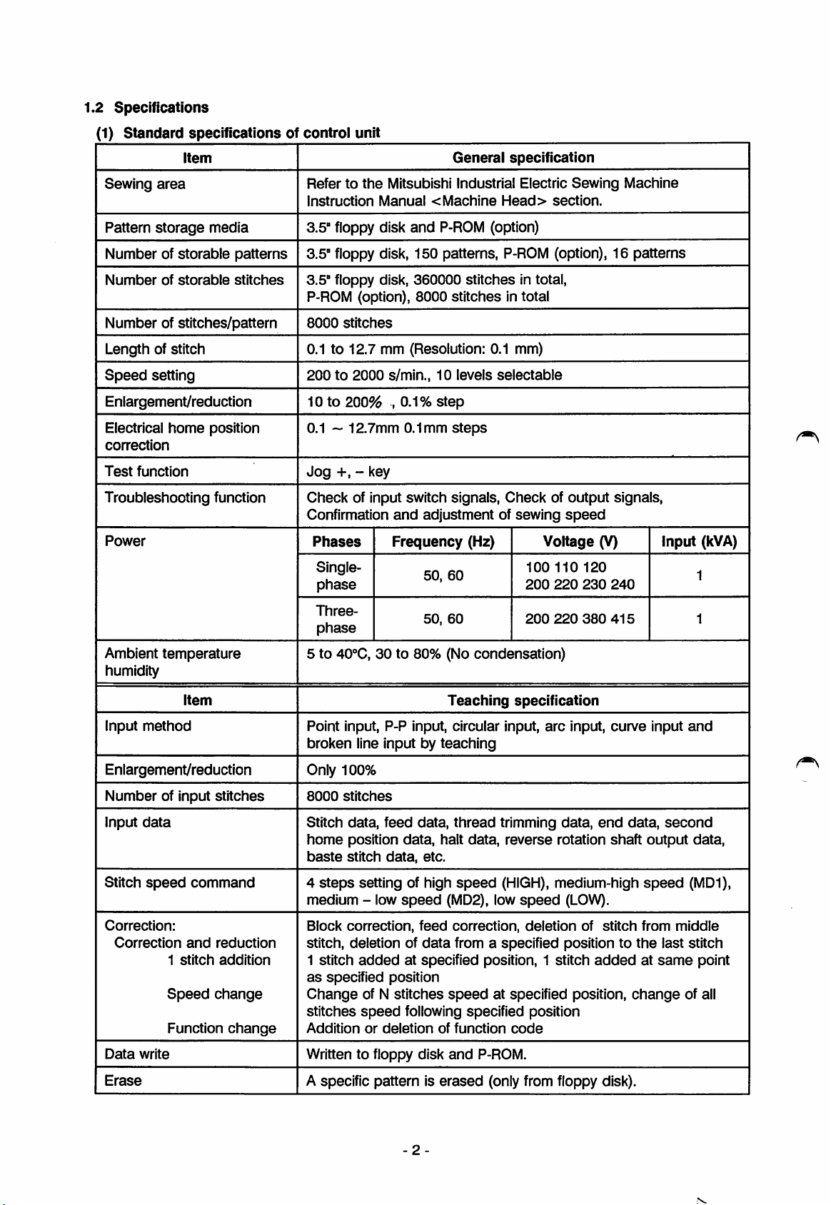
1.2
Specifications
(1)
Standard
specificationsofcontrol
unit
Item
Sewing
Pattern
Numberofstorable
Number
area
storage
of
storable
media
patterns
stitches
Number of stitches/pattern
Refertothe
Instruction
3.5" floppy disk
Mitsubishi Industrial Electric
Manual<Machine
and
3.5"floppy disk, 150 patterns,
3.5" floppy disk,
P-ROM (option), 8000
8000
stitches
P-ROM
360000
General
stitches
stitches
specification
Head>
(option)
P-ROM
in total,
in total
Length of stitch 0.1 to 12.7 mm (Resolution: 0.1 mm)
Speed
Enlargement/reduction 10 to
Electrical
correction
Test
Troubleshooting function
Power
setting
function
home
position
200to2000
200%
0.1 ~
12.7mm
Jog
-H,
- key
Check
of input switch signals.
Confirmation
Phases
Singlephase
s/min.,10levels
,0.1%
and
Frequency
step
0.1mm
steps
adjustmentofsewing
(Hz)
50,
60
selectable
Checkofoutput
100 110
200
Sewing
section.
Machine
(option), 16 patterns
signals,
speed
Voltage
220
120
230
(V)
240
Input
(kVA)
1
Three-
phase
Ambient temperature
5 to
40"'C,
humidity
Item
Input
method
Point input, P-P input, circular input,
broken
line input by
Enlargement/reduction Only 100%
Number
Input
Stitch
of input
data
speed
stitches
command
8000
stitches
Stitch data,
home
position
baste
stitch
4
steps
setting of high
medium - low
Correction:
Correction
and
1
stitch
Speed
Function
reduction
addition
change
change
Block
correction,
stitch, deletion of
1 stitch
as
Change
stitches
Addition
addedatspecified position, 1 stitch
specified
of N
speed
or
50,
60
200
30 to 80% (No condensation)
Teaching
specification
arc
teaching
feed
data,
data,
speed
data,
feed
data
thread
halt
etc.
speed
(MD2),
correction,
from a specified position to
data,
trimming
reverse
(HIGH),
low
speed
deletion
position
stitches
speed
at specified position,
following specified position
deletion
of
function
code
220
380
415
input,
curve
data,
end
rotation
shaft
medium-high
(LOW).
of
stitch
addedatsame
input
data,
output
speed
from
the
change
1
and
second
data,
(MD1),
middle
last stitch
point
of all
Data
write
Erase
Written to floppy disk
A specific pattern is
-2-
and
erased
P-ROM.
(only from floppy disk).
Page 8
2.
Precautions
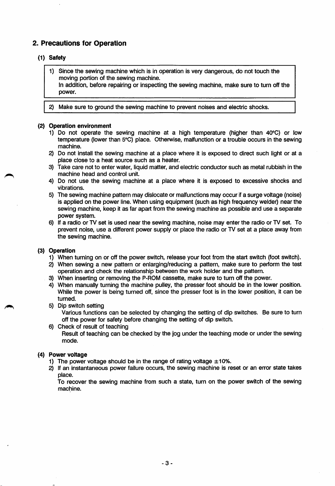
(1)
Safety
for
Operation
1) Since
2) Make
(2)
Operation
1) Do not operate
2) Do not install
3) Take
4) Do not
the
sewing machine which is in operation is very dangerous, do not touch
moving portion of
the
sewing machine.
in addition, before repairing or inspecting
power.
suretoground
the
sewing machine to prevent
environment
the
sewing machine at a high temperature (higher than 40''C) or low
temperature
machine.
place
close
care
machine
vibrations.
head
use
(lower
to a
not to
the
than
5°C) place. Otherwise, malfunction or a trouble
the
sewing machine at a place where it is
heat
enter
and
source
water, liquid matter,
control
suchasa heater.
unit.
sewing machine at a place where it is
the
sewing machine,
and
electric conductor
5) The sewing machine pattern may dislocate or malfunctions may
is
appliedonthe
sewing
power
6) Ifa
radioorTV
prevent noise,
the
sewing
machine,
system.
power
keepitas
setisused
use
machine.
line.
When
far
apart
near
the
a different power
using
equipment
from
the
sewing
sewing
machine,
supplyorplace
the
make
suretoturn off
noises
and
electric
shocks.
occursinthe
exposed
to direct
such
light or at a
suchasmetal rubbish in
exposed
to excessive
occurIfa
surge
voltage (noise)
shocks
(suchashigh frequency welder)
machineaspossible
noise
may
enter
the
radio or TV
set
the
at a
and
radio
place
useaseparate
or TV
the
sewing
near
set.
away
the
and
the
To
from
(3)
Operation
1) When turning on or offthe power switch, release your foot from the start switch (footswitch).
When sewing a new pattern or enlarging/reducing a pattern, make
2)
operation
When inserting or removing
3)
When manually turning
4)
While
the
turned.
Dip switch
5)
Various functions
off
the
power for safety before changing
6)
Check
of result of
Result of teaching
mode.
(4)
Power
1)
The
voltage
power
2) Ifaninstantaneous
place.
To recover the sewing machine from
machine.
and
check
the
power is being
setting
canbeselectedbychanging
teaching
canbecheckedbythe
voltage
shouldbein
power failure occurs,
relationship
the
P-ROM
the
machine pulley,
turned
off,
the
between
cassette,
the
since
the
the
jog
range
of rating voltage
the
such
a state, turn on
the
work
holder
make
sure
to turn off
presser
presser
the
foot
shouldbein
foot is in
settingofdip
setting of dip switch.
under
the
teaching mode or under
±10%.
sewing
machineisresetoran
the
sure
to perform
and
the
pattern.
the
the
the
lower position, it
switches. Be
power switch of
power.
lower position.
sure
the
error
state
the
the
test
can
to turn
sewing
takes
sewing
be
-3
Page 9
3.
Operation
3.1
Basic
FunctionofStructural
Machine
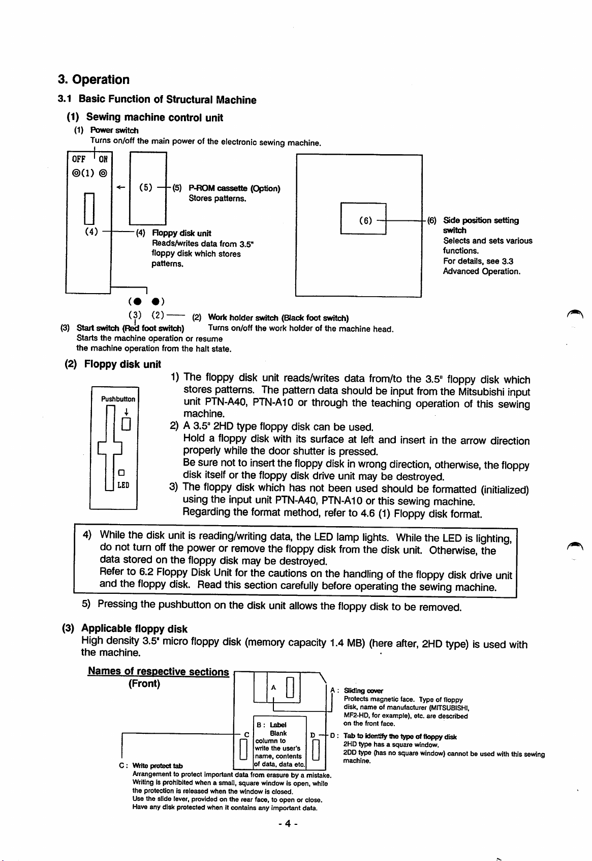
(1) Sewing
(1) Power switch
Turns
®(1)
®
machine
on/off
the
(5)
control unit
main
power
(5)
ofthe
electronic
P-ROM
cassette
Stores patterns.
sewinQ
(Option)
machine.
D
(4)
Roppy
disk unit
Reads/writes
floppy disk which
patterns.
• )
(3) (2)
(3)
Start switch(Redfoot switch) Turnson/offthe workholder of the machine head.
Starts the machine operation or
the
machine operation from
(2) Floppy
disk
unit
1)
Pushbutton
4
2) A
3)
C
•
H
•
LED
-
data
from
3.5"
stores
(2)
Work
holder
smtch
(Black
foot
switch)
resume
the
halt state.
The
floppy
stores
unit
PTN-A40,
machine.
3.5"
Hold a floppy disk with its surface at left
properly whilethe door shutter is pressed.
Be
sure
disk
itself
The
floppy
using
Regarding
disk
patterns.
2HD
type
nottoinsert
or the
disk
the
input
the
unit
reads/writes
The
pattern
data
PTN-A10orthrough
floppy
floppy
which
unit
format
disk can be used.
the
floppy
disk
has
PTN-A40,
method,
diskinwrong
drive
not
been
PTN-AI0
refer
data
shouldbeinput
the
unit
to 4.6
(6)
from/to
the
3.5"
from
teaching
and
operationofthis
insert in the arrow direction
direction,
maybe destroyed.
used
shouldbeformatted
orthis
(1)
sewing
Floppy
disk
Side
position setting
switch
Selects
and
functions.
For
details,
Advanced Operation.
floppy
the
otherwise,
sets
see
disk
Mitsubishi
the
(initialized)
machine.
format.
various
3.3
which
input
sewing
floppy
4)
While
the
disk
unitisreading/writing
do
not
turn
off
the
data stored on the
Referto6.2
and
the
5)
Pressing
(3) Applicable floppy disk
High
density
the
machine.
Names
of
C:
Floppy
floppy
respective
(Front)
Vtfirite
Arrangement
Writingisprohibited
the
Usethe slide lever,providedon the rear face, to open or close.
Haveany disk protected when it contains any important data.
disk.
the
pushbutton
3.5"
micro
protect
tab
to protect
protectionisreleased
powerorremove
floppy
sections
disk may be destroyed.
Disk
Unit
for
the
Read
this
section
onthe
floppy
important
whena small,square
when
disk
disk
(memory
B :
column
write
name,
D
of
data fromerasure bya
the
windowisclosed.
data,
the
LED
the
floppy
disk
cautionsonthe
carefully
unit
allows
capacity
Label
Blank
the
contents
data,
window
to
data
-4
user's
etc.
is open,
D - D
D
mistake.
while
lamp
from
lights.
the
disk
While
unit.
handlingofthe
before
the
\
operating
floppy
1.4
JA:Sitding
disk
MB)
(here
cover
Protects magnetic face. Typeoffloppy
disk, name of manufacturer
MF2-HD,for example), etc. are
on
the
front
Tab to identifythe type of floppy disk
2HDtype has a square window.
2DD
type
machine.
the
to be
after,
face.
(hasnosquare
the
LEDislighting,
Otherwise,
floppy
sewing
disk
machine.
removed.
2HD
type)isused
(MITSUBISHI,
described
window)
cannot
the
drive
beused
unit
with
with
this
sewing
Page 10
(4) P-ROM
Refer to
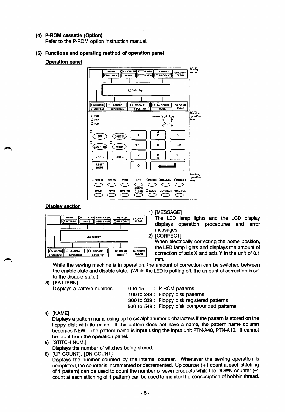
(5)
Functions
cassette
the
(Option)
P-ROM option instruction manual.
and
operating
methodofoperation
panel
Operation
oanel
SPEED
IOpattern I 1
o]
i
|Omessage|
OCORRECT
ORUN
Odisk
Orom
Open
10
(COUNTEm(WIND
RESET
HOME
in
speed
c:>
<o>
P/P-P
FEED
C3
O
Dsutchlen
X^SCALE
x.posrnoN
o
RETURN
C3
STITCH
NUM.
IstuchhumJ
NAME
1
LCD
display
1
|0
r^SCALE1|0ONCOUNT
Y-THTSniON
•<4
trim
END OWRITE ODELETE QMODIFY
srrrcH
CLEAR
SPEED
05
^
OCODE
|Oupcount|
O
METHOD
CODE
O' *9
CORRECT
CD
UP
CLEAR
ON
1
CLEAR
CO
FUNCTIO
CO
COUNT
COUNT
Display
soetion
Machine
opofalion
keys
Teaching
operation
keys
Display
section
1) [MESSAGE]
SPEED
Dstitch
LEN
STITCH
NUM.
|Omessage{
OCORRECT
While
the
to
[PATTERN]
3)
Displays a
[NAME]
4)
|0
PATTERN
1
10
X'^CALE
x-posmoN
the
sewing machine is in operation,
enable
the
disable state.)
1
NAME1jsTITCH
LCD
1
state
and
pattern
METHOD
NUmJ
10UPCOUNT
display
Y-POSmON
|0DNCOUNT
CODE
disable state. (While
number.
UP
COUNT
CLEAR
1
1 DN
COUNT
CLEAR
Oto
15
ICQto249
300to339
500
to
549
The
LED lamp lights
displays
messages.
2) [GORRECT]
When
the
correction
mm.
the
the
LEDis putting off,
electrically
LED lamp lights
amount
P-ROM
Floppy disk
Floppy
Floppy disk
operation
correcting
of
axisXand
of correction
the
patterns
patterns
disk
registered
compounded
and
the
procedures
the
home
and
displays
axisYin
canbeswitched
amount
of correction is
patterns
patterns
LCD display
and
the
amount
the
unitof0.1
Displays a pattern name using up to sixalphanumericcharactersifthe pattern isstored onthe
floppy
becomes
be
[STITCH
5)
Displays
[UP COUNT], [DN COUNT]
6)
disk
NEW.
input from
NUM.]
the
with
its name.Ifthe pattern does not have a name, the pattem name column
The pattern name is input using
the
operation panel.
numberofstitches
being
stored.
the
input unit
PTN-A40,
PTN-A10.
Displays the number counted by the internal counter. Whenever the sewing operation is
completed,the counter is incremented or decremented. Upcounter (+1 count at each stitching
of1 pattern) can be used to count the numberofsewn products
count at each stitchingof1 pattern)can be used to
monitor
while
the
DOWN
counter
the consumptionofbobbinthread.
error
position,
of
between
set
Itcannot
(-1
-5-
Page 11
7)
[X-SCALE],
Displays
of 0.1%. The enlargement/reduction can be performed independentiy on axis Xor axis
8)
[UP
COUNT
Resets the counting of the up/down counter to the
of
theupcounter
[Y-SCALE]
the
ratio of eniargement/reduction of a pattern in
CLEAR],
[DN
is "0000").
COUNT
CLEAR]
keys
the
initiai
setting vaiue (the
range
from 10 to 200% in
initiai
the
unit
Y.
setting vaiue
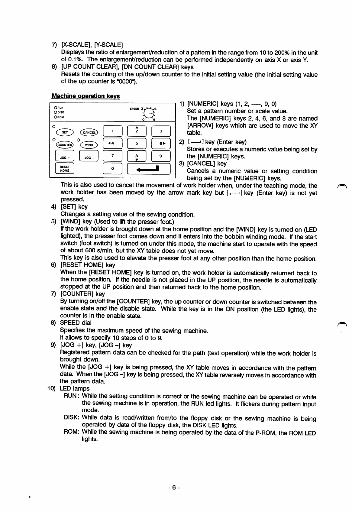
Machine
OnuN
Odisk
Orom
COUN^)
4)
5)
6)
7)
8)
9)
While
operation
- -
(^CANC^
(^WINl^
RESET
HOME
Thisis aiso used to cancel the movement of
work
hoider has been moved by the arrow mark key but
pressed.
[SET] key
Changes a setting value ofthe sewing condition.
[WiND]
if
lighted),
switch
of about 600 s/min. but
This
[RESET HOME] key
Whenthe
the home
stopped at the
[COUNTER] key
Bytuming on/offthe
enable state and the disable state.
counter
SPEED
Specifiesthe
Itallows to specify 10
[JOG +] key, [JOG
the
work
key
key (Used to
the presser foot comes downand itenters intothe bobbin
(foot
is aiso used to elevate the presser
[RESET
position.Ifthe needle is not piaced inthe
isinthe
diai
kevs
SPEED
lift
the presser foot.)
holder is brought
switch)
isturned on underthis
theXYtable
HOME]
UP
positionand then returned back to the home position.
[COUNTER]
enabie
maximum
state.
speed ofthe sewing machine.
steps
-]
key
1)
I]
3.>-k.6
u
[NUMERiC]
Setapattern
The
[NUMERIC]
[ARROW] keys which
[
table.
-j ] key (Enter key)
2)
[-
Storesorexecutes
the
[NUMERIC] keys.
3)
[CANCEL]
Cancels a numeric vaiue or setting condition
being
work
holderwhen, under the teaching mode, the
keys (1. 2,
numberorscale
key
setbythe
keys 2. 4, 6,
a numericvalue
[NUMERIC] keys.
[.—>]
down
atthe home
does
key is turned on,the
key,the up counter or down counter is switched between the
While
of 0 to 9.
position
mode,
not yet move.
foot
at anyother
work
and the
the machine start to operate
holder is automatically returned back to
UP
the key is in the
position
position,
ON
[WIND]
the needie is
position (the
Registered pattern data can be checked for the path (test operation)
brought
down.
the
[JOG+]keyisbeing
pressed,
theXYtabie
movesinaccordance
—,
9, 0)
value.
and8are
are
usedtomove
key (Enter
key
istumed on
winding
mode.Ifthe start
than the home
whiie
the
data. Whenthe [JOG-] keyisbeing pressed, theXYtable reversely moves inaccordance
the
10)
LED
RUN:
DiSK:
ROM:
pattern
lamps
data.
While
the setting
the
sewing
mode.
While
operated by data of the fioppy disk, the
While
iights.
data is
the sewing machine is being operated bythe data ofthe
condition
machineisin
read/written
iscorrectorthe
operation,
from/to
the
the
sewing
RUN
fioppy
DiSK
led
disk
LED
machinecan be operated or
lights,itfiickers
or the
lights.
sewing
during
machineisbeing
P-ROM,
being
key)
is not yet
with
the speed
position.
automatically
LED
lights),
work
hoideris
with
the
pattern
the
ROM
named
the
XY
set
by
(LED
the
pattern
with
while
input
LED
6-
Page 12
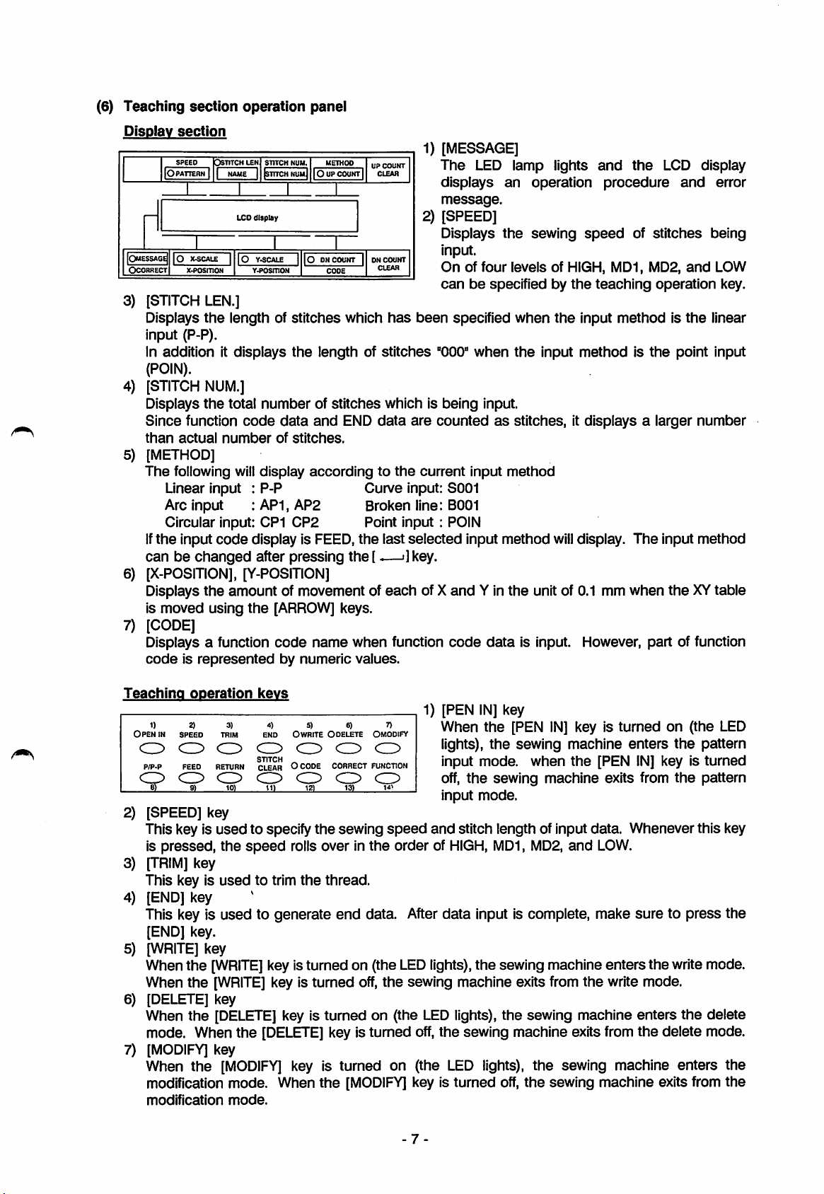
(6)
Teaching
section
operation
panel
Disoiav
IOmessag^
OCORRECT
3)
section
SPEED
|0
PATTERN
10
x.posmoN
[STITCH
Displays
DSTITCHLEN
1
1
X.SCALE
LEN.]
the
STITCH
NAME1tSTTTCH
LCD dfsptey
1
10
Y.SCALE
Y4>osrnoH
length of
NUM.
METHOD
NUmJ
10UPCOUNT
1
joONCOUNT
CODE
stitches
1
1
which
UP
DN
CLEAR
CLEAR
input (P-P).
In addition it
displays
the
length of
stitches
(POIN).
4)
[STITCH
Displays
Since
than
5)
[METHOD]
The
NUM.]
the
total
function
actual
following will
code
number
numberofstitches
data
and
END
of
stitches.
display
accordingtothe
data
Linear input : P-P Curve input: S001
Arc input : AP1, AP2 Broken line: 8001
Circular input: CP1
If
the
input
code
canbechanged
CP2
display is FEED,
after pressing
Point input : POIN
the
the[
-—i]key.
6) [X-POSITION], [Y-POSITION]
Displays
is
moved
the
amount of movement of
using
the
[ARROW]
keys.
7) [CODE]
Displays a function
codeisrepresented
code
by
name
numeric
when
values.
1) [MESSAGE]
COUNT
2) [SPEED]
COUNT
has
been
which is
are
current
last
selected
each
of X
function
The
LED lamp lights
displays
message.
Displays
an
the
operation
sewing
and
procedure
speed
the
LCD display
of
stitches
and
error
being
input.
Onoffour
canbespecifiedbythe
specified
"000"
being
when
input.
levels
of HIGH, MD1, MD2,
when
the
input
the
input
methodisthe
teaching
methodisthe
and
operation
point input
LOW
key.
linear
countedasstitches, it displays a larger number
input
method
input method
and
Y in
code
data
the
will
display.
unit of 0.1 mm when
The
input method
theXYtable
is input. However, part of function
Teaching
1)
Open
in
CO
PIP-P
CO
[SPEED] key
2)
This key is
is pressed,
[TRIM]
3)
This key is
[END] key
4)
This key is
[END] key.
[WRITE]
5)
Whenthe
When
[DELETE] key
6)
When the
mode. When
[MODIFY]
7)
When
modification
modification
operation
2)
SPEED
CO
FEED
CO
91
key
the
the
3)
TRIM
CO
RETURN
CO
10)
used
the
speed
used
used
key
[WRITE]
[WRITE]
[DELETE]
the
key
[MODIFY]
mode,
mode.
kevs
4)
0 WRITE O DELETE
CO
OCODE
CO
11)
5) 6)
CO CO
CORRECT
CO
12)
the
13)
sewing
END
CO
STITCH
CLEAR
to specify
rolls over in
to trim
to generate
the
thread.
end
key isturned on (the
key is turned
key is turned on (the
[DELETE]
key is turned
key is turned on (the
When
the
[MODIFY]
7)
Omodify
FUNCTION
CO
speed
the
order of
data. After
LED
off,
the
sewing machine exits from
key is
1) [PEN
and
IN]
key
When
lights),
input
off,
input
mode,
the
mode.
the
the
sewing
[PEN
sewing
when
IN]
key is
machine
the
machine
turned
enters
on
the
[PEN IN] key is
exits from
the
(the LED
stitch length of input data. Whenever this key
HIGH,
data
MD1,
MD2,
and
LOW.
input is complete, make
suretopress
pattern
turned
pattern
lights),the sewing machine entersthe writemode.
the
write mode.
LED
lights), the sewing machine enters
off,
the
sewing machine exits from
LED
lights), the sewing machine enters the
turned
off,
the
sewing machine exits from
the
the
delete mode.
the
delete
the
-7
Page 13
8) IP/P-P] key
The linear input (P-P), point input
(S001),
9) [FEED] key
This key is
10) [RETURN] key
When this key is
(which is
in
11)
[STITCH
This key is
mode.
12) [CODE] key
By turning on
home position data, halt data, or reverse rotation shaft data, etc.
allows
13) [CORRECT] key
When
position
and
used
the
data
being input, feed
CLEAR]
used
datatobe
the
[CORRECT] key is turned on (the
canbeset. After
break iine input (B001)
to input
pressed,
input start point) is automaticaiiy generated, if
key
to clear
the
sent/received
feed
feed
data
the
[CODE] key (the LED lights)
the
(POiN),
data.
data
until
the
number of stitches inthe pattern input mode or
to/from
correction, while
circuiar input (C P1), arc input (A P1), curve input
can
be selected with
from
the
point which is iast input to
second
the
home
input unit.
LED
the
and
lights),
[CORRECT] key is being
the
thereissecond
position is automaticaiiy
operating
the
lights),the amount of correction ofthe home position is enabled; while
being
14)
[FUNCTION]
0Ifthe
0
turned
position, various functions
During
off (the LED
key
[FUNCTION]
puts
key
isturned on
ofO,
the
amount
while
suchasthe
the
format of floppy disk, etc.
teaching, thisisusedto selectthespecial
of correction is disabled.
working
holder stays at the mechanical home
input
functionorconversion
[PEN
IN]
key.
the
home
home
position
generated.
the
modification
the
[NUMERIC]
canbeinput. This key also
amount of correction of
the
canbeoperated.
keys,
turned
on (the
[CORRECT]
input
position
data
second
the
home
LED
key is
function.
With
the keys which can be turned on or off
lighted when
the
key is
turned
on while
Note
LED
([PEN
goes
IN]
key, for example),
off if
the
key is turned off.
LED
is
8 -
Page 14
3.2
Basic
Operation
Method
Before
(1)
The
control flow after
The
various operation
stoppedatthe
The
basic
starting
Indicates
Indicates
which
Set
Turn
The
The
The back up memory is
(If
The setting conditions
the
operation
the
power switch is
modes
needle
UP position.
flow of control after
the
steps
the
steps, which
the
No., etc. is
the
floppy
on
the
power
diskorP-ROM
copyright notice
automatic
home
canbeselected
the
power
controlled by
checkedbythe
switch.
appears.
position return
checked
the
memory is not faulty.) is faulty.) on
are
checked
turned
switch is
the
are
automatically
cassette.
ON isasshowninthe
with
the
control unit
turned
Note
ON is
operator.
judged
operatorbymeans
operation
..
takes
(If
the
memory The results
(To
change
shown
and
place.
the
appendix
when
the
below.
executed, or
of LCD display.
the
Change
sewing machine is
setting conditions) conditions.
(Tooperate the sewing machine without changing the setting conditions)
The
sewing
Turn on
Turn
on
Check
Turn
on
Turn
on
Turn
on
machineisreadytooperate.
the
the
the
the
the
the
fRESET
work
operation
fRESET
work
start
HCME1
holder
of
HCME1
holder
switch.
switch.
the
switch.
sewino
key (home position return).
machine
key.
usinc
the
fJCG
+1
key
and
The sewing machine automatically works.
Is
the
machine operating with normal revolution?
(Yes)
Is it normal
the
detector
of sewing
(Yes)
Halt
switch
(located on
the
machine head)
machine?
...
(No)
(No)
(CN) Halt
Message
and
the
Message
and
the
(OFF)
Automatic
Automatic
End
sewing
home
completes.
position return
chart.
the
steps
are
displayed
LCD
display.
the
setting
fJCG-1key.
is displayed
machine
is displayed
machine
of
stops.
stops.
(2) Power ON,
1) Turn on
Check
cassette)
pattern
power
If
P-RCM
thatofthe
2)
Copyright
After
message
represents that
machine
Corporation.
both
home
the
that
the
which
has
switch.
the
media
cassette
position return,
power
medium (floppy disk or P-RCM
stores
been
set
and
have
been
has
a higher
the
desired
then
set,
precedence
and
turn on
the
memory
dataofthe
floppy disk.
notice
the
power is turned on,
appears
appears
on
the
software of
the
the
LCD
display. It
the
is a property of Mitsubishi Electric
sewing
the
than
following
sewing
check
The
following
(caseofPLK-A1710)
COPYRIGHT
PLK-A1710
MITSUBISHI
CORPORATION
Each
intervalofabout1second.
End
Note:
No.ofsoftware
at
(C)
1993
VER.».«
ELECTRIC
display is
the
position marked with *.
message
appears,
incremented
versionisindicated
with
an
Page 15
3) Home positioning
Using
the
dip switch SW 3-4,
in
the
OFF positionatfactory.
OFF position: While
the
sewing machine
position return operation.
ON position : Prohibits
In
accordance
operate
return
The
following
PRESS FOOT SW
®
Turn
on
the
work
♦
The
following
rvfy
PUSH RESET SW
the
following operation is performed. This switch
the
needle is in
home
position return operation. While
the
automatic
the
sewing machine using
stops
with
the
UP position,
the
home
the
message
needle in
operation.
message
message
holder
appears.
switch.
appears.
the
sewing machine automatically performs
the
the
UP position
needle
is not in
and
position return operation.
which
appears
the
switches to perform
on
has
been
the
UP position,
then
perform
the
LCD display, manually
the
home
placed
the
home
position
the
® Turnonthe
-
End
4)
Check
the
The control unit
(for
about
home
position return
When
the
The
(No
The
RESEniNG /
Turn
Pattern Pattern Stitch Up
number
t**
XI00.OX
X-scale
memory
one
week). The control unit automatically
pattern
memory is
pattern
following
TEACHING
on
the
name
******
0000
YIOO.OX
Y-scale
[RESET HOME! key (return to
stores
each
setting condition of
operation.
data
are
not
saved
in memory,
checked.
data
in memory)
message
fSETi
number
0000
9999
Down
appears.
kev.
counter
counter
home
position).
the
operation which
checks
the
was
memory after it performs
operateasinstructed below.
conducted
last time
the
Set
the
sewing conditions in
End
If
the pattern data are saved inmemory, respective setting conditions ofthe preceding operation
are
displayed on
When changing
the
LCD
the
contents of the setting conditions, turn on
display.
accordance
Check
-10-
with 3.2 (3) Setting operation panel.
the
contentsofthe
display.
the
[SET]
key.
Page 16
(3) Setting
After
the
in
the
operation
home
panel
positioning operation is
conducted
following manner.
the
Turn on
The
pattern
Setapattern
0to15 P-ROM
100to249
300to339
500to549
Turnon the [-—'Ikev.
The
X-SCALE LED lamp blinks.
X-scale
Setinthe
Turnonthe[-—'
The
Y-SCALE
Y-scale
Setinthe
Turnonthe
The
DN COUNT LED
Down
Setinthe
Turnonthe[^—'
Turn UP COUNT LED
Uo
counter
Setinthe
Turn on the [
fSETI kev (the LEDlamp lights).
number
number
LED lamp blinks.
usino
the
patterns
Floppy disk
patterns
Floppy disk registered patterns
Floppy disk
compounded
(Referto<Additional
settino
range
setting
counter
from 10 to
1kev.
LED lamp blinks.
range
from 10to200%
[-—'ikev.
lamp
settino
range
from 0to9999.
1kev.
settino
range
from 0 to 9999.
^—•]
kev. or turn off
blinks.
lamp
200%
blinks.
fNUMERICI
the
(Referto <Additional description> b.)
Read
ROM
or floppy disk of pattern from
The
RUN LED lamp lights.
The
Speed
Setinthe
End
sewing
dial
conditions
settino
range
have
from 0 to 9.
been
fSETl
set.
the
sewing conditions
kevs.
patterns
description> a.)
kev. (The
P-ROM
or floppy disk.
LED
canbesetorchanged
lamp puts
(LED
off.)
lights.)
<Additional description>
a. Not to
After
b. OFF of
change
that,
the
the
the
setting value,
next
setting
item
press
appears.
[SET] key is always operative
the
[-—"]key only.
and
the
sewing pattern is
displayed by LCD.
<
Setting
example
Pattern Pattern Stitch Up
number
X-scale
name
123
PATTER
X110.6X Y121.5X
Y-scale
0345
>
number
0000
9S99
Down
counter
counter
When a pattern with a nameis read, the pattern name is displayed. Although
A10 input unit
six
characters.
The patterns stored in
Remember
The stitch number represents
the
can
input up to eightalphanumeric characters,this control unit only displays
the
pattern
P-ROM
name
cannot be input from
the
do not have their names. They
the
operation panel.
total number of stitches of
11
the
are
pattern being read.
read
under
the
PTN-A40orPTN-
the
the
displayed in blank.
state
first
Page 17
(4)
Operation
After
check
1)
While
speedinaccordance
the
While
returns. When turned
check
the home position return operation isexecuted, whilethe work holder is inthe lowerposition,
the
operation using
the [JOG +] key is being turned on, the
position.
the [JOG -] key is turned
the
with
OFF,
the
[JOG +] key
and
[JOG-]key.
XY
table
(work
pattern. When the [JOG +] key is turned
ON,
the
XY
table
will
move in the direction that the pattern
theXYtable
will
stop in that position.
holder) moves at a constant
off,
the
2) WhentheXYtable comes to the end ofthe pattern by continuouslypressing the [JOG +]
the work holder rises
and
the home position return operation takes place.
When itcomes to the start of pattern after the [JOG -] key was operated repeatedly, the work
holder
in
Inthis state, by pressing the start switch,
the
3)
While
lower position; at the feed portions,
stopsatthe
the
input
pattern.
[JOG +] key,
descended
the
operation
position. Return it to home positionsofarasthere is no error
the
sewing operation
canbechecked.
can
be started or by pressing
checking the operation, at the sewing portions of the pattern, the presser foot is in the
the
presser foot is in the upper position.
table
stops
in
key,
(5) Raising/lowering
Byturning on/offthe
presser
[WIND]
foot
key (the
LED
lights/puts
ofO,
the presser foot
can
be raised/lowered.
Itis convenient to lowerthe presser foot for passing the thread. Afterthe thread is passed, turn
off
the
[WIND]
Note that ifthe start switch (red foot switch) is turned on
position,
the
key (the
sewing
LED
puts
machine
off).
rotates.
Note
while
the presser foot is inthe lower
Itis a good idea to move away the start switch to prevent the operation ofthe switch by
mistake.
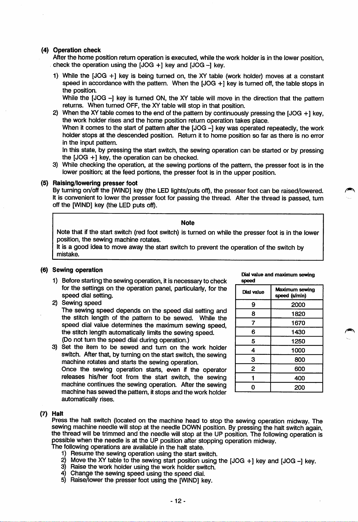
(6)
Sewing
operation
Dialvalue
and
maximum sewing
1) Beforestarting the sewing operation, itis necessaryto check
the
for
speed
2) Sewing
The sewing
the
speed
the
(Do not turn
3)
Set
switch.
machine rotates
Once the sewing operation starts, evenifthe operator
releases his/her foot
machine continues the sewing operation.
machine
automatically
settings on the operation panel, particularly, for the
dial setting.
speed
speed
stitch length of
dial value determines
stitch length automatically limits
the
the
item
After
has
to
depends
speed
be
the
sewed
on the
patterntobe
speed
sewed.
the
maximum sewing
the
sewing
dial setting and
dial during operation.)
and
turn
on
the
While
speed.
work
that, byturning on the start switch,the sewing
and
starts
the
sewing operation.
from
the start switch, the sewing
After
the
sewed
rises.
the
pattern, it
stops
and
the
work holder
the
speed,
holder
sewing
Dial
value
9
8
7
6
5
4
3
2
1
0
Maximum
speed
(s/min)
2000
1820
1670
1430
1250
1000
sewing
800
600
400
200
(7) Halt
Press the halt switch (located on the machine head to stop the sewing operation
sewingmachine needle
the thread
willbetrimmed
possible when the needle is at the UP position after stopping operation
The
following
1) Resume
2)
Move
operations
the
theXYtableto the
will
stop at the needle
and the needle
are
available in
sewing operation using
sewing
the
start
DOWN
will
stop at the
halt
the
start switch.
position
position.Bypressing the halt
UP
state.
using
position.
the
[JOG+]key
The
midway.
3) Raise the work holder using the work holder switch.
4) Change the sewing
5) Raise/lowerthe presserfoot using
speed
using the
the
-12-
speed
[WIND]
dial.
key.
following
and
[JOG-]key.
midway.
switch
again,
operationis
The
Page 18
(8)
(9)
Resewing
Using
the
If
the
sewing
XY
tabletothe
operation
Erroneous
1)
Reverse
It
judges
with following
Any
switches
vjy
REVERSE ROTATION
Turn
change
again
method
halt function,
machineisstopped
position
using
the
start
motion
turn of
during
sewino
automatically
message.
willbedisabledinsuch
the
power off
the
direction of
the
power
switch.
the
where
and,
item
switch.
sewing
machine
the
direction of
after
reversing
canberesewed.
during
the
thread
the
sewing
was
turns
occasion.
the
turns
of motor
plug, which is
operation
cut
using
when
the
machine
stopped
providedonthe
because
the
[JOG-]key
started
completely (it
the
motor
thread
and
and
takes
end
is cut,
restart
stops
about
cover,
move
the
sewing
the
operation
2 minutes),
and
back
the
on
2) Error with
When
short
Any
PG
SYNCHRONIZER DEFECT
Turn off
Above
the
thereisany
period
switches
my
the
message
detector
error on PG signal of detector,
and
the
stops
willbedisabledinsuch
power, repair
may
explained below.
3) Lock of
When
Any
vjy
MACHINE
Turn off
was
machine
the
machine
switches
imfx*}
WAS
the
caught
got
willbedisabledatsuch
LOCKED
power, remove
completely,
4) Momentarv power failure
When
the
power supply
operation
Turn to off
Vxm
POWER
stops,
the
n*7-
OFF THEN ON
then
power
any
switch
of sewino machine
showing following
occasion.
the
appear
detector
when
and
the
caughtbysome
occasion.
the
cause
of catching
the
above
was
switches
detector
interrupted for a moment, following
become
and
backonagain.
message.
backonthe
machine
reason,
error
inoperative.
the
machine
got
caught
following
and
backonthe
is raised.
power
message
operates
with high
again.
(stopsatthe
appears.
power.
message
speed
locked state)
When
the
appears
for a
as
machine
and
the
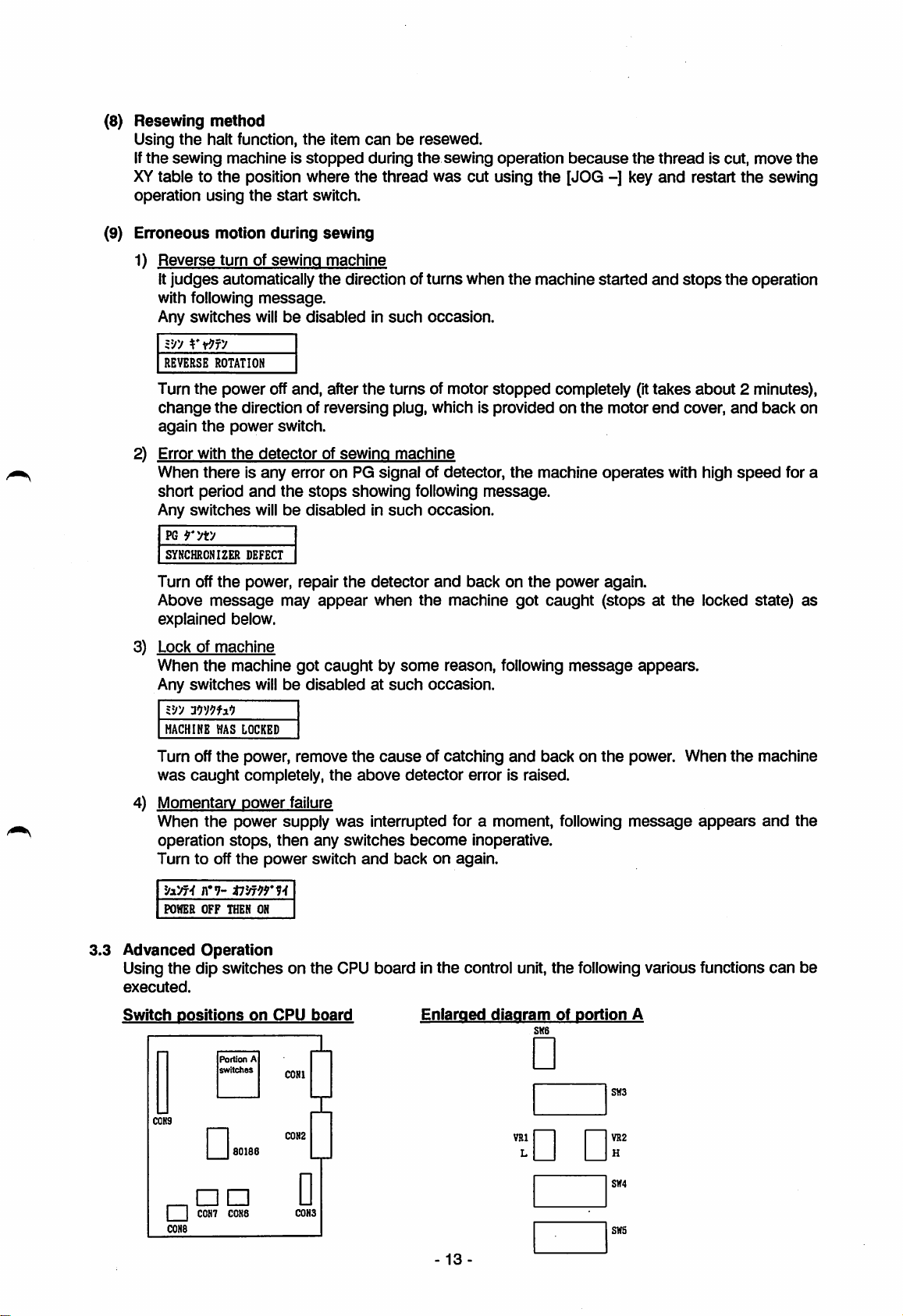
3.3
Advanced
Using
executed.
Switch
CONS
Operation
the
dip switches on
positions
Portion
switches
80186
I I
C0H7
CONS
CCN8
on
the
CPU board in
CPU
board
A
CONl
C0N2
C0N3
the
Eniaraed
-
13
control unit,
diagram
•
VRl
L
• •
the
following various functions
of
portion
SK6
A
SH3
VH2
H
SH4
SNS
can
be
Page 19
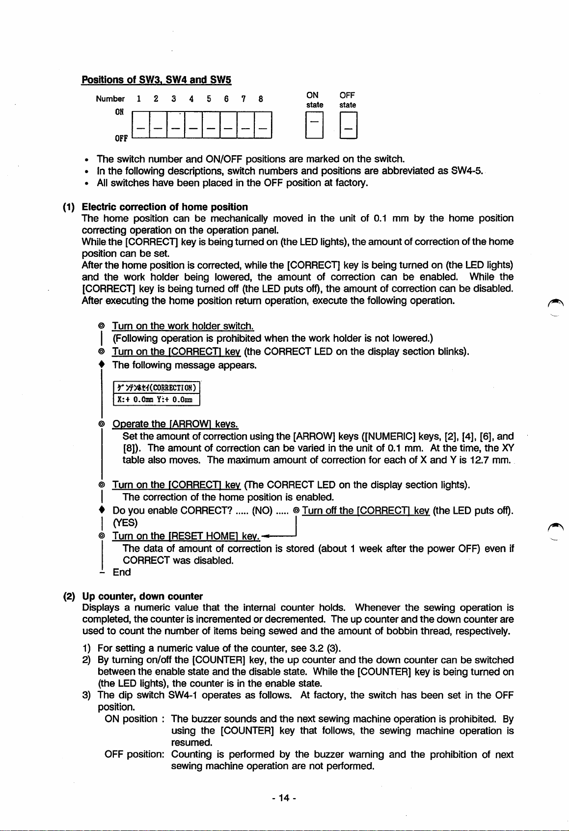
Positions
Number
of
SW3.
SW4
1 2 3 4 5 6
ON
and
SW5
ON
state
OFF
state
OFF
• The switch number
• In
the
following descriptions, switch numbers
•
All
switches
(1) Electric
The
correcting
While
position
After
and
correctionofhome
home
position
operationonthe
the
[CORRECT] key is being
canbeset.
the
home position is corrected, while
the
work
[CORRECT] key is being
After executing
Turn
on
(Following operation is prohibited
Turn on
The
following
r:^>«t'f(CORRECTIOH)
X;+
0.
and
ON/OFF positions
have
been
placedinthe
OFF position at factory.
position
can
be
mechanically moved in
holder
the
home
the
work
operation
being
lowered,
turned
position return operation,
holder
switch.
panel.
turned
on (the
the
off (the LED
when
the
rCORRECTI kev (the CORRECT
Y:+
message
O.Onm
appears.
0 0
are
marked on
and
positions
the
LED
lights),
the
[CORRECT] key is being turned on (the
amount
puts
of correction
off),
the
execute
the
work holder is not lowered.)
LEDonthe
the
switch.
are
abbreviatedasSW4-5.
unit of 0.1 mm by
the
amount
amount
the
following operation.
of correction of
can
be
of correction
display section blinks).
the
home
LED
enabled.
canbedisabled.
position
the
While
home
lights)
the
(2) Up
Displays a
completed,
usedtocount
1)
2)
The
3)
Operate
Turnonthe
Do you
Set
the
[8]).
The
table
also
The
correction of
enable
the
lARROWl
amountofcorrection
amount
moves.
kevs.
using
of correction
The
maximum
canbevaried In
fCORRECTI kev (The CORRECT LEDonthe
the
home
position is
CORRECT? (NO) ®Turn off
(YES)
Turn
on
the
[RESET
The
data
of amount of correction is stored (about 1 week after
CORRECT
End
counter,
down
numeric
the
was
counter
value
counterisincrementedordecremented.
the
number
For setting a numeric value of
Byturning on/off
between
the
(the LED lights),
dip
switch SW4-1
the
enable
the
H0ME1
disabled.
that
of items
[COUNTER]
state
and
counter
kev.^
the
internal
being
sewed
the
counter,
key,
the
disable state. While
is in
the
enable
operatesasfollows. At factory,
position.
ON position :
The
buzzer
using
resumed.
sounds
the
[COUNTER] key
and
OFF position: Counting is performed by
sewing
machine
operation
the
amount
counter
see
the
up counter
the
are
[ARROW]
of
correction
enabled.
holds.
and
the
3.2
(3).
state.
next
sewing
that
follows,
the
buzzer
not
performed.
keys
([NUMERIC] keys, [2], [4], [6],
the
unit of 0.1 mm. At
for
each
display
the
fCORRECTI kev (the
Whenever
Theupcounter
section
the
and
amountofbobbin
and
the
down
counter
the
[COUNTER] key is being
the
switch
has
ofXandYis
the
the
time,
lights).
LED
power OFF) even if
sewing
the
thread,
operation
down
respectively.
canbeswitched
been
setinthe
machine operation is prohibited. By
the
sewing
warning
and
machine
the
operation
prohibition of next
the
12.7
puts
counter
turned
and
XY
mm.
ofQ.
is
are
on
OFF
is
14-
Page 20
4)
[UP
COUNT
CLEARl
key,
[DM
COUNT
CLEAR]
key
Reset a displayvalue ofthe up counter or down counter to the
(3)
Repeat
Byturning on
placedinthe
While
still
setting value of
sewing
this switch is being turned on, when the sewing operation is completed, the
inthe lowerposition. Atthe time by turning on the start switch, the sewing operation can be
theupcounter
the
dip switch SW3-1,the repeat sewing operation is executed. This switch
OFF position at factory.
is "0000".)
immediately started. Thisfunction is very convenientto sew items
loweringthe work holder suchasan ornament sewing of parts.
initial
setting value. (The
without
frequently raisingand
work
initial
has
been
holder is
(4) Releasing sewing
By turning on
placedinthe
area
limit
the
dip
switch SW3-2,
OFF position at factory.
the
sewing
area
limit
canbereleased. This switch
Whenthe machine home position is moved, the sewing area is proportionally narrowed. To use
the
entire area, turn on this switch. This function is operative only when the power switch was
turned on. On or offoperation ofthis switch must be conducted whilethe power switch is turned
off.
(5) Using
work holder switch. After both
sewing machine
(6) Prohibiting automatic
two
step
work
holder
Byturning on
placed in
By turning on the dip switch SW3-4,
the
dip switch SW3-3,
the
OFF position at factory. When using the two
canbestarted. (Any of them
home
position return operation
the
the
work holder
two
step
canbelowered first.)
the
automatic home position return operation
work holder
step
and
the
two
canbeused.
work holder, connect the two step
step
prohibited. Thisswitch has been placed inthe OFFposition at factory.
The
work holder
While
a complicated holder
switch
are
lowered,
is being used, employing this function prevents the holder from damaging.
For the procedure,
(7) Prohibiting
thread
Byturning on the dip switch SW3-5, when
thread trimmingoperation can be prohibited. This switch has been placed in
factory.
The work holder is
see
3.2 (2).
trimming in halt
still
in the lower position.
state
(switch)
the
sewing operation is
stoppedbythe
the
halt switch, the
OFF position at
has
has
can
been
been
the
be
(8) Prohibiting work holder up operation in halt state (Input code) (Referto 4.2 (2) 8))
By turningonthe
holder up operation
In this state,
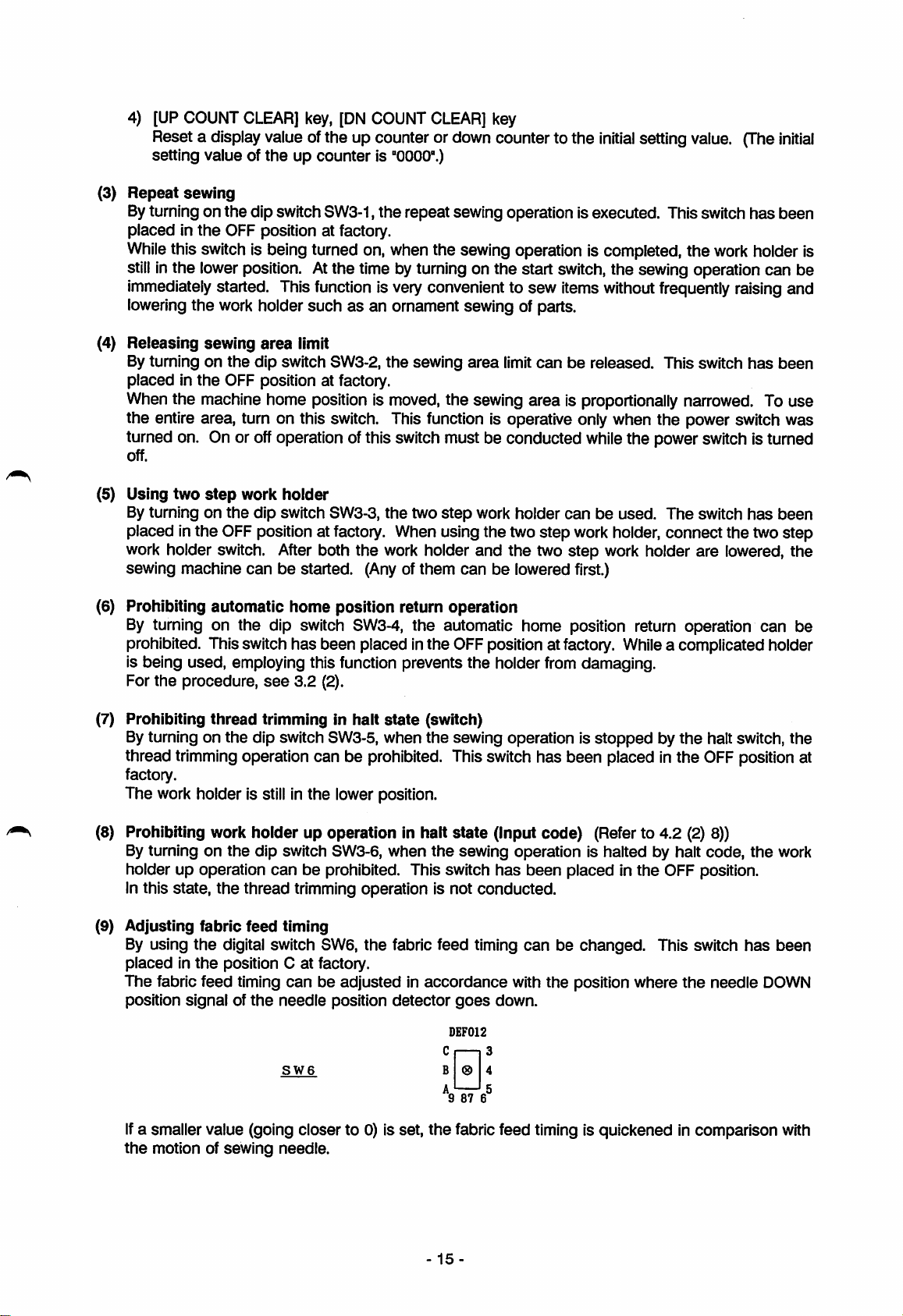
(9) Adjusting fabric
By using
placedinthe
The fabric feed timing
position
the
signalofthe
dip switch SW3-6,
canbeprohibited. This switch
the
thread trimming operation is not conducted.
feed
timing
digital switch SW6,
position Catfactory.
can
be adjusted in
needle
position
when
the
the
fabric feed timing
accordance
detector
sewing operation is halted by halt
goes
DEF012
has
can
with
down.
been
the
placed in
be
the
OFF position.
changed.
position where
This switch
the
code,
needle
cn^
SW6
If
a smaller value (going closer to 0) is set,
the
motion of
sewing
needle.
B 0 4
*9876®
the
fabric feed timing is quickened in comparison with
15-
the
has
work
been
DOWN
Page 21
(10) Sewing
position
By turning
machine
This switch
machine
canbeoperatedatany
operation using free
the
dip switch SW3-7,
has
been
placedinthe
(mechanical home position) at factory.
The
sewing operation using
position
position of
end
Contrary
return to
the
When
becomes
sewing
area
can
be
used
the
position.
to
the
pattern is
the
standard
mechanical
the
[RESET HOME] key is
the
free
home
automatically at
area
limitisreset
limit
dip
switch
SW3-2isnot
only
the
home
OFF position
the
free
when
sameasthat of
motion, it
home
position
turned
position is
the
on.
state
evenifthe
turned
home
sewing
position.
home
the
does
even
used,
where
sewing
on.
start
the
not
the
Turn
on
the
dip
Turn
on
Turn
on
Operate
Set
the
using
([NUMERIC]
the
the
the
start
switch
power
work
fARROWl
position of
the
keys [2], [4], [6],
SW3-7.
switch.
holder
switch.
kevs.
[ARROW]
the
pattern
keys
and
[8].)
(At
the
time,
the
XY
table also
moves.)
Turn
on
the
start
if
Automatic
it
End
sewing
switch.
operation
starts.
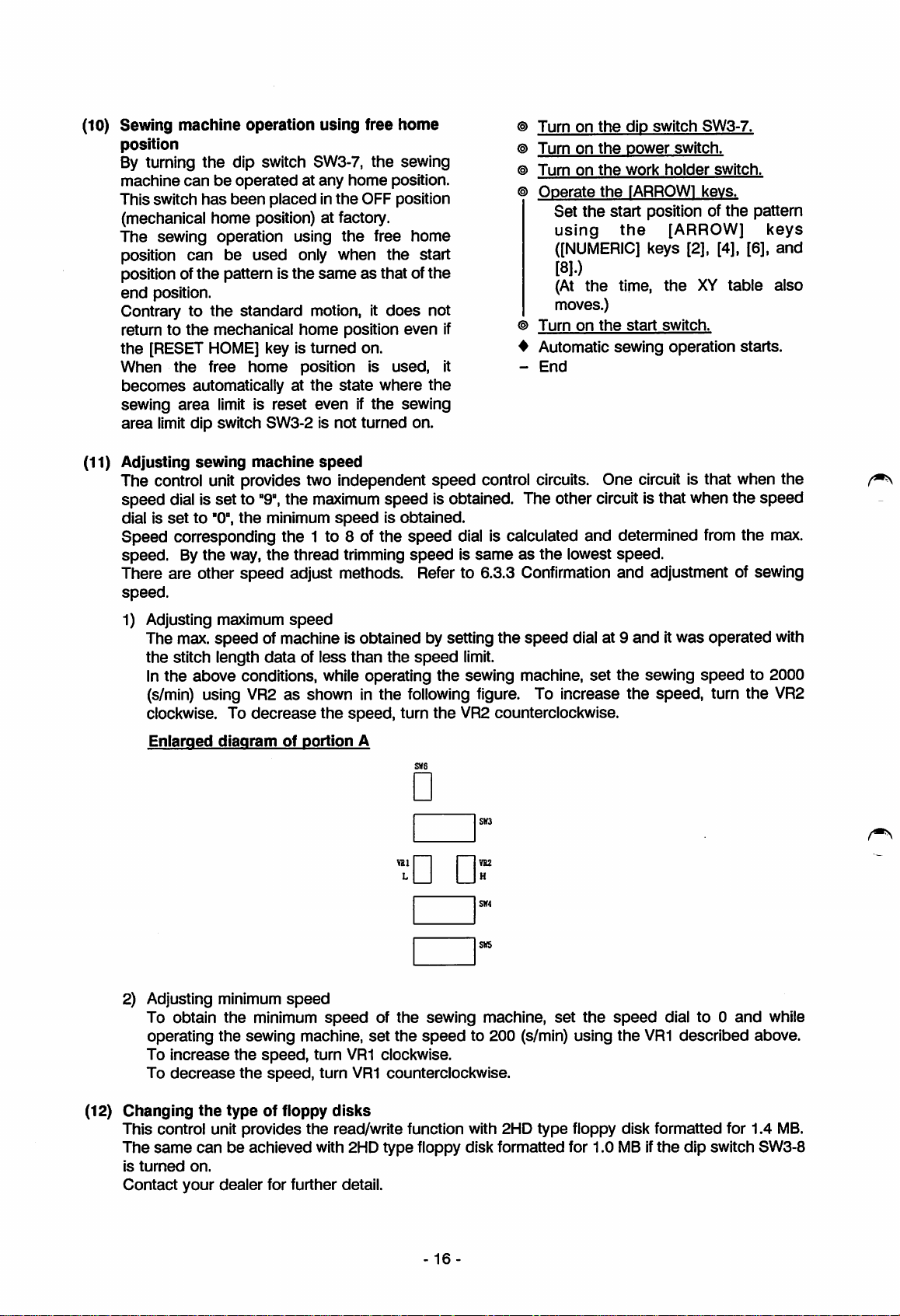
(11) Adjusting
sewing
machine
speed
The control unit provides two independent
speed
dial is
Speed
speed.
There are other
speed.
1) Adjusting maximum
dial is
setto"9",
setto"0",
the
the
maximum
minimum
corresponding the 1 to 8 of the
By
the
way,
the
thread trimming
The max.
the
stitch length
In
the
above
speed
speed
conditions, while operating
adjust methods. Refer to 6.3.3 Confirmation and adjustment of sewing
speed
of machine is obtained by setting the
dataofless
speedisobtained.
(s/min) using VR2asshown in the following figure. To increase the
clockwise. To
Enlarged
diagram
decrease
of
the
portion
than
speed,
A
speed
speed
speed
is obtained. The other circuitis that when the
control circuits. One circuit is that when the
dial is calculated
speedissameasthe
the
speed
turn
ong
limit.
the
sewing machine,
the
VR2 counterclockwise.
•
•
Dr
speed
and
lowest
dial at 9
set
determined from
speed.
anditwas
the
sewing
speed,
operated with
speed
turn the VR2
speed
the
max.
to 2000
s«s
2) Adjusting minimum
To obtain
operating
To
increase
decrease
To
(12)
Changing
the
This control unit provides
The
same
canbeachieved with 2HD type floppy disk formatted for 1.0MBif
is
tumed
Contact
on.
your
the
the
the
the
typeoffloppy
dealer
speed
minimum
speed
sewing machine,
speed,
speed,
for further detail.
turn
VR1 clockwise.
turn
disks
the
read/write function with 2HD type floppy disk formatted for 1.4
of
the
sewing
set
the
speed
VR1 counterclockwise.
16
machine,
to 200 (s/min) using
set
the
speed
the
VR1
dial to 0
and
described
the
dip switch SW3-8
while
above.
MB.
Page 22
(13) Prohibition of
if
the
dip
switch SW4-3 is
the
clamp
turned
also
special clamp, etc.
weight
switch is
Turn to ON
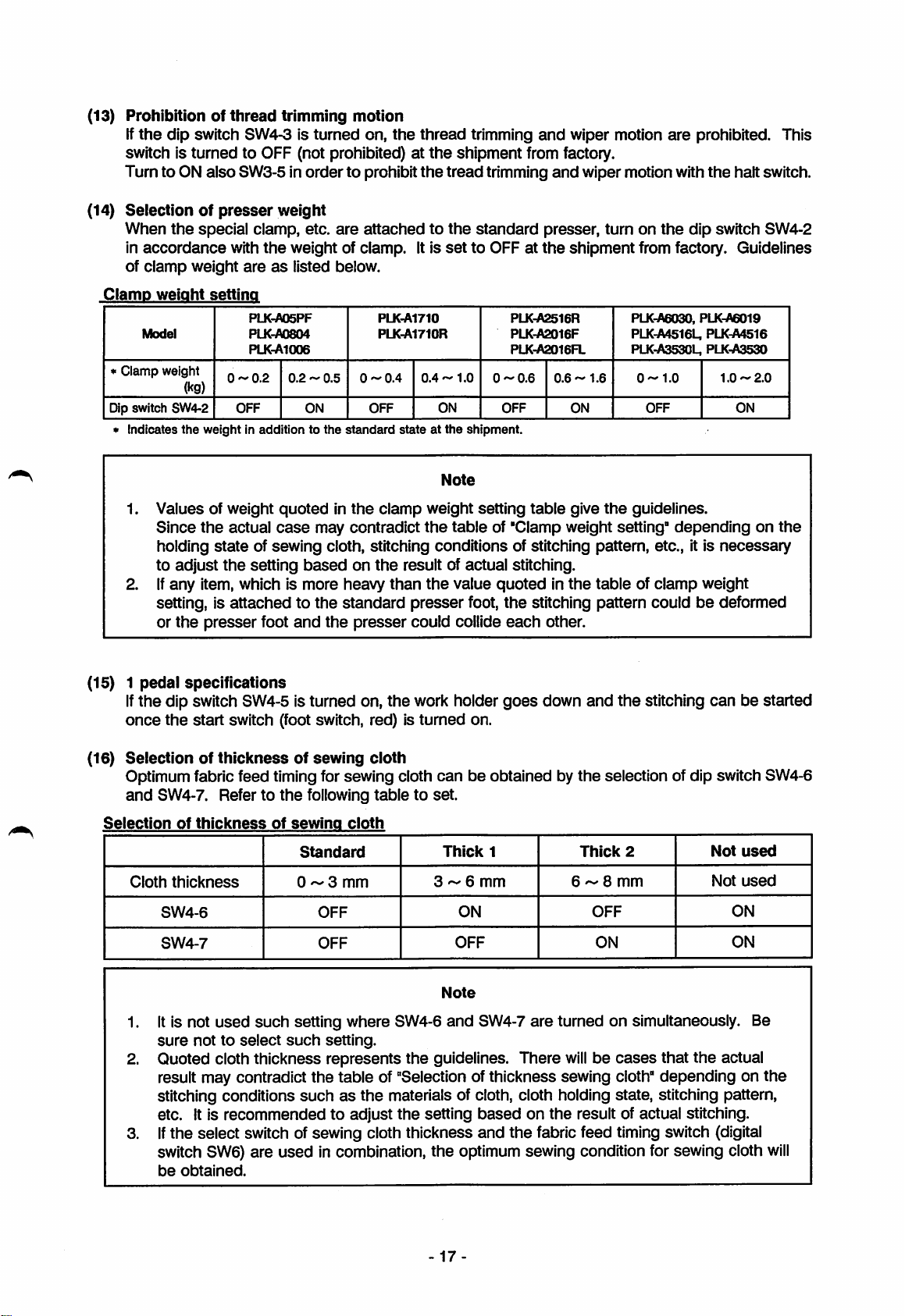
(14)
Selectionofpresser
When
in
accordance
of
thread
trimming motion
turned
on,
the
to OFF (not prohibited)atthe
SW3-5 in
order
to prohibit
weight
are
attachedtothe
with
the
weight of clamp. It is
areaslisted below.
thread
the
tread
set
trimming
shipment
trimming
standard
to OFF at
and
wiper motion
from factory.
and
wiper motion with
presser, turn on
the
shipment
are
prohibited. This
the
halt switch.
the
dip switch SW4-2
from factory. Guidelines
PLK-A05PF
Model
* Clamp weight
(kg)
Dip switch SW4-2
Indicates
the
1. Values of weight
Since
the
holding
to adjust
2. if
any
item, which is
setting, is
or
the
(15) 1
(16)
pedal
specifications
If
the
dip switch SW4-5 is turned on, the work holder
once
the
start
Selectionofthicknessofsewing
PLK-A0804
PLKnAlOOe
0.2-0.5
OFF
weight in addition to
ON
the
quotedinthe
actual
stateofsewing
the
case
setting
may
cloth, stitching conditions of stitching pattern, etc., it is
basedonthe
more
attachedtothe
presser
foot
CM
d
I
o
and
standard
the
switch (foot switch, red) is
Optimum fabric feed timing for sewing cloth
and
SW4-7. Refertothe
following
PLK-A1710
PLK-A1710R
0
1
o
OFF
standard
clamp
contradict
heavy
than
presser
cloth
tabletoset.
PLKnA2516R
PLKnA2016F
PLKnA2016FL
0~0.6
ON
0
stateatthe
1
Note
weight
the
tableof'Clamp
OFF
shipment.
b
setting
table
result of actual stitching.
the
value
quotedinthe
presser
could collide
turned
foot,
on.
the
stitching pattern couldbedeformed
each
other.
goes
down
canbeobtained by
PLKnA6030. PLKnASDig
PLK-A4516U PLKnA4516
PLK-A3530L, PLK-A3530
0.6-1.6
ON
give
the
guidelines.
weight setting"
tableofclamp
and
the
the
selection of dip switch SW4-6
OFF
dependingonthe
weight
0
1
b
stitching
can
1.0-2.0
ON
necessary
be started
Standard
Cloth
thickness
SW4-6
SW4-7
1. It is not
sure
nottoselect
used
0^3
such
setting where SW4-6
such
2. Quoted cloth thickness
result may contradict
stitching conditions
etc. It is
recommendedtoadjust
suchasthe
mm
OFF
OFF
setting.
represents
the
table of "Selection of thickness sewing cloth"
materials of cloth, cloth holding state, stitching pattern,
Thick
3 ~ 6
ON
OFF
Note
and
the
guidelines. There
the
setting
3.Ifthe select switch of sewing cloth thickness
switch SW6)
be
obtained.
are
used
in combination,
the
optimum sewing condition for sewing cloth
17-
1
mm
SW4-7
based
and
the
the
Not
Not
actual
Thick
2
6 ~ 8
mm
OFF
ON
are
turned on simultaneously. Be
willbecases
that
dependingonthe
on
the
result of actual stitching.
fabric feed timing switch (digital
used
used
ON
ON
will
Page 23
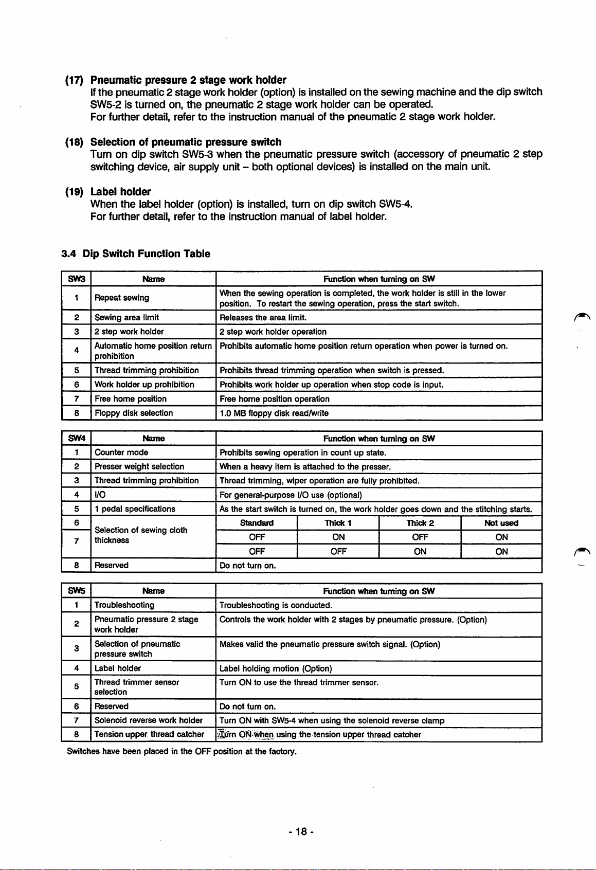
(17)
Pneumatic
If
the
SW5-2 is
For further detail, refertothe
(18)
Selectionofpneumatic
Turn on dip switch SW5-3 when
pressure2stage
pneumatic2
turned
stage
on,
work
holder
work holder (option) is installed on
the
pneumatic 2
instruction
pressure
stage
work holder
manualofthe
switch
the
pneumatic pressure switch (accessory of pneumatic 2
canbeoperated.
pneumatic2stage
switching device, air supply unit - both optional devices) is installed on
the
sewing machine
and
work holder.
the
main unit.
the
dip switch
step
(19) Label
When
For
3.4
Dip
SW3
Repeat
1
2 Sewing
2
3
Automatic
4
prohibition
5
Thread
Work
6
7 Free
Roppy
8
SW4
1
Counter
2
Presser
Thread trimming prohibition
3
4
I/O
5 1
6
Selection of sewing cloth
thickness
7
Reserved
8
holder
the
further
Switch
sewing
area
step
work holder
trimming
holder
home
disk selection
weight
pedal
label holder (option) is installed, turn on
detail,
Function
Name
limit
home
up prohibition
position Free
Name
mode
specifications
refertothe
Table
When
position. To
Releases
2
step
position return
prohibition Prohibits
selection
Prohibits
Prohibits work
1.0 MBfloppy disk read/write
Prohibits
When a heavy item is attached to the presser.
Thread
For general-purpose I/O
As
Do
instruction
the
work
manualoflabel
sewing operation is completed,
restart
the
area
holder
automatic
thread
trimming
holderupoperation
home
position
sewing
operationincountupstate.
trimming,
the
start switch is turned on,
Standard
OFF
OFF OFF
not
turn
wiper
on.
the
sewing
limit.
operation
home
operation
operation
use
dip
switch SW5-4.
holder.
Function
position return
operation
Function
Tbtck
operation,
when
are
(optional)
the
1
ON
when
when
when
fully
work holder
tumingonSW
the
work holder is still in
press
the
start
operation
switch is
stop
tumingonSW
prohibited.
code
goes
when
pressed.
is input.
down
Thick
OFF
ON
switch.
poweristurned
and
the
2
the
lower
on.
stitching starts.
Not
used
ON
ON
SW5
1
Troubleshooting
Pneumatic
2
work
Selection of
3
pressure
4
Label
Thread
5
selection
Reserved
6
7
Solenoid
Tension
8
Switches have
Name
pressure2stage
holder
pneumatic
switch
holder
trimmer
reverse
upper
been
placed in
sensor
work
thread
holder
catcher
the
OFF position at
Troubleshooting is
Controls
the
Makes valid
conducted.
work holder with 2
the
pneumatic
Label holding motion (Option)
Tum
ONtouse
Do
not
turn
Turn ON with SW5-4
^rn
QN
on.
Wiien
the
the
using
factory.
-
thread
when
the
18-
tension
Function
stages
pressure
trimmer
using
when
tumingonSW
by pneumatic pressure. (Option)
switch signal. (Option)
sensor.
the
solenoid reverse
upper
thread
clamp
catcher
Page 24
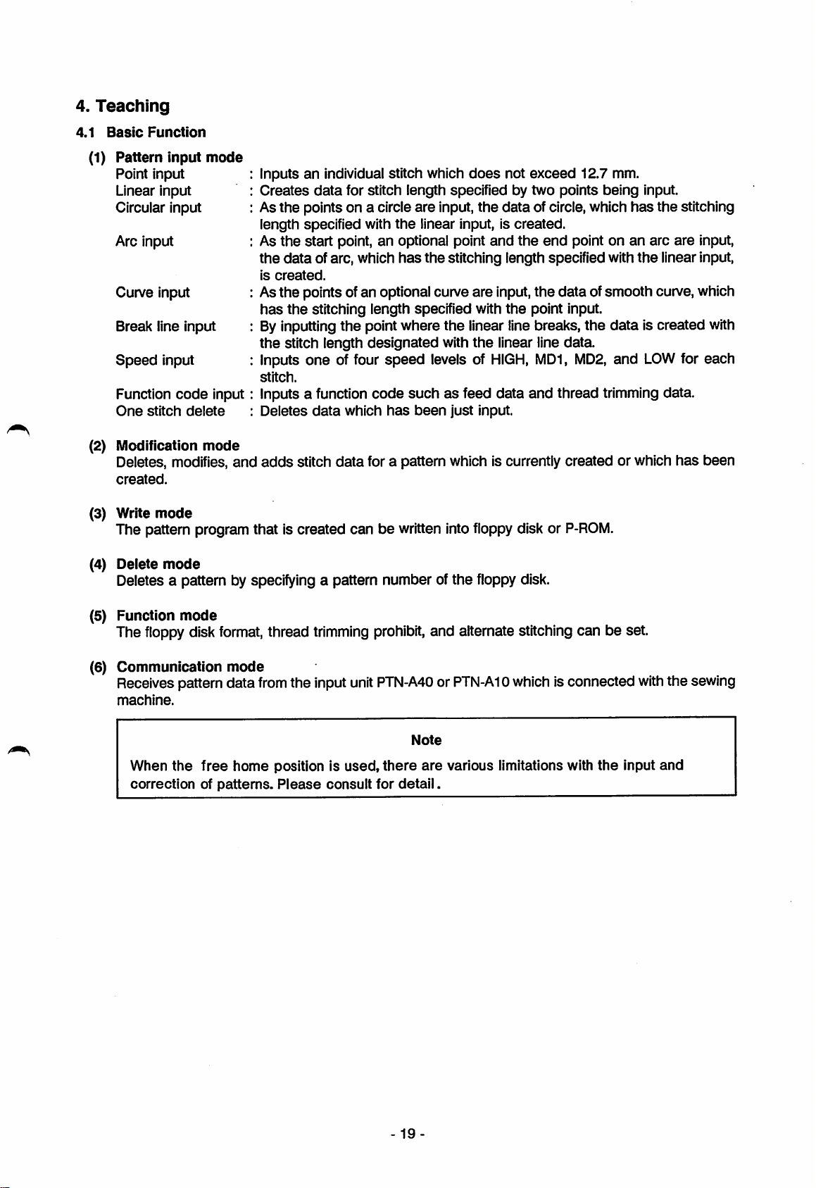
4.
Teaching
4.1
Basic
(1)
Function
Pattern
Point
Linear
Circular input
Arc input
Curve input
Break
Speed
Function
One
input
input
line
stitch
input
input
input
code
delete
mode
input
Inputsanindividual stitch which
Creates
As
length specified with
As
the
is
data
for stitch
the
points on a circle
the
start point, an optional point
data
of arc, which
created.
length
the
has
specifiedbytwo
are
input,
linear input, is
the
stitching length specified with
Asthe points ofan optional curve
has
the
stitching length specified with
Byinputting
the
stitch length
Inputs
stitch.
Inputs a function
Deletes
one
data
the
point where the linear line breaks, the
designated
of four
which
speed
code
has
with
levels of
suchasfeed data
been
just
does
not
the
data
created.
and
the
are
input,
the
the
linear line data.
HIGH,
input.
exceed
12.7 mm.
points
being
of circle, which
end
point onanarc
the
data
ofsmooth curve, which
point input.
data
MD1, MD2,
and
thread trimming data.
and
input.
has
the
stitching
are
input,
the
linear input,
is created with
LOW
for each
(2) Modification
Deletes, modifies,
created.
(3) Write
mode
The pattern program that is created can be written into floppy disk or
(4)
Delete
Deletes a pattern by specifying a pattern number of
(5)
Function
mode
mode
mode
and
adds
stitch
data
for a pattern which is currently created or which
P-ROM.
the
floppy disk.
The floppy disk format, thread trimming prohibit, and alternate stitching can be set.
(6)
Communication
Receives pattern data
machine.
When
the
correctionofpatterns.
free
mode
home
from
the input unit
position is
Please
used,
consult
PTN-A40orPTN-A10
Note
there
are
various limitations with
for
detail.
whichis connected
the
with
input
has
been
the sewing
and
-19
Page 25
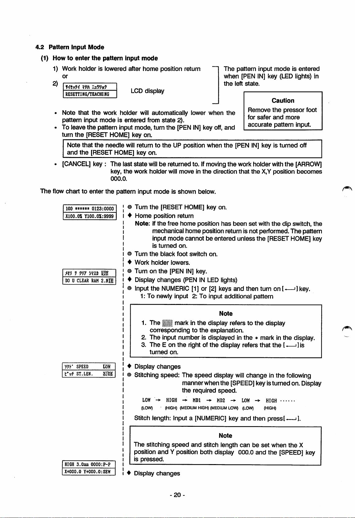
4.2
Pattern
Input
Mode
(1) Howtoenter
the
pattern
input
mode
1) Work holder is lowered after home position return
or
2)
mvf't
19I\ Z3.W39
RESEniNG/TEACHING
Note
that
the
pattern
To leave
turn
•
[CANCEL]
Note
and
input
the
pattern input mode, turn
the
[RESET HOME] key on.
that
the
the
[RESET HOME] key on.
key : The last state
The flow chart to enter
100
XIOO.OX
0123:0000
Y100.0X:S999
work
modeisentered
needle
key,
000.0.
the
LCD display
holder
will automatically lower
from
state
the
will
return to
the
work holder will
the
will
be returned to.Ifmoving
pattern input mode is shown below.
Turn
the
[RESET
Home
Note: If
position return
the
free
mechanical
input mode cannotbeentered unless
is
turned
Turn
the
black
Work
holder
m 3 m
DOUCLEAR
9m
RAM
2.N|1
Turn on
Display
input
the
changes
the
NUMERIC
1: To newly input 2: To input additional pattern
2).
[PEN
IN]
key
UP position
moveinthe
HOME]
home
position
home
position return is not performed.
on.
foot
switch
lowers.
[PEN
IN]
key.
(PENINLED lights)
[1] or [2] keys
when
off,
when
direction
key on.
has
on.
The
pattern
when [PEN
the
left
the
and
the
[PEN
the
workholder withthe
that
been
input
IN]
state.
Remove
for
safer
accurate
IN]
the
set
with
the
and
then
turn on [-—•] key.
modeisentered
key
(LED
Caution
the
pressor
and
more
pattern
key is
turned
X,Yposition
the
dip switch,
[RESET
lights) in
foot
input.
off
[ARROW]
becomes
The
pattern
HOME]
the
key
V9y
SPEED
V'jf
ST.LEN.
HIGH S.Oaun
X+COO.O
tow
SUM
0000:P-P
Y+000.0:SEW
Note
1. The mark in
correspondingtothe
the
display refers to
explanation.
2. The input number is displayed in
3.
The
E on
the
turned
^ Display
on.
changes
© Stitching speed: The
manner when
the
LOW
->
HIGH HDl ^
(LOW)
(HIGH)
(MEDIUM
Stitch length: Input a
The
stitching
speed
right of
and
the
speed
required
HIGH)
display
speed.
MD2
(MEDIUM
[NUMERIC]
Note
stitch length
display refers
the
[SPEED]key is turnedon. Display
LOW)
key
position and Y position both display 000.0
is
pressed.
♦
Display
changes
the
the
* mark in the display.
will
change
LOW
->
(LOW)
and
then pressl^—•].
canbeset
and
display
that
HIGH
(HIGH)
the
in the
when
the
l<—i]is
following
the
[SPEED]
X
key
20
Page 26
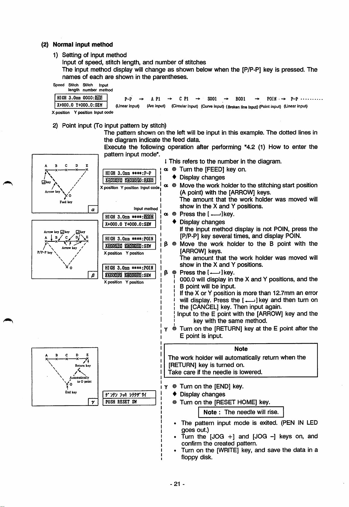
(2) Normal
Input
method
1) Setting of input method
Input of
The
namesofeach
speed
HIGH
X+000.0
X position Y position Input
speed,
stitch iength,
input method display
are
Stitct) Stitch Input
length
number
method
S.Omn
0000:^
Y+000.0:SEH
code
showninthe
P-P
(Unear
input)
2) Point input (To input pattern by stitch)
The
pattern
the
diagram indicate
0lcey X
Arrow key \ /
Arrow
/\
P/P-F
key \
Execute
pattern
HIGH
1
X position y position Input
Feed key
HIGH
X-POOO.G
key
0key
0key
HIGH
Arrow
\
key
Vo
mm
X position
HIGH
m
X position Y position
the
input mode".
a.Cmm
3.0mm
Y4000.0:SEH
3.(
)iim
msmiswH
Y position
3.(
imra
mursEw
and
number
will
changeasshown below when
of stitches
the
[P/P-P] key is
pressed.
parentheses.
->
API
-»•
C PI
->
SOOl
->
BOOl -*• POIN -^-
(Arc
input)
(Orcular
input)
(Curve
input)
(Broken
line
Input)
(Point
input)
(Unear
shownonthe
the
left
willbeinput in this example.
feed
data.
The
dotted
following operation after performing "4.2 (1) How to enter
code
Input
method
♦♦»*:POIN
I This refers to
06
©Turn
♦
Display
06
© Move
(A point) with
The
showintheXand
06®Press
4 Display
If
the
[P/P-P] key several times,
p © Move
the
the
[FEED] key on.
changes
the
work
amount
the
that
[.—'Ikey.
changes
input
method
the
work holder to
numberinthe
holdertothe
the
[ARROW]
the
work
Y positions.
display is
diagram.
stitching
keys.
holder
not
and
display POIN.
the
B point with
start
was
POiN,
[ARROW] keys.
The
♦♦«*:POIH
amount
showintheXand
Press
the
000.0
will
that
[-—'ikey.
display in
the
work
Y positions.
theXand
holder
Y positions,
was
B point willbeinput.
If
the
X or Y position is more
will
display.
the
[CANCEL] key.
Input to
key with
© Turn on
Press
the
E point with
the
[RETURN]
the
the
Then
same
than
[..—i]key
input again.
the
[ARROW]
method.
key at
the
12.7mmanerror
and
then
E point after
E point is input.
p-p
moved
press
moved
key
The
....
input)
lines in
the
position
will
the
the
will
and
the
turn on
and
the
the
Note
The
work
-X
X—X
/
Return
/K
^
Automatically
\ / to 0 point
\
End key
♦
key
[RETURN] key is
Take
holder
careifthe
© Turnonthe
♦
Display
PUSH RESET SW
© Turnonthe
The pattern input
goes
Turn
confirm
Turn on
will
automatically
turned
needle
[END] key.
changes
[RESET HOME] key.
Note:The
out.)
the
[JOG +]
the
created
the
[WRITE]
on.
is
lowered.
needle
mode
and
pattern.
key,
floppy disk.
21
-
return
when
the
will
rise.
is exited. (PENINLED
[JOG
-]
and
save
keys on,
the
data
and
in a
Page 27
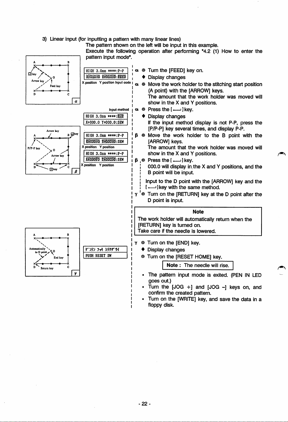
3) Linear Input (for inputting a pattern with many linear lines)
The
A B
key
✓
key
' " ]
| ,
Feed key
Arrow
key
>0
Arrow
/
Olkey
key
0 key <
Arrow
D C
P/P-P
pattern
Execute
pattern
HIGH a.OiDin
X position Y position Input code
a
HIGH 3.Cinm
X+000.0
ijkey
HIGH
a.Omm
X position Yposition
HIGH 3.0fliia
iUW
Xposition Yposition
shownonthe
the
following operation after performing "4.2 (1) How to
input
mode".
a
left
® Turn
4 Display
G6
® Move
Input
method
a
®
4 Display
Y+000.0:SEW
«:«:P-P
:SEW
»»«:P-P
»M:SEW
® Move
®
willbeinput in this example.
the
[FEED] key on.
changes
the
work holderto
(Apoint) with
The
amount
the
that
showintheXand
Press
the[—j
]key.
[ARROW]
the
the
work
Y positions.
changes
If
the
input method display is not P-P,
[P/P-P] key several times,
the
work holder to
[ARROW]
The
showintheXand
Press
000.0
B point
keys.
amount
the
will
that
[-—i]key.
display in.the X
willbeinput.
the
work
Y positions.
stitching
keys.
holder
and
display P-P.
the
holder
and
Y positions,
enter
start
position
was
moved
press
B point with
was
moved
and
the
will
the
the
will
the
Automatically
toO
pointy.'w®
^
x^-^.
n ^ _
Return
End
• ^
key
key
PUSH RESET SW
Input to
[-—']key
® Turn on
the
D point with
with
the
[RETURN]
the
same
the
[ARROW]
method.
key at
key
the
D point after the
D point is input.
Note
The
work holder
[RETURN] key is
Take
careifthe
® Turn on
♦
Display
® Turn on
The pattern input mode is exited.
goes
out.)
will
automatically return when
turned
needleislowered.
the
[END] key.
changes
the
[RESET
Note:The
on.
HOME]
needle
key.
will
rise.
(PEN
Turn the [JOG +] and [JOG -] keys on, and
confirm
Turn on the
fioppy disk.
the
created
[WRiTE]
pattern.
key,
and
save
the
and
the
IN
data
the
LED
in a
22
Page 28
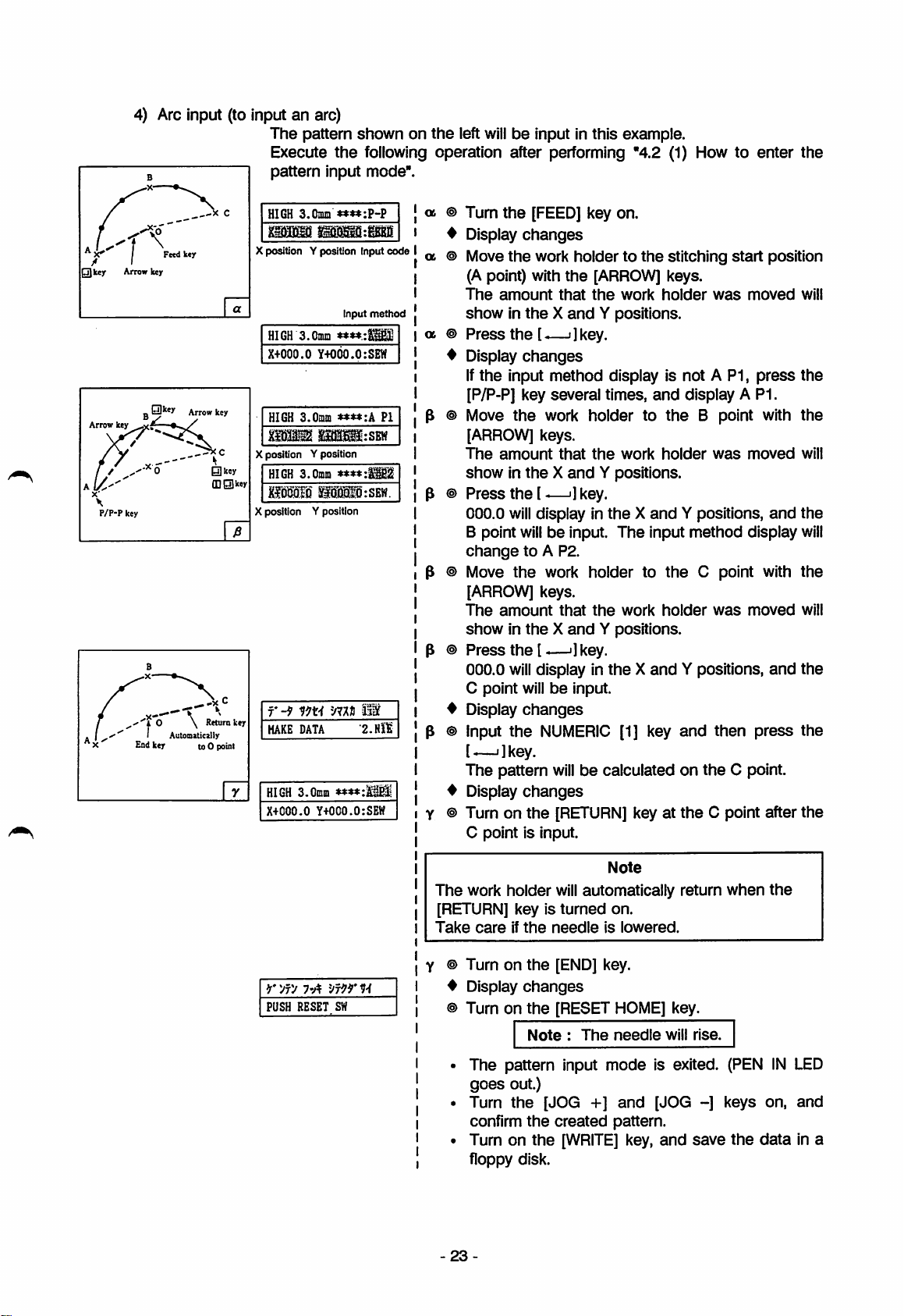
4) Arc input (to input an arc)
QJkey Arrowkey
Arrow
P/P-P
0key
key
key
i O \
Endkey to0 point
Fetd
key
Arrow
Automatically
-X
key
[DHltey
Return
The
pattern
Execute
pattern
C
HIGH
a.Cmm
X position Y position Input
HIGH S.Cmm
X+000.0
HIGH a.OmiD
Xposition Y position
HIGH
3.0mni
KfdMIS
X position Y position
7-9
key
HAKE DATA
HIGH
3.0niin
X+COO-0 Y+OCO.O:SEW
shownonthe
the
following operation after performing "4.2 (1) How to enter
left
willbeinput in this example.
input mode".
a © Tum
the
[FEED]
key on.
^ Displaychanges
code
input
method
****:.
Y+000.0:SEW
:SEW
****:
»M0:SBW.
mn
llf
•2.
Nil
PI
a © Move
a ©
♦
p © Move
p ©
p © Move
p ©
4 Display
p © Input
4 Display
Y © Turn on
the
work
holdertothe
(A point) with
The
amount
showintheXand
Press
the
Display
If
the
input method display is not A P1,
the
that
[-—i ]key.
changes
[ARROW]
the
work
Y positions,
[P/P-P] key several times,
the
work holder to
[ARROW] keys.
The
amount
showintheXand
Press
the
000.0
will
B point
that
the
[-—']key.
display in
willbeinput.
work
Y positions,
theXand
The
changetoA P2.
the
work
holdertothe
[ARROW] keys.
The
amount
showintheXand
Press
the
000.0
will
0 point
that
the
[-—']key.
display in
willbeinput.
work
Y positions,
theXand
changes
the
NUMERIC
[1] key
[,—.]key.
The
pattern
willbecalculated on
changes
the
[RETURN]
C point is input.
key at
stitching
keys.
holder
and
display A P1.
the
holder
Y positions,
input
method
holder
Y positions,
and
the
start
position
was
moved
press
B point with
was
moved
and
display
0 point with
was
moved
and
then
press
the
0 point.
0 point after
the
will
the
the
will
the
will
the
will
the
the
the
Note
The
work
r
yfy
PUSH RESET SW
vf99'
holder
[RETURN] key is
Take
careifthe
Turn on
9-i
Display
Turn on
The pattern input
goes
Turn
confirm
Turn on
will
automatically
turned
needle
the
[END]
changes
the
[RESET HOME] key.
Note:The
out.)
the
[JOG
the
the
+]
created
[WRITE]
on.
is
lowered.
key.
needle
mode
and
pattern.
key,
floppy disk.
23
return
when
the
will
rise.
is exited. (PENINLED
[JOG
-]
and
save
keys on,
the
data
and
In a
Page 29
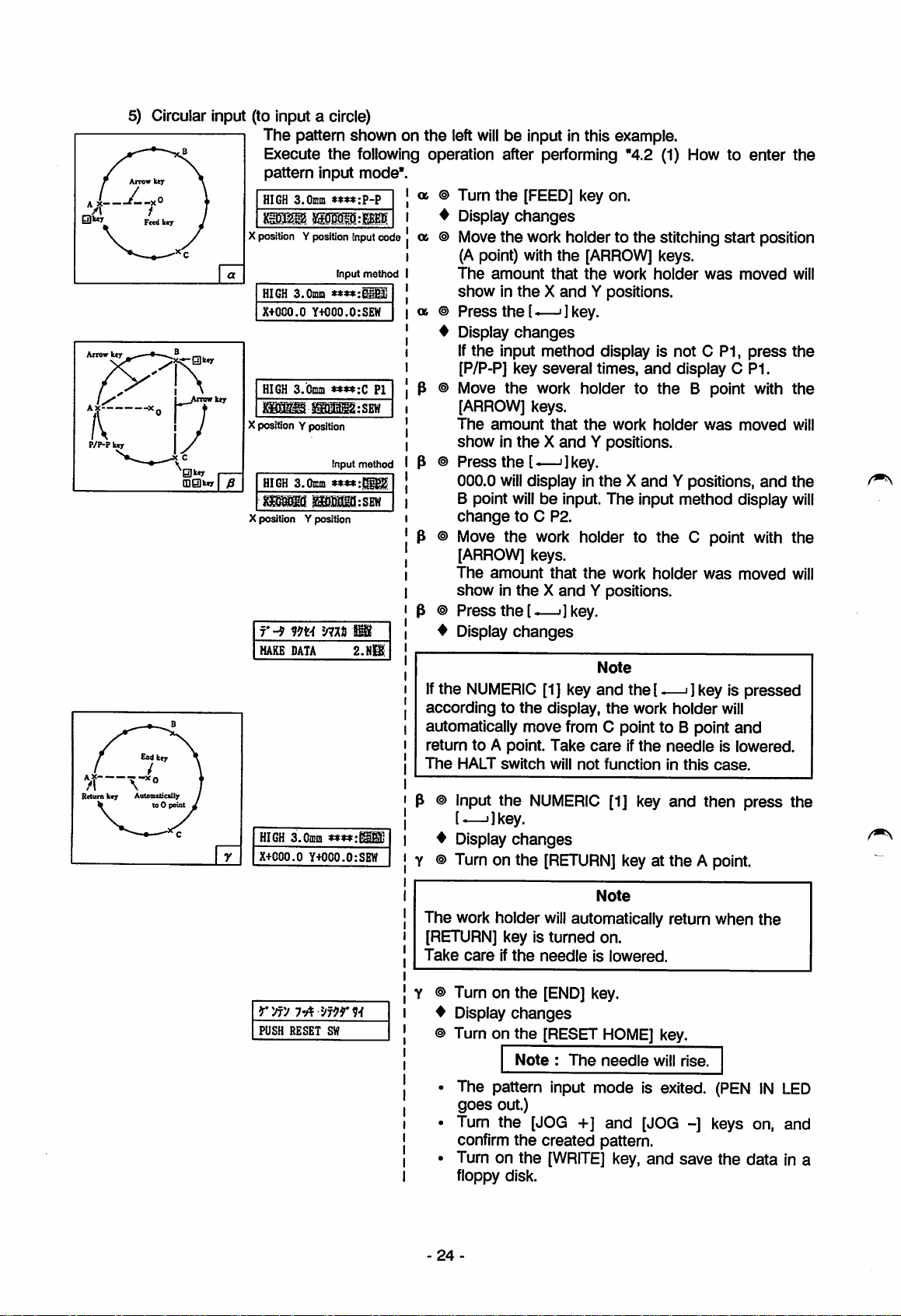
5) Circular Input (to input a circle)
The pattern shown on the left
Execute
pattern
HIGH
mm.
Xposition Yposition Inputcode
HIGH
X+000.0
Arrow
key
HIGH
XpositionV
HIGH
mms.
Xposition Y position
r-9
HAKE
HIGH 3.0mm
X+000.0
T V
Rctara
key Automitically
0key
(l]0kcy
ow key
the
input mode".
3.0mm
iMiiiM
Input
3.0mm
****:
Y+000.0:SEW
3.0mm
position
Input
3.Cmm
**t*:
miiQitsEw
mn
DATA
***«:
Y+000.0:SBW
will
be input in this example.
following operation after performing "4.2 (1) How to enter
ex.
Turn
the
[FEED] key on.
method
PI
:SEW
method
Display
ex.
Move
(Apoint) with
The
showintheXand
06
Press
Display
If
[P/P-P] key several times,
Move
[ARROW]
The
showintheXand
Press
000.0
B point
change
Move
changes
the
work holderto
amount
the
that
[ARROW]
the
work
the
stitching
keys.
holder
Y positions.
the[-—']key.
changes
the
input method display is not 0 P1,
and
the
work holder to
the
keys.
amount
that
the
work
holder
Y positions.
the
[^—']key.
will
display in
willbeinput.
theXand
The
input method display
to C P2.
the
work holder to
the
start
was
moved
press
display 0 P1.
B point with
was
moved
Y positions,
0 point with
position
and
[ARROW] keys.
The
amount
showintheXand
Press
the[-—>]
Display
If
the
NUMERIC
accordingtothe
automatically move from C point to B point
return to A point.
The
HALT
switch
p ® Input
the
that
changes
[1] key
display,
Take
will
NUMERIC
the
work
Y positions.
key.
Note
and
the[-—>] key is pressed
the
careifthe
not
functioninthis
[1] key
holder
was
work holder
needle
and
then press the
moved
will
and
is lowered.
case.
[e—i]key.
♦
Display changes
Y
©Turn
on the
[RETURN]
key at the A point.
the
will
the
the
will
the
will
the
will
Note
rvfy
I'A
PUSH RESET SW
The work holder
[RETURN] key is
Take
careifthe
© Turn on
♦
Display
© Turn on
will
automatically return when the
turned
needleislowered.
the
[END]
key.
changes
the
[RESET
Note:The
on.
HOME]
needle
The pattern input mode is exited.
goes
out.)
Turn the [JOG +] and [JOG ~] keys on, and
confirm
Turn on the
floppy disk.
-
24
the
created pattern.
[WRITE]
key,
and
key.
will
rise.
(PENINLED
save
the
data
in a
Page 30
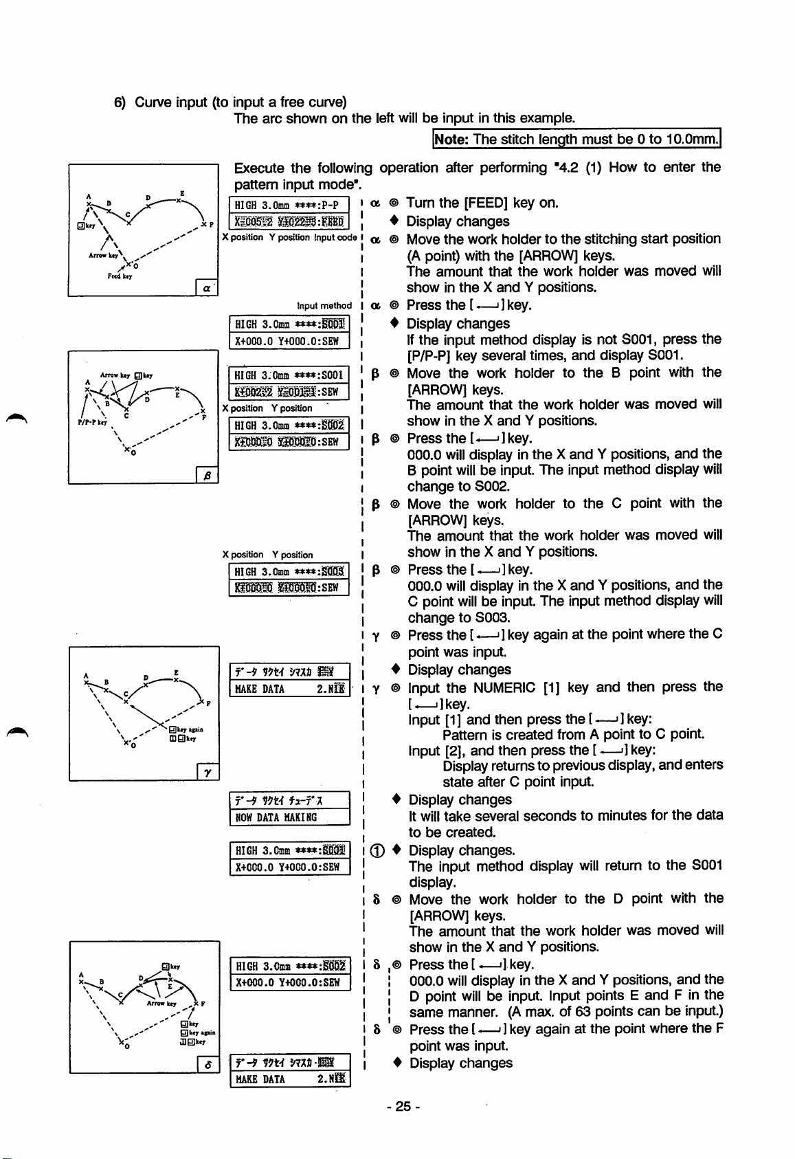
6) Curve input (to input a free curve)
The
arc
shownonthe
left willbeinput in
Note:
The
this
stitch
example.
length
must
be0to
10.0mm.
A D
A
Arrow
kty*^
Fctd kty
Arrow]uf
Qkty
/ \ c
P/P-P
ker
^ D --
^
x-"^—
V'
Wi'K
* Arrow ker .. X F
\
\
—
tD0ii«r
0kcr
E
\
,x?
0ker
0ker»liin
JlBker
Execute
pattern
HIGH
Xil0^
X position Y position Input
a
HIGH S.Cmm
X+000.0
HIGH S.Cmin
xsiM^
Xposition Y position
HIGH
X position Y position
HIGH
r-9
MAKE
r-^
HOW
HIGH S.Cmm
X+COO.O
HIGH
X+000.0
r-9
MAKE DATA
input mode".
3.0mm
liSStpBS
Y+000.0:SEW
ySi)M':SEVf
3.0mm
3.0mm
DATA
vm
DATA
MAKING
Y+000.0:SEW
3.0mm
Y+000.0:SEW
m-i
the
following operation after performing "4.2 (1) How to enter
ot
»»♦»:?-?
code
Input
method
****:
® Turn
4 Display
a
® Move
a
®
♦
the
[FEED] key on.
changes
the
work
holdertothe
(A point) with
The
amount
showintheXand
Press
the
Display
the
that
[-—ijkey.
changes
[ARROW]
the
work
Y positions.
stitching
keys.
holder
was
Ifthe input method display is not S001,
««:S001
♦♦♦♦cStlQl
P
P
P
****:
:SBW
P
[P/P-P] key several times,
® Move
the
work holder to
[ARROW] keys.
The
amount
that
showintheXand
®
Press
the
[^—']key.
000.0
will
display in
B point
will
be input. The input method display
changetoS002.
® Move
the
work
holdertothe
[ARROW] keys.
The
amount
that
showintheXand
®
Press
the
[.—•]
key.
000.0
will
display in
C point
change
will
be input.The input method display
to S003.
the
Y positions.
the
Y positions.
and
the
work
holder
theXand
work
holder
theXand
display S001.
B point with
was
Y positions,
0 point with
was
Y positions,
® Press the [-—'1key again at the point where the 0
point
was
input.
♦
'mt
2.NCi
Display
® Input the
changes
NUMERIC
[1] key
and
then press the
[.—i]key.
Input [1] and then press the [—>] key:
Pattern is
Input [2], and then press the [
created
from A point to C point.
-—>]
Displayreturns to previousdisplay, and enters
state
after C point input.
♦
fi-r
i
Display
It will
to
Display
0
♦
The input method display
be
changes
take
created.
changes.
several
seconds
to
minutes
will
return to the S001
display.
8 ®
Move
the
work holder to
the
D point with
[ARROW] keys.
The
amount
showintheXand
Press
the[-—']
000.0
will
D point
that
the
work
holder
was
Y positions.
key.
display in the Xand Y positions, and the
willbeInput.
Input points E and F in the
same manner.(Amax. of 63 points can be
8 ®
Press
the
(—']
'mi'
point
Display
was
changes
key again at
input.
the
point where
start
key:
moved
press
moved
moved
for
moved
the
position
will
the
the
will
and
the
will
the
will
and
the
will
the
data
the
will
input.)
the
F
25
Page 31

8 © Input the
NUMERIC
[1] key,
and
then press the
I—'Ikey.
Input [1],
Input [2],
r-^
mi
2-"
-—
'\
E
>
Retura
A»tcm«ieaI1y
toO
poiat
B
\
\
\
Eod key
NOW
HIGH
1
kcr
X+000.0
£
DATA
3.0Em
Y+OCO.O:SBW
H-ri
MAKING
4 Display
It will
to
be
4 Display changes.
The input method display
display.
e
©Turn
The
work holder
[RETURN] key is
Take
careifthe
and
then
press
Pattern Is
and
created
then
the[-—i]
from C point to F point.
press
the
key:
—»] key:
Display returns to previous display,
state
after F point input.
changes
take
created.
on
the
several
seconds
to
will
minutes
return to
[RETURN] key.
Note
will
automatically return when
turned
needleislowered.
on.
for
the
the
enters
data
S001
the
rw
I'A
PUSH RESET SW
Precautions when Inputting curve
0
When
creating
and
then continue withthe curve input.
A X
data
X '
forashapeasshown
c © Turn on
♦
Display
© Turn on
the
[END] key.
changes
the
[RESET
Note:The
HOME]
needle
key.
will
rise.
• The pattern input mode is exited. (PENINLED
goes
out.)
• Turn the [JOG +]
confirm
• Turn on
floppy disk.
below,
end
the
created pattern.
the
the
cun/e
[WRITE]
input
and
[JOG -] keys on, and
key,
and
save
the
onceatthe
corner(Kpoint),
data
in a
0
When
on
creating
the
curve.
curve
input
data,ahighly
accurate
data
canbecreatedbyinputting
Thus,asmany points as possible should be input evenifbothersome.
Example
1:To inputdata close to a
,x—?
' X
—X-
/
\
\
90*
I
circle
J
or arc, input5 points
\
-26-
within
90".
/
90*
many
points
Page 32

Example 2: To
create
changes
a curveasshown
from a soft to
sudden
below, inputasmany
7) Broken line input (to input a pattern with many lines)
P/P-P
Arrow
O
key
Fcedkcr
kty
•XA
Arrow
key
Arrow
0key
0keyapia
(DSkey
key
A linear pattern
same
patternasthe
with
the
special
Execute
pattern
HIGH
Xposition Yposition input code
HIGH
X+DCO.O
HIGH 3.Cmni
Xposition Y position
HIGH
X position Y position
r-^
£>'
HAKE
NOW
the
input mode".
3.0nm
3.0mm
Y+000.0:SEW
3.0mm
mn
DATA
DATA
HAKING
as
shownonthe
linear input (P-P)
input function.
following operation after performing "4.2 (1) How to
****:?-?
Input
method
♦♦♦♦:
***«:BOOI
:SEW
****:
:SEW
my
2.n!e
curve.
left
willbeinput in this example. Basically,
canbeinput. This input
a,
Turn
the
[FEED] key on.
Display
a
Move
changes
the
work
(A point) with
The
amount
showintheXand
a
Press
the[-—i]key.
Display
If
changes
the
input method display is not B001,
[P/P-P] key several times,
Move
the
P
[ARROW]
The
work holder to
keys.
amount
showintheXand
Press
the
U—'jkey.
000.0
will
display in
B point
willbeinput.
changetoB002.
Input points0,D
Press
the[-—•]
Display
Input
changes
the
NUMERIC
[.—i]key.
Input [1],
and
Patterniscreated
Input [2],
and
Display returnsto previousdisplay
state
after
Display
It will
data.
changes
take
several
pointsaspossible
X—
X—X—
holdertothe
the
[ARROW]
that
the
work
Y positions.
and
that
the
work
Y positions.
theXand
The
input
and
E in
the
key after inputting
[1] key,
then
press
the
from A point to E point.
then
press
the
E point input.
seconds
to
where
stitching
keys.
holder
display
the
B point with
holder
Y positions,
method
same
and
—i]key;
[-—']key:
minutes
the
curve
the
methodisused
enter
the
start
position
was
moved
press
will
the
BOOT
the
was
moved
display
and
will
the
will
manner.
the
E point.
then
press
the
and
enters
to
create
the
-27-
Page 33

HIGH
3.0mm
X+000.0
0
Eod
kqr
AistomtticxUr
Kttornkcr
to0 poiat
•xE
Y+000.0:SEW
♦
Display
changes
The input method display
8
©Turnonthe
The
work holder
[RETURN]
[RETURN] key is
Take
careifthe
needleislowered.
will
key.
Note
will
automatically return
turned
on.
change
to B001,
when
the
rVrV
7'A
'Jm'l-i
PUSH
RESET
SW
8) Code data input method (to input code data)
will
Ahalt data
Execute
"4.2 (2) 6) Curve input".
B
\
Oxle
key
BlOIli*)'
(UOlker
l.TRIM 2iSTOP 3.FUN1
4.2HP
5.NEXT
When 5 is input
11 key turned ON
6.BAT 7.LNK
9.FUN2
10.NEXT
When 10 is input and then the
11 key turned ON
11.FUNS
13.CODE
When 13 is input and then the
i-y
SET CODE NO.
I] key
12.FUN4
NO.
turned
be input on the 0 point ofthe curve patternasshown on the
the
following
02B
and
then the
8.END
OOE
ON
»*B
8 © Turn on
♦
Display
© Turn on
The pattern input
goes
Turn
confirm
Turn on
the
changes
the
Note:The
out.)
the
[JOG +]
the
created
the
[END]
[RESET
[WRITE]
key.
HOME]
needle
mode
and
pattern.
key,
key.
will
rise.
is exited. (PEN
[JOG -] keys on,
and
save
floppy disk.
operation at the 0
a © Turn on
♦
Display changes
01
© Input
the
position(0point
the
[CODE] key.
NUMERIC
(LED
flickers)
[2] key,
and
input
then
[-—']key.
2. STOP indicates halt. Refer to the following table
for
the
other
codes.
NEXT
refers to moving to the next code.
Code
TRIM
STOP
FUN1
2HP
NEXT
BAT
Function
Note) Input with
code
performed currently.
The sewing machine may operate abnormally when inputs are
made
with
Function
Trimming
Halt
Function
No.2home
position
To
Baste
1 is
used
the
code
code
code
code
code
next
display
code
for
the
reverse
specified
LINK
numbers. Never input with this method.
Code
INK Note)
END
1
FUN2
FUNS
FUN4
CODE NO Note)
shaft
code
and
Link
End
Function
Function
Function
Code
specification
rotation.
CODE NO.
IN
the
data
complete)
press
Function
code
code
code
code
code
number
cannot
LED
and
in a
left.
in
the
2
3
4
be
Caution
1
Input
The
input
ofthe code data
following
the
message
correct
value.
may
will
displayinthis
3-r
n*xi*9
ILLEGAL CODE
Perform
this.
not be possibleaccording to the type and place.
case.
rfr-f7x
NUMBER
28
steps
Turn
following
the
[.
0 in4.2
ijkey
on,
and
(2)6)Curve
inputafter
Page 34

2. Function
codes
1 to 4
are
usedinthe
following
manner.
Code
FUN1
FUN2
FUN3
FUN4
3.
The
No. 2
(3) 1 Stitch
The last input
Bypressing
TheXYtable
input
data
deleted. However
input
data
(4)
Save
and
Function
Function
Function
Function
Function
home
position
deletion
function
data
the
[DELETE]
will
alsobedeleted
was
linear, circular, arc, curve or broken line input,
the
willbedeleted
recall
function
code
code
code
code
Reverse
1
work
holder
Output
2
No. 4 (-) pins in
Output
3
and
No. 10 (-)
connector.
Output
4
and
No. 12 (-) pins in
connector.
data
canbeinput in only
Usage
shaft
between
between
between
method
rotation
No. 3
the
E connector.
the
No. 9
pinsinthe
the
No. 11 (+)
one
for
reverse
(+)
and
(+)
E
the
E
placeofthe
Do not
input
will
not
function
pneumatic
selection work holder,
work
holder,orsolenoid
work
holderIsselected
dip
switches.
The
four
turnonwith
off
with
the
pattern
data.
canbedeleted during linear input or point input by pressing
key severaltimes,
at this time,somove to
data
input with linear, circular, arc, curve or broken line input before
by stitch.
the
pattern
data
willbedeleted in orderfrom
the
position before
the
data
created
codes
pressure
function
the
even
the
the
2, 3,
when
the
2-step
2-step
with
code
data
odd
time
time.
[DELETE]
the
data. If
last
will
and
reverse
and
back.
the
ail
the
4
the
will
key.
last
be
last
1)
Save
When writing
the
2) Recall function
New pattern
input and combining itwiththepattern being input. However, the feed data before stitching and
the
The
[SET]
(5)
Special
Special pattern
The pattern input
1)
Overlap
Arrow key ^
Feed key
function
the
pattern that
save
pattern
300to339.
data
end
data
after stitching
recall function is
canbecreated
executed
does
not
by calling
willberemoved from
with
the
key on - input of pattern number with
input
function
data
suchastwo parallel stitching lines
with
the special input function cannot be used in point input
stitching (the
X
same
The
overlap
(=
Execute
pattern
positionYposition
is the repeated section)
the
input mode".
HIGH S.Omm
XIMii
Input
HIGH
3.0min
X+000.0
Y+000.0:SEW
stitch is sewed twice to reinforcethe stitch) Display is
stitching
will
following operation after performing "4.2 (1) How to enter the
I a
Input
code jX position Y position Input
code
|
I
method
I a ©
haveanend
out
data,
the
a pattern
the
saved
pattern called out.
pattern number
canbewritten into
in a floppy disk during
following operation:
[NUMERIC]
keys -
[SET]
key on - [.—i]key on.
canbecreated.
(POIN).
1.REP.
be input using broken line inputasshown on the
©Turn
the
[FEED] key on.
Display
Move
(A point) with
The
changes
the
work holder to
amount
the
that
showintheXand
Press
the
[-—']key.
Display
changes
the
[ARROW]
the
work
Y positions.
stitching
keys.
holder
was
start
moved
pattem
left.
position
will
-29
Page 35

P/p.pkey \
Function keyv
[DElkey
Q]BJkey
(Speedkey)
X. t »=
\
Arrow key
^
X -"X c
0
Q]key again
^ Automatically
\-yjr
0 *
=a=x
-v^BJkey
i
IL»Arrow
f
[l]0key
"0key
B
key
2.V^>
CONVERSION
2.INV
4.CPS 5.ZIG
HIGH S.Oram
X+000.0
m'
fvf
r-9m't
HAKE
NOW
HIGH S.Omm
X+000.0
Y+000,0:
SPEED
ST.LEN.
DATA
V?t-f
DATA HAKING
Y+OCO.O:SEW
'ma
fi-f'X
****:
3.PARA
6.B.T.II
Input
method
Input
M
SiSi
2.Nli
p ®
Press
the
[P/P-P] key several times,
B001. (Select
the
actual
input method: linear input:
P-P, circular input: C P1,
input: 8001, broken line input: B001.)
p
ilE
©Turn
♦
^ © Input
The
turn
♦
on
Display
the
[1]
indicates
E on
the
the
[-—'
Display
The
displays
the
[FUNCTION] key.
changes
NUMERIC [1] key,
the
special
Note
lower right of
]key on.
changes
have
the
following meanings:
input function.
the
1. REP : Overlap stitching
2.
INV
: Inverted overlapstitching
3.
PARA:
Parallel stitching 4. OPS: Offsetstitching
5. ZIG : Zigzag stitching 6. B.T.: Back tacking
p © Input
♦
the
1. REP :
Display
NUMERIC
overlap
changes
[1] key,
stitching is
REP indicating overlap' stitching is displayed on
the
input
code
© Check
for
that
broken
p © Tochange the stitching
the
[SPEED] key ON,
method
the
line input,
section.
input method section indicates B001
speed
and
4.2 (1).
p © Input from A point to C point with the
keys
and
the
[.—•
]key.
(The input method is the
Refer to section 4.2 (2) 7).)
Press
the
Y ©
♦
8 ®
Display
Input
[,—i] key again at
changes
the
NUMERIC
[1]
[—i]key.
The pattern from A point to C point, feed from C
pointto A point,
is
created.
♦
Display
♦
Display changes
changes
and
pattern from Apoint to C point
Thp Input method display
e © Turn on
the
[RETURN]
key.
and
display
arc
input: A P1, curve
and
then
the
[-—• ]key.
display indicates to
and
then
the
I.—i
]key.
selected.
or stitch length, turn
set
each.
Referto
section
[ARROW]
sameasnormal input.
the
C point.
key,
and then press the
will
change to
B001.
Note
/ \ p ^
Endkey \
Automatically
Return
to0 point
key
^'yfy
PUSH RESET SW
The work holder
[RETURN]
Take
careifthe
j © Turn on
♦
Display changes
© Turn on
will
automatically return when the
key is
turned
needleislowered.
the
[END]
the
[RESET
Note:The
on.
key.
HOME]
needle
The pattern input mode is exited.
goes
out.)
Turn the [JOG +] and [JOG -] keys on, and
confirm
Turn on
floppy disk.
-30
the
the
created
[WRITE]
pattern.
key,
will
and
key.
rise.
(PENINLED
save
the
data
in a
Page 36

Inverted
2)
the
stitch) Display is
Arrow
key
f ®
Feed
key
P/P-P key
Funcboa
key
iUakey
Blakey
(Speedkey)
Arrow key
Arrow
key
Automatically to A poiat
Return
key
/ ^
/ O
End
Automatically Q]a
to 0 point
key
repeat
* „
'''P
stitching
(the
same
2.INV.
The
repeat
(==
Execute
pattern
HIGH
moi
Xposition Y position Input
HIGH S.Omrn
X+000.0
l.REP
4.0FS 5.ZIG 6.B.T.21:'
HIGH
X+000.0
V9y
Vvf
f*-^
HAKE DATA
stitching
is
the
the
input
am
»*«:p-p
3.0c
Input
»»*»;
Y+000,0:SEW
CONVERSION
3.
Input
3.0mm
****:
Y+000.0:i
SPEED
ST.LEN.
m-f
'mn
overlap section)
following operation after performing "4.2 (1) How to
mode"
PARA
Input
2.
stitch is
sewed
twice from
the
reverse
willbeinput using circular inputasshownonthe
code
method
a ® Turn
♦
a © Move
a ©
^ Display
the
[FEED] key on.
Display
(A point) with
The
changes
the
work holder to
amount
the
that
showintheXand
Press
the[_i]key.
changes
the
[ARROW]
the
work
Y positions,
stitching
keys.
holder
p © Press the [P/P-P] key several times,
P1. (Select
P, circular input: C P1,
the
actual input method: linear input: P-
arc
input: A P1, curve input:
8001, broken line input: B001.)
p © Turnonthe
4 Display
Hi
p © Input
[1] indicates
4 Display
The
1.REP
the
displays have
[FUNCTION] key.
changes
NUMERIC
the
special input function.
changes
: Overlap
stitching
[1] key,
the
and
following meanings:
2. INV : Inverted overlap stitching
3.
PARA:
Parallel stitching 4. OFS: Offset stitching
5. ZIG : Zigzag stitching 6. B.T.: Back tacking
p © Input
method
4 Display
code
the
NUMERIC
2.
INV
: inverted overlap stitching is
[2] key,
and
changes
INV
indicating overlap stitching is displayed on
input
method
Check that
section.
the
input method section indicates A PI
for circular input.
To
change
the
[SPEED] key ON,
the
stitching
speed
and
set
Refer to section 4.2 (1).
Inputfrom B point to C point with
and
the
[-—']key.
(The input method is
the
same
Refer to section 4.2 (2) 4).)
NIB
Display
Input
changes
the
NUMERIC
[1] key,
[-—' ]key.
Input [1],
and
Pattern is
then
press
the
createdinorder
A point.
directiontoreinforce
left.
enter
the
start
position
was
then
then
moved
and
display A
the
[-—•]key.
the[—•
will
]key.
selected.
the
or stitch length, turn
each.
the
and
[ARROW]
as
normal input.
then
press
key
the
—']key:
of A point, C point,
Note
The
work
holder
will
from C point to A point.
Input [2],
31
-
and
then
press
The
display
and
willwait for C point input.
will
return to
the
automatically
[-—']key:
the
previous display
move
Page 37

r-9
m'i
NOW
DATA MAKING
HIGH
3.0[did
X+COO.O
H-rJ^
Y+000.0:SEW
^ Display
It will
data
♦
Display
•
©Turnonthe
The
work
changes
take
changes
holder
[RETURN] key is
Take
careifthe
several
seconds
[RETURN] key.
Note
will
automatically
turned
needle
on.
is
to
lowered.
minutes
return
to
when
create
the
the
© Turn on
rVfV
7-A
"JilTM
PUSH RESET SW
4 Display
© Turn on
•
• Turn
• Turn on
Parallei stitching (to stitch in parallei) Display is 3.
3)
The paraiiel stitching shown on
^•X
Feedkey Arrowkey
01cey
P/P-P key
Functioo
[D0key
•10
^ 0 A
-X-
Uvmaiekef, 0 key
t
Q]0key
(Speedkey)
A
key
key
Execute
pattern
HIGH
Xposition Y
HIGH
X+000.0
l.REP 2.IHV 31
4.0FS 5.ZIG
DISTANCE
the
following operation after performing "4.2 (1) How to
input mode".
3.0mm
position
Inputcode
Input
3.Cinm
**«:S0](1
Y+000.0:SEW
CONVERSION
6.B.T.I
method
a ®
♦
06 ®
a
P ®
the
[END] key.
changes
the
[RESET HOME] key.
The
pattern
goes
confirm
Note:The
out.)
the
[JOG
the
created
the
input
[WRiTE]
mode
+]
needle
will
rise.
is exited. (PEN iN LED
and
[JOG
-]
keys
pattern.
key,
and
save
the
on,
data
and
in a
fioppy disk.
PARA.
the
ieft
wiiibeinput.
enter
Turn
the
[FEED] key on.
Dispiay
Move
(Apoint) with
The
showintheXand
Press
Display
Press
S001. (Select
P-P, circuiar input: C P1,
input:
Turn on
Dispiay
input
[1] indicates
Dispiay
The displays have
1. REP :
2.
3.
changes
the
work
holdertothe
the
[ARROW]
amount
that
the
Y positions.
the
[.—'Jkey.
changes
the
[P/P-P] key several times,
the
actual input method: linear input:
8001,
broken iine input: B001.)
the
[FUNCTiON]
changes
the
NUMERiC [1] key,
the
speclai
changes
the
Overlap
iNV
: inverted overiapstitching
PARA:
Paraiiei stitching 4. OFS: Offset stitching
stitching
stitching
start
keys.
work
holder
was
and
arc
input: A P1, curve
key.
and
then
the[—i
input function.
following meanings:
position
moved
dispiay
]key.
5. ZiG : Zigzag stitching 6. B.T.: Back tacking
Input
the
NUMERIC [3] key,
3.
PARA:
Dispiay
Input a
Set
next
The
parallel stitching is seiected.
changes
[NUMERIC]
the
width (d) of
page.
maximum width of
key,
the
and
then
the[._i
and
then
press
[-—i]key.
paraiiei iines
the
parallei iines is 10.0mm.
showninthe
]key.
the
will
32
Page 38

Qlier
0 key Miia
030kty
Rctura
key
AutofBSticilly to 0 point
y
Cod key
A
DIRECTION
HIGH S.Cmm
X+000.0
m'
SPEED
fvf
ST.LEN.
f'-9
HAKE
DATA
Input
»»»«:SC01
Y+OCO.O;
mn
2.-
Input
il?
2.N31
method
code
+
direction
Travel direction right
Display
Input
Set
Display
the
the
changes
NUMERIC
right
side
changes
[1] key,
for
the
travel direction.
PARAindicating parallei stitching
input
code
Check
that
display
the
section.
input method section indicates8001
-
side
Travel direction left
: Input point
:
Created
and
then
direction
will
for curve input.
To
change
the
[SPEED] key ON,
the
stitching
speed
and
or stitch length,
set
each.
Refer to section 4.2 (1).
Input from A point to E point with
keys
and
the
[.—•
]key.
(The input
methodisthe
sameasnormal input.
Refer to section 4.2 (2) 6).)
Press
the
Display
Input
[
—']
Input [1],
changes
the
key.
and
The
E point to F point,
G point is
[-—>]key
NUMERIC
pattern from A point to E point, feed from
then
created.
againatthe
[1] key,
press
the
and
pattern from F point to
E point.
and
[-—ijkey:
side
data
the
I
'Ikey.
displayonthe
the
[ARROW]
then
press
turn
the
r-9
HOW
DATA
HIGH S.Omin
X+000,0
ryfy
i-A
PUSH RESET
fa-rx
MAKING
Input
Y+000.0:SEW
SW
method
The
work
holder
from E point to G point.
input [2],
♦
Display
It will
to
♦
Display
The
:
©Turn
The
work
[RETURN] key is
and
then
The display
and
waits
changestothe
for E point input.
changes
take
be
several
created.
seconds
changes
input method display
on
the
[RETURN] key.
holder
will
automatically return
turned
Takecareifthe needle is
: ©
Turnonthe
♦
Display
© Turnonthe
The pattern input
goes
Turn
confirm
Turn on
floppy disk.
[END] key.
changes
[RESET HOME] key.
Note:The
out.)
the
[JOG
+]
the
created
the
[WRITE]
press
Note
on.
lowered.
needle
mode
and
pattern.
key,
Note
will
move
automatically
the[ —"Ikey:
previous display
to
minutes
will
change
when
will
rise.
is exited. (PEN
[JOG
-]
keys on,
and
save
for
the
to S001.
the
the
data
IN
data
LED
and
in a
33
Page 39

4) Offset stitching (to stitch inside of label, etc.) Display is 4. CPS.
The
Arrow key
Peed key
offset stitching shown on
The input point is chain line
the
Execute
pattern
HIGH
3.0mm
X position Y position Input
following operation after performing "4.2 (1) How to enter
input mode".
code
• a
06
»»«:P-P
the
and
Turn
Display
Move
the
(Apoint) with
The
amount
showintheXand
C6
Press
Display
Press
p
HIGH
X+000.0
3.0mm
Y+000.0:SEW
Input
****:
method
B001. (Select
P-P, circular input: C P1,
input:
pttoctioa
(Dg)kcy
liOi=<r
key
2.\:/ny
l.REP
conversion
2.INV
5.ZIG
Ib
3.PARA
6.B.T.I
Turnonthe
p
Display
Input
p
[1]
indicates
Display
The displays have
1. REP :
INV
2.
3.
PARA:
^1
KuBeric
gjkcT
IDBJktr I
(Sp<td
ktr]^
key
t
5. ZIG : Zigzag stitching 6. B.T.: Back tacking
Input
p
4. OFS : offset stitching is
Display
DISTANCE
Input a
key.
Set
the
The
maximum
left
willbeinput in
the
created
dataisthe
the
broken line input.
full
line.
[FEED] key on.
changes
the
work
holdertothe
the
[ARROW]
that
the
work
stitching
keys.
holder
was
start
moved
Y positions.
the[—•]
key.
changes
the
[P/P-P] key several times,
the
actual
8001,
broken line input: B001.)
input
method:
arc
input: A P1, curve
and
linear input:
[FUNCTION] key.
changes
the
NUMERIC
the
[1] key,
special
and
then
the
input function.
changes
the
following meanings:
Overlap
stitching
: Inverted overlap stitching
Parallel stitching 4. OFS: Offset stitching
the
NUMERIC [4] key,
and
then
the[-—i]key.
selected.
changes
[NUMERIC]
width (d) of
key,
the
offset
widthofthe
direction
Travel direction right
and
then
press
showninthe
offsetis10.0mm.
-
direction
side
Travel direction left side
the
position
will
display
[—> 1key.
the[-—•]
below.
gjkqr
gjktyaitia
OlQllur
m key I
0kor
T B
Biay
Arrowkey\._
* t «
AatomJticaUy
to E point,
"
Arrow
Arrow
key
Qkeyi =-|
DIRECTION
"x
HIGH
X+000.0
m'
t'vf
3.0mm
SPEED
ST.LEN.
|
key
I
Input method
Input
****:B001
Y+000.0:
2.-
Input
method
code'
HiJH.
Hoe
Display
Input
Set
Display
changes
the
NUMERIC [1] key,
the
right
side
changes
for
the
travel direction.
OFS indicating offset stitching
input
code
Check
for
To
the
4.2
that
the
broken
change
line input.
the stitching
[SPEED] key ON,
(1).
display
input
section.
method
speed
and
set
Input from A point to B,0,and
A point with
(The input method is
the
[ARROW]
the
sameasnormal input.
Refer to section 4.2 (2) 7).)
8 ®
Press
the
[-—ijkey again at the A point.
34
: Input point
:
Created
data
and
then
the[
will
display on the
section
indicates
or stitch length, turn
each.
Refer to
D points,
keys
and
the
[-—"]key.
section
and
i]key.
B001
then
Page 40

r-9
HAKE DATA 2.NI1
mi
4 Display
8 ® input the
[.—i]key.
Input [1],
The
E pointtoF, G, H
changes
NUMERIC
and
then
feed
from O point to E point, pattern from
The
work
from A point to E point.
[1] key, and then press the
press
the
pointstoE point is
Note
holder
will
move
I-—'Ikey:
created.
automatically
AutOfflilicillir
point
to0
Input [2],
♦
r-9
mi
NOW
DATA
HIGH S.Cniiii
X+000.0
Y+000.0:SEW
fi-ri
MAKING
Display
It will
to
be
4 Dispiay
The input method dispiay
; © Turn on
The
work
[RETURN] key is
Take
careifthe
Turnonthe
ryfy
7'A
End Icey
_
j
PUSH RESET SW
mrvi
Dispiay
Turn on
The pattern input
goes
Tum
confirm
Tum on
and
The
display
enters
changes
take
several
created.
changes
the
hoider
changes
the
Note:The
out.)
the
the
the
then
press
changestothe
state
after
A point input.
seconds
[RETURN] key.
Note
wiiiautomaticaiiy
turned
needieisiowered.
on.
[END] key.
[RESET
HOME]
needle
mode
[JOG
+]
and
created
[WRITE]
pattern.
key,
the[—'Ikey;
previous display
to
wili
minutes
change
return
for
the
to B001.
when
key.
will
rise.
is exited. (PEN iN
[JOG
-]
keys on,
and
save
the
data
data
the
LED
and
in a
floppy disk.
Note
When using the broken iineinput withoffset stitching,ifthe distance fromthe input start point to
inputend pointis 0.4mmor iess after feed, the inputstart pointand input end point
matched, ifover 0.5mm,
5) Zigzag stitching (to stitch a zigzag pattern) Dispiay is 5.
Feed key
S)i»r2
Arrow
ktf
the
pattern in
the
above
figure
The zigzag stitching shown on the ieft
Execute the
pattern
HIGH S.Onun
foilowing
input mode".
♦♦♦«:?-?
operation after performing "4.2 (1) How to enter the
06
© Turn
> Dispiay
X position Y position Input
code
a © Move
(A point) with
a
HIGH
3.0mm
X+OCO.O Y+OCO.O:SEtf
Input
**t*:
method
The
showintheXand
a. ©
Press
4 Display
35
wiii
notbeobtained.
ZIG.
wiii
the
[FEED] key on.
changes
the
work holderto
the
amount
the
that
[-—»1key.
changes
be input with circuiar input.
the
[ARROW]
the
work
Y positions.
wiii
stitching
keys.
hoider
forcibiy
start
was
position
moved
be
wili
Page 41

P/P.P
key
F^oecioakey
(DO)key
Qy
key
Nttscrk
kffjr
0 k«y
(Swajr
width)
NttBchektjr0 key
{Pttd
JooMt)
Hamrie
k«f
ktr)
/\/
(^.1
xg ie
0i»y V
(Olrectico)
(Sftti
Press
the
l.RBP
4.
OPS
CONVERSION
2.INV
3.PARA
6.B.T.P
[P/P-P] key several times,
P1. (Select
P, circular input: C P1,
8001,
Turn on
Dispiay
li
Input
[1] indicates
Display
The
displays
the
actual
Input
arc
input: A P1,
broken iine input: B001.)
the
[FUNCTiON] key.
changes
the
NUMERIC
the
[1] key,
special
input function.
changes
have
the
following
method:
and
and
linear input: P-
curve
then
the
[-—•]key.
meanings:
display C
input:
1. REP : Overiap stitching
2.
INV
: Inverted overlap stitching
3. PARA: Parallel stitching 4. OPS: Offsetstitching
5. ZIG :
input
K
711iU\*
WIDTH
5. ZIG :
Display
Input
press
Set
The
m Va-)
PITCH
3.0E
Display
Input
press
Set
Zigzag
the
NUMERIC
Zigzag
stitching 6. B.T.:
stitchingisselected.
changes
the
NUMERIC
the
[-—ijkey.
the
width (d) of
maximum width of
changes
the
NUMERIC
the
(—iJkey.
the
feed
amount
[5] key,
and
then
[0], [5], [0] keys,
the
sway.
the
sway
is 10.0mm.
[0], [3], [0] keys,
(0.5mm to 10.0mm)
Back
the
tacking
[ -—'Ikey.
and
then
and
then
tm
DIRECTION
HIGH S.Onini
X+000.0 Y+ooo.o:|:j;e
Vn'
SPEED High
t'vf
ST.LEN.
1.+
Input
♦♦♦♦:C
input
3tOE
II
method
PI
code
Feed
amount
I 1
♦
Display changes.
® Input
♦
®
the
Set
the
direction of
NUMERIC
+
direction
NUMERIC
-
direction
Display
changes
NUMERIC
[1] key,
[2] key,
[2] key,
the
and
and
and
zigzag.
then
press
then
press
ZIG indicating zigzag stitching
input
code
Check
that
display
the
input
section.
method
section
then
will
for circular input.
® To
change
the
[SPEED] key ON,
Refer to
the stitching
section
4.2
(1).
speed
and
or stitch length, turn
set
each.
® Input B point and C point with the
and
the
[-—'ikey.
(The input method is
the
sameasnormai input.
Refer to section 4.2 (2) 5).)
Sway
width
the
I
the
[-—'Ikey
the
[-—'ikey
display on
indicates
[ARROW]
ikey.
the
C PI
keys
36-
Page 42

[HQ]key
r -9
mi
MAKE
DATA
r-9
mi
NOW
DATA
HIGH S.Onim
X+000.0
Y+000.0:SEW
vm
fx-ri
MAKING
Input
*t**\
il
2.NS
method
♦
Display
® input
I-—'Ikey.
Input [1],
Input [2],
♦
Display
It will
tobecreated.
♦
Display
The
® Turn
The
work
[RETURN]
Take
careIfthe
changes
the
NUMERIC
and
then
press
The
zigzag Is
and
The display
and
waits for 0 point Input.
created
then
press
changestothe
changes
take
several
seconds
changes
Input
on
the
holder
key Is
method
display
[RETURN] key.
willautomatically return
turned
needle
Is
[1] key,
Note
on.
lowered.
and
then
press
the
I-—ijkey:
from A pointtoA point.
the
—»Ikey:
previous display
to
will
minutes
change
for
to 0 P1.
when
the
the
the
data
AatmHiHfilly to 0 poiftt
rwj
PUSH RESET SW
'mrM
® Turn on
^ Display
® Turnonthe
•
The
goes
• Turn
confirm
• Turn
the
changes
Note:The
pattern Input
out.)
the
[JOG
the
on
the
floppy disk.
6) Back tacking 1 (To eliminate thread from coming undoneatstart
Display is 6. BT
The
five
back
tack
0key
Arrow
stitches
Bold
lineisthe
Execute
pattem
key
Feed key
:
This
the
input
following operation after performing "4.2 (1) How to enter the
mode".
sectionisthe
keys. It is not input in
HIGH a.OiHiii
X position Y position Input
*♦♦♦:?-?
m
code
shownonthe
fiveVtiack
part
the
a ® Turn
♦
Display
a ® Move
[ARROW]
The
tack
where
the
stitching
the
[FEED] key on.
changes
the
keys.
amount
work
showIntheXand
a ®
Press
the
[-—'Ikey.
changes
the
[P/P-P] key several times,
(Select
HIGH
X+000.0
S.Ooo
Y+000.0:SEW
Input
method
p ®
♦
Display
Press
B001.
P-P, circular Input: C P1,
Input:
8001,
Fuactioa
key
rnHkey
SlElkcy
[D01^
G^
1
I
1
t
i.
tr
D
2.V/Sy
c
CONVERSION
P ® Turnonthe
♦
Display
U.
P ® Input
[1] Indicates
changes
the
NUMERIC [1] key,
rr
[END] key.
[RESET
created
[WRITE]
mode
+]
HOME]
needle
key.
will
rise.
Is exited. (PEN IN
and
[JOG
pattern.
key,
and
save
and
end
of stitching)
-]
left willbeinputinbroken
stitches.
work
holderismoved
pattem.
that
holder
the
work
to
the
A point with
holder
was
Y positions,
the
actual
broken
Input
arc
line Input:
method:
Input: A P1,
BOOI.)
[FUNCTION] key.
and
then
the
special
Input function.
keys on,
the
data
line input.
with
the
moved
and
display
linear Input:
the[-—>
LED
and
In a
arrow
the
will
cun/e
]key.
37-
Page 43

Numeric
(Ho.
of start tack
key0]key
stitcba)
l.REP
4.0FS
2.INV
5.ZI6
3.PABA
Display
The
1. REP :
2.
changes
displays
INV
have
the
Overlap
stitching
: Inverted overlap stitching
following meanings:
♦
3. PARA: Parallel stitching 4. CPS: Offset stitching
q
7ir>t
START
B.T.
l.V
2.N
3.NO
5. ZIG : Zigzag stitching 6. B.T.: Back tacking
® Input
4 Display
® Input
the
6. B.T. :
the
NUMERIC
Back
tack
[6] key,
stitching is
changes
NUMERIC [1] key,
and
and
then
the!
selected.
then
-—'Jkey.
press
the
[.—i]key.
1:
Specifies
2:
Specifies
3:
Specifiesnofront
startVback
startVback
startNback
tack
StartNback
back
tackNostart
tack
tack
tack
back
tack
••key
Numeric
Qlkey
stitches)(Speed key)
Arrow
key
(No.
ofbacktack
GX
key
• key \
Arrow
key'
BJ
I Arrow key »,
Bx.
0 key
Q]key again'
key ^
"x"
0
:
Qkey
,xE
? F
' ip
XHkey
Arrow key
Hi
n'jJir
I
STITCH
NO
51
Display
Input
Set
changes
the
NUMERIC
the
numberofstart
[5] key,
and
tacking stitches.
then
the
I
i]key.
(Specify from 1 to 9.)
05'Dh*;t
END
STITCH
HIGH
X+OOO.O
f'jf
r-9
HAKE
py
B.T.
NO
3.0mni
y+OOO.O:01fi
SPEED
ST.LEN.
WM
i/7XDTvY
DATA
2.N 3.NO
Input
method
Input
2.N IE
61
code
Display
IB
s ©
Input
[
—i]key.
♦
Display
& ®
Input
Set
changes
the
NUMERIC [1] key,
1:
Specifies
2:
Specifies
endVback
endNback
3: Specifies no
ErtdVback
tack
EndNback
changes
the
NUMERIC [5] key,
the
number of
tack
tack
end
back
tackNoend
and
end
tacking stitches.
and
tack
back
tack
then
then
the
press
the
[-—i Jkey.
(Specify from 1 to 9.)
Display
BTindicating back tacking
code
Check
changes
display section.
that
the
input
method
will
display on
section
the
input
indicates B001
for broken line input.
To
change
the
[SPEED] key ON,
4.1.
Input from A point to E point with the
keys
needtobe
Press
Display
Input
[-—I
Input [1],
the
stitching
and
the
[-—'] key. (Points G
input.)
the
[-—>]key again at
changes
the
NUMERIC
Jkey.
and
then
and
[1] key,
press
speed
set
the
or stitch length, turn
each.
Refer to
section
[ARROW]
and
F do not
the
E point.
and
then
press
(-—>]key:
the
The feed from O point to G point, back
tacking at G, A, G points, stitching to G, B, C,
D,
F points, and back tacking at F, E, F points
is
created.
38
Page 44

f'-?
NOW
DATA
fx-f'j
MAKING
Note
When the [-—'] key is pressed, only the work holder
will
move to
data
lowered.
for
end
the
end
V tacking.
point (F point) of
Take
careifthe
the
needle
stitching
is
Automatically to 0 point
Ax / xE
Cx
X
1
^
End
key
Return
•
key
HIGH
3.0aini
X+COO.O
PUSH RESET SW
Y40CO.O:SEW
Input [2],
The
and
^ Display
It will
to
^ Display
The
©Turn
;
The
work
be
take
created.
input
on
holder
changes
changes
the
[RETURN] key is
Take
careifthe
Turn on
Display
the
changes
Turnonthe
Note:The
•
The
pattern input
goes
out.)
• Turn
•
the
confirm
the
Tumonthe
floppy disk.
and
then
press
the
l-—"jkey:
display
changestothe
willwait for E point input.
several
method
seconds
display
to
will
minutes
change
[RETURN] key.
Note
will
automatically return
turned
needle
on.
is
lowered.
[END] key.
[RESET HOME] key.
[JOG
created
[WRITE]
mode
+]
needle
and
pattern.
will
rise.
is exited. (PENINLED
[JOG
key,
and
save
previous display,
for
the
data
to B001.
when
the
-]
keys on,
the
data
and
in a
7) Back tacking 2 (Toeliminate threadfrom coming
stitching) Display is 6. BT
The
Arrow
key -
Feed
key '
P/PJ* key E
FunctioQ
key
(110 key
0key
E a/^ F B
X X
D C
^
-*\
/
\i
overlap
Execute
pattern
HIGH
Xposition Y position input
a
HIGH
X+OOO.Q
2.^yJ^V
back
: Bold line is
the
following operation after performing "4.2 (1) How to
input mode"
S.Omn
Input
metliod
a.Omm
****:
Y-H)00.0:SEW
CONVERSION
tack
the
1
code
H
stitches
overlap
shownonthe
back
Turn
Display
Gfc
Move
(A point) with
The
showintheXand
a
Press
Display
Press
B001. (Select
undone
the
the
amount
tack
at start
stitches.
and
left
willbeinput in break line input.
[FEED] key on.
changes
work
holdertothe
the
[ARROW]
that
the
work
Y positions.
the
[-—'Ikey.
changes
the
[P/P-P] key several times,
the
actual
P-P, circular input: C P1, curve input:
line input: B001.)
P ©
Tumonthe
Display
Input
the
[1] indicates
[FUNCTION] key.
changes
NUMERIC
the
special
[1] key,
end
ofstitching with overlap
stitching
start
keys.
holder
was
moved
and
input
method:
linear input:
8001,
and
then
the[-—•
input function.
enter
position
display
broken
the
will
]key.
-39
-
Page 45

(SOIkey
X-
(3J0key
E A F B
<—yX—X
\ /
\ /
••key
••key
Numeric key
• key D * ' C
(No.
(Speed
Arrow
» X 1
'
0
of repeat back tack stitches)
key)
[in key
Arrow key ™ Arrow key
Key
i
/UTOw,
s\A/t
<—^x-^-x—>
0key
y]key
key
/D
\ /
\ /
X
0
• I • X
f
Arrow
key B]key
I
c\
^x
f
6
^key
Arrow
•"key
l.REP
2.IHV
4.0FS
5.ZIG
7ir/
START
mn
END
REPEAT
REP STITCH NO
HIGH
X+000.0
Vn'
fvf
l.V
B.T.
l.V
B.T.
B.T.
3.0oin «*»:B[0Ci
Y+000.0:Bil
SPEED
ST.LEN.
3.PARA
2.N
2.N
2.N
Input
Input
3iHQi
m
31
e
method
code
SUB
Display
The
1. REP :
changes
displays
Overlap
have
the
following
stitching
meanings:
2. INV : Inverted overlap stitching
3.
PARA:
Parallel stitching 4. CPS: Offsetstitching
5. ZIG : Zigzag stitching 6. B.T.: Back tacking
Input
the
NUMERIC
6. B.T. : Back
Display
Input
changes
the
NUMERIC
tack
[6] key,
and
stitching is
[3] key,
then
selected.
and
then
the
1.—>
press
]key.
I-—'Ikey.
1:
Specifies
2:
Specifies
3:
Specifies
Display
Input
startVback
startNback
no front
changes
the
NUMERIC [3] key,
back
tack
tack
tack
and
then
press
[ -—'Ikey.
1:
Specifies
2:
Specifies
3:
Specifiesnoend
Display
Input
[ I]
1: Specifies
2: Specifies no
Display
~ ^ stitching
Input
the
Set
the
changes
the
NUMERIC
|^©y_
changes
NUMERIC
number of
endVback
endNback
back
[1] key,
repeated
back
repeated
[4] key,
repeated
tack
tack
tack
and
then
Repeated
tacking.
back
tacking.
and
then
the[
back tacking stitches.
press
stitching
-—ijkey.
(Specify from 1 to 9.)
Display
BTindicating back tacking
code
Check
changes
display
that
section.
the
input
method
will
display on
section
the
input
indicates B001
for broken line input.
To
change
the
[SPEED] key ON,
4.1.
Input from A point to B, C, D, E
[ARROW]
the
keys
stitching
and
and[—i
speed
set
]key.
or stitch length, turn
each.
Referto
and
A point with
section
the
the
the
the
part
^
Note
If
the
A point specified first
are
within ±0.4mm,
the
same.
An error
will
occur
the
ifmore
and
two points
than
Press the [-—'jkey again at the A point.
• key
••key
e\^a
V
0
Return
F/^B
VfW
mti
MAKE
DATA
key
m
2.N IB
Display
Input
[.—i]key.
Input [1],
changes
the
NUMERIC
and
then
The
pattern from A point to F point
created. The
during
the
repeated
[1] key,
press
needle
the
will
back tack from A point to F
point. The work holder
from A point to F point.
r-9
mn
NOW
DATA
m'i
MAKING
Input [2],
The display
and
then
press
changes
the[—«]
to the previous display and
waits for A point input.
-40-
the
return A point
willbejudged
±0.5mm apart.
and
then
(-—"Ikey:
dropatthe
will
move automatically
same
key:
press
will
as
the
be
point
Page 46

Returo leer
HIGH
a.Ornm
X+OOO.O
0000:|il
Y+000.0:SEW
♦
Display
It
tobecreated.
♦
Display
The
will
changes
take
changes
Input
® Turn on the
The work holder
[RETURN]
Take
key Is
careIfthe
several
methoddisplay
secondstominutes
will
change to
[RETURN]
will
automatically return when the
turned
needleIslowered.
key.
Note
on.
for
the
B001.
data
—Automatically
^toOpoint
^
End
key
ryfy
7^^
PUSH RESET
8) Precautions for special Inputfunction
Precautions for offsetstitching and parallel linesewing
(6)
Conversion
input
function
1) Mirror
A mirrorform
Input the left or right side with
operations
from A point.
SW
as
shown on
Turn on the
Display
Turn on the [RESET
[END]
changes
Note:The
key.
HOME]
needle
key.
will
The pattern input mode Is exited.
goes
out.)
Turn the [JOG +] and [JOG
confirm
Turn on
floppy disk.
the
created
the
[WRITE]
with
The
following
be
Input. (No.1
1. When
2.
Closed
curve
there
pattern
pattern.
key,
and
save
input.
patterns
and2cannotbeInput.)
Is a non-continuous point
3. When radius (r) is smaller than
the
left Is
the
movement
(Data
Inputting
input
linear Input,
amount
maybecreated
the
Inner side.)
and
perform the following
(d)
rise.
(PENINLED
-]
keys
on,
the
data
may notbeable
for
method
3 by
and
In a
to
1.^77
nansiii
FUNCTION
® Turn
a
® Input
♦
m
the
Display
[FUNCTION]
changes
the
NUMERIC
key on.
[2] key,
a
[.—i]key.
IfX 2.Y 3.XY
4.ROTA
a.
® Input
Select
♦
Display
the
conversion Input function.
changes
the
NUMERIC
[1] key,
[,—i]key.
1:
SelectXmirror
2:
SelectYmirror
3:
X
mnO
X MIRROR
2.N
♦
Displaychanges
Confirm
is
set.
a.
® Input
Select
that
the
XY
mirror
the
conversion
NUMERIC
[1] key,
[<—'Jkey:
X
mirrorIsexecuted.
41
and
then
and
then
functiontobe
and
then
press
press
executed
press
the
the
the
Page 47

Input
the
NUMERIC
[-—'Ikey:
The display returns to
♦
<o
PUSH RESET SW
<;
<
Display
® Turn on
® Turn on
pattern.
♦
After execution,
before
changes
the
[RESET HOME] key.
the
[JOG+j key,
the
[FUNCTION] key
2) Rotation (To rotate to match the pattern to the work holder)
The dotted line pattern shown in the left is converted into the
[2] key,
the
and
the
display
The
X mirror, Y mirror,
mirror will
patterns
lines in
shown
the
will
was
figures.
and
then
press
previous display.
confirm
the
return to
turned
create
with
full
on.
the
the
line.
the
created
the
state
and
stitching
dotted
XY
FUNCTION
Funetioa
key.
Numeric
(Rotation
m^lkey
CDEl'^
4.3
Modification
(1) Main
[2]Q]key
SIS
key
A
\
keyQ]
ke^
^
speed)
q
Mode
functionsofmodification
l.X
2.Y
wy
ANGLE
m*)
DIRECTION
MTJ
ROTATION
PUSH RESET
3.XY
2."
2.N m
SW
mode
• Modification of pattern (Display: 1. STITCH)
Block modification (Display: 1.
Feed
—
—1 stitch delete (Display: 3.
—Delete all
modification (Display: 2. FEED)
DEL1)
stitches
after specified stitch
(Display: 4. DEL2)
—1 stitch addition (Display: 5. AD1)
^Same 1
stitch
addition
(Display:6AD2):
m
G6
a.
IB
BLOK)
® Turn
♦
® Input
the
Display
[FUNCTION] key on.
changes
the
NUMERIC
[2] key,
and
then
[.—ijkey.
Select
4 Display
® Input
the
changes
the
conversion
NUMERIC
input function.
[4] key,
and
then
[—i]key.
4:
♦
®
Select
Display
Press
rotation.
changes
[1], [0], [0],
and
then
turn on
The rotation angle is set. (Set between 0 to 90.)
♦
Display
p ®
Input
[
—I
Input
[.—I
♦
Display
® Input
Input
[.—t]key:
♦
Display
® Turnonthe
® Turnonthe
pattern.
♦
After execution,
before
;
Indicate
with
Indicate
start
The
All
1 stitch is
One
changes
the
NUMERIC [1] key,
]key:
Set
+ direction rotation (right turn)
the
Ikey:
NUMERIC
Set
- direction rotation (leftturn)
[2] key,
changes
the
NUMERIC
—I Ikey: Rotation is
the
NUMERIC [2] key,
Display
[1] key,
executed.
returnstoprevious
changes
[RESET HOME] key.
the
[FUNCTION] key
the
two
broken
line, circular,
stitching
[JOG+]
key,
the
display
pointstobe
start
point
point.
specified stitch is deleted.
data
after
added
stitch is
specified
addedtosame
stitch is
to specified stitch.
and
then
and
then
and
then
and
then
and
confirm
will
return to
was
turned
modified
arcorlinear input.
and
movetostitching
deleted.
stitchasspecified.
the
[-—i]key.
display.
the
and
press
press
press
press
press
press
created
the
on.
the
the
the
the
the
the
state
modify
-42
Page 48

Stitching
speed
Modification of
T
Modification of
Code
data
modification (Display:3. CODE)
—r-Code
'—Code
data
data
(2) Howtoenter
• The modification
is
lowered
after
• The modification
position
• Turn
Note
and
the
[MODIFY]
that
the
after turning
modification
speed
speed
(Display:2.SPEED)
for all stitches (Display: 1:
for N stitches (Display: 2.
deletion (Display: 1. CODE
addition
modification
mode
home
mode
Y position
(Display:1.CODE
mode
is entered by pressing
return.
canbeentered by pressing
are
000.0 in
key offto leave
needle
the
will
[MODIFY]
return to
key off.
DEL)
ADD):Code
the
the
pattern input mode.
the
modify mode.
theupposition
ALL)
N STITCH):
: Code
data
dataisaddedtospecified
[MODIFY]
the
[MODIFY]
when
the
:
Speed
stitches
Speedischanged
is
changed
after specified stitch.
for Nstitches
after specified stitch.
for specified stitch is deleted.
key
(LED
lights) when
key
(LED
the
lights) when
[RESET HOME] key is
for all
stitch.
work holder
the
pressed
X
[CANCEL]
key: The last state
the
Block modification 1
(3)
The display is 1. STITCH - 1.
^
Xr-
/
Modiiy
key!
• gkey I
HI0key
again
Jog
®
T
I q
'
Jt
key
A H
Numeric
0key
(110
key
0key
key
0 key
-X
xB
"V
c \
\
Jog
^ m
willbereturned to.Ifmovingthe work holder with
work holder
(To
modify
will
moveinthe
a set range of the input pattern
BLOCK
The chain line pattern
Execute
returnorwhen
3.CODE
4.DEL2 S.ADl 6.AD2lil
START
END
4.P-P
the
following
*
**-*inni
is an arbitrary value.
2.SPEED
2.FEED
POINT
SHI
POINT
Wm
2.ARC 3.CURVE
the
3.DEL1
following is
i
0:
the
direction
will
be modifiedto a continuous lineasshown on
procedure whenthe
indicated
a
Turn
the
Display
a
Input
[,—ijkey.
1. Modification of
2. Modification of stitching
3.
Display
a
Input
[
—i]key.
1.
BLOK:
2:
FEED:
3.
DEL1:
4. DEL2: Delete all
5.
AD1 :
Display
Move
[JOG
Specify
Display
Move
that
the
X,Y
position
with
[MODIFY]
changes
the
NUMERIC
for
work
during
broken
holder is
pattern
key on.
(MODIFY
[1] key,
LED
line.)
lowered
input.
lights)
and
pattern
speed
Modification
of
code
data
changes
the
NUMERIC
Block
Feed
Delete1stitch
Add1stitch
[1] key,
modification
modification
stitches
and
following
6.
AD2:
changes
the
work holder to A point with [JOG +]
-],
and
then
press
the [-—ilkey.
the
modification start point.
changes
the
work holderto B point with [JOG+]and
[JOG -], and then press the [-—'] key.
Specify
Display
Input
[.—i]key.
the
modification
changes
the
NUMERIC
1.
LINE:Broken
2.
ARC
:
Arc
modification
end
[1] key,
line
modification
point.
and
[ARROW]
becomes
afterhome
then
then
specified
Add
same
then
000.0.
the
press
press
press
key,
left.
the
the
stitch
stitch
and
the
-43-
Page 49

3.
CURVE:
4.
P-P
The
work
holder
when
the[-—']keyisturned
Take
care
when
Curve
:
Linear
modification
modification
Note
willautomatically
on.
the
needle
is
lowered.
movetoA point
Vvf
STITCH
0
y,
"T
Arrow
key
^ \
A
gkey
(n0key
(4) Block modification 2 (To
The
display is 1. STITCH - 1. BLOK
r -9
HAKE
7'-9
NOW
1.STITCH
3.CODE
The chain iine pattern
as
shown
Execute
return or when
LEH
S.Oimn
j'TXfiJiiE
DATA
WW
fi-T'X
DATA MAKING
2.SPEED
modifyaset
on
the
the
following
:B001
Display
Input
the
Set
Display
Move
changes
the
NUMERIC
[3], [0] keys,
I.—i]key.
the
stitch length.
changes
the
work holder to C point with
keys.
Press
the
t-—•] key.
2.N 11
Display
Input
changes
the
NUMERIC [1] key,
['—'Ikey.
Input
the
[1] key,
Pattern is
and
created
then
to B point while
point to C point.
Input
the
[2] key,
and
then
Display returnsto previousdisplay,
C point input.
Display
It will
data.
4 Display
IE
After calculating
display
continued.
changes
take
changes
will
several
seconds
the
appear
cun/e
and
range of the input pattern with curve.)
will
be modified to a continuous line
left.
procedure
the
following is indicated for during pattern input.
when
the
work holder is lowered after
and
and
press
the
press
the[—>lkey:
to
minutes
modification,
corrections
(A,C,D,
then
the
[ARROW]
then
press
t-—ijkey:
passing
and
to
create
press
the
waitsfor
the
the
left
can
be
B points)
home
A
Jog key
Modify key
ll]0kcy
(DO]kcy agaia
0key
3
KimJ
• is
an
arbitrary value. ]
2.
SPEED
3.CODE
2.FEED
4.DEL2'5.AD1 6.AD2P
START
POINT
viVhm
END
POINT
M
3.DELI
fiH
m
IIK
|a
®
Turn
the
1
|a
1
1
1
1
1
1
{a
[MODIFY]
♦
©
Display
Input
changes
the
NUMERIC
[-—'Ikey.
1. Modification of pattern
2. Modification of stitching
3.
Modification
♦
©
Display
Input
changes
the
NUMERIC
key on.
(MODIFY
[1] key,
of
code
[1] key,
LED lights)
and
then
speed
data
and
then
press
press
the
the
[-—'Ikey.
1.
BLOK:
2:
FEED:
3.
DEL1:
4. DEL2: Delete all
5. AD1 :
Display
E
Move
[JOG
Specify
Display
E
Movethe work holder to Bpoint with [JOG +]
[JOG
Specify
-44-
Block
modification
Feed
modification
Delete1stitch
stitches
Add1stitch
following specifiedstitch
6.
AD2:
Add
changes
the
work holder to A point with [JOG +]
-],
and
then
press
the
—>]key.
the
modification start point.
changes
-],
and
then
press
the
[.—i]
key.
the
modification
end
point.
same
stitch
and
and
Page 50

'•x*'''
l.LINE
2.ARC
4.P-P
Qliw
)9fktr
0
Arrow
Koocnekt;
g]kcr
kcr
t'vf
STITCH LEN.
3.(
X position Y position
SMI
iSOOl
;S002
4 Display changes
® Input
the
NUMERIC
[3] key,
and
then
I-—'Ikey.
1.
LINE:Break
2.
ARC
3.
CURVE:
4.
P-P
The work holder
when
theI-—•
Take
care
when
♦
Display changes
Y © Input
the
the[—•!
Set
the
♦
Display
8 ® Move
8 ®
♦
the
keys,
and
Press
the
Display
(X,
Y positions
:
:
will
1key is
the
NUMERIC
key.
stitch length.
changes
work holder to C point with
then
—•] key.
changes
line
modification
Arc
modification
Cun/e
Linear
modification
modification
Note
automatically move to A point
turned
needle
on.
is
lowered.
[3], [0] keys,
and
the
press
the
[-—'Ikey.
will
display 000.0mm)
8 ® Movethe work holder to Dpoint withthe
press
then
press
[ARROWl
[ARROW]
the
keys.
8 ®
Press
the
[—'Ikey.
e ®
Press
the
[.—•]
key
Xposition Y position
r-9
mi
mfliP
MAKE
DATA
2.N
♦
Display
c ® Input
changes
the
NUMERIC
again.
[1] key,
and
then
press
the
[-—'Ikey.
Input [1],
Input [2],
and
then
press
the
I-—'Jkey:
Patternisautomatically
C, D, B points,
and
created
work
from A
holder
point.
and
then
press
the
[-—"Ikey:
Display returns to previous display,
point
returns
enters
to
to A
state
after D point input.
r-9
mi
Qkcr
tOQiur
NOW
DATA MAKING
1.STITCH
3.CODE
fi-ri
2.SPEED
IE
♦
Displaychanges
It will
take
data.
♦
Display
changes
After calculating
display
continued.
will
several
seconds
the
appear
to
minutes
to
curve modification,
and
corrections
create
the
can
the
left
be
Note
1. When arc modification (2.
by specifying only
2.
When
the
3.
linear modification (4. P-P) is
modification start point to
Note
thatifcode
4. Block modification of
5. The
the
Press
code
data
end
point of block modification
the
[.—i]
one
dataisincludedinthe
place for
key,
ARC)isselectedinthe
point.
selectedinthe
end
point with a linear iine
the
feedisnot
the
start point or the
cannotbespecified. An error
and
input
the
correct
-45-
biocktobe
possible.
points.
block modification,
block modification, a modification to link
canbeperformed.
modified,
code
data (excluding thread trimming code) for
the
code
will
the
arc
wilibemodified
data
willbedeleted.
display in this
case.
Page 51

(5)
0
/
Modify key
mSkey
Q]Q] key
Jog key
O
X'—
Feed
modification
The
display is 1. STITCH - 2. FEED
(To
changethe start
The
dashed
(The stitches
Execute the
return or when
*
ii*
is an arbitrary value.
PiMUl
3.CODE
l.BLOK
4.DEL2 5.AD1
-
V"
0key
•
B
a
I
Arrow
/in
key
»».*in!n
line feed
will
following
**♦♦:♦***
2.SPEED
3.DEL1
6.AD2^5:
Stitch
number
point
ofthe
input
pattern
data
on the leftfigure is modified to chain line feed
data)
not change)
procedure when the work holder is lowered after home
the
following is indicated for during pattern input.
a
©Turn
♦
06
© Input the
the
[MODIFY]
Display changes
NUMERIC
key on.
(MODIFY
LED
[1] key, and then press the
[-—'jkey.
♦
Display
06
© Input the
[.—I
1.
2:
3.
1. Modification of
2. Modification of
3.
Modification
changes
NUMERIC
jkey.
BLOK:
FEED:
DEL1:
Block
Feed
Delete1stitch
pattern
stitching
of
code
data
[2] key, and then press the
modification
modification
4. DEL2: Delete allstitches followingspecified stitch
5. AD1 :
♦
Display
p © Move
to
be
and
Add1stitch
6.
changes
the
work holder to
the
modified (Apoint) with [JOG +]
then
press
the
[-—»]key.
lights)
speed
AD2:
Add
start point of
and
same
data
stitch
the
feed
[JOG-],
If
the
Note
code
(6) Delete
end
data
is at
thatifthereiscode
data
willbemodified.
one
stitch (Delete
The pattern between the 0 point and D point is deletedasshown on the
Execute
return or
-x'
f
Modify key ON
IBg key
510
key
TV X
***.*
START
POIN Y
*«».»
1.STITCH
3.CODE
the
2.SPEED
O point,
datainthe
one
stitch from input pattern)
the
following
when
XIDMli
* is an arbitrary value.
liiimB
3.CODE
2.
SPEED
When
changing
turn
the
is
displayed
from
"FEED"to"SEW".
E
Display
Move
to
and
Display
the
IE
feed
feed
After correcting
and
Note
data
data
procedure
the
following is indicated for during
06
© Turn
♦
Display
06
© Input
[.—I
changes
the
work holder to
be
modified (B point) with
then
press
changes
corrections
willberecreated
before
modification,
The
when
the
[MODIFY]
display is 1.
the
changes
the
NUMERIC [1] key,
jkey.
1. Modification of
2. Modification of stitching
3.
Modification
♦
Display
changes
Note
the
stitching start point,
—•]
key on when
when
the
[-—i ]key.
the
feed
can
be
between
the
the
the
the
continued.
STITCH
the
display
end
the
left display
B point
feed
following
first
changes
point of
[ARROW]
will
and
- 3.
DEL1
"SEW"
the
feed
keys,
appear
O point.
the
left.
work holder is lowered after home
pattern
input.
key on.
(MODIFY
LED
lights)
and
then
press
pattern
speed
of
code
data
the
-46
Page 52

A B c
allow
D
I
C E
y
If
thereisend
the
E P
Elkey
•El
F
feed
l.BLOK
4.DEL2
key
1 VJW/3
0
DEL1STITCH
1 vy
DEL 1
1.STITCH
3.CODE
dataatthe
data
between
o6
2.FEED
S.ADl
6.AD2aE
© Input
[—i]key.
1.
BLOK:
2:
FEED:
3.
DEL1:
4. DEL2: Delete all
5.
AD1:Add1stitch
♦
TMM
SOM
%
Display
P ® Move
[JOG+]and
lif'/
3
STITCH
2.N
4 Display
p ® Input
[,—ilkey:
Input
[.—I
Ikey: Returns to previous display.
♦
2.SPEED
IE
Displaychanges
After deleting
appears,
Note
O point,
the
numberofstitches
F point to O point toberecreated.
the
NUMERIC
Block
Feed
Delete1stitch
changes
the
work
changes
the
NUMERIC
One
the
NUMERIC
and
deleted
[3] key,
modification
modification
stitches
and
following specifiedstitch
6.
AD2:
holderto0 pointtobe
[JOG
-],
and
then
press
[1] key,
stitch is
[2] key,
the
specified stitch,
corrections
may
and
deleted.
and
can
be
notbeone
then
press
Add
same
modified with
the[ -—'Ikey.
then
press
then
press
the
left display
continued.
stitch to
the
stitch
the
the
(7) Delete all
The
display is 1. STITCH - 3.
Modify ^
mS"**
B)y]k«r
A B C D £
Jof
key
C
A B
'Q'd
N.
"•Xq
stitches
xc
•X I
ic
XB
--X
E F
I
(Delete all stitches after specified stitch from input pattern)
DEI_2
The
continuous line pattern after F point is deletedasshownonthe
Execute
return or
3.CODE
the
when
*
• isanarbitrary
2.SPEED
following procedure when
the
following is indicated for during
****;****
value.
06
a ® Input
m
® Turn
♦
Display
[.—I
the
the
Ikey.
the
[MODIFY]
changes
NUMERIC
work holder is lowered after home
(MODIFY
1. Modification of pattern
2. Modification of stitching
3.
Modification
makey
l.BLOK
SlE
2.FEED
S:AD1
3.DELI
6.AD2|i
4 Display
06
® Input
[.—i]key.
1.
2:
3.
the
BLOK:
FEED:
DEL1:
changes
NUMERIC
Block
modification
Feed
modification
Delete1stitch
4. DEL2: Deleteall
5.
yfm
DEL
DEL
wj'a
ALL
STI
ALL
STI 2.N IE
i
SOil
S
p ® Move
p ® Input
AD1 :
♦
Display
[JOG
4 Display
Add1stitch
changes
the
work holder to F point tobemodified with
+]
and
[JOG-],
changes
the
NUMERIC
[—i]key:
All
Input
stitches
the
after specified stitch
NUMERIC
[-—i]key: Returns to previous display.
♦
1.STITCH
3.CODE
2.SPEED
Display
IE
After deleting all stitches,
and
changes
corrections
can
pattern
key on.
[1] key,
of
code
[4] key,
stitches
and
[1] key,
[2] key,
be
continued.
left.
input.
LED
lights)
and
then
press
speed
data
and
then
press
following specified stitch
6.
AD2:
Add
same
stitch
then
pressthe[-—i]key.
and
then
press
are
removed.
and
then
press
the
left display
appears,
the
the
the
the
47
Page 53

(8)
One
The
display is 1. STITCH - 5.
A B C D E
* X X X X
"'v XF
Modify
010]
CQQkty
Arrow
k«yj^^,^(Ug]l(^
AX
B C D E
w}$ X X X X
^
>-.
Jjf kiy Nx- ' '
f1
A*
B^
stitch addition (Add
A stitch of
The
Execute
return or
*
isanarbitrary value.
kcr
kty
3.
CODE
l.BLOK
4.DEL2 6.AD2SI
..Jo
°
C D E
irj
ADD
vrj
ADD
1.STITCH
3.CODE
one
stitch of desired stitch length to input pattern)
AD1
the
desired
stitch length is
maximum length is 12.7mm.
the
♦♦.♦mm
following
when
the
procedure
following is
a
Turn
Display
a,
a.
Input
t—ijkey.
Display
Input
2.
2.FEED
SPEED
m
3.DELI
[.—i]key.
1.
BLOK:
2:
FEED:
3.
DELI:
4. DEL2: Delete all
5.
AD1:Add1stitch
vHb
ISTITCH
g
Display
Move
[JOG+]and
X
vhh
ISTITCH Y
»«.♦
♦».»
g
Move work holder toA*point with
Display
keys, input
the[—I
Input [1],
A point.
Input [2],
2.SPEED
IE
Display
Afteradding the stitch, the leftdisplay appears,
corrections
addedtothe
when
the
work
indicated
the
for
[MODIFY]
changes
the
NUMERIC [1] key,
1. Modification of
patternasshownonthe
holderislowered
during
pattern
key on.
(MODIFY
LED lights)
pattern
2. Modification of stitching
3.
Modification
of
code
data
changes
the
NUMERIC [5] key,
Block
modification
Feed
modification
Delete1stitch
stitches
following
6.
changes
the
work
holdertoA point tobemodified with
[JOG-],
and
then
changes
the
NUMERIC
[1] key,
]key.
and
then
press
the
One
stitchisadded
and
then
Returnstoprevious
press
and
the
display.
changes
can
be
continued.
input.
and
speed
and
AD2:
Add
pressthe[
[-—"] key:
work
holder
[-—i]key:
after
then
press
then
press
specified
same
the
[ARROW]
and
then
returns
left.
home
the
the
stitch
stitch
—i]key.
press
to
and
Note
If
(9)
there is
allow
Same
V
(DSkty
IS)5]kcy
end
dataatthe
the
feed
data
between B point to O point toberecreated.
stitch addition (Add
The A' point that is the
in
the
Execute
return or when
fO
Modify key
--XF
• isanarbitrary
3.CODE
O point,
same
the
number of stitches
stitch to input pattern) The display is 1.
same
patternasshownonthe
the
following
the
value.
2.SPEED
procedure
following is indicated for during pattern input.
a
©Turn
♦
Display
06
® Input
(,—i]key.
added
may notbeone
stitch lengthasA point is added to the A point
left.
when
the
work holder is lowered after
the
[MODIFY]
changes
the
NUMERIC
1. Modification of
key on.
(MODIFY
[1] key,
pattern
2. Modificationof stitching
3.
48
Modification
-
of
code
STITCH
LED
lights)
and
speed
data
stitch to
- 6.
then
AD2
press
home
the
Page 54

A B c D E
0kW
m0k»y/^
Jog key
A A'
allow
N,
" f
N
C 0
B
-X
—X
oT"'
If
thereisend
the
,-XF
X X E
fT
feed
j
♦
l.BLOK
4.DEL2
2.FEED
5.AD1
3.DELI
Display
a ® Input
(—i]key.
1.
BLOK:
2:
FEED:
3.
DEL1:
4.
DEI_2:
5. AD1 :
♦
yw'jy
ADD SAME
m
STI
Display
p ® Move
[JOG +] and [JOG -],
ywvy
ADD
SAME
m
STI 2:N Ie;
♦
Display
P ® Input
[.—i]key:
Input the
[,—ilkey:
♦
1.STITCH
3.CODE
dataatthe
data
between B point to 0 point toberecreated.
2.SPEED
O point,
IE
the
Displaychanges
After adding
appears,
Note
number
of stitches
changes
the
NUMERIC
Block
Feed
Delete1stitch
Delete allstitchesfollowingspecifiedstitch
Add1stitch
changes
the
work holderto A point tobemodified with
changes
the
NUMERIC
The
NUMERIC
Returns to previous display.
the
and
corrections
added
[6] key,
modification
modification
and
[1] key,
same
stitchisadded.
[2] key,
same
may notbeone
and
then
6.
AD2:
Add
then pressthe[
and
then
and
then
stitch,
can
the
be
continued.
stitch to
press
same
press
press
left display
the
stitch
_j]key.
the
the
(10)
stitching
(To
change
The
display is 2. SPEED
A(H)
BCH)
X X X X X
COO
\
\
\
•x
0
f (H):
MoWy
(a0key
(00
(ZIQ]key
key
key
speed
DCH)
modification 1
the
stitching
The
stitching
speed.
Execute
E
returnorwhen
T<W
XF
(H)
ic
ladicates
1,;^^
speed
-1.
ALL
stitching
patternasshown
the
is an arbitrary value.
1.STITCH
3.CODE
for all stitches after specified stitch in pattern)
speed
following
for all stitches following
on
the
procedure
the
following is
indicated
a ® Turn
♦
Display
a ® Input
m
left
when
the
changes
the
the
will
change
the
work holder is lowered after
for
during
[MODIFY]
NUMERIC
stitch(Apoint) specified in
from high to medium high
pattern
key on.
(MODIFY
LED
[2] key,
[-—»lkey.
1. Modification of
pattern
2. Modification of stitching
3.
High
Medium
Medium
Low
Modification
Sew"
high
low
of
ng
machine
Dial
2/3 of dial
1/3
of dial
Dial 0
code
speed
speed
data
speed
speed
speed
(When not limited by stitch length)
input.
lights)
and
then
press
speed
t lieory
2000
s/min
1300
s/min
660
s/min
200
s/min
T
Example of dial 9
the
home
the
♦
2.N
jrV H STITCH
06
® Input
Display
changes
the
NUMERIC [1] key,
[,—ilkey.
1.
l.H
3.HD2
4.L
ALL
2. N STITCH: Modify
♦
Display
-49-
: Modify
specified
specified
changes
speed
stitch
speed
stitch
and
for all
for N
then
stitches
stitches
press
after
after
the
Page 55

{MD1)(MD1)(MD1XMD1)
/T'
_
medium-hi^
-XC
(MDl)
r
(MDl)
speed
ALL:HD1
1.STITCH
3.C0DE
fCj
2.SPEED
06
® Input
the
NUMERIC
[2] key,
[—ijkey.
1. H :High 2. MD1:Medium high
3.
MD2:Medium
♦
Display
p ® Move
[JOG
key.
♦
Display
After correcting
and
changes
the
work holder to A point tobemodified with
+] and
changes
corrections
low
4:
L
[JOG
-], and then press
the
speed,
can
be
continued.
:Low
the
and
then
left display
press
the
the['^—'1
appears,
(11) Stitching speed modification 2
in pattern) The display is 2. SPEED - 2. N
The stitching
stitching pattern
speed.
AOS BOS
X X X X X E
COS
DOS
Too
¥
V
Modiiy key
0)0
015]
OlQI key
A B C D
(MD2)(MD2)(MD2)(MD2)
gikey
B] 0 key XF
X X X X E
\
Jog key
•X
XG
key
key
0
XG
F
OS
a
ICH)
Execute
return or
• isanarbitrary
1.STITCH
3.CODE
IrJf^
.1.H.2.HD1
N STI:HD2
nm
STITCH
1.STITCH
3.CODE
the
when
410 XV T
UK***!
2.SPEED
(To
change the stitching speed for N stitches after specified stitch
STITOH
speed
following
vaiue.
for 4 stitches
as
shown on the left
following
will
the stitch(Apoint) specified inthe
change from high to medium high
procedure when the work holder is lowered after home
the
following is indicated for during pattern input.
:***«
a ® Turn
♦
06
® Input
High
Medium
Medium
Low
the
[MODIFY]
Display
changes
the
NUMERIC
[,—ijkey.
1. Modification of
2. Modification of
3.
Modification
Sewing
high
low
(MODIFY
of
machine
Dial
speed
2/3
of dial
1/3
of dial
Dial 0
key on.
[2] key,
pattern
stitching
code
speed
LED
data
speed
speed
speed
lights)
and
speed
fieory
t
then
2000
1300
660
200
Example of dial 9
(When not limited by stitch length)
ALL
06
♦
Display
® Input
changes
the
NUMERIC [2] key,
and
then
[,—tjkey.
4.L
1. ALL : Modify
2. N STITCH: Modify
4 Display
a ® Input
the
specified
specified
changes
NUMERIC [3] key,
speed
stitch
speed
stitch
for all
for N
and
stitches
stitches
then
[—i]key.
1. H iHigh 2. MD1:Medium high
3.
MD2:Medium
♦
Display
p ® Move
[JOG
changes
the
work
+]
and
low
4:
holdertoA
[JOG -],
L
:Low
pointtobe
and
then
modified with
press
key.
04B
4 Display
® Input
P
[—ijkey.
input.) Input
changes
the
NUMERIC [4] key,
(A maximum of 99
the
numberofstitches
and
then
stitches
for which
speedistobechanged.
4 Display
IE
Aftercorrecting
and
changes
corrections
the
can
speed,
be
continued.
the
leftdisplay appears,
press
s/min
s/min
s/min
s/min
T
press
after
after
press
the
press
can
the
the
the
the
be
the
-
50
Page 56

(12)
Jog key
Code
Of
Modify key
• BJkey
V
data
delete
_Halt
code
D E
—X
X
"X'
(To
delete
The
halt
code
Execute the
return or
KiPMi?
is an arbitrary value.
1.STITCH
when
mfM:****
2.SPEED
the
input
code
data)
(STOP) is deleted from
following
the
procedure when the work holder is lowered after home
following is indicated for during
I06©Turn
♦
a © Input
The
display is
the
patternasshown on
the
[MODIFY]
Displaychanges
the
NUMERIC
3.C0DE
pattern
key on.
(MODIFY
[3] key,
- 1. CODE DEL
the
left.
input.
LED
lights)
and
then
press
the
[,—.[key.
Halt
D E
code
E.a-h'^-IJ-CODE ADDll
2. Modification of stitching
3.
^ Display
a © Input
1. Modification of
Modification
changes
the
NUMERIC
of
pattern
code
data
[1] key,
speed
and
then
press
the
[ -—ijkey.
1.
BJkey
0
• Q] key
JOG+-
Code
data
display
♦
2.
Display
CODE
CODE
^ © Move
deleted
the [-—' ]key.The
display in
Code
data
Stitching
Feed
Thread
data
End
Stop
Function
No.2
position
Note:
data
data
trimming
data
data
code
home
code
1.
Function
2. The stitching
this
DEL
ADD
:
:
changes
the
work holder to
with [JOG+]and
following
the
code
data
Display
SEW
3*}
1 Is
data
FEED
TRIM
END
STOP
FUHl
2hp
used
and
1
item.
mw
-ffW
'jlW
nyfy
rnryfy
code
Code
dataisdeleted
Code
dataisadded
code
data
[JOG
-],
and
alphabetical characters
display:
Code
data
Baste
code
iink
code
Function
Function
Function
for
feed
the
data
code
code
code
reverse
cannot
2
3 F0N3
4
shaft
pointtobe
then
press
Display
m BAT
W/fV
LHK
FUN2
FUN4
rotation.
be deleted in
(13)
Code
„Y
Modify key
Q]51 key
Q]Q key
13 Q] key
data
addition (To
W/i-MxWV
DEL
:STOP
1.STITCH
3.CODE
add
The
function
shown
Execute
return or
*
* isanarbitrary
1.STITCH
n
♦
Display
J © Input
[
—.[key:
Input
[—'Ikey:
2.SPEED
IE
4 Display
After deleting
appears
to the input
code
on
the
left.
the
following procedure when the work holder is lowered after home
when
the
***«:«***
;***«
value.
2.SPEED
code
data) The display is 3.C0DE - 2. CODE
1 (reverse shaft rotation data) is
following is indicated for during
06
© Turn
♦
Display
a © Input
changes
the
the
NUMERIC
Code
NUMERIC
[1] key,
dataisdeleted.
[2] key,
and
and
Display returns to previous display.
changes
the
and
corrections
code
data,
canbecontinued.
addedtothe
the
changes
the
[MODIFY]
NUMERIC
pattern
key on.
(MODIFY
[3] key,
LED
input.
lights)
and
then
then
the
then
I-—'Ikey.
-51
1. Modification of
2. Modification of stitching
3.
Modification
of
pattern
code
speed
data
press
the
press
the
left display
ADD
pattern
press
as
the
Page 57

1.3-r?^r3-C0DB
DEL
♦
Display
a ® Input
changes
the
NUMERIC [2] key,
and
then
press
the
I-—'Ikey.
1.
l.TRIM 2.STOP SiEUNi;
4.2HP
5.NEXT
OSI
06
♦
® Input
CODE
2.
CODE
Display
the
I
-—'Ikey.
3 refers to
DEL
ADD
changes
NUMERIC
the
:
Code
:
Code
[3] key,
function
dataIsdeleted
dataisadded
and
then
code
1 (reverse
press
the
shaft
rotation)
NEXT
indicatestomovetothe
When 5 is input and then the
—I]key
turned
ON
6.BAT
7.LNK
8.END
9.FUN2
10.NEXT COE
Function
code
n.
0 u
hs
key
>0
lD0i'ey
When 10 is input
1
[ I]
11.FUNS
key
13.CODE
When 13 is input and then the
[ ,11keyturnedON
SET CODE NO.
key
and
turned
12.FUN4
NO
then the
ON
COE
Stitch
numtier
**** I
Code
data
Stitching
Feed
Thread
data
End
Stop
Function
No.2
position
Note:
data
data
trimming
data
data
code
home
code
1.
2.
3. Input with
4 Display
j ® Move
[JOG +]
am')
-IK';
hHOfVj
1
l\Vf>
r-fErvfy
Function
The
link
code
currently.
The sewing
inputs
are
this
method.
changes
the
work
and
Display
SEW
FEED
TRIM
END
STOP
FUHl
2HP
code1is
cannotbeadded
the
code
machine
made
with
holdertothe
[JOG -],
used
number
may
code
Baste
link
Function
Function
Function
for
next display.
Code
data
code
code
code
code
code
the
reverse
currently.
designationisnot
operate
numbers.
abnormally
Never
pointtobe
and
then
press
Display
m.
BAT
vy^v
LNK
2 FUN2
3
4
shaft
rotation.
possible
when
input
FUN3
FUH4
with
added
the[-—'1
with
key.
The
v-inuwfy
ADD:FUN1
Code
data
display
2.N|g
in
the
♦
Display
i ® Input
[-—'Ikey:
Input
alphabetic
code
changes
the
the
characters
data
display.
NUMERIC
Code
dataisadded.
shown
[1] key,
NUMERIC [2] key,
and
and
above
then
then
will
press
press
display
the
the
[-—'Ikey: Returns to previous display.
1.STITCH
3.CODE
2.SPEED
♦
Display
IE
After executing
appears
changes
and
corrections
code
data
addition,
can
be
the
left display
continued.
Note)
The
places
Refer to
Thread
End
No.2
where
the
following table.
Code
trimming
data
home
position
additions with
data
data
code
code
dataispossible
Addable
Inside stitching
Inside
feed
data
Inside
feed
data
52
place
data
(FEED)
(FEED)
(SEW)
are
limited.
Page 58

4.4
Write
Mode
A pattern which is being created or which has been created can be written to a floppy disk or P-
ROM.
The floppy disk which
has
not
been
used
shouldbeformatted (initialized) using
the
input unit PTN-
A40, PTN-A10 or this sewing machine.
the
For instruction offormatting
(1)
Media
writabie
floppy disk,
see
the
4.6 (1) Floppy disk format.
Typeoffloppy
3.5" high density
(2) Write
The write
Memory :
Byte/sector :
Sector/track
Track
method
mode
disk
record
:
density:
1.4
512
18
135
type
MB
bytes
sectors
TPI
(2HD)
1 (When specifying pattern number)
is entered by turning on
the
[WRITE]
Pattern numbers 100 to 249, register patterns300 to 339,
floppy disk
operationisshown
n*>r93
SET PAT
canbespecified. Refer to section 4.4.(3) for other programs. The flow of the write
below.
Press
the
the
the
changes
the
the
pattern
[WRITE]
write
method.
NUMERIC
pattern
pattern
number
100~249
number
'jiivin
NUMBER
(WRITE
aUsEs
2.NO
DATA)
Specify
Press
Display
Specify
Input
I-—'Ikey.
The
Floppy disk:
500 549 (compound patterns)
Set
the
write
conditions
The
following details
1.
2.
3.
The
Check
Check
Set
write
area
pattern
pattern
name
patternisnamed
100to249or500to549inthe
Error
check
An error
section
message
"5.
Message
will
canbeexited by pressing
<
Display
example
100
NEW
0250:0000
XIOO.OX YIOO.OX:
Specified
>
9S99
Prior
★
When
useofthe
specified
♦
Display
The
displayed
number
check
specified
numberisnot
changes
pattern number, pattern
and
Example in figure: Pattern number100, Pattern
*
When
OVER WRITE
2.NO
specified
*Tooyerwrite
♦
Display
By pressing
numberisfound
changes
automatically oyerwrittenonthe
TypeofP-ROM
key (the
key. (The
[1] key.
number.
with
mustbeset
(patterns),
are
automatically
number
"NEW"
appearonthe
table'
the
number
writing is
of
stitches
the
NUMERIC
27C256
27C512
LED
lights) after home position return.
and
compound patterns500 to 549 inthe
WRITE
the
LED
number
within
lights.)
keys,
the
following
300~339
and
then
range:
(register patterns),
set.
when
the
pattern
numberisbetween
floppy disk.
for details
LCD ifanerror
on
the
error.
occurs.
The
[-—'Ikey.
Is automatically
checked.
used
name
and
numberofstitches
completed.
name
250.
[1] key,
existing
the
new pattern is
pattern
number.
press
error
NEW,
the
Refer to
mode
is
No.
53-
Page 59

♦
Error
check
An error
Refer to section "5.
message
will
appear
Message
error mode can be exited by pressing
♦
Writing Is completed.
♦
To
not
overwrite
By pressing
number
When
be
was
overwrite Is
erased.
the
NUMERIC
specified Is returned to.
(WRITE
[2] key,
Note
executed,
on
the
LCDIfan
table" for details on
theI—'Ikey.
LED
goes
out.)
the
state
the
previous
pattern
error occurs.
the
before
data
error. The
the
pattern
will
(3) Write
Thewrite
The
n'vi'Oj
SET
< Display
100
method
2 (When not specifying pattern number)
modeIsentered
mode
Is exited automatically
PAT
'jf'Cmti
NUMBER
example
NEW
>
(WRITE
i.YES
ISNO
DATA)
0250
by turning on
Press
Specify
Press
Set
the
The
following details
1. Determines
2. Determines
3.
4. Setting of
5. Setting of
Error
An error
section
canbeexited by
Display
The
pattern
the
[WRITE]
when
turned
the
[WRITE]
the
pattern
the
[NUMERIC 2] key.
write
conditions
ROM
has
a higher
Check
P-ROM:
Floppy
write
0-15
disk:
500~549
The
youngest
setasthe
The
patternIsnamed
between
check
100to249Inthe
message
"5.
Message
changes
number,
off.
key. (The
number.
are
whether
the
area
pattern
ICQ
(compound
numberofthe
pattern
the
pattern
will
table"
pressing
pattern
Example In figure: Pattern
stitches
Start
Press
Error
An
section
canbeexited by
Writing Is
250.
writing
the[-—']key.
check
error
message
"5.
completed.
Message
pressing
will
table"
key (the
The
LED
flow of
WRITE
automatically
to write
precedence).
P-ROM
type (27C256 or 27C512)
number
- 249 (pattern),
patterns).
number.
name.
"NEW"
appear
on
for
the
[ -—>]key.
details
name
number
appear
on
for detailsonthe
the
[ -—i]key.
(WRITE LED
lights) after
the
write
operationIsshown
LED lights.)
set.
data
to P-ROM or floppy disk (P-
300-339
unused
when
floppy disk.
the
LCD Ifanerror
on
the
and
numberofstitches
100, Pattern
the
LCD Ifanerror
goes
out.)
home
numbers
the
pattern
error.
name
error.
position return.
below.
(register patterns),
Is automatically
number
occurs.
The
error
Refer to
mode
Is displayed.
NEW, No. of
occurs.
The
error
Refer
mode
to
Is
54
Page 60

(4) Write Method 3 (To write in
The
write
modeisenteredbypressing
write
mode
is exited automatically by turning off
The flow of
shown
below.
the
write operation with
Feed
data
\.
Home
position
home
Home
correction
position correction)
the
[WRITE]
home
position correction ON (pattern
position
amount
\(l
Home position
key (LEDlights) after
the
key.
Feed
Home
name
number
position
position return.
not specified) is
The
\
r^rVSt-fCCORRECTIOH)
X:+«».«Dim
READY
SET PAT
< Display
100
Y:+*».#nun
? (CORR.) 2.NO
'jf'i'mii
NUMBER
example
>
(WRITE
NEW
Pattern
i.yes
DATA)
0250
data
Press
correctionisexecuted.
the
work
holder
position
switch (following
When
home
correctioniswritten
operation
position
is prohibited
in.
When
home
work holder isn't lowered.)
Press
the
[CORRECT] key. (CORRECT LEDflickers)
Input
the
desired modification amount with
Press
the
[CORRECT] key again. (CORRECT LED lights)
Press
the
[RESET HOME]key.
Press
the
Display
Start
changes
home
[WRITE]
position
key.
(WRITE
correction
Home position correction write
LED
will
start when
lights)
the
the
[ARROW]
NUMERIC
keys.
pressed.
Press
the
NUMERIC
to
be
written.
Set
the
pattern
Press
the
NUMERIC
Refer to
Set
The
section
the
write
conditions
following details
1. Determines
has
ROM
2. Determines the
3.
Check
write
4. Setting of pattern
P-ROM:
Floppydisk:
number
4.4 (2)
whether
a higher
area
0-15
ICQ
[2] key
when
the
home
position correction is not
[2] key.
when
are
automatically
to write
setting
the
pattern number.
set.
data
to P-ROM or floppy disk (P-
precedence).
P-ROM
type (27C256 or 27C512)
number
- 249, 300 ~ 349 (register pattern), 500 ~ 549
(compound pattern).
The
setasthe
5. Setting of
The pattern is named
between
Error
check
An error
section "5.
can
be
exited by
Display
changes
youngest number of
pattern
the
100to249inthe
message
Message
pressing
number.
pattern
will
appearonthe
table" for details on
name.
the
[-—t] key.
the
unused
"NEW"
floppy disk.
LCD
numbers is automatically
when the pattern number is
ifan error occurs. Refer to
the
error.
The
error
The pattern number, pattern name and number ofstitches is displayed.
Example in figure: Pattern number 100, Pattern name
stitches
250.
NEW,
when
the
[1] key is
mode
No.
of
-55-
Page 61

4.5
Delete
Mode
By specifying a pattern
After
the
home
sewing
exits
The
000
machine
from
the
data
delete operation shouldbeexecuted in
Start
writing
Press
the
I-—ijkey.
Writing of
go
out.)
Press
Return to
position.
If
stitching is performed without
sewing
correction
the
the
[RESET HOME] key.
the
machine
amount
[RESET HOME] key.
number
storedonthe
position return motion, by turning on
enters
data
DELETE
delete
DATA
the
data
mode.
delete
Press
the
Set
pattern
Set
the
numberofthe
100
- 249:
Compound
Press
the
The
data
Error
check
An error
section
error
"5.
mode
mode.
[DELETE] key.
number
Pattern
pattern
[ —>] key.
deletion starts. (DELETE LEDflickers.)
message
Message
canbeexited by
Deletion is completed
Set
the
pattern
Press
the
[DELETE]
corrections is completed. (CORRECT
mechanical
may
operate
may
floppy disk,
By turning off
the
data,
not
home
be
the
position from
Note
pressing
abnormally or
set
properly. Always
the
[DELETE]
the
the
pattern
key (the LED lamp lights),
[DELETE] key,
following manner.
(DELETE
LED lights.)
pattern tobedeleted
300
~ 339: Register
the
[RESET HOME] key,
the
home
canbedeleted.
the
with
the
pattern
data
will
appearonthe
table" for detailsonthe
pressing
(LED
lights)
numberifanother
key.
(DELETE
LCD ifanerror
error
the
[—»1 key.
pattern is tobedeleted.
LED
goes
out.)
LED,
WRITE
corrected
position
press
the
sewing
[NUMERIC]
data,
500
occurs.
and
remedy.
LED
home
the
the
machine
keys.
~ 549:
Refer to
The
Note
P-ROM
is
This device is availableasan accessory for
your
4.6
Function
(1) Floppy
If
mode
cannot be
necessary.
dealer
the
for
further
Mode
disk
format
[FUNCTION]
and
you
can
Remember that all
erased
from the main unit of sewing machine. A special erasing device
the
input device
detail.
PTN-A40.
Please contact
key is turned on after the home position return motion, it enters in
format
the
floppy disk.
data
in a floppy disk is lost ifthat disk is formatted
-56
the
function
Page 62

The
flow of
Wi-lvY
R.-'fH'JtVS/ TRIM
7^-7vl>
«S
FORMATING-
FLD
FORMAT
F0RMAT(1.4HB)
2.H0
fiO-
FORMAT
the
formatting operation is shown below.
Press
the
[FUNCTION]
changes
the
NUMERIC
changes
the
NUMERIC
the
NUMERIC
changes
check
message
INHIBIT
®
Display
Press
♦
Display
®
Press
Press
♦
Display
♦
Error
An error
inserted or if
COMPLETE
Refer to
The
♦
Format completed normally
Press
®
error
the
section
mode
I-—'Ikey.
key.
[1] key.
[1] key,
[2] key,
will
display on
the
write protect of
"5.
Message
canbeexited by
Cautions
and
and
the
Table"
♦
thenlthen
I
when
the
LCD if
the
floppy disk is applied.
and
remedyinthis
pressing
the
[-—i]key.
Format error
The
following
repeat
FORMAT
formatting.
INCOMPLETE
not
formatting.
floppy disk is not
case.
will
display,
so
1.
When
the
floppy disk is 1.4 MBor
automatically with
The
dip switch
disk.
2.
As
the
format is performed, all
Therefore,
use
When
the
any
old disks which contain apparently
the
format
followed with
7^-791-
l.YES
If
the
following LCD display is not
and
turn
off
the
7^-7vF
FORMATING-•••
Handling of floppy disk
It is prohibited to
LCD.
7;t-7vh
FORMATING-
Confirm
the
7jr-7vF
FLD
following
1.0
the
state
of disk selection of dip switch.
shouldbeturned
to OFF normally, which is for
dataonthe
format shouldbeconducted
was
selected
the
[«—»]key ON,
F0RMAT(1.4MB)
2.NO
by mistake. If
you
can
yet
powersothat
take
out
fa7-
the
the
floppy disk
format is
messageisreadonLCD
FORMAT
COMPLETE
or
MB,
the
selection of
floppy disk is lost.
only with any newly
unnecessary
the
NUMERIC
get
out
of this mode.
shown,
take
aborted.
when
the
before
7*-79l-
I
FORMAT
INCOMPLETE
out
the
following
taking
type
canbeswitched
the
format of 1.4
bought
pattern data.
[2] key is
turned
floppy disk from
messageisshown
out
the
floppy disk.
MB
disks or to re
on
the
drive
on
(2)
Thread
Thread trimming motion
[FUNCTION] key after
TRIM
l:7^-7t»l-
INHIBIT
trimming
FORMAT
TRIM
Vjv
INHIBIT
1::YBS
2:N0
prohibit
the
will
®
®
®
be
prohibited it
home
position return motion.
Press
the
[FUNCTION] key.
Press
the
NUMERIC
Press
the
NUMERIC
-57-
the
[2] key.
[1] key.
function
modeisselected
by turning on
the
Page 63

Cautions
When
the
and
When
prohibit motion
However, when
is
released.
(3)
Alternate
By entering
(compound data)
thread
SW
4-3
the
thread
stitching
the
trimming motion is released, confirm that both dip switches SW 3-5
are
turned
willbevalid for
the
RESETTI6/TEACHING
function
canbecreated
off.
trimming prohibit motion
about
a week.
following
mode
message
and
and
is displayed,
pressing
confirmed.
was
the
input with
I—'Jkey
the
function mode,
the
thread
trimming prohibit motion
after home return, aitemate stitching
Alternate stitching refers to stitching by reading out the compound data created with an
(optional) in order. Refer to
the
I/O unit instruction manual for details.
the
I/O
unit
The flow of
the
alternate stitching
data
(compound data)
and
confirmation method is shown below.
1) To create alternate stitching (compound data) (when pattern number is not specified)
Press
the
l:7i-7yh
Mrorujn
2.r-9my
< Display
1.101
4.105
n'yj'07
set
pat
7-9
500
FORMAT
TRIM
example
2.102
5.
'yf'I'mti
number
{
IHHIBIT
PROG.SEW
MAKE
DATA
check
data
>
3.104
i.yes
12110
WRITE
DATA
Press
®
Press
®
Press
Display
Input
To input
A maximum of 24
If
the
specified
(If
no
display.)
Press
in
the
Press
Set
Press
Refer to
Setting
The
1.
2. Setting of pattern
Error
An
error
section
error
)
Start
Press
Error
An error
section
error
Writing is
[FUNCTION] key.
the
1<—i]key.
the
NUMERIC
the
NUMERIC
changes
the
pattern number,
another
pattern
patterns
wrong
numbers
the
number
pattern
canbedeleted
are
[-—•] key.
display example, four
the
[WRITE]
the
pattern
the
NUMERIC [2] key.
section
key.
number.
4.4 (2) on how to
of writing conditions
following details
Check
The
setasthe
check
mode
write
youngest
pattern
message
"5.
Message
will
canbeexited by
area
writing
the[-—•]
check
message
"5.
mode
key.
will
Message
canbeexited by
completed.
[3] key.
[1] key.
and
then
pressf-—'].
number,
repeat
this
canbeselected.
is input,
press
the
onebyone.
specified,
(WRITE
are
numberofthe
the
display
pattem
dataiscreatedascompound
LED
set
automatically
number
500—549
lights.)
the
pattern number.
set.
unused
number.
appear
on
the
LCD ifanerror
table" for detailsonthe
pressing
appear
on
table" for
pressing
(WRITE LED
detailsonthe
the
[^—']key.
the
LCD ifanerror
the
[-—<]key.
goes
out.)
step.
[CANCEL] key,
will
return to
(compound
numbers
patterns).
is automatically
occurs.
error
and
remedy.
occurs.
error
and
remedy.
the
and
the
normal
data.
Refer
The
Refer to
The
to
-58-
Page 64

Cautions
1. The stitching data
than the stitching area orifthe
creating alternate stitching
2. The
maximum
(compound
will
not be created properly ifeach designated pattern is larger
No.
2 home positionis included inthe pattern when
data
(compound
data).
numberof stitches that can be created in one alternate stitching data
data) pattern is 8000 stitches.
2) To confirm altemate stitching data (compound data)
®
Press
the
FORMAT
TRIM
MAKE
CHECK
< Display example >
1.101
4.104
3) To
2.102
sew
IHHlBlf
PROG. SEW
DATA
DATA
3.103
6.
®
Press
®
Press
Press
®
♦
Displaychanges
®Ifthere
page
from
using alternate stitching
[FUNCTION] key.
theI—'
the
NUMERIC
the
NUMERIC
are
many pattern numbers,
will
display on
the
last
page.
]key.
[3] key.
[2] key.
the
LCD.
press
The display
the
will
key
return to
and
the
the
first
next
page
< Display example>
500
NEW
0123
XIOO.0% YIOO.0%
< Display
example
>
101
NEW
0050
XIOO.0% YIOO.OX
< Display
example
102
NEW
0040
XIOO.OX
YIOO.OX
Press
the
[RESET HOME] key.
Press
the
[SET] key. (Pattern
Set
the
:0000
:999g
(address
Press
The
:0000
:9999
>
:0000
:999g
Turn
foot switch),
Display
The
Display
The next pattern
one
The
alternate stitching pattern
500).
the
[SET] key. (Pattern
alternate stitching
the
work holder (black foot switch) CN,
and
data
the
following pattern
changes
pattern
written in
compound
change
number
patterniscompleted.
next pattern
canbestitchedbypressing
switch) after turning on
To confirm
and
The
of
the
The
pressofthe
When
work
the
perform
alternate
UP
[ARROW]
alternate
the
numberofthe
holder
data
onebyone
the
following:
stitching
stitching
DOWN
switch on,
data
key.
[ARROW]
and
number
number
LED lights)
number
LED
with
goes
the
[NUMERIC]
out)
is called out.
press
the
start
switch (red
canbestitched.
data
No. 1 is
is automatically
the
work clamp switch (black foot switch).
with
the
[JCG] keys,
willberead
data
willberead
out
stitched.
read
inwhen
the
start
lift
from No. 1 with
out
from
the
the
stitching on
switch (red foot
the
work clamp
each
last
with
key.
pattern tobeconfirmed is displayed, turn
confirm
the
operation
with
the
[JOG] keys.
keys
press
each
the
59
-
Page 65

5.
Message
(1)
Messagesinsewing
Table
operation
Message
vii
wrj
r
jwj
CAN'T FIND DATA-FILE
rill
r
mziori
DISK
ISN'TINFDD
f'ii^
r
amy
DISK READ ERROR
tvfi
r
fr-fji
ILLEGAL SET
tvf^f
ILLEGAL SET VALUE
ivm
ILLEGAL SET VALUE
17
79 T-f»
LESS PRESSURESWOFF
lyy
MACHINE
fw?nrv7'(7i
NOT UP
r
fmr7i
r
mir7i
ryry
WAS
POSITION
VALUE
tj
LOCKED
Cause
The
pattern
also
appears
formatted
The
floppy disk is not inserted. Correctly insert
The
contentofthe
The
contentofthe
A mistaken
This
occurs
ratio. Input
This
occurs
enlargement
The
presser
Machine
Turn
off
Needle is displayed from
UP position
number
when
floppy disk.
setting
when
the
ratio properly.
when
ratio. Input
sensor
Is
locked.
the
power
detector.
is not found. Check
an unformatted floppy disk is inserted.
floppy disk
floppy disk
was
made.
the
fraction
a value
the
(option) is activated.
and
remove
the
and
cannotberead.
maybedestroyed.
Input
less
than
exceeding
ratio properly.
the
cause
UP position. Use
countermeasures
the
pattern number. This
the
floppy disk.
the
correct
setting.
10% is input at
200% is inputatthe
Check
the
air
of trouble.
the
[ -—ilkey to trip
message
Use
a correctly
the
setting of reduction
setting
of
pressure.
the
needle
l')7
Vsvh
OUT OF AREA
try'h')
OVER CURRENT
pMD
nryji')
PMD
OVER CURRENT
yivfin'i-iymrv'f
POWER
m9
PRESS COUNT-KEY
;rvi7mf
PRESS FOOT SW
ryrj
PUSH RESET SW
RESETTING/TEACHING
vjy
yir9fy
REVERSE
PG
yyty
SYNCHRONIZER
LIMIT
my
my
OFF THEN ON
1
iyf
irii
I'A
79n
ZiO'Ja9
ROTATION
DEFECT
The
work holder
exceeds
the
sewing
position.
The
overcurrent
brakeofthe
The
PMD overcurrent
PMD
connector
sensorisactivated.
sewing
machine.
sensor
connection.
is activated. Turn off
Momentary power failure protector
backonagain.
The
counter is
While
the
the
foot
switch.
Press
the
The contents of
input
the
Machineisrotating
Turn offthe power
The
PG signal of
Inspect
the
counted
up.
Press
dip switch SW3-4 is being turned on, this
[RESET HOME] key.
the
back up memory
pattern
sewing
again.
reversely.
and
change
the
sewing machine
machine
the
detector.
area.
Check
Check
the
theXYscale
solenoid,
the
has
been
tripped. Turn off
the
[COUNTER] key.
message
are
destroyed.
Set
reverse rotation plug.
detector
is broken.
motor
power
with
and
clutch,
and
check
the
power
appears.
the
[SET] key or
home
and
the
and
Lower
9m
tvry
THREAD
BROKEN
r
VrVit-KCORRECTION)
X:+«».»miii
Y:+»».»mni
The
set
This
home
needle
the
sensor.
message
position
thread
appears
correction
sensor
when the
(option) is activated.
[CORRECT]
operation.
-60
Connect
key is pressed. Execute the
the
needle
thread
and
Page 66

(2)
Messages
in teaching operation
Message
n'ry
r
7<J7ty
CAN'T
FIND
DATA-FILE
7'-9
n
DATA
LESS
7'~7
i-)\'
DATA
OVER
7'-9
DATA
TRANSMiniNG
f*7^yil/VfiOf
DATA
RECEIVING
r
DISK
ISN'TINFDD
7^~7yh
FORMAT
j-r
n'yj'oi'frm
ILLEGAL
7'-9l7-
ILLEGAL INPUT
n'yro
ILLEGAL
tvT-f r
ILLEGAL
M-f
r
ILLEGAL SET
tr>7^frfmr7x
ILLEGAL SET VALUE
ti/f-if
r
ILLEGAL SET VALUE
7uy7
r
MEMORYISFULL
r-9
lifmiorx
NOW
DATA MAKING
iy7
yjvF
OUT OF AREA
PATT. NOISFULL
xwri
TOO LARGE STITCHES
nm
ii*
TOO
MANY
xwri
TOO SHALL STITCHES
r-fBrVrV
U ARE IN 2ND-0RG POS
r^7ty
WRITE ERROR
7'^7ty
WRITE PROTECT
•>39*3
r*7ty
WRITE PROTECT
X
vjoziorx
I
INCOMPLETE
CODE
NUMBER
DATA
r
tr^ix
NUMBER
fji'm
SET
DATA
frm
VALUE
7vm7x
LIMIT
r
STITCHES
r
fmr7x
tvfi
9W7X
The pattern numberis not
also
appears
when an unformatted floppy disk is inserted. Use a formatted
Cause
found.
and
countermeasures
Checkthe pattern
floppy disk.
Only
one point was input for the curve or
Always
inputtwo or more points for the curve or
Over 64 points were input for the curve or
Dataisbeing
Data is being received. Wait a
The
floppy
sent.
Wait a moment.
moment
disk is not inserted. Correctly insertthe floppy disk.
broken
broken
Format was incomplete. Confirmthe floppy disk,
The
code
number is incorrect. Input
Data
that
cannotbecreated
Cancel
the
error
with
the
A mistaken pattern number
A mistaken setting
A mistaken value
was
was
was
[.—i]
was
made. Make a correct setting.
set. Input
This displays when a mistaken value or
Input
the
correct
value.
This displays when a mistaken value or
Input
the
correct
The
write memory is insufficient.
Format
The
The
Check
A pattern
The
Number
Reduce
The
Second
and
data
is being created.
work
holder
theXYscale
number
stitch length
of
the
stitch length is 0.
home
value.
useanew
exceeds
cannotbeobtained.
exceeded
stitches
number
position
floppy disk.
and
home
exceeds
of
stitches.
Set
has
Please
the
sewing
12.7mm.
over
a value
already
the
correct
input.
key.
specified. Specify a correct pattern number.
the
correct setting.
data
was
data
was
Check
the
data
wait a moment.
area.
position.
Use
a new floppy disk.
Set
a value below 12.7mm.
8000
stitches.
other
than
0.
been
set.
Writing is prohibited.
Format
Data
Data
the
floppy diskorcheck
cannotbewritten.
The
the
floppy
disk
floppy disk is write-protected.
cannotbedeleted. The floppy disk is write-protected.
number.
This
message
lineinput points.
broken
and
code
size.
unit.
line
input points.
line
input points.
reformat.
number.
input during modification.
input during modification.
61
Page 67

6.
Maintenance
6.1
Sewing
(1) Fiiter
Machine
Dust which is collected on
removed. (Otherwise,
(2)
Sewing
machine
Although ItIs not
does
not equally rotate, or
of
the
sewing machine. Inspect
Drive
Motor
the
end
cover
the
motor may overheat.)
drive
motor(Zmotor)
necessarytodisassemble
the
brake
section
the
sewing machine motor In
and
the
the
motor,Ifthe
pulley
side
stop
generatesanabnormal
the
dust
filter
should
be
accuracyIsdegraded,
sound
due
to long time
following manner.
periodically
the
motor
use
1) Turn off
off until
2) Remove
3) Remove
4) Remove
5) Using
The
6) In this state,
replace
In
(3)
Replacing
1) Hand
moving plate (brake lining)
2) Inreplacing
the
Make
brake
the
following
the
bearing
sure
the
the
power
the
motor completely stops).
the
the
the
bracket
sectionIsalso
check
Itwith a new
brake
clutch shaft
the
with a
to
and
stop
belt
and
motor pulley.
plug (for brake) which Is
three
bracket mounting screws.
clearance, remove
removed
the
conditions of
oneInaccordance
paragraph.
lining
and
moving platewith a new one, remove
new
one.
replace
the
bearlno
the
motor (It
takes
for
around
connectedtothe
the
bracket.
along
with
the
bracket.
the
brake lining
with
the
and
brake
gradually pull It toward you.
canberemoved along with
the
belno
removed
withanew
2 minutes after
control box.
brake plate.Ifthe
lining
replacement
The
driven
the
clutch shaft.
bearing on
member
the
one.
the
brake lining Isworn,
procedure
(cup section)
pulley
and
3) Assemble the parts Inthe reverse order.Ifthe clutch shaft cannot be manually Inserted,
knock
the
endofthe
4) When
turn
the
the
clutch
moving plate
Afterthat, execute
5)
Test
run
In
the
condition where
start
switch
dlsassembllnoorassembling
6) In
7)
Use
the
100
specified bearing.
clutch
has
shaft
and
check
the
test
the
timestostart
shaft
withawooden
been
replaced with a new
that
It lightly turns.
run of
the
motor In
accordance
sewing machine Is In
and
stop
the
motor.
the
When
motor,
reolaclna
take
Itwith a
hammer.
the
thread
care
new
one
and
has
been
with
the
following 5).
winding mode, turn on
not
to deform
one,
the
contact
assembled, manually
cap
section.
vour
dealer.
power Is
described
also replace
and
turned
and
lightly
off
the
6.2
Floppy
This unitemploys a highlyreliablefloppydisk device which
On the other hand, the floppy disk sheet Is highlysensitive. Observe
protect
Disk Unit
Important
data.
does
not needand specific maintenance.
following
1) Never put Itcloser to a magnet.
2) Do
not
bend.
3) Keep away from cigarette smoke.
4)
Avoid
the direct exposure to sun
5) Keep
6) Attach a
7) Reserve It In a
6.3
Troubleshooting
the
backupmemory.
correct
label on
case
and
the
after use.
Repair
Dipswitches, etc. are provided on CPUfor confirmation
machine,
To
the
To
power.
solenoid
operate
the
troubleshooting function, turn on
power Isturned
get
out of
the
motion
and
off.Ifthe power Is backed on,
mode, turn off
light
or do not put closer to a heating device.
sheet.
revolutions of
the
power first, turn off
sewing
-62-
and
adjustment ofswitch signals of sewing
machine.
the
dip switch SW5-1 on CPU circuit board, while
the
troubleshooting mode Is selected.
the
dip switch SW5-1
points In order to
and
then back on
the
Page 68

(1) Check of input switch signal
YI'jWJ
UN
so
0
UP
0
XH YH ZH XLM YLM ZLM
0 0
(test
2.CUT 3.SPEED
SI
S2
STP
0 0 0
DN RO PG
0 0
0
COCO
MODE)
Turn off
the
power switch.
Turn dip switch SW5-1 on.
The
troubleshooting
Turn on
the
power switch.
modeisset.
Elevatethe presser foot after the copyright screen is dispiayed.
Home position detection is not performed.
Display
Press
changes
the
NUMERIC
(RUN
[1] key.
LED
flickers.)
The inspectionprocess routingofthe inputswitchsignalisentered and
the sewing machine switch signals are inspected.
Display
changes
The upper lineindicates the name of the signal and the lowerlinethe
stateofthe
that
the
The number on the lower line
turned
Signal
50:Work
51:Two-step
Press
The sewing machine position detection signal
Display
The
upper
ON/OFFstate of
the
signal
Manually rotate
to 1 at
Signal
UP : Needle UP position RO: Thread release signal
DN : Needle DOWN position PG:
switch connection. 0 indicates
switchison.
onoroff.
name
the
holder
I-—'Ikey.
work
switch
holder
changes
line indicates
the
the
signal. 0 indicates that the signal is
is on.
the
sewing machine to confirm
the
specified position.
name
that
the
switch is off,
wiii
change from 1 to 0 ifany switch is
S2:Start
STP:
Halt
switch
switch
willbechecked.
nameofthe
signal
and
the
off,
that
each
Speed
detection signal
and
lower line
and
1 that
signal turns
the
(64 P/turn)
Press
the
[-—i]key.
The
home
Display
The
upper
ON/OFF
the
signal
The
stateofeach
power
Signal
XH
YH
ZH : Z axis
XLM:
YLM:
ZLM:
Press
thel-—'Jkey.
The
statusofthe
position detection signal is
changes
line indicates
stateofthe
the
signal. 0 indicates
is on.
signal
when
mustbeturned
off
oncetochange
name
: X axis
: Y axis
home
position detection signal
home
position detection signal
home
position detection signal (not
Z axis limit signal (not
Y axis limit signal (not
Z axis
limit
signal (not used)
dip switch SW3 function
nameofthe
the
used)
used)
checked.
that
power is
signal
the
turned
the
wiii
and
the
lower line
signal is
off,
on is displayed.
state.
used)
display.
and
the
1 that
The
1
-
63
Page 69

SW3-
12345678
00000000
SW4- 1 2 3 4 5 6 7 8
00000000
SW5- 1 2 3 4 5 6 7 8
00000000
'/ivvrv
(TEST
MODE)
UN2.OUT3,SPEED
Display
changes
The upper lineindicates the name of the signai and the lowerlinethe
ON/OFF
the signaiis on.The
on
state ofthe signai. 0 indicates that the signai is
and
dispiay
off.
wiii
change when the dip
off,
switch
and 1 that
isturned
Refer to section "3.4 Dip Switch Function Tabie" for the function
names
Press
The
Display
(signai names).
the
I—'Ikey.
statusofthe
changes
dip switch SW4 function
will
display.
The upper lineindicates the name of the signai and the ioweriinethe
ON/OFF
the signai is on. The dispiay
on
Refer to section "3.4 Dip Switch Function Tabie" for
names
Press
The
Display
state ofthe signal. 0 indicates that the signai is
wiii
change when the dip switch is turned
and
off.
(signai names).
the
[«—'jkey.
statusofthe
changes
dip switch SW5 function
will
display.
off,
and 1 that
the
function
The upper line indicates the name of the signai and the iower iine the
ON/OFF
the
on
Refer to section "3.4 Dip Switch Function
names
Press
Press
return to
Display
The
The
stateofthe
signai. 0 indicates that
signai is on. The dispiay
and
off.
(signai names).
the
[CANCEL] key.
the[—'jkey
the
switch signai
to reconfirm
changes
troubleshooting
inspection of
mode
the
input switch signai is
wiii
change
the
above
check
status.
is displayed.
the
when
the
Table'
details,
completed.
signai is
off,
and
dip switch is turned
for
the
function
and
the
dispiay
1 that
wiii
(2)
Checkofoutput
l.IN
2.OUT
W1W2W3 W4«5W6 W7
0 0 0 0 0 0 0
(TEST
MODE)
3.SPEED
signals
The
test
mode
is displayed.
Press
the
NUMERIC [2] key.
The
check
sewing machine solenoids
Dispiay
The
upper
or )(Y
The
presser
Turn
operation
Signai
W1: Work holder
W2:
W3:
process
changes
iine
tabie
output
solenoids
the
signalonand
with
name
Presser
Reverse
shows
signai. 0
the
sewing
foot
rotation
routine of
and
the
signai
indicates
are
checked.
off with
machine.
solenoid
solenoid
shaft
the
output
)(Y
tabie drive signals
name
the
ON/OFF with
ON/OFF with
solenoid
ON/OFF with
W4:
Two-step
work
holder
solenoid
ON/OFF with
W5:
Reverse
work
holder
solenoid
ON/OFF with
W6: WHLD6 ON/OFF with
W7: WHLD7 ON/OFF with
signai is
and
the
OFF,
and
[NUMERIC]
the
the
the
the
the
the
the
entered,
are
inspected.
iower iine
the
1 ON.
keys
and
check
NUMERIC [1] key
NUMERIC [2] key
NUMERIC
NUMERIC
NUMERIC [5] key
NUMERIC
NUMERIC
and
the
solenoid
the
[3] key
[4] key
[6] key
[7] key
64-
Page 70

TRH WIP
0
Caution
Do not leave the solenoids on for a long period or they may be
damaged.
Press
the
[,—i]key.
The
sewing machine solenoid is checked.
TL
BRK
0
0
0
Display
The
orXYtable output signal. 0 indicates OFF,
The
changes
upper
presser
line
shows
solenoids
the
are
signal
checked.
name
and
the
and
lower line
1 ON.
Turn the signal on and off with the numeric keys
operation with
Signal
TRM:
WIP
: Wiper solenoid ON/OFFwiththe
TL : Thread release solenoid
BRK:
Do not leave
damaged.
the
sewing machine.
name
Thread
trimming solenoid
ON/OFFwith
ON/OFF
withthe
Brake solenoid CN/CFF with
Caution
the
solenoids on for a long period or they may
the
the
the
and
check the
NUMERIC
NUMERIC
NUMERIC
NUMERIC
solenoid
[1] key
[2] key
[3] key
[4] key
be
XP XN YP YN
0 0
v'lvvrv
1. IN 2,
0 0 0
(TEST
OUT
ZP ZN
MODE)
3. SPEED
Press
the
t-—ijkey.
TheXYtable
0
Display
The
upper
orXYtable
The
presser
Tum
the
XY
table
the
sewing
Signal
XP: X axis
XN:
YP: Y axis
YN: Y axis
ZP: Z axis (+) direction
ZN: Z axis (-) direction
Press
the
To reconfirm
return to
♦
Displaychanges
Display
♦
Complete
drive
systemischecked.
changes
line
shows
output
solenoids
signal on
will
move whilethe key is held down. Check
machine.
name
(+)
Xaxis
(—)
(+)
(—)
[CANCEL]
the
the
solenoid
the
troubleshooting
the
output signal check.
the
signal name
signal. 0 indicates CFF,
are
checked.
and
offwith
direction
direction
direction
direction
the
[ARRCW]
Move with
Move with
Move with
Move
(Not
(Not
key.
above
details,
output
press
signal
mode.
check
and
with
used)
used)
the[—i]key
the
lower line
and
1 CN.
and
[NUMERIC]
the
the
[ARRCW ^] key
the
[ARRCW-]key
the
[ARRCW i] key
the
[ARRCWtjkey
and
state.
the
solenoid
keys. The
operationwith
the
display
will
-65
Page 71

(3) Confirmation
and
adjustmentofsewing
speed
l.IH
2.OUT
< Display
example
SPEED=3(H)
1, IH 2.
(TEST
MODE)
3ISPEED
>
VELOCITY)
OOOOSPM
(TEST
MODE)
OUT3,SPEED
Display
Press
The sewing
The
Display
Set
Set
example.
Press
The
Press
The
The
When released,
The
the
troubleshooting mode.
the
NUMERIC [3] key.
speed
machine
3 :
Speed
The
H : Relative
keyonthe
Select
the
the
the
work
the
sewing
sewing
speed
changes
dial value
speed
speedH,MD1,
H for
conditions
speed
dial
work holder switch (black foot switch).
holder
start
will
switch (red foot switch)
speed
machine
the
setting conditions
confirmation
from 0 to 9
teaching
the
and
with
needle
[SPEED] key.
Press
the
work holder switch (black foot switch).
The
work
Press
the
Display
The
changes
troubleshooting
holder
[CANCEL] key.
will
Complete confirmation
and
adjustment routine
canbemeasured.
canbeset
MD2
operation
normal sewing
relative
lower.
the
will
run only while
can
rise.
mode
and
speed
set
conditions
will
stopatthe
be
changed
willdisplay.
adjustmentofthe
with
the
or L
canbeset
keys.
speed
confirmation.
while referring to
will
display on
the
start
UP position.
with
the
sewing
willbeentered.
speed
with
dial.
the
the
the
[SPEED]
above
LCD.
switch is held down.
speed
dial
and
the
speed.
66
Page 72

Power
supply
catile
K
connector;
7.
Control
7.
1 Unit wiring
©PLK-A05PF
1971
-ipr
Had
Qraan/VaOa*
Unit
PLK-A0804
PLK-A1008
Power
F1
lOA
IPE
supply
Blackl
unit
PC
diagram(3<}»
Earth
(QP—10
^_^_Ore«n/Velloi»
O O ' O
Qtaan/Ywlow
20ov~220v)
C
connector
S'P
3191
R«d
•
connector
Power
supply
switch
(Red)b0
(Ore
)
White
Control
panel
unit
White
Work
holder
position
deteclion
| B
cormector
solenoid
Thread
Presser
trimmins
sirienoid
^
Tliread
loot
solenoid
rdeas&
solenoid
CO)
(M) (F)
Detector
en)
Black
319HMP
C1
connector
Wiper
solenoid
G1
cocmector
Halt
I I
I—I
switch
Home
I
Roppy
disk
driver
YO-701
6030
PLK-AIO-PMD
CONS
C0N4
C0N3
EE3 EE3
Stepping
motor
A
connector
Q connector (x) (y)
30EEEE3BEBEEd
CON1I
CON10
CONI2
PLK-A2-CPU
Z
type
power
motor
supply
C0N9
Reversingplug z type motor
AA
Ciuch
connector
Brake
AS
connector
(K)
(L)
C0N7
CON13
CON4
CONS
Earth
C0N14
a
work
J
reverse
OP3
reverse
0P4
OPS
connector
holder
cormector
connector
hdder
connector
connector
holder
Work
solenoid'
2
stage
hoiaer
Work
solenoid
Label
solenoid
Reverse
shall
label
solenoid
Reverse
solenoid
Reverse
inversion
Work
solenoid
holder
woik
solenoid
holder
holder
rotation
solenoid
holder
shaft
shaft
holder
rotlon
solenoid
C0NI5
CONIS
E
connector
W
connector
"r
X
cormector
Operation
panel
Opdon
0 2
stage
E
connectorJ1connector
Option
0
switch
Pneumatic
E
connector
OSolenold
E
connector
C0N3
T
cormector
U
connector
1-Y)
2
Stage
awIlol\^
work
I
Holder
start
input
Start
switch
(Red) (Black)
i-r:
y j
Work
!
J
holder
( ) Indicatesthe wire
Page 73

Power
supply
K
connectorI-ipa
@PLK-A1710, PLK-A1710R
PLK-A2016F,
PLK-A2516R
&
G«en^5^Earth
Black
i9n
Red
OfnrtMom
VVMIa
Fc
Power
PI
r-13
PLK-A2016FL
supply
unit
10A
Blackl
PO
_ .
i"0;*
o O O
Earth
(gp
Qicen/YaUcw
F2
Groen/YeiiOM
Work,
holder.
Wiper
o
Thread
M
connector
Note)
Presser
solenoid
loot
solenoid
soionoid
release
solenoid
i
Connection
for
PLK-A1710.
PLK-A2016FL
figure.
Power
supply
switch
OFF
C
connector
(Red)b<D
(Qreen)
1®
tOA
D
connector
Ocnei
Floppy
disk
driver
YO-701-
Power
supply
box unit
PLK-AIO-PMD
C0N5
3191-04P
COM4 COM3
EE3
EB
Back
C1
connector
P
connector
sr^enoid
connecto
Stepping
Q
Halt
siMtch
Wiper
G1 I IHome position
a
mot
A
connector
I B
connector
(x) (y)
connector
Thread
M
release
solenoid
connoctor
Detector
(M)
F
connecta
<F)
Wok
holder
solenoid
Presser
loot
solenoid
Threao
Mmming
solenoid
I
connector
(H)
1
F
connectorPconnector
H
connector
(FJ
(H)
a
from cc
PLK-A2016F,
refertoupper
Thread
triinmmg
solenoid
connector
connects
EHEHEE3QEEZ3EEE3Q
comi
CON10
C0N12 C0N13 C0N14 C0N15 CONIS
PU<-A2-CPU
Z
type
mota
power
supply
Reversing plug z type
Cluch
AA
connector
K) U
mota
Brake
AB
connecta
Earth
COM4
C0M7
TTT
C0N2
Je
comiOTtorr^jjlQ]
-Option
Wconnector*-
X
connecta
T
connecta
2
U
connecta
,
Stage
Holder
@
work switch
start
irtput
Start
)
Indicates
holder;
Operation
panel
Option
switch
Work
holder
(Red) (Black)
the
wire
switch
a
connector
Option
O
Reverse
holder
E
connectorElconnecta
OPneumatic
E
connecta
pressnre2tage
El
OPS
0P6
OP7
connecta
connecta
toaconnecta
connecta
Reverse
connecta
Thread
work
holder
toaconnecta
Reverse
-VjNo. 1, 2 optional soionoid
shaft
release
shalt
holder
solenoid
solenoid
holder
solenoid
Page 74

)
panel
CONS
Red
unit
PLK-A10-PMD
C0NI4
Earth ^
com
3191-MP
com
C0N3
EH3
E3
CONtS CON1S
CON3
E
W
X
T
U
connector
connector
connector
Pconnsctw
(Pi
connector
connector
Work
hdder
solenoid
Presser
foot
solenoid
Thread
trlnunlng
stage
rotalian
1 opOoo
work
shaft
solenoid
hdder
sdendd
shaft
sdendd
hdder
sdendd
sdendd
sdendd
Halt
switch
release
sdendd
1
Detector
M
connector
(M)
J
connector
0P1
F
connector
connector
H
connector
L
connector
2
Rover
Reverse
Wiper
sdendd
I I
Homo
Q1
connector
Stepping
motor
I
A
connectorBconnector
Q
connector
(Q)
'
poslfioo
detection
(x) (y]
Thread
J
Ope
ration
panel
Option
2
Stage
work
switch
Hdder
start
Input
—V—No.
start
switch
Work
hdder
(Rod) (Black)
switch
No.2 option
Option
(DPLK-A4516, PLK-A4516L
PLK-A6019
0
connector
Power
supply
unit
Earth
A9£22l!5aS>^
Power
supply
caljle
K
connectorI-'pf
>
•a
•a
a
3
a
X
o>
Biscfc
.1971
Rs<j
Z
type
motor
power
supply
Whits
Ft
1CA
Blaclil
PO
(o
Otssn/Ysllow
Reversingplug z typo motor
Brake
AB
connector
<L
AA
Cluch •
connector
4
(K)
Whits
D
(Qreen)l9
connector
Power
supply
switch
(Red)bffl
Floppy
driver
YD-70I-
CONIO
Control
CONIt CONI2 C0N13
EEE3BE3EE3
PLK-A2-CPU
CONS
( ) Indicates the wire
Page 75

Power
supply
cable
K
connector
®PLK-A3530, PLK-A3530L
PLK-A6030
Power
supply
[©
Eartii
ICSV'il
1971-1
PR
Red
!5SS2_r
Earth
unit
MS
II
R«d
lf30VtR*d
iri6vrBiu#
IftsvtYoB^
Blic»l
(Rm
(men/YeHow
Vtiinw
BIM*
C
conneotsr
3ISI 3191
•wp
-otm
S?>
D
connector
Ppwer
OFF
ON
Floppy
disk
driver
YD-701-
supply
(Red)
(Green)
6030
switc!)
FI
connector
Control
PMD
X
axis
panel
unit
3I9I-04P
"(MRl
Ct
connector
P
connector
Halt
switct)
• Wiper solenoid
Q1
PMD
Yaxis
R
conneotor
Q
connector
A
connector
connecter
Stepping
motor
Home
position
detection
QThfcad
Tnraad
Mnmlng
Detector
feitye
(olonoid
aolsnoid
M
connector
Ml
connectc
JBEEEEBEE
CONII
CON12
PLK-A2-CPU
CONS
CON13 CON14
CGN7
Z
type
power
motor
supply
AA
Reversing
Cluch
connector
plug
K (L
AB
Z
type
connector
motor
CON10
CON9
com
CONS
EarthTT
C0N15
CON
CON16
C0N1
C0N2
3
W
X
T
U
connector
connector
connector
2
connector
Stage
Holder
work
start
switch
Start
B
Input
connector
Option
switch
Wcric
holder
switch
(Black)
0P2
OPl
H
connector
conneotor
connector
connector
©
Presser
fool
Wortc
work
®Rever
Reverse
No. 1
2
option
solenoid
holder
holder
solenoid
rotation
shaft
holder
option
solenoid
solenoid
shaft
solencid
solenoid
solenoid
|
Page 76

7. 2
Connecting
diagramofconnector
)
pins
Connectors of control unit and power unit
No. and signal
nanrie
of each connector pin are as shown by table 7.2—7.11.
are
arrangedasshown by Fig. 7.1 and the
purposeofeach
Names of connecting signal between printed circuit boards are as shown Table7.12—7.38.
Control
unit
W
X
connector
connector
C2
Ci
E
T
U
connector
connector
connoetfir
®®©
®®®
®®®
®®®
conntcto'
cennoetor
cormeetor
Ct
connector-
T
U
®®o
@0®
®®®
©0®
©®®
®®o
®®®
®0®
®®®
connector
ccnnoctor
X
eonnoctor
C 2
connector
connector
Is as shown by
Power
unit
Power
supply
H3
I®®©®!Cconnector
Z type motor power supply
mi
o®©®
®®®®
®®®©
m 2 Controller power supply (CPU, PMD)
®®®®®
®®®®®
GXP®®®
m I Control
t>ox
(or 3 ^AC220,380.4t5V(triple)
and 3 ^AC380V( Germany),
1PLK-A3S30
®®®®
®®®®
®®®o
Table
switcti
don't
PLK-A3530L
PLK-AfiOaO
7.1.
K
connector
D
connector
have K connector.
Control
Condor
Conckrnuie
unit
BSM
E
Connectors
R
Sleppins
S Controller power supply
T
U
W
X
Power
C Powersupply switch
D
K
motor
2 stage workbolderinput (switch)
Holder,
start input (switch)
OperaUonpanel
Communicationconnector (RS-232C)
unit
Controller power supply
Z type motor power supply
Table
purpose
(or
purpose
estb
solenoid
7.1
13 For34>AC220, 380, 41SV(Trlple}
/PLK-A05PF\
/PLK-A08<M
/
PLK-A1006
PLK-A1710
PUv-AlTlOR
PLK-A2016FL
,
\
\
\PLK-A6019/
\
\
PLK-A2016F
PLK-A2S16R
PLK-A4516
PLK-A4516L/
/
fPLK-A3530\
PLK-A3530L
iPLK-AG030
I
Fig.
7.1
®®®l
«
C
connector
Page 77

Control
E
connecter
PfaiHo.
Work
1
2
3
Itblinriklto
4
5
bmilitnntn
6
7
itmnldldia
8
9
10 Opiioa 1
11
12
Opiios 2
Pin No.
10Yaxis
11
12
Pin No.
unit
Signal
boldei
+30V
+30V
+30V
+30V
+30V
+30V
R
connector
1360R-12P
1
2
3 X
4 X
S
6
7
8
9
S
connector
3191-1SP
1
2
3
4
5
6
7
8
9
10
11
12
13
14
IS
502S-I2P
Signal
X
axis
axis
axis
X
axis
X
axis
Y
axis
Y
axis
Yaxis
Yaxis
Signal
ACIOOV
30V
ISV
15V
12V
FG
ACIOOV
30V
15V
15V
12V
CPU
C0N7-1
CON7-2
CON7-2
CON7-4
CON7-3
CON7-5
CON7-7
CON7-3
CON7-6
CON7-8
CON7-6
CON7-9
PCS
PInHa.
1
2
Pin No.
1
2
3
4
W
Pin No.
2
3
4
5
6
7
8
9
10
11
12
13
14
15
16
17
18
19
20
21
22
23
24
25
26
27
28
29
30
31
32
33
34
35
connector
1
36
37
T
connector
Signer
InctmiMIe
GND
U
connector
Signal
Work
GND
GND
Start
Table
Signal
RO
R1
R2
R3
R4
R5
R6
R7
SO
SI
S2
BD
OAO
OAl
0A2
B2
+5V
+5V
GND
GND
-12V
R/W
D8
D9
DIO
Dll
D12
DIR
PaneHSe
+12V
Table
7.5
bolder
7.6
RDCD-37S-LN
E
RS
D13
D14
D15
Table
I545R
CPU
CON3-2
CON3-4
I490R
CPU
C0N3-1
CON3-4
CON3-4
CON3-3
CPU
CONl-1
CON
CON
CONl-4
CONl-S
CONI-6
CON
CON
CON
CON1-10
CON1-11
CON1-12
CON1-13
CON
CON1-15
CON
CON I
CON1-18
CON
CON
CON1-21
CON
CON
CON1-24
CON 1
CON
CON 1
CON
CON
CON
CON1-31
CON
CON1-33
CON1-34
CON1-35
CON 1
CON1-37
7.7
1-2
1-3
PCS
PCB
PCB
1-7
1-8
1-9
1-14
1-16
1-19
1-20
1-22
1-23
1-26
1-28
1-29
1-30
1-32
Power
unit
X
connector
R08D-2SS-LN
CPU
Signal
Pin No.
FG
1
SD
2
RD
3
RS
4
CS
5
DR
6
SG
7
8
9
10
11
12
13
14
IS
16
17
18
19
CD
20
21
22
23
24
25
-17
-25
-27
-36
PCB
CON
2-1
CON
2-2
CON2-3
CON
2-4
CON2-5
CON2-6
CON2-7
CON2-8
2-9
CON
CON
2-10
CON
2-11
CON
2-12
CON
2-13
CON
2-14
CON
2-15
CON
2-16
CON
2-17
CON
2-18
•
CON
2-19
CON
2-20
CON
2-21
CON
2-22
CON
2-23
CON
2-24
CON
2-25
3191-04P
Pin No.
1
2
3
4
PtaHx
1
2
3
4
5
6
7
8
9
10
11
12
13
14
IS
PLK-A1710
PLK-A1710R^
PLK-A2016F
PLK-A2016FLI
PLK-A2S16R
PLK-A3S30
PLK-A3530I.
PLK-A4516
PLK-A4516L ^
PLK-A6019
\
PLK-A6030>
Signal
SI
FG
32
S3
Signal
ACIOOV
30V
16V
16V
12V
FQ
ACIOOV
30V
16V
16V
12V
Pin Ha.
Signal
SI
1
FQ
2
S2
3
4
S3
S4
5
6
SS
For3<>AC220. 380,
415V(Triple)
Signal
Pin No.
ACSOV
1
30V
2
AC16V
3
AC16V
4
ACSOV
5
30V
6
AC16V
7
AC16V
8
FG
9
10
12V
11
12V
12
plk-aospf\
PI.K-A0804
PLK-A1006
'
Table
7.11
I
Pin No.
1
2
3
4
S
6
7
8
9
10
11
12
Table
Signal
U
W
Earth
V
7.10
Phase
phase
phase
Page 78

)
Tableofconnections
^CPU
connectv
RnNo.
t
2
3
4
5
6
Connection
between
CPU
Slonal
4-1
ACISV
*
• 2
• 3
ACISV
*
• 4
AC12V
» S
*
» 6
♦
7
AC30V
♦
♦
8
CPU
>
T3
TJ
O
HnNo.
RnNo.
1
2
3
4
CPU
1
2
3
4
5
6
7
8
9
connector
Table
connector
Table
Signal
Work
tiolder
tdageKitlcUs
Start
GNO
CPUind
Trani
Tram
Trim
Tram
Traai
6
Signal
Clutch
+30V
+30V
Brake
7.14
7
Signal
Work
holder
+30V
-I-30V
tdagaeotldikr
ReicnatltdidiGai
+30V
newsitlantdder
OpUon 1
Option 2
7.IS
between
3
Mns
ACISV
»
ACISV
•
ACI2V
*
AC30V
•
printed
tKConnectlon
KConneellon
circuit
Pin
RnNo.
10
11
12
13
PMO
4-1
» 2
♦
• 4
♦
» 6
♦
♦
♦
• 10
PMO
3-1
» 2
• 3
♦
♦
» 6
• 7
♦
♦
» 10
♦
11
• 12
t
2
3
4
5
S
7
8
CPU
1
2
3
4
5
6
7
8
9
3
5
7
8
9
4
S
8
9
CPU
No.
boards
connector
Presser
Itrtadtinniig
Thread
Table
7.16
connectorI3
XHOME
YHOME
between
Sional
XAP
XAH
XBP
XBN
SXIBN
SX2EN
SX3EN
SX4EN
YAP
YAH
Table
7.18
twtweon
Sional
YDP
YDN
SYIEN
SY2EH
SY3EN
SY4EN
XPD
YPD
P.M.OCT
+SV
*
GND
8
Signal
loot
+30V
+30V
Wiper
+30V
+30V
reisase
Signal
+12V
UP
ON
RO
PQ
QNO
GNO
+12V
GNO
GNO
STOP
PMDondCPU
CPU
PMOond
CPU
15-1
♦
• 3
• 4
» S
» 6
♦
• 8
♦
* 10
16-1
♦
* 3
* 4
» 5
» 6
• 7
• 8
» 9
* 10
» 11
♦
aPMO
(Xaalaneiot)
connoctor
1
Pin
No.
Sional
XB2
t
2
xm
——
3
4
XA2
5
XAl
«
aPMO
(Ya<i>laetcr)
connecter
2
Pin
No.
Sional
Y112
1
2 YD I
3
4
YAl
5
6
YA2
a
Connection
betwoon
PMO
and
trans.
PMO
Signal
5-1
ACISV
• 2
♦
3
ACISV
» 4
ACIOOV
♦
5
♦
6
ACIOOV
• 7
2
7
9
2
12
(FapoMtccoV)
connector
Flnlfc
2
CPU(Oetoctor)
connector
RnNa
1
2
3
4 •
CPU(Detector)
connector
BtoHx
1
2
3
(TbormeataO
connector;
PhNx
1
2
Traas
e
* *
Traas
PC
Excluded i
PLK-AOSPF
PLK-A0804
PLK-A1006
HPMO'
6
Signal
+12V
1
GND
12
Signal
+12V
AUtntESS
GND
14
Signal
+12V
TBRDBK
GND
PMO
Signal
E73SDW0C30
e
Trans
*
ACIOOV
Earth
*Aaoov
/
ACISV
♦
ACISV
PMO
Signal
ACtSV
5-1
e
♦
2
ACISV
♦
3
♦
» 4
Adapted (or only i
PLK-AOSPF
PLK-A0S04
PLK-A1006
CnKOpeaaxpnO
connoctor
1
Pin
No.
Signal
1
RO
2
♦
1
♦
2 3
3
4 » 3
» 4
5
6
♦
5
7♦6 7
8
♦
7 8
9
SO
10
SI
S2
11
12
BD 12
13
OAO
14
♦
1
IS♦2 IS
BZ
16
+5V
17
*
18
GNO
19
e
20
-12V
21
22 E
R/W
23
24 RS
2$ D8 2S
•9
zr
*10
28
•II
29
♦12
30
*13
31
*14
32
•IS
33
DIR
34
PAHUBE
3S
36
+:2V
37
Trana
Tram
.AC45V
•
Tram
ACISV
e
1
/
tmXtosTwifilon)
connoctor
Pin
Ho.
Signal
1
2
4
5
6
9
—
10
——
11
—
13
14
16
17
18
19
20
—
21
22
23
24
Tal>lt7.28
FDD
Sional
CPU
10-1
*-2
*-3
+
*-4
PC
SD
RD
RS
CS
OR
SC
CO
+SV
GNO
*
12V
Table
2
power
7.29
aupply
POO
2-1
Connection between CPUand FDD
CPU
Sional
11-1
A
B
anaocioiTTSiucT
I1-2A
•
B
IN
11-3A
B
HEADUXID
11-4
A
B
INDEX
11-5
A
B
DUVXStbRCr
11-6A
B
B
B
B
BtiemiBuer
B
B
WRtra
B
WRITB
B
B
B
READ
B
ilsini'RiitW
B
MOTOR
TRACK
GND
READY
Table
STEP
GNO
CND
GNO
CND
GND
CND
GND
CND
GND
GND
11-7A
11-8A
1I-9A
11-lOA
11-llA
1I-12A
U-13A
11-14A
11-lSA
*-2
*-3
*-4
I1-16A
11-I7A
CND
CND
GND
GND
GND
CND
USE
DATA
GATS
DATA
7.30
FOO
1-1
2
1-3
4
CD
Indicates
the
1-5
6
1-7
•
8
1-9
10
1-11
12
1-13
14
1-15
ON
16
1-17
IS
1-19
20
1-21
22
1-23
24
1-2S
00
26
1-27
28
1-29
30
1-31
32
1-33
34
signalis"Low
: Is aciapted for
PLK-AOSPF
PLK-A0804
PLK-A1006
PLK-A1710
PLK-A1710R
PLK-A2016F
PLK-A20I6FL
PLK-A2516R
PLK-A4516
PLK-A4516L
PLK-A6019
Active"
Page 79

Tableotconnections
Option
r
101
bovd
c«nneetor2
Pin
No.
Signal
1 A
+21V
B
2A
GOUTS
B
3A
B
4A
B
?A
0
6A
01N16
B
7A
B • 7 B
8A
B
9A
B • 5 B
•OA
B
IIA
B
12A
B
13A
B
HA
+24V
D
Table
7.31
Connecllon
CPU
9-lA
B
9-2A
B
9-3A
B
9-4A
B
9-5A
B
9-6A
B
9-7A
B
9-8A
B •
9-9A
D AZ B
9-lOA
B AO
9-llA
B
9-12A
B
9-13A
B
9-HA
B♦0 B
9-ISA
B
9-ISA
0
9-17A
B
9-ISA
B
9-19A
B
9-20A
B
L
102
ecnneclor
Pin
CND
No.
1 A
0
2 A
♦
7 B♦7
• 6
3A
» 5 B
*4
4A♦4
♦
3 D
*2
SA♦2
♦
1 B
6A
»8
B
• IS
7A
•H
8A♦14
♦6
B
♦13
9A
♦
12 lOA
♦
4 B
♦
11
IIA
♦3
B
♦
10
12A
♦
2 B♦2
♦
9
13A
♦
1 U
HA
U
Table
between
CPU
Signal
AC
♦
DC
♦
ON
UP
PGl
RESET
CSTE
CSTS
ROMINCS
R0M02CS
ROMOICS
102CS
lOlCS
WR
RO
A1
PD7
♦
6 D
♦
S 1
♦
4 B
♦
3
♦2
•1
—
-12V
•
+5V
♦
+
12V
♦
sc
♦
+E1
♦
between
board
2
Signal
CND
+24V
GOUTS
♦6
♦5
♦
3
♦
1
0IN16
♦
8
♦IS
♦
7
♦
6
♦13
♦
S
♦
12
♦
4
♦11
♦
3
♦10
♦
9
♦
1
+21V
7.32
and
MBR
1-lA
B
1-2A
D
1-3A
B
1
-4A
B
1-5A
0
1-6A
0
1-7A
B
1-8A
B
1-9A
1-lOA
B
1-llA
-12A
1
-13A
D
1
-HA
1-lSA
0
1-16A
B
1
-17A
U
1
-ISA
B
1
-19A
B
1-20A
B
printed
crlcuit
Ccnneetlon
between
RWT
1-1
A
C
1-2A
C
1-3A
C
1-4A
C C
1-5A
C C
1-6A
C C
1-7A
C
1-SA
C
1-9A
C
1-lOA
C
1-llA
C C
1
-12A
C AZ C
1-13A
C
1-HA
C WR C
1
-ISA
C C
1-16A
C
1-17A
C C
1-18A
C
1-19A
C C
1
-20A
C C
1-21A
ROMOICS
C
R0M02CS
-22A
ROMINCS
1
C C
1-23A
C
1-24A
C C
1-2SA
C
1-26A
C
1
-27A
C
1-2SA
C C
1-29A
C
1-30A
C
1
-31A
C
1
-32A
C
Table
boards
RWT
Signal
+5V
♦
+
I2V
♦
—
POO
♦
1 C
♦
2
♦
3 C
♦
4
♦
S C
♦
6
♦
7 C
A1
——
RD
——
RESET
—
—
__
CSTS
CSTE
—
+ E1
♦
DC
♦
SC
♦
AC
♦
7.34
and
2-3A
2-4A
2-5A
2-6A
2-7
2-8A
2-9A
2-lOA
2-llA
2-12A
2-13A
2-HA
2-ISA
2-16A
2-I7A
2-ISA
2-ISA
2-20A
2-21A
2-22A
2-23A
2-24
2-2SA
2-26A
2-27A
2-28A
2-29A
2-30A
2-31A
2-32A
MBR
2-1
2-2A
MBR
C
C
C
C
A
C
C
C
C
C
C
C
n
Connection
between
102
Connection
between
101
CcmacUo)
btlMM
RWTMd
CoMctcn
balKMa MSfl COM!am) COW
CONS
Signal
A
C
C
C
A
C
5-1
♦
2
♦
3
♦
4
♦
5
♦
6
• 7
♦
8
♦
9
♦
10
♦
11
♦
12
♦
13
♦
14
♦
IS
♦
16
♦
17
♦
18
♦
19
♦
20
♦
21
♦
22
♦
23
♦
24
♦
2S♦3
♦
26
♦
27
♦
28
♦
29
♦
30
ROXtOZCS
ROMINCS
ROMOICS
Table
+SV
DC
+
AC
CSTS
CSTE
lOlCS
I02CS
RESET
RD
WR
A1
A2
PD7
SC
CONS
6-1
♦
♦
2
♦
♦
♦
♦
♦
♦
♦
♦
• 11
♦
♦
♦
♦
♦
♦
♦
♦
♦
♦
♦
♦
♦
♦
♦
♦
♦
♦
•♦30
3
4
5
6
7
8
9
10
12
13
14
IS
16
17
18
19
20
21
22
23
24
2S
26
27
28
29
♦
12V
♦
♦
♦
6
♦5
♦
4
♦
2
♦1
♦
0
♦
7.3S
2-1
2-2A
2-3A
2-4
2-SA
2-6A
2-7A
2-8A
2-9A
2-lOA
Z-llA
2-12A
2-13A
2-HA
2-ISA
2-16A
2-17A
2-ISA
2-19A
2-20A
2-21A
2-22A
2-23A
2-24A
2-2SA
RWT
A
B
B
A
8
B
B
B
B
B
B
B
B
B
B
B
B
B
B
B
B
B
B
B
B
B
B
CSTS/CE
CSTE/A13
Signal
CST
2-1
CND
_
2-3A
Dl
D3
2-4A
—
2-5A
D5
D2
2-6A
—•
——
D6
2-7A
—
Dl
2-8A
— — —
2-9A
D7
2-lOA
DO
— —
2-llA
A1
AO
2-12A
A2
— —
AlO
2-13A
2-14
A3
2-ISA
2-16A
A4
All
AS
2-17A
— —
2-ISA
A9
— —
2-19A
A6
—-
• —
2-20A
AS
— —
A7
2-21A
—
OE/VPP
2-22A
.
——
AH
Z-23A
2-24
A12
—
2-2SA
vppjiis
+5V
CST^^ROM
ROM
A
B
•
——
♦
B
—
A
♦
B
_
—
A
♦B
1 A
2B
2A
3B
3A
4B
4A
SB
SA
6B
6A
7B
7A
SB
8A
9B
9A
lOB
lOA
IIB
IIA
12D
12A
13B
13A
HA
HB
lOl
1-1A
1-2A
1-3A
1-4A
1-5A
1-6A
1-7A
1-8A
1-9A
1-lOA
1-llA
1-12A
1-13A
1-14A
1-lSA
1-16A
1-17A
1-lSA
1-19A
1-20A
I-21A
1-22A
1-23A
1-24A
1-2SA
1-26A
1-27A
1-2SA
1
1-30A
1-31A
1-32A
-29A
C
C
C
C
C
C
C
C
C♦5
C
C
C
C
C
C
C
C
C
C
C
C
C
C
C
C
C
C
C
C
C
C
C
Signal
+ SV
—
+
12V
♦
—w
w—
POO
♦
I
*2
♦
3
♦
4
♦
6
♦
7 C
—
AI
A2
RD
WR
—
RESET
lOlCS
102CS
—
ROMOICS
R0M02CS
ROMINCS
—
—
—
—
—
—
CSTS
CSTE
—
—
+EI
*
DC
♦
SC
*
AC
♦
and
MBR
3-1
A
C 0
3-2A
C C C
3-3A
C
3-4A
C
3-SA
C
3-6A
C
3-7A
C
3-8A
C C
3-9A
C C
3-lOA
3-llA
C
3-ISA
C
3-13A
C
3-MA
C
3-ISA
C C
3-16A
C
3-17A
C
3-ISA
C
3-19A
C
3-20A
C
3-21A
C C
3-22A
C C
3-23A
C C
3-24A
C
3-25A
C
3-26A
C
3-27A
C
3-2SA
C
3-29A
C
3-30A
C
3-31A
C
3-32A
C
102
1-lA
1-2A
1-3A
C
1-4A
C
1-5A
C C
1-6A
C
1-7A
C♦1 C
1-8A
1-9A
1-lOA
C
l-llA
C C
1-12A
C
1-I3A
C C
1-HA
C
1-lSA
1-16A
C C
1-17A
C
1-18A
C
1-19A
C
1-20A
C
1-21A
I-22A
1-23A
1-24A
C
1-2SA
C
1-28A
C
1-2TA
C
1-2SA
C
1-29A
C
1-30A
C
1-31A
C
1-32A
C
Sienal
+SV
•
+12V
♦
—
PDO
♦
2
♦
3
♦
4
♦
S
♦
6
♦
7
Al
A2 C
RD
WR
RESET
lOlCS
102CS
—
ROMOICS
1I0M02CS
ROMINCS
—
CSTS
CSTE
— C
— C
+E1
♦
DC
♦
SC
♦
AC
♦
endMBR
MBR
4-lA
4-2A
4-3A
4-4A
4-5A
4-6A
4-7A
4-8A
4-9A
4-lOA
4-llA
4-12A
4-13A
4-HA
4-ISA
4-16A
4-17A
4-ISA
4-19A
4-20A
4-21A
4-22A
4-23A
4-Z4A
4-2SA
4-Z6A
4-27A
4-2SA
4-29A
4-30A
4-31A
4-32A
C
C
C
C
C
C
C
0
C
C
C
C
C
C
C
C
C
C
C
C
C
C
C
J
)
I I Indicates the signal is "Low
Active"
Page 80

)
7.3
Connecting diagram of
(1)
Ztype
motor
PcH"
single phase
section
lead
wires of eacti connector Is
(200V.
220V)
for
ttmp
Connection of
® For3 phaes
>
T3
"O
(D
a
a
S"
CO
(D
(100V,
each
110V)
connector
seen
from the direction to Insert tlie lead wire.
(End (ace of (raine)
Roranlng
® © ®
plug (t991-l2P-Z}
Connoetodto
CONS
(CPU)
Z
type
motor
clutch,brake
5197-04
(TwmlnaJ S194TIJ
Q
Drako
•
-1-30V
•
+30V
•
Cluteh
•
(3) Z type motorpower supply (reversing plug)
I
o-
K=l
o
•
P7J
m
la
•Q
AA
3I91-03P1 3191-03R1
(FWnalopin)
AB
camoctorAAconnoctor
(Malopin)
cennoctor
O]
ao
3191-02P1
(Fanulopln)
3191-02H1
CMalopIn}
AB
+30V
-faov
connecter
BK
Lnmp 3
Whita I I Mainwinding
Auxiliary
winding
Rovoralng plug (1931-121^)
Connactsd
to Z typo
rovoising phig '
motor
1991-t2R1pneaaaod
(Fomalapin)
Ram
Rovenlnoplug
O©0
-
0®©
©00
00Cl)
®®0tH
00©
0(2
1991-I2P
(Malopin)
Connoctad to K coonoctor, roarfaco of
conml
panol
Page 81

(2)Stepping
motcM-
section
<DPLK-A05PF, PLK-A0804, PLK-A1006, PLK-A1710
PLK-A1710R, PLK-A2016F, PLK-A2016FL, PLK-A2516R
PLK-A4516, PLK-A4516L, PLK-A6019
Qrowi/WMI*
(Biiek)
(While)
(Btua)
X axis
stepping
motor
1261R3
Qreen
[wMie/enyT;
Qreen
(Qreen)
(Ontngo)
©G>-
Molo
tormlnai
Fomalo
termlnol
A
connector
>
"D
n
a
3
a
X
A
Fomoio
Molo
connoctor
torminoJ
tonnlAU
Rod(Rod)
(YoDow)
Block (YoOow)(Black/Brown]
Red/Whiio(Blue)
(Rod)
1261R3
Qroon
B^ek
(Fomslatarmlnal)
B
connoctor
)
<Msla
B
©G>-
lannlnal)
e«naetor
1261 PI
Greon/Whlto
Lwhllo/Grty)
(Oroon)
lOfOAgo)
Bl«ck(Yolloiv)
Rod/Whno(Bluo)(Rod)
)
(Black)
(Blue)
(While)
Rod
(Rod)
[YoUow)
(BlKk/Brownl
(Color)
IndlcatesPLK-Al 710 PLK-A171OR
CCo!or)indlcatesPLK-A2016F
Y
axis
stepping
motor
PLK-A2016FL
PLK-A2516R
Page 82

)
(2)PLK-A3530, PLK-A3530L, PLK-A6030
Yanoi*
©
©f
©©
© ©
CcnneetadtaR
connector
©©O
12J111
H10
502S-06R1
( FenuloUnnlncl
50(BTU)
Aconnector
Male
CMalepin)
A
connector
pn
© ©
>
•o
TJ
(D
3
a.
x!
1360P(Male lennhsl ligOTL)
© ©
© o
5025-06R1
/ 2 pta Mala tennlnai
' (S006TL)
3
pin-
1
\ ( r
Faoiale
6pinJ(5005TL)
lantdiul
Bcoonector
5025-06P1
(Malephexcept (or 2pln)
Bcenneetar
Black
YeDoMf
Page 83

Connected
CON
(3)
to
13(CPUr
Sensor
STOP
QND
QNO
YHOHE
XHOKE
+12V
- ONO
ONO
section
(2)PLK-A1710,
PLK-A1710R,
PLK-A2016F
(DPLK-AOSPF,
PLK-A3530
PLK-A2016FL, PLK-A2516R, PLK-A4516 PLK-A3530L, PLK-A6030
©PLK-A0804, PLK-A1006
1292R2(Female
pin)
Q
connector
1292R2(
Sreen
©0©
©0©^
PLK-A4516L,
©©©n
O
VL
® ©l©-h
©©•
©
PLK-A6019
Female
pin)
Q
connector
PLK-A3530,
connectoris1625-09R
--©ei^-
©
®®--i
PLK-A3530L
1232P
Female tenninal)
R0<j Q connector
>
•o
•o
(D
3
Q.
X.
5102-13 (Tenninal 5103TU)
)
©©
©
P©
1991-06R1
PLK-A05PF. PLK-A0804
PLK-A1006. PLK-A1710
PLK-A1710R. PLK-A2016F
P1J<-A2016FL. PLK-A2516R
PLK-A4516. PLK-A4S16L
PLK-A6019
P
connector
©-•
©
(Female
Oft
Oreen
Blue
pin)
PLK-A3530.
PLK-ASa30
i©
©F
rf©®
PLK-A3530L
)
Page 84

©Stepping
motor
position
1292PI (Malopln))
detector
Qplk-AOSPF,
PLK-A1710,
PLK-A2016FL,
PLK-A0804,
PLK-A1710R,
PUK-A2516R,
PLK-A4516L, PLK-A6019
+12V
PLK-10-FSWX
PLK-A1006,
PLK-A2016F
PLK-A4516
)
Needle
position
detector
section
P
connector
1991-06P1
(Malopln)
PLK-IO-FSWY
1S45R1
1545P1
/\
/\
G1 connector G1 connector
STOP
©0
rt©
(p0
0
Pcaltion
detector
Q
connector
'tiawbiua."?
QNO
GND
STOP
VCC
5251-04
GNO
VCC
5251-05
QNO
@PLK-A3530, PLK-A3S30L, PLK-A6030
>
•o
•o
(D
3
9:
CO
-<D©r©'
00©
1292m
+12V
VCC
5251-04
GNO
PLK-IO-FSWX
3
VCC
5251-05
QNO
PLK-IO-FSWY
162S-02P1
A/N
16ffi-02m
STOP
Halt
switch
-fo
© '
©
QlconnectarG1connector
rO
X.Y
home
poaUcn
detector
Ddtdcrbooid
Pin
SMlbcard
(Snlebcoril
No.
2
3
Page 85

Appendix14
s
Q. Q.
_i _j
< <
ssd'
5|S'
s o 2
T »
in l <
It. ^
i §
SX
pf
jifl.r-L
©©©©
•DDDDOQD
QODDDDQ
DM
gg^ggsse
^OJ^^gggg
II
^000©
D©00
0jO©0©
©©©0©
6©(^00
l-r
•
DDDD
•••
8 S S S
8 8 S S
is
1§ f
Is
i
i
5
i E
sssssiia
DODDDDDD
DDDDDDDD ?
(D©
©©©©©
0©
^
DDDDDDD
11
§
iiisisi
•DDDDDD
i i i
•^MZ®
-.
s
si
tl
ii!2$
i §
I *
S 5
i
Page 86

Thread
trimming. Wiper,
Reverse
shaft
©PLK-A05PF,
holder,
PLK-A0804,
Thread
Option
release,
section.
PLK-A1006
Presser
foot. Work holder, 2
)
stage
work holder.
Thread
release
Wiper
Thread
trimming
Presser
foot
ConnectedtoCON8(CPU)
Bteck
Brown
5197-08 (5194TL)
Qreen
PfnNa.
1
2
3
4
5
6
7
8
Signal
Presserfoot
+30V
+30V
Ilnsdtneilie
Wioer
+30V
+30V
Thread
rdsase
name
(SCtSTL)
Wire
Brown
White
Yellow
Black
Rsd
Gray
Blue
Cable
I
Cable
Signal name
Worit
hdder
— —
— —
— —
—
—
— —
— —
— —
— —
—
2
Wire
Black
White
—
—
—
odor
ConnectedtoE
color
—
connector
Pin No.
1
2 +30V
3
4
S
6
7
8
9
10
n
12
a
connector
©dp®
36
(1381TL)
1380RI
(ISaiATU)
Connection
CatrieS
a
P
connector
Pin Not Signal name
1 -f-30V
+30V
2
+30V
3
4
Wrok
5
Ihread
6
Wioer
+30V
7
8
+30V
9
Presser
10
Thread
11
12
Don't
hdder
ttaisfno
FQ
release
Wlrecdor
Cablel
Cat(e2
—
Red
—
White
Rod
—
—
Black
—
Gray
—
Blue
—
White
—
Yellow
—
Green
Brown
Black
—
—
—
—
fed
ttte
PinM).
z
Sable
5
Signal name
1
+30V
2
+30V
3
+30V
4
Work
5
Thread
6
Wioer
7
8
+30V
9
10
Pressertod
11
Thread
12
Ocn't
+30V
FQ
hdder
ttoinlna
release
use
CahiaS
—
—
—
— —
— —
—
Red
WMte
— — —
Black
Green
—
Cable
'Green
Wlrecdor
Ca]il64
—
White
Black
— —
— —
—
—
—
White
Red
4
Green
CaMS
White
Red
—
Black
Green
—
—
—
' I
]—I
—
Black
/rvvi
I
Presser
1
1
1
foot
solenoid
l-n,
I
Thread
—I
I
Wiper
Thread trimming
Work
hdder
solenoid
release
sdenold
sctenold
adenoid
Page 87

e
ir
1 f
0000
0©©©
a
s
1
O
^ ^ It
S £
i ^ ^
S CC o
<M
<0©
Appendix16
1
©
000
©0©
0
©
IX
00
0
-5
w
4©^©-H
00
0
il
-40000
30©
^000
©
0©©©
0000
00©©
000
©
0000
©000
000
—00
/TRTi
nnn
Gh-1
cm
Page 88

)
Hiread
release
®@(3
M
connector
im
7
Femcie
solenoid
pin
Green
Cable
Cables
Wiper solenoid
1396R1
WhlteJ^
5
3191-02P1 P
Whte
<D
<D
Back
F
connector
Female
Black
connector
pin
No.1,2,
No.
(]>
(5>
1261FI3
Green
Black
White
3 pin Male pin
4,5,6 pin
Female
pin
Thread
trimming
solenoid
Work
Presser
holder
solenoid
foot
solenoid
(DPLK-A1710
PLK-A2016F
PLK-A2016FL
I396P1
WhiteIBlack
Cable
4
Thread
release
+30V
+30V
Wiper
Thread
Trimming
+30V
Presser
Connected
CONS
+30V
foot'
(CPU)
(Teiminal
to
>
T3
•o
O
3
Q.
5197-08
Yellow
Brown
S194TL)
Connected
E
ocnnector
(a)
31)0(3)
5205-12Rt
lo
(50
Female
(5005TL)
Connection
00®
00®
00®
Cable
1
®3(®
13S0R1
Female
Cable
2
pin
Cab
e 3
White
B
ack
J
3 9
<D
<D
Male
connector
HEP
Female
pin
J
connector
pin
(D-
(5>
000
00®
000
000
1361P
Cable
pin
2
stage
(option)
woik.holder
solenoid
Pin
No.
Signal
name
1
Presser
2
+30V
3
+30V
4
Thread
5
Wioor
6
+30V
7
+30V
B
Thread
fool
trimmino
release
Crta
Brown
—
Red
Gray
Blue
White
Yellow
Black
Pin No.
1
2
3
4 2
5
6
7
8
9
10
11
12
Signal
Work
stage
+30V
+30V
name
holder
— —
work
hdder
— —
— —
— —
—
— —
— —
—
Color
Black
White
Black
Whits
—
—
Pin No. Signal name
1
+30V
2
+30V
3
+30V
4
Work
5
6
7
8
9
to
11
12
holder
Thraad ttkninina
Wiper
+30V
+30V
FQ
Presser
Thread
release
foot
Csblel
Red
—
Red
—
Gray
Blue
White
Yellow
Green
Brawn
Bleck
Cable
2
Cable
4
Cables
— —
—
—
—
White
Green
Black
—
White
—
—
Black
—
—
— — —
— —
White
—
Black
— —
—
— — — —
—
—
— — —
—
1360P
Cable 6
Red
White
—
Black
—
—
—
—
Green
Cable?
—
Black
—
White
—
—
—
Pin No.
PinHx
Pin
1
2
3
1
2
1
2
3
No.
Signal name
+30V
2stagawakl)0ldar
M
connector
Signal name
+30V
Thread
release
FO
F
connector
Signal
name
+30V
— —
Wiper
Colar
White
Black
Color
White
Black
Color
Whits
Black
PhNo.
Signal name
1
Work
2
Presserfoot
+30V
3
4
+30V
5
6
—
Pin No.
1
2
8 connector
Signal
Thread
holder
—
— —
name
+30V
trimming
Colcr
Black
Brown
Red
White
—
Colcr
Whits
Black
Page 89

Thread
release
+30V
+30V
Wiper
Thread
Trimming
+30V
+30V
Presser
foot
/
(Terminal
/
^ Green Connected
•5 to
CON8(CPU)
T3
(D
3
Q.
X,
00
5197-OB
(DPLK-A1710R
PLK-A2516R
Yellow
Brown
S194TL)
J
00®
0®®
Connected
to
E
connector
Female
(SOOSTL)
Thread
release
sdeneid
Wiper solenoid
1396P1
Female
pin
(D®
Cable
4
Connection « connector
(p®(3>
(3)®®
3191-02P
0®®
I360ni
Female
Cable!
Cable
2
pin
Cables
Black
Male
J
connector
pin
Q)(5)0
®®®
®®0
iseop
pin
319!-02m
Female pin 2 Stase workholder solenoid
i^rvmAr^tnr
I
(optlon)
Green
Cables
Cable
1396R1
White
S '
Female
pin
Qreenl26IR3
No.1,2,3 pin Male pin
No.
H
connector
Red
KD®
Brown
[Black
White
or
T
4, S, 6 pin Female pin
1261-P
No.1,2,3 pin
No.4,S,
6 pin Male pin
Female
Thread
trimming
solenoid
Presser
foot
solendd
Work
holder
solenoid
pin
Color
Pin
No.
Sional
Wr*
ttaoa
+30V
work holder
+30V
name
holder
— —
—
— —
— —
— —
— —
— —
—
Black
Whits
Black
White
—
—
Pin
No.
Signal
1
Preiserfoot
+30V
2
3
+30V
4
Thread
5
Wloer
+30V
6
7
+30V
8
Thread
name
trimming
release
Color
Brown
—
Red
Gray
Blue
While
Yellow
Black
Pin No.
1
2
3
4 2
S
6
B
10
It
12
7
9
Sional
I
2
3
Work
4
thread
S
6
7
8
9
Presser
to
Thread
11
12
+30V
+30V
+30V
Wiper
+30V
+30V
FQ
name
holder
tifmmiDq
loot
release
Cahlel
Red
—
Red
—
Gray
Blue
White
Yellow
Green
Brown
Black
Cahlef
Calil62
— — —
White
— —
Black
— — —
—
— — —
—
—
— — —
—
— —
— —
—
WHta
Green
Black
Cables
White
Black
—
— —
— —
Cable
Red
White
Black
Green
Yellow
Brown
Jcnnector
Signal
Pin
6
—
—
—
1
2
Pin
1
2
3
Pin No.
2
3
Ho.
No.
1
+30V
2ttuawcrithdder
M
connector
Signal name
+30V
Thread
Fccmectcr
Skmal
+30V
Wioer
FG
—
name
release
name
Color
Whita
Black
Color
White
Black
Colar
White
Black
—
—
Signal
Pin
No.
Work
1
Presser
2
+30V
3
+30V
4
+3(W
5
Thread
6
name
holder
loot
trimming
Color
Black
Brown
Red
White
Yellow
Green
Page 90

)
Option
section
PLK-A1710, PLK-A1710R, PLK-A2016F, PLK-A2016FL, PLK-2516R
©Reverse
shaft holder
)
©©/©
Connoctad
to E
connector
'
>
TJ
•a
to
® © ©
®©©
®
©\©
S025-12R1
(Female toimlnal S005TL)
Groen
Black
White
©©
©©
©©
©00
( Male tennlnal 5006TL)
OP6
1S4SP1
Terminal
1pm1380TL
2
pin
0P7
5025-12P1
connoclor
\
1381ATU
j
connMtor
I
®
®
®
©
©
©
Aa
Aa
Reverse
Reverse
shaft
shall
hddor
rotation
©
1545P1
'
Pneumatic
Coimocted to E eonneclof
pressnre2stage
work
holder
© © ©
©©
iD®
©
©
( Male terminal 1380TL)
El
connector
<D
© ©
©©®
© © ®
© ® ®
5025-12Pt
( Maletoimlnal 5006TL)
5025-12R1
(Female terminal 5005TL)
©
©
©
©
©
162S-05RI
( Female
tem>lnal156ITL)
©
©
©
©
©
A-
A/-
Reverse
Nat,2
shaft
optional
holder
solenoid
solenoid
Page 91

®PLK-A4516, PLK-A4516L, PLK-A6019
TVoad
rotoato
tolanoid
npsis^
1396P1
Qroen
Thread
raleaM
+30V
+30V
ConmcltdIsCOnMCPU)
>
•o
TJ
(D
3
9;
* —
TtvMd
PrMMf
Wlpar
triranilBS
+30V
+30V
:
foot
5197-08
/ Malapin \
V 1380TL /
&
502SH2R1
Famala
pin
(SOOSTL)
©
©\G
© ©
©
XD
The
signal
oleach
pin
ol E
connector
isassameas
F
ccnnaetor
U96m
(Fcmalaplnl381ATL)
<S>.
Stack
Throad
I
3191-02R1
(Femoiepln
trlmminQ
eonnacter
1381ATL)
solonoid
wack
Hcoonaetcr
J
eomoctor
OP2connector
wiata
OPi
connector
502S-04m
(F««naliDin600STL)
5025-02H1
(F»malo(Xn5005TL)
3I91-04R1
(Fomaloptn1381A1X)
Red
502S-06R1
(Famala
ConnacUoa
Connac^on
SOOSTL)
Comactlon
SOL^l
^aaarfooL
work
hddor
Rad ^ SOL-2
tdandd
( Malapm)
S02S-02P (
Malapin
)
SOL-3
2 stage work
hddar
2 stage workhddor
3191-04P
(Male
pin)
SOL-4
SOI.-5
Ravarsa
shaft
rotation.
ravarsa shaR
502S-06P (Mala pki)
Red ^
pin
SOL-7
2 optional
SOL-6
sdendd
Rovena
Ravarsa
hddar
sctend
(opUon)
shaR roUUon
shaR
hdder
sdanoM (option)
d
3
Page 92

Ijxipueddv
ll
:
'°r
f i
8
I I I lilb
DDDDnDDDn
DDDDDDDDD
00
gg
00001
©00
ooo
I 5 5
? i f
ilM
I ? S
DDUDDDDD
DDDDDDDD
I
©GO
Page 93

(6) Start, work holder (2
stage
work holder) switch section
©PLK-A05PF, PLK-A0804, PLK-A1006,
PLK-A1710, PLK-A1710R, PLK-A2016F
PLK-A2016FL, PLK-A2516R, PLK-A4516
PLK-A4516L,
PLK-A6019
(Female
tomilnal
J381ATL)
(Malepin)
2
stage
woik holder foot switch (option)
--(r-S-
n
T
1381ATL)
oonnector
Worit
Slanswitoh
hoidor
loot
switch
T
•
Comoetod
to CONS (CPU) •»-
2
stage
>
•o
•a
(D
3
a
wok
Woffc
Start
holder
holder
QND
SW
SW
SW
1=3
CDCDCD
60-8283-3068-15-000
(TemtlnsI 60-8263-0513-00-808)
connector
1490R
( Female tsiminsi (Male pin)
(2)PLK-A6030. PLK-A3530L.
PLK-A3530
ConnectedtoT
oonnector
-
/\
1545P
0
<y-6"
2stago woritholder foot switch (option)
ay
(Male pin)
/\
(yo—j
-<y6-
Work
holder
switch
Connected
to U
connector
©
©
—
©
©
(Male pin)
Pin
1
2
'
No.
JitigeecrlthdderSW
Signal
QNO
name
HnNo.
Signal
name
Work
bolder
Start
QND
GND
SW
SW
1
2
3
4
Page 94

(7)
Connectionofpower
unit
®PLK-A05PF, PLK-A0804,PLK-A1006
)
)
(c) For 3 ^ AC380, 400~440V
wibply
bcs
(a) For 1 <|)AG100~120V
I
♦ACtOb^ttOV
(b)For 1
<|>AC200,
220~240V
PoMT
rt
MMly
3191M2P
bos
Esitfiro
n«i-04P
319t-06P
3in-o(in
1 31S1-0SR1
C2
ecnneolflr
AC3I0Y
(THple)
1♦AMSV (TUpm)
ni3ovf
I
♦AC380V
oomt
Orsew/Y—ow
(OfMA
wcdy
fioi
CMtbfO
lu
IXMZP
Power
Mpoiy
C1
connecter
{d)For 3
(a) For 3
<^AC220,
<^AC380V(
380, 415V(Triple)
Pcieer
wppljf
bai
White
ft
oHhO
Germany)
Power
AC220V (Trtpto)
eupply
boa
(Oreon)
E
1
♦AC20OV
{S-J
nsi-M
Page 95

(a)For
(DPLK-A1710,
PLK-A2516R,
1 <|)AC100~120V
Power
tupphr
PLK-A1710R,
PLK-A4516,
box
EamfO
PLK-A2016F,
PLK-A4516L,
PLK-2016FL
PLK-A6019
(C)
l991-l2Rip«V
For 3
-
♦AC380,
Power
400-440V
sepphr
ntoTTl
boi
eimio
Centra
piMl
Ofia
une
lEjm
EvailQ
Covra
S1S1-04P
pena
untt
Contra
pena
tnit
9♦AOSOV
(d)For 3
Power eupply cable
>
X)
•o
(D
3
Q.
<t>AC220,
380, 415V(Triple)
VIM. ift
318M5P
&
(b)For1<|>AC200,
1.
Omma
I831-12R
220--240V
Power
supply
box
UJW
3I91-0I
3)f}*15P
F2 IfiA I 3t«-lSP
Qreen/YeUov
Doennecler
Power
(Oreen)
supply
CUs
Centxl
(Oreen)
9♦AC220V
(Triple)
piMl
(e)For 3
urwi
Power
<)AC380V(
supply
ceMe
a
Germany)
Power
supply
boR
9191-OSP I St91*«SR1
C2
conneclor
t♦AC3KV (TMsle)
3 0
AdtSV
(Trfslel
lSS=5^@
iwIIn
31S1-04P
jovi
Corcrd
parts!
unit
I
♦ACSOOVSOHi
1♦AC22DVG0HZ
EertblQ
I
»AaiOV~2«vSM2
atovi]
Eg?
Page 96

(DPLK-A3530,
PLK-A3530L,
PLK-A6030
(c) For 3 * AC380, 400~440V
POMT
tupply
bCB
)
p
AC380V(
a O
170V1 ULJOVt
210V1]ir12V t
415V(Trlpl8)
3 4 AC220V Cmpla}
Germany)
Powf
supply
S181H5P
(QlMO)
ccnttd
paiMi
tntt
OrMD)
boi
3isi*C6PI3in-«ni
C2
ecnrweter
I♦AC380V
cmpto)
i * AC4)fV
(a) For 1
>
T3
•o
(D
3
a
&
(b)For
IMH2m
1991-12R2
<1>AC100~120V
Qk
1 «fAC200,
Po0%e
mmf
I
«AC10Q-nOV
220-240V
Pww
supply
box
10^
H'lWt
iosv*nir12V t
boi
IMVJ]
n'aovf
31S1-04P
319)«C4P1
31I1HSP
CeerwwsW
3in-0(m
199)-12R
ConM
panti
unit
(OrMn
I
OACiav
Rsd
nn-MP
sifi-ocn
(d)For3<|>AC22Cr380,
(e)For 3 4
»81-0(P
I420av<->2«v
I 4
AC2»tf'•240V90KI
o^0
ISO
©Wo
n aovt
0"
Central psfMl unll
Page 97

Floppy
disk
No.
Pattern
No.
Pattern
name
Remarks
r
t
Page 98

Amitsubishi
HEAD
OFR<X:^OTSlBISHlDB«IBLDS.MARU^*aX>^l
electric
TOKYO
corporation
100
TELEX
:J24532
CABLE
rMELOO
TOKYO
Printed In
Japan
(MEE) 9304
 Loading...