

Page 1
MITSUBISHI
Industrial
INSTRUCTION
Singie-Naedie
Electronic
Sewing
MANUAL
Model
Lockstitch
Pattern
Machine
PLK-S5S0A
Sewing
Machine
'A180E102P01
A
MITSUBISHI
ELECTRIC
Page 2
In
order
to
operate
the
sewing
machine
in
the
best
condition
at
all
times,
please
the
1.
2.
3.
4.
5.
6.
read
sewing
CONSTRUCTION 1
this
machine.
Instruction
Manual
-CONTENTS-
carefully
and
properly
handle
and
FEATURES
SPECIFICATIONS ^
3.1
3.2
INSTALLATION 8
PREPARATION
CONTROL
6.1
General
specifications
Replacement
BEFORE
SWITCHES
Switch
6.1.1
6.1.2
panel
Power
SCALE
parts
AND
for
medium
STATING THE OPERATION
FUNCTIONS
ON
and
OFF 13
and heavy
switches
fabrics
maintain
2
^
^
12
13
13
13
6.2
6.1.3
6.1.4
6.1.5
6.1.6
6.1.7
Foot
6.2.1
6.2.2
PATTERN
SPEED
RESET/HOME
MIRROR
ERROR
switches
WORK
START
select
setting
IMAGE
indication
HOLDER
switch
6.3 Operation panel on machine
7.
6.3.1
6.3.2
6.3.3
6.3.4
6.3.5
OPERATION
7.1
Loading
7.2
Switch
COARSE/FINE
MOVE
±JOG
UP
STOP
switch
the
setting
switches
switches
switch
FROM
on
switch
dial
select
switch
X, Y switches 1^
lamps
switch
head
select
cassette
switch
switch
panel
1^
1^
1^
1^
16
16
18
16
16
17
17
17
18
18
18
7.3
7.4
7.5
7.6
Switch
Sewing
STO ?
Operation
function
operation
switch
checking
operation
procedure
and
checking
18
19
19
20
Page 3
8.
9.
10.
CAUTIONS
HANDLING
9.1
9.2
9.3
9.4
9.5
9.6
9.7
9.8
9.9
9.10
9.11
9.12
9.13
9.14
9.15
9.16
9.17
9.18
9.19
9.20
9.21
ADJUSTING
10.1
10.2
10.3
10.4
10.5
10.6
10.7
10.8
10.9
10.10
10.11
ON
USE
THE
Installation
Winding
Threading
Thread
tension
Installing
Installing
Adjusting
Adjusting
Lubr
ication
Timing
adjustment
Adjusting
Thread
tension
Adjusting
Adjusting
Adjusting
Adjusting
Adjusting
Adjusting
Adjusting
Adjusting
Adjusting
THE
Thread
Installation
trimmer
Connection
Knife
driving
Installation
Installation
Adjusting
Adjusting
Adjusting
Adjusting
Hook,
bobbin
SEWING
the
the
the
the
the
the
the
the
the
the
the
the
the
the
the
the
THREAD
of
the
the
the
the
MACHINE
of
needle
bobbin
needle
bobbin
bobbin
needle
bobbin
between
hook
bobbin
needle
intensity
movable
thread
hook
presser
timing
needle
TRIMMER
mechanism
of
knife
knife
shaft
of
air
of
trimming
knife
needle
synchronizer
length
case
and
HEAD
thread
thread
case
thread
thread
needle
position
thread
thread
of
range
tension
oiling
rate
foot
of
presser
bar
stop
bracket
bracket
cylinder
cam
engagement
thread
of
needle
bobbin
tension
tension
tension
tension
thread
of
discs
(UP)
and
with
tension
discs
motion
takeup
takeup
foot
kife
driving
thread
spring
motion
position
bracket
release
end
and
spring
crank
hook
after
motion
unit
trimming
23
24
24
24
25
25
26
26
26
27
27
28
28
30
30
31
32
32
33
33
35
36
37
38
38
38
39
39
40
41
42
44
44
45
45
Page 4
11.
MAINTENANCE AND CHECKING
46
12.
13.
14.
11.1
11.2
11.3
11.4
12.1
12.2
12.3
Adjusting
Greasing
Pneumatic
Maintenance
CONTROL
LIMI-STOP
Grounding
Fuses
REPLACING
AUXILIARY
14.1
14.2
14.3
14.4
14.5
Repeat
Home
turned
Home
Thread
Adjustment
the
SYSTEM
and
THE
PROM
FU^TCTIONS
function
position
on
position
trimming
the
XY
XY
system
of
machine
Z
motor
for
prevention
magnetic
return
return
of
fabric
table
table
breakers
cancel
head
of
malfunction
cancellation
cancellation
when
HALT
feed
timing
when
switch
due
the
is
to
noise
power
is
depressed
46
47
47
47
49
49
50
50
52
53
53
53
53
54
54
15.
16.
14.6
15.1
15.2
Speed
WIRING
select
DIAGRAM
General
LIME-STOP Z
TROUBLESHOOTING
wiring
function
diagram
motor
wiring
55
56
56
57
60
Page 5
-fsmmt
•
itches
sure)
sure)
Page 6
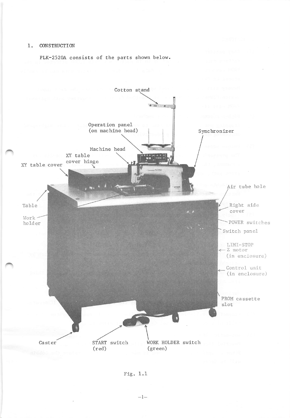
2.
(1)
FEATURES
Easy
pattern
change
Pattern
PROM
stored
Memory
device
PROM
(2)
High-performance
Stepping
stitching
(3)
Unique
The
movement,
given
(4)
Changeable
Pattern
XY
table,
data
cassette.
in
size
PTN-4000,
cassette.
motors
presser
presser
part,
start
can be
PROM.
stored
By
using the
can be expanded up
PTN-4000AorPTN-IOOO-OL
work
holder
and
belts
and
foot
thus
applique
pattern
or
increased
foot
moves
preventing
position
located
capable
up
and
start
may
to
productivity,
any
up
data
mechanism
used
of
and
down,
floating
heavy
position
be
determined
desired
to
10
patterns
input device,
to
4,000
to
drive
moving
being
of
material.
spot,
within
stitches
1,000
pattern
when
data
the
stitches
can be
data
is used together with optional
the
work
vertically
synchronized
fabrics
by
the
and
position
holder
securely
assure
with
detector
needle
holding
in
the
easily
input
high-speed
bar
a
on
the
(5)
(6)
(7)
(8)
(9)
Finely
Size
±4%
Easy
Stitching
stitch)
By
from
Various
Error
adjustable
of
pattern
independently
stitch
operation.
continuously
any
safety
lamps
Compact and
8-bit
Automatic
Powerful
Since
microcomputer
exceptionally
aligning
can
part
are
reliable
thread
thread
pattern
stored
in
be
suspended
operating
of
pattern
functions
provided
trimmer
trimmer
in
X and Y
design
is
used
permits
large
size
PROM
(SCALE
can
directions
HALT
and
iJOG
are
facilitating
hook
switch
amended
switches,
possible.
in
the
failure-free
is
function)
be
finely
by
means
and
JOG
or
aligned
pattern
tracing
full-electronic
control
used,
circuit.
frequency
adjusted
of
switch
checking
back
control
thread
to
within
digital
in
inching
of
trouble
trimming.
replace
switches.
(stitch
and
stitching
if
system
the
by
occurs.
bobbin
will
be
decreased.
-2-
Page 7
(10)
Mirror
image
(11)
With
Eacy
simple
machine
switch
maintenance
LIMIT-STOPZmotor
is
used
The
table
XY
to
table
cover.
drive
is
easily
operation,
equipped
the
sewing
symmetrical
with
machine,
accessible
clutch
requiring
for
pattern
featuring
almost
maintenance
is
easily
almost
permanent
no
maintenance.
by removing
stitched.
the
XY
life
-3-
Page 8
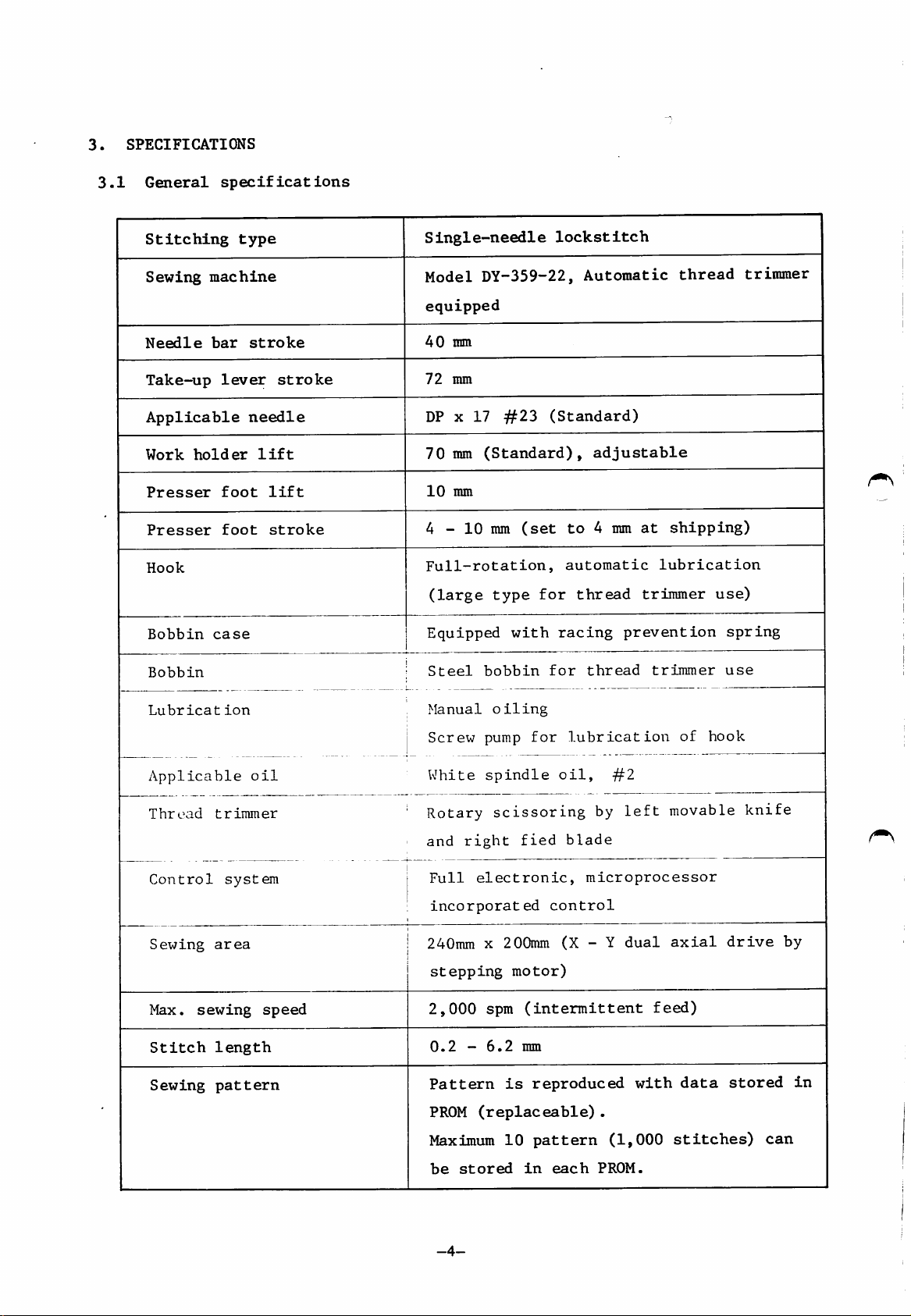
3.
SPECIFICATIONS
3.1
General
specifications
Stitching
Sewing
Needle
Take-up
Applicable
Work
Presser
Presser
Hook
Bobbin
holder
Bobbin
type
machine
bar
stroke
lever
needle
foot
foot
case
lift
lift
stroke
stroke
Single-needle
lockstitch
Model DY-359-22,
equipped
40
ram
72
mm
DP X 17
70mm
10
mm
4 -
Full-rotation,
(large
Equipped
Steel
#23
(Standard),
10
mm
type
bobbin
(set
with
(Standard)
for
racing
for
Automatic
adjustable
to4mm
automatic
thread
thread
thread
at
shipping)
lubrication
trimmer
prevention
trimmer
trimmer
use)
spring
use
Lubricat
Applicable
Thread
Control
Sewing
Max.
Stitch
Sewing
sewing
ion
trimmer
system
area
length
pattern
oil
speed
Manual
Screw
White
Rotary
and
Full
incorporated
oiling
pump
spindle
scissoring
right
electronic,
for
fied
lubrication
oil,
by
blade
microprocessor
control
240mm x 200mm (X - Y
stepping
2,000
0.2
Pattern
PROM
Maximum
motor)
spm
(intermittent
-
6.2
mm
is
reproduced
(replaceable).
10
pattern
#2
left
dual
with
(1,000
of
movable
axial
feed)
data
stitches)
hook
drive
stored
knife
by
in
can
be
stored
-4-
in
each
PROM.
Page 9
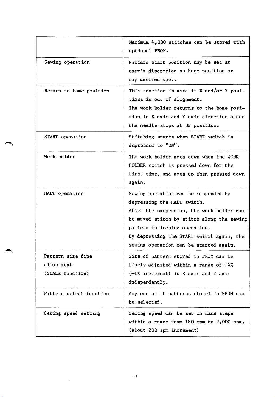
Maximum
4,000
stitches
can
be
stored
with
Sewing
Return
START
Work
operation
to
operation
holder
home
position
optional
Pattern
user's
any
desired
This
function
tions
The
work
tion
the
Stitching
in
needle
depressed
The
work
HOLDER
first
again.
PROM,
start
discretion
is
out
holder
X
axis
stops
starts
to
holder
switch
time,
position
spot.
is
of
"ON".
is
and
as
used
alignment.
returns
and
Y
at
UP
when
goes
pressed
goes
may
home
if
axis
position.
START
down
up
position
X
to
direction
when
down
when
be
set
and/or
the
switch
for
pressed
home
the
at
or
Y
posi
posi
after
is
WORK
the
down
HALT
Pattern
adjustment
operation
(SCALE
Pattern
Sewing
size
function)
•
select
speed
fine
function
setting
Sewing
depressing
After
be
moved
pattern
By
depressing
sewing
Size
of
finely
(±1%
increment)
independ
Any
one
be
selected.
Sewing
within
(about
operation
the
suspension,
stitch
in
operation
pattern
adjusted
ent
of
speed
a
range
200
the
HALT
inching
the
ly.
10
patterns
can
from
spm
can
be
switch.
by
stitch
operation.
START
can
be
stored
within
in
X
axis
be
set
180
increment)
suspended
the
switch
started
in
a
range
stored
in
spm
work
along
PROM
and
nine
to
holder
the
again,
again.
can
of
Y
axis
in
2,000
by
+4%
PROM
steps
can
sewing
the
be
can
spm,
-5-
Page 10
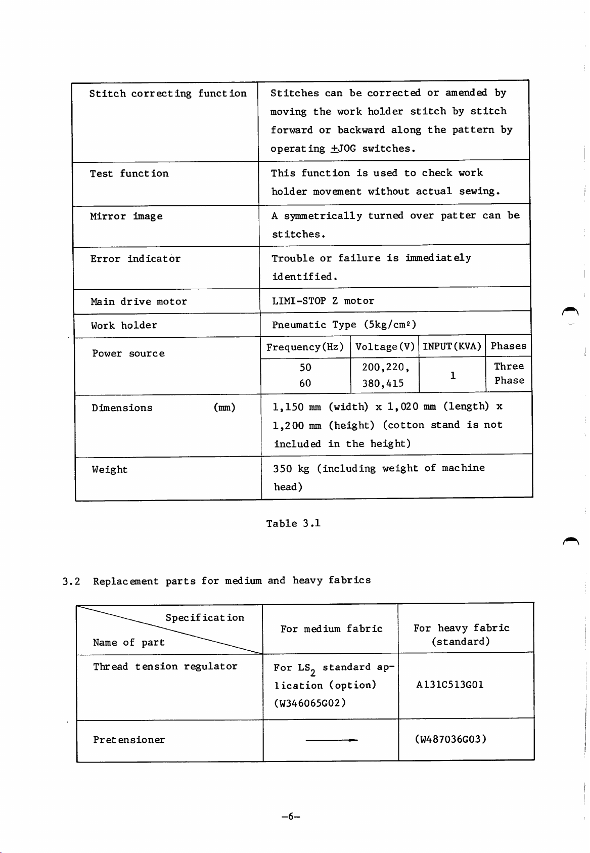
Stitch
correcting
function
Stitches
can
be
corrected
or
amended
by
Test
Mirror
Error
Main
Work
Power
function
image
indicator
drive
holder
source
motor
moving
forward
the
or
operating
This
holder
A
Stitches.
Trouble
LIMI-STOP
function
movement
symmetrically
or
identified.
Pneumatic
Frequency(Hz)
50
60
work
backward
±JOG
is
failure
Z
motor
Type
Voltage(V)
holder
along
switches.
used
without
turned
is
(5kg/cm2)
200,220,
380,415
stitch
the
to
check
actual
over
patter
immediately
INPUT(KVA)
by
stitch
pattern
work
sewing.
1
can
by
be
Phases
Three
Phase
3.2
Dimensions
Weight
Replacsnent
Name
of
Thread
tension
part
parts
Specification
for
regulator
(mm)
medium
1,150
1,200
included
350
head)
Table
and
For
For
lication
mm
mm
kg
(including
3.1
heavy
medium
LS^
standard ap-
(width)
(height)
in
the
fabrics
fabric
(option)
x
1,020
(cotton
height)
weight
mm
(length)
stand
of
machine
For
heavy
(standard)
AI31C513G01
is
fabric
x
not
(W346065G02)
Pretensioner
-6-
(W487036G03)
Page 11
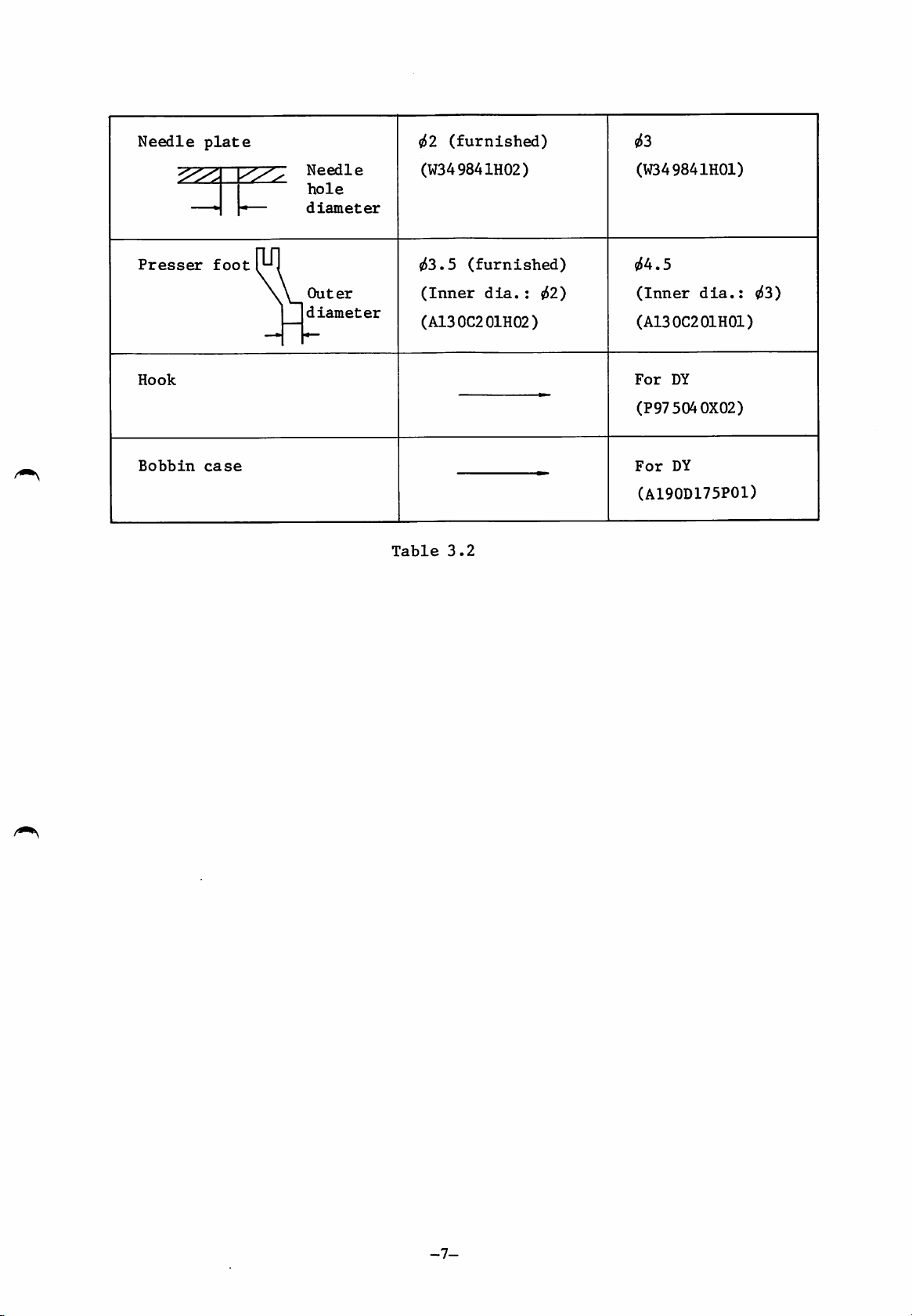
Needle
plate
(furnished)
<Z53
Presser
Hook
Bobbin
foot
case
Needle
hole
—
diameter
Outer
diameter
(W349841H02)
^3.5
(Inner
(furnished)
dia.:
(A130C201H02)
^2)
(W349841H01)
«54.5
(Inner
dia.:
(A130C201H01)
For
DY
^3)
(P975040X02)
For
DY
(A190D175P01)
Table
3.2
-7-
Page 12
4.
INSTALLATION
4.1
4.2
4.3
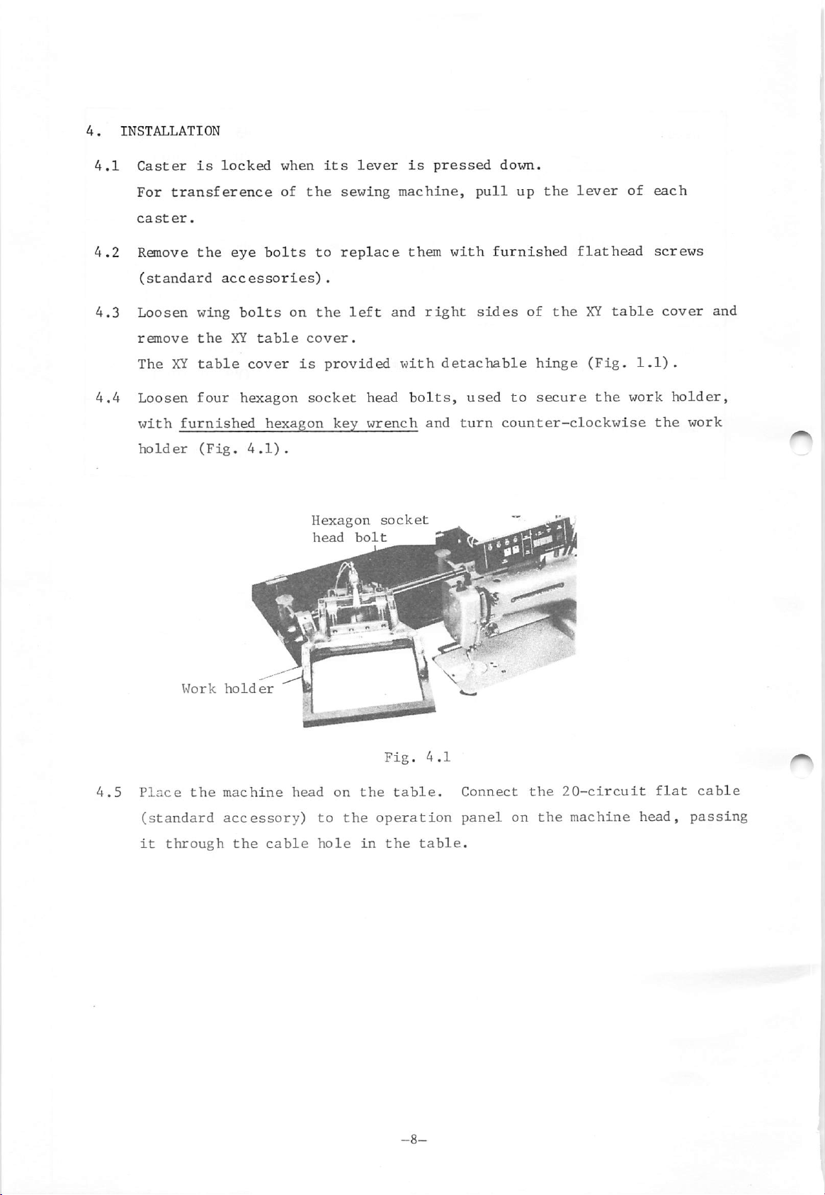
4.4
Caster
For
transference
caster.
Remove
(standard
Loosen
remove
The
XY
Loosen
with
holder
is
locked
the
accessories).
wing
the
table
four
furnished
(Fig.
eye
bolts
bolts
XY
table
cover
hexagon
hexagon
4.1).
when
of
on
is
its
the
sewing
to
replace
the
cover.
provided
socket
key
Hexagon
head
lever
left
head
wrench
bolt
machine,
and
with
socket
is
pressed
them
right
bolts,
and
down.
pull
with
furnished
sides
detachable
used
turn
up
the
lever
flathead
of
the
XY
to
hinge
secure
(Fig.
the
counter-clockwise
of
table
work
each
screws
1.1),
the
cover
holder,
and
work
4,5
Work
Place
(standard
it
through
the
holder
machine
accessory)
the
cable
head
to
hole
on
the
Fig.
the
table.
operation
in
the
4.1
table.
Connect
panel
on
the
the
20-circuit
machine
flat
head,
cable
passing
Page 13
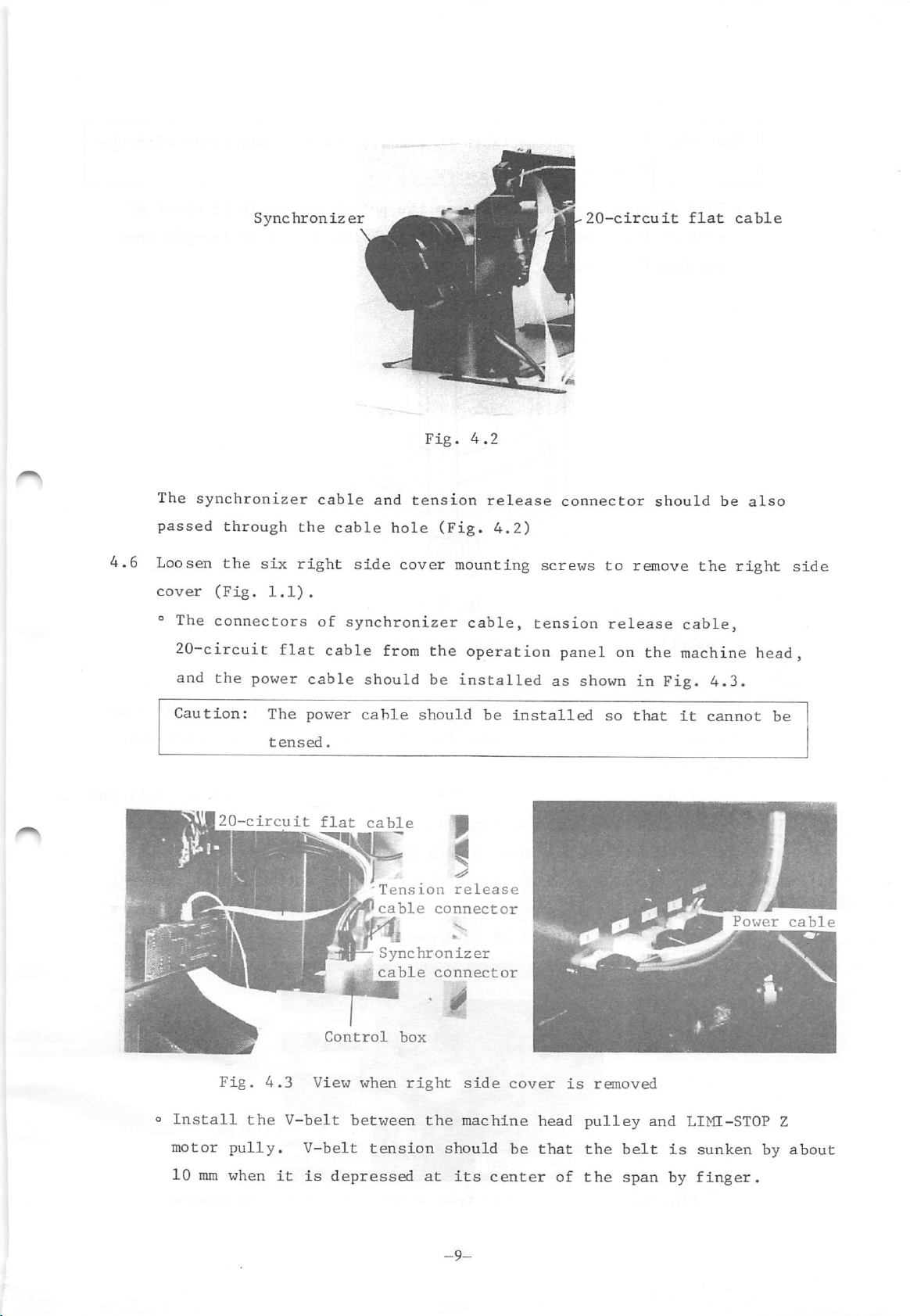
The
synchronizer
cable
and
Fig.
tension
4.2
release
20-circuit
connector
should
flat
be
cable
also
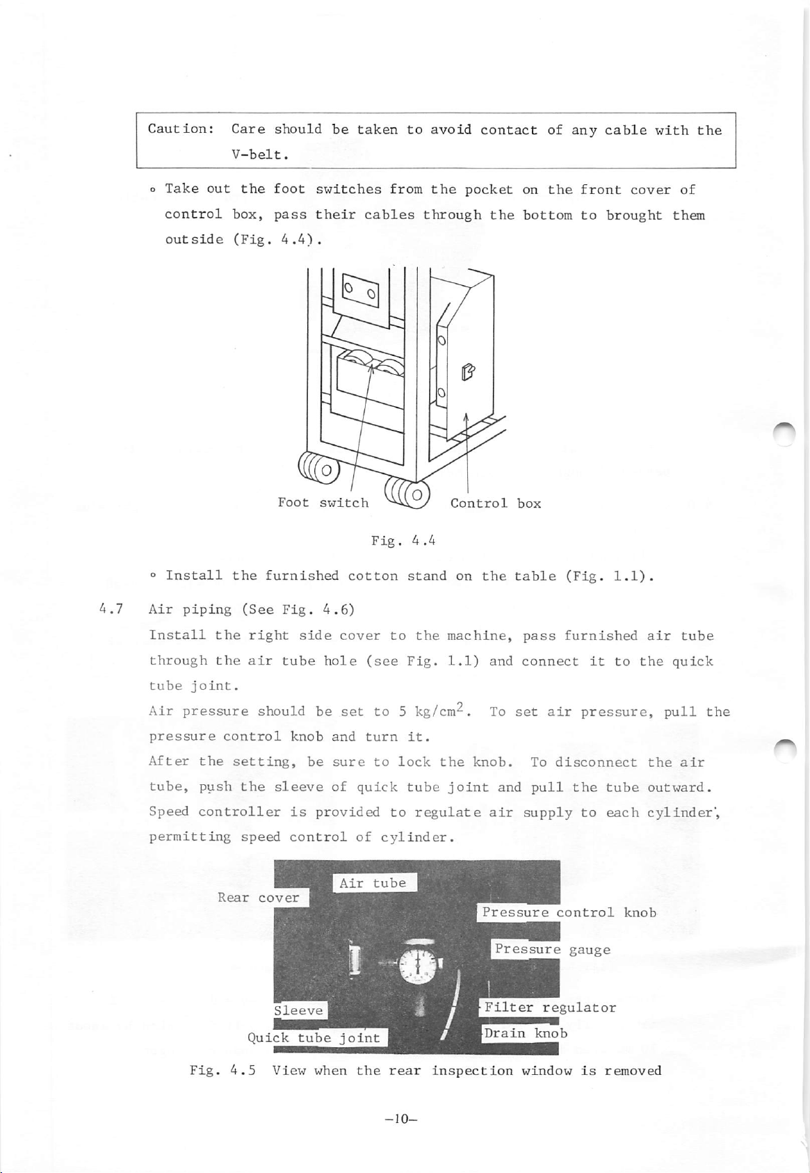
4.6
passed
Loosen
cover
® The
20'-circuit
and
Caution:
through
the
six
(Fig.
1.1).
connectors
flat
the
power
The
tensed.
20-circuit
the
right
of
cable
cable
power
flat
cable
side
hole
cover
synchronizer
from
should
cable
cable
Tension
cable
Synchronizer
cable
(Fig.
4.2)
mounting screws
cable,
the
operation
be
installed
should
connector
connector
be
release
tension
as
installed
to
release
panel on
shown
so
remove
the
in
Fig.
that
the
cable,
machine
4.3.
it
cannot
right
head,
Power
side
be
cable
o
motor
10
Install
nun
Fig.
pully.
when
the
4.3
it
View
V-belt
V-belt
is
Control
between
depressed
when
tension
box
right
the
at
side
machine
should
its
cover
be
center
head
that
of
is
pulley
the
the
removed
and
belt
span
LIMI-STOP Z
is
sunken
by
finger.
by
about
Page 14
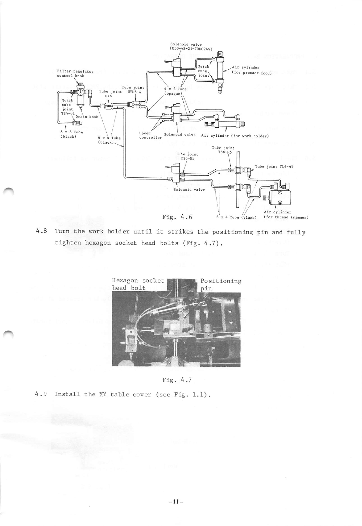
Caution:
0
Take
out
Care
V-belt,
the
should
foot
be
taken
switches
to
from
avoid
the
contact
pocket
on
of
the
any
front
cable
with
cover
the
of
control
outside
o
Install
Air
piping
box,
(Fig.
the
(See
pass
4.4).
Foot
furnished
Fig.
their
switch
4.6)
cables
Fig.
cotton
through
4.4
stand
Control
on
the
the
bottom
box
table
to
(Fig.
brought
1.1).
them
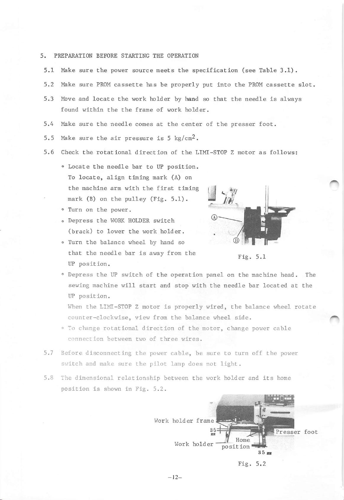
Install
through
tube
joint.
Air
pressure
pressure
After
tube,
Speed
permitting
the
right
the
air
control
the
setting,
push
the
controller
speed
Rear
Quick
side
tube
should be
knob
be
sleeve
is
provided
control
cover
Sleeve
tube
hole
and
sure
of
Air
joint
cover
to
(see
set
to 5 kg/cm^.
turn
to
quick
to
of
cylinder.
tube
the
Fig.
it.
lock
tube
regulate
machine,
1.1)
the
knob.
joint
and
To
and
air
Pressure
Pressure
Filter
pass
connect
set
To
pull
supply
regulator
furnished
it
air
pressure,
disconnect
the
to
control
gauge
to
tube
each
air
the
the
outward.
cylinder",
knob
tube
quick
pull
air
the
Fig.
4,5
View
when
the
rear
inspection
window
is
removed
Page 15
Filter
control
6x6
(black)
regulator
knob
T
CB
Tube
6x4
(black)^
joinc
Tube
Tube
UYD6-4
joint,
I
!onc2oller
Solenoid
(050-4E-2I-70DC24V)
4x3
(opaque)
Tube
Tube
TS6-H5
valve
joint
Air
cylinder
Tube
joint
TS6-M5
,Air
(for
(for
sylinder
presser
work
food)
holder)
Tube
joint
TL6-M5
4.8
Turn
tighten
the
work
hexagon
holder
socket
Hexagon
head
until
bolt
head
socket
Fig.
it
bolts
Solenoid
4.6
strikes
(Fig.
valve
the
4.7).
Positioning
pin
•J
^
6x4
Tube
1/
jf
(black)
positioning
- '
Air cylinder
(^of
pin
and
thread
trinmer)
fully
Fig.
4.7
4,9
Install
the
XY
table
cover
(see
-11-
Fig.
1.1).
Page 16
5.
PREPARATION
5.1
5.2
5.3
Make
Make
Move
sure
sure
and
BEFORE
the
PROM
locate
STARTING
power
cassette
the
source
work
THE
has
holder
OPERATION
meets
be
the
properly
by
hand
specification
put
into
so
that
the
the
(see
PROM
needle
Table
cassette
is
3.1).
slot.
always
5.4
5.5
5.6
found
Make
Make
Check
o
Locate
To
the
mark
®
Turn
o
Depress
(brack)
o
Turn
that
UP
®
Depress
within
sure
the
sure
the
the
rotational
the
needle
locate,
align
machine
(B)
on
on
the
the
to
the balance
the
needle
position.
the
the
the
needle
air
pressure
arm
with
the
pulley
power.
WORK
lower
bar
UP
switch
frame
comes
of
at
is
direction
bar
to
UP
timing
HOLDER
the
wheel
the
work
is
mark
(Fig.
switch
by
away
of
first
the
work
the
5 kg/cm^.
of
position.
(A)
timing
5.1).
holder.
hand
^
so
from
operation
holder.
center
the
on
the
of
the
LIMI-STOP
jJ
iw
®
panel
presser
Z
motor
^
® " |
on
Fig.
the
foot.
as
-j
r.
,
5.1
machine
follows:
head.
The
5.7
5.8
sewing
UP
When
counter-clockwise,
o To
connection
Before
switch
The
position
machine
position.
the
change
disconnecting
and
dimensional
is
will
LIMI-STOPZmotor
rotational
between
make
sure
relationship
shown
in
start
view
direction
two
the
the
Fig.
of
power
pilot
and
from
three
5.2.
Work
stop
is
properly
the
of
cable,
lamp
between
holder
Work
with
balance
the
wires.
does
be
the
frame
holder
the
wired,
wheel
motor,
sure
not
work
needle
the
side,
change
to
turn
light.
holder
Home
position'
bar
balance
power
off
and
located
wheel
cable
the
its
power
home
at
rotate
the
Fig.
5.2
Page 17
6.
CONTROL
SWITCHES
AND
FUNCTIONS
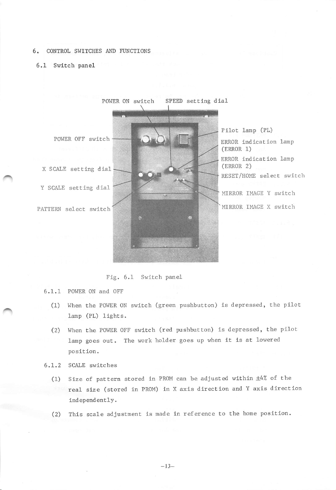
6.1
X
SCALE
Y SCALE
PATTERN
Switch
POWER
select
panel
OFF
setting
setting
switch
dial
switch
POWER
dial|
ON
switch
-
SPEED
setting
dial
Pilot
AERROR
I
(ERROR
I
ERROR
I
(ERROR
I RESET/HOME
1-
MIRROR
^MIRROR
lamp
indication
1)
indication
2)
IMAGE
IMAGE
(PL)
select
Y
X
lamp
lamp
switch
switch
switch
6.1.1
6.1.2
(1)
(2)
(1)
(2)
POWER
When
lamp
When
lamp
position,
SCALE
Size
real
independently.
This
ON
the
(PL)
the
goes
switches
of
size
scale
pattern
Fig.
and
OFF
POWER
lights.
POWER
out.
(stored
adjustment
6.1
ON
switch
OFF
switch
The work
stored
in
Switch
in
PROM)
is
panel
(green
(red
holder
PROM
inXaxis
made
pushbutton)
pushbutton)
goes
up when
can be
adjusted
direction
in
reference
is
depressed,
is
depressed,
it
within
andYaxis
to
the
is
at
home
the
the
lowered
±4%
of
direction
position.
pilot
pilot
the
Page 18
Cautions
1;
After
the
fine
adjustment
of
pattern,
test
should
be
6.1.3
6.1.4
6.1.5
2:
PATTERN
Any
one
select
of
patterns
"0"
to
"9").
SPEED
Sewing
(See
RESET/HOME
setting
speed
Table
performed
the
work
(Refer
Sewing
stitched.
(Refer
desired
by
operating
dial
can
8.1.)
select
to
speed
to
switch
be
to
holder
para.
para.
pattern
set
switch
check
may
the
frame.
6.3.3.)
8.1.)
PATTRN
by
be
can
this
that
reduced
be
dial.
the
selected
select
entire
when
switch
pattern
enlarge
from
pattern
10
different
(setting
is
within
is
ranges
from
(1)
(2)
6.1.6
RESET When
stopping
Causion;
HOME
Do
not
is
going
When
automatically
When
needle
to
In
MIRROR
A
direction
The
holder
pattern
switch
IMAGE X, Y
can
symmetrically
by
operating
setting
(MOVE
...
this
set
on.
this
the
automatically
the
home
usual
switches
does
para.
toggle
all
movements.
the
switch
toggle
returns
needle
position
operation,
these
not
6.3.2.)
switch
to
switch
position
the
turned
switches.
affect
and
to
goes
(see
is
RESET
is
the
is
up
Fig.
switch
over
axial
work
set
upward,
position
set
downward,
home
other
and
5.2).
is
in
X
movement
holder
position.
than
the
work
set
direction
traverse
the
while
UP
at
of
brake
stitching
the
position,
holder
HOME
and
the
direction
work
position.
Y
work
works
holder
the
returns
at
home
Since
mirror
ignor
ed.
return
the
image
mirror
(refer
switch
image
to
conditions
setting
para.
-14-
during
6.1.5).
are
initially
stitching
or
set,
test
change
operation
of
is
Page 19
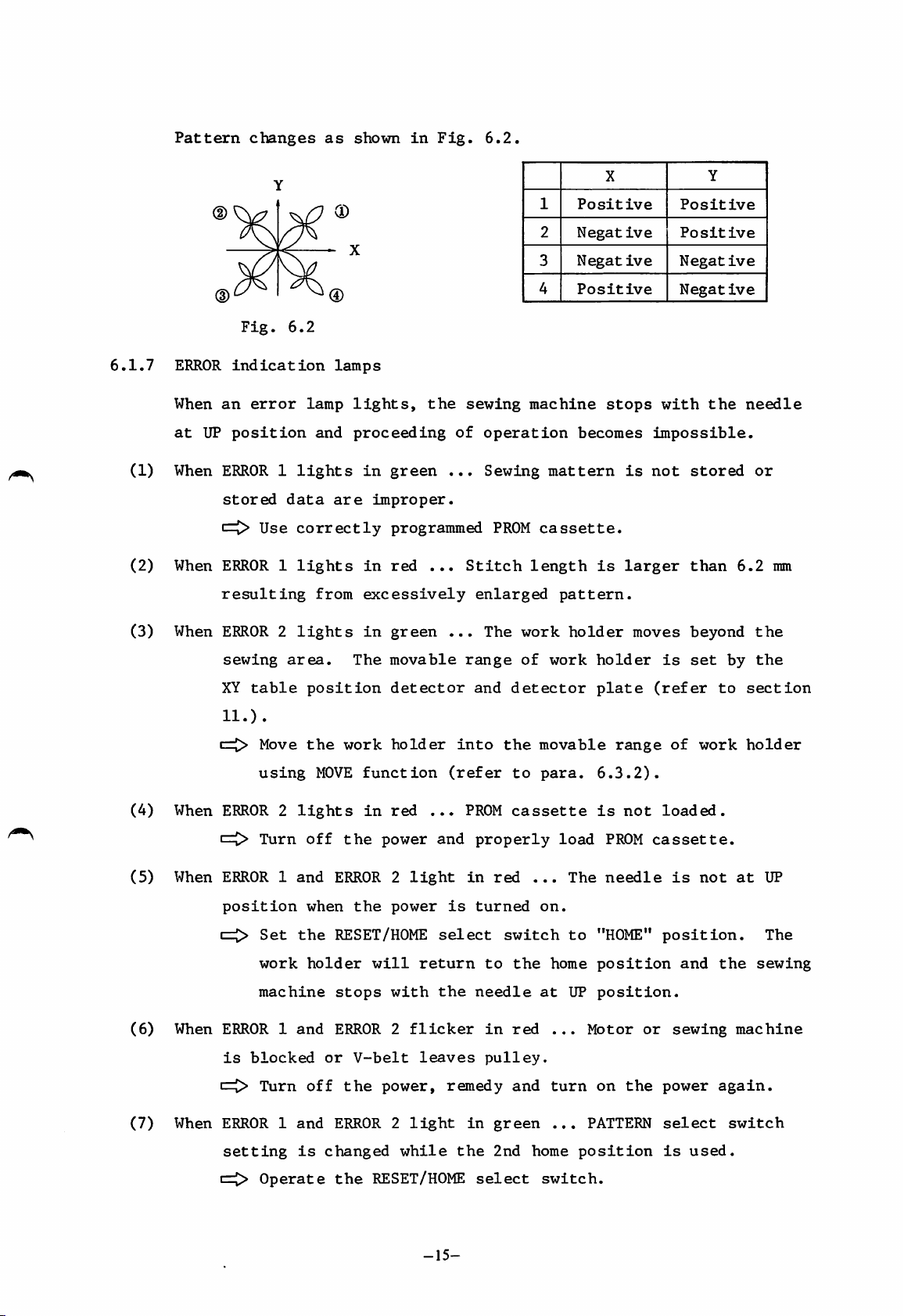
Pattern
changes
as
shown
in
Fig.
6.2.
6.1.7
(1)
(2)
ERROR
When
at
UP
When
When
Y
(D
Fig.
6.2
indication
an
error
lamp
position
ERROR1lights
stored
n=I>
Use
data
correctly
ERROR1lights
resulting
lamps
and
are
from
lights,
proceeding
in
green
improper.
programmed
in
red
excessively
the
...
sewing
of
...
Stitch
operation
Sewing
PROM
enlarged
1
2
3
4
machine
mattern
cassette.
length
pattern.
X
Positive Positive
Negative
Negative
Positive
stops
becomes
is
with
impossible.
is
not
larger
Y
Positive
Negative
Negative
the
stored
than
needle
or
6.2
mm
(3)
(4)
(5)
(6)
When
When
When
When
ERROR2lights
sewing
XY
11.)
cij>
table
.
Move
using
area.
position
the
MOVE
ERROR2lights
i=0>
Turn
off
ERROR1and
position
1=0
Set
the
work
machine
when
holder
ERROR1and
is
blocked
in
green
The
movable
detector
work
holder
function
in
red
the
power
ERROR2light
the
power
RESET/HOME
will
return
stops
with
ERROR2flicker
or
V-belt
leaves
...
(refer
...
and
is
select
the
The
range
and
into
PROM
properly
in
turned
to
needle
in
pulley.
detector
the
to
cassette
red
switch
the
red
work
of
movable
para.
...
on.
at
holder
work
load
The
to
home
UP
...
holder
plate
range
6.3.2).
is
PROM
needle
"HOME"
position
position.
Motor
moves
not
or
beyond
is
set
(refer
of
work
loaded.
cassette.
is
not
position.
and
sewing
by
to
section
holder
at
the
machine
the
the
UP
The
sewing
1=0
(7)
When
Turn
ERROR1and
setting
c=0
Operate
off
the
ERROR2light
is
changed
the
power,
while
remedy
the
RESET/HOME
-15-
in
select
and
green
2nd
turn
.,.
home
switch.
on
PATTERN
position
the
power
select
is
used.
again.
switch
Page 20
6.2
Foot
switches
(Fig.
1.1)
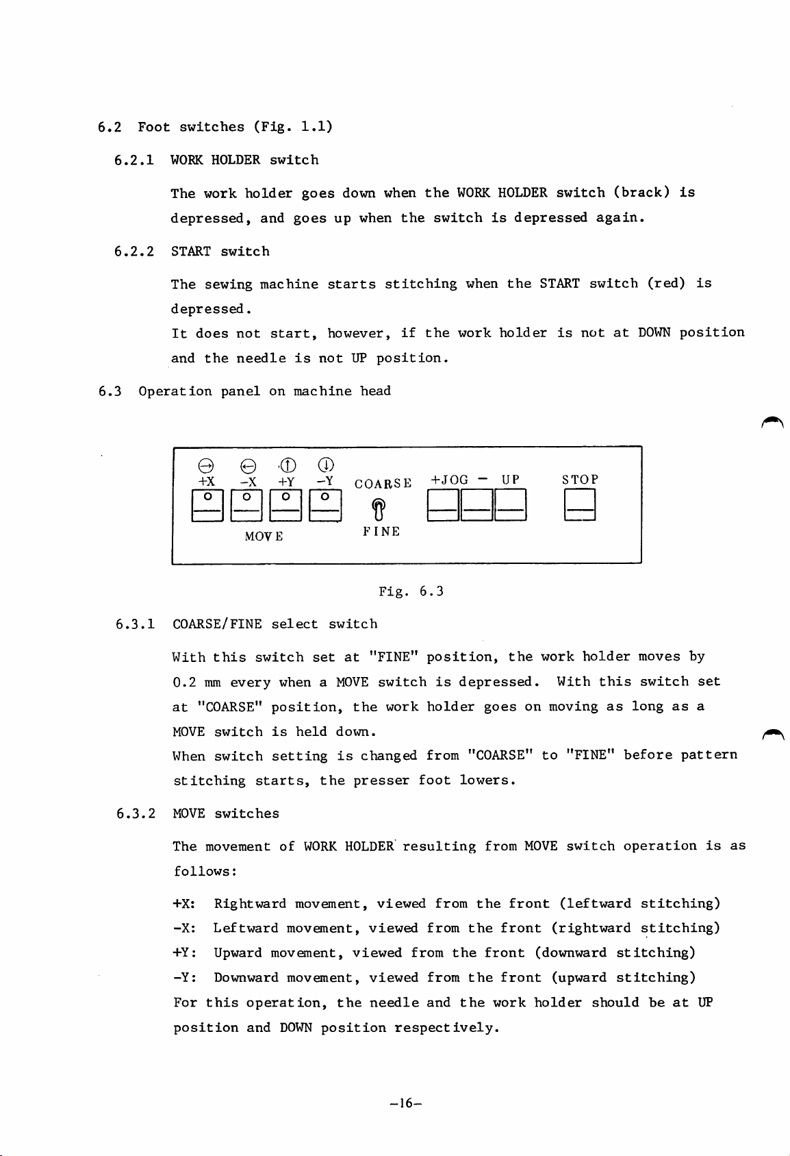
6.3
6.2.1
6.2.2
WORK
The work
depressed,
START
The
depressed.
It
and
Operation
HOLDER
sewing
does
the
+X
switch
not
needle
panel
-X
switch
holder
and
machine
start,
on
MOVE
goes
goes
is
machine
+Y
down when
up
starts
however,
not
UP
-Y
COARSE
when
position.
head
FINE
the
the
stitching
if
the
+^0G
WORK
switch
work
when
HOLDER
is
depressed
the
holder
UP
switch
START
is
STOP
again.
switch
not
(brack)
(red)
at
DOWN
is
is
position
6.3.1
6.3.2
coarse/FINE
With
0.2
at
"COARSE"
MOVE
When
this
mm
switch
switch
every
stitching
MOVE
The
follows:
+X:
-X:
switches
movement
Rightward
Leftward
+Y: Upward
-Y:
Downward
select
switch
when a
position,
is
held
setting
starts,
of
movement,
movement,
movement,
movement,
switch
set
the
WORK
at
MOVE
the
down.
is
changed
presser
HOLDER
viewed
Fig.
"FINE"
switch
work
viewed
viewed
viewed
6.3
position,
is
holder
from
foot
resulting
from
from
from
from
depressed.
goes
"COARSE"
lowers.
from
the
the
the
front
the
the
on
MOVE
front
front
front
work
holder
With
moving
to
"FINE"
switch
(leftward
(rightward
(downward
(upward
this
as
long
before
operation
stitching)
stitching)
moves
switch
as
pattern
stitching)
stitching)
by
set
a
is
as
For
this
position
operation,
and
DOWN
the
position
needle
respectively.
-16-
and
the
work
holder
should
be
at
UP
Page 21
6.3.3
(1)
+JOG
TEST
switches
function
(2)
Only
the
speed
returned
When
opposite
When
end
position.
When
the
the
of
the
position,
START
During
up
for
ing
operation).
Stitch
For
correction
work
while
to
-JOG
direction.
+JOG
pattern,
-JOG
switch
the
work
correct
it
test,
holder
the
+JOG
the
home
switch
switch
the
switch
stops
is
depressed),
holder
function
or
advances
switch
position.
is
is
work
is
there
the
presser
traversing
amendment
in
is
depressed,
held
down
holder
held
down
permitting
or
foot
(the
of
the
held
the
and
goes
and
test
goes
work
stitches,
stitching
down
work
the
up
and
the
start
(the
down
after
work
work
of
+JOG
holder
the
direction
the
holder
holder
then
holder
stitching
switch
for
moves
work
work
moves
reaches
returns
reaches
is
stitching,
without
holder
at
a
fixed
holder
in
the
the
to
the
the
(xi7hen
the
operated).
and
stitch
can
be
is
home
home
goes
moved
6.3.4
6.3.5
in
forward
by
operating
depressing
This
UP
When
than
When
in
that
test
switch
to
the
This
position.
STOP
inching
the
operation.
the
the
UP
UP
function
switch
the
replenishment
or
the
the
motion
work
sewing
position,
position.
sewing
backward
+JOG
STOP
holder
machine
can
be
machine
of
bobbin
direction
or
switch
is
same
moves
this
used
-JOG
(refer
as
stops
switch
only
must
thread,
switch
that
at
with
when
be
stitch
to
of
a
speed
the
is
the
stopped
this
by
stitch
after
para.
stitching
6.3.5).
test
lower
needle
depressed
work
for
switch
function,
than
at
a
to
holder
thread
is
used.
along
is
the
position
locate
is
breakage
the
suspended
but
differs
speed
the
at
the
pattern
in
other
needle
DOWN
or
for
by
Stitching
It
is
-JOG
also
switch.
can
possible
be
resumed by
to
move
depressing
the
work
-17-
the
holder
START
by
operating
switch
(red).
the
+JOG
or
Page 22

7.
7.1
OPERATION
Loading
the
PROM
cassette
7.2
7.3
Open
necessary
care
fail
For
PROM
the
not
to
pattern
writer
install
necessary.
PROM
Switch
In
follows:
Set
one
RESET/HOME
Switch
cassette,
order
the
of
setting
SCALEXand
IG
function
switch
pattern
to
insert
writing
(PT-100,
For
to
check
positions
switch
panel
data
it
the
front
and
selection
refer
on
switch
each
to
checking
front
in
have
wrong
erasure
cover
been
cover
and
stored
direction.
again.
to
and
insert
into
from
a
the
After
PROM,
PT-IOOA, PTN-4G00, PTN-4000A,
of
to
function,
Y
switches
("0"
"HOME"
section
panel
-
"9"),
position.
PROM,
to
13.
set
the
refer
"G",
each
the
SPEED
to
Table
switch
PATTERN
setting
PROM
cassette
cassette
the
insertion,
optionally
PTN-IOGQ-OL)
7.1.
on
the
select
dial
slot,
For
switch
switch
to
"4",
in
which
using
do
available
is
handling
panel
to
and
not
of
as
any
the
When
on
(1)
(2)
(3)
the
the
power
Home
Set
sure
6.1.5)
Work
The
depressed
Work
The
switch
When
to
stops
work
above-mentioned
and
check
return
the
reset/home
the
work
.
holder
work
lowering
holder
(it
holder
work
the
the
at
holder
holder
id
depressed.
work
UP
position,
the
movement
UP
is
holder
should
goes
should
holder
position
moving
preparatory
each
function
to
"RESET"
returns
motion
go
up
when
move
reaches
and
...
down
the
return
when
refer
position
to
when
switch
tracing
the
to
the
operation
as
follows:
the
home
the
the
end
of
the
+JOG
to
para.
and
position
WORK
is
depressed
given
the
home
switch
6.3.3).
has
then
HOLDER
pattern,
position
been
to
pattern
is
released
completed,
"HOME"
(refer
switch
again).
when
it
will
(the
to
to
is
the
work
while
turn
make
para.
go
holder
+JOG
up
the
-18-
Page 23

When
does
By
performing
the
not
test
occur.
is
the
made,
test,
only
check
the
work
the
holder
dimensions
moves
and
and
location
stitching
of
the
motion
work
7.4
7.5
holder.
and
proceed
Sewing
(1)
Refering
(2)
Set
work
start
Once
released,
thread
STOP
To
Stitching
To
switch
suspend
trimming.
start
To
check
as
operation
upafabric
holder.
stitching.
stitching
trimming.
operation
stitching,
stops
stitching
stitching
instructed
to
Fig.
and
with
again,
and
Then
starts,
stops
the
in
6.1.,
depress
depress
with
depress
work
adjust
condition,
para.
properly
the
the
it
continues
the
work
the
STOP
holder
the
7.4.
set
WORK
START
at
stitching
set
switches
HOLDER
switch,
even
holder
switch
the
stitching
when
at
(see
DOWN
atart
speed
on
the
switch
the
the
the
UP
Fig.6.3).
position
position
switch
to
sewing
START
position
to
let
after
"low
panel.
down
machine
switch
after
thread
by
operating
speed"
the
will
is
the
+JOG
sewing
Note:
machine
In
is
needle
PROMXQ'ty
2716
2716
2732
2732
Note:
X 1
X 2
X 1
X 2
For
PROM
and/or
order
-JOG
starts
to
recommended
thread.
Table
use
sockets
7.1
of
make
Number
two
switches
and
yourself
to
of
1000
2000
2000
4000
(PROM
PROMs, a
should
and
sews
the
operate
stitches
combination)
P.O.
be
used.
depress
remaining
familiar
switches
board
the
with
on
Number
of
START
pattern.
each
the
switch
of
10
10
10
10
Cassette
switch
switch
patterns
panel
case
again.
function,
without
having
The
it
two
-19-
Page 24

7.6
Checking
starting
operation
Operation
procedure
and
checking
The sewing machine should be
the
following
before
(1)
(2)
(3)
(4)
flow
Is
the
plugged
and
Are
plugged?
Is
PROM
machine?
Are
chart:
power
in
connector?
all
other
cassette
fuses
power
not
operated
cable
source
cables
loaded
blown
and checked
outlet
properly
on
out?
the
in
accordance
with
Section
paragraph
refferred
Operation
Preparation
Judgement
or
to
be
to
(^Preparation
Depress
POWER
LIMI-STOP
holder
to
Depress
switch
ON
Does
Z
motor
start
Does
the
work
its
position
9
WORK
to
switch.
return
start]
?
Yes
home
HOLDER
"ON".
Check
cable
connection.
Depress
POWER
No
Set
switch
"HOME"
Set
switch
"RESET"position
power
OFF
switch.
RESET/HOME
to
position
RESET/HOME
to
Check
of
direction
rotation.
Depress
ON
switch.
/Change
reversing
plug
POWER
phase'
setting
Turn
wheel
needle
the
Depress
machine
the
holder
the
to
UP
the
Does
work
down?
balance
locate
away
position
UP
Does
sewing
7
go
the
from
switch.
No
start
Depress
HOLDER
again
Depress
OFF
WORK
switch
to
switch.
"OFF"
POWER
(i8o'»).;
{
To
the next page }
-20-
Adjust
work
mechanism.
Check
LIMI-STOP
Z
motor
connection.
the
holder
cable
Page 25

Depress
POWER
switch.
Adjust
the
synchronizer
setting.
OFF
No
(
From
previous
direction
of
rotation
correct
the
page
Is
7
need!
ion
Test
operation
Set
switch
"HOME"
Set
switch
"RESET"
set
check
PROM
RESET/HOME
RESET/HOME
JOG
to
"OFF
cassette.
to
position.
to
position.
switch
t
•
No
Set
^et
depress
+JOG
work
properly
in
the
PATTERN
SCALE
the
reference
the
holder
switch
Does
work
holder
MOVE?
Is
the
holder
positioned
patter
?
Does
work
switch./
go
No.
to
^
No
No
Depress
OFF
switch.
POWER
Check
mechanism
and
c
Adjust
work
mechanism.
drive
control
ircuit.
holder
Preparation
completed
To
the
next page )
-21-
Page 26

(
Sewing
Set
stitching
speed.
Set
a
fabric(s).
up
start
)
Automatic
sewing
operation
Depress
WORK
switch
Depress
switch
mach
HOLDER
to
running
"ON'
ion
START
to
"ON"
Depress
WORK
switch
to
Depress
OFF
depress
switch
HOLDER
"OFF".
switch.
to
again
POWER
STOP
"ON"
PROM
data
input
broken
trimmed
pf
the
trimmer
satisfactory
thread
well
Is
thread
stitching
Are
threads
at
stitching
?
Is
thread
operation
9
Is
balanced
9
Ce^
during
the
tension
end
Depress
Switch
Depress
OFF
ligned
to
switch.
START
"ON".
POWER
(Operate
JOG
switches
to
align
stitches.
Adjust
sewing
machine.
the
-22-
Page 27

8.
(1)
CAUTIONS
Before
ON
USE
replacement
of
PROMinPROM
cassette,
carefully
read
section
13
(2)
(3)
(4)
(5)
(6)
(7)
"REPLACING
The
power
If
any
ERROR
in
para.
When a
finely
ship
Maximum
(Refer
Dust
During
When
When
power
new
adjusted,
between
to
in
operation,
the
adjustment
before
THE
should
6.1.7.
pattern
sewing
item
the
power
PROM".
lamp
the
speed
12.4
control
is
gaining
be
lights,
be
work
the
is
turned
is
sure
depends
for
unit
turned
made
access
off
trace
stitched
to
holder
detail)
might
control
on,
on
before
for
perform
movement
on
cause
box
foot
the
sewing
to
the
its
cause
the
test
stitch
cover
should
mechanisms
PROM
cassette
referring
first
operation
and
the
length.
malfunction
should
not
machine,
time,
pattern.
be
be
placed
be
or
is
to
or
to
or
trouble.
kept
sure
control
loaded
the
pattern
check
close.
on
the
to
turn
box
or
unloaded.
description
size
the
relation
START
off
interior.
is
switch.
the
(8)
(9)
Do
not
ment.
voltage
Since
drain
4.5).
apply
Ohterwise
from
air
fed
knob
a
the
af
multimeter
semiconductors
multimeter.
to
the
filter
regulator
to
pneumatic
the
control
in
line
to
the
circuit
contains
eliminate
circuit
might
moisture,
accumulated
for
checking
be
damaged
depress
water
or
the
(see
adjust
due
to
Fig.
-23-
Page 28

9.
9.1
HANDLING
Installation
THE
SEWING
of
MACHINE
needle
(Fig.
HEAD
9.1)
Prime
should
to
side
Caution:
Fully
turn
the
left
set
screw.
groove
come
the
left
insert
the
Before
for
prime
side
safety.
the
groove
and
installing
needle,
to
tighten
or
removing
Needle
inserted
direction
not
the
in
needle,
fully
wrong
turn
Prime
in
off
wrong
the
groove
direction
power
facing
9.2
Winding
the
[Adjustment]
bobbin
—
Tension
for
-
Conically
smaller
-
Length
adjusting
loosen
thread
of
polyester
diameter
of
the
Fig.
(Fig.
wound
wound
would
screw
screw
and
9.1
9.2)
thread
nylon
thread
of
thread
to
increase
to
....
thread.
wound
decrease.
Small
Move
thread
Tighten
length
tension
the
layers.
of
thread
the
wound
is
thread
thread,
recommended
guide
toward
length
and
-24-
Page 29

adjusting
i
Hi
80%
capacit
be
fill
cvl
indr
of
ced
on
d
need:
and
tensio:
Tight
tensi
bobbi
on.
n
nee
dl
e
th
re
or
loo
se
th
re
ad
t
en
se
sion,
needle
or
thr
tigh
Page 30

9.5
Installing
the
bobbin
9.6
9.5.1
9.5.2
9.5.3
9.6.1
Put
bobbin
Put
and
(D).
Pull
to
rotates
If
clockwise,
(B).
Installing
Locate
uppermost
the
the
the
lead
the
make
the
lower
bobbin
case
thread
it
thread
sure
clockwise.
bobbin
the
the
position
cover.
(A).
out
the
rotates
reverse
bobbin
needle
(B)
in
from
(E)
into
the
downward
bobbin
the
case
bar
and
slit
the
counter
bobbin
to
open
the
hole
(B)
its
(C)
Fig.
9.6
(D
9.7
9.6.2
Fully
latch
latch,
Adjusting
Needle
adjusted
tension
Tension
turned
Tension
turned
open
(A)
put
the
thread
by
turning
regulating
increases
clockwise.
decreases
counter-clockwise.
the
and,
it
needle
tension
bobbin
holding
into
thread
can
the
tumb
when
when
(B).
thread
nut
case
the
tension.
be
(A).
it
it
Fig.
is
is
Fig.
9.7
9.8
-26-
Page 31

9.8
Adjusting
the
bobbin
thread
tension
9.9
9.9.1
(1)
Bobbin
adjusted
adjusting
Tension
turned
Tension
turned
Lubrication
To
1ean
Lean
the
red
thread
by
turning
screw
increases
clockwise.
decreases
counter-clockwise.
fill
ed
the
the
bac
machine
oiling
line
tension
kward
hole
(B)
(A).
oil
.
the
tank
head
(A)
can
when
when
until
be
thread
it
it
with
and
is
is
the
pour
level
machine
oil
reaches
head
through
the
9.9.2
(2)
(1)
(2)
Oiling
requiring
If
it
Oil
To
fill
leaning
Loosen
gauge
machine
When
up
to
paint,
with
sufficient
(Fig.
rate
must
used:
the
the
and
found
bed.
the
the
the
9.11).
has
readjustment
be
adjusted,
White
oil
machine
remove
on
the
oil
gauge
lower
oil
tank
Oil
gauge
been
tank
the
end
amount
factory-adjusted,
in
usual
refer
spindle
without
head
oil
top
is
oiled
of
is
,
of
white
filled
of
oil,
oil
operation.
to
para.
#2
9,25.
Fig.
9.12
Fig.
White
9.11
paint
Page 32

(3)
If
oil
is
not
sufficient,
pour
suitable
quantity
of
oil
through
the
9.10
9.10.1
9.10.2
9.10.3
•9.10.4
9.10.5
threaded
Timing
Needle
Turn
the
lowermost
Remove
face
Loosen
screw
Vertically
(C)
bar
After
hole
adjustment
bar
position
the
balance
needle
position.
the
plate
the
(B).
to
adjust
motion*.
the
adjustment,
bar
rubber
(A).
needle
move
for
between
can
wheel
(C)
the
timing
oil
to
plug
bar
gauge
needle
be
to
the
from
bracket
needle
of
tighten
(Fig.
adjusted
located
the
bar
needle
motion
as
set
the
9.12).
and
follows:
hook
motion
Fig.
(D
©
9.13
9.11
set
*
Timing
-
When
the
needle
be
of
-
With
above
(E)
with
eye.
-
There
them
needle
Adjusting
screw
of
the
lowermost
bar
in
line
the
needle
the
step,
of
hook
the
are
should
used.
the
(B).
needle
needle
position,
timing
with
bar
adjustment
the
should
center
four
be
hook
bar
bar
mark
the
bushing
inside
(D)
timing
selected
position
(C)
lower
at
be
of
motion
is
the
(B)
the
surface
aligned
needle
marks
for
at
must
edge
(A).
and
the
one
of
© d)
)
1
Fig.
For
For
DB X 1
DP X
9.14
17
9.11.1
9.11.2
Loosen
Turn
point*.
and
the
position
hook
screw
the
(A).
hook
-28-
(B)
to
adjust
timing
of
motion
of
hook
Page 33

9.11.3
Gap
the
between
hook
point
the
needle
(C)
should
(D)
be
and
©
(1)
(2)
about
*
Timing
The
follows:
When
lifted
lowermost
timing
needle
2.4
conditions
The
the
The
upper
point
0.05
of
standard
the
by
marks
bar
mm),
hook
center
gap
between
edge
(D)
mm.
hook
needle
2.4
position
at
the
should
point
(C)
(E)
should
point
timing
bar
mm
from
(refer
(A)
put
an
interval
following
be
(D)
should
of
needle.
the
and
the
be
motion
is
as
(B)
the
on
satisfied,
needle
hook
within
is
the
to
of
meet
eye
a
"^5
^^2
Fig.
♦
©
^mm
9.15
©
1.5
mm
2.4mm
9.11.4
range
Location
Position
side
surface
stopper
from
point
of
of
1.0
hook
the
mm
of
(A)
to
positioner
hook
needle
as
1.5
mm.
positioner
(B)
is
shown
to
in
the
(A)
line
should
right.
with
'A)
be
the
Fig.
adjusted
side
Fig.
9.16
surface
9.17
so
that
of
the
hook
-CB)
-29-
Page 34

9.12
Thread
tensions
9.12.1
9.12.2
9.13
9.13.1
9.13.2
Needle
tension.
Bobbin
by
thread
Needle
by
takeup
tension
(A)
(3)
Adjusting
Put
into
the
Tie
(D)
thread
thread
changing
tension
thread
changing
spring
regulator,
of
thread
pressure
the
the
the
thread
furnished
to
the
tension
intensity
(1)
bobbin
bobbin
bobbin
(C)
thread
tension
spring.
tension
(B)
takeup
of
should
intensity
of
(2)
tension
thread
with
case
through
be
can
be
of
bobbin
can
be
of
needle
movable
spring
discs
tension
polyester
(A)
and
the
hexagon key wrench
(C)
to
hang
adjusted
adjusted
case
adjusted
thread
thread
range
(B),
(C).
thread
lead
slit
the
and
out
(B).
(small)
key
in
reference
#30
Fig.
to
9.18
\
bobbin
thread
(D
-d)
-©
9.13.3
wrench,
The
standard
that
the
when
and
*The
the
down.
Standard
bobbin
adjusted
bobbin
Thread
is
turned
turned
as
shown
bobbin
thread
bobbin
bobbin
by
case
tension
clockwise,
counter-clockwise.
is
case
thread
thread
turning the
thread
increases
in
Fig.
thread
gradually
tension
tension
is
and
9.18
slowly
tension
screw
when
decreases
tension*
unwound
swung
can
be
(B)
spring
the
is
up
of ^
(A).
screw
when
Fig.
'
123
Fig.
9.19
9.20
-30-
Page 35

9.14
Adjusting
the
needle
thread
tension
9.14.1
9.14.2
(Adjusting
takeup
Loosen
turn
until
(a)
Turn
the
with
turn
round.
The
spring)
the
tension
intensity
reaches
the
takeup
the
the
needle
adjusted
Standard
-
50g
the
tension
zero.
thread
spring
spring
tension
thread
to
the
needle
intensity
stud
of
stud
stopper
standard
thread
stud
(B)
counter-clockwise
thread
(B)
(A) comes
stud
(B)
tension
tension:
of
thread
set
screw
takeup
clockwise
into
and
then
about
will
tension.
spring
contact
further
3/4
be
About
and
until
40
-M
Fig.
(D
9.21
-31-
Page 36

9.15
Adjusting
spring
the
intensity
of
thread
takeup
9.15.3
9.16
9.15.1
9.15.2
9.16.1
9.16.2
Loosen
(A).
Intensity
can
tension
Spring
tension
and
counterclockwise.
After
set
Adjusting
spring
Loosen
stud
Turn
nut
counter-clockwise
the
be
adjusted
stud
intensity
stud
decreases
the
screw
the
the
set
the
(C)
clockwise
tension
of
thread
(B).
is
when
adjustment,
(A).
movable
needle
screw
tension
by
increases
turned
it
range
thread
(B).
regulating
or
to
stud
takeup
turning
clockwise,
is
tighten
of
adjust
set
turned
takeup
tension
screw
spring
the
when
the
thumb
movable
the
Fig.
(D
9.22
©
9.16.3
range
The
thumb
decreases
counterclockwise.
*The
takeup
takeup
guide
of
takeup
movable
nut
standard
spring
spring
(D))
range
is
when
ranges
spring*.
turned
turned
movable
(gap
(A)
increases
clockwise,
range
between
and
the
from
9mm
when
of
the
thread
to
the
and
lOmm.
Fig.
9.23
-32-
Page 37

9.17
Adjusting
the
thread
tension
discs
9.17.1
9.17.2
9.17.3
9.17.4
Lift
Loosen
set
Move
(B)*in
arrow
so
that
discs
0.8mm
After
tighten
*Whenever
regulator
make
discs
0.8mm
the
screw.
the
sure
presser
the
the
in
the
(a)
to
the
the
(a)
to
Fig.
1.0mm.
thread
tension
direction
9.23,
opening
is
within
adjustment,
set
the
needle
set
screw
the
opening
is
within
1.0mm.
foot.
tension
regulator
and
of
a
screw.
is
a
regulator
indicated
position
the
range
be
sure
thread
loosened,
of
tension
range
bushing
by
tension
from
to
tension
from
liilsigl
Tl-ij;
it
0.8-1.0mm
O
Fig.
9.24
9.18
Adjusting
9.18.1
9.18.2
Tighten
by
fingers
until
Loosen
range
rate.
the
it
the
of
hook
oiling
or
stops.
adjusting
one
oiling
adjusting
small
turn
rate
screwdriver
screw
to
adjust
screw
within
oiling
(A)
a
Fig.
9.25
-33-
Page 38

9.18.3
Hook
oiling
rate
can
be
checked
by
observing
from
Caution:
Max.
(about
the
the
hook,
r\
•:\
oiling
25Chng/min)
oil
onatest
Do
not
tighten
adjusting
rate
trace,
excessively
the
oiling
screw
Standard
splashed
paper
(A).
oiling
OD
(B).
rate
Min.
oiling
©
rate
Fig.
9.25
Oil
splashed
Fig.
from
9.26
hook
(for
10
sec.)
-34-
Page 39

9.19
Adjusting
the
presser
foot
9.19.1
Adjusting
• -' P r e s s u
Height
adjusted
of
so
the
the
that
height
presser
the
of
foot
lower
presser
should
end
foot
be
^^Pressure
lr«
surface
slight
O.Smm)
turned
foot
its
To
set
shown
presser
Note
too
trouble.
when
at
stroke.
adjust,
screw
in
that
high
of
contact
by
hand
the
or
Fig.
foot.
the
or
presser
with
the
balance
to
lowermost
loosen
presser
9.27
presser
low
may
foot
fabric
locate
the
bar
and
cause
comes
(0
wheel
the
position
presser
set
move
foot
adjusted
stitching
into
is
presser
of
foot
screw
the
stroke
adjusting
Presser
. ^
bolt
foot
Fig.
adjusting
9.27
Thumb
screw
nut
18mm
9.19.2
After
needle
foot
Note:
Adjusting
Presser
within
the
passes
end
When
changes,
presser
changed.
foot
a
adjustment,
bore.
the
range
(factory-adjusted
To
Increase
arm
cover
foot
Fig.
stroke
9.27
and
to
the
thickness
height
foot
presser
stroke
from
the
stroke,
loosen
adjusting
move
center
should
can
4mm
to
the
make
of
of
fabric
of
foot
be
to
4mm).
remove
the
the
bolt
adjusting
sure
presser
the
be
stroke
adjusted
10mm
presser
shown
the
the
in
bolt
upward.
When
position,
it
is
adjusted
the
storke
to
the
uppermost
is
about
10mm.
Page 40

9.19.3
Adjusting
the
presser
foot
pressure
9.19.4
9.20
Presser
adjusted
adjusting
thumb
pressure
adjusting
and
counter-clockwise.
The
Fig.
Adjusting
motion
para.
Adjusting
foot
motion
foot
vertical
adjusted
foot
nut
decreases
standard
9.27.
For
9.20.
the
Timing
through
pressure
by
turning
screw
shown
increases
screw
when
adjustment
the
timing
this
timing
of
movement
the
can
the
after
in
loosening
Fig.
when
is
turned
turned
of
adjustment,
of
presser
presser
can
be
opening
be
pressure
9.27.
the
clockwise,
is
shown
presser
refer
the
The
in
foot
to
Upper
vertical
crank
that
will
removing
(1)
Loosen
set
(2)
Turn
hand
needle
lowermost
The
screw
front
(3)
Loosen
set
(4)
Secure
(B).
Carefully
wheel
be
found
the
arm
the
screw
the
and
bar
eccetric
(a)
(standard
the
screw
the
to
cover.
eccentric
(C).
balance
stop
reaches
position.
ring
will
eccentric
(A).
eccentric
turn
position
after
wheel
it
when
come
position).
the
the
ring
its
set
to
ring
ring
balance
the
by
the
Window
Crank
Fig.
rod
9.28
(5)
eccentric
Timing
the
balance
turned
arrow
ring
becomes
in
the
(D),
wheel
direction
(B).
faster
is
when
of
—36—
Page 41

(6)
After
the
adjustment,
while
pressing
the
eccentric
ring
(B)
in
the
9.21
direction
order.
(7)
Position
screw,
parallel
uppermost
Note:
Adjusting
After
stitching,
should
the
timing
arm
positioned
For
adjustment
pressure,
the
completion
the
stop
mark
and
so
with
with
(A)
of
arrow
secure
that
position.
refer
needle
machine
the
on
in
line
the
the
the
of
bar
of
(E),
the
vertical
presser
presser
to
para.
stop
secure
upper
bar
9.19.
(UP)
the
vertical
center
when
foot
position
set
line
the
height,
screws
crank
of
takeup
vertical
2nd
/ _
the
(A)
with
bell
lever
timing
Coupling
L
and
the
crank
is
stroke
mark
(C)
in
clamping
is
at
the
and
Synchronizer
cover
this
in
with
mark
If
than
other,
screws
the
(B)
the
3 mm
coupling
adjust
NOTE:
(1)
Remove
(see
(2)
The
and
(3)
The
scale
If
115®
first
on
the
marks
from
loosen
of
synchronizer
and,
the
needle
Although
required
the
Fig.
first
the
matching
of
the
(see
timing
pulley.
deviate
each
the
set
holding
stop
the
DOWN
to
be
synchronizer
10.17).
synchronizer
second
mark on
second
first
disc
Fig.
more
the
position.
position
adjusted,
(black)
disc
is
10.18)
Timing
coupling
the
cover
disc
is
for
the
first
(black).
not
at
.
mark
with
of
the
following
by
(red)
UP
disc
115'
(A)
one
needle
pulling
is
for
position
(red)
turn
Red
disc
(down
1st
Fig.
hand,
check
it
DOWN
the
position)
timing
10.17
move
bar
is
should
toward
position
detection.
should
first
Black
(UP
Set
(2
mark
the
not
the
be
disc
disc
position)
screw
screws)
pulley
usually
be
performed.
cable
detection,
at
115®
to
set
to
side
on
the
to
10 12
I • I • I
A
Markonred
-37-
Fig.
10.18
Scaleonblack
disck
disc
(115°)
Page 42

10.
ADJUSTING
THE
THREAD
TRIMMER
Knife
Thread
10.1
Fixed
(1)
bracket
Knife
(2)
Thread
guide
knife
Drive
trimmer
Construction
unit
(L)
crank
Caution
A
hook
When
the
mechanism
Thread
Knife
shaft
at
shaft
machine
trimmer
Knife
unit
driving
adjustment
drive
is
bracket
Cam
crank
system
adjusted,
air
c'
follower'
(1)
is
cylinder
follower
crank
employed
if
the
unit
^
(2)
in
machine
Stopper
the
Thread
drive
Fig.
trimmer
runs
trimmer
unit
10.1
mechanism.
with
the
air
10.2
10.2.1
(1)
cylinder
engaged
contact
Therefore,
operation
Installation
Knife
Install
screw
(TO
with
with
of
bracket
the
A
(see
engaged
the
needle,
the
(from
knife
unit
knife
Fig.
(the
trimmer
air
lower
bracket
roller
and
cylinder
position
bracket
10.2).
cam
may
and
unit
Knife
unit
of
cam
groove),
be
damaged.
should
to
kife
to
w
be
upper
bracket
hook
bracket
follower
the
engaged
position)
shaft
r o f- I
crank
movable
in
unit
bushing
—I
Hook
only
shaft
(2)
knife
of
being
comes
usual
the
trimmer,
(L)
with
bushing
into
(L)
Fig.
10.2
-38-
Page 43

10.2.2
Knife
bracket
unit
10.2.3
(1)
(2)
Install
using
screw
positioner
10.3.
Relative
and
movable
Standard
knife
Fig.
If
the
and
10.4.
this
upper
the
knife
(A)
removed,
positions
knife
installation
movable
gap
(0.3mm)
thread
bracket
with
knife
may
of
the
as
is
leave
shown
fixed
of
is
too
unit
hook
the
shown
large,
the
in
knife
fixed
by
Fig.
Fig.
10.3
0.3
mm
Knife
t
in
B
lade.
7
(L)
o
o
10.3
10.4
Driving
crank
(3)
Connection
crank
Fig.
bracket
(1)
Knife
needle
On
the
small,
occur.
The
gap
movable
installed.
10.5
with
When
location
driving
eye
when
other
hand,
thread
should
knife
of
knife
shows
the
how
driving
connecting,
of
the
shaft
Apring
threads
if
trimming
be
adjusted
or
fixed
bracket
to
connect
pay
link.
Cam
follower
p|Vr~l
are
the
gap
failure
when
knife
with
the
crank.
attention
crank
Cam
follower
* •' I S
trimmed.
is
may
the
is
driving
knife
to
too
(1)
Fixed
knife
crank
(2)
Fig.
Fig.
Protector
10.4
Link
10.5
© ©
\ [
Specer
102
mm
-39-
Knife
shaft
4
Stopper
Fig.
driving
10.6
Adjusting
bolt
Page 44

(1)
Fig.
shaft.
10.6
shows
the
standard
installation
of
the
knife
driving
10.5
(2)
(3)
(4)
(1)
Installation
cylinder
(a)
To
assemble,
driving
Secure
driving
Secure
that
Installation
cylinder
Use
(C)
air
When
retracts,
about
the
screws
to
cylinder
the
2.5mm
crank
the
shaft.
the
knife
of
unit
install
air
gap
pass
first.
cam
follower
stopper
driving
air
of
(B)
and
the
unit.
cylinder
of
should
air
the
to
be
knife
crank
the
shaft
driving
flat
(1)
can
part
to
of
rotate
shaft
flat
through
part
the
knife
smoothly.
of
driving
the
the
hole
knife
of
shaft
so
(b)
developed
Adjust
moving
plate
is
When
extends,
0.5mm
developed
cam
and
Fig.
this
the
after
loosened.
the
should
follower
(2)
10.7
adjustment).
To
adjust
loosen
move
in
the
screw
the
direction
at
mounting
air
gap
between
as
shown
(standard
this
air
part
gap
by
screw
cylinder
of
about
be
arms
gap,
(A)
cylinder
in
and
of
(D).
(C)
the
(1)
Air
cylinder
Cam
follower
arm
(1)
unit
ffl
0 0
^
Fig.
O^'Driving
Cam
follower
0.5
mm
10.7
block
arm
(2)
the
Fig.
arrow
10.7.
shown
in
-40-
Page 45

10.6
Installation
of
trimming
cam
(1)
(2)
(3)
Note:
Match
the
mark on
With
the
direction
to
be
touch
tightening
When
release
the
trimmer
10.8
(c))
Fig.
If
10.9
position
adjusting
second
the
air
proper
air
at
cam
shows
bolt
Matching
arm.
cylinder
up by
2
screws
cylinder
original
and
of
the
(Fig.
tiraming
(see
by
the
Fig.
engaged,
allow
cam,
(B).
mark
in
then
(see
(A)
10.8
turn
Fig.
Fig.
disengaged,
the
the
position,
end
standard
cam
follower
of
and
roller
position
10.6) and then perform
mark
put
(a))
10.8
secure
the
the
is
crank
Pully
on
the
10.8
cam
gap
kept
of
2
the
trimmer
(b),
the
(b))
follower
between
0.5
the
is
pully
cam
until
trimmer
- 1.0mm.
cam
follower
changed,
steps
to
the
in
the
the
roller
cam by
crank
end
face
adjust
(1)
- (3) above.
matching
is
in
the
(see
crank
the
come
Fig.
2.
Fig.
10.8
-41-
(a)
Page 46

Trimmer
cam
Normal
of
rotation
Roller
Trimmer
direction
cam
Trimmer
cam
0.5
'V'
1.0
mm
\
Roller
I
Fig.
Cam
10.8
driving
(b)
0.6
mm
/roII
shaft
Hook
shaft
er
V0
Fig.
0y
10.8
(c)
/
\
Bed
face
10.7
(1)
(1)
Adjusting
Positions
fixed
Fig.
standard
the
the
knives
10.10
knives.
knife
of
movable
engagement
shows
installation
Fig.
the
and
of
-42-
10.9
Protector
Knife
Driving
crank
Fig.
10.10
5
Fixed
mm
knife
/
(S)
Page 47

(2)
Adjusting
engagement
the
knife
(3)
(1)
(2)
(1)
With
extended,
pulley
knife
When
comes
the
and
starts
the
to
position,
engagement
10.11
is
(standard
This
made
of
adjustment
by
the
driving
Adjusting
knife
The
engagement
movable
engagement
standard
air
cylinder
turn
the
rotating.
movable
the
farthest
the
knife
shown
1.5mm
adjustment).
changing
pressure
knife
is
that
knife
starts
the
machine
movable
knife
in
-
2.0mm
should
position
crank.
of
the
Fig,
be
Movable
Movable
1.3
knife
Fig
'V'
knife
2.0
10.11
3
mm
mm
Fixed
knife
(2)
(3)
engaging
knife
when
positioned
Fig.
10.12.
If
the
trimmed
because
slightly
of
the
To
adjust
knife
lock
10.10
screw
engagement,
nut
and
(A).
with
the
they
as
shown
threads
cannot
satisfactorily,
of
thickness,
increase
knife
engagement.
pressure
(B)
shown
turn
adjusting
fixed
are
pressure
loosen
of
in
in
be
the
Fig.
Fixed
knife
Fig.
Protector
10.12
-43-
Page 48

10.8
Adjusting
the
needle
thread
tension
release
(1)
(2)
Note:
Adjust
so
that
when
actuated.
To
adjust,
10.14
If
the
needle
short
Too
suitable
the
the
and
discs
thread
end
widely
the
tension
move
and
tension
needle
tension
loosen
do
may
leave
opened
the
not
thread
release
nut
flexible
be
discs
to
discs
(C)
open
trimmed
the
cannot
the
Wire
tension
open
solenoid
shown
wire.
sufficiently,
with
needle
assure
needle
release
about
in
eye.
thread.
is
Fig.
too
l.Oinm
the
Tension
Wire
El
regulator
Fig.
tube
About
1.0
10.13
mm
casing
10.9
(3)
(1)
(2)
(3)
When
loosen
three
Adjusting
Usually,
should
Pull
There
The
position,
position,
control,
The
the
be
first
second
Head
the
solenoid
screw
bolts
the
synchronizer
synchronizer
checked
outward
are
three
one
the
and
Tl~\
(A)
(B).
for
the
(red)
second
the
disc
Fig.
must
and
be
nut
discs
discs
position
synchronizer
synchronizer
is
used
one
third
has
one
scale.
10.14
attached
(C),
are
as
follows:
discs.
for
(black)
(blue)
Solenoid
remove
not
cover
timing
for
and
detached
the
required
to
remove.
control
timing
for
tension
wire
for
and
to
be
of
control
release
replacement,
then
loosen
adjusted,
needle
of
needle
timing
but
down
up
Mark
should
of
the
be
positioned
first
disc
to
(red)
115®
-44-
and
and
mark
175®
of
of
the
the
scale
third
disc
respectively.
(blue)
Page 49

Red
ring
(For
DN)
Blue
ring
(For
IM)
Black
ring
(For
PG, UP)
To
adjust
disc
Adjusting
end
can
Length
the
Length
the
Hook,
Marking
length
(blue)
after
be
nut
nut
within
the
trimming
made by
of
thread
(A)isturned
of
thread
(A)
is
bobbin
Fig.
of
trimmed
the
length
turning
end becomes
end
turned
case
and
o
10.15
thread
range
of
(1)
clockwise,
becomes
counter-clockwise.
bobbin
needle
This
the
pretensioner
from
adjustment
short
long
Marking
end,
position
175®
to
273®.
thread
^
^^ j
when ( T \
when
—Z
mark
JlJ
Fig.
Fig-
of
®
10.16
10.16
third
^
For
hook,
(having
that for thread
bobbin
shouldbeused.
For
bobbin
racing
used.
When
with
tension
Use
When
bobbin
the
should
lockstitch
the
aluminum
thread
case, that
prevention
thread
bobbin
be
smaller
for
usual
sewing
furnished
should
thread
case
bobbin
be
wound
trimmer
guide
having
spring
tension
than
single-needle
machine.
bobbin.
alone,
bobbin
is
loosely
(A)
used,
groove
bobbin
should
is
adjusted
the
thread
bobbin
to
use ® \
(A))
be
tension
prevent
\\
Fig.
Fig.
\~\
i
10.17
10.18
deformation
of
the
bobbin.
Page 50

11.
MAINTENANCE AND CHECKING
11.1
11.1.1
Tension
adjusting
Tension
adjusting
Adjusting
Adjusting
(toothed)
at
(1)
Loosen
used
(2)
Tighten
(3)
When
rotation
(4)
Loosen
line
(5)
The
is
nut
bolt
the
XY
two
places
the
for
mounting
the
tightening
of
the
when
belt
depressed
Bracket
table
the
belt
set
tension
the
bracket
the
tension
by
table
drive
belt
tension
(Fig.
tension can be adjusted as follows
each
for
X
axis
screw
the
tension
XY
finger.
Timing
of
adjusting
tension
set
table
should
^^rr
of
the
screw
is
belt
driven
driven
adjusting
adjusting
so
moved.
be
that
lage
^
and Y
nut.
TensT^^^H
adjusting
pulley
pulley
bolt.
that
no
axis):
bracket
bracket).
nut,
the
slackis
belt
nut
use
developed
.
11.1)
(to
(slotted
care
does
The
timing
be adjusted
bole
not
to
not
run
when
is
allow
out
the
of
belt
11.1.2
/,v
(1)
Fig.
11.1
Adjusting
Tension
(located
as
follows:
as
follows:
,
Loosen
Loosen
To
increase
tension
tension
tensed).
To
decrease
tension
The
belt
is
developed
finger.
Bracket
Y
axis
the
stepping
of
the
under
the
bracket
the
bracket
belt
adjusting
pulley
belt
adjusting
tension
when
side
timing
the
tension,
screw
moves
tension,
screw.
should
the
XY
set
set
set
motor
belt
table)
and
belt
adjus
screw
on
screw.
screw.
tighten
(thereby
the
loosen
be
that
is
t
belt
the
can
belt
no
depressed
Fig.
tension
pulley
be
adjusted
the
the
is
the
(Y
slack
"^B^Timing
Bracket Bracket
11.2
(Fig.
of
Timing
BBracket
• ^ .
•
screw^H^^H(X
X
11.2)
stepping
on
the
belt
setHTiming
axis
(Y
side
motor
tension
axis
axis
set
pulley
side)
belt
screw
belt
side)
[Bracket
'(Y
Tension
adjusting
screw
by
axis
Tension
Ter
adjusting
screw
axis
side)
Timing
I
(X
side)
belt
axis
Bracket
(X
side)
(Y
side)
axis
Fig.
11.2
Page 51

11.2
Greasing
For
smooth
the
and
XY
accurate
table
movement
of
the
XY
table,
grease
the
XY
table
11.3
carriage
11.3.1
11.3.2
through
Pneumatic
Apply
cylinders
6
Before
knob
(4
grease
system
small
months
of
places)
nipple
installed
(Fig.
the
operation
filter
and
using
quantity
11.4).
regulator
slide
Grease
Fig.
of
to
of
bracket
a
grease
nipple
11.3
turbine
the
the
(Fig.
pump
^Grease
oil
machine
pneumatic
4.5)
(2
places)
available
to
head
system,
nipple
the
and
once
air
work
every
on
the
inlet
holder
depress
6 months
market.
of
slim
once
the
every
drain
11.4
Maintenance
The
Work
thread
Hexagon
holder
of
trimmer
socket
Fig.
machine
head
11.3
and
head
hook
bolt
Fig.
can
11.4
be
maintained
11.4.1
11.4.2
11.4.3
and
Move
the
left
extremity
by
hand.
Using
wrench
hexagon
work
holder.
Fully
clockwise
screw
adjusted
work
the
key,
socket
swing
(Fig.
holder
of
furnished
loosen
head
the
around
11.5).
as
its
work
the
follows:
to
stroke
hexagon
four
bolts
holder
pivot
the
of
Page 52

11.4.4
Lean
or
adjustment.
the
machine
head
backward
and
perform
necessary
maintenance
11.4.5
11.4.6
After
that,
Return
tighten
Adjust
Hexagon
rise
the
the
work
socket
the
work
four
holder
machine
holder
hexagon
head
until
socket
position
head
boltmPositioning
Fig.
11.6
upright.
it
in
reference
strikes
head
bolts
pin
the
to
stopper
(Fig.
the
Pivot
Work
screw
11.6).
machine
pin
holder
and
needle.
Page 53

12.
CONTROL
SYSTEM
12.1
12.1.1
12.1.2
LIMI-STOP
Filter
Periodically
side.
The
If
sound
(1)
Motor
motor
stop
Turn
(Note
position
occurs
until
(2)
Remove
(3)
Remove
from
(4)
Remove
(5)
Remove
with
Z
is
off
the
the
motor
clean
that
usually
when
the
the
the
three
the
becomes
the
motor
belt
cable
bracket.
bracket.
bracket.
the
clogged
not
the
motor
power
stops
and
plug
bracket
air
filters
air
required
inaccurate,
to
stop
completely).
motor
(for
mounting
The
is
filter
braked,
the
pulley.
brake)
brake
in
may
to
be
speed
motor
screws.
assembly
the
end
cause
overhauled.
becomes
check
(it
connected
cover
overheat
the
will
will
and
unstable
motor
takes
to
be
as
the
removed
on
pulley
to
the
or
follows:
about
control
motor.)
metallic
2
min.
boX
together
(6)
(7)
(8)
(10
Check
If
the
the
brake
Holding
The
driven
with
of
To
When
If
and
and
the
they
thread
boss
replace
install
the
mentioned
bearing
part
In
When
in
assembling,
tap
the
the
brake
the
clutch
member
clutch
cannot
length)
(made
the
a
brake
at
is
removed,
reverse
Clutch
brake
lining
lining
shaft.
be
of
brake
new
lining
step
steps
if
shaft
lining
and
is
found
shaft
(cup)
and
removed,
and
screw
aluminum)
lining,
brake
(7)
lining
is
with
install
to
the
clutch
end
is
brake
worn
by
hand,
brake
prepare
them
to
remove
installed,
holes
a new
the
disassembling.
shaft
with
mallet.
replaced,
disc
out,
carefully
lining
into
remove
and
in
bearing.)
for
replace
two
bolts
the
the
the
bearing
bearing.
align
the
cannot
(Do
turn
condition.
pull
can
tapped
clutch
the
brake
(9)
be
not
the
clutch
it.
it
out.
be
removed
(M5X0.8,
holes
shaft.
on
the
tapped
lining.
Assemble
set
in
tap
it
shaft
together
Min.
in
the
pully
hole
(Whenever
place,
strongly.)
by
45mm
cup
side
each
lightly
hand
after
operation
To
switch
fit
the
assembling
for
the
brake
repeatedly.
fitting.
lining,
to
-49-
make
start
sure
the
it
motor
can
smoothly
and
operate
rotate
the
and
START
try
Page 54

Cautions:
o
o
During
cup
avoiding
Since
disassembling
its
bearing
of
and
deformation
special
assembling,
or
damage,
specification
carefully
Is
used,
handle
address
the
to
brake
us
12.2
12.3
when
Grounding
(1)
Malfunction
by
(When
indispensable
electrician.)
(2)
Do
Intense
Fuses
(1)
(2)
and
For
location
Magnetic
The
200V-50/60HZ
220V-50/60HZ
it
is
for
prevention
grounding
the
source
not
locate
noise,
magnetic
fuse,
thermal
use
of
breaker
replaced.
caused
the
control
voltage
forsafety.
the
such
breakers
glass
these
settings
of
malfunction
by
noise
sewing
as
high-frequency
tube
fuses,
of
2.6A
2.6A
may
box,
is
large
Leave
machine
fuse
refer
magnetic
due
to
be
eliminated
synchronizer
than
AC150V,
the
grounding
near
of
to
equipment
welders.
lOA
rating
Fig.
breakers
12.1.
noise
to
and
sewing
grounding
work
that
(<j6.4x30)
are
as
a
certain
to
generate
follows:
extent
machine
is
qualified
For
head.
380V-50/60HZ
415V
-
50/60HZ
Magnetic
breaker
2.1A
2.1A
Fuse
Control
box
Page 55

12,4
Speed
The
or
select
clutch
inserted
function
current
by
control
setting
the
resistor
switch
(12fi
shown
40W)
in
Fig,
can
be
12,1.
short-circuited
im
Table
control
CPU
P,C,
0
Fig,
12,2
knob,
board
ON
OFF
Resistor
12ft
12,1
shows
Control
^
box
.
Resistor
switch
and
the
relationship
stitch
between
switch
setting
and
length.
Faster
stitching
Internal
switch
Switch
Conditions
setting
Resistor
switch
Fabric
Needle
SW4
(4)
OFF
(insert)
Medium
Medium
ON
Initial
setting
ON
(short-circuit)
Heavy
Large
penetration
force
T3
(U
a>
a.
<0 c
O -U
(4>l (U
•U
bO O
C C
(U jbf!
^ O
O
•u
•H
•u o
w o
bo
(0
JQ
-u
C
Speed
Knob
setting
limit
Stitch
length
6,2
6,2
6,2
6,2
5,2
4,6
3,8
3,2
2.6
1,6
Increase
(mm)
-
5,4
-
5,4
-
5,4
-
5,4
-
4,8
-
4,0
-
3,4
-
2.8
-
1,8
-
0,2
Stitch
length
6,2
6,2
6,2
6,2
5,4
4,6
3,4
2,4
1,6
1,0
-
-
-
-
-
-
-
-
-
-
Standard
(mm)
5,6
5,6
5,6
5,6
4,8
3,6
2,6
1,8
1,2
0,2
speed
OFF
Speed
(rpm)
200
200
380
610
850
1060
1300
1550
1780
2000
When
changed,
When
required,
turn
Note:
the
exact
VR2,
switch
speed
The
and
should
speed
use
internal
the
setting
slightly
adjustment
a
speed
resistor
be
set
meter
switch
in
is
changes.
is
and
SW4(4)
switch
the
Table
Potentiometer
CZI
CD
in
csDBoa
ooosnooo
a o
lIDo
•
E=D
I I o p
12.2
EZl/EZr
°
HuEZD—-n
a o CD
CPU
• • • •
combination
shown
in
Table
-51-
12
3 4
J_
P.O.
VR2
SW4
U
\
.SW4
-System
No.
-System
No.
board
PROM
1
PROM
2
Page 56

13.
REPLACING
THE
PROM
PROMisinstalled
the
PROM
cassette.
Referring
(1)
(2)
(3)
Remove
(4)
damaged.
(5)
cover.
(6)
hand.
(7)
Lever
Take
Install
to
place
Put
Use
When
to
Fig.
out
out
the
a
the
P.O.
care
removing
avoiding
It
is
recommended
in
13.1
the
the
P.O.
PROM
new
PROM
it
in
board
not
to
damages
the
and
cassette
board
from
wrong
touch
the
PROM
to
to
socket
13.2,
cover
the
to
the
direction.
into
the
with
the
use
on
replace
from
socket
socket.
the
cassette
P.O.
screwdriver,
circuit
a IC
the
using
the
cassette.
using
Otherwise
board
pattern.
remover
printed
it
a
small
a
When
and
terminals
(Type
circuit
as
follows:
screwdriver.
screwdriver.
installing,
the
install
carefully
P-63,
board
PROM
the
(pins)
TAKARA
be
might
cassette
with
handle
encased
careful
be
it
TOOL
in
not
bare
S/S,
(8)
Cover
for
Do
or
example).
not
place
plastic,
PROM
Cassette
Fig.
the
but
13.1
case
P.C.
place
board
it
and
onametallic
P.C.
board
Lamp
Notch
P.C.
PROMonstatically
sheet.
PROM
IC
socket
of
IC
(PROM)
board
terminal
P.C.
Fig.
board
13.2
Marking
IC
Notch
should
side.
charged
pin
P.C.
terminals
come
of
No.
cloth
1
board
on
(9)
Optionally
for
memory
installed
available
expansion
as
shown
in
PROM
should
Fig.
-52-
cassette
be
13.3.
No.
2
Fig.
Notch
13.3
Page 57

14.
AUXILIARY
The
DIP
the
following
(The
FUNCTIONS
switches
switches
SWl
functions;
are
protected
and
SW2
on
with
the
CPU
a
transparent
card
in
the
cover.
control
box
have
SW2
14.1
After
Repeat
With
power
"ON",
the
nooo
switch
is
and,
Stitching
work
holder
setting,
I
function
turned
as
can
(A)
of
on,
usual,
be resumed
kept
at
be
SWl
or
kept
DOWN
sure
set
when
at
to
install
SWl
at
"ON",
the
down
only
by
position.
Fig.
14.1
the
WORK
positon
depressing
the
cover
Transparent
cover
(Switch
work
HOLDER
when
A
set
holder
switch
the
the
at
"OFF")
goes
is
stitching
START
D C B A
BBBB
Details
SWl
and
up
when
depressed
is
completed.
switch
with
DOWN
of
SW2
the
to
the
14.2
14.3
The
function
part
or
applique
Home
position
With
switch
automatically
not
start
Automatic
operated.
This
at
the
holder,
Home
Home
"ON",
of
the
When
pattern
when
home
function
time
for
position
position
that
work
this
stitching
is
return
(B)
return
is
the
example).
return
return
is,
holder
switch
very
useful
held
cancellation
of
SWl
to
the
power
return
used
power
cancellation
does
stitching
frame.
is
set
are
by
part
set
at
the
is
becomes
when
is
it
turned
not
can be
at
"OFF",
the
home
when a
guide
"ON",
home
turned
possible
is
on
occur
started
position
pattern
plate
when
the
position
on.
desired
(for
when
the
start
is
is
sewn.
the
power
work
holder
and
when
the
to
prohibit
avoiding
switch (C)
at
any
point
at
all
sewn
repeatedly
is
turned
does
the
sewing
RESET/HOME
automatic
collision
of
position
and end
times.
on
not
machine
switch
of
SWl
is
within
point
,
or
return
the
set
the
in
a
does
is
work
at
area
Since
switch
the
is
work
set
holder
at
"ON"
does
PRETURN
not
-53-
return
and
to
END
the
are
home
to
position
be
when
programmed
this
Page 58

14.4
Thread
Trimming
Cancel
when
HALT
Switch
is
Depressed
When
machine
When STOP command
When
the
switch
operates
the
thread
is
not
is
trimmed
STOP commands
trimmed
set
work
entered
holder
by
remains
Then,
When
switch.
to
the
and
ON
the
holder
by
remains
data
lowered.
lower
the
position,
HALT
the
work
Then,
trimmed
and
have
the
switch
remaining
data
input
the
holder
D
of
as
described
has
the
been
work
the
input
lowered.
device,
work
stitching
SWl
and
been
work
entered
holder
sewing
is
depressed,
lowered
holder
is
located
is
at
below.
the
work
entered
holder
stops
and
device,
When
TRIM
the
thread
when
operation
OFF
position
holder
by
stops
by
the
after
machine
the
stops.
the
and
it
at
the
is
(at
When
the
data
the
remains
data
after
rising.
HALT
input
rising.
input
operates
thread
When STOP command
thread
STOP
is
trimmed
is
located
lower
continued.
is
is
commands
at
position,
shipped),
switch
lowered
device,
device,
When
as
described
not
trimmed
not
trimmed
have
and
the
the
the
is
and
When TRIM
the
the
switch
has
been
work
upper
the
START
sewing
depressed,
stops.
the
thread
thread
D
below.
and
the
been
and
the
entered
holder
position.
and
is
is
work
14.5
Adjustment
Fabric
The
feed
timing
Switch (B) and (D)
arm
shaft
corresponds
DOWN
position,
When
example,
The
(1)
(2)
(3)
+2=6
rotation
feed
work
switches
pulses)
Locate
the
Depress
Start
of
timing
is
rotates
to
feed
as
compared
timing
the
power.
holder.
the
fabric
as
are
5.6®
and
(B) and
starting
that
can
needle
the
can
listed
set
by
rotation)
then
corresponds
with
be
WORK
feed
timing
be
set
below.
at
the
angle
the
(c)
are
timing
shipping
checked
at
UP
HOLDER
"OFF"when
sewing machine and
on
SW2
corresponding
after
feed
motion
set
to
delays
5.6
condition.
as
follows:
pesition
switch
then
switches.
the
machineisshipped,
to5pulses
the
synchronizer
starts.
"OFF",
by2pulses
arm
and
to
for
shaft
turn
lower
depress
on
the
the
(4
(one
detects
Switch
(A)OFF
(B)OFF
(C)OFF
(D)OFF
Fig.
thereby
pulse
needle
Timing
8
pulses
4
pulses
2
pulses
1
pulse
14.2
the
^mt>y
STOP
switch.
(4)
(5)
Remove
Depress
the V
the
belt
START
while keeping the sewing machine stopped.
switch
-54-
to
"ON"
without
the
V-belt.
Page 59

(6)
In
several
seconds
after
the
START
switch
is
set
to
"ON",
the
14.6
(7)
(8)
Speed
For
position.
ERROR1,2 lamps
and
the
LlMl-STOP Z
condition,
By
turning
the
stepping
Since
timing,visually
needle.
medium
the
select
and heavy
For
checking
the balance wheel by hand,
work
function
details,
motors.
holder
check
fabric,
flicker
motor
by
refer
(notifying
clutch
turning
movement
the
timing
switch
to
12.4.
that
the
is
disengaged.
the
balance
the
wheel
work
corresponds to
in
reference
SW4
(A)
should be
V-belt
may
holder
fabric
to
height
set
leaves
In
this
be
is
feed
to
pulley)
made.
driven
of
the
"ON"
by
-55-
Page 60

Ph
a s e
reversing
plug
1991-121
Line
power
c <u ^
"
LlLi_
QfV1 2 »\
source
gi9l-08P
•
I
ISO
-r4M
Switchl
Resistor
I991-04a
I991-06H
Synchro
-04ri
8191-021
1991-061
-viics)
199
-1
Clutch
a
Brake
3
coil
Synchronizer
nizer
t'.ltl«)
io
Jit
Ji
UO)
ll.K-l
CST
186011
1360-Pl
©(ir©®
OKK
-
—1=®
1991 - 1211
1991-0611
Ov
3 9 -
3191-osr
«i
061
3191
-0911
i»i.
I
8191
-091*
Trans
former
n.K-20
•V-121"
I'll
PLK-3C-CPU
ntn
rm
y
110
4 2 1
"TTI
10
42186}j
X
axis
OUWI
i
axis
LIMI-STOP
AVR
unit
HOME
POSITION
limit
switch
Stepping
motor
driver
ST-2
Transformer
8191-031
S10.S11
1292-111
149011
149011
Z
Presser
I
motor
1261-Pl
8191
1292P-1
cjiciK!
(8)18)«)
(8)
1490-1-1
1490-Pl
-OSill
1991-03R1
YI-'M'T
I991-03P1
START SW/WORK
I
HOLDER
PLK-IO-PSWX
VOC
8281-04
UNI)
-(3)(«)
8191-06111
8I90-06PI
«)(!)
<4)(2)
(l>(J>-H
8t9l-06Hl
819I-06PI
Presser
foot
Work
holder
SW
Ll
VCC
8261-05
UNU
Synchronizer
P1.K-I0-KSWY
s
axis
Stepping
motor
tepping
Page 61

15.2
Connector
arrangement
pin
A
Connector
B
connector
Control
A
1
2
3
4
5
6
B
1
2
8
4
5
6
7
8
9
10
11
12
1991-06R
Signal
GND
(RO)
+
1360R
Signal
Chassis
WIP
+80V
WHLD4
+30V
box
PG
UP
DN
12V
TRM
GND
CPU
CON
CPU
CON
10
C
".j
r 1
E
connector
8
1
2
8
4
5
6
E
1 +
2
8
4
5
6
7
8
9
1292-Rl
Signal
12V
XHOME
YHOME
XLIMIT
YLIMIT
GND
GND
GND
Switch
CPU
CON
8
1
2
8
4
5
6
6
4
F
connector
1490
R
6
1
2
F
1
2 S
8
4
Signal
A
B
B
PMD
output
view
C
connector
D
[=•
from
c
1
2
8
4
5
6
connector
D
1
2
8
[11
ElCl]
"A"
1261R
Signal 1 CON 4
CCD/u^P^flS?)
+80V
1 8
CHD/U^&r)
(WHLD8)
+80V
(WHLD4)
3191-03P
Signal
S
10
8
11
GND
CPU
CPU
CON
4
8
7
5
10
86
1
2
8
5
G
connector
G
1
2
8
4
1490R
Signal
A
s
B
B
PMD
output
view
0
connector
1860-P
from
"C"
J
connector
K
1
2
8
4
5
6
7
8
9
connector
J
1
2
8
4
5
6
3191-09P
Signal
AC200V
Chassis
AC200V
ACIOOV
ACIOOV
ACIOOV
ACIOOV
H
connector
H
1
2
8
4
1306P
PMD
signal
Signal
+5V
1
2
8
4
5
6
7
8
9
10
11
12
XPN
XPP
YPN
YPP
CON
5
2
1
4
8
input
11
CON
8
1
I
connector
40
I
1
2
8
4
5
6
7
8
9
10
11
12
Signal
AC
AC
i^hassls
AC
1991-04R
Signal
CL
+80V
+80V
BK
1991-12R
U2
200
W6
200
GND
200
CPU
CON
Magnet
contactor
(Red)
(Slack)
V 4 (Wliile)
7
1
2
8
4
K
ACIOOV
AC
ACIOOV
AC
Chassis
panel input
8191-06R
GND
3191-06P
Signal
100
lOOV
Switch
4
5
V
GND
Trans
input
White 1
Black
White 2
Black
PMD
1396-R1
2
former
1
2
.
input
1
)PL
)FAN
-57-
Page 62

view
from
PMD
cpnnector
1396-P
B
1396-P
signal
1
2
3
AC
Chassis
100
//
GND
power
input
Kconnector
8
9
PAL
connector
CON
AE
J
PS-20SEO-D4P1-1C
20-circuit
flat
J A E
PS-40SEO-D4P1-1C
40-circuit
PLK-20-PAL<^PV-12PPB
PAL
10
10
1
2
3
lA
2A
3A
4A
5 A
6 A
7A
8A
9A
IB
2B
3B
4B
5B
6B
7B
8B
9n
3
5274-03A
Signal
3
+
5V
GND
PMD
0
1360
connector
-P
1
11
B A
cable
flat
cable
,I A E
PS-50SEO-D4P1-1C
50-circuit
flat
cable
L
Signal
GND
C/FCH
STOP
-TEST
+TEST
JOGX+
JOGX-
JOGY+
JOGY-
A
UP
PPB
IKA
2KA
3BCA
4KA
SKA
OKA
7KA
SKA
9KA
10
1KB
2KB
3KB
4KB
KA
5KB
XPLMP
XNUIP
YP
LMP
YNLMP
1
H
5V
8KR
10
6KB
7KB
9KB
KB
R
connector
3191-06P
PLK-1
CPU
A1
A2
A3
A4
AS
AOYmirror
A7
A8
A9
A10
All
A
A13
A14
A
A16
A17
A 18
A19
A20
B1
B2
B3
B4
BS
BO
B7
B8
B9
BIO
Bll
B12
B13
B
BIS
B 16
B
B18
B19
B20
3191-06?
Signal
1
2
3
4
5
6
12
IS
14
17
AC
200
//
AC
100
//
AC
200
C-CPU^PLK-20-PAL
Signal
GND
ERR4
ERR
+JOG
UP
X
mirror
YPLMP
XNLMP
XPLMP
YNIAIP
JOGYJOGY+
JOGX-
JOGX+
XSCALE8
// 4
// 2
// 1
GND
ERR3
ERRl
-JOG
STOP
RESE-MIOV
C/FCH
PSEl
// 2
" 4
// 8
SPEEDl
❖
// 4
« 8
YSCALE8
" 4
// 2
// 1
2
image
image
2
Switch
Magnet
contactor
T
5Clack)
14
13
PAL
A1
A2
A3
A4
AS
AO
A7
AS
A9
AlO
All
A12
A13
A14
A15
AlO
A17
A18
A19
A20
B1
B2
B3
B4
BS
IE BO
B7
BS
B9
BIO
Bll
B12
B13
B14
BIS
BIO
B 17
B18
B19
B20
panel
M
1
Q
connector
1S0-R4M
1
2
3
4
150-R4M
Signal
AC
ff
Chassis
200
//
GND
PLK-1C-CPU"*-»PLK-1-CST
CPU
lA
Signal
GND
2A
3A
4A
5A
OA
7A
8A
9A
10 A
llA
12A
13A
14A
ISA
10
17A
18
19
20A
21A
A
A
A
D4
D3
D5
D2
DO
D1
D7
DO
A1
A2
AlO
A3
RESET
A4
AS
A9
AO
A8
A7
22A
23A
24A
2SA
IB
H-SV
GND
2B
3B
4B
SB
OB
7B
8B
WR
9B
10
B
11 B
12B
13
14
ISB
10
17
18
19
B
B
B
B
B
B
AO
All
20B
21 B
22
B
23
B
24
B
25
B
+
SV
Magnet
contactor
R1
S 3
T5
(Red)
(I'fhite)
(Black)
(Green)
CST
lA
2A
3A
4A
5A
OA
7A
8A
9A
10
llA
12A
13A
14A
ISA
lOA
17A
ISA
19A
20
21A
22A
23
24A
25A
2B
3B
4B
SB
OB
7B
SB
9B
lOB
11B
12
13B
14
ISB
10
17B
ISB
19
20
21B
22
23
24
25
N
A
A
A
IB
B
B
B
B
B
B
B
B
B
-58-
Page 63

LIMI-STOPZmotor
Motor
(200V,
White
220V)
wiring
W
(Flame
end)
r f —
4 m
Phase
Fig.
reversing
(1991-12P-2)
15.3
plug
White
Blue
White
-59-
Page 64

16.
TROUBLESHOOTING
If
any
trouble
occurs
with
the
sewing
machine,
the
following
checking
16.1
Z
should
(1)
(2)
(3)
(4)
(5)
The
turned
Does
motor
condition?
be
Is
the
All
Are
Is
the
(See
Does
(If
Is
any
(Two
work
on
LIMI-STOP
run
performed
power
all
connectors,
the
connectors
PROM
the
pilot
any
ERROR
any lamp
fuse
fuses
holder
in
good
source
cassette
is
not
are
does
prior
at
phase
in
lamp on
lamp
on
found
blown
used
not
return
to
elaborate
the
the
properly
the
the
lighting,
out?
in
the
specified
reversing
control
loaded
cassette
panel
trace
sewing
to
the
troubleshooting.
voltage?
plug
and
box
properly
in
position?
to
check.)
light
on?
the
cause
machine.)
home
postion
switches
installed?
and
when
properly
remedy.)
the
power
set?
is
needle
Is
motor
Note:
Is
the
at
position?
stepping
excited?
If
by
UP
stepping
hand.
motor
is
(1)
(1)
(2)
(1)
(1)
(2)
remains
not
Cause
The
power
V-belt
is
Synchronizer
Stepping
PROM
motor
cassette
RESET/HOME
set
excited,
cable
not
trouble
switch
at
the
is
installed.
driver
is
not
on
"RESET".
work
not
trouble
loaded
switch
holder
connected.
panel
may
be
Refer
4
4.6
9.21
6.1.7
6.1.5
moved
to
-60-
Page 65

16.2
The
ERROR
work
Does
lamp
on?
holder
any
light
does
not
(1)
(2)
move
Safety
START
when
the
means
switch
START
is
tripped
trouble
switch
is
operated
6.1.7
Fig.
1.1
16.3
16.4
Sewing
Does
holder
properly?
Stitched
machine
work
move
pattern
does
deviates
not
(1)
(2)
(1)
run
START
Machine
PROM
(work
instruction
switch
mechanism
is
programming
holder
traverse
is
defective.
is
locked.
error
instructed.)
without
Refer
the
instruction
manual
DATA
INPUT
DEVICE
to
of
Does
holder
properly?
work
move
(l)
(2)
(3)
(1)
(2)
(3)
Stitching
PROM
X-Y
programming
feed
adjustment
(Check
hand
Needle
the
for
stop
adjustment
is
improper.
Fabric
contact
is
(particularly
of
hard
Fabric
-61-
is
speed
mechanism
is
mechanism
motion.)
position
of
partly
with
machine
fabric).
too
is
too
high
error
improper.
by
synchronizer
in
body
in
the
case
heavy.
Refer
instruction
manual
INPUT
9.21
to
the
of
DATA
DEVICE.
Page 66

16.5
Thread
^Does
rimraer
thread^
solenoi
work?
cannot
Yes
be
trimmed
No
satisfactorily
(1)
(2)
Any
head
not
Control
....
lead
is
disconnected,
connected
box
from
the
trouble
machine
or
16.9
16.6
16.7
16.8
HALT
(stitching
Stitching
Stitching
speed
speed
suspension)
is
unusually
is
unusually
is
impossible
(1)
(2)
(3)
low...
(1)
(2)
high...
....
HALT
switch
any
lead
of
disconnected,
nected.
Control
Torque
the
due
box
required
stitching
to
distored
Synchronizer
trouble
HALT
or
trouble
is
trouble
switch
not
con
to
drive
too
large
mechanism.
is
(1)
-62-
Synchronizer
generator
(2)
Synchronizer
pulse
is
disconnected
trouble
Page 67

16.9
Troubleshooting
(sewing
machine
mechanisms)
Thread
not
Trouble
be
can
trimmed.
Fixed
properly
movable
Knife
Knife
worn.
Needle
Fixed
ed
properly.
Movable
fast
knife
engaged
knife.
engagement
blade
stops
knife
knife
and
thread
Cause
is
not
is
damaged,
too
is
not
motion
with
is
early.
cannot
loose.
position
too
be
or
Remedy
Adjust
engagement.
Ajust
engagement
ure
.
Replace
knife.
Adjust
stop
position.
Adjust
of
fixed
Adjust
of
thread
knife
knife
damaged
needle
position
knife.
position
press
trimm
Refer
to
10.7
10.7
9.21
io.7
10.6
Needle
comes
needle
after
trimming.
thread
off
eye
thread
trimmed
Tension
when
thread
Timing
is
not
Thread
knife
Needle
thread
Pretension
tight.
Thread
Protector
perly
.
properly.
discs
of
proper.
is
before
is
used.
tension
do
is
thread
trimmed
scissoring.
too
thick
discs
is
located
not
trimmed.
trimming
by
are
is
too
open
fixed
for
too
impro
faint.
ing
can.
Adjust
thread
Adjust
of
thread
ing
cam.
Adjust
of
fixed
Adjust
discs.
Adjust
tension.
Locate
properly.
the
needle
release.
position
trimm
position
knife.
pretension
thread
protector
10.8
10.6
10.7
10.10
10.7
-63-
Page 68

Trouble
Cause
Remedy
Refer
to
Stitches
interlocked
start
Trimmer
of
are
sewing.
end
Use
a
Bobbin
not
bobbin
at
due
to
thread
case
racing
extending
becomes
of
short
bobbin.
from
having
prenvention
bobbin
spring
case
for
of
10.11
racing.
Bobbin
too
Length
(needle
after
high.
thread
thread
of
thread)
tension
trimmed
trimming.
is
end
thread
is
too
short
Adjust
thread
1.
2.
3.
bobbin
tension.
Adjust
sion
Check
trimming
for
installa
tion
.
Check
preten
discs.
thread
cam
thread
9.12
10.10
10.6
ing.
Pretension
discs
are
too
Adjust
pretension
10.10
thread
thread)
long.
(needle
is
too
faint.
Thread
Thread
trimming
often
leaves
delays.
hook.
discs.
Adjust
of
thread
ming
Adjust
position
cam.
hook
trim
gap.
10.6
9.11
-64-
Page 69

Amitsubishi
SH
(NA)-3027-B
(8804) ROD Printed in
HEAD OFRCEtMITSUBlSHI DENKI BLOG. MARUNOUCHI. TOKYO 100
Japan
electric
corporation
TEL.03-218-3426
 Loading...