

Page 1
MTTSUBISHI
Industrial
INSTRUCTION
Electronic
Model
Pattern
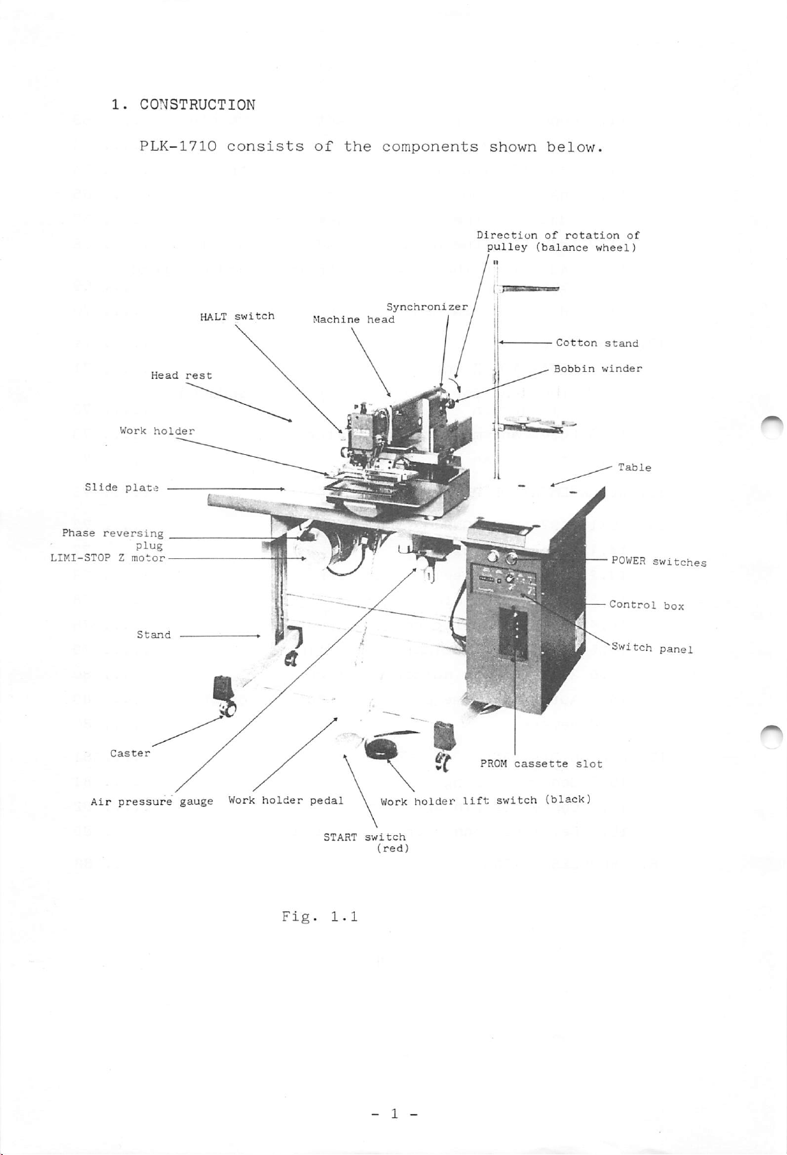
PLK-1710
Sewing
MANUAL
Sewing
Machine
Machine
AMITSUBISHIi
A180E104P03
MITSUBIi
ELECTRIC
Page 2
In
order
condition,
and
maintain
1.
CONSTRUCTION
2.
FEATURES
3.
SPECIFICATIONS
to
operate
please
properly
your
read
Instruction
the
-CONTENTS-
sewing
machine,
machine
Manual
PLK-1710,
carefully
in
the
and
best
handle
1
2
4
3.1
3.2
4.
INSTALLATION
4.1
4.2
4.3
4.4
4.5
4.6
4.7
4.8
5.
PREPARATION
6.
NAME
6.1
6.2
General
Replacement
fabrics
Installing
Installing
Installing
Connecting
Work
Power
lamp
cable
Changing
Installing
AND
AND
FUNCTIONS
Switch
POWER
panel
ON
specifications
parts
the
table
the
machine
the
air
the
leads
leads
connection
direction
the
work
CAUTIONS
OF
and
OFF
for
light
tubes
of
rotation
holder
BEFORE
CONTROL
switches
head
SWITCHES
and
heavy
of
pedal
OPERATION
motor
4
6
8
8
9
.12
13
14
15
16
16
17
19
19
19
6.3
6.4
6.5
6.6
6.7
6.8
6.9
6.10
6.11
6.12
6.13
6.14
7.
OPRATION
7.1
SCALE
PATTERN
SPEED
±JOG
switch
select
setting
switch
RESET/HOME
STOP/MOVE
ERROR
Work
HALT
START
Work
Thread
indicators
holder
switch
switch
holder
trimmer
Inserting
switch
switch
lift
pedal
the
switch
dial
switch
switch
PROM
(option)
cassette
19
20
20
20
21
22
22
23
24
24
24
24
25
25
- A -
Page 3
7.2
Setting
the
switches
on
the
switch
panel
25
7.3
7.4
7.5
7.6
8.
GENERAL
9.
HANDLING
9.1
9.2
9.3
9.4
9.5
9.6
9.7
9.8
9.9
9.10
Checking
Sewing
HALT
switch
Operating
INSTRUCTIONS
THE
Lubrication
Installing
Threading
Winding
Installing
Installing
Thread
Adjusting
Adjusting
Replacing
each
operation
procedure
SEWING
the
the
the
the
the
tensions
the
the
the
function
operation
MACHINE
needle
needle
bobbin
bobbin
bobbin
work
presser
lower
and
thread
thread
holder
clamp
checking
HEAD
case
foot
frame
25
26
26
27
30
32
32
33
34
34
35
35
35
37
38
40
10.
11.
ADJUSTMENT
10.1
10.2
10.3
10.4
10.5
10.6
10.7
Adjusting
and
Thread
Adjusting
Adjusting
Adjusting
Adjusting
Air
presser
10.8
10.9
10.10
10.11
10.12
ADJUSTMENT
Adjusting
Home
Adjusting
Adjusting
Adjusting
sion
AND
hook
piping
position
OF
MAINTENANCE
the
motion
tensions
the
the
the
the
to
foot
the
the
the
the
THREAD
timing
lubrication
bobbin
needle
timing
cylinders
and
thread
wiper
adjustment
X-Y
X-Y
LIMI-STOP
TRIMMER
table
table
between
winder
stop
of
presser
for
trimmer
belt
Z
to
UP
motor
needle
hook
position
work
tension
foot
holder,
belt
motion
motion
ten
41
41
43
46
47
47
48
50
50
52
57
59
61
62
11.1
11.2
11.3
Construction
Caution
Installation
bracket
unit
of
of
thread
knife
- B -
trimmer
bracket
mechanism
and
knife
62
62
62
Page 4
11.4
Connection
of
knife
bracket
to
drive
crank
63
11.5
11.6
11.7
11.8
11.9
11.10
11.11
12.
CONTROL
12.1
12.2
12.3
12.4
13.
REPLACEMENT
14.
AUXILIARY
Knife
Installation
Installation
Adjusting
Adjusting
Adjusting
end
Hook,
SYSTEM
LIMI-STOP
Grounding
malfunction
Fuses
Cooling
FUNCTIONS
drive
bobbin
and
OF
the
the
Z
for
magnetic
fan
PROM
shaft
of
of
the
motor
trimmer
trimming
knife
needle
length
case
and
prevention
contactor
air
cam
engagement
thread
of
trimmed
bobbin
of
cylinder
tension
needle
noise-induced
release
64
64
65
67
68
thread
69
70
71
71
73
73
73
75
77
14.1
14.2
14.3
14.4
14.5
14.6
14.7
14.8
15.
WIRING
15.1
15.2
15.3
16.
TROUBLESHOOTING
Repeat
Speed
Sewing
Thread
Adjusting
2-stage
Automatic
Remarks
DIAGRAMS
General
Connector
Detailed
function
limit
area
trimming
work
wiring
connector
select
limit
the
home
pin
release
release
fabric
holder
position
arrangement
function
feed
function
wiring
function
function
timing
return
diagrams
function
77
78
78
78
79
80
80
80
81
81
82
85
88
- C -
Page 5
wn
ion
iy
below.
of
(balance
rotation
of
wheel)
I
Cotton
Bobbin
stand
winder
POWER
Control
Switch
switches
box
panel
assette
tch
(black)
slot
Page 6
2.
FEATURES
(1)
Easy
pattern
change
Stitch
stitches
By
using
written
to
4,000
is
used
(2)
High-performance
The
work
assures
(3)
Presser
Since
ed
with
It
is
small
data
(or
a
PROM
to
PROM
stitches
together
(pattern
10
holder
high-quality
foot
the
motion
presser
needle
particularly
pieces
are
patterns)
writer
easily.
when
with
fabric
driven
synchronized
foot
motion,
advantagenous
sewn
data)
(option),
optional
PROM
feed
by
stitching
moves
"floating"
up,
can
in
each
Memory
writer
mechanism
stepping
vertically,
or
when
be
stored
PROM
pattern
size
(additional)
PTN-4000A
motors
at
high
with
of
when
heavy
up
cassette.
data
can
speed.
needle
being
fabric
emblems
fabrics
to
can
be
expanded
PROM
or
through
motion
does
or
2,000
be
up
cassette
PTN-1OOO0L.
belts
synchroniz
not
occur
any
other
are
sewn.
(4)
(5)
(6)
Easy
When
replaced
Pattern
A
pattern
and
Y
199%.
"HALT"
"HALT"
and
"JOG"
are
very
By
continuously
stitched
work
stitching
holder
pattern
immediately.
replacement
enlargement/reduction
stored
direction
switch
switch
switch
helpful
pattern
in
independently
and
permitting
permitting
when
operating
and
PROM
"JOG"
resumption
is
switch
used
changed,
can
be
within
immediate
stitch-by-stitch
to
amend
the
"JOG"
the
enlarged
suspension
stitches.
switch,
of
stitching
a
work
or
range
holder
reduced
from
of
feed
checking
after
can
in
0%
to
stitching
motion
of
suspen
be
X
sion
can
be
accomplished
easily.
- 2 -
Page 7
(7)
Safety
functions
(8)
(9)
(10)
Various
by
"error
failures
Full-electronic
reliability
8-bit
Large
Double-sized
Easy
o
o
microprocessor
hook
maitenance
The
head
thread
LIMI-STOP
featuring
indication"
control
hook
can
be
trimmer
Z
motor,
maintenance-free
or
reduces
leaned
and
errors
lamps.
is
other
having
in
system
used
labor
laterally
internal
operation
in
no
use,
with
the
for
compact
control
replacement
for
mechanisms.
"frictional
is
used
are
easy
visualized
design
system.
access
clutch"
as
main
of
and
bobbin.
to
and
drive
the
(11)
motor.
Work
It
fabric
holder
permits
and
pedal
easy
parts.
and
immediate
positioning
or
alignment
of
- 3 -
Page 8
3.
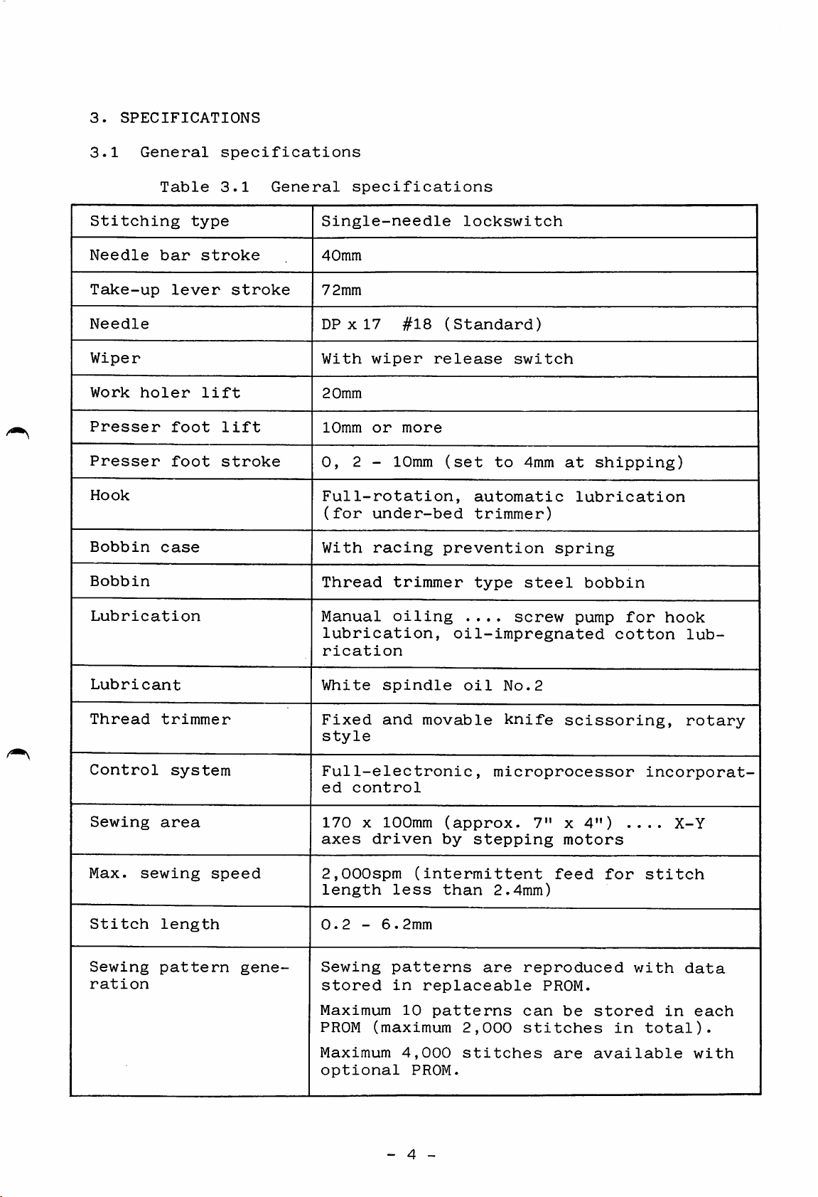
SPECIFICATIONS
3.1
Stitching
Needle
Take-up
Needle
Wiper
Work
Presser
Presser
Hook
Bobbin
General
Table
bar
lever
holer
foot
foot
case
specifications
3.1
type
stroke
stroke
lift
lift
stroke
General
specifications
Single-needle
40mm
72mm
DP
X17
With
20mm
10mm
0,
Full-rotation,
(for
With
wiper
or
2 - 10mm
under-bed
racing
#18
more
lockswitch
(Standard)
release
(set
automatic
trimmer)
prevention
to
switch
4mm
at
lubrication
spring
shipping)
Bobbin
Lubrication
Lubricant
Thread
Control
Sewing
Max.
Stitch
Sewing
ration
trimmer
system
area
sewing
length
pattern
speed
gene
Thread
Manual
trimmer
oiling
lubrication,
rication
White
Fixed
spindle
and
style
Full-electronic,
ed
control
170
X 100mm
axes
driven
2,000spm
length
0.2
Sewing
stored
-
less
6.2mm
patterns
in
type
....
oil-impregnated
oil
movable
(approx.
by
stepping
(intermittent
than
are
replaceable
steel
screw
No.2
knife
pump
scissoring,
microprocessor
7"
x
motors
feed
2.4mm)
reproduced
PROM.
bobbin
cotton
4")
for
for
incorporat
....
stitch
with
hook
lub
rotary
X-Y
data
Maximum
PROM
Maximum
optional
10
patterns
(maximum
4,000
PROM.
- 4 ~
2,000
stitches
can
stitches
are
be
stored
in
available
in
total).
each
with
Page 9
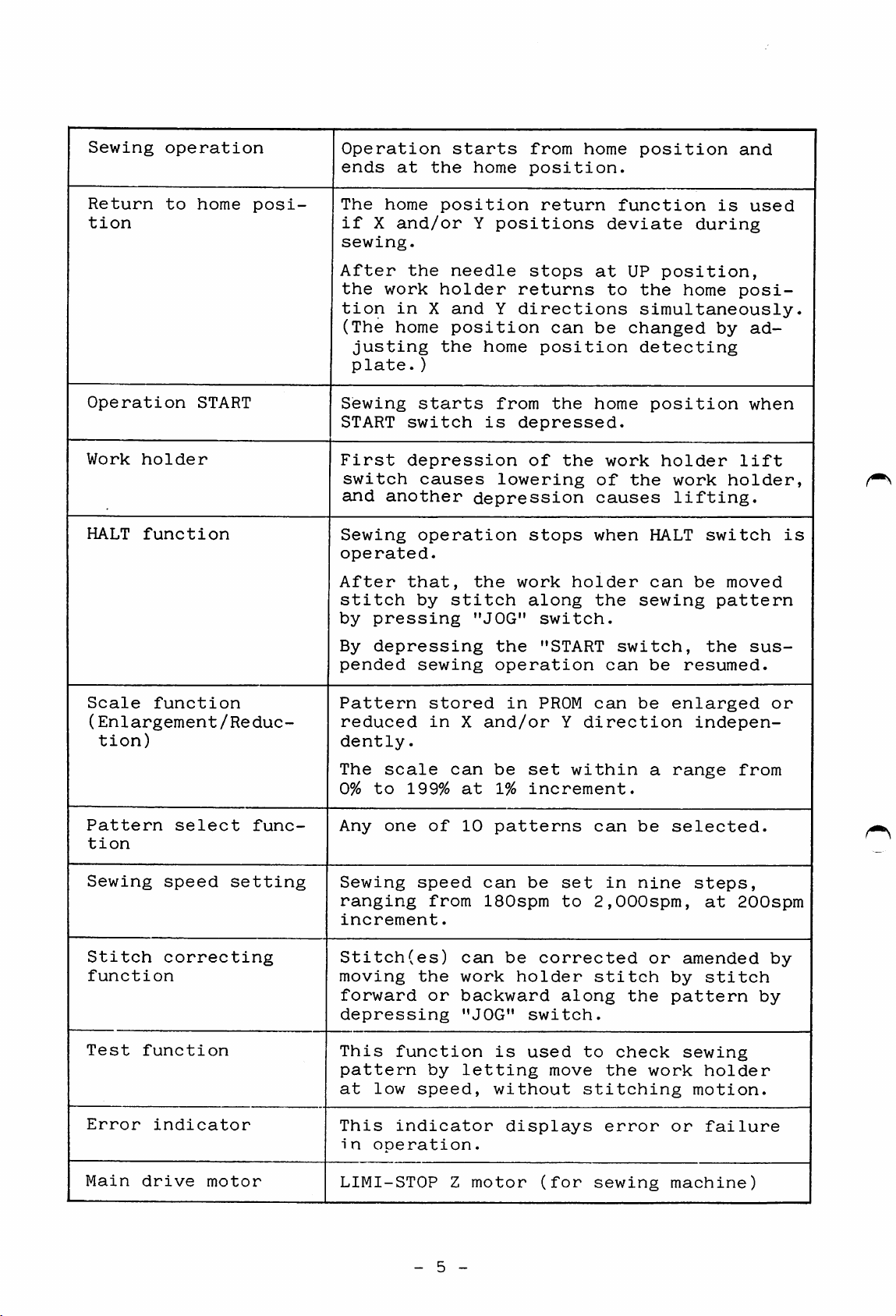
Sewing
operation
Operation
ends
starts
at
the
home
from
position.
home
position
and
Return
tion
Operation
Work
HALT
to
holder
function
home
START
posi
The
home
if
X
sewing.
After
the
work
tion
(The
justing
plate.)
Sewing
START
First
switch
and
another
Sewing
operated.
After
stitch
by
pressing
By
depressing
pended
position
and/or
the
holder
in
X
home
the
starts
switch
depression
causes
operation
that,
by
sewing
Y
positions
needle
and
Y
position
home
from
is
lowering
depression
the
stitch
"JOG"
the
operation
return
stops
returns
directions
can
position
the
depressed.
of
the
stops
work
holder
along
switch.
"START
function
deviate
at
UP
to
the
simultaneously.
be
changed
detecting
home
work
of
the
causes
when
the
sewing
switch,
can
be
position,
home
position
holder
work
lifting.
HALT
can
resumed.
is
during
by
holder,
switch
be
moved
pattern
the
used
posi
ad
when
lift
is
sus
Scale
function
(Enlargement/Reduc-
tion)
Pattern
tion
Sewing
Stitch
function
Test
Error
select
speed
correcting
function
indicator
setting
func
Pattern
reduced
dently
The
scale
0%
to
Any
one
Sewing
ranging
increment.
Stitch(es)
moving
forward
depressing
This
pattern
at
This
in
function
low
indicator
operation.
stored
in
.
199%
of
speed
from
the
or
by
speed,
X
and/or
can
be
at
1%
10
patterns
can
ISOspm
can
work
backward
"JOG"
is
letting
without
in
PROM
set
increment.
be
be
corrected
holder
switch.
used
displays
Y
within
set
to
along
move
can
be
direction
can
be
in
nine
2,000spm,
stitch
the
to
check
the
stitching
error
a
or
by
pattern
work
or
enlarged
range
selected.
indepen
from
steps,
at
200spm
amended
stitch
sewing
holder
motion.
failure
or
by
by
Main
drive
motor
LIMI-STOP
- 5 -
Z
motor
(for
sewing
machine)
Page 10
Work
holder
drive
Pneumatic
type,
4
-hO.
5/-0kg/cm^
Ambient
Power
Dimensions
Weight
Others
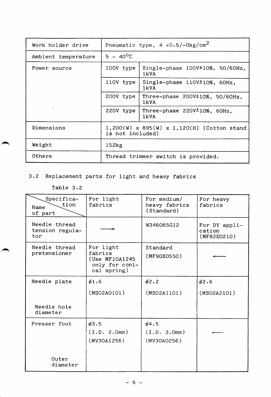
3.2
temperature
source
Replacement
Table
3.2
parts
lOOV
llOV
200V
cn
220V
type
type
type
type
1
o
1,200(W)
is
not
152kg
Thread
for
light
o
X
o
included)
trimmer
Single-phase
IkVA
Single-phase
IkVA
Three-phase
IkVA
Three-phase
IkVA
895(W)
switch
and
heavy
X
1,120(H)
fabrics
100V±10%,
110V±10%,
200V±10%,
220V±10%,
is
provided.
50/60Hz,
60Hz,
(Cotton
50/60Hz,
60Hz,
stand
Specifica
Name
of
part
Needle
tension
tor
Needle
pretensioner
Needle
Needle
diameter
Presser
thread
regula
thread
plate
hole
foot
tion
For
light
fabrics
For
light
fabrics
(Use
only
cal
MF10A1245
for
spring)
?51.6
(MS02A0101)
053.5
(I.D.
2.0mm)
coni
For
medium/
heavy
fabrics
(Standard)
W346065G12
Standard
(iyiF90E0550)
?52.2
(MS02A1101)
o54.
5
(I.D.
3.0mm)
For
heavy
fabrics
For
DY
appli
cation
(MF82E0210)
052.6
(MS02A2101)
(MV30A1256)
Outer
diaimeter
- 6 -
(MV30A0256)
Page 11
^""•"\Spe ci f i
Nain7\^°"
of
part
ca-
For
fabrics
light
For
medium/
heavy
(Standard)
fabrics
For
fabrics
heavy
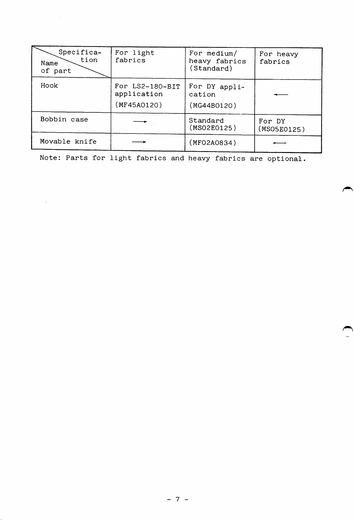
Hook
Bobbin
Movable
Note:
case
knife
Parts
for
For
LS2-180-BIT
application
(MF45A0120)
light
fabrics
For
cation
Standard
(MF02A0834)
and
heavy
DY
appli
(MG44B0120)
(MS02E0125)
fabrics
For
DY
(MS05E0125)
are
optional
- 7 -
Page 12
4.
INSTALLATION
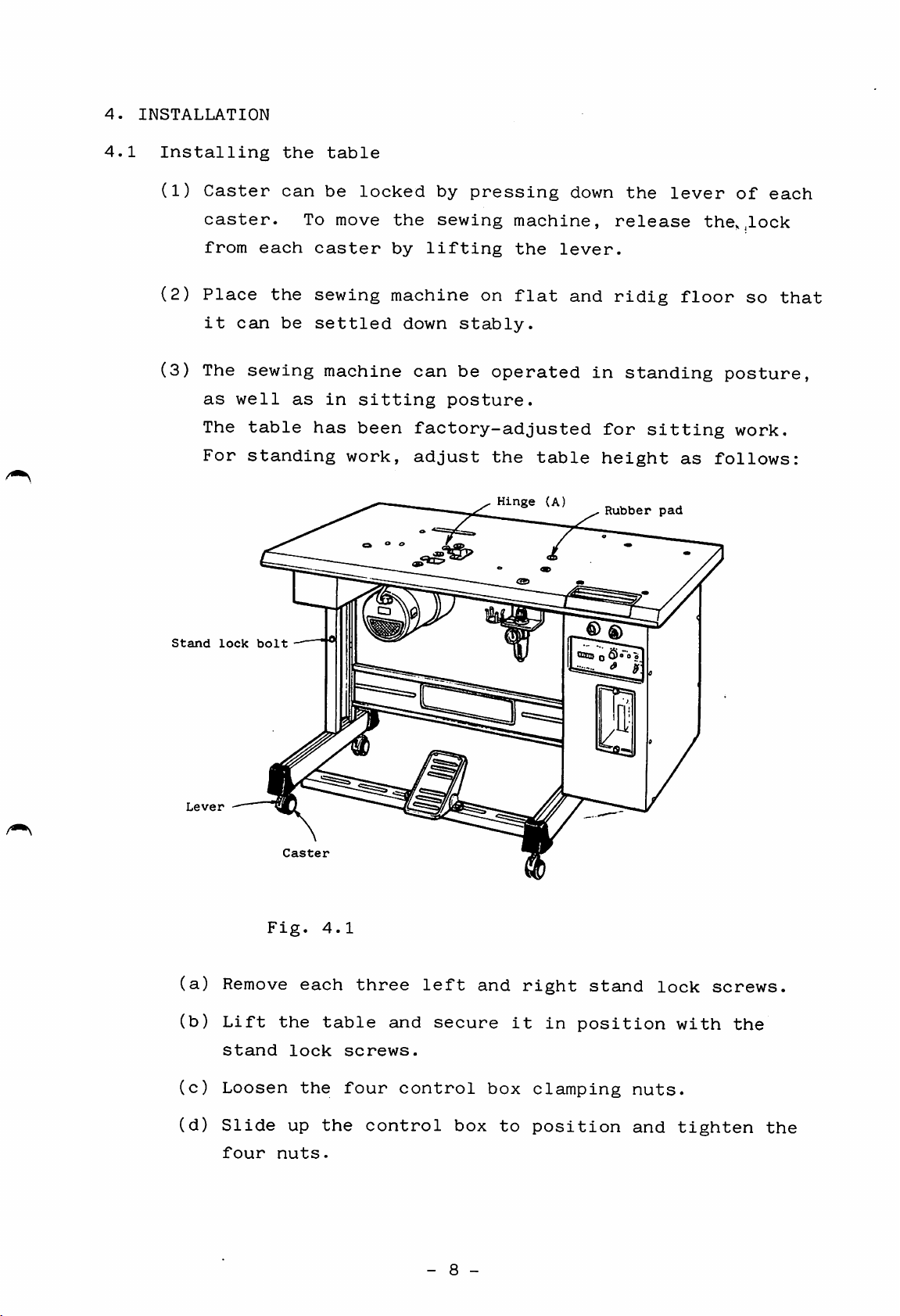
4.1
Installing
(1)
Caster
caster.
from
(2)
Place
it
(3)
The
as
The
For
each
the
can
sewing
well
table
standing
the
can
be
as
table
be
To
move
caster
sewing
settled
machine
in
has
locked
sitting
been
work,
by
pressing
the
sewing
by
lifting
machine
down
can
on
stably.
be
posture.
factory-adjusted
adjust
machine,
the
flat
operated
the
table
Hinge
(A)
down
lever.
and
release
ridig
in
for
height
Rubber
the
lever
floor
standing
sitting
as
pad
of
the,,lock
so
posture,
work.
follows:
each
that
Stand
(a)
(b)
(c)
Lever
lock
bolt
Remove
Lift
stand
Loosen
Fig.
the
each
lock
the
4.1
table
screws.
four
three
left
and
control
secure
and
box
right
it
in
clamping
oao
o 0 6
» 9
stand
position
lock
nuts.
with
screws.
the
(d)
Slide
four
up
nuts.
the
control
box
- 8 -
to
position
and
tighten
the
Page 13
Notes:
1.
Table
height
should
be
changed
before
the
machine
(4)
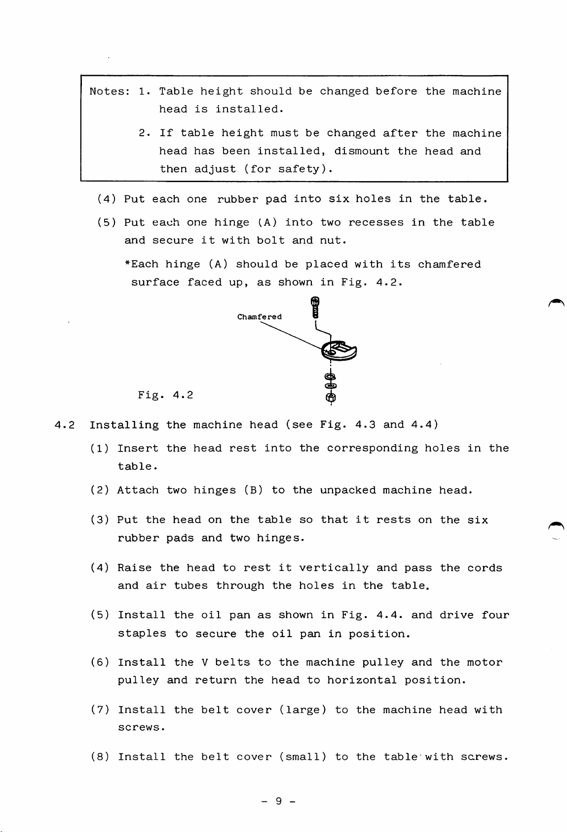
(5)
2.
Put
Put
and
*Each
surface
Fig.
head
If
head
then
each
each
secure
hinge
4.2
table
has
adjust
one
one
faced
is
it
(A)
installed.
height
been
rubber
hinge
with
should
up,
installed,
(for
bolt
as
Chamfered
pad
(A)
must
safety).
into
be
shown
into
and
be
changed
two
nut.
placed
in
dismount
six
recesses
Fig.
holes
with
after
4.2.
the
in
its
the
head
the
in
the
chamfered
machine
and
table.
table
4.2
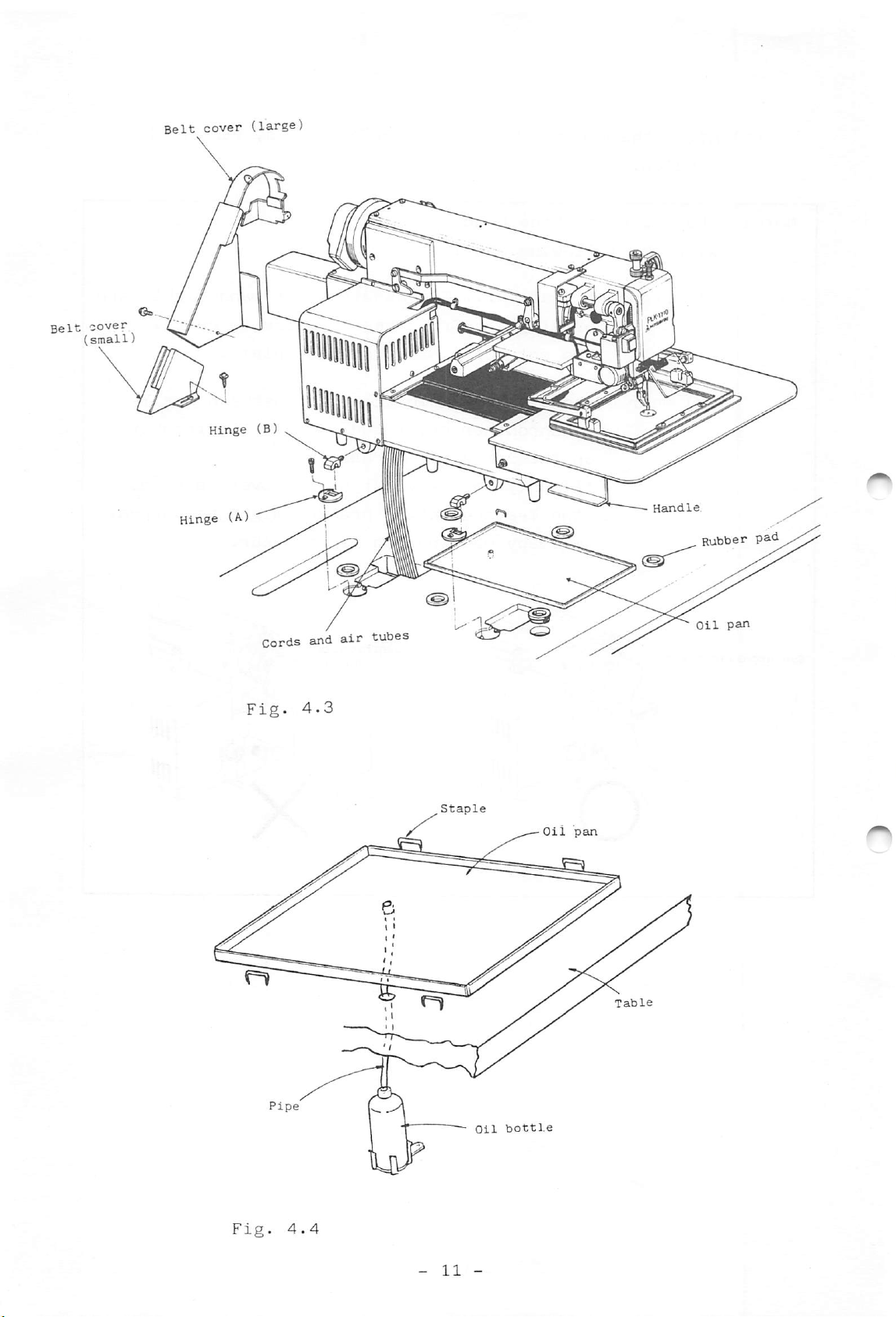
Installing
(1)
Insert
table.
(2)
Attach
(3)
Put
rubber
(4)
Raise
and
(5)
Install
staples
(6)
Install
pulley
(7)
Install
the
air
the
the
two
pads
the
head
tubes
the
the
and
the
head
to
machine
head
hinges
on
and
to
through
oil
secure
V
belts
return
belt
rest
the
two
pan
cover
head
(B)
rest
the
the
into
to
table
hinges.
it
the
as
shown
oil
to
the
head
(see
the
the
so
vertically
holes
pan
(large)
Fig.
corresponding
unpacked
that
in
in
machine
to
horizontal
to
4.3
it
in
the
Fig.
position.
pulley
the
and
machine
rests
and
table.
4.4.
machine
4.4)
holes
on
pass
and
and
position.
head.
the
the
drive
the
head
in
six
cords
four
motor
with
the
screws.
(8)
Install
the
belt
cover
(small)
- 9 -
to
the
table"
with
screws.
Page 14
(9)
After
handles.
the
machine
head
has
been
installed,
remove
the
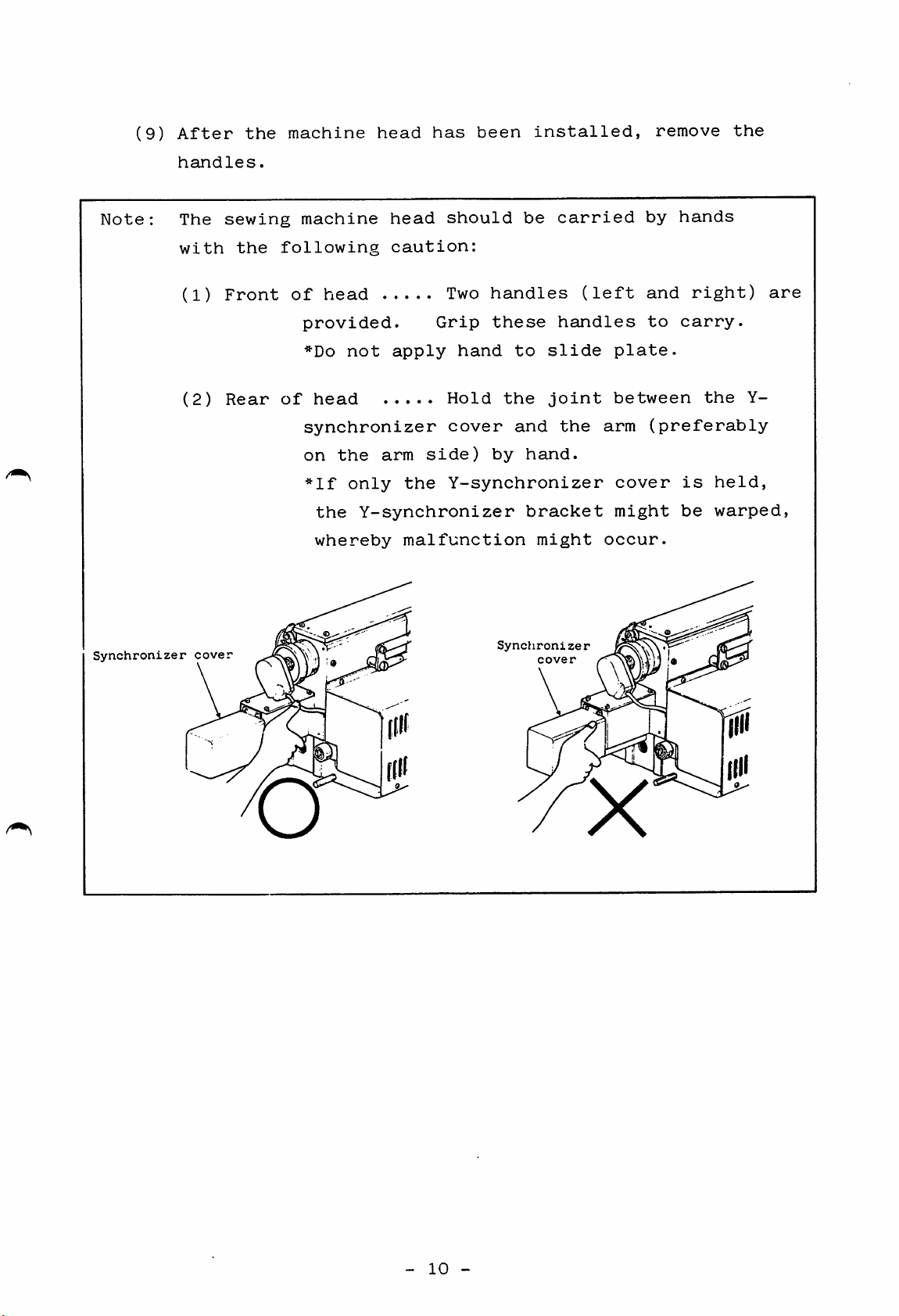
Note:
Synchronizer
The
with
(1)
(2)
cover
sewing
the
Front
Rear
machine
following
of
head
provided.
*Do
not
of
head
synchronizer
on
the
*lf
only
the
whereby
head
caution:
should
Two
Grip
apply
hand
Hold
cover
arm
side)
the
Y-synchronizer
Y-synchronizer
malfunction
be
handles
these
to
the
and
by
hand.
bracket
might
Synchronizer
cover
carried
(left
handles
slide
joint
the
plate.
between
arm
cover
might
occur.
by
hands
and
right)
to
carry.
the
(preferably
is
held,
be
warped,
are
Y-
o
X
-
10
-
Page 15
Oil
bottle
Oil
pan
Fig.
4.4
Page 16
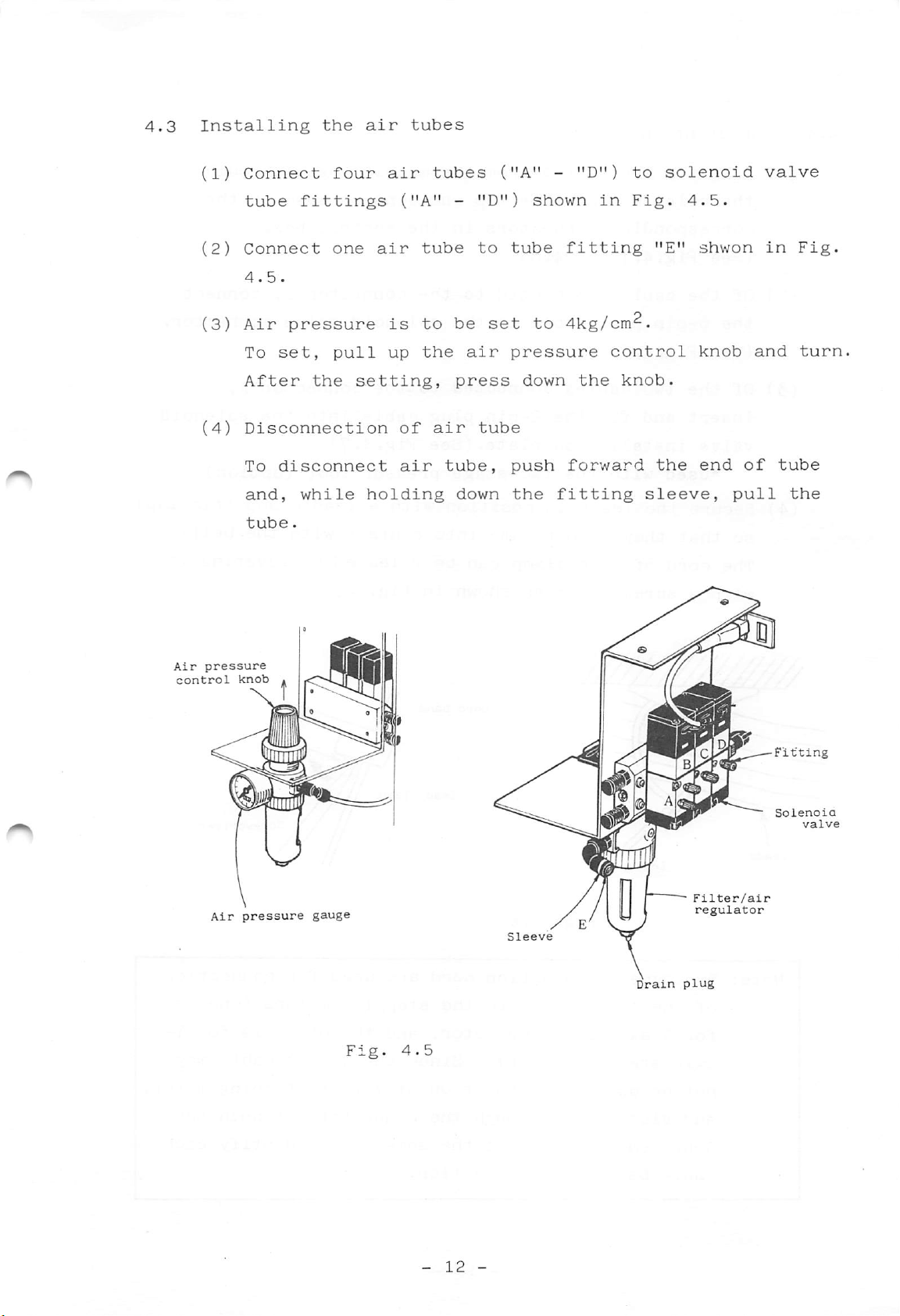
4.3
Installing
(1)
Connect
the
four
air
air
tubes
tubes
("A"
-
"D")
to
solenoid
valve
tube
(2)
Connect
4.5.
(3)
Air
To
After
(4)
Disconnection
To
and,
tube.
fittings
one
pressure
set,
disconnect
pull
the
while
air
is
up
setting,
holding
("A"
of
air
tube
to
the
air
-
be
air
press
tube,
down
"D")
to
set
tube
shown
tube
to
pressure
down
push
the
fitting
in
Fig.
fitting
4kg/cm^.
control
the
knob.
forward
"E"
the
sleeve,
4.5.
shwon
knob
end
of
pull
in
and
Fig.
turn
tube
the
Air
control
pressure
Air
knob
pressure
gauge
Fig.
4.5
Drain
C
Filter/air
regulator
plug
—Fitting
Solenoia
valve
-
12
-
Page 17
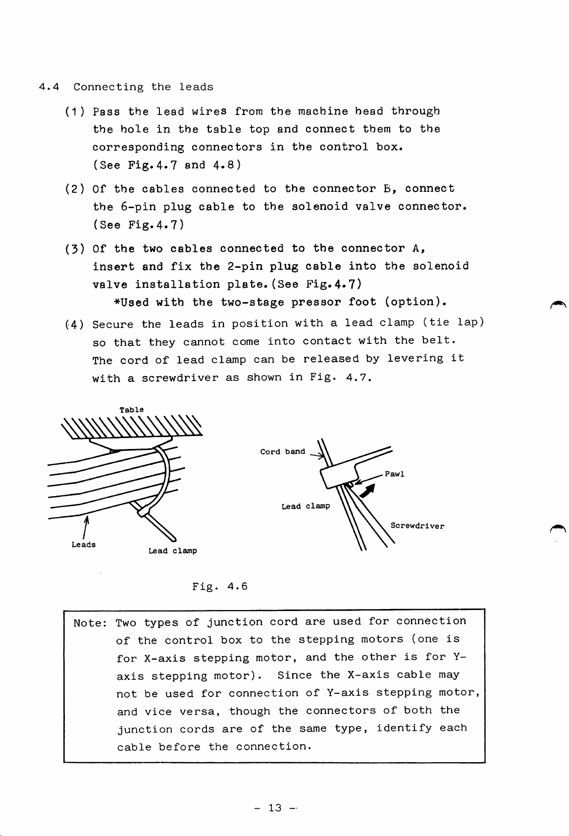
4.4
Connecting
(1)
Pass
the
the
hole
the
lead
in
leads
wires
the
table
from
top
the
and
machine
connect
head
them
through
to
the
corresponding
(See
(2)
Of
the
(See
(3)
Of
insert
valve
(4)
Secure
so
The
with
Fig.4.7
the
cables
6-pin
Fig.4.7)
the
two
and
installation
*Used
the
that
cord
a
screwdriver
Table
with
they
of
plug
cables
fix
leads
lead
connectors
and
4.8)
connected
cable
the
the
in
cannot
clamp
to
to
the
connected
2-pin
plate.(See
two-stage
position
come
can
as
shown
in
plug
into
the
the
solenoid
to
cable
pressor
with
contact
be
released
in
control
connector
the
Fig.4.7)
a
Fig.
box.
valve
connector
into
foot
lead
clamp
with
by
4.7.
B,
connect
connector.
A,
the
solenoid
(option).
the
levering
(tie
belt.
lap)
it
Leads
Note:
Two
types
of
the
for
X-axis
axis
not
be
and
vice
junction
Lead
clamp
control
stepping
used
versa,
Fig.
of
stepping
cords
4.6
junction
box
motor).
for
connection
are
to
though
of
Cord
cord
the
motor,
Since
the
the
band
Lead
stepping
clamp
are
used
and
the
the
of
Y-axis
connectors
same
X-axis
type,
Pawl
for
motors
other
stepping
of
identify
Screwdriver
connection
(one
is
for
cable
both
is
Y-
may
motor,
the
each
cable
before
the
connection.
-
13
-
Page 18
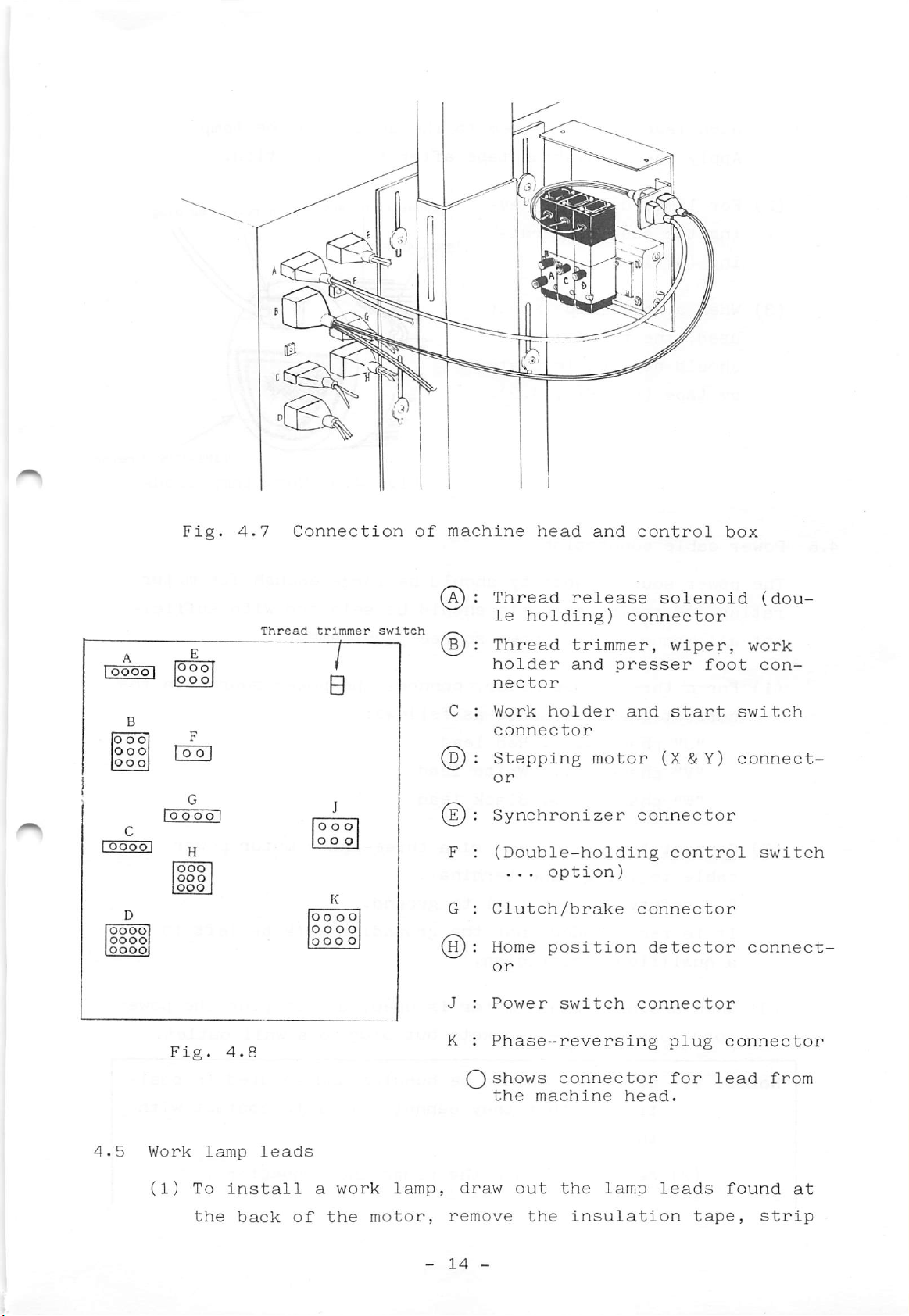
Fig.
4.7
Connection
of
machine
head
and
control
box
oooo
^ :
Thread
trimmer
switch
^ : Thread trimmer, wiper,
A
G
oooo
Fig.
oooo
oooo
oooo
4
^:
Thread
le
holder
nector
C :
Work
connector
D) :
Stepping
Synchronizer
F :
(Double-holding
G :
Clutch/brake
H):
Home
J :
Power
K :
Phase-reversing
Qshows
the
holding)
...
machine
release
and
holder
motor
option)
position
switch
connector
solenoid
connector
presser
and
(X&Y)
connector
connector
detector
connector
head.
foot
start
control
plug
for
(dou-
work
con
switch
connect-
switch
connect-
connector
lead
from
4.5
Work
(1)
To
the
lamp
leads
install
back
of
a
work
the
lamp,
motor,
-
draw
remove
14
-
out
the
the
insulation
lamp
leads
tape,
found
at
strip
Page 19
each
lead
and
join
them
to
the
cord
from
the
lamp.
4.6
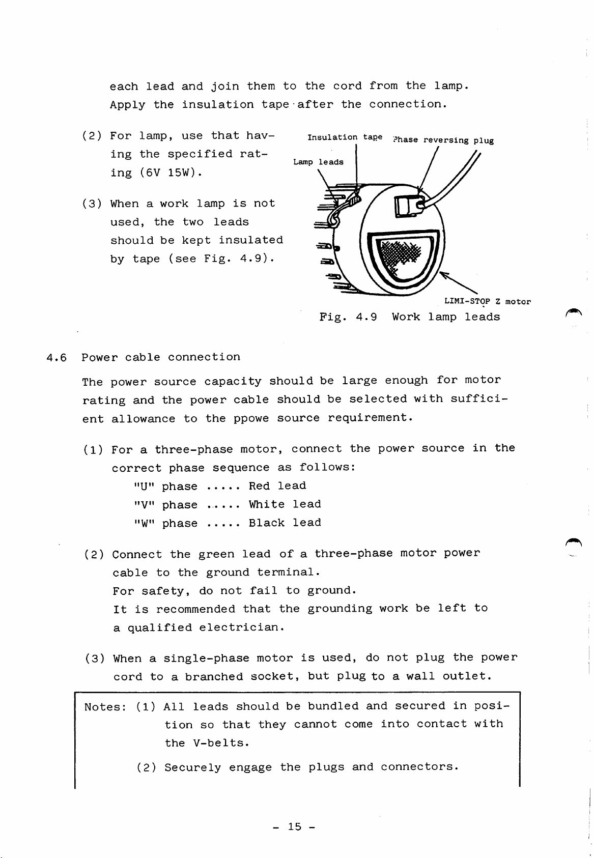
(2)
(3)
Power
The
Apply
For
ing
ing
When
used,
should
by
cable
power
lamp,
the
(6V
a
tape
the
specified
15W).
work
the
be
(see
connection
source
insulation
use
that
lamp
two
kept
leads
insulated
Fig.
capacity
rat
is
4.9).
hav
not
tape
should
after
Insulation
Lamp
leads
Fig.
be
the
tape Phase
4.9
large
connection.
Work
enough
reversing
LIMI-STOP
lamp
for
plug
leads
motor
Z
motor
rating
ent
(1)
(2)
(3)
and
allowance
For
a
correct
"U"
"V"
"W"
Connect
cable
For
safety,
It
is
a
qualified
When
cord
a
to
the
power
to
the
three-phase
phase
phase
phase
.....
phase
the
green
to
the
ground
do
recommended
electrician.
single-phase
a
branched
cable
ppowe
motor,
sequence
lead
not
that
Red
White
Black
terminal.
fail
motor
socket,
should
source
connect
as
follows:
lead
lead
lead
of
a
to
the
is
be
selected
requirement.
the
three-phase
ground.
grounding
used,
but
plug
do
to
power
motor
work
not
a
with
be
plug
wall
source
power
left
outlet.
suffici
in
to
the
the
power
Notes:
(1)
(2)
All
leads
tion
the
V-belts.
Securely
so
should
that
engage
they
-
be
the
15
bundled
cannot
plugs
-
come
and
and
secured
into
connectors.
contact
in
posi
with
Page 20
(3)
Before
starting
connection
of
leads,
unplug
the
4.7
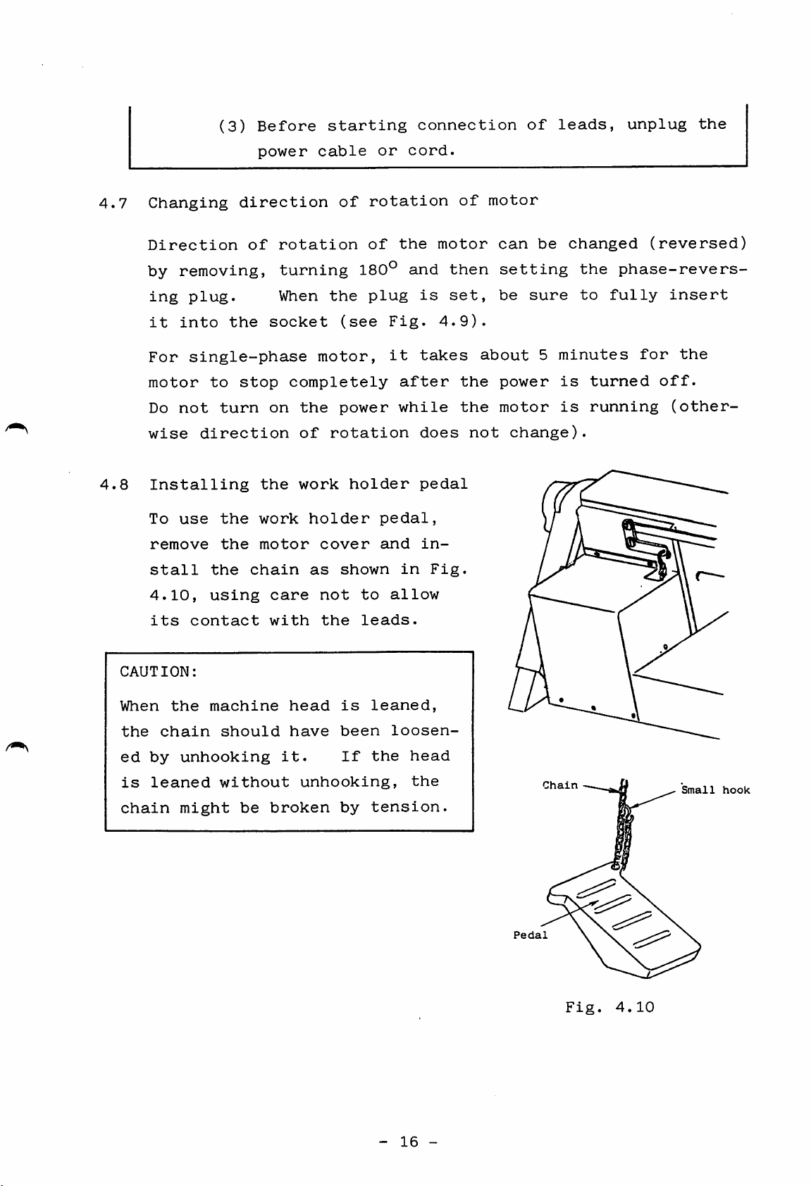
4.8
Changing
Direction
by
removing,
ing
plug.
it
into
For
single-phase
motor
Do
not
wise
Installing
To
remove
direction
use
the
to
turn
the
the
power
direction
of
rotation
turning
When
socket
stop
completely
on
the
work
motor
cable
motor,
the
of
work
holder
of
the
(see
power
rotation
holder
cover
or
rotation
of
180°
plug
Fig.
it
pedal,
and
cord.
the
and
is
takes
after
while
does
pedal
in
of
motor
then
set,
4.9).
the
the
about
not
motor
can
setting
be
power
motor
change).
be
sure
5
changed
the
to
minutes
is
turned
is
running
(reversed)
phase-revers
fully
for
insert
the
off.
(other
stall
4.10,
its
CAUTION:
When
the
chain
ed
by
is
leaned
chain
the
using
contact
the
machine
unhooking
without
might
should
be
chain
care
with
broken
as
head
have
it.
unhooking,
not
the
shown
to
leads.
is
been
If
by
in
allow
leaned,
loosen
the
head
the
tension.
Fig.
Pedal
Chain
Small
hook
Fig.
-
16
-
4.10
Page 21
5.
PREPARATION
(1)
Make
sure
AND
CAUTIONS
the
line
BEFORE
voltage
OPERATION
meets
that
specified
for
the
(2)
(3)
(4)
(5)
(6)
sewing
Make
the
(The
test
Move
is
always
Make
foot.
Make
Check
(for
To
check
machine.
sure
PROM
PROM
and
cassette
cassette
pattern
locate
the
PROM
program.)
the
located
sure the needle
sure
motor
the
the
rotational
switches,
the
direction
air
cassette
slot.
which
work
within
comes
pressure
direction
refer
of
has
is
loaded
holder
the
at
is
to
rotation,
been
by
frame
the
center
4kg/cm2.
of
the
Fig.
put
by
us
hand
of
work
LlMl-STOP
1.1
perform
properly
at
so
of
and
shipping
that
holder.
the
6.1)
the
into
has
the
needle
presser
Z
motor
following
^
(7)
steps:
1)
Press
2)
Set
the
3)
Set
(For
4)
Press
of
The
sewing
The
ed
Before
POWER
the
the
RESET/HOME
work
the
STOP/MOVE
function
the
rotation
pulley
machine
method
in
4.7.
unplugging
OFF
switch
POWER ON
holder
of
START
of
should
of
changing
and
switch
each
foot
the
front
the
switch.
switch
switch
switch
pulley
rotate
(see
power
make
to
to
let
to
switch,
(balance
clockwise
Fig.
direction
cord,
sure
RESET
down
STOP
position
the
position.
refer
momentarily
wheel).
as
1.1).
of
be
sure
the
red
work
to
Sec.
to
viewed
rotation
to
lamp
press
at
and
holder.
6.)
see
the
direction
from
is
press
^
the
describ
the
end
face
of
PROM-cassette
does
-
17
not
light.
-
Page 22
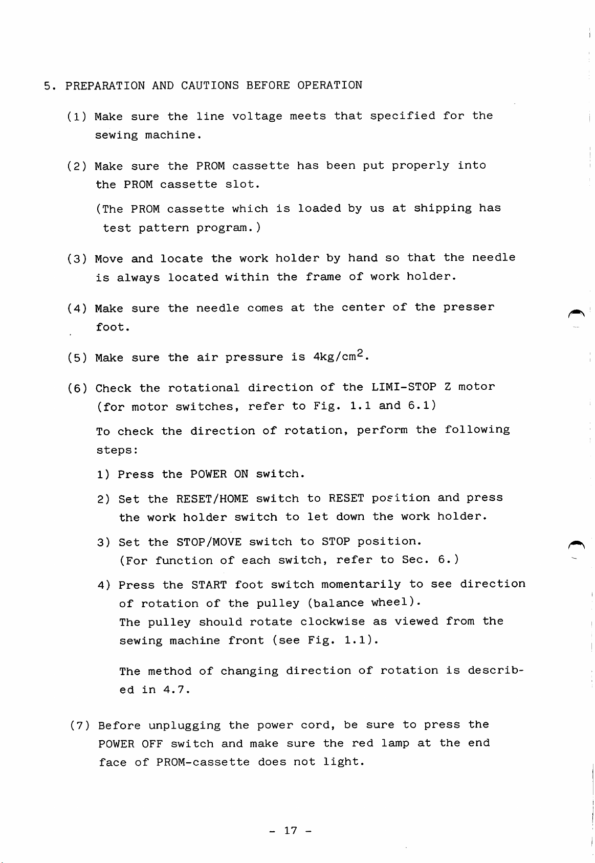
(8)
Position
of
work
holder
Work
The home
of
the
center
for
the
holder.—J
position
work
of
presser
the
1
holder,
work
(needle
foot,
but
holder
as
plate
deviates
by
shown
!
hole)
to
dimension
in
Fig.
Work
holder
Effective
the
is
equal
5.1.
arm
not
right
sewing
at
from
to
area
the
center
the
allowance
123
Fig.
5.1
108
Home
(same
position
as
needle
point)
-
18
-
Page 23
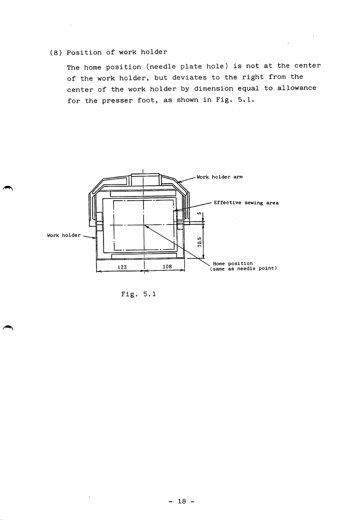
6.
NAME
AND
FUNCTIONS
OF
CONTROL
SWITCHES
6.1
Switch
/
X:
Y:
SCALE
panel
POWER OFF
SCALE
patte!rn_
select
JOG
switch
I
POWERONswitch
Sewing
Air
speed
pilot^
lamp
RESET/HOME
control
%
i
PROM
STOP/MOVE
cassette
1/
switch
6.2
6.3
POWER
(1)
(2)
SCALE
(1)
ON
and
When
the
of
When
the
is
Let
be
X
ed
the
power
PROM-cassette
the
red
at
switch
sewing
enlarged
axis
or
Fig.
OFF
POWER
supply
POWER
lamp
down
and
reduced
6.1
switches
ON.switch
is
lights.
OFF
goes
position.
out
pattern
or
reduced
Y
axis
independently
correspondingly).
on
switch
and
stored
(green
and
the
in
within
the
(red
pushbutton)
red
pushbutton)
work
PROM
a
be
range
(stitch
lamp
holder
100%
at
from
the
is
lifts
in
0%
length
is
pressed,
size,
to
pressed,
end
face
when
it
199%
is
enlarg
it
can
in
(2)
Pattern
position.
is
enlarged
or
-
reduced
19
-
in
reference
to
the
home
Page 24
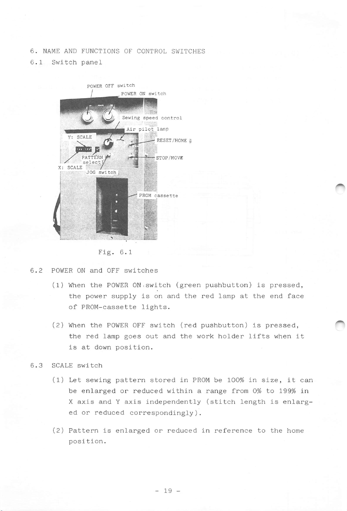
HI
Switch
from
The
or
150%
"000"
third
(1.5
setting
digit
times)
to
should
"199"
(hundred)
(%).
be
within
is
either
a
range
"0"
6.4
6.5
NOTES
PATTERN
The
tern
SPEED
The
speed
Fig.
6.2
Whenever
that
sewing
The
is
select
PATTERN
(patterns
setting
SPEED
for
the
sewing
stitched
select
setting
each
SCALE
pattern
enlarged
area
switch
are
dial
sewing
speed
switch
stored
dial
switch
(see
(see
is
pattern.
setting
is
pattern
para.
may
para.
is
in
used
enlarged,
6.6.1).
decrease
8
used
PROM).
to
is
(4)).
to
select
it
within
when
select
should
enlarged
the
be
the
range
the
sewing
maximum
verified
of
pattern
pat
sewing
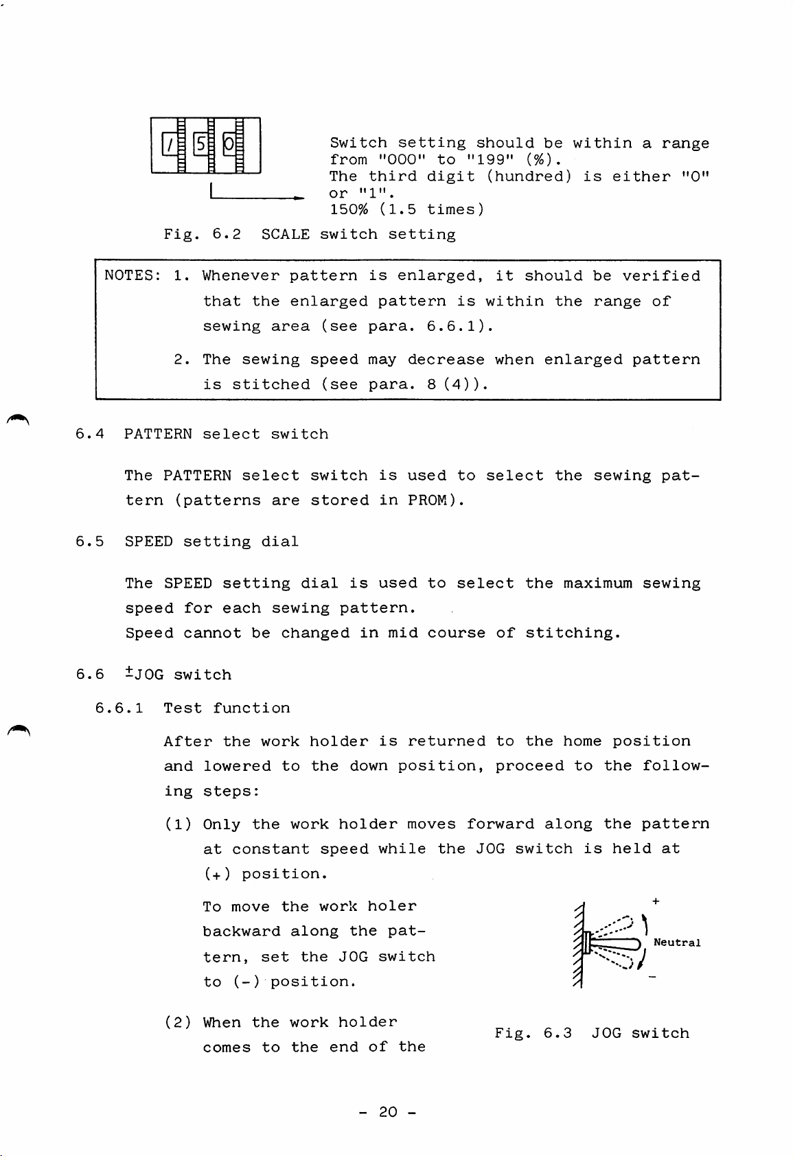
6.6
6.6.1
Speed
ijOG
switch
Test
After
and
ing
(1)
(2)
cannot
lowered
steps:
Only
at
(+)
To
backward
tern,
to
When
comes
function
the
constant
move
(-)
be
changed
work
to
the
position.
the
set
position.
the
to
holder
the
work
along
the
work
the
holder
speed
work
JOG
holder
end
in
down
holer
the
of
mid
is
position,
while
pat
switch
the
course
returned
moves
the
of
to
proceed
forward
JOG
Fig.
stitching.
the
along
switch
6.3
home
to
is
the
the
JOG
position
follow
pattern
held
switch
at
Neutral
-
20
-
Page 25
pattern
the
tion.
work
with
holder
the
JOG
lifts
switch
and
set
returns
at
to
(+)
position,
the
home
posi
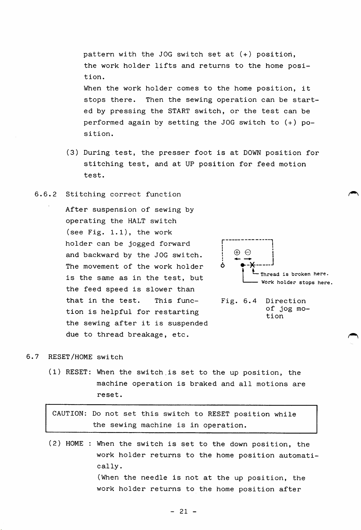
6.6.2
When
stops
ed
performed
sition.
(3)
During
stitching
test.
Stitching
After
operating
(see
holder
and
backward
The
movement
is
the
the
feed
the
by
correct
suspension
Fig.
can
same
speed
work
there.
pressing
again
test,
test,
the
HALT
1.1),
be
jogged
by
of
as
the
the
the
in
is
holder
Then
the
by
the
function
of
switch
work
JOG
work
the
slower
the
START
setting
presser
and
sewing
forward
test,
comes
sewing
at
UP
by
switch.
holder
than
switch,
foot
position
but
to
the
the
home
operation
or
JOG
is
at
© ©
the
switch
DOWN
for
-K-
L.
position,
can
test
to
position
feed
Thread
Work
be
can
(+)
motion
is
holder
start
broken
it
be
po
stops
for
here.
here,
6.7
that
tion
the
sewing
due
RESET/HOME
(1)
RESET: When
CAUTION:
(2)
HOME
in
is
to
thread
switch
machine
reset.
Do
the
: When
work
cally
(When
the
helpful
after
not
sewing
test.
breakage,
the
operation
set
the
holder
.
the
This
for
restarting
it
is
switch.is
this
machine
switch
returns
needle
func
suspended
etc.
set
is
switch
is
is
set
is
braked
in
to
not
to
to
RESET
operation.
to
the
at
the
the
home
the
Fig.
and
6.4
up
position,
all
position
down
position
up
Direction
of
tion
motions
position,
position,
jog
while
automati
mo
the
are
the
the
work
holder
returns
to
the
home
-
21
-
position
after
Page 26
the
needle
The
switch
position.
goes
is
up).
usually
to
be
set
at
the
down
(HOME)
6.8
STOP/MOVE
This
for
(1)
switch
lowering
Bobbin
When
switch
position,
motion
(2)
Lowering
When
presser
position
le
eye.
The
switch
the
the
switch
is
set
the
winding
START
set
at
the
of
the
the
STOP/MOVE
foot
when
is
at
presser
switch
STOP
main
work
presser
starts
the
usually
STOP
foot.
position,
motor
holder.
foot
switch
lowering.
thread
position
is
pressed
rotates
must
set
at
is
and
set
The
be
MOVE
for
with
the
at
to
passed
position.
bobbin
the
work
approx.
STOP
switch
winding,
STOP/MOVE
holder
600spm
position,
is
set
through
at
to
the
and
DOWN
without
the
STOP
need
6.9
ERROR
Error
needle
(1)
(2)
indicators
indicator
at
ERROR 1
Green
Red
light
ERROR 2
Red
light
the
light:
lights
UP
:
:
position
This
data
tion,
rectly
This
becomes
largement
This
is
indicator
are
indicator
indicator
not
and
the
if
not
for
the
programmed
more
of
put
into
sewing
error
present,
selected
than
the
lights
lights
sewing
lights
the
or
PROM
6.2mm
PROM
machine
failure
when
or
not
pattern.
cassette.
when
due
pattern.
when
cessette
stops
occurs.
sewing
in
stitch
to
the
pattern
good
Use
length
excessive
PROM
slot
with
condi
cor
cassette
the
en
cor
rectly.
Put
the
cassette
-
22
-
into
the
slot
Page 27
securely
in
correct
manner.
(3)
Green
ERROR
Two
Two
Two
light:
1,
red
red
green
ERROR 2
lamps
lamps
lamps
This
moves
the
light
at
is
to
er
flicker
is
Press
cause
indicator
beyond
pattern.
at
the
UP
pressed.
lift
to
the
locked
the
is
light
the
position
the
home
at
or
POWER
removed,
at
the
same
Operate
needle
the
the
the
lights
sewing
time:
when
and
position.
same
drive
OFF
press
same
when
the
time:
switch
time:
the
area.
The
the
POWER ON
RESET/HOME
return
The
belt
the
is
and,
POWER ON
Sewing
work
needle
the
main
out
after
Scale
work
pattern
holder
is
motor
of
down
not
switch
switch
hold
pulley.
the
switch.
6.10
Work
ERROR 1
time:
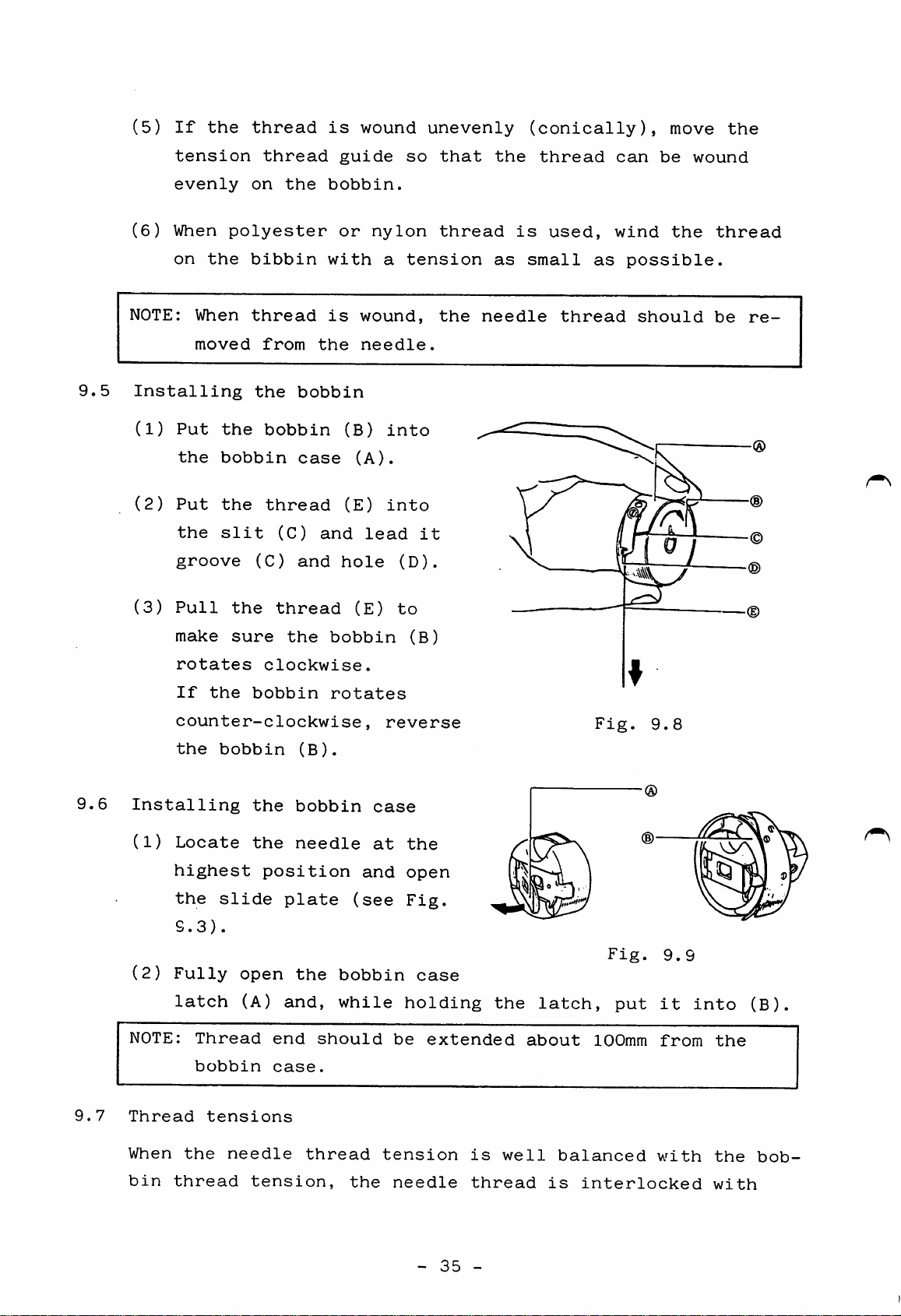
holder
red
lift
in
use
sition
Operate
work
holder
reset.
can
be
and
ERROR 2
(This
error
position
turning
The
RESET/HOME
work
Lower
RESET/HOME
holder
the
switch
is
is
the
used.
on
changed
used.
RESET/HOME
to
After
green
occurs
return"
the
at
work
switch.
while
the
that,
lamps
(refer
power.)
switch
the
holder
first
only
UP
the
switch
a
newly
light
when
is
position.
and
second
home
to
14.5)
operated
then
home
to
return
position
selected
as
the
"automatic
is
with
operate
pattern
same
used
po
the
to
home
for
the
the
This
er.
again.
foot
The
switch
work
(black)
holder
goes
-
is
pressed
up
23
when
-
to
the
lower
switch
the
is
work
pressed
hold
Page 28
5.11
HALT
switch
6.12
6.13
This
tion
START
Sewing
switch
(if
switch
operation
switch
Work
To
be
The
dependently.
work
When
after
start
holder
use
set
left
holders
the
this
to
suspension
if
the
(red)
"ON"
and
automatic
both
is
operated
thread
starts
is
pressed.
pedal
(option)
function,
("OFF"
right
The
are
not
of
the
work
is
SW4
when
work
START
at
home
sewing
to
suspend
broken,
from
(See
(A) on
the
holders
switch
DOWN
position
operation,
holders
for
the
home
Fig.
the
sewing
can
is
position.
return
are
the
sewing
example).
position
1.1)
CPU
circuit
machine
be
turnd
not
operative
function
the
not
at
machine
(See
is
on
function
DOWN
Fig.
when
board
shipped).
and
if
is
does
position.
opera
this
should
off
both
used
1.1)
in
the
not
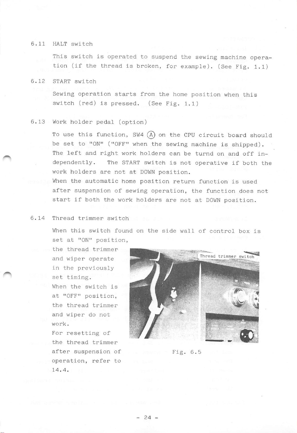
6.14
Thread
When
set
at
the
thread
and
wiper
in
the
set
timing.
When
at
"OFF"
the
thread
and
wiper
work.
For
resetting
the
thread
after
operation,
trimmer
this
"ON"
previously
the
switch
position,
suspension
switch
position,
trimmer
operate
trimmer
do
not
trimmer
refer
of
switch
found
is
of
to
on
the
side
Fig.
wall
.*•
of
,_1Thread
6.5
control
trimmer
box
switch
is
v
-41!
14.4.
-
24
-
Page 29
7.
OPERATION
7.1
7.2
Inserting
Remove
PROM
orient
To
tern(s)
the
cassette
the
store
stored
PTN-IOOO-OL
For
handling
Setting
Set
follows:
SCALE
PATTERN
SPEED
the
each
switch
switch
control
the
cover
cassette
sewing
ROM
of
switches
switch
PROM
on
into
pattern(s)
in
the
writer)
the
on
dial
cassette
the
the
correctly.
PROM,
cassette,
on
the
cassette
drive
is
the
switch
100
0
to
4
slot.
to
the
an
optional
required.
refer
switch
panel
(for
9,
depending
drive
X
Before
PROM,
to
panel
to
and
slot
or
device
section
check
Y
axes)
on
and
the
erase
its
selected
insert
insertion,
sewing
(PT-4000A
13.
function
pattern
the
pat
or
as
7.3
RESET/HOME
STOP/MOVE
Checking
After
the
(1)
the
power
Home
position,
stops
(2)
Work
switch.
when
(3)
Work
and
switch
switch
each
necessary
and
position
at
holder
pressed
holder
the
function
perform
and
the
The
work
Set
Set
preparation
the
return:
then
home
down
work
to
position
motion:
holder
again).
movement:
holder
at
at
following
Set
HOME
Set
moves
DOWN
DOWN
the
position.
Press
will
the
along
position
position
has
been
check:
RESET/HOME
(see
6.7).
the
go
JOG
the
completed,
work
down
switch
sewing
switch
The
holder
(it
to
work
will
(+)
pattern.
turn
to
RESET
holder
lift
go
up
position
on
The
when
During
switch
the
work
work
the
holder
it
traces
is
returned
holder
check
lifts
the
stops
described
and
pattern
to
the
at
-
above,
25
returns
completely.
neutral
DOWN
-
to
position
position.
the
work
the
home
(If
(See
holder
position
the
during
6.6)
JOG
moves
tracing,
but
Page 30
stitching
motion
does
not
occur.
7.4
Also
For
and
Sewing
(1)
(2)
check
stitching
perform
operation
Set
each
6.
1.
Set
up
holder
Press
stitching.
goes
When
med,
sition.
on
the
the
pattern
the
switch
the
lift
the
stitching
stitching
work
test,
test
fabric
switch
START
Once
size
set
on
switch
the
holder
and
the
in
accordance
the
switch
in
the
to
lower
and
sewing
even
is
completed
when
automatically
location
sewing
work
the
the
machine
the
speed
with
panel,
holder
work
sewing
START
and
of
moves
the
to
para.
referring
and
holder.
machine
starts
switch
the
work
"low
7.4.
press
stitching,
threads
up
holder.
speed"
is
to
to
the
starts
released,
are
the
Fig.
work
UP
it
trim
po
7.5
HALT
To
After
sition
To
ing
The
stitches
The
work
NOTE:
switch
stop
thread
resume
the
sewing
work
holder
Before
form
with
the
and
restart
are
holder
test
the
operation
stitching,
trimming,
the
the
stitching,
machine
completed.
switch
starting
operation
sewing
needle
position
automatically
can
during
press
the
stops
be
moved
sewing
in
machine
the
workholder
at
press
by
operating
up
HALT.
work,
order
functions.
the
the
and
HALT
UP
START
stops
down
remove
to
make
switch
stops
position.
switch
the
JOG
when
by
the
yourself
(see
at
the
after
switch.
the
remaining
operating
needle
Fig.
DOWN
adjust
the
and
familiar
1.1).
po
per
-
26
-
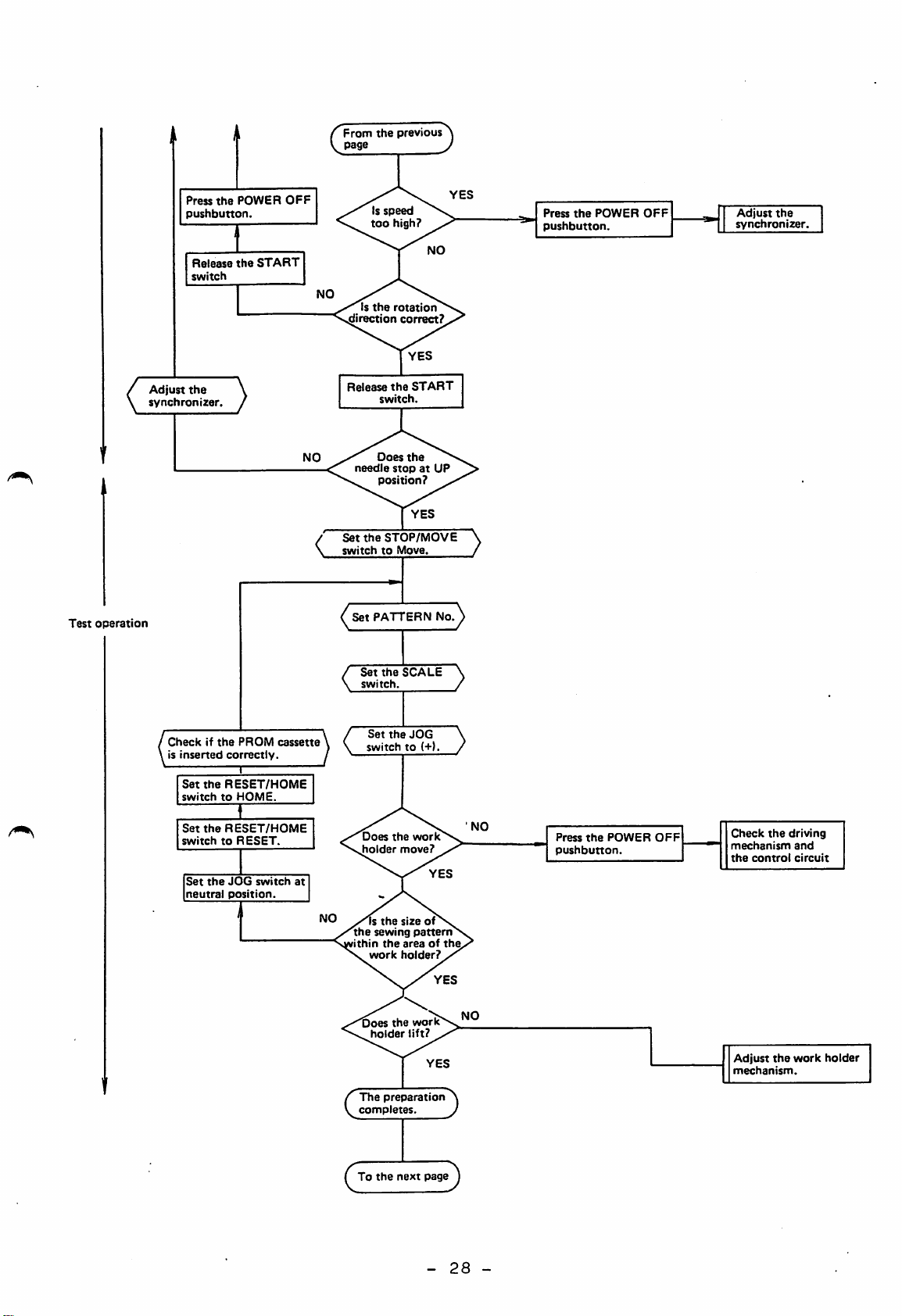
Page 31

7.6
Operating
The
sewing
procedure
machine
and
should
checking
be
operated
and
checked
in
accor
dance
Checking
before
operation:
with
the
following
flow
1) Checkif the power cable is plugged into
the
power source
2) Checkifthe other
3) Check if the
installed.
outlet.
cables
PROM
cassette is correctly
correctly connected.
4) Check if the fuses are not blown.
Start
preparation
Press
the
pushbutton
Does
motor
POWER
the
rotate?
main
ON
NO
Press
OFF
chart:
Check
source
the
pushbutton
power
wiring
POWER
>
CZ)
Reference
Operation
Preparation
Judgement
item
Check
rotational
direction.
Press
pushbutton.
Change
tion
or
reversing
the
(any
inverse
power
POWER
twoofthree
settingofphase
plug.
cable
ON
connec
Set
switchtoSTOP
Press
lift
the
START
wires)
Does
the
holder
home
the
holdergodown?
Depress
work
return
position?
STOP/MOVE
the
work
switchtolet
work
holder.
Does
the
work
the
switch
oes
the
sewing
achine
start?
to
holder
down
Set
switchtoHOME
Set
switchtoRESET
NO
the
RESET/HOME
the
RESET/HOME
Press
the
the
work
POWER
switchtolift
holder.
Press
pushbutton.
the
holder
work
OFF
lift
Adjust
mechanism.
Check
of
the
connector.
the
the
main
work
connection
motor
holder
To
the
next
page
-
27
-
Page 32
Press
pushbutton.
Release
switch
Ad|ust
the
synchronizer
the
POWER
the
START
OFF
From
the
Is
too
Is
the
needle
the
previous
speed
high?
rotation
correct?
the
switch.
Does
the
stopatUP
position?
STOP/MOVE
page
direction
Release
Set
switchtoMove
START
Press
the
pushbutton.
POWER
OFF
Adjust
the
synchronizer.
Test
operation
Checkifthe
is
inserted
correctly.
Set
the
RESET/HOME
switchtoHOME.
Set
the
RESET/HOME
switchtoRESET.
Set
the
JOG
neutral
position
PROM
I
I
switch
cassette
at
/set
PATTERN
/
Set
the
\
switch.
switchto(+1
Does
the
holder
Is
the
the
sewing
ithin
the
work
Does
the
holder
No.^
SCALE
work
move?
size
of
pattern
areaofthe
holder?
work
lift?
\
/
Check
the
control
the
driving
and
circuit
work
holder
Press
the
pushbutton
POWER
OFF
mechanism
the
Adjust
mechanism.
The
preparation
completes
To
the
next
page
-
28
-
Page 33

Start
sewing
D
Set
the
stitching
speed.
(
Automatic
(Sewing)
operation
(
Setupthe
Press
the
lift
switchtoget
work
holder
Is
held
Depress
switch.
Does
machine
Is
broken
fabric.
work
down.
the
fabric
securely?
the
the
sewing
start?
the
thread
during
operation?
holder
the
YES
START
Press
the
Press
OFF
Press
work
switchtolift
holder.
holder
the
work
the
POWER
pushbutton.
the
HALT
lift
switch
PROM
Refer
para.
data
6.9
error
to
Is
trimmed
has
Does
work
Is
trimmer
satisfactory?
tension
The
operation
the
thread
when
finished?
the
properly?
the
thread
operation
Is
thread
ballanced?
stitching
sewing
wiper
well
completes
Is
the
placedinthe
position?
Depress
the
switch.
Press
the
OFF
switch.
fabric
correct
START
POWER
<Adjust
the
positionbythe
switch.
work
Adjust
machine
holder
JOG
the
sewing
-
29
-
Page 34

8.
GENERAL
(1)
Before
INSTRUCTIONS
replacement
of
PROM
in
the
PROM
cassette,
read
the
description
Insert
drive
(2)
When
6.9.
(3)
When a new
used,
area
(4)
Maximum
as
Table
SWl
(b)
(Setting
Stitch
any
confined
shown
8.1
set
length
the
slot
check
sewing
at
in
PROM
after
error
sewing
that
in
Table
Max.
at
"OFF"
shipping)
section
cassette
turning
lamp
the
by
the
speed
sewing
Max.
lights,
pattern
sewing
work
differs
8.1
speed
13.
(see
speed
into
off
is
pattern
holder
for
and
the
power.
check
used
in
depending
6.5).
each
SW1@
Stitch
remove
for
or
is
test
stitch
cause
an
within
on
from
referring
enlarged
operation.
the
length
set
at
length
the
the
stitch
"ON"
cassette
pattern
sewing
Max.
to
is
length
speed
(5)
(6)
5.4
4.8
4.0
3.2
2.6
2.4mm
(Speed
Whenever
keep
When
justment
-
-
-
-
-
6.2mm
5.2mm
4.6mm
3.8mm
3.0mm
or
limit
his
the
less
1)
the
foot
right
or
maintenance,
power
away
side
850spm
llOOspm
1300spm
1550spm
1800spm
2000spm
is
turned
from
cover
the
the
of
on
pedal
control
power
5.4
4.8
4.0
3.4
2.8
2.2
2mm
(Speed
and
switches.
-
-
-
-
-
-
or
off,
box
should
6.2mm
5.2mm
4.6mm
3.8mm
3.2mm
2.6mm
less
limit
operator
is
have
2)
opened
been
eoospm
850spm
llOOspm
1300spm
1550spm
1800spm
2000spm
should
for
off.
ad
(7)
Avoid
to
applied
check.
applying
to
a
multimeter
Otherwise,
semiconductors
-
voltage
30
to
the
internal
from
and
cause
-
the
damage
control
multimeter
to
the
circuits
may
circuits.
be
Page 35

(8)
The
not
pulley
at
the
cannot
DOWN
be
position.
turned
by
hand
if
the
presser
foot
is
(9)
While
STOP
Since
is
off,
Since
moisture
to
time
the
power
position
the
presser
the
water
involved
to
and
pulley
is
accumulated
remove
is
on,
lower
foot
can
in
air,
the
operate
the
is
be
water
presser
the
turned
in
press
(see
the
DOWN
by
the
the
Fig.
STOP/MOVE
foot
position
hand
pneumatic
drain
4.1).
(see
while
freely.
system
knob
switch
6.8).
from
the
due
to
power
to
time
-
31
-
Page 36

9.
HANDLING
THE
SEWING
MACHINE
HEAD
9.1
(1)
Lubrication
Supplying
Before
bricant
9.2.
the
starting
to
the
lubricant
daily
points
Oil
gauge''
operation,
indicated
__Filling
hole
supply
by
arrow
a
few
in
drops
Fig.
9.1
of
lu
and
(2)
Before
of
the
through
lubricant
to
add).
*For
in
the
(for
*For
ser
Filling
bed
side)
Fig.
starting
hole
lower
*1,
plate,
sewing
holes
is
E,
direction
apply
the
9.1
machine,
A,
given
turn
horizontal
lubricant
oil
the
initial
B,
0,
automatically
the
of
tank
pour
D
power
arrow.
shaft
with
operation
a
and
and
to
the
lubricant
suitable
E
(during
and
fully
The
filling
bearings).
reverse
Fig.
after
amount
regular
therefore
push
(on
the
hole
surface
arm
9.2
the
of
side
installation
lubricant
operation,
not
necessary
clamp
will
of
appear
the
and
bracket
pres-
Fill
reaches
the
the
oil
tank
center
with
mark
-
lubricant
of
32
until
oil
gauge.
-
lubricant
level
Page 37

The
oiling
rate
is
factory-adjusted.
When
readjustment
is
9.2
necessary,
NOTE:
Installing
(1)
Before
turn
(2)
Insert
For
white
#2.
off
refer
lubricant,
spindle
the
needle
attaching
the
the
needle
to
power
10.3.
use
oil
or
for
into
Slide
detaching
safety.
the
plate
needle
the
Fig.
9.3
needle,
socket
be
until
Filling
sure
it
is
hole
to
Oil
gauge
stop
Put
until
the
prime
(3)
(4)
needle
it
set
groove
ped
Secure
facing
For
the
shown
Into
stops
screw
at
the
the
front.
better
needle
in
the
and
bottom
needle
stitching,
turned
Fig.
socket
tighten
9.4.
of
screw
about
Needle
needle
it
with
is
10°
with the needle inserted
oriented
front.
N=H
socket.
the
usually
in
the
not
fully
prime
recommended
direction
Gap
Hrr
groove
Needle
of
of
oriented
improperly,
i I
i !/
needle
to
arrow
set
X
X
I)
Fig.
9.4
-
33
-
Page 38

9.3
Threading
the
needle
thread
Pass
the
Fig.
needle
9.5
thread
as
shown
in
Fig.
Arm
® C
III
thread
9.5
Fig.
guide
and
Thread
9.6
9.6
Thread
guide
Take-up
spring
9.4
Winding
(1)
Wind
thread,
cotton
tension
around
several
shown
(2)
Press
lift
the
(3)
Set
switch
panel
and
the
the
stand
the
in
the
switch
work
the
on
to
press
bobbin
end
led
thread
turns
Fig.
work
holder.
of
from
via
bobbin
to
thread
guide,
as
9.7.
holder
lower
STOP/MOVE
the
switch
STOP
the
position
START
the
the
the
(4)
switch
When
wound,
the
(see
set
thread
the
6.8).
has
STOP/MOVE
Fig.
been
switch
-
34
-
to
MOVE
9.7
position
Page 39
(5)
If
the
thread
is
wound
unevenly
(conically),
move
the
9.5
tension
evenly
(6)
When
on
NOTE:
Installing
(1)
Put
the
(2)
Put
the
groove
(3)
Pull
the
When
moved
the
bobbin
the
slit
thread
on
the
polyester
bibbin
thread
from
the
bobbin
thread
(C)
(C)
the
thread
bobbin.
with
is
the
bobbin
case
and
and
guide
or
wound,
needle.
(B)
(A).
(E)
hole
(E)
nylon
a
into
into
lead
so
tension
it
(D).
to
that
thread
the
the
as
needle
is
small
thread
used,
thread
as
can
wind
possible.
should
be
the
wound
thread
be
re
9.6
make
rotates
If
counter-clockwise,
the
Installing
(1)
Locate
highest
the
S.3).
(2)
Fully
latch
NOTE:
Thread
bobbin
sure
the
bobbin
slide
clockwise.
bobbin
the
the
position
open
(A)
plate
and,
end
case.
the
(B).
bobbin
needle
the
should
bobbin
rotates
and
(see
bobbin
while
reverse
case
at
be
(B)
the
open
Fig.
case
holding
extended
the
latch,
about
Fig.
Fig.
put
100mm
9.8
9.9
it
from
into
(B).
the
9.7
Thread
When
bin
the
thread
tensions
needle
tension,
thread
the
tension
needle
-
35
is
thread
-
well
balanced
is
interlocked
with
the
with
bob
Page 40

the
bobbin
thread
along
the
center
line
of
fabric
layers
as
shown
Fig.
Fig.
NOTE:
(1)
in
(B):
(C):
Too
result
thread
Needle
Needle
justed
Fig.
Tight
sion
thread
Loosen
sion
thread
tight
thread
thread
by
9.10
(A)
needle
or
loose
needle
or
tight
thread
in
puckering
breakage.
tension
tension
turning
thread
bobbin
thread
bobbin
tension
the
and/or
can
thread
ten
be
ten
may
ad
X
Fig.
X
9.10
(2)
tension
(A).
Tension
thumb
Tension
thumb
clockwise
Bobbin
Bobbin
justed
tension
Tension
screw
regulating
increases
nut
decreases
nut
.
thread
thread
by
adjusting
increases
is
turned
is
turned
is
turned
turning
tension
tension
clockwise.
thumb
when
clockwise.
when
counter
the
screw
when
the
the
can
thread
(A).
the
nut
be
ad
Fig.
9.11
Tension
thumb
clockwise
nut
decreases
is
.
turned
when
counter
-
36
the
Fig.
-
9.12
Page 41

9.8
Adjusting
the
work
holder
9.8.1
9.8.2
Work
Work
can
knob
work
(The
holder
holder
be
(see
holder
standard
Adjusting
Work
wise
work
spanner.
Note
holder
and
holder
that
against
is
20mm.
After
adjusted
decreases
the
the
pressure
pressure
by
Fig.
4.5).
pressure
air
the
work
lift
arm
adjusting
too
large
wiper,
adjustment,
adjustment
is
operating
and
pressure
holder
increases
when
lift
presser
given
Increase
turned
do
the
decrease
is
lift
when
nut
may
cause
foot,
not
by
the
air
air
for
4kg/cm2,)
the
slider
counter-clockwise,
is
loosened
the
etc.
fail
to
pneumatic
pressure
pressure
smaller
with
work
The
fully
regulator
for
pressure.
is
turned
holder
standard
tighten
system,
larger
after
a
furnished
to
the
and
clock
the
hit
lift
ad
Work
holder
9.8.3
justing
Work
lift
Replacing
(1)
holder
The
nut.
work
the
Work
holder
Fig.
work
holder
Slider
arm
9.13
holder
can
be
Adjusting
o .
replaced
nut
immediately
and
easily
To
(2)
from
To
holder
remove
the
install
with
the
work
a
work
the
work
holder
work
holder,
arm
holder,
holder
-
37
pin.
-
push
engage
arm
the
the
pin.
work
U-groove
holder
of
down
work
Page 42

After
the
engagement,
check
if
play
exists
in
the
di
9.9
Work
Adjusting
holder
rection
play,
arm
if
the
indicated
exists,
u-groove
Fig.
presser
may
9.14
foot
by
arrow
cause
in
Fig.
deviation
9.14.
of
sitches.
Work
Note
holder
that
9.9.1
Adjusting
Adjust
foot
face
into
ric
when
cated
(0
(see
To
adjust,
foot
set
screw
Note
justed
cause
After
height
so
of
presser
slight
-
the
at
Fig.
set
that
too
stitching
the
the
that
contact
0.5mm
presser
its
9.15).
loosen
screw
shown
the
high
adjustment,
presser
of
the
above
lowest
or
presser
or
trouble.
the
bottom
foot
foot
in
presser
comes
with
fabric)
position,
the
presser
Fig.
low
foot
sur-
is
presser
9.16.
foot
may
make
fab
lo
bar
height
ad
sure
the
Fabrics
Fig.
needle
Presser
' I
Presser
foot
set
screw
foot
}0~0.5HUD
_1
9.15
is
at
the
cent
er
of
the
NOTE:
Height
dance
presser
of
with
the
presser
thickness
foot.
of
foot
fabric.
should
be
changed
in
accor
I
Page 43

9.9.2
Adjusting
the
presser
foot
stroke
Vertical
ser
foot
0,
or
to
10mm.
When
the
link
stepped
Fig.
a
range
When
tightened
6.16
the
arm,
a
range
The
stroke
stepped
within
the
16,
the
to
stroke
can
connection
and
screw
the
from
stepped
at
connect
the
from
is
screw
of
be
adjusted
a
range
the
arm
is
as
stroke
4mm
to
screw
hole
the
stroke
2mm
to
zero
is
tightened
the
between
shown
is
10mm.
"A"
when
pres
from
by
within
is
in
link
is
within
5mm.
the
the
to
2mm
in
Fig.
to
at
Needle
Presser
set
Presser
A
bar
screw
foot
foot
set
screw
\\\\'
Fig.
B
\
Wt
IM
9.
9.9.3
hole
The
stroke
sure
When
the
"B".
stroke
within
foot
the
lift
becomes 1 -
changes.
height,
Adjusting
Pressure
adjust
pressuer
the
thumb
Pressure
wise,
and
is
factory-adjusted
each
stroke
stepped
of
the
2mm
Therefore,
the
presser
of
the
foot
increases
pressure
screw
decreases
range
adjusting
screw
presser
larger
the
height
presser
(larger)
when
is
foot
and
after
foot
foot
adjusting
when
can
be
bolt.
tightened
at
the
adjustment
of
the
pressure
can
shown
the
adjusting
turned
to
4mm.
made
stop
height
presser
be
screw
in
Fig.
at
adjusted
Adjustment
by
loosening
hole
of
presser
of
the
of
foot
after
9.17.
presser
screw
counter-clockwise.
the
"A"
or
foot
presser
foot
bar.
by
turning
loosening
is
turned
of
"B",
motion
foot
the
pres
the
the
clock
The
Do
standard
not
change
setting
the
is
setting
shown
-
39
of
-
in
the
Fig.
smaller
9.17.
thumb
screw.
Page 44

Presser
foot
J /
pressure
Thumb
Thumb
nut
adjusting
(large)
nut
screw
(small)
9.9.4
9.10
Lift adjusting
Adjusting
For
adjusting
10.6.
Replacing
(1)
To
frame
the
replace
mounting
the
jpl-,
timing
the
lower
the
Fig.
timing
lower
screw
of
clamp
9.17
presser
of
frame
clamp
(screw
presser
(see
frame,
"A"
foot
foot
Fig.
in
motion
remove
Fig.
motion,
6.18)
the
9.18).
refer
lower
to
clamp
Lower
(2)
clamp
The
the
If
the
holder,
plate
guide
lower
lower
loosen
plate
clamp
clamp
screws
is
frame.
provided
frame
"A"
is
and
for
not
position
aligned
"B"
Fig.
and
9.18
adjustment
with
adjust.
Screw
Screw
Guide
A
the
of
work
B
plate
Page 45

10.
ADJUSTMENT
AND
MAINTENANCE
10.1
10.1.1
Adjusting
Adjusting
(1)
Lower
(2)
Turn
the
lowest
(3)
Remove
the
en
needle
(4)
Vertically
the
timing
and
screw
the
needle
face
the
needle
then
the
the
pulley
position.
the
plate
set
bar
of
tighten
(B).
timing
the
presser
bar
rubber
screw
clamp.
move
bar
needle
needle
to
(C)
(A)
and
(C)
between
foot.
position
to
plug
and
(B)
position
to
bar
the
position
its
from
loos
of
adjust
motion
set
needle
motion
and
Fis.
hook
10.1
motion
♦Timing
When
at
needle
or
the
bar
With
inside
should
(D)
Four
pair
of
needle
the
its
(J)
bottom
bushing
the
of
timing
of
needle
lowest
bar
must
edge
alignment
surface
be
aligned
needle
them
bar
position,
timing
be
(F).
eye.
marks
for
bar
in
of
(E)
motion
(C)
mark
line
the
at
of
with
are
the
is
(K)
with
needle
step
hook
center
put
needle
on
(1),
used.
the
needle
m
Fig.
bar.
10.2
Use
one
-
41
-
/
Page 46

10.1.2
(1)
Adjusting
Remove
(see
Fig.
the
the
slide
1.1).
hook
position
plate
}
For
DB
X1
)
For
DP
X17
(2)
(3)
NOTE:
Loosen
screw
sition
adjust
tion
(C).
Gap
(D)
(C)
0.05mm.
When
relative
slide
the
(A),
the
timing*
of
the
between
and
the
should
the
plate
hook
turn
hook
hook
the
hook
be
slide
to
set
and
(B)
of
point
needle
point
about
plate
the
screws.
po
to
mo
needle
is
position
installed,
Fig.
and
Fig.
adjust
then
10.4
10.3
its
tighten
Mii;!®
position
the
10.1.3
*Timing
The
follows:
When
lifted
position
mark
bar),
(1)
(2)
Position
of
standard
the
2.2mm
(A)
the
hook
meet
needle,
the
gap
hook
hook
needle
(refer
put
the
point
point
timing
bar
from
to
on
the
point
center
and
between
(D)
of
hook
motion
is
(B)
its
timing
needle
(D)
(C)
the
should
positioner
as
is
lowest
should
of
needle
be
eye
1.0mm
upper
-
1.5mm.
2.2
Fig.
® ©
ana
edge
10.5
(E)
and
1.0—1.5
the
nm
L
2.2
mm
The
hook
side
hook
positioner
surface
positioner
of
needle
(A)
-
(A)
as
42
should
(B)
shown
-
is
be
aligned
in
Fig.
adjusted
with
10.6.
so
the
that
point
the
of
Page 47

0.5~0.8
10.2
Thread
Needle
adjusted
thread
(1)
Bobbin
be
tensity
thread
(2)
Needle
be
tensions
thread
tension
adjusted
adjusted
(1)
take-up
thread
Fig.
in
reference
thread
of
tension
thread
intensity
spring
tension
10.6
tension
as
by
the
by
follows:
tension
changing
bobbin
spring.
tension
changing
of
thread
(B)
regulator,
should
to
of
be
bobbin
can
in
case
can
10.7
needle
or
(2)
take-up
sure
stroke
of
(A)
spring,
the
tension
of
or
the
(3)
discs
thread
pres
(C).
10.2.1
Adjusting
(1)
Put
thread
case
(C)
the
the
bobbin
#30
(A)
through
bobbin
into
and
slit
lead
with
the
thread
out
(B).
-
tension
polyester
bobbin
thread
43
-
Fig.
10.8
Page 48

(2)
Tie
(C)
The
is
swung.
a
hexagon
to
hang
standard
gradually
key
the
bobbin
unwound
wrench
key
wrench,
thread
when
(D)
tension
the
(furnished)
as
shown
bobbin
to
the
thread
in
Fig.
is
that
case
the
is
10.8.
thread
vertically
10.2.2
NOTE:
Adjusting
Standard
The
can
turning
of
bobbin
thread
spring
Thread
creases
screw
wise,
when
clockwise
the
bobbin
thread
be
adjusted
is
and
turned
needle
screw
tension
(A).
tension
when
turned
.
thread
tension
(B)
case
the
decreases
counter
thread
by
in
tension:
clock
tension
10
-
Fig.
15g
10.9
(a)
Adjusting
thread
(1)
Loosen
set
tension
ter-clockwise
tensity
take-up
reaches
(2)
Turn
clockwise
take-up
into
further
the
take-up
screw
the
contact
the
stud
of
spring
zero.
thread
spring
turn
intensity
spring
tension
and
turn
(B)
until
the
until
with
tension
coun
thread
(A)
stud
the
(A)
of
stud
the
in
comes
the
(B)
spring
stud
(B)
stopper
about
Fig.
1/2
and
10.10
then
turn.
-
44
-
Page 49

The
needle
thread
tension
will
be
adjusted
to
(b)
about
Adjusting
(1)
Loosen
sion
screw
(2)
Turn
or
clockwise
tension
to
sity
After
ment,
set
30
Standard
the
stud
clockwise
counter
adjust
of
the
tighten
screw
the
(A).
-
intensity
set
the
stud
inten
the
adjust
(A)
40g.
needle
ten
(B)
spring.
the
thread
of
tension:
thread
30
take-up
Fig.
-
spring
40g
10.11
(c)
Thread
the
creases
Adjusting
(1)
Loosen
tension
(B).
(2)
Turn
ing
wise
wise
of
The
the
tension
the
the
thumb
or
to
take-up
stroke
thumb
take-up
stud
when
stroke
the
needle
stud
tension
nut
counter-clock-
adjust
spring*.
increases
nut
spring
turned
set
(C)
the
is
intensity
is
turned
counter-clockwise.
of
take-up
thread
screw
regulat
clock
stroke
when
turned
increases
clockwise,
spring
^ Q 1A tfim
and
when
de
clockwise,
when
turned
and
decreases
counter-clockwise.
Fig..
-
45
-
10.12
Page 50

NOTE*:
The
standard
stroke
of
take-up
spring
(gap
(d)
Adjusting
(1)
Lift
foot
the
sion
set
(2)
Move
regulator
ing
direction
ed
10.13,
the
and
thread
regulator
screw.
the
(B)
by
between
(D))
the
presser
loosen
tension
in
arrow
so
ranges
thread
ten
bush
the
indicat
in
that
take-up
from
tension
Fig.
the
spring
9mm
discs
0.8~
to
(A)
10mm.
1.0
mm
and
thread
guide
10.3
Adjusting
(1)
Tighten
justing
gap
between
discs
a
range
After
NOTE*:
NOTE:
the
lubrication
the
screw
(A)
is
from
the
adjustment*,
Whenever
or
set
between
range
The
ser
med.
oiling
by
tension
within
0.8mm
screw
from
tension
foot
rate
fingers
the
to
the
is
to
needle
is
tension
0.8mm
discs
lifted
hook
ad
or
10.mm.
tighten
loosened,
to
work
and
Fig.
thread
discks
1.0mm.
only
when
the
10.13
set
tension
make
(A)
when
thread
screw.
sure
is
the
regulat
the
within
is
adjusting
pres
trim
Oiling
gap
a
rate
scr
(2)
with
it
Loosen
adjusting
small
stops.
one
screwdriver
turn
screw
or
to
until
less
adjust
-
46
the
View
-
with
machine
Fig.
head
10.
14
laid
down
Page 51

(3)
oiling
Oiling
rate.
rate
can
be
checked
by
observing
the
oil
trace,
splashed
NOTE:
Screw
Fig.
Screw
Fig.
Screw
Fig. (Q
from
Do
not
with
fully
loosened
loosened
the
hook
tighten
excessively
tightend
Max.
rate
(about
by
about
Standard
rate
by
one
Min.
on
the
large
oiling
250mg/min)
3/4
oiling
turn
oiling
to
oiling
turn
rate
a
force.
test
rate
paper.
adjusting
Oil
hook
splashed
Fig.
(for
10.15
screw
10
from
sec.)
10.4
10.5
Adjusting
The
contact
the
pulley
sembly
of
Adjusting
After
around
bobbin
the
stitching,
should
arm
If
positioned
the
marks
stop
the
bobbin
pressure
can
be
the
winder
the
(see
needle
completion
the
machine
with
the
in
deviate
winder
of
adjusted
pivot
Fig.
stop
of
line
the
pin
bobbin
by
after
10.16).
UP
moving
position
^ ~
winder
the
loosening
rubber
bobbin
one
wheel
winder
set
^ /
to
as
screw
s
Fig.
-
47
-
10.16
Page 52

more
than
3mm
from
each
other,
loosen
the
set
screws
of
synchronizer
hand,
NOTE:
move
Although
usually
should
(1)
(2)
(3)
coupling
the
required
be
Remove
ward
The
first
sition
UP
position
The
matching
be
at
If
the
pulley
the
DOWN
performed.
the
the
cable
detection,
115*^
first
and,
to
holding
adjust
position
to
be
synchronizer
side
synchronizer
and
detection.
mark
on
disc
the
on
scale
is
the
of
adjusted,
cover
(see
disc
the
the
of
not
the
needle
the
Fig.
second
first
second
at
coupling
needle
the
by
10.17).
(red)
disc
115
with
stop
position.
bar
following
pulling
is
for
(black)
(red)
disc
turn
one
is
check
it
DOWN
is
should
(black).
the
not
to
po
for
first
Timing
mark
10.6
(A)
/
y
A
1st
Fig.
Adjusting
To
adjust
the
cover
side
through
2nd
m
timing
disc
timing
Coupling
/
10.17
the
timing
on
mark
to
mark
Synchronizer^
cover
Set
(2
timing
of
the
back
the
opening.
set
screws)
presser
to
of
of
115^
Red
(DOWN
presser
arm
disc
O
foot
to
(see
position)
foot
vertical
make
Fig.
Fig.
10
motion
accessible
10.18).
Mark
10.18
Black
(up
12
I
Mark
motion,
Scale
disck
iisc
position)
O
on
on
red
to
black
disc
(115°)
remove
the
in
(1)
(2)
Loosen
Turn
its
The
the
the
pulley
lowest
eccentric
eccentric
and
position.
ring
-
48
set
ring
stop
-
it
screw
set
screw
when
(A)
the
will
(C).
needle
come
to
bar
reaches
the
front
Page 53

(3)
(standard
Loosen
the
position).
eccen
Upper
vertical
crank
(4)
(5)
(6)
tric
screw
Secure
tric
position.
Carefully
pulley
the
eccentric
(B).
Timing
earlier
pulley
the
direction
row
(D).
After
ring
(A).
the
ring
to
becomes
when
is
the
set
eccen
(B)
in
turn
position
turned
the
ring
the
of
adjustment,
in
ar
while
Fig.
pressing
Crank
10.19
the
rod
eccentric
ring
(7)
(B)
in
screws
Position
its
clamping
the
bell
when
NOTE:
the
For
stroke
the
(A)
and
crank
take-up
direction
and
(C)
secure
screw,
is
adjustment
and
of
in
the
so
in
parallel
lever
of
pressure,
this
that
is
arrow
order.
upper
at
presser
refer
(E),
vertical
the
with
the
tighten
vertical
the
highest
foot
to
height,
9.9.
feed
center
presser
position.
the
crank
set
line
foot
vertical
with
of
bar
Page 54

10.7
Air
piping
to
cylinders
for
work
holder,
presser
foot
and
Presser
air
Work
cylijider
holder
Thread
foot
,—r
'—L
trimmer
air
thread
Fig.
er.
Components
—
-r-
cylinder
air
in
cylinder
10.20
machine
trimmer
shows
incorporated
5-
u
the
diagram
06x4
tube
06x4 tube I
06x4
tube'
06x4
tube
Silencer
I"
w
of
air
piping
Components
outside
Solenoid
08x6
installed
machine
valve
tube
to
Drain
each
knob
Air
cylind
pressure
control
Figler/air
regulator
knob
10.8
10.8.1
Adjusting
(1)
(2)
Adjusting
When
shown
Set
the
machine
tion)
Loosen
so
that
of
presser
point
not
be
Fig.
the
the
wiper
in
Fig.
STOP/MOVE
stops
to
lower
the
the
and
used
10.22).
the
wiper
foot.
the
wiper
height
10.23
(take-up
top
wiper
(the
Fig.
is
the
of
not
switch
presser
set
wiper
If
wiper
10.20
of
used,
to
screw
the
top
wiper
"OFF".
to
lever
is
distance
is
may
set
STOP
foot.
and
1.0mm
less
hit
the
position
located
adjust
than
against
wiper
above
between
at
height
5mm,
the
its
the
release
when
highest
of
top
the
the
needle)
the
the
surface
needle
wiper
switch
sewing
posi
wiper
should
(see
CAUTION:
When
changed,
correspondingly.
height
height
or
lift
-
50
-
of
the
of
the
wiper
presser
should
foot
be
is
changed
Page 55

10.8.2
(1)
(2)
Adjusting
Loosen
Adjust
the
the
set
position
wiper
screw
of
drive
the
for
mechanism
rotary
stopper
solenoid
so
that
gap
drive
between
crank.
the
bent
(3)
(4)
(5)
part
per
21,
Locate
is
at
shown
Adjust
is
positioned
crank
Rotate
to
make
of
screw
and
the
in
is
stopper
in
secure
the
wiper
center
Fig.
position
brought
the
rotary
sure
Fig.
10.21.
as
it
and
it
drive
of
of
shown
into
can
the
10.21)
in.
that
crank
the
the
driven
in
contact
solenoid
move
Rotary
solenoid
washer
is
bout
position.
slotted
Fig.
by
smoothly.
(clsimped
so
that
hole
crank
10.23
with
hand
4mm,
the
(push
the
of
so
when
by
as
drive
that
stopper.
the
shown
driven
the
the
the
right
in
crank,
wiper
drive
Fig.
crank
wiper
stop
10.
pin
as
top
drive
crank)
Stopper
washer
Fig.
10.21
Slotted
Driven
Drive
Driven
Driven
crank
crank
crsink
hole
Wiper
crank
pi"
/
/
Screw
set
screw
Fig.
10.22
Presser
foot
Min.
Smm
-
51
-
Page 56

Wiper
release
switch
U.
10.9
Stopper
Home
When
fixed
e
\
/
position
the
f.
to
ee
1
Fig.
sewing
the
10.23
adjustment
machine
center
Rotary
Drive
Driven
of
crank
is
the
solenoid
crank
shipped,
effective
Wiper
the
sewing
home
position
area.
Needle
is
Effective
Home
The
below.
position
sewing
home
area
position
adj\astable
Initial
position
area
home
can
(Rear)
(Front)
be
changed
within
the
range
shown
Fig.
10.24
-
52
-
Page 57

10.9.1
(1)
Preparation
Set
SWl
(C)
for
switch
home
position
in
the
control
adjustment
box
to
"ON"
position
Effective
(refer
If
this
narrower
Ex.:
sewing
to
switch
when
When
and
"OFF",
shown
Initial
position
area
14.3).
home
40mm
below.
is
home
position
in
stitching
home
"OFF",
position
Y
direction
X
direction
is
(Rear)
the
effective
is
is
moved
impossible
T '
Y
direction
changed.
with
Shifted
60mm
SWl
in
home
sewing
in
the
(C)
the
position
area
X
switch
shaded
becomes
direction,
set
area
at
10.9.2
(2)
(1)
Home
made
Plot
position
frame.
After
locate
the
needle
Then
Home
Remove
Fig.
position
as
follows:
the
original
on
the
the
perform
position
the
10.25
adjustment
home
a
paper
RESET/HOME
original
position
the
following
adjustment
X-Y
cover
(Front)
and
switch
home
and
(upper)
can
position
put
position
secure
in
be
the
is
home
X
clamping
facilitated
and
paper
set
plotted
the
position
direction
the
to
paper
desired
on
the
RESET
in
adjustment:
screws,
on
when
lower
and
the
that
and
it
new
clamp
then
paper
position.
the
is
home
HOME,
to
X-
Y
cover
(upper).(see
Fig.
-
10.26).
53
-
Page 58

\2)
Remove
two
cover
gui
Remove
in
Fig.
the
10.27
X-Y
(lowe
(remov
»t,
,»
Cover
guide
Page 59

(3)
Home
position
can
be
shifted
to
the
right
by
moving
the
(4)
(5)
(6)
X-axis
detector
The
detector
slotted
Additional
by
loosening
Fine
Home
home
position
position
the
holder
After
that
the
the
X-axis
Operate
detector
plate
hole.
fine
the
detector
the
in
in
plate
movement
the
screws
position
can
adjusting
base
screw
adjustment,
detector,
RESET/HOME
the
direction
the
direction
can
be
of
the
adjustment
be
adjusted
(B)
move
plate
horizontal
switch
moved
(A)
screw
is
does
X-axis
and
finely
with
loosened.
the
not
to
of
of
within
sliding
X-Y
come
shaft,
make
arrow
arrow
detector
by
a
screwdriver
table
into
sure
D.
the
the
turning
by
etc.
C,
length
is
holder
hand
contact
home
and
possible
the
position
the
of
after
to
with
its
base.
home
check
has
been
shifted
Detector
Detector
set
plate
screw
as
plate
intended.
Holder
Home
fine
Sc
rew
(3)
base
position
adjusting
screw
bracket
Fig.
10.28
-
55
-
Page 60

10.9.3
(1)
(2)
Home
Remove
Home
position
the
position
adjustment
detector
can
be
cover.
shifted
in
Y
direction
backward
by
moving
the
Y-axis
(3)
(4)
(5)
(6)
detector
clamping
To move
screw
Home
position
position
loosened
After
pass
without
through
Operate
has
been
in
screws
the
(B)
fine
(adjustable
the
contact.
the
shifted
the
direction
are
Y-axis
and
tighten
can
adjusting
adjustment,
the
space
RESET/SET
as
loosened.
detector
be
adjusted
distance:
intended.
it
in
screw
check
between
switch
of
arrow
for
an
appropriate
finely
after
3mm).
that
the
to
long
the
make
(A)
distance,
by
the
detector
two
sure
after
turning
set
detector
home
the
screw
screw
plate
detector
remove
hole.
the
(A)
elements
position
the
home
is
can
Detector
place
Fig.
10.29
Detector
Sc
rew
(B)
Detector
bracket
Home
Y-axis
plate
position
bracket
detector
fine
adjusting
screw
-
56
-
Page 61

10.10
Adjusting
the
X-Y
table
10.10.1
(1)
(2)
(3)
Checking
After
and
the
moved
This
er.
by
letting
several
Long
due
to
the
X-Y
(see
When
retainer
stitching
power
by
is
caused
In
times.
use
dust
cover
Fig.
the
the
X-Y
hand
this
the
may
result
deposited
10.26
movable
is
reduced
table
of
small
is
turned
throughout
by
displacement
case,
table
(upper),
and
race
motion
retainer
strike
in
heavy
on
X-Y
10.27),
is
to
half
patterns
off,
the
races.
cover
shifted,
and
the
entire
of
position
against
movement
oil
and
of
race
movable
is
work
sewing
the
the
In
(lower)
clean
the
moving
repeated
holder
X-Y
can
X
of
the
this
and
moving
range
may
area.
table
be
corrected
and
X-Y
case,
cover
the
distance
distance.
for
retain
Y
stoppers
races.
long
not
table
remove
plate
be
of
\\\\0^
Fig.
10.30
-
57
-
Page 62

10.10.2
Adjusting
the
X-Y
table
bontact
pressure
(1)
(2)
(3)
To
adjust
X-Y
covers
lower
only
in
clamp
Loosen
3
screws).
While
(X),
tighten
Smaller
recommended.
Adjust
roller
in
position
tained
contact
clamp
the
plate
the
pressing
contact
the
slipping
when
(upper
plate
X
axis,
is
not
X-axis
the
pressure
by
located
pressure
and
(when
fixed
a
fixed
clamping
pressure
when
a
finger,
lower),
contract
removal
required).
race
race
so
that
it
is
to
the
of
of
screws.
which
the
moved
and
left
the
cover
the
clamping
(X)
against
does
work
that
and
X-Y
plate,
pressure
bellows
not
holder
with
good
right
table,
screws
mated
cause
one
balance
remove
bellows
is
adjusted
and
lower
(only
fixed
play
can
move
retainer
is
extremities.
the
and
front
race
is
with
held
re
(4)
Y-axis
Adjust
the
Adjusting
fixed
same
screw
race
the
contact
manner
X-axis
race'o
screw
x-axis
race
Fig.
as
fixed!
1ampi ng 1
fixed
10.31
pressure
above.
Y-axis
'
'
Adjusting
'^!
Retainer
fixed
screw
in
the
race
Y-axis
loosen
clamping
direction
this
crew.
screw
in
Page 63

10.11
Adjusting
the
X-Y
table
belt
tension
10.11.1
(1)
(2)
Adjusting
Loosen
tension
To
increase
tension
The
recommended
ed
when
span
This
by
tension
screw
four
adjusting
adjusting
the
finger.
about
the
bracket
X-axis
belt
will
90^'
X-axis
belt
is
from
belt
clamping
screw
belt
screw
tension
lightly
be
achieved
nearly
tension
to
adjust
tension,
at
the
depressed
screwed
screws
tighten
side
is
that
by
tightening
belt
and
of
no
at
up
turn
tension,
the
bed.
slack
its
the
position.
the
belt
X-axis
is
develop
center
adjusting
belt
of
Fig.
10.32
Belt
tension
adjusting
screw
-
59
-
Page 64

10,11.2
Adjusting
the
Y-axis
belt
tension
(1)
(2)
Loosen
that
To
increase
adjusting
The
recommended
ed
when
span
This
screw
by
the
the
the
finger.
tension
about
bracket
bracket
Y-axis
screw
belt
90°
will
can
(Y).
belt
is
be
from
Y
clamping
move
belt
tension,
tension
slightly
achieved
nearly
screws
slightly.
is
depressed
by
screwed
to
tighten
that
tightening
up
such
no
at
position.
the
slack
its
an
belt
the
extent
is
develop
center
adjusting
tension
of
Bracket
clamping
Fig.
bolt
10,33
Cover
plate
Y-axis
belt
tension
adjusting
screw
Page 65

10.12
(1)
(2)
(3)
Adjusting
Remove
Loosen
Adjust
the
two
motor
the
belt
nuts
LIMI-STOP
cover.
shown
position
Z
below.
by
motor
the
upper
belt
nut
tension
so
that
appropriate
tension
After
is
the
* t
given
adjustment,
to
the
belt
tighten
V-belt
by
the
the
gravity
lower
nut.
of
the
motor.
Fis.
10.34
LIMI-STOP
Z
motor
-
61
-
Page 66

11.
ADJUSTMENT
OF
THREAD
TRIMMER
Thread
Fixed
11.1
Knife
guide
knife
Movable
Construction
bracket
knife
Drive
unit
crank
Fig.
Knife
of
drive
11.1
thread
Trimming
Cam
follower
shaft
cam
trimmer
I
crank
Cam
Thread
1
follower
mechanism
trinuner
© ©
crank
air
Mouting
Q)
2
cylinder
block
Stopper
11.2
11.3
11.3.1
(1)
Caution
A
hook
When
tated
the
cam
the
movable
damaged.
be
actuated
Installation
Knife
Secure
(left)
the
with
shaft
machine
follower
Therefore,
bracket
the
with
cam
the
knife
during
of
knife
trimmer
knife
unit
screw
drive
is
adjusted,
(2)
comes
adjustment
bracket
(A).
system
air
is
the
bracket
cylinder
engaged
into
trimmer
unit
is
if
with
contact
or
and
to
employed
the
machine
in
actuation
the
with
air
cylinder
maintenance
knife
the
hook
ttim
in
trimming
the
bracket
shaft
the
pulley
needle,
should
of
trimmer.
(that
cam),
the
unit
bushing
is
ro
is,
and
not
machine
-
Fig.
62
11.2
Knife
-
bracket
unit
Hook
bushing
shaft
(left)
Page 67

11.3.2
Knife
bracket
unit
11.3.3
Secure
to
the
shown
Relative
(1)
The
of
movable
Fig.
(2)
If
shown
the
bed
in
Fig.
location
standard
the
11.4.
dimension
knife
with
fixed
in
knife
Fig.
screw
11.3
bracket
(A)
of
fixed
installation
knife
is
shown
of
0.3mm
11.4
and
is
unit
as
knife
in
too
and
(Blade)
Fig.
movable
0.3
11.3
nun
knife
Movable
knife
/
11.4
may
after
On
(3)
Connection
Connect
drive
large,
leave
the
dimension
thread
may
occur.
The
dimension
should
the
knife
the
fixed
the
crank
the
thread
other
trimming
be
of
knife
as
the
is
adjusted
bracket
knife
knife
shown
needle
trimming.
hand,
too
bracket
thread
needle
small,
failure
(0.3mm)
unit
is
bracket
in
Fig.
eye
if
the
when
installed.
to
to
Fixed
or
the
11.5.
drive
knife
Fig.
crank
11.4
Link
Pay
attention
link.
to
position
of
the
Fig.
-
63
-
11.5
Page 68

Drive
11.5
crank
Knife
drive
Coil
shaft
Cam
spring
follower
crank
B B
Cam
1
follower
crank
2
11.6
(1)
The
is
(2)
When
knife
(3)
Secure
shaft
(4)
Secure
play
Installation
Bushing
standard
shown
the
drive
in
in
in
knife
the
position
the
the
of
Fig.
Fig.
shaft
cam
stopper
axial
trimmer
11.6
installation
11.6.
drive
through
.follower
shown
so
direction,
Knife
drive
mechanism
crank
in
that
air
cylinder
of
the
Fig.
the
the
drive
and
Stopper
is
(1)
11.6.
knife
knife
assembled,
crank
to
the
drive
can
rotate
Adjusting
drive
knife
bolt
mechanism
pass
first.
shaft
smoothly.
drive
has
the
no
(1)
Installation
air
cylinder
@
The
screws
11.7.
When
der
tion,
should
To
screws
tion
(D
When
of
unit
unit
is
(C)
the
trimmer
is
in
release
a
gap
be
developed.
adjust
this
(C)
of
the
the trimmer
trimmer
installed
shown
of
and
bracket.
in
air
about
gap,
adjust
air
-
64
condi
-
by
Fig.
cylin
1mm
loosen
posi
cylin-
Cam
follower
Fig.
Thread
m"
in
crank
11.7
1ii
1
trimmer
0.5
Eni
air
Cam
cylinder
Drive
©
follower
crank
block
2
Page 69

der
the
is
cam
actuated,
follower
a
gap
arms
of
(1)
0.5mm
and
(2)
is
as
developed
shown
between
in
Fig.
11.7
Installation
(1)
Align
timing
(2)
Actuate
cam
trimming
with
(3)
Release
lower
11.7
To
adjust
move
Fig.
the
mark
clockwise
the
arm
(under
the
11.7.
of
second
the
cam
roller.
the
(2)
the
the
air
cylinder
trimming
on
the
trimmer
as
in
position
trimmer
is
standard
gap
to
cam
timing
arm,
air
shown
air
returned,
0.5mm,
in
mark
as
shown
cylinder
in
Fig.
when
cylinder.
the
installation).
loosen
the
direction
(A)
on
in
to
11.8
the
cam
gap
between
screws
the
Fig.
rotate
(b)
comes
When
of
pulley
11.8
the
and
the
the
(A)
arrow
with
(a).
trimming
secure
into
cam
cam
and
in
the
the
contact
fol
and
NOTE:
the
roller
(c).
The
it
If
when
should
Fig.
complished.
standard
is
actuated
the
the
11.6
should
position
stopper
be
adjusted
and
be
position
is
of
then
0.5mm
shown
plate
by
the
the
of
cam
is
the
steps
-
the
in
Fig.
follower
removed,
adjusting
1.0mm
cam
(1)
as
follower
11.9.
for
-
(3)
shown
(2)
example,
bolt
should
in
(2)
is
shown
Fig.
before
shifted,
be
11.8
it
in
ac
-
65
-
Page 70

Matching
®
n
y
<§)
mark
Trimming
cam
Fig.
J©
11.8
(b)
Fig.
Normal
direction
Roller
11.8
rotation
O
Jectional
from
Trimming
of
view
(a)
cam
Fig.
11.8
0.5
(c)
~ 1.0
HUD
Hook
Roller
Bed
Cam
Fig.
drive
shaft
11.9
-
66
-
surface
Page 71

11.8
Adjusting
(1)
Relative
ble
The
the
knife
movable
knife
positions
and
knife
engagement
of
fixed
and
knife
mova-
the
Movable
Movable
knife
knife
\ 5.5 ~
\ \
emm
Fixed
knife
(2)
fixed
cated
10
(standard
Adjusting
ment
(T)
When
der
ing
ming
knife.
When
vances
knife
as
shown
the
is
machine
cam
the
should
positions).
the
trimmer
actuated
rotates
movable
fully,
in
knife
is
be
Fig.
and
run,
knife
lo
11.
engage
air
the
the
the
knife
engage
cylin
sew
trim
movable
ad
Drive
Fig.
Movable
crank
knifs
11.10
1.5 -
2.0
Fixed
knife
(3)
ment
as
(2)
To
change
crank.
Adjusting
(T)
The
is
starts
fixed
sitioned
(1).
If
easily,
should
shown
adjust
position
the
standard
that
thread
the
engaging
knife
increase
in
knife
knife
as
cannot
be
1.5mm
Fig.
11.11.
engagement,
of
engagement
knife
movable
with
when
shown
they
be
knife
-
2.0mm
the
drive
engagement
knife
the
are
po
in
Fig.
trimmed
11.12
engage
Fig.
pressure
Movable
Fixed
11.11
kniis
Fig.
knife
3 am
11.12(1)
ment
pressure.
-
67
-
Page 72

@
To
adjust knife
engagement
pressure, loosen the lock
11.9
(4)
Installing
Put
movable
in
movable
Fig.
Adjusting
(1)
When
noide
discs
nut
screw
the
position
11.12(2).
the
the
is
should
(B) shown
(A).
the
protector
knife
knife,
tension
actuated,
and
together
needle
open
in
knife
as
thread
release
Fig.
under
secure
shown
the
about
11.10
protector
the
it
with
the
in
tension
sole-
tension
1.0mm
and
release
turn
Fig.
the
Max.
Center
11.12(2)
adjusting
Set
Movable
Protector
O.Smin
of
needle
screw
knife
(2)
NOTE:
(3)
as
shown
To
adjust,
shown
the
wire
Opening
increases
is
moved
If
needle
to
ever,
If
opening
loosen
in
of
opening
the
may
the
in
loosen
Fig.
tube.
the
when
to
thread
needle
cannot
screw
Fig.
11.14
the
of
cause
11.13.
the
tension
the
left.
the
may
thread.
loose
be
(A)
and
wire
tension
be
adjusted
and
nut
move
discs
tube
broken
stitch.
(C)
Too
pull
discs
due
by
the
loose
aushing
is
to
tension
moving
wire
About
Fig.
too
small,
excessive
the
to
11.13
discs,
wire
adjust.
1mm
the
tension
how
tube,
-
68
-
Page 73

Front
side
Solenoid
Screw
(A)
Wire
Nut
(C)
Wire
tube
''
(4)
Thread
can
the
cated
wheel
To
adjust,
ing
the
295*^
black
Thread
to
smaller
angle.
Fig.
11.14
release
be
adjusted
synchronizer
by
the
(pulley).
on
the
synchronizer
on
the
ring.
release
balance
set
blue
scale
angle,
timing
on
lo
the
mark
ring
to
of
becomes
and
in
faster
becomes
Black
(pulse
disc
generator
UP
position)
O
if
slower
Fig.
the
11.15
blue
if
(tension
set
Blue
ring
to
disc
O
is
larger
release)
Mark'
set
11.10
NOTE:
Adjusting
This
(A).
o
adjustment
Turning
Length
o
Turning
Length
Faster
trimming,
shorter
the
the
of
remaining
the
nut
of
remaining
thread
and
length
length
can
nut
of
be
clockwise
counter-clockwise
release
slower
of
thrimmed
made
thread
thread
-
trimmed
by
end
end
69
-
may
thread
needle
turning
becomes
becomes
cause
release
needle
thread
the
unstable
thread
pretension
short.
long.
may
end
thread
cause
end.
nut
Page 74

(HP
11.11
Hook,
(1)
(2)
NOTE:
Fig.
bobbin
Use
cation,
slit
The
(A)
When
justed
the
a
hook
(A),
bobbin
for
bobbin
tension
11.16
case
and
for
having
as
shown
case
prevention
thread
by
the
a
bobbin
thread
bobbin
should
bobbin
little
in
of
trimmer
thread
Fig.
have
racing.
tension
case,
smaller
appli
guide
11.16.
a
spring
is
adjust
ad
than
Fig.
11.17
(3)
that
needle
of
vention
Use
num
a
tension
formation
required
pressure
a
furnished
bobbin
lockstich
of
is
adjusted
of
of
racing.
bobbin,
used,
the
-
in
the
bobbin
ordinary
machine
wind
as
70
-
spring
or
small
in
equivalent.
the
due
single-
view
for
thread
as
possible
to
wound
pre
on
thread
When
the
to
Fig.
11.18
an
bobbin
prevent
tension.
alumi
under
de
Page 75

12.
CONTROL
SYSTEM
12.1
12.1.1
12.1.2
LIMI-STOP
Filter
Periodically
end
heavily
tor.
Motor
Overhaul
normal
sition
unusual
check
(1)
cover
the
Turn
take
Z
motor
clean
and
clogged
is
not
operating
inaccurate,
sound
motor
off
the
2
minutes
on
the
with
required
conditions.
occurs
as
power
the
pulley
dust
or
running
when
follows:
until
air
might
for
the
source
the
filters
side.
the
speed
motor
to
motor
cause
motor
If
stop
installed
Note
overheat
long
becomes
is
the
completely
that
used
use
braked,
motor.
at
air
under
makes
unstable,
stops
the
filter
to
the
the
stop
however,
(It
motor
mo
po
or
will
after
(2)
(3)
(4)
(5)
(6)
(7)
the
power
Remove
Unplug
box
from
Remove
Remove
Check
tion.
causing
Hold
out.
brake
If
they
the
the
The
lining
the
the
the
the
the
If
contact
clutch
cannot
is
turned
belt
case
bracket.
three
bracket.
brake
the
driven
can
and
(for
bracket
lining
brake
of
shaft
member
be
be
off.)
motor
brake)
lining
metallic
by
removed.
taken
pulley.
connected
mounting
and
the
parts,
hand
(cup-shaped
out,
is
set
brake
and
screws.
found
carefully
two
to
disc
excessively
replace
part)
screws
the
for
and
control
condi
it.
draw
the
(M5x0.8
worn,
it
with
holes
screws
brake
thread
provided
alternately
lining.
length
in
of
the
to
-
45mm
aluminum
release
71
-
or
longer)
boss
the
drive
and
into
tighten
member
the
tapped
the
and
the
Page 76

(8)
To
release
the
brake
lining,
remove
the
bearing
on
the
(9)
(10)
pulley
with
When
the
a
taken
meet
ing
Assemble
sembling.
If
ly
holes
should
the
tap
forcefully
When
the
shaft
to
make
side
new
to
clutch
the
by
bearing.
brake
let
of
be
the
clutch
tap).
brake
hand
sure
and
the
the
replaced
brake
shaft
after
the
replace
lining
tapped
brake
lining
shaft
in
cannot
shaft
the
the
is
holes,
lining
with
the
steps
end
is
replaced,
completion
can
brake
installed,
mentioned
(once
a
new
be
inserted
with
rotate
lining
one).
reverse
a
mallet
turn
of
smoothly
together
care
should
at
dismounted
to
the
by
hand,
(do
the
the
assembling
and
step
not
clutch
be
(7),
bear
disas
light
then
CAUTION:
o
Carefully
o
Since
from
perform
a
us
test
handle
special
when
it
operation
the
driven
bearing
must
be
by
member
is
used,
replaced.
turning
to
order
on
avoid
a
the
new
motor.
deformation.
bearing
-
72
-
Page 77

12.2
Grounding
(1)
Malfunction
for
prevention
caused
by
of
noise-induced
noises
may
be
malfunction
eliminated
to
a
12.3
(2)
Fuses
(1)
(2)
certain
er
and
(For
ing
authorized
Do
power
is
not
equipment
as
high-prequency
and
Use
two
For
location
Magnetic
The
thermal
extent
r
achine
source
indispensable.
electrician.)
locate
that
magnetic
glass-tube
of
contactor
setting
by
head.
the
generates
contactor
fuses,
grounding
of
voltage
The
sewing
welder.
fuses
refer
of
magnetic
the
grounding
machine
intense
of
lOA
higher
rating
to
control
than
near
electric
Fig.
contactor
box,
should
a
machine
(^6.4mm
12.1.
synchroniz
AC150V,
be
noises,
x
is,
ground
made
or
30mm).
by
such
12.4
200V
220V
Cooling
The
control
the
bottom
If
the
the
control
To
prevent
ing
fan
CAUTION:
fan
cooling
and
1.
-
50/60HZ
-
50/60HZ
box
of
box
such
clean
If
large
fan,
ter.
is
control
fan
might
a
the
equipped
does
trouble,
it
filter
force
the
The
box.
not
be
damaged.
monthly.
when
fan
blades
filter
with
work,
remove
is
pushed
it
is
might
should
2.6A
2.6A
a
cooling
electronic
the
with
attached
be
filter
be
fan
an
locked
attached
located
components
from
the
excessively
to
the
by
after
cool
cooling
the
on
in
flit
the
2.
Before
and
frame
make
is
removing
sure
removed.
the
-
73
the
-
fan
filter,
stops
turn
completely.
off
the
power
Page 78

Page 79

13.
REPLACEMENT
OF
PROM
PROM
encased
To
to
(1)
(2)
(3)
(4)
(5)
(6)
is
replace
Fig.
Lever
Take
Remove
Install
should
otherwise,
Put
stall
Use
installed
in
PROM
PROM,
13.1
out
out
the
a
be
the
printed
the
care
casette.
and
the
the
PROM
new
exercised
the
cassette
not
in
follow
13.2.
cassette
printed
from
PROM
PROM
circuit
to
directly
the
the
in
not
might
cover.
socket
steps
cover
circuit
the
the
to
board
on
socket
socket.
place
be
touch
the
described
using
board
using
it
damaged.
into
the
printed
below,
a
screwdriver.
from
the
a
screwdriver.
V^hen
in
wrong
the
cassette
printed
circuit
cassette.
installing,
orientation,
circuit
board
referring
and
board
care
in
Cover
(7)
(8)
terminals
When
damage
It
is
TOOL
Do
not
cally
sheet.
with
removing
the
circuit
recommended
S/S,
for
place
charged
fingers.
the
example).
the
printed
cloth
P.O.
PROM
patterns.
to
use
or
board
with
an
circuit
plastic,
Lamp
a
screwdriver,
IC
remover
board
but
PROM
ICsocket
O
place
•
<
(Type
and
IC
Notch
use
PROM
on
pin
care
P-63,
a
metallic
No.l
P.O.
on
mark
not
TAKARA
stati
board
to
PROM
Fig.
cassette
13.1
Notch
of
PROM
to
P.O.
Printed
Fig.
-
75
-
board
circuit
should
terminal
13.2
come
side.
board
Page 80

(9)
Optionally
available
PROM
cassette
(for
expansion
of
stitch
shown
Nal
Na2
data
below.
storage
^1=
Fig.
13.3
capacity)
Notch
should
be
installed
as
-
76
-
Page 81

14.
AUXILIARY
The
DIP
FUNCTIONS
switches
SWl,
SW2
and
SW4
on
the
CPU
board
in
the
control
(The
the
box
have
switches
completion
D
are
the
protected
of
DD
Q
following
setting,
with
be
functions:
transparent
sure
to
Trsinsparent
cover
attach
covers.
each
After
cover.)
UP
DOWN
(Switch
—.
set
"OFF")
at
14.1
Repeat
With
the
upon
held
holder
the
work
SWl
pattern
completion
pressed.
RESET/HOME
holder
after
ate
resumption
again
Tliereiorc:,
This
function
function
lifts,
the
when
(A)
switch
is
as
lift
completion
the
stitching
is
stitched
of
When
usual,
switch
switch
of
stitching
START
very
Fig.
set
stitching
this
is
of
switch
of
helpful
14.1
at
"OFF"
only
switch
when
set
is
pressed,
stitching,
operation
is
the
same
once
even
the
to
pressed).
when
Details
position
and
if
(A)
power
RESET
but
thus
pattern
a
the
the
is
at
is
position,
it
permitting
(stitching
part
of
SWl,
(initial
work
START
"ON",
turned
remains
can
(piece)
be
SW2
holder
switch
the
on,
or
starts
repeated.
is
and
setting),
rises
is
work
or
when
lowered
immedi
held
SW3
the
in
the
lower
stitching
clamp
embroidery
frame,
on
that
-
instead
part,
77
-
of
for
the
example.
work
holder,
for
Page 82

14.2
Speed
limit
select
function
When SWl (B)
ing
speed
8.1.
14.3
When
to
"Speed
sewn
Sewing
the
"Speed
Limit
(when
area
When SWl
•k
of
from
the
work
excess
function
This
limit
is
switch
Limit
the
limit
(C)
holder
pattern
is
used),
can
switch
restricted
(B)
2"
2"
should
work
switch
be
is
is
in
Table
be
holder
release
is
is
limited
enlargement
or
from
removed
set
to
at
at
at
"OFF"
"Speed
"ON",
8.1.
selected
and
function
"OFF"
to
stitching
when
Limit
sewing
fabric
(initial
prevent
or
this
(initial
speed
when
are
reduction
data
switch
1"
shown
a
heavy
heavy).
setting),
overrun
input
(C)
setting),
in
is
restricted
fabric
resulting
(when
error.
is
set
sew
Table
is
movement
SCALE
to
14.4
"ON".
The
function
position
Thread
When SWl
sion
the
When
with
occur
When
same
the
On
of
work
HALT
the
and
thread
time,
UP
the
switch
is
trimming
(D)
the
holder
signal
switch
the
thread
position.
contary,
(D)
set
is
used
shifted
release
switch
HALT
at
(D)
work
trimming
when
at
is
switch
its
is
given
set
holder
is
"ON",
to
(see
at
DOWN
signal
trimmed
the
expand
10.9).
function
"OFF"
causes
position.
from
at
"OFF",
stops
and
HALT
thread
the
thread
an
and
switch
trimming
sewing
(initial
external
thread
at
the
HALT
the
trimming
UP
signal
work
is
pressed
does
area
setting),
signal
trimming
position.
are
holder
not
when
and
given
stops
with
occur
the
depres
stop
source
does
this
at
home
of
not
the
at
and
the
work
When
with
occur
HALT
the
and
holder
signal
switch
the
work
stops
is
(D)
given
set
holder
-
at
the
78
at
DOWN
from
"ON",
stops
-
an
position.
external
thread
at
the
trimming
DOWN
signal
position.
source
does
not
Page 83

When
thread
trimming
signal
and
HALT
signal
are
given
at
the
14.5
same
set
at
stops
Sewing
with
Adjusting
Fabric
SW2
switches.
In
Table
When
feed
shaft
position
If
the
starts
time
"ON",
at
operation
the
feed
the
starts
rotates
switch
after
from
the
work
the
14.1,
switch
is
external
thread
DOWN
holder
fabric
timing
the
when
5.6°
detected
(C)
the
position.
can
can
initial
settings
rotation
per
is
arm
signal
trimming
be
resumed
at
the
feed
be
pulse)
by
the
set
shaft
occurs
DOWN
timing
changed
switch
are
of
synchronizer.
at
"OFF",
rotates
sources
as
the
is
and
by
pressing
position.
by
chaning
settings
shown
arm
shaft
completed
for
for
with
the
in
Table
example,
10
the
work
the
settings
are
for
after
pulses
switch
holder
START
listed.
14.1,
8
pulses
needle
fabric
(i.e.,
(D)
switch
of
fabric
(arm
DOWN
feed
8 + 2
pulses).
Fabric
checked
(1)
With
UP
power.
(2)
Press
switch
holder.
(3)
Start
(4)
While
feed
position,
fabric
remove
as
the
the
the
the
timing
follows:
needle
work
to
lower
sewing
feed
operation
the
starts.
rear
turn
can
at
holder
the
machine
cover
on
be
the
the
work
is
lift
in
(Fig.
and
press
suspension
4.2)
Switch
(A)
(B)
(C)
(D)
Table
the
and
OFF
ON 4
ON 2
ON 1
14.1
HALT
(HALT
the
V-belt.
Timing
8
pulses
pulses
pulses
pulse
switch
condition),
after
(5)
(6)
With
Turn
foot
the
the
will
V-belt
pulley
be
driven
removed,
(balance
by
-
79
wheel)
the
press
stepping
-
the
by
START
hand
motor.
switch.
and
the
presser
/
Page 84

(7)
The
presser
foot
motion
corresponds
to
the
fabric
feed
14.6
14.7
timing.
height
(8)
In
error
out
be
Under
2-stage
The
initial
When
set
Automatic
When
2-stage
to
SW4
of
several
lamp
of
position)
disengaged.
these
work
holder
setting
work
"ON".
home
(D)
Visually
the
seconds
will
conditions,
position
switch
needle.
light
and
function
of
holder
is
check
after
(indicating
the
SW4
is
return
set
the
the
LIMI-STOP
the
pulley
(A)
switch
used,
function
at
"ON"
timing
START
the
(initial
in
switch
that
Z
motor
can
is
"OFF".
switch
reference
is
the
V-belt
clutch
be
turned
(4)
setting),
to
pressed,
by
should
is
will
hand.
be
the
14.8
lifted
tion
When
up
When
turned
switch
HOME
It
when
the
and
the
switch
should
work
RESET/HOME
returns
switch
to
to
(RESET/HOME
DOWN
to
Remarks
SW4
position.
the
(B)
DOWN
and
holder
the
the
lower
(for
be
is
position.
(0)
power
to
(D)
home
the
prevention
noted
impossible)
switches
returns
is
switch
the
is
position
work
that
Before
turned
home
at
the
automatically
on.
is
operated,
position.
"OFF",
by
holder
of
sewing
when
operation,
are
set
the
pressing
and
collision
machine
the
at
work
by
operating
work
lower
"OFF".
to
the
holder
the
of
holder
the
the
work
work
work
does
Do
home
not
work
not
holder
can
holder
the
holder).
is
at
holder
change
posi
be
RESET/
work
the
goes
re
lift
settings
of
these
switches.
-
80
-
Page 85

Input
power
supply
(3«5)
cn cn
s:
OQ
l_j
O
M
(D
3
2
(D
o
•-s
o
P
M
>
o
H-
?
H-
s
w
P
PL
H-
• •
CON10CONS
p.c
I
I I
boar
-CST
•
M
C0N12
PLK-4C-CPU
CONS
CON
9
CON36CON37CON
E=]
O
!ise
reversing
plug'
limi-stop
Z
motor
V4
dW6
I
00
boardIiPLK-2
PV-
llPROm
PLK-11
-PAL
CZDIZZI
CON4 CON7
CONl
CON
CON
11
CON
OQ
p
"rlramer
HALT
switch
31
15
2
r
Wiper
Home
position
detector
A
work
holder
Tension
Synchronizer
release
OA
Fuse
Transformer
Transformer
^"^6
Stepping
driver
(X-axis,
PlVM-BA-5631
motor
Y-axis)
Work
START
holder
switch
switch
Stepping
2-stage
switch
motor
work
(option)
holder
Page 86

15.2
Connector
pin
arrangement
cnrn
Fig.
of
The
in
cables
15.2
each
pin
Table
and
connector
No.
15.2,
are
and
listed
Table
signal
and
15.1
respectively.
names
connection
in
Table
show
Con
nector
A
B
15.3
C
D
E
F
G
H
J
the
for
and
location
each
signal
and
15.4.
Thread
(2-stage
Thread
work
Work
Stepping
Synchronizer
2-stage
Clutch,
Home
POWER
and
connector
names
Application
tension
work
trimmer,
holder
holder
motor
work
brake
position
switch
application
are
for
release
holder)
wiper
(presser
and
START
(X,
holder
detector
listed
flot
and
foot)
switch
Y)
switch
Table
A
connector
?ln
connector
Ptn
Fig.
Control
Ko.
1
WHLD5
2
+
3
+
4
WHLD4
No.
1
2
BLACK
3
4
ORANGE
5
YELLOW
6
BLUE
7 -
8
BLACK
9
RED
10
ORANGE
11
YELLOW
12
BLUE
Signal
Signal
RED
15.2
30V
30V
-
3191
1360
15.2
box
—04P
R
CPW
board
CON4-9
//
"
"
Motor
X
axis
ft
//
tf
tf
Y
axis
tf
tf
tf
if
side
—5
-5
-10
wall
B
connector
Pin
1
2
3
4
5 +
6
7
8
9
connector
Pin
1
2
3
4
5
6 + 1
No*
No.
Signal
+
30V
TRM
WHLD3
WHLD2
30V
WIP
+
30V
WHLDl
T—7.
Signal
GND
PG
TM
UP
DN
1991-09
1991-06
CRO)
2V
K
L
Table
R
CPU
C0N4-1
«
"
//
"
//
"
"
-
R
CPU
C0N3-1
"
"
//
"
"
board
board
Motor
thread
-2
-7
-4
-I
-6
-3
-8
-2
-3
-4
-5
-6
15.1
C
phase
connector
Pin
No.
1
2
3
4
connector
Pin
No.
1
2
connector
pin
No.
1
2 +
3
4
trimmer
Signal
SIO
GND
GND
811
Signal
GND
S12
Signal
C L
30V
+
30V
BK
reversing
1490R
1545R
1991-04R
switch
CPU
board
CON36-1
"
"
"
CPU
board
CON37-2
/,
CPU
board
C0N7-1
"
"
"
plug
-3
-3
-2
-1
-2
-3
-4
-
82
-
Page 87

H
connector
Pin
8
1
2
3
4
5
6
7
9
»o.
Signal-
-f 1
2V
X-HOME
Y-HOME
X-LIMIT
Y-LIMIT
GND
GND
GND
STOP
1292-Rl
CPU
board
C0N8-1
"
"
//
"
"
ft
CONlO-6
K
connectorl991-12R
Pin
No.
-2
-3
-4
-5
-6
Signal
3 0
1 0
U
phase
1
2
3
4
5
6
7
8
9
/
10
11
12
U
W
phase
U
CND
phase
i
V
phase
phase
phase
CHO
phase
J
connector3191-06P
Pin
30200V/10
No.
1
2
3
4
5
6
100V.200V
105
V
OV
105V(El2)
OV
GND-.
fi
i)
•)
2)
Table
1
Signal
30220V/10
110.120.200.240
110V(*i".V)
0V<
BTk
llOV
OV
(Bin.4'
GND
1b
i"
V
30
380~440
170Viwht
i)
OV
210V
2)
210V
V
u
(Yiw)
(Pnic;
(B%m)
OV fBlk)
GND
• ^
-
83
-
Page 88

Connection
of
flat
cables
PLK-4C-CPU
50-circuit
CPU
1 A
2 A
3 A D 4
4 A
5 A
6 A
7 A
8 A D 1 8 A
9 A D 7 9 A
1 0 A D 0 1 0 A
J 1 A
1 2 A
1 3 A A 1 0
1 4 A
1 5 A
1 6 A A 4
1 7 A
] 8 A A 9
1 9 A A 6 1 9 A
2 0 A A 8
2 1 A A 7
2 2 A
2 3 A 2 3 A
2 4 A
2 5 A
~
Signal
G N D
CST-CHECK
C S 1
. C S 2
+ 5 V
connector
D 3
D 5
D 2
D 6 .
A 1
A 2
A 3
A 5
PLK-2-CST
GST
1 A
2 A
3 A
4 A
5 A
6 A
7 A
1 1 A
1 2 A
1 3 A
1 4 A
1 5 A
1 6 A
1 7 A
1 8 A
20
2 1 A
22
24
25
Table
CPU
1 B
2 B
3 B
4 B
5 B
6 B
7 B
8 B
9 B
1 0 B
1 1 B
1 2 B
1 3 B
1 4 B
1 5 B
1 6 B
1 7 B
1 8 B
1 9 B
A
20
B
2 1 B
A
A
A
2 2 B
23
24
25
B
B
B
Signal
G N D
C S 0
C S 3
C S 4
C S 5
C S 6
C S 7
W R
A 0
. R D
I 0 / M
A 1 2
A 1 1
+ 5 V
15.3
C S T
1 B
2 B
3 B
4 B
5 B
6 B
7 B
8 B
9 B
1 0 B
1 1 B
1 2 B
1 3 B
1 4 B
1 5 B
1 6 B
1 7 B
1 8 B
1 9 B
20
21
22
23
24
25
B
B
B
6
B
B
PLK-4C-CPU
CPU
1 A
2 A
3 A
4 A
5 A
6 A
7 A
8 A
9 A
I 0 A
1 1 A
1 2 A
1 3 A
1 4 A
1 5 A
1 6 A
1 7 A
1 8 A
1 9 A
2 0 A
PLK-llPAL
Signal
G N D
E R R 4
E R R 2
.1
0 G ( - )
X S C L S
Y S C L S
V S C A L E 8
" 4
1 0
20
40
8 0
X S C A L E 8
X S C A L E 1
Tab]
Le
15.4
PAL
1 A
2 A
3 A
4 A
5 A
6 A
7 A
8 A
9 A
1 0 A
2
1
t 1 A
1 2 A
1 3 A
1 4 A
1 5 A
1 6 A
1 7 A
4
2
1 8 A
1 9 A
2 0 A
CPU
1 B
2 B
3 B
4 B
5 B
6 B
7 B
8 B
9 B
1 0 B
1 1 B » 4
] 2 B
1 3 B
1 4 B
1 5 B
1 6 B
1 7 B
1 8 B
1 9 B
20
B
Signal
G N D
E R R 3
E R R 1
JOG
RESET/HOME
STOP/MOVE
P S E 1
S P M A X 1
" 4
XSCALE
XSCALE
( + )
C S T
1 B
2 B
3 6
4 B
5 B
6 B
7 B
8 B
9 B
2
8
2
8
80
4 0
2 0
10
1 0 B
1 1 B
1 2 B
1 3 B
1 4 B
1 5 B
1 6 B
1 7 B
I 8 B
1 9 B
20
B
-
84
-
Page 89

15.3
Detailed
(1)
LIMI-STOP Z
CD
connector
Motor
motor
(200V,
w
(Frame
wiring
220V)
end
face)
diagrams
Crn
Rea
Blk
Blu
Connected
connector
|in
control
box
Phase
(D
Clutch
1490-Pl
&
brak-
©
to
B
A
<D
©
©
Fig.
reversing
(1991
15.3
o]
Si
3191-03P
E3y
-12
in
L
plug
P-2)
m
3191-03R1
+
+
CL
BK
30V
30V
Clutch
I
^
s
Brake
coil
coil
3191-02
Fig.
-
85
15.4
P
-
3191-02R1
Page 90

(3)
Phase
reversing
Phase
plug
reversing
S©®
cord
plug
©
1991-12P
@®
(2)
Stepping
motor
1360P
®®©
.© ®
I
®/
Fig.
1261R
®®@
15.5
X
axis
Blu
®©
3
Y
axis
(3)
Stepping
1+®®^®
®®1®
motor
XLIMT
XHOME
Y-HOME
position
VCC
5251-04
GND
©©-JLdx^
1261 R 3
Fig.
YLIMIT
15.6
detector
PLK-lO-FSWX
VCC
5251-05
GND
PLK-l
1545R-1
0-FSV^'Y
®
STOP
HALT
switch
Fig.
-
86
15.7
-
Page 91
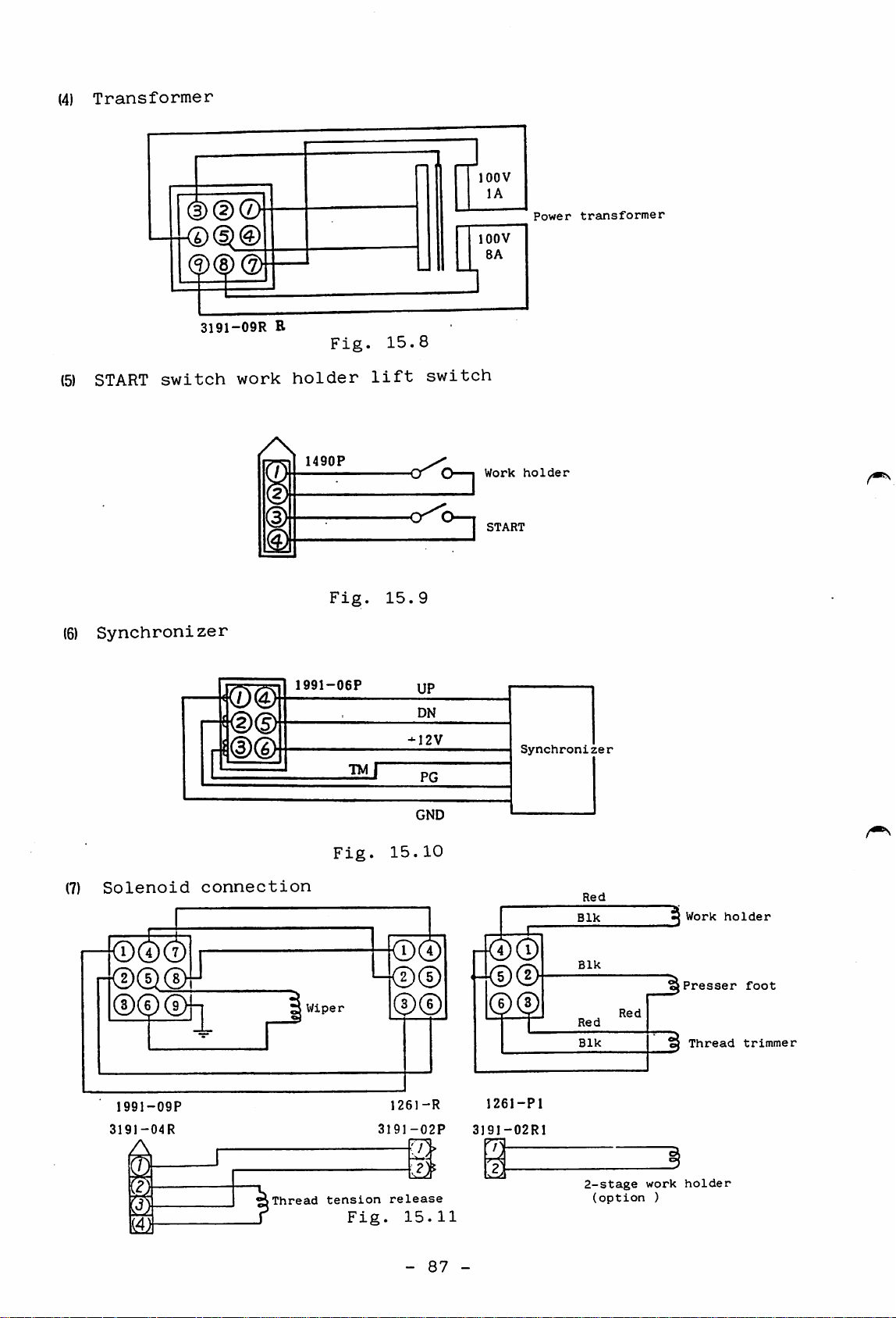
(4)
Transformer
lOOV
(5)
START
Synchroni
3191-09R
switch
zer
work
/\
E
holder
1490P
Fig.
Fig.
lift
15.8
•O^C
15.9
switch
lOOV
8A
Work
START
Power
holder
transformer
(7)
Solenoid
1991-09P
3191-04R
A
m
©d)
||®(g>
connection
(Thread
1991-06P
Wiper
tension
Fig.
Fig.
UP
DN
-12V
PG
GND
15.10
n<D®
h©®
0®
1261-R
3191-02P
A-
release
15.11
1261-Pl
319I-02R1
i
Synchronizer
Red
Blk
Blk
Red
Blk
2-stage
(option
Red
work
)
j Work
Presser
^
Thread
holder
holder
foot
trimmer
-
87
-
Page 92

16.
TROUBLESHOOTING
If
any
trouble
occurs
with
the
sewing
machine,
perform
the
16.1
following
(1)
Is
Are
set
(2)
Are
(3)
Is
(See
(4)
Does
(If
(5)
Is
Is
The
work
check
the
all
properly?
the
the
the
any
yes,
fuse
the
before
power
connectors,
source
connectors
PROM
rating
holder
cassette
power
error
determine
not
blown
pilot
lamp on
out
of
each
does
starting
at
the
phase
in
the
loaded
lamp
the
the
cause
(two
fuse
not
return
detailed
specified
reversing
control
properly?
on
the
front
and
fuses)?
correct
to
troubleshooting.
voltage?
plug
box
engaged
cassette
panel
remedy.)
the
light?
(lOA)?
home
and
to
position
switches
properly?
check.)
when
Does
LIMI-STOP
motor
the
run?
power
Z
is
turned
(1)
(1)
(2)
(1)
(1)
on
...
The
power
connected.
The
V-belt
ley.
The
synchronizer
tive
perly.
Fuse
PROM
properly.
Cause
or
not
is
blown
cassette
cable
is
adjusted
not
out.
is
is
is
not
of
not
defec
pul
pro
loaded
Refer
to
10.5
12.3
6.9
(2)
motor
RESET/HOME
panel
sition.
-
88
is
-
set
switch
at
"RESET"
on
switch
po
6.7
Page 93

16.2
The
is
work
pressed
holder
....
does
not
move
at
all
when
the
START
switch
work
16.4
Does
holder
move?
Stitching
the
line
No
deviates
(1)
(1)
(2)
not
(1)
(2)
(1)
Safety
START
SCALE
start
START
Machine
ed.
PROM
(Stitching
programmed.)
from
previously
means
switch
switch
switch
mechanism
programming
motion
is
actuated.
is
defective.
is
set
is
defective.
is
error
is
determined
at
lock
not
"0".
pat
6.9
6.3
Refer
Instruc
tion
Manual
for
Writer.
to
ROM
work
move
16.5
Does
ly'^
tern
the
holder
correct
Thread
to
the
cannot
wiper)
be
trimmed
(1)
Sewing
(2)
PROM
(3)
X-Y
adjusted
(1)
Needle
is
(2)
Fabric
machine
for
(3)
Fabric
successfully
table
(Move
check.)
justment
improper.
heavy
speed
programming
mechanism
properly.
the
table
stop
is
position
on
synchronizer
in
body
fabric).
is
too
(the
is
too
fast.
error
is
by
hand
contact
(particularly
thick.
same
ad
with
is
not
to
Refer
Instruc
tion
nual
ROM
Writer.
applied
to
Ma
for
10.5
TRIM-
89
TRIMMER
-
^
-
switch
to
(1)
Set
"ON".
Page 94

trimmer
work
Does
thread
solenoid
properly?
(1)
(2)
Lead(s)
head
or
broken.
Control
is
from
disconnected
box
machine
trouble
16.6
16.7
HALT
Sewing
(stitching
speed
suspension)
is
extremely
(1)
Thread
fective
justed
is
(1)
HALT
tive
(2)
HALT
disconnected
(3)
Control
low
low
(1)
Torque
drive
chanism
large,
sion
(2)
Synchronizer
tive
properly.
trimmer
properly.
impossible
switch
.
switch
required
stitching
due
of
or
or
not
....
is
lead
box
trouble
is
extrememly
to
mechanism.
not
adjusted
or
distor-
is
is
ad
defec
is
broken.
to
me
defec
de
16.10
10.5
16.8
16.9
Sewing
Checking
to
check.
Solenoid
Wiper
NOTE:
speed
the
Resistance
Resistance
Table
is
machine
12
ohm
16.1
extremely
head
shown
high
high
(1)
(2)
connector
connector
the
Connector
Across
above
Synchronizer
rator
is
Synchronizer
tive
properly.
following
is
pins
that
or
CONB
(5)
disconnected.
not
connector
(9-circuit
and
measured
pulse
is
defec
adjusted
(6)
at
gene
pins
connector)
20^0
10.
5
-
90
-
Page 95

16.10
Troubleshooting
(sewing
machine
mechanisms)
Trouble
Thread
not
med.
be
can
trim
Fixed
properly
with
movable
Knife
loose.
Knife
aged,
Needle
early.
Fixed
positioned
Movable
too
fast
cannot
Cause
knife
is
engaged
engagement
blade
or
is
worn.
stops
knife
is
properly.
knife
and
be
trimmed
knife.
too
motion
thread
not
dam
not
Remedy
Adjust
ment
is
Ajust
ment
Replace
knife.
Adjust
knife
.
knife
pressure.
needle
engage
engage
damaged
stop
Refer
to
11.8
11.8
10.5
position.
Adjust
fixed
Adjust
thread
position
knife.
position
trimming
of
of
cam.
11.8
11.7
pro
Needle
thread
off
eye
thread
ming.
needle
after
comes
trim
perly.
Tension
open
trimmed.
when
Timing
ming
is
Thread
fixed
scissoring.
Needle
for
thread
Pretension
too
tight.
Thread
too
faint.
of
is
knife
is
tension
discs
not
do
thread
thread
proper.
trimmed
before
too
used.
discs
thick
is
not
is
trim
by
are
Adjust
thread
Adjust
thread
Adjust
.
fixed
Adjust
discs.
Adjust
sion.
the
release.
position
trimming
position
knife.
pretension
thread
needle
ten
of
cam.
of
11.7
11.8
11.
•
CD
10
Protector
improperly.
is
located
Locate
protector
properly.
-
91
-
11.8
Page 96

Trouble
Cause
Remedy
Refer
to
Stitches
not
locked
start
sewing.
inter
are
at
of
Bobbin
from
short
bobbin.
Bobbin
is
Length
thread
is
too
trimming.
too
thread
bobbin
due
thread
high.
of
(needle
short
extending
case
to
racing
tension
trimmed
after
becomes
end
thread)
thread
of
Use
a
having
prenvention
racing.
Adjust
thread
1.
Adjust
sion
2.
Check
trimming
for
tion.
3.
Check
bobbin
spring
bobbin
tension.
discs.
installa
preten
thread
thread
case
of
cam
for
11.11
10.
11.10
11.7
2
ing.
Trimmer
thread
(needle
thread)
too
long.
end
is
Pretension
too
Thread
Thread
hook.
faint.
discs
trimming
often
leaves
are
delays
Adjust
discs.
Adjust
of
ming
Adjust
thread
pretension
position
cam.
hook
trim
gap
11.10
11.7
10.12
-
92
-
Page 97

A
MITSUBISHI ELECTRIC CORPORATION
HEAD
OFFICE:
MITSUBISHI
DENKI
BLDG.
MARUNOUCHI
TOKYO
100
TELEX:
J24532
CABLE
MELCO
TOKYO
{8902)ROD
Printed in Japan
 Loading...